
Site Improvement and Deep Foundations - …courses.washington.edu/cm510/Lecture4.pdfSite Improvement...
35
1 Advanced Construction Techniques Deep Foundations Professor Kamran M. Nemati Autumn Quarter 2016 1 CM 510 Advanced Construction Techniques Site Improvement and Deep Foundations 2 Foundation Construction Shallow Foundations: consisting of footings or rafts foundation sized to control settlement and provide adequate margin of safety against shear failure in the foundation soil Deep Foundations: piles and piers used to bypass unsatisfactory soils and transfer structure loads to a suitable bearing stratum
Transcript of Site Improvement and Deep Foundations - …courses.washington.edu/cm510/Lecture4.pdfSite Improvement...
1
Advanced Construction Techniques
Deep Foundations
Professor Kamran M. NematiAutumn Quarter 2016
1
CM 510
Advanced Construction Techniques
Site
Improvement
and Deep
Foundations
2
Foundation Construction
Shallow Foundations:
consisting of footings or rafts
foundation sized to control settlement and provide adequate margin of safety against shear failure in the foundation soil
Deep Foundations:
piles and piers
used to bypass unsatisfactory soils and transfer structure loads to a suitable bearing stratum
2
Advanced Construction Techniques
Deep Foundations
Professor Kamran M. NematiAutumn Quarter 2016
3
What is a Foundation?
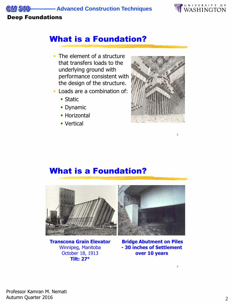
The element of a structure that transfers loads to the underlying ground with performance consistent with the design of the structure.
Loads are a combination of:
Static
Dynamic
Horizontal
Vertical
4
What is a Foundation?
Transcona Grain ElevatorWinnipeg, ManitobaOctober 18, 1913
Tilt: 27°
Bridge Abutment on Piles- 30 inches of Settlement
over 10 years
3
Advanced Construction Techniques
Deep Foundations
Professor Kamran M. NematiAutumn Quarter 2016
5
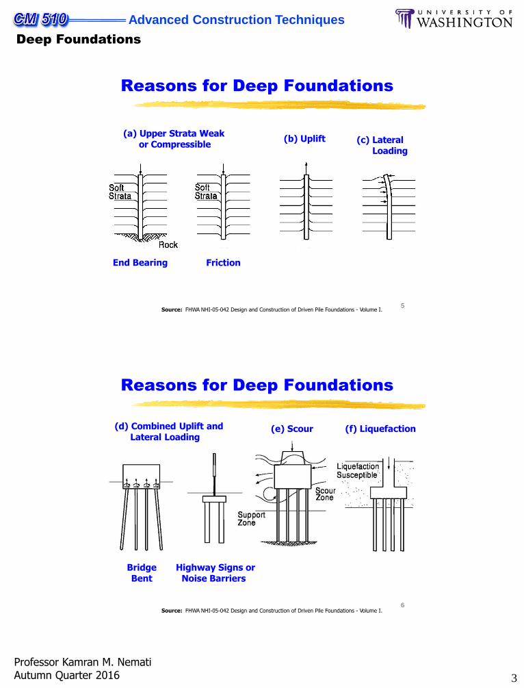
Reasons for Deep Foundations
Source: FHWA NHI-05-042 Design and Construction of Driven Pile Foundations - Volume I.
End Bearing Friction
(b) Uplift(a) Upper Strata Weak
or Compressible(c) Lateral
Loading
6
Reasons for Deep Foundations
Source: FHWA NHI-05-042 Design and Construction of Driven Pile Foundations - Volume I.
(d) Combined Uplift andLateral Loading
BridgeBent
Highway Signs orNoise Barriers
(e) Scour (f) Liquefaction
4
Advanced Construction Techniques
Deep Foundations
Professor Kamran M. NematiAutumn Quarter 2016
7
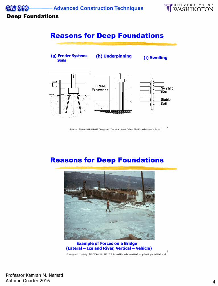
Reasons for Deep Foundations
Source. FHWA NHI-05-042 Design and Construction of Driven Pile Foundations - Volume I.
(h) Underpinning (i) Swelling(g) Fender Systems Soils
8
Reasons for Deep Foundations
Example of Forces on a Bridge (Lateral – Ice and River, Vertical – Vehicle)
Photograph courtesy of FHWA-NHI-132012 Soils and Foundations Workshop Participants Workbook
5
Advanced Construction Techniques
Deep Foundations
Professor Kamran M. NematiAutumn Quarter 2016
9
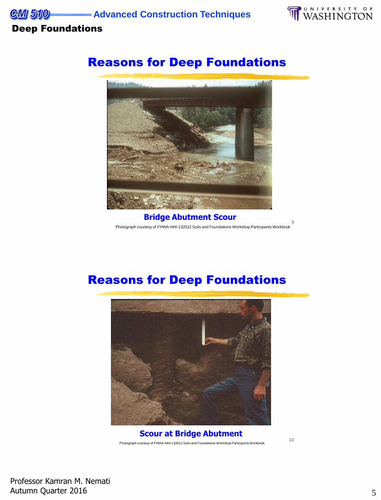
Reasons for Deep Foundations
Bridge Abutment ScourPhotograph courtesy of FHWA-NHI-132012 Soils and Foundations Workshop Participants Workbook
10
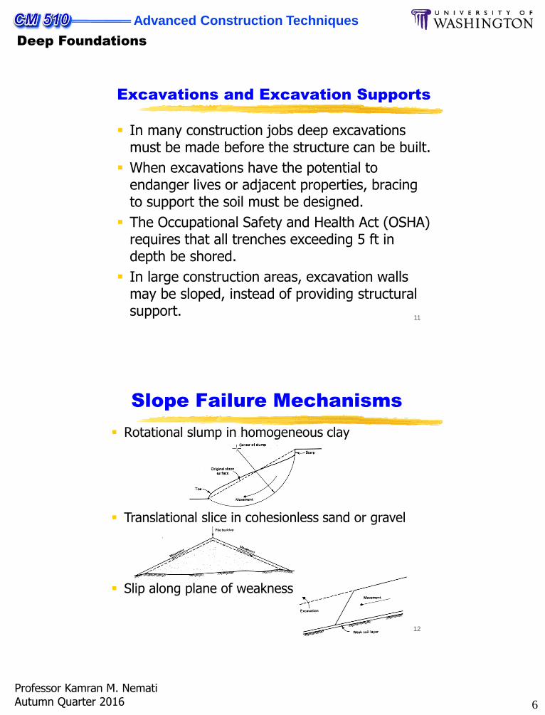
Reasons for Deep Foundations
Scour at Bridge AbutmentPhotograph courtesy of FHWA-NHI-132012 Soils and Foundations Workshop Participants Workbook
6
Advanced Construction Techniques
Deep Foundations
Professor Kamran M. NematiAutumn Quarter 2016
11
Excavations and Excavation Supports
In many construction jobs deep excavations must be made before the structure can be built.
When excavations have the potential to endanger lives or adjacent properties, bracing to support the soil must be designed.
The Occupational Safety and Health Act (OSHA) requires that all trenches exceeding 5 ft in depth be shored.
In large construction areas, excavation walls may be sloped, instead of providing structural support.
12
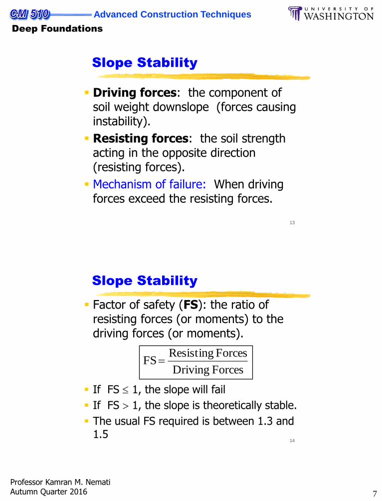
Slope Failure Mechanisms
Rotational slump in homogeneous clay
Translational slice in cohesionless sand or gravel
Slip along plane of weakness
7
Advanced Construction Techniques
Deep Foundations
Professor Kamran M. NematiAutumn Quarter 2016
13
Slope Stability
Driving forces: the component of soil weight downslope (forces causing instability).
Resisting forces: the soil strength acting in the opposite direction (resisting forces).
Mechanism of failure: When driving forces exceed the resisting forces.
14
Slope Stability
Factor of safety (FS): the ratio of resisting forces (or moments) to the driving forces (or moments).
Forces Driving
Forces ResistingFS
If FS 1, the slope will fail
If FS 1, the slope is theoretically stable.
The usual FS required is between 1.3 and 1.5
8
Advanced Construction Techniques
Deep Foundations
Professor Kamran M. NematiAutumn Quarter 2016
15
Slope Stability (Cont’d)
To estimate the factor of safety for a slope, the following information is required:
1. The soil and water profile
2. The kinematics of potential slope failure
3. The strength and weight of soils, and
4. The proposed slope geometry.
This estimate is for homogeneous materials.
16
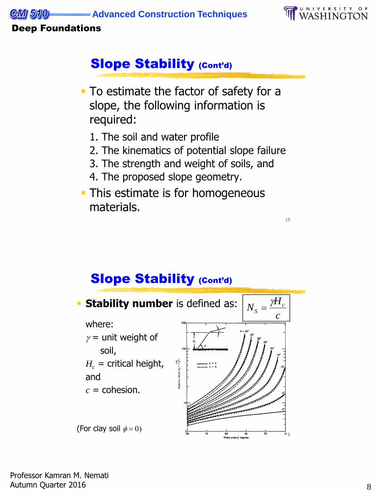
Slope Stability (Cont’d)
Stability number is defined as:c
HN c
S
where:
= unit weight of
soil,
Hc = critical height,
and
c = cohesion.
(For clay soil f 0)
9
Advanced Construction Techniques
Deep Foundations
Professor Kamran M. NematiAutumn Quarter 2016
17
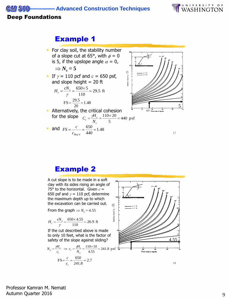
Example 1
For clay soil, the stability number of a slope cut at 65°, with f = 0 is 5, if the upslope angle a = 0,
565°
ft 5.29110
5650
s
c
cNH
48.120
5.29FS
psf 4405
20110
s
cc
N
HC
48.1440
650
dReq'c
c FS
Ns = 5
If = 110 pcf and c = 650 psf,
and slope height = 20 ft
Alternatively, the critical cohesion for the slope
and
18
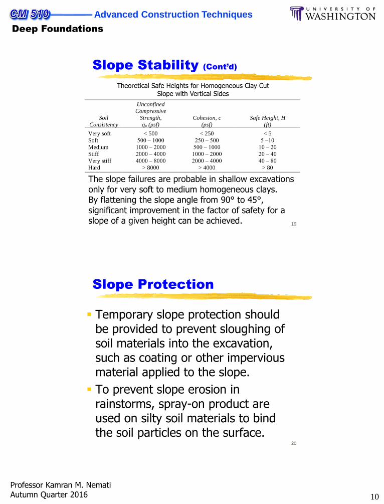
Example 2
4.55
ft 9.26110
55.4650
s
c
cNH
A cut slope is to be made in a soft clay with its sides rising an angle of 75° to the horizontal. Given c =
650 psf and = 110 pcf, determine
the maximum depth up to which the excavation can be carried out.
7.28.241
650 FS
cc
c
psf 8.24155.4
10110
S
cc
c
cS
N
Hc
c
HN
From the graph Ns = 4.55
If the cut described above is made to only 10 feet, what is the factor of safety of the slope against sliding?
10
Advanced Construction Techniques
Deep Foundations
Professor Kamran M. NematiAutumn Quarter 2016
19
Theoretical Safe Heights for Homogeneous Clay Cut Slope with Vertical Sides
Soil
Consistency
Unconfined
Compressive
Strength,
qu (psf)
Cohesion, c
(psf)
Safe Height, H
(ft)
Very soft < 500 < 250 < 5
Soft 500 – 1000 250 – 500 5 –10
Medium 1000 – 2000 500 – 1000 10 – 20
Stiff 2000 – 4000 1000 – 2000 20 – 40
Very stiff 4000 – 8000 2000 – 4000 40 – 80
Hard > 8000 > 4000 > 80
The slope failures are probable in shallow excavations only for very soft to medium homogeneous clays.By flattening the slope angle from 90° to 45°, significant improvement in the factor of safety for a slope of a given height can be achieved.
Slope Stability (Cont’d)
20
Slope Protection
Temporary slope protection should be provided to prevent sloughing of soil materials into the excavation, such as coating or other impervious material applied to the slope.
To prevent slope erosion in rainstorms, spray-on product are used on silty soil materials to bind the soil particles on the surface.
11
Advanced Construction Techniques
Deep Foundations
Professor Kamran M. NematiAutumn Quarter 2016
21
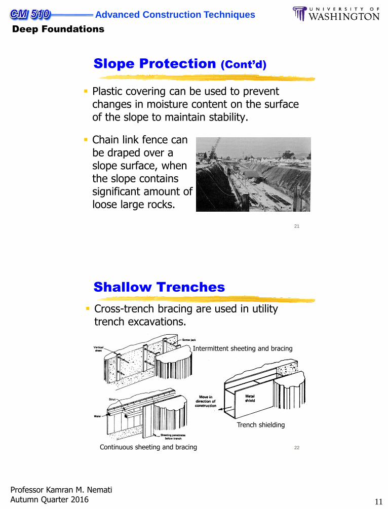
Slope Protection (Cont’d)
Plastic covering can be used to prevent changes in moisture content on the surface of the slope to maintain stability.
Chain link fence can be draped over a slope surface, when the slope contains significant amount of loose large rocks.
22
Shallow Trenches
Cross-trench bracing are used in utility trench excavations.
Intermittent sheeting and bracing
Continuous sheeting and bracing
Trench shielding
12
Advanced Construction Techniques
Deep Foundations
Professor Kamran M. NematiAutumn Quarter 2016
23
Deep Cuts
Excavation depths exceeding 10 to 20 ft, require specialized planning for support.
Lateral earth pressure is proportional to the vertical pressure.
As a cut is made, the soil at the face tend to expand and move into the cut area.
If a support is placed against the excavation surface to prevent the soil movement, then the pre-excavation stress is maintained.
24
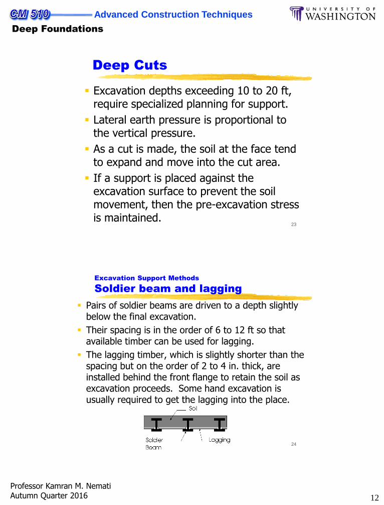
Excavation Support Methods
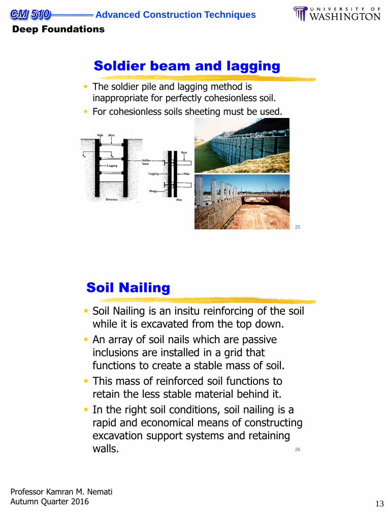
Soldier beam and lagging
Pairs of soldier beams are driven to a depth slightly below the final excavation.
Their spacing is in the order of 6 to 12 ft so that available timber can be used for lagging.
The lagging timber, which is slightly shorter than the spacing but on the order of 2 to 4 in. thick, are installed behind the front flange to retain the soil as excavation proceeds. Some hand excavation is usually required to get the lagging into the place.
13
Advanced Construction Techniques
Deep Foundations
Professor Kamran M. NematiAutumn Quarter 2016
25
Soldier beam and lagging
The soldier pile and lagging method is inappropriate for perfectly cohesionless soil.
For cohesionless soils sheeting must be used.
26
Soil Nailing
Soil Nailing is an insitu reinforcing of the soil while it is excavated from the top down.
An array of soil nails which are passive inclusions are installed in a grid that functions to create a stable mass of soil.
This mass of reinforced soil functions to retain the less stable material behind it.
In the right soil conditions, soil nailing is a rapid and economical means of constructing excavation support systems and retaining walls.
14
Advanced Construction Techniques
Deep Foundations
Professor Kamran M. NematiAutumn Quarter 2016
27
Soil Nailing
In many applications soil nailing can be the least disruptive way to construct a retaining wall.
Soil nailing requires an unusual amount of hand work, craftsmanship and geotechnical knowledge to construct.
The typical construction sequence begins with the excavation of a shallow cut. Then shotcrete is applied to the face of the cut and soil nails are drilled and grouted. This sequence is then repeated until subgrade is reached.
28
Soil Nailing Examples
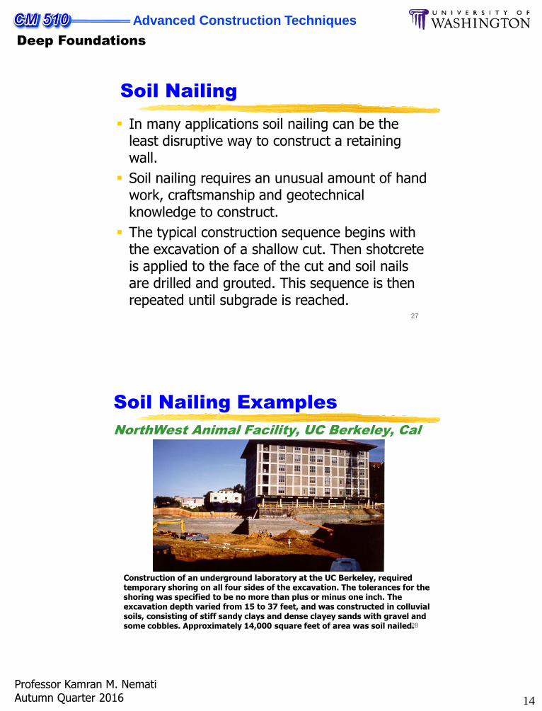
NorthWest Animal Facility, UC Berkeley, Cal
Construction of an underground laboratory at the UC Berkeley, required temporary shoring on all four sides of the excavation. The tolerances for the shoring was specified to be no more than plus or minus one inch. The excavation depth varied from 15 to 37 feet, and was constructed in colluvial soils, consisting of stiff sandy clays and dense clayey sands with gravel and some cobbles. Approximately 14,000 square feet of area was soil nailed.
15
Advanced Construction Techniques
Deep Foundations
Professor Kamran M. NematiAutumn Quarter 2016
29
Soil Nailing Examples
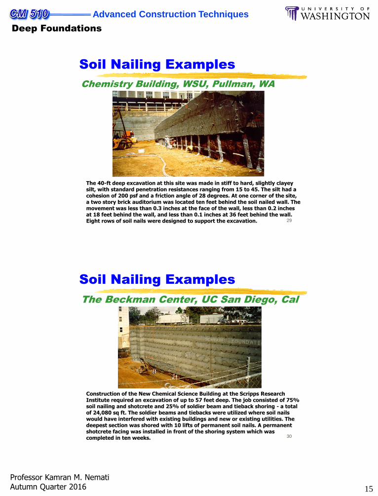
Chemistry Building, WSU, Pullman, WA
The 40-ft deep excavation at this site was made in stiff to hard, slightly clayey silt, with standard penetration resistances ranging from 15 to 45. The silt had a cohesion of 200 psf and a friction angle of 28 degrees. At one corner of the site, a two story brick auditorium was located ten feet behind the soil nailed wall. The movement was less than 0.3 inches at the face of the wall, less than 0.2 inches at 18 feet behind the wall, and less than 0.1 inches at 36 feet behind the wall. Eight rows of soil nails were designed to support the excavation.
30
Soil Nailing Examples
The Beckman Center, UC San Diego, Cal
Construction of the New Chemical Science Building at the Scripps Research Institute required an excavation of up to 57 feet deep. The job consisted of 75% soil nailing and shotcrete and 25% of soldier beam and tieback shoring - a total of 24,080 sq ft. The soldier beams and tiebacks were utilized where soil nails would have interfered with existing buildings and new or existing utilities. The deepest section was shored with 10 lifts of permanent soil nails. A permanent shotcrete facing was installed in front of the shoring system which was completed in ten weeks.
16
Advanced Construction Techniques
Deep Foundations
Professor Kamran M. NematiAutumn Quarter 2016
31
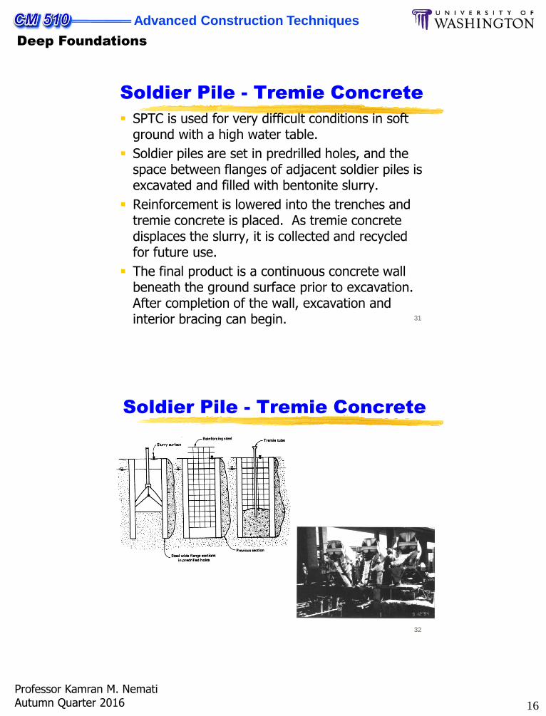
Soldier Pile - Tremie Concrete
SPTC is used for very difficult conditions in soft ground with a high water table.
Soldier piles are set in predrilled holes, and the space between flanges of adjacent soldier piles is excavated and filled with bentonite slurry.
Reinforcement is lowered into the trenches and tremie concrete is placed. As tremie concrete displaces the slurry, it is collected and recycled for future use.
The final product is a continuous concrete wall beneath the ground surface prior to excavation. After completion of the wall, excavation and interior bracing can begin.
32
Soldier Pile - Tremie Concrete
17
Advanced Construction Techniques
Deep Foundations
Professor Kamran M. NematiAutumn Quarter 2016
33
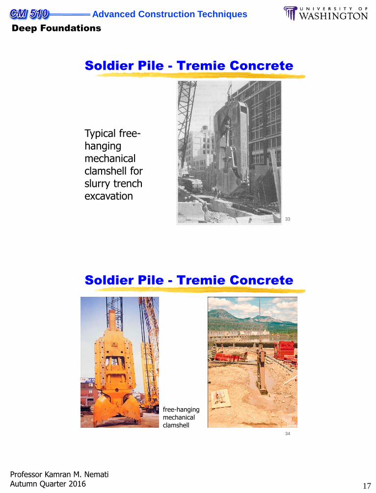
Soldier Pile - Tremie Concrete
Typical free-hanging mechanical clamshell for slurry trench excavation
34
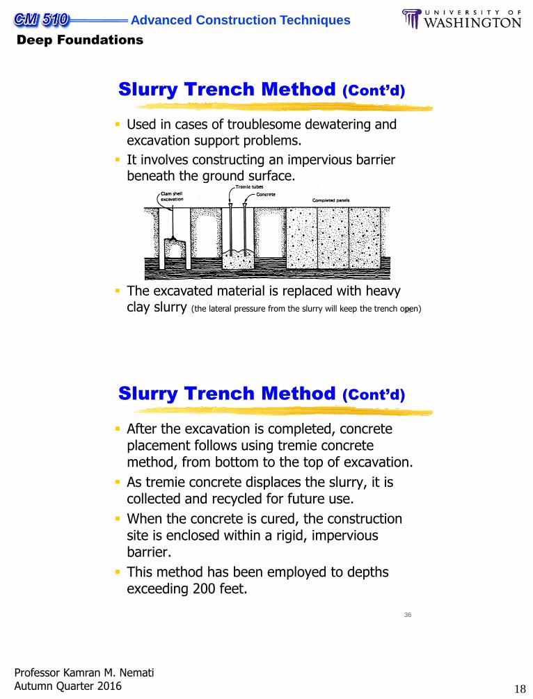
Soldier Pile - Tremie Concrete
free-hanging mechanical clamshell
18
Advanced Construction Techniques
Deep Foundations
Professor Kamran M. NematiAutumn Quarter 2016
35
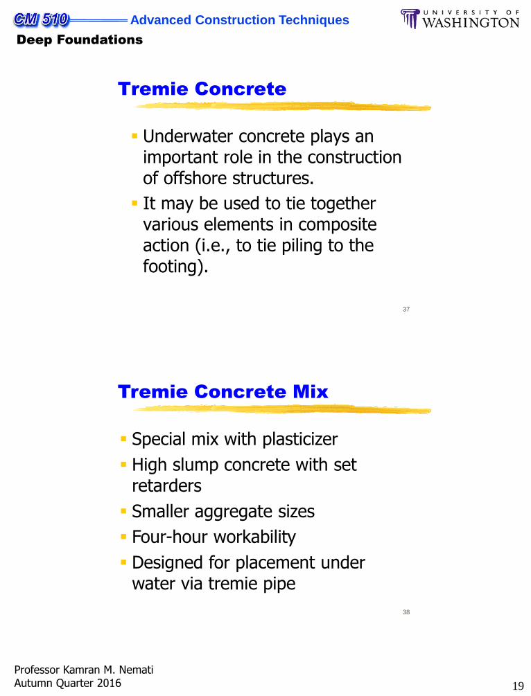
Slurry Trench Method (Cont’d)
Used in cases of troublesome dewatering and excavation support problems.
It involves constructing an impervious barrier beneath the ground surface.
The excavated material is replaced with heavy clay slurry (the lateral pressure from the slurry will keep the trench open)
36
After the excavation is completed, concrete placement follows using tremie concrete method, from bottom to the top of excavation.
As tremie concrete displaces the slurry, it is collected and recycled for future use.
When the concrete is cured, the construction site is enclosed within a rigid, impervious barrier.
This method has been employed to depths exceeding 200 feet.
Slurry Trench Method (Cont’d)
19
Advanced Construction Techniques
Deep Foundations
Professor Kamran M. NematiAutumn Quarter 2016
37
Tremie Concrete
Underwater concrete plays an important role in the construction of offshore structures.
It may be used to tie together various elements in composite action (i.e., to tie piling to the footing).
38
Tremie Concrete Mix
Special mix with plasticizer
High slump concrete with set retarders
Smaller aggregate sizes
Four-hour workability
Designed for placement under water via tremie pipe
20
Advanced Construction Techniques
Deep Foundations
Professor Kamran M. NematiAutumn Quarter 2016
39
Tremie Concrete
Underwater Concrete Mixes:
Structural concrete Coarse Aggregate: Gravel of 3/4” max. size.
Use 50-55 % of the total aggregate by weight.
Fine Aggregate: Sand, 45-50% of the total
aggregate by weight.
Cement: Type II ASTM (moderate heat of hydration),
600 lbs/yd3.
Pozzolans: ASTM 616 Type N or F, 100 lbs/ yd3.
40
Tremie Concrete
Water/Cement Ratio: 0.42 (0.45 Maximum).
Water-Reducing Admixture (preferably it is also plasticizer): Do not use superplasticizers.
Air-Entrainment Admixtures: To give 6% total air.
Retarding Admixture: To increase setting time to 4-24 hours, as required.
Slump: 6 1/2 in. ± 1 in.
This mix will develop compressive strength in the range of 5,600 – 7,000 psi at 28 days.
It will flow out on a slope of 6:1 to 8:1 horizontal/ vertical and, if properly placed, should give nominal segregation and laitance.
21
Advanced Construction Techniques
Deep Foundations
Professor Kamran M. NematiAutumn Quarter 2016
41
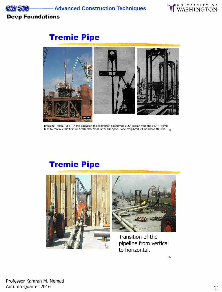
Tremie Pipe
Breaking Tremie Tube - In this operation the contractor is removing a 20' section from the 140' + tremie tube to continue the first full depth placement in the UR pylon. Concrete placed will be about 400 CYs.
42
Tremie Pipe
Transition of the pipeline from vertical to horizontal.
22
Advanced Construction Techniques
Deep Foundations
Professor Kamran M. NematiAutumn Quarter 2016
43
Placement of Tremie Concrete
The placement of tremie concrete is carried out through a tube, usually 10-to 12-in. pipe.
The pipe may be sectional but joints should be flanged and bolted, with soft rubber gasket, so as to prevent any in-leakage of water.
The tremie pipe must have sufficient wall thickness so that it negatively buoyant when empty.
44
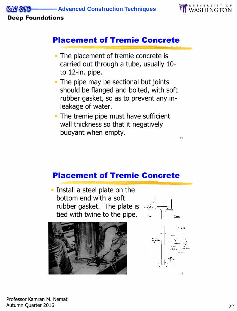
Placement of Tremie Concrete
Install a steel plate on the bottom end with a soft rubber gasket. The plate is tied with twine to the pipe.
23
Advanced Construction Techniques
Deep Foundations
Professor Kamran M. NematiAutumn Quarter 2016
45
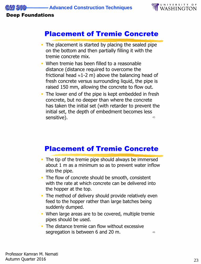
Placement of Tremie Concrete
The placement is started by placing the sealed pipe on the bottom and then partially filling it with the tremie concrete mix.
When tremie has been filled to a reasonable distance (distance required to overcome the frictional head 1-2 m) above the balancing head of fresh concrete versus surrounding liquid, the pipe is raised 150 mm, allowing the concrete to flow out.
The lower end of the pipe is kept embedded in fresh concrete, but no deeper than where the concrete has taken the initial set (with retarder to prevent the initial set, the depth of embedment becomes less sensitive).
46
Placement of Tremie Concrete
The tip of the tremie pipe should always be immersed about 1 m as a minimum so as to prevent water inflow into the pipe.
The flow of concrete should be smooth, consistent with the rate at which concrete can be delivered into the hopper at the top.
The method of delivery should provide relatively even feed to the hopper rather than large batches being suddenly dumped.
When large areas are to be covered, multiple tremie pipes should be used.
The distance tremie can flow without excessive segregation is between 6 and 20 m.
24
Advanced Construction Techniques
Deep Foundations
Professor Kamran M. NematiAutumn Quarter 2016
47
Placement of Tremie Concrete
48
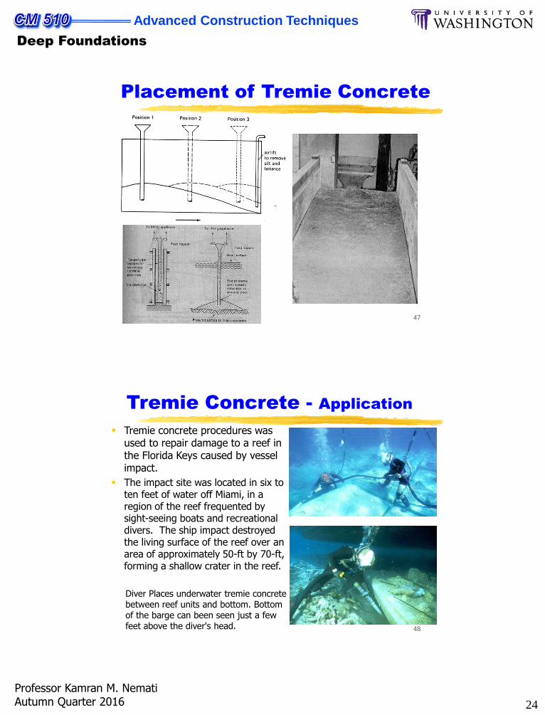
Tremie concrete procedures was used to repair damage to a reef in the Florida Keys caused by vessel impact.
The impact site was located in six to ten feet of water off Miami, in a region of the reef frequented by sight-seeing boats and recreational divers. The ship impact destroyed the living surface of the reef over an area of approximately 50-ft by 70-ft, forming a shallow crater in the reef.
Diver Places underwater tremie concrete between reef units and bottom. Bottom of the barge can been seen just a few feet above the diver's head.
Tremie Concrete - Application
25
Advanced Construction Techniques
Deep Foundations
Professor Kamran M. NematiAutumn Quarter 2016
49
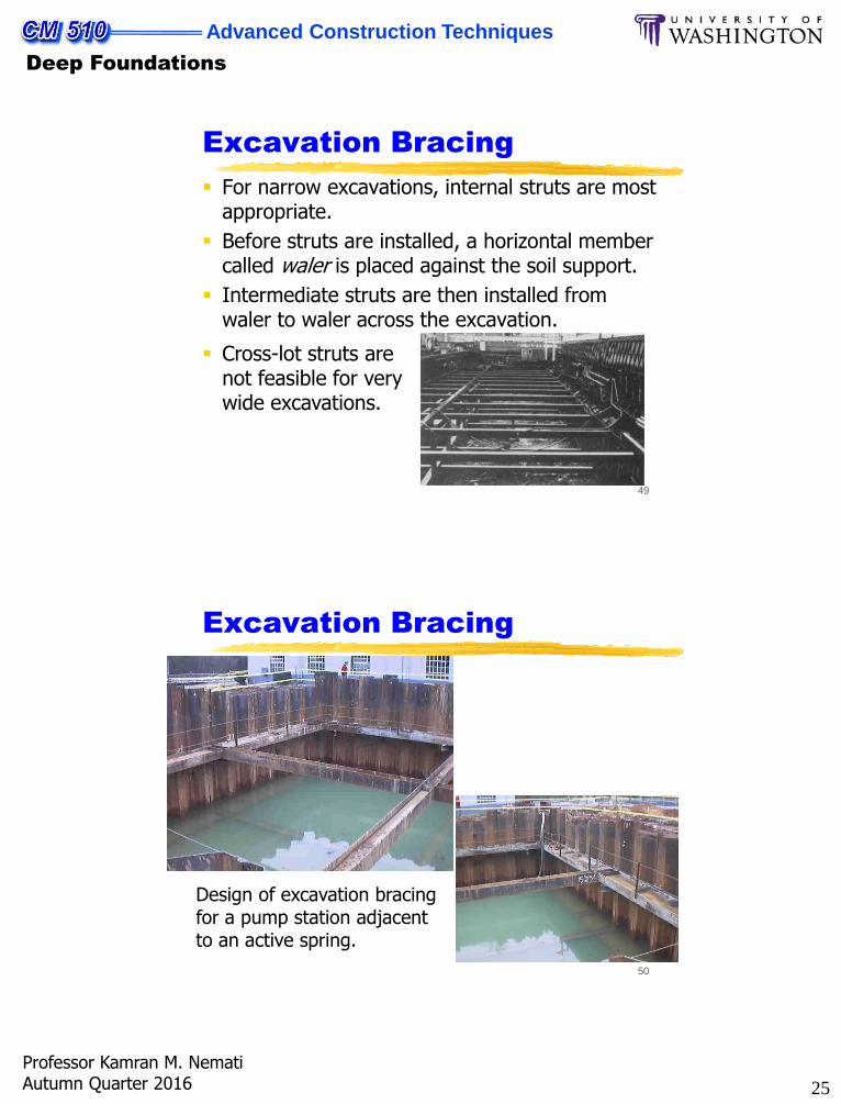
Excavation Bracing
For narrow excavations, internal struts are most appropriate.
Before struts are installed, a horizontal member called waler is placed against the soil support.
Intermediate struts are then installed from waler to waler across the excavation.
Cross-lot struts are not feasible for very wide excavations.
50
Excavation Bracing
Design of excavation bracing for a pump station adjacent to an active spring.
26
Advanced Construction Techniques
Deep Foundations
Professor Kamran M. NematiAutumn Quarter 2016
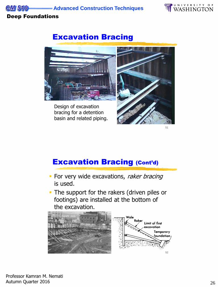
51
Excavation Bracing
Design of excavation bracing for a detention basin and related piping.
52
Excavation Bracing (Cont’d)
For very wide excavations, raker bracingis used.
The support for the rakers (driven piles or footings) are installed at the bottom of the excavation.
27
Advanced Construction Techniques
Deep Foundations
Professor Kamran M. NematiAutumn Quarter 2016
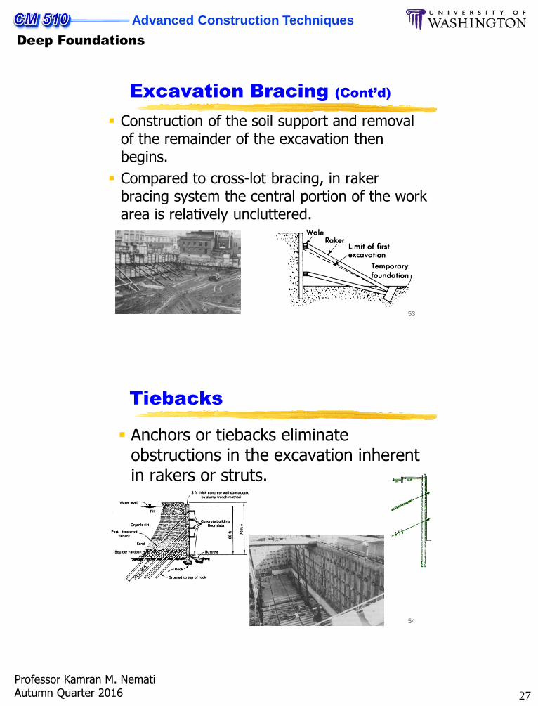
53
Excavation Bracing (Cont’d)
Construction of the soil support and removal of the remainder of the excavation then begins.
Compared to cross-lot bracing, in raker bracing system the central portion of the work area is relatively uncluttered.
54
Tiebacks
Anchors or tiebacks eliminate obstructions in the excavation inherent in rakers or struts.
28
Advanced Construction Techniques
Deep Foundations
Professor Kamran M. NematiAutumn Quarter 2016
55
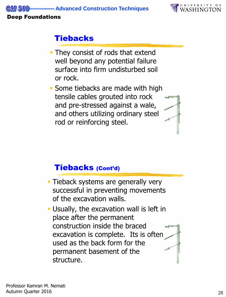
Tiebacks
They consist of rods that extend well beyond any potential failure surface into firm undisturbed soil or rock.
Some tiebacks are made with high tensile cables grouted into rock and pre-stressed against a wale, and others utilizing ordinary steel rod or reinforcing steel.
56
Tiebacks (Cont’d)
Tieback systems are generally very successful in preventing movements of the excavation walls.
Usually, the excavation wall is left in place after the permanent construction inside the braced excavation is complete. Its is often used as the back form for the permanent basement of the structure.
29
Advanced Construction Techniques
Deep Foundations
Professor Kamran M. NematiAutumn Quarter 2016
57
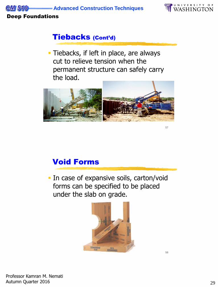
Tiebacks (Cont’d)
Tiebacks, if left in place, are always cut to relieve tension when the permanent structure can safely carry the load.
58
Void Forms
In case of expansive soils, carton/void forms can be specified to be placed under the slab on grade.
30
Advanced Construction Techniques
Deep Foundations
Professor Kamran M. NematiAutumn Quarter 2016
59
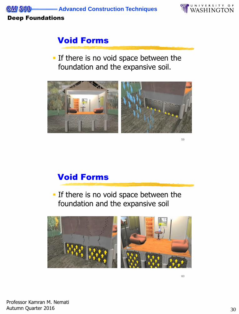
Void Forms
If there is no void space between the foundation and the expansive soil.
60
Void Forms
If there is no void space between the foundation and the expansive soil
31
Advanced Construction Techniques
Deep Foundations
Professor Kamran M. NematiAutumn Quarter 2016
61
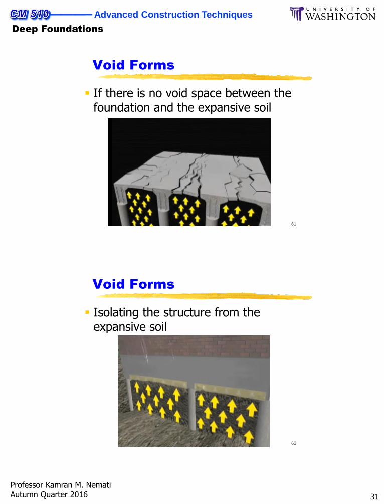
Void Forms
If there is no void space between the foundation and the expansive soil
62
Void Forms
Isolating the structure from the expansive soil
32
Advanced Construction Techniques
Deep Foundations
Professor Kamran M. NematiAutumn Quarter 2016
63
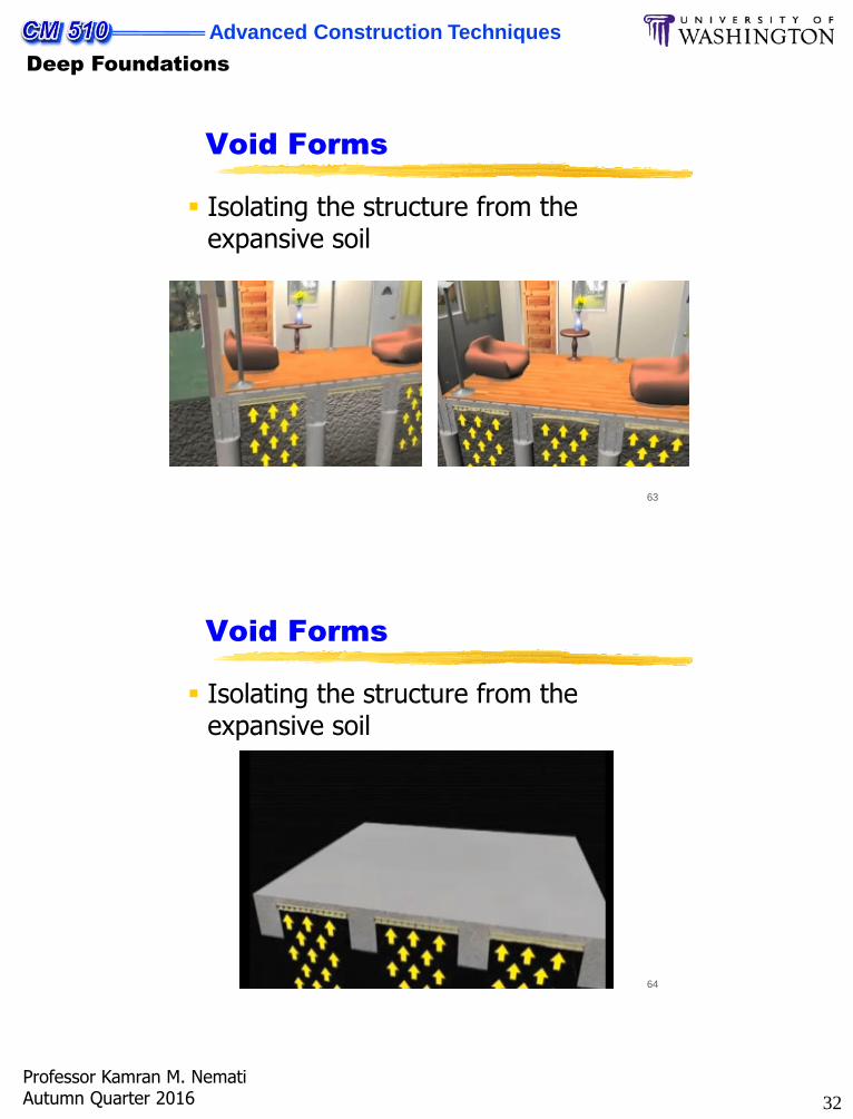
Void Forms
Isolating the structure from the expansive soil
64
Void Forms
Isolating the structure from the expansive soil
33
Advanced Construction Techniques
Deep Foundations
Professor Kamran M. NematiAutumn Quarter 2016
65
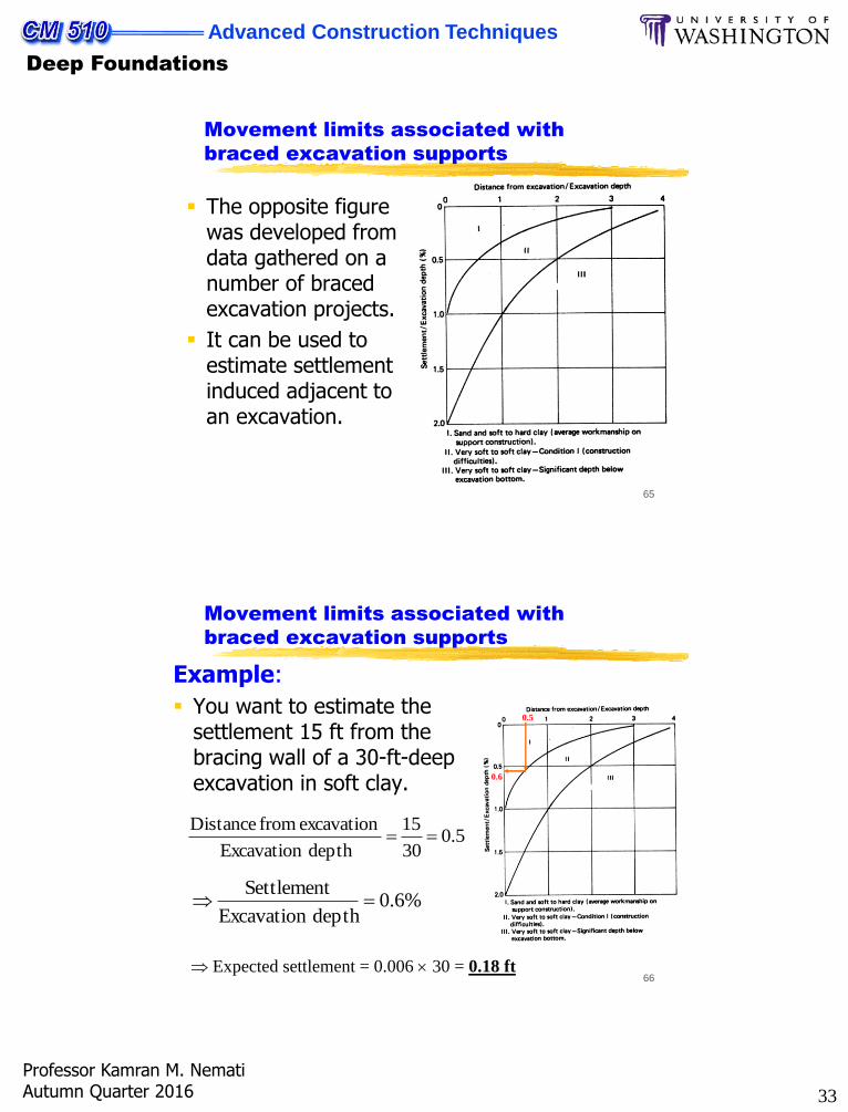
Movement limits associated with
braced excavation supports
The opposite figure was developed from data gathered on a number of braced excavation projects.
It can be used to estimate settlement induced adjacent to an excavation.
66
Movement limits associated with
braced excavation supports
Example:
You want to estimate the settlement 15 ft from the bracing wall of a 30-ft-deep excavation in soft clay.
5.030
15
depth Excavation
excavation from Distance
0.5
0.6
%6.0depth Excavation
Settlement
Expected settlement = 0.006 30 = 0.18 ft
34
Advanced Construction Techniques
Deep Foundations
Professor Kamran M. NematiAutumn Quarter 2016
67
GLOSSARY OF TERMS
Waler: Horizontal timber used to hold close sheeting in position.
Lagging: Lengths of sawn hardwood timber planks used to support the sides, walls or roof as necessary of shafts and drives and to prevent material from those faces falling into the excavation. The term is also sometimes used when referring to the layer of poling boards doing the same duty in trenches. The lagging is supported in turn by walkings, legs, caps, sets or frames, as applicable. (See also "lathes" below).
Lathes: Short lengths of hardwood timber usually split and about 1.25 to 1.5 meters long used to support the side walls (and roof in drives) and supported in turn by walings, legs or caps as applicable.
Strut: Hardwood timber (usually horizontal) in compression resisting thrust or pressure from the face or faces of an excavation.
Soldier: Vertical upright hardwood timber used for supporting a trench wall, taking the thrust from horizontal walers and supported by struts.
68
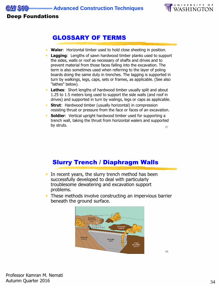
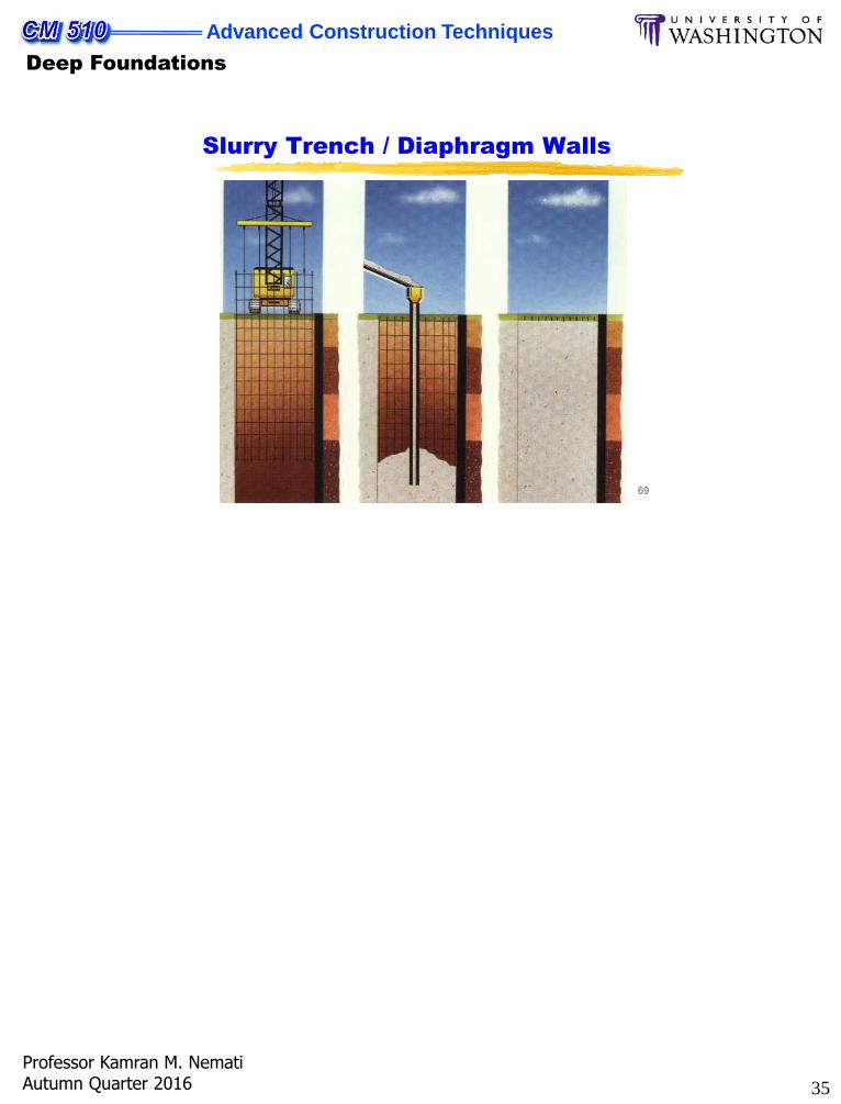
Slurry Trench / Diaphragm Walls
In recent years, the slurry trench method has been successfully developed to deal with particularly troublesome dewatering and excavation support problems.
These methods involve constructing an impervious barrier beneath the ground surface.
35
Advanced Construction Techniques
Deep Foundations
Professor Kamran M. NematiAutumn Quarter 2016
69
Slurry Trench / Diaphragm Walls