Near-surface site characterisation by ground stiffness profiling using surface wave geophysics

EIGG Test Site 1 Details Southmeads Road, Oadby, Leicester
Purpose: Location of environmental/engineering targets. Objects consist of an array of metallic and non-metallic materials of assorted shapes and buried at differing depths. These include: • Metal drums • Metal pipes • Plastic pipes • Concrete • Air-filled voids • Metal sheets • Concrete pipes • Brickwork • Backfilled trenches • Water-filled voids Site Description: The test site lies on the summit of a gentle hill-top. The surface layer of topsoil is about 0.3 metres thick, grading down into Boulder Clay. The Boulder Clay is uniform throughout the site, containing clasts up to 200 mm set in a clay matrix. This unit is 16 to 18 metres thick, and underlain by Liassic clays and limestones. Offset Wenner resistivity soundings confirm the depth to the boundary, and give a bulk resistivity of the Boulder Clay of 23 Ohm.m and 25 Ohm.m. for the Liassic Clay and limestone sequence. The water table is shallow, but the clay is of low permeability. During excavations water seeped slowly into most pits at depths of about 2 metres below the surface. The content and disposition of the test structures was discussed in detail by the EIGG committee, with the resulting plan being as shown in Figure 4. Each structure is defined in detail with plan and section drawings as necessary. Major considerations in the design were: • To provide targets suitable for most shallow geophysical methods such as
magnetics, electromagnetics, radar, resistivity and possibly gravity and seismics.
• To provide some simple targets for training purposes
1

• To provide a series of more challenging targets which would test the limits of present equipment resolution and field techniques.
• To provide a variety of targets which are of practical importance, but are currently undetectable by geophysical methods, e.g. plastic pipes.
The targets comprise a variety of different shapes and sizes of objects made from different materials. Tubes or beams, sheets, spheres and cubes, made of metal, concrete, brickwork and plastic are the major targets. Sizes range from 0.3 metres to 2 metres. The disturbance to the area caused by constructing the site was minimised. Burial holes were as small as possible, and back-filled with the extracted materials and compacted with a "Wacker". It is important that we can be sure that our measurement responses come from the buried objects, and not from the ground disturbance caused around them. To this end some trenches are back-filled with different materials (e.g. gravel, mixed ((homogenised) extracted subsoil) to act as controls. For practical reasons as well as to contain disturbance no excavation was deeper than 3 metres. Some soil compaction has occurred due to movement of plant. Continued maintenance may be necessary to level any further subsidence and ensure a uniform level surface with even grass cover.
2

Technical Description of Target Objects Brief details of the objects present at the site. Actual users of the site can obtain detailed drawings of the areas on which they have worked. No objects are buried to depths of greater than 2 metres to their top surface. Area 1. Metal Drums Simulation of buried waste drums. Metal waste disposal containers, and other similar objects buried from 0.5 to 2.0 metres, infilled with air or water.
Large boulder buried close to the waste drums Area 2. Plastic Pipes Simulation of Gas and water mains. Standard high-pressure pipes laid in trenches with back-fill of aggregates as standard for actual pipes. A real 2 inch Asbestos main also crosses this area. Area 3. Metal and Clay Pipes Buried in cut trenches backfilled with excavated materials, not aggregates. Area 4. Buried Walls and Trenches Simulation of various wall foundations and trench fills consisting of: modern concrete, corbelled brick, stone, aggregate, sand, and peat.
3

Simulated footings to present a "brownfield" or archaeological target. Area 5. Voids Simulation of air-filled voids underground. These consist of plastic waste disposal canisters filled as appropriate and sealed. Metal clips for the lids were not fitted. Area 6. Simulated Piles This area has not been constructed to date. It will be built when a drill-rig comes on site to drill the control boreholes. As yet there is no definite date for this. Area 7. Concrete in pits Simulation of isolated blocks in trench. Concrete blocks cast in situ in a battered trench with aggregate infill.
4

Area 7: Sandpit with cast concrete blocks.
Area 7: Radar image along the long axis of area 7 (Pulse Ekko PE100 system: with thanks to NERC Pool for the loan) Area 8. Metal plates in pits. Determination of resolution of multiple buried metal objects. 6 metal plates buried in a stair-case pattern along the axis of an aggregate-filled trench 6 m long, 2 m wide and 2 m deep.
5

Area 8: Sandpit with staircase structure of metal plates. Area 9. Voids under concrete ground slab Rectangular void spaces (lined with plastic casing) underlying concrete slab, partly reinforced with standard re-bar net. Area 10. Simulated rail track A small section of light railway track consisting of one rail and two sleepers.
6

Survey Area Location: The area available for operations is 40 metres by 70 metres. It is marked in outline by burned lines in the grass, and extends as shown on the detailed plan (Map 4). Apart from the buried objects, there are cultural effects as follows. 1. Metal railings in the hedge to the southern boundary. These provide an increasing magnetic gradient to the south, and a prominent EM anomaly. 2. Buildings to the East and West of the area have less pronounced but distinct effects on the nearest boundaries of the area. 3. Metal rail fencing at the northeast corner of the area and three concrete throwing circle all produce minor anomalies. 4. Any vehicles parked inside the entrance gates will have an effect on the eastern boundary of the area. Other Facilities: 1. Mains electricity is not normally available. 2. Water supply is not normally available, unless arranged in advance. 3. Toilets are available in the sports hall at the Southeast corner of the running track. 4. Shops/pubs/restaurants are accessible in Oadby 1km. to the South (see map 2) Participants in the development of the test site. Apart from assistance in the site design and generous financial support from the Impulse Radar Users Association (IRUA), other organisations have also supported this work. EIGG would wish to acknowledge them as follows: Use of land, and technical services (Leicester University) Steel waste disposal drums (Leigh Environmental) Sample gas mains (British Gas) Geological logging of cored material and excavations, and permanent archiving of core. (British Geological Survey) Ground-Penetrating Radar surveys both before and after construction. (Earth Science Systems)
7

Environmental and Industrial Geophysics Group 1.1: Manor Road Environmental Test Site
8 1 9
6 2 7
103
4
5
1312 14
11
0 5 m.35 mE 55 mE
20 mN
30 mN
40 mN
Area 1 Simulation of buried waste drums. Infilled with air or water. I.D #
Depth to top (m)
Diam (m)
height (m)
Object type Filling Orientation
1 1.0 0.6 0.9 Metal drum Air Vertical 2 1.0 0.6 0.9 Metal drum Water Vertical 3 1.0 0.6 0.9 Metal drum Water Vertical 4 1.0 0.6 0.9 Metal drum Air Vertical 5 1.0 0.6 0.9 Metal drum Air Vertical 6 0.5 0.6 0.9 Metal drum Air Vertical 7 2.0 0.6 0.9 Metal drum Air Vertical 8 1.0 0.6 0.9 Metal drum Air Horizontal E-W 9 1.0 0.6 0.9 Metal drum Air Horizontal N-S 10 1.0 0.6 0.9 Metal drum Air Horizontal NE-SW 11 1.0 0.6 0.9 Metal drum Air HorizontalNE-SW
dip 45o to NE 12 1.0 0.6
x 0.9 0.9 Granite
boulder - Vertical 0.9m E-W
13 1.0 0.6 0.01 Steel plate - Horizontal 14 1.0 0.6 0.05 Concrete slab
(square) - Horizontal
All holes backfilled with excavated materials.
5

Environmental and Industrial Geophysics Group 1.1: Manor Road Environmental Test Site
0 5 m.55 mE
Area 270 mE
1
3
2
0 mE
15 mN
Simulation of Gas and water mains. Standard high-pressure pipes laid in trenches with back-fill of aggregates as standard for actual pipes. A real 2 inch Asbestos main also crosses this area. I.D #
Depth to top (m)
Diam (m)
Object type Filling Orientation
1 0.7-1.0 0.15 Dipping from 0.7-1.0 m over full length of 6 m. Sealed, air-filled.
Air (sealed)
Dipping
2 0.7-1.0 0.15 Dipping from 0.7-1.0 m over full length of 6 m. Sealed, water-filled.
Water (sealed)
Dipping
3 0.5-1.0 0.15 Dipping from 0.5-1.0 m over full length of 10 m. Extended 2 m further up-dip and with vertical pipe and cap with access from surface. Pipe is drilled with 3 mm holes in lower 6 metres to allow water to drain into sand bed. Sand bed base parallel to pipe. Top is horizontal 0.3 m below ground surface, capped by soil.
Water (refilled via access cap.
Dipping
6

Environmental and Industrial Geophysics Group 1.1: Manor Road Environmental Test Site
0 5 m.15 mE 35 mE
28 mN
30 mN
40 mN
Area 3
1 2
3
4 5
67
Metal, Plastic and Clay Pipes Buried in cut trenches backfilled with excavated materials, not aggregates. I.D #
Depth to top (m)
Diam (m)
length (m)
Object type Filling Orientation
1 0.7 0.10 6.0 Cast iron or steel pipe 6m long
any Horizontal
2 0.7 0.05 6.0 Cast iron or steel pipe 6m long
any Horizontal
3 0.7 0.10 6.0 Cast iron or steel pipe 6 m long
any Horizontal
4 0.7 0.05 6.0 Cast iron or steel pipe 6 m long
any Horizontal
5 0.7 0.10 9.0 Clay pipes, socketed but not sealed. 9m total length.
any Horizontal
6 0.7 0.100 6.4 Plastic gas main sealed end-caps at both ends.
Air Horizontal
7 0.7 0.05 6.0 Plastic gas supply pipe. sealed both ends
Air Horizontal
7

Environmental and Industrial Geophysics Group 1.1: Manor Road Environmental Test Site
0 5 m.
19 mE 31 mE
12 mN
20 mN
Area 4
6
57
3
1
2
4
Buried Walls and Trenches Simulation of various wall foundations and trench fills consisting of: modern concrete, corbelled brick, stone, aggregate, sand, and peat. I.D #
Depth to base (m)
Width(m)
height (m)
Object type (Each 4m long )
Filling Orientation
1 1.0 0.45 0.4 Concrete, cast in-situ, non-reinforced.
- Horizontal
2 1.0 0.45 0.4 Brick, corbelled. Engineering bricks used.
- Horizontal
3 1.0 0.45 0.4 Stone blocks set in mortar.
- Horizontal
4 1.0 0.45 0.4 Aggregate, types 1 & 2 - Horizontal 5 1.0 0.45 0.4 Sand, building sand. - Horizontal 6 1.0 0.45 0.4 Peat and leaf mould - Horizontal 7 0.6 - - Paving slabs 0.6 x 0.6 m
and 0.6 x 0.9 m. Horizontal
8

Environmental and Industrial Geophysics Group 1.1: Manor Road Environmental Test Site
0 5 m.
43 mE31 mE7 mN
20 mN
Area 5
3
1 2
4
Voids Simulation of air-filled voids underground. These consist of plastic waste disposal canisters filled as appropriate and sealed. Metal clips for the lids were not fitted, the lids being sealed with glue. I.D #
Depth to top (m)
Diam (m)
height (m)
Object type Filling Orientation
1 2.0 0.6 1.0 Void Air - 2 2.0 0.6 1.0 Void Water - 3 1.0 0.6 1.0 Void Air - 4 1.0 0.6 1.0 Void Water -
9

Environmental and Industrial Geophysics Group 1.1: Manor Road Environmental Test Site
0 5 m.
55 mE43 mE7 mN
20 mN
Area 6
31
24
Simulated Piles This area has not been constructed to date. It will be built when a drill-rig comes on site to drill the control boreholes. As yet there is no definite date for this. I.D #
Depth to top (m)
Diam (m)
height (m)
Object type Filling Orientation
1 0.3 0.3 4.0 Cast in-situ concrete - Vertical 2 0.3 0.3 4.0 Cast in-situ reinforced
conc. - Vertical
3 0.3 0.1 2.0 Reinforced concrete fence post bedded in sand.
- Vertical
4 0.3 - - Left as space for future. - Vertical
10
Environmental and Industrial Geophysics Group 1.1: Manor Road Environmental Test Site
0 5 m.
70 mE63 mE20 mN
35 mN
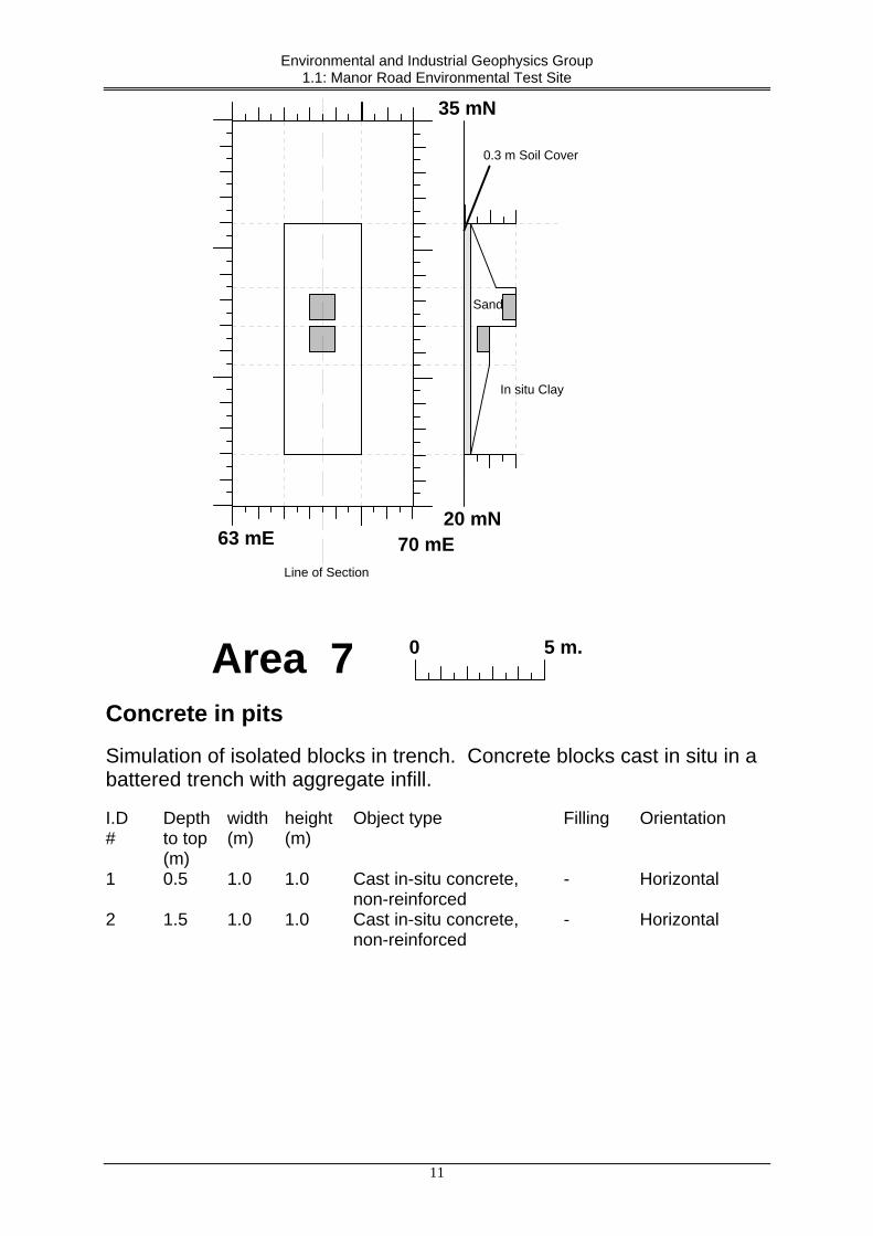
Area 7
Line of Section
0.3 m Soil Cover
Sand
In situ Clay
Concrete in pits Simulation of isolated blocks in trench. Concrete blocks cast in situ in a battered trench with aggregate infill. I.D #
Depth to top (m)
width(m)
height (m)
Object type Filling Orientation
1 0.5 1.0 1.0 Cast in-situ concrete, non-reinforced
- Horizontal
2 1.5 1.0 1.0 Cast in-situ concrete, non-reinforced
- Horizontal
11

Environmental and Industrial Geophysics Group 1.1: Manor Road Environmental Test Site
0 5 m.
61 mE55 mE
15 mN
25 mN
Area 8Line of Section
0.3 m Soil Cover
Sand
In situ Clay
1234
56
Metal plates in pits. Determination of resolution of multiple buried metal objects. 6 metal plates buried horizontally in a stair-case pattern along the axis of an aggregate-filled trench 6 m long, 2 m wide and 2 m deep. I.D #
Depth to top (m)
width (m)
length (m)
Object type Filling Orientation
1 0.3 0.3 0.6 Metal plate 0.01 m thick - Horizontal 2 0.6 0.3 0.6 Metal plate 0.01 m thick - Horizontal 3 0.9 0.3 0.6 Metal plate 0.01 m thick - Horizontal 4 1.2 0.3 0.6 Metal plate 0.01 m thick - Horizontal 5 1.5 0.3 0.6 Metal plate 0.01 m thick - Horizontal 6 1.8 0.3 0.6 Metal plate 0.01 m thick - Horizontal
12

Environmental and Industrial Geophysics Group 1.1: Manor Road Environmental Test Site
Area 9
0 5 m.
67 mE57 mE
38 mN
Area 9
Line of Section
In situ Clay
32 mN
1 2
3 3
Voids under concrete ground slab I.D #
Depth to top (m)
width (m)
length (m)
Object type Filling Orientation
1 0.0 2.0 3.0 Concrete slab, non-reinforced
- Horizontal
2 0.0 2.0 3.0 Concrete slab, reinforced
- Horizontal
3 0.3 0.6 0.4 Void (sealed plastic tank dimensions 0.6 x 0.4 x 0.5 deep)
- Horizontal
4 0.3 0.6 0.4 Void (sealed plastic tank dimensions 0.6 x 0.4 x 0.5 deep)
- Horizontal
13

Environmental and Industrial Geophysics Group 1.1: Manor Road Environmental Test Site
0 5 m.
23 mE 31 mE4 mN
12 mN
Area 10
1
1 2
Simulated rail track A small section of light railway track consisting of one rail and two sleepers. I.D #
Depth to base (m)
width (m)
length (m)
Object type Filling Orientation
1 1.0 0.25 1.5 Half railway sleeper - Horizontal 2 0.9 0.1 1.8 Iron rail - Horizontal
14