SWITCHES, FUSES, & CIRCUIT BREAKERS. OVERVIEW Switches Fuses Circuit Breakers.

Siemens LV 10 · 20044/4
SIRIUS Circuit-Breakers up to 100 A
General data
4
Overview
S0 circuit-breakers
3RV1 circuit-breakers are compact, current limiting circuit-breakers which are optimized for load feeders. The circuit-breakers are used for switching and protecting three-phase in-duction motors of up to 45 kW at AC 400 V and for other loads with rated currents of up to 100 A.
ConstructionThe circuit-breakers are available in four sizes:• Size S00 - overall width 45 mm,
max. rated current 12 A, at AC 400 V suitable for 3-phase induction motors up to 5.5 kW.
• Size S0 - overall width 45 mm, max. rated current 25 A, at AC 400 V suitable for 3-phase induction motors up to 11 kW.
• Size S2 - overall width 55 mm, max. rated current 50 A, at AC 400 V suitable for 3-phase induction motors up to 22 kW.
• Size S3 - overall width 70 mm, max. rated current 100 A, at AC 400 V suitable for 3-phase induction motors up to 45 kW.
Area of application
Operating conditions
3RV1 circuit-breakers are suitable for use in any climate. They are intended for use in enclosed areas where no severe operat-ing conditions (e.g. dust, corrosive vapors, damaging gases) are present. When installed in dusty and damp areas, suitable enclosures must be provided.
3RV circuit-breakers can optionally be fed from the top or from below.
The permissible ambient temperatures, the maximum switching capacities, the tripping currents and other boundary conditions can be found in the technical specifications and tripping charac-teristics.
3RV1 circuit-breakers are suitable for use in IT systems (IT net-works). In this case, the different short-circuit breaking capacity in the IT system must be taken into account.
Since operational currents, starting currents and current peaks are different even for motors with identical power ratings due to the inrush current, the motor ratings in the selection tables are only guide values. The specific rated and start-up data of the motor to be protected is always paramount to the choice of the most suitable circuit-breaker. This also applies to circuit-break-ers for transformer protection.
In order to prevent premature tripping due to the integrated phase failure sensitivity, circuit-breakers should always be con-nected to ensure current flows through all three main conducting paths.
Short-circuit protection
If a short-circuit occurs, the short-circuit releases of 3RV1 circuit-breakers isolate the faulty load feeder from the mains supply and thus prevent further damage.
Circuit-breakers with a short-circuit breaking capacity of 50 kA or 100 kA are virtually short-circuit proof at a voltage of AC 400 V, since higher short-circuit currents are not to be ex-pected in practice.
Motor protection
The tripping characteristics of 3RV10/3RV11 circuit-breakers are designed mainly to protect three-phase induction motors.
The circuit-breakers are therefore also referred to as motorcircuit-breakers.
The rated current In of the motor to be protected is set on the set-ting scale. Factory setting of the short-circuit release is 13 times the rated current of the circuit-breaker. This permits trouble-free start-up and ensures that the motor is properly protected.
The phase failure sensitivity of the circuit-breaker ensures that it is tripped in time in the event of a phase failure and overcurrents that occur as a result in the other phases.
Circuit-breakers with thermal overload releases are normally de-signed in accordance with trip class 10 (CLASS 10). Circuit-breakers of sizes S2 and S3 are also available in class 20 (CLASS 20) and therefore allow motors to be started up under arduous conditions.
Motor protection with overload relay function (automatic re-set)
Circuit-breakers for motor protection with overload relay function are designed for the protection of three-phase induction motors.
They are equipped with the same short-circuit release and over-load release as circuit-breakers for motor protection without overload relay function.
The circuit-breaker always remains closed in the event of an overload. The overload release activates only two auxiliary con-tacts (1 NO + 1 NC). The overload trip can be signaled to a higher-level control with the help of these auxiliary contacts. Generally, it is also possible to open a downstream contactor directly.
The overload signal is reset automatically. The circuit-breaker it-self only trips if a short-circuit occurs downstream.
Plant protection
The 3RV10/3RV11 circuit-breakers for motor protection are also suitable for plant protection.
In order to prevent premature tripping due to phase failure sen-sitivity, the three conducting paths must always be uniformly loaded. The conducting paths must be connected in series in the case of single-phase loads.

Siemens LV 10 · 2004 4/5
SIRIUS Circuit-Breakers up to 100 A
General data
4
Short-circuit protection for starter combinations
The 3RV13 circuit-breakers for starter combinations in sizes S0, S2 and S3 provide short-circuit protection with the help of a con-tactor and overload relay combination.
Like the circuit-breakers for motor protection, they are equipped with short-circuit releases which are permanently set to a value equivalent to 13 times the rated current of the circuit-breakers. They are not equipped with overload releases.
On overload, the overload relay triggers the contactor, the circuit-breaker remains closed.
Only when a short-circuit occurs in the feeder does the circuit-breaker trip as well.
The circuit-breaker for starter combinations must always be used in combination with an overload relay because the circuit-breaker alone cannot protect the motor and itself against over-load.
Transformer protection
When control-power transformers are protected on the line side, the high inrush currents generated at the time the transformers are switched on often cause spurious tripping in the protection mechanisms.
3RV14 circuit-breakers in sizes S0 and S2 for protecting trans-formers are therefore fitted with overcurrent releases which are permanently set in the factory to a value equivalent to 20 times the rated current.
Circuit-breakers can thus be used to provide line-side protection for transformers, the inrush peak currents of which are up to 30 times the rated current.
This type of circuit-breaker is not necessary in the case of con-trol-power transformers with low inrush currents, such as control transformers from Siemens. 3RV1 circuit-breakers for motor pro-tection can be used in this case.
Main and EMERGENCY-STOP switches
The circuit-breakers 3RV10, 3RV11, 3RV13, 3RV14 and 3RV16 comply with the isolating function to IEC 60947-2, therefore they can be used - taking IEC 60204-1 into account - as main and EMERGENCY-STOP switches.
3RV19.6-2. door-coupling rotary operating mechanisms for heavy duty also conform with the requirements for the isolating function.
Fuse monitoring
The 3RV16 11-0BD10 circuit-breaker size S00 is used for fuse monitoring.
A fuse is connected in parallel with each conducting path of the circuit-breaker. When a fuse blows, the current flows through the parallel conducting path and trips the circuit-breaker.
The 3RV16 11-0BD10 circuit-breaker must be equipped with a transverse or lateral auxiliary switch (accessories) that signals a tripping operation of the circuit-breaker and thus the tripping of the fuse, or switches off all poles of the disrupted electric circuit with the help of an appropriate switching device.
Notes on safety
When monitoring fuses with safety isolating functions, a warning sign must be affixed near the fuses indicating that voltage may still be present via the parallel circuit of the monitoring equip-ment assumed to be isolated after the fuse has been removed and if the monitoring equipment is not switched off.
We recommend the following text for this warning:
Important!For safety isolation, also switch off fuse monitoring equipment with the item code ...... .
Circuit-breaker for fuse monitoring
The 3RV16 11-0BD10 circuit-breaker for fuse monitoring is suit-able for the following voltages: 50Hz/60 Hz from AC 24 V to 690 V and up to DC 450 V. Fuse monitoring with 3RV16 11-0BD10 circuit-breakers is not permissible in feeders with power controllers that can induce DC feedback of higher values when an error occurs.
With parallel cables and meshed systems, the circuit-breaker will only trip, and a signal will be output to indicate this, if the volt-age difference across the circuit-breaker is at least 24 V.
Use of IT systems (IT networks)
3RV1 circuit-breakers are suitable for use in IT systems acc. toIEC 60947-2. In the event of a 3-pole short-circuit, their re-sponse in this system is the same as in others: Therefore, the same short-circuit breaking capacity applies, see technical specifications of Icu and Ics.
An initial fault (ground fault) does not necessarily force immedi-ate shutdown of the network when operating IT systems. If a sec-ond independent error occurs (ground fault), the switching ca-pacity of the circuit-breaker might be reduced.
This is the case if both ground faults occur in different phases and if one of the ground faults occurs on the line-side and the other on the secondary side of the circuit-breaker.
In order to maintain the short-circuit function of the circuit-breaker even with two independent ground faults (double ground faults), the reduced short-circuit breaking capacity with double ground faults must be taken into account in IT systems IcuIT (see technical specifications). If a ground fault is instanta-neously recognized and remedied (ground-fault monitoring), the risk of double ground fault and thus reduced short-circuit break-ing capacity IcuIT can be minimized.
Switching of DC currents
3RV1 circuit-breakers for alternating currents are also suitable for DC switching.
The maximum permissible DC current per conducting path must, however, be adhered to. Higher voltages require a series circuit with 2 or 3 conducting paths.
The response values of the overload release remain unchanged; the response values of a short-circuit release increase by ap-proximately 30 % for DC. The recommended circuits for DC switching can be seen in the table below.

Siemens LV 10 · 20044/6
SIRIUS Circuit-Breakers up to 100 A
General data
4
1) It is assumed that this circuit always provides safe cut-out even in the event of a double ground fault that bridges two contacts.
3RV16 voltage transformer circuit-breakers up to 3 A
The voltage transformer circuit-breaker protects the secondary side of voltage transformers used to connect protective devices with voltage-dependent starting. The circuit-breaker is used for distance protection with low-impedance starting. Special auxil-iary contacts reliably prevent low-impedance starting from trig-gering distance protection if only one fault has occurred in the transformer line.
The voltage transformer circuit-breaker can also be used to safely disconnect the distance protection device from the volt-age transformer. In this case, the special auxiliary contacts also prevent erratic triggering of the distance protection.
Additional fuses are not required. A "Fuse Failure Monitor" (FFM) is also not required.
Design
Assembly
The circuit-breakers are snap-mounted on a 35 mm mounting rail to EN 50022. A mounting rail with a height of 15 mm is re-quired for size S3 circuit-breakers. A 75 mm rail can be used as an alternative for size S3.
S2 and S3 circuit-breakers can also be screwed directly onto a baseplate.
The 3RB19 00-0B push-in lugs are available for screw mounting of S00 and S0 circuit-breakers.
Screw connection
3RV1 circuit-breakers of sizes S00 and S0 are fitted with termi-nals with captive screws and clamping pieces, allowing the con-nection of 2 conductors with different cross-sections.
The box terminals of the S2 and S3 circuit-breakers also enable 2 conductors with different cross-sections to be connected. With the exception of S3 circuit-breakers which are equipped with 4 mm hexagon socket screws, all terminal screws are tightened with a Pozidriv screwdriver size 2.
The box terminals of the S3 circuit-breakers can be removed in order to connect conductors with cable lugs or connecting bars. A terminal cover is available as shock protection and to ensure that the required clearances and creepage distances are main-tained if the box terminals are removed.
Cage Clamp connection
As an alternative to screw terminals, S00 circuit-breakers are also available with Cage Clamp connection.
This screwless connection technique, already familiar from ter-minal blocks, clamps the conductors using a cage tension spring and is shock-proof and vibration-proof.
Circuit-breakers with Cage Clamp connection allow indepen-dent connection of two conductors per terminal.
Circuit-breakers with Cage Clamp connection.
Recommended circuit for size S00 to S3 3RV1 circuit-breakers
Max. permissibleDC voltage Ue
Note
DC 150 V 2-pole switching, non-grounded system1)
If there is no possibility of a ground fault, or if every ground fault is rectified immediately (ground-fault monitoring), then the maximum permitted DC voltage can be tripled.
DC 300 V 2-pole switching, grounded systemThe grounded pole is always assigned to the individual current path, so that there are always 2 current paths in series in the event of a ground fault.
DC 450 V 1-pole switching, grounded system3 current paths in series. The grounded pole is assigned to the unconnected current path.
+ -

Siemens LV 10 · 2004 4/7
SIRIUS Circuit-Breakers up to 100 A
General data
4
3RV16 voltage transformer circuit-breakers up to 3 A
The voltage transformer circuit-breaker widely corresponds with the SIRIUS 3RV1 circuit-breaker, size S00. Two special features are taken into account for safe prevention of false tripping of the distance protection device.
Auxiliary switch for blocking the distance protection
The main contacts of the circuit-breaker are opened if the volt-age transformer circuit-breaker is tripped or switched off. The distance protection would falsely interpret low impedance as a fault, which results in immediate power cut-out within only a few milliseconds.
To prevent this fault response, special auxiliary contacts with a time-dependent assignment to the circuit-breaker's main con-tacts (see timing diagram) must be provided. The distance pro-tection is blocked with the help of these auxiliary contacts and thus prevents false tripping.
An auxiliary switch for blocking the distance protection device is available as 1 changeover contact fitted permanently in the volt-age transformer circuit-breaker. This changeover contact can be used as 1 NO (11-14) or 1 NC (11-12). Thanks to the high
contact stability of these auxiliary contacts at the lowest possible rated operational currents, they are also suitable for modern solid-state distance protection devices.
The laterally mounted auxiliary switches of the SIRIUS range can be used for signaling functions. They cannot be used for block-ing the distance protection device.
Impedance across the main contacts
There is only minor current flow across the main contacts of the voltage transformer circuit-breaker. To ensure reliable function-ing of the distance protection, transfer resistance of the main contacts must be minimal and nearly constant throughout the service life of the circuit-breaker.
This is implemented with suitable contacts and contact materials for the 3RV16 voltage transformer circuit-breaker.
Mounting
The circuit-breakers are snap-mounted on a 35 mm mounting rail to EN 50022. Push-in lugs are available for screw connection of the circuit-breakers (see Accessories for SIRIUS 3RV1 circuit-breakers).
Timing diagram of auxiliary switches for blocking distance protection
Functions
Releases
3RV1 circuit-breakers are equipped with inverse-time delayed overload releases based on the bimetal principle and with in-stantaneous overcurrent releases (electromagnetic short-circuit releases).
The overload releases can be set in accordance with the load current. The overcurrent releases are permanently set to a value 13 times the rated current and thus enable trouble-free start-up of motors.
Circuit-breakers for line-side transformer protection are set to 20 times the rated current to prevent tripping as a result of high transformer inrush current.
The scale cover can be sealed to prevent unauthorized adjust-ments to the set current.
Trip classes
The trip classes of thermally delayed releases are based on the tripping time (tA) at 7.2 times the operational current in cold state (excerpt from IEC 60947-4):• CLASS 10A 2 s < tA < 10 s• CLASS 10 4 s < tA < 10 s• CLASS 20 6 s < tA < 20 s• CLASS 30 9 s < tA < 30 s
The circuit-breaker must trip within this time!
Operating mechanisms
S00 circuit-breakers are activated by a rocker operating mecha-nism and S0, S2 and S3 circuit-breakers by a rotary operating mechanism. If the circuit-breaker trips, the rotary operating mechanism switches to the tripped position to indicate this. Be-fore the circuit-breaker is reclosed, the rotary operating mecha-nism must be reset manually to the 0 position to prevent the breaker from closing by mistake before the fault has been cleared. The circuit-breaker can then only be set to the I position afterwards.
In the case of circuit-breakers with rotary operating mecha-nisms, an electrical signal can be output by an alarm switch to indicate that the circuit-breaker has tripped.
All operating mechanisms can be locked in the 0 position with a padlock (shackle diameter 3.5 mm to 4.5 mm).
The circuit-breaker isolating function conforms to IEC 60947-2.
!! " #$$#%& # &#

Siemens LV 10 · 20044/8
SIRIUS Circuit-Breakers up to 100 A
General data
4
Technical specifications
Rated short-circuit breaking capacity Icn to IEC 60947-2
This table shows the rated ultimate short-circuit breaking capac-ity Icu and the rated service short-circuit breaking capacity Ics of the 3RV1 circuit-breakers with different inception voltages de-pendent of the rated current In of the circuit-breakers.
Circuit-breaker infeed is permissible at the upper or lower termi-nals without restricting the rated data. If the short-circuit current at the installation point exceeds that rated short-circuit breaking capacity of the circuit-breaker as specified in the table, a
back-up fuse is required. Alternatively, a circuit-breaker with a limiter function can be connected upstream.
The maximum rated current for the back-up fuse is specified in the tables. The rated ultimate short-circuit breaking capacity then applies as specified on the fuse.
Fuseless construction
Circuit-breaker contactor combinations for short-circuit currents up to 50 kA can be ordered in the form of fuseless load feeders in accordance with Part 6.
Short-circuit proof up to at 50 kA.
° No back-up fuse required, since short-circuit proof up to 100 kA.
1) 10% overvoltage.
2) 5% overvoltage.
3) Back-up fuse only required if the short-circuit current at the installation point > Icu.
4) Alternatively, fuseless limiter combinations for AC 690 V can also be used (see page 4/10).
Circuit-breaker Rated current In
up to AC 240 V1) up to AC 400 V1)/415 V2) up to AC 440 V1)/460 V2) up to AC 500 V1)/525 V2) up to AC 690 V1)
Icu Ics max. fuse(gL/gG)3)
Icu Ics max. fuse (gL/gG)3)4)
Icu Ics max. fuse (gL/gG)3)
Icu Ics max. fuse(gL/gG)3)
Icu Ics max. fuse(gL/gG)
Type A kA kA A kA kA A kA kA A kA kA A kA kA A
3RV10 1, 0.16 ... 0.8 100 100 ° 100 100 ° 100 100 ° 100 100 ° 100 100 °3RV16 11-0BD10 1 100 100 ° 100 100 ° 100 100 ° 100 100 ° 100 100 °Size S00 1.25 100 100 ° 100 100 ° 100 100 ° 100 100 ° 2 2 20
1.6 100 100 ° 100 100 ° 100 100 ° 100 100 ° 2 2 202 100 100 ° 100 100 ° 100 100 ° 10 10 35 2 2 352.5 100 100 ° 100 100 ° 100 100 ° 10 10 35 2 2 353.2 100 100 ° 100 100 ° 50 10 40 3 3 40 2 2 404 100 100 ° 100 100 ° 50 10 40 3 3 40 2 2 405 100 100 ° 100 100 ° 50 10 50 3 3 50 2 2 506.3 100 100 ° 100 100 ° 50 10 50 3 3 50 2 2 508 100 100 ° 50 12.5 80 50 10 63 3 3 63 2 2 6310 100 100 ° 50 12.5 80 10 10 63 3 3 63 2 2 6312 100 100 ° 50 12.5 80 10 10 80 3 3 80 2 2 80
3RV1. 2 0.16 ... 1.25 100 100 ° 100 100 ° 100 100 ° 100 100 ° 100 100 °Size S0 1.6 100 100 ° 100 100 ° 100 100 ° 100 100 ° 100 100 °
2 100 100 ° 100 100 ° 100 100 ° 100 100 ° 8 8 252.5 100 100 ° 100 100 ° 100 100 ° 100 100 ° 8 8 253.2 100 100 ° 100 100 ° 100 100 ° 100 100 ° 8 8 324 100 100 ° 100 100 ° 100 100 ° 100 100 ° 6 3 325 100 100 ° 100 100 ° 100 100 ° 100 100 ° 6 3 326.3 100 100 ° 100 100 ° 100 100 ° 100 100 ° 6 3 508 100 100 ° 100 100 ° 50 25 63 42 21 63 6 3 5010 100 100 ° 100 100 ° 50 25 80 42 21 63 6 3 5012.5 100 100 ° 100 100 ° 50 25 80 42 21 80 6 3 6316 100 100 ° 50 25 100 50 10 80 10 5 80 4 2 6320 100 100 ° 50 25 125 50 10 80 10 5 80 4 2 6322 100 100 ° 50 25 125 50 10 100 10 5 80 4 2 6325 100 100 ° 50 25 125 50 10 100 10 5 80 4 2 63
3RV1. 3 16 100 100 ° 50 25 100 50 25 100 12 6 63 5 3 63Size S2 20 100 100 ° 50 25 100 50 25 100 12 6 80 5 3 63
25 100 100 ° 50 25 100 50 15 100 12 6 80 5 3 6332 100 100 ° 50 25 125 50 15 125 10 5 100 4 2 6340 100 100 ° 50 25 160 50 15 125 10 5 100 4 2 6345 100 100 ° 50 25 160 50 15 125 10 5 100 4 2 6350 100 100 ° 50 25 160 50 15 125 10 5 100 4 2 80
3RV1. 41 40 100 100 ° 50 25 125 50 20 125 12 6 100 6 3 63Size S3 50 100 100 ° 50 25 125 50 20 125 12 6 100 6 3 80
63 100 100 ° 50 25 160 50 20 160 12 6 100 6 3 8075 100 100 ° 50 25 160 50 20 160 8 4 125 5 3 10090 100 100 ° 50 25 160 50 20 160 8 4 125 5 3 125100 100 100 ° 50 25 160 50 20 160 8 4 125 5 3 125
3RV1. 42 16 100 100 ° 100 50 ° 100 50 ° 30 15 80 12 7 63Size S3 20 100 100 ° 100 50 ° 100 50 ° 30 15 80 12 7 63with increased 25 100 100 ° 100 50 ° 100 50 ° 30 15 80 12 7 63switching capacity
32 100 100 ° 100 50 ° 100 50 ° 22 11 100 12 7 63
40 100 100 ° 100 50 ° 100 50 ° 18 9 160 12 6 8050 100 100 ° 100 50 ° 100 50 ° 15 7.5 160 10 5 10063 100 100 ° 100 50 ° 70 50 200 15 7.5 160 7.5 4 10075 100 100 ° 100 50 ° 70 50 200 10 5 160 6 3 12590 100 100 ° 100 50 ° 70 50 200 10 5 160 6 3 160100 100 100 ° 100 50 ° 70 50 200 10 5 160 6 3 160

Siemens LV 10 · 2004 4/9
SIRIUS Circuit-Breakers up to 100 A
General data
4
Short-circuit breaking capacity IcuIT in the IT system (IT net-work) to IEC 60947-2
3RV1 circuit-breakers are suitable for use in IT systems. Values valid for triple-pole short-circuit are Icu and Ics. In case of double ground fault on different phases at the input and output side of a circuit-breaker, the special short-circuit breaking capacity IcuITapplies. The specifications in the table below apply to 3RV1 cir-cuit-breakers.
In the colored areas, IcuIT is 100 kA, or in some ranges it is 50 kA. Therefore the circuit-breakers are short-circuit proof in these ranges.
If the short-circuit current at the installation point exceeds that rated short-circuit breaking capacity of the circuit-breaker as specified in the table, a back-up fuse is required.
The maximum rated current for the back-up fuse is specified in the tables. The rated short-circuit breaking capacity then applies as specified on the fuse.
Short-circuit proof down to min. 50 kA.
° No back-up fuse required, since short-circuit proof up to 100 kA.
1) 10% overvoltage.
2) 5% overvoltage.
3) Back-up fuse only required, if short-circuit current at the installation point > IcuIT.
4) Alternatively, fuseless limiter combinations for AC 690 V can also be used (see page 4/10).
Circuit-breaker Rated current In
up to AC 240 V1) up to AC 400 V1) / 415 V2) up to AC 500 V1) / 525 V2) up to AC 690 V1)
IcuIT max. fuse (gL/gG)3)
IcuIT max. fuse (gL/gG)3)
IcuIT max. fuse (gL/gG)3)4)
IcuIT max. fuse (gL/gG)3)
Type A kA A kA A kA A kA A
3RV10 1 0.16 ... 0.63 100 ° 100 ° 100 ° 100 °3RV16 11-0BD10 0.8 100 ° 100 ° 100 ° 2 16Size S00 1 100 ° 100 ° 100 ° 2 16
1.25 100 ° 2 20 2 20 2 201.6 100 ° 2 20 2 20 2 202 100 ° 2 35 2 35 2 352.5 100 ° 2 35 2 35 2 353.2 100 ° 2 40 2 40 2 404 100 ° 2 40 2 40 2 405 100 ° 2 50 2 50 2 506.3 100 ° 2 50 2 50 2 508 50 80 2 63 2 63 2 6310 50 80 2 63 2 63 2 6312 50 80 2 80 2 80 2 80
3RV1. 2 0.16 ... 0.63 100 ° 100 ° 100 ° 100 °Size S0 0.8 100 ° 100 ° 100 ° 6 16
1 100 ° 100 ° 100 ° 6 161.25 100 ° 100 ° 8 20 6 201.6 100 ° 100 ° 8 20 6 202 100 ° 8 25 8 25 6 252.5 100 ° 8 25 8 25 6 253.2 100 ° 8 32 8 32 6 324 100 ° 6 32 4 32 3 325 100 ° 6 32 4 32 3 326.3 100 ° 6 50 4 50 3 508 100 ° 6 50 4 50 3 5010 100 ° 6 50 4 50 3 5012.5 100 ° 6 63 4 63 3 6316 50 80 4 63 3 63 2 6320 50 80 4 63 3 63 2 6322 50 80 4 63 3 63 2 6325 50 80 4 63 3 63 2 63
3RV1. 3 16 50 100 8 100 6 80 5 63Size S2 20 50 125 8 100 6 80 5 63
25 50 125 8 100 6 80 5 6332 50 125 6 125 4 100 3 8040 50 160 6 125 4 100 3 8045 50 160 6 125 4 100 3 8050 50 160 6 125 4 100 3 80
3RV1. 41 40 50 125 10 63 5 50 5 50Size S3 50 50 125 8 80 3 63 3 63
63 50 160 6 80 3 63 3 6375 50 160 5 100 2 80 2 8090 50 160 5 125 2 100 2 100100 50 160 5 125 2 100 2 100
3RV1. 42 16 100 ° 12 63 6 50 6 50Size S3 20 100 ° 12 63 6 50 6 50with increased 25 100 ° 12 63 6 50 6 50switching capacity
32 100 ° 12 63 6 50 6 50
40 100 ° 12 80 6 63 6 6350 100 ° 10 100 4 80 4 8063 100 ° 7.5 100 4 80 4 8075 100 ° 6 125 3 100 3 10090 100 ° 6 160 3 125 3 125100 100 ° 6 160 3 125 3 125

Siemens LV 10 · 20044/10
SIRIUS Circuit-Breakers up to 100 A
General data
4
Limiter function with standard devices for AC 500 V and AC 690 V to IEC 60947-2
The table shows the rated ultimate short-circuit breaking capac-ity Icu and the rated service short-circuit breaking capacity Icswith an upstream standard circuit-breaker that fulfils the limiter function at AC 500 V and AC 690 V. The short-circuit breaking capacity can be increased significantly with an upstream stan-dard circuit-breaker.
The circuit-breaker which is connected downstream must be set to the rated current of the load.
With circuit-breaker combination assemblies, note the clearance to grounded parts and between the circuit-breakers. Short-cir-cuit proof wiring between the circuit-breakers must be ensured. The circuit-breakers can be mounted side-by-side in a modular arrangement.
Short-circuit proof up to at least 100 kA.
° No upstream circuit-breaker required since short-circuit proof up to 100 kA.
1) 10% overvoltage.
2) 5% overvoltage.
Standard circuit-breaker
Standard circuit-breaker with limiter functionType
Rated current In up to AC 500 V1) / 525 V2) up to AC 690 V1)
Icu IcsIcu Ics
Type Rated current In A kA kA kA kA
3RV10 2 3RV13 21-4DC10 up to 1 ° ° ° °Size S0 Size S0 1.25 ° ° ° °
In = 25 A 1.6 ° ° ° °2 ° ° 50 252.5 ° ° 50 253.2 ° ° 50 254 ° ° 50 255 ° ° 50 256.3 ° ° 50 258 100 50 20 1010 100 50 20 1012.5 100 50 20 1016 100 50 20 1020 100 50 20 1022 100 50 20 1025 100 50 20 10
3RV10 3 3RV13 31-4HC10 16 100 50 50 25Size S2 Size S2 20 100 50 50 25
In = 50 A 25 100 50 50 2532 100 50 50 2540 100 50 50 2550 100 50 50 25
3RV10 4 3RV13 41-4HC10 32 100 50 50 25Size S3 Size S3 40 100 50 50 25
In = 50 A 50 100 50 50 25
3RV10 4 3RV13 41-4MC10 50 100 50 50 25Size S3 Size S3 63 100 50 50 25
In = 100 A 75 100 50 50 2590 100 50 50 25100 100 50 50 25

Siemens LV 10 · 2004 4/11
SIRIUS Circuit-Breakers up to 100 A
General data
4
Rules for mounting circuit-breakers
When mounting circuit-breakers, the following clearances must be maintained to grounded or live parts.
Rules for mounting circuit-breakers with limiter function
Circuit-breaker Clearances to grounded or live parts acc. to IEC 60947-2
Type Size Ue
VYmm
Xmm
Zmm
3RV1. 1 S00 up to 690 20 70 9
3RV1. 2 S0 up to 500up to 690
3050
9090
930
3RV1. 3 S2 up to 690 50 140 30
3RV1. 4 S3 up to 240up to 440up to 500up to 690
5070110150
167167167167
10101030
' ( ) ) ) ' ( ) ) )
* * * * * *
+ + + + + +
' ( ) ) )
,
-
,
-
.
Circuit-breaker Clearances to grounded or live parts acc. to IEC 60947-2
Type Size Ue
VYmm
Xmm
Zmm
3RV1. 2 S0 up to 500up to 690
4050
9090
1030
3RV1. 3 S2 up to 690 50 140 10
3RV1. 4 S3 up to 500up to 690
110150
167167
1030
' ( ) ) ) ' ( ) ) )
* * * * * *
+ + + + + +
%
' ( ) ) )
,
-
,
-
.
Standard mounting for S0, S2 and S3 Structure for S0 for the setting ranges5.5 A ... 8 A to 20 A ... 25 A at 690 V
! " #
$ % &
$ % &
$ % &
' " ( % ) * ! " #
! ! ! + ,
- ( * ( ) , , " ( & - .
NS
B0_
0107
0
3RV1...3RV1...
1L1 3L2 5L3 1L1 3L2 5L3
2T1 4T2 6T32T1 4T2 6T3
Load side
Line side

Siemens LV 10 · 20044/12
SIRIUS Circuit-Breakers up to 100 A
General data
4
1) Technical specifications on 3RV16 voltage transformer circuit-breaker is given on page 4/17.
2) Over +60 °C current reduction.
3) 500 V with molded-plastic enclosure.
4) Terminal compartment IP00.
5) With appropriate accessories.
Rated short-circuit breaking capacity Icn see table on page 4/8.
General technical specifications
Type 3RV1.11) 3RV1.2 3RV1.3 3RV1.4
Standards• IEC 60947-1, EN 60947-1 (VDE 0660 Part 100) yes• IEC 60947-2, EN 60947-2 (VDE 0660 Part 101) yes• IEC 60947-4-1, EN 60947-4-1 (VDE 0660 Part 102) yes
Size S00 S0 S2 S3
Number of poles 3
Max. rated current Inmax (= max. rated operating current Ie) A 12 25 50 100
Permissible ambient temperature• Storage/transport °C -50 ... + 80• Operation °C -20 ... + 702)
Permissible rated current at inside temperature of cubicle:• +60 °C % 100• +70 °C % 87
Circuit-breaker inside enclosure
Permissible rated current at inside temperature of enclosure• +35 °C % 100• +60 °C % 87
Rated operating voltage Ue V 6903)
Rated frequency Hz 50/60
Rated insulation voltage Ui V 690
Rated impulse withstand voltage Uimp kV 6
Utilization category• IEC 60947-2 (circuit-breaker) A• IEC 60947-4-1 (motor starter) AC-3
Trip CLASS acc. to IEC 60947-4-1 10 10/20
DC short-circuit breaking capacity (time constant τ = 5 ms)• 1 conducting path DC 150 V kA 10• 2 conducting paths in series DC 300 V kA 10• 3 conducting paths in series DC 450 V kA 10
Power loss Pv per circuit-breaker dependent on rated current In(upper setting range)
Rper conducting path = P/I2 x 3
In: up to 1.25 A W 5 - - -In: 1.6 ... 6.3 A W 6 - - -In: 8 ... 12 A W 7 - - -
In: up to 0.63 A W - 5 - -In: 0.8 ... 6.3 A W - 6 -In: 8 ... 16 A W - 7 - -In: 20 ... 25 A W - 8 - -
In: up to 25 A W - - 12 -In: 32 A W - - 15 -In: 40 ... 50 A W - - 20 -
In: up to 63 A W - - - 20In: 75 and 90 A W - - - 30In: up to 100 A W - - - 38
Shock resistance acc. to IEC 60068-2-27 g/ms 25/11 (square and sinusoidal pulse)
Degree of protection acc. to IEC 60529 IP20 IP204)
Touch protection acc. to DIN VDE 0106-100 Finger-safe
Temperature compensation acc. to IEC 60947-4-1 °C -20 ... +60
Phase-failure sensitivity acc. to IEC 60947-4-1 yes
Explosion protection ATEX license to EU guideline 94/9/EG yes, for 3RV10 (CLASS 10), 3RV11 (CLASS 10)
Isolating function acc. to IEC 60947-2 yesMain and EMERGENCY-STOP switch characteristics 5)
acc. to IEC 60204-1 (VDE 0113) yes
Safe isolation between main and auxiliary circuits, required for PELV applications
acc. to DIN VDE 0106-101
• up to 400 V + 10 % yes• up to 415 V + 5 % (higher voltages on request) yes
Mechanical endurance Oper-ating cycles
100000 50000
Electrical endurance Oper-ating cycles
100000 25000
Max. operating frequency per hour (motor starts) 1/h 15
Siemens LV 10 · 2004 4/13
SIRIUS Circuit-Breakers up to 100 A
General data
4
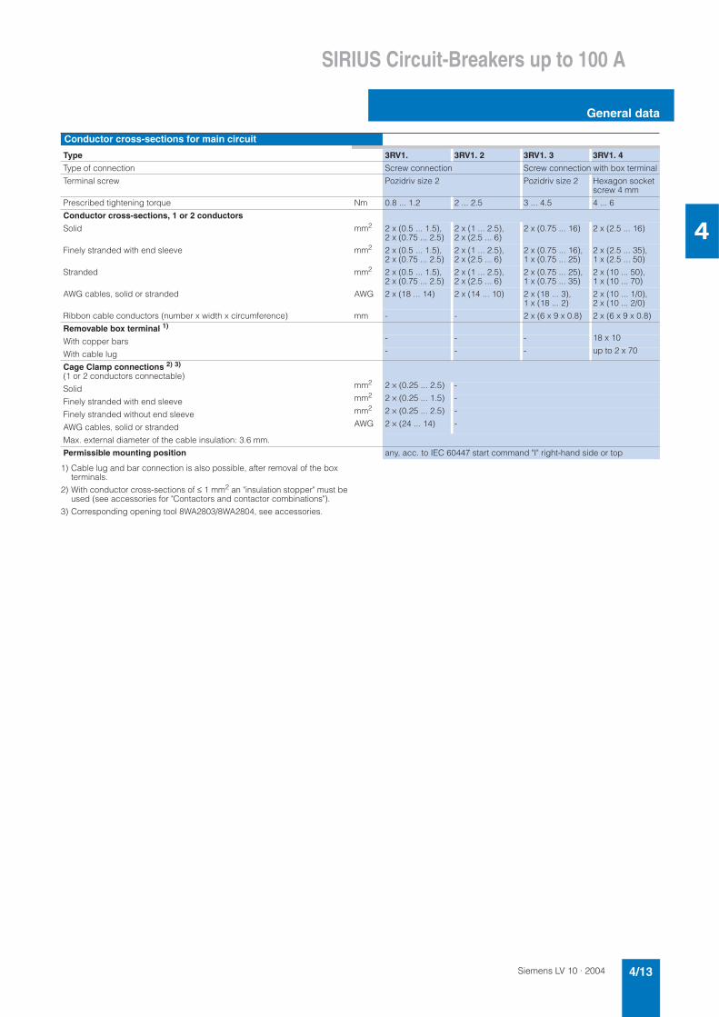
1) Cable lug and bar connection is also possible, after removal of the box terminals.
2) With conductor cross-sections of ≤ 1 mm2 an "insulation stopper" must be used (see accessories for "Contactors and contactor combinations").
3) Corresponding opening tool 8WA2803/8WA2804, see accessories.
Conductor cross-sections for main circuit
Type 3RV1. 3RV1. 2 3RV1. 3 3RV1. 4
Type of connection Screw connection Screw connection with box terminal
Terminal screw Pozidriv size 2 Pozidriv size 2 Hexagon socket screw 4 mm
Prescribed tightening torque Nm 0.8 ... 1.2 2 ... 2.5 3 ... 4.5 4 ... 6
Conductor cross-sections, 1 or 2 conductors
Solid mm2 2 x (0.5 ... 1.5), 2 x (0.75 ... 2.5)
2 x (1 ... 2.5), 2 x (2.5 ... 6)
2 x (0.75 ... 16) 2 x (2.5 ... 16)
Finely stranded with end sleeve mm2 2 x (0.5 ... 1.5), 2 x (0.75 ... 2.5)
2 x (1 ... 2.5), 2 x (2.5 ... 6)
2 x (0.75 ... 16), 1 x (0.75 ... 25)
2 x (2.5 ... 35), 1 x (2.5 ... 50)
Stranded mm2 2 x (0.5 ... 1.5), 2 x (0.75 ... 2.5)
2 x (1 ... 2.5), 2 x (2.5 ... 6)
2 x (0.75 ... 25), 1 x (0.75 ... 35)
2 x (10 ... 50), 1 x (10 ... 70)
AWG cables, solid or stranded AWG 2 x (18 ... 14) 2 x (14 ... 10) 2 x (18 ... 3), 1 x (18 ... 2)
2 x (10 ... 1/0), 2 x (10 ... 2/0)
Ribbon cable conductors (number x width x circumference) mm - - 2 x (6 x 9 x 0.8) 2 x (6 x 9 x 0.8)
Removable box terminal 1)
With copper bars - - - 18 x 10
With cable lug - - - up to 2 x 70
Cage Clamp connections 2) 3)
(1 or 2 conductors connectable)
Solid mm2 2 × (0.25 ... 2.5) -
Finely stranded with end sleeve mm2 2 × (0.25 ... 1.5) -
Finely stranded without end sleeve mm2 2 × (0.25 ... 2.5) -
AWG cables, solid or stranded AWG 2 × (24 ... 14) -
Max. external diameter of the cable insulation: 3.6 mm.
Permissible mounting position any, acc. to IEC 60447 start command "I" right-hand side or top

Siemens LV 10 · 20044/14
SIRIUS Circuit-Breakers up to 100 A
General data
4
Permissible ratings of devices approved for North America (UL/CSA)
Circuit-breakers of the 3RV1 series are approved for UL/CSA and according to UL 508 and CSA 22.2 No. 14 they can also be used as a load feeder in combination with a contactor.
These circuit-breakers can be used as "Manual Motor Control-lers" for "Group Installations", as "Manual Motor Controller Suit-able for Tap Conductor Protection in Group Installations" and as "Self-Protected Combination Motor Controller" (Type E).
3RV1 circuit-breaker as "Manual Motor Controller"
If used as a "Manual Motor Controller", the circuit-breaker is al-ways operated in combination with an upstream short-circuit protection device. As short-circuit-protection device, approved fuses or a circuit-breaker compliant with UL489/CSA 22.2 No.5 can be used. These devices must be dimensioned in accor-dance with the National Electrical Code (UL) or Canadian Elec-trical Code (CSA). Approval of the 3RV as a Manual Motor Con-troller can be found under the following file numbers: UL File No. 47705, CSA Master Contract 165071, Product Class 3211 05.
1) hp rating = power rating in horse power (maximum motor rating).
2) FLA = Full Load Amps/Motor full load current.
3) Complies with "short-circuit breaking capacity" to UL/CSA.
Circuit-breaker hp rating1) for FLA2)
max.Rated current In AC 240 V AC 480 Y/277 V AC 600 Y/347 V
UL CSA UL CSA UL CSA
Ibc3) Ibc
3) Ibc3) Ibc
3) Ibc3) Ibc
3)
Type V single-phase
three-phase
A kA kA kA kA kA kA
3RV10 11 0.16 ... 2 65 50 65 50 30 10
3RV16 11-0BD10 2.5 65 50 65 50 30 10
115 1/2 - 3.2 65 50 65 50 30 10
Size S00 200 1 1/2 3 4 65 50 65 50 30 10
230 2 3 5 65 50 65 50 30 10
FLA2) max. 12 A, 600 V 460 - 7 1/2 6.3 65 50 65 50 30 10
575/600 - 10 8 65 50 65 50 30 10
NEMA Size 00 10 65 50 65 50 30 10
12 65 50 65 50 30 10
3RV10 21 / 3RV11 21 0.16 ... 3.2 65 50 65 50 30 30
3RV13 21 4 65 50 65 50 30 30
5 65 50 65 50 30 30
Size S0 115 2 - 6.3 65 50 65 50 30 30
200 3 7 1/2 8 65 50 65 50 30 30
FLA2) max. 25 A, 600 V 230 5 7 1/2 10 65 50 65 50 30 30
460 - 15 12.5 65 50 65 50 30 30
NEMA Size 1 575/600 - 20 16 65 50 65 50 30 30
20 65 50 65 50 30 30
22 65 50 65 50 30 30
25 65 50 65 50 30 30
3RV10 31 / 3RV11 31 16 65 50 65 50 25 25
3RV13 31 20 65 50 65 50 25 25
115 3 - 25 65 50 65 50 25 25
Size S2 200 7 1/2 15 32 65 50 65 50 25 25
230 10 20 40 65 50 65 50 25 25
FLA2) max. 50 A,600 V 460 - 40 45 65 50 65 50 25 25
NEMA Size 2 575/600 - 50 50 65 50 65 50 25 25
3RV10 41 / 3RV10 42 16 65 50 65 50 30 30
3RV11 42 20 65 50 65 50 30 30
3RV13 41 / 3RV13 42 115 10 - 25 65 50 65 50 30 30
200 20 30 32 65 50 65 50 30 30
Size S3 230 20 40 40 65 50 65 50 30 30
460 - 75 50 65 50 65 50 30 30
FLA2) max. 100 A, 600 V 575/600 - 100 63 65 50 65 50 30 30
75 65 50 65 50 30 30
NEMA Size 3 90 65 50 65 50 30 30
100 65 50 65 50 30 30

Siemens LV 10 · 2004 4/15
SIRIUS Circuit-Breakers up to 100 A
General data
4
3RV10 circuit-breaker as "Manual Motor Controller Suitable for Tap Conductor Protection in Group Installations"
The application as "Manual Motor Controller Suitable for Tap Conductor Protection in Group Installations" is only available from UL. CSA does not recognize this approval! When the cir-cuit-breaker is used as a "Manual Motor Controller Suitable for Tap Conductor Protection in Group Installations", it must always be combined with upstream short-circuit protection. As short-
circuit-protection device, approved fuses or a circuit-breaker compliant with UL489 can be used.
These devices must be dimensioned in accordance with the Na-tional Electrical Code. The 3RV10 motor protection circuit-break-ers are approved as "Manual Motor Controller Suitable for Tap Conductor Protection in Group Installations" under the following file number: UL File No. 47705.
1) hp rating = Power rating in horse power (maximum motor rating).
2) FLA = Full Load Amps/Motor full load current.
3) Complies with "short-circuit breaking capacity" to UL.
Circuit-breaker hp rating1) for FLA2)
max.Rated current In AC 240 V AC 480 Y/277 V AC 600 Y/347 V
UL UL UL
Ibc3) Ibc
3) Ibc3)
Type V single-phase
three-phase
A kA kA kA
3RV10 11 0.16 ... 0.8 65 65 -
1 65 65 -
115 1/3 - 1.25 65 65 -Size S00 200 3/4 2 2 65 65 -
230 1 2 2.5 65 65 -
FLA2) max. 8A, 480 V 460 - 5 3.2 65 65 -
575/600 - - 4 65 65 -NEMA Size 00 5 65 65 -
6.3 65 65 -
8 65 65 -
3RV10 21 0.16 ... 1.6 65 65 30
2 65 65 30
2.5 65 65 30
Size S0 115 2 - 3.2 65 65 30
200 3 7 1/2 4 65 65 30
FLA2) max. 22 A, 480 V 230 3 7 1/2 5 65 65 30
12.5 A, 600 V 460 - 15 6.3 65 65 30
575/600 - 10 8 65 65 30
NEMA Size 1 10 65 65 30
12.5 65 65 30
16 65 65 -
20 65 65 -
22 65 65 -
3RV10 31 16 65 65 25
20 65 65 25
Size S2 115 3 - 25 65 65 25
200 7 1/2 15 32 65 65 25
FLA2) max. 50 A,600 V 230 10 20 40 65 65 25
NEMA Size 2 460 - 40 45 65 65 25
575/600 - 50 50 65 65 25
3RV10 4. 16 65 65 30
20 65 65 30
Size S3 115 10 - 25 65 65 30
200 20 30 32 65 65 30
FLA2) max. 100 A, 480 V 230 20 40 40 65 65 30
75 A, 600 V 460 - 75 50 65 65 30
NEMA Size 3 575/600 - 75 63 65 65 30
75 65 65 30
90 65 65 -
100 65 65 -

Siemens LV 10 · 20044/16
SIRIUS Circuit-Breakers up to 100 A
General data
4
3RV10 circuit-breaker as "Self-Protected Combination Motor Controller (Type E)"
As of 16 July 2001, UL 508 demands a line-side 1-inch air dis-tance and 2-inch creepage distance for "Self-Protected Combi-nation Motor Controller".
Therefore, 3RV10 circuit-breakers of size S0 and S3 are ap-proved to UL 508 in combination with the terminal blocks listed below.
The basic unit of 3RV10 circuit-breaker in size S2 conforms with the required air/creepage distances.
CSA does not demand these extended air/creepage distances. According to CSA, these terminal blocks can be omitted when the device is used as "Self-Protected Combination Motor Con-troller".
The 3RV10 motor protection circuit-breakers are approved as "Self-Protected Combination Motor Controller" under the follow-ing file numbers:UL File No. E156943, Product Class NKJH,CSA Master Contract 165071, Product Class 3211 08.
1) hp rating = Power rating in horse power (maximum motor rating).
2) FLA = Full Load Amps/Motor full load current.
3) Complies with "short-circuit breaking capacity" to UL/CSA.
4) Not required for CSA.
Circuit-breaker hp rating1) for FLA2)
max.Rated current In up to AC 240 V up to AC 480 Y/277 V up to AC 600 Y/347 V
UL CSA UL CSA UL CSA
Ibc3) Ibc
3) Ibc3) Ibc
3) Ibc3) Ibc
3)
Type V single-phase
three-phase
A kA kA kA kA kA kA
3RV10 21 0.16 ... 1.6 65 50 65 50 30 30
+ 3RV19 28-1H4) 2 65 50 65 50 30 30
115 2 - 2.5 65 50 65 50 30 30
Size S0 200 3 7 1/2 3.2 65 50 65 50 30 30
230 3 7 1/2 4 65 50 65 50 30 30
FLA2) max. 22 A, 480 V 460 - 15 5 65 50 65 50 30 30
12.5 A, 600 V 575/600 - 10 6.3 65 50 65 50 30 30
8 65 50 65 50 30 30
NEMA Size 1 10 65 50 65 50 30 30
12.5 65 50 65 50 30 30
16 65 50 65 50 - -
20 65 50 65 50 - -
22 65 50 65 50 - -
3RV10 31 16 65 50 65 50 25 25
20 65 50 65 50 25 25
Size S2 115 3 - 25 65 50 65 50 25 25
200 7 1/2 15 32 65 50 65 50 25 25
FLA2) max. 50 A,600 V 230 10 20 40 65 50 65 50 25 25
460 - 40 45 65 50 65 50 25 25
NEMA Size 2 575/600 - 50 50 65 50 65 50 25 25
3RV10 4. 16 65 50 65 50 30 30
+ 3RT19 46-4GA074) 20 65 50 65 50 30 30
115 10 - 25 65 50 65 50 30 30
Size S3 200 20 30 32 65 50 65 50 30 30
FLA2) max. 100 A, 480 V 230 20 40 40 65 50 65 50 30 30
75 A, 600 V 460 - 75 50 65 50 65 50 30 30
575/600 - 75 63 65 50 65 50 30 30
NEMA Size 3 75 65 50 65 50 30 30
90 65 50 65 50 - -
100 65 50 65 50 - -
Ratings of the auxiliary switches and alarm switches
Type Lateral auxiliary switch with1 NO + 1 NC, 2 NO, 2 NC, 2 NO + 2 NC and alarm switch
Transverse auxiliary switch with1 changeover contact
Transverse auxiliary switch with1 NO + 1 NC, 2 NC
Max. rated voltage
• to NEMA (UL) AC V 600 250• to NEMA (CSA) AC V 600 250
Continuous current A 10 5 2.5Switching capacity A600
Q300B600R300
C300R300

Siemens LV 10 · 2004 4/17
SIRIUS Circuit-Breakers up to 100 A
General data
4
Voltage converter circuit-breakersGeneral technical specifications
Type 3RV16 11-1AG14 3RV16 11-1CG14 3RV16 11-1DG14
Rated current In A 1.4 2.5 3
Ambient temperature• Storage/transport °C -50 ... + 80• Operation °C -20 ... + 60 (up to + 70 °C is possible with derating)
Rated operating voltage Ue V 400
Rated frequency Hz 16 2/3 ... 60
Rated insulation voltage Ui V 690
Short-circuit breaking capacity Icu at AC 400 V kA 50
Set value of the thermal overload release A 1.4 2.5 3
Operating value of the instantaneous overcurrent release A 6 ± 20% 10.5 ± 20% 20 ± 20%
Tripping time of the instantaneous overcurrent release ms approx. 6 at 12 A approx. 6 at 20 A approx. 6 at 40 A
Internal resistance• in cold state Ω > 0.25 ± 6.5 %• in heated state Ω > 0.30 ± 6.5 %
Shock resistance acc. to IEC 60068 Part 2-27 g 15
Degree of protection acc. to IEC 60529 IP20
Touch protection acc. to DIN VDE 0106-100 Finger-safe
Endurance• mechanical Oper-
ating cycles
10 000• electrical 10 000
Permissible mounting position any
Conductor cross-sections, main circuit, 1 or 2 conductors
Type 3RV16 11-1AG14 3RV16 11-1CG14 3RV16 11-1DG14
Terminal type Screw connectionTerminal screw Pozidriv size 2Solid mm2 2 x (0.5 ... 1.5), 2 x (0.75 ... 2.5), max. 4Finely stranded with end sleeve mm2 2 x (0.5 ... 1.5), 2 x (0.75 ... 2.5)Stranded mm2 2 x (0.5 ... 1.5), 2 x (0.75 ... 2.5), max. 4
Auxiliary switches for blocking the distance protection Auxiliary switch for blocking the distance protection • with defined lateral assignment for blocking distance protection 1 changeover contact (for use as 1 NO or 1 NC), solid-state compatible
• Rated operating voltage Ue Alternating voltage V 250• Rated operating current Ie / AC-14 at Ue = 250 V A 0.5• Rated operating current Ie / AC-14 at Ue = 125 V A 1
• Rated operating voltage Ue Direct voltage L/R 200 ms V 250• Rated operating current Ie / DC-13 at Ue = 250 V A 0.27• Rated operating current Ie / DC-13 at Ue = 125 V A 0.44Short-circuit protection for auxiliary circuit• Fuse gL/gG A 10• Miniature circuit-breaker, C characteristic A 6 (prospective short-circuit current < 0.4 kA)Auxiliary switches for other signaling functionsFor technical specifications, see "Mountable accessories"

Siemens LV 10 · 20044/18
SIRIUS Circuit-Breakers up to 100 A
General data
4
Characteristics
The time/current characteristic, the current limiting characteris-tics and the I2t characteristics were determined according to IEC 60947.
The tripping characteristic of the inverse-time delayed overload release (thermal overload releases, 'a' releases) for DC and AC with a frequency of 0 Hz to 400 Hz.
The characteristics apply to the cold state; at operating temper-ature, the tripping times of the thermal releases are reduced to approximately 25 %.
Under normal operating conditions, all three poles of the device must be loaded. The three main conducting paths must be con-nected in series in order to protect single-phase or DC loads.
With 2-pole and 3-pole loading, the maximum deviation in the tripping time of 3 times the setting current and upwards is ± 20 % and thus in accordance with VDE 0165.
The tripping characteristics for the instantaneous, electromag-netic overcurrent releases (short-circuit releases, 'n' releases) are based on the rated current In that also represents the maxi-mum value of the setting range for circuit-breakers with adjust-able overload releases. If the current is set to a lower value, the tripping current of the 'n' release is increased by a correspond-ing factor.
The characteristics of the electromagnetic overcurrent releases apply to frequencies of 50 Hz/60 Hz. Appropriate correction fac-tors must be used for lower frequencies down to 16 2/3 Hz, for higher frequencies up to 400 Hz and for DC.
The shown characteristic curve for the circuit-breaker relates to a specific setting range. It is, however, also valid as a schematic representation of circuit-breakers with other current ranges.
Time/current characteristics, current limiting characteristics and I2t curves can be ordered from "Technical Assistance" (e-mail: [email protected]).
Schematic representation of typical time/current characteristic of 3RV10
3RV16 voltage transformer circuit-breakers up to 3 A
The specified tripping characteristics of the thermal overload re-lease (a) correspond to the mean value of the scatter band in the cold state. At operating temperature, these times are reduced to approximately 25 % of the specified values.
The characteristic curves below are schematic representations. Precise characteristic curves are available from "Technical Assistance" (e-mail: [email protected]).
$ 1.4 A / 6 A% 2.5 A / 10.5 A& 3 A / 20 Aa) Thermal overload releaseb) Instantaneous electromagnetic overcurrent release
! !
!
>
>

Siemens LV 10 · 2004 4/19
SIRIUS Circuit-Breakers up to 100 A
General data
4
Circuit diagrams
Internal circuit diagrams
Typical circuits
Note:
When using the NC contact to connect the voltage transformer circuit-breaker, the binary input of the distance protection device (Siemens 7 SA xxx) should be set to "active without voltage". This type of connection is used for additional monitoring of cor-rect wiring.
Circuit-breakers
3RV10 ..
3RV14 ..
3RV16 11-0BD10
3RV11 .. 3RV13 ..
3RV16 voltage transformer circuit-breakers up to 3 A
" "
# # /
# /
0 1 ! / # 0
3RV11 circuit-breaker with overload relay function
S1 OFF pushbutton
S2 ON pushbutton
K1 Latching contact
F1; F2 Fuses gL/gG 6A
Q1 3RV11 circuit-breaker
L1
K1
N(L2)
F1
NS
B00
025a
K1
S1
S2
F2
Q1
3RV16 voltage transformer circuit-breakers up to 3 A
12 14
11
+
NS
B01
106a
Distance protection
BI (binary input)
Protective switch of voltage transformer is open (active withoutvoltage)

Siemens LV 10 · 20044/20
SIRIUS Circuit-Breakers up to 100 A
For motor protection
4
Selection and ordering data
Class 10, without/with auxiliary switch
1) Recommended values for standard 4-pole motors at AC 50 Hz 400 V. The actual start-up data and ratings for the motor to be protected are relevant.
2) Weights are specified for the variant with auxiliary switch.
Auxiliary switches can also be ordered separately (see "Mountable accessories").
For multi-unit packing and reusable packaging, see "Appendix".
Ratedcurrent
Suitablefor three-phaseinductionmotors1)
with P
Current set-ting range for thermal overloadrelease
Instan-taneous overcur-rent release
Short-cir-cuit break-ingcapacity atAC 400 V
DT Screw connection
PS* Weight per PU approx.2)
DT Cage Clamp connection
PS* Weight per PU approx.2)
In Icu Order No. Order No.
A kW A A kA kg kgSize S00
0.16 0.04 0.11 ... 0.16 2.1 100 3RV10 11-0AA1@ 1 unit 0.245 3RV10 11-0AA2@ 1 unit 0.2530.2 0.06 0.14 ... 0.2 2.6 100 3RV10 11-0BA1@ 1 unit 0.246 3RV10 11-0BA2@ 1 unit 0.2540.25 0.06 0.18 ... 0.25 3.3 100 3RV10 11-0CA1@ 1 unit 0.246 3RV10 11-0CA2@ 1 unit 0.2540.32 0.09 0.22 ... 0.32 4.2 100 3RV10 11-0DA1@ 1 unit 0.247 3RV10 11-0DA2@ 1 unit 0.254
0.4 0.09 0.28 ... 0.4 5.2 100 3RV10 11-0EA1@ 1 unit 0.250 3RV10 11-0EA2@ 1 unit 0.2560.5 0.12 0.35 .. .0.5 6.5 100 3RV10 11-0FA1 @ 1 unit 0.247 3RV10 11-0FA2 @ 1 unit 0.2520.63 0.18 0.45 ... 0.63 8.2 100 3RV10 11-0GA1@ 1 unit 0.249 3RV10 11-0GA2@ 1 unit 0.2540.8 0.18 0.5 5... 0.8 10 100 3RV10 11-0HA1@ 1 unit 0.250 3RV10 11-0HA2@ 1 unit 0.257
1 0.25 0.7 ... 1 13 100 3RV10 11-0JA1 @ 1 unit 0.249 3RV10 11-0JA2 @ 1 unit 0.2551.25 0.37 0.9 ... 1.25 16 100 3RV10 11-0KA1@ 1 unit 0.297 3RV10 11-0KA2@ 1 unit 0.3011.6 0.55 1.1 ... 1.6 21 100 3RV10 11-1AA1@ 1 unit 0.298 3RV10 11-1AA2@ 1 unit 0.3032 0.75 1.4 ... 2 26 100 3RV10 11-1BA1@ 1 unit 0.297 3RV10 11-1BA2@ 1 unit 0.302
2.5 0.75 1.8 ... 2.5 33 100 3RV10 11-1CA1@ 1 unit 0.298 3RV10 11-1CA2@ 1 unit 0.3043.2 1.1 2.2 ... 3.2 42 100 3RV10 11-1DA1@ 1 unit 0.299 3RV10 11-1DA2@ 1 unit 0.3054 1.5 2.8 ... 4 52 100 3RV10 11-1EA1@ 1 unit 0.296 3RV10 11-1EA2@ 1 unit 0.3045 1.5 3.5 ... 5 65 100 3RV10 11-1FA1 @ 1 unit 0.301 3RV10 11-1FA2 @ 1 unit 0.306
6.3 2.2 4.5 ... 6.3 82 100 3RV10 11-1GA1@ 1 unit 0.303 3RV10 11-1GA2@ 1 unit 0.3088 3 5.5 ... 8 104 50 3RV10 11-1HA1@ 1 unit 0.304 3RV10 11-1HA2@ 1 unit 0.31010 4 7 ... 10 130 50 3RV10 11-1JA1 @ 1 unit 0.300 3RV10 11-1JA2 @ 1 unit 0.30612 5.5 9 ... 12 156 50 3RV10 11-1KA1@ 1 unit 0.297 3RV10 11-1KA2@ 1 unit 0.302
Size S00.16 0.04 0.11 ... 0.16 2.1 100 3RV10 21-0AA1@ 1 unit 0.300 -0.2 0.06 0.14 ... 0.2 2.6 100 3RV10 21-0BA1@ 1 unit 0.304 -0.25 0.06 0.18 ... 0.25 3.3 100 3RV10 21-0CA1@ 1 unit 0.302 -0.32 0.09 0.22 ... 0.32 4.2 100 3RV10 21-0DA1@ 1 unit 0.303 -
0.4 0.09 0.28 ... 0.4 5.2 100 3RV10 21-0EA1@ 1 unit 0.303 -0.5 0.12 0.35 ... 0.5 6.5 100 3RV10 21-0FA1 @ 1 unit 0.304 -0.63 0.18 0.45 ... 0.63 8.2 100 3RV10 21-0GA1@ 1 unit 0.366 -0.8 0.18 0.55 ... 0.8 10 100 3RV10 21-0HA1@ 1 unit 0.367 -
1 0.25 0.7 ... 1 13 100 3RV10 21-0JA1 @ 1 unit 0.368 -1.25 0.37 0.9 ... 1.25 16 100 3RV10 21-0KA1@ 1 unit 0.369 -1.6 0.55 1.1 ... 1.6 21 100 3RV10 21-1AA1@ 1 unit 0.371 -2 0.75 1.4 ... 2 26 100 3RV10 21-1BA1@ 1 unit 0.371 -
2.5 0.75 1.8 ... 2.5 33 100 3RV10 21-1CA1@ 1 unit 0.372 -3.2 1.1 2.2 ... 3.2 42 100 3RV10 21-1DA1@ 1 unit 0.375 -4 1.5 2.8 ... 4 52 100 3RV10 21-1EA1@ 1 unit 0.370 -5 1.5 3.5 ... 5 65 100 3RV10 21-1FA1 @ 1 unit 0.376 -
6.3 2.2 4.5 ... 6.3 82 100 3RV10 21-1GA1@ 1 unit 0.374 -8 3 5.5 ... 8 104 100 3RV10 21-1HA1@ 1 unit 0.374 -10 4 7 ... 10 130 100 3RV10 21-1JA1 @ 1 unit 0.375 -12.5 5.5 9 ... 12.5 163 100 3RV10 21-1KA1@ 1 unit 0.374 -
16 7.5 11 ... 16 208 50 3RV10 21-4AA1@ 1 unit 0.382 -20 7.5 14 ... 20 260 50 3RV10 21-4BA1@ 1 unit 0.376 -22 11 17...22 286 50 3RV10 21-4CA1@ 1 unit 0.378 -25 11 20...25 325 50 3RV10 21-4DA1@ 1 unit 0.382 -
Order No. supplement fortransverse auxiliary switch
without 0 01 NO + 1 NC 5 B 5
* This quantity or a multiple thereof can be ordered.

Siemens LV 10 · 2004 4/21
SIRIUS Circuit-Breakers up to 100 A
For motor protection
4
Class 10, without auxiliary switch
1) Recommended values for standard 4-pole motors at AC 50 Hz 400 V. The actual start-up data and ratings for the motor to be protected are relevant.
Auxiliary switches can be ordered separately(see "Mountable accessories").
Multi-unit/reusable packaging, see "Appendix".
Rated current Suitable for three-phase inductionmotors1)
with P
Current set-ting rangeThermal over-load release
Instanta-neous over-current release
Short-circuit breaking capacityat AC 400 V
DT Screw connection PS* Weight per PU approx.
In Icu Order No.
A kW A A kA kgSize S2
16 7.5 11 ... 16 208 50 3RV10 31-4AA10 1 unit 1.04020 7.5 14 ... 20 260 50 3RV10 31-4BA10 1 unit 1.04025 11 18 ... 25 325 50 3RV10 31-4DA10 1 unit 1.03032 15 22 ... 32 416 50 3RV10 31-4EA10 1 unit 1.020
40 18.5 28 ... 40 520 50 3RV10 31-4FA10 1 unit 1.04045 22 36 ... 45 585 50 3RV10 31-4GA10 1 unit 1.03050 22 40 ... 50 650 50 3RV10 31-4HA10 1 unit 1.020
Size S3 40 18.5 28 ... 40 520 50 3RV10 41-4FA10 1 unit 2.21050 22 36 ... 50 650 50 3RV10 41-4HA10 1 unit 2.24063 30 45 ... 63 819 50 3RV10 41-4JA10 1 unit 2.240
75 37 57 ... 75 975 50 3RV10 41-4KA10 1 unit 2.25090 45 70 ... 90 1170 50 3RV10 41-4LA10 1 unit 2.280100 45 80 ... 100 1235 50 3RV10 41-4MA10 1 unit 2.290
Size S3, with increased switching capacity 16 7.5 11 ... 16 208 100 3RV10 42-4AA10 1 unit 2.17020 7.5 14 ... 20 260 100 3RV10 42-4BA10 1 unit 2.18025 11 18 ... 25 325 100 3RV10 42-4DA10 1 unit 2.21032 15 22 ... 32 416 100 3RV10 42-4EA10 1 unit 2.210
40 18.5 28 ... 40 520 100 3RV10 42-4FA10 1 unit 2.20050 22 36 ... 50 650 100 3RV10 42-4HA10 1 unit 2.23063 30 45 ... 63 819 100 3RV10 42-4JA10 1 unit 2.250
75 37 57 ... 75 975 100 3RV10 42-4KA10 1 unit 2.26090 45 70 ... 90 1170 100 3RV10 42-4LA10 1 unit 2.280100 45 80 ... 100 1235 100 3RV10 42-4MA10 1 unit 2.270
Class 20, without auxiliary switch
Size S2 16 7.5 11 ... 16 208 50 A 3RV10 31-4AB10 1 unit 1.06020 7.5 14 ... 20 260 50 A 3RV10 31-4BB10 1 unit 1.07025 11 18 ... 25 325 50 A 3RV10 31-4DB10 1 unit 1.05032 15 22 ... 32 416 50 A 3RV10 31-4EB10 1 unit 1.060
40 18.5 28 ... 40 520 50 A 3RV10 31-4FB10 1 unit 1.07045 22 36 ... 45 585 50 A 3RV10 31-4GB10 1 unit 1.07050 22 40 ... 50 650 50 A 3RV10 31-4HB10 1 unit 1.070
Size S3, with increased switching capacity 40 18.5 28 ... 40 520 100 A 3RV10 42-4FB10 1 unit 2.22050 22 36 ... 50 650 100 A 3RV10 42-4HB10 1 unit 2.26063 30 45 ... 63 819 100 A 3RV10 42-4JB10 1 unit 2.270
75 37 57 ... 75 975 100 A 3RV10 42-4KB10 1 unit 2.26090 45 70 ... 90 1170 100 A 3RV10 42-4LB10 1 unit 2.310100 45 80 ... 100 1235 100 A 3RV10 42-4MB10 1 unit 2.320
* This quantity or a multiple thereof can be ordered.

Siemens LV 10 · 20044/22
SIRIUS Circuit-Breakers up to 100 A
For motor protection with overload relay function
4
Selection and ordering data
CLASS 10, with overload relay function (automatic reset), without auxiliary switch
1) Recommended values for standard 4-pole motors at AC 50 Hz 400 V. The actual start-up data and ratings for the motor to be protected are relevant.
2) Accessories for mounting on the right (for series S0 to S3) and 3RV19 15 three-phase busbars (for size S0) cannot be used.
Auxiliary switches can be ordered separately(see "Mountable accessories").
Multi-unit/reusable packaging, see "Appendix".
Rated current Suitable for three-phase inductionmotors1)
with P
Current set-ting rangeThermal over-load release
Instanta-neous over-current release
Short-circuit breaking capacity at AC 400 V
DT Screw connection PS* Weight per PU approx.
In Icu Order No.
A kW A A kA kg
Size S02)
0.16 0.04 0.11 ... 0.16 2.1 100 A 3RV11 21-0AA10 1 unit 0.3540.2 0.06 0.14 ... 0.2 2.6 100 A 3RV11 21-0BA10 1 unit 0.3580.25 0.06 0.18 ... 0.25 3.3 100 A 3RV11 21-0CA10 1 unit 0.3520.32 0.09 0.22 ... 0.32 4.2 100 A 3RV11 21-0DA10 1 unit 0.352
0.4 0.09 0.28 ... 0.4 5.2 100 A 3RV11 21-0EA10 1 unit 0.3550.5 0.12 0.35 ... 0.5 6.5 100 A 3RV11 21-0FA10 1 unit 0.3560.63 0.18 0.45 ... 0.63 8.2 100 A 3RV11 21-0GA10 1 unit 0.4230.8 0.18 0.55 ... 0.8 10 100 A 3RV11 21-0HA10 1 unit 0.421
1 0.25 0.7 ... 1 13 100 A 3RV11 21-0JA10 1 unit 0.4161.25 0.37 0.9 ... 1.25 16 100 A 3RV11 21-0KA10 1 unit 0.4261.6 0.55 1.1 ... 1.6 21 100 A 3RV11 21-1AA10 1 unit 0.4222 0.75 1.4 ... 2 26 100 A 3RV11 21-1BA10 1 unit 0.427
2.5 0.75 1.8 ... 2.5 33 100 A 3RV11 21-1CA10 1 unit 0.4223.2 1.1 2.2 ... 3.2 42 100 A 3RV11 21-1DA10 1 unit 0.4284 1.5 2.8 ... 4 52 100 A 3RV11 21-1EA10 1 unit 0.4205 1.5 3.5 ... 5 65 100 A 3RV11 21-1FA10 1 unit 0.429
6.3 2.2 4.5 ... 6.3 82 100 A 3RV11 21-1GA10 1 unit 0.4268 3 5.5 ... 8 104 100 A 3RV11 21-1HA10 1 unit 0.42510 4 7 ... 10 130 100 A 3RV11 21-1JA10 1 unit 0.42812.5 5.5 9 ... 12.5 163 100 A 3RV11 21-1KA10 1 unit 0.426
16 7.5 11 ... 16 208 50 A 3RV11 21-4AA10 1 unit 0.43620 7.5 14 ... 20 260 50 A 3RV11 21-4BA10 1 unit 0.43022 11 17 ... 22 286 50 A 3RV11 21-4CA10 1 unit 0.42725 11 20 ... 25 325 50 A 3RV11 21-4DA10 1 unit 0.432
Size S22)
16 7.5 11 ... 16 208 50 A 3RV11 31-4AA10 1 unit 1.12020 7.5 14 ... 20 260 50 A 3RV11 31-4BA10 1 unit 1.13025 11 18 ... 25 325 50 A 3RV11 31-4DA10 1 unit 1.11032 15 22 ... 32 416 50 A 3RV11 31-4EA10 1 unit 1.110
40 18.5 28 ... 40 520 50 A 3RV11 31-4FA10 1 unit 1.12045 22 36 ... 45 585 50 A 3RV11 31-4GA10 1 unit 1.13050 22 40 ... 50 650 50 A 3RV11 31-4HA10 1 unit 1.100
Size S3, with increased switching capacity2)
16 7.5 11 ... 16 208 100 A 3RV11 42-4AA10 1 unit 2.24020 7.5 14 ... 20 260 100 A 3RV11 42-4BA10 1 unit 2.25025 11 18 ... 25 325 100 A 3RV11 42-4DA10 1 unit 2.28032 15 22 ... 32 416 100 A 3RV11 42-4EA10 1 unit 2.290
40 18.5 28 ... 40 520 100 A 3RV11 42-4FA10 1 unit 2.28050 22 36 ... 50 650 100 A 3RV11 42-4HA10 1 unit 2.32063 30 45 ... 63 819 100 A 3RV11 42-4JA10 1 unit 2.330
75 37 57 ... 75 975 100 A 3RV11 42-4KA10 1 unit 2.36090 45 70 ... 90 1170 100 A 3RV11 42-4LA10 1 unit 2.350100 45 80 ... 100 1235 100 A 3RV11 42-4MA10 1 unit 2.340
* This quantity or a multiple thereof can be ordered.

Siemens LV 10 · 2004 4/23
SIRIUS Circuit-Breakers up to 100 A
For starter combinations
4
Selection and ordering data
Without auxiliary switch.
1) Recommended values for standard 4-pole motors at AC 50 Hz 400 V. The actual start-up data and ratings for the motor to be protected are relevant.
2) For overload protection of the motors, appropriate overload relays must be used.
Auxiliary switches can be ordered separately(see "Mountable accessories").
Multi-unit/reusable packaging, see "Appendix".
Rated current Suitable for three-phase inductionmotors1)
with P
Current set-ting rangeThermal over-load release2)
Instanta-neous over-current release
Short-circuit breaking capacityat AC 400 V
DT Screw connection PS* Weight per PU approx.
In Icu Order No.
A kW A A kA kgSize S0
0.16 0.04 without 2.1 100 A 3RV13 21-0AC10 1 unit 0.2820.2 0.06 without 2.6 100 A 3RV13 21-0BC10 1 unit 0.2840.25 0.06 without 3.3 100 A 3RV13 21-0CC10 1 unit 0.2850.32 0.09 without 4.2 100 A 3RV13 21-0DC10 1 unit 0.282
0.4 0.09 without 5.2 100 A 3RV13 21-0EC10 1 unit 0.2860.5 0.12 without 6.5 100 A 3RV13 21-0FC10 1 unit 0.2830.63 0.18 without 8.2 100 A 3RV13 21-0GC10 1 unit 0.3480.8 0.18 without 10 100 A 3RV13 21-0HC10 1 unit 0.347
1 0.25 without 13 100 A 3RV13 21-0JC10 1 unit 0.3451.25 0.37 without 16 100 A 3RV13 21-0KC10 1 unit 0.3511.6 0.55 without 21 100 A 3RV13 21-1AC10 1 unit 0.3522 0.75 without 26 100 A 3RV13 21-1BC10 1 unit 0.352
2.5 0.75 without 33 100 A 3RV13 21-1CC10 1 unit 0.3523.2 1.1 without 42 100 A 3RV13 21-1DC10 1 unit 0.3534 1.5 without 52 100 A 3RV13 21-1EC10 1 unit 0.3495 1.5 without 65 100 A 3RV13 21-1FC10 1 unit 0.354
6.3 2.2 without 82 100 A 3RV13 21-1GC10 1 unit 0.3558 3 without 104 100 A 3RV13 21-1HC10 1 unit 0.35410 4 without 130 100 A 3RV13 21-1JC10 1 unit 0.35712.5 5.5 without 163 100 A 3RV13 21-1KC10 1 unit 0.354
16 7.5 without 208 50 A 3RV13 21-4AC10 1 unit 0.36220 7.5 without 260 50 A 3RV13 21-4BC10 1 unit 0.35722 11 without 286 50 A 3RV13 21-4CC10 1 unit 0.35825 11 without 325 50 A 3RV13 21-4DC10 1 unit 0.359
Size S2 16 7.5 without 208 50 A 3RV13 31-4AC10 1 unit 1.03020 7.5 without 260 50 A 3RV13 31-4BC10 1 unit 1.03025 11 without 325 50 A 3RV13 31-4DC10 1 unit 1.01032 15 without 416 50 A 3RV13 31-4EC10 1 unit 1.010
40 18.5 without 520 50 A 3RV13 31-4FC10 1 unit 1.03045 22 without 585 50 A 3RV13 31-4GC10 1 unit 1.04050 22 without 650 50 A 3RV13 31-4HC10 1 unit 1.010
Size S3 40 18.5 without 520 50 A 3RV13 41-4FC10 1 unit 2.19050 22 without 650 50 A 3RV13 41-4HC10 1 unit 2.22063 30 without 819 50 A 3RV13 41-4JC10 1 unit 2.240
75 37 without 975 50 A 3RV13 41-4KC10 1 unit 2.24090 45 without 1170 50 A 3RV13 41-4LC10 1 unit 2.260100 45 without 1235 50 A 3RV13 41-4MC10 1 unit 2.290
Size S3, with increased switching capacity 16 7.5 without 208 100 A 3RV13 42-4AC10 1 unit 2.17020 7.5 without 260 100 A 3RV13 42-4BC10 1 unit 2.18025 11 without 325 100 A 3RV13 42-4DC10 1 unit 2.21032 15 without 416 100 A 3RV13 42-4EC10 1 unit 2.200
40 18.5 without 520 100 A 3RV13 42-4FC10 1 unit 2.21050 22 without 650 100 A 3RV13 42-4HC10 1 unit 2.21063 30 without 819 100 A 3RV13 42-4JC10 1 unit 2.240
75 37 without 975 100 A 3RV13 42-4KC10 1 unit 2.27090 45 without 1170 100 A 3RV13 42-4LC10 1 unit 2.260100 45 without 1235 100 A 3RV13 42-4MC10 1 unit 2.290
* This quantity or a multiple thereof can be ordered.

Siemens LV 10 · 20044/24
SIRIUS Circuit-Breakers up to 100 A
For protection of transformers
4
Selection and ordering data
Class 10, without auxiliary switch
Circuit-breakers for the protection of transformers with high in-rush current.
Auxiliary switches can be ordered separately(see "Mountable accessories").
Multi-unit/reusable packaging, see "Appendix".
Rated current Current setting rangeThermal overload release
Instanta-neous over-current release
Short-circuit breaking capacityat AC 400 V
DT Screw connection PS* Weight per PU approx.
In Icu Order No.
A A A kA kgSize S0
0.16 0.11 ... 0.16 3.3 100 3RV14 21-0AA10 1 unit 0.2860.2 0.14 ... 0.2 4.2 100 3RV14 21-0BA10 1 unit 0.2870.25 0.18 ... 0.25 5.2 100 3RV14 21-0CA10 1 unit 0.2860.32 0.22 ... 0.32 6.5 100 3RV14 21-0DA10 1 unit 0.288
0.4 0.28 ... 0.4 8.2 100 3RV14 21-0EA10 1 unit 0.2870.5 0.35 ... 0.5 10 100 3RV14 21-0FA10 1 unit 0.2860.63 0.45 ... 0.63 13 100 3RV14 21-0GA10 1 unit 0.3480.8 0.55 ... 0.8 16 100 3RV14 21-0HA10 1 unit 0.352
1 0.7 ... 1 21 100 3RV14 21-0JA10 1 unit 0.3531.25 0.9 ... 1.25 26 100 3RV14 21-0KA10 1 unit 0.3541.6 1.1 ... 1.6 33 100 3RV14 21-1AA10 1 unit 0.3532 1.4 ... 2 42 100 3RV14 21-1BA10 1 unit 0.358
2.5 1.8 ... 2.5 52 100 3RV14 21-1CA10 1 unit 0.3543.2 2.2 ... 3.2 65 100 3RV14 21-1DA10 1 unit 0.3584 2.8 ... 4 82 100 3RV14 21-1EA10 1 unit 0.3545 3.5 ... 5 104 100 3RV14 21-1FA10 1 unit 0.357
6.3 4.5 ... 6.3 130 100 3RV14 21-1GA10 1 unit 0.3568 5.5 ... 8 163 100 3RV14 21-1HA10 1 unit 0.35810 7 ... 10 208 100 3RV14 21-1JA10 1 unit 0.36212.5 9 ... 12.5 260 100 3RV14 21-1KA10 1 unit 0.360
16 11 ... 16 286 50 3RV14 21-4AA10 1 unit 0.36520 14 ... 20 325 50 3RV14 21-4BA10 1 unit 0.365
Size S2 16 11 ... 16 325 50 3RV14 31-4AA10 1 unit 1.02020 14 ... 20 416 50 3RV14 31-4BA10 1 unit 1.03025 18 ... 25 520 50 3RV14 31-4DA10 1 unit 1.03032 22 ... 32 660 50 3RV14 31-4EA10 1 unit 1.02040 28 ... 40 836 50 3RV14 31-4FA10 1 unit 1.030
* This quantity or a multiple thereof can be ordered.

Siemens LV 10 · 2004 4/25
SIRIUS Circuit-Breakers up to 100 A
For fuse monitoring
4
Selection and ordering data
Without auxiliary switch
Multi-unit/reusable packaging, see "Appendix".
The auxiliary release required for signaling can be ordered sep-arately.
For further auxiliary switches, see "Mountable accessories".
Rated current Thermal overload release
Instantaneousoverload release
Short-circuit breaking capac-ity at AC 400 V
DT Screw connection PS* Weight per PU approx.
In Icu Order No.
A A A kA kgSize S00
0.2 0.2 1.2 100 3RV16 11-0BD10 1 unit 0.289
Type Version DT Order No. PS* Weight per PU approx.
kgMountable auxiliary switches
3RV19 01-1E
3RV19 01-1A
Transverse auxiliary switchwith screw connection
1 NO + 1 NC 3RV19 01-1E 1 unit 0.018
Lateral auxiliary switchwith screw connection
1 NO + 1 NC 3RV19 01-1A 1 unit 0.045
* This quantity or a multiple thereof can be ordered.

Siemens LV 10 · 20044/26
SIRIUS Circuit-Breakers up to 100 A
For distance protection
4
Selection and ordering data
Voltage transformer circuit-breaker with auxiliary switch
1) For further lateral auxiliary switches, see "Mountable accessories".
Further information
Conversion of voltage transformer circuit-breakers 3VU13 to 3RV1The previous version of the 3VU13 voltage circuit-breakers are no longer available.
The 3RV1 voltage transformer circuit-breakers will be offered as re-placement types.
Rated current Thermal over-load release
Instanta-neous over-current release
Auxiliary switch inte-grated in the switch, trans-verse
Short-circuit breaking capacityat AC 400 V
DT Screw connection PS* Weight per PU approx.
In Icu Order No.
A A A kA kgSize S00
1.4 1.4 6 1 CO 50 B 3RV16 11-1AG14 1 unit 0.3142.5 2.5 10.5 1 CO 50 B 3RV16 11-1CG14 1 unit 0.3183 3 20 1 CO 50 B 3RV16 11-1DG14 1 unit 0.315
Type Version DT Order No. PS* Weight per PU approx.
kgLaterally mountable auxiliary switches for other signaling purposes
3RV19 01-1A
Lateral auxiliary switch1) 1 NO + 1 NC 3RV19 01-1A 1 unit 0.045
Previous type Replacement type
3VU13 11-6HR00 3VU13 21-6HR00 3VU13 11-6JR00
3RV16 11-1CG143RV16 11-1CG14 + 3RV19 01-1A3RV16 11-1DG14
* This quantity or a multiple thereof can be ordered.

Siemens LV 10 · 2004 4/27
SIRIUS Circuit-Breakers up to 100 AAccessories
Mountable accessories
4
Overview
Mounting location and function
The 3RV1 circuit-breakers have three main contact elements. In order to achieve maximum flexibility, auxiliary switches, alarm switches, auxiliary releases and isolator modules can be sup-plied separately.
These components can be fitted as required on the switches without using tools.
Front
Note:
A maximum of 4 auxiliary con-tacts with auxiliary switches can be attached to each circuit-breaker.
Transverse auxiliary switch
1 NO + 1 NC
or
2 NO
or 1 changeover contact
An auxiliary contact block can be inserted transversely on the front. The overall width of the circuit-breakers remains unchanged.29
Left-hand side Lateral auxiliary switch (2 contacts)
1 NO + 1 NCor2 NOor2 NC
One of the three auxiliary switches can be mounted laterally for each circuit-breaker. The contacts of the auxiliary switch close and open together with the main contacts of the circuit-breaker.
The overall width of the lateral auxiliary switch with 2 contacts is 9 mm.
Lateral auxiliary switch (4 contacts)
2 NO + 2 NC
One auxiliary switch can be mounted laterally for each circuit-breaker. The contacts of the auxiliary switch close and open together with the main contacts of the circuit-breaker.
The overall width of the lateral auxiliary switch with 4 contacts is 18 mm.
Notes:
• Auxiliary switches (2 contacts) and alarm switches can be mounted separately or together.
• A maximum of 4 auxiliary con-tacts with auxiliary switches can be attached to each circuit-breaker.
Alarm switch for sizes S0, S2 and S3Trip 1 NO + 1 NCShort-circuit 1 NO + 1 NC
One alarm switch can be mounted at the side of each circuit-breaker with a rotary oper-ating mechanism.
The alarm switch has two contact systems.
One contact system always signals tripping irrespective of whether this was caused by a short-circuit, an overload or an auxiliary release. The other contact system only switches in the event of a short circuit. There is no signaling as a result of switching offwith the handle.
In order to be able to switch on the circuit-breaker again after a short-circuit, the alarm switch must be reset manually after the error cause has been eliminated.
The overall width of the alarm switch is 18 mm.
Right-hand side Shunt release For remote-controlled tripping of the circuit-breaker. The release coil should only be energized for short periods (see circuit diagrams).
or
Undervoltage release Trips the circuit-breaker when the voltage is interrupted and prevents the motor from being restarted accidentally when the voltage is restored. Used for remote-controlled tripping of the circuit-breaker.
Particularly suitable for EMERGENCY-STOP disconnection via the appropriate EMERGENCY-STOP button in accordance with IEC 60204-1.
or
Notes:
• One auxiliary release can be mounted per circuit-breaker.
• Accessories cannot be mounted at the right-hand side of the 3RV11 circuit-breakers with overload relay function.
Undervoltage release with lead-ing auxiliary contacts
(2 NO)
Function and use as for the undervoltage release without leading auxiliary contacts, but with the following additional function: The auxiliary contacts will open in switch position OFF to deenergize the coil of the undervoltage release, thus interrupting power con-sumption. In the "tripped" position of the breaker, these auxiliary contacts are not guar-anteed to open. The leading contacts permit the circuit-breaker to reclose.
The overall width of the auxiliary release is 18 mm.
Top Note:
The isolator module covers the terminal screws of the transverse auxiliary switch. If the isolator module is used, we therefore rec-ommend that either the lateral auxiliary switches be fitted or that the isolator module not be mounted until the auxiliary switch has been wired.
Isolator modules for circuit-breakersSize S0 and S2
Isolator modules can be mounted to the upper terminal end of circuit-breakers of sizes S0 and S2.
The supply cable is connected to the circuit-breaker via the isolator module. The plug can only be unplugged when the circuit-breaker is open and isolates all 3 poles of the circuit-breaker from the network. The shock-protected isolation point is clearly visible and secured with a padlock to prevent reinsertion of the plug.

Siemens LV 10 · 20044/28
SIRIUS Circuit-Breakers up to 100 A
Mountable accessories
Accessories
4
&
4%&?+2&&+& &()*+&%)2"#)+)1
(
'
&$
&$
)")1&,& ! )4& !!()*."+&& )&
- ?& &"#)+)1 ()*&+"#)+)1 ()*()* &+"#)+)1 ()*()*
*"&+& &4%&?+2&&+& &
C"+&& )& 0++ )4& $$$ C"+&& )&
4%&?+2&&+& &()*+&%)2"#)+)1
0 )4&
$$$
)2++)2 ()* +.%"+&
C"+&& )&
'
(
0 )4&
$$$%
&$
)")1&,& ()*."+&& )&
&$

Siemens LV 10 · 2004 4/29
SIRIUS Circuit-Breakers up to 100 AAccessories
Mountable accessories
4
Technical specifications
1) Prospective short-circuit current < 0.4 kA
Front transverse auxiliary switches
Switching capacity for different voltages
1 changeover contact 1 NO + 1 NC, 2 NORated operating voltage Ie• at AC-15, alternating voltage
- 24 V A 4 2- 230 V A 3 0.5- 400 V A 1.5 -- 690 V A 0.5 -
• at AC-12 = Ith, alternating voltage- 24 V A 10 2.5- 230 V A 10 2.5- 400 V A 10 -- 690 V A 10 -
• at DC-13, direct voltage L/R 200 ms- 24 V A 1 1- 48 V A - 0.3- 60 V A - 0.15- 110 V A 0.22 -- 220 V A 0.1 -
Front transverse solid-state compatible auxiliary switches
1 changeover contact
Rated operating voltage Ue Alternating voltage V 250Rated operating current Ie / AC-14 at Ue = 250 V A 0.5Rated operating current Ie / AC-14 at Ue = 125 V A 1
Rated operating voltage Ue Direct voltage L/R 200 ms V 250Rated operating current Ie / DC-13 at Ue = 250 V A 0.27Rated operating current Ie / DC-13 at Ue = 125 V A 0.44
Lateral auxiliary switches
Switching capacity for different voltages1 NO+1 NC, 2 NO, 2 NC, 2 NO + 2 NC and alarm switch
Rated operating voltage Ie• at AC-15, alternating voltage
- 24 V A 6- 230 V A 4- 400 V A 3- 690 V A 1
• at AC-12 = Ith, alternating voltage- 24 V A 10- 230 V A 10- 400 V A 10- 690 V A 10
• at DC, direct voltage L/R 200 ms- 24 V A 2- 110 V A 0.5- 220 V A 0.25- 440 V A 0.1
Auxiliary releases
Undervoltage release Shunt releasePower consumption• during pick-up
- AC voltages VA / W 20.2 / 13 20.2 / 13- DC voltages W 20 13 ... 80
• with continuous operation- AC voltages VA / W 7.2 / 2.4 -- DC voltages W 2.1 -
Response voltage• Trip V 0.35 ... 0.7 x Us 0.7 ... 1.1 x Us• Pick-up V 0.85 ... 1.1 x Us -
Max. opening time ms 20 20
Short-circuit protection for auxiliary and control circuits
• Fuses gL/gG A 10• Miniature circuit-breaker, C characteristic A 61)

Siemens LV 10 · 20044/30
SIRIUS Circuit-Breakers up to 100 A
Mountable accessories
Accessories
4
1) With conductor cross-sections of ≤ 1 mm2 an "insulation stopper" must be used, see accessories for "Contactors and contactor combinations".
2) Corresponding opening tool 8WA2803/8WA2804, see accessories.
Selection and ordering data
1) Each circuit-breaker can be fitted with one transverse and one lateral auxil-iary switch. The lateral auxiliary switch with 2 NO + 2 NC is used without transverse auxiliary switch.
2) Compatible with the following circuit-breakers: 3RV1.1 (size S00) as of version E01 3RV1.2 (size S0) as of version E04 3RV1.3 (size S2) as of version E04 3RV1.4 (size S3) as of version E04.
Conductor cross-sections for auxiliary and control circuits
Type of connection Screw connectionTerminal screw Pozidriv size 2Conductor cross-sections 1 or 2 conductors• Solid mm2 2 x (0.5 ... 1.5) / 2 x (0.75 ... 2.5)• Finely stranded with end sleeve mm2 2 x (0.5 ... 1.5) / 2 x (0.75 ... 2.5)• Stranded mm2 2 x (0.5 ... 1.5) / 2 x (0.75 ... 2.5)• AWG cables AWG 2 x (18 ... 14)
Terminal type Cage Clamp terminals 1) 2)
Conductor cross-sections (1 or 2 conductors connectable)• Solid mm2 2 x (0.25 ... 2.5)• Finely stranded with end sleeve mm2 2 x (0.25 ... 1.5)• Finely stranded without end sleeve mm2 2 x (0.25 ... 2.5)• AWG cables, solid and stranded AWG 2 x (24 ... 14)Max. external diameter of the cable insulation: 3.6 mm.
Type Version Forcircuit-breakers Size
DT Screw connection PS* Weight per PU approx.
Order No.kg
Auxiliary switches1)
3RV19 01-1E
3RV19 01-1G
Transverse auxiliary switchwith screw connection
1 CO S00, S0, S2, S3 3RV19 01-1D 1 unit 0.0151 NO + 1 NC 3RV19 01-1E 1 unit 0.0182 NO2)
3RV19 01-1F 1 unit 0.018
Transverse solid-state compatible auxiliary switchwith screw connection for use in dusty environments and in solid-state circuits with low operating currents
1 CO S00, S0, S2, S3 A 3RV19 01-1G 1 unit 0.016
3RV19 01-0H
Covering caps for transverse auxiliary switches
S00, S0, S2, S3 3RV19 01-0H 10 units 0.006
3RV19 01-1A 3RV19 01-1J
Lateral auxiliary switchwith screw connection
1 NO + 1 NC S00, S0, S2, S3 3RV19 01-1A 1 unit 0.0452 NO 3RV19 01-1B 1 unit 0.0452 NC 3RV19 01-1C 1 unit 0.0452 NO + 2 NC A 3RV19 01-1J 1 unit 0.083
* This quantity or a multiple thereof can be ordered.

Siemens LV 10 · 2004 4/31
SIRIUS Circuit-Breakers up to 100 AAccessories
Mountable accessories
4
1) One alarm switch can be mounted to the left of each circuit-breaker.
1) The voltage range is valid for 100 % (infinite) duty cycle.The response voltage is at 0.9 the lower limit of the voltage range.
2) The voltage range is valid for 5 s duty cycle at AC 50 Hz/60 Hz and DC. The response voltage is at 0.85 the lower limit of the voltage range.
3) One auxiliary release can be mounted to the right of each circuit-breaker.
4) Not a usual mains voltage.
Type Version Forcircuit-breakers Size
DT Screw connection PS* Weight per PU approx.
Order No.
kg
Alarm switch1)
3RV19 21-1M
Alarm switch Separate tripped and short-circuit alarms, 1 NO + 1 NC.
S0, S2, S3 3RV19 21-1M 1 unit 0.094
Isolator module
3RV19 38-1A with padlock
Isolator module Visible isolating distance for isolating individual circuit-breakers from the network, lockable in isolating position.
S0
S2
3RV19 28-1A
3RV19 38-1A
1 unit
1 unit
0.157
0.324
Rated control supply voltage Us For circuit-breakers Size
DT Screw connection PS* Weight per PU approx.
AC50 Hz
AC60 Hz
AC50/60 Hz
AC50/60 Hz, DC
DC
100 % ON 1) 5 s ON 2)
Order No.
V V V V V kg
Auxiliary releases3)
3RV19 02-1DP0
Undervoltage releases
- - - - 24 S00, S0, S2, S3
A 3RV19 02-1AB4 1 unit 0.13824 -4) - - - A 3RV19 02-1AB0 1 unit 0.134110 120 - - - A 3RV19 02-1AF0 1 unit 0.134-4) 208 - - - A 3RV19 02-1AM1 1 unit 0.128230 240 - - - 3RV19 02-1AP0 1 unit 0.131400 -4) - - - 3RV19 02-1AV0 1 unit 0.127415 480 - - - A 3RV19 02-1AV1 1 unit 0.129500 575 - - - A 3RV19 02-1AS0 1 unit 0.128
3RV19 12-1CP0
Undervoltage release with early-make auxiliary contacts 2 NO
230 240 - - - S00 A 3RV19 12-1CP0 1 unit 0.140400 -4) - - - A 3RV19 12-1CV0 1 unit 0.137415 480 - - - A 3RV19 12-1CV1 1 unit 0.139230 240 - - - S0, S2, S3 A 3RV19 22-1CP0 1 unit 0.139400 -4) - - - A 3RV19 22-1CV0 1 unit 0.136415 480 - - - A 3RV19 22-1CV1 1 unit 0.138
Shunt releases
- - 20 ... 24 20 ... 70 - S00, S0, S2, S3
3RV19 02-1DB0 1 unit 0.133- - 90 ... 110 70 ... 190 - A 3RV19 02-1DF0 1 unit 0.135- - 210 ... 240 190 ... 330 - 3RV19 02-1DP0 1 unit 0.130- - 350... 415 330 ... 500 - A 3RV19 02-1DV0 1 unit 0.126- - 500 500 - A 3RV19 02-1DS0 1 unit 0.126
* This quantity or a multiple thereof can be ordered.

Siemens LV 10 · 20044/32
SIRIUS Circuit-Breakers up to 100 A
Mountable accessories
Accessories
4
Circuit diagrams
Internal connections
Circuit diagrams
Typical circuits
Shunt release Undervoltage release
Undervoltage release with leading auxiliary contacts
Transverse auxiliary switches
3RV19 02-1D 3RV19 02-1A 3RV19 12-1C3RV19 22-1C
3RV19 01-1D3RV19 01-1G
3RV19 01-1E3RV19 01-2E
3RV19 01-1F
NS
B01
087
13 23
14 24
Lateral auxiliary switches with 2 contacts Lateral auxiliary switch with 4 contacts
Alarm switch
3RV19 01-1A3RV19 01-2A
3RV19 01-1B3RV19 01-2B
3RV19 01-1C3RV19 01-2C
3RV19 01-1J 3RV19 21-1M
NS
B01
086
13 21
14 22
31 43
32 44
Undervoltage release Shunt release
3RV1 circuit-breaker with 3RV19 21-1M alarm switch Circuit-breakers tripped by means of pushbutton or EMERGENCY-STOP button in the system
Separate "tripped" and "short-circuit" signals.
The early-make auxiliary contacts will open in switch position "OFF" to deenergize the coil of the under-voltage release, thus avoiding power consumption in the switched off state. In the "tripped" position of the circuit-breaker, these contacts are not guaranteed to open.
! " #
$ % & &
' ( )
*
'
+
+
,
,
+
' & - ) & . &
# ! & / 0 - 1
- & - ) & . & ,
& & & &
! " #
2 &
NS
B00
022a
L1L2L3N
H1H2
S1 Q1
v v v
1 3 5 57 65 77 85
2 4 6 58 66 78 86
F1
NS
B00
023a
L1L2L3N
Q1
Uv
S1
S2
S3
F4
v v v
1 3 5 D1 07
2 4 6 D2 08
F2
F1

Siemens LV 10 · 2004 4/33
SIRIUS Circuit-Breakers up to 100 AAccessories
Busbar accessories
4
Overview
Insulated three-phase busbar system
Three-phase busbar systems provide an easy and time-saving means of feeding 3RV1 circuit-breakers with screw-type termi-nals. Different designs are available for sizes S00, S0 and S2 and can be used for the various different types of circuit-break-ers. The only exceptions are the 3RV19 15 three-phase busbar systems, which are not suitable for the 3RV11 circuit-breakers with overload relay function.
The busbars are suitable for between 2 and 5 circuit-breakers. However, any kind of extension is possible by clamping the tags of an additional busbar (rotated by 180°) underneath the termi-nals of the respective last circuit-breaker. Different sized circuit-breakers cannot be clamped together due to the different di-mensions. Special connectors are available for connecting three-phase busbars for S0 circuit-breakers to busbars for S00 circuit-breakers.
Busbars with larger modular spacing can be used for circuit-breakers with laterally mounted accessories. The circuit-break-ers are supplied by appropriate line-side terminals.
3-phase busbar system, size S2
3-phase busbar system, size S00
3-phase busbar system, with example for combining sizes S00 and S0
The three-phase busbar systems are finger-safe. They are de-signed for any short-circuit stress which can occur at the load side of connected circuit-breakers.
For 3-phase busbar systems for Cage Clamp connection, see "Cage Clamp infeed system".
Busbar adapters
The circuit-breakers are mounted directly with the aid of busbar adapters on busbar systems with 40 mm and 60 mm center-line spacing in order to save space and to reduce infeed times and costs.
Busbar adapters for busbar systems with 40 mm center-line spacing are suitable for copper busbars with a width of 12 mm to 15 mm, while those with 60 mm center-line spacing are suit-able for copper busbars with a width of 12 mm to 30 mm. The busbars can be 4 to 5 mm or 10 mm thick. The circuit-breakers are snapped onto the adapter and connected on the line side. This prepared unit is then plugged directly onto the busbar sys-tem, and is thus connected both mechanically and electrically at the same time.
Further busbar adapters for snap-mounting direct-on-line start-ers and reversing starters as well as additional accessories such as line terminals and outgoing terminals, busbar copper, etc., can be found under "Distribution/busbar systems and con-trolgear".
SIRIUS circuit-breakers and load feeders with busbar adapters snapped onto busbars
91'
91&'
91'
'
91
&%*"2*(D
91&'
91
91'91
'
91&'
91'
9191
'
91'