SIP mobility and IPv4/IPv6 dual-stack supports in 3G IP ... a Node B through radio interface based...
15
WIRELESS COMMUNICATIONS AND MOBILE COMPUTING Wirel. Commun. Mob. Comput. 2006; 6:585–599 Published online in Wiley InterScience (www.interscience.wiley.com). DOI: 10.1002/wcm.412 SIP mobility and IPv4/IPv6 dual-stack supports in 3G IP multimedia subsystem Shiang-Ming Huang 1 , Quincy Wu 2∗, † , Yi-Bing Lin 1 and Che-Hua Yeh 1 1 Department of Computer Science, National Chiao Tung University, Hsinchu 300, Taiwan 2 Graduate Institute of Communication Engineering, National Chi Nan University, Nantou 545, Taiwan Summary In the Universal Mobile Telecommunications System (UMTS), session initiation protocol (SIP) and IPv6 are the default protocols for IP multimedia core network subsystem (IMS). However, a user equipment (UE) may not be allowed to roam or hand off from UMTS to a private-IPv4 GPRS network. In this paper, we utilize SIP mobility and an automatic IPv6 tunneling mechanism, called Teredo, to support roaming/handoff of a UE between different networks. We have developed the first non-commercial Linux-based Teredo mechanism, and compared our solution with other Teredo implementations in the public domain. Our study indicates that our solution can reduce the tunneling overhead and transmission delay over two other implementations by 44–74%. Copyright © 2006 John Wiley & Sons, Ltd. KEY WORDS: IPv6; NAT; SIPterminal mobility; Teredo; tunneling; UMTS 1. Introduction Universal Mobile Telecommunications System (UMTS) is a third-generation (3G) mobile network proposed by the Third Generation Partnership Project (3GPP). UMTS effectively integrates Internet protocol (IP) with cellular technologies. Specifically, the IP multimedia core network subsystem (IMS) utilizes IP version 6 (IPv6) to support large IP address space, and provides a variety of multimedia services based on session initiation protocol (SIP) [1]. Figure 1 illustrates the UMTS architecture for packet-switched service domain [2–5]. The general packet radio service (GPRS) network (Figure 1(b)) is an *Correspondence to: Quincy Wu, Graduate Institute of Communication Engineering, National Chi Nan University, No. 1, University Road, Puli, Nantou 545, Taiwan. † E-mail: [email protected] Contract/grant sponsor: National Science Council; contract/grant numbers: NSC93-2219-E-009-029; NSC93-2752-E-0090005- PAE. IP-based backbone network consists of serving GPRS support nodes (SGSNs; Figure 1(i)) and gateway GPRS support nodes (GGSNs; Figure 1(j)). An SGSN relays IP packets between the mobile users and the GGSN. A GGSN is a specialized router that functions like a gateway. It controls user data sessions and transfers the data packets between the GPRS network and the external packet data network (PDN; Figure 1(d)). The home subscriber server (HSS; Figure 1(h)) is a mas- ter database containing all 3G user-related subscription information. Both the GPRS and the IMS networks (Figure 1(c)) access the HSS for mobility manage- ment and session management. The UMTS terrestrial radio access network (UTRAN; Figure 1(a)) consists Copyright © 2006 John Wiley & Sons, Ltd.
Transcript of SIP mobility and IPv4/IPv6 dual-stack supports in 3G IP ... a Node B through radio interface based...
WIRELESS COMMUNICATIONS AND MOBILE COMPUTINGWirel. Commun. Mob. Comput. 2006; 6:585–599Published online in Wiley InterScience (www.interscience.wiley.com). DOI: 10.1002/wcm.412
SIP mobility and IPv4/IPv6 dual-stack supports in 3G IPmultimedia subsystem
Shiang-Ming Huang1, Quincy Wu2∗,†, Yi-Bing Lin1 and Che-Hua Yeh1
1Department of Computer Science, National Chiao Tung University, Hsinchu 300, Taiwan2Graduate Institute of Communication Engineering, National Chi Nan University, Nantou 545, Taiwan
Summary
In the Universal Mobile Telecommunications System (UMTS), session initiation protocol (SIP) and IPv6 are thedefault protocols for IP multimedia core network subsystem (IMS). However, a user equipment (UE) may not beallowed to roam or hand off from UMTS to a private-IPv4 GPRS network. In this paper, we utilize SIP mobilityand an automatic IPv6 tunneling mechanism, called Teredo, to support roaming/handoff of a UE between differentnetworks. We have developed the first non-commercial Linux-based Teredo mechanism, and compared our solutionwith other Teredo implementations in the public domain. Our study indicates that our solution can reduce thetunneling overhead and transmission delay over two other implementations by 44–74%. Copyright © 2006 JohnWiley & Sons, Ltd.
KEY WORDS: IPv6; NAT; SIP terminal mobility; Teredo; tunneling; UMTS
1. Introduction
Universal Mobile Telecommunications System(UMTS) is a third-generation (3G) mobile networkproposed by the Third Generation Partnership Project(3GPP). UMTS effectively integrates Internet protocol(IP) with cellular technologies. Specifically, the IPmultimedia core network subsystem (IMS) utilizes IPversion 6 (IPv6) to support large IP address space, andprovides a variety of multimedia services based onsession initiation protocol (SIP) [1].
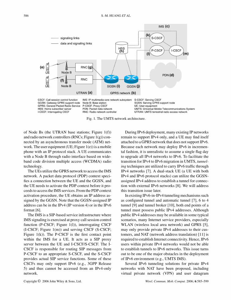
Figure 1 illustrates the UMTS architecture forpacket-switched service domain [2–5]. The generalpacket radio service (GPRS) network (Figure 1(b)) is an
*Correspondence to: Quincy Wu, Graduate Institute of Communication Engineering, National Chi Nan University, No. 1,University Road, Puli, Nantou 545, Taiwan.†E-mail: [email protected]
Contract/grant sponsor: National Science Council; contract/grant numbers: NSC93-2219-E-009-029; NSC93-2752-E-0090005-PAE.
IP-based backbone network consists of serving GPRSsupport nodes (SGSNs; Figure 1(i)) and gateway GPRSsupport nodes (GGSNs; Figure 1(j)). An SGSN relaysIP packets between the mobile users and the GGSN.A GGSN is a specialized router that functions like agateway. It controls user data sessions and transfersthe data packets between the GPRS network and theexternal packet data network (PDN; Figure 1(d)). Thehome subscriber server (HSS; Figure 1(h)) is a mas-ter database containing all 3G user-related subscriptioninformation. Both the GPRS and the IMS networks(Figure 1(c)) access the HSS for mobility manage-ment and session management. The UMTS terrestrialradio access network (UTRAN; Figure 1(a)) consists
Copyright © 2006 John Wiley & Sons, Ltd.
586 S.-M. HUANG ET AL.
Fig. 1. The UMTS network architecture.
of Node Bs (the UTRAN base stations; Figure 1(f))and radio network controllers (RNCs; Figure 1(g)) con-nected by an asynchronous transfer mode (ATM) net-work. The user equipment (UE; Figure 1(e)) is a mobilephone with an IP protocol stack. A UE communicateswith a Node B through radio interface based on wide-band code division multiple access (WCDMA) radiotechnology.
The UEs utilize the GPRS network to access the IMSnetwork. A packet data protocol (PDP) context speci-fies a connection between the UE and the GGSN, andthe UE needs to activate the PDP context before it pro-ceeds to access the IMS services. From the PDP contextactivation procedure, the UE obtains an IP address as-signed by the GGSN. Note that the GGSN-assigned IPaddress can be in the IPv4 (IP version 4) or in the IPv6format [6].
The IMS is a SIP-based service infrastructure whereIMS signaling is exercised at proxy call session controlfunction (P-CSCF; Figure 1(l)), interrogating CSCF(I-CSCF; Figure 1(m)) and serving CSCF (S-CSCF;Figure 1(k)). The P-CSCF is the first contact pointwithin the IMS for a UE. It acts as a SIP proxyserver between the UE and I-CSCF/S-CSCF. The I-CSCF is responsible for routing SIP messages fromP-CSCF to an appropriate S-CSCF, and the S-CSCFprovides actual SIP service functions. Some of theseCSCFs may only support IPv6 (e.g., 3GPP Release5) and thus cannot be accessed from an IPv4-onlynetwork.
During IPv6 deployment, many existing IP networksremain to support IPv4 only, and a UE may find itselfattached to a GPRS network that does not support IPv6.Because each network may deploy IPv6 in incremen-tal fashion, it is unrealistic to assume a single flag dayto upgrade all IPv4 networks to IPv6. To facilitate thetransition for IPv4 to IPv6 migration in UMTS, tunnel-ing techniques are utilized to carry IPv6 traffic throughIPv4 networks [7]. A dual-stack UE (a UE with bothIPv4 and IPv6 protocol stacks) can utilize the GGSN-assigned IPv4 address to establish a tunnel for connec-tion with external IPv6 networks [8]. We will addressthis transition issue later.
In existing IPv6-in-IPv4 tunneling mechanisms suchas configured tunnel and automatic tunnel [7], 6 to 4tunnel [9] and tunnel broker [10], both end points of atunnel must possess public IPv4 addresses. Althoughpublic IPv4 addresses may be available in some typicalscenarios, many Internet service providers, especiallyWLAN (wireless local area network) and GPRS [5],may only provide private IPv4 addresses to their cus-tomers, and NAT (network address translation) [11] isrequired to establish Internet connectivity. Hence, IPv6users within private IPv4 networks would not be ableto establish tunnels to IPv6 networks. This issue turnsout to be one of the major obstacles in the deploymentof IPv6 environment (e.g., UMTS IMS).
Several IPv6 tunneling solutions for private IPv4networks with NAT have been proposed, includingvirtual private network (VPN) and user datagram
Copyright © 2006 John Wiley & Sons, Ltd. Wirel. Commun. Mob. Comput. 2006; 6:585–599

SIP MOBILITY IN IP MULTIMEDIA SUBSYSTEM 587
Fig. 2. SIP pre-call mobility procedure.
protocol (UDP) tunnel [12]. These solutions provideIPv6 connectivity for private hosts, but requiremanual configuration at the user end of a tunnel. Thisconfiguration task is not transparent to users, and is noteasy for novice users. Therefore, these solutions arenot suitable for large private IPv4 networks. Moreover,in these approaches, only one static tunnel server isassigned to relay all IPv6 packets of a host in theprivate network. This tunnel server may potentiallybecome the bottleneck, and it is very likely that thetraffic follows a ‘dog leg’ route from the source to thetunnel server and then to the destination, resulting in anon-optimal routing path. To address the above issues,the Internet society proposes Teredo [13], an automatictunneling mechanism with the capability to traverseNATs.‡
Another important issue in UMTS is mobility sup-port for UEs. Within a single GPRS network, the UEmobility is supported by the SGSN and the GGSNwith a layer-2 protocol called GPRS tunneling protocol(GTP). However, if a UE hands off to different visitednetworks with different IPv4/IPv6 support (e.g., a UE
‡ Recently, an enhanced model of UDP tunnel called“Silkroad” [14] was proposed to alleviate the bottleneck is-sue. However, some critical algorithms of Silkroad are stillmissing at the time when this paper is written.
hands off to different operator’s IP network), the situ-ation becomes complicated. In this paper, we combinean application level mechanism, called SIP terminalmobility, and an automatic IPv6 tunneling mechanism,called Teredo, to support the handoff of a UE betweendifferent networks, including private IPv4 networks aswell as IPv6 networks.
This paper is organized as follows. Section 2 de-scribes the mobility support with SIP in UMTS net-work. Specifically, we elaborate on the procedures fora UE to access the IMS services when it hands offfrom its home network (UMTS) to a visited network(UMTS or GPRS). Section 3 describes the Teredomechanism that enables a UE to access the IPv6-only IMS via a private IPv4 PDP context. In Sec-tion 4, we investigate the design of our Linux-basedTeredo software architecture, and then show the per-formance comparison with other public-domain Teredosolutions.
2. SIP Terminal Mobility
SIP is an application-layer signaling protocol for es-tablishing, modifying, and terminating multimedia ses-sions [1]. The SIP protocol is capable of handling ter-minal mobility, session mobility, personal mobility, andservice mobility [15]. Here, we focus on SIP terminal
Copyright © 2006 John Wiley & Sons, Ltd. Wirel. Commun. Mob. Comput. 2006; 6:585–599

588 S.-M. HUANG ET AL.
Fig. 3. SIP mid-call mobility procedure.
mobility that allows a mobile host (i.e., a UE in UMTS)to move between IP subnets while remaining reachableto correspondent hosts (CHs). The SIP terminal mo-bility comprises SIP pre-call mobility (Figure 2) andSIP mid-call mobility (Figure 3), in which the formerenables a CH to establish sessions to a UE, and the lat-ter enables a UE to re-establish its on-going sessionswhile it moves to a visited network. In UMTS network,these two actions correspond to roaming and handoff,respectively.
The SIP pre-call mobility is illustrated in Figure 2. Inthis figure, a UE moves from its home network (UMTS)to a visited network (GPRS or UMTS), and initiates theSIP pre-call mobility procedure as described below.
Steps A.1 and A.2. The UE sends a SIP REGISTERrequest to update its new contact address with the SIPserver.
Steps A.3 and A.4. When a CH sends a SIP INVITErequest to the UE through the SIP server, the SIP servernotifies the CH of the UE’s new contact address.
Step A.5. The CH replies with a SIP ACK messageto notify the SIP Server that it has received the SIP 200OK response.
Upon receipt of the UE’s new contact address, theCH contacts this address directly and a session is estab-lished between the CH and the UE through the standardSIP call setup procedure.
In addition to SIP pre-call mobility which is appliedto allow call establishment of successive sessions afterthe UE moves, for UE movement in the middle of asession, SIP mid-call mobility must be applied to re-establish the on-going sessions. After the UE moves toa visited network and obtains a new contact address,it modifies the existing session by issuing a new SIPINVITE request, in which the SIP header fields ‘From’,‘To’, ‘Call-ID’ have identical values as those in theoriginal SIP INVITE request which establishes thissession. This secondary SIP INVITE request is calleda SIP re-INVITE request, and it modifies an ex-isting session by new parameters specified in the‘connection address’ field of the session descriptionprotocol (SDP) and new ‘Contact’ field in the SIPheader.
The SIP mid-call mobility is illustrated inFigure 2, where the UE and the CH first establish asession through the standard SIP call setup procedure,and then the UE moves to a visited network, and re-establishes this session with the following steps.
Step B.1. When the UE moves, it initiates the SIPmid-call mobility mechanism by sending a SIP re-INVITE request to the CH. In this request, the contactfield in the SIP header and the SDP connection addressfield are updated to the UE’s new IP address.
Step B.2. When the CH receives this request, itreplies a SIP 200 OK response.
Copyright © 2006 John Wiley & Sons, Ltd. Wirel. Commun. Mob. Comput. 2006; 6:585–599
SIP MOBILITY IN IP MULTIMEDIA SUBSYSTEM 589
Step B.3. The UE replies with an SIP ACK messageto notify the CH that it has received the SIP 200 OKresponse.
Step B.4. The CH modifies the session parametersaccording to the new connection address in the SDPcontent, and then the media data transmission is re-established between the CH and the UE with its newaddress.
The format of a SIP re-INVITE request is identi-cal to a SIP INVITE request. Thus it is unnecessary tomodify the SIP protocol or create a new SIP method.Moreover, SIP terminal mobility can fit the require-ments of fast handoff, low latency, and high bandwidthutilization [15,16].
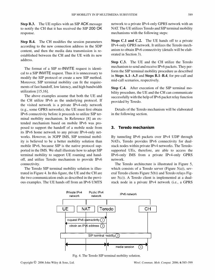
The above examples assume that both the UE andthe CH utilize IPv6 as the underlying protocol. Ifthe visited network is a private IPv4-only network(e.g., some GPRS networks), the UE must first obtainIPv6 connectivity before it proceeds to utilize SIP ter-minal mobility mechanism. In Reference [8] an ex-tended mechanism based on mobile IPv6 was pro-posed to support the handoff of a mobile node fromits IPv6 home network to any private IPv4-only net-works. However, in 3GPP IMS, SIP terminal mobil-ity is believed to be a better mobility solution thanmobile IPv6, because SIP is the native protocol sup-ported in the IMS. We shall illustrate how to adopt SIPterminal mobility to support UE roaming and hand-off, and utilize Teredo mechanism to provide IPv6connectivity.
The Teredo SIP terminal mobility solution is illus-trated in Figure 4. In this figure, the UE and the CH arethe two communication ends as described in the previ-ous examples. The UE hands off from an IPv6 UMTS
network to a private IPv4-only GPRS network with anNAT. The UE utilizes Teredo and SIP terminal mobilitymechanisms with the following steps:
Steps C.1 and C.2. The UE hands off to a privateIPv4-only GPRS network. It utilizes the Teredo mech-anism to obtain IPv6 connectivity (details will be elab-orated in Section 3).
Step C.3. The UE and the CH utilize the Teredomechanism to send and receive IPv6 packets. They per-form the SIP terminal mobility procedure as describedin Steps A.1–A.5 and Steps B.1–B.4, for pre-call andmid-call scenarios, respectively.
Step C.4. After execution of the SIP terminal mo-bility procedure, the UE and the CH can communicatesuccessfully with the help of IPv6 packet relay functionprovided by Teredo.
Details of the Teredo mechanism will be elaboratedin the following section.
3. Teredo mechanism
By tunneling IPv6 packets over IPv4 UDP throughNATs, Teredo provides IPv6 connectivity for dual-stack nodes within private IPv4 networks. The Teredo-supported UEs, therefore, are able to access theIPv6-only IMS from a private IPv4-only GPRSnetwork.
The Teredo architecture is illustrated in Figure 5,which consists of a Teredo server (Figure 5(a)), sev-eral Teredo clients Figure 5(b)) and Teredo relays Fig-ure 5(c)). A Teredo client is implemented at a dual-stack node in a private IPv4 network (i.e., a GPRS
Fig. 4. The Teredo SIP terminal mobility solution.
Copyright © 2006 John Wiley & Sons, Ltd. Wirel. Commun. Mob. Comput. 2006; 6:585–599

590 S.-M. HUANG ET AL.
Fig. 5. Teredo architecture.
Fig. 6. An entry in the address mapping table.
network in Figure 5(d)) that connects to public IPv4network Figure 5(e)) through NAT Figure 5(f)). ATeredo server assists a Teredo client to obtain anIPv6 address for IPv6 network access. A Teredo re-lay establishes IPv4 UDP tunnels with the Teredoclients using the designated port 3544, and relaysIPv6 packet between the Teredo clients and the IPv6network. For IPv6 packets sent from the IPv6 net-work and destined to a Teredo client, the Teredo re-lay encapsulates these packets in IPv4 UDP and for-wards them to the destination Teredo client in a pri-vate IPv4 network. In the reverse direction, the Teredorelay decapsulates IPv4 UDP packets sent from theTeredo client to the IPv6 network Figure 5(g)). Tobroadcast its identity, every Teredo relay advertisesan IPv6 address prefix 2001:0000::/32 to the IPv6network (path in Figure 5). Through the adver-tisement, the IPv6 hosts (Figure 5(h)) select appro-priate Teredo relays such that all IPv6 packets sentfrom these IPv6 hosts to a Teredo client are routedto Teredo relays closest to the packet sources. There-fore the traffic load to a Teredo client can be dy-namically adjusted among Teredo relays with optimalrouting.
The Teredo client in Figure 5 represents a dual-stackUE with Teredo client software running on it; the NATis most likely to be implemented at the GGSN, andthus the public IPv4 network is the PDN connected tothe GGSN.
In Figure 5, the IPv4 address of the Teredo serveris 3.3.3.3. The NAT is equipped with two networkinterfaces: the WAN interface (to the public network)has the public IPv4 address 1.1.1.1, and the LANinterface (to the private network) has the private
IPv4 address 192.168.0.1. The Teredo client isassigned the private IPv4 address 192.168.0.2. TheNAT performs private–public address translation forall pass-through packets according to an address-mapping table. Suppose that the NAT is a full coneNAT§ [17]. The fields of an entry in the NAT address-mapping table are illustrated in Figure 6. In this table,the ‘private IPv4 address’ and the ‘private port’ fieldsstore the private transport address of the private end(i.e., IPv4 address plus TCP/UDP port, whose valuesare 192.168.0.2 and 4096 for the example in Figure 5).The ‘transport protocol’ field stores the transport proto-col type (TCP or UDP). The ‘public IPv4 address’ andthe ‘public port’ fields store the public transport addressassigned by the NAT. The values in these fields (IPv4address 1.1.1.1 and port 7863 in this example) are usedto replace the private transport address. This publictransport address of a private IPv4 host is crucialfor translating IPv4 UDP packets passing throughthe NAT. When a host in the public IPv4 networksends an IPv4 UDP packet to this transport address(1.1.1.1:7863), the NAT dispatches this packet to the
§ When an internal host within a private network sends apacket to an external host, an NAT maps the private trans-port address of the internal host to a unique public transportaddress. Thereafter, a public host can send packets to theprivate host by delivering them to the mapped public trans-port address. However, different types of NATs have differentrules to handle incoming packets. The full cone NAT allowspackets from all public hosts to pass through, while a re-stricted cone NAT allows an external host (with IP addressX) sending a packet to the private transport address only ifthe private transport address had previously sent a packet toIP address X.
Copyright © 2006 John Wiley & Sons, Ltd. Wirel. Commun. Mob. Comput. 2006; 6:585–599

SIP MOBILITY IN IP MULTIMEDIA SUBSYSTEM 591
Fig. 7. Teredo IPv6 address format.
designated private IPv4 host (192.168.0.2:4096) withthe help of the address-mapping table.
As an automatic tunneling mechanism, Teredo em-beds the NAT traversal information in its 128-bit IPv6address. A Teredo IPv6 address format consists ofthe fields illustrated in Figure 7. The ‘2001:0000::/32’field specifies the IPv6 address prefix for Teredo. The‘Teredo server IPv4 address’ field indicates the IPv4 ad-dress of a Teredo server (e.g., 3.3.3.3 in Figure 5). The‘Flag’ field indicates the type of NAT (full cone or not)[17]. The ‘Obfuscated mapped public UDP port’ andthe ‘Obfuscated mapped public IPv4 address’ fields in-dicate the public transport address assigned by the NAT.This transport address is mapped to the Teredo client’sprivate transport address. The obfuscation mecha-nism is needed because some NAT products provide‘generic’ application layer gateway (ALG) functional-ity. The generic ALG hunts for IPv4 addresses, eitherin text or binary formats within a packet, and rewritesthem if they match a binding in the address-mappingtable. When this ‘smart NAT’ handles the payload ofpass-through IPv4 packets, it translates any occurrenceof IPv4 address in the payload that matches the addressto be translated in the IPv4 header (or translates anyoccurrence of port number in the payload that matchesthe port to be translated in the TCP/UDP header). Suchaction certainly interferes with normal Teredo opera-tions. To prevent the smart NAT from modifying theTeredo IPv6 addresses in the encapsulated IPv4 UDPpackets, obfuscation performs bitwise XOR operationon the original value with 1 to protect it.
At start-up, a Teredo client (i.e., a UE) obtains aTeredo IPv6 address by performing the qualificationprocedure with the Teredo server (path → →in Figure 5). From this procedure, the Teredo client de-tects the NAT type and learns its mapped public trans-port address from the Teredo server. As long as theTeredo clients obtain Teredo IPv6 addresses, they areable to communicate with the IPv6 network with thehelp of Teredo servers and Teredo relays. In the ex-ample of Figure 5, the Teredo client uses UDP port4096 to initiate the qualification procedure with theTeredo server. When this UDP request arrives at theNAT (path in Figure 5), the NAT dynamically allo-
cates an available UDP port (e.g., 7863 in this example)for this connection, and creates an entry in the addressmapping table with protocol type UDP, private trans-port address 192.168.0.2:4096 and public transport ad-dress 1.1.1.1:7863. Then the UDP request is sent tothe Teredo server (path in Figure 5), and the Teredoserver replies a UDP response containing the publictransport address (e.g., 1.1.1.1:7863 in this example)observed by the Teredo server (path in Figure 5).The Teredo client repeats this process following theNAT type detection algorithm in Reference [17], andthen calculates its Teredo IPv6 address by determiningthe value of each field as follows:
� Prefix (32 bits) = 0x20010000� Teredo server IPv4 address (32 bits) = 3.3.3.3 =
0x03030303� Flag (16 bits) = 0x8000 (full cone NAT)� Obfuscated mapped public UDP port (16 bits) =
7863 ⊕ 0xFFFF = 0x1EB7 ⊕ 0xFFFF = 0xE148� Obfuscated mapped public IPv4 address (32
bits) = 1.1.1.1 ⊕ 0xFFFFFFFF = 0x01010101 ⊕0xFFFFFFFF = 0xFEFEFEFE
Therefore, the Teredo IPv6 address obtained bythis Teredo client is 2001:0000:0303:0303:8000:E148:FEFE:FEFE.
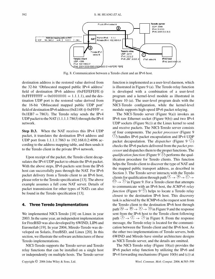
After qualification, communication between theTeredo client and an IPv6 host can be established. Fig-ure 8 illustrates how an IPv6 packet is delivered froman IPv6 host to a Teredo client with the following steps(see path → → in Figure 8).
Step D.1. The IPv6 packet is sent from the IPv6host to the Teredo relay. (The IPv6 host selectsthis Teredo relay according to the IPv6 address pre-fix 2001:0000::/32 advertisement; see path inFigure 5.)
Step D.2. The Teredo relay encapsulates the IPv6packet in an IPv4 UDP packet. The source address isthe IPv4 address of the Teredo relay (2.2.2.2), and thesource UDP port is 3544. The destination IPv4 addressand UDP port of this packet are determined based onthe IPv6 address of this Teredo client as follows. The
Copyright © 2006 John Wiley & Sons, Ltd. Wirel. Commun. Mob. Comput. 2006; 6:585–599
592 S.-M. HUANG ET AL.
Fig. 8. Communication between a Teredo client and an IPv6 host.
destination address is the restored value derived fromthe 32-bit ‘Obfuscated mapped public IPv4 address’field of destination IPv6 address (0xFEFEFEFE ⊕0xFFFFFFFF = 0x01010101 = 1.1.1.1), and the des-tination UDP port is the restored value derived fromthe 16-bit ‘Obfuscated mapped public UDP port’field of destination IPv6 address (0xE148 ⊕ 0xFFFF =0x1EB7 = 7863). The Teredo relay sends the IPv4UDP packet to the NAT (1.1.1.1:7863) through the IPv4network.
Step D.3. When the NAT receives this IPv4 UDPpacket, it translates the destination IPv4 address andUDP port from 1.1.1.1:7863 to 192.168.0.2:4096 ac-cording to the address mapping table, and then sends itto the Teredo client in the private IPv4 network.
Upon receipt of the packet, the Teredo client decap-sulates the IPv4 UDP packet to obtain the IPv6 packet.With the above steps, IPv6 packets sent from the IPv6host can successfully pass through the NAT. For IPv6packet delivery from a Teredo client to an IPv6 host,please refer to the Teredo specification [13]. The aboveexample assumes a full cone NAT server. Details ofpacket transmission for other types of NATs can alsobe found in the Teredo specification [13].
4. Three Teredo Implementations
We implemented NICI-Teredo [18] on Linux in year2003. In the same year, an independent implementationfor FreeBSD was also developed by 6WIND, LIP6 andEuronetlab [19]. In year 2004, Miredo-Teredo was de-veloped on Solaris, FreeBSD, and Linux [20]. In thissection, we illustrate the software architectures of theseTeredo implementations.
NICI-Teredo supports the Teredo server and Teredorelay functions that can be installed on a single hostor independently on multiple hosts. The Teredo server
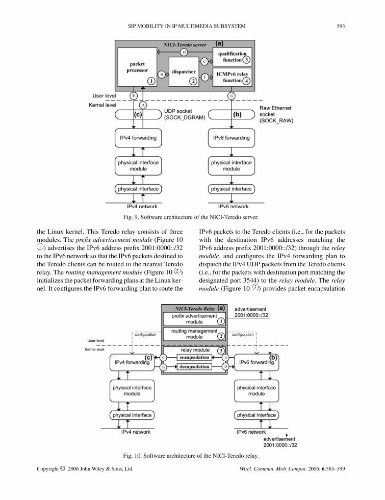
function is implemented as a user-level daemon, whichis illustrated in Figure 9 (a). The Teredo relay functionis developed with a combination of a user-levelprogram and a kernel-level module as illustrated inFigure 10 (a). The user-level program deals with theNICI-Teredo configuration, while the kernel-levelmodule supports high-speed IPv6 packet relaying.
The NICI-Teredo server (Figure 9(a)) invokes anIPv6 raw Ethernet socket (Figure 9(b)) and two IPv4UDP sockets (Figure 9(c)) at the Linux kernel to sendand receive packets. The NICI-Teredo server consistsof four components. The packet processor (Figure 9
) handles IPv6 packet encapsulation and IPv4 UDPpacket decapsulation. The dispatcher (Figure 9 )checks the IPv6 packets delivered from the packet pro-cessor and dispatches them to the proper functions. Thequalification function (Figure 9 ) performs the qual-ification procedure for Teredo clients. This functionhelps the Teredo client to discover the type of NAT andthe mapped public transport address, as described inSection 3. The Teredo server interacts with the Teredoclients for qualification through path → → →
→ in Figure 9. For a Teredo client that attemptsto communicate with an IPv6 host, the ICMPv6 relayfunction (Figure 9 ) helps to locate a Teredo relayclosest to the destination IPv6 host. This discoverytask is achieved by the ICMPv6 echo request sent fromthe Teredo client to the destination IPv6 host throughpath → → → in Figure 9 and the responsesent from the IPv6 host to the Teredo client followingpath → → in Figure 8. From the responsemessage, the Teredo relay is located for the communi-cation between the Teredo client and the IPv6 host. Asthe other two implementations of Teredo servers, both6WIND and Miredo have similar architecture designsas NICI-Teredo server, and the details are omitted.
The NICI-Teredo relay (Figure 10(a)) provides theIPv6 packet relay function by utilizing the IPv6 andIPv4 forwarding mechanisms (Figure 10(b) and (c)) at
Copyright © 2006 John Wiley & Sons, Ltd. Wirel. Commun. Mob. Comput. 2006; 6:585–599
SIP MOBILITY IN IP MULTIMEDIA SUBSYSTEM 593
Fig. 9. Software architecture of the NICI-Teredo server.
the Linux kernel. This Teredo relay consists of threemodules. The prefix advertisement module (Figure 10
) advertises the IPv6 address prefix 2001:0000::/32to the IPv6 network so that the IPv6 packets destined tothe Teredo clients can be routed to the nearest Teredorelay. The routing management module (Figure 10 )initializes the packet forwarding plans at the Linux ker-nel. It configures the IPv6 forwarding plan to route the
IPv6 packets to the Teredo clients (i.e., for the packetswith the destination IPv6 addresses matching theIPv6 address prefix 2001:0000::/32) through the relaymodule, and configures the IPv4 forwarding plan todispatch the IPv4 UDP packets from the Teredo clients(i.e., for the packets with destination port matching thedesignated port 3544) to the relay module. The relaymodule (Figure 10 ) provides packet encapsulation
Fig. 10. Software architecture of the NICI-Teredo relay.
Copyright © 2006 John Wiley & Sons, Ltd. Wirel. Commun. Mob. Comput. 2006; 6:585–599

594 S.-M. HUANG ET AL.
Fig. 11. Software architecture of the 6WIND-Teredo relay.
and decapsulation functions by two callback func-tions, udpip6 tunnel xmit() (Figure 10 )and udpip6 rcv() (Figure 10 ). These functionsare invoked by the IPv6 and the IPv4 forwardingmechanisms, respectively. From the IPv6 forwardingmechanism, the relay module receives IPv6 packets forIPv4 UDP encapsulation, and then passes them to theIPv4 forwarding mechanism by IPTUNNEL XMIT‖
(Figure 10 ). The encapsulated packets are then de-livered to the Teredo clients. In the reverse direction, thetunneled IPv4 UDP packets are decapsulated into IPv6by this module, and then passed to the IPv6 forwardingmechanism (i.e., via the Linux functionnetif rx())for delivery to the IPv6 networks (Figure 10 ).
The 6WIND-Teredo relay (Figure 11(a)) utilizes net-graph, a FreeBSD in-kernel networking subsystem,and the IPv6 forwarding mechanism (Figure 11(b))and socket functions (Figure 11(c)) at the FreeBSDkernel to provide packet relay function. Unlike theNICI-Teredo relay that utilizes a single kernel-levelmodule to provide all packet-processing functions, the6WIND-Teredo relay relies on the cooperation of sev-
‖ According to the Linux programming convention, the up-percase name IPTUNNEL XMIT() refers to a macro, whilethe lowercase name such asudpip6 rcv() refers to a func-tion. The same convention is used in the 6WIND implemen-tation on FreeBSD.
eral netgraph submodules and a kernel IPv4 UDPsocket to handle the packets. The 6WIND-Teredo relayconsists of three components. The prefix advertisementmodule (Figure 11 ) advertises the IPv6 address pre-fix 2001:0000::/32 to the IPv6 network, which providessimilar functions as the prefix advertisement modulein the NICI-Teredo relay. The routing managementmodule (Figure 11 ) initializes the IPv6 forwardingplan to route the IPv6 packets to the Teredo clientsthrough the netgraph module. The netgraph module(Figure 11 ) utilizes three submodules to deal withIPv6 packet processing. The netisr dispatch()and ng iface output() functions of the ngNsubmodule connect to the IPv6 protocol stack todeliver IPv6 packets; the so pru sosend() andso pru soreceive() functions of the ksocket sub-module utilize a kernel IPv4 UDP socket with port3544 to deliver the encapsulated packets with theTeredo clients, where the IPv4 UDP socket providespacket encapsulation and decapsulation functions.These two netgraph submodules interact with eachother through the ng teredo submodule. Specifically,the ng teredo submodule usesNG SEND DATA() andng teredo rcvdata() to deliver IPv6 packets be-tween the ngN and the ksocket submodules. Throughcooperation of these three submodules in the netgraphmodule, IPv6 packets received by the ngN submoduleare written to the kernel IPv4 UDP socket by the ksocketsubmodule, and vice versa.
Copyright © 2006 John Wiley & Sons, Ltd. Wirel. Commun. Mob. Comput. 2006; 6:585–599
SIP MOBILITY IN IP MULTIMEDIA SUBSYSTEM 595
Fig. 12. Software architecture of the Miredo-Teredo relay.
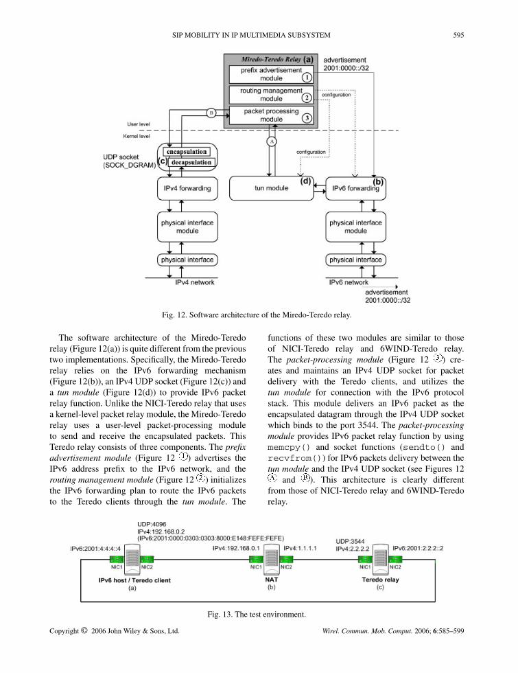
The software architecture of the Miredo-Teredorelay (Figure 12(a)) is quite different from the previoustwo implementations. Specifically, the Miredo-Teredorelay relies on the IPv6 forwarding mechanism(Figure 12(b)), an IPv4 UDP socket (Figure 12(c)) anda tun module (Figure 12(d)) to provide IPv6 packetrelay function. Unlike the NICI-Teredo relay that usesa kernel-level packet relay module, the Miredo-Teredorelay uses a user-level packet-processing moduleto send and receive the encapsulated packets. ThisTeredo relay consists of three components. The prefixadvertisement module (Figure 12 ) advertises theIPv6 address prefix to the IPv6 network, and therouting management module (Figure 12 ) initializesthe IPv6 forwarding plan to route the IPv6 packetsto the Teredo clients through the tun module. The
functions of these two modules are similar to thoseof NICI-Teredo relay and 6WIND-Teredo relay.The packet-processing module (Figure 12 ) cre-ates and maintains an IPv4 UDP socket for packetdelivery with the Teredo clients, and utilizes thetun module for connection with the IPv6 protocolstack. This module delivers an IPv6 packet as theencapsulated datagram through the IPv4 UDP socketwhich binds to the port 3544. The packet-processingmodule provides IPv6 packet relay function by usingmemcpy() and socket functions (sendto() andrecvfrom()) for IPv6 packets delivery between thetun module and the IPv4 UDP socket (see Figures 12
and ). This architecture is clearly differentfrom those of NICI-Teredo relay and 6WIND-Teredorelay.
Fig. 13. The test environment.
Copyright © 2006 John Wiley & Sons, Ltd. Wirel. Commun. Mob. Comput. 2006; 6:585–599

596 S.-M. HUANG ET AL.
Fig. 14. IPv6 to IPv4 latency histograms of the Teredo relays (1280 bytes).
The Teredo relay design significantly affects thepacket transmission performance. The packet process-ing latency of the NICI-Teredo relay is shorter becausethere are no packet copying operations between the ker-nel and the user levels. The performance comparisonof these Teredo implementations will be elaborated inthe next section.
As a remark, the NICI-Teredo relay is implementedas a loadable kernel module [21]. Although kernelhacking effort is required in developing the NICI-Teredo relay, the installation process is very simple andthe users do not need to modify or re-compile the Linuxkernel.
5. Performance Evaluation of TeredoRelay Implementations
Teredo relay handles large volume of network trafficand therefore is likely to be the bottleneck component
in the Teredo mechanism. In this section, we investigatethe performance of the three Teredo relay implemen-tations described in the previous section. The outputmeasurement is packet-processing latency, that is, theprocessing time at the Teredo relay, which is either theIPv6 to IPv4 latency (from a public IPv6 host to a pri-vate Teredo client) or the IPv4 to IPv6 latency (from aprivate Teredo client to a public IPv6 host).
The measurement environment consists of threehosts as illustrated in Figure 13. This environment fol-lows the testing architecture in RFC 2544 [22] wherea tester (Figure 13(a)) is configured as both the Teredoclient function and the IPv6 host. This IPv6 host runson Redhat Linux 9 with an IPv4 UDP daemon to simu-late the Teredo client function. The NAT (Figure 13(b))runs on Redhat Linux 9 with address mapping rules setby iptables [23]. The devices under test (DUTs) arethe three Teredo relay implementations (Figure 13(c)):NICI-Teredo (version 0.5), 6WIND-Teredo (version1.13) and Miredo-Teredo (version 0.4.1). Both NICI-
Table I. Average processing latency.
Teredo relay Average IPv6 to IPv4 latency (�s) Average IPv4 to IPv6 latency (�s)
64 bytes 512 bytes 1280 bytes 64 bytes 512 bytes 1280 bytes
NICI 7.56 7.67 7.91 8.47 8.71 8.936WIND 13.30 13.53 14.00 14.34 14.62 14.80Miredo 28.55 29.45 30.26 27.94 28.76 29.69
Copyright © 2006 John Wiley & Sons, Ltd. Wirel. Commun. Mob. Comput. 2006; 6:585–599

SIP MOBILITY IN IP MULTIMEDIA SUBSYSTEM 597
Fig. 15. IPv6 to IPv4 latency histograms of the Teredo relays (512 bytes).
Teredo relay and Miredo-Teredo relay run on RedhatLinux 9, while 6WIND-Teredo relay runs on FreeBSD4.9. The hardware for the Teredo relay in Figure 13 isa personal computer with 1800+ AMD Athlon CPU,256 MB SDRAM and two RealTek 8139 100BaseTxEthernet cards.
In our measurement, a C program invoking pcaplibrary [24] is used for catching the packet receivingand sending timestamps. We send one packet persecond to the Teredo relay from IPv6 to IPv4 or IPv4to IPv6, and measure the packet processing latency.Tests are conducted with three different packet sizes
Fig. 16. IPv6 to IPv4 latency histograms of the Teredo relays (64 bytes).
Copyright © 2006 John Wiley & Sons, Ltd. Wirel. Commun. Mob. Comput. 2006; 6:585–599

598 S.-M. HUANG ET AL.
(64, 512, and 1280 bytes, where the 1280-byte packetis the recommended IPv6 MTU size for Teredo [13]).Each test generates 10 000 packets to measure theIPv6 to IPv4 and IPv4 to IPv6 latencies.
Figure 14 shows the 1280-byte IPv6 to IPv4 latencyhistograms of the three Teredo relays. In this figure,the x-axis represents the delay time (in �s) andthe y-axis represents the percentage of the packets(out of the 10 000 testing packets) that have thisdelay value. The latency of the NICI-Teredo relay isclustered around 7–9 �s and 12–13 �s. The latencyof the 6WIND-Teredo relay is around 12–16 �s. Thelatency of the Miredo-Teredo relay is clustered around27–31 �s and 33–35 �s. The 1280-byte IPv4 to IPv6latency histograms are similar to those in Figure 14,and the average packet processing latency of the threeTeredo relays are listed in Table I.
With different packet sizes (1280, 512, 64 bytes),the IPv6 to IPv4 latency histograms of NICI-Teredorelay and 6WIND-Teredo relay (see Figures 14–16)have similar shapes, where the Miredo-Teredo relay haslonger latency than that of the NICI-Teredo relay. Forthe 1280-byte IPv6 to IPv4 latency listed in Table I, thelatency improvement of the NICI-Teredo relay over the6WIND-Teredo relay is around 44%, and the improve-ment of the NICI-Teredo relay over the Miredo-Teredorelay is around 74%.
6. Conclusion and Future work
This paper addressed the issues when dual-stack UEshand off or roam between the IPv6 UMTS and the pri-vate IPv4 GPRS networks. Especially, we addressed theNAT traversal issue between the GPRS (private IPv4)and the UMTS (IPv6) networks. To solve this prob-lem, we combined the SIP mobility mechanism and anautomatic IPv6 tunneling mechanism, called Teredo,to support the handoff of a UE between different net-works. As an NAT traversable automatic tunnelingmechanism, Teredo provides convenient IPv6 accessfrom the private IPv4 networks. We developed an effi-cient implementation for Teredo tunneling called NICI-Teredo. To our knowledge, NICI-Teredo was the firstnon-commercial Teredo implementation on Linux. Ourapproach has shorter packet processing latency thanthat of the 6WIND-Teredo relay (FreeBSD-based) andthe Miredo-Teredo relay (Linux-based). The advantageof packet processing performance of the NICI-Teredorelay makes it an appropriate IPv6 tunneling solution.
As a final remark, we point out that Teredo does notwork for all NAT servers. According to the rules for
port mapping and access control in NAT [17], the fourmajor types are full cone NAT, restricted cone NAT, portrestricted cone NAT, and symmetric NAT. AlthoughTeredo can successfully traverse the first three types ofNATs, it fails in traversing symmetric NAT. To enhanceTeredo for symmetric NAT is still an open issue forfurther study.
References
1. Rosenberg J, Schulzrinne H, Camarillo G, Johnston A, PetersonJ, Sparks R, Handley M, Schooler E. SIP: Session InitiationProtocol. RFC 3261, June 2002.
2. 3GPP. 3rd Generation Partnership Project; Technical Specifica-tion Group Services and System Aspects; IP Multimedia Subsys-tem (IMS); Stage 2 (Release 5). Technical Specification 3GPPTS 23.228 V5.13.0 (2004–12), December 2004.
3. 3GPP. 3rd Generation Partnership Project; Technical Specifica-tion Group Services and System Aspects; General Packet RadioService (GPRS); Service description; Stage 2 (Release 5). Tech-nical Specification, 3GPP TS 23.060 V5.10.0 (2005–03), March2005.
4. Lin Y-B, Huang Y-R, Pang A-C, Chlamtac I. ALL-IP approachfor UMTS third-generation mobile networks. IEEE NetworkMagazine 2002; 16(5): 8–19.
5. Lin Y-B, Chlamtac I. Wireless and Mobile Network Architec-tures. John Wiley & Sons: New York, 2001.
6. Chen Y-K, Lin Y-B. IP connectivity for gateway GPRS supportNode. IEEE Wireless Communications Magazine 2005; 12(1):37–46.
7. Gilligan R, Nordmark E. Transition Mechanisms for IPv6 Hostsand Routers. RFC 2893, August 2000.
8. Thakolsri S, Prehofer C, Kellerer W. Transition Mechanism inIP-based Wireless Networks. In Proceedings of 2004 IEEE Inter-national Symposium on Applications and the Internet Workshops(SAINT Workshops 2004), 2004; pp. 112–119.
9. Carpenter B, Moore K. Connection of IPv6 Domains via IPv4Clouds. RFC 3056, February 2001.
10. Durand A, Fasano P, Guardini I, Lento D. IPv6 Tunnel Broker.RFC 3053, January 2001.
11. Srisuresh P, Holdrege M. IP Network Address Translator(NAT) Terminology and Considerations. RFC2663, August1999.
12. Levkowetz H, Vaarala S. Mobile IP Traversal of Network Ad-dress Translation (NAT) Devices. RFC 3519, April 2003.
13. Huitema C. Teredo: Tunneling IPv6 over UDP through NATs.RFC 4380, February 2006.
14. Liu M, Wu X, Cai Y, Jin M, Li D. Tunneling IPv6 with pri-vate IPv4 addresses through NAT devices. draft-liumin-v6ops-silkroad-03.txt (expired), July 2005.
15. Schulzrinne H, Wedlund E. Application-layer mobility usingSIP. ACM SIGMOBILE Mobile Computing and Communica-tions Review 2000; 4(3): 47–57.
16. Banerjee N, Wu W, Das SK, Dawkins S, Pathak J. Mobility sup-port in wireless Internet. IEEE Wireless Communications Mag-azine 2003; 10(5): 54–61.
17. Rosenberg J, Weinberger J, Huitema C, Mahy R. STUN—Simple Traversal of User Datagram Protocol (UDP) ThroughNetwork Address Translators (NATs). RFC 3489, March2003.
18. Huang S-M, Wu Q-C. Implementation of Teredo—TunnelingIPv6 through NAT. Technical Report for National Informationand Communication Initiative (NICI) IPv6 R&D Division, Tai-wan, ROC, 2003.
19. Teredo for FreeBSD. http://www-rp.lip6.fr/teredo/
Copyright © 2006 John Wiley & Sons, Ltd. Wirel. Commun. Mob. Comput. 2006; 6:585–599
SIP MOBILITY IN IP MULTIMEDIA SUBSYSTEM 599
20. Miredo: Teredo for Linux. http://www.simphalempin.com/dev/miredo/
21. Henderson B. Linux Loadable Kernel Module HOWTO. http://www.linux.org/docs/ldp/howto/module-howto/
22. Bradner S, McQuaid J. Benchmarking Methodology for Net-work Interconnect Devices. RFC 2544, March 1999.
23. The netfilter/iptables project. http://www.netfilter.org/24. Tcpdump and libpcap. http://www.tcpdump.org/
Authors’ Biographies
Shiang-Ming Huang received his B.S.and M.S. degrees from National ChiaoTung University, Hsinchu, Taiwan, in2003 and 2005 respectively. He wrotethe STUN protocol dissector in Ethereal,which is a popular open source networkprotocol analyzer distributed all over theworld. In 2003, he helped Computer andCommunication Research Laboratories
(CCL) to enhance a commercial SIP User Agent to supportSTUN, which is an important mechanism proposed by In-ternet Engineering Task Force (IETF) in RFC 3489. Thisenhancement was then transferred to Industrial TechnologyResearch Institute (ITRI) later in the same year. After that,he joined the National Information and Communications Ini-tiative Committee (NICI) IPv6 deployment project in 2003,where he implemented the first non-commercial Teredo IPv6tunneling mechanism on Linux. Currently, he is working to-wards his Ph.D. in Computer Science, National Chiao TungUniversity, Hsinchu, Taiwan. His current research interestsinclude Internet Protocol version 6 (IPv6) and Session Initi-ation Protocol (SIP).
Quincy Wu received his B.S. degreein Mathematics from National TsingHua University in 1992, and his Ph.D.in Computer Science and InformationEngineering from National Tsing HuaUniversity in 2000. He joined NationalCenter for High-Performance Comput-ing with the NBEN (National BroadbandExperimental Network) project, where
he successfully designed and established the first island-wideIPv6 network among universities. In 2002, he began servingas a research assistant professor with National Chiao Tung
University, and helped National Telecommunications ProjectOffice to deploy a SIP-based VoIP Platform across severaluniversities. Since 2004, he co-chairs the SIP-H323 Work-ing Group of Asia-Pacific Advanced Network (APAN) andhelped Taiwan Academic Network (TANet) to design anddeploy VoIP services. He was appointed as an assistant pro-fessor of Graduate Institute of Communication Engineering,National Chi Nan University in 2005 and helped initiating theVoIP over WiMAX project in National Chi Nan University.His current research interests include session initiation pro-tocol, open service architecture, Internet protocol version 6,design and analysis of approximation algorithms, and servicecreation on the third generation mobile network.
Yi-Bing Lin is chair professor and vicepresident of Research and Development,National Chiao Tung University. His cur-rent research interests include wirelesscommunications and mobile computing.Dr. Lin has published over 190 journalarticles and more than 200 conferencepapers. Lin is the co-author of the bookWireless and Mobile Network Architec-
ture (with Imrich Chlamtac; published by John Wiley Sons).Lin is an IEEE fellow, an ACM fellow, an AAAS fellow, andan IEE fellow.
Che-Hua Yeh received his B.S. degreefrom National Chiao Tung University,Hsinchu, Taiwan in 2004. He had richresearch experience on SIP instant mes-saging and GSM short message ser-vice. Since 2003, he joined the ‘PersonalCommunication System’ research groupin National Chiao Tung University andworked on the project ‘Instant Messag-
ing and Short Messaging Service Gateway’ (IM-SMS Gate-way) which implemented a gateway converting instant mes-saging service and short messaging service between IP net-work and GSM network. After that, he developed the Intelli-gent Notify Center (iNotify Center) which integrates SIP in-stant messaging, SIP presence service, GSM short messagingservice, and E-mail service. He currently studies the subjectof Session Initiation Protocol (SIP) mobility and implementsSIP mobility in SIP user agent. He is now working towardsthe Master degree in Computer Science and Information En-gineering, National Chiao Tung University, Hsinchu, Taiwan.
Copyright © 2006 John Wiley & Sons, Ltd. Wirel. Commun. Mob. Comput. 2006; 6:585–599