
SIP-enabled Seamless Handover for Wireless Local Area Network
120
University of Kaiserslautern Faculty of Electrical and Computer Engineering Institute for Wireless Communications and Navigation "SIP-enabled Seamless Handover for Wireless Local Area Network" Master Thesis accomplished by: Alexandre Nin Sadurní Matrikel-Nr. 384602 Supervisors: Prof. Dr.-Ing. Hans D. Schotten Dipl.-Ing. Andreas Klein Submission Date: 17.07.2013
Transcript of SIP-enabled Seamless Handover for Wireless Local Area Network

University of Kaiserslautern Faculty of Electrical and Computer Engineering
Institute for Wireless Communications and Navigation
"SIP-enabled Seamless Handover for
Wireless Local Area Network"
Master Thesis accomplished by:
Alexandre Nin Sadurní
Matrikel-Nr. 384602
Supervisors:
Prof. Dr.-Ing. Hans D. Schotten
Dipl.-Ing. Andreas Klein
Submission Date: 17.07.2013

1

2
I declare that I have developed and written this thesis, submitted on 17th July 2013 and
entitled “SIP-Seamless Handover for Wireless Local Area Network", entirely on my own and
have not used outside sources without declaration in the text and detailed bibliography. Any
concepts or quotations applicable to this document are clearly attributed to them. Every
figure, picture or diagram has an explanatory meaning and is important to better understand
the concepts presented along, and they are referenced as well. This master thesis has not been
submitted in this same or similar version, not even in part, to any other authorities for grading
and has not been published elsewhere.
Kaiserslautern, 23th July 2013
………………………………………………………………………………….
Alexandre Nin Sadurní
3
Table of Contents
Abstract ......................................................................................................................................... 5
Abbreviations ................................................................................................................................ 6
List of Figures ................................................................................................................................ 7
1. Introduction ........................................................................................................................ 10
2. Mobility Support in WLANs ................................................................................................. 11
2.1 Handover Concept ....................................................................................................... 12
2.2 IP Mobility Support ..................................................................................................... 13
2.3 Alternative Proposals .................................................................................................. 15
2.4 IEEE 802.21 .................................................................................................................. 15
3. Session Initiation Protocol – SIP .......................................................................................... 17
3.1 SIP Entities ................................................................................................................... 18
3.1.1 User Agent ........................................................................................................... 19
3.1.2 Proxy Server ........................................................................................................ 19
3.1.3 Registrar .............................................................................................................. 21
3.1.4 Redirect Server .................................................................................................... 21
3.1.5 B2BUA .................................................................................................................. 22
3.2 SIP Messages ............................................................................................................... 23
3.2.1 SIP Request Messages ......................................................................................... 24
3.2.2 SIP Response Messages ....................................................................................... 26
3.2.3 SIP Transactions and Dialogs ............................................................................... 27
3.2.4 Typical SIP Scenarios ........................................................................................... 29
3.2.5 Dialog Flow Example ........................................................................................... 30
3.3 SIP Mobility Support .................................................................................................... 32
3.3.1 Terminal Mobility ................................................................................................ 34
3.3.1.1 Pre-Call Mobility .................................................................................................. 34
3.3.1.2 Mid-Call Mobility ................................................................................................. 34
3.3.2 SIP Mobility Support with Mobile IP ................................................................... 35
3.3.3 Error Recovery ..................................................................................................... 35
4. Scenario and Software Framework ..................................................................................... 37
4.1 Kamailio Open SIP Server ............................................................................................ 38
4.1.1 Installing and configuring MySQL and Kamailio (v 3.1.5) .................................... 39
4.2 wpa_supplicant ........................................................................................................... 43

4
4.3 RSSIMonitor ................................................................................................................. 44
4.3.1 Flow Control ........................................................................................................ 47
4.4 PJSIP-Client (User Agent) ............................................................................................. 49
4.4.1 Implementation ................................................................................................... 49
4.4.2 Analysis of Transmitted SIP Messages ................................................................ 50
4.4.2.1 Pre-Call Mobility .................................................................................................. 50
4.4.2.2 Mid-Call Mobility ................................................................................................. 52
5. SIP supported seamless handover evaluation .................................................................... 55
5.1 Pre-call mobility .......................................................................................................... 55
5.2 Mid-call mobility.......................................................................................................... 57
6. Conclusions and future work .............................................................................................. 60
References ................................................................................................................................... 61
Appendix ..................................................................................................................................... 63
A. How to run ...................................................................................................................... 63
B. Configuring modular Kamailio ......................................................................................... 65
C. RSSI Conversion Methods ............................................................................................... 68
D. Code ................................................................................................................................ 70
a. RSSIMonitor ................................................................................................................. 70
b. Simple_pjsua (SIP UA) ................................................................................................. 97
E. CD Content .................................................................................................................... 119

5
Abstract
Multimedia communication services such as VoIP (Voice over IP), videoconference or instant
messaging are becoming every day more popular among every kind of user. Main reasons are
the progresses achieved in the development of wireless network technologies, as well as the
big acceptation of mobile devices such as smartphones, laptops or tablets.
Session Initiation Protocol (SIP) is an IETF’s (Internet Engineering Task Force) standard, used as
signaling protocol to establish multimedia sessions through Internet. Among its features,
something as basic as a registrar entity, allows the user to inform the network where the
invitations for communicating with other users shall be received, and this is a powerful tool
from the perspective of the mobility issue.
WLAN (Wireless Local Area Network) technologies are widely spread nowadays and are one of
the most used options for internet access. One crucial issue to solve when in a mobility
situation is to achieve continuous connectivity if an AP’s (Access Point) migration happens.
In this work, SIP and WLAN technologies are employed together in order to reach the
objectives of a seamless media communication in a mobility context.

6
Abbreviations
AP …………………………………………………………………………………………………………………………. Access Point
BS …………………………………………………………………………………………………………………………. Base Station
BSS …………………………………………………………………………………………………………………. Basic Service Set
CH ……………………………………………………………………………………………………………. Correspondent Host
DHCP ……………………………………………………………………………… Dynamic Host Configuration Protocol
ESS ………………………………………………………………………………………………………….. Extended Service Set
HO ………………………………………………………………………………………………………………. Handover/handoff
IETF ………………………………………………………………………………………… Internet Engineering Task Force
IP …………………………………………………………………………………………………………………... Internet Protocol
LX ……………………………………………………………………………………………………………………………. OSI Layer X
MH ……………………………………………………………………………………………………..................... Mobile Host
MN ………………………………………………………………………………………………………………………. Mobile Node
NAT ……………………………………………………………………………………………. Network Address Translation
NIC …………………………………………………………………………………………….. Network Interface Controller
OSI ………………………………………………………………………………………….. Open Systems Interconnection
QoS ……………………………………………………………………………………………….................. Quality of Service
RTP ………………………………………………………………………………………….…. Real-time Transport Protocol
SIP ………………………………………………………………………………………………..…. Session Initiation Protocol
SDP ……………………………………………………………………………………………… Session Description Protocol
RTCP …………………………………………………………………………………………… Real Time Transport Protocol
TCP ……………………………………………………………………………................. Transmission Control Protocol
UA …………………………………………………………………………………………………..………………......... User Agent
UDP …………………………………………………………………………………….………........ User Datagram Protocol
VoIP ……………………………………………………………………………………………………...………..…… Voice over IP
Wi-Fi …………………………………………………………………………………………………………..….. Wireless Fidelity
WLAN ……………………………………………………………………………..………….. Wireless Local Area Network

7
List of Figures
Page
Figure 2.1
Scenario of Handover process ................................................................................................. 12
Figure 2.2
Horizontal and Vertical handoffs [1] ....................................................................................... 12
Figure 2.3
Mobile IP diagram [3] .............................................................................................................. 13
Figure 3.1
Relationship to other protocols [10] ....................................................................................... 17
Figure 3.2
basic SIP network [10] ............................................................................................................. 18
Figure 3.3
Invitation session [11] ............................................................................................................. 20
Figure 3.4
SIP Registrar server [12] .......................................................................................................... 21
Figure 3.5
B2BUA SIP based architecture [14] ......................................................................................... 22
Figure 3.6
Request message table [10] .................................................................................................... 24
Figure 3.7
Response message table [10] .................................................................................................. 26
Figure 3.8
SIP transactions and dialog [10] .............................................................................................. 28
Figure 3.9
SIP dialog [10] .......................................................................................................................... 30
Figure 3.10
Call transfer in Session mobility [9] ......................................................................................... 33
Figure 3.11
Registration in Pre-call mobility [3] ......................................................................................... 34
Figure 3.12
Re-Invite in Mid-call mobility [3] ............................................................................................. 35
Figure 4.1
Work scenario ......................................................................................................................... 37
Figure 4.2
Kamailio development evolution [18] ..................................................................................... 38
Figure 4.3
Starting Kamailio with associated pid ..................................................................................... 42
Figure 4.4
RSSI control flow diagram ....................................................................................................... 45
Figure 4.5
RSSIMonitor’s live capture when performing handover process ........................................... 46
Figure 4.6
RSSIMonitor’s live captures of the time employed by handover ........................................... 46

8
Figure 4.7
RSSIMonitor <---> wpa_supplicant flow at start up and during handover ............................. 48
Figure 4.8
Register OK .............................................................................................................................. 50
Figure 4.9
HO start observed in the UA ................................................................................................... 50
Figure 4.10
HO achieved notification and re-registration ......................................................................... 51
Figure 4.11
Re-registration OK ................................................................................................................... 51
Figure 4.12
Re-registration succeeded. Listening for incoming call .......................................................... 51
Figure 4.13
Start up and Invite request message ...................................................................................... 52
Figure 4.14
Call confirmed state ................................................................................................................ 52
Figure 4.15
Initiating handover procedure ................................................................................................ 53
Figure 4.16
Handover 501 message and re-registration request .............................................................. 53
Figure 4.17
Invite request with updated interface information ................................................................ 53
Figure 4.18
200 OK re-registration success and 100 trying request message ........................................... 54
Figure 4.19
Updated media session information and ACK received .......................................................... 54
Figure 5.1
wlan0 DHCP negotiation ......................................................................................................... 55
Figure 5.10
wlan0 RTP first packet with description .................................................................................. 58
Figure 5.11
time of the last RTP sent using wlan0 ..................................................................................... 58
Figure 5.12
wlan1 DHCP negotiation (mid-call) ......................................................................................... 58
Figure 5.13
wlan1 SIP Invite and 100 trying requests ................................................................................ 58
Figure 5.14
wlan1 SIP INVITE detail ........................................................................................................... 59
Figure 5.15
time of the first RTP packet sent using wlan1 ......................................................................... 59
Figure 5.2
Detail of wlan0’s SIP Register message ................................................................................... 55
Figure 5.3
IGMPv3 packet description over wlan0 interface ................................................................... 55
Figure 5.4

9
wlan1 DCHP negotiation ......................................................................................................... 56
Figure 5.5
wlan1 SIP OK time detail ......................................................................................................... 56
Figure 5.6
wlan1 SIP OK protocol detail ................................................................................................... 56
Figure 5.7
wlan0 DCHP negotiation (mid-call) ......................................................................................... 57
Figure 5.8
wlan0 SIP 100 trying, 180 ringing and ACK with description of this last ................................. 57
Figure 5.9
wlan0 RTCP packet .................................................................................................................. 57
Figure 5.10
wlan0 RTP first packet with description .................................................................................. 58
Figure 5.11
time of the last RTP sent using wlan0 ..................................................................................... 58
Figure 5.12
wlan1 DHCP negotiation (mid-call) ......................................................................................... 58
Figure 5.13
wlan1 SIP Invite and 100 trying requests ................................................................................ 58
Figure 5.14
wlan1 SIP INVITE detail ........................................................................................................... 59
Figure 5.15
time of the first RTP packet sent using wlan1 ......................................................................... 59
Figure B.1
Provided Kamailio’s network config [22] ................................................................................ 63
Figure B.2
Starting Openser ..................................................................................................................... 64
Figure B.3
Kamailio config file debug ....................................................................................................... 64
Figure B.4
Errors adding SIP user in from SIP Registrar ........................................................................... 65
Figure B.5
MySQL (Location Server) working ........................................................................................... 65
Figure B.6
Adding user in the Location Server’s VM ................................................................................ 65

10
1. Introduction
“IEEE (Institute of Electrical and Electronic Engineers) 802.11 is a set of Medium Access Control
(MAC) and Physical Layer (PHY) specifications for implementing wireless local area network
computer communication in the 2.4, 3.6, 5 and 60 GHz frequency bands. The base version of
the standard was released in 1997 and has had subsequent amendments. These standards
provide the basis for wireless network products using the Wi-Fi brand.” [8]
In an Extended Service Set (ESS), a user may require to change the AP to which he is
connected. Migration from one AP to another one while being in movement is one of the
biggest issues to confront within WLAN technologies, since this needs to be achieved
experiencing no gaps in the connection availability and without renouncing to aspects such as
reliability and Quality of Service (QoS).
SIP was born in 1996 when the first draft of an IP-based communication protocol, solving many
of the disadvantages of the previous protocols, was presented to the IETF. Novel and
interesting concepts where exposed in this draft, so it would later become one of the most
used protocols in media communication processes between users. It was finally accepted in
November 2000 as a recommended standard by the IETF.
SIP is meant to be a signalling protocol and, therefore, it is not transporting audio or video. SIP
was designed under the concept of “tool box”: SIP avails itself of the functions contributed by
other protocols. Because of this concept, SIP works together with other protocols. SIP focuses
on the establishment, modification and termination of the sessions. It is used together with
the Session Description Protocol (SDP), which is a format for describing streaming media
initialization parameters. SDP usually employs Real-time Transport Protocol (RTP) to transmit
the information under User Datagram Protocol (UDP) channels. [13]
When trying to achieve a seamless multimedia session while in a mobility situation, two main
aspects must be solved: the first one is to guarantee continuous communication service while
switching to a new AP. The second one is to avoid the session rupture in case of some gap in
the connectivity, which might happen due to circumstances such as network failure or the time
spent during the DHCP (Dynamic Host Configuration Protocol) negotiation.
This Thesis proposes a seamless and SIP-based mobility solution for these issues just
mentioned, within a WLAN environment.

11
2. Mobility Support in WLANs
The Wi-Fi Alliance defines Wi-Fi as any wireless local area network products that are based on
the Institute of Electrical and Electronics Engineers' (IEEE) 802.11 standards. A WLAN is a
wireless communication system that uses high frequency radio signals to transmit and receive
data over distances of several tens of meters, depending on the conditions. It is often
employed as alternative to the wired networks or as extension of these ones. A WLAN
transceiver (often referred to as an Access Point) acts essentially like a bridge: one side is
wireless and the other one is usually Ethernet.
A basic service set (BSS) is a set of stations that can communicate with each other. Every BSS
has an identification called the BSSID, which is the MAC address of the access point servicing
the BSS. An extended service set (ESS) is a set of connected BSSs. Access points in an ESS are
connected by a distribution system. Each ESS has an identificatior called the SSID which is a 32
bytes (maximum) character string. [6]
WLANs are usually configured in two different modes:
- Ad-Hoc: stations communicate only peer to peer (P2P). It allows each station to
directly communicate with the other(s), without involving central access points (APs).
- Infraestructure: mobile units communicate through an AP that serves as a bridge to a
wired network infrastructure.
Terminal mobility allows a device to move between IP subnets, while continuing to be
reachable for incoming requests and maintaining sessions across subnet changes. To achieve
seamless mobility when a user is moving along a more or less wide area with different APs,
some kind of mobility management mechanisms need to be implemented. The scope of this
process reaches almost every layer of the OSI (Open Systems Interconnection) model and,
therefore, a few solutions with different approaches have been proposed this far.
When a MN moves from one place to another, in order to support seamless connectivity,
proposals for mobility should have these properties [1]:
- Efficient handoff: should be handled efficiently in order to reduce or avoid the loss and
delay of packets as possible.
- Location management: the MN must be located while moving into different nodes.
- Efficient Routing: packets should be routed with the lowest latency possible.
- Security: although security is a crucial issue in a wireless communication, solutions
should not introduce additional security issues to the network.
- Fault tolerance: a scheme should be able to function even in the presence of a failure.
- Transparency: the mobility scheme should be transparent to applications in order to
manage handoff situations.
- Quality of Service: it should not be reduced as the MN moves and performs handoff.
It has to be considered two different aspects of mobility, micro and macro. Macro-mobility
refers to the inter-domain movement. A number of well-known proposals like Mobile IP
(section 2.2) are developed to address the issues in macro-mobility. These proposals are well

12
suited for macro-mobility due to their mechanisms for achieving efficient handoff, low rate of
packet loss, efficient routing of packets, etc. However, these proposals always have relatively
large overhead.
Some other issues may be considered when solutions for macro-mobility such as Mobile IP are
adopted for micro-mobility. Micro-mobility solutions are proposed for localized mobility in a
domain. These proposals focus on reducing the handoff latency by inducing additional
overheads due to control traffic as they have to maintain routing information at the local
network. [2]
2.1 Handover Concept
The term of Handover (also named handoff) refers to the process of transferring an ongoing
service from one base station to another, when the quality of the connection is insufficient
(Figure 2.1). Seamless handover technologies provide end-to-end IP continuity without failures
and ensure successful data transfer. The goals of seamless handover are the following [1]:
- Continuous connectivity
- Low latency
- Minimum packet loss
- Minimum infrastructural modifications
Furthermore, another important aspect is not only to ensure that a connection is established,
but also is to get the best connection available. The seamless architecture has to be able to
choose which one of the links will provide the highest throughput and QoS, and be able to
perform this transparently to the user/application.
Figure 2.1: Scenario of Handover process
When talking about low latency, it is required that the switch of base station (or AP) is
completed almost instantly. At the same time and independently of device mobility and
downtime, packet loss must be avoided in order to ensure that the whole transfer is
successfully done.
It is remarkable that all this goals need to be achieved without deep changes in the existing
protocols, standards and technologies. Seamless handover should be able to work onto
existing networks and topologies and any modification should be transparent to the current
existing technologies.

13
Handover can be performed in two different ways depending on the connectivity scenario:
horizontaly or verticaly. A horizontal (homogeneous) handoff is that in which the transfer is
made between two APs that are based on the same wireless link technology. This happens,
e.g., when a user moves out from a network provided by an AP to another one, and both APs
are based on the same IEEE 802.11 wireless technology. On the other hand, a vertical
(heterogeneous) handoff is a handoff between two different radio technologies (Figure 2.2). A
very common situation nowadays could be having a user connected to 802.11 while indoors,
but when he steps outside is handed off to a 3G network. Note that the seamless handover
solution proposed in this thesis is based on horizontal handoff, since the tests are made
switching between different 802.11 APs.
Figure 2.2: Horizontal and Vertical handoffs [1]
The last point to consider here is the concept of Hard- and Soft-Handover:
- Hard-handover: before the handoff process, the device is connected to its origin AP.
Once it starts, the device disconnects from this first AP and before establishing the link
with the new one, it is some time without any connection. This kind of handover uses
only one transmission channel.
- Soft-handover: in this case, during the handoff process, the device is connected firstly,
and using only one channel, to the origin AP, but then it uses a second channel to link
to the target AP. With this solution there is no interruption of the communication link
and it offers more reliability, but it’s much more difficult to implement and requires
more computing and hardware resources.
-
2.2 IP Mobility Support
The Internet Protocol (IP) was originally designed without any mobility support. The Mobile IP
(or MIP) is an extension to the IP and it was created by the Internet Engineering Task Force
(IETF) and designed to allow mobile users to move between networks but keeping the same IP
address.

14
Mobile IP introduces two new network entities, namely the Home Agent (HA) and Foreign
Agent (FA). The HA entity stores the networking parameters of the mobile node. The FA stores
the information about every visited node in the network. With this architecture, in case that a
mobile node is moving towards a new network, the node that wants to reach it uses first the
initial address to send the packets. This packets are intercepted by the HA, which uses a
references table and ‘tunneling’ to reach the new IP address. When the mobile node is the
transmitter, it sends the packets to the destiny through the foreign agent, using the same
virtual path but in the opposite direction.
Figure 2.3: Mobile IP diagram [3]
Mobile IP has some limitations: for delay-sensitive multimedia applications, mobile IP (in its
version for IPv4) has some limitations, including triangle routing, triangle registration,
encapsulation overhead and need for home address. Measurements [3] show that MIP
increases the latency around 45% within a campus, which can be expected to increase in a
wide area network with longer distances. For delay sensitive traffic, these numbers are not
acceptable. The fact that the packets are tunneled also means that an overlay of typically 20
bytes in concept of encapsulation is added to each packet. An audio packet, including IP, UDP
and RTP headers, is around 60 bytes, so adding 20 extra is not optimal.
Mobile IP mechanism introduces significant network overhead in terms of delay, packet loss,
and signaling. For example, real-time media applications such as Voice IP (VoIP) may suffer
degradation of service, as the delay and packet loss rate are key aspects for them.
Route optimization solves the triangular routing by using binding updates to inform the
correspondent host about the current IP address. However, route optimization has several
drawbacks too [3]:
- It requires changes in the IP stack of the CH, since it must be able to encapsulate the
packets, and store the addresses of the Foreign Agent or MH.
- Home Agent may send binding updates to CH. This means there is an extra delay
before the CH finds out where to send the packets.
- The MH needs to rely on the old Foreign Agent forwarding packets to its new FA until
the CH has got the binding update.

15
- The binding warnings and updates should be used sparingly, since it may be expected
that many hosts will not support the binding update function.
Furthermore, the Home and Foreign Agents can become bottlenecks if they have to handle
tunneling for a possible large number of MH. Another issue is that the MH needs permanent IP
address, which is a problem due to the address exhaustion in IPv4.
Because of all this requirements, it cannot be expected that route optimization will be widely
employed in the near future. The solution suggested [3] is to use mobile IP for long-lived TCP
connections, but to use a more appropriate mobility support for real-time communications;
this more appropriate support is, as it is seen in the next chapter, the SIP protocol.
2.3 Alternative Proposals
There are also some other well-known proposals for mobility management in IP-based wireless
networks, such as MSOCKS for transport layer mobility and TCP Migrate. Transport layer
schemes are based on an end-to-end approach to mobility that attempt to keep the Internet
infrastructure unchanged by allowing the end hosts to take care of mobility.
- MSOCKS: is a transport-layer mobility architecture which also uses home-agent-based
approach. Here the connection redirection is achieved by using a split-connection
proxy. It divides a TCP connection at a proxy and thus the host-to-host communication
is divided into host-proxy and proxy-host communications, which is called TCP Splice.
MSOCKS uses TCP Splice to migrate the connection from the old address to the new
one. When a MN moves to a new location, it obtains a new IP address and establishes
a new connection using the new interface with the proxy. [2]
- TPC Migrate: TCP migrate decouples the binding of host identifier and topology
location by redirecting through the DNS. In TCP Migrate, both the MN and
correspondent node use a modified form of TCP which can tolerate a change in IP
address for communication. The correspondent node uses DNS to learn the current
address of the MN, which updates DNS every time it moves. Since it does not use an
indirection point, TCP Migrate can achieve an optimal latency stretch and is as fault
tolerant as IP routing. It has the some limitations such as not preserving location
privacy, lack of simultaneous mobility support and need of modification in the TCP
implementation in both ends. [2]
2.4 IEEE 802.21
802.21 is an IEEE’s standard published in January of 2009. With more than 30 companies
joining the group, the standard supports algorithms enabling both horizontal and vertical
seamless handover.
The main objective of 802.21 is to provide the rules and support to achieve media-
independent-handover-services. 802.21 optimizes the OSI Layer 3 (L3) and above, as well as

16
controlling the L2 to L3 triggers, events and handover messages, while offering a media
independent information service. [4]
Other important point is the negotiation of the handover decision. 802.21 standards enable
co-operative handover decision making between the mobile devices and the networks
themselves, which allows the process to be more agile and with optimized data throughput.
The core of the 802.11 is the Media Independent Handover (MIH) protocol, which is applicable
to 802.11, 802.16, IETF and 3GPP technologies and it affects, mainly, the network discovery,
the network selection and the handover negotiation.
It’s not the purpose of this work to go further into the details of this protocol, as well as it
would need and extensive document to be appropriately descriptive. In any case, 802.21
supports also the SIP signaling protocol which is the main objective of this work and therefore
they both can work together with the proposed implementation (see Chapter 4).
IEEE 802.11 is actually a quite new standardization thus is not popularized at all yet. Many of
the devices users are still using don’t support most of the upgrades that MIH protocol offers,
but the recent and new releases should be already able to work under this standard.

17
3. Session Initiation Protocol – SIP
The Session Initiation Protocol (SIP) is an IETF-defined signaling protocol (RFC 3261) used for
creating, modifying and terminating two-party or multiparty end-to-end sessions. Sessions
may consist of one or several media streams, such as voice and video calls over IP (VoIP),
instant messaging, file transfer or even online gaming.
SIP is an Application Layer protocol designed to be independent of the underlying Transport
Layer. It can run on TCP, UDP or Stream Control Transmission Protocol. SIP uses similar design
text-elements than the Hypertext Transfer Protocol (HTTP) and the Simple Mail Transfer
Protocol (SMTP). This similitude is natural since SIP was created to integrate telephony services
on internet. In November 2000, Sip was established as the standard signaling protocol for
3GPP and as a permanent element in the IP Multimedia Subsystem (IMS) architecture.
SIP is not the only protocol needed to establish the communication between devices because
it’s not meant to be a general purpose protocol. The two protocols that are the most often
used along SIP are RTP and SDP [5]. RTP is used to carry the real time multimedia data,
encoding and splitting this data into packets. SDP is used to describe and encode capabilities of
the session participants. This description is then used to negotiate the characteristics of the
session.
The end-to-end concept of SIP means that all the logic and states are stored in the end devices
(except routing SIP messages). The price to pay for the distributiveness and scalability is higher
message overhead. It is worth of mentioning that the end-to-end concept of SIP is significant
divergence from regular PSTN (Public Switched Telephone Network), where the states and
logic are stored both in the network and the end devices, in a much more primitive way. The
aim of SIP is not only to provide these PSTN functionalities, but also to dispose of much more
powerful features with which implementing new upgrades and media services.
Figure 3.1: Relationship to other protocols [10]
Other similar protocols exist so far, as the ITU H.323, Cisco’s SCCP or IAX2, but it seems that bit
by bit SIP is winning the battle for the standard. Microsoft and some of the most important
telephony enterprises worldwide have chosen SIP for their convergence strategy, taking profit
then of the scalability, flexibility and interoperability that it offers. When at comparing it to
H.323 or IAX2, some aspects are really favorable to SIP; some of its most important
characteristics against them are [7]:

18
- Call control is stateless, thus provides scalability between mobile devices and servers.
- Fewer CPU cycles are needed to generate signaling messages, so that one server is
able to manage more transactions.
- A SIP call is independent of the existence of connection in the Transport Layer.
- SIP supports caller and callee’s authentication through HTTP’s procedures.
- Authentication, encryption and cryptography are supported hop by hop by SSL/TSL
(common protocols to implement security through digital certificates in the web
services), but SIP can actually use any Transport Layer or any of the security
characteristics of HTTP, such as SSH or S-HTTP.
- A SIP proxy is able to control call signaling and bifurcate to any other number of
devices simultaneously.
So, over the past few years SIP has become the protocol of choice for multimedia session
management over the Internet. Even though it was not part of its original goal, SIP can be
easily adapted to work over the Wireless Internet. Its independence of IP addresses makes SIP
suitable for use over both homogeneous and heterogeneous networks.
3.1 SIP Entities
Although in the simplest configuration it is possible to use two user agents (3.1.1) that send SIP
messages directly to each other, a typical SIP network will contain more than one type of SIP
element. Basic SIP entities are user agents, proxies, registrars and re-direct servers (Figure 3.2).
Note that the elements, as presented in this section, are often only logical entities. It is often
profitable to build them together in the same system in order to increase the speed of
processing, but that depends on each particular implementation and configuration.
Before introducing the SIP entities it is necessary to describe how are they identified. SIP URI
(Uniform Resource Identifier) has form of sip:username@domain, e.g. sip:[email protected].
Every SIP URI contains first the label sip: followed by the username and the server name
delimited by @ character. Is it usual to write the domain directly in form of IP, e.g
sip:[email protected], which is usually the IP address of the proxy server, since this is the
first entity to be reached. Note that username can be written in letters and/or numbers.
Figure 3.2: basic SIP network [10]
19
3.1.1 User Agent
In SIP, a User Agent (UA) is the endpoint entity. User Agents initiate and terminate session by
exchanging requests and responses. RFC 2543 defines the User Agent as an application, which
contains both a User Agent Client and User Agent Server, as follows:
- User Agent Client (UAC): a client application that initiates SIP requests.
- User Agent Server (UAS): a server application that contacts the user when a SIP
request is received and that returns a response on behalf of the user.
Because of a User Agent contains both UAC and UAS, it is often said that the UA behaves like a
UAC or UAS. For instance, caller’s User Agent behaves like UAC when it sends an invitation
request and receives response to it. Callee’s UA behaves then like a UAS when it receives the
invitation and sends response.
3.1.2 Proxy Server
A Proxy Server is an intermediate entity that acts both as server and a client for the purpose of
making requests on behalf of other clients. It receives SIP requests from UAs or another proxy.
Requests are serviced either internally or by passing them on, possibly after translation, to
other servers.
A Proxy interprets and, if necessary, rewrites a request message before forwarding it but,
typically, it is not allowed to generate requests, only forward them –the exception of this rule
are the Cancel and ACK requests which will be explained later (3.2.1)-. They are very important
entities in the SIP infrastructure. They perform routing of sessions according to invitee’s
current location authentication, accounting and many other important functions.
The most important task of the proxy server is to route session invitations closer to callee. The
session invitation will usually go through a set of proxies until it finds one which knows the
actual location of the callee. Such a proxy will forward then the session invitation directly to
the callee, which will accept or decline the session invitation.
It is also important to bear in mind that proxy servers can be either stateful or stateless:
The Stateless Proxy Servers are simple message forwarders. They forward messages
independent of each other (they don’t keep any previous state), so the communication
consists only of independent pairs of request and response. Stateless proxies are simple, but
faster than stateful proxy servers. They can be used as simple load balancers, message
translators and routers. One of drawbacks of stateless proxies is that they are unable to absorb
retransmissions of messages and perform more advanced routing, for instance, forking or
recursive traversal [9].
On the other hand, Stateful Proxy Servers are more complex. Upon reception of a request, they
create a state and keep it until the transaction finishes. Some of these transactions, especially
those dealing with invitations, can last quite long (until callee accepts or declines the session).
Because of having to maintain the state for the duration of the transactions, their performance
is limited.

20
The ability to associate SIP messages into transactions gives them some interesting capabilities
[9]:
- They can perform forking, that means upon reception of a message, it can be
forwarded to several destinations.
- Stateful Proxies can absorb retransmissions if they have already received the same
message.
- They can perform more complex methods when finding a user. One possible
implementation is to keep on looking a user (into other domains and Registrars) once
the first attempt to reach it has not been successful, since they can know the state of
the transaction.
Most SIP proxys nowadays are stateful, although their configuration is usually very complex.
Their advantages against the stateless proxies are remarkable, and they usually perform
accounting, forking and Network Address Translation (NAT) traversal procedures (techniques
to establish and maintain IP connections traversing NAT gateways. The proxy here
implemented with Kamailio (section 4.2) is a stateful proxy with all these features enabled.
Figure 3.3 shows the next scenario: user Joe from domain A wants to invite user Bob to a
session, which is into domain B. Every domain has its own proxy. User Joe uses the address
sip:[email protected] to call Bob, so first the INVITE message coming from Joe’s UA reaches the
proxy A. Both proxies can be previously configured to be able to find their respective users
directly. If this is not done, proxy A will use the DNS service records to locate in which IP
address is the proxy B. Then it will send the message to that IP address and reach proxy B,
which will send it finally to Bob’s UAs. It’s important to notice that when Bob wants to finish
the session and send a BYE message, his nearby proxy already knows in which IP is
sip:[email protected] located, so it won’t have to check it again and it will be directly forwarded to
proxy A.
Figure 3.3: Invitation session [11]

21
3.1.3 Registrar
When a user wants to reach another proxy, it must first register into the Registrar. Registrars
are special SIP logical entities that receive registration from UAs, extract information about
their current location (IP address, port and username) and store it in a location database. The
purpose of this location database is to map each user adding to every URI its current IP address
and communication port. Because of their tight coupling with proxies, registrars are usually co-
located with proxy servers.
Following with the previous example (figure 3.3), the URI sip:[email protected] will be recorded into
the location database as sip:[email protected]:5060. The location database is then used directly by
B’s proxy server. When the proxy A receives an invitation to [email protected], it searches the URI in
the location database and then sends the message to the corresponding IP and port.
Figure 3.4: SIP Registrar server [12]
Each registration has a limited lifespan. The User Agent must refresh the registration within
the lifespan otherwise it will expire.
3.1.4 Redirect Server
The entity that receives a request and sends back a reply containing a list of the current
location of a particular user is called redirect server. It receives requests and looks up the
intended recipient of the request in the location database created by the registrar.
In some architectures it may be desirable to reduce the processing load on proxy servers that
are responsible for routing requests, and improve signaling path robustness, by relying on
redirection.
Redirection allows servers to push routing information for a request back in a response to the
client, thereby taking themselves out of the loop of further messaging for this transaction
while still aiding in locating the target of the request. When the originator of the request
receives the redirection, it will send a new request based on the URIs it has received. By
propagating URIs from the core of the network to its edges, redirection allows for considerable
network scalability.

22
3.1.5 B2BUA
SIP Back-to-Back User Agent (B2BUA) Servers are probably the most powerful type of SIP
logical entities. The difference between proxy servers and B2BUAs is sometimes not fully
understood, but B2BUA servers are much stronger and intelligent entities that can perform a
large number of additional features that a proxy server cannot.
Their power is derived mostly from the fact that they are not confined to conform to any
specified standard. However, this same characteristic is the root of its inherent complexity,
and a source of controversy.
A back-to-back user agent operates between both end points of a phone call or
communications session and divides the communication channel into two call legs and
mediates all SIP signaling between both ends of the call, from call establishment to
termination. As all control messages for each call flow through the B2BUA, a service provider
may implement value-added features available during the call.
In the originating call leg, the B2BUA acts as UAS and processes the requests as a UAC to the
destination end, handling and signaling between points back-to-back. A B2BUA maintains
complete state for the calls it handles. Each side of a B2BUA operates as a standard SIP
network element as specified in RFC 3261.
Some of their most important features are [14]:
- Call management (automatic call disconnection, call transfer, mobility, multi-point call
management, etc.)
- Online-billing/prepaid functions
- Network interworking (with or without protocol adaption)
- Privacy Servers and security gateway (private addresses, network topology, etc.)
- Full control over the media session and 3rd Party Call Control Applications (3PCC)
Figure 3.5: B2BUA SIP based architecture [14]

23
In Figure 3.5 can be observed the common SIP architecture based on B2BUAs. The
implementation reaches both ends of a local network, having B2BUA entities implemented in
the mobile host and the gateway. With this configuration is possible to provide good mobility
solutions, as seen in the document [14]: when a user is moving and, as soon as his UA knows
that a new profitable connection has been found, B2BUA entity creates a duplicated UA (UA2)
which connects through this new interface. The gateway B2BUA filter duplicates and forwards
then the transmitted packets both to UA1 and UA2. With these two active interfaces, the
mobile host, supported by its B2BUA, is able to disconnect from interface 1 (UA1 off) and, with
the help of the filter and duplicated packets, create a mobility solution to the user.
However, B2BUAs have also important disadvantages that can affect time-to-market and
operational expenses. These characteristics are of business nature and thus may seem only
indirectly related to the technical discussion, but there are technical properties of B2BUAs that
do have very direct business impact [15].
The single greatest disadvantage of B2BUA is broken transparency. As previously seen, B2BUAs
split each call in two halves and every one of them is technically a call on its own in that
elements that are not guaranteed to be the same. The troubleshooting can become then
certainly complex, especially if there are errors under failure circumstances. Since there is no
specification for B2BUA, automated monitoring equipment cannot be easily deployed thus this
complex troubleshooting is left to high skilled human experts, with consequent impact on
customer care costs.
Another issue is the fact that B2BUAs active control of signaling requires understanding of SIP
features that are to be communicated between call parties. That’s different from proxy servers
that transparently relay SIP messages from one party to another. The fundamental
shortcoming of B2BUA is that it can never anticipate SIP features introduced by end-devices,
resulting in a slower capability to introduce new services.
Because of this here exposed, a large number of Service Providers stated to consider B2BUAs
harmful and they are usually only deployed for very concrete services and most of the SIP
services providers in internet (free or not) are actually based only on proxy servers.
3.2 SIP Messages
Since SIP was designed using a request/response model there are 2 types of SIP messages,
request (also called Methods) and SIP responses. Messages can be transported independently
by the network and, usually, they are transported each in a separate UDP datagram each. Each
message consists of first line, message header and message body. The first line identifies the
kind of message.
As defined by RFC 3261, the baseline SIP specification, a request is “A SIP message sent from a
client to a server, for the purpose of invoking a particular operation.” On the other hand, RFC
3261 defines a Response as, “A SIP message sent from a server to a client, to indicate the
status of a request sent from the client to the server.”

24
3.2.1 SIP Request Messages
According to the message structure mentioned before, SIP’s requests look like this:
Figure 3.6: Request message table [10]
The request line is composed of the request type, the SIP URI of the destination or next hop,
and the version of SIP being used. It can be seen that the request type is an INVITE request,
with the SIP URI addressed to sip:[email protected] and the SIP version is 2.0
which is the current and only version at this time.
Next is the header section containing multiple headers, each carrying its own well defined
information. SIP headers are used to convey attributes associated with the specific message
types. These headers follow a format similar to HTTP and contain the header type or name and
then the header value. A header can span multiple lines and some headers may be seen
multiple times within the same message. Although there are many other headers in the SIP
environment, the most important are:
- Via: contains the logical address of the originator of the request or the address of the
device that is expecting responses to the request.
- Max-Forwards: is used to limit the amount of intermediate nodes or devices (hops) a
message goes through while maintaining its validity.

25
- Contact: contains the SIP address that is the direct address of the originator of the
message.
- To: header contains the display name and the address of the UA representing the
called party.
- From: contains the display name and the address of the UA that sent the Invite.
- Call-ID: is mandatory in all requests and responses. It is used to identify messages
relating to a call between 2 users.
- CSeq: is comprised of a random number and the Method name. It is used to determine
non-delivery of messages or out of order messages.
- Allow: used to indicate all methods supported by the sender of the message.
- Record-Route: used by a proxy to force all subsequent routing of messages within a
session through the proxy. This header contains the SIP address of the proxy requiring
message routing.
- Content-Type: indicates what type of information is being carried in the message body.
- Content-Length: indicates the length of the message body in octets.
The final part of the request message is the message body, which is optional on the type of the
message and where it falls within the establishment process. The boundary between the
Header section and the message body is defined by a blank line. The message shown in Figure
3.6 contains a message body of Session Description Protocol. This SDP message body is 322
characters long. This information is listed in the Content-Type header field (application/sdp)
and the Content-Length header field (322).
Apart from the INVITE message shown above, which is used to invite a callee to a session, the
most used requests in SIP are:
- ACK: acknowledges receipt of a final response to INVITE. Establishing of a session uses
a 3-way hand-shaking due to asymmetric nature of invitation. It make take a while
before the callee accepts or declines the call, so the callee’s UA periodically
retransmits a positive final response until it receives an ACK.
- REGISTER: its purpose is to let registrar know of current user's location. Information
about current IP address and port on which a user can be reached is carried in these
messages. Registrar extracts this information and puts it into a location database. The
database can be later used by SIP proxy servers to route calls to the user. Registrations
are time-limited and need to be periodically refreshed.
- CANCEL: is used to cancel not yet fully established session. It is used when the callee
hasn't replied with a final response yet but the caller wants to abort the call (typically
when a callee doesn't respond for some time).
- BYE: its purpose is to tear down multimedia sessions. A party wishing to tear down
sessions sends a BYE to the other party.
- INFO: used to carry call signaling information from a user agent to another user agent,
which it has an on-going media session.

26
3.2.2 SIP Response Messages
Example of SIP response message:
Figure 3.7: Response message table [10]
In this case, the status line is comprised of three elements; the protocol version, the status
code and the reason phrase. Only the first two elements of the status line are processed by
any SIP network element. The status code (or reply code) of this example is 100, which is used
to indicate to the receiver that another device has received the request and it may take a bit
longer for this media session to be established. The final part is the reason phrase of “Trying”.
Actually Response and request message are very similar and the main difference is the first
line. Therefore, headers section and message body are as described in request messages.
The reply codes of the status line are generated by a UAS in response to a request sent by a
UAC. These responses are categorized by number from the 100s to the 600s and also contain a
reason phrase. The integer numbers are arranged in classes of 1XX, 2XX, 3XX, 4XX, 5XX, and
6XX. Each class of responses pertains to a particular set of conditions within the SIP network.
Individual SIP entities only process or understand the specific response numbers
- 1XX (Response class) are provisional responses. A provisional response tells to its
recipient that the associated request was received but result of the processing is not
known yet. Provisional responses are sent only when the processing doesn‘t finish
immediately. The initial 1XX received by a UAC, is understood by to mean that the
INIVITE has been received by the UAS and stops any resending of the Invite by the
UAC.
Typically proxy servers send responses with code 100 when they start processing an
INVITE and User Agents send responses with code 180 (Ringing) which means that the
callee‘s phone is ringing.
- 2XX (Response class) are positive final responses. A final response is the ultimate
response that the originator of the request will ever receive. Therefore final responses
express result of the processing of the associated request. Final responses also
terminate transactions. Responses with code from 200-299 are positive responses

27
which means that the request was processed successfully and accepted. For instance a
200 OK response is sent when a user accepts invitation to a session (INVITE request).
A UAC may receive several 200 messages to a single INVITE request. This is because a
forking proxy can fork the request so it will reach several UAS and each of them will
accept the invitation. In this case each response is distinguished by the tag parameter
in the header field. Each response represents a distinct dialog with unambiguous
dialog identifier.
- 3XX (Redirection) responses are used to redirect a caller. A redirection response gives
information about the user‘s new location or an alternative service that the caller
might use to satisfy the call. Redirection responses are usually sent by proxy servers.
When a proxy receives a request and doesn‘t want or can‘t process it for any reason, it
will sent a redirection response to the caller and put another location into the
response which the caller might to try. It can be the location of another proxy or the
current location of the callee (from the location database created by a registrar). The
caller is then supposed to re-send the request to the new location. 3xx responses are
final.
- 4XX (Client Error) are negative final responses. A 4XX response means that the
problem is on the sender‘s side. The request couldn‘t be processed because it contains
bad syntax or cannot be fulfilled at this server.
- 5XX (Server Error) means that the problem is on server‘s side. The request is
apparently valid but the server failed to fulfill it. These responses may contain a Retry-
After: header indicating that the request may be retried after the specified amount of
time.
- 6XX (Global failure) reply code means that the request cannot be fulfilled at any
server. This response is usually sent by a server who has definitive information about
the request URI that indicated that the request cannot be completed. User Agents
usually send a 603 Decline response when the user doesn‘t want to participate in the
session. These responses may also contain a Retry-After.
3.2.3 SIP Transactions and Dialogs
SIP is said to be a transactional protocol; although we said that SIP messages are sent
independently over the network, they are usually arranged into transactions by user agents
and certain types of proxy servers.
A transaction is a sequence of SIP messages exchanged between SIP network elements. A
transaction consists of one request and all responses to that request. That includes zero or
more provisional responses and one or more final responses. As example, if a transaction was
initiated by an INVITE request then the same transaction also includes ACK, but only if the final
response was not a 2XX response. If the final response was a 2XX response then the ACK is not
considered part of the transaction.

28
This is a quite asymmetric behavior -ACK is part of transactions with a negative final response
but is not part of transactions with positive final responses. The reason for this separation is
the importance of delivery of all 200 OK messages. Not only that they establish a session, but
also 200 OK can be generated by multiple entities when a proxy server forks the request and
all of them must be delivered to the calling user agent. Therefore user agents take
responsibility in this case and retransmit 200 OK responses until they receive an ACK. Also note
that only responses to INVITE are retransmitted.
SIP entities that have notion of transactions are called stateful. Such entities usually create a
state associated with a transaction that is kept in the memory for the duration of the
transaction. When a request or response comes, a stateful entity tries to associate the request
(or response) to existing transactions. To be able to do this, it must extract a unique
transaction identifier from the message and compare it to identifiers of all existing
transactions. The state is then updated from the message.
SIP dialogs are formed by an ordered and logical sequence of SIP transactions. A dialog
represents a peer-to-peer SIP relationship between two user agents. A dialog persists for some
time and it is very important concept for user agents. Dialogs facilitate proper sequencing and
routing of messages between SIP endpoints.
Figure 3.8: SIP transactions and dialog [10]
Dialogs are identified using Call-ID, From-tag, and To-tag. Messages that have these same
three identifiers belong to the same dialog. Header CSeq number is used to order messages
within a dialog and, in fact, it identifies a transaction within a dialog.
Call-ID is so called call identifier. It must be a unique string that identifies a call. A call consists
of one or more dialogs. All such dialogs are part of the same call and have the same Call-ID. On
the contrary, From-tag is generated by the caller and it uniquely identifies the dialog in the
caller's user agent. To-tag is generated by a callee and it uniquely identifies, just like From tag,
the dialog in the callee's user agent.
Some messages establish a dialog and some do not. This allows to explicitly express the
relationship of messages and also to send messages that are not related to other messages

29
outside a dialog. That is easier to implement because user agent don't have to keep the dialog
state.
When the caller sends an INVITE request to the callee, this INVITE message is sent from proxy
to proxy until it reaches one that knows the current location of the callee. Once the request
reaches the callee, his UA creates a response that is sent back to the client. Inside this
response also appears the Contact header field, which contains its location. Thanks to this,
both UAs know the exact location of each other and is no longer necessary to send further
requests to any proxy, since they are sent directly between both UAs.
This is a significant improvement because proxies do not see all the messages within a dialog
and they are only used to route them at the beginning of a session. The direct messages are
also delivered with much smaller latency because a typical proxy usually implements complex
routing logic.
3.2.4 Typical SIP Scenarios
Here a brief overview of typical SIP scenarios with the involved SIP traffic is given. It will be
explained which entities are involved in each of the different sessions and the messages that
need to be sent:
- Session Registration: users must register themselves with a registrar to be reachable
by other users. A registration comprises a REGISTER message followed by a 200 OK
sent by registrar if the registration was successful. Registrations are usually authorized
so a 407 reply can appear if the user didn‘t provide valid credentials.
- Session Invitation: consists of one INVITE request which is usually sent to a proxy. The
proxy sends immediately a 100 Trying reply to stop retransmissions and forwards the
request further. All provisional responses generated by callee are sent back to the
caller. See 180 Ringing response in the call flow of figure 3.9. The response is
generated when callee‘s phone starts ringing. A 200 OK is generated once the callee
picks up the phone and it is retransmitted by the callee‘s User Agent until it receives an
ACK from the caller. The session is established at this point.
- Session Termination: it is accomplished by sending a BYE request within dialog
established by INVITE. BYE messages are sent directly from one User Agent to the
other unless a proxy on the path of the INVITE request indicated that it wishes to stay
on the path by using record routing. Party wishing to tear down a session sends a BYE
request to the other party involved in the session. The other party sends a 200 OK
response to confirm the BYE and the session is terminated.
- Record Routing: all requests sent within a dialog are by default sent directly from one
UA to the other. Only requests outside a dialog traverse SIP proxies. This approach
makes SIP network more scalable because only a small number of SIP messages hit the
proxies.

30
There are certain situations in which a SIP proxy needs to stay on the path of all
further messages. For instance, proxies controlling NAT (B2BUAs) or proxies doing
accounting need to stay on the path of BYE requests.
Mechanism by which a proxy can inform UAs that it wishes to stay on the path of all
further messages is called record routing. Such a proxy would insert Record-Route
header field into SIP messages which contains address of the proxy. Messages sent
within a dialog will then traverse all SIP proxies that put a Record-Route header field
into the message.
The recipient of the request receives a set of Record-Route header fields in the
message. It must mirror all the Record-Route header fields into responses because the
originator of the request also needs to know the set of proxies.
3.2.5 Dialog Flow Example
In this local network scenario, John Smith has the SIP telephone number (username)
9103683957 and the IP address of his UA is 192.168.16.105. The proxy with IP 192.168.16.140
used in the scenario is a stateful proxy, so all SIP messages are forced through the proxy to
facilitate its ability to keep track of all call states. Finally, the other subscriber is Jane Doe with
a telephone number of 9103682854 and the IP 192.168.16.102, for her UA.
Figure 3.9: SIP dialog [10]
Note that the respective URIs to John and Jane are sip:[email protected] and
sip:[email protected], since they both are directly registered on the same SIP
proxy.

31
The signaling flow is as follows:
INVITE #1 - John Smith dials 9103682854 on his UA to call Jane Doe. The UA is configured to
route all out going request through the proxy at IP address 192.168.16.140. John’s UA
formulates an Invite message with all pertinent information regarding this call and sends it to
the proxy.
INVITE #2 - The proxy receives the Invite request and analyzes it to determine where the
request should be sent. The proxy knows that Jane Doe is currently active at IP
192.168.16.102. The proxy appends its own IP to the request and sends it to Jane’s UA.
100 TRYING #3 - Jane Doe’s User Agent receives and analyses the Invite Request from the
proxy. The User Agent sends a 100 Trying Response regarding this call to the proxy.
100 TRYING #4 - The proxy receives the 100 Trying from Jane’s UA and forwards it the John’s
UA indicating that the call will take a little longer to set up. John’s UA receives the 100 Trying.
180 RINGING #5 - Jane’s User Agent starts alerting Jane of an incoming call. The user agent
sends a 180 Ringing response to the proxy indicating the alerting has begun.
180 RINGING #6 - The Proxy receives the 180 Ringing response and forwards it to John’s UA.
John’s UA receives the 180 Ringing response and uses it to trigger the Ring back tone from UA
to John’s.
200 OK #7 - Jane and her associated UA have decided that the call from John should be
accepted (Call Answered). A 200 OK response is sent to the proxy. The 200 OK contains an SDP
message body listing the media parameters required by Jane’s User Agent for establishing the
media session.
200 OK #8 - The 200 Ok response is received by the proxy and forwarded to John’s UA. It
receives the 200 OK response and starts preparing the ports, codecs and other capabilities for
the media session.
ACK #9 - John’s UA sends an ACK to the proxy regarding this call. As the ACK is sent the media
session is established using RTP and is addressed directly from John’s UA to Jane’s UA.
ACK #10 - The Proxy receives the ACK from John’s UA and forwards it to Jane’s. Her UA
receives the ACK and insures the media session is established according to the SDP received in
the Invite request. The media from Jane’s UA toward John’s UA uses RTP and is addressed
directly to John’s UA.
BYE #11 - After the conversation has been completed, John hangs up the call so that his UA
recognizes this condition and sends a Bye request to the proxy regarding this call, tearing down
the media session.
BYE #12 - The proxy receives the Bye from John’s UA and forwards it to Jane. Jane’s UA
receives the Bye and tears down the media session.

32
200 OK #13 - Jane’s User Agent sends a 200 OK to the proxy confirming the Bye and the
disconnection of the media session. The proxy receives the 200 OK and forwards it to John’s
User Agent.
200 OK #14 - John’s User Agent receives the 200 OK from the proxy and releases any resources
associated with the call.
3.3 SIP Mobility Support
As seen on chapter 2, mobility is the most important feature of wireless networks that makes
continuous service possible in pervasive/ubiquitous environments and seamless service is
usually achieved by supporting handoff.
Usually, a mobility management protocol, operating at the control layer independent of the
data layer supports handoff. Although the data plane protocols provide QoS to the
applications, it is the responsibility of the mobility management protocol to maintain the QoS
during the handoff period.
Despite the advantages of SIP in providing mobility support in IP based heterogeneous
networks, there are some issues that need to be resolved for proper QoS provisioning to
multimedia applications. The handoff delay in SIP based mobility is essentially the time
required by the re-INVITE message to reach the CH from the MH, but several different
operations need to be completed before the INVITE message could be transported. These are:
- Detection of the new network by the MH. This depends on the networking technology
(e.g., periodic beacons from the access points are used in WLANs to intimate a mobile
device about the presence of the network) as well as on the operating system in the
MH.
- The MH needs to acquire an IP address by a procedure specific to the access network.
This may be DHCP address configuration for WLAN or Attach and PDP Context
Activation for GPRS networks.
Analytical study [9] reveals that the handoff delay can be more than 1 second for the average
network’s bandwidth access, for which hard handoff, according to the previous discussion, has
considerable effect on the application quality. Soft handoff technique provides mechanisms to
deal with the large handoff delays and consequent packet drop.
SIP can be used to implement the four different mobility aspects to consider: personal,
session, service and terminal mobility.
- Personal mobility: allows addressing a single user located at different terminals by the
same logical address. Both 1-to-n (one address, many potential terminals) and m-to-1
(many addresses reaching one terminal) mappings are useful. Using SIP forking
proxies, a user can be reached at any of the several devices via the same name, making
its device choice transparent to third parties.
- Session mobility: allows a user to maintain a media session even while changing
terminals. In the simplest approach, end systems that are to receive and send a media

33
stream are somehow configured by the primary end system, which then conveys their
IP addresses and ports to the other party using a new INVITE request.
Figure 3.10: Call transfer in Session mobility [9]
In third-party call control, the original session participant sends an INVITE request to
the terminal used as new session destination, indicating the session parameters, such
as IP address, of the remote session participant. The original terminal also sends to the
CH the session description generated by the new terminal, so that the UA sends the
media stream from the new user’s terminal. This approach has the disadvantage that
the original session participant has to remain involved in the session, as it will be
contacted to change or terminate the session.
- Service mobility: allows users to maintain access to their services even while moving
or changing devices and network service providers. With respect to service mobility
two aspects must be considered: maintaining adequate QoS for the duration of a
session regardless of the network changes, and ensuring that the users have access to
all their subscribed services regardless of the point of attachment to the network.
In order to support access to subscribed services, SIP uses a combination of AAA
(Authentication, Authorization and Accounting) and SIP REGISTRAR functions. This can
be implemented in two ways, with centralized registration through the home network
or with distributed registration through the visited network. The first solution provides
easier call-control and accounting functionality, as well as better security. The second
one reduces the domain handover delays and latencies, but requires more powerful
terminals.
So, as seen, SIP-based mobility can be used to provide all common forms of mobility, including
session, personal and service mobility. Therefore, application-layer mobility can either partially
replace or complement network-layer mobility. There is still another mobility aspect to treat,
terminal mobility, which is the most important according to the focus of this work.

34
3.3.1 Terminal Mobility
Terminal Mobility refers to the user’s ability to use his terminal to move across networks while
having access to the same set of subscribed services. As the terminal moves across
heterogeneous networks new temporary identifiers (IP addresses) are assigned to the
terminal. These are updated with the SIP Registrar by using the REGISTER method. The current
location of the device is always up-to-date so that messages can be redirected successfully, in
a time-efficient manner.
Terminal mobility impacts SIP mainly at two stages, pre-call and mid-call.
3.3.1.1 Pre-Call Mobility
It happens when the mobile host (MH) acquires a new address prior to receiving or making a
call. The MH simply re-registers with its home registrar each time it obtains a new IP address.
The only difficult part there is the ability to detect, at the application layer, when the IP
address has changed. Pre-call is the easier part of SIP mobility.
Figure 3.11: Registration in Pre-call mobility [3]
Different solutions can be implemented in this case. It’s possible to make the client check the
IP every certain period of time, send notifications every time the IP address changes,
implement 302 (moved temporary) messages, use paging, which is recommendable for MH
power conservation, etc.
3.3.1.2 Mid-Call Mobility
Into this situation, the moving MH sends another INVITE request to the CH, without going
through any intermediate SIP proxies, since the MH knows the IP address of the callee. This
INVITE request contains an updated session description, with the new IP of the MH. Because of
this, the location update using this re-invite process takes only one-way delay after the
application in the MH recognizes that it has acquired a new IP address. For wideband access,
the delay is probably equal to the propagation delay plus a few milliseconds, but narrowband
systems may impose delays of several tens of milliseconds.

35
Depending on the call setup and especially when using B2BUAs, it’s also possible to make the
proxy work as the intermediary if it has requested to be part of signaling messages by inserting
a Record-Route header. In the document [14], there is one interesting solution based on
B2BUAs.
Figure 3.12: Re-Invite in Mid-call mobility [3]
Since the handoff process is not achieved instantly, few additional features can be
implemented in order to avoid packet loss and degradation of QoS. One interesting solution is
to make the UA communicate with the program performing the handover process in the lower
layers. As with the pre-call mobility case, two different solutions are implemented and
analyzed in the chapter 4 of this document.
3.3.2 SIP Mobility Support with Mobile IP
In the case that the mobile host is using mobile IP, it is not necessary, though useful, for the
SIP server to have knowledge about the current location of the mobile host. It is however a
waste of resources to keep duplicate information about the host’s current address - both in
the SIP server and in the home agent. One solution to avoid duplicate information is to co-
locate the SIP redirect or proxy server and the home UA, or to allow the SIP server to ask the
home agent about the location of the MH. It would also be possible to actually send the
invitation to the home address, let the UA forward the invitation to the correct location, and
let the MH provide information about its location in the response, using the Contact header.
3.3.3 Error Recovery
A network partition refers to the failure of a network device that causes a network to divide,
making the subnets not reachable between themselves. If the network partition lasts less than
around 30 seconds, SIP will recover automatically without further mechanisms, as it
retransmits the update request if there is no answer for some time. If the network partition
lasts longer, these updates may be lost and the other user may also have moved. In this case,
each side has to address the INVITE request to the home proxy of the other side. The period to
automatically recover from such partitions can be implemented with user-configurable
intervals.

36
Another possible adverse scenario is when the CH, if for some reason, has an outdated address
of the MH, it must have a fall-back mechanism to break the error situation. One example of
this is when we have two mobile hosts having a conversation; both lose contact for a while and
when they gain contact again, they have both got a new IP address.
In order to avoid situations like this, a host can send retransmissions of invitations also to the
SIP server on the MH’s home network. The SIP server has a fixed address, so the mobile host
can always send registrations to it. In this fashion, the CH is able to re-locate the lost MH.

37
4. Scenario and Software Framework
In order to achieve the objectives here proposed, a certain scenario needs to be built: the
components needed are a SIP Server, one station which will act as callee and a mobile station,
with at least two AP available. The interconnection between this different elements is like the
picture below shows:
Figure 4.1: Work scenario
The idea of this scenario is having one computer and the Kamailio SIP server connected to the
network using the Ethernet interface. The mobile host can access the network, through two
different wireless access points. When the MH is moving from one of the APs to the other
while maintaining an active SIP session with the CH, a handover will be executed to switch to
the most favorable AP and thus, some changes have to be implemented in the MH’s SIP client
and the MH’s network manager as well.
First of all, a computer working as server is required, in this case a Citrix Xen Server based on
Ubuntu’s 10.04.
The mobile host is a conventional Dell Latitude E5500 portable computer, but it has the
particularity of having two Network Interface Controllers (NIC) installed, one Intel internal
wireless network card (based on Cisco drivers) and a D-link wireless external one (based on
Atheros drivers). The operative system used is Ubuntu 12.04 with kernel 3.2.02002013.
The SIP client employed to implement the client in the MH is developed using the PJSUA/PJSIP
API [16], since it is a very powerful and configurable set of libraries and tools for SIP
communications. Furthermore, the software controlling the network processes of this MH is
the RSSIMonitor working together with the wpa_supplicant. Both are detailed in the chapter
4.2.
The correspondent host is a conventional DELL Optiplex 760 desktop computer, with
connectivity to the local area network and the SIP client used is Linphone 3.3.2 [17]. It’s not
necessary to use here a PJSIP based client, as all the changes to be made in order to support
SIP seamless handover take place in the side of the MH and both clients should be able to
communicate with no problems, to establish and maintain a successful SIP session.

38
Notice that the network used to establish the communication is a local area network, which is
enough for the development and testing the results. However, it would be very easy to
reconfigure Kamailio in order to work under other network conditions or requirements.
Apart from Kamailio and the software already mentioned, some other tools and programs
have been used with different purposes:
- UNIX shell: used for editing, compiling and linking all the files and libraries needed
regarding the implementations of the SIP client and RSSI Monitor. All the images
showing the different messages involved in a SIP session are taken directly from it.
- XenCenter for Citrix XenServer: XenCenter is software providing remote access to the
Xen physical server, in which Kamailio is installed. It allows to manage the VMs and to
work directly into them, while providing debugging and error checking.
- Eclipse Indigo: employed to develop and debug the programming code of the SIP client
and the RSSI Monitor.
- Wireshark: used to analyze the packets transmitted and received along the SIP session,
in the MH side.
4.1 Kamailio Open SIP Server
The Kamailio SIP Server is leading open source software and employed to build SIP services
such as SIP Proxy, SIP Location Server and much more. It is the results of 10 years of
development, in the SIP express router project, the OpenSER project and SIP Router project.
Kamailio is the result of the merger of this multiple projects.
Figure 4.2: Kamailio development evolution [18]

39
In its lasts v3.X releases, Kamailio can act as SIP Proxy server, SIP Registrar server, SIP Location
server, SIP application server and SIP dispatcher server, although these last two functionalities
are not on the scope of this project. It’s important to understand that Kamailio cannot work as
SIP Phone, media server or B2BUA.
Among its features, the most important to comment are:
- Robust SIP (RFC3261) Server, with the functionalities listed above
- Flexibility and Scalability: small footprint with functionalities stripped/added via
modules, plug&play modular interface and modular architecture.
- SIP Routing capabilities: stateless and transactional stateful SIP Proxy processing, serial
and parallel forking, NAT traversal support for SIP and RTP traffic, routing failover
support, etc.
- Transport Layers: support for communication via UDP, TCP, TLS and SCTP, IPv4 and
IPv6 and transport layer gatewaying.
- Asynchronous Processing
- Secure Communication: Digest SIP user, IP and Network authentication, TLS support
for SIP signaling, authentication and authorization against databases, such as MySQL,
used in this implementation.
- Event based and configurable accounting data details.
- Monitoring and Troubleshooting.
The version here finally installed is the v3.1.5
4.1.1 Installing and configuring MySQL and Kamailio (v 3.1.5)
It’s recommendable to install the MySQL database manager first, because some of the MySQL
features are needed while installing and configuring Kamailio. To do it, first the packages
mysql-server and mysql-client need to be downloaded and installed through the mysql-admin
graphic environment, which can be made with the command (usually requiring root access):
root apt-get install pack_name
Once the installation is finished, the next line in the file /etc/mysql/my.cnf needs to be
modified with the proper IP address. That allows access to the database from this IP, which is
used by the Kamailio’s proxy to access it.
Bind-address=192.168.1.178
After editing and saving the file, the next command has to be run to reinitiate the service with
the new configuration:
./mysql restart
It’s here decided to install all the Kamailio’s modules running together under the same VM, as
a modular configuration (each SIP Server working under a different IP) adds no more required
features and simplifies the configuration process. The first step is to check and download the
next packages if they are not available. The packages are: git, gcc, flex, bison, libmysqlclient-
dev, make, libssl-dev, libcurl-dev, libxml2-dev and lipcre3-dev.

40
To install everything together in the same file system directory, one must be created. The
directory here used is:
cd /usr/local/src/kamailio-3.3
Once inside this new directory, the sources are downloaded from GIT using:
git clone --depth 1 git://git.sip-router.org/sip-router Kamailio
cd kamailio
git checkout –b 3.3 origin/3.3
Next step is to set build flavour to Kamailio. If this is not made, the default build is SER (SIP
Express Router), as they both are based in the same source code, although Kamailio SER
doesn’t enable by default the Kamailio’s static support and application server extensions.
make FLAVOUR=kamailio cfg
To enable the MySQL module, the file modules.lst has to be modified like the next line:
Include_modules= db_mysql
or it can be also enabled when making flavour using:
make FLAVOUR=kamailio include_modules=”db_mysql” cfg
It’s then time to compile Kamailio:
make all && make install
In order to have the Proxy, Registrar and Location Server working under the same VM, the next
components have been installed:
- Kamailio (OpenSER) core: it is the component that provides the low-level
functionalities.
- Transaction module (TM): enables stateful processing of SIP transactions.
- Stateless replier module (SL): allows Kamailio to act as a stateless UA server and
generate replies to SIP requests without keeping state.
- Record-route and route module (RR): The module contains record routing logic to add
awareness.
- Max-Forward processor module (MAXFWD): The module implements all the
operations regarding Max-Forward header field, like adding it (if not present) or
decrementing and checking the value of the existent one.
- User location implementation (USRLOC): The module keeps a user location table and
provides access to the table to other modules. The module exports no functions that
could be used directly from scripts.
- SIP Registrar implementation (REGISTRAR): The module contains REGISTER processing
logic.

41
- MySQL-backend for database API (MYSQL): This is a module which provides MySQL
connectivity for Kamailio. It implements the DB API defined in Kamailio.
- Location service: MySQL full server.
The list of binaries and executable scripts, stored in the path /usr/local/sbin, is:
- kamailio: Kamailio SIP Server
- kamdbctl: script to create and manage the databases
- kamctl: script to manage and control Kamailio SIP server
- sercmd: command line tool to interface with Kamailio SIP Server
Now it’s time to configure some files. In this section it’s explained how to modify certain files
in order to make Kamailio work in the current scenario. To get more detailed information and
the full code of each file, check the Appendix.
Notice that, since Kamailio is going to act as a server providing SIP services to different users, is
important to configure the system where it is installed to work under a fixed IP. To do this the
file /etc/network/interfaces has to be reconfigured. The proper settings for this scenario are
these next ones:
auto eth0
iface eth0 inet static
address 192.168.1.178
gateway 192.168.1.1
netmask 255.255.255.0
network 192.168.1.0
broadcast 192.168.1.255
Once this is done, MySQL and Kamailio can be properly configured.
To create the MySQL database and link it properly to the Proxy, the file kamctlrc needs to be
edited:
/usr/local/etc/kamailio/kamctlrc
The DBENGINE variable is set to MYSQL and other network values are changed next:
DBENGINE=MYSQL
SIP_DOMAIN=192.168.1.178
DBHOST=192.168.1.178
Note that all the IP’s are referred to the VM containing the modules needed to run Kamailio.
Once these changes are saved, the script to create the database must be executed. This script
will create a database named openser containing the tables required by Kamailio:

42
/usr/local/sbin/kamdbctl create
Last file is in /usr/local/etc/kamailio/kamailio.cfg, in which the most important fields to modify
are:
!define WITH_MYSQL
port=5060
listen=192.168.1.178
modparam("usrloc", "db_url","mysql://openser:[email protected]/openser");
modparam("usrloc", "db_mode", 2);
The instructions modparam(), managed by the USRLOC module, tells the proxy the location of
the database that has to be used and requires user credentials. When the openser data base
was created, the script automatically added two users in MySQL:
- Name: openser - Password: openserrw - full access user to openser database
- Name: openserro - Password: openserro - read only access to openser database
At this point, everything is already properly configured and it is finally possible to initiate the
Kamailio’s SIP services with the command kamctl start:
Figure 4.3: Starting Kamailio with associated pid
Next and last is to add the users directly in the Registrar, using a specific URI for each one.
Since no further security systems or accounts authentication mechanisms have been here
implemented, it’s not mandatory to follow this step: the users can directly register from the
UA when initiating a session. This can be done using the command (in this case for the user
alex0):
kamctl add [email protected] wicon123

43
4.2 wpa_supplicant
“A supplicant is an entity at one end of a point-to-point LAN segment that seeks to be
authenticated by an authenticator attached to the other end of that link. As used in the IEEE
802.1X standard, a supplicant can be either hardware or software. In practice, a supplicant is a
software application installed on an end-user's computer. The user invokes the supplicant and
submits credentials to connect the computer to a secure network. If the authentication is
successful, the authenticator typically allows the computer to connect to the network.” *19]
Having a quick overview of the actual security systems employed, WEP, the original security
mechanism of IEEE 802.11 standard was not designed to be strong and has proven to be
insufficient for most networks that require some kind of security. WPA (Wi-Fi Protected
AccessTM) is an intermediate solution for the security issues. It uses Temporal Key Integrity
Protocol (TKIP) to replace WEP, which is compromise on strong security and possibility to use
existing hardware. WPA implements a new key handshake (4-Way Handshake and Group Key
Handshake) for generating and exchanging data encryption keys between the Authenticator
and Supplicant. This handshake is also used to verify that both Authenticator and Supplicant
know the master session key. [20]
WPA2 includes support for more robust encryption algorithm (CCMP) to replace TKIP and
optimizations for handoff like reduced number of messages in initial key handshake, pre-
authentication and PMKSA caching. WPA2 is based on the standard 802.11i and was approved
on July 2004 by the Wi-Fi Alliance. It’s also able to accomplish the link-speed specification
offered by the most recent 802.11n standard.
The supplicant here installed to manage both NIC adapters’ drivers is wpa_supplicant 0.6.9., a
free software implementation of the part that runs in the client stations of the WPA Supplicant
component, integrating full featured WPA2, WPA and older wireless LAN security protocols. In
addition, it controls the roaming and IEEE 802.11 authentication/association of the wlan
driver. It is designed to be a "daemon" program that runs in the background and acts as the
backend component controlling the wireless connection. It cannot run together with other
wireless supporting software, like Network Manager, Wicd, etc. so all of them have to be
removed of the system.
wpa_supplicant is able to control multiple interfaces at the same time. To do this and
according to the respective drivers of each NIC card, the next order is given to run it:
wpa_supplicant -c /etc/wpa_supplicant2.conf -i wlan0 -D nl80211 -N -c *
*/etc/wpa_supplicant2.conf -i wlan1 -D wext
Notice that both drivers are referred to the same configuration file wpa_supplicant2.conf,
which contains the security keys used for identification with each AP. Although this file could
be different for each interface, both must be into this scenario able to get connectivity to the
same APs. The configuration file here used allows only connecting to two APs, GLABAP3 and
GLABAP4, which are enough to accomplish the handover objectives here expected to reach.

44
4.3 RSSIMonitor
The Received Signal Strength Indicator (RSSI) is a generic metric to be used in several wireless
systems to describe a measurement of the power of a received signal at the sink. In most cases
this is done at the intermediate frequency. The RSSI parameter is obtained by a measurement
of the energy observed at the antenna of the receiver, which is used to receive the current
Physical Protocol Data Unit (PPDU). The RSSI is supposed to be measured between the
beginning of the Start Frame Delimiter (SFD) and the end of the Physical Layer Convergence
Procedure (PLCP) Header Error Check (HEC). The RSSI value is defined as a relative quantity
with a resolution of one unsigned byte (usually with values between 0 and 255). The
implementation and scaling of the range of the RSSI values is vendor specific due to the
definition of a RSSI MAX value.
In the present implementation the RSSI power levels are used for path loss calculations and for
that a reference and not a relative power level is needed. So the RSSI value needs to be
converted to a power value measured in dBm. The basic principle of converting the relative
RSSI into a dBm-value is given subsequently. The RSSI value initially was designed to be used in
the internal processing and not for post-processing calculations, as applied in the present
implementation. Although it is supposed not to be precise to a great extent it is sometimes
quite useful to convert the values referring to RSSI to a non-relative power level like dBm.
The IEEE 802.11 standard assigns the RSSI a relative definition hence it is indeed vendor
specific to relate the RSSI value to a real power value measured in mW or dBm. As seen in the
beginning of the scenario framework, two different NIC cards are here used, one using Atheros
drivers and Cisco’s the other. In the Appendix C, full conversion algorithms and tables for Cisco
and Atheros are provided.
When at using two NIC cards to perform terminal based horizontal handover, instead of only
one, next objectives are expected to be accomplished:
- To make efficient use of both NIC cards and using them simultaneously to perform
tasks reducing the burden on the other.
- Improve the handover latency and get better performance than when using a single
NIC card.
- Deciding upon the various parameters required to make the handover decision and
the threshold values for optimal handover
Basically, three different systems participate on the overall handover procedure: the mobile
node, which contains the RSSI Monitor, which communicates with the drivers of both NIC
cards, the serving AP (or PoA) and the target AP. Figure 4.4 shows the control flow and the
exchange of messages between them.
On startup, the RSSI Monitor does an initial scan to find available APs and setup a connection
to the one with highest RSSI, using one of the NIC cards, while the other one keeps on
periodically scanning the rest of APs.

45
Figure 4.4: RSSI control flow diagram

46
When the card scanning the potential APs finds some candidate, the next condition is checked:
If(RSSI Value of target > RSSI Value of Connected + threshold margin )
If this condition is satisfied , the RSSI Monitor executes the function perform_assoc() to the
selected target AP and this connection set up is done by the card that was inactive, while the
other one drops off the current linked AP and starts periodically scanning to repeat the
process.
Since most of the time is consumed during the DHCP process, it’s important to notice that the
handover here implemented is a soft-handover, which means that the old interface (the one
looking for a new candidate) doesn’t release its connection until the new interface has been
linked and obtained a new IP. It takes around one second (950-1000 milliseconds) for a scan to
complete and decide if the handover is required or not. Most of the rest of the time employed
for acquiring the new connection, around 10 seconds [21], is used by DHCP, while the other
processes like scanning and getting information are trivial due to the short time required for
them.
The image below shows the time of some tests made when running the RSSI Monitor and
performing handover between two APs. It can be also observed the process of, once selected
the objective network, to select the objective connection using the function ctrlCommand(),
which sends a SELECT_NETWORK flag and its proper information to the WPA_Supplicant. The
time shown is for the total time spent in this process, observed between the layers 2 and 3:
Figure 4.5: RSSIMonitor’s live capture when performing handover process
Other results of the time spent in the same process are:
Figure 4.6: RSSIMonitor’s live captures of the time employed by handover

47
Although is usual to have a time spent in the procedure of around 3 seconds, some other tests
show how it might be lengthened to more than 10 seconds. The soft-handover
implementation makes here a big difference, allowing the user not to experience time gaps
without any active connection.
The parameters for the threshold decision are set at the beginning of the process. In this
implementation a simple comparison based on the RSSI values with predefined thresholds is
used. The margin here used is of 5 dBm, since it is the one achieving the best results. These
and other parameters are defined in the RSSIMonitor code, which can be checked in the
Appendix D.
It is important to notice that the decision whether performing handover or not is here
triggered by the RSSI value alone. For future implementations it would be really interesting to
consider other aspects such as load of the network, number of users and priorities, available
bandwith, trajectory of the device, etc.
4.3.1 Flow Control
wpa_supplicant implements a control interface that can be used by external programs to
control the operations of the wpa_supplicant daemon and to get status information and event
notifications. There is a small C library, in a form of a single C file, wpa_ctrl.c, that provides
helper functions to facilitate the use of the control interface. RSSIMonitor is linked to it and
then able to use the functions documented in wpa_ctrl.h to interact with the supplicant.
wpa_supplicant uses the control interface for two types of communication: commands and
unsolicited event messages. Commands are a pair of messages, a request from the external
program and a response from wpa_supplicant. These can be executed using the function
wpa_ctrl_request(). The unsolicited event messages are not used in this implementation. The
reason is that all networking and interface information is obtained directly using the
L2engine.c libraries, which are able to work together with the wpa_supplicant or another
network manager/supplicant.
As seen in the Figure 4.4, RSSIMonitor takes four different main sequences to perform the
handover:
Sequence 1 - Start up: once the process is started, RSSIMonitor checks (with the help of the
L2engine.c functions) which is the available listed AP with the highest RSSI value and triggers
the connection for one of the two interfaces (wlan0 usually). To do it, the function
wpa_ctrl_open() is called to create a virtual control interface to wpa_supplicant/hostapd. Then
the RSSIMonitor gathers all the related information of the network (using L2engine.c
functions) and sends the commands ADD_NETWORK, SET_NETWORK and SELECT_NETWORK
to the wpa_supplicant daemon (the commands need to be sent in that order). The
SET_NETWORK command is sent together with the respective information of the network:
SSID, BSSID, kind of security employed and pass key. After it, the RSSIMonitor just needs to call
the shell command dhclient wlanX to activate the connection through DHCP negotiation.

48
Sequence 2 - Target AP discovery: once the first interface is selected to establish a new
connection, the non-used one is used for scanning the rest of active networks, thus reducing
the burden on the card used for an active internet connection.
Sequence 3 - Threshold condition trigger and target AP selection: among the list of all
networks scanned and found, the one with the highest RSSI value is selected and used to check
the threshold condition (explained in section 4.3).
Sequence 4 - Handover: when the target AP achieves the threshold condition, the handover
process is performed. It follows then the same sequence of instructions and commands used
to get connectivity to the first interface (create virtual control interface -> wpa_supplicant
commands -> DCHP negotiation). The moment in which the old connection is unlinked is
especially critical here and has to be chosen carefully. Into this implementation of the
RSSIMonitor and in order to achieve a soft-handover, the first active connection is not dropped
off until the second interface finishes with the DHCP negotiation process and obtained a new
IP address. Notice then that both connections remains connected at the same time (but to
different SSIDs) during a short period of time.
Figure 4.7: RSSIMonitor <---> wpa_supplicant flow at start up and during handover
In addition, RSSIMonitor implements AF_INET datagram sockets to communicate and share
messages with the SIP client, as will be seen in section 4.4.
wpa_supplicant RSSIMonitor
wlan0 virtual interface
wlan1 virtual interface
ADD_NETWORK
SELECT_NETWORK
SET_NETWORK
ADD_NETWORK
SELECT_NETWORK
SET_NETWORK
wlan0 CloseConn()
wlan0 DHCP negotiation
wlan1 DHCP negotiation
49
4.4 PJSIP-Client (User Agent)
“PJSIP is a free and open source multimedia communication library written in C language
implementing standard based protocols such as SIP, SDP, RTP, STUN, TURN, and ICE. It
combines signaling protocol (SIP) with rich multimedia framework and NAT traversal
functionality into high level API that is portable and suitable for almost any type of systems
ranging from desktops, embedded systems, to mobile handsets.
PJSIP is both compact and feature rich. It supports audio, video, presence, and instant
messaging, and has extensive documentation. PJSIP is very portable. On mobile devices, it
abstracts system dependent features and in many cases is able to utilize the native multimedia
capabilities of the device.” [16]
4.4.1 Implementation
The PJSIP’s 2.0.1 version API has been used in this Thesis to develop the User Agent side and
has been properly suited to the required handover specifications. It is a complete and full-
working SIP User Client, supporting two network interfaces working at the same time and
enabling seamless handover over Wi-Fi and with audio enabled.
The User Client communicates directly to the RSSIMonitor using AF_INET datagram sockets.
This information exchange is used to synchronize both programs when an important event
occurs. These important events are basically three and they are implemented using the SIP’s
response codes format. According to it, these events and messages are:
- 301: RSSIMonitor detects that the threshold condition has been achieved by a new AP,
so it sends this 301 message to the User Client.
- 501: It is sent when the RSSIMonitor has finished establishing the new connection for
the second interface and thus, at least one connection is already active. Notice the “at
least”, since when this message is sent, the first connected interface may has still not
finished releasing the former connection.
- 200: this message is transmitted simply to send a 200 OK confirmation to the
RSSIMonitor when the UA has finished taking the proper actions to confront the
handover, thus the RSSIMonitor can start configuring the new connection.
It’s also important to remark that, although at the end of the applications’ development the
seamless soft handover procedure was achieved, this UA implementation is also resistant and
able not to lose packets in case of handover with a connection gap, which was also useful
during the development period. Some features are enabled in order to accomplish it and are
explained in the next point.
It’s not the objective of this section to bring in a detailed explanation of each function used in
the code and every procedure implemented. The complete code of the implementation can be
found in the Appendix XX, as well as commentaries along it.

50
4.4.2 Analysis of Transmitted SIP Messages
As previously seen in the Terminal Mobility section (3.3.1), when a terminal is moving across
different heterogeneous networks and gets a new IP address (from the same BSS or another
one, whether the user has got the credentials), two different situations need to be issued: pre-
mid and pre-call mobility.
The purpose of the section is to take a look to the most relevant information displayed by the
UA during the process and it needs to be backed by the section 5 of this document for a better
comprehension.
4.4.2.1 Pre-Call Mobility
When the user is already registered into the SIP Proxy but has not yet established a call and a
mobility situation may happen, the UA needs to incorporate some procedures to be resistant
against it.
Figure 4.8: Register OK
The UA registers first the user, using his URI account ([email protected] in this case). The
figure 4.8 shows the 200 OK message sent by the proxy. The UA remains then aware of a
mobility process and waiting for any incoming call. In case that before receiving any call the UA
gets an incoming message from the RSSIMonitor indicating handover (301), it will
automatically set the offline status (online status 0) and await until it’s completed. The process
can be followed in the figures above and below:
Figure 4.9: HO start observed in the UA
The offline status is just a flag sent to the registrar server which makes to appear “momentary
offline”. In case the handover is soft kind, during the time in which this flag is set to 0, the user
will be yet reachable if it receives some call of somebody ignoring the mentioned flag. This
procedure is implemented just to inform the rest of the contacts in case the connection is lost
momentary during the mobility process, when in a non-soft handoff.

51
When the new interface has acquired a new IP address, RSSIMonitor informs the UA, which
displays this information (handover 501 code) and sends a new register message to the proxy
and registrar to update the new account information with the new interface data. Reached this
point is interesting to take a look to the transmitted packets report, in the section 5 of this
document, in order to examine through which interface is every packet sent.
Figure 4.10: HO achieved notification and re-registration
Figure 4.10 shows the confirmation of the message 501 received and the register request
containing the updated information, sent to the proxy. Figure 4.11 shows how the UA sets its
online status again to 1, meanwhile it receives the OK confirmation from the proxy.
Figure 4.11: Re-registration OK
Figure 4.12: Re-registration succeeded. Listening for incoming call
Few milliseconds later after receiving the OK message for the new registration, the UA is
reachable again (if after hard handover) and remains listening to possible incoming calls,
repeating the loop (Figure 4.12).
Notice that if the UA receives a call, it will automatically answer it and go into the mid-call
mobility loop. But when in between of a handover, two things can happen: if it’s a hard
handover, the UA won’t be reachable and thus it will remain waiting until the process is
finished. But if it is a soft handover, the UA will automatically answer the call and go into the
mid-call mobility loop. If the active connection is still the old one, the call will be answered
through this old interface and the migration will be performed into the mid-call loop.

52
4.4.2.2 Mid-Call Mobility
When the user receives a call while being already registered, or is the same user who directly
calls to another one using its URI, the UA goes into the mid-call mobility loop. The URI’s here
used are [email protected] for the mobile host and [email protected] for the callee.
As usual, the user must first register in the server. Once done, if a SIP URI to call has been
introduced, the UA will call the callee. The first step is to send an Invite request. Figure 4.13
shows the media channels initialization and the Invite message sent to the callee.
Figure 4.13: Start up and Invite request message
In the body of the invite message some new fields have been added to send the interface
contact information directly to the Proxy, as well as to the callee once the message has been
forwarded. The fields here showed are:
- Sip-address: [email protected]
- IP-address: 192.168.5.223
- MAC-address: 00:21:6A:7B:F0:54 (wlan0)
- Session-Name: Test-Session
Figure 4.14 shows the moment in which the UA sets the call up and starts transferring the
media data:
Figure 4.14: Call confirmed state
The call will then continue until a 301 handover message is received from the RSSIMonitor.
When this message is received (Figure 4.15) the UA puts the call on hold state. This was
implemented to avoid packets loss if there is some gap in the connection during the handoff
procedure (hard-handover). When the 301 is received, the UA “freezes” de data transference
until the 501 message is received.

53
Figure 4.15: Initiating handover procedure
In this current implementation, although the hold call flag is still active, the media channels
(RTP packets) are not frozen. This is so because in this test the soft handover was already
achieved and connection availability is guaranteed in every moment.
Figure 4.16: Handover 501 message and re-registration request
After receiving the 501 handover confirmation, first a re-invite request is sent to the server to
update the new account information in the registrar (Figure 4.16).
Figure 4.17: Invite request with updated interface information
Just after it, a new Invite (re-Invite) request is sent to the callee. In the figure 4.17 this new
Invite can be observed with detail. The new interface configuration is included in the body of
this message. The fields incorporated are:
- Re-Sip-address: [email protected]
- Re-IP-address: 192.168.4.208
- Re-MAC-address: 00:17:9A:45:9A:80 (wlan1)
- Re-Session-Name: Test-Session
It can be seen how the the SIP-address (URI) and the Session-Name are still the same, at the
same time than the UA is working under the new interface (wlan1) with the corresponding
new IP and the device’s MAC address.

54
Figure 4.18: 200 OK re-registration success and 100 trying request message
Figure 4.18 shows the 200 OK sent from the callee to continue with the on-going session, but
this time through the new caller interface. Next the 100 trying request is sent again to re-
establish the media flow.
Figure 4.19: Updated media session information and ACK received
When the ACK coming from the callee is received, the media transmission is retaken. In this
last figure 4.19 is possible to observe all this process. First lines show all the actions taken in
the ports and coders to make the transmission possible. Below it can be seen this last ACK
message. After this ACK reply, the UA waits until a new handover happens.
Notice that from the time in which the re-Invite message is sent to the moment in which the
ACK is received, there are only few milliseconds of difference. Thanks to this speed of the
transmitted SIP messages, the communication will not be frozen or delayed and the RTP
packets will suffer a negligible delay in a soft-handover procedure.

55
5. SIP supported seamless handover evaluation
After having made a look to the UA client and the messages involved, it’s time to check the
packets involved in the communication process. The captures showed here are all directly
taken from Wireshark. The complete packets-record files of Wireshark can be found in the
support CD submitted together with this document.
5.1 Pre-call mobility
Since no media session is yet established before being in a call, there are no transmission RTP
packets to check out. Anyway, the SIP messages and DHCP processes can still be analyzed.
Figure 5.1: wlan0 DHCP negotiation
Figure 5.1 shows the DHCP process performed between the interface wlan0 with IP
192.168.3.213 and the access point GLABAP3, which although it lasts around 80 ms to
complete, the time until the connection is finally active in upper layers is significantly higher,
as seen when analyzing the handover times with the RSSIMonitor.
Figure 5.2: Detail of wlan0’s SIP Register message
In the figure 5.2 the detail of the registering process with the proxy server can be observed.
Figure 5.3: IGMPv3 packet description over wlan0 interface

56
Notice the time in which the last packet is sent through wlan0 before the handover is
performed (Figure 5.3), which is 18:42:23.720. IGMPv3 protocol is a broadband protocol and
that’s why it has been caught on the interface wlan0. Notice that although the RSSIMonitor
(and the UA subsequently) selects as main interface the new wlan1 interface as soon as this is
active, the connection of the old interface wlan0 is dropped after, so that new packets can still
be received.
If wlan1 is now the interface observed, it’s possible to see the moment in which the DHCP is
started: 18:42:20.152 (Figure 5.4). The interface IP is now the 192.168.4.208 and the DHCP is
completed with the access point GLABAP4.
Figure 5.4: wlan1 DCHP negotiation
In the figure 5.5 appears the time in which the re-register under the new interface is
completed: 18:42:20.889, which is around 2 seconds earlier than the time of the last packet
sent using the interface wlan0.
Figure 5.5: wlan1 SIP OK time detail
The figure 5.6 shows the SIP protocol details of the same 200 OK packet. In it can be observed
the MAC of wlan1 and the same SIP URI for the user as well.
Figure 5.6: wlan1 SIP OK protocol detail

57
5.2 Mid-call mobility
It’s first interesting to take a look to the DHCP negotiation between the interface wlan0 and
the access point GLABAP3 (figure 5.7). The IP for the wlan0 is 192.168.3.213:
Figure 5.7: wlan0 DCHP negotiation (mid-call)
Since the user is making a call, in the figure 5.8 the process after registration, the 100 trying
and 180 Ringing messages can be observed:
Figure 5.8: wlan0 SIP 100 trying, 180 ringing and ACK with description of this last
Once the SIP session has been established, a RTCP packet is sent, with the information
necessary to create a media session between the caller and the calle:
Figure 5.9: wlan0 RTCP packet
After receiving this packet, containing the description of the media session, the first RTP
packet is sent. Figure 5.10 shows the content of the RTP message. In it, different information
like the sequence number or the timestamp is useful to re-order the messages once they have
reached the destination.

58
Figure 5.10: wlan0 RTP first packet with description
It’s important to take a look to the time in which the last RTP packet sent using the interface
wlan0 is sent to the callee, since this time is the last moment before the new interface wlan1 is
selected by the RSSIMonitor and UA. This time is 15:50:48.509 (figure 5.11).
Figure 5.11: time of the last RTP sent using wlan0
It’s then the moment then to take a look to the wlan1 interface. Figure 5.12 shows the DHCP
negotiation between the interface wlan1, with assigned IP 192.168.4.208 and the access point
GLABAP4:
Figure 5.12: wlan1 DHCP negotiation (mid-call)
Figure 5.13: wlan1 SIP Invite and 100 trying requests
The figure 5.13 shows how the called is trying to be re-invited to the on-going session, sending
for that purpose the appropriate SIP messages. If we take a deeper look into the body of the
Invite request message (figure 5.14), it’s possible to see the new fields implemented showing
the current SIP URI, Re-IP-address (192.168.4.208), Re-MAC-address (00:17:9A:45:9A:80) and
Re-Session-Name:

59
Figure 5.14: wlan1 SIP INVITE detail
Although everything seems to be in order and according to the desired goal to reach,
something else needs to be checked. Figure 5.15 shows the time in which the first RTP packet
(after the RTCP description packet) is sent using the interface wlan1. This time is exactly
15:50:48.297. If this time is compared with the last packet sent through wlan0 (15:50:48.509)
is possible to see how there were at least 212 milliseconds in which both connections were
active at the same time so no packets where lost or delayed and, therefore, the soft handover
is achieved in the SIP layer.
Figure 5.15: time of the first RTP packet sent using wlan1
Once the incoming RTP are reaching their destination, the RTP protocol itself re-organizes
them accordingly to the RTP fields already mentioned, the number of sequence and the
timestamp, and sends them to higher layers already in order.
60
6. Conclusions and future work
After several tests made obtaining satisfactory results, it is concluded that SIP capabilities are
excellent in the field of mobility solutions. With only a few messages involved in the process,
with really low latencies and delays, is able to solve the issue of mobility and maintain an on-
going multimedia communication without any interruptions or degradations of service. It is
also able to interrupt and maintain an on-going session in case of connection gap and retake it
as soon as possible.
It has been essential to use two NIC cards working in parallel. This allows solving the handover
delays, especially the DHCP negotiation (which is the process consuming most of the time),
and achieving so a seamless process. Sometimes it’s not easy to deal with two interfaces
working at the same time, but wpa_supplicant and RSSIMonitor together offer finally a good
result and are able to meet the requirements of seamless connectivity.
Finally, although using only a threshold value based on the power received from each AP has
proved to be enough in this scenario (in which there were only two accessible APs), as soon as
the number and density of APs increase, it would be interesting to base the handover decision
on much more advanced algorithms, in order to avoid too many handover processes and result
in a message overflow. Notice too that connecting to a new AP only because of the power
received doesn’t assure the QoS, so other parameters such as network load, number of
simultaneous connections, bandwidth available or transfer rate may be taken into
consideration.

61
References
*1+ Benjamin Cheung, Duke Nguyen, “Seamless Handoff in Personal Area Networks”
(December 12, 2013) UCLA Computer Science Department, pp: 2-6.
*2+ XiuJia Jin, “A Survey on Network Architectures for Mobility” (Last modified on April 24,
2006) Computer Science & Engineering in Washington University in St. Louis.
<http://www.cse.wustl.edu/~jain/cse574-06/ftp/mobility_arch/#Section2.1.2>
[3] Elin Wedlund, Henning Schulzrinne, “Mobility Support using SIP” Department of Computer
Science, Columbia University.
*4+ Vivek Gupta, “IEEE P802.21 Media Indenpendent Handover Tutorial”, (July 17, 2006) IEEE.
<http://www.ieee802.org/21/>
[5] “Session Initiation Protocol” Wikipedia, The Free Encyclopedia. (Last modified on January 3,
2013) Wikimedia Foundation. Inc. Retrieved February 3, 2013
<http://en.wikipedia.org/wiki/Session_Initiation_Protocol>
[6+ Fengping Li, “A study of mobility in WLAN”. Telecommunication Software and Multimedia
Laboratory, Helsinki University of Technology.
[7] “SIP – Session Initiation Protocol” Quarea ITC Management & Consulting. Inc. Retrieved
February 5, 2013.
<http://www.quarea.com/es/tutorial/SIP_session_initiation_protocol>
*8+ “IEEE 802.11” Wikipedia, The Free Encyclopedia. (Last modified on May 28, 2013)
Wikimedia Foundation. Inc. Retrieved June 19, 2013
<http://en.wikipedia.org/wiki/IEEE_802.11>
*9+ Henning Schulzrinne, Elin Wedlunf, “Application-Layer Mobility Using SIP” Dept. of
Computer Science, Columbia University. Netinsight.
[10] Tom Jenkins “A Guide to Session Initiation Protocol (SIP)” (November 2010) Xpress
Products, <http://www.scribd.com/doc/54600750/4/SIP-Network-Elements>
[11] Saverio Niccolini, Dr. Rosario Giuseppe Garroppo, Dr. Jörg Ott, Stefan Prelle, Dr. Jiri
Kuthan, Dr. Sven Ubik, Dr. Margit Brandl, Dimitris Daskopoulos, Egon Verharen and Erik
Dobbelsteijn,‖(November 2011). IP Telephony Cookbook
<http://www.terena.org/activities/iptel/contents1.html>
[12] M. Handley, H. Schulzrinne, E. Schooler, and J. Rosenberg. “SIP: Session initiation
protocol”. (March 1999). Internet Engineering Task Force.
[13] Elio Rojano, “Aclarando conceptos sobre SIP y VoIP” (April 15, 2008) Sinologic. Inc
Retrieved May 28, 2013
<http://www.sinologic.net/blog/2008-04/aclarando-conceptos-sip-y-voip.html>

62
[14] Nilanjan Banerjee, Arup Acharya, Sajal K. Das, “Seamless SIP-Based Mobility for
Multimedia Applications”, (March-April 2006). IEEE Network.
*15+ Jiri Kuthan, “Back-to-Back User Agents (B2BUA) Considered Harmful for Service
Providers”, (January 13, 2009). Oracke-Tekelec.
*16+ “PJSUA API – High Level Softphone API”, PJSIP.org
<http://www.pjsip.org/pjsip/docs/html/group__PJSUA__LIB.htm>
[17] Linphone Free VOIP Client. <www.linphone.org>
*18+ “Kamailio History”, SIP-Router Kamailio. <http://www.kamailio.org/w/history/>
[19] “wpa_supplicant” Wikipedia, The Free Encyclopedia. (Last modified on April 28, 2013)
Wikimedia Foundation. Inc. Retrieved June 01, 2013
<http://en.wikipedia.org/wiki/wpa_supplicant>
[20] Jouni Malinen, “WPA Supplicant”, (Last modified on June 12, 2012).
<http://hostap.epitest.fi/gitweb/gitweb.cgi?p=hostap.git;a=blob_plain;f=wpa_supplicant/REA
DME>
[21] Sang-Jo Yoo, “Predictive Link Trigger Mechanism for Seamless Handovers in
Heterogeneous Wireless Networks”. Inha University, Korea.
<www. antd.nist.gov/pubs/j_wc_mc_r3.pdf>
*22+ Neili Ma, “Development of an Infrastructure for Session Continuity in SIP” (November 11,
2011), Technische Universität Kaiserslautern
[23] Joshua Bardwell, “The Truth about 802.11 Signal and Noise Met”
<http://www.connect802.com/download/techpubs/2004/you_ believe_D100201.pdf, 2000.
Last accessed on January, 21 2010.>

63
Appendix
A. How to run
a. wpa_supplicant
Unpack the wpa_supplicant binary files provided in the support CD.
Build with the command:
make
Install binaries with the command (requires root access):
cp wpa_supplicant /usr/local/bin
Copy the provided file wpa_supplicant2.conf into the system folder (configured to work with
the access points GLABAP3 and GLABAP4):
/etc
Run with the command (requires root access):
wpa_supplicant -c /etc/wpa_supplicant2.conf -i wlan0 -D nl80211 -N -c *
*/etc/wpa_supplicant2.conf -i wlan1 -D wext
b. RSSIMonitor
Copy the RSSIMonitor folder, provided in the support CD, into the desired destination.
Build with the command:
make
Run with the command (requires root access):
./RSSIMonitor
c. PJSIP client
Unpack the PJSIP binary files provided in the support CD.
Configure the installation with the command (requires root access):
./configure

64
Copy the provided file simple_pjsua.c into the folder (will replace original version):
/pjsip-2.0.1/pjsip-apps/src/samples
Build from the main directory with the command (requires root access):
make && make dep
Run from the directory:
/pjsip-2.0.1/pjsip-apps/bin/samples/i686-pc-linux-gnu
In case of wanting to register into the server but without calling, run with the command
(requires root access):
./simple_pjsua
In case of wanting to make a call to a determinated SIP URI, run with the command:
./simple_pjsua sip:user@domain
In case of wanting to stream a .wav audio file, copy it to:
/pjsip-2.0.1/pjsip-apps/bin/samples/i686-pc-linux-gnu
and then run the client with the command:
./simple_pjsua sip:user@domain file.wav

65
B. Configuring modular Kamailio
At the beginning of this Thesis, an already implemented version of Kamailio (v3.1.4) was
provided, although it had to be reconfigured to be adapted to the new network settings
requirements. The original network configuration was like the picture below:
Figure B.1: provided Kamailio’s network config [22]
As the reader can notice, it is built in a modular configuration, with the different servers
working onto different IP addresses (and in different VMs). Hence the first action to do is to
change this network and ports configuration, which can be made in the next file:
/etc/network/interfaces
There, the next configuration is established:
LocationServer -> IP: 192.168.1.134
RegistrarServer -> IP: 192.168.1.133
ProxyServer -> IP: 192.168.1.132
These changes can be checked with: run /etc/init.d/kamailio
Figure B.2: Starting Openser

66
Then it is recommendable to execute the command: /etc/init.d/kamailio debug
Figure B.3: Kamailio config file debug
As it can be observed, the network is still not properly configured and some Kamailio’s files
need to be edited. To solve that, the next files have to be checked and reconfigured inside
each of the VMs. For the Proxy and the Registrar, these files are:
/etc/kamailio/kamailio.cfg
/etc/kamailio/kamctlrc
And for the Location server:
/etc/mysql/my.cnf
According to the Kamailio’s documentation, these are all the files containing the network
configuration. In the next point (Installing Kamailio v3.3.0) a more detailed explanation about
the fields and lines to edit into each file is provided. The same fields are configured in this case
in accordance with this modular IP map configuration.
Next step then is to restart each server with:
/etc/init.d/kamailio restart
Figure B.4: Errors adding SIP user in from SIP Registrar
Nevertheless and despite the “Can’t connect to MySQL” message, it’s possible to check if it is
possible to be reached in the corresponding IP address:
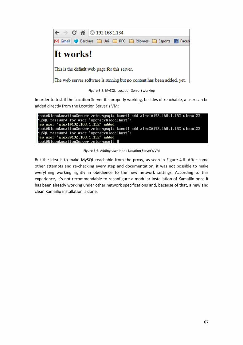
67
Figure B.5: MySQL (Location Server) working
In order to test if the Location Server it’s properly working, besides of reachable, a user can be
added directly from the Location Server’s VM:
Figure B.6: Adding user in the Location Server’s VM
But the idea is to make MySQL reachable from the proxy, as seen in Figure 4.6. After some
other attempts and re-checking every step and documentation, it was not possible to make
everything working rightly in obedience to the new network settings. According to this
experience, it’s not recommendable to reconfigure a modular installation of Kamailio once it
has been already working under other network specifications and, because of that, a new and
clean Kamailio installation is done.

68
C. RSSI Conversion Methods
The conversion of a RSSI value, reported by the PHY of a NIC to a non-relative value measured
in mW or dBm, is basically a two-step approach. Most vendors have different RSSI MAX values.
Those values have to be multiplied with the percentage – which is related to the RSSI MAX.
This value has to be mapped on a vendor and NIC specific table, to get a referring dBm value.
Those values are linear in all cases, which is related to the logarithmic nature of dBm.
Note: The conversion tables do not only vary with the vendor but also with the NIC series. The
following tables are based on the results of [23].
Conversion for Atheros
Atheros does not provide a table to convert from RSSI-value to dBm. Instead a short algorithm
is provided: RSSI Max = 60
• Convert % to RSSI
• Subtract 95 from RSSI to derive dBm
Note: The range of the dBm values is between -35dBm (at 100%) and -95dBm at (0%)
Conversion for Cisco
Cisco has the most granular dBm lookup table due to the largest RSSI MAX value.
RSSI Max = 100.
To get a value in dBm the table in the following needs to be applied. Referring to table 3 the
RSSI is on the left, and the corresponding dBm value (a negative number) is on the right.

69
Figure C.1: RSSI Conversion Table

70
D. Code
a. RSSIMonitor
/* * RSSIMonitor.c * * Created on: 14.09.2009 * Author: Christian Lottermann * * Modified on: July 2013 * By Alexandre Nin Sadurni * * * License: This program is free software; you can redistribute it and/or modify * it under the terms of the GNU General Public License version 3 as * published by the Free Software Foundation. * See http://www.gnu.org/copyleft/gpl.html for more details. * Comment: This program is the PoA-MIHF and responsible for * performing a Get_Selfinformation_request and for forwarding the * data to the MIIS. In a second thread a forwarding engine is
implemented * to forward the structures from MN or MIIS to the target entities. * Note: The server is in the old_packages/POA_L2 */ #include "include/common.h" #include "include/wpa_ctrl.h" #include "include/os.h" #include "include/includes.h" #include "include/common.h" #include "include/mih_requirements.h" #include "include/iwlib.h" #include "include/wpa_ctrl.h" #include <string.h> /* Include for Socket connection*/ #include <errno.h> #include <sys/types.h> #include <sys/socket.h> #include <sys/un.h> #define HO_margin 5 static struct wpa_ctrl *ctrl_conn=NULL; //static int wpa_cli_attached = 0; static const char *ctrl_iface_dir = "/var/run/wpa_supplicant"; int printStatus(); int printDone();

71
/** * @params: MIH_PoA_Information* headOne, * MIH_PoA_Information* headTwo * @return: MIH_PoA_Information* */ static MIH_PoA_Information* merge(MIH_PoA_Information* headOne, MIH_PoA_Information* headTwo) { MIH_PoA_Information* headThree; if (headOne == NULL) return headTwo; if (headTwo == NULL) return headOne; if (headOne->rssi < headTwo->rssi) { headThree = headOne; headThree->next = merge(headOne->next, headTwo); } else { headThree = headTwo; headThree->next = merge(headOne, headTwo->next); } return headThree; } /** * mergeSort and merge fulfill the merge sort algorithm implemented for linked lists. * @params: MIH_PoA_Information* head * @return: MIH_PoA_Information* */ static MIH_PoA_Information* mergeSort(MIH_PoA_Information* head) { MIH_PoA_Information* headOne; MIH_PoA_Information* headTwo; if ((head == NULL) || (head->next == NULL)) return head; headOne = head; headTwo = head->next; while ((headTwo != NULL) && (headTwo->next != NULL)) { head = head->next; headTwo = head->next->next; } headTwo = head->next; head->next = NULL; return merge(mergeSort(headOne), mergeSort(headTwo)); } /** * This function embodies the stdout for signaling if the HO was complete. * @param: MIH_PoA_Information* assocedPoA (supposed to be the MIH_L2_Commit.response)

72
* @return: int (for error indication) */ static int actionResponse(MIH_PoA_Information* assocedPoA) { if (assocedPoA == NULL) printf("Something went wrong -> Could not connect to new target PoA!\n"); else { printDone(); char buffer[128]; iw_saether_ntop(&assocedPoA->bssid,buffer); printf( "Everything went all right -> I was able to get associated with: %s\n\n\n HO COMPLETE\n", buffer); } return 0; } static type_ts getTimeMS(void) { struct timeval tv; struct timeval *ptr = malloc(sizeof(struct timeval)); *ptr = tv; printf("vor gettimeofday\n"); gettimeofday(&tv, NULL); time_t timeh = time(NULL); int ms = tv.tv_usec / 1000; free(ptr); printf("end gettimems\n"); return timeh * 1000 + ms; } /*------------------------------------------------------------------*/ /* * Get wireless informations & config from the device driver * We will call all the classical wireless ioctl on the driver through * the socket to know what is supported and to get the settings... */ static int get_info(int skfd, char * ifname, struct wireless_info * info) { struct iwreq wrq; memset((char *) info, 0, sizeof(struct wireless_info)); /* Get basic information */ if(iw_get_basic_config(skfd, ifname, &(info->b)) < 0) {
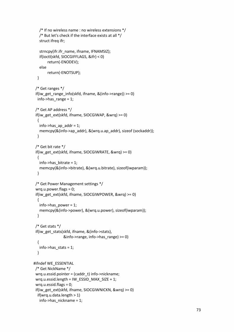
73
/* If no wireless name : no wireless extensions */ /* But let's check if the interface exists at all */ struct ifreq ifr; strncpy(ifr.ifr_name, ifname, IFNAMSIZ); if(ioctl(skfd, SIOCGIFFLAGS, &ifr) < 0) return(-ENODEV); else return(-ENOTSUP); } /* Get ranges */ if(iw_get_range_info(skfd, ifname, &(info->range)) >= 0) info->has_range = 1; /* Get AP address */ if(iw_get_ext(skfd, ifname, SIOCGIWAP, &wrq) >= 0) { info->has_ap_addr = 1; memcpy(&(info->ap_addr), &(wrq.u.ap_addr), sizeof (sockaddr)); } /* Get bit rate */ if(iw_get_ext(skfd, ifname, SIOCGIWRATE, &wrq) >= 0) { info->has_bitrate = 1; memcpy(&(info->bitrate), &(wrq.u.bitrate), sizeof(iwparam)); } /* Get Power Management settings */ wrq.u.power.flags = 0; if(iw_get_ext(skfd, ifname, SIOCGIWPOWER, &wrq) >= 0) { info->has_power = 1; memcpy(&(info->power), &(wrq.u.power), sizeof(iwparam)); } /* Get stats */ if(iw_get_stats(skfd, ifname, &(info->stats), &info->range, info->has_range) >= 0) { info->has_stats = 1; } #ifndef WE_ESSENTIAL /* Get NickName */ wrq.u.essid.pointer = (caddr_t) info->nickname; wrq.u.essid.length = IW_ESSID_MAX_SIZE + 1; wrq.u.essid.flags = 0; if(iw_get_ext(skfd, ifname, SIOCGIWNICKN, &wrq) >= 0) if(wrq.u.data.length > 1) info->has_nickname = 1;

74
if((info->has_range) && (info->range.we_version_compiled > 9)) { /* Get Transmit Power */ if(iw_get_ext(skfd, ifname, SIOCGIWTXPOW, &wrq) >= 0) { info->has_txpower = 1; memcpy(&(info->txpower), &(wrq.u.txpower), sizeof(iwparam)); } } /* Get sensitivity */ if(iw_get_ext(skfd, ifname, SIOCGIWSENS, &wrq) >= 0) { info->has_sens = 1; memcpy(&(info->sens), &(wrq.u.sens), sizeof(iwparam)); } if((info->has_range) && (info->range.we_version_compiled > 10)) { /* Get retry limit/lifetime */ if(iw_get_ext(skfd, ifname, SIOCGIWRETRY, &wrq) >= 0) { info->has_retry = 1; memcpy(&(info->retry), &(wrq.u.retry), sizeof(iwparam)); } } /* Get RTS threshold */ if(iw_get_ext(skfd, ifname, SIOCGIWRTS, &wrq) >= 0) { info->has_rts = 1; memcpy(&(info->rts), &(wrq.u.rts), sizeof(iwparam)); } /* Get fragmentation threshold */ if(iw_get_ext(skfd, ifname, SIOCGIWFRAG, &wrq) >= 0) { info->has_frag = 1; memcpy(&(info->frag), &(wrq.u.frag), sizeof(iwparam)); } #endif /* WE_ESSENTIAL */ return(0); } /*------------------------------------------------------------------*/ /* * Print on the screen in a neat fashion all the info we have collected * on a device. */ static void

75
display_info(struct wireless_info * info, char * ifname, MIH_PoA_Information* connectedPoA) { char buffer[128]; /* Temporary buffer */ /* One token is more of less 5 characters, 14 tokens per line */ int tokens = 3; /* For name */ /* Display device name and wireless name (name of the protocol used) */ // printf("%-8.16s %s ", ifname, info->b.name); /* Display ESSID (extended network), if any */ if(info->b.has_essid) { if(info->b.essid_on) { /* Does it have an ESSID index ? */ if((info->b.essid_on & IW_ENCODE_INDEX) > 1) printf("ESSID:\"%s\" [%d] ", info->b.essid, (info->b.essid_on & IW_ENCODE_INDEX)); else { // printf("ESSID:\"%s\" ", info->b.essid); memcpy(connectedPoA->ssid, info->b.essid, sizeof(info->b.essid)); } } else { strcpy(connectedPoA->ssid,""); connectedPoA->rssi=-100; printf("ESSID:off/any "); } } /* Display the address of the current Access Point */ if(info->has_ap_addr) { /* A bit of clever formatting */ if(tokens > 8) { // printf("\n "); tokens = 0; } tokens +=6; /* Oups ! No Access Point in Ad-Hoc mode */ if((info->b.has_mode) && (info->b.mode == IW_MODE_ADHOC)) printf("Cell:"); else {

76
strcpy(connectedPoA->ssid,""); connectedPoA->rssi=-100; // printf("Access Point:"); } printf(" %s ", iw_sawap_ntop(&info->ap_addr, buffer)); // sockaddr2bssid(iw_sawap_ntop(&info->ap_addr, buffer),connectedPoA->mihfID); sockaddr2bssid(&info->ap_addr,connectedPoA->mihfID); } #ifndef WE_ESSENTIAL /* Display sensitivity */ if(info->has_sens) { /* A bit of clever formatting */ if(tokens > 10) { // printf("\n "); tokens = 0; } tokens +=4; /* Fixed ? */ // printf("Sensitivity%c", info->sens.fixed ? '=' : ':'); if(info->has_range) /* Display in dBm ? */ if(info->sens.value < 0) { // printf("%d dBm ", info->sens.value); connectedPoA->rssi = info->sens.value; } // else // printf("%d/%d ", info->sens.value, info->range.sensitivity); // else // printf("%d ", info->sens.value); } #endif /* WE_ESSENTIAL */ /** * This function writes IEs about the connected PoA to the linked list. * @param: PoA_Information** headRef * @return: int for error indication */ static int connectedPoA(char *ifname, MIH_PoA_Information* connectedPoA) { int skfd; /* Create a channel to the NET kernel. */ if((skfd = iw_sockets_open()) < 0) {

77
perror("socket"); return -1; } /* formerly: print_info(skfd, ifname, NULL, 0); */ struct wireless_info info; int rc; /* Avoid "Unused parameter" warning */ //args = args; count = count; rc = get_info(skfd, ifname, &info); /* content of info -> poa */ switch(rc) { case 0: /* Success */ /* Display it ! */ display_info(&info, ifname, connectedPoA); //connectedPoA->bssid = info.ap_addr; //connectedPoA->rssi = info.; break; case -ENOTSUP: fprintf(stderr, "%-8.16s no wireless extensions.\n\n", ifname); break; default: fprintf(stderr, "%-8.16s %s\n\n", ifname, strerror(-rc)); } /* Close the socket. */ iw_sockets_close(skfd); return(rc); } MIH_PoA_Information* getSuitPoA(MIH_PoA_Information* headPoA,int cse) { MIH_PoA_Information* returnPoA=NULL; int connected,otherconnected; MIH_PoA_Information *connectedPoA1=NULL; connectedPoA1 = (MIH_PoA_Information*)malloc(sizeof(MIH_PoA_Information)); MIH_PoA_Information *otherconnectedPoA1=NULL; otherconnectedPoA1 = (MIH_PoA_Information*)malloc(sizeof(MIH_PoA_Information)); printf("connected PoA info\n"); if(cse==0) { connected = connectedPoA(IFNAME0,connectedPoA1); printf("%s %d",connectedPoA1->ssid,connectedPoA1->rssi); otherconnected = connectedPoA(IFNAME1,otherconnectedPoA1); printf("%s %d",otherconnectedPoA1->ssid,otherconnectedPoA1->rssi); }

78
else { connected = connectedPoA(IFNAME1,connectedPoA1); printf("%s %d",connectedPoA1->ssid,connectedPoA1->rssi); otherconnected = connectedPoA(IFNAME0,otherconnectedPoA1); printf("%s %d",otherconnectedPoA1->ssid,otherconnectedPoA1->rssi); } MIH_PoA_Information* tempheadPoA; mergeSort(headPoA); // if(connected == 0) // printf("connected searching for a better to handover\n"); // else // printf("trying to connect for first time\n"); tempheadPoA=headPoA; while(tempheadPoA) { if(((strcmp(tempheadPoA->ssid,"GLABAP5")==0)||(strcmp(tempheadPoA->ssid,"GLABAP4")==0)||(strcmp(tempheadPoA->ssid,"GLABAP3")==0)||(strcmp(tempheadPoA->ssid,"GLABAP2")==0)||(strcmp(tempheadPoA->ssid,"GLABAP1")==0)))//&&(strcmp(tempheadPoA->ssid,connectedPoA1->ssid)!=0)&&(tempheadPoA->rssi > connectedPoA1->rssi)) { if((tempheadPoA->rssi > otherconnectedPoA1->rssi)&&(strcmp(tempheadPoA->ssid,otherconnectedPoA1->ssid)!=0)) { printf("%s\t",tempheadPoA->ssid); free(connectedPoA1); return tempheadPoA; } } tempheadPoA=tempheadPoA->next; } free(connectedPoA1); return returnPoA; } static void wpa_cli_msg_cb(char *msg, size_t len) { //printf("%s\n", msg); } static int ctrlCommand(struct wpa_ctrl *ctrl, char *cmd) { char buf[2048]; size_t len; int ret; if (ctrl == NULL) { printf("Not connected to wpa_supplicant - command dropped.\n"); return -1; } len = sizeof(buf) - 1; ret = wpa_ctrl_request(ctrl, cmd, os_strlen(cmd), buf, &len, wpa_cli_msg_cb);// declared in wpa_ctrl.h

79
printf("ctrlCommand: %s\n", cmd); if (ret == -2) { printf("'%s' command timed out.\n", cmd); return -2; } else if (ret < 0) { printf("'%s' command failed.\n", cmd); return -1; } buf[len] = '\0'; // prints the response from wpa_ctrl_request if (!strncmp(cmd, "ADD_NETWORK", 11)) { return atoi(buf); } else return 0; } /** * This functions sets the values of the new network and returns 0 if everything performed correctly and * a negative int-value if something went wrong. * @param: struct wpa_ctrl *ctrl: self-explaning * int nwid: id of the recently added network, returned from add_network * char* ssid, char* bssid, char* key_mgmt, char* psk: properties of the new network to be set * @return: int for error indication */ static int setNewPoA(struct wpa_ctrl *ctrl, int nwid, char* ssid, char* bssid, char* key_mgmt, char* psk) { char cmdbuf[256]; sprintf(cmdbuf, "SET_NETWORK %d ssid \"%s\"", nwid, ssid); if (ctrlCommand(ctrl, cmdbuf) < 0) { fprintf(stderr, "ctrlCommand: could not set 'ssid'\n"); return -1; } sprintf(cmdbuf, "SET_NETWORK %d bssid %s", nwid, bssid); if (ctrlCommand(ctrl, cmdbuf) < 0) { fprintf(stderr, "ctrlCommand: could not set 'bssid'\n"); return -2; } sprintf(cmdbuf, "SET_NETWORK %d key_mgmt %s", nwid, key_mgmt); if (ctrlCommand(ctrl, cmdbuf) < 0) { fprintf(stderr, "ctrlCommand: could not set 'key_mgmt'\n"); return -3; } sprintf(cmdbuf, "SET_NETWORK %d psk \"%s\"", nwid, psk); if (ctrlCommand(ctrl, cmdbuf) < 0) { fprintf(stderr, "ctrlCommand: could not set 'psk'\n"); return -4; } return 0; }

80
static int removePoA(struct wpa_ctrl *ctrl, int nwid) { char cmd[32]; sprintf(cmd, "REMOVE_NETWORK %d", nwid); cmd[sizeof(cmd) - 1] = '\0'; return ctrlCommand(ctrl, cmd); } /** * Function to select a poa; * performed when a "select_network" command is done * @param: struct wpa_ctrl *ctr, self-explaining * int nwid: id of the network to be selected * @return: int for error indication */ static int selectNewPoA(struct wpa_ctrl *ctrl, int nwid) { char cmd[32]; //int res; sprintf(cmd, "SELECT_NETWORK %d", nwid); cmd[sizeof(cmd) - 1] = '\0'; return ctrlCommand(ctrl, cmd); } struct wpa_ctrl* openConnection(const char *ifname) { /* in wpa_cli another fucntion for determining the iface-name is defined*/ char *cfile; int flen, res; if (ifname == NULL) { printf("ifname empty\n"); return NULL; } flen = os_strlen(ctrl_iface_dir) + os_strlen(ifname) + 2; cfile = os_malloc(flen); if (cfile == NULL) { printf("cfile empty\n"); return NULL; } res = os_snprintf(cfile, flen, "%s/%s", ctrl_iface_dir, ifname); if (res < 0 || res >= flen) { os_free(cfile); printf("ifname empty\n"); return NULL; } printf("wpa_ctrl_open\n"); ctrl_conn = wpa_ctrl_open(cfile); printf("nach aufruf von wpa_ctrl_open\n"); os_free(cfile); printf("vor return wpa_ctrl_open\n");
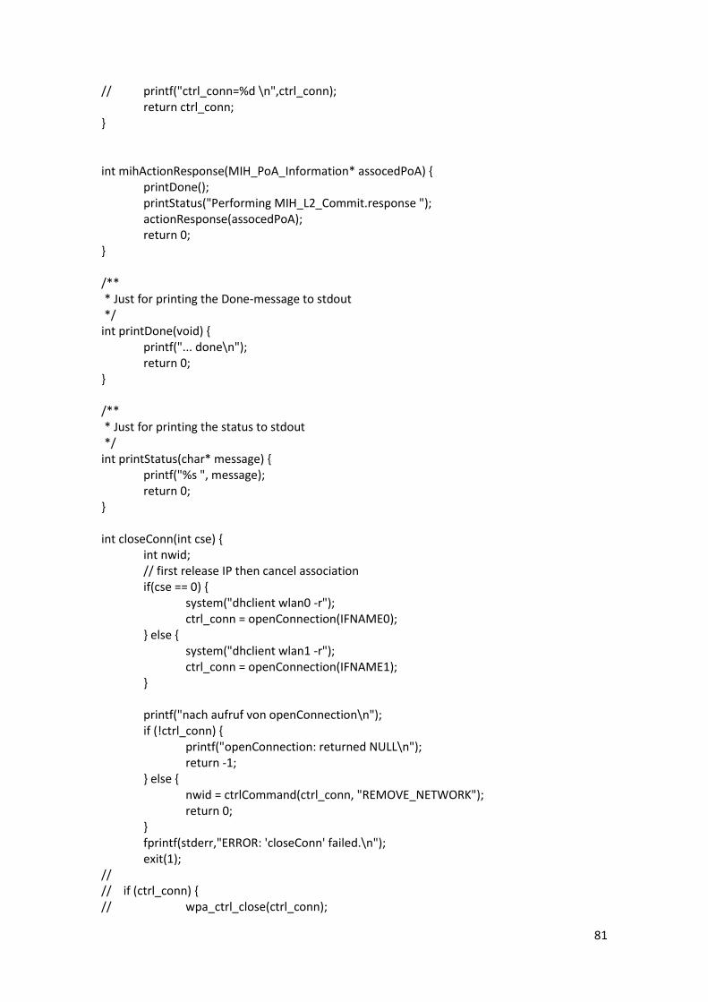
81
// printf("ctrl_conn=%d \n",ctrl_conn); return ctrl_conn; } int mihActionResponse(MIH_PoA_Information* assocedPoA) { printDone(); printStatus("Performing MIH_L2_Commit.response "); actionResponse(assocedPoA); return 0; } /** * Just for printing the Done-message to stdout */ int printDone(void) { printf("... done\n"); return 0; } /** * Just for printing the status to stdout */ int printStatus(char* message) { printf("%s ", message); return 0; } int closeConn(int cse) { int nwid; // first release IP then cancel association if(cse == 0) { system("dhclient wlan0 -r"); ctrl_conn = openConnection(IFNAME0); } else { system("dhclient wlan1 -r"); ctrl_conn = openConnection(IFNAME1); } printf("nach aufruf von openConnection\n"); if (!ctrl_conn) { printf("openConnection: returned NULL\n"); return -1; } else { nwid = ctrlCommand(ctrl_conn, "REMOVE_NETWORK"); return 0; } fprintf(stderr,"ERROR: 'closeConn' failed.\n"); exit(1); // // if (ctrl_conn) { // wpa_ctrl_close(ctrl_conn);

82
// ctrl_conn = NULL; // return 0; // } // else // return -1; } /** * This function performs the re-association with the targetPoA contained * in targetPoA. * @param: MIH_PoA_Information* targetPoA * @return: int for error indication */ int performAssoc(MIH_PoA_Information* targetPoA, int cse) { //printDone(); type_ts tic, toc; int nwid; char bssid[17],sysSTR[20]; int cse2; int ret = 0; /* targetPoA = getSuitPoA(targetPoA,cse); if (targetPoA == NULL) { printf("Could not find a suitable PoA -> closing connection!\n"); mihActionResponse(NULL); return -1; } */ if(cse==0) ctrl_conn = openConnection(IFNAME0); else ctrl_conn = openConnection(IFNAME1); printf("nach aufruf von openConnection\n"); if (!ctrl_conn) { printf("openConnection: returned NULL\n"); return -1; } else { //printf("vor tic\n"); tic = getTimeMS(); printf("target poa details \n"); //printf("vor sockaddr2bssid\n"); //printf("targetPoA->bssid.sa_data set: %s\n",targetPoA->bssid.sa_data); //printf("sizeof(targetPoA->bssid.sa_data): %d\n",sizeof(targetPoA->bssid.sa_data)); memcpy(bssid,targetPoA->bssid.sa_data,sizeof(targetPoA->bssid.sa_data)); sockaddr2bssid(&targetPoA->bssid,bssid); printf("\nbssid: %s\n",bssid); printf("ssid:%s\n",targetPoA->ssid); strcpy(targetPoA->key,"AP_06012010\0"); }

83
nwid = ctrlCommand(ctrl_conn, "ADD_NETWORK"); printf("ADD_NETWORK: %d\n", nwid); printf("SSID: %s\tbssid: %s\tWPA-PSK: %s\n", targetPoA->ssid, bssid, targetPoA->key); // strcpy(targetPoA->mihfID,"00216A7BE720\0");targetPoA->mihfID printf("SET_NETWORK: %d\n", setNewPoA(ctrl_conn, nwid, targetPoA->ssid, bssid, "WPA-PSK", targetPoA->key)); printf("SELECT_NETWORK: %d\n", selectNewPoA(ctrl_conn, nwid)); if(cse == 0) strcpy(sysSTR,"dhclient wlan0"); else strcpy(sysSTR,"dhclient wlan1"); cse2 = cse ^ 1; if( (ret = closeConn(cse2)) < 0){ fprintf(stderr,"ERROR: closing connection with wlan0 failed.\n"); exit(1); } //Close current connection if (!system(sysSTR)) { // Get a IP-address using dhclient printStatus("Performing Link_Perform_Action.response "); //printf("GetT IP address using dhclient ...\n"); toc = getTimeMS(); printf("The L2 and L3 related handover lasted %d ms", (int)(toc-tic)); // mihActionResponse(targetPoA); /* if( (ret = closeConn(cse2)) < 0){ fprintf(stderr,"ERROR: closing connection with wlan0 failed.\n"); exit(1); } //Close current connection */ } else { printf("dhclient: something went wrong"); // mihActionResponse(NULL); return -1; } return 0; } /*int performDEAssoc(int cse) { PoA_Information *connectedPoA1=NULL; int nwid; connectedPoA1 = (PoA_Information*)malloc(sizeof(PoA_Information)); if(cse==0) { ctrl_conn = openConnection(IFNAME0); connectedPoA(IFNAME0,connectedPoA1);

84
} else { ctrl_conn = openConnection(IFNAME1); connectedPoA(IFNAME1,connectedPoA1); } printf("nach aufruf von openConnection\n"); if (!ctrl_conn) { printf("openConnection: returned NULL\n"); return -1; } else { nwid = ctrlCommand(ctrl_conn, "REMOVE_NETWORK"); removePoA(ctrl_conn,nwid); } return 0; }*/ /*GET THE BEST PoA*/ int getbestPoA(MIH_PoA_Information *visit,MIH_PoA_Information *targetPoA, MIH_PoA_Information *result) { MIH_PoA_Information tmp; MIH_PoA_Information *visit2 = visit; if (targetPoA->rssi == 100){ // not connected printf("[getbestPoA] not connected\n"); // MIH_PoA_Information tmp; // strcpy(tmp.mihfID,visit->mihfID); // strcpy(tmp.ssid,visit->ssid); // tmp.rssi = visit->ssid; tmp.rssi = 10; while(visit) { // printf("[getbestPoA] list: visit->ssid: %s\tvisit->mihfID: %s\tvisit->rssi: %d\n",visit->ssid,visit->mihfID,visit->rssi); if (strncmp("GLABAP",visit->ssid,6) == 0) { // printf("[getbestPoA] GLABAP found: visit->ssid: %s\tvisit->mihfID: %s\tvisit->rssi: %d\n",visit->ssid,visit->mihfID,visit->rssi); if(tmp.rssi == 10 ) { tmp.rssi = visit->rssi; strcpy(tmp.mihfID,visit->mihfID); strcpy(tmp.ssid,visit->ssid); printf("[FIRST GLABAP FOUND]: tmp.mihfID: %s\tvisit->mihfID: %s\ttmp.ssid: %s\n",tmp.mihfID,visit->mihfID,tmp.ssid); } if(tmp.rssi < visit->rssi) { printf("[getbestPoA] if tmp.mihfID: %s\tvisit->mihfID: %s\n",tmp.mihfID,visit->mihfID);

85
tmp.rssi = visit->rssi; strcpy(tmp.mihfID,visit->mihfID); strcpy(tmp.ssid,visit->ssid); printf("[getbestPoA] after tmp.ssid: %s\ttmp.mihfID: %s\ttmp.rssi: %d\n",tmp.ssid,tmp.mihfID,tmp.rssi); } if(visit->next==NULL) { printf("THE BEST , next null = after tmp.mihfID: %s\ttmp.rssi: %d\n",tmp.mihfID,tmp.rssi); } } visit = visit->next; } printf("[getbestPoA] end tmp.ssid: %s\ttmp.mihfID: %s\ttmp.rssi: %d\n",tmp.ssid,tmp.mihfID,tmp.rssi); printf("[BESTPoA] tmp.mihfID: %s\n",tmp.mihfID); strcpy(result->mihfID, tmp.mihfID); strcpy(result->ssid, tmp.ssid); result->rssi = tmp.rssi; //targetPoA = result; // now connect to best GLABAP targetPoA->rssi = tmp.rssi; strcpy(targetPoA->mihfID, tmp.mihfID); strcpy(targetPoA->ssid, tmp.ssid); printf("new connection found: targetPoA->ssid: %s\ttargetPoA->mihfID: %s\ttargetPoA->rssi: %d\n",targetPoA->ssid,targetPoA->mihfID,targetPoA->rssi); return 0; } else { printf("\n[getbestPoA] connected case\n"); printf("connected with %s\tmihfID: %s\trssi: %d\n",targetPoA->ssid,targetPoA->mihfID,targetPoA->rssi); while(visit) { printf("[getbestPoA] list: visit->ssid: %s\tvisit->mihfID: %s\tvisit->rssi: %d\n",visit->ssid,visit->mihfID,visit->rssi); if(strcmp(visit->mihfID,targetPoA->mihfID) == 0){ //strcpy(targetPoA->ssid,visit->ssid); // UPDATE OF CONNECTED PoA printf("\nupdate of current conn.: %s: prev. rssi: %d\t",targetPoA->mihfID,targetPoA->rssi); targetPoA->rssi=visit->rssi; tmp.rssi = targetPoA->rssi; strcpy(tmp.mihfID,targetPoA->mihfID); strcpy(tmp.ssid,targetPoA->ssid); printf("new rssi: %d\n",visit->rssi); break; } visit=visit->next; } printf("[getbestPoA] GLABAP found: visit->ssid: %s\tvisit->mihfID: %s\tvisit->rssi: %d\n",visit2->ssid,visit2->mihfID,visit2->rssi);

86
// printf("[FIRST GLABAP FOUND]: tmp.mihfID: %s\tvisit->mihfID: %s\ttmp.ssid: %s\n",tmp.mihfID,visit->mihfID,tmp.ssid); // // printf("[FIRST ONE]: %s\tvisit->mihfID: %s\n",tmp.mihfID,visit->mihfID); // // } if(tmp.rssi < visit2->rssi) { // printf("[getbestPoA] if tmp.mihfID: %s\tvisit->mihfID: %s\n",tmp.mihfID,visit->mihfID); tmp.rssi = visit2->rssi; strcpy(tmp.mihfID,visit2->mihfID); strcpy(tmp.ssid,visit2->ssid); printf("[getbestPoA] better GLABAP FOUND: tmp.ssid: %s\ttmp.mihfID: %s\ttmp.rssi: %d\n",tmp.ssid,tmp.mihfID,tmp.rssi); } if(visit2->next==NULL) { printf("THE BEST , next null = after tmp.mihfID: %s\ttmp.rssi: %d\n",tmp.mihfID,tmp.rssi); } } visit2 = visit2->next; } printf("[getbestPoA] end tmp.ssid: %s\ttmp.mihfID: %s\ttmp.rssi: %d\n",tmp.ssid,tmp.mihfID,tmp.rssi); printf("[BESTPoA] tmp.mihfID: %s\n",tmp.mihfID); strcpy(result->mihfID, tmp.mihfID); strcpy(result->ssid, tmp.ssid); result->rssi = tmp.rssi; return 0 ; } } void check_HO(MIH_PoA_Information* targetPoA, MIH_PoA_Information* tmpPoA, int* HO_ind) { printf("[check_HO] tmpPoA: %d - targetPoA %d > %d\n",tmpPoA->rssi,targetPoA->rssi, HO_margin); // if( (abs(tmpPoA->rssi - targetPoA->rssi) > HO_margin) && (tmpPoA->rssi > targetPoA->rssi)) { if (strcmp(tmpPoA->mihfID,targetPoA->mihfID) != 0 ) { if( ((tmpPoA->rssi - targetPoA->rssi) > HO_margin) ) { printf("HO condition satisfied.\n"); *HO_ind += 1; } } else // reset HO indicator *HO_ind = 0; printf("[check_HO] HO NEW VALUE IS: %d \n",*HO_ind); }

87
/* SEND Message to UA that HO has started */ /* use this function just before performAssoc is started */ void send_HO_starting_in(){ int sockfd; struct sockaddr_in servaddr; char sendline[8]="301"; sockfd=socket(AF_INET,SOCK_DGRAM,0); bzero((char *) &servaddr,sizeof(servaddr)); servaddr.sin_family = AF_INET; servaddr.sin_addr.s_addr=inet_addr("127.0.0.1"); servaddr.sin_port=htons(5000); if(sendto(sockfd,sendline,strlen(sendline),0,&servaddr,sizeof(servaddr)) == -1){ perror("send error"); exit(1); } close(sockfd); } int open_AF_INET_socket(char *buffer){ int sockfd, newsockfd, portno; socklen_t clilen; struct sockaddr_in serv_addr, cliaddr; int n; /* creates a new socket */ sockfd = socket(AF_INET, SOCK_DGRAM, 0); if (sockfd < 0) error("ERROR opening socket"); /* configure addresses */ bzero((char *) &serv_addr, sizeof(serv_addr)); portno = 5001; serv_addr.sin_family = AF_INET; serv_addr.sin_addr.s_addr = INADDR_ANY; serv_addr.sin_port = htons(portno); /*bind a socket to an address*/

88
if (bind(sockfd, &serv_addr,sizeof(serv_addr)) < 0) error("ERROR on binding"); clilen = sizeof(cliaddr); bzero(buffer,8); /*wait until receives a Handover notification*/ n = recvfrom(sockfd,buffer,8,0,&cliaddr,&clilen); close(sockfd); return(n); } void send_HO_done_in() { int sockfd; struct sockaddr_in servaddr; char sendline[8]="501"; sockfd=socket(AF_INET,SOCK_DGRAM,0); bzero((char *) &servaddr,sizeof(servaddr)); servaddr.sin_family = AF_INET; servaddr.sin_addr.s_addr=inet_addr("127.0.0.1"); servaddr.sin_port=htons(5000); if(sendto(sockfd,sendline,strlen(sendline),0,&servaddr,sizeof(servaddr)) == -1){ perror("send error"); exit(1); } close(sockfd); } ///* ////#include "include/iwlib.h" ////static type_ts getTimeMS(void); //#include "include/wireless_tools.h" //*/ /** * RSSIMonitor main function */ int main(int argc, char* argv[]) { printf("RSSIMonitor Wlan0 started.\n\n"); int ret = 0, HO_ind = 0, onStart = 0, scanFlag = 0; char ipv4[16]=""; // including '\0' char mihfID[13]; char buff[8]; MIH_PoA_Information *head_PoAs = NULL; // MIH_PoA_Information *visit_PoAs1 = NULL; // MIH_PoA_Information *visit_PoAs2 = NULL;

89
if(getMIHFId(mihfID,0) != 0) perror("getMIHFId"); if(getIfIP(IFNAME0,ipv4) != 0) perror("getIfIP"); printf("mihfID: %s\tipv4: %s\n",mihfID,ipv4); /* if( (ret = listScanPoALl(IFNAME0,&head_PoAs)) < 0) perror("[ERROR] listScanPoALl"); visit_PoAs1 = head_PoAs; visit_PoAs2 = head_PoAs; while(visit_PoAs1) { printf("[RSSIMonitor] visit_assoc->mihfID = %s\n",visit_PoAs1->mihfID); visit_PoAs1 = visit_PoAs1->next; } /* Create and validate XML and send it to CxB */ //if(xmlSend2Server(mihfID,ipv4,visit_PoAs2) < 0) //perror("ERROR: xmlSend2Server failed!\n"); /* printf("RSSIMonitor wlan0 finished.\n"); printf("***************************************************\n"); printf("RSSIMonitor Wlan1 started.\n\n"); int ret1 = 0; char ipv41[16]=""; // including '\0' char mihfID1[13]; MIH_PoA_Information *head_PoAs1 = NULL; MIH_PoA_Information *visit_PoAs = NULL; MIH_PoA_Information *visit_PoAs21 = NULL; if(getMIHFId(mihfID1,1) != 0) perror("getMIHFId"); if(getIfIP(IFNAME1,ipv41) != 0) perror("getIfIP"); printf("mihfID1: %s\tipv4: %s\n",mihfID1,ipv41); if( (ret1 = listScanPoALl(IFNAME1,&head_PoAs1)) < 0) perror("[ERROR] listScanPoALl"); visit_PoAs = head_PoAs1; visit_PoAs21 = head_PoAs1; char returnstring[1024]=""; while(visit_PoAs) { char buffer[20]; strcat(returnstring,visit_PoAs->mihfID); strcat(returnstring,","); strcat(returnstring,visit_PoAs->ssid); strcat(returnstring,","); sprintf(buffer,"%d",visit_PoAs->rssi); strcat(returnstring,buffer);

90
strcat(returnstring,","); sprintf(buffer,"%d",visit_PoAs->channel); strcat(returnstring,buffer); strcat(returnstring,","); sprintf(buffer,"%lld",visit_PoAs->timestamp); strcat(returnstring,buffer); strcat(returnstring,","); strcat(returnstring,"\n"); // printf("[RSSIMonitor] visit_assoc->mihfID = %s\n",visit_PoAs->mihfID); // printf("[RSSIMonitor] visit_assoc->ssid = %s\n",visit_PoAs->ssid); // printf("[RSSIMonitor] visit_assoc->rssi = %d\n",visit_PoAs->rssi); // printf("[RSSIMonitor] visit_assoc->channel = %d\n",visit_PoAs->channel); //printf("[RSSIMonitor] visit_assoc->timestamp = %I64d\n",visit_PoAs->timestamp); visit_PoAs = visit_PoAs->next; } printf("%s",returnstring); /* Create and validate XML and send it to CxB */ //if(xmlSend2Server(mihfID1,ipv41,visit_PoAs21) < 0) //perror("ERROR: xmlSend2Server failed!\n"); /* printf("RSSIMonitor WLan 1 finished.\n"); */ // check whether connected MIH_PoA_Information *visit_PoAs; int connected, otherconnected; MIH_PoA_Information *connectedPoA1 = NULL; connectedPoA1 = (MIH_PoA_Information*) malloc(sizeof(MIH_PoA_Information)); MIH_PoA_Information *otherconnectedPoA1 = NULL; otherconnectedPoA1 = (MIH_PoA_Information*) malloc(sizeof(MIH_PoA_Information)); visit_PoAs = (MIH_PoA_Information*) malloc(sizeof(MIH_PoA_Information)); MIH_PoA_Information *head_PoAs123 = NULL; MIH_PoA_Information *visit_PoAs2123 = NULL; MIH_PoA_Information *currentPoA = NULL; currentPoA = (MIH_PoA_Information*) malloc(sizeof(MIH_PoA_Information)); currentPoA->rssi = 100; MIH_PoA_Information tmpPoA, memPoA, *result; result = (MIH_PoA_Information*) malloc(sizeof(MIH_PoA_Information)); connected = connectedPoA(IFNAME0, connectedPoA1); printf("connectedPoA: 0: %s %d",connectedPoA1->ssid, connectedPoA1->rssi); otherconnected = connectedPoA(IFNAME1, otherconnectedPoA1);

91
printf("connectedPoA: 1: %s %d",otherconnectedPoA1->ssid, otherconnectedPoA1->rssi); printf("\nTrying the scenario\n"); printf("connected: %d\totherconnected: %d\n",connected,otherconnected); if(onStart == 0) { if( (connected) || (otherconnected)) { if((connected) && (otherconnected)) { // connected with both, close wlan1 printf("connected with both cards\n"); if( (ret = closeConn(1)) < 0) { fprintf(stderr,"ERROR: closing connection with 'wlan1' failed.\n"); exit(1); } scanFlag = 1; } if (connected) {// wlan0 connected printf("connected with 'wlan0'\n"); scanFlag = 1; } if (otherconnected) {// wlan1 connected printf("connected with 'wlan0'\n"); scanFlag = 0; } } else { // not connected, find best AP printf("Not connected, start scan\n"); if( (ret = listScanPoALl(IFNAME0,&head_PoAs123)) < 0) perror("[ERROR] listScanPoALl"); // performAssoc(&head_PoAs123,1); visit_PoAs2123=head_PoAs123; visit_PoAs = head_PoAs123; while(visit_PoAs) { /* char buffer[20]; strcat(returnstring,visit_PoAs->mihfID); strcat(returnstring,","); strcat(returnstring,visit_PoAs->ssid); strcat(returnstring,","); sprintf(buffer,"%d",visit_PoAs->rssi); strcat(returnstring,buffer); strcat(returnstring,","); sprintf(buffer,"%d",visit_PoAs->channel); strcat(returnstring,buffer); strcat(returnstring,","); sprintf(buffer,"%lld",visit_PoAs->timestamp); strcat(returnstring,buffer); strcat(returnstring,","); strcat(returnstring,"\n"); */ printf("[RSSIMonitor] visit_assoc->mihfID = %s\n",visit_PoAs->mihfID);

92
printf("[RSSIMonitor] visit_assoc->ssid = %s\n",visit_PoAs->ssid); printf("[RSSIMonitor] visit_assoc->rssi = %d\n",visit_PoAs->rssi); printf("[RSSMonitor] visit_assoc->channel = %d\n",visit_PoAs->channel); //printf("[RSSIMonitor] visit_assoc->timestamp = %I64d\n",visit_PoAs->timestamp); visit_PoAs = visit_PoAs->next; } // identify best AP //******************************************TO ANDREAS KLEIN:********************************************************************************// // So, the "connect" first time is NULL, since this will be pointer to the connected node, so we can update it in future. // // result will give us the best result from the list // - I get lost after we changed those pointers....the connect and result are something wrong... //************************************************************************************************************************** // if (currentPoA != NULL) { // printf("' (currentPoA != NULL)'\n"); // exit(1); // } while (strncmp(currentPoA->ssid,"GLABAP",6) != 0) { if((ret = getbestPoA(visit_PoAs2123,currentPoA,result)) < 0) { fprintf(stderr,"ERROR: get first AP failed.\n"); exit(1); } } if( (ret = performAssoc(result,0)) < 0 ) { fprintf(stderr,"ERROR: performAssoc failed.\n"); exit(1); } scanFlag = 1; } printf("\nFIRST CONNECTION ESTABLISHED with %s\n",result->ssid); printf("\nresult->ssid %s\trssi: %d\n",result->ssid,result->rssi); printf("\ncurrentPoA->ssid %s\trssi: %d\n",currentPoA->ssid,currentPoA->rssi); //performAssoc(visit_PoAs2123,1); head_PoAs123 = NULL; //scanFlag=1; } printf("***********Start Swapping Mechanism************* \n\n"); printf("************************************************ \n\n"); while(1) { if(scanFlag == 1) { printf("***********Start Search for WLAN 1************* \n\n"); while(HO_ind < 2) { if( (ret = listScanPoALl(IFNAME1,&head_PoAs123)) < 0)

93
perror("[ERROR] RSSIMonitor: listScanPoALl wlan1\n"); visit_PoAs2123 = head_PoAs123; head_PoAs123 = NULL; //not to add results to the list non-stop ????????? or not ??? ret = getbestPoA(visit_PoAs2123,currentPoA,result); if(ret == -1) { currentPoA == NULL; fprintf(stderr,"ERROR: WE LOST CONNECTION DURING SWAPPING MECHANISM.\n"); exit(1); // break; // The ID of PoA that we should be connected with doesn't exist on the list } // check whether tmpPoA satisfies HO condition check_HO(currentPoA,result,&HO_ind); // save best PoA that satisfies HO condition if (HO_ind == 1){ strcpy(memPoA.mihfID,result->mihfID); strcpy(memPoA.ssid,result->ssid); memPoA.rssi = result->rssi; printf("wlan1: 'HO_ind == 1': %s\n",result->ssid); } } /* end of 'while(HO_ind < TTT)' */ printf("wlan1: WE LEFT WHILE LOOOOOOOOP = HO=2 \n"); send_HO_starting_in(); // Here a HO notification is sent to SIP client to freeze the communication !!! open_AF_INET_socket(&buff); // Client sends OK if (strcmp(buff,"200")!=0) error("ERROR HO data: content not expected"); else printf("\n SIP session on HOLD, waiting to finish HO\n"); // check whether whether new and memorised AP are identical and initiate HO if (strcmp(memPoA.mihfID, result->mihfID) == 0) { //head_PoAs123 = NULL; if( (ret = performAssoc(result,1)) == 0) { scanFlag = 0; HO_ind = 0; //currentPoA = result; // remember the new connected one strcpy(currentPoA->mihfID,result->mihfID); strcpy(currentPoA->ssid,result->ssid); currentPoA->rssi=result->rssi;

94
send_HO_done_in(); // HO performed notification to SIP Client sent to re-initiate session !!! } else { fprintf(stderr,"ERROR: performAssoc with 'wlan1' to '%s' failed.\n",result->ssid); exit(1); } } else { printf("ERROR: memorised and candidate AP are not identical!\nContinue scanning with 'wlan1'.\n"); printf("memPoA.mihfID: %s\tresult->mihfID: %s\n",memPoA.mihfID, result->mihfID); // printf("We correctly changed the connection, and we should start WLAN1 Scan \n\n"); // connect=result; // to remember the new connected one scanFlag = 1; HO_ind = 0; } } /* end of 'if(scanFlag == 1)' */ if(scanFlag == 0) { printf("***********Start Search for WLAN 0************* \n\n"); while(HO_ind < 2) { if( (ret = listScanPoALl(IFNAME0,&head_PoAs123)) < 0) perror("[ERROR] RSSIMonitor: listScanPoALl wlan0\n"); visit_PoAs2123 = head_PoAs123; head_PoAs123=NULL; ret = getbestPoA(visit_PoAs2123,currentPoA,result); if(ret < 0) { fprintf(stderr,"ERROR: WE LOST CONNECTION DURING SWAPPING MECHANISM.\n"); exit(1); } // check whether tmpPoA satisfies HO condition check_HO(currentPoA,result,&HO_ind); // save best PoA that satisfies HO condition if (HO_ind == 1) { strcpy(memPoA.mihfID,result->mihfID); strcpy(memPoA.ssid,result->ssid); memPoA.rssi=result->rssi; printf("wlan0: 'HO_ind == 1': %s\n",result->ssid); } } /* end of 'while(HO_ind < TTT)' */ printf("wlan0: WE LEFT WHILE LOOOOOOOOP = HO=2 \n");

95
send_HO_starting_in(); // Here a HO notification is sent to SIP client to freeze the communication !!! open_AF_INET_socket(&buff); // Client sends OK if (strcmp(buff,"200")!=0) error("ERROR HO data: content not expected"); // check whether whether new and memorised AP are identical and initiate HO if (strcmp(memPoA.mihfID, result->mihfID) == 0) { //head_PoAs123 = NULL; if(strncmp(result->mihfID,"0000",4) == 0) { fprintf(stderr,"mihfID '%s' not valid\n",result->mihfID); exit(1); } if( (ret = performAssoc(result,0)) == 0) { scanFlag = 1; HO_ind = 0; //currentPoA = result; // remember the new connected one currentPoA->rssi = result->rssi; strcpy(currentPoA->mihfID,result->mihfID); strcpy(currentPoA->ssid,result->ssid); send_HO_done_in(); // HO performed notification to SIP Client sent to re-initiate session !!! } else { fprintf(stderr,"ERROR: performAssoc with 'wlan0' to '%s' failed.\n",result->ssid); exit(1); } } else { printf("ERROR: memorised and candidate AP are not identical!\nContinue scanning with 'wlan1'.\n"); printf("memPoA.mihfID: %s\tresult->mihfID: %s\n",memPoA.mihfID, result->mihfID); // printf("We correctly changed the connection, and we should start WLAN1 Scan \n\n"); // connect=result; // to remember the new connected one scanFlag = 0; HO_ind = 0; }

96
} /* end of 'if(scanFlag == 0)' */ if ((scanFlag != 0) && (scanFlag != 1)) { fprintf(stderr,"Error, 'scanFlag' has not appropriate value ... 'scanFlag' set to value 1\n"); scanFlag=1; } } return 0; }

97
b. Simple_pjsua (SIP UA)
* This program is free software; you can redistribute it and/or modify
* it under the terms of the GNU General Public License as published by
* the Free Software Foundation; either version 2 of the License, or
* (at your option) any later version.
/**
* simple_pjsua.c
*
* This is a very simple but fully featured SIP user agent, with the
* following capabilities:
* - SIP registration
* - Making and receiving call
* - Audio to sound device.
* - Incoming calls will automatically be answered with 200.
* This program will quit once it has completed a single call.
*/
#include <pjsua-lib/pjsua.h>
#include <pjsua-lib/pjsua_internal.h>
#include <stdio.h>
#include <sys/types.h>
#include <sys/socket.h>
#include <netinet/in.h>
#include <rpid.h>
#include <signal.h>
#define THIS_FILE "APP"
#define HAND_OVER_GO "301"

98
#define HAND_OVER_DONE "501"
#define SIP_DOMAIN "192.168.1.178"
#define SIP_USER "alex0"
#define SIP_PASSWD "wicon123"
#define IF_NAMESIZE 16
#define SIOCGIFHWADDR 0x8927 /* Get hardware address*/
#define SIOCGIFADDR 0x8915 /* get PA address*/
#define IFNAME0 "wlan0"
#define IFNAME1 "wlan1"
#define ifr_name ifr_ifrn.ifrn_name /* interface name */
#define ifr_addr ifr_ifru.ifru_addr /* IP address */
#define ifr_hwaddr ifr_ifru.ifru_hwaddr /* MAC address */
struct ifreq
{
# define IFHWADDRLEN 6
# define IFNAMSIZ IF_NAMESIZE
union
{
char ifrn_name[IFNAMSIZ]; /* Interface name, e.g. "en0". */
} ifr_ifrn;
union
{
struct sockaddr ifru_addr;
struct sockaddr ifru_dstaddr;
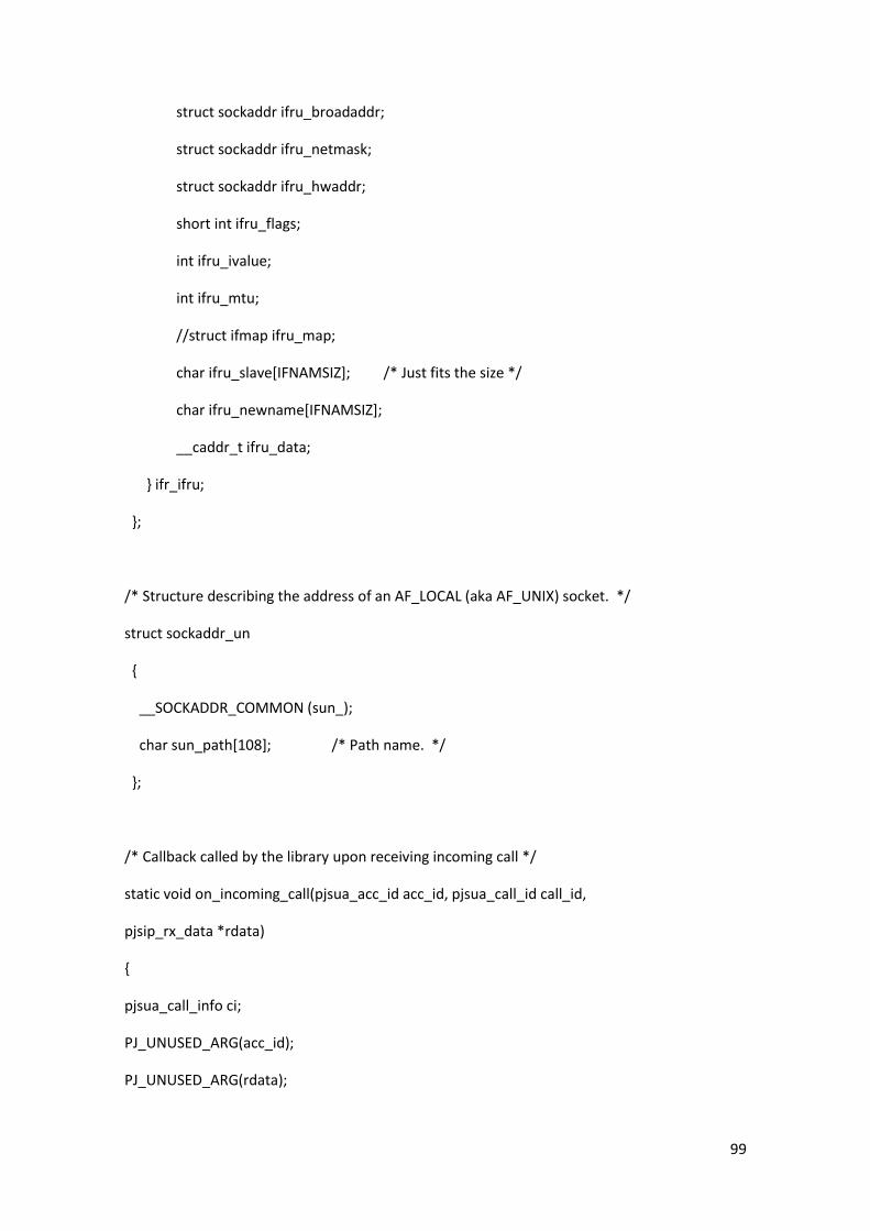
99
struct sockaddr ifru_broadaddr;
struct sockaddr ifru_netmask;
struct sockaddr ifru_hwaddr;
short int ifru_flags;
int ifru_ivalue;
int ifru_mtu;
//struct ifmap ifru_map;
char ifru_slave[IFNAMSIZ]; /* Just fits the size */
char ifru_newname[IFNAMSIZ];
__caddr_t ifru_data;
} ifr_ifru;
};
/* Structure describing the address of an AF_LOCAL (aka AF_UNIX) socket. */
struct sockaddr_un
{
__SOCKADDR_COMMON (sun_);
char sun_path[108]; /* Path name. */
};
/* Callback called by the library upon receiving incoming call */
static void on_incoming_call(pjsua_acc_id acc_id, pjsua_call_id call_id,
pjsip_rx_data *rdata)
{
pjsua_call_info ci;
PJ_UNUSED_ARG(acc_id);
PJ_UNUSED_ARG(rdata);

100
pjsua_call_get_info(call_id, &ci);
PJ_LOG(3,(THIS_FILE, "Incoming call from %.*s!!",(int)ci.remote_info.slen,ci.remote_info.ptr));
/* Automatically answer incoming calls with 200/OK */
pjsua_call_answer(call_id, 200, NULL, NULL);
}
/* Callback called by the library when call's state has changed */
static void on_call_state(pjsua_call_id call_id, pjsip_event *e)
{
pjsua_call_info ci;
PJ_UNUSED_ARG(e);
pjsua_call_get_info(call_id, &ci);
PJ_LOG(3,(THIS_FILE, "Call %d state=%.*s", call_id,(int)ci.state_text.slen,ci.state_text.ptr));
}
/* Callback called by the library when call's media state has changed */
static void on_call_media_state(pjsua_call_id call_id)
{
pjsua_call_info ci;
pjsua_call_get_info(call_id, &ci);
if (ci.media_status == PJSUA_CALL_MEDIA_ACTIVE) {
// When media is active, connect call to sound device.
pjsua_conf_connect(ci.conf_slot, 0);
pjsua_conf_connect(0, ci.conf_slot);
}
}

101
/* Display error and exit application */
static void error_exit(const char *title, pj_status_t status)
{
pjsua_perror(THIS_FILE, title, status);
pjsua_destroy();
exit(1);
}
void error(const char *msg)
{
perror(msg);
pjsua_destroy();
exit(1);
}
/**
* This function is used by higher layer functions (i.e. MIHF-user) to get the L2Address
* of the network card.
* @param: char* mihfid: pointer to char-array
* @return: void
*/
int getMIHFId(char* mihfid,int cse) {
int skfd;
struct ifreq ifr;
skfd = socket(AF_INET, SOCK_DGRAM, 0);
ifr.ifr_addr.sa_family = AF_INET;
if(cse==0)
strncpy(ifr.ifr_name, IFNAME0, IFNAMSIZ - 1);

102
else
strncpy(ifr.ifr_name, IFNAME1, IFNAMSIZ - 1);
if(ioctl(skfd, SIOCGIFHWADDR, &ifr) < 0)
{
perror("Can't read local L2 address!\n");
return -1;
}
close(skfd);
sprintf(mihfid, "%02X%02X%02X%02X%02X%02X",
(unsigned char) ifr.ifr_hwaddr.sa_data[0],
(unsigned char) ifr.ifr_hwaddr.sa_data[1],
(unsigned char) ifr.ifr_hwaddr.sa_data[2],
(unsigned char) ifr.ifr_hwaddr.sa_data[3],
(unsigned char) ifr.ifr_hwaddr.sa_data[4],
(unsigned char) ifr.ifr_hwaddr.sa_data[5]);
return 0;
}
/**
* This function is used by higher layer functions (i.e. MIHF-user) to get the IP Address of the
respective interface
* of the network card.
* @param: char* IP: pointer to char-array
* @return: int
*/
int getIfIP(char* ifname, char* IP) {
int skfd;
struct ifreq ifr;

103
skfd = socket(AF_INET, SOCK_DGRAM, 0);
ifr.ifr_addr.sa_family = AF_INET;
strncpy(ifr.ifr_name, ifname, IFNAMSIZ - 1);
if(ioctl(skfd, SIOCGIFADDR, &ifr) < 0)
{
perror("Can't read IP address of respective interface!\n");
return -1;
}
close(skfd);
sprintf(IP, "%d.%d.%d.%d",
(unsigned char) ifr.ifr_addr.sa_data[2],
(unsigned char) ifr.ifr_addr.sa_data[3],
(unsigned char) ifr.ifr_addr.sa_data[4],
(unsigned char) ifr.ifr_addr.sa_data[5]);
return 0;
}
void send_HO_received_in()
{
int sockfd;
struct sockaddr_in servaddr;
char sendline[8]="200";
sockfd=socket(AF_INET,SOCK_DGRAM,0);
bzero((char *) &servaddr,sizeof(servaddr));
servaddr.sin_family = AF_INET;
servaddr.sin_addr.s_addr=inet_addr("127.0.0.1");

104
servaddr.sin_port=htons(5001);
socklen_t size = sizeof(servaddr);
sendto(sockfd,sendline,strlen(sendline),0, (struct sockaddr*) &servaddr,size);
close(sockfd);
}
/* socket function*/
int open_AF_INET_socket(char *buffer)
{
int sockfd, newsockfd, portno;
socklen_t clilen;
struct sockaddr_in serv_addr, cli_addr;
int n;
/* creates a new socket */
sockfd = socket(AF_INET, SOCK_DGRAM, 0);
if (sockfd < 0)
perror("ERROR opening socket");
/* configure addresses */
bzero((char *) &serv_addr, sizeof(serv_addr));
portno = 5000;
serv_addr.sin_family = AF_INET;
serv_addr.sin_addr.s_addr = INADDR_ANY;
serv_addr.sin_port = htons(portno);

105
/*bind a socket to an address*/
if (bind(sockfd, (struct sockaddr*) &serv_addr, sizeof(serv_addr)) < 0)
perror("ERROR on binding");
clilen = sizeof(cli_addr);
bzero(buffer,8);
/*wait until receives a Handover notification*/
n = recvfrom(sockfd,buffer,8,0,(struct sockaddr*) &cli_addr,&clilen);
close(sockfd);
return(n);
}
//Configures the audio session
pj_status_t stream_to_call( pjsua_call_id call_id )
{
int status;
pjsua_player_id player_id;
status = pjsua_player_create("queen.wav", 0, &player_id);
if (status != PJ_SUCCESS)
return status;
status = pjsua_conf_connect(
pjsua_player_get_conf_port(player_id),pjsua_call_get_conf_port(player_id) );
return status;
}

106
/*pjsua_msg_data msg_init(pj_int8_t HOstatus, char ipv4, char mihfID){
pjsua_msg_data new_hdr;
pjsip_generic_string_hdr my_hdr, my_hdr2, my_hdr3, my_hdr4, my_hdr5;
pj_str_t hname = pj_str("Sip-address");
pj_str_t hvalue = pj_str(SIP_USER "@" SIP_DOMAIN);
pj_str_t hname2 = pj_str("IP-address");
pj_str_t hvalue2 = pj_str(&ipv4); // Adding current IP
address got with getIfIP()
pj_str_t hname3 = pj_str("MAC-address");
pj_str_t hvalue3 = pj_str(&mihfID); // Adding current MAC
addres got with getMIFIHd()
pj_str_t hname4 = pj_str("Session-Name");
pj_str_t hvalue4 = pj_str("Test-Session");
pj_str_t hname5 = pj_str("Handover state"); // Adding HO status
pj_str_t hvalue5 = pj_str("TRUE");
pjsua_msg_data_init(&new_hdr);
pjsip_generic_string_hdr_init2(&my_hdr, &hname, &hvalue);
pjsip_generic_string_hdr_init2(&my_hdr2, &hname2, &hvalue2);
pjsip_generic_string_hdr_init2(&my_hdr3, &hname3, &hvalue3);
pjsip_generic_string_hdr_init2(&my_hdr4, &hname4, &hvalue4);
pjsip_generic_string_hdr_init2(&my_hdr5, &hname5, &hvalue5);
pj_list_push_back(&new_hdr.hdr_list, &my_hdr);
pj_list_push_back(&new_hdr.hdr_list, &my_hdr2);
pj_list_push_back(&new_hdr.hdr_list, &my_hdr3);
pj_list_push_back(&new_hdr.hdr_list, &my_hdr4);
pj_list_push_back(&new_hdr.hdr_list, &my_hdr5);
return new_hdr;
}*/

107
/*
* main()
*
* argv[1] may contain URL to call.
*/
int main(int argc, char *argv[])
{
pjsua_acc_id acc_id;
pj_status_t status;
pjsip_rx_data rdata;
pj_caching_pool cp;
pj_pool_t *pool;
pjmedia_endpt *med_endpt;
pjmedia_port *file_port;
pjmedia_snd_port *snd_port;
pjsua_call_id p_call_id;
int i=0; int j=0;
char buffer[8];
pjsua_transport_id t_id;
char ipv4[16]=""; // including '\0'
char mihfID[13];
/* Shows the current MAC and IP address and save both parameters into variables */
if(getMIHFId(mihfID,0) != 0)
perror("getMIHFId");
if(getIfIP(IFNAME0,ipv4) != 0)
perror("getIfIP");

108
printf("mihfID: %s\tipv4: %s\n",mihfID,ipv4);
/* Create pjsua first! */
status = pjsua_create();
if (status != PJ_SUCCESS)
error_exit("Error in pjsua_create()", status);
/* If argument is specified, it's got to be a valid SIP URL */
if (argc > 1) {
status = pjsua_verify_url(argv[1]);
if (status != PJ_SUCCESS)
error_exit("Invalid URL in argv", status);
}
/* Init pjsua */
{
pjsua_config cfg;
pjsua_logging_config log_cfg;
pjsua_config_default(&cfg);
cfg.cb.on_incoming_call = &on_incoming_call;
cfg.cb.on_call_media_state = &on_call_media_state;
cfg.cb.on_call_state = &on_call_state;
pjsua_logging_config_default(&log_cfg);
log_cfg.console_level = 4;
status = pjsua_init(&cfg, &log_cfg, NULL);
if (status != PJ_SUCCESS)
error_exit("Error in pjsua_init()", status);
}

109
/* Add UDP transport. */
{
pjsua_transport_config cfg;
pjsua_transport_config_default(&cfg);
cfg.port = 5060;
status = pjsua_transport_create(PJSIP_TRANSPORT_UDP, &cfg, &t_id);
if (status != PJ_SUCCESS)
error_exit("Error creating transport", status);
}
/* Create a memory pool for the file player*/
{
pj_caching_pool_init(&cp, &pj_pool_factory_default_policy, 0);
status = pjmedia_endpt_create(&cp.factory,NULL,1,&med_endpt);
if (status != PJ_SUCCESS)
error_exit("Error starting memory pool", status);
pool = pj_pool_create(&cp.factory,"wav",4000,4000,NULL);
}
/* Create file media part from the WAV file*/
{
//char* filename = "/Desktop/queen.wav";
status = pjmedia_wav_player_port_create(pool,argv[2],20,0,0,&file_port);
if (status != PJ_SUCCESS)
error_exit("Unable to use WAV file", status);
}
/* Create sound player port */

110
{
status = pjmedia_snd_port_create_player(pool,-1,PJMEDIA_PIA_SRATE(&file_port-
>info),PJMEDIA_PIA_CCNT(&file_port->info),PJMEDIA_PIA_SPF(&file_port-
>info),PJMEDIA_PIA_BITS(&file_port->info),0,&snd_port);
if (status != PJ_SUCCESS)
error_exit("Unable to open sound device", status);
}
/* Initialization is done, now start pjsua */
status = pjsua_start();
if (status != PJ_SUCCESS)
error_exit("Error starting pjsua", status);
/* Register to SIP server by creating SIP account. */
{
pjsua_acc_config cfg;
pjsua_acc_config_default(&cfg);
cfg.id = pj_str("sip:" SIP_USER "@" SIP_DOMAIN);
cfg.reg_uri = pj_str("sip:" SIP_DOMAIN);
cfg.cred_count = 1;
cfg.cred_info[0].realm = pj_str(SIP_DOMAIN);
cfg.cred_info[0].scheme = pj_str("digest");
cfg.cred_info[0].username = pj_str(SIP_USER);
cfg.cred_info[0].data_type = PJSIP_CRED_DATA_PLAIN_PASSWD;
cfg.cred_info[0].data = pj_str(SIP_PASSWD);
status = pjsua_acc_add(&cfg, PJ_TRUE, &acc_id);
if (status != PJ_SUCCESS)
error_exit("Error adding account", status);
}
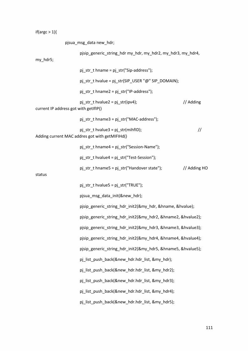
111
if(argc > 1){
pjsua_msg_data new_hdr;
pjsip_generic_string_hdr my_hdr, my_hdr2, my_hdr3, my_hdr4,
my_hdr5;
pj_str_t hname = pj_str("Sip-address");
pj_str_t hvalue = pj_str(SIP_USER "@" SIP_DOMAIN);
pj_str_t hname2 = pj_str("IP-address");
pj_str_t hvalue2 = pj_str(ipv4); // Adding
current IP address got with getIfIP()
pj_str_t hname3 = pj_str("MAC-address");
pj_str_t hvalue3 = pj_str(mihfID); //
Adding current MAC addres got with getMIFIHd()
pj_str_t hname4 = pj_str("Session-Name");
pj_str_t hvalue4 = pj_str("Test-Session");
pj_str_t hname5 = pj_str("Handover state"); // Adding HO
status
pj_str_t hvalue5 = pj_str("TRUE");
pjsua_msg_data_init(&new_hdr);
pjsip_generic_string_hdr_init2(&my_hdr, &hname, &hvalue);
pjsip_generic_string_hdr_init2(&my_hdr2, &hname2, &hvalue2);
pjsip_generic_string_hdr_init2(&my_hdr3, &hname3, &hvalue3);
pjsip_generic_string_hdr_init2(&my_hdr4, &hname4, &hvalue4);
pjsip_generic_string_hdr_init2(&my_hdr5, &hname5, &hvalue5);
pj_list_push_back(&new_hdr.hdr_list, &my_hdr);
pj_list_push_back(&new_hdr.hdr_list, &my_hdr2);
pj_list_push_back(&new_hdr.hdr_list, &my_hdr3);
pj_list_push_back(&new_hdr.hdr_list, &my_hdr4);
pj_list_push_back(&new_hdr.hdr_list, &my_hdr5);

112
/* If URL is specified, add new headers to INVITE message and make call to the
URL. */
pj_str_t uri = pj_str(argv[1]);
status = pjsua_call_make_call(acc_id, &uri, 0, NULL, &new_hdr, &p_call_id);
if (status != PJ_SUCCESS){
error_exit("Error making call", status);
}
status = pjmedia_snd_port_connect(snd_port, file_port); //Enables audio
streaming with selected file
if (status != PJ_SUCCESS){
error_exit("Error playing file", status);
}
// INTO this for() loop we are dealing with MID-CALL mobility
/* Wait until Handover notification, then send RE-INVITE */
for (;;) {
if(open_AF_INET_socket(buffer) != -1) // Connect with
RSSIMonitor to know the HO status
printf ("HO status received properly\n");
else {
error("HO data transfer ERROR");
}
printf("The HO message is: %s\n",buffer);
if (strcmp(buffer,HAND_OVER_GO)!=0){
error("ERROR HO data: content not expected");
}
else{
pjsua_msg_data new_hdr;

113
pjsip_generic_string_hdr my_hdr, my_hdr2, my_hdr3,
my_hdr4, my_hdr5;
pj_str_t hname = pj_str("Sip-address");
pj_str_t hvalue = pj_str(SIP_USER "@" SIP_DOMAIN);
pj_str_t hname2 = pj_str("IP-address");
pj_str_t hvalue2 = pj_str(ipv4);
// Adding current IP address got with getIfIP()
pj_str_t hname3 = pj_str("MAC-address");
pj_str_t hvalue3 = pj_str(mihfID);
// Adding current MAC address got with getMIFIHd()
pj_str_t hname4 = pj_str("Session-Name");
pj_str_t hvalue4 = pj_str("Test-Session");
pj_str_t hname5 = pj_str("Handover state");
// Adding HO status
pj_str_t hvalue5 = pj_str("TRUE");
pjsua_msg_data_init(&new_hdr);
pjsip_generic_string_hdr_init2(&my_hdr, &hname,
&hvalue);
pjsip_generic_string_hdr_init2(&my_hdr2, &hname2,
&hvalue2);
pjsip_generic_string_hdr_init2(&my_hdr3, &hname3,
&hvalue3);
pjsip_generic_string_hdr_init2(&my_hdr4, &hname4,
&hvalue4);
pjsip_generic_string_hdr_init2(&my_hdr5, &hname5,
&hvalue5);
pj_list_push_back(&new_hdr.hdr_list, &my_hdr);
pj_list_push_back(&new_hdr.hdr_list, &my_hdr2);
pj_list_push_back(&new_hdr.hdr_list, &my_hdr3);
pj_list_push_back(&new_hdr.hdr_list, &my_hdr4);
pj_list_push_back(&new_hdr.hdr_list, &my_hdr5);

114
status = pjsua_call_set_hold(p_call_id, &new_hdr); // This
enables not to lose any packets until connection is re-established
if (status != PJ_SUCCESS){
error_exit("Error freezing call", status);
}else{
send_HO_received_in(); // Tell to the
RSSIMonitor the order's been received
printf("\n HO process started, freeze data transfer until
HO is done\n");
}
}
printf(".................... Wait until receiving HO achieved message\n");
if(open_AF_INET_socket(buffer) != -1) // Connect with
RSSIMonitor to know the HO status
printf ("HO status received properly\n");
else {
error("HO data transfer ERROR");
}
printf("The HO message is: %s\n",buffer);
if (strcmp(buffer,HAND_OVER_DONE)!=0){
error("ERROR HO data: content not expected");
}else{
printf("HO achieved: acquiring IP and MAC new values and
sending RE-INVITE");
status = pjsua_acc_set_registration(acc_id,1);
if (status != PJ_SUCCESS){
error_exit("Error updating user info", status);
}

115
/* Shows the new MAC and IP address and save both
parameters into variables */
if(getMIHFId(mihfID,1) != 0)
perror("getMIHFId");
if(getIfIP(IFNAME1,ipv4) != 0)
perror("getIfIP");
printf("mihfID: %s\tipv4: %s\n",mihfID,ipv4);
pjsua_msg_data new_hdr;
pjsip_generic_string_hdr my_hdr, my_hdr2, my_hdr3,
my_hdr4, my_hdr5;
pj_str_t hname = pj_str("Re-Sip-address");
pj_str_t hvalue = pj_str(SIP_USER "@" SIP_DOMAIN);
pj_str_t hname2 = pj_str("Re-IP-address");
pj_str_t hvalue2 = pj_str(ipv4); // Adding current IP address
got with getIfIP()
pj_str_t hname3 = pj_str("Re-MAC-address");
pj_str_t hvalue3 = pj_str(mihfID); // Adding current MAC
addres got with getMIFIHd()
pj_str_t hname4 = pj_str("Re-Session-Name");
pj_str_t hvalue4 = pj_str("Test-Session");
pj_str_t hname5 = pj_str("Handover state"); // Adding HO
status
pj_str_t hvalue5 = pj_str("FALSE");
pjsua_msg_data_init(&new_hdr);
pjsip_generic_string_hdr_init2(&my_hdr, &hname, &hvalue);
pjsip_generic_string_hdr_init2(&my_hdr2, &hname2,
&hvalue2);

116
pjsip_generic_string_hdr_init2(&my_hdr3, &hname3,
&hvalue3);
pjsip_generic_string_hdr_init2(&my_hdr4, &hname4,
&hvalue4);
pjsip_generic_string_hdr_init2(&my_hdr5, &hname5,
&hvalue5);
pj_list_push_back(&new_hdr.hdr_list, &my_hdr);
pj_list_push_back(&new_hdr.hdr_list, &my_hdr2);
pj_list_push_back(&new_hdr.hdr_list, &my_hdr3);
pj_list_push_back(&new_hdr.hdr_list, &my_hdr4);
pj_list_push_back(&new_hdr.hdr_list, &my_hdr5);
status = pjsua_call_reinvite(p_call_id,
PJSUA_CALL_UPDATE_CONTACT, &new_hdr);
if (status != PJ_SUCCESS){
error_exit("Error re-inviting call", status);
}
}
}
} else { // PRE-CALL mobility HO management
printf("Waiting for incoming calls\n");
for(;;){
if(open_AF_INET_socket(buffer) != -1) // Connect with
RSSIMonitor to know the HO status
printf ("HO status received properly\n");
else error("HO data transfer ERROR");

117
printf("The HO message is: %s\n",buffer);
send_HO_received_in();
if (strcmp(buffer,HAND_OVER_GO)!=0)
error("ERROR HO data: content not expected");
else{
pj_str_t hvalue = pj_str(SIP_USER "@" SIP_DOMAIN);
pjrpid_element element;
element.activity = PJRPID_ACTIVITY_AWAY;
pj_str_t note = pj_str("User performing HO");
element.note = note;
element.type = PJRPID_ELEMENT_TYPE_PERSON;
element.id = hvalue;
pj_bool_t onl_stat = PJ_FALSE;
status = pjsua_acc_set_online_status2(acc_id, onl_stat,
&element);
if(status != PJ_SUCCESS)
error_exit("Error when setting online status due to
HO", status);
else{
printf("\n HO process started, showing status OFFLINE to other
users with HO info\n");
}
}
printf(".................... Wait until receiving HO achieved
message\n");
if(open_AF_INET_socket(buffer) != -1) // Connect with
RSSIMonitor to know the HO status
printf ("HO status received properly\n");
else error("HO data transfer ERROR");

118
printf("The HO message is: %s\n",buffer);
if (strcmp(buffer,HAND_OVER_DONE)!=0)
error("ERROR HO data: content not expected");
status = pjsua_acc_set_registration(acc_id,1);
if (status != PJ_SUCCESS){
error_exit("Error updating user
info", status);
}
pj_bool_t onl_stat = PJ_TRUE;
status = pjsua_acc_set_online_status(acc_id, onl_stat);
if(status != PJ_SUCCESS)
error_exit("Error when setting online status
due to HO", status);
else printf("HO achieved, showing status ONLINE\n");
}
}
/* Destroy pjsua */
pjsua_destroy();
return 0;
}

119
E. CD Content
/Master_Thesis_Alexandre_Nin
PDF digital versión of this document
/PJSIP Client
Developed PJSUA client’s implementation (simple_pjsua.c)
/Resources
Linphone 3.5.2 binaries (linphone-3.5.2.tar)
PJSIP 2.0.1 binaries (pjproject-2.0.1.tar)
wpa_supplicant 0.6.9 binaries (wpa_supplicant-0.6.9.tar)
wpa_supplicant configuration file (wpa_supplicant2.conf)
/RSSIMonitor
Developed RSSIMonitor.c version, including all necessary files and libraries
/Wireshark capture files
Wireshark files captured when running simple_pjsua.c, for pre and mid-call mobility cases.
Open with any version of Wireshark
/Readme.txt
How to run instructions


![Seamless Realtime Traffic Handover Policy for IEEE …netsys.kaist.ac.kr/publication/papers/Resources/[IC109].pdf · Seamless Realtime Traffic Handover Policy for IEEE 802.16m Mobile](https://static.fdocuments.in/doc/165x107/5ab3b9637f8b9ac66c8e91bd/seamless-realtime-traffic-handover-policy-for-ieee-ic109pdfseamless-realtime.jpg)

