Sinusoidal vertical motion of a sonobuoy suspension ... · PDF fileSinusoidal vertical motion...
36
Defence R&D Canada – Atlantic DEFENCE DÉFENSE & Sinusoidal vertical motion of a sonobuoy suspension: experimental data and a theoretical model David M. F. Chapman DRDC Atlantic Dusko B. A. Kezele Sparton of Canada Limited Also published in: The Technical Cooperation Program, Subgroup G (Undersea Warfare) Technical Panel GTP-10 25th Sonobuoy Working Party, Warminster, PA, 3-5 December 1990. Technical Memorandum DRDC Atlantic TM 2008-121 June 2008 Copy No. _____ Defence Research and Development Canada Recherche et développement pour la défense Canada
Transcript of Sinusoidal vertical motion of a sonobuoy suspension ... · PDF fileSinusoidal vertical motion...

Defence R&D Canada – Atlantic
DEFENCE DÉFENSE&
Sinusoidal vertical motion of a sonobuoy
suspension: experimental data and a
theoretical model
David M. F. ChapmanDRDC Atlantic
Dusko B. A. KezeleSparton of Canada Limited
Also published in: The Technical Cooperation Program, Subgroup G (Undersea Warfare) Technical Panel GTP-1025th Sonobuoy Working Party, Warminster, PA, 3-5 December 1990.
Technical Memorandum
DRDC Atlantic TM 2008-121
June 2008
Copy No. _____
Defence Research andDevelopment Canada
Recherche et développementpour la défense Canada

This page intentionally left blank.

Sinusoidal vertical motion of a sonobuoy suspension: experimental data and a theoretical model David M. F. Chapman DRDC Atlantic Dusko B. A. Kezele Sparton of Canada Limited Also published in: The Technical Cooperation Program, Subgroup G (Undersea Warfare) Technical Panel GTP-10 25th Sonobuoy Working Party, Warminster, PA, 3-5 December 1990
Defence R&D Canada – Atlantic Technical Memorandum DRDC Atlantic TM 2008-121 June 2008

Principal Author
Original signed by David M. F. Chapman
David M. F. Chapman
Defence Scientist
Approved by
Original signed by J. S. Kennedy
J. S. Kennedy
Head, Maritime Information and Combat Systems Section
Approved for release by
Original signed by J. L. Kennedy
J. L. Kennedy
Chief Scientist
© Her Majesty the Queen in Right of Canada, as represented by the Minister of National Defence, 2008
© Sa Majesté la Reine (en droit du Canada), telle que représentée par le ministre de la Défense nationale, 2008

DRDC Atlantic TM 2008-121 i
Abstract ……..
To isolate its acoustic sensor from the large vertical motions of the buoy at the ocean surface, a typical sonobuoy employs a low-pass mechanical filter comprising a bungee cord (spring) and a damper disk (hydrodynamic added mass and damping). If the system were to behave as a driven simple harmonic oscillator, the transfer function of vertical motion would roll off at 40 dB/decade above resonance; however, experimental systems of this sort exhibit a rolloff of approximately 30 dB/decade. Experiments have shown that the inertia coefficient CI and the drag coefficient CD of a circular disk in sinusoidal motion are in fact not constants, but depend on the dimensionless ratio of amplitude of motion to disk diameter, A/d. Incorporating this concept, the simple harmonic oscillator model has been enhanced to produce an iterative model for the transfer function of the bungee/disk system that agrees well with experimental data. Well above resonance, the model simplifies to an expression giving a 27 dB/decade rolloff.
Résumé ….....
Pour que les grands mouvements verticaux qu’elles font à la surface de l’océan ne nuisent pas à la performance de leurs capteurs acoustiques, les bouées acoustiques sont généralement munies d’un filtre mécanique passe-bas composé d’un extenseur (ressort) et d’un disque d’amortissement (masse ajoutée et amortissement hydrodynamiques). La pente de diminution du transfert du mouvement vertical du filtre mécanique des oscillateurs harmoniques simples commandés est de 40 dB par décade. La pente du filtre expérimental est cependant de 30 dB par décade. Selon des expériences, le coefficient d’inertie Ci et le coefficient de frottement Cf d’un disque circulaire en mouvement sinusoïdal ne sont pas constants et dépendent du rapport adimensionnel entre l’amplitude du mouvement et le diamètre du disque, soit un rapport A/d. Grâce à l’intégration de ce concept, nous avons été en mesure d’améliorer le modèle de l’oscillateur harmonique simple et ainsi de produire un modèle itératif dont la fonction de transfert du filtre mécanique correspond aux données expérimentales. Bien au-delà de la fréquence de résonance escomptée, le modèle amélioré a une pente de diminution de 27 dB par décade.

ii DRDC Atlantic TM 2008-121
This page intentionally left blank.
DRDC Atlantic TM 2008-121 iii
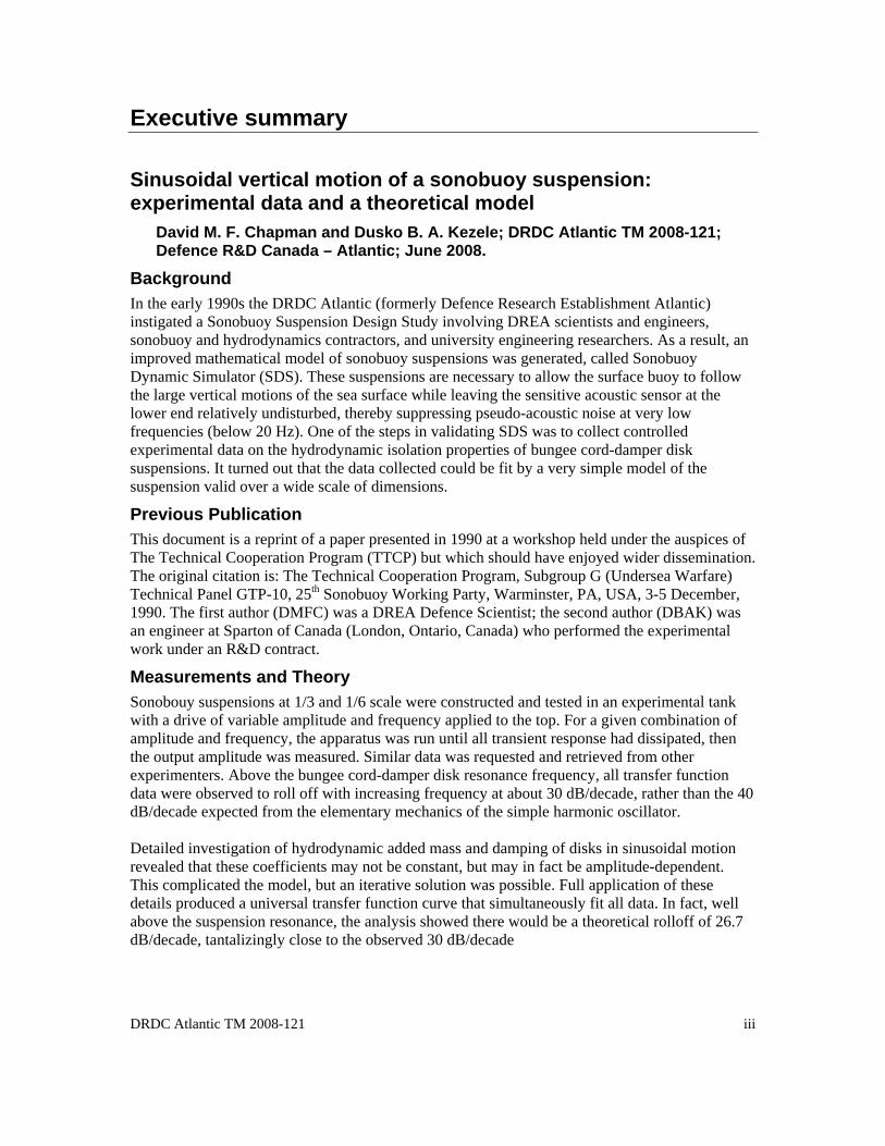
Executive summary
Sinusoidal vertical motion of a sonobuoy suspension: experimental data and a theoretical model
David M. F. Chapman and Dusko B. A. Kezele; DRDC Atlantic TM 2008-121; Defence R&D Canada – Atlantic; June 2008.
Background In the early 1990s the DRDC Atlantic (formerly Defence Research Establishment Atlantic) instigated a Sonobuoy Suspension Design Study involving DREA scientists and engineers, sonobuoy and hydrodynamics contractors, and university engineering researchers. As a result, an improved mathematical model of sonobuoy suspensions was generated, called Sonobuoy Dynamic Simulator (SDS). These suspensions are necessary to allow the surface buoy to follow the large vertical motions of the sea surface while leaving the sensitive acoustic sensor at the lower end relatively undisturbed, thereby suppressing pseudo-acoustic noise at very low frequencies (below 20 Hz). One of the steps in validating SDS was to collect controlled experimental data on the hydrodynamic isolation properties of bungee cord-damper disk suspensions. It turned out that the data collected could be fit by a very simple model of the suspension valid over a wide scale of dimensions.
Previous Publication This document is a reprint of a paper presented in 1990 at a workshop held under the auspices of The Technical Cooperation Program (TTCP) but which should have enjoyed wider dissemination. The original citation is: The Technical Cooperation Program, Subgroup G (Undersea Warfare) Technical Panel GTP-10, 25th Sonobuoy Working Party, Warminster, PA, USA, 3-5 December, 1990. The first author (DMFC) was a DREA Defence Scientist; the second author (DBAK) was an engineer at Sparton of Canada (London, Ontario, Canada) who performed the experimental work under an R&D contract.
Measurements and Theory Sonobouy suspensions at 1/3 and 1/6 scale were constructed and tested in an experimental tank with a drive of variable amplitude and frequency applied to the top. For a given combination of amplitude and frequency, the apparatus was run until all transient response had dissipated, then the output amplitude was measured. Similar data was requested and retrieved from other experimenters. Above the bungee cord-damper disk resonance frequency, all transfer function data were observed to roll off with increasing frequency at about 30 dB/decade, rather than the 40 dB/decade expected from the elementary mechanics of the simple harmonic oscillator. Detailed investigation of hydrodynamic added mass and damping of disks in sinusoidal motion revealed that these coefficients may not be constant, but may in fact be amplitude-dependent. This complicated the model, but an iterative solution was possible. Full application of these details produced a universal transfer function curve that simultaneously fit all data. In fact, well above the suspension resonance, the analysis showed there would be a theoretical rolloff of 26.7 dB/decade, tantalizingly close to the observed 30 dB/decade

iv DRDC Atlantic TM 2008-121
Significance This model could prove useful for practical engineering of sonobuoy suspensions not needing sophisticated modeling and simulation.

DRDC Atlantic TM 2008-121 v
Sommaire .....
Mouvements verticaux sinusoïdaux du mécanisme de suspension de la bouée acoustique : données expérimentales et modèle théorique
David M.F. Chapman et Dusko B. A. Kezele; RDDC Atlantique TM 2008-121; R & D pour la défense Canada — Atlantique; juin 2008.
Introduction Au début des années 1990, RDDC Atlantique (anciennement le Centre de recherches pour la défense Atlantique) a lancé une étude sur la conception du mécanisme de suspension de la bouée acoustique (Sonobuoy Suspension Design Study) en collaboration avec des scientifiques et des ingénieurs de RDDC Atlantique, des entrepreneurs spécialistes des bouées acoustiques et de l’hydrodynamique, ainsi que des chercheurs universitaires en ingénierie. L'étude a ainsi permis de créer un modèle mathématique amélioré du mécanisme de suspension de la bouée acoustique appelé Sonobuoy Dynamic Simulator (SDS). Le mécanisme de suspension est indispensable pour permettre à la bouée, qui flotte à la surface de l’eau, de suivre les grands mouvements verticaux de l’océan tout en laissant le capteur acoustique sensible plus ou moins stationnaire au fond de l'eau, ce qui élimine les bruits pseudo-acoustiques de très basse fréquence (moins de 20 Hz). Parmi les étapes à suivre pour valider le modèle SDS, il a fallu recueillir des données expérimentales de contrôle concernant les propriétés d’isolation hydrodynamique du mécanisme de suspension extenseur/disque d’amortissement. On a découvert qu’un modèle très simple du mécanisme de suspension, applicable à une grande variété de dimensions, donnait des résultats correspondant aux données expérimentales recueillies.
Publication antérieure L’actuel document est une réimpression d’une présentation faite en 1990 à un atelier organisé par le Programme de coopération technique (TTCP) et qui n’avait pas été très répandue. Le renvoi d’origine était The Technical Cooperation Program, Subgroup G (Undersea Warfare) Technical Panel GTP-10, 25th Sonobuoy Working Party, Warminster, PA, USA, 3-5 December, 1990. L’auteur principal (DMFC) était un scientifique de RDDC – Atlantique, et le second (DBAK), un ingénieur chez Sparton of Canada (à London (Ontario), Canada) qui a mené les expériences en vertu d’un contrat du RDDC.
Mesures et théorie On a créé des modèles d’un tiers et d’un sixième de la grandeur des mécanismes de suspension de la bouée acoustique, on les a mis à l’essai dans un réservoir et on a appliqué diverses valeurs d’amplitude et de fréquence à la bouée à la surface. Pour chacune des combinaisons amplitude/fréquence, on a laissé le mécanisme fonctionner jusqu’à ce que la réponse transitoire se dissipe entièrement avant de mesurer l’amplitude de sortie. Des données semblables ont été demandées et recueillies auprès d'autres chercheurs. Au-delà de la fréquence de résonance du mécanisme extenseur-disque d’amortissement, toutes les données de la fonction de transfert avaient une pente de diminution dont la fréquence augmentait progressivement à environ 30 dB par décade plutôt qu’à 40 dB par décade, ce qui était pourtant prévu pour la mécanique rudimentaire de l’oscillateur harmonique simple.

vi DRDC Atlantic TM 2008-121
À la suite d’enquêtes approfondies sur la masse ajoutée et l’amortissement hydrodynamiques des disques en mouvement sinusoïdal, on a découvert que ces coefficients n’étaient peut-être pas constants et qu’ils dépendaient vraisemblablement de l’amplitude, ce qui a complexifié le modèle. Nous avons toutefois trouvé une solution itérative. L’entière intégration de ces détails nous a permis de produire une courbe universelle de la fonction de transfert qui correspond à toutes les données. En effet, l’analyse suggère une pente de diminution théorique bien au-delà de la fréquence de résonance escomptée, soit de 26,7 dB par décade, ce qui se rapproche de très près de la pente mesurée de 30 dB par décade.
Portée Pour l’ingénierie appliquée du mécanisme de suspension des bouées acoustiques qui n’a pas besoin de modèles et de simulations perfectionnés, le présent modèle pourrait s’avérer utile.

DRDC Atlantic TM 2008-121 vii
Table of contents
Abstract …….. ................................................................................................................................. i Résumé …..... ................................................................................................................................... i Executive summary ....................................................................................................................... iii Sommaire ........................................................................................................................................ v Table of contents .......................................................................................................................... vii List of figures .............................................................................................................................. viii List of tables .................................................................................................................................. ix Acknowledgements ........................................................................................................................ x 1 Introduction............................................................................................................................... 1 2 The Vertical Motion Experiments ............................................................................................ 2 3 Theory....................................................................................................................................... 4
3.1 Inertia and drag coefficients for uniformly-accelerated motion .................................... 5 3.2 Inertia and drag coefficients for sinusoidal motion ....................................................... 5 3.3 The iterative model........................................................................................................ 6 3.4 The simple model .......................................................................................................... 7
4 Comparison of experiment and theory...................................................................................... 8 4.1 Sparton of Canada data.................................................................................................. 8 4.2 Other data sets ............................................................................................................... 8 4.3 Discussion ................................................................................................................... 11
5 Possible future work ............................................................................................................... 12 6 Conclusions............................................................................................................................. 12 References. .................................................................................................................................... 14 List of symbols/abbreviations/acronyms/initialisms .................................................................... 15 Distribution list ............................................................................................................................. 17

viii DRDC Atlantic TM 2008-121
List of figures
Figure 1: Schematic diagram of the experimental apparatus........................................................... 3 Figure 2: Transfer function data and model calculations for the SOC 1/6-scale suspension: 1’
input amplitude, 5’ bungee, and 12” damper disk......................................................... 9 Figure 3: Transfer function data and model calculations for the SOC 1/3-scale suspension: 2’
input amplitude, 10’ bungee, and 12” damper disk...................................................... 9 Figure 4: Transfer function data for the 5 data sets of Table II plotted as a function of
normalized frequency, along with the universal model curve..................................... 10

DRDC Atlantic TM 2008-121 ix
List of tables
Table I: Vertical motion transfer function data ............................................................................... 3 Table II: Characteristics of the experimental data sets.................................................................. 10

x DRDC Atlantic TM 2008-121
Acknowledgements

DRDC Atlantic TM 2008-121 1
1 Introduction

2 DRDC Atlantic TM 2008-121
2 The Vertical Motion Experiments

DRDC Atlantic TM 2008-121 3
Figure 1: Schematic diagram of the experimental apparatus
Table I: Vertical motion transfer function data
Column 1 Heading Column 2 Heading Column 3 Heading Column 4 Heading
Table text Table text Table text Table text
Table text Table text Table text Table text
This is a sample of a table footnote.

4 DRDC Atlantic TM 2008-121
3 Theory

DRDC Atlantic TM 2008-121 5
3.1 Inertia and drag coefficients for uniformly-accelerated motion
3.2 Inertia and drag coefficients for sinusoidal motion

6 DRDC Atlantic TM 2008-121
3.3 The iterative model
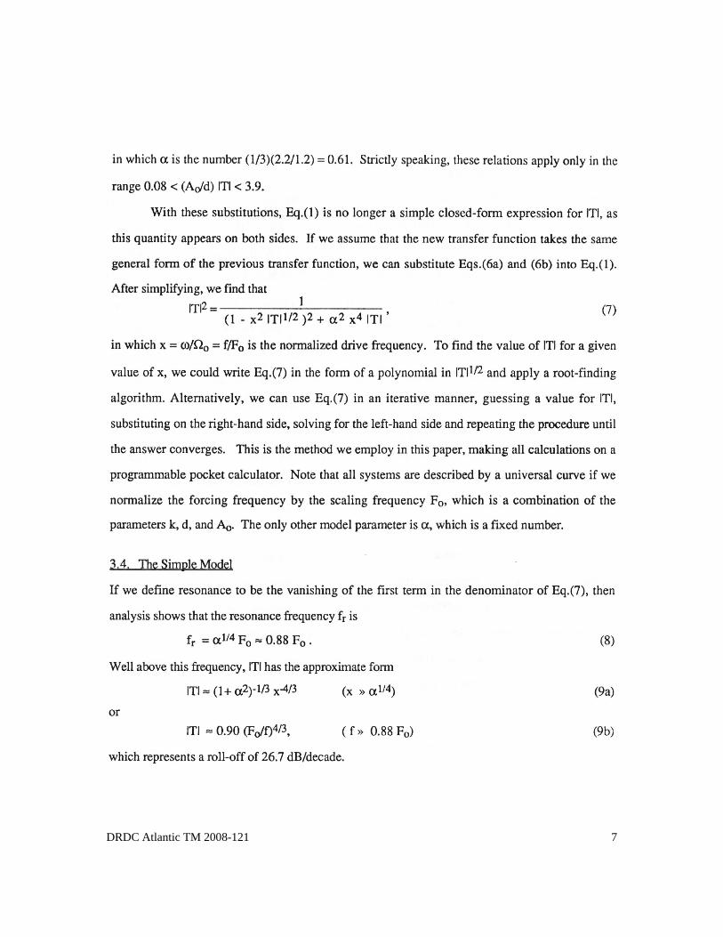
DRDC Atlantic TM 2008-121 7
3.4 The simple model
8 DRDC Atlantic TM 2008-121
4 Comparison of experiment and theory
4.1 Sparton of Canada data
4.2 Other data sets

DRDC Atlantic TM 2008-121 9
Figure 2: Transfer function data and model calculations for the SOC 1/6-scale suspension: 1’ input amplitude, 5’ bungee, and 12” damper disk
Figure 3: Transfer function data and model calculations for the SOC 1/3-scale suspension: 2’ input amplitude, 10’ bungee, and 12” damper disk

10 DRDC Atlantic TM 2008-121
Table II: Characteristics of the experimental data sets
Column 1 Heading Column 2 Heading Column 3 Heading Column 4 Heading
Table text Table text Table text Table text
Table text Table text Table text Table text
This is a sample of a table footnote.
Figure 4: Transfer function data for the 5 data sets of Table II plotted as a function of normalized frequency, along with the universal model curve.

DRDC Atlantic TM 2008-121 11
4.3 Discussion
12 DRDC Atlantic TM 2008-121
5 Possible future work
6 Conclusions
DRDC Atlantic TM 2008-121 13

14 DRDC Atlantic TM 2008-121
References.

DRDC Atlantic TM 2008-121 15
List of symbols/abbreviations/acronyms/initialisms
DRDC Atlantic Defence Research & Development Canada - Atlantic
DREA Defence Research Establishment Atlantic (former name for DRDC Atlantic)
NADC Naval Air Development Center (US)
SOC Sparton of Canada

16 DRDC Atlantic TM 2008-121
This page intentionally left blank.

DRDC Atlantic TM 2008-121 17
Distribution list
Document No.: DRDC Atlantic TM 2008-121
LIST PART 1: Internal Distribution by Centre DRDC Atlantic:
5 Library 2 David M.F. Chapman 2 James Theriault 1 Nicole Collison 1 Brian Maranda 1 Garfield Mellema 1 Don Mosher
13 TOTAL LIST PART 1
LIST PART 2: External Distribution by DRDKIM
1 Library and Archives Canada 1 DAEPM(M) 2-5 1 DRDKIM
3 TOTAL LIST PART 2
16 TOTAL COPIES REQUIRED

18 DRDC Atlantic TM 2008-121
This page intentionally left blank.

DOCUMENT CONTROL DATA (Security classification of title, body of abstract and indexing annotation must be entered when the overall document is classified)
1. ORIGINATOR (The name and address of the organization preparing the document. Organizations for whom the document was prepared, e.g. Centre sponsoring a contractor's report, or tasking agency, are entered in section 8.) Defence R&D Canada – Atlantic 9 Grove Street P.O. Box 1012 Dartmouth, Nova Scotia B2Y 3Z7
2. SECURITY CLASSIFICATION (Overall security classification of the document including special warning terms if applicable.)
UNCLASSIFIED
3. TITLE (The complete document title as indicated on the title page. Its classification should be indicated by the appropriate abbreviation (S, C or U) in parentheses after the title.) Sinusoidal vertical motion of a sonobuoy suspension: experimental data and a theoretical model
4. AUTHORS (last name, followed by initials – ranks, titles, etc. not to be used) David M. F. Chapman and Dusko B. A. Kesele
5. DATE OF PUBLICATION (Month and year of publication of document.) June 2008
6a. NO. OF PAGES (Total containing information, including Annexes, Appendices, etc.)
32
6b. NO. OF REFS (Total cited in document.)
6 7. DESCRIPTIVE NOTES (The category of the document, e.g. technical report, technical note or memorandum. If appropriate, enter the type of report,
e.g. interim, progress, summary, annual or final. Give the inclusive dates when a specific reporting period is covered.) Technical Memorandum
8. SPONSORING ACTIVITY (The name of the department project office or laboratory sponsoring the research and development – include address.) Defence R&D Canada – Atlantic 9 Grove Street P.O. Box 1012 Dartmouth, Nova Scotia B2Y 3Z7
9a. PROJECT OR GRANT NO. (If appropriate, the applicable research and development project or grant number under which the document was written. Please specify whether project or grant.)
9b. CONTRACT NO. (If appropriate, the applicable number under which the document was written.)
10a. ORIGINATOR'S DOCUMENT NUMBER (The official document number by which the document is identified by the originating activity. This number must be unique to this document.) DRDC Atlantic TM 2008-121
10b. OTHER DOCUMENT NO(s). (Any other numbers which may be assigned this document either by the originator or by the sponsor.)
11. DOCUMENT AVAILABILITY (Any limitations on further dissemination of the document, other than those imposed by security classification.)
Unlimited
12. DOCUMENT ANNOUNCEMENT (Any limitation to the bibliographic announcement of this document. This will normally correspond to the Document Availability (11). However, where further distribution (beyond the audience specified in (11) is possible, a wider announcement audience may be selected.)) Unlimited

13. ABSTRACT (A brief and factual summary of the document. It may also appear elsewhere in the body of the document itself. It is highly desirable that the abstract of classified documents be unclassified. Each paragraph of the abstract shall begin with an indication of the security classification of the information in the paragraph (unless the document itself is unclassified) represented as (S), (C), (R), or (U). It is not necessary to include here abstracts in both official languages unless the text is bilingual.)
To isolate its acoustic sensor from the large vertical motions of the buoy at the ocean surface, a typical sonobuoy employs a low-pass mechanical filter comprising a bungee cord (spring) and a damper disk (hydrodynamic added mass and damping). If the system were to behave as a driven simple harmonic oscillator, the transfer function of vertical motion would roll off at 40 dB/decade above resonance; however, experimental systems of this sort exhibit a rolloff of approximately 30 dB/decade. Experiments have shown that the inertia coefficient CI and the drag coefficient CD of a circular disk in sinusoidal motion are in fact not constants, but depend on the dimensionless ratio of amplitude of motion to disk diameter, A/d. Incorporating this concept, the simple harmonic oscillator model has been enhanced to produce an iterative model for the transfer function of the bungee/disk system that agrees well with experimental data. Well above resonance, the model simplifies to an expression giving a 27 dB/decade rolloff.
14. KEYWORDS, DESCRIPTORS or IDENTIFIERS (Technically meaningful terms or short phrases that characterize a document and could be helpful in cataloguing the document. They should be selected so that no security classification is required. Identifiers, such as equipment model designation, trade name, military project code name, geographic location may also be included. If possible keywords should be selected from a published thesaurus, e.g. Thesaurus of Engineering and Scientific Terms (TEST) and that thesaurus identified. If it is not possible to select indexing terms which are Unclassified, the classification of each should be indicated as with the title.) sonobuoy; suspension systems; vertical motion damping; noise reduction

This page intentionally left blank.