Sinus K Manual
98
• 15P0095B1 • SINUS K FULL DIGITAL INVERTER USER MANUAL -Installations Instructions- Upd. 13/06/03 R. 02 Elettronica Santerno S.p.A. Via G. Di Vittorio, 3 - 40020 Casalfiumanese (Bo) Italy Tel. +39 0542 668611 - Fax +39 0542 668622 After-sales Service Tel. +39 0542 668610 - Fax +39 0542 668623 Sales Department Tel. +39 0542 668611 - Fax +39 0542 668600 • This manual is integrant and essential to the product. Carefully read the instructions contained herein as they provide important hints for use and maintenance safety. • This device is to be used only for the purposes it has been designed to. Other uses should be considered improper and dangerous. The manufacturer is not responsible for possible damages caused by improper, erroneous and irrational uses. • Elettronica Santerno is responsible for the device in its original setting. • Any changes to the structure or operating cycle of the device must be performed or authorized by the Engineering Department of Elettronica Santerno. • Elettronica Santerno assumes no responsibility for the consequences resulting by the use of non-original spare- parts. • Elettronica Santerno reserves the right to make any technical changes to this manual and to the device without prior notice. If printing errors or similar are detected, the corrections will be included in the new releases of the manual. • Elettronica Santerno is responsible for the information contained in the original version of the Italian manual. • The information contained herein is the property of Elettronica Santerno and cannot be reproduced. Elettronica Santerno enforces its rights on the drawings and catalogues according to the law. English
-
Upload
charlesschlaepfer7998 -
Category
Documents
-
view
485 -
download
10
Transcript of Sinus K Manual

• 15P0095B1 •
SINUS K FULL DIGITAL INVERTER
USER MANUAL -Installations Instructions-
Upd. 13/06/03 R. 02
Elettronica Santerno S.p.A. Via G. Di Vittorio, 3 - 40020 Casalfiumanese (Bo) Italy
Tel. +39 0542 668611 - Fax +39 0542 668622 After-sales Service Tel. +39 0542 668610 - Fax +39 0542 668623 Sales Department Tel. +39 0542 668611 - Fax +39 0542 668600
• This manual is integrant and essential to the product. Carefully read the instructions contained herein as they provide important hints for use and maintenance safety. • This device is to be used only for the purposes it has been designed to. Other uses should be considered improper and dangerous. The manufacturer is not responsible for possible damages caused by improper, erroneous and irrational uses. • Elettronica Santerno is responsible for the device in its original setting. • Any changes to the structure or operating cycle of the device must be performed or authorized by the Engineering Department of Elettronica Santerno. • Elettronica Santerno assumes no responsibility for the consequences resulting by the use of non-original spare-parts. • Elettronica Santerno reserves the right to make any technical changes to this manual and to the device without prior notice. If printing errors or similar are detected, the corrections will be included in the new releases of the manual. • Elettronica Santerno is responsible for the information contained in the original version of the Italian manual. • The information contained herein is the property of Elettronica Santerno and cannot be reproduced. Elettronica Santerno enforces its rights on the drawings and catalogues according to the law.
E n g l i s h
15P0095B2 SINUS K INSTALLATION MANUAL
2/95
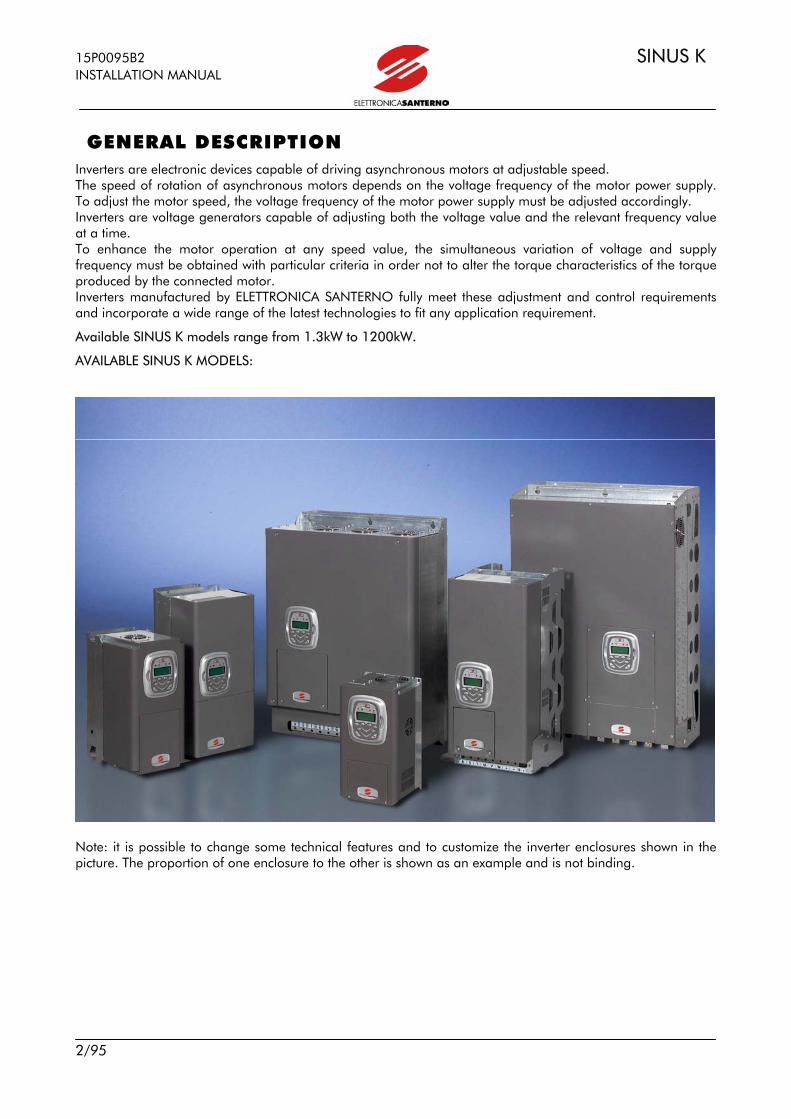
GENERAL DESCRIPTION Inverters are electronic devices capable of driving asynchronous motors at adjustable speed. The speed of rotation of asynchronous motors depends on the voltage frequency of the motor power supply. To adjust the motor speed, the voltage frequency of the motor power supply must be adjusted accordingly. Inverters are voltage generators capable of adjusting both the voltage value and the relevant frequency value at a time. To enhance the motor operation at any speed value, the simultaneous variation of voltage and supply frequency must be obtained with particular criteria in order not to alter the torque characteristics of the torque produced by the connected motor. Inverters manufactured by ELETTRONICA SANTERNO fully meet these adjustment and control requirements and incorporate a wide range of the latest technologies to fit any application requirement.
Available SINUS K models range from 1.3kW to 1200kW.
AVAILABLE SINUS K MODELS:
Note: it is possible to change some technical features and to customize the inverter enclosures shown in the picture. The proportion of one enclosure to the other is shown as an example and is not binding.
SINUS K 15P0095B2 INSTALLATION MANUAL
3/95
TABLE OF CONTENTS
GENERAL DESCRIPTION.............................................................................................................................2 TABLE OF CONTENTS................................................................................................................................3 FEATURE LIST .............................................................................................................................................5 CAUTION STATEMENTS .............................................................................................................................7 1 EQUIPMENT DESCRIPTION AND INSTALLATION....................................................................................10
1.1 PRODUCTS COVERED IN THIS MANUAL ........................................................................................11 1.2 INSPECTION UPON RECEIPT OF THE GOODS ...............................................................................12 1.3 INSTALLING THE EQUIPMENT........................................................................................................13
1.3.1 Environmental Requirements for the Equipment Installation, Storage and Transport ....................15 1.3.2 Air cooling ..............................................................................................................................16 1.3.3 Size, Weight and Dissipated Power...........................................................................................17
Models STAND-ALONE IP20 and IP00 ..........................................................................................17 Models STAND-ALONE IP54.........................................................................................................18 Models BOX IP54*........................................................................................................................19 Models CABINET IP24 and IP54* ..................................................................................................20
1.3.4 Standard Mounting and Piercing Templates..............................................................................21 1.3.5 Through-panel Assembly and Piercing templates ......................................................................22
1.4 WIRING .........................................................................................................................................27 1.4.1 Wiring Diagram ......................................................................................................................27 1.4.2 Control Terminals ...................................................................................................................28 1.4.3 Signals and programming on board ES778 (control board).......................................................30
1.4.3.1 Indicator leds ...................................................................................................................31 1.4.3.2 JUMPERS AND DIP-SWITCH .............................................................................................31
1.4.4 Digital input features (Terminals 6 to 15) ..................................................................................32 1.4.4.1 ENABLE (TERMINAL 6)......................................................................................................32 1.4.4.2 START (TERMINAL 7) ........................................................................................................33 1.4.4.3 RESET (TERMINAL 8).........................................................................................................33 1.4.4.4 M.D.I. (Terminals 9 to 13) ................................................................................................33 1.4.4.5 Motor Thermal Protection Input.........................................................................................33
1.4.5 Analog input features (Terminals 2,3,15 and 21) ......................................................................34 1.4.6 Digital output features .............................................................................................................34
1.4.6.1 RELAY OUTPUTS..............................................................................................................36 1.4.7 Analog Output Features (Terminals 17 and 18) ........................................................................37 1.4.8 Power Terminals Arrangement .................................................................................................37 1.4.9 Cross-sections of Power Connection Wires and Size of Protection Devices ..................................40
1.5 OPERATING AND REMOTING THE KEYPAD....................................................................................41 1.5.1 Remoting the keypad...............................................................................................................43
1.6 SERIAL COMMUNICATION ............................................................................................................44 1.6.1 General features ..................................................................................................................44 1.6.2 Direct connection .................................................................................................................44 1.6.3 Network connection .............................................................................................................44 1.6.4 Connection..........................................................................................................................45 1.6.5 The software ........................................................................................................................45 1.6.6 Comunication ratings...........................................................................................................46
2 STARTUP PROCEDURES.........................................................................................................................47 2.1 STARTUP PROCEDURE FOR IFD SOFTWARE....................................................................................47 2.2 STARTUP PROCEDURE FOR VTC SOFTWARE...................................................................................48
3 TECHNICAL SPECIFICATIONS ...............................................................................................................50 3.1 CHOOSING THE PRODUCT...........................................................................................................52
3.1.1 Technical Sheet for LIGHT applications:....................................................................................53 Overload 105%÷120%....................................................................................................................53 3.1.2 Technical sheet for STANDARD Applications: ............................................................................54 Overload 120÷140% ......................................................................................................................54 3.1.3 Technical sheet for HEAVY Applications: ...................................................................................55
15P0095B2 SINUS K INSTALLATION MANUAL
4/95
Overload 150%÷175%....................................................................................................................55 3.1.4 Technical sheet for STRONG Applications:................................................................................56 Overload 200% ...............................................................................................................................56
3.2 CARRIER FREQUENCY SETTING (IFD SW only) AND PEAK CURRENT SETTING..................................57 4 ACCESSORIES.......................................................................................................................................58
4.1 BRAKING RESISTORS......................................................................................................................58 4.1.1 Application tables....................................................................................................................58
4.1.1.1 Braking resistors for applications with branking duty cycle of 10% and 380-500Vac supply voltage ........................................................................................................................................59 4.1.1.2 Braking resistors for applications with a braking duty cycle of 20% and 380-500Vac supply voltage ........................................................................................................................................60 4.1.1.3 Braking resistors for applications with a duty cycle of 50% and 380-500Vac Supply voltage.61 4.1.1.4 Braking resistors for applications with a braking duty cycle of 10% and 200-240Vac supply voltage ........................................................................................................................................62 4.1.1.5 Braking resistors for applications with a braking duty cycle of20% and 200-240Vac supply voltage. .......................................................................................................................................63 4.1.1.6 Braking resistors for applications with a branking duty cycle of 50% and 200-240Vac supply voltage ........................................................................................................................................64
4.1.2 Avaible models .......................................................................................................................65 4.1.2.1 Model 56-100Ohm/350W...............................................................................................65 4.1.2.2 Model 75Ohm/1300W ....................................................................................................66 4.1.2.3 Models from 1100W to 2200W........................................................................................67 4.1.2.4 Models 4kW-8kW-12kW ..................................................................................................68 4.1.2.5 Models – Box Resistors IP23, 4KW-64kW...........................................................................69
4.2 BRAKING MODULE........................................................................................................................70 4.3 REMOTING KIT ..............................................................................................................................70 4.4 REACTANCE ..................................................................................................................................71
4.4.1 Input inductance......................................................................................................................71 4.4.2 Inductance ratings...................................................................................................................73
4.4.2.1 L2 Reactance ratings ........................................................................................................74 4.4.2.2 L4 Reactance ratings ........................................................................................................75 4.4.2.3 L4 Single-Phase Reactance Ratings....................................................................................76
4.4.3 Output Reactance....................................................................................................................77 4.5 ENCODER BOARD ES797/1...........................................................................................................79
4.5.1. Environmental Requirements.............................................................................................80 4.5.2 Electrical Features ................................................................................................................80 4.5.3 Installing the Encoder Board on the Inverter...........................................................................80 4.5.4 Encoder Board Terminals .....................................................................................................81 4.5.5 Trimmer ..............................................................................................................................81 4.5.6 Encoder Wiring Example ......................................................................................................82 4.5.7 Wiring ....................................................................................................................................86
5 PROVISIONS.........................................................................................................................................87 5.1 RADIOFREQUENCY DISTURBANCE ................................................................................................91
5.2.1 The Mains...............................................................................................................................92 5.2.2 Output Toroid Filters ...............................................................................................................94 5.2.3 The Cabinet ............................................................................................................................94 5.2.4 Input and output filters.............................................................................................................95

SINUS K 15P0095B2 INSTALLATION MANUAL
5/95
FEATURE LIST • One product, three functions: vectorial-modulation IFD software for general-purpose applications (V/f curve) (*); sensorless, vectorial VTC software for high torque demanding performance (direct torque control) (*); vectorial-modulation LIFT software for lift applications* (in compliance with EN 81-1 and lift directive) (V/f
curve) (NOT COVERED IN THIS MANUAL) (*); (*) must be specified when ordered or may be serial programmed over a special connector or may be programmed through JTAG programming interface. • Wide range of supply voltage (200VAC ∼ 500VAC) for stand-alone models and up to 690VAC for cabinet models. Standard power supply: 280VDC ∼ 705VDC. (970VDC for cabinet models). • Wide range of voltage values and power values for the electrical motor to be connected to any single inverter size. Stand-alone model: up to 450kW; cabinet: up to 1200kW.
MODEL LIGHT STANDARD HEAVY STRONG SINUS K 0025 4TBA2X2 22kW 18.5kW 15kW 11kW
• Built-in filters for the whole SINUS K range in compliance with regulation EN61800-3, issue 2 concerning emission limits.
• No line contactor included. The new hardware configuration is standard supplied with a safety system including redundant contacts for the inhibition of firing pulses in the power circuit, in compliance with the latest requirements of the safety regulations in force. (However, respect the specific rules of the field of application).
• Beyond performance enhancement, the new series of SINUS K models are more compact than the prior models. The overall dimensions have been reduced up to 50% in order to install the inverter in small-sized, light-weight control panels. A compact, book-like structure allows an easy side-by-side installation. The SINUS K may be installed in cabinets and its system design offers a better price/performance ratio. • Automatic control of the cooling system (up to Size S30). The ventilation system activates only when required and indicates any failures of the cooling fan. This ensures a greater energy saving, a lower wear of the cooling fans and a weaker noise. In case of equipment failure, it is possible to adjust the system speed in order not to stop the equipment and to limit dissipated power. • Built-in braking module up to Size S30. • Noiseless operation ensured by a high modulation frequency programmable up to 16kHz (IFD SW). • Integrated motor control through a PTC input. • Control panel with LCD display showing full words for an easier comprehension of the operation parameters. • Managing and programming panel provided with eight function keys. • Window-structured programming menu for an easy and quick control of each functionality.

15P0095B2 SINUS K INSTALLATION MANUAL
6/95
• Preset parameters for the most used applications. • PC interface for WINDOWS environment with REMOTE DRIVE software in five foreign languages. • PC compiled software for the programming of more than 20 application functions. • Serial communication RS485 MODBUS RTU for serial links to PC, PLC and control interfaces. • Optional field buses of any type (Profibus DP, Can Bus, Device Net, Ethernet, etc.)

SINUS K 15P0095B2 INSTALLATION MANUAL
7/95
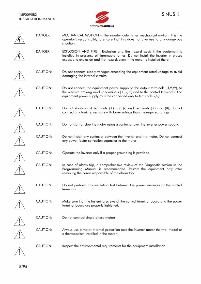
CAUTION STATEMENTS This section contains safety statements. The non-observance of these safety instructions may cause serious injury or death and equipment failure. Carefully read the instructions below before installing, starting and operating the inverter. Only competent personnel must carry out the equipment installation.
SYMBOLS:
DANGER!! Indicates operating procedures that, if not correctly performed, may cause serious injury or death due to electrical shock.
CAUTION: Indicates operating procedures that, if not carried out, may cause serious
equipment failure. NOTE: Indicates important hints concerning the equipment operation.
SAFETY STATEMENTS TO FOLLOW WHEN INSTALLING AND OPERATING THE EQUIPMENT:
NOTE: Always read this instruction manual before starting the equipment. NOTE: The ground connection of the motor casing should follow a separate path to
avoid possible interferences.
DANGER!! ALWAYS PROVIDE A PROPER GROUNDING OF THE MOTOR CASING AND THE INVERTER FRAME.
DANGER!! The inverter may generate an output frequency up to 800Hz (IFD SW); this may
cause a motor rotation speed up to 16 (sixteen) times the motor rated speed: never use the motor at a higher speed than the max. allowable speed stated on the motor nameplate.
DANGER!! ELECTRICAL SHOCK HAZARD – Never touch the inverter electrical parts when
the inverter is on; always wait at least 5 minutes after switching off the inverter. DANGER!! Never perform any operation on the motor when the inverter is on. DANGER!! Do not perform electrical connections on the motor or the inverter if the inverter
is on. Electrical shock hazard exists on output terminals (U,V,W) and resistive braking module terminals (+, -, B) even when the inverter is disabled. Wait at least 5 minutes after switching off the inverter before operating on the electrical connection of the motor or the inverter.
15P0095B2 SINUS K INSTALLATION MANUAL
8/95
DANGER!! MECHANICAL MOTION – The inverter determines mechanical motion. It is the
operator's responsibility to ensure that this does not give rise to any dangerous situation.
DANGER!! EXPLOSION AND FIRE – Explosion and fire hazard exists if the equipment is
installed in presence of flammable fumes. Do not install the inverter in places exposed to explosion and fire hazard, even if the motor is installed there.
CAUTION: Do not connect supply voltages exceeding the equipment rated voltage to avoid
damaging the internal circuits. CAUTION: Do not connect the equipment power supply to the output terminals (U,V,W), to
the resistive braking module terminals (+, -, B) and to the control terminals. The equipment power supply must be connected only to terminals R,S,T.
CAUTION: Do not short-circuit terminals (+) and (-) and terminals (+) and (B); do not
connect any braking resistors with lower ratings than the required ratings. CAUTION: Do not start or stop the motor using a contactor over the inverter power supply. CAUTION: Do not install any contactor between the inverter and the motor. Do not connect
any power factor correction capacitor to the motor. CAUTION: Operate the inverter only if a proper grounding is provided. CAUTION: In case of alarm trip, a comprehensive review of the Diagnostic section in the
Programming Manual is recommended. Restart the equipment only after removing the cause responsible of the alarm trip.
CAUTION: Do not perform any insulation test between the power terminals or the control
terminals. CAUTION: Make sure that the fastening screws of the control terminal board and the power
terminal board are properly tightened. CAUTION: Do not connect single-phase motors. CAUTION: Always use a motor thermal protection (use the inverter motor thermal model or
a thermoswitch installed in the motor). CAUTION: Respect the environmental requirements for the equipment installation.

SINUS K 15P0095B2 INSTALLATION MANUAL
9/95
CAUTION: The bearing surface of the inverter must be capable of withstanding high
temperatures (up to 90°C). CAUTION: The inverter electronic boards contain components which may be affected by
electrostatic discharges. Do not touch them unless it is strictly necessary. Always be very careful so as to prevent any damage caused by electrostatic discharges.

15P0095B2 SINUS K INSTALLATION MANUAL
10/95
1 EQUIPMENT DESCRIPTION AND INSTALLATION The inverters of the SINUS K series are full digital inverters for the speed regulation of asynchronous motors up to 1200 kW. The inverters of the SINUS K series are designed and manufactured in Italy by the technicians of Elettronica Santerno; they incorporate the most advanced features offered by the latest electronic technologies. SINUS K inverters fit any application thanks to their advanced features, among which: 16-bit multiprocessor control board; vectorial modulation; power control with the latest IGBTs; high immunity to radio interference; high overload capability. Any value of the quantities required for the equipment operation may be easily programmed through the keypad, the alphanumeric display and the parameter menus and submenus. The inverters of the SINUS K series are provided with the following standard features: - power supply from 380-500VAC mains (-10%,+5%) up to 690VAC for SINUS CABINET; - EMC filters for industrial environment incorporated in any inverter Size; - EMC filters for domestic environment incorporated in Sizes S05 and S10; - possibility of AC power supply; - built-in braking module up to Size S30; - serial interface RS485 with communications protocol according to standard MODBUS RTU; - degree of protection IP20 up to Size S40; - possibility of providing IP54 up to Size S30; - 3 analog inputs 0±10VDC, 0(4)÷20mA; - 8 optoisolated, configurable digital inputs (NPN/PNP); - 2 configurable analog outputs 0÷10V, 4÷20mA, 0÷20mA; - 1 static, “open collector” digital output (optoisolated); - 2 relay digital outputs with reverse contacts. A comprehensive set of diagnostic messages allows a quick fine-tuning of the parameters during the equipment starting and a quick resolution of any problem during the equipment operation. The inverters of the SINUS K series have been designed and manufactured in compliance with the requirements of the “Low Voltage Directive”, the “Machine Directive” and the “Electromagnetic Compatibility Directive”.

SINUS K 15P0095B2 INSTALLATION MANUAL
11/95
1.1 PRODUCTS COVERED IN THIS MANUAL This manual covers any inverter of the SINUS K series provided with IFD software or VTC software.

15P0095B2 SINUS K INSTALLATION MANUAL
12/95
1.2 INSPECTION UPON RECEIPT OF THE GOODS Make sure the equipment is not damaged and it complies with the equipment you ordered by referring to the nameplate located on the inverter front part. The inverter nameplate is described below. If the equipment is damaged, contact the supplier or the insurance company concerned. If the equipment does not comply with the one you ordered, please contact the supplier as soon as possible. If the equipment is stored before being started, make sure that the ambient conditions do not exceed the ratings mentioned in Section 1.3 “Installation”). The equipment guarantee covers any manufacturing defect. The manufacturer has no responsibility for possible damages due to the inverter transportation or unpacking. The manufacturer is not responsible for possible damages or faults caused by improper and irrational uses; wrong installation; improper conditions of temperature, humidity, or the use of corrosive substances. The manufacturer is not responsible for possible faults due to the inverter operation at values exceeding the inverter ratings and is not responsible for consequential and accidental damages. The equipment is covered by a 3-year guarantee starting from the date of delivery.
SINUS K 0005 4 T B A2 X 2 1 2 3 4 5 6 7 8 9
1 Product line:
SINUS stand-alone inverter SINUS BOX inverter contained inside a box SINUS CABINET inverter contained inside a cabinet
2 "K" type of control with three types of software installed: IFD = Space vector modulation for general-purpose applications (vectorial modulation PWM with V/f curve) VTC = Vector Torque Control for high torque demanding applications (Sensorless vectorial control with direct torque control) LIFT = Space vector modulation with a special software for lift applications (vectorial modulation PWM with V/f curve) (NOT COVERED IN THIS MANUAL)
3 Inverter size 4 Supply voltage
2 = power supply 200÷240VAC; 280÷340VDC. 4 = power supply 380÷500VAC; 530÷705VDC. 5 = power supply 500÷575VAC, 705÷810VDC. 6 = power supply 660÷690VAC; 930÷970VDC.
5 Type of power supply T = three-phase S = single-phase(available by request)
6 Braking module X = no braking chopper (optional external braking chopper) B = built-in braking chopper
7 Type of EMC filter: I = no filter, EN50082-1, -2. A1 = integrated filter, EN 61800-3 issue 2 FIRST ENVIRONMENT Category C2, EN55011 gr.1 cl. A for industrial and domestic users, EN50081-2, EN50082-1, -2, EN61800-3-A11. A2 = integrated filter, EN 61800-3 issue 2 SECOND ENVIRONMENT Category C3, EN55011 gr.2 cl. A for industrial users, EN50082-1, -2, EN61800-3-A11. B = integrated input filter (type A1) plus external, output toroid filter, EN 61800-3 issue 2 FIRST ENVIRONMENT Category C1, EN55011 gr.1 cl. B for industrial and domestic users, EN50081-1,-2, EN50082-1, -2, EN61800-3-A11.
8 Control panel X = without control panel K = with control panel, back-lit, 16x2 characters LCD display.
9 Degree of protection 0 = IP00 2 = IP203 = IP24 5 = IP54
SINUS K 15P0095B2 INSTALLATION MANUAL
13/95
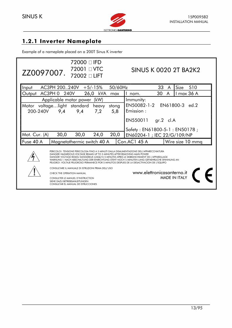
1.2.1 Inverter Nameplate Example of a nameplate placed on a 200T Sinus K inverter
ZZ0097007.
72000 IFD 72001 VTC 72002 LIFT
SINUS K 0020 2T BA2K2
Input AC3PH 200..240V +5/-15% 50/60Hz 33 A Size S10 Output AC3PH 0 240V 26,0 kVA max I nom. 30 A I max 36 A
Applicable motor power (kW) Motor voltage…light standard heavy stong 200-240V 9,4 9,4 7,2 5,8
Mot. Cur. (A) 30,0 30,0 24,0 20,0
Immunity: EN50082-1-2 EN61800-3 ed.2 Emission :
EN550011 gr.2 cl.A
Safety : EN61800-5-1 : EN50178 ; EN60204-1 ; IEC 22/G/109/NP
Fuse 40 A Magnetothermic switch 40 A Con.AC1 45 A Wire size 10 mmq
PERICOLO!: TENSIONE PERICOLOSA FINO A 5 MINUTI DALLA DISALIMENTAZIONE DELL’APPARECCHIATURA DANGER! HAZARDOUS VOLTAGE REMAIS UP TO 5 MINUTES AFTER REMOVING MAIN POWER DANGER! VOLTAGE RESIDU DANGEREUX JUSQU’A 5 MINUTES APRES LE DEBRANCHEMENT DE L’APPAREILLAGE WARNUNG !: NACH ABSCHALTUNG DER EINRICHTUNG STEHT NOCH 5 MINUTEN LANG GEFAEHRLICHE SPANNUNG AN PELIGRO!: VOLTAJE PELIGROSO PERMANECE POR 5 MINUTOS DESPUES DE LA DESACTIVACION DE L’EQUIPO CONSULTARE IL MANUALE DI ISTRUZIONI PRIMA DELL’USO
CHECK THE OPERATION MANUAL www.elettronicasanterno.it CONSULTER LE MANUEL D’INSTRUCTION MADE IN ITALY SIEHE DAZU BETRIEBSANLEITUNGEN CONSULTAR EL MANUAL DE ISTRUCCIONES

15P0095B2 SINUS K INSTALLATION MANUAL
14/95
Example of a nameplate placed on a 400T Sinus K inverter
ZZ0097007.
72000 IFD 72001 VTC 72002 LIFT
SINUS K 0020 4T BA2K2
Input AC3PH 200..380 500v +5/-15% 50/60Hz 33 A Size S10 Output AC3PH 0 500V 26,0 kVA max I nom. 30 A I max 36 A
Applicable motor power (kW) Motor voltage…light standard heavy stong 380-415V 15 15 11 9,2 440-460V 18 18 14 11
480-500V 19 19 15 12
Mot. Cur. (A) 30,0 30,0 24,0 20,0
Immunity: EN50082-1-2 EN61800-3 ed.2 Emission :
EN550011 gr.2 cl.A
Safety : EN61800-5-1 : EN50178 ; EN60204-1 ; IEC 22/G/109/NP
Fuse 40 A Wire size 10 mmq
PERICOLO!: TENSIONE PERICOLOSA FINO A 5 MINUTI DALLA DISALIMENTAZIONE DELL’APPARECCHIATURA DANGER! HAZARDOUS VOLTAGE REMAIS UP TO 5 MINUTES AFTER REMOVING MAIN POWER DANGER! VOLTAGE RESIDU DANGEREUX JUSQU’A 5 MINUTES APRES LE DEBRANCHEMENT DE L’APPAREILLAGE WARNUNG !: NACH ABSCHALTUNG DER EINRICHTUNG STEHT NOCH 5 MINUTEN LANG GEFAEHRLICHE SPANNUNG AN PELIGRO!: VOLTAJE PELIGROSO PERMANECE POR 5 MINUTOS DESPUES DE LA DESACTIVACION DE L’EQUIPO CONSULTARE IL MANUALE DI ISTRUZIONI PRIMA DELL’USO
CHECK THE OPERATION MANUAL www.elettronicasanterno.it CONSULTER LE MANUEL D’INSTRUCTION MADE IN ITALY SIEHE DAZU BETRIEBSANLEITUNGEN CONSULTAR EL MANUAL DE ISTRUCCIONES

SINUS K 15P0095B2 INSTALLATION MANUAL
15/95
1.3 INSTALLING THE EQUIPMENT The inverters of the SINUS K series - degree of protection IP20 – are capable of being installed inside another enclosure. Only models with degree of protection IP54 may be wall-mounted. The inverter must be installed vertically. The ambient conditions, the instructions for the mechanical assembly and the electrical connections of the inverter are detailed in the sections below.
CAUTION: Do not install the inverter horizontally or upside-down.
CAUTION: Do not mount any heat-sensitive components on top of the inverter to prevent them from damaging due hot exhaust air.
CAUTION: The inverter bottom may reach high temperatures; make sure that the inverter
bearing surface is not heat-sensitive.
1.3.1 ENVIRONMENTAL REQUIREMENTS FOR THE EQUIPMENT
INSTALLATION, STORAGE AND TRANSPORT
Operating ambient temperatures 0-40°C with no derating from 40°C to 50°C with a 2% derating of the rated current for each degree beyond 40°C
Ambient temperatures for storage and transport - 25°C - +70°C Installation environment Pollution degree 2 or higher.
Do not install in direct sunlight and in places exposed to conductive dust, corrosive gases, vibrations, water sprinkling or dripping; do not install in salty environments.
Altitude Up to 1000 m above sea level. For higher altitudes, derate the output current of 2% every 100m above 1000m (max. 4000m).
Operating ambient humidity From 5% to 95%, from 1g/m3 to 25g/m3, non condensing and non freezing (class 3k3 according to EN50178)
Storage ambient humidity From 5% to 95%, from 1g/m3 to 25g/m3, non condensing and non freezing (class 1k3 according to EN50178).
Ambient humidity during transport Max. 95%, up to 60g/m3; condensation may appear when the equipment is not running (class 2k3 according to EN50178)
Storage and operating atmospheric pressure From 86 to 106 kPa (classes 3k3 and 1k4 according to EN50178)
Atmospheric pressure during transport From 70 to 106 kPa (class 2k3 according to EN50178)
CAUTION: Ambient conditions strongly affect the inverter life. Do not install the equipment in places that do not have the above-mentioned ambient conditions.
15P0095B2 SINUS K INSTALLATION MANUAL
16/95
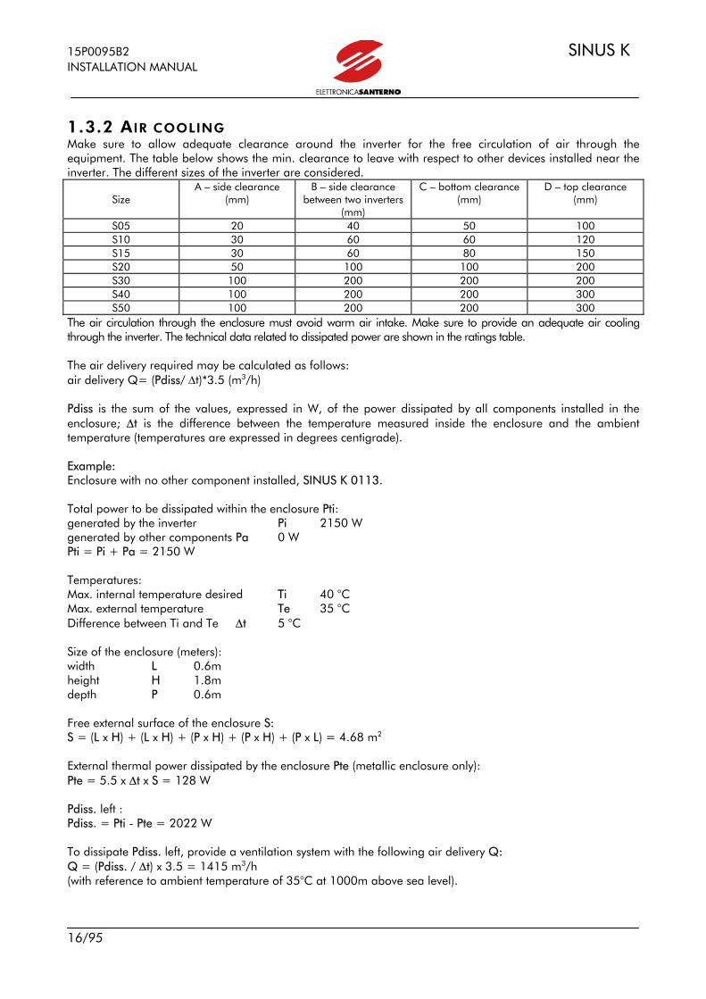
1.3.2 AIR COOLING Make sure to allow adequate clearance around the inverter for the free circulation of air through the equipment. The table below shows the min. clearance to leave with respect to other devices installed near the inverter. The different sizes of the inverter are considered.
Size
A – side clearance (mm)
B – side clearance between two inverters
(mm)
C – bottom clearance (mm)
D – top clearance (mm)
S05 20 40 50 100 S10 30 60 60 120 S15 30 60 80 150 S20 50 100 100 200 S30 100 200 200 200 S40 100 200 200 300 S50 100 200 200 300
The air circulation through the enclosure must avoid warm air intake. Make sure to provide an adequate air cooling through the inverter. The technical data related to dissipated power are shown in the ratings table. The air delivery required may be calculated as follows: air delivery Q= (Pdiss/ ∆t)*3.5 (m3/h) Pdiss is the sum of the values, expressed in W, of the power dissipated by all components installed in the enclosure; ∆t is the difference between the temperature measured inside the enclosure and the ambient temperature (temperatures are expressed in degrees centigrade). Example: Enclosure with no other component installed, SINUS K 0113. Total power to be dissipated within the enclosure Pti: generated by the inverter Pi 2150 W generated by other components Pa 0 W Pti = Pi + Pa = 2150 W Temperatures: Max. internal temperature desired Ti 40 °C Max. external temperature Te 35 °C Difference between Ti and Te ∆t 5 °C Size of the enclosure (meters): width L 0.6m height H 1.8m depth P 0.6m Free external surface of the enclosure S: S = (L x H) + (L x H) + (P x H) + (P x H) + (P x L) = 4.68 m2 External thermal power dissipated by the enclosure Pte (metallic enclosure only): Pte = 5.5 x ∆t x S = 128 W Pdiss. left : Pdiss. = Pti - Pte = 2022 W To dissipate Pdiss. left, provide a ventilation system with the following air delivery Q: Q = (Pdiss. / ∆t) x 3.5 = 1415 m3/h (with reference to ambient temperature of 35°C at 1000m above sea level).

SINUS K 15P0095B2 INSTALLATION MANUAL
17/95
1.3.3 SIZE, WEIGHT AND DISSIPATED POWER MODELS STAND-ALONE IP20 AND IP00
L H D Wgt Dissipated power at
Inom. Size MODEL
mm mm mm kg W SINUS K 0005 7 215 SINUS K 0007 7 240 SINUS K 0009 7 315 SINUS K 0011 7 315
S05
SINUS K 0014
170 340 175
7 315 SINUS K 0017 10.5 380 SINUS K 0020 10.5 420 SINUS K 0025 11.5 525 SINUS K 0030 11.5 525
S10
SINUS K 0035
215 391 216
11.5 525 S15 SINUS K 0040 225 466 331 22.5 820
SINUS K 0049 33.2 950 SINUS K 0060 33.2 1050 SINUS K 0067 33.2 1250 SINUS K 0074 36 1350
S20
SINUS K 0086
279 610 332
36 1500 SINUS K 0113 51 2150 SINUS K 0129 51 2300 SINUS K 0150 51 2450
S30
SINUS K 0162
302 748 421
51 2700 SINUS K 0179 112 3200 SINUS K 0200 112 3650 SINUS K 0216 112 4100
S40
SINUS K 0250
630 880 381
112 4250 SINUS K 0312 148 4900 SINUS K 0366 148 5600 S50 SINUS K 0399
666 1000 421 148 6400
D

15P0095B2 SINUS K INSTALLATION MANUAL
18/95
MODELS STAND-ALONE IP54
L H D Wgt Dissipated Power at
Inom. Size MODEL
mm mm mm kg W SINUS K 0005 11 215 SINUS K 0007 11 240 SINUS K 0009 11 315 SINUS K 0011 11 315
S05
SINUS K 0014
245 540 225
11 315 SINUS K 0017 15 380 SINUS K 0020 15 420 SINUS K 0025 16 525 SINUS K 0030 16 525
S10
SINUS K 0035
290 595 268
15 525 S15 SINUS K 0040 305 665 381 32 820
SINUS K 0049 58 950 SINUS K 0060 58 1050 SINUS K 0067 58 1250 SINUS K 0074 60 1350
S20
SINUS K 0086
359 810 382
60 1500 SINUS K 0113 70 2150 SINUS K 0129 70 2300 SINUS K 0150 74 2450
S30
SINUS K 0162
382 948 471
74 2700

SINUS K 15P0095B2 INSTALLATION MANUAL
19/95
MODELS BOX IP54*
Size L H D Wgt Dissipated power at Inom.
MODEL
mm mm mm kg W S05B SINUS BOX K 0005 17 215
SINUS BOX K 0007 17 240 SINUS BOX K 0009 17 315 SINUS BOX K 0011 17 315
SINUS BOX K 0014
300 400 215
17 315 S10B SINUS BOX K 0017 32 380
SINUS BOX K 0020 32 420 SINUS BOX K 0025 33 525 SINUS BOX K 0030 33 525
SINUS BOX K 0035
380 600 355
33 525 S15B SINUS BOX K 0040 380 600 355 47 820 S20B SINUS BOX K 0049 87 950
SINUS BOX K 0060 87 1050 SINUS BOX K 0067 87 1250 SINUS BOX K 0074 89 1350
SINUS BOX K 0086
600 760 355
89 1500 *Size and weight may vary depending on optional components required. AVAILABLE OPTIONAL COMPONENTS: Disconnecting switch with line fast fuses. Line magnetic circuit breaker with release coil. Line contactor in AC1. Front control through key-operated selector switch for LOCAL/REMOTE control and EMERGENCY push-button. Line input impedance. Motor-side output impedance. Output toroid filter. Motor fan-cooling circuit. Anticondensation resistance. Additional terminal board for input/output wires.

15P0095B2 SINUS K INSTALLATION MANUAL
20/95
MODELS CABINET IP24 AND IP54*
L H D Weight Dissipated Power at
Inom. Size MODEL
mm mm mm kg W SINUS CABINET K 0049 155 950 SINUS CABINET K 0060 155 1050 SINUS CABINET K 0067 155 1250 SINUS CABINET K 0074 157 1350
S20C
SINUS CABINET K 0086
600 2000 500
157 1500 SINUS CABINET K 0113 188 2150 SINUS CABINET K 0129 188 2300 SINUS CABINET K 0150 192 2450
S30C
SINUS CABINET K 0162
600 2200 800
192 2700 SINUS CABINET K 0179 248 3200 SINUS CABINET K 0200 248 3650 SINUS CABINET K 0216 257 4100
S40C
SINUS CABINET K 0250
800 2200 800
257 4250 SINUS CABINET K 0312 348 4900 SINUS CABINET K 0366 348 5600 S50C SINUS CABINET K 0399
1200 2200 800 348 6400
SINUS CABINET K 0457 463 7400 S60C SINUS CABINET K 0524
1400 2200 800 463 8400
SINUS CABINET K 0598 510 9600 SINUS CABINET K 0748 510 12000 S70C SINUS CABINET K 0831
1600 2200 800 510 13300
* Size and weight may vary depending on optional components required. AVAILABLE OPTIONAL COMPONENTS:
- Disconnecting switch with line fast fuses. - Line magnetic circuit breaker with release coil. - Line contactor in AC1. - Front control through key-operated selector switch
for LOCAL/REMOTE control and EMERGENCY push-button. - Line input impedance. - Motor-side output impedance. - Additional terminal board for input/output wires. - Output toroidal filter. - Motor fan-cooling circuit. - Braking module for size ≥ S40. - Anticondensation resistance. - Devices PT100 for motor temperature control. - Optional components by request.
SINUS K 15P0095B2 INSTALLATION MANUAL
21/95
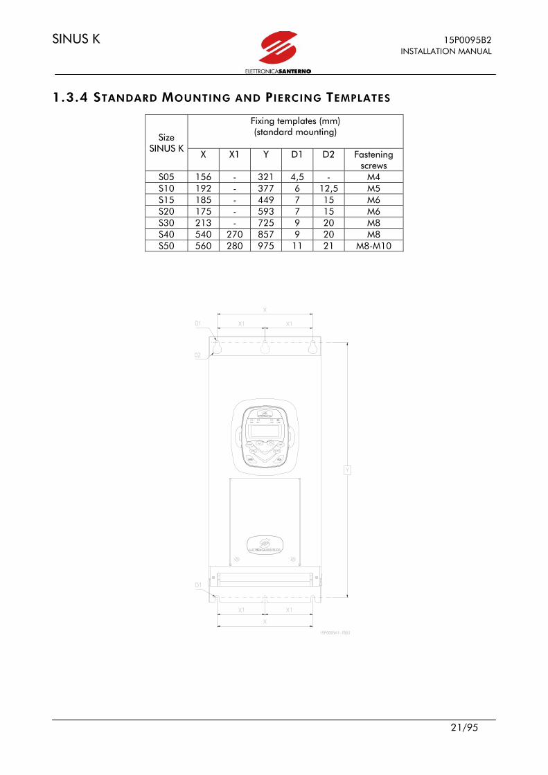
1.3.4 STANDARD MOUNTING AND PIERCING TEMPLATES
Fixing templates (mm) (standard mounting)
Size SINUS K
X X1 Y D1 D2 Fastening screws
S05 156 - 321 4,5 - M4 S10 192 - 377 6 12,5 M5 S15 185 - 449 7 15 M6 S20 175 - 593 7 15 M6 S30 213 - 725 9 20 M8 S40 540 270 857 9 20 M8 S50 560 280 975 11 21 M8-M10
15P0095B2 SINUS K INSTALLATION MANUAL
22/95
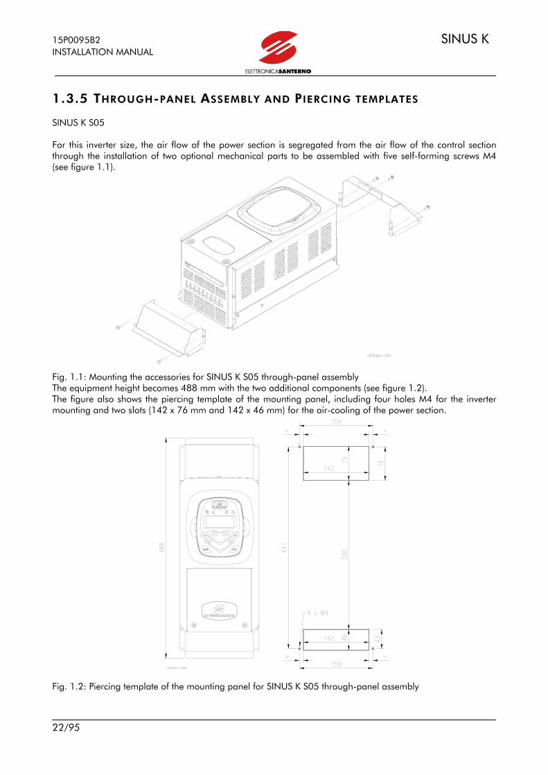
1.3.5 THROUGH-PANEL ASSEMBLY AND PIERCING TEMPLATES SINUS K S05 For this inverter size, the air flow of the power section is segregated from the air flow of the control section through the installation of two optional mechanical parts to be assembled with five self-forming screws M4 (see figure 1.1). Fig. 1.1: Mounting the accessories for SINUS K S05 through-panel assembly The equipment height becomes 488 mm with the two additional components (see figure 1.2). The figure also shows the piercing template of the mounting panel, including four holes M4 for the inverter mounting and two slots (142 x 76 mm and 142 x 46 mm) for the air-cooling of the power section. Fig. 1.2: Piercing template of the mounting panel for SINUS K S05 through-panel assembly

SINUS K 15P0095B2 INSTALLATION MANUAL
23/95
SINUS K S10 A through-panel assembly is provided for this inverter size. A special kit is to be assembled on the inverter (see figure 1.3). No. 13 self-forming screws are used for this type of assembly. L’ingombro in pianta dell’apparecchiatura, con kit per montaggio passante assemblato, diventa di 452 x 238 mm (vedi figura sotto). Nella figura sotto vengono anche riportati la dima di foratura del pannello di sostegno, comprendente 4 fori M5 ed un’asola rettangolare di 218 x 420 mm, e la vista laterale con evidenziati i due flussi d’aria (“A” per la parte di controllo e “B” per la potenza). Fig. 1.3: Mounting the accessories for SINUS K S10 through-panel assembly The overall dimensions of the equipment including the through-panel assembly kit is 452 x 238 mm (see figure below). The figure shows the piercing template of the mounting panel, including four holes M5 and a rectangular slot (218 x 420 mm) as well as the equipment side view with two air flows (air flow “A” for the control section and air flow “B” for the power section). Fig.1.4: Piercing template of the mounting panel for SINUS K S10 through-panel assembly
4 5
A B
A B

15P0095B2 SINUS K INSTALLATION MANUAL
24/95
SINUS K S15-S20-S30 No additional mechanical component is required for the through-panel assembly of these three SINUS K sizes. The piercing template shown in the figure below is to be made on the mounting panel. Measures are shown in the table. The figure below also shows the side view of the through-panel assembly of the equipment. The air flows and the front and rear projections are highlighted as well (see measures in the table). Fig.1.5: Through-panel assembly and piercing templates for SINUS K S15, S20, S50
Inverter size
Front and rear projection
Slot size for through-panel
assembly
Templates for fastening
holes
Thread and fastening screws
S1 S2 X1 Y1 X2 Y2 Y3 MX S15 256 75 207 420 185 18 449 4 x M6 S20 256 76 207 558 250 15 593 4 x M6 S30 257 164 270 665 266 35 715 4 x M8

SINUS K 15P0095B2 INSTALLATION MANUAL
25/95
SINUS K S40 For the through-panel assembly of this inverter size, remove the bottom mounting plate. The figure below shows how to disassemble the mounting plate.
To disassemble the mounting plate, remove 8 screws M6 (the figure 1.6 shows 4 screws on one side of the inverter).
Fig.1.6: Removing the mounting plate from SINUS K S40 for the through-panel assembly
The piercing template shown in the figure 1.7 is to be made on the mounting panel (see relevant measures). The figure also shows the side view of the equipment through-panel assembly. The air flows and the front and rear projections are highlighted as well (with relevant measures). Fig.1.7: Through-panel assembly and piercing templates for SINUS KS40

15P0095B2 SINUS K INSTALLATION MANUAL
26/95
SINUS K S50 For the through-panel assembly of this inverter size, remove the bottom mounting plate. The figure 1.8 shows how to disassemble the mounting plate.
To disassemble the mounting plate, remove 6 screws M8 (the figure shows the three screws in one side of the inverter).
Fig. 1.8: Removing the mounting plate from SINUS K S50 for the through-panel assembly.
The piercing template shown in the figure below (right) is to be made on the mounting panel (see relevant measures). The figure 1.9 also shows the side view of the through-panel assembly of the equipment. The air flows and the front and rear projections are highlighted as well (with relevant measures). Fig.1.9: Through-panel assembly and piercing templates for Sinus K S50

SINUS K 15P0095B2 INSTALLATION MANUAL
27/95
1.4 WIRING
1.4.1 WIRING DIAGRAM - The wiring diagram relates to the factory setting. - Connection terminals of the braking resistor: from Size S05 to Size S20 (terminals 47 and 48; Size S30 terminals 50 and 48). - Connection terminals of the external braking module: Size S40: terminals 51 and 52; Size S50: terminals 51 and 49. - Terminals for inverter power supply from DC source: terminals 47 and 49.
BRAKING RESISTOR
(OPTIONAL) BRAKING MODULE
(OPTIONAL) OUTPUT REACTAN
(OPTIONAL) OUTPUT REACTANCE
(OPTIONAL)
TH
REE
-PH
ASE
POW
ER S
UPP
LY
OU
TPU
T FI
LTER
(O
PTIO
NAL
)
CURRENT REFERENCE INPUT
SERIAL LINE CONNECTOR
ANALOG OUTPUTS
DIGITAL OUTPUTS
PID INPUT
DIGITAL INPUTS
CURRENT REFERENCE INPUT
15P0095B2 SINUS K INSTALLATION MANUAL
28/95
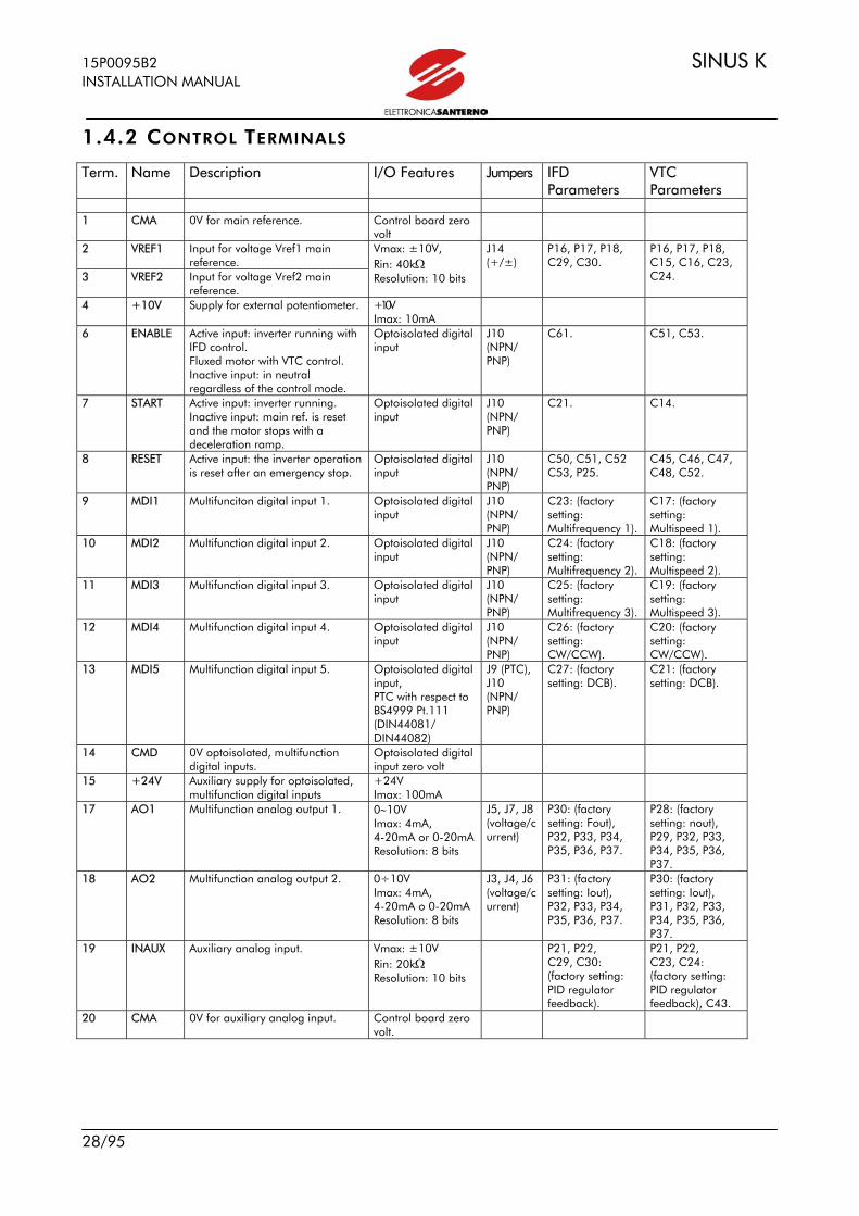
1.4.2 CONTROL TERMINALS
Term. Name Description I/O Features Jumpers IFD Parameters
VTC Parameters
1 CMA 0V for main reference.
Control board zero volt
2 VREF1 Input for voltage Vref1 main reference.
3 VREF2 Input for voltage Vref2 main reference.
Vmax: ±10V, Rin: 40kΩ Resolution: 10 bits
J14 (+/±)
P16, P17, P18, C29, C30.
P16, P17, P18, C15, C16, C23, C24.
4 +10V Supply for external potentiometer. +10V Imax: 10mA
6 ENABLE Active input: inverter running with IFD control. Fluxed motor with VTC control. Inactive input: in neutral regardless of the control mode.
Optoisolated digital input
J10 (NPN/ PNP)
C61. C51, C53.
7 START Active input: inverter running. Inactive input: main ref. is reset and the motor stops with a deceleration ramp.
Optoisolated digital input
J10 (NPN/ PNP)
C21.
C14.
8 RESET Active input: the inverter operation is reset after an emergency stop.
Optoisolated digital input
J10 (NPN/ PNP)
C50, C51, C52 C53, P25.
C45, C46, C47, C48, C52.
9 MDI1 Multifunciton digital input 1.
Optoisolated digital input
J10 (NPN/ PNP)
C23: (factory setting: Multifrequency 1).
C17: (factory setting: Multispeed 1).
10 MDI2 Multifunction digital input 2.
Optoisolated digital input
J10 (NPN/ PNP)
C24: (factory setting: Multifrequency 2).
C18: (factory setting: Multispeed 2).
11 MDI3 Multifunction digital input 3.
Optoisolated digital input
J10 (NPN/ PNP)
C25: (factory setting: Multifrequency 3).
C19: (factory setting: Multispeed 3).
12 MDI4 Multifunction digital input 4.
Optoisolated digital input
J10 (NPN/ PNP)
C26: (factory setting: CW/CCW).
C20: (factory setting: CW/CCW).
13 MDI5 Multifunction digital input 5.
Optoisolated digital input, PTC with respect to BS4999 Pt.111 (DIN44081/ DIN44082)
J9 (PTC), J10 (NPN/ PNP)
C27: (factory setting: DCB).
C21: (factory setting: DCB).
14 CMD 0V optoisolated, multifunction digital inputs.
Optoisolated digital input zero volt
15 +24V
Auxiliary supply for optoisolated, multifunction digital inputs
+24V Imax: 100mA
17 AO1 Multifunction analog output 1. 0∼10V Imax: 4mA, 4-20mA or 0-20mA Resolution: 8 bits
J5, J7, J8 (voltage/current)
P30: (factory setting: Fout), P32, P33, P34, P35, P36, P37.
P28: (factory setting: nout), P29, P32, P33, P34, P35, P36, P37.
18 AO2
Multifunction analog output 2. 0÷10V Imax: 4mA, 4-20mA o 0-20mA Resolution: 8 bits
J3, J4, J6 (voltage/current)
P31: (factory setting: Iout), P32, P33, P34, P35, P36, P37.
P30: (factory setting: Iout), P31, P32, P33, P34, P35, P36, P37.
19 INAUX
Auxiliary analog input.
Vmax: ±10V Rin: 20kΩ Resolution: 10 bits
P21, P22, C29, C30: (factory setting: PID regulator feedback).
P21, P22, C23, C24: (factory setting: PID regulator feedback), C43.
20 CMA
0V for auxiliary analog input. Control board zero volt.

SINUS K 15P0095B2 INSTALLATION MANUAL
29/95
21 IREF
Input for current main reference (0 20mA, 4÷20mA).
Rin: 100Ω Resolution: 10 bits
P19, P20, C29, C30: (factory setting: not used).
P19, P20, C23, C24: (factory setting: not used).
22 CMA
0V for current main reference. Control board zero volt
24
MDOC
Open collector digital output (collector terminal).
25 MDOE
Open collector digital output (emitter terminal).
Open collector NPN/PNP Vmax: 48V Imax: 50mA
P60: (factory setting: FREQ. LEVEL), P63, P64, P69, P70.
P60: (factory setting: SPEED LEVEL), P63, P64, P69, P70, P75, P76, P77.
26
RL1-NC Multifunction digital relay output 1 (NC contact).
27
RL1-C Multifunction digital relay output 1 (common).
28 RL1-NO Multifunction digital relay output (NO contact).
250 VAC, 3A 30 VDC, 3A
P61: (factory setting: INV O.K. ON), P65, P66, P71, P72.
P61: (factory setting: INV O.K. ON), P65, P66, P71, P72, P75, P76, P77.
29
RL2-C Multifunction digital relay output 2 (common).
30
RL2-NO Multifunction digital relay output 2 (NO contact).
31 RL2-NC Multifunction digital relay output 2 (NC contact).
250 VAC, 3A 30 VDC, 3A
P62: (factory setting: FREQ. LEVEL), P67, P68, P73, P74.
P62: (factory setting: SPEED LEVEL), P67, P68, P73, P74, P75, P76, P77.

15P0095B2 SINUS K INSTALLATION MANUAL
30/95
1.4.3 SIGNALS AND PROGRAMMING ON BOARD ES778 (CONTROL
BOARD) SW1 J14 J3,J4,J6 J9 J10 J5,J7,J8
VBLIM=Voltage limiting IMLIM=Current limiting RUN=Inverter enabled
L1= +5V on L2= -15V on L4= +15V on

SINUS K 15P0095B2 INSTALLATION MANUAL
31/95
1.4.3.1 INDICATOR LEDS LED L3, red (VBLIM): voltage limiting activation during deceleration; “on” when VDC within the equipment exceeds by 20% the rated value during dynamic braking. LED L5, red (IMLIM): current limiting activation during acceleration or due to overload conditions; “on” if the motor current exceeds the values set in C41 and C43 (Limits submenu) during acceleration and at constant frequency (IFD SW) respectively. This Led is on even when the torque needed exceeds the value set in C42, Limits submenu (VTC SW). LED L6, green (RUN): Inverter enabled; “on” when the inverter is running or is enabled only (VTC SW only) (fluxed motor). LED L1, green (+5V): control board +5V power supply on. LED L2, green (-15V): control board -15V power supply on. LED L4, green (+15V): control board +15V power supply on. 1.4.3.2 JUMPERS AND DIP-SWITCH J3 (1-2) 4-20mA on AO2 (2-3) 0-20mA on AO2 J4 (2-3) V on AO2 (1-2) mA on AO2 J5 (1-2) 4-20mA on AO1 (2-3) 0-20mA on AO1 J6 (1-2) 4-20mA on AO2 (2-3) 0-20mA on AO2 J7 (2-3) V on AO1 (1-2) mA on AO1 J8 (1-2) 4-20mA on AO1 (2-3) 0-20mA on AO1 J9 (2-3) PTC OFF
(1-2) PTC ON J10 (1-2) PNP inputs (2-3) NPN inputs J14 (2-3) VREF + reference (1-2) VREF ± reference SW1 (on) bias resistors and termination on RS485 enabled (off) bias resistors and termination on RS485 disabled

15P0095B2 SINUS K INSTALLATION MANUAL
32/95
1.4.4 DIGITAL INPUT FEATURES (TERMINALS 6 TO 15) All digital inputs are galvanically insulated with respect to zero volt of the inverter control board (ES778). Consider power supply on terminals 14 and 15 before activating the inverter digital inputs. Depending on the position of jumper J10, signals may be activated both to zero volt (NPN-type command) and to + 24 Volts (PNP-type command). The figure below shows the different control modes based on the position of jumper J10. Auxiliary power supply +24 VDC (terminal 15) is protected by a self-resetting fuse.
NPN command (active to zero Volt) throughvoltage-free contact.
PNP contact (active to +24V) through voltage-free contact.
NPN command (active to zero Volt) sent from adifferent device (PLC, digital output board, etc.)
PNP command (active to + 24 Volt) sent from a different device (PLC, digital output board, etc.)
0V
DIGITAL OUTPUT
DIGITALOUTPUT
0V
Fig. Digital input control modes
NOTE: Terminal 14 (CMD – digital input zero volt) is galvanically insulated from terminals 1, 20, 22 (CMA – control board zero volt) and from terminal 25 (MDOE = emitter terminal of multifunction digital output).
The operating condition of the digital inputs is indicated by parameter M08 (IFD SW) or parameter M11 (VTC SW) in the Measure submenu. Digital inputs (except form terminal 6 and terminal 8) are disabled if parameter C21 (IFD SW) or C14 (VTC SW) is set to REM. In that case, the command is sent through serial communication. If parameter C21 (IFD SW) or C14 (VTC SW) is programmed to Kpd, input 7 command is sent via keypad (START key). 1.4.4.1 ENABLE (TERMINAL 6) ENABLE input is always to be activated to enable the inverter operation regardless of the control mode. If ENABLE input is disabled, the inverter output voltage is set to zero, so the motor performs a cost to stop. If the ENABLE command is active at power on, the inverter will not start until terminal 6 is opened and closed again. This safety measure may be disabled through parameter C61 (IFD SW) or C53 (VTC SW). The ENABLE command also unlocks PID regulator - if used regardless of the inverter operation - whether neither MDI3 nor MDI4 are set as A/M (Automatic/Manual).
SINUS K 15P0095B2 INSTALLATION MANUAL
33/95
NOTE: When the ENABLE command is active, alarms A11 (Bypass Failure), A25
(Mains Loss) (IFD SW only), A30 (DC OverVoltage) and A31 (DC UnderVoltage) are enabled as well.
1.4.4.2 START (TERMINAL 7) To enable the Start input, set the control modes via terminal board (factory setting). When the START input is active, the main reference is enabled; otherwise, the main reference is set to zero. The output frequency (IFD SW) or the speed motor (VTC SW) drops to zero with respect to the preset deceleration ramp. If C21 (IFD SW) or C14 (VTC SW) is set to Kpd (command sent via keypad), the START input is disabled and its functionality is performed by the inverter remotable keypad (see Section 5.1, “COMMANDS MENU”). If the REV function ("reverse rotation") is active, the START input may be used only when the REV input is inactive; if START and REV are enabled at a time, the main reference is set to zero. 1.4.4.3 RESET (TERMINAL 8) If an alarm trips, the inverter stops, the motor performs a coast to stop and the display shows an alarm message (see section 8 “DIAGNOSTICS”). Open the reset input for a while or press the RESET key to reset the alarm. This happens only if the cause responsible for the alarm has disappeared and the display shows "Inverter OK". If factory setting is used, enable and disable the ENABLE command to restart the inverter. If parameter C61 (IFD SW) or C53 (VTC SW) is set to [YES], the inverter is reset and restarts. The reset terminal also allows to reset the UP/DOWN commands; to do so, set parameter P25 "U/D RESET" to [YES].
NOTE: Factory setting does not reset alarms at power off. Alarms are stored and displayed at next power on and the inverter is locked. To reset the inverter, turn it off and set parameter C53 (IFD SW) or C48 (VTC SW) to [YES].
CAUTION: If an alarm trips, see the Diagnostics section and reset the equipment after detecting the cause responsible for the alarm.
DANGER: Shock hazard persists even when the inverter is locked on output terminals (U, V, W) and on the terminals used for the connection of resistive braking devices (+, -, B).
1.4.4.4 M.D.I. (TERMINALS 9 TO 13) The programmable digital input functionality is detailed in the Programming Manual. 1.4.4.5 MOTOR THERMAL PROTECTION INPUT The inverter manages the signal sent from a thermistor incorporated in the motor windings to obtain a hardware thermal protection of the motor. The thermistor ratings must comply with BS4999 Pt.111 (DIN44081/DIN44082): Resistor corresponding to trip value: 1000 ohm (typical rating) Resistor at Tr–5°C: < 550 ohm Resistor at Tr+5°C: > 1330 ohm

15P0095B2 SINUS K INSTALLATION MANUAL
34/95
Do the following to use the thermistor:
1) Set jumper J9 to position 1-2, 2) Connect thermistor between terminals 13 and 14 in the control board, 3) Set MDI5 as auxiliary trip. In that way, the inverter will stop and indicate "auxiliary trip" as soon as the motor temperature exceeds threshold value Tr.
1.4.5 ANALOG INPUT FEATURES (TERMINALS 2,3,15 AND 21) Inputs Vref1 and Vref2 (terminals 2 and 3) acknowledge both unipolar signals (0÷10V, factory setting) and bipolar signals (±10V) based on jumper J14 position. Signals sent to terminals 2 and 3 are summed up. Auxiliary power supply (+10V, terminal 4) is available to power an external potentiometer (2.5÷10 kΩ). Do the following to use a bipolar signal (± 10 V) at the inverter input: - set jumper J14 to position 1-2 (+/-) - set parameter P18 (Vref J14 Pos.) as “+/-” - set parameter P15 (Minimum Ref) as “+/-” The motor direction of rotation changes when the main reference sign becomes opposite. Bipolar voltage (±10V) may be sent to input Inaux (terminal 19). The motor direction of rotation changes when negative signals are sent. Analog input Iref (terminal 21) acknowledges a current value ranging from 0 to 20mA as an input signal (factory setting: 4÷20 mA).
CAUTION: Do not apply signals exceeding ±10V to terminals 2 and 3. Do not send a current value higher than 20mA to terminal 21.
Parameters P16 (Vref Bias), P17 (Vref Gain), P19 (Inmax), and P20 (Iref Gain) allow to change the relationship between the signals sent to terminals 2, 3 and 21 and the main reference. It is possible to change the relationship between the signal sent to terminal 19 (Inaux) and the value acquired through parameters P21 and P22. Programming and functionality of the parameters managing analog inputs are detailed in the Programming Manual.
1.4.6 DIGITAL OUTPUT FEATURES An OPEN COLLECTOR output is available on terminals 24 (collector) and 25 (common terminal). The OC output is galvanically insulated from zero volt of the control board and is capable of driving a load up to 50mA with 48V power supply. The output functionality is determined by parameter P60 in the "Digital output" submenu. The output enabling/disabling delay may be programmed through the parameters below: - P63 MDO ON Delay - P64 MDO OFF Delay. The factory setting is the following: frequency/speed threshold: the transistor activates when the output frequency (IFD SW) or the motor speed (VTC SW) attains the level set through the "Digital Output" menu (parameters P69 "MDO level", P70 "MDO Hyst.").

SINUS K 15P0095B2 INSTALLATION MANUAL
35/95
The figure shows an example of a relay connected to the output. Fig. – Connecting a relay to the OPEN COLLECTOR output.
CAUTION: Always use freewheeling diode (D) for inductive loads (e.g. relay coils).
CAUTION: Never exceed max. allowable voltage and max. allowable current values.
NOTE: Terminal 25 is galvanically insulated from terminals 1, 20, 22, (CMA – control board zero volt) and from terminal 14 (CMD – digital input zero volt).
NOTE: As an auxiliary power supply, voltage at terminal 15 (+24V) and terminal 14
(CMD) (control terminals) may be used. Max. allowable current: 100mA.
25
MDOC
CONTROL BOARD
24 RL
+
D
25
24
RL
+
D CONTROL BOARD
MDOE
12÷48 VDC
12÷48 VDC
MDOC
MDOE
“PNP” CONNECTION “NPN” CONNECTION

15P0095B2 SINUS K INSTALLATION MANUAL
36/95
1.4.6.1 RELAY OUTPUTS Two relay outputs are available: - terminals 26, 27, 28: relay RL1; reverse contact (250 VAC, 3A; 30 VDC, 3A) - terminals 29, 30, 31: relay RL2; reverse contact (250 VAC, 3A; 30 VDC, 3A) Parameters P61 (RL1 Opr) and P62 (RL2 Opr) in the Digital Output submenu affect the relay output functionality. Relay energizing and de-energizing may be delayed through the following parameters: - P65 RL1 Delay ON - P66 RL1 Delay OFF - P67 RL2 Delay ON - P68 RL2 Delay OFF Factory-setting is as follows: RL1: relay “ready” (terminals 26, 27 and 28); energizes when the inverter is ready to supply the motor. At power on, the equipment takes some seconds before initializing; the relay energizes when an alarm trips. The alarm trip locks the inverter. RL2: “frequency/speed threshold” relay (terminals 29, 30 and 31); energizes when the output frequency (IFD SW) or the motor speed (VTC SW) attains the level set through the "Digital Output" menu (parameters P73 "RL2 level", P74 "RL2 Hyst.").
CAUTION: Never exceed max. voltage and max. current values allowed by relay contacts.
CAUTION: Use freewheeling diode for DC inductive loads. Use antidisturbance filters for AC inductive loads.
SINUS K 15P0095B2 INSTALLATION MANUAL
37/95
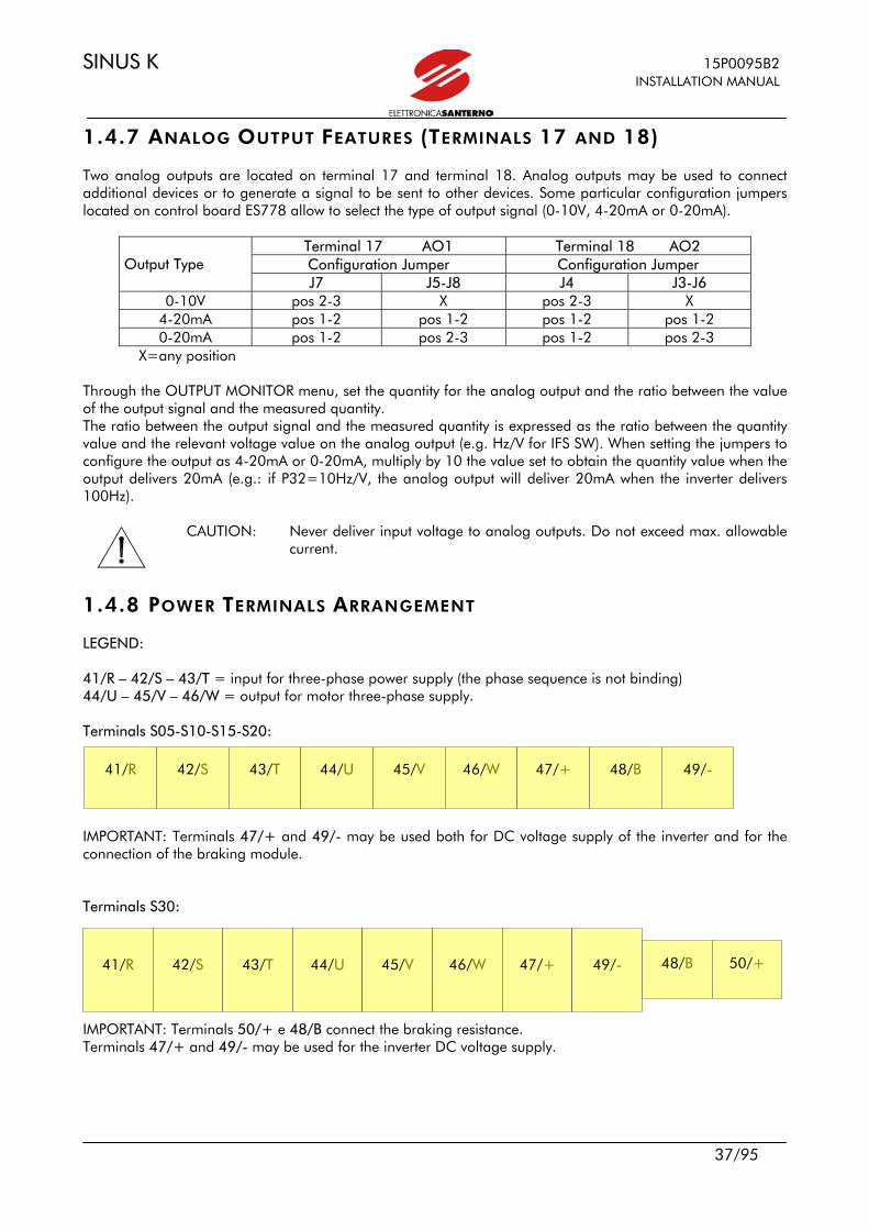
1.4.7 ANALOG OUTPUT FEATURES (TERMINALS 17 AND 18) Two analog outputs are located on terminal 17 and terminal 18. Analog outputs may be used to connect additional devices or to generate a signal to be sent to other devices. Some particular configuration jumpers located on control board ES778 allow to select the type of output signal (0-10V, 4-20mA or 0-20mA).
Terminal 17 AO1 Terminal 18 AO2 Configuration Jumper Configuration Jumper Output Type J7 J5-J8 J4 J3-J6
0-10V pos 2-3 X pos 2-3 X 4-20mA pos 1-2 pos 1-2 pos 1-2 pos 1-2 0-20mA pos 1-2 pos 2-3 pos 1-2 pos 2-3
X=any position Through the OUTPUT MONITOR menu, set the quantity for the analog output and the ratio between the value of the output signal and the measured quantity. The ratio between the output signal and the measured quantity is expressed as the ratio between the quantity value and the relevant voltage value on the analog output (e.g. Hz/V for IFS SW). When setting the jumpers to configure the output as 4-20mA or 0-20mA, multiply by 10 the value set to obtain the quantity value when the output delivers 20mA (e.g.: if P32=10Hz/V, the analog output will deliver 20mA when the inverter delivers 100Hz).
CAUTION: Never deliver input voltage to analog outputs. Do not exceed max. allowable current.
1.4.8 POWER TERMINALS ARRANGEMENT LEGEND: 41/R – 42/S – 43/T = input for three-phase power supply (the phase sequence is not binding) 44/U – 45/V – 46/W = output for motor three-phase supply. Terminals S05-S10-S15-S20: IMPORTANT: Terminals 47/+ and 49/- may be used both for DC voltage supply of the inverter and for the connection of the braking module. Terminals S30: IMPORTANT: Terminals 50/+ e 48/B connect the braking resistance. Terminals 47/+ and 49/- may be used for the inverter DC voltage supply.
41/R
42/S
43/T
44/U
45/V
46/W
47/+
48/B
49/-
41/R
42/S
43/T
44/U
45/V
46/W
47/+
49/-
48/B
50/+

15P0095B2 SINUS K INSTALLATION MANUAL
38/95
Terminals S40 IMPORTANT: Terminals 51/+ and 52/- connect the inverter bar to the external braking module. Terminals 47/+ and 49/- may be used for the inverter DC voltage supply. Terminals S50:
IMPORTANT: Terminals 47/+ and 49/- may be used both for DC voltage supply of the inverter and for the connection of the braking module.
DANGER: Before changing the equipment connections, shut off the inverter and wait at least 5 minutes to allow for the discharge of the heatsinks in the DC-link.
DANGER: Use only B-type differential circuit breakers. CAUTION: Connect the power supply line to supply terminals only. The connection of the
power supply line to any other terminal will damage the inverter. CAUTION: Always make sure that the supply voltage ranges between the limits stated in
the inverter nameplate. CAUTION: Always connect the ground terminal to avoid electrical shock hazard and to
limit disturbance. The user has the responsibility to provide a grounding system in compliance
with the regulations in force. CAUTION: After connecting the equipment, check the following: - all wires must be properly connected; - no link is missing; - no short-circuit is occurring between the terminals and between the
terminals and the ground. CAUTION: Do not start or stop the inverter using a contactor installed over the inverter
power supply line.
49/-
47/+
41/R
42/S
43/T
44/U
45/V
46/W
41/R
42/S
43/T
44/U
45/V
46/W
51/+
52/-
47/+
49/-

SINUS K 15P0095B2 INSTALLATION MANUAL
39/95
CAUTION: The inverter power supply must always be protected by fast fuses or by a
thermal/magnetic circuit breaker. CAUTION: Do not apply single-phase voltage. CAUTION: Always mount antidisturbance filters on the contactor coils and the solenoid
valve coils. CAUTION: At power on, if the inverter commands “ENABLE ” (terminal 6) and “START”
(terminal 7) are active, the motor will immediately start when the main reference is other than zero. This may be very dangerous. To avoid the motor accidental starting, set parameter C61 (IFD SW) or C53 (VTC SW) to [NO]. In that case, the motor will start only after opening and closing the command contact on terminal 6.

15P0095B2 SINUS K INSTALLATION MANUAL
40/95
1.4.9 CROSS-SECTIONS OF POWER CONNECTION WIRES AND SIZE OF
PROTECTION DEVICES
Inverter Rated
Current
Terminal Cross-section
Wire Peeling
Tightening Torque
Wire Cross-section
Mains Side and Motor
Side
Fast Fuses. +
Disconnecting switch
Magnetic
switch
AC1
Contactor Size Class
Ampere mm2 mm Nm mm2 Ampere Ampere Ampere
SINUS K 0005 10,5 0,5÷10 10 1,2-1,5 2,5 16 25 10,5
SINUS K 0007 12,5 0,5÷10 10 1,2-1,5 2,5 16 25 12,5
SINUS K 0009 16,5 0,5÷10 10 1,2-1,5 4 25 25 16,5
SINUS K 0011 16,5 0,5÷10 10 1,2-1,5 4 25 25 16,5
S05
SINUS K 0014 16,5 0,5÷10 10 1,2-1,5 4 32 30 16,5
SINUS K 0017 30 0,5÷10 10 1,2-1,5 10 40 45 30
SINUS K 0020 30 0,5÷10 10 1,2-1,5 10 40 45 30
SINUS K 0025 41 0,5÷10 10 1,2-1,5 10 63 55 41
SINUS K 0030 41 0,5÷10 10 1,2-1,5 10 63 60 41
S10
SINUS K 0035 41 0,5÷10 10 1,2-1,5 10 100 100 41 S15 SINUS K 0040 72 4÷25 15 2,5 25 100 100 72
SINUS K 0049 80 25÷50 24 6-8 25 100 100 80
SINUS K 0060 88 25÷50 24 6-8 35 125 115 88
SINUS K 0067 103 25÷50 24 6-8 50 125 125 103
SINUS K 0074 120 25÷50 24 6-8 50 160 145 120
S20
SINUS K 0086 135 25÷50 24 6-8 50 160 160 135
SINUS K 0113 180 35÷155 30 10 95 200 250 180
SINUS K 0129 195 35÷155 30 10 120 250 250 195
SINUS K 0150 215 35÷155 30 10 120 400 275 215 S30
SINUS K 0162 240 35÷155 30 10 120 400 275 240
SINUS K 0179 300 70÷240 40 25-30 185 400 350 300
SINUS K 0200 345 70÷240 40 25-30 210 400 400 345
SINUS K 0216 375 70÷240 40 25-30 240 630 450 375 S40
SINUS K 0250 390 70÷240 40 25-30 240 630 450 390
SINUS K 0312 480 Bar - 3 2x150 630 550 480 SINUS K 0366 550 Bar - 3 2x210 800 600 550 S50
SINUS K 0399 630 Bar - 3 2x240 800 700 630 SINUS K 0457 720 Bar - 3 2x240 800 800 720
S60 SINUS K 0524 800 Bar - 3,5 3x210 1000 1000 800
SINUS K 0598 900 Bar - 3,5 3x210 1250 1000 900
SINUS K 0748 1000 Bar - 3,5 3x240 1250 2x700 1000 S70
SINUS K 0831 1200 Bar - 3,5 3x240 1600 2x800 1200

SINUS K 15P0095B2 INSTALLATION MANUAL
41/95
1.5 OPERATING AND REMOTING THE KEYPAD For the parameter programming and view a keypad is located on the front part of SINUS K inverters. The keypad includes 4 LEDs, an LCD display and 8 function keys. During operation, the display shows the parameter values, the alarm messages (if any) and the value of the measures processed by the inverter.
LED REF: “on” when a frequency/ speed/torque reference is sent. IFD SW ONLY LED REF: flashes when run command active; frequency reference equal to 0.
LED RUN: is on during the inverter operation VTC SW ONLY: LED RUN: flashes with inverter enabled (fluxed motor) IFD SW ONLY: LED RUN and LED REF: if both Leds are flashing, the inverter is performing a deceleration ramp up to frequency reference 0.
↓ Down arrow: scrolls through the menus and decrements parameter values
PROG allows to enter and quit the submenus. Enables parameter alteration.
LED “TRM”: if on, commands are sent from terminal board.
LED “REM”: if on, commands are sent from serial link.
↑ Up arrow: scrolls through the menus and increments the parameter values.
SAVE saves each parameter.
START starts the motor (active in KeyPad mode only).
MENU allows to access the main menu.
RESET resets the alarms tripped.
STOP stops the motor (active in KeyPad mode only).

15P0095B2 SINUS K INSTALLATION MANUAL
42/95
The keypad includes the following keys: PROG, ↓, ↑, SAVE, MENU, RESET, START, STOP. They are detailed below. - PROG allows to enter and quit the menus and submenus and enables altering the inverter parameters (when switching from parameter display to parameter programming, the cursor starts flashing); - ↓ down arrow; scrolls through the menus and submenus, the pages in a submenu or the parameters in descending order. During programming, it decrements the parameter value; - ↑ up arrow; scrolls through the menus and submenus, the pages in a submenu or the parameters in descending order. During programming, it increments the parameter value; - SAVE in programming mode, this key saves to non-volatile memory (EEPROM) the value of the parameter being altered. This prevents any parameter modification from being cleared in case of mains loss; - MENU if pressed once, allows to access the main menu; if pressed twice, allows to return to the prior condition; - RESET resets the alarms tripped; - START if enabled, allows to start the motor; - STOP if enabled, allows to stop the motor; - RETURN TO THE FIRST PAGE OF A SUBMENU: simultaneously press PROG and ↓ .
NOTE: The inverter operation is affected by the active parameter set. The parameter being altered with ↑ and ↓ immediately replaces the prior parameter value, even if the SAVE key is not pressed. The new parameter value will be cleared at power off.
The keypad also includes the LEDs below: - LED “RUN”: if on and not flashing, indicates that the inverter is running: the inverter is enabled (ENABLE contact closed) and a frequency/speed/torque reference is present (START contact closed). Only for VTC SW: if flashing, indicates that the inverter is enabled only (fluxed motor); - LED “REF”: indicates a frequency/speed/torque reference other than 0 (from potentiometer, keypad, and so on); - LED “TRM”: indicates that the START command and the commands relating to multifunction digital inputs MDI1÷MDI5 are sent from the terminal board; - LED “REM”: indicates that the START commands and the commands relating to multifunction digital inputs MDI1÷MDI5 are sent from serial link.
SINUS K 15P0095B2 INSTALLATION MANUAL
43/95
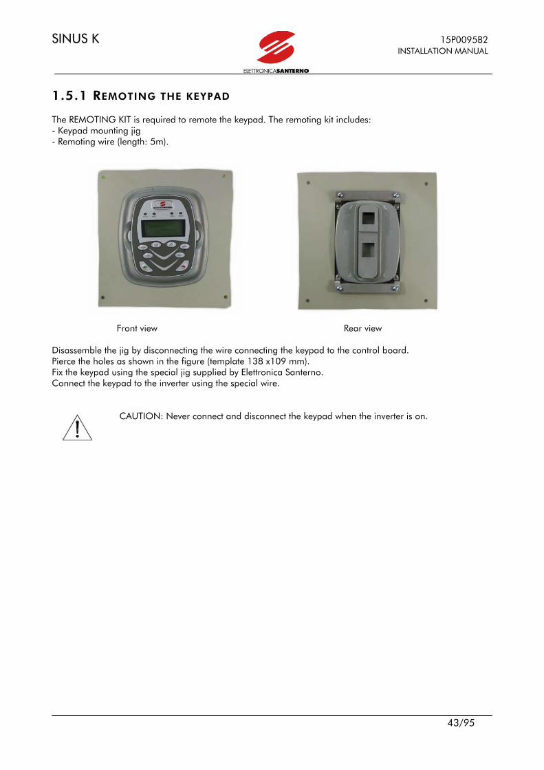
1.5.1 REMOTING THE KEYPAD The REMOTING KIT is required to remote the keypad. The remoting kit includes: - Keypad mounting jig - Remoting wire (length: 5m).
Front view Rear view Disassemble the jig by disconnecting the wire connecting the keypad to the control board. Pierce the holes as shown in the figure (template 138 x109 mm). Fix the keypad using the special jig supplied by Elettronica Santerno. Connect the keypad to the inverter using the special wire.
CAUTION: Never connect and disconnect the keypad when the inverter is on.
15P0095B2 SINUS K INSTALLATION MANUAL
44/95
1.6 SERIAL COMMUNICATION
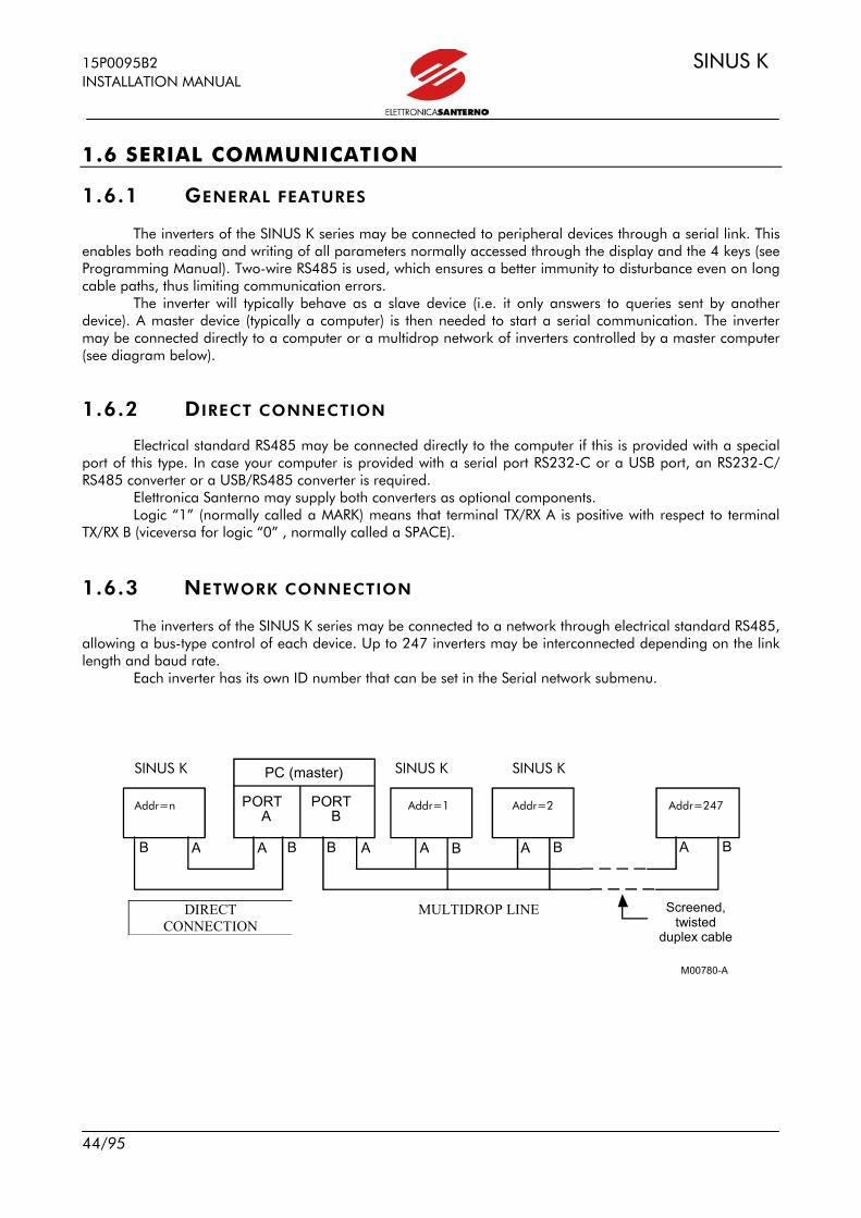
1.6.1 GENERAL FEATURES The inverters of the SINUS K series may be connected to peripheral devices through a serial link. This enables both reading and writing of all parameters normally accessed through the display and the 4 keys (see Programming Manual). Two-wire RS485 is used, which ensures a better immunity to disturbance even on long cable paths, thus limiting communication errors. The inverter will typically behave as a slave device (i.e. it only answers to queries sent by another device). A master device (typically a computer) is then needed to start a serial communication. The inverter may be connected directly to a computer or a multidrop network of inverters controlled by a master computer (see diagram below).
1.6.2 DIRECT CONNECTION Electrical standard RS485 may be connected directly to the computer if this is provided with a special port of this type. In case your computer is provided with a serial port RS232-C or a USB port, an RS232-C/ RS485 converter or a USB/RS485 converter is required. Elettronica Santerno may supply both converters as optional components. Logic “1” (normally called a MARK) means that terminal TX/RX A is positive with respect to terminal TX/RX B (viceversa for logic “0” , normally called a SPACE).
1.6.3 NETWORK CONNECTION The inverters of the SINUS K series may be connected to a network through electrical standard RS485, allowing a bus-type control of each device. Up to 247 inverters may be interconnected depending on the link length and baud rate. Each inverter has its own ID number that can be set in the Serial network submenu.
B
P C ( m a s t e r )
P O R T A
P O R T B
B B B A A A
M 0 0 7 80-A
A B A B A
SINUS K SINUS K SINUS K
Addr=n Addr=1 Addr=2 Addr=247
DIRECT CONNECTION
MULTIDROP LINE
Screened, twisted
duplex cable
SINUS K 15P0095B2 INSTALLATION MANUAL
45/95
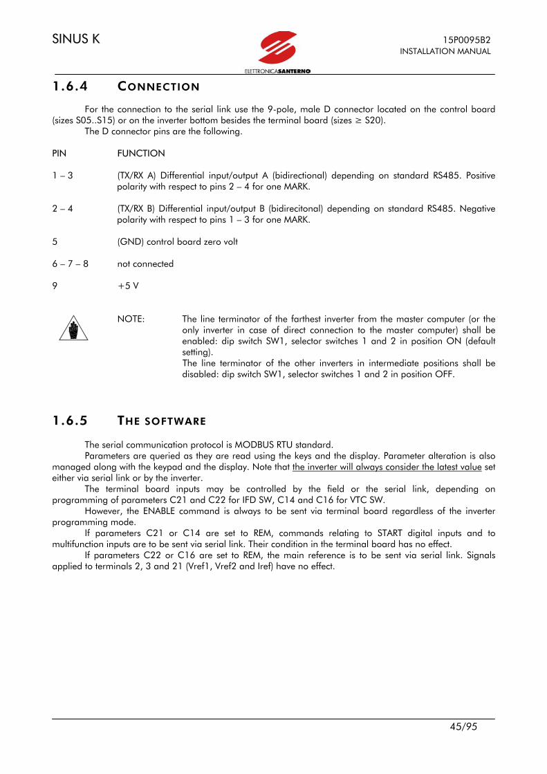
1.6.4 CONNECTION For the connection to the serial link use the 9-pole, male D connector located on the control board (sizes S05..S15) or on the inverter bottom besides the terminal board (sizes ≥ S20). The D connector pins are the following. PIN FUNCTION 1 – 3 (TX/RX A) Differential input/output A (bidirectional) depending on standard RS485. Positive
polarity with respect to pins 2 – 4 for one MARK. 2 – 4 (TX/RX B) Differential input/output B (bidirecitonal) depending on standard RS485. Negative
polarity with respect to pins 1 – 3 for one MARK. 5 (GND) control board zero volt 6 – 7 – 8 not connected 9 +5 V
NOTE: The line terminator of the farthest inverter from the master computer (or the only inverter in case of direct connection to the master computer) shall be enabled: dip switch SW1, selector switches 1 and 2 in position ON (default setting). The line terminator of the other inverters in intermediate positions shall be disabled: dip switch SW1, selector switches 1 and 2 in position OFF.
1.6.5 THE SOFTWARE The serial communication protocol is MODBUS RTU standard. Parameters are queried as they are read using the keys and the display. Parameter alteration is also
managed along with the keypad and the display. Note that the inverter will always consider the latest value set either via serial link or by the inverter.
The terminal board inputs may be controlled by the field or the serial link, depending on programming of parameters C21 and C22 for IFD SW, C14 and C16 for VTC SW.
However, the ENABLE command is always to be sent via terminal board regardless of the inverter programming mode.
If parameters C21 or C14 are set to REM, commands relating to START digital inputs and to multifunction inputs are to be sent via serial link. Their condition in the terminal board has no effect.
If parameters C22 or C16 are set to REM, the main reference is to be sent via serial link. Signals applied to terminals 2, 3 and 21 (Vref1, Vref2 and Iref) have no effect.
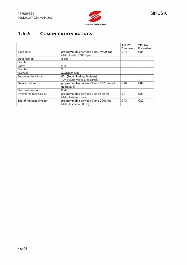
15P0095B2 SINUS K INSTALLATION MANUAL
46/95
1.6.6 COMUNICATION RATINGS IFD SW
Parameters VTC SW Parameters
Baud rate: programmable between 1200..9600 bps (default rate: 9600 bps)
C94 C84
Data format: 8 bits Start bit: 1 Parity: NO Stop bit: 2 Protocol: MODBUS RTU Supported functions: 03h (Read Holding Registers)
10h (Preset Multiple Registers)
Device address: programmable between 1 and 247 (default address: 1)
C90 C80
Electrical standard: RS485 Inverter response delay: programmable between 0 and 500 ms
(default delay: 0 ms) C91 C81
End of message timeout: programmable between 0 and 2000 ms (default timeout: 0 ms)
C93 C83

SINUS K 15P0095B2 INSTALLATION MANUAL
47/95
2 STARTUP PROCEDURES The startup procedures described below relate to commands sent via terminal board (factory setting). For terminal configuration, see section 1.4.2. "Control Terminals" and 1.4.3. "Power terminals arrangement").
DANGER: Before changing the equipment connections, shut off the inverter and wait at least 5 minutes to allow for the discharge of the heatsinks in the DC-link.
DANGER: At startup, if the connected motor rotates in the wrong direction, send a low frequency reference and check to see if the direction of rotation is correct.
DANGER: When an alarm message is displayed, find the cause responsible for the alarm trip before restarting the equipment.
2.1 STARTUP PROCEDURE FOR IFD SOFTWARE 1) Connection: Follow the instructions stated in sections “Caution Statements” and
“Installation”. 2) Power on: Link to terminal 6 (inverter disabled) is to be open when the inverter is started. 3) Parameter alteration: Set parameter P01 (Key parameter) to 1. Use the PROG, ↓, ↑ and SAVE keys
to access the other parameters. See the "Submenu Tree" in the Programming Manual.
4) Motor parameters: Access the V/f Pattern submenu and set the following: C05 (Imot) (motor
rated current); C06 (fmot1) (motor rated frequency); C07 (fomax1) (maximum output frequency desired) and C09 (Vmot1) (motor rated voltage). Press SAVE each time a new parameter value is set.
5) Overload: Set parameters C41/C43/C45 in the Limits submenu with respect to the
maximum current desired. 6) Startup: Close terminals 6 (ENABLE) and 7 (START) and send a frequency reference:
the RUN LED and REF LED will come on and the motor will start. Make sure the motor is rotating in the right direction. If not, operate on terminal 12 (CW/CCW) or open terminals 6 and 7. Shut off the inverter, wait a few minutes and reverse two of the motor phases.
7) Possible failures: If no failure occurred, go to step 8. Otherwise, check the inverter connections
paying particular attention to supply voltages, DC link and input reference. Also check if alarm messages are displayed. In the Measure submenu, check the reference frequency (M01), the supply voltage to the control section (M05), the DC link voltage (M06), and the condition of terminals 6, 7, 8, 9, 10, 11, 12, and 13 (M08; a number other than 0 indicates the "activation" of the relevant terminal). Check to see if these readings match with the measured values.
15P0095B2 SINUS K INSTALLATION MANUAL
48/95
8) Additional alterations: Note that you can change Cxx parameters in the CONFIGURATION menu only
when the inverter is DISABLED or STOPPED. Always set parameter P01 to 1 before changing any parameter. You can write
down any customized parameter in the table on the last pages of the Programming Manual.
9) Reset: If an alarm trips, find the cause responsible for the alarm and reset the
equipment. Enable terminal 8 (Reset) for some time, or press the RESET key.
2.2 STARTUP PROCEDURE FOR VTC SOFTWARE The startup procedures described below relate to commands sent via terminal board (factory setting). For terminal configuration, see section 1.4.2. "Control Terminals" and 1.4.3. "Power terminals arrangement"). 1) Connection: Follow the instructions stated in sections “Caution Statements” and
“Installation”. 2) Power on: Link to terminal 6 (inverter disabled) is to be open when the inverter is started. 3) Parameter alteration: Set parameter P01 (Key parameter) to 1. Use the PROG, ↓, ↑ and SAVE keys
to access the other parameters. See the "Submenu Tree" in the Programming Manual.
4) Motor parameters: Access the VTC Pattern submenu and set the following: C01 (fmot) (motor
rated frequency); C02 (Speedmax) (desired maximum speed); C03 (Vmot) (motor rated voltage); C04 (Pnom) (motor rated power); C05 (Imot) (motor rated current); and C06 (Speednom) (motor rated speed). Also set C07 (resistance of one stator phase for a star connection or one third of one phase resistance for a delta connection), C08 (resistance of one rotor phase for a star connection or one third of one phase resistance for a delta connection) and C09 (inductance of stator leakage of one phase for star connection or one third of the leakage of one phase for a delta connection). If values to be set in C07, C08, and C09 are not known, either use parameter C10 to perform the parameter autotuning (see step 5) or go to step 6. Press SAVE each time a new parameter value is set.
5) Overload: Set parameter C42 (Limits submenu) depending on the maximum torque that
can be generated. 6) Vectorial control
autotuning: Set C10 to [YES]: close the ENABLE contact (terminal 6) and wait approx. 30 sec. The inverter will compute the motor parameters. Open terminal 6.
7) Startup: Close terminals 6 (ENABLE) and 7 (START) and send a speed reference. The
RUN LED and REF LED will come on and the motor will start. Make sure the motor is rotating in the right direction. If not, operate on terminal 12 (CW/CCW) or open terminals 6 and 7. Shut off the inverter, wait a few minutes and reverse two of the motor phases.

SINUS K 15P0095B2 INSTALLATION MANUAL
49/95
8) Speed regulator
adjustment: If an overdisplacement occurs when the speed setpoint is reached or if a system instability is detected (irregular motor operation) adjust the parameters relating to the speed loop (“Speed loop” submenu; P100 Speed prop. Gain and P101 Speed integr. time). Set low values for P100 and high values for P101, then increase P100 until an overdisplacement takes place when the setpoint is reached. Decrease P100 by approx. 30%, then decrease P101 until an acceptable setpoint response is reached. Check that the motor runs smoothly at constant speed.
9) Possible failures: If no failure occurred, go to step 10. Otherwise, check the inverter
connections paying particular attention to supply voltages, DC link and input reference. Also check if alarm messages are displayed. In the Measure submenu, check the speed reference(M01), the supply voltage of the control voltage (M08), the DC link voltage (M09), the condition of terminals 6,7,8,9,10,11,12, and 13 (M11; if a number other than 0 appears, this indicates the “activation” of the relevant terminal). Check to see if these readings match with the measured values.
10) Additional alterations: Note that you can change Cxx parameters in the CONFIGURATION menu
only when the inverter is DISABLED. Always set parameter P01 to 1 before changing any parameter. You can write down any customized parameter in the table on the last pages of the Programming Manual.
11) Reset: If an alarm trips, find the cause responsible for the alarm and reset the
equipment. Enable terminal 8 (Reset) for some time, or press the RESET key.
15P0095B2 SINUS K INSTALLATION MANUAL
50/95
3 TECHNICAL SPECIFICATIONS
Power Range • kW connected motor/voltage range 1.3~395kW 200÷240VAC, 3phase 2.2~630kW 380÷415VAC, 3phase 2.5~751kW 440÷460VAC, 3phase 2.7~819kW 480÷500VAC, 3phase 470~981kW 575VAC, 3phase 563~1177kW 660÷690VAC, 3phase • Degree of protection/size STAND ALONE: IP20 from Size S05 to Size S40, IP00 Size S50, IP54 from Size S05 to Size S30 BOX: IP54 CABINET: IP24 and IP54.
Mains • VAC supply voltage/tolerance 200÷240VAC, 3phase, -15% +10% 380÷500VAC, 3phase, -15% +5% 500÷575VAC, 3phase, -15% +10% 660÷690VAC, 3phase, -15% +10% • VDC supply voltage/tolerance 280÷360VDC, -15% +10% 530÷705VDC, -15% +5% 705÷810VDC, -15% +10% 930÷970VDC, -15% +10% • Supply frequency (Hz)/tolerance 50÷60Hz, +/-10%
Motor Specifications • Motor voltage range/precision 0÷Vmains, +/-2% • Current/torque to motor/time 105÷200% for 2min. every 20min. up to S30. 105÷200% for 1min. every 10min. from S40. • Starting torque/max. time 240% for a short time • Output frequency/resolution 0÷800Hz (120Hz for VTC SW), resolution 0.01Hz • Braking torque DC braking 30%*Cn Braking while decelerating up to 20%*Cn (with no braking resistor) Braking while decelerating up to 150%*Cn (with braking resistors) • Adjustable carrier frequency with silent random modulation. IFD SW: S05÷S15 = 0.8÷16kHz S20 = 0.8÷12,8kHz S30 = 0.8÷10kHz (5kHz for 0150 and 0162) ≥S40 = 0.8÷4kHz VTC SW: 5kHz
Environmental Requirements • Ambient temperature 0÷40°C no derating (40°C to 50°C derating 2% of rated current every degree beyond 40°C) • Storage temperature -25÷+70°C • Humidity 5÷95% (non condensing) • Altitude Up to 1000m a.s.l. For higher altitudes, derate the output current of 2% every 100m beyond 1000m (max. 4000m) • Vibrations Lower than 5.9m/sec2 (=0.6G) • Installation environment Do not install in direct sunlight and in places exposed to conductive dust, corrosive gases, vibrations, water sprinkling or dripping (if not protected by an adequate degree of protection). Do not install in salty environments. • Operating atmospheric pressure 86÷106kPa • Cooling system: Forced air-cooling
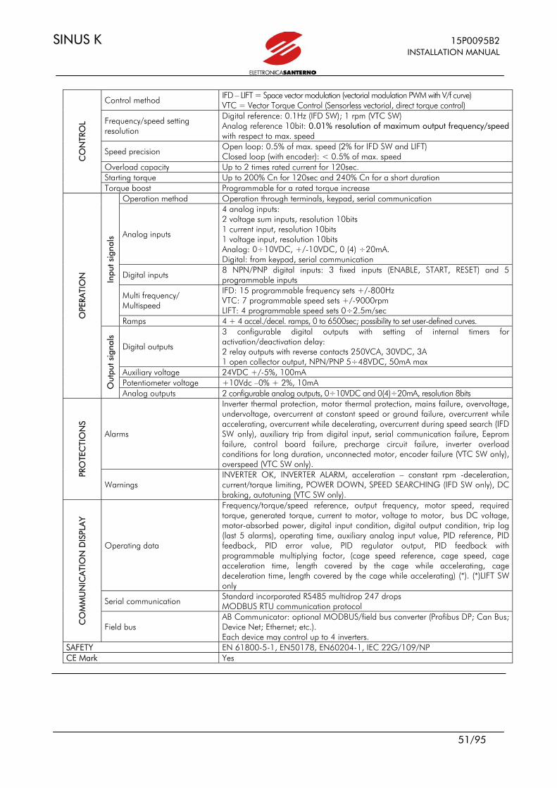
SINUS K 15P0095B2 INSTALLATION MANUAL
51/95
Control method IFD – LIFT = Space vector modulation (vectorial modulation PWM with V/f curve) VTC = Vector Torque Control (Sensorless vectorial, direct torque control)
Frequency/speed setting resolution
Digital reference: 0.1Hz (IFD SW); 1 rpm (VTC SW) Analog reference 10bit: 0.01% resolution of maximum output frequency/speed with respect to max. speed
Speed precision Open loop: 0.5% of max. speed (2% for IFD SW and LIFT) Closed loop (with encoder): < 0.5% of max. speed
Overload capacity Up to 2 times rated current for 120sec. Starting torque Up to 200% Cn for 120sec and 240% Cn for a short duration
CO
NTR
OL
Torque boost Programmable for a rated torque increase Operation method Operation through terminals, keypad, serial communication
Analog inputs
4 analog inputs: 2 voltage sum inputs, resolution 10bits 1 current input, resolution 10bits 1 voltage input, resolution 10bits Analog: 0÷10VDC, +/-10VDC, 0 (4) ÷20mA. Digital: from keypad, serial communication
Digital inputs 8 NPN/PNP digital inputs: 3 fixed inputs (ENABLE, START, RESET) and 5 programmable inputs
Multi frequency/ Multispeed
IFD: 15 programmable frequency sets +/-800Hz VTC: 7 programmable speed sets +/-9000rpm LIFT: 4 programmable speed sets 0÷2.5m/sec
Inpu
t sig
nals
Ramps 4 + 4 accel./decel. ramps, 0 to 6500sec; possibility to set user-defined curves.
Digital outputs
3 configurable digital outputs with setting of internal timers for activation/deactivation delay: 2 relay outputs with reverse contacts 250VCA, 30VDC, 3A 1 open collector output, NPN/PNP 5÷48VDC, 50mA max
Auxiliary voltage 24VDC +/-5%, 100mA Potentiometer voltage +10Vdc –0% + 2%, 10mA
OPE
RATI
ON
Out
put s
igna
ls
Analog outputs 2 configurable analog outputs, 0÷10VDC and 0(4)÷20mA, resolution 8bits
Alarms
Inverter thermal protection, motor thermal protection, mains failure, overvoltage, undervoltage, overcurrent at constant speed or ground failure, overcurrent while accelerating, overcurrent while decelerating, overcurrent during speed search (IFD SW only), auxiliary trip from digital input, serial communication failure, Eeprom failure, control board failure, precharge circuit failure, inverter overload conditions for long duration, unconnected motor, encoder failure (VTC SW only), overspeed (VTC SW only).
PRO
TEC
TIO
NS
Warnings INVERTER OK, INVERTER ALARM, acceleration – constant rpm -deceleration, current/torque limiting, POWER DOWN, SPEED SEARCHING (IFD SW only), DC braking, autotuning (VTC SW only).
Operating data
Frequency/torque/speed reference, output frequency, motor speed, required torque, generated torque, current to motor, voltage to motor, bus DC voltage, motor-absorbed power, digital input condition, digital output condition, trip log (last 5 alarms), operating time, auxiliary analog input value, PID reference, PID feedback, PID error value, PID regulator output, PID feedback with programmable multiplying factor, (cage speed reference, cage speed, cage acceleration time, length covered by the cage while accelerating, cage deceleration time, length covered by the cage while accelerating) (*). (*)LIFT SW only
Serial communication Standard incorporated RS485 multidrop 247 drops MODBUS RTU communication protocol
CO
MM
UN
ICA
TIO
N D
ISPL
AY
Field bus AB Communicator: optional MODBUS/field bus converter (Profibus DP; Can Bus; Device Net; Ethernet; etc.). Each device may control up to 4 inverters.
SAFETY EN 61800-5-1, EN50178, EN60204-1, IEC 22G/109/NP CE Mark Yes

15P0095B2 SINUS K INSTALLATION MANUAL
52/95
3.1 CHOOSING THE PRODUCT The inverter of the SINUS K series are dimensioned based on allowable current and overload. Each inverter model may be connected to 4 different motor power sizes depending on load performance. Four types of torque/current overload are available; their duration is 120sec every 20min up to S30 and 60 sec every 10min from S40 to S70: LIGHT overload 105%÷120%; may be connected to light loads with constant/quadratic torque
(pumps, fans, etc.); STANDARD overload 120%÷140%; may be connected to standard loads with constant torque (conveyors,
mixers, extruders, etc.); HEAVY overload 150%÷175%; may be connected to heavy loads with constant torque (lifts, injection
presses, mechanical presses, translation and lifting of cranes, bridge cranes, mills, etc.); STRONG overload 200%; may be applied to very heavy loads with constant torque (mandrels, axis
control, etc.). The SINUS K series is dimensioned with 2 current values: current Imot, for the stated torque overload, and current Inom, representing the max. deliverable continuous current. The rated current of the connected motor should be lower than Inom (tolerance: +5%). In case of the connection of multiple motors, the sum of the rated current values must not exceed Inom (an output inductance is recommended in that case).

SINUS K 15P0095B2 INSTALLATION MANUAL
53/95
3.1.1 TECHNICAL SHEET FOR LIGHT APPLICATIONS: OVERLOAD 105%÷120%
CONNECTABLE MOTOR (VOLTAGE) DELIVERABLE CURRENT 200-
240VAC 380-
415VAC 440-
460VAC 480-
500VAC 575VAC 660-
690VAC Imot Inom Imax Size MODEL
kW kW kW kW kW kW A A A
SINUS K 0005 2.9 4.7 5.5 6.0 - - 10.5 10.5 11.5 SINUS K 0007 3.6 5.5 6.7 7.4 - - 12.5 12.5 13.5 SINUS K 0009 17.5 SINUS K 0011 21
S05
SINUS K 0014 4.9 7.5 9.2 10 - - 16.5 16.5
25 SINUS K 0017 32 SINUS K 0020
9.4 15 18 19 - - 30 30 36
SINUS K 0025 48 SINUS K 0030 56
S10
SINUS K 0035 13 22 25 27 - - 41 41
72 S15 SINUS K 0040 23 37 44 48 - - 72 72 75
SINUS K 0049 26 45 50 54 - - 80 80 96 SINUS K 0060 29 48 55 59 - - 88 88 112 SINUS K 0067 34 55 65 71 - - 103 103 118 SINUS K 0074 40 65 76 83 - - 120 120 144
S20
SINUS K 0086 44 75 84 91 - - 135 135 155 SINUS K 0113 59 100 112 122 - - 180 180 200 SINUS K 0129 66 110 126 137 - - 195 195 215 SINUS K 0150 73 120 138 151 - - 215 215 270
S30
SINUS K 0162 81 132 153 167 - - 240 240 290 SINUS K 0179 101 170 191 209 - - 300 300 340 SINUS K 0200 119 200 225 246 - - 345 345 365 SINUS K 0216 129 215 245 267 - - 375 375 430
S40
SINUS K 0250 134 220 255 278 333 400 390 390 480 SINUS K 0312 165 280 314 342 410 492 480 480 600 SINUS K 0366 190 315 361 394 472 567 550 550 660 S50 SINUS K 0399 218 355 414 451 541 649 630 630 720
SINUS K 0457 243 400 462 504 604 725 720 720 880 S60
SINUS K 0524 270 450 512 559 670 804 800 800 960
SINUS K 0598 307 500 584 637 763 916 900 900 1100
SINUS K 0748 343 560 651 710 851 1022 1000 1000 1300 S70
SINUS K 0831 395 630 751 819 981 1177 1200 1200 1440
CABINET model available only
Legend: Imot = motor rated current for the stated torque overload Inom = continuous rated current of the inverter Imax = max. current the inverter can deliver for 120 sec every 20 min up to S30, for 60 sec every 10 min for S40 and higher
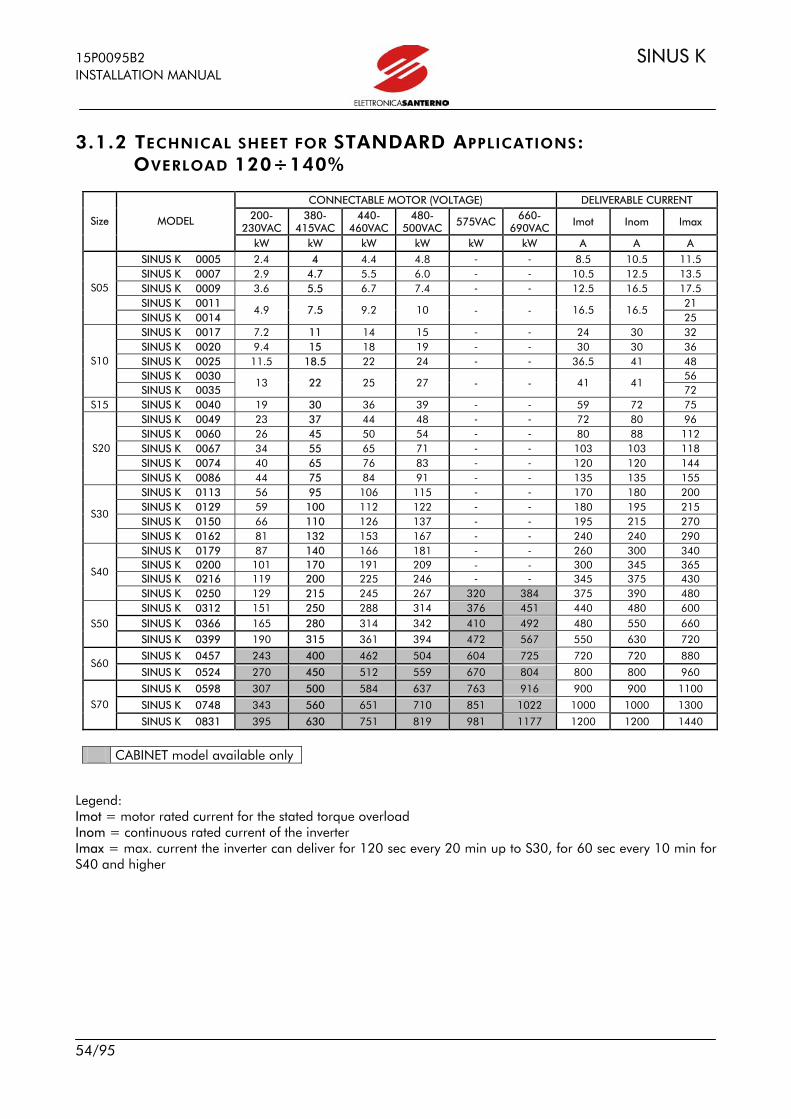
15P0095B2 SINUS K INSTALLATION MANUAL
54/95
3.1.2 TECHNICAL SHEET FOR STANDARD APPLICATIONS: OVERLOAD 120÷140%
CONNECTABLE MOTOR (VOLTAGE) DELIVERABLE CURRENT 200-
230VAC 380-
415VAC 440-
460VAC 480-
500VAC 575VAC 660-
690VAC Imot Inom Imax Size MODEL
kW kW kW kW kW kW A A A
SINUS K 0005 2.4 4 4.4 4.8 - - 8.5 10.5 11.5 SINUS K 0007 2.9 4.7 5.5 6.0 - - 10.5 12.5 13.5 SINUS K 0009 3.6 5.5 6.7 7.4 - - 12.5 16.5 17.5 SINUS K 0011 21
S05
SINUS K 0014 4.9 7.5 9.2 10 - - 16.5 16.5
25 SINUS K 0017 7.2 11 14 15 - - 24 30 32 SINUS K 0020 9.4 15 18 19 - - 30 30 36 SINUS K 0025 11.5 18.5 22 24 - - 36.5 41 48 SINUS K 0030 56
S10
SINUS K 0035 13 22 25 27 - - 41 41
72 S15 SINUS K 0040 19 30 36 39 - - 59 72 75
SINUS K 0049 23 37 44 48 - - 72 80 96 SINUS K 0060 26 45 50 54 - - 80 88 112 SINUS K 0067 34 55 65 71 - - 103 103 118 SINUS K 0074 40 65 76 83 - - 120 120 144
S20
SINUS K 0086 44 75 84 91 - - 135 135 155 SINUS K 0113 56 95 106 115 - - 170 180 200 SINUS K 0129 59 100 112 122 - - 180 195 215 SINUS K 0150 66 110 126 137 - - 195 215 270
S30
SINUS K 0162 81 132 153 167 - - 240 240 290 SINUS K 0179 87 140 166 181 - - 260 300 340 SINUS K 0200 101 170 191 209 - - 300 345 365 SINUS K 0216 119 200 225 246 - - 345 375 430
S40
SINUS K 0250 129 215 245 267 320 384 375 390 480 SINUS K 0312 151 250 288 314 376 451 440 480 600 SINUS K 0366 165 280 314 342 410 492 480 550 660 S50 SINUS K 0399 190 315 361 394 472 567 550 630 720
SINUS K 0457 243 400 462 504 604 725 720 720 880 S60
SINUS K 0524 270 450 512 559 670 804 800 800 960
SINUS K 0598 307 500 584 637 763 916 900 900 1100
SINUS K 0748 343 560 651 710 851 1022 1000 1000 1300 S70
SINUS K 0831 395 630 751 819 981 1177 1200 1200 1440
CABINET model available only
Legend: Imot = motor rated current for the stated torque overload Inom = continuous rated current of the inverter Imax = max. current the inverter can deliver for 120 sec every 20 min up to S30, for 60 sec every 10 min for S40 and higher
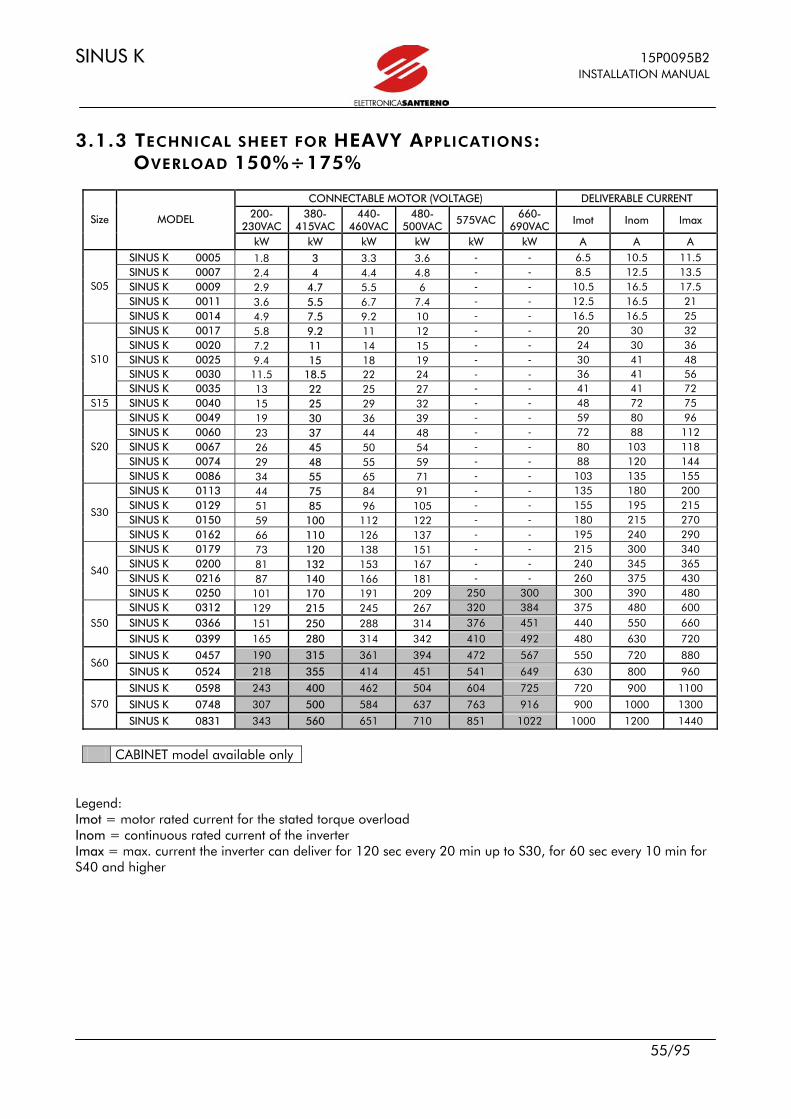
SINUS K 15P0095B2 INSTALLATION MANUAL
55/95
3.1.3 TECHNICAL SHEET FOR HEAVY APPLICATIONS: OVERLOAD 150%÷175%
CONNECTABLE MOTOR (VOLTAGE) DELIVERABLE CURRENT 200-
230VAC 380-
415VAC 440-
460VAC 480-
500VAC 575VAC 660-
690VAC Imot Inom Imax Size MODEL
kW kW kW kW kW kW A A A
SINUS K 0005 1.8 3 3.3 3.6 - - 6.5 10.5 11.5 SINUS K 0007 2.4 4 4.4 4.8 - - 8.5 12.5 13.5 SINUS K 0009 2.9 4.7 5.5 6 - - 10.5 16.5 17.5 SINUS K 0011 3.6 5.5 6.7 7.4 - - 12.5 16.5 21
S05
SINUS K 0014 4.9 7.5 9.2 10 - - 16.5 16.5 25 SINUS K 0017 5.8 9.2 11 12 - - 20 30 32 SINUS K 0020 7.2 11 14 15 - - 24 30 36 SINUS K 0025 9.4 15 18 19 - - 30 41 48 SINUS K 0030 11.5 18.5 22 24 - - 36 41 56
S10
SINUS K 0035 13 22 25 27 - - 41 41 72 S15 SINUS K 0040 15 25 29 32 - - 48 72 75
SINUS K 0049 19 30 36 39 - - 59 80 96 SINUS K 0060 23 37 44 48 - - 72 88 112 SINUS K 0067 26 45 50 54 - - 80 103 118 SINUS K 0074 29 48 55 59 - - 88 120 144
S20
SINUS K 0086 34 55 65 71 - - 103 135 155 SINUS K 0113 44 75 84 91 - - 135 180 200 SINUS K 0129 51 85 96 105 - - 155 195 215 SINUS K 0150 59 100 112 122 - - 180 215 270
S30
SINUS K 0162 66 110 126 137 - - 195 240 290 SINUS K 0179 73 120 138 151 - - 215 300 340 SINUS K 0200 81 132 153 167 - - 240 345 365 SINUS K 0216 87 140 166 181 - - 260 375 430
S40
SINUS K 0250 101 170 191 209 250 300 300 390 480 SINUS K 0312 129 215 245 267 320 384 375 480 600 SINUS K 0366 151 250 288 314 376 451 440 550 660 S50 SINUS K 0399 165 280 314 342 410 492 480 630 720
SINUS K 0457 190 315 361 394 472 567 550 720 880 S60
SINUS K 0524 218 355 414 451 541 649 630 800 960
SINUS K 0598 243 400 462 504 604 725 720 900 1100
SINUS K 0748 307 500 584 637 763 916 900 1000 1300 S70
SINUS K 0831 343 560 651 710 851 1022 1000 1200 1440
CABINET model available only
Legend: Imot = motor rated current for the stated torque overload Inom = continuous rated current of the inverter Imax = max. current the inverter can deliver for 120 sec every 20 min up to S30, for 60 sec every 10 min for S40 and higher

15P0095B2 SINUS K INSTALLATION MANUAL
56/95
3.1.4 TECHNICAL SHEET FOR STRONG APPLICATIONS: OVERLOAD 200%
APPLICABLE MOTOR (VOLTAGE) DELIVERABLE CURRENT 200-
230VAC 380-
415VAC 440-
460VAC 480-
500VAC 575VAC 660-
690VAC Imot Inom Imax Size MODEL
kW kW kW kW kW kW A A A
SINUS K 0005 1.3 2.2 2.5 2.7 - - 5 10.5 11.5 SINUS K 0007 1.8 3 3.3 3.6 - - 6.5 12.5 13.5 SINUS K 0009 2.4 4 4.4 4.8 - - 8.5 16.5 17.5 SINUS K 0011 2.9 4.7 5.5 6.0 - - 10.5 16.5 21
S05
SINUS K 0014 3.6 5.5 6.7 7.4 - - 12.5 16.5 25 SINUS K 0017 4.9 7.5 9.2 10 - - 16.5 30 32 SINUS K 0020 5.8 9.2 11 12 - - 20 30 36 SINUS K 0025 7.2 11 14 15 - - 24 41 48 SINUS K 0030 9.4 15 18 19 - - 30 41 56
S10
SINUS K 0035 11.5 18.5 22 24 - - 36 41 72 S15 SINUS K 0040 13 22 25 27 - - 41 72 75
SINUS K 0049 15 25 29 32 - - 48 80 96 SINUS K 0060 19 30 36 39 - - 59 88 112 SINUS K 0067 21 34 39 43 - - 64 103 118 SINUS K 0074 23 37 44 48 - - 72 120 144
S20
SINUS K 0086 26 45 50 54 - - 80 135 155 SINUS K 0113 34 55 65 71 - - 103 180 200 SINUS K 0129 40 65 76 83 - - 120 195 215 SINUS K 0150 44 75 84 91 - - 135 215 270
S30
SINUS K 0162 53 90 100 109 - - 160 240 290 SINUS K 0179 59 100 112 122 - - 180 300 340 SINUS K 0200 66 110 126 137 - - 195 345 365 SINUS K 0216 73 120 138 151 - - 215 375 430
S40
SINUS K 0250 81 132 153 167 200 240 240 390 480 SINUS K 0312 101 170 191 209 250 300 300 480 600 SINUS K 0366 119 200 225 246 295 354 345 550 660 S50 SINUS K 0399 134 220 255 278 333 400 390 630 720
SINUS K 0457 189 250 359 392 470 564 550 720 880 S60
SINUS K 0524 217 280 412 449 538 646 630 800 960
SINUS K 0598 249 315 473 516 618 741 720 900 1100
SINUS K 0748 311 355 591 644 772 927 900 1000 1300 S70
SINUS K 0831 338 400 641 700 839 1006 1000 1200 1440
CABINET model available only
Legend: Imot = motor rated current for the stated torque overload Inom = continuous rated current of the inverter Imax = max. current the inverter can deliver for 120 sec every 20 min up to S30, for 60 sec every 10 min for S40 and higher
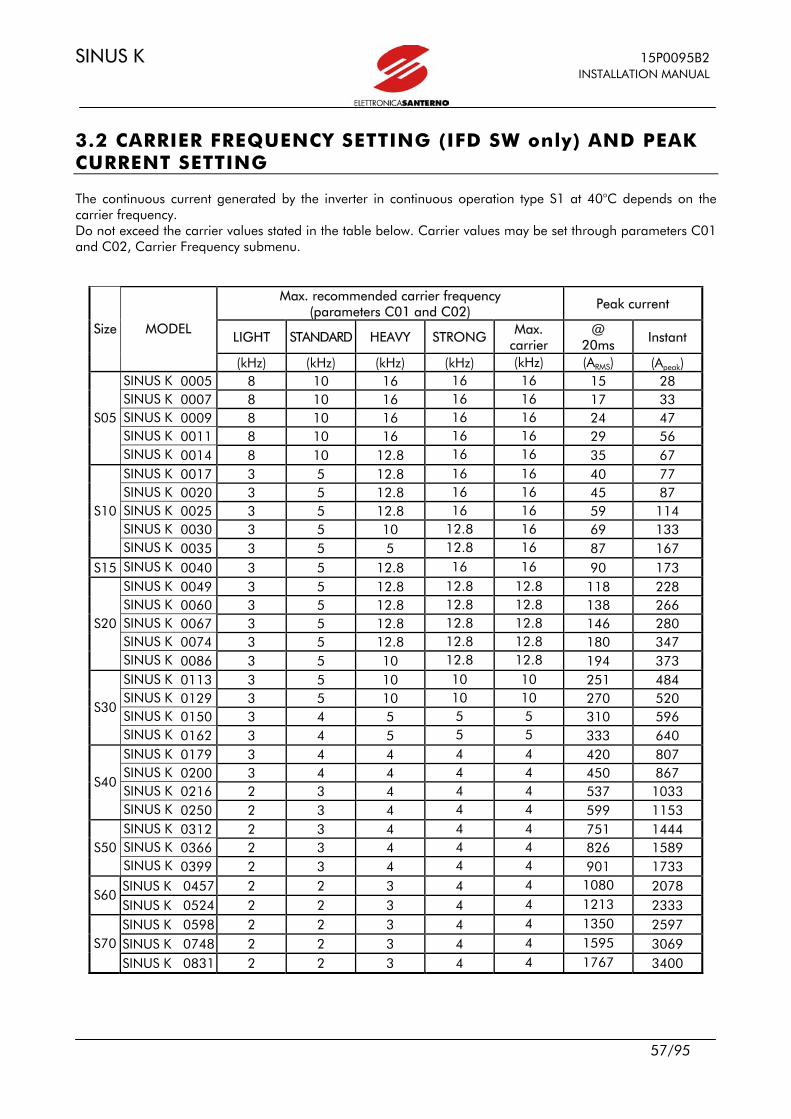
SINUS K 15P0095B2 INSTALLATION MANUAL
57/95
3.2 CARRIER FREQUENCY SETTING (IFD SW only) AND PEAK CURRENT SETTING The continuous current generated by the inverter in continuous operation type S1 at 40°C depends on the carrier frequency. Do not exceed the carrier values stated in the table below. Carrier values may be set through parameters C01 and C02, Carrier Frequency submenu.
Max. recommended carrier frequency (parameters C01 and C02) Peak current
LIGHT STANDARD HEAVY STRONG Max. carrier
@ 20ms Instant
Size MODEL
(kHz) (kHz) (kHz) (kHz) (kHz) (ARMS) (Apeak) SINUS K 0005 8 10 16 16 16 15 28 SINUS K 0007 8 10 16 16 16 17 33 SINUS K 0009 8 10 16 16 16 24 47 SINUS K 0011 8 10 16 16 16 29 56
S05
SINUS K 0014 8 10 12.8 16 16 35 67 SINUS K 0017 3 5 12.8 16 16 40 77 SINUS K 0020 3 5 12.8 16 16 45 87 SINUS K 0025 3 5 12.8 16 16 59 114 SINUS K 0030 3 5 10 12.8 16 69 133
S10
SINUS K 0035 3 5 5 12.8 16 87 167 S15 SINUS K 0040 3 5 12.8 16 16 90 173
SINUS K 0049 3 5 12.8 12.8 12.8 118 228 SINUS K 0060 3 5 12.8 12.8 12.8 138 266 SINUS K 0067 3 5 12.8 12.8 12.8 146 280 SINUS K 0074 3 5 12.8 12.8 12.8 180 347
S20
SINUS K 0086 3 5 10 12.8 12.8 194 373 SINUS K 0113 3 5 10 10 10 251 484 SINUS K 0129 3 5 10 10 10 270 520 SINUS K 0150 3 4 5 5 5 310 596
S30
SINUS K 0162 3 4 5 5 5 333 640 SINUS K 0179 3 4 4 4 4 420 807 SINUS K 0200 3 4 4 4 4 450 867 SINUS K 0216 2 3 4 4 4 537 1033
S40
SINUS K 0250 2 3 4 4 4 599 1153 SINUS K 0312 2 3 4 4 4 751 1444 SINUS K 0366 2 3 4 4 4 826 1589 S50 SINUS K 0399 2 3 4 4 4 901 1733 SINUS K 0457 2 2 3 4 4 1080 2078
S60 SINUS K 0524 2 2 3 4 4 1213 2333 SINUS K 0598 2 2 3 4 4 1350 2597 SINUS K 0748 2 2 3 4 4 1595 3069 S70 SINUS K 0831 2 2 3 4 4 1767 3400

15P0095B2 SINUS K INSTALLATION MANUAL
58/95
4 ACCESSORIES
4.1 BRAKING RESISTORS
4.1.1 APPLICATION TABLES From size S05 to size S30, SINUS K inverters are supplied with a built-in braking module. The braking resistor is to be incorporated in the inverter and connected to terminal B and terminal + (see section 1.4 “Wiring”). For IFD SW only, the braking module is enabled through programming parameter C57, Special Functions submenu. An external braking module is used for higher sizes (MFI). When choosing the braking resistor, consider its Ohm value and rated power. The Ohm value determines the instant power dissipated in the braking resistor and is relating to the motor power; the rated power determines the mean power to be dissipated in the braking resistor and is relating to the duty cycle of the equipment, i.e. to the resistor activation time with respect the duty cycle full time (the duty cycle of the resistor is equal to the motor braking time divided by the equipment duty cycle). It is not possible to connect resistors with a Ohm value lower than the min. value acknowledged by the inverter. The following pages contain application tables stating the resistors to be used depending on the inverter size, the application requirements and the supply voltage. The braking resistor power is stated as an approximate value. A correct dimensioning of the braking resistor is based on the equipment duty cycle and the power regenerated during the braking stage. For more details on the connection and features of the external braking module, refer to the braking module instruction manual.
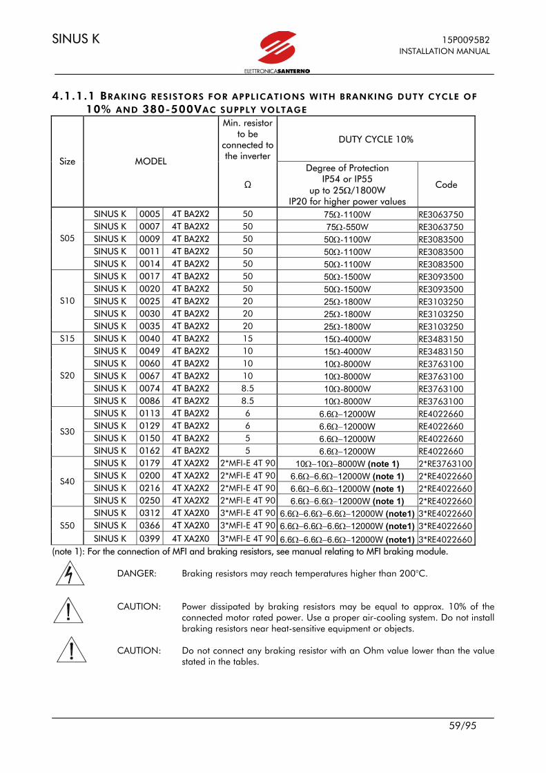
SINUS K 15P0095B2 INSTALLATION MANUAL
59/95
4.1.1.1 BRAKING RESISTORS FOR APPLICATIONS WITH BRANKING DUTY CYCLE OF
10% AND 380-500VAC SUPPLY VOLTAGE Min. resistor
to be connected to the inverter
DUTY CYCLE 10%
Size MODEL
Ω
Degree of Protection IP54 or IP55
up to 25Ω/1800W IP20 for higher power values
Code
SINUS K 0005 4T BA2X2 50 75Ω-1100W RE3063750 SINUS K 0007 4T BA2X2 50 75Ω-550W RE3063750 SINUS K 0009 4T BA2X2 50 50Ω-1100W RE3083500 SINUS K 0011 4T BA2X2 50 50Ω-1100W RE3083500
S05
SINUS K 0014 4T BA2X2 50 50Ω-1100W RE3083500 SINUS K 0017 4T BA2X2 50 50Ω-1500W RE3093500 SINUS K 0020 4T BA2X2 50 50Ω-1500W RE3093500 SINUS K 0025 4T BA2X2 20 25Ω-1800W RE3103250 SINUS K 0030 4T BA2X2 20 25Ω-1800W RE3103250
S10
SINUS K 0035 4T BA2X2 20 25Ω-1800W RE3103250 S15 SINUS K 0040 4T BA2X2 15 15Ω-4000W RE3483150
SINUS K 0049 4T BA2X2 10 15Ω-4000W RE3483150 SINUS K 0060 4T BA2X2 10 10Ω-8000W RE3763100 SINUS K 0067 4T BA2X2 10 10Ω-8000W RE3763100 SINUS K 0074 4T BA2X2 8.5 10Ω-8000W RE3763100
S20
SINUS K 0086 4T BA2X2 8.5 10Ω-8000W RE3763100 SINUS K 0113 4T BA2X2 6 6.6Ω−12000W RE4022660 SINUS K 0129 4T BA2X2 6 6.6Ω−12000W RE4022660 SINUS K 0150 4T BA2X2 5 6.6Ω−12000W RE4022660
S30
SINUS K 0162 4T BA2X2 5 6.6Ω−12000W RE4022660 SINUS K 0179 4T XA2X2 2*MFI-E 4T 90 10Ω−10Ω−8000W (note 1) 2*RE3763100 SINUS K 0200 4T XA2X2 2*MFI-E 4T 90 6.6Ω−6.6Ω−12000W (note 1) 2*RE4022660 SINUS K 0216 4T XA2X2 2*MFI-E 4T 90 6.6Ω−6.6Ω−12000W (note 1) 2*RE4022660
S40
SINUS K 0250 4T XA2X2 2*MFI-E 4T 90 6.6Ω−6.6Ω−12000W (note 1) 2*RE4022660 SINUS K 0312 4T XA2X0 3*MFI-E 4T 90 6.6Ω−6.6Ω−6.6Ω−12000W (note1) 3*RE4022660 SINUS K 0366 4T XA2X0 3*MFI-E 4T 90 6.6Ω−6.6Ω−6.6Ω−12000W (note1) 3*RE4022660 S50
SINUS K 0399 4T XA2X0 3*MFI-E 4T 90 6.6Ω−6.6Ω−6.6Ω−12000W (note1) 3*RE4022660 (note 1): For the connection of MFI and braking resistors, see manual relating to MFI braking module.
DANGER: Braking resistors may reach temperatures higher than 200°C. CAUTION: Power dissipated by braking resistors may be equal to approx. 10% of the
connected motor rated power. Use a proper air-cooling system. Do not install braking resistors near heat-sensitive equipment or objects.
CAUTION: Do not connect any braking resistor with an Ohm value lower than the value
stated in the tables.
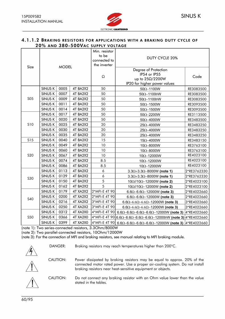
15P0095B2 SINUS K INSTALLATION MANUAL
60/95
4.1.1.2 BRAKING RESISTORS FOR APPLICATIONS WITH A BRAKING DUTY CYCLE OF
20% AND 380-500VAC SUPPLY VOLTAGE Min. resistor
to be connected to the inverter
DUTY CYCLE 20%
Size MODEL
Ω
Degree of Protection IP54 or IP55
up to 25Ω/2200W IP20 for higher power values
Code
SINUS K 0005 4T BA2X2 50 50Ω−1100W RE3083500 SINUS K 0007 4T BA2X2 50 50Ω−11000W RE3083500 SINUS K 0009 4T BA2X2 50 50Ω−11000W RE3083500 SINUS K 0011 4T BA2X2 50 50Ω−1500W RE3093500
S05
SINUS K 0014 4T BA2X2 50 50Ω−1500W RE3093500 SINUS K 0017 4T BA2X2 50 50Ω−2200W RE3113500 SINUS K 0020 4T BA2X2 50 50Ω−4000W RE3483500 SINUS K 0025 4T BA2X2 20 25Ω−4000W RE3483250 SINUS K 0030 4T BA2X2 20 25Ω−4000W RE3483250
S10
SINUS K 0035 4T BA2X2 20 25Ω−4000W RE3483250 S15 SINUS K 0040 4T BA2X2 15 15Ω−4000W RE3483150
SINUS K 0049 4T BA2X2 10 10Ω−8000W RE3763100 SINUS K 0060 4T BA2X2 10 10Ω−8000W RE3763100 SINUS K 0067 4T BA2X2 10 10Ω−12000W RE4023100 SINUS K 0074 4T BA2X2 8.5 10Ω−12000W RE4023100
S20
SINUS K 0086 4T BA2X2 8.5 10Ω−12000W RE4023100 SINUS K 0113 4T BA2X2 6 3.3Ω+3.3Ω−8000W (note 1) 2*RE3762330 SINUS K 0129 4T BA2X2 6 3.3Ω+3.3Ω−8000W (note 1) 2*RE3762330 SINUS K 0150 4T BA2X2 5 10Ω//10Ω−12000W (note 2) 2*RE4023100
S30
SINUS K 0162 4T BA2X2 5 10Ω//10Ω−12000W (note 2) 2*RE4023100 SINUS K 0179 4T XA2X2 2*MFI-E 4T 90 6.6Ω−6.6Ω−12000W (note 3) 2*RE4022660 SINUS K 0200 4T XA2X2 2*MFI-E 4T 90 6.6Ω−6.6Ω−12000W (note 3) 2*RE4022660 SINUS K 0216 4T XA2X2 3*MFI-E 4T 90 6.6Ω−6.6Ω−6.6Ω−12000W (note 3) 3*RE4022660
S40
SINUS K 0250 4T XA2X2 3*MFI-E 4T 90 6.6Ω−6.6Ω−6.6Ω−12000W (note 3) 3*RE4022660 SINUS K 0312 4T XA2X0 4*MFI-E 4T 90 6.6Ω−6.6Ω−6.6Ω−6.6Ω−12000W (note 3) 4*RE4022660 SINUS K 0366 4T XA2X0 4*MFI-E 4T 90 6.6Ω−6.6Ω−6.6Ω−6.6Ω−120000W (note 3) 4*RE4022660 S50
SINUS K 0399 4T XA2X0 4*MFI-E 4T 90 6.6Ω−6.6Ω−6.6Ω−6.6Ω−12000W (note 3) 4*RE4022660 (note 1): Two series-connected resistors, 3.3Ohm/8000W (note 2): Two parallel-connected resistors, 10Ohm/12000W (note 3): For the connection of MFI and braking resistors, see manual relating to MFI braking module.
DANGER: Braking resistors may reach temperatures higher than 200°C.
CAUTION: Power dissipated by braking resistors may be equal to approx. 20% of the
connected motor rated power. Use a proper air-cooling system. Do not install braking resistors near heat-sensitive equipment or objects.
CAUTION: Do not connect any braking resistor with an Ohm value lower than the value
stated in the tables.

SINUS K 15P0095B2 INSTALLATION MANUAL
61/95
4.1.1.3 BRAKING RESISTORS FOR APPLICATIONS WITH A DUTY CYCLE OF 50% AND
380-500VAC SUPPLY VOLTAGE
Min. resistor to be connected to the inverter
DUTY CYCLE 50% Size MODEL
Ω Degree of Protection IP23 Code SINUS K 0005 4T BA2X2 50 50Ω−4000W RE3503500 SINUS K 0007 4T BA2X2 50 50Ω−4000W RE3503500 SINUS K 0009 4T BA2X2 50 50Ω−4000W RE3503500 SINUS K 0011 4T BA2X2 50 50Ω−4000W RE3503500
S05
SINUS K 0014 4T BA2X2 50 50Ω−4000W RE3503500 SINUS K 0017 4T BA2X2 50 50Ω−8000W RE3783500 SINUS K 0020 4T BA2X2 50 50Ω−8000W RE3783500 SINUS K 0025 4T BA2X2 20 50Ω−8000W RE4053200 SINUS K 0030 4T BA2X2 20 20Ω−12000W RE4053200
S10
SINUS K 0035 4T BA2X2 20 20Ω−12000W RE4053200 S15 SINUS K 0040 4T BA2X2 15 15Ω−16000W RE4163150
SINUS K 0049 4T BA2X2 10 15Ω−16000W RE4163150 SINUS K 0060 4T BA2X2 10 10Ω−24000W RE4293100 SINUS K 0067 4T BA2X2 10 10Ω−24000W RE4293100 SINUS K 0074 4T BA2X2 8.5 10Ω−24000W RE4293100
S20
SINUS K 0086 4T BA2X2 8.5 10Ω−24000W RE4293100 SINUS K 0113 4T BA2X2 6 6Ω−48000W RE4452600 SINUS K 0129 4T BA2X2 6 6Ω−48000W RE4452600 SINUS K 0150 4T BA2X2 5 5Ω−64000W RE4552500
S30
SINUS K 0162 4T BA2X2 5 5Ω−64000W RE4552500 SINUS K 0179 4T XA2X2 2*MFI-E 4T 90 6.6Ω−6.6Ω−32000W (note 1) 2*RE4362660 SINUS K 0200 4T XA2X2 2*MFI-E 4T 90 6.6Ω−6.6Ω−32000W (note 1) 2*RE4362660 SINUS K 0216 4T XA2X2 2*MFI-E 4T 90 6.6Ω−6.6Ω−32000W (note 1) 2*RE4362660
S40
SINUS K 0250 4T XA2X2 2*MFI-E 4T 90 6Ω−6 Ω−48000W (note 1) 2*RE4452600 SINUS K 0312 4T XA2X0 3*MFI-E 4T 90 6.6Ω−6.6Ω−6.6Ω−32000W (note 1) 3*RE4362660 SINUS K 0366 4T XA2X0 3*MFI-E 4T 90 6Ω−6Ω−6Ω−48000W (note 1) 3*RE4452600 S50
SINUS K 0399 4T XA2X0 3*MFI-E 4T 90 6Ω−6Ω−6Ω−48000W (note 1) 3*RE4452600 (note 1): For the connection of MFI and braking resistors, see manual relating to MFI braking module.
DANGER: Braking resistors may reach temperatures higher than 200°C. CAUTION: Power dissipated by braking resistors may be equal to approx. 50% of the
connected motor rated power. Use a proper air-cooling system. Do not install braking resistors near heat-sensitive equipment or objects.
CAUTION: Do not connect any braking resistor with an Ohm value lower than the value
stated in the tables.

15P0095B2 SINUS K INSTALLATION MANUAL
62/95
4.1.1.4 BRAKING RESISTORS FOR APPLICATIONS WITH A BRAKING DUTY CYCLE OF
10% AND 200-240VAC SUPPLY VOLTAGE Min. resistor to be connected to the inverter
DUTY CYCLE 10%
Size MODEL
Ω
Degree of Protection IP54 or IP55
up to 15Ω/1100W IP20 for higher power values
Code
SINUS K 0005 2T BA2X2 25.0 56Ω−350W RE2643560 SINUS K 0007 2T BA2X2 25.0 56Ω−350W RE2643560 SINUS K 0009 2T BA2X2 25.0 56Ω//56Ω−350W (note 1) 2*RE2643560 SINUS K 0011 2T BA2X2 25.0 56Ω//56Ω−350W (note 1) 2*RE2643560
S05
SINUS K 0014 2T BA2X2 25.0 56Ω//56Ω−350W (note 1) 2*RE2643560 SINUS K 0017 2T BA2X2 25.0 56Ω//56Ω−350W (note 1) 2*RE2643560 SINUS K 0020 2T BA2X2 25.0 56Ω//56Ω−350W (note 1) 2*RE2643560 SINUS K 0025 2T BA2X2 10.0 15Ω−1100W RE3083150 SINUS K 0030 2T BA2X2 10.0 15Ω−1100W RE3083150
S10
SINUS K 0035 2T BA2X2 10.0 15Ω−1100W RE3083150 S15 SINUS K 0040 2T BA2X2 7.5 15Ω//15Ω−1100W (note 2) 2*RE3083150
SINUS K 0049 2T BA2X2 5.0 5Ω−4000W RE3482500 SINUS K 0060 2T BA2X2 5.0 5Ω−4000W RE3482500 SINUS K 0067 2T BA2X2 5.0 5Ω−4000W RE3482500 SINUS K 0074 2T BA2X2 4.2 5Ω−4000W RE3482500
S20
SINUS K 0086 2T BA2X2 4.2 5Ω−4000W RE3482500 SINUS K 0113 2T BA2X2 3.0 3.3Ω−8000W RE3762330 SINUS K 0129 2T BA2X2 3.0 3.3Ω−8000W RE3762330 SINUS K 0150 2T BA2X2 2.5 3.3Ω−8000W RE3762330
S30
SINUS K 0162 2T BA2X2 2.5 3.3Ω−8000W RE3762330 SINUS K 0179 2T XA2X2 2*MFI-E 2T 45 3.3Ω//3.3Ω−8000W (note 3) 2*RE3762330 SINUS K 0200 2T XA2X2 2*MFI-E 2T 45 3.3Ω//3.3Ω−8000W (note 3) 2*RE3762330 SINUS K 0216 2T XA2X2 2*MFI-E 2T 45 3.3Ω//3.3Ω−8000W (note 3) 2*RE3762330
S40
SINUS K 0250 2T XA2X2 2*MFI-E 2T 45 3.3Ω//3.3Ω−8000W (note 3) 2*RE3762330 SINUS K 0312 2T XA2X0 3*MFI-E 2T 45 3.3Ω//3.3Ω//3.3Ω−8000W (note 3) 3*RE3762330 SINUS K 0366 2T XA2X0 3*MFI-E 2T 45 3.3Ω//3.3Ω//3.3Ω−8000W (note 3) 3*RE3762330 S50
SINUS K 0399 2T XA2X0 3*MFI-E 2T 45 3.3Ω//3.3Ω//3.3Ω−8000W (note 3) 3*RE3762330 (note 1): Two parallel-connected resistors, 56Ohm/350W (note 2): Four parallel-connected resistors, 15Ohm/1100W (note 3): For the connection of MFI and braking resistors, see manual relating to MFI braking module
DANGER: Braking resistors may reach temperatures higher than 200°C. CAUTION: Power dissipated by braking resistors may be equal to approx. 10% of the
connected motor rated power. Use a proper air-cooling system. Do not install braking resistors near heat-sensitive equipment or objects.
CAUTION: Do not connect any braking resistor with an Ohm value lower than the value
stated in the tables.

SINUS K 15P0095B2 INSTALLATION MANUAL
63/95
4.1.1.5 BRAKING RESISTORS FOR APPLICATIONS WITH A BRAKING DUTY CYCLE
OF20% AND 200-240VAC SUPPLY VOLTAGE.
Min. resistor tobe connected to the inverter
DUTY CYCLE 20%
Size MODEL
Ω
Degree of Protection IP54 or IP55
up to 25 Ω /1800W IP20 for higher power values
Code
SINUS K 0005 2T BA2X2 25.0 56Ω−350W RE2643560 SINUS K 0007 2T BA2X2 25.0 100Ω/100Ω−350W (note1) 2*RE2644100 SINUS K 0009 2T BA2X2 25.0 56Ω//56Ω−350W 2*RE2635560 SINUS K 0011 2T BA2X2 25.0 56Ω//56Ω−350W 2*RE2635560
S05
SINUS K 0014 2T BA2X2 25.0 100Ω//100Ω//100Ω//100Ω−350W (note 2) 4*RE2644100 SINUS K 0017 2T BA2X2 25.0 100Ω//100Ω//100Ω//100Ω−350W (note 2) 4*RE2644100 SINUS K 0020 2T BA2X2 25.0 25Ω−1800W RE3103250 SINUS K 0025 2T BA2X2 10.0 75Ω//75Ω//75Ω//75Ω//75Ω//75Ω−550W (note3) 6*RE3063750 SINUS K 0030 2T BA2X2 10.0 75Ω//75Ω//75Ω//75Ω//75Ω//75Ω−550W (note3) 6*RE3063750
S10
SINUS K 0035 2T BA2X2 10.0 75Ω//75Ω//75Ω//75Ω//75Ω//75Ω−550W (note3) 6*RE3063750 S15 SINUS K 0040 2T BA2X2 8.0 25Ω//25Ω−1800W (note 4) 2*RE3103250
SINUS K 0049 2T BA2X2 5.0 5Ω−4000W RE3482500 SINUS K 0060 2T BA2X2 5.0 5Ω−8000W RE3762500 SINUS K 0067 2T BA2X2 5.0 5Ω−8000W RE3762500 SINUS K 0074 2T BA2X2 4.2 5Ω−8000W RE3762500
S20
SINUS K 0086 2T BA2X2 4.2 5Ω−8000W RE3762500 SINUS K 0113 2T BA2X2 3.0 3.3Ω−12000W RE4022330 SINUS K 0129 2T BA2X2 3.0 3.3Ω−12000W RE4022330 SINUS K 0150 2T BA2X2 2.5 3.3Ω−12000W RE4022330
S30
SINUS K 0162 2T BA2X2 2.5 3.3Ω−12000W RE4022330 SINUS K 0179 2T XA2X2 2*MFI-E 2T 45 3.3Ω−3.3Ω−8000W (note 5) 2*RE3762330 SINUS K 0200 2T XA2X2 2*MFI-E 2T 45 3.3Ω−3.3Ω−8000W (note 5) 2*RE3762330 SINUS K 0216 2T XA2X2 2*MFI-E 2T 45 3.3Ω−3.3Ω−12000W (note 5) 2*RE4022330
S40
SINUS K 0250 2T XA2X2 2*MFI-E 2T 45 3.3Ω−3.3Ω−12000W (note 5) 2*RE4022330 SINUS K 0312 2T XA2X0 3*MFI-E 2T 45 3.3Ω−3.3Ω−3.3Ω−12000W (note 5) 3*RE4022330 SINUS K 0366 2T XA2X0 3*MFI-E 2T 45 3.3Ω−3.3Ω−3.3Ω−12000W (note 5) 3*RE4022330 S50
SINUS K 0399 2T XA2X0 3*MFI-E 2T 45 3.3Ω−3.3Ω−3.3Ω−12000W (note 5) 3*RE4022330 (note 1): Two parallel-connected resistors, 100Ohm/350W (note 2): Four parallel-connected resistors, 100Ohm/350W (note 3): Six parallel-connected resistors, 75Ohm/550W (note 4): Two parallel-connected resistors, 25Ohm/1800W (note 5): For the connection of MFI and braking resistors, see manual relating to MFI braking module.
DANGER: Braking resistors may reach temperatures higher than 200°C. CAUTION: Power dissipated by braking resistors may be equal to approx. 20% of the
connected motor rated power. Use a proper air-cooling system. Do not install braking resistors near heat-sensitive equipment or objects.
CAUTION: Do not connect any braking resistor with an Ohm value lower than the value
stated in the tables.

15P0095B2 SINUS K INSTALLATION MANUAL
64/95
4.1.1.6 BRAKING RESISTORS FOR APPLICATIONS WITH A BRANKING DUTY CYCLE OF
50% AND 200-240VAC SUPPLY VOLTAGE DUTY CYCLE 50%
Size MODEL
Min. resistor tobe connected to the inverter
Ω
Degree of Protection IP54 or IP55
up to 25 Ω /1800W IP20 for higher power values
Code
SINUS K 0005 2T BA2X2 25.0 50Ω−1100W RE3083500 SINUS K 0007 2T BA2X2 25.0 50Ω−1100W RE3083500 SINUS K 0009 2T BA2X2 25.0 25Ω−1800W RE3103250 SINUS K 0011 2T BA2X2 25.0 25Ω−1800W RE3103250
S05
SINUS K 0014 2T BA2X2 25.0 25Ω−4000W RE3483250 SINUS K 0017 2T BA2X2 25.0 25Ω−4000W RE3483250 SINUS K 0020 2T BA2X2 25.0 25Ω−4000W RE3483250 SINUS K 0025 2T BA2X2 10.0 10Ω−8000W RE3763100 SINUS K 0030 2T BA2X2 10.0 10Ω−8000W RE3763100
S10
SINUS K 0035 2T BA2X2 10.0 10Ω−8000W RE3763100 S15 SINUS K 0040 2T BA2X2 8.0 10Ω−8000W RE3763100
SINUS K 0049 2T BA2X2 5.0 6.6Ω−12000W RE4022660 SINUS K 0060 2T BA2X2 5.0 6.6Ω−12000W RE4022660 SINUS K 0067 2T BA2X2 5.0 5Ω−8000W RE3762500 SINUS K 0074 2T BA2X2 4.2 10Ω//10Ω−8000W (note1) 2*RE3763100
S20
SINUS K 0086 2T BA2X2 4.2 10Ω//10Ω−8000W (note1) 2*RE3763100 SINUS K 0113 2T BA2X2 3.0 6.6Ω/6.60Ω−12000W (note 2) 2*RE4022660 SINUS K 0129 2T BA2X2 3.0 6.6Ω/6.60Ω−12000W 2*RE4022660 SINUS K 0150 2T BA2X2 2.5 10Ω//10Ω//10Ω−12000W (note 3) RE4023100
S30
SINUS K 0162 2T BA2X2 2.5 10Ω//10Ω//10Ω−12000W (note 3) RE4023100 SINUS K 0179 2T XA2X2 2*MFI-E 2T 45 6.6Ω/6.6Ω−6.6Ω−12000W (note 4) 3*RE4022660 SINUS K 0200 2T XA2X2 2*MFI-E 2T 45 6.6Ω/6.6Ω−6.6Ω−12000W (note 4) 4*RE4022660 SINUS K 0216 2T XA2X2 2*MFI-E 2T 45 6.6Ω/6.6Ω−6.6Ω−12000W 4*RE4022660 S40
SINUS K 0250 2T XA2X2 3*MFI-E 2T 45 6.6Ω/6.6Ω−6.6Ω6.6Ω/6.6Ω−12000W (note 4) 5*RE4022660
SINUS K 0312 2T XA2X0 3*MFI-E 2T 45 6.6Ω/6.6Ω−6.6Ω6.6Ω/6.6Ω6.6Ω/−12000W
(note 4) 6*RE4022660
SINUS K 0366 2T XA2X0 3*MFI-E 2T 45 6.6Ω/6.6Ω−6.6Ω6.6Ω/6.6Ω6.6Ω/−12000W
(note 4) 6*RE4022660 S50
SINUS K 0399 2T XA2X0 4*MFI-E 2T 45 6.6Ω/6.6Ω−6.6Ω6.6Ω/6.6Ω6.6Ω/−12000W
(note 4) 7*RE4022660 (note 1): Two parallel-connected resistors, 10Ohm/8000W (note 2): Four parallel-connected resistors, 6.6Ohm/12000W (note 3): Three parallel-connected resistors, 10Ohm/12000W (note 4): For the connection of MFI and braking resistors, see manual relating to MFI braking module.
DANGER: Braking resistors may reach temperatures higher than 200°C. CAUTION: Power dissipated by braking resistors may be equal to approx. 50% of the
connected motor rated power. Use a proper air-cooling system. Do not install braking resistors near heat-sensitive equipment or objects.
CAUTION: Do not connect any braking resistor with an Ohm value lower than the value stated in the tables.

SINUS K 15P0095B2 INSTALLATION MANUAL
65/95
4.1.2 AVAIBLE MODELS 4.1.2.1 MODEL 56-100OHM/350W Fig. 4.1: Overall dimensions, resistor 56-100Ω/350W Overall dimensions, resistor 56-100Ω/350W (*) max. value to be set for parameter Brake Enable (C68 (IFD SW) or C60 (VTC SW)). Set Brake Disable C67 (IFD SW) or C59 (VTC SW) so as not to exceed the max. power to be dissipated by the braking resistor. Set Brake Disable=0 and Brake enableg0 not to limit the operation of the built-in braking module.
Type Wgt (g)
Degree of protection
Average pwr to be dissipated
(W)
Max. duration of continuous operation for
200-240VAC (s)*
56Ohm/350W RE2643560 400 IP55 350 3.5
100Ohm/350W RE2644100 400 IP55 350 3.5
M00265-0
35
30
200L = 300
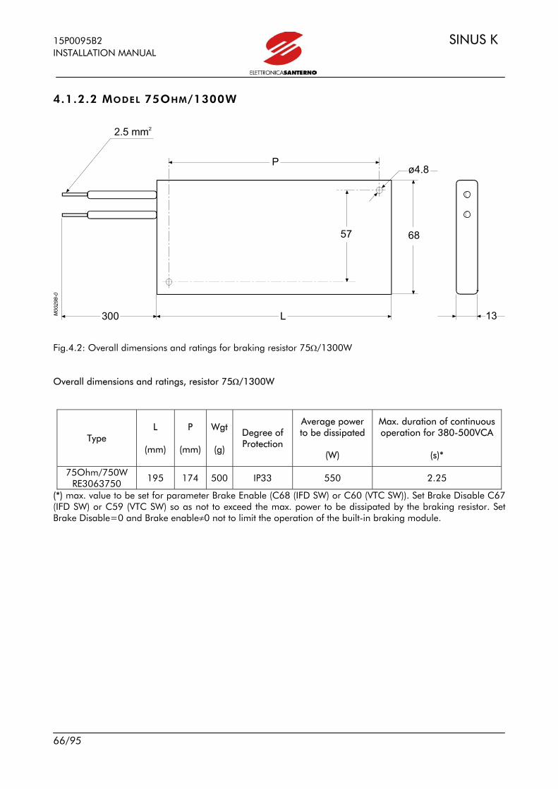
15P0095B2 SINUS K INSTALLATION MANUAL
66/95
4.1.2.2 MODEL 75OHM/1300W Fig.4.2: Overall dimensions and ratings for braking resistor 75Ω/1300W Overall dimensions and ratings, resistor 75Ω/1300W
Type L
(mm)
P
(mm)
Wgt
(g)
Degree of Protection
Average power to be dissipated
(W)
Max. duration of continuous operation for 380-500VCA
(s)*
75Ohm/750W RE3063750 195 174 500 IP33 550 2.25
(*) max. value to be set for parameter Brake Enable (C68 (IFD SW) or C60 (VTC SW)). Set Brake Disable C67 (IFD SW) or C59 (VTC SW) so as not to exceed the max. power to be dissipated by the braking resistor. Set Brake Disable=0 and Brake enableg0 not to limit the operation of the built-in braking module.
2.5 mm2
300 L
P
13
ø4.8
6857

SINUS K 15P0095B2 INSTALLATION MANUAL
67/95
4.1.2.3 MODELS FROM 1100W TO 2200W Fig.4.3: Overall dimensions and mechanical features for braking resistors from 1100W to 2200 W Overall dimensions and mechanical features, braking resistors 1100W to 2200 W
Max. duration of continuous operation
Type A
(mm)
B
(mm)
L
(mm)
l
(mm)
P
(mm)
Wgt
(g)
Degree of protection
Mean power to
be dissipated
(W)
380-500Vac
(s)*
200-240Vac
(s)*
15Ohm/1100W RE3083150
not applic. 6
20Ohm/1100W RE3083500 not applic. 8
50Ohm/1100W RE3083500
95 30 320 80-84 240 1250 IP55 950
5 20
10Ohm/1500W RE3093100 not applic. 4,5
39Ohm/1500W RE3093390
50Ohm/1500W RE3093500
120 40 320 107-112 240 2750 IP54 1100
4.5 18
25Ohm/1800W RE310250 120 40 380 107-
112 300 3000 IP54 1300 3 12
50Ohm/2200W RE3113500 8
75Ohm/2200W RE3113750
190 67 380 177-182 300 7000 IP54 2000
11 not limited
wire standard length: 300mm (*) max. value to be set for parameter Brake Enable (C68 (IFD SW) or C60 (VTC SW)). Set Brake Disable C67 (IFD SW) or C59 (VTC SW) so as not to exceed the max. power to be dissipated by the braking resistor. Set Brake Disable=0 and Brake enableg0 not to limit the operation of the built-in braking module.
B
A
L
P
I
M 0 0 6 1 9 - 0
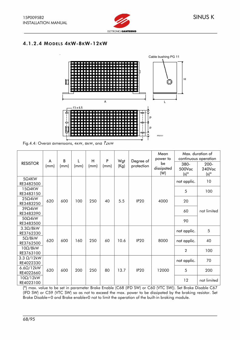
15P0095B2 SINUS K INSTALLATION MANUAL
68/95
4.1.2.4 MODELS 4KW-8KW-12KW Fig.4.4: Overall dimensions, 4kW, 8kW, and 12kW
Max. duration of continuous operation
RESISTOR A (mm)
B (mm)
L (mm)
H (mm)
P (mm)
Wgt (Kg)
Degree of protection
Mean power to
be dissipated
(W)
380-500Vac
(s)*
200-240Vac
(s)* 5Ω4KW
RE3482500 not applic. 10
15Ω4KW RE3483150 5 100
25Ω4kW RE3483250 20
39Ω4kW RE3483390 60
50Ω4kW RE3483500
620 600 100 250 40 5.5 IP20 4000
90
not limited
3.3Ω/8kW RE3762330 not applic. 5
5Ω/8kW RE3762500 not applic. 40
10Ω/8kW RE3763100
620 600 160 250 60 10.6 IP20 8000
2 100
3.3 Ω/12kW RE4022330 not applic. 70
6.6Ω/12kW RE4022660 5 200
10Ω/12kW RE4023100
620 600 200 250 80 13.7 IP20 12000
12 not limited
(*) max. value to be set in parameter Brake Enable (C68 (IFD SW) or C60 (VTC SW)). Set Brake Disable C67 (IFD SW) or C59 (VTC SW) so as not to exceed the max. power to be dissipated by the braking resistor. Set Brake Disable=0 and Brake enableg0 not to limit the operation of the built-in braking module.
Cable bushing PG 11

SINUS K 15P0095B2 INSTALLATION MANUAL
69/95
4.1.2.5 MODELS – BOX RESISTORS IP23, 4KW-64KW
OVERALL DIMENSIONS
Nameplate Grounding bolt M8
Eyebolts for powers over 24,000Wincluded
Fastening hole positions
Grill panel fastening screws
Grill panel fastening screws
Fastening hole positions
Fig.4.5: Box Resistor IP23 WIRING
CONNECTION TERMINAL DETAIL
CONNECTION TERMINAL DETAIL
Screws 8x20
Connection terminal
Fig.4.6 Position of electrical connections in box resistors Remove grids to gain access to wiring terminals. Important: Figure shows resistor 20Ohm/12kW. For certain models, remove both panels to gain access to wiring terminals.

15P0095B2 SINUS K INSTALLATION MANUAL
70/95
Max. duration of continuous operation (s)*
RESISTOR P
(mm)
P1
(mm)
P2
(mm)
L
(mm)
H
(mm)
Weight
(Kg)
Degree of protection
Mean power to be
dissipated
(W) 380-
500VAC 200-
240VAC
50Ω/4KW RE3503500 650 530 710 320 375 20 IP23 4000 not limited
50Ω/8KW RE3783500 650 530 710 380 375 23 IP23 8000 not limited
20Ω/12KW RE4053200 650 530 710 460 375 34 IP23 12000 not limited
15Ω/16KW RE4163150
650 530 710 550 375 40 IP23 16000 not limited
10Ω /24kW RE4293100 650 530 710 750 375 54 IP23 24000 not limited
6.6Ω/32kW RE4362660 650 530 710 990 375 68 IP23 32000
not limited
6Ω/48kW RE4452600 650 530 710 750 730 101 IP23 48000
not limited
5Ω/64kW RE4552500 650 530 710 990 730 128 IP23 64000 not limited
(*) max. value to be set for parameter Brake Enable (C68 (IFD SW) or C60 (VTC SW)). Set Brake Disable C67 (IFD SW) or C59 (VTC SW) so as not to exceed the max. power to be dissipated by the braking resistor. Set Brake Disable=0 and Brake enableg0 not to limit the operation of the built-in braking module.
4.2 BRAKING MODULE A braking module is available to be connected to terminals + and – (see paragraph 1.4 “Wiring”) of the inverter for sizes S40 to S70. Braking modules can be used when a high braking torque is needed, particularly when a prompt braking is needed for high inertial loads (e.g. fans).
4.3 REMOTING KIT The inverter keypad may be remoted. A special kit is supplied, which includes the following: - mounting plate for the keypad fastening to the cabinet door, - remoting wire (length: 5m). For any details on the keypad remoting, see section 1.5 “Operating and Remoting the Keypad”.

SINUS K 15P0095B2 INSTALLATION MANUAL
71/95
4.4 REACTANCE
4.4.1 INPUT INDUCTANCE We suggest that a three-phase inductance be installed on the supply line to obtain the following benefits: - limit input current peaks and improve input current shape; - reducing supply harmonic current; - increasing power factor, thus reducing line current; - increasing the duration of line capacitors inside the inverter.
Harmonic current
The shapes of the different waves (current or voltage) may be expressed as the sum of the basic frequency (50 or 60Hz) and its multiples. In balanced, three-phase systems, only odd harmonic current exists, as even current is neutralized by symmetrical considerations. Harmonic current is generated by non linear loads absorbing non-sinusoidal current. Typical sources of this type are bridge rectifiers (power electronics), switching feeders and fluorescent lamps. Three-phase rectifiers absorb line current with a harmonic content n=6K±1 with K=1,2,3,… (e.g. 5th,7th,11th,13th,17th,19th, etc.). Harmonic current amplitude decreases when frequency increases. Harmonic current carries no active power; it is additional current carried by electrical cables. Typical effects are: conductor overload, power factor decrease and measurement systems instability. Voltage generated by current flowing in the transformer reactance may also damage other appliances or interfere with mains-synchronized switching equipment.
Solving the problem
Harmonic current amplitude decreases when frequency increases; as a result, reducing high-amplitude components determines the filtering of low-frequency components. The better way is to increase low-frequency impedance by installing an inductance. Power drive systems with no mains-side inductance generate larger harmonic currents than power drives which do have an inductance. Unlike DC inductance, AC inductance suppresses most harmonic currents and protects the rectifier from supply voltage peaks. For >500kW drives, a 12-pulse inductance is normally used. This suppresses the lowest harmonic current in the supply line. In a 12-pulse inductance, the lowest harmonics are the 11th and the 13th, followed by the 23th, the 25th and so on, with their relevant low levels. The supply current shape is very similar to a sinusoid.

15P0095B2 SINUS K INSTALLATION MANUAL
72/95
Harmonic currents
60%
With an inductance
50% With no inductance
40%
30%
20%
10%
5th 7th 11th 13th 17th 19th 23rd 25th Sequence
Input reactance L2 and L4 are available, having a different inductance value. Section 4.4.2 details the inductance ratings based on the inverter size.

SINUS K 15P0095B2 INSTALLATION MANUAL
73/95
4.4.2 INDUCTANCE RATINGS
type L2 code type L4 code INVERTER MODEL
INVERTER CURRENT mH mH
0005 10.5 1.1 IM0120204 0.15 3x IM0100354 0007 12.5 1.1 IM0120204 0.15 3x IM0100354 0009 16.5 1.1 IM0120204 0.15 3x IM0100354 0011 16.5 1.1 IM0120204 0.15 3x IM0100354
S05
0014 16.5 1.1 IM0120204 0.15 3x IM0100354
0017 30 0.3 IM0120254 0.045 IM0122104 0020 30 0.3 IM0120254 0.045 IM0122104 0025 41 0.3 IM0120254 0.045 IM0122104 0030 41 0.3 IM0120254 0.045 IM0122104
S10
0035 41 0.3 IM0120254 0.045 IM0122104 S15 0040 72 0.3 IM0120254 0.045 IM0122104
0049 80 0.18 IM0120304 0.03 IM0122154 0060 88 0.18 IM0120304 0.03 IM0122154 0067 103 0.18 IM0120304 0.03 IM0122154 0074 120 0.18 IM0120304 0.03 IM0122154
S20
0086 135 0.12 IM0120354 0.02 IM0122204
0113 180 0.09 IM0120404 0.015 IM0122254 0129 195 0.09 IM0120404 0.015 IM0122254 0150 215 0.09 IM0120404 0.015 IM0122254
S30
0162 240 0.062 IM0120504 0.01 IM0122304
0179 300 0.062 IM0120504 0.01 IM0122304 0200 345 0.04 IM0120604 0.0062 IM0122404 0216 375 0.04 IM0120604 0.0062 IM0122404
S40
0250 390 0.04 IM0120604 0.0062 IM0122404
0312 480 0.04 IM0120604 0.0062 IM0122404 0366 550 0.025 IM0120704 0.0045 IM0122604 S50
0399 630 0.025 IM0120704 0.0045 IM0122604
CAUTION: Always use L2 inductance under the following circumstances: mains instability; converters installed for DC motors; loads generating strong voltage variations at startup; mains power exceeding 500 KVA.

15P0095B2 SINUS K INSTALLATION MANUAL
74/95
4.4.2.1 L2 REACTANCE RATINGS
Code Current Inductance Power loss SIZE Wgt
type L2 A mH Watt A B C E G H J M Hole kg
IM0120154 18 1.1 35 120 75 14 67 55 130 61 25 5 2.5
IM0120204 35 0.60 60 170 105 15 125 70 175 90 40 14x7 5
IM0120254 70 0.30 80 180 140 35 150 80 160 110 60 14x7 8
IM0120304 120 0.18 100 180 145 40 150 80 160 109 60 14x7 9
IM0120354 170 0.13 170 240 185 43 200 110 205 145 80 18x7 17
IM0120404 235 0.090 170 240 195 39 200 120 205 155 80 18x7 22
IM0120504 335 0.062 180 300 215 45 250 130 260 170 100 24x9 43
IM0120604 520 0.040 300 300 230 60 250 130 290 170 100 24x9 53
IM0120704 780 0.025 410 360 265 55 300 160 310 200 120 24x9 68 Fig.4.5: Overall dimensions of L2 reactance
G J
= =
M M
M 6 x 3 0
M 0 0 2 6 7 - A
F o ro fis s a g g i o B J C
C a p o c o r d a p e r c o n n e s s i o n e Connection lug
Fastening hole
M M
B J
1 5 15
F o r o Ø 9
3 0
G J
=
M 6 x 3 0
M00269-A
F ro f ssa gio
Terminali pe r 3 3 5 A - P i a t t o 3 0 x 5
=
C
2 0 20
F o r o Ø 1 0
4 0 Terminali pe r 5 2 0 A - P i a t t o 4 0 x 5
2 5 25
F o r o Ø 1 2
5 0 Terminali pe r 7 8 A - P i a t t o 5 0 x 5
Connection terminals
Fastening hole
Terminals for 335°-Flat 30x5
Terminals for 520A°-Flat 40x5
Terminals for 76A°-Flat 50x5
Hole ∅9
Hole ∅10
Hole ∅12
JG F
BJ
M5 x 15
C
M M
FM 0 0 2 6 4 - A
Morsettiera per connessioneConnection terminal board
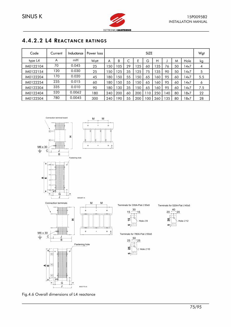
SINUS K 15P0095B2 INSTALLATION MANUAL
75/95
4.4.2.2 L4 REACTANCE RATINGS
Code Current Inductance Power loss SIZE Wgt
type L4 A mH Watt A B C E G H J M Hole kg
IM0122104 70 0.045 25 150 105 29 125 60 135 76 50 14x7 4
IM0122154 120 0.030 25 150 125 35 125 75 135 90 50 14x7 5
IM0122204 170 0.020 45 180 150 55 150 65 160 95 60 14x7 5.5
IM0122254 235 0.015 60 180 150 55 150 65 160 95 60 14x7 6
IM0122304 335 0.010 90 180 130 35 150 65 160 95 60 14x7 7.5
IM0122404 520 0.0062 180 240 200 60 200 110 250 140 80 18x7 22
IM0122504 780 0.0045 300 240 190 55 200 100 260 135 80 18x7 28 Fig.4.6 Overall dimensions of L4 reactance
G J
= =
M M
M 6 x 3 0
M 0 0 2 6 7 - A
Fo r o f i s s a g g i o B J C
C a p o c o r d a p e r c o n n e s s i o n e Connection terminal board
Fastening hole
B J C
1515
Foro Ø 9
30
M M
G J
=
M 6 x 3 0
M 0 0 7 7 9 - A
F o r o f i s s a g g i o
Terminali per 335 A - Piatto 30 x 5
=
2 0 2 0
F o r o Ø 1 0
4 0 Termin a l i p e r 5 2 0 A - P i a t t o 4 0 x 5
2525
Foro Ø 12
50Terminali per 780 A - Piatto 50 x 5
T e r m i n a l i p e r c o n n e s s i o n e
Fastening hole
Connection terminals Terminals for 335A-Flat ∅30x5
Terminals for 780A-Flat ∅50x5
Terminals for 520A-Flat ∅40x5
Hole ∅9
Hole ∅10
Hole ∅12
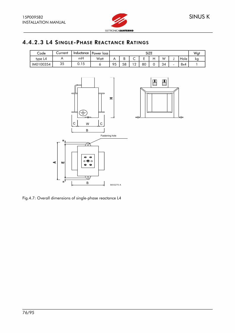
15P0095B2 SINUS K INSTALLATION MANUAL
76/95
4.4.2.3 L4 SINGLE-PHASE REACTANCE RATINGS
Code Current Inductance Power loss SIZE Wgt
type L4 A mH Watt A B C E H W J Hole kg
IM0100354 35 0.15 6 95 58 12 80 0 34 - 8x4 1
Fig.4.7: Overall dimensions of single-phase reactance L4
B
W B
C
F o ro d i f is s a g g io
M 00275-A
C
Fastening hole
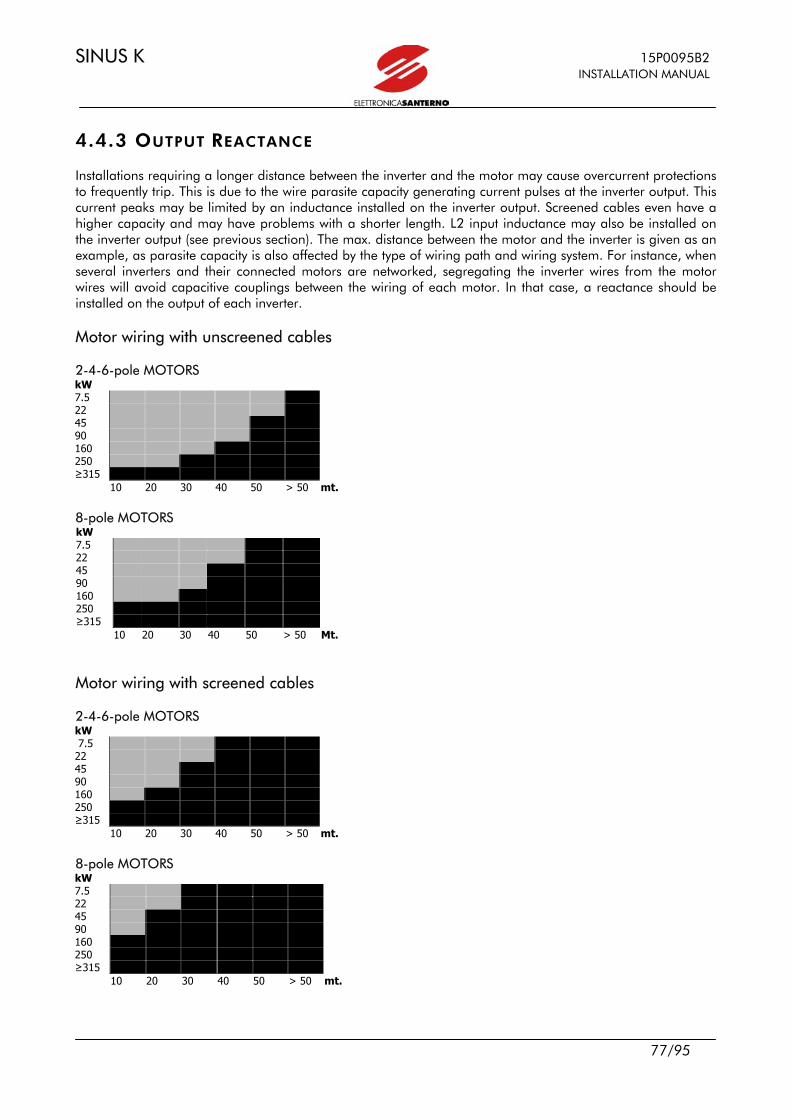
SINUS K 15P0095B2 INSTALLATION MANUAL
77/95
4.4.3 OUTPUT REACTANCE Installations requiring a longer distance between the inverter and the motor may cause overcurrent protections to frequently trip. This is due to the wire parasite capacity generating current pulses at the inverter output. This current peaks may be limited by an inductance installed on the inverter output. Screened cables even have a higher capacity and may have problems with a shorter length. L2 input inductance may also be installed on the inverter output (see previous section). The max. distance between the motor and the inverter is given as an example, as parasite capacity is also affected by the type of wiring path and wiring system. For instance, when several inverters and their connected motors are networked, segregating the inverter wires from the motor wires will avoid capacitive couplings between the wiring of each motor. In that case, a reactance should be installed on the output of each inverter. Motor wiring with unscreened cables 2-4-6-pole MOTORS kW 7.5 22 45 90 160 250 ≥315 10 20 30 40 50 > 50 mt. 8-pole MOTORS kW 7.5 22 45 90 160 250 ≥315 10 20 30 40 50 > 50 Mt. Motor wiring with screened cables 2-4-6-pole MOTORS kW 7.5 22 45 90 160 250 ≥315 10 20 30 40 50 > 50 mt. 8-pole MOTORS kW 7.5 22 45 90 160 250 ≥315 10 20 30 40 50 > 50 mt.

15P0095B2 SINUS K INSTALLATION MANUAL
78/95
Always use an output inductance for >= 10-pole motors or parallel-connected motors controlled by a single inverter
Output inductance NOT required Output inductance REQUIRED
Output inductance wiring
CAUTION: L2 inductance may be used when the inverter output frequency does not
exceed 60 Hz. For a higher output frequency a special inductance for the max. allowable operating frequency must be used. Please contact Elettronica Santerno S.p.a.
R S
T
U
V
W
L
MO T O R
M 0 0 2 9 9 - 0
I N V E R T E R S I N U S / I F D - I F D V
S I N U S / I F D E - I F D E V
INVERTER SINUS K

SINUS K 15P0095B2 INSTALLATION MANUAL
79/95
4.5 ENCODER BOARD ES797/1 Board for incremental, bidirectional encoder to be used as a speed feedback for inverters of the SINUS K series with VTC control and LIFT control. Two versions are available: one for encoders with 24V output signals and one for encoders with 5V output signals. Both 24V supply and 5V supply are available on both encoder boards.
COMPATIBLE ENCODERS DESCRIPTION CODE POWER SUPPLY OUTPUT
5V Encoder acquisition board
ZZ0095830.AA231 5V or 24V LINE DRIVER, PNP, NPN, PUSH-PULL, 5V
24V Encoder acquisition board
ZZ0095830.AA232 24V LINE DRIVER, PNP, NPN, PUSH-PULL, 24V
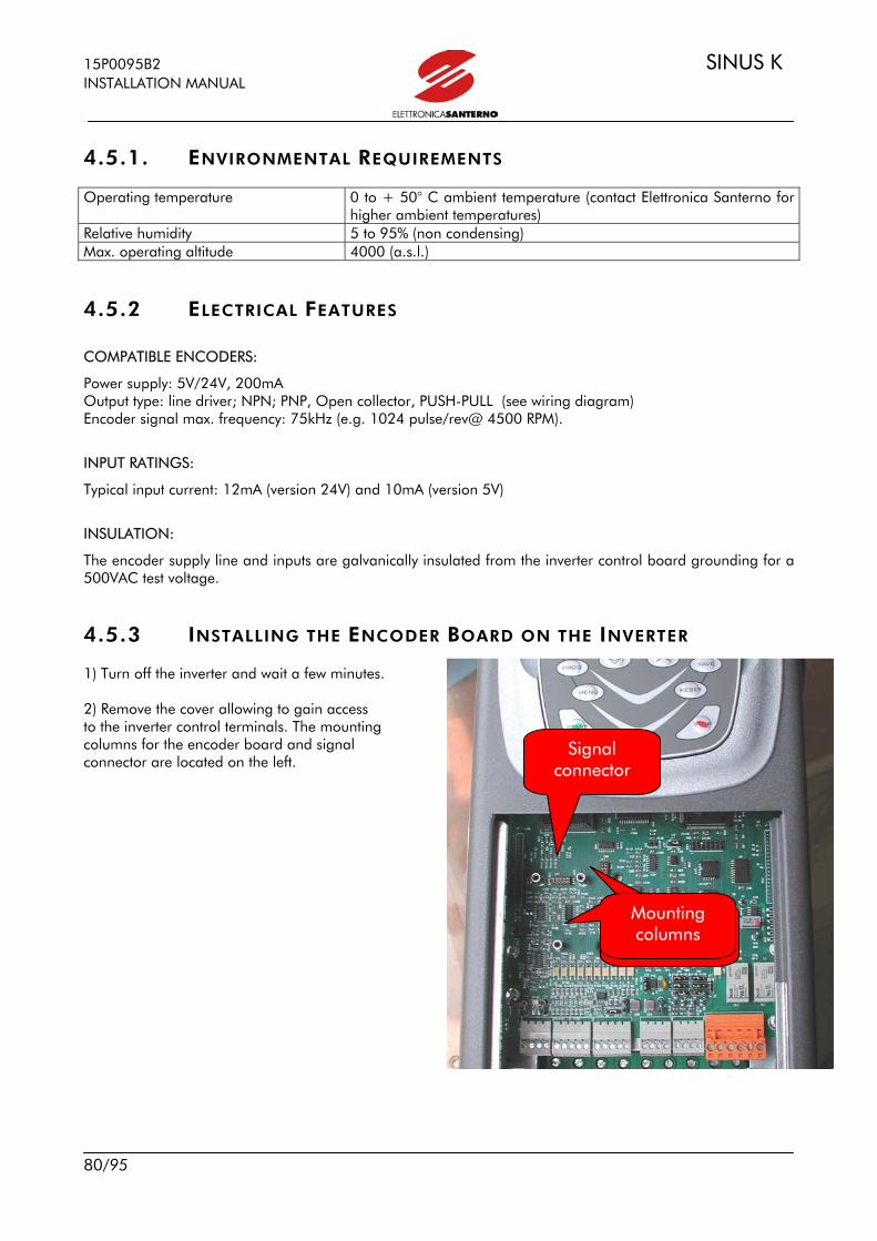
15P0095B2 SINUS K INSTALLATION MANUAL
80/95
4.5.1. ENVIRONMENTAL REQUIREMENTS Operating temperature 0 to + 50° C ambient temperature (contact Elettronica Santerno for
higher ambient temperatures) Relative humidity 5 to 95% (non condensing) Max. operating altitude 4000 (a.s.l.)
4.5.2 ELECTRICAL FEATURES
COMPATIBLE ENCODERS:
Power supply: 5V/24V, 200mA Output type: line driver; NPN; PNP, Open collector, PUSH-PULL (see wiring diagram) Encoder signal max. frequency: 75kHz (e.g. 1024 pulse/rev@ 4500 RPM).
INPUT RATINGS:
Typical input current: 12mA (version 24V) and 10mA (version 5V)
INSULATION:
The encoder supply line and inputs are galvanically insulated from the inverter control board grounding for a 500VAC test voltage.
4.5.3 INSTALLING THE ENCODER BOARD ON THE INVERTER 1) Turn off the inverter and wait a few minutes. 2) Remove the cover allowing to gain access to the inverter control terminals. The mounting columns for the encoder board and signal connector are located on the left.
Signal connector
Colonnette difissaggio
Mounting columns

SINUS K 15P0095B2 INSTALLATION MANUAL
81/95
3) Fit the encoder board and make sure that all contacts enter the relevant housing in the signal connector. Fasten the encoder board to the metal columns using the screws supplied. 4) Turn on the inverter and set the parameters relating to the encoder feedback (see Programming Manual).
4.5.4 ENCODER BOARD TERMINALS A 9-pole terminal board is located on the front side of the encoder board. Terminal: CHA Channel A encoder CHA Channel A encoder with complementary outputs CHB Channel B encoder CHB Channel B encoder with complementary outputs CHC Channel C encoder (Zero notch) CHC Channel C encoder with complementary outputs +5VENC 5V supply for encoder (max. 200mA with electronic limit) +24VENC 24V supply for encoder (max. 200mA protected by self-resetting fuse) 0VE encoder supply ground For the encoder connection to the encoder board, see wiring diagrams (following pages).
4.5.5 TRIMMER Trimmer +5VADJ installed on board ES797/1 allows to adjust output voltage +5VENC. This can compensate voltage drops in case of long distance between the encoder and the encoder board. Adjustment procedure: put a tester on the encoder supply connector (encoder side of the connecting cable); make sure the encoder is on. rotate the trimmer clockwise to increase supply voltage (max. allowable voltage for encoder board terminals is 5.5V).

15P0095B2 SINUS K INSTALLATION MANUAL
82/95
4.5.6 ENCODER WIRING EXAMPLE 5V BOARD a) LINE DRIVER or PUSH-PULL encoder b) LINE DRIVER or PUSH-PULL encoder with complementary outputs with complementary outputs Supply: 5V Supply: 24V Complementary outputs A and B: 5V Complementary outputs A and B: 5V
EncEEncodd
ES797/1 Version 5V ES797/1 Version 5V
EncEEncodd
Encoder Supply 5V Output 5V
Encoder Supply 24V Output 5V
1 C
HA
2
CH
A
3 C
HB
4 C
HB
5 C
HC
6
CHC
7
+5V
8
+24V
9
0V
1 C
HA
2
CH
A
3 C
HB
4 C
HB
5 C
HC
6
CH
C
7 +
5V
8 +2
4V
9 0
V
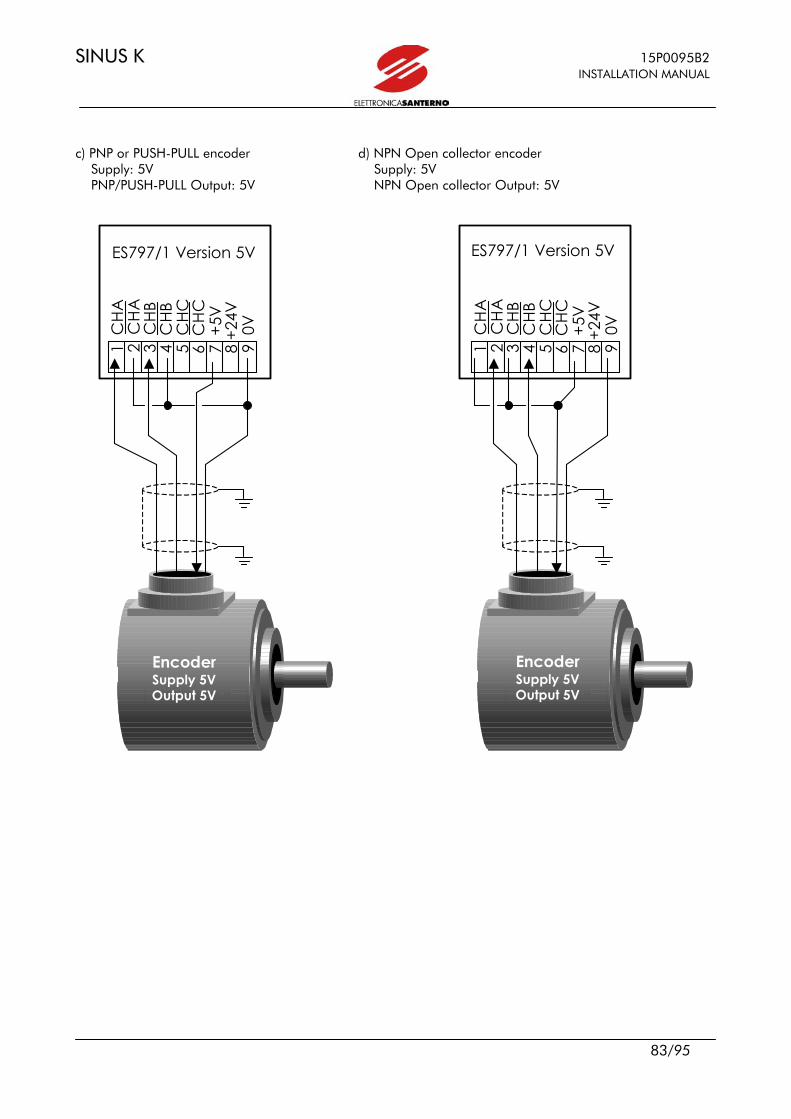
SINUS K 15P0095B2 INSTALLATION MANUAL
83/95
c) PNP or PUSH-PULL encoder d) NPN Open collector encoder Supply: 5V Supply: 5V PNP/PUSH-PULL Output: 5V NPN Open collector Output: 5V
EncEEncodd
EncEEncodd
Encoder Supply 5V Output 5V
Encoder Supply 5V Output 5V
ES797/1 Version 5V
1 C
HA
2
CH
A
3 C
HB
4 C
HB
5 C
HC
6 C
HC
7
+5V
8
+24V
9
0V
ES797/1 Version 5V
1 C
HA
2
CH
A
3 C
HB
4 C
HB
5 C
HC
6 C
HC
7
+5V
8
+24V
9
0V
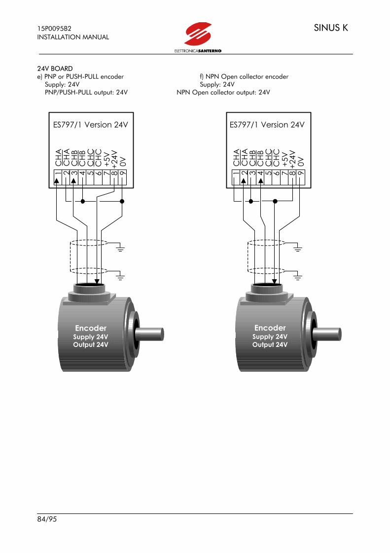
15P0095B2 SINUS K INSTALLATION MANUAL
84/95
24V BOARD e) PNP or PUSH-PULL encoder f) NPN Open collector encoder Supply: 24V Supply: 24V PNP/PUSH-PULL output: 24V NPN Open collector output: 24V
EncEEncodd
EncEEncodd
Encoder Supply 24V Output 24V
Encoder Supply 24V Output 24V
ES797/1 Version 24V
1 C
HA
2
CH
A
3 C
HB
4 C
HB
5 C
HC
6 C
HC
7
+5V
8
+24V
9
0V
ES797/1 Version 24V
1 C
HA
2
CH
A
3 C
HB
4 C
HB
5 C
HC
6 C
HC
7
+5V
8
+24V
9
0V

SINUS K 15P0095B2 INSTALLATION MANUAL
85/95
g) PUSH-PULL encoder with complementary outputs Supply: 24V Complementary outputs A and B: 24V
WARNING: a wrong encoder-board connection may damage both the encoder and the board.
EncEEncodd
Encoder Supply 24V Output 24V
ES797/1 Version 24V1
CH
A
2 C
HA
3
CHB
4
CHB
5
CHC
6
CH
C
7 +
5V
8 +2
4V
9 0
V
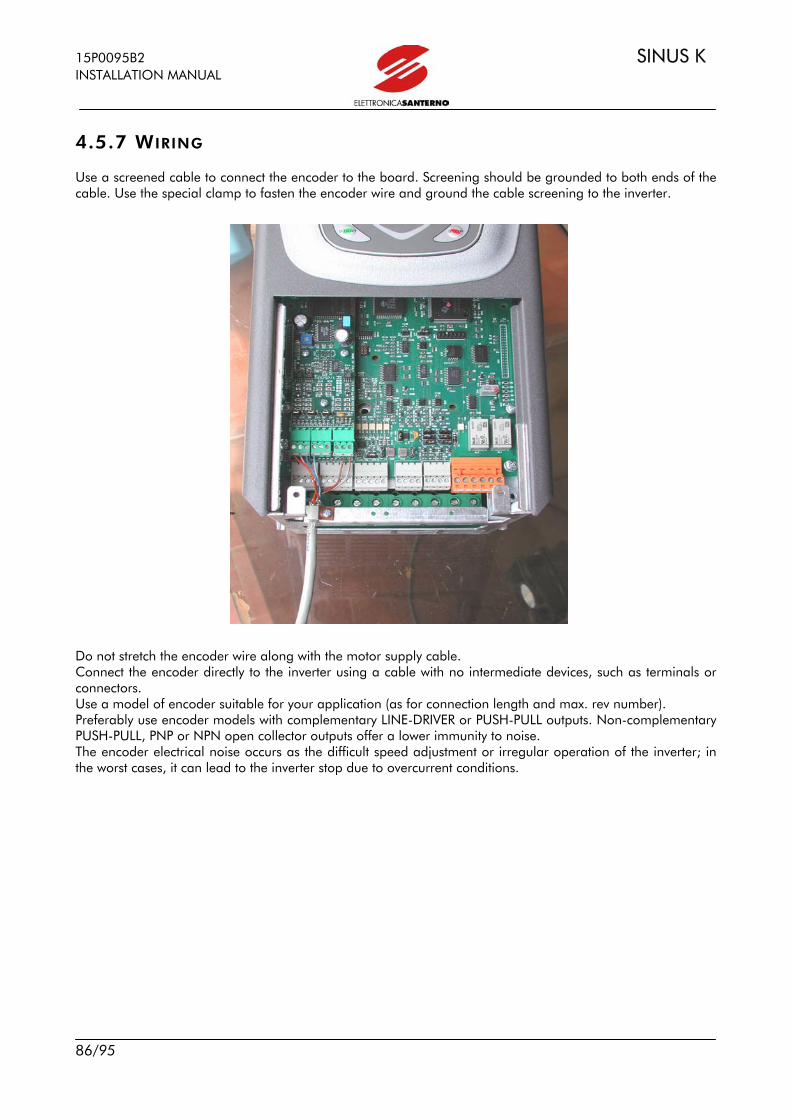
15P0095B2 SINUS K INSTALLATION MANUAL
86/95
4.5.7 WIRING Use a screened cable to connect the encoder to the board. Screening should be grounded to both ends of the cable. Use the special clamp to fasten the encoder wire and ground the cable screening to the inverter. Do not stretch the encoder wire along with the motor supply cable. Connect the encoder directly to the inverter using a cable with no intermediate devices, such as terminals or connectors. Use a model of encoder suitable for your application (as for connection length and max. rev number). Preferably use encoder models with complementary LINE-DRIVER or PUSH-PULL outputs. Non-complementary PUSH-PULL, PNP or NPN open collector outputs offer a lower immunity to noise. The encoder electrical noise occurs as the difficult speed adjustment or irregular operation of the inverter; in the worst cases, it can lead to the inverter stop due to overcurrent conditions.

SINUS K 15P0095B2 INSTALLATION MANUAL
87/95
5 PROVISIONS Electromagnetic Compatibility 89/336/CEE and following amendments 92/31/CEE, 93/68/CEE, and 93/97/CEE. In most systems, the processing control also requires additional devices, such as computers, captors, and so on, that are usually installed one next to the other, thus causing disturbance: - Low frequency – harmonics. - High frequency – electromagnetic interference (EMI) High frequency interference High frequency interference is disturbance or radiated interference with >9kHz frequency. Critical values range from 150kHz to 1000MHz. Interference is often caused by commutations to be found in any device, i.e. switching feeders and drive output modules. High frequency disturbance may interfere with the correct operation of the other devices. High frequency noise produced by a device may cause malfunctions in measurement systems and communication systems, so that radio receivers only receive electrical noise. This may cause unexpected faults. Two fields may be concerned: immunity (EN50082-1-2, EN61800-3/A11 and following EN 61800-3 issue 2) and emissions (EN 55011group 1 and 2 cl. A, EN 55011 group 1 cl.B, EN61800-3-A11 and following EN 61800-3 issue 2). Standards EN55011 and 50082, as well as standard EN61800-3, define immunity and emission levels required for devices designed to operate in different environments. Drives manufactured by ELETTRONICA SANTERNO are designed to operate under the most different conditions, so they all ensure high immunity against RFI and high reliability in any environment. The table below defines PDS (Power Drive Systems) of EN 61800-3:2002 (which will become EN61800-3 issue 2).
FIRST ENVIRONMENT Environment including domestic devices and industrial devices which are connected directly to a low-voltage mains (with no intermediate transformer) for domestic usage.
SECOND ENVIRONMENT Environment including industrial connections different from “First Environment” connections.
PDS of Category C1 PDS with rated voltage lower than 1000 V to be used in the First Environment.
PDS of Category C2 PDS with rated voltage lower than 1000 V; if used in the First Environment, they are intended to be installed and commissioned by professional users only.
PDS of Category C3 PDS with rated voltage lower than 1000 V to be used in the Second Environment.
PDS of Category C4 PDS with rated voltage equal to or higher than 1000 V or with a current equal to or higher than 400A to be used in complex systems installed in the Second Environment.

15P0095B2 SINUS K INSTALLATION MANUAL
88/95
Emission Limits The standards in force also define the allowable emission level for different environments. The diagrams below show emission limits allowed by Pr EN 61800-3 issue 2 (corresponding to EN61800-3/A11)
A1 = EN 61800-3 issue 2 FIRST ENVIRONMENT, Category C2, EN55011 gr.1 cl. A, EN50081-2,EN61800-3/A11.
A2 = EN 61800-3 issue 2 SECOND ENVIRONMENT Category C3, EN55011 gr.2 cl. A, EN61800-3/A11.
'SECOND ENVIROMENT' Disturbance Limit
0
20
40
60
80
100
120
140
0,1 1 10 100
log f (MHz)
dB (
uV
)
Quasi-Peak I <= 100 A
Mean Value I <= 100 A
Quasi-Peak I > 100 A
Mean Value I > 100 A
B = EN 61800-3 issue 2 FIRST ENVIRONMENT, Category C1, EN55011 gr.1 cl. B, EN50081-1,-2,EN61800-3/A11.
First enviroment Disturbance Limits'
0
10
20
30
40
50
60
70
80
90
0,1 1 10 100
log f (MHz)
dB (
uV
) Quasi-Peak Category C2
Mean Value Category C2
Quasi-Peak Category C1
Mean Value Category C1
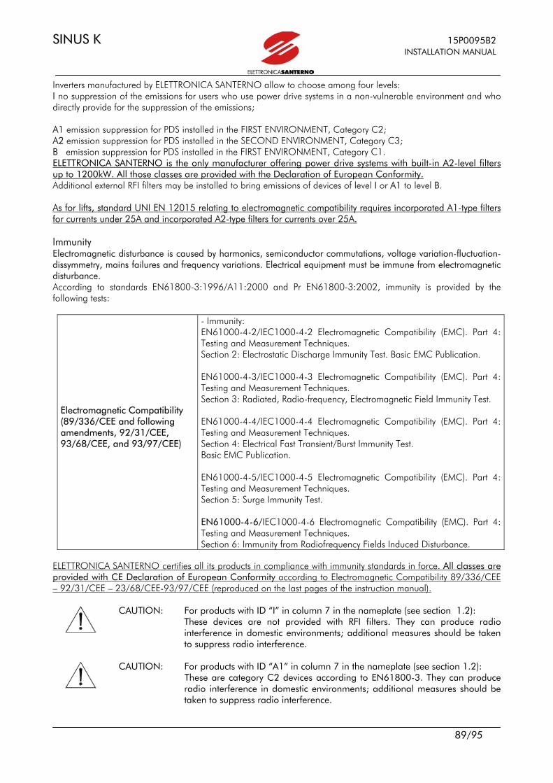
SINUS K 15P0095B2 INSTALLATION MANUAL
89/95
Inverters manufactured by ELETTRONICA SANTERNO allow to choose among four levels: I no suppression of the emissions for users who use power drive systems in a non-vulnerable environment and who directly provide for the suppression of the emissions; A1 emission suppression for PDS installed in the FIRST ENVIRONMENT, Category C2; A2 emission suppression for PDS installed in the SECOND ENVIRONMENT, Category C3; B emission suppression for PDS installed in the FIRST ENVIRONMENT, Category C1. ELETTRONICA SANTERNO is the only manufacturer offering power drive systems with built-in A2-level filters up to 1200kW. All those classes are provided with the Declaration of European Conformity. Additional external RFI filters may be installed to bring emissions of devices of level I or A1 to level B. As for lifts, standard UNI EN 12015 relating to electromagnetic compatibility requires incorporated A1-type filters for currents under 25A and incorporated A2-type filters for currents over 25A. Immunity Electromagnetic disturbance is caused by harmonics, semiconductor commutations, voltage variation-fluctuation-dissymmetry, mains failures and frequency variations. Electrical equipment must be immune from electromagnetic disturbance. According to standards EN61800-3:1996/A11:2000 and Pr EN61800-3:2002, immunity is provided by the following tests:
Electromagnetic Compatibility (89/336/CEE and following amendments, 92/31/CEE, 93/68/CEE, and 93/97/CEE)
- Immunity: EN61000-4-2/IEC1000-4-2 Electromagnetic Compatibility (EMC). Part 4: Testing and Measurement Techniques. Section 2: Electrostatic Discharge Immunity Test. Basic EMC Publication. EN61000-4-3/IEC1000-4-3 Electromagnetic Compatibility (EMC). Part 4: Testing and Measurement Techniques. Section 3: Radiated, Radio-frequency, Electromagnetic Field Immunity Test. EN61000-4-4/IEC1000-4-4 Electromagnetic Compatibility (EMC). Part 4: Testing and Measurement Techniques. Section 4: Electrical Fast Transient/Burst Immunity Test. Basic EMC Publication. EN61000-4-5/IEC1000-4-5 Electromagnetic Compatibility (EMC). Part 4: Testing and Measurement Techniques. Section 5: Surge Immunity Test. EN61000-4-6/IEC1000-4-6 Electromagnetic Compatibility (EMC). Part 4: Testing and Measurement Techniques. Section 6: Immunity from Radiofrequency Fields Induced Disturbance.
ELETTRONICA SANTERNO certifies all its products in compliance with immunity standards in force. All classes are provided with CE Declaration of European Conformity according to Electromagnetic Compatibility 89/336/CEE – 92/31/CEE – 23/68/CEE-93/97/CEE (reproduced on the last pages of the instruction manual).
CAUTION: For products with ID “I” in column 7 in the nameplate (see section 1.2): These devices are not provided with RFI filters. They can produce radio interference in domestic environments; additional measures should be taken to suppress radio interference.
CAUTION: For products with ID “A1” in column 7 in the nameplate (see section 1.2):
These are category C2 devices according to EN61800-3. They can produce radio interference in domestic environments; additional measures should be taken to suppress radio interference.
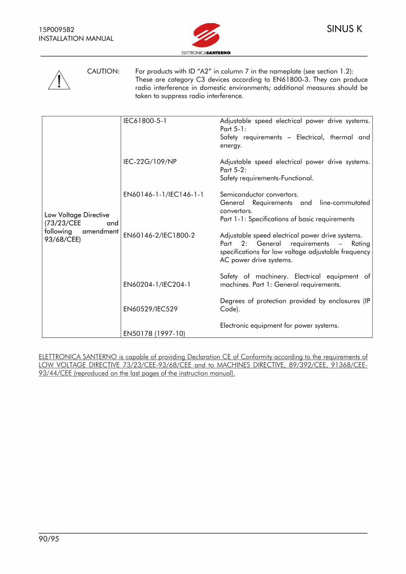
15P0095B2 SINUS K INSTALLATION MANUAL
90/95
CAUTION: For products with ID “A2” in column 7 in the nameplate (see section 1.2):
These are category C3 devices according to EN61800-3. They can produce radio interference in domestic environments; additional measures should be taken to suppress radio interference.
Low Voltage Directive (73/23/CEE and following amendment 93/68/CEE)
IEC61800-5-1 IEC-22G/109/NP EN60146-1-1/IEC146-1-1 EN60146-2/IEC1800-2 EN60204-1/IEC204-1 EN60529/IEC529 EN50178 (1997-10)
Adjustable speed electrical power drive systems. Part 5-1: Safety requirements – Electrical, thermal and energy. Adjustable speed electrical power drive systems. Part 5-2: Safety requirements-Functional. Semiconductor convertors. General Requirements and line-commutated convertors. Part 1-1: Specifications of basic requirements Adjustable speed electrical power drive systems. Part 2: General requirements – Rating specifications for low voltage adjustable frequency AC power drive systems. Safety of machinery. Electrical equipment of machines. Part 1: General requirements. Degrees of protection provided by enclosures (IP Code). Electronic equipment for power systems.
ELETTRONICA SANTERNO is capable of providing Declaration CE of Conformity according to the requirements of LOW VOLTAGE DIRECTIVE 73/23/CEE-93/68/CEE and to MACHINES DIRECTIVE, 89/392/CEE, 91368/CEE-93/44/CEE (reproduced on the last pages of the instruction manual).
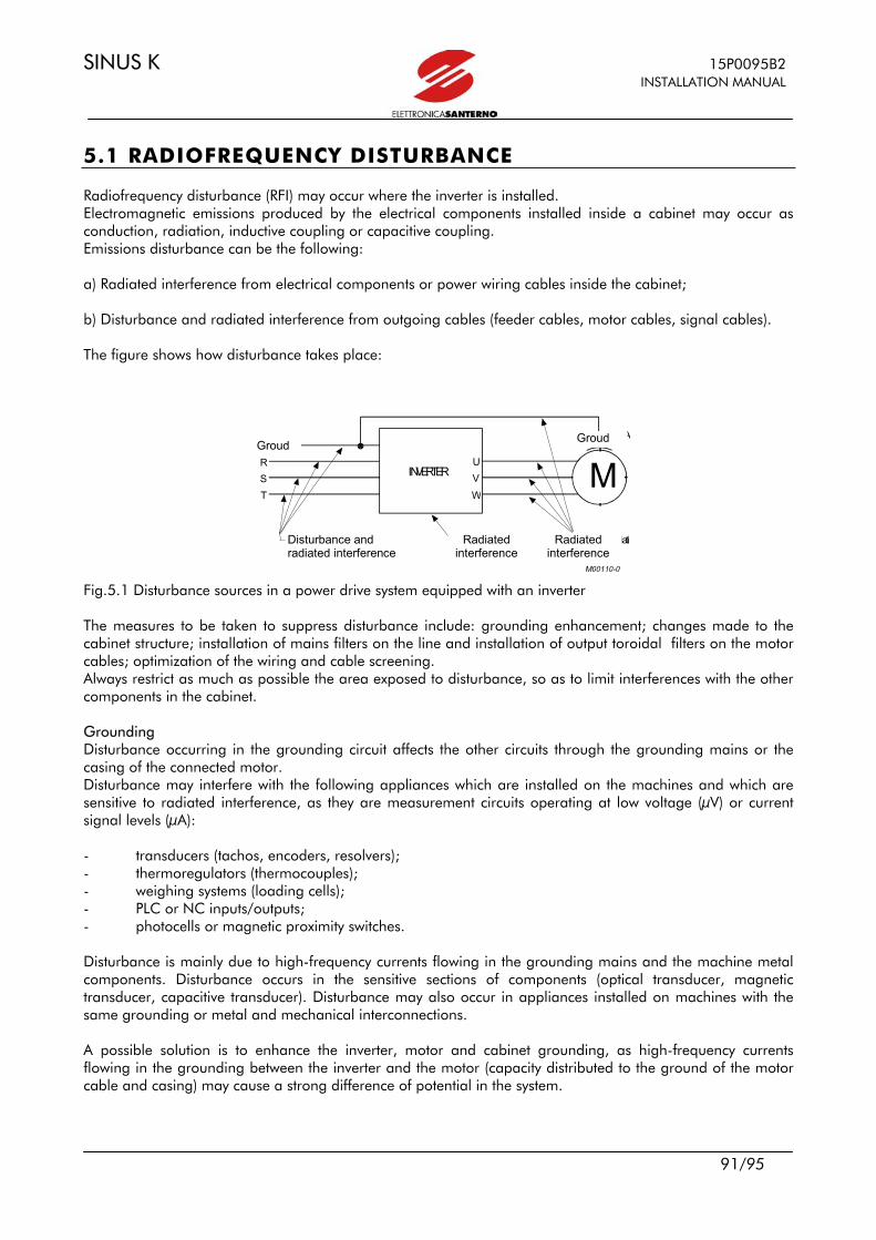
SINUS K 15P0095B2 INSTALLATION MANUAL
91/95
5.1 RADIOFREQUENCY DISTURBANCE Radiofrequency disturbance (RFI) may occur where the inverter is installed. Electromagnetic emissions produced by the electrical components installed inside a cabinet may occur as conduction, radiation, inductive coupling or capacitive coupling. Emissions disturbance can be the following: a) Radiated interference from electrical components or power wiring cables inside the cabinet; b) Disturbance and radiated interference from outgoing cables (feeder cables, motor cables, signal cables). The figure shows how disturbance takes place:
TER R A
MINVERTERST
UVW
T E RRAR
D i s t u r b i i r r a d i a t i e c o n d o tti Disturbi irradiati Disturbi irrad i a t i
Groud
Disturbance and radiated interference
Radiated interference
Radiated interference
Groud
Fig.5.1 Disturbance sources in a power drive system equipped with an inverter The measures to be taken to suppress disturbance include: grounding enhancement; changes made to the cabinet structure; installation of mains filters on the line and installation of output toroidal filters on the motor cables; optimization of the wiring and cable screening. Always restrict as much as possible the area exposed to disturbance, so as to limit interferences with the other components in the cabinet. Grounding Disturbance occurring in the grounding circuit affects the other circuits through the grounding mains or the casing of the connected motor. Disturbance may interfere with the following appliances which are installed on the machines and which are sensitive to radiated interference, as they are measurement circuits operating at low voltage (µV) or current signal levels (µA): - transducers (tachos, encoders, resolvers); - thermoregulators (thermocouples); - weighing systems (loading cells); - PLC or NC inputs/outputs; - photocells or magnetic proximity switches. Disturbance is mainly due to high-frequency currents flowing in the grounding mains and the machine metal components. Disturbance occurs in the sensitive sections of components (optical transducer, magnetic transducer, capacitive transducer). Disturbance may also occur in appliances installed on machines with the same grounding or metal and mechanical interconnections. A possible solution is to enhance the inverter, motor and cabinet grounding, as high-frequency currents flowing in the grounding between the inverter and the motor (capacity distributed to the ground of the motor cable and casing) may cause a strong difference of potential in the system.
15P0095B2 SINUS K INSTALLATION MANUAL
92/95
5.2.1 THE MAINS Disturbance and radiated interference occur in the mains. Limiting disturbance results in weakening radiated interference. Disturbance on the mains may interfere with devices installed on the machine or devices installed even some hundred meters far from the machine and which are connected to the same mains. The following appliances are particularly sensitive to disturbance: - computers; - radio receivers and TV receivers; - biomedical equipment; - weighing systems; - machines using thermoregulation; - telephone systems. Mains disturbance may be limited by installing a mains filter to reduce RFI. ELETTRONICA SANTERNO adopted this solution to suppress RFI. Incorporated filters installed in the inverters are shown in section 5.2.4.
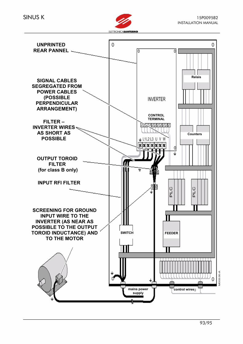
SINUS K 15P0095B2 INSTALLATION MANUAL
93/95
UNPRINTED
REAR PANNEL
SIGNAL CABLES SEGREGATED FROM
POWER CABLES (POSSIBLE
PERPENDICULAR ARRANGEMENT)
FILTER – INVERTER WIRES
AS SHORT AS POSSIBLE
OUTPUT TOROID FILTER
(for class B only)
INPUT RFI FILTER
SCREENING FOR GROUND INPUT WIRE TO THE
INVERTER (AS NEAR AS POSSIBLE TO THE OUTPUT TOROID INDUCTANCE) AND
TO THE MOTOR
mains power supply
control wires
SWITCH FEEDER
Counters
Relais
CONTROL TERMINAL

15P0095B2 SINUS K INSTALLATION MANUAL
94/95
5.2.2 OUTPUT TOROID FILTERS Ferrite is a simple radiofrequency filter. Ferrite cores are high-permeable ferromagnetic materials used to weaken cable disturbance: - in case of three-phase conductors, all phases must go through ferrite; - in case of single-phase conductors (or 2wire line) both phases must go through ferrite (incoming and outcoming conductor cables that are to be filtered must go through ferrite). See section 5.2.4 for the selection of the output toroid filter to weaken radiofrequency interference. 5.2.3 THE CABINET To prevent input and output of electromagnetic emissions to and from the cabinet, draw particular attention to the cabinet doors, opening and cable paths. A) Use a seam-welded metal frame ensuring electrical continuity. Provide an unpainted, reference grounding support on the frame bottom. This steel sheet or metal grill is to be connected to the metal frame, which is also connected to the ground mains of the equipment. All components must be bolted directly to the grounding support. B) Hinged parts or mobile parts (i.e. doors) must be made of metal and capable of restoring electrical conductivity once closed. C) Segregate cables bases on the type and intensity of electrical quantities and the type of devices which they are connected to (components that may generate electromagnetic disturbance and components that are particularly sensitive to disturbance): high sensitivity - analog inputs and outputs: voltage reference and current reference - sensors and measurement circuits (ATs and VTs) - DC supply (10V, 24V) low sensitivity - digital inputs and outputs: optoisolated commands, relay outputs low perturbation - filtered AC supply high perturbation - power circuits in general - inverter non-filtered AC supply
- contactors - inverter-motor wires Measures to take when wiring the cabinet or the system: - Sensitive signals and perturbator signals must never exist within a cable. - Avoid that cables carrying sensitive signals and perturbator signals run parallel at short distance:
whenever possible, paths of cables carrying sensitive signals and perturbator signals should be reduced to a minimum.
- The distance between segregated cables should be proportional to the cable length. Whenever possible, cable crossing should be perpendicular.
Wires connecting the motor or load mainly generate disturbance. Disturbance is important in inverter power drive systems or the devices installed on the machine, and could interfere with local communication circuits located near the inverter (radiotelephones, mobile phones). Follow the instructions below to solve these problems: - Provide for a motor cable path as short as possible. - Screen the power cables to the motor; ground screening both to the inverter and to the motor.
Excellent results are obtained using cables in which the protection connection (yellow-green cable) is external to the screening (this type of cables are available on the market with a cross-section up to 35mm2 per phase). If no screened cable having a suitable cross-section is available, segregate power cables in grounded, metal raceways.
- Screen signal cables and ground screening on the inverter side. - Segregate power cable from signal cables. - Leave a clearance of at least 0.5m between signal cables and motor cables. - Series-connect a common mode inductance (toroid) (approx. 100µH) to the inverter-motor
connection.
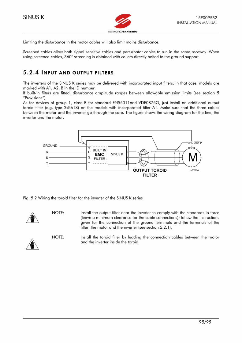
SINUS K 15P0095B2 INSTALLATION MANUAL
95/95
Limiting the disturbance in the motor cables will also limit mains disturbance. Screened cables allow both signal sensitive cables and perturbator cables to run in the same raceway. When using screened cables, 360° screening is obtained with collars directly bolted to the ground support.
5.2.4 INPUT AND OUTPUT FILTERS The inverters of the SINUS K series may be delivered with incorporated input filters; in that case, models are marked with A1, A2, B in the ID number. If built-in filters are fitted, disturbance amplitude ranges between allowable emission limits (see section 5 “Provisions”). As for devices of group 1, class B for standard EN55011and VDE0875G, just install an additional output toroid filter (e.g. type 2xK618) on the models with incorporated filter A1. Make sure that the three cables between the motor and the inverter go through the core. The figure shows the wiring diagram for the line, the inverter and the motor. Fig. 5.2 Wiring the toroid filter for the inverter of the SINUS K series
NOTE: Install the output filter near the inverter to comply with the standards in force (leave a minimum clearance for the cable connections); follow the instructions given for the connection of the ground terminals and the terminals of the filter, the motor and the inverter (see section 5.2.1).
NOTE: Install the toroid filter by leading the connection cables between the motor
and the inverter inside the toroid.
T E R RA
M
VN ERTERSINUS/IFDE
- FS S T T
U
V
W
T E R R A R R
FILTROTOROIDALEDI USCITA2xK618
F I L TROE MC
I N T ERNO
M 0 0 5 3 6 - A
SINUS K
GROUND GROUND
BUILT INEMC
FILTER
OUTPUT TOROID FILTER