SINUMERIK - ماشين · PDF fileSINUMERIK SINUMERIK 840D sl/840Di sl/ 828D/802D sl ISO...
12
SINUMERIK SINUMERIK 840D sl/840Di sl/828D/802D sl ISO Milling _ _____________ _ _____________ _ _____________ _ _____________ _ _____________ _ _____________ _ _____________ _ _____________ _ _____________ Principles of programming 1 Drive commands 2 Motion commands 3 Additional functions 4 Abbreviations A G code table B Data Description C Data lists D Interrupts E SINUMERIK SINUMERIK 840D sl/840Di sl/ 828D/802D sl ISO Milling Programming Manual 06/09 6FC5398-7BP10-1BA0 Valid for Software Version SINUMERIK 802D sl 1.4 SINUMERIK 828D 2.6 SINUMERIK 840D sl/DE sl 2.6 SINUMERIK 840Di sl/DiE sl 1.4
Transcript of SINUMERIK - ماشين · PDF fileSINUMERIK SINUMERIK 840D sl/840Di sl/ 828D/802D sl ISO...

SINUMERIK SINUMERIK 840D sl/840Di sl/828D/802D sl ISO Milling
____________________________
__________________________________________________________________________________________________
Principles of programming 1
Drive commands
2
Motion commands
3
Additional functions
4
Abbreviations
A
G code table
B
Data Description
C
Data lists
D
Interrupts
E
SINUMERIK
SINUMERIK 840D sl/840Di sl/828D/802D sl ISO Milling
Programming Manual
06/09 6FC5398-7BP10-1BA0
Valid for Software Version SINUMERIK 802D sl 1.4 SINUMERIK 828D 2.6 SINUMERIK 840D sl/DE sl 2.6 SINUMERIK 840Di sl/DiE sl 1.4

Legal information Legal information Warning notice system
This manual contains notices you have to observe in order to ensure your personal safety, as well as to prevent damage to property. The notices referring to your personal safety are highlighted in the manual by a safety alert symbol, notices referring only to property damage have no safety alert symbol. These notices shown below are graded according to the degree of danger.
DANGER indicates that death or severe personal injury will result if proper precautions are not taken.
WARNING indicates that death or severe personal injury may result if proper precautions are not taken.
CAUTION with a safety alert symbol, indicates that minor personal injury can result if proper precautions are not taken.
CAUTION without a safety alert symbol, indicates that property damage can result if proper precautions are not taken.
NOTICE indicates that an unintended result or situation can occur if the corresponding information is not taken into account.
If more than one degree of danger is present, the warning notice representing the highest degree of danger will be used. A notice warning of injury to persons with a safety alert symbol may also include a warning relating to property damage.
Qualified Personnel The device/system may only be set up and used in conjunction with this documentation. Commissioning and operation of a device/system may only be performed by qualified personnel. Within the context of the safety notes in this documentation qualified persons are defined as persons who are authorized to commission, ground and label devices, systems and circuits in accordance with established safety practices and standards.
Proper use of Siemens products Note the following:
WARNING Siemens products may only be used for the applications described in the catalog and in the relevant technical documentation. If products and components from other manufacturers are used, these must be recommended or approved by Siemens. Proper transport, storage, installation, assembly, commissioning, operation and maintenance are required to ensure that the products operate safely and without any problems. The permissible ambient conditions must be adhered to. The information in the relevant documentation must be observed.
Trademarks All names identified by ® are registered trademarks of the Siemens AG. The remaining trademarks in this publication may be trademarks whose use by third parties for their own purposes could violate the rights of the owner.
Disclaimer of Liability We have reviewed the contents of this publication to ensure consistency with the hardware and software described. Since variance cannot be precluded entirely, we cannot guarantee full consistency. However, the information in this publication is reviewed regularly and any necessary corrections are included in subsequent editions.
Siemens AG Industry Sector Postfach 48 48 90026 NÜRNBERG GERMANY
Ordernumber: 6FC5398-7BP10-1BA0 Ⓟ 07/2009
Copyright © Siemens AG 2009. Technical data subject to change

ISO Milling Programming Manual, 06/09, 6FC5398-7BP10-1BA0 3
Table of contents
1 Principles of programming ......................................................................................................................... 7
1.1 Introductory comments ..................................................................................................................7 1.1.1 Siemens mode ...............................................................................................................................7 1.1.2 ISO dialect mode ...........................................................................................................................7 1.1.3 Switching between the modes .......................................................................................................7 1.1.4 Display of the G code.....................................................................................................................8 1.1.5 Maximum number of axes/axis identifiers......................................................................................8 1.1.6 Decimal point programming ...........................................................................................................8 1.1.7 Comments....................................................................................................................................10 1.1.8 Skip block.....................................................................................................................................10 1.2 Preconditions for the feed ............................................................................................................11 1.2.1 Rapid traverse..............................................................................................................................11 1.2.2 Path feed (F function) ..................................................................................................................11 1.2.3 Fixed feedrates F0 to F9..............................................................................................................13 1.2.4 Linear feed (G94).........................................................................................................................15 1.2.5 Inverse-time feed (G93) ...............................................................................................................15 1.2.6 Revolutional feedrate (G95).........................................................................................................16
2 Drive commands...................................................................................................................................... 17 2.1 Interpolation commands...............................................................................................................17 2.1.1 Rapid traverse (G00) ...................................................................................................................17 2.1.2 Linear interpolation (G01) ............................................................................................................18 2.1.3 Circular interpolation (G02, G03).................................................................................................19 2.1.4 Contour definition programming and addition of chamfers or radiuses.......................................22 2.1.5 Helical interpolation (G02, G03)...................................................................................................25 2.1.6 Involute interpolation (G02.2, G03.2)...........................................................................................26 2.1.7 Cylindrical interpolation (G07.1)...................................................................................................27 2.2 Reference point approach with G functions.................................................................................30 2.2.1 Reference point approach with intermediate point (G28) ............................................................30 2.2.2 Checking the reference position (G27) ........................................................................................32 2.2.3 Reference point approach with reference point selection (G30) .................................................33
3 Motion commands ................................................................................................................................... 35 3.1 The coordinate system.................................................................................................................35 3.1.1 Machine coordinate systems (G53) .............................................................................................36 3.1.2 Workpiece coordinate system (G92) ...........................................................................................37 3.1.3 Resetting the tool coordinate system (G92.1) .............................................................................38 3.1.4 Selection of a workpiece coordinate system................................................................................38 3.1.5 Writing work offset/tool offsets (G10)...........................................................................................38 3.1.6 Local coordinate system (G52) ....................................................................................................40 3.1.7 Selection of the plane (G17, G18, G19) ......................................................................................41 3.1.8 Parallel axes (G17, G18, G19).....................................................................................................42 3.1.9 Rotation of the coordinate system (G68, G69) ............................................................................43 3.1.10 3D rotation G68/G69....................................................................................................................45 3.2 Defining the input modes of the coordinate values......................................................................46 3.2.1 Absolute/incremental dimensioning (G90, G91) ..........................................................................46 3.2.2 Inch/metric input (G20, G21)........................................................................................................47

Table of contents
ISO Milling 4 Programming Manual, 06/09, 6FC5398-7BP10-1BA0
3.2.3 Scaling (G50, G51) ..................................................................................................................... 48 3.2.4 Programmable mirroring (G50.1, G51.1) .................................................................................... 51 3.3 Time-controlled commands......................................................................................................... 53 3.3.1 Dwell time (G04) ......................................................................................................................... 53 3.4 Tool offset functions .................................................................................................................... 54 3.4.1 Tool offset data memory ............................................................................................................. 54 3.4.2 Tool length compensation (G43, G44, G49) ............................................................................... 54 3.4.3 Cutter radius compensation (G40, G41, G42) ............................................................................ 57 3.4.4 Collision detection ....................................................................................................................... 61 3.5 S-, T-, M- and B functions ........................................................................................................... 65 3.5.1 Spindle function (S function) ....................................................................................................... 65 3.5.2 Tool function................................................................................................................................ 65 3.5.3 Additional function (M function)................................................................................................... 65 3.5.4 M functions of spindle control...................................................................................................... 66 3.5.5 M functions for subroutine calls .................................................................................................. 67 3.5.6 Macro call via M function............................................................................................................. 67 3.5.7 M functions.................................................................................................................................. 68 3.6 Controlling the feedrate............................................................................................................... 69 3.6.1 Automatic corner override G62 ................................................................................................... 69 3.6.2 Compressor in the ISO dialect mode .......................................................................................... 71 3.6.3 Exact stop (G09, G61), Continuous-path mode (G64), tapping (G63) ....................................... 72
4 Additional functions.................................................................................................................................. 73 4.1 Program supporting functions ..................................................................................................... 73 4.1.1 Fixed drilling cycles ..................................................................................................................... 73 4.1.2 Deep hole drilling cycle with chip breakage (G73)...................................................................... 78 4.1.3 Fine drilling cycle (G76) .............................................................................................................. 81 4.1.4 Drilling cycle, preboring (G81) .................................................................................................... 84 4.1.5 Drilling cycle, preboring (G82) .................................................................................................... 85 4.1.6 Deep hole drilling cycle with chip removal (G83) ........................................................................ 87 4.1.7 Drilling cycle (G85)...................................................................................................................... 90 4.1.8 Boring cycle (G86) ...................................................................................................................... 91 4.1.9 Boring cycle, reverse countersinking (G87) ................................................................................ 93 4.1.10 Drilling cycle (G89), return with G01 ........................................................................................... 96 4.1.11 Cycle "Tapping without compensating chuck" (G84).................................................................. 98 4.1.12 "Drilling a left-hand thread without compensating chuck" cycle (G74) ..................................... 101 4.1.13 Left or right tapping cycle (G84 or G74).................................................................................... 103 4.1.14 Deselection of a fixed cycle (G80) ............................................................................................ 106 4.1.15 Program example with a tool length compensation and fixed cycles ....................................... 107 4.1.16 Multiple-start threads with G33 ................................................................................................. 109 4.2 Programmable data input (G10) ............................................................................................... 110 4.2.1 Changing the tool offset value................................................................................................... 110 4.2.2 Working area limitation (G22, G23) .......................................................................................... 110 4.2.3 M function for calling subroutines (M98, M99) .......................................................................... 111 4.3 Eight-digit program number....................................................................................................... 113 4.4 Polar coordinates (G15, G16) ................................................................................................... 115 4.5 Polar coordinates interpolation (G12.1, G13.1) ........................................................................ 116 4.6 Measuring functions .................................................................................................................. 118 4.6.1 Rapid lift with G10.6 .................................................................................................................. 118 4.6.2 Measuring with "delete distance-to-go" (G31) .......................................................................... 118 4.6.3 Measuring with G31, P1 - P4 .................................................................................................... 121
Table of contents
ISO Milling Programming Manual, 06/09, 6FC5398-7BP10-1BA0 5
4.6.4 Interrupt program with M96, M97...............................................................................................122 4.6.5 "Tool life control" function ..........................................................................................................124 4.7 Macro programs.........................................................................................................................125 4.7.1 Differences with subroutines......................................................................................................125 4.7.2 Macro program call (G65, G66, G67) ........................................................................................125 4.7.3 Macro call via G function............................................................................................................132 4.8 Special functions........................................................................................................................135 4.8.1 Contour repetition (G72.1, G72.2) .............................................................................................135 4.8.2 Switchover modes for DryRun and skip levels ..........................................................................137
A Abbreviations......................................................................................................................................... 139 B G code table .......................................................................................................................................... 147 C Data Description .................................................................................................................................... 151
C.1 General machine data................................................................................................................151 C.2 Channel-specific machine data..................................................................................................164 C.3 Axis-specific setting data ...........................................................................................................177 C.4 Channel-specific setting data.....................................................................................................178
D Data lists................................................................................................................................................ 181 D.1 Machine data..............................................................................................................................181 D.2 Setting data ................................................................................................................................183 D.3 Variables ....................................................................................................................................184
E Interrupts ............................................................................................................................................... 187 Glossary ................................................................................................................................................ 189 Index...................................................................................................................................................... 213

ISO Milling Programming Manual, 06/09, 6FC5398-7BP10-1BA0 7
Principles of programming 11.1 Introductory comments
1.1.1 Siemens mode The following conditions are valid in the Siemens mode: ● The default of the G commands can be defined for each channel via the machine data
20150 $MC_GCODE_RESET_VALUES. ● No language commands from the ISO dialects can be programmed in the Siemens mode.
1.1.2 ISO dialect mode The following conditions are valid in the active ISO dialect mode: ● The ISO dialect mode can be set with machine data as the default setting of control
system. The control system reboots by default in the ISO dialect mode subsequently. ● Only G functions from the ISO dialect can be programmed; the programming of Siemens
G functions is not possible in the ISO Mode. ● Mixing of ISO dialect and Siemens language in the same NC block is not possible. ● Switching between ISO Dialect M and ISO Dialect T with a G command is not possible. ● Subroutines that are programmed in the Siemens mode can be called. ● If Siemens functions are to be used, one must first switch to the Siemens mode.
1.1.3 Switching between the modes The following G functions can be used to switch between the Siemens mode and the ISO dialect mode: ● G290 - Siemens NC programming language active ● G291 - ISO Dialect NC Programming language active The active tool, the tool offsets and work offsets are not influenced by the switchover. G290 and G291 must be programmed alone in an NC block.

Principles of programming 1.1 Introductory comments
ISO Milling 8 Programming Manual, 06/09, 6FC5398-7BP10-1BA0
1.1.4 Display of the G code The G code is displayed in the same language (Siemens or ISO Dialect) as the relevant current block. If the display of the blocks is suppressed with DISPLOF, the G codes continue to be displayed in the language in which the active block is displayed.
Example The G functions of the ISO dialect mode are used to call the Siemens standard cycles. To do this, DISPLOF is programmed at the start of the relevant cycle; this way the G functions that are programmed in the ISO dialect language continue to be displayed. PROC CYCLE328 SAVE DISPLOF N10 ... ... N99 RET
Procedure The Siemens shell cycles are called via main programs. The Siemens mode is selected automatically by calling the shell cycle. With DISPLOF, the block display is frozen on calling the cycle; the display of the G code continues in the ISO Mode. The G codes that were changed in the shell cycle, are reset to their original status at the end of the cycle with the "SAVE" attribute.
1.1.5 Maximum number of axes/axis identifiers The maximum number of axes in the ISO dialect mode is 9. The axis identifiers for the first three axes are defined permanently with X, Y and Z. All other axes can be identified with the letters A, B, C, U, V and W.
1.1.6 Decimal point programming In the ISO dialect mode, there are two notations for evaluating programmed values without decimal point: ● Pocket calculator notation
Values without decimal points are interpreted as mm, inch or degree. ● Standard notation
Values without decimal point are multiplied by a conversion factor. The setting is done over MD10884 $MN_EXTERN_FLOATINGPOINT_PROG. There are two different conversion factors, IS-B and IS-C. This weighting is related to the addresses X Y Z U V W A B C I J K Q R and F. Example: Linear axis in mm:

Principles of programming 1.1 Introductory comments
ISO Milling Programming Manual, 06/09, 6FC5398-7BP10-1BA0 9
● X 100.5 corresponds to a value with decimal point: 100.5 mm
● X 1000 – Pocket calculator notation: 1,000 mm – Standard notation:
IS-B: 1,000* 0.001= 1 mm IS-C: 1,000* 0.0001= 0.1 mm
ISO dialect milling
Table 1- 1 Different conversion factors for IS-B and IS-C
Address Unit IS-B IS-C Linear axis mm
inch 0,001 0,0001
0,0001 0,00001
Rotary axis Degree 0,001 0,0001 F feed G94 (mm/inch per min.) mm
inch 1 0,01
1 0,01
F feed G95 (mm/inch per min.) mm inch
0,01 0,0001
0,01 0,0001
F thread lead mm inch
0,01 0,0001
0,01 0,0001
C chamfer mm inch
0,001 0,0001
0,0001 0,00001
R radius, G10 toolcorr mm inch
0,001 0,0001
0,0001 0,00001
Q mm inch
0,001 0,0001
0,0001 0,00001
I, J, K IPO parameters mm inch
0,001 0,0001
0,0001 0,00001
G04 X or U s 0,001 0,001 A angle contour definition Degree 0,001 0,0001 G74, G84 tapping cycles $MC_EXTERN_FUNCTION_MASK Bit8 = 0 F as feed such as G94, G95 Bit8 = 1 F as thread lead

Principles of programming 1.1 Introductory comments
ISO Milling 10 Programming Manual, 06/09, 6FC5398-7BP10-1BA0
1.1.7 Comments In the ISO dialect mode, brackets are interpreted as comment signs. In the Siemens mode, ";" is interpreted as comment. To simplify matters, an ";" is also understood as comment in the ISO dialect mode. If the comment start sign '(' is used inside a comment again, the comment is ended only if all the open brackets are closed again. Example: N5 (comment) X100 Y100 N10 (comment(comment)) X100 Y100 N15 (comment(comment) X100) Y100
X100 Y100 is executed in block N5 and N10, but only Y100 in block N15, because the first bracket is closed only after X100. Everything up to that point is interpreted as comment.
1.1.8 Skip block The sign of skipping or suppression of blocks "/" can be used at any convenient position in a block, i.e. even in the middle of the block. If the programmed block skip level is active on the date of the compilation, the block is not compiled from this point up to the end of the block. An active block skip level has the same effect as a block end. Example: N5 G00 X100. /3 YY100 --> Alarm 12080 "Syntax error" N5 G00 X100. /3 YY100 --> no alarm, if block skip level 3 is active Block skip signs within a comment are not interpreted as block skip signs Example: N5 G00 X100. ( /3 Part1 ) Y100 ;the Y axis is traversed even when the block skip level 3 is active The block skip levels /1 to /9 can be active. Block skip values <1 and >9 lead to alarm 14060 "Impermissible skip level for differential block skip". The function is mapped to the existing Siemens skip levels. Unlike the ISO Dialect original, "/" and "/1" are separate skip levels that must also be activated separately.
Note The "0" in "/0" can be omitted.

Principles of programming 1.2 Preconditions for the feed
ISO Milling Programming Manual, 06/09, 6FC5398-7BP10-1BA0 11
1.2 Preconditions for the feed The following Section describes the feed function with which the feedrate (covered path per minute or per rotation) of a cutting tool is defined.
1.2.1 Rapid traverse Rapid traverse is used for positioning (G00) as well as for manual traverse with rapid traverse (JOG). In rapid traverse, each axis is traversed with the rapid traverse rate set for the individual axes. The rapid traversing rate is defined by the machine manufacturer and it is specified by the machine data for the individual axes. As the axes traverse independently of each other, each axis reaches its target point at a different time. Hence, the resulting tool path is generally not a straight line.
1.2.2 Path feed (F function)
Note Unless something else is specified, the unit "mm/min" always stands for feedrate of the cutting tool in this documentation.
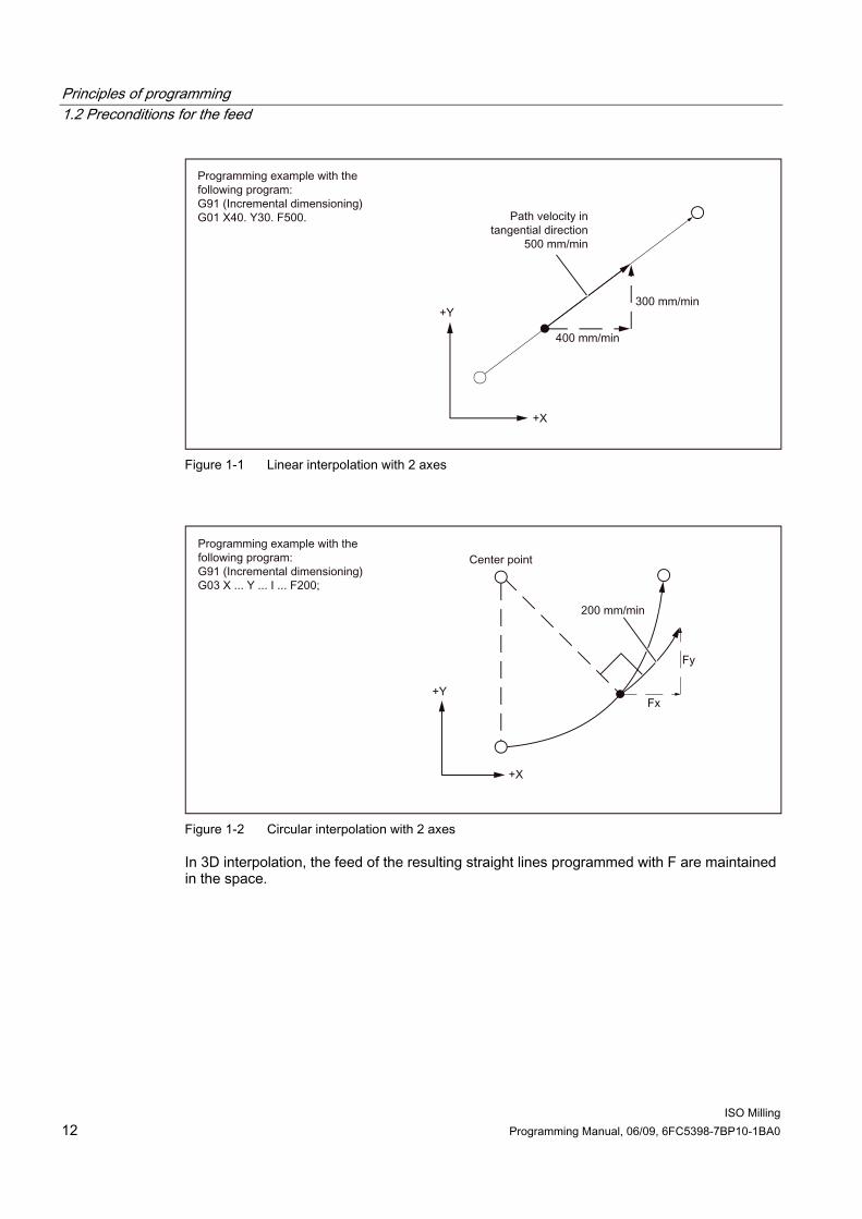
The feed with which a tool should be traversed in linear interpolation (G01) or circular interpolation (G02, G03) is designated with the address character "F". The feed of the cutting tool in "mm/min" is specified after the address character "F". The permissible range of F values is specified in the documentation of the machine manufacturer. Possibly, the feed is limited by the servo system and the mechanical system in the upward direction. The maximum feed is set in the machine data and limited to the value defined there before an overshoot. The path feed is generally composed of the individual speed components of all geometry axes participating in the movement and refers to the cutter center (see the two following figures).
Principles of programming 1.2 Preconditions for the feed
ISO Milling 12 Programming Manual, 06/09, 6FC5398-7BP10-1BA0
Figure 1-1 Linear interpolation with 2 axes
Figure 1-2 Circular interpolation with 2 axes
In 3D interpolation, the feed of the resulting straight lines programmed with F are maintained in the space.