SINUMERIK 840D sl HMI Advanced - Siemens AG · SINUMERIK 840D sl SINUMERIK 840D/840Di/810D HMI...
470
SINUMERIK 840D sl SINUMERIK 840D/840Di/810D HMI Advanced Edition 08/2005 Operator's Guide Introduction 1 Operator Components/ Operating Sequences 2 Example of operation 3 Machine 4 Parameters 5 Program 6 Services 7 Diagnostics 8 Startup 9 Service 10 Appendix A Valid for Programmable controller SINUMERIK 840D sl/840 DE sl SINUMERIK 840D powerline/840DE powerline SINUMERIK 840Di powerline/840DiE powerline SINUMERIK 810D powerline/810DE powerline Software Software release HMI Advanced 7.1
Transcript of SINUMERIK 840D sl HMI Advanced - Siemens AG · SINUMERIK 840D sl SINUMERIK 840D/840Di/810D HMI...

SINUMERIK 840D sl SINUMERIK 840D/840Di/810D
HMI Advanced
Edition 08/2005
Operator's Guide
Introduction 1
Operator Components/
Operating Sequences 2
Example of operation 3
Machine 4
Parameters 5
Program 6
Services 7
Diagnostics 8
Startup 9
Service 10
Appendix A
Valid for Programmable controller SINUMERIK 840D sl/840 DE sl SINUMERIK 840D powerline/840DE powerline SINUMERIK 840Di powerline/840DiE powerline SINUMERIK 810D powerline/810DE powerline Software Software release HMI Advanced 7.1

SINUMERIK® Documentation Printing history Brief details of this edition and previous editions are listed below. The status of each version is indicated by the code in the "Remarks" columns. Status code in the "Remarks" column: A .... New documentation. B .... Unrevised reprint with new order number C .... Revised edition with new version code
If factual changes have been made on the page since the last edition, this is indicated by the new version code in the header on that page.
Version Order No. Remarks 08/2005 6FC5398-2AP10-0BA0 C This manual is included in the documentation available on the CD-ROM (DOConCD) Version Order No. Remarks
Trademarks
All names that appear in conjunction with ® are registered trademarks of Siemens AG. Other names used in this publication may be trademarks, which, if used by third parties for their own means, may violate the rights of their owners.
Exclusion of liability
We have checked that the content of this publication agrees with the hardware and software described. Since discrepancies cannot be precluded entirely, we cannot guarantee full agreement. The information contained in this document is, however, reviewed regularly and any necessary changes will be included in the next edition.
Copyright (©) Siemens AG 1995 - 2005. 6FC5398-2AP10-0BA0 Siemens AG 2005 Subject to change without prior notice

0 08/2005 Foreword
Structure of the manual 0
© Siemens AG 2005 All rights reserved. SINUMERIK 840D sl/840D/840Di/810D Operator's Guide HMI Advanced (BAD) - Edition 08/2005 iii
Foreword SINUMERIK®
Documentation The SINUMERIK documentation is organized in 3 parts:
• General documentation • User documentation • Manufacturer/service documentation
Please contact your local Siemens office for more detailed information about other SINUMERIK 840D sl/840D/840Di/810D publications and publications that apply to all SINUMERIK controls (e.g. universal interface, measuring cycles, etc.).
An overview of publications, which is updated monthly and also provides information about the language versions available, can be found on the Internet at: http://www.siemens.com/motioncontrol Follow menu items "Support" "Technical Documentation" "Overview of Publications".
The Internet version of DOConCD (DOConWEB) is available at: http://www.automation.siemens.com/doconweb
Target audience This Manual is intended for machine-tool users. The document describes in detail all the technical information an operator needs to operate the 840D sl/840D/840Di/810D programmable controllers.
Standard version This Operator’s Guide describes only the functionality of the standard version. Extensions or changes made by the machine tool manufacturer are documented by the machine tool manufacturer.
Other functions not described in this documentation might be executable in the control. This does not, however, represent an obligation to supply such functions with a new control or when servicing.
Hotline If you have any questions, please get in touch with our hotline: A&D Technical Support Phone.: +49 (0) 180 / 5050 - 222 Fax: +49 (0) 180 / 5050 - 223 Internet: http://www.siemens.de/automation/support-request
Please send any queries about the documentation (suggestions or corrections) to the following fax number or e-mail address: Fax: +49 (0) 9131 / 98 - 63315 E-mail: [email protected]
Fax form: See the reply form at the end of the document. Internet address http://www.siemens.com/motioncontrol

0 Foreword 08/2005
Structure of the manual 0
© Siemens AG 2005 All rights reserved. iv SINUMERIK 840D sl/840D/840Di/810D Operator's Guide HMI Advanced (BAD) - Edition 08/2005
Safety Information This Manual contains information which you should carefully observe to ensure your own personal safety and the prevention of material damage. Notes relating to your personal safety are highlighted in the manual by means of a warning triangle, no warning triangle appears in conjunction with notes that relate to property damage. The warnings appear in decreasing order of risk as given below.
Danger indicates that death or severe personal injury will result if proper
precautions are not taken.
Warning This warning notice indicates that death or severe personal injury can
result if proper precautions are not taken.
Caution “Caution" with a warning triangle indicates that minor personal injury
can result if proper precautions are not taken.
Caution “Caution” without a warning triangle indicates that material damage
can result if proper precautions are not taken.
Notice This means that an undesirable result or an undesirable state can
occur if the information is ignored.

0 08/2005 Foreword
Structure of the manual 0
© Siemens AG 2005 All rights reserved. SINUMERIK 840D sl/840D/840Di/810D Operator's Guide HMI Advanced (BAD) - Edition 08/2005 v
If several hazards of different degrees occur, the hazard with the highest degree must always be given preference. If a warning notice with a warning triangle warns of personal injury, the same warning notice can also contain a warning of material damage.
Qualified Personnel Startup and operation of the device/equipment/system in question must only be performed using this documentation. The device/system must only be started up and operated by qualified personnel. Qualified personnel as referred to in the safety guidelines of this documentation are those who are authorized to start up, ground and label units, systems and circuits in accordance with the relevant safety standards.
Proper usage Note the following:
Warning The device must only be used for the applications specified in the catalog and in the technical description. The device must only be used in conjunction with external devices and components recommended or approved by Siemens. To ensure trouble-free and safe operation of the product, it must be transported, stored and installed as intended and maintained and operated with care.

0 Foreword 08/2005
Structure of the manual 0
© Siemens AG 2005 All rights reserved. vi SINUMERIK 840D sl/840D/840Di/810D Operator's Guide HMI Advanced (BAD) - Edition 08/2005
Export versions Function 840DE sl 840DE
840DiE 810DE
Helical interpolation 2D+6
(basic version, no options) − − −
Milling machining package − − −
5-axis machining package − − −
Handling transformation package − − −
Multi-axis interpolation
(> 4 interpolating axes) − − −
OA NCK compile cycles − − −
Clearance control 1D/3D in position-control cycle 1)
− − −
Synchronized actions 1)
(basic version, no options)
# # #
Master-value coupling and curve table interpolation
# # #
Sag compensation, multi-dimensional # # #
Synchronized actions, stage 2 1) − # −
Electronic gear 1) − # −
Electronic transfer − # −
# Restricted functionality
− Function not possible
1) In the case of the SINUMERIK 840DE sl/SINUMERIK 840DE/840DiE/810DE powerline export versions, the restricted functions are limited to "max. 4 interpolating axes“

0 08/2005 Foreword
Structure of the manual 0
© Siemens AG 2005 All rights reserved. SINUMERIK 840D sl/840D/840Di/810D Operator's Guide HMI Advanced (BAD) - Edition 08/2005 vii
Structure of descriptions All functions and operating options have been described according to the same internal structure as far as this is meaningful and practicable. The various levels of information have been organized such that you can selectively access the information you need for the task in hand.
1. Function
The theoretical section is primarily intended as learning material for the NC entry-level user and includes important information to assist the user to understand the operator functions. You should work through the manual at least once to get an idea of the operational scope and capability of your SINUMERIK control.
2. Sequence of operations
This section contains the sequence of keys required for operation at a glance. If inputs have to be made at individual stages of the sequence or if you require additional information, you will find this next to the key illustrations.
3. Additional notes
For safety reasons, some functions are disabled to protect them from unauthorized access. The machine manufacturer can customize or modify the described functionality. Please comply fully with the instructions of the machine-tool manufacturer.
In this documentation, you will find this symbol with a reference to an
ordering data option. The described function can only run if the control contains the designated option.
Notes This symbol appears in this documentation whenever it is necessary to draw your attention to an important item of information.
References This symbol appears whenever specific information can be found in other documentation. A complete list of available literature is included in the Appendix of this Operator’s Guide.

0 Foreword 08/2005
Structure of the manual 0
© Siemens AG 2005 All rights reserved. viii SINUMERIK 840D sl/840D/840Di/810D Operator's Guide HMI Advanced (BAD) - Edition 08/2005
Explanation of symbols:
Function
Sequence of operations
Additional notes
Cross-references to other documentation or sections
Danger notices
Additional notes or background information
Ordering data option
Explanation
Description of syntax
Programming examples
■

0 08/2005 Contents 0
© Siemens AG 2005 All rights reserved. SINUMERIK 840D sl/840D/840Di/810D Operator's Guide HMI Advanced (BAD) - Edition 08/2005 ix
Contents Introduction 1-17
1.1 Product Overview...................................................................................................... 1-19
1.2 Handling notes .......................................................................................................... 1-20
1.3 Control Power ON/Power OFF ................................................................................. 1-21
Operator Components/Operating Sequences 2-23
2.1 Operator panel front.................................................................................................. 2-24 2.1.1 Keys on the operator front panel .............................................................................. 2-24 2.1.2 Standard full keyboard .............................................................................................. 2-29
2.2 Machine control panel............................................................................................... 2-30 2.2.1 EMERGENCY STOP button ..................................................................................... 2-31 2.2.2 Operating modes and machine functions ................................................................. 2-31 2.2.3 Feed control .............................................................................................................. 2-33 2.2.4 Spindle control .......................................................................................................... 2-35 2.2.5 Keylock switch .......................................................................................................... 2-36 2.2.6 Program control ........................................................................................................ 2-37
2.3 Screen layout ............................................................................................................ 2-38 2.3.1 Display of control states............................................................................................ 2-38 2.3.2 Global machine status display .................................................................................. 2-39 2.3.3 Program control display ............................................................................................ 2-43
2.4 General operating sequences................................................................................... 2-45 2.4.1 Program overview and program selection ................................................................ 2-45 2.4.2 Switch menu windows............................................................................................... 2-46 2.4.3 Select a directory/file................................................................................................. 2-47 2.4.4 Edit inputs/values...................................................................................................... 2-48 2.4.5 Confirm/cancel the input ........................................................................................... 2-49 2.4.6 Edit the part program in the ASCII editor.................................................................. 2-50 2.4.8 m:n-Communication links.......................................................................................... 2-57 2.4.9 Pocket calculator....................................................................................................... 2-60
2.5 Call help function ...................................................................................................... 2-61 2.5.1 Editor help ................................................................................................................. 2-63 2.5.2 Quick help for program commands........................................................................... 2-64 2.5.3 Extended help for program commands..................................................................... 2-67
2.6 Job list ....................................................................................................................... 2-68 2.6.1 Syntax description for job lists .................................................................................. 2-70 2.6.2 Example of a job list with two-channel 1:1 links ....................................................... 2-73 2.6.3 Example of a job list with multi-channel m:n links .................................................... 2-74 2.6.4 “Execute job list” operating sequence....................................................................... 2-75 2.6.5 Rename workpieces with job lists............................................................................. 2-77 2.6.6 Copy workpieces with job lists .................................................................................. 2-78 2.6.7 Archive workpieces with job lists in case of m:n....................................................... 2-78

0 Contents 08/2005
0
© Siemens AG 2005 All rights reserved. x SINUMERIK 840D sl/840D/840Di/810D Operator's Guide HMI Advanced (BAD) - Edition 08/2005
Example of operation 3-79
3.1 Typical sequence of operations ................................................................................3-79
Machine operating area 4-81
4.1 CNC data structure ...................................................................................................4-83 4.1.1 Operating modes and machine functions .................................................................4-84 4.1.2 Mode group and channels.........................................................................................4-86 4.1.3 Cross-channel status display via symbols ................................................................4-87 4.1.4 Two-channel display .................................................................................................4-88 4.1.5 Mode selection, mode change ..................................................................................4-89
4.2 General functions and displays.................................................................................4-92 4.2.1 Start/stop/abort/continue part program .....................................................................4-92 4.2.2 Display program level................................................................................................4-93 4.2.3 Toggle between machine/workpiece coordinate system (MCS/WCS) .....................4-94 4.2.4 Display axis feedrates ...............................................................................................4-96 4.2.5 Display G functions, transformations and swivel data ..............................................4-97 4.2.6 Display auxiliary functions.........................................................................................4-98 4.2.7 Display modal M functions ........................................................................................4-98 4.2.8 Display spindles ......................................................................................................4-100 4.2.9 Handwheel ..............................................................................................................4-101 4.2.10 Status of synchronized actions ...............................................................................4-102 4.2.11 Preset ......................................................................................................................4-104 4.2.12 Set actual value.......................................................................................................4-105 4.2.13 Inch ↔ Metric switchover........................................................................................4-106
4.3 Reference point approach.......................................................................................4-108
4.4 Jog mode.................................................................................................................4-111 4.4.1 Function and main screen.......................................................................................4-111 4.4.2 Traverse the axes....................................................................................................4-114 4.4.3 Inc: Inc: Increment...................................................................................................4-115 4.4.4 Repos (repositioning) ..............................................................................................4-116 4.4.5 SI (Safety Integrated): User agreement ..................................................................4-117 4.4.6 Scratching ...............................................................................................................4-118 4.4.7 Display system frames ............................................................................................4-121
4.5 MDI mode................................................................................................................4-124 4.5.1 Function and main screen.......................................................................................4-124 4.5.2 Save program, file function .....................................................................................4-126 4.5.3 Teach-in ..................................................................................................................4-127
4.6 Automatic mode ......................................................................................................4-129 4.6.1 Function and main screen.......................................................................................4-129 4.6.2 Program overview ...................................................................................................4-131 4.6.3 Load and unload the workpiece/part program ........................................................4-132 4.6.4 Log: Program loading list ........................................................................................4-133 4.6.5 Execution from hard disk.........................................................................................4-134 4.6.6 Access an external network drive ...........................................................................4-135

0 08/2005 Contents 0
© Siemens AG 2005 All rights reserved. SINUMERIK 840D sl/840D/840Di/810D Operator's Guide HMI Advanced (BAD) - Edition 08/2005 xi
4.6.7 Program editing....................................................................................................... 4-137 4.6.8 Set block search/search target ............................................................................... 4-139 4.6.9 Accelerated external block search.......................................................................... 4-142 4.6.10 Block search in Program test mode, multi-channel ................................................ 4-145 4.6.11 Overstore ................................................................................................................ 4-147 4.6.12 Program control ...................................................................................................... 4-149 4.6.13 DRF offset ............................................................................................................... 4-153
Parameters operating area 5-155
5.1 Tool data ................................................................................................................. 5-157 5.1.1 Tool offset structure ................................................................................................ 5-157 5.1.2 Tool types and tool parameters .............................................................................. 5-157
5.2 Tool offset ............................................................................................................... 5-172 5.2.1 Tool offset function and main screen...................................................................... 5-172 5.2.2 New tool .................................................................................................................. 5-174 5.2.3 Display tool.............................................................................................................. 5-175 5.2.4 Delete tool ............................................................................................................... 5-176 5.2.5 New cutting edge .................................................................................................... 5-177 5.2.6 Delete cutting edge ................................................................................................. 5-178 5.2.7 Determine tool offsets ............................................................................................. 5-178 5.2.8 Make active tool offset operative immediately ........................................................ 5-179
5.3 Tool management ................................................................................................... 5-180 5.3.1 Basic tool management functions........................................................................... 5-181 5.3.2 Display/edit tool data............................................................................................... 5-189 5.3.3 Change in the significance/representation of tool wear values .............................. 5-193 5.3.4 Grinding parameters, expansion............................................................................. 5-196 5.3.5 Load ........................................................................................................................ 5-198 5.3.6 Unload..................................................................................................................... 5-202 5.3.7 Relocation ............................................................................................................... 5-204 5.3.8 Tool master data in the tool catalog........................................................................ 5-205 5.3.9 Tool offset data in the tool cabinet.......................................................................... 5-208 5.3.10 Batch processing of tools........................................................................................ 5-211
5.4 R parameters (arithmetic parameters).................................................................... 5-219
5.5 Setting data ............................................................................................................. 5-220 5.5.1 Working area limitation ........................................................................................... 5-220 5.5.2 Jog data .................................................................................................................. 5-221 5.5.3 Spindle data ............................................................................................................ 5-222 5.5.4 Dry run feedrate for DRY run.................................................................................. 5-223 5.5.5 Starting angle for thread cutting.............................................................................. 5-224 5.5.6 Miscellaneous setting data ..................................................................................... 5-225 5.5.7 Protection zones ..................................................................................................... 5-226 5.5.8 Electronic gear ........................................................................................................ 5-227
5.6 Work offset .............................................................................................................. 5-228 5.6.1 Function .................................................................................................................. 5-228 5.6.2 Edit the settable work offset (G54 ...) ..................................................................... 5-230

0 Contents 08/2005
0
© Siemens AG 2005 All rights reserved. xii SINUMERIK 840D sl/840D/840Di/810D Operator's Guide HMI Advanced (BAD) - Edition 08/2005
5.6.3 Global work offset/frame .........................................................................................5-230 5.6.4 Display active settable work offset ..........................................................................5-233 5.6.5 Display active programmable work offset ...............................................................5-234 5.6.6 Display active external work offset..........................................................................5-235 5.6.7 Display the sum of the active work offsets..............................................................5-235 5.6.8 Immediately activate work offset and basic frame ..................................................5-236 5.6.9 Actual-value display: Settable zero system, SZS ...................................................5-236
5.7 Define user data ......................................................................................................5-237 5.7.1 Define variables (GUD, PUD, LUD) ........................................................................5-237 5.7.2 Edit/find user data ...................................................................................................5-238 5.7.3 Activate user data (GUD) ........................................................................................5-240
5.8 Display system variables.........................................................................................5-242 5.8.1 Create variable views..............................................................................................5-243 5.8.2 Manage variable views............................................................................................5-245 5.8.3 Log system variables ..............................................................................................5-246
Program operating area 6-249
6.1 Program types .........................................................................................................6-251 6.1.1 Part program ...........................................................................................................6-251 6.1.2 Subprogram.............................................................................................................6-251 6.1.3 Workpiece ...............................................................................................................6-251 6.1.4 Cycles......................................................................................................................6-251 6.1.5 Store programs........................................................................................................6-251 6.1.6 Templates................................................................................................................6-252
6.2 Program main screen..............................................................................................6-254
6.3 Edit programs in the standard ASCII editor ............................................................6-256 6.3.1 Undo and redo in the standard ASCII editor ...........................................................6-257 6.3.2 Additional editor options..........................................................................................6-258 6.3.3 Selective program protection *RO* .........................................................................6-259
6.4 Structured step sequence display (option)..............................................................6-261
6.5 Multi-channel step sequence programming (option)...............................................6-265 6.5.1 Multi-channel workpiece program views.................................................................6-268 6.5.2 Activate timing .........................................................................................................6-273 6.5.3 Activate simulation ..................................................................................................6-275
6.6 Free contour programming......................................................................................6-279 6.6.1 Program contour......................................................................................................6-280 6.6.2 Undercuts for turning technology ............................................................................6-285 6.6.3 Parameterize contour elements ..............................................................................6-289 6.6.4 Graphic representation of contours.........................................................................6-291 6.6.5 Symmetrical contours with milling technology ........................................................6-292 6.6.6 Specify contour elements in polar coordinates, close the contour .........................6-295 6.6.7 Contour programming support ................................................................................6-300 6.6.8 Parameter description of straight line/circle contour elements ...............................6-301 6.6.9 Examples of free contour programming..................................................................6-302

0 08/2005 Contents 0
© Siemens AG 2005 All rights reserved. SINUMERIK 840D sl/840D/840Di/810D Operator's Guide HMI Advanced (BAD) - Edition 08/2005 xiii
6.6.10 Cycle support .......................................................................................................... 6-305
6.7 Program simulation ................................................................................................. 6-306 6.7.1 Simulation operation ............................................................................................... 6-308 6.7.2 Simulation settings.................................................................................................. 6-317 6.7.3 Downtime settings................................................................................................... 6-323 6.7.4 Display and colors................................................................................................... 6-324 6.7.5 Section-by-section simulation ................................................................................. 6-325 6.7.6 Quick display in the simulation for mold making..................................................... 6-326 6.7.7 Simulation with external network drives.................................................................. 6-328 6.7.8 Simulation using the orientable toolholder.............................................................. 6-329
6.8 Manage programs................................................................................................... 6-329 6.8.1 New workpiece/part program.................................................................................. 6-331 6.8.2 Create programs/data in a workpiece directory...................................................... 6-333 6.8.3 Save setup data ...................................................................................................... 6-334 6.8.4 Select a program for execution............................................................................... 6-335 6.8.5 Load/unload a program........................................................................................... 6-338 6.8.6 Manage programs................................................................................................... 6-339 6.8.7 Copy/insert .............................................................................................................. 6-340 6.8.8 Delete...................................................................................................................... 6-343 6.8.9 Rename................................................................................................................... 6-344 6.8.10 Enable ..................................................................................................................... 6-345 6.8.11 Log .......................................................................................................................... 6-346
6.9 Accessing an external network drive/computer ...................................................... 6-347
Services operating area 7-349
7.1 Services main screen.............................................................................................. 7-351 7.1.1 Read in data............................................................................................................ 7-354 7.1.2 Read out data ......................................................................................................... 7-355 7.1.3 Display logs............................................................................................................. 7-356
7.2 Manage data ........................................................................................................... 7-358 7.2.1 Download and upload ............................................................................................. 7-359 7.2.2 Copy and insert....................................................................................................... 7-360 7.2.3 Delete...................................................................................................................... 7-361 7.2.4 Change properties .................................................................................................. 7-362
7.3 Data selection ......................................................................................................... 7-365 7.3.1 Special directories and memory areas ................................................................... 7-368 7.3.2 Data on the hard disk.............................................................................................. 7-369
7.4 Startup functions ..................................................................................................... 7-371 7.4.1 Series startup.......................................................................................................... 7-371 7.4.2 Updating (only SINUMERIK powerline) .................................................................. 7-374 7.4.3 Restore original state via NC card (only SINUMERIK powerline) .......................... 7-375 7.4.4 Transfer display MD from HMI Embedded ............................................................. 7-376
Diagnostics operating area 8-379
8.1 Diagnostics main screen......................................................................................... 8-380

0 Contents 08/2005
0
© Siemens AG 2005 All rights reserved. xiv SINUMERIK 840D sl/840D/840Di/810D Operator's Guide HMI Advanced (BAD) - Edition 08/2005
8.2 Alarms and messages.............................................................................................8-382
8.3 Service display ........................................................................................................8-384 8.3.1 Service axis .............................................................................................................8-386 8.3.2 Drive service............................................................................................................8-387 8.3.3 Safety Integrated service ........................................................................................8-388 8.3.4 Output configuration data........................................................................................8-391 8.3.5 Communication error log.........................................................................................8-392 8.3.6 Action log.................................................................................................................8-392
8.4 Callversion displays ................................................................................................8-393 8.4.1 Sort and save version data .....................................................................................8-394 8.4.2 Display the version displays for cycles ...................................................................8-395 8.4.3 Output cycle versions..............................................................................................8-397 8.4.4 Displayloadable compile cycles ..............................................................................8-398
8.5 Query thePLC status...............................................................................................8-399 8.5.1 Change/delete values .............................................................................................8-400 8.5.2 Assign symbolic PLC addresses.............................................................................8-401 8.5.3 Select operand screens for PLC status ..................................................................8-406 8.5.4 File functions ...........................................................................................................8-407
8.6 Display NC system resources.................................................................................8-408
Startup operating area 9-409
9.1 Startup main screen ................................................................................................9-410
9.2 Machine data...........................................................................................................9-414 9.2.1 Display options: Masking filter.................................................................................9-416 9.2.2 User views...............................................................................................................9-418 9.2.3 File functions ...........................................................................................................9-419
9.3 NC ...........................................................................................................................9-420
9.4 PLC..........................................................................................................................9-421 9.4.1 Set time/date ...........................................................................................................9-421
9.5 Set HMI ...................................................................................................................9-422 9.5.1 System settings .......................................................................................................9-425 9.5.2 End OEM startup.....................................................................................................9-428
9.6 Optimization/Test ....................................................................................................9-429
9.7 Startup of other components...................................................................................9-431 9.7.1 Drives ......................................................................................................................9-431 9.7.2 Quick startup for axes and drives ...........................................................................9-432 9.7.3 Tool management ...................................................................................................9-432
Service 10-433
10.1 Operating data.......................................................................................................10-434
10.2 Cleaning ................................................................................................................10-435

0 08/2005 Contents 0
© Siemens AG 2005 All rights reserved. SINUMERIK 840D sl/840D/840Di/810D Operator's Guide HMI Advanced (BAD) - Edition 08/2005 xv
Appendix A-437
A Abbreviations ..........................................................................................................A-438
B Terminology ............................................................................................................A-442
C References..............................................................................................................A-457
Index I-461
Commands, identifiers............................................................................................................. I-467

0 Contents 08/2005
0
© Siemens AG 2005 All rights reserved. xvi SINUMERIK 840D sl/840D/840Di/810D Operator's Guide HMI Advanced (BAD) - Edition 08/2005

1 08/2005 Introduction 1
© Siemens AG 2005 All rights reserved. SINUMERIK 840D sl/840D/840Di/810D Operator's Guide HMI Advanced (BAD) - Edition 08/2005 1-17
Introduction 1.1 Product Overview......................................................................................................1-19
1.2 Handling notes ..........................................................................................................1-20
1.3 Control Power ON/Power OFF..................................................................................1-21

1 Introduction 08/2005
1
© Siemens AG 2005 All rights reserved. 1-18 SINUMERIK 840D sl/840D/840Di/810D Operator's Guide HMI Advanced (BAD) - Edition 08/2005

1 08/2005 Introduction 1
© Siemens AG 2005 All rights reserved. SINUMERIK 840D sl/840D/840Di/810D Operator's Guide HMI Advanced (BAD) - Edition 08/2005 1-19
1.1 Product Overview The SINUMERIK controller is a CNC control system (Computerized
Numerical Control) for machine tools. You can use the CNC to implement the following basic functions for a machine tool: • Creation and adaptation of part programs • Execution of part programs • Manual control • Reading in and reading out of part programs and data • Editing of data for programs • Displaying and troubleshooting alarms • Editing of machine data • Setting up of communication links between 1 or more operating
units (m) or 1 or more NCs (n) (m:n, m operating units and n NCK/PLC units).
Operating areas The basic functions are grouped in the following operating areas in
the control (in gray boxes):
Operating areas
MACHINE
PROGRAM
SERVICES
DIAGNOSIS
START-UP
PARAMETERS
Execution of part programs,manual control
Developmentand adaptationof part programs
Reading in/outand archivingprograms and data
Alarm displays,service displays
Adaptation of NCdata to machine,system settings
Editing datafor programs/tool management

1 Introduction 08/2005 1.2 Handling notes
1
© Siemens AG 2005 All rights reserved. 1-20 SINUMERIK 840D sl/840D/840Di/810D Operator's Guide HMI Advanced (BAD) - Edition 08/2005
The user can call up all the functions via the user interface. The user interface consists of: • Display units such as screen, LEDs, etc. • Control elements such as keys, switches, handwheels, etc.
Read Chapter 2 "Operation" carefully before proceeding with further chapters. All subsequent chapters are written on the assumption that you have done so!
1.2 Handling notes
Caution
The operator panel front/machine control panel may only be opened by trained personnel for servicing purposes.
Danger
Never open the operator panel front/machine control panel unless the power supply has been disconnected! Failure to comply could result in fatal injury!
Warning
Electronic components inside the operator panel/machine control panel can be destroyed by electrostatic discharge if they are handled incorrectly.
Before operating any of the control elements on this operator panel front: Please first read the explanations supplied in this documentation!

1 08/2005 Introduction 1
© Siemens AG 2005 All rights reserved. SINUMERIK 840D sl/840D/840Di/810D Operator's Guide HMI Advanced (BAD) - Edition 08/2005 1-21
1.3 Control Power ON/Power OFF
Function
Power ON A variety of methods can be employed to switch on the power supply to the control system or to the whole plant.
Machine manufacturer
Please follow the machine manufacturer's instructions!
After the control has been switched on, the "Reference point approach" display or another main screen programmed by the machine manufacturer will appear.
MachineChannel ResetProgram aborted
Jog
MKS Position.Repos-Versch.
+ X 900.000 mm 0.000- Y -156.000 mm 0.000+ Z 230.000 mm 0.000
MCS Position
+X900.000mm0.000-Y-156.000mm0.000+Z230.000mm0.000
-X 0.000 mm
+Y 0.000 mm
+Z 0.000 mm
+ 0.000 mm
Tool
preselected tool :
G0 G91
Master spindle S1Act. + 0.000 rev./min
Set 0.000 rev./min
Pos. 0.000 deg.
0.000 %
Power [%\
Feedrate mm/minAct. 0.000 0.000 %Set 0.000
REF
Power OFF Please follow the instructions below for switching off the control or the entire system!
Machine manufacturer
Please follow the machine manufacturer's instructions!

1 Introduction 08/2005 1.3 Control Power ON/Power OFF
1
© Siemens AG 2005 All rights reserved. 1-22 SINUMERIK 840D sl/840D/840Di/810D Operator's Guide HMI Advanced (BAD) - Edition 08/2005
Sequence of operations
When you press the "Area switchover" key, operating areas are displayed on the horizontal softkey bar and operating modes are displayed on the vertical softkey bar. You can use this key to go to the area menu bar from any location in the menu hierarchy if you wish to select another operating mode or a different operating area.
MachineChannel Reset
Jog
MCS Position
+ X 900.000 mm 0.000- Y -156.000 mm 0.000+ Z 230.000 mm 0.000
Auxiliary FunctionsM0
M0
M0
H0.000000H0.000000
H0.000000
M0
M0
+ X 900.000 mm
- Y -156.000 mm
+ Z 230.000 mm
Feedrate mm/minAct. 3000.000 0.0 %Set. 3000.000
Aut o
MDI
JOG
REPOS
REF
ToolT0 D0T0 D0T0 D0
G1
.
.
.
Program aborted
Machine Parameters Program Services Diagnosis Start-up
By pressing the "Area switchover" key twice, you can toggle between the operating areas last selected, e.g. between the "Parameters" and "Machine" areas.
■

2 08/2005 Operator Components/Operating Sequences2.1 Operator panel front
2
© Siemens AG 2005 All rights reserved. SINUMERIK 840D sl/840D/840Di/810D Operator's Guide HMI Advanced (BAD) - Edition 08/2005 2-23
Operator Components/Operating Sequences 2.1 Operator panel front ..................................................................................................2-24
2.1.1 Keys on the operator front panel...............................................................................2-24 2.1.2 Standard full keyboard ..............................................................................................2-29
2.2 Machine control panel ...............................................................................................2-30 2.2.1 EMERGENCY STOP button .....................................................................................2-31 2.2.2 Operating modes and machine functions .................................................................2-31 2.2.3 Feed control ..............................................................................................................2-33 2.2.4 Spindle control ..........................................................................................................2-35 2.2.5 Keylock switch...........................................................................................................2-36 2.2.6 Program control.........................................................................................................2-37
2.3 Screen layout ............................................................................................................2-38 2.3.1 Display of control states ............................................................................................2-38 2.3.2 Global machine status display ..................................................................................2-39 2.3.3 Program control display ............................................................................................2-43
2.4 General operating sequences...................................................................................2-45 2.4.1 Program overview and program selection ................................................................2-45 2.4.2 Switch menu windows...............................................................................................2-46 2.4.3 Select a directory/file.................................................................................................2-47 2.4.4 Edit inputs/values ......................................................................................................2-48 2.4.5 Confirm/cancel the input ...........................................................................................2-49 2.4.6 Edit the part program in the ASCII editor ..................................................................2-50 2.4.8 m:n-Communication links..........................................................................................2-57 2.4.9 Pocket calculator.......................................................................................................2-60
2.5 Call help function.......................................................................................................2-61 2.5.1 Editor help .................................................................................................................2-63 2.5.2 Quick help for program commands...........................................................................2-64 2.5.3 Extended help for program commands.....................................................................2-67
2.6 Job list .......................................................................................................................2-68 2.6.1 Syntax description for job lists...................................................................................2-70 2.6.2 Example of a job list with two-channel 1:1 links........................................................2-73 2.6.3 Example of a job list with multi-channel m:n links.....................................................2-74 2.6.4 “Execute job list” operating sequence.......................................................................2-75 2.6.5 Rename workpieces with job lists .............................................................................2-77 2.6.6 Copy workpieces with job lists ..................................................................................2-78 2.6.7 Archive workpieces with job lists in case of m:n .......................................................2-78

2 Operator Components/Operating Sequences 08/2005 2.1 Operator panel front
2
© Siemens AG 2005 All rights reserved. 2-24 SINUMERIK 840D sl/840D/840Di/810D Operator's Guide HMI Advanced (BAD) - Edition 08/2005
2.1 Operator panel front Example
In this example, the OP 012 SINUMERIK operator panel front is used to illustrate the operator components, which are available for operating the SINUMERIK control and machine tool.
Features The OP 012 operator panel front with 12.1" TFT color display with a resolution of 800 x 600 pixels (SVGA) features a 59-key membrane keypad as well as 2 x (8 + 2) horizontal and 2 x 8 vertical softkeys and a built-in mouse. The 2 x 8 vertical softkeys can be used as direct keys.
A Display B Alphanumeric keypad Correction/cursor keys C Mouse and mouse keys 1 Machine area key 2 Recall (return) 3 Softkey bar (horizontal) 4 ETC key (menu extension) 5 Area switchover key 6 Softkey bar (vertical)
2.1.1 Keys on the operator front panel
Keys on the operator
front panel The elements of the operator panel keyboard and the symbols used to represent them in this manual are shown and explained below. The keys marked with an * correspond to the key symbols in US layout.
Softkeys Keys to which functions are assigned by means of a menu bar displayed on the screen. • It is possible to access further menu levels via the horizontal
softkeys in any operating area. Each horizontal menu item has a vertical menu bar/softkey assignment.
• The vertical softkeys are assigned functions for the currently selected horizontal softkey.

2 08/2005 Operator Components/Operating Sequences2.1 Operator panel front
2
© Siemens AG 2005 All rights reserved. SINUMERIK 840D sl/840D/840Di/810D Operator's Guide HMI Advanced (BAD) - Edition 08/2005 2-25
A function is called up by pressing one of the vertical softkeys. The assignments of the vertical softkey bar can change if further subsidiary functions are classified under a function.
Parameters
Softkey (horizontal or vertical): This key symbol indicates that you must have selected an operating area or a menu item or have already performed certain functions before you are able to execute the function described in the relevant section.
Machine area key Direct branch to the "Machine" operating area.
Recall key Return to the higher-level menu. Recall closes a window.
ETC key Expansion of the horizontal softkey bar in the same menu.
Area switchover key You can call the main menu from any operating area by pressing this key. Pressing the key twice in succession changes from the current operating area to the previous one and back again. The standard main menu branches into the following operating areas:1. Machine 2. Parameters 3. Program 4. Services 5. Diagnostics 6. Startup
Shift key Switches between functions on keys with double assignment.
Switch over channel In a configuration with several channels, it is possible to switch between channels (switch from channel 1 through to channel n). When a "Channel menu" is configured, all existing communication links to other NCUs plus the associated channels are displayed on softkeys. (See Section "Switch over channel")
2 Operator Components/Operating Sequences 08/2005 2.1 Operator panel front
2
© Siemens AG 2005 All rights reserved. 2-26 SINUMERIK 840D sl/840D/840Di/810D Operator's Guide HMI Advanced (BAD) - Edition 08/2005
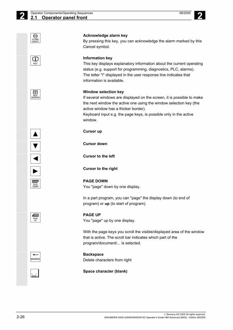
Acknowledge alarm key By pressing this key, you can acknowledge the alarm marked by this Cancel symbol.
Information key This key displays explanatory information about the current operating status (e.g. support for programming, diagnostics, PLC, alarms). The letter "i" displayed in the user response line indicates that information is available.
Window selection key If several windows are displayed on the screen, it is possible to make the next window the active one using the window selection key (the active window has a thicker border). Keyboard input e.g. the page keys, is possible only in the active window.
Cursor up
Cursor down
Cursor to the left
Cursor to the right
PAGE DOWN You "page" down by one display. In a part program, you can "page" the display down (to end of program) or up (to start of program).
PAGE UP You "page" up by one display. With the page keys you scroll the visible/displayed area of the window that is active. The scroll bar indicates which part of the program/document/... is selected.
Backspace Delete characters from right
Space character (blank)

2 08/2005 Operator Components/Operating Sequences2.1 Operator panel front
2
© Siemens AG 2005 All rights reserved. SINUMERIK 840D sl/840D/840Di/810D Operator's Guide HMI Advanced (BAD) - Edition 08/2005 2-27
Selection key/toggle key • Selection key for values set in input fields and selection lists
labeled with this key symbol. • Activate/deactivate a field:
= active
= not active multiple option button (you can select several options or none)
= active
= not active Single-option button/option (only one option can be active at a time)
Edit key/undo key • Switch over to edit mode in tables and input fields (in this case, the
input field is in insert mode) or • UNDO function on table elements and input fields (the value is not
validated when you exit a field using the edit key; instead it is reset to the previous value = UNDO).
End of line key • With this key, the cursor is moved to the end of the line in the page
opened in the editor. • Rapid positioning of the cursor on a group of related input fields. • Has same effect as Tab key.
Delete key The setting in a parameterization field is deleted. The field remains blank.
Input key • Accepts an edited value • Opens/closes a directory • Opens file
Tab key
Ctrl key
Alt key
*
Tool offset Takes you directly to the tool offset

2 Operator Components/Operating Sequences 08/2005 2.1 Operator panel front
2
© Siemens AG 2005 All rights reserved. 2-28 SINUMERIK 840D sl/840D/840Di/810D Operator's Guide HMI Advanced (BAD) - Edition 08/2005
*
Program management program overview A program can be opened in the text editor.
*
ALARM Takes you directly to the Alarms screen
Custom key Can be configured by the customer
Notes
The keys marked with an * also have a function in conjunction with ShopMill/ShopTurn.
PROGRAM hardkey For this function to work, at least one recently edited program must be
found with sufficient read rights. The program must not be already open in either a simulation or any other application. Actions such as load, copy, select, etc. must not be in progress and the part program must not be running on the NC. In the above cases, the operation is denied with alarms 1203xx.
Press this hardkey in any operating area to reopen and display the part program or file last edited in the Program operating area: • If you are already in the Program operating area and the editor is
open, the program you last edited is displayed. • If you are in any other operating area, and the editor is open, you
jump back to the editor in the Program operating area and the most recent editor status is displayed.
If the editor is not open: • If you are in another user application, you jump back to the
Program operating area and the editor is opened with the program you last edited.

2 08/2005 Operator Components/Operating Sequences2.1 Operator panel front
2
© Siemens AG 2005 All rights reserved. SINUMERIK 840D sl/840D/840Di/810D Operator's Guide HMI Advanced (BAD) - Edition 08/2005 2-29
2.1.2 Standard full keyboard
A full standard keyboard can be connected. However, a machine
control panel is required in addition to this keyboard.
The special function keys of the operator keyboard can also be used with the full PC keyboard. The following table shows how the horizontal and vertical softkeys and the special keys for the operator panels are mapped onto the PC keyboard keys:
Softkey assignment
F1 F2 F3 F4 F5 F6 F7 F8 F9 F10 F11 F12
5 Esc Insert Home PageUp
PageDown
Enter
Fullkeyobard
withSHIFT
verticsoft.
1
verticsoft.
2
verticsoft.
3
verticsoft.
4
verticsoft.
5
verticsoft.
6
verticsoft.
8horizsoft.
1
horizsoft.
2
horizsoft.
3
horizsoft.
4
horizsoft.
5
horizsoft.
6
horizsoft.
8withoutSHIFT
Fullkeyboard
withoutSHIFT
verticsoft.
7horizsoft.
7
End
The following table shows how the hardkeys of the MF 2 keyboard on
the PC are mapped onto the keys for the operator panels:
Hardkey assignment
F10F12
Home PageUp
PageDown
Hardkey
MFII withSHIFT
Hard- key
1
Hard- key
2
Hard- key
3
Hard- key
4
Hard- key
5
Hard- key
6
Hard- key
8
MFII with-out SHIFT
MFII-Num Block
Hard- key
7
F11
operator keyboard
F10
M-Position
Caution The full standard keyboard does not meet the requirements (EMC) of
a SINUMERIK control. For this reason, it can be used only for installation and service purposes.
Additional notes
Since the English version of Windows is used in the control, the keyboard language is English. A different keyboard language cannot be set.
2 Operator Components/Operating Sequences 08/2005 2.2 Machine control panel
2
© Siemens AG 2005 All rights reserved. 2-30 SINUMERIK 840D sl/840D/840Di/810D Operator's Guide HMI Advanced (BAD) - Edition 08/2005
2.2 Machine control panel
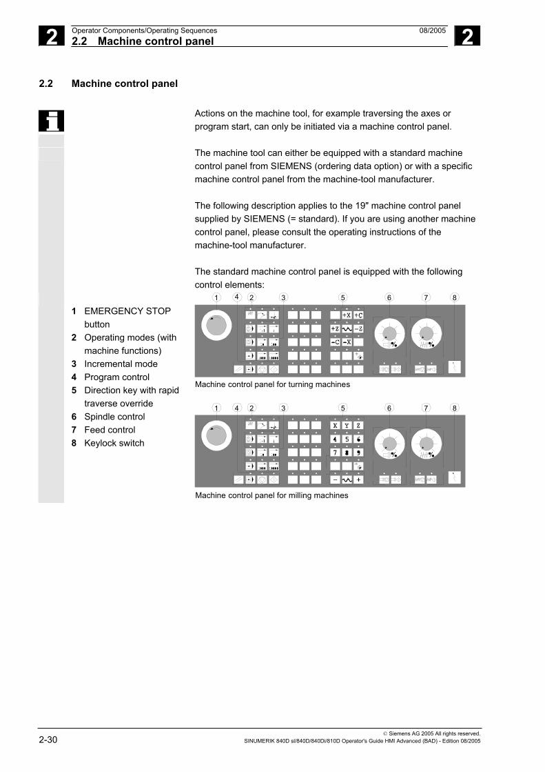
Actions on the machine tool, for example traversing the axes or program start, can only be initiated via a machine control panel.
The machine tool can either be equipped with a standard machine control panel from SIEMENS (ordering data option) or with a specific machine control panel from the machine-tool manufacturer. The following description applies to the 19" machine control panel supplied by SIEMENS (= standard). If you are using another machine control panel, please consult the operating instructions of the machine-tool manufacturer. The standard machine control panel is equipped with the following control elements:
1 EMERGENCY STOP
button 2 Operating modes (with
machine functions) 3 Incremental mode 4 Program control 5 Direction key with rapid
traverse override 6 Spindle control 7 Feed control 8 Keylock switch
1 4 2 3 5 6 7 8
1 4 2 3 5 6 7 8
Machine control panel for turning machines
Machine control panel for milling machines
2 08/2005 Operator Components/Operating Sequences2.2 Machine control panel
2
© Siemens AG 2005 All rights reserved. SINUMERIK 840D sl/840D/840Di/810D Operator's Guide HMI Advanced (BAD) - Edition 08/2005 2-31
2.2.1 EMERGENCY STOP button
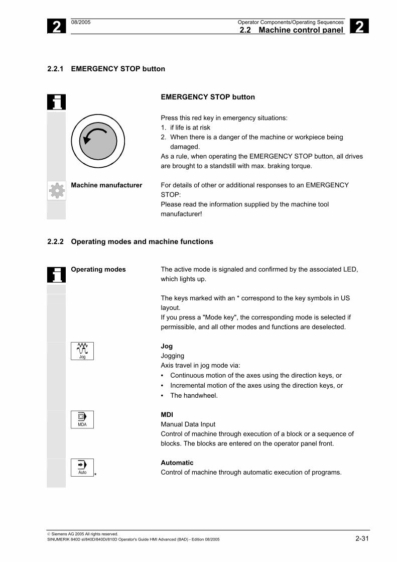
EMERGENCY STOP button
Press this red key in emergency situations: 1. if life is at risk 2. When there is a danger of the machine or workpiece being
damaged. As a rule, when operating the EMERGENCY STOP button, all drives are brought to a standstill with max. braking torque.
Machine manufacturer For details of other or additional responses to an EMERGENCY STOP: Please read the information supplied by the machine tool manufacturer!
2.2.2 Operating modes and machine functions
Operating modes The active mode is signaled and confirmed by the associated LED,
which lights up.
The keys marked with an * correspond to the key symbols in US layout. If you press a "Mode key", the corresponding mode is selected if permissible, and all other modes and functions are deselected.
Jog
Jog Jogging Axis travel in jog mode via: • Continuous motion of the axes using the direction keys, or • Incremental motion of the axes using the direction keys, or • The handwheel.
MDA
MDI Manual Data Input Control of machine through execution of a block or a sequence of blocks. The blocks are entered on the operator panel front.
Auto *
Automatic Control of machine through automatic execution of programs.

2 Operator Components/Operating Sequences 08/2005 2.2 Machine control panel
2
© Siemens AG 2005 All rights reserved. 2-32 SINUMERIK 840D sl/840D/840Di/810D Operator's Guide HMI Advanced (BAD) - Edition 08/2005
Inc keys
You can activate the Inc functions in conjunction with the following
modes: • "JOG" operating mode • "MDI/Teach-in" operating mode
VAR
Inc Var Incremental feed variable Incremental traverse with variable increment size (see “Parameters operating area, setting data”).
1
10
100
1000
10000
Inc Incremental feed Incremental traverse with preset increment size of 1, 10, 100, 1,000, 10,000 increments.
A machine data code defines how the incremental dimension is interpreted.
Machine functions
MDA
Teach In
Teach-in Creation of programs in interactive mode with the machine in "MDI" mode.
Jog
Repos
Repos Repositioning Reposition, re-approach contour in "Jog" mode.
Jog
Ref Point
Ref Approaching a reference point Approach the reference point (Ref) in "Jog" mode.

2 08/2005 Operator Components/Operating Sequences2.2 Machine control panel
2
© Siemens AG 2005 All rights reserved. SINUMERIK 840D sl/840D/840Di/810D Operator's Guide HMI Advanced (BAD) - Edition 08/2005 2-33
2.2.3 Feed control
Feedrate rapid traverse override (feedrate override switch)
Control range: 0% to 120% of programmed feedrate. In rapid traverse, the 100% value is not exceeded. Settings: 0%, 1%, 2%, 4%, 6%, 8%, 10%, 20%, 30%, 40%, 50%, 60%, 70%, 75%, 80%, 85%, 90%, 95%, 100%, 105%, 110%, 115%, 120%
Feed Stop
Feed stop
If you press the "Feed stop" key: • Execution of the current program is stopped • The axis drives are brought to a standstill under control, • The associated LED lights up as soon as feed stop has been
accepted by the control and • The following appears in the header (program control display):
FST (= Feed Stop) Example: - In "MDI" mode, an error is detected during execution of a block. - A tool change is to be carried out.
Feed Start
Feed start
If you press the "Feed start" key: • The part program is continued in the current block, • The feedrate is accelerated to the value specified by the program, • The associated LED lights up as soon as feed start has been
accepted by the control.
Axis keys (for turning machines):
+X
+Z
Press these keys to traverse the selected axis (X ... Z) in the positive direction.
X
Z
Press these keys to traverse the selected axis (X ... Z) in the negative direction.

2 Operator Components/Operating Sequences 08/2005 2.2 Machine control panel
2
© Siemens AG 2005 All rights reserved. 2-34 SINUMERIK 840D sl/840D/840Di/810D Operator's Guide HMI Advanced (BAD) - Edition 08/2005
Axis keys (for milling machines):
X ... 9th Axis
Select the axis (X ... 9) for traversing
+
in the positive direction by pressing the "+" key or
in the negative direction by pressing the "-" key.
Rapid
Rapid traverse override If you press this key together with key "+" or "-", the axis moves in rapid traverse mode.
Machine manufacturer − The specified increments and control range apply to standard machines.
− Increments and control range can be modified by the machine tool manufacturer to suit specific applications.
− Feedrate/rapid traverse feedrate and the values for the feedrate override positions (if the feedrate override switch is also active for rapid traverse) are defined in the machine data (see the information supplied by the machine manufacturer).
WCS MCS
WCS/MCS You can switch between the machine and workpiece coordinate systems in the Machine operating area using softkeys (MCS)/(WCS) or the corresponding key on the machine control panel.

2 08/2005 Operator Components/Operating Sequences2.2 Machine control panel
2
© Siemens AG 2005 All rights reserved. SINUMERIK 840D sl/840D/840Di/810D Operator's Guide HMI Advanced (BAD) - Edition 08/2005 2-35
2.2.4 Spindle control
Spindle override (spindle speed override switch)
• The rotary switch with latch positions allows you to increase or decrease the programmed spindle speed "S" (equivalent to 100%).
• The set spindle speed value "S" is output as an absolute value and a percentage in the "Spindles" display (vertical softkey on main screen).
Control range: 50% to 120% of programmed spindle speed Increment: 5% between latch positions
Spindle Stop *
Spindle stop
When you press the "Spindle stop" key: • The spindle is decelerated down to zero speed and • The associated LED lights up as soon as "Spindle stop" is
reached. Example: • To change a tool • To enter S, T, H, M functions during setup
Spindle Start
Spindle start
When you press the "Spindle start" key: • The spindle speed is accelerated to the value defined in the
program and • The associated LED lights up as soon as "Spindle start" has been
accepted by the control.
Machine manufacturer − The specified increment and the control range apply to standard machine data (MD). These MD can be edited by the machine-tool manufacturer to suit the specific application.
− The maximum spindle speed and the values for the spindle speed override position are defined in the machine data and setting data (see information supplied by the machine-tool manufacturer).

2 Operator Components/Operating Sequences 08/2005 2.2 Machine control panel
2
© Siemens AG 2005 All rights reserved. 2-36 SINUMERIK 840D sl/840D/840Di/810D Operator's Guide HMI Advanced (BAD) - Edition 08/2005
2.2.5 Keylock switch
SIEMENS keylock switch Machine manufacturer
The keylock switch on the SINUMERIK 840D, 810D has 4 settings to which protection levels 4 to 7 are assigned. Functions can be assigned to keylock switch positions by the machine manufacturer. Using machine data, it is also possible to set access to programs, data and functions to suit the user's requirements. The keylock switch has three different colored keys which can be removed in the specified positions:
Switch positions
Position 0 No key Protection level 7 Position 1 Key 1 black Protection level 6 Position 2 Key 1 green Protection level 5 Position 3 Key 1 red Protection level 4
Lowest access authorization
↓ Highest
access authorization
Changing access rights The screen is not automatically updated after a change in access authorization (e.g., when the keylock switch position is changed), but only when the screen is next refreshed (e.g., on closing and opening a directory). The currently valid access authorization is checked every time a function is executed.
If the PLC is in the stop state, the input image of the machine control panel is not scanned. For this reason, the keylock switch positions are not evaluated during startup.
Passwords As an additional option for setting access authorization, it is possible to enter three passwords in the "Startup" operating area. If the password is set, the keylock switch positions are irrelevant.
References /IAD/, Installation and startup guide 840D or /IAC/, Installation and startup guide 810D

2 08/2005 Operator Components/Operating Sequences2.2 Machine control panel
2
© Siemens AG 2005 All rights reserved. SINUMERIK 840D sl/840D/840Di/810D Operator's Guide HMI Advanced (BAD) - Edition 08/2005 2-37
2.2.6 Program control
Cycle Start
NC Start If you press the "NC Start" key, the selected part program (part program name is displayed in header) is started at the current block and the associated LED lights up.
Cycle Stop
NC Stop If you press the "NC Stop" key, processing of the active part program is halted and the associated LED lights up. After this, you can continue processing with NC Start.
Single Block
Single block This function allows you to execute a part program block by block. You can activate the "Single Block" function in "Automatic" and "MDI" modes. If single block is activated, the associated LED on the machine control panel lights up. If single block execution is active, • Stop is displayed on the screen in the cycle (in the program control
line) • The message "Stop: Block completed in single block" is displayed
in the channel operational message line (in interrupt state). • The current block in the part program will not be executed until you
press the "NC Start" key. • Program processing is stopped after one block is executed. • You can execute the next block by pressing the "NC Start" key
again. You can deselect the function by pressing the "Single block" key again.
This function is dependent on the settings under "Program control" in the Machine operating area.
Reset
Reset
When you press the "Reset" key: • Execution of the current part program is aborted. • Messages issued by the monitoring function are deleted (except
the alarms POWER ON, NC Start and "Acknowledge alarm"). • The channel is set to "Reset" state, i.e.,
- The NC control remains synchronized with the machine. - The control is in its initial state and ready for a new program
run. See also /FB/, K1 Description of Functions Mode Group, Channel, Program Control.

2 Operator Components/Operating Sequences 08/2005 2.3 Screen layout
2
© Siemens AG 2005 All rights reserved. 2-38 SINUMERIK 840D sl/840D/840Di/810D Operator's Guide HMI Advanced (BAD) - Edition 08/2005
2.3 Screen layout
2.3.1 Display of control states
MachineChannel interruptedStop: No NC Ready
Jog
MCS Position Repos offset Auxiliary FunctionsM0M0
M0
H0.000000H0.000000
H0.000000
M0
M0
+ X 900.000 mm 0.000
- Y -156.000 mm 0.000
+ Z 230.000 mm 0.000
Feedrate mm/minAct. 3000.000 0.0 %Set. 3000.000
Auto
MDI
JOG
REPOS
REF
Machine Parameters Program Services Diagnosis
Tool
G0 G91
.
1 4 6
89
2
i
53
7
16
11
12
13
11
11
1111
17
preselected tool:
Start-up>10
>
CHAN1 \MPF.DIRSHAFT1.MPFP
Global machine status display
Horizontal softkeys
Vertical softkeys
18
19
Program stoppedDRY ROV
1 Operating areas
2 Channel status 3 Channel operational messages 4 Channel name 5 Alarm and message line 6 Operating mode, submode, (increment if relevant) 7 Program name of the selected program 8 Program status 9 Program control
10 Additional information (help) i You can display information by pressing the i key ^ Recall: Return to higher-level menu > ETC.: Expansion of the horizontal softkey bar in the same. menu

2 08/2005 Operator Components/Operating Sequences2.3 Screen layout
2
© Siemens AG 2005 All rights reserved. SINUMERIK 840D sl/840D/840Di/810D Operator's Guide HMI Advanced (BAD) - Edition 08/2005 2-39
11 Working windows, NC displays The working windows (program editor) and NC displays (feedrate, tool) available in the selected operating area are displayed here.
The unit for positional data is preceded by the diameter symbol Æ in the work pane if the axis is currently the transverse axis and if the tool coordinate system is set. If diameter programming is disabled with DIAMOF, the symbol preceding the unit is no longer visible.
12 User response line with user information Here user information is displayed for the selected function (if available).
13 Focus The selected pane is highlighted by a frame. The window header display is inverted. Data entered on the operator panel front apply to this window.
16 Recall function, i.e., key ^ is active 17 ETC. function, i.e., > key is active
18 Horizontal softkeys 19 Vertical softkeys
The softkey functions available in the selected operating area are displayed in the horizontal/vertical softkey bar (corresponding to F1 to F8 on the full keyboard).
Additional notes
The screen layout may differ slightly from the layout displayed above, depending on the screen size or resolution used.
2.3.2 Global machine status display
1 Operating areas The currently selected operating area is displayed (Machine,
Parameters, Program, Services, Diagnostics, Startup).
2 Channel status The current channel status is displayed - Channel reset - Channel interrupted - Channel active
3 Channel operational
messages For displaying the channel operational messages with symbols:
If the status shows this symbol , operating input is required.
1 Stop: No NC ready
2 Operator Components/Operating Sequences 08/2005 2.3 Screen layout
2
© Siemens AG 2005 All rights reserved. 2-40 SINUMERIK 840D sl/840D/840Di/810D Operator's Guide HMI Advanced (BAD) - Edition 08/2005
2 Stop: Mode group ready
3 Stop: EMERGENCY STOP active
4 Stop: Alarm active with stop
5 Stop: M0/M1 active
6 Stop: Block ended in SBL mode
7 Stop: Cycle stop active
8 Wait: No read-in enable
9 Wait: No feed enable
12 Wait: No axis enable
17 Wait: Feedrate override > 0%
18 Stop: Error in NC block
19 Wait: For external NC blocks
22 Wait: No spindle enable
23 Wait: Axis feedrate value is 0
31 Stop: No channel ready
45 Stop: SERUPRO search has found search target and the NCK has stopped. SERUPRO is the abbreviation for “SEarchRUn by PROgram test”; it is a new type of block search.
If the status shows this symbol operation is generally not required.
10 Wait: Remaining dwell time __ Sec. for seconds or
Remaining dwell time __ rev. for revolutions
This can be parameterized via an OPI variable. 0 = sec./1 = rev.
11 Wait: No aux. funct. ackn.
13 Wait: Exact stop not reached
14 Wait: For positioning axis
15 Wait: For spindle
16 Wait: For other channel
20 Wait: Due to SYNACT instruction
21 Wait: Block search active
24 Wait: For tool change acknowledgement
25 Wait: For gear stage change
26 Wait: For position control
27 Wait: For thread cut
2 08/2005 Operator Components/Operating Sequences2.3 Screen layout
2
© Siemens AG 2005 All rights reserved. SINUMERIK 840D sl/840D/840Di/810D Operator's Guide HMI Advanced (BAD) - Edition 08/2005 2-41
29 Wait: For punching
30 Wait: For safe operation
32 Stop: Oscillation active
33 Stop: Axis replacement active (block change inhibited because axis replacement in progress)
34 Wait: For axis container rotation
35 Wait: AXCT axis active as slave axis
36 Wait: AXCT axis active as master axis
37 Wait: AXCT axis changing to follow-up
38 Wait: AXCT internal status change in axis
This delay status may be attributable to the following causes:
• Activation of position control • Requesting of zero marker • Reference point approach active • Parameter block change active • Measuring system change active • Measurement on-the-fly active • Closed-loop controller enable removed • Status change, axis/spindle disable
39 Wait: AXCT axis drive disable
40 Wait: AXCT axis overlaid motion active
41 Wait: AXCT axis axis replacement active
42 Wait: AXCT axis interpolator active
43 Wait: WAIT_FOR_CC_ENABLE: Waiting for compile cycle
44 Wait: On access to system variable
46 Stop: ESR triggered
47 Wait: Axis container rotation waiting for spindle stop
48 Wait: Axis container rotation waiting for synchronization of MD data (New-Config)
49 Wait: For axis replacement: Axis currently coupled
50 Wait: For axis replacement: Lift fast active
51 Wait: For axis replacement: New-Config active
52 Wait: For axis replacement: Axis container rotation active
53 Wait: For axis replacement: Waitp active
54 Wait: For axis replacement: Axis is currently in another channel
55 Wait: For axis replacement: Axis is currently PLC axis
56 Wait: For axis replacement: Axis is currently reciprocating axis
2 Operator Components/Operating Sequences 08/2005 2.3 Screen layout
2
© Siemens AG 2005 All rights reserved. 2-42 SINUMERIK 840D sl/840D/840Di/810D Operator's Guide HMI Advanced (BAD) - Edition 08/2005
57 Wait: For axis replacement: Axis is currently jog axis
58 Wait: For axis replacement: Axis is currently command axis
59 Wait: For axis replacement: Axis is currently OEM axis
60 Wait: For axis replacement: Axis is currently slave axis in
master-value coupling
61 Wait: For axis replacement: Axis is currently coupled-motion axis
62 Wait: For axis replacement: Axis is currently coupled slave axis
4 Channel name Name of the channel in which the program is running.
5 Alarm and message line - Alarms and messages or
- Information that was programmed in the part program using the MSG command (if no alarms pending)
6 Operating mode display The currently selected operating mode, i.e. Jog, MDI or AUTO (automatic) is displayed. The active submode is displayed next to the operating mode. An active increment is also displayed underneath, e.g., JOG Repos 1000
7 Program name Press NC Start to execute this program. The "Program name" output field can be configured for JOG and MDI. See machine manufacturer's specifications.
8 Program status The current status of the part program being executed is output - Program aborted - Program running - Program stopped The "program status" output field can be configured, e.g. with the "Channel-wide status display with symbols" function (Subsection 4.1.3); see machine manufacturer's specifications.
9 Program control display Functions that have been activated can be set via "Program control" so that they are displayed. (See Section 4.6 Automatic mode, “Program control”)

2 08/2005 Operator Components/Operating Sequences2.3 Screen layout
2
© Siemens AG 2005 All rights reserved. SINUMERIK 840D sl/840D/840Di/810D Operator's Guide HMI Advanced (BAD) - Edition 08/2005 2-43
2.3.3 Program control display
Function
Functions that have been activated are visible in the program control display (can be set via "Program control", see Subsection 4.6.12). The functions are displayed irrespective of the selected menu.
SKP Skip block
Program blocks in which the block number is preceded by a slash are skipped when you run the program (e.g. "/N100 ..."). Up to 10 program levels can be hidden (e.g., "/6N100 .."; the 7th program level is hidden) References: /PG/ Programming Guide Fundamentals, Chapter 2.
SKPn n = active skip levels
SBL1 Single block with STOP after each machine function block
If this function is active, execution is interrupted after every block that triggers a function on the machine (calculation blocks do not cause an interruption).
SBL2 Single block with STOP after each block
If this function is active, the part program blocks are executed as follows: Each block is decoded separately and execution is interrupted after every block.
SBL3 Stop in cycle
If this function is active, the part program blocks are executed individually in the cycle as follows: Each block is decoded separately and execution is interrupted after every block. Part program blocks are • Traversing blocks • Switching and auxiliary functions • Blocks generated within the control
(e.g.: blocks inserted by tool radius compensation) • Thread blocks after retraction • Thread blocks with dry run feedrate Thread blocks without dry run feedrate are an exception to this. Here, execution is only interrupted at the end of the current thread block. SBL2 can only be selected in the Reset state. Either SBL1 or SBL2 can be selected! This function can be activated only in the "Single block" state.

2 Operator Components/Operating Sequences 08/2005 2.3 Screen layout
2
© Siemens AG 2005 All rights reserved. 2-44 SINUMERIK 840D sl/840D/840Di/810D Operator's Guide HMI Advanced (BAD) - Edition 08/2005
DRY Traverse movements are performed with the feedrate value set in the setting data "Dry run feedrate". This dry run feedrate function replaces the programmed motion commands.
ROV Rapid traverse override
The override switch for the feedrate also applies to the rapid traverse feedrate.
M01 Programmed stop 1
When this function is active, processing of the program is stopped at every block in which miscellaneous function M01 is programmed. The message "Stop: M00/M01 active" is then displayed on the screen. Press the NC Start key to resume execution. If the function is not activated, special function M01 (from the part program) is not taken into account.
Additional M fct. Programmed stop 2
When this function is active, program execution on the NC is interrupted on request by the PLC at blocks containing the additional function for a conditional stop. In machine data 22256: AUXFO_ASSOC_M1_VALUE you can define a function associated with M01. The value of this miscellaneous M function number is then equivalent to a programmed stop 2.
References /FB1/Description of Functions - Basic Machine Predefined Auxiliary Function "Associated auxiliary functions for M0, M1"
DRF DRF selection
When the "DRF" function is active, DRF offsets are applied.
PRT Program test
If "Program test" is selected, the output of setpoints to axes and spindles is disabled. The setpoint display "simulates" the traverse movements.
FST Feed stop
The activated feed stop is displayed. “Feed stop” is indicated in the feedrate window by means of the symbol “Feedrate not enabled” and is omitted from the program control display. This function is not activated/deactivated under Program control, but via the Feed Start/Feed Stop keys on the machine control panel.

2 08/2005 Operator Components/Operating Sequences2.4 General operating sequences
2
© Siemens AG 2005 All rights reserved. SINUMERIK 840D sl/840D/840Di/810D Operator's Guide HMI Advanced (BAD) - Edition 08/2005 2-45
2.4 General operating sequences
Keys A range of keys are available in the various operating areas and menus. The function of the keys is the same in all operating areas.
This identical functionality applies only if the operating areas are left intact as supplied by Siemens AG and no modifications have been configured by the user.
Additional notes
It is possible to customize the menu trees. In this way, users are able to define softkeys according to their individual needs. Due to this capability, the menus and softkeys on your control may be different to those described in this Operator's Guide.
References /IAM/, IM4 Chapter 5 "Functions/Parameter settings" See user-specific menu trees
Functions The following section describes functions which you can select in several operating modes.
2.4.1 Program overview and program selection
Function
After selection of a workpiece or program overview, individual workpieces or programs can be enabled or disabled for execution.
Operating sequence
"AUTO" mode is selected in the "Machine" operating area. The appropriate channel is selected. The channel is in reset state. The workpiece/program to be selected is in the memory.
An overview of all workpiece directories/programs that exist is displayed.
Position the cursor on the desired workpiece/program.
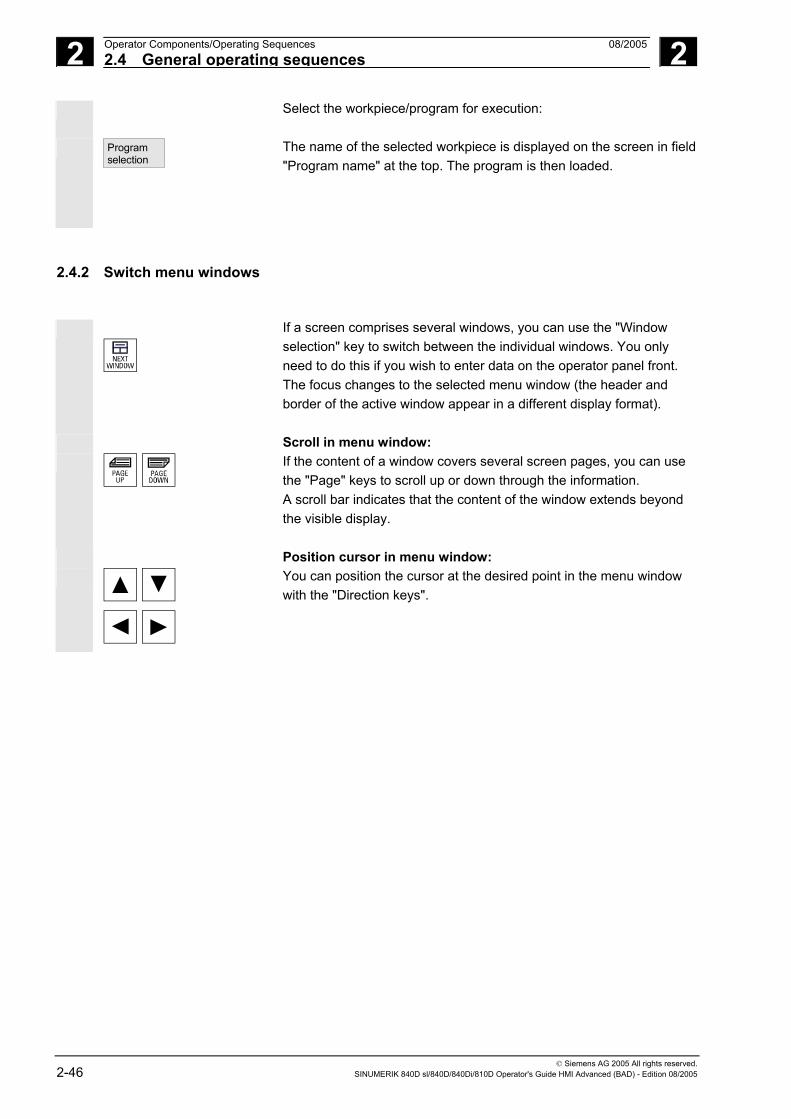
2 Operator Components/Operating Sequences 08/2005 2.4 General operating sequences
2
© Siemens AG 2005 All rights reserved. 2-46 SINUMERIK 840D sl/840D/840Di/810D Operator's Guide HMI Advanced (BAD) - Edition 08/2005
Select the workpiece/program for execution:
Program selection
The name of the selected workpiece is displayed on the screen in field "Program name" at the top. The program is then loaded.
2.4.2 Switch menu windows
If a screen comprises several windows, you can use the "Window selection" key to switch between the individual windows. You only need to do this if you wish to enter data on the operator panel front. The focus changes to the selected menu window (the header and border of the active window appear in a different display format).
Scroll in menu window:
If the content of a window covers several screen pages, you can use the "Page" keys to scroll up or down through the information. A scroll bar indicates that the content of the window extends beyond the visible display.
Position cursor in menu window:
You can position the cursor at the desired point in the menu window with the "Direction keys".

2 08/2005 Operator Components/Operating Sequences2.4 General operating sequences
2
© Siemens AG 2005 All rights reserved. SINUMERIK 840D sl/840D/840Di/810D Operator's Guide HMI Advanced (BAD) - Edition 08/2005 2-47
2.4.3 Select a directory/file
The "Direction keys" can be used to position the cursor on the desired directory/file. If you enter a character on the alphanumeric keyboard, the cursor moves to the first name that begins with the character.
Open/close directory:
Press the "Input" key to open or close a directory.
Open file:
You can open a file with the "Input" key if you wish to edit it in the ASCII editor. The editor is opened automatically.
Select file
This key is used to select a file. It is possible to select multiple files. The symbol appears next to the cursor bar when a file is selected.
Select multiple files
In order to select a block of files, press the "Shift" and "Cursor down" keys simultaneously.
The first time you press the keys, the start of the block is selected. The subsequent files are selected continuously
or
until you press the "Cursor up" or "Cursor down" (without "Shift") key.
Deselects a selected file.
Cancels all selections.

2 Operator Components/Operating Sequences 08/2005 2.4 General operating sequences
2
© Siemens AG 2005 All rights reserved. 2-48 SINUMERIK 840D sl/840D/840Di/810D Operator's Guide HMI Advanced (BAD) - Edition 08/2005
2.4.4 Edit inputs/values
If you wish to edit inputs/values, the corresponding key is always
displayed automatically on the right of the input field. The following input fields are available:
1. Option buttons (single selection button/multiple option button): You can use the "Select" key to activate or deactivate a selection field.
Multiple option button (you can select several options or none) = active
= not active
Single-option button/option button (only one option can be active at a time)
= active
= not active
2. Input fields: Position the cursor on the input field and start to type. When you
begin typing, you automatically switch to Insert mode.
Confirm your input with the "Input" key. The value is accepted.
To change an existing value, press the "Edit" key to switch to insert mode. Enter the value or word (e.g. file name, etc.) on the alphanumeric keypad.
In some fields, it is possible to choose between several preset values by means of the "Toggle" key.
3. Selection list Selection lists show you a selected value from a list of possible values.
Press the "Edit" key to open a complete list of possible or existing values.
Position the cursor on the value of your choice using the "Direction" keys.

2 08/2005 Operator Components/Operating Sequences2.4 General operating sequences
2
© Siemens AG 2005 All rights reserved. SINUMERIK 840D sl/840D/840Di/810D Operator's Guide HMI Advanced (BAD) - Edition 08/2005 2-49
Always confirm your input with the "Input" key. The value is accepted.
With this key, you can switch to the next value in the selection list without displaying the entire list (e.g. to select from only a small number of values/settings).
• The editor displays only the characters which can be input via the operator panel front keyboard.
• A part program opened by the editor cannot be simultaneously started in the NC (enable is canceled); an alarm (14014) is indicated in this case. If the control is switched off while the editor is open, the enable might have to be set manually.
2.4.5 Confirm/cancel the input
Confirm input:
OK
Your inputs are accepted when you press the "OK" softkey. The selected function is executed. The window is closed, and you return to the menu level from which the window was called.
Abort
Cancel input: Your inputs are rejected if you select the "Cancel" softkey. The selected function is aborted. The window is closed and you return to the menu level from which the window was called. This is the same as when returning from a function (vertical softkey bar).
The "Edit" key can also have an "Undo" function if you abandon the input/modification you have just entered. The cursor remains positioned in the currently selected field.
Switch from the horizontal menu level back to the call menu level.

2 Operator Components/Operating Sequences 08/2005 2.4 General operating sequences
2
© Siemens AG 2005 All rights reserved. 2-50 SINUMERIK 840D sl/840D/840Di/810D Operator's Guide HMI Advanced (BAD) - Edition 08/2005
2.4.6 Edit the part program in the ASCII editor
Function
The ASCII editor provides you with the following functions: − Switch between insert and overwrite mode − Select, copy, delete block − Paste block − Position cursor / find/replace text − Save file − Create contour (programming support) − Parameterize cycles (drilling, milling, turning) − Start simulation − Recompile (cycles, free contour programming) − Renumber blocks − Change settings − 2. Open file
Additional notes
A part program selected in the NC can generally only be edited when the channel is in the reset state. When a part program is selected and the relevant channel is in the "Channel Reset" state, the program can be fully edited. The end of block character is not displayed as " LF"; instead it is displayed as "¶". Please note: It is possible to edit a program both directly in the NC and on the hard disk in the ASCII editor. How programs are saved on the hard disk is determined by settings.
Operating sequence
The following functions are fully enabled in the Program and Services operating areas but only partially in the Machine operating area. In the Machine operating area, the ASCII editor is called via the program editor, in Services, by selecting a file in the file manager.
You have selected the file you wish to edit in the directory and pressed the "Enter" key, the vertical softkey bar changes. Your selected file is opened in the text editor.
Cursor block: Use the "Direction keys" to position the cursor in the text.
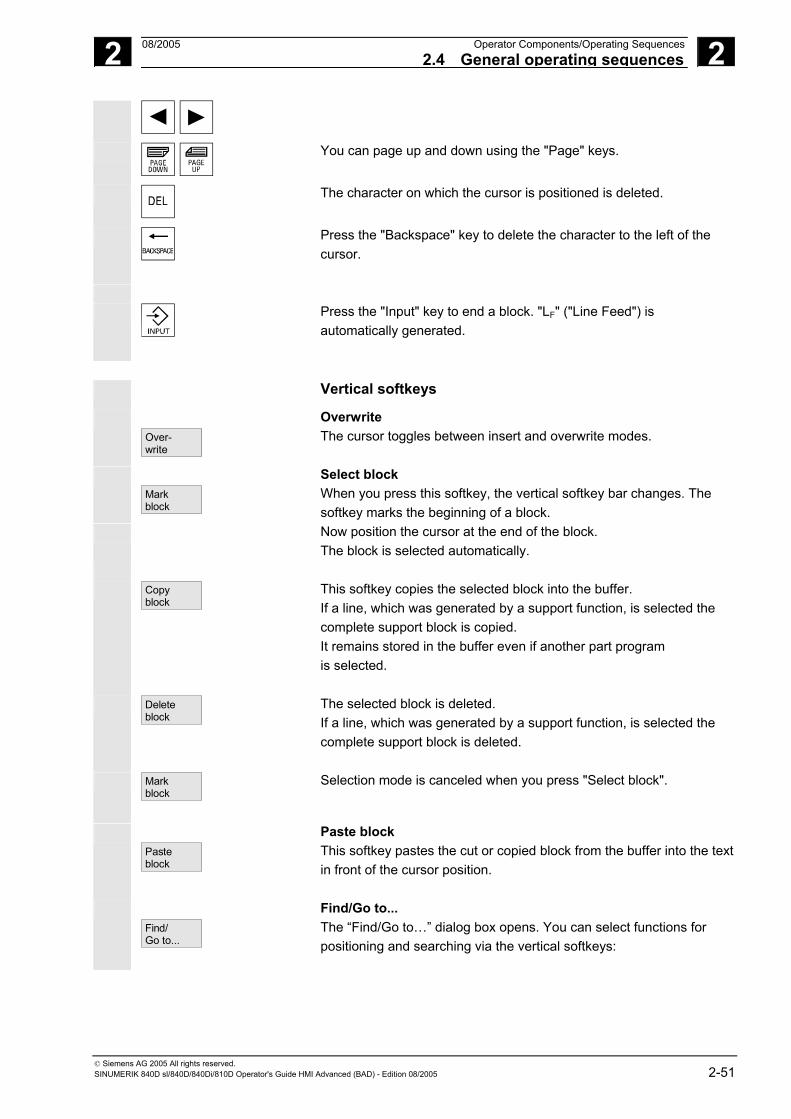
2 08/2005 Operator Components/Operating Sequences2.4 General operating sequences
2
© Siemens AG 2005 All rights reserved. SINUMERIK 840D sl/840D/840Di/810D Operator's Guide HMI Advanced (BAD) - Edition 08/2005 2-51
You can page up and down using the "Page" keys.
The character on which the cursor is positioned is deleted.
Press the "Backspace" key to delete the character to the left of the cursor.
Press the "Input" key to end a block. "LF" ("Line Feed") is automatically generated.
Vertical softkeys
Over- write
Overwrite The cursor toggles between insert and overwrite modes.
Mark block
Select block When you press this softkey, the vertical softkey bar changes. The softkey marks the beginning of a block.
Now position the cursor at the end of the block. The block is selected automatically.
Copy
block This softkey copies the selected block into the buffer. If a line, which was generated by a support function, is selected the complete support block is copied. It remains stored in the buffer even if another part program is selected.
Delete block
The selected block is deleted. If a line, which was generated by a support function, is selected the complete support block is deleted.
Mark block
Selection mode is canceled when you press "Select block".
Paste block
Paste block This softkey pastes the cut or copied block from the buffer into the text in front of the cursor position.
Find/ Go to...
Find/Go to... The “Find/Go to…” dialog box opens. You can select functions for positioning and searching via the vertical softkeys:
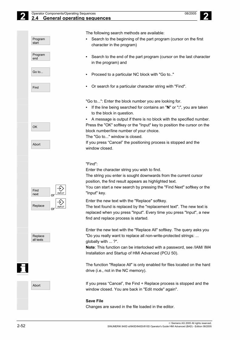
2 Operator Components/Operating Sequences 08/2005 2.4 General operating sequences
2
© Siemens AG 2005 All rights reserved. 2-52 SINUMERIK 840D sl/840D/840Di/810D Operator's Guide HMI Advanced (BAD) - Edition 08/2005
Program start
Program end
Go to...
Find
The following search methods are available: • Search to the beginning of the part program (cursor on the first
character in the program) • Search to the end of the part program (cursor on the last character
in the program) and • Proceed to a particular NC block with "Go to.." • Or search for a particular character string with "Find".
"Go to...": Enter the block number you are looking for. • If the line being searched for contains an "N" or ":", you are taken
to the block in question. • A message is output if there is no block with the specified number.
OK
Press the "OK" softkey or the "Input" key to position the cursor on the block number/line number of your choice. The "Go to..." window is closed.
Abort
If you press “Cancel” the positioning process is stopped and the window closed.
"Find":
Enter the character string you wish to find. The string you enter is sought downwards from the current cursor
position, the find result appears as highlighted text.
Find next or
You can start a new search by pressing the "Find Next" softkey or the "Input" key.
Replace
or
Enter the new text with the "Replace" softkey. The text found is replaced by the "replacement text". The new text is replaced when you press "Input". Every time you press "Input", a new find and replace process is started.
Replace all texts
Enter the new text with the "Replace All" softkey. The query asks you "Do you really want to replace all non-write-protected strings: ... globally with ... ?". Note: This function can be interlocked with a password, see /IAM/ IM4 Installation and Startup of HMI Advanced (PCU 50).
The function "Replace All" is only enabled for files located on the hard drive (i.e., not in the NC memory).
Abort
If you press “Cancel”, the Find + Replace process is stopped and the window closed. You are back in "Edit mode" again".
Save File Changes are saved in the file loaded in the editor.

2 08/2005 Operator Components/Operating Sequences2.4 General operating sequences
2
© Siemens AG 2005 All rights reserved. SINUMERIK 840D sl/840D/840Di/810D Operator's Guide HMI Advanced (BAD) - Edition 08/2005 2-53
Save file
Additional notes
Please note that the changes to programs stored in the NC memory take immediate effect. The save options for the control system can be altered in the "Settings" menu (e.g., save automatically, etc.). (See Chapter "Startup")
Close editor
Close editor When you select the "Close editor" softkey, a dialog box may appear in which you must confirm whether or not to save the changes. The text editor is then closed and the current program overview is displayed again.
Horizontal softkeys
Free contour programming Contour
Generate contour
Use the "Contour" and "Generate contour" softkeys to call up the free contour programming function.
Accept contour
The part program block is inserted in the part program with the appropriate parameters.
Cycle parameterization
The following programming support functions are available: • Drilling, milling, turning (cycles) • Contouring (free contour programming)
Drilling
Milling
Turning
You can call up the relevant cycle parameter settings via the Drilling, Milling, Turning vertical softkeys. Enter the new values for the cycle parameters.
OK
The part program block is inserted in the part programs with the appropriate parameter settings. Example: CYCLE81 (110, 100, 2, 35)
References /PGC/, Programming Guide Cycles
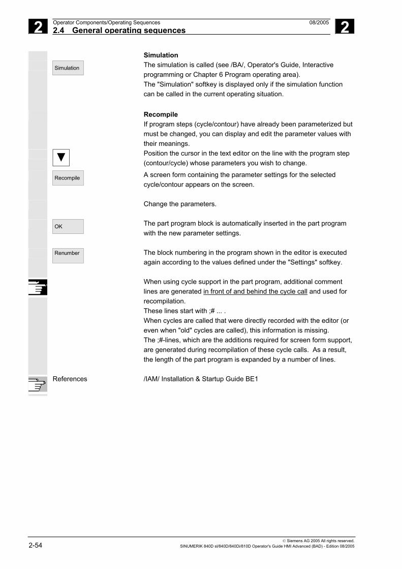
2 Operator Components/Operating Sequences 08/2005 2.4 General operating sequences
2
© Siemens AG 2005 All rights reserved. 2-54 SINUMERIK 840D sl/840D/840Di/810D Operator's Guide HMI Advanced (BAD) - Edition 08/2005
Simulation Simulation
The simulation is called (see /BA/, Operator's Guide, Interactive programming or Chapter 6 Program operating area). The "Simulation" softkey is displayed only if the simulation function can be called in the current operating situation.
Recompile If program steps (cycle/contour) have already been parameterized but must be changed, you can display and edit the parameter values with their meanings.
Position the cursor in the text editor on the line with the program step (contour/cycle) whose parameters you wish to change.
Recompile
A screen form containing the parameter settings for the selected cycle/contour appears on the screen.
Change the parameters.
OK
The part program block is automatically inserted in the part program with the new parameter settings.
Renumber
The block numbering in the program shown in the editor is executed again according to the values defined under the "Settings" softkey.
When using cycle support in the part program, additional comment lines are generated in front of and behind the cycle call and used for recompilation. These lines start with ;# ... . When cycles are called that were directly recorded with the editor (or even when "old" cycles are called), this information is missing. The ;#-lines, which are the additions required for screen form support, are generated during recompilation of these cycle calls. As a result, the length of the part program is expanded by a number of lines.
References /IAM/ Installation & Startup Guide BE1

2 08/2005 Operator Components/Operating Sequences2.4 General operating sequences
2
© Siemens AG 2005 All rights reserved. SINUMERIK 840D sl/840D/840Di/810D Operator's Guide HMI Advanced (BAD) - Edition 08/2005 2-55
Settings Settings
Define the following values in the "Editor Settings" window: • Horizontal scrolling ON/OFF • Display hidden lines ON/OFF • Deactivate LF in program
If this setting is selected, a space is displayed in the editor window on the screen in place of the linefeed character. In the file to be edited, the linefeed character is retained.
• Time interval for Automatic Save When you set Automatic Save, you can also set the time intervals at which text must be saved automatically (applicable only to files on hard disk). If a value ≠ 0 is entered, the "Save file" softkey is not displayed. If the value 0 is entered, automatic save is not performed.
• Automatic numbering ON/OFF A new block number is automatically inserted on every new line. If you wish to assign new block numbers to an existing program, use the "Renumber" function.
• Number of first block • Incrementation of block numbers (e.g. 1, 5, 10)
Setting contour
The following settings are possible for contour programming: • Last line
Each time you complete a program step in the contour programming you can insert a text in the last line (e.g., "End of contour").
Additional notes
• The coordinate system and the technology to be used are set via the machine data; see /IAM/ Installation and Startup Guide IM4.
• Edited programs are automatically enabled after saving.

2 Operator Components/Operating Sequences 08/2005 2.4 General operating sequences
2
© Siemens AG 2005 All rights reserved. 2-56 SINUMERIK 840D sl/840D/840Di/810D Operator's Guide HMI Advanced (BAD) - Edition 08/2005
2.4.7 Channel switchover
It is possible to switch between channels when several are in use. Since individual channels may be assigned to different mode groups, a channel switchover command is also an implicit mode switchover command. If the selected channel is linked to another NCU (m:n link), the HMI Advanced is also switched over implicitly to the relevant NCU. When a "Channel menu" is configured, all existing communication links to other NCUs plus the associated channels are displayed on softkeys.
Channel statuses The following three channel statuses can occur in each mode: 1. Channel reset
The machine is in the initial state, e.g., after power-on or after end of program. The initial state is defined by the machine-tool manufacturer in the PLC program.
2. Channel active. A program has been started, the program is being executed or a reference point approach is in progress.
3. Channel interrupted The running program or reference point approach has been interrupted.
In this context, a program can be a main program, subprogram, cycle or a series of NC blocks.
There are 3 different switchover levels:
1. Switch to next channel. 2. Switch over configured channel group/channels (1 NC). 3. Switch to another NC (with m:n link involving several NCs).

2 08/2005 Operator Components/Operating Sequences2.4 General operating sequences
2
© Siemens AG 2005 All rights reserved. SINUMERIK 840D sl/840D/840Di/810D Operator's Guide HMI Advanced (BAD) - Edition 08/2005 2-57
2.4.8 m:n-Communication links
General An m:n link means that m-HMI Advanced-units and n-NCU/PLC-units
are linked together. This does not however mean that all possible links are active. In this case, an HMI Advanced is linked to only one NC at any given point in time (cf. 1:1 link) and communicates only with this unit. With an m:n link, the link can also be switched over to another NC. Using the channel switchover key and channel menu, you can switch the MMC over to another link.
The channel menu function is an option and must be configured in the NETNAMES.INI file. You can change to the channel menu in all operating areas by activating the channel switchover key. The only change is to the horizontal and vertical softkeys. Use the horizontal softkeys to select a channel group (max. 24), 8 links to channels on different NCUs can be set up in each channel group.
All current communication links and associated symbol names are listed in display "Channel menu".
!
Important Only two links may be active simultaneously on one NCU.

2 Operator Components/Operating Sequences 08/2005 2.4 General operating sequences
2
© Siemens AG 2005 All rights reserved. 2-58 SINUMERIK 840D sl/840D/840Di/810D Operator's Guide HMI Advanced (BAD) - Edition 08/2005
Function
You can set up a link in any operating area between the HMI unit and the connected NCU/PLC units via the operator interface.
MachineChannel Reset Program aborted
Jog
MCS Position
+ X 900.000 mm 0.000- Y -156.000 mm 0.000+ Z 230.000 mm 0.000
Auxiliary FunctionsM0M0M0
H0.000000H0.000000
H0.000000
M0M0
+ X 900.000 mm - Y -156.000 mm + Z 230.000 mm
Feedrate mm/minAct. 3000.000 0.0 %Set. 3000.000
Channel 11
MI I LL1
ToolT0 D0T0 D0T0 D0
G1
.
.
.
Channel 12
Channel 13
Channel 14
Channel 15
MI I LL2
Activate the channel changeover key. The currently existing
connection is displayed by means of the highlighted softkeys (horizontal, vertical) if the channel menu is active.
Channel switchover You can change to other channels by means of the vertically arranged softkeys.
Group switchover Use the horizontal softkeys to change over to a different group; the channels of the current group are now displayed on the vertical softkeys. Switchover to another channel (and if necessary to another NC) only takes place upon activation of a vertical softkey.
NC switchover You can change to another NC via the vertical softkeys if the channel is not on the current NC.
Additional notes
• Horizontal softkeys are assigned to vertical softkeys in the NETNAMES.INI file. The assignment merely represents an HMI-specific grouping characteristic.

2 08/2005 Operator Components/Operating Sequences2.4 General operating sequences
2
© Siemens AG 2005 All rights reserved. SINUMERIK 840D sl/840D/840Di/810D Operator's Guide HMI Advanced (BAD) - Edition 08/2005 2-59
• When you select a vertical softkey, you are selecting a channel and potentially an NC as well.
• Channels that are configured in the channel menu, but defined as a channel gap in the corresponding NC, will not be displayed.
• If an application (e.g. execution from external source) disables switchover to the selected NC, then only the channels of the current NC are displayed in the channel menu.
Example: 1 HMI Advanced and 3 NCUs
One HMI unit can be linked to several NCU/PLC units. The machine control panel MCP is permanently assigned to the NCU. You can connect an additional programming device (PG) with the startup tool.
The configuration illustrated below allows several NCUs to be operated from one HMI, i.e. • Multiple autonomous machines with multiple NCUs or • One large machine with multiple NCUs.
PCU 50 PG with STEP7Start-up tool
MCP1 NCU1 MCP2 NCU2 MCP3 NCU3
OPI
The following rules apply to the operation of several NCUs from one HMI: • The NCU being operated is selected via the channel switchover
key and the channel menu. • The highlighted softkeys in the channel menu show the mode
group/NC/channel to which the HMI is currently connected. After setting up a link to another NCU, the operating area selected last is always available for this NCU (as for the NCU whose link was disconnected).

2 Operator Components/Operating Sequences 08/2005 2.4 General operating sequences
2
© Siemens AG 2005 All rights reserved. 2-60 SINUMERIK 840D sl/840D/840Di/810D Operator's Guide HMI Advanced (BAD) - Edition 08/2005
2.4.9 Pocket calculator
Requirement:
The cursor is positioned on an input field or input/output field.
=
Equals key Switch to pocket calculator mode. If you enter a basic arithmetic symbol (+, -, /, *) followed by a value (e.g. 13.5) in this mode
and then press the input key, the next value entered is calculated with the preceding value. If the input/output field is opened with the input or equals key, the editor is in insert mode; if the field is opened directly with a character, the editor is in overwrite mode.
Inch/metric conversion In pocket calculator mode, you can convert numeric values from the
metric to inch system by entering "I" and from the inch to metric system by entering "M".
=
Proceed as follows to convert values: • Position the cursor on an input field which contains a numeric
value or enter a value • Press the equals key • Enter the letter "I" (convert to inches) or "M" (convert to metric)
• Press the "input" key, the value is converted.

2 08/2005 Operator Components/Operating Sequences2.5 Call help function
2
© Siemens AG 2005 All rights reserved. SINUMERIK 840D sl/840D/840Di/810D Operator's Guide HMI Advanced (BAD) - Edition 08/2005 2-61
2.5 Call help function
Function
Whenever the symbol "i" appears in the user response line, this means that additional information can be called via the Help key. A comment appears in the user response line or a dialog box opens.
An HMI Help function, which is similar to the Windows Help function, is provided on the HMIs. If, for example, you have made an input error, you can select the HMI Help to access detailed information about the error that has just occurred, e.g. the Diagnostics guide is displayed.
Available help functions include: • Alarm help
Detailed information about the alarm/message displayed • MD help
Detailed information about the selected MD/SD • Editor help
Brief information or, if the key is pressed again, detailed information about the command/function indicated by the cursor position.
Operating sequence
Pressing the "Information" key, e.g., in the "Diagnostics" operating area, automatically calls and displays HMI Help information for a currently pending alarm.
Page down or
Page up
You can page through the document with the softkeys "Page up" and "Page down",
Next entry
you jump to the next hit in the document with "Next entry".
Follow cross ref.
Where there are cross-references to other documents, you can jump to a particular point in that document with this softkey.
Go to...
You can search for any words in the document with the search function "Go to ...".
Zoom + or
Zoom -
With the softkeys "Zoom +" and "Zoom -" you can increase or decrease the zoom factor in the document view.
Exit help
By pressing "Exit help", you can return to the editor.

2 Operator Components/Operating Sequences 08/2005 2.5 Call help function
2
© Siemens AG 2005 All rights reserved. 2-62 SINUMERIK 840D sl/840D/840Di/810D Operator's Guide HMI Advanced (BAD) - Edition 08/2005
In some cases, help is provided in a similar manner to Windows Help by pressing the following softkeys:
Page up
Page down
Press the "Page down" or "Page up" softkey. The display scrolls up or down by a whole page.
Highlight back
Highlight fwd.
Use the "Selection fwd" or "Selection back" softkeys to go to the entry of your choice.
Follow cross ref.
Press the "Follow cross-ref." softkey. The required entry appears on the screen.
Back
Press the "Back" softkey to return to the previously displayed entry.
Contents
Select and display an entry in HMI Help: Press "Contents" softkey. The current contents of HMI Help are displayed.
You exit the HMI Help and return to the previous menu.
Exit
help Context-independent Help call:
HMI help
Press the following keys to call HMI Help directly: “Menu Select” key” Followed by “ETC” key HMI Help

2 08/2005 Operator Components/Operating Sequences2.5 Call help function
2
© Siemens AG 2005 All rights reserved. SINUMERIK 840D sl/840D/840Di/810D Operator's Guide HMI Advanced (BAD) - Edition 08/2005 2-63
2.5.1 Editor help
Function
The following help functions are available as programming support for editing part programs in the editor via the "information" key: • Quick help for programming commands
Configuring see /IAM/ HE1, Help in editor. − Help in part program for instructions: Display descriptive text
(e.g. G9 "Exact stop - deceleration") − Display an overview of topics (e.g. "Preparatory functions",
"Path commands", "Path traversing behavior" etc.), to which instructions are assigned.
− Display an overview of instructions with descriptive text − Search selectively in special screen forms on the basis of topic
assignment or by entering a character string − Transfer the selected instruction to the editor
• Quick help "Parameterization form" + extended help "pdf" Configurable parameterization forms from which you can jump to a particular page in the documentation (pdf file), e.g., parameterization forms for cycles, jump to Programming Guide Cycles: For configuring instructions, see: /IAM/, BE1 Expanding the operator interface.
• Quick help for program commands + extended help "pdf". From the context-sensitive help you can jump to the corresponding page in the documentation with the "information" key, e.g. jump to Programming Guide Fundamentals.

2 Operator Components/Operating Sequences 08/2005 2.5 Call help function
2
© Siemens AG 2005 All rights reserved. 2-64 SINUMERIK 840D sl/840D/840Di/810D Operator's Guide HMI Advanced (BAD) - Edition 08/2005
2.5.2 Quick help for program commands
Function
You can call up a help function to provide programming support with the editing of part programs via the "information" key. This help function can assist in the following ways: • Context-sensitive display of instructions plus descriptive text on the
basis of the cursor position (e.g., G9 "Exact stop - deceleration) • Display an overview of topics (e.g. "Preparatory functions", "Path
commands", "Path traversing behavior", etc.), to which instructions are assigned.
• Display an overview of instructions with descriptive text • Search selectively in special screen forms on the basis of topic
assignment or by entering a character string • Jump from the context-sensitive help via the "information" key onto
the corresponding page of the documentation, e.g., jump to Programming Guide Fundamentals
• Jump to an input screen with the "Input screen" softkey in which, for example, a cycle is assigned new parameters.
• Transfer the selected instruction to the editor
Notes
If the help function is being used by one editor, it is not available for use by other editors.
Operating sequence
You can call up a help function to provide programming support with the editing of part programs via the "information" key.
Depending on the current context of the cursor: • With standard context sensitivity ("displayed if wording is
identical"), only the programmed instruction with descriptive text or• with extended context sensitivity ("displayed if initial wording is the
same"), additionally all instructions with the same initial wording or• if there is no match, a full overview (see below) is displayed.

2 08/2005 Operator Components/Operating Sequences2.5 Call help function
2
© Siemens AG 2005 All rights reserved. SINUMERIK 840D sl/840D/840Di/810D Operator's Guide HMI Advanced (BAD) - Edition 08/2005 2-65
Transfer
to editor
If transfer is possible, the instruction selected in the overview is inserted directly in the part program with "Transfer to editor".
If an instruction selected when context sensitivity is active differs from the programmed instruction, the programmed instruction is overwritten. If extended context sensitivity is not active or if a different selection is displayed with "Find", "Topics" or "General overview", the selected instruction text is inserted in the part program after the instruction marked by the cursor.
Exit help
As an alternative to returning to the editor by transferring an entry, this softkey can be selected to close the Help window and return to the part program writing screen.
Apart from context-sensitive help, it is also possible to search
independently of context for instructions, descriptive texts or topics. General
overview
With "General overview" a full overview of the instructions and relevant descriptive text stored in the help system is displayed.
Headings
With "Topics" the stored topics are listed for which a functional grouping of the instructions can be displayed. To select a topic, you can either use the cursor keys or enter the topic number in an input box.
Show heading
If a topic is selected and you press "Input" or the "Display topic" softkey, the instructions associated with the selected topic are displayed.

2 Operator Components/Operating Sequences 08/2005 2.5 Call help function
2
© Siemens AG 2005 All rights reserved. 2-66 SINUMERIK 840D sl/840D/840Di/810D Operator's Guide HMI Advanced (BAD) - Edition 08/2005
Search
With the "Find" softkey you can define a search text in an input window, which you can search for using • "Instruction text only" • "Descriptive text only" • "Instruction and descriptive texts". No distinction is made between upper and lower case.
Start search
With "Input" or "Start search" a search is made using the defined search text in accordance with the instruction or descriptive part. Any matching instructions or descriptions found during the search are displayed.
Settings
Notes for setting the help system in the editor
The editor help uses a standard text file (see /IAM/, "Installation and startup guide IM4", Chapter "Help in editor"), which contains topics and instructions with descriptive text. If you want to create an end user text file for the help in order to record your own instructions/topics, you can enter the path\name of the text file under the "Settings" softkey in an input window as "end user text file". You can also change the context sensitivity under "Settings". You can choose between: • "Display with same initial wording" (extended context sensitivity)
and • "Display with identical wording" If, for example, in the option "Display with same initial wording" the cursor is located to the right of the instruction "G4", all instructions with the same initial wording, e.g., "G40, G41, G42" are also displayed. With "Display with identical wording" the current instruction, e.g., "G4" is displayed. The settings are activated by restarting the help system.
If you select the individual descriptions in the full overview with the cursor key, you can jump directly to the Programming Guide, for example, with the "info" key, if the symbol for the info key is displayed on the bottom right part of the screen (see Fig. below).

2 08/2005 Operator Components/Operating Sequences2.5 Call help function
2
© Siemens AG 2005 All rights reserved. SINUMERIK 840D sl/840D/840Di/810D Operator's Guide HMI Advanced (BAD) - Edition 08/2005 2-67
Parameter input
If "Parameter input" appears in the vertical softkey bar, you can assign parameters in an input screen for a particular instruction (e.g., a cycle).
2.5.3 Extended help for program commands
Function
You can call up a help function (quick help) to provide programming support for editing part programs via the "information" key in the program command editor. If the quick help is not sufficient, you can also open the Programming Guide (pdf file) by pressing the "information" key again. The command you are looking for is highlighted in the document.
Operating sequence
Requirement: The cursor is positioned on a programming command (e.g. G01).
You can call up the help function (quick help) in the editor using the "information" key.
Press the "information" key again to open the Programming Guide (pdf file) with Adobe Acrobat Reader.

2 Operator Components/Operating Sequences 08/2005 2.6 Job list
2
© Siemens AG 2005 All rights reserved. 2-68 SINUMERIK 840D sl/840D/840Di/810D Operator's Guide HMI Advanced (BAD) - Edition 08/2005
2.6 Job list
Function
A job list (loading list) can be created for each workpiece. This list contains instructions which prepare the following for the execution of part programs (in several channels if necessary): • Parallel setup (LOAD/COPY), i.e.:
Main programs and subprograms along with associated data such as - Initialization programs (INI) - R parameters (RPA) - User data (GUD) - Work offsets (UFR) - Tool/magazine data (TOA/TMA) - Setting data (SEA) - Protection zones (PRO) and - Sag/angularity (CEC) load or copy from the hard disk of the HMI to the main memory of the NC.
• Preparations for the NC Start (SELECT), i.e.: Select programs in different channels as well as starting preparations for execution
• Parallel clearing (reversed LOAD/COPY), i.e.: Remove/unload main programs, subprograms and associated data from the NC working memory to the hard disk of the HMI
• Backup (in preparation for the next software version)
Notes
Parallel setup, preparations for NC Start, parallel cleanup and backup can also be executed from the PLC.
The job list is executed if the workpiece contains a job list of the same name. The job list instructions are activated (see diagram) on 1. Parallel setup with "Load" (LOAD/COPY) 1. "Select" (LOAD/COPY/SELECT) 2. "NC Start" (program is executed and SELECT is activated) 3. Parallel clearing with "Unload" (reversed LOAD/COPY) 4. "Backup" (in preparation for the next software version)

2 08/2005 Operator Components/Operating Sequences2.6 Job list
2
© Siemens AG 2005 All rights reserved. SINUMERIK 840D sl/840D/840Di/810D Operator's Guide HMI Advanced (BAD) - Edition 08/2005 2-69
NCU
MMC
active
Hard disk
passive
1
2
3
4
4
New
Create the file "Workpiece.JOB" (e.g. SHAFT.JOB) There are various methods by which job lists can be created: • While creating a workpiece directory with the function "New",
generate a standard job list as a file in this workpiece. The job list syntax is included as a comment in this standard job list. The "Create templates for job list" field under "Startup/HMI/System settings/Templates” must first be checked. With this method, the file is automatically assigned the name of the relevant workpiece directory, Workpiece.JOB (e.g., SHAFT.JOB).
• Create job lists with different names in an existing workpiece directory with the function "New".
• Job lists can be inserted in an existing workpiece directory. The job list can be modified with the editor.
Notes
You can create your own templates for job lists or standard part programs/subprograms in the directory \Templates\Manufacturer or \Templates\User. The data manager always searches the User directory first, then the Manufacturer directory, and finally the Siemens directory. Job list templates can be stored according to language and system. See Programming operating area: 6.1.5 Templates.
2 Operator Components/Operating Sequences 08/2005 2.6 Job list
2
© Siemens AG 2005 All rights reserved. 2-70 SINUMERIK 840D sl/840D/840Di/810D Operator's Guide HMI Advanced (BAD) - Edition 08/2005
2.6.1 Syntax description for job lists
Explanation
The job list syntax consists of 3 instructions • Load instruction LOAD • Select instruction SELECT • Copy instruction COPY (for m:n link only)
Notes
As regards the job list commands, a distinction must be made between an m:n network and a 1:1 link between the HMI and NCs. It is advisable to use the instruction LOAD for a 1:1 link and COPY for an m:n link, at least for global programs and, in particular, cycles used in several NCUs. Comment All terms placed inside "brackets" or ";" are comments and are ignored when the job list is processed.
Description of syntax
LOAD [source] The LOAD instruction loads one or several files from the HMI into the NC working memory, deleting the source file on the HMI. In other words, the files are only stored in one location. This instruction is recommended for a 1:1 link. [source] is [path]/[name] The path/name defines the relevant path within the file tree of the data manager. Wildcards (i.e., *) may also be used in the name. Examples: LOAD *
(Loads all files from the workpiece directory of the job list) LOAD /MPF.DIR/* (Loads all files from one directory, e.g., in this case all files from part programs (MPF.DIR)) LOAD PART1.MPF
(Loads one file, e.g., PART1.MPF from the currently selected workpiece directory of the job list)
LOAD /SPF.DIR/PART1.SPF (Loads one file from one directory, in this case from the subprogram directory SPF.DIR)

2 08/2005 Operator Components/Operating Sequences2.6 Job list
2
© Siemens AG 2005 All rights reserved. SINUMERIK 840D sl/840D/840Di/810D Operator's Guide HMI Advanced (BAD) - Edition 08/2005 2-71
SELECT [source] [destination] [DISK]
The SELECT instruction selects a program for execution. The selected program must be loaded into the working memory of the NC. It can then be started with NC Start. If programs on the hard disk must be executed, then the command must include the keyword DISK.
[source] is the name of the main program which is selected for execution in a specific channel in the NCK. [destination] A channel must be specified as the destination. CH= Channel number (for a 1:1 link only); or with NETNAMES:INI: Channel name (channels are unambiguously distributed across all NCs); or NC name, channel number Example: CH=2 (2, corresponds to the channel number) CH=Station5 (Station5, corresponds to channel name from NETNAMES.INI) CH=ncu_b,1 (ncu_b, corresponds to the NCU name from NETNAMES.INI 1, corresponds to the local channel number of this NCU) [DISK] can be optionally specified for program execution from hard disk.
Examples: SELECT PART12 CH=CHANNEL22 SELECT PART12 CH=NCU_2,2 (PART2 is selected in the 2nd channel of NCU_2) SELECT /shaft1.wpd/side1.mpf CH=2 DISK (Part program PAGE1.MPF of workpiece SHAFT1.WPD is executed from hard disk in the 2nd channel)
2 Operator Components/Operating Sequences 08/2005 2.6 Job list
2
© Siemens AG 2005 All rights reserved. 2-72 SINUMERIK 840D sl/840D/840Di/810D Operator's Guide HMI Advanced (BAD) - Edition 08/2005
COPY [source] [destination]
The COPY instruction copies one or several files from the HMI to an NC working memory. The original files remain stored on the HMI. The COPY instruction is executed only if the relevant file does not yet exist at the destination or if it has a different time stamp. This instruction is recommended for an m:n link. If this type of file needs to be modified, it must always be edited on the NC. If the file has been distributed more than once via the job list, and you want the changes to be active in all NCs, you must first unload that file, then edit it, and finally redistribute it via the job list. [source] is [path]/[name] [destination] is the NCU/channel address: The destination can be specified using one of the three address categories. Only the logical name from the NETNAMES.INI file is taken into account. NC= name of NCU Without NETNAMES.INI, it is only possible to specify the NC name with NC=. CG= Name of the channel group, i.e., copy in every channel of this group (therefore in all NCs to which the channels are assigned). Parameter CG can be specified only if a channel menu is configured. CH= Name of channel Channel names are only uniquely assigned across all NCs, if a channel menu is configured. If no destination is specified, the source is copied to the NC currently linked to the HMI. If * is entered as the destination, the source is distributed to all the NCs configured in NETNAMES.INI.
Examples:
COPY * * (Copies all files from the workpiece of the job list to all NCs that are configured in NETNAMES.INI) COPY PART12.MPF NC=NCU_2 (Copies one file from the workpiece of the job list to the NC "NCU_2")

2 08/2005 Operator Components/Operating Sequences2.6 Job list
2
© Siemens AG 2005 All rights reserved. SINUMERIK 840D sl/840D/840Di/810D Operator's Guide HMI Advanced (BAD) - Edition 08/2005 2-73
COPY /SPF.DIR/PART1.* CG=MILL2 (Copies all files with one name from one directory, e.g., PART1.* from subprograms (SPF.DIR) to a channel group, i.e., to all NCs that have channels from this group assigned to them) COPY /MPF.DIR/* CH=CHANNEL22 (Copies all files from one directory, e.g., all files from part programs (MPF.DIR) to the NC which has this channel assigned to it.)
2.6.2 Example of a job list with two-channel 1:1 links
Example
If only channel1 and channel2 on NCU1 (1:1 link) were involved in machining of the workpiece, then the job list structure would be as follows:
LOAD /MPF.DIR/Gen.MPF LOAD /Work.DIR/Part1.WPD/WpdGen.MPF LOAD /Work.DIR/Part1.WPD/ Channel1.MPF LOAD /Work.DIR/Part1.WPD/ Channel1.INI LOAD /Work.DIR/Part1.WPD/ K12.MPF LOAD /Work.DIR/Part1.WPD/ Channel2.MPF LOAD /Work.DIR/Part1.WPD/ Channel2.INI LOAD /Work.DIR/Part1.WPD/ K22.MPF SELECT /Work.DIR/Part1.WPD/Channel1.MPF CH=1 SELECT /Work.DIR/Part1.WPD/Channel2.MPF CH=2 The destination is not specified for loading in a 1:1 link, the current NC is the default.
2 Operator Components/Operating Sequences 08/2005 2.6 Job list
2
© Siemens AG 2005 All rights reserved. 2-74 SINUMERIK 840D sl/840D/840Di/810D Operator's Guide HMI Advanced (BAD) - Edition 08/2005
2.6.3 Example of a job list with multi-channel m:n links
Example
HMI1 to two NCs NCU1 with channel1 and channel2 NCU2 with channel3
Part1.JOB: COPY /MPF.DIR/Gen.MPF NC=NCU1 (or CH=CHANNEL1) COPY /Work.DIR/Part1.WPD/WpdGen.MPF NC=NCU1 (or CH=CHANNEL1) COPY /Work.DIR/Part1.WPD/Channel1.MPF NC=NCU1 (or CH=CHANNEL1) COPY /Work.DIR/Part1.WPD/Channel1.INI NC=NCU1 (or CH=CHANNEL1) COPY /Work.DIR/Part1.WPD/Ch12.MPF NC=NCU1 (or CH=CHANNEL1) COPY /Work.DIR/Part1.WPD/Channel2.MPF NC=NCU1 (or CH=CHANNEL2) COPY /Work.DIR/Part1.WPD/Channel2.INI NC=NCU1 (or CH=CHANNEL2) COPY /Work.DIR/Part1.WPD/Ch22.MPF NC=NCU1 (or CH=CHANNEL2) COPY /MPF.DIR/Gen.MPF NC=NCU2 (or CH=CHANNEL3) COPY /Work.DIR/Part1.WPD/WpdGen.MPF NC=NCU2 (or CH=CHANNEL3) COPY /Work.DIR/Part1.WPD/Channel3.MPF NC=NCU2 (or CH=CHANNEL3) COPY /Work.DIR/Part1.WPD/Channel3.INI NC=NCU2 (or CH=CHANNEL3) COPY /Work.DIR/Part1.WPD/Ch32.MPF NC=NCU2 (or CH=CHANNEL3) SELECT /Work.DIR/Part1.WPD/Channel1.MPF CH=CHANNEL1 SELECT /Work.DIR/Part1.WPD/Channel2.MPF CH=CHANNEL2 SELECT /Work.DIR/Part1.WPD/Channel3.MPF CH=CHANNEL3

2 08/2005 Operator Components/Operating Sequences2.6 Job list
2
© Siemens AG 2005 All rights reserved. SINUMERIK 840D sl/840D/840Di/810D Operator's Guide HMI Advanced (BAD) - Edition 08/2005 2-75
2.6.4 “Execute job list” operating sequence
Managedata
E.g., press the "Manage data" softkey under "Services". The horizontal and vertical softkey bars change.
Position the cursor on the correct workpiece directory. Load
Selection
Unload
Then execute functions • "Load" • "Select" • "Unload" If a job list named Workpiece.JOB is stored in a workpiece directory, then the functions are executed for that job list. However, the functions can be executed directly on the job list, e.g., if the directory contains job lists that are named differently from the workpiece.
Additional notes
Load
"Load" job list "Load" means that all the prepared job list instructions are executed. The data is distributed from [Source] to [Destination], to the destination NCs with the instruction LOAD or COPY. The workpiece is then marked as "loaded". SELECT instructions are ignored. If the workpiece/job list is loaded, then the log window displays a list of the files to be distributed. The log window can be displayed in the event of an error. Loading of the job list can then be aborted if necessary.
Marking of files on user interface If the file is stored only on the hard disk of the HMI, then it is marked as "not loaded". If the file is only located in the working memory of the NC, it is marked as loaded with an "X". If the file is located both on the HMI and the NC, the identifier "X" is only removed when the files are no longer identical. If the files have different time stamps or are of different lengths, the identifier is "!X!".
Selection
"Select" job list If you select a job list or workpiece with job list, all instructions of the job list are executed.
2 Operator Components/Operating Sequences 08/2005 2.6 Job list
2
© Siemens AG 2005 All rights reserved. 2-76 SINUMERIK 840D sl/840D/840Di/810D Operator's Guide HMI Advanced (BAD) - Edition 08/2005
LOAD instructions are executed if the files are still stored on the HMI. COPY instructions are executed only if the files are not stored on the NC or if the file copy on the NC has a different time stamp to the HMI copy. If the time stamps are different, the system asks whether the file should be overwritten. SELECT instructions are executed.
Unload
"Unload" job list "Unload" means that the instructions of the job list are "undone", the instructions in the job list are executed in reverse order, e.g.: Data which have been loaded to a destination NC with a LOAD instruction are unloaded from [destination] to [source] into the source directory on the HMI. Data which has been loaded to a destination NC with a COPY instruction is deleted in the [destination] if the time stamps are identical. If the file on the NC was changed, the user is prompted whether the version from the NC is to be saved to the HMI. With "Unload" only files are transferred from the passive file system of the NC. If, for example, modifications have been made to the active data in parameters, these must be saved beforehand.

2 08/2005 Operator Components/Operating Sequences2.6 Job list
2
© Siemens AG 2005 All rights reserved. SINUMERIK 840D sl/840D/840Di/810D Operator's Guide HMI Advanced (BAD) - Edition 08/2005 2-77
2.6.5 Rename workpieces with job lists
Function
When you rename a workpiece directory, all the workpiece files under that directory that have the same name as the directory are renamed.If a job list with the name of the directory exists, the instructions in that job list are also renamed. Comment lines remain unchanged. Example: Workpiece directory A.WPD is renamed B.WPD: All files with the name A.XXX are renamed as B.XXX , i.e., the extension is retained. If a job list called A.JOB exists, it is renamed as B.JOB. If this job list contains instructions of file A.XXX and these are located in this workpiece directory, then that file is also renamed B.XXX. Example: If job list A.JOB contains an instruction LOAD/Work.DIR/A.WPD/A.MPF it is renamed as LOAD/Work.DIR/B.WPD/B.MPF However, if a job list contains the instruction LOAD/MPF.DIR/A.MPF or LOAD/Work.DIR/X.WPD/A.MPF the files are not renamed.
Operating sequence
Manageprograms
The "Manage programs" softkey in the "Program" operating area must be pressed.
Place the cursor on the workpiece directory that you want to rename.
Rename
The "Rename" dialog window opens.
Enter the new name.

2 Operator Components/Operating Sequences 08/2005 2.6 Job list
2
© Siemens AG 2005 All rights reserved. 2-78 SINUMERIK 840D sl/840D/840Di/810D Operator's Guide HMI Advanced (BAD) - Edition 08/2005
2.6.6 Copy workpieces with job lists
This function only applies to the "Program" operating area.
When you copy under "Services", the names remain unchanged.
Operating sequence
Manageprograms
The "Manage programs" softkey in the "Program" operating area must be pressed.
Copy
Position the cursor on the file that you want to copy and press the "Copy" softkey. The file is marked as the source for copying.
Insert
OK
Press the "Insert" softkey, specify another name if required and confirm with "OK".
2.6.7 Archive workpieces with job lists in case of m:n
Function
When archiving workpieces that contain job lists of the same name, in the case of m:n, you are asked whether the job lists to be unloaded are to be executed. You can terminate the action with "Cancel", otherwise all job lists are executed and archiving is then started.
Operating sequence
Data
from
In the "Services" operating area, press the "Data from" softkey. The "Programs/Data" file tree is displayed. The vertical softkey bar changes. Please refer to Chapter "Reading out data" in "Services" operating area for additional sequences of operation.

3 08/2005 Example of operation3.1 Typical sequence of operations
3
© Siemens AG 2005 All rights reserved. SINUMERIK 840D sl/840D/840Di/810D Operator's Guide HMI Advanced (BAD) - Edition 08/2005 3-79
Example of operation
3.1 Typical sequence of operations To provide support for entry-level users or an orientation guide for
others, this overview uses a typical operating sequence (from control system power-up to back-up of a user-generated part program) to explain how the functions described can be located.
Step In section/ subsection
Setup • Switch on machine 1.3
• Reference point approach 4.3
• Clamp workpiece/blank
• Select tools
• Define workpiece zero for coordinates • Enter work offset
5.6.2
• Enter tool offsets 5.2.7
• Calculate speeds and feedrates 4.2.4
• Define a reference point (scratching) 4.4.6
Enter and test a program • Create part program or • Import via external data interface
2.6.6 7.1
• Select a part program 6.9.5
• Execute a trial program run (without a tool) − Start a part program
(e.g., in single block) − Revise part program using program
editing function or diagnostics guide/help
4.2.1 4.6.7 8.2
• Optimize a part program 6.6
Machine the workpiece • Use tool • Execute machining program
5.3
Store a program • Save a part program − To hard disk or − Export via external data interface
6.10 7.2 7.1
■

3 Example of operation 08/2005 3.1 Typical sequence of operations
3
© Siemens AG 2005 All rights reserved. 3-80 SINUMERIK 840D sl/840D/840Di/810D Operator's Guide HMI Advanced (BAD) - Edition 08/2005
Notes

4 08/2005 Machine operating area 4
© Siemens AG 2005 All rights reserved. SINUMERIK 840D sl/840D/840Di/810D Operator's Guide HMI Advanced (BAD) - Edition 08/2005 4-81
Machine operating area 4.1 CNC data structure ...................................................................................................4-83
4.1.1 Operating modes and machine functions .................................................................4-84 4.1.2 Mode group and channels.........................................................................................4-86 4.1.3 Cross-channel status display via symbols ................................................................4-87 4.1.4 Two-channel display .................................................................................................4-88 4.1.5 Mode selection, mode change ..................................................................................4-89
4.2 General functions and displays.................................................................................4-92 4.2.1 Start/stop/abort/continue part program .....................................................................4-92 4.2.2 Display program level................................................................................................4-93 4.2.3 Toggle between machine/workpiece coordinate system (MCS/WCS) .....................4-94 4.2.4 Display axis feedrates ...............................................................................................4-96 4.2.5 Display G functions, transformations and swivel data ..............................................4-97 4.2.6 Display auxiliary functions.........................................................................................4-98 4.2.7 Display modal M functions ........................................................................................4-98 4.2.8 Display spindles ......................................................................................................4-100 4.2.9 Handwheel ..............................................................................................................4-101 4.2.10 Status of synchronized actions ...............................................................................4-102 4.2.11 Preset ......................................................................................................................4-104 4.2.12 Set actual value.......................................................................................................4-105 4.2.13 Inch ↔ Metric switchover........................................................................................4-106
4.3 Reference point approach.......................................................................................4-108
4.4 Jog mode.................................................................................................................4-111 4.4.1 Function and main screen.......................................................................................4-111 4.4.2 Traverse the axes ...................................................................................................4-114 4.4.3 Inc: Inc: Increment...................................................................................................4-115 4.4.4 Repos (repositioning) ..............................................................................................4-116 4.4.5 SI (Safety Integrated): User agreement ..................................................................4-117 4.4.6 Scratching ...............................................................................................................4-118 4.4.7 Display system frames ............................................................................................4-121
4.5 MDI mode................................................................................................................4-124 4.5.1 Function and main screen.......................................................................................4-124 4.5.2 Save program, file function .....................................................................................4-126 4.5.3 Teach-in ..................................................................................................................4-127
4.6 Automatic mode ......................................................................................................4-129 4.6.1 Function and main screen.......................................................................................4-129 4.6.2 Program overview ...................................................................................................4-131 4.6.3 Load and unload the workpiece/part program ........................................................4-132 4.6.4 Log: Program loading list ........................................................................................4-133 4.6.5 Execution from hard disk.........................................................................................4-134 4.6.6 Access an external network drive ...........................................................................4-135 4.6.7 Program editing.......................................................................................................4-137 4.6.8 Set block search/search target ...............................................................................4-139

4 Machine operating area 08/2005
4
© Siemens AG 2005 All rights reserved. 4-82 SINUMERIK 840D sl/840D/840Di/810D Operator's Guide HMI Advanced (BAD) - Edition 08/2005
4.6.9 Accelerated external block search ..........................................................................4-142 4.6.10 Block search in Program test mode, multi-channel.................................................4-145 4.6.11 Overstore.................................................................................................................4-147 4.6.12 Program control .......................................................................................................4-149 4.6.13 DRF offset ...............................................................................................................4-153

4 08/2005 Machine operating area4.1 CNC data structure
4
© Siemens AG 2005 All rights reserved. SINUMERIK 840D sl/840D/840Di/810D Operator's Guide HMI Advanced (BAD) - Edition 08/2005 4-83
4.1 CNC data structure
Function
Environment The following components exist: • NC with part program memory • HMI with hard disk
HMI Use the "Load" - "Unload" softkeys to transfer the data to the NC or from the NC to the hard disk.
Hard disk HMI
Edit Edit
Edit
LoadUnloadSave
Tool offset TOAZero offset ZOAR parametersGUD
Program memoryParts programsSub routinesWorkpieces
Channel 1...Channel n
RS-232 IFC
Axes
Axes
Display data
NC
Data in the NC memory are retained when the control power supply is switched off. Only one copy exists of programs that are loaded from the hard disk to the NC memory. The program memory in the NC is limited (see memory display).

4 Machine operating area 08/2005 4.1 CNC data structure
4
© Siemens AG 2005 All rights reserved. 4-84 SINUMERIK 840D sl/840D/840Di/810D Operator's Guide HMI Advanced (BAD) - Edition 08/2005
4.1.1 Operating modes and machine functions
Function
The Machine operating area includes all functions and influencing variables which initiate actions on the machine tool or measure its status. There are three different modes in this area: • Jog: Jog is the mode required for manual operation and setting up
of the machine. The setup functions provided are "Reference point approach", "Repositioning", "Handwheel" or "Traverse in preset increments" and "Redefine control zero" (preset).
• MDI: Semi-automatic operation Part programs can be set up and processed block by block in this mode. The tested blocks can then be stored in the part program.
• In Teach-in mode, positions can be traversed and stored to generate motion sequences, which are then stored in the MDI program.
• Automatic: Fully automatic operation Part programs are executed fully automatically in Automatic mode, i.e., part programs are selected, started, corrected, selectively controlled (e.g., single block) and executed in Automatic.
Select machine area
or Machine
You can switch to the "Machine" area at any time from any of the other operating areas simply by pressing the "Machine area" key.
When you switch on the control, it is usually in the "Machine" operating area and in "Jog" mode. Please consult the documentation provided by the machine manufacturer!
Machine manufacturer
The state after power-up can be configured and might therefore deviate from the default.
Machine functions In "Jog" mode you can select the following machine functions via the machine control panel or softkeys in the main menu:
Inc (traverse in preset increments)
Repos
Repos (repositioning according to a defined position)

4 08/2005 Machine operating area4.1 CNC data structure
4
© Siemens AG 2005 All rights reserved. SINUMERIK 840D sl/840D/840Di/810D Operator's Guide HMI Advanced (BAD) - Edition 08/2005 4-85
Ref Point
Ref (reference point approach to coordinate machine and control zero points)
MDA
In "MDI" mode, it is possible to select "Teach-in" (storage of motion sequences in a part program through position approach) by pressing the MCP key.
Preparation for
production To start actual production, some preparatory measures must be taken: 1. Set up the tools and workpiece 2. Traverse the tools/workpiece to the start position specified in the
setup plan 3. Download the part program to the control memory 4. Check/enter the work offsets 5. Check/enter the tool offsets

4 Machine operating area 08/2005 4.1 CNC data structure
4
© Siemens AG 2005 All rights reserved. 4-86 SINUMERIK 840D sl/840D/840Di/810D Operator's Guide HMI Advanced (BAD) - Edition 08/2005
4.1.2 Mode group and channels
Function
Every channel behaves like an independent NC. A maximum of one
part program can be processed per channel. • Control with one channel:
One mode group exists. • Control with several channels:
Channels can be grouped to form several "mode groups." Example: Control with 4 channels, where machining is carried out in 2 channels and 2 other channels are used to control the transport of the new workpieces. Mode Group1 Channel 1 (machining) Channel 2 (transport) Mode Group2 Channel 3 (machining) Channel 4 (transport)
Technologically-related channels can be combined to form a mode
group. Axes and spindles of the same mode group can be controlled by one or more channels. An operating mode group is in one of "Automatic", "Jog" or "MDI" operating modes, i.e., several channels of an operating mode group can never assume different operating modes.
Channel status via symbol The channel status and the channel operational messages are output with symbols in the channel status line: Channel status
Channel interrupted
Channel active
Channel RESET
Channel operational messages
Stop: Action is required (e.g., cancel feed disable).
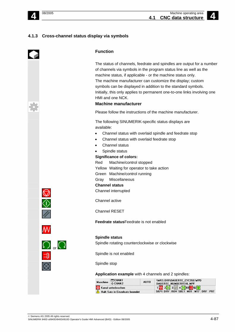
4 08/2005 Machine operating area4.1 CNC data structure
4
© Siemens AG 2005 All rights reserved. SINUMERIK 840D sl/840D/840Di/810D Operator's Guide HMI Advanced (BAD) - Edition 08/2005 4-87
4.1.3 Cross-channel status display via symbols
Function
The status of channels, feedrate and spindles are output for a number of channels via symbols in the program status line as well as the machine status, if applicable - or the machine status only. The machine manufacturer can customize the display; custom symbols can be displayed in addition to the standard symbols. Initially, this only applies to permanent one-to-one links involving one HMI and one NCK.
Machine manufacturer
Please follow the instructions of the machine manufacturer.
The following SINUMERIK-specific status displays are available: • Channel status with overlaid spindle and feedrate stop • Channel status with overlaid feedrate stop • Channel status • Spindle status Significance of colors: Red Machine/control stopped Yellow Waiting for operator to take action Green Machine/control running Gray Miscellaneous
Channel status
Channel interrupted
Channel active
Channel RESET
Feedrate statusFeedrate is not enabled
or
Spindle status Spindle rotating counterclockwise or clockwise
Spindle is not enabled
Spindle stop
Application example with 4 channels and 2 spindles:

4 Machine operating area 08/2005 4.1 CNC data structure
4
© Siemens AG 2005 All rights reserved. 4-88 SINUMERIK 840D sl/840D/840Di/810D Operator's Guide HMI Advanced (BAD) - Edition 08/2005
4.1.4 Two-channel display
Assuming that the following requirements are met, you can display channel information for 2 channels simultaneously with controls for which 2 or more channels have been configured.
Requirements • An M:N assignment is not active • Two or more channels exist • The machine data display is set for 2 channels
Representation Two channels are shown side by side. One of these channels has the focus.
The 1st channel (left pane) is the channel which was explicitly selected in single-pane view This selection can also be made outside the Machine operating area. The right-hand pane displays:
• The associated channel configured in netnames.ini in section [MULTICHANNEL] or, if not available
• The subsequent channel configured in the same group in netnames.ini or, if not available
• The channel with the next highest number.
Assuming that the above conditions are met, two-channel display becomes immediately effective when the Machine operating area is started.
Additional notes
Two-channel display is simply a display method for viewing the channel information. Changes to NC channel data must still be made in the single-pane display. See switchover. As changes to the NC channel data are not entered via two-channel display, no mode-specific softkeys are required if channels in different operating modes are displayed in the left and right panes.
Two-channel view The division into two channel panes results in new supplementary conditions for the information in each channel pane: In two-channel view • It is not possible to make entries in the relevant buffers in "MDI"
and "Teach-in" modes. You have to switch to single-channel view to make entries.
• Traversing movements of the axes are not accepted. • The "program blocks" display is disabled if a part program is being
executed from an external source in one of the displayed channels.For selecting and changing operating modes, please refer to the following chapter.

4 08/2005 Machine operating area4.1 CNC data structure
4
© Siemens AG 2005 All rights reserved. SINUMERIK 840D sl/840D/840Di/810D Operator's Guide HMI Advanced (BAD) - Edition 08/2005 4-89
Single-channel view If "overstore" is active in single-channel view, the overstore function is explicitly exited on switchover to two-channel view, provided this is permitted by the NC. Otherwise, single-channel view is retained.
Channel switchover is effective for the pane which has the focus. If exactly two channels are configured, the channel windows do not switch places; only the focus changes.
Switchover
The M key will only switch between single-channel and two-channel display in the current Machine operating area.
4.1.5 Mode selection, mode change
Function
The defined modes for operating a SINUMERIK control system are
Jog, MDI and Automatic. They are selected via the MCP or by means of softkeys.
Machine manufacturer
Whether the requested mode can be accessed and the manner in which it is accessed can be configured for a specific machine in the PLC program.
Mode change Not all mode changes are permitted. An error message is output if a mode change request is rejected by the system. The error message will indicate the error cause and possibly the remedy.
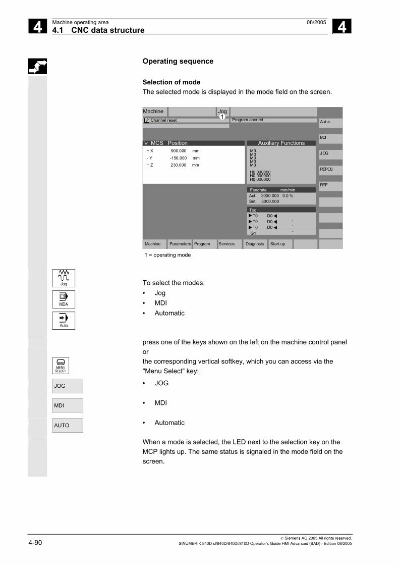
4 Machine operating area 08/2005 4.1 CNC data structure
4
© Siemens AG 2005 All rights reserved. 4-90 SINUMERIK 840D sl/840D/840Di/810D Operator's Guide HMI Advanced (BAD) - Edition 08/2005
Operating sequence
Selection of mode The selected mode is displayed in the mode field on the screen. Machine
Channel reset Program aborted
Jog
MCS Position
+ X 900.000 mm 0.000- Y -156.000 mm 0.000+ Z 230.000 mm 0.000
Auxiliary FunctionsM0
M0
M0
H0.000000H0.000000
H0.000000
M0
M0
+ X 900.000 mm
- Y -156.000 mm
+ Z 230.000 mm
Feedrate mm/minAct. 3000.000 0.0 %Set. 3000.000
Aut o
MDI
JOG
REPOS
REF
ToolT0 D0T0 D0T0 D0
G1
.
.
.
1
Machine Parameters Program Services Diagnosis Start-up
1 = operating mode
Jog
MDA
Auto
To select the modes: • Jog • MDI • Automatic
press one of the keys shown on the left on the machine control panel or the corresponding vertical softkey, which you can access via the "Menu Select" key:
JOG
• JOG
MDI
• MDI
AUTO
• Automatic
When a mode is selected, the LED next to the selection key on the MCP lights up. The same status is signaled in the mode field on the screen.

4 08/2005 Machine operating area4.1 CNC data structure
4
© Siemens AG 2005 All rights reserved. SINUMERIK 840D sl/840D/840Di/810D Operator's Guide HMI Advanced (BAD) - Edition 08/2005 4-91
Additional notes
The main screen of the selected mode appears on the screen.
If a mode change is not possible, please contact your installation
engineer, the machine-tool manufacturer or our service personnel. In many cases, a mode change is enabled for trained personnel only on safety grounds. To provide this type of protection, the control system offers a facility for disabling or enabling mode changes.
/FB/, K1, Description of functions
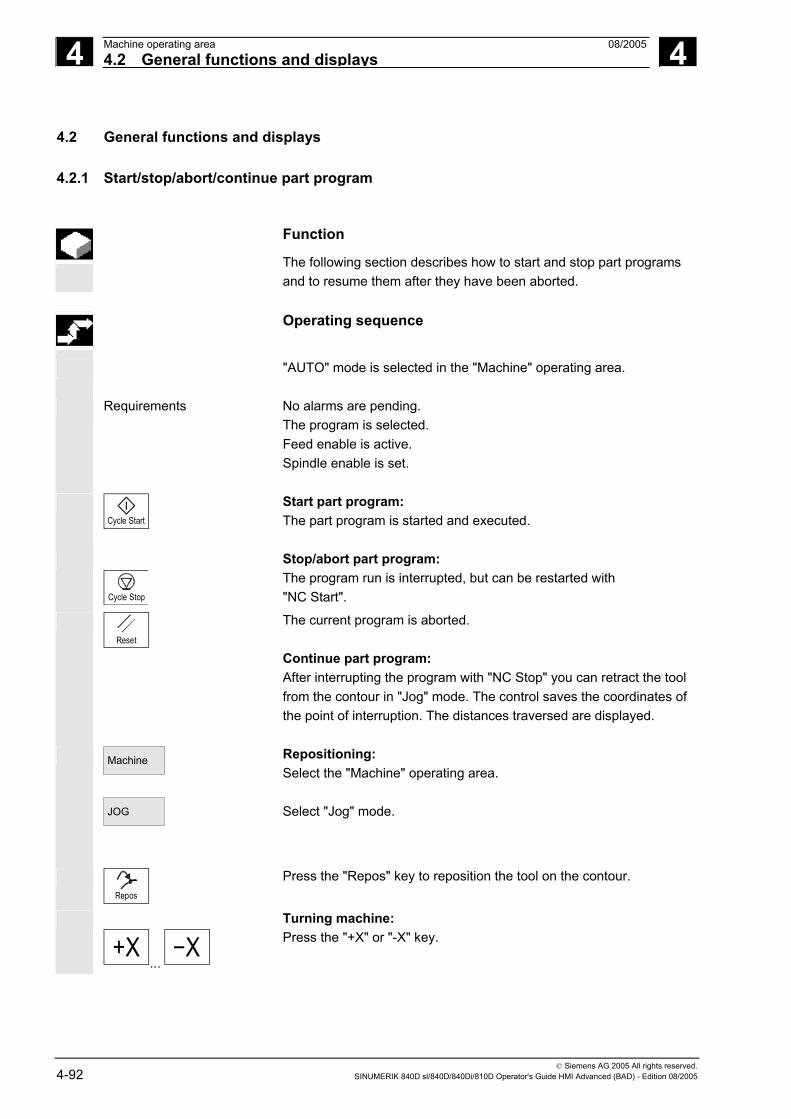
4 Machine operating area 08/2005 4.2 General functions and displays
4
© Siemens AG 2005 All rights reserved. 4-92 SINUMERIK 840D sl/840D/840Di/810D Operator's Guide HMI Advanced (BAD) - Edition 08/2005
4.2 General functions and displays
4.2.1 Start/stop/abort/continue part program
Function
The following section describes how to start and stop part programs and to resume them after they have been aborted.
Operating sequence
"AUTO" mode is selected in the "Machine" operating area.
Requirements No alarms are pending.
The program is selected. Feed enable is active. Spindle enable is set.
Cycle Start
Start part program: The part program is started and executed.
Cycle Stop
Stop/abort part program: The program run is interrupted, but can be restarted with "NC Start".
Reset
The current program is aborted. Continue part program: After interrupting the program with "NC Stop" you can retract the tool from the contour in "Jog" mode. The control saves the coordinates of the point of interruption. The distances traversed are displayed.
Machine
JOG
Repositioning: Select the "Machine" operating area. Select "Jog" mode.
Repos
Press the "Repos" key to reposition the tool on the contour.
+X...
X
Turning machine: Press the "+X" or "-X" key.

4 08/2005 Machine operating area4.2 General functions and displays
4
© Siemens AG 2005 All rights reserved. SINUMERIK 840D sl/840D/840Di/810D Operator's Guide HMI Advanced (BAD) - Edition 08/2005 4-93
X... 9th Axis
Milling machine: Select the axis to be traversed and
... +
then press the "-" or "+" key.
Traverse the axes to the point of interruption.
4.2.2 Display program level
Function
If subprograms are called while a part program is running, the block numbers for the main program and subprograms together with their pass number (P) can be displayed.
Operating sequence
"AUTO" mode is selected in the "Machine" operating area.
When you press the "Program level" softkey, the window headed "Program level" appears instead of the "Current block" window. The softkey labeling changes to "Current block".
During execution of a part program, the block numbers for the main program and subprograms, together with their pass number (P), are displayed in the "Program level" window. The main level is always visible, a nesting depth of up to 12 can be displayed.
Current block
When you press the "Current block" softkey, the "Current block" window containing the program blocks of the current part program is displayed again.

4 Machine operating area 08/2005 4.2 General functions and displays
4
© Siemens AG 2005 All rights reserved. 4-94 SINUMERIK 840D sl/840D/840Di/810D Operator's Guide HMI Advanced (BAD) - Edition 08/2005
4.2.3 Toggle between machine/workpiece coordinate system (MCS/WCS)
Function
The display can be toggled between the machine and workpiece
coordinate systems by means of special key "MCS/WCS" on the MCP or via softkeys (depending on MCP model and user program). The actual position display for the distance-to-go and the corresponding axes change.
Machine axes Machine axes are axes that actually exist on the machine and have been parameterized during installation.
Geometry axes and special axes
These are the axes programmed in the part program. Geometry axes and special axes are offset by the selected work offset relative to the machine axes. Three is the maximum number of Cartesian geometry axes.
Machine (MCS) The machine coordinate system (= MCS) refers to the coordinates of the machine axes, i.e., all machine axes are displayed in the machine coordinate system.
Machine position Repos offset X Y Z Work (WCS) An offset (e.g., work offset, rotation) can be used to set up a
relationship, e.g., with the workpiece clamp. This relationship defines the position of the workpiece coordinate system (= Work) in relation to the machine coordinate system. The workpiece is always represented in a Cartesian coordinate system. All geometry axes and special axes are displayed in the workpiece coordinate system.
Work position Repos offset X1 Y1 Z1
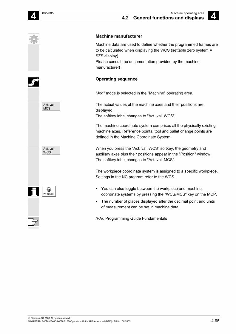
4 08/2005 Machine operating area4.2 General functions and displays
4
© Siemens AG 2005 All rights reserved. SINUMERIK 840D sl/840D/840Di/810D Operator's Guide HMI Advanced (BAD) - Edition 08/2005 4-95
Machine manufacturer
Machine data are used to define whether the programmed frames are to be calculated when displaying the WCS (settable zero system = SZS display). Please consult the documentation provided by the machine manufacturer!
Operating sequence
"Jog" mode is selected in the "Machine" operating area.
Act. val. MCS
The actual values of the machine axes and their positions are displayed. The softkey label changes to "Act. val. WCS".
The machine coordinate system comprises all the physically existing machine axes. Reference points, tool and pallet change points are defined in the Machine Coordinate System.
Act. val. WCS
When you press the "Act. val. WCS" softkey, the geometry and auxiliary axes plus their positions appear in the "Position" window. The softkey label changes to "Act. val. MCS". The workpiece coordinate system is assigned to a specific workpiece. Settings in the NC program refer to the WCS.
WCS MCS
• You can also toggle between the workpiece and machine coordinate systems by pressing the "WCS/MCS" key on the MCP.
• The number of places displayed after the decimal point and units of measurement can be set in machine data.
/PA/, Programming Guide Fundamentals

4 Machine operating area 08/2005 4.2 General functions and displays
4
© Siemens AG 2005 All rights reserved. 4-96 SINUMERIK 840D sl/840D/840Di/810D Operator's Guide HMI Advanced (BAD) - Edition 08/2005
4.2.4 Display axis feedrates
Function
In operating mode "Jog" or "MDI" or "AUTO", you can display the current feedrate, residual path information and the associated override data.
Operating sequence
"Jog" mode is selected in the "Machine" operating area.
Axis feedrate
Press the "Axis feedrate" softkey: • With "Machine" the feed window is displayed with the current
feedrates and distance-to-go information as well as the associated override.
• With "Work" the feed window for the axes taking part in the interpolation is displayed with the current feed and the distance-to-go information with path override; for the remaining axes the current feed and distance-to-go information is displayed with single-axis override.
or
You can use the "Page" keys to display other axes if required.

4 08/2005 Machine operating area4.2 General functions and displays
4
© Siemens AG 2005 All rights reserved. SINUMERIK 840D sl/840D/840Di/810D Operator's Guide HMI Advanced (BAD) - Edition 08/2005 4-97
4.2.5 Display G functions, transformations and swivel data
Function
Active G functions and transformations in the currently active channel can be displayed.
Operating sequence
"AUTO"/"MDI"/"Jog" mode is selected in the "Machine" operating area.
G Fct.+ Transf.
The window "G Functions + Transformations" with the active G functions and transformations is displayed.
or
Using the "Page" keys you can scroll up and down to display other G functions.
Additional notes
Every G group has a fixed location. The group number (no.) and the current G function of the G groups are displayed only if a G function is active.
References /PG/Programming Guide Fundamentals
Swivel data status display
Requirement: The swivel function (CYCLE800) has been set up by the machine manufacturer.
The active swivel data record (orientable toolholder TOOLCARRIER) is displayed concurrently with the transformations.
The following values are displayed:
TCARR = 1 ... n* *n is the maximum number of swivel data items that have been set up (TOOLCARRIER) and are active.
References /PGZ/ Programming Guide Cycles: Chapter “Swiveling”

4 Machine operating area 08/2005 4.2 General functions and displays
4
© Siemens AG 2005 All rights reserved. 4-98 SINUMERIK 840D sl/840D/840Di/810D Operator's Guide HMI Advanced (BAD) - Edition 08/2005
4.2.6 Display auxiliary functions
Function
Auxiliary functions that are active in the selected channel can be displayed.
Operating sequence
"AUTO"/"MDI"/"Jog" mode is selected in the "Machine" operating area.
Display Aux. fct.
The "Auxiliary Functions" window appears on the screen. Up to 5 M functions and 3 H functions can be displayed.
4.2.7 Display modal M functions
Function
Modal M functions remain active until they are deleted or overwritten by another command. M functions are not merely displayed block-by-block, but also remain visible for as long as they are active. M functions are grouped together (in the same way as G functions, for example), but it is not necessary to display every group.
Display the statuses of modal M functions
The statuses of M functions are displayed as follows:
M function active M function retrieved during search, but not yet output to PLC
M function output to PLC but not yet acknowledged (yellow text on black background signifies: Wait)

4 08/2005 Machine operating area4.2 General functions and displays
4
© Siemens AG 2005 All rights reserved. SINUMERIK 840D sl/840D/840Di/810D Operator's Guide HMI Advanced (BAD) - Edition 08/2005 4-99
Window division
5 lines are displayed: 1st line: Standard M functions: M03/M04/M05/M19, M7/M8, M40/M41/M42/M43/M44/M45 2nd line: customized, grouped together M functions 3rd line: customized, grouped together M functions 4th line: non-grouped M functions 5th line: H functions
The lines are oriented toward the actual value positions. A maximum of 5 M functions or 5 H functions can be displayed in each line. Example:
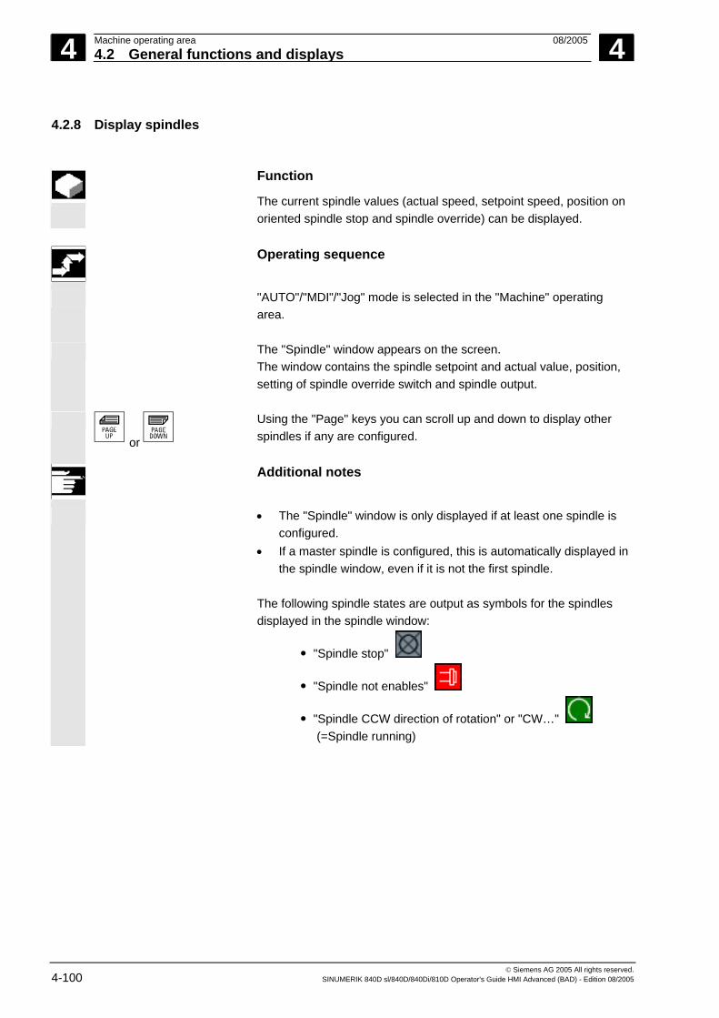
4 Machine operating area 08/2005 4.2 General functions and displays
4
© Siemens AG 2005 All rights reserved. 4-100 SINUMERIK 840D sl/840D/840Di/810D Operator's Guide HMI Advanced (BAD) - Edition 08/2005
4.2.8 Display spindles
Function
The current spindle values (actual speed, setpoint speed, position on oriented spindle stop and spindle override) can be displayed.
Operating sequence
"AUTO"/"MDI"/"Jog" mode is selected in the "Machine" operating
area.
The "Spindle" window appears on the screen. The window contains the spindle setpoint and actual value, position, setting of spindle override switch and spindle output.
or
Using the "Page" keys you can scroll up and down to display other spindles if any are configured.
Additional notes
• The "Spindle" window is only displayed if at least one spindle is
configured. • If a master spindle is configured, this is automatically displayed in
the spindle window, even if it is not the first spindle. The following spindle states are output as symbols for the spindles displayed in the spindle window:
"Spindle stop"
"Spindle not enables"
"Spindle CCW direction of rotation" or "CW…" (=Spindle running)

4 08/2005 Machine operating area4.2 General functions and displays
4
© Siemens AG 2005 All rights reserved. SINUMERIK 840D sl/840D/840Di/810D Operator's Guide HMI Advanced (BAD) - Edition 08/2005 4-101
4.2.9 Handwheel
Function
Using the "Handwheel" function, you can assign an axis to the handwheels and activate them.
Operating sequence
"Jog" mode is selected in the "Machine" operating area.
The "Handwheel" window appears on the screen.
Position the cursor on the handwheel of your choice (1-3).
An axis identifier is suggested in the "Axis" field. All other existing axes can be selected via the "Toggle" key. The settings are accepted immediately and an axis is assigned to each handwheel (1-3).
Every time you press the "Toggle" key in the "Active" field you activate or deactivate enabling of the relevant handwheel. The settings become active immediately.
When you turn the handwheel, the assigned axis traverses by the number of increments that have been set for it (Inc keys).
Machine manufacturer The machine manufacturer is responsible for the design of handwheels. Operation may therefore differ from the explanation above. Please refer to the machine manufacturer's documentation!

4 Machine operating area 08/2005 4.2 General functions and displays
4
© Siemens AG 2005 All rights reserved. 4-102 SINUMERIK 840D sl/840D/840Di/810D Operator's Guide HMI Advanced (BAD) - Edition 08/2005
4.2.10 Status of synchronized actions
Function
Status information (such as "enabled", "disabled", etc.) can be displayed here to support startup of synchronized actions. References: /PGA/, Programming Guide Advanced, Chapter "Synchronized actions"
Operating sequence
"AUTO"/"MDI"/"Jog" mode is selected in the "Machine" operating
area.
Synchron. actions
Press the “ETC” key followed by the "Synchroniz. actions" softkey. The display "Status of synchronized actions" appears.
Search inprogram
Status of synchronized actions
+ X 900.000 mm 0.000- Y -156.000 mm 0.000+ Z 230.000 mm 0.000
+X900.000mm0.000-Y-156.000mm0.000+Z230.000mm0.000
Current block
Status Block no. SPF
N100 X100N200 X200N300 X0
Programmed synchronized actions
N100 Ids=1N129 Ids=2N100 ID=3N1000
enableddisabled
enabled
N111
The display shows: • "Current block" column:
Current section of selected part program: Preceding, current and following block
• "Programmed synchronized actions" column: The programmed synchronized actions are listed block by block with block number (static/modal actions are listed together with the number of the synchronized action)

4 08/2005 Machine operating area4.2 General functions and displays
4
© Siemens AG 2005 All rights reserved. SINUMERIK 840D sl/840D/840Di/810D Operator's Guide HMI Advanced (BAD) - Edition 08/2005 4-103
• "Status" column: • " " (no information given)
the condition is checked in the interpolation cycle. • "disabled"
LOCK was set from the PLC for the synchronized action • "active"
The action is currently being executed. If the instruction part of a programmed synchronized action starts a subprogram/cycle, the current block number of the cycle is additionally displayed in the "Block number SPF" column.
Search in
program
A window opens: Here you must enter the system variable/synchronized action of your choice. The control searches the current or an additionally specified program for synchronized actions which match the current block and synchronized action numbers. If the control finds matching program blocks, the associated condition and instruction parts are also shown on the main screen along with the other data.
Press RECALL to return to the "Automatic" main screen.
4 Machine operating area 08/2005 4.2 General functions and displays
4
© Siemens AG 2005 All rights reserved. 4-104 SINUMERIK 840D sl/840D/840Di/810D Operator's Guide HMI Advanced (BAD) - Edition 08/2005
4.2.11 Preset
Function
Resetting the actual value A new position value is entered for the current axis positions.
Danger
After the actual value has been reset, none of the protection zones or software limit switches are operative! The protection zones and software limit switches are only reactivated following another reference point approach.
The "Preset" function can be used to redefine the control zero in the
machine coordinate system. The preset values act on machine axes. Axes do not move when "Preset" is active.
Machine manufacturer
See machine manufacturer's specifications.
Operating sequence
"Jog" mode is selected in the "Machine" operating area.
Preset
The "Preset" window appears on the screen.
Enter the new actual value, which must in future correspond to the current axis position, for each individual axis. By doing so, you are redefining the control zero in the MCS. When the control zero is redefined, the tool change point, for example, also changes.
Additional notes
Machine manufacturer The "Preset" function can be disabled by means of protection levels (keylock switch position).
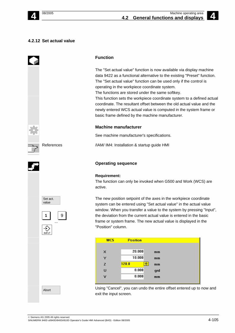
4 08/2005 Machine operating area4.2 General functions and displays
4
© Siemens AG 2005 All rights reserved. SINUMERIK 840D sl/840D/840Di/810D Operator's Guide HMI Advanced (BAD) - Edition 08/2005 4-105
4.2.12 Set actual value
Function
The "Set actual value" function is now available via display machine data 9422 as a functional alternative to the existing "Preset" function. The "Set actual value" function can be used only if the control is operating in the workpiece coordinate system. The functions are stored under the same softkey.
This function sets the workpiece coordinate system to a defined actual coordinate. The resultant offset between the old actual value and the newly entered WCS actual value is computed in the system frame or basic frame defined by the machine manufacturer.
Machine manufacturer
See machine manufacturer's specifications.
References /IAM/ IM4: Installation & startup guide HMI
Operating sequence
Requirement: The function can only be invoked when G500 and Work (WCS) are active.
Set act. value
1...
9
The new position setpoint of the axes in the workpiece coordinate system can be entered using "Set actual value" in the actual value window. When you transfer a value to the system by pressing "Input", the deviation from the current actual value is entered in the basic frame or system frame. The new actual value is displayed in the "Position" column.
Abort
Using "Cancel", you can undo the entire offset entered up to now and exit the input screen.

4 Machine operating area 08/2005 4.2 General functions and displays
4
© Siemens AG 2005 All rights reserved. 4-106 SINUMERIK 840D sl/840D/840Di/810D Operator's Guide HMI Advanced (BAD) - Edition 08/2005
4.2.13 Inch ↔ Metric switchover
Function
The control can work with imperial inches or metric units of measurement. You can switch between imperial inches and metric units of measurement in the "Machine" operating area. The control converts the values accordingly. In order to convert the channel-specific values in the machine date, display machine data 9014 must be set to 1.
Machine manufacturer
The switchover is only possible if: • The corresponding machine data have been set. • All channels are in the Reset state. • Axes are not traversing with JOG, DRF or PLC control. • Constant grinding wheel peripheral speed (GWPS) is not active. Display machine data 9011 is used to define the display resolution for the imperial units of measurement (inches).
Actions such as mode change or part program start are disabled for the duration of the switchover.
Operating sequence
"AUTO"/"MDI"/"Jog" mode is selected in the "Machine" operating area.
Switch to metric
Press the “ETC” key followed by the "Switch to metric" softkey.
When the measuring system is changed, all length-related parameters are automatically converted to the new measuring system from the perspective of the user. If the switchover cannot be performed, this is indicated by a message on the user interface.
References /FB/, G2 Section "Metric/inch measuring system"
4 08/2005 Machine operating area4.2 General functions and displays
4
© Siemens AG 2005 All rights reserved. SINUMERIK 840D sl/840D/840Di/810D Operator's Guide HMI Advanced (BAD) - Edition 08/2005 4-107
Warning
If several NCUs are linked by an NCU link, then the switchover affects all linked NCUs. If the switchover requirements are not met in respect of one of the linked NCUs, no switchover will take place on any of the NCUs. It is assumed that in the case of an NCU link, interpolations should take place across all the linked NCUs, the results of which will only be correct if the same measuring system is used in each case.
References /FB/, B3, Distributed systems

4 Machine operating area 08/2005 4.3 Reference point approach
4
© Siemens AG 2005 All rights reserved. 4-108 SINUMERIK 840D sl/840D/840Di/810D Operator's Guide HMI Advanced (BAD) - Edition 08/2005
4.3 Reference point approach
Function
The "Ref Point" function ensures that the control and machine are synchronized after Power ON. Before a reference point approach can be carried out, the axes must be located at positions (if necessary, traversed to these positions using the axis keys/handwheel) from where the machine reference point can be approached without collision. If reference point approach is called from a part program, all axes can be traversed simultaneously.
Reference point approach can only be performed by machine axes. The actual value display does not match the real position of the axes when the control is switched on.
Caution • If the axes are not safely positioned, you must traverse them to
safe positions in "Jog" or "MDI" mode. • You must follow the axis motions directly on the machine! • Ignore the actual value display until the axes have been
referenced! • The software limit switches are not active!
Operating sequence
"Jog" or "MDI" is selected in the "Machine" operating area. The channel for reference point approach is selected.
Ref Point
The "Ref Point" machine function is selected.
+X...
X
Turning machine: Press the "Axis" keys.
X
... 9th Axis
Milling machine: Select the axis to be traversed and
+
then press the "+" or "-" key.
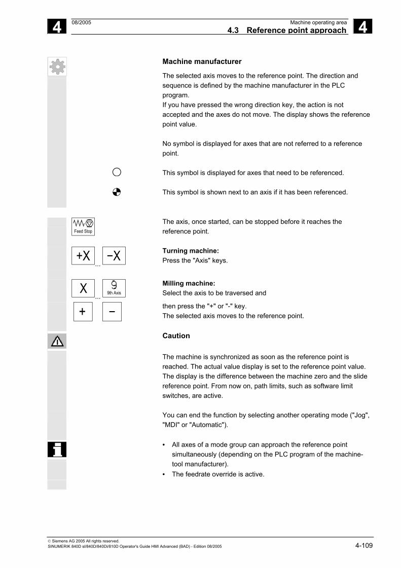
4 08/2005 Machine operating area4.3 Reference point approach
4
© Siemens AG 2005 All rights reserved. SINUMERIK 840D sl/840D/840Di/810D Operator's Guide HMI Advanced (BAD) - Edition 08/2005 4-109
Machine manufacturer
The selected axis moves to the reference point. The direction and sequence is defined by the machine manufacturer in the PLC program. If you have pressed the wrong direction key, the action is not accepted and the axes do not move. The display shows the reference point value. No symbol is displayed for axes that are not referred to a reference point. This symbol is displayed for axes that need to be referenced. This symbol is shown next to an axis if it has been referenced.
Feed Stop
The axis, once started, can be stopped before it reaches the reference point.
+X...
X
Turning machine: Press the "Axis" keys.
X
... 9th Axis
Milling machine: Select the axis to be traversed and
+
then press the "+" or "-" key. The selected axis moves to the reference point.
Caution
The machine is synchronized as soon as the reference point is reached. The actual value display is set to the reference point value. The display is the difference between the machine zero and the slide reference point. From now on, path limits, such as software limit switches, are active.
You can end the function by selecting another operating mode ("Jog", "MDI" or "Automatic").
• All axes of a mode group can approach the reference point simultaneously (depending on the PLC program of the machine-tool manufacturer).
• The feedrate override is active.

4 Machine operating area 08/2005 4.3 Reference point approach
4
© Siemens AG 2005 All rights reserved. 4-110 SINUMERIK 840D sl/840D/840Di/810D Operator's Guide HMI Advanced (BAD) - Edition 08/2005
Machine manufacturer
Your machine manufacturer will instruct you how to select axes if you intend to enter more than nine.
Additional notes
The sequence in which axes must be referenced can be defined by the machine-tool manufacturer. The NC cannot be started in Automatic mode until all axes with a defined reference point (see machine data MD) have actually reached this point.

4 08/2005 Machine operating area4.4 Jog mode
4
© Siemens AG 2005 All rights reserved. SINUMERIK 840D sl/840D/840Di/810D Operator's Guide HMI Advanced (BAD) - Edition 08/2005 4-111
4.4 Jog mode
4.4.1 Function and main screen
Function
In manual mode you can: 1. Synchronize the control measuring system with the machine
(reference point approach), 2. Set up the machine, i.e., activate manually-controlled motions on
the machine using the keys and handwheels provided on the machine control panel.
3. Activate manually-controlled motions on the machine using the keys and handwheels provided on the machine control panel while a part program is being interrupted.
The following "Jog" main screen is displayed when you press the "Menu Select" key
Jog
followed by the "Jog" key.
The "Jog" main screen contains values relating to position, feedrate, spindle and tool.
MachineChannel reset G. fct. +
transf.
Spindles
Displayaux. funct.
ZoomAct. val.
Axisfeedrate
WCS
Preset Handwheel INC
Program abortedJog
MCS Position Repos offset
+X900.000mm0.000-Y-156.000mm0.000+Z230.000mm0.000
Master spindle S1Act. + 0.000 rpm
Set 0.000 rpm
Pos 0.000 deg.
0.000 %
Power [%]
-X 90.646 mm 0.000
+Y 113.385 mm 0.000
+Z 109.131 mm 0.000
+V 0.000 mm 0.000
Feedrate mm/minAct. 7000.000 0.000%Set 7000.000
Tool
Preselected tool:
G0 G91
Act. val.
Scratch

4 Machine operating area 08/2005 4.4 Jog mode
4
© Siemens AG 2005 All rights reserved. 4-112 SINUMERIK 840D sl/840D/840Di/810D Operator's Guide HMI Advanced (BAD) - Edition 08/2005
Explanations relating to the Jog main screen
Work (WCS) + X2* Y2* Z2*
Displays the addresses of the existing axes with the machine axis identifier (MCS) or with the geometry axis identifier (WCS). (see also Section "Toggle between machine/workpiece coordinate system (MCS/WCS)")
Machine manufacturer
Machine data are used to define whether the programmed frames are to be calculated when displaying the WCS (settable zero system = SZS display). Please consult the documentation provided by the machine manufacturer!
• If the axis identifier can only be displayed in an abbreviated form, it
is replaced by the character *.
• If you traverse an axis in the positive (+) or negative (-) direction, a plus or minus sign is shown in the relevant field. The axis is in position if neither + nor - is displayed in the position display.
Position
0.0 0.1 –0.1 1.1 0.0
The actual position of each configured axis in the machine (MCS) or work (WCS) is displayed in these fields. The sign is only displayed for negative values.
Repos. offset 0.0 0.1 –0.1 1.1 0.0
If the axes are traversed in the "Program interrupted" status "in "Jog" mode, the path traversed by every axis with respect to the point of interruption is displayed in the REPOS offset.

4 08/2005 Machine operating area4.4 Jog mode
4
© Siemens AG 2005 All rights reserved. SINUMERIK 840D sl/840D/840Di/810D Operator's Guide HMI Advanced (BAD) - Edition 08/2005 4-113
Spindle
Spindle window (if spindle is available) The window contains the setpoint and actual values for the spindle speed, the spindle position, setting of the spindle override switch and spindle output.
Nibbling The spindle window is replaced by a nibble window if the "Nibbling" technology option is set. The active function, if any, appears at the top left in the window header: • PON Punching ON • SON Nibbling ON • SPOF Punching/nibbling OFF
Feedrate
Feedrate window Display of the setpoint and actual value of the feedrate as well as the position of the feedrate override switch (in %). The actual setpoint to be traversed is dependent on the override switch. When G00 (rapid traverse movement) is programmed, the rapid override value is displayed.
If the feedrate is not enabled, the symbol "Feedrate not enabled" is output in the feedrate window. (FST is not indicated in the "program control display" field).
Tool Tool window Display of active tool offset (e.g., D1), tool currently in use (T no.), preselected tool (on milling machines) plus currently active motion commands (e.g., G01, SPLINE, ...) or tool radius compensation not active (e.g., G40).
The following values are displayed: • The "Path section" and "Stroke rate" are displayed in reverse video
if you have programmed the automatic block division with "Path section length" or "Number of path sections".
• The "delay time" can only be displayed if you have set "Punching with delay time".
Zoom
act. val.
Increases the size of the actual-value display.

4 Machine operating area 08/2005 4.4 Jog mode
4
© Siemens AG 2005 All rights reserved. 4-114 SINUMERIK 840D sl/840D/840Di/810D Operator's Guide HMI Advanced (BAD) - Edition 08/2005
4.4.2 Traverse the axes
Traverse rate The initial settings for traverse rate and feed mode are stored in
setting data for JOG mode. Traverse rates are defined by the machine manufacturer. The default setting for the feedrate is mm/min. See operating area "Parameters/Setting data/Jog data".
Operating sequence
"Jog" mode is selected in the "Machine" operating area.
Traverse the axes Using the "Inc" (increment) function, manually traverse the selected axis in preset increments in the appropriate direction by pressing an "Axis key" repeatedly:
VAR
• [.] Variable increment can be set via the "Inc" softkey (see Subsection 3.2.5).
1...
10000
• [1], [10], ..., [10000] fixed increment
+X
... X
Turning machine: Press the "Axis" keys. If necessary, set the rate with the override selector.
Rapid
If you press "Rapid traverse override" at the same time, you can traverse the axis in rapid traverse mode.
X
... 9th Axis
Milling machine: Select the axis to be traversed and
+
then press the "-" or "+" key. Feedrate and rapid traverse override switches can be operative.
One or several axes can be selected at the same time (depending on PLC program).

4 08/2005 Machine operating area4.4 Jog mode
4
© Siemens AG 2005 All rights reserved. SINUMERIK 840D sl/840D/840Di/810D Operator's Guide HMI Advanced (BAD) - Edition 08/2005 4-115
Additional notes
• When the control is switched on, the axes can be traversed right up to the limits of the machine as the reference points have not yet been approached and the axes referenced. Emergency limit switches might be triggered as a result.
• The software limit switches and the working area limitation are not yet operative!
• The feedrate enable must be set (FST display must not light up in the program control display).
Machine manufacturer If no advantage is to be gained from moving several axes simultaneously, the machine manufacturer must implement the appropriate interlock in the PLC program.
4.4.3 Inc: Increment
Function
The "Inc" (increment) function can be used to enter a settable
increment value for Inc variable traversing.
Operating sequence
"Jog" mode is selected in the "Machine" operating area.
INC
The "Increment" window appears on the screen.
Enter the desired increment.
VAR
Press this key in manual mode together with the "Axis" key to traverse the selected axis in the appropriate direction in accordance with the increments set above (see also Section "Traversing axes"). Increment keys with preset increment sizes are temporarily inoperative.

4 Machine operating area 08/2005 4.4 Jog mode
4
© Siemens AG 2005 All rights reserved. 4-116 SINUMERIK 840D sl/840D/840Di/810D Operator's Guide HMI Advanced (BAD) - Edition 08/2005
4.4.4 Repos (repositioning)
Function
After a program interruption in Automatic mode (e.g., to take a
measurement on the workpiece or to compensate tool wear values or after tool breakage), you can retract the tool manually from the contour after selecting "Jog" mode. In such cases, the control stores the coordinates of the point of interruption and displays the path distances traversed by the axes in "Jog" mode as a "Repos" offset in the actual value window. "Repos" offsets can be displayed in the machine coordinate system (MCS) or workpiece coordinate system (WCS).
Operating sequence
"Jog" mode is selected in the "Machine" operating area. The axes have been moved away from the point of interruption.
Repos
Select machine function "Repos".
+X...
X
Turning machine: Press the "Axis" keys.
X
... 9th Axis
Milling machine: Select the axis to be traversed and
+
then press the "-" or "+" key.
It is not possible to overtravel the point of interruption. The feedrate override switch is active.
Warning The rapid traverse override key is active. Non-compensated Repos offsets are compensated with programmed feedrate and linear interpolation on switchover to Automatic mode and selection of NC Start.

4 08/2005 Machine operating area4.4 Jog mode
4
© Siemens AG 2005 All rights reserved. SINUMERIK 840D sl/840D/840Di/810D Operator's Guide HMI Advanced (BAD) - Edition 08/2005 4-117
4.4.5 SI (Safety Integrated): User agreement
Function
If the option "user agreement" is installed on the NC, you must enable or disable the function depending on the keylock switch position in "Approach reference point" mode.
User agreement can only be granted if keylock switch position 3 or higher applies in respect of the access rights.
The displayed values always refer to the machine (MCS).
Operating sequence
"Jog Ref" mode is selected in the "Machine" operating area.
The channel to be referenced is already selected.
User agreement
Press the "User agreement" softkey. The "Confirm Machine Positions" window is opened. The machine axes in the MCS are displayed, together with the current position and a checkbox for activating/deactivating user agreement.
Machine axes that do not need to be referenced are displayed in reverse video with their current position, but without a checkbox.
Position the cursor on the desired machine axis.
Activate or deactivate user agreement for the selected machine axis via the "Toggle" key.
Check whether the axis is referenced. If not, error message "Please reference axis first" is output. User agreement cannot be activated for the axis until it has been referenced.

4 Machine operating area 08/2005 4.4 Jog mode
4
© Siemens AG 2005 All rights reserved. 4-118 SINUMERIK 840D sl/840D/840Di/810D Operator's Guide HMI Advanced (BAD) - Edition 08/2005
Additional notes
References
The user agreement function is only provided if user enabling is required for at least one axis of the channel. /FBSI/, Description of functions SINUMERIK Safety Integrated.
4.4.6 Scratching
Notes
Depending on the machine data configuration described in /IAM/, IM4, two scratching modes are possible.
Function
You can determine the work offset by "scratching" the workpiece, taking an (active) tool and, if necessary, the basic offset into account. A window is provided for the "Scratching" function.
Scratching
Operating sequence
1. Press the "Scratch" softkey: The softkey will only be made available if you are entitled to use it (machine data).
• The active plane is displayed and can be altered. • The active NV is displayed and can be changed. • The active tool is displayed. No tool is displayed if none is active
(message).

4 08/2005 Machine operating area4.4 Jog mode
4
© Siemens AG 2005 All rights reserved. SINUMERIK 840D sl/840D/840Di/810D Operator's Guide HMI Advanced (BAD) - Edition 08/2005 4-119
Meanings of columns in the "Scratch" window: • "Offset": Current value of offset to be determined. The coarse
offset is displayed; the fine offset is taken into account and remains valid.
• "Position setpoint": Input of subsequent position setpoint for scratched edge.
• "Approach direction": selection fields for positive/negative approach direction
2. Use the cursor to select the first axis to be traversed in the "Scratch" display. Selected axes are automatically marked in parallel in the actual value window.
X
+
3. Traverse the axis up to the workpiece, enter the chosen position setpoint (e.g., "0") and press the "Input" key. The offset is then calculated. Repeat the process for other axes.
OK
4. Press "OK" to transfer all values to the selected WO. The offset is always calculated in relation to the current work (WCS).
5. To ensure that allowance is made in the tool geometry (or the tool base dimension), position the cursor in the "Approach direction" column on the axis to be altered and press the "Toggle key" so that the desired approach direction is visible.

4 Machine operating area 08/2005 4.4 Jog mode
4
© Siemens AG 2005 All rights reserved. 4-120 SINUMERIK 840D sl/840D/840Di/810D Operator's Guide HMI Advanced (BAD) - Edition 08/2005
Example 1
Y
X
Approachdirection
Set "+R" with toggle key.
The figure below shows how system frame $P_SETFR is displayed as
the line "Set work offset".
Toolholder If a toolholder is active in the present system, it is displayed in the G
function window as "TCARR=n" (n = 1 or 2).

4 08/2005 Machine operating area4.4 Jog mode
4
© Siemens AG 2005 All rights reserved. SINUMERIK 840D sl/840D/840Di/810D Operator's Guide HMI Advanced (BAD) - Edition 08/2005 4-121
Swivel adjustment
With scratching in a swiveled level with rotary axes without encoder, the "Swivel adjustment" vertical softkey appears in addition to the toolholder information in the "Transformations + G functions" window. Upon activation, the NC updates the toolholder data after scratching. If this operation is successful, "Swivel adjustment completed" is output in the message line. If an error occurs, e.g. the channel is in "active" state or the connection with the NC is disrupted, "Swiveling: adjustment not possible" is displayed in the message line.
4.4.7 Display system frames
If system frames have been activated via MD, they can be displayed
via the Parameters operating area, Active WO + Override, Details.
The following assignment is applicable:
$P_SETFR System frame for actual value setting, scratching $P_EXTFR System frame for work offset external $P_PARTFR System frame for TCARR and PAROT $P_TOOLFR System frame for TOROT and TOFRAME $P_WPFR System frame for workpieces $P_CYCFR System frame for cycles

4 Machine operating area 08/2005 4.4 Jog mode
4
© Siemens AG 2005 All rights reserved. 4-122 SINUMERIK 840D sl/840D/840Di/810D Operator's Guide HMI Advanced (BAD) - Edition 08/2005
Both the offset set via frames (coarse and fine) and the rotation and mirroring defined there are displayed. Display is according to the position in the frame chain. You can choose between the system frames and basic frames by scrolling through the desired section.
The following figure shows an example screen layout:
Protection levels for system frames
The machine manufacturer or user can assign the appropriate protection levels for system frames as well as for individual functions and data areas using display machine data. Default: These machine data are assigned protection level 7 by default during the standard startup procedure. This means that access is granted to all these data areas and functions when the keylock switch is in the 0 position. If required, these protection levels can be changed by the machine manufacturer or user. Protection levels 0 to 3 can also be entered.

4 08/2005 Machine operating area4.4 Jog mode
4
© Siemens AG 2005 All rights reserved. SINUMERIK 840D sl/840D/840Di/810D Operator's Guide HMI Advanced (BAD) - Edition 08/2005 4-123
Protection levels are available for the following system frames: System frame MD
numberName/description
ToolFrame 9183 $MM_USER_CLASS_WRITE_TOOLFRAME Protection level write toolholder
PartFrame 9184 $MM_USER_CLASS_WRITE_PARTFRAME Protection level write tool reference point
WPFrame 9185 $MM_USER_CLASS_WRITE_WPFRAME Protection level write workpiece reference point
CYCFrame 9186 $MM_USER_CLASS_WRITE_CYCFRAME Protection level write cycle frame
TraFrame 9187 $MM_USER_CLASS_WRITE_TRAFRAME Protection level write transformation frame
ExtFrame 9188 $MM_USER_CLASS_WRITE_EXTFRAME Protection level write external WO
SetFrame 9210 $MM_USER_CLASS_WRITE_ZOA Protection level write settable WO
Note:
In the case of SetFrame, the same machine data applies as for settable work offsets, as this practically does constitute a work offset. This also applies to SetFrame fine offset, in respect of which no user intervention is permitted. For fine offset of the settable work offsets, there is a dedicated machine data: 9203 $MM_USER_CLASS_WRITE_FINE. The associated protection level is generally lower than for coarse offset.
Further information:
Set zero point corresponds to $P_SETFR Ext. WO frame corresponds to $P_EXTFR Toolholder corresponds to $P_PARTFR Tool reference corresponds to $P_TOOLFR Workpiece ref. corresponds to $P_WPFR Cycles corresponds to $P_CYCFR
See also Subsection 4.4.6

4 Machine operating area 08/2005 4.5 MDI mode
4
© Siemens AG 2005 All rights reserved. 4-124 SINUMERIK 840D sl/840D/840Di/810D Operator's Guide HMI Advanced (BAD) - Edition 08/2005
4.5 MDI mode
4.5.1 Function and main screen
Function
In "MDI" (Manual Data Input) mode, you can write part programs block by block and execute them. You can transfer the required motions as single part program blocks to the control using the operator panel. The control processes the entered program blocks when you press the "NC Start" key.
Caution The same safety interlocks must be applied as used in fully automatic operation. The same preconditions must be fulfilled as for fully automatic operation.
The automatic functions (traverse blocks) are active in "MDI" mode.
Teach-in
The functions associated with "Jog" are active in submode "Teach-in" and can be accessed via an MCP key. You can therefore create and store a program in the input and manual modes by alternating between "MDI" and "Teach-in". You can use the editor to edit the program blocks in the MDI window. You can view blocks that have already been executed by paging upwards. Blocks that have already been executed can only be edited in the Reset state. Further blocks can be added with "Input". Blocks can only be input and executed with the channel in the "Channel Reset" or "Channel interrupted" state. The program created in MDI mode can be saved in the part program directory (MPF.DIR).

4 08/2005 Machine operating area4.5 MDI mode
4
© Siemens AG 2005 All rights reserved. SINUMERIK 840D sl/840D/840Di/810D Operator's Guide HMI Advanced (BAD) - Edition 08/2005 4-125
MDIprogram
Workingmemory
Clipboard
programs
Main memory
MDI (automatic function)
Teach in (Jog functions)
Parts
The "MDI" main screen contains values relating to position, feedrate, spindle and tool as well as the contents of the MDI buffer.
Channel active G fct.
transf.
Spindles
Auxiliaryfunctions
Axisfeedrate
Act. val.WCS
HandwheelProgramcontrol
Editorfunction
Program running
MCS Position Dist.-to-go
+ X 900.000 mm 0.000- Y -156.000 mm 0.000+ Z 230.000 mm 0.000
Master spindle S1
Feedrate mm/minMDA- programAct. 7000.000 0.000 %Set 7000.000
N51 Y0 H55=99Y120 F7000
Tool
G0 G91
+X900.000mm0.000-Y-156.000mm0.000+Z230.000mm0.000
-X 90.301 mm 9.699+Y 80.081 mm 9.919
+Z 0.000 mm 0.000
+V 0.000 mm 0.000
Act. + 0.000 rpm
Set 0.000 rpmPos 0.000 deg.
0.000 %
Power [%]
preselected tool:
Machine MDI
DeleteMDI bufferMDIfile fct.
Zoomact. val.
CHAN1 \SYF.DIROSTORE1.SYF
Programsequence
Explanation of "MDI" main screen
As with the Jog main screen, the actual value window, spindle window, feedrate window and tool window are output.
Save MDI prog.
The "Store MDI program" softkey copies the MDI program to the clipboard.
Editor functions
Press this softkey to access functions via vertical softkeys that will facilitate the editing process: Overwrite, Mark, Copy, Paste, Delete, Find, Find Next, Position.
MDI file fct.
You can save the MDI buffer contents or copy a part program to the MDI buffer for editing in MDI or Teach-in.

4 Machine operating area 08/2005 4.5 MDI mode
4
© Siemens AG 2005 All rights reserved. 4-126 SINUMERIK 840D sl/840D/840Di/810D Operator's Guide HMI Advanced (BAD) - Edition 08/2005
Vertical softkeys
Like the Jog main screen, the MDI main screen contains softkeys "G Fct.+Transf.", "Auxiliary functions" and "Spindle" (if spindle is configured).
Delete MDI buffer
The contents of the MDI program in the NC are erased.
4.5.2 Save program, file function
Function
You can use the MDI file function to • Save the contents of the MDI program to a file or • Read a part program to the MDI clipboard to edit it in MDI or
Teach-in mode.
Operating sequence
"MDI" mode is selected in the "Machine" operating area.
MDI file function
The program overview of "Part programs" is opened, a dialog window also appears.
The new file is then displayed in the program overview.
Read in MDI
The program overview of part programs is displayed. From the list of programs, select the one that you wish to copy to the MDI buffer with "Read in MDI". This can now be edited accordingly.
Save MDI prog.
The system will ask you to enter a name for the file to be saved to the MDI clipboard. The program is saved/stored as a part program (MPF) under the name you have entered in the part programs directory.

4 08/2005 Machine operating area4.5 MDI mode
4
© Siemens AG 2005 All rights reserved. SINUMERIK 840D sl/840D/840Di/810D Operator's Guide HMI Advanced (BAD) - Edition 08/2005 4-127
4.5.3 Teach-in
Function
With the "Teach-in" function, part programs (main programs and subprograms) for motion sequences or simple workpieces can be created, edited and executed by approaching and then storing positions in combination with the "MDI" function. There are two possible methods of writing programs with "Teach-in" and "MDI": 1. Manual positioning 2. Manual input of coordinates and additional information
Both entry of blocks (input, delete, insert) and automatic insertion by manual approach of positions are possible only at points that have not yet been executed.
1. Manual positioning
Operating sequence
"MDI" mode is selected in the "Machine" operating area.
Teach In
Submode "Teach-in" is selected. After selection of the function, the cursor is located in the first blank line of the "Teach-in program" window.
+X...
X
Turning machine: Press the "Axis" keys.
X
... 9th Axis
Milling machine: Select the axis to be traversed.
9th Axis ...
+
then press the "-" or "+" key. The axis name and the path being traversed are displayed continuously on the screen in the "Teach-in program" window. The axis identifier and axis positions are transferred to the MDI program as values referred to the workpiece coordinate system.

4 Machine operating area 08/2005 4.5 MDI mode
4
© Siemens AG 2005 All rights reserved. 4-128 SINUMERIK 840D sl/840D/840Di/810D Operator's Guide HMI Advanced (BAD) - Edition 08/2005
Save position values: Enter the additional functions (e.g. feedrates, auxiliary functions, etc.)
in the program (if permitted).
Using MDI file functions, you can save the MDI program in the "Part programs" directory (MPF.DIR).
Using the edit functions of the vertical softkeys, you can execute the following program block functions: Overwrite, Select, Copy, Paste, Delete, Find, Find Next and Position.
MDA Cycle Start
When you switch to "MDI" mode and press "NC Start", the corresponding traversing motions and additional function entries are executed as program blocks. While the program is being processed, the blocks traversed by the NC are displayed in the "Current block" window.
2. Manual input of coordinates
Operating sequence
"MDI" mode is selected in the "Machine" operating area.
Save position values/additional functions:
Transfer the coordinates of the traversing positions plus any additional functions (preparatory functions, auxiliary functions, etc.) to the program by entering them in the "MDI program" window.
Additional notes
• Any change to the work offset will cause the axis to carry out compensating movements when you press NC Start.
• In the case of G64, the end point response will differ when the part program is executed in "Automatic" mode.
• All the G functions can be used. • When using special kinematics or robots, the positions of the STAT
machine and rotary axis TU are displayed in addition to the positions in the workpiece coordinate system.

4 08/2005 Machine operating area4.6 Automatic mode
4
© Siemens AG 2005 All rights reserved. SINUMERIK 840D sl/840D/840Di/810D Operator's Guide HMI Advanced (BAD) - Edition 08/2005 4-129
4.6 Automatic mode
4.6.1 Function and main screen
You can execute part programs fully automatically in "Automatic"
mode, i.e., this mode is normally used for machining parts.
Preconditions The following conditions must be fulfilled before you can execute part programs: • You have already synchronized the control measuring system with
the machine (i.e. "approached" reference points). • You have already downloaded the associated part program to the
control. • You have checked or entered the necessary offset values, such as
work offsets or tool offsets. • The required safety interlocks are already active.
The "Automatic" main screen contains values relating to position, feedrate, spindle and tool as well as the block currently being processed or program pointer.
MachineChannel reset G fct.
transf.
Spindles
Auxiliaryfunc.
Axisfeedrate
Zoomact. val.
Act. val.WCS
ProgramlevelProgramoverview
Programcontrol
DRFoffset
Over-store
Blocksearch
Program aborted
Auto
MCS Position Dist.-to-go
+ X 900.000 mm 0.000- Y -156.000 mm 0.000+ Z 230.000 mm 0.000
Master spindle S1
Feedrate mm/minCurrent blockAct. 7000.000 0.000 %Set 7000.000
N51 Y0 H55=99Y120 F7000
TEST.MPF
+X900.000mm0.000-Y-156.000mm0.000+Z230.000mm0.000
-X 53.761 mm -25.761
+Y 30.000 mm 0.000
+Z 112.704 mm -112.704
+ 0.000 mm 0.000
Act. + 0.000 rpm
Set 0.000 rpm
Pos 0.000 deg.
0.000 %
Power [%]
Tool
preselected tool:
G0 G91
Handwheel
Programblocks
\WKS.DIR\TEST.MPF
Explanation of main
screen Like the Jog main screen, the Automatic main screen contains actual value, spindle, feedrate and tool windows.

4 Machine operating area 08/2005 4.6 Automatic mode
4
© Siemens AG 2005 All rights reserved. 4-130 SINUMERIK 840D sl/840D/840Di/810D Operator's Guide HMI Advanced (BAD) - Edition 08/2005
Horizontal softkeys
Program
overview The workpiece or program overview is displayed. In this area, it is possible to select programs for execution. The memory space available on the hard disk and in the NCU is displayed in the footer.
Vertical softkeys
Current
block The "Current block" window is also displayed. The current block is highlighted while the program is running. The name of the program to which the blocks on the screen belong is output in the window header.
Program level
When you press the "Program level" softkey, the window headed "Program level" appears instead of the "Current block" window. The program nesting depth (P = number of passes) is displayed.
Program level or
Current block
In program control, it is possible to toggle between the "Program level" and "Current block" displays.
Program blocks
Seven program blocks of the current program are displayed together with the current position in the part program. Unlike with the "Current block" function, the program created by the programmer is displayed.
Additional notes
The other softkeys are described in the sections below.

4 08/2005 Machine operating area4.6 Automatic mode
4
© Siemens AG 2005 All rights reserved. SINUMERIK 840D sl/840D/840Di/810D Operator's Guide HMI Advanced (BAD) - Edition 08/2005 4-131
4.6.2 Program overview
Function
After selection of a workpiece or program overview, individual workpieces or programs can be enabled or disabled for execution.
Operating sequence
"AUTO" mode is selected in the "Machine" operating area.
The appropriate channel is selected. The channel is in reset state. The workpiece/program to be selected is in the memory.
Programoverview
An overview of all workpiece directories/programs that exist is displayed.
Position the cursor on the desired workpiece/program.
Vertical softkeys
Select the workpiece/program for execution:
Selection
The name of the selected workpiece is displayed on the screen in the "Program name" field at the top. The program is also loaded and selected for processing.
Alter enable
The selected workpiece/program is enabled (X) or disabled (no "X"). A selection can only be made when the workpiece/program is enabled.
Explanation of other softkeys: All existing programs of a particular type are displayed via the
horizontal softkeys:
Work- pieces
Display of all existing workpiece directories
Part programs
Display of all existing part programs
Sub- routines
Display of all existing subprograms

4 Machine operating area 08/2005 4.6 Automatic mode
4
© Siemens AG 2005 All rights reserved. 4-132 SINUMERIK 840D sl/840D/840Di/810D Operator's Guide HMI Advanced (BAD) - Edition 08/2005
Standard cycles
Display of all existing standard cycles
User cycles
Display of all existing user cycles
Manu-facturer
Display of all existing manufacturer cycles
4.6.3 Load and unload the workpiece/part program
Function
Workpieces and part programs can be stored in the NC working memory ("Load") and erased from this memory again ("Unload") after they have been executed. In this way, it is possible to prevent the NC working memory from becoming unnecessarily overloaded because programs that are no longer required can be erased immediately.
Operating sequence
The "Machine" operating area is selected.
Programoverview
The "Program overview" opens. The vertical softkey bar changes.
Position the cursor in the directory tree on the workpiece/part program that you wish to load.
Download HD->NC
The selected workpiece/part program is loaded from the hard disk into the memory of the NC.
It is erased from the hard disk.
Enabling of
If the enable command (X) is set, the workpiece can be machined.
Upload NC->HD
The highlighted workpiece/part program is loaded from the NC memory to the hard disk.
The workpiece/program is erased from the NC memory.
Execute fr. hard disk
If a program requires more memory than the NC can provide for execution, then it can be executed from the hard disk without loading it completely into the NC.

4 08/2005 Machine operating area4.6 Automatic mode
4
© Siemens AG 2005 All rights reserved. SINUMERIK 840D sl/840D/840Di/810D Operator's Guide HMI Advanced (BAD) - Edition 08/2005 4-133
Additional notes
Workpieces/part programs that have been loaded into the NC memory
are marked with ("X") in the "Loaded" column in the workpiece/program overview.
4.6.4 Log: Program loading list
Function
Error list: Display of previously loaded programs if errors have occurred during loading.
Operating sequence
The "Machine" operating area is selected.
Program
overview The "Program overview" opens. The softkey bars change.
Log
Press the "Log" softkey. The "Job log for program overview" window is opened.

4 Machine operating area 08/2005 4.6 Automatic mode
4
© Siemens AG 2005 All rights reserved. 4-134 SINUMERIK 840D sl/840D/840Di/810D Operator's Guide HMI Advanced (BAD) - Edition 08/2005
4.6.5 Execution from hard disk
Function
If a program requires more memory than the NC can provide for execution, then it can be loaded continuously from the hard disk.
Operating sequence
The "Machine" operating area is selected.
Program
overview The "Program overview" opens. The vertical softkey bar changes. Select the program you wish to execute with the cursor (enable (x) must be set).
Execute fr. hard disk
The highlighted program is loaded continuously to the NC working memory during execution.
Cycle Start
Press "NC Start".
The program remains stored on the hard disk while the "Execute from hard disk" function is in progress.
External programs
The "External programs" window is opened. The "Status" field indicates what percentage of the program has been loaded from the hard disk.
Additional notes
Programs which are executed from the hard disk are marked with "EXT" in the program overview. The identifier "EXT" does not disappear until a different part program is selected in this channel. If the programs are executed from the hard disk, the 3-block display (softkey program run) or the larger multi-block display (softkey program blocks) can be selected during automatic operation. The setting made applies for the single block or NC stop status.

4 08/2005 Machine operating area4.6 Automatic mode
4
© Siemens AG 2005 All rights reserved. SINUMERIK 840D sl/840D/840Di/810D Operator's Guide HMI Advanced (BAD) - Edition 08/2005 4-135
4.6.6 Access an external network drive
Function
With the SINDNC software, you can link your control to external network drives or other computers. This makes it possible, for example, to execute part programs from other computers.
Requirement: • The SINDNC software is installed. • The computer or drive which you want to link up to is
accessible/enabled. • A connection to the computer/drive has been established. • The softkeys for selecting the drive/computer link have been
configured in the machine data, see /IAM/ IM4, Installation and startup guide, IM4, Section: Data transmission
• Separate display machine data which define the access rights to external drives exist for the Machine and Program operating areas/IAM/ IM4, Installation and startup guide HMI
Operating sequence
Machine
Programoverview
You can access the softkeys (configured) for the external drive or computer in the Machine operating area via the "Program overview" softkey and the "ETC." key. Horizontal softkeys 1 to 4 are reserved for external execution. The vertical softkey bar changes.
Drive F: or
R4711
When you press a softkey, e.g., "Drive F:" or "R4711" the Explorer appears on the screen with the data of the external drive, e.g. "Drive F" or of computer "R4711".
Execute fr. hard disk
Select the program that you want to execute with the cursor and then press the "Execute from hard disk" softkey.
Cycle Start
The program starts when you press "NC Start".

4 Machine operating area 08/2005 4.6 Automatic mode
4
© Siemens AG 2005 All rights reserved. 4-136 SINUMERIK 840D sl/840D/840Di/810D Operator's Guide HMI Advanced (BAD) - Edition 08/2005
Softkey arrangement Press the "Program overview" softkey in the Machine (and Program) operating area to access the first three softkeys configured for external network drives. If you have configured four softkeys, the fourth one is displayed in the More bar when you press the "ETC" key. If no softkeys are configured for external drives, the "Standard cycles", "User cycles" and "Manufacturer cycles" softkeys can be found in the appropriate places in the horizontal softkey bar.
Program call from the part program: EXTCALL
It is possible to access files on network drives from a part program using the EXTCALL command. The programmer can set the source directory in the part program in setting data SD 42700: EXT_PROG_PATH, then specify the file name of the subprogram to be loaded in the EXTCALL command.
The following supplementary conditions must be taken into account with EXTCALL calls: • With EXTCALL, you can only call files with the MPF or SPF
extension from a network drive. • DOS naming conventions must be used for the files and paths:
Max. 25 characters for the name, 3 characters for the file extension.
• A program unit is found on a network drive with the EXTCALL command if - The search path in SD 42700: EXT_PROG_PATH points to
the network drive or a directory contained on the network drive. The program must be stored directly on that level, no subdirectories are searched.
- The correct location of the program is specified in the EXTCALL call itself by means of a fully qualified path that can also point to a subdirectory of the network drive.
- The search path is not restricted by means of SD 42700: EXT_PROG_PATH.
References For further information about the EXTCALL command, please refer to:
/PGA/ Programming Guide Advanced, Chapter 2. /FB/, K1 Description of functions "Execution from external source"

4 08/2005 Machine operating area4.6 Automatic mode
4
© Siemens AG 2005 All rights reserved. SINUMERIK 840D sl/840D/840Di/810D Operator's Guide HMI Advanced (BAD) - Edition 08/2005 4-137
4.6.7 Program editing
Function
As soon as a syntax error in the part program is detected by the control, program execution is interrupted and the syntax error is displayed in the alarm line. You can switch to the program editor and monitor the program run in a full-screen display. If an error occurs (Stop state), you can edit the program in the program editor.
Operating sequence
"AUTO" mode is selected in the "Machine" operating area.
It is not possible to overtravel the point of interruption. The feedrate
override switch is active. The program status is "Stopped" or "Reset".
Correct program
When you press this softkey, the correction editor is displayed, the softkey bars change and the softkey "Edit" is highlighted. If an error occurs, the faulty block is highlighted and can be corrected.
Using editor functions "Overwrite", "Highlight block", "Insert block", "Go To..." and "Find...", you can edit the program in the compensation block editor.
Program level + or
Program level -
You can toggle between program levels using these softkeys. Press "Level -" to view the program in which the faulty routine is called. You can return to the program to be edited by pressing "Level +". This is only possible if the NC has a compensation block.
Cycle Start
After you have corrected the error, you can continue the program run by pressing "NC Start".
4 Machine operating area 08/2005 4.6 Automatic mode
4
© Siemens AG 2005 All rights reserved. 4-138 SINUMERIK 840D sl/840D/840Di/810D Operator's Guide HMI Advanced (BAD) - Edition 08/2005
• NC Stop status: Only program lines that have not yet been executed can be edited.
• Reset status: All program lines can be edited.
Note:
You cannot use the "Program editing" function if you are executing a program from the hard disk.
Additional notes
If the error cannot be corrected in the "Channel aborted" state, an appropriate message is displayed when the "Compensation block" softkey is pressed. In this case, program execution must be aborted with "NC Reset". The part program can then be edited under Programming.

4 08/2005 Machine operating area4.6 Automatic mode
4
© Siemens AG 2005 All rights reserved. SINUMERIK 840D sl/840D/840Di/810D Operator's Guide HMI Advanced (BAD) - Edition 08/2005 4-139
4.6.8 Set block search/search target
Function
The block search function allows you to run the part program forward until you reach the block you require. Four types of search are available: 1. With calculation on contour:
During block searches with calculation, the same calculations are performed as in normal program control. The complete target block is then executed in the same way as with normal program execution.
2. With calculation at block end point: During block search with calculation, the same calculations are performed as in normal program control. The interpolation mode valid in the target block is then applied to approach its end point or the next programmed position.
3. Without calculation: No calculations are made during block search. The values stored in the control remain the same as they were before the block search.
4. Multi-channel block search with calculation This block search is called SERUPRO in "Program test mode". Single-channel applications are supported for parallel interaction with other functions. No axis movements are executed during the block search; however, all auxiliary functions are output to the PLC. The NC will start the selected program in Program test mode automatically. If the NC reaches the specified target block in the current channel, it stops at the beginning of the target block and deselects Program test mode again. The auxiliary functions of the target block are not output.
The search target can be determined: • Through direct positioning • By specifying a block number, a label, a program name or any
character string.
References For further information about block search, please refer to: /FB/ K1, BAG, Channel, Program control

4 Machine operating area 08/2005 4.6 Automatic mode
4
© Siemens AG 2005 All rights reserved. 4-140 SINUMERIK 840D sl/840D/840Di/810D Operator's Guide HMI Advanced (BAD) - Edition 08/2005
Operating sequence
"AUTO" mode is selected in the "Machine" operating area. The channel is in reset status The program in which the block search is to be performed is selected.
Block search
Calls up the "Search position" function. Position the cursor on the target block. The block search is started when you press one of the following three softkeys:
Calculate contour
Block search start with calculation on contour
• When you press "NC Start", a compensatory axis motion is initiated between the current actual position and the new position determined by the block search.
• The current position is defined by the program status (all axis positions, active auxiliary functions) at the beginning of the selected block, i.e., after a block search the control stops at the final position of the NC block before the target of the search.
Calculate
block end
Block search start with calculation at block end point
Without calculation
Block search start without calculation
• If the target block is found, this block becomes the current block. HMI announces "Search target found" and displays the target block in the current block display.
• Action blocks (e.g., collection of auxiliary functions) are output after NC Start.
• Alarm 10208 is output to indicate that operator interventions such as Overstore or Mode Change after JOG are permissible.
• When you press NC Start, the program is started and the process resumes at this target block.
Reset
Block search can be aborted with Reset.

4 08/2005 Machine operating area4.6 Automatic mode
4
© Siemens AG 2005 All rights reserved. SINUMERIK 840D sl/840D/840Di/810D Operator's Guide HMI Advanced (BAD) - Edition 08/2005 4-141
Define search target in program editor: Search
position The currently selected program level is displayed.
Position the cursor bar on a target block of your choice in the part program.
Program level + or
Program level -
You can toggle between program levels using these softkeys if necessary.
Define search target in search pointer: Search
pointer Once the "search pointer" softkey has been pressed, a screen with the program pointer is displayed.
It contains input fields for program name, search type (block number, text, ...) and search target (content). The cursor is positioned in the input field for the "search type".
0...
5
You must enter your selected search type for the search target in the "Type" input field.
Information about the available search types is displayed in the user response line.
The following search types can be entered:
Search type (= jump to ...) Value in search type field End of program 0 Block number 1 Jump label 2 Any character string 3 Program name 4 Line number 5 Different search types can be specified for different program levels.
A
... Z
You can enter your chosen search target (according to search type) in the "Search target" field.
0...
9
You can enter the corresponding number of program passes in the "P" field (pass counter).
Preassign search target as last program interruption point: Interrup.
point The search pointer is assigned the data of the last program interruption point.

4 Machine operating area 08/2005 4.6 Automatic mode
4
© Siemens AG 2005 All rights reserved. 4-142 SINUMERIK 840D sl/840D/840Di/810D Operator's Guide HMI Advanced (BAD) - Edition 08/2005
4.6.9 Accelerated external block search
Function
The block search function allows you to run the part program forward until you reach the block you require. You can use the "External without calc." softkey in the "Search position" and "Search pointer" menus to start an accelerated block search in programs that are executed from an external device (local hard disk or network drive). The search target can be determined: • By directly positioning the cursor on the target block, or • Specifying a block or line number
Block search sequence: Only those programs and program parts which are needed in order to reach the specified search target and to continue program execution are transferred to the NC. This applies to the following: • “Execution from external source” • Execution of EXTCALL instructions
Example:
The following search targets are entered in the Block search menu:
Search target 1 “Level1”: MAIN1.MPF "Line": 8
Search target 2 “Level2”: SUBPRG2.SPF "Line": 4000
Search target 3 “Level3”: SUBPRG3.SPF "Line": 2300

4 08/2005 Machine operating area4.6 Automatic mode
4
© Siemens AG 2005 All rights reserved. SINUMERIK 840D sl/840D/840Di/810D Operator's Guide HMI Advanced (BAD) - Edition 08/2005 4-143
Programs MAIN1.MPF 1 G90 2 X100 Y200 F2000 3 EXTCALL "SUBPRG1" 4 X200 Y400 5 EXTCALL "SUBPRG2" 6 EXTCALL "SUBPRG3" 7 X0 Y0
Search target 1 8 EXTCALL "SUBPRG2" 9 X50 10 M30
SUBPRG2.SPF 1 X200 Y300 2 X400 Y500 3 EXTCALL "SUBPRG3"
. .
Search target 2 4000 EXTCALL "SUBPRG3" . .
5000 M17
SUBPRG3.SPF 1 X20 Y50 2 .
. Search target 3 2300 X100 Y450
.
. 5000 M17
A distinction is made between the following two cases for block
search: 1. The main program MAIN1.MPF is in the NC, the subprograms
SUBPRG1.SPF to SUBPRG3.SPF are executed from an external source.
2. The main program MAIN1.MPF and the subprograms SUBPRG1.SPF to SUBPRG3.SPF are executed from an external source.
Case 1
• Search target 1: The NC does not consider the EXTCALL calls in lines 3, 5, and 6 of the main program MAIN1.MPF and jumps to the search target Line 8.
• Search target 2: The NC jumps to the search target at line 4000 of external subprogram SUBPRG2.SPF; the previous statements in the external program are skipped.
• Search target 3: The NC jumps to the search target at line 2300 of external subprogram SUBPRG3.SPF; the previous statements are skipped, and the search stops.
On NC Start, the subprogram SUBPRG3.SPF is processed starting at the target line.
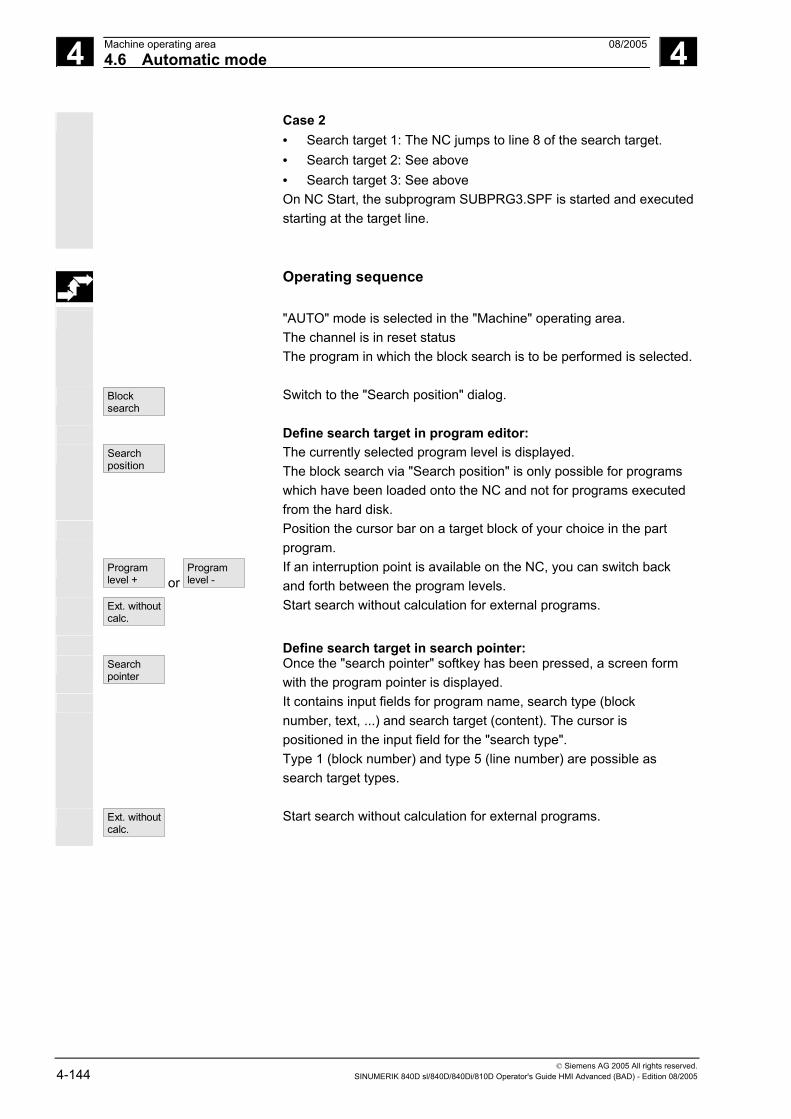
4 Machine operating area 08/2005 4.6 Automatic mode
4
© Siemens AG 2005 All rights reserved. 4-144 SINUMERIK 840D sl/840D/840Di/810D Operator's Guide HMI Advanced (BAD) - Edition 08/2005
Case 2 • Search target 1: The NC jumps to line 8 of the search target. • Search target 2: See above • Search target 3: See above On NC Start, the subprogram SUBPRG3.SPF is started and executed starting at the target line.
Operating sequence
"AUTO" mode is selected in the "Machine" operating area. The channel is in reset status The program in which the block search is to be performed is selected.
Block search
Switch to the "Search position" dialog.
Define search target in program editor: Search
position The currently selected program level is displayed. The block search via "Search position" is only possible for programs which have been loaded onto the NC and not for programs executed from the hard disk.
Position the cursor bar on a target block of your choice in the part program.
Program level + or
Program level -
If an interruption point is available on the NC, you can switch back and forth between the program levels.
Ext. without calc.
Start search without calculation for external programs.
Define search target in search pointer: Search
pointer Once the "search pointer" softkey has been pressed, a screen form with the program pointer is displayed.
It contains input fields for program name, search type (block number, text, ...) and search target (content). The cursor is positioned in the input field for the "search type". Type 1 (block number) and type 5 (line number) are possible as search target types.
Ext. without calc.
Start search without calculation for external programs.

4 08/2005 Machine operating area4.6 Automatic mode
4
© Siemens AG 2005 All rights reserved. SINUMERIK 840D sl/840D/840Di/810D Operator's Guide HMI Advanced (BAD) - Edition 08/2005 4-145
4.6.10 Block search in Program test mode, multi-channel
Function
The NC is operated in Program test mode for this block search, so that interactions between channel and synchronous actions and between multiple channels are possible within an NCU. The "Block search in Program test mode" enables a program advance up to the desired point of the part program with the following functions: During "Block search in Program test mode", the NC outputs all auxiliary functions to the PLC and the part program commands for channel coordination (WAITE, WAITM, WAITMC, Axis replacement, Write variables, etc.) are carried out by the NC.
• This means that the PLC is updated during this block search and • Machining operations involving multiple channels are executed
correctly within the block search. You can select the function via the "Prog. test Contour" softkey in the "Search position" and "Search pointer" menus.
You can define the search target by • Directly positioning the cursor on the target block, or • Using the input fields "Program name", "Search type" and "Search
target".
Operating sequence
Requirement: • "AUTO" is selected as operating mode. • All channels are in the Reset state. • The program in which the block search is to be performed is
selected. The channel in which the target block is searched for or the program
pointer set is the target channel. Other channels are started according to the setting in the "machine.ini" file.
Block search
Switches to the "Search position" dialog.

4 Machine operating area 08/2005 4.6 Automatic mode
4
© Siemens AG 2005 All rights reserved. 4-146 SINUMERIK 840D sl/840D/840Di/810D Operator's Guide HMI Advanced (BAD) - Edition 08/2005
Define search target in program editor: Search
position The currently selected program level is displayed.
Position the cursor bar on a target block of your choice in the part program.
Program level + or
Program level -
You can toggle between program levels using these softkeys if necessary.
Prog. test
contour Start of search in Program test mode. A dialog message appears as soon as all the channels involved in the current search have exited Program test mode. This message indicates that Repos offsets may, depending on the particular part program, have been produced in the channels involved during the block search and will be retracted by the NC through interpolation the next time it starts. You must acknowledge this message. The repositioning offsets that occur may be traversed manually in JOG mode before continuing program processing with the "NC Start" key at the program position reached in the block search.
Define search target in search pointer: Search
pointer Once the "search pointer" softkey has been pressed, a screen with the program pointer is displayed.
This contains input fields for program name, search type (block number, text, ...) and search target (content). The cursor is positioned in the input field for the "search type".
Prog. test contour
Start of search in Program test mode.
A dialog message appears as soon as all the channels involved in the current search have exited Program test mode, see "Search target in program editor mode" above. Any repositioning offsets (in the individual channels) can be retracted in sequence via manually controlled traversing movements in JOG mode, before program processing is continued via NC Start at the point in the program reached by the block search.
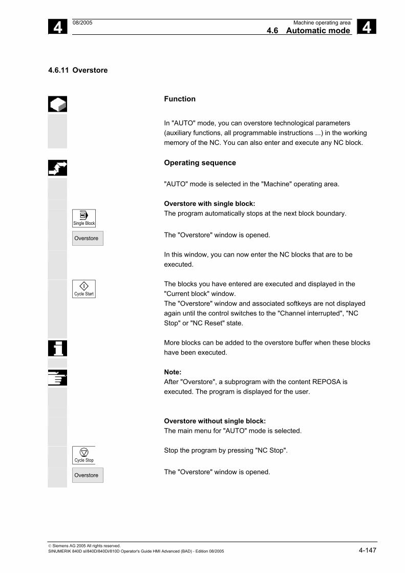
4 08/2005 Machine operating area4.6 Automatic mode
4
© Siemens AG 2005 All rights reserved. SINUMERIK 840D sl/840D/840Di/810D Operator's Guide HMI Advanced (BAD) - Edition 08/2005 4-147
4.6.11 Overstore
Function
In "AUTO" mode, you can overstore technological parameters (auxiliary functions, all programmable instructions ...) in the working memory of the NC. You can also enter and execute any NC block.
Operating sequence
"AUTO" mode is selected in the "Machine" operating area.
Overstore with single block:
Single Block
The program automatically stops at the next block boundary.
Overstore
The "Overstore" window is opened.
In this window, you can now enter the NC blocks that are to be executed.
Cycle Start
The blocks you have entered are executed and displayed in the "Current block" window. The "Overstore" window and associated softkeys are not displayed again until the control switches to the "Channel interrupted", "NC Stop" or "NC Reset" state.
More blocks can be added to the overstore buffer when these blocks have been executed.
Note: After "Overstore", a subprogram with the content REPOSA is executed. The program is displayed for the user.
Overstore without single block:
The main menu for "AUTO" mode is selected.
Cycle Stop
Stop the program by pressing "NC Stop".
Overstore
The "Overstore" window is opened.

4 Machine operating area 08/2005 4.6 Automatic mode
4
© Siemens AG 2005 All rights reserved. 4-148 SINUMERIK 840D sl/840D/840Di/810D Operator's Guide HMI Advanced (BAD) - Edition 08/2005
In this window, you can now enter the NC blocks that are to be executed.
Cycle Start
The blocks you have entered are executed, the "Current block" window is opened and the softkeys disappear. The "Overstore" window and associated softkeys are not displayed again until the control switches to the "Channel interrupted", "NC Stop" or "NC Reset" state.
More blocks can be added (to the overstore buffer) when these blocks have been executed.
Additional notes
• You can close the window and exit the Overstore function by pressing the "Recall" key. You have now exited the Overstore function.
• You cannot change operating modes until you have deselected "Overstore" with the "Recall" key.
• The program that was selected before Overstore is now resumed in "AUTO" mode when you press "NC Start" again.
• Overstore does not alter the programs stored in the part program memory.

4 08/2005 Machine operating area4.6 Automatic mode
4
© Siemens AG 2005 All rights reserved. SINUMERIK 840D sl/840D/840Di/810D Operator's Guide HMI Advanced (BAD) - Edition 08/2005 4-149
4.6.12 Program control
Function
You can use this function to change a program sequence in "AUTO" and "MDI" modes. The following program control functions can be activated or deactivated: DRY Dry run feedrate ROV Rapid traverse override M01 Programmed stop 1 MFct* Programmed stop 2 DRF DRF selection PRT Program test SBL1 Single block with STOP after each machine function SBL2 Single block with STOP after each block SBL3 Stop in cycle MFct* The M function defined in the machine data is displayed. • “Skip blocks” softkey: You can activate up to 10 skip levels in
respect of SKP skip blocks. See machine manufacturer's specifications.
• "Block display" softkey: Block display modes during program execution: Either all blocks are displayed or only motion blocks.
The display is dependent on the machine data of the operator panel front in which access authorization can be set.
References For further information, please refer to Section 2.5, under “Program control display” /FB/, A2, Various interface signals, Chapter 4, or /FB/ K1, BAG, Channel, Program control
DRY Program control with DRY When you select the DRY function "dry run feedrate" in "Automatic" mode, the feedrate entered in setting data SD 42100: DRY_RUN_FEED is applied in the program instead of the programmed feedrate.
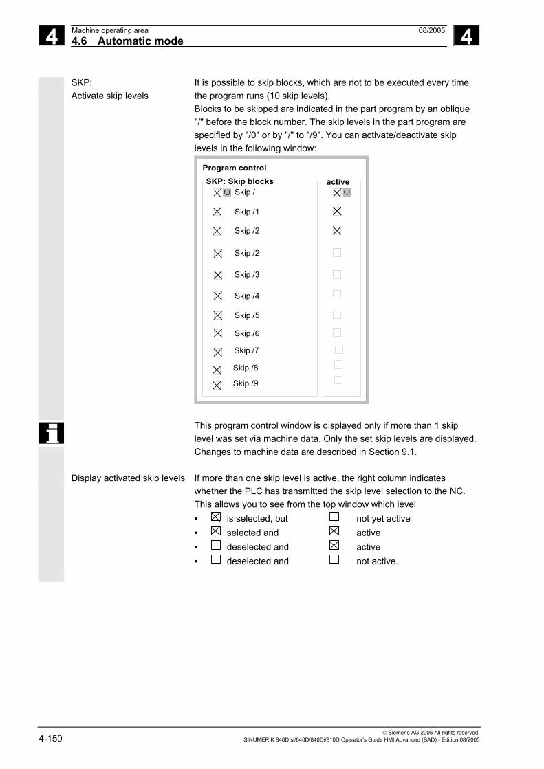
4 Machine operating area 08/2005 4.6 Automatic mode
4
© Siemens AG 2005 All rights reserved. 4-150 SINUMERIK 840D sl/840D/840Di/810D Operator's Guide HMI Advanced (BAD) - Edition 08/2005
SKP: Activate skip levels
It is possible to skip blocks, which are not to be executed every time the program runs (10 skip levels). Blocks to be skipped are indicated in the part program by an oblique "/" before the block number. The skip levels in the part program are specified by "/0" or by "/" to "/9". You can activate/deactivate skip levels in the following window:
Program control
Skip /
Skip /1
Skip /2
Skip /2
Skip /3
Skip /4
Skip /5
Skip /6
Skip /7
SKP: Skip blocks active
Skip /8
Skip /9
This program control window is displayed only if more than 1 skip level was set via machine data. Only the set skip levels are displayed.Changes to machine data are described in Section 9.1.
Display activated skip levels If more than one skip level is active, the right column indicates whether the PLC has transmitted the skip level selection to the NC. This allows you to see from the top window which level • is selected, but not yet active • selected and active • deselected and active • deselected and not active.

4 08/2005 Machine operating area4.6 Automatic mode
4
© Siemens AG 2005 All rights reserved. SINUMERIK 840D sl/840D/840Di/810D Operator's Guide HMI Advanced (BAD) - Edition 08/2005 4-151
Operating sequence
"AUTO" or "MDI" mode is selected in the "Machine" operating area.
Programcontrol
Press the "Program control" horizontal softkey.
Another window pane, "Program control", appears on the main screen. The softkey bars change and the softkeys of the skip blocks and block display appear in the vertical menu.
Each actuation of the "toggle key" activates or deactivates the selected program control function.
Skip blocks The block display appears in an extended "program control" window pane and can be selected with the "Block display" vertical softkey.
Skip blocks
Press the "Skip blocks" vertical softkey.
The "Skip blocks" vertical softkey is only displayed if more than 1 skip level was set in MD 9423: MA_MAX_SKP_LEVEL. The levels to be skipped can only be changed when the control is in the Stop/Reset state.
Place the cursor at the required position.
Each press of the "Toggle key" activates or deactivates the selected skip level in the "Program control" window.
Additional notes
The entries influence the program control display (see Section 2.5). The program control display is output irrespective of the selected menu.
References For further information about how to program skip levels, please see: /PG/, Programming Guide Fundamentals

4 Machine operating area 08/2005 4.6 Automatic mode
4
© Siemens AG 2005 All rights reserved. 4-152 SINUMERIK 840D sl/840D/840Di/810D Operator's Guide HMI Advanced (BAD) - Edition 08/2005
Block display during
program execution
Block display during program execution appears in an extended "Program control" window pane and can be selected with the "Block display" vertical softkey.
Block display
Press the "Block display" vertical softkey.
Program execution modes
A separate "program control" window pane with the previous block display appears on the main screen. You can select the following while the program is running: Block display during program execution Display all blocks Display traversing blocks only
Current block The last current block is shown in the block display. If you want to display all current blocks, you can use the selection menu to choose the desired block.
M Fct* When this function is active, program execution on the NC is interrupted on request by the PLC at blocks in which the additional *associated M function* is programmed for a conditional stop 2. The M Fct* number displayed here can be changed to the desired value in the Startup operating area under Machine Data/Channel MD by selecting the machine data corresponding to the M function. The number stored in this machine data is then displayed. The value of this auxiliary M function number must match the programmed stop 2.
Additional notes
Blocks which are too long for the display window (approx. 65 characters) are truncated and the truncated code is replaced by "...".

4 08/2005 Machine operating area4.6 Automatic mode
4
© Siemens AG 2005 All rights reserved. SINUMERIK 840D sl/840D/840Di/810D Operator's Guide HMI Advanced (BAD) - Edition 08/2005 4-153
4.6.13 DRF offset
Function
In the Basic coordinate system, the DRF offset (differential resolver function) affects the geometry and special axes. However, the handwheel assignment must be made in respect of the machine axis (e.g., activate handwheel via NC/PLC interface signals DB31, ... DBX4.0 – 2) to which the geometry or special axis is mapped.
Power ON/Power OFF The DRF offset can be switched on and off for specific channels by means of the "Program control" function. It remains stored until • Power ON is performed for all axes • DRFOF (selection of DRF via part program) • PRESETON (modification of the actual value through Preset)
Alter DRF You can alter the DRF offset by traversing the appropriate machine axis using the handwheel (the actual value display does not change).
Operating sequence
"AUTO" mode is selected in the "Machine" operating area. The standard axis assignment is defined.
Handwheel
Enter the desired handwheel or select via the MCP.
INC
or VAR
Enter the desired increment or select via the MCP.
DRF offset
The "DRF offset" window is displayed. Traverse the required axes using the handwheel.
Using the same operating sequence, you can also return the DRF offset to the value "0".
■

4 Machine operating area 08/2005 4.6 Automatic mode
4
© Siemens AG 2005 All rights reserved. 4-154 SINUMERIK 840D sl/840D/840Di/810D Operator's Guide HMI Advanced (BAD) - Edition 08/2005
Notes

5 08/2005 Parameters operating area 5
© Siemens AG 2005 All rights reserved. SINUMERIK 840D sl/840D/840Di/810D Operator's Guide HMI Advanced (BAD) - Edition 08/2005 5-155
Parameters operating area 5.1 Tool data .................................................................................................................5-157
5.1.1 Tool offset structure ................................................................................................5-157 5.1.2 Tool types and tool parameters ..............................................................................5-157
5.2 Tool offset................................................................................................................5-172 5.2.1 Tool offset function and main screen ......................................................................5-172 5.2.2 New tool ..................................................................................................................5-174 5.2.3 Display tool..............................................................................................................5-175 5.2.4 Delete tool ...............................................................................................................5-176 5.2.5 New cutting edge ....................................................................................................5-177 5.2.6 Delete cutting edge .................................................................................................5-178 5.2.7 Determine tool offsets .............................................................................................5-178 5.2.8 Make active tool offset operative immediately ........................................................5-179
5.3 Tool management ...................................................................................................5-180 5.3.1 Basic tool management functions ...........................................................................5-181 5.3.2 Display/edit tool data...............................................................................................5-189 5.3.3 Change in the significance/representation of tool wear values...............................5-193 5.3.4 Grinding parameters, expansion.............................................................................5-196 5.3.5 Load ........................................................................................................................5-198 5.3.6 Unload.....................................................................................................................5-202 5.3.7 Relocation ...............................................................................................................5-204 5.3.8 Tool master data in the tool catalog........................................................................5-205 5.3.9 Tool offset data in the tool cabinet ..........................................................................5-208 5.3.10 Batch processing of tools ........................................................................................5-211
5.4 R parameters (arithmetic parameters) ....................................................................5-219
5.5 Setting data .............................................................................................................5-220 5.5.1 Working area limitation............................................................................................5-220 5.5.2 Jog data...................................................................................................................5-221 5.5.3 Spindle data ............................................................................................................5-222 5.5.4 Dry run feedrate for DRY run ..................................................................................5-223 5.5.5 Starting angle for thread cutting..............................................................................5-224 5.5.6 Miscellaneous setting data......................................................................................5-225 5.5.7 Protection zones .....................................................................................................5-226 5.5.8 Electronic gear ........................................................................................................5-227
5.6 Work offset ..............................................................................................................5-228 5.6.1 Function...................................................................................................................5-228 5.6.2 Edit the settable work offset (G54 ...)......................................................................5-230 5.6.3 Global work offset/frame .........................................................................................5-230 5.6.4 Display active settable work offset ..........................................................................5-233 5.6.5 Display active programmable work offset ...............................................................5-234 5.6.6 Display active external work offset..........................................................................5-235 5.6.7 Display the sum of the active work offsets..............................................................5-235 5.6.8 Immediately activate work offset and basic frame ..................................................5-236

5 Parameters operating area 08/2005
5
© Siemens AG 2005 All rights reserved. 5-156 SINUMERIK 840D sl/840D/840Di/810D Operator's Guide HMI Advanced (BAD) - Edition 08/2005
5.6.9 Actual-value display: Settable zero system, SZS....................................................5-236
5.7 Define user data ......................................................................................................5-237 5.7.1 Define variables (GUD, PUD, LUD) ........................................................................5-237 5.7.2 Edit/find user data....................................................................................................5-238 5.7.3 Activate user data (GUD) ........................................................................................5-240
5.8 Display system variables.........................................................................................5-242 5.8.1 Create variable views ..............................................................................................5-243 5.8.2 Manage variable views............................................................................................5-245 5.8.3 Log system variables...............................................................................................5-246

5 08/2005 Parameters operating area5.1 Tool data
5
© Siemens AG 2005 All rights reserved. SINUMERIK 840D sl/840D/840Di/810D Operator's Guide HMI Advanced (BAD) - Edition 08/2005 5-157
5.1 Tool data
5.1.1 Tool offset structure
A tool is selected in the program with the T function. Numbers T0 to
T32000 can be assigned to tools. Each tool can have up to 9 cutting edges: D1-D9. D1 to D9 activates the tool offset of a cutting edge for the active tool. The tool length compensation is applied with the first traversing motion (linear or polynomial interpolation) of the axis. A tool radius compensation is activated by programming of G41/42 in the active plane (G17, 18, 19) and in a program block with G0 or G1.
Tool wear Allowances for changes in the active tool shape can be made in the tool length (tool parameters 12-14) and tool radius (tool parameters 15-20).
Tool offset with flat D numbers
The so-called "flat D numbers" can be activated by means of NC machine data. This means that tool management is no longer available. The D number range increases to 1 - 32000. A D number can be assigned only once for each tool, i.e., each D number represents precisely one tool offset data record.
5.1.2 Tool types and tool parameters
Entries T No. Tool number
D No. Cutting edge number Every data field (offset memory) that can be called with a D number contains not only the geometric information for the tool but also further entries, i.e., the tool type (drill, milling cutter, turning tools with cutting edge position, etc.).

5 Parameters operating area 08/2005 5.1 Tool data
5
© Siemens AG 2005 All rights reserved. 5-158 SINUMERIK 840D sl/840D/840Di/810D Operator's Guide HMI Advanced (BAD) - Edition 08/2005
Tool types Tool type classification: • Group type 1xx (milling cutters): 100 Milling cutter to CLDATA 110 Ball-end cylindrical die-sinking cutter 111 Ball-end tapered die-sinking cutter 120 End mill (without corner rounding) 121 End mill (with corner rounding) 130 Angle head cutter (without corner rounding) 131 Angle head cutter (with corner rounding) 140 Facing tool 145 Thread cutter 150 Side mill 151 Saw 155 Bevel cutter 156 Bevel cutter with rounding 157 Tapered die-sinking cutter 160 Drill and thread milling cutter
Required offset values for a milling cutter
F
Effect
G17:
G18:
Length 1 in ZRadius in X/YLength 1 in YRadius in Z/X
Length1 in XRadius in Y/ZG19:
Wear valuesaccording torequirement
Other values must be set to zero
Entries intool parameters
DP3
DP6
Length 1
Radius
DP1 1xy
F - Toolholder reference point
Rad
ius
Length 1

5 08/2005 Parameters operating area5.1 Tool data
5
© Siemens AG 2005 All rights reserved. SINUMERIK 840D sl/840D/840Di/810D Operator's Guide HMI Advanced (BAD) - Edition 08/2005 5-159
Milling cutter with adapter FF'
Entries intool parameters
DP3
DP6
DP21
Length 1 -Geometry
Radius -Geometry
Length -Adapter
Wear valuesaccording torequirement
Other values mustbe set to zero
DP1 1xy
G17:
G18:
G19:
F´- Toolholder reference point
F-Adapter reference point (when tool is inserted = toolholder reference point)
Effect
Length 1
Length 1 total
Length 1 adapter
Length 1 in Z Radius in X/Y Length 1 in Y Radius in Z/X
Length 1 in X Radius in Y/Z
• Group type 2xx (drills):
200 Twist drill 205 Drill 210 Boring bar 220 Center drill 230 Countersink 231 Counterbore 240 Tap regular thread 241 Tap fine thread 242 Tap Whitworth thread 250 Reamer
Required offset values for a drill
F
Entries intool parameters
DP1
DP3
2xy
Length 1
Wear valuesaccording torequirement
Other values mustbe set to zero
EffectG17: Length 1 in Z
Length 1 in Y
Length 1 in X
G18:
G19:
F - Toolholder reference point
Length 1

5 Parameters operating area 08/2005 5.1 Tool data
5
© Siemens AG 2005 All rights reserved. 5-160 SINUMERIK 840D sl/840D/840Di/810D Operator's Guide HMI Advanced (BAD) - Edition 08/2005
• Group type 4xx (grinding tools):
400 Surface grinding wheel 401 Surface grinding wheel with monitoring 402 Surface grinding wheel without monitoring 403 Surface grinding wheel with monitoring without tool base dimension for grinding wheel peripheral speed GWPS 410 Facing wheel 411 Facing wheel with monitoring 412 Facing wheel without monitoring 413 Facing wheel with monitoring without tool base dimension for grinding wheel peripheral speed (GWPS) 490 Dresser
Offset values required by a surface grinding wheel
F
Z
X
Entries intool parametersSTC_DP1STC_DP3STC_DP4STC_DP6
403Length 1Length 2Radius
Wear valuesaccording torequirement
Other values mustbe set to zero
Effect
G19:
Length 1 in YLength 2 in XRadius in X/YLength 1 in XLength 2 in ZRadius in Z/XLength 1 in ZLength 2 in YRadius in Y/Z
G17:
G18:
F - Toolholder reference point
e.g.G18: Z/X plane
Leng
th 1
(X)
Radius
Length 2 (Y)

5 08/2005 Parameters operating area5.1 Tool data
5
© Siemens AG 2005 All rights reserved. SINUMERIK 840D sl/840D/840Di/810D Operator's Guide HMI Advanced (BAD) - Edition 08/2005 5-161
Required offset values for inclined grinding wheel with implicit monitoring selection
F'
Entries intool parametersSTC_DP1STC_DP3STC_DP4STC_DP6
403Length 1Length 2Radius
STC_TPG1STC_TPG2
STC_TPG4STC_TPG5STC_TPG6STC_TPG7STC_TPG8
STC_TPG3
STC_TPG9
Spindle numberChaining ruleMinimum wheel radiusMinimum wheel widthCurrent wheel widthMaximum speedMax. surface speedAngle of the inclined wheelParameter no. for radius calculation
Wear values accordingto requirement
Other values mustbe set to zero
Effect
G17:
G18:
G19:
Length 1 in YLength 2 in XRadius in X/YLength 1 in XLength 2 in ZRadius in Z/X
Length 1 in ZLength 2 in YRadius in Y/Z
F: Toolholder reference point
Radius
Length 2 (Z)
∝
Leng
th 1
(X)
Required offset values
for inclined grinding wheel with implicit monitoring selection
F'
F
Entries intool parametersSTC_DP1STC_DP3STC_DP4STC_DP6
403Length 1Length 2Radius
STC_TPG1STC_TPG2
STC_TPG4STC_TPG5STC_TPG6STC_TPG7STC_TPG8
STC_TPG3
STC_TPG9
Spindle numberChaining ruleMinimum wheel radiusMinimum wheel widthCurrent wheel widthMaximum speedMax. surface speedAngle of the inclined wheelParameter no. for radius calculationWear values according
to requirement
Other values mustbe set to zero
Effect
G17:
G18:
G19:
Length 1 in YLength 2 in XRadius in X/YLength 1 in XLength 2 in ZRadius in Z/X
Length 1 in ZLength 2 in YRadius in Y/Z
F: Toolholder reference point
Radius
GeometryLength 2
Base Length 2
Bas
eLe
ngth
1
Geo
met
ryLe
ngth
1∝

5 Parameters operating area 08/2005 5.1 Tool data
5
© Siemens AG 2005 All rights reserved. 5-162 SINUMERIK 840D sl/840D/840Di/810D Operator's Guide HMI Advanced (BAD) - Edition 08/2005
Required offset values of
a surface grinding wheel without tool base dimension for GWPS
Entries intool parametersSTC_DP1STC_DP3STC_DP4STC_DP6
403Length 1Length 2Radius
STC_TPG1STC_TPG2
STC_TPG4STC_TPG5STC_TPG6STC_TPG7STC_TPG8
STC_TPG3
STC_TPG9
Spindle numberChaining ruleMinimum wheel radiusMinimum wheel widthCurrent wheel widthMaximum speedMax. surface speedAngle of the inclined wheelParameter no. for radius calculationWear values according
to requirementOther values mustbe set to zeroEffect
G17:
G18:
G19:
Length 1 in YLength 2 in XRadius in X/YLength 1 in XLength 2 in ZRadius in Z/X
Length 1 in ZLength2 in YRadius in Y/Z
F: Toolholder reference point
F'
F
Bas
eLe
ngth
1
BaseLength 2
Geo
met
ry L
engt
h 1
Geometry Length 2
Radius
STC_DP21STC_DP22
L1 baseL2 base
Required offset values of a
facing wheel with monitoring parameters
Entries intool parametersSTC_DP1STC_DP3STC_DP4STC_DP6
403Length 1Length 2Radius
STC_TPG1STC_TPG2
STC_TPG4STC_TPG5STC_TPG6STC_TPG7STC_TPG8
STC_TPG3
STC_TPG9
Spindle numberChaining rueMinimum wheel radiusMinimum wheel widthCurrent wheel widthMaximum speedMax. surface speedAngle of the inclined wheelParameter no. for radius calculation
Wear values accordingto requirement
Other values mustbe set to zero
Effect
G17:
G18:
G19:
Length 1 in YLength 2 in XRadius in X/YLength 1 in XLength 2 in ZRadius in Z/X
Length 1 in ZLength 2 in YRadius in Y/Z
F: Toolholder reference point
FZ
X
Radius
Leng
th 1
(X)
Length 2 (Z)
e.g.G18: Z/X plane

5 08/2005 Parameters operating area5.1 Tool data
5
© Siemens AG 2005 All rights reserved. SINUMERIK 840D sl/840D/840Di/810D Operator's Guide HMI Advanced (BAD) - Edition 08/2005 5-163
Assignment of Parameter Significance Data type tool-specific Tool-specific parameters
parameters $TC_TPG1 Spindle number Integer
$TC_TPG2 Chain rule Integer
$TC_TPG3 Minimum wheel radius Real
$TC_TPG4 Minimum wheel width Real
$TC_TPG5 Current wheel width Real
$TC_TPG6 Maximum speed Real
$TC_TPG7 Maximum peripheral speed
Real
$TC_TPG8 Angle of inclined wheel Real
$TC_TPG9 Parameter number for radius calculation
Integer
Additional parameters
$TC_TPC1 Angle of inclined wheel Real
up to
$TC_TPC10 Real
• Group type 5xx (turning tools):
500 Roughing tool 510 Finishing tool 520 Plunge cutter 530 Parting tool 540 Threading tool 550 Steel profile 560 Rotary drill (ECOCUT) 580 Oriented probe
Required offset values for a turning tool with tool radius compensation
Z
XF R S
P
Turning toole.g. G18: Z/X plane
F: Toolholder reference point
Length 2 (Z)
Tool tip P(Cutting edge 1 = Dn)
Leng
th 1
(X)
R: Tool nose radius (tool radius)S: Tool nose center position

5 Parameters operating area 08/2005 5.1 Tool data
5
© Siemens AG 2005 All rights reserved. 5-164 SINUMERIK 840D sl/840D/840Di/810D Operator's Guide HMI Advanced (BAD) - Edition 08/2005
Required offset values for a turning tool with tool radius compensation
Z
X1 2 4 5
P
Z
X76 8 9
P=S
3
Entries intool parametersDP1DP2DP3DP4
DP6
5xy1...9Length 1Length 2
Radius
Effect
G17:
G18:
G19:
Length 1 in YLength 2 in XLength 1 in XLength 2 in Z
Length 1 in ZLength 2 in Y
Wear values according torequirement
Other values mustbe set to zero
Tool parameter DP2 defines the tool nose position.Any value between 1 and 9 can be entered.
Tool nose position DP2
Note:Length 1, length 2 refer to point P for edgepositions 1–8;but in case of 9 to S (S = P)
• Group type 7xx (special tools):
700 Slotting saw 710 3D probe 711 Edge probe 730 Stop

5 08/2005 Parameters operating area5.1 Tool data
5
© Siemens AG 2005 All rights reserved. SINUMERIK 840D sl/840D/840Di/810D Operator's Guide HMI Advanced (BAD) - Edition 08/2005 5-165
Required offset values for slotting saw
• Type 700 (slotting saw)
Entries in tool parametersDP3 Length 1 - Base
DP4 Length 2 - Base
DP6 Diameter - Geometry
DP7 Zero width - Geometry
DP8 Projection - Geometry
Wear valuesaccordingto requirement
EffectG17: Semi-diameter (L1) in Z
Projection in (L2) Y Saw blade in (R) X/Y
G18: Semi-diameter (L1) in Y Projection in (L2) X
Saw blade in (R) Z/X
G19: Semi-diameter (L1) in Z Projection in (L2) Z
Saw blade in (R) Y/Z
Plane selection1st–2nd axis (X–Y)
Plane selection1st–3rd axis (X–Z)
Plane selection2nd–3rd axis (Y–Z)
Slot width b
Length 2
Projectionk
Tool
bas
e L
engt
h 1 Dia
met
er d
Other values must be set to zero
L1 = DP3 + DP6/2L2 = DP4 + DP7/2 - DP8R = DP7/2
Tool base
The offset data (TOA data) you can enter for tool type 700 "slotting
saw" are as follows:
Geometry Wear Base
Length compensation
Length 1 $TC_DP3 $TC_DP12 $TC_DP21 mm
Length 2 $TC_DP4 $TC_DP13 $TC_DP22 mm
Length 3 $TC_DP5 $TC_DP14 $TC_DP23 mm
Radius compensation
Diameter $TC_DP6 $TC_DP15 mm
Slot width b $TC_DP7 $TC_DP16 mm
Projection k $TC_DP8 $TC_DP17 mm
3D probe Type 710
See /BNM/, User Manual, Measuring cycles Stop Type 730
The stop is used to position the material in turning machines with bar feed. Only tool length compensation is important.

5 Parameters operating area 08/2005 5.1 Tool data
5
© Siemens AG 2005 All rights reserved. 5-166 SINUMERIK 840D sl/840D/840Di/810D Operator's Guide HMI Advanced (BAD) - Edition 08/2005
Calculation of tool parameters
Types 1xx (milling cutters), 2xx (drills) and 5xx (turning tools) are calculated according to the same scheme. Several entries exist for the geometric variables (e.g., length 1 or radius). These are added together to produce a value (e.g., total length 1, total radius), which is then used for the calculations.
Tool parameter number (P)
Significance Remarks
1 Tool type For overview, see list
2 Cutting edge position Only for turning tools
Geometry Length compensation
3 Length 1 Calculation according to type and plane
4 Length 2
5 Length 3
Geometry Radius
6 Radius Does not apply to drills
7 Reserved
8 Reserved
9 Reserved
10 Reserved
11 Reserved
Wear Length and radius compensation Radius compensation
12 Length 1
13 Length 2
14 Length 3
15 Radius
16 Reserved
17 Reserved
18 Reserved
19 Reserved
20 Reserved

5 08/2005 Parameters operating area5.1 Tool data
5
© Siemens AG 2005 All rights reserved. SINUMERIK 840D sl/840D/840Di/810D Operator's Guide HMI Advanced (BAD) - Edition 08/2005 5-167
Tool base dimension/
adapter Tool length offsets
21 Length 1
22 Length 2
23 Length 3
Technology
24 Clearance angle For turning tools
25 Clearance angle
Offsets that are not required must be assigned the value 0 (= default
when the offset memory is set up). The individual values of the offset memory (P1 to P25) can be read and written by the program via system variables.
The tool offsets can be entered not only via the operator panel front but also via the data input interface.
Calculation of tool base dimensions for two-dimensional millhead F
F'
X
Y
Z
Z
X
Y
Y
Z
XWear values accordingto requirement
Other values must be set to zero
Effect
G17:
G18:
G19:
Length1 in YLength 2 in XLength 3 in ZRadius in X/Y
Length 1 in XLength 2 in ZLength 3 in YRadius in Z/X
Length 1 in ZLength 2 in YLength 3 in XRadius in Y/Z
Rad
ius
Length 1- Geometry
Tool
bas
eLe
ngth
2
Tool base Length 1F´: Tool base
reference pointF: Toolholder reference point
Entries intool parametersDP1
DP6
DP3
DP21DP22DP23
5xy
Length 1 - Geometry
Radius - Geometry
Length 1 - Base Length 2 - Base Length 3 - Base
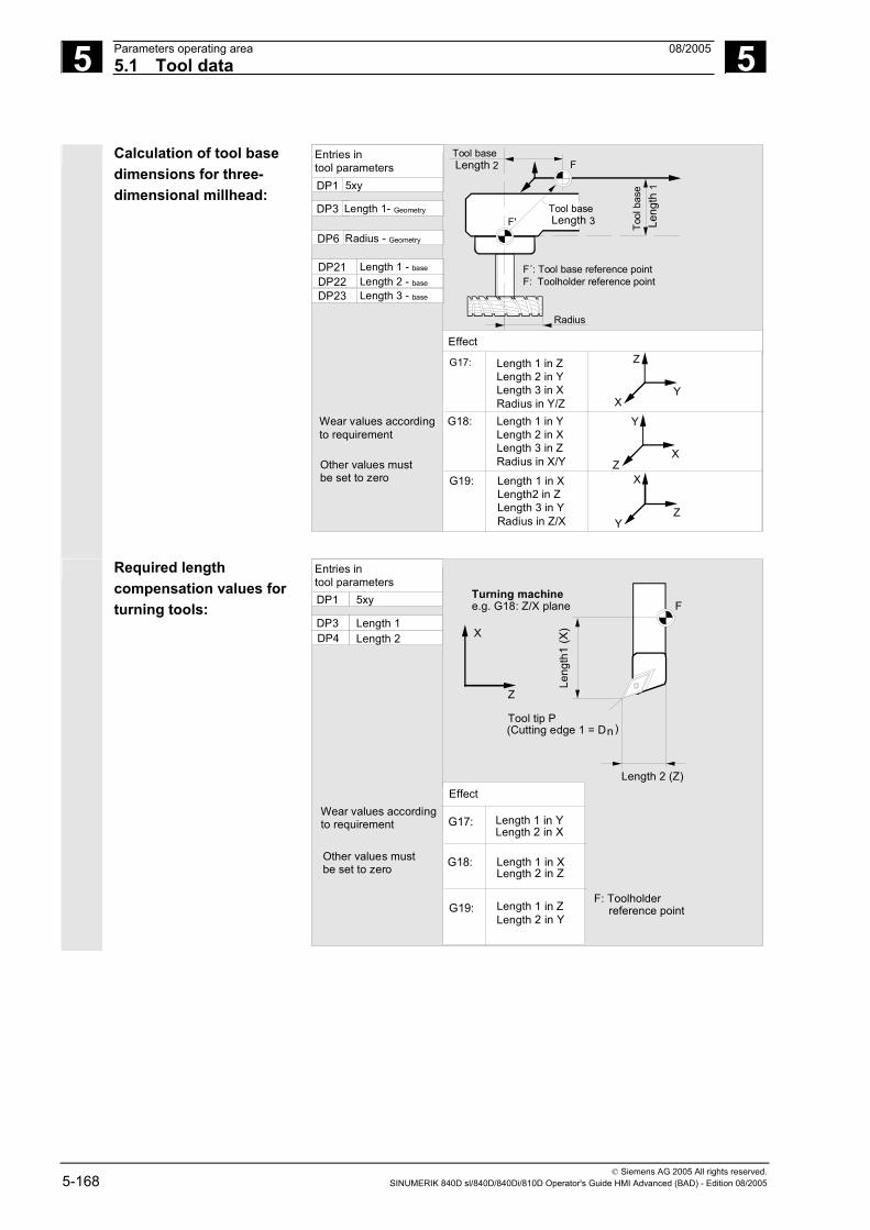
5 Parameters operating area 08/2005 5.1 Tool data
5
© Siemens AG 2005 All rights reserved. 5-168 SINUMERIK 840D sl/840D/840Di/810D Operator's Guide HMI Advanced (BAD) - Edition 08/2005
Calculation of tool base
dimensions for three-dimensional millhead:
X
Y
Z
Z
X
Y
Y
Z
X
Wear values accordingto requirement
Other values mustbe set to zero
Effect
G17:
G18:
G19:
Length 1 in YLength 2 in XLength 3 in ZRadius in X/Y
Length 1 in XLength2 in ZLength 3 in YRadius in Z/X
Length 1 in ZLength 2 in YLength 3 in XRadius in Y/Z
Entries intool parametersDP1
DP6
DP3
DP21DP22DP23
5xy
Length 1- Geometry
Radius - Geometry
Length 1 - base Length 2 - base
Length 3 - base
F'
F
Tool base Length 3
Tool base Length 2
Tool
bas
e L
engt
h 1
F´: Tool base reference pointF: Toolholder reference point
Radius
Required length
compensation values for turning tools:
Wear values accordingto requirement
Other values mustbe set to zero
Effect
G17:
G18:
G19:
Length 1 in YLength 2 in X
Length 1 in XLength 2 in Z
Length 1 in ZLength 2 in Y
Entries intool parametersDP1
DP4DP3
5xy
Length 1 Length 2
Z
X
FTurning machinee.g. G18: Z/X plane
Leng
th1
(X)
Length 2 (Z)
Tool tip P (Cutting edge 1 = Dn)
F: Toolholder reference point

5 08/2005 Parameters operating area5.1 Tool data
5
© Siemens AG 2005 All rights reserved. SINUMERIK 840D sl/840D/840Di/810D Operator's Guide HMI Advanced (BAD) - Edition 08/2005 5-169
Turning tool with several
cutting edges - length compensation:
Wear values accordingto requirement
Other values must be set to zero
G17:
G18:
G19:
Length 1 in YLength 2 in X
Length 1 in XLength 2 in Z
Length 1 in ZLength 2 in Y
Entries intool parametersDP1
DP4DP3
5xy
Length 1 Length 2
F: Toolholder reference point
DP1
DP4DP3
5xy
Length 1 Length 2
Z
XF
Grooving toole.g. G18: Z/X plane
Tool tip P (Cutting edge 1 = D n )
Tool tip P
(Cutting edge 2 = D n )
Dn: Length 2 (Z)
Dn:
Len
gth
1 (X
)
Dn:
Len
gth
1 (X
)
Effect
Calculation of tool base
dimensions for turning machine:
Wear values according torequirement
Other values mustbe set to zero
G17:
G18:
G19:
Length 1 in YLength 2 in X
Length 1 in XLength 2 in Z
Length 1 in ZLength 2 in Y
Entries intool parametersDP1
DP4DP3
5xy
Length 1 - Geometry Length 2 - Geometry
F´: Tool base reference pointF: Toolholder reference point
DP22DP21 Length 1 - Base
Length 2 - Base
Z
X F
F'
Tool baseLength 2
Leng
th 1
-Geo
met
ry
Length 2-Geometry
Tool
bas
e L
engt
h 1
Turning toole.g. G18 Z/X plane
Effect

5 Parameters operating area 08/2005 5.1 Tool data
5
© Siemens AG 2005 All rights reserved. 5-170 SINUMERIK 840D sl/840D/840Di/810D Operator's Guide HMI Advanced (BAD) - Edition 08/2005
Tool type 4xx (grinding tools) is calculated separately.
Several entries exist for the geometric variables (e.g., length 1 or radius).
Parameter Grinding wheel-comp. left
Grinding wheel-comp. right
Dresser left
Dresser right
Tool-specific parameters
$TC_DP1 Tool type *(20=1) Tool type Tool type
$TC_DP2 Cutting edge position
Cutting edge position
Cutting edge position
Cutting edge position
Geometry tool length compensation
$TC_DP3 Length 1 *(22=4) Length 1 Length 1
$TC_DP4 Length 2 *(23=8) Length 2 Length 2
$TC_DP5 Length 3 *(24=16) Length 3 Length 3
$TC_DP6 Radius Radius Radius Radius
$TC_DP7 to $TC_DP11
Reserved Reserved Reserved Reserved
Wear tool length compensation
$TC_DP12 Length 1 *(211=2048) Length 1 Length 1
$TC_DP13 Length 2 *(212=4096) Length 2 Length 2
$TC_DP14 Length 3 *(213=8192) Length 3 Length 3
$TC_DP15 Radius Radius Radius Radius
$TC_DP16 to $TC_DP20
Reserved Reserved Reserved Reserved
Tool base dimension/adapter dimension tool length compensation
$TC_DP21 Basic length 1
*(220=1048576)
Basic length 1 Basic length 1
$TC_DP22 Basic length 2
*(221=2097152)
Basic length 2 Basic length 2
$TC_DP23 Basic length 3
*(222=4194304)
Basic length 3 Basic length 3

5 08/2005 Parameters operating area5.1 Tool data
5
© Siemens AG 2005 All rights reserved. SINUMERIK 840D sl/840D/840Di/810D Operator's Guide HMI Advanced (BAD) - Edition 08/2005 5-171
Technology
$TC_DP24 Reserved Reserved Reserved Reserved
$TC_DP25 Reserved Reserved Reserved Reserved
Additional parameters
$TC_DPC1
up to
$TC_DPC10
* Value of the chaining parameter if the compensation parameters is to be chained.
Parameter number for
radius calculation $TC_TPG9
With this parameter it is possible to define which offset value is used for grinding wheel peripheral speed, tool monitoring and centerless grinding. The value always refers to cutting edge D1.
$TC_TPG9 = 3 Length 1 (geometry + wear + base, depending on tool type)
$TC_TPG9 = 4 Length 2 (geometry + wear + base, depending on tool type)
$TC_TPG9 = 5 Length 3 (geometry + wear + base, depending on tool type)
$TC_TPG9 = 6 Radius
*: The tool parameter of cutting edge 2 is chained to the parameter of cutting edge 1 (see tool-specific grinding data $TC_TPG2, chain rule). Here, typical chains are shown and the associated place value is specified in brackets.
Spindle number $TC_TPG1
This parameter contains the number of the spindle to which the monitoring data and GWPS refer.
Chain rule $TC_TPG2
This parameter defines which tool parameters of the right wheel edge (D2) and left wheel edge (D1) must be chained (see TOA data). If the value of one of the chained parameters is changed, it is then automatically included in the chained parameter. It must be noted that the minimum grinding wheel radius must be specified in the Cartesian coordinate system for an inclined grinding wheel. The length compensations always specify the distances between the toolholder reference point and the tool tip in Cartesian coordinates.
The monitoring data apply to both the left-hand and the right-hand cutting edge of the grinding wheel. The tool lengths are not automatically compensated when the angle is altered. On inclined axis machines the same angle must be specified for the inclined axis and the inclined wheel.

5 Parameters operating area 08/2005 5.2 Tool offset
5
© Siemens AG 2005 All rights reserved. 5-172 SINUMERIK 840D sl/840D/840Di/810D Operator's Guide HMI Advanced (BAD) - Edition 08/2005
Offsets that are not required must be assigned the value 0 (= default when the offset memory is set up). The tool offsets can be entered not only via the operator panel front but also via the data input interface.
For programming offset data, see /PG/, Programming Guide Fundamentals
5.2 Tool offset
5.2.1 Tool offset function and main screen
Tool offset data consist of data which describe the geometry, wear,
identification, tool type and the assignment to parameter numbers. The unit used for the dimensions of the tool is displayed. The input field is highlighted.
Every offset number contains up to 25 parameters, depending on the tool type. The number of parameters shown in the window is that for the tool type.
The maximum number of offset parameters (T and D numbers) can be set by means of machine data.

5 08/2005 Parameters operating area5.2 Tool offset
5
© Siemens AG 2005 All rights reserved. SINUMERIK 840D sl/840D/840Di/810D Operator's Guide HMI Advanced (BAD) - Edition 08/2005 5-173
Tool wear: Fine offset
If, as a minimum, you have the access rights necessary to edit the data in MD 9202: USER_CLASS_TOA_WEAR, you can modify the tool fine offset values incrementally. The difference between the old and new values must not exceed the limit stored in MD 9450: WRITE_TOA_FINE_LIMIT.
Horizontal softkeys You can select different data types with the horizontal softkeys:
Tool offset
Selection of "Tool offset" menu
R variables
Selection of "R parameters" menu
Setting data
Selection of "Setting data" menu
Zero offset
Selection of "Work offset" menu
User data
Selection of "User data" menu
Determine compens...
Support in determining tool offsets. This softkey is not required if the tool management function is available.
Vertical softkeys The vertical softkeys support data input:
T No.+
Selection of the next tool
T No.–
Selection of the previous tool
D No.+
Selection of next highest offset number (cutting edge)
D No.–
Selection of next lowest offset number (cutting edge)
Delete...
Deletion of a tool or cutting edge
Go to...
Find any tool or the active tool
Overview…
List of all available tools
New ...
New cutting edge or a new tool
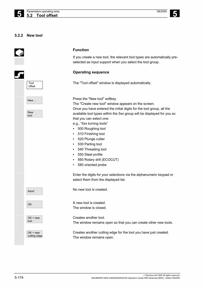
5 Parameters operating area 08/2005 5.2 Tool offset
5
© Siemens AG 2005 All rights reserved. 5-174 SINUMERIK 840D sl/840D/840Di/810D Operator's Guide HMI Advanced (BAD) - Edition 08/2005
5.2.2 New tool
Function
If you create a new tool, the relevant tool types are automatically pre-selected as input support when you select the tool group.
Operating sequence
Tooloffset
The "Tool offset" window is displayed automatically.
New ...
New tool
Press the "New tool" softkey. The "Create new tool" window appears on the screen. Once you have entered the initial digits for the tool group, all the available tool types within the 5xx group will be displayed for you so that you can select one: e.g., “5xx turning tools” • 500 Roughing tool • 510 Finishing tool • 520 Plunge cutter • 530 Parting tool • 540 Threading tool • 550 Steel profile • 560 Rotary drill (ECOCUT) • 580 oriented probe
Enter the digits for your selections via the alphanumeric keypad or select them from the displayed list.
Abort
No new tool is created.
OK
A new tool is created. The window is closed.
OK + new tool
Creates another tool. The window remains open so that you can create other new tools.
OK + new cutting edge
Creates another cutting edge for the tool you have just created. The window remains open.

5 08/2005 Parameters operating area5.2 Tool offset
5
© Siemens AG 2005 All rights reserved. SINUMERIK 840D sl/840D/840Di/810D Operator's Guide HMI Advanced (BAD) - Edition 08/2005 5-175
5.2.3 Display tool
Function
You can select tools that you have created and access their tool offset data.
Operating sequence
Tooloffset
The "Tool offset" window is displayed automatically.
If the "Parameters” area has already been selected, the window and the last tool selected when the area was exited are displayed. The tool offset data of the current tool are displayed immediately. If no tool has yet been selected, the data of the first tool are shown together with its first D number. If no tools are available in the area, a message is output.
T No.+
T No.–
Select the created tools.
Additional notes
Input of the geometry and wear data of the tool can be disabled using the keylock switch.

5 Parameters operating area 08/2005 5.2 Tool offset
5
© Siemens AG 2005 All rights reserved. 5-176 SINUMERIK 840D sl/840D/840Di/810D Operator's Guide HMI Advanced (BAD) - Edition 08/2005
5.2.4 Delete tool
Function
The tool is deleted together with all its cutting edges and the tool list updated accordingly.
Operating sequence
Tooloffset
The "Tool offset data" window is displayed automatically.
T No. +/- D No. +/-
Scroll the screen contents until you reach the tool to be deleted.
Delete
The vertical softkey bar changes when the "Delete" softkey is selected.
Delete tool
Press the "Delete tool" softkey. The tool and all its edges are deleted. The tool offsets of the tool number preceding the deleted tool are displayed.

5 08/2005 Parameters operating area5.2 Tool offset
5
© Siemens AG 2005 All rights reserved. SINUMERIK 840D sl/840D/840Di/810D Operator's Guide HMI Advanced (BAD) - Edition 08/2005 5-177
5.2.5 New cutting edge
Function
To help you to select a new cutting edge, the associated tool types are displayed automatically when you select a tool group.
Operating sequence
Tooloffset
The "Tool offset" window is displayed automatically.
New ...
New edge
Press the "New ..." and "New cutting edge" softkeys. The "New cutting edge" window is displayed. Once you have entered the initial digits for the tool group, all the available tool types within the 5xx group will be displayed for you so that you can select one: e.g., "5xx turning tools" • 500 Roughing tool • 510 Finishing tool • 520 Plunge cutter • 530 Parting tool • 540 Threading tool • 550 Steel profile • 560 Rotary drill (ECOCUT) • 580 oriented probe
The possible cutting edge positions are displayed automatically for
some tool types (e.g., for special tools, turning tools, grinding tools).
Enter the appropriate digit on the alphanumeric keyboard. Abort
Creation of a new cutting edge is aborted.
OK
A new cutting edge is created.
OK + new cutting edge
A new cutting edge is created. Another new cutting edge can be created.
OK + new tool
A new cutting edge is created. Another new tool can be created.

5 Parameters operating area 08/2005 5.2 Tool offset
5
© Siemens AG 2005 All rights reserved. 5-178 SINUMERIK 840D sl/840D/840Di/810D Operator's Guide HMI Advanced (BAD) - Edition 08/2005
5.2.6 Delete cutting edge
Function
You can delete one or several edges of a tool. The tool list is updated automatically.
Delete
Delete edge
Select the cutting edge of a tool, press the "Delete" softkey and then the "Delete edge" softkey.
5.2.7 Determine tool offsets
Function
The "Determine tool offsets" function allows you to change the absolute coordinates of different axes and then to calculate them.
X
Z
P
R
WM
TO
TO
TO Tool offset, absolute coordinate
R Tool mounting point M Machine zero W Workpiece zero

5 08/2005 Parameters operating area5.2 Tool offset
5
© Siemens AG 2005 All rights reserved. SINUMERIK 840D sl/840D/840Di/810D Operator's Guide HMI Advanced (BAD) - Edition 08/2005 5-179
Operating sequence
Tooloffset
The "Tool offset" window is displayed.
Position the cursor on the tool parameter you wish to change. Determine
compens... The "Absolute coordinate" window opens.
Select the appropriate axis with the "Toggle key". Alter the reference value, if necessary, using the numeric keypad.
OK
When you press the "OK" softkey, the current position and corresponding reference value for the selected tool parameter are calculated. The following equation applies: Position - reference value = input value The window is closed.
Calculate
Position - reference value is entered in the input field. The window remains open.
If "Jog" mode is selected, it is also possible to change the position by traversing the axes. The control automatically calculates the value from the reference value and the new position.
5.2.8 Make active tool offset operative immediately
Function
The machine data can be set to specify that the active tool offset can be activated immediately if the part program switches to the "Reset" or "Stop" state.
Additional notes
When the function is used in the Reset state, the machine data item $MC_RESET_MODE_MASK must be set such that the offset is not reset when the program switches to Reset.
References /FB/ Description of functions, Basic functions:
K2 Axes, Coordinate systems, etc.
Caution
The offset is applied after NC Start of the Reset in response to the next programmed axis movement in the part program.

5 Parameters operating area 08/2005 5.3 Tool management
5
© Siemens AG 2005 All rights reserved. 5-180 SINUMERIK 840D sl/840D/840Di/810D Operator's Guide HMI Advanced (BAD) - Edition 08/2005
5.3 Tool management The tool management system is organized by means of various
configurable lists which show different views of the tools used.
Magazine list In the "Magazine list", the tools of a magazine are displayed in order of ascending magazine location numbers. You can search for, display and, in the majority of cases, edit the data. A function is also provided for checking the D numbers and subsequently activating tools.
This list is mainly used to load and unload tools during setup, and to move tools between magazines.
Tool list In the "Tool list", the tools are displayed in the order of ascending T numbers.
You use this list if you are working with small tool magazines and know the exact magazine location of each tool.
Working offset list The cutting edges of active replacement tools are displayed in the "Working offset list". They are sorted in order of ascending D numbers. You can search (according to D number/DL number), display and edit the data.
Important
Use this list to edit and monitor sum offsets (local offsets), quantities and cutting edge parameters during the machining process. You can configure up to three different views for the working offset list. The TOA is assigned to multiple channels and is effective in the channel in which the tool is active. If you want to change the wear in the list of working offsets without having to call the tool again at the next NC Start, ensure that the correct channel is selected for this tool.

5 08/2005 Parameters operating area5.3 Tool management
5
© Siemens AG 2005 All rights reserved. SINUMERIK 840D sl/840D/840Di/810D Operator's Guide HMI Advanced (BAD) - Edition 08/2005 5-181
Tool catalog and tool cabinet
The tool catalog contains only "ideal" tools. "Ideal" tools are characterized by the relevant tool "master data" (i.e., with ideal tool dimensions, no wear, etc.). An "ideal" tool is uniquely defined by its "tool name". The tool cabinet contains only "real" tools. "Real" tools (i.e., real tool dimensions, with wear, etc.) are characterized by the relevant tool "offset data". A "real" tool is uniquely defined by its "tool name" and the associated "Duplo number". It is the "Duplo number" that assigns actual data to a "real" tool.
If a connection to a host computer exists, a message is automatically output to this host computer when a tool is loaded (but not relocated), unloaded or deleted, and the corresponding data block is transferred. The data are then still available on the host computer even after the tool has been deleted.
Machine manufacturer
Please refer to the information supplied by your machine manufacturer to see which functions are included in your tool management. See /FBW/ Description of functions, Tool management or /FBSP Description of functions, ShopMill
5.3.1 Basic tool management functions
The tool management system offers various tool types for selection.
You can assign geometric and technological data to the tool types in order to set up your master tool data. Several versions of each tool can exist. You can assign the current data of the tool used (particular tool data) to these versions.
Tool ma-nagement
You start the tool management function from the "Parameters" operating area by pressing the relevant softkey. The machine manufacturer configures which list is to be displayed when the tool management system is called up. In the example shown, the current "Magazine list" is displayed.

5 Parameters operating area 08/2005 5.3 Tool management
5
© Siemens AG 2005 All rights reserved. 5-182 SINUMERIK 840D sl/840D/840Di/810D Operator's Guide HMI Advanced (BAD) - Edition 08/2005
Important
The structure of the table is freely configurable (configured by the machine manufacturer). The example shows only one possible case:
Magazinelist 1
Magazinelist
Toollist
Load Unload
Parameter
Channel RESET
AUTOCHAN1
ROV FST
MPF.DIRLEER.MPF
Magazinelist 2
Magazinelist 3
Tooldata
Bufferlocations
Search andposition
Nextmagazine
Relocate Workingoffset list
Magazine list 1
Magazin: Plätze: AVB:2 - Kette20 20 0
Pl
123456789
1011121314
P
--------------
WerkzeugID
newRack860Wzg1
Wzg2Wzg3
P
-FF--FFFFFFFFF
PTP
11111111111111
Dupl
11
11
TNr
176
857
PTT
11
11
W
FF
FF
W
--
--
W
G-
--
W
M-
--
W
V-
--
W
--
E-
PV
00000000000000
WTyp
900900
900900
xGeo-L1
11.00000.0000
0.00000.0000
xGeo-L2
11.00000.0000
0.00000.0000
ActivateD check
Program aborted
Location (Pl) Location number
Location state (P) Location state
(one column is provided for each state) e.g. F = Location enabled G = Location disabled Z = Reserved for tool in buffer B = Reserved for tool to be loaded L = Left half location occupied R = Right half location occupied O = Upper half location occupied U = Lower half location occupied l = Left half location reserved r = Right half location reserved o = Upper half location reserved u = Lower half location reserved
PTP Type assigned to the location
Tool ID Name of the tool
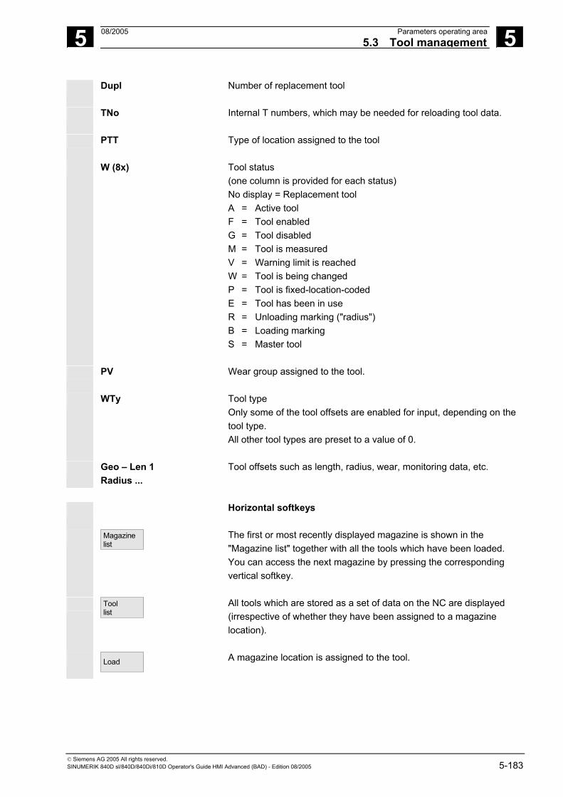
5 08/2005 Parameters operating area5.3 Tool management
5
© Siemens AG 2005 All rights reserved. SINUMERIK 840D sl/840D/840Di/810D Operator's Guide HMI Advanced (BAD) - Edition 08/2005 5-183
Dupl Number of replacement tool
TNo Internal T numbers, which may be needed for reloading tool data.
PTT Type of location assigned to the tool
W (8x) Tool status (one column is provided for each status) No display = Replacement tool A = Active tool F = Tool enabled G = Tool disabled M = Tool is measured V = Warning limit is reached W = Tool is being changed P = Tool is fixed-location-coded E = Tool has been in use R = Unloading marking ("radius") B = Loading marking S = Master tool
PV Wear group assigned to the tool.
WTy Tool type Only some of the tool offsets are enabled for input, depending on the tool type. All other tool types are preset to a value of 0.
Geo – Len 1 Radius ...
Tool offsets such as length, radius, wear, monitoring data, etc.
Horizontal softkeys
Magazine
list
The first or most recently displayed magazine is shown in the "Magazine list" together with all the tools which have been loaded. You can access the next magazine by pressing the corresponding vertical softkey.
Tool list
All tools which are stored as a set of data on the NC are displayed (irrespective of whether they have been assigned to a magazine location).
Load
A magazine location is assigned to the tool.

5 Parameters operating area 08/2005 5.3 Tool management
5
© Siemens AG 2005 All rights reserved. 5-184 SINUMERIK 840D sl/840D/840Di/810D Operator's Guide HMI Advanced (BAD) - Edition 08/2005
Unload
The tool is deleted from the current magazine location.
Relocate
The tool is moved from the current magazine location to another location.
Working offset list
The cutting edges of active replacement tools are displayed. They are sorted in order of ascending D numbers.
Further softkeys are displayed when you press the "ETC." key:
Tool catalog
You can create new tool master data ("ideal" tools) and edit the existing data.
Tool cabinet
You can create new tool offset data and tool operating data ("real" tools) and edit the existing data.
Trans- formation
This softkey allows you to display the tool data as transformed data (adapter data are calculated) or non-transformed data.
This conversion feature is only available in the magazine list display. The data are always displayed as non-transformed data in the tool list and as transformed data in the working offset list.
Special feature: If you display transformed data and want to create a new tool in the magazine list (loading mode), the transformed data display is activated exclusively for input of this data block.
(Names assigned by user)
Vertical softkeys (magazine list) Selection of user-specific display windows (if configured), e.g.,
Magazine list 1
• General data
Magazine list 2
• Geometry data
Magazine list 3
• Wear data

5 08/2005 Parameters operating area5.3 Tool management
5
© Siemens AG 2005 All rights reserved. SINUMERIK 840D sl/840D/840Di/810D Operator's Guide HMI Advanced (BAD) - Edition 08/2005 5-185
Tool data
You can display and edit the complete data of a tool. Call up the start screen for updating the tool data. You can display and normally also edit all the data of the tool, its cutting edges and its working offsets in this screen and subsidiary screens. The vertical softkey bar changes. The exact procedure is described under "Display/edit tool data" (see Page "Display/edit tool data").
Activate D check
Two functions are implemented with this softkey:
• Verify unique D number assignment Duplication can occur when assigning D numbers to the cutting edges of the individual tools. This function checks all numbers within the current magazine or all allocated D numbers within a TO unit (configured by parameter).
• Activate the tools
If unique D numbers were assigned, a wear group is activated. A tool is subsequently activated from each replacement tool group in the TOA of the current channel. Allowance is made for the active wear group.
Only automatically accessible magazines are considered for
processing. Any previously active tools are disabled by the activation of tools, especially if the wear group is changed.
Buffer locations
Display and hide the buffer window in the magazine list. The display shows spindles, grippers, etc., i.e., locations which can accommodate tools but which are not magazine locations. If no buffer is defined, this key has no function.

5 Parameters operating area 08/2005 5.3 Tool management
5
© Siemens AG 2005 All rights reserved. 5-186 SINUMERIK 840D sl/840D/840Di/810D Operator's Guide HMI Advanced (BAD) - Edition 08/2005
Search andposition
The "Find tool/location" window appears.
• Search − Tool:
Enter the tool name and Duplo number and start the search with OK. The cursor is positioned on the tool found.
− Location: Enter the magazine and location number and start the search with OK. The cursor is positioned on the tool found.
• Positioning Select the "Position" softkey, tool/location is moved to loading point. If there is more than one possible loading point, a window is opened. You can select the correct one with the cursor.
Next
magazine The locations of the next magazine are displayed in the magazine list.
You can only scroll forwards. When you reach the last magazine, the display returns to the first magazine.
(Names assigned by user)
Vertical softkeys (tool list) Selection of a table structure configured by the user (if configured), e.g.:
Tool list 1
• General data
Tool list 2
• Geometry data
Tool list 3
• Wear data
Tool details
You can display and edit the complete data of a tool (as in the magazine list).
Tool fromCC
The tool data are read from a code carrier and entered in the tool list (you can then edit the data).
Tool incabinet
Select the tool in the tool cabinet. The tool data are read from there and entered in the tool list. A list display appears for which you can parameterize a filter for the tool number, duplo number and tool type. The list displays all the tools that fulfill the filter criteria. You can select the tool you require from the list.

5 08/2005 Parameters operating area5.3 Tool management
5
© Siemens AG 2005 All rights reserved. SINUMERIK 840D sl/840D/840Di/810D Operator's Guide HMI Advanced (BAD) - Edition 08/2005 5-187
Delete tool
The selected tool is removed from the list. Use the vertical softkeys to determine whether to save the tool data.
Tool incabinet
The data are copied into the tool cabinet. The tool can be loaded later with the same data.
Data onCC
If a code carrier is installed, the tool data are stored on the carrier. The tool can then be loaded later with the same data.
Abort
The operation is canceled. The tool is not removed from the list.
OK
The tool is deleted from the list. The tool data are no longer available.
New tool
Each time you press this softkey, a tool is created immediately. The screen form for entering the tool data (tool details) and the associated softkey bar (same as tool details) appear. The values are initialized with the default settings (configured in the INI file) and can be edited here (e.g., you can change the name of the tool). Use the vertical softkey bar to display the tables for cutting edge data and offsets with the default settings. If necessary, enter any changes in the individual views.
<<
Terminates input of the tool data and switches to the tool list display. The new tool appears in the table and is available for loading. Once you have set up a new tool, the cursor automatically jumps to the line containing the new tool when you return to the tool list. This gives you feedback about your operation.

5 Parameters operating area 08/2005 5.3 Tool management
5
© Siemens AG 2005 All rights reserved. 5-188 SINUMERIK 840D sl/840D/840Di/810D Operator's Guide HMI Advanced (BAD) - Edition 08/2005
Note
The data you enter are always updated immediately (without prompting). You can edit the properties of the new tool by pressing the "Tool details" softkey. It is not possible to edit the data directly in the table. You can only edit the name and type of a tool by selecting Create New, not via Tool details. To change a name, you have to create a new tool and delete the old one.
(Names assigned by user)
Vertical softkeys (working offset list) Selection of a table structure configured by the user (if configured), e.g.:
W. offset list 1
• General data
W. offset list 2
• Geometry data
W. offset list 3
• Wear data
Tool data
You can display and edit the complete data of a tool (as in the magazine list).
Find D number
Find an entry with a specific D number/DL number. • Enter the D number and DL number you want to find in the search
window. • Confirm with "OK". If a matching entry is found, the cursor jumps to
the corresponding line. If you have not specified a DL number, the cursor is positioned on the first line of the matching tool.
Current
D number The D number of the current tool is determined and displayed.

5 08/2005 Parameters operating area5.3 Tool management
5
© Siemens AG 2005 All rights reserved. SINUMERIK 840D sl/840D/840Di/810D Operator's Guide HMI Advanced (BAD) - Edition 08/2005 5-189
5.3.2 Display/edit tool data
Function
You can view and edit the tool data of the tool selected in the lists.
You can edit the following cutting edge data:
• Offset values • Monitoring data • User data
Operating sequence
Tool ma-nagement
Press the "Tool management" softkey. The list configured by the machine manufacturer appears (e.g., the magazine list). The horizontal and vertical softkey bars change. Select the appropriate list via softkey:
Magazine list
• "Magazine list"
Tool list
• "Tool list"
Workingoffset list
• "Working offset list"
Position the cursor bar on the appropriate tool. The tool is selected. Notice: Please ensure that the channel in which the offsets are to be applied is displayed.
Tool details
Select the "Tool details" softkey. The input screen for "Tool details" appears. The vertical softkey bar changes again. The following functions are available: • Create new cutting edges • Edit cutting edge data • Edit monitoring data • Edit local offsets (DL numbers) • Delete cutting edges

5 Parameters operating area 08/2005 5.3 Tool management
5
© Siemens AG 2005 All rights reserved. 5-190 SINUMERIK 840D sl/840D/840Di/810D Operator's Guide HMI Advanced (BAD) - Edition 08/2005
You can edit the following data in the input screen : • Location type • Location coding • Monitoring type • Status (enabled, disabled, measured, etc.) • Tool user data (Omit; x = 1...10) • D numbers • Tool name • Duplo number • Tool type, only in magazine list and tool list
Note The tool data Name, Duplo number and Type can only be changed if the option has been enabled by the machine manufacturer. If the option is not activated you cannot make any changes. These data are permanently defined when a new tool is created.
New edge
New cutting edges are created for the displayed tool. A cutting edge number to which no D number has yet been assigned is automatically selected in the table. When you have allocated a D number, the value is displayed in red (the cutting edge has not yet been created). Select "Cutting edge data" in the vertical softkey bar. The selected cutting edge is created. Default values are assigned to the cutting edge data and the corresponding table is displayed. Enter any necessary changes.
You can use the "Cutting edge +" and "Cutting edge -" softkeys to display and, if necessary, edit the data of the other cutting edges. The data are updated immediately.
Press the "<<" softkey to return to the Tool details input screen. The new cutting edge is defined. The display color changes.
Additional notes
If twelve cutting edges have already been defined for the tool, you must delete one of the cutting edges (via softkey) before you can create a new one. The machine manufacturer can limit the maximum permissible number of cutting edges for each tool to a smaller number. The default setting is nine cutting edges.

5 08/2005 Parameters operating area5.3 Tool management
5
© Siemens AG 2005 All rights reserved. SINUMERIK 840D sl/840D/840Di/810D Operator's Guide HMI Advanced (BAD) - Edition 08/2005 5-191
A new cutting edge can be added to a tool at any time (even if the tool is already located in the magazine). Select "New cutting edge" and enter the cutting edge data.
Edit tool data Press the "Cutting edge data", "Mon. data" and "Local offsets" softkeys to display tables for editing the respective data. You can move freely between the individual tables. The name, Duplo number and type of tool and all defined cutting edges (#1...#12) are displayed. Use the "Cutting edge +" and "Cutting edge -" softkeys to toggle between the cutting edges. Press "<<" to return to the "Tool details" input screen.
Note
When you edit the data, the new data is saved immediately. The "<<" softkey only changes the display.
Cuttingedge data
The cutting edge data and tool offsets of the currently selected cutting edge are displayed and can be edited. You can edit the following data: • Cutting edge user data (OEM_Sx; x = 1...10) • Tool offsets
− Geometry − Wear − Basic offset − Cutting edge position (for turning tools) − Tool clearance angle (for turning tools)
You can define the value of Length1, Length2, Length3 and Radius1 for every parameter.
Monitoringdata
The monitoring data of the currently selected cutting edge are displayed and can be edited. When you have selected a cutting edge, define the actual value, setpoint and warning limit monitoring data for the following parameters: • Quantity • Tool life • Wear

5 Parameters operating area 08/2005 5.3 Tool management
5
© Siemens AG 2005 All rights reserved. 5-192 SINUMERIK 840D sl/840D/840Di/810D Operator's Guide HMI Advanced (BAD) - Edition 08/2005
Loc-dep.offsets
The tool offsets (identical to the cutting edge data table) and the local offsets of the currently selected cutting edge are displayed and can be edited. The following options are available: • Values can be defined for Length1, Length2, Length3 and Radius1
for each parameter. • Up to six local offsets (DL1...DL6) are possible (according to the
machine manufacturer's configuration). • Setup values and wear values can be defined for each offset.
Edge +
In the individual tables, this softkey displays the data/offsets of the next cutting edge for editing.
Edge –
The data/offsets of the previous cutting edge are displayed and can be edited.
Deleteedge
In the table, select the cutting edge you want to delete (by positioning the cursor).
Notice! There is no separate prompt.
The D number is removed from the table and can be reallocated.
<<
Terminates input of the tool data and returns to the table displayed previously.
Note
You can enter individual tool data items directly in the current list, provided you have the necessary access authorization and the data are displayed in the list (the list structure is configurable). Select the value to be edited and enter the required data. The system automatically switches to edit mode.

5 08/2005 Parameters operating area5.3 Tool management
5
© Siemens AG 2005 All rights reserved. SINUMERIK 840D sl/840D/840Di/810D Operator's Guide HMI Advanced (BAD) - Edition 08/2005 5-193
5.3.3 Change in the significance/representation of tool wear values
In the tool list screens, additional symbols indicate whether special
features have to be taken into account for the current tool according to G code 56 and setting data SD 42935: WEAR_TRANSFORM.
Symbols /
The G56 reset value is TOWSTD / and at least 1 bit is set in $SC_WEAR_TRANSFORM. The current tool for channel "REV2" is indicated in row 1. The current value of G56 on channel "REV2" deviates from the G56 reset value ( ). Row 9 displays the current tool for channel "HAND". There the current value of G56 is equal to the reset value ( ).

5 Parameters operating area 08/2005 5.3 Tool management
5
© Siemens AG 2005 All rights reserved. 5-194 SINUMERIK 840D sl/840D/840Di/810D Operator's Guide HMI Advanced (BAD) - Edition 08/2005
Symbols /
The G56 reset value is TOWMCS / and
$SC_WEAR_TRANSFORM is set. The current tool for channel "REV2" is indicated in row 2. The current value of G56 on channel "REV2" deviates from the G56 reset value ( ). Row 11 displays the current tool for channel "HAND". There the current value of G56 is equal to the reset value ( ).

5 08/2005 Parameters operating area5.3 Tool management
5
© Siemens AG 2005 All rights reserved. SINUMERIK 840D sl/840D/840Di/810D Operator's Guide HMI Advanced (BAD) - Edition 08/2005 5-195
Symbols /
The G56 reset value is TOWWCS / and
$SC_WEAR_TRANSFORM is set. The current tool for channel "REV2" is indicated in row 6. The current value of G56 on channel "REV2" is the same as the reset value ( ). Row 15 displays the current tool for channel "HAND". Here, the current value of G56 deviates from the G56 reset value ( ).
Additional notes
Additional information can be found in /FBW/, Description of functions, Tool management
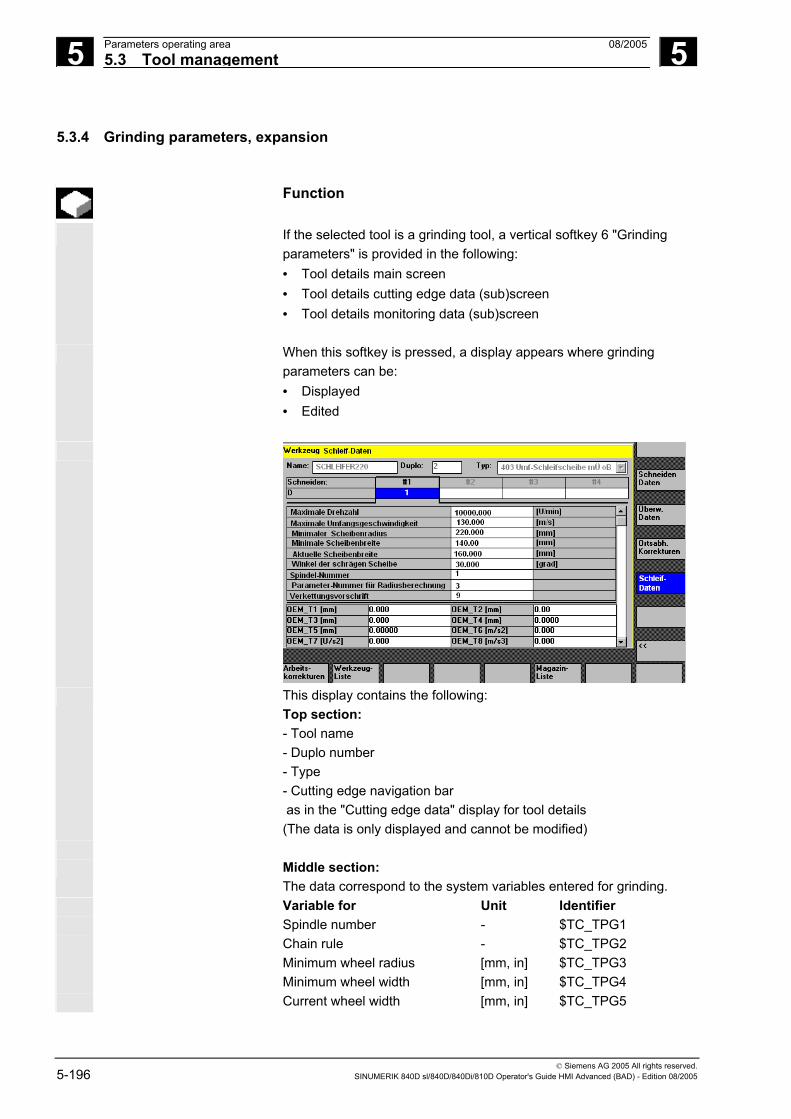
5 Parameters operating area 08/2005 5.3 Tool management
5
© Siemens AG 2005 All rights reserved. 5-196 SINUMERIK 840D sl/840D/840Di/810D Operator's Guide HMI Advanced (BAD) - Edition 08/2005
5.3.4 Grinding parameters, expansion
Function
If the selected tool is a grinding tool, a vertical softkey 6 "Grinding parameters" is provided in the following: • Tool details main screen • Tool details cutting edge data (sub)screen • Tool details monitoring data (sub)screen
When this softkey is pressed, a display appears where grinding parameters can be: • Displayed • Edited
This display contains the following:
Top section: - Tool name - Duplo number - Type - Cutting edge navigation bar as in the "Cutting edge data" display for tool details (The data is only displayed and cannot be modified)
Middle section:
The data correspond to the system variables entered for grinding. Variable for Unit Identifier Spindle number - $TC_TPG1 Chain rule - $TC_TPG2 Minimum wheel radius [mm, in] $TC_TPG3 Minimum wheel width [mm, in] $TC_TPG4 Current wheel width [mm, in] $TC_TPG5

5 08/2005 Parameters operating area5.3 Tool management
5
© Siemens AG 2005 All rights reserved. SINUMERIK 840D sl/840D/840Di/810D Operator's Guide HMI Advanced (BAD) - Edition 08/2005 5-197
Maximum speed [rpm] $TC_TPG6 Maximum peripheral speed [m/s, ft/s] $TC_TPG7 Angle of inclined wheel [degrees] $TC_TPG8 Parameter number for radius
calculation/compensation parameter for GWPS
- $TC_TPG9
Additional notes
For information on NC variables, please refer to the Description of functions /FB/, W4 Grinding-specific tool offset and monitoring.
Bottom section:
Tool OEM data are displayed as on the main screen for tool details. The tool OEM data can be edited on both the grinding parameters screen and the main tool details screen. The designation and the unit in the OEM data can be parameterized in the relevant language. The bottom section of the display is only available if tool OEM data are available on the NC.
Scroll bar A scroll bar appears next to the middle and bottom sections if the
bottom section is displayed. The grinding parameters screen and the softkeys are only displayed if
the tool is a grinding tool (tool type between 400 and 499). Access rights are checked for grinding parameters. Default access is "All".
All tool cutting edges are of the same type. The same applies to the dresser cutting edges of grinding tools.
Tool types The tool types for grinders are 4xy in accordance with /FB/, W4. They are available in displays/functions for:
• Tool cabinet • Tool catalog • Cutting edge parameters in tool details • Lists (magazine list, tool list, working offset list)
Supplementary conditions - The tool-specific grinding parameters cannot be displayed in the list displays. - They are not saved in the tool cabinet/tool catalog. - They are not transferred via code carrier/SINCOM. - The extension is available in HMI Advanced Version 6.2 or later.
5 Parameters operating area 08/2005 5.3 Tool management
5
© Siemens AG 2005 All rights reserved. 5-198 SINUMERIK 840D sl/840D/840Di/810D Operator's Guide HMI Advanced (BAD) - Edition 08/2005
5.3.5 Load
Function
You can load a tool in one of the following ways: • You can enter the individual tool data directly in the list. • You can import tool data from existing tools. You can load a tool from the "Magazine list" or the "Tool list".
• Loading a tool from the "Magazine list" To edit tool data directly in the list, you must first find a suitable empty location for the tool (use the softkeys). You can then enter the data directly in the list.
You can also load all existing tools into the magazine. You load the associated tool data: − From the master data catalog − From the tool cabinet − From the code carrier (if one exists) or − From the host computer (if one is connected). In this case, the system automatically tries to find a suitable empty location for the selected tool.
• Loading a tool from the "Tool list"
Tools for which data are already stored in the TO memory can be loaded into the magazine. The magazine location is selected either by searching for an empty location or by entering a magazine number and location number in the corresponding columns of the list.

5 08/2005 Parameters operating area5.3 Tool management
5
© Siemens AG 2005 All rights reserved. SINUMERIK 840D sl/840D/840Di/810D Operator's Guide HMI Advanced (BAD) - Edition 08/2005 5-199
Additional notes
In the lists, you can parameterize a filter for loading tools. A list display appears for which you can parameterize a filter for the tool ID, duplo number and tool type. The list then displays the tools in the tool cabinet that meet the filter criteria. By selecting it from the list, you accept the tool.
Sequence of operations (loading from the "Magazine list")
Tool ma-
nagement
Press the "Tool management" softkey. The "Magazine list" is displayed. The horizontal and vertical softkey bars change.
Magazine list
The "Magazine list" is selected. The appropriate magazine is selected.
Load
Press the "Load" softkey. The vertical softkey bar changes again.
Manual data input (with search for empty location)
If you want to enter data directly in the table, you must first find a suitable empty location in the magazine. There are four methods by which you can find an empty location for different tool sizes in combination with location types: 1. Directly in the magazine list ("Manually"). 2. Via a user-defined location
e.g., "oversize" (name configured by machine manufacturer) 3. Via the "Find empty location" softkey 4. Via the "To loading point" softkey
Additional notes
Values are checked for validity when you enter a tool type in the lists. Only known tool types are permitted.
Searching directly in the magazine list Position the cursor on the location of your choice in the magazine list.
Search via user-defined location (example) The assignment of the softkeys is configured by the machine manufacturer.

5 Parameters operating area 08/2005 5.3 Tool management
5
© Siemens AG 2005 All rights reserved. 5-200 SINUMERIK 840D sl/840D/840Di/810D Operator's Guide HMI Advanced (BAD) - Edition 08/2005
normal
• "Normal" (name configured by machine manufacturer)
large
• "Large" (name configured by machine manufacturer)
oversize
• "Oversize" (name configured by machine manufacturer)
normal andheavy
• "Normal and heavy" (name configured by machine manufacturer)
The system searches for a suitable empty location. The cursor bar is automatically positioned on the magazine location found in the "Magazine list".
Search via the "Find empty location" softkey Find empty
location
Enter the "Tool size" and "Location type" in the query window. If more than one loading point is configured, select the desired loading point from a query window. The system searches for the corresponding empty location. The cursor bar is automatically positioned on the magazine location found in the "Magazine list".
Search via the "To loading point" softkey To loading
point
You have found an empty location in front of the current loading point.When you press "To loading point" the cursor is automatically positioned at this location.
Enter data If the desired empty location is found after a search operation, the system switches to edit mode and the softkey bar changes. When you search for an empty location manually, the system switches to edit mode as soon as you start entering the data on the keyboard.
Tool details
You can use "Tool details" to edit the current data of the tool to be loaded (if necessary). If the tool has not yet been created, it is created automatically when you call the input screen.
Abort
Load/input mode is canceled. A tool created via "Tool details" or "Start" is deleted. You can search for another empty location.
Start
The loading operation is initiated. If the tool has not yet been created, it is created automatically.

5 08/2005 Parameters operating area5.3 Tool management
5
© Siemens AG 2005 All rights reserved. SINUMERIK 840D sl/840D/840Di/810D Operator's Guide HMI Advanced (BAD) - Edition 08/2005 5-201
If data are still missing for loading, the tool details input screen appears. The missing data are initialized with default values and can be edited if necessary. Start the loading operation again afterwards.
Import tool data In addition to direct data entry, there are various ways of importing tool data belonging to tools which have already been defined and of subsequently loading these tools:
Data fromCC
1. Read the data in from a code carrier (if one is installed)
Data fromhost
2. Read the data in from a host computer (if one is installed)
Tool fromcabinet
3. Select the "Tool from cabinet" menu. Select the tool in the tool cabinet. The tool data are read from there.
If not all of the softkeys are visible, change the display by pressing the appropriate key on the operator panel front.
When you have defined the source for loading, the system automatically tries to find a suitable empty location for the tool to be imported. The vertical softkey bar changes. If no location is found, an error message is displayed.
Tool details
You can use the "Tool details" display to edit the data of the tool to be loaded (if necessary). If the tool has not yet been created, it is created automatically when you call the input screen.
Abort
Load/input mode is canceled. A tool created via "Tool details" or "Start" is deleted. You can search for another empty location.
Start
The loading operation is initiated. If the tool has not yet been created, it is created automatically.
"Load directly to spindle" is possible if the cursor is positioned on the spindle buffer location.

5 Parameters operating area 08/2005 5.3 Tool management
5
© Siemens AG 2005 All rights reserved. 5-202 SINUMERIK 840D sl/840D/840Di/810D Operator's Guide HMI Advanced (BAD) - Edition 08/2005
Sequence of operations (loading from the "Tool list")
Tool
list The "Tool list" is selected. The appropriate tool is selected.
Load
Press the "Load" softkey. The vertical softkey bar changes.
Find empty location
Search for an empty location for a tool which has already been created or enter the desired location and magazine number in the list.
The location found is entered under the magazine/location number.
Abort
The loading operation is not initiated. The main screen appears.
Start
The loading operation is initiated.
5.3.6 Unload
Function
This function allows you to unload a selected tool and to save its data.
Operating sequence
Tool ma-nagement
Press the "Tool management" softkey. The "Magazine list" is displayed. The horizontal and vertical softkey bars change. You can unload a tool from the "Magazine list" or the "Tool list". The sequence of operations is the same for both methods.

5 08/2005 Parameters operating area5.3 Tool management
5
© Siemens AG 2005 All rights reserved. SINUMERIK 840D sl/840D/840Di/810D Operator's Guide HMI Advanced (BAD) - Edition 08/2005 5-203
Select the appropriate list via softkey: Magazine
list • "Magazine list"
A tool is to be physically removed from a magazine location. You can configure whether the corresponding NC block is also removed from the TO memory. Select the magazine and the tool to be unloaded (select the tool with the cursor).
or Tool
list • "Tool list"
The NC block is to be unloaded from the memory. Select the tool to be unloaded (select the tool with the cursor).
Unload
Select the "Unload" softkey. The vertical softkey bar changes.
Tool incabinet
The tool data of the selected tool are stored in the tool cabinet on the hard disk. This allows you to load the tool with the same data again at a later point.
Data onCC
If a code carrier is installed, the tool data are automatically stored there. This allows you to load the tool with the same data again at a later point.
From magazine
The selected tool is unloaded. The corresponding line is deleted from the magazine list. The entries in the magazine number and location number columns are removed from the tool list.
"Unload directly from spindle" is only possible if the buffer is selected and the cursor is positioned on the location of the spindle. To exit the screen without unloading the tool, select another display in the vertical softkey bar before pressing "Start".
Delete
tool The tool data of the selected tool are deleted from the TO memory. If the tool is in a magazine location, it is unloaded and deleted.
If a host computer is connected, the data are transferred to the host computer each time a tool is deleted or unloaded.

5 Parameters operating area 08/2005 5.3 Tool management
5
© Siemens AG 2005 All rights reserved. 5-204 SINUMERIK 840D sl/840D/840Di/810D Operator's Guide HMI Advanced (BAD) - Edition 08/2005
5.3.7 Relocation
Function
This function allows you to move a selected tool from one location to another.
Operating sequence
Tool ma-nagement
Press the "Tool management" softkey. The "Magazine list" is displayed. The horizontal and vertical softkey bars change. You can relocate a tool from the magazine list or the tool list. The sequence of operations is the same for both methods.
Select the appropriate list via softkey: Magazine
list • "Magazine list"
Select the magazine and the tool to be relocated (position the cursor on the magazine location containing the tool).
or Tool list
• "Tool list"
Select the tool to be relocated (position the cursor on the tool). This tool must already have been loaded (entry in the magazine number and location number columns).
Relocate
When you select the "Relocate" key, the "Relocate tool" window opens.
There are 2 methods by which you can select the new location for the tool:
• Enter the magazine and location numbers in the "Relocate tool" window.
or • Press the "Find empty location" softkey and select the desired data
in the window.

5 08/2005 Parameters operating area5.3 Tool management
5
© Siemens AG 2005 All rights reserved. SINUMERIK 840D sl/840D/840Di/810D Operator's Guide HMI Advanced (BAD) - Edition 08/2005 5-205
Abort
The tool is not relocated.
Start
The tool is relocated to the new empty location.
Use magazine number 9998 to move a tool to or from a spindle
location.
When relocating from the buffer, the previous location information is entered by default. This applies to fixed-location-coded and variable tools.
5.3.8 Tool master data in the tool catalog
Function
You can create tool master data in the tool catalog. A set of data can be created for every tool in use.
Advantage Master data which apply to the tool, regardless of which cutting edge you use, do not have to be reentered for each tool, but can be copied from the tool catalog (in the tool cabinet) for each tool used.
Ideal tools The tool catalog contains only "ideal" tools. "Ideal" tools are characterized by the relevant tool "master data" (i.e., with ideal tool dimensions, no wear, etc.). An "ideal" tool is uniquely defined by its "Tool name".

5 Parameters operating area 08/2005 5.3 Tool management
5
© Siemens AG 2005 All rights reserved. 5-206 SINUMERIK 840D sl/840D/840Di/810D Operator's Guide HMI Advanced (BAD) - Edition 08/2005
Operating sequence
Tool ma-nagement
Press the "Tool management" softkey. The horizontal and vertical softkey bars change.
The horizontal softkey bar is expanded.
Tool catalog
Press the "Tool catalog" softkey. The vertical softkey bar changes again. The tool details of the tool catalog are displayed. You can use the list fields to display the available standard tools and tools which have already been defined or to create new tools.
Create tool data
Proceed as follows to create the tool data: • Select the desired technology in the appropriate list field (e.g.,
drilling tools, milling tools). • Define the tool type in the second list field
(e.g., twist drill).
New
• Activate this softkey to create a new tool. You can edit the field for the tool name.
• Enter a tool name.
• In the open window, "Tool details", define the tool properties (in
"Tool size" you define the total number of tool half locations occupied by the tool).
Abort
• Select "Cancel" to discard the settings.
The tool is not created.
OK
• Save your data with OK. The new tool is created.
Display/edit tool data In addition to the tool master data already defined, you can enter
default settings in the tool catalog for all the other tool data (e.g., cutting edge data, user data). You can edit this data later. Duplo number 0 is allocated to the tool.

5 08/2005 Parameters operating area5.3 Tool management
5
© Siemens AG 2005 All rights reserved. SINUMERIK 840D sl/840D/840Di/810D Operator's Guide HMI Advanced (BAD) - Edition 08/2005 5-207
Tools in the tool catalog are used as a basis for real tools. It is recommended to define only data actually required in that exact form for several real tools. This helps to minimize the amount of changes required later.
Tool data are displayed and edited as follows: Offsets
• Tool offset data (cutting edge data)
The tool offset data window is displayed. The data of the first cutting edge are listed in a table. The vertical softkey bar changes. Enter the required settings.
The following functions are available for editing the cutting edge data:
Edge +
The cutting edge data of the next defined cutting edge are displayed in a table.
Edge −
The data of the previous cutting edge are listed.
New
A new cutting edge is created for the tool.
Delete
The current cutting edge and all the data defined for the cutting edge are deleted after a prompt.
Abort
Select "Cancel" to discard the changes. No new cutting edge is created.
OK
Save the cutting edge data with "OK". A new cutting edge is created (if defined).
Cut. edge user data
• Cutting edge user data (if configured) Switches to the "Cutting edge user data" input screen. Up to 10 user-specific cutting edge data are displayed here. Enter the required settings in the table.
Tool user
data • Tool user data (if configured)
Switches to the "Tool user data" input screen. Up to 10 user-specific tool data are displayed here. Enter the required settings in the table.

5 Parameters operating area 08/2005 5.3 Tool management
5
© Siemens AG 2005 All rights reserved. 5-208 SINUMERIK 840D sl/840D/840Di/810D Operator's Guide HMI Advanced (BAD) - Edition 08/2005
Additional functions The following functions are also available in the tool catalog:
Copy
The data of the tool are copied and a new tool is created with identical data. You are prompted to enter a name for the new tool.
Delete
The currently selected tool is deleted after a prompt. All data relating to this tool are lost.
Additional notes
The "Tool offset data", "Cutting edge user data" and "Tool user data" softkeys are always displayed when you edit the tool details. This allows you to toggle between the individual tables as required. The tool data for tools of the catalog can be edited at any time.
5.3.9 Tool offset data in the tool cabinet
Function
You can create tool offset data in the tool cabinet. A set of data can be created for every tool in use. The "ideal" master data defined in the tool catalog can be copied to the tool cabinet.
Advantage Tools which have already been used can be stored in the tool cabinet before they are unloaded from the magazine. The current data, such as the remaining tool life, remain stored and can be accessed again the next time the tool is loaded. You can also enter the tool data of tools which you plan to use in future (like the tools in a real tool cabinet).
Real tools The tool cabinet contains "real" tools only. "Real" tools (i.e., real tool dimensions, with wear, etc.) are characterized by the relevant tool "offset data".
A "real" tool is uniquely defined by its "tool name" and the associated "Duplo number". It is the "Duplo number" that assigns actual data to a "real" tool.

5 08/2005 Parameters operating area5.3 Tool management
5
© Siemens AG 2005 All rights reserved. SINUMERIK 840D sl/840D/840Di/810D Operator's Guide HMI Advanced (BAD) - Edition 08/2005 5-209
Operating sequence
Tool ma-nagement
Press the "Tool management" softkey. The horizontal and vertical softkey bars change.
The horizontal softkey bar is expanded.
Tool cabinet
Press the "Tool cabinet" softkey. The vertical softkey bar changes again.
Create- tool offset data
In order to add a tool to the tool cabinet, it must first be created in the tool catalog. You create a real tool by defining a new Duplo number in the tool cabinet.
Please proceed as follows:
• Select the desired technology, tool type and tool successively in the appropriate list fields.
• Define the Duplo number.
The tool master data are loaded into the tool cabinet. The editing functions are available.
• Use the vertical softkeys to make all the necessary changes to the
cutting edge data and user data.
Abort
• Select "Cancel" to discard the settings. The tool is not created.
OK
• Select "OK" to save the changes.
The tool is created with the current offset data.
The defined tool data can be edited at any time. You can overwrite the data for the current tool or allocate a new Duplo number to create a replacement tool.

5 Parameters operating area 08/2005 5.3 Tool management
5
© Siemens AG 2005 All rights reserved. 5-210 SINUMERIK 840D sl/840D/840Di/810D Operator's Guide HMI Advanced (BAD) - Edition 08/2005
Display/edit tool data The vertical softkeys can be used to display and edit the data for tools already stored in the cabinet:
Offsets
• Tool offset data (cutting edge data) Enter the required offset values. The design of the vertical softkeys is identical to the tool catalog softkeys (see previous section under offsets).
A new cutting edge can be added to a tool at any time (even if the tool
is already located in the magazine).
Cut. edgeuser data
• Cutting edge user data (if configured) Up to 10 user-specific cutting edge data entries are displayed here. Enter the required settings in the table.
Tool user
data • Tool user data (if configured)
Up to 10 user-specific tool data entries are displayed here. Enter the required settings in the table.
Abort
• Select "Cancel" to discard the settings.
The data retain their old values.
OK
• Press "OK" to accept the changes. The data are updated.
Additional functions The "Delete" function is also available in the tool cabinet. It is not
possible to copy or create a new ideal tool here (only in the tool catalog).
Delete
The currently selected tool is deleted from the tool cabinet after a prompt.
All data of the tool with this Duplo number are lost. The master data in the tool catalog are not affected (tool with Duplo number 0).

5 08/2005 Parameters operating area5.3 Tool management
5
© Siemens AG 2005 All rights reserved. SINUMERIK 840D sl/840D/840Di/810D Operator's Guide HMI Advanced (BAD) - Edition 08/2005 5-211
Additional notes
The "Tool offset data", "Cutting edge user data" and "Tool user data" softkeys are always displayed when you edit the tool details. This allows you to toggle between the individual tables as required. A tool entered in the cabinet can be loaded to a magazine location via the "Tool from cabinet" softkey.
5.3.10 Batch processing of tools
Function
Area of application The "Batch processing of tools" function allows the user to: • Load and unload, delete and store tools in the cabinet in a single
process for several tools. • Monitor the progress of execution. • Utilize the "Reactivate tools" function. Parameterizable filters are used to select the tools. These enable you to create a snapshot of the tool data inventory of the NC containing all tools with the properties specified in the filter definition, e.g., all tools with particular tool status bits set, with a particular tool type, with a certain length, with particular OEM data, etc. The search is carried out exclusively in the NC. Batch processing for tools can be initiated via the operator interface and monitored there. Loading, unloading and reactivation can take place in the background, even if the associated interface is not active. The filter definition and some of the interface settings are carried out in the paramtm.ini and patm_xx.ini files for tool management.

5 Parameters operating area 08/2005 5.3 Tool management
5
© Siemens AG 2005 All rights reserved. 5-212 SINUMERIK 840D sl/840D/840Di/810D Operator's Guide HMI Advanced (BAD) - Edition 08/2005
Application The machine operator can use the "Batch processing for tools" function to perform the following operations for sets of tools according to predefined filter criteria: • Load • Unload and • Reactivate The function is available within the tool management. The parameters and other settings for the filter criteria are made in the paramtm.ini file without a separate operator interface.
Description of functions
Operator interface: The "Batch processing for tools" function is selected via the "Filter lists" horizontal softkey from the basic states of the magazine and tool lists in the tool management. There are three states relating to "Batch processing for tools", which are represented by different screens: 1. Filter selection 2. Displays the hit list, enables tool selection and selection and start
of batch processing in 2 screens: Load batch list and standard batch list.
3. Batch execution Each TOA (data area for tool offsets) has a separate state. You can
exit the "Filter lists" in these states and display different tool management screens or switch to other operating areas. The next time you press the "Filter lists" horizontal softkey, the screen for the noted state is displayed. The 2nd state "Hit list" stores the hit list and the tool selection as a snapshot. The 3rd state "Batch execution" stores the data for the selected tools and the batch type. You can exit the "Filter lists" during batch processing. After returning to the "Filter lists", the new status of batch processing is displayed. The status of the batch as a whole and the states of the individual batch elements are visible.
Paramtm.ini You can set the user rights for the softkeys involved in the
paramtm.ini file (section [ACCESSLEVEL], entries "SKB..."). The filter lists are parameterized in the paramtm.ini file in the [BatchTools] section. Country-specific sections are parameterized in the "language\patm_xx.ini" file in the section [BatchTools]; "xx" stands for the 2 letters of the country code.

5 08/2005 Parameters operating area5.3 Tool management
5
© Siemens AG 2005 All rights reserved. SINUMERIK 840D sl/840D/840Di/810D Operator's Guide HMI Advanced (BAD) - Edition 08/2005 5-213
Operating sequence
Requirements
I. Select the tool management
"Filter lists" softkey Filter selection
The screen provides up to 6 filters for selection by softkey, depending on the configuration in paramtm.ini.
Vertical softkeys Filter 1-6
The softkey label "Filter 1- 6" is an example of how a label can be configured to represent the 6 filters that are permitted. Pressing the softkey starts determining the tools that match the criteria in the NC and jumps to a 2nd screen that displays the hit list. The filter produces a snapshot of the data. This data is not updated later.
Magazine selection
You can use the filter definition to specify whether the filter always applies to the whole TOA or is restricted only to single magazines. You can use the "Magazine selection" softkey to select a particular magazine or "All magazines" for a restrictable filter. When you switch from a magazine list to the filter lists and no current filter or batch processing is active in the TOA (you access the first screen "Filter selection"), the current magazine in the magazine list is taken as the preset value for restrictable filters. If the situation is the same when coming from the tool list, the preset value is "All magazines".

5 Parameters operating area 08/2005 5.3 Tool management
5
© Siemens AG 2005 All rights reserved. 5-214 SINUMERIK 840D sl/840D/840Di/810D Operator's Guide HMI Advanced (BAD) - Edition 08/2005
II. Hit list
in the "Loading list" and "Standard list" screens
The "Hit list" screen has one of 2 configuration-dependent variants: • Loading list with the functions "Load" and "Reactivate" • Standard list with the functions "Reactivate", "Unload", "Delete",
"In cabinet". When filtering has started in screen 1 "Filter selection", the tools found in screen 2 "Hit list" are displayed in a list with one line per tool. The data are a snapshot created at the time of filtering; it is not updated later when the data in the NC change.
Selection
of tools
No tool is selected for batch processing at the outset. By positioning the cursor and pressing the Select key, you can toggle the tool selection for batch processing. To change the tool selection for batch processing, you can use the "Select all" and "Deselect" softkeys. Selected tools are represented in color and also indicated by a symbol in the 2nd column of the hit list on the display screen.
In the standard setting, a tool selected for batch processing is
displayed with a checkbox ticked off ( and . The color for "Cursor" and for "Selected for batch processing" is identical and corresponds to the general selection display.
When selection of the tools is completed, press the softkey to start the batch function.

5 08/2005 Parameters operating area5.3 Tool management
5
© Siemens AG 2005 All rights reserved. SINUMERIK 840D sl/840D/840Di/810D Operator's Guide HMI Advanced (BAD) - Edition 08/2005 5-215
Start batch function
"Load"
Vertical softkeys Select all
All tools in the hit list are selected for batch processing.
Cancel
selection The selection for batch processing is canceled for all tools in the hit list.
Loading
"Loading" is initiated as a batch command for the selected tools. You are prompted to enter the destination magazine and the load point in a dialog box.
Reactivate
"Reactivate" is initiated as a batch command for the selected tools. When reactivating a tool, the monitoring actual values and the wear are reset. You can use the INI file (entry n_ReactivatePositioningMode) to specify (for each filter) whether reactivation is to be carried out "always", "never", or "on request" with magazine positioning. Depending on the setting, the dialog box prompts for positioning and the load point as appropriate to the setting.

5 Parameters operating area 08/2005 5.3 Tool management
5
© Siemens AG 2005 All rights reserved. 5-216 SINUMERIK 840D sl/840D/840Di/810D Operator's Guide HMI Advanced (BAD) - Edition 08/2005
"Unload"
Delete
"Delete" is initiated as a batch command for the selected tools. Loaded tools are unloaded prior to deletion. You are prompted to specify the unloading point in a dialog box.
Unload
"Unload" is initiated as a batch command for the selected tools. The tools are not deleted. You are prompted to specify the unloading point in a dialog box.
Relocation
"Relocation" is initiated as a batch command for the selected tools. A dialog box prompts you to enter the destination magazine where the tools are to be relocated. This magazine is the destination for all tools in this batch processing operation.
In thecabinet
The "In the cabinet" batch command is initiated for the selected tools. This function is similar to the "Delete" function; in addition, the tool data are saved in the tool cabinet database. Loaded tools are unloaded before being saved and deleted. In this case, the unloading point is queried interactively.
Update
filter
The current filter and its magazine settings are used again and a new hit list produced. The tool selection for batch processing is canceled completely.
Recall "^"
The current number of hits is discarded and the 1st screen, "Filter selection", is displayed.
If batch processing has been started and the necessary entries have been made, the display switches to the 3rd screen, "Batch execution".

5 08/2005 Parameters operating area5.3 Tool management
5
© Siemens AG 2005 All rights reserved. SINUMERIK 840D sl/840D/840Di/810D Operator's Guide HMI Advanced (BAD) - Edition 08/2005 5-217
Batch execution The screen shows the information relating to the batch execution as a whole and with respect to the individual tools. The user may halt, continue or cancel batch processing and monitor the results during and after batch processing.
Each tool is represented by a separate line in the list. The status of the tool is represented by the configured symbol in the 2nd column.
The following states are displayed by default:
• "Waiting to be machined": gray field, • "Current tool in batch processing": yellow/blue arrow,
• "Completed without errors": green field ticked off,
• "Completed with error(s)": red field with "X", X
The status of the tool on which the cursor is placed is displayed in the
form of a text, for example, any errors, load destination. The state of the current tool in batch processing is displayed in the
message line. If the user does not move the cursor for a few seconds, the cursor is
automatically placed on the current tool for batch processing when the next processing step has been completed.

5 Parameters operating area 08/2005 5.3 Tool management
5
© Siemens AG 2005 All rights reserved. 5-218 SINUMERIK 840D sl/840D/840Di/810D Operator's Guide HMI Advanced (BAD) - Edition 08/2005
Vertical softkeys Stop
Batch processing is halted. Processing of the active element up to this point is either completed or canceled depending on the status and batch type. This softkey can only be used while batch processing is in progress.
Continue
Any batch processing operation that has been halted is continued. This softkey can only be used while batch processing is halted.
Abort
Any batch processing operation that is halted is canceled. Non-completed jobs are discarded and display returns to the "Filter selection" screen. This softkey can only be used while batch processing is halted.
OK
All information relating to completed, detailed batch operations is discarded and the display returns to the "Filter selection" screen: This softkey can only be used when all detailed batch operations have been completed, irrespective of whether errors occurred or not.
Batch processing continues running in the background when you
switch from your operator interface to other tool management screens or to other operating areas.

5 08/2005 Parameters operating area5.4 R parameters (arithmetic parameters)
5
© Siemens AG 2005 All rights reserved. SINUMERIK 840D sl/840D/840Di/810D Operator's Guide HMI Advanced (BAD) - Edition 08/2005 5-219
5.4 R parameters (arithmetic parameters)
Function
Parameters are read and written by programs. In this operating area, parameters can be edited manually.
Edit/delete/find R parameters
The number of channel-specific R parameters is defined in a machine data. Range: R0-R999 (dependent on machine data). There are no gaps in the numbering within the range.
Operating sequence
R
parameters The "Channel-specific R parameters" window appears. The channel-specific parameters are displayed. The vertical softkey bar changes.
You can page up and down using the "Page" keys.
Edit parameters: Position the cursor bar on the appropriate input field and enter the
new values. Delete parameters: Delete
area Displays a screen in which you can specify the R parameter range Rx to Ry to be deleted.
Delete all
The entire R parameter range is deleted, i.e., all values are set to "0".
Abort
Inputs are discarded.
OK
Deletes the entered R parameter range.
Find parameters: Find
An input window for a parameter number appears when you press the "Find" softkey. Enter the R parameter number you wish to find via the numeric keypad.
When you press the "Input" key, the cursor is automatically positioned on this parameter if it exists.

5 Parameters operating area 08/2005 5.5 Setting data
5
© Siemens AG 2005 All rights reserved. 5-220 SINUMERIK 840D sl/840D/840Di/810D Operator's Guide HMI Advanced (BAD) - Edition 08/2005
Additional notes Input and deletion of parameters can be disabled via the keylock switch.
5.5 Setting data
5.5.1 Working area limitation
Function
The "Working area limitation" function can be used to limit the range within which a tool can traverse in all channel axes. These commands allow you to set up protection zones in the working area which are out of bounds for tool movements.
Operating sequence
Setting
data
Press the "Setting data" softkey. The vertical softkey bar changes.
Workingarea limitat.
Press the "Working area limitation" softkey. The "Working area limitation" window opens.
Edit the working area limitation: Position the cursor on the desired field. Enter the new values on the numeric keypad. The upper or lower limit of the protection zone changes according to your input.
Activate the relevant working area limitation with the "Select" key.
In "MDI" and "Automatic" modes, the working area limitation is not activated according to setting data within the current NC program until a "WALIMON" command is set.
Additional notes
The "Working area limitation" function can be disabled by means of the keylock switch.

5 08/2005 Parameters operating area5.5 Setting data
5
© Siemens AG 2005 All rights reserved. SINUMERIK 840D sl/840D/840Di/810D Operator's Guide HMI Advanced (BAD) - Edition 08/2005 5-221
5.5.2 Jog data
Function
The feedrates must be specified in the unit determined by the G function.
G function G94 Feedrate in mm (inch)/min G95 Revolutional feedrate in mm (inch)/rev
Jog feedrate Feedrate value in JOG mode
Continuous jog • JOG mode: The axis moves as long as the key is pressed.• Continuous mode: The axis begins to move when the key is
pressed once and continues until: - The key is pressed again, - NC Stop, - Reset, - Software/hardware limit switch.
Variable increment Increment value for Jog variable increment
The following data are displayed only if a spindle is configured: JOG spindle speed
Spindle speed in Jog mode
Spindle Jog data for the master spindle: • Spindle no.: Name of leading spindle • Direction of rotation: Direction of rotation of leading spindle • Spindle speed: Speed of the master spindle in Jog mode
Operating sequence
Settingdata
Press the "Setting data" softkey. The vertical softkey bar changes.
Jog data
Press the "Jog data" softkey. The "Jog data" window is opened.
Edit JOG data:
Position the cursor bar on the appropriate input field and enter a new value or

5 Parameters operating area 08/2005 5.5 Setting data
5
© Siemens AG 2005 All rights reserved. 5-222 SINUMERIK 840D sl/840D/840Di/810D Operator's Guide HMI Advanced (BAD) - Edition 08/2005
select a new value using the "Select" key.
Additional notes
The limit values for the maximum and minimum permissible values are defined in the machine data.
5.5.3 Spindle data
Function
Max./min. The value entered for the spindle speed in the fields max./min. must be within the limit values defined in the machine data.
Programmed Programmable upper speed limit (G96) for constant cutting speed.
Operating sequence
Settingdata
Press the "Setting data" softkey. The vertical softkey bar changes.
Spindledata
Press the "Spindle data" softkey. The "Spindle data limitation" window opens.
Edit spindle data:
Position the cursor bar on the appropriate input field and enter a new value or
select a new value using the "Select" key.
Additional notes
• The limit values for the maximum and minimum permissible values are defined in the machine data.
• The "Spindle data" function is displayed only if a spindle is configured.

5 08/2005 Parameters operating area5.5 Setting data
5
© Siemens AG 2005 All rights reserved. SINUMERIK 840D sl/840D/840Di/810D Operator's Guide HMI Advanced (BAD) - Edition 08/2005 5-223
5.5.4 Dry run feedrate for DRY run
Function
The feedrate entered here is used in the active program instead of the programmed feedrate when the function "Dry run feedrate" (program control) is selected in "Automatic" mode.
Operating sequence
Setting
data
Press the "Setting data" softkey. The vertical softkey bar changes.
Feedrate DRY
Press the "Feedrate DRY" softkey. The "Dry run feedrate" window is opened.
Edit the dry run feedrate: Enter a new value.

5 Parameters operating area 08/2005 5.5 Setting data
5
© Siemens AG 2005 All rights reserved. 5-224 SINUMERIK 840D sl/840D/840Di/810D Operator's Guide HMI Advanced (BAD) - Edition 08/2005
5.5.5 Starting angle for thread cutting
Function
For thread cutting, a starting position for the master spindle is displayed as the starting angle. A multiple thread can be cut by changing the angle when the thread cutting operation is repeated.
X
Z
Starting pointoffset in °
Starting angle for thread(setting data)
Operating sequence
Setting
data
Press the "Setting data" softkey. The vertical softkey bar changes.
Starting angle
Edit starting angle: Press the "Starting angle" softkey. The "Starting angle for thread" window opens.
Enter a new value.

5 08/2005 Parameters operating area5.5 Setting data
5
© Siemens AG 2005 All rights reserved. SINUMERIK 840D sl/840D/840Di/810D Operator's Guide HMI Advanced (BAD) - Edition 08/2005 5-225
5.5.6 Miscellaneous setting data
Function
All the setting data in the control are displayed in tabular form sorted according to general (i.e., NCK-specific), channel-specific and axis-specific setting data. The table contains both the setting data on the vertical softkeys such as working area limitation, Jog data etc., as well as special setting data such as software cam, oscillation, compensation, etc.
Operating sequence
Setting
data
Press the "Setting data" softkey. The vertical softkey bar changes.
Display setting data: Misc.
Press the "Misc." softkey. The horizontal and vertical softkey bars change.
Select the type: General
SD • The "General setting data ($SN_)" window appears.
Channel-specific SD
• The "Channel-specific setting data ($SC_)" window appears.
Axis-specific SD
• The "Axis-specific setting data ($SA_)" window appears.
The current setting data of the corresponding type $SN_, $SC_or $SA_ are displayed.
You can page up and down using the "Page" keys.
Find setting data: Find
Enter the setting data you wish to find in the "Find" window (initial ID is sufficient).
Find next
If several setting data have the same initial identifier, you can display other setting data by selecting the "Find next" softkey.
Edit setting data: Position the cursor bar on the appropriate input field and enter a new value.

5 Parameters operating area 08/2005 5.5 Setting data
5
© Siemens AG 2005 All rights reserved. 5-226 SINUMERIK 840D sl/840D/840Di/810D Operator's Guide HMI Advanced (BAD) - Edition 08/2005
Additional notes
Data can be edited or not depending on the active access protection level.
5.5.7 Protection zones
Function
The "Protection zones" function allows you to protect various elements on the machine, your equipment or the machined workpiece against incorrect axis motions. You can view up to 10 programmed protection zones in levels G17, G18 and G19.
For further information about protection zones, please refer to /PGA/, Programming Guide Advanced.
Operating sequence
Setting
data
Press the "Setting data" softkey. The vertical softkey bar changes.
Protectionzones
Press the "Protection zones" softkey. The "Working area limitations and protection zones" window opens. The vertical softkey bar changes again.
Protectionzone +
Protectionzone −
Press the "Protection zone +" or "Protection zone -" softkey. Up to 10 protection zones are displayed in succession.
Select the plane in which the relevant protection zone is located: G17
• Plane G17 (X,Y; Infeed direction Z)
G18
• Plane G18 (Z,X; Infeed direction Y)
G19
• Plane G19 (Y,Z; Infeed direction X)

5 08/2005 Parameters operating area5.5 Setting data
5
© Siemens AG 2005 All rights reserved. SINUMERIK 840D sl/840D/840Di/810D Operator's Guide HMI Advanced (BAD) - Edition 08/2005 5-227
5.5.8 Electronic gear
Function
The "electronic gear" function allows you to move a drive axis as a following axis in synchronism with up to five leading axes. The electronic gear is encoded via the following axis and has several lead axes, each of which applies a gear ratio. The ratio to the drive axis has a linear response and is defined as a coupling factor, numerator to denominator. A gear group is defined and activated during part program execution.
References For further information, please see /PGA/, Programming Guide Advanced.
Operating sequence
Setting
data
Press the "Setting data" softkey. The vertical softkey bar changes.
Further >>>
Press the "Further >>>" softkey. Two further softkeys appear, "Gearbox link" and "<<", for changing to the first softkey bar.
Gearbox link
The vertical softkey bar changes to the "Electronic gear"
Following axis Coupling factor Synchronization position Leading axes Numerator
Denominator Following axis Leading axis
• 1 : Displays the position at which the teeth of the • 2 : electronically simulated gear engage • 3 : • 4 : • 5 : Following
axis + + Following axis - -
You can use the softkeys "Following axis + +" and "Following axis - -" to advance the following axis in both directions through the configured gear stages. The motion component of the following axis is derived from the coupling factors of the individual leading axes.

5 Parameters operating area 08/2005 5.6 Work offset
5
© Siemens AG 2005 All rights reserved. 5-228 SINUMERIK 840D sl/840D/840Di/810D Operator's Guide HMI Advanced (BAD) - Edition 08/2005
5.6 Work offset
5.6.1 Function
Machine/
tool zero The actual values are referred to the machine zero after a reference point approach. The machining program of the workpiece refers to the workpiece zero. Machine zero and workpiece zero need not be identical. Depending on the type of workpiece and the way it is clamped, the distance between the machine zero and workpiece zero can vary. In part program processing this is compensated for by the work offset.
Work offset on a milling machine
X
Z
XMR
P
R=F
WMZM
W
ZMR
WR
XMW
P Tool setting point W Workpiece zero F Slide reference point XMR, ZMR Reference point coordinates XMW, ZMW Work offset M Machine zero R Machine reference point WR Workpiece reference point
Effective WO The work offset effective in an axis
$P_ACTFRAME=.. resulting from the sum of the following work offsets:

5 08/2005 Parameters operating area5.6 Work offset
5
© Siemens AG 2005 All rights reserved. SINUMERIK 840D sl/840D/840Di/810D Operator's Guide HMI Advanced (BAD) - Edition 08/2005 5-229
Settable WO You can activate a settable work offset in the program you have called with G54 to G57 and other G functions or with $P_IFRAME=... Basic work offset (basic frame): displayed like a settable WO.
Programmable WO You can use the programmable work offset $P_PFRAME=.. to program an additional work offset for geometry and special axes in the part program you have called. The values of the programmed work offsets are deleted with end of program or reset.
External WO In addition to all the offsets which define the position of the workpiece zero, an external work offset can be overlaid by means of the handwheel (DRF offset) or from the PLC.
DRF offset Differential Resolver Function: NC function which generates an incremental work offset in AUTOMATIC mode in conjunction with an electronic handwheel.
Frame Frame is the conventional term for a geometrical expression that describes an arithmetic rule, such as translation or rotation. Frames are used to describe the position of a destination coordinate system by specifying coordinates or angles starting from the current workpiece coordinate system.
Possible frames • Basic frame (basic offset) • Settable frames (G54...G599) • Programmable frames References: /PG/, Programming Guide Advanced
Frame components Frame components A frame can consist of the following arithmetic rules: • Work offset, TRANS, ATRANS • Rotation, ROT, AROT • Scale, SCALE, ASCALE • Mirroring, MIRROR, AMIRROR
In the part program, all work offsets can be deselected non-modally with G53.

5 Parameters operating area 08/2005 5.6 Work offset
5
© Siemens AG 2005 All rights reserved. 5-230 SINUMERIK 840D sl/840D/840Di/810D Operator's Guide HMI Advanced (BAD) - Edition 08/2005
5.6.2 Edit the settable work offset (G54 ...)
Function
$P_UIFR[] This identifier can be used to edit a settable work offset in the program.
Coarse offset The value of the coarse offset is defined for the relevant axis.
Fine offset
MD 9451 WRITE_ZOA_FINE_LIMIT is programmed to set data limits (absolute) for the fine work offset. The fine offset is displayed in the "Settable work offset" display. Activation of WO via MD MM_FRAME_FINE_TRANS.
5.6.3 Global work offset/frame
Function
In addition to the settable, programmable and external work offsets, up to eight global work offsets/frames (basic WO) can be defined. This allows offsets, scales and mirrors to be defined simultaneously for all channel and machine axes. The global work offsets (NCU global frames) apply uniformly to all channels. They can be read and written from all channels. The activation is performed in the relevant channel.
Basic TO (total basic frame)
In addition, eight channel-specific basic work offsets can be defined in each channel. The global and channel-specific frames are combined to produce a total basic frame (basic WO).
Machine manufacturer
Recommendation: Use the 3rd basic offset onwards for your own applications. The 1st and 2nd basic offsets are reserved for setting the actual value and the external work offset.

5 08/2005 Parameters operating area5.6 Work offset
5
© Siemens AG 2005 All rights reserved. SINUMERIK 840D sl/840D/840Di/810D Operator's Guide HMI Advanced (BAD) - Edition 08/2005 5-231
With global frames there is no geometrical relationship between the axes. It is therefore not possible to perform rotations or program geometry axis identifiers.
The settable work offset and the basic work offset are represented in
one table. You can edit the values in this table. You can switch between the values of the individual axes. For all work offsets, you can display either the defined offsets (coarse and fine) or the specified rotations, scales and mirrors for each value.
References /FB/ K2: Axis Types, Coordinate Systems, Frames
Rotation The value of the rotation around the respective geometry axis (e.g. X, Y, Z) can be entered. Rotation can only be programmed around geometry axes.
Scale The scale factor can be defined for the respective axis.
Mirroring Mirroring of the relevant axis around the coordinate zero can be activated and deactivated.
Display and edit work offsets
Work offset
Press the "Work offset" softkey. The vertical softkey bar changes.
Axes +
The display switches to the defined work offsets of the next axis.
Axes -
The display switches to the defined work offsets of the previous axis.
Offsets
Rotationscl, mirr
You can use these softkeys to change the display mode of the currently displayed work offsets. The following takes place: • Either the absolute offsets (coarse and fine) with reference to the
coordinate axes • Or a list of individual values, split into components for rotation,
scale and mirroring. You can select and, if necessary, edit the individual values of the work offsets in both display modes.

5 Parameters operating area 08/2005 5.6 Work offset
5
© Siemens AG 2005 All rights reserved. 5-232 SINUMERIK 840D sl/840D/840Di/810D Operator's Guide HMI Advanced (BAD) - Edition 08/2005
Basic WO
All defined basic work offsets (global and channel-specific) are displayed in a table. The display mode can be changed by softkey (see above). You can edit the values directly in the table. Rotations are not possible with global frames, since no geometrical relationship exists between the axes in this case.
Settable WO
All defined settable work offsets are displayed in a table and can be edited if necessary (select and edit).
Additional notes • Changes to the work offsets are updated immediately on input.
The entries no longer have to be confirmed separately. • If not all work offsets are displayed in the tables, you can scroll
through the table with the corresponding keys.
Display and edit the active work offset
Active WO + offset
Press the "Active WO + offset" horizontal softkey. The vertical softkey bar changes.
Axes +
Displays the active work offset of the next axis.
Axes -
Displays the active work offset of the previous axis.
Offsets
Rot. dim. mirr.
You can use these softkeys to change the display mode of the currently displayed work offsets.
Change active WO
A table of currently active work offsets and the offsets of the selected axis are displayed. You can select and, if necessary, edit the individual values in the table. The following values are displayed: • Global basic WO; Coarse and fine (if defined) • Channel-specific basic WO; Coarse and fine (if defined) • Settable WO; Coarse and fine (G57) • Programmable WO; G58 (TRANS), G59 (ATRANS) • T number and D number of active tool • G17 (geometry, wear, base).

5 08/2005 Parameters operating area5.6 Work offset
5
© Siemens AG 2005 All rights reserved. SINUMERIK 840D sl/840D/840Di/810D Operator's Guide HMI Advanced (BAD) - Edition 08/2005 5-233
5.6.4 Display active settable work offset
Function
The active settable work offsets (selected from part program or MDI) can be displayed.
Operating sequence
Work offset
Go to...
Press the "Work offset" and "Go to ..." softkeys. The vertical softkey bar changes.
Activesettable
The "Active settable WO" window opens. You can edit these values if necessary.
/PGA/, Programming Guide Advanced
Overview
An overview shows all values of the active work offset and offsets (no changes possible) including a selection of tool data (T number, D number, etc.). The basic work offset and the settable work offset are displayed as the sum.

5 Parameters operating area 08/2005 5.6 Work offset
5
© Siemens AG 2005 All rights reserved. 5-234 SINUMERIK 840D sl/840D/840Di/810D Operator's Guide HMI Advanced (BAD) - Edition 08/2005
The following values are displayed: • Actual value of MCS and settable zero system • Overlaid movements • DRF offsets • Work offsets external • Sum of the work offsets; calculated from the basic, settable and
programmable work offsets (corresponds to the “Editing the active…” table)
• Data of the active tool (T number, D number with reference to the plane G17, lengths, radius)
• WCS actual value.
Additional notes
The active work offset must be changed only when the NC program is stopped. Changes are updated immediately. The work offset values in the display are updated cyclically.
5.6.5 Display active programmable work offset
Function
The active, selected programmable work offsets (from part program or MDI) can be displayed. Values cannot be edited in this display.
Operating sequence
Work
offset Go to...
Press the "Work offset" and "Go to ..." softkeys. The vertical softkey bar changes.
Active progr. WO
The "Active progr. WO" window opens.

5 08/2005 Parameters operating area5.6 Work offset
5
© Siemens AG 2005 All rights reserved. SINUMERIK 840D sl/840D/840Di/810D Operator's Guide HMI Advanced (BAD) - Edition 08/2005 5-235
5.6.6 Display active external work offset
Function
The active, external work offsets can be displayed. Values cannot be edited in this display.
Operating sequence
Work offset
Go to...
Press the "Work offset" and "Go to ..." softkeys. The vertical softkey bar changes.
External WO
The "External WO" window is opened.
5.6.7 Display the sum of the active work offsets
Function
The sum of the active work offsets from the part program can be displayed. Values cannot be edited in this display.
Operating sequence
Work offset
Go to...
Press the "Work offset" and "Go to ..." softkeys. The vertical softkey bar changes.
Sum ofWO
The "Sum of WO" window is opened. The sum of work offsets is calculated in the following way: Sum WO = active settable WO + active programmable WO
The values can be edited only in the "Settable work offsets" menu. (see Section "Settable work offsets" menu)

5 Parameters operating area 08/2005 5.6 Work offset
5
© Siemens AG 2005 All rights reserved. 5-236 SINUMERIK 840D sl/840D/840Di/810D Operator's Guide HMI Advanced (BAD) - Edition 08/2005
5.6.8 Immediately activate work offset and basic frame
Function
Machine data MD $MM_ACTIVATE_SEL_USER_DATA can be set to ensure that the work offset and basic frame are made immediately effective when the part program is in the "Reset" state. This also occurs if the part program was first switched to JOG status. If the channel is in the "Reset" state, active work offset and basic frame are not activated until the part program is continued.
Additional notes
When the function is used in the Reset state, MD $MC_RESET_MODE_MASK must be set such that the settable work offset or basic frame is not reset when the program switches to Reset.
Machine manufacturer
See machine manufacturer’s instructions.
/FB/ K2: Axes, coordinate systems, frames
Danger
The offset is applied the next time the part program is started.
5.6.9 Actual-value display: Settable zero system, SZS
Function
You can make a setting in the MD to define whether • The position of the workpiece coordinate system, WCS (=
programmed position, corresponds to default setting) or • The holding position of the active tool relative to the workpiece
zero (settable zero system = SZS) must be shown in the actual-value display.
References /IAM/ IM4: Installation/Startup HMI, Section Work Offset

5 08/2005 Parameters operating area5.7 Define user data
5
© Siemens AG 2005 All rights reserved. SINUMERIK 840D sl/840D/840Di/810D Operator's Guide HMI Advanced (BAD) - Edition 08/2005 5-237
5.7 Define user data
5.7.1 Define variables (GUD, PUD, LUD)
Function
User data (UD) can be defined by means of a variety of variables: • GUD - global variables which are valid in all programs. • LUD - local variables which are valid only in the program or
subprogram in which they have been defined. • PUD – global program variables.
Local variables (LUD) defined in the main program are turned into global program variables (PUD) by a setting in a machine data. PUD variables are valid on all subprogram levels, where they can also be written and read.
The user data (GUD) can be defined for HMI in the Services operating area (in the Definitions directory); reinitialization is not necessary. The following applies: • Definition files that are on the hard disk are not active. • Files can be transferred to NC and activated using the "Activate"
softkey.
The user memory must be configured to a large enough size before the GUD definition file is loaded to the control. All relevant machine data have GUD as a component of their name.
The display of global user data (GUD) can be locked by means of the keylock switch or a password.
For more information on how to protect global user data in the part program, please refer to /PGA/, Programming Guide Advanced Section: File and Program Management.

5 Parameters operating area 08/2005 5.7 Define user data
5
© Siemens AG 2005 All rights reserved. 5-238 SINUMERIK 840D sl/840D/840Di/810D Operator's Guide HMI Advanced (BAD) - Edition 08/2005
5.7.2 Edit/find user data
Operating sequence
User
data Press the "User data" softkey. The "Global user data" window is displayed. The vertical softkey bar changes.
Global user data
You can toggle between windows • "Global user data" (GUD)
Channel-spuser data
• "Channel-specific user data" and
Program user data
• "Program user data" Program-global variables (PUD) and local variables (LUD) are displayed.
You can scroll up and down in the list using the "Page" keys.
Edit user data
Position the cursor on the user data that you wish to edit and enter a new value.
New values are automatically accepted.
GUD +
GUD -
Find user data
GUD:
Press the "GUD +" and "GUD - " softkeys to scroll through user data from GUD 1 to GUD 9.
GUD:
The "Select global user data" window is opened. The following values are permissible: • 1 = SGUD (Siemens) • 2 = MGUD (machine manufacturer) • 3 = UGUD (machine user) • 4 ... 9 = GD4… GD9 (additional, e.g., grinding cycles, etc.)
The selected data are displayed in the "Global user data" window.
Additional notes
Up to 200 characters can be entered/displayed for GUD of type String.

5 08/2005 Parameters operating area5.7 Define user data
5
© Siemens AG 2005 All rights reserved. SINUMERIK 840D sl/840D/840Di/810D Operator's Guide HMI Advanced (BAD) - Edition 08/2005 5-239
Find
Press the "Find" softkey. The "Find user data" dialog window appears on the screen.
The data name or a character string within the name can be entered as the search target. The cursor must be positioned on the user data to be found.
Find next
The next user data with the initial identifier searched for is displayed.
User data of types AXIS and FRAME are not displayed.
Only those local user data that still exist in the execution chain of the control are displayed. The list of local user data for the display window is updated every time "NC Stop" is actuated. The data values are updated continuously. Before global user data definitions can be made operative in the control, it may be necessary to set machine data.
Additional notes
A description of how to define and activate user data can be found in Chapter “Services operating area”.

5 Parameters operating area 08/2005 5.7 Define user data
5
© Siemens AG 2005 All rights reserved. 5-240 SINUMERIK 840D sl/840D/840Di/810D Operator's Guide HMI Advanced (BAD) - Edition 08/2005
5.7.3 Activate user data (GUD)
Function
Create a definition file for user data: • In the "Services" operating area using the "Manage data" softkey • in the "Definitions" directory
Procedure If a definition file is edited in the NC, when exiting the Editor you are
prompted whether the definitions are to be activated.
OK
Cancel
Example: "Do you want to activate the definitions from file GUD7.DEF?"
"OK" A query is displayed asking if the currently active data should be saved. “Should the previous definition data be retained?” "OK" The GUD blocks of the definition file to be edited are saved, the new definitions are activated and the saved data are re-imported. "Cancel" The new definitions are activated, the old ones are discarded. "Cancel" The changes in the definition file are discarded, the corresponding data block is not changed.
Unload If a definition file is unloaded, the associated data block is deleted after a query is displayed.
Activate If a definition file is loaded, a prompt is displayed asking whether to activate the file or retain the data. If you do not activate, the file is not loaded.
If the cursor is positioned on a loaded definition file, the softkey labeling changes from "Load" to "Activate" to activate the definitions. If you select "Activate", another prompt is displayed asking whether you want to retain the data.

5 08/2005 Parameters operating area5.7 Define user data
5
© Siemens AG 2005 All rights reserved. SINUMERIK 840D sl/840D/840Di/810D Operator's Guide HMI Advanced (BAD) - Edition 08/2005 5-241
Data is only saved for variable definition files, not for macros.
Additional notes
If there is insufficient memory space available to activate the definition file, then the file must be unloaded. After the memory size has been adjusted, the file must be loaded from the NC to the HMI and back again to the NC. The files are then activated.
Create a definitions directory
The definition files that the user can access are created and edited under the definitions directory _N_DEF_DIR:
• SACCESS.DEF (_N_SACCESS_DEF) • MACCESS.DEF (_N_MACCESS_DEF) • UACCESS.DEF (_N_UACCESS_DEF)
They do not need to be activated but are loaded to the passive file system of the NCK as follows:
Managedata
Press the "Manage data" softkey. The horizontal and vertical softkey bars change.
New
Load the definitions directory in the HMI without modifying the existing access authorization.
Change write access The data imported during the series startup are created and edited in the definitions directory _N_DEF_DIR:
• SACCESS.DEF (_N_SACCESS_DEF) • MACCESS.DEF (_N_MACCESS_DEF) • UACCESS.DEF (_N_UACCESS_DEF)
They do not need to be activated but are loaded to the passive file system of the NCK as follows:
References Definition and creation of user data
See /PGA/, Programming Guide Advanced

5 Parameters operating area 08/2005 5.8 Display system variables
5
© Siemens AG 2005 All rights reserved. 5-242 SINUMERIK 840D sl/840D/840Di/810D Operator's Guide HMI Advanced (BAD) - Edition 08/2005
5.8 Display system variables
Function
System variables can be used for a wide range of different functions (e.g. as variables or in synchronized actions). The following options are available: • View variables in a defined display (e.g., as a value or graphic
characteristic) or − Manage variable views − Display variables of a view − Define variable views
• Generate a log of the response of variables during a program run − Define logs − Start a log − Manage a log − Display a log
Operating sequence
System
variable The “System variable views” screen appears.
Moreviews
Views of system variables
+ X 900.000 mm 0.000
+ Z 230.000 mm 0.000+X900.000mm0.000-Y-156.000mm0.000+Z230.000mm0.000
Actual values
100.0
$AA_IW[1]$AA_IW[2]
Calculation parameters
$R[0]
View 1
View 2
View 3
View 4
Editview
Selectview
Variablelog
10000.14420089.000
*
*
*
*
* The names of these softkeys can be customized.
Editview
This softkey opens a window in which views can be created or edited.
Select
view With "Select view", a dialog is started in which the user can select
individual views or a file with several views.

5 08/2005 Parameters operating area5.8 Display system variables
5
© Siemens AG 2005 All rights reserved. SINUMERIK 840D sl/840D/840Di/810D Operator's Guide HMI Advanced (BAD) - Edition 08/2005 5-243
View 1 ...
View 4
Moreviews
The names of the views of a file are assigned to the "View 1" to "More
views" vertical softkeys. If a file contains more than five views, you
can press the "More views" softkey to select the views stored in the
file in blocks of four.
Variable log
The "Logging system variables" display is selected with the "Variable
log" softkey.
5.8.1 Create variable views
Function
You can compile your own variable views.
The display of variables can be edited:
• Layout (e.g., 2 columns with 2 rows) or
• Properties (e.g. name, display type, input limits).
Operating sequence
Editview
The "Edit view" softkey changes to edit mode.
Insert variable
OK
Insert uservariable
With "Insert variable", a dialog box is opened in which the required system variable can be selected from a list using the cursor and the "Edit" key. The full name of the variable appears in the info line.
It is included in a new line or column in the view with the "Input" key. The variable is inserted after the cursor position.
Confirm your input with OK. By selecting the "Insert user variable" softkey, it is possible to access any existing user data by the same method. These user variables are available in the respective GUD block even when no GUD definition files are activated. The NCK does not assign a $ as initial character.
Properties
The "Properties" softkey opens a dialog box in which the text
displayed with a variable can be edited.

5 Parameters operating area 08/2005 5.8 Display system variables
5
© Siemens AG 2005 All rights reserved. 5-244 SINUMERIK 840D sl/840D/840Di/810D Operator's Guide HMI Advanced (BAD) - Edition 08/2005
The following properties can be edited:
• Identifier Assign variable name,
Displayed OPI variable Assign a different variable,
Variable type REAL Number of places after the decimal
point:
CHAR
STRING Text length:
BOOL
VARIANT Selection for format
INT Format: Decimal B, W, D, BU, WU, DU
Binary B, W, D
Hex BU, WU, DU
Access levels 0 to 7 are possible
• Limit value check Min + Max only Min or only Max or
list entries
• Text: User response line text Long text on right next to header
Graphic text Text on left next to I/O field
Text for units Text on right next to I/O field
Screen text Displayed variable text
• Text orientation and text positioning,
(when 0 values are entered, the field is automatically set to default
values.)
• Text size (character size) and display type
• Path for help screen file
Path for help text file
Index in the help text file Search text
You can display additional information about the variables (variable
description) by pressing the "info key".
Delete variable
If you want to remove a system or user variable from a view, select it
and press the "Delete variable" softkey.
Delete all
You can delete the entire contents of the display with "Delete all",
which does not affect a stored view on which the screen contents are
based.

5 08/2005 Parameters operating area5.8 Display system variables
5
© Siemens AG 2005 All rights reserved. SINUMERIK 840D sl/840D/840Di/810D Operator's Guide HMI Advanced (BAD) - Edition 08/2005 5-245
5.8.2 Manage variable views
Function
The views you create are stored and managed in file form.
Operating sequence
Editview
Manage views
New file Filecontents Delete file
With the "Edit view" and "Manage views" softkeys you can open a
window in which files and views can be
• created
• displayed and
• deleted.
Filecontents Display view
The "File contents" softkey takes you to another window in which the views of the previously selected file are displayed. With the "Display view" softkey you exit the dialog box and the previously selected view is displayed on the "System variable views" screen.
New view Delete view Save view
These softkeys also enable you to create views, delete views and save the currently displayed view under a selected name.

5 Parameters operating area 08/2005 5.8 Display system variables
5
© Siemens AG 2005 All rights reserved. 5-246 SINUMERIK 840D sl/840D/840Di/810D Operator's Guide HMI Advanced (BAD) - Edition 08/2005
5.8.3 Log system variables
Function
When variables are used in synchronized actions, it may be
necessary to evaluate and log the status of actions in the interpolation
cycle. This is done by writing the values selected for a log definition to
a log file of defined size in the specified cycle.
Recording of synchronized action variables can be limited to the event
with identification number 1.
This event records variables in the IPO cycle or multiples thereof.
• A maximum of 6 variable contents can be recorded simultaneously
in the log file.
• Size for memory depth: Values between 3 and 50 KB.
The HMI interprets the contents of the log file and displays them in
graphic form.
Operating sequence
System variable
The “System variable views" appears.
Variable log
The "Variable log" softkey opens the screen with the heading "Log
system variables".
Insert variable
The "Insert variable" softkey opens a dialog box in which the system variable to be recorded can be selected.
Insert user
variable
The "Insert user variable" softkey opens a dialog box in which the existing user variable can be selected.
OK
The variable name in the higher-level window in the current recording
list appears after confirmation with "OK".
If the list already contains 6 entries, the entry on which the cursor is
positioned is overwritten.
Initial. log
Whenever you create a log, you must first initialize the logging
function in the NC by pressing the "Initial. log" button.
You are informed when initialization is complete in the bottom left-
hand corner of the display with the message "Logging initialized - You
can now start".

5 08/2005 Parameters operating area5.8 Display system variables
5
© Siemens AG 2005 All rights reserved. SINUMERIK 840D sl/840D/840Di/810D Operator's Guide HMI Advanced (BAD) - Edition 08/2005 5-247
Start log or
$A_PROTO=1
You can start logging by pressing the "Start log" button or with the
system variable $A_PROTO=1 in the part program.
Stoplog or
$A_PROTO=0
You can stop by pressing the "Stop log" button or with the system
variable $A_PROTO=0.
After stopping, the log memory is automatically unloaded into a file.
Manage log
The button "Manage log" calls up a dialog box in which you can
• Save a new log to a file or
• Reselect a log that is already saved.
Graphiclog
With the "Graphic log" button you call up a window in which the
changeover time of the variables is displayed as a curve.
Measuring times are output along the horizontal axis
and variable contents are output along the vertical axis. A graphic log
window may contain several curves, the appropriate variable name is
displayed at the top left of each curve.
Graphic log
+ X 900.000 mm 0.000
+ Z 230.000 mm 0.000
Setmarker
<<
$AA_IW[1]=1002.000
t[ms]=2000
$A_OUT[3]=0
Set marker
The "Graphic log" display provides you with a zoom function in which
a section that you have already selected can be expanded to cover
the entire display surface.
With the "Set marker" softkey a vertical cursor line appears, which is
moved with the cursor left and cursor right keys.
The softkey text then changes from "Set marker" to "Set marker2" and
from "Set marker2" to "Expand".

5 Parameters operating area 08/2005 5.8 Display system variables
5
© Siemens AG 2005 All rights reserved. 5-248 SINUMERIK 840D sl/840D/840Di/810D Operator's Guide HMI Advanced (BAD) - Edition 08/2005
Variable values marked by the cursor line are displayed on the left of
the display.
You do not need to normalize the display in any way, normalization
values are calculated automatically. The characteristic is automatically
normalized to values between minimum and maximum. Binary signals
are represented in expanded form.
■

6 08/2005 Program operating area 6
© Siemens AG 2005 All rights reserved. SINUMERIK 840D sl/840D/840Di/810D Operator's Guide HMI Advanced (BAD) - Edition 08/2005 6-249
Program operating area 6.1 Program types.........................................................................................................6-251
6.1.1 Part program ...........................................................................................................6-251 6.1.2 Subprogram.............................................................................................................6-251 6.1.3 Workpiece ...............................................................................................................6-251 6.1.4 Cycles......................................................................................................................6-251 6.1.5 Store programs .......................................................................................................6-251 6.1.6 Templates................................................................................................................6-252
6.2 Program main screen..............................................................................................6-254
6.3 Edit programs in the standard ASCII editor ............................................................6-256 6.3.1 Undo and redo in the standard ASCII editor ...........................................................6-257 6.3.2 Additional editor options..........................................................................................6-258 6.3.3 Selective program protection *RO* .........................................................................6-259
6.4 Structured step sequence display (option)..............................................................6-261
6.5 Multi-channel step sequence programming (option)...............................................6-265 6.5.1 Multi-channel workpiece program views .................................................................6-268 6.5.2 Activate timing.........................................................................................................6-273 6.5.3 Activate simulation ..................................................................................................6-275
6.6 Free contour programming......................................................................................6-279 6.6.1 Program contour .....................................................................................................6-280 6.6.2 Undercuts for turning technology ............................................................................6-285 6.6.3 Parameterize contour elements ..............................................................................6-289 6.6.4 Graphic representation of contours.........................................................................6-291 6.6.5 Symmetrical contours with milling technology ........................................................6-292 6.6.6 Specify contour elements in polar coordinates, close the contour..........................6-295 6.6.7 Contour programming support ................................................................................6-300 6.6.8 Parameter description of straight line/circle contour elements ...............................6-301 6.6.9 Examples of free contour programming..................................................................6-302 6.6.10 Cycle support ..........................................................................................................6-305
6.7 Program simulation .................................................................................................6-306 6.7.1 Simulation operation ...............................................................................................6-308 6.7.2 Simulation settings ..................................................................................................6-317 6.7.3 Downtime settings...................................................................................................6-323 6.7.4 Display and colors...................................................................................................6-324 6.7.5 Section-by-section simulation .................................................................................6-325 6.7.6 Quick display in the simulation for mold making.....................................................6-326 6.7.7 Simulation with external network drives..................................................................6-328 6.7.8 Simulation using the orientable toolholder ..............................................................6-329
6.8 Manage programs ...................................................................................................6-329 6.8.1 New workpiece/part program ..................................................................................6-331 6.8.2 Create programs/data in a workpiece directory ......................................................6-333 6.8.3 Save setup data ......................................................................................................6-334

6 Program operating area 08/2005 6
Siemens AG 2005 All rights reserved. 6-250 SINUMERIK 840D sl/840D/840Di/810D Operator's Guide HMI Advanced (BAD) - Edition 08/2005
6.8.4 Select a program for execution ...............................................................................6-335 6.8.5 Load/unload a program ...........................................................................................6-338 6.8.6 Manage programs ...................................................................................................6-339 6.8.7 Copy/insert ..............................................................................................................6-340 6.8.8 Delete ......................................................................................................................6-343 6.8.9 Rename ...................................................................................................................6-344 6.8.10 Enable .....................................................................................................................6-345 6.8.11 Log...........................................................................................................................6-346
6.9 Accessing an external network drive/computer.......................................................6-347

6 08/2005 Program operating area6.1 Program types
6
© Siemens AG 2005 All rights reserved. SINUMERIK 840D sl/840D/840Di/810D Operator's Guide HMI Advanced (BAD) - Edition 08/2005 6-251
6.1 Program types
6.1.1 Part program
A part program consists of a sequence of instructions to the NC
control. In its entirety, this sequence affects the production of a specific workpiece or a particular machining process on a given blank.
6.1.2 Subprogram
A subprogram is a sequence of instructions in a part program which
can be called repeatedly with different defining parameters. Cycles are a type of subprogram.
6.1.3 Workpiece
• A workpiece is a part to be produced or machined by the machine
tool. • In the HMI, a workpiece is a directory in which programs and
other data for machining a particular workpiece are stored.
6.1.4 Cycles
Cycles are subprograms for the execution of a recurring machining
process on the workpiece.
6.1.5 Store programs
Programs can be saved in the NC memory or on hard disk. The
currently available memory space is displayed in the user response line. Cycles can also be stored in the NC Flash File System.

6 Program operating area 08/2005 6.1 Program types
6
© Siemens AG 2005 All rights reserved. 6-252 SINUMERIK 840D sl/840D/840Di/810D Operator's Guide HMI Advanced (BAD) - Edition 08/2005
6.1.6 Templates
Templates are objects that can be used for creating new workpieces,
part programs, subprograms, job lists, work offsets, etc. and can be edited and customized to suit the task at hand. With HMI Advanced, templates for job lists are stored in the file system by default. Specific user templates must first be created in template directories. This allows you to access them when creating new objects. Templates can be designed in different languages and named to allow easy language-specific access to them. If you create a template with a wildcard in the name, the current workpiece name will be inserted into the name when the template is activated.
There is no difference between creating templates and creating workpieces, part programs, subprograms, job lists, work offsets, etc. You can use the administration functions and naming conventions to enter objects you want to use as templates in the template directory. Templates can be created from the Services operating area directly in the required directories. Existing templates are offered for selection when you create new objects.
Naming conventions for templates
_TEMPL_ If this string is assigned as part of the template name, it is replaced by the workpiece name when the template is activated. The template is not copied if the name exceeds 24 characters after replacement.
_XX If the template name terminates in _XX (XX stands for the language code, e.g., _GR for German), only the objects are offered from the template directory where the current language matches the language code in the template name. Templates for different languages can therefore be stored together in the template directory.
1_1 If the template name starts with 1_1, the template is proposed for standard configuration.
M_N If the template name starts with M_N, the template is proposed for M:N system configurations (netnames.ini is configured). 1_1 or M_N can be combined with _XX.

6 08/2005 Program operating area6.1 Program types
6
© Siemens AG 2005 All rights reserved. SINUMERIK 840D sl/840D/840Di/810D Operator's Guide HMI Advanced (BAD) - Edition 08/2005 6-253
Additional notes
Language-specific templates are given priority over non-language-specific templates with the same core name component. Therefore, you can create a template which can be used for all languages for which no language-specific variants are available.
Directories for templates The Services operating area contains the following subdirectories under Templates: User Empty when shipped Manufacturer Empty when shipped Siemens Standard job lists provided when shipped Templates Empty when shipped
If the Templates subdirectory for this data type is not empty when creating a new data type, you can enter "No template" to access the templates in the user, manufacturer and Siemens directories.
User, manufacturer and Siemens templates are available for individual file types under: Startup → HMI → System settings → Templates The activation differs according to: − Job lists − Initialization programs − Part programs/subprograms − DAT template for MCSP data (only available with the MCSP
option)
In the Templates directory, you can store: - Individual templates for various data types and - Complete workpieces as templates in a subdirectory. The full workpiece templates are offered for selection when data type WPD is newly created. If selected, all components belonging to the template are copied to the new workpiece in accordance with the above naming conventions. With other data types only the selected template is used.
Create templates In the Services operating area select the directory for which you are authorized. Templates/Users /Manufacturer /Siemens /Templates
New ...
Define the name, data type and - if required - template. Confirm with OK. Use the editor to process the created template.

6 Program operating area 08/2005 6.2 Program main screen
6
© Siemens AG 2005 All rights reserved. 6-254 SINUMERIK 840D sl/840D/840Di/810D Operator's Guide HMI Advanced (BAD) - Edition 08/2005
You can use the administration functions to copy and paste template objects to the directories and use the above mentioned naming conventions to rename the templates e.g., for specific languages or workpiece names.
Save templates You can save existing templates under Services "Data out" or read saved templates back in with "Data in".
6.2 Program main screen The program’s main screen contains a complete overview of all
workpiece and program directories.
ProgramChannel reset
LoadHD->NC
New...
UnloadNC->HD
Simulation
Manageprograms...
Select
Sub-programs
Partsprograms
Work-pieces
Usercycles
Program aborted
Mda
Program overview
HUG0 WPD 01.06.2000 x WKS WPD 01.06.2000 WKS WPD 01.06.2000
Free memory: Hard disk: NCU:
Standardcycles
CHAN1
Save setup dataPress INPUT key for program overview
Name Type Loaded Length Date Enable
Manufact.cycles
Horizontal softkeys
Parts
programs An overview of all part programs (main programs) stored in the selected directory is displayed.
Sub-programs
An overview of all subprograms stored in the selected directory is displayed. Subprograms are processed in the same way as described for "Process main programs".
<External drive>
If external drives are configured, up to three softkeys can be found in the softkey bar with the configured drive/computer designation.
6 08/2005 Program operating area6.2 Program main screen
6
© Siemens AG 2005 All rights reserved. SINUMERIK 840D sl/840D/840Di/810D Operator's Guide HMI Advanced (BAD) - Edition 08/2005 6-255
Standard cycles
Select the "Standard cycles" softkey to display a list of the cycles that Siemens has added. See softkey definitions.
User cycles
Select the "User cycles" softkey to display a list of the user cycles that you have added.
Manufact.cycles
Select the "Manufacturer cycles" softkey to display a list of the cycles that have been integrated by the manufacturer.
Log
After pressing the "ETC" key and the "Log" softkey, you can display the log of error messages for errors which occurred during "Copy", "Rename", "Load", etc.
Softkey definitions If external network drives are configured for the control, the softkeys for these drives replace the "Standard cycles", "User cycles" and "Manufacturer cycles" softkeys. If you have configured four softkeys, the fourth one is displayed in the More bar when you press the "ETC" key. If network drives are configured, the "Standard cycles", "User cycles" and "Manufacturer cycles" softkeys also appear in the More bar after pressing the "ETC" key.
Vertical softkeys
New ...
Creates a new file for a workpiece/part program. If activated templates exist for the created data type, they are proposed. If they are accepted, the copy of the template becomes the created object.
The highlighted program (or programs) is (are) loaded from the hard disk to the NC memory.
LoadHD->NC
The highlighted program is unloaded from the NC memory to the hard disk.
UnloadNC->HD
With the function "Simulation" you can display axis movements graphically and simulate the results of machining on the screen.
Simulation
With the "Manage programs" softkey you can manage the functions "New", "Copy", "Insert", "Delete", "Rename" and "Enable".
Manage programs...
The name of the selected workpiece is displayed in the top of screen in the “Program name” field. The program is also loaded and selected for processing.

6 Program operating area 08/2005 6.3 Edit programs in the standard ASCII editor
6
© Siemens AG 2005 All rights reserved. 6-256 SINUMERIK 840D sl/840D/840Di/810D Operator's Guide HMI Advanced (BAD) - Edition 08/2005
Select
When you branch to a workpiece, the "<<" softkey automatically appears to allow you to return to the main menu.
<<
6.3 Edit programs in the standard ASCII editor
Function
The default editor for creating and editing part programs or other text files is the standard ASCII editor. This allows users to edit part programs using individual instructions: G codes, keywords, etc.
The version with two windows displaying two sets of program instructions side-by-side is referred to as the “Dual ASCII editor” (dual editor).
• The standard ASCII editor displays the characters that can be entered via the keys on the operator panel.
• A part program opened by the editor cannot be simultaneously started in the NC (enable is canceled); an alarm (14011) is indicated in this case. If the control is switched off while the editor is open, the enable might have to be set manually.
• When you exit the editor after editing cycles in the NC and if these cycles are also stored in the Flash File System, then an activity symbol (fan symbol) is displayed while the data is being copied into the Flash File System.
See also: → Subsection 6.1.5 Storing programs → Chapter 2 General operating sequences
Dual ASCII editor
Search/ Go to ...
View subprogr.
If you are positioned on a subprogram call in the ASCII editor, this program is loaded to the second editor when you press the "View subprogram" softkey. This function is only available in the ASCII editor.

6 08/2005 Program operating area6.3 Edit programs in the standard ASCII editor
6
© Siemens AG 2005 All rights reserved. SINUMERIK 840D sl/840D/840Di/810D Operator's Guide HMI Advanced (BAD) - Edition 08/2005 6-257
Synchronized view in the dual ASCII editor
Search/ Go to ...
Synchron. WAIT markers
You can view instruction groups in the ASCII editor. Position the cursor on a WAIT marker instruction in one of the two ASCII editors.
Press the “Synchron. WAIT markers" softkey. This string is searched in the second editor and displayed at the same height in the window as the cursor in the first editor. The focus remains in the first editor.
If no WAIT marker instruction is found together with its brackets, the next WAIT marker instruction is displayed in the adjacent window regardless of the brackets.
6.3.1 Undo and redo in the standard ASCII editor
Function
Edit When editing a part program or a text file, you can undo complete blocks in the editor: • Press "Ctrl" and "Z" for “Undo” (reset) • Press "Ctrl" and "Y" for "Redo" (reactivate)
Once you undo a series of blocks, you can redo the same number of blocks. Both functions only apply to programs that are not loaded.

6 Program operating area 08/2005 6.3 Edit programs in the standard ASCII editor
6
© Siemens AG 2005 All rights reserved. 6-258 SINUMERIK 840D sl/840D/840Di/810D Operator's Guide HMI Advanced (BAD) - Edition 08/2005
Operating sequence
"Ctrl" + "Z" Press the key combination "Ctrl" + "Z". All changes in the entire block
are undone. Repeat the key combination to undo the previous change. The "CR" symbol at the end of the block is also considered. This procedure can be repeated until the last change or the set number of changes has been reached.
"Ctrl" + "Y" Press the key combination "Ctrl" + "Y". The last changes undone in the editor are redone. This procedure can be repeated until the last change is redone or the set number of maximum changes has been reached.
The default number is 10 steps; this setting can be changed. Setting the number to zero deactivates the function.
References /IAM/, IM4 Installation and startup, Chapter 5 Functions and Parameters.
6.3.2 Additional editor options
Step editor display (option) As an option, the single step sequence display can be used with
extended functions. These extended functions allow you to process technology-oriented program steps which are stored and displayed with special icons in the editor for each step type to enable easier recognition. The steps must be defined in the SEDITOR.INI file:
- Groups of individual instructions: G codes, keywords, etc. - Synchronization instructions (e.g. WAITM) - Cycles - Contour definitions
Advantages:
- Improved readability of programs - Operations based on steps (copy, insert, delete, etc.) - Recompilation from step to DIN code, contour definition and cycle display available - Step sequence displays offer the preconditions for multi-channel step sequence programming.
See Section 6.7 Structured display in the step editor (option)

6 08/2005 Program operating area6.3 Edit programs in the standard ASCII editor
6
© Siemens AG 2005 All rights reserved. SINUMERIK 840D sl/840D/840Di/810D Operator's Guide HMI Advanced (BAD) - Edition 08/2005 6-259
Multi-channel step sequence programming (option)
Multi-channel step sequence programming is available as an option and offers the following features: • Simultaneous display of several programs for a workpiece in
multiple channels • Optional fixed step lengths or time proportional display of step
lengths in the channels • Display of processing duration for steps and waiting time at
synchronization points
See Section 6.8 Multi-channel step sequence programming (option)
6.3.3 Selective program protection *RO*
Function
In programs written with program templates or when using the programming support functions, certain machine-specific code lines may be protected against changes. A read-only identifier (";*RO*") is tagged onto the code program blocks as a comment.
The user can always identify protected program sections by the "Read Only" identifier (";*RO*"). Any attempt to change a program part protected by the read-only identifier is denied with the message "Block cannot be written".
Example The ASCII editor recognizes these blocks, hides them or displays them in the read-only text color (gray), and prevents changes to these blocks.

6 Program operating area 08/2005 6.3 Edit programs in the standard ASCII editor
6
© Siemens AG 2005 All rights reserved. 6-260 SINUMERIK 840D sl/840D/840Di/810D Operator's Guide HMI Advanced (BAD) - Edition 08/2005
Reserved character strings
Reserved character strings occur in part program code lines which are generated by calling cycles and programming contour definitions. They can be viewed by setting "Display hidden lines" in the editor.
The following character strings must not be used in part program lines that are directly input: ;# ;#END ;NCG ;*RO* ;*HD*
Additional notes
When creating a program template, remember to position the “Read Only” identifier directly at the end of the block.

6 08/2005 Program operating area6.4 Structured step sequence display (option)
6
© Siemens AG 2005 All rights reserved. SINUMERIK 840D sl/840D/840Di/810D Operator's Guide HMI Advanced (BAD) - Edition 08/2005 6-261
6.4 Structured step sequence display (option)
Function
You can either edit a part program in the ASCII editor (standard display) or in step sequence display (“Sequence” softkey).
Configuring the SEDITOR.INI file enables NC programs to be displayed in a structured manner without changing the program. In addition, the “SEFORM()” instruction can be inserted for a structured step display.
Advantages The step view improves the readability of the NC program. Step sequence display has the following advantages: • Quicker sequence detection • Quicker navigation • Easier sequence editing (block functions at step level: e.g.,
modifying the sequence) • Single keystroke (Recompile or Input) to access the standard
ASCII editor environment (ASCII or dialog with support functions such as cycle screens, contour calculator).
If you have created your own user cycles, which you use regularly in several programs and want to display clear steps, please contact your machine supplier so that a user-specific SEDITOR.INI can be placed in the user area for you.
Structure
I
Specific keywords stored in the configuration file are searched for in the ASCII program of the loaded program. These are then assigned to the primary level or secondary level to create a structure for the step sequence display. As a result, a structured display can be achieved in so-called step sequences without changing the ASCII program. The special display of control structures such as IF, THEN, ELSE, GOTO, CASE, FOR, WHILE, etc., has not been considered here. Using the SEFORM instruction it is possible to achieve additional structures in the program, if required. Pressing the keys CTRL + I will insert a predefined SEFORM instruction in the SEDITOR.INI.
The configuration file stores the following information: • Which single or multi line sequence is recognized as a step (e.g.,
cycle call, contour element, WAITM call) • Which step identifier and which symbol is displayed instead of
the recognized sequence • To which level (0-Primary level/1-Secondary level) a symbol and
to which step identifier the recognized sequence should be assigned.
This ensures that an existing program can be displayed in steps without intervention.

6 Program operating area 08/2005 6.4 Structured step sequence display (option)
6
© Siemens AG 2005 All rights reserved. 6-262 SINUMERIK 840D sl/840D/840Di/810D Operator's Guide HMI Advanced (BAD) - Edition 08/2005
If you wish to store your own icons or use existing ones, please contact your machine supplier.
Switch view
+ or
You can toggle between two views in step sequence display: The secondary level is either shown (+ Expanded) or hidden (- Collapsed).
You can toggle between both views using these buttons.
Example "Collapsed" view
Example “Expanded” view

6 08/2005 Program operating area6.4 Structured step sequence display (option)
6
© Siemens AG 2005 All rights reserved. SINUMERIK 840D sl/840D/840Di/810D Operator's Guide HMI Advanced (BAD) - Edition 08/2005 6-263
References For more information, please refer to: • IAM / IM4, Chapter “Configuring settings using INI files” for the
SEDITOR.INI file • /PGA/ Programming Guide Advanced, Chapter “File and program
management” for the SEFORM instruction
Select step sequence display When requested via the softkey, the part program in the editor is displayed in steps.
Sequence
To display a program selected in the editor in step sequence format, press the "Sequence" horizontal softkey in the expanded softkey bar. A new program only displays the empty step "End". The new program steps must be inserted before this step.
Additional notes
• If a program contains a SEFORM instruction in the first 500 lines, step sequence display is automatically activated after opening.
• If you switch over to the dual editor, step sequence display is applied to both editor panes. When you switch back to the ASCII editor, both panes change to ASCII display.
• Combined step sequence and ASCII editor view is not supported.• Options are required, if you wish to edit a program with SEFORM
instructions in anything other than the ASCII editor.
Operating sequence
Operation is virtually identical to that of the ASCII editor; the only different key functions for the step editor are:
and Edit
Recompile
• Steps such as G code and WAIT markers are opened with the ASCII editor.
• All standard cycles and contours can be recompiled.
OK
Press INSERT to insert a new step before the currently selected step. The editor window is automatically opened. The new step becomes visible in the step sequence display via the step name and - if configured - the associated icons.
Default text is free DIN code with G icons. New steps are added using cycle support. Each new work step which is started on the same level with SEFORM, is the end of the preceding work step for this level.

6 Program operating area 08/2005 6.4 Structured step sequence display (option)
6
© Siemens AG 2005 All rights reserved. 6-264 SINUMERIK 840D sl/840D/840Di/810D Operator's Guide HMI Advanced (BAD) - Edition 08/2005
Instead of the step name strings you can also write the text numbers which are used in the file with the configured (alarm) texts. Enter them in the format $8xxxx. They are then displayed in the currently active language.
Mark block
With collapsed display, the entire step is highlighted will all substeps and can be copied or deleted as required. With expanded display, the selected steps are highlighted.
Note
If you have switched between “Expanded” and “Collapsed” view while sequences were highlighted, the highlighting is removed for the sequences.
Copy block
All selected steps are copied to the clipboard and can be inserted anywhere in the active channel or in another channel program (step or ASCII view). The clipboard is valid for each operating area at a time. An editor which is, e.g., activated by the simulation or as a correction editor cannot access the clipboard, which contains data created in the Program operating area.
Find/ Go to...
Find If the search term is located in the step identifier, the cursor is positioned on the step. If the search term is not found within a step, a message is displayed "Search text not found". This is because only the displayed step identifiers are included in the search. The search works in the same way in the collapsed step sequence display and individual hits are only possible within the step identifier at zero level. Go to: If the block number is located within a step, the cursor is positioned on the primary level or secondary level of the step.

6 08/2005 Program operating area6.5 Multi-channel step sequence programming (option)
6
© Siemens AG 2005 All rights reserved. SINUMERIK 840D sl/840D/840Di/810D Operator's Guide HMI Advanced (BAD) - Edition 08/2005 6-265
6.5 Multi-channel step sequence programming (option)
Function
Application Multi-channel step sequence programming is an extension of the single step sequence display to several channels.
Support is provided with the following tasks when working with multi-channel workpiece programs:
• Open by pressing the “Edit workpiece” softkey” once: All programs, which should be selected and executed in several channels simultaneously, are loaded into the editor.
• Display the step sequences of several programs: Left icon column per channel; right step display of the selected channel. You can switch between two display modes:
− Standardized and synchronized view during program generation before executing a trial run
− Time-proportional and synchronized view after executing a trial run on the basis of times recorded per step.
• Navigate in the channel’s program (cursor up/down as well as previous/next step of same type) and from program to program of neighboring channels (cursor right/left)
• Edit the program in the standard ASCII environment (recompile or input softkey) or using the block functions at step level (change sequences in the program or distribute across programs).
• Optimize the sequence, processing time: Including the “Record times” program control, traverse programs.
The program sequence is monitored using “traces”, which record the times for each step in the DAT file and form the basis for the time view. Based on this time-proportional view, programmers can quickly recognize which steps require a long time and carry out a redistribution or change in the sequence in relation to the channels.
Note
The preconditions for support when opening multi-channel workpiece programs can be configured by the machine manufacturer or machine setter: See “Create programming support for multi-channels”.

6 Program operating area 08/2005 6.5 Multi-channel step sequence programming (option)
6
© Siemens AG 2005 All rights reserved. 6-266 SINUMERIK 840D sl/840D/840Di/810D Operator's Guide HMI Advanced (BAD) - Edition 08/2005
Preconditions and configuration
The “Edit workpiece” softkey enables you to edit a workpiece in the step editor.
The program directory offers the following files for channel assignment: • Select a workpiece directory in which a DAT, JOB or MPF (with
INIT/START) file with the same name is stored. • Directly select a DAT file • Directly select a JOB file using Select instructions • Directly select a MPF file using INIT/START instructions. It is also possible to create the channel assignment under a workpiece directory, e.g., for certain sequences on the machine stored in separate channel programs (setup, remove stock, measure…). In this case, you are recommended to store the most frequently used scenario in the file workpiecename.DAT, *.JOB or *.MPF. If you only want to open the setup scenario, select Setup.name.DAT, .JOB or .MPF in the data selector.
Edit workpiece
To activate the step sequence display, press the “Edit workpiece” softkey and • Select the workpiece in the workpiece directory WPD • Select the JOB list • <Workpiece name>.MPF is available (and no JOB list or DAT file
with the same name).
If these preconditions are met, the DAT file is created or updated for: • Section [Environment*] → Multi-channel program display and
editing • Section [TimeData_*] → Recorded time for time-proportional
step sequence display • Basis for section-by-section simulation (see Chapter “Program
simulation”)
Settings..
If step sequence display is active (single-channel and multi-channel) you can use the softkey to select whether, e.g., the times are to be specified in the step sequence displays next to the step identifiers. The settings become active immediately.
Templates
As with the JOB list, the internal file workpiece name.DAT for coordinating the multi-channel step sequence display and simulation can also be created from a template. A workpiece name.DAT file is only created/entries entered in this file if the files were selected via workpiece name.WPD, workpiece name.JOB or workpiece name.MPF. It is updated upon selection of a multi-channel program and the "Edit workpiece" softkey and when timing is active.

6 08/2005 Program operating area6.5 Multi-channel step sequence programming (option)
6
© Siemens AG 2005 All rights reserved. SINUMERIK 840D sl/840D/840Di/810D Operator's Guide HMI Advanced (BAD) - Edition 08/2005 6-267
See also: Chapter Startup operating area, HMI, "System settings".
Operating sequence
Open With a single keystroke, all of the MPF available for a workpiece are
opened in the assigned channel (Load/Unload/Select via job list), i.e., the corresponding programs no longer have to be selected individually in the data selector, but rather the workpiece softkey can be selected directly if all the necessary preparations have been made.
For existing part programs, which are shown in the step sequence display, the following preconditions must be met before opening: The channel assignment is defined in the following files: • JOB list • DAT file • START/INIT in a start program
DAT environment The DAT file contains the description of which program should be
opened and in which channel (channel number) of the machine (NC) this should be called up for execution; this is also referred to as the DAT environment.
Create a DAT file If this file does not already exist in the workpiece directory, it will be created automatically under the following preconditions:
• <Workpiece name>.job with the same name exists and this job list contains select instructions.
• Can be derived from the information required for the DAT environment.
• <Workpiece name>.mpf with the same name exists and this part program contains INIT/START instructions.
• Can be derived from the information required for the DAT environment.
As soon as a DAT file has been created and is available, a check is carried out each time it is opened to ensure that the DAT file has the latest time stamp. If the time stamp is not current, the file is updated.

6 Program operating area 08/2005 6.5 Multi-channel step sequence programming (option)
6
© Siemens AG 2005 All rights reserved. 6-268 SINUMERIK 840D sl/840D/840Di/810D Operator's Guide HMI Advanced (BAD) - Edition 08/2005
Operating sequence
Navigate
or
A step is searched for in the channel to the left of the current channel - which is executed at approximately the same time as the one just viewed. If the current channel is the leftmost channel, then the search is performed in the rightmost channel.
or or
A step is searched for in the channel to the right of the current channel - which is executed at approximately the same time as the one just viewed. If the current channel is the rightmost channel, then the search is performed in the leftmost channel.
Return to previous/go to next step.
Back to previous step with the same execution (icon)
Go to next step with the same execution (icon)
Return to the previous synchronization mark
Go to the next synchronization mark
Further operation corresponds to the single step sequence display.
6.5.1 Multi-channel workpiece program views
Function
Window structure The basic structure is the same for all display modes: • Graphic section (left) with icons for the channel columns • Step editor section (right) with icons, level symbols and step
identifiers in ASCII
The size of both sections can be adjusted, so that there is always sufficient width for displaying and reading the step identifier, regardless of the number of channels.

6 08/2005 Program operating area6.5 Multi-channel step sequence programming (option)
6
© Siemens AG 2005 All rights reserved. SINUMERIK 840D sl/840D/840Di/810D Operator's Guide HMI Advanced (BAD) - Edition 08/2005 6-269
Views There are 3 display modes: - Standardized view, all step sequences are the same length:
Only if no current time data exist. - Synchronized view:
The synchronized view can be selected without a preceding timing operation. Change to the other view using the “Find/Syncron. WAIT markers” softkey.
- Time-proportional view: Current time data are required for this view.
Number of channels Up to 10 channels can be opened and displayed side-by-side at any one time. The channels on a machine involved in a workpiece program can vary. This view is supported in that the associated step sequence icon column is only displayed for the programs of one channel. The width of the step sequence icons is defined dynamically.
Switch displays Synchron. view
The following transitions between display types are available:
• When first opened: − No time data available Standardized view − Time data available time-related view
• In standardized view: only change to synchronized view possible.
• In time-related view: only change to synchronized view possible. No change is possible to the standardized view, as the steps and channels already have the correct relation to one another in the time-related view.
• In synchronized view: change to synchronized view possible, if − No time data available Standardized view − Time data available time-proportional view
Switch to the standard ASCII editor
You can change directly from the MCSP to the standard ASCII editor using the ASCII view softkey. The program which has the focus is then displayed as usual. You can return to the opened MCSP environment with or without changes using the Close editor or Cancel buttons.
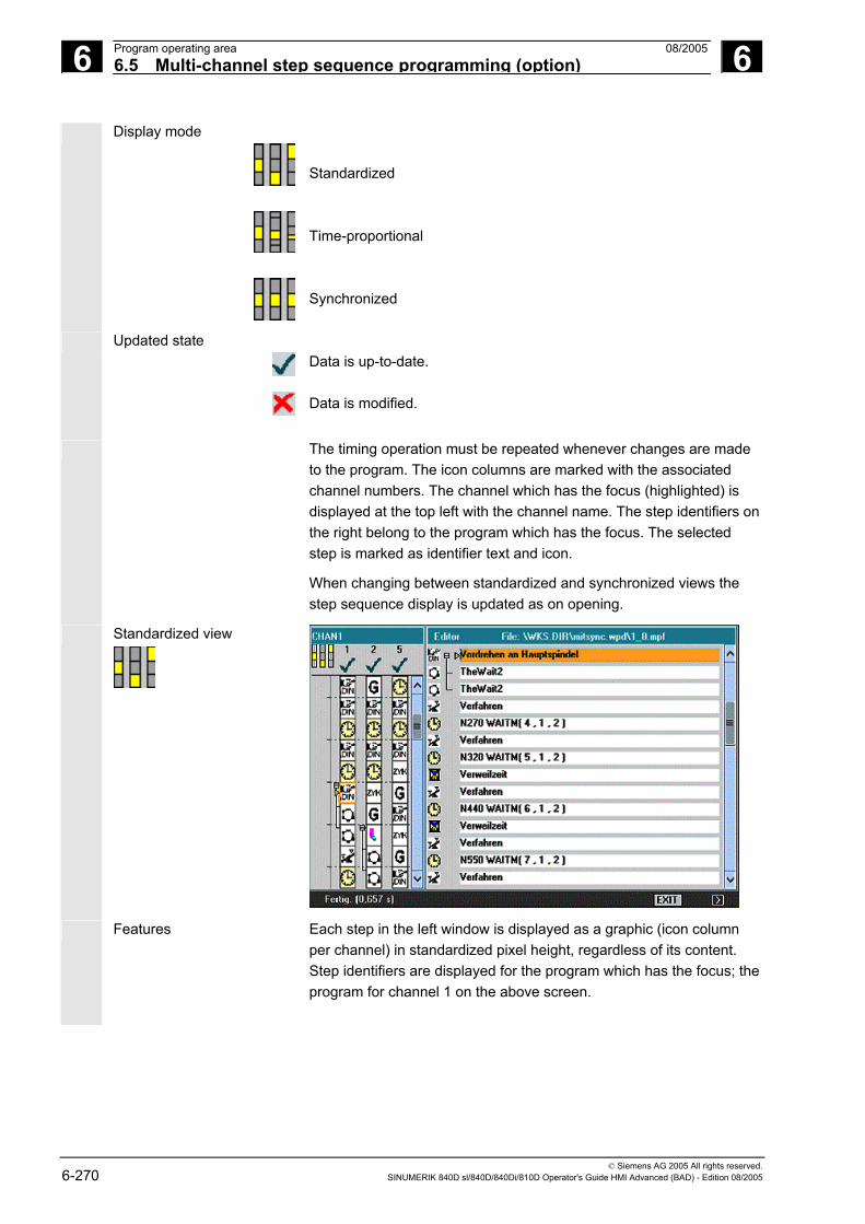
6 Program operating area 08/2005 6.5 Multi-channel step sequence programming (option)
6
© Siemens AG 2005 All rights reserved. 6-270 SINUMERIK 840D sl/840D/840Di/810D Operator's Guide HMI Advanced (BAD) - Edition 08/2005
Display mode
Standardized Time-proportional Synchronized
Updated state
Data is up-to-date. Data is modified.
The timing operation must be repeated whenever changes are made to the program. The icon columns are marked with the associated channel numbers. The channel which has the focus (highlighted) is displayed at the top left with the channel name. The step identifiers on the right belong to the program which has the focus. The selected step is marked as identifier text and icon.
When changing between standardized and synchronized views the step sequence display is updated as on opening.
Standardized view
Features Each step in the left window is displayed as a graphic (icon column per channel) in standardized pixel height, regardless of its content. Step identifiers are displayed for the program which has the focus; the program for channel 1 on the above screen.

6 08/2005 Program operating area6.5 Multi-channel step sequence programming (option)
6
© Siemens AG 2005 All rights reserved. SINUMERIK 840D sl/840D/840Di/810D Operator's Guide HMI Advanced (BAD) - Edition 08/2005 6-271
Time-proportional view
Features Steps are displayed in the left window in proportion to the duration of their execution time. In the case of WAIT markers, the step length (i.e., the number of pixels in height is changed) is displayed in proportion to the waiting time.
Precondition for time-proportional view
Timing by means of the execution of the workpiece program must have been performed. If timing has not been performed, the standardized view is displayed.
Programs which have been modified following timing are marked with "Data modified".
Computing the time again sets all programs to "Data updated".
Synchronized view
Synchron. view
Features The icons are displayed in a fixed size regardless of the time required for the step. The grouped synchronization steps are displayed in parallel with the channels (horizontal to one another) and filled with empty steps if the number of steps is uneven.
6 Program operating area 08/2005 6.5 Multi-channel step sequence programming (option)
6
© Siemens AG 2005 All rights reserved. 6-272 SINUMERIK 840D sl/840D/840Di/810D Operator's Guide HMI Advanced (BAD) - Edition 08/2005
After switching to synchronized view, the data of all programs are initially "up-to-date". Making changes can lead to programs being marked with "Data modified".
When you change back to standardized view and back to synchronized view all programs are re-synchronized and displayed as "up-to-date".
Significance of icon background color
If you position the cursor on a synchronization icon additional states from a channel view are shown by means of the icon’s background colors.
Green: Correct synchronization step -> The synchronization syntax/parameter assignment specified in the configuration file SEDITOR.INI is recognized. All addressed partners are found. Cursor on synchronization icon: The channel is affected by this synchronization and synchronization partner found.
Yellow: Not all partners can be checked: A channel number cannot be opened. At least one channel is addressed in the synchronization syntax that is not contained in workpiece.DAT. There may be an error in the program. Cursor on synchronization icon: The channel is affected by this synchronization, but at least one of the specified channel numbers is not registered in the workpiece.DAT file.
Red: Not all partners were found: An error is pending in the synchronization syntax. Consequently, the synchronization syntax must be checked and the faulty synchronization programming corrected in the addressed channel.
Unsymmetrical channel numbers in respect of synchronization partners found.
Examples are: Channel C1 WAITM(99,1,2,3) Channel C2 WAITM(99,1,2) Channel C3 WAITM(99,1,3)
Cursor on synchronization icon: In this channel, the partner was not found or the channel for the synchronization icon which has the focus contains at least one channel number from workpiece.DAT in which the partner being searched for was not found.
Programming must be modified either in the selected channel (too many or incorrect channel numbers specified) or in the searched channel (missing synchronization).

6 08/2005 Program operating area6.5 Multi-channel step sequence programming (option)
6
© Siemens AG 2005 All rights reserved. SINUMERIK 840D sl/840D/840Di/810D Operator's Guide HMI Advanced (BAD) - Edition 08/2005 6-273
The channel is affected by this synchronization but the specified channel number does not match the selected synchronization icon.
Synchronization errors The difference in the number of channels is crucial for unsymmetrical channel numbers. The number of the channel in which the WAIT marker is programmed must not be included. If the sequence is dependent on which channel reaches the WAIT marker first, an error is pending in the synchronization programming.
Pos. block number
Cancel
The first synchronization that was not found (red) is output in a dialog box:
Synchronization string, channel, channel to be synchronized: Further information on the cause of the fault can be obtained by positioning the cursor on the block number.
“Cancel” softkey.
6.5.2 Activate timing
Function
Timing for steps is based on the monitoring of times per step and per channel in relation to the program end or reset states of all involved programs (end of step per channel and creation of TimeData_* entries in the relevant file).
Timing Preparation phase - Message: Timing initializing. Please wait....
Initiation of execution – Message: Timing is active.
After completion - Message: Recorded data is processed. Please wait....

6 Program operating area 08/2005 6.5 Multi-channel step sequence programming (option)
6
© Siemens AG 2005 All rights reserved. 6-274 SINUMERIK 840D sl/840D/840Di/810D Operator's Guide HMI Advanced (BAD) - Edition 08/2005
Timing is activated in the Machine operating area under “Program control”. The steps are initialized for all channels stored in the relevant DAT environment.
Edit workpiece
The multi-channel program display is opened when you press the "Edit workpiece" softkey once the above listed preparations have been completed.
Evaluation and optimization Reposition the steps or synchronization points (WAITM()) so that multi-channel execution improves parallelism and therefore shorter workpiece processing times:
• Select extremely long steps and analyze the environment • Redistribute some tasks across the channels (e.g., break down
longer-lasting steps so that processing can be carried out by several channels in parallel)
• Optimize synchronization between the channels • Change the technological process (e.g., use steel profiles or
special tools with a shorter processing time)
Additional notes
After making changes to the program, you need to process the workpiece again to compute the new times. Programs which have been modified are marked with a red X until the times have been updated. If timing has not been performed, all steps in the program are displayed with equal time lengths. The computed times are saved in a .DAT file for each workpiece.

6 08/2005 Program operating area6.5 Multi-channel step sequence programming (option)
6
© Siemens AG 2005 All rights reserved. SINUMERIK 840D sl/840D/840Di/810D Operator's Guide HMI Advanced (BAD) - Edition 08/2005 6-275
6.5.3 Activate simulation
Function
The multi-channel step sequence display also supports multi-channel simulations. Here, the NC language labels such as WAIT2: WAITM are inserted in the NC part program. The labels are removed again when you exit the simulation and return to multi-channel step sequence display.
The labels continue to remain in place, if you are in the simulation or in the correction editor and also: • The control is switched off. • The write access for the opened file is canceled.
Multi-channel, section by section program simulation
There are specific NC instructions for program coordination for synchronizing program execution as required for multi-channel manufacturing of workpieces: (INIT(..), START(..), WAITM(..) etc.). In principle, they can be used to start independent program sections in parallel channels almost simultaneously and synchronize them via e.g. WAITM(Marker No., ...) once the associated machining operations have been executed and before starting the next sections.
Simultaneous aspects can only be sequentially emulated with simulation. NC program labels serve to mark program sections. Emulating the multi-channel program coordination in the simulation assumes that NC instructions for program coordination were marked with NC labels (manually or automatically during program generation). Simultaneous operational sequences which are independent of one another are executed one after the other in the respective channels (channel change per section required), before sequences are created for the next sections in the same manner. The result in the simulation is a similar sequence of machining steps to that on the machine.
Supplementary conditions • Only one out of 10 possible channel instances can be assigned to the single-channel graphic module (simulation display) at any one time (no simultaneous mode for channels!). Commands for multi-channel program coordination (INIT(..), START(..), WAITM(..) etc.) are not executed in the program interpreter for the simulation.
• Partial processing of the "channels" on the same stationary blank are superimposed.

6 Program operating area 08/2005 6.5 Multi-channel step sequence programming (option)
6
© Siemens AG 2005 All rights reserved. 6-276 SINUMERIK 840D sl/840D/840Di/810D Operator's Guide HMI Advanced (BAD) - Edition 08/2005
• Path labels are universal markings/section structure aids in NC programs which can trigger specific actions during the simulation run: - Path labels can be optionally displayed in the graphic - The intermediate time can be computed for sections delimited by path labels. - The graphic state can be stored temporarily for sections that are delimited by path labels.
Path labels have a defined label syntax: Identifiers for simulation should exist singly in one NC block in so far as possible.
• The channel changes section by section with defined path labels (NC program labels).
Section limitation using path labels
If the "Stop label" column is clearly defined, the "Start label" is created implicitly:
• An empty "Start label" field has the same meaning as a start from the beginning of the program
• An empty "Stop label" field has the same meaning as a stop at the end of the program
• With the same "program name", the "start label" of a section is equal to the "stop label" of the preceding section
• If start and stop labels are not specified, the entire program is executed.
JOB list If the job list does not yet exist, it is created on simulation selection
and populated with default values from the job list or from the corresponding step editor (MCSP) list contained within the current workpiece directory.
After confirmation of the machining list with OK, the relevant [JOB] section is generated in the workpiece-specific DPWP.ini file. The following entries are managed: • Program name.type • Channel number • Spindle unit: Main spindle, counterspindle, variable • Start label (path label) • Stop label (path label) • Length of the machining list (number of sections)
The machining list can be updated at any time via the "Channel/spindle" menu.

6 08/2005 Program operating area6.5 Multi-channel step sequence programming (option)
6
© Siemens AG 2005 All rights reserved. SINUMERIK 840D sl/840D/840Di/810D Operator's Guide HMI Advanced (BAD) - Edition 08/2005 6-277
Simulation sequence The simulation sequence is controlled by the contents of the machining list menu "Channel/spindle" and supports simulation of multi-channel program coordination:
• Selecting the list validates the specified operational sequence.
• In each sequence step the designated program can be fully executed - as before - (i.e. from program start to M2/M30 or M17) in the specified channel by leaving the fields "Start label" and "Stop label" empty
• With each sequence step you can change to a different channel at the section of another program (section by section channel change) up to the specified "Stop label".
• If a label which was not previously defined as a "Stop label" for the sequence is specified in the "Start label" field, an implicit search run will be performed (without output of graphics) up to the "Start label" in the selected program before the simulation run is started.
• If the label assignments are inconsistent, the simulation is reset to the last valid state and a message is issued to this effect, e.g. "Label xxxxxx not found. Adapt label definition in machining list or adapt part program!".
• Each sequence step should be started separately and can also be reset separately.
• Section-by-section change of the spindle unit within the step sequence is permissible and controlled by means of keywords from the program.
• The section-by-section channel change during program run is only supported in conjunction with specification of the corresponding program labels (path labels), which are either programmed manually or generated internally via integrated functions.

6 Program operating area 08/2005 6.5 Multi-channel step sequence programming (option)
6
© Siemens AG 2005 All rights reserved. 6-278 SINUMERIK 840D sl/840D/840Di/810D Operator's Guide HMI Advanced (BAD) - Edition 08/2005
Simulation result By superimposing the partial executions from the machining list on a blank the section by section simulation mode only changes for the sequence of machining sections in the graphic. There is no change in the overall result.
Search run
The list of machining steps (for which an intermediate model is available in the graphic module in the current simulation state) allows direct selection of a section in the simulation. See also "Display and colors"/Manage path labels. The corresponding section is selected and confirmed with OK. The simulation will start at the beginning of this section and is based on the state which the preceding section was in the last time its execution was completed.
Timing Timing
The timing table shows an analysis of the timings calculated from within the simulation and encompasses the specified sequence of execution up to the current state of the simulated machining sections. The timing table is in cumulated form and takes into account the defined downtime values (for T, S, M and H functions if present); data is shown for the respective section limits.
The section limits are marked with the associated ASCII label derived from the "Stop label" (if present) or with M30 at the end of the program. Times are computed at each section end.

6 08/2005 Program operating area6.6 Free contour programming
6
© Siemens AG 2005 All rights reserved. SINUMERIK 840D sl/840D/840Di/810D Operator's Guide HMI Advanced (BAD) - Edition 08/2005 6-279
6.6 Free contour programming
Function
Free contour programming is a support tool for the editor. The contour programming function enables you to create simple and complex contours. An integrated contour calculator (geometry processor) calculates any missing parameters for you, provided that they can be calculated from other parameters. You can link together contour elements. Contour transition elements “radius” and “chamfer” are also provided. The programmed contours are transferred to the edited part program.
Technologies
The scope of functions of the contour calculator differs depending on the chosen technology:
Functions which are only available in the turning technology include:• Toggling between radius/diameter programming (DIAMON,
DIAMOF, DIAM90) • Chamfer/radius at the start and end of the contour • Undercuts as transition elements between two axially parallel
straight lines, where one runs horizontally and the other vertically (Form E, Form F, thread undercut, free undercut)
Functions which are only available in the milling technology include:• Contours with symmetry (mirroring) • Contours with repetitions • Combinations of both
The contour calculator takes into account channel-specific display
machine data. As it does not know which channel the program is being created for, it always analyzes the display machine data of the 1st channel. Allowances parallel to the contour, which are required for grinding, can be created by free contour programming and modified again if necessary.

6 Program operating area 08/2005 6.6 Free contour programming
6
© Siemens AG 2005 All rights reserved. 6-280 SINUMERIK 840D sl/840D/840Di/810D Operator's Guide HMI Advanced (BAD) - Edition 08/2005
Contour elements The following are contour elements: Starting point Straight line (planar, longitudinal, inclined)
Circular arc A pole is a pseudo contour element. Straight lines and circular arcs can also be defined by polar coordinates in reference to a pole.
Additional notes
1. The valid geometry axes in the first channel are determined and used in the part program.
2. The contour editor uses the last programmed axis position for the starting point, without allowing for previously valid G functions.
3. You must also specify the side on which the contour allowance should lie, e.g., "right" or "left".
6.6.1 Program contour
Sequence
New contour
New
OK
Use the "Workpiece" and "Part program" softkeys in the Program operating area to select an existing program and press the "Input" key or open a new part program using the “New” softkey, enter a name and confirm with “OK”. You are now in the ASCII editor.
Contour
Generate contour
Contour 1 str. line
Contour 2 str. lines
Contour 3 str. lines
The "Contour" softkey displays a vertical softkey bar with the following options:
The contour calculator is activated to generate a contour chain from contour elements. Preparatory cycles are displayed with help displays for creating straight lines and transition elements, if applicable.
Recompile
You can edit an existing contour by selecting the "Recompile" softkey. The editor cursor must be positioned inside the contour to do this.

6 08/2005 Program operating area6.6 Free contour programming
6
© Siemens AG 2005 All rights reserved. SINUMERIK 840D sl/840D/840Di/810D Operator's Guide HMI Advanced (BAD) - Edition 08/2005 6-281
Notice
Upon recompilation only the contour elements that were created with free contour programming are regenerated. In addition, only the texts that were added using the "free text input" input field are recompiled. Any changes you made directly in the program text are lost. However, you can subsequently insert and edit user-defined texts, which will not be lost.
Sequence
Define the starting point The input screen for the contour start point is displayed.
The input field with the input focus is indicated by the yellow
background color. Once the input is acknowledged with "Accept element" or "Cancel", you can navigate around the contour chain using the ↑ , ↓ arrow keys. The current position in the chain is indicated in red.
When entering a contour, begin at a position which you already know and enter it as the starting point. The default tool axis or program level (defined in the machine data) can be changed for machines with more than two geometry axes. The associated starting point axes are automatically adjusted. Together with defining the contour starting point, a pole can also be defined for contour programming in polar coordinates. The pole can also be defined or redefined at a later time. The programming of the polar coordinates always refers to the pole that was defined last.

6 Program operating area 08/2005 6.6 Free contour programming
6
© Siemens AG 2005 All rights reserved. 6-282 SINUMERIK 840D sl/840D/840Di/810D Operator's Guide HMI Advanced (BAD) - Edition 08/2005
Accept element
Select the "Accept element" softkey to store the starting point. You can add the next element by selecting the appropriate softkey:
The approach motion to the starting point can be changed from G0 (rapid traverse) to G1 (linear interpolation) via the "Approach starting point" field. You can define a specific feedrate for G1 via the "Free text input" field , e.g.,, G1 F0.3.
Alternative
Position the cursor on the "Transverse axis dimension" field and click on the field using the "Alternative" softkey (or with the "Selection" key) repeatedly until the dimension you require is displayed.
1...
0
Enter the values for the starting point.
Accept element
The values you have entered are accepted when you select "Accept element" and you can then add the next element by selecting the appropriate softkey.
Sequence
Define contour elements
From the starting point enter the first contour element, e.g.,, straight line. Enter all of the data from the workpiece drawing: Length of straight lines, end position, transition to following element, angle of pitch, etc.
All parameters
Select the "All parameters" softkey to display a selection list of all the parameters for the contour element.
If you leave any parameter input fields blank, the control assumes that you do not know the right values and attempts to calculate these from the settings of the other parameters.
The contour is always machined in the programmed direction.
You can select an existing contour element with "INPUT". A new contour element is inserted after the cursor when you select one of the contour elements on the horizontal softkey bar; the input focus is then switched to the parameter input on the right of the graphic display. You can navigate around the contour chain again after selecting "Accept element" or "Cancel". The following contour elements (example for turning: G18) are available for the definition of contours:
Horizontal line
Vertical line
Straight line in the horizontal direction. Enter the end point of the straight line (incremental/absolute can be selected with the "Alternative" softkey), program the transition to the following element and then press the "Accept element" softkey.

6 08/2005 Program operating area6.6 Free contour programming
6
© Siemens AG 2005 All rights reserved. SINUMERIK 840D sl/840D/840Di/810D Operator's Guide HMI Advanced (BAD) - Edition 08/2005 6-283
Vertical line
Straight line in the X direction. Oblique line in the X/Z direction. Enter the end point of the line using coordinates or an angle.
Circle
Arc with any direction of rotation
Sequence
Contour transition elements A transition element can be used whenever there is a point of intersection between two neighboring elements; this can be calculated from the input values.
You can choose to insert either a radius RD or a chamfer FS as the transition element between any two contour elements. The transition is always appended to the end of a contour element. You select transition elements in the parameter input screen for the relevant contour element.
The undercut transition element is only offered in turning technology, see Chapter “Undercuts in turning technology”.
Abort
When you select "Cancel", the contour element values are discarded and you return to the main screen. The input focus switches back to the contour chain.
Delete value
The values for the element are deleted.
Radius or chamfer at the start or end of a turning contour.
In simple turning contours a chamfer or radius should generally be appended at the start and end of the contour.
These form a closure to the axially parallel blank:
You select the direction of transition for the contour start in the starting point screen. You can choose between chamfer and radius. The value is defined in the same manner as for the transition elements. In addition, four directions can be selected in a single selection field.

6 Program operating area 08/2005 6.6 Free contour programming
6
© Siemens AG 2005 All rights reserved. 6-284 SINUMERIK 840D sl/840D/840Di/810D Operator's Guide HMI Advanced (BAD) - Edition 08/2005
You select the direction of the transition element for the contour end in the end screen. This selection is always proposed, even if previous elements were assigned no transition.
Example
The selected transition chamfer on the contour start and its given value is displayed for clarity in an output field in the end screen next to the direction selection:
Symbolic representation of contour elements
The elements of the contour and pole, if applicable, are displayed next to the graphic window using symbols in the sequence in which they were programmed in a contour chain.
Parameter with gray background:
These parameters have been calculated by the control and cannot be altered.
When the programmable parameter input fields (white background) are altered, the control calculates new data, which are then immediately displayed in the input screen.
Input value is already calculated
With some contours, the control may already have calculated an input value from other settings.
Problems may then arise if the control-calculated value does not tally with the workshop drawing. In this case, you must delete the settings from which the control has automatically calculated the input value. You can then enter the precise value from the workshop drawing.

6 08/2005 Program operating area6.6 Free contour programming
6
© Siemens AG 2005 All rights reserved. SINUMERIK 840D sl/840D/840Di/810D Operator's Guide HMI Advanced (BAD) - Edition 08/2005 6-285
Free text input
Under "Free text input" you can enter a comment that is inserted in
the program at the end of the contour (e.g.,, specifying the technology, feedrate, M function).
Contour allowance
By selecting "Cont. allow.", you can specify the allowance parallel to the contour and the side of the contour on which the allowance applies. It is displayed as an allowance in the graph window.
It is possible to change the allowance and the parameters from the original contour. These changes are applied to subsequent machining operations in the part program, e.g.,, for grinding.
6.6.2 Undercuts for turning technology
Function
Supplementary conditions
The form E and F undercut and form DIN 76 and general thread undercut functions are only activated when turning technology is enabled. The display machine data 9020: TECHNOLOGY is analyzed to determine the technology. Form E and F undercuts as well as thread undercuts are only available if level G18 is set. Undercuts are only permitted on contour edges of the rotational body, which run in the direction of the longitudinal axis (usually parallel to the Z axis). The longitudinal axis is identified by the machine data. The machine data 20100: DIAMETER_AX_DEF for turning machines contains the name of the transverse axis (usually X). The other axis in G18 is the longitudinal axis (usually Z). If MD 20100: DIAMETER_AX_DEF does not contain a name or contains a name that does not conform to G18, there are no undercuts. Undercuts only appear on corners between horizontal and vertical straight lines, including any straight lines, which are at 0°, 90°, 180° or 270°. A tolerance of ±3° is required here, so that conical threads are also possible (these undercuts do not meet the standard in this case).
Operator focus When the operator focus is on "Trans. to following element", use the

6 Program operating area 08/2005 6.6 Free contour programming
6
© Siemens AG 2005 All rights reserved. 6-286 SINUMERIK 840D sl/840D/840Di/810D Operator's Guide HMI Advanced (BAD) - Edition 08/2005
Select key or "Alternative" softkey to select Undercut. When the focus is on the following field, the undercut form can be defined. The Select key and "Alternative" softkey can be used to select the following options: Form E Form F DIN 76 thread General thread
Operation If the undercut form is specified, the RxT field can be opened with the input key and the desired coordinates can be selected with the cursor keys. The desired coordinates can also be selected by repeatedly pressing the Select key. If the diameter is already known when selecting the undercut, the list box displays a suggested value. Za is the machining allowance (grinding allowance) permitted according to DIN 509.

6 08/2005 Program operating area6.6 Free contour programming
6
© Siemens AG 2005 All rights reserved. SINUMERIK 840D sl/840D/840Di/810D Operator's Guide HMI Advanced (BAD) - Edition 08/2005 6-287
Form E
Form F
DIN thread

6 Program operating area 08/2005 6.6 Free contour programming
6
© Siemens AG 2005 All rights reserved. 6-288 SINUMERIK 840D sl/840D/840Di/810D Operator's Guide HMI Advanced (BAD) - Edition 08/2005
In the case of standard thread undercuts, the characteristic size of the thread pitch is P. The depth, length and transition radius of the undercut are calculated according to the DIN standard. The (metric) thread pitches specified in DIN 76 can be used. The arc-in angle can be freely selected in the 30°-90° range. If the diameter is known when selecting the undercut, an appropriate thread pitch is suggested. Forms DIN 76 A (external control) and DIN 76 C (internal control) are available. The program detects the two forms automatically using their geometry and topology.
General thread Based on the thread undercut according to DIN (see above) you can
use the “General thread” undercut type to create specific undercuts, e.g.,, for inch threads. The following inputs can be made:

6 08/2005 Program operating area6.6 Free contour programming
6
© Siemens AG 2005 All rights reserved. SINUMERIK 840D sl/840D/840Di/810D Operator's Guide HMI Advanced (BAD) - Edition 08/2005 6-289
6.6.3 Parameterize contour elements
Function
In principle, input screens are handled according to the same procedure already described for handling contour elements STRAIGHT LINE, OBLIQUE LINE and CIRCLE.
To help you to program a contour, the following softkeys are also available:
Tangent to previous element Tangent prev. elem.
The "Tangent preced. elem." softkey presets the angle α2 to a value of 0. The contour element has a tangential transition to the preceding element, i.e., the angle to the preceding element (α2) is set to 0 degrees.
Display additional parameters Allparameters
If your drawing contains further data (dimensions) for a contour element, select the "All parameters" softkey to extend the range of input options for the element.
Alternative
The "Alternative" softkey is displayed only in cases where the cursor is positioned on an input field with several switchover settings.
Select dialog Select dialog
Some parameter configurations can produce several different contour characteristics. In such cases, you will be asked to select a dialog. By clicking the "Select dialog" softkey, you can display the available selection options in the graphic display area.
Select dialog
Accept dialog
Select the "Select dialog" softkey to make the correct selection (black solid line) and confirm your choice with the "Accept dialog" softkey.
Change a selected dialog Change selection
Select dialog
Accept dialog
If you want to change an existing dialog selection, you must select the contour element in which the dialog was originally chosen. Both alternatives are displayed again when you select the "Change selection" softkey.
You can select another dialog.
Clear a parameter input field Delete value
You can delete the value in the selected parameter input field with the DEL key or "Delete value" softkey.

6 Program operating area 08/2005 6.6 Free contour programming
6
© Siemens AG 2005 All rights reserved. 6-290 SINUMERIK 840D sl/840D/840Di/810D Operator's Guide HMI Advanced (BAD) - Edition 08/2005
Save a contour element Accept element
If you have entered the available data for a contour element or selected the desired contour by means of the "Select dialog" softkey, select the "Accept element" softkey to store the contour element and return to the main screen. You can then program the next contour element.
Append contour element Use the cursor keys to select the element in front of the end marker. Use the softkeys to select the contour element of your choice and
enter the values you know in the input screen for that element. Accept
element Confirm your inputs with the "Accept element" softkey.
Select a contour element
Position the cursor on the desired contour element in the contour chain, and select using the "Input" key. The parameters for the selected element will then be displayed. The name of the element appears at the top of the parameter configuration window.
If the contour element can be represented geometrically, it is highlighted accordingly in the graphic display area, i.e. the color of the contour element changes from black to red.
Edit a contour element
You can use the cursor keys to select a programmed contour element in the contour chain. The "Input" key displays the parameter input fields. These can now be edited.
Insert contour element Use the cursor keys to select the contour element after which you wish to insert another element in the contour chain.
Then select the contour element to be inserted from the softkey bar.
Accept element
After you have configured the parameters for the new contour element, confirm the insert operation by selecting the "Accept element" softkey.
Depending on the new status of the contour, the contour elements below are updated automatically or when the cursor arrow is hovered over them. Contour elements that appear after the insertion point and are not updated are displayed in green in the contour chain.
Delete a contour element Deleteelement
Use the arrow keys to select the element you wish to delete. The selected contour symbol and associated contour element in the programming graphic are highlighted in red. Then press the "Delete element" softkey and confirm the query.
Undo an input
Cancel
By selecting the "Cancel" softkey you can return to the main screen, without transferring the last edited values to the system.

6 08/2005 Program operating area6.6 Free contour programming
6
© Siemens AG 2005 All rights reserved. SINUMERIK 840D sl/840D/840Di/810D Operator's Guide HMI Advanced (BAD) - Edition 08/2005 6-291
6.6.4 Graphic representation of contours
Function
The graphics window displays the progress of the contour chain as you configure the parameters for the contour elements. The element you have selected is displayed in red in the graphics window. Navigation within the contour is described in "Contour programming".
The created contour element can be displayed in various line types and colors depending on its status:
Color/line Meaning Black Programmed contour Red Current contour element Green Alternative element Black unbroken line
Element is fully defined
Light blue line Element is partially defined Dashed green line Alternative element
The current status of the contour is displayed insofar as it can be interpreted by the control on the basis of parameter inputs. If the contour is still not displayed in the programming graphic, further values must be entered. Check the contour elements you have already programmed, if required. You may have forgotten to enter all of the known data. The coordinate system scaling is automatically adapted to changes in the complete contour.

6 Program operating area 08/2005 6.6 Free contour programming
6
© Siemens AG 2005 All rights reserved. 6-292 SINUMERIK 840D sl/840D/840Di/810D Operator's Guide HMI Advanced (BAD) - Edition 08/2005
The position of the coordinate system is displayed in the graphics
window.
Contour allowance Here, you enter the complete description of the allowance parallel to the contour and the side of the contour on which the allowance applies.
6.6.5 Symmetrical contours with milling technology
Function
Milling contours are often symmetrical. To exploit the symmetry of contours only the relevant parts of the contour are input, the remainder is created through replication.
Symmetries Closed symmetrical contours can be created through a combination of mirroring and turning repetitions:
• Mirroring: The programmed contour can be mirrored in the starting or end point on any given straight line. In addition, a radius or chamfer can be entered in the mirroring point.
• Repetition for closed contour:
The mirrored contour can be closed to the left or to the right through repetition. In addition, a radius or chamfer can be input at the repetition corner points (similar to closing a contour from the end point to the starting point).
Example
R20
R15
90
40

6 08/2005 Program operating area6.6 Free contour programming
6
© Siemens AG 2005 All rights reserved. SINUMERIK 840D sl/840D/840Di/810D Operator's Guide HMI Advanced (BAD) - Edition 08/2005 6-293
The relevant (non-symmetrical) part of the contour is described as standard:
The finished contour is created through mirroring and repetition:
The lines of symmetry are displayed using a dashed line. The mid point of the created contour is marked with a cross. The symmetry is only visible on the end point.
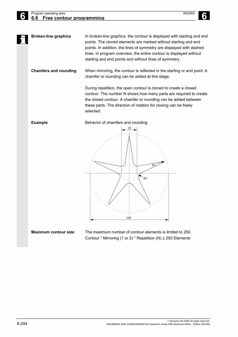
6 Program operating area 08/2005 6.6 Free contour programming
6
© Siemens AG 2005 All rights reserved. 6-294 SINUMERIK 840D sl/840D/840Di/810D Operator's Guide HMI Advanced (BAD) - Edition 08/2005
Broken-line graphics In broken-line graphics, the contour is displayed with starting and end points. The cloned elements are marked without starting and end points. In addition, the lines of symmetry are displayed with dashed lines. In program overview, the entire contour is displayed without starting and end points and without lines of symmetry.
Chamfers and rounding When mirroring, the contour is reflected in the starting or end point. A chamfer or rounding can be added at this stage. During repetition, the open contour is cloned to create a closed contour. The number N shows how many parts are required to create the closed contour. A chamfer or rounding can be added between these parts. The direction of rotation for closing can be freely selected.
Example Behavior of chamfers and rounding
R5
100
R1
20
Maximum contour size The maximum number of contour elements is limited to 250. Contour * Mirroring (1 or 2) * Repetition (N) ≤ 250 Elements
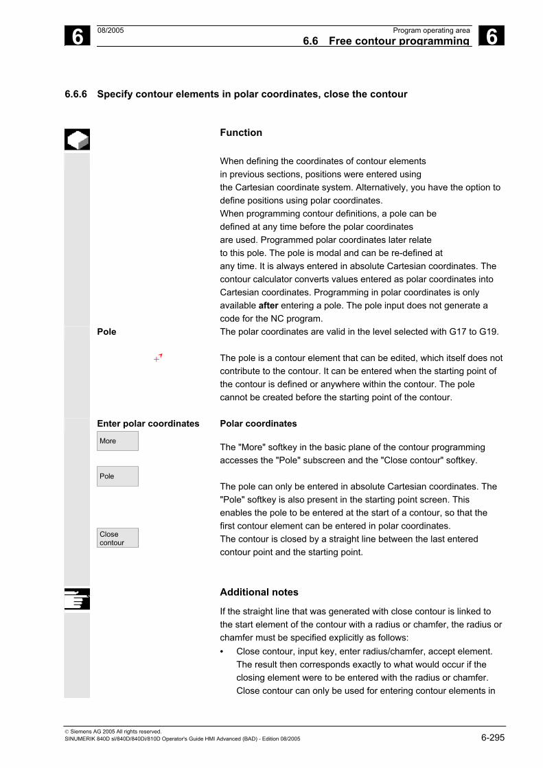
6 08/2005 Program operating area6.6 Free contour programming
6
© Siemens AG 2005 All rights reserved. SINUMERIK 840D sl/840D/840Di/810D Operator's Guide HMI Advanced (BAD) - Edition 08/2005 6-295
6.6.6 Specify contour elements in polar coordinates, close the contour
Function
When defining the coordinates of contour elements in previous sections, positions were entered using the Cartesian coordinate system. Alternatively, you have the option to define positions using polar coordinates. When programming contour definitions, a pole can be defined at any time before the polar coordinates are used. Programmed polar coordinates later relate to this pole. The pole is modal and can be re-defined at any time. It is always entered in absolute Cartesian coordinates. The contour calculator converts values entered as polar coordinates into Cartesian coordinates. Programming in polar coordinates is only available after entering a pole. The pole input does not generate a code for the NC program.
Pole
The polar coordinates are valid in the level selected with G17 to G19. The pole is a contour element that can be edited, which itself does not contribute to the contour. It can be entered when the starting point of the contour is defined or anywhere within the contour. The pole cannot be created before the starting point of the contour.
Enter polar coordinates
More
Pole
Closecontour
Polar coordinates
The "More" softkey in the basic plane of the contour programming accesses the "Pole" subscreen and the "Close contour" softkey. The pole can only be entered in absolute Cartesian coordinates. The "Pole" softkey is also present in the starting point screen. This enables the pole to be entered at the start of a contour, so that the first contour element can be entered in polar coordinates. The contour is closed by a straight line between the last entered contour point and the starting point.
Additional notes
If the straight line that was generated with close contour is linked to the start element of the contour with a radius or chamfer, the radius or chamfer must be specified explicitly as follows: • Close contour, input key, enter radius/chamfer, accept element.
The result then corresponds exactly to what would occur if the closing element were to be entered with the radius or chamfer. Close contour can only be used for entering contour elements in

6 Program operating area 08/2005 6.6 Free contour programming
6
© Siemens AG 2005 All rights reserved. 6-296 SINUMERIK 840D sl/840D/840Di/810D Operator's Guide HMI Advanced (BAD) - Edition 08/2005
polar coordinates if the starting point of the contour was set to polar and the same pole is still valid at the closing point.
Input switchover: Cartesian/polar
Once a pole has been set, whether inserted in the starting point or subsequently, the contour elements can be entered as: - Circular arcs - Straight lines/(inclined) or as polar coordinates. To switch between Cartesian and polar coordinates additional toggle fields are displayed for "Straight line, any" and "Circular arc" in both the basic contour input view and the view with "All parameters". A toggle field is not displayed if no poles exist. Input fields and display fields are then only available for Cartesian values.
Absolute/incremental input In the case of "polar" coordinates, absolute and incremental polar coordinates can be entered. The input fields and display fields are labeled inc and abs. Absolute polar coordinates are defined by an absolute distance to the pole that is always positive and an angle in the range of 0° ... +/- 360°. When absolute dimensions are specified, the angular reference is based on a horizontal axis of the working plane, e.g., X axis with G17. The positive direction of rotation runs counter-clockwise. If there are several input poles, the definitive pole is the last pole before the input or edited element.

6 08/2005 Program operating area6.6 Free contour programming
6
© Siemens AG 2005 All rights reserved. SINUMERIK 840D sl/840D/840Di/810D Operator's Guide HMI Advanced (BAD) - Edition 08/2005 6-297
Incremental polar coordinates relate to both the definitive pole and the
end point of the preceding element.
For an incremental input, the absolute distance to the pole is calculated using the absolute distance from the end point for the preceding element to the pole plus the length increment that was entered. The increment can be positive or negative. The absolute angle is calculated accordingly using the absolute polar angle of the preceding element plus the angular increment. Here it is not necessary for the preceding element to have been entered as polar.
In contour programming, the contour calculator converts the Cartesian coordinates of the preceding end point using the definitive pole into polar coordinates. This also applies if the preceding element has been given in polar coordinates, since this could relate to another pole if a pole has been inserted in the meantime.

6 Program operating area 08/2005 6.6 Free contour programming
6
© Siemens AG 2005 All rights reserved. 6-298 SINUMERIK 840D sl/840D/840Di/810D Operator's Guide HMI Advanced (BAD) - Edition 08/2005
Pole change example Pole: XPole = 0.0, YPole = 0.0 (Pole 0) End point: L1abs = 10.0 ϕabs = 30.0° Calculated Cart. coordinates Xabs = 8,6603 Yabs =5.0 New pole: XPole1 = 5.0 YPole1 = 5.0 (Pole 1) Calculated polar coord. for preced.
element L1abs = 3.6603 ϕabs = 0.0° Next point: L1inc = -2.0 ϕ inc = 45.0° Absol. pol. coord. for current
element L1abs = 1.6603 ϕabs = 45.0° Calc. Cart. coordinates Xabs = 1.1740 Yabs = 1.1740
5
5
10Y
X
8.6603 10Pole 0
Pole1
φinc 45.0 °
φinc 30.0 °
L1inc -2
Prev. element
Polar coordinates for prevelement with ref to pole 1:
L1= 3.6603, φ = 0
φ 0 °
1.6603
Polar coordinates withref. to pole 0 (entry)

6 08/2005 Program operating area6.6 Free contour programming
6
© Siemens AG 2005 All rights reserved. SINUMERIK 840D sl/840D/840Di/810D Operator's Guide HMI Advanced (BAD) - Edition 08/2005 6-299
Example: input circular arc, polar
You require a counter-clockwise arc to travel from the starting point X67.5 Y80.211 around the center point I=50, J=50 (according to the pole) and the radius 34.913 to the end point with an absolute polar angle of 200.052 degrees.
The inputs for the circular arc are as follows:
The code created in the part program is as follows:
References For further details, see: /PG/, Programming Guide Fundamentals "Circular programming with polar coordinates"

6 Program operating area 08/2005 6.6 Free contour programming
6
© Siemens AG 2005 All rights reserved. 6-300 SINUMERIK 840D sl/840D/840Di/810D Operator's Guide HMI Advanced (BAD) - Edition 08/2005
6.6.7 Contour programming support
Function
When you input parameters, you can call up a help screen using the Info key which graphically represents the parameters you are entering. The help screen that appears depends on the cursor position in the parameter display.
The help screen is placed over the graphic display.
If you press the Info key again the help screen is closed and the graphic display is activated once again. The help screens displayed correspond to the selected coordinate system. The axis identifiers are derived from the current geometry axis names.
Help screens are displayed for the following entries: • Starting point • Straight vertical line • Straight vertical line, angle entry field • Straight horizontal line • Straight horizontal line, angle entry field • Straight line in any direction • Straight line in any direction, angle entry field • Circle • Circle, angle entry field • Radius/chamfer

6 08/2005 Program operating area6.6 Free contour programming
6
© Siemens AG 2005 All rights reserved. SINUMERIK 840D sl/840D/840Di/810D Operator's Guide HMI Advanced (BAD) - Edition 08/2005 6-301
6.6.8 Parameter description of straight line/circle contour elements
Parameter Contour element "Straight line"
X absolute X incremental
Absolute end position in X direction Incremental end position in X direction
Y absolute Y incremental
Absolute end position in Y direction Incremental end position in Y direction
l Length of straight line α1 Pitch angle with reference to X axis α2 Angle to preceding element; tangential transition: α2=0 Transition to
following element
Transition element to next contour is a chamfer (FS) Transition element to next contour is a radius (R) FS=0 or R=0 signifies no transition element
Parameter Contour element "Circle"
X absolute X incremental
Absolute end position in X direction Incremental end position in X direction
Y absolute Y incremental
Absolute end position in Y direction Incremental end position in Y direction
α1 Starting angle with reference to X axis α2 Angle to preceding element; tangential transition: α2=0 β1 End angle with reference to X axis β2 Angle of aperture of circle Direction of
rotation In clockwise or counter-clockwise direction
R Radius of circle I Position of circle center point in X direction (abs. or incr.) J Position of circle center point in Y direction (abs. or incr.) Transition to
following element
Transition element to next contour is a chamfer (FS) Transition element to next contour is a radius (R) FS=0 or R=0 means no transition element
Machine manufacturer
The names of the identifiers (X or Y ...) are defined in the machine data where they can also be changed.

6 Program operating area 08/2005 6.6 Free contour programming
6
© Siemens AG 2005 All rights reserved. 6-302 SINUMERIK 840D sl/840D/840Di/810D Operator's Guide HMI Advanced (BAD) - Edition 08/2005
6.6.9 Examples of free contour programming
Example 1 Starting point: X=5.67 abs., Y=0 abs., machining plane G17
The contour is programmed in a counter-clockwise direction.
Workpiece drawing of contour X= - 137.257 abs.
X=5.67 Y=0
43.972
R72
125°
Starting point
X
Y
Element Softkey Parameter Remarks 1
All parameters, α1=180 degrees Observe angles in help screen!
2
X=−43.972 inc, all parameters X=−137.257 abs. α1=−125 degrees
Definition of coordinates in X in "abs." and in "inc." Observe angles in help screen!
3
X=43.972 inc α1=−55 degrees
Definition of coordinates in X in "inc" Observe angles in help screen!
4
X=5.67 abs
5
Clockwise direction of rotation, R=72, X=5.67 abs.., Y=0 abs.., Select dialog

6 08/2005 Program operating area6.6 Free contour programming
6
© Siemens AG 2005 All rights reserved. SINUMERIK 840D sl/840D/840Di/810D Operator's Guide HMI Advanced (BAD) - Edition 08/2005 6-303
Example 2 Starting point: X=5.67 abs., Y=0 abs., machining plane G17 The contour is programmed in the clockwise direction with dialog selection. For this contour it is advisable to display all parameters via the "All parameters" softkey.
Workpiece drawing of contour
R5
30°
6
R7.5
R25
Y
X
Starting pointX=0, Y=0
Element Softkey Parameter Remarks 1
Y=−104 abs.
2
Clockwise direction of rotation, R=79, I=0 abs., Select dialog, all parameters, β2=30 degrees
3
Clockwise direction of rotation, tangent to preced. R=7.5, all parameters, β2=180 degrees
4
Counter-clockwise direction of rotation, R=64, X=−6 abs., I=0 abs., Make dialog selection, make dialog selection Transition to following element: R=5
5
All parameters, α1=90 degrees, Transition to following element: R=5
Observe angles in help screen!
6
Clockwise direction of rotation, R=25, X=0 abs., Y=0 abs. I=0 abs., make dialog selection, make dialog selection

6 Program operating area 08/2005 6.6 Free contour programming
6
© Siemens AG 2005 All rights reserved. 6-304 SINUMERIK 840D sl/840D/840Di/810D Operator's Guide HMI Advanced (BAD) - Edition 08/2005
Example 3 Starting point: X=0 abs., Y=5.7 abs., machining plane G17 The contour is programmed in a clockwise direction.
Workpiece drawing of contour
5
22°
R2R3.2
R2
60°
R2
R9.5
11.5
Starting pointX=0, Y=5.7 15
.214
.8
Y
X
4.65
4.65
Element Softkey Parameter Remarks 1
Counter-clockwise direction of rotation, R=9.5, I=0 abs., make dialog selection, Transition to following element: R=2
2
α1=−30 degrees Observe angles in help screen!
3
Clockwise direction of rotation, tangent to preced. R=2, J=4.65 abs.
4
Counter-clockwise direction of rotation, tangent to preced. R=3.2, I=11.5 abs., J=0 abs., make dialog selection, make dialog selection
5
Clockwise direction of rotation, tangent to preced. R=2, J=−4.65 abs., make dialog selection
6
Tangent to preced. α1=−158 degrees, Y=−14.8 abs., α2=0 degrees
Observe angles in help screen!
7 All parameters, L=5, make dialog selection
8
Y=5.7 abs.
9 X=0 abs.

6 08/2005 Program operating area6.6 Free contour programming
6
© Siemens AG 2005 All rights reserved. SINUMERIK 840D sl/840D/840Di/810D Operator's Guide HMI Advanced (BAD) - Edition 08/2005 6-305
6.6.10 Cycle support
The following technologies:
• Drilling • Milling • Turning
are provided with additional support in the form of pre-defined cycles, which must then be parameterized.
References Programming Guide Cycles
Settings Settings
Editor settings
Define the following values in the "Settings editor" window: • Horizontal paging ON/OFF • Display hidden lines ON/OFF • Time interval for Automatic Save
When selecting Automatic Save you can define the time intervals at which saves are automatically performed (applicable only to files on the hard disk). If a value ≠ 0 is entered, the "Save file" softkey is not displayed. If the value 0 is entered, automatic save is not performed.
• Automatic numbering ON/OFF A new block number is automatically inserted on every new line. If you wish to assign block numbers to an existing program, use the "Renumber" function.
• Number of first block • Incrementation of block numbers (e.g., 1, 5, 10)
Set. contour prog.
The following settings are available for contour programming: • Last line
Each time you complete a program step in contour programming you can insert text in the last line (e.g., "End of contour").
Additional notes
• The coordinate system and the technology to be used are set via the machine data; see /IAM/ Installation and Startup Guide HMI Advanced.
• Edited programs are automatically enabled after saving.

6 Program operating area 08/2005 6.7 Program simulation
6
© Siemens AG 2005 All rights reserved. 6-306 SINUMERIK 840D sl/840D/840Di/810D Operator's Guide HMI Advanced (BAD) - Edition 08/2005
6.7 Program simulation
Function
Simulation Drilling/milling and complete turning operations
Simulation selection Graphical simulation is implemented as a self-contained process. The simulation can be selected directly from the program overview or from the ASCII editor after selection of a part program in the "Program" operating area.
Startup You can perform simulation without any special startup. The simulation can be started with default data in accordance with the set turning or milling technology. Using the "Match data" function, selected data can be loaded from NC to the simulation environment and are then available for the simulated programs just like during program execution in the NC. Providing the correct password is used, additional functions and optimizations (e.g. accelerate simulation run-up) can be performed. This is described in IAM/IM4/ Startup HMI Advanced /Chapter Match simulation data. In addition, the default values listed in the simulation interface can be adapted to suit the machine manufacturer’s requirements.
Technology types
• Drilling/milling • Complete turning operations • Workpiece-specific technology assignment through local
"DPWP.INI" file
Superimposing principle The simulation results of several part programs in succession (e.g. for multilateral machining during milling, internal/external machining during turning, multi-slide machining, etc.) can be superimposed on an overall display of the same blank (see machining list in Channel/Spindle softkey). The finished part results from the sequential interaction of all the simulated part programs. The direct simulation of several part programs (simultaneously) is not possible. The range of effectiveness (channel, spindle, tool, sequence) of the currently selected part program is visible in the status line on the lower edge of the simulation window.

6 08/2005 Program operating area6.7 Program simulation
6
© Siemens AG 2005 All rights reserved. SINUMERIK 840D sl/840D/840Di/810D Operator's Guide HMI Advanced (BAD) - Edition 08/2005 6-307
ASCII editor link After deliberate interruptions (simulation STOP or Single-block in the main simulation menu) or on alarms, you can use the "Correct program" softkey to open the program in the editor at the point of interruption. For interruptions within protected cycles the program pointer is positioned at the line with the corresponding subprogram call. If changes are made in the editor, simulation is returned to the last active section (intermediate model if available).
Additional notes
1. The integrity of the simulation data (programs, subprograms, tool data, etc.) is assured by systematic time-stamp evaluation for all loading operations.
2. NC language labels (e.g. WAIT2: WAITM...) programmed to identify particular points in the program, can be inserted in the simulation graphic as path labels. You can simultaneously initiate the generation of intermediate models at these points in the program (see "Manage settings\Display and colors...\Manage path labels").
3. The model used is based on a 3D Cartesian model. 4. The software limit switches are not evaluated during the simulation
because no reference point approach is performed. Even an entry in the DPSIM.TEA file is not taken into account.
References DPSIM.TEA is used to adjust machine data which the user may have
defined incorrectly in the INITIAL.INI. For a detailed description please refer to: /FB1/ D2: Description of Functions - Basic Machine Interactive programming, Chapter 2

6 Program operating area 08/2005 6.7 Program simulation
6
© Siemens AG 2005 All rights reserved. 6-308 SINUMERIK 840D sl/840D/840Di/810D Operator's Guide HMI Advanced (BAD) - Edition 08/2005
6.7.1 Simulation operation
Operating sequence
Main menu After a program or workpiece is selected, the Simulation softkey is
made available.
Turning technology main screen When you select a simulation via a workpiece, first the machining list from the Channel/spindle menu (see below) is displayed. Press OK to exit the menus. The main menu is now displayed.
Horizontal main menu End
simulation
Terminate simulation. Return to the program overview or ASCII editor. You need the correct password for this.
Loaded data or
Match data
With the correct password you can match the simulation data with the corresponding "NC active data" (setup data, tool data, machine data, cycles). See "Match data" menu
Time computation
Tabular evaluation of the execution times for the current simulation session (see Chapter "Downtime settings")
Search run
The function "Search run" can be used to start the simulation selectively for specific sections.

6 08/2005 Program operating area6.7 Program simulation
6
© Siemens AG 2005 All rights reserved. SINUMERIK 840D sl/840D/840Di/810D Operator's Guide HMI Advanced (BAD) - Edition 08/2005 6-309
Correct program
Activate the ASCII editor from the current simulation interruption status (cursor position synchronized with graphic).
• Return to simulation with "Close editor"
Channel/ spindle
Program-specific channel and spindle assignments (activate processing list in combination with the overlay principle). See menu "Channel/spindle"
Vertical main menu
or
Simulation START or simulation STOP (program-by-program in conjunction with the machining list)
Simulation RESET The previous execution result is discarded for the program at hand and a polymarker is displayed. Simulation single block ON/OFF - SINGLE BLOCK (status display in header SBL1, SBL2 or SBL3)
Milling Turning
or
Technology-specific workpiece views Milling: Top view Turning: External view (front)
or
Milling: Default top view Turning: Full section, frontal and front view (free selection under "Details...")
or
Milling: 3D view Turning: Default half-section, frontal or wire model Front and wire model (free selection under "Details...")
Details...
Select status-dependent detail menu (active view, alarm status)
Settings or
Select user and vendor-specific setting menus in RESET or STOP state or in RUN state display current simulation override

6 Program operating area 08/2005 6.7 Program simulation
6
© Siemens AG 2005 All rights reserved. 6-310 SINUMERIK 840D sl/840D/840Di/810D Operator's Guide HMI Advanced (BAD) - Edition 08/2005
Notes 1. On simulation START and program change, any 3D view currently displayed is automatically deselected and replaced by a technology-specific default view.
2. If you repeat machining simulation START after end of program M2/M30 of the last program to be simulated, the simulation channels are usually RESET and the simulation graphic reset if no machining list has been activated with the "Channel/spindle" softkey.
3. If the machining list under "Channel/spindle" is activated, the overlay principle takes effect for the listed programs, where global reset in combination with a simulation START is only activated after a query on the last M2/M30.
4. New selection or reselection of one of the listed workpiece views is implicitly linked to automatic screen size adjustment.
5. In the case of "turning" technology, drills and milling cutters in the G18 plane can only be displayed as polymarkers (cross symbol) in the side views. Only the tool center point path without the tool body is displayed. The tool is visible on the front face view (G17) or on peripheral surface processing (G19).
“Details...” menu
Standard horizontal Milling Turning Top view or
External view
Front view or
Half section
Side view or
Full section
Wire model or
Wire model
Face end
Periph. surface
Assuming 2 window views with no alarm status: • Default when milling: “Top view and front view” • Default when turning: “Half-section and wire model” With 2 window views only: Free selection of the different views in window activated by means of
ditto
ditto ditto ditto ditto

6 08/2005 Program operating area6.7 Program simulation
6
© Siemens AG 2005 All rights reserved. SINUMERIK 840D sl/840D/840Di/810D Operator's Guide HMI Advanced (BAD) - Edition 08/2005 6-311
“Details...” menu Standard vertical Tool paths on/off or
Tool paths on/off
• "Top view" or "top view and front view" for milling
• "Wire model" (3D without tool data) for milling • All views for turning
Activate/deactivate representation of the tool center point path. Deactivation also deletes any tool paths from the current model that have already been stored (default setting: tool paths on).
Front view...
With 2 window views only: Select active window. Possible in the same manner with "TAB" or "NEXT WINDOW (V06.02.13 and higher). Conditionally with 2 window views: "Front..." depending on type of view active (horizontal selection) same meaning as "from above..." or "from left..."
Rear view...
Conditionally with 2 window views: "Rear..." depending on type of view active (horizontal selection) same meaning as "from below..." or "from right..."
Fit to size
Automatic screen resizing
relative to the window activated with . Also possible with the "ENTER" or "INPUT" key.
Zoom...
<<
Show window pane border in active window. (Size can be altered with "+" - and "-" keys, position can be altered with cursor keys.) Return to main simulation menu.
Menu "Details...."
3D vertical
"3D view" (3D with tool data) for milling, not effective for turning simulation Standard 3D view, orientation top/front
3D view, orientation top/left, rotated clockwise by 90 °. 3D view, orientation top/right, rotated clockwise by 90 °.
3D view, orientation bottom/front, inclined towards top

6 Program operating area 08/2005 6.7 Program simulation
6
© Siemens AG 2005 All rights reserved. 6-312 SINUMERIK 840D sl/840D/840Di/810D Operator's Guide HMI Advanced (BAD) - Edition 08/2005
Fit to size
Automatic screen size adaptation Also possible using the "ENTER" or "INPUT" key.
Zoom...
<<
Show window pane border in active window (Size can be altered with "+" - and "-" keys, position can be altered with cursor keys.) Return to main simulation menu
Menu Alarm "Details...."vertical
Assuming an alarm status during simulation, independent of the view currently active
Reset POWER ON alarms of simulation. The simulation is terminated and loaded again. Reset RESET alarms of simulation. The simulation interpreter is reset. The simulation can be started again.
End simulation
Reset CANCEL alarms of simulation. The simulation can be continued. The simulation process is terminated. A load operation is necessary before the simulation is selected again.
Details view...
<<
Open the menu bar corresponding to the active workpiece view "Details..." (standard or 3D) from the alarm state. The simulation alarms remain active. Return to main simulation menu
Additional notes
1. Simulation alarms are only messages of the simulation interpreter and have no direct association with the current NCK machining status on the machine tool.
2. If more than one simulation alarm is pending, you can show or hide the complete alarm list with the "toggle" key. You can select an alarm with the "cursor" keys.
3. If you press the information key "i" the online help with an explanation of the selected alarm is displayed.</F>
4. Program sequences which cannot be interpreted in simulation contexts only and only then trigger an alarm (e.g. in user cycles because the relevant PLC data and signals are not available in the simulation interpreter), must be jumped conditionally in the

6 08/2005 Program operating area6.7 Program simulation
6
© Siemens AG 2005 All rights reserved. SINUMERIK 840D sl/840D/840Di/810D Operator's Guide HMI Advanced (BAD) - Edition 08/2005 6-313
corresponding NC program with evaluation of system variable $P_SIM during the simulation (..IF $P_SIM GOTOF label). The components relevant to simulation (e.g. tool change position and M switching functions for tool change in tool change cycles, etc. cannot be skipped, they must be executed.
5. The simulation does not evaluate events set by MD 20108, which lead to program activation.
Menu "Match data"
vertical
Correct password and NC components are prerequisite for using Match data to load data selected in the NC to the simulation environment. The data is then available for the simulated programs just like during program execution in the NC. (Matched data see data management \DP.DIR\SIM.DIR)
Loaded data
The loaded files are displayed. User programs, user cycles, standard cycles, manufacturer cycles and base data.
Compare
setup data The selected data is loaded into the simulation environment from the NC.
After editing NC data, a new data synchronization operation must be performed. On the other hand, the response of the NC to modified data can be simulated in advance by editing the data within the simulation environment.
Compare tools Compare mach. data
The tool data for all channels is loaded to the simulation environment and copied to the file TO_INI.INI. The machine data and active definition files are loaded to the simulation environment and copied to the file INITIAL.INI.
Compare cycles
<<
The cycles which have already been loaded into the simulation are replaced by cycles with more recent time stamps. Return to main simulation menu.

6 Program operating area 08/2005 6.7 Program simulation
6
© Siemens AG 2005 All rights reserved. 6-314 SINUMERIK 840D sl/840D/840Di/810D Operator's Guide HMI Advanced (BAD) - Edition 08/2005
Additional notes
1. If no Match data operation has yet taken place (and the NCK component is installed), a request is automatically issued in the form of a message when the simulation is initialized. The user is automatically informed of modifications to tool data.
2. The working cycles are loaded from the part program once on the first call and remain active for all subsequent simulation sessions.
3. With the "Match cycles" softkey you can load updated cycles with a new timestamp into the simulation. Cycles with access protection are always reloaded, irrespective of the timestamp. The Match data process only needs to be repeated if changes have been made to the cycles.
4. It is recommended to set MD11210=0 "Match all machine data".
"Channel/spindle" menu
Vertical Channel/ spindle
Only accessible from RESET or STOP status.
The screen shows the current execution list for the selected part programs.
Sequence Simulation sequence of programs
Program name List of programs
Start label Path label from which a program is simulated. If this is not specified,
simulation takes place from program start.
6 08/2005 Program operating area6.7 Program simulation
6
© Siemens AG 2005 All rights reserved. SINUMERIK 840D sl/840D/840Di/810D Operator's Guide HMI Advanced (BAD) - Edition 08/2005 6-315
Stop label Path label up to which a program is simulated. If this is not specified, simulation takes place to program end. (See also "Multi-channel, section by section program simulation".)
Channel Processing channel in the SIMNCK interpreter
Spindle Turning: MS main spindle, CS counterspindle, var variable controlled via NC vocabulary word. (Milling: currently unused)
from Skip. The designated section/program is not simulated in the current session.
Channel settings
Milling Turning
Leads to the manufacturer-specific channel settings (subject to correct password). Constant machine arrangement Machine arrangement in front or behind turning center.
Spindle settings
Milling Turning
Leads to the manufacturer-specific spindle settings (subject to correct password). currently unused Defines longitudinal offset for main spindle and counterspindle, longitudinal mirroring on/off, NC keyword definitions for spindle switchover.
Copy
Copy selected line of machining list to clipboard.
Paste
Insert the machining list line that was copied/deleted from the clipboard at the position of the selected line (the selected line is moved down one row).
Delete
Delete the selected line from the machining list

6 Program operating area 08/2005 6.7 Program simulation
6
© Siemens AG 2005 All rights reserved. 6-316 SINUMERIK 840D sl/840D/840Di/810D Operator's Guide HMI Advanced (BAD) - Edition 08/2005
Cancel
OK
Return to main simulation menu: Modifications to the current machining list are not saved Return to main simulation menu: Modifications to the current machining list are saved and activated with the information displayed
Channel/ spindle
Additional notes
1. To activate the machining list after a workpiece selection, it must be selected explicitly at least once with the "Channel/spindle" softkey. The list is displayed implicitly every time a program is subsequently selected from the same workpiece directory so that it can be added to as required. It only makes sense to define a simulation sequence using the machining list "Channel/spindle" provided if the overlay principle for part machining is used (i.e., when the simulation result of several part programs in succession is to be viewed at a single blank). In such cases, it is especially important to also follow the instructions at the bottom of the dialog. These may contains lines for which an intermediate model has already been created, a special status display. By selecting such a line in the machining list you can place the simulation directly on the associated intermediate model again.
2. If individual programs are simulated, the machining list default
produces the correct simulation sequence even if the menu item "Channel/spindle" is not selected (and therefore without applying the overlay principle).
3. With the correct password you can define manufacturer-specific
default setting values with "Change default" under menu items "Channel settings" and "Spindle settings", which then apply globally for all new workpieces.

6 08/2005 Program operating area6.7 Program simulation
6
© Siemens AG 2005 All rights reserved. SINUMERIK 840D sl/840D/840Di/810D Operator's Guide HMI Advanced (BAD) - Edition 08/2005 6-317
6.7.2 Simulation settings
"Settings..." menu
Only accessible from the RESET or STOP state of the simulation (e.g., single block mode) Other settings can only be displayed/hidden if you enter a valid password via the “Options” softkey.
Load
standard Options on/off or
Options on/off
Load manufacturer-specific default settings (See data management: \DP.DIR\SIM.DIR\SIMINI_M.COM for milling or SIMINI_T.COM for turning and differential files in the \USER directory. Display/hide optional setting parameters in the current window, (Initial setting is options off)
Change default
The default values can be modified according to the manufacturer's requirements if a valid password is entered. The changes to the manufacturer-specific default set values in files "SIMINI_M.COM" and "SIMINI_T.COM" are used as differential parameters in the files "DPMWP.INI" and "DPTWP.INI" in the \USER directory and taken into account for all new workpieces.
Downtime settings
With the correct password, you can set the desired computation mode for secondary times and selectively define estimated secondary times for the NC functions T, S, M and H. Settable parameters: See Chapter “Downtime settings”
The input screen has been changed to enable selection between the machine data and an individual tool change time (as previously).
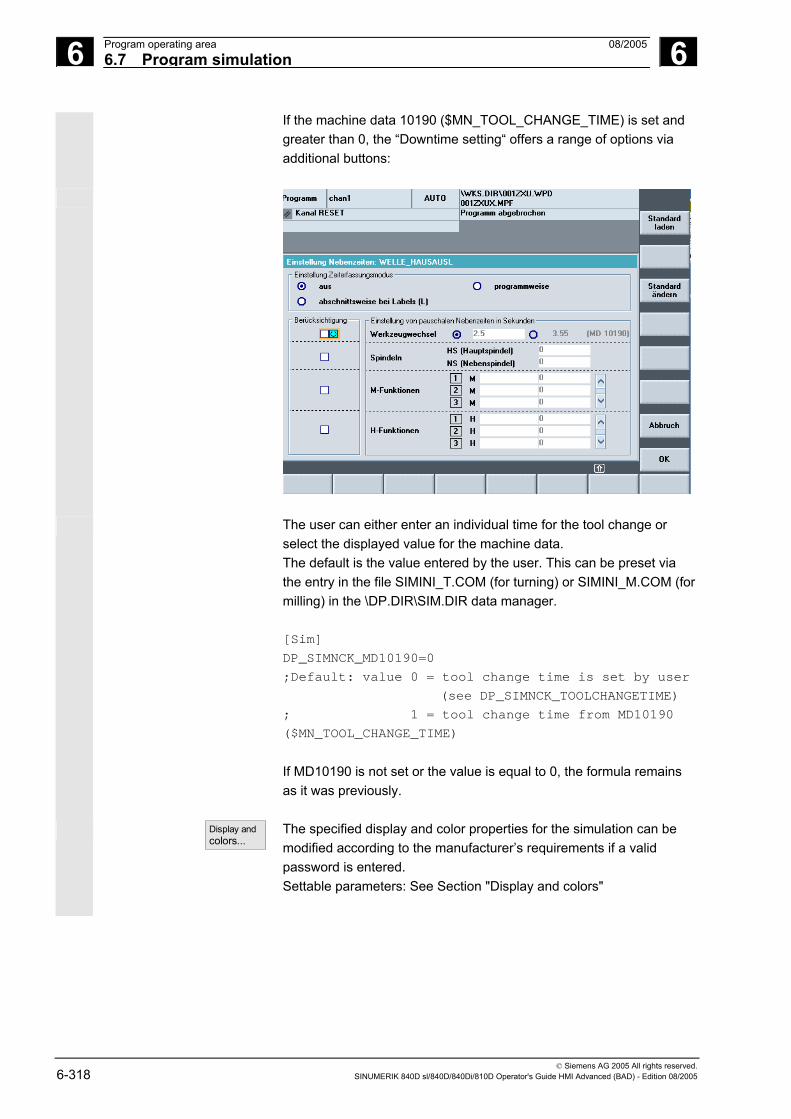
6 Program operating area 08/2005 6.7 Program simulation
6
© Siemens AG 2005 All rights reserved. 6-318 SINUMERIK 840D sl/840D/840Di/810D Operator's Guide HMI Advanced (BAD) - Edition 08/2005
If the machine data 10190 ($MN_TOOL_CHANGE_TIME) is set and greater than 0, the “Downtime setting“ offers a range of options via additional buttons:
The user can either enter an individual time for the tool change or
select the displayed value for the machine data. The default is the value entered by the user. This can be preset via the entry in the file SIMINI_T.COM (for turning) or SIMINI_M.COM (for milling) in the \DP.DIR\SIM.DIR data manager. [Sim]
DP_SIMNCK_MD10190=0
;Default: value 0 = tool change time is set by user
(see DP_SIMNCK_TOOLCHANGETIME)
; 1 = tool change time from MD10190
($MN_TOOL_CHANGE_TIME)
If MD10190 is not set or the value is equal to 0, the formula remains as it was previously.
Display and colors...
The specified display and color properties for the simulation can be modified according to the manufacturer’s requirements if a valid password is entered. Settable parameters: See Section "Display and colors"

6 08/2005 Program operating area6.7 Program simulation
6
© Siemens AG 2005 All rights reserved. SINUMERIK 840D sl/840D/840Di/810D Operator's Guide HMI Advanced (BAD) - Edition 08/2005 6-319
Abort
OK
Return to main simulation menu. The old settings before the setting screen was selected are retained. Return to main simulation menu. The modified settings are saved and activated immediately.
Basic "Settings..."
Blank Active view Blank dimension cuboid Program control
- Milling: without model (display area), cuboid (blank dimension
cuboid), cylinder (blank dimension cylinder). - Turning: without model (display area), cylinder (blank dimension
cylinder) and active processing diameter for peripheral surface. - Milling: X-Y, Z-X, Y-Z (for "Cuboid" and "Without model" only) - Turning: Z-X always defined, cannot be changed - Minimum and maximum dimensions for each axis - SKP: Skip blocks (10 skip levels are available) - M01: Programmed STOP 1 or - M101: Programmed STOP 2 taken into account - Single block mode:
SBL1: Stop after each machine function SBL2: Stop after each block SBL3: Stop in cycle
- Display all blocks or only traversing blocks
Tool data (source) NC active data
The tool offsets are used in accordance with the active NC (Match tool data \TO_INI.INI) and the tool path is simulated with graphic tools. With technology turning the cutter radius is not modeled. The tool radius compensation is evaluated. Tools that are not interpreted are displayed as polymarkers.
With tool HMI data, local TOA data, global SPF file, tool match data from data management \DP.DIR\SIM.DIR\TO_INI.INI
Default tools Evaluation only with milling/drilling if no TO_INI.INI (Match tool data) is present and tool management option not active. The tool diameter can be parameterized (providing access is enabled via a valid password) if ON is activated under the Options settings. The tool radius compensation is evaluated.
Without tool data The tool path is simulated with a polymarker. No evaluation of tool radius compensation i.e. broken-line graphics with compensation value D0.
6 Program operating area 08/2005 6.7 Program simulation
6
© Siemens AG 2005 All rights reserved. 6-320 SINUMERIK 840D sl/840D/840Di/810D Operator's Guide HMI Advanced (BAD) - Edition 08/2005
Additional notes
1. In order to reduce the input effort when the blank type is repeatedly changed, the blank dimensions and the display area are compared internally when the settings are saved.
2. A suitable image of the NC-active data INITIAL.INI and TO_INI.INI under DH\DP.DIR\SIM.DIR is required for simulation with the option "Tool monitoring". Default settings for the tool management are taken from the supplementary tool data ..\mmc2\dp\sim\to_addon.ini. Tools which are not loaded in the active magazine image (...from TO_INI.INI) can therefore be called during simulation if necessary.
3. In simulation "without tool data", using standard cycles results in the representation of the final contour derived from the available cycle parameters.
4. Simulation "without model" and/or "without tool data" both limits the required graphic memory and increases the simulation speed.
Optional "Settings..."
Options on/off
Depths for color classification
Other settings can only be displayed/hidden if you enter a valid password via the Options softkey. Depth range across which the available VGA system colors for displaying depth information are distributed (default range = blank thickness). The rounding inaccuracy in defining depth of color is 10 -3 units.
Default values • Tool diameter: Tool diameter used for milling simulation with default tool (end mill/drill).
• IPO mm or inch: Approximation precision of simulation interpolator in mm or inches depends on actual measuring system.
• F override %. Setting the simulation feed % setting options: %1 to %500 (from V06.12.13 < 10 %)
- Increment of 10 with "+" or "-" key - Increment of 50 with "Cursor right" or "Cursor left" - Max/Min value with "Cursor up" or "Cursor down". - Standard value 100 with "Toggle" key

6 08/2005 Program operating area6.7 Program simulation
6
© Siemens AG 2005 All rights reserved. SINUMERIK 840D sl/840D/840Di/810D Operator's Guide HMI Advanced (BAD) - Edition 08/2005 6-321
Display options • Actual position: Display hide actual value of simulated channel axes (Note: TRANS, ROT, SCALE and MIRROR are not taken into account in the actual value display).
• NC block: Activate/deactivate display of current NC block • Machining time: Activate/deactivate display of the calculated
machining time in the header of the basic simulation window (T = calculated machining time (from the programmed feedrates) ∑ = machining time + sum of all estimated down times).
Simulation mode • Always reload tools
∗ In position "on" (default setting), all the necessary tool data are reloaded on each program change.
∗ In position "off", tool data are only reloaded if required, if the timestamp is altered (automatic query). Otherwise, the existing tool environment is not changed.
• Save tool path ∗ In position "on" (default setting), all the tool paths in the
simulation sequence are visualized and stored temporarily in the model for future display (zoom, etc.).
∗ In position "off", the resulting tool paths are visualized once and not stored temporarily in the model. When the display is subsequently manipulated (e.g., Zoom +), the tool paths are lost.
• Block-by-block processing ∗ In position "on", discontinuous path processing, but largely
accelerated (reduced number of IPO interpolation points, for example, only at block end points on straight lines).
∗ In position "off" (default setting), largely continuous path processing (constant distance between interpolation points depending on the IPO setting).
• Waiting for dwell times ∗ In position "on", program instructions with dwell times cause
real dwell times in the simulation. ∗ In position "off" (default setting), the dwell is suppressed in
the simulation and the dwell times are only taken into account in time calculations.

6 Program operating area 08/2005 6.7 Program simulation
6
© Siemens AG 2005 All rights reserved. 6-322 SINUMERIK 840D sl/840D/840Di/810D Operator's Guide HMI Advanced (BAD) - Edition 08/2005
Recommended settings
Additional notes
1. Changes to the blank dimensions in the infeed axis (min or max) are automatically traced in the depths for color separation (min or max).
2. High values for the interpolator approximation accuracy cause
increased distortion of the geometry representation (e.g. in details and rounded sections), but also reduce the amount of graphics memory required and increase the speed of the simulation.
3. Recommended setting for group "simulation mode":
• .. in production -Always reload tool "off" and store tool path "off"
- Block by block preparation "on" and wait with dwell times "off"
• .. in program mode (default setting) -Always reload tool "on" and store tool path "on"
- Block by block preparation "off" and wait with dwell times "off"
• .. In training operation -Always reload tool "on" and store tool path "off"
- Block by block preparation "off" and wait with dwell times "off"
4. The following settings are recommended for demonstrations with endless program loops (accelerated execution of simulation with reduced demands on the graphic memory): - Always reload tool "off" and store tool path "off" - Block by block preparation "on" and wait with dwell times "off" and additionally: - Blank "without model" (no memory used for graphic!) - Or "without tool data", if representation of the tool center-point path (broken-line graphics) is sufficient.
If the blank model is active ("cuboid", "cylinder"), reduced graphic memory capacity might result, which, depending on the complexity of the part and model resolution set, could exhaust the graphic memory despite the save tool path setting "OFF".

6 08/2005 Program operating area6.7 Program simulation
6
© Siemens AG 2005 All rights reserved. SINUMERIK 840D sl/840D/840Di/810D Operator's Guide HMI Advanced (BAD) - Edition 08/2005 6-323
6.7.3 Downtime settings
Timing mode
Settings
Downtimesettings
OFF (default setting)
Setting timing for downtimes: Central timing does not include fixed downtimes or the processing of information for tabular "Time analysis".
Per program Central timing includes the elements listed in "Inclusion on" in the downtime analysis. The tabular "Time computation" is processed once per program in each case with M30, for example.
Per section with labels Effect as for "per program", only that processing of the tabular "time computation" is also performed when freely definable program labels occur or in combination with the path labels displayed in the simulation graphic (see ..\ Display and colors...\ Manage path labels).
Inclusion Tool changeON/OFF Spindles ON/OFF M functions ON/OFF H functions ON/OFF
Enabling and setting of fixed downtimes in seconds - Definition of a fixed downtime for tool changes - Definition of a fixed downtime for main spindle and secondary spindle instructions - Definition of a fixed downtime for M functions - Definition of a fixed downtime for H functions
Settings
Load standard
Change default
Additional notes
The default values can be modified according to the manufacturer’s requirements if a valid password is entered. The new values are then globally valid for all new workpieces.

6 Program operating area 08/2005 6.7 Program simulation
6
© Siemens AG 2005 All rights reserved. 6-324 SINUMERIK 840D sl/840D/840Di/810D Operator's Guide HMI Advanced (BAD) - Edition 08/2005
6.7.4 Display and colors
General attributes
Settings
Display and colors...
Setting the general properties of the simulation graphics:
Rapid traverse dashed line Alternatively, rapid traverse as a full line, as used for feedrate
Scale at edge of window Alternatively, as scale on the coordinate axes
Path labels Offers various possibilities under "Manage path labels" for displaying program labels, which have been inserted freely to identify specific points in the NC program (observe label syntax), as path labels at the corresponding point in the simulation graphics and then storing the associated graphic model in the buffer. Program labels can also be used to mark program sections, which can then be included by the central timing facility (see .. \ Downtime settings \ Timing mode \ In sections with labels). Path labels are specified in "Channel/spindle" as delimiter for section-by-section simulation in the same or different channels. You can save section models and use a search run to start again at that point without needing to repeat the preceding sections.
Use of color palettes
- Select a color with the cursor keys and press the Select key. The color of the focus frame changes. - Use the cursor keys to select the object and press the Select key again. The object displays the selected color..
General colors In addition to the standard VGA colors, the color elements black and transparent to hide graphic elements are available in the color palette.Color selection option for background, blank, axis intersection, tool holder and tool edge.

6 08/2005 Program operating area6.7 Program simulation
6
© Siemens AG 2005 All rights reserved. SINUMERIK 840D sl/840D/840Di/810D Operator's Guide HMI Advanced (BAD) - Edition 08/2005 6-325
Color palettes for tool path Two freely definable color palettes are available for tool paths for differentiating between feedrate and rapid traverse movements. In each color palette it is possible to differentiate between different basic tool types (without tools, drilling tools, milling tools, turning tools, threading tools, special tools), to allow differentiation for path visualization.
Channel assignment of color palettes
One of the two tool type specific color palettes can be freely assigned to each of the required simulation channels.
Planes for color classification
In the case of milling/drilling, the available colors are assigned to the defined cutting depth range. The default value is the thickness of the blank.
Settings
Load standard
Change default
Additional notes
The default values can be modified according to the manufacturer’s requirements if a valid password is entered. The new values are then globally valid for all new workpieces.
6.7.5 Section-by-section simulation
Function
A procedure in which first the individual sections of a program are optimized one after the other without collision consideration is the preferred method for testing part programs graphically. Section by section simulation allows the user to go to the individual section of the program via reference points (using block search).
The reference points are always defined by path markers (program labels).

6 Program operating area 08/2005 6.7 Program simulation
6
© Siemens AG 2005 All rights reserved. 6-326 SINUMERIK 840D sl/840D/840Di/810D Operator's Guide HMI Advanced (BAD) - Edition 08/2005
Settings
Display and colors...
Requirement: • In order to manage path markers (program labels, e.g.
MARKER1), they must be programmed at the required position in the program.
• Using the "Manage path markers" setting (Settings -> Display/Colors -> Manage path markers) you can decide whether − the path markers are to be displayed in the graphic and/or − the associated intermediate model is to be saved.
Block
Intermediate stages of the simulation model can be stored next to the path markers, allowing synchronized resumption of simulation without resetting the graphic that already exists. You can skip any sections that are already optimized. Block search: In the menu "Block search" you can select the path marker you wish to jump to.
Additional notes
• You can also load the machining list in menu "Channel/spindle" directly from the current workpiece via the "Program selection" softkey or from a JOB list.
6.7.6 Quick display in the simulation for mold making
Purpose The function offers quick display of machining paths, e.g. like those used by CAD systems. Generally these part programs are very large.
Any existing work offsets, Go, G2, G3 are not taken into account, only those axis paths resulting from G1 are displayed.
Characteristics of quick display
• Simulation for mold making is a standard function • Switching between 2D and 3D is supported • Rotation of workpiece in 3D view • Representation in the various different planes • Size scaling, zoom for the displayed workpiece • Search via row number/string • Search via machining block which traverses marked positions • Progress display • Execution of part program blocks • Distance measurement • Can be interrupted by other operating areas/can be aborted • The programs to be simulated can be executed from external
drives • The NC interpreter does not take part in the simulation.

6 08/2005 Program operating area6.7 Program simulation
6
© Siemens AG 2005 All rights reserved. SINUMERIK 840D sl/840D/840Di/810D Operator's Guide HMI Advanced (BAD) - Edition 08/2005 6-327
Activation
Operation for mold making simulation is available in the Program operating area if display machine data 9480: MA_SIMULATION_MODE is set to a value between 0 and 2. -1 Standard simulation 0 Selection between standard simulation/mold making G1 blocks via operation 1 Mold making only, G1 blocks 2 Automatic mode selection via program size. The limit value for the program size is specified in the display Machine data 9481: MA_STAND_SIMULATION_LIMIT.
Size scaling The following scaling settings are available: Zoom in, Zoom out and Automatic fit window. The automatic scaling function "Fit to size" uses the part program to take the largest expansion of the workpiece in the individual axes into account.
Search In the submenu Details, the search function displays the part program block whose machining path traverses the position (which was previously marked using the cursor keys or softkeys) in the workpiece representation. First activate Block search then use the cursor keys or softkeys to move the cross-hair to the desired location. Press the input key to search for the required block and display it. The cross-hair must be positioned in the area of the displayed workpiece section.
In the submenu Edit you can choose whether to search for a block designated by a block number or a block which contains a specified string.
The search function will return the blocks that match the criteria and display them in the 2-line program section above the graphic display and highlight them.
Progress display The message line shows the percentage value of the entire part program which is displayed in the graphic. Loading the workpiece graphic can be cancelled at any time by pressing the End softkey. Changing to a different operating area interrupts loading the graphic. When you return to the Program operating area, the loading process is continued.

6 Program operating area 08/2005 6.7 Program simulation
6
© Siemens AG 2005 All rights reserved. 6-328 SINUMERIK 840D sl/840D/840Di/810D Operator's Guide HMI Advanced (BAD) - Edition 08/2005
Rotation In 3D representation the displayed workpiece can be rotated around any of the axes. The rotation instructions become active after you press Accept to confirm.
Distance measurement In the graphic display you can use the Mark point A and Mark point B softkeys to enter two markers at the positions you have set via the cursor keys. The direct path (space diagonal) between the points is output in the message line.
6.7.7 Simulation with external network drives
Function
With the SINDNC software, you can link your control to external network drives or other computers and use this facility for program simulation. It is possible to access files on network drives from a part program using the command EXTCALL.
• With EXTCALL, the drives in the network are also searched for subprograms (SPF only) if the program is called without a path. Subdirectories are not searched. The program will also be found if the search range is defined with the variable $SC_EXT_PROG_PATH or if a path to a file in the network - even in a subdirectory - has been defined.
• Programs in the network drives (with the extension MPF and SPF) can be simulated.
• If write access is set for a network drive, file DPWP.INI is created and the current directory is treated like a workpiece.
• If write access has not been set, a DPWP.INI is created for each network drive in the TEMP directory of the HMI irrespective of the current directory. In this case, the simulation settings are lost when the directory on the drive is changed.

6 08/2005 Program operating area6.8 Manage programs
6
© Siemens AG 2005 All rights reserved. SINUMERIK 840D sl/840D/840Di/810D Operator's Guide HMI Advanced (BAD) - Edition 08/2005 6-329
6.7.8 Simulation using the orientable toolholder
Function
You can process part programs for orientable toolholders using the simulation function. The following boundary conditions must be observed: • The simulation distinguishes whether a toolholder Y has been
activated for a tool x. • Changes in the active toolholder are not detected. This is why the
simulation uses the toolholder kinematic set initially for a tool y. • Changes made after first activation (TCARR=x) are not
considered. • To use several toolholder kinematics for one tool y, create several
identical tools with different toolholder settings. • Inactive files are grayed out.
6.8 Manage programs
Function
To allow you to handle data and programs flexibly, you can organize, store and display them according to different criteria. The memory is divided into: • NC memory (main memory and program memory) containing the
active system and user programs as well as all part programs for immediate execution and
• Hard disk
Programs can be exchanged between the program memory and hard disk. Part programs may be stored either in the program memory of the NC or on the hard disk, but they are always executed from the program memory. The "Load" and "Unload" functions are used to load or unload programs to or from the program memory.

6 Program operating area 08/2005 6.8 Manage programs
6
© Siemens AG 2005 All rights reserved. 6-330 SINUMERIK 840D sl/840D/840Di/810D Operator's Guide HMI Advanced (BAD) - Edition 08/2005
Program management The programs and files are stored in different directories and can be administered in the Program and Services operating areas. The details are shown in the following overview: Name of directories: Operating area: • Subprograms Programs and Services • Part programs Programs and Services • Workpieces Programs and Services • Definitions Services • Comments Services • Standard cycles Programs and Services • Manufacturer cycles Programs and Services • User cycles Programs and Services
The following diagram shows an example of directory contents:
Internal directoryname
Directory name oninterface
Internal file name
...
Program memory
_N_SMAC_DEF_N_MMAC_DEF_N_UMAC_DEF_N_SGUD_DEF_N_MGUD_DEF_N_UGUD_DEF_N_GUD4_DEF..._N_GUD9_DEF
_N_POCKET1_SPF_N_..._SPF
_N_L199_SPF_N_..._SPF
_N_GLOB_SPF_N_..._SPF
_N_MPF1_MPF_N_MOV_MPF_N_..._MPF_N_...
_N_SHAFT_WPD _N_MPF123_WPD
_N_SHAFT_MPF_N_PART2_MPF_N_PART1_SPF_N_PART2_SPF_N_SHAFT_INI_N_SHAFT_SEA_N_PART2_INI_N_PART2_UFR_N_PART2_COM_N_SHAFT
_N_MPF123_MPF_N_L1_SPF_N_..._...
Name in bold script: contained as standardNames not in bold script: assigned by the user
_N_CUS_DIR_N_CMA_DIR_N_CST_DIR_N_DEF_DIR _N_SPF_DIR _N_MPF_DIR _N_WKS_DIR _N_COM_DIR
User cyclesManufact. cyclesStandard cyclesDefinitions Subprograms Parts programs W orkpieces Comments
NC data types and
directories
File types can be identified by the file name extension (e.g. .MPF). name.MPF Main program name.SPF Subprogram
name.TEA Machine data name.SEA Setting data name.TOA Tool offsets name.UFR Work offsets/frame name.INI Initialization file name.COM Comment name.DEF Definition of global user data and macros
6 08/2005 Program operating area6.8 Manage programs
6
© Siemens AG 2005 All rights reserved. SINUMERIK 840D sl/840D/840Di/810D Operator's Guide HMI Advanced (BAD) - Edition 08/2005 6-331
Please note that on the directories: comments \COM.DIR and definitions \DEF.DIR can only be accessed in the Services operating area via "Manage data".
6.8.1 New workpiece/part program
Function
The following subsection describes how you can select workpieces and part programs in a directory. A selected file can then be called and edited in the text editor.
Operating sequence
Select workpiece/part program: Work-
pieces • Workpieces
Part programs
• Part programs
Sub- programs
• Subprograms
User cycles
• User cycles
Clipboard
• Clipboard
Position the cursor in the directory on the desired file. For each file, the file name, file type, length, date of creation/last change are displayed. You can change the properties of the file display (see Section "Startup", "Settings" menu)
Call a part program:
Use the cursor to select a program in the program overview and press the "Input" key. The text editor is displayed with the file you have selected. You can now edit the part program.

6 Program operating area 08/2005 6.8 Manage programs
6
© Siemens AG 2005 All rights reserved. 6-332 SINUMERIK 840D sl/840D/840Di/810D Operator's Guide HMI Advanced (BAD) - Edition 08/2005
Open workpiece:
The workpiece directory is opened and the programs it contains displayed on the screen.
Workpiece directory, create
You can set up various types of files such as main programs, initialization files, tool offsets, etc. in the new workpiece directory.
Operating sequence
Workpieces
The current overview of all workpiece directories appears on the screen.
New
Input window "New" is opened. The cursor is located in the input field for the name of the new workpiece directory.
Enter the name of the new directory on the alphanumeric keyboard. Specify the created type in the data type field: WPF
If there are any templates for the specified data type in the Templates directory they are offered for selection. Press OK to confirm your selection.
A new directory is set up in the workpiece overview. You are asked straight away for the name of the first part program and the Editor is opened.
When creating a workpiece with New, all templates corresponding to your selection are only copied from the Templates\Siemens ... Manufacturer ... User directory to Startup\Settings\Templates if "No template" is selected in the Templates selection field.
If a template is proposed for the workpiece, then all elements assigned to it such as job list, part program, subprograms are transferred to the new workpiece in compliance with the template and its language-specific elements.

6 08/2005 Program operating area6.8 Manage programs
6
© Siemens AG 2005 All rights reserved. SINUMERIK 840D sl/840D/840Di/810D Operator's Guide HMI Advanced (BAD) - Edition 08/2005 6-333
6.8.2 Create programs/data in a workpiece directory
Function
This section explains how you can create a new file for a part program or workpiece.
Operating sequence
The current overview of the workpiece directories stored on the NC appears.
Position the cursor on the required workpiece and open it.
An overview will be displayed listing the data and programs that have already been created in the workpiece directory. If no data is available, the program overview is blank.
New ...
A dialog box appears when you press the "New" softkey. Enter the new file name.
You can also enter the corresponding file type using the "Insert key".
Some of the possible file types are listed below: File type Meaning .041 AutoTurn program
.CEC Sag/angularity
.COM Comment
.DAT MCSP data
.GUD Channel user data
.IKA Compensation data
.INI Initialization program
.JOB Job list
.MPF Part program (main program file)
.PRO Protection zones
.RPA Arithmetic parameters
.SEA Setting data active
.SPF Subprogram (subprogram file)
.TCM Tool plan reformatted (for SINTDI)
.TEA Machine data (testing data active)
.TMA Magazine data
.TOA Tool offsets (tool offset active)
Tool plan
.UFR Work offset/frame
.WPD Workpiece
6 Program operating area 08/2005 6.8 Manage programs
6
© Siemens AG 2005 All rights reserved. 6-334 SINUMERIK 840D sl/840D/840Di/810D Operator's Guide HMI Advanced (BAD) - Edition 08/2005
Create part programs in the part program/subprogram directory: Part
programs or Sub- programs
You can set up main programs and subprograms by opening directories "Part programs" and "Subprograms".
New
Press the "New" softkey to display a dialog window in which you can enter the names of the new main programs and subprograms. The matching file type is automatically assigned in this case.
Number of workpieces
• A maximum of 100,000 files can be stored in the data manager. • The number of files per directory must not exceed 1,000 (or per
workpiece directory for workpieces *.WPD). • The maximum size of editable files is 56 MB.
6.8.3 Save setup data
Function
With the "Save setup data" softkey, you can store all the active data belonging to a particular workpiece located in the working memory of the NC. The data are stored for each channel under the same name under a workpiece.
Additional notes
"Save setup data" can be disabled by the manufacturer using the protection levels.
Operating sequence
Workpieces
The current overview of all workpiece directories appears on the screen.
Place the cursor on the workpiece directory or workpiece in which you want to store the workpiece-specific data.
Save setup data
The input window "Store workpiece data" is opened when you select "Save setup data". In this input window you can select the workpiece data that you wish to save.
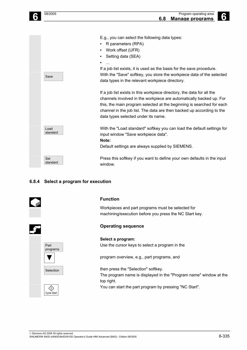
6 08/2005 Program operating area6.8 Manage programs
6
© Siemens AG 2005 All rights reserved. SINUMERIK 840D sl/840D/840Di/810D Operator's Guide HMI Advanced (BAD) - Edition 08/2005 6-335
E.g., you can select the following data types: • R parameters (RPA) • Work offset (UFR) • Setting data (SEA) • ... If a job list exists, it is used as the basis for the save procedure.
Save
With the "Save" softkey, you store the workpiece data of the selected data types in the relevant workpiece directory. If a job list exists in this workpiece directory, the data for all the channels involved in the workpiece are automatically backed up. For this, the main program selected at the beginning is searched for each channel in the job list. The data are then backed up according to the data types selected under its name.
Load standard
With the "Load standard" softkey you can load the default settings for input window "Save workpiece data". Note: Default settings are always supplied by SIEMENS.
Set standard
Press this softkey if you want to define your own defaults in the input window.
6.8.4 Select a program for execution
Function
Workpieces and part programs must be selected for machining/execution before you press the NC Start key.
Operating sequence
Select a program: Part
programs
Selection
Use the cursor keys to select a program in the program overview, e.g., part programs, and then press the "Selection" softkey. The program name is displayed in the "Program name" window at the top right.
Cycle Start
You can start the part program by pressing "NC Start".

6 Program operating area 08/2005 6.8 Manage programs
6
© Siemens AG 2005 All rights reserved. 6-336 SINUMERIK 840D sl/840D/840Di/810D Operator's Guide HMI Advanced (BAD) - Edition 08/2005
Select a workpiece: A workpiece directory can be selected for machining in the currently active channel.
Work- pieces
Selection
Use the cursor keys to select the workpiece in the workpiece overview and then press the "Selection" softkey.
Cycle Start
• If only one main program (MPF) exists in this directory, it is automatically selected for execution. If the directory contains several main programs, the main program with the same name as the directory is automatically selected for execution (e.g. if you select workpiece SHAFT.WPD main program SHAFT.MPF is automatically selected). The program name is output along with workpiece information in the "Program name" window at the top right. You can start the part program you have selected by pressing the "NC Start" key.
• If an INI file of the same name exists (e.g. SHAFT.INI), it will be executed once at first part program start after select the part program. Machine data 11280 $MN_WPD_INI_MODE controls which additional INI files are executed.
Selection
When you select workpiece directory SHAFT.WPD you implicitly select program SHAFT. If a .JOB file with the same name is stored in the workpiece directory, it is executed immediately. See also Chapter "Job list" and "Sequence of operations" "Executing job list".
Find path for program call
If the call path is not explicitly specified in the part program when a subprogram (or an initialization file) is called, the called program is located according to the predefined search strategy.
Case 1: When a subprogram is called by name with specification of the data type ("identifier" or "extension"),e.g. SHAFT1.MPF the system searches through the directories in the following sequence: 1. Current directory / name.type Workpiece/standard
directory MPF.DIR 2. /SPF.DIR / name.type Global subprograms 3. /CUS.DIR / name.type User cycles 4. /CMA.DIR / name.type Manufacturer cycles

6 08/2005 Program operating area6.8 Manage programs
6
© Siemens AG 2005 All rights reserved. SINUMERIK 840D sl/840D/840Di/810D Operator's Guide HMI Advanced (BAD) - Edition 08/2005 6-337
5. /CST.DIR / name.type Standard cycles
Case 2: When a subprogram is called by name without specification of the data type ("identifier" or "extension"), e.g. SHAFT1 the system searches through the directories in the following sequence: 1. Current directory / name Workpiece/standard
directory MPF.DIR 2. Current directory / name.SPF 3. Current directory / name.MPF 4. /SPF.DIR / name.SPF Subprograms 5. /CUS.DIR / name.SPF User cycles 6. /CMA.DIR / name.SPF Manufacturer cycles 7. /CST.DIR / name.SPF Standard cycles
References /PGA/, Programming Guide Advanced
Machine manufacturer
See machine manufacturer’s instructions.
Preconditions: - A main program (MPF) is selected in the workpiece directory - "NC Start" was activated $MN_WPD_INI_MODE=0: The INI file with the same name as the selected workpiece is executed. For example, if SHAFT1.MPF is selected, SHAFT1.INI is executed when “NC Start” is pressed. (Behavior as with previous software versions) $MN_WPD_INI_MODE=1: All files of type INI, SEA, GUD, RPA, UFR, PRO, TOA, TMA and CEC which have the same name as the selected main program are executed in the specified sequence.
• The main programs stored in a workpiece directory can be selected and processed by several channels.
References /IAM/ IM4 Startup guide

6 Program operating area 08/2005 6.8 Manage programs
6
© Siemens AG 2005 All rights reserved. 6-338 SINUMERIK 840D sl/840D/840Di/810D Operator's Guide HMI Advanced (BAD) - Edition 08/2005
6.8.5 Load/unload a program
Function
Programs can be stored in the NC memory ("Load") and then erased from it again ("Unload") after execution. This prevents the NC memory from being overloaded unnecessarily.
Operating sequence
Position the cursor on the program to be loaded.
Download HD->NC
The highlighted program is loaded from the hard disk to the NC memory.
The selected program is deleted on the hard disk.
See also Chapter "Job list".
Alter enable
If enable is set "(X)", the program can be executed.
Upload NC->HD
The highlighted program is unloaded from the NC memory to the hard disk.
The selected program is deleted in the NC memory.
Additional notes
Programs which have been loaded to the NC memory are automatically marked with an "(X)" (in the "Loaded" column) in the program overview. If the file is located both in the HMI and in the NC, the identifier "X" is only removed when the files are no longer identical. If the files have different time stamps or are of different lengths, the identifier is "!X!".
If you want to "load/unload" a workpiece directory and a job list with the name of the directory exists in the directory, then this job list is processed.
If no job list exists, all the files in that directory are loaded/unloaded (working memory of NC might overflow!).

6 08/2005 Program operating area6.8 Manage programs
6
© Siemens AG 2005 All rights reserved. SINUMERIK 840D sl/840D/840Di/810D Operator's Guide HMI Advanced (BAD) - Edition 08/2005 6-339
6.8.6 Manage programs
Function
You can reorganize programs and files in the "program overview" using the "Manage programs" function: New… Select new workpiece/part program Copy/insert Copy directories and files Delete Delete workpieces and files Rename Rename file and data type Modify enable Enable each workpiece/part program in the program overview or not.
Operating sequence
Manage
programs... In the "Program overview" dialog box, press the "Manage programs..." horizontal softkey. Active functions are indicated by softkeys in which the text appears on a black background. Inactive softkeys are grayed out.
New ...
Press the "New ..." softkey to select a new workpiece or part program. The "interactive programming" window is opened and the cursor is positioned in the input field for the name of the new directory. Enter the new name of the program. The file type is assigned automatically. The display also shows whether or not a template exists.
Default You can choose between interactive programming and the text editor. The more frequent choice, file editing with "interactive programming", is the default setting. Alternatively, you can use the text editor to edit files.
Confirm your input with the "Input" key.
Abort
This key cancels the entire operation.
OK
Press the "OK" softkey to load the workpiece or part program you have just selected. You can then use the program management functions available in the horizontal softkey bar.
6 Program operating area 08/2005 6.8 Manage programs
6
© Siemens AG 2005 All rights reserved. 6-340 SINUMERIK 840D sl/840D/840Di/810D Operator's Guide HMI Advanced (BAD) - Edition 08/2005
6.8.7 Copy/insert
Function
This section tells you how to copy files from a source directory to an existing destination directory. Except when overwriting workpieces, the files are copied from the NC program memory or from the hard disk to: Hard disk (HD) or NC memory (NCK) or Buffer or Diskette (is specified as network drive) or Network drive (Network1 to Network4) All directories with the exception of compile cycles can be copied to the destinations specified above.
Copy/insert Several selected files or workpieces can be copied together in a single operation. When copying workpieces: All associated files are copied too. All files with the workpiece name are automatically renamed to the new workpiece name. Files from the Workpieces directory can only be overwritten in another directory. All workpiece files of type .WPD can be copied from one drive to any other drive.
Specify the file name and file type
Copying from network drives: All data types known to the HMI are set according to their extension and the data management scheme. A dialog box is opened for files with an unknown extension. You can enter or change the name and file type - up to 3 characters are permissible.
If a file of the same name is already stored on the hard disk or in the NC memory, a dialog box prompts you to change the name and file type. If the source file and destination are identical, the existing file is not overwritten. The copy operation can either be canceled or an integer is added to the existing file name in ascending order.
6 08/2005 Program operating area6.8 Manage programs
6
© Siemens AG 2005 All rights reserved. SINUMERIK 840D sl/840D/840Di/810D Operator's Guide HMI Advanced (BAD) - Edition 08/2005 6-341
Operating sequence
Manage programs
The "Manage programs" softkey must be pressed.
Copy
Position the cursor on the file that you want to copy and press the "Copy" softkey. The file is marked as the source for copying. An existing file is either overwritten or, if the name or file type was changed, saved with the new name.
Please note that several "Save as" dialogs give you the chance to change the file name and file type before the files are overwritten. The "Save as" dialog box appears if the "All without query" vertical softkey was not pressed and: 1. you have pressed "Insert" for the first time. 2. the file cannot be created in the current directory. 3. the file already exists.
Paste
OK
Press the "Insert" softkey, enter a new name and confirm with "OK".
When you insert a file in a workpiece directory, you can change its file type with the "Toggle" key. The file types are automatically adjusted in the global part program and the global subprogram directory.
Additional notes
• Only files can be stored in a workpiece directory but not other workpiece directories.
• If the target specified is incorrect an error message is output. • If a workpiece directory is copied, all the files that it contains are
copied at the same time. • If the files of a workpiece directory are copied to a new directory,
all the files with the same directory name are renamed to the new workpiece directory name.
• If a job list with the name of the directory exists, all the instructions in that job list are renamed.
This function only applies to the "Program" operating area. When you copy under "Services", the names remain unchanged. See also section "Renaming".

6 Program operating area 08/2005 6.8 Manage programs
6
© Siemens AG 2005 All rights reserved. 6-342 SINUMERIK 840D sl/840D/840Di/810D Operator's Guide HMI Advanced (BAD) - Edition 08/2005
Query dialogs "Save as"
In the "Startup" operating area, press the HMI/System settings/Query softkeys to specify that a dialog box is to appear before files are overwritten. Otherwise, the files are overwritten without prompting or a copy is created.
Vertical softkeys for "Save as"
All without query
Press the "All without prompt" softkey if all existing files in the current directory are to be created with new names without a "Save as" dialog. All files for which the original file type cannot be created are automatically converted to the specified data type.
Skip file
Press the "Skip file" softkey if the copy operation is to be continued with the next file.
Abort
This key cancels the entire copy operation.
OK
An existing file is either overwritten or, if the name or file type was changed, saved with the new name. The "OK" softkey is disabled if you have to enter a new name. The "Data type" input field accepts 0 to 3 letters.
Query dialogs Copy file from hard disk:
• The file exists on hard disk and is overwritten when you select "OK" if the name/data type are to remain unchanged!
• The file exists on hard disk. When you select "OK" a copy is created if the name/file type are to remain unchanged!
Copy file from NC memory: • The file exists on the NCK and is overwritten when you select "OK"
if the name/data type are to remain unchanged! • The file exists on the NCK. When you select "OK" a copy is
created if the name/file type are to remain unchanged!
Copy a workpiece: • The workpiece already exists. When you select "OK" a copy of the
workpiece is created if a new name is not specified!
Copy a directory: • The directory already exists. When you select "OK" the contents
are overwritten if a new name is not specified! • The directory already exists. When you select "OK" the contents
are overwritten if the directory with a fixed data type cannot be changed.
Copy a file of data type main program (MPF): • The file cannot be created at this location under its original "main
program" data type!

6 08/2005 Program operating area6.8 Manage programs
6
© Siemens AG 2005 All rights reserved. SINUMERIK 840D sl/840D/840Di/810D Operator's Guide HMI Advanced (BAD) - Edition 08/2005 6-343
6.8.8 Delete
Function
This section explains how you can delete workpieces or files.
Operating sequence
Manage programs
The "Manage programs" softkey must be pressed.
Position the cursor on the workpiece or the file you want to delete.
Delete several files: If you wish to select several files, position the cursor on the first file, press the "Select" key and then position the cursor on the last file. The files you have selected are highlighted.
Delete
The prompt "Do you really want to delete the file?" appears.
OK
Confirm your input.
Additional notes
• You can only delete programs that are not currently running. • If you want to delete a workpiece directory, make sure that none of
the programs it contains is currently selected. • If a workpiece directory is deleted, all the files that it contains are
deleted at the same time.

6 Program operating area 08/2005 6.8 Manage programs
6
© Siemens AG 2005 All rights reserved. 6-344 SINUMERIK 840D sl/840D/840Di/810D Operator's Guide HMI Advanced (BAD) - Edition 08/2005
6.8.9 Rename
Function
As regards files, you can alter their name as well as the associated file type.
Operating sequence
Manage programs
The "Manage programs" softkey must be pressed.
Position the cursor on the file you want to rename.
Rename
The "Rename" dialog window opens.
Enter the new name.
When you rename a workpiece, you can also change the file type with the "Toggle key". File types are matched automatically in the part program and subprogram directories.
There are two ways of renaming files: • Renaming the workpiece directory • Renaming a directory in the workpiece directory
Renaming a workpiece directory: When you rename a workpiece directory, all the workpiece files under that directory that have the same name as the directory are renamed.If a job list with the name of the directory exists, the instructions in that job list are also renamed. Comment lines remain unchanged.
Examples: Workpiece directory A.WPD is renamed B.WPD: All files with the name A.XXX are renamed to B.XXX , i.e. the extension is retained. If a job list called A.JOB exists, if is renamed to B.JOB. If this job list contains instructions of file A.XXX located in this workpiece directory, then that file is also renamed B.XXX.

6 08/2005 Program operating area6.8 Manage programs
6
© Siemens AG 2005 All rights reserved. SINUMERIK 840D sl/840D/840Di/810D Operator's Guide HMI Advanced (BAD) - Edition 08/2005 6-345
If job list A.JOB contains an instruction LOAD/Work.DIR/A.WPD/A.MPF it is renamed to LOAD/Work.DIR/B.WPD/B.MPF However, if a job list contains the instruction LOAD/MPF.DIR/A.MPF or LOAD/Work.DIR/X.WPD/A.MPF the files are not renamed.
Renaming a directory in the workpiece directory: If you rename the files in the workpiece directory, all files with the same name but a different extension are renamed. Exception: If a job list of the same name exists in the directory, then this one is not renamed.
6.8.10 Enable
Function
The program overview indicates whether a workpiece or part program is enabled. This means that it may be executed (e.g., because it has already been tested) by the control after you select the "Program selection" softkey and the "NC Start" key. If you set up a new program, it is automatically enabled.
Operating sequence
To set the enable for a program or abort it, position the cursor on the desired workpiece or part program in the program overview.
Change enable
Press the "Change enable" softkey. A cross indicating "Enable issued" appears behind the workpiece or part program.
(x) Enable issued (program can be executed)
( ) No enable issued (program must not be executed)

6 Program operating area 08/2005 6.8 Manage programs
6
© Siemens AG 2005 All rights reserved. 6-346 SINUMERIK 840D sl/840D/840Di/810D Operator's Guide HMI Advanced (BAD) - Edition 08/2005
Additional notes
• The system checks whether a program may be executed when the program is called (after selection via operator input or from part program). If you want it to be enabled, you must enable it beforehand. (See also Chapter 6 "Changing properties of file/directory/archive")
6.8.11 Log
Function
If you are working on the hard disk, the following data are included in the log: • Name of program currently being executed (execution from
external source) • Names of previously executed programs • Prompts: e.g. "Do you really want to delete job?" • Error list: Names of previously executed programs in which an
error occurred.
Operating sequence
Log
Press the "Log" softkey. The "Job log for programs" window opens. Depending on the status of the current program run, the following functions can be executed by means of the vertical softkeys (e.g. when prompt "Really delete?" is displayed in the "Query" window):
Yes
• The program currently being executed is deleted.
All
• All programs in the current job list are deleted.
No
• The program currently being executed is not deleted.
Stop
• The program currently being executed is aborted.

6 08/2005 Program operating area6.9 Accessing an external network drive/computer
6
© Siemens AG 2005 All rights reserved. SINUMERIK 840D sl/840D/840Di/810D Operator's Guide HMI Advanced (BAD) - Edition 08/2005 6-347
6.9 Accessing an external network drive/computer
Function
With the SINDNC software, you can link your control to external network drives or other computers. The following conditions apply:
• The SINDNC software is installed. • The computer or drive which you want to link up to is
accessible/enabled. • A connection to the computer/drive has been established. • The softkeys for selecting the drive/computer link have been
configured by making entries in the file "MMC.INI", see /IAM/IM4 Installation and startup guide HMI.
Operating sequence
Program
You can access network drives 1 to 3 from level 0 of the Program operating area using horizontal softkeys 4 to 6. With the "ETC" key, you can access network drive 4 from level 2 using horizontal softkey 7. The cycle directories are also stored at level 2 and are assigned to softkeys 4 to 6.
Drive F: or
R4711
When you press a softkey, e.g., "Drive F:" or "R4711" the Explorer appears on the screen with the data of the external drive, e.g. "Drive F" or of computer "R4711".
You can perform the following operations (in addition to paging) via the vertical softkeys in the Program operating area: • Copy/insert files (not directories) from network drives in the data
manager. A type conversion cannot be performed according to the destination directory.
• Copy/insert from the data manager or a network drive to network drives. The files are set up on the network drive using DOS naming conventions. The file name used in the data management (source) is maintained.
• Deleting files (no directories) on the network drives • Simulation • Editing files (find/go to, mark block, edit) if write access to the drive
is enabled. • Files on the network drives can be simulated. This applies to files with the identifier MPF or SPF.

6 Program operating area 08/2005 6.9 Accessing an external network drive/computer
6
© Siemens AG 2005 All rights reserved. 6-348 SINUMERIK 840D sl/840D/840Di/810D Operator's Guide HMI Advanced (BAD) - Edition 08/2005
Additional notes
• If the drive/computer is not connected or enabled, the message "No data available" is displayed.
• A root directory can only be selected as the destination for copying to a network drive if "." is displayed.
• In the Machine operating area, only files with an HMI-compatible name can be selected for "Exec. f. hard disk" (i.e. up to 27 characters, no special characters, no blanks).
• In operating area Program, the functions Copy, Insert, and Delete can only be applied to files without blanks in their name.
• The file name is displayed as it would be in the Windows Explorer with a long file name, but only up to 25 characters are displayed.
■

7 08/2005 Services operating area 7
© Siemens AG 2005 All rights reserved. SINUMERIK 840D sl/840D/840Di/810D Operator's Guide HMI Advanced (BAD) - Edition 08/2005 7-349
Services operating area 7.1 Services main screen..............................................................................................7-351
7.1.1 Read in data............................................................................................................7-354 7.1.2 Read out data..........................................................................................................7-355 7.1.3 Display logs.............................................................................................................7-356
7.2 Manage data ...........................................................................................................7-358 7.2.1 Download and upload .............................................................................................7-359 7.2.2 Copy and insert .......................................................................................................7-360 7.2.3 Delete ......................................................................................................................7-361 7.2.4 Change properties...................................................................................................7-362
7.3 Data selection .........................................................................................................7-365 7.3.1 Special directories and memory areas....................................................................7-368 7.3.2 Data on the hard disk ..............................................................................................7-369
7.4 Startup functions .....................................................................................................7-371 7.4.1 Series startup ..........................................................................................................7-371 7.4.2 Updating (only SINUMERIK powerline) ..................................................................7-374 7.4.3 Restore original state via NC card (only SINUMERIK powerline)...........................7-375 7.4.4 Transfer display MD from HMI Embedded..............................................................7-376

7 Services operating area 08/2005 7.1 Services main screen
7
© Siemens AG 2005 All rights reserved. 7-350 SINUMERIK 840D sl/840D/840Di/810D Operator's Guide HMI Advanced (BAD) - Edition 08/2005
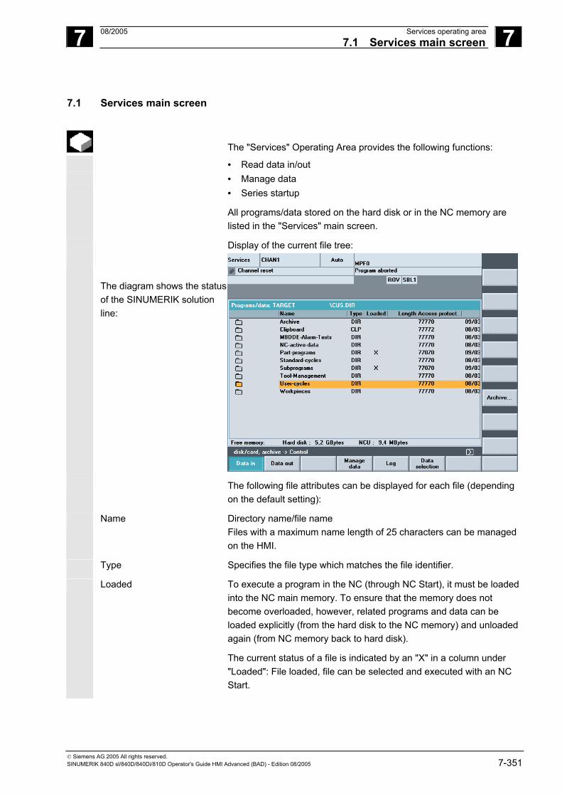
7 08/2005 Services operating area7.1 Services main screen
7
© Siemens AG 2005 All rights reserved. SINUMERIK 840D sl/840D/840Di/810D Operator's Guide HMI Advanced (BAD) - Edition 08/2005 7-351
7.1 Services main screen
The "Services" Operating Area provides the following functions:
• Read data in/out • Manage data • Series startup
All programs/data stored on the hard disk or in the NC memory are listed in the "Services" main screen.
Display of the current file tree:
The diagram shows the status of the SINUMERIK solution line:
The following file attributes can be displayed for each file (depending on the default setting):
Name Directory name/file name Files with a maximum name length of 25 characters can be managed on the HMI.
Type Specifies the file type which matches the file identifier.
Loaded To execute a program in the NC (through NC Start), it must be loaded into the NC main memory. To ensure that the memory does not become overloaded, however, related programs and data can be loaded explicitly (from the hard disk to the NC memory) and unloaded again (from NC memory back to hard disk).
The current status of a file is indicated by an "X" in a column under "Loaded": File loaded, file can be selected and executed with an NC Start.

7 Services operating area 08/2005 7.1 Services main screen
7
© Siemens AG 2005 All rights reserved. 7-352 SINUMERIK 840D sl/840D/840Di/810D Operator's Guide HMI Advanced (BAD) - Edition 08/2005
Notice: Data may only be loaded for programs for which an enable has been set!
Length
File length in bytes (directory length is not displayed)
Date
Date of creation or date of last modification to file
Enable
Enable (=selection/right to execute) activated "X" or not activated " " When you set up a program, you may not necessarily be able to process it immediately with an NC Start (e.g. if it is not ready or requires a trial run). To indicate that a program is ready for NC Start, it is possible to enable or disable the program. The current state of a file is indicated by an "X" in the "Enable" column (= enable activated).
access authorization There are also 5 access rights for each file: • Read Corresponds to level 5 • Write Corresponds to level 3 • Execute Corresponds to level 7 • Show Corresponds to level 2 • Delete Corresponds to level 1 The access right for each file is indicated in the file tree. Not every user should be able to edit data and programs on the control. Access levels are therefore defined for each file. They range from level 0 (SIEMENS password) to level 7 (keylock switch 0). A description of how to set the access rights is given in Chapter "Properties".
The access rights are not displayed as the numbers 1-7 in the display, instead the display only includes objects which can be executed depending on the rights assigned when the control was started.
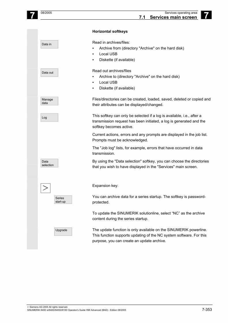
7 08/2005 Services operating area7.1 Services main screen
7
© Siemens AG 2005 All rights reserved. SINUMERIK 840D sl/840D/840Di/810D Operator's Guide HMI Advanced (BAD) - Edition 08/2005 7-353
Horizontal softkeys
Data in
Read in archives/files: • Archive from (directory "Archive" on the hard disk) • Local USB • Diskette (if available)
Data out
Read out archives/files • Archive to (directory "Archive" on the hard disk) • Local USB • Diskette (if available)
Manage data
Files/directories can be created, loaded, saved, deleted or copied and their attributes can be displayed/changed.
Log
This softkey can only be selected if a log is available, i.e., after a transmission request has been initiated, a log is generated and the softkey becomes active.
Current actions, errors and any prompts are displayed in the job list. Prompts must be acknowledged.
The "Job log" lists, for example, errors that have occurred in data transmission.
Data selection
By using the "Data selection" softkey, you can choose the directories that you wish to have displayed in the "Services" main screen.
Series start-up
Expansion key: You can archive data for a series startup. The softkey is password-protected. To update the SINUMERIK solutionline, select “NC” as the archive content during the series startup.
Upgrade
The update function is only available on the SINUMERIK powerline. This function supports updating of the NC system software. For this purpose, you can create an update archive.

7 Services operating area 08/2005 7.1 Services main screen
7
© Siemens AG 2005 All rights reserved. 7-354 SINUMERIK 840D sl/840D/840Di/810D Operator's Guide HMI Advanced (BAD) - Edition 08/2005
Vertical softkeys
The vertical softkeys allow you to select the source area (for data import) or the target area (for data export). The yellow title in the window indicates the area.
Diskette
• Diskette
Archives
• "Archives" directory on hard disk
NC card
• "Archives" directory on the NC card
Note:
Users with access authorization to level 3 and higher can access this softkey. It is displayed only if archive _N_ORIGINAL_ARC is stored on the NC card.
7.1.1 Read in data
Function
When reading in archives and files, the following are possible source areas: • Archive (i.e. the "Archives" directory) in the directory tree (even if
it is not displayed under "Data selection"). • USB memory module • A diskette drive • The NC card, if formatted on a Flash File System.
When archives are read in, their format is recognized automatically.
Data with longer file names (> 8 + 3 characters) can be read in from diskette.

7 08/2005 Services operating area7.1 Services main screen
7
© Siemens AG 2005 All rights reserved. SINUMERIK 840D sl/840D/840Di/810D Operator's Guide HMI Advanced (BAD) - Edition 08/2005 7-355
Operating sequence
Data in
The "Programs/Data" file tree is displayed. The vertical softkey bar changes.
Mark the file into which you wish to read the archive.
Select the source area (see title in window): Diskette
• Diskette drive: Shows the contents of the diskette. Select the
archive you wish to import.
Archives
• Opens the "Archives" directory on the hard disk. Select the archive you wish to import.
NC card
• The contents of the archives directory on the NC card are displayed. Select the archive you wish to import.
7.1.2 Read out data
Function
Create archives: With the "Data out" function, the source area (see title in window) for data transmission is the displayed directory tree. Possible target areas are: • The "Archives" directory on the hard disk • USB memory module • A diskette drive • Free memory areas on the NC card.
Operating sequence
Data out
The "Programs/Data" file tree is displayed. The vertical softkey bar changes.
You have marked the data that you wish to save/archive.
Select the target area (see title in window):
Diskette
• Diskette drive: The diskette contents are displayed. Enter the name of the new archive file.

7 Services operating area 08/2005 7.1 Services main screen
7
© Siemens AG 2005 All rights reserved. 7-356 SINUMERIK 840D sl/840D/840Di/810D Operator's Guide HMI Advanced (BAD) - Edition 08/2005
Archives
• The contents of the "Archives" directory on the hard disk are displayed. Enter the name of the new archive file.
NC card
• The contents of the archives directory on the NC card are displayed. Enter the name of the new archive file.
Start
When exporting data from diskette/archive, press the "Start" softkey, otherwise the control is ready to receive immediately. The data transfer is initiated. The vertical softkey bar changes. The softkey labeling of the target area changes to "Stop". To abort data transmission, press the relevant softkey again.
Additional notes
Archives to be stored on diskette need not fit completely on a single diskette. Distribution of the archive over several diskettes is supported. When archiving workpieces that contain job lists of the same name, in the case of m:n you are asked whether the job lists to be unloaded are to be executed. You can terminate the action with "Cancel", otherwise all job lists are executed and archiving is then started.
7.1.3 Display logs
Function
A job log is generated automatically for each transmission. You can press the “Log” softkey to display the following information: • The transmitted files in the job list • The error list, which displays messages regarding whether the
transmission has been successful or not.
Operating sequence
Services
The "Services" operating area is selected.

7 08/2005 Services operating area7.1 Services main screen
7
© Siemens AG 2005 All rights reserved. SINUMERIK 840D sl/840D/840Di/810D Operator's Guide HMI Advanced (BAD) - Edition 08/2005 7-357
Log
The "Log" window is opened. The source or target of the job is displayed in the header. The vertical softkey bar changes.
Jobs are assigned to the vertical softkeys, i.e. jobs for Manage
data • "Manage data"
Diskette
• Floppy disk drive
You can switch between windows with these softkeys. The softkey label displays "...Stop" if a job is not running. You can abort a job in progress by pressing the "Stop" softkey again.
A message line is displayed in the "Error list" field to indicate whether or not errors have occurred during data transmission.
In the case of queries, the prompt "Please acknowledge query in log window" appears in the user response line. Confirm the prompt with one of the vertical softkeys:
No
• Do not confirm
Yes, all
• Confirm all
Yes
• Confirm
Name/type
• Change name/type
Stop
• Abort complete job
Delete log
The currently displayed log is deleted. The log window is closed when the last log is deleted.
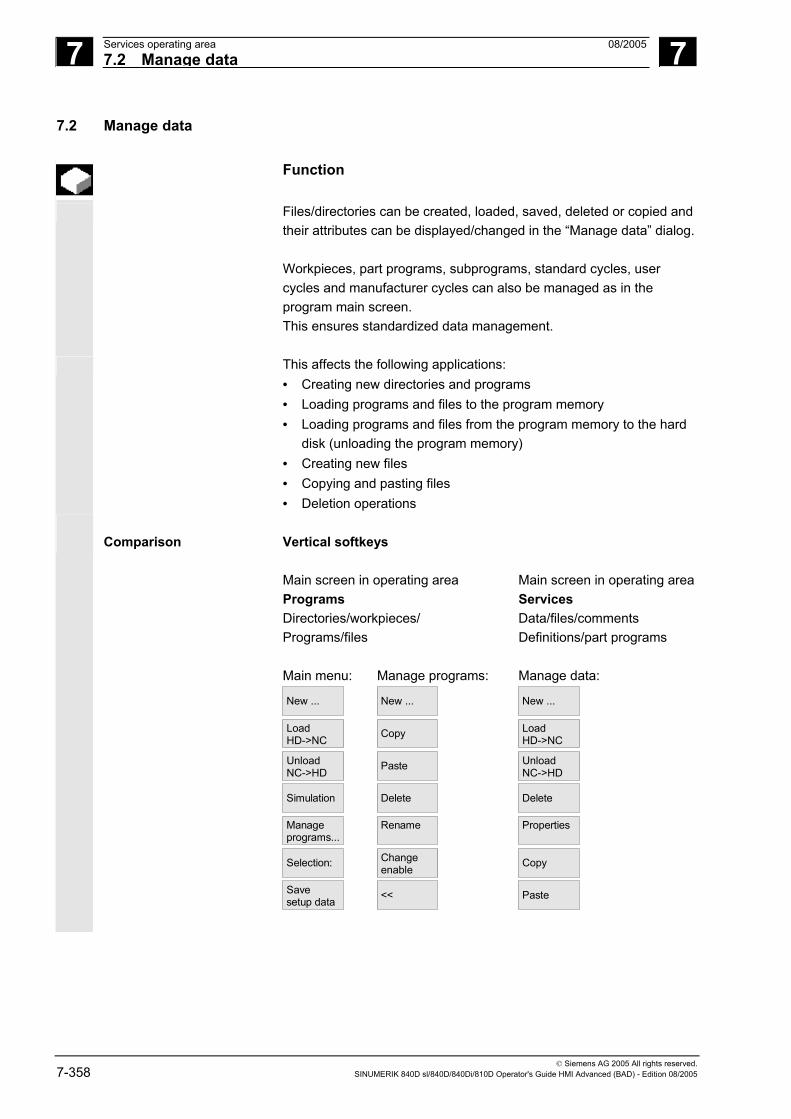
7 Services operating area 08/2005 7.2 Manage data
7
© Siemens AG 2005 All rights reserved. 7-358 SINUMERIK 840D sl/840D/840Di/810D Operator's Guide HMI Advanced (BAD) - Edition 08/2005
7.2 Manage data
Function
Files/directories can be created, loaded, saved, deleted or copied and their attributes can be displayed/changed in the “Manage data” dialog. Workpieces, part programs, subprograms, standard cycles, user cycles and manufacturer cycles can also be managed as in the program main screen. This ensures standardized data management.
This affects the following applications: • Creating new directories and programs • Loading programs and files to the program memory • Loading programs and files from the program memory to the hard
disk (unloading the program memory) • Creating new files • Copying and pasting files • Deletion operations
Comparison Vertical softkeys
Main screen in operating area Main screen in operating areaPrograms Services Directories/workpieces/ Data/files/comments Programs/files Definitions/part programs Main menu: Manage programs: Manage data:
New ...
New ...
New ...
LoadHD->NC
Copy
LoadHD->NC
UnloadNC->HD
Paste
UnloadNC->HD
Simulation
Delete
Delete
Manage programs...
Rename
Properties
Selection:
Changeenable
Copy
Save setup data
<<
Paste

7 08/2005 Services operating area7.2 Manage data
7
© Siemens AG 2005 All rights reserved. SINUMERIK 840D sl/840D/840Di/810D Operator's Guide HMI Advanced (BAD) - Edition 08/2005 7-359
Operating sequence: new file or new directory
Managedata
Press the "Manage data" softkey. The horizontal and vertical softkey bars change.
New ...
The "New" window appears.
Enter a new file name.
If the preassigned file type does not match, use the "End" key to switch between input field "Name" and "File type". Select the new file type.
OK
The new directory/file is set up in the directory overview.
7.2.1 Download and upload
Operating sequence
Manage
data
Press the "Manage data" softkey. The horizontal and vertical softkey bars change.
Position the cursor on the desired file. Load
HD->NC
The selected file is deleted from the hard disk and loaded to the NC memory. In the display the entry "X" = loaded is added to the file. See also Chapter "Job list".
UnloadNC->HD
The selected file is deleted from the NC memory and loaded to the hard disk. In the display, the entry " " = not loaded is added to the file.
If you want to "load/unload" a workpiece directory and a job list with the name of the directory exists in the job list, that job list is executed. If a job list does not exist, all the files in that directory are loaded/unloaded.

7 Services operating area 08/2005 7.2 Manage data
7
© Siemens AG 2005 All rights reserved. 7-360 SINUMERIK 840D sl/840D/840Di/810D Operator's Guide HMI Advanced (BAD) - Edition 08/2005
Loadable compile cycles You can use the HMI user interface to transfer the loadable compile cycles (CC) easily to the NC using an NC card. Further storage locations are any external drive, such as a disk drive, USB memory module or network drives 1 to 4. This storage location appears in the Service operating area under "Manage data". You can also use the SinuCom NC or SINUCOPY-FFS startup tool to transfer the loadable compile cycles into the control.
Load a compile cycle Each time the NC is booted, all loadable compile cycles with the extension .ELF, which are available in the /_N_CCOEM.DIR directory, are automatically loaded into the NCK system software. Loadable compile cycles are always loaded on an NCU reset.
For a detailed description of how to install compile cycles, please see:/FB3/, TE0 Installation and Activation of Loadable Compile Cycles.
7.2.2 Copy and insert
Function
Copy compile cycles Following a reset, the optionally available compile cycles are stored on the NCU in the Flash File System (FFS) in directory /_N_CCOEM.DIR and can be copied selectively from/to an external drive, disk or NC card. It is thus possible to archive individual compile cycles. The "Insert" function is available in addition to "Copy". You can copy 1. A single file, 2. Several files or 3. A complete directory.
You can display any existing compile cycles in the Diagnostics operating area under Service displays/Version/Compile cycles.
Operating sequence
Manage
data
Press the "Manage data" softkey. The horizontal and vertical softkey bars change.
Select the source files that you wish to copy.

7 08/2005 Services operating area7.2 Manage data
7
© Siemens AG 2005 All rights reserved. SINUMERIK 840D sl/840D/840Di/810D Operator's Guide HMI Advanced (BAD) - Edition 08/2005 7-361
Copy
A second window for the target directory (see title in window) is opened. If available, select the target device via the vertical softkeys.
Programs/data
The contents of "Programs/data" are displayed.
Clipboard
Archive files or complete directories can be copied from an existing NC card.
NC card
You can use the “Local USB” softkey to access the USB interface on the front panel. This is activated as soon as a USB memory has been plugged in and recognized.
Diskette
If a diskette drive is installed, you can copy to or from diskette. The diskette contents are displayed. Select a target directory.
Paste
The source files are copied to the target directory you have selected.
NC card
On SINUMERIK solutionline, the NC card softkey has the same functionality after pressing the expansion key.
With this copying action in operating area "Services" the names
remain unchanged. See Chapter "Copy/Insert" in the "Program" operating area.
7.2.3 Delete
Function
File You can delete a single file or a group of files (multiple selection). Directory You can delete a directory and all its contents.
The system settings relating to deletion determine whether a prompt
appears before files/directories/data are finally deleted. See Chapter "Startup operating area"

7 Services operating area 08/2005 7.2 Manage data
7
© Siemens AG 2005 All rights reserved. 7-362 SINUMERIK 840D sl/840D/840Di/810D Operator's Guide HMI Advanced (BAD) - Edition 08/2005
Operating sequence
Manage
data
Press the "Manage data" softkey. The horizontal and vertical softkey bars change.
Position the cursor on the desired file.
Delete
A query window appears.
OK
You can delete the highlighted file by pressing "OK".
Archives stored on the NC card can be deleted by selecting "NC card" under "Manage data".
7.2.4 Change properties
Function
This function allows you to view the contents of a file (or directory) as well as other information, to view file/directory properties and to change some properties. You can perform the following actions: • Rename a file • Convert a file to another file type • Change the access rights to the file/directory • View the contents of readable files. The contents of text files are
displayed.
You can change access levels only if you have the appropriate access rights to do so.
Operating sequence
Managedata
Press the "Manage data" softkey. The horizontal and vertical softkey bars change.
Properties
The "Properties" window is opened. Enter the changes you wish to make, e.g. rename the file or change the file type.

7 08/2005 Services operating area7.2 Manage data
7
© Siemens AG 2005 All rights reserved. SINUMERIK 840D sl/840D/840Di/810D Operator's Guide HMI Advanced (BAD) - Edition 08/2005 7-363
Rename file
Place the cursor on the file name and press the "Edit" key (displayed next to the type list), enter the new file name.
There are two ways of renaming files: • Renaming the workpiece directory • Renaming a directory in the workpiece directory
Rename a workpiece directory: When you rename a workpiece directory, all the workpiece files under that directory that have the same name as the directory are renamed.If a job list with the name of the directory exists, the instructions in that job list are also renamed. Comment lines remain unchanged.
Example: Workpiece directory A.WPD is renamed B.WPD: All files with the name A.XXX are renamed to B.XXX , i.e., the extension is retained. If a job list called A.JOB exists, it is renamed to B.JOB. If this job list contains instructions of file A.XXX located in this workpiece directory, then that file is also renamed B.XXX. Example: If job list A.JOB contains an instruction LOAD/Work.DIR/A.WPD/A.MPF it is renamed to LOAD/Work.DIR/B.WPD/B.MPF However, if a job list contains the instruction LOAD/MPF.DIR/A.MPF or LOAD/Work.DIR/X.WPD/A.MPF the files are not renamed. Rename a directory in the workpiece directory: If you rename the files in the workpiece directory, all files with the same name but a different extension are renamed. Exception: If a job list of the same name exists in the directory, then this one is not renamed.

7 Services operating area 08/2005 7.2 Manage data
7
© Siemens AG 2005 All rights reserved. 7-364 SINUMERIK 840D sl/840D/840Di/810D Operator's Guide HMI Advanced (BAD) - Edition 08/2005
Change the file type
Use the "Edit" key (displayed next to the type bar) to show the list of file types to which the file may be converted.
Only the file types are displayed which are permissible in the directory
where the file is located.
Use the "Direction" keys to display the new file type.
Confirm your selection with the "Input" key (displayed next to the file type you have selected).
OK
The file is assigned the new file type.
Additional notes
• No check is made to determine whether or not the file contents may be stored under the new file type!
• The contents of a file are not altered when the file type is converted.
• All data types may be stored in the "Clipboard" directory. • The file type is displayed in the properties window for network
drives or disk, and the extension with 0 to 3 characters can be modified in the "Type" input field.

7 08/2005 Services operating area7.3 Data selection
7
© Siemens AG 2005 All rights reserved. SINUMERIK 840D sl/840D/840Di/810D Operator's Guide HMI Advanced (BAD) - Edition 08/2005 7-365
7.3 Data selection
Function
Using the "File selection" softkey, you can choose the directories that you wish to have displayed in the "Services" area. The directories can be selected for two different access levels: • Users • Service
Data selection for display: Users User cycles
Display machine data Archives Machining sequence Data management Definitions Diagnostics Interactive programming Manufacturer cycles MSD data Startup Comments MBDDE alarm texts NC active data NC data backup OEM data Standard cycles System Part programs Templates Subprograms FDD data Workpieces Tool management Clipboard

7 Services operating area 08/2005 7.3 Data selection
7
© Siemens AG 2005 All rights reserved. 7-366 SINUMERIK 840D sl/840D/840Di/810D Operator's Guide HMI Advanced (BAD) - Edition 08/2005
Keywords/directories in the hierarchical file structure
The different files are made available for transfer under the following directories: • Data (general)
- Option data - Machine data (all, NC MD, channel MD, axis MD) - Setting data - Tool offsets - Work offsets - Global user data - R parameters
• Startup data - NCK data - PLC data
• Compensation data - Leadscrew pitch/encoder error - Quadrant errors - Sag/angularity
• Display machine data • Workpieces • Part programs • Subprograms • User cycles • Standard cycles • Comment data • Definitions • Feed drives • AC Main Spindle Drives • OEM data • System data (NC) • Logbook • Communication error log If your control includes additional directories, these can be found in the file tree.

7 08/2005 Services operating area7.3 Data selection
7
© Siemens AG 2005 All rights reserved. SINUMERIK 840D sl/840D/840Di/810D Operator's Guide HMI Advanced (BAD) - Edition 08/2005 7-367
Operating sequence
Services
The "Services" operating area is selected.
Data
selection Press the "Data selection" softkey. The "Data selection for display" window is opened. The vertical softkey bar changes.
You can page through the window using the "Page" keys.
Users
You can toggle between the settings • Users
Service
• Service
Standard values
• Default values The "Standard values" softkey assigns default values to the settings "User" or "Maintenance". These are suitable defaults that are supplied in the software.
Select, for example, the "User" setting. Position the cursor on an additional directory.
, OK
Mark the directory of your choice and press the "OK" softkey.
Cancel
A reset command by means of the "Cancel" softkey for the selected access level resets the data selection.
Additional notes
The file tree displays files that the user may view on the basis of his or her access rights.

7 Services operating area 08/2005 7.3 Data selection
7
© Siemens AG 2005 All rights reserved. 7-368 SINUMERIK 840D sl/840D/840Di/810D Operator's Guide HMI Advanced (BAD) - Edition 08/2005
7.3.1 Special directories and memory areas
The following directories contain special files:
Clipboard The clipboard is a directory on the hard disk, where files, which cannot be included in the copy target directory, are stored. This may be the case for example, if their file type is unknown, or is not permitted in the copy target directory or if the reading process is canceled (e.g., on USB memory media).
Archive If you wish to save several files, you can store them in an archive file (.ARC). The source path for the files, which are to be stored in the archive file, is also saved. This allows the packed file to be transferred back to the same directory from which it was copied when the archive file is unpacked again. Series startup archives are also stored in this directory.
USB memory
The following USB memory with a capacity of 512 MB is suitable for use with SINUMERIK: Order number 6ES7648-0DC20-0AA0
NC active data
The NC memory contains data (e.g., R parameters, tool offsets, machine data) that are not stored there in file format. The directory "NC active data" is provided in the file manager to allow the user to access these data and store them on the hard disk in file format. If the user wishes to save data in files on the hard disk, they can set up the same directory structure under a directory of any name for "NC data" (.MDN). Via "Copy/paste" any active data can be fetched from the NC and stored in files on the hard disk.
NC-active data cannot be unloaded.

7 08/2005 Services operating area7.3 Data selection
7
© Siemens AG 2005 All rights reserved. SINUMERIK 840D sl/840D/840Di/810D Operator's Guide HMI Advanced (BAD) - Edition 08/2005 7-369
7.3.2 Data on the hard disk
Function
General In addition to the NC working memory, SINUMERIK controls with HMI are provided with a hard disk. It is thus possible to store all data or programs which are not required in the NC on the hard disk. All data are displayed in a single file tree on the user interface. In the "Services" operating area, all files on the hard disk and in the NC memory can be: • Managed (new, load, unload, copy, delete, change properties), • Saved for a series startup (NC, PLC and HMI data) and • Downloaded to the NC memory (programs and files).
Copy to diskette When you copy to diskette the full file names are stored on the diskette.
Additional notes
The end of block character is displayed not as "LF" but as " ¶".
System queries The system behavior when copying/creating data (e.g. overwrite
existing files or query first) can be configured for all operating areas.
Query dialogs "Save as"
In the "Startup" operating area, press the HMI/System settings/Query softkeys to specify that a dialog box is to appear before files are overwritten. Otherwise, the files are overwritten without prompting or a copy is created.
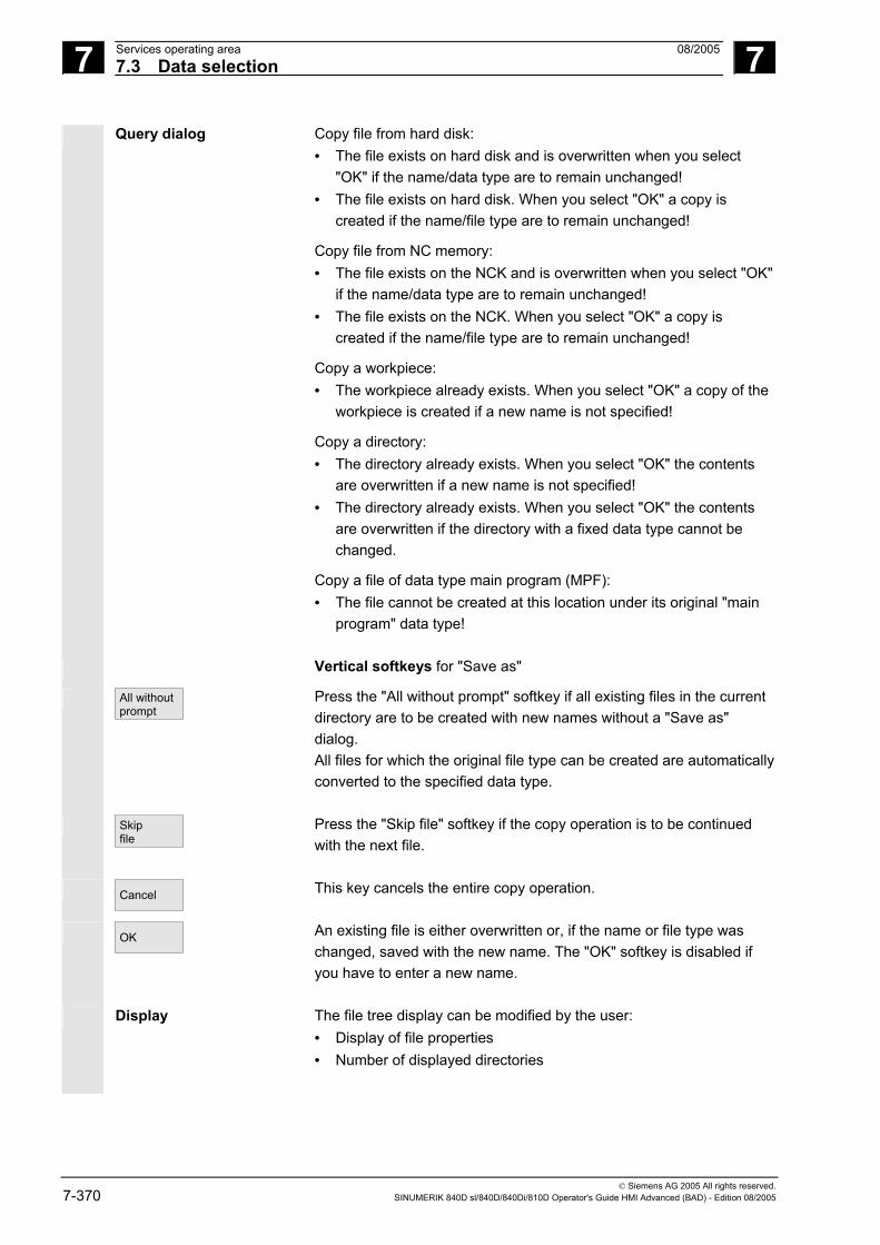
7 Services operating area 08/2005 7.3 Data selection
7
© Siemens AG 2005 All rights reserved. 7-370 SINUMERIK 840D sl/840D/840Di/810D Operator's Guide HMI Advanced (BAD) - Edition 08/2005
Query dialog Copy file from hard disk: • The file exists on hard disk and is overwritten when you select
"OK" if the name/data type are to remain unchanged! • The file exists on hard disk. When you select "OK" a copy is
created if the name/file type are to remain unchanged!
Copy file from NC memory: • The file exists on the NCK and is overwritten when you select "OK"
if the name/data type are to remain unchanged! • The file exists on the NCK. When you select "OK" a copy is
created if the name/file type are to remain unchanged!
Copy a workpiece: • The workpiece already exists. When you select "OK" a copy of the
workpiece is created if a new name is not specified!
Copy a directory: • The directory already exists. When you select "OK" the contents
are overwritten if a new name is not specified! • The directory already exists. When you select "OK" the contents
are overwritten if the directory with a fixed data type cannot be changed.
Copy a file of data type main program (MPF): • The file cannot be created at this location under its original "main
program" data type!
Vertical softkeys for "Save as"
All without prompt
Press the "All without prompt" softkey if all existing files in the current directory are to be created with new names without a "Save as" dialog. All files for which the original file type can be created are automatically converted to the specified data type.
Skip file
Press the "Skip file" softkey if the copy operation is to be continued with the next file.
Cancel
This key cancels the entire copy operation.
OK
An existing file is either overwritten or, if the name or file type was changed, saved with the new name. The "OK" softkey is disabled if you have to enter a new name.
Display The file tree display can be modified by the user: • Display of file properties • Number of displayed directories

7 08/2005 Services operating area7.4 Startup functions
7
© Siemens AG 2005 All rights reserved. SINUMERIK 840D sl/840D/840Di/810D Operator's Guide HMI Advanced (BAD) - Edition 08/2005 7-371
Data management Data management directories: • Workpieces • Part programs • Subprograms • User cycles • Standard cycles • Manufacturer cycles
Limit of data management
In data management directories, the number of files in each directory (each *.WPD workpiece directory for workpieces) is limited to 1,000 files. The total of 100,000 does not apply to the other directories; however, each directory is also limited to a maximum of 1000 files, e.g., a maximum of 1000 archives in the archive directory. Network drives are also limited to a maximum of 1000 files in each directory. The options that are available depend on the file size and the available memory space. A large number of files slows down the display building for directory displays.
7.4 Startup functions
7.4.1 Series startup
Function
"Series startup" means to establish the same initial data status on several control systems. You can select PLC, NC and HMI data and loadable compile cycles, and archive or restore them for a series machine startup. Compensation data can be saved at the same time if necessary. The drive data are saved as binary data which cannot be modified.
Operating sequence
Requirement: The password, e.g. with access level 3 (user) is set.

7 Services operating area 08/2005 7.4 Startup functions
7
© Siemens AG 2005 All rights reserved. 7-372 SINUMERIK 840D sl/840D/840Di/810D Operator's Guide HMI Advanced (BAD) - Edition 08/2005
Series startup
Press the "Series startup" softkey. The vertical softkey bar changes.
The "Create series startup archive" window opens. Create an archive for the series startup-file: You can select which data you wish to save as the archive contents: • HMI • NC with compensation data • Loadable compile cycles • PLC • Profibus drives • Archive name:
The suggested archive name depends on the selected area and can be changed if necessary.
Example:
If PLC is selected, the new archive name MMCNCPLC will be proposed on the basis of the original archive name MMCNCPLC.
MMC data selection
If you have selected the "HMI" area, you can select the data you wish to archive by pressing the "HMI data selection" softkey. The F:USER directory is always backed up. Directories \ADD_ON and \OEM can be saved additionally under "Additional products", either completely ("Complete") or just the INI files ("Configuration").
The archiving operation commences when you select the target device. Archive data to:
Diskette...
• Floppy disk drive
Archives ...
• "Archives" directory on hard disk
NC card
• "Archives" directory on the NC card
The softkey labeling changes to "Stop". The series startup archive is set up.
Read start- up archive
Toggle between functions "Create series startup archive" and "Read startup archive".

7 08/2005 Services operating area7.4 Startup functions
7
© Siemens AG 2005 All rights reserved. SINUMERIK 840D sl/840D/840Di/810D Operator's Guide HMI Advanced (BAD) - Edition 08/2005 7-373
Reading series startup archive: The data can be read via: Diskette...
• The diskette drive
Archives ...
• The "Archives" directory on the hard disk.
NC card
• "Archives" directory on the NC card
• Select the required archive file.
Start
• Start reading in the archive. The softkey labeling changes to "Stop".
Make start-up archive
Switchover from "Read" to "Make".
Additional notes
For importing a series startup file from diskette, there must be sufficient free hard disk memory to store the series startup file.
If a control is configured for M:N (several operator panel fronts and NCUs), a Power On must be initiated on the HMI (PCU 50) after a series startup so that the stations on the bus (NC, PLC, HMI) can be re-synchronized.
Archiving loadable compile cycles (CC): You can archive loadable compile cycles in the series machine startup
if the following conditions are met: • At least one CC must be available in the startup archive in
destination directory \NC_CARD.DIR\CCOEM.DIR. • Selective archiving of individual CC is performed by copying to a
data carrier, e.g., diskette. The read-in process only takes into account archive with access rights for the series startup of access levels 0 to 4.

7 Services operating area 08/2005 7.4 Startup functions
7
© Siemens AG 2005 All rights reserved. 7-374 SINUMERIK 840D sl/840D/840Di/810D Operator's Guide HMI Advanced (BAD) - Edition 08/2005
7.4.2 Updating (only SINUMERIK powerline)
Function
This function supports updating of the NC system software. For this purpose, you can create an update archive. This contains all NC data (like a series startup archive) including compensation data. Software updates are carried out according to the same principle as series startups. Differences between updates and series startups include: • The drive data are saved and re-imported in ASCII format with
software updates (thus allowing these data to be altered if necessary).
• The same machine is always affected, i.e., it is useful to copy the compensation.
References Startup guide 840D and 810D.
Operating sequence
Upgrade
Press the "Upgrade" softkey. The vertical softkey bar changes.
The "Create update archive" window opens. The NC data are preset as archive contents. You can enter any archive name of your choice.
The archiving operation commences when you select the target device. Data can be archived to
Diskette...
• Floppy disk drive
Archives ...
• "Archives" directory on hard disk
NC card
The contents of the archives directory on the NC card are displayed. Enter the name of the new archive file.
The softkey labeling changes to "Stop". The update archive is set up.

7 08/2005 Services operating area7.4 Startup functions
7
© Siemens AG 2005 All rights reserved. SINUMERIK 840D sl/840D/840Di/810D Operator's Guide HMI Advanced (BAD) - Edition 08/2005 7-375
Read in update archive: The read-in operation commences when you select the source device
connected to the RS-232 interface. The data are read in via: Diskette ...
• The diskette drive
Archives ...
• The "Archives" directory on the hard disk.
NC card
• The "Archives" directory on the NC card
• Select the required archive file. Start
• Start reading in the archive. The softkey labeling changes to "Stop".
7.4.3 Restore original state via NC card (only SINUMERIK powerline)
Function
The free memory on the NC card (PCMCIA card) can be used to store a startup archive. The archive can be loaded onto the NC card with SINUCOPY-FFS (on an external PG/PC) :
The series startup archive can be stored directly on the NC card from the HMI with the name "Original" (see Series startup - creating a file).
Operating sequence
Requirement:
The startup archive with the name _N_ORIGINAL_ARC is located on the NC card (in the directory _N_NC_CARD_DIR\_N_ARC_DIR). Please see machine manufacturer’s instructions
Original state
Select the "ETC" key in the Services main screen and then the "Original state" softkey.
When you press the softkey, the protocol window appears with the query: “Series startup archive: Execute series startup?”. Confirm to import the data.
Caution All user-specific NC data (and PLC data depending on contents) will be deleted and replaced by the data from the archive.

7 Services operating area 08/2005 7.4 Startup functions
7
© Siemens AG 2005 All rights reserved. 7-376 SINUMERIK 840D sl/840D/840Di/810D Operator's Guide HMI Advanced (BAD) - Edition 08/2005
7.4.4 Transfer display MD from HMI Embedded
Function
Use When migrating from the HMI component HMI Embedded (PCU20) to HMI Advanced (PCU50/PCU70) you may like to transfer tried and proven display machine data from the HMI Embedded configuration to the HMI Advanced configuration, e.g. for use with ShopMill/ShopTurn. The following section describes how to proceed for to transfer the machine data.
Initial situation Display machine data reside on the NCU for HMI Embedded, and on the hard disk of the PCU50/PCU70 for HMI Advanced.
Case 1:
Case 2:
Display MD
Display MD
HMI-EmbeddedNCU1
HMI-Advanced
Case 1
Display MD
NCU1Netw. drive
Floppy Disk Display MD
HMI-AdvancedNCU2
Case 2
PCU 50
PCU 50
PCU 20
HMI-Embedded
Operating sequence
The transfer consists of two steps:
• Copy the display machine data with HMI Embedded • Read into the PCU50/PCU70 under HMI Advanced
Case 1 acc. to diagram On the HMI Advanced system: Services operating area Transfer display machine data to the display if not yet activated: Services ® Select data Select "Display machine data" OK
Copy display machine data: Services → Manage data Display machine data\BDxxyy.tea Copy

7 08/2005 Services operating area7.4 Startup functions
7
© Siemens AG 2005 All rights reserved. SINUMERIK 840D sl/840D/840Di/810D Operator's Guide HMI Advanced (BAD) - Edition 08/2005 7-377
Target directory Select the target directory Diagnostics\MachDat\OperatorPanel Paste
Activate inserted display machine data via Startup: Startup → Machine data → Display MD → File functions Set up directory and file BDyy.tea →Load
Additional notes
HMI Embedded manages more display machine data than HMI Advanced. An entry is made in the error log for each proposed display machine data that is not defined in HMI Advanced or contains an error.
Case 2 acc. to diagram Transfer display MD to floppy disk or network drive: On the HMI Embedded system: Program → ETC → Set up operator data BDx.tea →Copy → ETC Select destination medium: Network drive or floppy disk Paste
On the HMI Advanced system: Services → Manage data Select transfer medium: Network drive or floppy disk Select BDxxyy.tea →Copy
Continue as for the 1st case, destination directory, see above.
7 Services operating area 08/2005 7.4 Startup functions
7
© Siemens AG 2005 All rights reserved. 7-378 SINUMERIK 840D sl/840D/840Di/810D Operator's Guide HMI Advanced (BAD) - Edition 08/2005
Notes

8 08/2005 Diagnostics operating area 8
© Siemens AG 2005 All rights reserved. SINUMERIK 840D sl/840D/840Di/810D Operator's Guide HMI Advanced (BAD) - Edition 08/2005 8-379
Diagnostics operating area 8.1 Diagnostics main screen.........................................................................................8-380
8.2 Alarms and messages.............................................................................................8-382
8.3 Service display ........................................................................................................8-384 8.3.1 Service axis.............................................................................................................8-386 8.3.2 Drive service ...........................................................................................................8-387 8.3.3 Safety Integrated service ........................................................................................8-388 8.3.4 Output configuration data........................................................................................8-391 8.3.5 Communication error log.........................................................................................8-392 8.3.6 Action log ................................................................................................................8-392
8.4 Callversion displays ................................................................................................8-393 8.4.1 Sort and save version data .....................................................................................8-394 8.4.2 Display the version displays for cycles ...................................................................8-395 8.4.3 Output cycle versions..............................................................................................8-397 8.4.4 Displayloadable compile cycles ..............................................................................8-398
8.5 Query thePLC status...............................................................................................8-399 8.5.1 Change/delete values .............................................................................................8-400 8.5.2 Assign symbolic PLC addresses.............................................................................8-401 8.5.3 Select operand screens for PLC status ..................................................................8-406 8.5.4 File functions ...........................................................................................................8-407
8.6 Display NC system resources.................................................................................8-408

8 Diagnostics operating area 08/2005 8.1 Diagnostics main screen
8
© Siemens AG 2005 All rights reserved. 8-380 SINUMERIK 840D sl/840D/840Di/810D Operator's Guide HMI Advanced (BAD) - Edition 08/2005
8.1 Diagnostics main screen A display headed "Alarms" appears when you select the “Diagnostics”
operating area.
Main screen
Number The alarm number is output under "Number". The alarms are output in
chronological order.
Date The date and time at which the alarm occurred is displayed with the date, in hours, min, sec.
Delete criterion The symbol denoting the alarm abort key is displayed for every alarm.
Text The alarm text is displayed under "Text".
Horizontal softkeys
Alarms
All active alarms are displayed in the "Alarms" display.
Messages
An overview of active messages is displayed.

8 08/2005 Diagnostics operating area8.1 Diagnostics main screen
8
© Siemens AG 2005 All rights reserved. SINUMERIK 840D sl/840D/840Di/810D Operator's Guide HMI Advanced (BAD) - Edition 08/2005 8-381
Alarm log
The alarm log of alarms and messages that have occurred is displayed. The log also includes alarms that have already been reset.Default setting for alarm buffer: 150 alarms/messages
Service displays
You can view updated information about axes and drives installed in your system under the "Service displays" softkey.
PLC status
Information on the current status of the PLC memory locations.
ePS
Expansion key: Remote diagnostics: The control can be operated externally over a remote connection (e.g., modem)
References For more information about remote diagnostics please refer to /FB/ F3, Remote Diagnostics.
Vertical softkeys
Acknowl.
MMC alarm HMI alarms (alarm number 120...) that have occurred can be acknowledged. HMI alarms are the same as HMI alarms
Acknowl. SQ alarm
SQ alarms (PLC alarms) that have occurred can be acknowledged.

8 Diagnostics operating area 08/2005 8.2 Alarms and messages
8
© Siemens AG 2005 All rights reserved. 8-382 SINUMERIK 840D sl/840D/840Di/810D Operator's Guide HMI Advanced (BAD) - Edition 08/2005
8.2 Alarms and messages
Function
You can display a list of alarms and messages and acknowledge them.
Operating sequence
Alarms: Alarms
The alarm overview displays all active alarms with alarm numbers, date, clearance criteria and descriptions. Clear the alarm by pressing the key that is displayed as a symbol:
Switch device off and on again (main switch) or NCK POWER ON
Reset
Press "Reset" key.
Press "Alarm Cancel" key.
Cycle Start
Alarm is cleared by "NC Start".
Alarm is cleared with the "Recall" key.
Messages: Messages
PLC operational messages that do not have to be acknowledged (as standard) (configurable).
Alarm log: Alarm
log A log containing the alarms and messages that have so far occurred is displayed. 150 alarms/messages can be logged as standard.
It also contains the alarms that have already been acknowledged.
This symbol means "Alarm is still active".
Display new
The alarm is updated (static display).
Save log
By pressing this softkey, the current status of the log is stored in the displayed path and can be archived from here as required.
Sorting old -> new
Changing the chronological sorting sequence of the alarms in the display.
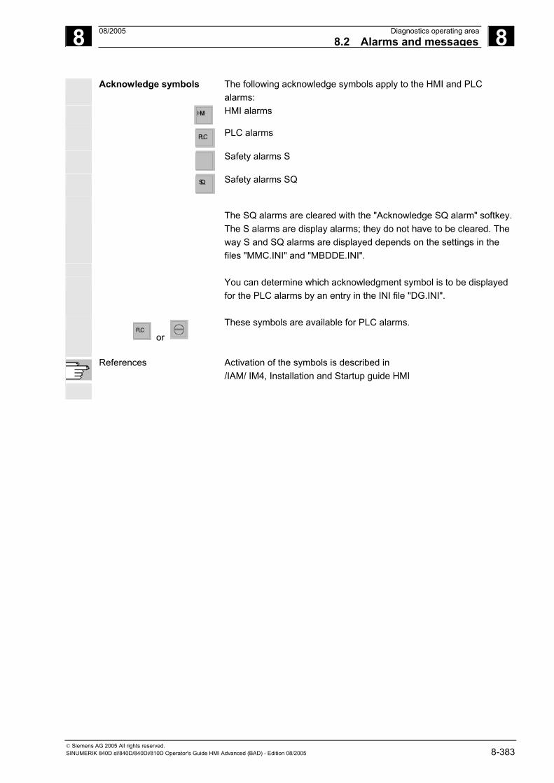
8 08/2005 Diagnostics operating area8.2 Alarms and messages
8
© Siemens AG 2005 All rights reserved. SINUMERIK 840D sl/840D/840Di/810D Operator's Guide HMI Advanced (BAD) - Edition 08/2005 8-383
Acknowledge symbols
The following acknowledge symbols apply to the HMI and PLC alarms:
HMI
HMI alarms
PLC
PLC alarms
Safety alarms S
SQ
Safety alarms SQ
The SQ alarms are cleared with the "Acknowledge SQ alarm" softkey.
The S alarms are display alarms; they do not have to be cleared. The way S and SQ alarms are displayed depends on the settings in the files "MMC.INI" and "MBDDE.INI".
You can determine which acknowledgment symbol is to be displayed
for the PLC alarms by an entry in the INI file "DG.INI".
PLC
or These symbols are available for PLC alarms.
References Activation of the symbols is described in /IAM/ IM4, Installation and Startup guide HMI

8 Diagnostics operating area 08/2005 8.3 Service display
8
© Siemens AG 2005 All rights reserved. 8-384 SINUMERIK 840D sl/840D/840Di/810D Operator's Guide HMI Advanced (BAD) - Edition 08/2005
8.3 Service display
Function
When commissioning digital drives and diagnosing faults, the various operating states of individual machine axes can be visualized with a type of traffic light indicator in the "Service overview" display, which you can open from the "Service display" menu.
Service overview This overview shows specific enable signals and statuses for each of the available axes 1 to 31. Up to 6 different states can occur on each axis:
Columns for machine axes 1 to 31 Traffic light indicator states per axis: Green: The axis is behaving normally. Yellow: The axis is not ready. Gray: The axis is not affected. Red: An alarm is pending for this axis. Line: No drive assigned to axis. Special
characters: Error when reading the data, e.g., if date not available.
Rows with the drive diagnostic functions Drive enable (terminal 64/63) Pulse enable (terminal 64/48) Pulse enable (term. 663 / SI: drive relay) Setup mode (terminal 112) PLC pulse enable NC speed controller enable DC link status Enable pulses Drive ready Heatsink temperature warning Power section in i2t limitation Motor temperature warning Measuring system 1 active Measuring system 2 active
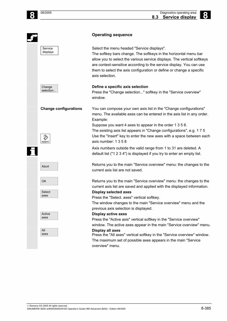
8 08/2005 Diagnostics operating area8.3 Service display
8
© Siemens AG 2005 All rights reserved. SINUMERIK 840D sl/840D/840Di/810D Operator's Guide HMI Advanced (BAD) - Edition 08/2005 8-385
Operating sequence
Service
displays
Select the menu headed "Service displays". The softkey bars change. The softkeys in the horizontal menu bar allow you to select the various service displays. The vertical softkeys are context-sensitive according to the service display. You can use them to select the axis configuration or define or change a specific axis selection.
Change selection...
Define a specific axis selection Press the "Change selection..." softkey in the "Service overview" window.
Change configurations You can compose your own axis list in the "Change configurations" menu. The available axes can be entered in the axis list in any order. Example: Suppose you want 4 axes to appear in the order 1 3 5 8. The existing axis list appears in "Change configurations", e.g. 1 7 5
Use the "Insert" key to enter the new axes with a space between each axis number: 1 3 5 8
Axis numbers outside the valid range from 1 to 31 are deleted. A default list ("1 2 3 4") is displayed if you try to enter an empty list.
Abort
OK
Returns you to the main "Service overview" menu: the changes to the current axis list are not saved. Returns you to the main "Service overview" menu: the changes to the current axis list are saved and applied with the displayed information.
Selectaxes
Display selected axes Press the "Select. axes" vertical softkey. The window changes to the main "Service overview" menu and the previous axis selection is displayed.
Activeaxes
Display active axes Press the "Active axis" vertical softkey in the "Service overview" window. The active axes appear in the main "Service overview" menu.
Allaxes
Display all axes Press the "All axes" vertical softkey in the "Service overview" window. The maximum set of possible axes appears in the main "Service overview" menu.

8 Diagnostics operating area 08/2005 8.3 Service display
8
© Siemens AG 2005 All rights reserved. 8-386 SINUMERIK 840D sl/840D/840Di/810D Operator's Guide HMI Advanced (BAD) - Edition 08/2005
8.3.1 Service axis
Function
The information in the "Service Axis" display is used to • check the setpoint branch (e.g. position setpoint, speed setpoint,
spindle speed setpoint prog.) • check the actual-value branch (e.g. position actual value,
measuring system ½, actual speed value), optimize the position control of the axis (e.g. following error, control difference, servo gain factor)
• check the entire control loop of the axis (e.g. through position setpoint/actual-value comparison and speed setpoint/actual-value comparison)
• check hardware faults (e.g. encoder check: If the axis is moved mechanically, the actual position value must change)
• set and check axis monitoring functions.
References: /FB/, Description of Functions D1, Diagnostics Tools
Operating sequence
Service
displays
Select the menu headed "Service displays". The softkey bars change. The vertical softkeys are context-sensitive according to the service display. The softkeys in the horizontal menu bar allow you to select the corresponding service displays.
Serviceaxis
Press the "Service axis" horizontal softkey The "Service axis/spindle" window displays reference values and units for the machine axis together with axis name and axis number.
You can page up and down with the "Page" keys.
Vertical softkeys for axis selection Axis
+ Axis -
The service values of the next (+) and the previous (-) axis are displayed.
Direct selection...
The "Direct selection" vertical softkey in the window of the same name allows you to select an axis directly from the list of available axes.

8 08/2005 Diagnostics operating area8.3 Service display
8
© Siemens AG 2005 All rights reserved. SINUMERIK 840D sl/840D/840Di/810D Operator's Guide HMI Advanced (BAD) - Edition 08/2005 8-387
8.3.2 Drive service
Function
The information contained in the "Service drive" display is used to • Check the status of the enable and control signals (e.g., pulse
enable, drive enable, motor selection, setpoint parameter set) • Check the status of the FDD/MSD operating modes (e.g., setup
mode, parking axis) • Display temperature warnings • Check the current setpoint/actual-value display (e.g. position
actual-value measuring system ½, speed setpoint, speed actual value)
• check the drive status • Display the current ramp-up phase • Display the group error message (message status class 1) • Display the status messages of the drive (e.g. threshold torque not
reached, actual speed = set speed)
References /FB/, Description of Functions D1, Diagnostics Tools
Operating sequence
Service
displays
Select the menu headed "Service displays". The softkey bars change. The vertical softkeys are context-sensitive according to the service display. The softkeys in the horizontal menu bar allow you to select the corresponding service displays.
Service drive
The "Service drive" window displays information about the axis drive together with axis name and number.
You can page up and down with the "Page" keys.
Vertical softkeys for axis selection Drive
+ Drive -
The service values of the next (+) and the previous (-) drive are displayed.
Direct selection...
The "Direct selection" vertical softkey in the window of the same name allows you to select an axis directly from the list of available axes.

8 Diagnostics operating area 08/2005 8.3 Service display
8
© Siemens AG 2005 All rights reserved. 8-388 SINUMERIK 840D sl/840D/840Di/810D Operator's Guide HMI Advanced (BAD) - Edition 08/2005
8.3.3 Safety Integrated service
Function
Three information blocks on Safety Integrated data are offered for the selected axis by pressing the "Service SI" softkey: • Status SI (selected by default) • SGE/SGA • SPL
Status SI
The axis +, axis - vertical softkeys or direct selection are used to set
the desired axis. The active axis is displayed in the top right half of the table.
Available signals/values • Safe actual position • Position deviation NCK/drive • "Safe operating stop" monitoring active • Safely-reduced speed" monitoring active • Active SG step • Active SG correction factor • Safe actual speed limit • Setpoint speed limit • Actual speed difference • Maximum speed difference • Active safe software limit switch • Active gear ratio (step) • Active stop • Currently requested external stop

8 08/2005 Diagnostics operating area8.3 Service display
8
© Siemens AG 2005 All rights reserved. SINUMERIK 840D sl/840D/840Di/810D Operator's Guide HMI Advanced (BAD) - Edition 08/2005 8-389
• Stop F code value (Alarm 300911) • Pulses enabled • Traversing inhibit due to a stop in other axis
References /FBSI/ Description of Functions Safety Integrated
Operating sequence
Servicedisplays
Select the menu headed "Service displays". The horizontal softkey bar changes.
Service SI
The "Service SI" window displays information about Safety Integrated data together with the associated axis name and axis number.
You can page up and down with the "Page" keys.
Axis+ Axis -
The service values of the next (+) and the previous (-) axis are displayed.
Direct selection...
An axis can be directly selected from the available axes.
SGE/SGA
Use this softkey to display the safety-relevant input and output signals SGE and SGA.
SGE/SGA
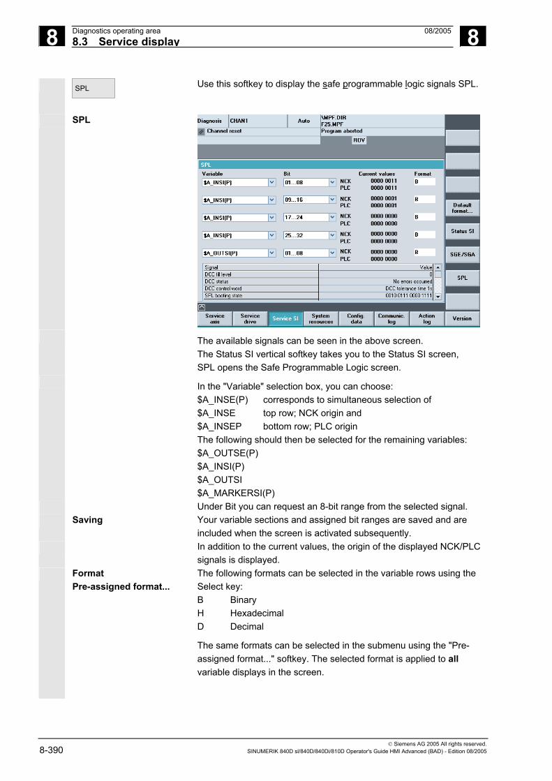
8 Diagnostics operating area 08/2005 8.3 Service display
8
© Siemens AG 2005 All rights reserved. 8-390 SINUMERIK 840D sl/840D/840Di/810D Operator's Guide HMI Advanced (BAD) - Edition 08/2005
SPL
Use this softkey to display the safe programmable logic signals SPL.
SPL
The available signals can be seen in the above screen.
The Status SI vertical softkey takes you to the Status SI screen, SPL opens the Safe Programmable Logic screen.
In the "Variable" selection box, you can choose: $A_INSE(P) corresponds to simultaneous selection of $A_INSE top row; NCK origin and $A_INSEP bottom row; PLC origin The following should then be selected for the remaining variables: $A_OUTSE(P) $A_INSI(P) $A_OUTSI $A_MARKERSI(P)
Under Bit you can request an 8-bit range from the selected signal. Saving Your variable sections and assigned bit ranges are saved and are
included when the screen is activated subsequently. In addition to the current values, the origin of the displayed NCK/PLC
signals is displayed. Format
Pre-assigned format... The following formats can be selected in the variable rows using the Select key: B Binary H Hexadecimal D Decimal
The same formats can be selected in the submenu using the "Pre-assigned format..." softkey. The selected format is applied to all variable displays in the screen.

8 08/2005 Diagnostics operating area8.3 Service display
8
© Siemens AG 2005 All rights reserved. SINUMERIK 840D sl/840D/840Di/810D Operator's Guide HMI Advanced (BAD) - Edition 08/2005 8-391
Individually set or fixed format settings are saved and taken into consideration in the following displays.
Selectable variables $A_INSE(P) $A_OUTSE(P) $A_INSI(P) $A_OUTSI(P) $A_MARKERSI(P)
Displayed signals KDV level (KDV = cross-checking) Cross-checking status Cross-checking control word SPL power up status SPL powered up SPL interfaces are parameterized "SAFE.SPL" SPL program file loaded NCK waits until the PLC has started Interrupt for SPL start should be assigned Interrupt for SPL start has been assigned Interrupt processing for SPL start called Interrupt processing for SPL start terminated NCK cross-checking has been started PLC cross-checking has been started Cyclic SPL checksum test active All SPL protection features active
8.3.4 Output configuration data
Function
The configuration data of a machine (HMI version, NCU version, axis configuration, drive configuration, bus parameters, active bus nodes) can be written into a file and subsequently read out or printed. Configuration data is output in 2 stages: 1. Creation of the configuration data file CONFIGURATION_DATA in
the "Diagnostics" operating area by pressing the "Config. data" softkey.
2. Read-out of the CONFIGURATION_DATA file in the “Services” operating area. The configuration file CONFIGURATION_DATA is created in the "Services" operating area for this purpose.

8 Diagnostics operating area 08/2005 8.3 Service display
8
© Siemens AG 2005 All rights reserved. 8-392 SINUMERIK 840D sl/840D/840Di/810D Operator's Guide HMI Advanced (BAD) - Edition 08/2005
Operating sequence
Servicedisplays
Select the menu headed "Service displays". The horizontal softkey bar changes.
Config. data
Press the "Config. data" softkey. The system gathers the configuration data, writes it into the file CFGDAT.TXT and displays it. The path and name of the file are output in the info line.
Additional notes
The configuration data can be read out in the “Services operating area.
8.3.5 Communication error log
Communic. error log
Function
Errors that occur during communication between the HMI and NCK/PLC are registered in a communication error log. You can display the errors by pressing this softkey.
The error log file is principally used by the control manufacturer (Siemens) as a diagnostic tool for communication errors.
8.3.6 Action log
Action
log An existing action log can be displayed.
For configuration of the action log, see /IAM/ IM4 Installation and startup guide, HMI Advanced

8 08/2005 Diagnostics operating area8.4 Callversion displays
8
© Siemens AG 2005 All rights reserved. SINUMERIK 840D sl/840D/840Di/810D Operator's Guide HMI Advanced (BAD) - Edition 08/2005 8-393
8.4 Callversion displays
Function
The version data of the installed system software are output in the Version display. Sort and save functions are available for the displayed version data. Version displays saved as ASCII files can be edited as required or sent to the hotline in the event of an error.
Operating sequence
Service
displays
Press the "Service displays" softkey. The horizontal softkey bar changes.
Version
Open the "Version" window in the "Service displays" menu. The following softkeys are displayed:
NCU version
"NCU version" for the version data of the NCU and
HMI version
"HMI version" for the version data of the HMI.
Cycle version
"Cycle version" Version data for each of the cycle packages
Definitions
"Definitions" The version data for definitions
Option: Compile cycles If "Compile cycles" is available on the NCK, the version is displayed.
Use the "Page" keys to scroll up and down.

8 Diagnostics operating area 08/2005 8.4 Callversion displays
8
© Siemens AG 2005 All rights reserved. 8-394 SINUMERIK 840D sl/840D/840Di/810D Operator's Guide HMI Advanced (BAD) - Edition 08/2005
8.4.1 Sort and save version data
Function
There are various sorting functions for the following version lists: • NCU version • HMI version • Cycle version • Definitions
Sort
In the left-hand part of the pane for sorting, you can select a sort criterion from the column designations in the list by pressing the Select key. In the right-hand pane you can choose from descending and ascending sorting sequence for the selected sort criterion.
Save versions
The sorted and unsorted version displays of the display area are saved as follows for HMI versions:
Area Destination File HMI version Services→Diagnostics\Log files HMI.COM
How to save the other areas is described in the area descriptions.
Specific features of HMI versions
Software objects are displayed in red if they are not unambiguous (e.g. several executable programs with the same name in different directories) or, if the entry in the registry file does not match the actual storage location of an object. A language-independent message is displayed in the message line: 1: <actual registry entry> or 1: - , if there is no registry entry or 2 for all other files under a different path The dialog messages are also written to the log file.
The checking procedure takes place when the respective version display is first accessed.
The version number is 8 digits long and structured as follows:
V xx.yy.zz.nn
Major Release yy:Minor Release zz:
nn:Hotfix Number

8 08/2005 Diagnostics operating area8.4 Callversion displays
8
© Siemens AG 2005 All rights reserved. SINUMERIK 840D sl/840D/840Di/810D Operator's Guide HMI Advanced (BAD) - Edition 08/2005 8-395
8.4.2 Display the version displays for cycles
Function
The following version screens can be displayed and used to diagnose the cycle states: • Overview of the cycle packages available on the control. • Details of the individual packages. • An overview of all available cycles. • Separate overview for user, manufacturer and standard cycles. • Definitions
Operating sequence
Service
displays
Press the "Service displays" softkey. The horizontal softkey bar changes.
Versions
Open the "Version" window in the "Service displays" menu. The following softkeys are displayed:
Package overview Cycle version
Package overview
The cycle packages available on the NCK can be displayed in a separate "Cycle version data" overview by pressing the "Version data cycles" horizontal softkey. The "Package overview" vertical softkey is included automatically.
Related cycles can be grouped together in packages and listed in a package list. The complete package is assigned a package name and a version identifier. The file type of the cycle package list is .cyp (cycle package). Package lists are named cyc_xxx.cyp and the following standard names are defined:
Predefined package lists Package list Cycle package cyc_sc.cyp Standard cycles
cyc_scs.cyp Cycle support (for standard cycles) cyc_mc.cyp Measuring cycles cyc_mcs.cyp Measuring cycle support cyc_mj.cyp Measuring in JOG cyc_sm.cyp ShopMill cyc_st.cyp ShopTurn cyc_mt.cyp ManualTurn cyc_c950.cyp Extended stock removal cyc_c73.cyp Pocket surfaces with islands cyc_iso.cyp ISO compatibility for cycles cyc_cma.cyp Manufacturer cycles (predefined name) cyc_cus.cyp User cycles (predefined name)

8 Diagnostics operating area 08/2005 8.4 Callversion displays
8
© Siemens AG 2005 All rights reserved. 8-396 SINUMERIK 840D sl/840D/840Di/810D Operator's Guide HMI Advanced (BAD) - Edition 08/2005
Details of packages Cycle version
Details
Select a package in the package overview and press the "Details" vertical softkey. The following details for the selected package appear in the "Version data" overview: • Package name Name • Package type Type • Load status Loaded • Package length Length • Storage directory Directory (in data management) • Date • Version entry Version
Overview of Cycle version
All cycles All cycles
Press the "All cycles" vertical softkey. The "Cycle version" horizontal softkey is included automatically. All available cycles of the types .com and .spf from the user cycle (CUS.DIR), manufacturer cycle (CMA.DIR) and standard cycle (CST.DIR) directories are displayed in the "Version data" overview irrespective of the packages. If a file is stored in several directories, the text color of the active version appears in black in the editor. Inactive files are grayed out.
Cycle
version
User User cycles
Manufacturer Manufac-turer cycles
Standard Standard cycles
Cycles
Press the desired vertical softkey • "User cycles" or • "Manufacturer cycles" or • "Standard cycles" The "Cycle version" horizontal softkey remains active. All files of the type .com and .spf from the user, manufacturer or standard cycle directory are displayed in the "Version data" overview without the package lists.
Definitions Defi-nitions
The definition files available on the NCK can be displayed in a separate "Version data definitions" overview by pressing the "Definitions" horizontal softkey. All the definition files from the DEF.DIR directory in the data management then appear in this overview. You can change to another version display by pressing a different horizontal softkey.
Sort
The version information can be sorted according to the proposed criteria in either ascending or descending order.

8 08/2005 Diagnostics operating area8.4 Callversion displays
8
© Siemens AG 2005 All rights reserved. SINUMERIK 840D sl/840D/840Di/810D Operator's Guide HMI Advanced (BAD) - Edition 08/2005 8-397
Save versions
The sorted and unsorted version displays of the displayed definitions are saved as follows:
Area Destination File Definitions Services→Diagnostics\Log files DEF.COM
8.4.3 Output cycle versions
Function
You can save the contents of the version displays for cycles in a separate log file.
Operating sequence
Service
displays
Versions
Cycle version
Save versions
To create a separate log file for the following version contents, press the "Save versions" vertical softkey in the "Version data type cycles" version display: File: Type: CYP.COM Package overview CYP_DET.COM Details ALLCYCLE.COM All cycles CUS.COM User cycles CMA.COM Manufacturer cycles CST.COM Standard cycles
When the data have been saved, the following message appears: "File stored!" "
Services:\Diagnostics\LogFiles\xxx.com. xxx stands for the respective file name preceding the extension .COM for each type.

8 Diagnostics operating area 08/2005 8.4 Callversion displays
8
© Siemens AG 2005 All rights reserved. 8-398 SINUMERIK 840D sl/840D/840Di/810D Operator's Guide HMI Advanced (BAD) - Edition 08/2005
8.4.4 Displayloadable compile cycles
Function
Loadable compile cycles (CC) are an optional extra. The functionality must be enabled explicitly. If loadable compile cycles are available on your NCK, you can display them in a separate "Version data cycles" display under Service displays/Version/Compile cycles.
Operating sequence
Loadable compile cycles
Servicedisplays
Compile cycles are loaded when you initiate an NCU reset and can then be displayed under Service displays/Version/Compile cycles.
Version
Compile cycles
Open the "Version" window in the "Service displays" menu. The "Compile cycles" softkey appears. Press the "Compile cycles" softkey.
Display loaded CC All loaded files of the type .elf are displayed in the "Version data compile cycles" overview.
You can check the storage location of the loadable compile cycles in the Services operating area in the "Manage data" main screen. You can copy the available loadable compile cycles from here onto an installed NC card. Other storage locations, such as any external drive, e.g. disk drive or network drives 1 to 4, are supported.
Display non-loaded CC All non-loaded files of the type .elf can also be displayed in the "Manage data" main screen. To do this, select the appropriate directory. You can display all the main properties of an individual compile cycle by selecting any individual file with the extension .elf.
Properties
Press the "Properties" softkey The horizontal and vertical softkey bar changes and a "Properties" window, such as the one below for NC card, appears.

8 08/2005 Diagnostics operating area8.5 Query thePLC status
8
© Siemens AG 2005 All rights reserved. SINUMERIK 840D sl/840D/840Di/810D Operator's Guide HMI Advanced (BAD) - Edition 08/2005 8-399
Properties Path :\NCcard\LoadableCompileCycles
Name :CCMCSC Date: Time Extension :ELF Length: Loaded: Type :Loadable compile cycle
Access authorization Read: Write: Enable: List: Delete:
Version display Contents: Loadable compile cycle Version: MCSC Coupling axes Machine Time Date
Advance version of compile cycle (Preliminary) Interface: 001.001@Interfaces=002.000 @TChain=001.000
Current access authorization access level:
8.5 Query thePLC status
Function
You can obtain information about the current states of the following memory locations of the PLC and change them if necessary:
Inputs: Input bit (Ex), input byte (EBx) Input word (Ewx), input double word (Edx)
Outputs: Output bit (Ax), output byte (Abx) Output word (Awx), output double word (Adx)
Bit memories: Memory bit (Mx), memory byte (MBx) Memory word (MWx), memory double word (MDx)
Timers: Time (Tx) Counters: Counter (Cx) data: Data block (DBx), data bit (DBxx), data byte (DBBx),
data word (DBWx), data double word (DBDx) Format: B = binary
H = hexadecimal D = decimal G = floating comma (for doublewords)

8 Diagnostics operating area 08/2005 8.5 Query thePLC status
8
© Siemens AG 2005 All rights reserved. 8-400 SINUMERIK 840D sl/840D/840Di/810D Operator's Guide HMI Advanced (BAD) - Edition 08/2005
Operand Example Read Write Format Value Range Inputs
I 2.0 IB 2
Yes Yes B B H D
0 0101 1010 5A 90
0-127
Outputs Q20.1 QB 20
Yes Yes B B HD
1 1101 0110 D6 214
0-127
Markers M 60.7 MB60 MW 60
Yes Yes B B H D
1 1101 0110 B8 180
0-255
Timers T20 Yes No B H D
0-31
Counters C20 Yes Yes B H D
0-31
DB / Data byte
DB3.DBB9
Yes Yes H D B
0-255 0-255 Q 10 000 0000 0000 1010
In HMI, the "Page" keys can be used to scroll up and down.
8.5.1 Change/delete values
Function
The values of operands can be changed.
Operating sequence
Diagnosis
The "Diagnostics" operating area is selected.
PLCstatus
Press the "PLC status" softkey. The first operand screen form appears. The vertical softkey bar changes.
Modified
Cyclic updating of the values is interrupted.
Operand +
Operand -
You can increase or decrease the address of the operand by 1 place at a time.

8 08/2005 Diagnostics operating area8.5 Query thePLC status
8
© Siemens AG 2005 All rights reserved. SINUMERIK 840D sl/840D/840Di/810D Operator's Guide HMI Advanced (BAD) - Edition 08/2005 8-401
Softkey allocation Default
format
A selection window appears. You can preset the format fields to "B" (binary), "H" (hexadecimal), "D" (decimal) or "G" (floating point).
Change the operand, the format or the value.
Delete: Delete
The entries for the selected operand (formats and values) are deleted. A query window is opened.
Undo changes: Undo
changes:
Cyclic updating is continued; the entered values are not transferred to the PLC.
Accept: Accept
The entered values are transferred to the PLC. Cyclic updating is continued.
Press the "information key". A description of the permissible input syntax for the PLC status display is overlaid.
8.5.2 Assign symbolic PLC addresses
Function
PLC data can also be edited via symbols. To do this, the symbol tables and texts for the symbols in the PLC project must have been suitably prepared and made available in the HMI.
Additional notes
The program PlcSymbolsGenerator.exe and its description are located in the PLC tool box. It creates the files with symbols and language-dependent texts in the representation required for the HMI.
Requirements Preparation of PLC data: • Save the files created with PlcSymbolsGenerator.exe in the
Services operating area under path: Diagnostics/PLC Data (F:\DH\DG.DIR\PLC.DIR\ ) with the following predefined names and extensions: PlcSym.SNH (symbols) PlcSym_<language extension>.SNT (texts e.g., PlcSym_GR.SNT)

8 Diagnostics operating area 08/2005 8.5 Query thePLC status
8
© Siemens AG 2005 All rights reserved. 8-402 SINUMERIK 840D sl/840D/840Di/810D Operator's Guide HMI Advanced (BAD) - Edition 08/2005
• NC RESET or HMI reboot for file activation • Only for M:N configurations: There must be an entry which
makes the symbols available in netnames.ini for each addressable NCU.
References For more information, please refer to:
/IAM/ IM4, Chapter 5
Language If the texts (symbol comments) are stored for multiple languages, you can also change language to work with texts in the other languages.
Operating sequence
Diagnosis
PLC symbols
The "Diagnostics" operating area is selected. If the above listed requirements are met, the PLC symbol softkey is displayed.
The following are represented in the table from left to right: • Symbolic address • Absolute address • Format • Value

8 08/2005 Diagnostics operating area8.5 Query thePLC status
8
© Siemens AG 2005 All rights reserved. SINUMERIK 840D sl/840D/840Di/810D Operator's Guide HMI Advanced (BAD) - Edition 08/2005 8-403
Vertical softkeys
Sort
Select a sort option from:
Depending on your selection, sorting takes place on column one or column two in ascending or descending alphabetical order to make it easy to find a symbol or address. "As in symbol table" means: In the same sequence as the symbol table in the PLC project.
Filter
Select the categories of symbols/addresses that you want to display. Press OK to activate the filter. Filters are retained after you exit screens/operating areas and after reboot.
Find/ go to...
After entering a search term and search direction, the section of the table is displayed with the focus on the symbol/absolute address if it was found. The search is performed in the following sequence: absolute addresses, symbols. When you enter the search term in the "Address" field, take care to enter the correct notation. Press OK to start the search.

8 Diagnostics operating area 08/2005 8.5 Query thePLC status
8
© Siemens AG 2005 All rights reserved. 8-404 SINUMERIK 840D sl/840D/840Di/810D Operator's Guide HMI Advanced (BAD) - Edition 08/2005
If the search term is not found, the dialog box remains open for a new
search. After you change screens, the search term and search direction are retained in the dialog box
Start
Press this softkey to jump to the beginning of the symbol table.
End
Press this softkey to jump to the end of the symbol table.
Details
All information is displayed for the selected address or symbol in the following representation:
If relevant texts are available in the PLC project, they are displayed here as "description".

8 08/2005 Diagnostics operating area8.5 Query thePLC status
8
© Siemens AG 2005 All rights reserved. SINUMERIK 840D sl/840D/840Di/810D Operator's Guide HMI Advanced (BAD) - Edition 08/2005 8-405
Modified
You can change the value of the symbol that is currently displayed in detail. The input marker is positioned on Value. Value input is completed by pressing the Enter key; however, the values are only activated when the "Accept" softkey is pressed. You can also choose a more suitable display format.
Accept
The entered value is transferred to the PLC interface.
Modified
You can change the value for the selected symbol. Value input is completed by pressing the Enter key; however, the values are only activated when the "Accept" softkey is pressed. You can also choose a more suitable display format. Before pressing the Accept softkey to validate the data changes, you can modify any number of symbol values in sequence.
Accept
The previously entered values are transferred to the PLC interface.
Symbols in the status screen Diagnosis
PLC status
If the above mentioned requirements are met, the additional "Symbol" softkey is displayed in the PLC status screen.
Symbols
You can use the softkey to switch between absolute addresses and symbols for inputs and display in the status screen. If a symbol is selected, the "Operand+" and "Operand-" softkeys defined for absolute addresses are not available. Otherwise, the above description for PLC status also applies to the status screen.

8 Diagnostics operating area 08/2005 8.5 Query thePLC status
8
© Siemens AG 2005 All rights reserved. 8-406 SINUMERIK 840D sl/840D/840Di/810D Operator's Guide HMI Advanced (BAD) - Edition 08/2005
8.5.3 Select operand screens for PLC status
Function
You can save the operands entered in the "PLC status" window to a file or read in a back-up list of operands.
Operating sequence
Diagnosis or
Start-up
The "Startup" operating area is selected.
PLC
Press the "PLC" softkey. The horizontal and vertical softkey bars change.
File functions
Press the "File functions" softkey. The vertical softkey bar changes.
Enter the name of the file in which you wish to save the operands. You can select existing back-up files from a list.
All the following functions refer to the file name entered:
Delete
The selected operand back-up file is deleted.
Save
The selected operands are saved to the specified file.
Load
The selected operand file is loaded to the "PLC status" window for processing.
Error
log
If errors occur during transfer of the machine data, these are entered in an error log.
The error log is transfer-specific, i.e. it is cleared before each new
transfer.
Editor
The ASCII editor is called with the selected file. You can now edit the operand back-up file.
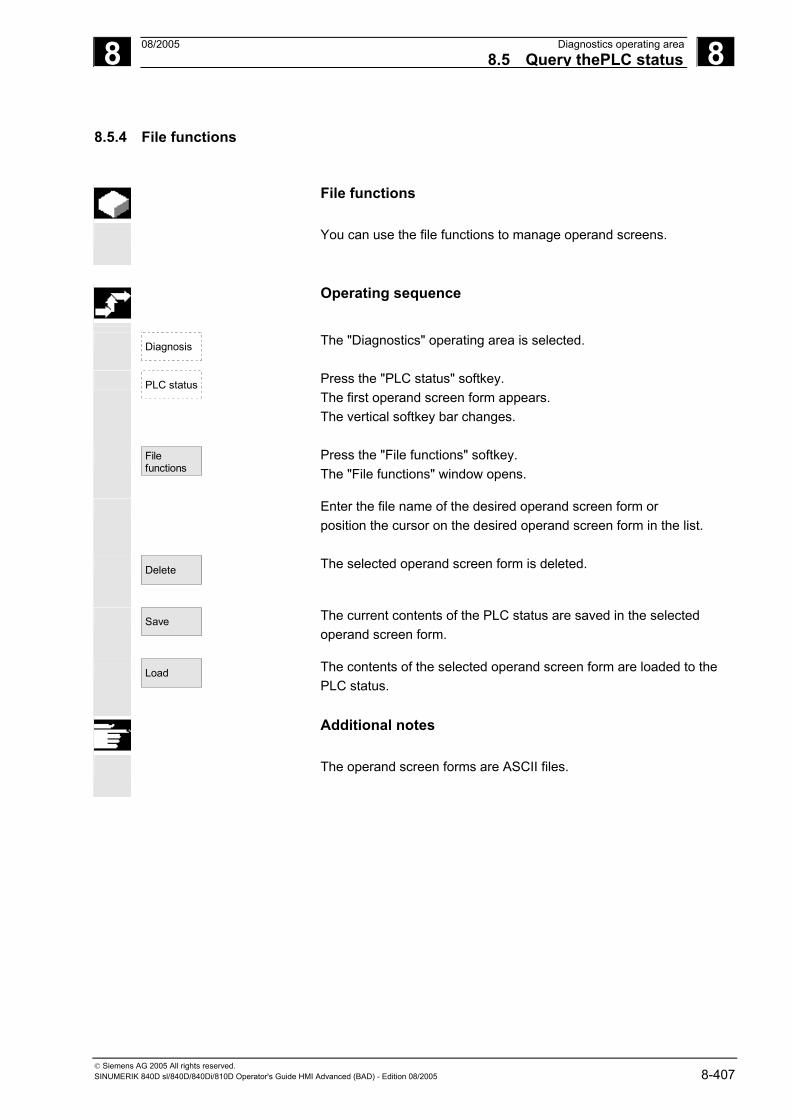
8 08/2005 Diagnostics operating area8.5 Query thePLC status
8
© Siemens AG 2005 All rights reserved. SINUMERIK 840D sl/840D/840Di/810D Operator's Guide HMI Advanced (BAD) - Edition 08/2005 8-407
8.5.4 File functions
File functions
You can use the file functions to manage operand screens.
Operating sequence
Diagnosis
The "Diagnostics" operating area is selected.
PLC status
Press the "PLC status" softkey. The first operand screen form appears. The vertical softkey bar changes.
File functions
Press the "File functions" softkey. The "File functions" window opens.
Enter the file name of the desired operand screen form or position the cursor on the desired operand screen form in the list.
Delete
The selected operand screen form is deleted.
Save
The current contents of the PLC status are saved in the selected operand screen form.
Load
The contents of the selected operand screen form are loaded to the PLC status.
Additional notes
The operand screen forms are ASCII files.

8 Diagnostics operating area 08/2005 8.6 Display NC system resources
8
© Siemens AG 2005 All rights reserved. 8-408 SINUMERIK 840D sl/840D/840Di/810D Operator's Guide HMI Advanced (BAD) - Edition 08/2005
8.6 Display NC system resources
Function
For the NC areas you can display the system resources (utilization display) currently being used: Net and gross runtimes of • position controller, • interpolator and • preprocessing.
Operating sequence
Diagnosis
The "Diagnostics" operating area is selected.
Service displays
System resources
NC
Press the "Service displays" softkey then "System resources". The "NC utilization" screen is displayed. The following minimum/maximum total data for the servo, IPO cycle and preprocessing are displayed: • Net runtime in ms • Gross runtime in ms • Level of the IPO buffer in percent • Total capacity utilization in percent
Stop
Start
The display update can be halted with the "Stop" softkey, the displayed values are updated again with the "Start" softkey.

9 08/2005 Startup operating area9.1 Startup main screen
9
© Siemens AG 2005 All rights reserved. SINUMERIK 840D sl/840D/840Di/810D Operator's Guide HMI Advanced (BAD) - Edition 08/2005 9-409
Startup operating area 9.1 Startup main screen ................................................................................................9-410
9.2 Machine data...........................................................................................................9-414 9.2.1 Display options: Masking filter.................................................................................9-416 9.2.2 User views...............................................................................................................9-418 9.2.3 File functions ...........................................................................................................9-419
9.3 NC ...........................................................................................................................9-420
9.4 PLC .........................................................................................................................9-421 9.4.1 Set time/date ...........................................................................................................9-421
9.5 Set HMI ...................................................................................................................9-422 9.5.1 System settings.......................................................................................................9-425 9.5.2 End OEM startup.....................................................................................................9-428
9.6 Optimization/Test ....................................................................................................9-429
9.7 Startup of other components...................................................................................9-431 9.7.1 Drives ......................................................................................................................9-431 9.7.2 Quick startup for axes and drives ...........................................................................9-432 9.7.3 Tool management ...................................................................................................9-432

9 Startup operating area 08/2005 9.1 Startup main screen
9
© Siemens AG 2005 All rights reserved. 9-410 SINUMERIK 840D sl/840D/840Di/810D Operator's Guide HMI Advanced (BAD) - Edition 08/2005
9.1 Startup main screen
Danger
Changes in the startup operating area have a significant influence on the machine. Incorrect configuration of the parameters can endanger human life and cause damage to the machine.
Access to certain menus in the "Start-up" operating area can be
protected by keylock switch or password. This Chapter describes functions which the machine operator can perform on the basis of his or her access rights.
References For additional information on startup, refer to: /IAM/ IM4 Startup: HMI Advanced
Target groups include: • System personnel • Machine manufacturers • Service personnel • Machine users (machine setters)
Function
The diagram shows the status of the SINUMERIK solutionline:
The "Machine configuration" window is displayed in the "Start-up" main screen.

9 08/2005 Startup operating area9.1 Startup main screen
9
© Siemens AG 2005 All rights reserved. SINUMERIK 840D sl/840D/840Di/810D Operator's Guide HMI Advanced (BAD) - Edition 08/2005 9-411
Horizontal softkeys
Machine data
Enables you to edit the machine data for all areas.
NC
You can perform an NC boot in different modes.
Drives
See Subsection 9.7.1
PLC
The PLC status function is available. You can update the date and time of the PLC and HMI.
HMI
Here you can enter the settings on the user interface.
Rap.st-up axis/drive
See Subsection 9.7.2
Optimiz./ test
The system provides support here for startup of the drive. Coupled axes are supported for measuring in the current control loop, speed control loop or position control loop.
Expanded softkey bar: Here you can manage and activate licenses for installed software and options (see Section 9.3).
Tool man-agement
See Subsection 9.7.3
References /IDS/ NCU Startup Manual
/IAD/ SIMODRIVE 611 Digital Installation & Startup Guide

9 Startup operating area 08/2005 9.1 Startup main screen
9
© Siemens AG 2005 All rights reserved. 9-412 SINUMERIK 840D sl/840D/840Di/810D Operator's Guide HMI Advanced (BAD) - Edition 08/2005
Vertical softkeys
ChangeLanguage
You can use two languages in parallel. When you press the "Change Language" softkey, screen texts are displayed in the other of the two languages.
The user only has access to information related to this protection level and the levels below it. The machine data is assigned different protection levels by default.
NCKReset
You can press this softkey to initiate NCK power ON/Reset. This softkey appears only if you have been granted appropriate access rights.
Password...
You can set, change or delete a password.
Function
The control has a protection level system for enabling data areas. There are access levels 0 to 7; where • 0 is the highest and • 7 is the lowest.
Protection level locking for levels • 0 to 3 is controlled by means of passwords and for • 4 to 7 by means of keylock switch settings.
Protection level
Locked by Area
0 Password Siemens 1 Password Machine manufacturer 2 Password Installation engineer, service
3 Password End user 4 Keylock switch position 3 Programmer, machine setter
5 Keylock switch position 2 Qualified operator 6 Keylock switch position 1 Trained operator 7 Keylock switch position 0 Semi-skilled operator Depending on the authorization level, it will be possible to edit data
such as cycles and machine data. Access levels 0 to 3 require the input of a password. The password for level 0 provides access to all data areas. At system boot in Startup mode (NCK startup switch in position 1), the default passwords are entered by default.

9 08/2005 Startup operating area9.1 Startup main screen
9
© Siemens AG 2005 All rights reserved. SINUMERIK 840D sl/840D/840Di/810D Operator's Guide HMI Advanced (BAD) - Edition 08/2005 9-413
Press the "Password" softkey to set default passwords 1 to 3, which were entered at system boot after activation, to the required standard for the software version. If one of the above passwords is set, the keylock switch position is ignored.
Operating sequence
Start-up
The "Start-up" operating area is selected.
Password...
Press the "Password" softkey. You can activate the password for the system via the Set password, Delete password and Change password horizontal softkeys.
Set password
Press the "Set password" softkey. The input window for entering the password is displayed. Enter one of the three possible default passwords and press the Input key or symbol to confirm. A permissible password is acknowledged as set and the currently applicable access level is displayed. Invalid passwords will be rejected. You must delete the old password before activating a password for a lower access level than the one activated.
Delete password
Press the "Delete password" softkey. After pressing the "Delete password" softkey the valid password is deleted and deletion is acknowledged. The currently valid access level keylock switch position 0 is set.
Change password
If one of the three default passwords is set, proceed as follows to change it. Press the "Change password" softkey. The “Change password” input box appears: Access level:
System Manufacturer Please enter new password: Service Please confirm password: User
The modified password must be entered in both input fields then confirmed by pressing the "OK" softkey. Both entered passwords must match for the modified password to become valid.

9 Startup operating area 08/2005 9.2 Machine data
9
© Siemens AG 2005 All rights reserved. 9-414 SINUMERIK 840D sl/840D/840Di/810D Operator's Guide HMI Advanced (BAD) - Edition 08/2005
9.2 Machine data
Danger Changes in the machine data have a considerable influence on the machine. Incorrect configuration of the parameters can endanger human life and cause damage to the machine.
Access to the machine data operating area can be controlled by keylock switch or password.
Function
Areas The machine data is divided into the following areas: • General machine data ($MN) • Channel-specific machine data ($MC) • Axis-specific machine data ($MA) • Display machine data ($MM) • Drive-specific machine data ($M_) • Machine data control unit: Drive parameters (solutionline) • Machine data feed-in: Drive parameters (solutionline) A separate list display is provided for each of these areas in which you can view and edit machine data. The following information about the machine data is displayed from left to right: • Machine data number • Machine data name, with field index if applicable. • Value of the machine data • Unit of the machine data • Activation
If the machine data does not use units, no units are displayed. If data is not available, the "#" symbol is displayed instead of the value. If the value ends in an "H", it is a hexadecimal value.

9 08/2005 Startup operating area9.2 Machine data
9
© Siemens AG 2005 All rights reserved. SINUMERIK 840D sl/840D/840Di/810D Operator's Guide HMI Advanced (BAD) - Edition 08/2005 9-415
The physical units of machine data are displayed on the right-hand side of the input field.
Examples m/s**2 m/s2 (meter/second squared): Acceleration rev/s**3 rev/s3 (revolution/second to the power of 3): Change
in rate of acceleration for rotating axis kg/m**2 kgm2 (kilogram/meters squared): Moment of inertia: mH mH (millihenry): Inductance Nm Nm (Newton meters): Torque µs µs (microseconds): Time µA µA (microamperes): Amperage µVs µVs (microvolt-seconds): Magnetic flux userdef User-defined: The unit is defined by the user.
The abbreviation in the right-hand column indicates the activation
criterion for a machine data: • so = Immediately active • cf = When confirmed via the "Activate MD" softkey • re = Reset • po = POWER ON (NCK Power ON reset)
Operating sequence
Start-up
The "Start-up" operating area is selected.
Machine
data General MD
Press the "Machine data" softkey. The horizontal and vertical softkey bars change. You can select the desired machine data range, e.g. “General MD”.

9 Startup operating area 08/2005 9.2 Machine data
9
© Siemens AG 2005 All rights reserved. 9-416 SINUMERIK 840D sl/840D/840Di/810D Operator's Guide HMI Advanced (BAD) - Edition 08/2005
9.2.1 Display options: Masking filter
Function
The purpose of masking filters is to selectively reduce the number of displayed machine data. For this function, all machine data in areas • General machine data • Channel-specific machine data • Axis-specific machine data • Drive machine data are assigned to specific groups (e.g. configuration data, etc.). The following applies: 1. Each area has its own group organization. 2. Each group corresponds to one bit in the word filter ("spare" bit in
previous SW) 3. Each area has a maximum of 13 groups (group 14 is reserved for
Expert mode (see below), bit 15 is reserved for add-ons).
Display machine data is subdivided into groups.
Filter criteria
The following table shows the criteria for displaying machine data in the order in which they are evaluated:
Criterion Test 1. Access authorization If the level of access authorization is not sufficient, the MD is not
displayed. Otherwise criterion 2 is checked.
2. Masking filter active The MD is always displayed when the filter is not active. Otherwise criterion 3 is checked.
3. Expert mode The MD is not displayed if expert mode bit is set and expert mode is not selected. Otherwise criterion 4 is checked.
4. Groups If at least one group bit is both set and selected in the masking filter, criterion 6 is checked. Otherwise criterion 5 is checked.
5. All others If none of the group bits is set and "All others" is selected in the masking filter, then criterion 6 is checked. If none of the group bits is set and "All others" is not selected in the masking filter, then the MD is not displayed.
6. Index from to If the index check is selected and the index of an array is within the chosen range, then the MD is displayed. If the index check is selected and the index of an array is not within the chosen range, then the MD is not displayed. If the index check is not selected, then the MD is displayed.

9 08/2005 Startup operating area9.2 Machine data
9
© Siemens AG 2005 All rights reserved. SINUMERIK 840D sl/840D/840Di/810D Operator's Guide HMI Advanced (BAD) - Edition 08/2005 9-417
Filter for displaying machine data
This filter allows you to hide machine data and only show selective machine data as "display options" according to their specific field of use. For example, machine data can be grouped according to their affiliation:
Display groups Area of application H01 ShopMill H02 ShopTurn H03 ManualTurn H04 Access levels All display MD which determine the access
protection * H05 Standard machine HMI Advanced or HMI Embedded All others If no group bit is set. * define for specific functions. MD display filter
active If the display filter is active, only the set display groups are displayed. With "All others" only the machine data are displayed for which no filter bit is set. The softkeys behave in the same manner as with the display options for general machine data. The settings are saved.
Initialization
When you open a machine data window, the filter setting that matches the area is automatically updated.
Operating sequence
Start-up
The "Start-up" operating area is selected.
Machine data
Display MD
Displayoptions
Press the "Machine data" softkey. The horizontal and vertical softkey bars change. Press the "Display MD" softkey. The horizontal and vertical softkey bars change. Select the "Display options" softkey. A list of all the ranges that can be displayed/hidden appears.
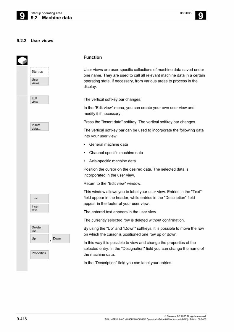
9 Startup operating area 08/2005 9.2 Machine data
9
© Siemens AG 2005 All rights reserved. 9-418 SINUMERIK 840D sl/840D/840Di/810D Operator's Guide HMI Advanced (BAD) - Edition 08/2005
9.2.2 User views
Function
Start-up
User views
User views are user-specific collections of machine data saved under one name. They are used to call all relevant machine data in a certain operating state, if necessary, from various areas to process in the display.
Edit view
Insert data...
<<
Insert text ...
Delete line Up
/ Down
Properties
The vertical softkey bar changes.
In the "Edit view" menu, you can create your own user view and modify it if necessary.
Press the "Insert data" softkey. The vertical softkey bar changes.
The vertical softkey bar can be used to incorporate the following data into your user view:
• General machine data
• Channel-specific machine data
• Axis-specific machine data
Position the cursor on the desired data. The selected data is incorporated in the user view.
Return to the "Edit view" window.
This window allows you to label your user view. Entries in the "Text" field appear in the header, while entries in the "Description" field appear in the footer of your user view.
The entered text appears in the user view.
The currently selected row is deleted without confirmation.
By using the "Up" and "Down" softkeys, it is possible to move the row on which the cursor is positioned one row up or down.
In this way it is possible to view and change the properties of the selected entry. In the "Designation" field you can change the name of the machine data.
In the "Description" field you can label your entries.
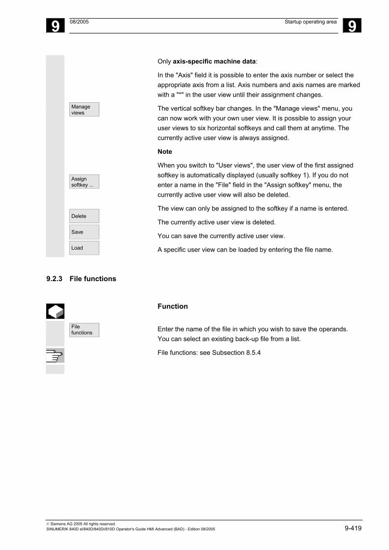
9 08/2005 Startup operating area 9
© Siemens AG 2005 All rights reserved. SINUMERIK 840D sl/840D/840Di/810D Operator's Guide HMI Advanced (BAD) - Edition 08/2005 9-419
Only axis-specific machine data:
In the "Axis" field it is possible to enter the axis number or select the appropriate axis from a list. Axis numbers and axis names are marked with a "*" in the user view until their assignment changes.
Manageviews
Assign softkey ...
Delete
Save
Load
The vertical softkey bar changes. In the "Manage views" menu, you can now work with your own user view. It is possible to assign your user views to six horizontal softkeys and call them at anytime. The currently active user view is always assigned.
Note
When you switch to "User views", the user view of the first assigned softkey is automatically displayed (usually softkey 1). If you do not enter a name in the "File" field in the "Assign softkey" menu, the currently active user view will also be deleted.
The view can only be assigned to the softkey if a name is entered.
The currently active user view is deleted.
You can save the currently active user view.
A specific user view can be loaded by entering the file name.
9.2.3 File functions
Function
File functions
Enter the name of the file in which you wish to save the operands. You can select an existing back-up file from a list.
File functions: see Subsection 8.5.4

9 Startup operating area 08/2005 9.3 NC
9
© Siemens AG 2005 All rights reserved. 9-420 SINUMERIK 840D sl/840D/840Di/810D Operator's Guide HMI Advanced (BAD) - Edition 08/2005
9.3 NC
Function
Start-up key
The startup switch function is only available on the SINUMERIK powerline. You can only define the startup switch settings if you have the appropriate access rights to do so.
NCK addresses
The NCK address function is only available on the SINUMERIK powerline. View the NCU address and change it. It is normally only necessary to edit the address for M: N operation. You cannot undo an address change with general reset. The address change is not saved in an NC series startup archive.
NC memory
The NC user memories available for programs and data are displayed here: • Overview • SRAM assignment in bytes • DRAM assignment in bytes
Further information on the selection can be displayed using the “Details” softkey.
Vertical softkeys
NCK Reset
NCK gen. reset
The NCK reset and NCK general reset functions are only available in the SINUMERIK solutionline:
• “NCK Reset” performs a warm restart of the NC.
• “NCK general reset” resets all of the machine data to the default values.

9 08/2005 Startup operating area9.4 PLC
9
© Siemens AG 2005 All rights reserved. SINUMERIK 840D sl/840D/840Di/810D Operator's Guide HMI Advanced (BAD) - Edition 08/2005 9-421
9.4 PLC
Function
Changes can only be made with the corresponding access authorization (password): • Setting date/time (see blow) • PLC status for PLC operands (see Section 8.5) • File functions (see Subsection 8.5.4)
Danger
Changes in the states of PLC memory locations have a major impact on the machine. Incorrect configuration of the parameters can endanger human life and cause damage to the machine.
9.4.1 Set time/date
Function
You can change the date and time of the PLC and synchronize the date and time of the PLC and HMI.
Operating sequence
Start-up
The "Start-up" operating area is selected.
PLC
Press the "PLC" softkey. The horizontal and vertical softkey bars change.
Set date/clock
Press the "Set date/clock" softkey. The "Set date/clock" window is displayed.
Enter the correct values in the input fields.
Accept
The date and time on the HMI are transferred to the PLC. The synchronization can be verified in the "Current time:" output field.
References See /IAM/, IM4: Installation & Startup Guide HMI Advanced
The set values are retained when the control is rebooted.

9 Startup operating area 08/2005 9.5 Set HMI
9
© Siemens AG 2005 All rights reserved. 9-422 SINUMERIK 840D sl/840D/840Di/810D Operator's Guide HMI Advanced (BAD) - Edition 08/2005
9.5 Set HMI
Function
You can modify and save individual settings on the HMI.
Operating sequence
Start-up
The "Start-up" operating area is selected.
HMI
Press the "HMI" softkey. The horizontal and vertical softkey bars change.
The following submenus are available via the horizontal softkeys:
Language
The softkey offers the available system languages from which the first and second language can be selected. You can toggle between these languages with the "Change Language" softkey.
Operator panel
The operator panel function is only available on the SINUMERIK powerline. Depending on the HMI variant in use (HMI and MCI2 board in the PCU [internal HMI] / HMI operating an 840Di via OPI or MPI [external HMI] / standard configurations 840D/810D), you can only operate the parameters that can actually be changed. You can make the following settings in the "Operator panel front interface parameters" menu:
• Connection - 1:1 (1 NC and 1 HMI) - m:n (1/multiple NC(s) and 1/multiple HMI(s)), not for 840Di
• Baud rate ("Bus") - OPI 1.5 Mbit/s) - MPI 187.5 Mbit/s) - Softbus MC
• Highest bus address (15-31 available)
• Network address
- HMI address (local address which is sent to the bus) - NCK address (address with which the communication is set up) - PLC address
NCK and PLC addresses can be changed only if you are using a 1:1 link. With m:n links, addresses are transferred from the "netnames.ini" file.

9 08/2005 Startup operating area9.5 Set HMI
9
© Siemens AG 2005 All rights reserved. SINUMERIK 840D sl/840D/840Di/810D Operator's Guide HMI Advanced (BAD) - Edition 08/2005 9-423
Bus node
Vertical softkey: Lists the addresses of active nodes that can be activated with "Update".
Internal HMI for 840Di: External HMI for 840Di:
With internal HMI which is only available for the 840Di, the bus is always a SOFTBUS and cannot be changed. M:N is not possible. The default address for NCK is 3 and 2 for the PLC. It can be changed in the range from 1 to the highest bus address. With external HMI, the available settings can be selected via a switch:• MPI (187.5 kBaud), • OPI (1.5 MBaud) and • MCI2 (840Di − 187.5kBaud). M:N is not possible with MCI2. There are no setting options for the NCK address as the NCK is addressed via the PLC and therefore always has the same address as the PLC. The default address for the PLC is 2. It can be changed in the range from 1 to the highest bus address.
NCU
link
The NCU link function is only available on the SINUMERIK solutionline. It allows you to adjust the IP address of the NCU. The IP address stored in mmc.ini is displayed.
The NCU is supplied from the factory with the default address 192.168.214.1. In the case of a 1:1 link, this address can be maintained without the need for additional networking.
Pressing the “Default address” softkey transfers the factory set IP address 192.168.214.1 to the address field for the NCU.

9 Startup operating area 08/2005 9.5 Set HMI
9
© Siemens AG 2005 All rights reserved. 9-424 SINUMERIK 840D sl/840D/840Di/810D Operator's Guide HMI Advanced (BAD) - Edition 08/2005
However, if the control is linked to a company network, for example, the IP addresses will be different. You must restart the HMI for the changes to take effect. The section with the new IP address is written to user/mmc.ini.
References /IDS/ NCU Startup Manual
System
settings
see Chapter “System settings”
Select printer
This softkey will only function if a printer is installed under Windows NT. It can be used to print displays and data from the startup operating area. You can use the Select button to choose which of the installed printers should be used for output. Default setting: Output as bitmap file
References For additional information, please see /FBA/ Description of Functions, Drive Function.
Editor
This key opens the ASCII editor in which files can be edited at DOS level. You can select existing drives via the vertical softkeys.
DOS
SHELL
You open a DOS shell.
Enter the "Exit" command to go back.

9 08/2005 Startup operating area9.5 Set HMI
9
© Siemens AG 2005 All rights reserved. SINUMERIK 840D sl/840D/840Di/810D Operator's Guide HMI Advanced (BAD) - Edition 08/2005 9-425
9.5.1 System settings
Function
System settings
This softkey provides access to settings for inquiry windows, file tree display and screen display in the Machine, Program and Services operating areas.
File display
You can set the file tree display for the Services, Machine and Program operating areas. The following columns can be selected: • Type (Extension) • Loaded • Length • Access protection • Date • Time • Enable • Display levels (branch to directory trees, max. 7) • Name length (max. 25 characters)
Your settings are automatically displayed in the "Preview" window.
Inquiry
Request confirmation before Deleting data/programs, − Deleting directories, − Overwriting files.
Symbols
Select
Here you can define whether keys must be represented as symbols or as text in HMI displays. Example: Operator panel front in US layout
Selection button as a symbol () Select button as text
Templates
When creating a new workpiece, you can specify here whether templates should be transferred to the new workpiece (directory): • Job lists • Part programs • Initialization programs
See Chapter 6 “Templates”.
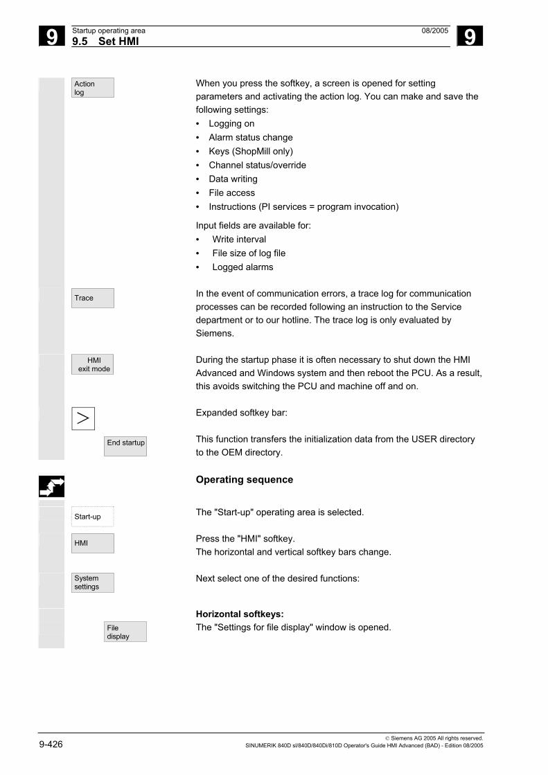
9 Startup operating area 08/2005 9.5 Set HMI
9
© Siemens AG 2005 All rights reserved. 9-426 SINUMERIK 840D sl/840D/840Di/810D Operator's Guide HMI Advanced (BAD) - Edition 08/2005
Action log
When you press the softkey, a screen is opened for setting parameters and activating the action log. You can make and save the following settings: • Logging on • Alarm status change • Keys (ShopMill only) • Channel status/override • Data writing • File access • Instructions (PI services = program invocation)
Input fields are available for: • Write interval • File size of log file • Logged alarms
Trace
In the event of communication errors, a trace log for communication processes can be recorded following an instruction to the Service department or to our hotline. The trace log is only evaluated by Siemens.
HMI exit mode
During the startup phase it is often necessary to shut down the HMI Advanced and Windows system and then reboot the PCU. As a result, this avoids switching the PCU and machine off and on.
End startup
Expanded softkey bar: This function transfers the initialization data from the USER directory to the OEM directory.
Operating sequence
Start-up
The "Start-up" operating area is selected.
HMI
Press the "HMI" softkey. The horizontal and vertical softkey bars change.
System settings
Next select one of the desired functions:
Horizontal softkeys:
File display
The "Settings for file display" window is opened.

9 08/2005 Startup operating area9.5 Set HMI
9
© Siemens AG 2005 All rights reserved. SINUMERIK 840D sl/840D/840Di/810D Operator's Guide HMI Advanced (BAD) - Edition 08/2005 9-427
Inquiry
The "Settings for inquiries" window is opened. You can specify whether or not an inquiry window should be displayed after certain commands, e.g. Delete.
Symbols
The "Representation of keys in displays..." window is opened.
Templates
Use workpiece templates For more information, see Subsection 6.1.5 Templates
Action log
Log control processes
Vertical softkey
File display
Sort...
Sort information according to sort criteria and sequence. A dialog box is displayed for setting the sorting sequence of one column. The defined sequence applies when displaying the corresponding window in the Machine, Program and Services operating areas of the selected column.
You can select from the following sort criteria: • Without sorting:
Sorted in ascending order according to “Name” by default. • One of the column designations:
The sorting sequence runs in ascending or descending order. Confirm with OK.
In the operating areas The sorting sequence set is shown as an arrow symbol next to the
name of the column selected as the sorting criterion. In HMI Advanced systems with an optional mouse, the following
operating options are also available for column sorting: 1. A click on the column name with the arrow symbol changes the
direction and sorts the information accordingly. 2. A click on another column makes this the sorting criterion.
Click again to change the direction, if necessary, as in (1.) The selection of another sorting criterion in the operating area changes the sorting criterion for all operating areas (Machine, Program, Services).

9 Startup operating area 08/2005 9.5 Set HMI
9
© Siemens AG 2005 All rights reserved. 9-428 SINUMERIK 840D sl/840D/840Di/810D Operator's Guide HMI Advanced (BAD) - Edition 08/2005
Additional notes
When the sorting sequence is set using the "Sort" softkey, if the sorting criterion is not available in the display image of the operating area, the information is sorted in ascending order according to the column name. The sorting sequence defined in the dialog applies to the operating areas, in which the criterion set in the dialog appears.
Position the cursor on the desired point and perform the settings.
Save
Transfers your settings to system.
9.5.2 End OEM startup
Function
This function provides the user with an empty USER directory and
deletes any existing initialization files (*.ini) stored there, without losing the settings it contains. The initialization data from the USER directory are transferred to the OEM directory.
If no OEM directory is available one is created automatically, if
initialization files are stored in the USER directory.
Operating sequence
Start-up
The "Start-up" operating area is selected.
HMI
Systemsettings
Press the "HMI" followed by the “System settings” softkeys. The horizontal and vertical softkey bars change.
End startup
Transmit all INI files If you wish to transfer all initialization files, press the “End startup” softkey. The following message will appear: “Transmit all initialization files (*.ini) from the USER directory with the corresponding files of the OEM directory.”

9 08/2005 Startup operating area9.6 Optimization/Test
9
© Siemens AG 2005 All rights reserved. SINUMERIK 840D sl/840D/840Di/810D Operator's Guide HMI Advanced (BAD) - Edition 08/2005 9-429
Save
Press the "Save" softkey to start data transmission. Existing entries in the OEM directory are overwritten by the corresponding entries from the USER directory. New files are created. Files which do not appear in the USER directory, but already exist in the OEM directory, are saved. During transmission the name of each file is displayed in the status bar. Once all of the data has been transmitted successfully the file is deleted from the USER directory.
Select data
Transmit selected INI files If you wish to transfer only specific initialization files, press the “Select data” vertical softkey. A list of all files stored in the USER directory is displayed.
Save
Select the desired files and start transmission by pressing the “Save” softkey. The file display is updated once transmission is complete.
9.6 Optimization/Test
Function
This menu contains functions for startup of the axes: • Current control loop • Speed control loop • Position control loop • Function generator • Circularity test • Servo trace • AM/MSD self-optimization (inactive) • DAC configuration (inactive) Expanded softkey bar: • Aut. selector setting
Servo trace involves the recording of up to 10 bit signals throughout the measuring time for bit-encoded Safety Integrated signals.
References /FBA/ Description of Functions, Drive Functions /FBSI/ Safety Integrated

9 Startup operating area 08/2005 9.6 Optimization/Test
9
© Siemens AG 2005 All rights reserved. 9-430 SINUMERIK 840D sl/840D/840Di/810D Operator's Guide HMI Advanced (BAD) - Edition 08/2005
Measurement of coupled axes
Start-up
For the startup of SIMODRIVE 611 digital drives, coupled axes are supported for measuring in the current control loop, speed control loop or position control loop: • Pure gantry axis groupings • Pure master/slave relationships • Hybrid coupling of master/slave axes with gantry axes You can enter specific measuring parameters and select a measurement for each available axis in these axis groupings.
Measuring parameter
The following measuring parameters are available: • Amplitude leading axis or master axis • Amplitude synchronized axis/axes or slave axis/axes • Bandwidth of the frequency range to be analyzed • Information on measuring accuracy and measurement duration
increase • Delay settling time • OFFSET to accelerate via an acceleration ramp
References /IAD/ Installation & Startup Guide: Section "Measuring functions for coupled axes"
Display all coupled axes
You can record the results for up to two axes simultaneously. There is always only one leading axis. All other axes are synchronized axes; their amplitude can be assigned separately. All active axes of the grouping are displayed. The components visible are: • With pure gantry axis groupings a max. of one leading axis and
two following axes. • With master-slave couplings one master and two slave axes. With a hybrid master-slave coupling with pure gantry axes the leading axis always comes from the pure gantry axis grouping. All other axes are synchronized axes. The texts displayed in the operator interface change and are updated according to the active type of coupling.
You can navigate through all active axes in the "Gantry measurement" or "Master / slave measurement" selection screens where all active couplings are displayed. You can measure up to 2 axes simultaneously. The measuring process must be repeated after each axis selection.

9 08/2005 Startup operating area9.7 Startup of other components
9
© Siemens AG 2005 All rights reserved. SINUMERIK 840D sl/840D/840Di/810D Operator's Guide HMI Advanced (BAD) - Edition 08/2005 9-431
Additional notes
The axis couplings show the axis identifiers e.g. X1, Z1 or A1 as well as the axis number of the respective axis grouping. The values have the following meanings: SRM Synchronous motors (synchronous rotation motor) ARM Asynchronous motors (asynchronous rotation motor) The HMI does not support initiation of a measurement job for a master/slave coupling in the position control loop. If you are currently performing a position control measurement on an axis which is coupled but not initiated by the HMI, the start is inhibited for this slave axis and a message is displayed.
9.7 Startup of other components
Owing to their complex nature and scope, the startup of the following components is described in a separate manual.
9.7.1 Drives
Function
Drives
Select this softkey to configure the parameters for one or more drives. You can page through the drives using the “Drive +” and “Drive –” vertical softkeys. The “Drive selection…” vertical softkey opens a dialog allowing you to select a drive. By using these three vertical softkeys you can select all of the drive devices on all PROFIBUS segments. The “Change…” softkey starts the configuration assistant for the drive.
References /IDS/ NCU Startup Manual

9 Startup operating area 08/2005 9.7 Startup of other components
9
© Siemens AG 2005 All rights reserved. 9-432 SINUMERIK 840D sl/840D/840Di/810D Operator's Guide HMI Advanced (BAD) - Edition 08/2005
9.7.2 Quick startup for axes and drives
Function
Rap.st-up axis/drive
This menu contains functions for the startup of the axes and drives.
References /FBA/ Description of Functions, Drive Functions
9.7.3 Tool management
Function
Tool managem.
This is where you can enter tool data, create tool lists and assign the tool magazine locations.
References /FBA/ Description of Functions, Tool Management

10 08/2005 Service 10
© Siemens AG 2005 All rights reserved. SINUMERIK 840D sl/840D/840Di/810D Operator's Guide HMI Advanced (BAD) - Edition 08/2005 10-433
Service 10.1 Operating data ......................................................................................................10-434
10.2 Cleaning ................................................................................................................10-435

10 Service 08/2005 10.1 Operating data
10
© Siemens AG 2005 All rights reserved. 10-434 SINUMERIK 840D sl/840D/840Di/810D Operator's Guide HMI Advanced (BAD) - Edition 08/2005
10.1 Operating data Operating data Value Air humidity, humidity class to DIN 40040 F Atmospheric pressure 860 to 1080 hPa Protection against physical contact
protection class to DIN VDE 0160 I
Degree of protection according to DIN 40050
• Front of operator panel
IP 54
• Back of operator panel
IP 00
• Front of machine control panel
IP 54
• Back of machine control panel IP 00
References You will find the comprehensive operating data in the documentation
/BH/ Operator Components Manual and in the relevant information sheets.

10 08/2005 Service 10
© Siemens AG 2005 All rights reserved. SINUMERIK 840D sl/840D/840Di/810D Operator's Guide HMI Advanced (BAD) - Edition 08/2005 10-435
10.2 Cleaning Cleaning agents The front of the monitor and the surface of the operator panel front
can be cleaned. For dirt that is relatively easy to remove, standard household washing-up liquid, or an industrial cleaner (such as "Special Swipe") can be used. These cleaners will also remove dirt containing graphite. Cleansing agents which contain one or more of the following ingredients can be used for a short period of time: • Diluted mineral acids • Bases • Organic hydrocarbons • Detergent solutions
Plastic material used The plastic material used on the front of the OP015, OP012 or OP015 is suitable for use on machine tools. It is resistant to: 1. Greases, oils, mineral oils 2. Bases and lyes 3. Detergent solutions and 4. Alcohol Solvents such as chlorinate hydrocarbons, benzene, esters and ethers should be avoided!
■

10 Service 08/2005 10.2 Cleaning
10
© Siemens AG 2005 All rights reserved. 10-436 SINUMERIK 840D sl/840D/840Di/810D Operator's Guide HMI Advanced (BAD) - Edition 08/2005
Notes

A 08/2005 Appendix A
© Siemens AG 2005 All rights reserved. SINUMERIK 840D sl/840D/840Di/810D Operator's Guide HMI Advanced (BAD) - Edition 08/2005 A-437
Appendix A Abbreviations ..........................................................................................................A-438
B Terminology.............................................................................................................A-442
C References..............................................................................................................A-457

A Appendix 08/2005 A Abbreviations
A
© Siemens AG 2005 All rights reserved. A-438 SINUMERIK 840D sl/840D/840Di/810D Operator's Guide HMI Advanced (BAD) - Edition 08/2005
A Abbreviations ASCII American Standard Code for Information Interchange American
coding standard for the exchange of information
AuxF Auxiliary Function
BAG Mode group
BP Basic Program
C1 .. C4 Channel 1 to channel 4
CAD Computer-Aided Design
CNC Computerized Numerical Control
CR Carriage Return
DAC Digital-to-Analog Converter
DB Data Block in the PLC
DBB Data Block Byte in the PLC
DBW Data Block Word in the PLC
DBX Data block bit in the PLC
DIN Deutsche Industrie Norm (German Industry Standard)
DIR DIRectory
DOS Disk Operating System
DPM Dual-Port Memory
DRAM Dynamic Random Access Memory
DRF Differential Resolver Function: (handwheel)
DRY DRY run: Dry run feedrate
DW Data Word

A 08/2005 AppendixA Abbreviations
A
© Siemens AG 2005 All rights reserved. SINUMERIK 840D sl/840D/840Di/810D Operator's Guide HMI Advanced (BAD) - Edition 08/2005 A-439
FDD Feed Drive
FRAME Data block (FRAME)
GUD Global User Data
HD Hard Disk
HW Hardware
I Input
ICA Interpolatory Compensation
INC Increment
INI INItializing data
IPO Interpolator
ISO International Standard Organization
ISO code Special punched tape code, Number of holes per character always even
JOG JOGging: Setup mode
Kv Servo gain factor
LED Light Emitting Diode
LF Line Feed
LUD Local User Data
MB Megabyte
MCP Machine control panel
MCS (Machine) Machine Coordinate System
MD Machine data
MDI Manual Data Input: Manual input
MLFB Machine-readable product designation

A Appendix 08/2005 A Abbreviations
A
© Siemens AG 2005 All rights reserved. A-440 SINUMERIK 840D sl/840D/840Di/810D Operator's Guide HMI Advanced (BAD) - Edition 08/2005
MMC Man-Machine Communication: User interface on numerical control systems for operator control, programming and simulation
MPF Main Program File: NC part program (main program)
MPI Multi Port Interface
MSD Main spindle drive
NC Numerical Control
NCK Numerical Control Kernel: NC kernel with block preparation, travel range, etc.
NCU Numerical Control Unit: NCK hardware unit
O (Q) Output
OEM Original Equipment Manufacturer
OP Operator Panel: Operating setup
OPI Operator Panel Interface
PCMCIA Personal Computer Memory Card International Association plug-in memory normalization board
PCU Programmable Control Unit
PG Programming device
PLC Programmable Logic Control
REF REFerence point approach function
REPOS REPOSition function
ROV Rapid Override
RPA R-Parameter Active: Memory area in NCK for R-NCK for R parameter numbers
SBL Single Block

A 08/2005 AppendixA Abbreviations
A
© Siemens AG 2005 All rights reserved. SINUMERIK 840D sl/840D/840Di/810D Operator's Guide HMI Advanced (BAD) - Edition 08/2005 A-441
SD Setting Data
SEA Setting Data Active: Identifier (file type) for setting data
SK Softkey
SKP SKiP: Skip block
SPF Sub Program File: Subprogram
SRAM Static RAM (non-volatile)
SU Startup
SW Software
SYF SYstem Files
TC Tool change
TEA Testing Data Active: Identifier for machine data
TO Tool Offset
TO Tool offset
TOA Tool Offset Active: Identifier (file type) for tool offsets
UFR User FRame: Work offset
WCS (Work) Workpiece coordinate system
WO Work offset
ZOA Zero Offset Active: Identifier (file type) for work offset data

A Appendix 08/2005 B Terminology
A
© Siemens AG 2005 All rights reserved. A-442 SINUMERIK 840D sl/840D/840Di/810D Operator's Guide HMI Advanced (BAD) - Edition 08/2005
B Terminology Important terms are listed in alphabetical order. The → symbol
precedes terms, which are explained in a separate entry in this list. A
Access authorization The CNC program blocks and data are protected by a 7-level system of access restrictions: • Three password levels for system manufacturers, machine
manufacturers and users and • Four keylock switch settings, which can be evaluated via the PLC.
Address An address is the identifier for a certain operand or operand range, e.g., input, output, etc.
Alarms All → messages and alarms are displayed on the operator panel in plain text with date and time as well as the appropriate symbol for the delete criterion. Alarms and messages are displayed separately. 1. Alarms and messages in the part program
Alarms and messages can be displayed directly from the part program in plain text.
2. Alarms and messages from PLC Alarms and messages relating to the machine can be displayed directly from the PLC program in plain text. No additional function block packages are required for this purpose.
Archiving Reading out data and/or directories to an external memory device.
A-Spline The Akima-Spline runs under a continuous tangent through the
programmed interpolation points (3rd order polynomial).
Automatic Operating mode of the control (block sequence operation according to DIN): Operating Mode in NC systems in which a → part program is selected and continuously executed.
Auxiliary functions, Auxiliary functions can be used to transfer → parameters to the → PLC in → part programs, where they trigger reactions, which are defined by the machine manufacturer.
Axes In accordance with their functional scope, the CNC axes are subdivided into: • Axes: interpolating path axes • Auxiliary axes: non-interpolating feed and positioning axes with an
axis-specific feed rate. Auxiliary axes are not involved in the actual machining, and include for example tool feeders and tool magazines.

A 08/2005 AppendixB Terminology
A
© Siemens AG 2005 All rights reserved. SINUMERIK 840D sl/840D/840Di/810D Operator's Guide HMI Advanced (BAD) - Edition 08/2005 A-443
Axis address See → axis identifier
Axis identifier Axes are labeled in accordance with DIN 66217 (for a clockwise orthogonal → coordinate system) with the letters X,Y, Z. → Rotary axes which rotate about X,Y,Z are labeled with the letters A, B, C. Additional axes parallel to the above can be identified with further address letters.
Axis name See → axis identifier
B
B Spline With the B-Spline, the programmed positions are not interpolation points, as they are just "control points" instead. The generated curve only runs near to the control points, not directly through them (optional 1st, 2nd or 3rd order polynomials).
Basic coordinate system Cartesian coordinate system which is mapped by transformation onto the machine coordinate system. In the → part program, the programmer uses the axis names of the basic coordinate system. The basic coordinate system exists in parallel to the → machine coordinate system when no → transformation is active. The difference between the systems relates to the axis identifiers.
Baud rate Rate of data transfer (Bit/s).
Blank Workpiece as it is before the part is machined.
Block A section of a → part program terminated with a line feed. A distinction is made between → main blocks and →subblocks.
Block search The block search function allows any point in the part program to be selected, at which machining must start or be continued. The function is provided for the purpose of testing part programs or continuing machining after a program abort.
C
C axis Axis around which the tool spindle describes a controlled rotational and positioning movement.
Channel A channel can execute a → part program independently of the other channels. A channel exclusively controls the axes and spindles assigned to it. Part programs runs of various channels can be coordinated by → synchronization.

A Appendix 08/2005 B Terminology
A
© Siemens AG 2005 All rights reserved. A-444 SINUMERIK 840D sl/840D/840Di/810D Operator's Guide HMI Advanced (BAD) - Edition 08/2005
Channel structure The channel structure makes it possible to process the → programs of
individual channels simultaneously and asynchronously.
CNC → NC
CNC programming language
The CNC programming language is based on DIN 66025 with high-level language expansions. The → CNC high-level language and programming support the definition of macros (sequenced statements), for example.
Compensation memory Data range in the control, in which the tool offset data are stored.
Contour Outline of the → workpiece
Contour monitoring The following error is monitored within a definable tolerance band as a measure of contour accuracy. Overloading of the drive, for example, may result in an unacceptably large following error. In such cases, an alarm is output and the axes are stopped.
Coordinate system See → Machine coordinate system → Workpiece coordinate system
C-Spline The C-Spline is the most well-known and widely used spline. The transitions at the interpolation points are continuous, both tangentially and in terms of curvature. 3rd order polynomials are used.
Cycle Protected subprogram for executing a repeated machining operation on the → workpiece
Cycle support The available cycles are listed in the "Cycle support" menu in the "Program" operating area. Once the desired machining cycle has been selected, the parameters required for assigning values are displayed in plain text.
D
Data block 1. A data unit on the → PLC, which can be accessed by → HIGHSTEP programs.
2. NC → data unit: Data modules contain data definitions for global user data. These data can be initialized directly when they are defined.
Data word A data unit, two bytes in size, within a → data block.

A 08/2005 AppendixB Terminology
A
© Siemens AG 2005 All rights reserved. SINUMERIK 840D sl/840D/840Di/810D Operator's Guide HMI Advanced (BAD) - Edition 08/2005 A-445
Diagnostics 1. Operating area of the control. 2. The control has both a self-diagnostics program as well as test
functions for servicing purposes: status, alarm and service displays.
Dimensions specification, metric and inches
Position and pitch values can be programmed in inches in the machining program. The control is set to a basic system regardless of the programmable dimensional specification (G70/G71).
DRF Differential Resolver Function: NC function which generates an incremental work offset in Automatic mode in conjunction with an electronic handwheel.
Drive • SINUMERIK FM-NC offers an analog +10V interface to the SIMODRIVE 611A converter system.
• The SINUMERIK 840D control system is connected to the SIMODRIVE 611D converter system by means of a high-speed digital parallel bus.
E
Editor The editor makes it possible to create, edit, extend, join, and import programs/texts/program blocks.
Electronic handwheel Electronic handwheels can be used to traverse the selected axes simultaneously in manual mode. The handwheel clicks are analyzed by the increment analyzer.
Exact stop With a programmed exact stop instruction, the position stated in a block is approached precisely and very slowly, if necessary. In order to reduce the approach time, ® exact stop limits are defined for rapid traverse and feed.
Exact stop limit When all path axes reach their exact stop limits, the control responds as if it had reached its precise destination point. The ® part program continues execution at the next block.
External work offset A work offset specified by the ® PLC. F
Feed override The current feedrate setting entered via the control panel or by the PLC is overlaid on the programmed feedrate (0-200 %). The feedrate can also be corrected by a programmable percentage factor (1-200%) in the machining program.

A Appendix 08/2005 B Terminology
A
© Siemens AG 2005 All rights reserved. A-446 SINUMERIK 840D sl/840D/840Di/810D Operator's Guide HMI Advanced (BAD) - Edition 08/2005
Frame A frame is an arithmetic rule that transforms one Cartesian coordinate system into another Cartesian coordinate system. A frame contains the components → work offset, → rotation, → scaling, → mirroring.
G
General reset The following → CPU memories are erased by a general reset operation: • → Working memory • Read/write area of the → load memory • → System memory • → Backup memory
Geometry Description of a → workpiece in the → workpiece coordinate system.
Geometry axis Geometry axes are used to describe a 2- or 3-dimensional range in the workpiece coordinate system.
Global main program/subprogram
Each global main program/subprogram may appear only once under its name in the directory. It is not possible to use the same program name in different directories with different contents as a global program.
H
Helical interpolation The helical interpolation function is ideal for machining internal and external threads using form milling cutters and for milling lubrication grooves. The helix comprises two movements: 1. Circular movement in one plane 2. Linear movement perpendicular to this plane.
I
Identifier In accordance with DIN 66025, identifiers (names) for variables (calculation variables, system variables, user variables), for subprograms, for keywords and words can contain several address letters. These supplements have the same meaning as the words with respect to block format. Identifiers must be unique. It is not permissible to use the same identifier for different objects.
Inch measuring system Measuring system, which defines distances in inches and fractions of inches.
Increment Travel path length specification based on number of increments. The number of increments can be stored as a → setting data or selected with keys labeled with 10, 100, 1000, 10,000.

A 08/2005 AppendixB Terminology
A
© Siemens AG 2005 All rights reserved. SINUMERIK 840D sl/840D/840Di/810D Operator's Guide HMI Advanced (BAD) - Edition 08/2005 A-447
Interpolator Logical unit of the → NCK, which determines intermediate values for the movements to be traversed on the individual axes, on the basis of destination positions specified in the part program.
J
Jog Control operating mode (setup operation): In JOG mode, it is possible to set up the machine. Individual axes and spindles can be traversed in JOG mode by means of the direction keys. Other functions available in JOG mode are → reference point approach, → repositioning and → preset (setting an actual value).
K
Keylock switch 1. S7-300: The keylock switch is the mode selector switch on the → CPU. The keylock switch is operated by a removable key.
2. 840D: The keylock switch on the → machine control panel has 4 settings, to which functions are assigned by the operating system of the control. Further, the keylock switch has three differently colored keys, which can be removed in the specified positions.
Keywords Words with a specific notation, which have a defined meaning in the
programming language for → part programs.
Kv Servo gain factor, a control variable in a control loop. l
Language The user guidance display texts and the system messages are available in five system languages (diskette): German, English, French, Italian, and Spanish. The user can select two of the listed languages at a time in the control.
Leadscrew error compensation
Compensation for the mechanical inaccuracies of a leadscrew participating in the feed. The control uses stored deviation values for the compensation.
Linear axis The linear axis is an axis, which, in contrast to a rotary axis, describes a straight line.
Linear interpolation The tool travels along a straight line to the destination point while machining the workpiece.
M
Machine Operating area of the control.
A Appendix 08/2005 B Terminology
A
© Siemens AG 2005 All rights reserved. A-448 SINUMERIK 840D sl/840D/840Di/810D Operator's Guide HMI Advanced (BAD) - Edition 08/2005
Machine axes Physically existent axes on the machine tool.
Machine control panel An operator panel on a machine tool with operating elements such as keys, rotary switches, etc., and simple indicators such as LEDs. It is used to directly influence the machine tool via the PLC.
Machine coordinate system
A coordinate system, which is related to the axes of the machine tool.
Machine zero A fixed point on the machine tool, which can be referenced by all (derived) measuring systems.
Machining channel Via a channel structure, parallel sequences of movements, such as positioning a loading gantry during machining, can shorten unproductive times. Here, a CNC channel must be regarded as a separate CNC control system with decoding, block preparation and interpolation.
Main program → Part program identified by a number or name, in which other main programs, subprograms or → cycles may be called.
MDI Control operating mode: Manual Data Input: In the MDI mode, individual program blocks or block sequences with no reference to a main program or subprogram can be input and executed immediately afterwards through actuation of the NC start key.
Messages All messages programmed in the part program and → alarms detected by the system are displayed on the operator panel in plain text with date and time, as well as the appropriate symbol for the delete criterion. Alarms and messages are displayed separately.
Metric measurement system
Standardized system of units: for lengths in millimeters (mm), meters (m), etc.
Mirroring Mirroring reverses the signs of the coordinate values of a contour, with respect to an axis. It is possible to mirror with respect to more than one axis at a time.
Mode group At all times all of the axles/spindles are assigned to precisely one channel. Each channel is assigned to one operating mode group. The same → mode is always assigned to the channels in a mode group.
N
NC Numerical Control: NC incorporates all the components of the machine tool control system: → NCK, → PLC, → MMC, → COM.

A 08/2005 AppendixB Terminology
A
© Siemens AG 2005 All rights reserved. SINUMERIK 840D sl/840D/840Di/810D Operator's Guide HMI Advanced (BAD) - Edition 08/2005 A-449
Note: CNC (computerized numerical control) would be more appropriate for the SINUMERIK 840D or FM-NC controls: MARS and Merkur controls.
NCK Numerical Control Kernel: Component of the NC control, which executes → part programs and essentially coordinates the movements on the machine tool.
O
OEM The scope for implementing individual solutions (OEM applications) for the SINUMERIK 840D has been provided for machine manufacturers, who wish to create their own operator interface or integrate process-oriented functions in the control.
Operating mode An operating concept on a SINUMERIK control. The operating modes → Jog, → MDI and → Automatic are defined.
Oriented spindle stop Stops the workpiece spindle with a specified orientation angle, e.g., to perform an additional machining operation at a specific position.
Oriented tool retraction RETTOOL: If machining is interrupted (e.g., when a tool breaks), a program command can be used to retract the tool in a user-specified orientation by a defined distance.
Override Manual or programmable control feature, which enables the user to override programmed feedrates or speeds in order to adapt them to a specific workpiece or material.
P
Parameters 1. The S7-300 uses two types of parameter: - Parameters of a STEP 7 instruction Parameters of a STEP 7
instruction represent the address of the operand to be edited or a constant.
- Parameter of a → parameter block A parameter of a parameter block determines the behavior of a module.
2. 840D: - Operating area of the control. - Arithmetic parameter for which the programmer of the part
program can assign or request values as required in the program.
Part program A sequence of instructions to the NC control which combine to
produce a specific → workpiece. Likewise, performing a certain machining operation on a specific → blank.

A Appendix 08/2005 B Terminology
A
© Siemens AG 2005 All rights reserved. A-450 SINUMERIK 840D sl/840D/840Di/810D Operator's Guide HMI Advanced (BAD) - Edition 08/2005
Part program management
The part program management function can be organized according to → workpieces. The number of programs and data to be managed determine the size of the user memory. Each file (programs and data) can be given a name consisting of a maximum of 24 alphanumeric characters.
PG Programming device
PLC Programmable Logic Control: → Programmable logic controller. Component of the → NC control: Programmable controller for processing the control logic of the machine tool.
PLC program memory SINUMERIK 840D The PLC user program, the user data and the basic PLC program are stored together in the PLC user memory. The PLC user memory can be expanded up to 96 KB with memory expansions.
PLC programming The PLC is programmed with STEP 7 software. STEP 7 programming software is based on the standard WINDOWS operating system and incorporates the functionality of STEP 5 programming with innovative expansions and developments.
Polar coordinates A coordinate system, which defines the position of a point on a plane in terms of its distance from the origin and the angle formed by the radius vector with a defined axis.
Polynomial interpolation Polynomial interpolation provides a means of generating a very wide range of curves, including straight-line, parabolic and exponential functions (SINUMERIK 840D).
Positioning axis Axis that performs an auxiliary movement on a machine tool (e.g., tool magazine, pallet transport). Positioning axes are axes that do not interpolate with path axes.
Power On Control is switched off and then switched on again.
Preset The control zero point can be redefined in the machine coordinate system by means of the Preset function. Preset does not cause the axes to move; instead, a new position value is entered for the current axis positions.
Program 1. Operating area of the control. 2. Sequence of instructions to the control.

A 08/2005 AppendixB Terminology
A
© Siemens AG 2005 All rights reserved. SINUMERIK 840D sl/840D/840Di/810D Operator's Guide HMI Advanced (BAD) - Edition 08/2005 A-451
Programmable frames Programmable → frames can be used to dynamically define new coordinate system starting points while the part program is running. A distinction is made between absolute definition using a new frame and additive definition with reference to an existing starting point.
Programmable working area limitation
Limitation of the motion space of the tool to a space defined by programmed limitations.
R
R parameters Arithmetic parameters can be set or requested by the programmer of the → part program for any purpose in that program.
Rapid traverse The highest traverse rate of an axis. It is used for example to move the tool from rest to the → workpiece contour or retract the tool from the contour.
Reference point Point on the machine tool used to reference the measuring system of the → machine axes.
Reference point approach
If the utilized distance measuring system is not an absolute value encoder then it is necessary to perform a reference point approach to ensure that the actual values returned by the measuring system match the machine coordinate values.
REPOS 1. Reapproach contour, triggered by operator REPOS allows the tool to be returned to the interrupt position by means of the direction keys.
2. Programmed contour reapproach A selection of approach strategies are available in the form of program commands: Approach point of interruption, approach start of block, approach end of block, approach a point on the path between start of block and interruption.
Rotary axis Rotary axes apply a workpiece or tool rotation to a defined angular
position.
Rotary axis, turning continuously
Depending on the application, the travel range of a rotary axis can be limited to less than 360 degrees or the axis can be continuously turned in both directions. Continuously turning rotary axes are used, for example, for eccentric machining, grinding and winding.
Rotation Component of a → frame, which defines a rotation of the coordinate system through a specific angle.

A Appendix 08/2005 B Terminology
A
© Siemens AG 2005 All rights reserved. A-452 SINUMERIK 840D sl/840D/840Di/810D Operator's Guide HMI Advanced (BAD) - Edition 08/2005
S
Safety functions The control incorporates monitors, which are active at all times and, which are designed to detect malfunctions in the → CNC, the programmable controller (→ PLC) and the machine at an early stage, in order to minimize the risk of damage to the tool, workpiece or machine. In the event of a fault, the machining operation is interrupted and the drives stopped. The cause of the malfunction is logged and output as an alarm. At the same time, the PLC is notified that a CNC alarm has been triggered.
Scaling Component of a → frame, which causes axis-specific alterations in the scale.
Services Operating area of the control.
Setting data Data, which communicates the properties of the machine tool to the NC control, as defined by the system software.
Softkey A key, whose name appears on an area of the screen. The choice of softkeys displayed is dynamically adapted to the operating situation. The freely assignable function keys (softkeys) are assigned defined functions in the software.
Software limit switch Software limit switches define the limits of the travel range of an axis and prevent the slide contacting the hardware limit switches. Two pairs of values can be assigned per axis and activated separately via the → PLC.
Spindles The spindle functionality is a two-level construct: 1. Spindles: Digital speed or position controlled spindle drives
(SINUMERIK 840D) 2. Auxiliary spindles: speed-controlled spindle drives, "auxiliary
spindle" function package e.g. for driven tools.
Spline interpolation Using the spline interpolation function, the control is able to generate a smooth curve from just a small number of specified interpolation points along a setpoint contour.
Standard cycles Standard cycles are provided for machining operations, which are frequently repeated: • Cycles for drilling/milling applications • for turning technology The available cycles are listed in the "Cycle support" menu in the "Program" operating area. Once the desired machining cycle has

A 08/2005 AppendixB Terminology
A
© Siemens AG 2005 All rights reserved. SINUMERIK 840D sl/840D/840Di/810D Operator's Guide HMI Advanced (BAD) - Edition 08/2005 A-453
been selected, the parameters required for assigning values are displayed in plain text.
Subprogram A sequence of instructions of a → part program, which can be called repeatedly with various defining parameters. The subprogram is called from a main program. Every subprogram can be protected against unauthorized read-out and display. → Cycles are a type of subprogram.
Synchronization Instructions in → part programs for coordination of the operations in different → channels at specific machining points.
Synchronized actions 1. Auxiliary function output While a workpiece is being machined, technological functions (→ auxiliary functions) can be output from the CNC program to the PLC. These auxiliary functions are used for example to control additional equipment for the machine tool, such as quills, grabbers, clamping chucks etc.
2. High-speed auxiliary function output
For time-critical switching functions, the acknowledgement times for the → auxiliary functions can be minimized and unnecessary stops in the machining process can be avoided.
Synchronized axes
Synchronized axes take the same time to traverse their path as the geometry axes take for their path.
System variable A variable, which exists, although it has not been programmed by the → part program programmer. It is defined by a data type and the variable name preceded by the character $. See also → User-defined variable.
T
Teach-in Teach-in is a means of creating or correcting part programs. The individual program blocks can be input via the keyboard and executed immediately. Positions approached via the direction keys or handwheel can also be stored. Additional information such as G functions, feedrates or M functions can be entered in the same block.
Text editor → Editor
Tool A part used on the machine tool for machining. Examples include turning tools, milling cutters, drills, laser beams, etc.

A Appendix 08/2005 B Terminology
A
© Siemens AG 2005 All rights reserved. A-454 SINUMERIK 840D sl/840D/840Di/810D Operator's Guide HMI Advanced (BAD) - Edition 08/2005
Tool Nose Radius Compensation
Contour programming assumes that the tool is pointed. Since this is not actually the case in practice, the curvature radius of the tool used must be communicated to the control, which then takes it into account. The curvature center is maintained equidistantly around the contour, offset by the curvature radius.
Tool offset By programming a T function (5 decades, integer) in the block, you can select the tool. Every T number can be assigned up to nine cutting edges (D addresses). The number of tools to be managed in the control is set at the configuration stage.
Tool radius compensation
In order to program a desired → workpiece contour directly, the control must traverse a path equidistant to the programmed contour, taking into account the radius of the tool used (G41/G42).
Transformation Programming in a Cartesian coordinate system, execution in a non-Cartesian coordinate system (e.g., with machine axes as rotary axes).
Traversing range The maximum permissible travel range for linear axes is ± 9 decades. The absolute value depends on the selected input and position control resolution and the unit of measurement (inch or metric).
U
User interface The user interface (UI) is the display medium for a CNC control in the form of a screen. It is laid out with eight horizontal and eight vertical softkeys.
User memory All programs and data, such as part programs, subprograms, comments, tool offsets, and work offsets/frames, as well as channel and program user data can be stored in the shared CNC user memory.
User program User programs for the S7-300 automation systems are created using the programming language STEP 7. The user program has a modular layout and consists of individual blocks. The basic block types are: Code blocks: these blocks contain the STEP 7 commands. Data blocks: these blocks contain the constants and variables for the STEP 7 program.
User-defined variable Users can define variables in the → part program or data block (global user data) for their own use. A definition contains a data type specification and the variable name. See also → System variable.
A 08/2005 AppendixB Terminology
A
© Siemens AG 2005 All rights reserved. SINUMERIK 840D sl/840D/840Di/810D Operator's Guide HMI Advanced (BAD) - Edition 08/2005 A-455
V
Variable definition A variable definition includes the specification of a data type and a variable name. The variable names can be used to access the value of the variables.
Velocity control In order to achieve an acceptable traverse rate on very short traverse movements, predictive evaluation over several blocks (→ Look Ahead) can be set.
W
Work offset Specification of a new reference point for a coordinate system through reference to an existing origin and a → frame. 1. Settable
SINUMERIK 840D: A configurable number of settable work offsets are available for each CNC axis. The offsets - which are selected by means of G functions - take effect alternately.
2. External In addition to all the offsets which define the position of the workpiece zero, an external work offset can be overlaid by means of the − handwheel (DRF offset) or − from the PLC.
3. Programmable It is possible to program work offsets for all path and positioning axes by means of the TRANS statement.
Working area Three-dimensional zone into which the tool tip can be moved on
account of the physical design of the machine tool. See also → protection zone.
Working area limitation With the aid of the working area limitation, the traversing range of the axes can be further restricted in addition to the limit switches. One value pair per axis may be used to describe the protected working area.
Working memory The working memory is a RAM area in the → CPU which is accessed by the processor to access the user program during program execution.
Workpiece Part to be made/machined by the machine tool.
Workpiece coordinate system
The starting position of the workpiece coordinate system is the → workpiece zero. In machining operations programmed in the workpiece coordinate system, the dimensions and directions refer to this system.

A Appendix 08/2005 B Terminology
A
© Siemens AG 2005 All rights reserved. A-456 SINUMERIK 840D sl/840D/840Di/810D Operator's Guide HMI Advanced (BAD) - Edition 08/2005
Workpiece zero The workpiece zero is the starting point for the → workpiece coordinate system. It is defined by the distance from the machine zero.

A 08/2005 AppendixC References
A
© Siemens AG 2005 All rights reserved. SINUMERIK 840D sl/840D/840Di/810D Operator's Guide HMI Advanced (BAD) - Edition 08/2005 A-457
C References An overview of publications, which is updated monthly and also provides information about the language versions available, can be found on the Internet at: http://www.siemens.com/motioncontrol Select the menu items “Support” → “Technical documentation” → “Summary of publications” or “DOConWEB”.
■

A Appendix 08/2005 C References
A
© Siemens AG 2005 All rights reserved. A-458 SINUMERIK 840D sl/840D/840Di/810D Operator's Guide HMI Advanced (BAD) - Edition 08/2005
Notes

I 08/2005 AppendixIndex
I
© Siemens AG 2005 All rights reserved. SINUMERIK 840D sl/840D/840Di/810D Operator's Guide HMI Advanced (BAD) - Edition 08/2005 I-459
Index
A
Access rights 2-36 Acknowledge symbols, changed 8-383 Action log 8-392 Activate basic frame immediately 5-236 Activate timing 6-273 Alarm buffer 8-381 Alarm help 2-61 Alarms 8-382 Archive 7-368 Arithmetic parameters 5-219 Automatic 2-31, 4-129 Axes
Display active 8-385 Display all 8-385 Display feedrate 4-96 Display selected 8-385 Traverse 4-114
B
Backspace 2-26 Block display during program execution 4-152 Block search 4-139
Accelerated, external 4-142 In Program test mode 4-145
C
Chain rule 5-171 Change language 9-412 Channel
active 2-56 Display status via symbols 4-87 interrupted 2-56 Reset 2-56 Status 2-56
Channel operational messages 2-39 Channel switchover 2-56 Cleaning 10-435 Clipboard 7-368 CNC data structure 4-83 Communication error log 8-392 Communication links 2-57 Configuration data 8-391 Contour
Close 6-295
Graphic representation 6-291 Symbolic representation 6-284 Symmetrical elements 6-292
Contour calculator 6-279, 6-297 Contour definition programming 6-279 Contour element
Insert 6-290 Parameterize 6-289 Select 6-290
Control Power ON/Power OFF 1-21 Conversion inch/metric 2-60 Coordinate system switchover 4-94 Coordinates, Cartesian/polar 6-296 Cutting edge
Create new 5-177 Delete 5-178
Cycles 6-251 Parameterization 2-53 Recompile 2-54 Support 6-305
D
Data selection 7-365 Delete 6-343 Diagnostics
Drive 8-384 Main screen 8-380
Display Auxiliary functions 4-98 Compile cycles 8-398 G functions 4-97 Machine status 2-39 Modal M functions 4-98 Options 9-416 PLC status 8-399 Program control 2-43 Service 8-384 Spindles 4-100 System resources 8-408 Two-channel 4-88 Utilization 8-408
Display groups 9-417 Display Machine data 9-414 Display PLC status 8-399 Display swivel data record 4-97 Display transformations 4-97 Display version 8-395

I Appendix 08/2005 Index
I
© Siemens AG 2005 All rights reserved. I-460 SINUMERIK 840D sl/840D/840Di/810D Operator's Guide HMI Advanced (BAD) - Edition 08/2005
Displaying auxiliary functions 4-98 Downtime settings 6-323 DRF (Differential resolver function) 4-153 Drives 9-431 Dry run feedrate 5-223 Dual ASCII editor
Synchronized view 6-257 View 6-256
Dwell time 2-40
E
Editor help 2-61, 2-63 Electronic gear 5-227 EMERGENCY STOP button 2-31 Enable 6-345 End OEM startup 9-428 Extended help for program commands 2-67 External network drive 6-347
F
Feed override 2-33 File
Change properties 7-362 Copy 6-340, 7-360 Create 7-359 Delete 6-343, 7-361 Download 7-359 Insert 6-340, 7-360 Rename 6-344 Save 2-52 Upload 7-359
File functions 8-407, 9-419 File types 6-330 Find 2-51, 2-52 Find path for program call 6-336 Flat D numbers 5-157 Following axis 5-227 Free contour programming 2-53
G
Geometry axes 4-94 Geometry processor → Contour calculator 6-279 Go to 2-52 Graphic model 6-324 Grinding parameters 5-196
H Handwheel 4-101 Hard disk 4-134, 7-369 Hardkey assignment 2-29 Help
Context-sensitive 2-63 Machine data 2-61
Hierarchical file structure 7-366
I Inc (increment) 4-115 Inch/Metric switchover 4-106 Increment (Inc) 2-32 Incremental dimension 2-32 Information key 2-64, 2-67 Initialization program
User data, define 5-237
J
Job list 2-68 Execute 2-75 Syntax 2-70
Jog 2-31, 4-111 Continuous 5-221 Data 5-221 Feedrate 5-221
K
Key Acknowledge alarm 2-26 Alt 2-27 Ctrl 2-27 Delete 2-27 Edit 2-27 End of line 2-27 Expansion 2-25 Inc 2-32 Information 2-26 Input 2-27 Machine area 2-25 Recall 2-25 Select window 2-26 Selection 2-27 Shift 2-25 Switch over channel 2-25 Switchover area 2-25 Tab 2-27

I 08/2005 AppendixIndex
I
© Siemens AG 2005 All rights reserved. SINUMERIK 840D sl/840D/840Di/810D Operator's Guide HMI Advanced (BAD) - Edition 08/2005 I-461
Undo 2-27 Keylock switch 2-36
L
Leading axis 5-227 Limit of data management 7-371 Load 5-198
From magazine list 5-202 Load standard 6-335 Loading list 4-133 Log 6-346
M
MAC user data 5-238 Machine axes 4-94 Machine control panel 2-30 Machine coordinate system 2-34, 4-94 Machine data
Display 9-414 Display filter 9-417
Machine functions 2-32, 4-84 Machine zero 5-228 Machining list 6-276 Magazine list 5-199 Main screen
Diagnostics 8-380 Jog 4-111 MDI 4-125 Program 6-254 Services 7-351 Tool management 5-181
Main screen, startup 9-410 Make active tool offset operative immediately
5-179 Manage path labels 6-324 Maschine data
TOOL_CHANGE_TIME (10190)50 6-317 Masking filter 9-416 MDI 2-31, 4-124
Save program 4-126 Messages 8-382 MF 2 keyboard 2-29 Milling contour 6-292 Modes
Change 4-89 Group 4-86 Selection 4-89
Multi-channel step sequence programming (option) 6-265
N
NC card Delete data on... 7-362 Read in data from... 7-355, 7-356 Restore original state.. 7-375 Series startup from ... 7-372, 7-373 Update from... 7-374
NC memory:active data 7-368 NC Start, NC Stop 2-37 NCU link 9-423 Network drive, external 4-135
O
OEM directory 9-428 Save INI files 9-428
Operand Change values 8-400 Delete values 8-400
Operands PLC status 8-406
Operating data 10-434 Operating modes 2-31
Automatic, Jog, MDI 4-84 Operator focus 6-285 Optimization/Test Drive 9-429 Output cycle versions 8-397 Overstore 4-147 Overwrite 2-51
P
Page down 2-26 Page up 2-26 Parameter number for radius calculation 5-171 Part program 6-251
Continue 4-92 Create new 6-331 Load/unload 4-132 Select 6-308, 6-329, 6-331 Start/Stop 4-92
Password 2-36, 9-413 Change 9-413 Delete 9-413 Set 9-413
PLC 9-421

I Appendix 08/2005 Index
I
© Siemens AG 2005 All rights reserved. I-462 SINUMERIK 840D sl/840D/840Di/810D Operator's Guide HMI Advanced (BAD) - Edition 08/2005
PLC addresses, symbolic 8-401 PLC status 9-421 Pocket calculator 2-60 Polar coordinates 6-281
Define pole 6-281 Program contour element 6-295
Predefined package lists 8-395 Preset 4-104 Product Overview 1-19 Program
Display levels 4-93 Edit 6-256 Enable 6-345 Execute 6-335 Load 6-338 Load from hard disk 4-134 Manage 6-329, 6-339 Select 6-335 Simulate 6-306 Store 6-251 Unload 6-338
Program control 2-37, 2-43, 4-149 Program editing 4-137 Program overview 4-131 Program protection *RO* 6-259 Program types 6-251 Protection levels 2-36, 9-412 Protection zones 5-226
Q
Quick help for program commands 2-64 Quick startup for drives/axes 9-432
R
R parameters 5-219 Delete 5-219 Edit 5-219 Find 5-219
Rapid traverse override 2-33, 2-34 Recompile expansion 2-54 Reference point approach 4-108 Remote diagnostics 8-381 Rename 6-344 REPOS (Repositioning) 4-116 Reset 2-37 Restore the original state 7-375
S Safety Integrated 4-117 Save setup data 6-334 Scratching 4-118 Screen layout 2-38 Search target 4-139 Select block 2-51 Series startup 7-371 Service
axis 8-386 Display 8-384 Drive 8-387 Safety Integrated(SI) 8-388
Services Log 7-356 Main screen) 7-351 Manage data 7-358 Read in data 7-354 Read out data 7-355
Set actual value 4-105 Set date 9-421 Set HMI 9-422 Set standard 6-335 Set time 9-421 Setting
Editor 2-55, 6-305 Setting data 5-220, 5-225
Display 5-225 Edit 5-225 Find 5-225
Simulation 2-54 Drilling/milling 6-306 Multi-channel step sequence display 6-275 Network drive 6-328 Orientable toolholder 6-329 Reference points 6-325 Set colors 6-324 With multiple channels 6-275
Simulation of complete turning operations 6-306 Single block 2-37 Skip levels, activate 4-150 Softkey
Assignment 2-29 Keys 2-24 Password 9-413
Software version 8-393 space character 2-26
I 08/2005 AppendixIndex
I
© Siemens AG 2005 All rights reserved. SINUMERIK 840D sl/840D/840Di/810D Operator's Guide HMI Advanced (BAD) - Edition 08/2005 I-463
Special axes 4-94 Spindle data 5-222 Spindle number 5-171 Spindle override 2-35 Standard ASCII editor 6-256 Standard full keyboard 2-29 Starting angle for thread cutting 5-224 Startup, Main screen 9-410 Step sequence display
Collapsed 6-262 Expanded 6-262 Structure 6-261
Subprogram 6-251 Support
Free contour programming 6-300 Switching between Cartesian/polar 6-296 Symmetrical milling contour 6-292 Synchronized actions 4-102 System frames
Display 4-120, 4-121 Protection levels 4-122
System settings 9-425 System variables
Display 5-242 Log 5-246
SZS Settable Zero System 5-236
T
Teach-in 4-124, 4-127 Templates 6-252, 6-266 Thread undercut (turning) 6-285 Toggle between radius/diameter programming
6-279 Tool
Create new 5-174 Delete 5-176 Display 5-175 Relocation 5-204 Wear 5-193
Tool cabinet 5-208 Tool catalog 5-205 Tool change time 6-317 Tool data 5-157
Create 5-206 display 5-206 Display 5-210 edit 5-206
Edit 5-189, 5-210 Tool management 9-432
Display 5-180 Main screen 5-181
Tool offset Determine absolute coordinate 5-178 Main screen 5-172
Tool offset data Create 5-209
Tool parameters calculate 5-166 specific 5-163
Tool structure Structure 5-157
Tool type 5-157 Drills 5-159 Grinding tools 5-160 Milling cutters 5-158 Slotting saw 5-164 Turning tools 5-163
Tool zero 5-228 Toolholder, orientable 6-329 Transmit.INI files 9-428 Traverse rate 4-114 Turning contour
Chamfer 6-283 Radius 6-283
U
Undercut (turning) 6-285 Unload 5-202 Update NC system software 7-374 USB memory 7-368 User data 5-237
Activate 5-240 Define 5-237 Edit/find 5-238
User views 9-418
V
Variable increment 5-221 Variable views
Create 5-243 Edit 5-243 Manage 5-245
Version HMI 8-394

I Appendix 08/2005 Index
I
© Siemens AG 2005 All rights reserved. I-464 SINUMERIK 840D sl/840D/840Di/810D Operator's Guide HMI Advanced (BAD) - Edition 08/2005
Save data 8-394 Software package 8-393
Version display Cycles 8-395
Version number 8-394 View, Multi-channel programs 6-268
W
Work offset 5-228 Activate immediately 5-236 Active external 5-235 Active programmable 5-234 Active settable 5-233 Display 5-235 Settable 5-230
Working area limitation 5-220 Workpiece 6-251
Create new 6-331 Enable 6-345 Execute 6-335 Load/unload 4-132 Quantity 6-334 Select 6-308, 6-329, 6-331
Workpiece coordinate system 2-34, 4-94 Workpiece directory, create 6-332
I 08/2005 AppendixIndex
I
© Siemens AG 2005 All rights reserved. SINUMERIK 840D sl/840D/840Di/810D Operator's Guide HMI Advanced (BAD) - Edition 08/2005 I-465
Commands, identifiers
C
COPY 2-72 CYCLE800 4-97
G
GUD 5-237, 5-238
L
LOAD 2-70 LUD 5-237
M
Machine data AUXFO_ASSOC_M1_VALUE (22256) 2-44 MA_PRESET_MODE (9422) 4-105 RESET_MODE_MASK (20110) 5-179 USER_CLASS_TOA_WEAR (9202) 5-173 WPD_INI_MODE (11280) 6-336 WRITE_TOA_FINE_LIMIT (9450) 5-173
Maschine data DIAMETER_AX_DEF (20100) 6-285 MA_SIMULATION_MODE (9480) 6-327 MA_STAND_SIMULATION_LIMIT (9481)
6-327 TECHNOLOGY (9020) 6-285
P
PUD 5-237
S
SEDITOR.INI 6-261 SELECT 2-71, 6-285 SERUPRO (Search RUn by PROgram test) 2-40
T
TCARR 4-97 Transfer display MD 7-376

I Appendix 08/2005 Index
I
© Siemens AG 2005 All rights reserved. I-466 SINUMERIK 840D sl/840D/840Di/810D Operator's Guide HMI Advanced (BAD) - Edition 08/2005
Notes

To Siemens AG
Suggestions Corrections
A&D MC BMS P.O. Box 3180
For Publication/Manual: SINUMERIK 840D sl SINUMERIK 840D/840Di/810D
D-91050 Erlangen Phone +49 (0) 180 / 5050-222 [hotline]
Fax +49 (0) 9131 / 98–63315 [documentation]
E-mail: [email protected]
HMI Advanced User Documentation
From Name:
Operator's Guide Order No.: 6FC5398-2AP10-0BA0 Edition 08/2005
Company/Dept.
Street:
Zip code: ____________ City:
Phone: __________ /
Fax: ________ /
Should you come across any printing errors when reading this publication, please notify us using this form. Suggestions for improvements are also welcome.
Suggestions and/or corrections


User documentation
SINUMERIK
Documentation overview SINUMERIK 840D sl (08/2005)
Brochure
840D sl
Manual OperatorComponents *)
SINUMERIK
SINUMERIK
840D sl840D840Di810D
SINAMICS
S120840D sl840D840Di810D
Function Manual– Fundamentals *)– Extended functions– Special functions
SINUMERIK
SINUMERIKSINAMICSMotors
DOCONCD *)DOCONWEB
General documentation
Electronic Documentation
Manufacturer/Service Documentation
Manufacturer/Service Documentation
Diagnostics Manual *)
840D sl840D840Di810D
Programming Manual– Cycles– Measuring cycles
Manual NCU *)
Function ManualDrive Functions
840D sl
*) These documents are a minimum requirement
Operating manual – HMI Embedded *)– ShopMill– ShopTurn
SINUMERIK
840D sl
SINUMERIK
SINUMERIK
Function ManualSafety Integrated
840D sl
SINUMERIK
SINAMICS
S120
Catalog D21.2 Servo Control *)
Commissioning ManualCNC *)– Part 1 NCK, PLC,
drive– Part 2 HMI– Part 3 ShopMill– Part 4 ShopTurn– Part 5 Basesoftware
SINUMERIK
840D sl
SINUMERIK
Catalog NC 61 *)
840D sl
Operating manual – HMI Advanced *)– User manual
(Compact)
SINUMERIK
840D sl840D840Di810D
ParameterManual *)– Part 1– Part 2
SINUMERIK
840D sl840D840Di810D
SINUMERIK
840D sl840D840Di810D
Programming Manual– Fundamentals *)– Prep. for operation *)– Programming Manual
(Compact)– Parameter Manual– ISO Turning/Milling
840D sl840D840Di810D
Function Manual– Synchronized
Actions– ISO Dialects
SINUMERIK
840D sl840D840Di810D
EMV Guidelines
SINUMERIK

Manufacturer/Service DocumentationUser Documentation
SINUMERIK
840D/810D
SINUMERIK
Documentation overview SINUMERIK 840D/840Di/810D (08.2005)
Brochure Catalog Ordering info.NC 60 *)
Desription of Functions Drive Functions*)
Desciption of Functions– Basic Machine *)– Extended Functions– Special Functions
611D840D/810D
SINUMERIK
840D/840Di/810D
ApplicationManual
SafetyIntegrated ApplicationManual
SafetyIntegrated
840D/840Di810D
Lists*)Installation & Start-up Guide. *)– 810D– 840D/611D– HMI
SINUMERIK
840D
Description of Functions Digitizing
611D
SINUMERIK
SINUMERIK
840D/810D
Configuring KitHMI Embedded
SINUMERIK
840D/840Di/810D
SINUMERIK
840D/840Di/810D
Description of FunctionsSINUMERIKSafety Integrated
SINUMERIKSIMODRIVE
SINUMERIK
840D/840Di/810D611, Motors
SIMODRIVE
DOC ON CD *)The SINUMERIK System
General Documentation
Electronic Documentation
Manufacturer/Service Documentation
Manufacturer/Service Documentation
SINUMERIK
840D/810D/FM-NC
SINUMERIK
840D/840Di/810D
User Documentation
Diagnostics Guide *)
Operator ’s Guide – HT 6
AutoTurn– Short Guide– Programming/
Setup
SINUMERIK
840D/840Di/810D
Program. Guide– Short Guide– Fundamentals *)– Advanced *)– Cycles– Measuring Cycles– ISO Turning/Milling– Lists System Variable
Description ofFunctions– ManualTurn– ShopMill– ShopTurn
Description ofFunctionsSynchronizedActions
840D/840Di/810D
SINUMERIK
Operator ’s Guide– ManualTurn– Short Guide ManualTurn– ShopMill– Short Guide ShopMill– ShopTurn– Short Guide ShopTurn
840D/810D
*) These documents are a minimum requirement
Operators Guide *)– Short Guide– HMI Embedded– HMI Advanced
SINUMERIK
840D/840Di/810D
Configuring (HW) *)– 810D– 840D
SINUMERIK
840D/840Di/810D
SINUMERIK
840D/810D
Description of FunctionsOperator InterfaceOP 030
Desription of FunctionsTool Manage-ment
SINUMERIKSIMODRIVE
SINUMERIKSIMODRIVE
SINUMERIKSIMODRIVE
SINUMERIKSIMODRIVE
SINUMERIKSIMODRIVE
840D611D
840D611D
Description of FunctionsLinear motor
Description of Functions– Hydraulics Modules– Analog Modules
MOTIONCONTROLSYSTEMS
EMV Guidelines
Manufacturer/Service Documentation
SINUMERIK
Description of FunctionsISO Dialects for SINUMERIK
840D/840Di/810D
SINUMERIK
Manual(HW + Installation and Start-up)
840Di
SINUMERIK
Systemoverview
840Di
840D/840Di/810D
SINUMERIK
Desription of FunctionsRemote Diagnosis
840D/810D
SINUMERIK
OperatorComponents(HW) *)
SINUMERIK
Manual@ Event
840D/840Di/810D
SINUMERIK
840D/810D
MCIS– Computer Link– Tool Data Information
System– NC Data Management– NC Data Transfer– Tool Data Communication
SINUMERIK
840D/810D