Singularly Useful
14
1 Singularly Useful: Using Kinematic Redundancy to Increase the Versatility of Industrial Robots Clayton Button Western Washington University Manufacturing Engineering Technology
-
Upload
clayton-button -
Category
Documents
-
view
100 -
download
0
description
A technical essay on the mathematical exploitation of kinematic redundancy in industrial manipulators.
Transcript of Singularly Useful

1
Singularly Useful:
Using Kinematic Redundancy to Increase
the Versatility of Industrial Robots Clayton Button
Western Washington University
Manufacturing Engineering Technology

2
Contents
ABSTRACT ....................................................................................................................................................... 3
INTRODUCTION ................................................................................................................................................ 3
MODEL-BASED ROBOT CONTROL ...................................................................................................................... 6
PROPERTIES OF KINEMATIC REDUNDANCY ......................................................................................................... 8
RESOLUTION OF KINEMATIC REDUNDANCY ...................................................................................................... 10
APPLICATIONS OF KINEMATIC REDUNDANCY ................................................................................................... 10
CONCLUSION ................................................................................................................................................. 13
WORKS CITED ............................................................................................................................................... 14

3
ABSTRACT
Demand for versatile industrial robots is increasing, due to changes in the robot
industry’s target demographic. Kinematic redundancy can be exploited to increase the
versatility of manipulators, especially to enable dynamic re-posturing for singularity avoidance
or secondary functionality. The mathematical basis for dynamic re-posturing is briefly
discussed, along with potential and known applications.
INTRODUCTION
This paper begins by broadly summarizing the state of industrial robotics, model-based
control, and modeling kinematic redundancy. The reader who is well-acquainted with these
topics can proceed directly to Resolution of Kinematic Redundancy.
The International Organization for Standardization (ISO) defines an industrial robot as
“an automatically controlled, reprogrammable, multi-purpose manipulator programmable in
three or more axes.” [4] Most industrial robots consist of straight-line linkages, which define
the shape of the robot and bear loads, and joints, the motor-powered and variable connections
of the linkages. Industrial robots can be grouped into three categories: Cartesian (or gantry),
articulated, and parallel. [4] These varieties are differentiated by their joint types; broadly
speaking, joints can be prismatic (linearly actuated) or revolute (rotationally actuated).
Cartesian robots have only prismatic joints, and typically operate in three degrees of freedom.
Articulated robots have revolute joints, although they may also have prismatic joints. An

4
important subtype of articulated robot is the SCARA (Selective Compliance Assembly Robot
Arm); SCARA robots have two revolute joints (with parallel axes of rotation) and a third
prismatic joint. Parallel robots, the least common of the three types, have a fundamentally
different structure than articulated robots: their linkages form closed loops rather than an open
chain, allowing the position and orientation of a platform or end effector to be adjusted by
several independent actuators. Robots that use a combination of parallel and series joints have
been made for research purposes, but are seldom seen in industrial application. [3]
Figure 1
Moving clockwise from the top left – A
Cartesian robot, a six-axis articulated robot,
a SCARA robot, and a parallel “pick-and-
place” robot.

5
While the definition of an industrial robot provides that it must be multi-purpose, some
robots are clearly more versatile than others. A manipulator’s “degrees of freedom” is equal to
the number of variables needed to fully describe its position in three dimensional space. [6] It is
intuitive that the number of applications for a manipulator is proportional to its degrees of
freedom; in other words, the more ways that the manipulator can be moved or contorted, the
greater the number of tasks that can be handled by the manipulator. Unfortunately, increasing
the degrees of freedom necessitates a dramatic increase in the complexity of the robot and its
control, which means a much greater cost. [7] A manipulator that is able to translate its end
effector (the device which interacts with the task environment) in three axes and rotate it in
three axes is considered “fully versatile” for industrial applications. [7] [6] “General purpose
robots” with this ability are being increasingly adopted in modern robotics applications. [2]
Development of industrial robots is primarily guided by two factors: cost and
application. Most of the cost of a robot comes from its “drive line” – the gear boxes, motors,
drive units, rectifiers, etc. that are responsible for powering its movement. Cost strongly
incentivizes the design of manipulators with minimal degrees of freedom for their intended
applications. In past years, the automotive industry was the primary consumer of industrial
robots; in fact, robots were mostly developed for press tending, car body assembly, painting,
and coating. This narrow set of applications led to a convergence of commercial design
concepts, with relatively few exceptions. However, the market for these applications is very
nearly saturated, so industrial robotics will need to expand into new applications quickly in the
coming years. Many of the solutions developed for the auto industry do not translate well into

6
other applications, and industrial robot makers will need to develop new concepts in robot
control. [2]
MODEL-BASED ROBOT CONTROL
Robot control is most generally defined as “All the technologies needed to control the
electromechanical system of an industrial robot.” [2] In the earliest industrial robots, this was
accomplished by repetition of prerecorded changes in joint variables; today, various control
methods expedite or otherwise improve the programming process. “Model-based” robot
control uses computer simulated kinematic and/or dynamic models of the manipulator to
predict motion paths, and allows for “off-line” programming (e.g. programming the robot for a
new application while it is performing its current task), as well as for error-correction routines.
Simulation using dynamic models can be used to estimate control parameters (mathematical
constants used in position calculations) and to optimize such traits as cycle time and
repeatability. Machine learning-based methods have also been explored. [2]
The use of kinematic models allows for the forward or backward calculation of joint
positions from joint variables. The fundamental kinematic mappings are
(1) ( )
(2) ̇ ( ) ̇
where:
q is the vector of joint variables
f is a differentiable nonlinear vector function of q, based on a geometric model of the
manipulator

7
x is the “task vector”, nearly always the location of the end effector, but more generally a direct
kinematic function of joint variables expressed in an a suitable reference frame
J is the Jacobian matrix of the arm, defined as ( )
(the time-derivative of the forward
kinematic equations)
It follows, so long as J(q) is invertible, that
(3) ( )
(4) ̇ ( ) ̇
These are the “inverse kinematic equations”. Of course, J is often singular, so (4) is typically
approximated with a pseudo-inverse of J or numerical methods. [7] [3]
The advantage of this kinematic model-based relationship is that the user can choose the
task vector trajectory ̇ (e.g. the desired velocity of the end effector) and from it, calculate the
necessary rates at which the joint variables must change ( ̇). Because the kinematic equations
provide instantaneous solutions, some method must be used to connect the solutions into
continuous movement. Conventionally, they are iterated many times throughout the
movement in task space, and connected with splining functions. [7]
The drawback of this approach is that certain combinations of ̇ and ̇ result in “kinematic
singularities”. A kinematic singularity refers to a trajectory in task space which cannot be
mapped into joint space; this may stem from several mechanisms. For example, if an industrial
robot is programmed to reach outside of its work envelope (the space composed of possible
positions of the end effector) a singularity will result from the physical limitations of the arm.
Another type of singularity occurs when a task-space trajectory requires an impossibly large

8
velocity in one joint; in the model above, this corresponds to the condition ( ) for
equal-dimensioned task and joint spaces. A spatial example of such a condition is shown in
Figure 2. A third type of singularity results when the mapping from task to joint space is not one
to one; i.e., when there are infinite solutions to (4). This type of singularity results from a
condition known as kinematic redundancy.
PROPERTIES OF KINEMATIC REDUNDANCY
While a general condition for kinematic redundancy may be given in mathematical
terms, a physical description of kinematic redundancy can only be defined with respect to a
particular task. It occurs when a manipulator has enough active degrees of freedom that at
Figure 2
Depiction of a two-dimensional manipulator, with the current position on the right
side of the y-axis, and the desired future position on the left side of the y-axis. A
path for the end effector is specified along decreasing x and y = 0. θ is a joint
variable corresponding to rotation about the origin, and r is a joint variable
corresponding to a telescoping motion of the arm. When r reaches 0, an
instantaneous 180° rotation of θ is required, which corresponds to an angular
velocity of 180/0. [1]

9
least one is arbitrary while performing that task. For example, a commercial six-axis articulated
arc-welding or laser robot will often experience kinematic redundancy; see Figure 3 for an
example.
In the previous example, the kinematic redundancy of the manipulator could be
expressed in terms of a single joint variable. More generally, kinematic redundancy results from
an arbitrary choice in the combination of joint velocities to satisfy (2); this is equivalent to the
columns of ( ) being linearly dependent. As a consequence, the null space of J must have
nontrivial solutions. This is interesting, because it means that ( ) ̇ for some ̇; or
equivalently, the joint variables can be changed in certain ways without movement in task
space. For an industrial robot, this means that the arm can be continually re-postured
Figure 3
This laser-cutting robot’s task trajectory is independent of the value
of the sixth joint variable, making the robot kinematically
redundant (if joint 6 is active) for all laser-cutting tasks.

10
throughout a movement without affecting the trajectory of the end effector. This type of
motion is called “self-movement”. [7]
RESOLUTION OF KINEMATIC REDUNDANCY
The problem posed by kinematic redundancy is that it necessitates an additional set of
heuristics before a joint-space action can be chosen. A simple, but less than ideal, solution to
that problem would be to decrease the number of active joints (e.g. choose not to rotate J6 of
the aforementioned laser-welding robot). This solution is less than ideal because there are
numerous ways to capitalize on the potential re-posturing of the manipulator. For example, an
objective function of q that maps onto null(J) could be optimized. This could mean minimizing
the combined joint actuator power consumption, or maximizing the “manipulability” of the
robot (i.e. orthogonal distance from singularities in joint space).
Another approach would be to increase the dimension of the task space by adding self-
movement constraints, which could be defined based on obstructions in the work envelope or a
cost function associated with self-movement. [7]
APPLICATIONS OF KINEMATIC REDUNDANCY
Some kinematically-redundant manipulator applications have already been identified.
The UC Davis engineering team built a hybrid serial/parallel redundant industrial manipulator
for the application of loading and unloading packages on a flatbed trailer. Their design, dubbed
“UPSarm” (shown in Figure 4), utilizes a closed-loop kinematic chain to provide shoulder
movements, prismatic joints, and a parallel driven wrist subsystem, which together effectively
create ten degrees of freedom in joint space. The design was able to achieve the high strength
11
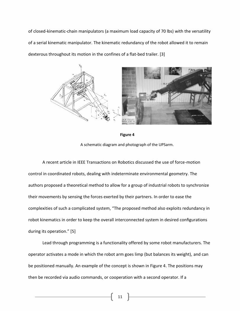
of closed-kinematic-chain manipulators (a maximum load capacity of 70 lbs) with the versatility
of a serial kinematic manipulator. The kinematic redundancy of the robot allowed it to remain
dexterous throughout its motion in the confines of a flat-bed trailer. [3]
A recent article in IEEE Transactions on Robotics discussed the use of force-motion
control in coordinated robots, dealing with indeterminate environmental geometry. The
authors proposed a theoretical method to allow for a group of industrial robots to synchronize
their movements by sensing the forces exerted by their partners. In order to ease the
complexities of such a complicated system, “The proposed method also exploits redundancy in
robot kinematics in order to keep the overall interconnected system in desired configurations
during its operation.” [5]
Lead through programming is a functionality offered by some robot manufacturers. The
operator activates a mode in which the robot arm goes limp (but balances its weight), and can
be positioned manually. An example of the concept is shown in Figure 4. The positions may
then be recorded via audio commands, or cooperation with a second operator. If a
Figure 4
A schematic diagram and photograph of the UPSarm.

12
kinematically redundant industrial robot were programmed with this method, an objective
function based on maximum manipulability and minimal self-movement could conceivably be
created, allowing the robot to subtly re-posture itself while the operator moves it between
positions, reducing the possibility of encountering singularities during programming or
automatic runs. Alternatively, force sensors on intermediate links of the robot could potentially
enable the operator to reposition the robot while keeping the end effector still.
According to Brogardh:
“…there is a big interest from industry to have robots performing bin picking of
components randomly placed in many layers ... The solution to this problem is of course mainly
given by an intelligent vision system but there are also some tricky problems to solve for the
robot control since all robot movements are random as ordered by the vision system. This
means that the ordered movements may pass or end up in singularities, may need the transition
to a new configuration of the robot arms or the robot wrist...To handle singularities,
functionality for singularity avoidance by tool orientation adjustments can be used and robot
Figure 5
An operator uses both hands to lead an industrial robot
through the necessary motions for an arc-welding task. [2]

13
configuration changes can be handled by automatic analysis of predicted robot configurations
before trajectory generation.”
A kinematically redundant manipulator would have the capability of making such configuration
changes during movement, so long as its joint space trajectory remained in the null space of
J(q).
CONCLUSION
The market for industrial robots is shifting away from the conventional applications in
the automotive business, necessitating new paradigms for development. While manipulators
with high degrees of freedom are more expensive and complicated than those with low degrees
of freedom, they offer greater versatility, which will become increasingly valuable as the
applications for industrial robots continue to diversify. Kinematic redundancy allows for
creative uses of self-movement, which are likely to play an important role in the development
of future control systems. As computational power becomes less expensive and the need for
highly versatile and intuitive manipulators grows, it can be expected that the benefits of
kinematic redundancy will outweigh its costs, and manipulators with many degrees of
kinematic freedom will be developed.

14
WORKS CITED
1. Allen, Peter K., Dr. "CS 4733 Class Notes: Kinematic Singularities and Jacobians."
Columbia University CS 4733. Web. 3 May 2014.
<http://www.cs.columbia.edu/~allen/F13/NOTES/jacobians.pdf>.
2. Brogardh, Tony. "Robot Control Overview: An Industrial Perspective." Modeling,
Identification and Control 30.3 (2009): 167-80. Web. 2 May 2014.
3. Cheng, Harry. "Kinematic Analysis of a Hybrid Serial-and-Parallel Driven Redundant
Industrial Manipulator." International Journal of Robotics & Automation 10.4 (1995):
159-66. Web. 3 May 2014.
4. "Industrial Robots." IFR RSS. International Federation of Robotics, n.d. Web. 04 May
2014. <http://www.ifr.org/industrial-robots/>.
5. Namvar, Mehrzad, and Farhad Aghili. "Adaptive Force-Motion Control of Coordinated
Robots Interacting With Geometrically Unknown Environments." IEEE
TRANSACTIONS ON ROBOTICS 21.4 (2005): n. pag. Web. 3 May 2014.
6. Schilling, Robert J. Fundamentals of Robotics: Analysis and Control. Englewood Cliffs,
NJ: Prentice Hall, 1990. N. pag. Print.
7. Siciliano, Bruno. "Kinematic Control of Redundant Robot Manipulators: A Tutorial."
Journal of Lntelligent and Robotic Systems 212th ser. 3.201 (1990): n. pag. Web. 3 May
2014.