
Singularity Analysis of Closed Kinematic Chains · Singularity Analysis of Closed Kinematic Chains...
7
F. C. Park J. W. Kim School of Mechanical and Aerospace Engineering Seoul National University Seoul 151-742, Korea Singularity Analysis of Closed Kinematic Chains This paper presents a coordinate-invariant differential geometric analysis of kine- matic singularities for closed kinematic chains containing both active and passive joints. Using the geometric framework developed in Park and Kim (1996) for closed chain manipulability analysis, we classify closed chain singularities into three basic types: (i) those corresponding to singular points of the joint configuration space (configuration space singularities), (iij those induced by the choice of actuated joints (actuator singularities), and (Hi) those configurations in which the end-effector loses one or more degrees of freedom of available motion (end-effector singularities). The proposed geometric classification provides a high-level taxonomy for mechanism singularities that is independent of the choice of local coordinates used to describe the kinematics, and includes mechanisms that have more actuators than kinematic degrees of freedom. 1 Introduction The physical notion of a singularity in kinematics refers to configurations in which a mechanism's number of degrees of freedom changes instantaneously. For serial chains that have an end-effector frame attached to the final link, a kinematic singularity is a configuration in which the end-effector loses one or more degrees of freedom of motion; mathematically this loss is reflected by a drop in rank of the forward kinematics Jacobian. Clearly there is very little ambiguity in the physical and mathematical characterization of an open chain kinematic singularity. There now exists extensive literature on open chain singularities, ranging from their topological classification and analysis (e.g., Shamir, 1990; Baker and Wampler, 1988; Tchon, 1991) to recursive algorithms for finding all singularities (Bur- dick, 1995). Closed chains, on the other hand, present a number of subtle- ties. Kinematically, the most obvious difference with open chains is that a closed chain's joint configuration space will no longer be flat (i.e., locally isometric to 9i"); in general it will be a curved multi-dimensional surface embedded in a higher- dimensional ambient space, e.g., the configuration space for a planar five-bar linkage will be a 2-dimensional surface embed- ded in the 5-dimensional torus T^. The additional nonlinearity introduced by the curved configuration space, combined with the fact that for closed chains arbitrary subsets of the joints may be actuated, leads to new types of singularities not found in open chains. In general these new singularity types are influ- enced both by the choice of actuated joints as well as the loca- tion of the end-effector frame. In this paper we present a mathe- matical analysis and classification of closed chain singularities using the coordinate-invariant methods of differential geometry. One of the first works to address singularities of general closed chains is that of Gosselin and Angeles (1990), whose perspective is perhaps the closest in spirit to our approach. Their analysis begins by choosing a set of input and output coordinates for the mechanism, denoted 0 and x, respectively, where d and X are assumed to be of the same dimension and equal to the degrees of freedom of the mechanism, n. The relationship be- tween the input and output coordinates is then written F(0,x) = O (1) where F: St" X SR" -* 9{". Differentiating the above with respect to time yields V,F-x + VflF-e = 0 (2) Contributed by the Mechanisms Committee for publication in the JOURNAL OP MECHANICAL DESIGN. Manuscript received Nov., 1996; revised Oct., 1998. Associate Technical Editor: V. Kumar. Configurations in which det(VflF) = 0 correspond to the open chain singularity case, in which the output link loses a degree of freedom. If det(V^F) = 0, the mechanism is in a configuration in which the output link is locally movable even when all the actuated joints are locked. Finally, if both det(VeF) = det(V,F) = 0 then the mechanism can undergo finite motions even when its actuators are locked, or a finite motion of the inputs can fail to produce motion at the outputs. A number of approaches to closed chain singularity analysis based on screw theory and line geometry have also been pro- posed. In his classic book. Hunt (1982) lays down the general framework for applying screw theory to singularity analysis, and introduces the notion of stationary and uncertainty configu- rations. Kumar (1992) provides a more detailed screw-theoretic analysis of closed chain singularities, by appealing to the con- cept of screw reciprocity. In particular, he shows that for parallel manipulators with a symmetric structure (i.e., mechanisms con- sisting of two platforms connected by a set of six degree-of- freedom open chains) its singularities can be precisely classified according to the rank of certain families of reciprocal screws determined by the actuated joints. As an example, he classifies the singularities of a five-ljar planar linkage into four basic types. Kumar is also one of the first works to point out and directly address the effects of actuator placement on singularit- ies, as well as the duality between kinematics and statics-based approaches to singularity analysis. Merlet (1989) shows that by applying line (or Grassmann) geometry, it is possible to analytically enumerate all the singu- larities of classes of Stewart platforms without resorting to Com- plicated algebraic computations. Long and ColUns (1995, 1997) also provide an analysis of parallel manipulator singularities based on screw theory. Their primary focus is on parallel manip- ulators with six actuators, in which the moving platform is supported by a set of identical six degree-of-freedom serial chains, with the last three joints unactuated and equivalent to a spherical joint at the point of contact. They also provide an algebraic approach to singularity determination using the ma- chinery of Clifford algebras. Other recent approaches to closed chain singularity analysis and classification can be found in, e.g., Xu et al. (1992), Shi and Fenton (1992), Notash and Podhoreski (1993), Zlatonov et al. (1994). Obviously any method of singularity analysis, if it is to be physically and mathematically consistent, should be invariant with respect to choice of local coordinates, and should also take into account the nonlinearity of both the joint configuration 32 / Vol. 121, MARCH 1999 Copyright © 1999 by ASME Transactions of the ASME Downloaded 04 Jun 2008 to 147.83.2.29. Redistribution subject to ASME license or copyright; see http://www.asme.org/terms/Terms_Use.cfm
-
Upload
nguyencong -
Category
Documents
-
view
234 -
download
0
Transcript of Singularity Analysis of Closed Kinematic Chains · Singularity Analysis of Closed Kinematic Chains...
F. C. Park
J. W. Kim
School of Mechanical and Aerospace Engineering
Seoul National University Seoul 151-742, Korea
Singularity Analysis of Closed Kinematic Chains This paper presents a coordinate-invariant differential geometric analysis of kinematic singularities for closed kinematic chains containing both active and passive joints. Using the geometric framework developed in Park and Kim (1996) for closed chain manipulability analysis, we classify closed chain singularities into three basic types: (i) those corresponding to singular points of the joint configuration space (configuration space singularities), (iij those induced by the choice of actuated joints (actuator singularities), and (Hi) those configurations in which the end-effector loses one or more degrees of freedom of available motion (end-effector singularities). The proposed geometric classification provides a high-level taxonomy for mechanism singularities that is independent of the choice of local coordinates used to describe the kinematics, and includes mechanisms that have more actuators than kinematic degrees of freedom.
1 Introduction The physical notion of a singularity in kinematics refers to
configurations in which a mechanism's number of degrees of freedom changes instantaneously. For serial chains that have an end-effector frame attached to the final link, a kinematic singularity is a configuration in which the end-effector loses one or more degrees of freedom of motion; mathematically this loss is reflected by a drop in rank of the forward kinematics Jacobian. Clearly there is very little ambiguity in the physical and mathematical characterization of an open chain kinematic singularity. There now exists extensive literature on open chain singularities, ranging from their topological classification and analysis (e.g., Shamir, 1990; Baker and Wampler, 1988; Tchon, 1991) to recursive algorithms for finding all singularities (Bur-dick, 1995).
Closed chains, on the other hand, present a number of subtleties. Kinematically, the most obvious difference with open chains is that a closed chain's joint configuration space will no longer be flat (i.e., locally isometric to 9i"); in general it will be a curved multi-dimensional surface embedded in a higher-dimensional ambient space, e.g., the configuration space for a planar five-bar linkage will be a 2-dimensional surface embedded in the 5-dimensional torus T^. The additional nonlinearity introduced by the curved configuration space, combined with the fact that for closed chains arbitrary subsets of the joints may be actuated, leads to new types of singularities not found in open chains. In general these new singularity types are influenced both by the choice of actuated joints as well as the location of the end-effector frame. In this paper we present a mathematical analysis and classification of closed chain singularities using the coordinate-invariant methods of differential geometry.
One of the first works to address singularities of general closed chains is that of Gosselin and Angeles (1990), whose perspective is perhaps the closest in spirit to our approach. Their analysis begins by choosing a set of input and output coordinates for the mechanism, denoted 0 and x, respectively, where d and X are assumed to be of the same dimension and equal to the degrees of freedom of the mechanism, n. The relationship between the input and output coordinates is then written
F(0 ,x ) = O (1)
where F : St" X SR" -* 9{". Differentiating the above with respect to time yields
V,F-x + VflF-e = 0 (2)
Contributed by the Mechanisms Committee for publication in the JOURNAL OP MECHANICAL DESIGN. Manuscript received Nov., 1996; revised Oct., 1998. Associate Technical Editor: V. Kumar.
Configurations in which det(VflF) = 0 correspond to the open chain singularity case, in which the output link loses a degree of freedom. If det(V^F) = 0, the mechanism is in a configuration in which the output link is locally movable even when all the actuated joints are locked. Finally, if both det(VeF) = det(V,F) = 0 then the mechanism can undergo finite motions even when its actuators are locked, or a finite motion of the inputs can fail to produce motion at the outputs.
A number of approaches to closed chain singularity analysis based on screw theory and line geometry have also been proposed. In his classic book. Hunt (1982) lays down the general framework for applying screw theory to singularity analysis, and introduces the notion of stationary and uncertainty configurations. Kumar (1992) provides a more detailed screw-theoretic analysis of closed chain singularities, by appealing to the concept of screw reciprocity. In particular, he shows that for parallel manipulators with a symmetric structure (i.e., mechanisms consisting of two platforms connected by a set of six degree-of-freedom open chains) its singularities can be precisely classified according to the rank of certain families of reciprocal screws determined by the actuated joints. As an example, he classifies the singularities of a five-ljar planar linkage into four basic types. Kumar is also one of the first works to point out and directly address the effects of actuator placement on singularities, as well as the duality between kinematics and statics-based approaches to singularity analysis.
Merlet (1989) shows that by applying line (or Grassmann) geometry, it is possible to analytically enumerate all the singularities of classes of Stewart platforms without resorting to Complicated algebraic computations. Long and ColUns (1995, 1997) also provide an analysis of parallel manipulator singularities based on screw theory. Their primary focus is on parallel manipulators with six actuators, in which the moving platform is supported by a set of identical six degree-of-freedom serial chains, with the last three joints unactuated and equivalent to a spherical joint at the point of contact. They also provide an algebraic approach to singularity determination using the machinery of Clifford algebras. Other recent approaches to closed chain singularity analysis and classification can be found in, e.g., Xu et al. (1992), Shi and Fenton (1992), Notash and Podhoreski (1993), Zlatonov et al. (1994).
Obviously any method of singularity analysis, if it is to be physically and mathematically consistent, should be invariant with respect to choice of local coordinates, and should also take into account the nonlinearity of both the joint configuration
32 / Vol. 121, MARCH 1999 Copyright © 1999 by ASME Transactions of the ASME
Downloaded 04 Jun 2008 to 147.83.2.29. Redistribution subject to ASME license or copyright; see http://www.asme.org/terms/Terms_Use.cfm
space and the space of rigid-body displacements. In Park and Kim (1996) a geometric framework is developed for analyzing the manipulability of closed chains in a coordinate-invariant manner. Using this frame jrk as our point of departure, we develop a classification ot closed chain singularities based on first- and second-orde properties of a certain quadratic form in joint configuration space.
Using this approach the following three basic types of singularities can be identified: (i) singularities of the joint configuration space (configuration space singularity); (ii) configurations in which the mechanism loses one or more degrees of freedom as a result of the choice of actuated joints (actuator singularity); (iii) the mechanism's end-effector frame loses degrees of freedom of available motion (end-effector singularity). Actuator singularities can be further subclassified into degenerate and nondegenerate types: degenerate actuator singularities physically correspond to configurations in which some of the links can move even when the actuators are locked in place (i.e., self-motions of the mechanism), while nondegenerate singularities correspond to configurations in which certain actuator forces may cause the mechanism to break apart. Methods for detecting degenerate actuator singularities in a special class of parallel manipulators have also been presented in the recent work of Karger and Husty (1996).
While our geometric perspective bears a number of similarities to that of Gosselin and Angeles (1990), our framework is more general in that it includes redundantly actuated mechanisms in a natural way. Also, to correctly apply the method of Gosselin and Angeles often requires considerable kinematic intuition. For example, if the input and output coordinates 0 and X or the constraint mapping F(0, x) a n not selected properly, seemingly mathematically inconsistent results can occur, particularly at kinematic branch points. Also, existing line geometric studies of parallel manipulator singularities focus only on actuator and c-space singularities, and do not identify end-effector singularities. In this sense our framework provides a high-level taxonomy for mechanism singularities, in which the various screw and line geometry-based singularity analyses can be organized and placed in a general hierarchy. Such a taxonomy can, we feel, also help to unify the myriad terms that have been introduced in connection with mechanism singularities, e.g., deadpoints, special configurations, stationary configurations, uncertainty configurations, change points, limit points, limit positions, etc.
The paper is organized as follows. In Section 2 we introduce the necessary differential geometric background, and review the geometric framework for manipulability analysis on which much of the subsequent singularity analysis is based. The main results are presented in Section 3, where we formulate our geometric classification and discuss its physical interpretation, and illustrate the basic singularity types via several examples. We conclude in Section 4 with a discussion of some open problems and directions for future research.
2 Geometric Framework In this section we introduce the necessary geometric back
ground for our subsequent singularity analysis, in particular the Riemannian geometric formulation for closed chain manipulability as described in Park and Kim (1996). This formulation leads very naturally to a characterization of a singularity as a dimensional change in manipulability.
There are essentially two features of closed chains that make differential geometry a natural candidate for their kinematic analysis: the joint configuration space is curved, and the end-effector configuration space forms a subset of the Special Euclidean Group SE (3). For an m degree-of-freedom mechanism, the joint configuration space forms an m-dimensional surface in a higher-dimensional (possibly curved) ambient space. The joint configuration space of a planar five-bar closed-loop link
age, for example, forms a two-dimensional surface in the five-dimensional torus r ' . Similarly, a Stewart Platform comprised of 12 ball-and-socket joints and 6 prismatic joints has as its joint configuration space a six-dimensional surface in the ambient space /?'' X SO(3)'^ (assuming the configuration space for a ball-and-socket joint is taken to be SO(3)).
We first fix some notation. Let X denote the fc-dimensional manifold corresponding to the ambient space, and M denote the OT-dimensional manifold corresponding to the joint configuration space of the mechanism; here we use the term "manifold' ' in a looser sense than the strict mathematical definition, to include manifolds containing boundaries and other singular sets of measure zero. Let JV denote the n-dimensional manifold corresponding to the end-effector space of the mechanism. For example, if orientations are ignored, then JV will be fR^ for a planar mechanism, and dV for a spatial mechanism. In the general spatial case JV is usually taken to be the special Euclidean group SE(3).
In order to define manipulability in a coordinate-invariant way, Riemannian metrics are next defined on X , M, and jV, denoted by e, g, and h, respectively. Later we discuss how to choose these metrics in a physically meaningful way, and illustrate these concepts via concrete examples. Let x = {x\ . . . , x'') and u = ( « ' , . . . , «'") denote local coordinates on J{ and M, respectively. Since M is embedded in X , x can be written as a function of u, i.e., x = x (u ) . Let f = ( / ' , . . . , / " ) be local coordinates on Jf, and also denote the forward kinematics / : J / -> ./i in local coordinates by f (u). We use the notation J = V„ f to represent the derivative of f with respect to u. The Riemannian metrics on X , M, and Jf can then be expressed in local coordinates by the symmetric positive definite matrices E, G, and H, respectively.
Now, any symmetric function' of the roots of det(G\ -J T I J ) = C (or, in coordinate-free language, the proper values of the pullback metric/ *h) will be a coordinate-invariant function defined on the Riemannian manifold M. At a regular point J by definition will have maximal rank, and the proper values of / *h will have exactly n nonzero values (assuming m si n); we label these, in descending order, as X,, X.2,. . . , \.„. These proper values are also the eigenvalues of J G ~ ' J ^ . Various symmetric functions of these proper values can now be constructed to reflect kinematic manipulability. For example, a condition number-based manipulability measure is
cif) = - (3)
while the generaUzation of Yoshikawa's manipulability measure (Yoshikawa 1985) is
v(f) = (\r--Ky (4)
We now discuss the issue of the choice of Riemannian metrics. The basic strategy is to choose the metric e on the ambient space X corresponding to the virtual work performed by the mechanism; the metric g is then obtained by projecting e onto Ji. Since passive joints do not contribute to virtual work, we need only consider the actuated joints in formulating the metric e. To illustrate, consider once again the five-bar planar closed-loop linkage, in which the five revolute joints are parametrized by local coordinates Xt through Xs. The metric e is then chosen to be
ds^ X tjdx^i (5)
where 6, = 1 if the ith joint is actuated, and 0 otherwise. The corresponding matrix E in this case is diagonal, with I's on the
' A function is symmeti'ic if it is invariant witli respect to permutations of its arguments.
Journal of Mechanical Design MARCH 1999, Vol. 121 / 33
Downloaded 04 Jun 2008 to 147.83.2.29. Redistribution subject to ASME license or copyright; see http://www.asme.org/terms/Terms_Use.cfm
diagonal entries corresponding to the actuated joints, and all other entries 0. Note that this procedure uniformly treats both nonredundant and redundantly actuated cases. Moreover, it can be generalized to mechanisms containing more complex joint types, by selecting a suitable set of local coordinates for the joint, and choosing a metric such that only actuated joints contribute to work. In general, however, the actuated joints of most mechanisms are one degree-of-freedom revolute or prismatic joints, in which case the metric E on JT will as before be a diagonal matrix composed of I's and O's. Observe that E may only be positive semidefinite, and hence strictly speaking a pseudo-Riemannian metric.
Once the metric e on i ' is chosen, the metric on M is obtained by projecting e onto M. as follows. Since dx = V„X'(iu, it follows that
ds^ = ^ dx^dx
\ rfu''(V„x)^(V„x)a'u
(6)
(7)
The projected metric on M, denoted G, is therefore G = (V„x)^(V„x) . Again, observe that since E may only be posi-tive-semidefinite, G may also be only positive-semidefinite at some points. As we will see later, these points in fact correspond to kinematic singularities induced by the choice of actuated joints.
The metric on Jf, which we denote H, is also chosen from physical considerations. In the event that Jf is some proper subset of either SO(3) or Euclidean space, there exists a natural choice of Riemannian metric, given by the standard Euclidean inner product for velocities and angular velocities (see Park, 1995). When Jf is taken to be either SE(2)orSE(3) , however, there now exists a one-parameter family of suitable Riemannian metrics parametrized by the choice of length scale for physical space. Since there is no natural length scale for physical space, there is some arbitrariness involved in the choice of metric on SE (3). Fortunately this lack of a natural metric does not pose a problem for singularity analysis; as will become clear in the next Section, kinematic singularities are in fact invariant with respect to choice of length scale, since the matrix H will always be nonsingular.
3 Geometric Analysis of Singularities By interpreting a singularity as a dimensional change in ma-
nipulability, it suffices to examine those points at which the quadratic form JG"'J1I becomes either singular or ill-defined. In this section we examine the various ways in which this can occur.
Recall that a natural choice for the Riemannian metric H on SE(3) is the left- or right-invariant metric parametrized by a choice of length scale for physical space. Fortunately (for our purposes) such an H is always nonsingular regardless of the choice of length scale, and hence has no effect on singularity behavior. Therefore, at any singular configuration we need only consider the following three possibilities:
• the joint configuration space manifold is singular (a configuration space singularity).
• the rank of G decreases (an actuator singularity). • the rank of J decreases (an end-effector singularity).
By construction, the above classification of singularities is completely independent of the choice of local coordinates. Observe that the first two types of singularities do not require the presence of an end-effector frame attached to the mechanism. Furthermore, actuator singularities are directly influenced by the choice of actuated joints. We now describe in more detail the above three cases, illustrating instances of each with the following examples: a slider-crank mechanism, a planar five-bar closed-loop linkage, a spherical 6-bar closed-loop linkage.
and the Eclipse, a novel six degree-of-freedom spatial parallel manipulator consisting of three serial substructures that has been designed for universal machining applications.
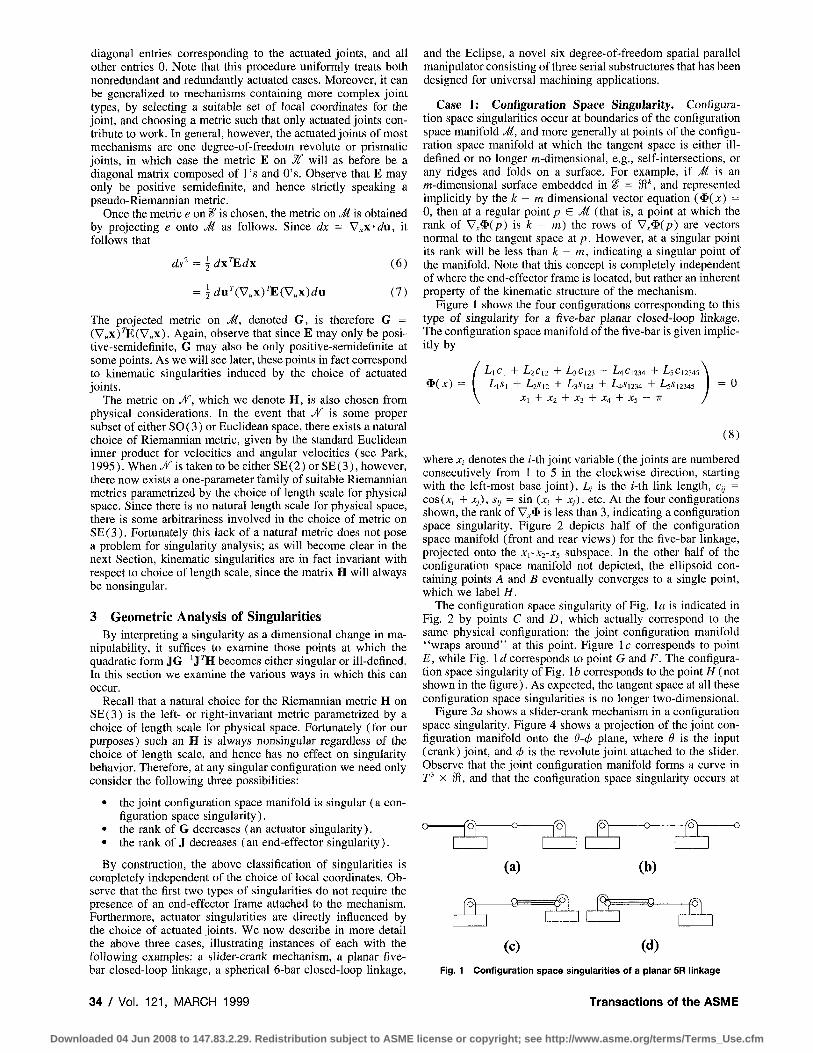
Case 1: Configuration Space Singularity. Configuration space singularities occur at boundaries of the configuration space manifold M, and more generally at points of the configuration space manifold at which the tangent space is either ill-defined or no longer m-dimensional, e.g., self-intersections, or any ridges and folds on a surface. For example, if M is an m-dimensional surface embedded in i" = 91*, and represented implicitly by the A: - m dimensional vector equation (* (x ) = 0, then at a regular point p & M (that is, a point at which the rank of VJ!^ip) h k - m) the rows of V^^(p) are vectors normal to the tangent space at p. However, at a singular point its rank will be less than k - m, indicating a singular point of the manifold. Note that this concept is completely independent of where the end-effector frame is located, but rather an inherent property of the kinematic structure of the mechanism.
Figure 1 shows the four configurations corresponding to this type of singularity for a five-bar planar closed-loop linkage. The configuration space manifold of the five-bar is given implicitly by
( LiC\ + L2C12 + L^Ci23 + ^4^1234 + L5C12345 \
L,.s, -I- L2J12 + LjSni + LASUM + LsSi2M5 I = 0 X, + X2 + X^ + X4 + X5 — IT /
(8)
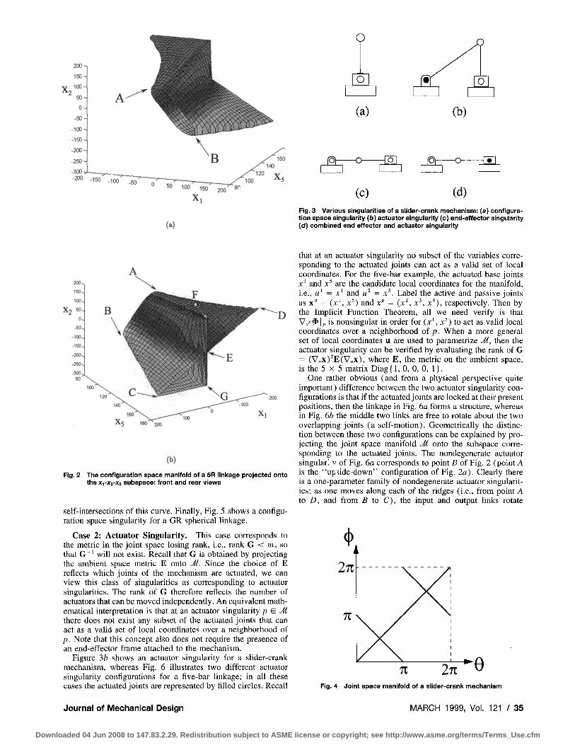
where Xi denotes the «-th joint variable (the joints are numbered consecutively from 1 to 5 in the clockwise direction, starting with the left-most base joint), L, is the i-th link length, c,, = cos(;c; + Xj), Sy = sin (jc; + Xj), etc. At the four configurations shown, the rank of V^^ is less than 3, indicating a configuration space singularity. Figure 2 depicts half of the configuration space manifold (front and rear views) for the five-bar linkage, projected onto the XrX2-Xs subspace. In the other half of the configuration space manifold not depicted, the ellipsoid containing points A and B eventually converges to a single point, which we label H.
The configuration space singularity of Fig. la is indicated in Fig. 2 by points C and D, which actually correspond to the same physical configuration: the joint configuration manifold "wraps around" at this point. Figure Ic corresponds to point E, while Fig. Id corresponds to point G and F. The configuration space singularity of Fig. lb corresponds to the point H (not shown in the figure). As expected, the tangent space at all these configuration space singularities is no longer two-dimensional.
Figure 3a shows a slider-crank mechanism in a configuration space singularity. Figure 4 shows a projection of the joint configuration manifold onto the d-tf) plane, where 9 is the input (crank) joint, and (p is the revolute joint attached to the slider. Observe that the joint configuration manifold forms a curve in T^ X D t, and that the configuration space singularity occurs at
fl ft (a)
CZH
(b)
(c) (d)
Fig. 1 Configuration space singularities of a planar 5R linkage
34 / Vol. 121, MARCH 1999 Transactions of the ASME
Downloaded 04 Jun 2008 to 147.83.2.29. Redistribution subject to ASME license or copyright; see http://www.asme.org/terms/Terms_Use.cfm
^° 1» 1 5 0 ^ ^ an
(a)
JSh
O
O
(a)
- o
(c)
^
(b)
[ = ] [ jSh - o - •s
(d) Fig. 3 Various singularities of a slider-crank mechanism: (a) configuration space singularity (b) actuator singularity (c) end-effector singularity (cf) combined end effector and actuator singularity
Fig. 2
(b)
The configuration space manifold of a 5R linkage projected onto the Xi-Xs-Xs subspace: front and rear views
self-intersections of this curve. Finally, Fig. 5 shows a configuration space singularity for a GR spherical linkage.
Case 2: Actuator Singularity. This case corresponds to the metric in the joint space losing rank, i.e., rank G < m, so that G"' will not exist. Recall that G is obtained by projecting the ambient space metric E onto Ji. Since the choice of E reflects which joints of the mechanism are actuated, we can view this class of singularities as corresponding to actuator singularities. The rank of G therefore reflects the number of actuators that can be moved independently. An equivalent mathematical interpretation is that at an actuator singularity p ^ M there does not exist any subset of the actuated joints that can act as a valid set of local coordinates over a neighborhood of p. Note that this concept also does not require the presence of an end-effector frame attached to the mechanism.
Figure "ih shows an actuator singularity for a slider-crank mechanism, whereas Fig. 6 illustrates two different actuator singularity configurations for a five-bar linkage; in all these cases the actuated joints are represented by filled circles. Recall
that at an actuator singularity no subset of the variables corresponding to the actuated joints can act as a valid set of local coordinates. For the five-bar example, the actuated base joints jf' and x^ are the candidate local coordinates for the manifold, i.e., « ' = x' and u^ = x^. Label the active and passive joints as x" = (x ' , x^) and x'' = (x^, x^, x'*), respectively. Then by the Implicit Function Theorem, all we need verify is that Vxf^li, is nonsingular in order for (x', x^) to act as valid local coordinates over a neighborhood of p. When a more general set of local coordinates u are used to parametrize J(, then the actuator singularity can be verified by evaluating the rank of G = (V„x) t (V„x) , where E, the metric on the ambient space, is the 5 X 5 matrix Diag {1, 0, 0, 0, 1).
One rather obvious (and from a physical perspective quite important) difference between the two actuator singularity configurations is that if the actuated joints are locked at their present positions, then the linkage in Fig. 6a forms a structure, whereas in Fig. 6b the middle two links are free to rotate about the two overlapping joints (a self-motion). Geometrically the distinction between these two configurations can be explained by projecting the joint space manifold M onto the subspace corresponding to the actuated joints. The nondegenerate actuator singular! V of Fig. 6a corresponds to point D of Fig. 2 (point A is the "up>ide-down" configuration of Fig. 2a). Clearly there is a one-parameter family of nondegenerate actuator singularities: as one moves along each of the ridges (i.e., from point A to D, and from B to C), the input and output links rotate
Fig. 4 Joint space manifold of a slider-crank mechanism
Journal of Mechanical Design MARCH 1999, Vol. 121 / 35
Downloaded 04 Jun 2008 to 147.83.2.29. Redistribution subject to ASME license or copyright; see http://www.asme.org/terms/Terms_Use.cfm
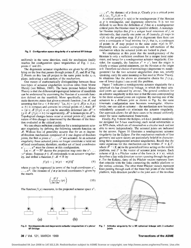
Fig. 5 Configuration space singularity of a splierical 6R linkage
uniformly in the same direction, until the mechanism finally reaches the configuration space singularities of Fig. 1 (i.e., points C and D).
The degenerate actuator singularities are given by all points lying on the line that passes through points F, E, and H of Fig. 2. Points on this line all project to the same point in the Xi-x^ plane, indicating a self-motion of the mechanism.
One means of mathematically distinguishing between these two types of actuator singularities involves ideas from Morse Theory (see Milnor, 1969). The basic premise behind Morse Theory is that the differential topological behavior of manifolds can be understood by examining the Hessian of a smooth function defined on the manifold. More specifically, one of the main theorems states that given a smooth function / o n M, and assuming that iov a < b the set/"'[<a:, b] = [p & M\a ^f{p) ^ b] is compact and contains no critical points of/, then M" = Ip G Ji \f(p) s a} can be smoothly deformed into M'' = {p ^ M \f{.p) s b ] (orequivalently, M" is homotopic to M''). Topological changes hence occur at critical points of/, and the nature of this change is determined by the Hessian of the function evaluated at the critical point.
We can obtain sufficient conditions for a nondegenerate actuator singularity by defining the following smooth function on M. Without loss of generality assume that for an m degree-of-freedom mechanism composed of k one degree-of-freedom joints, the first m joints x ' , . . . , %'" are actuated. At an actuator singularity these actuated joints no longer constitute a valid set of local coordinates; therefore, another set of local coordinates u\ . .., u'" must be chosen at this configuration.
Let TT: M -* 9i"' denote the projection map onto the x'- . . . -x"' plane. Suppose p G M corresponds to an actuator singularity, and define a function/: M -*'^hy
fip) = 2 hip) - ^(p)f (9)
where p can be expressed in terms of the local coordinates u', . . . , « ' " . The Hessian of f at p in local coordinates is given by the matrix
du'du-(P) (10)
The function/(p) measures, in the projected actuator space x '
A & ft
. . . , x'", the distance of p from p. Clearly p is a critical point of/, i.e., V„/(p) = 0.
A critical point p is said to be nondegenerate if the Hessian at p is nonsingular, and degenerate otherwise. It is not too difficult to see from the definition of / that at a nondegenerate critical point the Hessian must be positive definite. A nonsingular Hessian implies that p' is a unique local minimum of / , or alternatively, that exactly one point on J( (namely, p) maps to Trip) via the projection map. If p is degenerate then there can exist a continuum of local minima for / ; that is, a continuum of points in J( may project to the same point 7r(p) in ?ii"'. Physically this situation corresponds to self-motions of the mechanism when the actuated joints are locked in place.
We emphasize at this point that the nondegeneracy of the Hessian is only a sufficient condition for a unique local minimum, and hence for a nondegenerate actuator singularity. Consider, for example, the function x'* + y"; here the origin is clearly a unique global minimum, yet the Hessian at the origin is 0. Therefore our choice of terminology (degenerate vs. nondegenerate) for the two actuator singularities does not, strictly speaking, carry the same meaning as that used in Morse Theory. In situations like the above an alternative choice for / ( e .g . , one of lower degree) can avoid this problem.
Figure 7 indicates a nondegenerate actuator singularity for a spherical six-bar closed-loop linkage, in which the three actuated joints are indicated by arrows. The general condition for an actuator singularity in this case is that the axes corresponding to the three actuated joints are coplanar. By moving one of the actuators to a different joint as shown in Fig. 8a, the same kinematic configuration now becomes nonsingular. Alternatively, one can add an actuator—the mechanism now becomes redundantly actuated—to eliminate the actuator singularity. Our approach allows for all these cases to be treated uniformly under the same mathematical framework.
Finally, Fig. 9 shows the Eclipse, a 6 d.o.f. parallel manipulator designed for 5-face machining; each serial substructure is an RPS chain, which are all mounted on a circular track and are able to move independently. The actuated joints are indicated by the arrows. Figure 10 illustrates a nondegenerate actuator singularity for the Eclipse. For this mechanism methods of line geometry and screw theory are particularly helpful in characterizing these nondegenerate actuator singularities. Recall that the static equations for this mechanism can be written ^ = J/5^, where J^ = (f, m) is the generalized force acting on the mobile platform, and ^ is the vector of actuator joint torques. Each column of Jj is a Pliicker vector of the form (s, r X s), which describes a line with direction vector s passing through the point r . For the Eclipse, three of the Pliicker vectors represent lines that coincide with the links connecting the mobile platform to the vertical columns. The other three Pliicker vectors represent lines passing through each of the three ball joints of the mobile platform, with direction parallel to the joint axis of the re volute
(a) (b) Fig. 6 Nondegenerate and degenerate actuator singularities of a planar Fig. 7 Actuator singularity for a 6R spherical linkage with 3 actuated
5R linkage joints
36 / Vol. 121, MARCH 1999 Transactions of the ASME
Downloaded 04 Jun 2008 to 147.83.2.29. Redistribution subject to ASME license or copyright; see http://www.asme.org/terms/Terms_Use.cfm
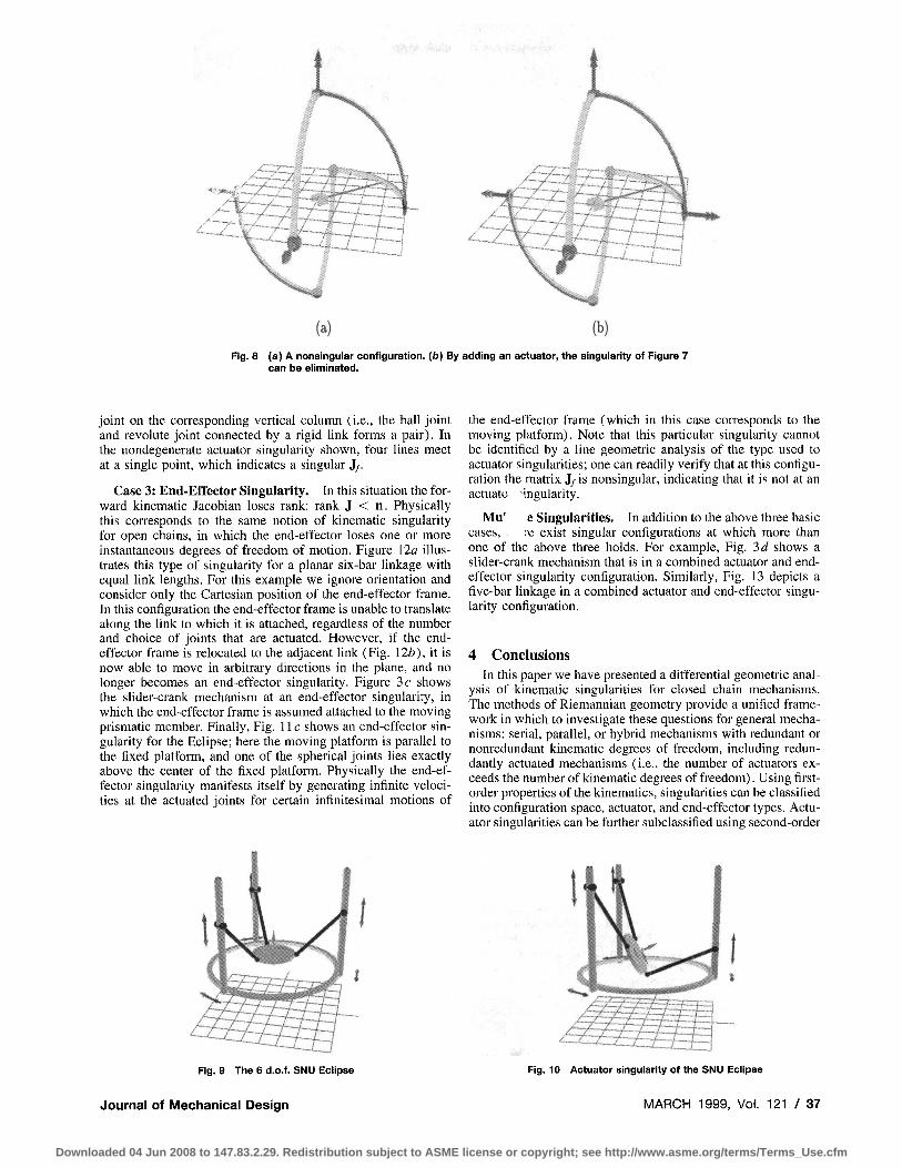
(a) (b) Fig. 8 (a) A nonsingular configuration, (b) By adding an actuator, the singuiarity of Figure 7
can be eliminated.
joint on the corresponding vertical column (i.e., the ball Joint and revolute joint connected by a rigid link forms a pair). In the nondegenerate actuator singularity shown, four lines meet at a single point, which indicates a singular J/.
Case 3: End-Effector Singularity. In this situation the forward kinematic Jacobian loses rank: rank J < n. Physically this corresponds to the same notion of kinematic singularity for open chains, in which the end-effector loses one or more instantaneous degrees of freedom of motion. Figure 12a illustrates this type of singularity for a planar six-bar linkage with equal link lengths. For this example we ignore orientation and consider only the Cartesian position of the end-effector frame. In this configuration the end-effector frame is unable to translate along the link to which it is attached, regardless of the number and choice of joints that are actuated. However, if the end-effector frame is relocated to the adjacent link (Fig. \2b), it is now able to move in arbitrary directions in the plane, and no longer becomes an end-effector singularity. Figure 3 c shows the slider-crank mechanism at an end-effector singularity, in which the end-effector frame is assumed attached to the moving prismatic member. Finally, Fig. 11 c shows an end-effector singularity for the Eclipse; here the moving platform is parallel to the fixed platform, and one of the spherical joints lies exactly above the center of the fixed platform. Physically the end-effector singularity manifests itself by generating infinite velocities at the actuated joints for certain infinitesimal motions of
the end-effector frame (which in this case corresponds to the moving platform). Note that this particular singularity cannot be identified by a line geometric analysis of the type used to actuator singularities; one can readily verify that at this configuration the matrix J/ is nonsingular, indicating that it is not at an actuate singularity.
Mu' e Singularities. In addition to the above three basic cases, i'e exist singular configurations at which more than one of the above three holds. For example. Fig. 3d shows a slider-crank mechanism that is in a combined actuator and end-effector singularity configuration. Similarly, Fig. 13 depicts a five-bar linkage in a combined actuator and end-effector singularity configuration.
4 Conclusions In this paper we have presented a differential geometric anal
ysis of kinematic singularities for closed chain mechanisms. The methods of Riemannian geometry provide a unified framework in which to investigate these questions for general mechanisms: serial, parallel, or hybrid mechanisms with redundant or nonredundant kinematic degrees of freedom, including redundantly actuated mechanisms (i.e., the number of actuators exceeds the number of kinematic degrees of freedom). Using first-order properties of the kinematics, singularities can be classified into configuration space, actuator, and end-effector types. Actuator singularities can be further subclassified using second-order
Fig. 9 The 6 d.o.f. SNU Eclipse
/:
Journal of Meclianical Design
Fig. 10 Actuator singularity of the SNU Eclipse
MARCH 1999, Vol. 121 / 37
Downloaded 04 Jun 2008 to 147.83.2.29. Redistribution subject to ASME license or copyright; see http://www.asme.org/terms/Terms_Use.cfm
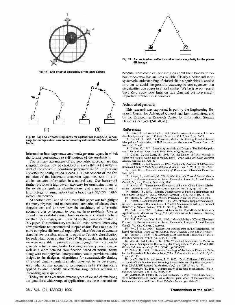
Fig. 11 End-effector singularity of tfie SNU Eciipse
(a) (b) Fig. 12 (a) End-effector singuiarity for a planar 6R linkage. (/)) A non-singular configuration can be achieved by relocating the end effector frame.
information into degenerate and nondegenerate types, in which the former corresponds to self-motions of the mechanism.
The primary advantages of the geometric approach are that singularities can now be classified in a way that is (i) independent of the choice of coordinate parameterization for joint and end-effector configuration spaces, (ii) independent of the formulation of the kinematic constraint equations, and (iii) includes actuator information in a natural way. Our framework further provides a high level taxonomy for organizing many of the existing singularity classifications, and a unifying set of terminology for singularities that is based on a rigorous mathematical framework.
At another level, one of the aims of this paper was to highlight the many physical and mathematical subtleties of closed chain singularities, and to show how the machinery of differential geometry can be brought to bear on these problems. Clearly closed chains exhibit a much broader range of kinematic behavior than open chains, as illustrated by the examples treated in this paper. Our preliminary results also raise several interesting new questions not encountered in open chains. For example, is a more complete differential topological classification of actuator singularities possible, similar in spirit to Tchon's classification for redundant open chains (1991)? In particular, in this paper we were only able to provide sufficient conditions for a nondegenerate actuator singularity. Deriving necessary conditions, as well as a more detailed classification based on normal forms along with their physical interpretation, would provide valuable insight to the designer. Algorithms for systematically finding all closed chain singularities also have yet to be developed. Also, whether line geometric techniques can be systematically applied to also identify end-effector singularities remains an interesting open question.
Today we see ever more diverse types of closed chains being designed for a wider range of applications. As these mechanisms
Fig. 13 A combined end-effector and actuator singularity for the planar 5R linkage
become more complex, our intuition about their kinematic behavior becomes less and less reliable. Clearly a better and more systematic understanding of closed chain singularities is needed in order to avoid the possibly catastrophic consequences that singularities can cause in closed chains. We believe our results have shed some new light on this classical yet increasingly important problem in kinematics.
Acknowledgements This research was supported in part by the Engineering Re
search Center for Advanced Control and Instrumentation, and by the Engineering Research Center for Information Storage Devices (97K3-0912-01-03-1).
References 1 Baker, D., and Wampler, C , 1988, "On the Inverse Kinematics of Redun
dant Manipulators," Int. J. Robotics Research, Vol. 7, No. 2, pp. 3-21. 2 Burdick, J., 1995, "A Recursive Method for Finding Revolute-Jointed
Manipulator Singularities," ASME JOURNAL OF MECHANICAL DESIGN, Vol. 117, No. l ,pp . 55-63.
3 Collins, C , 1997, "Singularity Analysis and Design of Parallel Manipulators," Ph.D. thesis, Dept. Mech. Eng., Univ. of Calif., Irvine.
4 Collins, C , and Long, G., 1995, "On the Duality of Twist/Wrench in Serial and Parallel Chain Robot Manipulators," Proc. IEEE Int. Conf. Robotics Autom., Nagoya, pp. 526-531.
5 Gosselin, C., and Angeles, J., 1990, "Singularity Analysis of Closed-Loop Kinematic Chains," IEEE Trans. Robotics & Autom., Vol. 6, No. 3, pp. 281-290.
6 Hunt, K. H., Kinematic Geometry of Mechanisms, Clarendon Press, Oxford, 1978.
7 Karger, A., and Husty, M., "On Self-Motions of a Class of Parallel Manipulators," in Recent Advances in Robot Kinematics, Lenarcic, J., and Parenti-Castelli, V., eds., Kluwer, Dordrecht, 1996.
8 Kumar, V., "Instantaneous Kinematics of Parallel-Chain Robotic Mechanisms," ASME JOURNAL OF MECHANICAL DESIGN, Vol. 114, pp. 349-358.
9 Merlet, J. P., 1989, "Singular Configurations of Parallel Manipulators and Grassmann Geometry," Int. J. Robotics Research, Vol. 8, No. 5, pp. 45-56.
10 Milnor, J., 1969, Morse Theory, Princeton University Press, Princeton, 11 Notash, L., and Podhorodeski, R. P., 1993, "Forward Displacement Analy
sis and Uncertainty Configurations of Parallel Manipulators with a Redundant Branch," J. Robotic Systems, Vol 13, No. 9, p. 587-601.
12 Park, F. C , 1995, "Distance Metrics on the Rigid-Body Motions with Applications to Mechanism Design,'' ASME JOURNAL OF MECHANICAL DESIGN, Vol, 117, pp. 48-54.
13 Park, F. C , and Kim, J. W., 1996, "Manipulability of Closed Kinematic Chains," in Recent Advances in Robot Kinematics, Lenarcic, J., and Parenti-Castelli, V., eds., Kluwer, Dordrecht.
14 Ryu, S. et al, 1998, "Eclipse: An Overactuated Parallel Mechanism for Rapid Machining" Proc. ASME TMECE Symp. Machine Tools and Metrology.
15 Shamir, T., 1990, "The Singularities of Redundant Robot Arms," Int. J. Robotics Research, Vol. 9, No. 1, pp. 113-121.
16 Shi, X., and Fenton, R. G., 1992, "Structural Instabilities in Platform-Type Parallel Manipulators Due to Singular Configurations," Proc. 22nd ASME Biennial Mechanisms Conf., Vol. DE-45, pp. 347-352.
17 Tchon, K., 1991, "Differential Topology of the Inverse Kinematic Problem for Redundant Robot Manipulators," Int. J. Robotics Research, Vol. 10, No. 5, pp. 492-504.
18 Xu, Y., KohU, D., and Weng, T. C , 1992, "Direct Differential Kinematics of Hybrid-Chain Manipulators Including Singularities and Stability Analyses." Proc. 22nd ASME Biennial Mechanisms Conf, Vol. DE-45, pp. 65-73.
19 Yoshikawa, T., 1985, "Manipulability of Robotic Mechanisms," Int. J. Robotics Research, Vol. 4, No. 2, pp. 3-9.
20 Zlatonov, D., Fenton, R. G., and Benhabib, B., 1994, "Singularity Analysis of Mechanisms and Robots Via a Motion-Space Model of the Instantaneous Kinematics," Proc. IEEE Int. Conf Robotics Autom., pp. 980-991.
38 / Vol. 121, MARCH 1999 Transactions of the ASME
Downloaded 04 Jun 2008 to 147.83.2.29. Redistribution subject to ASME license or copyright; see http://www.asme.org/terms/Terms_Use.cfm


![Singularity - easybuilders.github.ioeasybuilders.github.io/easybuild/files/EUM17/20170208-1_Singularity… · Singularity Workflow 1. Create image file $ sudo singularity create [image]](https://static.fdocuments.in/doc/165x107/5f0991027e708231d4277151/singularity-singularity-workflow-1-create-image-file-sudo-singularity-create.jpg)