Single/Dual Compressor Centrifugal Chillers - DaikinSingle/Dual Compressor Centrifugal Chillers...
63
Original Instructions Single/Dual Compressor Centrifugal Chillers DWSC/DWDC 050, 063, 079, 087, 100, 113, 126, Cooling Only DWCC 100, 113, 126 DHSC 050, 063, 079, 087, 100, 126, Heat Recovery Installation, Operation and Maintenance Manual D-EIMWC00808-16EN
-
Upload
trinhxuyen -
Category
Documents
-
view
236 -
download
3
Transcript of Single/Dual Compressor Centrifugal Chillers - DaikinSingle/Dual Compressor Centrifugal Chillers...
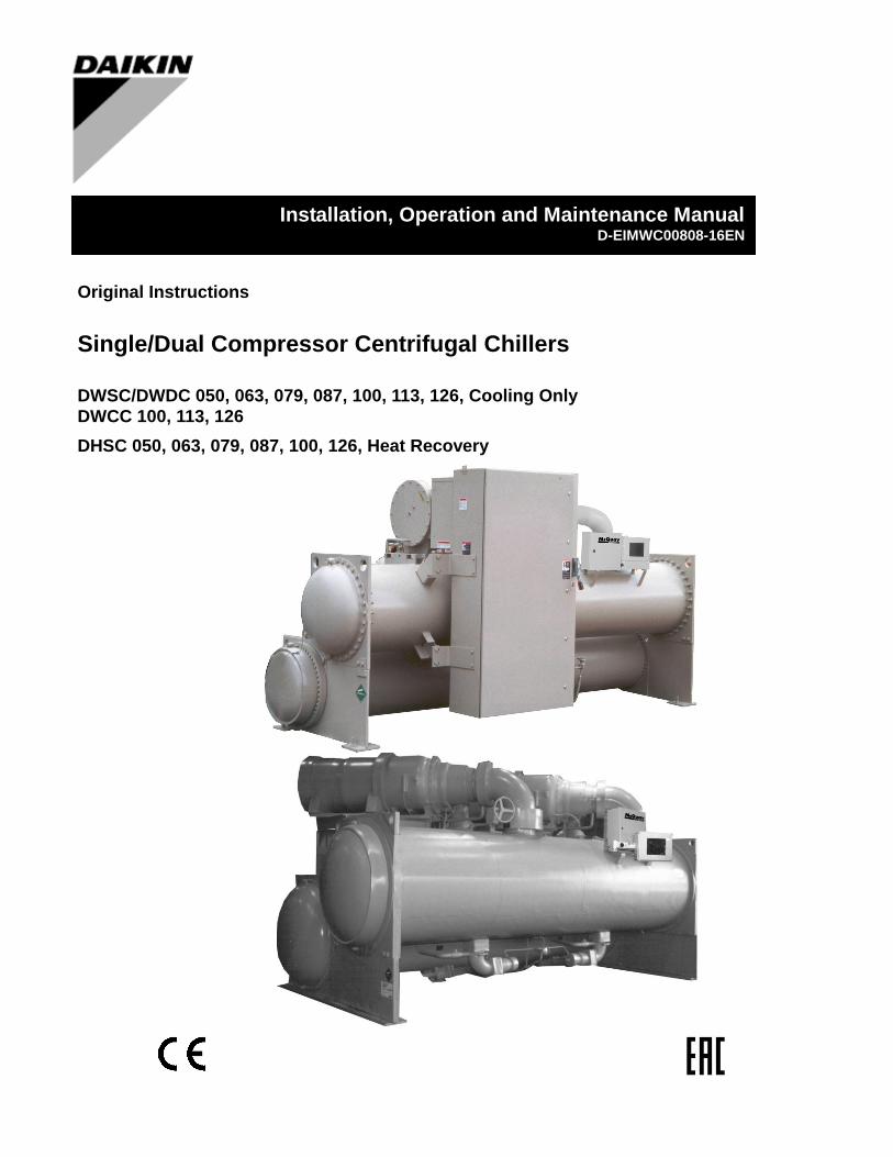
Original Instructions
Single/Dual Compressor Centrifugal Chillers
DWSC/DWDC 050, 063, 079, 087, 100, 113, 126, Cooling Only
DWCC 100, 113, 126
DHSC 050, 063, 079, 087, 100, 126, Heat Recovery
Installation, Operation and Maintenance Manual D-EIMWC00808-16EN
D–EIMWC00808-16HU - 3/64
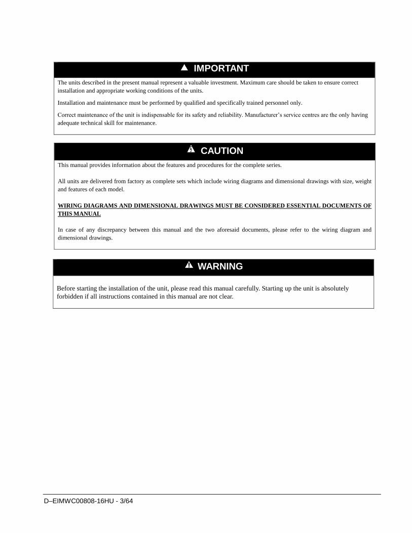
IMPORTANT
The units described in the present manual represent a valuable investment. Maximum care should be taken to ensure correct
installation and appropriate working conditions of the units.
Installation and maintenance must be performed by qualified and specifically trained personnel only.
Correct maintenance of the unit is indispensable for its safety and reliability. Manufacturer’s service centres are the only having
adequate technical skill for maintenance.
CAUTION
This manual provides information about the features and procedures for the complete series.
All units are delivered from factory as complete sets which include wiring diagrams and dimensional drawings with size, weight
and features of each model.
WIRING DIAGRAMS AND DIMENSIONAL DRAWINGS MUST BE CONSIDERED ESSENTIAL DOCUMENTS OF
THIS MANUAL
In case of any discrepancy between this manual and the two aforesaid documents, please refer to the wiring diagram and
dimensional drawings.
WARNING
Before starting the installation of the unit, please read this manual carefully. Starting up the unit is absolutely
forbidden if all instructions contained in this manual are not clear.
D–EIMWC00808-16HU - 4/64
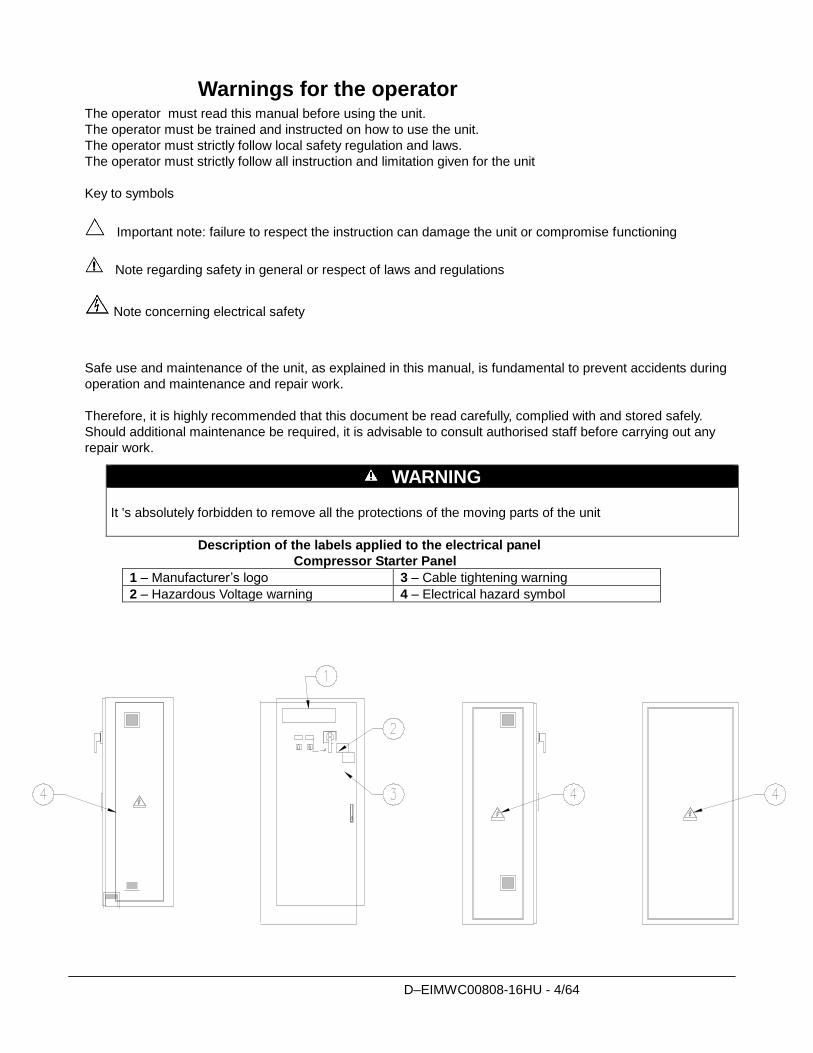
Warnings for the operator The operator must read this manual before using the unit.
The operator must be trained and instructed on how to use the unit.
The operator must strictly follow local safety regulation and laws.
The operator must strictly follow all instruction and limitation given for the unit
Key to symbols
Important note: failure to respect the instruction can damage the unit or compromise functioning
Note regarding safety in general or respect of laws and regulations
Note concerning electrical safety
Safe use and maintenance of the unit, as explained in this manual, is fundamental to prevent accidents during
operation and maintenance and repair work.
Therefore, it is highly recommended that this document be read carefully, complied with and stored safely.
Should additional maintenance be required, it is advisable to consult authorised staff before carrying out any
repair work.
Description of the labels applied to the electrical panel
Compressor Starter Panel
1 – Manufacturer’s logo 3 – Cable tightening warning
2 – Hazardous Voltage warning 4 – Electrical hazard symbol
WARNING
It 's absolutely forbidden to remove all the protections of the moving parts of the unit
D–EIMWC00808-16HU - 5/64
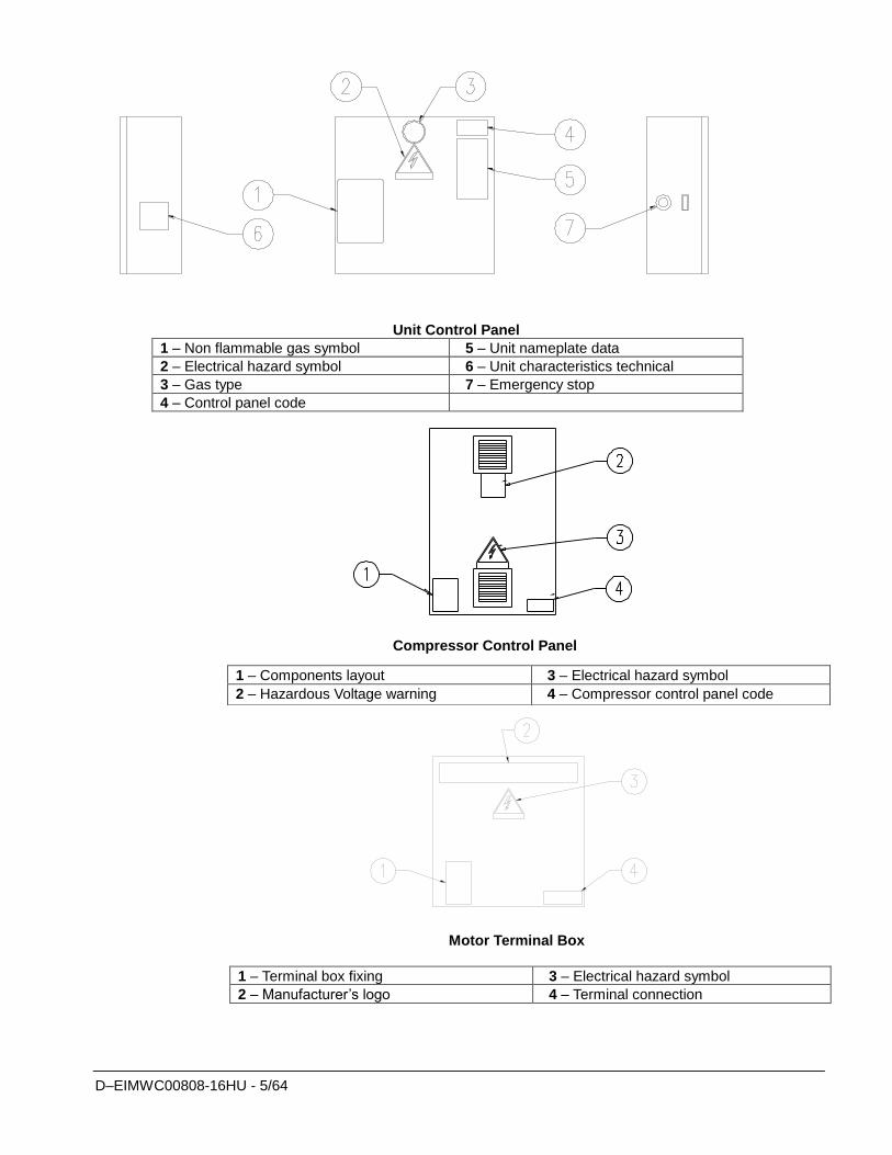
Unit Control Panel
1 – Non flammable gas symbol 5 – Unit nameplate data
2 – Electrical hazard symbol 6 – Unit characteristics technical
3 – Gas type 7 – Emergency stop
4 – Control panel code
Compressor Control Panel
Motor Terminal Box
1 – Terminal box fixing 3 – Electrical hazard symbol
2 – Manufacturer’s logo 4 – Terminal connection
1 – Components layout 3 – Electrical hazard symbol
2 – Hazardous Voltage warning 4 – Compressor control panel code
D–EIMWC00808-16HU - 6/64
Table of Contents Warnings for the operator .................................................................................................... 4
Introduction ......................................................................................................7 General Description ............................................................................................................. 7 Application........................................................................................................................... 7 Nomenclature ....................................................................................................................... 7
Installation ........................................................................................................8 Receiving and Handling ....................................................................................................... 8 Location and Mounting ........................................................................................................ 9 Operating/Standby Limits .................................................................................................... 9 Safety ................................................................................................................................. 10 System Water Volume ........................................................................................................ 11 Low Condenser Water Temperature Operation .................................................................. 11 Water Piping ...................................................................................................................... 14 Field Insulation Guide ........................................................................................................ 17 Physical Data and Weights ................................................................................................. 19 Oil Coolers ......................................................................................................................... 21 Oil Heater ........................................................................................................................... 24 Relief Valves ...................................................................................................................... 24 Electrical ............................................................................................................................ 25 Power Wiring ..................................................................................................................... 25 Remote Starter Display Wiring .......................................................................................... 28 Control Power Wiring ........................................................................................................ 28 Multiple Chiller Setup ........................................................................................................ 33 Prestart System Checklist ................................................................................................... 36
Operation ........................................................................................................37 Operator Responsibilities ................................................................................................... 37 Standby Power ................................................................................................................... 37 MicroTech II Control ..................................................................................................... 37 Capacity Control System .................................................................................................... 39 Surge and Stall ................................................................................................................... 42 Lubrication System ............................................................................................................ 42 Hot Gas Bypass .................................................................................................................. 43 Condenser Water Temperature ........................................................................................... 43
Maintenance ...................................................................................................44 Pressure/Temperature Chart ............................................................................................... 44 Routine Maintenance ......................................................................................................... 44 Annual Shutdown ............................................................................................................... 47 Annual Startup ................................................................................................................... 48 Repair of System ................................................................................................................ 49 Oil Analysis ........................................................................................................................ 51
Maintenance Schedule ...................................................................................54
Service Programs ...........................................................................................56
Operator Schools ............................................................................................56
Warranty Statement .......................................................................................56
Important information regarding the refrigerant used ..............................57
Information and illustrations cover the Daikin products at the time of publication and we reserve the right to make changes in design and construction at anytime without notice.
D–EIMWC00808-16HU - 7/64
Introduction
General Description Daikin Centrifugal Water Chillers are complete, self-contained, automatically controlled fluid
chilling units. Each unit is completely assembled and factory tested before shipment. Models
DWSC/DWDC/DWCC are cooling-only and Models DHSC are cooling with heat recovery
accomplished in a bundle of condenser tubes separate from the cooling tower tube bundle.
In the DWSC and DHSC series, each unit has one compressor connected to a condenser and
evaporator. The DWDC series is equipped with two compressors operating in parallel on a single
evaporator and condenser. The DWCC series is equipped with two compressors, each operating on
one refrigerant circuit of a two circuit evaporator and condenser. Information in this manual
referring to DWSC and DWDC also applies to DWCC and DHSC units except where specifically
noted.
The chillers use refrigerant R-134a to reduce the size and weight of the package compared to
negative pressure refrigerants, and since R-134a operates at a positive pressure over the entire
operation range, no purge system is required.
The controls are pre-wired, adjusted and tested. Only normal field connections such as piping,
electrical and interlocks, etc. are required, thereby simplifying installation and increasing
reliability. Most necessary equipment protection and operating controls are factory installed in the
control panel.
The basic sizes of units are the 050 063, 076, 079, 087, 100, 113 and 126. They provide a cooling
capacity range from 80 tons to 2500 tons. In this manual all references to the DWSC models will
equally apply to other models unless specifically referenced otherwise.
Application The procedures presented in this manual apply to the standard DWSC/DWDC/DWCC family of
chillers and DHSC heat recovery chillers. Refer to the Operating Manual, OM CentrifMicro II
(latest version available on www.daikineurope.com), for details on operation of the MicroTech II
unit controller.
All Daikin centrifugal chillers are factory tested prior to shipment and must be initially started at
the job site by a factory trained Daikin service technician. Failure to follow this startup procedure
can affect the equipment warranty.
The standard limited warranty on this equipment covers parts that prove defective in material or
workmanship. Specific details of this warranty can be found in the warranty statement furnished
with the equipment.
Cooling towers used with Daikin centrifugal chillers are normally selected for maximum condenser
inlet water temperatures between 75°F and 90°F (24°C and 32°C). Lower entering water
temperatures are desirable from the standpoint of energy reduction, but a minimum does existHeat
recovery models, DHSC, basically operate the same as cooling-only units. The heat recovery
function is controlled externally to the chiller as explained later in this manual.
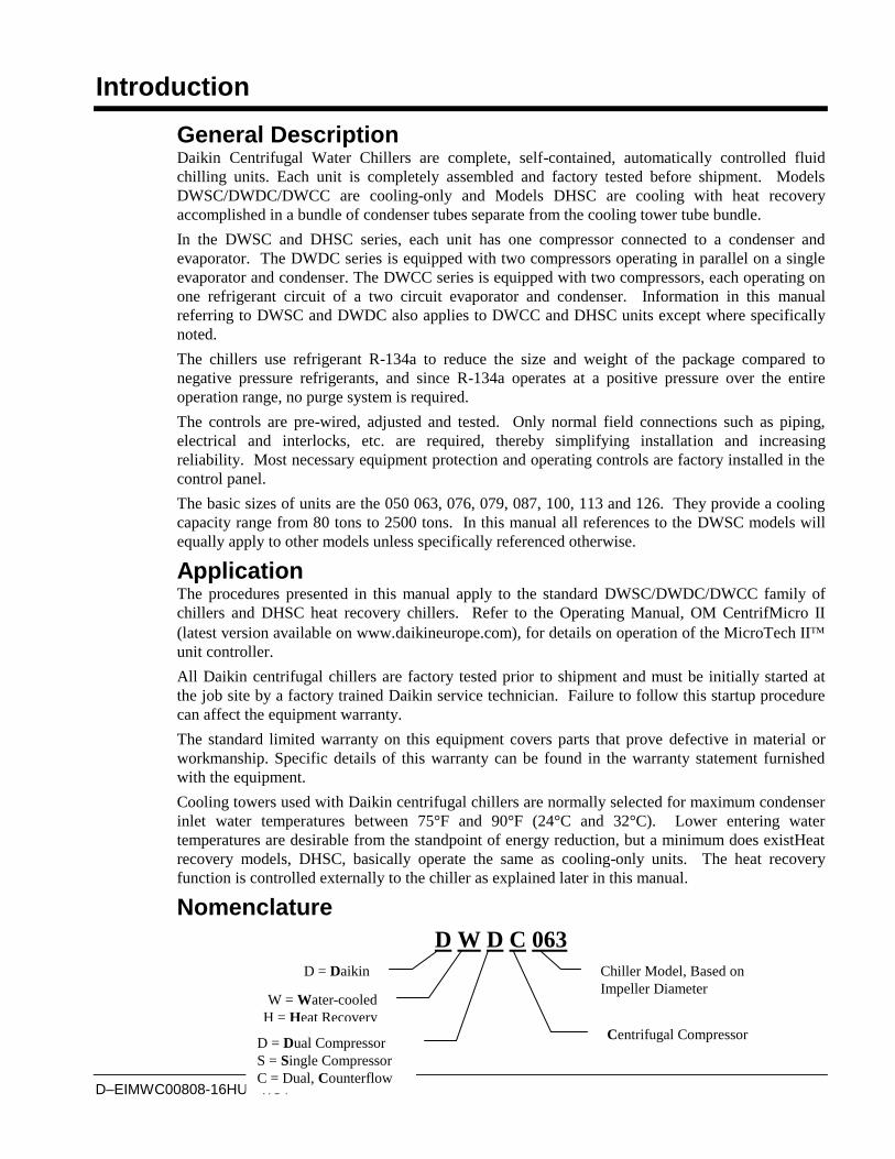
Nomenclature
D W D C 063
W = Water-cooled
H = Heat Recovery
D = Dual Compressor
S = Single Compressor
C = Dual, Counterflow
Centrifugal Compressor
Chiller Model, Based on
Impeller Diameter
D = Daikin
D–EIMWC00808-16HU - 8/64
Installation
Receiving and Handling The unit should be inspected immediately after receipt for possible damage.
All Daikin centrifugal water chillers are shipped FOB factory and all claims for handling and
shipping damage are the responsibility of the consignee.
Insulation corners from the evaporator's rigging hole locations are shipped loose and should be
glued in place after the unit is finally placed. Neoprene vibration pads are also shipped loose.
Check that these items have been delivered with the unit.
If so equipped, leave the shipping skid in place until the unit is in its final position. This will aid
in handling the equipment.
Extreme care must be used when rigging the equipment to prevent damage to the control panels
or refrigerant piping. See the certified dimension drawings included in the job submittal for the
center of gravity of the unit. Consult the local Daikin sales office for assistance if the drawings
are not available.
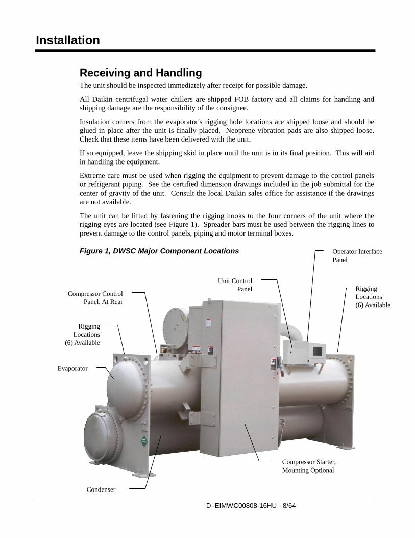
The unit can be lifted by fastening the rigging hooks to the four corners of the unit where the
rigging eyes are located (see Figure 1). Spreader bars must be used between the rigging lines to
prevent damage to the control panels, piping and motor terminal boxes.
Figure 1, DWSC Major Component Locations
Unit Control
Panel Rigging
Locations
(6) Available
Evaporator
Condenser
Rigging
Locations
(6) Available
Compressor Starter,
Mounting Optional
Compressor Control
Panel, At Rear
Operator Interface
Panel
D–EIMWC00808-16HU - 9/64
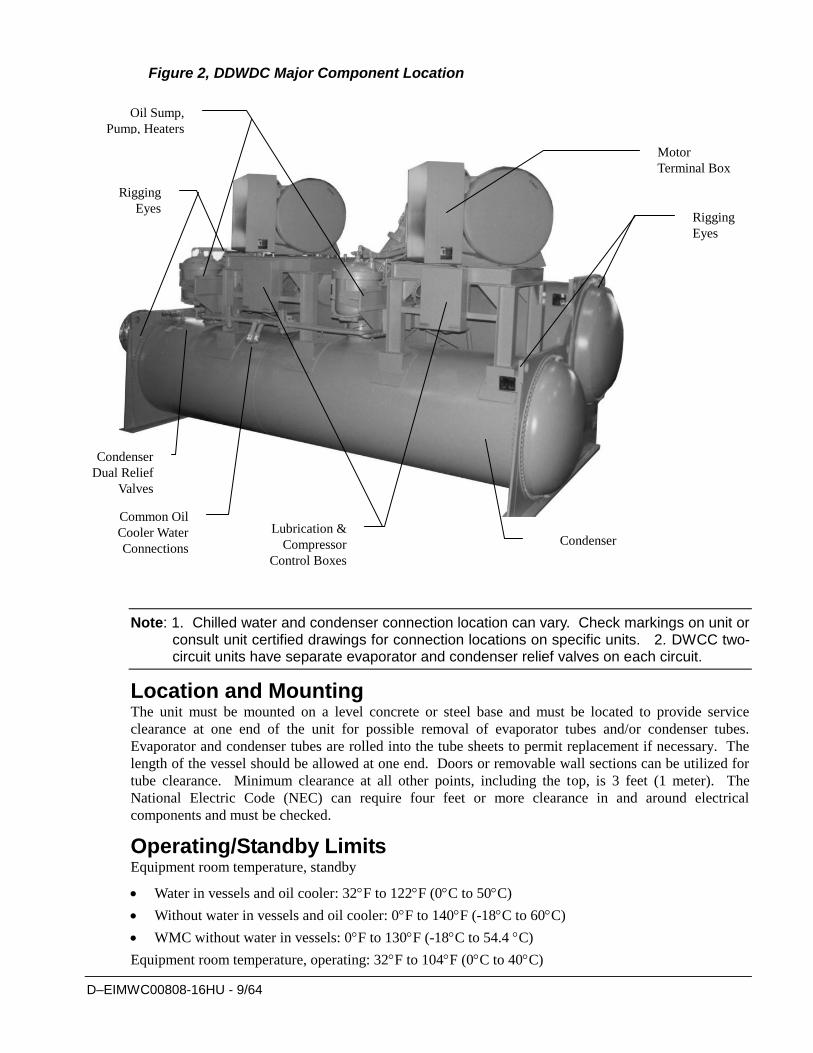
Figure 2, DDWDC Major Component Location
Note: 1. Chilled water and condenser connection location can vary. Check markings on unit or consult unit certified drawings for connection locations on specific units. 2. DWCC two-circuit units have separate evaporator and condenser relief valves on each circuit.
Location and Mounting The unit must be mounted on a level concrete or steel base and must be located to provide service
clearance at one end of the unit for possible removal of evaporator tubes and/or condenser tubes.
Evaporator and condenser tubes are rolled into the tube sheets to permit replacement if necessary. The
length of the vessel should be allowed at one end. Doors or removable wall sections can be utilized for
tube clearance. Minimum clearance at all other points, including the top, is 3 feet (1 meter). The
National Electric Code (NEC) can require four feet or more clearance in and around electrical
components and must be checked.
Operating/Standby Limits Equipment room temperature, standby
Water in vessels and oil cooler: 32F to 122F (0C to 50C)
Without water in vessels and oil cooler: 0F to 140F (-18C to 60C)
WMC without water in vessels: 0F to 130F (-18C to 54.4 C)
Equipment room temperature, operating: 32F to 104F (0C to 40C)
Condenser
Rigging
Eyes
Condenser
Dual Relief
Valves
Rigging
Eyes
Oil Sump,
Pump, Heaters
Motor
Terminal Box
Common Oil
Cooler Water
Connections
Lubrication &
Compressor
Control Boxes
D–EIMWC00808-16HU - 10/64
Maximum entering condenser water temperature, startup: design plus 5 degrees F (2.7 degrees
C)
Maximum entering condenser water temperature, operating: job specific design temperature
Minimum entering condenser water temperature, operating: see page 11.
Minimum leaving chilled water temperature: 38F (3.3C)
Minimum leaving chilled fluid temperature with correct anti-freeze fluid: 15F (9.4C)
Maximum entering chilled water temperature, operating: 90F (32.2C)
Maximum oil cooler/VFD entering temperature: 90F (32.2C)
Minimum oil cooler/VFD entering temperature: 42F (5.6C)
Vibration Pads The shipped-loose neoprene vibration pads should be located under the corners of the unit
(unless the job specifications state otherwise). They are installed to be flush with the sides and
outside edge of the feet. Most DWSC units have six mounting feet although only the outer four
are required. Six pads are shipped and the installer can place pads under the middle feet if
desired.
Mounting Make sure that the floor or structural support is adequate to support the full operating weight of
the complete unit.
It is not necessary to bolt the unit to the mounting slab or framework; but should this be
desirable, 1 1/8" (28.5 mm) mounting holes are provided in the unit support at the four corners.
Note: Units are shipped with refrigerant and oil valves closed to isolate these fluids for shipment. Valves must remain closed until start-up by the Daikin technician.
Nameplates
There are several identification nameplates on the chiller:
The unit nameplate is located on the side of the Unit Control Panel. It has a Style No.
XXXX and Serial No. XXXX, both are unique to the unit and will identify it. These
numbers should be used to identify the unit for service, parts, or warranty questions. This
plate also has the unit refrigerant charge.
Vessel nameplates are located on the evaporator and condenser. Along with other
information, they have a National Board Number (NB) and a serial number, either of which
identify the vessel (but not the entire unit).
A compressor nameplate is located on the compressor itself and contains identification
numbers.
Safety
The machine must be firmly secured to the ground. It is essential to observe the following instructions:
- The machine must be raised only by the lifting points. Only these points can support the whole weight of
the unit.
- Do not allow unauthorised and/or unqualified personnel to access the machine.
- It is forbidden to access the electrical components without having opened the
machine's general disconnecting switch and switched off the power supply.
- It is forbidden to access the electrical components without using an insulating
platform. Do not access the electrical components if water and/or moisture are
present.
D–EIMWC00808-16HU - 11/64
- All operations on the refrigerant circuit and on components under pressure must be
carried out by qualified personnel only.
- Replacement of a compressor or addition of lubricating oil must be carried out by
qualified personnel only- Sharp edges can cause wounds. Avoid direct contact.
- Avoid introducing solid bodies into the water pipes while the machine is connected to the system.
- A mechanical filter must be installed on the water pipe connected to the heat exchanger inlet.
- The machine is supplied with safety valves, that are installed on both the high and
the low pressure sides of the refrigerant circuit.
In case of sudden stop of the unit, follow the instructions on the Control Manual Operating Manual
which is part of the on-board documentation delivered to the end user with this manual.
It is recommended to perform installation and maintenance with other people. In case of accidental
injury or unease, it is necessary to:
- keep calm
- press the alarm button if present in the installation site
- move the injured person in a warm place far from the unit and in rest position
- contact immediately emergency rescue personnel of the building or if the Health Emergency
Service
- wait without leaving the injured person alone until the rescue operators come
- give all necessary information to the the rescue operators
System Water Volume All chilled water systems need adequate time to recognize a load change, respond to that load
change and stabilize, without undesirable short cycling of the compressors or loss of control. In
air conditioning systems, the potential for short cycling usually exists when the building load
falls below the minimum chiller plant capacity or on close-coupled systems with very small
water volumes.
Some of the things the designer should consider when looking at water volume are the minimum
cooling load, the minimum chiller plant capacity during the low load period and the desired
cycle time for the compressors.
Assuming that there are no sudden load changes and that the chiller plant has reasonable
turndown, a rule of thumb of “gallons of water volume equal to two to three times the chilled
water gpm flow rate” is often used.
A properly designed storage tank should be added if the system components do not provide
sufficient water volume.
Low Condenser Water Temperature Operation When ambient wet bulb temperature are lower than design, the condenser water temperature can
be allowed to fall. Lower temperatures will improve chiller performance.
Up to 300 Tons
Daikin centrifugal chillers up to 300 tons are equipped with electronic expansion valves (EXV)
and will start and run with entering condenser water temperatures as low as shown in Figure 3 or
as calculated from the following equation on which the curves are based.
D–EIMWC00808-16HU - 12/64
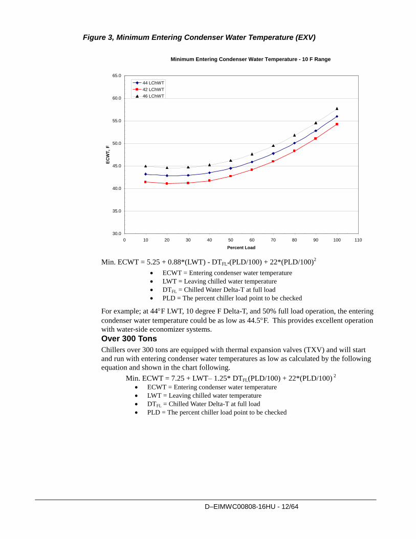
Figure 3, Minimum Entering Condenser Water Temperature (EXV)
Min. ECWT = 5.25 + 0.88*(LWT) - DTFL*(PLD/100) + 22*(PLD/100)2
ECWT = Entering condenser water temperature
LWT = Leaving chilled water temperature
DTFL = Chilled Water Delta-T at full load
PLD = The percent chiller load point to be checked
For example; at 44F LWT, 10 degree F Delta-T, and 50% full load operation, the entering
condenser water temperature could be as low as 44.5F. This provides excellent operation
with water-side economizer systems.
Over 300 Tons
Chillers over 300 tons are equipped with thermal expansion valves (TXV) and will start
and run with entering condenser water temperatures as low as calculated by the following
equation and shown in the chart following.
Min. ECWT = 7.25 + LWT– 1.25* DTFL(PLD/100) + 22*(PLD/100) 2
ECWT = Entering condenser water temperature
LWT = Leaving chilled water temperature
DTFL = Chilled Water Delta-T at full load
PLD = The percent chiller load point to be checked
Minimum Entering Condenser Water Temperature - 10 F Range
30.0
35.0
40.0
45.0
50.0
55.0
60.0
65.0
0 10 20 30 40 50 60 70 80 90 100 110
Percent Load
EC
WT
, F
44 LChWT
42 LChWT
46 LChWT
D–EIMWC00808-16HU - 13/64
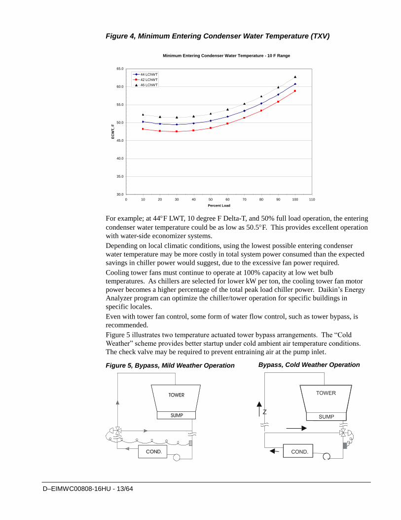
Figure 4, Minimum Entering Condenser Water Temperature (TXV)
For example; at 44F LWT, 10 degree F Delta-T, and 50% full load operation, the entering
condenser water temperature could be as low as 50.5F. This provides excellent operation
with water-side economizer systems.
Depending on local climatic conditions, using the lowest possible entering condenser
water temperature may be more costly in total system power consumed than the expected
savings in chiller power would suggest, due to the excessive fan power required.
Cooling tower fans must continue to operate at 100% capacity at low wet bulb
temperatures. As chillers are selected for lower kW per ton, the cooling tower fan motor
power becomes a higher percentage of the total peak load chiller power. Daikin’s Energy
Analyzer program can optimize the chiller/tower operation for specific buildings in
specific locales.
Even with tower fan control, some form of water flow control, such as tower bypass, is
recommended.
Figure 5 illustrates two temperature actuated tower bypass arrangements. The “Cold
Weather” scheme provides better startup under cold ambient air temperature conditions.
The check valve may be required to prevent entraining air at the pump inlet.
Figure 5, Bypass, Mild Weather Operation
Bypass, Cold Weather Operation
Minimum Entering Condenser Water Temperature - 10 F Range
30.0
35.0
40.0
45.0
50.0
55.0
60.0
65.0
0 10 20 30 40 50 60 70 80 90 100 110
Percent Load
EC
WT
, F
44 LChWT
42 LChWT
46 LChWT
D–EIMWC00808-16HU - 14/64
Water Piping Water Pumps
Avoid the use of 3600/3000-rpm (two-pole motor) pump motors. It is not uncommon to find that
these pumps operate with objectionable noise and vibration.
It is also possible to build up a frequency beat due to the slight difference in the operating rpm of
the pump motor and the Daikin centrifugal motor. Daikin encourages the use of 1750/1460 rpm
(four-pole) pump motors.
Vessel Drains at Start-up
Unit vessels are drained of water in the factory and are shipped with the drain plugs in the heads
removed and stored in the control panel or with open ball valves in the drain hole. Be sure to
replace plugs or close the valves prior to filling the vessel with fluid.
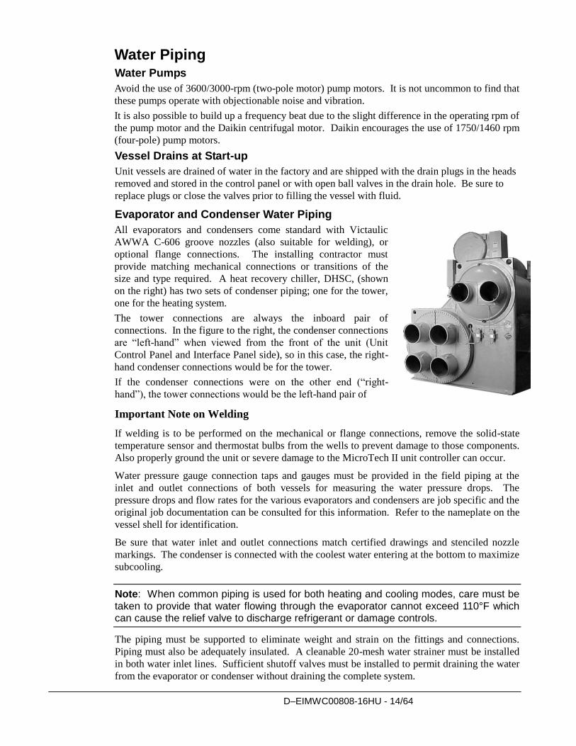
Evaporator and Condenser Water Piping
All evaporators and condensers come standard with Victaulic
AWWA C-606 groove nozzles (also suitable for welding), or
optional flange connections. The installing contractor must
provide matching mechanical connections or transitions of the
size and type required. A heat recovery chiller, DHSC, (shown
on the right) has two sets of condenser piping; one for the tower,
one for the heating system.
The tower connections are always the inboard pair of
connections. In the figure to the right, the condenser connections
are “left-hand” when viewed from the front of the unit (Unit
Control Panel and Interface Panel side), so in this case, the right-
hand condenser connections would be for the tower.
If the condenser connections were on the other end (“right-
hand”), the tower connections would be the left-hand pair of
Important Note on Welding
If welding is to be performed on the mechanical or flange connections, remove the solid-state
temperature sensor and thermostat bulbs from the wells to prevent damage to those components.
Also properly ground the unit or severe damage to the MicroTech II unit controller can occur.
Water pressure gauge connection taps and gauges must be provided in the field piping at the
inlet and outlet connections of both vessels for measuring the water pressure drops. The
pressure drops and flow rates for the various evaporators and condensers are job specific and the
original job documentation can be consulted for this information. Refer to the nameplate on the
vessel shell for identification.
Be sure that water inlet and outlet connections match certified drawings and stenciled nozzle
markings. The condenser is connected with the coolest water entering at the bottom to maximize
subcooling.
Note: When common piping is used for both heating and cooling modes, care must be taken to provide that water flowing through the evaporator cannot exceed 110°F which can cause the relief valve to discharge refrigerant or damage controls.
The piping must be supported to eliminate weight and strain on the fittings and connections.
Piping must also be adequately insulated. A cleanable 20-mesh water strainer must be installed
in both water inlet lines. Sufficient shutoff valves must be installed to permit draining the water
from the evaporator or condenser without draining the complete system.
D–EIMWC00808-16HU - 15/64
Flow Switch
A water flow switch must be installed to signal the presence of adequate water flow to the
vessels before the unit can start. They also serve to shut down the unit in the event that water
flow is interrupted to guard against evaporator freeze-up or excessive discharge pressure.
Thermal dispersion flow switches are available from Daikin as a factory-mounted option. It is
mounted in an evaporator and condenser water nozzle and factory wired.
A paddle type flow switch can be supplied by the owner for field mounting and wiring.
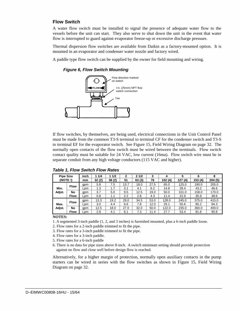
Figure 6, Flow Switch Mounting
If flow switches, by themselves, are being used, electrical connections in the Unit Control Panel
must be made from the common T3-S terminal to terminal CF for the condenser switch and T3-S
to terminal EF for the evaporator switch. See Figure 15, Field Wiring Diagram on page 32. The
normally open contacts of the flow switch must be wired between the terminals. Flow switch
contact quality must be suitable for 24 VAC, low current (16ma). Flow switch wire must be in
separate conduit from any high voltage conductors (115 VAC and higher).
Table 1, Flow Switch Flow Rates
Pipe Size
(NOTE !)
inch 1 1/4 1 1/2 2 2 1/2 3 4 5 6 8
mm 32 (2) 38 (2) 51 63 (3) 76 102 (4) 127 (4) 153 (4) 204 (5)
Min.
Adjst.
Flow gpm 5.8 7.5 13.7 18.0 27.5 65.0 125.0 190.0 205.0
Lpm 1.3 1.7 3.1 4.1 6.2 14.8 28.4 43.2 46.6
No
Flow
gpm 3.7 5.0 9.5 12.5 19.0 50.0 101.0 158.0 170.0
Lpm 0.8 1.1 2.2 2.8 4.3 11.4 22.9 35.9 38.6
Max.
Adjst.
Flow gpm 13.3 19.2 29.0 34.5 53.0 128.0 245.0 375.0 415.0
Lpm 3.0 4.4 6.6 7.8 12.0 29.1 55.6 85.2 94.3
No
Flow
gpm 12.5 18.0 27.0 32.0 50.0 122.0 235.0 360.0 400.0
Lpm 2.8 4.1 6.1 7.3 11.4 27.7 53.4 81.8 90.8
NOTES:
1. A segmented 3-inch paddle (1, 2, and 3 inches) is furnished mounted, plus a 6-inch paddle loose.
2. Flow rates for a 2-inch paddle trimmed to fit the pipe.
3. Flow rates for a 3-inch paddle trimmed to fit the pipe.
4. Flow rates for a 3-inch paddle.
5. Flow rates for a 6-inch paddle
6. There is no data for pipe sizes above 8-inch. A switch minimum setting should provide protection
against no flow and close well before design flow is reached.
Alternatively, for a higher margin of protection, normally open auxiliary contacts in the pump
starters can be wired in series with the flow switches as shown in Figure 15, Field Wiring
Diagram on page 32.
Flow direction marked on switch
I in. (25mm) NPT flow switch connection
Tee
D–EIMWC00808-16HU - 16/64
CAUTION
Freeze Notice: Neither the evaporator nor the condenser is self-draining;
both must be blown out to help avoid damage from freezing.
The piping should also include thermometers at the inlet and outlet connections and air vents at
the high points.
The water heads can be interchanged (end for end) so that the water connections can be made at
either end of the unit. If this is done, new head gaskets must be used and control sensors
relocated.
In cases where the water pump noise can be objectionable, vibration isolation sections are
recommended at both the inlet and outlet of the pump. In most cases, it will not be necessary to
provide vibration eliminator sections in the condenser inlet and outlet water lines. But they can
be required where noise and vibration are critical.
Cooling Towers
The condenser water flow rate must be checked to be sure that it conforms to the system design.
Some form of temperature control is also required if an uncontrolled tower can supply water
below about 65F (18C). If tower fan control is not adequate, a tower bypass valve is
recommended. Unless the system and chiller unit are specifically for condenser bypass or
variable condenser flow is not recommended since low condenser flow rates can cause unstable
operation and excessive tube fouling.
The condenser water pumps must cycle on and off with the unit. See Figure 15, Field Wiring
Diagram on page 32 for wiring details.
Tower water treatment is essential for continued efficient and reliable unit operation. If not
available in-house, competent water treatment specialists can be contracted.
Heat Recovery Chillers DHSC heat recovery chillers control the chilled water leaving temperature. The cooling load
determines compressor loading and unloading, the same as in a conventional chiller. A heat
recovery chiller’s control algorithms are identical to a conventional cooling-only chiller.
The temperature of the hot water being supplied from the recovery condenser to the heating load
is established by manipulating the cooling tower water temperature. The 3-way cooling tower
bypass valve is controlled by the heating water inlet temperature to the recovery bundle of the
condenser. Based on the signal the 3-way valve gets from the heating hot water sensor, it will
bypass sufficient water around the tower to force the tower condenser water loop high enough
for the recovery bundle to produce the desired hot water temperature.
The chilled water and its control system do not “know” that the condensing pressure and
condenser water temperatures are being regulated in this manner.
D–EIMWC00808-16HU - 17/64
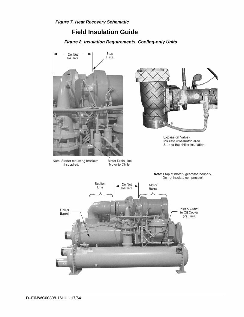
Figure 7, Heat Recovery Schematic
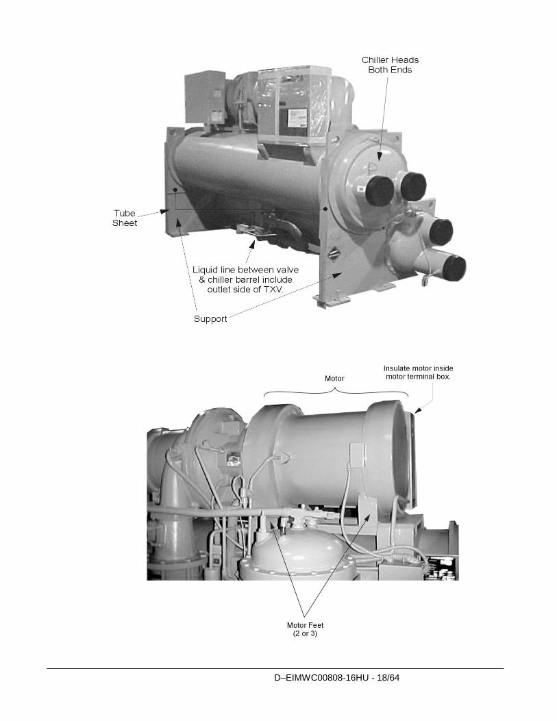
Field Insulation Guide
Figure 8, Insulation Requirements, Cooling-only Units
D–EIMWC00808-16HU - 18/64
D–EIMWC00808-16HU - 19/64
Physical Data and Weights Evaporator The standard insulation of cold surfaces includes the evaporator and non-connection water head,
suction piping, compressor inlet, motor housing, and motor coolant outlet line.
Insulation is UL recognized (File # E55475). It is 3/4" thick ABS/PVC flexible foam with a
skin. The K factor is 0.28 at 75°F. Sheet insulation is fitted and cemented in place forming a
vapor barrier, then painted with a resilient epoxy finish that resists cracking.
The insulation complies to, or has been tested in accordance, with the following:
ASTM-C-177 ASTM-C-534 Type 2 UL 94-5V
ASTM-D-1056-91-2C1 ASTM E 84 MEA 186-86-M Vol. N
CAN/ULC S102-M88
Refrigerant-side design pressure is 200 psi (1380 kPa) on DWSC/DWCC/DHSC units and 180
psi (1242 kPa) on DDWDC units. Water-side is 150 psi (1034 kPa) on all.
In the event insulation is to be field-installed, none of the cold surfaces identified above will be
factory insulated. Required field insulation is shown beginning on page 17. Approximate total
square footage of insulation surface required for individual packaged chillers is tabulated by
evaporator code and can be found below.
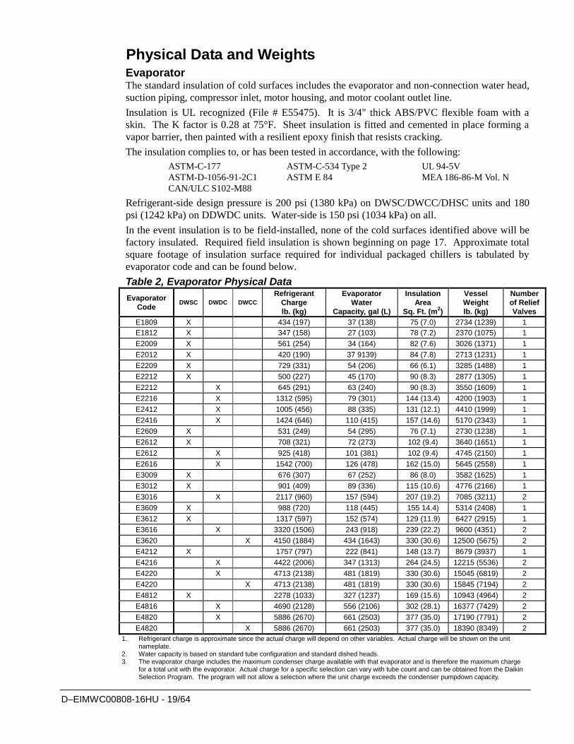
Table 2, Evaporator Physical Data
Evaporator
Code DWSC DWDC DWCC
Refrigerant
Charge
lb. (kg)
Evaporator
Water
Capacity, gal (L)
Insulation
Area
Sq. Ft. (m2)
Vessel
Weight
lb. (kg)
Number
of Relief
Valves
E1809 X 434 (197) 37 (138) 75 (7.0) 2734 (1239) 1
E1812 X 347 (158) 27 (103) 78 (7.2) 2370 (1075) 1
E2009 X 561 (254) 34 (164) 82 (7.6) 3026 (1371) 1
E2012 X 420 (190) 37 9139) 84 (7.8) 2713 (1231) 1
E2209 X 729 (331) 54 (206) 66 (6.1) 3285 (1488) 1
E2212 X 500 (227) 45 (170) 90 (8.3) 2877 (1305) 1
E2212 X 645 (291) 63 (240) 90 (8.3) 3550 (1609) 1
E2216 X 1312 (595) 79 (301) 144 (13.4) 4200 (1903) 1
E2412 X 1005 (456) 88 (335) 131 (12.1) 4410 (1999) 1
E2416 X 1424 (646) 110 (415) 157 (14.6) 5170 (2343) 1
E2609 X 531 (249) 54 (295) 76 (7.1) 2730 (1238) 1
E2612 X 708 (321) 72 (273) 102 (9.4) 3640 (1651) 1
E2612 X 925 (418) 101 (381) 102 (9.4) 4745 (2150) 1
E2616 X 1542 (700) 126 (478) 162 (15.0) 5645 (2558) 1
E3009 X 676 (307) 67 (252) 86 (8.0) 3582 (1625) 1
E3012 X 901 (409) 89 (336) 115 (10.6) 4776 (2166) 1
E3016 X 2117 (960) 157 (594) 207 (19.2) 7085 (3211) 2
E3609 X 988 (720) 118 (445) 155 14.4) 5314 (2408) 1
E3612 X 1317 (597) 152 (574) 129 (11.9) 6427 (2915) 1
E3616 X 3320 (1506) 243 (918) 239 (22.2) 9600 (4351) 2
E3620 X 4150 (1884) 434 (1643) 330 (30.6) 12500 (5675) 2
E4212 X 1757 (797) 222 (841) 148 (13.7) 8679 (3937) 1
E4216 X 4422 (2006) 347 (1313) 264 (24.5) 12215 (5536) 2
E4220 X 4713 (2138) 481 (1819) 330 (30.6) 15045 (6819) 2
E4220 X 4713 (2138) 481 (1819) 330 (30.6) 15845 (7194) 2
E4812 X 2278 (1033) 327 (1237) 169 (15.6) 10943 (4964) 2
E4816 X 4690 (2128) 556 (2106) 302 (28.1) 16377 (7429) 2
E4820 X 5886 (2670) 661 (2503) 377 (35.0) 17190 (7791) 2
E4820 X 5886 (2670) 661 (2503) 377 (35.0) 18390 (8349) 2
1. Refrigerant charge is approximate since the actual charge will depend on other variables. Actual charge will be shown on the unit nameplate.
2. Water capacity is based on standard tube configuration and standard dished heads. 3. The evaporator charge includes the maximum condenser charge available with that evaporator and is therefore the maximum charge
for a total unit with the evaporator. Actual charge for a specific selection can vary with tube count and can be obtained from the Daikin Selection Program. The program will not allow a selection where the unit charge exceeds the condenser pumpdown capacity.
D–EIMWC00808-16HU - 20/64
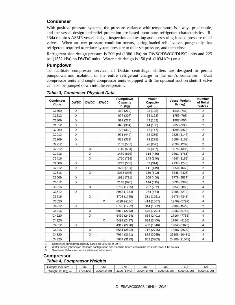
Condenser
With positive pressure systems, the pressure variance with temperature is always predictable,
and the vessel design and relief protection are based upon pure refrigerant characteristics. R-
134a requires ASME vessel design, inspection and testing and uses spring-loaded pressure relief
valves. When an over pressure condition occurs, spring-loaded relief valves purge only that
refrigerant required to reduce system pressure to their set pressure, and then close.
Refrigerant side design pressure is 200 psi (1380 kPa) on DWSC/DWCC/DHSC units and 225
psi (1552 kPa) on DWDC units. Water side design is 150 psi (1034 kPa) on all.
Pumpdown To facilitate compressor service, all Daikin centrifugal chillers are designed to permit
pumpdown and isolation of the entire refrigerant charge in the unit’s condenser. Dual
compressor units and single compressor units equipped with the optional suction shutoff valve
can also be pumped down into the evaporator.
Table 3, Condenser Physical Data
Condenser
Code DWSC DWDC DWCC
Pumpdown
Capacity
lb. (kg)
Water
Capacity
gal. (L)
Vessel Weight
lb. (kg)
Number
of Relief
Valves
C1609 X 468 (213) 33 (125) 1645 (746) 2
C1612 X 677 (307) 33 (123) 1753 (795) 2
C1809 X 597 (271) 43 (162) 1887 (856) 2
C1812 X 845 (384) 44 (166) 2050 (930) 2
C2009 X 728 (330) 47 (147) 1896 (860) 2
C2012 X 971 (440) 62 (236) 2528 (1147) 2
C2209 X 822 (372) 73 (278) 2596 (1169) 2
C2212 X 1183 (537) 76 (290) 2838 (1287) 2
C2212 X 1110 (504) 89 (337) 3075 (1395) 2
C2216 X 1489 (676) 114 (430) 3861 (1751) 2
C2416 X 1760 (799) 143 (540) 4647 (2188) 2
C2609 X 1242 (563) 83 (314) 2737 (1245) 2
C2612 X 1656 (751) 111 (419) 3650 (1660) 2
C2616 X 2083 (945) 159 (603) 5346 (2425) 2
C3009 X 1611 (731) 108 (409) 3775 (2537) 2
C3012 X 2148 (975) 144 (545) 5033 (3383) 2
C3016 X 2789 (1265) 207 (782) 6752 (3063) 4
C3612 X 2963 (1344) 234 (884) 7095 (3219) 2
C3616 X 3703 (1725) 331 (1251) 9575 (4343) 4
C3620 X 4628 92100) 414 (1567) 12769 (5797) 4
C4212 X 3796 (1722) 344 (1302) 9984 (4529) 2
C4216 X 5010 (2273) 475 (1797) 12662 (5743) 4
C4220 X 5499 (2494) 634 (2401) 17164 (7785) 4
C4220 X 5499 (2497) 634 (2400) 17964 (8156) 4
C4812 X 4912 (2228) 488 (1848) 12843 (5826) 4
C4816 X 5581 (2532) 717 (2715) 18807 (8530) 4
C4820 X 7034 (3191) 862 (3265) 23106 (10481) 4
C4820 x 7034 (3193) 862 (3263) 24306 (11045) 4
1. Condenser pumpdown capacity based on 90% full at 90F. 2. Water capacity based on standard configuration and standard heads and can be less with lower tube counts. 3. See Relief Valves section for additional information.
Compressor Table 4, Compressor Weights
Compressor Size 050 063 079 087 100 113 126
Weight lb. (kg) 870 (390) 3200 (1440) 3200 (1440) 3200 (1440) 6000 (2700) 6000 (2700) 6000 (2700)
D–EIMWC00808-16HU - 21/64
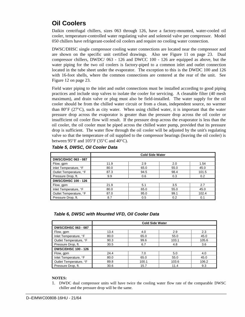
Oil Coolers Daikin centrifugal chillers, sizes 063 through 126, have a factory-mounted, water-cooled oil
cooler, temperature-controlled water regulating valve and solenoid valve per compressor. Model
050 chillers have refrigerant-cooled oil coolers and require no cooling water connection.
DWSC/DHSC single compressor cooling water connections are located near the compressor and
are shown on the specific unit certified drawings. Also see Figure 11 on page 23. Dual
compressor chillers, DWDC/ 063 - 126 and DWCC 100 - 126 are equipped as above, but the
water piping for the two oil coolers is factory-piped to a common inlet and outlet connection
located in the tube sheet under the evaporator. The exception to this is the DWDC 100 and 126
with 16-foot shells, where the common connections are centered at the rear of the unit. See
Figure 12 on page 23.
Field water piping to the inlet and outlet connections must be installed according to good piping
practices and include stop valves to isolate the cooler for servicing. A cleanable filter (40 mesh
maximum), and drain valve or plug must also be field-installed. The water supply for the oil
cooler should be from the chilled water circuit or from a clean, independent source, no warmer
than 80F (27C), such as city water. When using chilled water, it is important that the water
pressure drop across the evaporator is greater than the pressure drop across the oil cooler or
insufficient oil cooler flow will result. If the pressure drop across the evaporator is less than the
oil cooler, the oil cooler must be piped across the chilled water pump, provided that its pressure
drop is sufficient. The water flow through the oil cooler will be adjusted by the unit's regulating
valve so that the temperature of oil supplied to the compressor bearings (leaving the oil cooler) is
between 95F and 105F (35C and 40C).
Table 5, DWSC, Oil Cooler Data
Table 6, DWSC with Mounted VFD, Oil Cooler Data
NOTES:
1. DWDC dual compressor units will have twice the cooling water flow rate of the comparable DWSC
chiller and the pressure drop will be the same.
Cold Side Water
DWSC/DHSC 063 - 087
Flow, gpm 11.9 2.9 2.0 1.54
Inlet Temperature, F 80.0 65.0 55.0 45.0
Outlet Temperature, F 87.3 94.5 98.4 101.5
Pressure Drop, ft. 9.9 0.6 0.3 0.2
DWSC/DHSC 100 - 126
Flow, gpm 21.9 5.1 3.5 2.7
Inlet Temperature, F 80.0 65.0 55.0 45.0
Outlet Temperature, F 87.0 95.0 99.1 102.4
Pressure Drop, ft. 8.7 0.5 0.2 0.1
Cold Side Water
DWSC/DHSC 063 - 087
Flow, gpm 13.4 4.0 2.9 2.3
Inlet Temperature, F 80.0 65.0 55.0 45.0
Outlet Temperature, F 90.3 99.6 103.1 105.6
Pressure Drop, ft. 30.5 6.7 4.8 3.6
DWSC/DHSC 100 - 126
Flow, gpm 24.4 7.0 5.0 4.0
Inlet Temperature, F 80.0 65.0 55.0 45.0
Outlet Temperature, F 89.8 100.1 103.6 106.2
Pressure Drop, ft. 30.6 15.7 11.4 9.3
D–EIMWC00808-16HU - 22/64
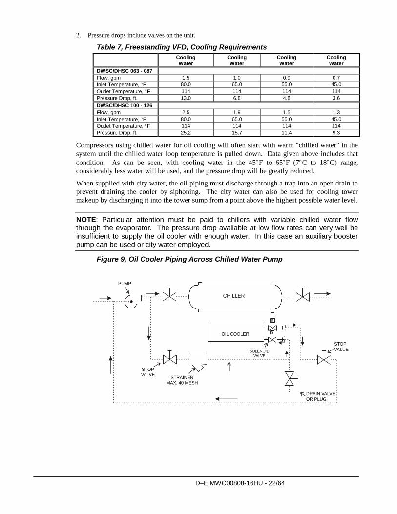
2. Pressure drops include valves on the unit.
Table 7, Freestanding VFD, Cooling Requirements
Cooling
Water
Cooling
Water
Cooling
Water
Cooling
Water
DWSC/DHSC 063 - 087
Flow, gpm 1.5 1.0 0.9 0.7
Inlet Temperature, F 80.0 65.0 55.0 45.0
Outlet Temperature, F 114 114 114 114
Pressure Drop, ft. 13.0 6.8 4.8 3.6
DWSC/DHSC 100 - 126
Flow, gpm 2.5 1.9 1.5 1.3
Inlet Temperature, F 80.0 65.0 55.0 45.0
Outlet Temperature, F 114 114 114 114
Pressure Drop, ft. 25.2 15.7 11.4 9.3
Compressors using chilled water for oil cooling will often start with warm "chilled water" in the
system until the chilled water loop temperature is pulled down. Data given above includes that
condition. As can be seen, with cooling water in the 45F to 65F (7C to 18C) range,
considerably less water will be used, and the pressure drop will be greatly reduced.
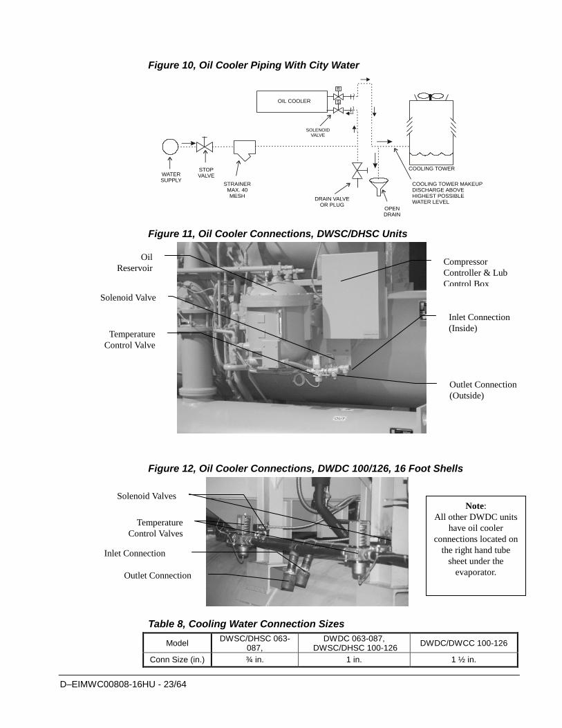
When supplied with city water, the oil piping must discharge through a trap into an open drain to
prevent draining the cooler by siphoning. The city water can also be used for cooling tower
makeup by discharging it into the tower sump from a point above the highest possible water level.
NOTE: Particular attention must be paid to chillers with variable chilled water flow through the evaporator. The pressure drop available at low flow rates can very well be insufficient to supply the oil cooler with enough water. In this case an auxiliary booster pump can be used or city water employed.
Figure 9, Oil Cooler Piping Across Chilled Water Pump
CHILLER
OIL COOLER
STOPVALVE
STRAINERMAX. 40 MESH
SOLENOIDVALVE
DRAIN VALVEOR PLUG
STOPVALUE
PUMP
R
S
D–EIMWC00808-16HU - 23/64
Figure 10, Oil Cooler Piping With City Water
COOLING TOWER
OPENDRAIN
DRAIN VALVEOR PLUG
SOLENOIDVALVE
OIL COOLER
WATERSUPPLY
STOPVALVE
STRAINERMAX. 40MESH
COOLING TOWER MAKEUPDISCHARGE ABOVEHIGHEST POSSIBLEWATER LEVEL
R
S
Figure 11, Oil Cooler Connections, DWSC/DHSC Units
Figure 12, Oil Cooler Connections, DWDC 100/126, 16 Foot Shells
Table 8, Cooling Water Connection Sizes
Model DWSC/DHSC 063-
087, DWDC 063-087,
DWSC/DHSC 100-126 DWDC/DWCC 100-126
Conn Size (in.) ¾ in. 1 in. 1 ½ in.
Oil
Reservoir
Solenoid Valve
Temperature
Control Valve
Compressor
Controller & Lub
Control Box
Inlet Connection
(Inside)
Outlet Connection
(Outside)
Solenoid Valves
Temperature
Control Valves
Inlet Connection
Outlet Connection
Note:
All other DWDC units
have oil cooler
connections located on
the right hand tube
sheet under the
evaporator.
D–EIMWC00808-16HU - 24/64
Oil Heater The oil sump is equipped with an immersion heater that is installed in a tube so that it can be
removed without disturbing the oil.
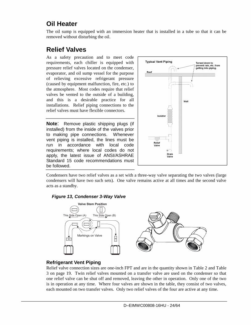
Relief Valves As a safety precaution and to meet code
requirements, each chiller is equipped with
pressure relief valves located on the condenser,
evaporator, and oil sump vessel for the purpose
of relieving excessive refrigerant pressure
(caused by equipment malfunction, fire, etc.) to
the atmosphere. Most codes require that relief
valves be vented to the outside of a building,
and this is a desirable practice for all
installations. Relief piping connections to the
relief valves must have flexible connectors.
Note: Remove plastic shipping plugs (if
installed) from the inside of the valves prior to making pipe connections. Whenever vent piping is installed, the lines must be run in accordance with local code requirements; where local codes do not apply, the latest issue of ANSI/ASHRAE Standard 15 code recommendations must be followed.
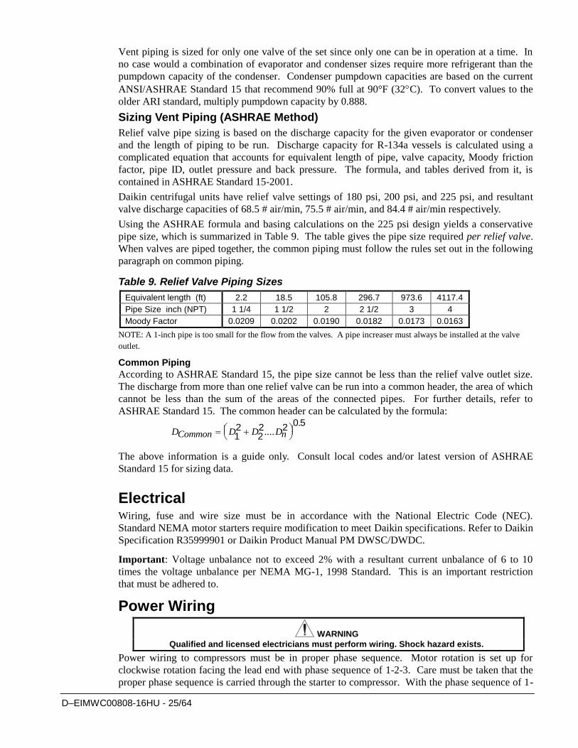
Condensers have two relief valves as a set with a three-way valve separating the two valves (large
condensers will have two such sets). One valve remains active at all times and the second valve
acts as a standby.
Figure 13, Condenser 3-Way Valve
Refrigerant Vent Piping Relief valve connection sizes are one-inch FPT and are in the quantity shown in Table 2 and Table
3 on page 19. Twin relief valves mounted on a transfer valve are used on the condenser so that
one relief valve can be shut off and removed, leaving the other in operation. Only one of the two
is in operation at any time. Where four valves are shown in the table, they consist of two valves,
each mounted on two transfer valves. Only two relief valves of the four are active at any time.
D–EIMWC00808-16HU - 25/64
Vent piping is sized for only one valve of the set since only one can be in operation at a time. In
no case would a combination of evaporator and condenser sizes require more refrigerant than the
pumpdown capacity of the condenser. Condenser pumpdown capacities are based on the current
ANSI/ASHRAE Standard 15 that recommend 90% full at 90°F (32C). To convert values to the
older ARI standard, multiply pumpdown capacity by 0.888.
Sizing Vent Piping (ASHRAE Method)
Relief valve pipe sizing is based on the discharge capacity for the given evaporator or condenser
and the length of piping to be run. Discharge capacity for R-134a vessels is calculated using a
complicated equation that accounts for equivalent length of pipe, valve capacity, Moody friction
factor, pipe ID, outlet pressure and back pressure. The formula, and tables derived from it, is
contained in ASHRAE Standard 15-2001.
Daikin centrifugal units have relief valve settings of 180 psi, 200 psi, and 225 psi, and resultant
valve discharge capacities of 68.5 # air/min, 75.5 # air/min, and 84.4 # air/min respectively.
Using the ASHRAE formula and basing calculations on the 225 psi design yields a conservative
pipe size, which is summarized in Table 9. The table gives the pipe size required per relief valve.
When valves are piped together, the common piping must follow the rules set out in the following
paragraph on common piping.
Table 9. Relief Valve Piping Sizes
Equivalent length (ft) 2.2 18.5 105.8 296.7 973.6 4117.4
Pipe Size inch (NPT) 1 1/4 1 1/2 2 2 1/2 3 4
Moody Factor 0.0209 0.0202 0.0190 0.0182 0.0173 0.0163
NOTE: A 1-inch pipe is too small for the flow from the valves. A pipe increaser must always be installed at the valve
outlet.
Common Piping
According to ASHRAE Standard 15, the pipe size cannot be less than the relief valve outlet size.
The discharge from more than one relief valve can be run into a common header, the area of which
cannot be less than the sum of the areas of the connected pipes. For further details, refer to
ASHRAE Standard 15. The common header can be calculated by the formula:
DCommon D D Dn
12
22 2
0 5....
.
The above information is a guide only. Consult local codes and/or latest version of ASHRAE
Standard 15 for sizing data.
Electrical Wiring, fuse and wire size must be in accordance with the National Electric Code (NEC).
Standard NEMA motor starters require modification to meet Daikin specifications. Refer to Daikin
Specification R35999901 or Daikin Product Manual PM DWSC/DWDC.
Important: Voltage unbalance not to exceed 2% with a resultant current unbalance of 6 to 10
times the voltage unbalance per NEMA MG-1, 1998 Standard. This is an important restriction
that must be adhered to.
Power Wiring
WARNING
Qualified and licensed electricians must perform wiring. Shock hazard exists.
Power wiring to compressors must be in proper phase sequence. Motor rotation is set up for
clockwise rotation facing the lead end with phase sequence of 1-2-3. Care must be taken that the
proper phase sequence is carried through the starter to compressor. With the phase sequence of 1-
D–EIMWC00808-16HU - 26/64
2-3 and L1 connected to T1 and T6, L2 connected to T2 and T4, and L3 connected to T3 and T5,
rotation is proper. See diagram in terminal box cover.
The Daikin start-up technician will determine the phase sequence.
CAUTION
Connections to terminals must be made with copper lugs and copper wire.
Care must be taken when attaching leads to compressor terminals.
CAUTION
Before any installation and connection work, the system must be switched off and secured.
After switching off the unit, when an inverter is installed, the intermediate circuit capacitors of
the inverter are still charged with high voltage for a short period of time. The unit can be
worked on again after it has been switched of for 5 minutes.
CAUTION
Before taking any action, switch off the main switch to cut off electricity to the machine.
When the machine is off but the disconnecting switch is in the closed position, unused
circuits are always live.
Never open the terminal board box of the compressors unless the main switch of the machine
has been switched off.
CAUTION
The units of the series can be provided with non-linear high power electrical components
(inverters) which introduce higher harmonics, can cause considerable leakage to earth,
(higher than 300 mA).
The electricity supply system protection must take the above values into account.
Note: Do not make final connections to motor terminals until wiring has been checked and approved by a Daikin technician.
Under no circumstances should a compressor be brought up to speed unless proper sequence and
rotation have been established. Serious damage can result if the compressor starts in the wrong
direction. Such damage is not covered by product warranty.
It is the installing contractor's responsibility to insulate the compressor motor terminals when the
unit voltage is 600 volts or greater. This is to be done after the Daikin start-up technician has
checked for proper phase sequence and motor rotation.
Following this verification by the Daikin technician, the contractor should apply the following
furnished items.
Materials required:
1. Loctite brand safety solvent (12 oz. package available as Daikin part number
350A263H72)
2. 3M Co. Scotchfil brand electrical insulation putty (available in a 60-inch roll as Daikin
part number 350A263H81)
D–EIMWC00808-16HU - 27/64
3. 3M Co. Scotchkote brand electrical coating (available in a 15 oz. can with brush as
Daikin Part Number 350A263H16)
4. Vinyl plastic electrical tape
The above items are also available at most electrical supply outlets.
Application procedure:
1. Disconnect and lock out the power source to the compressor motor.
2. Using the safety solvent, clean the motor terminals, motor barrel adjacent to the
terminals, lead lugs, and electrical cables within the terminal 4OX to remove all dirt,
grime, moisture and oil.
3. Wrap the terminal with Scotchfil putty, filling in all irregularities. The final result should
be smooth and cylindrical.
4. Doing one terminal at a time, brush the Scotchkote coating on the motor barrel to a
distance of up to '/2" around the terminal and on the wrapped terminal, the rubber
insulation next to the terminal, and the lug and cable for approximately 10". Wrap
additional Scotchfil insulation over the Scotchkote coating.
5. Tape the entire wrapped length with electrical tape to form a protective jacket.
6. Finally, brush on one more coat of Scotchkote coating to provide an extra moisture
barrier.
D–EIMWC00808-16HU - 28/64
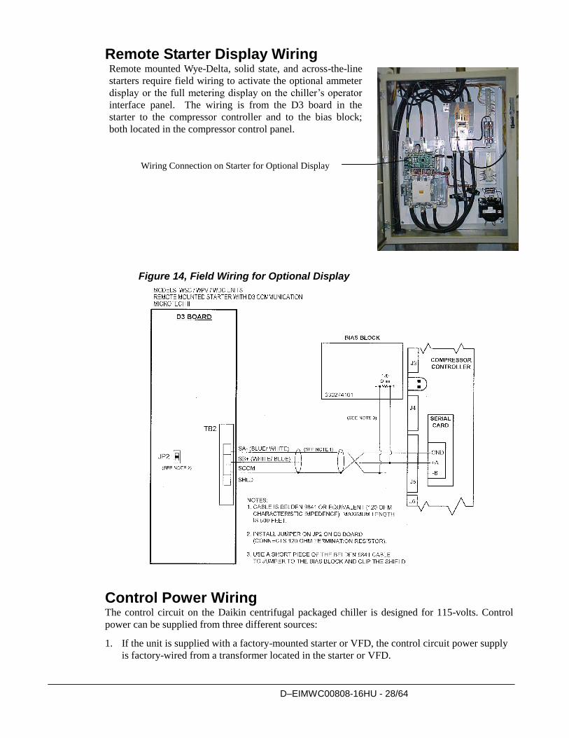
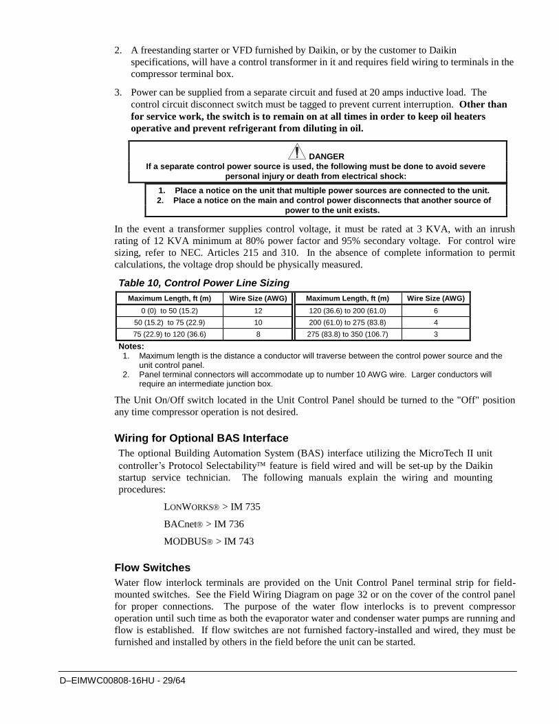
Remote Starter Display Wiring Remote mounted Wye-Delta, solid state, and across-the-line
starters require field wiring to activate the optional ammeter
display or the full metering display on the chiller’s operator
interface panel. The wiring is from the D3 board in the
starter to the compressor controller and to the bias block;
both located in the compressor control panel.
Figure 14, Field Wiring for Optional Display
Control Power Wiring The control circuit on the Daikin centrifugal packaged chiller is designed for 115-volts. Control
power can be supplied from three different sources:
1. If the unit is supplied with a factory-mounted starter or VFD, the control circuit power supply
is factory-wired from a transformer located in the starter or VFD.
Wiring Connection on Starter for Optional Display
Option
D–EIMWC00808-16HU - 29/64
2. A freestanding starter or VFD furnished by Daikin, or by the customer to Daikin
specifications, will have a control transformer in it and requires field wiring to terminals in the
compressor terminal box.
3. Power can be supplied from a separate circuit and fused at 20 amps inductive load. The
control circuit disconnect switch must be tagged to prevent current interruption. Other than
for service work, the switch is to remain on at all times in order to keep oil heaters
operative and prevent refrigerant from diluting in oil.
DANGER
If a separate control power source is used, the following must be done to avoid severe
personal injury or death from electrical shock:
1. Place a notice on the unit that multiple power sources are connected to the unit.
2. Place a notice on the main and control power disconnects that another source of
power to the unit exists.
In the event a transformer supplies control voltage, it must be rated at 3 KVA, with an inrush
rating of 12 KVA minimum at 80% power factor and 95% secondary voltage. For control wire
sizing, refer to NEC. Articles 215 and 310. In the absence of complete information to permit
calculations, the voltage drop should be physically measured.
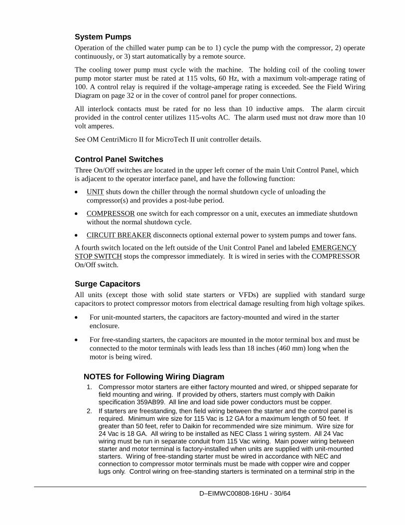
Table 10, Control Power Line Sizing
Maximum Length, ft (m) Wire Size (AWG) Maximum Length, ft (m) Wire Size (AWG)
0 (0) to 50 (15.2) 12 120 (36.6) to 200 (61.0) 6
50 (15.2) to 75 (22.9) 10 200 (61.0) to 275 (83.8) 4
75 (22.9) to 120 (36.6) 8 275 (83.8) to 350 (106.7) 3
Notes: 1. Maximum length is the distance a conductor will traverse between the control power source and the
unit control panel. 2. Panel terminal connectors will accommodate up to number 10 AWG wire. Larger conductors will
require an intermediate junction box.
The Unit On/Off switch located in the Unit Control Panel should be turned to the "Off" position
any time compressor operation is not desired.
Wiring for Optional BAS Interface
The optional Building Automation System (BAS) interface utilizing the MicroTech II unit
controller’s Protocol Selectability feature is field wired and will be set-up by the Daikin
startup service technician. The following manuals explain the wiring and mounting
procedures:
LONWORKS > IM 735
BACnet > IM 736
MODBUS > IM 743
Flow Switches
Water flow interlock terminals are provided on the Unit Control Panel terminal strip for field-
mounted switches. See the Field Wiring Diagram on page 32 or on the cover of the control panel
for proper connections. The purpose of the water flow interlocks is to prevent compressor
operation until such time as both the evaporator water and condenser water pumps are running and
flow is established. If flow switches are not furnished factory-installed and wired, they must be
furnished and installed by others in the field before the unit can be started.
D–EIMWC00808-16HU - 30/64
System Pumps
Operation of the chilled water pump can be to 1) cycle the pump with the compressor, 2) operate
continuously, or 3) start automatically by a remote source.
The cooling tower pump must cycle with the machine. The holding coil of the cooling tower
pump motor starter must be rated at 115 volts, 60 Hz, with a maximum volt-amperage rating of
100. A control relay is required if the voltage-amperage rating is exceeded. See the Field Wiring
Diagram on page 32 or in the cover of control panel for proper connections.
All interlock contacts must be rated for no less than 10 inductive amps. The alarm circuit
provided in the control center utilizes 115-volts AC. The alarm used must not draw more than 10
volt amperes.
See OM CentriMicro II for MicroTech II unit controller details.
Control Panel Switches
Three On/Off switches are located in the upper left corner of the main Unit Control Panel, which
is adjacent to the operator interface panel, and have the following function:
UNIT shuts down the chiller through the normal shutdown cycle of unloading the
compressor(s) and provides a post-lube period.
COMPRESSOR one switch for each compressor on a unit, executes an immediate shutdown
without the normal shutdown cycle.
CIRCUIT BREAKER disconnects optional external power to system pumps and tower fans.
A fourth switch located on the left outside of the Unit Control Panel and labeled EMERGENCY
STOP SWITCH stops the compressor immediately. It is wired in series with the COMPRESSOR
On/Off switch.
Surge Capacitors
All units (except those with solid state starters or VFDs) are supplied with standard surge
capacitors to protect compressor motors from electrical damage resulting from high voltage spikes.
For unit-mounted starters, the capacitors are factory-mounted and wired in the starter
enclosure.
For free-standing starters, the capacitors are mounted in the motor terminal box and must be
connected to the motor terminals with leads less than 18 inches (460 mm) long when the
motor is being wired.
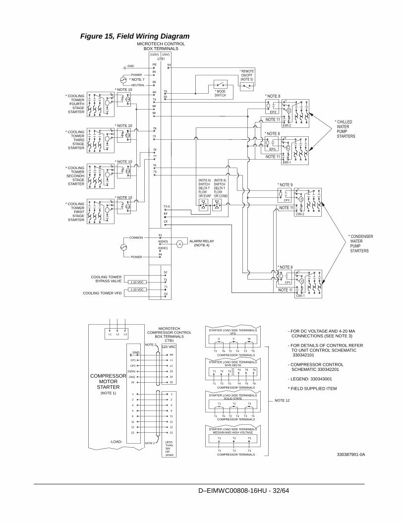
NOTES for Following Wiring Diagram
1. Compressor motor starters are either factory mounted and wired, or shipped separate for field mounting and wiring. If provided by others, starters must comply with Daikin specification 359AB99. All line and load side power conductors must be copper.
2. If starters are freestanding, then field wiring between the starter and the control panel is required. Minimum wire size for 115 Vac is 12 GA for a maximum length of 50 feet. If greater than 50 feet, refer to Daikin for recommended wire size minimum. Wire size for 24 Vac is 18 GA. All wiring to be installed as NEC Class 1 wiring system. All 24 Vac wiring must be run in separate conduit from 115 Vac wiring. Main power wiring between starter and motor terminal is factory-installed when units are supplied with unit-mounted starters. Wiring of free-standing starter must be wired in accordance with NEC and connection to compressor motor terminals must be made with copper wire and copper lugs only. Control wiring on free-standing starters is terminated on a terminal strip in the
D–EIMWC00808-16HU - 31/64
motor terminal box (not the unit control panel). Wiring from the unit control panel to the motor terminal is done in the factory.
3. For optional sensor wiring, see unit control diagram. It is recommended that DC wires be run separately from 115 Vac wiring.
4. Customer furnished 24 or 120 Vac power for alarm relay coil can be connected between UTB1 terminals 84 power and 51 neutral of the control panel. For normally open contacts, wire between 82 & 81. For normally closed contacts, wire between 83 & 81. The alarm is operator programmable. The maximum rating of the alarm relay coil is 25 VA.
5. Remote on/off control of unit can be accomplished by installing a set of dry contacts between terminals 70 and 54.
6. Evaporator and condenser paddle type flow switches or water pressure differential switches are required and must be wired as shown. If field supplied pressure differential switches are used then these must be installed across the vessel and not the pump.
7. Customer supplied 115 Vac, 20 amp power for optional evaporator and condenser water pump control power and tower fans is supplied to unit control terminals (UTBI) 85 power / 86 neutral, PE equipment ground.
8. Optional customer supplied 115 Vac, 25 VA maximum coil rated chilled water pump relay (EP 1 & 2) can be wired as shown. This option will cycle the chilled water pump in response to building load.
9. The condenser water pump must cycle with the unit. A customer supplied 115 Vac 25 VA maximum coil rated condenser water pump relay (CP1 & 2) is to be wired as shown.
10. Optional customer supplied 115 Vac, 25 VA maximum coil rated cooling tower fan relays (CL - C4) can be wired as shown. This option will cycle the cooling tower fans in order to maintain unit head pressure.
11. Auxiliary 24 Vac rated contacts in both the chilled water and condenser water pump starters must be wired as shown.
12. For VFD, Wye-Delta, and solid state starters connected to six (6) terminal motors, the conductors between the starter and motor carry phase current and their ampacity must be based on 58 percent of the motor rated load amperes (RLA) times 1.25. Wiring of free-standing starter must be in accordance with the NEC and connection to the compressor motor terminals shall be made with copper wire and copper lugs only. Main power wiring between the starter and motor terminals is factory-installed when chillers are supplied with unit-mounted starters.
13. Optional Protocol Selectability BAS interfaces. The locations and interconnection requirements for the various standard protocols are found in their respective installation manuals, obtainable from the local Daikin sales office and also shipped with each unit:
Modbus IM 743-0 LonWorks IM 735-0 BACnet IM 736-0
14. The “Full Metering” or “Amps Only Metering” option will require some field wiring when free-standing starters are used. Wiring will depend on chiller and starter type. Consult the local Daikin sales office for information on specific selections.
D–EIMWC00808-16HU - 32/64
Figure 15, Field Wiring Diagram
80
CP2
CP1
H
O
A
C4
H
A
O
C3
H
A
O
79
78
77
74
73
54
CF
86
EF
86
C
25
1
2
11
11
12
22
1
2
6
11
12
22
NOTE 2
NOTE 2
(115V) (24V)
25
55
70
H
A
O
H
A
O
H
O
A C
H
O
A C
H
O
A C
C2
C1 T3-S
PE
L1
L2CP2
CP1
24
23(5A)
24(5)
23
3
4
3
4
76
75
PE
85
86
81
84
A82(NO)
83(NC)
POWER
EP2
EP1
L1 L2 L3
GND
T4 T5 T6T1 T2 T3
T4 T5 T6T1 T2 T3
T1 T2 T3
T3T1 T2
U V W
T4 T3 T5T1 T6 T2
T1 T2 T3
T4 T3 T5T1 T6 T2
GND
LESS
THAN30V
OR
24VAC
53
71
71
52
1-10 VDC
1-10 VDC
MICROTECH CONTROLBOX TERMINALS
* COOLINGTOWER
FOURTHSTAGE
STARTER
* COOLINGTOWER
THIRDSTAGE
STARTER
* COOLINGTOWER
SECONDHSTAGE
STARTER
* COOLINGTOWER
FIRSTSTAGE
STARTER
COOLING TOWERBYPASS VALVE
COOLING TOWER VFD
ALARM RELAY(NOTE 4)
MICROTECHCOMPRESSOR CONTROL
BOX TERMINALSCTB1
-LOAD-
COMPRESSORMOTOR
STARTER(NOTE 1)
115 VAC
STARTER LOAD SIDE TERMINBALSVFD
STARTER LOAD SIDE TERMINBALSWYE-DELTA
STARTER LOAD SIDE TERMINBALSSOLID STATE
STARTER LOAD SIDE TERMINBALSMEDIUM AND HIGH VOLTAGE
COMPRESSOR TERMINALS
COMPRESSOR TERMINALS
COMPRESSOR TERMINALS
COMPRESSOR TERMINALS
NOTE 12
- FOR DC VOLTAGE AND 4-20 MA CONNECTIONS (SEE NOTE 3)
- FOR DETAILS OF CONTROL REFER TO UNIT CONTROL SCHEMATIC 330342101
- COMPRESSOR CONTROL SCHEMATIC 330342201
- LEGEND: 330343001
* FIELD SUPPLIED ITEM
* NOTE 7
* NOTE 10
* NOTE 10
* NOTE 10
* NOTE 10
330387901-0A
COMMON
NEUTRAL
POWER
D–EIMWC00808-16HU - 33/64
Multiple Chiller Setup Single compressor chillers DWSC and dual compressor chillers DWDC and DWCC have
their main control components factory wired to an internal pLAN network so that the
components can communicate with each other, within the chiller itself.
On multi-chiller applications, up to four chillers, either single, or dual compressor, can be
interconnected by this internal pLAN. All that is required is simple field RS485
interconnecting wiring, the addition of accessory communication isolation board(s)
485OPDR (Daikin P/N 330276202), and some MicroTech II control settings (see special
DWCC instructions at the end of this section). The 485OPDR isolation board can be
purchased with the unit or separately, during or after chiller installation. The number of
chillers minus one boards are required.
pLAN Setup
Interconnecting MicroTech II pLAN RS485 wiring should be installed by the installing
contractor prior to start-up. The Daikin start-up technician will check the connections and
make the necessary set point settings.
1. With no pLAN connections between chillers, disconnect chiller control power and set
the DIP switches as shown in Table 11.
2. With all manual switches off, turn on control power to each chiller and set each OITS
address (see Note 2 on page 34).
3. Verify correct nodes on each OITS Service Screen.
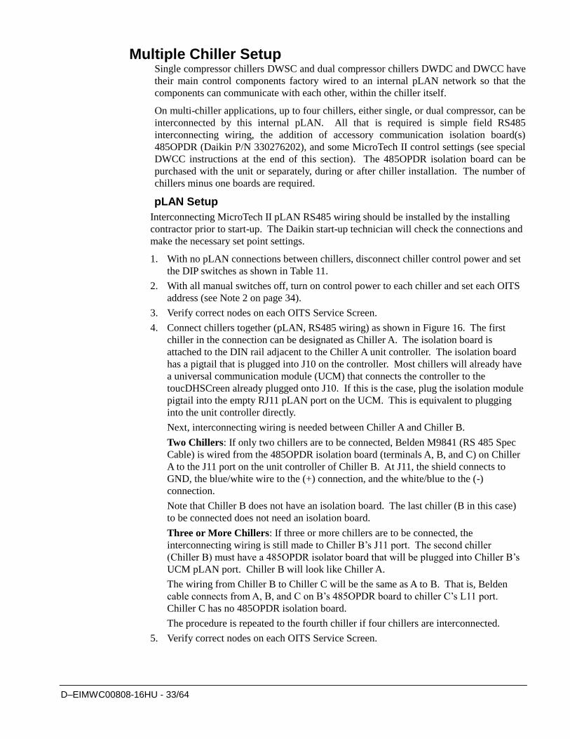
4. Connect chillers together (pLAN, RS485 wiring) as shown in Figure 16. The first
chiller in the connection can be designated as Chiller A. The isolation board is
attached to the DIN rail adjacent to the Chiller A unit controller. The isolation board
has a pigtail that is plugged into J10 on the controller. Most chillers will already have
a universal communication module (UCM) that connects the controller to the
toucDHSCreen already plugged onto J10. If this is the case, plug the isolation module
pigtail into the empty RJ11 pLAN port on the UCM. This is equivalent to plugging
into the unit controller directly.
Next, interconnecting wiring is needed between Chiller A and Chiller B.
Two Chillers: If only two chillers are to be connected, Belden M9841 (RS 485 Spec
Cable) is wired from the 485OPDR isolation board (terminals A, B, and C) on Chiller
A to the J11 port on the unit controller of Chiller B. At J11, the shield connects to
GND, the blue/white wire to the (+) connection, and the white/blue to the (-)
connection.
Note that Chiller B does not have an isolation board. The last chiller (B in this case)
to be connected does not need an isolation board.
Three or More Chillers: If three or more chillers are to be connected, the
interconnecting wiring is still made to Chiller B’s J11 port. The second chiller
(Chiller B) must have a 485OPDR isolator board that will be plugged into Chiller B’s
UCM pLAN port. Chiller B will look like Chiller A.
The wiring from Chiller B to Chiller C will be the same as A to B. That is, Belden
cable connects from A, B, and C on B’s 485OPDR board to chiller C’s L11 port.
Chiller C has no 485OPDR isolation board.
The procedure is repeated to the fourth chiller if four chillers are interconnected.
5. Verify correct nodes on each OITS Service Screen.
D–EIMWC00808-16HU - 34/64
Figure 16, Communication Wiring
Chiller APIGTAIL
485OPDRC AB
UCM
J10 J11
BLU/WHT
WHT/BLU
SHIELD
(+) (-)
UNIT CONTROL
J11 PORT
Chiller B
485OPDR
C
BLU/WHT
WHT/BLU
SHIELD
B AUCM
J10PORT
Chiller C(+) (-)
J11 Port
UNIT CONTROL
UNIT CONTROL
P P
P P
NOTE: A fourth chiller, Chiller D would be connected to chiller C same as chiller C to chiller B.
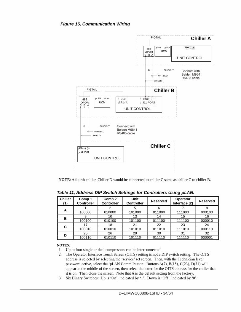
Table 11, Address DIP Switch Settings for Controllers Using pLAN.
Chiller
(1)
Comp 1
Controller
Comp 2
Controller
Unit
Controller Reserved
Operator
Interface (2) Reserved
A 1 2 5 6 7 8
100000 010000 101000 011000 111000 000100
B 9 10 13 14 15 16
100100 010100 101100 011100 111100 000010
C 17 18 21 22 23 24
100010 010010 101010 011010 111010 000110
D 25 26 29 30 31 32
100110 010110 101110 011110 111110 000001
NOTES:
1. Up to four single or dual compressors can be interconnected.
2. The Operator Interface Touch Screen (OITS) setting is not a DIP switch setting. The OITS
address is selected by selecting the ‘service’ set screen. Then, with the Technician level
password active, select the ‘pLAN Comm’ button. Buttons A(7), B(15), C(23), D(31) will
appear in the middle of the screen, then select the letter for the OITS address for the chiller that
it is on. Then close the screen. Note that A is the default setting from the factory.
3. Six Binary Switches: Up is ‘On’, indicated by ‘1’. Down is ‘Off’, indicated by ‘0’.
D–EIMWC00808-16HU - 35/64
MicroTech II Operator Interface Touch Screen (OITS) Settings
Settings for any type of linked multiple compressor operation must be made to the
MicroTech II controller. Settings on a dual compressor unit are made in the factory prior
to shipment, but must be verified in the field before startup. Settings for multiple chiller
installations are set in the field on the Operator Interface Touch Screen as follows:
Maximum Compressors ON – SETPOINTS - MODES screen, Selection #10 ‘= 2 for a
dual, 4 for 2 duals, 3 for three separate, single compressor chillers, etc. If all compressors
in the system are to be available as normal running compressors, then the value entered in
#10 should equal the total number of compressors. If any compressors are for standby and
not operated in normal rotation, they should not be included in the compressor count in
Selection #10. The Max Comp ON setting can be made in only one toucDHSCreen, the
system will observe the highest number set on all chillers-it is a global setting.
Sequence and Staging – SETPOINTS - MODES screen, Selection #12 & #14; #11 & #13.
Sequence sets the sequence in which compressors will start. Setting one or more
compressors to “1” evokes the automatic lead/lag feature and is the normal setting. The
compressor with least starts will start first and the compressor with maximum hours will
stop first, and so on. Units with higher numbers will stage on in sequence.
The Modes setpoints will do several different types of operation (Normal, Efficiency,
Standby, etc.) as described in the operating manual.
The same Modes setting must be replicated on each chiller in the system.
Nominal Capacity – SETPOINTS - MOTOR screen, Selection #14. The setting is the
compressor design tons. Compressors on dual units are always of equal capacity.
DWCC Settings
Since the DWCC is essentially two chillers combined into one counterflow, single pass,
dual-circuit chiller, the compressor on the downstream circuit (leaving chilled water) must
always be designated as the Stage 1 compressor-first on, last off.
Operating Sequence
For multiple-chiller, parallel operation, the MicroTech II controllers are tied together by a
pLAN network and stage and control compressor loading among the chillers. Each
compressor, single or dual compressor chiller, will stage on or off depending on the
sequence number programmed into it. For example, if all are set to “1”, the automatic
lead/lag will be in effect.
When chiller #1 is fully loaded, the leaving chilled water temperature will rise slightly.
When the Delta-T above setpoint reaches the Staging Delta-T, the next chiller scheduled to
start will receive a start signal and start its pumps if they are set up to be controlled by the
Microtech controller. This procedure is repeated until all chillers are running. The
compressors will load-balance themselves.
If any of the chillers in the group are dual compressor, they will stage and load according
to the staging instructions.
See OM CentrifMicro II-3 for a complete description of the various staging sequences
available.
D–EIMWC00808-16HU - 36/64
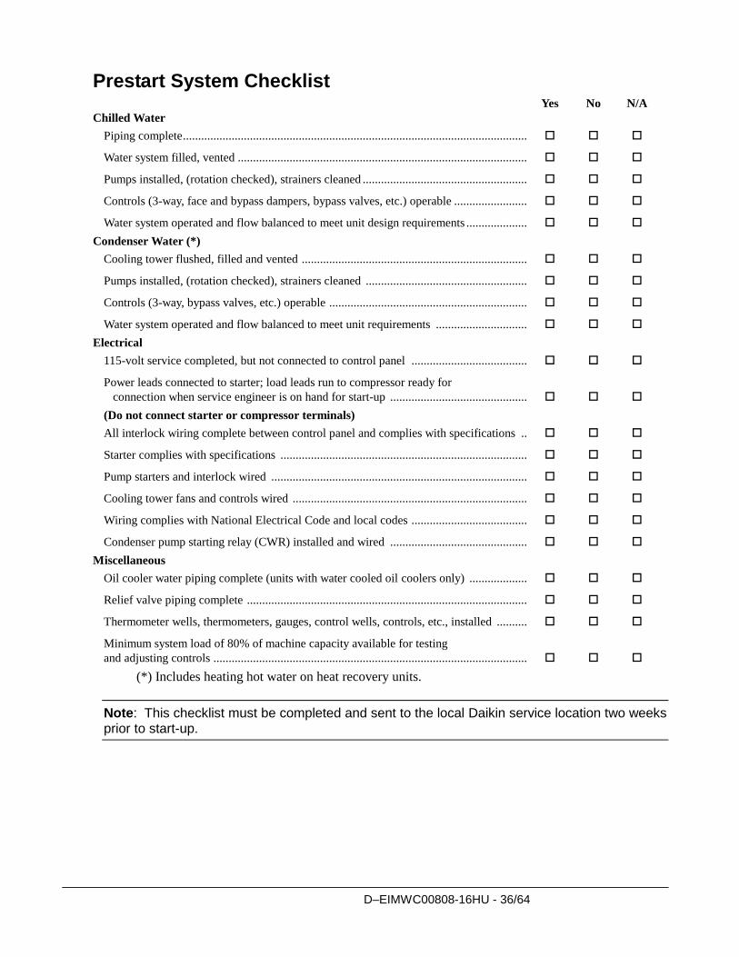
Prestart System Checklist Yes No N/A
Chilled Water
Piping complete .................................................................................................................
Water system filled, vented ...............................................................................................
Pumps installed, (rotation checked), strainers cleaned ......................................................
Controls (3-way, face and bypass dampers, bypass valves, etc.) operable ........................
Water system operated and flow balanced to meet unit design requirements ....................
Condenser Water (*)
Cooling tower flushed, filled and vented ..........................................................................
Pumps installed, (rotation checked), strainers cleaned .....................................................
Controls (3-way, bypass valves, etc.) operable .................................................................
Water system operated and flow balanced to meet unit requirements ..............................
Electrical
115-volt service completed, but not connected to control panel ......................................
Power leads connected to starter; load leads run to compressor ready for
connection when service engineer is on hand for start-up .............................................
(Do not connect starter or compressor terminals)
All interlock wiring complete between control panel and complies with specifications ..
Starter complies with specifications .................................................................................
Pump starters and interlock wired ....................................................................................
Cooling tower fans and controls wired .............................................................................
Wiring complies with National Electrical Code and local codes ......................................
Condenser pump starting relay (CWR) installed and wired .............................................
Miscellaneous
Oil cooler water piping complete (units with water cooled oil coolers only) ...................
Relief valve piping complete ............................................................................................
Thermometer wells, thermometers, gauges, control wells, controls, etc., installed ..........
Minimum system load of 80% of machine capacity available for testing
and adjusting controls .......................................................................................................
(*) Includes heating hot water on heat recovery units.
Note: This checklist must be completed and sent to the local Daikin service location two weeks prior to start-up.
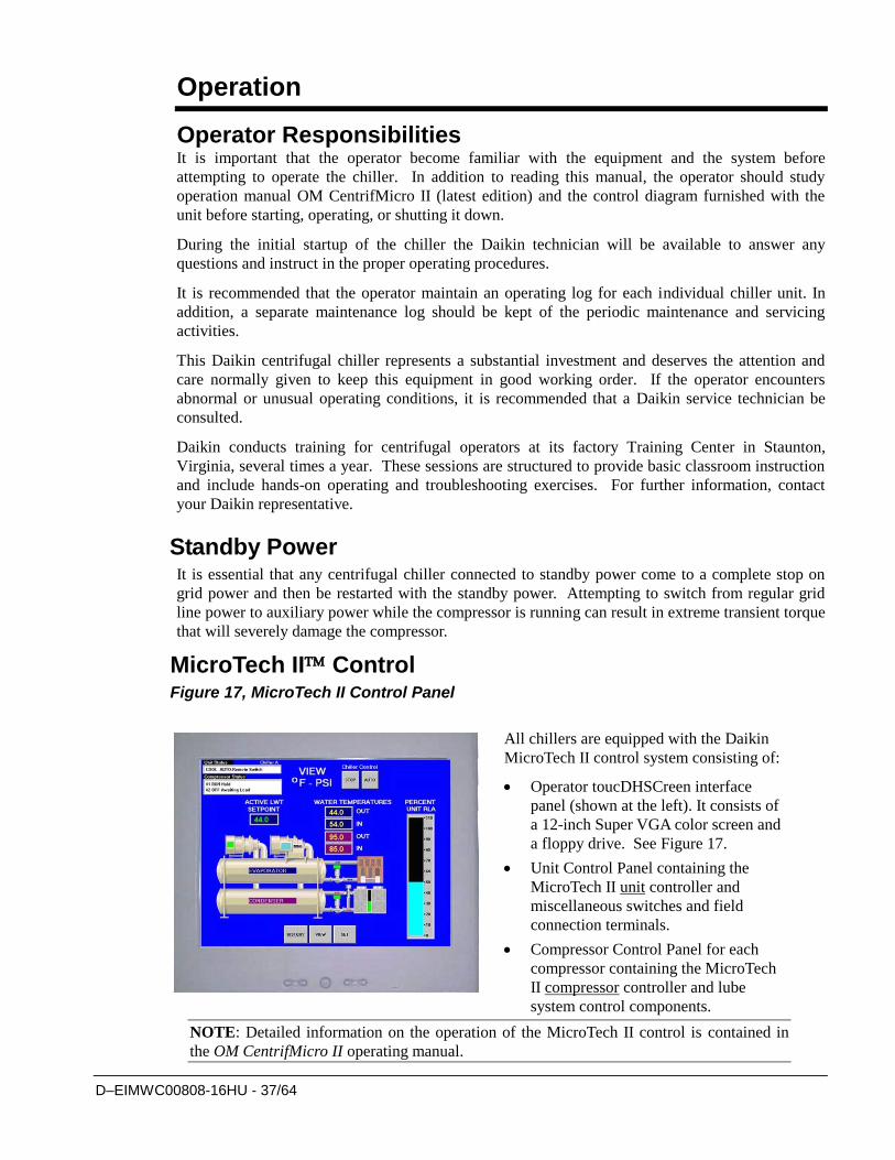
D–EIMWC00808-16HU - 37/64
Operation
Operator Responsibilities It is important that the operator become familiar with the equipment and the system before
attempting to operate the chiller. In addition to reading this manual, the operator should study
operation manual OM CentrifMicro II (latest edition) and the control diagram furnished with the
unit before starting, operating, or shutting it down.
During the initial startup of the chiller the Daikin technician will be available to answer any
questions and instruct in the proper operating procedures.
It is recommended that the operator maintain an operating log for each individual chiller unit. In
addition, a separate maintenance log should be kept of the periodic maintenance and servicing
activities.
This Daikin centrifugal chiller represents a substantial investment and deserves the attention and
care normally given to keep this equipment in good working order. If the operator encounters
abnormal or unusual operating conditions, it is recommended that a Daikin service technician be
consulted.
Daikin conducts training for centrifugal operators at its factory Training Center in Staunton,
Virginia, several times a year. These sessions are structured to provide basic classroom instruction
and include hands-on operating and troubleshooting exercises. For further information, contact
your Daikin representative.
Standby Power It is essential that any centrifugal chiller connected to standby power come to a complete stop on
grid power and then be restarted with the standby power. Attempting to switch from regular grid
line power to auxiliary power while the compressor is running can result in extreme transient torque
that will severely damage the compressor.
MicroTech II Control Figure 17, MicroTech II Control Panel
All chillers are equipped with the Daikin
MicroTech II control system consisting of:
Operator toucDHSCreen interface
panel (shown at the left). It consists of
a 12-inch Super VGA color screen and
a floppy drive. See Figure 17.
Unit Control Panel containing the
MicroTech II unit controller and
miscellaneous switches and field
connection terminals.
Compressor Control Panel for each
compressor containing the MicroTech
II compressor controller and lube
system control components.
NOTE: Detailed information on the operation of the MicroTech II control is contained in
the OM CentrifMicro II operating manual.
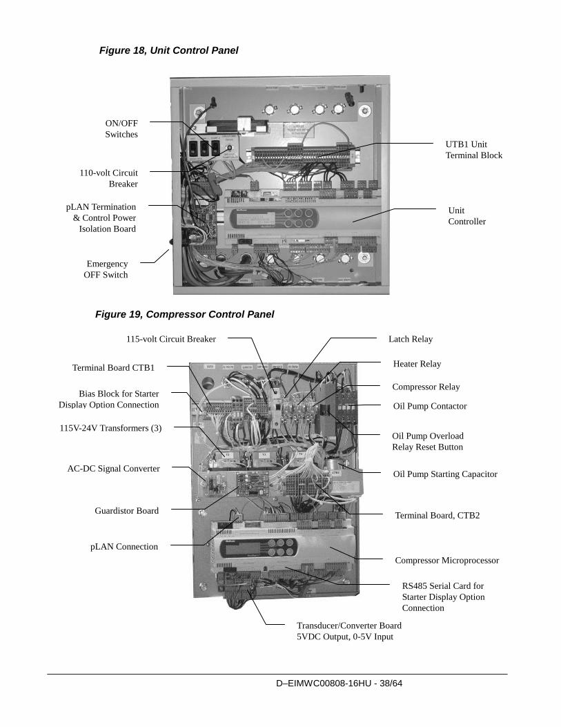
D–EIMWC00808-16HU - 38/64
Figure 18, Unit Control Panel
Figure 19, Compressor Control Panel
UTB1 Unit
Terminal Block
Unit
Controller
ON/OFF
Switches
Emergency
OFF Switch
pLAN Termination
& Control Power
Isolation Board
110-volt Circuit
Breaker
115-volt Circuit Breaker Latch Relay
Heater Relay
Compressor Relay
Oil Pump Overload
Relay Reset Button
Oil Pump Contactor
Oil Pump Starting Capacitor
Terminal Board, CTB2
Compressor Microprocessor
Transducer/Converter Board
5VDC Output, 0-5V Input
pLAN Connection
Guardistor Board
AC-DC Signal Converter
115V-24V Transformers (3)
Terminal Board CTB1
RS485 Serial Card for
Starter Display Option
Connection
Bias Block for Starter
Display Option Connection
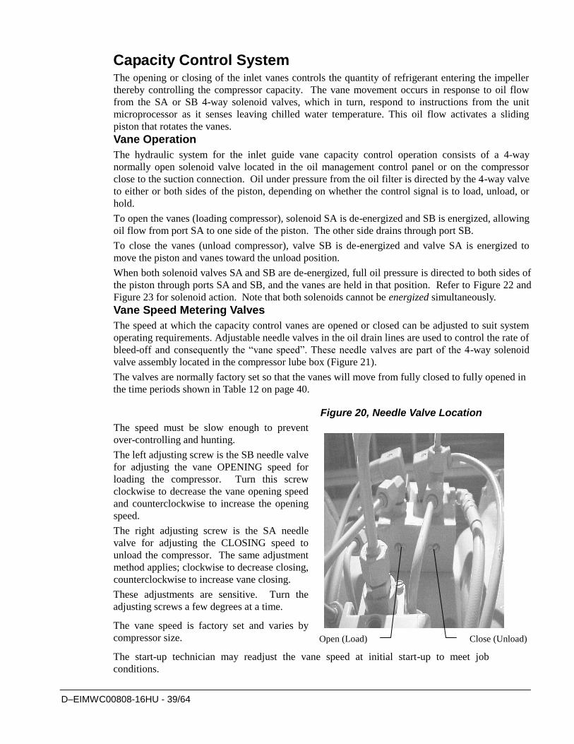
D–EIMWC00808-16HU - 39/64
Capacity Control System The opening or closing of the inlet vanes controls the quantity of refrigerant entering the impeller
thereby controlling the compressor capacity. The vane movement occurs in response to oil flow
from the SA or SB 4-way solenoid valves, which in turn, respond to instructions from the unit
microprocessor as it senses leaving chilled water temperature. This oil flow activates a sliding
piston that rotates the vanes.
Vane Operation
The hydraulic system for the inlet guide vane capacity control operation consists of a 4-way
normally open solenoid valve located in the oil management control panel or on the compressor
close to the suction connection. Oil under pressure from the oil filter is directed by the 4-way valve
to either or both sides of the piston, depending on whether the control signal is to load, unload, or
hold.
To open the vanes (loading compressor), solenoid SA is de-energized and SB is energized, allowing
oil flow from port SA to one side of the piston. The other side drains through port SB.
To close the vanes (unload compressor), valve SB is de-energized and valve SA is energized to
move the piston and vanes toward the unload position.
When both solenoid valves SA and SB are de-energized, full oil pressure is directed to both sides of
the piston through ports SA and SB, and the vanes are held in that position. Refer to Figure 22 and
Figure 23 for solenoid action. Note that both solenoids cannot be energized simultaneously.
Vane Speed Metering Valves
The speed at which the capacity control vanes are opened or closed can be adjusted to suit system
operating requirements. Adjustable needle valves in the oil drain lines are used to control the rate of
bleed-off and consequently the “vane speed”. These needle valves are part of the 4-way solenoid
valve assembly located in the compressor lube box (Figure 21).
The valves are normally factory set so that the vanes will move from fully closed to fully opened in
the time periods shown in Table 12 on page 40.
Figure 20, Needle Valve Location
The speed must be slow enough to prevent
over-controlling and hunting.
The left adjusting screw is the SB needle valve
for adjusting the vane OPENING speed for
loading the compressor. Turn this screw
clockwise to decrease the vane opening speed
and counterclockwise to increase the opening
speed.
The right adjusting screw is the SA needle
valve for adjusting the CLOSING speed to
unload the compressor. The same adjustment
method applies; clockwise to decrease closing,
counterclockwise to increase vane closing.
These adjustments are sensitive. Turn the
adjusting screws a few degrees at a time.
The vane speed is factory set and varies by
compressor size.
The start-up technician may readjust the vane speed at initial start-up to meet job
conditions.
Open (Load) Close (Unload)
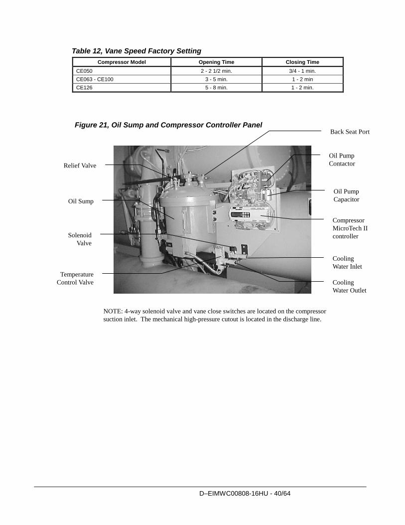
D–EIMWC00808-16HU - 40/64
Table 12, Vane Speed Factory Setting
Compressor Model Opening Time Closing Time
CE050 2 - 2 1/2 min. 3/4 - 1 min.
CE063 - CE100 3 - 5 min. 1 - 2 min
CE126 5 - 8 min. 1 - 2 min.
Figure 21, Oil Sump and Compressor Controller Panel
NOTE: 4-way solenoid valve and vane close switches are located on the compressor
suction inlet. The mechanical high-pressure cutout is located in the discharge line.
Oil Pump
Contactor
Oil Pump
Capacitor
Compressor
MicroTech II
controller
Cooling
Water Inlet
Cooling
Water Outlet
Temperature
Control Valve
Solenoid
Valve
Oil Sump
Relief Valve
Back Seat Port
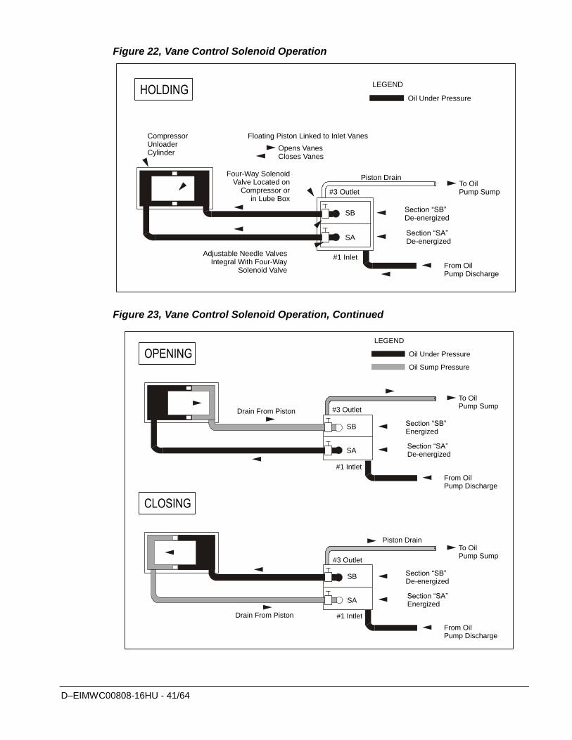
D–EIMWC00808-16HU - 41/64
Figure 22, Vane Control Solenoid Operation
CompressorUnloaderCylinder
Floating Piston Linked to Inlet Vanes
Opens VanesCloses Vanes
Four-Way SolenoidValve Located on
Compressor or in Lube Box
Piston Drain
#3 Outlet
SB
SA
#1 Inlet
LEGEND
Oil Under Pressure
To OilPump Sump
Section “SB”De-energized
Section “SA”De-energized
From OilPump Discharge
Adjustable Needle ValvesIntegral With Four-Way
Solenoid Valve
HOLDING
Figure 23, Vane Control Solenoid Operation, Continued
Drain From Piston #3 Outlet
SB
SA
#1 Intlet
LEGEND
Oil Under Pressure
To OilPump Sump
Section “SB”Energized
Section “SA”De-energized
From OilPump Discharge
OPENINGOil Sump Pressure
Drain From Piston
#3 Outlet
SB
SA
#1 Intlet
To OilPump Sump
Section “SB”De-energized
Section “SA”Energized
From OilPump Discharge
CLOSING
Piston Drain
D–EIMWC00808-16HU - 42/64
Surge and Stall Stall and surge are a characteristic of all centrifugal compressors. These conditions occur
when low load combines with high compressor lift. In a stall, discharge gas has
insufficient velocity leaving the impeller to reach the volute and just “sits” or stalls in the
diffuser section. The compressor sound level goes way down due to no flow and the
impeller starts to heat up. In surge, the heated discharge gas alternately flows back
through the impeller and then reverses to the volute about every two seconds. Extreme
noise and vibration occur. The compressor is equipped with a temperature sensor that
shuts it off if these conditions occur.
Lubrication System The lubrication system provides lubrication and heat removal for compressor bearings and
internal parts. In addition, the system provides lubricant under pressure to hydraulically
operate the unloading piston for positioning the inlet guide vanes for capacity control.
DWDC, dual compressor chillers, have completely independent lubrication systems for
each compressor.
Only the recommended lubricant, as shown in Table 13, can be used for proper operation
of the hydraulic system and bearing lubrication system. Each unit is factory-charged with
the correct amount of the recommended lubricant. Under normal operation, no additional
lubricant is needed. Lubricant must be visible in the sump sight glass at all times.
The lubricant system for the CE0050 compressor is completely self-contained within the
compressor housing. The assembly includes the pump, pump motor, and lubricant heater.
The oil is pumped to the internal oil filter in the compressor casting and then to the
internal refrigerant-cooled oil cooler.
The other compressor sizes, CE063, through CE126, utilize a separate lubricant pump
located in the sump. The sump includes the pump, motor, heater and lubricant/vapor
separator system. The lubricant is pumped through the external oil cooler and then to the
oil filter located inside the compressor housing. DWSC/DWDC/DWCC 063-126 units,
single or dual compressor, all utilize a water-cooled oil cooler for each compressor.
The oil coolers maintain the proper oil temperature under normal operating conditions.
The coolant flow control valve maintains 95°F to 105°F (35°C to 41°C). Lubrication
protection for coast down in the event of a power failure is accomplished by a spring-
loaded piston in models CE050 through 100. When the oil pump is started, the piston is
forced back against the spring by the oil pressure, compressing the spring, and filling the
piston cavity with oil. When the pump stops, the spring pressure on the piston forces the
oil back out to the bearings.
In model CE126 the compressor coast down lubrication is supplied from a gravity feed oil
reservoir.
A typical flow diagram is shown in Figure 24.
Table 13, Approved Polyolester Oils For R-134a Units Compressor Models CE050 - 126
Lubricant Designation Mobil Artic EAL 46; ICI Emkarate RL32H(2)
Daikin Part Number 55 Gal. Drum 5 Gal. Drum 1 Gal. Can
735030432, Rev 47 735030433, Rev 47 735030435, Rev 47
Compressor Oil Label 070200106, Rev OB
NOTES:
1. Approved oil from two suppliers can be mixed, although they have slightly different viscosity. 2. Lubricant from either supplier can be furnished when ordering by Daikin part number.
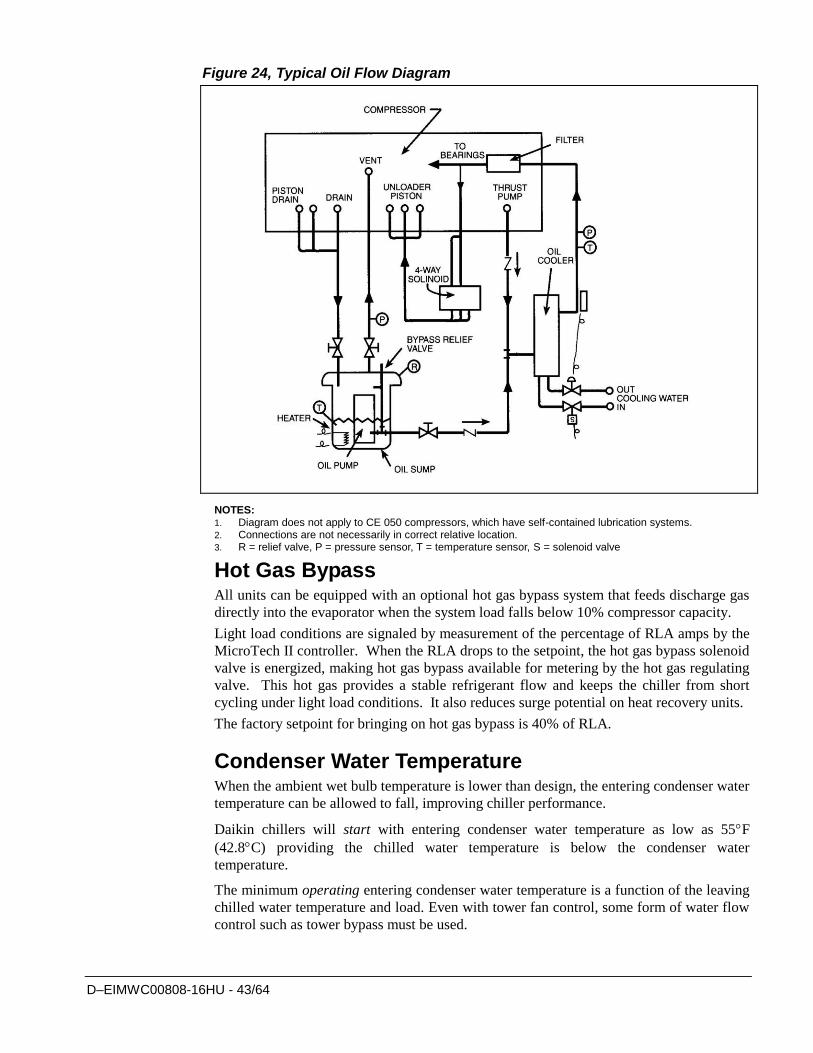
D–EIMWC00808-16HU - 43/64
Figure 24, Typical Oil Flow Diagram
NOTES: 1. Diagram does not apply to CE 050 compressors, which have self-contained lubrication systems. 2. Connections are not necessarily in correct relative location. 3. R = relief valve, P = pressure sensor, T = temperature sensor, S = solenoid valve
Hot Gas Bypass All units can be equipped with an optional hot gas bypass system that feeds discharge gas
directly into the evaporator when the system load falls below 10% compressor capacity.
Light load conditions are signaled by measurement of the percentage of RLA amps by the
MicroTech II controller. When the RLA drops to the setpoint, the hot gas bypass solenoid
valve is energized, making hot gas bypass available for metering by the hot gas regulating
valve. This hot gas provides a stable refrigerant flow and keeps the chiller from short
cycling under light load conditions. It also reduces surge potential on heat recovery units.
The factory setpoint for bringing on hot gas bypass is 40% of RLA.
Condenser Water Temperature When the ambient wet bulb temperature is lower than design, the entering condenser water
temperature can be allowed to fall, improving chiller performance.
Daikin chillers will start with entering condenser water temperature as low as 55F
(42.8C) providing the chilled water temperature is below the condenser water
temperature.
The minimum operating entering condenser water temperature is a function of the leaving
chilled water temperature and load. Even with tower fan control, some form of water flow
control such as tower bypass must be used.
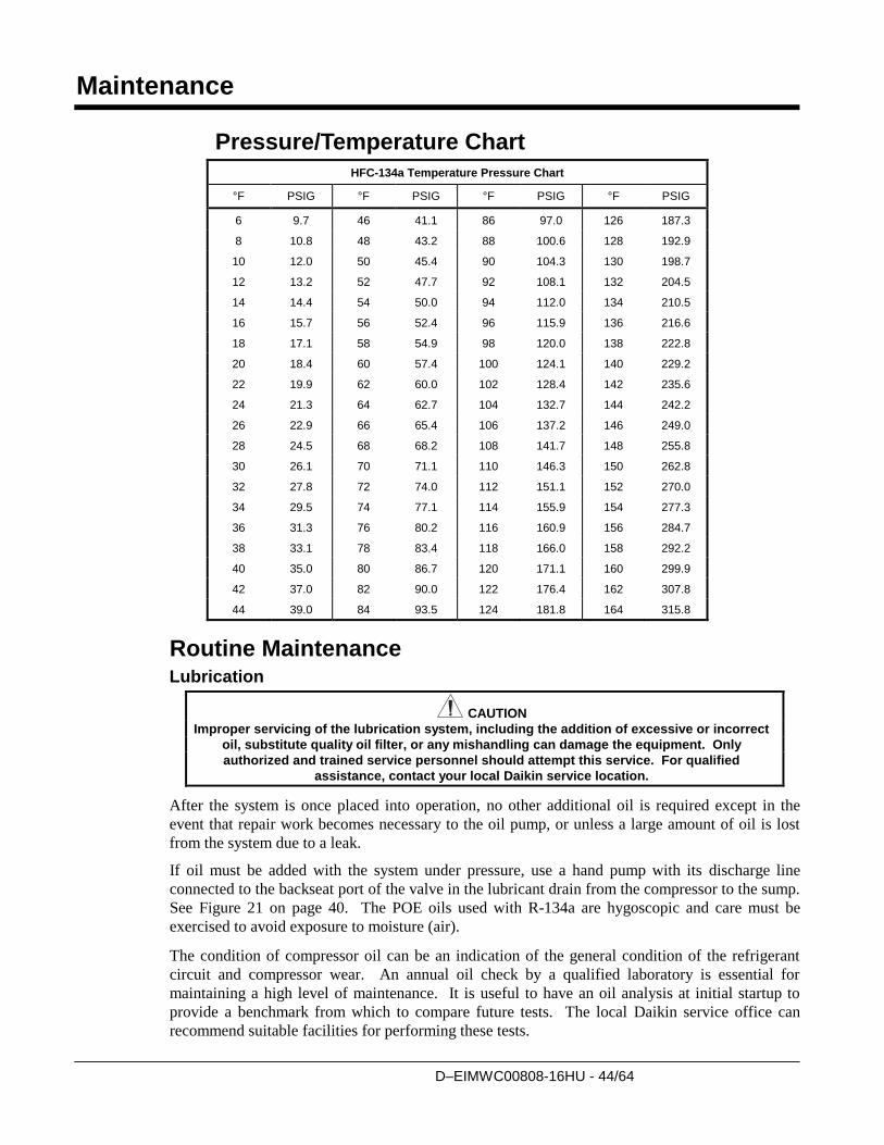
D–EIMWC00808-16HU - 44/64
Maintenance
Pressure/Temperature Chart
HFC-134a Temperature Pressure Chart
°F PSIG °F PSIG °F PSIG °F PSIG
6 9.7 46 41.1 86 97.0 126 187.3
8 10.8 48 43.2 88 100.6 128 192.9
10 12.0 50 45.4 90 104.3 130 198.7
12 13.2 52 47.7 92 108.1 132 204.5
14 14.4 54 50.0 94 112.0 134 210.5
16 15.7 56 52.4 96 115.9 136 216.6
18 17.1 58 54.9 98 120.0 138 222.8
20 18.4 60 57.4 100 124.1 140 229.2
22 19.9 62 60.0 102 128.4 142 235.6
24 21.3 64 62.7 104 132.7 144 242.2
26 22.9 66 65.4 106 137.2 146 249.0
28 24.5 68 68.2 108 141.7 148 255.8
30 26.1 70 71.1 110 146.3 150 262.8
32 27.8 72 74.0 112 151.1 152 270.0
34 29.5 74 77.1 114 155.9 154 277.3
36 31.3 76 80.2 116 160.9 156 284.7
38 33.1 78 83.4 118 166.0 158 292.2
40 35.0 80 86.7 120 171.1 160 299.9
42 37.0 82 90.0 122 176.4 162 307.8
44 39.0 84 93.5 124 181.8 164 315.8
Routine Maintenance Lubrication
CAUTION
Improper servicing of the lubrication system, including the addition of excessive or incorrect
oil, substitute quality oil filter, or any mishandling can damage the equipment. Only
authorized and trained service personnel should attempt this service. For qualified
assistance, contact your local Daikin service location.
After the system is once placed into operation, no other additional oil is required except in the
event that repair work becomes necessary to the oil pump, or unless a large amount of oil is lost
from the system due to a leak.
If oil must be added with the system under pressure, use a hand pump with its discharge line
connected to the backseat port of the valve in the lubricant drain from the compressor to the sump.
See Figure 21 on page 40. The POE oils used with R-134a are hygoscopic and care must be
exercised to avoid exposure to moisture (air).
The condition of compressor oil can be an indication of the general condition of the refrigerant
circuit and compressor wear. An annual oil check by a qualified laboratory is essential for
maintaining a high level of maintenance. It is useful to have an oil analysis at initial startup to
provide a benchmark from which to compare future tests. The local Daikin service office can
recommend suitable facilities for performing these tests.
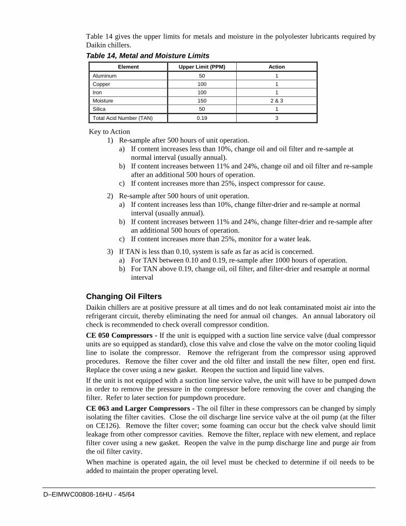
D–EIMWC00808-16HU - 45/64
Table 14 gives the upper limits for metals and moisture in the polyolester lubricants required by
Daikin chillers.
Table 14, Metal and Moisture Limits
Element Upper Limit (PPM) Action
Aluminum 50 1
Copper 100 1
Iron 100 1
Moisture 150 2 & 3
Silica 50 1
Total Acid Number (TAN) 0.19 3
Key to Action
1) Re-sample after 500 hours of unit operation.
a) If content increases less than 10%, change oil and oil filter and re-sample at
normal interval (usually annual).
b) If content increases between 11% and 24%, change oil and oil filter and re-sample
after an additional 500 hours of operation.
c) If content increases more than 25%, inspect compressor for cause.
2) Re-sample after 500 hours of unit operation.
a) If content increases less than 10%, change filter-drier and re-sample at normal
interval (usually annual).
b) If content increases between 11% and 24%, change filter-drier and re-sample after
an additional 500 hours of operation.
c) If content increases more than 25%, monitor for a water leak.
3) If TAN is less than 0.10, system is safe as far as acid is concerned.
a) For TAN between 0.10 and 0.19, re-sample after 1000 hours of operation.
b) For TAN above 0.19, change oil, oil filter, and filter-drier and resample at normal
interval
Changing Oil Filters
Daikin chillers are at positive pressure at all times and do not leak contaminated moist air into the
refrigerant circuit, thereby eliminating the need for annual oil changes. An annual laboratory oil
check is recommended to check overall compressor condition.
CE 050 Compressors - If the unit is equipped with a suction line service valve (dual compressor
units are so equipped as standard), close this valve and close the valve on the motor cooling liquid
line to isolate the compressor. Remove the refrigerant from the compressor using approved
procedures. Remove the filter cover and the old filter and install the new filter, open end first.
Replace the cover using a new gasket. Reopen the suction and liquid line valves.
If the unit is not equipped with a suction line service valve, the unit will have to be pumped down
in order to remove the pressure in the compressor before removing the cover and changing the
filter. Refer to later section for pumpdown procedure.
CE 063 and Larger Compressors - The oil filter in these compressors can be changed by simply
isolating the filter cavities. Close the oil discharge line service valve at the oil pump (at the filter
on CE126). Remove the filter cover; some foaming can occur but the check valve should limit
leakage from other compressor cavities. Remove the filter, replace with new element, and replace
filter cover using a new gasket. Reopen the valve in the pump discharge line and purge air from
the oil filter cavity.
When machine is operated again, the oil level must be checked to determine if oil needs to be
added to maintain the proper operating level.
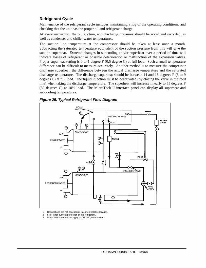
D–EIMWC00808-16HU - 46/64
Refrigerant Cycle
Maintenance of the refrigerant cycle includes maintaining a log of the operating conditions, and
checking that the unit has the proper oil and refrigerant charge.
At every inspection, the oil, suction, and discharge pressures should be noted and recorded, as
well as condenser and chiller water temperatures.
The suction line temperature at the compressor should be taken at least once a month.
Subtracting the saturated temperature equivalent of the suction pressure from this will give the
suction superheat. Extreme changes in subcooling and/or superheat over a period of time will
indicate losses of refrigerant or possible deterioration or malfunction of the expansion valves.
Proper superheat setting is 0 to 1 degree F (0.5 degree C) at full load. Such a small temperature
difference can be difficult to measure accurately. Another method is to measure the compressor
discharge superheat, the difference between the actual discharge temperature and the saturated
discharge temperature. The discharge superheat should be between 14 and 16 degrees F (8 to 9
degrees C) at full load. The liquid injection must be deactivated (by closing the valve in the feed
line) when taking the discharge temperature. The superheat will increase linearly to 55 degrees F
(30 degrees C) at 10% load. The MicroTech II interface panel can display all superheat and
subcooling temperatures.
Figure 25. Typical Refrigerant Flow Diagram
1. Connections are not necessarily in correct relative location. 2. Filter is for burnout protection of the refrigerant. 3. Liquid injection does not apply to CE 050, compressors.
D–EIMWC00808-16HU - 47/64
Electrical System
Maintenance of the electrical system involves the general requirement of keeping contacts clean
and connections tight and checking on specific items as follows:
1. The compressor current draw should be checked and compared to nameplate RLA value.
Normally, the actual current will be lower, since the nameplate rating represents full load
operation. Also check all pump and fan motor amperages, and compare with nameplate
ratings.
2. Inspection must verify that the oil heaters are operative. The heaters are insert-cartridge type
and can be checked by ammeter reading. They should be energized whenever power is
available to the control circuit, when the oil temperature sensor calls for heat, and when the
compressor is inoperative. When the compressor runs, the heaters are de-energized. The
Digital Output screen and second View screen on the operator interface panel both indicate
when the heaters are energized.
3. At least once a quarter, all equipment protection controls except compressor overloads should
be made to operate and their operating points checked. A control can shift its operating point
as it ages, and this must be detected so the controls can be adjusted or replaced. Pump
interlocks and flow switches should be checked to be sure they interrupt the control circuit
when tripped.
4. The contactors in the motor starter should be inspected and cleaned quarterly. Tighten all
terminal connections.
5. The compressor motor resistance to ground should be checked and logged semi-annually. This
log will track insulation deterioration. A reading of 50 megohms or less indicates a possible
insulation defect or moisture and must be further checked.
CAUTION
Never Megger a motor while in a vacuum. Severe motor damage can result.
6. The centrifugal compressor must rotate in the direction indicated by the arrow on the rear
motor cover plate, near the rotation sight glass. If the operator has any reason to suspect that
the power system connections have been altered, (phases reversed) the compressor must be
jogged to check rotation. For assistance, call the local Daikin service location.
Cleaning and Preserving
A common cause of service calls and equipment malfunction is dirt. This can be prevented with
normal maintenance. The system components most subject to dirt are:
1. Permanent or cleanable filters in the air handling equipment must be cleaned in accordance
with the manufacturer’s instructions; throwaway filters should be replaced. The frequency of
this service will vary with each installation.
2. Remove and clean strainers in chilled water system, oil cooler line and condenser water system
at every inspection.
Seasonal Servicing
Prior to shutdown periods and before starting up again, the following service procedures must be
completed.
Annual Shutdown Where the chiller can be subject to freezing temperatures, the condenser and chiller must be
drained of all water. Dry air blown through the condenser will aid in forcing all water out.
Removal of condenser heads is also recommended. The condenser and evaporator are not self-
D–EIMWC00808-16HU - 48/64
draining and tubes must be blown out. Water permitted to remain in the piping and vessels can
rupture these parts if subjected to freezing temperature.
Forced circulation of antifreeze through the water circuits is one method of avoiding freeze
up.
1. Take measures to prevent the shutoff valve in the water supply line from being accidentally
turned on.
2. If a cooling tower is used, and if the water pump will be exposed to freezing temperatures, be
sure to remove the pump drain plug and leave it out so any water that can accumulate will drain
away.
3. Open the compressor disconnect switch, and remove the fuses. If the transformer is used for
control voltage, the disconnect must remain on to provide power to the oil heater. Set the
manual UNIT ON/OFF switch in the Unit Control Panel to the OFF position.
4. Check for corrosion and clean and paint rusted surfaces.
5. Clean and flush water tower for all units operating on a water tower. Make sure tower
blowdown or bleed-off is operating. Set up and use a good maintenance program to prevent
“liming up” of both tower and condenser. It should be recognized that atmospheric air contains
many contaminants that increase the need for proper water treatment. The use of untreated
water can result in corrosion, erosion, sliming, scaling or algae formation. It is recommended
that the service of a reliable water treatment company be used. Daikin assumes no
responsibility for the results of untreated or improperly treated water.
6. Remove condenser heads at least once a year to inspect the condenser tubes and clean if
required.
Annual Startup A dangerous condition can exist if power is applied to a faulty compressor motor starter that has
been burned out. This condition can exist without the knowledge of the person starting the
equipment.
This is a good time to check all the motor winding resistance to ground. Semi-annual checking
and recording of this resistance will provide a record of any deterioration of the winding
insulation. All new units have well over 100 megohms resistance between any motor terminal and
ground.
Whenever great discrepancies in readings occur, or uniform readings of less than 50 megohms are
obtained, the motor cover must be removed for inspection of the winding prior to starting the unit.
Uniform readings of less than 5 megohms indicate motor failure is imminent and the motor
should be replaced or repaired. Repair before failure occurs can save a great deal of time and
labor spent in the cleanup of a system after a motor burnout.
1. The control circuit must be energized at all times, except during service. If the control
circuit has been off and oil is cool, energize oil heaters and allow 24 hours for heater to
remove refrigerant from the oil before starting.
2. Check and tighten all electrical connections.
3. Replace the drain plug in the cooling tower pump if it was removed at shutdown time the
previous season.
4. Install fuses in main disconnect switch (if removed).
5. Reconnect water lines and turn on supply water. Flush condenser and check for leaks.
6. Refer to Manual OM CentrifMicro II before energizing the compressor circuit.
D–EIMWC00808-16HU - 49/64
Repair of System Pressure Relief Valve Replacement Current condenser designs use two relief valves separated by a three-way shutoff valve (one set).
This three-way valve allows either relief valve to be shut off, but at no time can both be shut off.
In the event one of the relief valves are leaking in the two valve set, these procedures must be
followed:
If the valve closest to the valve stem is leaking, back seat the three-way valve all the way,
closing the port to the leaking pressure relief valve. Remove and replace the faulty relief
valve. The three-way shutoff valve must remain either fully back seated or fully forward to
normal operation. If the relief valve farthest from the valve stem is leaking, front seat the
three-way valve and replace the relief valve as stated above.
The refrigerant must be pumped down into the condenser before the evaporator relief valve
can be removed.
Pumping Down If it becomes necessary to pump the system down, extreme care must be used to avoid damage to
the evaporator from freezing. Always make sure that full water flow is maintained through the
chiller and condenser while pumping down. To pump the system down, close all liquid line
valves. With all liquid line valves closed and water flowing, start the compressor. Set the
MicroTech II control to the manual load. The vanes must be open while pumping down to avoid a
surge or other damaging condition. Pump the unit down until the MicroTech II controller cuts out
at approximately 20 psig. It is possible that the unit might experience a mild surge condition prior
to cutout. If this should occur, immediately shut off the compressor. Use a portable condensing
unit to complete the pump down, condense the refrigerant, and pump it into the condenser or
pumpout vessel using approved procedures.
A pressure regulating valve must always be used on the drum being used to build the system
pressure. Also, do not exceed the test pressure given above. When the test pressure is reached
disconnect the gas cylinder.
Pressure Testing No pressure testing is necessary unless some damage was incurred during shipment. Damage can
be determined upon a visual inspection of the exterior piping, checking that no breakage occurred
or fittings loosened. Service gauges should show a positive pressure. If no pressure is evident on
the gauges, a leak may have occurred, discharging the entire refrigerant charge. In this case, the
unit must be leak tested to determine the location of the leak.
Leak Testing In the case of loss of the entire refrigerant charge, the unit must be checked for leaks prior to
charging the complete system. This can be done by charging enough refrigerant into the system to
build the pressure up to approximately 10 psig (69 kPa) and adding sufficient dry nitrogen to bring
the pressure up to a maximum of 125 psig (860 kPa). Leak test with an electronic leak detector.
Halide leak detectors do not function with R-134a. Water flow through the vessels must be
maintained anytime refrigerant is added or removed from the system.
WARNING
Do not use oxygen or a mixture of R-22 and air to build up pressure
as an explosion can occur causing serious personal injury.
If any leaks are found in welded or brazed joints, or it is necessary to replace a gasket, relieve the
test pressure in the system before proceeding. Brazing is required for copper joints.
After making any necessary repair, the system must be evacuated as described in the following
section.
D–EIMWC00808-16HU - 50/64
Evacuation
After it has been determined that there are no refrigerant leaks, the system must be evacuated using
a vacuum pump with a capacity that will reduce the vacuum to at least 1000 microns of mercury.
A mercury manometer, or an electronic or other type of micron gauge, must be connected at the
farthest point from the vacuum pump. For readings below 1000 microns, an electronic or other
micron gauge must be used.
The triple evacuation method is recommended and is particularly helpful if the vacuum pump is
unable to obtain the desired 1 millimeter of vacuum. The system is first evacuated to
approximately 29 inches of mercury. Dry nitrogen is then added to the system to bring the pressure
up to zero pounds.
Then the system is once again evacuated to approximately 29 inches of mercury. This is repeated
three times. The first pulldown will remove about 90% of the noncondensables, the second about
90% of that remaining from the first pulldown and, after the third, only 1/10-1% noncondensables
will remain.
Charging the System
DWSC and DWDC water chillers are leak tested at the factory and shipped with the correct charge
of refrigerant as indicated on the unit nameplate. In the event the refrigerant charge was lost due to
shipping damage, the system should be charged as follows after first repairing the leaks and
evacuating the system.
1. Connect the refrigerant drum to the gauge port on the liquid line shutoff valve and purge the
charging line between the refrigerant cylinder and the valve. Then open the valve to the mid-
position.
2. Turn on both the cooling tower water pump and chilled water pump and allow water to
circulate through the condenser and the chiller. (It will be necessary to manually close the
condenser pump starter.)
3. If the system is under a vacuum, stand the refrigerant drum with the connection up, and open
the drum and break the vacuum with refrigerant gas to a saturated pressure above freezing.
4. With a system gas pressure higher than the equivalent of a freezing temperature, invert the
charging cylinder and elevate the drum above the condenser. With the drum in this position,
valves open, water pumps operating, liquid refrigerant will flow into the condenser.
Approximately 75% of the total requirement estimated for the unit can be charged in this
manner.
5. After 75% of the required charge has entered the condenser, reconnect the refrigerant drum
and charging line to the service valve on the bottom of the evaporator. Again purge the
connecting line, stand the drum with the connection up, and place the service valve in the open
position.
IMPORTANT: At this point, the charging procedure should be interrupted and prestart checks made before attempting to complete refrigerant charge. The compressor must not be started at this time. (Preliminary check must first be completed.)
NOTE: It is of utmost importance that all local, national, and international regulations concerning the handling and emission of refrigerants are observed.
D–EIMWC00808-16HU - 51/64
Oil Analysis
Interpreting Oil Analysis Data
Oil wear metals analysis has long been recognized as a useful tool for indicating the
internal condition of rotating machinery and continues to be a preferred method for Daikin
centrifugal chillers. Daikin Service or a number of laboratories specializing in oil testing
can do the test. To accurately estimate the internal condition it is essential to properly
interpret the oil wear test results.
Numerous test results from various testing laboratories have recommended action that has
prompted unnecessary concern by customers. Polyolester oils are excellent solvents and
can readily dissolve trace elements and contaminants. Most of these elements and
contaminates eventually end up in the oil. Also, the polyolester oils used in R-134a
chillers are more hygroscopic than mineral oils and can contain much more water in
solution. For this reason, it is imperative that extra care be used when handling
polyolester oils to minimize their exposure to ambient air. Extra care must also be used
when sampling to ensure that sample containers are clean, moisture-free leak proof and
non-permeable.
Daikin has done extensive testing in conjunction with refrigerant and lubricating oil
manufacturers and has established guidelines to determine action levels and the type of
action required. Table 1 indicates these parameters.
In general Daikin does not recommend changing lubricating oils and filters on a periodic
basis. The need to change lubricating oil and filters should be based on a careful
consideration of oil analysis, vibration analysis and knowledge of the operating history of
the equipment. A single oil sample is not sufficient to estimate the condition of the chiller.
Oil analysis is only useful if employed to establish wear trends over time. Changing
lubricating oil and filter prior to when its needed will reduce the effectiveness of oil
analysis as a tool in determining machinery condition.
The following metallic elements or contaminates and their possible sources will typically
be identified in an oil wear analysis.
Aluminum
Typical sources of aluminum are bearings, impellers, seals or casting material. An
increase in aluminum content in the lubricating oil may be an indication of bearing,
impeller or other wear. A corresponding increase in other wear metals may also
accompany an increase in aluminum content.
Copper The source of copper can be the evaporator or condenser tubes, copper tubing used in the
lubrication and motor cooling systems or residual copper from the manufacturing process.
The presence of copper may be accompanied by a high TAN (total acid number) and high
moisture content. High copper contents may also result from residual mineral oil in
machines which have been converted to R-134a. Some mineral oils contained wear
inhibitors which react with copper and result in high copper content in lubricating oil.
Iron Iron in the lubricating oil can originate from compressor castings, oil pump components,
shells, tube sheets, tube supports, shaft material and rolling element bearings. High iron
content may also result from residual mineral oil in machines which have been converted
to R-134a. Some mineral oils contain wear inhibitors which react with iron and can result
in a high iron content in the lubricating oil.
D–EIMWC00808-16HU - 52/64
Tin The source of tin may be from bearings.
Zinc There is no zinc used in the bearings on Daikin chillers. The source, if any may be from
additives in some mineral oils.
Lead The source of lead in Daikin centrifugal chillers is the thread sealant compounds used
during chiller assembly. The presence of lead in the lubricating oil in Daikin chillers does
not indicate bearing wear.
Silicon Silicon can originate from residual particles of silicon left from the manufacturing process,
filter drier material, dirt or anti-foam additives from residual mineral oil which may be
present in machines that have been converted to R-134a.
Moisture Moisture in the form of dissolved water can be present in lubricating oil to varying
degrees. Some polyolester oils may contain up to 50 parts per million (ppm) of water
from new unopened containers. Other sources of water may be the refrigerant (new
refrigerant may contain up to 10 ppm water), leaking evaporator condenser tubes or oil
coolers, or moisture introduced by the addition of either contaminated oil or refrigerant or
improperly handled oil.
Liquid R-134a has the ability to retain up to 1400 ppm of water in solution at 100 degrees
F. With 225 ppm of water dissolved in liquid R-134a, free water would not be released
until the liquid temperature reached -22 degrees F. Liquid R-134a can hold approximately
470 ppm at 15 degrees F (an evaporator temperature which could be encountered in ice
applications). Since free water is what causes acid production, moisture levels should not
be of a concern until they approach the free water release point.
A better indicator of a condition which should be of concern is the TAN (Total Acid
Number). A TAN below 0.09 requires no immediate action. TANs above 0.09 require
certain actions. In the absence of a high TAN reading and a regular loss of refrigerant oil
(which may indicate a heat transfer surface leak) a high moisture content in an oil wear
analysis is probably due to handling or contamination of the oil sample. It should be noted
that air (and moisture) can penetrate plastic containers. Metal or glass containers with
gasket in the top will slow moisture entry.
In conclusion, a single element of an oil analysis should not be used as the basis to
estimate the overall internal condition of a Daikin chiller. The characteristics of the
lubricants and refrigerants, and knowledge of the interaction of wear materials in the
chiller must be considered when interpreting a wear metal analysis. Periodic oil analysis
performed by a reputable laboratory and used in conjunction with compressor vibration
analysis and operating log review can be helpful tools in estimating the internal condition
of a Daikin chiller.
Normal Sample Intervals
Daikin recommends that an oil analysis be performed annually. Professional judgment
must be exercised under unusual circumstances, for example, it might be desirable to
sample the lubricating oil shortly after a unit has been placed back into operation after it
has been opened for service, as recommended from previous sample results or after a
failure. The presence of residual materials from a failure should be taken into
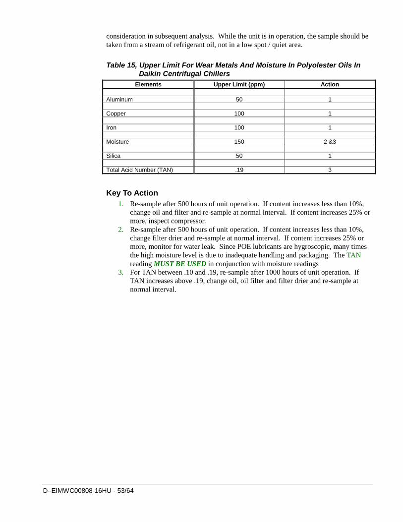
D–EIMWC00808-16HU - 53/64
consideration in subsequent analysis. While the unit is in operation, the sample should be
taken from a stream of refrigerant oil, not in a low spot / quiet area.
Table 15, Upper Limit For Wear Metals And Moisture In Polyolester Oils In
Daikin Centrifugal Chillers
Elements Upper Limit (ppm) Action
Aluminum 50 1
Copper 100 1
Iron 100 1
Moisture 150 2 &3
Silica 50 1
Total Acid Number (TAN) .19 3
Key To Action
1. Re-sample after 500 hours of unit operation. If content increases less than 10%,
change oil and filter and re-sample at normal interval. If content increases 25% or
more, inspect compressor.
2. Re-sample after 500 hours of unit operation. If content increases less than 10%,
change filter drier and re-sample at normal interval. If content increases 25% or
more, monitor for water leak. Since POE lubricants are hygroscopic, many times
the high moisture level is due to inadequate handling and packaging. The TAN
reading MUST BE USED in conjunction with moisture readings
3. For TAN between .10 and .19, re-sample after 1000 hours of unit operation. If
TAN increases above .19, change oil, oil filter and filter drier and re-sample at
normal interval.
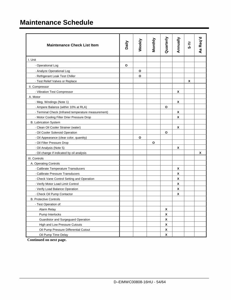
D–EIMWC00808-16HU - 54/64
Maintenance Schedule
Maintenance Check List Item
Daily
Weekly
Mo
nth
ly
Qu
art
erl
y
An
nu
ally
5-Y
r
As R
eq
’d
I. Unit
· Operational Log O
· Analyze Operational Log O
· Refrigerant Leak Test Chiller O
· Test Relief Valves or Replace X
II. Compressor
· Vibration Test Compressor X
A. Motor
· Meg. Windings (Note 1) X
· Ampere Balance (within 10% at RLA) O
· Terminal Check (Infrared temperature measurement) X
· Motor Cooling Filter Drier Pressure Drop X
B. Lubrication System
· Clean Oil Cooler Strainer (water) X
· Oil Cooler Solenoid Operation O
· Oil Appearance (clear color, quantity) O
- Oil Filter Pressure Drop O
· Oil Analysis (Note 5) X
· Oil change if indicated by oil analysis X
III. Controls
A. Operating Controls
· Calibrate Temperature Transducers X
· Calibrate Pressure Transducers X
· Check Vane Control Setting and Operation X
· Verify Motor Load Limit Control X
· Verify Load Balance Operation X
· Check Oil Pump Contactor X
B. Protective Controls
· Test Operation of:
Alarm Relay X
Pump Interlocks X
Guardistor and Surgeguard Operation X
High and Low Pressure Cutouts X
Oil Pump Pressure Differential Cutout X
Oil Pump Time Delay X
Continued on next page.
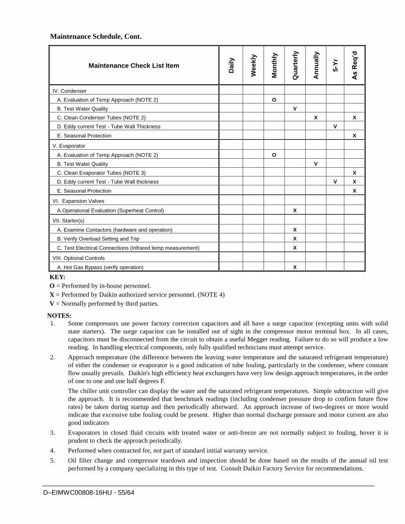
D–EIMWC00808-16HU - 55/64
Maintenance Schedule, Cont.
Maintenance Check List Item
Daily
Weekly
Mo
nth
ly
Qu
art
erl
y
An
nu
ally
5-Y
r
As R
eq
’d
IV. Condenser
A. Evaluation of Temp Approach (NOTE 2) O
B. Test Water Quality V
C. Clean Condenser Tubes (NOTE 2) X X
D. Eddy current Test - Tube Wall Thickness V
E. Seasonal Protection X
V. Evaporator
A. Evaluation of Temp Approach (NOTE 2) O
B. Test Water Quality V
C. Clean Evaporator Tubes (NOTE 3) X
D. Eddy current Test - Tube Wall thickness V X
E. Seasonal Protection X
VI. Expansion Valves
A.Operational Evaluation (Superheat Control) X
VII. Starter(s)
A. Examine Contactors (hardware and operation) X
B. Verify Overload Setting and Trip X
C. Test Electrical Connections (Infrared temp measurement) X
VIII. Optional Controls
A. Hot Gas Bypass (verify operation) X
KEY:
O = Performed by in-house personnel.
X = Performed by Daikin authorized service personnel. (NOTE 4)
V = Normally performed by third parties.
NOTES:
1. Some compressors use power factory correction capacitors and all have a surge capacitor (excepting units with solid
state starters). The surge capacitor can be installed out of sight in the compressor motor terminal box. In all cases,
capacitors must be disconnected from the circuit to obtain a useful Megger reading. Failure to do so will produce a low
reading. In handling electrical components, only fully qualified technicians must attempt service.
2. Approach temperature (the difference between the leaving water temperature and the saturated refrigerant temperature)
of either the condenser or evaporator is a good indication of tube fouling, particularly in the condenser, where constant
flow usually prevails. Daikin's high efficiency heat exchangers have very low design approach temperatures, in the order
of one to one and one half degrees F.
The chiller unit controller can display the water and the saturated refrigerant temperatures. Simple subtraction will give
the approach. It is recommended that benchmark readings (including condenser pressure drop to confirm future flow
rates) be taken during startup and then periodically afterward. An approach increase of two-degrees or more would
indicate that excessive tube fouling could be present. Higher than normal discharge pressure and motor current are also
good indicators
3. Evaporators in closed fluid circuits with treated water or anti-freeze are not normally subject to fouling, hover it is
prudent to check the approach periodically.
4. Performed when contracted for, not part of standard initial warranty service.
5. Oil filter change and compressor teardown and inspection should be done based on the results of the annual oil test
performed by a company specializing in this type of test. Consult Daikin Factory Service for recommendations.
D–EIMWC00808-16HU - 56/64
Service Programs
It is important that an air conditioning system receive adequate maintenance if the full equipment
life and full system benefits are to be realized.
Maintenance should be an ongoing program from the time the system is initially started. A full
inspection should be made after 3 to 4 weeks of normal operation on a new installation, and on a
regular basis thereafter.
Daikin offers a variety of maintenance services through the local Daikin service office, its
worldwide service organization, and can tailor these services to suit the needs of the building owner.
Most popular among these services is the Daikin Comprehensive Maintenance Contract.
For further information concerning the many services available, contact your local Daikin service
office.
Operator Schools
Training courses for Centrifugal Maintenance and Operation are held through the year at the
Training Center in Staunton, Virginia. The school duration is three and one-half days and includes
instruction on basic refrigeration, MicroTech controllers, enhancing chiller efficiency and reliability,
MicroTech troubleshooting, system components, and other related subjects. Further information can
be found on www.daikineurope.com or call Daikin at 540-248-0711 and ask for the Training
Department.
Warranty Statement
Limited Warranty
Consult your local Daikin Representative for warranty details. Refer to Form 933-43285Y. To find
your local Daikin Representative, go to www.daikineurope.com.
The following are trademarks or registered trademarks of their respective companies: Loctite
from Henkel Company; 3M, Scotchfil and Scotchkote from the 3M Company; Victaulic from
Victaulic Company; Megger from Megger Group Limited; Distinction Series, MicroTech II and
Protocol Selectability from Daikin.
Obligatory routine checks and starting up apparatuses
under pressure The units are included in category IV of the classification according to European Directive PED
2014/68/EU
For chillers belonging to this category, some local regulations require a periodic inspection by an
authorized agency. Please check with your local requirements.
D–EIMWC00808-16HU - 57/64
Important information regarding the refrigerant used
This product contains fluorinated greenhouse gases. Do not vent gases into the atmosphere.
Refrigerant type: R134a
GWP(1) value: 1430
(1)GWP = Global Warming Potential
The refrigerant quantity is indicated on the unit name plate.
Periodical inspections for refrigerant leaks may be required depending on European or local legislation. Please contact
your local dealer for more information.
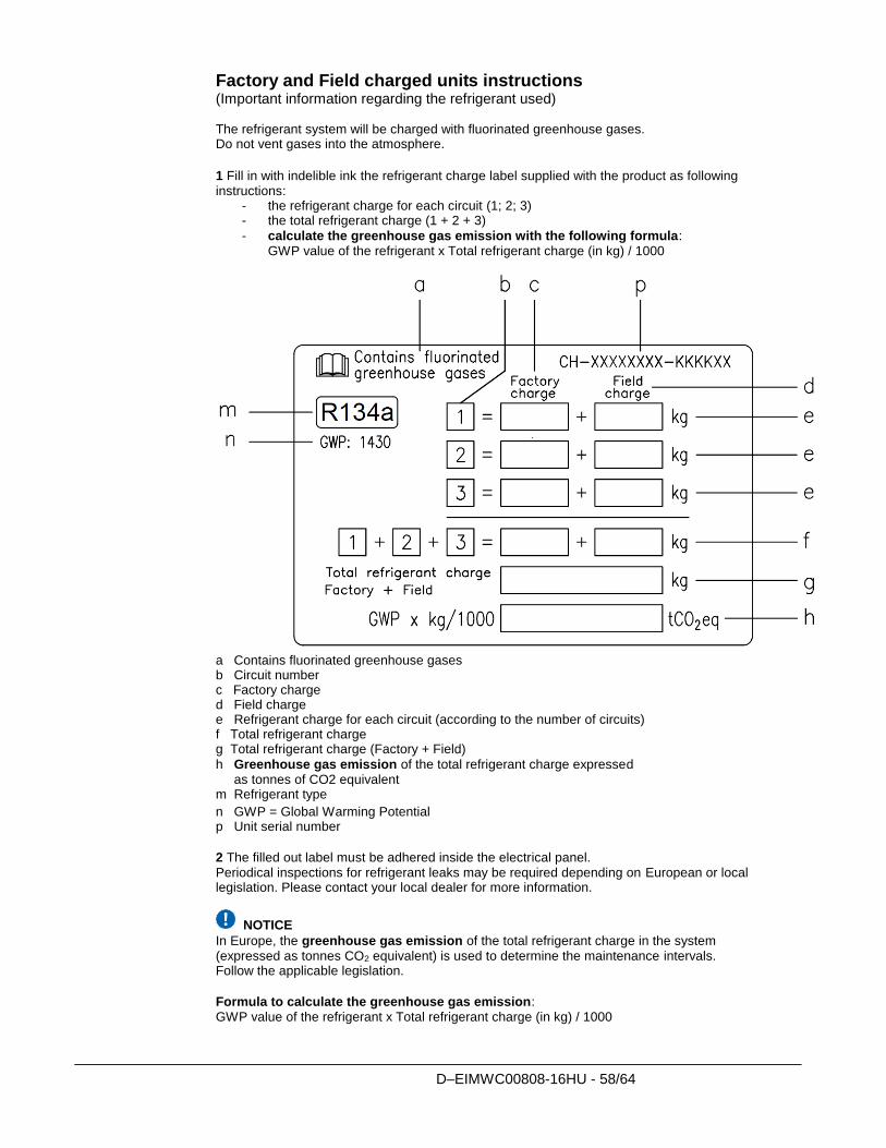
D–EIMWC00808-16HU - 58/64
Factory and Field charged units instructions (Important information regarding the refrigerant used) The refrigerant system will be charged with fluorinated greenhouse gases. Do not vent gases into the atmosphere.
1 Fill in with indelible ink the refrigerant charge label supplied with the product as following instructions:
- the refrigerant charge for each circuit (1; 2; 3) - the total refrigerant charge (1 + 2 + 3)
- calculate the greenhouse gas emission with the following formula: GWP value of the refrigerant x Total refrigerant charge (in kg) / 1000
a Contains fluorinated greenhouse gases b Circuit number c Factory charge d Field charge e Refrigerant charge for each circuit (according to the number of circuits) f Total refrigerant charge g Total refrigerant charge (Factory + Field)
h Greenhouse gas emission of the total refrigerant charge expressed as tonnes of CO2 equivalent m Refrigerant type
n GWP = Global Warming Potential p Unit serial number
2 The filled out label must be adhered inside the electrical panel. Periodical inspections for refrigerant leaks may be required depending on European or local legislation. Please contact your local dealer for more information.
NOTICE
In Europe, the greenhouse gas emission of the total refrigerant charge in the system (expressed as tonnes CO2 equivalent) is used to determine the maintenance intervals. Follow the applicable legislation.
Formula to calculate the greenhouse gas emission: GWP value of the refrigerant x Total refrigerant charge (in kg) / 1000
D–EIMWC00808-16HU - 59/64
Use the GWP value mentioned on the greenhouse gases label. This GWP value is based on the 4th IPCC Assessment Report. The GWP value mentioned in the manual might be outdated (i.e. based on the 3rd IPCC Assessment Report)
D–EIMWC00808-16HU - 60/64
Disposal
The unit is made of metal and plastic parts. All these parts must be disposed of in accordance with the local regulations in
terms of disposal. Lead batteries must be collected and taken to specific refuse collection centres.


The present publication is drawn up by of information only and does not constitute an offer binding upon Daikin Applied Europe S.p.A..
Daikin Applied Europe S.p.A. has compiled the content of this publication to the best of its knowledge. No express or implied warranty
is given for the completeness, accuracy, reliability or fitness for particular purpose of its content, and the products and services
presented therein. Specification are subject to change without prior notice. Refer to the data communicated at the time of the order.
Daikin Applied Europe S.p.A. explicitly rejects any liability for any direct or indirect damage, in the broadest sense, arising from or
related to the use and/or interpretation of this publication. All content is copyrighted by Daikin Applied Europe S.p.A..
DAIKIN APPLIED EUROPE S.p.A. Via Piani di Santa Maria, 72 - 00072 Ariccia (Roma) - Italia
Tel: (+39) 06 93 73 11 - Fax: (+39) 06 93 74 014
http://www.daikinapplied.eu