Industrial Grade Integrally Geared Pumps Perfect for High ...
2
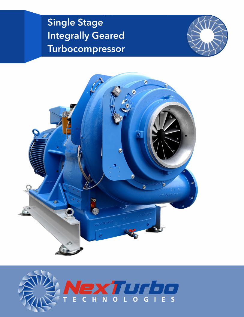
Single Stage Integrally Geared Turbocompressor
2
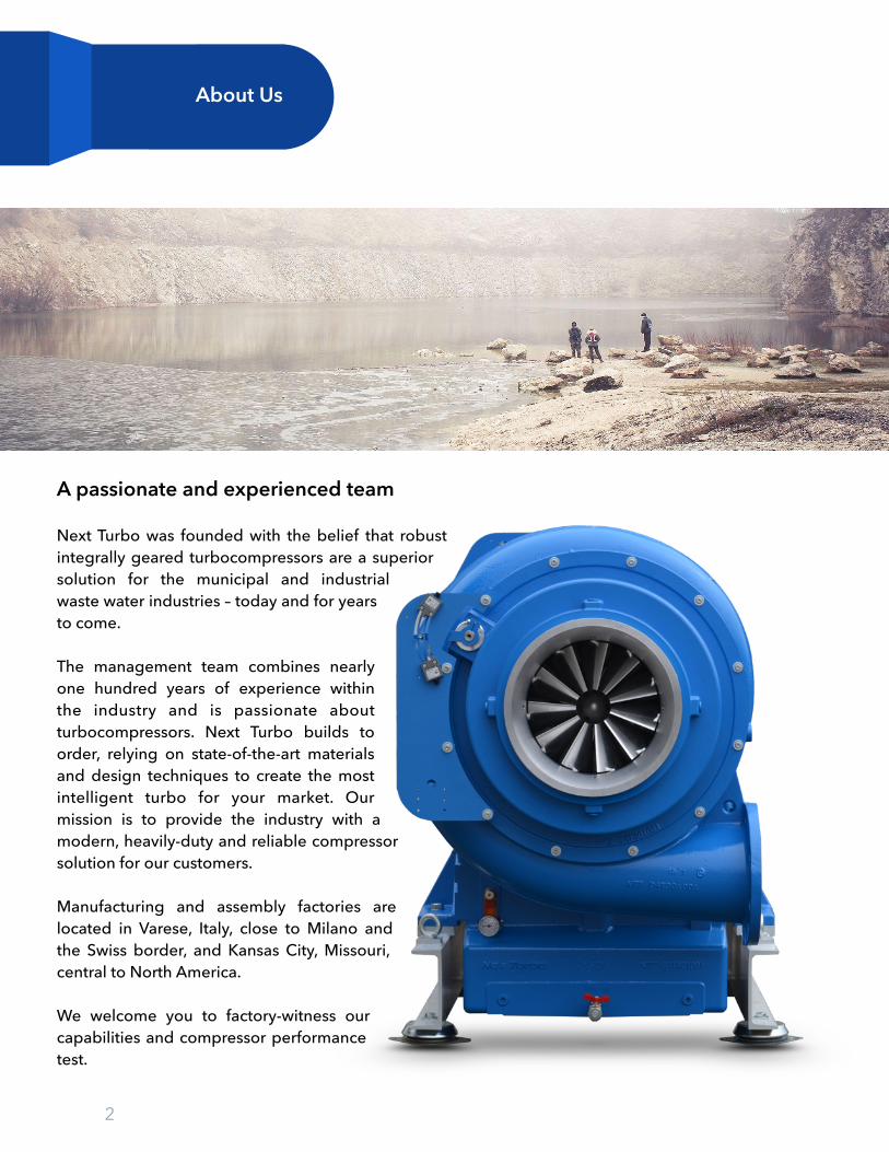
A passionate and experienced team
Next Turbo was founded with the belief that robust integrally geared turbocompressors are a superior solution for the municipal and industrial waste water industries – today and for years to come.
The management team combines nearly one hundred years of experience within the industry and is passionate about turbocompressors. Next Turbo builds to order, relying on state-of-the-art materials and design techniques to create the most intelligent turbo for your market. Our mission is to provide the industry with a modern, heavily-duty and reliable compressor solution for our customers.
Manufacturing and assembly factories are located in Varese, Italy, close to Milano and the Swiss border, and Kansas City, Missouri, central to North America. We welcome you to factory-witness our capabilities and compressor performance test.
About Us
�3
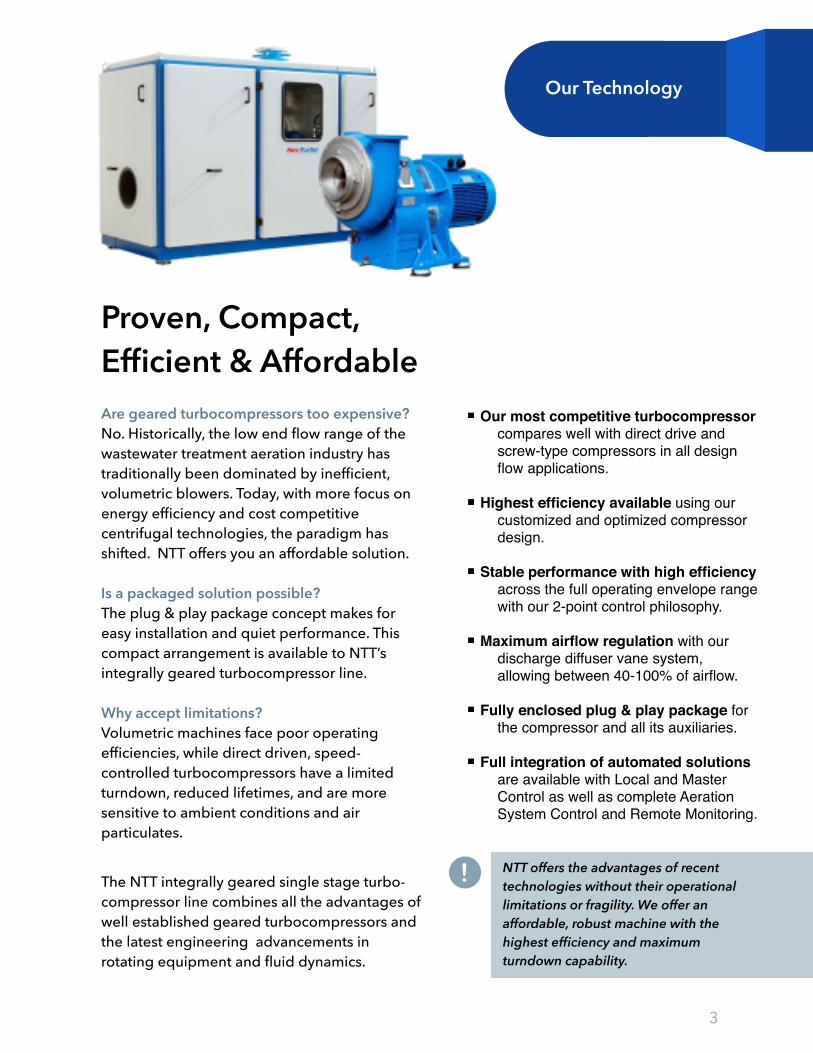
Proven, Compact, Efficient & Affordable Are geared turbocompressors too expensive? No. Historically, the low end flow range of the wastewater treatment aeration industry has traditionally been dominated by inefficient, volumetric blowers. Today, with more focus on energy efficiency and cost competitive centrifugal technologies, the paradigm has shifted. NTT offers you an affordable solution.
Is a packaged solution possible? The plug & play package concept makes for easy installation and quiet performance. This compact arrangement is available to NTT’s integrally geared turbocompressor line.
Why accept limitations? Volumetric machines face poor operating efficiencies, while direct driven, speed-controlled turbocompressors have a limited turndown, reduced lifetimes, and are more sensitive to ambient conditions and air particulates.
The NTT integrally geared single stage turbo-compressor line combines all the advantages of well established geared turbocompressors and the latest engineering advancements in rotating equipment and fluid dynamics.
Our most competitive turbocompressor compares well with direct drive and screw-type compressors in all design flow applications.
Highest efficiency available using our customized and optimized compressor design.
Stable performance with high efficiency across the full operating envelope range with our 2-point control philosophy.
Maximum airflow regulation with our discharge diffuser vane system, allowing between 40-100% of airflow.
Fully enclosed plug & play package for the compressor and all its auxiliaries.
Full integration of automated solutions are available with Local and Master Control as well as complete Aeration System Control and Remote Monitoring.
NTT offers the advantages of recent technologies without their operational limitations or fragility. We offer an affordable, robust machine with the highest efficiency and maximum turndown capability.
Our Technology
!
4
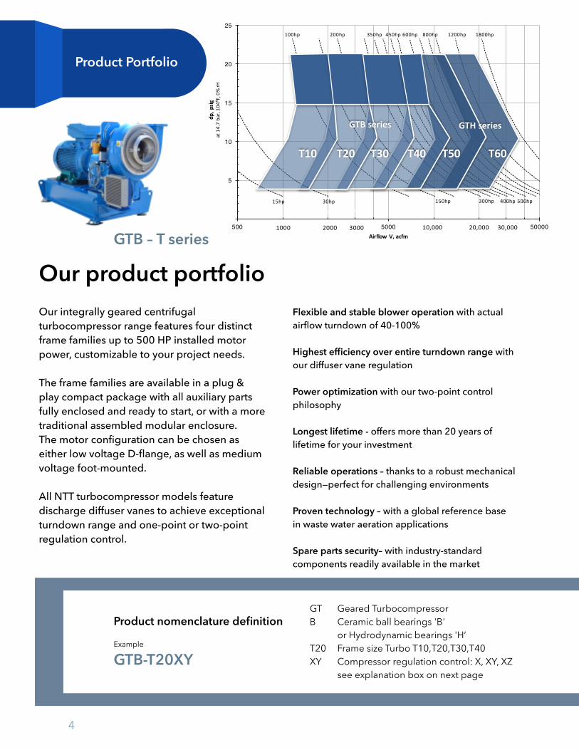
Product Portfolio
GTB – T series
Our product portfolio Our integrally geared centrifugal turbocompressor range features four distinct frame families up to 500 HP installed motor power, customizable to your project needs.
The frame families are available in a plug & play compact package with all auxiliary parts fully enclosed and ready to start, or with a more traditional assembled modular enclosure. The motor configuration can be chosen as either low voltage D-flange, as well as medium voltage foot-mounted.
All NTT turbocompressor models feature discharge diffuser vanes to achieve exceptional turndown range and one-point or two-point regulation control.
Flexible and stable blower operation with actual airflow turndown of 40-100%
Highest efficiency over entire turndown range with our diffuser vane regulation
Power optimization with our two-point control philosophy
Longest lifetime - offers more than 20 years of lifetime for your investment
Reliable operations – thanks to a robust mechanical design—perfect for challenging environments
Proven technology – with a global reference base in waste water aeration applications
Spare parts security– with industry-standard components readily available in the market
GT Geared Turbocompressor B Ceramic ball bearings 'B' or Hydrodynamic bearings 'H‘ T20 Frame size Turbo T10,T20,T30,T40 XY Compressor regulation control: X, XY, XZ see explanation box on next page
Example
GTB-T20XY
Product nomenclature definition
5
10
15
20
25
500 5000 50000
dp,p
sigat14.7bar,10
4ºF,0%
rH
Airflow V,acfm1000 2000 3000 10,000 20,000 30,000
100hp 200hp 350hp 450hp 600hp 800hp 1200hp 1800hp
15hp 30hp 150hp 300hp 400hp 500hp
GTBseries
T10 T20 T30 T40 T60
GTHseries
T50
5
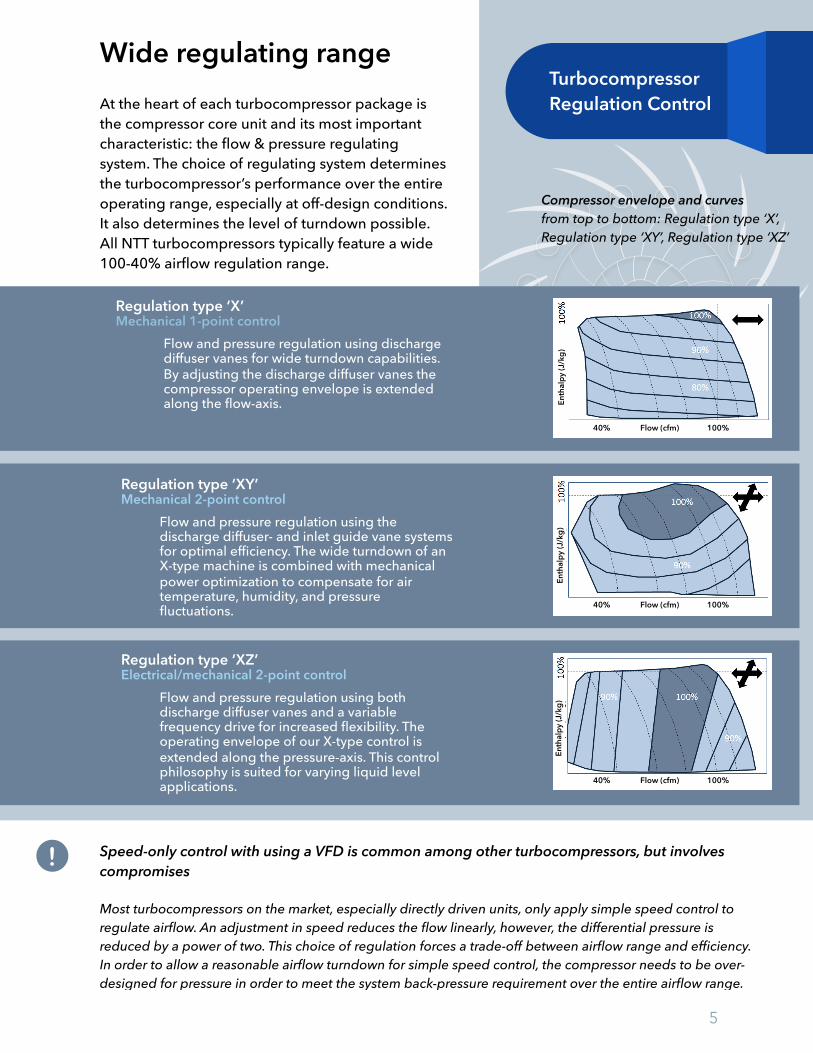
Wide regulating range At the heart of each turbocompressor package is the compressor core unit and its most important characteristic: the flow & pressure regulating system. The choice of regulating system determines the turbocompressor’s performance over the entire operating range, especially at off-design conditions. It also determines the level of turndown possible. All NTT turbocompressors typically feature a wide 100-40% airflow regulation range.
Speed-only control with using a VFD is common among other turbocompressors, but involves compromises
Most turbocompressors on the market, especially directly driven units, only apply simple speed control to regulate airflow. An adjustment in speed reduces the flow linearly, however, the differential pressure is reduced by a power of two. This choice of regulation forces a trade-off between airflow range and efficiency. In order to allow a reasonable airflow turndown for simple speed control, the compressor needs to be over-designed for pressure in order to meet the system back-pressure requirement over the entire airflow range.
Turbocompressor Regulation Control
Compressor envelope and curves from top to bottom: Regulation type ‘X’, Regulation type ‘XY’, Regulation type ‘XZ’
Regulation type ‘X’ Mechanical 1-point control
Flow and pressure regulation using discharge diffuser vanes for wide turndown capabilities. By adjusting the discharge diffuser vanes the compressor operating envelope is extended along the flow-axis.
Regulation type ‘XY’ Mechanical 2-point control
Flow and pressure regulation using the discharge diffuser- and inlet guide vane systems for optimal efficiency. The wide turndown of an X-type machine is combined with mechanical power optimization to compensate for air temperature, humidity, and pressure fluctuations.
Regulation type ‘XZ’ Electrical/mechanical 2-point control
Flow and pressure regulation using both discharge diffuser vanes and a variable frequency drive for increased flexibility. The operating envelope of our X-type control is extended along the pressure-axis. This control philosophy is suited for varying liquid level applications.
!
40% Flow (cfm) 100%
40% Flow (cfm) 100%
40% Flow (cfm) 100%
Enth
alpy
(J/k
g)En
thal
py (J
/kg)
Enth
alpy
(J/k
g)
6
1
2
34
6
7
8
5
9 10
11
11
12
13
14
11
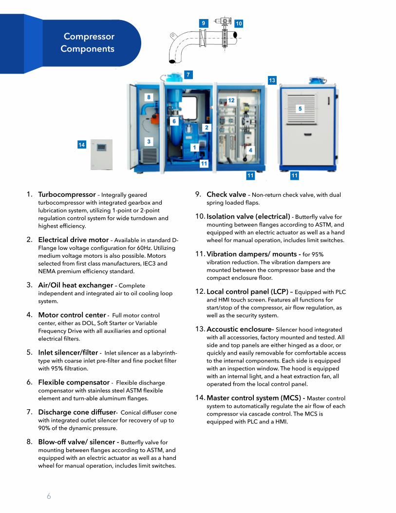
Compressor Components
1. Turbocompressor – Integrally geared turbocompressor with integrated gearbox and lubrication system, utilizing 1-point or 2-point regulation control system for wide turndown and highest efficiency.
2. Electrical drive motor – Available in standard D-Flange low voltage configuration for 60Hz. Utilizing medium voltage motors is also possible. Motors selected from first class manufacturers, IEC3 and NEMA premium efficiency standard.
3. Air/Oil heat exchanger – Complete independent and integrated air to oil cooling loop system.
4. Motor control center - Full motor control center, either as DOL, Soft Starter or Variable Frequency Drive with all auxiliaries and optional electrical filters.
5. Inlet silencer/filter - Inlet silencer as a labyrinth-type with coarse inlet pre-filter and fine pocket filter with 95% filtration.
6. Flexible compensator - Flexible discharge compensator with stainless steel ASTM flexible element and turn-able aluminum flanges.
7. Discharge cone diffuser- Conical diffuser cone with integrated outlet silencer for recovery of up to 90% of the dynamic pressure.
8. Blow-off valve/ silencer - Butterfly valve for mounting between flanges according to ASTM, and equipped with an electric actuator as well as a hand wheel for manual operation, includes limit switches.
9. Check valve – Non-return check valve, with dual spring loaded flaps.
10. Isolation valve (electrical) - Butterfly valve for mounting between flanges according to ASTM, and equipped with an electric actuator as well as a hand wheel for manual operation, includes limit switches.
11. Vibration dampers/ mounts - for 95% vibration reduction. The vibration dampers are mounted between the compressor base and the compact enclosure floor.
12. Local control panel (LCP) – Equipped with PLC and HMI touch screen. Features all functions for start/stop of the compressor, air flow regulation, as well as the security system.
13. Accoustic enclosure- Silencer hood integrated with all accessories, factory mounted and tested. All side and top panels are either hinged as a door, or quickly and easily removable for comfortable access to the internal components. Each side is equipped with an inspection window. The hood is equipped with an internal light, and a heat extraction fan, all operated from the local control panel.
14. Master control system (MCS) - Master control system to automatically regulate the air flow of each compressor via cascade control. The MCS is equipped with PLC and a HMI.

7
Acoustical Enclosure Options
b c
a
Compact enclosure for compressor with D-flanged console, available up to 400 HP motor size. All components fully enclosed, including optional Motor Control Center. The compact enclosure can be lifted via eyebolts (a), forklift (b) or special bolts (c).
Modular enclosure for compressors both with D-flanged console or foot-mounted basement, delivered as a build up kit, covers the full range up to 500 HP motor size. The local control panel and the optional Motor Control Center are built as stand alone panels. The blow-off valve, check valve and inlet system are external and shipped loose.
Compact plug & play packageA fully enclosed, pre-wired and tested plug & play solution
The compact acoustic enclosure integrates all required accessories, factory mounted and tested. Main steel structure comes with all side and top panels either hinged as a door, or is quickly and easily removable for comfortable access to the internal components. Each side is equipped with an inspection window. The compact enclosure comes with an internal light and heat extraction fan, controlled from the local control panel. The peak noise during start and stop is eliminated due to the integrated blow-off valve and silencer. The package is easy to handle due to access holes for fork-lift at the base plate and dedicated lifting lugs on top of the enclosure.
Dedicated compartments can be provided for local control panel, MCC configuration with VFD, soft starter, DOL and the inlet system. Only one external connection at power supply is necessary, accessible from top or from bottom. The Next step is to press the start button.
A traditional modular enclosure for easy installation customized to site conditions
The modular enclosure is built around the compressor unit, which is installed on the floor. The modular enclosure consists of several doors (modules) which are easily removed in case of maintenance (lift and remove). Some doors are hinged and equipped with a window. Both structure and sound absorbing panels are made of sandwich bended Aluzinc steel sheets filled with mineral wool and a plaster sheet.
The inlet silencer is installed in front of the unit and connected to the compressor inlet via a flexible metal joint. A stand alone local control can is shipped loose and mounted outside of the enclosure.
Modular package
Both Compact and Modular solutions are available with outdoor installation configuration
8
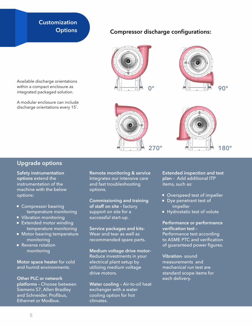
Customization Options Compressor discharge configurations:
Available discharge orientations within a compact enclosure as integrated packaged solution.
A modular enclosure can include discharge orientations every 15˚.
Upgrade optionsSafety instrumentation options extend the instrumentation of the machine with the below options:
Compressor bearing temperature monitoring
Vibration monitoring Extended motor winding
temperature monitoring Motor bearing temperature
monitoring Reverse rotation
monitoring
Motor space heater for cold and humid environments.
Other PLC or network platforms – Choose between Siemens S7, Allen Bradley and Schneider. Profibus, Ethernet or Modbus.
Remote monitoring & service integrates our intensive care and fast troubleshooting options.
Commissioning and training of staff on site – factory support on site for a successful start-up.
Service packages and kits- Wear and tear as well as recommended spare parts.
Medium voltage drive motor-Reduce investments in your electrical plant setup by utilizing medium voltage drive motors.
Water cooling – Air-to-oil heat exchanger with a water cooling option for hot climates.
Extended inspection and test plan – Add additional ITP items, such as:
Overspeed test of impeller Dye penetrant test of
impeller Hydrostatic test of volute
Performance or performance verification test – Performance test according to ASME PTC and verification of guaranteed power figures.
Vibration- sound measurements and mechanical run test are standard scope items for each delivery.
0° 90°
270° 180°
9
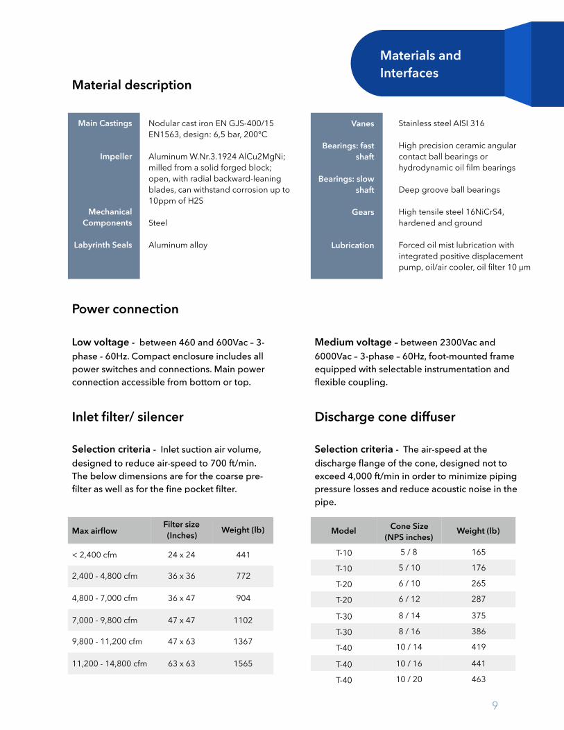
Material description
Materials and Interfaces
Nodular cast iron EN GJS-400/15 EN1563, design: 6,5 bar, 200℃
Aluminum W.Nr.3.1924 AlCu2MgNi; milled from a solid forged block; open, with radial backward-leaning blades, can withstand corrosion up to 10ppm of H2S
Steel
Aluminum alloy
Main Castings
Impeller
Mechanical Components
Labyrinth Seals
Vanes
Bearings: fast shaft
Bearings: slow shaft
Gears
Lubrication
Power connection
Low voltage - between 460 and 600Vac – 3-phase - 60Hz. Compact enclosure includes all power switches and connections. Main power connection accessible from bottom or top.
Inlet filter/ silencer
Selection criteria - Inlet suction air volume, designed to reduce air-speed to 700 ft/min. The below dimensions are for the coarse pre-filter as well as for the fine pocket filter.
Medium voltage – between 2300Vac and 6000Vac – 3-phase – 60Hz, foot-mounted frame equipped with selectable instrumentation and flexible coupling.
Selection criteria - The air-speed at the discharge flange of the cone, designed not to exceed 4,000 ft/min in order to minimize piping pressure losses and reduce acoustic noise in the pipe.
Discharge cone diffuser
Stainless steel AISI 316
High precision ceramic angular contact ball bearings or hydrodynamic oil film bearings
Deep groove ball bearings
High tensile steel 16NiCrS4, hardened and ground
Forced oil mist lubrication with integrated positive displacement pump, oil/air cooler, oil filter 10 µm
Max airflowFilter size (Inches) Weight (lb)
< 2,400 cfm 24 x 24 441
2,400 - 4,800 cfm 36 x 36 772
4,800 - 7,000 cfm 36 x 47 904
7,000 - 9,800 cfm 47 x 47 1102
9,800 - 11,200 cfm 47 x 63 1367
11,200 - 14,800 cfm 63 x 63 1565
Model Cone Size (NPS inches)
Weight (lb)
T-10 5 / 8 165
T-10 5 / 10 176
T-20 6 / 10 265
T-20 6 / 12 287
T-30 8 / 14 375
T-30 8 / 16 386
T-40 10 / 14 419
T-40 10 / 16 441
T-40 10 / 20 463
10
Automated Solutions
Local control panel
The local control panel (LCP) features the main functions for starting and stopping the compressor, as well as the health monitoring procedures. Within the compact enclosure, the LCP is fully integrated in its own compartment. Other features:
All compressor controls, alarms, trips and all auxiliaries Diffuser capacity control (airflow control) Connection to master control system (MCS) or plant distributed control system (DCS) Power supply 3 x 460Vac + N + PE
Master Control System (MCS)The MCS (Master Control System) controls the turbocompressor air flow with a high efficiency cascade control that perfectly matches process air requirements and equalizes compressor duty hours. The MCS is a stand-alone panel situated in or near the blower room.
The Master Control System with integrated Dissolved Oxygen (DO) controlThe MCS-DO system covers all the functions of the MCS system, and additionally controls the aeration valves in the treatment basin based on the DO set-point and the DO process value. The DO transmitters, as well as the aeration control valves, are connected to the MCS-DO panel (via hardwire or network). The MCS-DO CPU’s software, with multiple parallel algorithms, compares the DO process value to the set-point and adjusts the aeration valves accordingly.
In the highly fluctuating aeration environment, the overall system pressure in the pipe is constantly changing. The MCS-DO automatically calculates the lowest system pressure using MOV (Most Open Valve) philosophy. This function allows the system pressure to be kept at a minimum because the aeration valves will be operated in their most efficient operational ranges, reducing overall operating costs. The “hunting” phenomena, which many plants using third-party software are subject to, is also minimized by adopting this functionality.
Cascade control Most turbocompressors using only speed control must operate in parallel, where all blowers are adjusted simultaneously at the same speed to prevent surging. Next Turbo’s cascade control modulates only one blower for a more precise airflow adjustment, while the remaining blowers operate at minimum, maximum airflow or standby. NTT’s typical 100—40% turndown range allows for an overlap when operating multiple blowers, increasing process stability.
Model Network
Siemens S7-ET200SP Ethernet, Profibus
Siemens S7-300 Profibus, Ethernet
Allan Bradley Ethernet
Schneider Modicon M2xx Ethernet, Modbus
Available PLC platforms & networks: !
http://www.next-turbo.com
Publishedandcopyright©2016–NextTurboAmericas,Inc.MoreinformaDonavailableathFp://www.next-turbo.comAllrightsreserved.TrademarksmenDonedinthisdocumentarethepropertyofNTTS.p.A.,itsaffiliates,ortheirrespecDveowners.SubjecttochangewithoutpriornoDce.TheinformaDoninthisdocumentcontainsgeneraldescripDonofthetechnicalfeatures,whichmaynotapplyinallcases.TherequiredtechnicalopDonsshouldthereforebespecifiedinthecontract.