SINGLE POINT TOOLS - Direktori File UPIfile.upi.edu/Direktori/FPTK/JUR._PEND._TEKNIK_MESIN/... ·...
26
SINGLE POINT TOOLS Cutting tools are designed with sharp edges to minimized rubbing contact between the tool and the workpiece. The various angles ground on a tool bit are called the basic tool angles, and compose what is often termed the tool geometry. The signature is a sequence of number listing the various angles, in degrees, and the size of the nose radius.
Transcript of SINGLE POINT TOOLS - Direktori File UPIfile.upi.edu/Direktori/FPTK/JUR._PEND._TEKNIK_MESIN/... ·...

SINGLE POINT TOOLS
Cutting tools are designed with sharp edges to minimized rubbing contact
between the tool and the workpiece. The various angles ground on a tool bit are called the
basic tool angles, and compose what is often termed the tool geometry. The signature is a
sequence of number listing the various angles, in degrees, and the size of the nose radius.

Back rake angle. This is the angle between the face of the tool and a line that is
parallel to the base of the toolholder. It is measured in a plane that is parallel to the side
cutting edge and perpendicular to the base. Variation in the back rake angle affect the
direction of chip flow.
Side rake angle. This angle is defined as the angle between the tool face and the
plane parallel to the tool base. It is measured in a plane perpendicular to both the base of
the holder and the side cutting edge. Variations in this angle affect the direction of chip
flow.
End relief angle. This is the angle between the end flank and a line perpendicular
to the base of the tool. The purpose of this angle is to prevent rubbing between the
workpiece and the end flank of the tool.
Side relief angle. This is the angle between the side flank of the tool and a line
drawn perpendicular to the base. For turning operations, the side relief angle must be
large enough to allow for the feed helix angle on the shoulder of the workpiece.
End cutting edge angle. This is the angle between the edge on the end of the tool
and a plane perpendicular to the side of the tool shank. The purpose is to avoid rubbing
between the edge of the tool and the workpiece.
Side cutting edge angle. This is the angle between the straight cutting edge on
bthe side of the tool and the side of the tool shank. This side edge provides the major
cutting action and should be kept as sharp as possible.
Nose radius. The nose radius connects the side and end cutting edges and should
blend smoothly into each to facilitate grinding.
Tool signature. The seven elements that comprise the signature of a single point
cutting tools are always stated in the following order; back rake angle, side rake angle,
end relief angle, side relief angle, end cutting edge angle, side cutting edge angle, and
nose radius.

Figure 1-4 illustrates the effect of using a holder that position the base of the tool
in a plane nonparallel with the plane of feeding motion. A 15 degrees toolholder is used,
and the tool signature indicates the angle that result when the tool is positioned in the
holder.

Chip formation
Chip formation involves the basic requirements:
1. their must be a cutting tool that is harder and more wear resistant than the
workpiece material.
2. there must be interference between the tool and the workpiece as designated by
the feed and depth of cut
3. there must be a relative motion or cutting velocity between the tool and the
workpiece with sufficient force and power to overcome the resistance of the
workpiece material.
As long as these three conditions exist, the portion of the material being machined
that interferes with free passage of the tool will be displaced to create a chip.
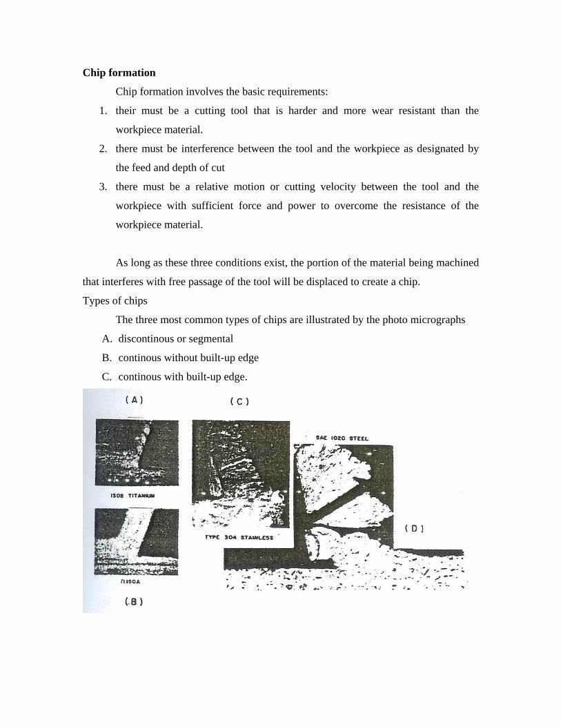
Types of chips
The three most common types of chips are illustrated by the photo micrographs
A. discontinous or segmental
B. continous without built-up edge
C. continous with built-up edge.

Tool wear
For the sake of recognition and understanding of the fundamentals of metal
cutting, the effects of changes in the manipulating factors have been described without
regard to their influence upon such criteria as tool wear and tool life. Yet there is no
known tool material flat can completely resist contact and rubbing at high temperatures
and high pressure, with some changes from its original contours over a period time. It
becomes necessary, therefore to think of the effect of the manipulating factors not only
upon the cutting process itself, but upon the performance of the cutting tool, which may,
in turn, itself affect the cutting process.
Tool life
The types and mechanism of tool failure have been previously described. It was
shown that excessive cutting speeds cause a rapid failure of the cutting edge; thus, the
tool can be declared to have had a short life. Other criteria are sometimes used to evaluate
tool life, these are :
1. change of the quality of the machined surface
2. change in the magnitude of the cutting force resulting in changes in machine and
workpiece deflections causing workpiece dimensions to change
3. change in the cutting temperature.

The logarithm of tool life in minutes is plotted against the logarithm of cutting
speed in feet perminute. The resulting curve is very nearly a straight line in the most
instances. For are practical purposes it can be considered a straight line. This curved is
expressed by the following equation :
VTn = C
Where : V = cutting speed, feet per minute
T = tool life, minutes
C = a constant equal to the intercept of the curve and the ordinate or the
cutting speed- actually it is the cutting speed for a one minute tool life.
n = slope of the curve.
Machining economics
Althoughts the equation already given will predict the tool life for a given cutting
speed with reasonable accuracy, they do not answer the question of what tool life should
be obtained for maximum production or for minimum cost per part. The following
equations will provide the answers to these questions.
Tool life for maximum production :
211
Kn
T
Tool life for minimum cost per part:
3
43211
K
KKK
nT
Where : T = tool life,minutes
N = slope of the tool life curve
K2 = tool changing time per tool, minutes
K3 = machine labor plus burden cost, dollars perminute.
K4 = tool regrinding cost, dollars per cutting edge plus original cost of
tool, devided by the number of available cutting edges per tool.

Basic Principles Of Multiple Point Tools
Multiple-point cutting tools are basically a series of single point tools mounted in
or integral with a holder or body and operated in such a manner that all the teeth follow
essentially the same path across the work piece. Multiple point tools may be of either the
linear-travel or the rotary type.

WORKHOLDING DEVICES
The term workholder embraces all devices that hold, grip or chuck a workpiece in
a prescribed manner of firmness and location, to perform on it a manufacturing operation.
The holding force may be applied mechanically, electrically, hydraulically or
pneumatically.

Evolution of workholders
Direction of forces. The application of any metal removal process to a specific
workpiece will result in a distinctive combination of forces. It is possible to list the many
processes and anticipate forces to some extent. The torque of a drilling operations or the
thrust of a shaping operations can be readily visualized.
Magnitude of forces. The workholder must support the workpiece ina precise
location while it is subjected to the cutting forces. The workholder must therefore be
designed to withstand forces of specific direction and magnitude.
Combined methods. The cut and try approach in itself is neither efficient nor sale.
The resulting workholders may be either much stronger than required or may be on the
brink of failure with potential danger to personnel. The analytical approach in itself is not
practical. Complete determination of the magnitude and direction of all forces coupled
with virgin design of all fixture components would in most cases be economically
impossible. A workholder would probably have fasteners of different diameter at each
attachment point to match the anticipated load, and therefore would be impractical from
maintenance standpoint.

DESIGN OF PRESSWORKING TOOLS
Power pressed
Energy stored in the rotating flywheel of a mechanical press or supplied by a
hydraulic system in a hydraulic press is transferred to the ram for its linear movement. An
open back incenable (OBI) press, widely used, has C shaped frame which allows access
to its working space.
Cutting (shearing )operations
Shear action in die cutting operations
The cutting of metal between die components is a shearing process in which the metal is
stressed in shear between two cutting edges to the point of fracture or beyond its ultimate
strength.

Cutting forces
The pressure P required to cut (shear) work material is
)(
)(..
contoursotherforSLtP
holesroundforStDP
Where : S = shear strength of material, Psi
D = hole diameter, in.
L = shear length,in.
T = material thickness,in.
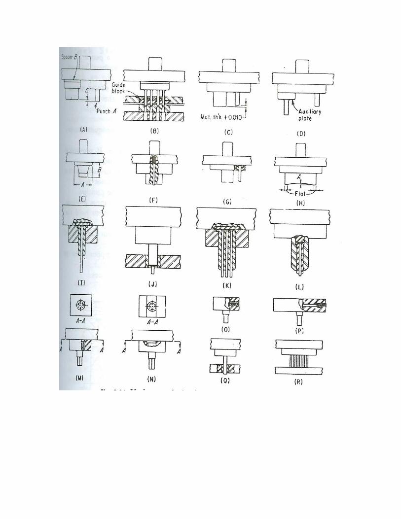
Methods of punch support
Gambar
Pilots
Since pilot breakage can result in the production of inaccurate parts and jamming or
breaking of die elements, pilot should be made of made of good tool-steel, heat treated
for maximum toughness and to hardness of Rockwell C57 to 60.

Types of die cutting operations
The operations of die cutting of work materials are classified as follows :
Piercing (punching). Is the operation in which a round punch (or of other
contours) cuts a hole in the work material which is supported by a die having an opening
corresponding exactly to the contour of the punch. The material (slug) cut from the work
material is often scrap.
Blanking. Fundamentally differs from piercing only in that the part cut from the
work material is usable, becoming a blank (workpiece) for subsequent pressworking or
other processing.
Lancing. Combines bending and cutting along a line in the work material. It does
not produce a detached slug and leaves a bent portion or tab attached to the work
material.
A cut off operation achieves complete separation of the work material by cutting
it along straight or curved lines.

Piercing die design
A complete press tool for cutting two holes in work material, at one stroke of the
press, as classified and standardized by a large manufacturer as a single-station piercing
die.

Blanking die design.
Cutting-rule dies. Instead of a conventional female die, the sharp edges of steel
rule form the cutting blades of the dies. The rule, bent to the contour of the blank outline,
is used principally for blanking cork, paper and similar nonmetallic fibrous material,
although the economical blanking of aluminum stock up to 0,4 in.

BENDING, FORMING AND DRAWING DIES
Bending dies
Bending is uniform straining of material, usually flat sheet or strip metal, around a
straight axis which lies in the neutral plane and normal to the lengthwise direction of the
sheet or strip. Metal flow takes place within the plastic range of the metal, so that the
bend retains a permanent set after removal of the applied stress. The inner surface of a
bend is in compression; the outer surface is in tension. A pure bending action does not
reproduce the exact shape of the punch and die in the metal; such a reproduction is one of
forming.

Forming dies
Forming dies, often considered in the same class with bending dies, are classified
as tools that form or bend the blank along a curved axis instead of straight axis. There is
very little stretching or compressing of the material. The internal movement or the plastic
flow of the material is localized and has little or no effect on the total area or thickness of
the material. The operations classified as forming are embossing, curling, beading,
twisting, and hole flanging
Solid form dies
Forming dies with pressure pads

Drawing dies
Drawing is a process of changing a flat, precut metal blank into a hollow vessel
without excessive wrinkling, thinning or fracturing. The various form produced may be
cylindrical or box-shaped with straight or tapered sides or a combination of straight,
tapered or curved sides. The size of the part may vary from ¼ in. diameter or smaller, to
aircraft or automotive parts large enough to require the use of mechanical handling
equipment.
Single action dies

Double action dies
Evolution of a draw die

INJECTION MOLDS AND EXTRUSION MOLDS
Classification of injection molds
A critical evaluation of a large number of injection molds for part fulfilling a
variety of applications results in the identification of certain classes and groups thet differ
from each other in the construction in some basic manner. a basic requirement of any
mold that is intended for use on an automatic injection molding machine is that the
molded parts be automatically ejected from the mold without the necessity for secondary
operations.
From a practical standpoint, a classification of injection molds should be based on
the main design features and manner of operation. These include:
The type of gating and means of degating
The type of ejection used for the molded parts
The presence or absence of external or internal undercuts on the parts to be
molded.
The manner in which the part is released from the mold
Effect of draft on the design of an injection mold
For functional reasons, the draft that must sometimes be employed in an injection
mold appears contrary to that required for easy part removal. The requirements in this
example is to produce a slip together protective coil case consisting of two identical
halves of which four are produced simultaneously in one mold


Four cavity injection mold for production of ABS cases

Runner system and gating
Sizing of sprues and runners
Sprues, runners and gates fulfill the function of conveying the plastics melt from
the nozzle of the injection unit to the individual cavities.
Sprue
The sprue may be considered the continuation in the mold of the channel in the
nozzle. Single cavity molds where the sprue leads directly to the molded part are said to
have direct sprue gating. The sprue should have 1,5o of draft. Greater draft may simplify
removal from the sprue bushing, but with a longer sprue results in a greater diameter and
thus longer cooling time. The nozzle orifice should be about 0,5 mm smaller in diameter
than the smallest opening in the sprue bushing so that there is no undercut at the end of
the sprue to hinder removal.
Runners
In multiple cavity molds, the plastic melt must flow to the individual cavities
through runners in the mold parting line. The same basic rules that apply to the sprue
apply also to the cross section of this runners. An additional factor that must be
considered is that the cross section is also a function of the length of the runner, since it
may be assumed that the pressure lost in a runner increase at least proportionally with the
length. Because the sprue and runner system represent lost material and lost plasticating
capacity, the runners should be designed to be as short as possible and with the smallest
possible section.

Self degating injection molds for flat parts

Extrusion dies
Impact extrusion, as known as cold extrusion or cold forging, is closely allied to
coining, sizing and forging operation. The operation are generally performed in hydraulic
or metal presses. The press applies sufficient pressure to cause plastic flow of the
workpiece material (metal) and to form the metal to a desired shape. A metal slug is
placed in a stationary die cavity into which a punch is driven by the press action. The
metal is extruded upward around the punch, downward through an orifice, or in any
direction to fill the cavity between the punch and die. The shape of the finished part is
determined by the shape of the punch and the die.