Single, compact, cost-effective fixture control -...
20
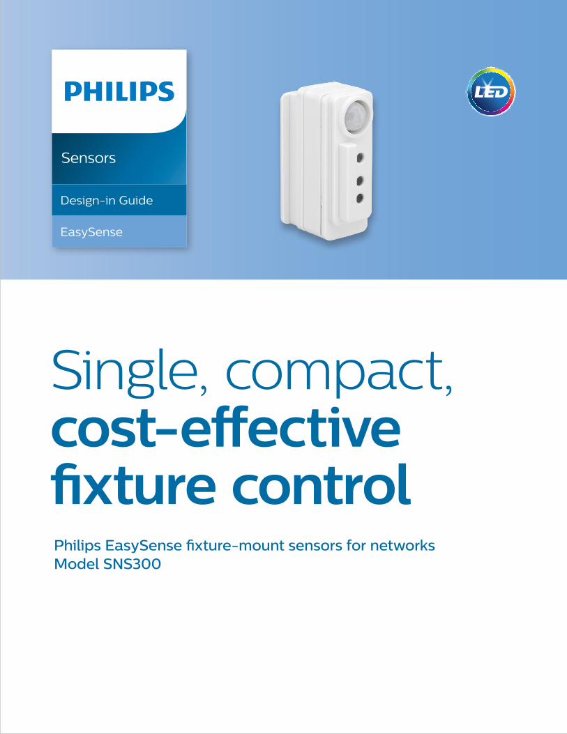
Sensors Design-in Guide EasySense Single, compact, cost-effective fixture control Philips EasySense fixture-mount sensors for networks Model SNS300
Transcript of Single, compact, cost-effective fixture control -...
Sensors
Design-in Guide
EasySense
Single, compact, cost-effective fixture controlPhilips EasySense fixture-mount sensors for networks Model SNS300

2 Philips
ContentsIntroduction to this guide 3 More information or support 3Warnings and instructions 3Introduction of EasySense 4Product characteristics 5 EasySense overview 5 NFC antenna 5 RF antenna 5 Infared (IR) receiver 5 Motion detector 6 Light sensor 7 LED indicator 8 Lighting control 8 Limited functions of Philips Field Apps 9Mechanical design-in 10 Mounting to a luminaire 10 Wiring diagram with Philips Advance Xitanium SR LED driver 12 Labeling for field installation and commissioning 14 Recommendations to design a luminaire around EasySense with good RF signal 15 Sensor position 15 Sensor spacing recommendations 16EasySense with multiple Philips Advance Xitanium SR LED drivers 1:N application 17FCC/IC compliance statement 18Contact details 19Disclaimer 19
3
Introduction to this guide
Thank you for choosing the Philips EasySense sensor. In this guide, fixture manufacturers will find the information required to design this product into a luminaire and configure it to suit specific applications. This design-in guide covers sensor functionality, mechanical mounting and wiring details. For sensor specifications, please see the datasheet available at www.philips.com/easysense.
More information or support
For further information or support, please consult your local Philips sales representative
or visit www.philips.com/easysense.
EasySense
Design-in Guide
Introduction
to This Guide
Warnings and instructions • EasySense must be used only with a Philips Advance Xitanium SR LED driver.
• Do not apply mains power directly to the sensor.
• Do not cover the sensor during operation or mount the sensor recessed.
• External infrared light source in the space might have influence on occupancy detection.
• Incorrect location of sensor (e.g., outside the view angle of the occupancy sensor) will result in occupancy detection not functioning correctly.
• Make sure the sensor, especially the occupancy detection lens, is protected from damage during shipment and handling.
• The application area of EasySense is designed for a typical indoor environment (open/private offices, conference rooms, classrooms, corridors, etc.) in normally heated and ventilated areas. EasySense has no protection against aggressive chemicals or water.
• Make sure the the EasySense RF antenna is not covered by metal for proper RF communication.
4 Philips
Introduction of EasySense
EasySense for networks is based on Zigbee technology for use in wireless systems for
indoor connected lighting. It provides a simple solution to actively manage and control
energy usage, while remotely adjusting light settings and determining service needs.
With the added Zigbee functionality, EasySense can now be an integral part of networks
also based on the Zigbee standard. A program is under development by Philips to qualify
third-party network systems for use with EasySense SNS300.
EasySense is renowned for its compact size and ability to easily integrate into luminaires.
In addition, the sensors are compatible with Philips Advance Xitanium SR LED drivers,
eliminating the need for auxiliary devices and alleviating time-consuming configuration
issues. The simple two-wire connection from driver to sensor reduces design-in complexity
and eliminates additional components that add to overall costs. Now, SNS300 can provide
fixture-specific information into networks for centralized control and enable functionality
such as energy monitoring, scheduling and load shedding.

5
Product characteristics
EasySense overview
The Philips EasySense contains multiple functions in one housing and uses two wires to
connect with an SR driver. (See wiring diagram in the Mechanical design-in section.)
Functions include:
• RF antenna
• NFC antenna
EasySense is designed for a typical indoor environment (open/private offices, conference
rooms, classrooms, corridors, etc.) in normally heated and ventilated areas. EasySense has
no protection against aggressive chemicals or water. The sensor is normally mounted to a
luminaire and is optimized for a sensor mounting height of 8ft to 10ft (2.5m to 3m).
NFC antenna
Device model/version information and MAC address can be read out using the Philips Field Apps (Easysense NFC). NFC is the set of protocols that enables electronic devices to establish radio communication with each other by touching the devices together or bringing them into proximity to a distance of typically 0.4"/1cm or less.
RF antenna
The RF antenna allows communication via RF technology. It should not be covered by metal and should be exposed to free air to ensure there is sufficient range.
Infared (IR) receiver
The infrared receiver serves as a communication portal for the commissioning tools. Network settings for an individual sensor can be reset with the Philips Field Apps (Easysense IR).
EasySense
Design-in Guide
Product
Characteristics
• Occupancy sensor (PIR)
• Light sensor
• Infrared receiver
• LED indicator

6 Philips
Motion detector
The occupancy sensor is a PIR (Passive Infrared) sensor that detects movement with an X-Y cross-area under an angle of X = 72° and Y = 86°. Two types of movements are defined in NEMA WD7 as follows:
Major movement: movement of a person walking into or through an area.
Minor movement: movement of a person sitting at an office desk reaching for a telephone, turning the pages in a book, opening a file folder, picking up a coffee cup, etc.
When installed in a typical office ceiling at H, the sensor is sensitive to minor movements within X1 by Y1 area. It will respond to minor movements down to a few centimeters at the task area of a desk and is sensitive to major movements within a range of X2 by Y2. The maximum recommended height to place the sensor in the ceiling is 10ft/3m to assure movement coverage and detection. The PIR sensor reacts on movement by means of a temperature difference, such as the human body temperature versus its surrounding temperature. A car that just starts its engine is not seen by the PIR nor does the PIR see people sitting within the car or a forklift truck. Therefore, it is recommended not to use EasySense in outdoor, parking or industrial applications. Please refer to the EasySense datasheet for coverage area details.
Sensor view shield
The sensor comes with an occupancy view shield that can be used to block the movement detection by the sensor in a certain area. The shield comes inverted. (See Figure 2.) This view shield can be pulled out, flipped and inserted back in the sensor and then rotated so the correct area is shielded off from the detection area. If such shield is not needed in the application, it can be easily pulled out from the sensor or left inverted.
Figure 2. Sensor view shield.
Occupancy view shield
Figure 1. Motion detection area. H: ceiling height. Minor movement detection area: X1 by Y1. Major movement detection area: X2 by Y2.
7
EasySense
Design-in Guide
Product
Characteristics
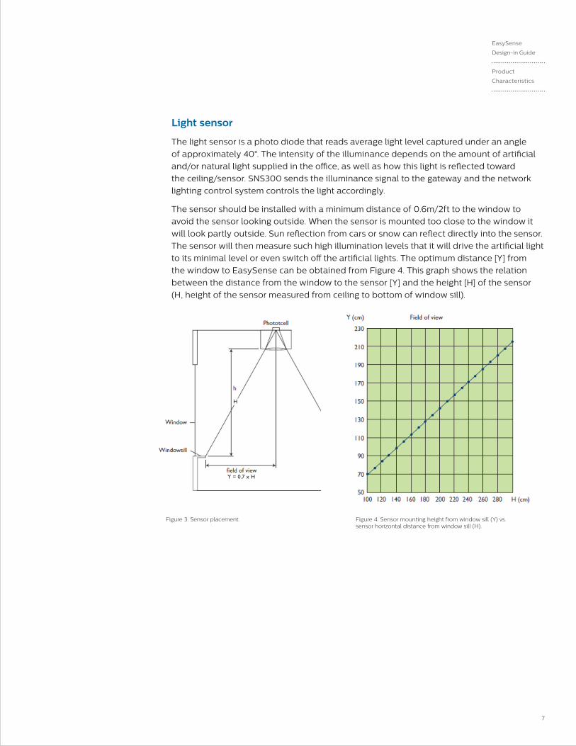
Light sensor
The light sensor is a photo diode that reads average light level captured under an angle
of approximately 40°. The intensity of the illuminance depends on the amount of artificial
and/or natural light supplied in the office, as well as how this light is reflected toward
the ceiling/sensor. SNS300 sends the illuminance signal to the gateway and the network
lighting control system controls the light accordingly.
The sensor should be installed with a minimum distance of 0.6m/2ft to the window to
avoid the sensor looking outside. When the sensor is mounted too close to the window it
will look partly outside. Sun reflection from cars or snow can reflect directly into the sensor.
The sensor will then measure such high illumination levels that it will drive the artificial light
to its minimal level or even switch off the artificial lights. The optimum distance [Y] from
the window to EasySense can be obtained from Figure 4. This graph shows the relation
between the distance from the window to the sensor [Y] and the height [H] of the sensor
(H, height of the sensor measured from ceiling to bottom of window sill).
Figure 3. Sensor placement.
Y = 0.7 x H
H
Figure 4. Sensor mounting height from window sill (Y) vs. sensor horizontal distance from window sill (H).
8 Philips
LED indicator
The product contains an LED indicator to help comply with California Title 20 requirements.
The LED indicator is enabled by default. The behavior of the LED is as follows:
Yellow LED on: vacancy & light sensor are functional.
Red LED on: motion is detected and hold time is not expired yet.
Lighting control
Calibration and lighting control is done by the coordinating network system.

9
EasySense
Design-in Guide
Limited Functions
of Philips
Field AppsLimited functions of Philips Field Apps
The EasySense NFC App can be used to read out model/version information of SNS300
and the MAC address. The EasySense IR App can be used to reset the network settings
of individual sensor.
Phone requirements: The EasySense app works only on Android-based smartphones.
Check the EasySense website for the latest list of compatible phones and their NFC
reader locations.
The app can be downloaded from the Google Play Store. This is a B2B app which requires
authentication with user ID and password. Please register at www.philips.com/easysense
to obtain a user id and password.
Please check the latest user's manual at www.philips.com/easysense for information on
using the app with EasySense.

10 Philips
Mechanical design-in
Mounting to a luminaire
EasySense is a fixture-mount sensor that is directly powered by a Philips Advance
Xitanium SR LED driver. It can be mounted to a slot or a cut-out in sheet metal.
1. Mounting in a U-shaped slot in the fixture sheet metal
EasySense can be assembled into an open-ended slot with dimensions following the
cut-out dimensions shown in the data sheet. Max sheet metal thickness is 1mm.
Note: Please make sure the the Easysense RF antenna is not covered by metal.
11
EasySense
Design-in Guide
Mechanical
Design-in
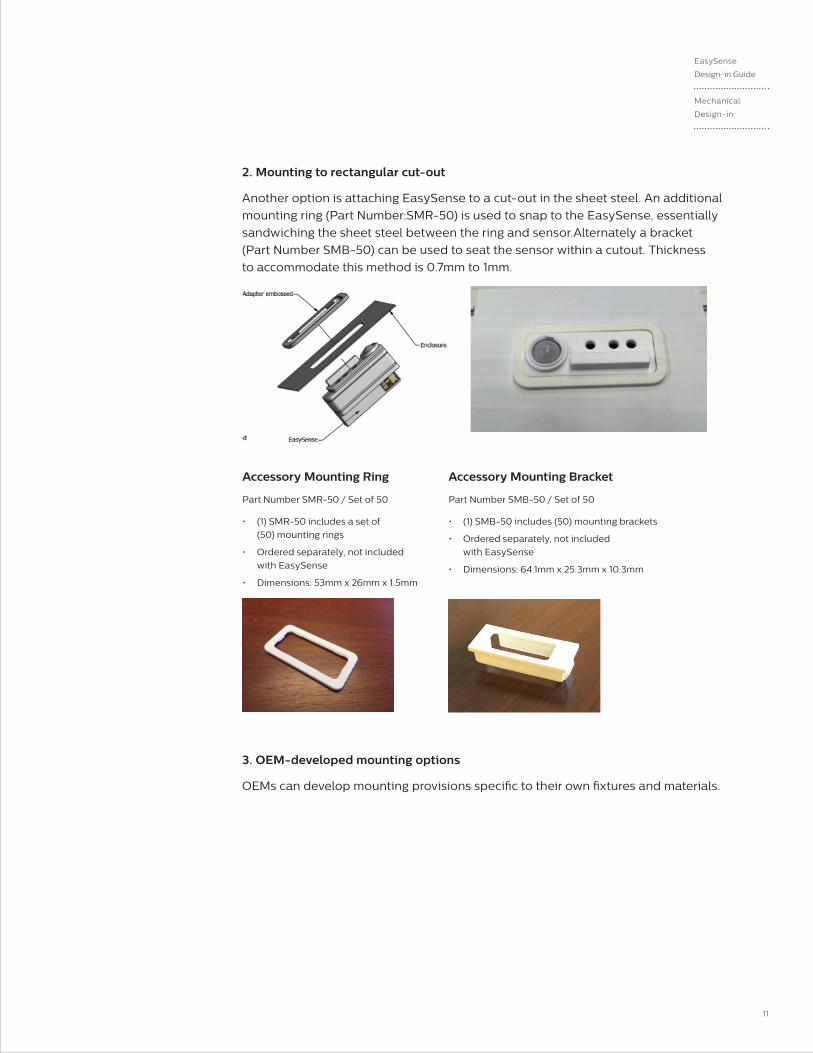
2. Mounting to rectangular cut-out
Another option is attaching EasySense to a cut-out in the sheet steel. An additional
mounting ring (Part Number:SMR-50) is used to snap to the EasySense, essentially
sandwiching the sheet steel between the ring and sensor.Alternately a bracket
(Part Number SMB-50) can be used to seat the sensor within a cutout. Thickness
to accommodate this method is 0.7mm to 1mm.
3. OEM-developed mounting options
OEMs can develop mounting provisions specific to their own fixtures and materials.
Accessory Mounting Ring
Part Number SMR-50 / Set of 50
• (1) SMR-50 includes a set of
(50) mounting rings
• Ordered separately, not included
with EasySense
• Dimensions: 53mm x 26mm x 1.5mm
Accessory Mounting Bracket
Part Number SMB-50 / Set of 50
• (1) SMB-50 includes (50) mounting brackets
• Ordered separately, not included
with EasySense
• Dimensions: 64.1mm x 25.3mm x 10.3mm
12 Philips
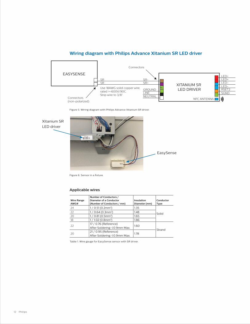
Wiring diagram with Philips Advance Xitanium SR LED driver
Applicable wires
Wire Range AWG#
Number of Conductors / Diameter of a Conductor (Number of Conductors / mm)
Insulation Diameter (mm)
Conductor Type
24 1 / 0.51 (0.2mm2) 1.35
Solid22 1 / 0.64 (0.3mm2) 1.4820 1 / 0.81 (0.5mm2) 1.6518 1 / 1.02 (0.8mm2) 1.86
2217 / 0.76 (Reference) After Soldering: ¢0.9mm Max.
1.60Strand
2021 / 0.95 (Reference) After Soldering: ¢0.9mm Max.
1.78
Table 1. Wire gauge for EasySense sensor with SR driver.
XITANIUM SR LED DRIVER
EASYSENSELED+LED+
LED-LED-
RSET2SGND
NFC ANTENNA
SR-
Connectors
SR+SRSR
LINENEUTRAL
GROUNDNC
Connectors(non-polarized)
Use 18AWG solid copper wire, rated >=600V/90C. Strip wire to 3/8”.
Figure 5. Wiring diagram with Philips Advance Xitanium SR driver.
Figure 6. Sensor in a fixture.
Xitanium SR
LED driver
EasySense

13
EasySense
Design-in Guide
Mechanical
Design-in
Figure 7: Wire strip length.
Wire strip length
Wire insertion
Wire separation from the connector
Wire distance for remote mounting
It is recommended to keep the wire distance from sensor to Philips Advance Xitanium
SR LED driver less than 50 feet and meet the wire gauge requirement to guarantee
the performance.
[Conductor : Bare Copper/Strand Wire]
metal
Figure 8: Wire insertion.
Figure 9: Wire separation from the connector.
14 Philips
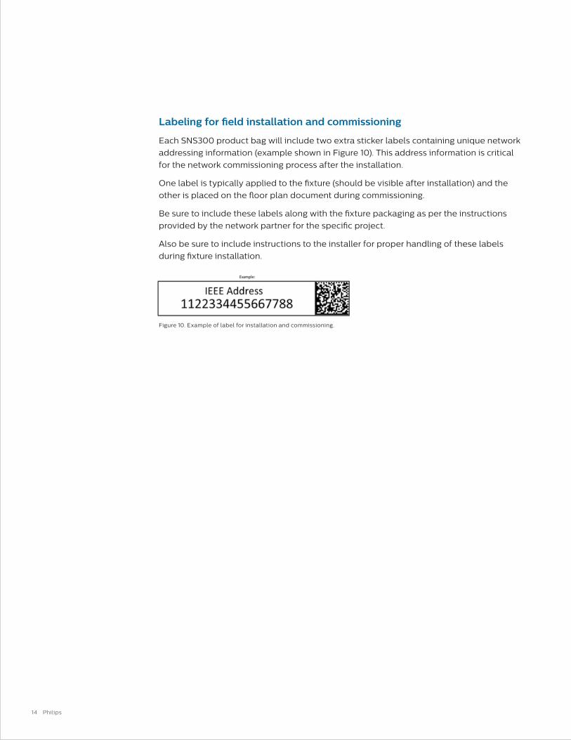
Labeling for field installation and commissioning
Each SNS300 product bag will include two extra sticker labels containing unique network
addressing information (example shown in Figure 10). This address information is critical
for the network commissioning process after the installation.
One label is typically applied to the fixture (should be visible after installation) and the
other is placed on the floor plan document during commissioning.
Be sure to include these labels along with the fixture packaging as per the instructions
provided by the network partner for the specific project.
Also be sure to include instructions to the installer for proper handling of these labels
during fixture installation.
Figure 10. Example of label for installation and commissioning.
15
EasySense
Design-in Guide
Mechanical
Design-in
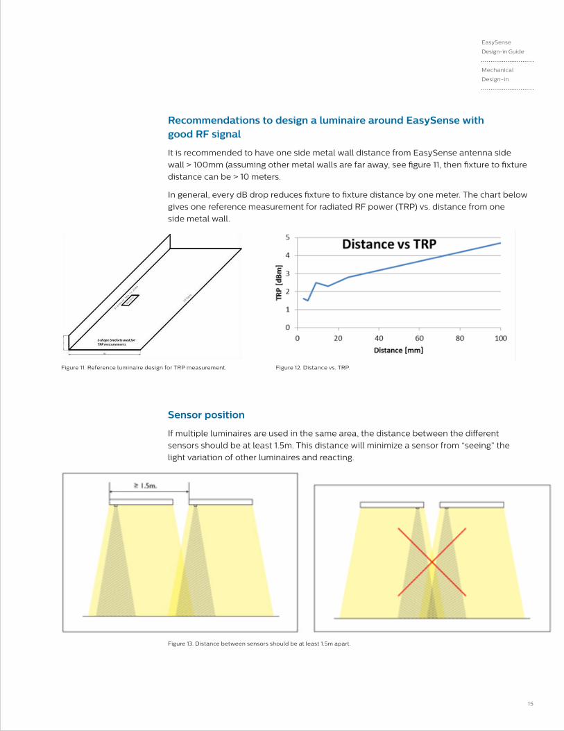
Figure 13. Distance between sensors should be at least 1.5m apart.
Recommendations to design a luminaire around EasySense with good RF signal
It is recommended to have one side metal wall distance from EasySense antenna side
wall > 100mm (assuming other metal walls are far away, see figure 11, then fixture to fixture
distance can be > 10 meters.
In general, every dB drop reduces fixture to fixture distance by one meter. The chart below
gives one reference measurement for radiated RF power (TRP) vs. distance from one
side metal wall.
Sensor position
If multiple luminaires are used in the same area, the distance between the different
sensors should be at least 1.5m. This distance will minimize a sensor from “seeing” the
light variation of other luminaires and reacting.
Figure 11. Reference luminaire design for TRP measurement. Figure 12. Distance vs. TRP.
16 Philips
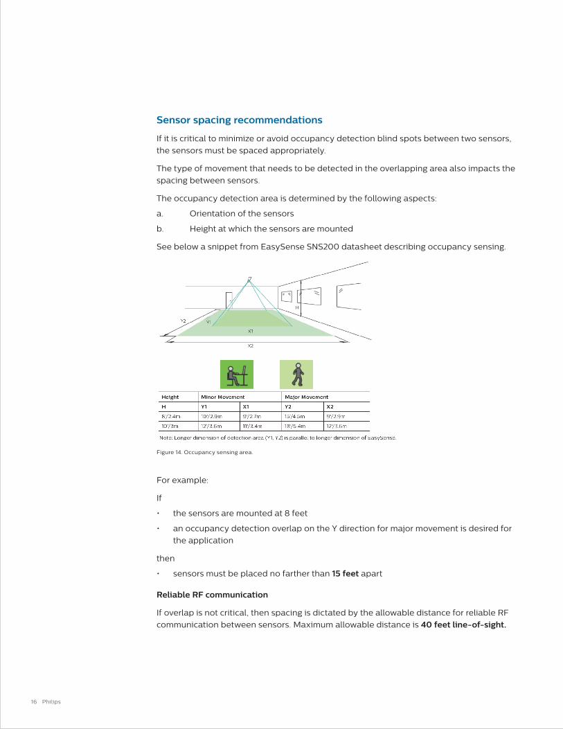
Sensor spacing recommendations
If it is critical to minimize or avoid occupancy detection blind spots between two sensors,
the sensors must be spaced appropriately.
The type of movement that needs to be detected in the overlapping area also impacts the
spacing between sensors.
The occupancy detection area is determined by the following aspects:
a. Orientation of the sensors
b. Height at which the sensors are mounted
See below a snippet from EasySense SNS200 datasheet describing occupancy sensing.
For example:
If
• the sensors are mounted at 8 feet
• an occupancy detection overlap on the Y direction for major movement is desired for
the application
then
• sensors must be placed no farther than 15 feet apart
Reliable RF communication
If overlap is not critical, then spacing is dictated by the allowable distance for reliable RF
communication between sensors. Maximum allowable distance is 40 feet line-of-sight.
Figure 14. Occupancy sensing area.
17
EasySense
Design-in Guide
EasySense with
Multiple Philips
Advance Xitanium
SR LED Drivers
(1:N Application)
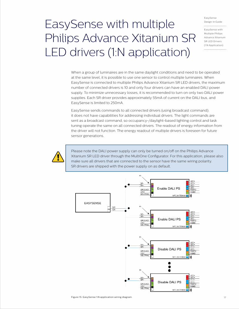
EasySense with multiple Philips Advance Xitanium SR LED drivers (1:N application)
When a group of luminaires are in the same daylight conditions and need to be operated
at the same level, it is possible to use one sensor to control multiple luminaires. When
EasySense is connected to multiple Philips Advance Xitanium SR LED drivers, the maximum
number of connected drivers is 10 and only four drivers can have an enabled DALI power
supply. To minimize unnecessary losses, it is recommended to turn on only two DALI power
supplies. Each SR driver provides approximately 55mA of current on the DALI bus, and
EasySense is limited to 250mA.
EasySense sends commands to all connected drivers (using broadcast command);
it does not have capabilities for addressing individual drivers. The light commands are
sent as a broadcast command, so occupancy-/daylight-based lighting control and task
tuning operate the same on all connected drivers. The readout of energy information from
the driver will not function. The energy readout of multiple drivers is foreseen for future
sensor generations.
Please note the DALI power supply can only be turned on/off on the Philips Advance
Xitanium SR LED driver through the MultiOne Configurator. For this application, please also
make sure all drivers that are connected to the sensor have the same wiring polarity.
SR drivers are shipped with the power supply on as default.
Figure 15. EasySense 1:N application wiring diagram.

18 Philips
FCC/IC compliance statement
This device complies with part 15 of the FCC rules for the United States and Industry
Canada (IC) license-exempt RSS standard(s). Operation is subject to the following two
conditions: (1) This device may not cause harmful interference, and (2) this device must
accept any interference received, including interference that may cause undesired
operation. Any changes or modifications not expressly approved by Philips could void
the user’s authority to operate this equipment. This product is intended for commercial
use only.
Déclaration de conformité à la fcc/ic
Ce dispositif est conforme à la partie 15 des règles de la Federal Communications
Commission (FCC) des États-Unis et d'Industrie Canada (IC) exempts de licence RSS
norme(s). Son fonctionnement est assujetti aux deux conditions suivantes : (1) Ce
dispositif ne doit pas provoquer de brouillage préjudiciable, et (2) il doit accepter tout
brouillage reçu, y compris le brouillage pouvant entraîner un mauvais fonctionnement.
Tous les changements ou modifications non expressément approuvés par Philips, sont
susceptibles d’annuler le droit de l’utilisateur à se servir de cet équipement. Ce produit
est exclusivement destiné à un usage commercial
19
EasySense
Design-in Guide
Contact Details
and Disclaimer
Contact details
Philips EasySense
Product information:
www.philips.com/easysense
Or contact your local Philips sales representative.
Disclaimer
©2017 Philips Lighting Holding B.V. All rights reserved.
Note that the information provided in this document is subject to change.
This document is not an official testing certificate and cannot be used or construed
as a document authorizing or otherwise supporting an official release of a luminaire.
The user of this document remains at all times liable and responsible for any and all
required testing and approbation prior to the manufacture and sale of any luminaire.
The recommendations and other advice contained in this document, are provided
solely for informational purposes for internal evaluation by the user of this
document. Philips Lighting does not make and hereby expressly disclaims any
warranties or assurances whatsoever as to the accuracy, completeness, reliability,
content and/or quality of any recommendations and other advice contained in this
document, whether express or implied including, without limitation, any warranties
of satisfactory quality, fitness for a particular purpose or non-infringement. Philips
Lighting has not investigated, and is under no obligation or duty to investigate, whether
the recommendations and other advice contained in this document are, or may be,
in conflict with existing patents or any other intellectual property rights. The
recommendations and other advice contained herein are provided by Philips
Lighting on an “as is” basis, at the user’s sole risk and expense.
Specifically mentioned products, materials and/or tools from third parties are
only indicative and reference to these products, materials and/or tools does not
necessarily mean they are endorsed by Philips Lighting. Philips Lighting gives no
warranties regarding these and assumes no legal liability or responsibility for any
loss or damage resulting from the use of the information thereto given here.

© 2017 Philips Lighting Holding B.V. All rights reserved. Philips reserves the right to makechanges in specifications and/or to discontinue any product at any time without notice orobligation and will not be liable for any consequences resulting from the use of this publication.
PLt-17XXXDG 07/17 philips.com
Philips LightingNorth America Corporation10275 W. Higgins RoadRosemont IL 60018Tel: 800-322-2086 Fax: 888-423-1882Customer/Technical Service: 800-372-3331OEM Support: 866-915-5886
Philips Lighting Canada Ltd.281 Hillmount Rd, Markham, ON, Canada L6C 2S3Tel. 800-668-9008