SINGLE BAR MOWERS - Rowse Rakes · 1 Rowse Single Bar Mower Operator’s Manual & Parts List TABLE...
80
SINGLE BAR MOWERS OPERATOR’S MANUAL Serial No. ________________________ "QUICK-ATTACH" TRAILING THREE-POINT MOUNTED HITCH Pitmanless and Balanced Head PTO Drive Assemblies
Transcript of SINGLE BAR MOWERS - Rowse Rakes · 1 Rowse Single Bar Mower Operator’s Manual & Parts List TABLE...

SINGLE BAR MOWERSOPERATOR’S MANUAL
Serial No. ________________________
"QUICK-ATTACH" TRAILING THREE-POINT MOUNTED HITCH
Pitmanless and Balanced Head PTO Drive Assemblies

Revised May 2016
LIPS Printing Service · Kearney, NE

1
Rowse Single Bar Mower Operator’s Manual & Parts List
TABLE OF CONTENTSRefer to the Table of Contents for easy reference as to NH Type or IH Type Models. Head and bar type is determined by the following: NH Type head and bar are yellow in color. IH Type head is red in color, and IH Type bar is black in color. If not designated, references are for both NH and IH Type.INTRODUCTION ............................................................ 2SAFETY .......................................................................... 3SET UP INSTRUCTIONS .......................................... 4-17
Basic Unit ................................................................... 4Drive Belt .................................................................... 4Drive Shield ................................................................ 5Installation of Cylinder ................................................ 5Power Take-Off Drives ............................................... 6
NH TypeCutter Bar Head Installation ....................................... 7Cutter Bar, Inner Shoe, Sole, & Grass Rod ................ 7Outer Shoe and Swath Board .................................... 8Mower Knife Drive ...................................................... 9
IH TypeBalanced Head Drive ............................................... 10Cutter Bar and Inner Shoe ........................................11Outer Shoe Sole, Swath Board, & Grass Rods ........ 12Mower Knife Drive .................................................... 13
Both TypesAttaching to Tractor Trailing Mower ........................................................ 14 Transport Bar Removal .......................................... 14 Three-Point Mower ................................................. 15Cutter Bar and Knife Alignment ................................ 16Break-In Procedure .................................................. 17General Information ................................................. 17
ADJUSTING AND OPERATING ............................. 18-24Inner Shoe Balance Spring ...................................... 18Gag Rod ................................................................... 18Cutter Bar Tilt ........................................................... 18Automatic Safety Release ........................................ 19Cutter Bar Lead ........................................................ 20Cutter Bar Lap .......................................................... 20Angle of Cut ............................................................. 21Cutting a Square Corner Trailing Mower ........................................................ 21 Three-Point Mower ................................................. 21
NH TypeSwath Board ............................................................. 22Height of Cut ............................................................ 22
IH TypeSwath Board ............................................................. 23Height of Cut ............................................................ 23
Both TypesFlywheel Speed ........................................................ 24Drive Belt .................................................................. 24PTO Speed .............................................................. 24
TRANSPORTING & DETACHING MOWER ................ 25STORAGE .................................................................... 26MAINTENANCE ...................................................... 27-34
General Information ................................................. 27Servicing the Cutter Bar and Components ............... 28Knife Removal and Replacement ............................. 28
NH TypeGuard Alignment ...................................................... 29Wear Plates .............................................................. 29Knife Hold-Down Clips ............................................. 29Replacing Bushing in Knife Head ............................. 29
MAINTENANCE (continued)IH Type
Guard Replacement and Alignment ......................... 30Knife Hold-Down Clips and Wear Plates .................. 30Adjustable Hold-Down Clips ..................................... 30Guard and Hold-Down Clip Alignment ..................... 31Replacing Bushing In Knife Head ............................ 31Knife Pin and Bushing .............................................. 31
BEARING ADJUSTMENT ............................................ 32NH Type
Bearing Adjustment - Crankshaft Bearings .............. 32Knife Drive Bearings & Assembly ............................. 33
IH TypeChecking Head Bearings ......................................... 34
LUBRICATION GUIDE ............................................ 35-37TROUBLESHOOTING ................................................. 38PARTS LIST ............................................................ 39-71
Introduction .............................................................. 39Frame Parts ............................................................. 40Hitch Assembly 3-Point Mounted Mower, Row Crop Tractor Model with Hydraulic Vertical Lift ..................................... 41 3-Point Mounted Mower, Compact Tractor Model with Hydraulic Vertical Lift ..................................... 42 3-Point Mounted Mower, Row Crop Tractor Model with Mechanical Lift .............................................. 43 3-Point Mounted Mower, Compact Tractor Model (16-50hp) with Mechanical Lift .............................. 44Pivot Frame, Breakaway Arm & Latch Support Plate ........................................... 45-46Mower Mounting Parts ........................................ 47-48Bellcrank, Gag & Lift Lever & Balancing Spring ....... 49Front & Rear Cutter Bar Support Hinge Coupling, Idler Pulley & Shields ........................................ 50-51Drive Shaft Housing, Pulley, V-Belt & Shield ............ 52PTO Assembly, Model #270(7ft) & #290(9ft), Constant Velocity Drive, One Drive Model ........... 53PTO Assembly, Model #270(7ft) & #290(9ft), Two Drive Model .................................................. 54PTO Parts, Drive #1, Two Drive Model .................... 55PTO Parts, Drive #2, Two Drive Model .................... 56PTO Three-Point Mounted Mower ........................... 573" Hydraulic Cylinder ................................................ 586-Bolt "888 Hub" Wheel ........................................... 59NH Type Mower Head ................................................... 60-61 Cutter Bar ....................................................... 62-64Adjustable Hold Down Clips ..................................... 65IH Type Mower Head ................................................... 66-67 Cutter Bar ....................................................... 68-69 Inner Shoe Sole, Grass Deflectors & Knife Assembly ............................................. 70-71SPECIFICATIONS ................................................... 72WARRANTY ............................................................. 73WARRANTY DETAIL ................................................ 74
1
Rowse Single Bar Mower Operator’s Manual & Parts List
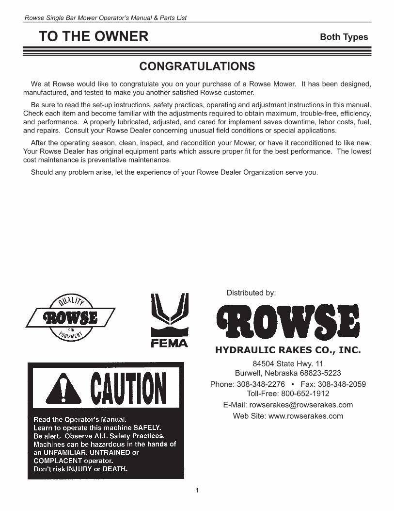
TO THE OWNER
CONGRATULATIONSWe at Rowse would like to congratulate you on your purchase of a Rowse Mower. It has been designed,
manufactured, and tested to make you another satisfied Rowse customer.
Be sure to read the set-up instructions, safety practices, operating and adjustment instructions in this manual. Check each item and become familiar with the adjustments required to obtain maximum, trouble-free, efficiency, and performance. A properly lubricated, adjusted, and cared for implement saves downtime, labor costs, fuel, and repairs. Consult your Rowse Dealer concerning unusual field conditions or special applications.
After the operating season, clean, inspect, and recondition your Mower, or have it reconditioned to like new. Your Rowse Dealer has original equipment parts which assure proper fit for the best performance. The lowest cost maintenance is preventative maintenance.
Should any problem arise, let the experience of your Rowse Dealer Organization serve you.
Distributed by:
HYDRAULIC RAKES CO., INC.84504 State Hwy. 11
Burwell, Nebraska 68823-5223Phone: 308-348-2276 • Fax: 308-348-2059
Toll-Free: 800-652-1912E-Mail: [email protected]
Web Site: www.rowserakes.com
Both Types

2
Rowse Single Bar Mower Operator’s Manual & Parts List
The Rowse Single Bar “Quick-Attach” Trailing and Three-Point Hitch Mowers are available for most tractors equipped with a 540 RPM, 1- 3/8"-6 spline PTO shaft.
Your mower is designed so that the bar can be raised or lowered hydraulically, thus hydraulic requirements are 1 single acting control valve with float detent. If adequate hydraulic system or valves are not standard on tractor, they can be purchased from Rowse through your dealer.
The bar is equipped with an automatic safety release to protect the cutter bar and mower frame from dam-age. They can be easily adjusted for more or less tension for mowing in light or heavy hay crops.
"QUICK-ATTACH" TRAILING MOWERST
ALL MOWER MODELSThe trailing mower attaches to the tractor by a hitch pin through mower hitch and tractor drawbar (Clevis Hitch)
or by a ball on the tractor drawbar and coupler welded to the mower hitch (Ball Hitch).
INTRODUCTION
The drawbar must measure 16" from center of hitch pin hole in drawbar to end of PTO shaft on Tractor. Use of tractor with drawbar other than this measurement will result in damage to mower unit, tractor, or both.
AGAIN, CHECK 16" MEASUREMENT.
Both Types
THREE-POINT HITCH MOWERSM
ALL MOWER MODELSThe Three-Point Mower attaches to standard ASAE category 1 and 11 tractor hitches.
Throughout this manual you will encounter the terms: left and right, front and rear. The following is an example to distinguish left from right and front from rear. Right and left are determined from a position behind the machine facing the direction of travel. The front is the tongue end of the mower.
3
Rowse Single Bar Mower Operator’s Manual & Parts List
Your mower has been designed to minimize the pos-sibility of accidents. However, there is no substitute for a careful operator. The safety suggestions which follow help you to be that kind of operator.
BEFORE OPERATING• Review this Manual.• Do not wear loose fitting clothing, it may catch in moving
parts.• See that all safety shields including the tractor PTO
parts are in place, and that they are properly secured.• Use extreme care when making any knife adjustments.• After servicing, be sure all tools, parts, or servicing
equipment are removed from the machine.• Make sure that there is no one near the machine before
starting it.
DURING OPERATION• Shut off the tractor engine and be sure to wait until the
knife has come to a complete stop before adjusting, cleaning, or lubricating.
• Do not attempt to remove any obstructions from belt or knife while the machine is running.
• Disengage the tractor PTO drive and shut off tractor engine before dismounting from the tractor.
• Do not stand near the cutter bar while the machine is in operation.
• Keep hands, feet, and clothing away from moving parts.• Use extreme care when operating close to ditches,
fences, or on hillsides.
TRANSPORTING• Always place the machine in the transport position for
road travel.• Check clearance carefully before driving the mower un-
der trees, electric lines, or bridges, and into buildings.• Use warning devices (e.g. flags, SMV Emblem, lights,
etc.) which are approved for use by your local govern-ment agencies, when moving equipment on public roads.
• Keep these devices clean and in good working condi-tion.
• Drive at a reasonable speed to maintain complete con-trol of the machine at all times.
SAFETY
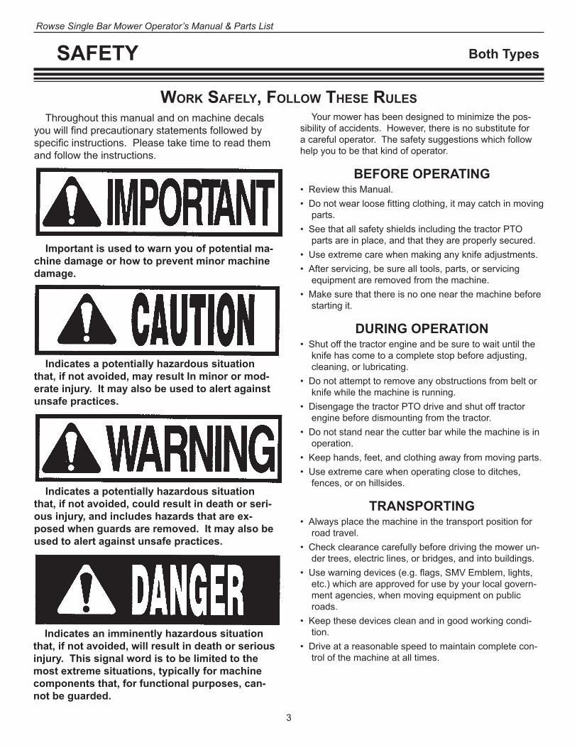
Work Safely, folloW TheSe ruleSThroughout this manual and on machine decals
you will find precautionary statements followed by specific instructions. Please take time to read them and follow the instructions.
Important is used to warn you of potential ma-chine damage or how to prevent minor machine damage.
Indicates a potentially hazardous situation that, if not avoided, may result In minor or mod-erate injury. It may also be used to alert against unsafe practices.
Indicates a potentially hazardous situation that, if not avoided, could result in death or seri-ous injury, and includes hazards that are ex-posed when guards are removed. It may also be used to alert against unsafe practices.
Indicates an imminently hazardous situation that, if not avoided, will result in death or serious injury. This signal word is to be limited to the most extreme situations, typically for machine components that, for functional purposes, can-not be guarded.
Both Types

4
Rowse Single Bar Mower Operator’s Manual & Parts List
SET UP INSTRUCTIONS
BaSic uniT
Remove the drive shield to install the knife drive belt. See “Drive Shield” Page 5, Fig. 3.
Adjust the V-belt so a slight thumb pressure will deflect the belt 1/2 inch at a point midway between the pulleys.
Basic mowers are assembled at the Rowse factory prior to shipment, except for mower head, cutter bars, shoes, swath boards, and drives which you may need to attach to your mower.
The basic mower may be detached from framework for shipping purposes. If this is the case, mount the mowers as shown in Fig. 37 on page 18 (Adjusting and Operat-
Drive Belt Idler
Drive Pulley Knife Drive V-Belt
Drive Belt Roller
In Fig. 1 and Fig. 2 the guards and shields are removed for illustration pur-poses only.
DO NOT OPERATE WITHOUT GUARDS AND SHIELDS IN PLACE AND FUNCTIONING.
Fig. 1
ing), with the use of 4 bolts, F, G, H, I, gripping the 2" shaft on mower frame.
The left side of the front mower should be mounted 6" from the left side of the front 2" shaft. The rear mower should be mounted 3" from the left side of the rear 2" shaft. These measurements are approximate and may vary due to bar lead, etc.
Drive BelTTo install, remove, or adjust the V-belt, loosen nuts A,
B, and C-clamp (inset view). Remove or install V-belt. Tighten nut C until proper belt tension is obtained. Retighten nuts A and B.
Both Types
B C
A
Fig. 2

5
Rowse Single Bar Mower Operator’s Manual & Parts List
SET UP INSTRUCTIONS
Drive ShielD
Both Types
Drive Shield Eight bolts 1/4" x 3/8"and lock washers
under the bolt heads.
Fig. 3
See "Detaching Trailing Mower"
page 25
Install cylinder to cylinder mount (with vented plug 10 and cylinder port pointed down) using cylinder pin, 11 and cotter pin 12. Then, install cylinder shaft end to linkage arms 3 with pin 4 and cotter pin 5. Attach the Restrictor Valve 9 to tube fitting 7, not shown.
Important: Arrow on restrictor must point away from lift cylinder as shown. Install the swivel fitting 6 to the cylinder 1. Attach the 1/2" pressure hose 8 to the restrictor 9 and the other end to the nipple 6 on cylinder in expanded photo.
inSTallaTion of cylinDer
1211
Fig. 4

6
Rowse Single Bar Mower Operator’s Manual & Parts List
SET UP INSTRUCTIONS
PoWer Take-off DriveS
Hex Head Bolt, 3/8" x 1" and Lockwasher
Power Take-Off Shield
Stayrod Holder
Fig. 8
Both Types
Roll Pin, 5/16" x 2 1/4"
Power Take-Off Drive Knuckle Fig. 9
A
7
Rowse Single Bar Mower Operator’s Manual & Parts List
SET UP INSTRUCTIONS NH Type
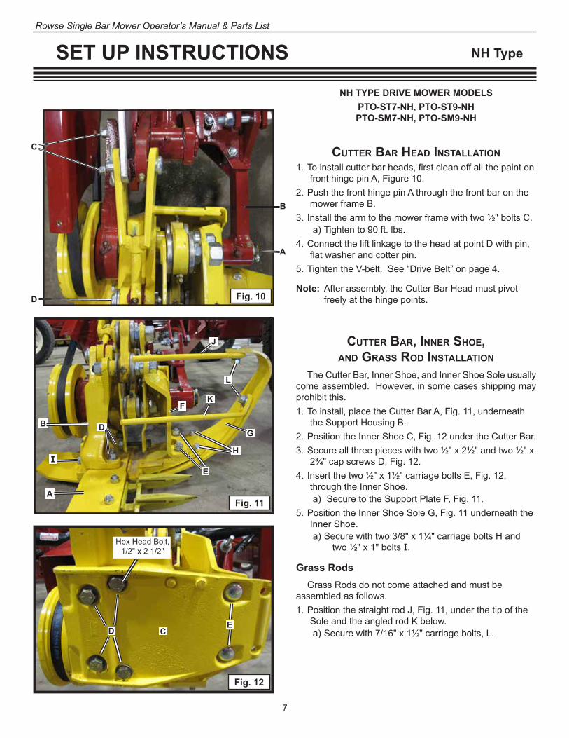
cuTTer Bar, inner Shoe,anD GraSS roD inSTallaTion
The Cutter Bar, Inner Shoe, and Inner Shoe Sole usually come assembled. However, in some cases shipping may prohibit this.1. To install, place the Cutter Bar A, Fig. 11, underneath
the Support Housing B.2. Position the Inner Shoe C, Fig. 12 under the Cutter Bar.3. Secure all three pieces with two ½" x 2½" and two ½" x
2¾" cap screws D, Fig. 12. 4. Insert the two ½" x 1½" carriage bolts E, Fig. 12,
through the Inner Shoe.a) Secure to the Support Plate F, Fig. 11.
5. Position the Inner Shoe Sole G, Fig. 11 underneath the Inner Shoe.a) Secure with two 3/8" x 1¼" carriage bolts H and
two ½" x 1" bolts I.
Grass RodsGrass Rods do not come attached and must be
assembled as follows.1. Position the straight rod J, Fig. 11, under the tip of the
Sole and the angled rod K below. a) Secure with 7/16" x 1½" carriage bolts, L.
DB
A
I
F
E
J
L
K
GH
Fig. 11
NH TYPE DRIVE MOWER MODELSPTO-ST7-NH, PTO-ST9-NHPTO-SM7-NH, PTO-SM9-NH
cuTTer Bar heaD inSTallaTion1. To install cutter bar heads, first clean off all the paint on
front hinge pin A, Figure 10. 2. Push the front hinge pin A through the front bar on the
mower frame B. 3. Install the arm to the mower frame with two ½" bolts C.
a) Tighten to 90 ft. lbs. 4. Connect the lift linkage to the head at point D with pin,
flat washer and cotter pin.5. Tighten the V-belt. See “Drive Belt” on page 4.
Note: After assembly, the Cutter Bar Head must pivot freely at the hinge points.
C
D
B
A
Fig. 10
CD E
Hex Head Bolt, 1/2" x 2 3/4" Hex Head Bolt,
1/2" x 2 1/2"
Fig. 12
CE
D

8
Rowse Single Bar Mower Operator’s Manual & Parts List
SET UP INSTRUCTIONS NH Type
In most cases the outer shoe is attached to mower bar, however, if it has been removed, follow this procedure.
1. Attach outer shoe A, Fig. 13 to the cutter bar with two 7/16" x 1 1/2" Plow bolts, B,
2. Attach the outer shoe sole C with one 1/2" x 2" Carriage bolt,
ouTer Shoe anD SWaTh BoarD inSTallaTion
Fig. 13
3. Install the Swath Board Assembly D to the outer shoe at E. Tighten E enough so it will not raise while mowing in heavy crops, but can move if an obstruction is hit. Be sure to install a cotter pin or use a lock nut.

9
Rowse Single Bar Mower Operator’s Manual & Parts List
SET UP INSTRUCTIONS
MoWer knife Drive inSTallaTion
NH Type
Fig. 16
1. To install, slide knife, Fig. 15 into cutter bar between guards A and hold-down clips, Fig. 14.
2. Insert knife head bolt B, Fig. 14 through wedge driv-elock, plate, knife head with rubber bushing C, Fig. 15, and through plate.a) Secure with hex nut D, Fig. 14.
3. With the KNIFE IN THE CENTER OF ITS STROKE, Fig. 16, tighten the knife head bolt to 85-90 ft. lbs. torque Fig. 16. a) A ratchet, extension and universal joint socket
works the best for removing and replacing.4. If knife binds when sliding into cutter bar,
a) Check to make sure knife is not bent or twisted. b) Then, check for restrictive hold-down clips.c) See “Cutter Bar and Knife Alignment” on page 16.
Knife Head Bolt In Center Of Stroke
Fig. 14
B
A
D
Fig. 15
C
10
Rowse Single Bar Mower Operator’s Manual & Parts List
SET UP INSTRUCTIONS IH Type
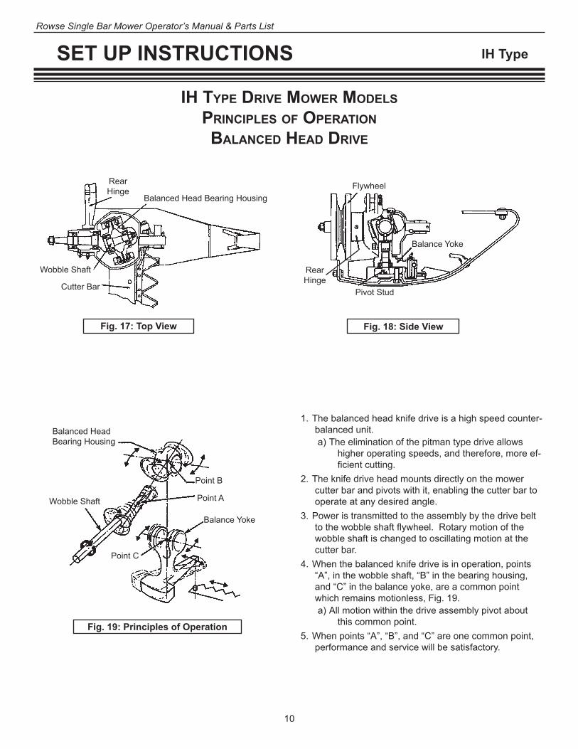
ih TyPe Drive MoWer MoDelS PrinciPleS of oPeraTion BalanceD heaD Drive
1. The balanced head knife drive is a high speed counter-balanced unit. a) The elimination of the pitman type drive allows
higher operating speeds, and therefore, more ef-ficient cutting.
2. The knife drive head mounts directly on the mower cutter bar and pivots with it, enabling the cutter bar to operate at any desired angle.
3. Power is transmitted to the assembly by the drive belt to the wobble shaft flywheel. Rotary motion of the wobble shaft is changed to oscillating motion at the cutter bar.
4. When the balanced knife drive is in operation, points “A”, in the wobble shaft, “B” in the bearing housing, and “C” in the balance yoke, are a common point which remains motionless, Fig. 19. a) All motion within the drive assembly pivot about
this common point.5. When points “A”, “B”, and “C” are one common point,
performance and service will be satisfactory.
Fig. 17: Top View Fig. 18: Side View
Fig. 19: Principles of Operation
Balanced Head Bearing Housing
Balance Yoke
Rear Hinge
Balanced Head Bearing Housing
Wobble Shaft
Cutter Bar Pivot Stud
Flywheel
Balance Yoke
Rear Hinge
Wobble Shaft
Point C
Point A
Point B
11
Rowse Single Bar Mower Operator’s Manual & Parts List
SET UP INSTRUCTIONS Both Types
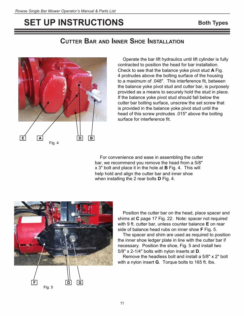
cuTTer Bar anD inner Shoe inSTallaTion
Operate the bar lift hydraulics until lift cylinder is fullycontracted to position the head for bar installation.Check to see that the balance yoke pivot stud A Fig.4 protrudes above the bolting surface of the housingto a maximum of .048". This interference fit, betweenthe balance yoke pivot stud and cutter bar, is purposelyprovided as a means to securely hold the stud in place.If the balance yoke pivot stud should fall below thecutter bar bolting surface, unscrew the set screw thatis provided in the balance yoke pivot stud until the head of this screw protrudes .015" above the boltingsurface for interference fit.
E A D BFig. 4
For convenience and ease in assembling the cutterbar, we recommend you remove the head from a 5/8"x 3" bolt and place it in the hole at B Fig. 4. This willhelp hold and align the cutter bar and inner shoe when installing the 2 rear bolts D Fig. 4.
Position the cutter bar on the head, place spacer andshims at C page 17 Fig. 22. Note: spacer not required with 9 ft. cutter bar, unless counter balance E on rear side of balance head rubs on inner shoe F Fig. 5. The spacer and shim are used as required to position the inner shoe ledger plate in line with the cutter bar if necessary. Position the shoe, Fig. 5 and install two5/8" x 2-1/4" bolts with nylon inserts at D. Remove the headless bolt and install a 5/8" x 2" boltwith a nylon insert G. Torque bolts to 165 ft. lbs.
F D GFig. 5
SET UP
CUTTER BAR AND INNER SHOE INSTALLATION
8

12
Rowse Single Bar Mower Operator’s Manual & Parts List
SET UP INSTRUCTIONS Both Types
ouTer Shoe Sole, SWaTh BoarD, & GraSS roDS inSTallaTion
1. Position the outer shoe sole A, Fig. 23, and install the 1/2" special head bolt.a) This is the same for either type of swath board.
Fig. 23
Small Swath Board1. Install the swath board and grass rod assembly at E,
Fig. 24.a) Secure with tension spring, 1/2" x 3 1/2" square
head bolt, washer, and lock nut.
Large Swath Board1. Install the swath board to the outer shoe with a 1/2" x
3 1/2" square head bolt, tension spring, washer, and locknut. B, Fig. 23.
2. Position the grass rod at the desired level.3. Install the carriage bolt, washer, lockwasher, and nut at
C and the carriage bolt, dampener washer, and nut at D.
Grass Rod
Clamp, 3/8" x 1" Carriage Bolt,
13/32" x 1" x 11 ga. Flatwasher, 3/8" Lockwasher, and Hex Nut
Swath Board Support, four 3/8" x 3/4" Carriage Bolts,
and Two-Way LocknutsSwath Board
1/2" x 3 1/2" Square Head Bolt, Tension Spring,
17/32" x 1 1/4" x 16 ga. Flatwasher, and Locknut
A
C
B
D
Fig. 24
E
Position the outer shoe sole A Fig. 16 and install the 1/2" special head bolt. This is the samefor either type of swath board.
Install the swath board to the outer shoe with a 1/2" x 3" bolt, tension spring, washer and lock nut B Fig. 16 then position the grass rod at the desired level and install the carriage bolt, washer and lock nut at C and the carriage bolt, dampener washer and lock nut at D.
C B AFig. 16
D
Optional Grass Board Deflector
SET UP
OUTER SHOE AND SWATH BOARD INSTALLATION
Rubberdampener washer
Grass rod
Flat washer13/32" x 1" x 11 ga.
Hex lock nut3/8"
Swathboard
Carriage bolt3/8" x 1 1/2"
15
D

13
Rowse Single Bar Mower Operator’s Manual & Parts List
SET UP INSTRUCTIONS IH Type
Fig. 25
Cutter Bar
Yoke
Clearance .010"
SpacerInner Shoe Front Bolt
Knife ArmUse shim .010" here, if necessary, to maintain specified alignment
Spacer not used with 9-ft. cutter bar
MoWer knife Drive inSTallaTion
1. Loosen the first hold-down clip on the cutter bar A, Fig. 24, and any other clips that might restrict the knife installation.
2. Remove the clamp bolt B and lift the knife pin C, Fig. 25. a) We recommend that you use the special Guard Lip
gauge tool, Fig. 26, (Part No. 670588) (optional).3. Slide the knife in place. 4. Align the knife head with the balance yoke, Fig. 27, and
slide the knife pin in place.5. A minimum clearance of .010" is required between the
knife area and the balance yoke D, Fig. 25. a) If necessary, place a shim or shims between the
cutter bar and the inner shoe on the front mount-ing bolt.
Note: Shim installation will lower the inner shoe ledger plate to prevent binding of the knife. Shim the bolt only if necessary.
Guard Lip Gauge Tool (optional)
Fig. 27
Removing or tightening bolt
Lifting pin
Aligning pin to insert bolt
6. Lower the knife pin and install the clamp bolt.
IMPORTANT: Use external tooth lockwashers under the head of the clamp bolt and nut. Torque clamp bolt 85 to 95 ft. lbs.
7. Position the knife to the outward end of its stroke.8. Reposition hold-down clip (s) and tighten bolts.
Fig. 261. Loosen the first hold-down clip on the cutter bar B
A Fig. 18 and any other clips that might restrict theknife installation.
2. Remove the clamp bolt B Fig. 18 and lift the knife
pin C Fig. 19. We recommend you use the special guard lip gauge tool Fig. 17 (Part No. 670588).
3. Slide the knife in place. Align the knife head with
the balance yoke Fig. 20 and slide the knife pin inplace.
A
Fig. 18
Fig. 17
Fig.19
4. A minimum clearance of .010" is required betweenthe knife arm and the balance yoke D Fig. 19. If nec-essary, place a shim or shims between the cutter barand the inner shoe sole on the front mounting bolt.Note: Shim installation will lower the inner shoe ledgerplate to prevent binding of the knife. Shim the bolt onlyif necessary.
5. Lower the knife pin and install the clamp bolt.
IMPORTANT: Use external tooth lockwashers under the head of the clamp bolt and nut.
Torque clamp bolt to 85 to 95 ft. lb.Fig. 20
6. Position the knife to the outward end of its stroke.
7. Reposition hold-down clip(s) and tighten bolts.
SET UP
MOWER KNIFE DRIVE INSTALLATION
Guard lip gauge tool
Removing & tightening bolt
Lifting pin
Aligning pin to insert bolt
Cutter bar
Yoke
Clearance.010"
Spacer
Spacer notused with Inner
shoe Front boltUse shim .010" here, ifnecessary, to maintainspecified alignment
Knife arm
D C
16
Fig. 24
14
Rowse Single Bar Mower Operator’s Manual & Parts List
SET UP INSTRUCTIONS Both Types
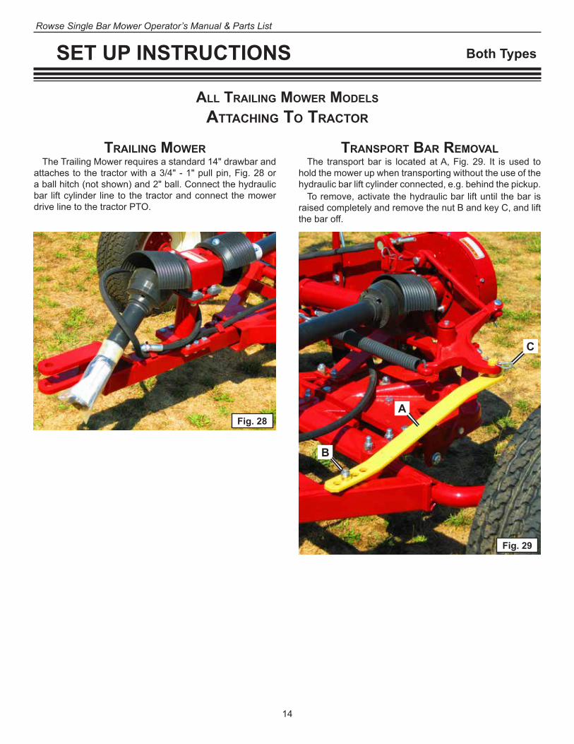
all TrailinG MoWer MoDelS
aTTachinG To TracTor
TrailinG MoWerThe Trailing Mower requires a standard 14" drawbar and
attaches to the tractor with a 3/4" - 1" pull pin, Fig. 28 or a ball hitch (not shown) and 2" ball. Connect the hydraulic bar lift cylinder line to the tractor and connect the mower drive line to the tractor PTO.
TranSPorT Bar reMovalThe transport bar is located at A, Fig. 29. It is used to
hold the mower up when transporting without the use of the hydraulic bar lift cylinder connected, e.g. behind the pickup.
To remove, activate the hydraulic bar lift until the bar is raised completely and remove the nut B and key C, and lift the bar off.
A
C
B
Fig. 28
Fig. 29

15
Rowse Single Bar Mower Operator’s Manual & Parts List
SET UP INSTRUCTIONS Both Types
all Three-PoinT MounTeD MoWer MoDelS
aTTachinG To TracTor
Three-PoinT MoWerThe Three-Point hitch mower attaches to mostcategory I or II Three-Point hitch tractors.
ProceDure for aTTachinG To TracTor1. Support Mower so the mower hitch pins are level with
the tractor's lower links.* Disconnect the stay rod on the cutter bar and lower it.
*Note: Lower links on Three-Point are adjustable in height by the operator from the tractor seat.
2. Connect the lower links to hitch pins A and stabilize, Fig. 30. See your tractor operator's Manual for your
specific situation. Then connect the tractor upper link to the mower hitch B, Fig. 30.
3. Connect the mower drive line to the tractor PTO.
4. Adjust tractor upper link C, so mower hitch is perpendicular to lower links. Then adjust tractor lift links E, Fig. 30, to position mower hitch pins 22¼" from ground level, Fig. 30. Lift links should be equal to length for proper adjustment.
5. After the mower has been properly adjusted the cutter bar tilt may need adjusting. Refer to "Cutter Bar Tilt Adjusting and Operating", page 18.
6. Then connect the hydraulic line to the cutter bar lift cylinder.
DO NOT ENGAGE THE PTOUNTIL THIS PROCEDURE IS COMPLETED
A
A
B
CE
D
22¼"
Fig. 30

16
Rowse Single Bar Mower Operator’s Manual & Parts List
cuTTer Bar anD knife aliGnMenTCutter Bar And Knife Alignment1. If knife binds when inserting into cutter bar, check to
make sure knife is not bent or twisted. 2. If it still binds, loosen all hold-down clips A, Fig. 31. With
the knife at the outer end of its stroke, retighten and check for restrictive clips, Fig. 32.
3. To correct hold-down clip alignment use a punch to spring clip up from underneath. See Fig. 33 for proper align-ment of hold-down clips.
4. With the knife at the outer end of its stroke, check guards B, Fig. 31 for proper alignment. If a guard is improperly aligned, Fig. 34 or 35, use a metal mallet to bend guard to proper alignment, Fig. 33.
5. If hold-down clips and guards are positioned but entire knife is out of alignment, cutter bar may need to be tilted.
Tilting NH Type Cutter Bar 1. If the knife tips up, Fig. 34, a shim or shims as required
need to be positioned on rear bolts between bar E and head F at C, Fig. 31, to tilt the cutter bar up so that the knife rests flat on the ledger surface, Fig. 33.
2. If the knife tips down, Fig. 35, a shim or shims as required need to be positioned on front bolts between bar E and head F at D, Fig. 34, to tilt the cutter bar down, for proper knife alignment Fig. 33.
Fig. 31
Tilting IH Type Cutter Bar1. If knife tips up, Fig. 34, a shim or shims as required need
to be positioned on rear bolts between bar E and head F at C, Fig. 31, to tilt the cutter bar up so that the knife rests flat on the ledger surface, Fig. 32.
2. If knife tips down, Fig. 35, a shim or shims as required need to be positioned on front bolt between bar E and head F at D, Fig. 31, to tilt the cutter bar down, for proper knife alignment Fig. 33.
Checking Alignment1. Run the knife for a short time, then check clips or areas
for excessive heat.2. The cutter bar will be warm; however, if it is excessive
you may have a restrictive clip or the knife may be bent or twisted.
Caution: Be sure to disengage the tractor PTO before leaving the tractor.
SET UP INSTRUCTIONS Both Types
If knife binds when inserting into cutter bar, check tomake sure knife is not bent or twisted. If it still binds, C Dloosen all hold-down clips A Fig. 22. With the knifeat the outer end of its stroke, retighten and checkfor restrictive clips Fig. 26. To correct hold-down clip alignment tighten adjusting bolt E. See Fig. 25 for proper knife alignment. With the knife at the outer end of its stroke, checkguards B Fig. 22 for proper alignment. If a guard is improperly aligned, Fig. 23 or 24, use a metal malletto bend guard to proper alignment Fig. 25 If hold-down clips and guards are positioned but entire knife is out of alignment, cutter bar may needto be tilted. If knife tips up, Fig. 23, a shim or shims as required A Bneed to be positioned at C Fig. 22, to tilt the cutter Fig. 22bar up so that the knife rests flat on the ledgersurface Fig. 25. Or if knife tips down, Fig. 24, a shim or shims asrequired need to be positioned at D Fig. 22, to tilt the cutter bar down, for proper knife alignment Fig. 25. Run the knife for a short time, then check clips or areas for excessive heat. The cutter bar will be warm. However, if it is excessive, you may have a restrictive clip or the knife may be bent or twisted.
E
Fig. 26
SET UP
CUTTER BAR AND KNIFE ALIGNMENT
IMPROPER KNIFE ALIGNMENTHold-down clipsshould be bent up.
Bend guard tip up so knife section clears
Hold-down clips should be bent
Bend guard tip down so knife
Wear plate should be set against knife
Guard tip should be bent up so front of knife section will rest on ledger surface.
Knife back should lay flat on wear plate.
Guard tip should be bent down so back of knife section will rest flat on ledger surface.
Fig. 23 Fig. 24
PROPER KNIFE ALIGNMENTHold-down clips must hold knife down but should not bind.
Lip should be straight and shouldn't contact section.
Wear plate sets forward against knife back.
Knife section should rest on front of ledgersurface.
Fig. 25 Adjustable Hold-down Clip
17
Fig. 32
Fig. 33
Fig. 34 Fig. 35
If knife binds when inserting into cutter bar, check tomake sure knife is not bent or twisted. If it still binds, C Dloosen all hold-down clips A Fig. 22. With the knifeat the outer end of its stroke, retighten and checkfor restrictive clips Fig. 26. To correct hold-down clip alignment tighten adjusting bolt E. See Fig. 25 for proper knife alignment. With the knife at the outer end of its stroke, checkguards B Fig. 22 for proper alignment. If a guard is improperly aligned, Fig. 23 or 24, use a metal malletto bend guard to proper alignment Fig. 25 If hold-down clips and guards are positioned but entire knife is out of alignment, cutter bar may needto be tilted. If knife tips up, Fig. 23, a shim or shims as required A Bneed to be positioned at C Fig. 22, to tilt the cutter Fig. 22bar up so that the knife rests flat on the ledgersurface Fig. 25. Or if knife tips down, Fig. 24, a shim or shims asrequired need to be positioned at D Fig. 22, to tilt the cutter bar down, for proper knife alignment Fig. 25. Run the knife for a short time, then check clips or areas for excessive heat. The cutter bar will be warm. However, if it is excessive, you may have a restrictive clip or the knife may be bent or twisted.
Fig. 26
IMPROPER KNIFE ALIGNMENTHold-down clipsshould be bent up.
Bend guard tip up so knife section clears
Hold-down clips should be bent
Bend guard tip down so knife
Wear plate should be set against knife
Guard tip should be bent up so front of knife section will rest on ledger surface.
Knife back should lay flat on wear plate.
Guard tip should be bent down so back of knife section will rest flat on ledger surface.
Fig. 23 Fig. 24
P R O P E R KNIFE ALIGNMENTHold-down clips must hold knife down but should not bind.
Lip should be straight and shouldn't contact section.
Wear plate sets forward against knife back.
Knife section should rest on front of ledgersurface.
Fig. 25 Adjustable Hold-down Clip
17
F If knife binds when inserting into cutter bar, check tomake sure knife is not bent or twisted. If it still binds, C Dloosen all hold-down clips A Fig. 22. With the knifeat the outer end of its stroke, retighten and checkfor restrictive clips Fig. 26. To correct hold-down clip alignment tighten adjusting bolt E. See Fig. 25 for proper knife alignment. With the knife at the outer end of its stroke, checkguards B Fig. 22 for proper alignment. If a guard is improperly aligned, Fig. 23 or 24, use a metal malletto bend guard to proper alignment Fig. 25 If hold-down clips and guards are positioned but entire knife is out of alignment, cutter bar may needto be tilted. If knife tips up, Fig. 23, a shim or shims as required A Bneed to be positioned at C Fig. 22, to tilt the cutter Fig. 22bar up so that the knife rests flat on the ledgersurface Fig. 25. Or if knife tips down, Fig. 24, a shim or shims asrequired need to be positioned at D Fig. 22, to tilt the cutter bar down, for proper knife alignment Fig. 25. Run the knife for a short time, then check clips or areas for excessive heat. The cutter bar will be warm. However, if it is excessive, you may have a restrictive clip or the knife may be bent or twisted.
Fig. 26
IMPROPER KNIFE ALIGNMENTHold-down clipsshould be bent up.
Bend guard tip up so knife section clears
Hold-down clips should be bent
Bend guard tip down so knife
Wear plate should be set against knife
Guard tip should be bent up so front of knife section will rest on ledger surface.
Knife back should lay flat on wear plate.
Guard tip should be bent down so back of knife section will rest flat on ledger surface.
Fig. 23 Fig. 24
P R O P E R KNIFE ALIGNMENTHold-down clips must hold knife down but should not bind.
Lip should be straight and shouldn't contact section.
Wear plate sets forward against knife back.
Knife section should rest on front of ledgersurface.
Fig. 25 Adjustable Hold-down Clip
17
E
17
Rowse Single Bar Mower Operator’s Manual & Parts List
Break-in ProceDure
The knife drive is rugged and simple; designed to ensure long life and trouble-free operation. Its precision construction, however, requires a break-in period. After assembly is completed:1. Thoroughly lubricate the machine (see “Lubrication
Guide” pages 35-37).2. Operate the machine at 300 RPM during the first 10
hours of operation. a) During the first 10 hours of operation, the bearing
in the knife drive will tend to run warmer than usual. This is normal and not harmful to the mower.
3. After the initial 10-hour break-in period, the machine may be operated at maximum recommended RPM (540) thereafter.
4. If the mower seems to vibrate excessively at 540 RPM, reduce RPM until mower runs smoothly.
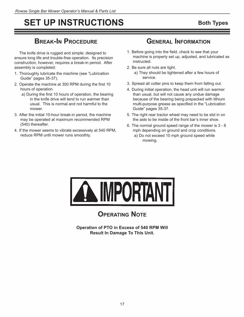
oPeraTinG noTe
Operation of PTO in Excess of 540 RPM Will Result In Damage To This Unit.
General inforMaTion
1. Before going into the field, check to see that your machine is properly set up, adjusted, and lubricated as instructed.
2. Be sure all nuts are tight. a) They should be tightened after a few hours of
service. 3. Spread all cotter pins to keep them from falling out.4. During initial operation, the head unit will run warmer
than usual, but will not cause any undue damage because of the bearing being prepacked with lithium multi-purpose grease as specified in the “Lubrication Guide” pages 35-37.
5. The right rear tractor wheel may need to be slid in on the axle to be inside of the front bar’s inner shoe.
6. The normal ground speed range of the mower is 3 - 8 mph depending on ground and crop conditions. a) Do not exceed 10 mph ground speed while
mowing.
SET UP INSTRUCTIONS Both Types

18
Rowse Single Bar Mower Operator’s Manual & Parts List
ADJUSTING AND OPERATING Both Types
Fig. 36
inner Shoe Balance SPrinG
1. The inner shoe balance spring A, Fig. 36, provides floating action to the cutter bar.
2. This spring should be tensioned to the point where the inner shoes require approximately 85-100 Ibs. to lift. a) This is accomplished by tightening locknut B.
GaG roD
1. After the inner shoe balance spring is adjusted, adjust the gag rod C, Fig. 36 so the outer shoe requires ap-proximately 25 lbs. to lift.
2. The outer shoe should raise in unison with the inner shoe. a) If the outer shoe droops or hangs down, tighten the
gag rod nut D until outer shoe raises properly.
cuTTer Bar TilT
1. To tilt the cutter bar upward (raising point of guards), loosen nuts F and G, Fig. 37, while at the same time tighten nuts H and I.
2. For downward tilt, loosen H and I while tightening F and G. A jack may be required to raise the rear of the basic mower for downward tilt adjustment.
3. During this adjustment the lower cap, which is held in place by the keyseat, will remain stationary.
Inner Shoe Float Adjusting Bolt
Outer Shoe Float Adjusting Nuts
Fig. 37
G
H
F
I
D
C
A
B

19
Rowse Single Bar Mower Operator’s Manual & Parts List
ADJUSTING AND OPERATING Both Types
auToMaTic SafeTy releaSe
1. The mower is equipped with an automatic safety release. a) If any solid obstruction is encountered, the cutter
bar will automatically swing toward the rear. 2. To recouple, back the tractor and mower until the re-
lease snaps back into operating position. 3. The drive belt will remain tight without danger of
running off the sheaves.4. The tension on the automatic safety release spring
should not be changed unless the mower releases in ordinary cutting.
5. Tension bolt B should be tightened only enough to hold. a) Too tight could cause major damage to the unit. b) After adjusting the tension of the spring F, Fig. 38,
tighten the locknut G, against the spring.6. If the automatic release cannot be tightened enough
to hold, an additional leaf spring H, may be added to regain the required tension.
Do not raise the bar with the hydraulic lift when the bar is hung up on an obstruction. You may
damage the bar.
Cutter Bar Lead Adjustment Bolt
Leaf Springs
Fig. 38: Bottom view of pivot frame with latch support plate cut away for clarity.
Automatic Safety Release Adjustment Bolt
Automatic Safety Release Spring
GC
E
H
BF
Locknut
M

20
Rowse Single Bar Mower Operator’s Manual & Parts List
ADJUSTING AND OPERATING Both Types
cuTTer Bar leaD1. The outer end of the cutter bar should be ahead of the
inner end, Fig. 39. a) In some instances of extremely heavy crops, incor-
rect bar lead can cause an increase of 30% to 50% more HP needed to operate each knife.
2. To check the cutter bar lead: a) Pull the outer end of the bar to the rear. b) With a straight edge along the tractor’s rear tires,
the measurement between it and the outer end should be ahead of the inner end 3-1/16 of an inch for 7-foot bars and 3-15/16 of an inch for 9-foot bars, Fig. 39.
3. Alternate method to check the cutter bar lead:a) Using two straight edge articles such as pipe.b) Place one along the rear tires and one along the
front of the mower frame, Fig. 41. c) B and C should measure the same.
4. When cutting extremely heavy crops, measurement C may be less, this will increase the cutter bar leads.
5. To correct the lead of the cutter bars: a) Unscrew A, Fig. 40. b) One full turn will make an approximate 2" to 3"
increase in the lead of both bars.
Fig. 41
Incorrect Bar Lead Correct Bar Lead cuTTer Bar laP1. When the mower is in correct bar lap position, uncut
hay should run between the 2nd and 3rd guards on the rear cutter bar, see D, Fig. 39.
2. Insufficient bar lap will leave a strip of uncut hay be-tween the front and rear bars.
3. Excessive bar lap will result in an inner portion of the rear bar to run in mowed hay and may cause hay build up and plugging on the inner portion of the rear cutter bar.
4. To correct cutter bar lap:a) Loosen F, G, and H, I, page 18, Fig. 37. b) Slide rear mower in or out to achieve correct lap.
6. This adjustment will decrease bar lap. a) See Cutter Bar Lap below to correct.
7. To correct bar lead of each separately, see Fig. 38, page 19. a) Loosen the locknut C on the adjustment rod. b) Turn the adjusting nut E until the proper lead is
obtained.c) Tighten nut C.
Fig. 40
A
Fig. 39Cutter Bar Lead inner
end measurementCutter Bar Lead outer end measurement
D

21
Rowse Single Bar Mower Operator’s Manual & Parts List
ADJUSTING AND OPERATING Both Types
Fig. 42
1. The cutter bar can be operated with sickles running at nearly any angle, Fig. 42. a) This allows the operator to
hydraulically lower or raise the cutter bar for mowing ditches or hills.
2. The bar may also be raised vertical while passing posts, trees, or other obstructions, without stopping to disengage the PTO drive. a) Care should be given, however,
that the raised bar does not hit or hook obstructions.
anGle of cuT
90° a
bove
leve
l
Level
30° above level
20° below level
Fig. 43Cutter Bar Lead inner
end measurementCutter Bar Lead outer end measurement
D
To cut a square corner, turn the tractor sharply to the right when the bar has cut completely out of the grass at the edge of the field, heading tractor directly back toward grass. Then turn sharply left so right tractor tire follows edge of the field. With a little practice you will become familiar with your equipment and crop conditions, and will soon have no problems cutting a square corner.
To cut a square corner, turn the tractor sharply to the right when the center of the drive wheel is in line with the edge of the field.
TrailinG MoWer Three-PoinT MoWer
cuTTinG a Square corner

22
Rowse Single Bar Mower Operator’s Manual & Parts List
ADJUSTING AND OPERATING NH Type
SWaTh BoarD1. The height of the swath divider F, Fig. 45, on the outer shoe may be adjusted to any of the three holes, not shown.
a) This adjustment should be set depending on the height of the crop being cut so the crop is most effectively pushed aside, leaving a path for the inner shoe on the next round.
2. The tension on the swath board mounting spring G, Fig. 45, should be set so the rods will deflect easily when an obstruction is hit. a) It should be tight enough, however, so the rods will
not move around when the mower is being trans-ported.
3. The grass rods can be bent to help get a cleaner divi-sion between swaths in unusual crop conditions.
heiGhT of cuT1. To regulate the height of cut, raise or lower the adjust-
able shoe soles H, Fig. 45, under the inner shoe C, and outer shoe D, Fig. 46.
2. To adjust the outer shoe sole, insert the bolt I, Fig. 45 into the desired notch, not shown.
3. To adjust the inner shoe sole, loosen the front bolts E, Fig. 46, in the shoe before attempting to change the height bolts K, Fig. 44.
4. Be sure both soles are adjusted to the same height to keep the cutter bar level.
5. On rough or stony land, the cutter bar should be pro-tected by tilting the bar upward, see page 18.
Fig. 45
HIGF
Fig. 46
C
E
D
Fig. 44
FK
A

23
Rowse Single Bar Mower Operator’s Manual & Parts List
ADJUSTING AND OPERATING IH Type
SWaTh BoarD
1. The tension on the swath board mounting spring A, Fig. 47 and 48, should be set so the rods will deflect easily when an obstruction is hit. a) It should be tight enough, however, so the rods
will not move around when the mower is being transported.
2. The grass rods B, Fig. 47, can be bent to help get a cleaner division between swaths in unusual crop con-ditions.
3. The grass rods C, Fig. 48, can be adjusted for a high or low position according to crop height.
Fig. 49
heiGhT of cuT
1. To regulate the height of cut, raise or lower the adjust-able shoe soles.
2. To adjust the outer shoe sole, slide the bolt F, Fig. 47 & 48, in the notch to obtain desired height.
3. To adjust the inner shoe sole, insert the bolt G, Fig. 49, into the desired position.
4. Be sure both soles are adjusted to the same height to keep the cutter bar level.
5. On rough or stony land, the cutter bar should be pro-tected by tilting the bar upward, see page 18, Fig. 37.
G
Fig. 43
A
Fig. 48
Grass Rod
Clamp, 3/8" x 1" Carriage Bolt,
13/32" x 1" x 11 ga. Flatwasher, 3/8" Lockwasher, and Hex Nut
Swath Board Support, four 3/8" x 3/4" Carriage Bolts,
and Two-Way LocknutsSwath Board
1/2" x 3 1/2" Square Head Bolt, Tension Spring,
17/32" x 1 1/4" x 16 ga. Flatwasher, and Locknut
C
AF
Position the outer shoe sole A Fig. 16 and install the 1/2" special head bolt. This is the samefor either type of swath board.
Install the swath board to the outer shoe with a 1/2" x 3" bolt, tension spring, washer and lock nut B Fig. 16 then position the grass rod at the desired level and install the carriage bolt, washer and lock nut at C and the carriage bolt, dampener washer and lock nut at D.
C B AFig. 16
D
Optional Grass Board Deflector
SET UP
OUTER SHOE AND SWATH BOARD INSTALLATION
Rubberdampener washer
Grass rod
Flat washer13/32" x 1" x 11 ga.
Hex lock nut3/8"
Swathboard
Carriage bolt3/8" x 1 1/2"
15
Position the outer shoe sole A Fig. 16 and install the 1/2" special head bolt. This is the samefor either type of swath board.
Install the swath board to the outer shoe with a 1/2" x 3" bolt, tension spring, washer and lock nut B Fig. 16 then position the grass rod at the desired level and install the carriage bolt, washer and lock nut at C and the carriage bolt, dampener washer and lock nut at D.
Fig. 16
D
Optional Grass Board De�ector
SET UP
OUTER SHOE AND SWATH BOARD INSTALLATION
Rubberdampener washer
Grass rod
Flat washer13/32" x 1" x 11 ga.
Hex lock nut3/8"
Swathboard
Carriage bolt3/8" x 1 1 /2"
15
F
B
B
Fig. 47

24
Rowse Single Bar Mower Operator’s Manual & Parts List
ADJUSTING AND OPERATING Both Types
flyWheel SPeeD NH Type DriveThe RPM of the Flywheel speed should not exceed 825 RPM with normal speed being 800 RPM.
IH Type DriveThe RPM of the Flywheel speed should not exceed 1050 RPM with normal speed being 1000 RPM.
Drive BelT
1. The V-Belt is properly adjusted when a slight thumb pressure will deflect the belt 1/2 inch at a point midway between the pulleys.
2. To tighten the V-Belt, see “Drive Belt”, page 4.
Do not exceed the recommended PTO speed for the driven machine.
If there appears to be excessive vibration at the 540 RPM speed, decrease RPM until vibration diminishes. This should not affect performance under normal conditions.
PTo SPeeD
1. This mower is designed to operate at a PTO (Power Take-Off) speed of 540 RPM.
2. When used with a tractor providing more than one rated engine speed, adjust the throttle to obtain the required RPM as indicated on tractor tachometer. a) Tachometers may be obtained from your Rowse
Dealer.3. Running at too high RPM will cause excessive vibra-
tion. a) If unit vibrates at the 540 PTO speed, lower RPM
until unit runs smoothly.
IMPORTANT
25
Rowse Single Bar Mower Operator’s Manual & Parts List
TRANSPORTING Both Types
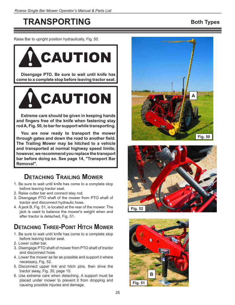
CAUTION
DeTachinG TrailinG MoWer1. Be sure to wait until knife has come to a complete stop
before leaving tractor seat.2. Raise cutter bar and connect stay rod. 3. Disengage PTO shaft of the mower from PTO shaft of
tractor and disconnect hydraulic hose.4. A jack B, Fig. 51, is located at the rear of the mower. The
jack is used to balance the mower's weight when and after tractor is detached, Fig. 51.
Disengage PTO. Be sure to wait until knife has come to a complete stop before leaving tractor seat.
CAUTIONExtreme care should be given in keeping hands
and fingers free of the knife when fastening stay rod A, Fig. 50, to bar for support while transporting.
You are now ready to transport the mower through gates and down the road to another field. The Trailing Mower may be hitched to a vehicle and transported at normal highway speed limits; however, we recommend you replace the transport bar before doing so. See page 14, "Transport Bar Removal".
Raise Bar to upright position hydraulically, Fig. 50.
DeTachinG Three-PoinT hiTch MoWer1. Be sure to wait until knife has come to a complete stop
before leaving tractor seat.2. Lower cutter bar.3. Disengage PTO shaft of mower from PTO shaft of tractor
and disconnect hose. 4. Lower the mower as far as possible and support it where
necessary, Fig. 52.5. Disconnect upper link and hitch pins, then drive the
tractor away, Fig. 30, page 15.6. Use extreme care when detaching. A support must be
placed under mower to prevent it from dropping and causing possible injuries and damage. Fig. 51
B
A
Fig. 50
Fig. 52

26
Rowse Single Bar Mower Operator’s Manual & Parts List
STORAGE Both Types
STorinG The MachineThe life of the machine depends on how well it is taken
care of during the harvest season and while in storage be-tween seasons. The storing period of the machine, which is usually about eight months of each year, is an important factor in the life of the machine.
Even though the machine is idle and not subject to operational wear, it can, if not properly stored, receive costly wear and serious damage by being exposed to the weather or by being struck by heavy objects. No machine should be allowed to stand outside unprotected from the weather for a long period of time any more than an auto-mobile.
A storage shed is a good investment because of the savings effected by assuring a longer lasting machine, reducing the operating costs, and continuing the highly efficient field performance.
afTer reMovinG The Machine froM SToraGe anD Before BeGinninG The harveST SeaSon
1. Remove the excess grease from the mower. 2. Make sure that all bolts and nuts are properly tight-
ened. This can save wasted time and needless ex-pense.
3. Lubricate the machine thoroughly in accordance with the “Lubrication Guide” to make sure that all bearings have a protective coating prior to field operation.
Before STorinG The Machine1. Clean the machine of all dirt, trash and superfluous
grease; if left on, it will hold moisture and thus cause serious damage from rust.
2. Lubricate all points of the mower as shown in the Lubri-cation Guide, and run the unit slowly for approximately ten minutes to allow lubricant to give a protective coat-ing to all bearings and members subject to rust and corrosion.
3. Loosen the drive belt.4. Remove the knife from the cutter bar. Cover the knife
with a good rust preventive and store in a safe place.5. Apply a light coating of oil on all exposed metal wearing
parts.6. Inspect for any worn and broken parts, and order them
early. This will give your dealer ample time to provide the genuine ROWSE parts and give you sufficient time to install them before the next harvest season.

27
Rowse Single Bar Mower Operator’s Manual & Parts List
MAINTENANCE Both Types
General inforMaTion
1. 90% of mower problems are a result of improper ad-justment and lack of maintenance of the cutter bar.
2. Periodic checking and servicing of your mower will pay dividends in a cleaner job of mowing, less damage to parts, decreased draft, and decreased maintenance costs.
3. Excessive plugging is usually due to the following:• A dull knife.• Wet and/or tangled crops.• Non-alignment of the cutter bar.• Insufficient “Bar Lead” (end of bar hanging back).
Refer to “Cutter Bar Lead” on page 20.• Poor adjustment of the cutter bar parts.• Excessive “Lap” (rear bar set too far to the left).
Refer to “Cutter Bar Lead” on page 20.
4. The knife is permanently registered at the factory and no further adjustment is needed unless damage or wear requires knife replacement. a) Refer to “Knife Removal and Replacement” on
page 28.5. The knife must be straight.
a) It must be supported by the wearing plates so that all sections run parallel and flat on the guard.
b) Refer to Fig. 53 on page 28.6. Guards must be at the same height (level so that all
sections contact). a) Correct installation of new guards is very important.
7. Bent guards must be reset to the proper height so that all guards are at the same height (level).
8. Do not hammer or bend down the lips of the guards. a) This practice will result in choking the knife, caus-
ing the mower to run hard.

28
Rowse Single Bar Mower Operator’s Manual & Parts List
MAINTENANCE Both Types
ServicinG The cuTTer Bar anD coMPonenTS1. The Cutter Bar of the mower corresponds to a multiple
set of shears. a) Just as with hand shears, the opposing edges (the
knife section and guard) must be sharp and con-tact each other if a smooth, clean cutting action is to result.
2. The knife should fit in the cutter bar as shown in Fig. 53. a) The following sections describe the means of
achieving this fit.b) Also see “Cutter Bar and Knife Alignment” on
page 16.
Fig. 53
Proper Knife AlignmentHold-down clips must hold knife down but should not bind.
Wear plate sets forward against knife back.
Lip should be straight and should not contact section.
Knife section should rest on front of ledger surface.
Fig. 54
New section: proper angle and bevel.
Correctly ground: proper angle and bevel.
Incorrectly ground: wrong angle and
narrow bevel.
Incorrectly ground: sections off-center,
knife will not register.
Fig. 52A
plates and guards after you have installed the new knife, operate the mower slowly and pour water on the bar. Do not let it harden. a) Use extreme CAUTION when performing this pro-
cedure. Always stand behind and as far away as possible from moving parts.
NH Type Knife Removal1. Remove the knife from the drive plates by removing the
bolt A, Fig. 55, and wedge spacer, through the drive plates and knife head.
2. When a new knife is installed, first position the knife so that it is in the CENTER OF ITS STROKE, Fig. 56.
3. Tighten the knife head bolt, B, to 85-90 ft. lbs. torque. a) 90 ft. lbs. of torque
is equal to 90 lbs. of force applied to a wrench 12" from the center of the bolt.
b) A socket extension and ratchet is needed to complete this installation
c) Also see “Mower Knife Drive” on page 9.
IH Type Knife Removal1. Remove the knife from the balance yoke by removing
the knife bolt at Point A, Fig 56A. 2. Lift the knife pin using the optional guard lip gauge tool.3. When a new knife is installed, check the clearance
between the balance yoke and the knife head. a) It must be between .010" to .070" B, Fig. 56A. b) Use a shim or shims between the cutter bar and
inner shoe to attain this clearance.c) See page
13, “Mower Knife Drive Installation.”
4. Install the knife pin and knife bolt.a) Torque 85-95 ft.
lbs.
Knife Removal And Replacement1. Always check the replacement knife to be sure it is
straight especially in areas from the knife head bush-ing to 15" - 16" to the right along the knife assembly. a) Any bends or twists will result
in poor cutting action and excessive wear.
b) Failure of the knife head bush-ing can be due to a bent knife head.
2. Before installing a knife, be sure all sections are tight and properly sharpened. a) Fig. 54 shows properly sharp-
ened sections. b) Inspect for wear on the knife
head and be sure the rivets are tight.
3. It is recommended to use a set of knives, in rotation, to assure uni-form wear on each until they are discarded, or sections replaced. Setting the parts on the cutter bar to one knife will then result in a proper fit on the remaining knives.
4. If there is gummy trash on the wear
Fig. 55
A
Fig. 56
B
The Cutter Bar of the mower corresponds to a multiple set of shears. Just as with hand shears, the op-posing edges (knife section and ledger plate) must be sharp and contact each other if a smooth clean cut-ting action is to result. The knife should �t in the cutter bar as shown in Fig. 45. The following sections describe the means of achieving this �t and also see "Cutter Bar and Knife Alignment" pages 16 and 17.
Remove the knife from the balance yoke by removingthe knife bolt. Lift the knife pin using guard lip gaugetool A Fig. 47. Compare Fig. 50, page 31.
Always check the replacement knife to be sure it isstraight, especially in areas from the knife head bush-ing to 15" - 16" to the right along the knife assembly.Any bends or twists will result in poor cutting actionand excessive wear. Failure of the knife head bushingcan be due to a bent knife head. Fig. 45
Before installing a knife, be sure all sections are tight and properly sharpened. Fig. 46 shows properly sharpened sections. Inspect for wear on knife head and be sure the rivets or bolts are tight.
When a new knife is installed, check the clearancebetween the balance yoke and the knife head. It mustbe between .010" to .070" B Fig 47. Use a shim orshims between the cutter bar and the inner shoe to attain this clearance. See page 16, "Mower Knife Drive Installation." Install the knife pin and knife bolt and torque 85 to 95 ft. lbs.
It is recommended to use a "set" of knives, in rotat-ion to assure uniform wear on each until they are dis-carded, or sections replaced. Setting the parts on thecutter bar to one knife will result in a proper "�t" on the
Fig. 46 remaining knives.
If there is gummy trash on the wear plates andguards after you have installed the new knife, operatethe mower slowly and spray water on the bar. DO NOTlet it harden. Use extreme CAUTION when performingthis procedure. Always stand behind and as far away as possible from moving parts. B
Fig. 47
MAINTENANCE
SERVICING THE CUTTER BAR AND COMPONENTS
KNIFE REMOVAL AND REPLACEMENT
PROPER KNIFE ALIGNMENTHold-down clips must hold knife down but should not bind.
Lip should be straight andshouldn't contact section.
Wear plate sets forwardagainst knife back.
Knife section should rest on front of ledger surface.
New sectionsproper angle and bevel.
Correctly groundproper angle and bevel.
Incorrectly groundwrong angle
and narrow bevel.
Incorrectly groundsections o� center.
Knife will not register.
30
A
Fig. 56A

29
Rowse Single Bar Mower Operator’s Manual & Parts List
MAINTENANCE NH Type
GuarD aliGnMenT
1. Guard alignment is a very important operation. a) A new knife or a straight one not badly worn should
be used in aligning the guards. 2. Insert the knife and first set the high guards down.
a) Do so by striking at the thickest part in front of the ledger plate starting at the inner shoe.
3. Then, set the low guards up to secure the knife ledger plate relationship shown in Figure 57.
4. Tighten guard bolts before and after setting the guard. 5. If all guards seem to be out of line, shims may need to
be positioned to tilt the cutter bar, see “Cutter Bar and Knife Alignment” on page 16.
6. Disregard the alignment of the points of the guards, but keep them well pointed.
7. Straighten the guard wings, if necessary; so they are parallel to the knife back.
8. Keep the guard lip well raised above the ledger plate to prevent binding of the knife.
9. Replace Worn Or Dull Guards Promptly.a) Dull guards or knives put more strain on the drive
mechanism which will result in more expensive repairs.
Wear PlaTeS
1. Worn wear plates should be adjusted or replaced to take up wear on knife back and reduce play of the knife back in the neck of the guards as shown in Fig. 57.
2. In setting the wear plates ahead, be sure there is enough clearance in front of the sections to keep from striking the guards.
3. The front edges of all wear plates should be in line to give the knife back a straight wearing surface.
knife holD-DoWn cliPS
Fig. 57
Proper Guard and Clip AlignmentHold-down clips must hold knife down but should not bind.
Wear plate sets forward against knife back.
Lip should be straight and should not contact section.
Knife section should rest on front of ledger surface.
rePlacinG BuShinG in knife heaD
1. The knife head bushing must be snug.a) Excessive looseness will result in noisy operation,
as well as, knife or knife head breakage.2. Remove the old bushings using a 1" pipe, Fig. 58.
a) Care should be taken not to bend the knife head, Fig. 59.
3. Using the 1" pipe again, install the new bushing. a) Be sure that the pipe and pressure you apply only
contacts the steel outer portion of the bushing.b) Pressure on the inner rubber portion will cause
damage.
Fig. 58
Bushing
1" Pipe
1. The knife hold-down clips must be adjusted so that they hold the knife sections down against the guard while mowing, but allow the knife to move without binding.
2. When the knife clips are adjusted properly, the knife can be moved backward and forward through the guards without binding, Fig. 57.
Steel Outer Portion
Fig. 59Rubber Inner Portion

30
Rowse Single Bar Mower Operator’s Manual & Parts List
MAINTENANCE IH Type
GuarD rePlaceMenT & aliGnMenT
1. Remove broken guards and repair or replace guards which are worn on cutting edge.
2. When installing new guards, make certain that the bar is free of dirt.
3. Draw the nut up tight and then strike the guard several hammer blows on the pad section at the counter sunk hole for the bolt, Fig. 60. a) This will seat the
guard. b) Then retighten the
bolt.4. Replace worn or dull
guards promptly. a) Dull guards or knives
put more strain on the drive mecha-nism which will re-sult in more expen-sive repairs.
5. Guard alignment is very important. a) Check all guards for correct ledger plate height.
6. Guards which have been bent up must be pounded down to proper height by striking on the heavy section just ahead of the plate.
7. Low guards must be raised by striking the underside of the same location.
Note: If guards are bent during field operation, remove the knife and bend the guard so that it is at the cor-rect height according to the gauge tool.
8. Disregard the alignment of the points of the guards, but keep them well pointed.
9. Straighten the guard wings, if necessary, so they are parallel to the knife back.
knife holD-DoWn cliPS anD Wear PlaTeS
1. Position knife in the guards with hold-down clips and wear plates slightly loose.
2. Replace knife pin and tighten knife bolt 85 to 95 ft. lbs. torque.
3. Move hold-down clips and wear plates forward against the knife assembly with the balanced head in the cen-ter of the stroke.
4. Tighten bolts enough to permit wear plates and hold-down clips to align themselves while rotating the bal-anced head at the right hand end of the stroke.
5. Move hold-down clips rearward an additional 1/32" and tighten bolts.
6. Rotate the balanced head to center stroke position and check clearance between hold-down clips and knife sections with the section pressed against cuffing sur-face of the guard. a) The clearance should be .008". b) If clip is too tight, hammer on the hump to raise. c) If clip is providing more than .008" clearance, ham-
mer on the front tip.
aDjuSTaBle holD-DoWn cliPS
1. The adjustable hold-down clip assembly (1 in Fig. 61) can be installed on any mower or mower-conditioner equipped with standard guards. a) The adjustable hold-down clips cannot be used on
machines with stub guards. 2. The same adjustable hold-down clip is used on all
machines.a) A locknut (2 in Figure 61) on the adjusting bolt is
used to adjust the clearance between the front of the hold-down and the knife section at Y
(in Fig. 61).NOTE: All kits also include 0.010" (0.25 mm) shims
that may be required to adjust the clearance be-tween the rear lip on the clip and the knife section at X (in Figure 61.)
Fig. 60
Fig. 61
112
X Y
4 25 1
6
3
Y X Fig. 62
31
Rowse Single Bar Mower Operator’s Manual & Parts List
MAINTENANCE IH Type
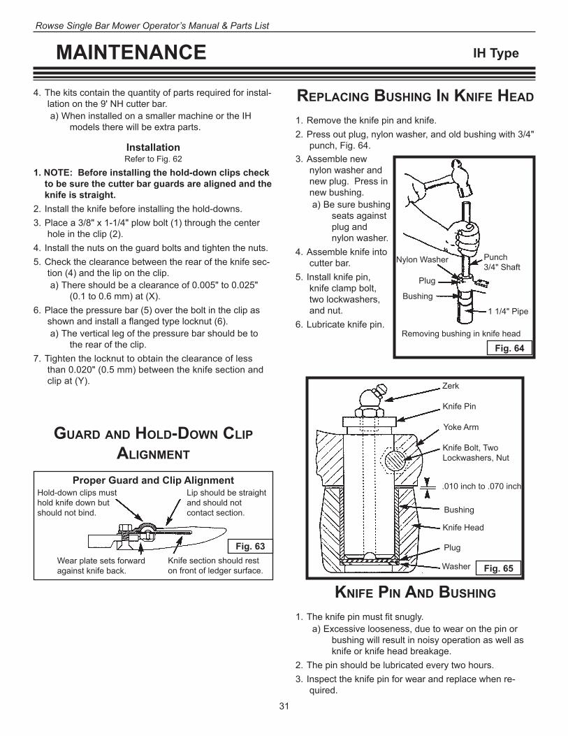
rePlacinG BuShinG in knife heaD
1. Remove the knife pin and knife.2. Press out plug, nylon washer, and old bushing with 3/4"
punch, Fig. 64.
knife Pin anD BuShinG
1. The knife pin must fit snugly. a) Excessive looseness, due to wear on the pin or
bushing will result in noisy operation as well as knife or knife head breakage.
2. The pin should be lubricated every two hours.3. Inspect the knife pin for wear and replace when re-
quired.
Fig. 63
Proper Guard and Clip AlignmentHold-down clips must hold knife down but should not bind.
Wear plate sets forward against knife back.
Lip should be straight and should not contact section.
Knife section should rest on front of ledger surface.
GuarD anD holD-DoWn cliP aliGnMenT
4. The kits contain the quantity of parts required for instal-lation on the 9' NH cutter bar.a) When installed on a smaller machine or the IH
models there will be extra parts.
InstallationRefer to Fig. 62
1. NOTE: Before installing the hold-down clips check to be sure the cutter bar guards are aligned and the knife is straight.
2. Install the knife before installing the hold-downs. 3. Place a 3/8" x 1-1/4" plow bolt (1) through the center
hole in the clip (2).4. Install the nuts on the guard bolts and tighten the nuts.5. Check the clearance between the rear of the knife sec-
tion (4) and the lip on the clip.a) There should be a clearance of 0.005" to 0.025"
(0.1 to 0.6 mm) at (X).6. Place the pressure bar (5) over the bolt in the clip as
shown and install a flanged type locknut (6).a) The vertical leg of the pressure bar should be to
the rear of the clip.7. Tighten the locknut to obtain the clearance of less
than 0.020" (0.5 mm) between the knife section and clip at (Y). Zerk
Knife Pin
Yoke Arm
Knife Bolt, Two Lockwashers, Nut
.010 inch to .070 inch
Bushing
Knife Head
Plug
Washer Fig. 65
Nylon Washer
Plug
Punch 3/4" Shaft
Bushing
1 1/4" Pipe
Fig. 64Removing bushing in knife head
3. Assemble new nylon washer and new plug. Press in new bushing. a) Be sure bushing
seats against plug and nylon washer.
4. Assemble knife into cutter bar.
5. Install knife pin, knife clamp bolt, two lockwashers, and nut.
6. Lubricate knife pin.

32
Rowse Single Bar Mower Operator’s Manual & Parts List
MAINTENANCE NH Type
The following procedure is suggested to periodically adjust the crankshaft tapered roller bearings, or when resetting them after repacking with grease.1. Remove the belt shield. 2. Loosen the belt and remove it. 3. Loosen the bolt, A, two full turns so the pulley can be
loosened on the tapered spline shaft. Fig. 67.4. Install a wheel puller to break the pulley loose on the
splined shaft.5. Remove the pulley as shown in Fig. 66. 6. Remove the knife head bolt and wedge drivelock so the
crankshaft, C, Fig. 66, can be turned freely.7. Tighten the slotted nut, D, Fig. 66, until 2-6 ft. lbs. of
torque is required to turn the crankshaft.8. Replace hinge arm (E).9. Replace the drive pulley making sure that the spring
pin will align with one of the slots between the tabs of the slotted nut, D.
100 ft. lbs. of torque is equal to 100 lbs. of force applied to a wrench 12" from the center of the bolt.
Make sure the splined shaft and the bore of the crank shaft pulley are clean before installing the pulley on the shaft.
BearinG aDjuSTMenT - crankShafT BearinGS
9. Replace the heavy washer B and the bolt, A, Fig. 67. a) Torque the bolt to 95-100 ft. lbs. b) NOTE: If the spring pin is not positioned properly
in the slot of the slotted nut, it will extend at least 1/4" beyond the pulley at B, Fig. 67.
10. Strike the pulley next to the hub with a heavy hammer to properly seat the splined shaft in the pulley. a) Retorque the nut again.
11. Repeat this sequence twice or until torque does not decrease.
12. Replace the belt and shield.13. Replace knife head bolt and wedge drivelock.
a) When KNIFE IS AT CENTER OF STROKE tighten bolt to 85-90 ft. lbs.
Fig. 66
D
C
Fig. 67
A
B
E

33
Rowse Single Bar Mower Operator’s Manual & Parts List
MAINTENANCE NH Type
knife Drive BearinGS
To service the knife drive area, remove the cutter bar as-sembly from the mower frame by performing the following steps:1. Loosen the drive belt tension and remove the belt from
the drive pulley.2. Remove the clevis pin and cotter key A, Fig. 68 and the
two bolts from the arm and mower frame, C, Fig. 68.3. Remove the inner shoe sole, B, Fig. 68.4. Remove nuts, D and E, and remove the support plate.5. To service an individual pivot link bearing,
a) Remove knife head bolt and nuts, F.b) Remove the front drive plate. c) Remove the respective bearing adjusting nuts.
6. The crank connecting rod can be removed by removing the locknut.
7. To remove the bearing studs, remove the nuts in back of rear support housing.
aSSeMBly
1. Install the bearing studs into the rear support housing and secure the nuts. a) Tighten nuts to 100 ft. lbs.
2. Place dust caps on bearing studs and rear drive plate studs. a) Place larger dust cap on crank pin stud on drive
plate.3. With the bearings in the respective pivot links, install
the pivot links and crank connecting rod.a) NOTE: Be sure zerks are positioned correctly.
4. Install a dust cap over all link and connecting rod bear-ings.
5. Install adjusting nuts, G.a) Tighten the adjusting nuts to 30 ft. lbs. to properly
seat the bearings and back nuts off two flats or 1/3 of a turn.
6. Install locknut and tighten to 10 ft. lbs. 7. Install front drive plate and install nuts, F.
a) Tighten nuts to 100 ft. lbs. b) Make sure the bearing adjusting nuts G do not turn
when tightening nuts, F.8. Place a spacer on studs and install the support plate.
a) Install nuts, E and D. b) Tighten nuts, E, to 100 ft. lbs.
9. Install the cutter bar assembly and tighten bolts, C, Fig. 68 to 90 ft. lbs.
10. Install belt and tighten as outlined under “Drive Belt”, Page 4.
11. Install knife head bolt and tighten when KNIFE IS IN THE CENTER OF ITS STROKE to 85-90 ft. lbs.
inSTallaTionSee page 7 -- Cutter Bar Head Installation
Fig. 68
D B
D
C
A
G
G
E
F
F

34
Rowse Single Bar Mower Operator’s Manual & Parts List
MAINTENANCE IH Type
Pivot Head Bushings1. Move end shoe of bar backward and forward.
a) This will indicate any wear on bronze bearings A, the large pivot pin B, and the large bronze pivot bushing located inside the flywheel at area C, Fig. 69.
b) This also checks to assure tightness of bar to head.
Bottom Yoke Bearing2. Lift yoke in an upward and downward motion D, Fig. 69.
a) Should the yoke show any movement, replace bearing immediately.
b) Failure to do so may/will result in damage to the yoke, etc.
Wobble Shaft Bearings3. Pull in and out on flywheel E, Fig. 69 to check end play
of wobble shaft bearings.4. With yoke centered, turn flywheel back and forth to
check bearings on wobble shaft. a) They should move in complete unison.
ProceDure for checkinG heaD BearinGS
SpecificationsBalanced head bearing housing end play in balance yoke. Bearing housing -
Part No. (458953R2) (balanced yoke): .006" to .007"
Bearing housing -Part No. 670298 (458953R3) (crank shaft):
.003" to .004"Wobble shaft end play
In wobble shaft housing: .0015" to .002"
In balanced head bearing housing: .003" to .005"
Wobble shaft assembly runout (gauge block measurement):
.014" Maximum
Special TorquesYoke bearing bolts ................................10 to 11 ft. lb.Front hinge pin lock bolt ............................. 120 ft. lb.Drive housing bolts ............................. 80 to 85 ft. lb.Flywheel locknut ........................................ 150 ft. lb.Mounting bolts, bar ......................... 155 to 175 ft. lb.
Fig. 69
A
B
D
C
E
IMPORTANTBearings should be
checked after the first hour of use and
then daily. We recommend you
check the bearings asyou do the daily
lubrication.
Service NoteThe Balanced Head knife drive is an efficient and precise operating unit. Should a bearing or seal need to be replaced,
we recommend you contact your Rowse Dealer. He has the experience and precision tools necessary to service the bal-anced head design. However, should you desire to service your own drive head, you should order the Service Manual (GSS-1038-H) and some of the precision tools needed from Rowse.

35
Rowse Single Bar Mower Operator’s Manual & Parts List
LUBRICATION GUIDE Both Types
1. This mower is designed to require a minimum amount of lubrication; however, regular and sufficient lubrica-tion increases the life of the machine, saves many dol-lars in service parts and is the best insurance against delays.
2. Before starting, lubricate the complete machine follow-ing the “Lubrication Guide”.
3. Thereafter, lubricate at regular intervals as specified.4. Do not use a high pressure gun! Excessive lubrication
may destroy the seals. 5. Keep the lubricator gun clean and wipe off all dirt from
the zerks before using the gun.
NEVER LUBRICATE MOWER WHILE TRACTOR ENGINE IS
RUNNING!
Fig. 70
Fig. 71
Key To Lubrication GuideMore often than daily
Daily or after every 8 hours of operation
Every three days or after 30 hours of opera-tion which ever is less
Periodically
Pivot frame hinges A fig. 70
Front hinge A fig. 72 NH, 73 lH, page 36
Rear hinge fig. 73 page 36
A Use No. 2 multi-purpose lithium grease and apply sufficient lubrication to flush out the old grease and dirt.
2
3
4
Daily or After Every 8 Hours of Operation
Bellcrank B fig. 71
Lower cylinder mount B fig. 73 pg 36
Cylinder tube B fig. 73 pg 36
Bar lift linkage B fig. 73 pg 36
Power drive knuckles B fig. 70
B Use No. 2 multi-purpose lithium grease and lubricate the uni-versal drive center crosses (2 zerks). Only a few strokes of the lubricator gun are required. Do not use a high pres-sure gun. Excessive lubricant forced through the bearings may destroy the seals.
5
6
7
8
10
10
2
26
6
7
11
12
5

36
Rowse Single Bar Mower Operator’s Manual & Parts List
LUBRICATION GUIDE Both Types
More Often Than Daily
IH Type Drive
Daily or After Every 8 Hours of Operation
NH Type Drive
Knife Pin F fig. 73
Main Frame Component Parts
pg. 40 parts and assy.
F Every 2 hours, use IH251HEP grease or equivalent No. 2 multi-purpose lithium grease and apply sufficient lubrica-tion to flush out the old grease and dirt. Rowse has a product available, Piston Plate, which reduces friction and increases life of knife pin and knife head bushing.
21
22
– Pivot link bearings B NH Type (4) fig. 72
Connecting rod bearings B NH Type (2)
fig. 72
B Use No. 2 multi-purpose lithium grease and lubricate the universal drive center crosses (2 zerks). Only a few strokes of the lubricator gun are required. Do not use a high pressure gun. Excessive lubricant forced through the bearings may destroy the seals.
16
20
19
#1 Power drive knuckle, shaft, and sleeve E
fig. 74 pg. 37
E Should be pulled apart and lubricated with grease daily.
15
Knife guards, wear plates, and hold-down knife clips D
fig. 72 NH, 73 IH
D Lubricate with oil can. In locations where soil is sandy, the knife guard, wearing plates, and hold-down knife clips should not be oiled. In other localities where these conditions do not exist, oil them daily.
14
Bellcrank lift rod C fig. 71
Gag rod C fig. 71
Crankshaft housing bearings NH Type fig. 72
C Use oil can.
11
12
13
Fig. 73
IH Type shown
Fig. 72
NH Type shown
18
317
19
20
1613
14
7
8
6
3
14
24
21
23
4
25
4
23
22

37
Rowse Single Bar Mower Operator’s Manual & Parts List
LUBRICATION GUIDE Both Types
Every Three Days or After 30 Hours of Operation, Whichever is Less
Balanced head bearing housingG IH Type
fig. 73
Crankshaft housing (under top button plug)G IH Type
fig. 73
Yoke bearing (behind front button plug above knife pin)G IH Type
fig. 73
G Use a pressure gun lubricant. Apply 3/8 ounce of IH251HEP grease or equivalent No. 2 multi-purpose lithium grease. This can be determined in terms of strokes of the lubri-cant gun, depending on the type used. Do not use a high-pressure gun.
23
24
25
Drive shaft housing zerk H fig. 70 pg 35
H Use No. 2 multi-purpose lithium grease. Only a few strokes of the lubricator gun are required. Do not use a high-pressure gun. Excessive lubricant forced through the bearings may destroy the seals.
26
Periodic
Lubricate the one fitting per hub every 500 hours. Do not overgrease or seals will force out.
fig. 7427
Fig. 74
27
27

38
Rowse Single Bar Mower Operator’s Manual & Parts List
TROUBLESHOOTING Both Types
Possible Cause Possible RemedyPLUGGING OF THE CUTTER BARGuard missing, loose, or out of line
Tighten and align guards. See Page 29(NH), 30(IH).
Too much tilt of Cutter Bar Change angle of tilt.See Page 18.
Dull or worn-out knife Sharpen or replace knife section. See Page 28.
Guards dull Replace.See Page 29(NH), 30(IH).
Knife Clips not properly set Reset knife clips.See Page 29(NH), 30(IH).
Lips of Guards bent down too far
Align guards.See Page 29(NH), 30(IH).
Drive Belt slipping Adjust drive belt.See Page 4.
Improper Bar lead Correct. See Page 20.Lack of lubrication Lubricate the mower.
See Pages 35-37.
PLUGGING OF THE INNER SHOESwath not properly divided Adjust grass rods.
See Page 22(NH), 23(IH.Inner Shoe too heavy Adjust inner shoe balance
spring, See Page 18.Broken section Replace. See Page 28.Cutting too low Adjust height of cut.
See Page 22 (NH), 23(IH).Inner Ledger dull or missing Sharpen or replace.
See Page 27(NH), 28(IH).
PLUGGING AT OUTER SHOECutting too low Adjust height of cut.
See Page 22(NH), 23(IH).Outer Shoe too heavy Adjust Gag Rod.
See Page 18.End Ledger Plate dull or missing
Replace.
Broken Section Replace. See Page 28.
Most mower difficulties are caused by improper adjustments. When you encounter trouble, make a systematic check of all mower adjustments, using the following chart as a guide.
In some instances, special attachments are available to help overcome various ground or crop conditions. It
should be kept in mind, however, special attachments will not eliminate the difficulty if the machine is not properly adjusted.
If mower difficulties cannot be corrected by making the adjustments given in this manual, see your ROWSE Dealer.
Possible Cause Possible RemedyBREAKING OF KNIVES
Guards loose or out of line Tighten and align guards. See Page 29(NH), 30(IH).
Dull Sections and Ledger Plates
Sharpen or replace. See Page 28 & 29(NH), 30(IH).
Worn Knife Pin or Bushing Replace.See Page 29(NH), 31(IH).
Over speed of Tractor PTO PTO to run at 540 RPM only. Consult your ROWSE Dealer for proper changes needed.
Crooked Knife Straighten or replace. See Page 28.
Wear Plates too far forward
Adjust or replace wear plates.See Page 29(NH), 30(IH).
EXCESSIVE VIBRATIONOver speed of Tractor PTO Reduce PTO RPM.
See Page 24.Loose Head Bearings Check Bearings. See Page
32-33(NH), 34(IH).Improper Knife installation Correct.
See Page 9(NH), 13(IH).Dull Section and Guards Sharpen or replace. See
Page 28-29(NH), 30(IH).
KNOCKING AND NOISE IN DRIVE
Check Knife Head Pivot for looseness
Tighten or replace knife head bushing. See Pages 9 & 29(NH), 13 & 31(IH).
Loose Drive Head Bearings Adjust or replace Bearings.See Page 32-33(NH), 34(IH).
39
Rowse Single Bar Mower Operator’s Manual & Parts List
PARTS LIST Both Types
inTroDucTion4. Be sure to use the correct part number and quantity for
your mower model where parts differ.5. Touch-up paint in convenient aerosol cans is available
from Rowse.
PTO-ST7-NH, PTO-ST9-NH H PTO-ST7-IH, PTO-ST9-IH PTO-SM7-NH, PTO-SM9-NH HH
PTO-SM7-IH, PTO-SM9-IH
1. Rowse attempts to keep on hand at all times an adequate supply of all parts. a) However, some fast-moving, high volume parts
may need to be ordered early to be sure of meeting delivery requirements.
2. Check the assembly drawing and description with the part you need and give the part number and quantity when ordering.
3. Most parts are interchangeable between the Mower Models with these exceptions:a) Frame and Hitchb) Arm Linkagec) Mower Headsd) Cutter Bars and Componentse) PTO Drive Lines
H ST Model Mowers are 2-wheel Trail MowersH SM Model Mowers are 3-point Mowers

40
Rowse Single Bar Mower Operator’s Manual & Parts List
PARTS LIST Both Types
fraMe
Ref. Part No. Description Qty. PTO-ST COMPLETE FRAME & TONGUE ASSEMBLY (all below except RM-2368, tires & wheels), (choice of coupler or clevis hitch) 1 ST-3801 FRAME AND AXLE ..............................................................................................................1 2 845502225 TIRE, P225/75R15 ................................................................................................................2 3 RM-2383 BAR, to hold mower assembly for transporting w/o bar lift hydraulics. (ST-3803) ................1 4 62C150HCS5Z BOLT, WELDED 5/8" x 1½"...................................................................................................1 5 62CNNE0Z/NE NUT, 5/8" Lock ......................................................................................................................1 6 111-20 HAIR PIN CLIP, #6 ................................................................................................................1 7 ST-3808 TONGUE ASSEMBLY, coupler hitch, incl. PTO drive stand #15A (two drive model) ............1 7A ST-3808C TONGUE ASSEMBLY, clevis hitch, incl. PTO drive stand #15A, (two drive model) .............1 8 75C500HCS5Z BOLT, 3/4" X 5" .....................................................................................................................1 9 75C200HCS5Z BOLT, 3/4" X 2" .....................................................................................................................1 10 75NSAE0Z WASHER, Flat 3/4" x 1½" x 1/8" ...........................................................................................1 11 75NLOC0Z WASHER, 3/4" Lock .............................................................................................................2 12 75CNFH0Z NUT, Hex 3/4" .......................................................................................................................2 13 2B2M COUPLER, ball 2" weld on ...................................................................................................1 14 RM-2368 BALL, 2" w/1" Shank .............................................................................................................1 RM-2371 BALL, 2" w/1" Shank 3" Long ................................................................................................1 15A 23810312 SUPPORT (stand), PTO Drive Lines (two drive model only) ................................................1 50C150HC55Z BOLT, 1/2" x 1-1/2" ..............................................................................................................10 50CNNE0Z/NE NUT, 1/2" Lock ....................................................................................................................10
TWO DRIVE MODEL CLEVIS HITCH (shown)
15A

41
Rowse Single Bar Mower Operator’s Manual & Parts List
PARTS LIST Both Types
Three-PoinT MounTeD MoWer hiTch aSSeMBlyroW croP TracTor MoDelS
WiTh hyDraulic verTical lifTMoWer MoDelS 530-nh, 730-nh, 930-nh
530-ih, 730-ih, 930-ih
Ref. Part No. Description Qty. PTO-SM HITCH ASSEMBLY COMP. (incl. all except 2- LA-1 & Fittings) 1 SM-3901 HITCH ASSEMBLY ...............................................................................................................1 2 LA-1 PIN, Side Link (Category 1) ..................................................................................................2 87NLOC0Z WASHER, 7/8" Lock .............................................................................................................2 87CNFH0Z NUT, 7/8" ...............................................................................................................................2 670206 KLIK PIN, 7/16" X 1¾" ..........................................................................................................2 2A SM-3902-1 PIN, Side Link (ROWSE Special, Category 2) ......................................................................2 87NLOC0Z WASHER, 7/8" Lock .............................................................................................................2 87CNFH0Z NUT, 7/8" ...............................................................................................................................2 670206 KLIK PIN, 7/16" X 1¾" ..........................................................................................................2 3 TLP3 PIN, Top 3/4" x 3" (Category 1) .............................................................................................1 TLB34-1 BUSHING, 3/4" x 1" x 2" (Category 2) ..................................................................................1 4 RM-2246 CLAMP, hose ........................................................................................................................1 37CNNE0Z/NE NUT, 3/8" lock .......................................................................................................................1
2A

42
Rowse Single Bar Mower Operator’s Manual & Parts List
PARTS LIST Both Types
Three-PoinT MounTeD MoWer hiTch aSSeMBlycoMPacT TracTor MoDelS (16-50 horSe PoWer)
WiTh hyDraulic verTical lifTMoWer MoDelS PTo-cv-5-nh, PTo-cv7-nh, PTo-cv9-nh
PTo-cv5-ih, PTo-cv7-ih anD PTo-cv9-ih
Ref. Part No. Description Qty. PTO-SM3 HITCH ASSEMBLY COMP. (incl. all except 2- LA-1 & Fittings) 1 SM-3903 HITCH ASSEMBLY, Compact Tractor Models ......................................................................1 2 LA-1 PIN, Side Link (IH Type 525921 R1) .....................................................................................2 87NLOC0Z WASHER, 7/8" Lock .............................................................................................................2 87CNFH0Z NUT, 7/8" ...............................................................................................................................2 670206 KLIK PIN, 7/16" x 1¾" ...........................................................................................................2 2A SM-3902-1 PIN, Side Link (ROWSE Special Cat. 1 & 2) ........................................................................2 87NLOC0Z WASHER, 7/8" Lock .............................................................................................................2 87CNFH0Z NUT, 7/8" ...............................................................................................................................2 670206 KLIK PIN, 7/16" x 1¾" ...........................................................................................................2 3 TLP3 PIN, Top 3/4" x 4" ..................................................................................................................1 TLB34-1 BUSHING, 3/4" x 1" ..............................................................................................................1 4 RM-2246 CLAMP, hose ........................................................................................................................1 37CNNE0Z/NE NUT, 3/8" lock .......................................................................................................................1
2A

43
Rowse Single Bar Mower Operator’s Manual & Parts List
PARTS LIST Both Types
Three-PoinT MounTeD MoWer hiTch aSSeMBlyroW croP TracTor MoDelS
WiTh Mechanical lifTMoWer MoDelS 730-nh, 930-nh, 730-ih, & 930-ih
Ref. Part No. Description Qty. 1 SM-3901 HITCH ASSEMBLY, Compact Tractor Models ......................................................................1 2 LA-1 PIN, Side Link (IH Type 525921 R1) .....................................................................................2 87NLOC0Z WASHER, 7/8" Lock .............................................................................................................2 87CNFH0Z NUT, 7/8" (013478) ...............................................................................................................2 670206 KLIK PIN, 7/16" x 1¾" ...........................................................................................................2 2A SM-3902-1 PIN, Side Link (ROWSE Special Category 2) .......................................................................2 87NLOC0Z WASHER, 7/8" Lock .............................................................................................................2 87CNFH0Z NUT, 7/8" (013478) ...............................................................................................................2 670206 KLIK PIN, 7/16" x 1¾" ...........................................................................................................2 3 670145 LIFT BRACKET ASSEMBLY (135205 C1) ............................................................................1 4 670104 BOLT, Special Head (101216 C2) .........................................................................................1 K4324 Washer, 17/32" x 1¼" x 16 ga. (25555 R1) ...........................................................................1 50CNST0 Nut, 1/2" Slotted (K3943) ......................................................................................................1 139-31 Cotter Key, 3/32" x 1½" .........................................................................................................1 5 670105 PULLEY, Lifting Cable (101217 C1) ......................................................................................1 RM-2112 Pin, 3/4" x 2¾" (22929 R1) ...................................................................................................1 25R150PCO0Z Cotter Key, 1/4" x 1¼" (010242)............................................................................................1 6 101-100 ZERK, 1/8" PTF straight (011962) ........................................................................................1 7 670804 BAR (61704 C1) ....................................................................................................................2 670808 Pin, 1/2" x 1.625" (21955 R1) ...............................................................................................1 18R100PCO0Z Cotter Key, 3/16" x 1" (010229).............................................................................................1 50F175HCS5Z Bolt, 1/2" x 1¾" machine, NF ................................................................................................1 670806 Spacer (521039) ...................................................................................................................2 8 50FNNE0Z/NE NUT, 1/2" Lock NF (18452 R1) .............................................................................................1 9 670803 CABLE (61705 C1) ...............................................................................................................1 10 670107 WIRE ROPE THIMBLE (61706 C1) ......................................................................................1 11 670805 CABLE CLAMP, 5/16" includes nuts (552230 R91) ..............................................................2 12 670103 EYE BOLT ASSEMBLY (101211 C1) ....................................................................................1 13 75CNFH0Z Nut, 3/4" (013475) .................................................................................................................1 670900 SPACER (959047 R1) ..........................................................................................................1 14 TLP3 PIN, Top 3/4" x 4" (Category 1) .............................................................................................1 TLB34-1 Bushing, 3/4" x 1" (Category 1 to 2) ......................................................................................1
2A

44
Rowse Single Bar Mower Operator’s Manual & Parts List
PARTS LIST Both Types
Three-PoinT MounTeD MoWer hiTch aSSeMBlycoMPacT TracTor MoDelS (16-50 horSePoWer)
WiTh Mechanical lifTMoWer MoDelS PTo-cM5-nh, PTo-cM7-nh, PTo-cM9-nh
PTo-cM5-ih, PTo-cM7-ih anD PTo-cM9-ih
Ref. Part No. Description Qty. 1 SM-3903 HITCH ASSEMBLY, Compact Tractor Models ......................................................................1 2 LA-1 PIN, Side Link (IH Type 525921 R1) .....................................................................................2 87NLOC0Z WASHER, 7/8" Lock .............................................................................................................2 87CNFH0Z NUT, 7/8" (013478) ...............................................................................................................2 670206 KLIK PIN, 7/16" x 1¾" ...........................................................................................................2 2A SM-3902-1 PIN, Side Link (ROWSE Special Category 2) .......................................................................2 87NLOC0Z WASHER, 7/8" Lock .............................................................................................................2 87CNFH0Z NUT, 7/8" (013478) ...............................................................................................................2 670206 KLIK PIN, 7/16" x 1¾" ...........................................................................................................2 3 670145 LIFT BRACKET ASSEMBLY (135205 C1) ............................................................................1 4 670104 BOLT, Special Head (101216 C2) .........................................................................................1 K4324 Washer, 17/32" x 1¼" x 16 ga. (25555 R1) ...........................................................................1 50CNST0 Nut, 1/2" Slotted (K3943) ......................................................................................................1 139-31 Cotter Key, 3/32" x 1½" .........................................................................................................1 5 670105 PULLEY, Lifting Cable (101217 C1) ......................................................................................1 RM-2112 Pin, 3/4" x 2¾" (22929 R1) ...................................................................................................1 25R150PCO0Z Cotter Key, 1/4" x 1¼" (010242)............................................................................................1 6 101-100 ZERK, 1/8" PTF straight (011962) ........................................................................................1 7 670804 BAR (61704 C1) ....................................................................................................................2 670808 Pin, 1/2" x 1.625" (21955 R1) ...............................................................................................1 18R100PCO0Z Cotter Key, 3/16" x 1" (010229).............................................................................................1 50F175HCS5Z Bolt, 1/2" x 1¾" machine, NF ................................................................................................1 670806 Spacer (521039) ...................................................................................................................2 8 50FNNE0Z/NE NUT, 1/2" Lock NF (18452 R1) .............................................................................................1 9 670803 CABLE (61705 C1) ...............................................................................................................1 10 670107 WIRE ROPE THIMBLE (61706 C1) ......................................................................................1 11 670805 CABLE CLAMP, 5/16" includes nuts (552230 R91) ..............................................................2 12 670103 EYE BOLT ASSEMBLY (101211 C1) ....................................................................................1 13 75CNFH0Z Nut, 3/4" (013475) .................................................................................................................1 670900 SPACER (959047 R1) ..........................................................................................................1 14 TLP3 PIN, Top 3/4" x 4" (Category 1) .............................................................................................1 TLB34-1 Bushing, 3/4" x 1" (Category 1 to 2) ......................................................................................1
2A

45
Rowse Single Bar Mower Operator’s Manual & Parts List
PARTS LIST Both Types
PivoT fraMe, BreakaWay arM, & laTch SuPPorT PlaTe
BELL CRANKSEE PAGE 52

46
Rowse Single Bar Mower Operator’s Manual & Parts List
PARTS LIST Both Types
Ref. Part No. Description Qty. 1 50C400BTA5Z BOLT, spring adjusting, 1/2" x 4" tap (570 640 R1) ..............................................................1 50CNFH0Z Nut, 1/2"-13 Hex (125 536 C1) .............................................................................................1 2 50NUSS0Z WASHER, 1/2" Flat (178 374 R1) ........................................................................................1 3 670835 PLUG, spring (M 1425) ........................................................................................................1 4 670880 SPRING, breakaway latch, 25 coils (PO 199 A) ..................................................................1 5 100N150AMB0/10GA WASHER, 1" x 1-1/2" x 10 ga. (21 714 R1) .........................................................................2 6 670678 CAP, breakaway arm (489 480 R1) .....................................................................................2 62C550HCS5Z Bolt, 5/8"- 11 x 5-1/2" HHC ...................................................................................................4 62CNNE0Z/NE Nut, 5/8"-11 nylon insert (21 620 R1) ...................................................................................4 7 670268 ARM, breakaway (458 891 R2) ............................................................................................1 8 670262 FRAME (458 888 R2) ..........................................................................................................1 62C350HCS5Z Bolt, 5/8" x 3-1/2" H HC .......................................................................................................5 62CNNE0Z/NE Nut, 5/8"-11 nylon insert (124 589 R1) .................................................................................5 62NUSS0Z Washer, 5/8" Flat ..................................................................................................................3 9 101-100 ZERK, 1/8" PTF straight lub (109 461 R1) ...........................................................................2 10 670265 SHIM, pivot frame (458 890 R1) ...................................................................8 or as required 62C450HCS5Z Bolt, 5/8"-11 x 4-1/2" HHC ....................................................................................................4 62CNNE0Z/NE Nut, 5/8"-11 nylon insert (21 620 R1) ...................................................................................4 11 670264 CAP, pivot frame (458 889 R 1) ...........................................................................................2 12 670275 PLATE, latch support (458 906 R1) .....................................................................................1 13 670358 ROLLER ASSY, breakaway latch (462 764 R93) .................................................................1 18R150PCO0Z Cotter Key, 3/16" x 1-1/2" (20 328 R1) .................................................................................1 100N150AMB0/10G Washer, 1" x 1-1 /2" x 10 ga. ................................................................................................2 14 670335 BUSHING, latch strap pivot (459 396 R2) ...........................................................................1 15 670276 EYEBOLT, lead adjustment (458 907 R1) ............................................................................1 75CNFH0Z Nut, 3/4"-10 Hex (220 086 R1) .............................................................................................2 16 670725 SPRING, front (490 529 R1) ................................................................................................2 50C150HCS5Z Bolt, 1/2"-20 x 1-1/2" C-Z HEX HD CAP ..............................................................................1 50NUSS0Z Washer, 1/2” Flat ..................................................................................................................1 50FNNE0Z/NE Nut, 1/2"-20 nylon insert .......................................................................................................1 17 670758 SPRING, Leaf (524 453 R1) (short) .....................................................................................2 18 RM-2510 BREAKAWAY STOP, front mower ........................................................................................1 37C125HCS5Z BOLT, 3/8 x 1-1/4" HHC ........................................................................................................1 37NLOC0Z WASHER, LOCK 3/8 .............................................................................................................1 19 111-100 ZERK, 90 Deg, 1/4-28 NPTF ................................................................................................1 20 RM-2148 ZERK, 1/8" PTF 65, 2-1/2" Long ...........................................................................................1
PivoT fraMe, BreakaWay arM, & laTch SuPPorT PlaTe

47
Rowse Single Bar Mower Operator’s Manual & Parts List
PARTS LIST Both Types
MoWer MounTinG ParTS
Ref. Part No. Description Qty. 1 RM-2100 MOUNT, front arm linkage, NH Type Models .......................................................................1 RM-2252 MOUNT, front arm linkage, IH Type Models ........................................................................1 2 RM-2103 ARM, linkage ........................................................................................................................1 3 RM-2106 LINKAGE, mower hookup, NH Type Models .......................................................................1 RM-2107 LINKAGE, mower hookup, IH Type Models .........................................................................1 4 RM-2112 PIN, clevis, 3/4" x 2-3/4", NH Type Models ..........................................................................1 4 A 670735 PIN, clevis, 3/4" x 2-5/16", IH Type Models ..........................................................................1 5 25R150PCO0Z COTTER KEY, 1/4" x 1-1/2" .................................................................................................1 6 50C350HCS5Z BOLT, 1/2" x 3-1/2", Hex ......................................................................................................2 7 R-3 PLATE, mounting .................................................................................................................1 8 50CNNE0Z/NE NUT, 1/2", Hex Lock .............................................................................................................2 9 RM-2115 PIN, hinge, 1" x 6-1/2" ...........................................................................................................1 9A RM-2115-A Pin, hinge, bolted w/ strap. (For mowers 2008 & newer.) .....................................................1 10 PSW-1001-64 BUSHING, bronze, 1" x 1-1/4" x 1" .......................................................................................2 11 RM-2118 GAG ROD, lift ......................................................................................................................1 12 OG-5144 SPRING, gag rod .................................................................................................................2 13 RM-2133 SPACER ..............................................................................................................................2
27
28
42
15 18
43
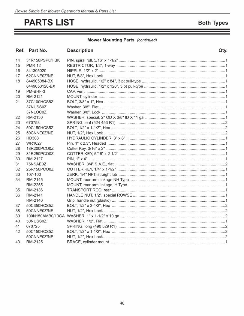
48
Rowse Single Bar Mower Operator’s Manual & Parts List
PARTS LIST Both Types
14 31R150PSP0/HBK PIN, spiral roll, 5/16" x 1-1/2" ................................................................................................1 15 PMR 12 RESTRICTOR, 1/2", 1-way ..................................................................................................1 16 841305020 NIPPLE, 1/2" x 2" ..................................................................................................................1 17 62CNNE0Z/NE NUT, 5/8", Hex Lock .............................................................................................................1 18 844905084-BX HOSE, hydraulic, 1/2" x 84", 3 pt pull-type ...........................................................................1 8449050120-BX HOSE, hydraulic, 1/2" x 120", 3 pt pull-type .........................................................................1 19 PM-BHF-3 CAP, vent .............................................................................................................................1 20 RM-2121 MOUNT, cylinder ..................................................................................................................1 21 37C100HCS5Z BOLT, 3/8" x 1", Hex .............................................................................................................1 37NUSS0Z Washer, 3/8", Flat .................................................................................................................1 37NLOC0Z Washer, 3/8", Lock ...............................................................................................................1 22 RM-2130 WASHER, special, 2" OD X 3/8" ID X 11 ga ........................................................................1 23 670758 SPRING, leaf (524 453 R1) .................................................................................................2 24 50C150HCS5Z BOLT, 1/2" x 1-1/2", Hex ......................................................................................................2 25 50CNNE0Z/NE NUT, 1/2", Hex Lock .............................................................................................................2 26 HD308 HYDRAULIC CYLINDER, 3" x 8" .........................................................................................1 27 WR1027 Pin, 1" x 2.3", Headed ..........................................................................................................1 28 18R200PCO0Z Cotter Key, 3/16" x 2" ...........................................................................................................1 29 31R250PCO0Z COTTER KEY, 5/16" x 2-1/2" ...............................................................................................1 30 RM-2127 PIN, 1" x 4" ...........................................................................................................................1 31 75NSAE0Z WASHER, 3/4" S.A.E., flat ...................................................................................................2 32 25R150PCO0Z COTTER KEY, 1/4" x 1-1/2" ..................................................................................................1 33 107-100 ZERK, 1/4" NFT, straight lub ................................................................................................1 34 RM-2145 MOUNT, rear arm linkage NH Type .....................................................................................1 RM-2255 MOUNT, rear arm linkage IH Type .......................................................................................1 35 RM-2136 TRANSPORT ROD, rear ......................................................................................................1 36 RM-2141 HANDLE NUT, 1/2", special ROWSE ...................................................................................1 RM-2140 Grip, handle nut (plastic) ......................................................................................................1 37 50C350HCS5Z BOLT, 1/2" x 3-1/2", Hex ......................................................................................................2 38 50CNNE0Z/NE NUT, 1/2", Hex Lock .............................................................................................................2 39 100N150AMB0/10GA WASHER, 1" x 1-1/2" x 10 ga ..............................................................................................2 40 50NUSS0Z WASHER, 1/2", Flat .............................................................................................................1 41 670725 SPRING, long (490 529 R1) ................................................................................................2 42 50C150HCS5Z BOLT, 1/2" x 1-1/2", Hex ......................................................................................................2 50CNNE0Z/NE NUT, 1/2", Hex Lock ..............................................................................................................2 43 RM-2125 BRACE, cylinder mount ........................................................................................................1
Mower Mounting Parts (continued)
Ref. Part No. Description Qty.
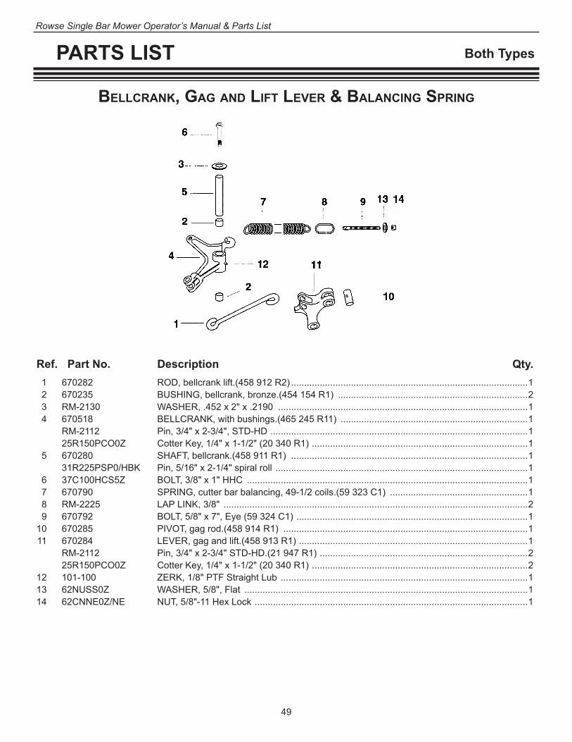
49
Rowse Single Bar Mower Operator’s Manual & Parts List
PARTS LIST Both Types
Ref. Part No. Description Qty. 1 670282 ROD, bellcrank lift.(458 912 R2) ...........................................................................................1 2 670235 BUSHING, bellcrank, bronze.(454 154 R1) .........................................................................2 3 RM-2130 WASHER, .452 x 2" x .2190 ................................................................................................1 4 670518 BELLCRANK, with bushings.(465 245 R11) ........................................................................1 RM-2112 Pin, 3/4" x 2-3/4", STD-HD ...................................................................................................1 25R150PCO0Z Cotter Key, 1/4" x 1-1/2" (20 340 R1) ...................................................................................1 5 670280 SHAFT, bellcrank.(458 911 R1) ...........................................................................................1 31R225PSP0/HBK Pin, 5/16" x 2-1/4" spiral roll .................................................................................................1 6 37C100HCS5Z BOLT, 3/8" x 1" HHC ............................................................................................................1 7 670790 SPRING, cutter bar balancing, 49-1/2 coils.(59 323 C1) .....................................................1 8 RM-2225 LAP LINK, 3/8" .....................................................................................................................2 9 670792 BOLT, 5/8" x 7", Eye (59 324 C1) .........................................................................................1 10 670285 PIVOT, gag rod.(458 914 R1) ..............................................................................................1 11 670284 LEVER, gag and lift.(458 913 R1) ........................................................................................1 RM-2112 Pin, 3/4" x 2-3/4" STD-HD.(21 947 R1) ................................................................................2 25R150PCO0Z Cotter Key, 1/4" x 1-1/2" (20 340 R1) ...................................................................................2 12 101-100 ZERK, 1/8" PTF Straight Lub ...............................................................................................1 13 62NUSS0Z WASHER, 5/8", Flat .............................................................................................................1 14 62CNNE0Z/NE NUT, 5/8"-11 Hex Lock .........................................................................................................1
Bellcrank, GaG anD lifT lever & BalancinG SPrinG

50
Rowse Single Bar Mower Operator’s Manual & Parts List
PARTS LIST Both Types
fronT & rear cuTTer Bar SuPPorT hinGe couPlinG, iDler Pulley, & ShielDS
Ref. Part No. Description Qty. 1 670685 SHIELD, rear, incl. decal (489 491 R1) (old style) ...............................................................1 1A 670685-H Shield and Rim, heavy ..........................................................................................................1 25C50BCG2Z Bolt, 1/4"-20 x 1/2" CRG ......................................................................................................8 25CNFH0Z Nut, 1/4"-20 Hex ...................................................................................................................8 25NLOC0Z Washer, 1/4" med Lock ........................................................................................................8 3 R-606 SHIELD COVER ..................................................................................................................1 25C37HCS5Z Bolt, 1/4" -20 x 3/8" H HC ....................................................................................................3 25NLOC0Z Washer, 1/4" med Lock ........................................................................................................3 RM-2280 Safety Decal, “Warning, Keep All Shields …” .......................................................................1 4 670788 SPACER, drive shield (586 329 R1) ....................................................................................1 5 670680 DAMPENER, rubber washer (489 486 R1) ..........................................................................2 6 670698 ROLLER, drive belt (489 497 R1) ........................................................................................1 50NSAE0Z Washer, 1/2" S.A.E., Flat .....................................................................................................2 7 670682 SHIELD, front, includes decal (489 487 R1) (old style) .......................................................1 7A 670682-H Shield, heavy ........................................................................................................................1 37C125BCG5Z Bolt, 3/8" x 1-1/4" CRG (18 684 R1) ....................................................................................2 Quantities are per each mower unit.
1A
16
18
17
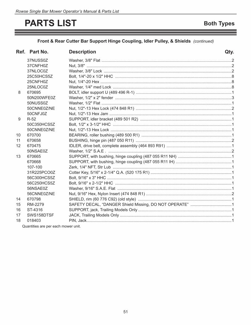
51
Rowse Single Bar Mower Operator’s Manual & Parts List
PARTS LIST Both Types
Front & Rear Cutter Bar Support Hinge Coupling, Idler Pulley, & Shields (continued)
Ref. Part No. Description Qty. 37NUSS0Z Washer, 3/8" Flat ..................................................................................................................2 37CNFH0Z Nut, 3/8" ...............................................................................................................................2 37NLOC0Z Washer, 3/8" Lock ................................................................................................................2 25C50HCS5Z Bolt, 1/4"-20 x 1/2" HHC ......................................................................................................8 25CNFH0Z Nut, 1/4"-20 Hex ...................................................................................................................8 25NLOC0Z Washer, 1/4" med Lock ........................................................................................................8 8 670695 BOLT, idler support U (489 496 R-1) ....................................................................................1 50N200WFE0Z Washer, 1/2" x 2" fender ......................................................................................................3 50NUSS0Z Washer, 1/2" Flat ..................................................................................................................1 50CNNE0Z/NE Nut, 1/2"-13 Hex Lock (474 848 R1) ....................................................................................2 50CNFJ0Z Nut, 1/2"-13 Hex Jam ...........................................................................................................1 9 R-52 SUPPORT, idler bracket (489 501 R2) ................................................................................1 50C350HCS5Z Bolt, 1/2" x 3-1/2" HHC ........................................................................................................1 50CNNE0Z/NE Nut, 1/2"-13 Hex Lock ..........................................................................................................1 10 670700 BEARING, roller bushing (489 500 R1) ...............................................................................1 11 670658 BUSHING, hinge pin (487 050 R11) ....................................................................................2 12 670475 IDLER, drive belt, complete assembly (464 893 R91) .........................................................1 50NSAE0Z Washer, 1/2" S.A.E . ............................................................................................................2 13 670665 SUPPORT, with bushing, hinge coupling (487 055 R11 NH) ...............................................1 670668 SUPPORT, with bushing, hinge coupling (487 055 R11 IH) .................................................1 107-100 Zerk, 1/4" NFT, Str Lub ........................................................................................................1 31R225PCO0Z Cotter Key, 5/16" x 2-1/4" Q.A. (520 175 R1) .......................................................................1 56C300HCS5Z Bolt, 9/16" x 3" HHC .............................................................................................................1 56C250HCS5Z Bolt, 9/16" x 2-1/2" HHC ......................................................................................................1 56NSAE0Z Washer, 9/16" S.A.E. Flat ....................................................................................................1 56CNNE0Z/NE Nut, 9/16" Hex, Nylon Insert (474 848 R1) ...........................................................................2 14 670798 SHIELD, rim (60 776 C92) (old style) ..................................................................................1 15 RM-2279 SAFETY DECAL, “DANGER Shield Missing, DO NOT OPERATE” ....................................1 16 ST-4316 SUPPORT, jack, Trailing Models Only ..................................................................................1 17 SWS158DTSF JACK, Trailing Models Only ..................................................................................................1 18 018403 PIN, Jack ...............................................................................................................................1 Quantities are per each mower unit.
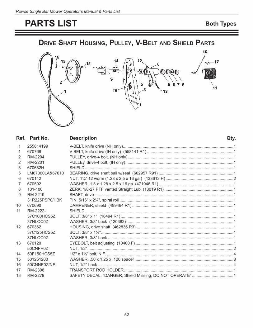
52
Rowse Single Bar Mower Operator’s Manual & Parts List
PARTS LIST Both Types
Ref. Part No. Description Qty. 1 255814199 V-BELT, knife drive (NH only) ................................................................................................1 1 670768 V-BELT, knife drive (IH only) (558141 R1) ...........................................................................1 2 RM-2204 PULLEY, drive-4 bolt, (NH only) ............................................................................................1 2 RM-2201 PULLEy, drive-4 bolt, (IH only) ..............................................................................................1 3 670682H SHIELD .................................................................................................................................1 5 LM67000LA&67010 BEARING, drive shaft ball w/seal (602957 R91) .................................................................1 6 670142 NUT, 1¼" 12 worm (1.28 x 2.5 x 16 ga.) (133613 H) ...........................................................2 7 670592 WASHER, 1.3 x 1.28 x 2.5 x 16 ga. (471946 R1) .................................................................1 8 101-100 ZERK, 1/8-27 PTF vented Straight Lub (13019 R1) ............................................................1 9 RM-2219 SHAFT, drive .........................................................................................................................1 31R225PSP0/HBK PIN, 5/16" x 2¼", spiral roll ...................................................................................................1 10 670690 DAMPENER, shield (489494 R1) ........................................................................................1 11 RM-2222-1 SHIELD .................................................................................................................................1 37C100HCS5Z BOLT, 3/8" x 1" (18494 R1) ..................................................................................................1 37NLOC0Z WASHER, 3/8" Lock (120382) .............................................................................................1 12 670362 HOUSING, drive shaft (462836 R3) .....................................................................................1 37C125HCS5Z BOLT, 3/8" x 1¼" ...................................................................................................................1 37NLOC0Z WASHER, 3/8" Lock .............................................................................................................1 13 670120 EYEBOLT, belt adjusting (10400 F) .....................................................................................1 50CNFH0Z NUT, 1/2" ...............................................................................................................................2 14 50F150HCS5Z 1/2" x 1½" bolt, N.F. ..............................................................................................................4 15 501251200 WASHER, .50 x 1.25 x .120 spacer ......................................................................................8 16 50CNNE0Z/NE NUT, 1/2" Lock ......................................................................................................................4 17 RM-2398 TRANSPORT ROD HOLDER ...............................................................................................1 18 RM-2279 SAFETY DECAL, "DANGER, Shield Missing, DO NOT OPERATE" ....................................1
Drive ShafT houSinG, Pulley, v-BelT anD ShielD ParTS
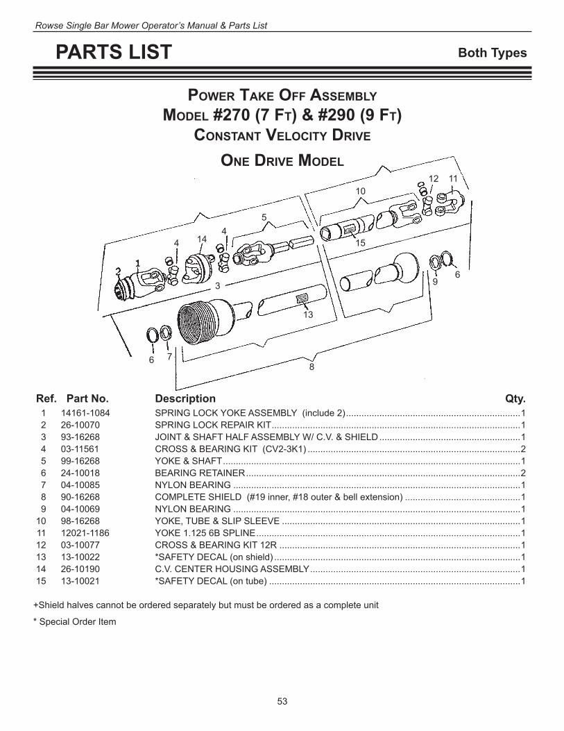
53
Rowse Single Bar Mower Operator’s Manual & Parts List
PARTS LIST Both Types
Ref. Part No. Description Qty. 1 14161-1084 SPRING LOCK YOKE ASSEMBLY (include 2) ....................................................................1 2 26-10070 SPRING LOCK REPAIR KIT .................................................................................................1 3 93-16268 JOINT & SHAFT HALF ASSEMBLY W/ C.V. & SHIELD .......................................................1 4 03-11561 CROSS & BEARING KIT (CV2-3K1) ...................................................................................2 5 99-16268 YOKE & SHAFT ....................................................................................................................1 6 24-10018 BEARING RETAINER ...........................................................................................................2 7 04-10085 NYLON BEARING ................................................................................................................1 8 90-16268 COMPLETE SHIELD (#19 inner, #18 outer & bell extension) .............................................1 9 04-10069 NYLON BEARING ................................................................................................................1 10 98-16268 YOKE, TUBE & SLIP SLEEVE .............................................................................................1 11 12021-1186 YOKE 1.125 6B SPLINE .......................................................................................................1 12 03-10077 CROSS & BEARING KIT 12R ..............................................................................................1 13 13-10022 *SAFETY DECAL (on shield) ................................................................................................1 14 26-10190 C.V. CENTER HOUSING ASSEMBLY ..................................................................................1 15 13-10021 *SAFETY DECAL (on tube) ..................................................................................................1
+Shield halves cannot be ordered separately but must be ordered as a complete unit
* Special Order Item
PoWer Take off aSSeMBlyMoDel #270 (7 fT) & #290 (9 fT)
conSTanT velociTy Drive
one Drive MoDel
3
44
5
6
6 78
9
101112
13
14 15

54
Rowse Single Bar Mower Operator’s Manual & Parts List
PARTS LIST Both Types
Ref. Part No. Description Qty. 222-1603839 COMPLETE TWO DRIVE SET UP ......................................................................................... 1 222-16038 COMPLETE DRIVE W/ SHIELD #1 12R 29" ........................................................................1 31R225PSP0/HBK PIN, 5/16" X 1-1/5" spiral roll ................................................................................................1 2 222-16039 COMPLETE DRIVE W/ SHIELD #2 12R 37.5" .....................................................................1 31R225PSP0/HBK PIN, 5/16" X 1-1/5" spiral roll ................................................................................................2 3 23810312 SUPPORT (stand), PTO Drive Lines (two drive model only) ................................................1 50C150HC55Z BOLT, 1/2" x 1-1/2" ..............................................................................................................10 50CNNE0Z/NE NUT, 1/2" Lock ....................................................................................................................10 4 RM-2326 PILLOW BLOCK ASSEMBLY ...............................................................................................2 RM-2329 PILLOW BLOCK HOUSING .................................................................................................2 G1106KRRB/COL PILLOW BLOCK BEARING, only .........................................................................................2 S 1106 K COLLAR, pillow block, eccentric lock ...................................................................................2 5 RM-2332 SHAFT, splined .....................................................................................................................1 6 RM-2222-1 SHIELD, pillow block .............................................................................................................2 37C125HCS5Z BOLT, 3/8" x 1¼" ...................................................................................................................2 37NUSS0Z WASHER, 3/8" flat ................................................................................................................2 37NLOC0Z WASHER, 3/8" lock ...............................................................................................................2 7 RM-2223 BRACKET, pillow block shield ...............................................................................................1 8 50C200HCS5Z BOLT, 1/2" x 2" ......................................................................................................................6 9 50CNNE0Z/NE NUT, 1/2" lock .......................................................................................................................6 10 107-100 ZERK, 1/4" NPT straight lub. ................................................................................................2 11 RM-2279 SAFETY DECAL, "DANGER", shield missing, Do not operate .............................................1 12 RM-2280 SAFETY DECAL, "WARNING", keep all shields in place .....................................................1 13 RM-2297 DECAL, OPERATIONAL "IMPORTANT" operate PTO below 540rpm .................................1 14 RM-2291 SAFETY DECAL, "CAUTION", read owners manual ............................................................1 15 37C125HCS5Z BOLT, 3/8" x 1¼" ...................................................................................................................2 16 37NUSS0Z WASHER, 3/8" flat ................................................................................................................2 17 37NLOC0Z WASHER, 3/8" lock ...............................................................................................................2
PoWer Take off aSSeMBlyMoDel #270 (7 fT) & #290 (9 fT)
TWo Drive MoDel
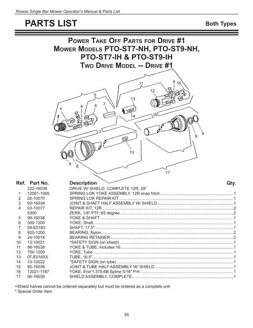
55
Rowse Single Bar Mower Operator’s Manual & Parts List
PARTS LIST Both Types
Ref. Part No. Description Qty. 222-16038 DRIVE W/ SHIELD, COMPLETE 12R, 29" 1 12061-1000 SPRING LOK YOKE ASSEMBLY, 12R snap hitch ................................................................1 2 26-10070 SPRING LOK REPAIR KIT ...................................................................................................1 3 93-16038 JOINT & SHAFT HALF ASSEMBLY W/ SHIELD ..................................................................1 4 03-10077 REPAIR KIT, 12R ..................................................................................................................2 5300 ZERK, 1/8" PTF, 65 degree...................................................................................................2 5 99-16038 YOKE & SHAFT ....................................................................................................................1 6 300-1200 YOKE, Shaft ..........................................................................................................................1 7 09-E0183 SHAFT, 17.5" ........................................................................................................................1 8 920-1200 BEARING, Nylon ...................................................................................................................2 9 24-10018 BEARING RETAINER ...........................................................................................................2 10 13-10021 *SAFETY SIGN (on shield) ...................................................................................................1 11 98-16038 YOKE & TUBE, includes 16 ..................................................................................................1 12 700-1200 YOKE, Tube ..........................................................................................................................1 13 07-E0165X TUBE, 16.5" ..........................................................................................................................1 14 13-10022 *SAFETY SIGN (on tube) .....................................................................................................1 15 92-16038 JOINT & TUBE HALF ASSEMBLY W/ SHIELD ....................................................................1 16 12021-1187 YOKE, End 1.375-6B Spline 5/16" P.H. ................................................................................1 17 90-16038 SHIELD ASSEMBLY, COMPLETE ........................................................................................1
+Shield halves cannot be ordered separately but must be ordered as a complete unit* Special Order Item
PoWer Take off ParTS for Drive #1MoWer MoDelS PTo-ST7-nh, PTo-ST9-nh,
PTo-ST7-ih & PTo-ST9-ihTWo Drive MoDel -- Drive #1
3
4
4
5
6 7
8
8 9
9
10
11
12
13
14 15
16
17

56
Rowse Single Bar Mower Operator’s Manual & Parts List
PARTS LIST Both Types
Ref. Part No. Description Qty. 222-16039 DRIVE W/ SHIELD, COMPLETE 12R, 37½" 1 12021-1187 YOKE, End 1.375 - 6B Spline w/5/16" P.H. ...........................................................................1 2 03-10077 REPAIR KIT, 12R ..................................................................................................................2 5300 ZERK, 1/8" PTF 65 Degree ...................................................................................................2 3 93-16039 JOINT & SHAFT HALF ASSEMBLY W/ SHIELD ..................................................................1 4 99-16039 YOKE & SHAFT ....................................................................................................................1 5 300-1200 YOKE, Shaft ..........................................................................................................................1 6 09-E0263 SHAFT, 26" ...........................................................................................................................1 7 920-1200 BEARING, Nylon ...................................................................................................................2 8 24-10018 BEARING RETAINER, Nylon ................................................................................................2 9 13-10021 *SAFETY SIGN (on shield) ...................................................................................................1 10 98-16039 YOKE & TUBE, includes 15 ..................................................................................................1 11 700-1200 YOKE, Tube ..........................................................................................................................1 12 07-E0276X TUBE, 25½" ..........................................................................................................................1 13 13-10022 *SAFETY SIGN (on tube) .....................................................................................................1 14 92-16039 JOINT & TUBE HALF ASSEMBLY W/ SHIELD ....................................................................1 15 12021-1186 YOKE, End 1.125 - 6B Spline with 5/16" P.H. .......................................................................1 16 90-16039 SHIELD ASSEMBLY, COMPLETE ........................................................................................1
+Shield halves cannot be ordered separately but must be ordered as a complete unit* Special Order Item
PoWer Take off ParTS for Drive #2MoWer MoDelS PTo-ST7-nh, PTo-ST9-nh,
PTo-ST7-ih & PTo-ST9-ihTWo Drive MoDel -- Drive #2
2
3
2
4
56
78
9
78
11
12
1314
1510
16

57
Rowse Single Bar Mower Operator’s Manual & Parts List
PARTS LIST Both Types
Ref. Part No. Description Qty. 412-16041-00 COMPLETE DRIVE W/ SHIELD, 33", 6R 1 06241-1044 SPRING LOK YOKE ASSEMBLY .........................................................................................1 2 26-10070 SPRING LOK REPAIR KIT ...................................................................................................1 3 03-10002 REPAIR KIT, 6R ....................................................................................................................2 4 99-16040 YOKE & SHAFT ....................................................................................................................1 5 300-0600 YOKE, SHAFT ......................................................................................................................1 6 09-C0225 SHAFT, 22.5" ........................................................................................................................1 7 920-0600 NYLON BEARING ................................................................................................................2 8 24-10018 BEARING RETAINER ...........................................................................................................2 9 13-10021 *SAFETY DECAL (on shield) ................................................................................................1 10 98-16040 YOKE & TUBE, includes #16 ................................................................................................1 11 700-0600 YOKE, TUBE ........................................................................................................................1 12 07-CF215X TUBE ....................................................................................................................................1 13 13-10022 *SAFETY DECAL (on tube) ..................................................................................................1 14 06061-3102 END YOKE 1.125-6B Spline .................................................................................................1 15 90-16041 COMPLETE SHIELD ASSEMBLY (#12 & 17) ......................................................................1
+Shield halves cannot be ordered separately but must be ordered as a complete unit* Special Order Item
PoWer Take off aSSeMBlyThree-PoinT MounTeD MoWer MoDelS
3
3
4
5 6
7 8
8 7
9
10
11
12
13
14
15

58
Rowse Single Bar Mower Operator’s Manual & Parts List
PARTS LIST Both Types
3" hyDraulic cylinDer
1211
9
8
8
10
3
5
6
1
2
4
8
9
7
2
1314
15
Ref. Part No. Description Qty. 1 HD3S Shaft, with Pen Eye ...............................................................................................................1 2 PSW-1001-64 Bushing, Bronze, 1" x 1 1/4" x 1" ..........................................................................................2 3 107-100 Zerk, 1/4"-28 Straight Lub .....................................................................................................2 4 HD3Z Packing Nut ...........................................................................................................................1 5 HD3K Collar .....................................................................................................................................1 6 HD3G Packing .................................................................................................................................1 7 HD3H Head, Cylinder ......................................................................................................................1 8 HD3L Washer, Backup ....................................................................................................................3 9 HD3O O-Ring ...................................................................................................................................2 10 HD3P Piston, Cylinder .....................................................................................................................1 11 HD3E O-Ring ...................................................................................................................................1 12 HD3N Nut, Hex ................................................................................................................................1 13 HD3B Barrel, Cylinder, with Clevis ..................................................................................................1 14 WR1027 Pin, 1" x 2.3", Headed ..........................................................................................................1 15 18R200PCO0Z Cotter Key, 3/16" x 2" ...........................................................................................................1
Assemblies
HD308 Hydraulic Cylinder Assembly, 3" Bore x 8" Stroke (Items 1 thru 13) .....................................1 HD3RK-P Cylinder Repair Kit, 3" with Packing (Items 6, 8, 9, 11) .........................................................1 NOTE: These items are available only in this kit. They are not available individually. HD3RK Cylinder Repair Kit, 3" without Packing(Items 8, 9, 11) .........................................................1 NOTE: These items are available only in this kit. They are not available individually.

59
Rowse Single Bar Mower Operator’s Manual & Parts List
PARTS LIST Both Types
MoWer - 6-BolT "888 huB" Wheel aSSeMBly
Ref. Part No. Description Qty. 1 2807220L7.0 SPINDLE ASSEMBLY, 7", includes Ref. 8, 9, & 11 ..............................................................1 2 CR16289 SEAL ....................................................................................................................................1 3 JL69349 CONE, bearing (inner) . .......................................................................................................1 4 JL69310 CUP, bearing (inner) ............................................................................................................1 5 W 888 HUB, only .............................................................................................................................1 6 LM67010 CUP, bearing (outer) ............................................................................................................1 7 LM67048 CONE, bearing (outer) .........................................................................................................1 8 9136831 WASHER .............................................................................................................................1 9 15R125PCO0Z COTTER KEY, 5/32" x 1-1/4" (905939) ................................................................................1 10 909905 CAP, hub ..............................................................................................................................1 11 9129521 NUT, slotted .........................................................................................................................1 12 0613945 LUG BOLT, Wheel ................................................................................................................6 13 0411141 WHEEL, 15" x 6" x 6" ...........................................................................................................1 14 207167 HUB ASSEMBLY (Ref. 2, 3, 4, 5, 6, 7, 10, & 12) .................................................................1 15 845502225 TIRE, 2.25/7.5/R15 6-ply .....................................................................................................2

60
Rowse Single Bar Mower Operator’s Manual & Parts List
PARTS LIST NH Types
Ref. Part No. Description Qty. 671213 MOWER HEAD ASSEMBLY COMPLETE (includes all items listed below) ..........................1 1 671215 SUPPORT HOUSING ASSEMBLY (includes Ref. 4 & 8).(784665) .....................................1 2 671190 BUSHING, bronze.(63904) ..................................................................................................1 3 671450 HINGE, rear, w/bronze bushing.(467 216 R1) .....................................................................1 4 LM48510 CUP, tapered roller bearing (48976) ....................................................................................1 5 LM48500LA CONE, tapered roller bearing (58202) .................................................................................1 6 671302 CRANKSHAFT ASSEMBLY (includes Ref. 7).(172396) ......................................................1 7 671305 CRANK PIN (172397) (includes Ref. 39A nut, lock) ............................................................1 8 LM67010 CUP, tapered roller bearing (36723) ....................................................................................1 9 LM67048 CONE, tapered roller bearing (36726) .................................................................................1
MoWer heaD aSSeMBly
8910
11
12
13
1416
17
6
7
5
18
4
3
2
1
192021
22
23
2425
26
41
42
43
2728
2930
2728
30
282930
29
25
30
31
3233
3435 36
3738
39
40
29
3228
28
3029
3234
38
3637
3130
2928
32
34
33
See Ref. No. 14-16 Cutter Bar Assembly,
page 9.

61
Rowse Single Bar Mower Operator’s Manual & Parts List
PARTS LIST NH Types
Mower Head Assembly (continued)Ref. Part No. Description Qty.
10 671325 SEAL, oil.(181991) ...............................................................................................................1 11 671220 NUT, HEX, slotted special.(67437) ......................................................................................1 12 12R200PSP0/HBK PIN, 1/8" x 2" spiral roll (280462) .........................................................................................1 13 671235 SHEAVE ASSEMBLY (130585) ...........................................................................................1 14 671425 WASHER, special (618086) .................................................................................................1 16 50F150HCS5Z BOLT, 1/2"-20 x 1-1/2" HHC NF (88338) ..............................................................................1 17 671185 SUPPORT PLATE WELD ASSEMBLY, front (784667 or 63881) .........................................1 50C150BCG5Z BOLT, 1/2" x 1-1/2", Carriage (280420 or 88783) . ..............................................................2 50NLOC0Z WASHER, 1/2", Lock (80679) ..............................................................................................2 50CNFH0Z NUT, 1/2", Hex (280431 or 84946) .......................................................................................2 18 671165 SHIM (63848) ...................................................................................................... As required 19 671335 WASHER, special (197025) .................................................................................................2 20 671205 WASHER, special, plated (64972) .......................................................................................1 21 25R200PCO0Z COTTER KEY, 1/4" x 2" (88182) ..........................................................................................1 22 671435 PLATE WELD ASSEMBLY, front (784858 or 617223) .........................................................1 23 671440 PLATE WELD ASSEMBLY, rear (784859 or 617218) ..........................................................1 24 671420 WEDGE, drive lock (605205) ...............................................................................................1 25 50F300HCS5Z BOLT, 1/2" x 3", KNIFE HEAD, NF, HHC (88849) ................................................................1 671125 NUT, 1/2", special, NF, Hex (29790) ....................................................................................1 26 12R75PCO0Z COTTER KEY, 1/8" x 3/4" (80756) .......................................................................................1 62FNFH0Z NUT, 5/8" NF, Hex (87262) ...................................................................................................4 62NLOC0Z WASHER, 5/8", Lock (84057) ..............................................................................................4 27 671295 PIN, weld assembly (172391) ..............................................................................................2 62FNFH0Z NUT, 5/8" NF, Hex (87262) ...................................................................................................4 62NLOC0Z WASHER, 5/8", Lock ...........................................................................................................4 28 671315 * SHIELD (172433) ...............................................................................................................10 29 LM11949 * CONE, tapered roller bearing (36724) ...............................................................................10 30 LM11910 * CUP, tapered roller bearing (36725) ..................................................................................10 31 671300 PIVOT LINK (172395) ..........................................................................................................2 111-100 ZERK, 1/4" 90-Degree, NFT (87415 or 80718) ....................................................................4 32 75FNFJ0Z NUT, 3/4", NF, Hex Jam (87313) ..........................................................................................5 33 671316 BUSHING (172434) .............................................................................................................2 34 671245 NUT, special, Hex (143517) .................................................................................................3 35 671290 CONNECTING ROD (172390) ............................................................................................1 109-100 ZERK, 1/4" 45-Degree, NFT (80721) ...................................................................................1 36 671310 * SHIELD (172427) .................................................................................................................2 37 L44643 * CONE, tapered roller bearing (132710) ...............................................................................2 38 L44610 * CUP, tapered roller bearing (132709) ..................................................................................2 39 671415 * HEX NUT, slotted, special (603373 or 143183) ...................................................................139A 671415L NUT, Lock .............................................................................................................................1 40 18R150PCO0Z COTTER KEY, 3/16" x 1-1/2" (80754 or 80737) ..................................................................1 41 671280 SHIELD (172204) .................................................................................................................1 43NUSS0Z WASHER, 7/16" (87363) ......................................................................................................1 25C50HCS5Z BOLT, 1/4" x 1/2", HHC (88542 or 88503) ............................................................................1 25NLET0Z WASHER, 1/4", external tooth, Lock (87552 or 280279) .....................................................1 42 671160 SHIM (63843) ...................................................................................................... As required 43 101-100 ZERK, 1/8" Str Lub (109-461 R1) .........................................................................................1 671212 BEARING KIT includes all * items ........................................................................................1
Note: Part quantities are for one Mower Head ONLY.NUMBERS IN PARENTHESIS ARE NEW HOLLAND PARTS NUMBERS.
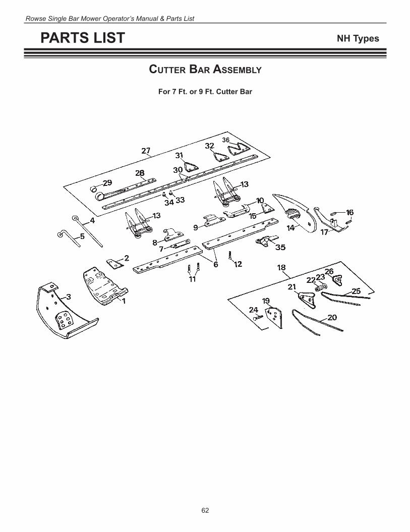
62
Rowse Single Bar Mower Operator’s Manual & Parts List
PARTS LIST NH Types
cuTTer Bar aSSeMBly
For 7 Ft. or 9 Ft. Cutter Bar
36
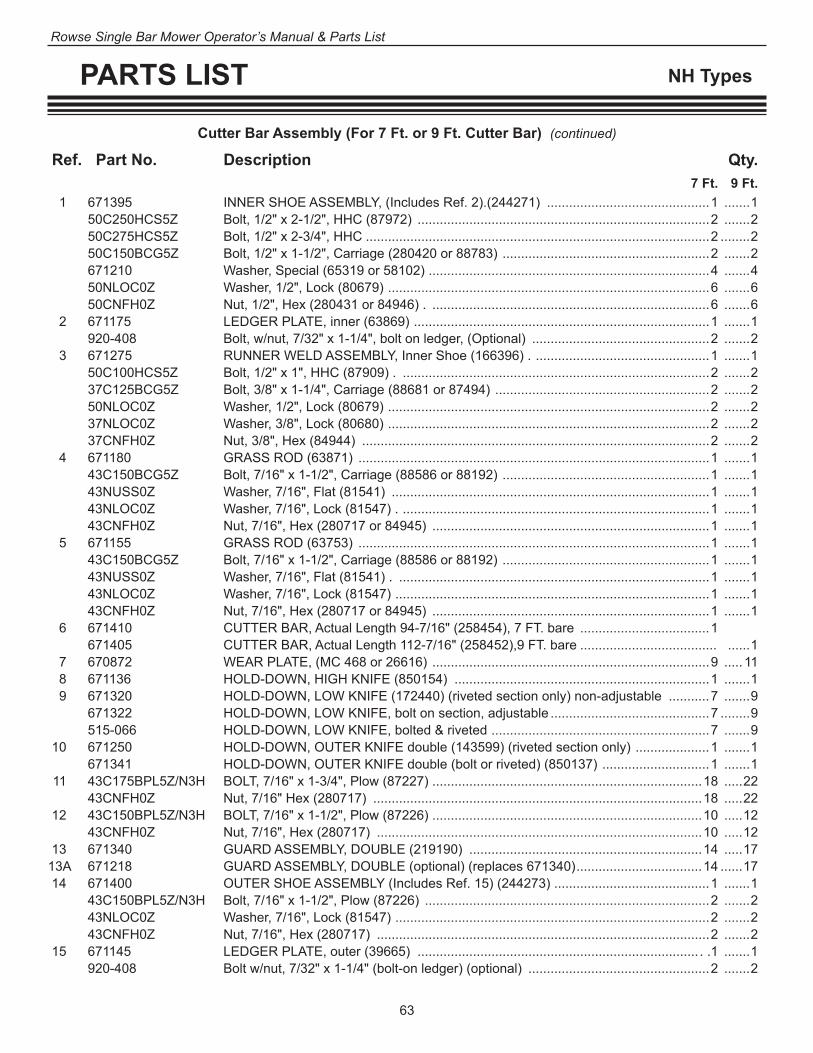
63
Rowse Single Bar Mower Operator’s Manual & Parts List
PARTS LIST NH Types
Cutter Bar Assembly (For 7 Ft. or 9 Ft. Cutter Bar) (continued)
Ref. Part No. Description Qty. 7 Ft. 9 Ft. 1 671395 INNER SHOE ASSEMBLY, (Includes Ref. 2).(244271) ............................................1 .......1 50C250HCS5Z Bolt, 1/2" x 2-1/2", HHC (87972) ...............................................................................2 .......2 50C275HCS5Z Bolt, 1/2" x 2-3/4", HHC .............................................................................................2 ........2 50C150BCG5Z Bolt, 1/2" x 1-1/2", Carriage (280420 or 88783) ........................................................2 .......2 671210 Washer, Special (65319 or 58102) ............................................................................4 .......4 50NLOC0Z Washer, 1/2", Lock (80679) .......................................................................................6 .......6 50CNFH0Z Nut, 1/2", Hex (280431 or 84946) . ...........................................................................6 .......6 2 671175 LEDGER PLATE, inner (63869) ................................................................................1 .......1 920-408 Bolt, w/nut, 7/32" x 1-1/4", bolt on ledger, (Optional) ................................................2 .......2 3 671275 RUNNER WELD ASSEMBLY, Inner Shoe (166396) . ...............................................1 .......1 50C100HCS5Z Bolt, 1/2" x 1", HHC (87909) . ...................................................................................2 .......2 37C125BCG5Z Bolt, 3/8" x 1-1/4", Carriage (88681 or 87494) ..........................................................2 .......2 50NLOC0Z Washer, 1/2", Lock (80679) .......................................................................................2 .......2 37NLOC0Z Washer, 3/8", Lock (80680) .......................................................................................2 .......2 37CNFH0Z Nut, 3/8", Hex (84944) ..............................................................................................2 .......2 4 671180 GRASS ROD (63871) ...............................................................................................1 .......1 43C150BCG5Z Bolt, 7/16" x 1-1/2", Carriage (88586 or 88192) ........................................................1 .......1 43NUSS0Z Washer, 7/16", Flat (81541) ......................................................................................1 .......1 43NLOC0Z Washer, 7/16", Lock (81547) . ...................................................................................1 .......1 43CNFH0Z Nut, 7/16", Hex (280717 or 84945) ...........................................................................1 .......1 5 671155 GRASS ROD (63753) ...............................................................................................1 .......1 43C150BCG5Z Bolt, 7/16" x 1-1/2", Carriage (88586 or 88192) ........................................................1 .......1 43NUSS0Z Washer, 7/16", Flat (81541) . ....................................................................................1 .......1 43NLOC0Z Washer, 7/16", Lock (81547) .....................................................................................1 .......1 43CNFH0Z Nut, 7/16", Hex (280717 or 84945) ...........................................................................1 .......1 6 671410 CUTTER BAR, Actual Length 94-7/16" (258454), 7 FT. bare ...................................1 671405 CUTTER BAR, Actual Length 112-7/16" (258452),9 FT. bare ..................................... ......1 7 670872 WEAR PLATE, (MC 468 or 26616) ...........................................................................9 ..... 11 8 671136 HOLD-DOWN, HIGH KNIFE (850154) .....................................................................1 .......1 9 671320 HOLD-DOWN, LOW KNIFE (172440) (riveted section only) non-adjustable ...........7 .......9 671322 HOLD-DOWN, LOW KNIFE, bolt on section, adjustable ...........................................7 ........9 515-066 HOLD-DOWN, LOW KNIFE, bolted & riveted ...........................................................7 .......9 10 671250 HOLD-DOWN, OUTER KNIFE double (143599) (riveted section only) ....................1 .......1 671341 HOLD-DOWN, OUTER KNIFE double (bolt or riveted) (850137) .............................1 .......1 11 43C175BPL5Z/N3H BOLT, 7/16" x 1-3/4", Plow (87227) .........................................................................18 .....22 43CNFH0Z Nut, 7/16" Hex (280717) .........................................................................................18 .....22 12 43C150BPL5Z/N3H BOLT, 7/16" x 1-1/2", Plow (87226) .........................................................................10 .....12 43CNFH0Z Nut, 7/16", Hex (280717) ........................................................................................10 .....12 13 671340 GUARD ASSEMBLY, DOUBLE (219190) ...............................................................14 .....17 13A 671218 GUARD ASSEMBLY, DOUBLE (optional) (replaces 671340) ..................................14 ......17 14 671400 OUTER SHOE ASSEMBLY (Includes Ref. 15) (244273) ..........................................1 .......1 43C150BPL5Z/N3H Bolt, 7/16" x 1-1/2", Plow (87226) .............................................................................2 .......2 43NLOC0Z Washer, 7/16", Lock (81547) .....................................................................................2 .......2 43CNFH0Z Nut, 7/16", Hex (280717) ..........................................................................................2 .......2 15 671145 LEDGER PLATE, outer (39665) ............................................................................ . .1 .......1 920-408 Bolt w/nut, 7/32" x 1-1/4" (bolt-on ledger) (optional) .................................................2 .......2

64
Rowse Single Bar Mower Operator’s Manual & Parts List
PARTS LIST NH Types
16 671330 SHIM (189475) ...................................................................................................As Required 17 671285 OUTER SHOE SOLE ASSEMBLY (172208) ............................................................1 .......1 50C200BCG5Z Bolt, 1/2" x 2", Carriage (84250) ...............................................................................1 .......1 50NLOC0Z Washer, 1/2", Lock (80679) .......................................................................................1 .......1 50CNFH0Z Nut, 1/2", Hex (280431 or 84946) .............................................................................1 .......1 18 671262 SWATHBOARD ASSEMBLY, (Includes Ref. 19 thru 26) ...........................................1 .......1 19 671170 SWATHBOARD PLATE (63867) ...............................................................................1 .......1 43C125BCG5Z Bolt, 7/16" x 1-1/4", Carriage (87013) .......................................................................1 .......1 43NLOC0Z Washer, 7/16", Lock (81547) .....................................................................................1 .......1 43CNFH0Z Nut, 7/16", Hex (280717 or 84945) ...........................................................................1 .......1 20 671270 DIVIDER (143617) ....................................................................................................1 .......1 21 671195 CLAMP, Divider (63905) ...........................................................................................1 .......1 22 671140 SPRING (38391) .......................................................................................................1 .......1 23 671110 WASHER, Special (26312) .......................................................................................1 .......1 24 671200 BOLT, Carriage, Drilled (63908) ................................................................................1 .......1 50CNST0 Nut, 1/2", Hex, Slotted (87240) . ...............................................................................1 .......1 12R100PCO0Z Cotter Key, 1/8" x 1" (80741) . ...................................................................................1 .......1 25 671265 DIVIDER (143616) ....................................................................................................1 .......1 26 671260 CLAMP, Divider (143615) .........................................................................................1 .......1 43C150BCG5Z Bolt, 7/16" x 1-1/2", Carriage (88586 or 88192) ........................................................1 .......1 43CNNE0Z/NE Nut, 7/16", Hex Lock (280980 or 280377) .................................................................1 .......1 27 671365 KNIFE ASSEMBLY, Smooth, 7 Ft. (228433) .............................................................1 671364 KNIFE ASSEMBLY, Smooth, 7 Ft. bolt-on sections ..................................................1 671355 KNIFE ASSEMBLY, Smooth, 9 Ft. (228432) ............................................................... ......1 671354 KNIFE ASSEMBLY, Smooth, 9 Ft. bolt-on sections .................................................... ......1 671385 KNIFE ASSEMBLY, Underserrated 7 Ft. (228435) ...................................................1 671384 KNIFE ASSEMBLY, Underserrated 7 Ft. bolt-on sections .........................................1 671375 KNIFE ASSEMBLY, Underserrated 9 Ft. (228434) ..................................................... ......1 671374 KNIFE ASSEMBLY, Underserrated 9 Ft. bolt-on sections ........................................... ......1 28 671255 KNIFE HEAD ASSEMBLY, (Includes Ref. 29) (143603) ...........................................1 .......1 29 671230 BUSHING, rubber, knife head (127610) . .................................................................1 .......1 30 671350 KNIFE BACK (228431) 7 Ft. ....................................................................................1 671345 KNIFE BACK (228430) 9 Ft. ...................................................................................... ......1 31 670852 KNIFE SECTION, Heavy Smooth (26622) .............................................................29 .....35 32 671130 KNIFE SECTION, Heavy Underserrated (29875) ...................................................29 .....35 33 5-1/2X9/16 OH RIVET, BAR, Oval Head, #5-1/2 x 9/16" (46436) ....................................................51 .....63 B55-0055 Bolt w/locknut, 7/32" x 5/8" (bolt-in section) (optional) ............................................51 .....63 34 5-1/2X15/16 OH RIVET, HEAD, Oval Head, #5-1/2 x 15/16" (65474) .................................................9 .......9 B55-0085 Bolt w/locknut, 7/32" x 1" (bolt-in section) (optional) .................................................9 .......9 35 RM-2505 PLUG BUNDLE, (691163) (optional) ........................................................................1 .......1 43C200BPL5/N3H Bolt w/nut, 7/16" x 2" Plow ........................................................................................2 .......2 36 612-080 Section, Double End ..................................................................................................1 ........1
NOTE: Quantities listed are for one 7 ft. or 9 ft. Cutter Bar ONLY. NUMBERS IN PARENTHESIS ARE NEW HOLLAND PARTS NUMBERS.
Cutter Bar Assembly (For 7 Ft. or 9 Ft. Cutter Bar) (continued)
Ref. Part No. Description Qty. 7 Ft. 9 Ft.

65
Rowse Single Bar Mower Operator’s Manual & Parts List
PARTS LIST Both Types
Ref. Part No. Description Qty. 7 Ft. 9 Ft.
671337 ADJUSTABLE HOLD-DOWN KIT (86523028) (consists of the following): 86523032 Instructions .................................................................................................................1 .......1 1 37C100BPL5Z Bolt, 3/8" x 1-1/4" Sq-Nk Crg. (86517871) ...............................................................10 ......10 2 671322 HOLD-DOWN, low (86504492) ................................................................................10 ......10 2H 671136 HOLD-DOWN, high (850134), Non-Adjustable ..........................................................1 ........1 3 671324 PRESSURE BAR, hold-down (9800028) .................................................................10 ......10 4 671336 NUT, 3/8" flange (593045)........................................................................................10 ......10
aDjuSTaBle holD DoWn cliPS
23 1
4
1

66
Rowse Single Bar Mower Operator’s Manual & Parts List
PARTS LIST IH Types
MoWer heaD aSSeMBly
Ref. Part No. Description Qty. 670612 HOUSING ASSEMBLY, BALANCED HEAD (1265780 C91) (Consists of all parts listed below except item 30) 1 670618 PULLEY ASSEMBLY, flywheel (478787 R11) includes item 670625 washer pulley ............1 670625 Washer, pulley (478789 R1) .................................................................................................1 2 670622 NUT, Lock and Seal (478788 R1) ........................................................................................1 3 LM67048 CONE, housing bearing assembly (651818 R91) ................................................................1 4 LM67010 CUP, housing bearing (651817 R1) .....................................................................................1 5 LM29700LA&29710 CONE, CUP & SEAL, wobble shaft, bearing (478790 R91) ................................................2 6 670888 KEY, 1/4" x 1", SQ parallel (Q 53) ........................................................................................1 7 670615 SHAFT- ASSEMBLY, wobble (478786 R11) .........................................................................1 7A 670185 Nut, 3/4"-16 Special Hex NF (254771 R1) ...........................................................................2 7B 670158 Washer, 25/32" x 1-1/2" x 7 Ga. (21211 R1) ........................................................................1 8 670306 CAP, yoke BRG (458958 R1) ...............................................................................................2 25C100HCS5Z Bolt, 1/4" x 1" (26329 R1) ....................................................................................................6 9 670302 SHIM, yoke bearing cap, .002 (458955 R1) .........................................................................2 9 670304 SHIM, yoke bearing cap, .006 (458956 R1) ..................................................6 or as required 9 670305 SHIM, yoke bearing cap, .010 (458957 R1) ..................................................6 or as required 10 M12600LA&M12610 CONE, CUP & SEAL, balance yoke roller (458952 R91) ....................................................2 11 670298 HOUSING, balanced head BRG (458953 R3) .....................................................................1 12 5099 ZERK, 1/8"-27, PTF STR Vented LUB (13019 R1) ..............................................................1 13 670188 CLAMP, hose, bearing housing cap (317596 R1) ................................................................1

67
Rowse Single Bar Mower Operator’s Manual & Parts List
PARTS LIST IH Types
14 M12610 CUP, balanced head housing bearing (371883 R1) .............................................................1 15 M12649 CONE, balanced head housing bearing (371882 R92) .......................................................1 16 670300 CAP, crankshaft BRG housing (458954 R1) ........................................................................1 670346 Sealer, Crankshaft BRG housing cap (461678 R1) .............................................................1 17 670650 HOUSING, wobble (487047 R1) ..........................................................................................1 50C125HCS5/NE Bolt, w/nylon insert, 1/2" x 1-1/4" HHC (143865 C1) ...........................................................4 50C175HCS5/NE Bolt, w/nylon insert, 1/2" x 1-3/4" HHC (143866 C1) ...........................................................3 56F250HCS5Z Bolt, 9/16" x 2-1/2" HHC, front hinge pin (181461) ..............................................................1 670605 Nut, 9/16"-18 Hex, two way Lock (472215 R1) ....................................................................1 18 670440 PLUG, button (464197 R1) ..................................................................................................2 20 MRD-1205EAL BEARING ASSEMBLY, balance yoke pivot stud . ................................................................1 670795 Washer, felt (59357 DA), use with MRD-1205EAL bearing .................................................1 MR1205EL Bearing assembly, balance yoke pivot stud .........................................................................1 RM-2400 Washer, felt, use with MR1205EL Bearing ...........................................................................1 6205Z Bearing assembly (467146R1) ............................................................................................1 670360 Washer, Felt (462800R1), use with 6205Z bearing ..............................................................1 21 670308 STUD, balance yoke pivot (1253780 C1) ............................................................................1 50C50KSCE Set Screw, 1/2"-13 x 1/2" HEX-SOC-HD cup PT (102615) ..................................................1 22 670322 PIN, knife (458973 R4) ........................................................................................................1 50FNFH0Z Nut, 1/2", Hex NF (103028) ..................................................................................................1 50NLET0Z Washer, 1/2" EXT-Tooth lock (543115 R1) ...........................................................................2 23 670652 YOKE ASSEMBLY, balance (1253779 C1) ..........................................................................1 50F250HCS8 Bolt, 1/2" x 2-1/2", NF GR8 (336132 R1) .............................................................................1 50FNFH0Z Nut, 1/2" Hex NF (103028) ...................................................................................................1 50NLET0Z Washer, 1/2" EXT-Tooth lock (543115 R1) ...........................................................................2 24 107-100 ZERK, 1/4"-28 NFT STR LUB (110146 R91) .......................................................................1 25 5100 ZERK, 1/8"-27 PTF Short 30 degree angle LUB (109459) ..................................................1 26 670628 HOUSING ASSEMBLY, wobble shaft (478797 R91) (includes part #670560) .....................1 670735 Pin, 3/4" x 2-5/16" (519416 R1) ...........................................................................................1 25R150PCO0Z Cotter Key, 1/4" x 1-1/2" (20340 R1) ....................................................................................1 27 670560 BUSHING, rear shaft housing (467215 R1) .........................................................................1 28 670660 SHAFT, front hinge (487051 R1) ..........................................................................................1 125N187AMB0/14GA Washer, 1-1/4" x 1-7/8" x 14 Ga. (608700 R1) .....................................................................1 31R200PCO0Z Cotter Key, 5/16" x 2" (22442 R1) ........................................................................................1 29 5100 ZERK, 1/8"-27 PTF Short 30-degree angle LUB (461252 R1) ............................................1 30 670562 HINGE, rear (467216 R1) ....................................................................................................1 101-100 Zerk, 1/8"-27 PTF STR LUB (109461) .................................................................................1 50C250HCS5Z Bolt, 1/2" x 2-1/2" HHC (179891) .........................................................................................2 50CNFH0Z Nut, 1/2" Hex (102637) ........................................................................................................2 50NLOC0Z Washer, 1/2" Med Lock (103323) .........................................................................................2
NOTE: Quantities are for one assembly ONLY. # in parentheses are *IH, *Bower and *Timkin part
* Trade Mark
Mower Head Assembly (continued)
Ref. Part No. Description Qty.

68
Rowse Single Bar Mower Operator’s Manual & Parts List
PARTS LIST IH Types
cuTTer Bar aSSeMBly
For 7 Ft. or 9 Ft. Cutter Bar
Ref. Part No. Description Qty. 7 Ft. 9 Ft.
1 670648 SHOE ASSEMBLY, inner (486 934 R91) (includes 670310 ledger plate, IH) ...........1 .......1 2 670645 SHIELD, inner shoe. (486 708 R1) ...........................................................................1 .......1 43C125BCG5Z Bolt, 7/16" x 1-1/4" CRG. (15016 R1) .......................................................................1 .......1 43NUSS0Z Washer, 7/16" Flat .....................................................................................................1 .......1 3 43CNNE0Z/NE NUT, 7/16", Hex Lock (664 646 R1) ..........................................................................1 .......1 4 670310 LEDGER PLATE, inner shoe (458 965 R1) ..............................................................1 .......1 920-408 Bolt w/nut, 7/32" x 1-1/4", bolt in ledger plate (optional) ...........................................2 .......2 62C200HCS5/NE Bolt, bar, w/nylon insert, 5/8" x 2" (143868Cl) ...........................................................1 .......1 62C225HCS5/NE Bolt, bar, w/nylon insert, 5/8" x 2-1/4" (27434R1) .....................................................2 .......2 5 670642 WASHER, 5/8" Flat (486 707 R1) .............................................................................3 .......3 6 670290 SHIM, cutter bar (458 941 R1) ......................................................................2 or as required 7 670675 SHIM, spacer (488 411 R1) ..........................................................................3 or as required 8 670292 SPACER, cutter bar 1/8" (458 942 R1) .....................................................................1 9 670325 CUTTER BAR, 7 ft. bare (458 974 R1) .....................................................................1 670370 CUTTER BAR, 9 ft. bare (1 265 863 C1) .................................................................... ......1 10 43C150BPL5Z/N3H BOLT, w/nut, short guard, 7/16" x 1-1 /2" (M 805 X) ...............................................13 .....17 43CNFH0Z Nut, 7/16", Hex (271500) ........................................................................................13 .....17 11 43C175BPL5Z/N3H BOLT, w/nut, long guard, 7/16" x 1-3/4" (Q 3596 X) ................................................14 .....18 43CNFH0Z Nut, 7/16", Hex (271500) ........................................................................................14 .....18 12 670600 GUARD, double, IH Type Double Heat Treat (483 500 R3) ..............................13-1/2 17-1/2 670601 GUARD, double, IH Type Double Heat Treat w/ wear plate .............................13-1/2 17-1/2 671340 GUARD, NH double (219190) ...........................................................................13-1/2 17-1/2 671218 GUARD, NH type ..............................................................................................13-1/2 17-1/2 13 RM-2506 PLUG BUNDLE (optional) .........................................................................................1 .......1 43C200BPL5/N3H Bolt, 7/16" x 2" Plow ..................................................................................................2 .......2 43CNFH0Z Nut, 7/16", Hex (271500) ..........................................................................................2 .......2 14 670740 SHIM (521036) .....................................................................................................as required
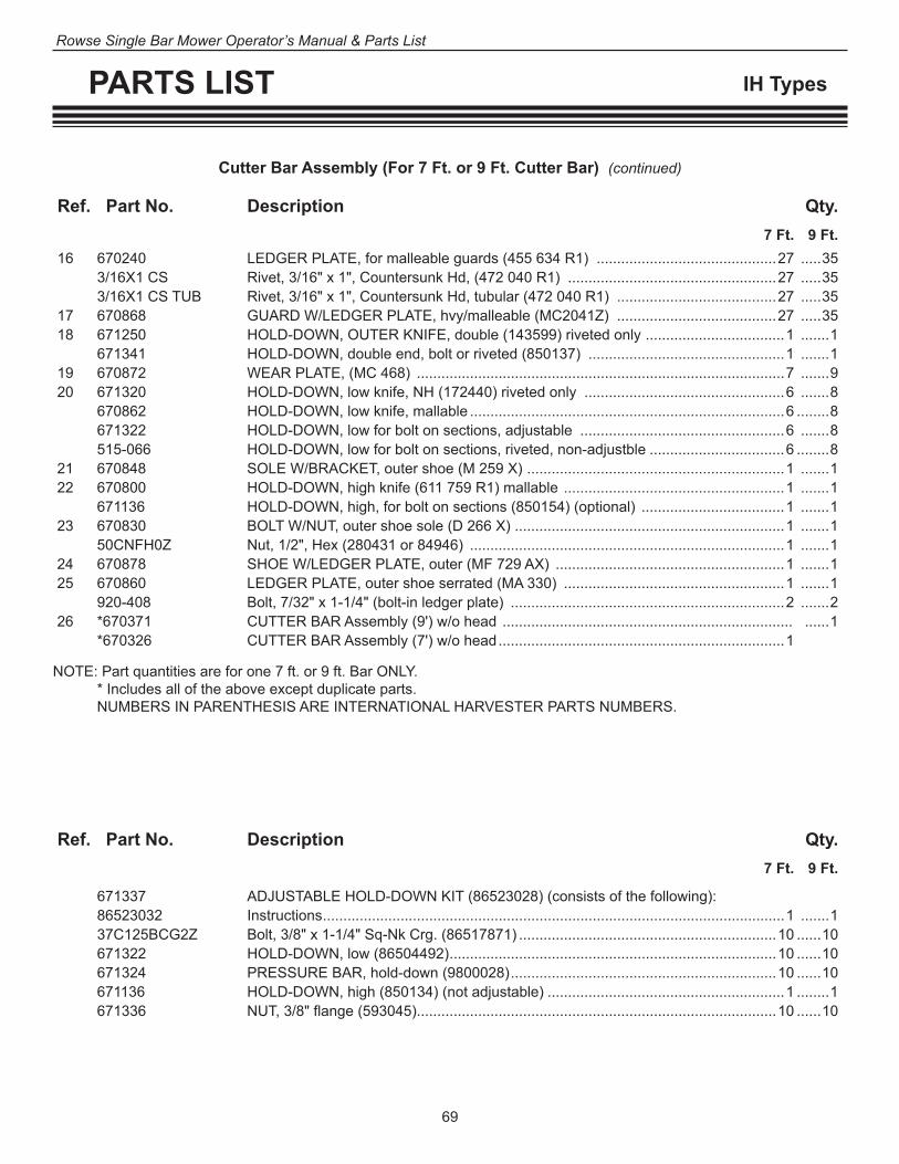
69
Rowse Single Bar Mower Operator’s Manual & Parts List
PARTS LIST IH Types
Cutter Bar Assembly (For 7 Ft. or 9 Ft. Cutter Bar) (continued)
Ref. Part No. Description Qty. 7 Ft. 9 Ft. 16 670240 LEDGER PLATE, for malleable guards (455 634 R1) ............................................27 .....35 3/16X1 CS Rivet, 3/16" x 1", Countersunk Hd, (472 040 R1) ...................................................27 .....35 3/16X1 CS TUB Rivet, 3/16" x 1", Countersunk Hd, tubular (472 040 R1) .......................................27 .....35 17 670868 GUARD W/LEDGER PLATE, hvy/malleable (MC2041Z) .......................................27 .....35 18 671250 HOLD-DOWN, OUTER KNIFE, double (143599) riveted only ..................................1 .......1 671341 HOLD-DOWN, double end, bolt or riveted (850137) ................................................1 .......1 19 670872 WEAR PLATE, (MC 468) ..........................................................................................7 .......9 20 671320 HOLD-DOWN, low knife, NH (172440) riveted only .................................................6 .......8 670862 HOLD-DOWN, low knife, mallable .............................................................................6 ........8 671322 HOLD-DOWN, low for bolt on sections, adjustable ..................................................6 .......8 515-066 HOLD-DOWN, low for bolt on sections, riveted, non-adjustble .................................6 ........8 21 670848 SOLE W/BRACKET, outer shoe (M 259 X) ...............................................................1 .......1 22 670800 HOLD-DOWN, high knife (611 759 R1) mallable ......................................................1 .......1 671136 HOLD-DOWN, high, for bolt on sections (850154) (optional) ...................................1 .......1 23 670830 BOLT W/NUT, outer shoe sole (D 266 X) ..................................................................1 .......1 50CNFH0Z Nut, 1/2", Hex (280431 or 84946) .............................................................................1 .......1 24 670878 SHOE W/LEDGER PLATE, outer (MF 729 AX) ........................................................1 .......1 25 670860 LEDGER PLATE, outer shoe serrated (MA 330) ......................................................1 .......1 920-408 Bolt, 7/32" x 1-1/4" (bolt-in ledger plate) ...................................................................2 .......2 26 *670371 CUTTER BAR Assembly (9') w/o head ....................................................................... ......1 *670326 CUTTER BAR Assembly (7') w/o head ......................................................................1
NOTE: Part quantities are for one 7 ft. or 9 ft. Bar ONLY. * Includes all of the above except duplicate parts. NUMBERS IN PARENTHESIS ARE INTERNATIONAL HARVESTER PARTS NUMBERS.
Ref. Part No. Description Qty. 7 Ft. 9 Ft.
671337 ADJUSTABLE HOLD-DOWN KIT (86523028) (consists of the following): 86523032 Instructions .................................................................................................................1 .......1 37C125BCG2Z Bolt, 3/8" x 1-1/4" Sq-Nk Crg. (86517871) ...............................................................10 ......10 671322 HOLD-DOWN, low (86504492) ................................................................................10 ......10 671324 PRESSURE BAR, hold-down (9800028) .................................................................10 ......10 671136 HOLD-DOWN, high (850134) (not adjustable) ..........................................................1 ........1 671336 NUT, 3/8" flange (593045)........................................................................................10 ......10

70
Rowse Single Bar Mower Operator’s Manual & Parts List
PARTS LIST IH Types
inner Shoe Sole, GraSS DeflecTorS & knife aSSeMBly
For 7 Ft. or 9 Ft. Cutter Bar
Ref. Part No. Description Qty. 7 Ft. 9 Ft. 1 670355 SOLE, inner shoe, STUB type (462743R1) ..............................................................1 .......1 50C150BCG5Z Bolt, 1/2" x 1-1/2", CRG (17140 R1) .........................................................................2 .......2 50NLOC0Z Washer, 1/2", Med Lock (120384) .............................................................................2 .......2 50CNFH0Z Nut, 1/2", Hex (120378) ............................................................................................2 .......2 50C200BCG5Z Bolt, 1/2" x 2", CRG ..................................................................................................1 .......1 50NUSS0Z Washer, 1/2", Flat (K846) ..........................................................................................1 ........1 50NLOC0Z Washer, 1/2", Med Lock (1120384) ...........................................................................1 ..... 11 50CNFH0Z Nut, 1/2", Hex (1203780) ..........................................................................................1 .......1 2 670356 ROD, inner shoe upper grass (462744 R1) ..............................................................1 .......1 3 670340 ROD, inner shoe lower grass (461281 R1) ...............................................................1 .......1 4 670710 ROD, grass deflector (489536 R1) ...........................................................................1 .......1 37C150BCG5Z Bolt, 3/8" x 1-1/2", CRG (143245 R1) .......................................................................1 .......1 37NUSS0Z Washer, 3/8" Flat .......................................................................................................1 .......1 37CNNE0Z/NE Nut, 3/8", Hex Lock (385525 R1) ..............................................................................1 .......1 5 670712 CLAMP, grass rod (489537 R1) ................................................................................1 .......1 37C100BCG5Z Bolt, 3/8" x 1", CRG (17351 R1) ...............................................................................1 .......1 37NUSS0Z Washer, 3/8", Flat ......................................................................................................1 .......1 37NLOC0Z Washer, 3/8", Med Lock (120382) .............................................................................1 .......1 37CNFH0Z Nut, 3/8", Hex (120377) ............................................................................................1 .......1 6 670708 DEFLECTOR, grass (489535 R1) ............................................................................1 .......1 7 670715 SUPPORT, grass deflector (489538 R1) ..................................................................1 .......1 37C75BCG5Z Bolt, 3/8" x 3/4", CRG (605449 R1) ..........................................................................4 .......4 37CNNE0Z/NE Nut, 3/8", Hex Lock (385525 R1) ..............................................................................4 .......4 9 670680 DAMPENER, rubber grass rod (489486 R1) ............................................................1 .......1 10 670342 CLIP, grass rod (461383 R1) ....................................................................................1 .......1 11 670705 GRASS BOARD DEFLECTOR ASSEMBLY (489533 R91) ......................................1 .......1 12 670376 ROD ASSEMBLY, outer shoe grass (463326 R11) ...................................................1 .......1
17A
Seal 300004
Bearings 670315
Plug 670319-BSeal 670766-B
Head Assembly with Bearings -- 670771B

71
Rowse Single Bar Mower Operator’s Manual & Parts List
PARTS LIST IH Types
13 670330 CLAMP, outer shoe grass rod (458979 R1) ..............................................................1 .......1 37C150HCS5Z Bolt, 3/8" x 1-1/2", HHC (17471 R1) .........................................................................1 .......1 37CNFH0Z Nut, 3/8" Hex (120377) .............................................................................................1 .......1 25R75PCO0Z Cotter Key, 1/4" x 3/4" (103417) ................................................................................1 .......1 37NLOC0Z Washer, 3/8", Lock (103321) .....................................................................................1 .......1 14 670832 SPRING, grass rod tension (M 1015) .......................................................................1 .......1 50C350BSQ5Z Bolt, 1/2" x 3-1/2", SQ-HD .........................................................................................1 .......1 50CNNE0Z/NE Nut, 1/2", Hex, Lock (22816 R1) ...............................................................................1 .......1 50NUSS0Z Washer, 1/2", Flat (178374 R1) .................................................................................1 .......1 15 670422 GRASS ROD DEFLECTOR ASSEMBLY (463411 R92) ............................................1 .......1 16 670354 KNIFE ASSEMBLY, 7 Ft., w/heavy smooth sections (462381 R92) ..........................2 670352 KNIFE ASSEMBLY, 7 Ft., w/heavy underserrated sections (462380 R92) ...............2 670364 KNIFE ASSEMBLY, 9 Ft., w/heavy underserrated sections (463159 R92) ..........................2 670368 KNIFE ASSEMBLY, 9 Ft., w/heavy smooth sections (463182 R92) .....................................2 670351 KNIFE ASSEMBLY, 7 Ft., w/heavy underserrated, bolt-on sections (optional) .........2 670353 KNIFE ASSEMBLY, 7 Ft., w/heavy smooth, bolt-on sections (optional) ....................2 670363 KNIFE ASSEMBLY, 9 Ft., w/heavy underserrated, bolt-on sections (optional) ....................2 670367 KNIFE ASSEMBLY, 9 Ft., w/heavy smooth, bolt-on sections (optional) ...............................2 17 670770 HEAD ASSEMBLY, knife w/bushing (56692 C91) .....................................................1 .......1 17A 670771B HEAD ASSEMBLY with bearings, includes: 300004 Seal ............................................................................................................................1 ........1 670315 Bearing .......................................................................................................................2 ........2 670319-B Plug ............................................................................................................................1 ........1 670766-B Seal ............................................................................................................................1 ........1 18 670318 BUSHING, knife head (458971 R1) ..........................................................................1 .......1 19 670320 PLUG, knife head (458972 R2) .................................................................................1 .......1 20 670765 WASHER, seal (544553 R1) .....................................................................................1 .......1 21 670852 SECTION, smooth heavy knife (826724C1 or M333 1/2) .......................................28 .....36 670838 SECTION, underserrated heavy knife (826722 C1 or M22 831) ............................28 .....36 670815 SECTION, top serrated, (recommended for alfalfa only) ........................................28 .....36 5-1/2X9/16 OH Rivet, 5-1/2 x 9/16" OV-HD (19869 R1) ..................................................................47 .....63 B55-0055 Bolt, w/Locknut 7/32" x 5/8", bolt-on section ...........................................................47 .....63 5-1/2X15/16 OH Rivet, 5-1/2 x 15/16", OV-HD (14768 R1) .................................................................9 .......9 B55-0085 Bolt, w/Locknut 7/32" x 1", bolt-on section ................................................................9 .......9 22 612-080 SECTION, US hvy dbl. end (2-US) ...........................................................................1 .......1 612-130 SECTION, SM hvy dbl end (1-SM) ...........................................................................1 .......1 23 670588 GAUGE, guard lip and knife pin (469975 R3) (optional) ...........................................1 .......1
NOTE: Part quantities are for one 7 ft. or 9 ft. Bar ONLY. NUMBERS IN PARENTHESIS ARE INTERNATIONAL HARVESTER PARTS NUMBERS.
Inner Shoe Sole, Grass Deflectors & Knife Assembly (For 7 Ft. or 9 Ft. Cutter Bar) (continued)
Ref. Part No. Description Qty. 7 Ft. 9 Ft.

72
Rowse Single Bar Mower Operator’s Manual & Parts List
SPECIFICATIONS Both Types
PTo-ST7-nh, PTo-ST9-nh, PTo-SM7-nh, PTo-SM9-nh
MoWer MoDelSKnife Register ........... Maintained at any cutting angleKnife Speed at 540 PTO RPM ........ 1600 cutting strokes per minuteKnife Stroke .............. 3-3/8" Guards ...................... Medium-Carbon forged steel double
guards -- single rock guard optionalCutter Bar Drive ........ Tapered roller bearings, PitmanlessDrive Bearings .......... Tapered roller bearings, knife head
uses a rubber torsion bushingFlywheel Speed at 540 PTO RPM ........ Approximately 800 RPM
ROWSE Hydraulic Rakes Co., Inc. is always striving to make improvements on present machines and specifications are subject to change without notice. ROWSE is not responsible for making changes or additions to equipment sold previously.
all MoWer MoDelSCutter Bar Width of Cut ............7 ft. or 9 ft. swath Cutting Range .........90° above, 20° below Breakaway ..............Automatic, 42° swing back Lead ........................5°, adjustable Knife ........................Heavy underserrated or heavy smooth Swath Divider ..........Spring steelMowing Speed .............Up to 8 mphDrive Power Source.....From PTO shaft through universal joint drive shaft, V-belt drive to drive headPTO Drive Bearings .....Needle bearingsType of Lift ...................Hydraulic to vertical position, single actingTractor Requirements HP Req. ...................Trailing -- 25+ Three-Point -- 30+ PTO Req. ................540 RPM Hitch Req. ...............Trailing -- Standard drawbar Three-Point Hitch -- Most ASAE category 1 & 2 tractors Hydraulic Req. ........One single acting valve, bar liftWeight .........................PTO-ST7-NH Approximately 805 lb. PTO-ST9-NH Approximately 826 lb. PTO-SM7-NH Approximately 625 lb. PTO-SM9-NH Approximately 650 lb. PTO-ST7-NH Approximately 765 lb. PTO-ST9-IH Approximately 785 lb. PTO-SM7-IH Approximately 585 lb. PTO-SM9-IH Approximately 610 lb.
PTo-ST7-ih, PTo-ST9-ih,PTo-SM7-ih, PTo-SM9-ih
MoWer MoDelSKnife Speed at 540 PTO RPM ........ 2000 cutting strokes per minuteKnife Stroke .............. 2-5/8" Cutter Bar Drive ........ Enclosed wobble shaft attached to
yoke creating an oscillating motionGuards ...................... Double forged, standardDrive Bearings .......... Tapered roller bearingsFlywheel Speed at 540 PTO RPM ........ Approximately 1000 RPM

73
Rowse Single Bar Mower Operator’s Manual & Parts List
WARRANTY Both Types
ROWSE HYDRAULIC RAKES CO., INC.84504 State Hwy. 11, Burwell, Nebraska 68823-5223
Phone: 308-348-2276 • Fax: 308-348-2059Toll-Free: 800-652-1912
E-Mail: [email protected] Site: www.rowserakes.com
New Rowse Agricultural and Industrial Machines
Rowse Hydraulic Rakes Co., Inc., (hereinafter “Rowse”), warrants each new agricultural and industrial machine or equipment, (hereinafter “Product”) to be free from defects in materials and workmanship under normal use for which it was intended for a period of one year from the date of purchase. The obligation of Rowse under this warranty is limited to repairing or at its option, replacing F.O.B. factory any part or parts which is reported in writing to Rowse within 30 days from the date of failure thereof and specifying the nature of the defect or failure and which Rowse inspections shall disclose to have been defective. It is the responsibility of buyer to transport at his own expense the product to the dealer’s service shop or Rowse factory. When requested by Rowse, part or parts shall be returned for inspection, transportation prepaid, to Rowse or a place designated by Rowse. In no event shall Rowse be obligated for incidental or consequential damages caused by such failure or defect, including, but not limited to, the loss of crops, inconvenience, rental of replacement equipment, loss of profits, or other commercial loss.
There is no warranty with respect to used products or new products that have been improperly assembled by one other than an authorized dealer, modified or altered, repaired, neglected, or used for purposes other than those for which it was intended.
EXCEPT AS SPECIFICALLY WARRANTED HEREIN, ROWSE DIS-CLAIMS ANY OTHER WARRANTY OF MERCHANTABILITY, IMPLIED OR EXPRESSED, AND FITNESS FOR PURPOSE. THERE ARE NO WAR-RANTIES WHICH EXTEND BEYOND THE FACE HEREOF.
liMiTeD WarranTy

74
Rowse Single Bar Mower Operator’s Manual & Parts List
WARRANTY DETAIL Both Types
IntroductionThe following information explains for you the details of
Rowse’s farm equipment warranty. These details include an explanation of the criteria for determining warranty, those items which are included for warranty, those which are not covered, and information about how to obtain warranty service.
Warranty DeterminationOnly defective parts are covered under this warranty.
Any part found to be defective in accordance with the pro-visions of this warranty will be repaired or replaced by an authorized ROWSE dealer.
Items Covered By WarrantyROWSE’S warranty includes the replacement or repair
of any part or parts of machines or attachments on ROWSE new equipment purchased from an authorized ROWSE dealer (except tires and tubes) which are defective in mate-rial, workmanship, or both.
Obtaining Warranty ServiceTo obtain warranty service, contact the authorized
ROWSE dealer from whom the machine was purchased. In the event this is not practical to do, any authorized ROWSE dealer may perform warranty work. However, a servicing dealer who did not sell the unit has the right to charge the customer the difference between their normal shop rate and the rate ROWSE allows for warranty work.
Items Not Covered1. Tires shall be warranted by the selling dealer or by local
representatives of the tire manufacturer.
2. Dealer Travel Time—The customer shall be responsible for payment of dealer travel time to the machine or to deliver the machine to the dealer’s service shop for repair. ROWSE warranty does not cover travel time.
3. Used Equipment—ROWSE warranty shall apply only to the original owner of new equipment sold by an authorized ROWSE dealer. ROWSE shall have no liability for used equipment.
4. No warranty shall be made on any equipment or parts that have been modified, or altered in any way without prior approval and knowledge of ROWSE, nor is there warranty if service, other than normal replacement of service items, is performed by someone other than an authorized ROWSE dealer.
5. Normal Wear or Maintenance Parts—ROWSE shall not be responsible for normal replacement parts such as cut-ting knives, chains, belts, filters, oil, nor for parts which are worn out unless they are deemed to be defective in material or workmanship.
6. No warranty shall apply to damage resulting from ac-cident, misapplication, abuse, or damage caused by environment; (such as exposure to corrosive material).
Leased Or Rented UnitsIf a unit is leased or rented, the warranty period starts
on the date the unit is first leased and / or rented. If the unit is sold to a second user at a later date, it is then considered a used machine.
ImprovementsROWSE continually strives to improve its products
and, therefore, reserves the right to make improvements or changes without incurring any obligations to make such changes or additions on equipment previously sold.
PatentedThis machine is covered by one or more of the following
U.S. patents:
6,212,866, 6,151,877, 6,220,008.
WarranTy DeTailS

75
Rowse Single Bar Mower Operator’s Manual & Parts List

76
Rowse Single Bar Mower Operator’s Manual & Parts List

77
Rowse Single Bar Mower Operator’s Manual & Parts List
HYDRAULIC RAKES CO., INC.84504 State Hwy. 11
Burwell, Nebraska 68823-5223Phone: 308-348-2276 • Fax: 308-348-2059
Toll-Free: 800-652-1912E-Mail: [email protected]
Web Site: www.rowserakes.com
Printed in U.S.A.


![ADA / ASR · ADA/ASR (A) = Standard Torques for single acting actuators - ASR [Nm] Type 3 bar 3.5 bar 4 bar 4.5 bar 5 bar 5.5 bar 6 bar (A) 6.5 bar 7 bar 8 bar Spring torque Number](https://static.fdocuments.in/doc/165x107/5fc8c599781c974e9e2bc04a/ada-asr-adaasr-a-standard-torques-for-single-acting-actuators-asr-nm.jpg)