Single Atom Catalysts: Carbon‐Supported Single Atom Catalysts...
26
Vol. 30 • No. 48 • November 28 • 2018 www.advmat.de
Transcript of Single Atom Catalysts: Carbon‐Supported Single Atom Catalysts...

Vol. 30 • No. 48 • November 28 • 2018
www.advmat.de
ADMA_30_48_cover.indd 4 29/10/18 8:49 PM
REVIEW
1801995 (1 of 25) © 2018 WILEY-VCH Verlag GmbH & Co. KGaA, Weinheim
www.advmat.de
Carbon-Supported Single Atom Catalysts for Electrochemical Energy Conversion and StorageYi Peng, Bingzhang Lu, and Shaowei Chen*
Y. Peng, B. Z. Lu, Prof. S. W. ChenDepartment of Chemistry and BiochemistryUniversity of California1156 High Street, Santa Cruz, CA 95064, USAE-mail: [email protected]
The ORCID identification number(s) for the author(s) of this article can be found under https://doi.org/10.1002/adma.201801995.
DOI: 10.1002/adma.201801995
1. Introduction
Transition-metal nanoparticles, such as Ru, Rh, Pd, Ag, Ir, Pt, and Au, have been used extensively as effective catalysts in a wide range of electrochemical reactions for energy conver-sion and storage, such as hydrogen evolution reaction (HER), oxygen reduction reaction (ORR), oxygen evolution reaction (OER), and carbon dioxide reduction reaction (CO2RR).[1–9] However, the high costs and/or low natural abundance of noble metals significantly hamper the wide-spread applications of these technologies. One way to mitigate these issues is to minimize the usage of these materials without compromising the catalytic performance, thus leading to drastic enhancement of the specific/mass activity. Toward this end, a variety of strate-gies have been developed, which have been primarily focused on structural manipulation of the metal nanoparticles within the context of core size,[10–13] shape,[14–17] crystalline facets,[18–23]
Single atoms of select transition metals supported on carbon substrates have emerged as a unique system for electrocatalysis because of maximal atom utilization (≈100%) and high efficiency for a range of reactions involved in electrochemical energy conversion and storage, such as the oxygen reduction, oxygen evolution, hydrogen evolution, and CO2 reduction reactions. Herein, the leading strategies for the preparation of single atom catalysts are summarized, and the electrocatalytic performance of the resulting samples for the various reactions is discussed. In general, the carbon substrate not only provides a stabilizing matrix for the metal atoms, but also impacts the electronic density of the metal atoms due to strong interfacial interactions, which may lead to the formation of additional active sites by the adjacent carbon atoms and hence enhanced electrocatalytic activity. This necessitates a detailed understanding of the material structures at the atomic level, a critical step in the construction of a relevant structural model for theoretical simulations and calculations. Finally, a perspective is included highlighting the promises and challenges for the future development of carbon-supported single atom catalysts in electrocatalysis.
Single Atom Catalysts
alloying with other noble or non-noble metals,[24–28] and hybridization of noble metal catalysts with other materials.[29–35]
As the reactions take place only on the nanoparticle catalyst surface and the adsorption of reactants and desorption of products at the active sites represent key steps that largely dictate the catalytic efficiency, the reaction dynamics has been found to be readily manipulated by nanoparticle size and shape, and the cata-lytic activity is mostly dominated by the surface atoms with minimal contributions from the inner core. Recent research has shown that shrinking of the nanoparticle size down to the sub-nanometer regime leads to an increasing number of under-coordinated metal atoms that may serve as catalytic active sites, which will reach a maximum at the single atom level when individual metal atoms are accessible and catalytically active.[36] Furthermore, to enhance dispersion and stability, nano-
particle catalysts are generally supported on a substrate sur-face, and the metal-substrate electronic interactions have long been recognized to play an important role in manipulating the electronic structure of the metal nanoparticles and hence interactions with reaction intermediates.[37] This has indeed been exploited as a unique variable in the mechanistic control of nanoparticle catalytic performance. It can be envisaged that when the nanoparticle size diminishes to the single atom level, such metal-substrate interactions will be maximized, which may lead to the generation of new catalytic active sites, emer-gence of new reaction pathways, and eventually enhancement of the catalytic performance.[38,39] Because of these, single atom catalysis has been attracting a great deal of attention lately.
It should be noted that for decades a wide variety of orga-nometallic complexes have been used as effective catalysts in diverse electrocatalytic reactions.[40] As they generally contain individual metal centers, one may argue that these compounds represent the early examples of single atom cata-lysts (SACs). Thus far, there has been no clear, strict definition of SACs, which typically refer to single metal atoms embedded within a solid matrix, such as a metal, metal oxide, metal nitride, or carbon, and the resulting nanostructures behave as heterogeneous catalysts, in contrast to organometallic com-pounds that are typically involved in homogeneous catalysis.[41]
Back in 1991, the Basset group reported the first preparation of SACs based on silica-supported zirconium and tantalum
Adv. Mater. 2018, 1801995
In celebration of the 60th Anniversary of the University of Science and Technology of China

© 2018 WILEY-VCH Verlag GmbH & Co. KGaA, Weinheim1801995 (2 of 25)
www.advmat.dewww.advancedsciencenews.com
complexes and their applications in heterogeneous catalysis.[42,43] In 2011, Zhang and coworkers deposited single Pt atoms sup-ported on iron oxide for CO oxidation.[44] Both experimental studies and density functional theory (DFT) calculations showed that the high catalytic activity was due to the partially vacant 5d orbitals of the high-valence, positively charged Pt atoms which lowered the CO adsorption energy and activation barrier for CO oxidation. This is in sharp contrast with bulk Pt surfaces that are known to be readily poisoned by CO due to strong adsorption of CO. Subsequently, a range of SACs (e.g., Ir, Pt, Au, Rh, and Pd) have been prepared on various substrates such as TiN, Al2O3, TiO2, ZnO, Co3O4, FeOx, and CeO2,
[45–64] and shown apparent catalytic activity toward diverse reactions such as hydrogenation, CO oxidation, and water gas-shift reaction, as summarized in several recent review articles.[36,65–68]
In recent years, SACs have also found significant applications in electrochemical energy conversion and storage, in particular, ORR, OER, HER, and CO2RR,[69–111] and the results suggest that the supporting substrates such as carbon-based materials not only provide anchoring sites for the single metal atoms, offer good electrical conductance with the graphitic skeletons, but also manipulate the charge density and electronic structure of the metal atoms because of strong interfacial interactions between the metal atoms and adjacent carbon atoms. Such attributes may be exploited for the enhancement of the electrocatalytic perfor-mance due to generation of an increasing number of active sites.
Toward this end, DFT is a powerful tool to probe the geometric configuration and electronic structure of SACs, a critical step in unraveling the mechanistic insights into the reaction dynamics.[112] Specifically, DFT calculations may yield quantitative information of the bond length, bond angle, charge density distribution, and Bader charge that are critical in examining the binding energy of reaction intermediates to the metal atoms.[77,109] The resulting density of states (DOS) can be used to identify whether the system is metallic or insulating, and the extent of electron delocalization of the metal atoms.[113] By analyzing the DOS at the Fermi level, one can identify the specific atoms that make contributions to the states, which play a significant role in determining the chem-ical reaction dynamics.[114] Moreover, free energy of elementary reaction steps can be quantitatively estimated by calculating the binding energy, entropy, zero-point energy and solvation energy of possible intermediates on the catalyst. From the resulting energy diagram, one can identify rate determine steps and compare the activity among various atomic sites, an effective procedure in the identification of catalytic active sites.[115–117]
In this review, we will first summarize leading methods used in the preparation of SACs supported on carbon-based mate-rials, and then highlight their unique electrocatalytic activity toward important reactions in electrochemical energy conver-sions and storages, such as HER, ORR, OER, and CO2RR. The roles and contributions of the metal atoms and carbon supports will be discussed and compared. Finally, we present a perspec-tive of the promises and challenges of carbon-supported SACs.
2. Sample Preparation
A variety of experimental techniques have been reported in recent literatures for the preparation of carbon-supported
SACs, such as pyrolysis, wet chemistry synthesis, physical and chemical vapor deposition, electrochemical deposition, as well as ball milling.
Yi Peng received his B.S. degree in chemistry in 2014 from Beihang University, Beijing, China, and then went on to the University of California at Santa Cruz (UCSC) to pursue a Ph.D. in chemistry under the supervisor of Prof. Shaowei Chen. His research interests include metal/semicon-ductor nanoparticle surface
functionalization, nanoparticle charge-transfer dynamics, and single atom catalysts for electrochemical energy conversion and storage.
Bingzhang Lu received his B.S. degree in chemistry in 2015 from the University of Science and Technology of China (USTC, Class 1103). He is currently a Ph.D. candidate at UCSC under the supervision of Prof. Shaowei Chen and coadvised by Prof. Yuan Ping. His research focuses on the design, syn-thesis, and DFT calculations
of effective electrocatalysts toward new energy conversion devices.
Shaowei Chen received his B.S. degree in chemistry from USTC (Class 8603) in 1991, and his M.S. and Ph.D. degrees from Cornell University in 1993 and 1996, respectively. Following a post-doctoral appointment at the University of North Carolina at Chapel Hill, he started his independent career in Southern Illinois University
in 1998. In 2004, he moved to UCSC. He is currently a professor of chemistry and the faculty director of the UCSC COSMOS program. His research interests are primarily focused on high-performance catalysts for electrochemical energy conversion and storage, impacts of metal–ligand interfacial bonding interactions on nanoparticle charge-transfer dynamics, Janus nanoparticles by interfacial engineering, and antimicrobial activity of functional nanomaterials.
Adv. Mater. 2018, 1801995
© 2018 WILEY-VCH Verlag GmbH & Co. KGaA, Weinheim1801995 (3 of 25)
www.advmat.dewww.advancedsciencenews.com
2.1. Pyrolysis
Pyrolysis has been used rather extensively in the preparation of SACs by thermal decomposition of select precursors at elevated temperatures under the protection of a controlled atmosphere (i.e., N2, NH3, Ar, or H2). The precursors in general come from five sources, as detailed below.
(a) Hybrids of Carbon Matrices and Metal-Containing Complexes: This is a widely used route to the synthesis of SACs on carbon-based materials. Figure 1a schematically illustrates the synthesis of single metal atoms embedded in nitrogen-doped holey graphene frameworks (M-NHGF, M = Ni, Co, and Fe).[105] Briefly, metal ions-containing porous hydrogels are obtained by hydrothermal treatment of a graphene oxide (GO) solution with metal salts and H2O2. Then the hydrogels are freeze-dried and annealed at elevated temperatures in the atmosphere of NH3 and Ar, where NH3 not only serves as the reducing agent but also provides the nitrogen source. In the final products, MN4 moieties are formed and embedded within the graphene lattice. This method is particularly use-ful in the synthesis of MNx (M = Fe, Ni, and Co) moieties in a graphene matrix with nitrogen-free precursors.[89,91,118] For nitrogen-containing precursors, this method is suitable as well. For instance, RuN4 moieties have been prepared and incorporated into a graphene matrix by annealing GO nanosheets decorated with [Ru(NH3)6]3+ due to the strong interactions between the oxygen-containing functional groups of GO and Ru(III) metal cations in an NH3 flow.[79] Note that with nitrogen-containing precursors such as hemin, phen, porphyrin, phthalocyanine, melamine, carbon nitride, cyanamide, and 2,3,7,8-tetra(pyridin-2-yl)pyrazino[2,3-g]qui-noxaline, NH3 gas becomes unnecessary and can be replaced by N2 or Ar.[84,86,102,119–124] Other SACs have also been synthe-sized in a similar fashion, such as CoP4 embedded in C3N4, Co, and P co-doped rGO, PtS4 in graphitic carbon, as well as single metal atoms (e.g., Ni, Co, NiCo, CoFe, and NiPt) in N-doped carbon nanotubes (CNT) and graphene.[75,78,125–127]
(b) Metal–Organic Frameworks (MOFs): In recent years, MOFs have been attracting extensive interest because of the well-defined porous structure and highly ordered arrangement of organic linkers and metal nodes; in addition, MOFs and MOF-derived materials have been widely employed as cata-lyst precursors or catalysts.[60,129–133] As the metal species are atomically dispersed in MOFs, SACs supported on car-bon can be readily obtained, despite the challenge of metal atom aggregation to form nanoparticles during high-tem-perature pyrolysis.[131,134,135] For instance, Li and coworkers showed that during pyrolysis of a Co-containing MOF (e.g., zeolitic imidazolate frameworks, ZIF-67), the organic link-ers were converted into N-doped porous carbon and cobalt was reduced by carbon and aggregated, leading to the pro-duction of a hybrid consisting of Co nanoparticles incorpo-rated in N-doped carbon (NC).[96] Yet, when half of the Co in ZIF-67 was replaced by Zn forming the bimetallic coun-terpart, Zn1Co1-BMOFs, single Co atoms were formed after pyrolysis and embedded in the N-doped carbon matrix. This is because (i) the addition of Zn enlarged the distance be-tween the Co atoms and (ii) the evaporation of Zn at high
temperatures produced an increasing number of nitrogen anchoring sites that stabilized Co (Figure 1b), both of which impeded the formation of CoCo bonds. Wu’s group used a similar method and obtained Co-NC SACs with CoN4 em-bedded in a graphitic carbon matrix.[97] In fact, this method has been adopted as a generic strategy for the synthesis of SACs in a carbon matrix. For instance, Ni and Fe SACs on NC have been prepared by confining Ni2+ and Fe3+ within the ZIF-8 pores, respectively.[99–101,108,136] Interestingly, when ZIF-8 is replaced with Co-containing BMOFs, FeCl3 can still be encapsulated in the cavities, producing (Co,Fe)-NC SACs.[93] Besides ZIF, other MOFs have also been employed for SAC synthesis, such as Ru-NC SACs from Ru-hosted UiO-66 (or UiO-66-NH2) and Ni-NC SACs from [Ni2(L-asp)2(bipy)]·CH3OH·H2O (Ni-MOF, asp = aspartic acid, bipy = 4,4′-bipyridine).[107,137]
(c) Polymers: Recently polymer precursors have also been used to synthesize SACs. For instance, Lou’s group prepared Pt-NC SACs in a porous carbon matrix (PCM) (Figure 1c),[92] where the Pt component was loaded onto the surface of a polydopamine/diblock copolymer (PDA/PS-b-PEO), PDA was then carbonized and PS-b-PEO was removed during the pyrolysis process, resulting in isolated Pt single atoms on a mesoporous carbon matrix. In another study,[98] Chen and coworkers used phen and polyaniline as dual nitrogen precursors and synthesized Fe-N-C hybrid structures with a graphene-like morphology. The introduction of phen as a precursor not only enhanced nitrogen-doping but also acted as a sacrificial pore-forming agent, because of the relatively low thermal decomposition temperature of phen that facil-itated the formation of a significant amount of gas during pyrolysis. The Zelenay group also synthesized SACs with FeN4 moieties embedded in a graphitic carbon matrix by py-rolysis of dual nitrogen-precursors of polyaniline (PANI) and cyanamide.[104]
(d) Small Molecular Precursors: This is a straightforward method, but has not been widely used because small molecular pre-cursors usually have relatively low thermal decomposition temperatures, which renders it difficult to carbonize the precursors. To synthesize SACs, the selection of molecular precursors is critical, and thus far most of the precursors are nitrogen-rich. For instance, Chen et al.[128] used silver tricyanomethanide (AgTCM) and cyanamide as the starting molecular precursors and successfully obtained graphitic carbon nitride (C3N4) nanosheets doped with individual Ag atoms (Figure 1d). Wang et al.[138] synthesized C3N4-based SACs co-loaded with Ag single atoms and carbon quantum dots. Gao et al.[139] pyrolyzed [Cu2Cl2(µ-Cl)(µ-OCH3)(CH3OH)(MA)2 • 2Et2O] (MA = melamine) and obtained Cu SACs on C3N4. In another study, Yang et al.[106] prepared Ni SACs in a nitrogen-doped graphene (NG) matrix and nitrogen and sulfur co-doped graphene (NSG) matrix using melamine, nickel salt, and L-alanine (C3H7NO2, for NG) or L-cysteine (C3H7NO2S, for NSG) as the precursors.
(e) Sacrificial Template-Assisted Route: Porosity, and hence BET surface area, of SACs can be enhanced during the pyrolysis process by the incorporation of sacrificial templates.[140–144] For instance, Liang et al. synthesize a family of Co and Fe SACs embedded in mesoporous carbon by using silica
Adv. Mater. 2018, 1801995

© 2018 WILEY-VCH Verlag GmbH & Co. KGaA, Weinheim1801995 (4 of 25)
www.advmat.dewww.advancedsciencenews.com
Adv. Mater. 2018, 1801995
Figure 1. Representative examples of metal SACs supported on a carbon matrix through a pyrolysis route with various precursors. a) Preparation of M-NG (M = Fe, Co, Ni) with MN4C4 moieties in which the precursors are metal ions adsorbed on a 3D graphene hydrogel. Reproduced with permission.[105] Copyright 2018, Macmillan Publishers Limited. b) Preparation of Co-NG from a Zn1Co1-BMOF precursor. Reproduced with permission.[96] Copyright 2016, Wiley-VCH. c) Synthesis of Pt-PCM starting with polydopamine. Reproduced under the terms of the CC-BY 4.0 license.[92] Copyright 2018, American Association for the Advancement of Science. d) Ag-C3N4 derived from silver tricynomethanide and cyanamide. Reproduced with permission.[128] Copyright 2016, American Chemical Society. e) Synthesis of Fe-NC with the assistance of various templates. Reproduced with permission.[95] Copyright 2013, American Chemical Society.
© 2018 WILEY-VCH Verlag GmbH & Co. KGaA, Weinheim1801995 (5 of 25)
www.advmat.dewww.advancedsciencenews.com
colloid, ordered mesoporous silica SBA-15 and montmoril-lonite clay as sacrificial templates, and vitamin B12 or PANI-Fe as the Co or Fe precursors (Figure 1e). After pyrolysis, the templates were removed by HF etching leading to the genera-tion of CoNx or FeNx moieties in a porous matrix.[95] Silica- based templates have also been used to synthesize FeN2 moieties in mesoporous carbon and Co SACs in hollow N-doped carbon spheres.[94,103] Additionally, nano-MgO and Mg(OH)2 have been used as sacrificial templates for the synthesis of FeNx (x = 4 − 6) and CoN4 moieties in a carbon matrix.[145,146]
2.2. Wet Chemistry
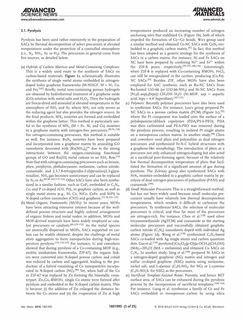
SACs have also been prepared by wet chemistry routes, pri-marily involving two slightly different procedures. The first one is based on chelation between metal centers and N, O or S coordination sites in carbon-based materials. For instance, Vile et al.[147] synthesized Pd SACs supported on mesoporous C3N4 by mixing PdCl2 and NaCl in a C3N4 dispersion under
magnetic stirring and sonication, followed by NaBH4 reduction (Figure 2a). This was primarily ascribed to the strong coordina-tion between the metal centers and the N sites of C3N4, and the procedure has also been used to prepare Pt-C3N4 and Ru-C3N4 SACs.[113,148] In some of the studies, the structure of the metal atoms in the carbon matrix is not clearly defined.[82,83] For instance, Xi et al.[149] reported the synthesis of Pd SACs sup-ported on reduced graphene oxide/amorphous carbon (rGO/AC/Pd) by stir-mixing of K2PdCl4 with rGO@AC. Whereas Pd was presumed to be intercalated between AC and rGO, the exact chemical structure was unclear.
The other procedure takes advantage of the formation of a guest-host structure through covalent bonds, π–π stacking or electrostatic interactions between the guest molecules and the carbon-based host materials.[74,76,150–152] For instance, Pt single atoms have been anchored onto thiolated CNTs via covalent PtS bonds.[153] Nickel or cobalt complexes can be grafted onto CNT surfaces by the strong noncovalent π–π stacking interactions between the pyrene moiety in the ligand and CNTs (Figure 2b).[74,76] Carbon-supported binuclear-cobalt
Adv. Mater. 2018, 1801995
Figure 2. Representative examples of metal SAC supported on carbon-based materials synthesized by wet chemistry routes. a) Pd-C3N4 based on a chelation mechanism that Pd atoms are coordinated to N sites. Reproduced with permission.[147] Copyright 2015, Wiley-VCH. b) Synthesis of Co-CNT based on a host-guest mechanism where the Co complexes are adsorbed on CNT by pyrene moieties. Reproduced with permission.[74] Copyright, 2016, Wiley-VCH.

© 2018 WILEY-VCH Verlag GmbH & Co. KGaA, Weinheim1801995 (6 of 25)
www.advmat.dewww.advancedsciencenews.com
phthalocyanine (bi-CoPc/C) has been prepared in the same manner.[81] Note that in some rare occasions, specific SACs can also be prepared by the combination of these two procedures.[85]
2.3. Physical and Chemical Deposition
Formation of SACs can also be achieved by deposition of atomic species onto a select support matrix, such as atomic layer depo-sition (ALD) and chemical vapor deposition (CVD). ALD is a gas-phase deposition technique which can be traced back to the 1960s as “molecular layering”.[154,155] Because this technique allows the control of the amount of deposited materials, it has been widely used in nanomaterials synthesis ranging from nan-oparticles, nanoclusters and down to single atoms.[46,57,77,156–160] For example, by controlling the ALD cycle numbers, the Sun and Botton groups obtained Pt SACs, Pt nanoclusters (PtNCs) and Pt nanoparticle (PtNPs) supported on graphene surfaces by using (methylcyclopentadienyl)-trimethylplatinum as the Pt source (Figure 3a).[77,157,160] Lu’s group used ALD to synthesize Pd SACs on graphene where palladium hexafluroacetylacetytate (Pd(hfac)2) was first anchored onto the oxygen functional groups of graphene and then the hfac ligands were removed under ALD conditions.[57] In a similar manner, Huang et al.[158] synthesized different Pd-C3N4 composites including Pd SACs and Pd nanoparticles supported on C3N4 by controlling the exposure time of the Pd(hfac)2 precursors. It should be noted that the samples prepared by ALD synthesis are usually nonuni-form in size and shape, rendering it challenging to understand the correlation between the material structures and catalytic performance.
CVD is a widely used technique in the preparation of two-dimensional materials, due to the precise control of
the structure and purity of the materials; yet the application of this method in the production of SACs has remained limited.[161,162] Rummeli’s group employed CVD to form a single layer of iron on a substrate, a structure close to that of single atoms.[163] More recently, Qiu et al.[90] used CVD to deposit nickel single atoms in a nanoporous graphene matrix. As shown in Figure 3b, the nanoporous Ni substrates were prepared by dealloying of a NiMn alloy and coated with a layer of graphene by a CVD process. After the Ni substrate was etched away by an HCl solution, the remaining graphene structure contained Ni single atoms. This route is highly dependent on the time of the acid etching process and the graphene vacancies generated in the CVD process which dic-tates the reactivity with Ni atoms.
Electrochemical deposition, while not extensively used in the preparation of SACs, is worthy of fundamental studies. In one study,[72] using a three-electrode setup with single-wall carbon nanotubes (SWCNT) dropcast on a glassy carbon working electrode, a Pt foil counter and a Ag/AgCl reference electrode, repeated potential cycling in a 0.5 m H2SO4 elec-trolyte led to the dissolution of Pt atoms from the Pt foil and re-deposition on the SWCNT forming Pt-SWCNT SACs (Figure 3c). This simple method was also successfully used in the synthesis of Pt SACs supported on CoP nanotubes.[69] In another study,[80] using a niobium rod anode and a carbon rod cathode, arc-discharge led to the formation of Nb SACs sup-ported on graphene.
2.4. Ball Milling
As high-energy ball milling is a powerful method to cut and/or reconstruct chemical bonds,[164,165] it may be used to synthesize
Adv. Mater. 2018, 1801995
Figure 3. Representative examples of metal SACs supported on carbon materials by different deposition techniques. a) Pt-NG synthesized by ALD. Reproduced under the terms of the CC-BY 4.0 license.[77] Copyright 2016, the Authors, published by Springer Nature. b) CVD preparation of Ni-G SACs. Reproduced with permission.[90] Copyright 2015, Wiley-VCH. c) Pt-SWCNT SACs prepared by electrochemical deposition. Reproduced with permis-sion.[72] Copyright 2017, American Chemical Society.

© 2018 WILEY-VCH Verlag GmbH & Co. KGaA, Weinheim1801995 (7 of 25)
www.advmat.dewww.advancedsciencenews.com
SACs. For instance, using iron phthalocyanine and graphene as the starting materials, Deng et al.[166] successfully embedded FeN4 moieties in graphene matrices at high Fe loadings (up to 4.0 wt%). Subsequently, they expanded the study to other metals (i.e., Mn, Fe, Co, Ni, and Cu) by simply using the cor-responding metal phthalocyanine as the precursor.[167]
2.5. Graphene Vacancy-Directed Synthesis
This strategy entails two key steps. The first is to create gra-phene vacancies by high-energy atom/ion irradiation and control the number of vacancies by the energy density[168]; and the second is to fill the graphene vacancies with select metal atoms, such as Au, Pt, Fe, Co, and In, by well-controlled sput-tering or focused ion beams.[169–171] The advantage of this strategy includes a well-defined and custom-tailored structure of the final products, allowing a reliable model for theoretical simulations, while the disadvantage entails rather sophisticated instrumentation, tedious fabrication and an extremely low yield (for instance, the preparation is generally limited to a very small area, e.g., 10 nm × 10 nm),[169] rendering it difficult for scale-up synthesis of practical catalysts.
3. Electrocatalytic Performance
The SACs prepared above exhibit apparent electrocata-lytic activity toward various reactions that are critical in electrochemical energy conversion and storage. Theoretical calculations represent a powerful tool in analyzing/predicting the catalytic performance, which can be exploited as a funda-mental framework for the rational design and engineering of the catalysts. For instance, in ORR, OER, and CO2RR, a linear relation (a.k.a. scaling relation) has been widely observed between the binding energy of various critical intermediate species,[114,172–174] a unique feature that can be used for the manipulation and optimization of the catalytic performance. In ORR, the traditional four-step reaction can be written below (with the corresponding reaction free energies of ΔG1 to ΔG4)[175]
* O H e OOH2*
1G+ + + → ∆+ − (1)
OOH H e O H O* *2 2G+ + → + ∆+ − (2)
O H e OH* *3G+ + → ∆+ − (3)
OH H e H O*2
*4G+ + → + ∆+ −
(4)
where * represents a catalytic active site. Note that ΔG2 + ΔG3 = EOH* − EOOH* + b′, where EOH* and EOOH* are the binding energy of the OH and OOH intermediates, respectively, and b′ is a constant. In ORR, typically either step (1) or (4) is the rate determine step, and at ΔG1 = ΔG4 = ΔGave ( = 1/4ΣΔGi), the performance of the catalyst is predicted to reach the
maximum. At this point, since ΣΔGi = −4.92 eV, ΔG2 + ΔG3 = −4.92 − (ΔG1 + ΔG4), and ΔEOH* − ΔEOOH* = −2.46 − b′. That is, EOH* and EOOH* scale linearly with each other, and from the inter-cept, b′ can be determined, which can then be used to predict the optimal electrode potential (U).
Similarly, in CO2RR, the first three reaction steps are gener-ally expressed as
CO g H aq e COOH2* *
5G( ) ( )+ + + ↔ ∆+ − (5)
COOH H aq e CO H O* *2 6G( )+ + ↔ + ∆+ − (6)
( )↔ + ∆CO CO g* *7G (7)
( )+ + ↔ ∆+ −CO H aq e CHO* *8G (8)
When CO is the final product, the rate determine step is either reaction (5) or (7),[176] and a linear correlation has been observed between ECOOH* and ECO*.[177] With other final prod-ucts, reaction (8) is the rate-determine step,[178] and a scaling relation can be found between ECHO* and ECO*.[177]
Interestingly, such a scaling relation can be broken with SACs,[173,177] as manifested with a different intercept value. In a previous study,[114] we showed that in Fe,N-codoped carbon for ORR, the Fe center of FeN4 exhibited a markedly different linear relation between EOH* and EOOH* from that of regular carbon sites (Figure 4a). The smaller intercept corresponded to a more positive onset potential (Eonset), in good agreement with experimental results that showed an enhanced ORR performance. Such a deviation from the conventional scaling relation has been observed in other catalytic reactions (e.g., CO2RR in Figure 4b), leading to marked enhancement of the catalytic activity over that without the SAC moiety. Below, we will summarize recent progress in the design and engineering of SACs in ORR, HER, OER, and CO2RR.
3.1. ORR
Platinum has been the catalyst of choice for ORR. Yet, Pt SACs behave markedly differently than conventional Pt/C catalysts. For instance, Choi et al.[78] loaded S-doped zeolite-templated carbon with single Pt atoms to form PtS4 SACs. The sulfur worked as the binding site of Pt that mitigated the aggregation problem of SACs on carbon substrates. Interest-ingly, the resulting atomically dispersed Pt showed a high yield of H2O2, indicating that oxygen underwent only two-electron reduction, in sharp contrast to conventional (bulk) Pt catalysts where four-electron reduction is commonly observed.[51,179–183] In fact, the sample with the highest PtS4 concentration showed a H2O2 yield of 96% with an Eonset of +0.71 V versus RHE in 0.1 m HClO4. DFT studies indicated that the 2e reduction of oxygen was under kinetic control rather than thermodynamic control, as the reorganization energy (λ0) for the 2e pathway was markedly smaller than that for the 4e pathway. Consistent
Adv. Mater. 2018, 1801995

© 2018 WILEY-VCH Verlag GmbH & Co. KGaA, Weinheim1801995 (8 of 25)
www.advmat.dewww.advancedsciencenews.com
experimental results were obtained in other studies with Pt SACs supported on TiC, TiN or ATO.[181] This is because the Pt atoms are the ORR active sites and can adsorb only one O atom of O2, which renders it difficult to break the OO bond; and for four-electron reduction of oxygen to H2O, the breaking of the OO bond may be facilitated when two adjacent Pt sites are available to adsorb both two O atoms of O2. In addition, DFT calculations suggest that the interac-tion between Pt single atoms and TiN increases the affinity of oxygen species onto the catalysts and thus diminishes the catalytic activity.
SACs of other noble metals have also been examined as ORR catalysts. Zhang et al.[79] developed a Ru SAC for ORR by ther-mally annealing Ru compounds and N-doped carbon. EXAFS and high-resolution scanning TEM studies suggested successful formation of RuN4 moieties in the structure, which exhibited a high ORR activity in acid electrolytes. The Eonset and E1/2 (half-wave potential) values were identified at +0.89 V and +0.75 V versus RHE, respectively, a performance better than that of FeN4 and very close to that of commercial Pt/C. DFT study showed that the binding of the Ru center in RuN4 with O was responsible for the ORR activity, and the rate-determine step was likely the protonation of O2 that was adsorbed onto the Ru site.
Non-noble metal SACs have also been examined as ORR catalysts. For instance, Lee et al.[184] synthesized Fe-doped CNTs with a FeN4 structure by a conventional plasma-enhanced CVD method, and the material possessed apparent electrocatalytic activity toward ORR. XPS studies showed a Fe:N:C atomic ratio close to 1:4:100, which was consistent with results from the formation energy calculations, where the content of the Fe dopant was found to diminish with decreasing N concentration in CNTs. Results of band structure calculations suggested that FeN4 and other nitrogen dopant defects enhanced the electrical conductivity over pristine CNTs, due to the shift of the Fermi level, the formation of new states ≈0.3 eV above the Fermi level by the FeN4 moieties, and spin-polarization effect. The shift of the Fermi level was favorable for the adsorption of intermediate
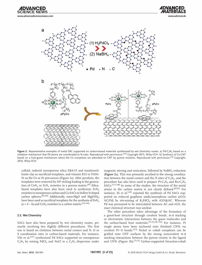
species, although there was no explicit discussion in the studies about the correlation with the activity of the catalyst.[175,185] Recently, similar structures were further examined theoretically with the advancements of the ORR mechanism. For instance, Wang et al.[186] used iron-phthalocyanine (Fe-Pc) as an analogue to FeN4 and calculated the ORR activity with a 2 × 2 supercell for a Fe-Pc monolayer in an acidic environment. It was found that O2 could readily bind to the Fe center with charge transfer from Fe to O2, and O2* reduction was identified to be the rate-determine step. The results showed that the four-electron pathway was favored on Fe-Pc, with an activity between those of N-doped carbon and Pt. In another study,[187] the metal-N4 struc-ture was systematically evaluated by including metals of groups 6B, 7B, 8, 1B and 2B. The results showed that MN4 of the Mn, Fe, and Co group metals exhibited apparent activity toward ORR, with the adsorption of OOH and release of OH being the rate determine steps. We observed similar behaviors in an early study.[114] We calculated the free energy change of every elemen-tary step in ORR in a wide range of structural configurations of N-doped graphene and FeN4-embedded graphene. The most active configurations are shown in Figure 5a,b, where the Fe center of FeN4 exhibited a much higher activity (with a reaction free energy as low as 0.39 eV) than carbon atoms of N-doped graphene (reaction free energy at least 0.61 eV). Moreover, from the DOS plots (Figure 5c,d), it can be seen that the number of states around the Fermi level was significantly higher for the FeN4 moiety than for neighboring nitrogen and carbon, with dominant contributions from the Fe 3d orbital. This indicates that the Fe center is favorable for the adsorption of O2 and may donate electrons to reduce O2, in contrast to the adjacent carbon sites.
Such mechanistic insights suggest that in metal and nitrogen-codoped carbon, the MN4 moieties play a dominant role in ORR electrocatalysis and are most likely the ORR active sites.[95] It should be noticed that this topic has been under active debates and intensive investigations.[188–191] For instance, Chen et al.[99] used ZIF-8 to trap Fe(acac)3, and pyrolysis of the resulting structure yielded single Fe atoms embedded
Adv. Mater. 2018, 1801995
Figure 4. a) EOOH* ∼ EOH* linear relation for ORR. The data points from regular carbon sites follow the linear relation (red line), whereas the two data points beyond the linear range represent single atom Fe centers of FeN4. Reproduced with permission.[114] Copyright 2017, American Chemical Society. b) ECHO* ∼ ECO* linear relation for CO2RR, where SACs (blue circles) are situated beyond the linear range for metal (211) surfaces (black dots). Repro-duced under the terms of the CC-BY 3.0 license.[173] Copyright 2018, Royal Society of Chemistry.
© 2018 WILEY-VCH Verlag GmbH & Co. KGaA, Weinheim1801995 (9 of 25)
www.advmat.dewww.advancedsciencenews.com
within the carbon skeletons. From Figure 6a,b, single Fe atoms (marked with red circles) can be seen to be distributed rather evenly across the carbon matrix, and the structure is further confirmed by EXAFS measurements (Figure 6c). The peak at ≈1.5 Å is consistent with the FeN bond, and the absence of any peak at ≈2.2 Å indicates no FeFe bond in the sample. Moreover, from EXAFS fitting, the coordination number of Fe was estimated to be 5 with a mean bond length of 2.01 Å, consistent with the FeN4 structure with the adsorption of an O2 molecule (Figure 6d). The resulting sample showed an ORR activity even better than that of Pt/C, with Eonset and E1/2 estimated to be +0.99 V and +0.90 V, respectively (Figure 6e). In poisoning tests with SCN−, these potentials were found to shift cathodically by 90 mV and 95 mV, respectively (Figure 6f), which further proved that the Fe center was the active site for ORR. In another study,[104] Chung et al. used atomic-resolution STEM to identify single Fe atoms in carbon, and qualitatively estimated the Fe:N ratio by EELS measurements, which sug-gested an average composition of FeN4. They argued that the FeN4 sites near the edge of the graphene layers were the major contributors to the ORR activity.
Consistent results have also been observed in other studies.[87,98,100,101] However, it has been noted that in Fe-NC materials, the presence of Fe and peroxide (an ORR interme-diate) may cause degradation of organic ionomers and fuel cell membranes due to Fenton reaction.[192,193] To mitigate this issue, Co-NC materials have been designed and fabricated. For instance, Wang et al.[97] used ZIF doped with different concen-trations of Co to fabricate Co-NC SACs, and attributed the ORR activity to the CoN4 moieties.
In some other studies, the ORR activity of MNC hybrids is actually ascribed to the metal center of an MN2 moiety. For instance, Shen et al.[103] used SBA-15 as a template, FeCl3,
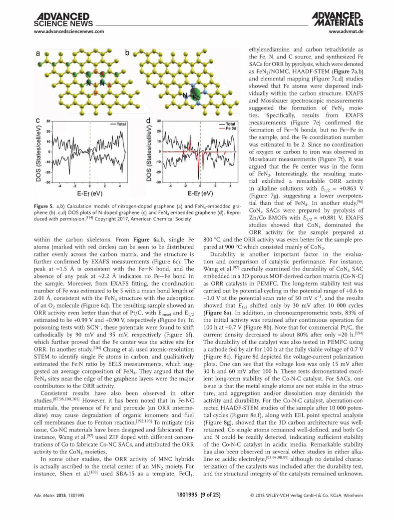
ethylenediamine, and carbon tetrachloride as the Fe, N, and C source, and synthesized Fe SACs for ORR by pyrolysis, which were denoted as FeN2/NOMC. HAADF-STEM (Figure 7a,b) and elemental mapping (Figure 7c,d) studies showed that Fe atoms were dispersed indi-vidually within the carbon structure. EXAFS and Mossbauer spectroscopic measurements suggested the formation of FeN2 moie-ties. Specifically, results from EXAFS measurements (Figure 7e) confirmed the formation of FeN bonds, but no FeFe in the sample, and the Fe coordination number was estimated to be 2. Since no coordination of oxygen or carbon to iron was observed in Mossbauer measurements (Figure 7f), it was argued that the Fe center was in the form of FeN2. Interestingly, the resulting mate-rial exhibited a remarkable ORR activity in alkaline solutions with E1/2 = +0.863 V (Figure 7g), suggesting a lower overpoten-tial than that of FeN4. In another study,[96] CoNx SACs were prepared by pyrolysis of Zn/Co BMOFs with E1/2 = +0.881 V. EXAFS studies showed that CoN4 dominated the ORR activity for the sample prepared at
800 °C, and the ORR activity was even better for the sample pre-pared at 900 °C which consisted mainly of CoN2.
Durability is another important factor in the evalua-tion and comparison of catalytic performance. For instance, Wang et al.[97] carefully examined the durability of CoN4 SAC embedded in a 3D porous MOF-derived carbon matrix (Co-N-C) as ORR catalysts in PEMFC. The long-term stability test was carried out by potential cycling in the potential range of +0.6 to +1.0 V at the potential scan rate of 50 mV s−1, and the results showed that E1/2 shifted only by 30 mV after 10 000 cycles (Figure 8a). In addition, in chronoamperometric tests, 83% of the initial activity was retained after continuous operation for 100 h at +0.7 V (Figure 8b). Note that for commercial Pt/C, the current density decreased to about 80% after only ≈20 h.[194] The durability of the catalyst was also tested in PEMFC using a cathode fed by air for 100 h at the fully viable voltage of 0.7 V (Figure 8c). Figure 8d depicted the voltage-current polarization plots. One can see that the voltage loss was only 15 mV after 30 h and 60 mV after 100 h. These tests demonstrated excel-lent long-term stability of the Co-N-C catalyst. For SACs, one issue is that the metal single atoms are not stable in the struc-ture, and aggregation and/or dissolution may diminish the activity and durability. For the Co-N-C catalyst, aberration-cor-rected HAADF-STEM studies of the sample after 10 000 poten-tial cycles (Figure 8e,f), along with EEL point spectral analysis (Figure 8g), showed that the 3D carbon architecture was well-retained, Co single atoms remained well-defined, and both Co and N could be readily detected, indicating sufficient stability of the Co-N-C catalyst in acidic media. Remarkable stability has also been observed in several other studies in either alka-line or acidic electrolyte,[93,94,98,99] although no detailed charac-terization of the catalysts was included after the durability test, and the structural integrity of the catalysts remained unknown.
Adv. Mater. 2018, 1801995
Figure 5. a,b) Calculation models of nitrogen-doped graphene (a) and FeN4-embedded gra-phene (b). c,d) DOS plots of N-doped graphene (c) and FeN4 embedded graphene (d). Repro-duced with permission.[114] Copyright 2017, American Chemical Society.

© 2018 WILEY-VCH Verlag GmbH & Co. KGaA, Weinheim1801995 (10 of 25)
www.advmat.dewww.advancedsciencenews.com
In summary, thus far studies have been mainly focused on two kinds of SACs for ORR. One is single atoms of noble metals such as Pt and Pd, and the other is MNx moiety embedded in a carbon matrix. For Pt SACs, ORR is dominated by the two-elec-tron pathway and generates H2O2 as the final product, instead of H2O or OH−. Meanwhile, the onset potential exhibits an apparent cathodic shift, as compared to that of commercial Pt/C, suggesting impeded electron-transfer kinetics in oxygen reduction, likely due to restricted adsorption of oxygen onto the single Pt atomic site. For SACs with the MNx structures, the metal centers are gene rally believed to be responsible for the ORR activity, although
the coordination number may vary due to different synthetic pro-cedures. Consistent results are obtained in DFT studies within the context of adsorption energy of oxygen species on various atomic sites and contributions to the DOS near the Fermi level.
3.2. HER
The first heterogeneous catalysts for HER are based on “host–guest” structures where single metal centers are hosted on the surface of conductive carbon materials by covalent[151,152] or
Adv. Mater. 2018, 1801995
Figure 6. a) TEM image of Fe-trapped ZIF-8 after high-temperature treatment. b) HRTEM image of single atom Fe (highlighted by red circle), c) EXAFS r space fitting curves of single Fe atoms of Fe-ISACs/CN, and d) its schematic model, Fe (orange), O (red) and C (grey). e) LSV curve of Fe-ISAs/CN, Pt/C and sample without single atom Fe (named as CN). The data were taken in 0.1 m KOH. f) LSV curve of Fe-ISACs/CN acquired in 0.1 m HClO4 with and without 0.01 m NaSCN. Reproduced with permission.[99] Copyright 2017, Wiley-VCH.

© 2018 WILEY-VCH Verlag GmbH & Co. KGaA, Weinheim1801995 (11 of 25)
www.advmat.dewww.advancedsciencenews.com
noncovalent bonds.[74,76,150] In a recent study, inspired by hydro-genases,[195–198] nickel bisdiphosphine was assembled onto CNT surfaces,[199] which exhibited high catalytic activity toward HER, with an onset potential of only −20 mV and almost unchanged current density after continuous operation for 10 h. In another study,[74] a hybrid of ploy(cobaloxime) and CNTs was prepared by π–π interactions between CNTs and the pyrene moiety which was tethered to ploy(cobaloxime). The hybrid catalyst possessed an apparent activity toward HER at near-neutral pH, with the cobalt-based turnover number up to 420, about four times higher than that of monomeric cobaloxime. Obviously, in this type of HER catalysts, the metal centers work as the active sites for HER, while the carbon materials are used as the con-ducting support. As the structures are well defined, relevant structural models can be readily built for computational studies for a coherent understanding of the reaction mechanism. How-ever, the catalytic performance is generally subpar as compared to those of benchmark catalysts like Pt/C.
More recently, carbon-supported SACs based on single atoms of non-noble metals (e.g., Fe, Co, Ni, and Cu) have been prepared and examined for HER electrocatalysis. For instance, the Tour group synthesized single Co atoms incorporated in nitrogen-doped graphene (Co-NG) or undoped graphene (Co-G) via a pyrolysis process.[91] In dark-field TEM measure-ments (Figure 9a), the white spots of 2 to 3 Å in size are the dispersed Co atoms, whereas Fourier-transformed EXAFS studies (Figure 9b) showed only a major peak at ≈1.5 Å for both Co-NG and Co-G, and waveket-transformed EXAFS studies (Figure 9c) showed a maximum (point A) at 3.2 Å−1 and 3.5 Å−1, due to the formation of CoC and CoN bonds in Co-G and Co-NG, respectively, confirming the formation of single Co atom structure in the samples.[200] In HER tests, Co-NG showed an excellent performance, with an onset poten-tial of only −30 mV, and an overpotential (η10) of −140 mV to reach the current density of 10 mV cm−2, in comparison to
NG and Co-G where η10 ≈ −440 mV and −390 mV, respectively (Figure 9d). In fact, the HER performance of Co-NG was higher than or comparable to results of relevant catalysts in the litera-ture (Figure 9e).[166,201–206] In another study,[107] Ni-NC SAC was also found to possess excellent HER performance.
Interestingly, when single Ni atoms were embedded into a (undoped) graphene matrix, apparent HER activity was also observed.[90] DFT calculations evaluated the energetic proper-ties of several possible configurations, such as interstitial Ni in the center of the phenyl rings (Niab), substitutional doping at the vacancy of the graphene lattice (Nisub), and anchoring on the defect sites (Nidef). The results (Figure 10a,b) showed that all these configurations exhibited a decrease of the absolute Gibbs free energy of hydrogen adsorption (|ΔGH*|) at carbons neighboring the Ni atoms, as compared to that of pristine gra-phene. Notably, the |ΔGH*| of carbons adjacent to Nisub was only 0.10 eV, very close to that of Pt (0.09 eV). This was contributed to charge transfer between Nisub (d orbitals) and surrounding carbons (sp orbitals), resulting in the formation of an empty C-Ni hybrid orbital close to the Fermi level and hence the for-mation of a catalytic active site (Figure 10c,d). In the studies by Muralikrishna et al.,[207–209] single Cu atoms were chelated to GO, and the corresponding HER performance was better than those of other copper-based HER catalysts.
Single Pt atoms supported on carbon-based materials have also been prepared and evaluated for HER electroca-talysis. Cheng et al. compared Pt SACs and Pt nanoclusters loaded on nitrogen-doped graphene nanosheets (Pt1-NG and PtNC-NG, respectively).[77] Interestingly, both Pt1-NG and PtNC-NG exhibited higher activities than commer-cial Pt/C. The DOS plot of Pt1-NG shows a strong overlap of the Pt 5d orbital and N 2p orbital around the Fermi level. Bader charge analysis shows that Pt was positively charged, and when two hydrogen atoms were adsorbed on the Pt, there is a strong overlap of the Pt 5d and
Adv. Mater. 2018, 1801995
Figure 7. a,b) HAADF-STEM of FeN2/NOMC-3 on carbon, and c,d) EELS mapping analysis of Fe (c) and N (d). e) Fourier-transformed EXAFS spectra of FeN2/NOMC-3. f) Fe57 Mössbauer spectra of Fe57N2/NOMC-3. g) ORR polarization curves of NOMC, FeN2/NOMC and commercial Pt/C (20%) at 1600 rpm in an O2-saturated 0.1 m KOH solution at the potential scan rate of 10 mV s−1. Reproduced with permission.[103] Copyright 2017, Elsevier Ltd.

© 2018 WILEY-VCH Verlag GmbH & Co. KGaA, Weinheim1801995 (12 of 25)
www.advmat.dewww.advancedsciencenews.com
H 1s orbitals, along with the formation of a number of new states beyond the Fermi level, indicating charge transfer from Pt to H, a critical process in proton reduction. The Lou group further studied the HER performance on Pt SACs in a PCM, where EXAFS and DFT studies indicated that both Pt atom centers and the adjacent carbon/nitrogen atoms were likely the active sites, due to charge density redistribution.[92] Chen et al.[210] synthesized Mo SAC catalysts anchored on N-doped carbon by a pyrolysis process using Na2MoO4 and chitosan as precursors, and the materials exhibited an η10 of only −132 mV, much lower than β-Mo2C (−195 mV) or MoN (−225 mV). EXAFS studies showed that Mo was threefold
coordinated by one N atom and two C atoms (MoNC2), similar to the above mentioned structure of Nisub
[90] but with O2 adsorbed onto Mo. DFT calculations showed that MoNC2 possessed the lowest |ΔGH*|, as compared to N-doped graphene, MoN, and β-Mo2C, consistent with experimental results. Results from DOS calculations indicated a higher electronic density of MoNC2 near the Fermi level, a feature beneficial for HER charge transfer. PDOS studies showed that the charge density was mainly due to Mo d-orbital, while con-tributions from the p-orbitals of C and N were negligible. This suggests that the enhanced catalytic performance of MoNC2 was largely ascribed to Mo single atoms, with minimal
Adv. Mater. 2018, 1801995
Figure 8. Durability tests of Co-NC SACs as oxygen reduction catalysts in PEMFC. a) Potential cycling in O2-saturated 0.5 m H2SO4 in the potential range of +0.6 to +1.0 V. b) Chronoamperometric profile at the potential at +0.7 V. c) PEMFC test under H2–air conditions at +0.7 V, 150 kPa for 100 h. d) H2–O2 polarization curves before and after 30 h and 100 h durability tests at +0.7 V. e–g) Representative aberration-corrected HAADF-STEM images at low resolution (e) and high resolution (f), and the corresponding EEL point spectra (g). Reproduced with permission.[97] Copyright 2018, Wiley-VCH.

© 2018 WILEY-VCH Verlag GmbH & Co. KGaA, Weinheim1801995 (13 of 25)
www.advmat.dewww.advancedsciencenews.com
contributions from the C and N coordination sites. Note that this is different from other MNxC4-x or Nisub structures where the enhanced catalytic performance is mostly accounted for by the interaction between the metal centers and N, C coordination atoms.
In a recent study,[113] the Chen group showed that Ru ions-complexed C3N4 exhibited a remarkable HER performance, due to the formation of RuN2 moieties, where the interaction between the pyridinic nitrogen of C3N4 and Ru metal center led to charge redistribution of the system and facilitated the adsorp-tion of protons. In a subsequent study,[111] it was found that the performance might be markedly improved by incorporating rGO nanosheets into the Ru- C3N4 catalyst by a wet-chemistry route (Figure 11a), with η10 of only about −80 mV (Figure 11b). Double-layer capacitance measurements (Figure 11c,d) showed that the effective electrochemical surface area of Ru-C3N4/rGO was dramatically enhanced, most likely due to enhanced electrical conductivity of the composite with the incorporation of rGO,
as manifested by electrochemical impedance measurements (Figure 11e), where the serial resistance (Rs) was estimated to be 7.9, 10.0, and 35.4 Ω for Ru-C3N4/rGO, C3N4/rGO, and C3N4, respectively. Mott–Schottky analysis (Figure 11f) showed that the flat-band potential (Efb) was virtually unchanged for Ru-C3N4/rGO and C3N4/rGO, but shifted anodically as compared to that of C3N4, indicating narrowing of the energy barrier of hydrogen evolution (H+/H2, 0.59 V vs Ag/AgCl in 0.1 m Na2SO4).[211] Fur-thermore, the charge-carrier density of Ru-C3N4/rGO was about 250 times of that of C3N4 and 6 times of that C3N4/rGO. These results highlight the synergetic effects between the various struc-tural components on the HER performance.
In short, a large variety of SACs for HER have emerged in recent studies. Results have shown that the single metal atoms serve as the active sites, and the activity may be further enhanced by the carbon supports due to interfacial charge transfer with the metal centers, leading to the generation of additional catalytic active centers.
Adv. Mater. 2018, 1801995
Figure 9. a) HAADF-STEM image of the Co-NG, exhibiting well-dispersed Co atoms in the carbon matrix; scale bar 1 nm. b) Fourier-transformed k2-weighted EXAFS spectra in R space for the Co-NG and Co-G samples. c) Wavelet-transformed k2-weighted EXAFS spectra for the Co-NG and Co-G samples. d) LSVs of Co-NG and other catalysts in 0.5 m H2SO4 at the potential scan rate of 2 mV s−1. The inset depicts the zoom-in LSVs for Co-NG near the onset region. e) Comparison of TOF values of the Co-NG catalyst (black line) with others in recent literature (references cited are those in the original article). Reproduced under the terms of the CC-BY 4.0 license.[91] Copyright 2015, Macmillan Publishers Limited.

© 2018 WILEY-VCH Verlag GmbH & Co. KGaA, Weinheim1801995 (14 of 25)
www.advmat.dewww.advancedsciencenews.com
3.3. OER
The application of SACs supported on carbon-based mate-rials in OER electrocatalysis has been rarely reported. In an early study,[83] Jahan et al. described the OER activity of Cu SAC coordinated into a GO-MOF structure. Wurster et al.[212] found that the OER activity was nonlinearly dependent on the coordination positions of Fe and Co in a supramolecular structure. Ding et al.[73] developed a sandwich structure where CNT was coated with a uniform layer of polymerized ionic liq-uids (PIL), and Co atoms were dispersed at the interface. The resulting Co-PIL-CNT SACs showed much better OER catalytic activity than Co3O4/CNT and CoCO3 despite a much lower Co content. This enhancement was ascribed to the combined con-tributions of the three different components, where Co atoms acted as the active sites, PIL not only served as the anchors for Co SACs but also affected the charge density distribution of Co species leading to enhanced catalytic activity, and CNT provided good electrical conductivity.
More recently, Fei et al.[105] investigated the MN4C4 (M = Fe, Co, and Ni) moieties in a graphene matrix by DFT calcula-tions and experimental studies. Both the M and C in MN4C4 moieties were considered as possible active sites and a four-step reaction mechanism were analyzed based on prior studies.[213,214] Interestingly, the OER process was found to be highly dependent on the metal center in MN4C4. For M = Fe or Co, the reaction mechanism was via the single site of the metal center because the binding between M and the intermediates was much stronger than the adjacent C sites (Figure 12a). By contrast, for M = Ni, the reaction mechanism involved both Ni and C sites, and the C cites were favorable for O* and OH* adsorption while the Ni site was preferred for OOH* adsorp-tion (Figure 12b). Figure 12c depicts the calculated energy diagram of OER at 1.23 V for the various MN4C4 moieties, and
the results suggested a diminishing activity trend of Ni > Co > Fe, with a totally different rate-determining step, which was oxidation of O* to OOH*, oxidation of OH* to O*, and the for-mation of OOH*, respectively. A consistent changing trend was indeed observed in electrochemical measurements, where η10 was estimated to be 331 mV for NiN4C4, 402 mV for CoN4C4, and 488 mV for FeN4C4 (Figure 12d); and the Tafel slopes varied accordingly at 63, 80, and 164 mV dec−1 (Figure 12e), respec-tively. Note that the OER performance of NiN4C4 was actually comparable to those of Ni-based nanoparticle catalysts.[215–218]
3.4. CO2RR
Gao et al.[109] constructed a structural model with single Pd and Pt atoms embedded in C3N4 cavities and calculated their elec-trocatalytic behaviors in CO2 reduction. They showed that the ideal geometry for the deposition of metal atoms is the center of a sixfold cavity, i.e., position 1 in Figure 13a. Moreover, both Pd and Pd show strong electronic interactions with neighboring pyridinic nitrogen. Specifically, charge is depleted from the Pd d-orbital of Pd-C3N4, while both charge accumulation and depletion happen on Pt in Pt-C3N4 (Figure 13b,c). CO2 could be electroreduced to HCOOH, CH3OH and CH4. Figure 13b shows the energy diagram of CO2 reduction catalyzed by a Pd-C3N4 SAC, where reduction of CO2 to HCOOH and CH3OH was both investigated. The reactions are summarized as follows
CO 2H 2e HCOOH2 + + →+ − (9)
CO 6H 6e CH OH H O2 3 2+ + → ++ − (10)
While reaction (10) follows the first two steps of reaction (9), the rate-determine step of reaction (9) is hydrogenation of HCOOH* adsorbed onto the Pd atom, with an energy barrier of 0.66 eV. By contrast, the rate-determine step of reaction (10) is hydrogenation of CH2OH species adsorbed onto the Pd atom, with a much larger energy barrier of 1.46 eV. This result indicated that the Pd-C3N4 is favorable to produce HCOOH instead of CH3OH.
Figure 13c shows the energy diagram of CO2 reduction cata-lyzed Pt-C3N4. In addition to reactions (9) and (10), the pathway to CH4 is also under consideration:
CO 8H 8e CH 2H O2 4 2+ + → ++ − (11)
Note that reaction (11) follows the first 6 steps of reaction (10). Pt-C3N4 shows a significantly different behavior in catalyzing reaction (9) than Pd-C3N4. The energy barrier of hydrogena-tion of HCOOH* is 1.01 eV of the former, much higher than that of the latter; a similar behavior was observed with the HCOOH* desorption energy (1.06 eV for Pt-C3N4 and 0.46 eV for Pd-C3N4). This indicates that Pt-C3N4 is unfavorable to pro-duce HCOOH from CO2 reduction. However, once HCOOH* is formed, the hydrogenation of other species is much easier than Pd-C3N4. Thus, Pt-C3N4 can catalyze both reactions (10) and (11). Among these two reactions, CH2*+H2O* is more stable than CH3OH* by 0.47 eV, suggesting that the CH4 path
Adv. Mater. 2018, 1801995
Figure 10. a) DFT calculations of TDOS and PDOS projected to the Nisub atom (red lines) and the adjacent C atoms (green lines) with opti-mized structures. b) Orbital-dependent PDOS of the adjacent C atoms in the Ni-G. Inset is the side view and top view of the Nisub atom in the graphene lattice. c) Hydrogen adsorption sites and configuration of the Nisub-G model. d) Calculated ΔGH* of HER at equilibrium of various cata-lysts. Reproduced with permission.[90] Copyright 2015, Wiley-VCH.

© 2018 WILEY-VCH Verlag GmbH & Co. KGaA, Weinheim1801995 (15 of 25)
www.advmat.dewww.advancedsciencenews.com
is more favorable. In summary, electroreduction of CO2 to HCOOH is favorable when catalyzed by Pd-C3N4, whereas the path to CH4 is favored when catalyzed by Pt-C3N4.
Relevant DFT calculations have also been carried out recently. He et al.[113] calculated the energetic characteristics of single metal atoms (e.g., Ag, Cu, Pd, Pt, and Co) supported on defective carbon in CO2RR to C1 products. They found that Ag might serve as a promising catalyst in reducing CO2 to CH4 while Pt shows a good activity in CO2RR to CH3OH. Using a very similar SAC model, Back et al.[173] showed that carbon-supported SACs exhibited enhanced selectivity for CO2RR, as compared to HER. In particular, Ni and Pt SACs show good selectivity toward the production of CH3OH, while Os and Ru prefer the reduction of CO2 to CH4.
Notably, in several recent studies of non-noble tran-sition metals, Ni SACs exhibit very good CO2RR activity. Yang et al.[106] pyrolyzed a mixture of amino acid (with or without sulfur), melamine and nickel acetate under an argon atmosphere. From the TEM image in Figure 14a, it can be seen that the resulting sample exhibited a smooth surface, with single Ni atoms (white spots) dispersed throughout the material. Results from XPS studies suggested the formation of Ni-N and Ni-S, at the respective Ni concentration of 4 wt% and 2.5 wt% in N and S co-doped carbon (NSG). Furthermore, XAS study showed that the valence state of Ni was +1, con-sistent with results from EPR measurements, an oxidation state favored for CO2RR. XANES measurements suggested the formation of MN4 structures in D4h symmetry (Figure 14b),
Adv. Mater. 2018, 1801995
Figure 11. a) Schematic illustration of the synthesis of RuSA-C3N4/rGO nanocomposites. b) LSV curves of various electrocatalysts in 0.5 m H2SO4. c) CV curves recorded at various scan rates in the potential range without faradaic reaction. d) Capacitive currents as a function of scan rates at +0.15 V. e) Nyquist plots of the various electrocatalysts in 0.5 m H2SO4 at −0.1 V. Inset is the full plot of C3N4. f) Mott–Schottky plots of the various electrocata-lysts in 0.1 m Na2SO4 at the frequency of 1000 Hz. Reproduced with permission.[111] Copyright 2018, Wiley-VCH.

© 2018 WILEY-VCH Verlag GmbH & Co. KGaA, Weinheim1801995 (16 of 25)
www.advmat.dewww.advancedsciencenews.com
Adv. Mater. 2018, 1801995
consistent with results from EXAFS studies, where the peaks for NiN (1.45 Å) and NiS (1.81 Å) bonds were clearly defined, whereas the NiNi peak at 2.15 Å was not observed (Figure 14c). In electrochemical measurements (Figure 14d), one can see that the N-doped carbon alone exhibited only neg-ligible CO2RR activity, which was slightly improved with the deposition of Ni nanoparticles, and marked improvement was observed with NSG-supported Ni SACs in the reduction of CO2 to CO. The Ni SACs exhibited a Faradaic efficiency up to 97%. DFT calculations showed that the Ni(I) site was most likely responsible for the CO2RR activity. In another study,[108] Zhao et al. pyrolyzed a ZIF-8 MOF loaded with Ni2+ ions. The nickel valence state of the resulting sample was identified to be between Ni(0) to Ni(II), in the form of NiN3. Electro-chemical measurements showed that the obtained Ni SAC exhibited a much better CO2RR performance than Ni nano-particles. In fact, the Faradaic efficiency of CO2RR to CO can reach 71.9%. Several other studies also showed that Ni SACs of Ni-NC were effective in reducing CO2 to CO.[75,89]
SACs based on a “host–guest” structure have also been used for CO2RR electrocatalysis. For instance, Zhang et al.[219] deposited cobalt phthalocyanine (CoPc, 6 wt%) onto CNT via π–π interactions (Figure 15a), and the electrocatalytic perfor-mance toward CO2RR was examined by CV measurements, in comparison with other catalysts such as Pc/CNT, CoPc/rGO and CoPc/CB (Figure 15b). One can see that Co single atoms coordinated in Pc played a significant role in the catalytic reac-tion, and among the various types of carbon supports, CNTs-supported catalysts showed the best activity, likely due to the highest degree of graphitization of CNTs which facilitated π–π interactions with CoPc and highest electrical conductivity.[220] Furthermore, the selectivity of the catalysts were compared at −0.59 V, and CoPc/CNT showed the highest Faradaic efficiency (FE) for CO but the lowest for H2 (Figure 15c). Interestingly, when the CoPc phenyl rings were further functionalized with CN groups (CoPc-CN), the resulted hybrid catalyst, CoPc-CN/CNT (Figure 15d inset), showed an even higher reduction current density and better selectivity than CoPc/CNT in the
Figure 12. a,b) Proposed OER mechanism of MN4C4 with the intermediates adsorbed on the single site (M = Fe or Co) (a) and dual site (M = Ni) (b). c) Free energy diagram at 1.23 V for OER at M-NG with MN4C4 moieties. d) OER activity evaluated by LSV (with iR correction) in 1 m KOH at the potential scan rate of 5 mV s−1 for M-NG, NG, and commercial RuO2/C. e) Corresponding Tafel plots of the catalysts. Reproduced with permission.[105] Copyright 2018, Macmillan Publishers Limited.

© 2018 WILEY-VCH Verlag GmbH & Co. KGaA, Weinheim1801995 (17 of 25)
www.advmat.dewww.advancedsciencenews.com
Adv. Mater. 2018, 1801995
reduction of CO2 to CO at the same potential (Figure 15d). This enhancement by CN substitution was attributed to the electron-withdrawing effect.[221] Note that in previous studies,[222,223] significant CO2RR activity has also been observed with homo-geneous molecular catalysts that featured a MN4 structure (M = Fe or Co).
3.5. Multifunctional Catalysts
In the above discussion, one may notice that some catalysts are actually active in multiple reactions. For instance, Co-NC SACs have been employed as effective catalysts toward HER, OER and ORR in separate studies,[91,97,105] and Ni-NC SACs show apparent
Figure 13. a) Optimized structure of pristine g-C3N4, Pd/C3N4 and Pt/C3N4. The yellow and blue in Pd/C3N4 and Pt/C3N4 indicate charge accumulation and charge depletion with an isovalue of 0.005e/A3. b,c) Reaction pathways of CO2 reduction catalyzed by Pd/C3N4 (b) and Pt/C3N4 (c) under standard conditions: Pt, green; C, grey; O, red; and H, white. Reproduced with permission.[109] Copyright 2016, American Chemical Society.

© 2018 WILEY-VCH Verlag GmbH & Co. KGaA, Weinheim1801995 (18 of 25)
www.advmat.dewww.advancedsciencenews.com
Adv. Mater. 2018, 1801995
Figure 14. a) HAADF-STEM image of Ni-NG; scale bar 5 nm. b) Ni K-edge XANES spectra of Ni-NG, Ni-NSG and NiPc, where peak A represents 1s → 3d transition, peak B represents 1s → 4pz transition, C and D represent 1s → 4px,y transitions and multiple scattering processes, respectively (inset shows the expanded pre-edge region). c) Fourier-transformed EXAFS spectra in which the NiPc spectrum has been reduced in size. d) LSV curves acquired in a CO2-saturated 0.5 m KHCO3 solution on a rotating disc electrode at a rotation speed of 1600 rpm and potential scan rate of 5 mV s−1. Catalyst loading 0.1 mg cm−2. The inset highlights the LSV curves in the potential range of −0.1 to −0.7 V versus RHE. The dots on the curves show the specific CO formation current of 10 mA mgcatalyst
1− . Reproduced with permission.[106] Copyright 2018, Macmillan Publishers Limited.
Figure 15. a) TEM image of CoPc/CNT (6%). Inset is the schematic structure of the CoPc/CNT hybrid. b) CO2 reduction reaction tested by CV measurements in 0.1 m KHCO3 using Pc/CNT, CoPc/RGO, CoPc/CB, and CoPc/CNT as the electrocatalysts. c) Faradaic efficiencies of CO2 reduction products (CO and H2) catalyzed by various electrocatalysts at −0.59 V versus RHE. d) Faradaic efficiencies of CO2 reduction products at different potentials for CoPc/CNT (dash lines) and CoPc-CN/CNT (solid lines). Inset is a schematic of the hybrid structure. Reproduced with permission.[219] Published under CC-BY 4.0 license. Copyright 2016, the Authors.

© 2018 WILEY-VCH Verlag GmbH & Co. KGaA, Weinheim1801995 (19 of 25)
www.advmat.dewww.advancedsciencenews.com
Adv. Mater. 2018, 1801995
electrocatalytic activity toward CO2RR, HER and OER.[105–108] This suggests that some of these SACs may act as bifunctional or even multifunctional catalysts, a unique feature that is important for rechargeable batteries. For instance, Cu SACs supported on GO/MOF hybrids[83] exhibit low overpotentials and high current den-sities for ORR, OER and HER, as compared to that without GO, because of the porous scaffold for enhanced mass transfer, effi-cient charge-transport, and synergistic interactions between GO and MOF. Zheng et al.[126] reported bifunctional activity of P and Co co-doped rGO toward ORR and OER, and the electrocatalytic activity of the resulting Co SACs was accounted for by the for-mation of rGO structural defects after co-doping and modifica-tion of the charge and spin density, although there was no explicit experimental evidence to substantiate the argument. In another study,[224] Du and coworkers carried out ab initio studies to under-stand the interaction between metal dopant and graphene matrix, and the effect on the HER and OER performances. Generally, the M-C moieties are assumed as the active sites for the adsorption of reaction intermediates. The possible doping structures are sche-matically illustrated in Figure 16a, and calculations of different Ni sites showed that the interaction with hydrogen was weakened by increasing the Ni coordination number. Figure 16b shows the vol-cano plot of a variety of transition metals, including Mn, Fe, Co, Cu, and Pd, at low coordination numbers (1 to 2). The structures located around the peak, such as Ni@1-zigzag, Fe@1-armchair, and Co@1-zigzag, are expected to possess a best HER perfor-mance. Figure 16c depicts the volcano plots of theoretical over-potentials using the O* and OH* binding energy as the reaction descriptors.[225] Based on the plots, one can clearly see that Ni@4 has the lowest overpotential of 0.35 V among the structures and is close to the peak of OER at +0.24 V, thus is expected to show the best OER activity. Pd@4 and Pd@2-armchair are identified as the next best samples. These results suggest that selection of metal SACs can be approached by optimizing the coordination number of the MCx moieties.
More complicated structures involving SACs have also been reported. For instance, in one study,[136] Fe SACs were embedded into a nitrogen-doped carbon matrix in the form of FeN4, and a second Pt SAC was then loaded onto the sample surface via a Pt-O2-Fe-N4 configuration, as confirmed by Fourier-transformed EXAFS measurements (Figure 17a,b). Figure 17c shows two possible structures of the proposed moiety. The resulting catalyst, Pt1@Fe-NC SAC, exhibited much enhanced activity toward ORR, HER, and OER, as compared to Fe-NC SAC. Specifically, based on LSV measurements (Figure 17d), the ORR Eonset was identified at +0.93 V and E1/2 at +0.80 V for Pt1@Fe-NC in 0.5 m H2SO4, a performance somewhat better than that of Fe-NC SAC. In addition, LSV measurements for up to 10000 potential cycles (Figure 17e) showed that E1/2 of Pt1@Fe-NC shifted negatively only by 12 mV, and a much larger neg-ative shift (36 mV) was observed for Fe-NC SAC. The durability of the catalysts was also tested in an acidic PEMFC for 50 h, and the Pt1@Fe-NC catalyst was found to decay slower than Fe-NC SAC (Figure 17f). This suggests that the introduction of Pt SAC into the catalyst markedly improved the durability. As for HER, Pt1@Fe-NC showed apparent activity in both acidic and basic electrolytes (Figure 17g,h). The η10 value was found to decrease from −130 mV to −60 mV in 0.5 m H2SO4 and from −165 mV to −110 mV in 1.0 m KOH after the introduction of
Pt SAC. The enhancement was attributed to the formation of a heteroatom pair of Pt-O2-Fe that was favorable for the cleavage
Figure 16. a) M-G (M = Mn, Fe, Co, Ni, Cu and Pd) composite models with different coordination numbers (C sites) of the Ni sites: carbon, brown; hydrogen, white; and nickel, grey. b) HER volcano curve of exchange cur-rent (i0) as the function of the Gibbs free energy of hydrogen adsorption ( H*G∆ ° ) on various low coordinated transition metals. c) Theoretical OER overpotential volcano plot with O* and OH* binding energy as descrip-tors to compare the theoretical activity of M-G composite catalysts. Repro-duced with permission.[224] Copyright 2017, Royal Society of Chemistry.

© 2018 WILEY-VCH Verlag GmbH & Co. KGaA, Weinheim1801995 (20 of 25)
www.advmat.dewww.advancedsciencenews.com
of HOH bond and to the Pt-O2- linkage that might enhance water desorption due to electronic and steric effects on the FeN4 moiety.[226,227] For OER electrocatalysis, LSV measure-ments (Figure 17i) showed that to reach the current density of 10 mA cm−2, the electrode potential (E10) was about +1.54 V for Pt1@FeSA-NC, markedly lower than those for Fe-NC and Pt/C and even better that that of state-of-the-art RuO2 catalysts (E10 ≈ +1.58 V).
Notably, the bifunctional electrocatalysts for ORR and OER can be applied to rechargeable metal-air batteries.[228–230] For instance, Chen et al.[231] examined the performance of a recharge-able Zn-air battery using FeNx species on N and S co-doped carbon layers coated on CNT (denoted as S,N-Fe/N/C-CNT, Figure 18a) as the electrode materials. The bifunctional electro-catalytic activity toward ORR and OER was first quantified by vol-tammetric measurements, where the oxygen electrode potential, ΔΕ = η10,OER − E1/2,ORR, for S,N-Fe/N/C-CNT was only 0.75 V (Figure 18b), much lower than that of Pt/C (1.12 V) and other cat-alysts in recent literatures.[213,232–234] Although the performance
was a combined contribution of various components in the catalysts, the FeNx species were thought to play a major role. The catalyst was then integrated into a Zn–air battery with S,N-Fe/N/C-CNT as the cathode and a Zn plate anode (Figure 18c). From the charge–discharge polarization curves (Figure 18d), one can see that the open circuit voltage (1.35 V) was higher than that with commercial Pt/C as the cathode, indicating enhanced performance of the device. When the discharge polarization curves were converted into power density plots (Figure 18e), it was found that the power density of the S,N-Fe/N/C-CNT battery was as high as 102.7 mW cm−2; and there was no obvious voltage change over 100 cycles (Figure 18f), suggesting excellent long-term stability of the catayst in Zn–air batteries.
4. Summaries and Perspectives
Single metal atoms supported on carbon-based materials rep-resent a new class of low-cost, high-efficiency electrocatalysts
Adv. Mater. 2018, 1801995
Figure 17. a,b) k3-Weighted, Fourier-transformed EXAFS data of Fe (a) and Pt (b) in a series of samples, including Pt1@Fe-NC. c) Two proposed struc-tures of Pt-O2-Fe-NC moieties. d) LSV curves of various catalyst samples acquired by RRDE measurements in O2-saturated 0.5 m H2SO4. e) LSV curves of (red curves) Pt1@Fe-NC and (blue curves) Fe-NC in the first (solid curves), 5000th (dashed-dotted curves) and 10 000th potential cycles (dotted curves) in an air-saturated electrolyte. f) Normalized current density of Fe-NC and Pt1@Fe-NC in a fuel cell during continuous operation for 50 h at 0.5 V with 80 °C H2/O2, 100% RH. g,h) HER polarization curves of the various catalysts in 0.5 m H2SO4 (g) and 1.0 m KOH (h) electrolytes. i) OER polarization curves of the catalysts in 0.1 m KOH. Reproduced with permission.[136] Copyright 2017, Wiley-VCH.

© 2018 WILEY-VCH Verlag GmbH & Co. KGaA, Weinheim1801995 (21 of 25)
www.advmat.dewww.advancedsciencenews.com
in important electrochemical reactions that are of funda-mental and technological significance in electrochemical energy conversion and storage, such as HER, ORR, OER and CO2RR. In this review, leading strategies for the synthesis of SACs are first summarized, such as pyrolysis, wet-chemistry routes, physical and chemical vapor deposition, electrochem-ical deposition, and ball milling. In the resulting samples, SACs primarily involve metal atoms bound to nonmetal atoms such as C, N, O, S, and P of the carbon supporting matrix through covalent bonds or coordination bonds, and the maximal metal–matrix interfacial interaction leads to the manipulation of the electronic structures of the materials, and emergence of additional active sites. This is a key attribute that plays an important role in regulating the reaction dynamics and eventual electrocatalytic activity, and distinguishes SACs from conventional nanoparticle catalysts, in that new reaction pathways and electron-transfer dynamics may emerge.
Despite the progress, challenges remain. For instance, the loading of active materials in SACs is generally minimal, leading to the production of only a low current density unfit for practical applications. Yet at increasing loadings one may inevitably face the issues of migration and agglomeration of metal atoms to form nanoparticles. Thus, a delicate balance needs to be struck between SAC loading and electrocatalytic activity. This may take advantage of theoretical modeling and simulations for SAC design and engineering and devel-opment of effective synthetic chemistry, such that SACs at high metal loadings and uniform coordination structures can be produced. As demonstrated in the cited examples in this review, an integration of theory and experiment is critical in advancing our understanding of the reaction mechanism,
and developing a fundamental framework within which fur-ther engineering and optimization of the catalysts can be achieved. In addition, given the experimental challenges encountered in SAC synthesis, for instance, when SACs are extended to non-carbon supporting matrices, sometimes theoretical studies are anticipated to play a leading role. This necessitates the development of effective computational methods and tools.
Furthermore, diverse metal-nonmetal bonding interactions have been formed in organometallic chemistry and played a crit-ical role in a wide range of catalytic reactions. The fundamental insights have been exploited for the deliberate functionali-zation of metal nanoparticles. For instance, for conjugated metal–ligand interfacial bonding interactions, intraparticle charge delocalization occurs between the particle-bound func-tional moieties.[235] Such a delicate control of the nanoparticle electronic properties have been exploited for the manipulation of nanoparticle catalysts in a range of electrochemical reac-tions. For metal SACs, this interfacial interaction is anticipated to be even more pronounced, leading to an ever increasing level of control of the electrocatalytic activity. To this end, drastic pro-gress has to be made on both the synthetic front and structural characterizations. This will be a focus in future research.
AcknowledgementsY.P. and B.Z.L. contributed equally to this work. The authors thank the National Science Foundation (CHE-1710408 and DMR-1409396) for partial support of the work. We also thank the anonymous reviewers for their helpful comments and critiques.
Adv. Mater. 2018, 1801995
Figure 18. a) Schematic morphology of S,N-Fe/N/C-CNT and the atomic structure of FeNx species in the carbon matrix. b) Overall polarization curves of S,N-Fe/N/C-CNT in ORR and OER in 0.1 m KOH, in comparison with other catalysts. c) Schematic illustration of a rechargeable Zn–air battery with the S,N-Fe/N/C-CNT catalyst as the cathode and a Zn plate as the anode. d) Charge and discharge polarization curves of the Zn–air battery in (c). e) Discharge polarization curves and corresponding power density plots. f) Charge-discharge cycling performance at a constant charge-discharge cur-rent density of 5 mA cm−2 of the Zn–air battery in (c) with Pt/C as the cathode catalysts. Reproduced with permission.[231] Copyright 2017, Wiley-VCH.

© 2018 WILEY-VCH Verlag GmbH & Co. KGaA, Weinheim1801995 (22 of 25)
www.advmat.dewww.advancedsciencenews.com
Conflict of InterestThe authors declare no conflict of interest.
KeywordsCO2 reduction reaction, hydrogen evolution reaction, oxygen evolution reaction, oxygen reduction reaction, single atom catalysts
Received: March 28, 2018Revised: May 30, 2018
Published online:
[1] G. Li, Z. Tang, Nanoscale 2014, 6, 3995.[2] B. Wu, N. Zheng, Nano Today 2013, 8, 168.[3] B. Wu, Y. Kuang, X. Zhang, J. Chen, Nano Today 2011, 6, 75.[4] X. Liu, J. Iocozzia, Y. Wang, X. Cui, Y. Chen, S. Zhao, Z. Li, Z. Lin,
Energy Environ. Sci. 2017, 10, 402.[5] J. Fang, B. Zhang, Q. Yao, Y. Yang, J. Xie, N. Yan,
Coordin. Chem. Rev. 2016, 322, 1.[6] H. L. Liu, F. Nosheen, X. Wang, Chem. Soc. Rev. 2015, 44, 3056.[7] M. H. Shao, Q. W. Chang, J. P. Dodelet, R. Chenitz, Chem. Rev.
2016, 116, 3594.[8] K. D. Gilroy, A. Ruditskiy, H. C. Peng, D. Qin, Y. Xia, Chem. Rev.
2016, 116, 10414.[9] Z. Fan, H. Zhang, Acc. Chem. Res. 2016, 49, 2841.
[10] B. E. Hayden, Acc. Chem. Res. 2013, 46, 1858.[11] W. Chen, S. W. Chen, Angew. Chem., Int. Ed. 2009, 48, 4386.[12] F. J. Perez-Alonso, D. N. McCarthy, A. Nierhoff, P. Hernandez-Fernandez,
C. Strebel, I. E. L. Stephens, J. H. Nielsen, I. Chorkendorff, Angew. Chem., Int. Ed. 2012, 51, 4641.
[13] D. F. Gao, H. Zhou, J. Wang, S. Miao, F. Yang, G. X. Wang, J. G. Wang, X. H. Bao, J. Am. Chem. Soc. 2015, 137, 4288.
[14] N. S. Porter, H. Wu, Z. W. Quan, J. Y. Fang, Acc. Chem. Res. 2013, 46, 1867.
[15] J. B. Wu, A. Gross, H. Yang, Nano Lett. 2011, 11, 798.[16] J. Y. Chen, B. Lim, E. P. Lee, Y. N. Xia, Nano Today 2009, 4, 81.[17] Y. J. Kang, P. D. Yang, N. M. Markovic, V. R. Stamenkovic, Nano
Today 2016, 11, 587.[18] Z. W. Quan, Y. X. Wang, J. Y. Fang, Acc. Chem. Res. 2013, 46, 191.[19] M. S. Jin, H. Zhang, Z. X. Xie, Y. N. Xia, Angew. Chem., Int. Ed.
2011, 50, 7850.[20] L. D. Li, Y. Peng, Y. H. Yue, Y. Hu, X. Liang, P. G. Yin, L. Guo,
Chem. Commun. 2015, 51, 11591.[21] N. Tian, Z. Y. Zhou, S. G. Sun, Y. Ding, Z. L. Wang, Science 2007,
316, 732.[22] T. Sheng, Y. F. Xu, Y. X. Jiang, L. Huang, N. Tian, Z. Y. Zhou,
I. Broadwell, S. G. Sun, Acc. Chem. Res. 2016, 49, 2569.[23] C. H. Cui, S. H. Yu, Acc. Chem. Res. 2013, 46, 1427.[24] Y. J. Wang, N. N. Zhao, B. Z. Fang, H. Li, X. T. T. Bi, H. J. Wang,
Chem. Rev. 2015, 115, 3433.[25] D. M. Alonso, S. G. Wettstein, J. A. Dumesic, Chem. Soc. Rev.
2012, 41, 8075.[26] C. Chen, Y. J. Kang, Z. Y. Huo, Z. W. Zhu, W. Y. Huang, H. L. L. Xin,
J. D. Snyder, D. G. Li, J. A. Herron, M. Mavrikakis, M. F. Chi, K. L. More, Y. D. Li, N. M. Markovic, G. A. Somorjai, P. D. Yang, V. R. Stamenkovic, Science 2014, 343, 1339.
[27] X. Q. Huang, Z. P. Zhao, L. Cao, Y. Chen, E. B. Zhu, Z. Y. Lin, M. F. Li, A. M. Yan, A. Zettl, Y. M. Wang, X. F. Duan, T. Mueller, Y. Huang, Science 2015, 348, 1230.
[28] B. Lim, M. J. Jiang, P. H. C. Camargo, E. C. Cho, J. Tao, X. M. Lu, Y. M. Zhu, Y. N. Xia, Science 2009, 324, 1302.
[29] K. Parvez, S. B. Yang, Y. Hernandez, A. Winter, A. Turchanin, X. L. Feng, K. Mullen, ACS Nano 2012, 6, 9541.
[30] D. K. Perivoliotis, N. Tagmatarchis, Carbon 2017, 118, 493.[31] M. Zhou, H. L. Wang, S. J. Guo, Chem. Soc. Rev. 2016, 45, 1273.[32] D. Higgins, P. Zamani, A. P. Yu, Z. W. Chen, Energy Environ. Sci.
2016, 9, 357.[33] Q. Li, N. Mahmood, J. H. Zhu, Y. L. Hou, S. H. Sun, Nano Today
2014, 9, 668.[34] Q. R. Shi, Y. Cha, Y. Song, J. I. Lee, C. Z. Zhu, X. Y. Li, M. K. Song,
D. Du, Y. H. Lin, Nanoscale 2016, 8, 15414.[35] F. Bonaccorso, L. Colombo, G. H. Yu, M. Stoller, V. Tozzini,
A. C. Ferrari, R. S. Ruoff, V. Pellegrini, Science 2015, 347, 1246501.
[36] X. F. Yang, A. Q. Wang, B. T. Qiao, J. Li, J. Y. Liu, T. Zhang, Acc. Chem. Res. 2013, 46, 1740.
[37] J. Cordon, G. Jimenez-Oses, J. M. Lopez-de-Luzuriaga, M. Monge, Nat. Commun. 2017, 8, 1657.
[38] J. Li, X. Li, H. J. Zhai, L. S. Wang, Science 2003, 299, 864.[39] M. Valden, X. Lai, D. W. Goodman, Science 1998, 281, 1647.[40] A. Behr, P. Neubert, Applied Homogeneous Catalysis, Wiley-VCH,
Weinheim, Germany 2012.[41] B. Han, R. Lang, B. T. Qiao, A. Q. Wang, T. Zhang, Chin. J. Catal.
2017, 38, 1498.[42] C. Lecuyer, F. Quignard, A. Choplin, D. Olivier, J. M. Basset,
Angew. Chem., Int. Ed. 1991, 30, 1660.[43] V. Vidal, A. Theolier, J. ThivolleCazat, J. M. Basset, J. Corker,
J. Am. Chem. Soc. 1996, 118, 4595.[44] B. T. Qiao, A. Q. Wang, X. F. Yang, L. F. Allard, Z. Jiang, Y. T. Cui,
J. Y. Liu, J. Li, T. Zhang, Nat. Chem. 2011, 3, 634.[45] X. K. Gu, B. T. Qiao, C. Q. Huang, W. C. Ding, K. J. Sun, E. S. Zhan,
T. Zhang, J. Y. Liu, W. X. Li, ACS Catal. 2014, 4, 3886.[46] C. L. Wang, X. K. Gu, H. Yan, Y. Lin, J. J. Li, D. D. Liu, W. X. Li,
J. L. Lu, ACS Catal. 2017, 7, 887.[47] Y. R. Li, Z. W. Wang, T. Xia, H. X. Ju, K. Zhang, R. Long, Q. Xu,
C. M. Wang, L. Song, J. F. Zhu, J. Jiang, Y. J. Xiong, Adv. Mater. 2016, 28, 6959.
[48] Y. T. Shi, C. Y. Zhao, H. S. Wei, J. H. Guo, S. X. Liang, A. Q. Wang, T. Zhang, J. Y. Liu, T. L. Ma, Adv. Mater. 2014, 26, 8147.
[49] S. E. J. Hackett, R. M. Brydson, M. H. Gass, I. Harvey, A. D. Newman, K. Wilson, A. F. Lee, Angew. Chem., Int. Ed. 2007, 46, 8593.
[50] R. Lang, T. Li, D. Matsumura, S. Miao, Y. Ren, Y. T. Cui, Y. Tan, B. Qiao, L. Li, A. Wang, X. Wang, T. Zhang, Angew. Chem., Int. Ed. 2016, 55, 16054.
[51] S. Yang, J. Kim, Y. J. Tak, A. Soon, H. Lee, Angew. Chem., Int. Ed. 2016, 55, 2058.
[52] B. Zhang, H. Asakura, J. Zhang, J. G. Zhang, S. De, N. Yan, Angew. Chem., Int. Ed. 2016, 55, 8319.
[53] J. Lin, B. T. Qiao, N. Li, L. Li, X. C. Sun, J. Y. Liu, X. D. Wang, T. Zhang, Chem. Commun. 2015, 51, 7911.
[54] J. X. Liang, J. Lin, X. F. Yang, A. Q. Wang, B. T. Qiao, J. Y. Liu, T. Zhang, J. Li, J. Phys. Chem. C 2014, 118, 21945.
[55] J. Lin, A. Q. Wang, B. T. Qiao, X. Y. Liu, X. F. Yang, X. D. Wang, J. X. Liang, J. X. Li, J. Y. Liu, T. Zhang, J. Am. Chem. Soc. 2013, 135, 15314.
[56] J. C. Matsubu, V. N. Yang, P. Christopher, J. Am. Chem. Soc. 2015, 137, 3076.
[57] H. Yan, H. Cheng, H. Yi, Y. Lin, T. Yao, C. L. Wang, J. J. Li, S. Q. Wei, J. L. Lu, J. Am. Chem. Soc. 2015, 137, 10484.
[58] F. Dvorak, M. Farnesi Camellone, A. Tovt, N. D. Tran, F. R. Negreiros, M. Vorokhta, T. Skala, I. Matolinova, J. Myslivecek, V. Matolin, S. Fabris, Nat. Commun. 2016, 7, 10801.
[59] L. B. Wang, W. B. Zhang, S. P. Wang, Z. H. Gao, Z. H. Luo, X. Wang, R. Zeng, A. W. Li, H. L. Li, M. L. Wang, X. S. Zheng, J. F. Zhu, W. H. Zhang, C. Ma, R. Si, J. Zeng, Nat. Commun. 2016, 7, 14036.
Adv. Mater. 2018, 1801995

© 2018 WILEY-VCH Verlag GmbH & Co. KGaA, Weinheim1801995 (23 of 25)
www.advmat.dewww.advancedsciencenews.com
[60] H. S. Wei, X. Y. Liu, A. Q. Wang, L. L. Zhang, B. T. Qiao, X. F. Yang, Y. Q. Huang, S. Miao, J. Y. Liu, T. Zhang, Nat. Commun. 2014, 5, 5634.
[61] S. R. Zhang, L. Nguyen, J. X. Liang, J. J. Shan, J. Y. Liu, A. I. Frenkel, A. Patlolla, W. X. Huang, J. Li, F. Tao, Nat. Commun. 2015, 6, 7938.
[62] J. Jones, H. F. Xiong, A. T. Delariva, E. J. Peterson, H. Pham, S. R. Challa, G. S. Qi, S. Oh, M. H. Wiebenga, X. I. P. Hernandez, Y. Wang, A. K. Datye, Science 2016, 353, 150.
[63] W. E. Kaden, T. P. Wu, W. A. Kunkel, S. L. Anderson, Science 2009, 326, 826.
[64] P. X. Liu, Y. Zhao, R. X. Qin, S. G. Mo, G. X. Chen, L. Gu, D. M. Chevrier, P. Zhang, Q. Guo, D. D. Zang, B. H. Wu, G. Fu, N. F. Zheng, Science 2016, 352, 797.
[65] G. Zhao, H. Liu, J. Ye, Nano Today 2018, 19, 108.[66] H. Zhang, G. Liu, L. Shi, J. Ye, Adv. Energy Mater. 2018, 8, 1701343.[67] S. Liang, C. Hao, Y. Shi, ChemCatChem 2015, 7, 2559.[68] M. Yang, M. Flytzani-Stephanopoulos, Catal Today 2017, 298, 216.[69] L. Zhang, L. Han, H. Liu, X. Liu, J. Luo, Angew. Chem., Int. Ed.
2017, 56, 13694.[70] M. Xing, S. Guo, L. Guo, Theor. Chem. Acc. 2018, 137, 18.[71] J. Zhao, J.-X. Zhao, Q. Cai, Phys. Chem. Chem. Phys. 2018, 20,
9248.[72] M. Tavakkoli, N. Holmberg, R. Kronberg, H. Jiang, J. Sainio,
E. I. Kauppinen, T. Kallio, K. Laasonen, ACS Catal. 2017, 7, 3121.[73] Y. Ding, A. Klyushin, X. Huang, T. Jones, D. Teschner, F. Girgsdies,
T. Rodenas, R. Schlogl, S. Heumann, Angew. Chem., Int. Ed. 2018, 57, 3514.
[74] B. Reuillard, J. Warnan, J. J. Leung, D. W. Wakerley, E. Reisner, Angew. Chem., Int. Ed. 2016, 55, 3952.
[75] Y. Cheng, S. Zhao, B. Johannessen, J. P. Veder, M. Saunders, M. R. Rowles, M. Cheng, C. Liu, M. F. Chisholm, R. De Marco, H. M. Cheng, S. Z. Yang, S. P. Jiang, Adv. Mater. 2018, 30, 1706287.
[76] P. D. Tran, A. Le Goff, J. Heidkamp, B. Jousselme, N. Guillet, S. Palacin, H. Dau, M. Fontecave, V. Artero, Angew. Chem., Int. Ed. 2011, 50, 1371.
[77] N. C. Cheng, S. Stambula, D. Wang, M. N. Banis, J. Liu, A. Riese, B. W. Xiao, R. Y. Li, T. K. Sham, L. M. Liu, G. A. Botton, X. L. Sun, Nat. Commun. 2016, 7, 13638.
[78] C. H. Choi, M. Kim, H. C. Kwon, S. J. Cho, S. Yun, H. T. Kim, K. J. J. Mayrhofer, H. Kim, M. Choi, Nat. Commun. 2016, 7, 10922.
[79] C. Zhang, J. Sha, H. Fei, M. Liu, S. Yazdi, J. Zhang, Q. Zhong, X. Zou, N. Zhao, H. Yu, ACS Nano 2017, 11, 6930.
[80] X. F. Zhang, J. J. Guo, P. F. Guan, C. J. Liu, H. Huang, F. H. Xue, X. L. Dong, S. J. Pennycook, M. F. Chisholm, Nat. Commun. 2013, 4, 1924.
[81] B. Li, X. Zhou, X. Wang, B. Liu, B. Li, J. Power Sources 2014, 272, 320.
[82] S. Muralikrishna, T. N. Ravishankar, T. Ramakrishnappa, D. H. Nagaraju, R. Krishna Pai, Environ. Prog. Sustainable Energy 2016, 35, 565.
[83] M. Jahan, Z. L. Liu, K. P. Loh, Adv. Funct. Mater. 2013, 23, 5363.[84] J. Wang, H. Zhang, C. Wang, Y. Zhang, J. Wang, H. Zhao,
M. Cheng, A. Li, J. Wang, Energy Storage Mater. 2018, 12, 1.[85] J. Guo, X. Yan, Q. Liu, Q. Li, X. Xu, L. Kang, Z. Cao, G. Chai,
J. Chen, Y. Wang, J. Yao, Nano Energy 2018, 46, 347.[86] W. Li, J. Wu, D. C. Higgins, J.-Y. Choi, Z. Chen, ACS Catal. 2012, 2,
2761.[87] H. Yin, C. Z. Zhang, F. Liu, Y. L. Hou, Adv. Funct. Mater. 2014, 24, 2930.[88] Y. G. Li, W. Zhou, H. L. Wang, L. M. Xie, Y. Y. Liang, F. Wei,
J. C. Idrobo, S. J. Pennycook, H. J. Dai, Nat. Nanotechnol. 2012, 7, 394.
[89] K. Jiang, S. Siahrostami, T. Zheng, Y. Hu, S. Hwang, E. Stavitski, Y. Peng, J. Dynes, M. Gangisetty, D. Su, K. Attenkofer, H. Wang, Energy Environ. Sci. 2018, 11, 893.
[90] H. J. Qiu, Y. Ito, W. Cong, Y. Tan, P. Liu, A. Hirata, T. Fujita, Z. Tang, M. Chen, Angew. Chem., Int. Ed. 2015, 54, 14031.
[91] H. L. Fei, J. C. Dong, M. J. Arellano-Jimenez, G. L. Ye, N. D. Kim, E. L. G. Samuel, Z. W. Peng, Z. Zhu, F. Qin, J. M. Bao, M. J. Yacaman, P. M. Ajayan, D. L. Chen, J. M. Tour, Nat. Commun. 2015, 6, 8668.
[92] H. Zhang, P. An, W. Zhou, B. Y. Guan, P. Zhang, J. Dong, X. W. Lou, Sci. Adv. 2018, 4, eaao6657.
[93] J. Wang, Z. Huang, W. Liu, C. Chang, H. Tang, Z. Li, W. Chen, C. Jia, T. Yao, S. Wei, Y. Wu, Y. Li, J. Am. Chem. Soc. 2017, 139, 17281.
[94] Y. Han, Y. G. Wang, W. Chen, R. Xu, L. Zheng, J. Zhang, J. Luo, R. A. Shen, Y. Zhu, W. C. Cheong, C. Chen, Q. Peng, D. Wang, Y. Li, J. Am. Chem. Soc. 2017, 139, 17269.
[95] H. W. Liang, W. Wei, Z. S. Wu, X. L. Feng, K. Mullen, J. Am. Chem. Soc. 2013, 135, 16002.
[96] P. Q. Yin, T. Yao, Y. Wu, L. R. Zheng, Y. Lin, W. Liu, H. X. Ju, J. F. Zhu, X. Hong, Z. X. Deng, G. Zhou, S. Q. Wei, Y. D. Li, Angew. Chem., Int. Ed. 2016, 55, 10800.
[97] X. X. Wang, D. A. Cullen, Y. T. Pan, S. Hwang, M. Wang, Z. Feng, J. Wang, M. H. Engelhard, H. Zhang, Y. He, Y. Shao, D. Su, K. L. More, J. S. Spendelow, G. Wu, Adv. Mater. 2018, 30, 1706758.
[98] X. Fu, P. Zamani, J. Y. Choi, F. M. Hassan, G. Jiang, D. C. Higgins, Y. Zhang, M. A. Hoque, Z. Chen, Adv. Mater. 2017, 29, 1604456.
[99] Y. J. Chen, S. F. Ji, Y. G. Wang, J. C. Dong, W. X. Chen, Z. Li, R. A. Shen, L. R. Zheng, Z. B. Zhuang, D. S. Wang, Y. D. Li, Angew. Chem., Int. Ed. 2017, 56, 6937.
[100] Q. Liu, X. Liu, L. Zheng, J. Shui, Angew. Chem., Int. Ed. 2018, 57, 1218.
[101] S. Fu, C. Zhu, D. Su, J. Song, S. Yao, S. Feng, M. H. Engelhard, D. Du, Y. Lin, Small 2018, 1703118.
[102] Z. Zhang, X. Gao, M. Dou, J. Ji, F. Wang, Small 2017, 13, 1604290.[103] H. Shen, E. Gracia-Espino, J. Ma, H. Tang, X. Mamat, T. Wagberg,
G. Hu, S. Guo, Nano Energy 2017, 35, 9.[104] H. T. Chung, D. A. Cullen, D. Higgins, B. T. Sneed, E. F. Holby,
K. L. More, P. Zelenay, Science 2017, 357, 479.[105] H. Fei, J. Dong, Y. Feng, C. S. Allen, C. Wan, B. Volosskiy, M. Li,
Z. Zhao, Y. Wang, H. Sun, P. An, W. Chen, Z. Guo, C. Lee, D. Chen, I. Shakir, M. Liu, T. Hu, Y. Li, A. I. Kirkland, X. Duan, Y. Huang, Nat. Catal. 2018, 1, 63.
[106] H. B. Yang, S.-F. Hung, S. Liu, K. Yuan, S. Miao, L. Zhang, X. Huang, H.-Y. Wang, W. Cai, R. Chen, J. Gao, X. Yang, W. Chen, Y. Huang, H. M. Chen, C. M. Li, T. Zhang, B. Liu, Nat. Energy 2018, 3, 140.
[107] L. Fan, P. F. Liu, X. Yan, L. Gu, Z. Z. Yang, H. G. Yang, S. Qiu, X. Yao, Nat. Commun. 2016, 7, 10667.
[108] C. Zhao, X. Dai, T. Yao, W. Chen, X. Wang, J. Wang, J. Yang, S. Wei, Y. Wu, Y. Li, J. Am. Chem. Soc. 2017, 139, 8078.
[109] G. P. Gao, Y. Jiao, E. R. Waclawik, A. J. Du, J. Am. Chem. Soc. 2016, 138, 6292.
[110] Y. Peng, L. Li, R. Tao, L. Tan, M. Qiu, L. Guo, Nano Res. 2018, 11, 3222.
[111] Y. Peng, W. Pan, N. Wang, J. E. Lu, S. Chen, ChemSusChem 2018, 11, 130.
[112] F. He, K. Li, C. Yin, Y. Wang, H. Tang, Z. Wu, Carbon 2017, 114, 619.
[113] Y. Peng, B. Lu, L. Chen, N. Wang, J. E. Lu, Y. Ping, S. Chen, J. Mater. Chem. A 2017, 5, 18261.
[114] B. Z. Lu, T. J. Smart, D. D. Qin, J. E. Lu, N. Wang, L. M. Chen, Y. Peng, Y. Ping, S. W. Chen, Chem. Mater. 2017, 29, 5617.
[115] Y. Jiao, Y. Zheng, M. T. Jaroniec, S. Z. Qiao, Chem. Soc. Rev. 2015, 44, 2060.
[116] J. K. Norskov, T. Bligaard, J. Rossmeisl, C. H. Christensen, Nat. Chem. 2009, 1, 37.
Adv. Mater. 2018, 1801995

© 2018 WILEY-VCH Verlag GmbH & Co. KGaA, Weinheim1801995 (24 of 25)
www.advmat.dewww.advancedsciencenews.com
Adv. Mater. 2018, 1801995
[117] S. Kattel, P. Atanassov, B. Kiefer, Phys. Chem. Chem. Phys. 2013, 15, 148.
[118] M. Li, S. Wu, X. Yang, J. Hu, L. Peng, L. Bai, Q. Huo, J. Guan, Appl. Catal., A 2017, 543, 61.
[119] J. Wang, T. T. Wang, F. B. Wang, D. Y. Zhang, K. Wang, X. H. Xia, J. Phys. Chem. C 2016, 120, 15593.
[120] L. Birry, J. H. Zagal, J.-P. Dodelet, Electrochem. Commun. 2010, 12, 628.
[121] W. Li, A. Yu, D. C. Higgins, B. G. Llanos, Z. Chen, J. Am. Chem. Soc. 2010, 132, 17056.
[122] M. S. Thorum, J. M. Hankett, A. A. Gewirth, J. Phys. Chem. Lett. 2011, 2, 295.
[123] J. Wu, W. Li, D. Higgins, Z. Chen, J. Phys. Chem. C 2011, 115, 18856.
[124] R. S. Hsu, Z. Chen, ECS Trans. 2010, 28, 39.[125] W. Liu, L. Cao, W. Cheng, Y. Cao, X. Liu, W. Zhang, X. Mou,
L. Jin, X. Zheng, W. Che, Q. Liu, T. Yao, S. Wei, Angew. Chem., Int. Ed. Engl. 2017, 56, 9312.
[126] X. Zheng, Z. Yang, J. Wu, C. Jin, J.-H. Tian, R. Yang, RSC Adv. 2016, 6, 64155.
[127] C. Gao, S. Chen, Y. Wang, J. Wang, X. Zheng, J. Zhu, L. Song, W. Zhang, Y. Xiong, Adv. Mater. 2018, 30, 1704624.
[128] Z. P. Chen, S. Pronkin, T. P. Fellinger, K. Kailasam, G. Vile, D. Albani, F. Krumeich, R. Leary, J. Barnard, J. M. Thomas, J. Perez-Ramirez, M. Antonietti, D. Dontsova, ACS Nano 2016, 10, 3166.
[129] Z. Liang, C. Qu, D. Xia, R. Zou, Q. Xu, Angew. Chem. 2018, 57, 9604.
[130] S. Dang, Q.-L. Zhu, Q. Xu, Nat. Rev. Mater. 2017, 3, 17075.[131] Y. V. Kaneti, J. Tang, R. R. Salunkhe, X. C. Jiang, A. B. Yu,
K. C. W. Wu, Y. Yamauchi, Adv. Mater. 2017, 29, 1604898.[132] A. Dhakshinamoorthy, A. M. Asiri, H. García, Angew. Chem.,
Int. Ed. 2016, 55, 5414.[133] W. Xia, A. Mahmood, R. Zou, Q. Xu, Energy Environ. Sci. 2015, 8,
1837.[134] S. N. Zhao, X. Z. Song, S. Y. Song, H. J. Zhang, Coordin. Chem. Rev.
2017, 337, 80.[135] T. Y. Ma, S. Dai, M. Jaroniec, S. Z. Qiao, J. Am. Chem. Soc. 2014,
136, 13925.[136] X. Zeng, J. Shui, X. Liu, Q. Liu, Y. Li, J. Shang, L. Zheng, R. Yu,
Adv. Energy Mater. 2018, 8, 1701345.[137] X. Wang, W. Chen, L. Zhang, T. Yao, W. Liu, Y. Lin, H. Ju, J. Dong,
L. Zheng, W. Yan, X. Zheng, Z. Li, X. Wang, J. Yang, D. He, Y. Wang, Z. Deng, Y. Wu, Y. Li, J. Am. Chem. Soc. 2017, 139, 9419.
[138] F. Wang, Y. Wang, Y. Feng, Y. Zeng, Z. Xie, Q. Zhang, Y. Su, P. Chen, Y. Liu, K. Yao, W. Lv, G. Liu, Appl. Catal., B 2018, 221, 510.
[139] J. K. Gao, J. P. Wang, X. F. Qian, Y. Y. Dong, H. Xu, R. J. Song, C. F. Yan, H. C. Zhu, Q. W. Zhong, G. D. Qian, J. M. Yao, J. Solid State Chem. 2015, 228, 60.
[140] Y. Xia, Z. Yang, R. Mokaya, Nanoscale 2010, 2, 639.[141] N. Fechler, T. P. Fellinger, M. Antonietti, Adv. Mater. 2013, 25, 75.[142] B. Liu, H. Shioyama, T. Akita, Q. Xu, J. Am. Chem. Soc. 2008, 130,
5390.[143] J. Yan, Q. Wang, T. Wei, L. Jiang, M. Zhang, X. Jing, Z. Fan, ACS
Nano 2014, 8, 4720.[144] P. Strubel, S. Thieme, T. Biemelt, A. Helmer, M. Oschatz,
J. Brückner, H. Althues, S. Kaskel, Adv. Funct. Mater. 2015, 25, 287.[145] W. G. Liu, L. L. Zhang, W. S. Yan, X. Y. Liu, X. F. Yang, S. Miao,
W. T. Wang, A. Q. Wang, T. Zhang, Chem. Sci. 2016, 7, 5758.[146] W. Liu, L. Zhang, X. Liu, X. Liu, X. Yang, S. Miao, W. Wang,
A. Wang, T. Zhang, J. Am. Chem. Soc. 2017, 139, 10790.[147] G. Vile, D. Albani, M. Nachtegaal, Z. Chen, D. Dontsova,
M. Antonietti, N. Lopez, J. Perez-Ramirez, Angew. Chem., Int. Ed. 2015, 54, 11265.
[148] X. Li, W. Bi, L. Zhang, S. Tao, W. Chu, Q. Zhang, Y. Luo, C. Wu, Y. Xie, Adv. Mater. 2016, 28, 2427.
[149] J. Xi, H. Sun, D. Wang, Z. Zhang, X. Duan, J. Xiao, F. Xiao, L. Liu, S. Wang, Appl. Catal., B 2018, 225, 291.
[150] V. Georgakilas, J. N. Tiwari, K. C. Kemp, J. A. Perman, A. B. Bourlinos, K. S. Kim, R. Zboril, Chem. Rev. 2016, 116, 5464.
[151] S. Canaguier, V. Artero, M. Fontecave, Dalton Trans. 2008, 0, 315.[152] C. Tard, C. J. Pickett, Chem. Rev. 2009, 109, 2245.[153] Y.-T. Kim, K. Ohshima, K. Higashimine, T. Uruga, M. Takata,
H. Suematsu, T. Mitani, Angew. Chem. 2006, 118, 421.[154] R. L. Puurunen, Chem. Vap. Deposition 2014, 20, 332.[155] H. Van Bui, F. Grillo, J. R. van Ommen, Chem. Commun. 2017, 53,
45.[156] J. L. Lu, J. W. Elam, P. C. Stair, Acc. Chem. Res. 2013, 46, 1806.[157] S. H. Sun, G. X. Zhang, N. Gauquelin, N. Chen, J. G. Zhou,
S. L. Yang, W. F. Chen, X. B. Meng, D. S. Geng, M. N. Banis, R. Y. Li, S. Y. Ye, S. Knights, G. A. Botton, T. K. Sham, X. L. Sun, Sci. Rep. 2013, 3, 1775.
[158] X. H. Huang, Y. J. Xia, Y. J. Cao, X. S. Zheng, H. B. Pan, J. F. Zhu, C. Ma, H. W. Wang, J. J. Li, R. You, S. Q. Wei, W. X. Huang, J. L. Lu, Nano Res. 2017, 10, 1302.
[159] Z. Li, N. M. Schweitzer, A. B. League, V. Bernales, A. W. Peters, A. Getsoian, T. C. Wang, J. T. Miller, A. Vjunov, J. L. Fulton, J. A. Lercher, C. J. Cramer, L. Gagliardi, J. T. Hupp, O. K. Farha, J. Am. Chem. Soc. 2016, 138, 1977.
[160] S. Stambula, N. Gauquelin, M. Bugnet, S. Gorantla, S. Turner, S. H. Sun, J. Liu, G. X. Zhang, X. L. Sun, G. A. Botton, J. Phys. Chem. C 2014, 118, 3890.
[161] Z. Cai, B. Liu, X. Zou, H.-M. Cheng, Chem. Rev. 2018, 118, 6091.[162] T. Zhang, L. Fu, Chem 2018, 4, 671.[163] J. Zhao, Q. M. Deng, A. Bachmatiuk, G. Sandeep, A. Popov,
J. Eckert, M. H. Rummeli, Science 2014, 343, 1228.[164] I.-Y. Jeon, Y.-R. Shin, G.-J. Sohn, H.-J. Choi, S.-Y. Bae,
J. Mahmood, S.-M. Jung, J.-M. Seo, M.-J. Kim, D. W. Chang, Proc. Natl. Acad. Sci. USA 2012, 109, 5588.
[165] S. Immohr, M. Felderhoff, C. Weidenthaler, F. Schüth, Angew. Chem., Int. Ed. 2013, 52, 12688.
[166] D. H. Deng, X. Q. Chen, L. Yu, X. Wu, Q. F. Liu, Y. Liu, H. X. Yang, H. F. Tian, Y. F. Hu, P. P. Du, R. Si, J. H. Wang, X. J. Cui, H. B. Li, J. P. Xiao, T. Xu, J. Deng, F. Yang, P. N. Duchesne, P. Zhang, J. G. Zhou, L. T. Sun, J. Q. Li, X. L. Pan, X. H. Bao, Sci. Adv. 2015, 1, e1500462.
[167] X. J. Cui, J. P. Xiao, Y. H. Wu, P. P. Du, R. Si, H. X. Yang, H. F. Tian, J. Q. Li, W. H. Zhang, D. H. Deng, X. H. Bao, Angew. Chem., Int. Ed. 2016, 55, 6708.
[168] A. W. Robertson, C. S. Allen, Y. A. Wu, K. He, J. Olivier, J. Neethling, A. I. Kirkland, J. H. Warner, Nat. Commun. 2012, 3, 1144.
[169] A. W. Robertson, B. Montanari, K. He, J. Kim, C. S. Allen, Y. A. Wu, J. Olivier, J. Neethling, N. Harrison, A. I. Kirkland, J. H. Warner, Nano Lett. 2013, 13, 1468.
[170] H. Wang, Q. Wang, Y. Cheng, K. Li, Y. Yao, Q. Zhang, C. Dong, P. Wang, U. Schwingenschlogl, W. Yang, X. X. Zhang, Nano Lett. 2012, 12, 141.
[171] H. Wang, K. Li, Y. Cheng, Q. Wang, Y. Yao, U. Schwingenschlogl, X. Zhang, W. Yang, Nanoscale 2012, 4, 2920.
[172] M. Li, L. Zhang, Q. Xu, J. Niu, Z. Xia, J. Catal. 2014, 314, 66.[173] S. Back, J. Lim, N.-Y. Kim, Y.-H. Kim, Y. Jung, Chem. Sci. 2017, 8,
1090.[174] V. Viswanathan, H. A. Hansen, J. Rossmeisl, J. K. Nørskov, ACS
Catal. 2012, 2, 1654.[175] Y. Peng, B. Lu, N. Wang, L. Li, S. Chen, Phys. Chem. Chem. Phys.
2017, 19, 9336.[176] P. Su, K. Iwase, T. Harada, K. Kamiya, S. Nakanishi, Chem. Sci.
2018, 9, 3941.[177] K. Chan, C. Tsai, H. A. Hansen, J. K. Nørskov, ChemCatChem 2014,
6, 1899.[178] A. A. Peterson, J. K. Nørskov, J. Phys. Chem. Lett. 2012, 3, 251.

© 2018 WILEY-VCH Verlag GmbH & Co. KGaA, Weinheim1801995 (25 of 25)
www.advmat.dewww.advancedsciencenews.com
[179] J. Kim, C.-W. Roh, S. K. Sahoo, S. Yang, J. Bae, J. W. Han, H. Lee, Adv. Energy Mater. 2018, 8, 1701476.
[180] J. Luo, H. Tang, X. Tian, S. Hou, X. Li, L. Du, S. Liao, ACS Appl. Mater. Interfaces 2018, 10, 3530.
[181] S. Yang, Y. J. Tak, J. Kim, A. Soon, H. Lee, ACS Catal. 2017, 7, 1301.[182] R. Q. Zhang, T. H. Lee, B. D. Yu, C. Stampfl, A. Soon,
Phys. Chem. Chem. Phys. 2012, 14, 16552.[183] J. Kim, H. E. Kim, H. Lee, ChemSusChem 2018, 11, 104.[184] D. H. Lee, W. J. Lee, W. J. Lee, S. O. Kim, Y. H. Kim, Phys. Rev. Lett.
2011, 106, 175502.[185] F. H. B. Lima, J. Zhang, M. H. Shao, K. Sasaki, M. B. Vukmirovic,
E. A. Ticianelli, R. R. Adzic, J. Phys. Chem. C 2007, 111, 404.[186] Y. Wang, H. Yuan, Y. Li, Z. Chen, Nanoscale 2015, 7, 11633.[187] F. Calle-Vallejo, J. I. Martínez, J. Rossmeisl, Phys. Chem. Chem.
Phys. 2011, 13, 15639.[188] W. X. Yang, X. J. Liu, X. Y. Yue, J. B. Jia, S. J. Guo, J. Am. Chem. Soc.
2015, 137, 1436.[189] G. Y. Ren, X. Y. Lu, Y. N. Li, Y. Zhu, L. M. Dai, L. Jiang, ACS
Appl. Mater. Interfaces. 2016, 8, 4118.[190] J. S. Lee, G. S. Park, S. T. Kim, M. L. Liu, J. Cho, Angew. Chem.,
Int. Ed. 2013, 52, 1026.[191] W. J. Jiang, L. Gu, L. Li, Y. Zhang, X. Zhang, L. J. Zhang, J. Q. Wang,
J. S. Hu, Z. D. Wei, L. J. Wan, J. Am. Chem. Soc. 2016, 138, 3570.
[192] C. Walling, Acc. Chem. Res. 1975, 8, 125.[193] S.-F. Kang, H.-M. Chang, Water Sci. Technol. 1997, 36, 215.[194] V. Vij, J. N. Tiwari, W. G. Lee, T. Yoon, K. S. Kim, Sci. Rep. 2016, 6,
20132.[195] C. Mealli, T. B. Rauchfuss, Angew. Chem., Int. Ed. 2007, 46, 8942.[196] Y. Shomura, M. Taketa, H. Nakashima, H. Tai, H. Nakagawa,
Y. Ikeda, M. Ishii, Y. Igarashi, H. Nishihara, K. S. Yoon, S. Ogo, S. Hirota, Y. Higuchi, Science 2017, 357, 928.
[197] C. Tard, X. M. Liu, S. K. Ibrahim, M. Bruschi, L. De Gioia, S. C. Davies, X. Yang, L. S. Wang, G. Sawers, C. J. Pickett, Nature 2005, 433, 610.
[198] A. D. Wilson, R. K. Shoemaker, A. Miedaner, J. T. Muckerman, D. L. DuBois, M. R. DuBois, Proc. Natl. Acad. Sci. USA 2007, 104, 6951.
[199] A. Le Goff, V. Artero, B. Jousselme, P. D. Tran, N. Guillet, R. Metaye, A. Fihri, S. Palacin, M. Fontecave, Science 2009, 326, 1384.
[200] H. Funke, A. C. Scheinost, M. Chukalina, Phys. Rev. B 2005, 71, 094110.
[201] T. F. Jaramillo, K. P. Jorgensen, J. Bonde, J. H. Nielsen, S. Horch, I. Chorkendorff, Science 2007, 317, 100.
[202] J. Kibsgaard, T. F. Jaramillo, Angew. Chem., Int. Ed. 2014, 53, 14433.
[203] J. Kibsgaard, T. F. Jaramillo, F. Besenbacher, Nat. Chem. 2014, 6, 248.
[204] J. R. McKone, B. F. Sadtler, C. A. Werlang, N. S. Lewis, H. B. Gray, ACS Catal. 2013, 3, 166.
[205] E. J. Popczun, J. R. McKone, C. G. Read, A. J. Biacchi, A. M. Wiltrout, N. S. Lewis, R. E. Schaak, J. Am. Chem. Soc. 2013, 135, 9267.
[206] E. J. Popczun, C. G. Read, C. W. Roske, N. S. Lewis, R. E. Schaak, Angew. Chem., Int. Ed. 2014, 53, 5427.
[207] J.-M. Yan, Z.-L. Wang, H.-L. Wang, Q. Jiang, J. Mater. Chem. 2012, 22, 10990.
[208] J. Ahmed, A. Ganguly, S. Saha, G. Gupta, P. Trinh, A. M. Mugweru, S. E. Lofland, K. V. Ramanujachary, A. K. Ganguli, J. Phys. Chem. C 2011, 115, 14526.
[209] B. Kumar, S. Saha, M. Basu, A. K. Ganguli, J. Mater. Chem. A 2013, 1, 4728.
[210] W. Chen, J. Pei, C. T. He, J. Wan, H. Ren, Y. Zhu, Y. Wang, J. Dong, S. Tian, W. C. Cheong, S. Lu, L. Zheng, X. Zheng, W. Yan, Z. Zhuang, C. Chen, Q. Peng, D. Wang, Y. Li, Angew. Chem., Int. Ed. 2017, 56, 16086.
[211] J. Zhang, X. Chen, K. Takanabe, K. Maeda, K. Domen, J. D. Epping, X. Fu, M. Antonietti, X. Wang, Angew. Chem., Int. Ed. Engl 2010, 49, 441.
[212] B. Wurster, D. Grumelli, D. Hotger, R. Gutzler, K. Kern, J. Am. Chem. Soc. 2016, 138, 3623.
[213] J. Zhang, Z. Zhao, Z. Xia, L. Dai, Nat. Nanotechnol. 2015, 10, 444.
[214] P. Liao, J. A. Keith, E. A. Carter, J. Am. Chem. Soc. 2012, 134, 13296.
[215] K. Xu, H. Ding, H. Lv, P. Chen, X. Lu, H. Cheng, T. Zhou, S. Liu, X. Wu, C. Wu, Adv. Mater. 2016, 28, 3326.
[216] C. C. McCrory, S. Jung, J. C. Peters, T. F. Jaramillo, J. Am. Chem. Soc. 2013, 135, 16977.
[217] K. Fan, H. Chen, Y. Ji, H. Huang, P. M. Claesson, Q. Daniel, B. Philippe, H. Rensmo, F. Li, Y. Luo, Nat. Commun. 2016, 7, 11981.
[218] J. Ren, M. Antonietti, T. P. Fellinger, Adv. Energy Mater. 2015, 5, 1401660.
[219] X. Zhang, Z. Wu, X. Zhang, L. Li, Y. Li, H. Xu, X. Li, X. Yu, Z. Zhang, Y. Liang, H. Wang, Nat. Commun. 2017, 8, 14675.
[220] Y. Liang, Y. Li, H. Wang, H. Dai, J. Am. Chem. Soc. 2013, 135, 2013.
[221] N. Morlanés, K. Takanabe, V. Rodionov, ACS Catal. 2016, 6, 3092.
[222] S. Lin, C. S. Diercks, Y. B. Zhang, N. Kornienko, E. M. Nichols, Y. Zhao, A. R. Paris, D. Kim, P. Yang, O. M. Yaghi, C. J. Chang, Science 2015, 349, 1208.
[223] C. Costentin, M. Robert, J. M. Saveant, Acc. Chem. Res. 2015, 48, 2996.
[224] G. Gao, S. Bottle, A. Du, Catal. Sci. Technol. 2018, 8, 996.[225] D. Friebel, M. W. Louie, M. Bajdich, K. E. Sanwald, Y. Cai,
A. M. Wise, M.-J. Cheng, D. Sokaras, T.-C. Weng, R. Alonso-Mori, J. Am. Chem. Soc. 2015, 137, 1305.
[226] M. Ledendecker, G. Clavel, M. Antonietti, M. Shalom, Adv. Funct. Mater. 2015, 25, 393.
[227] R. Subbaraman, D. Tripkovic, D. Strmcnik, K.-C. Chang, M. Uchimura, A. P. Paulikas, V. Stamenkovic, N. M. Markovic, Science 2011, 334, 1256.
[228] Z. L. Wang, D. Xu, J. J. Xu, X. B. Zhang, Chem. Soc. Rev. 2014, 43, 7746.
[229] D. U. Lee, P. Xu, Z. P. Cano, A. G. Kashkooli, M. G. Park, Z. Chen, J. Mater. Chem. A 2016, 4, 7107.
[230] S. Zhao, L. Yan, H. Luo, W. Mustain, H. Xu, Nano Energy 2018, 47, 172.
[231] P. Chen, T. Zhou, L. Xing, K. Xu, Y. Tong, H. Xie, L. Zhang, W. Yan, W. Chu, C. Wu, Y. Xie, Angew. Chem., Int. Ed. 2017, 56, 610.
[232] A. Aijaz, J. Masa, C. Rösler, W. Xia, P. Weide, A. J. R. Botz, R. A. Fischer, W. Schuhmann, M. Muhler, Angew. Chem., Int. Ed. 2016, 55, 4087.
[233] N. Ranjbar Sahraie, J. P. Paraknowitsch, C. Gobel, A. Thomas, P. Strasser, J. Am. Chem. Soc. 2014, 136, 14486.
[234] J. Wang, H. Wu, D. Gao, S. Miao, G. Wang, X. Bao, Nano Energy 2015, 13, 387.
[235] P. G. Hu, L. M. Chen, X. W. Kang, S. W. Chen, Acc. Chem. Res. 2016, 49, 2251.
Adv. Mater. 2018, 1801995