Sindh Madressatul Islam University
417
Sindh Madressatul Islam University Model School Tender Document Volume-II Technical Specifications Development of SMIU Model School & University Academic Block at SMIU City Campus Karachi (Phase-I) July, 2018
Transcript of Sindh Madressatul Islam University

Sindh Madressatul Islam University
Model School
Tender DocumentVolume-II
Technical Specifications
Development of SMIU Model School & University Academic Block
at SMIU City Campus Karachi (Phase-I)
July, 2018

SMIU Technical Specifications
EA Consulting (Pvt) Ltd.
TECHNICAL SPECIFICATION
TABLE OF CONTENTS
S.NO DESCRIPTION
1 CIVIL WORK
A. STRUCTURE
B. ARCHITECTURE
2 ELECTRICAL WORKS
3 PLUMBING WORKS
Note: - Refer Sindh CSR-2012 Specifications for all Schedule items for above discipline.

CIVIL WORKS

ARCHITECTURE
SMIU Technical Specifications – Architectural Works
1
Table of Contents:
1- General
2- Masonry:
2.1- Unit Masonry assemblies
3- Metal Work
3.1- Metal Fabrication
3.2- Ornamental handrails and railings
3.3- Custom steel door and frames
4- Wood, Plastic and Composite
4.1- Wooden doors
4.2- Access doors and frames
4.3- Rough carpentry
4.4- Interior Architectural Woodwork
4.5- Polycarbonate Resin Panels
5- Thermal and Moisture Protection
5.1- Liquid applied waterproofing
5.2- Roof waterproofing
5.3- Waterproofing general
5.4- Sheet metal flashing and trim
5.5- Joint sealants
6- Doors and Windows:
6.1- Aluminum framed entrances
6.2- Aluminum windows
6.3- Door Hardware
6.4- Glazed Aluminum Curtain Wall
6.5- Platform Screen Door
6.6- Mirror
6.7- Glass and Glazing
7- Finishes:
7.1. Unit Pavers
7.2. Gypsum Board Assemblies
7.3. Portland Cement Plaster
7.4. Ceramic Tile
7.5. Stone Flooring (Marble and Granite)
7.6. Porcelain Tiles
7.7. Painting
7.8. Acoustical Ceiling
7.9. Perforated Metal Ceiling
7.10. Linear Metal Ceilings

SMIU Technical Specifications – Architectural Works
2
7.11. Glass Tile
7.12. Carpet Tile
7.13. Resilient Floor Tile
8- Specialties:
8.1. Louvers And Vents
8.2. Toilet And Bath Accessories
8.3. Termite Control
8.4. Signs
8.5. Architectural precast cladding.
SMIU Technical Specifications – Architectural Works
3
1 GENERAL
1.01 This General Specification is to be taken as applying to all the works in this
Contract. Figured dimensions on the working drawings shall be followed in
preference to the scale.
1.02 Until and unless specified otherwise, all goods and materials are to be Pakistan
manufactured and to be of the best quality, and where not otherwise specified
shall be according to latest engineering practice and conforming to Pakistan
Standards (P.S) or British Standard Specifications (B.S.S) or Standard of
American Society of Testing Materials (ASTM). The Engineer or the Consultants
may also supplement such specifications during the progress of work.
1.03 All materials and goods used for such and other items shall be subjected to
standard testing and if found below the specified standard such as PS or BSS or
ASTM or their equivalent shall be removed from the site immediately at
Contractor's own expense. All testing of materials finished and unfinished, shall
be carried out by the Contractor at his cost, in the presence of Engineer or
Engineer or his Representative for which the Contractor shall maintain a
reasonably well equipped laboratory of his own, close to the site of work or
make any other additional arrangement to the satisfaction and convenience
of the Engineer. The Contractor shall include testing charges in his quotations
and shall not be entitled to any reimbursement on this account for routine
testing.
1.04 The Contractor must give early attention to the submission of samples of
materials for approval of the Engineer, indicating the names of the
manufacturing firms where applicable especially of cement, sand,
aggregates, steel, water, tiles, hard-core and all fittings. Whenever practicable,
samples shall be submitted at least three weeks before it is proposed to use the
materials. Until and unless specified otherwise and whenever materials are
ordered to be forwarded to a testing laboratory other than site laboratory for
check/ testing, the Contractor will be reimbursed the cost of fees for such tests
if proved satisfactory, by the Employer. The Contractor, however, will be
required to bear the cost of the fees for tests, which proved unsatisfactory.
1.05 The Contractor must take all steps necessary to prevent damage or
interference with all supply lines such as water, electric power, fuel, telephones,
drains, buried cables and any construction designed for the use of the public,
government or semi government authorities or the Employer. The Contractor
shall be responsible for any damage caused to such services or constructions
and settle all claims in respect of such damage.
1.06 The Contractor shall protect from injury by covering all work, internally and
externally needing protection including new concrete, Formwork, surface
renderings, floors, etc., to the satisfaction of the Engineer, including the work of
his sub-contractors at his own cost.
1.07 The whole work shall be carried out in the best manner in accordance with the
instructions contained in these documents and those given by the Engineer
SMIU Technical Specifications – Architectural Works
4
from time to time during the progress of the work. The work shall be carried out
in conformity with the best of the standard construction practices preferably
the British Codes of Practices.
1.08 The Contractor shall submit to the Engineer for his approval before beginning
the work, a complete plan of the proposed sequence and methods of
operations for the execution of the works. Detailed drawings showing the
location and construction of dumping and working platforms, cranes, building
and all other structures in connection with the Contractor's plant and material
storage sheds shall also be submitted to the Engineer for his approval before
construction.
1.09 Orders and directions may be given orally by the Engineer or his
Representative, and shall be received and promptly obeyed by the Contractor
or his Representative or any superintendent or foreman or any supervisor of the
Contractor whosoever may have charge of the particular part or section of
work in relation to which the orders or directions are given, and a confirmation
in writing of such order or directions will be given to the Contractor by the
Engineer, if so requested. The Contractor shall provide and maintain at his own
expense during the performance of the work an office in the vicinity of work.
Orders or directions, written or oral, from the Engineer or his Representative
delivered at such office shall be considered as delivered to the Contractor. The
Contractor's office shall be fitted with a telephone connected to the local
Telephone Exchange.
1.10 The Contractor shall not use the site for any other purpose than that of carrying
out this Contract work. The operations of the Contractor shall be confined to
the area immediately adjoining the buildings and the works included in this
Contract but site clearance shall be kept to the satisfaction of the Engineer to
permit carrying out of other works by other Contractors. The Contractor shall
not affix advertisements; neither shall he permit advertisements to be displayed
without the written consent of the Engineer.
1.11 The contract drawings are the working drawings to guide the Contractor
generally about the shape and size of all the structures and fittings. Before
proceeding to make preparations, fabrication, execution, erection of any such
fittings and other details of any temporary works, scaffolds, railings, shuttering,
details of doors, windows, partitions, iron mongers work, etc.; the Contractor
shall be under obligation to prepare and submit all detailed shop drawings to
the satisfaction and the approval of the Engineer, before doing any or all of
that described above or as directed. Approval of the contractor’s drawings
shall not relieve the Contractor for any part of his obligation to meet all the
requirements of the specifications or correctness of his drawings. On site Mock-
up and sample must be prepared and informed to engineer and client two
weeks prior for visit.
1.12 No cement work shall be permitted during extreme cold weather when unless
otherwise authorized by the engineer.

SMIU Technical Specifications – Architectural Works
5
1.13 PAYMENT
Contractor shall not be entitled to any separate or additional payment on
account of all these general requirements and any other arrangement or
action Contractor has to undertake under the direction of the Engineer for a
proper carrying out of the works and meeting all obligations of the Contract.
END OF SECTION
SMIU Technical Specifications – Architectural Works
6
2 UNIT MASONRY ASSEMBLIES
2.1 BLOCK MASONRY
2.1.1 SCOPE OF WORK
The work covered by this section of the specifications consists of furnishing all
plant, labour, equipment, appliances and materials and in performing all the
operations in connection with block masonry work complete in strict
accordance with the specifications herein and the applicable drawings and
subject to the terms and conditions of the contract.
2.2 MATERIALS
2.2.1 CEMENT
Cement shall be Portland cement meeting the requirements specified under
clause of section of “Concrete”.
2.2.2 Aggregates
Aggregates used shall meet the requirements specified under clause of
section of “Concrete”.
2.2.3 Water
Water shall be as specified under clauses of the section of “Water”.
2.2.4 Concrete Masonry Units
2.2.4.1 General: Provide shapes indicated and as follows:
i) Provide special shapes for corners, jambs, sash, control joints, headers,
bonding, and other special conditions.
ii) Provide square-edged units for outside corners, unless indicated as bullnose.
2.2.4.2 CMU units designations: Currently, six ASTM standards apply to units intended
primarily for construction of concrete masonry walls, beams, columns, or
specialty applications:
Type of Unit is Non-load bearing Concrete Masonry Units and ASTM Designation
is C 129
2.2.4.3 Concrete Masonry Units: ASTM C 129 and as follows:
i) Unit Compressive Strength: Provide units with minimum average net-area
compressive strength of 13.1 MPa [7.5 MPa on gross area].
a) Normal-weight units: more than 125 lb/cu. ft. (2002 kg/cu. m)
ii) 2. Weight Classification: Normal weight, unless otherwise indicated.
2.2.4.4 Concrete masonry units shall be made on the project site and shall be of the
sizes required by the drawings and / or as directed by the Engineer.
2.2.4.5 The blocks shall be solid or hollow as required and shall be carefully made so
that they are true in line and face with square corners and free from all defects.
SMIU Technical Specifications – Architectural Works
7
2.2.4.6 The concrete for the blocks shall be mixed in the proportions of one (1) part of
cement, three (3) parts of sand and six (6) parts of well graded course
aggregate not exceeding ½” in size.
2.2.4.7 Concrete blocks shall be machine moulded. The concrete shall be well worked
in the moulds, vibrated tamped and pressed to ensure that the blocks are
dense and free from voids.
2.2.4.8 The blocks shall be cured by keep moist continuously for a period of at least
ten (10) days and then shall be allowed to dry in a shady location for at least
eight (8) days before being used in masonry.
2.2.4.9 Where blocks are to be exposed to view they shall have clean, cut straight and
true, edges, smooth dense faces of uniform appearance without voids,
honeycombs, projections or variation in texture and shall be free from cracks,
spells, chips, ragged edges or other defects detrimental of their appearance.
2.2.4.10 Where blocks are to be plastered the exposed surfaces shall have a
coarse texture suitable for bonding the plaster as approved by the Engineer.
2.2.4.11 The average compressive strength of any five blocks picked at random
shall be not less than the strength as specified for Class ‘D’ concrete under
clause of the section of “Concrete”.
2.2.4.12 The average moisture content of all concrete masonry units shall not
exceed 30% of the total absorption of the units.
2.3 HANDLING AND STORAGE
Concrete masonry unit shall be stacked on platforms and covered or stored
in any other manner approved by the Consultants to protect from contact
with the soil and exposure to weather. Care shall be taken in handling to
avoid chipping and breakage. Storage piles stacks, or bins shall be so
located as to avoid being disturbed or shall be barricaded to protect the
blocks from damages by construction operations.
2.4 MORTAR FOR MASONRY
2.4.1. General: Do not use admixtures, including pigments, air-entraining agents,
accelerators, retarders, water-repellent agents, antifreeze compounds, or
other admixtures, unless otherwise indicated.
1) Do not use calcium chloride in mortar or grout.
2) 2. Use mortar cement mortar unless otherwise indicated.
3) 3. For exterior masonry, use mortar cement mortar.
2.4.2. Pre-blended, Dry Mortar Mix: Furnish dry mortar ingredients in the form of a pre
blended mix. Measure quantities by weight to ensure accurate proportions,
and thoroughly blend ingredients be- fore delivering to Project site. Comply
with ASTM C 270 Property Specification:
1) Wet mix life: <1.5 hours

SMIU Technical Specifications – Architectural Works
8
2) 2. Initial adhesion at 28 days: > 0.3N/mm2
3) 3. Bending strength: around 1N/ mm2
4) 4. Compressive strength : not less than 5 ±1 N/ mm2
5) 5. Min. cement sand mix: 1:3-4
6) 6. Testing: ASTM C 780
2.4.3. Mortar for Unit Masonry: Comply with ASTM C 270 Property Specification. For
job mixed mortars, minimum properties shall be as follows:
1) Compressive strength : not less than 5 ±1 N/ mm2
2) 2. Min. cement sand mix: 1:3-4
3) 3. Bending strength: around 1N/ mm2
4) 4. Testing: ASTM C 780
2.4.4. Property specification ASTM C 270:
Aggregate Ratio (Measured in Damp, Loose Conditions): Not less than 2 1⁄4 and not
more than 3 1⁄2 the sum of the separate volumes of cementitious materials Minimum
water retention 75 %
1) For masonry below grade or in contact with earth, use Type M.
2) For reinforced masonry, use Type S.
3) For mortar parge coats, use Type S or Type N.
4) For exterior, above-grade, non-load-bearing walls and parapet walls; for
interior non-load- bearing partitions; and for other applications where
another type is not indicated, use Type N.
2.4.5. Grout for Unit Masonry: Comply with ASTM C 476.
1) Use grout of type indicated or, if not otherwise indicated, of type (fine or
coarse) that will comply with Table 1.15.1 in ACI 530.1/ASCE 6/TMS 602 for
dimensions of grout spaces and pour height.
2) Proportion grout in accordance with ASTM C 476, Table 1 or paragraph
4.2.2 for specified
3) 28-day compressive strength indicated, but not less than 14 MPa.
4) Provide grout with a slump of 203 to 279 mm as measured according to
ASTM C 143/C 143M. PART
2.4.6. Cement shall be Portland as specified under Clause of the Section of
“Concrete”.
2.4.7. Fine aggregate shall be clean, hard, durable particles free from laminated
material well graded from No. 4 to 100 sieve.

SMIU Technical Specifications – Architectural Works
9
2.4.8. Water shall be clean and free from injurious acids, alkali and organic
impurities.
2.4.9. All mortar for masonry shall be proportion of one (1) part of cement and four
(4) parts of sand (fine aggregate) and the ingredients shall be mixed by
volume.
2.4.10. Mortar shall be mixed thoroughly in a drum type batch mixer for a period of
not less than three minutes, using the quantity of water required to obtain the
desired workability. Hand mixing shall be subject to approval by the Engineer
and if he allows the mortar materials shall be mixed in a light mortar mixing
box. In no case the mixing of mortar shall be done on open platform.
2.4.11. The mortar shall be subject to compressive strength test and the average
compressive strength of three numbers 50 mm (2”) cylinders of mortar shall be
not less than 1,800 lbs per sq. inch at 28 days.
2.4.12. Mortar shall be used in the masonry within half an hour from addition of water
into the mortar. The mortar which has already set shall not be used in the
masonry.
2.5 MASONRY AND JOINTING
a) All masonry shall be laid plumb, true to the line and level and accurately
spaced coursed and with each course breaking joints with the course
below. Bond shall be keeping plumb; corners and reveals shall be plumb
and true. Chases, grooves, reglet blocks and raked out joints shall be kept
free from mortar and other debris.
b) The thickness and length of various walls shall be as indicated on the
drawings.
c) Unless otherwise shown on the drawings or specified the spaces around
forms and other built in items shall be solidly filled with mortar except that
joints that are to be caulked shall be raked out 20 mm (3/4”).
d) Work required to be built in with masonry including anchor, wall plugs and
accessories shall be built in as the work progresses. Wood plugs and
blocking shall not be built into masonry.
e) All horizontal and vertical joints shall be completely and solidly filled with
mortar when and as the blocks are laid.
f) (1/2”) deep when the mortar is still fresh so as to give proper bond to the
plaster.
g) Where masonry abuts RCC columns or walls it shall be anchored thereto by
means of wire anchors of galvanized metal not less than 10 gauge or 25
SMIU Technical Specifications – Architectural Works
10
mm (1”) wide G.I. strip 22 gauge located at every fourth horizontal joint.
h) The top course of partitions under slabs beams shall not be laid until the
forms have been removed and the roofing placed.
i) Masonry walls shall be cured for at least ten days from the day it is erected.
2.6 MATERIALS
a. Mortar
b. Cement
Comply with requirements of BS 12: 1989. Use ordinary Portland cement (grey)
unless specified otherwise.
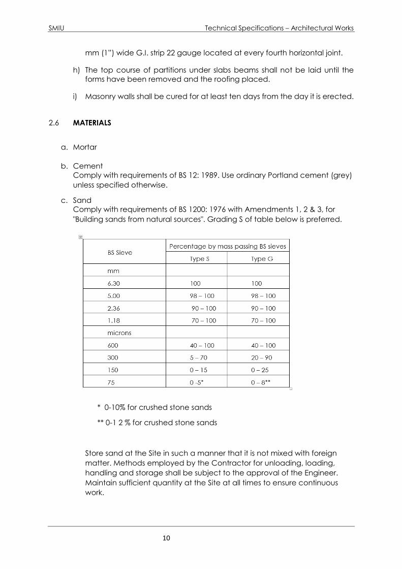
c. Sand
Comply with requirements of BS 1200: 1976 with Amendments 1, 2 & 3, for
"Building sands from natural sources". Grading S of table below is preferred.
* 0-10% for crushed stone sands
** 0-1 2 % for crushed stone sands
Store sand at the Site in such a manner that it is not mixed with foreign
matter. Methods employed by the Contractor for unloading, loading,
handling and storage shall be subject to the approval of the Engineer.
Maintain sufficient quantity at the Site at all times to ensure continuous
work.
SMIU Technical Specifications – Architectural Works
11
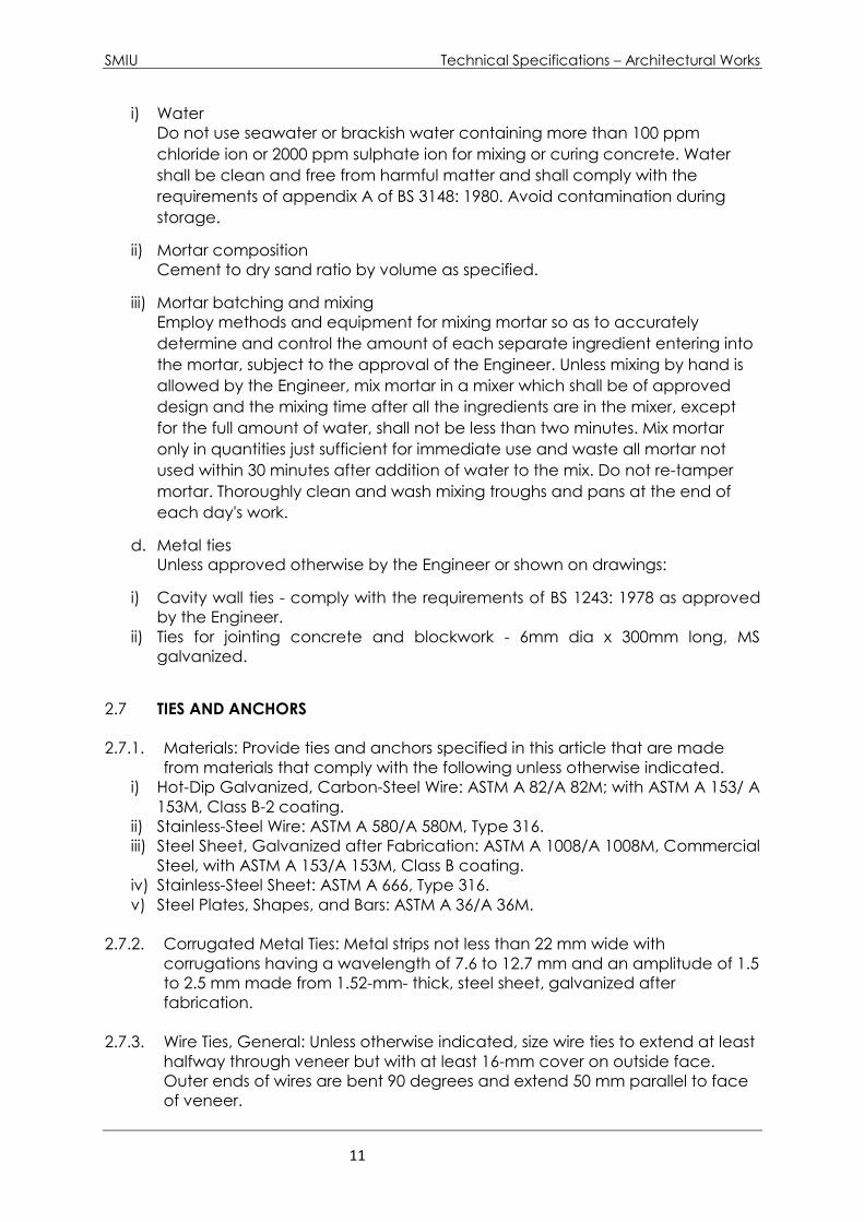
i) Water
Do not use seawater or brackish water containing more than 100 ppm
chloride ion or 2000 ppm sulphate ion for mixing or curing concrete. Water
shall be clean and free from harmful matter and shall comply with the
requirements of appendix A of BS 3148: 1980. Avoid contamination during
storage.
ii) Mortar composition
Cement to dry sand ratio by volume as specified.
iii) Mortar batching and mixing
Employ methods and equipment for mixing mortar so as to accurately
determine and control the amount of each separate ingredient entering into
the mortar, subject to the approval of the Engineer. Unless mixing by hand is
allowed by the Engineer, mix mortar in a mixer which shall be of approved
design and the mixing time after all the ingredients are in the mixer, except
for the full amount of water, shall not be less than two minutes. Mix mortar
only in quantities just sufficient for immediate use and waste all mortar not
used within 30 minutes after addition of water to the mix. Do not re-tamper
mortar. Thoroughly clean and wash mixing troughs and pans at the end of
each day's work.
d. Metal ties
Unless approved otherwise by the Engineer or shown on drawings:
i) Cavity wall ties - comply with the requirements of BS 1243: 1978 as approved
by the Engineer.
ii) Ties for jointing concrete and blockwork - 6mm dia x 300mm long, MS
galvanized.
2.7 TIES AND ANCHORS
2.7.1. Materials: Provide ties and anchors specified in this article that are made
from materials that comply with the following unless otherwise indicated.
i) Hot-Dip Galvanized, Carbon-Steel Wire: ASTM A 82/A 82M; with ASTM A 153/ A
153M, Class B-2 coating.
ii) Stainless-Steel Wire: ASTM A 580/A 580M, Type 316.
iii) Steel Sheet, Galvanized after Fabrication: ASTM A 1008/A 1008M, Commercial
Steel, with ASTM A 153/A 153M, Class B coating.
iv) Stainless-Steel Sheet: ASTM A 666, Type 316.
v) Steel Plates, Shapes, and Bars: ASTM A 36/A 36M.
2.7.2. Corrugated Metal Ties: Metal strips not less than 22 mm wide with
corrugations having a wavelength of 7.6 to 12.7 mm and an amplitude of 1.5
to 2.5 mm made from 1.52-mm- thick, steel sheet, galvanized after
fabrication.
2.7.3. Wire Ties, General: Unless otherwise indicated, size wire ties to extend at least
halfway through veneer but with at least 16-mm cover on outside face.
Outer ends of wires are bent 90 degrees and extend 50 mm parallel to face
of veneer.

SMIU Technical Specifications – Architectural Works
12
2.7.4. Individual Wire Ties: Rectangular units with closed ends and not less than 100
mm wide.
i) Z-shaped ties with ends bent 90 degrees to provide hooks not less than 50 mm
long may be used for masonry constructed from solid units.
ii) Where wythes do not align, use adjustable ties with pintle-and-eye connections
having a maximum adjustment of 32 mm.
iii) Wire: Fabricate from 6.35-mm- diameter, hot-dip galvanized steel wire.
2.7.5. Adjustable Anchors for Connecting to Structural Steel Framing: Provide
anchors that allow vertical or horizontal adjustment but resist tension and
compression forces perpendicular to plane of wall.
i) Anchor Section for Welding to Steel Frame: Crimped 6.35-mm- diameter, hot-
dip galvanized steel wire.
ii) Tie Section: Triangular-shaped wire tie, sized to extend within 25 mm of masonry
face, made from 6.35-mm- diameter, hot-dip galvanized steel wire.
2.7.6. Adjustable Anchors for Connecting to Concrete: Provide anchors that allow
vertical or horizontal adjustment but resist tension and compression forces
perpendicular to plane of wall.
i) Connector Section: Dovetail tabs for inserting into dovetail slots in concrete
and attached to tie section; formed from 2.66-mm- thick, steel sheet,
galvanized after fabrication.
ii) Tie Section: Triangular-shaped wire tie, sized to extend within 25 mm of masonry
face, made from 6.35-mm- diameter, hot-dip galvanized steel wire.
iii) Corrugated Metal Ties: Metal strips not less than 22 mm wide with corrugations
having a wavelength of 7.6 to 12.7 mm and an amplitude of 1.5 to 2.5 mm
made from 2.66-mmthick, steel sheet, galvanized after fabrication with
dovetail tabs for inserting into dovetail slots in concrete and sized to extend to
within 25 mm of masonry face.
2.7.7. Provide Adjustable Anchors for Connecting to Structural Steel Framing or
Concrete made of stain- less steel sheet or wire where required for location
and directed by Engineer.
2.7.8. Partition Top anchors: 2.66-mm- thick metal plate with 9.5-mm- diameter
metal rod 152 mm long welded to plate and with closed-end plastic tube
fitted over rod that allows rod to move in and out of tube. Fabricate from
steel, hot-dip galvanized after fabrication. I. Rigid Anchors: Fabricate from
steel bars 38 mm wide by 6.35 mm thick by 610 mm long, with ends turned
up 51 mm or with cross pins unless otherwise indicated.
i) Corrosion Protection: Hot-dip galvanized to comply with ASTM A 153/A 153M.
2.8 MISCELLANEOUS MASONRY ACCESSORIES
2.8.1. Compressible Filler: Pre-molded filler strips complying with ASTM D 1056,
Grade 2A1; compressible up to 35 percent; of width and thickness indicated;
formulated from neoprene, urethane or PVC.
SMIU Technical Specifications – Architectural Works
13
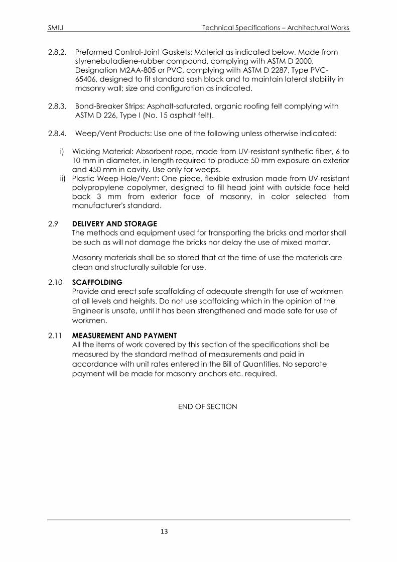
2.8.2. Preformed Control-Joint Gaskets: Material as indicated below, Made from
styrenebutadiene-rubber compound, complying with ASTM D 2000,
Designation M2AA-805 or PVC, complying with ASTM D 2287, Type PVC-
65406, designed to fit standard sash block and to maintain lateral stability in
masonry wall; size and configuration as indicated.
2.8.3. Bond-Breaker Strips: Asphalt-saturated, organic roofing felt complying with
ASTM D 226, Type I (No. 15 asphalt felt).
2.8.4. Weep/Vent Products: Use one of the following unless otherwise indicated:
i) Wicking Material: Absorbent rope, made from UV-resistant synthetic fiber, 6 to
10 mm in diameter, in length required to produce 50-mm exposure on exterior
and 450 mm in cavity. Use only for weeps.
ii) Plastic Weep Hole/Vent: One-piece, flexible extrusion made from UV-resistant
polypropylene copolymer, designed to fill head joint with outside face held
back 3 mm from exterior face of masonry, in color selected from
manufacturer's standard.
2.9 DELIVERY AND STORAGE
The methods and equipment used for transporting the bricks and mortar shall
be such as will not damage the bricks nor delay the use of mixed mortar.
Masonry materials shall be so stored that at the time of use the materials are
clean and structurally suitable for use.
2.10 SCAFFOLDING
Provide and erect safe scaffolding of adequate strength for use of workmen
at all levels and heights. Do not use scaffolding which in the opinion of the
Engineer is unsafe, until it has been strengthened and made safe for use of
workmen.
2.11 MEASUREMENT AND PAYMENT
All the items of work covered by this section of the specifications shall be
measured by the standard method of measurements and paid in
accordance with unit rates entered in the Bill of Quantities. No separate
payment will be made for masonry anchors etc. required.
END OF SECTION
SMIU Technical Specifications – Architectural Works
14
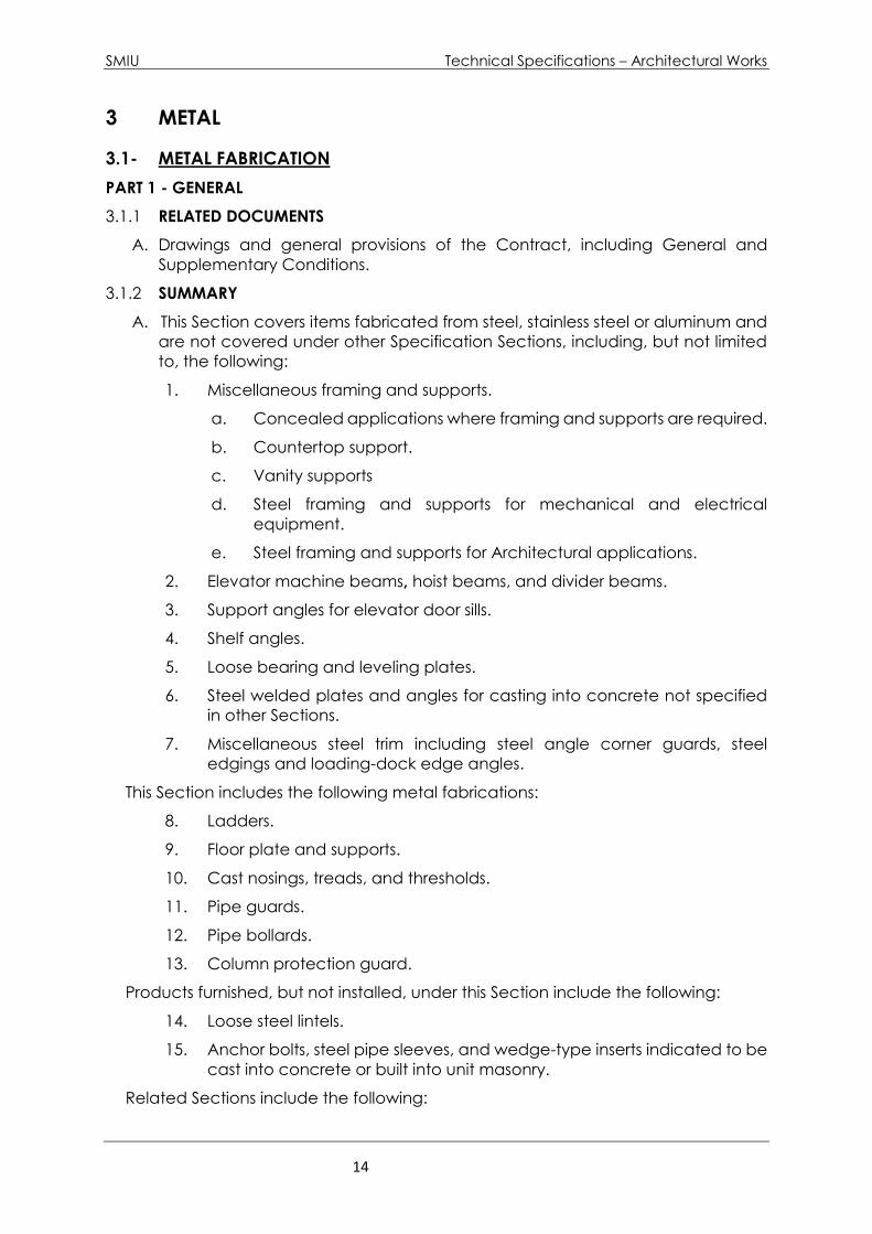
3 METAL
3.1- METAL FABRICATION
PART 1 - GENERAL
3.1.1 RELATED DOCUMENTS
A. Drawings and general provisions of the Contract, including General and
Supplementary Conditions.
3.1.2 SUMMARY
A. This Section covers items fabricated from steel, stainless steel or aluminum and
are not covered under other Specification Sections, including, but not limited
to, the following:
1. Miscellaneous framing and supports.
a. Concealed applications where framing and supports are required.
b. Countertop support.
c. Vanity supports
d. Steel framing and supports for mechanical and electrical
equipment.
e. Steel framing and supports for Architectural applications.
2. Elevator machine beams, hoist beams, and divider beams.
3. Support angles for elevator door sills.
4. Shelf angles.
5. Loose bearing and leveling plates.
6. Steel welded plates and angles for casting into concrete not specified
in other Sections.
7. Miscellaneous steel trim including steel angle corner guards, steel
edgings and loading-dock edge angles.
This Section includes the following metal fabrications:
8. Ladders.
9. Floor plate and supports.
10. Cast nosings, treads, and thresholds.
11. Pipe guards.
12. Pipe bollards.
13. Column protection guard.
Products furnished, but not installed, under this Section include the following:
14. Loose steel lintels.
15. Anchor bolts, steel pipe sleeves, and wedge-type inserts indicated to be
cast into concrete or built into unit masonry.
Related Sections include the following:
SMIU Technical Specifications – Architectural Works
15
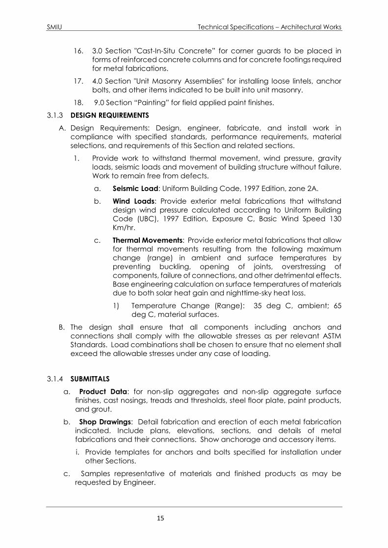
16. 3.0 Section "Cast-In-Situ Concrete” for corner guards to be placed in
forms of reinforced concrete columns and for concrete footings required
for metal fabrications.
17. 4.0 Section "Unit Masonry Assemblies" for installing loose lintels, anchor
bolts, and other items indicated to be built into unit masonry.
18. 9.0 Section “Painting” for field applied paint finishes.
3.1.3 DESIGN REQUIREMENTS
A. Design Requirements: Design, engineer, fabricate, and install work in
compliance with specified standards, performance requirements, material
selections, and requirements of this Section and related sections.
1. Provide work to withstand thermal movement, wind pressure, gravity
loads, seismic loads and movement of building structure without failure.
Work to remain free from defects.
a. Seismic Load: Uniform Building Code, 1997 Edition, zone 2A.
b. Wind Loads: Provide exterior metal fabrications that withstand
design wind pressure calculated according to Uniform Building
Code (UBC), 1997 Edition, Exposure C, Basic Wind Speed 130
Km/hr.
c. Thermal Movements: Provide exterior metal fabrications that allow
for thermal movements resulting from the following maximum
change (range) in ambient and surface temperatures by
preventing buckling, opening of joints, overstressing of
components, failure of connections, and other detrimental effects.
Base engineering calculation on surface temperatures of materials
due to both solar heat gain and nighttime-sky heat loss.
1) Temperature Change (Range): 35 deg C, ambient; 65
deg C, material surfaces.
B. The design shall ensure that all components including anchors and
connections shall comply with the allowable stresses as per relevant ASTM
Standards. Load combinations shall be chosen to ensure that no element shall
exceed the allowable stresses under any case of loading.
3.1.4 SUBMITTALS
a. Product Data: for non-slip aggregates and non-slip aggregate surface
finishes, cast nosings, treads and thresholds, steel floor plate, paint products,
and grout.
b. Shop Drawings: Detail fabrication and erection of each metal fabrication
indicated. Include plans, elevations, sections, and details of metal
fabrications and their connections. Show anchorage and accessory items.
i. Provide templates for anchors and bolts specified for installation under
other Sections.
c. Samples representative of materials and finished products as may be
requested by Engineer.

SMIU Technical Specifications – Architectural Works
16
d. Mill Certificates: Signed by manufacturers of stainless-steel sheet certifying
that products furnished comply with requirements.
e. Welding Certificates signed by Contractor certifying that welders comply
with requirements specified under the "Quality Assurance" Article.
f. Qualification Data: For firms and persons specified in the "Quality Assurance"
Article to demonstrate their capabilities and experience. Include lists of
completed projects with project names and addresses, names and addresses
of architects/engineers and owners, and other information specified.
3.1.5 QUALITY ASSURANCE
a. Quality System: Comply with ISO 9001/9002 Quality System as a minimum.
Incorporate all the standard procedures supplied by the Engineer and the
Employer.
b. Fabricator Qualifications: A firm experienced in producing metal fabrications
similar to those indicated for this Project and with a record of successful in-
service performance, as well as sufficient production capacity to produce
required units, without delaying the work.
c. Engineering Responsibility: Engage a fabricator who utilizes a qualified and
experienced structural engineer to prepare design calculations, shop
drawings, and other structural data.
d. Welding: Qualify procedures and personnel according to the following:
i. AWS D1.1, "Structural Welding Code--Steel."
ii. AWS D1.2, "Structural Welding Code--Aluminum."
iii. AWS D1.3, "Structural Welding Code--Sheet Steel."
iv. AWS D1.6, "Structural Welding Code--Stainless Steel."
v. Certify that each welder has satisfactorily passed AWS qualification tests
for welding processes involved and, if pertinent, has undergone
recertification.
vi. Qualification tests according to the Structural Steel Code of Practice
Prevailing in the country or other international Code or standard may
also be accepted by the Engineer.
3.1.6 PROJECT CONDITIONS
a. Field Measurements: Where metal fabrications are indicated to fit walls and
other construction, verify dimensions by field measurements before fabrication
and indicate measurements on Shop Drawings. Coordinate fabrication
schedule with construction progress to avoid delaying the Work.
i. Where field measurements cannot be made without delaying the Work,
guarantee dimensions and proceed with fabricating products without
field measurements. Coordinate construction to ensure that actual
dimensions correspond to guaranteed dimensions. Allow for trimming
and fitting.
3.1.7 COORDINATION
a. Coordinate installation of anchorages for metal fabrications. Furnish setting
drawings, templates, and directions for installing anchorages, including

SMIU Technical Specifications – Architectural Works
17
sleeves, concrete inserts, anchor bolts, and items with integral anchors, that are
to be embedded in concrete or masonry. Deliver such items to Project site in
time for installation.
PART2 - PRODUCTS
3.1.8 METALS, GENERAL
A. Metal Surfaces, General: For metal fabrications exposed to view in the
completed Work, provide materials with smooth, flat surfaces without
blemishes. Do not use materials with exposed pitting, seam marks, roller marks,
rolled trade names, or roughness.
3.1.9 FERROUS METALS
A. Steel Plates, Shapes, and Bars: ASTM A 36M, Tensile strength 400 Pa and
minimum yield point 250 MPa.
B. Stainless-Steel Sheet, Strip, Plate, and Flat Bars: ASTM A 666, Type 304.
C. Stainless Steel:
1. Grade and type designated below for each form required:
a) Tubing: ASTM A 554, Grade MT 316
b) Pipe: ASTM A 312M, Grade TP 316.
c) Castings: ASTM A 743M, Grade CF 8M.
d) Plate: ASTM A 167, Type 316.
e) Bar Stock: ASTM A 276.
2. Finish: Bright, directional polish; match AISI No. 4 finish.
D. Rolled-Steel Floor Plate: ASTM A 786M, rolled from plate complying with
ASTM A 36/A 36M or ASTM A 283/A 283M, Grade C or D.
E. Rolled-Stainless-Steel Floor Plate: ASTM A 793.
F. Steel Tubing: Product type (manufacturing method) and as follows:
1. Cold-Formed Steel Tubing: ASTM A 500.
a) Provide tubing with hot-dip galvanized coating per ASTM A 53.
G. Steel Pipe: ASTM A 53, standard weight (Schedule 40), unless another weight is
indicated or required by structural loads.
1. Provide galvanized finish for all steel pipes.
H. Malleable-Iron Castings: ASTM A 47M, Grade 22010.
I. Gray-Iron Castings: ASTM A 48M, Class 200, unless another class is indicated or
required by structural loads.
J. Cast-in-Place Anchors in Concrete: Anchors of type indicated below,
fabricated from corrosion-resistant materials capable of sustaining, without
failure, the load imposed within a safety factor of 4, as determined by testing
per ASTM E 488, conducted by a qualified independent testing agency.

SMIU Technical Specifications – Architectural Works
18
1. Threaded or wedge type; galvanized ferrous castings, either ASTM A 47M
malleable iron or ASTM A 27/A 27M cast steel. Provide bolts, washers, and shims
as needed, hot-dip galvanized per ASTM A 153/A 153M.
K. Welding Rods and Bare Electrodes: Select according to AWS specifications for
metal alloy welded.
3.1.10 ALUMINUM
a. Aluminum Extrusions: ASTM B 221M, alloy 6063-T6.
b. Aluminum-Alloy Rolled Tread Plate: ASTM B 632M, alloy 6061-T6.
3.1.11 PAINT
a. Shop Primers: Provide primers that comply with 9.00 Section "Painting."
b. Shop Primer for Ferrous Metal: Fast-curing, lead- and chromate-free, universal
modified-alkyd primer complying with performance requirements in FS TT-P-664;
selected for good resistance to normal atmospheric corrosion, compatibility
with finish paint systems indicated, and capability to provide a sound
foundation for field-applied topcoats despite prolonged exposure.
c. Shop Primer for Ferrous Metal: Organic zinc-rich primer, complying with SSPC-
Paint 20 and compatible with topcoat.
d. Galvanizing Repair Paint: High-zinc-dust-content paint for re-galvanizing welds
in galvanized steel, with dry film containing not less than 94 percent zinc dust
by weight, and complying with DOD-P-21035 or SSPC-Paint 20.
e. Bituminous Paint: Cold-applied asphalt mastic complying with SSPC-Paint 12,
except containing no asbestos fibers, or cold-applied asphalt emulsion
complying with ASTM D 1187.
3.1.12 FASTNERS
a. General: Provide Type 304 or 316 stainless-steel fasteners for exterior use and
zinc-plated fasteners with coating complying with ASTM B 633, Class Fe/Zn ,
where built into exterior walls. Select fasteners for type, grade, and class
required.
b. Bolts and Nuts: Regular hexagon-head bolts, ASTM F 568M, Property
Class 4.6; with hex nuts, ASTM A 563M; and, where indicated, flat washers.
c. Anchor Bolts: ASTM F 1554, Grade 36.
d. Machine Screws: ASME B18.6.7M.
e. Lag Bolts: ASME B18.2.3.8M.
f. Wood Screws: Flat head, carbon steel, ASME B18.6.1.
g. Plain Washers: Round, carbon steel, ASME B18.22M.
h. Lock Washers: Helical, spring type, carbon steel, ASME B18.21.2M.
i. Expansion Anchors: Anchor bolt and sleeve assembly of material indicated
below with capability to sustain, without failure, a load equal to six times the
load imposed when installed in unit masonry and equal to four times the load
imposed when installed in concrete, as determined by testing per
ASTM E 488, conducted by a qualified independent testing agency.
SMIU Technical Specifications – Architectural Works
19
i) Material: Carbon-steel components zinc-plated to comply with
ASTM B 633, Class Fe/Zn 5.
ii) Material: Alloy Group 1 or 2 stainless-steel bolts complying with
ASTM F 738M and nuts complying with ASTM F 836M.
j. Toggle Bolts: FS FF-B-588, tumble-wing type, class and style as needed.
3.1.13 GROUT
a. General: Grout shall meet the requirements of 3.0 section, “Cast-in-Place
Concrete”.
b. Non-shrink, Metallic Grout: Factory-packaged, ferrous-aggregate grout
complying with ASTM C 1107, specifically recommended by manufacturer
for heavy-duty loading applications.
c. Non-shrink, Nonmetallic Grout: Factory-packaged, non-staining, non-
corrosive, nongaseous grout complying with ASTM C 1107. Provide grout
specifically recommended by manufacturer for interior and exterior
applications.
3.1.14 CONCRETE FILL
Concrete Materials and Properties: Comply with requirements in 3.0 Section
"Cast-in-Place Concrete" for normal-weight, air-entrained, ready-mix
concrete with a minimum 28-day compressive strength of 20 MPa, unless
otherwise indicated.
3.1.15 FABRICATION, GENERAL
a. Shop Assembly: Preassemble items in shop to greatest extent possible to
minimize field splicing and assembly. Disassemble units only as necessary for
shipping and handling limitations. Use connections that maintain structural
value of joined pieces. Clearly mark units for reassembly and coordinated
installation.
b. Shear and punch metals cleanly and accurately. Remove burrs.
c. Ease exposed edges to a radius of approximately 1 mm, unless otherwise
indicated. Form bent-metal corners to smallest radius possible without
causing grain separation or otherwise impairing work.
d. Weld corners and seams continuously to comply with the following:
i) Use materials and methods that minimize distortion and develop
strength and corrosion resistance of base metals.
ii) Obtain fusion without undercut or overlap.
iii) Remove welding flux immediately.
iv) At exposed connections, finish exposed welds and surfaces smooth
and blended so no roughness shows after finishing and contour of
welded surface matches that of adjacent surface.
e. Provide for anchorage of type indicated; coordinate with supporting
structure. Fabricate and space anchoring devices to secure metal
fabrications rigidly in place and to support indicated loads.
SMIU Technical Specifications – Architectural Works
20
f. Cut, reinforce, drill, and tap metal fabrications as indicated to receive finish
hardware, screws, and similar items.
g. Fabricate joints that will be exposed to weather in a manner to exclude
water, or provide weep holes where water may accumulate.
h. Form exposed work true to line and level with accurate angles and surfaces
and straight sharp edges.
i. Remove sharp or rough areas on exposed traffic surfaces.
j. Form exposed connections with hairline joints, flush and smooth, using
concealed fasteners where possible. Use exposed fasteners of type
indicated or, if not indicated, Phillips flat-head (countersunk) screws or bolts.
Locate joints where least conspicuous.
k. Form metal fabrications from materials of size, thickness, and shapes
indicated but not less than that needed to comply with performance
requirements indicated. Work to dimensions indicated or accepted on shop
drawings, using proven details of fabrication and support. Use type of
materials indicated or specified for various components of each metal
fabrication.
3.1.16 MISCELLANEOUS FRAMING AND SUPPORTS
a. General: Provide steel framing and supports indicated or not indicated that
are not a part of structural-steel framework as necessary to complete the
Work.
b. Fabricate units from structural-steel shapes, plates, and bars of welded
construction, unless otherwise indicated. Fabricate to sizes, shapes, and
profiles indicated and as necessary to receive adjacent construction
retained by framing and supports. Cut, drill, and tap units to receive
hardware, hangers, and similar items.
i) Fabricate units from slotted channel framing where indicated.
ii) Where units are indicated to be cast into concrete or built into masonry,
equip with integrally welded steel strap anchors 32 mm (1.25”) wide by
6 mm (1/4”) thick by 200 mm (8”) long at 600 mm (24”) o.c., unless
otherwise indicated.
iii) Furnish inserts if units must be installed after concrete is placed.
c. FINISH:
i) Interior: Prime painted, unless indicated as galvanized.
d. Prime miscellaneous framing and supports with zinc-rich primer.
3.1.17 RECEIVING STEEL CAGES
Receiving steel cages are to be included in the steelwork package. Cages
are to be designed to incorporate the following:
a. Total 7 cages size shown on drawings and 10’-0” high.
b. Cage are to be constructed from steel frames with wire mesh wall and roof
cladding. Wire mesh is to be ¼” bars @ maximum 2” centres both ways

SMIU Technical Specifications – Architectural Works
21
c. All cages to have 2 roller shutter doors as indicated on the architectural plans.
Doors to type 1 cage to have aluminum doors in accordance with the
architectural specifications. Roller shutter door controls to incorporate facility
that only one door per cage may be open or partly open at any one time.
d. Design, supply, and insulation to including all fixings, claddings, and flashings
required to construct the cages.
e. All materials to be painted in accordance with specifications.
3.1.18 SHELF ANGLES
a. Fabricate shelf angles from steel angles of sizes indicated and for
attachment to concrete framing. Provide horizontally slotted holes to
receive 19-mm 3/4” bolts, spaced not more than 150 mm 6” from ends and
600 mm 24” o.c., unless otherwise indicated.
i) Provide mitered and welded units at corners.
ii) Provide open joints in shelf angles at expansion and control joints.
Make open joint approximately 50 mm 2” larger than expansion or
control joint.
b. Galvanize shelf angles located in exterior walls.
c. Furnish wedge-type concrete inserts, complete with fasteners, to attach
shelf angles to cast-in-place concrete.
3.1.19 LOOSE BEARING AND LEVELING PLATES
a. Column base plates are not included in this category.
b. Provide loose bearing and leveling plates for steel items bearing on masonry
or concrete construction, made flat, free from warps or twists, and of the
required thickness and bearing area. Drill plates to receive anchor bolts and
for grouting as required. Galvanize after fabrication.
3.1.20 STEEL WELD PLATES AND ANGLES
Provide steel weld plates and angles not specified in other Sections, for items
supported from concrete construction as needed to complete the Work.
Provide each unit with not less than two integrally welded steel strap anchors
for embedding in concrete.
3.1.21 MISCELLANEOUS STEEL TRIM
a. Unless otherwise indicated, fabricate units from structural-steel shapes,
plates, and bars of profiles shown with continuously welded joints, and
smooth exposed edges. Miter corners and use concealed field splices
where possible.
SMIU Technical Specifications – Architectural Works
22
b. Provide cutouts, fittings, and anchorages as needed to coordinate assembly
and installation with other work. Provide anchors, welded to trim, for
embedding in concrete or masonry construction, spaced not more than 150
mm 6” from each end, 150 mm 6” from corners, and 600 mm 24” o.c., unless
otherwise indicated.
c. Galvanize miscellaneous steel trim in the following locations:
i) Exterior.
ii) Interior, where indicated.
3.1.22 LOOSE STEEL LINTELS
a. Unless otherwise indicated on Drawings, provide steel lintels as follows.
b. Fabricate loose structural-steel lintels from steel angles and shapes of size
indicated for openings and recesses in masonry walls and partitions at
locations indicated.
c. Weld adjoining members together to form a single unit where indicated.
d. Size loose lintels to provide bearing length at each side of openings equal to
one-twelfth of clear span, but not less than 200 mm 8”, unless otherwise
indicated.
e. Galvanize loose steel lintels located in exterior walls.
3.1.23 STEEL LADDERS
a. General: Fabricate ladders for locations shown, with dimensions, spacings,
details, and anchorages as indicated.
i) Comply with ANSI A14.3, unless otherwise indicated on Drawings.
b. Side rails: Continuous, 500 x 10 mm (20” x ½”) steel flat bars, with eased edges,
spaced 460 mm (19”) apart.
c. Bar Rungs: 20-mm (3/4”) - diameter steel bars, spaced 300 mm (12”) o.c
maximum.
d. Fit rungs in centerline of side rails; plug-weld and grind smooth on outer rail
faces.
e. Support each ladder at top and bottom and not more than 1500 mm (5’-0”)
o.c. with welded or bolted steel brackets.
i) Size brackets to support design dead and live loads indicated and to hold
centerline of ladder rungs clear of the wall surface by not less than 150 mm
(6”).
ii) Extend side rails using 30-mm (1.25) diameter galvanized steel pipes to a height
of 0.90 m above top rung, and return rails to wall or structure unless other secure
handholds are provided. If the adjacent structure does not extend above the
top rung, goose-neck the extended rails back to the structure to provide
secure ladder access
SMIU Technical Specifications – Architectural Works
23
f. Provide non-slip surfaces on top of each rung, either by coating rung with
aluminum-oxide granules set in epoxy-resin adhesive or by using a type of
manufactured rung filled with aluminum-oxide grout.
g. Galvanize ladders, including brackets and fasteners.
h. Finish is to be field-applied alkyd paint system of color and gloss as selected by
the Engineer.
3.1.24 METAL FLOOR PLATE
a. Fabricate raised-pattern floor plates from rolled-steel floor plate of thickness
indicated below:
i) Thickness: As indicated.
ii) Pattern: As selected from manufacturer's standard patterns.
b. Fabricate raised-pattern floor plates from rolled-aluminum-alloy tread plate
of thickness indicated below:
i) Thickness: 6.00 mm (1/8”), unless otherwise higher thickness is indicated.
c. Include steel angle stiffeners, and fixed and removable sections as
indicated.
i) Provide flush steel bar drop handles for lifting removable sections, one
at each end of each section.
3.1.25 CAST NOSINGS, TREADS AND THRESHOLDS
a. Fabricate units of material, sizes, and configurations indicated. If not
indicated, provide cast-iron units with an integral abrasive finish. Furnish in
lengths as required to accurately fit each opening or conditions.
i) Cast units with an integral abrasive grit consisting of aluminum oxide,
silicon carbide, or a combination of both.
b. Drill for mechanical anchors with countersunk holes located not more than
100 mm from ends and not more than 300 mm (12”) o.c., evenly spaced
between ends, unless otherwise indicated. Provide closer spacing if
recommended by the manufacturer.
i) Provide 2 rows of holes for units over 125 mm (5”) wide, with 2 holes
aligned at ends and intermediate holes staggered.
c. Apply black asphaltic coating to concealed bottoms, sides, and edges of
cast-iron units set into concrete.
d. Provide a plain surface texture, except where fluted or cross-hatched
surfaces are indicated.
3.1.26 PIPE BOLLARDS
a. Fabricate pipe bollards from Schedule 40 steel pipe.
i) Cap bollards with 6-mm (1/8”) - minimum steel plate.
b. Fabricate bollards with 10-mm (1/2”) - thick steel base plates for bolting to
concrete slab. Drill base plates at all four corners for 19-mm (3/4”) anchor
bolts.

SMIU Technical Specifications – Architectural Works
24
i) Where bollards are to be anchored to sloping concrete slabs, angle
base plates for plumb alignment of bollards.
c. Finish is to be factory-applied manufacturer’s standard thermo setting
coating including rust inhibition coat and of minimum dry film thickness of 60
microns.
3.1.27 COLUMN PROTECTION GUARDS
a. Metal Protection: Formed steel plates with welded lugs for building into
concrete filling. Galvanize protection after fabrication to be not less than
300 gm/m2 (28 gm/sft zinc coating intensity.
b. Pads: Prefabricated from ASTM D2000, extruded synthetic rubber with type
A shore durometer Hardness of 75, plus or minus 5 when tested according to
ASTM D2240. Furnish in thickness as recommended by manufacturer for
traffic type, but not less than thickness indicated on Drawings.
c. Filling Concrete: As specified in this Section.
d. Finish: Is to be field-applied epoxy paint system to exposed surfaces of steel
and concrete as specified in 9.0 Section “Painting”.
3.1.28 FINISHES, GENERAL
a. Comply with NAAMM's "Metal Finishes Manual for Architectural and Metal
Products" for recommendations for applying and designating finishes.
b. Finish metal fabrications after assembly.
3.1.29 STEEL AND IRON FINISHES
a. Galvanizing: For those items indicated for galvanizing, apply zinc coating by
the hot-dip process complying with the following requirements:
i) ASTM A 153 for galvanizing iron and steel hardware.
ii) ASTM A 123 for galvanizing both fabricated and un-fabricated iron and
steel products made of uncoated rolled, pressed, and forged shapes,
plates, bars, and strip 0.76 mm thick or thicker.
b. Preparation for Shop Priming: Prepare uncoated ferrous-metal surfaces to
comply with minimum requirements indicated below for SSPC surface-
preparation specifications and environmental exposure conditions of
installed metal fabrications:
i) Exteriors (SSPC Zone 1B): SSPC-SP 6/NACE No. 3, "Commercial Blast
Cleaning."
ii) Interiors (SSPC Zone 1A): SSPC-SP 3, "Power Tool Cleaning."
c. Apply shop primer to uncoated surfaces of metal fabrications, except those
with galvanized finishes and those to be embedded in concrete, sprayed-
on fireproofing, or masonry, unless otherwise indicated. Comply with SSPC-
PA 1, "Paint Application Specification No. 1," for shop painting.
i) Stripe paint corners, crevices, bolts, welds, and sharp edges.
SMIU Technical Specifications – Architectural Works
25
3.1.30 STAINLESS-STEEL FINISHES
a. Remove tool and die marks and stretch lines or blend into finish.
b. Grind and polish surfaces to produce uniform, directionally textured,
polished finish indicated, free of cross scratches. Run grain with long
dimension of each piece.
c. Bright, Directional Polish: No. 4 finish.
d. When polishing is completed, passivate and rinse surfaces. Remove
embedded foreign matter and leave surfaces chemically clean.
3.1.31 ALUMINUM FINISHES
a. Finish designations prefixed by AA comply with the system established by
the Aluminum Association for designating aluminum finishes.
b. As-Fabricated Finish: AA-M10 (Mechanical Finish: as fabricated,
unspecified).
c. Class I, Clear Anodic Finish: AA-M12C22A41 (Mechanical Finish: no specular
as fabricated; Chemical Finish: etched, medium matte; Anodic Coating:
Architectural Class I, clear coating but with no less 0.025 mm or thicker)
complying with AAMA 611.
d. For powder coat finishes, AAMA 2605 is the high-performance exterior
specification. Depending on the manufacturer, a 2605 powder coat may
or may not utilize a fluoropolymer resin (PVDF). These finishes are resistant to
moisture, weathering, ozone and UV radiation. An application for this finish
would include architectural projects that require long term cosmetic and
functional protection.
PART3 - EXECUTION
3.1.32 PREPERATION
A. Coordinate and furnish anchorages, setting drawings, diagrams, templates,
instructions, and directions for installing anchorages, including concrete inserts,
sleeves, anchor bolts, and miscellaneous items having integral anchors that are
to be embedded in concrete or masonry construction. Coordinate delivery of
such items to Project site.
B. Center nosings on tread widths with noses flush with riser faces and tread
surfaces.
C. Set sleeves in concrete with tops flush with finish surface elevations. Protect
sleeves from water and concrete entry.
3.1.33 INSTALLATION, GENERAL
A. Fastening to In-Place Construction: Provide anchorage devices and fasteners
where necessary for securing metal fabrications to in-place construction.
Include threaded fasteners for concrete and masonry inserts, toggle bolts,
through-bolts, lag bolts, wood screws, and other connectors.
B. Cutting, Fitting, and Placement: Perform cutting, drilling, and fitting required for
installing metal fabrications. Set metal fabrications accurately in location,
alignment, and elevation; with edges and surfaces level, plumb, true, and free
of rack; and measured from established lines and levels.
SMIU Technical Specifications – Architectural Works
26
C. Provide temporary bracing or anchors in formwork for items that are to be built
into concrete, masonry, or similar construction.
D. Fit exposed connections accurately together to form hairline joints. Weld
connections that are not to be left as exposed joints but cannot be shop
welded because of shipping size limitations. Do not weld, cut, or abrade
surfaces of exterior units that have been hot-dip galvanized after fabrication
and are for bolted or screwed field connections.
E. Field Welding: Comply with the following requirements:
1. Use materials and methods that minimize distortion and develop
strength and corrosion resistance of base metals.
2. Obtain fusion without undercut or overlap.
3. Remove welding flux immediately.
4. At exposed connections, finish exposed welds and surfaces smooth and
blended so no roughness shows after finishing and contour of welded
surface matches that of adjacent surface.
F. Corrosion Protection: Coat concealed surfaces of aluminum that will come
into contact with grout, concrete, masonry, wood, or dissimilar metals with a
heavy coat of bituminous paint.
3.1.34 SETTING, BEARING AND LEVELING PLATES
A. Clean concrete and masonry bearing surfaces of bond-reducing materials,
and roughen to improve bond to surfaces. Clean bottom surface of plates.
B. Set bearing and leveling plates on wedges, shims, or leveling nuts. After
bearing members have been positioned and plumbed, tighten anchor
bolts. Do not remove wedges or shims but, if protruding, cut off flush with
edge of bearing plate before packing with grout.
1. Use non-shrink grout, either metallic or nonmetallic, in concealed
locations where not exposed to moisture; use non-shrink, nonmetallic
grout in exposed locations, unless otherwise indicated.
2. Pack grout solidly between bearing surfaces and plates to ensure that
no voids remain.
3.1.35 INSTALLING NOSING, TREADS AND THRESHOLDS
A. Install with anchorage system indicated to comply with manufacturer's
written instructions.
B. Center nosings on tread widths.
C. For nosings embedded in concrete steps or curbs, align nosings flush with
riser faces and level with tread surfaces.
D. Seal thresholds exposed to exterior with elastomeric sealant complying with
7.0 Section "Joint Sealants" to provide a watertight installation.
3.1.36 INSTALLING PIPE BOLLARDS
A. Anchor bollards in place with concrete footings. Support and brace bollards
in position in footing excavations until concrete has been placed and cured.
B. Fill bollards solidly with concrete, mounding top surface.

SMIU Technical Specifications – Architectural Works
27
3.1.37 ADJUSTING AND CLEANING
A. Touchup Painting: Immediately after erection, clean field welds, bolted
connections, and abraded areas of shop paint, and paint exposed areas
with the same material as used for shop painting to comply with SSPC-PA 1
for touching up shop-painted surfaces.
1. Apply by brush or spray to provide a minimum 0.05-mm (1/32”) dry film
thickness.
B. Touchup Painting: Cleaning and touchup painting of field welds, bolted
connections, and abraded areas of shop paint are specified in 9.0 Section
"Painting."
C. Galvanized Surfaces: Clean field welds, bolted connections, and abraded
areas and repair galvanizing to comply with ASTM A 780.
3.2- ORNAMENTAL HANDRAILS AND RAILINGS
3.2.1 GENERAL
3.2.2 RELATED DOCUMENTS
A. Drawings and general provisions of the Contract, including General and
Supplementary Conditions.
3.2.3 SUMMARY
A. This Section includes the following:
i) Stainless steel ornamental handrails and railings.
B. Related Sections include the following:
i) 5.0 Section "Pipe and Tube Railings" for handrails and railings fabricated
from pipe and tube components.
ii) 5.0 Section “Custom Steel Door".
3.2.4 PERFORMANCE REQUIREMENTS
A. General: In engineering handrails and railings to withstand structural loads
indicated, determine allowable design working stresses of materials based
on the following:
i) Stainless Steel: ASCE 8, "Specification for the Design of Cold-Formed
Stainless Steel Structural Members."
B. Structural Performance of Handrails and Railings: Provide handrails and
railings capable of withstanding structural loads required by ASCE 7 without
exceeding allowable design working stress of materials for handrails, railings,
anchors, and connections.
C. Structural Performance of Handrails and Railings: Provide handrails and
railings capable of withstanding the following structural loads without
exceeding allowable design working stress of materials for handrails, railings,
anchors, and connections:

SMIU Technical Specifications – Architectural Works
28
1. Handrails Not Serving As Top Rails: Capable of withstanding the
following loads applied as indicated:
a. Concentrated load of 890 N applied at any point and in any
direction.
b. Uniform load of 730 N/m applied in any direction.
c. Concentrated and uniform loads above need not be assumed
to act concurrently.
2. Infill Area of Guards: Capable of withstanding a horizontal
concentrated load of 82.71 N applied to 0.96 Sft. m at any point in
system, including panels, intermediate rails, balusters, or other elements
composing infill area.
a. Load above need not be assumed to act concurrently with loads
on top rails in determining stress on guard.
3. Demonstrate capability of proposed handrail systems by:
a. Submission of structural calculations.
b. Submission of laboratory test report conducted on the proposed
product during the last three years.
D. Thermal Movements: Provide handrails and railings that allow for thermal
movements resulting from the following maximum change (range) in
ambient and surface temperatures by preventing buckling, opening of
joints, overstressing of components, failure of connections, and other
detrimental effects. Base engineering calculation on surface temperatures
of materials due to both solar heat gain and nighttime-sky heat loss.
1. Temperature Change (Range): 35 deg. C, ambient; 65 deg. C, material
surfaces.
E. Control of Corrosion: Prevent galvanic action and other forms of corrosion by
insulating metals and other materials from direct contact with incompatible
materials.
3.2.5 SUBMITTALS
A. Product Data: For manufacturer's product lines of handrails and railings
assembled from standard components.
1. Include Product Data for grout, anchoring cement, and paint products.
B. Shop Drawings: Show fabrication and installation of handrails and railings.
Include plans, elevations, sections, details, and attachments to other Work.
1. For installed handrails and railings indicated to comply with design
loads, include structural analysis data signed and sealed by the
qualified professional engineer responsible for their preparation.
C. Samples for Initial Selection: Short sections of railing or flat sheet metal
Samples showing available mechanical finishes.
D. Samples for Verification: For each type of exposed finish required, prepared
on components indicated below and of same thickness and metal
indicated for the Work. If finishes involve normal color and texture variations,
include sample sets showing the full range of variations expected.

SMIU Technical Specifications – Architectural Works
29
1. 150 mm (6”) long sections of each different linear railing member,
including handrails, top rails, posts, and balusters.
2. Fittings and brackets.
3. Welded connections.
4. Assembled Samples of railings, made from full-size components,
including top rail, post, handrail, and infill. Show method of finishing
members at intersections. Samples need not be full height.
E. Samples of exposed fasteners, where exposed fasteners are indicated.
F. Qualification Data: For firms and persons specified in "Quality Assurance"
Article to demonstrate their capabilities and experience. Include lists of
completed projects with project names and addresses, names and
addresses of architects/engineers and owners, and other information
specified.
G. Product Test Reports: Indicating products comply with requirements, based
on comprehensive testing of current products.
3.2.6 QUALITY ASSURANCE
A. Quality System: Comply with ISO 9001/9002 Quality System as a minimum.
Incorporate all the standard procedures supplied by the Engineer and the
Employer.
B. Structural/Consulting Engineer Qualifications: A structural consulting
engineer who is legally qualified to practice, and who is experienced in
providing engineering services of the kind indicated. Engineering services
are defined as those performed for installations of handrails and railings that
are similar to those indicated for this Project in material, design, and extent.
C. Testing Agency Qualifications: To qualify for acceptance, an independent
testing agency shall demonstrate to the Engineer's satisfaction, based on
evaluation of agency-submitted criteria conforming to ASTM E 699, that it
has the experience and capability to satisfactorily conduct the testing
indicated.
D. Source Limitations: Obtain each type of railing through one source from a
single manufacturer.
E. Mockups: Before installing handrails and railings, build mockups to verify
selections made under sample Submittals and to demonstrate aesthetic
effects and qualities of materials and execution. Build mockups to comply
with the following requirements, using materials indicated for the completed
Work:
1. Build mockups in the location as directed by the Engineer.
2. Build mockups for each form and finish of railing consisting of three
posts, top rail, infill area, and anchorage system components that are
full height and are not less than 600 mm (24”) in length.
3. Demonstrate the proposed range of aesthetic effects and
workmanship.
4. Notify the Engineer seven days in advance of dates and times when
mockups will be constructed.
SMIU Technical Specifications – Architectural Works
30
5. Obtain the Engineer's approval of mockups before fabricating
ornamental handrails and railings.
6. Maintain mockups during construction in an undisturbed condition as
a standard for judging the completed Work.
7. Demolish and remove mockups when directed.
8. Approved mockups may become part of the completed Work if
undisturbed at time of Substantial Completion.
3.2.7 STORAGE
A. Store handrails and railings in a dry, well-ventilated, weathertight
place.
3.2.8 PROJECT CONDITIONS
A. Field Measurements: Verify handrail and railing dimensions by field
measurements before fabrication and indicate measurements on
Shop Drawings. Coordinate fabrication schedule with construction
progress to avoid delaying the Work.
3.2.9 COORDINATION
A. Coordinate installation of anchorages for handrails and railings. Furnish
Setting Drawings, templates, and directions for installing anchorages,
including sleeves, concrete inserts, anchor bolts, and items with
integral anchors, that are to be embedded in concrete or masonry.
Deliver such items to Project site in time for installation.
3.2.10 SCHEDULING
A. Schedule installation so that handrails and railings are mounted only
on completed walls. Do not support temporarily by any means that
do not satisfy structural performance requirements.
PRODUCTS
3.2.11 METALS
A. General: Provide metal free from pitting, seam marks, roller marks,
stains, discolorations, and other imperfections where exposed to view
on finished units.
B. Stainless Steel: Grade or type designated below for each form
required.
1. Tubing: ASTM A 554, Grade MT 304.
2. Pipe: ASTM A 312/A 312M, Grade TP 304.
3. Castings: ASTM A 743/A 743M, Grade CF 8 or CF 20.
4. Plate: ASTM A 666, Type 304.
C. Brackets, Flanges, and Anchors: Cast or formed metal of same type
of material and finish as supported rails, unless otherwise indicated.
1. Provide formed steel brackets with predrilled hole for bolted
anchorage and with Snap-on cover that matches rail finish and
conceals bracket base and bolt head.
SMIU Technical Specifications – Architectural Works
31
3.2.12 MISCELLANEOUS MATERIALS
A. Filler Metal and Electrodes: Provide type and alloy of filler metal and
electrodes as recommended by producer of metal to be welded or
brazed and as required for color match, strength, corrosion resistance,
and compatibility in fabricated items.
3.2.13 FASTNERS
A. Fasteners for Anchoring Handrails and Railings to Other Construction:
Select fasteners of type, grade, and class required to produce
connections suitable for anchoring handrails and railings to other types
of construction indicated and capable of withstanding design loads.
1. For stainless-steel handrails and railings, use fasteners fabricated
from Type 304 stainless steel.
B. Fasteners for Interconnecting Handrail and Railing Components: Use
fasteners fabricated from same basic metal as fastened metal, unless
otherwise indicated. Do not use metals that are corrosive or
incompatible with materials joined.
1. Provide concealed fasteners for interconnecting railing
components and for attaching them to other Work, unless
exposed fasteners are unavoidable or are standard fastening
method for handrail and railing indicated.
C. Cast-in-Place and Post installed Anchors: Anchors of type indicated
below, fabricated from corrosion-resistant materials with capability to
sustain, without failure, a load equal to six times the load imposed
when installed in unit masonry and equal to four times the load
imposed when installed in concrete, as determined by testing per
ASTM E 488 conducted by a qualified independent testing agency.
1. Chemical anchors.
2. Expansion anchors.
3.2.14 PAINT
A. Bituminous Paint: Cold-applied asphalt mastic complying with SSPC-
Paint 12 but containing no asbestos fibers, or cold-applied asphalt
emulsion complying with ASTM D 1187.
3.2.15 GROUT AND ANCHORING CEMENT
A. Non-shrink, Nonmetallic Grout: Premixed, factory-packaged,
nonstaining, noncorrosive, nongaseous grout complying with
ASTM C 1107. Provide grout specifically recommended by
manufacturer for interior and exterior applications.
3.2.16 FABRICATION
A. General: Fabricate handrails and railing systems to comply with
requirements indicated for design, dimensions, details, finish, and
member sizes, including wall thickness of hollow members, post
spacings, and anchorage, but not less than that required to support
structural loads.
B. Assemble handrails and railings in shop to greatest extent possible to
minimize field splicing and assembly. Disassemble units only as
necessary for shipping and handling limitations. Clearly mark units for

SMIU Technical Specifications – Architectural Works
32
reassembly and coordinated installation. Use connections that
maintain structural value of joined pieces.
C. Form changes in direction of railing members as follows:
1. By bending.
2. By flush radius bends.
3. By radius bends of radius indicated.
4. By mitering at elbow bends.
5. By inserting prefabricated flush elbow fittings.
6. By any method indicated above, applicable to change in
direction involved.
D. Form simple and compound curves by bending members in jigs to
produce uniform curvature for each repetitive configuration required;
maintain profile of member throughout entire bend without buckling,
twisting, cracking, or otherwise deforming exposed surfaces of handrail
and railing components.
E. Welded Connections: Fabricate handrails and railings for connecting
members by welding. Cope components at perpendicular and skew
connections to provide close fit, or use fittings designed for this
purpose. Weld connections continuously to comply with the following:
1. Use materials and methods that minimize distortion and develop
strength and corrosion resistance of base metals.
2. Obtain fusion without undercut or overlap.
3. Remove flux immediately.
4. At exposed connections, finish exposed surfaces smooth and
blended so that no roughness shows after finishing and welded
surface matches contours of adjoining surfaces.
F. Mechanical Connections: Fabricate handrails and railings by
connecting members with railing manufacturer's standard concealed
mechanical fasteners and fittings, unless otherwise indicated.
Fabricate members and fittings to produce flush, smooth, rigid, hairline
joints.
1. Fabricate splice joints for field connection using epoxy structural
adhesive where this is manufacturer's standard splicing method.
G. Brackets, Flanges, Fittings, and Anchors: Provide manufacturer's
standard wall brackets, flanges, miscellaneous fittings, and anchors to
connect handrail and railing members to other construction.
H. Provide inserts and other anchorage devices to connect handrails and
railings to concrete or masonry. Fabricate anchorage devices
capable of withstanding loads imposed by handrails and railings.
Coordinate anchorage devices with supporting structure.
I. For railing posts set in concrete, provide preset sleeves of steel not less
than 150 mm (6”) long with inside dimensions not less than 13 mm (½”)
larger than outside dimensions of post, and steel plate forming bottom
closure.
1. Provide chain with eye, snap hook, and staple across gaps
formed by removable railing sections at locations indicated.
Fabricate from same metal as railings.
J. Shear and punch metals cleanly and accurately. Remove burrs from
exposed cut edges.
K. Ease exposed edges to a radius of approximately 1 mm (1/32”), unless
otherwise indicated. Form bent-metal corners to smallest radius
SMIU Technical Specifications – Architectural Works
33
possible without causing grain separation or otherwise impairing the
Work.
L. Cut, reinforce, drill, and tap components, as indicated, to receive finish
hardware, screws, and similar items.
M. Close exposed ends of railing members with prefabricated end fittings.
N. Toe Boards: Where indicated, provide toe boards at railings around
openings and at edge of open-sided floors and platforms. Fabricate
to dimensions and details indicated.
O. Fillers: Provide fillers made from steel plate, or other suitably crush-
resistant material, where needed to transfer wall bracket loads through
wall finishes to structural supports. Size fillers to suit wall finish thicknesses
and to produce adequate bearing area to prevent bracket rotation
and overstressing of substrate.
P. Provide sleeves, inserts, and other anchorage devices to connect
handrails and railing systems to concrete, masonry, embedded steel
plates, and structural steel work. Fabricate anchorage devices
capable of withstanding loads imposed by handrails and railing
systems. Coordinate anchorage devices with supporting structure.
3.2.17 FINISHES, GENERAL
A. Comply with NAAMM's "Metal Finishes Manual for Architectural and
Metal Products" for recommendations for applying and designating
finishes.
B. Protect mechanical finishes on exposed surfaces from damage by
applying a strippable, temporary protective covering before
shipment.
C. Appearance of Finished Work: Variations in appearance of abutting
or adjacent pieces are acceptable if they are within one-half of the
range of approved Samples. Noticeable variations in same piece are
not acceptable. Variations in appearance of other components are
acceptable if they are within the range of approved Samples and are
assembled or installed to minimize contrast.
3.2.18 STAINLESS-STEEL FINISHES
A. Remove or blend tool and die marks and stretch lines into finish.
B. Grind and polish surfaces to produce uniform, directionally textured,
polished finish indicated, free of cross scratches. Run grain with long
dimension of each piece.
C. Mirrorlike Reflective, Nondirectional Polish: No. 8 finish.
D. When polishing is completed, passivate and rinse surfaces. Remove
embedded foreign matter and leave surfaces chemically clean.
EXECUTION
3.2.19 EXAMINATION
A. Examine plaster and gypsum board assemblies, where reinforced to
receive anchors, to verify that locations of concealed reinforcements
have been clearly marked for Installer. Locate reinforcements and
mark locations if not already done.
B. Coordinate setting drawings, diagrams, templates, instructions, and
directions for installing anchorages, such as sleeves, concrete inserts,
anchor bolts, and miscellaneous items having integral anchors that are

SMIU Technical Specifications – Architectural Works
34
to be embedded in concrete, masonry, and terrazzo construction.
Coordinate delivery of such items to Project site.
3.2.20 INSTALLATION, GENERAL
A. Fit exposed connections together to form tight, hairline joints.
B. Cutting, Fitting, and Placement: Perform cutting, drilling, and fitting
required for installing handrails and railings. Set handrails and railings
accurately in location, alignment, and elevation, measured from
established lines and levels and free from rack.
1. Do not weld, cut, or abrade surfaces of railing components that
have been coated or finished after fabrication and that are
intended for field connection by mechanical or other means
without further cutting or fitting.
2. Set posts plumb within a tolerance of 2 mm (1/32”) in 1 m (3’-3”).
3. Align rails so that variations from level for horizontal members and
from parallel with rake of steps and ramps for sloping members
do not exceed 5 mm (1/4”) in 3 m (3’-3”).
C. Adjust handrails and railings before anchoring to ensure alignment at
abutting joints. Space posts at interval indicated, but not less than that
required by structural loads.
D. Fastening to In-Place Construction: Use anchorage devices and
fasteners where necessary for securing handrails and railings and for
properly transferring loads to in-place construction.
E. Field Welding:
1. Use materials and methods that minimize distortion and develop
strength and corrosion resistance of base metals.
2. Obtain fusion without undercut or overlap.
3. Remove welding flux immediately.
4. At exposed connections, finish exposed welds and surfaces
smooth and blended so that no roughness or discoloration shows
after finishing and welded surface matches contours and finish of
adjoining surfaces.
F. Non-welded Connections: Use mechanical or adhesive joints for
permanently connecting railing components. Use wood blocks and
padding to prevent damage to railing members and fittings. Seal
recessed holes of exposed locking screws using plastic cement filler
colored to match finish of handrails and railings.
G. Welded Connections: Use fully welded joints for permanently
connecting railing components. Comply with requirements for welded
connections in "Fabrication" Article whether welding is performed in
shop or in field.
H. Expansion Joints: Install expansion joints at locations indicated but not
further apart than required to accommodate thermal movement.
Provide slip-joint internal sleeve extending 50 mm beyond joint on
either side; fasten internal sleeve securely to one side; locate joint
within 150 mm (6”) of post.

SMIU Technical Specifications – Architectural Works
35
3.2.21 ANCHORING POSTS
A. Use steel pipe sleeves preset and anchored into concrete for installing
posts. After posts have been inserted into sleeves, fill annular space
between post and sleeve with the following anchoring material, mixed
and placed to comply with anchoring material manufacturer's written
instructions.
1. Non-shrink nonmetallic grout.
B. Form or core-drill holes not less than 125 mm (5”) deep and 20 mm
(3/4”) greater than OD of post for installing posts in concrete. Clean
holes of loose material, insert posts, and fill annular space between
post and concrete with the following anchoring material, mixed and
placed to comply with anchoring material manufacturer's written
instructions:
1. Non-shrink, nonmetallic grout.
C. Cover anchorage joint with a flange of same metal as post, attached
to post as follows:
1. Welded to post after placing anchoring material.
2. By set screws.
3. Set flange in clear silicone sealant / adhesive flow surface.
D. Leave anchorage joint exposed, wipe off surplus anchoring material,
and leave 3 mm build-up, sloped away from post.
E. Anchor posts to metal surfaces with flanges, angle or floor type as
required by conditions, connected to posts and to metal supporting
members as follows:
1. For stainless-steel railings, weld flanges to post and bolt to metal
supporting members.
F. Where shown on Drawings, fasten posts to face of spandrel
construction as indicated and in accordance with manufacturer's
instructions.
3.2.22 ANCHORING RAIL ENDS
A. Anchor rail ends to concrete and masonry with flanges connected to
rail ends and anchored with postinstalled anchors and bolts.
3.2.23 CLEANING
A. Clean stainless steel by washing thoroughly with clean water and soap
and rinsing with clean water.
3.2.24 PROTECTION
A. Protect finishes of handrails and railings from damage during
construction period with temporary protective coverings approved by
railing manufacturer. Remove protective coverings at the time of
Substantial Completion.
B. Restore finishes damaged during installation and construction period
so that no evidence remains of correction work. Return items that
cannot be refinished in field to shop; make required alterations and
refinish entire unit, or provide new units.

SMIU Technical Specifications – Architectural Works
36
3.3- CUSTOM STEEL DOOR AND FRAMES - GENERAL
3.3..1 RELATED DOCUMENTS
A. Drawing and provision of the contract, including general and
supplementary Conditions.
3.3..2 SUMMARY
A. This Section includes the following:
1. Steel doors.
2. Steel door frames.
3. Fire-rated door and frame assemblies.
4. Fire-rated window assemblies.
5. Louvers in doors. Steel louvered door.
B. Related Sections include the following:
1. Section "Unit Block Masonry Assemblies" for building anchors into
and grouting frames in masonry construction.
2. 8.0 Section "Door Hardware" for door hardware and weather
stripping.
3. 8.0 Section "Glazing" for glass in doors.
3.3..3 PERFORMANCE REQUIREMENTS
A. Fire-Rated Door Assemblies: Assemblies complying with NFPA 80 that
are listed and labeled by a testing and inspecting agency acceptable
to the Consultant, for fire ratings indicated, based on testing according
to NFPA 252.
1. Test Pressure: Test at atmospheric pressure.
2. Oversize Fire-Rated Door Assemblies: For units exceeding sizes of
tested assemblies, provide certification by a testing agency
acceptable to authorities having jurisdiction that doors comply
with standard construction requirements for tested and labeled
fire-rated door assemblies except for size.
3. Temperature-Rise Rating: If indicated, provide doors that have a
temperature-rise rating of 250 deg C maximum in 30 minutes of
fire exposure.
B. Fire Resisting Door Components: All components of fire resisting doors
and assemblies, including but not limited to: door leaves, frames,
ironmongery, hardware and glazing, shall carry identifying labels of an
approved independent testing and inspection agency or laboratory,
confirming their individual fire resistance rating. The rating of all door
components shall be equal to the rating of the door assembly.
C. Fire Resisting Door Closers: All fire resisting doors shall be fitted with door
closers that automatically close and positively latch the door. In case
of double-leaf doors, the closing system shall ensure that the inactive
door leaf (door leaf with strike) closes first prior to active door leaf (door
leaf with lock).
D. Fire rated door assemblies that are tested and certified according to
British Standard Specifications (BS) shall also be accepted.
E. Weather Stripping: provide weather seals to all external doors.
F. Smoke-Control Door Assemblies: Comply with NFPA 105.
SMIU Technical Specifications – Architectural Works
37
3.3..4 SUBMITTALS
A. Product Data: Include construction details, material descriptions, core
descriptions, label compliance, sound and fire-resistance ratings, and
finishes for each type of door and frame specified.
B. Shop Drawings: Show fabrication and installation of doors and frames.
Include details of each frame type, elevations of door design types,
conditions at openings, details of construction, dimensions of profiles
and hardware preparation, location and installation requirements of
door and frame hardware and reinforcements, and details of joints
and connections. Show anchorage and accessories.
C. Door Schedule: Submit schedule of doors and frames using same
reference numbers for details and openings as those on Drawings.
1. Coordinate glazing frames and stops with glass and glazing
requirements.
D. Samples for Initial Selection: Manufacturer's color charts showing the
full range of finishes or colors available for units with factory-applied
color finishes.
E. Samples for Verification: For each type of exposed finish required,
prepared on Samples not less than 75 by 125 mm (3” x 5”) and of same
thickness and material indicated for the Work. If finishes involve normal
color and texture variations, include sample sets showing the full range
of variations expected.
F. Construction Samples: Approximately 300 by 300 mm, (12” x 12”)
representing the required construction of doors and frames for Project.
1. Doors: Show vertical-edge, top, and bottom construction;
insulation; face stiffeners; and hinge and other applied hardware
reinforcement. Include louver section and glazing stops if
applicable.
2. Frames: Show profile, welded corner joint, welded hinge
reinforcement, dust-cover boxes, floor and wall anchors, stops,
and silencers. Include panel and louver sections and glazing
stops if applicable.
G. Product Certificates: Signed by manufacturers of doors certifying that
products furnished comply with or exceed the acceptance criteria of
ANSI A250.4 for Level A doors.
H. Oversize Construction Certification: For door assemblies required to be
fire rated and exceeding limitations of labeled assemblies, submit
certification of a testing agency acceptable to authorities having
jurisdiction that each door and frame assembly has been constructed
to comply with design, materials, and construction equivalent to
requirements for labeled construction.
3.3..5 QUALITY ASSURANCE
A. Quality System: Comply with ISO 9001/9002 Quality System as a
minimum. Incorporate all the standard procedures supplied by the
Consultant and the Employer.
B. Manufacturer Qualifications: A firm experienced in manufacturing
custom steel doors and frames similar to those indicated for this Project
and with a record of successful in-service performance, as well as
sufficient production capacity to produce required units.
SMIU Technical Specifications – Architectural Works
38
C. Mockups: Before installing custom steel doors and frames, build
mockups to verify selections made under sample Submittals and to
demonstrate aesthetic effects and qualities of materials and
execution. Build mockups to comply with the following requirements,
using materials indicated for the completed Work:
1. Build mockups in the location indicated or, if not indicated, as
directed by Consultant.
2. Build mockups for each custom steel doors and frames, and
anchorage system components.
3. Notify Consultant seven days in advance of dates and times
when mockups will be constructed.
4. Obtain Consultant's approval of mockups before fabricating
custom steel doors and frames.
5. Maintain mockups during construction in an undisturbed
condition as a standard for judging the completed Work.
6. Approved mockups may become part of the completed Work if
undisturbed at time of Substantial Completion.
3.3..6 WARRANTY
A. Door Manufacturer's Warranty: Provide written Warranty, signed by
manufacturer, Installer, and Contractor, agreeing to repair or replace
defective doors that do not fulfill quality and performance
requirements or do not comply with tolerances in referenced quality
standard such as, but not limited to:
1. Structural failures.
2. Faulty operation of movable parts and hardware.
3. Deterioration of metals, metal finishes, and other materials
beyond normal weathering.
B. Warranty shall also include installation and finishing that may be
required due to repair or replacement of defective doors.
1. Warranty Period: Three years from date of Substantial
Completion.
3.3..7 DELIVERY, STORAGE AND HANDLING
A. Deliver doors and frames palleted, wrapped, or crated to provide
protection during transit and Project site storage. Do not use
nonvented plastic.
B. Inspect doors and frames, on delivery, for damage. Minor damage
may be repaired provided refinished items match new work and are
approved by Consultant; otherwise, remove and replace damaged
items as directed.
C. Store doors and frames under cover at building site. Place units on
minimum 100-mm- high wood blocking. Avoid using nonvented plastic
or canvas shelters that could create a humidity chamber. If wrappers
on doors become wet, remove cartons immediately. Provide minimum
6-mm spaces between stacked doors to permit air circulation.
SMIU Technical Specifications – Architectural Works
39
PRODUCTS
3.3..8 MATERIALS
A. Metallic-Coated Steel Sheets: ASTM A 653/A 653M, CS (commercial
steel), Type B; with Z180 zinc (galvanized) or ZF180 zinc-iron-alloy
(galvannealed) coating.
B. Inserts, Bolts, and Fasteners: Manufacturer's standard units. Where
items are to be built into exterior walls, zinc coat according to
ASTM A 153/A 153M, Class C or D as applicable.
3.3..9 DOORS
A. General: Provide flush-design doors, minimum 44 mm thick, (1¾”) of
seamless construction, unless otherwise indicated. Construct doors with
smooth, flush surfaces without visible joints or seams on exposed faces
or stile edges.
1. Visible joints or seams around glazed or louvered panel inserts are
permitted.
2. For single-acting swing doors, bevel both vertical edges 3 mm
(2/16”) in 50 mm (2”).
3. For double-acting swing doors, round vertical edges with 54-mm
(2¼”) radius.
B. Metallic Core Construction: Provide the following core construction
welded to both door faces:
1. Steel-Stiffened Core: Galvanized steel vertical stiffeners
extending full-door height, spaced not more than 150 mm apart
and spot welded to face sheets a maximum of 150 mm (16”) o.c.
Fill spaces between stiffeners with rockwool insulation of minimum
96.00 kg/cu. m (2.72 kg/cft) density applied to inside surfaces of
face sheets.
2. Use for all doors internal and external.
3. Thickness of vertical stiffeners shall be equal to or more than
thickness of door skins
C. Fire Door Cores: As required to provide fire-protection and
temperature-rise ratings indicated.
D. Astragals: As required by NFPA 80 to provide fire ratings indicated.
Comply with requirements specified in 8.0 section “Hardware”
E. Top and Bottom Channels: Spot weld metal channel not less than
thickness of face sheet to face sheets not more than 150 mm o.c.(6”)
1. Reinforce tops and bottoms of doors with inverted horizontal
channels of same material as face sheet so flanges of channels
are even with bottom and top edges of face sheets.
2. For exterior doors, close bottom edge with metallic-coated steel
closing channel and top edge with filler channel of same
material, so webs of channels are flush with bottom and top door
edges.
F. Hardware Reinforcement: Fabricate reinforcing plates from the same
material as door to comply with the following:

SMIU Technical Specifications – Architectural Works
40
1. Hinges and Pivots: 4.2 mm (1’8”) thick by 38 mm (1.5”) wide by
150 mm (6”) longer than hinge, secured by not less than 6 spot
welds.
2. Lock Face, Flush Bolts, Closers, and Concealed Holders: 2.3 mm
(1/16”) thick.
3. All Other Surface-Mounted Hardware: 1.3 mm (1/16”) thick.
G. Interior Doors: Fabricate face sheets of doors from two 1.30-mm-
(2/32”) thick metallic-coated, cold-rolled, stretcher-leveled steel
sheets and other metal components from hot- or cold-rolled steel
sheets.
H. Thickness of face sheets for fire rated interior doors shall be as
recommended by manufacturer to obtain fire rating indicated, but not
less than 1.30 mm (2/32”).
I. Thickness of face sheets for interior steel doors to receive armor plates
shall be 1.60 mm.
J. Exterior Steel Doors: Fabricate face sheets of doors from two 1.6-mm-
(3/32”) thick, stretcher-leveled, metallic-coated steel sheets. Provide
weep-hole openings in bottom of doors to permit entrapped moisture
to escape. Seal joints in top edges of doors against water penetration.
3.3..10 FRAMES
A. Fabricate frames of full-welded unit construction, with corners mitered,
reinforced, and continuously welded full depth and width of frame.
Knockdown frames are not acceptable.
1. For exterior use, form frames from 2.00-mm- (4’-0”) thick, metallic-
coated cold-rolled steel sheets.
2. For interior use, form frames from metallic-coated cold-rolled
steel sheet of the following thicknesses:
a) Openings up to and including 1200 mm (48”) Wide: 1.60 mm
(3/32”).
b) Openings More Than 1200 mm (48”) Wide: 1.7 mm (3/32”).
B. Hardware Reinforcement: Fabricate from same material as frame.
Minimum thickness of steel reinforcing plates for the following
hardware:
1. Hinges and Pivots: 4.2 mm 1/8”) thick by 38 mm (1.5”) wide by 150
mm (6”) longer than hinge, secured by not less than 6 spot welds.
2. Strikes, Flush Bolts, and Closers: 2.3 mm (2/8”).
3. Surface-Mounted Hold-Open Arms and Panic Devices: 2.3 mm
(2/8”).
C. Mullions and Transom Bars: Provide closed or tubular mullions and
transom bars where indicated. Fasten mullions and transom bars at
crossings and to jambs by butt welding. Reinforce joints between frame
members with concealed clip angles or sleeves of same metal and
thickness as frame.
1. Provide false head member to receive lower ceiling where
frames extend to finish ceilings of different heights.
D. Head Reinforcement: Where installed in masonry, leave vertical
mullions in frames open at top for grouting.
SMIU Technical Specifications – Architectural Works
41
E. Jamb Anchors: Weld jamb anchors to frames near hinges and directly
opposite on strike jamb as required to secure frames to adjacent
construction.
1. In-Place Concrete or Masonry: Anchor frame jambs with
minimum 9-mm- (6/16”) diameter concealed bolts into expansion
shields or inserts 150 mm from top and bottom and 650 mm (26”)
o.c., unless otherwise indicated. Reinforce frames at anchor
locations. Except for fire-rated openings, apply removable stop
to cover anchor bolts, unless otherwise indicated.
F. Floor Anchors: Provide floor anchors for each jamb and mullion that
extends to floor, formed of same material as frame, 1.7 mm (3/32”)
thick, as follows:
1. Monolithic Concrete Slabs: Clip-type anchors, with two holes to
receive fasteners, welded to bottom of jambs and mullions.
2. Cement-Based Screeds: Adjustable type with extension clips,
allowing not less than 50-mm height adjustment. Terminate
bottom of frames at finish floor surface.
G. Head Anchors: Provide 2 head anchors for frames more than 1066 mm
(43”) wide and mounted in steel-stud walls.
H. Head Strut Supports: Provide 9-by-50-mm (6/16” x 12”) vertical steel
struts extending from top of frame at each jamb to supporting
construction above, unless frame is anchored to masonry or to other
structural support at each jamb. Bend top of struts to provide flush
contact for securing to supporting construction above. Provide
adjustable wedged or bolted anchorage to frame jamb members.
I. Structural Reinforcing Members: Provide as part of frame assembly,
where indicated at mullions, transoms, or other locations to be built into
frame.
J. Head Reinforcement: For frames more than 1200 mm (48”) wide in
masonry wall openings, provide continuous steel channel or angle
stiffener, 2.3 mm (2/8”) thick for full width of opening, welded to back
of frame at head.
K. Spreader Bars: Provide removable spreader bar across bottom of
frames, tack welded to jambs and mullions.
L. Rubber Door Silencers: Except on weather-stripped doors, drill stop in
strike jamb to receive three silencers on single-door frames and drill
head jamb stop to receive two silencers on double-door frames. Install
plastic plugs to keep holes clear during construction. Silencers shall be
neoprene, UL-rated for fire doors.
M. Plaster Guards: Provide 0.4-mm- thick plaster guards or dust-cover
boxes of same material as frame, welded to frame at back of
hardware cutouts to close off interior of openings and prevent mortar
or other materials from obstructing hardware operation.
N. External frames shall have continuous grooves along perimeter to
house weather stripping.
3.3..11 LOUVERS
A. Door Louvers: Fabricate louvers and mount flush into doors without
overlapping moldings on surface of door face sheets. Provide internal
support as recommended by louver manufacturer. Prime paint steel
louvers after fabrication.
SMIU Technical Specifications – Architectural Works
42
1. Interior Louvers: Sightproof, stationary type, constructed of
inverted Y-shaped blades formed of same material as door.
a) Steel: 1.00 mm (2/32”) thick.
B. Fire-Rated Automatic Louvers: Sight proof louver inserts fabricated from
1.3-mm- thick (2/32”) steel, spring operated, and released by 57 deg C
fusible links listed and labeled for use in fire-rated door assemblies of
type and fire-resistance rating indicated by the same testing and
inspecting agency that established fire-resistance rating of door
assembly.
3.3..12 STOPS AND MOLDINGS
A. Provide stops and moldings around solid, glazed, and louvered panels
where indicated.
B. Form fixed stops and moldings integral with frame, unless otherwise
indicated.
C. Provide removable stops and moldings where indicated or required,
formed of 0.8-mm- thick steel sheets matching steel frames. Secure
with countersunk flat or oval head machine screws spaced uniformly
not more than 300 mm (12”) o.c. Form corners with butted hairline
joints.
D. Coordinate rabbet width between fixed and removable stops with
type of glass or panel and type of installation indicated.
3.3..13 FABRICATION
A. Fabricate doors and frames rigid, neat in appearance, and free of
defects, warp, or buckle. Accurately form metal to required sizes and
profiles. Weld exposed joints continuously; grind, fill, dress, and make
smooth, flush, and invisible. Where practical, fit and assemble units in
manufacturer's plant. Clearly identify work that cannot be
permanently factory assembled before shipment, to assure proper
assembly at Project site.
1. Fabricate doors to comply with acceptance criteria of
ANSI A250.4 for a Level A door.
B. For doors with metallic core construction, weld cores to both door face
sheets.
C. For doors with nonmetallic core construction, laminate core material
to both door face sheets with waterproof adhesive.
D. Exposed Fasteners: Provide countersunk flat or oval heads for exposed
screws and bolts, unless otherwise indicated.
E. Thermal-Rated (Insulating) Assemblies: At exterior locations and
elsewhere as shown or scheduled, provide doors and frames
fabricated as thermal-insulating assemblies and tested according to
ASTM C 236 or ASTM C 976.
1. Provide thermal-rated assemblies with U-factor matching that of
the assembly involving door.
F. Hardware Preparation: Prepare doors and frames to receive hardware,
including cutouts, reinforcement, mortising, drilling, and tapping,
according to final hardware schedule and templates provided by
hardware supplier. Comply with applicable requirements of ANSI A115
Series specifications for door and frame preparation for hardware.

SMIU Technical Specifications – Architectural Works
43
1. Reinforce doors and frames to receive surface-applied
hardware. Drilling and tapping for surface-applied hardware
may be done at Project site.
2. Locate hardware as indicated or, if not indicated, according to
HMMA 831, "Recommended Hardware Locations for Custom
Hollow Metal Doors and Frames."
G. Electrical Closets Doors: Are to comply with the following requirements:
1. Doors are to be proprietary, labeled as one (1) hour fire resistance
rated and complying with requirements specified in this Section.
2. Frames are to be integral with sill to be anchored to underlying sill
construction.
3.3..14 STEEL LOUVERED DOOR
A. General: Are to heavy-duty construction, stile-and-rail door leaves with
prefabricated framed steel louver panels mechanically fixed flush with
stiles and rail of the door leaves.
1. Stiles and rails are to of tubular construction with sound
deadening core material. Stiles and top rail are to be 75 mm (3”)
wide, bottom rail 250 mm (10”) high, unless otherwise indicated
on Drawings.
2. Stiles and rails are to be from galvanized sheet steel as specified,
1.30 mm (2/32”) thick minimum. Reinforcement for hinge
installation is to be minimum 4.00 (3/16”) thick galvanized steel
plates. Drilling and tapping for surface applied ironmongery may
be done on Project Site.
3. Louver panels are to be pre-fabricated panels from galvanized
steel sheets as specified in this Section comprising tubular frame
and fixed Z-shaped, blades, 1.60 mm (3/32”) thick minimum, in
welded construction. Free area shall not be less than 43%.
4. Furnish doors with louver panels pre-assembled and finished with
factory applied baked enamel system including corrosion
inhibiting protective coating and baked-on polyester topcoat of
minimum dry film thickness of 60 microns. Color is to be selected
by the Consultant.
5. Louver panel fasteners are to be galvanized steel of matching
finish.
3.3..15 FINISHES, GENERAL
A. Comply with NAAMM's "Metal Finishes Manual for Architectural and
Metal Products" for recommendations for cleaning, treating, priming,
and when specified, finishing.
B. Finish products specified in this Section after fabrication.
3.3..16 METALLIC COATED STEEL FINISHES
A. Surface Preparation: Clean surfaces with non-petroleum solvent so
surfaces are free of oil and other contaminants. After cleaning, apply
a conversion coating suited to the organic coating to be applied over
it. Clean welds, mechanical connections, and abraded areas, and
apply galvanizing repair paint specified below to comply with
ASTM A 780.
1. Galvanizing Repair Paint: High-zinc-dust-content paint for re-
galvanizing welds in steel, complying with SSPC-Paint 20.
SMIU Technical Specifications – Architectural Works
44
B. Factory-Applied Finish: Immediately after cleaning and pre-treating,
apply manufacturer's standard two-coat, air-dried-enamel, baked-
enamel, or polyester finish consisting of prime coat and topcoat that
complies with ANSI A250.3 acceptance criteria. Comply with paint
manufacturer's instructions for applying and baking to achieve a
minimum dry film thickness of 0.03 mm for topcoat.
1. Color and Gloss: As selected by Consultant from manufacturer's
full range.
EXECUTION
3.3..17 INSTALLATION
A. General: Install doors and frames according to DHI A115.IG and
manufacturer's written instructions.
B. Frames: Install steel frames for doors, transoms, sidelights, borrowed
lights, and other openings, of size and profile indicated.
1. Where frames are fabricated in sections due to shipping or
handling limitations, field splice at approved locations by welding
face joint continuously; grind, fill, dress, and make splice smooth,
flush, and invisible on exposed faces.
2. Install frames with removable glazing stops located on secure
side of opening.
3. Install door silencers in frames before grouting.
4. Remove temporary braces necessary for installation only after
frames have been properly set and secured.
5. Check plumb, squareness, and twist of frames as walls are
constructed. Shim as necessary to comply with installation
tolerances.
6. Apply bituminous coating to backs of frames that are filled with
mortar, grout, and plaster containing anti-freezing agents.
7. Set masonry anchorage devices where required for securing
frames to in-place concrete or masonry construction.
a) Set anchorage devices opposite each anchor location
according to details on Shop Drawings and anchorage device
manufacturer's written instructions. Leave drilled holes rough, not
reamed, and free of dust and debris.
8. Floor anchors may be set with powder-actuated fasteners
instead of masonry anchorage devices and machine screws, if
so indicated on Shop Drawings.
9. Placing Frames: Set frames accurately in position; plumb; align,
and brace securely until permanent anchors are set. After wall
construction is complete, remove temporary braces and
spreaders, leaving surfaces smooth and undamaged.
a) At existing concrete or masonry construction, set frames and
secure in place with machine screws and masonry
anchorage devices.
b) At fire-rated openings, install frames according to NFPA 80.
c) Field splice only at approved locations. Weld, grind, and finish
as required to conceal evidence of splicing on exposed
faces.
SMIU Technical Specifications – Architectural Works
45
d) Remove spreader bars from each frame only after frame is
properly set and secured.
10. Hollow core of frames shall be fully filled with cement sand grout.
11. Metal-Stud Partitions: Solidly pack mineral-fiber insulation behind
frames.
12. Masonry Walls: Coordinate installation of frames to allow for
solidly filling space between frames and masonry with mortar as
specified in 4.0 Section "Unit Masonry Assemblies."
13. Concrete Walls: Solidly fill space between frames and concrete
with grout. Install grout in lifts and take precautions, including
bracing frames, to ensure that frames are not deformed or
damaged by grout forces.
14. In-Place Concrete or Masonry Construction: Secure frames in
place with post installed expansion anchors. Countersink
anchors, and fill and make smooth, flush, and invisible on
exposed faces.
15. In-Place Gypsum Board Partitions: Secure frames in place with
post installed expansion anchors through floor anchors at each
jamb. Countersink anchors, and fill and make smooth, flush, and
invisible on exposed faces.
16. Ceiling Struts: Extend struts vertically from top of frame at each
jamb to supporting construction above, unless frame is anchored
to masonry or to other structural support at each jamb. Bend top
of struts to provide flush contact for securing to supporting
construction above. Provide adjustable wedged or bolted
anchorage to frame jamb members.
C. Doors: Fit non-fire-rated doors accurately in their respective frames,
with the following clearances:
1. Jambs and Head: 2 mm (3/32”).
2. Meeting Edges, Pairs of Doors: 3 mm (3/32”).
3. Bottom: 9 mm (6/16”), if no threshold or carpet.
4. Bottom: 3 mm (3/32”), at threshold or carpet.
D. Fire-Rated Doors: Install with clearances as specified in NFPA 80.
E. Smoke Control Doors: Install according to NFPA 105.
3.3..18 ADJUSTING AND CLEANING
A. Final Adjustments: Check and readjust operating hardware items just
before final inspection. Leave work in complete and proper operating
condition. Remove and replace defective work, including doors or
frames that are warped, bowed, or otherwise unacceptable.
B. Factory-Finish Touchup: Immediately after erection, sand to feather-
edge minor scratched, chipped, or damaged areas and apply
touchup of compatible air-drying paint. Minor finish imperfections may
be repaired provided finish matches new work finish and is approved
by Consultant; otherwise, remove and replace.
END OF SECTION

SMIU Technical Specifications – Architectural Works
46
4 WOOD, PLASTIC AND COMPOSITE
4.1- WOODEN DOORS
GENERAL SECTION
4.1.1.1 RELATED DOCUMENTS
A. Drawing and general provisions of the contract, including general and
supplementary Conditions.
4.1.1.2 SUMMARY
A. This Section includes the following:
1. Non-fire-rated flush wood doors of semi-solid core.
2. Shop priming flush wood doors.
3. Factory fitting flush wood doors to frames and factory machining for
hardware.
4. Louvers for flush wood doors.
B. Related Sections include the following:
8.0 Section “Steel Doors and Frames” for steel frames to receive flush
wood doors.
1. Section "Door Hardware" hardware for flush wood doors.
2. 8.0 Section "Glazing" for glass view panels in flush wood doors.
3. 9.0 Section "Painting".
4.1.1.3 SUBMITTALS
Product Data: For each type of door. Include details of core and edge
construction, trim for openings, and louvers.
1. Include factory-finishing specifications.
A. Shop Drawings: Indicate location, size, and hand of each door; elevation of
each kind of door; construction details not covered in Product Data; location
and extent of hardware blocking; and other pertinent data.
1. Indicate dimensions and locations of mortises and holes for hardware.
2. Indicate dimensions and locations of cutouts.
3. Indicate doors to be factory finished and finish requirements.
B. Samples for Initial Selection: Color charts consisting of actual materials in small
sections for the following:
1. Faces of factory-finished doors with opaque finish. Show the full range
of colors available.
C. Samples for Verification: As follows:
1. Corner sections of doors approximately 200 by 250 mm (8” x 10”) with
door faces and edgings representing the typical range of color and
grain for each species of veneer and solid lumber required. Finish sample
with same materials proposed for factory-finished doors.
2. Louver blade and frame sections, 150 mm (6”) long, for each material
and finish specified.
3. Frames for light openings, 150 mm (6”) long, for each material, type, and
finish required.
SMIU Technical Specifications – Architectural Works
47
4.1.1.4 QUALITY ASSURANCE
Quality System: Comply with ISO 9001/9002 Quality System as a minimum.
Incorporate all the standard procedures supplied by the Consultant and the
Employer.
A. Source Limitations: Obtain flush wood doors through one source from a single
manufacturer.
4.1.1.5 DELIVERY, STORAGE, AND HANDLING
Protect doors during transit, storage, and handling to prevent damage,
soiling, and deterioration. Comply with requirements of referenced standard
and manufacturer's written instructions.
1. Individually package doors in plastic bags or cardboard cartons.
2. Individually package doors in cardboard cartons and wrap bundles of doors
in plastic sheeting.
A. Mark each door with individual opening numbers used on Shop Drawings. Use
removable tags or concealed markings.
4.1.1.6 PROJECT CONDITIONS
Environmental Limitations: Do not deliver or install doors until building is
enclosed, wet-work is complete, and HVAC system is operating and will
maintain temperature and relative humidity at occupancy levels during the
remainder of the construction period.
A. Environmental Limitations: Do not deliver or install doors until conditions for
temperature and relative humidity have been stabilized and will be
maintained in storage and installation areas during the remainder of the
construction period to comply with requirements of the referenced quality
standard for Project's geographical location.
4.1.1.7 WARRANTY
Door Manufacturer's Warranty: Provide written Warranty, signed by
manufacturer, Installer, and Contractor, agreeing to repair or replace
defective doors that have warped (bow, cup, or twist) more than 6.5 mm
(4/16”) in a 1100-by-2100-mm (44” x 84”) section or that show telegraphing
of core construction in face veneers exceeding 0.25 mm in a 75-mm (3”)
span, or do not comply with tolerances in referenced quality standard.
1. Warranty shall also include installation and finishing that may be required
due to repair or replacement of defective doors.
2. Warranty shall be in effect during the following period of time after the
date of Substantial Completion:
a) Semi-solid-core Interior Doors: Two years.
PRODUCTS
4.1.2.1 WOODS, GENERAL
A. Woods shall be marked-on as Class-1 stocks which shall be properly treated,
adequately seasoned and free from roy or insect attack, splits, shakes or
checks, warping, twisting, chipping, loose knots and waming. Provide woods
SMIU Technical Specifications – Architectural Works
48
of wane-free edges. Woods shall conform to the requirements of BS EN No.
942; plywood to BS EN No. 636.
B. Preservative Treatment: All woods and plywood used shall be preservative
treated. Application is to be carried out after cutting and machining, but
before assembly, by a processor licensed by the treatment solution
manufacturer. Solution strengths and treatment by pressure, vacuum or
immersion process are to be selected to achieve service life and to suit wood
treatability. Moisture content of wood at time of treatment is to be as specified
for use in the work. After treatment, allow wood to dry before use. For each
batch of wood, provide certificate of assurance that treatment has been
carried out as specified.
C. Softwoods
1. Douglas Fir: Yellowish Brown wood of average intensity not less
than 570 kg/m3 (16.5 kg/cft) at 12% moisture content.
2. Whitewood: White/pale Yellowish Brown wood of average
intensity of 470 kg/m3 (13.32 kg/cft).
3. Or as directed by the Architect.
D. Hardwoods
1. White Oak Wood: Yellowish Brown, fine-grained wood of strong,
compact, homogenous fibers and uniform texture. Average
intensity shall not be less than 720 kg/m3 (20.40 kg/cft) at 12%
moisture content. Or as directed by the Architect.
E. Plywood
1. General: Shall be highest grade to BS EN 636, designated as
veneer, with minimal imperfections as peeled. Moisture content
shall not exceed 12%. Thickness shall be as specified. Employ
plywood glued with INT glues to BS 1203.
2. Softwood Plywood: All layers shall be of softwood.
3. Hardwood Plywood: White Oak plywood; White-Oak veneer 0.90
mm thick minimum shall be factory hot-applied at exposed face
of door, cut and match of veneer shall be selected by the
Consultant.
4.1.2.2 ACCESSORY MATERIALS
Preservative treatment: Type listed in BS 1282 (except coal tar creosote)
obtained from approved manufacturer to provide protection against
termites and other destroying organisms.
A. Adhesives: Close contact type to BS EN 301 or BS EN 302, suitable for the
purpose and compatible with preservative treatment.
4.1.2.3 NON-FIRE RATED SEMI-SOLID-CORE FLUSH WOOD DOORS
General: Non-fire-rated flush wood doors shall be swinging-type side-hinged
to jambs of frames with hand of doors as indicated on Drawings, fabricated
to the general tolerances of BS No. 4787 and shall consist of a frame (door
leaf frame) consisting of stiles and rails constructed of Douglas fir and a core
constructed of a lower-density softwood (Whitewood). Core strips shall cover,
at least, 67% of door leaf area (Semi-solid core).

SMIU Technical Specifications – Architectural Works
49
A. Door Leaf Frame: Stiles and rails shall be of dimensions as indicated on Draw-
ings but in no case shall the width be less than 140 mm (5.50”) for mortise stile
or less than 100 mm for other stile and rails, before lipping. Door-leaf-frame
components shall be continuously lipped at outer edges with 20 mm (3/4”)
thick lipping constructed of White Oak wood. Oak lipping shall be fixed to stiles
and rails in continuous glued tongue-and-groove joints. Stiles, rails and lipping
of door leaf frame shall be constructed in one piece, no jointing or splicing shall
be permissible. Joints between stiles and rails shall be glued mortise-and-tenon.
B. Semi-Solid Cores: Shall be horizontal rails of White wood, of uniform width.
Ratio of solid to vacant shall be 2:1. Horizontal core rails shall be in one piece.
Throughout door leaf height, at least, two horizontal core rails shall be mortise-
and-tenon jointed and glued to stiles.
C. Facing: Facing material shall be 6 mm (1/4”) thick plywood glued with
waterproof glue under pressure to both sides of core. Facing material shall
extend flush and uniform, in both directions, between inner edges of lipping.
Extend facing in one piece; no jointing or splicing shall be permissible. Type of
facing material shall be as follows:
1. Doors of Opaque Finish: Softwood plywood
D. Thickness of Doors: Unless otherwise indicated on Drawings, finish thickness of
flush non-fire-rated wood doors shall be 45 mm; (1¾”) thickness of stiles, rails
and core strips shall be 33 mm (1.5”) and 45 mm (1¾”) wood lipping.
4.1.2.4 LOUVERS AND LIGHT FRAMES
Metal Louvers: As follows:
1. Blade Type: Vision proof, inverted V.
2. Metal and Finish: Extruded aluminum with clear anodic finish,
25micron thick minimum.
4.1.2.5 HARDWARE
Hardware shall be as indicated in Hardware Sets and Door Schedule and as
specified in 8.0, Section "Door Hardware".
4.1.2.6 FABRICATION, GENERALLY
Flush wood doors shall be fabricated in accordance with details shown on
Drawings, requirements of this Section, general tolerances of BS No. 4787
and other in-contradicting requirements of BS No. 1186: Part 2.
A. Carefully plan and layout the work to erect wood doors and to accommodate
the work of other trades.
B. Finish wood shall be smoothly dressed and sanded prior to assembly of door
inner frames and shall be free from open joints, hammer and machine marks
and other defects or surface blemishes.
C. Re-treat all treated wood which is sawn along the length, ploughed, thickness,
planed or otherwise extensively processed. Treat wood surfaces exposed by
minor cutting and drilling with two flood coats of solution recommended for the
purpose by the treatment solution manufacturer.
D. Finish and cut wood at exact dimensions as required. Stile and rails shall be
connected only in glued mortise-and tenon joints with horizontal core strips
assembled and jointed at their locations between rails, along stiles. The
resulting frame shall be robust, firm and square.
SMIU Technical Specifications – Architectural Works
50
E. Facing material shall be glued to core and frame. No nail-fixing exposed or
concealed, for facing material shall be permissible. The assembly shall be
glued under pressure with waterproof casein glue and be thoroughly dried and
seasoned.
F. Join lipping at outer perimeter of frame in continuous tongue-and-groove joints
with glue.
G. Factory machine doors for hardware that is not surface applied. Locate
hardware as indicated on approved shop drawings. Comply with final
hardware schedules, door frame shop drawings, and hardware templates.
1. Coordinate measurements of hardware mortises in metal frames to verify
dimensions and alignment before factory machining.
H. Openings: Cut and trim openings through doors to comply with applicable
requirements of referenced standards for kind(s) of door(s) required.
1. Light Openings: Trim openings with moldings of material and profile
indicated.
2. Louvers: Factory install louvers in prepared openings.
4.1.2.7 SHOP PRIMING
Doors for Opaque Finish: Shop seal faces and edge of doors including
cutouts with one coat of wood primer specified in 9.0 Section "Painting."
PART 2 - EXECUTION
4.1.3.1 EXAMINATION
A. Examine installed door frames before hanging doors.
1. Verify that frames comply with indicated requirements for type, size,
location, and swing characteristics and have been installed with plumb
jambs and level heads.
2. Reject doors/ frames with defects.
B. Proceed with installation only after unsatisfactory conditions have been
corrected.
4.1.3.2 INSTALLATION
Hardware: For installation, see 8.0 Section "Door Hardware."
A. Manufacturer's Written Instructions: Install wood doors to comply with
manufacturer's written instructions, referenced quality standard, and as
indicated.
B. Job-Fit Doors: Align and fit doors in frames with uniform clearances and bevels
as indicated below; do not trim stiles and rails in excess of limits set by
manufacturer. Machine doors for hardware. Seal cut surfaces after fitting and
machining.
1. Clearances: Provide 3.2 mm (4/32”) at heads, jambs, and between pairs of
doors. Provide 3.2 mm (4/32”) from bottom of door to top of decorative
floor finish or covering. Where threshold is shown or scheduled, provide 6.4
mm (4/16”) from bottom of door to top of threshold.
2. Bevel non-fire-rated doors 3-1/2 degrees at lock and hinge edges.
C. Field-Finished Doors: Refer to the following for finishing requirements:
1. 9.0 Section "Painting."
SMIU Technical Specifications – Architectural Works
51
4.1.3.3 ADJUSTING AND PROTECTING
Operation: Re-hang or replace doors that do not swing or operate freely.
A. Protect doors as recommended by door manufacturer to ensure that wood
doors are without damage or deterioration at the time of Substantial
Completion by the Employer.
SMIU Technical Specifications – Architectural Works
52
4.2- ACCESS DOORS AND FRAMES
GENERAL
4.2.1.1 RELATED DOCUMENTS
A. Drawing and general provisions of the Contracts, including general and
supplementary Condition.
4.2.1.2 SUMMARY
A. This Section includes the following:
1. Wall access doors and frames.
2. Recessed panels for ceramic tiles.
3. Access panels for suspended gypsum board ceilings.
4. Wood shaft access doors.
B. Related Sections include the following:
1. 4.0 Section "Unit Masonry Assemblies" for anchoring and grouting access
door frames set in masonry construction.
2. 6.0 Section "Rough Carpentry" for materials and workmanship requirements
for wooden shaft access doors.
3. 9.0 Section "Gypsum Board Assemblies" for access panels to be installed in
suspended gypsum board ceilings.
4. 9.0 Section "Ceramic Tiles" for ceramic tiles and adhesives.
5. 9.0 Section "Painting".
4.2.1.3 SUBMITTALS
A. Product Data: For each type of door and frame indicated. Include
construction details relative to materials, individual components and profiles,
finishes, and fire ratings (if required) for access doors and frames.
B. Shop Drawings: Show fabrication and installation details of doors and frames.
Include plans, elevations, sections, details, and attachments to other Work.
C. Samples: For each door face material, at least 75 by 125 mm (3” x 5”) in size,
in specified finish.
4.2.1.4 QUALITY ASSUARANCE
A. Source Limitations: Obtain each type of doors and frames through one source
from a single manufacturer.
B. Fire-Rated Access Doors and Frames: Units complying with NFPA 80 that are
identical to access door and frame assemblies tested for fire-test-response
characteristics per the following test method and that are labeled and listed
by UL, ITS, or another testing and inspecting agency acceptable to authorities
having jurisdiction:
1. NFPA 252 for vertical access doors.
C. Size Variations: Obtain Engineer's acceptance of manufacturer's standard-size
units, which may vary slightly from sizes indicated.

SMIU Technical Specifications – Architectural Works
53
4.2.1.5 COORDINATION
A. Verification: Determine specific locations and sizes for access doors needed
to gain access to concealed equipment, and indicate on schedule specified
in "Submittals" Article.
PRODUCTS
4.2.2.1 MATERIALS
A. Steel Plates, Shapes, and Bars: ASTM A 36/A 36M.
B. Metallic-Coated Steel Sheet: ASTM A 653/A 653M, Commercial Steel (CS),
Type B, with ZF180 zinc-iron-alloy (galvannealed) coating or Z180 mill-
phosphatized zinc coating; stretcher-leveled standard of flatness; with
minimum thickness indicated representing specified thickness according to
ASTM A 924/A 924M.
C. Plaster Bead: Casing bead formed from 0.75-mm (1/32”) zinc-coated steel
sheet with flange formed out of expanded metal lath and in size to suit
thickness of plaster.
4.2.2.2 PAINT
A. Shop Primers: Provide primers that comply with 9.0 Section "Painting."
B. Shop Primer for Metallic-Coated Steel: Organic zinc-rich primer complying with
SSPC-Paint 20 and compatible with topcoat.
C. Galvanizing Repair Paint: High-zinc-dust-content paint for re-galvanizing welds
in steel, complying with SSPC-Paint 20.
D. Epoxy paint: Provide primers that comply with 9.0 Section "Painting."
4.2.2.3 ACCESS DOORS AND FRAMES
A. Flush, Insulated, Fire-Rated Access Doors and Trimless Frames: Fabricated from
metallic-coated steel sheet.
1. Locations: wall surfaces.
2. Fire-Resistance Rating: As indicated on Drawings.
3. Temperature Rise Rating: 139 deg C at the end of 30 minutes.
4. Door: Flush panel with a core of mineral-fiber insulation enclosed
in sheet metal with a minimum thickness of 1.5 mm (2/32”).
5. Frame: Minimum 1.5-mm (2/32”) thick sheet metal with plaster
bead.
6. Hinges: Concealed pin type.
7. Lock: Key-operated cylinder lock, specified in 8.0 Section “Door
Hardware”.
B. Recessed Panels for Ceramic tiles: Units consisting of frame with expansion
casing bead, door, hardware and complying with the following requirements:
1. Frame: Zinc-coated steel sections and shapes.
2. Plaster casing Bead: 0.76 mm (1/32”) zinc coated steel casing
bead with flange formed out of expanded metal lath.
3. Panel: 2 mm (2/32”) zinc coated steel sheet.
4. Finish: Ceramic wall tiles matching adjacent walls adhered with
water cleanable epoxy-based adhesive.
5. Hardware: Nickel-plated steel hinges, exposed type and self-
latching bolt operated with knurled knob.
C. Heavy Duty Gypsum Board Ceiling Panels: Heavy duty ceiling flush access
panel with fully concealed steel frame and gypsum board inlay fastened to
door.

SMIU Technical Specifications – Architectural Works
54
1. Material: Removable spring-loaded door, integrated safety
catches, patented concealed nylon hinge mechanism, rounded
or square corners as directed, formed galvanized frames,
stainless steel springs, zinc-plated fasteners, self-adhesive rubber
gasket and accessories. Frame shall be two-part type fixed to
opening edges and recessed door gypsum board inlay.
2. Latch: Tamper-resistant cam latch.
Sizes: As indicated on Drawings.
4.2.2.4 SHAFT ACCESS DOOR
A. Doors: Solid core from approved softwood. 3 mm (2/16”) thick plywood facing
and hardwood lipping.
B. Frame: Fabricate from preservative treated hardwood. Joints between stile
and rail shall be single dove tail joints. Protect frame surfaces in contact with
masonry with approved bitumen-based cold-applied protection coating.
C. Anchors: Type suitable for fixing into concrete or hollow concrete masonry with
metal components fabricated from corrosion-resistant material. Use minimum
two anchors per each frame jamb or sill.
D. General: Comply with requirements of Sections “Rough Carpentry” and “Flush
Wood Doors” for preservative treatment and general workmanship
requirements
E. Finishing: Field-applied approved paint type of color selected by Engineer.
4.2.2.5 FABRICATION
A. General: Provide access door assemblies manufactured as integral units ready
for installation.
B. Metal Surfaces: For metal surfaces exposed to view in the completed Work,
provide materials with smooth, flat surfaces without blemishes. Do not use
materials with exposed pitting, seam marks, roller marks, rolled trade names, or
roughness.
C. Steel Doors and Frames: Grind exposed welds smooth and flush with adjacent
surfaces. Furnish attachment devices and fasteners of type required to secure
access panels to types of supports indicated.
1. For trimless frames with plaster bead for full-bed plaster
applications, provide zinc-coated expanded metal lath and
exposed casing bead welded to perimeter of frames.
D. Latching Mechanisms: Furnish number required to hold doors in flush, smooth
plane when closed.
1. For cylinder lock, furnish two keys per lock and key all locks alike.
2. For recessed panel doors, provide access sleeves for each
locking device. Furnish plastic grommets and install in holes cut
through finish.
4.2.2.6 FINISHES, GENERAL
A. Comply with NAAMM's "Metal Finishes Manual for Architectural and Metal
Products" for recommendations for applying and designating finishes.
B. Finish metal fabrications after assembly.
4.2.2.7 METALLIC-COATED STEEL FINISHES
A. Galvanizing of Steel Shapes and Plates: Hot-dip galvanize items indicated to
comply with applicable standard listed below:

SMIU Technical Specifications – Architectural Works
55
1. ASTM A 123/A 123M, for galvanizing steel and iron products.
2. ASTM A 153/A 153M, for galvanizing steel and iron hardware.
B. Surface Preparation: Clean surfaces with non-petroleum solvent so surfaces
are free of oil and other contaminants. For galvanized surfaces, apply, after
cleaning, a conversion coating suited to the organic coating to be applied
over it. For metallic-coated surfaces, clean welds, mechanical connections,
and abraded areas, and apply galvanizing repair paint specified below to
comply with ASTM A 780.
1. Galvanizing Repair Paint: High-zinc-dust-content paint for re-
galvanizing welds in steel, complying with SSPC-Paint 20.
C. Factory Priming for Field-Painted Finish: Apply shop primer immediately after
cleaning and pre-treating.
EXECUTION
4.2.3.1 PREPARATION
A. Advise installers of other work about specific requirements relating to access
door and floor door installation, including sizes of openings to receive access
door and frame, as well as locations of supports, inserts, and anchoring
devices.
4.2.3.2 INSTALLATION
A. Comply with manufacturer's written instructions for installing access doors and
frames.
B. Set frames accurately in position and attach securely to supports with plane of
face panels aligned with adjacent finish surfaces.
C. Install access doors with trim less frames flush with adjacent finish surfaces or
recessed to receive finish material.
D. Installation of fire-rated access doors and panels shall maintain same
applicable requirements of Standards referenced for installation of fire-rated
steel frames in 8.0 Section "Custom Steel Doors and Frames".
4.2.3.3 ADJUSTING AND CLEANING
A. Adjust doors and hardware after installation for proper operation.
B. Remove and replace doors and frames that are warped, bowed, or otherwise
damaged.

SMIU Technical Specifications – Architectural Works
56
4.3- RIOUGH CARPENTARY
GENERAL - RELATED WORK
1. Architectural Wood Work
2. Gypsum Board System
4.3.1.1 THIS SECTION INCLUDES
This Section specifies incidental rough carpentry required for support or
attachment of other construction and not specified in other sections and
includes, but is not limited to, the following items:
a. Wood grounds, blockings, nailers.
b. Temporary and permanent grounds, blockings and supports required by
other trades.
4.3.1.2 RELATED DOCUMENTS
A. Drawings and general provisions of the Contract, including General and
Supplementary Conditions.
1. Wood grounds, nailers, and blocking.
2. Wood furring.
3. Wood sub-frames.
4.3.1.3 PRESERVATIVE TREATMENT
a. Application is to be carried out after cutting and machining, but before
assembly, by processor licensed by the treatment solution
manufacturer.
b. Solution strengths and treatment by pressure, vacuum or immersion
process are to be selected to achieve service life and to suit wood
treatability.
c. Moisture content of wood at time of treatment is to be as specified for
use in the work.
d. After treatment, allow wood to dry before use.
e. For each batch of wood, provide certificate of assurance that
treatment has been carried out as specified.
f. Re-treat all treated wood which is sawn along the length, plouged,
thicknessed, planed or otherwise extensively processed.
g. Treat wood surfaces exposed by minor cutting and drilling with two flood
coats of solution recommended for the purpose by the treatment
solution manufacturer.
4.3.1.4 SUBMITTALS
a. Samples of all materials used in the work of this Section.
b. Shop drawings for furring including details, sizes of wood sections, panel,
spacings and method of attachment.
SMIU Technical Specifications – Architectural Works
57
4.3.1.5 QUALITY ASSURANCE
A. Quality System: Comply with ISO 9001/9002 Quality System as a
minimum. Incorporate all the standard procedures supplied by the
Engineer and the Employer.
4.3.1.6 DELIVERY, STORAGE AND HANDLING
Keep materials under cover and dry. Protect from weather and contact
with damp or wet surfaces. Stack lumber, plywood, and other panels.
Provide for air circulation within and around stacks and under temporary
coverings.
PRODUCTS
TIMBER
a. Timber shall be well seasoned and free from decay, insect attack except
pinhole borers,
and knots wider than half of the width of the section.
b. Timber shall be kiln dried to a maximum moisture content of 12% by weight.
c. Timber required to be treated with preservatives or fire retardant shall be
seasoned and kiln dried before treatment, and re-dried after treatment.
d. Softwood shall be free from decay and insect attack, except pinhole borers,
with
no knots wider than half the width of the section. Softwood shall comply with
BS EN 942 softwood spices to be used in external locations are to be
recommended for the purpose.
e. Hardwood shall comply with BS EN 942. Hard wood to be used in internal
locations are to be recommended for the purpose.
1. Wood used for exterior applications or for interior applications in wet
areas shall be factory treated to prevent moisture absorption.
SOFTWOOD
To be either:
a. Douglas Fir (Standard Grade)
b. European Redwood
c. Or as suggested by the Architect.
HARDWOOD
a. Teakwood
b. White American Oakwood
c. Or as suggested by the Architect.
SMIU Technical Specifications – Architectural Works
58
RIGID SHEETS
4.3.2.1 MDF (Fire Resistance)
a. Medium density fiberboard's for fabric panels, 8-10mm thick.
b. Strips of MDF around fabric panels edging.
c. All MDF components to be fire resistant.
4.3.2.2 PLYWOOD
a. Plywood: BS EN 636: Part 1, face grade for general use. Bonding is to be to BS
1203, type WBP for external use and type MR or INT for internal use.
b. Marine Quality Plywood: to BS 1088 and BS 4079, excluding plywood made
from gaboon.
4.3.2.3 CORK BOARD
Are to be pre-formed sheets that have been formed from clean granulated
cork particles securely bound together by a synthetic resin of an insoluble
nature. Minimum thickness of sheets is to be 25 mm (1”), width and length are
to be as indicated on Drawings.
4.3.2.4 FASTNERS
a. Nails: to BS 1202, Part 1, 2 or 3 generally, but non-ferrous types to Parts 2 or 3 for
external use.
b. Wood Screws: to BS 1210 generally, but non-ferrous types for external use.
c. Self-Tapping Screws: to BS 4174.
d. Dowels: mild steel, 10 mm (1/2”) diameter, 100 mm (4”) long, galvanized to BS
EN ISO 1461 after fabrication.
e. Cramps: mild steel, 25 x 3 x 250 mm (1” x 2/16” x 10”) girth, turned up at one
end and twice drilled for 3 mm (2/16”) screws, fish-tailed at other end for
building in and galvanized to BS 729 after fabrication.
f. Plugs: either traditional hardwood plugs, shaped to twist and grip when driven,
or proprietary fibre or plastics plugs, or other approved type.
4.3.2.5 TREATMENTS, ADHESIVE AND FINISHES
a. Preservative Treatment: shall be type listed in BS 1282 (except coal tar
creosote), obtained from an approved manufacturer, to give suitable
protection against termites and other wood destroying organisms.
b. Adhesive for Joinery: shall be close contact type to BS EN 301 or BS EN 302
suitable for the purpose. Obtain manufacturer's confirmation that adhesive is
compatible with preservative treatment.
EXECUTION
4.3.3.1 INSTALLATION, GENERAL
a. Discard units of material with defects that impair quality of rough carpentry and
that are too small to use with minimum number of joints or optimum joint
arrangement.
b. Set rough carpentry to required levels and lines, with members plumb, true to
line, cut, and fitted.
SMIU Technical Specifications – Architectural Works
59
c. Fit rough carpentry to other construction; scribe and cope as required for
accurate fit. Correlate location of furring, nailers, blocking, grounds, and similar
supports to allow attachment of other construction.
d. Apply field treatment to cut surfaces of preservative-treated lumber and
plywood.
e. Securely attach rough carpentry work to substrate by anchoring and fastening
as indicated.
f. Use common wire nails, unless otherwise indicated. Select fasteners of size that
will not fully penetrate members where opposite side will be exposed to view
or will receive finish materials. Make tight connections between members.
Install fasteners without splitting wood; predrill as required.
g. Use hot-dip galvanized nails.
h. Countersink nail heads on exposed carpentry work and fill holes with wood filler.
4.3.3.2 WOOD GROUNDS, NAILERS, BLOCKING AND SLEEPERS
a. Install wood grounds, nailers, blocking, and sleepers where shown and where
required for screeding or attaching other work. Form to shapes shown and cut
as required for true line and level of attached work. Coordinate locations with
other work involved.
b. Attach to substrates to support applied loading. Recess bolts and nuts flush
with surfaces, unless otherwise indicated. Build into masonry during installation
of masonry work. Where possible, anchor to formwork before concrete
placement.
c. Install permanent grounds of dressed, preservative-treated, key-beveled
lumber not less than 1-38 mm wide and of thickness required to bring face of
ground to exact thickness of finish material. Remove temporary grounds when
no longer required.
4.3.3.3 WOOD FURRING
a. Install plumb and level with closure strips at edges and openings. Shim with
wood as required for tolerance of finish work.
b. Firestop furred spaces of walls at each floor level and at ceiling with wood
blocking or noncombustible materials, accurately fitted to close furred spaces.
c. Furring to Receive Wood or Plastic Sheets or Boards: Install 19-by-63-mm actual-
size furring at 600 mm o.c., horizontally and vertically. Select furring with no
knots capable of producing bent-over nails and damage to paneling.
d. Furring to Receive Gypsum Board: Install 19 (3/4”)-by-38-mm (1½”) actual-size
furring at 400 mm (16”) o.c., vertically.
e. Furring to Receive Plaster Lath: Install 19 (3/4”)-by-38-mm (1½”) actual-size
furring at 400 mm (16”) o.c., vertically.

SMIU Technical Specifications – Architectural Works
60
4.4- INTERIOR ARCHITECTURAL WOODWORK
GENERAL
4.4.1.1 RELATED DOCUMENTS
A. Drawings and general provisions of the Contract, including General and
Supplementary Conditions.
4.4.1.2 SUMMARY
A. This Section includes the following:
1. Pantry cupboard.
2. Laboratory bench.
3. Vanities constructed from solid surfacing.
4. Wood base.
B. Related Sections include the following:
1. 6.0 Section "Rough Carpentry".
2. 9.0 Section "Painting" for field finishing of interior architectural
wood works components that need finishing.
4.4.1.3 SUBMITTALS
A. Product Data: For each type of product indicated, including finishing
materials and processes.
1. Include data for fire-retardant treatment from chemical treatment
manufacturer and certification by treating plant that treated
materials comply with requirements.
B. Shop Drawings: Show location of each item, dimensioned plans and
elevations, large-scale details, attachment devices, and other
components.
1. Show details full size.
2. Show locations and sizes of furring, blocking, and hanging strips,
including concealed blocking and reinforcement specified in other
Sections.
3. Show locations and sizes of cutouts and holes for items installed in
architectural woodwork.
C. Samples for Initial Selection: Manufacturer's color charts consisting of
units or sections of units showing the full range of colors, textures, and
patterns available for each type of material indicated.
1. Shop-applied transparent finishes.
2. Solid-surfacing materials.
D. Samples for Verification: For the following:
1. Solid-surfacing materials, 150 mm (6”) square.
2. Pantry hardware.
3. Plastic-laminate-clad panel products, 200 by 250 mm, (8” x 10”)
for each type, color, pattern, and surface finish, with separate
samples of unfaced panel product used for core.
E. Product Certificates: Signed by suppliers of used woods and rigid sheets
certifying that products comply with requirements specified.
SMIU Technical Specifications – Architectural Works
61
4.4.1.4 QUALITY ASSURANCE
A. Installer Qualifications: An experienced installer who has completed
architectural woodwork similar in material, design, and extent to that
indicated for this Project and whose work has resulted in construction
with a record of successful in-service performance.
B. Fabricator Qualifications: A firm experienced in producing architectural
woodwork similar to that indicated for this Project and with a record of
successful in-service performance, as well as sufficient production
capacity to produce required units.
C. Source Limitations: Engage a qualified woodworking firm to assume
undivided responsibility for production and installation of interior
architectural woodwork.
4.4.1.5 PROJECT CONDITIONS
A. Field Measurements: Where woodwork is indicated to fit to other
construction, verify dimensions of other construction by field
measurements before fabrication and indicate measurements on Shop
Drawings. Coordinate fabrication schedule with construction progress
to avoid delaying the Work.
1. Locate concealed framing, blocking, and reinforcements that
support woodwork by field measurements before being enclosed
and indicate measurements on Shop Drawings.
4.4.1.6 COORDINATION
A. Coordinate sizes and locations of framing, blocking, furring,
reinforcements, and other related units of Work specified in other
Sections to ensure that interior architectural woodwork can be
supported and installed as indicated.
PRODUCTS
4.4.2.1 WOOD
A. Softwood shall be free from decay and insect attack, except pinhole
borers, with no knots wider than half the width of the section. Softwood
shall comply with BS EN 942 softwood spieces to be used in external
locations are to be recommended for the purpose.
B. Hardwood shall comply with BS EN 942. Hardwood to be used in the
works are to be recommended for the purpose.
C. Wood shall be treated to prevent absorption of moisture.
D. Plastic Laminate: to BS EN 438, color and pattern as follows:
1. Color and Pattern: Shall be selected by Engineer from
manufacturer’s full range of colors and patterns.
2. Minimum Thickness: 1.20 mm (1/16”).
3. Where indicated, select plastic laminate type suitable for post
forming application.
4.4.2.2 RIGID SHEETS
A. Plywood: BS EN 636: Part 1, face grade for general use. Bonding is to be
to BS 1203, type WBP for external use and type MR or INT for internal use.
SMIU Technical Specifications – Architectural Works
62
4.4.2.3 FASTENERS
A. Nails: to BS 1202, Part 1, galvanized steel.
B. Wood Screws: to BS 1210 generally, galvanized steel.
C. Self-Tapping Screws: to BS 4174.
D. Dowels: mild steel, 10 mm (1/2”) diameter, 100 mm (4”) long, galvanized to BS
EN ISO 1461 after fabrication.
E. Cramps: mild steel, 25 x 3 x 250 mm (1” x 1/32” x 10”) girth, turned up at one
end and twice drilled for 3 mm (1/32”) screws, fish-tailed at other end for
building in and galvanized to BS EN ISO 1461 after fabrication.
F. Plugs: either traditional hardwood plugs, shaped to twist and grip when driven,
or proprietary fiber or plastics plugs, or other approved type.
4.4.2.4 FIRE-RETARDANT-TREATED MATERIALS
A. General: Where indicated, use materials impregnated with fire-retardant
chemical formulations indicated by a pressure process or other means
acceptable to Engineer to produce products with fire-test-response
characteristics specified.
1. Do not use treated material that does not comply with requirements of
referenced woodworking standard or that is warped, discolored, or
otherwise defective.
2. Use fire-retardant-treatment formulations that do not bleed through or
otherwise adversely affect finishes. Do not use colorants in solution to
distinguish treated material from untreated material.
B. Fire-Retardant-Treated Lumber and Plywood by Pressure Process: Comply with
BS 5589. Use the following treatment type:
1. Type: Organic-resin-based formulation thermally set in wood by kiln-drying.
2. Mill lumber before treatment and implement special procedures during
treatment and drying processes that prevent lumber from warping and
developing discolorations from drying sticks or other causes, marring, and
other defects affecting appearance of treated woodwork.
3. Kiln-dry material before and after treatment to levels required for untreated
material.
C. All lumber, wood, fir, plywood or boards used in the works of this Section are to
be preservative and fire-retardant treated.
4.4.2.5 SOLID SURFACE MATERIAL
A. Solid-Surfacing Material for Counter Top: Homogeneous solid sheets of filled
plastic resin complying with material and performance requirements in ANSI
Z124.3, for Type 5 or Type 6, without a pre-coated finish.
4.4.2.6 INSTALLATION MATERIALS, GENERAL
A. Furring, Blocking, Shims, and Hanging Strips: Softwood or hardwood lumber,
kiln-dried to less than 15 percent moisture content.
4.4.2.7 5FABRICATION, GENERAL
A. General: Comply with requirements of BS 1186-2.
B. Wood Moisture Content: Comply with requirements of referenced quality
standard for wood moisture content in relation to ambient relative humidity
during fabrication and in installation areas.

SMIU Technical Specifications – Architectural Works
63
C. Sand fire-retardant-treated wood lightly to remove raised grain on exposed
surfaces before fabrication.
D. Fabricate woodwork to dimensions, profiles, and details indicated.
E. Complete fabrication, including assembly, finishing, and hardware
application, to maximum extent possible, before shipment to Project site.
Disassemble components only as necessary for shipment and installation.
Where necessary for fitting at site, provide ample allowance for scribing,
trimming, and fitting.
1. Notify Engineer seven days in advance of the dates and times woodwork
fabrication will be complete.
2. Trial fit assemblies at fabrication shop that cannot be shipped completely
assembled. Install dowels, screws, bolted connectors, and other fastening
devices that can be removed after trial fitting. Verify that various parts fit
as intended and check measurements of assemblies against field
measurements indicated on Shop Drawings before disassembling for
shipment.
F. Shop cut openings, to maximum extent possible, to receive hardware,
appliances, plumbing fixtures, electrical work, and similar items. Locate
openings accurately and use templates or roughing-in diagrams to produce
accurately sized and shaped openings. Sand edges of cutouts to remove
splinters and burrs.
G. Fabricated; cabinets and similar items are to be of robust firm neat construction
with:
1. Shutters, sashes, drawers and other opening or moving parts working
smooth without bound conditions.
2. Clearance between sashes and between jambs and sashes uniform.
3. Level horizontal surfaces and plumb vertical surfaces when installed.
4.4.2.8 SHOP PRIMING
A. General: Priming of interior architectural woodwork required to be performed
at fabrication shop are specified in this Section. Refer to 9.0 Section "Painting"
for final finishing of installed architectural woodwork and for priming materials
to be used.
B. Preparations for Priming: Comply with 9.0 Section "Painting" for sanding, filling
countersunk fasteners, sealing concealed surfaces, and similar preparations for
priming woodwork, as applicable to each unit of work.
a. Back-priming: Apply one coat of sealer or primer, compatible with finish
coats, to concealed surfaces of woodwork. Apply two coats to end-
grain surfaces.
4.4.2.9 PANTRY CUPBOARD AND BENCHES
A. Base counters and upper cabinets units shall be pre-fabricated units
constructed to dimensions and details indicated on Drawings.
B. Construct units from the following materials so as to have all exposed or semi-
exposed surfaces of plastic laminate finish:
1. 19 mm (3/4”) thick plywood with post-formed plastic laminate finish at both
faces for front doors, bottoms and top of upper cabinet and shelves.
2. 19 mm (3/4”) thick solid surfacing material with integral factory formed
back splash top of base counter with integral back splash.
3. 6 mm (2/8”) thick plywood of plastic laminate finish at one face for units
backs and drawer base.
SMIU Technical Specifications – Architectural Works
64
4. 19 mm (3/4”) thick plywood with post-formed plastic laminate finish for
drawers front, sides and back
C. Plastic laminate sheet veneers shall be as specified in Clause 2.1 of this Section,
color and pattern to the selection of the Engineer. Units are to be assembled
in manufacturer's standard system to provide neat and robust construction.
D. Construct sole of base counter, consisting of perimeter sides and intermediate
struts, from hardwood solid blocks and finish exposed fronts to match finish of
surrounding floors.
E. Provide metal pre-slotted shelf holders of baked enamel finish complete with
removable brackets for shelf supporting. Color is to be to the selection of the
Engineer.
F. Provide manufacturer's standard hardware including hinges, drawer slides,
latches and knobs of finish to the selection of the Engineer. All hardware shall
be manufactured from stainless steel, alloy 304, of satin finish.
G. Blocking wood shall be from approved hardwood type.
H. Construct top of base cabinet units integral with coved back splash from solid
surfacing material as specified. Color or colors shall be selected by the
Engineer from manufacturer's full range. To the maximum possible extent
provide seamless construction. Where seams are unavoidable, align adjacent
solid surfacing-material units and factory form seams. Joints are to be dressed
smooth with surface scratches removed and entire surface cleaned.
4.4.2.10 WOOD BASES
A. Are to be constructed from White Oak hardwood.
B. Fabricate to dimensions and details indicated.
C. Furnish in length as long as practice.
D. Corners are to be mitered at 45 degrees.
E. Finish of bases shall be transparent stained varnish as specified in
section “Painting”.
4.4.2.11 VANITIES
A. Furnish vanities pre-fabricated in the workshop from solid surfacing
material. Color(s) shall be selected by the Engineer.
B. Fabricate vanities to dimensions indicated on Drawings and details
indicated on approved shop drawings. Comply with the following sheet
thickness:
- Vanity: 20.0 mm (3/4”)
- Aprons and backsplash: 13.0 mm (1/2”).
C. Provide seamless vanity construction with pre-opened holes for assembly
of lavatories. Use approved samples of lavatories for fixing size of holes.
Comply with manufacturer’s printed instructions for fabrication of vanities.
EXECUTION
4.4.3.1 PREPARATION
A. Condition woodwork to average prevailing humidity conditions in
installation areas before installation.
B. Before installing architectural woodwork, examine shop-fabricated
work for completion and complete work as required, including
removal of packing and back priming.
SMIU Technical Specifications – Architectural Works
65
4.4.3.2 INSTALLATION
A. Quality Standard: Install woodwork to comply with BS 1186-2 and
details indicated on Drawings and approved shop drawings.
B. Install woodwork level, plumb, true, and straight. Shim as required with
concealed shims. Install level and plumb (including tops).
C. Scribe and cut woodwork to fit adjoining work, and refinish cut
surfaces and repair damaged finish at cuts.
D. Fire-Retardant-Treated Wood: Handle, store, and install fire-retardant-
treated wood to comply with recommendations of chemical
treatment manufacturer, including those for adhesives used to install
woodwork.
E. Anchor woodwork to anchors or blocking built in or directly attached
to substrates. Secure with countersunk, concealed fasteners and blind
nailing as required for complete installation. Use fine finishing nails or
finishing screws for exposed fastening, countersunk and filled flush with
woodwork and matching final finish if transparent finish is indicated.
F. Fix wood bases with pre-drilled, expansion-type wall plugs fabricated
from hard nylon and galvanized-steel wood screws of suitable length
and diameter at maximum intervals of 750 mm (30”). Counter sink
heads of screws in wood and overfill with approved wood filler of
matching color as adjacent finished stained wood.
G. Refer to 9.0 Section “Painting” for final finishing of installed
architectural woodwork components that need finishing.
4.4.3.3 ADJUSTING AND CLEANING
A. Repair damaged and defective woodwork, where possible, to
eliminate functional and visual defects; where not possible to repair,
replace woodwork. Adjust joinery for uniform appearance.
B. Clean woodwork on exposed and semi exposed surfaces.
END OF SECTION

SMIU Technical Specifications – Architectural Works
66
4.5 - POLYCARBONATE RESIN PANELS
PART 1 GENERAL
4.5.1. SECTION INCLUDES
A. Polycarbonate plastic glazing.
B. Abrasion-resistant polycarbonate plastic glazing.
C. Enhanced UV-resistant polycarbonate plastic glazing.
D. Flame inhibiting polycarbonate plastic glazing.
E. Laminated polycarbonate plastic glazing for security applications.
F. Multiwall Enhanced UV-resistant polycarbonate plastic glazing.
4.5.2. REFERENCES
A. ANSI Z 97.1 - American National Standard for Glazing Materials Used in Buildings --
Safety Performance Specifications and Methods of Test.
B. ASTM C 297 - Standard Test Method for Tensile. Strength on Flat Sandwich
Constructions in. Flatwise Plane.
C. ASTM D 256 - Standard Test Method for Determining the Pendulum Impact
Resistance of Notched Specimens of Plastics.
D. ASTM D 638 - Standard Test Method for Tensile Properties of Plastics.
E. ASTM D 790 - Standard Test Methods for Flexural Properties of Unreinforced and
Reinforced Plastics and Electrical Insulating Materials.
F. ASTM D 792 - Standard Test Methods for Density and Specific Gravity (Relative
Density) of Plastics by Displacement.
G. ASTM D1003 Standard Test Method for Haze and Luminous transmittance of
Transparent Plastics.
H. ASTM D 1929 - Standard Test Method for Ignition Properties of Plastics.
I. ASTM F 1233 - Standard Test Method for Security Glazing Materials and Systems.
J. ASTM F 1915 - Standard Test Method for Glazing for Detention Facilities.
K. UL 752 Standard for Bullet-Resisting Equipment.
4.5.3. SUBMITTALS
A. Submit under provisions of Section 01300.
B. Product Data: Manufacturer's data sheets on each product to be used, including:
1. Physical properties including data on material weight, wind load capacity, light
transmission, shading coefficient, and thermal expansion
2. Preparation instructions and recommendations.
3. Storage and handling requirements and recommendations.
4. Installation methods and glazing procedures, including edge engagement
guidelines.
C. Selection Samples: For each finish product specified, two complete sets of color
chips representing manufacturer's full range of available colors and patterns.
D. Verification Samples: Submit samples for each finish product specified, two
samples, minimum size 6 inches (150 mm) square, representing actual product and
framed on two adjacent sides to show glazing system.
E. Manufacturer's Certificates: Certify products meet or exceed specified
requirements.

SMIU Technical Specifications – Architectural Works
67
4.5.4. DELIVERY, STORAGE, AND HANDLING
A. Deliver polycarbonate sheets on enclosed pallets.
B. Store products in manufacturer's unopened packaging until ready for installation.
C. Store in dry, well-ventilated and covered areas at temperatures below 80
degrees F
(27 degrees C).
D. Handle polycarbonate sheets carefully to prevent damage; do not drop, slide, or
drag.
4.5.5. PROJECT CONDITIONS
A. Maintain environmental conditions (temperature, humidity, and ventilation) within
limits recommended by manufacturer for optimum results. Do not install products
under environmental conditions outside manufacturer's absolute limits.
4.5.6. WARRANTY
A. Provide manufacturer's written warranty covering breakage.
B. Provide manufacturer's written warranty covering breakage, loss of light
transmission, and yellowing.
C. Provide manufacturer's written warranty covering breakage, abrasion resistance,
coating failure, loss of light transmission, and yellowing.
D. Provide manufacturer's written 15 year warranty covering breakage, abrasion
resistance, coating failure, loss of light transmission, and yellowing.
PART 2 PRODUCTS
4.5.7. POLYCARBONATE SHEET GLAZING
A. Polycarbonate Sheet: Comply with ANSI Z 97.1 and with properties as follows:
1. Specific gravity: 1.2, per ASTM D 792.
2. Tensile strength, yield: 9,000 psi (62 MPa), per ASTM D 638.
3. Tensile strength, ultimate: 9,500 psi (65 MPa), per ASTM D 638.
4. Tensile modulus: 345,000 psi (2378 MPa), per ASTM D 638.
5. Flexural strength at 5 percent strain: 13,500 psi (93 MPa), per ASTM D 790.
6. Flexural modulus: 345,000 psi (2378 MPa), per ASTM D 790.
7. Izod impact strength (0.125 inch (3.2 mm) notched): 12-16 ft lb/in/in (641 - 854
J/m) of notch, per ASTM D 256.
8. Self-ignition temperature: 1070 degrees F (577 degrees C), per ASTM D 1929.
9. Flash ignition temperature: 870 degrees F (466 degrees C), per ASTM D 1929.
10. Thickness and colour : as indicated on drawing.
B. Enhanced UV Resistant Type: plastic glazing sheet
C. UV and Abrasion Resistant Type: hard-coated plastic glazing sheet.
D. UV and Abrasion Resistant Type: hard-coated plastic glazing sheet.
E. Flame Inhibiting Plastic Glazing: solid flame inhibiting polycarbonate sheet.
Meets requirements of UL 94 V-0 test criteria.
1. Heat deflection temperature at 264 psi, 270 degrees F (132 degrees C), per ASTM
D 648.
2. Heat deflection temperature at 66 psi, 280 degrees F (138 degrees C), per ASTM
D 648.
SMIU Technical Specifications – Architectural Works
68
4.5.8. LAMINATED POLYCARONATE SHEET GLAZING
A. Polycarbonate Laminated Sheet: Comply with ANSI Z 97.1 and with properties as
follows:
1. Specific gravity: 1.2, per ASTM D 792.
2. Tensile strength, yield: 9,000 psi (62 MPa), per ASTM D 638.
3. Tensile strength, ultimate: 9,500 psi (65 MPa), per ASTM D 638.
4. Tensile modulus: 340,000 psi (2343 MPa), per ASTM D 638.
5. Flexural strength at 5 percent strain: 13,500 psi (93 MPa), per ASTM D 790.
6. Flexural modulus: 345,000 psi (2378 MPa), per ASTM D 790.
7. Izod impact strength (0.125 inch (3.2 mm) notched): 12-16 ft lb/in/in (641 - 854
J/m) of notch, per ASTM D 256.
8. Self-ignition temperature: 1077 degrees F (581 degrees C), per ASTM D 1929.
9. Flash ignition temperature: 872 degrees F (467 degrees C), per ASTM D 1929.
B. Containment Glazing:
1. Provide two-ply polycarbonate laminate with the following properties:
a. Overall Thickness: 0.375 inches (9.5 mm).
b. Conforms to ASTM F 1915, Grade 3.
c. Forced entry ratings: ASTM F1233 Class III Sequence 12; H.P. White TP- 0500.02 Level
II Step 11.
d. Ballistic Rating: H.P. White TP-0500.02 Level A (.38 Special).
e. Gage: 0.380 inch, plus/minus 5 percent tolerance.
f. Weight: 2.5 pounds per sq ft.
g. Shading coefficient: 0.92.
h. Light transmittance (clear): 86 percent.
j. Color: Custom color to match Architect's sample.
2. Provide three-ply polycarbonate laminate with the following properties:
a. Overall Thickness: 0.5 inches (12.7 mm).
b. Conforms to ASTM F 1915, Grade 2.
c. Forced entry ratings: ASTM F1233 Class III Sequence 15; H.P. White TP-0500.02 Level
II Step 12.
d. Ballistic Rating: H.P. White TP-0500.02 Level A (.38 Special).
e. Gage: 0.525 inch, plus/minus 5 percent tolerance.
f. Weight: 3.3 pounds per sq ft.
g. Shading coefficient: 0.90.
h. Light transmittance (clear): 83 percent.
j. Color: Custom color to match Architect's sample.
3. Provide three-ply polycarbonate laminate with the following properties:
a. Overall Thickness: 0.75 inches (19 mm).
b. Conforms to ASTM F 1915, Grade 1.
c. Forced entry ratings: ASTM F1233 Class IV Sequence 26; H.P. White TP-0500.02 Level
IV Step 31
d. Ballistic Rating: H.P. White TP-0500.02 Level B (9 mm).
e. Gage: 0.775 inch, plus/minus 5 percent tolerance.
f. Weight: 4.9 pounds per sq ft.
g. Shading coefficient: 0.87.
h. Light transmittance (clear): 77 percent.
j. Color: Custom color to match Architect's sample.
SMIU Technical Specifications – Architectural Works
69
4.5.9. MULTI WALL POLYCARONATE SHEET GLAZING
A. Polycarbonate Sheet: Comply with ANSI Z 97.1 and with properties as follows:
1. Specific gravity: 1.2, per ASTM D 792.
2. Tensile strength, yield: 9,000 psi (62 MPa), per ASTM D 638.
3. Tensile strength, ultimate: 9,500 psi (65 MPa), per ASTM D 638.
4. Tensile modulus: 345,000 psi (2378 MPa), per ASTM D 638.
5. Flexural strength at 5 percent strain: 13,500 psi (93 MPa), per ASTM D 790.
6. Flexural modulus: 345,000 psi (2378 MPa), per ASTM D 790.
7. Izod impact strength (0.125 inch (3.2 mm) notched): 12-16 ft lb/in/in (641 - 854
J/m) of notch, per ASTM D 256.
8. Self-ignition temperature: 1070 degrees F (577 degrees C), per ASTM D 1929.
9. Flash ignition temperature: 870 degrees F (466 degrees C), per ASTM D 1929.
B. Multi Wall Glazing:
I. Provide twin wall polycarbonate sheet with the following properties:
a. Overall Thickness: 4 mm.
b. Rib distance: 6 mm.
c. Color/Light Transmittance:
1) Clear 1099 / 79 percent.
2) White 1146 / 77 percent.
3) Bronze 1850 / 59 percent.
4) White 1125 / 21 percent.
5) Blue 1545 / 42 percent.
6) Green 1650 / 55 percent.
d. Heat Transfer Coefficient: 4.1 w/m2 K per ASTM C 976.
e. Coefficient of Thermal Expansion: 0.065 mm/m degrees C.
f. Possible expansion due to heat and moisture: 3 mm/m.
g. Maximum service temperature without load. 120 degrees C. h. Coextruded UV
protective layer on exterior face.
II. Twin wall polycarbonate sheet with the following properties:
a. Overall Thickness: 6 mm.
b. Rib distance: 6 mm.
c. Color/Light Transmittance:
1) Clear 1099 / 81 percent.
2) White 1146 / 78 percent.
3) Bronze 1850 / 61 percent.
4) White 1125 / 21 percent.
5) Blue 1545 / 44 percent.
6) Green 1650 / 58 percent.
7) Clear 4099 No drop.
d. Heat Transfer Coefficient: 3.7 w/m2 K per ASTM C 976.
e. Coefficient of Thermal Expansion: 0.065 mm/m degrees C.
f. Possible expansion due to heat and moisture: 3 mm/m.
g. Maximum service temperature without load. 120 degrees C.
h. Weighted sound reduction index: 10 db.
i. Coextruded UV protective layer on exterior face.
SMIU Technical Specifications – Architectural Works
70
III. Twin wall polycarbonate sheet with the following properties:
a. Overall Thickness: 8 mm.
b. Rib distance: 10.5 mm.
c. Color/Light Transmittance:
1) Clear 1099 / 81 percent.
2) White 1146 / 78 percent.
3) Bronze 1850 / 61 percent.
4) White 1125 / 21 percent.
5) Blue 1545 / 44 percent.
6) Green 1650 / 58 percent.
7) Clear 4099 No drop.
d. Heat Transfer Coefficient: 3.3 w/m2 K per ASTM C 976.
e. Coefficient of Thermal Expansion: 0.065 mm/m degrees C.. f. Possible expansion
due to heat and moisture: 3 mm/m.
g. Maximum service temperature without load. 120 degrees C.
h. Coextruded UV protective layer on exterior face.
IV. Twin wall polycarbonate sheet with the following properties:
a. Overall Thickness: 10 mm.
b. Rib distance: 10.5 mm.
c. Color/Light Transmittance:
1) Clear 1099 / 80 percent.
2) White 1146 / 70 percent.
3) White 1140 IQ-Relax (Heat Reflecting) 70 percent.
4) White 1125 / 19 percent.
5) Blue 1545 / 42 percent.
6) Green 1650 / 54 percent.
7) Bronze 1850 / 56 percent.
8) Clear 4099 No drop.
d. Heat Transfer Coefficient: 3.1 w/m2 K per ASTM C 976.
e. Coefficient of Thermal Expansion: 0.065 mm/m degrees C..
f. Possible expansion due to heat and moisture: 3 mm/m.
g. Maximum service temperature without load. 120 degrees C.
h. Coextruded UV protective layer on exterior face.
V. Wall polycarbonate sheet with the following properties:
a. Overall Thickness: 8mm.
b. Rib distance: 6mm.
c. Color/Light Transmittance:
1) Clear 1099 / 68 percent.
2) White 1146 / 61 percent.
3) White 1140 IQ-Relax (Heat Reflecting) 52 percent.
4) Clear 4099 No drop.
d. Heat Transfer Coefficient: 2.76 w/m2 K per ASTM C 976.
e. Coefficient of Thermal Expansion: 0.065 mm/m degrees C..
f. Possible expansion due to heat and moisture: 3 mm/m.
g. Maximum service temperature without load. 120 degrees C.
SMIU Technical Specifications – Architectural Works
71
h. Coextruded UV protective layer on exterior face.
6. Provide wall polycarbonate sheet with the following properties:
a. Overall Thickness: 25 mm.
b. Rib distance: 25 mm X structure. c. Color/Light
Transmittance:
1) Clear 1099 / 54 percent.
2) White 1146 / 40 percent.
3) White 1140 IQ-Relax (Heat Reflecting) 37 percent. d. Heat
Transfer Coefficient: 1.6 w/m2 K per ASTM C 976.
e. Coefficient of Thermal Expansion: 0.065 mm/m degrees C.
f. Possible expansion due to heat and moisture: 3 mm/m.
g. Maximum service temperature without load. 120 degrees C.
h. Weighted sound reduction index: 19 dB.
i. Coextruded UV protective layer on exterior face.
4.5.10. ACCESSORIES
A. Glazing Accessories: As recommended by manufacturer of plastic glazing sheet
for wet or dry glazing installations.
B. Glazing Accessories: In accordance with Section 08850 - Glazing Accessories.
C. Sealants: In accordance with Section 07900 - Joint Sealants
PART 3 EXECUTION
4.5.11. EXAMINATION
A. Do not begin installation until openings have been properly prepared.
B. Inspect and verify that frame openings are correct size and conform to
recommendations of the plastic glazing sheet manufacturer.
C. If opening preparation is the responsibility of another installer, notify Architect of
unsatisfactory preparation before proceeding.
4.5.12. PREPARATION
A. Prepare surfaces using the methods recommended by the manufacturer for
achieving the best result for the substrate under the project conditions.
B. Clean frame contact surfaces with compatible solvent and wipe dry. Do not allow
solvent to pool in glazing channels.
C. Immediately prior to installation, expose glazing edges of plastic sheet by peeling
back factory-applied protective masking to a dimension sufficient for edge
engagement.
4.5.13. INSTALLATION
A. Install plastic glazing in accordance with manufacturer's recommendations for
edge engagement and expansion allowance.
B. Sawing:
1. Cut using triple chip design saw blades at steady feed rate. Do not force material
through saw.
2. Sand or scrape cut edges smooth after sawing.
C. Mechanical Attachment:
1. Drill slightly oversized holes through plastic glazing and frames.
SMIU Technical Specifications – Architectural Works
72
2. Install nuts, bolts and washers according to manufacturer's recommendations.
3. Use material backer strips with same strength and ballistic characteristics as
glazing material.
4. Ensure bolts are not overtightened.
D. Non-mechanical Installation:
1. Use wet or dry gaskets compatible with plastic glazing material.
2. b. Insert glazing tape between metal frame and plastic glazing and ensure there is
no contact between frame and glazing material.
E. Employ only sealants and glazing accessories that have been approved by
manufacturer of plastic glazing sheet. F. Remove protective masking immediately
after all glazing operations are completed.
4.5.14. PROTECTION
A. Protect installed products until completion of project.
B. Affix polyethylene film or other covering approved by plastic glazing sheet
manufacturer to framing members, as required to protect plastic glazing from other
construction operations.
C. Repair or replace damaged products before Substantial Completion.
4.5.15. MAINTENANCE
A. Wash plastic glazing sheets regularly using soft cloth or sponge and mild soap and
water solution.
B. Dry using chamois or sponge
C. Do not use abrasive cleaners or sharp instruments such as razor blades or scrapers
that may gouge plastic glazing sheet surfaces.

SMIU Technical Specifications – Architectural Works
73
5- THERMAL AND MOISTURE PROTECTION
5.1- LIQUID APPLIED WATERPROOFING
GENERAL
5.1.1.1 CONCRETE WORK
CLASSIFICATION OF CONCRETE:
Classes of concrete to be used in various parts of the works shall be as
indicated on the drawings and mentioned in Bill of Quantities. The concrete of
various grades shall be proportioned as set out in Table-I appended hereto
TABLE-I: Showing minimum required compressive strengths 150 x 300 or
100 x 200 mm test cylinder and minimum quantity of cement
required per cum or 100 cft. Of finished concrete for various mixes
and under various conditions.
Class of
Concrete
Nomin
al Min.
Ratio
Min. Qty. of
Cement Preliminary Cylinder strength
Lbs.
per
100
cft.
Kg. /
Cu.m.
at 7 days at 28 days
Lbs./
Sq. in.
N/
Sq.mm.
Lbs./
Sq. in.
N/
Sq.mm.
A. 1:1:2 3024 485 3350 23.10 4000 27.58
B. 1:11/2:
3 2520 404 2800 19.31 3000 20.68
C. 1:2:4 2016 323 2250 15.51 2500 17.24
D. 1:3:6 1344 216 1100 7.58 1500 10.34
E. 1:4:8 1008 161 700 4.82 1000 5.86
5.1.1.2 WORK INCLUDED
A. Fluid applied cold applied one or two component polyurethane
membrane waterproofing. For internal application.
B. Protective covering.
5.1.1.3 REFERENCE
A. ANSI/ASTM D412 - Rubber Properties in Tension.
B. ANSI/ASTM D746 - Test for Brittleness Temperature of Plastics and Elastomeric by
Impact.
C. ASTM C836 - High Solids Content, Cold Liquid-applied Elastomeric
Waterproofing Membrane for Use With Separate Wearing Course.
D. ASTM D624 - Rubber Property - Tear Resistance.
E. ASTM D2240 - Rubber Property - Durometer Hardness.

SMIU Technical Specifications – Architectural Works
74
F. ASTM E96 - Water Vapour Transmission of Materials.
5.1.1.4 QUALITY ASSURANCE
A. Membrane Manufacturer: Company specializing in liquid waterproofing
membrane systems with eight years minimum experience.
B. Applicator: Company specializing in application of specified
waterproofing with five years minimum experience and approved by
manufacturer.
5.1.1.5 FIELD SAMPLE
A. Provide field sample of installed membrane.
B. Field sample to represent conditions of finished work including internal and
external corners, seam jointing, attachment method, sealing and counter
flashing cover, and control and expansion joints.
C. Approved sample may be incorporated as part of the Work.
5.1.1.6 SUBMITTALS
A. Submit shop drawings and product data under provisions of General
Requirements.
B. Submit shop drawings detailing special joint or termination conditions and
conditions of interface with other materials.
C. Submit product data for liquid membrane compound, flexible flashing, joint
cover sheet, and joint and crack sealants, with temperature range for
application of waterproofing membrane.
D. Submit manufacturer's installation instructions under provisions Contract
Documents.
5.1.1.7 ENVIRONMENTAL REQUIREMENTS
A. Do not apply waterproofing during inclement weather or when air substrate
temperature is below 5 degrees C.
B. Liquid water proofing should be non-toxic.
5.1.1.8 WARRANTY
A. Provide (10) ten years warranty under provisions of General Conditions of
Contract.
B. Warranty includes coverage of materials and installation and resultant
damage from failure of installation to resist penetration of moisture.
C. Warranty includes coverage of waterproofing failure to resist penetration of
water except where such failures are the result of structural failures of
building. Hairline cracking of concrete due to temperature change or
shrinkage is not considered as structural failure.
PRODUCTS
5.1.2.1 ACCEPTABLE MANUFACTURERS
A. Carisle Corporation System Liquiseal
B. Chevron USA (Asphalt Div) System C.I.M.
C. Floorlite - Andek System Rooftex
D. Tremco Ltd System Tremproof 60
E. Fosroc Nitoproof 10
SMIU Technical Specifications – Architectural Works
75
F. Or approved equal.
Note: The products and manufacturer specified herein are specified for the purpose
of establishing minimum quality standards. Products equal to or better than
those specified will be considered acceptable. The decision of acceptability
shall rest with Engineer/Engineer Representative.
5.1.2.2 MATERIAL
A. General: Provide liquid applied waterproofing, and other required materials
produced by one manufacturer.
B. Waterproofing Membrane: Pitch Modified, High Polymer one part
Polyurethane Elastomeric Membrane Type. Trowel apply membrane at
areas indicated on Drawings to receive "Waterproofing", consisting of a high
polymer and polyurethane applied in multiple layers forming a seamless
waterproofing membrane to a minimum thickness of 1.5mm.
C. The Physical properties of the membrane must satisfy the following criteria:
1. Specific Gravity : 1.2
2. Solid Contents : 92% minimum
3. Application Temperature : 5 degrees C to 45 degrees C
4. Cure Time : 4 – 6 Hour
5. Store "A" Hardness : 30 degrees C
6. Tensile Strength : 20N/mm2
7. Ultimate Elongation : 680%
8. Accelerated Weathering: 12000 Hours. No appreciable
deterioration.
D. Sealer (For Substrate): As recommended by manufacturer.
E. Cant Strips: As recommended by manufacturer.
5.1.2.3 ACCESSORIES
A. Surface Conditioner: as recommended by membrane manufacturer.
B. Elastic Flashings: 1.2 as recommended by membrane manufacturer.
C. Joint and Crack Sealant: As recommended by membrane manufacturer.
D. Cant: as detailed on drawings.
SMIU Technical Specifications – Architectural Works
76
5.1.2.4 PROTECTIVE MATERIALS
A. Protection Board: 3mm thick, (2/32”) asphalt impregnated board
manufactured by W.R. Meadows.
B. Tack-free Surfacer: Normal Portland Cement.
C. Separation Sheet: Sheet polyethylene, 0.15 mm thick (1/32”).
EXECUTION
5.1.3.1 EXAMINATION
A. Verify surfaces are solid, free of frozen matter, loose particles, cracks, pits, rough
projections, and foreign matter detrimental to adhesion and application of
waterproofing.
B. Do not apply waterproofing to damp, frozen, dirty, dusty, or deck surfaces
unacceptable to manufacturer and applicator.
C. Verify items, which penetrate surfaces to receive waterproofing, are securely
installed.
D. Beginning of installation means acceptance of substrate.
5.1.3.2 PREPARATION
A. Clean and prepare surfaces to receive waterproofing, in accordance with
manufacturer's instructions.
B. Apply mastic to seal penetrations, small cracks, and honeycomb in substrate.
C. Protect adjacent surfaces not designated to receive waterproofing.
D. Apply surface conditioner at a rate recommended by membrane
manufacturer.
5.1.3.3 APPLICATION
A. Apply membrane in accordance with manufacturer's instructions.
B. Apply and spread membrane to minimum 2mm thickness, averaging 2.5mm in
thickness.
C. Continue membrane up vertical surfaces minimum 150mm (6”) or as indicated
on drawings.
D. Seal items projecting through membrane.
E. Install membrane flashing and seal into membrane.
F. Reinforce membrane over static or moving joints.
5.1.3.4 FIELD QUALITY CONTROL
A. On completion of horizontal membrane installation, dam installation in
preparation for flood testing.
B. Flood to minimum depth of 30mm (1.25”). with clean water. After 48 hours,
check for leaks.
C. If leaking is found, patch using new waterproofing materials; repeat flood-test.
Repair damage to building.
D. When area is proved watertight, drain water and remove dam.
SMIU Technical Specifications – Architectural Works
77
5.1.3.5 PROTECTION
A. Immediately after cooling, dust membrane with Portland Cement at rate of
approximately 4 kg/10 sq m (4kg / 108 Sft).
B. Apply protection boards over cured membrane surface. Scribe boards around
pipes and projections.
C. Close off area to prevent un-authorized traffic or work over membrane until
final concrete topping is applied.
PART 3 - LOCATION OF THE WORKS
A. In toilets, pantries and preparation areas, below tiling 2 – Below screed at
delivery yard area 3 – Below cold rooms flooring in structurally recessed areas.
SMIU Technical Specifications – Architectural Works
78
5.2- ROOF WATERPROOFING
GENERAL
5.2.1- RELATED DOCUMENT
A. Drawings and general provisions of the Contract, including General and
Supplementary Conditions and 1.0 Specification Sections, apply to this Section.
5.2.2- SUMMARY
A. This Section includes Roof waterproofing.
B. Related Sections include the following:
1. Section "Cast-in-Place Concrete" for formwork, water stops, and finishing
concrete walls and slabs to receive waterproofing.
2. 4.0 Section "Unit Masonry Assemblies" for preparing concrete unit
masonry walls to receive waterproofing.
3. 9.0 Section "Portland Cement Plaster" for plaster finishes to be applied
over waterproofing.
5.2.3- SUBMITTALS
A. Product Data: Include construction details, and material descriptions and
installation instructions for waterproofing.
B. Product Certificates: For waterproofing, signed by product manufacturer.
C. Qualification Data: For Installer and manufacturer.
D. Material Test Reports: For waterproofing.
E. Manufacturer's inspection reports of completed installation.
F. Warranty: Special warranty specified in this Section.
5.2.4- QUALITY ASSURANCE
A. Installer Qualifications: An employer of workers trained and approved by
manufacturer.
B. Mockups: Provide mockups of waterproofing to verify selections made under
sample submittals and to demonstrate aesthetic effects.
1. Engineer will select locations of mockups that represent typical surfaces
and conditions for applications of waterproofing.
a. Vertical and Horizontal Surfaces: Provide samples of at least one sq.m.
2. Apply waterproofing according to requirements for the completed Work
after permanent lighting and other environmental services have been
activated.
C. Pre-installation Conference: Conduct conference at Project site to comply
with requirements. Review methods and procedures related to waterproofing
including, but not limited to, the following:
1. Review and finalize construction schedule and verify availability of materials,
Installer's personnel, equipment, and facilities needed to make progress
and avoid delays.
2. Review required certifying procedures.
SMIU Technical Specifications – Architectural Works
79
5.2.5- PROJECT CONDITIONS
A. Weather Limitations: Proceed with application only when existing and
forecasted weather conditions permit waterproofing to be performed
according to manufacturer's written instructions and warranty requirements.
B. Proceed with waterproofing work only after pipe sleeves, vents, curbs, inserts,
drains, and other projections through the substrate to be waterproofed have
been completed. Proceed only after concrete and masonry substrate
defects, including honeycombs, voids, and cracks, have been repaired to
provide a sound substrate free of forming materials, including reveal inserts.
C. Ambient Conditions: Proceed with waterproofing work only if temperature is
maintained at 4.4 deg C or above during work and cure period and space is
well ventilated and kept free of water.
5.2.6- WARRANTY
A. Special Warranty: Manufacturer's standard form in which Installer agrees to
repair or replace components of waterproofing that fail in materials or
workmanship within specified warranty period.
1. Failures include, but are not limited to, the following:
a. Failure to maintain watertight conditions within specified
warranty period.
2. Warranty Period: Ten years from date of Substantial Completion.
PRODUCTS
5.2.7- MATERIALS
A. Waterproofing: A prepackaged, white-colored proprietary blend of Portland
cement, specially treated sand, and active chemicals that, when mixed with
water and applied, penetrates by capillary action into concrete or masonry
and reacts chemically with free lime in the presence of water to develop
growth within concrete or masonry capillaries to produce an impervious,
dense, waterproof concrete or masonry with properties meeting or exceeding
the following criteria:
1. Permeability: 0 for water at 10 m when tested according to CE CRD-
C 48.
2. Compressive Strength: 28 MPa when tested according to
ASTM C 109M.
B. Patching Compound: Cementations waterproofing and repair mortar for filling
and patching tie holes, honeycombs, reveals, and other imperfections; with
properties meeting or exceeding the following criteria:
1. Compressive Strength: 52.44 MPa at 28 days when tested
according to ASTM C 109M.
2. Flexural Strength: 4.8 MPa at 28 days when tested according to
ASTM C 348.
3. Shrinkage: Minus 0.093 percent at 28 days and plus 0.073 percent
at 90 days when tested according to ASTM C 596.
C. Plugging Compound: Cementations compound with hydrophobic properties;
resistant to water and moisture but vapor permeable for all standard
applications (vertical, overhead and horizontal surfaces not exposed to
vehicular traffic); with properties meeting or exceeding the following criteria:
1. Permeability: 9 m when tested according to CE CRD-C 48.
SMIU Technical Specifications – Architectural Works
80
2. Compressive Strength: 41.4 MPa at 28 days when tested
according to ASTM C 109M.
3. Flexural Strength: 6.9 MPa at 28 days when tested according to
ASTM C 348.
4. Bond Strength: 2.1 MPa at 14 days when tested according to
ASTM C 321.
D. Water: Potable
5.2.8- PROPORTION AND DESIGN OF PROTECTIVE TOPPING MIX
A. Protective Topping: Measure, batch, and mix Portland cement and sand in
the proportion of 1:3 and water. Blend together with mechanical mixer to
required consistency.
EXECUTION
5.2.9- EXAMINATION
A. Acceptance of Conditions: Examine substrates, with Applicator present, where
waterproofing is to be applied.
1. Proceed with application only after unsatisfactory conditions
have been corrected.
2. Notify Engineer in writing of active leaks or structural defects that
would affect system performance.
5.2.10- PREPARATION
A. Protect other work from damage from cleaning, preparation, and application
of waterproofing. Provide temporary enclosure to confine spraying operation
and to ensure adequate ambient temperatures and ventilation conditions for
application.
B. Stop active water leaks according to waterproofing manufacturer's written
instructions.
C. Repair damaged or unsatisfactory concrete or masonry according to
manufacturer's written instructions.
D. Surface Preparation: Comply with waterproofing manufacturer's written
instructions to remove efflorescence, chalk, dust, dirt, mortar spatter, grease,
oils, curing compounds, and form-release agents to ensure that waterproofing
bonds to concrete or masonry surfaces.
1. Clean concrete surfaces according to ASTM D 4258.
a) Scratch- and Float-Finished Concrete: Etch with 10 percent
muriatic (hydrochloric) acid solution according to ASTM D 4260.
b) Prepare smooth-formed and trowel-finished concrete by
mechanical abrading or abrasive-blast cleaning according to
ASTM D 4259.
2. Concrete Joints: Clean reveals according to waterproofing
manufacturer's written instructions.
5.2.11- APPLICATION
A. General: Comply with waterproofing manufacturer's written instructions for
application.
1. Dampen surface for several hours prior to application with water and
maintain damp condition until applying waterproofing.
2. Apply waterproofing to positive-side surfaces.
3. Number of Coats: Two for spray application.
4. Dampen surface between coats.
B. Final Coat Finish: Smooth.

SMIU Technical Specifications – Architectural Works
81
C. Moist-cure waterproofing for three days immediately after application has set,
followed by two days of air drying as recommended in writing by
manufacturer.
D. Waterproofing Treatment Extensions: Extend waterproofing treatment as
follows:
1. Onto columns integral with treated walls.
2. Onto interior non-treated walls intersecting exterior treated walls, for
a distance of 600 mm (24”) for cast-in-place concrete.
3. Onto exterior walls and onto both exterior and interior columns, for a
height of 300 mm, (12”) where floors, but not walls, are treated.
4. Onto every substrate in areas indicated for treatment, including pipe
trenches, pipe chases, pits, sumps, and similar offsets and features.
E. Protective Floor Topping: Apply 40-mm- (11/2”) thick, protective topping over
floor surfaces.
5.2.12- PROTECTION
A. Protect applied waterproofing from rapid drying, severe weather exposure,
and water accumulation. Maintain completed Work in moist condition for not
less than three days by procedures recommended in writing by waterproofing
manufacturer. Protect waterproofing from temperatures below 2 deg C.
5.2.13- FIELD QUALITY CONTROL
A. Inspection: Manufacturer's representative to inspect completed application
and to provide a written report that application complies with manufacturer's
written instructions.
SMIU Technical Specifications – Architectural Works
82
5.3 - WATERPROOFING
GENERAL
5.3.1.1 RELATED DOCUMENTS
A. Drawings and general provisions of the Contract, including Conditions of
Contract and 1.0 Section Specification Sections, apply to this Section.
5.3.1.2 SUMMARY
A. This Section includes the following:
1. Two-ply modified bituminous sheet waterproofing.
B. Related Sections: include the following::
2. Section "Cast-in-Place Concrete" for concrete curing and finishing.
5.3.1.3 PERFORMANCE REQUIREMENTS
A. Provide waterproofing that prevents the passage of water.
5.3.1.4 SUBMITTALS
A. Product Data: Include manufacturer's written instructions for evaluating,
preparing, and treating substrate, technical data, and tested physical and
performance properties of waterproofing.
B. Shop Drawings: Show locations and extent of waterproofing. Include details
for substrate joints and cracks, sheet flashings, penetrations, inside and outside
corners, tie-ins with adjoining waterproofing, and other termination conditions.
C. Samples: For the following products:
1. 300 by 300 mm (12”) square of waterproofing.
D. Installer Certificate: Signed by sheet waterproofing manufacturer certifying
that the Installer complies with specified requirements.
E. Product Test Reports: From a qualified independent testing agency
acceptable to the Engineer, indicating and interpreting test results of
waterproofing for compliance with requirements, based on comprehensive
testing of current waterproofing formulations.
F. Sample Warranty: Before starting waterproofing, copy of waterproofing
manufacturer's and Installer's warranty, stating obligations, remedies,
limitations, and exclusions.
5.3.1.5 QUALITY ASSURANCE
A. Quality System: Comply with ISO 9001/9002 Quality System as a minimum.
Incorporate all the standard procedures supplied by the Engineer and the
Employer.
B. Installer Qualifications: A qualified Installer who is authorized, approved, or
licensed by sheet waterproofing manufacturer to install manufacturer's
products; and who is eligible to receive waterproofing warranty specified.
C. Source Limitations: Obtain waterproofing materials through one source from a
single manufacturer.
D. Mockup: Apply waterproofing to at least 15 sq. m (161 Sft) of deck and/or wall
to demonstrate surface preparation, crack and joint treatment, corner
treatment, and execution quality.

SMIU Technical Specifications – Architectural Works
83
1. Construct mockup in the location and of the size indicated or, if not
indicated, as directed by the Engineer.
2. Notify the Engineer 7 days in advance of dates and times when
mockup will be constructed.
3. Obtain the Engineer's approval of mockup before starting sheet
waterproofing.
4. If the Engineer determines mockup does not comply with
requirements, reapply waterproofing until mockup is approved.
5. Approved mockups may become part of the completed Work if
undisturbed at time of Substantial Completion.
E. Pre-Installation Conference: Conduct conference at Project site to comply
with requirements in 1.0 Section "Project Management and Coordination."
Review requirements for waterproofing, including surface preparation
specified under other Sections, substrate condition and pretreatment,
minimum curing period, forecasted weather conditions, special details and
sheet flashings, installation procedures, testing and inspection procedures, and
protection and repairs.
5.3.1.6 DELIVERY, STORAGE, AND HANDLING
A. Deliver liquid materials to Project site in original packages with seals unbroken,
labeled with manufacturer's name, product brand name and type, date of
manufacture, and directions for storing and mixing with other components.
B. Store liquid materials in their original undamaged packages in a clean, dry,
protected location and within temperature range required by waterproofing
manufacturer.
C. Remove and replace liquid materials that cannot be applied within their stated
shelf life.
D. Store rolls according to manufacturer's written instructions.
E. Protect stored materials from direct sunlight.
5.3.1.7 PROJECT CONDITIONS
A. Environmental Limitations: Apply waterproofing within range of ambient
and substrate temperatures recommended by waterproofing
manufacturer. Do not apply waterproofing to a damp or wet substrate.
a) Do not apply waterproofing in rain, fog, or mist.
B. Maintain adequate ventilation during preparation and application of
waterproofing materials.
5.3.1.8 WARRANTY
A. Manufacturer's Warranty: Provide written warranty, signed by waterproofing
manufacturer and Installer, and countersigned by the Contractor, agreeing
to replace waterproofing material that does not comply with requirements
or that does not remain watertight within specified warranty period.
Warranty includes responsibility for removing and replacing construction
and other work that conceals modified bituminous sheet waterproofing.
1. Warranty Period: 10 years after date of Substantial Completion.

SMIU Technical Specifications – Architectural Works
84
PRODUCTS
5.3.2.1 SHEET WATERPROOFING
A. APP-Modified Bituminous Sheet, Smooth Surfaced: ASTM D 6222, Grade S,
Type I or II, polyester reinforced, atactic-polypropylene-modified bituminous
sheet, smooth surfaced; suitable for application indicated and installation
method specified; for use as follows:
1. Use: Base and top plies of two-ply, modified bituminous sheet
waterproofing.
B. Physical Properties: Provide APP-modified bituminous sheet materials with the
following properties when tested according to ASTM D 5147:
1. Thickness: 4.5 mm.
2. Tensile Strength: 15.75 kN/m at minus 18 deg. C (minus 0.4 deg. F) in
each direction.
3. Elongation at Maximum Load: 20 percent minimum at minus
18 deg. C (minus 0.4 deg. F) in each direction.
4. Tear Strength: 378 N minimum.
5. Low-Temperature Flexibility: Pass at minus 10 deg. C (14 deg. F).
5.3.2.2 AUXILIARY MATERIALS
A. General: Furnish auxiliary materials recommended by waterproofing
manufacturer for intended use and compatible with sheet waterproofing.
B. Asphalt Primer: ASTM D 41.
C. Asphalt: ASTM D 312, Type III or Type IV, as recommended by sheet
waterproofing manufacturer.
1. Label each container or provide certification with each load of bulk
asphalt identifying type of asphalt and indicating softening point,
minimum flash point, equiviscous temperature, and finished blowing
temperature.
D. Cants and Miscellaneous Accessories: Provide cants and miscellaneous
accessories recommended by sheet waterproofing manufacturer for
intended use.
E. Waterproofing and Sheet Flashing Accessories: Provide sealants, pourable
sealers, cone and vent flashings, inside and outside corner flashings,
termination reglets and bars, and other accessories recommended by
waterproofing manufacturer for intended use.
F. Protection Course: The following or, at the Contractor's option, alternative
means of protection as recommended by waterproofing manufacturer for
intended use, and acceptable to the Engineer.
1. Sand – cement scred layer.
2. Semi rigid sheet of fiberglass or mineral – reinforced asphaltic care,
pressure laminated between two asphalt – saturated fibrous liners
and as follows:
a. Thickness : 3 mm.
b. adhesive: Rubber based solvent type recommended by water
proofing manufacturer for type of protection course.
SMIU Technical Specifications – Architectural Works
85
EXECUTION
5.3.3.1 EXAMINATION
A. Examine substrates, areas, and conditions, for compliance with requirements
and other conditions affecting performance.
1. Do not proceed with installation until after the minimum concrete
curing period recommended by waterproofing manufacturer.
2. Verify that substrate is visibly dry and free of moisture. Test for
capillary moisture by plastic sheet method according to
ASTM D 4263.
3. Notify the Engineer in writing of anticipated problems using
waterproofing over substrate.
4. Proceed with installation only after unsatisfactory conditions have
been corrected.
5.3.3.2 SURFACE PREPARATION
A. Clean, prepare, and treat substrate according to manufacturer's written
instructions. Provide clean, dust-free, and dry substrate for waterproofing
application.
B. Remove grease, oil, bitumen, form-release agents, paints, curing compounds,
and other penetrating contaminants or film-forming coatings from concrete.
C. Remove fins, ridges, mortar, and other projections and fill honeycomb,
aggregate pockets, holes, and other voids.
D. Prepare, fill, prime, and treat joints and cracks in substrate. Remove dust and
dirt from joints and cracks according to ASTM D 4258.
E. Mask off adjoining surfaces not receiving waterproofing to prevent spillage
and overspray affecting other construction.
F. Prepare, treat, and seal vertical and horizontal surfaces at terminations and
penetrations through waterproofing and at drains and protrusions according
to manufacturer's written instructions.
G. Install and secure cants, reinforcement strips, flashings and miscellaneous
accessories to comply with manufacturer's written instructions and
requirements for treatments at construction joints, horizontal to vertical surface
intersections, inside and outside corners, perimeters, and edges.
5.3.3.3 MODIFIED BITUMINOUS SHEET INSTALLATION
A. Install modified bituminous sheet over areas to receive waterproofing,
according to manufacturer's written instructions and applicable
recommendations.
1. Unroll sheet and allow to relax for the minimum time period required
by manufacturer.
B. Two-Ply, Modified Bituminous Membrane: Install 2 plies of modified bituminous
sheet waterproofing, consisting of a base ply and a finish ply.
1. Base- and Finish-Ply Application: Torch apply each ply to substrate.
C. Horizontal Application: Apply sheets from low point to high point to ensure that
side laps shed water.
D. Laps: Accurately align sheets, without stretching, and maintain uniform side
and end laps of minimum dimensions required. Stagger end laps. Heat-weld
side and end laps and completely seal by rolling, leaving no voids.
1. Repair tears and voids in laps and lapped seams not completely
sealed.
SMIU Technical Specifications – Architectural Works
86
E. Repair tears and voids in waterproofing not complying with requirements. Slit
and flatten fishmouths and blisters. Patch with sheet waterproofing extending
150 mm beyond repaired areas in all directions.
F. Correct deficiencies to satisfaction of the Engineer, or remove sheet
waterproofing that does not comply with requirements, repair and prepare
substrates, re-apply waterproofing and repair flashings.
5.3.3.4 PROTECTION COURSE INSTALLATION
A. Install protection course over waterproofing membrane according to
manufacturer's written instructions and before beginning subsequent
construction operations. Minimize exposure of membrane.
5.3.3.5 PROTECTION AND CLEANING
A. Do not permit foot or vehicular traffic on unprotected horizontal membrane.
B. Protect installed waterproofing and protection course from damage due to
ultraviolet light, harmful weather exposures, physical abuse, and other causes.
Provide temporary coverings where installation may be subject to abuse and
cannot be concealed and protected by permanent construction immediately
after installation.
C. Clean spillage and soiling from adjacent construction using cleaning agents
and procedures recommended by manufacturer of affected construction.

SMIU Technical Specifications – Architectural Works
87
5.4 - SHEET METAL FLASHING AND TRIM
GENERAL
5.4.1.1 RELATED DOCUMENTS
A. Drawings and general provisions of the Contract, including General and
Supplementary Conditions and Section 1 Specification Sections, apply to this
Section.
5.4.1.2 SUMMARY
A. This Section includes the following sheet metal flashing and trim.
1. Formed roof flashing and trim.
B. Related Sections include the following:
1. Section "Cast-in-Place Concrete" for installing reglets.
2. 4.0 Section "Unit Block Masonry Assemblies" for installing through-wall
flashing, reglets, and other sheet metal flashing and trim.
3. 6.0 Section "Rough Carpentry" for wood nailers, curbs, and blocking.
4. 7.0 Section "Metal Roof Panels" for factory-formed metal roof panels
and flashing and trim not part of sheet metal flashing and trim.
5. 7.0 Section "Metal Wall Panels" for factory-formed metal wall panels
and flashing and trim not part of sheet metal flashing and trim.
6. 7.0 Section "Joint Sealants" for field-applied sheet metal flashing and
trim sealants.
5.4.1.3 PERFORMANCE REQUIREMENTS
A. General: Install sheet metal flashing and trim to withstand wind loads, structural
movement, thermally induced movement, and exposure to weather without
failing, rattling, leaking, and fastener disengagement.
B. Fabricate and install roof edge flashing and copings capable of resisting the
following forces according to:
1. Wind Loading: Design fascia panels to withstand wind forces
calculated in accordance with the UBC for a basic wind speed of
130 km/h, Importance Factor 1.00, and Exposure Category "C".
C. Thermal Movements: Provide sheet metal flashing and trim that allow for
thermal movements resulting from the following maximum change (range) in
ambient and surface temperatures by preventing buckling, opening of joints,
hole elongation, overstressing of components, failure of joint sealants, failure of
connections, and other detrimental effects. Provide clips that resist rotation
and avoid shear stress as a result of sheet metal and trim thermal movements.
Base engineering calculation on surface temperatures of materials due to both
solar heat gain and nighttime-sky heat loss.
1. Temperature Change (Range): 35 deg. C, ambient; 65 deg. C,
material surfaces.
D. Water Infiltration: Provide sheet metal flashing and trim that do not allow water
infiltration to building interior.

SMIU Technical Specifications – Architectural Works
88
5.4.1.4 SUBMITTALS
A. Product Data: For each type of product indicated. Include construction
details, material descriptions, dimensions of individual components and
profiles, and finishes.
B. Shop Drawings: Show layouts of sheet metal flashing and trim, including plans
and elevations. Distinguish between shop and field assembled work. Include
the following:
1. Identify material, thickness, weight, and finish for each item and
location in Project.
2. Details for forming sheet metal flashing and trim, including profiles,
shapes, seams, and dimensions.
3. Details for fastening, joining, supporting, and anchoring sheet metal
flashing and trim, including fasteners, clips, cleats, and attachments
to adjoining work.
4. Details of expansion-joint covers, including showing direction of
expansion and contraction.
C. Samples for Initial Selection: For each type of sheet metal flashing and trim
indicated with factory-applied color finishes.
1. Include similar Samples of trim and accessories involving color
selection.
D. Samples for Verification: For each type of exposed finish required, prepared
on Samples of size indicated below:
1. Sheet Metal Flashing: 300 mm long. Include fasteners, cleats, clips,
closures, and other attachments.
2. Trim: 300 mm long. Include fasteners and other exposed
accessories.
3. Accessories: Full-size Sample.
E. Qualification Data: For firms and persons specified in Article 1.4, "Quality
Assurance" to demonstrate their capabilities and experience. Include lists of
completed projects with project names and addresses, names and addresses
of the Engineers and Employers, and other information specified.
5.4.1.5 QUALITY ASSURANCE
A. Quality System: Comply with ISO 9001/9002 Quality System as a minimum.
Incorporate all the standard procedures supplied by the Engineer and the
Employer.
B. Sheet Metal Flashing and Trim Standard: Comply with SMACNA's "Architectural
Sheet Metal Manual." Conform to dimensions and profiles shown unless more
stringent requirements are indicated.
1. Copper Standard: Comply with CDA's "Copper in Architecture
Handbook."
C. Mockups: Build mockups to demonstrate aesthetic effects and set quality
standards for fabrication and installation.
1. Mockup of roof level, including built-in gutter fascia trim apron
flashing, approximately 1200 mm long, including supporting
construction cleats, seams, attachments, underlayment, and
accessories.
2. Approval of mockups is for other material and construction qualities
specifically approved by the Engineer in writing.
SMIU Technical Specifications – Architectural Works
89
3. Approval of mockups does not constitute approval of deviations
from the Contract Documents contained in mockups unless such
deviations are specifically approved by the Engineer in writing.
4. Approved mockups may become part of the completed Work if
undisturbed at time of Substantial Completion.
D. Pre-installation Conference: Conduct conference at Project site to comply
with requirements in 1 Section "Project Management and Coordination."
1. Meet with the Employer, Engineer, Employer's insurer if applicable,
Installer, and installers whose work interfaces with or affects sheet
metal flashing and trim including installers of roofing materials, roof
accessories, unit skylights, and roof-mounted equipment.
2. Review methods and procedures related to sheet metal flashing and
trim.
3. Examine substrate conditions for compliance with requirements,
including flatness and attachment to structural members.
4. Document proceedings, including corrective measures and actions
required, and furnish copy of record to each participant.
5.4.1.6 DELIVERY, STORAGE, AND HANDLING
A. Deliver sheet metal flashing materials and fabrications undamaged. Protect
sheet metal flashing and trim materials and fabrications during transportation
and handling.
B. Unload, store, and install sheet metal flashing materials and fabrications in a
manner to prevent bending, warping, twisting, and surface damage.
C. Stack materials on platforms or pallets, covered with suitable weather tight and
ventilated covering. Do not store sheet metal flashing and trim materials in
contact with other materials that might cause staining, denting, or other
surface damage.
5.4.1.7 COORDINATION
A. Coordinate installation of sheet metal flashing and trim with interfacing and
adjoining construction to provide a leak proof, secure, and noncorrosive
installation.
PRODUCTS
5.4.2.1 SHEET METALS
A. Aluminum Sheet: ASTM B 209M, Alloy 3003, 3004, 3105, or 5005, Temper suitable
for forming and structural performance required, but not less than H14, finished
as follows:
1. Anodized Finish: Apply the following coil-anodized finish:
a. Class I, Clear Anodic Finish: AA-M12C22A41 (Mechanical
Finish: non-specular as-fabricated; Chemical Finish: etched,
medium matte; Anodic Coating: Architectural Class I, clear
coating but 0.025 mm or thicker) complying with AAMA 611.
5.4.2.2 UNDERLAYMENT MATERIALS
A. Slip Sheet: Rosin-sized paper, minimum 0.16 kg/sq. m.
SMIU Technical Specifications – Architectural Works
90
5.4.2.3 MISCELLANEOUS MATERIALS
A. General: Provide materials and types of fasteners, solder, welding rods,
protective coatings, separators, sealants, and other miscellaneous items as
required for complete sheet metal flashing and trim installation.
B. Fasteners: Wood screws, annular threaded nails, self-tapping screws, self-
locking rivets and bolts, and other suitable fasteners designed to withstand
design loads.
1. Fasteners: Stainless steel.
2. Fasteners for Flashing and Trim: Blind fasteners or self-drilling screws,
gasketed, with hex washer head.
3. Blind Fasteners: High-strength aluminum or stainless-steel rivets.
4. Spikes and Ferrules: Same material as gutter; with spike with ferrule
matching internal gutter width.
C. Sealing Tape: Pressure-sensitive, 100 percent solids, polyisobutylene compound
sealing tape with release-paper backing. Provide permanently elastic, non-
sag, nontoxic, non-staining tape.
D. Elastomeric Sealant: ASTM C 920, elastomeric polyurethane, polysulfide or
silicone polymer sealant; of type, grade, class, and use classifications required
to seal joints in sheet metal flashing and trim and remain watertight.
E. Butyl Sealant: ASTM C 1311, single-component, solvent-release butyl rubber
sealant, polyisobutylene plasticized, heavy bodied for hooked-type expansion
joints with limited movement.
F. Bituminous Coating: Cold-applied asphalt mastic, SSPC-Paint 12,
compounded for 0.4 mm dry film thickness per coat. Provide inert-type
noncorrosive compound free of asbestos fibers, sulfur components, and other
deleterious impurities.
5.4.2.4 MANUFACTURED SHEET METAL FLASHING AND TRIM
A. Flashing: Fabricate from aluminum sheets to details indicated on Drawings and
approved shop drawings. Thickness shall not be less than 1.00 mm.
5.4.2.5 FABRICATION, GENERAL
A. General: Custom fabricate sheet metal flashing and trim to comply with
recommendations in SMACNA's "Architectural Sheet Metal Manual" that apply
to design, dimensions, metal, and other characteristics of item indicated. Shop
fabricate items where practicable. Obtain field measurements for accurate fit
before shop fabrication.
B. Fabricate sheet metal flashing and trim in thickness or weight needed to
comply with performance requirements, but not less than that specified for
each application and metal.
C. Fabricate sheet metal flashing and trim without excessive oil canning, buckling,
and tool marks and true to line and levels indicated, with exposed edges
folded back to form hems.
1. Seams for Aluminum: Fabricate nonmoving seams with flat-lock
seams. Form seams and seal with epoxy seam sealer. Rivet joints for
additional strength.
2. Seams for Other Than Aluminum: Fabricate nonmoving seams in
accessories with flat-lock seams. Tin edges to be seamed, form
seams, and solder.
SMIU Technical Specifications – Architectural Works
91
D. Sealed Joints: Form non-expansion but movable joints in metal to
accommodate elastomeric sealant to comply with SMACNA
recommendations.
E. Expansion Provisions: Where lapped or bayonet-type expansion provisions in
the Work cannot be used, form expansion joints of intermeshing hooked
flanges, not less than 25 mm deep, filled with elastomeric sealant concealed
within joints.
F. Conceal fasteners and expansion provisions where possible on exposed-to-
view sheet metal flashing and trim, unless otherwise indicated.
G. Fabricate cleats and attachment devices from same material as accessory
being anchored or from compatible, noncorrosive metal.
1. Thickness: As recommended by SMACNA's "Architectural Sheet
Metal Manual" for application but not less than thickness of metal
being secured.
H. Separate metal from non-compatible metal or corrosive substrates by coating
concealed surfaces at locations of contact with asphalt mastic or other
permanent separation as recommended by manufacturer.
5.4.2.6 FINISHES
A. Comply with NAAMM's "Metal Finishes Manual for Architectural and Metal
Products" for recommendations for applying and designating finishes.
B. Aluminum finish is specified in Clause 2.1 of this Section.
EXECUTION
5.4.3.1 EXAMINATION
A. Examine substrates, areas, and conditions, with the Installer present, to verify
actual locations, dimensions and other conditions affecting performance of
work.
1. Verify that substrate is sound, dry, smooth, clean, sloped for
drainage, and securely anchored.
2. Proceed with installation only after unsatisfactory conditions have
been corrected.
5.4.3.2 INSTALLATION, GENERAL
A. General: Anchor sheet metal flashing and trim and other components of the
Work securely in place, with provisions for thermal and structural movement.
Use fasteners, solder, welding rods, protective coatings, separators, sealants,
and other miscellaneous items as required to complete sheet metal flashing
and trim system.
1. Torch cutting of sheet metal flashing and trim is not permitted.
B. Metal Protection: Where dissimilar metals will contact each other or corrosive
substrates, protect against galvanic action by painting contact surfaces with
bituminous coating or by other permanent separation as recommended by
fabricator or manufacturers of dissimilar metals.
SMIU Technical Specifications – Architectural Works
92
1. Coat side of uncoated aluminum sheet metal flashing and trim with
bituminous coating where flashing and trim will contact wood,
ferrous metal, or cementations construction.
2. Underlayment: Where installing metal flashing directly on
cementations or wood substrates, install a course of felt
underlayment and cover with a slip sheet or install a course of
polyethylene underlayment.
3. Bed flanges in thick coat of asphalt roofing cement where required
for waterproof performance.
C. Install exposed sheet metal flashing and trim without excessive oil canning,
buckling, and tool marks.
D. Install sheet metal flashing and trim true to line and levels indicated. Provide
uniform, neat seams with minimum exposure of solder, welds, and elastomeric
sealant.
E. Install sheet metal flashing and trim to fit substrates and to result in watertight
performance. Verify shapes and dimensions of surfaces to be covered before
fabricating sheet metal.
1. Space cleats not more than 300 mm apart. Anchor each cleat with
two fasteners. Bend tabs over fasteners.
F. Expansion Provisions: Provide for thermal expansion of exposed flashing and
trim. Space movement joints at a maximum of 3 m with no joints allowed within
600 mm of corner or intersection. Where lapped or bayonet-type expansion
provisions cannot be used or would not be sufficiently watertight, form
expansion joints of intermeshing hooked flanges, not less than 25 mm deep,
filled with elastomeric sealant concealed within joints.
G. Fasteners: Use fasteners of sizes that will penetrate substrate not less than 32
mm for nails and not less than 20 mm for wood screws.
1. Aluminum: Use stainless-steel fasteners.
H. Seal joints with elastomeric sealant as required for watertight construction.
1. Where sealant-filled joints are used, embed hooked flanges of joint
members not less than 25 mm into sealant. Form joints to completely
conceal sealant. When ambient temperature at time of installation
is moderate, between 4 and 21 deg. C, set joint members for 50
percent movement either way. Adjust setting proportionately for
installation at higher ambient temperatures. Do not install sealant-
type joints at temperatures below 4 deg. C.
2. Prepare joints and apply sealants to comply with requirements in 7.0
Section "Joint Sealants."
I. Aluminum Flashing: Rivet or weld joints in uncoated aluminum where necessary
for strength.
5.4.3.3 ROOF FLASHING INSTALLATION
A. General: Install sheet metal roof flashing and trim to comply with performance
requirements, sheet metal manufacturer's written installation instructions, and
SMACNA's "Architectural Sheet Metal Manual." Provide concealed fasteners
SMIU Technical Specifications – Architectural Works
93
where possible, set units true to line, and level as indicated. Install work with
laps, joints, and seams that will be permanently watertight.
B. Counter flashing: Coordinate installation of counter flashing with installation of
base flashing. Insert counter flashing in reglets or receivers and fit tightly to base
flashing. Extend counter flashing 100 mm over base flashing. Lap counter
flashing joints a minimum of 100 mm and bed with elastomeric sealant.
1. Secure in a waterproof manner by means of snap-in installation and
sealant or lead wedges and sealant.
C. Roof-Penetration Flashing: Coordinate installation of roof-penetration flashing
with installation of roofing and other items penetrating roof. Install flashing as
follows:
1. Turn lead flashing down inside vent piping, being careful not to block
vent piping with flashing.
2. Seal with elastomeric sealant and clamp flashing to pipes
penetrating roof except for lead flashing on vent piping.
5.4.3.4 CLEANING AND PROTECTION
A. Clean exposed metal surfaces of substances that interfere with uniform
oxidation and weathering.
B. Clean and neutralize flux materials. Clean off excess solder and sealants.
C. Remove temporary protective coverings and strippable films as sheet metal
flashing and trim are installed. On completion of installation, clean finished
surfaces, including removing unused fasteners, metal filings, pop rivet stems,
and pieces of flashing. Maintain in a clean condition during construction.
D. Replace sheet metal flashing and trim that have been damaged or that have
deteriorated beyond successful repair by finish touchup or similar minor repair
procedures.
SMIU Technical Specifications – Architectural Works
94
5.5 - JOINT SEALANTS
GENERAL
5.5.1.1 RELATED DOCUMENTS
A. Related Drawing and Detail.
5.5.1.2 SUMMARY
A. This Section includes sealants for the applications indicated on Drawings and
applications specified by reference to this Section.
B. Related Sections include the following:
1. Section "Unit Block Masonry Assemblies" for masonry control and expansion
joint fillers and gaskets.
2. 7.0, "Sheet Metal Flashing and Trim" for sealing joints related to flashing and
sheet metal for roofing.
3. 8.0 Section "Glazing" for glazing sealants.
4. 9.0 Section "Gypsum Board Assemblies" for sealing perimeter joints of
gypsum board assemblies to reduce sound transmission.
5. 9.0 "Ceramic Tile" for sealing joints in ceramic tile.
6. 9.0 Section "Acoustical Panel Ceilings" for sealing edge moldings at
perimeters of acoustical ceilings.
5.5.1.3 DEFINITIONS
A. TRAFFICABLE SEALANT: To qualify for traffic use under ASTM C 920 requirements,
elastomeric sealants must demonstrate a shore A hardness of not less than 25
nor more than 50
B. LOW MODULUS: Tensile strength of 310 kPa or less.
C. MEDIUM MODULUS: Tensile strength of not less than 310 kPa or more than 517
kPa. Movement capabilities of ±50%
D. HIGH MODULUS: Tensile strength of more 517 kPa. Joint movement is limited to
±25% or less
5.5.1.4 PERFORMANCE REQUIREMENTS
A. Provide joint sealants that have been produced and installed to establish and
maintain airtight continuous seals, that are water resistant and cause no
staining or deterioration of joint substrates.
B. Sealant shall be compatible for adhesion with specified aluminum finishes, resin
base paint, glass, stone, metal, ceramic tiles, anodized aluminum, galvanized
steel and plastics such as polycarbonate and pvc etc.
C. Sealant shall be capable of withstanding dynamic movement of 50 %.
D. Bond width of the sealant shall be minimum 10 mm.
E. All exterior joints shall be filled with self-expanding “Compriband”
F. Where required, use acoustical foam tape in conjunction with sealant.
G. Sealant shall be non-chalking and non-cracking. Based on performance, the
sealant shall be non-fire hazard.
H. Sealants for joints that may be exposed to direct sun rays shall be UV-resistant.
I. Fire-Resistive Joint Sealants: Provide joint sealants with fire-resistance ratings
indicated, as determined per ASTM E 119, but not less than that equaling or
exceeding the fire-resistance rating of the construction in which the joint
occurs.
SMIU Technical Specifications – Architectural Works
95
5.5.1.5 SUBMITTALS
A. Product Data: For each joint-sealant product indicated.
B. Samples for Initial Selection: Manufacturer's color charts consisting of strips of
cured sealants showing the full range of colors available for each product
exposed to view.
C. Samples for Verification: For each type and color of joint sealant required.
Install joint sealants in 13-mm- (1/2”) wide joints formed between two 150-mm-
(6”) long strips of material matching the appearance of exposed surfaces
adjacent to joint sealants.
D. Product Certificates: Signed by manufacturers of joint sealants certifying that
products furnished comply with requirements and are suitable for the use
indicated.
E. Installer Certificates: Signed by product manufacturer certifying that Installer is
approved, authorized, or licensed by manufacturer to install his products.
F. Installer Experience: List of five projects (minimum) of a similar nature carried
out successfully by the installer with the same product endorsed by the
manufacturer’s representative.
G. Qualification Data: For firms and persons specified in "Quality Assurance" Article
to demonstrate their capabilities and experience. Include lists of completed
projects with project names and addresses, names and addresses of
architects/Consultants and owners, and other information specified.
H. Preconstruction Field Test Reports: Indicate which sealants and joint
preparation methods resulted in optimum adhesion to joint substrates based
on preconstruction testing specified in "Quality Assurance" Article.
I. Field Test Report Log: For each elastomeric sealant application. Include
information specified in "Field Quality Control" Article.
J. Product Test Reports: From a qualified testing agency indicating sealants
comply with requirements and are compatible with joint substrates, shims, joints
sealant backings, secondary seals and miscellaneous materials, based on
comprehensive testing of current product formulations.
K. Warranties: Special warranties specified in this Section.
5.5.1.6 QUALITY ASSURANCE
A. Quality System: Comply with ISO 9001/9002 Quality System as a minimum.
Incorporate all the standard procedures supplied by the Consultant and the
Employer.
B. Installer Qualifications: An experienced installer who has specialized in installing
joint sealants similar in material, design, and extent to those indicated for this
Project and whose work has resulted in joint-sealant installations with a record
of successful in-service performance.
C. Source Limitations: Obtain each type of joint sealant through one source from
a single manufacturer.
D. Product Testing: Obtain test results for "Product Test Reports" Paragraph in
"Submittals" Article from a qualified testing agency based on testing current
sealant formulations within a 36-month period.
1. Testing Agency Qualifications: An independent testing agency qualified
according to ASTM C 1021 to conduct the testing indicated, as
documented according to ASTM E 548.
SMIU Technical Specifications – Architectural Works
96
2. Test elastomeric joint sealants for compliance with requirements specified
by reference to ASTM C 920, and where applicable, to other standard test
methods.
3. Test elastomeric joint sealants according to SWRI's Sealant Validation
Program for compliance with requirements specified by reference to ASTM
C 920 for adhesion and cohesion under cyclic movement, adhesion-in peel,
and indentation hardness.
4. Test other joint sealants for compliance with requirements indicated by
referencing standard specifications and test methods.
5. Include test results performed on joint sealants after they have cured for 1
year.
E. Preconstruction Field-Adhesion Testing: Before installing elastomeric sealants,
field test their adhesion to joint substrates as follows:
1. Locate test joints where indicated or, if not indicated, as directed by
Consultant.
2. Conduct field tests for each application indicated below:
a. Each type of elastomeric sealant and joint substrate indicated.
b. Each type of non-elastomeric sealant and joint substrate indicated.
3. Notify Consultant seven days in advance of dates and times when test joints
will be erected.
4. Arrange for tests to take place with joint sealant manufacturer's technical
representative present.
5. Test Method: Test joint sealants by hand-pull method described below:
a. Install joint sealants in 1500-mm- long joints using same materials and
methods for joint preparation and joint-sealant installation required for
the completed Work. Allow sealants to cure fully before testing.
b. Make knife cuts from one side of joint to the other, followed by two cuts
approximately 50 mm long at sides of joint and meeting cross cut at one
end. Place a mark 25 mm from cross-cut end of 50-mm piece.
c. Use fingers to grasp 50-mm piece of sealant between cross-cut end and
25-mm mark; pull firmly at a 90-degree angle or more in direction of side
cuts while holding a ruler along side of sealant. Pull sealant out of joint
to the distance recommended by sealant manufacturer for testing
adhesive capability, but not less than that equaling specified maximum
movement capability in extension; hold this position for 10 seconds.
d. For joints with dissimilar substrates, check adhesion to each substrate
separately. Do this by extending cut along one side, checking adhesion
to opposite side, and then repeating this procedure for opposite side.
6. Report whether sealant in joint connected to pulled-out portion failed to
adhere to joint substrates or tore cohesively. Include data on pull distance
used to test each type of product and joint substrate. For sealants that fail
adhesively, retest until satisfactory adhesion is obtained.
7. Evaluation of Preconstruction Field-Adhesion-Test Results: Sealants not
evidencing adhesive failure from testing, in absence of other indications of
noncompliance with requirements, will be considered satisfactory. Do not
use sealants that fail to adhere to joint substrates during testing.
F. Mockups: Before installing joint sealants, apply elastomeric sealants as follows
to verify selections made under sample Submittals and to demonstrate
aesthetic effects and qualities of materials and execution:
SMIU Technical Specifications – Architectural Works
97
1. Joints in mockups of assemblies specified in other Sections that are
indicated to receive elastomeric joint sealants, which are specified by
reference to this Section.
5.5.1.7 DELIVERY, STORAGE, AND HANDLING
A. Deliver materials to Project site in original unopened containers or bundles with
labels indicating manufacturer, product name and designation, color,
expiration date, pot life, curing time, and mixing instructions for multi
component materials.
B. Store and handle materials in compliance with manufacturer's written
instructions to prevent their deterioration or damage due to moisture, high or
low temperatures, contaminants, or other causes.
5.5.1.8 PROJECT CONDITIONS
A. Environmental Limitations: Do not proceed with installation of joint sealants
under the following conditions:
1. When ambient and substrate temperature conditions are outside limits
permitted by joint sealant manufacturer.
2. When ambient and substrate temperature conditions are outside limits
permitted by joint sealant manufacturer or are below 4.4 deg C.
3. When joint substrates are wet.
B. Joint-Width Conditions: Do not proceed with installation of joint sealants where
joint widths are less than those allowed by joint sealant manufacturer for
applications indicated.
C. Joint-Substrate Conditions: Do not proceed with installation of joint sealants
until contaminants capable of interfering with adhesion are removed from joint
substrates.
5.5.1.9 SEQUENCE AND SCHEDULING
A. Sequence installation of joint sealants to occur not less than 21 or more than 30
days after completion of waterproofing, unless otherwise indicated.
SMIU Technical Specifications – Architectural Works
98
5.5.1.10 WARRANTY
A. General Warranty: Special warranties specified in this Article shall not deprive
Employer of other rights Employer may have under other provisions of the
Contract Documents and shall be in addition to, and run concurrent with, other
warranties made by Contractor under requirements of the Contract
Documents.
B. Special Installer's Warranty: Written warranty, signed by Installer agreeing to
repair or replace elastomeric joint sealants that do not comply with
performance and other requirements specified in this Section within specified
warranty period.
1. Warranty Period: Two years from date of Substantial Completion.
C. Special Manufacturer's Warranty: Written warranty, signed by elastomeric
sealant manufacturer agreeing to furnish elastomeric joint sealants to repair or
replace those that do not comply with performance and other requirements
specified in this Section within specified warranty period.
1. Warranty Period: 10 years from date of Substantial Completion.
D. Special warranties specified in this Article exclude deterioration or failure of
elastomeric joint sealants from the following:
1. Movement of the structure resulting in stresses on the sealant exceeding
sealant manufacturer's written specifications for sealant elongation and
compression caused by structural settlement or errors attributable to
design or construction.
2. Disintegration of joint substrates from natural causes exceeding design
specifications.
3. Mechanical damage caused by individuals, tools, or other outside
agents.
4. Changes in sealant appearance caused by accumulation of dirt or
other atmospheric contaminants.
PRODUCTS
5.5.2.1 MATERIALS, GENERAL
A. Compatibility: Provide joint sealants, backings, and other related materials that
are compatible with one another and with joint substrates under conditions of
service and application, as demonstrated by sealant manufacturer based on
testing and field experience.
B. Colors of Exposed Joint Sealants: As selected by Consultant from
manufacturer's full ranges for this characteristic.
5.5.2.2 SOLVENT-RELEASE-CURING JOINT SEALANTS
A. Acrylic Sealant: Manufacturer's standard one-part, nonsag,
solvent-release-curing acrylic terpolymer sealant complying with AAMA 808.3
or FS TT-S-00230 or both, with capability when tested for adhesion and cohesion
under maximum cyclic movement per ASTM C 719, to withstand the following
percentage change in joint width existing at time of application and remain
adhered to joint substrates indicated for Project without failing cohesively:
1. 12-1/2 percent movement in both extension and compression for a
total of 25 percent.
SMIU Technical Specifications – Architectural Works
99
5.5.2.3 ELASTOMERIC JOINT SEALANTS
A. Elastomeric Sealant Standard: Comply with ASTM C 920 and other requirements
indicated for each liquid-applied chemically curing sealant in the Elastomeric
Joint-Sealant Schedule at the end of Part 3, including those referencing
ASTM C 920 classifications for type, grade, class, and uses.
B. Additional Movement Capability: Where additional movement capability is
specified in the Elastomeric Joint-Sealant Schedule, provide products with the
capability, when tested for adhesion and cohesion under maximum cyclic
movement per ASTM C 719, to withstand the specified percentage change in
the joint width existing at the time of installation and remain in compliance with
other requirements of ASTM C 920 for uses indicated.
C. Stain-Test-Response Characteristics: Where elastomeric sealants are specified
in the Elastomeric Joint-Sealant Schedule to be non-staining to porous
substrates, provide products that have undergone testing according to
ASTM C 1248 and have not stained porous joint substrates indicated for Project.
D. Suitability for Contact with Food: Where elastomeric sealants are indicated for
joints that will come in repeated contact with food, provide products that
comply with 21 CFR 177.2600.
E. Suitability for Immersion in Liquids. Where elastomeric sealants are indicated
for Use I for joints that will be continuously immersed in liquids, provide products
that have undergone testing according to ASTM C 1247 and qualify for the
length of exposure indicated by reference to ASTM C 920 for Class 1 or 2. Liquid
used for testing sealants is deionized water, unless otherwise indicated.
5.5.2.4 ACOUSTICAL JOINT SEALANTS
A. Acoustical Sealant for Exposed and Concealed Joints: For each product of this
description indicated in the Acoustical Joint-Sealant Schedule at the end of
Part 3, provide manufacturer's standard non-sag, paintable, non-staining latex
sealant complying with ASTM C 834 and the following:
1. Product effectively reduces airborne sound transmission through
perimeter joints and openings in building construction as
demonstrated by testing representative assemblies according to
ASTM E 90.
5.5.2.5 LATEX JOINT SEALANTS
A. Latex Sealant Standard: Comply with ASTM C 834
5.5.2.6 JOINT-SEALANT BACKING
A. General: Provide sealant backings of material and type that are non-staining;
are compatible with joint substrates, sealants, primers, and other joint fillers; and
are approved for applications indicated by sealant manufacturer based on
field experience and laboratory testing.
B. Cylindrical Sealant Backings: ASTM C 1330, of type indicated below and of size
and density to control sealant depth and otherwise contribute to producing
optimum sealant performance:
1. Proprietary, reticulated, closed-cell polymeric foam, nonoutgassing,
with a density of 40 kg/cu. m and tensile strength of 241 kPa in
SMIU Technical Specifications – Architectural Works
100
accordance with ASTM D 1623, and with water absorption less than
0.02 g/cc in accordance with ASTM C 1083.
C. Bond-Breaker Tape: Polyethylene tape or other plastic tape recommended by
sealant manufacturer for preventing sealant from adhering to rigid, inflexible
joint-filler materials or joint surfaces at back of joint where such adhesion would
result in sealant failure. Provide self-adhesive tape where applicable.
D. Elastomeric Tubing Joint Backings: Neoprene, butyl, EPDM, or silicone tubing
complying with ASTM D 1056, nonabsorbent to water and gas, capable of
remaining resilient at temperatures down to -32 deg C. Provide products with
low compression set and of size and shape to provide a secondary seal, to
control sealant depth, and otherwise contribute to optimum sealant
performance.
5.5.2.7 MISCELLANEOUS MATERIALS
A. Primer: Material recommended by joint sealant manufacturer where required
for adhesion of sealant to joint substrates indicated, as determined from
preconstruction joint-sealant-substrate tests and field tests.
B. Cleaners for Nonporous Surfaces: Chemical cleaners acceptable to
manufacturers of sealants and sealant backing materials, free of oily residues
or other substances capable of staining or harming joint substrates and
adjacent nonporous surfaces in any way, and formulated to promote optimum
adhesion of sealants with joint substrates.
C. Masking Tape: Non-staining, nonabsorbent material compatible with joint
sealants and surfaces adjacent to joints.
EXECUTION
5.5.3.1 EXAMINATION
A. Examine joints indicated to receive joint sealants, with Installer present, for
compliance with requirements for joint configuration, installation tolerances,
and other conditions affecting joint-sealant performance.
B. Proceed with installation only after unsatisfactory conditions have been
corrected.
5.5.3.2 PREPARATION
A. Surface Cleaning of Joints: Clean out joints immediately before installing joint
sealants to comply with joint sealant manufacturer's written instructions and the
following requirements:
1. Remove all foreign material from joint substrates that could interfere
with adhesion of joint sealant, including dust, paints (except for
permanent, protective coatings tested and approved for sealant
adhesion and compatibility by sealant manufacturer), old joint
sealants, oil, grease, waterproofing, water repellents, water, surface
dirt, and frost.
2. Clean porous joint substrate surfaces by brushing, grinding, blast
cleaning, mechanical abrading, or a combination of these methods
to produce a clean, sound substrate capable of developing optimum
bond with joint sealants. Remove loose particles remaining from above
cleaning operations by vacuuming or blowing out joints with oil-free
compressed air. Porous joint surfaces include the following:
a) Concrete.
SMIU Technical Specifications – Architectural Works
101
b) Masonry.
c) Unglazed surfaces of ceramic tile.
3. Remove laitance and form-release agents from concrete.
4. Clean nonporous surfaces with chemical cleaners or other means that
do not stain, harm substrates, or leave residues capable of interfering
with adhesion of joint sealants.
a) Metal.
b) Glass.
c) Porcelain enamel.
d) Glazed surfaces of ceramic tile.
B. Joint Priming: Prime joint substrates where recommended in writing by joint
sealant manufacturer, based on preconstruction joint-sealant-substrate tests or
prior experience. Apply primer to comply with joint sealant manufacturer's
written instructions. Confine primers to areas of joint-sealant bond; do not allow
spillage or migration onto adjoining surfaces.
C. Masking Tape: Use masking tape where required to prevent contact of sealant
with adjoining surfaces that otherwise would be permanently stained or
damaged by such contact or by cleaning methods required to remove sealant
smears. Remove tape immediately after tooling without disturbing joint seal.
5.5.3.3 INSTALLATION OF JOINT SEALANTS
A. General: Comply with joint sealant manufacturer's written installation
instructions for products and applications indicated, unless more stringent
requirements apply.
B. Sealant Installation Standard: Comply with recommendations of ASTM C 1193
for use of joint sealants as applicable to materials, applications, and conditions
indicated.
C. Acoustical Sealant Application Standard: Comply with recommendations of
ASTM C 919 for use of joint sealants in acoustical applications as applicable to
materials, applications, and conditions indicated.
D. Install sealant backings of type indicated to support sealants during
application and at position required to produce cross-sectional shapes and
depths of installed sealants relative to joint widths that allow optimum sealant
movement capability.
1. Do not leave gaps between ends of sealant backings.
2. Do not stretch, twist, puncture, or tear sealant backings.
3. Remove absorbent sealant backings that have become wet before
sealant application and replace them with dry materials.
E. Install bond-breaker tape behind sealants where sealant backings are not used
between sealants and back of joints.
F. Install sealants by proven techniques to comply with the following and at the
same time backings are installed:
1. Place sealants so they directly contact and fully wet joint substrates.
2. Completely fill recesses provided for each joint configuration.
3. Produce uniform, cross-sectional shapes and depths relative to joint
widths that allow optimum sealant movement capability.
G. Tooling of Non-sag Sealants: Immediately after sealant application and before
skinning or curing begins, tool sealants according to requirements specified

SMIU Technical Specifications – Architectural Works
102
below to form smooth, uniform beads of configuration indicated; to eliminate
air pockets; and to ensure contact and adhesion of sealant with sides of joint.
1. Remove excess sealants from surfaces adjacent to joint.
2. Use tooling agents that are approved in writing by sealant
manufacturer and that do not discolor sealants or adjacent surfaces.
3. Provide concave joint configuration per Figure 5A in ASTM C 1193,
unless otherwise indicated.
4. Provide flush joint configuration, per Figure 5B in ASTM C 1193, where
indicated.
5. Provide recessed joint configuration, per Figure 5C in ASTM C 1193,
of recess depth and at locations indicated.
a) Use masking tape to protect adjacent surfaces of recessed
tooled joints.
5.5.3.4 FIELD QUALITY CONTROL
A. Field-Adhesion Testing: Field-test joint-sealant adhesion to joint substrates as
follows:
1. Extent of Testing: Test completed elastomeric sealant joints as follows:
a) Perform 10 tests for the first 300 m of joint length for each type of
elastomeric sealant and joint substrate.
b) Perform one test for each 300 m of joint length thereafter or one
test per each floor per elevation.
2. Test Method: Test joint sealants by hand-pull method described
below:
a) Make knife cuts from one side of joint to the other, followed by
two cuts approximately 50 mm long at sides of joint and meeting
cross cut at one end. Place a mark 25 mm from cross-cut end of
50-mm piece.
b) Use fingers to grasp 50-mm piece of sealant between cross-cut
end and 25-mm mark; pull firmly at a 90-degree angle or more in
direction of side cuts while holding a ruler along side of sealant.
Pull sealant out of joint to the distance recommended by sealant
manufacturer for testing adhesive capability, but not less than
that equaling specified maximum movement capability in
extension; hold this position for 10 seconds.
c) For joints with dissimilar substrates, check adhesion to each
substrate separately. Do this by extending cut along one side,
checking adhesion to opposite side, and then repeating this
procedure for opposite side.
3. Inspect joints for complete fill, for absence of voids, and for joint
configuration complying with specified requirements. Record results
in a field adhesion test log.
4. Inspect tested joints and report on the following:
a) Whether sealants in joints connected to pulled-out portion failed
to adhere to joint substrates or tore cohesively. Include data on
pull distance used to test each type of product and joint
substrate. Compare these results to determine if adhesion passes
sealant manufacturer's field- adhesion hand-pull test criteria.
b) Whether sealants filled joint cavities and are free from voids.

SMIU Technical Specifications – Architectural Works
103
c) Whether sealant dimensions and configurations comply with
specified requirements.
5. Record test results in a field adhesion test log. Include dates when
sealants were installed, names of persons who installed sealants, test
dates, test locations, whether joints were primed, adhesion results
and percent elongations, sealant fill, sealant configuration, and
sealant dimensions.
6. Repair sealants pulled from test area by applying new sealants
following same procedures used to originally seal joints. Ensure that
original sealant surfaces are clean and new sealant contacts original
sealant.
B. Evaluation of Field-Test Results: Sealants not evidencing adhesive failure from
testing or noncompliance with other indicated requirements, will be
considered satisfactory. Remove sealants that fail to adhere to joint substrates
during testing or to comply with other requirements. Retest failed applications
until test results prove sealants comply with indicated requirements.
5.5.3.5 SEALANT INSTALLATION SCHEDULE
A. General: Unless otherwise indicated, install sealants at the following locations.
For locations and applications not specified, install sealants of types
recommended by the joint sealant manufacturer.
B. Exterior Joints:
1. Non-Traffic Joints: One-part non-sag urethane sealant.
2. Joints Subject to Traffic: Multi-part pourable urethane sealant.
C. Interior Joints:
1. Joints Subject to Traffic: Multi-part pourable urethane sealant.
2. Non-Traffic Joints:
a) Joints Subject to Movement of 10 to 25 Percent: One-part non-
sag urethane sealant.
b) Joints Subject to Movement Under 10 Percent: Acrylic sealant.
3. Tiled Areas and Areas Subject to Attack by Mildew: One-part
mildew-resistant silicone sealant.
4. Acoustical Rated Assemblies: Use acoustical sealant for sealing joints
through and around acoustical rated assemblies.
5. Paintable Wall Joints: Acrylic sealant.
6. Sealants Subject to Contact with Food: Comply with requirements in
Clause 2.3/D of this Section.
7. Sealants Subject to Water Immersion: Comply with requirements in
Clause 2.3/E of this Section.
5.5.3.6 CLEANING
A. Clean off excess sealants or sealant smears adjacent to joints as the Work
progresses by methods and with cleaning materials approved in writing by
manufacturers of joint sealants and of products in which joints occur.
SMIU Technical Specifications – Architectural Works
104
PROTECTION
A. Protect joint sealants during and after curing period from contact with
contaminating substances and from damage resulting from construction
operations or other causes so sealants are without deterioration or damage at
time of Substantial Completion. If, despite such protection, damage or
deterioration occurs, cut out and remove damaged or deteriorated joint
sealants immediately so installations with repaired areas are indistinguishable
from the original work.
END OF SECTION
SMIU Technical Specifications – Architectural Works
105
2. Doors and Windows
6.1- ALUMINIUM FRAMED ENTRANCES AND STORESFRONTS
GENERAL
6.1.1.1 RELATED DOCUMENTS
A. Drawing and general provisions of the contracts, including general and
supplementary Conditions.
6.1.1.2 SUMMARY
A. This Section includes the following:
1. Exterior manual-swing aluminum doors.
B. Related Sections include the following:
1. 8.0 Section "Door Hardware" for lock cylinders and closers.
2. 8.0 Section "Glazing" for glazing requirements to the extent not specified in
this Section.
6.1.1.3 PERFORMANCE REQUIREMENTS
A. General: Provide aluminum-framed systems, including anchorage, capable of
withstanding, without failure, the effects of the following:
1. Structural loads.
2. Thermal movements.
3. Movements of supporting structure indicated on Drawings including, but
not limited to, story drift and deflection from uniformly distributed and
concentrated live loads.
4. Dimensional tolerances of building frame and other adjacent construction.
5. Failure includes the following:
a) Deflection exceeding specified limits.
b) Thermal stresses transferred to building structure.
c) Framing members transferring stresses, including those caused by
thermal and structural movements, to glazing.
d) Glazing-to-glazing contact.
e) Noise or vibration created by wind and thermal and structural
movements.
f) Loosening or weakening of fasteners, attachments, and other
components.
g) Sealant failure.
h) Failure of operating units to function properly.
B. Structural Loads:
1. Wind Loads: Uniform Building Code (UBC) 1997 Edition, Exposure C, Basic
Wind Speed 130 km/hr.
2. Seismic Loads: Provide aluminum systems, including anchorage, capable
of withstanding the effects of earthquake motions calculated according to
requirements of Uniform Building Code (UBC), 1997 Edition, Zone 2A.
C. Deflection of Framing Members:
1. Deflection Normal to Wall Plane: Limited to 1/175 of clear span for spans up
to 4.1 m and to 1/240 of clear span plus 6.35 mm (4/16”) for spans greater
than 4.1 m (3/16”).
2. Deflection Parallel to Glazing Plane: Limited to amount not exceeding that
which reduces glazing bite to less than 75 percent of design dimension and
that which reduces edge clearance between framing members and
glazing or other fixed components directly below to less than 3.2 mm (2/16”)
SMIU Technical Specifications – Architectural Works
106
and clearance between members and operable units directly below to less
than 1.5 mm (1/16”).
D. Structural-Test Performance: Provide aluminum systems tested according to
ASTM E 330 as follows:
1. When tested at positive and negative wind-load design pressures, systems
do not evidence deflection exceeding specified limits.
2. When tested at 150 percent of positive and negative wind-load design
pressures, systems, including anchorage, do not evidence material failures,
structural distress, and permanent deformation of main framing members
exceeding 0.2 percent of span.
3. Test Durations: As required by design wind velocity but not less than 10
seconds.
E. Thermal Movements: Provide exterior aluminum systems that allow for thermal
movements resulting from the following maximum change (range) in ambient
and surface temperatures. Base Consultanting calculation on surface
temperatures of materials due to both solar heat gain and nighttime-sky heat
loss.
1. Temperature Change (Range): 35 deg C, ambient; 65 deg C, material
surfaces.
2. Test Performance: No buckling; stress on glass; sealant failure; excess stress
on framing, anchors, and fasteners; or reduction of performance when
tested according to AAMA 501.5.
a) Test Ambient Temperature Range: plus 15 to 55 deg. C.
F. Air Infiltration: Provide exterior aluminum systems with maximum air leakage
through fixed glazing and framing areas of 0.03 L/s per sq. m of fixed wall area
when tested according to ASTM E 283 at a minimum static-air-pressure
difference of 300 Pa.
G. Water Penetration Under Static Pressure: Provide exterior aluminum systems that
do not evidence water penetration through fixed glazing and framing
areas when
tested according to ASTM E 331 at a minimum static-air-pressure difference
of 20
percent of positive wind-load design pressure, but not less than 300 Pa.
F. Water Penetration Under Dynamic Pressure: Provide exterior aluminum systems
that do not evidence water leakage through fixed glazing and framing areas
when tested according to AAMA 501.1 under dynamic pressure equal to 20
percent of positive wind-load design pressure, but not less than 300 Pa.
G. Sound Transmission: Provide exterior aluminum-framed systems with fixed
glazing and framing areas having minimum STC 30 according to ASTM E 413
and an OITC 26 according to ASTM E 1332, as determined by testing according
to ASTM E 90.
6.1.1.4 SUBMITTALS
A. Product Data: Include construction details, material descriptions, dimensions of
individual components and profiles, and finishes for each type of product
indicated.
SMIU Technical Specifications – Architectural Works
107
B. Shop Drawings: For aluminum-framed systems. Include plans, elevations,
sections, details, and attachments to other work.
1. Include structural analysis data signed and sealed by the qualified
professional Consultant responsible for their preparation.
2. Include details of provisions for system expansion and contraction and for
draining moisture occurring within the system to the exterior.
3. For entrances, include hardware schedule and indicate operating
hardware types, functions, quantities, and locations.
C. Samples for Initial Selection: For units with factory-applied color finishes.
D. Samples for Verification: For each type of exposed finish required, in
manufacturer's standard sizes.
E. Fabrication Sample: Of each vertical-to-horizontal intersection of systems,
made from 300-mm (12”) lengths of full-size components and showing details
of the following:
1. Joinery
2. Anchorage
3. Expansion provisions
4. Glazing
5. Flashing and drainage
F. Welding certificates.
G. Qualification Data: For Installer and testing agency.
H. Preconstruction Sealant Test Reports: For structural-sealant-glazed systems,
compatibility and adhesion test reports from sealant manufacturer indicating
that materials forming joint substrates and joint-sealant backings have been
tested for compatibility and adhesion with sealants. Include sealant
manufacturer's interpretation of test results for sealant performance and
recommendations for primers and substrate preparation needed to obtain
adhesion.
I. Product Test Reports: Based on evaluation of comprehensive tests performed
by a qualified testing agency, for aluminum-framed systems.
J. Field quality-control test and inspection reports.
K. Maintenance Data: For aluminum-framed systems to include in maintenance
manuals.
L. Warranties: Special warranties specified in this Section.
6.1.1.5 QUALITY ASSURANCE
A. Quality System: Comply with ISO 9001/9002 Quality System as a minimum.
Incorporate all the standard procedures supplied by the Consultant and the
Employer.
B. Installer Qualifications: Capable of assuming Consultant responsibility and
performing work of this Section and who is acceptable to manufacturer.
1. Consultant Responsibility: Preparation of data for aluminum-framed systems
including Shop Drawings based on testing and Consultant analysis of
manufacturer's standard units in assemblies similar to those indicated for this
Project and submission of reports of tests performed on manufacturer's
standard assemblies.
C. Testing Agency Qualifications: An independent agency qualified according to
ASTM E 699 for testing indicated.
D. Product Options: Information on Drawings and in Specifications establishes
requirements for systems' aesthetic effects and performance characteristics.
SMIU Technical Specifications – Architectural Works
108
Aesthetic effects are indicated by dimensions, arrangements, alignment, and
profiles of components and assemblies as they relate to sightlines, to one
another, and to adjoining construction. Performance characteristics are
indicated by criteria subject to verification by one or more methods including
preconstruction testing, field testing, and in-service performance.
1. Do not modify intended aesthetic effects, as judged solely by Consultant,
except with Consultant's approval. If modifications are proposed, submit
comprehensive explanatory data to Consultant for review.
E. Welding: Qualify procedures and personnel according to AWS D1.2, "Structural
Welding Code-Aluminum."
F. Mockups: Prior to installing aluminum entrances, construct one mockup for an
exterior aluminum entrances to verify selections made under sample submittals
and to demonstrate aesthetic effects as well as qualities of materials and
execution. Build mockups to comply with the following requirements, using
materials indicated for Work. Include class, glazing materials and spandrel
panels.
1. Locate mockups on-site in the location and of the size indicated on
Drawings.
2. Notify Consultant 7 days in advance of the dates and times when mockups
will be constructed.
3. Demonstrate the proposed range of aesthetic effects and workmanship.
4. Obtain Consultant's approval of mockups before start of Work.
5. Retain and maintain mockups during construction in an undisturbed
conditions as a standard for judging the completed Work.
a) Approved mockups in an undisturbed condition at the time of
Substantial Completion as judged solely by the Consultant may
become part of the completed Work, otherwise dismantle
mockup and install permanent works.
6.1.1.6 PROJECT CONDITIONS
A. Field Measurements: Verify actual locations of structural supports for aluminum-
framed systems by field measurements before fabrication and indicate
measurements on Shop Drawings.

SMIU Technical Specifications – Architectural Works
109
6.1.1.7 WARRANTY
A. Special Assembly Warranty: Manufacturer's standard form in which
manufacturer agrees to repair or replace components of aluminum-framed
systems that do not comply with requirements or that deteriorate as defined in
this Section within specified warranty period.
1. Failures include, but are not limited to, the following:
a) Structural failures including, but not limited to, excessive
deflection.
b) Noise or vibration caused by thermal movements.
c) Deterioration of metals, metal finishes, and other materials
beyond normal weathering.
d) Water leakage through fixed glazing and framing areas.
e) Failure of operating components to function properly.
f) Warranty Period: Five years from date of Substantial Completion.
B. Special Finish Warranty: Manufacturer's standard form in which manufacturer
agrees to repair or replace components on which finishes fail within specified
warranty period. Warranty does not include normal weathering.
1. Warranty Period: 20 years from date of Substantial Completion.
PRODUCTS
6.1.2.1 MATERIALS
A. Aluminum: Alloy and temper recommended by manufacturer for type of use
and finish indicated, but not less than alloy and temper 6063 T5. Minimum wall
thickness of extrusions for main ribs shall be 2.00 mm.
1. Sheet and Plate: ASTM B 209M.
2. Extruded Bars, Rods, Profiles, and Tubes: ASTM B 221M.
3. Extruded Structural Pipe and Tubes: ASTM B 429.
4. Structural Profiles: ASTM B 308/B 308M.
5. Welding Rods and Bare Electrodes: AWS A5.10/A5.10M.
6.1.2.2 FRAMING SYSTEMS
A. Framing Members: Manufacturer's standard extruded-aluminum framing
members of thickness required and reinforced as required to support imposed
loads.
B. Brackets and Reinforcements: Manufacturer's standard high-strength
aluminum with non-staining, nonferrous shims for aligning system components.
C. Fasteners and Accessories: Manufacturer's standard corrosion-resistant, non-
staining, non-bleeding fasteners and accessories compatible with adjacent
materials.
1. Where fasteners are subject to loosening or turning out from thermal
and structural movements, wind loads, or vibration, use self-locking
devices.
2. Reinforce members as required to receive fastener threads.
3. Use exposed fasteners with countersunk Phillips screw heads, finished
to match framing system.

SMIU Technical Specifications – Architectural Works
110
6.1.2.3 Weather-stripping
A. Compression Weather stripping: Cellular elastomeric preformed gasket and
sealing material of vulcanized rubber, EPDM or neoprene, to ASTM D 2000
6.1.2.4 GLAZING SYSTEMS
A. Glass Type: As indicated on Drawings and specified in 8.0, Section "Glazing".
B. Glazing Material: As specified in 8.0 Section "Glazing."
C. Bond-Breaker Tape: Manufacturer's standard TFE-fluorocarbon or polyethylene
material to which sealants will not develop adhesion.
6.1.2.5 DOORS
A. Doors: Manufacturer's standard glazed doors, for manual swing operation.
1. Door Construction: 44-mm (2”) overall thickness unless otherwise
indicated on Drawings, with minimum 5-mm (3/16”), extruded-
aluminum tubular rail and stile members. Mechanically fasten corners
with reinforcing brackets that are deep penetration and fillet welded
or that incorporate concealed tie rods.
2. Door Design: Wide stile; 127-mm (5”) nominal width.
3. Glazing Stops and Gaskets: Square, snap-on, extruded-aluminum stops
and preformed gaskets.
4. Provide non removable glazing stops on outside of door.
6.1.2.6 HARDWARE
A. General: Provide heavy-duty hardware units indicated in sizes, number, and
type recommended by manufacturer for swing doors indicated and
fabricated from cast, wrought or extruded aluminum. Finish exposed parts to
match door finish, unless otherwise indicated.
B. Pivot Hinges:
1. Standard: BHMA A156.4, Grade 1.
2. Offset-Pivot Hinges: Provide top, bottom and intermediated offset
pivots at each door leave.
C. Closers, General: Comply with requirements of 8.0 Section “Door Hardware”
and manufacturer's recommendations for closer size, depending on door size,
exposure to weather, and anticipated frequency of use.
1. Closing Cycle: Comply with requirements of authorities having
jurisdiction.
2. Opening Force: Comply with the following maximum opening-force
requirements for locations indicated:
a) Exterior Doors: 15 lbf (67 N).
D. Hardware for Swing Doors:
1. Hinges: As specified.
2. Door Pulls: Provide manufacturer's standard aluminum pull grips.
3. Door Stops: Floor-or-wall-mounted door stop as appropriate, with
integral rubber bumper complying with ANSI A 156.16, Grade 1.
4. Keyed Cylinders: Mortise-type, 5-pin tumbler, stainless steel, inside
cylinder units with cast aluminum face complying with ANSI A 156.5,
Grade 1. Furnish 4 keys for each cylinder. Include cylinders in the
master keying system.
SMIU Technical Specifications – Architectural Works
111
5. Locks: Roller type, for installation in aluminum styles of width indicated,
aluminum casing.
6. Closers: As specified in this Section and in 8.0, Section “Door
Hardware”.
6.1.2.7 ACCESSORY MATERIALS
A. Joint Sealants: For installation at perimeter of aluminum-framed systems, as
specified in 7.0 Section "Joint Sealants."
B. Bituminous Paint: Cold-applied asphalt-mastic paint complying with SSPC-
Paint 12 requirements except containing no asbestos, formulated for 0.75-mm
(1/32”) thickness per coat.
6.1.2.8 FABRICATION
A. General: Fabricate components that, when assembled, will have accurately
fitted joints with ends coped or mitered to produce hairline joints free of burrs
and distortion. After fabrication, clearly mark components to identify their
locations in Project according to Shop Drawings.
1. Form aluminum shapes before finishing.
2. Weld in concealed locations to greatest extent possible to minimize
distortion or discoloration of finish. Remove weld spatter and welding
oxides from exposed surfaces by descaling or grinding.
3. Framing Members, General: Fabricate components that, when
assembled, have the following characteristics:
a) Profiles that are sharp, straight, and free of defects or
deformations.
b) Accurately fitted joints with ends coped or mitered.
c) Means to drain water passing joints, condensation occurring
within framing members, and moisture migrating within the
system to exterior.
d) Physical and thermal isolation of glazing from framing members.
e) Accommodations for thermal and mechanical movements of
glazing and framing to maintain required glazing edge
clearances.
f) Provisions for field replacement of glazing from exterior or interior.
g) Fasteners, anchors, and connection devices that are concealed
from view to greatest extent possible.
B. Mechanically Glazed Framing Members: Fabricate for flush glazing (without
projecting stops).
C. Door Frames: Reinforce as required to support loads imposed by door
operation and for installing hardware.
1. At exterior doors, provide compression weather stripping at fixed stops.
2. At interior doors, provide silencers at stops to prevent metal-to-metal
contact. Install three silencers on strike jamb of single-door frames and
two silencers on head of frames for pairs of doors.
D. Doors: Reinforce doors as required for installing hardware.
1. At pairs of exterior doors, provide sliding weather stripping retained in
adjustable strip mortised into door edge.
2. At exterior doors, provide weather sweeps applied to door bottoms.

SMIU Technical Specifications – Architectural Works
112
E. Hardware Installation: Factory install hardware to the greatest extent possible.
Cut, drill, and tap for factory-installed hardware before applying finishes.
1. After fabrication, clearly mark components to identify their locations in
Project according to Shop Drawings.
F. Forming: Form shapes with sharp profiles, straight and free of defects or
deformations, before finishing.
1. Prepare components to receive concealed fasteners and anchor and
connection devices.
2. Fabricate components to drain water passing joints and condensation
and moisture occurring or migrating within the system to the exterior.
G. Welding: Weld components to comply with referenced AWS standard. Weld
before finishing components to greatest extent possible. Weld in concealed
locations to greatest extent possible to minimize distortion or discoloration of
finish. Remove weld spatter and welding oxides from exposed surfaces by
descaling or grinding.
H. Glazing Channels: Provide minimum clearances for thickness and type of glass
indicated according to FGMA's "Glazing Manual."
I. Metal Protection: Where aluminum will contact dissimilar metals, protect
against galvanic action by painting contact surfaces with primer or by
applying sealant or tape recommended by manufacturer for this purpose.
Where aluminum will contact concrete or masonry, protect against corrosion
by painting contact surfaces with bituminous paint.
J. Entrances: Fabricate door framing in profiles indicated. Reinforce as required
to support imposed loads. Factory assemble door and frame units and factory
install hardware to greatest extent possible. Reinforce door and frame units as
required for installing hardware indicated. Cut, drill, and tap for factory-
installed hardware before finishing components.
K. Exterior Doors: Provide compression weather stripping at fixed stops. At other
locations, provide sliding weather stripping retained in adjustable strip mortised
into door edge.
6.1.2.9 ALUMINUM FINISHES
A. General: Comply with NAAMM's "Metal Finishes Manual for Architectural and
Metal Products" for recommendations for applying and designating finishes.
B. Finish designations prefixed by AA comply with the system established by the
Aluminum Association for designating aluminum finishes.
C. High-Performance Organic Finish (3-Coat Fluoropolymer): AA-C12C40R1x
(Chemical Finish: cleaned with inhibited chemicals; Chemical Finish:
conversion coating; Organic Coating: manufacturer's standard 3-coat,
thermocured system consisting of specially formulated inhibitive primer,
fluoropolymer color coat, and clear fluoropolymer topcoat, with both color
coat and clear topcoat containing not less than 70 percent polyvinylidene
fluoride resin by weight). Prepare, pretreat, and apply coating to exposed
metal surfaces to comply with AAMA 2605 and with coating and resin
manufacturers' written instructions.
1. Color and Gloss: As selected by Consultant from manufacturer's full
range.
SMIU Technical Specifications – Architectural Works
113
EXECUTION
6.1.3.1 EXAMINATION
A. Examine areas, with Installer present, for compliance with requirements for
installation tolerances and other conditions affecting performance of work.
1. Proceed with installation only after unsatisfactory conditions have
been corrected.
6.1.3.2 INSTALLATION
A. Install aluminum swing doors in accordance with manufacturer's recom-
mendations and approved shop drawings.
B. Install units plumb, level, and square, true to line or curvature as required, in
alignment with work of other trades, free from waves, buckles, sags or other
defects. Provide secure anchorage for all parts of work. Coordinate with
related trades to ensure proper mating and connecting of the work.
C. Isolate aluminum from contact with dissimilar metals and materials by applying
on contact surfaces a heavy coat of approved alkali-resistant bituminous
paint; or by separating surfaces with a non-absorptive tape or gasket.
D. Install work in prepared openings. Conform with applicable requirements for
assuring use of proper materials and procedures to prevent electrolytic
deterioration.
E. Comply with manufacturer's instructions and recommendations for installation
of work. Shim and allow for movement resulting from changes in thermal
conditions.
F. Set frames level, plumb and in true alignment in accordance with approved
shop drawings. Construct completely tight and waterproof assemblies.
Provide proper support and anchor securely in place.
G. Provide sealing as necessary to make work watertight and properly finished
including joints between frames and adjoining construction.
H. Moving Parts: There shall be no aluminum to aluminum contact between
hardware parts or swing doors members which move relative to each other
and remain in contact.
I. Hardware: Install hardware to hardware manufacturer's instructions and
installation templates.
6.1.3.3 FIELD QUALITY CONTROL
A. Testing Agency: Engage a qualified independent testing and inspecting
agency to perform field tests and inspections and prepare test reports.
B. Test Services: Test aluminum swing doors as part of the assembly including them
as specified in relevant Specifications Sections.
6.1.3.4 Adjusting
A. Adjust operating swing doors and hardware to provide a tight fit at contact
points and weather-stripping for smooth operation and weathertight closure.
6.1.3.5 Cleaning
A. Clean aluminum surfaces promptly after installing units. Avoid damaging
protective coatings and finishes. Remove excess glazing and sealing
compounds, dirt and other substances.
SMIU Technical Specifications – Architectural Works
114
B. Lubricate hardware and the moving parts. Clean glass of pre-glazed units
promptly after installing sliding glass door units.
C. Wash and polish glass on both faces not more than 4 days prior to the date
scheduled for final inspection. Comply with manufacturer's recommendations
for final cleaning and maintenance.
D. Remove and replace glass that is broken, chipped, cracked, abraded, or
damaged in other ways during the construction period, including by natural
causes, accidents and vandalism at no additional cost to the Employer.
6.1.3.6 Protection
A. Institute and maintain protective and other precautions required through
remainder of construction period to ensure that except for normal weathering
aluminum.
B. Aluminum swing doors units will be clean, neat and without damage or
deterioration at time of Substantial Completion.
SMIU Technical Specifications – Architectural Works
115
6.2 - ALUMINUM WINDOWS
GENERAL
2.11.2.1 RELATED DOCUMENTS
A. Drawing and general provisions of the Contract, including general and
supplementary Conditions.
2.11.2.2 SUMMARY
A. This Section includes aluminum-framed windows
B. Related Sections include the following:
1. 8.0 Section "Aluminum Framed Entrances and Storefronts."
2. 8.0 Section "Glazing" for glazing requirements for aluminum windows,
including those specified to be factory glazed.
2.11.2.3 DEFINITIONS
A. Structural test pressure, for uniform load structural test, is equivalent to 150
percent of design pressure.
2.11.2.4 PERFORMANCE REQUIREMENTS
A. General: Provide aluminum windows capable of complying with performance
requirements indicated, based on testing manufacturer's windows that are
representative of those specified and that are of test size indicated below:
1. Size indicated on Drawings.
B. Structural Performance: Provide aluminum windows capable of withstanding
the following, including wind loads based on passing AAMA/NWWDA 101/I.S.2,
Uniform Load Structural Test, at basic wind speed indicated:
2. Deflection: Design glass framing system to limit lateral deflections of
glass edges to less than 1/175 of glass-edge length 19 mm, whichever
is less, at design pressure based on structural computations.
3. Basic Wind Speed: Determine wind loads and resulting design
pressures applicable to Project according to the following, based on
mean roof heights above grade as indicated on Drawings:
a) Uniform Building Code, 1997 Edition, Exposure C, Basic Wind
Speed 130 km/hr
C. Air Infiltration: Maximum rate not more than indicated when tested according
to AAMA/NWWDA 101/I.S.2, Air Infiltration Test.
1. Maximum Rate: 2 cu. m/h x sq. m of area at an inward test pressure of
300 Pa.
D. Water Resistance: No water leakage as defined in AAMA/NWWDA referenced
test methods at a water test pressure equaling that indicated, when tested
according to AAMA/NWWDA 101/I.S.2, Water Resistance Test.
1. Test Pressure: 20 percent of positive design pressure, but not more than
580 Pa.
E. Thermal Transmittance: Provide aluminum windows with a whole-window U-
value maximum indicated at 15-mph (24-km/h) exterior wind velocity and
winter condition temperatures when tested according to AAMA 1503 and
ASTM E 1423.
SMIU Technical Specifications – Architectural Works
116
1. U-Value: shall not exceed U-value specified for glass insulating units
specified in 8.0 Section "Glazing".
F. Sound Transmission Class: Provide glazed windows rated for not less than 26
STC when tested for laboratory sound transmission loss according to ASTM E 90
and determined by ASTM E 413.
G. Thermal Movements: Provide aluminum windows, including anchorage, that
accommodate thermal movements of units resulting from the following
maximum change (range) in ambient and surface temperatures without
buckling, distortion, opening of joints, failure of joint sealants, damaging loads
and stresses on glazing and connections, and other detrimental effects. Base
Consultant calculation on actual surface temperatures of materials due to
solar heat gain and nighttime-sky heat loss.
1. Temperature Change (Range): 35 deg C, ambient; 65 deg C material
surfaces.
H. Life-Cycle Testing: Test according to AAMA 910 and comply with AAMA/
WDMA 101/I.S.2.
2.11.2.5 SUBMITTALS
A. Product Data: Include construction details, material descriptions, fabrication
methods, dimensions of individual components and profiles, hardware, finishes,
and operating instructions for each type of aluminum window indicated.
B. Shop Drawings: Include plans, elevations, sections, details, hardware,
attachments to other Work, operational clearances, and the following:
1. Mullion details, including reinforcement and stiffeners.
2. Joinery details.
3. Expansion provisions.
4. Flashing and drainage details.
5. Weather-stripping details.
6. Thermal-break details.
7. Glazing details.
8. For installed products indicated to comply with design loads, include
structural analysis data signed and sealed by the qualified professional
Consultant responsible for their preparation and used to determine the
following:
a) Structural test pressures and design pressures from basic wind
speeds indicated.
b) Deflection limitations of glass framing systems.
C. Samples for Initial Selection: For units with factory-applied color finishes.
D. Samples for Verification: For aluminum window components required,
prepared on Samples of size indicated below.
1. Main Framing Member: 300-mm- (12”) long, full-size sections of
extrusions with factory-applied color finish.
2. Hardware: Full-size units with factory-applied finish.
3. Weather Stripping: 300-mm- (12”) long sections.
4. Consultant reserves the right to require additional samples that show
fabrication techniques, workmanship, and design of hardware and
accessories.
E. Qualification Data: For manufacturer, Installer, and testing agency.
SMIU Technical Specifications – Architectural Works
117
1. Installer Experience: List of five projects (minimum) of a similar nature
carried out successfully by the installer with the same product
endorsed by the manufacturer’s representative.
2. Field Quality-Control Test Reports: From a qualified testing and
inspecting agency engaged by Contractor.
F. Product Test Reports: Based on evaluation of comprehensive tests performed
within the last four years by a qualified testing agency, for each type, grade,
and size of aluminum window. Test results based on use of down-sized test units
will not be accepted.
G. Maintenance Data: For operable window sash, operating hardware, weather
stripping and finishes to include in maintenance manuals.
2.11.2.6 QUALITY ASSURANCE
A. Quality System: Comply with ISO 9001/9002 Quality System as a minimum.
Incorporate all the standard procedures supplied by the Consultant and the
Employer.
B. Manufacturer Qualifications: A firm experienced in manufacturing items
specified in this section similar to those indicated for this Project and with a
record of successful in-service performance, as well as sufficient production
capacity to manufacture required units.
C. Installer Qualifications: An installer acceptable to aluminum window
manufacturer for installation of units required for this Project.
1. A qualified firm specializing in performing the work of this Section with
minimum three years documented experience and that is approved,
authorized, or licensed by the product manufacturer to install his
product and that is eligible to receive manufacturer's warranty.
Include project names and addresses, names and addresses of
Consultants and Employers, and other information specified
D. Testing Agency Qualifications: An independent testing agency, acceptable to
Consultant, with the experience and capability to conduct the testing
indicated, as documented according to ASTM E 548.
E. Source Limitations: Obtain aluminum windows through one source from a single
manufacturer.
F. Fenestration Standard: Comply with AAMA/WDMA 101/I.S.2, "Voluntary
Specifications for Aluminum, Vinyl (PVC) and Wood Windows and Glass Doors,"
for minimum standards of performance, materials, components, accessories,
and fabrication unless more stringent requirements are indicated.
G. Mockups: Build mockups to verify selections made under sample Submittals
and to demonstrate aesthetic effects and qualities of materials and execution.
1. Build mockup in building envelope wall in locations selected by
Consultant.
2. Build one mockup of each type of windows indicated on Drawings.
3. Approved mockups may become part of the completed Work if
undisturbed at time of Substantial Completion as judged solely by the
Consultant, otherwise dismantle mockups, remove site and install
permanent works.
H. Pre-installation Conference: Conduct conference at Project site to comply with
requirements in 1.0 Section "Project Management and Coordination."
2.11.2.7 PROJECT CONDITIONS
SMIU Technical Specifications – Architectural Works
118
A. Field Measurements: Verify aluminum window openings by field measurements
before fabrication and indicate measurements on Shop Drawings.
2.11.2.8 WARRANTY
A. Special Warranty: Provide written warranty signed by Manufacturer and
Contractor in which manufacturer agrees to repair or replace aluminum
windows that fail in materials or workmanship within specified warranty period.
Failures include, but are not limited to, the following:
1. Failure to meet performance requirements.
2. Structural failures including excessive deflection.
3. Water leakage, air infiltration, or condensation.
4. Faulty operation of movable sash and hardware.
5. Deterioration of metals, metal finishes, and other materials beyond
normal weathering.
6. Insulting glass failure.
7. Warranty Period: 5 years from date of Substantial Completion.
8. Warranty Period for Metal Finishes: 20 years from date of Substantial
Completion.
PRODUCTS
6.2.2.1 MATERIALS, GENERAL
A. Aluminum Extrusions: Alloy and temper recommended by aluminum window
manufacturer for strength, corrosion resistance, and application of required
finish, but not less than 150-MPa ultimate tensile strength, not less than 110-MPa
minimum yield strength, and not less than 2.00 mm (3/32”) thickness at any
location for the main frame and sash members.
B. Fasteners: Aluminum, nonmagnetic stainless steel, epoxy adhesive, or other
materials warranted by manufacturer to be non-corrosive and compatible with
aluminum window members, trim, hardware, anchors, and other components
1. Reinforcement: Where fasteners screw-anchor into aluminum less than
3.2 mm (2/16”) thick, reinforce interior with aluminum or nonmagnetic
stainless steel to receive screw threads, or provide standard, non-
corrosive, pressed-in, splined grommet nuts.
2. Exposed Fasteners: Unless unavoidable for applying hardware, do not
use exposed fasteners. For application of hardware, use fasteners that
match finish of member or hardware being fastened, as appropriate.
C. Anchors, Clips, and Accessories: Aluminum, nonmagnetic stainless steel, or
zinc-coated steel or iron complying with ASTM B 633 for SC 3 severe service
conditions; provide sufficient strength to withstand design pressure indicated.
D. Reinforcing Members: Aluminum or nonmagnetic stainless steel, complying
with ASTM B 456 for Type SC 3 severe service conditions, provide sufficient
strength to withstand design pressure indicated.
E. Sliding-Type Weather Stripping: Provide woven-pile weather stripping of wool,
polypropylene, or nylon pile and resin-impregnated backing fabric. Comply
with AAMA 701/702.
1. Sliding Weather Stripping: Wool, polypropylene, or nylon woven pile
with nylon--fabric or aluminum-strip backing complying with AAMA
701/702 requirements.
SMIU Technical Specifications – Architectural Works
119
F. Compression-Type Weather Stripping: Provide compressible weather stripping
designed for permanently resilient sealing under bumper or wiper action, and
completely concealed when aluminum window is closed.
1. Weather-Stripping Material: Dense elastomeric gaskets complying with
ASTM C 864 fabricated from EPDM.
G. Replaceable Weather Seals: Comply with AAMA 701/702.
H. Sealant: For sealants required within fabricated windows, provide window
manufacturer's standard, permanently elastic, non-shrinking, and non-
migrating type recommended by sealant manufacturer for joint size and
movement.
6.2.2.2 GLAZING
A. Glass and Glazing Materials: Refer to 8.0 Section "Glazing" for glass units and
glazing requirements applicable to glazed aluminum window units.
B. Glazing System: Manufacturer's standard factory-glazing system that produces
weather tight seal or as indicated in 8.0 Section "Glazing".
6.2.2.3 HARDWARE
A. General: Provide manufacturer's standard hardware fabricated from
aluminum, designed to smoothly operate, tightly close, and securely lock
aluminum windows and sized to accommodate sash or ventilator weight and
dimensions. Cadmium-plated hardware is not permitted. Do not use aluminum
in frictional contact with other metals. Where exposed, provide extruded, cast,
or wrought aluminum with clear anodized satin finish.
B. Hardware, General: Comply with AAMA 902.
C. Sill Cap/Track: Extruded-aluminum with finish matching that of window track
of thickness, dimensions, and profile indicated; designed to comply with
performance requirements indicated and to drain to the exterior.
D. Locks and Latches: Designed to allow unobstructed movement of the sash
across adjacent sash in direction indicated and operated from the inside only.
E. Roller Assemblies: Low-friction design.
F. Four- or Six-Bar Friction Hinges: Comply with AAMA 904.
1. Locking mechanism and handles for manual operation.
2. Friction Shoes: Provide friction shoes of nylon or other nonabrasive,
non-staining, non-corrosive, durable material.
G. Limit Devices: Provide limit devices designed to restrict sash or ventilator
opening.
1. Safety Devices: Limit clear opening to 150 mm (6”) for ventilation; with
custodial key release.
H. Horizontal-Sliding Windows: Provide the following operating hardware:
1. Sash Rollers: Stainless-steel, lubricated ball-bearing rollers with nylon
tires.
2. Sash Lock: Spring-loaded, snap-type lock at jambs; two per sash.
I. Projected Windows: Provide the following operating hardware:
1. Hinge: Five-knuckle butt hinge.
2. Lock: Combination lever handle and cam-action lock with concealed
pawl and keeper.
3. Limit Device: Concealed friction adjustor, adjustable stay bar limit
device; located on jamb of each ventilator.

SMIU Technical Specifications – Architectural Works
120
6.2.2.4 FABRICATION
A. General: Fabricate aluminum windows, in sizes indicated, that comply with
AAMA/WDMA 101/I.S.2 for performance class and performance grade
indicated. Include a complete system for assembling components and
anchoring windows.
B. Fabricate aluminum windows that are reglazable without dismantling sash or
ventilator framing.
C. Thermally Improved Construction: Fabricate aluminum windows with an
integral, concealed, low-conductance thermal barrier; located between
exterior materials and window members exposed on interior side; in a manner
that eliminates direct metal-to-metal contact.
1. Provide thermal-break construction that has been in use for not less
than three years and has been tested to demonstrate resistance to
thermal conductance and condensation and to show adequate
strength and security of glass retention.
2. Provide thermal barriers tested according to AAMA 505; determine the
allowable design shear flow per the appendix in AAMA 505.
3. Provide hardware with low conductivity for hardware bridging thermal
breaks at frame or vent sash.
D. Weather Stripping: Provide full-perimeter weather stripping for each operable
sash and ventilator.
E. Weep Holes: Provide weep holes and internal passages to conduct infiltrating
water to exterior.
F. Mullions: Provide mullions and cover plates as shown, matching window units,
complete with anchors for support to structure and installation of window units.
Allow for erection tolerances and provide for movement of window units due
to thermal expansion and building deflections, as indicated. Provide mullions
and cover plates capable of withstanding design loads of window units.
G. Sub-frames: Provide sub-frames with anchors for window units as shown, of
profile and dimensions indicated but not less than 1.6-mm- (2/32”) thick
extruded aluminum. Miter or cope corners, and weld and dress smooth with
concealed mechanical joint fasteners. Finish to match window units. Provide
subframes capable of withstanding design loads of window units.
H. Factory-Glazed Fabrication: Glaze aluminum windows in the factory where
practical and possible for applications indicated. Comply with requirements in
8.0 Section "Glazing" and with AAMA/WDMA 101/I.S.2.
I. Glazing Stops: Provide snap-on glazing stops coordinated with 8.0 Section
"Glazing" and glazing system indicated. Provide glazing stops to match sash
and ventilator frames.
6.2.2.5 FINISHES
A. General: Comply with NAAMM's "Metal Finishes Manual for Architectural and
Metal Products" for recommendations for applying and designating finishes.
B. Finish designations prefixed by AA comply with the system established by the
Aluminum Association for designating aluminum finishes.
C. High-Performance Organic Finish (3-Coat Fluoropolymer): AA-C12C40R1x
(Chemical Finish: cleaned with inhibited chemicals; Chemical Finish:
conversion coating; Organic Coating: manufacturer's standard 3-coat,
thermocured system consisting of specially formulated inhibitive primer,
fluoropolymer color coat, and clear fluoropolymer topcoat, with both color
SMIU Technical Specifications – Architectural Works
121
coat and clear topcoat containing not less than 70 percent polyvinylidene
fluoride resin by weight). Prepare, pretreat, and apply coating to exposed
metal surfaces to comply with AAMA 2605 and with coating and resin
manufacturers' written instructions.
D. Color and Gloss: As selected by Consultant from manufacturer's full range.
EXECUTION
6.2.3.1 EXAMINATION
A. Examine openings, substrates, structural support, anchorage, and conditions,
with Installer present, for compliance with requirements for installation
tolerances; rough opening dimensions; levelness of sill plate; coordination with
wall flashings, vapor retarders, and other built-in components; operational
clearances and other conditions affecting performance of work.
1. Masonry and Concrete Surfaces: Visibly dry and free of excess mortar,
sand, and other construction debris.
B. Proceed with installation only after unsatisfactory conditions have been
corrected.
6.2.3.2 INSTALLATION
A. General: Comply with manufacturer's written instructions for installing windows,
hardware, accessories, and other components; Drawings; and Shop Drawings.
B. Install windows level, plumb, square, true to line, without distortion or impeding
thermal movement, anchored securely in place to structural support, and in
proper relation to wall flashing and other adjacent construction.
C. Set sill members in bed of sealant or with gaskets, as indicated, for weathertight
construction.
D. Install windows and components to drain condensation, water penetrating
joints, and moisture migrating within windows to the exterior.
E. Metal Protection: Separate aluminum and other corrodible surfaces from
sources of corrosion or electrolytic action at points of contact with other
materials by complying with requirements specified in "Dissimilar Materials"
Paragraph in Appendix B in AAMA/WDMA 101/I.S.2.
6.2.3.3 ADJUSTING
A. Adjust operating sashes and ventilators, screens, hardware, and accessories for
a tight fit at contact points and weather stripping for smooth operation and
weather-tight closure. Lubricate hardware and moving parts.
6.2.3.4 PROTECTION AND CLEANING
A. Protect window surfaces from contact with contaminating substances resulting
from construction operations. In addition, monitor window surfaces adjacent
to and below exterior concrete and masonry surfaces during construction for
presence of dirt, scum, alkaline deposits, stains, or other contaminants. If
contaminating substances do contact window surfaces, remove
contaminants immediately according to manufacturer's written
recommendations.
SMIU Technical Specifications – Architectural Works
122
B. Clean aluminum surfaces immediately after installing windows. Avoid
damaging protective coatings and finishes. Remove excess sealants, glazing
materials, dirt, and other substances.
C. Clean factory-glazed glass immediately after installing windows. Comply with
manufacturer's written recommendations for final cleaning and maintenance.
Remove nonpermanent labels and clean surfaces.
D. Remove and replace glass that has been broken, chipped, cracked, abraded,
or damaged during construction period.
SMIU Technical Specifications – Architectural Works
123
6.3 - DOOR HARDWARE
PART 4 - GENERAL
6.3.1.1 RELATED DOCUMENTS
A. Drawing and provisions of the contract, including General and supplementary
Conditions.
6.3.1.2 SUMMARY
A. This Section includes the following:
1. Commercial door hardware for the following steel and wood doors:
a) Swinging doors.
b) Cylinders for doors specified in other Sections.
c) Electrified door hardware.
B. Related Sections include the following:
2. 8.0 Section "Custom Steel Doors and Frames" for astragals provided as
part of a fire-rated labeled assembly and for door silencers provided
as part of the time.
3. 8.0 Section "Flush Wood Doors" for astragals provided as part of a fire-
rated labeled assembly.
4. 6.0 Section "Access Doors and Frames".
5. 8.0 Section "Aluminum Framed Entrances and Storefronts".
6. 8.4 Section "Sliding Automatic Entrance Doors" for entrance door
hardware, except cylinders.
C. Products furnished, but not installed, under this Section include the following.
Coordinating, purchasing, delivering, and scheduling remain requirements of
this Section.
1. Cylinders for locks on aluminum and glass entrance doors.
6.3.1.3 SUBMITTALS
A. Product Data: Include installation details, material descriptions, dimensions of
individual components and profiles, and finishes.
B. Shop Drawings: Details of electrified door hardware, indicating the following:
1. Wiring Diagrams: Detail wiring for power, signal, and control
systems and differentiate between manufacturer-installed and
field-installed wiring. Include the following:
a) System schematic.
b) Point-to-point wiring diagram.
c) Riser diagram.
d) Elevation of each door.
e) Detail interface between electrified door hardware and fire
other building systems.
C. Samples for Initial Selection: Manufacturer's color charts consisting of units or
sections of units showing the full range of colors, textures, and patterns
available for each type of door hardware indicated.
D. Samples: For exposed door hardware of each type indicated below, in
specified finish, full size. Tag with full description for coordination with the Door
Hardware Schedule. Submit samples before, or concurrent with, submission of
the final Door Hardware Schedule.
1. Door Hardware: Each piece of hardware indicated in hardware
schedule or on Drawings.
2. Samples will be returned to Contractor. Units that are acceptable
and remain undamaged through submittal, review, and field

SMIU Technical Specifications – Architectural Works
124
comparison process may, after final check of operation, be
incorporated into the Work, within limitations of keying
requirements.
E. Door Hardware Schedule: Prepared by or under the supervision of supplier,
detailing fabrication and assembly of door hardware, as well as procedures
and diagrams. Coordinate the final Door Hardware Schedule with doors,
frames, and related work to ensure proper size, thickness, hand, function, and
finish of door hardware.
1. Format: Comply with scheduling sequence and vertical format in
DHI's "Sequence and Format for the Hardware Schedule."
2. Organization: Organize the Door Hardware Schedule into door
hardware sets indicating complete designations of every item
required for each door or opening.
a) Organize door hardware sets in same order as in the Door
Hardware Schedule at the end of Part 3.
3. Content: Include the following information:
a) Type, style, function, size, label, hand, and finish of each
door hardware item.
b) Manufacturer of each item.
c) Fastenings and other pertinent information.
d) Location of each door hardware set, cross-referenced to
Drawings, both on floor plans and in door and frame
schedule.
e) Explanation of abbreviations, symbols, and codes
contained in schedule.
f) Mounting locations for door hardware.
g) Door and frame sizes and materials.
h) Description of each electrified door hardware function,
including location, sequence of operation, and interface
with other building control systems.
i) Sequence of Operation: Include description of component
functions that occur in the following situations: authorized
person wants to enter; authorized person wants to exit;
unauthorized person wants to enter; unauthorized person
wants to exit.
F. Submittal Sequence:
1. Submit the final Door Hardware Schedule at earliest possible date,
particularly where approval of the Door Hardware Schedule must
precede fabrication of other work that is critical in the Project
construction schedule. Include Product Data, Samples, Shop
Drawings of other work affected by door hardware, and other
information essential to the coordinated review of the Door
Hardware Schedule.
2. Submit initial draft of final schedule along with essential Product
Data to facilitate the fabrication of other work that is critical in
the Project construction schedule. Submit the final Door
Hardware Schedule after Samples, Product Data, coordination
with Shop Drawings of other work, delivery schedules, and similar
information has been completed and accepted.

SMIU Technical Specifications – Architectural Works
125
G. Keying Schedule: Prepared by or under the supervision of supplier, detailing
Employer's final keying instructions for locks. Include schematic keying diagram
and index each key set to unique door designations.
H. Product Certificates: Signed by manufacturers of electrified door hardware
certifying that products furnished comply with requirements.
1. Certify that door hardware approved for use on types and sizes
of labeled fire doors complies with listed fire door assemblies.
I. Qualification Data: For firms and persons specified in "Quality Assurance" Article.
1. Include lists of completed projects with project names and
addresses of architects/Consultants and owners, and other
information specified.
J. Product Test Reports: Based on evaluation of comprehensive tests performed
by manufacturer and witnessed by a qualified testing agency, indicating
current products comply with requirements.
K. Maintenance Data: For each type of door hardware to include in maintenance
manuals specified in 1.0 section.
L. Warranties: Special warranties specified in this Section.
6.3.1.4 QUALITY ASSURANCE
A. Quality System: Comply with ISO 9001/9002 Quality System as a minimum.
Incorporate all the standard procedures supplied by the Consultant and the
Employer.
B. Installer Qualifications: A qualified firm specializing in performing the work of
this Section and who has completed door hardware similar in material, design,
and extent to that indicated for this Project with minimum three years
documented experience and that is approved, authorized, or licensed by the
product manufacturer to install his product and that is eligible to receive
manufacturer's warranty. Include project names and addresses, names and
addresses of Consultants and Employers, and other information specified
C. Supplier Qualifications: A recognized architectural door hardware supplier,
with warehousing facilities in the Project's vicinity, that has a record of
successful in-service performance for supplying conventional and security door
hardware similar in quantity, type, and quality to that indicated for this Project
and that employs an experienced architectural hardware consultant (AHC)
who is available to Employer, Consultant, and Contractor, at reasonable times
during the course of the Work, for consultation. The supplier shall have access
to adequate inventory of all hardware items to meet Project construction
schedules and shall have the ability to submit samples, hardware data,
templates, and hardware schedules in accordance with Project construction
schedules.
1. Require supplier to meet with Employer to finalize keying
2. Electrified Door Hardware Supplier Qualifications: An
experienced door hardware supplier who has completed
projects with electrified door hardware similar in material, design,
and extent to that indicated for this Project, whose work has
resulted in construction with a record of successful in-service
performance, and who is acceptable to manufacturer of primary
materials.

SMIU Technical Specifications – Architectural Works
126
a) Consultant Responsibility: Prepare data for electrified door
hardware, including Shop Drawings, based on testing and
Consultant analysis of manufacturer's standard units in
assemblies similar to those indicated for this Project.
b) Scheduling Responsibility: Preparation of door hardware
and keying schedules.
D. Architectural Hardware Consultant Qualifications: A person who is currently
certified by the Door and Hardware Institute as an Architectural Hardware
Consultant and who is experienced in providing consulting services for door
hardware installations that are comparable in material, design, and extent to
that indicated for this Project.
1. Electrified Door Hardware Qualifications: Experienced in providing
consulting services for electrified door hardware installations.
E. Source Limitations: Obtain each type and variety of door hardware from a
single manufacturer, unless otherwise indicated.
1. Provide electrified door hardware from same manufacturer as
mechanical door hardware, unless otherwise indicated. Manufacturers
that are listed to perform electrical modifications, by a testing and
inspecting agency acceptable to authorities having jurisdiction, are
acceptable.
F. Regulatory Requirements: Comply with provisions of the following:
2. NFPA 101: Comply with the following for means of egress doors:
a) Latches, Locks, and Exit Devices: Not more than 67 N to release
the latch. Locks shall not require the use of a key, tool, or special
knowledge for operation.
b) Delayed-Egress Locks: Lock releases within 15 seconds after
applying a force not more than 67 N for not more than 3 seconds.
c) Door Closers: Not more than 133 N to set door in motion and not
more than 67 N to open door to minimum required width.
d) Thresholds: Not more than 13 mm (1/2”) high.
e) Electrified Door Hardware: Listed and labeled as defined in
NFPA 70, Article 100, by a testing agency acceptable to
authorities having jurisdiction.
G. Fire-Rated Door Assemblies: Provide door hardware for assemblies complying
with NFPA 80, or any approved equal international standard, that are listed and
labeled by a testing and inspecting agency acceptable to Consultant, for fire
ratings indicated, based on testing according to NFPA 252.
1. Test Pressure: Test at atmospheric pressure.
2. Labels: All hardware components of fire resisting doors assemblies
including, but not limited hinges, locks, bolts, door closers shall carry the
identifying labels of an approved independent testing and inspection
agency or laboratory, confirming their fire resistance rating. The rating
of all door components shall be equal to the rating of the door
assembly.
SMIU Technical Specifications – Architectural Works
127
H. Door Closers on Fire Rated Doors: Comply with requirements with specified in
Clause 2.10 of this Section.
I. Keying Conference: Conduct conference at Project site to comply with
requirements in "Project Meetings." Incorporate keying conference decisions
into final keying schedule after reviewing door hardware keying system
including, but not limited to, the following:
1. Function of building, flow of traffic, purpose of each area, degree of
security required, and plans for future expansion.
2. Preliminary key system schematic diagram.
3. Requirements for key control system.
4. Address for delivery of keys.
J. Pre-installation Conference: Conduct conference at Project site to comply with
requirements in 1.0 Section "Project Meetings." Review methods and
procedures related to electrified door hardware including, but not limited to,
the following:
1. Inspect and discuss electrical roughing-in and other preparatory work
performed by other trades.
2. Review sequence of operation for each type of electrified door
hardware.
3. Review and finalize construction schedule and verify availability of
materials, Installer's personnel, equipment, and facilities needed to
make progress and avoid delays.
4. Review required testing, inspecting, and certifying procedures.
6.3.1.5 DELIVERY, STORAGE, AND HANDLING
A. Inventory door hardware on receipt and provide secure lock-up for door
hardware delivered to Project site.
B. Tag each item or package separately with identification related to the final
Door Hardware Schedule, and include basic installation instructions with each
item or package.
C. Deliver keys to manufacturer of key control system.
D. Deliver keys to Employer by registered mail or overnight package service.
6.3.1.6 COORDINATION
A. Coordinate layout and installation of recessed pivots and closers with floor
construction. Cast anchoring inserts into concrete. Concrete, reinforcement,
and formwork requirements are specified in 3.0 Section "Cast-in-Place
Concrete."
B. Templates: Obtain and distribute to the parties involved templates for doors,
frames, and other work specified to be factory prepared for installing door
hardware. Check Shop Drawings of other work to confirm that adequate
provisions are made for locating and installing door hardware to comply
with indicated requirements.

SMIU Technical Specifications – Architectural Works
128
C. Electrical System Roughing-in: Coordinate layout and installation of
electrified door hardware with connections to power supplies and fire alarm
system and detection devices and any other building system as indicated
on Drawings.
6.3.1.7 WARRANTY
A. General Warranty: Special warranties specified in this Article shall not deprive
Employer of other rights Employer may have under other provisions of the
Contract Documents and shall be in addition to, and run concurrent with,
other warranties made by Contractor under requirements of the Contract
Documents.
B. Special Warranty: Written warranty, executed by manufacturer agreeing to
repair or replace components of door hardware that fail in materials or
workmanship within specified warranty period. Failures include, but are not
limited to, the following:
1. Structural failures including excessive deflection, cracking, or
breakage.
2. Faulty operation of operators and door hardware.
3. Deterioration of metals, metal finishes, and other materials
beyond normal weathering.
A. Warranty Period: Three years from date of Substantial Completion, unless
otherwise indicated.
B. Warranty Period for Electromagnetic and delayed-Egress Locks: Five years
from date of Substantial Completion.
C. Warranty Period for Manual Closers: 10 years from date of Substantial
Completion.
D. Warranty Period for Concealed Floor Closers: Five years from date of
Substantial Completion.
6.3.1.8 MAINTENANCE SERVICE
A. Maintenance Tools and Instructions: Furnish a complete set of specialized
tools and maintenance instructions as needed for Employer's continued
adjustment, maintenance, and removal and replacement of door
hardware.
B. Maintenance Service: Beginning at Substantial Completion, provide six
months' full maintenance by skilled employees of door hardware Installer.
Include quarterly preventive maintenance, repair or replacement of worn or
defective components, lubrication, cleaning, and adjusting as required for
proper door hardware operation. Provide parts and supplies as used in the
manufacture and installation of original products.
SMIU Technical Specifications – Architectural Works
129
PRODUCTS
6.3.2.1 SCHEDULED DOOR HARDWARE
A. General: Provide door hardware for each door to comply with requirements
in this Section, and the Door and Hardware sets Schedule annexed at the
end of Part 3.
1. Door Hardware Sets: Provide quantity, item, size, finish or color
indicated, and products complying with BHMA standard
referenced.
2. Sequence of Operation: Provide electrified door hardware function,
sequence of operation, and interface with other building control
systems indicated.
B. Designations: Requirements for design, grade, function, finish, size, and other
distinctive qualities of each type of door hardware are indicated in the Door
and Hardware sets Schedule at the end of Part 3. Products are identified by
using door hardware designations, as follows:
1. International hardware manufactures have to establish their
compliance with these specifications and with international fire
codes for fire rated hardware.
2. References to BHMA Standards: Provide products complying with
these standards and requirements for description, quality, and
function.
6.3.2.2 HINGES AND PIVOTS
A. Standards: Comply with the following:
1. Butts and Hinges: BHMA A156.1.
2. Template Hinge Dimensions: BHMA A156.7.
3. Self-Closing Hinges and Pivots: BHMA A156.17.
4. Pivots: BHMA A156.4.
B. Size: Provide the following minimum sizes, unless otherwise indicated, with
hinge widths sized for door thickness and clearances required:
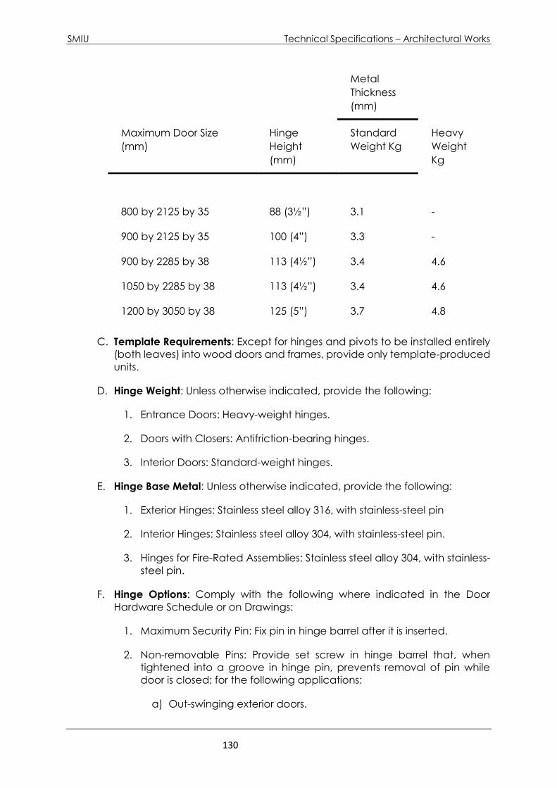
SMIU Technical Specifications – Architectural Works
130
Metal
Thickness
(mm)
Maximum Door Size
(mm)
Hinge
Height
(mm)
Standard
Weight Kg
Heavy
Weight
Kg
800 by 2125 by 35 88 (3½”) 3.1 -
900 by 2125 by 35 100 (4”) 3.3 -
900 by 2285 by 38 113 (4½”) 3.4 4.6
1050 by 2285 by 38 113 (4½”) 3.4 4.6
1200 by 3050 by 38 125 (5”) 3.7 4.8
C. Template Requirements: Except for hinges and pivots to be installed entirely
(both leaves) into wood doors and frames, provide only template-produced
units.
D. Hinge Weight: Unless otherwise indicated, provide the following:
1. Entrance Doors: Heavy-weight hinges.
2. Doors with Closers: Antifriction-bearing hinges.
3. Interior Doors: Standard-weight hinges.
E. Hinge Base Metal: Unless otherwise indicated, provide the following:
1. Exterior Hinges: Stainless steel alloy 316, with stainless-steel pin
2. Interior Hinges: Stainless steel alloy 304, with stainless-steel pin.
3. Hinges for Fire-Rated Assemblies: Stainless steel alloy 304, with stainless-
steel pin.
F. Hinge Options: Comply with the following where indicated in the Door
Hardware Schedule or on Drawings:
1. Maximum Security Pin: Fix pin in hinge barrel after it is inserted.
2. Non-removable Pins: Provide set screw in hinge barrel that, when
tightened into a groove in hinge pin, prevents removal of pin while
door is closed; for the following applications:
a) Out-swinging exterior doors.
SMIU Technical Specifications – Architectural Works
131
3. Corners: 4-mm (5/32”) radius.
G. Hinges, General: Shall be full mortise, template, of concealed ball bearing,
5 knuckles, suitable for high frequency applications and of life time warranty.
6.3.2.3 LOCKS AND LATCHES
A. Standards: Comply with the following:
1. Mortise Locks and Latches: BHMA A156.13.
2. Interconnected Locks and Latches: BHMA A156.12.
3. Auxiliary Locks: BHMA A156.5.
4. Push-Button Combination Locks: BHMA A156.2.
5. Electromagnetic Locks: BHMA A156.23.
6. Delayed-Egress Locks: BHMA A156.24.
7. Exit Locks: BHMA A156.5.
B. Mortise Locks: Stamped steel case with stainless steel parts; BHMA Grade 1;
Series 1000. Provide mortise locks for exterior doors, throughout the job,
except for toilets. All lock shall be ADA compliant Marine grade mortise locks
shall be provided in the exterior and in non air conditioned areas. Provide
ten years product warranty for performance and finish.
C. Mortise Lock: Shall be types produced for extra-heavy-duty applications.
Lock lever shall be of anti-vandalism design.
D. Where threaded bars are used to assemble the two pieces of lock spindle,
minimum inner diameter of threading bar shall be 6 mm (1/4”).
E. Interconnected Locks: BHMA Grade 1; Series 5000.
F. Auxiliary Locks: BHMA Grade 1.
G. Push-Button Combination Locks: BHMA Grade 1 for cylindrical locks and
Grade 2 for mortise locks.
H. Certified Products: Provide door hardware listed in the following BHMA
directories:
1. Mechanical Locks and Latches: BHMA's "Directory of Certified Locks &
Latches."
I. Lock Trim: Comply with the following: All trims to have returns. Trims shall be
ADA compliant. Trim shall be stainless steel BHMA-630
1. Lever: Wrought, forged, or cast.
2. Escutcheon (Rose): Wrought, forged, or cast.
SMIU Technical Specifications – Architectural Works
132
3. Dummy Trim: Match lock trim and escutcheons.
4. Lockset Designs: Provide the lockset design designated below or, if sets
are provided by another manufacturer, provide designs that match
those designated:
J. Lock Functions: Function numbers and descriptions indicated in the Door
Hardware Schedule comply with the following:
1. Mortise Locks: BHMA A156.13.
2. Interconnected Locks: BHMA A156.12.
K. Lock Features: Comply with testing requirements for length of bolts to comply
with labeled fire door requirements, and as follows:
1. Mortise Locks: Minimum 19-mm (3/4”) latchbolt throw.
2. Deadbolts: Minimum 25-mm (1”) bolt throw.
3. Pairs of Doors: 16-mm (3/4”) minimum throw of latch.
4. Fire-Rated Doors: Comply with UL requirements for throw of bolts and
latches on rated fire openings.
5. Heavy duty anti friction tongue.
6. Non handed auxiliary guard latch.
7. Adjustable stainless steel armor front.
8. Seven pin interchangeable core cylinder.
9. Corrosion protected steel case.
L. Rabbeted Doors: Provide special rabbeted front and strike on locksets for
rabbeted meeting stiles.
M. Backset: 70 mm, (3”) unless otherwise indicated.
N. Lock Function: Provide lock functions as described below, but not limited to
1. F-04 Office lock, with faceplate button depressed function.
2. Classroom function for stores
3. F-13 Corridor lock.
4. Provide classroom dead bolts for main doors of toilets and janitors
rooms
Additional lock function will be required as per function of various rooms.
SMIU Technical Specifications – Architectural Works
133
O. Locks shall have double buttons in face plate. For Office Locks the handle
will rotate only when bottom button is depressed or turning key for outside
cylinder. For other locks, the bottom button in face plate shall also retract
the latch.
P. These requirements for mortise locks shall remain applicable in all respects
for wood doors, steel doors and minimum doors.
6.3.2.4 DOOR BOLTS
A. Standards: Comply with the following:
1. Surface Bolts: BHMA A156.16.
2. Manual Flush Bolts: BHMA A156.16.
B. Surface Bolts: BHMA Grade 1.
1. Flush Bolt Heads: Minimum of 13-mm- (1/2”) diameter rods of
brass, bronze, or stainless steel with minimum 300-mm- (24”) long
rod for doors up to 2100 mm in height. Provide longer rods as
necessary for doors exceeding 2100 mm (7’-0”).
C. Flush Bolts: BHMA Grade 1, designed for mortising into door edge.
D. Bolt Throw: Comply with testing requirements for length of bolts to comply with
labeled fire door requirements, and as follows:
1. Half-Round Surface Bolts: Minimum 22-mm (1”) throw.
2. Interlocking Surface Bolts: Minimum 24-mm (1”) throw.
3. Fire-Rated Surface Bolts: Minimum 25-mm (1”) throw; listed and
labeled for fire-rated doors.
4. Dutch-Door Bolts: Minimum 19-mm (3/4”) throw.
5. Mortise Flush Bolts: Minimum 19-mm (3/4”) throw.
6.3.2.5 EXIT DEVICES
A. Standard: BHMA A156.3.
1. BHMA Grade: Grade 1.
B. Certified Products: Provide exit devices listed in BHMA's "Directory of Certified
Exit Devices."
C. Panic Exit Devices: Listed and labeled by a testing and inspecting agency
acceptable to authorities having jurisdiction, for panic protection, based on
testing according to UL 305.
D. Panic Exit Devices: For non-fire rated doors are to be as specified in Sub-
Clause but with facility to hold latchbolts in retracted position so that the
doors may be used as push/pull. Dogging is to be accomplished by a hex
key cylinder installed on the body of touch bar devices or a hexagonal key
in the hinge and lock cases of cross bar devices
E. Fire Exit Devices: Complying with NFPA 80 that are listed and labeled by a
testing and inspecting agency acceptable to authorities having jurisdiction,
for fire and panic protection, based on testing according to UL 305 and
NFPA 252.

SMIU Technical Specifications – Architectural Works
134
F. Dummy Push Bar: Nonfunctioning push bar matching functional push bar.
1. Operation: Rigid.
G. Outside Trim: Lever with cylinder or Pull with cylinder; unless otherwise
indicated material and finish to match locksets, unless otherwise indicated.
1. Match design for locksets and latchsets, unless otherwise
indicated.
H. Through Bolts: For exit devices and trim on metal doors and non-fire-rated
wood doors.
I. Fire and panic exit devices shall be of concealed latches. No exposed
latches shall be accepted.
6.3.2.6 CYLINDERS AND KEYING
A. Standards: Comply with the following:
1. Cylinders: BHMA A156.5.
2. Key Control System: BHMA A156.5.
B. Cylinder Grade: BHMA Grade 1 or Grade 1A.
C. Cylinders: Manufacturer's standard tumbler type, constructed from brass or
bronze, stainless steel, or nickel silver, and complying with the following:
1. Number of Pins: Seven.
2. Mortise Type: Threaded cylinders with rings and straight- or clover-
type cam.
3. Rim Type: Cylinders with back plate, flat-type vertical or horizontal
tailpiece, and raised trim ring.
D. Permanent Cores: Manufacturer's standard; finish face to match lockset;
complying with the following:
1. Interchangeable Cores: Core insert, removable by use of a
special key, and usable with other manufacturers' cylinders.
2. Removable Cores: Core insert, removable by use of a special key,
and for use with only the core manufacturer's cylinder and door
hardware.
E. Construction Keying: Comply with the following:
1. Construction Master Keys: Provide cylinders with feature that
permits voiding of construction keys without cylinder removal.
Provide 10 construction master keys.
2. Construction Cores: Provide construction cores that are
replaceable by permanent cores. Provide 4 constructions master
keys for Employer/Consultant use.
a) Replace construction cores with permanent cores, as directed
by Employer.
b) Furnish permanent cores to Employer for installation.
F. Keying System: Unless otherwise indicated, provide a factory-registered
keying system complying with the following requirements:
SMIU Technical Specifications – Architectural Works
135
1. Master Key System: Cylinders are operated by a change key and
a master key.
G. Keys: Provide stainless steel keys complying with the following:
1. Stamping: Permanently inscribe each key with a visual key
control number and include the following notation:
a) Notation: Information to be furnished by Employer.
2. Quantity: In addition to one extra blank key for each lock,
provide the following:
a) Cylinder Change Keys: Three.
b) Master Keys: Five.
H. Key Control System: BHMA Grade 1 system, including key-holding hooks,
labels, two sets of key tags with self-locking key holders, key-gathering
envelopes, and temporary and permanent markers. Contain system in metal
cabinet with baked-enamel finish.
1. Wall-Mounted Cabinet: Cabinet with hinged-panel door
equipped with key-holding panels and pin-tumbler cylinder door
lock.
2. Capacity: Able to hold keys for 150 percent of the number of
locks.
3. Cross-Index System: Set up by key control manufacturer,
complying with the following:
a) Card Index: Furnish four sets of index cards for recording key
information. Include three receipt forms for each key-
holding hook.
6.3.2.7 STRIKES
A. Standards: Comply with the following:
1. Strikes for Mortise Locks and Latches: BHMA A156.13.
2. Strikes for Interconnected Locks and Latches: BHMA A156.12.
3. Strikes for Auxiliary Deadlocks: BHMA A156.5.
4. Dustproof Strikes: BHMA A156.16.
B. Strikes: Provide manufacturer's standard strike with strike box for each latch or
lock bolt, with curved lip extended to protect frame, finished to match door
hardware set, unless otherwise indicated, and as follows:
1. Flat-Lip Strikes: For locks with three-piece antifriction latchbolts, as
recommended by manufacturer.
2. Extra-Long-Lip Strikes: For locks used on frames with applied wood
casing trim.
3. Aluminum-Frame Strike Box: Provide manufacturer's special strike
box fabricated for aluminum framing.
4. Provide recess type top strikes for bolts locking into head frames,
unless otherwise indicated.
SMIU Technical Specifications – Architectural Works
136
5. Provide dust-proof strikes for foot bolts, except where special
threshold construction provides non recessed strike for bolt.
C. Dustproof Strikes: BHMA Grade 1.
6.3.2.8 CARD READER
A. Proximity Reader with Keypad:
1. Technology: Wiengand proximity system compatible with building security system.
2. Housing: Weather resistant ABS plastic housing. Color as selected by Consultant
from manufacturer’s full line.
3. Key Pad: 12 button key pad for entry of Personal Identification Number (PIN) in
addition to proximity card.
4. Display Status: 3 LED status display and controllable beeper to indicate reader
operation and status.
5. Tamper Detection: Mechanical tamper switch to send signal to security room if
reader is completely removed from wall in addition to detecting when reader has
been separated from its back plate.
6. Provide all mounting plates, cables, programs and other items required to make
card reader work with building security system.
6.3.2.9 OPERATING TRIM
A. Standard: Comply with BHMA A156.6.
B. Door handles shall have returns in direction of door, straight handles shall not
be accepted.
C. Handles shall be with round (rose) cover plates.
D. Materials: Fabricate from stainless steel, unless otherwise indicated.
E. Push-Pull Design: As indicated on Drawings.
6.3.2.10 ACCESSORIES FOR PAIRS OF DOORS
A. Standards: Comply with the following:
1. Coordinators: BHMA A156.3.
B. Carry-Open Bars: Provide carry-open bars for inactive leaves of pairs of doors,
unless automatic or self-latching bolts are used.
C. Do not use security astragals. Use split adjustable astragals or concealed side
mounted.
6.3.2.11 CLOSERS
A. Closers, General-unless otherwise indicated, provide closers on all fire-rated
doors, exterior doors, toilet and locker room doors, sound-retardant doors,
corridor doors, doors between heated/cooled and unheated / uncooled
areas, elevator equipment room doors, and other door as required. Closer
shall be tested for 10 million cycles and will withstand 57 degree ambient
temperature and will be provided with all weather hydraulic fluid. Closer will
be equipped with the function of variable back check and delayed action.
Closer will be provided with ten years warranty and warranty against leaks.
SMIU Technical Specifications – Architectural Works
137
Closer will be non banded. Closer will be provided with adjustable with
speed and hold open facility. Concealed door closer will be completely and
components will minimize tempering and vandalism.
1. Size of Units: Unless otherwise indicated, comply with the
manufacturer’s recommendation for size of door control unit
depending on size of door, exposure to weather and drafts, and
anticipated frequency of use.
2. Arms: Provide parallel arms for all overhead closers, unless
otherwise indicated. Provide closer unit one size larger than
recommended for use with standard arms.
3. Closing Cycle: Comply with requirements of authorities having
jurisdiction or the Americans with Disabilities Act (ADA),
“Accessibility Guidelines for Buildings and Facilities (ADAAG)”,
whichever are most stringent
4. Opening Force: Comply with the following maximum opening-
force requirements for locations indicated:
a) Exterior Doors: 67 N.
b) Interior Doors: 22.2N.
5. Construction: Provide marine-grade construction for closers in
non-air conditioned areas and in door swimming pool areas,
consisting of nonferrous and stainless steel components.
B. Aluminum Entrance Doors: Provide concealed door closer. Standards:
Comply with the following:
1. Closers: BHMA A156.4.
2. Closer Holder Release Devices: BHMA A156.15.
C. Surface Closers: BHMA Grade 1.
D. Concealed Closers: BHMA Grade 1.
E. Certified Products: Provide door closers listed in BHMA's "Directory of Certified
Door Closers".
F. Door Closers on Fire Rated Doors: Shall be type that closes the door and
positively latch the door.
G. Hold-Open Closers/Detectors: Coordinate and interface integral smoke
detector and closer device with fire alarm system. Fire rated doors with
closers of hold open facility shall release automatically in case of fire based
on signal from the fire alarm system (electric release door closer). System of
release device for double leaf fire rated doors shall be adjustable so as the
inactive leaf shall close prior to the active leaf and that active leave shall
positively latch to the inactive leaf at final closing position (electric release
door closers and door coordinator).
H. Flush Floor Plates: Provide finish cover plates for floor closers unless thresholds
are indicated. Match door hardware finish, unless otherwise indicated.
I. Recessed Floor Plates: Provide recessed floor plates with insert of floor finish
material for floor closers, unless thresholds are indicated. Provide extended
closer spindle to accommodate thickness of floor finish.
SMIU Technical Specifications – Architectural Works
138
J. Weather Comply with manufacturer's written recommendation of exposure
to weather. Provide factory-sized closers, adjustable to meet field conditions
and requirements for opening force.
K. Grade: Door closers shall be from types tested for 10 millions cycles of
operation and sized for door leafs of minimum weight of 200 kilogram per
leaf for both steel doors and external doors.
6.3.2.12 PROTECTIVE TRIM UNITS
A. Standard: Comply with BHMA A156.6.
B. Materials: Fabricate protection plates from the following to match requirement
indicate:
1. Stainless Steel: beveled top and 2 sides.
C. Protection Plates, General:
1. Fabricate edge trim of stainless steel to fit door thickness in standard
lengths or to match height of protection plates.
D. Kick Plates: beveled top and two side edges (B3E). Provide two kick plates for
toilet doors. Kick plate will ensure that the door bottom is protected.
1. Metal Plates: Stainless steel, 3.00 mm (2/16”) thick
E. Armor Plates: 3 mm (2/16”) thick, 914 mm (36”) high by full width of door less
clearance for stops on door frame.
F. Fasteners: Provide manufacturer's standard exposed fasteners for door trim
units consisting of either machine or self-tapping screws.
G. Furnish protection plates sized 38 mm (1.5”) less than door width on push side
and 13 mm (1/2”) less than door width on pull side, by height specified in Door
Hardware Schedule.
6.3.2.13 STOPS AND HOLDERS
A. Standards: Comply with the following:
1. Stops and Bumpers: BHMA A156.16.
2. Mechanical Door Holders: BHMA A156.16.
3. Electromagnetic Door Holders: BHMA A156.15.
4. Combination Overhead Holders and Stops: BHMA A156.8.
5. Door Silencers: BHMA A156.16.
B. Stops and Bumpers: BHMA Grade 1.
C. Mechanical Door Holders: BHMA Grade 1.
D. Combination Floor and Wall Stops and Holders: BHMA Grade 1.
E. Combination Overhead Stops and Holders: BHMA Grade 1.
SMIU Technical Specifications – Architectural Works
139
F. Electromagnetic Door Holders for Labeled Fire Door Assemblies: Coordinate
with fire detectors and interface with fire alarm system.
G. Floor Stops: For doors, unless wall or other type stops are scheduled or
indicated. Do not mount floor stops where they will impede traffic.
a) Where floor or wall stops are not appropriate, provide overhead
holders.
H. Silencers for Wood Door Frames: BHMA Grade 1; neoprene or rubber, minimum
16 by 19 mm; (½” ~ ¾”) fabricated for drilled-in application to frame.
I. Silencers for Metal Door Frames: BHMA Grade 1; neoprene or rubber, minimum
diameter 13 mm; (1/2”) fabricated for drilled-in application to frame.
6.3.2.14 DOOR GASKETING
A. Standard: Comply with BHMA A156.22.
B. General: Provide continuous weather-strip gasketing on exterior doors and
provide smoke, light, or sound gasketing on interior doors where indicated
or scheduled. Provide non-corrosive fasteners for exterior applications and
elsewhere as indicated.
1. Perimeter Gasketing: Apply to head and jamb, forming seal between
door and frame.
2. Meeting Stile Gasketing: Fasten to meeting stiles, forming seal when
doors are closed.
3. Door Bottoms: Apply to bottom of door, forming seal with threshold
when door is closed.
C. Air Leakage: Not to exceed 0.000774 cu. m/s per m (0.0000209 cft / s per 3’-
0”) of crack length for gasketing other than for smoke control, as tested
according to ASTM E 283.
D. Smoke-Labeled Gasketing: Assemblies complying with NFPA 105 that are
listed and labeled by a testing and inspecting agency acceptable to
authorities having jurisdiction, for smoke-control ratings indicated, based on
testing according to UL 1784.
1. Provide smoke-labeled gasketing on 20-minute-rated doors and on
smoke-labeled doors.
E. Fire-Labeled Gasketing: Assemblies complying with NFPA 80 that are listed
and labeled by a testing and inspecting agency acceptable to authorities
having jurisdiction, for fire ratings indicated, based on testing according to
UL 10B or NFPA 252.
F. Sound-Rated Gasketing: Assemblies that are listed and labeled by a testing
and inspecting agency, for sound ratings indicated, based on testing
according to ASTM E 1408.

SMIU Technical Specifications – Architectural Works
140
G. Replaceable Seal Strips: Provide only those units where resilient or flexible
seal strips are easily replaceable and readily available from stocks
maintained by manufacturer.
H. Gasketing Materials: Comply with ASTM D 2000 and AAMA 701/702.
I. Weather-stripping and Seal Types: Unless otherwise indicated, provide the
following, or approved equal:
1. Door Shoes: Extruded aluminum, with vinyl seal and integral rain
drip.
2. Rain Drips: Extruded aluminum. Unless noted otherwise, provide rain
drips for all exterior doors.
3. Automatic Door Bottoms: Extruded aluminum with neoprene insert for
doors to achieve STC of 47 or better, as indicated in the hardware
schedule.
4. Meeting Stile Seals (Astragal Seals): Extruded anodized aluminum, with
silicon seal.
5. Weather-stripping, Smoke Seals, and Sound Retarding Gaskets:
Compression-type self-adhesive silicone gasket applied to door stops,
white color.
6. Security Astragals: Cam operated automatic security astragal.
6.3.2.15 THRESHOLDS
A. General: Unless otherwise indicated, provide standard metal threshold units
of type, size, and profile as shown or scheduled. Comply with
ANSI/BHMA A156.21.
1. Material: Extruded aluminum, non-slip finish, except as otherwise
specified.
2. Exterior Hinged Doors: Provide units not less than 100 mm (4”) wide,
and not more than 12-mm- (1/2”) high, with beveled edges providing
a floor level change with a slope of not more than 1:2, formed to
accommodate change in floor elevation where indicated, fabricated
to accommodate door hardware and to fit door frames, and as
follows:
a) For in-swinging doors provide units with interlocking lip and interior
drain channel; include hook on bottom edge of door and drain
pan.
b) For out-swinging doors provide rabbeted type units with
replaceable weather-strip insert in stop. Provide threshold with
thermal break when mentioned in the hardware schedule

SMIU Technical Specifications – Architectural Works
141
B. Exterior Thresholds: ANSI/BHMA A156.21, extruded aluminum. Provide flat
saddle type or interlocking type with resilient insert as shown.
C. Threshold for Aluminum Entrance Doors: Manufacturer’s standard threshold
with cutouts coordinated for operating hardware, with anchors and jamb
clips, and not more than 12-mm-(1/2”) high, with beveled edges providing
a floor level change with a slope of not more than 1:2, formed to
accommodate change in floor elevation where indicated.
D. Threshold for Doors with Exit Devices: Extruded aluminum latching type, with
replaceable vinyl inserts.
E. Interior Thresholds: Extruded aluminum flat saddle type with smooth surface.
6.3.2.16 MISCELLANEOUS DOOR HARDWARE
A. Standard: Comply with the following:
1. Auxiliary Hardware: BHMA A156.16.
2. Exit Alarms: BHMA A156.5.
B. Auxiliary Hardware: BHMA Grade 1, unless otherwise indicated.
C. Boxed Power Supplies: Modular unit in NEMA ICS 6, Type 4 enclosure; filtered
and regulated; voltage rating and type matching requirements of door
hardware served; and listed and labeled for use with fire alarm systems.
6.3.2.17 FABRICATION
A. Manufacturer's Nameplate: Do not provide manufacturers' products that
have manufacturer's name or trade name displayed in a visible location
(omit removable nameplates) except in conjunction with required fire-rated
labels and as otherwise approved by Consultant.
1. Manufacturer's identification will be permitted on rim of lock cylinders
only.
B. Base Metals: Produce door hardware units of base metal specified,
fabricated by forming method indicated, using manufacturer's standard
metal alloy, composition, temper, and hardness. Furnish metals of a quality
equal to or greater than that of specified door hardware units and
BHMA A156.18 for finishes. Do not furnish manufacturer's standard materials
or forming methods if different from specified standard.
C. Fasteners: Provide door hardware manufactured to comply with published
templates generally prepared for machine, wood, and sheet metal screws.
Provide screws according to commercially recognized industry standards for
application intended. Provide Phillips flat-head screws with finished heads to
match surface of door hardware, unless otherwise indicated.
1. Concealed Fasteners: For door hardware units that are exposed when
door is closed, except for units already specified with concealed

SMIU Technical Specifications – Architectural Works
142
fasteners. Do not use through bolts for installation where bolt head or
nut on opposite face is exposed unless it is the only means of securely
attaching the door hardware. Where through bolts are used on hollow
door and frame construction, provide sleeves for each through bolt.
2. Steel Machine or Wood Screws: For the following fire-rated
applications:
a) Mortise hinges to doors.
b) Strike plates to frames.
c) Closers to doors and frames.
3. Steel Through Bolts: For the following fire-rated applications, unless
door blocking is provided:
a) Surface hinges to doors.
b) Closers to doors and frames.
c) Surface-mounted exit devices.
4. Spacers: For through bolting of hollow metal doors.
5. Fasteners for Wood Doors: Comply with requirements of DHI WDHS.2,
"Recommended Fasteners for Wood Doors."
6.3.2.18 Base Metal
A. Base Metal for hardware and door furniture shall be as follows:
1. Exterior Units: Stainless Steel alloy 316
2. Interior Units: Stainless Steel alloy 304
6.3.2.19 FINISHES
A. Standard: Comply with BHMA A156.18.
B. Protect mechanical finishes on exposed surfaces from damage by applying
a strippable, temporary protective covering before shipping.
C. Appearance of Finished Work: Variations in appearance of abutting or
adjacent pieces are acceptable if they are within one-half of the range of
approved Samples. Noticeable variations in the same piece are not
acceptable. Variations in appearance of other components are
acceptable if they are within the range of approved Samples and are
assembled or installed to minimize contrast.
D. BHMA Designations: Comply with base material and finish requirements
indicated by the following:

SMIU Technical Specifications – Architectural Works
143
1. BHMA 630: Satin stainless steel, over stainless-steel base metal.
EXECUTION
6.3.2.20 EXAMINATION
A. Examine doors and frames, with Installer present, for compliance with
requirements for installation tolerances, labeled fire door assembly
construction, wall and floor construction, and other conditions affecting
performance.
B. Examine roughing-in for electrical power systems to verify actual locations of
wiring connections before electrified door hardware installation.
C. Proceed with installation only after unsatisfactory conditions have been
corrected.
6.3.2.21 PREPARATION
A. Steel Doors and Frames: Comply with DHI A115 series.
1. Surface-Applied Door Hardware: Drill and tap doors and frames
according to SDI 107.
B. Wood Doors: Comply with DHI A115-W series.
6.3.2.22 INSTALLATION
A. Mounting Heights: Mount door hardware units at heights indicated in following
applicable publications, unless specifically indicated or required to comply
with governing regulations:
1. Custom Steel Doors and Frames: DHI's "Recommended Locations for
Builders' Hardware for Custom Steel Doors and Frames."
2. Wood Doors: DHI WDHS.3, "Recommended Locations for Architectural
Hardware for Wood Flush Doors."
B. Install each door hardware item to comply with manufacturer's written
instructions. Where cutting and fitting are required to install door hardware onto
or into surfaces that are later to be painted or finished in another way,
coordinate removal, storage, and reinstallation of surface protective trim units
with finishing work specified in 9.0 Sections. Do not install surface-mounted
items until finishes have been completed on substrates involved.
1. Set units level, plumb, and true to line and location. Adjust and
reinforce attachment substrates as necessary for proper installation
and operation.
2. Drill and countersink units that are not factory prepared for anchorage
fasteners. Space fasteners and anchors according to industry
standards.

SMIU Technical Specifications – Architectural Works
144
C. Key Control System: Place keys on markers and hooks in key control system
cabinet, as determined by final keying schedule.
D. Thresholds: Set thresholds for exterior and acoustical doors in full bed of sealant
complying with requirements specified in 7.0 Section "Joint Sealants."
6.3.2.23 Adjusting
A. Initial Adjustment: Adjust and check each operating item of door hardware
and each door to ensure proper operation or function of every unit. Replace
units that cannot be adjusted to operate as intended. Adjust door control
devices to compensate for final operation of heating and ventilating
equipment and to comply with referenced accessibility requirements.
1. Door Closers: Adjust sweep period so that, from an open position of 70
degrees, the door will take at least 3 seconds to move to a point 75 mm
(3”) from the latch, measured to the leading edge of the door.
B. Six-Month Adjustment: Approximately six months after date of Substantial
Completion, Installer shall perform the following:
1. Examine and readjust each item of door hardware as necessary to
ensure function of doors, door hardware, and electrified door hardware.
2. Consult with and instruct Employer's personnel on recommended
maintenance procedures.
3. Replace door hardware items that have deteriorated or failed due to
faulty design, materials, or installation of door hardware units.
6.3.2.24 CLEANING AND PROTECTION
A. Clean adjacent surfaces soiled by door hardware installation.
B. Clean operating items as necessary to restore proper function and finish.
C. Provide final protection and maintain conditions that ensure door hardware
is without damage or deterioration at time of Substantial Completion.
6.3.2.25 DEMONSTRATION
Engage a factory-authorized service representative to train Employer's maintenance
personnel to adjust, operate, and maintain door hardware and door hardware
finishes.
SMIU Technical Specifications – Architectural Works
145
6.4 – GLAZED ALUMINUM CURTAIN WALL
6.4.1. Section Includes:
A. Aluminum framing system.
B. Glass Panels
C. Other accessories including integral fire stops at floor slabs and Perimeter sealant.
6.4.2. REFERENCES
A. AAMA - American Architectural Manufacturer Association
AAMA Metal Curtain Wall, Window, Store Front and Entrance -Guide
Specifications Manual
AAMA Aluminum Curtain Wall Design Guide Manual
AAMA Curtain Wall Manual #10 - Care and Handling of Architectural
Aluminum from Shop to Site
AAMA Series No. 11 - Design Wind loads for Buildings and Boundary
Layer Wind Tunnel Testing
AAMA 501 Methods of Test for Metal Curtain Walls
AAMA 603.8 Performance Requirements and Test Procedures for Pigmented
Organic Coatings on Extruded Aluminum
AAMA 605.2 Specification for High Performance Organic Coatings on
Architectural Extrusions and Panels
AAMA 606.1 Specifications and Inspection Methods for Integral Color Anodic
Finishes for Architectural Aluminum
AAMA 607.1 Specifications and Inspection Methods for Clear Anodic Finishes for
Architectural Aluminum
AAMA 608.1 Specification and Inspection Methods for Electrolytically Deposited
Color Anodic Finishes for Architectural Aluminum
AAMA T1R A1 Sound Control for Aluminum Curtain Walls and Windows
AAMA FC-1 Field Check of Metal Curtain Walls for Water Leakage
B. ASTM - American Society of Testing and Materials
ANSI/ASTM A36 Structural Steel
ANSI/ASTM A386 Zinc Coating (Hot Dip) on Assembled Steel Products
ANSI/ASTM A446 Steel Sheet, Zinc-Coated (Galvanized) by the Hot-Dip
Process, Structural (Physical) Quality.
ANSI/ASTM B209 Aluminum and Aluminum-Alloy Sheet and Plate
ANSI/ASTM B221 Aluminum-Alloy Extruded Bar, Rod, Wire, Shape, and Tube
ANSI/ASTM E283 Rate of Air Leakage through Exterior Windows, Curtain
Walls, and Doors
ANSI/ASTM E330 Structural Performance of Exterior Windows, Curtain Walls, and
Doors by Uniform Static Air Pressure Difference
ANSI/ASTM E331 Test Method for Water Penetration of Exterior Windows,
Curtain Walls, and Doors by Uniform Static Air Pressure
Difference
ASTM E413 Classification for Determination of Sound Transmission Class
B. SSPC - Steel Structures Painting Council
SP-10 Near-White Blast Cleaning
PS-12.00 Guide for Selecting Zinc-Rich Painting Systems
SMIU Technical Specifications – Architectural Works
146
6.4.3. SYSTEM DESCRIPTION
A. Glazed aluminum curtain wall system includes PVDF3 coated aluminum sections
with self-supporting framing, shop fabricated, factory pre-finished, vision double
glazing glass, glass spandrel infill; related flashings, anchorage and attachment
devices.
6.4.4. 1.04 PERFORMANCE REQUIREMENTS
A. General: Provide glazed aluminum curtain wall system that has the following
capabilities based on pre-construction testing:
1. Withstand loads and thermal and structural movement requirements indicated
without failure. Failure includes the following:
a. Air infiltration and water penetration not exceeding the specified limits.
b. Framing members transferring stresses, including those caused by thermal and
structural movement, to glazing units.
B. Glazing: Glazing shall be physically and thermally isolated from framing members.
C. System is reglazable from interior, except spandrel glazing are reglazable from
exterior.
D. Wind Loads: Provide glazed aluminum curtain wall system, including anchorage,
capable of withstanding wind-load inward and outward design pressures calculated
according to requirements of the Saudi Code for loading and Saudi
Code of Structural Steel works.
E. Design and size components to withstand seismic loads and sway displacement
when wind loads effect maximum overturning moment.
F. Limit deflection of framing members in a direction normal to wall plane to 1/175 of
clear span or 19 mm whichever is smaller; with full recovery of glazing materials.
Where system affects gypsum board or plaster surfaces, limit deflection of framing
members in a direction normal to wall plane to 1/360 of clear span or 19 mm
maximum, whichever is smaller.
G. System to accommodate, without damage to system, components or
deterioration of seals; movement within system; movement between system and
perimeter framing components; dynamic loading and release of loads; deflection of
structural support framing, shortening of building concrete structural columns, creep
of concrete structural members and a mid-span slab edge deflection of 1/175 of
clear span, 19 mm maximum.
H. Test Performance: Provide glazed aluminum curtain wall system that does not
evidence material failures, structural distress, or permanent deformation of main
framing members exceeding 0.2 percent of clear span when tested according to
ASTM E330 and achieving the following:
1. Test Pressure: 150 percent of inward and outward wind-load design pressure.
2. Duration: As required by design wind velocity; fastest 1 mile of wind for relevant
exposure category.
I. Average Thermal Conductance: Provide double glazed aluminum curtain wall
system with average U-value 2 W/m2C.
J. Sound Attenuation Through Wall system (Exterior to Interior): > STC 37, measured
according to ASTM E413.
K. Air infiltration through Assembly: Limit air infiltration to 0.3 L/s/sq. m of fixed wall
area when tested according to ANSI/ASTM E283 at a static-air-pressure difference of
299 Pa.
L. Water Leakage: None, when measured in accordance with ASTM E331.

SMIU Technical Specifications – Architectural Works
147
M. System to provide for expansion and contraction within system components
caused by a cycling temperature range of 95 degrees C over a 12 hour period
without causing detrimental effect to system components.
N. Drain water entering joints, condensation occurring in glazing channels, or
migrating moisture occurring within system, to the exterior by a weep drainage
network.
O. Maintain system components from dust and moisture during assembly, after
transport to site, during and after installation.
P. Reinforce curtain wall system to accommodate window washing guide rails.
Provide anchors sufficiently rigid to resist loads caused by equipment platform,
without damage to wall system.
Q. Not Permitted: Vibration harmonics, wind whistles, noises caused by thermal
movement, thermal movement transmitted to other building elements, loosening,
weakening, or fracturing of attachments or components of system.
6.4.5. SUBMITTALS
A. Design calculations by professional engineer
B. Shop Drawings: Indicate system dimensions, framed opening requirements and
tolerances, anticipated deflection under load, affected related Work, weep
drainage network, expansion and contraction joint location and details, and field
welding required.
C. Product Data:
1. Provide component dimensions, describe components within assembly,
anchorage and fasteners, glass and infill, internal drainage details and water flow
diagrams.
2. Product Data: Provide framing member structural and physical characteristics,
dimensional limitations, and special installation requirements.
3. Type and properties of glass and method of fixation.
D. Submit 2 samples 300 x 300 mm in size illustrating prefinished aluminum surface,
specified glass units, insulated infill panels, glazing materials illustrating edge and
corner.
E. Test Reports: Submit substantiating engineering data, test results of previous tests
which purport to meet performance criteria, and other supportive data.
F. Manufacturer's Installation Instructions: Indicate special installation procedures,
instruction and other recommendations.
G. Properties of PVDF3 finish, indicating durability of coating considering the project
site weather.
6.4.6. QUALITY ASSURANCE
A. Drawings and Specifications: Plans, elevations and details as shown on Drawings
and the requirements specified in this section, indicate design concept. The
approved manufacturer shall be responsible for complete curtain wall system design
based on the system performance requirements specified in this section.
B. Applicable Standards: Perform Work in accordance with the following:
1. AAMA - Metal Curtain Wall, Window, Store Front and Entrance - Guide
Specifications Manual.
2. AAMA - Aluminum Curtain Wall Design Guide Manual.
6.4.7. MANUFACTURER AND INSTALLER QUALIFICATIONS

SMIU Technical Specifications – Architectural Works
148
A. Manufacturer: Company specializing in manufacturing aluminum curtain wall
systems with minimum 10 years documented experience.
B. Installer for Total System: Company authorized by system manufacturer and
approved by The Engineer.
C. Design structural support framing components under direct supervision of a
Professional Engineer experienced in design of this work.
6.4.8. MOCKUP
A. Provide a floor-to-floor mock-up including intermediate mullion, corner mullion, sill,
vision glass light, and infill panel. Assemble to illustrate component assembly
including glazing materials, weep drainage system, attachments, anchors, and
perimeter sealant.
B. Mockup may not remain as part of the Work.
6.4.9. DELIVERY, STORAGE, AND HANDLING
A. Deliver, store, protect and handle products to site in strict accordance with
manufacturer's instructions.
B. Protect prefinished aluminum surfaces. Do not use adhesive papers or sprayed
coatings which bond when exposed to sunlight or weather.
6.4.10. WARRANTY
A. Provide five year for the glazed curtain wall system. Warranty shall include
coverage for complete system for failure to meet specified requirements.
PRODUCTS
6.4.11. MATERIALS AND ACCESSORIES
A. Aluminum: Alloy and temper shall be as recommended by manufacturer for type
of use and finish indicated and complying with the following requirements:
1. Sheet and Plate: ASTM B209
2. Extruded Bars, Rods, Shapes, and Tubes: ASTM B221
3. Extruded Structural Pipe and Tube: ASTM B429
4. Welding Rods and Bare Electrodes: AWS A5.10
5. Aluminum Coating PVDF 3.
B. Steel Reinforcement:
1. ASTM A36 for structural shapes, plates and bars.
2. ASTM A611 for cold-rolled sheet and strip.
3. ASTM A570 for hot-rolled sheet and strip.
C. Glazing: Double glazing as specified in item 2.03
D. Glazing Gasket: Manufacturer standard sealed-corner pressure-glazing system of
resilient elastomeric glazing gaskets, setting blocks, and shims or spacers; in hardness
as recommended by manufacturer.
E. Glazing Sealant: As recommended by manufacturer for the intended application.
F. Fasteners: Stainless steel.
G. Touch-Up Primer for Galvanized Steel Surfaces: Zinc rich type.
SMIU Technical Specifications – Architectural Works
149
6.4.12. COMPONENTS
A. Mullion Profile: Manufacturer standard aluminum extrusions, matching stops and
pressure plate of sufficient size and strength to provide bite on glass and infill panels;
drainage holes; deflector plates and internal flashings to accommodate internal
weep drainage system; internal mullion baffles to eliminate "stack effect" air
movement within internal spaces.
B. Reinforced Mullion: Where required, provide profile of extruded or sheet aluminum
cladding with internal reinforcement of shaped steel structural section.
C. Operable Windows: Heavy Commercial grade, complying with the requirements
specified in of AAMA 101 as well as Section 08520 - ALUMINUM WINDOWS.
D. Infill Panel: Internally reinforced, glazing units, color to match vision glass,
structurally sufficient to support wall fin radiation saddles with glass fiber insulation
core and aluminum backing.
E. Column Covers: Aluminum with backing, thickness as recommended by
manufacturer to ensure flat surface, finish as selected to match curtain wall mullion
sections.
F. Flashings: Aluminum, thickness as recommended by manufacturer to ensure flat
surface, finish as selected to match curtain wall mullion sections where exposed,
secured with concealed fastening method.
G. Louver Screening: Provide bird screen at exhaust and insect screen at intake air
louver inside surface.
6.4.13. GLASS AND GLAZING MATERIALS
A. Refer to the requirements in the following table:
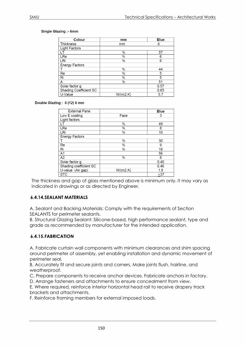
SMIU Technical Specifications – Architectural Works
150
The thickness and gap of glass mentioned above is minimum only. It may vary as
indicated in drawings or as directed by Engineer.
6.4.14. SEALANT MATERIALS
A. Sealant and Backing Materials: Comply with the requirements of Section
SEALANTS for perimeter sealants.
B. Structural Glazing Sealant: Silicone-based, high performance sealant, type and
grade as recommended by manufacturer for the intended application.
6.4.15. FABRICATION
A. Fabricate curtain wall components with minimum clearances and shim spacing
around perimeter of assembly, yet enabling installation and dynamic movement of
perimeter seal.
B. Accurately fit and secure joints and corners. Make joints flush, hairline, and
weatherproof.
C. Prepare components to receive anchor devices. Fabricate anchors in factory.
D. Arrange fasteners and attachments to ensure concealment from view.
E. Where required, reinforce interior horizontal head rail to receive drapery track
brackets and attachments.
F. Reinforce framing members for external imposed loads.
SMIU Technical Specifications – Architectural Works
151
6.4.16. 2.06 FINISHES
A. Exposed aluminum surfaces shall have PVDF3 finish.
B. Concealed Steel Items: Galvanized in accordance with ANSI/ASTM A386 to 610
gm/sq m).
C. Apply one coat of bituminous paint to concealed aluminum and steel surfaces in
contact with cementitious or dissimilar materials.
EXECUTION
6.4.17. 3.01 EXAMINATION
A. Verify site opening conditions.
B. Verify dimensions, tolerances, and method of attachment with other work.
C. Verify wall openings and adjoining air and vapor seal materials are ready to
receive work of this Section.
6.4.18. 3.02 INSTALLATION
A. Install curtain wall system in strict accordance with manufacturer's instructions as
well as the following standard:
1. AAMA - Metal Curtain Wall, Window, Store Front and Entrance - Guide
Specifications Manual.
2. AAMA - Aluminum Curtain Wall Design Guide Manual.
B. Attach to structure to permit sufficient adjustment to accommodate construction
tolerances and other irregularities.
C. Provide alignment attachments and shims to permanently fasten system to
building structure.
D. Align assembly plumb and level, free of warp or twist. Maintain assembly
dimensional tolerances, aligning with adjacent work.
E. Provide thermal isolation where components penetrate or disrupt building
insulation.
F. Where required, install sill flashings.
G. Coordinate installation of fire and air stop insulation at each floor slab edge.
H. Coordinate attachment and seal of perimeter air and vapor barrier materials.
I. Pack fibrous insulation in shim spaces at perimeter of assembly to maintain
continuity of thermal barrier.
J. Install operating sash in accordance with Drawings.
K. Install louvers, associated flashings, blank-off plates and screening. Fit blank-off
plates tight to ductwork.
L. Install glass and infill panels in accordance with Section 08800 - GLAZING.
M. Install perimeter sealant to method required to achieve performance criteria,
backing materials, and installation criteria in accordance with Section 07900 -
SEALANTS.
6.4.19. 3.03 TOLERANCES
A. Maximum Variation from Plumb: 1.5 mm/m non-cumulative or 12 mm/30 m),
whichever is less.
B. Maximum Misalignment of Two Adjoining Members Abutting in Plane: 0.8 mm.
SMIU Technical Specifications – Architectural Works
152
6.4.20. 3.04 FIELD QUALITY CONTROL
A. Inspection will monitor quality of installation and glazing.
B. Air Infiltration: Test areas of installed system for compliance with system
performance requirements according to ASTM E783.
C. Repair or remove defected and damaged work that does not meet requirements
or that is damaged by testing; replace to conform to specified requirements.
6.4.21. 3.05 ADJUSTING AND CLEANING
A. Adjust operating sash for smooth operation.
B. Remove protective material from prefinished aluminum surfaces and system
components.
C. Wash down surfaces with a solution of mild detergent in warm water, applied with
soft, clean wiping cloths. Take care to remove dirt from corners. Wipe surfaces
clean.
D. Remove excess sealant by moderate use of mineral spirits or other solvent
acceptable to sealant manufacturer.
6.4.22. PROTECTION OF FINISHED WORK
A. After work completion provide final protection and maintain conditions, in a
manner acceptable to Manufacturer, Installer and the Engineer, that ensure glazed
aluminum curtain wall system is without damage or deterioration at time of
Substantial Completion.
END OF SECTION

SMIU Technical Specifications – Architectural Works
153
6.5 - PLATFORM SCREEN DOOR (PSD)
6.5.1. General Compliance and standards
PSD doors will be subject to heavy and intensive use. They should have the capacity
to make 1000 to 1500 cycles of opening and closing daily. The motor must be certified
by an independent laboratory of 10,000,000 cycles of opening and closing with a 2
year warranty without the need for repair.
-High performance VVVT motor type brushless of 24V and 10.000.000 minimum cycles,
with Certificates according to standards UNE-EN 16005:2013 > 10,000,000 cycles.
- Door stops machined in steel and anti-noise rubbers in the area of contact with the
carrier
- Transmission toothed belt for connection to the belt fitting
- Certificate IP-65 Protection rating according to IEC 60529 Standards
- Maximum Thrust force according to European Standards less than 220N
- CE Certificate in Low Voltage Directive UNE EN 61000 2004/108/CE, Machinery
Directive 2006/42/CE, RoHs 2002/95/CE
Minimum Functional metro doors installation of 5000 metro doors.
Local experience of minimum 300 metro doors installations in Pakistan.
Manufacturer must have experience of Metros in at least 7 different cities.
All equipment should be from single source and should be made in Europe.
All equipment should be suitable for outdoors Application (IP-55/65 ) and should work
from 0-50 C temperature range, Humidity tolerance should be relative humidity of
85% non-condensing.
All doors should be linked to central control station by SCADA for faults, alarms and
maintenance issues.
Vehicle detection system through reflective photoelectric sensors of adjustable
range, compact body, and long range adjustable to a maximum distance of 2 m.
Type IP-67 rated for demanding and intensive applications. Receiver equipped with
two-segment diodes. This can be done independently of the colour or background.
It incorporates the ability to place two sensors very close or facing each other without
interfering with each other. Adjustable long range reflectivity.
System should be capable of Self-contained Power backup system for 200 cycles
(Opening and Closing)

SMIU Technical Specifications – Architectural Works
154
6.5.2. General Compliances
Quality Management System ISO 9001:2015
Environmental Management System ISO 14001:2015
Directive 2006/95/EC:
o EN 60335-2-103:2005 + A11:2010 in connection with
o EN 60335-1:2012 + A11:2014 + AC:2014
Directive 2004/108/EC:
o EN 61000-6-3:2007 + A1:2012
o EN 61000-3-2:2014
o EN 61000-3-3:2013
o EN 61000-6-1:2007
o EN 61000-4-2:2010
o EN 61000-4-3:2007 + A1:2008 + A2:2011
o EN 61000-4-4:2013
o EN 61000-4-5:2015
o EN 61000-4-6:2014
o EN 61000-4-8:2011
o EN 61000-4-11:2015
Relating to the motor:
o EN 60529 IP65.
o Certificate 10.000.000 of cycles UNE-EN 16005:2013
Relating to wiring:
o EN 60754-1:2014
o EN 60754-2:2014
Relating to glazing:
o EN 12600:2003
SMIU Technical Specifications – Architectural Works
155
Relating to profiles:
o DIN 50049, DIN 17162
o ASTM A 480
o ISO 7599:2011
6.5.3. SLIDING DOOR OPERATOR
- Door Operator for platform screen doors (PSDs) Screen System of two (02) or three
(03) center-opening door leaves which includes:
- Body in minimum 16 gauge extruded Stainless Steel AISI 304 matte finish and
dimensions W=122 mm and H= 200 mm, with fixing guides to install all the mechanical
and electronic elements of the operator
- Reinforced side covers in 3 mm thick steel finished with black hot-melt paint.
- Front cover with reinforcing folds, self-locking and fastening with anti-vandal screw.
- Control module and independent motor interconnected by each other.
- Fixing carriers system for the moving door leaf by reinforced screws and machined
steel plate of 4-5 mm. High performance PA66-GF10 wheels
- Adjustable derailment guide.
- Toothed belt coupling located with independent carrier in the center of the sliding
blade made of 4-5 mm steel to keep center of gravity of traction.
- Adjustable tension pulley, machined with galvanized electrolytic UNE EN ISO 2081 or
1015
6.5.4. Automatic door operator for platform screen doors SCREEN SYSTEM of BRT
system. Components:
- Microprocessor
- Function card: Electronic.
- Programming Unit.
- 24 VDC motor. Brushless, maintenance-free.
- Transmission: Toothed Belt.
- Working temperature: -25 ° C / 50 ° C
- Relative Humidity: 85%, non-condensing
-Power supply: AC 110 - 220 V, 50/60 Hz.
SMIU Technical Specifications – Architectural Works
156
- Maximum consumption: <150W.
- Standby power consumption: 10 W
- Consumption at medium speeds: <100 W.
- Fuse: F3A 250V.
- Adjustable opening speed: 150 - 460 mm / s.
- Adjustable closing speed: 130 - 460 mm / s
- Closing force: 1500 N.
- Braking speed: 200 - 600 mm / s
- Hold open time: 0-9 s.
- Opening Width: Adjustable.
- Braking Distance: Adjustable
- Anti-crushing: Closing force <50N
- Static force: Adjustable 90-150 N
- Frequency of use: Continuous.
- Connection to PC: through RJ45 connector
- Power backup system for 200 cycles (Opening and Closing)
- Certificate 10,000,000 cycles.
- IP-65 rating according to IEC 60529
Maximum weight
AG90/200: 1 x 150 kg / 2 x 150 kg.
Dimensions:
AG90/200 Height (H) 200 mm., Width (W) 120 mm.
6.5.5. FRAMES AND PROFILES FOR PSD
- Profiles made of minimum 16 gauge extruded Stainless Steel AISI 304 matte finish for
moving door leaves: 60x20 mm on the upper and lower horizontal part, vertical profiles
with dimensions 22x20mm, glass finish framed in the whole of the perimeter of the
moving leaves.
- Finish: minimum 16 gauge extruded Stainless Steel AISI 304 matte finish with 12mm
tempered clear glass (Guardian or saint Gobain or equivalent)

SMIU Technical Specifications – Architectural Works
157
-Horizontal profile type double “H”
- Horizontal profile "H" with external wall thickness of 2.95 mm. with double internal
reinforcement of 2 mm, anchoring holes at all angles for the inner wall, thickness of 3
mm in the area where the glass is installed. Internal recess is every 4 mm to place
EPDM seals. Reinforced Internal divisions separated 14 mm. Clamping brackets for
placement of the metal anchor of the sliding carriers.
- Vertical profile type "H" with a wall thickness of 3 mm in the area where the glass is
installed, 2 mm in the central part where the central reinforcement is located and 4
mm in the lower part where anchoring plate of the sliding carrier is located. There are
4 mm internal recesses for EPDM joints. 14 mm gap to install the glass and 10.36 mm
for the plate.
- All profiles must be tested in accordance with the quality requirements UNE-EN 573-
3: 2014 and UNE-EN 12020-2: 2009.- Universal floor guides adjustable in stainless steel.
Mechanized in cold without welds and without bond adhesives. Upper metal plate
for fixing the glass and lower plate to adjust the thickness of the glass / Profiles.
Adjustment measures from 08 to 40mm.
6.5.6. ELECTRONIC COMMUNICATION, CONTROL AND DIAGNOSIS, OF THE PSD
DOORS WITH BRT-AT SYSTEM
Door operator control and communication devices should allow the synchronization
of the doors and peripheral devices.
- The programming of the control card should allow programming different opening /
closing commands according to the type of Bus and doors to be synchronized.
- Vehicle detection system through reflective photoelectric sensors of adjustable
range type compact body, and long range adjustable to a maximum distance of 2
m. Type IP-67 rated for demanding and intensive applications. Receiver equipped
with two-segment diodes. This may be done independently of the color or
background. Adjustable long range reflectivity.
- The system should allow the operation of the indicative traffic light of open and
closed doors.
- The system should allow the incorporation of a monitoring, control, tracking system
and supervision that can be done locally or remotely, online and in real time.
- Electronic Control Cards that incorporate a system to visualize the functioning of the
devices through LED diodes that show in real time the operation of these, if they are
active or need to be replaced.
- - Scalable PSD system with the possibility of incorporating new devices.
- An opening device capable of making an emergency intervention of all the doors
simultaneously should be provided

SMIU Technical Specifications – Architectural Works
158
- There should be possibility of placing an opening device in each of the doors of the
platform
- The programmable sound signal should be provided. It should have programmed
volume control.
- The system should keep the doors closed and locked without the need to install an
additional lock. The thrust forces are higher than 1500 Newtons.
- The system allows the programming of door closing without possibility of reopening
and with an alert through an acoustic and luminous alarm.
- PSD electronics ready for the integration of a people counting system for bus access
and exits
- Scalable system BRT SCREEN SYSTEM, with the option of integrating various visual
control devices, CCTV, SCADA, bus monitoring, etc.
- The system should provide a SCADA that incorporates online status of doors,
maintenance notification, number of door life cycles, and time of arrival and stop of
the buses in the station, peripheral device failures, and information regarding arrival
/ departures of buses.
6.5.7. SCADA (REMOTE MONITORING AND CONTROL SYSTEM OF BRT-AT SYSTEM)
System of Remote Supervision, Control and Data Acquisition to facilitate real-time
feedback with field devices and control the process automatically. It should provide
all the information generated in the production process (supervision, quality control,
production control, data storage, etc.) and allow its management and intervention.
Must Include:
- Application software for local or remote stations
- Connection to a local or remote PC to a central server.
- On Line Monitoring of the doors operation.
- Remote intervention of security opening of one or group of doors.
- Monitoring of peripheral devices
- HMI Human-Machine Interface located in the station.
- Operating cycle counter, maintenance alert and control settings
- Allows the sending of an audible alert of use or emergency.
- Operation history for assessment of usage statistics.

SMIU Technical Specifications – Architectural Works
159
HMI device touch panel 17 "TFT-LED True Flat where an easy-to-learn functional
scheme is incorporated. Includes OS Windows 7
- Main control PC for integration with other devices of the monitoring system and
connected to supervisory HMIs.
- PC touch panel 17 "TFT-LED True Flat with an OS Windows 7 Professional 64 bits for
visualization of maintenance alarms, situation of the emergency opening push button,
positioning sensors, signal lights, etc.
- Communication module between the HMI and the door operator
- UTP type cable and RJ-45 connector for interconnection of devices. Maximum
distance of 100 mt.
- SCADA working environment, adaptable to the particular application intended to
develop. Open architecture system (able to adapt according to the needs of the
owner). Easy communication both with the user and central control equipment.
6.5.8. UPS (UNINTERRUPTIBLE POWER SUPPLY)
UPS, uninterruptible power supply backup system for PSDs and SCADA installed in
each of the stations.
Specifications: Continuous Power UPS 3000 VA, 1920 Oh, dimensions
operating temperature 0 - 40 ° C
6.5.9. WARRANTY
All system should have minimum warranty of two years.
6.5.10. SPECIAL TERMS AND CONDITIONS
PSD doors will be subject to heavy and intensive use. They should have the capacity
to make 1000 to 1500 cycles of opening and closing daily. The motor must be certified
by an independent laboratory of 10,000,000 cycles of opening and closing with a 7
year warranty without the need for repair.
The PSD doors should be CE marked with sufficient technical assistance and original
spare parts.
The supplier must guarantee the existence of the components and spare parts of the
doors in at least 5% of the number of units to be placed.
END OF SECTION
SMIU Technical Specifications – Architectural Works
160
6.6 - MIRRORS
GENERAL
6.6.1. RELATED DOCUMENTS
A. Drawings and general provisions of the Contract, including General and
Supplementary Conditions and Division 1 Specification Sections, apply to this
Section.
6.6.2. SUMMARY
A. Section includes the following types of silvered flat glass mirrors:
1. Annealed monolithic glass mirrors.
B. Related Sections include the following:
1. Division 1 Section "Architectural Products Submittals and Substitutions" for
requirements regarding submittals and substitutions of architectural products.
2. Division 1 Sections for contractual requirements.
3. Division 10 Section "Toilet and Bath Accessories".
6.6.3. SUBMITTALS
A. Product Data: For each type of product indicated.
1. Mirrors. Include description of materials and process used to produce each type
of silvered flat glass mirror specified that indicates sources of glass, glass coating
components, edge sealer, and quality-control provisions.
B. Shop Drawings: Include mirror elevations, edge details, mirror hardware, and
attachments to other work.
C. Samples: For each type of the following products:
1. Mirrors: 300 mm square, including edge treatment on two adjoining edges.
2. Mirror Clips: Full size.
D. Qualification Data: For qualified Installer.
E. Product Certificates: For each type of mirror and mirror mastic, from manufacturer.
F. Preconstruction Test Reports: From mirror manufacturer indicating that mirror
mastic was tested for compatibility and adhesion with mirror backing paint and
substrates on which mirrors are installed.
G. Maintenance Data: For mirrors to include in maintenance manuals.
H. Warranty: Sample copy of manufacturer's proposed warranty complying with
specified requirements, and stating obligations, remedies, limitations, and exclusions
of warranty.
6.6.4. QUALITY ASSURANCE
A. Installer Qualifications: A qualified installer who employs glass installers for this
Project who are certified under the National Glass Association's Certified Glass
Installer Program.
B. Source Limitations for Mirrors: Obtain mirrors from single source from single
manufacturer.
C. Source Limitations for Mirror Accessories: Obtain mirror glazing accessories from
single source.
D. Glazing Publications: Comply with the following published recommendations:

SMIU Technical Specifications – Architectural Works
161
1. GANA's "Glazing Manual" unless more stringent requirements are indicated. Refer
to this publication for definitions of glass and glazing terms not otherwise defined in
this Section or in referenced standards.
2. GANA Mirror Division's "Mirrors, Handle with Extreme Care: Tips for the
Professional on the Care and Handling of Mirrors."
E. Preconstruction Mirror Mastic Compatibility Test: Submit mirror mastic products to
mirror manufacturer for testing to determine compatibility of mastic with mirror
backing paint and substrates on which mirrors are installed.
6.6.5. DELIVERY, STORAGE, AND HANDLING
A. Protect mirrors according to mirror manufacturer's written instructions and as
needed to prevent damage to mirrors from moisture, condensation, temperature
changes, direct exposure to sun, or other causes.
B. Comply with mirror manufacturer's written instructions for shipping, storing, and
handling mirrors as needed to prevent deterioration of silvering, damage to edges,
and abrasion of glass surfaces and applied coatings. Store indoors.
6.6.6. PROJECT CONDITIONS
A. Environmental Limitations: Do not install mirrors until ambient temperature and
humidity conditions are maintained at levels indicated for final occupancy.
6.6.7. WARRANTY
A. Mirrors Warranty: Provide complete warranty in which Manufacturer, Contractor
and
Installer are jointly and severally responsible and agree to repair or replace without
limitations, all or any part of the mirrors specified in this section which fails or
becomes defective in materials or workmanship within specified warranty period.
1. Defects: Deterioration of mirrors is defined as defects developed from normal use
that are not attributed to mirror breakage or to maintaining and cleaning mirrors
contrary to manufacturer's written instructions. Defects include discoloration, black
spots, and clouding of the silver film.
2. Warranty Period: Five years from date of Substantial Completion.
PRODUCTS
6.6.8. SILVERED FLAT GLASS MIRRORS
A. Glass Mirrors, General: ASTM C 1503.
Clear Glass: Mirror Glazing Quality.
Nominal Thickness: 6.0 mm.
6.6.9. MISCELLANEOUS MATERIALS
A. Setting Blocks: Elastomeric material with a Shore, Type A durometer hardness of
85, plus or minus 5.
B. Edge Sealer: Coating compatible with glass coating and approved by mirror
manufacturer for use in protecting against silver deterioration at mirrored glass
edges.

SMIU Technical Specifications – Architectural Works
162
C. Mirror Mastic: An adhesive setting compound, asbestos-free, produced
specifically for setting mirrors and certified by both mirror manufacturer and mastic
manufacturer as compatible with glass coating and substrates on which mirrors will
be installed.
6.6.10. MIRROR HARDWARE
A. Mirror Bottom Clips: One Piece continuous fixed type 25 mm high brass nickel
plated, as shown on detail.
B. Mirror Top Clips: One Piece adjustable type, 30 mm high brass nickel plated with
16 mm counter sunk screw and slot, as shown on detail.
C. Fasteners: Fabricated of same basic metal and alloy as fastened metal and
matching it in finished color and texture where fasteners are exposed.
D. Anchors and Inserts: Provide devices as required for mirror hardware installation.
Provide toothed or lead-shield expansion-bolt devices for drilled-in-place anchors.
Provide galvanized anchors and inserts for applications on inside face of exterior
walls and where indicated.
6.6.11. FABRICATION
A. Mirror Sizes: To suit Project conditions, cut mirrors to final sizes and shapes.
B. Cutouts: Fabricate cutouts for notches and holes in mirrors without marring visible
surfaces.
Locate and size cutouts so they fit closely around penetrations in mirrors.
C. Mirror Edge Treatment: Beveled polished edge of width shown.
1. Seal edges of mirrors with edge sealer after edge treatment to prevent chemical
or atmospheric penetration of glass coating.
2. Require mirror manufacturer to perform edge treatment and sealing in factory
immediately after cutting to final sizes.
EXECUTION
6.6.12. EXAMINATION
A. Examine substrates, over which mirrors are to be mounted, with Installer present,
for compliance with installation tolerances, substrate preparation, and other
conditions affecting performance of the Work.
B. Verify compatibility with and suitability of substrates, including compatibility of
mirror mastic with existing finishes or primers.
C. Proceed with installation only after unsatisfactory conditions have been
corrected and surfaces are dry.
6.6.13. PREPARATION
Comply with mastic manufacturer's written installation instructions for preparation of
substrates, including coating substrates with mastic manufacturer's special bond
coating where applicable.
SMIU Technical Specifications – Architectural Works
163
6.6.14. INSTALLATION
A. General: Install mirrors to comply with mirror manufacturer's written instructions
and with referenced GANA publications. Mount mirrors accurately in place in a
manner that avoids distorting reflected images.
B. Provide a minimum air space of 3 mm between back of mirrors and mounting
surface for air circulation between back of mirrors and face of mounting surface.
C. Wall-Mounted Mirrors: Install mirrors with mastic and mirror hardware. Attach mirror
hardware securely to mounting surfaces with mechanical fasteners installed with
anchors or inserts as applicable. Install fasteners so heads do not impose point loads
on backs of mirrors.
1. Mirror Clips: Place a felt or plastic pad between mirror and each clip to prevent
spalling of mirror edges. Locate clips where indicated.
2. Install mastic as follows:
a. Apply barrier coat to mirror backing where approved in writing by manufacturers
of mirrors and backing material.
b. Apply mastic to comply with mastic manufacturer's written instructions for
coverage and to allow air circulation between back of mirrors and face of
mounting surface.
c. After mastic is applied, align mirrors and press into place while maintaining a
minimum air space of 3 mm between back of mirrors and mounting surface.
6.6.15. CLEANING AND PROTECTION
A. Protect mirrors from breakage and contaminating substances resulting from
construction operations.
B. Do not permit edges of mirrors to be exposed to standing water.
C. Maintain environmental conditions that will prevent mirrors from being exposed to
moisture from condensation or other sources for continuous periods of time.
D. Wash exposed surface of mirrors not more than four days before date scheduled
for inspections that establish date of Substantial Completion. Wash mirrors as
recommended in writing by mirror manufacturer.
END OF SECTION

SMIU Technical Specifications – Architectural Works
164
6.7 - GLASS AND GLAZING
GENERAL
6.7.1. DESCRIPTION
A. Furnish labor, materials and equipment to supply and install glass in different types
of windows and doors.
6.7.2. SUBMITTALS
A. Samples:
1. 300 x 300 mm (12 x 12 IN), of each specified type, class and thickness.
2. Sample of translucent ceramic fit pattern.
B. Project close-out information
1. Guarantee
6.7.3. JOB CONDITIONS
Do not proceed with installation under adverse weather conditions, or when
temperature are below or above manufacturer’s recommended limitations.
6.7.4. STORAGE AND HANDLING:
A. Store glazing in cases within building in a dry, well-ventilated area to avoid cyclic
wetting and drying and damage from moisture.
B. Store glazing out of case vertically with interweaving or pacing between the
individual lights
C. Protect glazing from welding operation, wind-blown objects, and run-off over
alkaline materials.
D. Handle glazing carefully to prevent edge damage.
6.7.5. GUARANTEE
Written 5 year guarantee singed by installer to cover weather tightness of installation
including air and water integrity. Guarantee structural adequacy of units and
hardware, sealants and caulking within and around perimeter of installation.
PRODUCTS
6.7.6. MATERIALS
A. Glass materials.
1. Comply with specified standards
2. Manufacturer or fabricator is responsible for determining if any of these materials
should be heat strengthened or fully tempered and provide accordingly.
B. Tinted glass for aluminum windows & doors
1. Tinted tempered float glass 6 or 8, 10 or 12 mm thick as produced by
Pilkington or similar.
2. The following performance:
SMIU Technical Specifications – Architectural Works
165
a- Visible light transmittance 71%
b- Outdoor reflectance (%) 7%
c- Total solar energy transmittance 33%
d- Shading Coefficient 0.58%
C. Clear glass for windows and doors
1. Clear tempered float glass, 6 mm, 8 mm or 10 mm thick ASTM C1048.
D. Glazing compounds:
1. Non-sag, non-stain type.
2. Pigmented to match frame units not requiring painting.
3. Compatible with adjacent surfaces.
4. For use in setting glass: One part polyurethane or silicone sealant, F.S. TTS-00230C
(2), Type II, class A or two-part polyurethane sealant, F.S. TT-S- 00227E, Type II, class A.
5. Sealant tape: Performed butyl 1 rubber sealant tape or ribbon having a continues
neoprene rubber shim.
6. Gaskets: Polyvinyl chloride or neoprene, extruded, flexible, of profile and hardness
required to receive glass and provide a watertight installation.
D. Setting blocks and spacers: Neoprene, compatible with sealants used.
1. Setting blocks: 70 - 90 udometer
2. Spacers: 40-50 udometer
3. Compressible filler stock: closed-cell jacketed rod stock of synthetic rubber or
plastic foam.
E. Shims clips, springs, angles, beads, attachment screws and other
miscellaneous items: As indicated or required.
EXECUTION
6.7.7. INSPECTION
Examine framing or glazing channel surfaces, backing, stop design, and conditions
under which glazing is to be performed.
6.7.8. INSTALLATION
A. Do not install glass with edge damage.
B. Contractor is responsible for correct glass size for each opening, within tolerances
and dimensions established.
C. Comply with combined recommendation of material manufacturers, except
where more stringent requirements are shown or specified.
D. Install sealants as recommended by sealant manufacturer.
A. E. Install setting blocks in adhesive.
F. Provide spacers inside and out, of proper size and spacing, for all glass sizes larger
than 1270 united mm, expect where gaskets are used for glazing. Provide 3.175 mm
minimum bite of spacers on glass. Use thickness equal to sealant width. Use
preshimmed tape, if tape is used.
G. Miter cut and bond gasket ends together at corner. Do not stretch gaskets.
H. Immediately after installation, attach crossed streamers to framing held away
from glass. Do not apply anything to surfaces to glass.
I. Remove, and replace damaged glass and provide new acceptable materials.

SMIU Technical Specifications – Architectural Works
166
6.7.9. CLEANING AND PROTECTION
A. Maintain glass reasonably clean during construction, so that it will not be
damaged by corrosive action and will not contribute to deterioration of other
materials.
B. Wash and polish, glass on both faces not more than 7 days prior to Engineers
acceptance of work in each area. Comply with glass manufacturer’s
recommendation.
END OF SECTION
SMIU Technical Specifications – Architectural Works
167
3. FINISHES
7.1. UNIT PAVERS
GENERAL
7.1.1 RELATED DOCUMENTS
A. Drawing and general provision of the contract, including condition of Contract
and other Details.
7.1.2 SUMMARY
A. This Section includes the following:
1. Concrete pavers set in aggregate setting bed.
B. Related Sections include the following:
1. 2.0 Section "Earthwork" for compacted sub grade and sub base
course, if any, under unit pavers.
7.1.2.1 SUBMITTALS
A. Product Data: For the following:
1. Concrete pavers.
B. Samples for Initial Selection: Manufacturer's color charts consisting of units or
sections of units showing the full range of colors, textures, and patterns
available for each type of unit paver indicated.
1. Include similar samples of material for joints and accessories involving
color selection.
C. Samples for Verification: Full-size units of each type of unit paver indicated; in
sets for each color, texture, and pattern specified, showing the full range of
variations expected in these characteristics.
1. Provide samples with joints grouted and cured, showing the full range
of colors to be expected in the completed Work.
D. Qualification Data: For firms and persons specified in "Quality Assurance" Article
to demonstrate their capabilities and experience. Include lists of completed
projects with project names and addresses, names and addresses of
architects/Consultants and owners, and other information specified.
7.1.2.2 QUALITY ASSURANCE
A. Installer Qualifications: An experienced installer who has completed unit paver
installations similar in material, design, and extent to that indicated for this
Project and whose work has resulted in construction with a record of successful
in-service performance.
B. Source Limitations: Obtain each type of unit paver, joint material, and setting
material from one source with resources to provide materials and products of
consistent quality in appearance and physical properties.
C. Mockups: Before installing unit pavers, build mockups for each form and
pattern of unit pavers required to verify selections made under sample
Submittals and to demonstrate aesthetic effects and qualities of materials and
execution. Build mockups to comply with the following requirements, using
materials indicated for the completed Work, including same base construction,
special features for expansion joints, and contiguous work as indicated:
SMIU Technical Specifications – Architectural Works
168
1. Build mockups in the location and of the size indicated or, if not indicated,
as directed by the Consultant.
2. Notify the Consultant 7 days in advance of dates and times when mockups
will be constructed.
3. Demonstrate the proposed range of aesthetic effects and workmanship.
4. Obtain the Consultant's approval of mockups before starting unit paver
installation.
5. Maintain mockups during construction in an undisturbed condition as a
standard for judging the completed Work.
6. Demolish and remove mockups when directed.
7. Approved mockups may become part of the completed Work if
undisturbed at time of Substantial Completion.
7.1.2.3 DELIVERY, STORAGE, AND HANDLING
A. Protect unit pavers and aggregate during storage and construction against
soiling or contamination from earth and other materials.
1. Cover pavers with plastic or use other packaging materials that will
prevent rust marks from steel strapping.
PRODUCTS
7.1.2.1 COLORS AND TEXTURES
A. Colors and Textures: As shown on drawings and as selected by the Consultant
from the manufacturer’s full range.
7.1.2.2 UNIT PAVERS
A. Concrete Pavers: Solid, interlocking paving units, ASTM C 936, made from
normal-weight aggregates in sizes and shapes indicated. Interlocking Paving
should be installed on 30-50 mm thick sand setting bed over 250 mm thick sub-
base. The minimum thickness of concrete pavers shall be 60mm. Concrete
pavers shall be tested for compressive strength, abrasion resistance, absorption
and dimensional tolerance. The test results shall comply with the requirements
specified in ASTM C 936.
7.1.2.3 ACCESSORIES
A. Precast Concrete Edge Restraints: Precast concrete curbing, made from
normal-weight aggregate, in shapes and sizes indicated.
7.1.2.4 AGGREGATE SETTING-BED MATERIALS
A. Graded Aggregate for Sub base: Sound crushed stone or gravel complying
with ASTM D 448 for Size No. 57.
B. Graded Aggregate for Sub base: ASTM D 2940, sub base material.
C. Graded Aggregate for Base: Sound crushed stone or gravel complying with
ASTM D 448 for Size No. 8.
D. Graded Aggregate for Base: ASTM D 2940, base material.
E. Geotextile: Woven or nonwoven geotextile manufactured from polyester or
polypropylene fibers, with a permeability rating 10 times greater than that of

SMIU Technical Specifications – Architectural Works
169
soil on which paving is founded and an apparent opening size small enough
to prevent passage of fines from leveling course into graded aggregate of
base course below.
F. Sand for Leveling Course: Sound, sharp, washed natural sand or crushed stone
complying with gradation requirements of ASTM C 33 for fine aggregate.
G. Stone Screenings for Leveling Course: Sound stone screenings complying with
ASTM D 448 for Size No. 10.
H. Sand for Joints: Fine, sharp, washed natural sand or crushed stone with 100
percent passing 1.18 mm sieve and no more than 10 percent passing 0.075 mm
sieve.
1. Provide sand of color needed to produce required joint color.
EXECUTION
7.1.3.1 EXAMINATION
A. Examine areas indicated to receive paving, with the Installer present, for
compliance with requirements for installation tolerances and other conditions
affecting performance. Proceed with installation only after unsatisfactory
conditions have been corrected.
1. Where pavers are to be installed over waterproofing, examine
waterproofing installation, with the waterproofing Installer present, for
protection from paving operations. Examine areas where
waterproofing system is turned up or flashed against vertical surfaces
and horizontal waterproofing. Proceed with installation only after
protection is in place.
7.1.3.2 PREPARATION
A. Vacuum clean concrete substrates to remove dirt, dust, debris, and loose
particles.
B. Remove substances, from concrete substrates, that could impair mortar bond,
including curing and sealing compounds, form oil, and laitance.
C. Proof-roll prepared sub grade surface to check for unstable areas and areas
requiring additional compaction. Proceed with unit paver installation only after
deficient sub grades have been corrected and are ready to receive sub base
for unit pavers.
7.1.3.3 INSTALLATION, GENERAL
A. Do not use unit pavers with chips, cracks, voids, discolorations, and other
defects that might be visible or cause staining in finished work.
B. Mix pavers from several pallets or cubes, as they are placed, to produce
uniform blend of colors and textures.
C. Cut unit pavers with motor-driven masonry saw equipment to provide clean,
sharp, unchipped edges. Cut units to provide pattern indicated and to fit
adjoining work neatly. Use full units without cutting where possible. Hammer
cutting is not acceptable.
1. For concrete pavers, a block splitter may be used.
D. Joint Pattern: Herringbone.
E. Pavers over Waterproofing: Exercise care in placing pavers and setting
materials over waterproofing so protection materials are not displaced and
waterproofing is not punctured or otherwise damaged. Carefully replace
SMIU Technical Specifications – Architectural Works
170
protection materials that become displaced and arrange for repair of
damaged waterproofing before covering with paving.
1. Provide joint filler, at waterproofing that is turned up on vertical
surfaces; or, if not indicated, provide temporary filler or protection until
paver installation is complete.
F. Tolerances: Do not exceed 0.8 mm unit-to-unit offset from flush (lippage) nor 3
mm in 3 m from level, or indicated slope, for finished surface of paving.
7.1.3.4 AGGREGATE SETTING-BED PAVER APPLICATIONS
A. Compact soil sub grade uniformly to at least 95 percent of ASTM D 1557
laboratory density.
B. Place geotextile over prepared sub grade, overlapping ends and edges at
least 300 mm.
C. Place aggregate sub base in thickness indicated. Compact by tamping with
plate vibrator and screed to depth required to allow setting of pavers.
D. Place aggregate sub base over compacted sub grade. Provide compacted
thickness indicated. Compact sub base to 100 percent of ASTM D 1557
maximum laboratory density and screed to depth required to allow setting of
pavers.
E. Place geotextile over compacted base course, overlapping ends and edges
at least 300 mm.
F. Place leveling course and screed to a thickness of 25 to 38 mm, taking care
that moisture content remains constant and density is loose and constant until
pavers are set and compacted.
G. Treat leveling base with soil sterilizer to inhibit growth of grass and weeds.
H. Set pavers with a minimum joint width of 1.6 mm and a maximum of 3 mm,
being careful not to disturb leveling base. If pavers have spacer bars, place
pavers hand tight against spacer bars. Use string lines to keep straight lines. Fill
gaps between units that exceed 10 mm with pieces cut to fit from full-size unit
pavers.
1. When installation is performed with mechanical equipment, use only
unit pavers with spacer bars on sides of each unit.
I. Vibrate pavers into leveling course with a low-amplitude plate vibrator
capable of a 16- to 22 kN compaction force at 80 to 90 Hz. Perform at least
three passes across paving with vibrator. Vibrate under the following
conditions:
1. After edge pavers are installed and there is a completed surface or
before surface is exposed to rain.
2. Before ending each day's work, fully compact installed concrete
pavers to within 900 mm of the laying face. Cover open layers with
non-staining plastic sheets overlapped 1200 mm on each side of the
laying face to protect it from rain.
J. Spread dry sand and fill joints immediately after vibrating pavers into leveling
course. Vibrate pavers and add sand until joints are completely filled, then
remove excess sand. Leave a slight surplus of sand on the surface for joint filling.
K. Do not allow traffic on installed pavers until sand has been vibrated into joints.
L. Repeat joint-filling process 30 days later.

SMIU Technical Specifications – Architectural Works
171
7.1.3.5 REPAIR
A. Remove and replace unit pavers that are loose, chipped, broken, stained, or
otherwise damaged or that do not match adjoining units as intended. Provide
new units to match adjoining units and install in same manner as original units,
with same joint treatment and with no evidence of replacement.
7.2. GYPSUM BOARD ASSEMBLIES
GENERAL
7.2.1. RELATED DOCUMENTS
A. Drawing and general provisions of the contract, including general and
supplementary Conditions.
7.2.2. SUMMARY
A. This Section includes the following:
1. Suspended gypsum board ceilings.
2. Gypsum board walls and partitions.
3. Recessed Lighting enclosure.
4. Partition Closers.
5. Framed steelwork encasement.
B. Related Sections: The following Sections contain requirements that relate to this
Section:
1. 5.0 Section” Metal Fabrication”.
2. 6.0 Section "Rough Carpentry" for wood framing and furring, and gypsum
sheathing applied over wood framing.
3. 5.0 Section "Custom Steel Doors and Frames" for steel door to be installed in
gypsum board walls or partitions.

SMIU Technical Specifications – Architectural Works
172
7.2.3. DEFINITIONS
A. Gypsum Board Construction Terminology: Refer to ASTM C 11 and GA-505 for
definitions of terms for gypsum board assemblies not defined in this Section or
in other referenced standards.
7.2.4. ASSEMBLY PERFORMANCE REQUIREMENTS
A. Fire Resistance Characteristics: Provide interior gypsum board assemblies with
fire-resistance ratings indicated.
7.2.5. SUBMITTALS
A. Product Data: For each type of product specified.
B. Installer Experience: List of five projects (minimum) of a similar nature carried
out successfully by the installer with the same product Qualification Data: For
firms and persons specified in the "Quality Assurance" Article to demonstrate
their capabilities and experience. Include lists of completed projects with
project names and addresses, names of Consultants and Employers, and other
any information required by the Consultant.
C. Shop Drawings: Showing locations, fabrication, and installation of control and
expansion joints including plans, elevations, sections, details of components,
and attachments to other units of Work.
D. Samples: For the following products:
1. Trim Accessories: Full-size sample in 300-mm-(12”) long length for each trim
accessory indicated.
2. Access panel framing and hardware
E. Product Certificates: Signed by manufacturers of gypsum board assembly
components certifying that their products comply with specified requirements.
F. Installer Certificates: Signed by the product manufacturer certifying that the
Installer is approved, authorized, or licensed by the manufacturer to install his
products.
G. Installer Experience: List of five projects (minimum) of a similar nature carried
out successfully by the installer with the same product endorsed by the
manufacturer’s representative.
7.2.6. QUALITY ASSURANCE
A. Quality System: Comply with ISO 9001/9002 Quality System as a minimum.
Incorporate all the standard procedures supplied by the Consultant and the
Employer.
B. Installer Qualifications: A qualified firm specializing in performing the work of
this Section with minimum three years documented experience and that is
approved, authorized, or licensed by the product manufacturer to install his
product and that is eligible to receive manufacturer's warranty. Include project
names and addresses, names and addresses of Consultants and Employers,
and other information specified
C. Single-Source Responsibility for Gypsum Boards and Steel Framing: Obtain
each type of gypsum board and other panel products and steel framing from
a single manufacturer.
D. Single-Source Responsibility for Finishing Materials: Obtain finishing materials
from either the same manufacturer that supplies gypsum board and other
panel products or from a manufacturer acceptable t the gypsum board
manufacturer.

SMIU Technical Specifications – Architectural Works
173
E. Fire-Test-Response Characteristics: Where fire-resistance-rated gypsum board
assemblies are indicated, provide gypsum board assemblies that comply with
the following requirements:
1. Gypsum board assemblies indicated are identical to assemblies tested for
fire resistance according to ASTM E 119 or BS 476 Part 20-24by an
independent testing and inspecting agency acceptable to the Consultant.
2. Deflection and Firestop Track: Top runner provided in fire-resistance-rated
assemblies indicated is labeled and listed by UL, Warnock Hersey, or
another testing and inspecting agency acceptable to the Consultant.
F. Mockups: Prior to finishing gypsum board assemblies, construct mockups of at
least 9 sq. m in surface area to demonstrate aesthetic effects of finishes as well
as qualities of materials and execution. Simulate finished lighting conditions for
review of in-place unit of Work.
1. Construct mockups for each of the following applications:
a) Ceiling surfaces indicated to receive emulsion paint finishes.
2. Build mockups to comply with the following requirements, using
materials indicated for final unit of Work.
a) Locate mockups on site in the location and of the size indicated or,
if not indicated, as directed by the Consultant.
b) Notify the Consultant one week in advance of the dates and times
when mockups will be constructed.
c) Demonstrate the proposed range of aesthetic effects and
workmanship.
d) Obtain the Consultant's approval of mockups before start of final
unit of Work.
e) Retain and maintain mockups during construction in an
undisturbed condition as a standard for judging the completed
Work.
f) Approved mockups in an undisturbed condition at the time of
Substantial Completion may become part of the completed Work.
7.2.7. Delivery, storage and handling
A. Deliver materials in original packages, containers, or bundles bearing brand
name and identification of manufacturer or supplier.
B. Store materials inside under cover and keep them dry and protected against
damage from weather, direct sunlight, surface contamination, corrosion,
construction traffic, and other causes. Neatly stack gypsum panels flat to
prevent sagging.
C. Handle steel framing materials in a manner not to cause bending or denting of
sections.
7.2.8. PROJECT CONDITIONS
A. Environmental Conditions, General: Establish and maintain environmental
conditions for applying and finishing gypsum board to comply with ASTM C 840
requirements or gypsum board manufacturer's recommendations, whichever
are more stringent.
B. Room Temperatures: Maintain room temperature at not less than 4 deg. C.
C. Ventilation: Ventilate building spaces as required to dry joint treatment
materials. Avoid drafts during hot, dry weather to prevent finishing materials
from drying too rapidly.

SMIU Technical Specifications – Architectural Works
174
PRODUCTS
7.2.9. STEEL FRAMING COMPONENTS FOR SUSPENDED CEILINGS
A. General: Provide components complying with ASTM C 754 for conditions
indicated.
B. Post-installed Anchors in Concrete: Anchors of type indicated below,
fabricated from corrosion-resistant materials, with holes or loops for attaching
hanger wires, and with capability to sustain, without failure, a load equal to 5
times that imposed by ceiling construction, as determined by testing according
to ASTM E 488 conducted by a qualified independent testing agency.
1. Expansion anchor.
C. Wire Ties: ASTM A 641M, Class 1 zinc coating, soft temper, 1.6 mm thick.
D. Hanger Rods: Mild steel and zinc coated or protected with rust-inhibitive paint.
E. Flat Hangers: Mild steel and zinc coated or protected with rust-inhibitive paint.
F. Angle-Type Hangers: Angles with legs not less than 22.2 mm (3/4”) wide,
formed from 1.6-mm- (2/32”) thick galvanized steel sheet complying with
ASTM A 653M, Z 180 coating designation, with bolted connections and 8 mm
(1/2”) diameter bolts.
G. Channels: Cold-rolled steel, 1.5 mm (2/32”) minimum thickness of base
(uncoated) metal and 11.1 mm wide flanges, and as follows:
1. Carrying Channels: 38 mm (1.5”) deep, 70 kg/100 m (70 kg/328 Rft), unless
otherwise indicated.
2. Furring Channels: 19 mm (3/4”) deep, 45 kg/100 m (45 kg/328 Rft), unless
otherwise indicated.
3. Finish: ASTM A 653M, Z 180 hot-dip galvanized coating.
7.2.10. STEEL FRAMING FOR WALLS AND PARTITIONS
A. General: Provide steel framing members complying with the following
requirements:
1. Protective Coating: ASTM A 653M, Z180 hot-dip galvanized corrosion
resistant coating.
B. Steel Studs and Runners: ASTM C 645, with flange edges of studs bent back 90
degrees and doubled over to form 5 mm (1/4”) wide minimum lip (return), and
complying with the following requirements for minimum thickness of base
(uncoated) metal and for depth:
1. Thickness: 0.84 mm (1/32”) as follows:
a) For head runner, sill runner, jamb, and cripple studs at door and
other openings.
b) Where indicated.
2. Depth: As required to obtain thickness indicated on Drawings.
C. Deflection Track: Manufacturer's standard top runner designed to prevent
cracking of gypsum board applied to interior partitions resulting from deflection
of the structure above fabricated from steel sheet complying with ASTM A 653M
or ASTM A 568M. Thickness as indicated for studs, and width to accommodated
depth of studs, and of the following configuration:
1. Top Runner with Compressible Flanges: 64 mm (2.5”) deep flanges with V-
shaped offsets that compress when pressure is applied from construction
above.

SMIU Technical Specifications – Architectural Works
175
2. Top Runner with Slotted Flanges: 64 mm (2.5”) deep flanges with slots 25 mm
(1”) o.c.
3. Top runner with 64 mm (2.5”) deep flanges that either have V-shaped offsets
that compress when pressure is applied from construction above or have
slots 25 mm (1”) o.c. that allow fasteners attached to studs through the slots
to accommodate structural movement by slipping.
D. Deflection and Firestop Track for Fire Rated Assemblies: Top runner designed to
allow partition heads to expand and contract with movement of structure
above while maintaining continuity of the assembly. Comply with requirements
of ASTM C 645 except configuration, of thickness indicated for studs and width
to accommodate depth of studs indicated with flanges offset at midpoint to
accommodate gypsum board thickness.
1. Offset Configuration: Shadow-line design with offset projecting out from
depth of stud.
2. Offset Configuration: Reveal design with offset recessing in from depth of
stud.
E. Steel Rigid Furring Channels: ASTM C 645, hat shaped, depth and minimum
thickness of base (uncoated) metal as follows:
1. Thickness: 0.84 mm (1/32”) , unless otherwise indicated.
2. Depth: 22.2 mm (1”).
F. Furring Brackets: Serrated-arm type, adjustable, fabricated from corrosion-
resistant steel sheet complying with ASTM C 645, minimum thickness of base
(uncoated) metal of 0.84 mm (1/32”), designed for screw attachment to steel
studs and steel rigid furring channels used for furring.
G. Steel Resilient Furring Channels: Manufacturer's standard product designed to
reduce sound transmission, fabricated from steel sheet complying with
ASTM A 653M or ASTM A 568M to form 13 mm (1/2”) deep channel of the
following configuration:
1. Single-Leg Configuration: Asymmetric-shaped channel with face
connected to a single flange by a single-slotted leg (web).
2. Double-Leg Configuration: Hat-shaped channel with 38 mm (1.5”) wide
face connected to flanges by double-slotted or expanded-metal legs
(webs).
H. Z-Furring Members: Manufacturer's standard Z-shaped furring members with
slotted or nonslotted web, fabricated from steel sheet complying with
ASTM A 653M or ASTM A 568M; with a minimum base metal (uncoated)
thickness of 0.45 mm, face flange of 31.8 mm, wall-attachment flange of 22.2
mm, (1”) and of depth required to fit insulation thickness indicated.
I. Steel Channel Bridging: Cold-rolled steel, 1.5 mm (1/16”) minimum thickness of
base (uncoated) metal and 11.1 mm wide flanges, 38 mm (1.5”) deep, 45
kg/100 m, (45 kg / 328 Rft.) unless otherwise indicated.
J. Steel Flat Strap and Backing Plate: Steel sheet for blocking and bracing
complying with ASTM A 653M or ASTM A 568M, length and width as indicated,
and with a minimum base metal (uncoated) thickness as follows:
1. Thickness: 1.5 mm (1/16”) where indicated.
7.2.2.1 Fasteners for Metal Framing: Provide fasteners of type, material, size, corrosion
resistance, holding power, and other properties required to fasten steel
framing and furring members securely to substrates involved; complying

SMIU Technical Specifications – Architectural Works
176
with the recommendations of gypsum board manufacturers for
applications indicated.
7.2.11. GYPSUM BOARD PRODUCTS
A. General: Provide gypsum board of types indicated in maximum lengths
available that will minimize end-to-end butt joints in each area indicated to
receive gypsum board application.
1. Widths: Provide gypsum board in widths of 1200 mm (48”).
2. Composition: The mix for manufacture of gypsum boards shall incorporate
reinforcing noncombustible glass fibers.
B. Gypsum Wallboard: ASTM C 36 and as follows:
1. Type: Regular, unless otherwise indicated for lining.
2. Type: Type X where required for fire-resistance-rated assemblies.
3. Type: Sag-resistant type for ceiling surfaces.
4. Edges: Tapered.
5. Thickness: 13 mm, (1/2”) unless otherwise indicated and unless higher
thickness is recommended by manufacturer to obtain fire performance
rating specified.
C. Water-Resistant Gypsum Backing Board: ASTM C 630 and as follows:
1. Type: Regular, unless otherwise indicated.
2. Type: Type X where required for fire-resistance-rated assemblies and where
indicated.
3. Type: Sag-resistant type for ceiling surfaces.
4. Thickness: 13 mm, (1/2”) unless otherwise indicated and unless higher
thickness is recommended by manufacturer to obtain fire performance
rating specified.
5. Use for application in wet areas and where indicated on Drawings or
specified.
7.2.12. TRIM ACCESSORIES
A. Accessories for Interior Installation: Cornerbead, edge trim, and control joints
complying with ASTM C 1047 and requirements indicated below:
1. Material: Formed metal or plastic, with metal complying with the following
requirement:
a) Steel sheet zinc coated by hot-dip, G60 (Z180) coating intensity.
2. Shapes indicated below by reference to Fig. 1 designations in ASTM C 1047:
a) Cornerbead on outside corners, unless otherwise indicated.
b) LC-bead with both face and back flanges; face flange formed
to receive joint compound. Use LC-beads for edge trim, unless
otherwise indicated.
c) L-bead with face flange only; face flange formed to receive joint
compound. Use L-bead where indicated.
d) U-bead with face and back flanges; face flange formed to be
left without application of joint compound. Use U-bead where
indicated.
e) One-piece control joint formed with V-shaped slot and
removable strip covering slot opening.
7.2.13. JOINT TREATMENT MATERIALS
SMIU Technical Specifications – Architectural Works
177
A. General: Provide joint treatment materials complying with ASTM C 475 and the
recommendations of both the manufacturers of sheet products and of joint
treatment materials for each application indicated.
B. Joint Tape for Gypsum Board: Use open-weave, glass-fiber reinforcing tape, 50
mm (2”) wide with compatible joint compound where recommended by the
manufacturer of gypsum board and joint treatment materials for application
indicated.
C. Drying-Type Joint Compounds for Gypsum Board: Factory-packaged vinyl-
based products complying with the following requirements for formulation and
intended use.
1. Ready-Mixed Formulation: Factory-mixed product.
a) All-purpose compound formulated for both taping and topping
compounds.
7.2.14. ACOUSTICAL SEALANT
A. Acoustical Sealant for Exposed and Concealed Joints: Manufacturer's
standard nonsag, paintable, nonstaining latex sealant complying with
ASTM C 834 and the following requirements:
1. Product is effective in reducing airborne sound transmission through
perimeter joints and openings in building construction as
demonstrated by testing representative assemblies according to
ASTM E 90.
B. Acoustical Sealant for Concealed Joints: Manufacturer's standard nondrying,
nonhardening, nonskinning, nonstaining, gunnable, synthetic-rubber sealant
recommended for sealing interior concealed joints to reduce transmission of
airborne sound.
7.2.15. MISCELLANEOUS MATERIALS
A. General: Provide auxiliary materials for gypsum board construction that comply
with referenced standards and recommendations of gypsum board
manufacturer.
B. Steel drill screws complying with ASTM C 1002 for the following applications:
1. Fastening gypsum board to steel members less than 0.84 mm thick.
C. Steel drill screws complying with ASTM C 954 for fastening gypsum board to
steel members from 0.84 to 2.84 mm (1/32” to 4/32”) thick.
D. Steel drill screws of size and type recommended by unit manufacturer for
fastening cementations boards.
E. Foam Gaskets: Closed-cell vinyl foam adhesive-backed strips that allow
fastener penetration without foam displacement, 3.2 mm (2/16”) thick, in width
to suit metal stud size indicated.
F. Sound-Attenuation Blankets: Un-faced mineral-fiber blanket insulation
produced by combining mineral fibers of type described below with
thermosetting resins to comply with ASTM C 665 for Type I (blankets without
membrane facing).
1. Mineral-Fiber Type: Fibers manufactured from glass, slag wool, or rock wool.
2. Blanket is to be 40 mm (1.5”) thick, 60 kg/m3 (60 kg/35.28 cft) intensity,
minimum.
3. Where ceiling plenum is used for air condition return, use sound blanket with
foil scrim facing and set with facing at upper side in the as-installed position.
G. Core Material: Material indicated below, of thickness and width to fill inner
cavity of gypsum board wall or partition.
SMIU Technical Specifications – Architectural Works
178
1. Un-faced Mineral-Fiber Blanket Insulation: Un-faced mineral-fiber blanket
insulation produced by combining mineral fibers of type described below
with thermosetting resins to comply with ASTM C 665 for Type I (blankets
without membrane facing).
a) Mineral-Fiber Type: Fibers manufactured from glass, slag wool, or rock
wool.
b) Intensity: As recommended by manufacturer to attain performance
specified.
2. Manufacturer’s standard pre-packed mineral fiber insulation quilts to be
snugly fitted in vertical studs.
a) Mineral-Fiber Type: Fibers manufactured from glass, slag wool, or rock
wool.
b) Intensity: As recommended by manufacturer to attain performance
specified.
H. Vapor Retarder Tape: Pressure-sensitive tape of type recommended by vapor
retarder manufacturer for sealing joints and penetrations in vapor retarder. Use
at warm side of open-to-air assemblies.
7.2.16. RECESSED LIGHTING ENCLOSURE
A. Shall be constructed from 13.00 mm (1/2”) thick plasterboards, moisture-
resistant type, fixed to galvanized steel furring channels not less than 0.84 mm
(1/32”) thick with galvanized steel plasterboard screws
B. Lighting Enclosure shall also comprise stainless steel, alloy 304, grille of polished
mirror finish loosely laid on stainless steel T-section supports of material and finish
matching that of the adjoining suspended ceiling. Comply with applicable
requirements of 5.0 Section “Metal Fabrications” for manufacture of grilles.
C. Inner surfaces of plasterboards are to receive smooth acrylic emulsion paint
finish of White color, as specified in 9.0, Section “Painting”.
7.2.17. PARTITIONS CLOSERS
A. Partition Closers: Are nonload-bearing gypsum boards short solid partitions
used to close the gabs between masonry walls and partitions and aluminum
used in building elevations.
B. Fire Rating: Partition closer is to be of the same fire resisting rating as of the
masonry wall or partition to which it is fixed.
7.2.18. FRAMED STEELWORK ENCASEMENT
A. System:
1. Fire rated gypsum boards as specified fixed to lightweight framework
connected to structural steel work with manufacturer’s standard clips.
2. Manufacturer’s standard patent system that is tested and list for fire
protection ratings indicated on Drawings and recommended by
manufacturers for steel sections and applications indicated.
3. Framework: Fabricated from galvanized steel sheets, not less than 180
gm/m2 zinc coating intensity. Clips and fasteners or anchors are to be from
galvanized steel of same minimum zinc coating intensity.
4. Joints: Tape and finish using manufacture’s jointing compounds used in
laboratory fire testing of the system.
5. Where necessary, use moisture resistant fire rated gypsum boards.
6. Fire Protections Rating: As indicated on Fire Drawings.
7. Use of Frameless steelwork encasement is not acceptable.
SMIU Technical Specifications – Architectural Works
179
EXECUTION
7.2.19. EXAMINATION
Examine substrates to which gypsum board assemblies attach or abut, installed
hollow metal frames, cast-in-anchors, and structural framing, with the Installer
present, for compliance with requirements for installation tolerances and other
conditions affecting performance of assemblies specified in this Section. Do not
proceed with installation until unsatisfactory conditions have been corrected.
7.2.20. PREPARATION
A. Ceiling Anchorages: Coordinate installation of ceiling suspension systems with
installation of overhead structural assemblies to ensure that inserts and other
provisions for anchorages to building structure have been installed to receive
ceiling hangers that will develop their full strength and at spacing required to
support ceilings.
B. Before sprayed-on fireproofing is applied, attach offset anchor plates or ceiling
runners (tracks) to surfaces indicated to receive sprayed-on fireproofing.
Where offset anchor plates are required, provide continuous units fastened to
building structure not more than 600 mm (24”) o.c.
C. After sprayed-on fireproofing has been applied, remove only as much
fireproofing as needed to complete installation of gypsum board assemblies
without reducing thickness of fireproofing below that is required to obtain fire-
resistance rating indicated. Protect remaining fireproofing from damage.
7.2.21. INSTALLING STEEL FRAMING, GENERAL
A. Steel Framing Installation Standard: Install steel framing to comply with
ASTM C 754 and with ASTM C 840 requirements that apply to framing
installation.
B. Install supplementary framing, blocking, and bracing at terminations in gypsum
board assemblies to support fixtures, equipment services, heavy trim, grab bars,
toilet accessories, furnishings, or similar construction. Comply with details
indicated and with recommendations of gypsum board manufacturer or, if
none available, with United States Gypsum Co.'s "Gypsum Construction
Handbook."
C. Isolate steel framing from building structure at locations indicated to prevent
transfer of loading imposed by structural movement.
1. Where building structure abuts ceiling perimeter or penetrates ceiling.
2. Where lining abut structure, except at floor.
a) Provide cushioned-type joints as detailed to attain lateral support
and avoid axial loading.
3. Do not bridge building control and expansion joints with steel framing or
furring members. Independently frame both sides of joints with framing
or furring members as indicated.
7.2.22. INSTALLING STEEL FRAMING FOR SUSPENDED CEILINGS
A. Suspend ceiling hangers from building structural members and as follows:
SMIU Technical Specifications – Architectural Works
180
1. Install hangers plumb and free from contact with insulation or other
objects within ceiling plenum that are not part of supporting structural
or ceiling suspension system. Splay hangers only where required to miss
obstructions and offset resulting horizontal forces by bracing, counter-
splaying, or other equally effective means.
2. Where width of ducts and other construction within ceiling plenum
produces hanger spacing’s that interfere with the location of hangers
required to support standard suspension system members, install
supplemental suspension members and hangers in form of trapezes or
equivalent devices. Size supplemental suspension members and
hangers to support ceiling loads within performance limits established
by referenced standards.
3. Secure wire hangers by looping and wire-tying, either directly to
structures or to inserts, eye-screws, or other devices and fasteners that
are secure and appropriate for substrate, and in a manner that will not
cause them to deteriorate or otherwise fail.
4. Secure flat, angle, and rod hangers to structure, including intermediate
framing members, by attaching to inserts, eye-screws, or other devices
and fasteners that are secure and appropriate for structure as well as
for type of hanger involved, and in a manner that will not cause them
to deteriorate or otherwise fail.
5. Do not support ceilings directly from permanent metal forms. Furnish
cast-in-place hanger inserts that extend through forms.
6. Do not attach hangers to steel deck tabs.
7. Do not attach hangers to steel roof deck. Attach hangers to structural
members.
8. Do not connect or suspend steel framing from ducts, pipes, or conduit.
B. Sway-brace suspended steel framing with hangers used for support.
C. Install suspended steel framing components in sizes and at spacing’s
recommended by manufacturer, but not less than that required by the
referenced steel framing installation standard.
1. Wire Hangers: 1200 mm (48”) o.c.
2. Carrying Channels (Main Runners): 1200 mm (48”) o.c.
3. Furring Channels (Furring Members): 400 mm (16”) o.c.
D. Installation Tolerances: Install steel framing components for suspended ceilings
so that cross-furring or grid suspension members are level to within 3 mm (2/16”)
in 3.6 m (12’-0”) as measured both lengthwise on each member and
transversely between parallel members.
E. Wire-tie or clip furring members to main runners and to other structural supports
as indicated.
7.2.23. INSTALLING STEEL FRAMING FOR WALLS AND PARTITIONS
A. Install runners (tracks) at floors, ceilings, and structural walls and columns where
gypsum board stud assemblies abut other construction.
1. Where studs are installed directly against exterior walls, install asphalt felt
strips or foam gaskets between studs and wall.
2. Additional Runners and Furring: Where fittings, equipment or accessories
are to be hung to gypsum board walls or partitions, provide additional
runners or furring of suitable section and wall thickness installed at
locations so as to receive fasteners of fittings, equipment or accessories.
Coordinate with Drawings or shop drawings indicating work items to be
hung to gypsum board walls or partitions.
SMIU Technical Specifications – Architectural Works
181
B. Installation Tolerances: Install each steel framing and furring member so that
fastening surfaces do not vary more than 3 mm (2/16”) from the plane formed
by the faces of adjacent framing.
C. Extend partition framing full height from structural floors to structural supports or
substrates above suspended ceilings, except where partitions are indicated to
terminate at suspended ceilings. Continue framing over frames for doors and
openings and frame around ducts penetrating partitions above ceiling to
provide support for gypsum board.
1. Cut studs 13 mm (2/16”) short of full height to provide perimeter relief.
2. For fire-resistance-rated partitions that extend to the underside of
floor/roof slabs and decks or other continuous solid structural surfaces to
obtain ratings, install framing around structural and other members
extending below floor/roof slabs and decks, as needed, to support
gypsum board closures needed to make partitions continuous from floor
to underside of solid structure.
D. Install steel studs and furring in sizes and at spacing’s indicated.
1. Single-Layer Construction: Space studs 400 mm (16”) o.c., unless
otherwise indicated.
2. Multilayer Construction: Space studs 600 mm (24”) o.c., unless otherwise
indicated.
E. Install steel studs so that flanges point in the same direction and leading edge
or end of each gypsum board panel can be attached to open (unsupported)
edges of stud flanges first.
F. Frame door openings to comply with GA-219, and with applicable published
recommendations of the gypsum board manufacturer, unless otherwise
indicated. Attach vertical studs at jambs with screws either directly to frames
or to jamb anchor clips on door frames; install runner track section (for cripple
studs) at head and secure to jamb studs.
1. Install 2 studs at each jamb, unless otherwise indicated.
2. Install cripple studs at head adjacent to each jamb stud, with a
minimum 13 mm (1/2”) clearance from jamb stud to allow for installation
of control joint.
3. Extend jamb studs through suspended ceilings and attach to underside
of floor or roof structure above.
G. Frame openings other than door openings to comply with details indicated or,
if none indicated, as required for door openings. Install framing below sills of
openings to match framing required above door heads.
H. Install insulation to manufacturer’s standard details approved by the
Consultant.
I. Install polyethylene vapor retarder where indicated to comply with the
following requirements:
1. Extend vapor retarder to extremities of areas to be protected from
vapor transmission. Secure in place with mechanical fasteners or
adhesives. Extend vapor retarder to cover miscellaneous voids in
insulated substrates, including those filled with loose mineral-fiber
insulation.
2. Seal vertical joints in vapor retarders over framing by lapping not less
than 2 wall studs. Fasten vapor retarders to framing at top, end, and
bottom edges, at perimeter of wall openings, and at lap joints; space
fasteners 400 mm (16”) o.c.
SMIU Technical Specifications – Architectural Works
182
3. Seal joints in vapor retarders caused by pipes, conduits, electrical boxes,
and similar items penetrating vapor retarders with vapor retarder tape.
4. Repair any tears or punctures in vapor retarder immediately before
concealing it with the installation of gypsum board or other construction.
7.2.24. APPLYING AND FINISHING GYPSUM BOARD, GENERAL
A. Gypsum Board Application and Finishing Standards: Install and finish gypsum
panels to comply with ASTM C 840 and GA-216.
B. Install sound-attenuation blankets, where indicated, prior to installing gypsum
panels unless blankets are readily installed after panels have been installed on
one side.
C. Install ceiling board panels across framing to minimize the number of abutting
end joints and to avoid abutting end joints in the central area of each ceiling.
Stagger abutting end joints of adjacent panel’s not less than one framing
member.
D. Install gypsum panels with face side out. Do not install imperfect, damaged, or
damp panels. Butt panels together for a light contact at edges and ends with
not more than 1.5 mm of open space between panels. Do not force into place.
E. Locate both edge or end joints over supports, except in ceiling applications
where intermediate supports or gypsum board back-blocking is provided
behind end joints. Do not place tapered edges against cut edges or ends.
Stagger vertical joints on opposite sides of partitions. Avoid joints other than
control joints at corners of framed openings where possible.
F. Attach gypsum panels to steel studs so that leading edge or end of each panel
is attached to open (unsupported) edges of stud flanges first.
G. Attach gypsum panels to framing provided at openings and cutouts.
H. Form control and expansion joints at locations indicated and as detailed, with
space between edges of adjoining gypsum panels, as well as supporting
framing behind gypsum panels.
I. Cover both faces of steel stud partition framing with gypsum panels in
concealed spaces (above ceilings, etc.), except in chases that are braced
internally.
1. Except where concealed application is indicated or required for sound,
fire, air, or smoke ratings, coverage may be accomplished with scraps
of not less than 0.7 sq. m (7.50 Sft) in area.
2. Fit gypsum panels around ducts, pipes, and conduits.
3. Where partitions intersect open concrete coffers, concrete joists, and
other structural members projecting below underside of floor/roof slabs
and decks, cut gypsum panels to fit profile formed by coffers, joists, and
other structural members; allow 6.5 to 9.5 mm wide joints to install
sealant.
J. Isolate perimeter of nonload-bearing gypsum board partitions at structural
abutments, except floors, as detailed. Provide 6.5 to 13 mm (1/4” ~ ½”) wide
spaces at these locations and trim edges with U-bead edge trim where edges
of gypsum panels are exposed. Seal joints between edges and abutting
structural surfaces with acoustical sealant.

SMIU Technical Specifications – Architectural Works
183
K. Space fasteners in gypsum panels according to referenced gypsum board
application and finishing standard and manufacturer's recommendations.
1. Space screws a maximum of 300 mm (12”) o.c. for vertical applications.
2. Space screws a maximum of 200 mm (8”) o.c. for ceilings.
L. Space fasteners in panels that are tile substrates a maximum of 200 mm (8”)
o.c.
7.2.25. GYPSUM BOARD APPLICATION METHODS
A. Single-Layer Application: Install gypsum wallboard panels as follows:
1. On ceilings, apply gypsum panels prior to wall/partition board
application to the greatest extent possible and at right angles to
framing, unless otherwise indicated.
2. On partitions/walls, unless otherwise indicated, and provide panel
lengths that will minimize end joints.
3. On partitions/walls, apply gypsum panels horizontally (perpendicular to
framing), unless parallel application is required for fire-resistance-rated
assemblies. Use maximum-length panels to minimize end joints.
a) Stagger abutting end joints not less than one framing member in
alternate courses of board.
b) At stairwells and other high walls, install panels horizontally.
B. Multilayer Application on Partitions/Walls: Apply gypsum board indicated for
base layers and gypsum wallboard face layers vertically (parallel to framing)
with joints of base layers located over stud or furring member and face-layer
joints offset at least one stud or furring member with base-layer joints. Stagger
joints on opposite sides of partitions.
1. On Z-furring members, apply base layer vertically (parallel to framing)
and face layer either vertically (parallel to framing) or horizontally
(perpendicular to framing) with vertical joints offset at least one furring
member. Locate edge joints of base layer over furring members.
C. Single-Layer Fastening Methods: Apply gypsum panels to supports as follows:
1. Fasten with screws.
7.2.26. INSTALLING TRIM ACCESSORIES
A. General: For trim accessories with back flanges, fasten to framing with the same
fasteners used to fasten gypsum board. Otherwise, fasten trim accessories
according to accessory manufacturer's directions for type, length, and
spacing of fasteners.
B. Install corner-bead at external corners.
C. Install edge trim where edge of gypsum panels would otherwise be exposed.
Provide edge trim type with face flange formed to receive joint compound,
except where other types are indicated.
SMIU Technical Specifications – Architectural Works
184
1. Install LC-bead where gypsum panels are tightly abutted to other
construction and back flange can be attached to framing or supporting
substrate.
2. Install L-bead where edge trim can only be installed after gypsum panels
are installed.
3. Install U-bead where indicated.
4. Install aluminum trim and other accessories where indicated.
D. Install control joints at locations indicated.
E. Install control joints according to ASTM C 840 and manufacturer's
recommendations and in specific locations approved by the Consultant for
visual effect.
7.2.27. FINISHING GYPSUM BOARD ASSEMBLIES
A. General: Treat gypsum board joints, interior angles, and flanges of cornerbead,
edge trim, control joints, penetrations, fastener heads, surface defects, and
elsewhere as required to prepare gypsum board surfaces for decoration.
B. Apply joint tape over gypsum board joints, except those with trim accessories
having flanges not requiring tape.
C. Apply joint tape over gypsum board joints and to flanges of trim accessories as
recommended by the trim accessory manufacturer.
D. Levels of Gypsum Board Finish: Provide the following levels of gypsum board
finish per GA-214.
1. Level 5.
E. Use one of the following joint compound combinations as applicable to the
finish levels specified.
F. Where Level 5 gypsum board finish is indicated, embed tape in joint compound
and apply first, fill (second), and finish (third) coats of joint compound over
joints, angles, fastener heads, and accessories; and apply a thin, uniform skim
coat of joint compound over entire surface. For skim coat, use joint compound
specified for third coat, or a product specially formulated for this purpose and
acceptable to the gypsum board manufacturer. Touch up and sand between
coats and after last coat as needed to produce a surface free of visual
defects, tool marks, and ridges and ready for decoration.
7.2.3.1 FIELD QUALITY CONTROL
A. Above-Ceiling Observation: The Consultant will conduct an above-ceiling
observation prior to installation of gypsum board ceilings and report any
deficiencies in the Work observed. Do not proceed with installation of gypsum
board to ceiling support framing until deficiencies have been corrected.
1. Notify the Consultant one week in advance of the date and the time
when the Project, or part of the Project, will be ready for an above-
ceiling observation.
2. Prior to notifying the Consultant, complete the following in areas to
receive gypsum board ceilings:

SMIU Technical Specifications – Architectural Works
185
a) Installation of 80 percent of lighting fixtures, powered for operation.
b) Installation, insulation, and leak and pressure testing of water piping
systems.
c) Installation of air duct systems.
d) Installation of air devices.
e) Installation of mechanical system control air tubing.
f) Installation of ceiling support framing.
7.2.3.2 CLEANING AND PROTECTION
A. Promptly remove any residual joint compound from adjacent surfaces.
B. Provide final protection and maintain conditions, in a manner acceptable to
the Installer, that ensure that gypsum board assemblies are without damage or
deterioration at the time of Substantial Completion.
SMIU Technical Specifications – Architectural Works
186
7.3 PORTLAND CEMENT PLASTER
PART 5 - GENERAL
7.3.1.1 RELATED DOCUMENTS
A. Drawing and general provisions of the contract, including general and
supplementary conditions.
7.3.1.2 SUMMARY
A. This Section includes the following:
1. Portland cement plaster.
2. Metal Lath suspended ceiling.
B. Related Sections: The following Sections contain requirements that relate to this
Section:
1. 6.0 Section "Rough Carpentry".
2. 9.0 Section "Ceramic Tiles" for plaster base coat to be applied to receive
ceramic wall tiles.
7.3.1.3 SUBMITTALS
A. Product Data: For each product specified.
B. Samples for Initial Selection: manufacturer's color charts consisting of actual
units or sections of units at least 300 mm (12”) square showing the full range of
colors, textures, and patterns available for each type of finish indicated.
1. Where finish involves normal color and texture variations, include Sample
sets composed of 2 or more units showing the full range of variations
expected.
2. Include similar Samples of material for joints and accessories involving color
selection.
C. Shop Drawings: Submit shop drawings for suspended metal lath ceilings
including layout and details of ceilings installation
D. Material Certificates: certificate signed by manufacturer for each kind of
plaster aggregate certifying that materials comply with requirements.
7.3.1.4 QUALITY ASSURANCE
A. Quality System: Comply with ISO 9001/9002 Quality System as a minimum.
Incorporate all the standard procedures supplied by the Consultant and the
Employer.
B. Mockups: Prior to installing plaster work, construct panels for each type of finish
and application required to verify selections made under Sample submittals
and to demonstrate aesthetic effects as well as qualities of materials and
execution. Build mockups to comply with the following requirements, using
materials indicated for final unit of Work.
1. Locate mockups on-site in the location and of the size indicated or, if not
indicated, as directed by Consultant.
2. Erect mockups 1200 by 1200 mm (48” x 48”) by full thickness in presence of
Consultant using materials, including lath, support system, and control joints,
indicated for final Work.

SMIU Technical Specifications – Architectural Works
187
3. Notify Consultant 7 days in advance of the dates and times when mockups
will be constructed.
4. Demonstrate the proposed range of aesthetic effects and workmanship.
5. Obtain Consultant's approval of mockups before start of plaster Work.
6. Retain and maintain mockups during construction in an undisturbed
condition as a standard for judging the completed Portland cement plaster
Work.
7. When directed demolish mockups, remove rubbles from site and replace
with permanent works.
7.3.1.5 DELIVERY, STORAGE, AND HANDLING
A. Deliver cementations materials to Project site in original packages, containers,
or bundles, labeled with manufacturer's name, product brand name, and lot
number.
B. Store materials indoor, under cover, and dry, protected from weather, direct
sunlight, surface contamination, aging, corrosion, and damage from
construction traffic and other causes.
7.3.1.6 PROJECT CONDITIONS
A. Environmental Requirements, General: Comply with requirements of
referenced plaster application standards and recommendations of plaster
manufacturer for environmental conditions before, during, and after plaster
application.
B. Warm-Weather Requirements: Protect plaster against uneven and excessive
evaporation and from strong flows of dry air, both natural and artificial. Apply
and cure plaster as required by climatic and job conditions to prevent dry out
during cure period. Provide suitable coverings, moist curing, barriers to deflect
sunlight and wind, or combinations of these, as required.
C. Exterior Plaster Work: Do not apply plaster when ambient temperature is below
4 deg C.
D. Interior Plaster Work: Maintain at least 10 deg C temperatures in areas to be
plastered for at least 48 hours before, during, and after application.
E. Ventilation: Provide natural or mechanical means of ventilation to properly dry
interior spaces after Portland cement plaster has cured.
F. Protect contiguous work from soiling and moisture deterioration caused by
plastering. Provide temporary covering and other provisions necessary to
minimize harmful spattering of plaster on other work.
PART 6 - PRODUCTS
7.3.2.1 METAL SUPPORTS FOR SUSPENDED CEILINGS
A. General: Size metal ceiling supports to comply with ASTM C 1063, unless
otherwise indicated.
B. Post installed Anchors in Concrete: Anchors of type indicated below,
fabricated from corrosion-resistant materials, with holes or loops for attaching
hanger wires; and with capability to sustain, without failure, a load equal to 5
times that imposed by ceiling construction, as determined by testing according
to ASTM E 488 conducted by a qualified independent testing agency.
1. Chemical anchor.
C. Wire for Hangers and Ties: ASTM A 641M, Class 1 zinc coating, soft temper.

SMIU Technical Specifications – Architectural Works
188
D. Rod Hangers: Mild steel, zinc coated.
E. Flat Hangers: Mild steel, zinc coated or protected with rust-inhibitive paint.
F. Channels: Cold-rolled steel, minimum 1.5-mm- (1/16”) thick base (uncoated)
metal and 11.1-mm- wide flanges, and as follows:
1. Carrying Channels: Based on design calculations but not less than 38 mm
(1.5”) deep, 0.7 kg/m.
G. Finish: ASTM A 653M, Z180 hot-dip galvanized coating for framing where
indicated.
7.3.2.2 LATH
A. Expanded-Metal Lath: Comply with ASTM C 847 for material, type,
configuration, and other characteristics indicated below.
1. Material: Fabricate expanded-metal lath from sheet metal conforming to
the following:
a) Galvanized Steel: Structural-quality, zinc-coated (galvanized) steel
sheet complying with ASTM A 653M, Z275 minimum coating designation,
unless otherwise indicated.
b) Form: Coil.
c) Special Pieces: For internal corners.
2. Diamond-Mesh Lath for Plaster Background: Comply with the following
requirements:
a) Configuration: Flat.
i) Weight: 1.1 kg/sq. m.
3. Rib Lath for Suspended Ceilings: Comply with the following requirements:
a) Configuration: Flat, rib depth of not over 3 mm (2/16”).
i) Weight: 1.8 kg/sq. m.
7.3.2.3 ACCESSORIES
A. General: Comply with material provisions of ASTM C 1063 and the requirements
indicated below; coordinate depth of accessories with thicknesses and
number of plaster coats required.
1. Galvanized Steel Components (for internal plaster): Fabricated from zinc-
coated (galvanized) steel sheet complying with ASTM A 653M, Z90 minimum
coating designation.
B. Metal Corner Reinforcement: Expanded, large-mesh, diamond-metal lath
fabricated from zinc-alloy or welded-wire mesh fabricated from 1.2-mm-
diameter, zinc-coated (galvanized) wire and specially formed to reinforce
external corners of Portland cement plaster on exterior exposures while
allowing full plaster encasement.
C. Cornerbeads: Small nose cornerbeads fabricated from the following metal,
with expanded flanges of large-mesh diamond-metal lath allowing full plaster
encasement.
D. Casing Beads: Square-edged style, with expanded flanges.
E. Curved Casing Beads: Square-edged style, fabricated from aluminum coated
with clear plastic, preformed into curve of radius indicated.
F. Control Joints: Prefabricated, of material and type indicated below:
1. One-Piece Type: Folded pair of non-perforated screeds in M-shaped
configuration, with expanded or perforated flanges.
SMIU Technical Specifications – Architectural Works
189
2. Two-Piece Type: Pair of casing beads with back flanges formed to provide
slip-joint action, adjustable for joint widths from 3 to 16 mm (2/16” to 3/4”).
a) Provide removable protective tape on plaster face of control joints.
G. Foundation Sill (Weep) Screed: Manufacturer's standard profile designed for
use at sill plate line to form plaster stop and prevent plaster from contacting
damp earth, fabricated from zinc-coated (galvanized) steel sheet.
H. Lath Attachment Devices: Material and type required by ASTM C 1063 for
installations indicated.
7.3.2.4 PLASTER MATERIALS
A. Base-Coat Cements: Type as indicated below:
1. Portland cement, ASTM C 150, Type I.
B. Job-Mixed Finish-Coat Cement: Material and color as indicated below:
1. Portland cement: sand aerated mix
C. Cement Color: Gray.
D. Lime: do not use lime.
E. Plasticizer: ASTM C260.
F. Sand Aggregate for Base Coats: ASTM C 897.
G. Aggregate for Finish Coats: ASTM C 897 system and as indicated below:
1. Manufactured or natural sand, White in color.
7.3.2.5 MISCELLANEOUS MATERIALS
A. Fiber for Base Coat: Alkaline-resistant glass or polypropylene fibers, 13 mm long,
free of contaminates, manufactured for use in Portland cement plaster.
B. Water for Mixing and Finishing Plaster: Potable.
C. Acid-Etching Solution: Muriatic acid (10 percent solution of commercial
hydrochloric acid) mixed 1 part to not less than 6 nor more than 10 parts water.
D. Dash-Coat Material: 2 parts Portland cement to 3 parts fine sand, mixed with
water to a mushy-paste consistency.
7.3.2.6 PLASTER MIXES AND COMPOSITIONS
A. General: Comply with ASTM C 926 for base- and finish-coat mixes as applicable
to plaster bases, materials, and other requirements indicated. Do not use lime
in plaster mixes.
B. Base-Coat Mixes and Compositions: Proportion materials for respective base
coats in parts by volume per sum of cementations materials for aggregates to
comply with the following requirements for each method of application and
plaster base indicated. Adjust mix proportions below within limits specified to
attain workability.
C. Fiber Content: Add fiber to following mixes after ingredients have mixed at least
2 minutes. Comply with fiber manufacturer's written instructions but do not
exceed 16 kg/cu. m (1/2 kg/cft) of cementations materials. Reduce aggregate
quantities accordingly to maintain workability.
D. Three-Coat Work over Metal Lath: Base-coat proportions as indicated below:
1. Scratch Coat: 1 part Portland cement, 2-1/2 to 4 parts aggregate.
2. Brown Coat: 1 part Portland cement, 3 to 5 parts aggregate.
3. Admixtures and workability aids, as per manufacturer’s printed instructions

SMIU Technical Specifications – Architectural Works
190
E. Two-Coat Work over Concrete and Concrete Unit Masonry: Base-coat
proportions as indicated below:
1. Base Coat: 1 part Portland cement, 5 parts aggregate, aerating plasticizer
as per manufacturer’s recommendation.
F. Job-Mixed Finish Coats: Proportion materials for finish coats in parts by volume
for cementations materials and parts by volume per sum of cementations
materials to comply with the following requirements:
1. Proportions using sand aggregates as indicated below:
a) 1 part Portland cement, 4 parts aggregate, aerating plasticizer
as per manufacturer’s recommendation.
MIXING
A. Mechanically mix cementations and aggregate materials for plasters to
comply with applicable referenced application standard and with
recommendations of plaster manufacturer.
PART 7 - EXECUTION
7.3.3.1 INSTALLATION OF CEILING SUSPENSION SYSTEMS
A. Preparation and Coordination: Coordinate installation of ceiling suspension
system with installation of overhead structural systems to ensure inserts and
other structural anchorage provisions have been installed to receive ceiling
hangers in a manner that will develop their full strength and at spacing’s
required to support ceiling.
B. Hanger Installation: Attach hangers to structure above ceiling to comply with
ML/SFA 920, "Guide Specifications for Metal Lathing and Furring," and with
referenced standards.
C. Install ceiling suspension system components of sizes and spacing’s indicated,
but not in smaller sizes or greater spacing’s than those required by referenced
lathing and furring installation standards.
1. Wire Hangers: Space 4-mm- (3/16”) diameter wire hanger’s not over 1200
mm (48”) o.c., parallel with and not over 900 mm (36”) perpendicular to
direction of carrying channels, unless otherwise indicated, and within 150
mm (6”) of carrying channel ends.
2. Carrying Channels: Space carrying channels not over 900 mm (36”) o.c.
with 1200-mm (48”) o.c. hanger spacing.
3. Furring Channels to Receive Metal Lath: Space furring channels not over
500 mm (20”) o.c. for 1.8-kg/sq. m (16 kg / sft) flat rib lath.
7.3.3.2 PREPARATIONS FOR PLASTERING
A. Clean plaster bases and substrates for direct application of plaster, removing
loose material and substances that may impair the Work.
B. Etch concrete and concrete unit masonry surfaces indicated for direct plaster
application. Scrub with acid-etching solution on previously wetted surface and
rinse thoroughly with clean water. Repeat application, if necessary, to obtain
adequate suction and mechanical bond of plaster (where dash coat, bonding
agent, or additive is not used).

SMIU Technical Specifications – Architectural Works
191
C. Dissimilar Backgrounds: where rendering is to be continued without break
across joints between dissimilar solid backgrounds which are in the same plane
and rigidly bonded or tied together, cover joints with 150mm (6”) wide strip of
building paper overlaid with 300mm (12”) wide galvanized steel lathing fixed
with corrosion resistant fasteners at not more than 600mm (24”) centers along
both edges.
D. Apply dash coat on concrete and concrete masonry surfaces indicated for
direct plaster application. Moist-cure dash coat for at least 24 hours after
application and before plastering.
E. Install temporary grounds and screeds to ensure accurate rodding of plaster to
true surfaces; coordinate with scratch-coat work.
F. Refer to 6.0 Sections for installing permanent wood grounds, if any.
G. Surface Conditioning: Immediately before plastering, dampen concrete and
concrete unit masonry surfaces that are indicated for direct plaster
application. Determine and apply amount of moisture and degree of
saturation that will result in optimum suction for plastering.
7.3.3.3 LATHING
A. Install metal lath for the following applications where plaster base coats are
required. Provide appropriate type, configuration, and weight of metal lath
selected from materials indicated that comply with referenced ML/SFA
specifications and ASTM lathing installation standards.
1. Dissimilar Backgrounds: where rendering is to be continued without break
across joints between dissimilar solid backgrounds which are in the same
plane and rigidly bonded or tied together, cover joints with 150 mm (6”)
wide strip of building paper overlaid with 300 mm (12”) wide galvanized
steel lathing fixed at not more than 600 mm (24”) centers along both edges.
7.3.3.4 INSTALLATION OF PLASTERING ACCESSORIES
A. General: Comply with referenced lathing and furring installation standards for
provision and location of plaster accessories of type indicated. Miter or cope
accessories at corners; install with tight joints and in alignment. Attach
accessories securely to plaster bases to hold accessories in place and in
alignment during plastering. Install accessories of type indicated at following
locations:
1. External Corners: Install corner reinforcement at external corners.
2. Terminations of Plaster: Install casing beads, unless otherwise indicated.
3. Control Joints: Install at locations indicated or, if not indicated, at locations
complying with the following criteria and approved by Consultant:
a) Where an expansion or contraction joint occurs in surface of
construction directly behind plaster membrane.
b) Distance between Control Joints: Not to exceed 5.5 m (4/16”) in either
direction or a length-to-width ratio of 2-1/2 to 1.
c) Wall Areas: Not more than 13 sq. m (140 Sft).
d) Horizontal Surfaces: Not more than 9 sq. m (97 Sft) in area.
e) Where plaster panel sizes or dimensions change, extend joints full width
or height of plaster membrane.
SMIU Technical Specifications – Architectural Works
192
7.3.3.5 PLASTER APPLICATION
A. Plaster Application Standard: Apply plaster materials, composition, and mixes
to comply with ASTM C 926.
B. Do not use materials that are frozen, caked, lumpy, dirty, or contaminated by
foreign materials.
C. Do not use excessive water in mixing and applying plaster materials.
D. Flat Surface Tolerances: Do not deviate more than plus or minus 3 mm (2/16”)
in 3 m (10’-0”) from a true plane in finished plaster surfaces, as measured by a
3-m (10’-0”) straightedge placed at any location on surface.
E. Grout hollow-metal frames, bases, and similar work occurring in plastered
areas, with base-coat plaster material, and before lathing where necessary.
Except where full grouting is indicated or required for fire-resistance rating,
grout at least 150 mm (6”) at each jamb anchor.
F. Sequence plaster application with installation and protection of other work so
that neither will be damaged by installation of other.
G. Plaster flush with metal frames and other built-in metal items or accessories that
act as a plaster ground, unless otherwise indicated. Where interior plaster is not
terminated at metal frame by casing beads cut base coat free from metal
frame before plaster sets and groove finish coat at junctures with metal.
H. Corners: Make internal corners and angles square; finish external corners flush
with corner beads on interior work, square and true with plaster faces on
exterior work.
I. Finish Coats: Apply finish coats to comply with the following requirements:
1. Float Finish: Apply finish coat to a minimum thickness of 3 mm (2/16”) to
completely cover base coat, uniformly floated to a true even plane with
fine-textured finish matching samples approved by the Consultant.
J. Number of Coats and Thickness: Excluding dash coats and dubbing out coats
apply plaster of composition indicated, to comply with the following
requirements:
1. Two Coats: Base and finish coats over the following plaster bases:
a) Concrete unit masonry.
b) Concrete, cast-in-place or precast when surface condition
complies with ASTM C 926 for plaster bonded to solid base.
2. Three Coats: Scratch, base and finish coats over metal lath backgrounds
and installations.
3. Overall thickness is to be 15.00 mm (3/4”) for internal plaster and 20.00 mm
(3/4”) for external plaster.
4. One plaster base coat (15 mm (3/4”) thick) for walls to be finished with
ceramic tiles set with thin bed adhesive.
5. One coat work (15 mm (3/4”) thick) for plaster on concrete structural slabs
uniformly floated to a true even plane.
K. Moist-cure plaster base and finish coats to comply with ASTM C 926, including
written instructions for time between coats and curing in "Annex A2 Design
Considerations."
7.3.3.6 CUTTING AND PATCHING
A. Cut, patch, replace, repair, and point up plaster as necessary to
accommodate other work. Repair cracks and indented surfaces. Point-up
finish plaster surfaces around items that are built into or penetrate plaster
surfaces. Repair or replace work to eliminate blisters, buckles, check cracking,
SMIU Technical Specifications – Architectural Works
193
dry outs, efflorescence, excessive pinholes, and similar defects. Repair or
replace work as necessary to comply with required visual effects.
7.3.3.7 CLEANING AND PROTECTING
A. Remove temporary covering and other provisions made to minimize spattering
of plaster on other work. Promptly remove plaster from doorframes, windows,
and other surfaces not to be plastered. Repair surfaces stained, marred or
otherwise damaged during plastering work. When plastering work is
completed, remove unused materials, containers, equipment, and plaster
debris.
B. Provide final protection and maintain conditions, in a manner acceptable to
Consultant, that ensure plaster work is without damage or deterioration at the
time of Substantial Completion.
SMIU Technical Specifications – Architectural Works
194
7.4 - CERAMIC TILE
PART 8 - GENERAL
7.4.1.1 RELATED DOCUMENTS
A. Drawing and general provisions of the contract, including general and
supplementary Conditions.
7.4.1.2 SUMMARY
A. This Section includes the following:
1. PorcelinTiles.
B. Related Sections include the following:
1. 7.0 Section "Liquid Applied Waterproofing" for waterproofing under thickset
mortar beds.
2. 9.0 Section "Portland Cement Plaster" for Portland cement scratch coat
over metal lath on wall surfaces.
7.4.1.3 DEFINITIONS
A. Module Size: Actual tile size (minor facial dimension as measured per
ASTM C 499) plus joint width indicated.
1. Facial Dimension: Actual tile size (minor facial dimension as measured per
ASTM C 499).
2. Facial Dimension: Nominal tile size as defined in ANSI A137.1.
7.4.1.4 PERFORMANCE REQUIREMENTS
A. Static Coefficient of Friction: For tile installed on walkway surfaces, provide
products with the following values as determined by testing identical products
per ASTM C 1028:
1. Level Surfaces: Minimum 0.6 (1/32”).
B. Load-Bearing Performance: Provide installations rated for the following load-
bearing performance level based on testing assemblies according to
ASTM C 627 that are representative of those indicated for this Project:
1. Heavy: Passes cycles 1 through 12. Use where indicated in Finishing
Schedules.
2. Moderate: Passes cycles 1 through 10. Use for other applications indicated
on Schedule where heavy duty is not indicated.
7.4.1.5 SUBMITTALS
A. Product Data: For each type of tile, mortar, grout, and other products specified.
1. Shop Drawings: For the following:
a) Tile patterns and locations.
b) Widths, details, and locations of expansion, contraction, control, and
isolation joints in tile substrates and finished tile surfaces.
c) Locate precisely each joint and crack in tile substrates, record
measurements on shop drawings, and coordinate them with tile joint
locations, as approved by Consultant.
B. Tile Samples for Initial Selection: Manufacturer's color charts consisting of
actual tiles or sections of tiles showing the full range of colors, textures, and
patterns available for each type and composition of tile indicated. Include
Samples of accessories involving color selection.

SMIU Technical Specifications – Architectural Works
195
C. Grout Samples for Initial Selection: Manufacturer's color charts consisting of
actual sections of grout showing the full range of colors available for each type
of grout indicated.
D. Samples for Verification: Of each item listed below, prepared on Samples of
size and construction indicated. Where products involve normal color and
texture variations, include Sample sets showing the full range of variations
expected.
1. Each type and composition of tile and for each color and texture required,
at least 400 mm square, (1.76 Sft) mounted on braced cementations backer
units, and with grouted joints using product complying with specified
requirements and approved for completed work in color or colors selected
by Consultant.
2. Full-size units of each type of trim and accessory for each color required.
3. Stone thresholds in 150-mm (6”) lengths.
E. Master Grade Certificates: For each shipment, type, and composition of tile,
signed by tile manufacturer and Installer.
F. Product Certificates: Signed by manufacturers certifying that the products
furnished comply with requirements.
G. Installer Experience: List of five projects (minimum) of a similar nature carried
out successfully by the installer with the same product.
H. Installer Experience: List of five projects (minimum) of a similar nature carried
out successfully by the installer with the same product Qualification Data: For
firms and persons specified in the "Quality Assurance" Article to demonstrate
their capabilities and experience. Include lists of completed projects with
project names and addresses, names of Consultants and Employers, and other
any information required by Consultant.
I. Test Reports: Material test reports from qualified independent testing laboratory
indicating and interpreting test results relative to compliance of tile and tile
setting and grouting products with requirements indicated.
J. Setting Material Test Reports: Indicate and interpret test results for compliance
of tile-setting and -grouting products with specified requirements.
7.4.1.6 QUALITY ASSURANCE
A. Quality System: Comply with ISO 9001/9002 Quality System as a minimum.
Incorporate all the standard procedures supplied by the Consultant and the
Employer.
1. Installer Qualifications: Engage an experienced installer who has
completed tile installations similar in material, design, and extent to that
indicated for this Project and with a record of successful in-service
performance.
2. Source Limitations for Tile: Obtain each color, grade, finish, type,
composition, and variety of tile from one source with resources to provide
products from the same production run for each contiguous area of
consistent quality in appearance and physical properties without delaying
the Work.
3. Source Limitations for Setting and Grouting Materials: Obtain ingredients of
a uniform quality for each mortar, adhesive, and grout component from a
single manufacturer and each aggregate from one source or producer.
4. Source Limitations for Other Products: Obtain each of the following products
specified in this Section from one source and by a single manufacturer for
each product:

SMIU Technical Specifications – Architectural Works
196
a) Stone thresholds.
b) Cementations backer units.
c) Joint sealants.
d) Waterproofing.
B. Mockups: Before installing tile, construct mockups for each form of construction
and finish required to verify selections made under Sample submittals and to
demonstrate aesthetic effects and qualities of materials and execution. Build
mockups to comply with the following requirements, using materials indicated
for completed Work.
1. Locate mockups in the location and of the size indicated or, if not
indicated, as directed by Consultant.
2. Notify Consultant 7 days in advance of the dates and times when mockups
will be constructed.
3. Demonstrate the proposed range of aesthetic effects and workmanship.
4. Obtain Consultant's approval of mockups before proceeding with final unit
of Work.
5. Maintain mockups during construction in an undisturbed condition as a
standard for judging the completed Work.
a) Approved mockups in an undisturbed condition as judged solely by the
Consultant at the time of Substantial Completion may become part of
the completed Work, otherwise demolish mockups, remove rubbles
from site and install permanent works.
7.4.1.7 DELIVERY, STORAGE AND HANDLING
A. Deliver and store packaged materials in original containers with seals unbroken
and labels intact until time of use. Comply with requirement of ANSI A137.1 for
labeling sealed tile packages.
1. Prevent damage or contamination to materials by water, freezing, foreign
matter, and other causes.
2. Handle tile with temporary protective coating on exposed surfaces to
prevent coated surfaces from contacting backs or edges of other units. If
coating does contact bonding surfaces of tile, remove coating from
bonding surfaces before setting tile.
7.4.1.8 PROJECT CONDITIONS
A. Environmental Limitations: Do not install tile until construction in spaces is
completed and ambient temperature and humidity conditions are being
maintained to comply with referenced standards and manufacturer's written
instructions.
7.4.1.9 EXTRA MATERIALS
A. Deliver extra materials to Employer. Furnish extra materials described below
that match products installed, are packaged with protective covering for
storage, and are identified with labels describing contents.
1. Tile and Trim Units: Furnish quantity of full-size units equal to 3 percent of
amount installed, for each type, composition, color, pattern, and size
indicated.
SMIU Technical Specifications – Architectural Works
197
PART 9 - PRODUCTS
7.4.2.1 PRODUCTS, GENERAL
1. Provide tile complying with Standard Grade requirements, unless otherwise
indicated.
2. Retain below with appropriate definitions in referenced part 1 article.
3. For facial dimensions of tile, comply with requirements relating to tile sizes.
4. Tiles are to be highest grade of production in manufacturer’s quality
grading system.
A. ANSI Standards for Tile Installation Materials: Provide materials complying with
ANSI standards referenced in "Setting Materials" and "Grouting Materials"
articles.
B. Colors, Textures, and Patterns: Where manufacturer's standard products are
indicated for tile, grout, and other products requiring selection of colors,
surface textures, patterns, and other appearance characteristics, provide
specific products or materials complying with the following requirements:
1. Provide Consultant's selections from manufacturer's full range of colors,
textures, and patterns for products of type indicated.
C. Factory Blending: For tile exhibiting color variations within the ranges selected
during Sample submittals, blend tile in the factory and package so tile units
taken from one package show the same range in colors as those taken from
other packages and match approved Samples.
D. Mounting: Where factory-mounted tile is required, provide back- or edge-
mounted tile assemblies as standard with manufacturer, unless another
mounting method is indicated.
E. Factory-Applied Temporary Protective Coating: Where indicated under tile
type, protect exposed surfaces of tile against adherence of mortar and grout
by precoating them with a continuous film of petroleum paraffin wax, applied
hot. Do not coat unexposed tile surfaces.
7.4.2.2 TILE PRODUCTS
A. General Characteristics: Tiles are to comply with the following general
requirements:
1. Floor Tiles:
a) Abrasive Hardness: Minimum Index 253 to ASTM C 501 (unglazed tiles),
unless otherwise specified.
b) Bending Strength: Minimum 35 Kg/cm2 to ASTM C 648
c) Water Absorption: As specified.
d) Chemical Resistance: Unaffected with moderate acids.
e) Tile Rating: For heavy duty floor by a rating system acceptable to the
Consultant.
2. Wall Tiles:
a) Water Absorption: Maximum 6% to ASTM C 373.
B. Unglazed Paver Tile: Provide flat tile complying with the following requirements:
1. Composition: Porcelain mix.
2. Constriction: Color-through.
3. Water Absorption: Less than 0.5% to ASTM C 373.
4. Surface Finish: Matt or Polished as indicated on Drawings.

SMIU Technical Specifications – Architectural Works
198
5. Facial Dimensions: As indicated on Drawings.
6. Thickness: minimum 9.0 mm (1/2”) for tiles and 8.50 mm (1/2”) for fittings.
7. Face: Plain with Square or cushion edges.
C. Wall Tile: Provide flat tile complying with the following requirements:
1. Module Size: As indicated on Drawings.
2. Water Absorption: Less than 6% to ASTM C373.
3. Thickness: minimum 20 mm (3/4”).
4. Face: Plain with modified square edges or cushion edges.
D. Trim Units: Provide tile trim units to match characteristics of adjoining flat tile
and to comply with the following requirements:
1. Size: As indicated, coordinated with sizes and coursing of adjoining flat tile
where applicable.
2. Shapes: As follows, selected from manufacturer's standard shapes:
a) Base for Portland Cement Mortar Installations: Coved.
b) Wainscot Cap for Thin-Set Mortar Installations: Surface bullnose.
c) External Corners for Thin-Set Mortar Installations: Surface bullnose.
d) Internal Corners: Field-butted square corners, except with coved base
and cap angle pieces designed to member with stretcher shapes.
E. Tiles Thickness of Tiles: Specified thickness of tiles excludes thickness of keying
patterns on back.
Background/Base: 15mm thick 1:4 cement/sand render on concrete or
concrete block works
Bedding: Thin cement based adhesive to be approved
Grouting material: Epoxy grout Nitotile 489 as supplied by Fosroc or equal
approved to be used in accordance with manufacturer recommendations.
Colour to architects approval.
Movement joints: All internal corners; Width: 6mrn
Accessories: all exposed edges and corners to have preformed rounded
edges
7.4.2.3 PORECALIN WALL TILING
- Background/Base: 15mrn (3/4”) thick 1:4 cement/sand render on concrete or
concrete block works.
- Bedding: Thin bed cement based adhesive. Adhesive: to be approved
- Grouting material: Epoxy grout Nitotile 489 as supplied by Fosroc or equal
approved to be used in accordance with manufacturer recommendations.
Colour to architects approval.
- Joint width: 3mm. (2/16”) Movement joints: Location: All internal corners; Width:
6mm (2/8”).
- Accessories: all exposed edges and corners to have preformed rounded
edges In toilets, no tiles behind low level ducts or full height ducts. Complete
tiling should be done behind mirrors. In pantry, tiles are to be fixed behind base
and wall units but not behind service duct panels. Plaster only where no tiles.

SMIU Technical Specifications – Architectural Works
199
7.4.2.4 FLOOR TILING
- Background/Base: screed 1 in-situ concrete
- Screed: 11.5:3 cement/sand/aggregate semi-dry screed laid to falls and
towards
- Floor drain outlets, overall thickness of flooring to be 75mm (3”).
- Bedding: Waterproof adhesive on cement 1 sand bed
- Adhesive: to be approved
- Waterproofing: 2 coats Fosroc Nitoproof 10, or equal, to B.S. Standard. laid to
- manufacturer's recommendations, with necessary accessories
- Grouting material: Epoxy grout Nitotile 489 as supplied by Fosroc or equal
approved
- to be used in accordance with manufacturer recommendations. Colour to
architects
- approval.
- Joint width: 2.5mm (3/32”).
- Movement joints: location: At all perimeters including door thresholds; Width:
6mm
- (1/4”).
- Accessories:
o Skirting: Coved skirting tiles, 100mm (4”) high to match ceramic floor tiles,
set flush with render, to be fixed on plastered walls, grouted with epoxy
grout Nitotile 489 as supplied by Fosroc or equal approved, applied in
accordance with manufacturer's recommendations.
7.4.2.5 CERAMIC FLOOR TILING TO HALL AREA
- Type/Size: Vitrified matt finish floor files 400mmx400mm (16” x 16”) as
manufactured by GRANITS or equivalent. Tiles to be beige colour as per
approved sample and to Carrefour standard requirements. Tile size tolerance
to be not greater than + or – 0.25mm (1/64”) in any side.
- Background/Base: screed on in-situ concrete.
- Screed: Quick furing proprietary wet mix sand/cement screed, such as
*Isocrete Heavy Duty KScreed’ laid in panels (maximum area 90m2) (970 Sft)
and as per manufacturer’s recommendations.
- Note: semi-dry screed will not be permitted in these areas.
- Adhesive and grout: Adhesive shall be Laticrete 325 or equivalent. Application
strictly in accordance with manufacturer’s instruction. Grout shall be epoxy
Laticrete or equivalent. Colour to Architect approval.
- Joint width: 3mm (2/16”)
7.4.2.6 GROUTING MATERIALS
A. Sand-Portland Cement Grout: ANSI A108.10, composed of white or gray
cement and white or colored aggregate as required to produce color
indicated.
B. Chemical-Resistant Epoxy Grout: ANSI A 118.3, color as indicated.
1. Provide product capable of resisting continuous and intermittent exposure
to temperatures of up to 60 deg C and 100 deg C, respectively, as certified
by mortar manufacturer for intended use.
C. Grout Colors: Provide colors as selected by the Consultant from manufacturer’s
full range of standard and custom colors. Finish shall be smooth, unless
otherwise specified or directed by the Consultant.
SMIU Technical Specifications – Architectural Works
200
7.4.2.7 ELASTOMERIC SEALANTS
A. General: Provide manufacturer's standard chemically curing, elastomeric
sealants of base polymer and characteristics indicated that comply with
applicable requirements of 7.0 Section "Joint Sealants."
B. Colors: Provide colors of exposed sealants to match colors of grout in tile
adjoining sealed joints, unless otherwise indicated.
7.4.2.8 MISCELLANEOUS MATERIALS
A. Trowelable Underlayments and Patching Compounds: Latex-modified,
Portland-cement-based formulation provided or approved by manufacturer
of tile-setting materials for installations indicated.
B. Temporary Protective Coating: Provide product indicated below that is
formulated to protect exposed surfaces of tile against adherence of mortar
and grout; is compatible with tile, mortar, and grout products; and is easily
removable after grouting is completed without damaging grout or tile.
2. Petroleum paraffin wax, fully refined and odorless, containing at least 0.5
percent oil with a melting point of 49 to 60 deg C per ASTM D 87.
C. Tile Cleaner: A neutral cleaner capable of removing soil and residue without
harming tile and grout surfaces, specifically approved for materials and
installations indicated by tile and grout manufacturers.
MIXING MORTARS AND GROUT
A. Mix mortars and grouts to comply with referenced standards and mortar and
grout manufacturers' written instructions.
1. Add materials, water, and additives in accurate proportions.
2. Obtain and use type of mixing equipment, mixer speeds, mixing containers,
mixing time, and other procedures to produce mortars and grouts of
uniform quality with optimum performance characteristics for installations
indicated.
PART 10 - EXECUTION
7.4.3.1 EXAMINATION
A. Examine substrates, areas, and conditions where tile will be installed for
compliance with requirements for installation tolerances and other conditions
affecting performance of installed tile.
1. Verify that substrates for setting tile are firm; dry; clean; free from oil, waxy
films, and curing compounds; and within flatness tolerances required by
referenced ANSI A108 series of tile installation standards for installations
indicated.
SMIU Technical Specifications – Architectural Works
201
7.5 - MARBLE AND GRANITE
PART 11 - GENERAL
7.5.1.1 RELATED DOCUMENTS
A. Drawing and general provisions of the contract, including general and
supplementary Conditions.
7.5.1.2 SUMMARY
A. This Section includes the following:
1. Marble & Granite.
B. Related Sections include the following:
1. 7.0 Section "Liquid Applied Waterproofing" for waterproofing under thickset
mortar beds.
2. 9.0 Section "Portland Cement Plaster" for Portland cement scratch coat
over metal lath on wall surfaces.
7.5.1.3 DEFINITIONS
A. Module Size: Actual tile size (minor facial dimension as measured per
ASTM C 499) plus joint width indicated.
1. Facial Dimension: Actual tile size (minor facial dimension as measured per
ASTM C 499).
2. Facial Dimension: Nominal tile size as defined in ANSI A137.1.
7.5.1.4 PERFORMANCE REQUIREMENTS
A. Static Coefficient of Friction: For tile installed on walkway surfaces, provide
products with the following values as determined by testing identical products
per ASTM C 1028:
1. Level Surfaces: Minimum 0.6 (1/32”).
B. Load-Bearing Performance: Provide installations rated for the following load-
bearing performance level based on testing assemblies according to
ASTM C 627 that are representative of those indicated for this Project:
1. Heavy: Passes cycles 1 through 12. Use where indicated in Finishing
Schedules.
2. Moderate: Passes cycles 1 through 10. Use for other applications indicated
on Schedule where heavy duty is not indicated.
7.5.1.5 SUBMITTALS
A. Product Data: For each type of tile, mortar, grout, and other products specified.
B. Shop Drawings: For the following:
1. Tile patterns and locations.
2. Widths, details, and locations of expansion, contraction, control, and
isolation joints in tile substrates and finished tile surfaces.
3. Locate precisely each joint and crack in tile substrates, record
measurements on shop drawings, and coordinate them with tile joint
locations, as approved by Consultant.
C. Tile Samples for Initial Selection: Manufacturer's color charts consisting of
actual tiles or sections of tiles showing the full range of colors, textures, and
patterns available for each type and composition of tile indicated. Include
Samples of accessories involving color selection.
SMIU Technical Specifications – Architectural Works
202
D. Grout Samples for Initial Selection: Manufacturer's color charts consisting of
actual sections of grout showing the full range of colors available for each type
of grout indicated.
E. Samples for Verification: Of each item listed below, prepared on Samples of
size and construction indicated. Where products involve normal color and
texture variations, include Sample sets showing the full range of variations
expected.
1. Each type and composition of tile and for each color and texture required,
at least 400 mm square, (1.80 Sft) mounted on braced cementations backer
units, and with grouted joints using product complying with specified
requirements and approved for completed work in color or colors selected
by Consultant.
2. Full-size units of each type of trim and accessory for each color required.
3. Stone thresholds in 150-mm (6”) lengths.
F. Master Grade Certificates: For each shipment, type, and composition of tile,
signed by tile manufacturer and Installer.
G. Product Certificates: Signed by manufacturers certifying that the products
furnished comply with requirements.
H. Installer Experience: List of five projects (minimum) of a similar nature carried
out successfully by the installer with the same product.
I. Installer Experience: List of five projects (minimum) of a similar nature carried
out successfully by the installer with the same product Qualification Data: For
firms and persons specified in the "Quality Assurance" Article to demonstrate
their capabilities and experience. Include lists of completed projects with
project names and addresses, names of Consultants and Employers, and other
any information required by Consultant.
J. Test Reports: Material test reports from qualified independent testing laboratory
indicating and interpreting test results relative to compliance of tile and tile
setting and grouting products with requirements indicated.
K. Setting Material Test Reports: Indicate and interpret test results for compliance
of tile-setting and -grouting products with specified requirements.
7.5.1.6 QUALITY ASSURANCE
A. Quality System: Comply with ISO 9001/9002 Quality System as a minimum.
Incorporate all the standard procedures supplied by the Consultant and the
Employer.
B. Installer Qualifications: Engage an experienced installer who has completed
tile installations similar in material, design, and extent to that indicated for this
Project and with a record of successful in-service performance.
C. Source Limitations for Marble & Granite: Obtain each color, grade, finish, type,
composition, and variety of tile from one source with resources to provide
products from the same production run for each contiguous area of consistent
quality in appearance and physical properties without delaying the Work.
D. Source Limitations for Setting and Grouting Materials: Obtain ingredients of a
uniform quality for each mortar, adhesive, and grout component from a single
manufacturer and each aggregate from one source or producer.
E. Source Limitations for Other Products: Obtain each of the following products
specified in this Section from one source and by a single manufacturer for each
product:
1. Stone thresholds.
SMIU Technical Specifications – Architectural Works
203
2. Cementations backer units.
3. Joint sealants.
4. Waterproofing.
F. Mockups: Before installing tile, construct mockups for each form of construction
and finish required to verify selections made under Sample submittals and to
demonstrate aesthetic effects and qualities of materials and execution. Build
mockups to comply with the following requirements, using materials indicated
for completed Work.
1. Locate mockups in the location and of the size indicated or, if not
indicated, as directed by Consultant.
2. Notify Consultant 7 days in advance of the dates and times when mockups
will be constructed.
3. Demonstrate the proposed range of aesthetic effects and workmanship.
4. Obtain Consultant's approval of mockups before proceeding with final unit
of Work.
5. Maintain mockups during construction in an undisturbed condition as a
standard for judging the completed Work.
a) Approved mockups in an undisturbed condition as judged solely by the
Consultant at the time of Substantial Completion may become part of
the completed Work, otherwise demolish mockups, remove rubbles
from site and install permanent works.
G. Pre-installation Conference: Conduct conference at Project site to comply with
requirements of 1.0 Section "Project Management and Coordination."
7.5.1.7 DELIVERY, STORAGE AND HANDLING
A. Deliver and store packaged materials in original containers with seals unbroken
and labels intact until time of use. Comply with requirement of ANSI A137.1 for
labeling sealed tile packages.
1. Prevent damage or contamination to materials by water, freezing, foreign
matter, and other causes.
2. Handle tile with temporary protective coating on exposed surfaces to
prevent coated surfaces from contacting backs or edges of other units. If
coating does contact bonding surfaces of tile, remove coating from
bonding surfaces before setting tile.
7.5.1.8 PROJECT CONDITIONS
A. Environmental Limitations: Do not install tile until construction in spaces is
completed and ambient temperature and humidity conditions are being
maintained to comply with referenced standards and manufacturer's written
instructions.
7.5.1.9 EXTRA MATERIALS
A. Deliver extra materials to Employer. Furnish extra materials described below
that match products installed, are packaged with protective covering for
storage, and are identified with labels describing contents.
1. Tile and Trim Units: Furnish quantity of full-size units equal to 3 percent of
amount installed, for each type, composition, color, pattern, and size
indicated.
SMIU Technical Specifications – Architectural Works
204
PRODUCTS
7.5.2.1 PRODUCTS, GENERAL
1. Provide tile complying with Standard Grade requirements, unless otherwise
indicated.
2. Retain below with appropriate definitions in referenced part 1 article.
3. For facial dimensions of tile, comply with requirements relating to tile sizes
specified in Part 1 "Definitions" Article.
4. Marble & Granite are to be highest grade of production in manufacturer’s
quality grading system.
A. ANSI Standards for Tile Installation Materials: Provide materials complying with
ANSI standards referenced in "Setting Materials" and "Grouting Materials"
articles.
1. Colors, Textures, and Patterns: Where manufacturer's standard products are
indicated for tile, grout, and other products requiring selection of colors,
surface textures, patterns, and other appearance characteristics, provide
specific products or materials complying with the following requirements:
a) Provide Consultant's selections from manufacturer's full range of colors,
textures, and patterns for products of type indicated.
2. Factory Blending: For tile exhibiting color variations within the ranges
selected during Sample submittals, blend tile in the factory and package
so tile units taken from one package show the same range in colors as those
taken from other packages and match approved Samples.
7.5.2.2 PRODUCTS
A. General Characteristics: Materials are to comply with the following general
requirements:
1. For Flooring:
a) Abrasive Hardness: Minimum Index 253 to ASTM C 501 (unglazed tiles), unless
otherwise specified.
b) Water Absorption: As specified.
c) Chemical Resistance: Unaffected with moderate acids.
d) Tile Rating: For heavy duty floor by a rating system acceptable to the
Consultant.
2. For Wall:
a) Water Absorption: Maximum 6% to ASTM C 373.
B. Unglazed Paver Tile: Provide flat tile complying with the following requirements:
1. Composition: Natural Stone.
2. Constrition: Color-through.
3. Water Absorption: Less than 0.5% to ASTM C 373.
4. Surface Finish: Matt or Polished as indicated on Drawings.
5. Facial Dimensions: As indicated on Drawings.
6. Thickness: minimum 9.0 mm (1/2”) for tiles and 8.50 mm (3/4”) for fittings.
7. Face: Plain with Square or cushion edges.
C. Wall Tile: Provide flat tile complying with the following requirements:

SMIU Technical Specifications – Architectural Works
205
8. Module Size: As indicated on Drawings.
a) Water Absorption: Less than 10% to ASTM C373.
b) Thickness: minimum 20 mm (3/4”).
c) Face: Plain with modified square edges or cushion edges.
D. Trim Units: Provide tile trim units to match characteristics of adjoining flat tile
and to comply with the following requirements:
1. Size: As indicated, coordinated with sizes and coursing of adjoining flat tile
where applicable.
2. Shapes: As follows, selected from manufacturer's standard shapes:
a) Base for Portland Cement Mortar Installations: Coved.
b) Wainscot Cap for Thin-Set Mortar Installations: Surface bull-nose.
c) External Corners for Thin-Set Mortar Installations: Surface bull-nose.
d) Internal Corners: Field-butted square corners, except with coved
base and cap angle pieces designed to member with stretcher
shapes.
E. Tiles Thickness of Marble: Specified thickness of tiles exclude thickness of keying
patterns on back.
- Background/Base: 15mm (3/4”) thick 1:4 cement/sand render on concrete
or concrete block works
- Bedding: Thin cement based adhesive to be approved
- Grouting material: Epoxy grout Nitotile 489 as supplied by Fosroc or equal
approved to be used in accordance with manufacturer recommendations.
Colour to architects approval.
- Movement joints: All internal corners; Width: 6mrn (2/8”)
- Accessories: all exposed edges and corners to have preformed rounded
edges
7.5.2.3 MARBLE WALL TILING
- Background/Base: 15mrn (3/4”) thick 1:4 cement/sand render on concrete
or concrete block works.
- Bedding: Thin bed cement based adhesive. Adhesive: to be approved
- Grouting material: Epoxy grout Nitotile 489 as supplied by Fosroc or equal
approved to be used in accordance with manufacturer recommendations.
Colour to architects approval.
- Joint width: 3mm (2/16”). Movement joints: Location: All internal corners;
Width: 6mm
- Accessories: all exposed edges and corners to have preformed rounded
edges In toilets, no tiles behind low level ducts or full height ducts. Complete
tiling should be done behind mirrors. In pantry, tiles are to be fixed behind
base and wall units but not behind service duct panels. Plaster only where
no tiles.
7.5.2.4 FLOOR
- Background/Base: screed 1 in-situ concrete
- Screed: 11.5:3 cement/sand/aggregate semi-dry screed laid to falls and
towards floor drain outlets, overall thickness of flooring to be 75mm (3”)
- Bedding: Waterproof adhesive on cement 1 sand bed
- Adhesive: to be approved

SMIU Technical Specifications – Architectural Works
206
- Waterproofing: 2 coats Fosroc Nitoproof 10, or equal, to B.S. Standard. laid to
manufacturer's recommendations, with necessary accessories.
- Grouting material: Epoxy grout Nitotile 489 as supplied by Fosroc or equal
approved to be used in accordance with manufacturer recommendations.
Colour to architects approval.
- Joint width: 2.5mm (3/32”).
- Movement joints: location: At all perimeters including door thresholds; Width:
6mm(2/8”)
Accessories:
Skirting: Coved skirting tiles, 100mm (4”) high to match ceramic floor tiles, set
flush with render, to be fixed on plastered walls, grouted with epoxy grout
Nitotile 489 as supplied by Fosroc or equal approved, applied in accordance
with manufacturer's recommendations.
Joint width: 3mm (2/16”)
7.5.2.5 GROUTING MATERIALS
A. Sand-Portland Cement Grout: ANSI A108.10, composed of white or gray
cement and white or colored aggregate as required to produce color
indicated.
B. Chemical-Resistant Epoxy Grout: ANSI A 118.3, color as indicated.
1. Provide product capable of resisting continuous and intermittent exposure
to temperatures of up to 60 deg C and 100 deg C, respectively, as certified
by mortar manufacturer for intended use.
C. Grout Colors: Provide colors as selected by the Consultant from manufacturer’s
full range of standard and custom colors. Finish shall be smooth, unless
otherwise specified or directed by the Consultant.
7.5.2.6 ELASTOMERIC SEALANTS
A. General: Provide manufacturer's standard chemically curing, elastomeric
sealants of base polymer and characteristics indicated that comply with
applicable requirements.
B. Colors: Provide colors of exposed sealants to match colors of grout in tile
adjoining sealed joints, unless otherwise indicated.
7.5.2.7 MISCELLANEOUS MATERIALS
A. Trowel able Underlayment’s and Patching Compounds: Latex-modified,
Portland-cement-based formulation provided or approved by manufacturer
of tile-setting materials for installations indicated.
B. Temporary Protective Coating: Provide product indicated below that is
formulated to protect exposed surfaces of tile against adherence of mortar
and grout; is compatible with tile, mortar, and grout products; and is easily
removable after grouting is completed without damaging grout or tile.
1. Petroleum paraffin wax, fully refined and odorless, containing at least 0.5
percent oil with a melting point of 49 to 60 deg C per ASTM D 87.
C. Marble Cleaner: A neutral cleaner capable of removing soil and residue
without harming tile and grout surfaces, specifically approved for materials and
installations indicated by tile and grout manufacturers.

SMIU Technical Specifications – Architectural Works
207
7.5.2.8 MIXING MORTARS AND GROUT
A. Mix mortars and grouts to comply with referenced standards and mortar and
grout manufacturers' written instructions.
1. Add materials, water, and additives in accurate proportions.
2. Obtain and use type of mixing equipment, mixer speeds, mixing containers,
mixing time, and other procedures to produce mortars and grouts of
uniform quality with optimum performance characteristics for installations
indicated.
PART 12 - EXECUTION
7.5.3.1 EXAMINATION
A. Examine substrates, areas, and conditions where tile will be installed for
compliance with requirements for installation tolerances and other conditions
affecting performance of installed tile.
1. Verify that substrates for setting tile are firm; dry; clean; free from oil, waxy
films, and curing compounds; and within flatness tolerances required by
referenced ANSI A108 series of tile installation standards for installations
indicated.
END OF SECTION

SMIU Technical Specifications – Architectural Works
208
7.6 - PORCELAIN TILES
PART 13 - GENERAL
7.6.1.1 RELATED DOCUMENTS
A. Drawing and general provisions of the contract, including general and
supplementary Conditions.
7.6.1.2 SUMMARY
A. This Section includes the following:
1. Porcelain Tiles.
B. Related Sections include the following:
1. 7.10 Section "Liquid Applied Waterproofing" for waterproofing under
thickset mortar beds.
2. D9.24 Section "Portland Cement Plaster" for Portland cement scratch coat
over metal lath on wall surfaces.
7.6.1.3 DEFINITIONS
A. Module Size: Actual tile size (minor facial dimension as measured per
ASTM C 499) plus joint width indicated.
1. Facial Dimension: Actual tile size (minor facial dimension as measured per
ASTM C 499).
2. Facial Dimension: Nominal tile size as defined in ANSI A137.1.
7.6.1.4 PERFORMANCE REQUIREMENTS
A. Static Coefficient of Friction: For tile installed on walkway surfaces, provide
products with the following values as determined by testing identical products
per ASTM C 1028:
1. Level Surfaces: Minimum 0.6 (1/32”).
A. Load-Bearing Performance: Provide installations rated for the following load-
bearing performance level based on testing assemblies according to
ASTM C 627 that are representative of those indicated for this Project:
1. Heavy: Passes cycles 1 through 12. Use where indicated in Finishing
Schedules.
2. Moderate: Passes cycles 1 through 10. Use for other applications indicated
on Schedule where heavy duty is not indicated.
7.6.1.5 SUBMITTALS
A. Product Data: For each type of tile, mortar, grout, and other products specified.
B. Shop Drawings: For the following:
1. Tile patterns and locations.
2. Widths, details, and locations of expansion, contraction, control, and
isolation joints in tile substrates and finished tile surfaces.
3. Locate precisely each joint and crack in tile substrates, record
measurements on shop drawings, and coordinate them with tile joint
locations, as approved by Consultant.
C. Tile Samples for Initial Selection: Manufacturer's color charts consisting of
actual tiles or sections of tiles showing the full range of colors, textures, and
SMIU Technical Specifications – Architectural Works
209
patterns available for each type and composition of tile indicated. Include
Samples of accessories involving color selection.
D. Grout Samples for Initial Selection: Manufacturer's color charts consisting of
actual sections of grout showing the full range of colors available for each type
of grout indicated.
E. Samples for Verification: Of each item listed below, prepared on Samples of
size and construction indicated. Where products involve normal color and
texture variations, include Sample sets showing the full range of variations
expected.
1. Each type and composition of tile and for each color and texture required,
at least 400 mm square, (1.80 Sft) mounted on braced cementations backer
units, and with grouted joints using product complying with specified
requirements and approved for completed work in color or colors selected
by Consultant.
2. Full-size units of each type of trim and accessory for each color required.
3. Stone thresholds in 150-mm (6”) lengths.
F. Master Grade Certificates: For each shipment, type, and composition of tile,
signed by tile manufacturer and Installer.
G. Product Certificates: Signed by manufacturers certifying that the products
furnished comply with requirements.
H. Installer Experience: List of five projects (minimum) of a similar nature carried
out successfully by the installer with the same product.
I. Installer Experience: List of five projects (minimum) of a similar nature carried
out successfully by the installer with the same product Qualification Data: For
firms and persons specified in the "Quality Assurance" Article to demonstrate
their capabilities and experience. Include lists of completed projects with
project names and addresses, names of Consultants and Employers, and other
any information required by Consultant.
J. Test Reports: Material test reports from qualified independent testing laboratory
indicating and interpreting test results relative to compliance of tile and tile
setting and grouting products with requirements indicated.
K. Setting Material Test Reports: Indicate and interpret test results for compliance
of tile-setting and -grouting products with specified requirements.
7.6.1.6 QUALITY ASSURANE
A. Quality System: Comply with ISO 9001/9002 Quality System as a minimum.
Incorporate all the standard procedures supplied by the Consultant and the
Employer.
B. Installer Qualifications: Engage an experienced installer who has completed
tile installations similar in material, design, and extent to that indicated for this
Project and with a record of successful in-service performance.
C. Source Limitations for Tile: Obtain each color, grade, finish, type, composition,
and variety of tile from one source with resources to provide products from the

SMIU Technical Specifications – Architectural Works
210
same production run for each contiguous area of consistent quality in
appearance and physical properties without delaying the Work.
D. Source Limitations for Setting and Grouting Materials: Obtain ingredients of a
uniform quality for each mortar, adhesive, and grout component from a single
manufacturer and each aggregate from one source or producer.
E. Source Limitations for Other Products: Obtain each of the following products
specified in this Section from one source and by a single manufacturer for each
product:
1. Stone thresholds.
2. Cementations backer units.
3. Joint sealants.
4. Waterproofing.
F. Mockups: Before installing tile, construct mockups for each form of construction
and finish required to verify selections made under Sample submittals and to
demonstrate aesthetic effects and qualities of materials and execution. Build
mockups to comply with the following requirements, using materials indicated
for completed Work.
1. Locate mockups in the location and of the size indicated or, if not
indicated, as directed by Consultant.
2. Notify Consultant 7 days in advance of the dates and times when mockups
will be constructed.
3. Demonstrate the proposed range of aesthetic effects and workmanship.
4. Obtain Consultant's approval of mockups before proceeding with final unit
of Work.
5. Maintain mockups during construction in an undisturbed condition as a
standard for judging the completed Work.
a) Approved mockups in an undisturbed condition as judged solely by
the Consultant at the time of Substantial Completion may become
part of the completed Work, otherwise demolish mockups, remove
rubbles from site and install permanent works.
G. Pre-installation Conference: Conduct conference at Project site to comply with
requirements of 1.0 Section "Project Management and Coordination."
7.6.1.7 DELIVERY, STORAGE AND HANDLING
A. Deliver and store packaged materials in original containers with seals unbroken
and labels intact until time of use. Comply with requirement of ANSI A137.1 for
labeling sealed tile packages.
B. Prevent damage or contamination to materials by water, freezing, foreign
matter, and other causes.
C. Handle tile with temporary protective coating on exposed surfaces to prevent
coated surfaces from contacting backs or edges of other units. If coating does
contact bonding surfaces of tile, remove coating from bonding surfaces
before setting tile.

SMIU Technical Specifications – Architectural Works
211
7.6.1.8 PROJECT CONDITIONS
A. Environmental Limitations: Do not install tile until construction in spaces is
completed and ambient temperature and humidity conditions are being
maintained to comply with referenced standards and manufacturer's written
instructions.
A. EXTRA MATERIALS
B. Deliver extra materials to Employer. Furnish extra materials described below
that match products installed, are packaged with protective covering for
storage, and are identified with labels describing contents.
1. Tile and Trim Units: Furnish quantity of full-size units equal to 3 percent of
amount installed, for each type, composition, color, pattern, and size
indicated.
PART2 – PRODUCTS
PRODUCTS, GENERAL
1. Provide tile complying with Standard Grade requirements, unless otherwise
indicated.
2. Retain below with appropriate definitions in referenced part 1 article.
3. For facial dimensions of tile, comply with requirements relating to tile sizes
specified in Part 1 "Definitions" Article.
4. Tiles are to be highest grade of production in manufacturer’s quality
grading system.
A. ANSI Standards for Tile Installation Materials: Provide materials complying with
ANSI standards referenced in "Setting Materials" and "Grouting Materials"
articles.
B. Colors, Textures, and Patterns: Where manufacturer's standard products are
indicated for tile, grout, and other products requiring selection of colors,
surface textures, patterns, and other appearance characteristics, provide
specific products or materials complying with the following requirements:
1. Provide Consultant's selections from manufacturer's full range of colors,
textures, and patterns for products of type indicated.
C. Factory Blending: For tile exhibiting color variations within the ranges selected
during Sample submittals, blend tile in the factory and package so tile units
taken from one package show the same range in colors as those taken from
other packages and match approved Samples.
D. Mounting: Where factory-mounted tile is required, provide back- or edge-
mounted tile assemblies as standard with manufacturer, unless another
mounting method is indicated.
E. Factory-Applied Temporary Protective Coating: Where indicated under tile
type, protect exposd surfaces of tile against adherence of mortar and grout

SMIU Technical Specifications – Architectural Works
212
by pre-oating them with continuous film of petroleum paraffin wax, applied
hot. Do not coat unexposed tile surfaces.
7.6.2.1 TILE PRODUCET
A. General Characteristics: Tiles are to comply with the following general
requirements:
1. Floor Tiles:
a) Abrasive Hardness: Minimum Index 253 to ASTM C 501 (unglazed
tiles), unless otherwise specified.
b) Bending Strength: Minimum 35 Kg/cm2 (1 kg / cft) to ASTM C 648
c) Water Absorption: As specified.
d) Chemical Resistance: Unaffected with moderate acids.
e) Tile Rating: For heavy duty floor by a rating system acceptable to the
Consultant.
2. Wall Tiles:
a) Water Absorption: Maximum 6% to ASTM C 373.
B. Unglazed Paver Tile: Provide flat tile complying with the following requirements:
1. Composition: Porcelain mix.
2. Constriction: Color-through.
3. Water Absorption: Less than 0.5% to ASTM C 373.
4. Surface Finish: Matt or Polished as indicated on Drawings.
5. Facial Dimensions: As indicated on Drawings.
6. Thickness: minimum 9.0 mm (1/2”) for tiles and 8.50 mm (1/2”) for fittings.
7. Face: Plain with Square or cushion edges.
C. Wall Tile: Provide flat tile complying with the following requirements:
1. Module Size: As indicated on Drawings.
a) Water Absorption: Less than 6% to ASTM C373.
b) Thickness: minimum 8.0 mm (1/2”).
c) Face: Plain with modified square edges or cushion edges.
D. Trim Units: Provide tile trim units to match characteristics of adjoining flat tile
and to comply with the following requirements:
1. Size: As indicated, coordinated with sizes and coursing of adjoining flat
tile where applicable.
2. Shapes: As follows, selected from manufacturer's standard shapes:
a) Base for Portland cement Mortar Installations: Coved.
b) Wainscot Cap for Thin-Set Mortar Installations: Surface bull nose.
c) External Corners for Thin-Set Mortar Installations: Surface bull
nose.
d) Internal Corners: Field-butted square corners, except with
coved base and cap angle pieces designed to member with
stretcher shapes.
E. Thickness of Tiles: Specified thickness of tiles excludes thickness of keying
patterns on back.
- Background/Base: 12mm (1/2”) thick 1:4 cement/sand render on concrete or
concrete block works
- Bedding: Thin cement based adhesive to be approved
SMIU Technical Specifications – Architectural Works
213
- Grouting material: Epoxy grout Nitotile 489 as supplied by Fosroc or equal
approved to be used in accordance with manufacturer recommendations.
Colour to architects approval.
- Movement joints: All internal corners; Width: 6mrn (2/8”)
- Accessories: all exposed edges and corners to have preformed rounded
edges.
7.6.2.2 PORCELAIN WALL TIMING
- Background/Base: 15mrn (3/4”) thick 1:4 cement/sand render on concrete
or concrete block works.
- Bedding: Thin bed cement based adhesive. Adhesive: to be approved
- Grouting material: Epoxy grout Nitotile 489 as supplied by Fosroc or equal
approved to be used in accordance with manufacturer recommendations.
Colour to architects approval.
- Joint width: 3mm (2/16”). Movement joints: Location: All internal corners;
Width: 6mm (2/8”)
- Accessories: all exposed edges and corners to have preformed rounded
edges in toilets, no tiles behind low level ducts or full height ducts. Complete
tiling should be done behind mirrors. In pantry, tiles are to be fixed behind
base and wall units but not behind service duct panels. Plaster only where
no tiles.
SMIU Technical Specifications – Architectural Works
214
7.6.2.3 FLOOR TILING
- Background/Base: screed 1 in-situ concrete
- Screed: 11.5:3 cement/sand/aggregate semi-dry screed laid to falls and
towards floor drain outlets, overall thickness of flooring to be 75mm (3”)
- Bedding: Waterproof adhesive on cement 1 sand bed
- Adhesive: to be approved
- Waterproofing: 2 coats Fosroc Nitoproof 10, or equal, to B.S. Standard.
laid to manufacturer's recommendations, with necessary accessories
- Grouting material: Epoxy grout Nitotile 489 as supplied by Fosroc or
equal approved to be used in accordance with manufacturer
recommendations. Colour to architects approval
- Joint width: 2.5mm (3/32”).
- Movement joints: location: At all perimeters including door thresholds;
Width: 6mm- Accessories:
- Skirting: Coved skirting tiles, 100mm (4”) high to match ceramic floor tiles,
set flush with render, to be fixed on plastered walls, grouted with epoxy
grout Nitotile 489 as supplied by Fosroc or equal approved, applied in
accordance with manufacturer's recommendations.
7.6.2.4 CERAMIC FLOOR TILING TO HALL AREA
- Type/Size: Vitritied matt finish floor files 400mmx400mm (16” x 16”) as
manufactured by GRANITO or equivalent. Tiles to be beige colour as per
approved sample and to Carrefour standard requirements. Tile size
tolerance to be not greater than + or – 0.25mm (1/32”) in any side.
- Background/Base: screed on in-situ concrete.
- Screed: Quick furing proprietary wet mix sand/cement screed, such as
*Isocrete Heavy Duty KScreed’ laid in panels (maximum area 90m2) (970

SMIU Technical Specifications – Architectural Works
215
Sft) and as per manufacturer’s recommendations. Note: semi-dry
screed will not be permitted in these areas.
- Adhesive and grout: Adhesive shall be Laticrete 325 or equivalent.
Application strictly in accordance with manufacturer’s instruction. Grout
shall be epoxy Laticrete or equivalent. Colour to Architect approval.
- Joint width: 3mm (2/16”)
7.6.2.5 GROUTING MATERIALS
A. Sand-Portland Cement Grout: ANSI A108.10, composed of white or gray
cement and white or colored aggregate as required to produce color
indicated.
B. Chemical-Resistant Epoxy Grout: ANSI A 118.3, color as indicated.
1. Provide product capable of resisting continuous and intermittent exposure
to temperatures of up to 60 deg C and 100 deg C, respectively, as certified
by mortar manufacturer for intended use.
C. Grout Colors: Provide colors as selected by the Consultant from manufacturer’s
full range of standard and custom colors. Finish shall be smooth, unless
otherwise specified or directed by the Consultant.
7.6.2.6 ELASTOMERIC SEALANTS
A. General: Provide manufacturer's standard chemically curing, elastomeric
sealants of base polymer and characteristics indicated that comply with
applicable requirements of 7.0 Section "Joint Sealants."
B. Colors: Provide colors of exposed sealants to match colors of grout in tile
adjoining sealed joints, unless otherwise indicated.
7.6.2.7 MISCELLANEOUS MATERIALS
A. Trowel able Underlayment’s and Patching Compounds: Latex-modified,
Portland-cement-based formulation provided or approved by manufacturer
of tile-setting materials for installations indicated.
B. Temporary Protective Coating: Provide product indicated below that is
formulated to protect exposed surfaces of tile against adherence of mortar
and grout; is compatible with tile, mortar, and grout products; and is easily
removable after grouting is completed without damaging grout or tile.
1. Petroleum paraffin wax, fully refined and odorless, containing at least 0.5
percent oil with a melting point of 49 to 60 deg C per ASTM D 87.
C. Tile Cleaner: A neutral cleaner capable of removing soil and residue without
harming tile and grout surfaces, specifically approved for materials and
installations indicated by tile and grout manufacturers.
SMIU Technical Specifications – Architectural Works
216
7.6.2.8 MIXING MORTARS AND GROUT
A. Mix mortars and grouts to comply with referenced standards and mortar and
grout manufacturers' written instructions.
1. Add materials, water, and additives in accurate proportions.
2. Obtain and use type of mixing equipment, mixer speeds, mixing containers,
mixing time, and other procedures to produce mortars and grouts of
uniform quality with optimum performance characteristics for installations
indicated.
PART 14 - EXECUTION
7.6.3.1 EXAMINATION
A. Examine substrates, areas, and conditions where tile will be installed for
compliance with requirements for installation tolerances and other conditions
affecting performance of installed tile.
1. Verify that substrates for setting tile are firm; dry; clean; free from oil, waxy
films, and curing compounds; and within flatness tolerances required by
referenced ANSI A108 series of tile installation standards for installations
indicated.
END OF SECTION
SMIU Technical Specifications – Architectural Works
217
7.7 - PAINTING
PART 15 - GENERAL
7.7.1.1 RELATED DOCUMENTS
A. Drawing and general provision of the contract, including general and
supplementary Conditions.
7.7.1.2 SUMMARY
A. This Section includes surface preparation and field painting of the following:
1. Exposed exterior items and surfaces.
2. Exposed interior items and surfaces.
3. Surface preparation, priming, and finish coats specified in this Section
are in addition to shop priming and surface treatment specified in other
Sections.
B. Paint exposed surfaces, except where the paint schedules indicate that a
surface or material is not to be painted or is to remain natural. If the paint
schedules do not specifically mention an item or a surface, paint the item
or surface the same as similar adjacent materials or surfaces whether or not
schedules indicate colors. If the schedules do not indicate color or finish,
the Consultant will select from standard colors and finishes available.
C. Do not paint pre-finished items, concealed surfaces, finished metal
surfaces, operating parts, and labels.
1. Concealed surfaces include walls or ceilings in the following generally
inaccessible spaces:
2. Operating parts include moving parts of operating equipment and the
following:
3. Labels: Do not paint over Underwriters Laboratories (UL), Factory Mutual
(FM), or other code-required labels or equipment name, identification,
performance rating, or nomenclature plates.
D. Related Sections include the following:
1. 5.0 Section "Metal Fabrications" for shop priming ferrous metal.
2. 6.0 Section "Flush Wooden Doors" for shop priming wood doors.
7.7.1.3 DEFINITIONS
A. General: the following coating terms apply to this Section.
1. Flat refers to a lusterless or matte finish with a gloss range below 15 when
measured at an 85-degree meter.
2. Eggshell refers to low-sheen finish with a gloss range between 5 and 20
when measured at a 60-degree meter.

SMIU Technical Specifications – Architectural Works
218
3. Satin refers to low-sheen finish with a gloss range between 15 and 35
when measured at a 60-degree meter.
4. Semi-gloss refers to medium-sheen finish with a gloss range between 30
and 65 when measured at a 60-degree meter.
5. Full gloss refers to high-sheen finish with a gloss range more than 65 when
measured at a 60-degree meter.
7.7.1.4 SUBMITTALS
A. Product Data: For each paint system specified. Include block fillers and
primers.
1. Material List: Provide an inclusive list of required coating materials.
Indicate each material and cross-reference specific coating, finish
system, and application Identify each material by manufacturer's
catalog number and general classification.
2. Manufacturer's Information: Provide manufacturer's technical
information, including label analysis and instructions for handling,
storing, and applying each coating material proposed for use.
B. Samples for Initial Selection: Manufacturer's color charts showing the full
range of colors available for each type of finish-coat material indicated.
1. After color selection, the Consultant will furnish color chips for surfaces
to be coated.
C. Samples for Verification: Of each color and material to be applied, with
texture to simulate actual conditions, on representative Samples of the
actual substrate.
1. Provide stepped Samples, defining each separate coat, including block
fillers and primers. Use representative colors when preparing Samples for
review. Resubmit until required sheen, color, and texture are achieved.
2. Provide a list of materials and applications for each coat of each
sample. Label each sample for location and application.

SMIU Technical Specifications – Architectural Works
219
3. Submit Samples on the following substrates for the Consultant's review
of color and texture only:
a) Concrete: Provide two 100-mm- (4”) square samples for each color
and finish.
b) Ferrous Metal: Provide two 100-mm- (4”) square samples of flat metal
and two 200-mm- long samples of solid metal for each color and
finish.
D. Qualification Data: For firms and persons specified in the "Quality
Assurance" Article to demonstrate their capabilities and experience.
Include lists of completed projects with project names and addresses,
names and addresses of Consultants and owners, and other information
specified.
7.7.1.5 QUALITY ASSURANCE
A. Quality System: Comply with ISO 9001/9002 Quality System as a minimum.
Incorporate all the standard procedures supplied by the Consultant and
the Employer.
B. Applicator Qualifications: Engage an experienced applicator who has
completed painting system applications similar in material and extent to
that indicated for this Project with a record of successful in-service
performance.
C. Source Limitations: Obtain fillers, primers, and undercoat materials for each
coating system from the same manufacturer as the finish coats.
D. Benchmark Samples (Mockups): Provide a full-coat benchmark finish
sample of each type of coating and substrate required on the Project.
1. The Consultant will select one room or surface to represent surfaces and
conditions for each type of coating and substrate to be painted.
a) Wall Surfaces: Provide samples on at least 9 sq. m (97 Sft) of wall
surface.
b) Small Areas and Items: The Consultant will designate an item or area
as required.
2. After permanent lighting and other environmental services have been
activated, apply coatings in this room or to each surface according to
SMIU Technical Specifications – Architectural Works
220
the Schedule or as specified. Provide required sheen, color, and texture
on each surface.
a) After finishes are accepted, the Consultant will use the room or
surface to evaluate coating systems of a similar nature.
3. Final approval of colors will be from job-applied samples.
E. Manufacturers Qualifications: Paint materials shall be the products of paint
and coating manufacturers whose qualifications are as follows:
1. Manufacturers shall be reputable of multi-national scale in production
and distribution with capabilities to deliver paint materials quantities
necessary for the project on due time.
2. Manufacturers shall have evidence from scientific bodies that
demonstrate their participation and share in the development of paint
industry generally and production of new painting materials kinds.
3. Manufacturers shall have their own proprietary brand names that are
well known worldwide.
4. Manufacturers shall have minimum 25 years of successful experience in
producing painting materials for use in prestigious projects worldwide of
same standard of quality as that intended for the Project.
5. Manufacturers shall be registered in the associations, councils, boards,
federations or other similar bodies of paint manufacturers in countries of
origin and practice.
F. Performance of Paints: Paints shall be fit for purpose and manufactured
specifically for the applications indicated and uses intended, taking into
account the type, nature, location, and aesthetic and utility requirements
of the Project.
1. Opacity: Paint shall cover or hide the substrate to the Consultant's
satisfaction.
2. Clean ability: Paint shall not absorb dirt and shall be capable of being
washed or scrubbed periodically, to the Consultant's satisfaction,
without adverse effect on its attributes or appearance.
3. Scrub resistance wet and dry: paint shall resist abrasion caused by
scrubbing in accordance with ASTM D 2486.
4. Adhesion: Paint shall adhere firmly to the substrate without peeling.
5. Exposure resistance: Paint shall resist yellowing and weathering caused
by UV rays and ozone.
G. Standards: Paints shall be manufactured to relevant US standards, or any
other international standard approved by Authorities having jurisdiction.

SMIU Technical Specifications – Architectural Works
221
7.7.1.6 DELIVERY, STORAGE, AND HANDLING
A. Deliver materials to the Project Site in manufacturer's original, unopened
packages and containers bearing manufacturer's name and label, and the
following information:
1. Product name or title of material.
2. Product description (generic classification or binder type).
3. Manufacturer's stock number and date of manufacture.
4. Contents by volume, for pigment and vehicle constituents.
5. Thinning instructions.
6. Application instructions.
7. Color name and number.
8. VOC content.
B. Store materials not in use in tightly covered containers in a well-ventilated
area at a minimum ambient temperature of 7 deg C. Maintain containers
used in storage in a clean condition, free of foreign materials and residue.
1. Keep storage area neat and orderly. Remove oily rags and waste daily.
Take necessary measures to ensure that workers and work areas are
protected from fire and health hazards resulting from handling, mixing,
and application.
7.7.1.7 PROJECT CONDITIONS
A. Apply water-based paints only when the temperature of surfaces to be
painted and surrounding air temperatures are between 10 and 32 deg C.
B. Apply solvent-thinned paints only when the temperature of surfaces to
be painted and surrounding air temperatures are between 7.2 and
35 deg C.
C. Do not apply paint in snow, rain, fog, or mist; or when the relative humidity
exceeds 85 percent; or at temperatures less than 3 deg C above the dew
point; or to damp or wet surfaces.
1. Painting may continue during inclement weather if surfaces and
areas to be painted are enclosed and heated within temperature
limits specified by manufacturer during application and drying
periods.
7.7.1.8 EXTRA MATERIALS
A. Furnish extra paint materials from the same production run as the materials
applied and in the quantities described below. Package with protective
SMIU Technical Specifications – Architectural Works
222
covering for storage and identify with labels describing contents. Deliver
extra materials to the Employer.
1. Quantity: Furnish the Employer with an additional 5 percent, but not
less than 3.8 L or 1 case, as appropriate, of each material and color
applied.
PART 2 – PRODUCTS
7.7.2.1 PAINT MATERIALS, GENERAL
A. General: Employed paints and painting materials shall be the highest grade
and top quality in manufacturer's range of products for the generic kind of
paint or paint material.
B. General: Materials for paint works shall comply with requirements of BS 6150,
as applicable.
C. Material Compatibility: Provide block fillers, primers, undercoats, and finish-
coat materials that are compatible with one another and the substrates
indicated under conditions of service and application, as demonstrated by
manufacturer based on testing and field experience.
D. Material Quality: Provide manufacturer's best-quality paint material of the
various coating types specified. Paint-material containers not displaying
manufacturer's product identification will not be acceptable.
E. Colors: Provide color selections made by the Consultant or by reference to
manufacturer's color designations.
7.7.2.2 ANTI-CARBONATION PAINT MATERIALS, GENERAL
A. Paint for application on internal and external is to be anti-carbonation paint
that is easy to clean, applicable on new or existing concrete, Portland cement
plaster or masonry, water-based and non toxic, allows substrate to breath,
Protects substrates form Carbonation, of elastic nature with crack bridging
properties.
B. Anti-carbonation paint is to be self-cleaning by application of just sprayed
water, highly durable, copolymer based coating which cures to form a tightly
adherent, decorative weatherproof membrane guaranteed for up to 15 years.
The formed coating membrane shall tolerate thermal movement in the
substrate without splitting or cracking and will retain its elastomeric properties
even after prolonged exposure to ultra-violet light. Coating shall have the
advantage of being reinforced using glass fiber matting or tapes and shall be
capable of bridging cracks or joints between different substrates. The finished
surface shall be chemical and pollution-resistant surface that has been
specially manufactured to shed dirt, ensuring that it retains a bright, attractive
appearance throughout its life. Coating shall be vapor permeable and allows
entrapped substrate moisture to escape without causing blistering or
delimitation and shall produce an effective barrier to carbon dioxide diffusion
SMIU Technical Specifications – Architectural Works
223
and provide reinforced concrete substrates with an excellent defense against
the harmful effects of carbonation. Color and sheen shall be selected by the
Consultant from manufacturer’s full range of products.
C. Anti carbonation paint shall also comply with following properties;
1. Carbon Dioxide Diffusion Resistance, Tay wood Method
a) Equivalent Thickness of Air: More than 175 mm (7”).
b) Equivalent Thickness of 30N Concrete: More than 500 mm (20”).
2. Chloride Ion Diffusion Coefficient: No chloride ion diffusion after 60 days;
Tay wood Method
3. Static Crack Spanning Capability for 200-micron Dry Film Thickness at 23 ºC:
Minimum 2.00 mm to ASTM C836.
4. Tear Resistance: 15 N/mm to ASTM D1004.
5. Tensile Strength: 5.00 N/mm2 to ASTM D412.
6. Reduction in Water absorption: Not less than 82% to ASTM C642.
7. Reduction in Chloride Ions Penetration: Not less than 92% to AASHTO M259.
8. Adhesion: Not less than 1.00 N/mm2, BS 1881.
SMIU Technical Specifications – Architectural Works
224
PART 3 – EXECUTION
7.7.3.1 EXAMINATION
A. Examine substrates, areas, and conditions, with the Applicator present, under
which painting will be performed for compliance with paint application
requirements.
1. Do not begin to apply paint until unsatisfactory conditions have been
corrected and surfaces receiving paint are thoroughly dry.
2. Start of painting will be construed as the Applicator's acceptance of
surfaces and conditions within a particular area.
B. Coordination of Work: Review other Sections in which primers are provided to
ensure compatibility of the total system for various substrates. On request,
furnish information on characteristics of finish materials to ensure use of
compatible primers.
1. Notify the Consultant about anticipated problems using the materials
specified over substrates primed by others.
7.7.3.2 PREPARATION
A. General: Preparation of surfaces to receive paints is to be according with
requirements of BS 6150 and recommendations of paints manufacturer.
B. General: Remove hardware and hardware accessories, plates, machined
surfaces, lighting fixtures, and similar items already installed that are not to be
painted. If removal is impractical or impossible because of the size or weight of
the item, provide surface-applied protection before surface preparation and
painting.
1. After completing painting operations in each space or area, reinstall items
removed using workers skilled in the trades involved.
C. Cleaning: Before applying paint or other surface treatments, clean the
substrates of substances that could impair the bond of the various coatings.
Remove oil and grease before cleaning.
1. Schedule cleaning and painting so dust and other contaminants from the
cleaning process will not fall on wet, newly painted surfaces.
D. Surface Preparation: Clean and prepare surfaces to be painted according to
manufacturer's written instructions for each particular substrate condition and
as specified.
1. Provide barrier coats over incompatible primers or remove and re-prime.
2. Cementations Materials: Prepare concrete, concrete masonry block,
cement plaster, and mineral-fiber-reinforced cement panel surfaces to be
painted. Remove efflorescence, chalk, dust, dirt, grease, oils, and release
agents. Roughen as required to remove glaze. If hardeners or sealers have
been used to improve curing, use mechanical methods of surface
preparation.
a) Use abrasive blast-cleaning methods if recommended by paint
manufacturer.
b) Determine alkalinity and moisture content of surfaces by performing
appropriate tests. If surfaces are sufficiently alkaline to cause the finish
paint to blister and burn, correct this condition before application. Do
SMIU Technical Specifications – Architectural Works
225
not paint surfaces where moisture content exceeds that permitted in
manufacturer's written instructions.
c) Clean concrete floors to be painted with a 5 percent solution of muriatic
acid or other etching cleaner. Flush the floor with clean water to remove
acid, neutralize with ammonia, rinse, allow to dry, and vacuum before
painting.
d) Clean concrete floors to be painted with a 5 percent solution of muriatic
acid or other etching cleaner. Flush the floor with clean water to remove
acid, neutralize with ammonia, rinse, allow to dry, and vacuum before
painting.
Ferrous Metals: Clean un-galvanized ferrous-metal surfaces that have not been shop
coated; remove oil, grease, dirt, loose mill scale, and other foreign substances. Use
solvent or mechanical cleaning methods that comply with recommendations of
referenced standards.
a) Blast steel surfaces clean as recommended by paint system manufacturer
and according to requirements of referenced standards.
b) Treat bare and sandblasted or pickled clean metal with a metal treatment
wash coat before priming.
c) Touch up bare areas and shop-applied prime coats that have been
damaged. Wire-brush, clean with solvents recommended by paint
manufacturer, and touch up with the same primer as the shop coat.
3. Galvanized Surfaces: Clean galvanized surfaces with nonpetroleum-based
solvents so surface is free of oil and surface contaminants. Remove
pretreatment from galvanized sheet metal fabricated from coil stock by
mechanical methods.
E. Materials Preparation: Mix and prepare paint materials according to
manufacturer's written instructions.
1. Maintain containers used in mixing and applying paint in a clean condition,
free of foreign materials and residue.
2. Stir material before application to produce a mixture of uniform density. Stir as
required during application. Do not stir surface film into material. If necessary,
remove surface film and strain material before using.
3. Use only thinners approved by paint manufacturer and only within
recommended limits.
F. Tinting: Tint each undercoat a lighter shade to simplify identification of each
coat when multiple coats of the same material are applied. Tint undercoats to
SMIU Technical Specifications – Architectural Works
226
match the color of the finish coat, but provide sufficient differences in shade of
undercoats to distinguish each separate coat.
7.7.3.3 APPLICATION
A. General: Apply paint according to recommendations of BS 6150 and
manufacturer's written instructions. Use applicators and techniques best suited
for substrate and type of material being applied.
1. Paint colors, surface treatments, and finishes are indicated in the schedules.
2. Do not paint over dirt, rust, scale, grease, moisture, scuffed surfaces, or
conditions detrimental to formation of a durable paint film.
3. Provide finish coats that are compatible with primers used.
4. The term "exposed surfaces" includes areas visible when permanent or built-
in fixtures, convector covers, covers for finned-tube radiation, grilles, and
similar components are in place. Extend coatings in these areas, as
required, to maintain the system integrity and provide desired protection.
5. Paint surfaces behind movable equipment and furniture the same as similar
exposed surfaces. Before the final installation of equipment, paint surfaces
behind permanently fixed equipment or furniture with prime coat only.
6. Paint interior surfaces of ducts with a flat, non-specular black paint where
visible through registers or grilles.
7. Paint back sides of access panels and removable or hinged covers to
match exposed surfaces.
8. Finish exterior doors on tops, bottoms, and side edges the same as exterior
faces.
9. Finish interior of wall and base cabinets and similar field-finished casework
to match exterior.
10. Sand lightly between each succeeding enamel or varnish coat.
SMIU Technical Specifications – Architectural Works
227
B. Scheduling Painting: Apply first coat to surfaces that have been cleaned,
pretreated, or otherwise prepared for painting as soon as practicable after
preparation and before subsequent surface deterioration.
1. The number of coats and the film thickness required are the same regardless
of application method. Do not apply succeeding coats until the previous
coat has cured as recommended by the manufacturer. If sanding is
required to produce a smooth, even surface according to manufacturer's
written instructions, sand between applications.
2. Omit primer on metal surfaces that have been shop primed and touchup
painted.
3. If undercoats, stains, or other conditions show through final coat of paint,
apply additional coats until paint film is of uniform finish, color, and
appearance. Give special attention to ensure edges, corners, crevices,
welds, and exposed fasteners receive a dry film thickness equivalent to that
of flat surfaces.
4. Allow sufficient time between successive coats to permit proper drying. Do
not recoat surfaces until paint has dried to where it feels firm, does not
deform or feel sticky under moderate thumb pressure, and where
application of another coat of paint does not cause the undercoat to lift or
lose adhesion.
C. Application Procedures: Apply paints and coatings by brush, roller, spray, or
other applicators according to manufacturer's written instructions.
1. Brushes: Use brushes best suited for the type of material applied. Use brush
of appropriate size for the surface or item being painted.
2. Rollers: Use rollers of carpet, velvet back, or high-pile sheep's wool as
recommended by the manufacturer for the material and texture required.
3. Spray Equipment: Use airless spray equipment with orifice size as
recommended by the manufacturer for the material and texture required.
D. Minimum Coating Thickness: Apply paint materials no thinner than
manufacturers recommended spreading rate. Provide the total dry film
thickness of the entire system as recommended by the manufacturer.
E. Mechanical and Electrical Work: Painting of mechanical and electrical work is
limited to items exposed in equipment rooms and in occupied spaces.
F. Prime Coats: Before applying finish coats, apply a prime coat of material, as
recommended by the manufacturer, to material that is required to be painted
SMIU Technical Specifications – Architectural Works
228
or finished and that has not been prime coated by others. Recoat primed and
sealed surfaces where evidence of suction spots or unsealed
G. areas in first coat appears, to ensure a finish coat with no burn through or other
defects due to insufficient sealing.
H. Pigmented (Opaque) Finishes: Completely cover surfaces as necessary to
provide a smooth, opaque surface of uniform finish, color, appearance, and
coverage. Cloudiness, spotting, holidays, laps, brush marks, runs, sags, ropiness,
or other surface imperfections will not be acceptable.
I. Transparent (Clear) Finishes: Use multiple coats to produce a glass-smooth
surface film of even luster. Provide a finish free of laps, runs, cloudiness, color
irregularity, brush marks, orange peel, nail holes, or other surface imperfections.
1. Provide satin finish for final coats.
J. Stipple Enamel Finish: Roll and redistribute paint to an even and fine texture.
Leave no evidence of rolling, such as laps, irregularity in texture, skid marks, or
other surface imperfections.
K. Completed Work: Match approved samples for color, texture, and coverage.
Remove, refinish, or repaint work not complying with requirements.
7.7.3.4 FIELD QUALITY CONTROL
A. The Employer reserves the right to invoke the following test procedure at any
time and as often as the Employer deems necessary during the period when
paint is being applied:
1. The Employer will engage the services of an independent testing agency
to sample the paint material being used. Samples of material delivered to
the Project will be taken, identified, sealed, and certified in the presence of
the Contractor.
2. The testing agency will perform appropriate tests for the following
characteristics as required by the Employer:
a) Quantitative material analysis.
b) Abrasion resistance.
c) Apparent reflectivity.
d) Flexibility.
e) Wash ability.
f) Absorption.
g) Accelerated weathering.
h) Dry opacity.
i) Accelerated yellowness.
j) Recoating.
k) Skinning.
l) Color retention.
m) Alkali and mildew resistance.
3. The Employer may direct the Contractor to stop painting if test results show
material being used does not comply with specified requirements. The
Contractor shall remove non-complying paint from the site, pay for testing,
SMIU Technical Specifications – Architectural Works
229
and repaint surfaces previously coated with the rejected paint. If
necessary, the Contractor may be required to remove rejected paint from
previously painted surfaces if, on repainting with specified paint, the 2
coatings are incompatible.
7.7.3.5 CLEANING
A. Cleanup: At the end of each workday, remove empty cans, rags, rubbish, and
other discarded paint materials from the site.
1. After completing painting, clean glass and paint-spattered surfaces.
Remove spattered paint by washing and scraping. Be careful not to
scratch or damage adjacent finished surfaces.
7.7.3.6 PROTECTION
A. Protect work of other trades, whether being painted or not, against damage
by painting. Correct damage by cleaning, repairing or replacing, and
repainting, as approved by Consultant.
B. Provide "Wet Paint" signs to protect newly painted finishes. Remove temporary
protective wrappings provided by others to protect their work after completing
painting operations.
1. At completion of construction activities of other trades, touch up and
restore damaged or defaced painted surfaces.
7.7.3.7 EXTERIOR PAINT SCHEDULE
A. Coordinate the following paint coats with surface preparation steps as
specified.
B. Concrete and Cement Sand Portland Plaster: Provide the following finish
system over exterior concrete and Portland Cement Plaster.
1. Light Textured Emulsion Paint
a) 100% pure acrylic-based paint specially formulated for external
application. The paint is to dry by evaporation of water and will
produce a durable, flexible, excellent water and alkali resistant and is to
provide long lasting protection for coated surfaces. The paint is to be
UV-resistant, of high bond strength to substrates and distinguished color
retention, and is to provide anti-carbonation shield for the substrate
while allowing moisture of substrate to escape to the outside.
b) Finished surface is to be of light texture.
C. Ferrous Metal: Provide the following finish system over exterior ferrous metal.
1. Full-Gloss, Epoxy-Based Enamel: Two finish coat over primer.
a) Primer: High-molecular-weight, epoxy-resin primer at spreading rate
recommended by manufacturer.
b) Finish Coat: High-molecular-weight, epoxy-resin topcoat at spreading
rate recommended by the manufacturer.
c) Protection Coating: Two Coats of clear polyurethane-based, UV
resistant protection coating.
7.7.3.8 INTERIOR PAINT SCHEDULE
A. Coordinate the following paint coats with surface preparation steps as
specified.
SMIU Technical Specifications – Architectural Works
230
B. Concrete: Provide the following paint systems over interior concrete and
masonry surfaces:
1. Flat Acrylic Finish: 2 finish coats over a primer.
a. Primer: Alkali-resistant, acrylic-latex, interior primer applied at
spreading rate recommended by the manufacturer to achieve a
total dry film thickness of not less than 0.025 mm.
2. First and Second Coats: Flat, acrylic latex-based, interior paint applied at
spreading rate recommended by the manufacturer to achieve a total dry
film thickness of not less than 0.060 mm per coat.
C. Plaster: Provide the following finish systems over new, interior Portland
A. cement plaster surfaces:
1. Flat Acrylic Finish: 2 finish coats over a primer.
a) Primer: Alkali-resistant, acrylic-latex, interior primer applied at spreading
rate recommended by the manufacturer to achieve a total dry film
thickness of not less than 0.036 mm.
b) Undercoat: same material for finish coats specified hereafter diluted to
the manufacturer’s recommendations.
c) First and Second Finish Coats: Flat, acrylic-latex, interior paint applied at
spreading rate recommended by the manufacturer to achieve a total
dry film thickness of not less than 0.064 mm per coat.
2. Semi gloss, Alkyd-Enamel Finish: One finish coat over an undercoat and a
primer.
a) Primer: Alkali-resistant, alkyd- or latex-based, interior primer, as
recommended by the manufacturer for this substrate, applied at
spreading rate recommended by the manufacturer to achieve a total
dry film thickness of not less than 1.2 mils (0.031 mm).
b) First and Second Coats: Semi gloss, alkyd, interior enamel applied at
spreading rate recommended by the manufacturer to achieve a total
dry film thickness of not less than 0.066 mm.
D. Woodwork and Hardboard: Provide the following paint finish systems over new,
interior wood surfaces:
1. Semigloss, Acrylic-Enamel Finish: 2 finish coats over a wood undercoated.
a) Undercoat: Alkyd- or acrylic-latex-based, interior wood undercoated,
as recommended by the manufacturer for this substrate, applied at
spreading rate recommended by the manufacturer to achieve a total
dry film thickness of not less than 0.031 mm.
b) First and Second Coats: Semi gloss, acrylic-latex, interior enamel applied
at spreading rate recommended by the manufacturer to achieve a
total dry film thickness of not less than 0.066 mm.
2. Full-Gloss, Alkyd-Enamel Finish: 2 finish coats over a wood undercoated.
a) Undercoat: Alkyd, interior enamel undercoated applied at spreading
rate recommended by the manufacturer to achieve a total dry film
thickness of not less than 0.031 mm.
b) First and Second Coats: Full-gloss, alkyd, interior enamel applied at
spreading rate recommended by the manufacturer to achieve a total
dry film thickness of not less than 0.061 mm.

SMIU Technical Specifications – Architectural Works
231
E. Stained Woodwork: Provide the following stained finishes over new, interior
woodwork:
1. Alkyd-Based, Satin-Varnish Finish: 2 finish coats of an alkyd-based, clear-
satin varnish over a sealer coat and an alkyd-based, interior wood stain.
Wipe wood filler before applying stain.
a) Filler Coat: Paste-wood filler applied at spreading rate recommended
by the manufacturer.
b) Stain Coat: Alkyd-based, interior wood stain applied at spreading rate
recommended by the manufacturer.
c) Sealer Coat: Clear sanding sealer applied at spreading rate
recommended by the manufacturer.
d) First and Second Finish Coats: Alkyd-based or polyurethane varnish, as
recommended by the manufacturer, applied at spreading rate
recommended by the manufacturer.
F. Zinc-Coated Metal: Provide the following finish systems over zinc-coated
metal:
1. Full-Gloss, Alkyd-Enamel Finish: One finish coat over an enamel undercoat
and a primer.
a) Primer: Galvanized metal primer applied at spreading rate
recommended by the manufacturer to achieve a total dry film thickness
of not less than 0.031 mm.
b) Undercoat: Alkyd, interior enamel undercoat or semigloss, interior,
alkyd-enamel finish coat, as recommended by the manufacturer for this
substrate, applied at spreading rate recommended by the
manufacturer to achieve a total dry film thickness of not less than 0.031
mm.
c) Finish Coat: Full-gloss, alkyd, interior enamel applied at spreading rate
recommended by the manufacturer to achieve a total dry film thickness
of not less than 0.031 mm.
G. Ferrous Metal: Provide the following finish systems over ferrous metal:
1. Full-Gloss, Alkyd-Enamel Finish: two finish coat over a primer.
a) Primer: Interior ferrous-metal primer at spreading rate recommended by
the manufacturer to achieve a total dry film thickness of not less than
0.031 mm.
b) Finish Coat: Full-gloss, alkyd, interior enamel applied at spreading rate
recommended by the manufacturer to achieve a total dry film thickness
of not less than 0.031 mm per coat.
SMIU Technical Specifications – Architectural Works
232
H. Ferrous Metal: Provide the following finish systems over ferrous metal:
1. Full-Gloss, Epoxy-Based Enamel: Two finish coat over primer.
a) Primer: High-molecular-weight, epoxy-resin primer at spreading rate
recommended by manufacturer.
b) Finish Coat: High-molecular-weight, epoxy-resin topcoat at spreading
rate recommended by the manufacturer.
End of Section

SMIU Technical Specifications – Architectural Works
233
7.8 - ACOUSTICAL CEILING
PART 1 – GENERAL
7.9.1.1 RELATED DOCUMENTS
A. Drawing and general provision of the contract, including general and
supplementary Conditions.
7.9.1.2 SUMMARY
A. This Section includes acoustical tiles for ceilings and the following:
1. Concealed and Semi-concealed suspension systems.
2. Glass fiber acoustical tiles.
B. Related Sections include the following:
1. 9.0 Section "Acoustical Panel Ceilings" for ceilings consisting of glass-fiber-
base acoustical panels and exposed suspension systems.
C. Products furnished, but not installed under this Section, include anchors, clips,
and other ceiling attachment devices to be cast in concrete at ceilings.
7.9.1.3 DEFINITIONS
A. CAC: Ceiling Attenuation Class.
B. LR: Light Reflectance coefficient.
C. NRC: Noise Reduction Coefficient.
7.9.1.4 SUBMITTALS
A. Product Data: For each type of product indicated.
B. Coordination Drawings: Reflected ceiling plans drawn to scale and
coordinating penetrations and ceiling-mounted items. Show the following:
1. Ceiling suspension assembly members.
2. Method of attaching hangers to building structure.
a) Furnish layouts for cast-in-place anchors, clips, and other ceiling
attachment devices whose installation is specified in other Sections.
1. Size and location of initial access modules for acoustical tile.
2. Ceiling-mounted items including lighting fixtures, diffusers, grilles, speakers,
sprinklers, access panels, and special moldings.
3. Minimum Drawing Scale: 1:50.
C. Samples for Initial Selection: For components with factory-applied color
finishes.
D. Samples for Verification: For each component indicated and for each
exposed finish required, prepared on Samples of size indicated below.
1. Acoustical Tile: Set of full-size Samples of each type, color, pattern, and
texture.
2. Concealed Suspension System Members: 300-mm (12”) long Sample of
each type.
3. Exposed Moldings and Trim: Set of 300-mm (12”) long Samples of each type
and color.
E. Qualification Data: For testing agency.
F. Product Test Reports: Based on evaluation of comprehensive tests performed
by a qualified testing agency, for each acoustical tile ceiling.
G. Research/Evaluation Reports: For acoustical tile ceiling and components and
anchor type.
H. Maintenance Data: For finishes to include in maintenance manuals.
7.9.1.5 QUALITY ASSURANCE
A. Quality System: Comply with ISO 9001/9002 Quality System as a minimum.
SMIU Technical Specifications – Architectural Works
234
Incorporate all the standard procedures supplied by the Consultant and the
Employer.
B. Acoustical Testing Agency Qualifications: An independent testing laboratory,
or an NVLAP-accredited laboratory, with the experience and capability to
conduct the testing indicated, as documented according to ASTM E 548.
NVLAP-accredited laboratories must document accreditation, based on a
"Certificate of Accreditation" and a "Scope of Accreditation" listing the test
methods specified.
C. Source Limitations:
1. Acoustical Ceiling Tile: Obtain each type through one source from a single
manufacturer.
2. Suspension System: Obtain each type through one source from a single
manufacturer.
D. Source Limitations: Obtain each type of acoustical ceiling tile and supporting
suspension system through one source from a single manufacturer.
E. Fire-Test-Response Characteristics: Provide acoustical tile ceilings that comply
with the following requirements:
F. Surface-Burning Characteristics: Provide acoustical tiles with the following
surface-burning characteristics complying with ASTM E 1264 for Class A
materials as determined by testing identical products per ASTM E 84:
1. Smoke-Developed Index: 450 or less.
G. Seismic Standard: Provide acoustical tile ceilings designed and installed to
withstand the effects of earthquake motions according to the following:
1. CISCA's Recommendations for Acoustical Ceilings: Comply with CISCA's
"Recommendations for Direct-Hung Acoustical Tile and Lay-in Panel
Ceilings--Seismic Zones 0-2."
H. Mockups: Build mockups to verify selections made under sample Submittals
and to demonstrate aesthetic effects and qualities of materials and execution.
1. Approved mockups may become part of the completed Work if
undisturbed at time of Substantial Completion.
I. Preinstallation Conference: Conduct conference at Project site to comply with
requirements in 1.0 Section "Project Management and Coordination."
7.9.1.6 DELIVERY, STORAGE, AND HANDLING
A. Deliver acoustical tiles, suspension system components, and accessories to
Project site in original, unopened packages and store them in a fully enclosed,
conditioned space where they will be protected against damage from
moisture, humidity, temperature extremes, direct sunlight, surface
contamination, and other causes.
B. Before installing acoustical tiles, permit them to reach room temperature and
a stabilized moisture content.
C. Handle acoustical tiles carefully to avoid chipping edges or damaging units in
any way.
7.9.1.7 PROJECT CONDITIONS
A. Environmental Limitations: Do not install acoustical tile ceilings until spaces are
enclosed and weatherproof, wet work in spaces is complete and dry, work
above ceilings is complete, and ambient temperature and humidity conditions
are maintained at the levels indicated for Project when occupied for its
intended use.
SMIU Technical Specifications – Architectural Works
235
1. Pressurized Plenums: Operate ventilation system for not less than 48 hours
before beginning acoustical tile ceiling installation.
7.9.1.8 COORDINATION
A. Coordinate layout and installation of acoustical tiles and suspension system
with other construction that penetrates ceilings or is supported by them,
including light fixtures, HVAC equipment, fire-suppression system, and partition
assemblies.
7.9.1.9 EXTRA MATERIALS
A. Furnish extra materials described below that match products installed and that
are packaged with protective covering for storage and identified with labels
describing contents.
1. Acoustical Ceiling Units: Full-size units equal to 2.0 percent of quantity installed.
2. Suspension System Components: Quantity of each concealed grid and
exposed component equal to 2.0 percent of quantity installed.
SMIU Technical Specifications – Architectural Works
236
PART 2 – PRODUCTS
7.9.2.1 ACOUSTICAL TILES, GENERAL
A. Acoustical Tile Standard: Provide manufacturer's standard tiles of configuration
indicated that comply with ASTM E 1264 classifications as designated by types,
patterns, acoustical ratings, and light reflectances, unless otherwise indicated.
1. Mounting Method for Measuring NRC: Type E-400; plenum mounting in
which face of test specimen is 400 mm (16”) away from test surface per
ASTM E 795.
B. Acoustical Tile Colors and Patterns: Match appearance characteristics
indicated for each product type.
1. Where appearance characteristics of acoustical tiles are indicated by
referencing pattern designations in ASTM E 1264 and not manufacturers'
proprietary product designations, provide products selected by Architect
from each manufacturer's full range that comply with requirements
indicated for type, pattern, color, light reflectance, acoustical
performance, edge detail, and size.
C. Tile-Based Antimicrobial Treatment: Provide acoustical tiles treated with
manufacturer's standard antimicrobial solution that inhibits fungus, mold,
mildew, and gram-positive and gram-negative bacteria.
7.9.2.2 NODULAR, CAST OR MOLDED, MINERAL-BASE ACOUSTICAL PANELS
A. Classification: Provide panels complying with ASTM E 1264 for type, form, and
pattern as follows:
1. Type and Form: Type III, mineral base with painted finish; Form 1, nodular or
Form 4, cast or molded according to manufacturer standard.
B. Composition:
1. Core: 100% glass wool treated with water repellent.
2. Backing: Glass tissue bonded to backing.
3. Surface Coating: Manufacturer's standard latex.
4. Thickness: 20.00 mm.
C. Pattern and Color of Surface: Smooth surface with microscopic holes, White
color.
D. Size: 600 x 600 mm.
E. Edge Condition: Rabbeted to allow flush reveal ceiling to ASTM E 1264.
F. Particle Emission: Low emission classification to an international classification
system acceptable to the Consultant.
G. Fire burning Characteristics: As specified in Clause 1.5 of the Section.
H. Acoustical Performance:
1. Reverberation Time: less than 0.60 second between 250-4000 Hz.
2. Sound Absorption (ap): Not less than 0.80 between 250 - 4000 Hz to ISO 354
and ISO 11654.
3. Noise Reduction Coefficient - 0.85 to ASTM C 423.
4. Sound Insulation (Rw) - Not less than 35 dB room to room air borne sound
insulation to ISO 14019.
5. Moisture Resistant withstand minimum 95% relative humidity at 30 C without
sagging, warp.
6. Light Reflectance Not less that 84%.
SMIU Technical Specifications – Architectural Works
237
7.9.2.3 METAL SUSPENSION SYSTEMS, GENERAL
A. Metal Suspension System Standard: Provide manufacturer's standard metal
suspension systems of types, structural classifications, and finishes indicated that
comply with applicable requirements in ASTM C 635.
B. Finishes and Colors, General: Comply with NAAMM's "Metal Finishes Manual for
Architectural and Metal Products" for recommendations for applying and
designating finishes. Provide manufacturer's standard factory-applied finish for
type of system indicated.
1. High-Humidity Finish: Comply with ASTM C 635 requirements for "Coating
Classification for Severe Environment Performance" where high-humidity
finishes are indicated.
C. Attachment Devices: Size for five times the design load indicated in
ASTM C 635, Table 1, "Direct Hung," unless otherwise indicated.
1. Anchors in Concrete: Anchors of type and material indicated below, with
holes or loops for attaching hangers of type indicated and with capability
to sustain, without failure, a load equal to five times that imposed by ceiling
construction, as determined by testing per ASTM E 488 or ASTM E 1512 as
applicable, conducted by a qualified testing and inspecting agency.
a) Type: Postinstalled expansion anchors.
b) Corrosion Protection: Carbon-steel components zinc plated to comply
with ASTM B 633, Class Fe/Zn 5 (0.005 mm) for Class SC 1 service
condition.
D. Wire Hangers, Braces, and Ties: Provide wires complying with the following
requirements:
1. Zinc-Coated Carbon-Steel Wire: ASTM A 641/A 641M, Class 1 zinc coating,
soft temper.
2. Size: Select wire diameter so its stress at three times hanger design load
(ASTM C 635, Table 1, "Direct Hung") will be less than yield stress of wire, but
provide not less than 3.5-mm diameter wire.
E. Hanger Rods and Flat Hangers: Mild steel, zinc coated or protected with rust-
inhibitive paint.
F. Angle Hangers: Angles with legs not less than 22 mm (1”) wide; formed with 1-
mm thick, galvanized steel sheet complying with ASTM A 653/A 653M, G90
(Z275) coating designation; with bolted connections and 8-mm (3/8”)diameter
bolts.
G. Seismic Struts: Manufacturer's standard compression struts designed to
accommodate lateral forces.
H. Seismic Clips: Manufacturer's standard seismic clips designed and spaced to
secure acoustical tiles in-place.
7.9.2.4 METAL SUSPENSION SYSTEM FOR ACOUSTICAL TILE CEILING
A. Direct-Hung, Single-Web Suspension System: Main and cross runners roll
formed from and capped with cold-rolled steel sheet, pre-painted, electrolytic
zinc coated, or hot-dip galvanized according to ASTM A 653/A 653M, Z90
coating designation.
1. Structural Classification: Heavy duty system.
2. Access: Downward and end or side pivoted, with initial access openings of size
indicated below and located throughout ceiling within each module formed
by main and cross runners, with additional access available by progressively
removing remaining acoustical tiles.
3. Initial Access Opening: In each module as indicated on Drawings or approved

SMIU Technical Specifications – Architectural Works
238
shop drawings.
7.9.2.5 METAL EDGE MOLDINGS AND TRIM
A. Roll-Formed Sheet-Metal Edge Moldings and Trim: Type and profile indicated
or, if not indicated, manufacturer's standard moldings for edges and
penetrations that fit acoustical tile edge details and suspension systems
indicated; formed from sheet metal of same material and finish as that used
for exposed flanges of suspension system runners.
1. For circular penetrations of ceiling, provide edge moldings fabricated to
diameter required to fit penetration exactly.
B. Extruded-Aluminum Edge Moldings and Trim: Where indicated, provide
manufacturer's extruded-aluminum edge moldings and trim of profile
indicated or referenced by manufacturer's designations, including splice
plates, corner pieces, and attachment and other clips, complying with the
following requirements:
1. Aluminum Alloy: Alloy and temper recommended by aluminum producer
and finisher for type of use and finish indicated, and with not less than the
strength and durability properties of aluminum extrusions complying with
ASTM B 221 (ASTM B 221M) for alloy and temper 6063-T5.
2. Finish designations prefixed by AA comply with system established by the
Aluminum Association for designating aluminum finishes.
3. Baked-Enamel Finish: AA-C12C42R1x (Chemical Finish: cleaned with
inhibited chemicals; Chemical Finish: acid-chromate-fluoride-phosphate
conversion coating; Organic Coating: as specified below). Apply baked
enamel complying with paint manufacturer's written instructions for
cleaning, conversion coating, and painting.
a) Organic Coating: Thermosetting, enamel primer/topcoat system with a
minimum dry film thickness of 0.8 to 1.2 mils (0.02 to 0.03 mm).
7.9.2.6 ACOUSTICAL SEALANT
A. Acoustical Sealant for Exposed and Concealed Joints: Manufacturer's
standard non-sag, paintable, non-staining latex sealant complying with
ASTM C 834 and effective in reducing airborne sound transmission through
perimeter joints and openings in building construction as demonstrated by
testing representative assemblies according to ASTM E 90.
B. Acoustical Sealant for Concealed Joints: Manufacturer's standard nondrying,
non-hardening, non-skinning, non-staining, gunnable, synthetic-rubber sealant
recommended for sealing interior concealed joints to reduce airborne sound
transmission.
PART 3 – EXECUTION
7.9.3.1 EXAMINATION
A. Examine substrates, areas, and conditions, including structural framing and
substrates to which acoustical tile ceilings attach or abut, with Installer present,
for compliance with requirements specified in this and other Sections that
affect ceiling installation and anchorage and with requirements for installation
tolerances and other conditions affecting performance of acoustical tile
ceilings.
B. Proceed with installation only after unsatisfactory conditions have been
corrected.
SMIU Technical Specifications – Architectural Works
239
7.9.3.2 PREPARATION
A. Testing Substrates: Before installing adhesively applied tiles on wet-placed
substrates such as cast-in-place concrete or plaster, test and verify that
moisture level is below tile manufacturer's recommended limits.
B. Measure each ceiling area and establish layout of acoustical tiles to balance
border widths at opposite edges of each ceiling. Avoid using less-than-half-
width tiles at borders, and comply with layout shown on reflected ceiling plans.
7.9.3.3 INSTALLATION, SUSPENDED ACOUSTICAL TILE CEILINGS
A. General: Install acoustical tile ceilings to comply with ASTM C 636 and seismic
requirements indicated, per manufacturer's written instructions and CISCA's
"Ceiling Systems Handbook."
B. Suspend ceiling hangers from building's structural members and as follows:
1. Install hangers plumb and free from contact with insulation or other objects
within ceiling plenum that are not part of supporting structure or of ceiling
suspension system.
2. Splay hangers only where required to miss obstructions; offset resulting
horizontal forces by bracing, counters playing, or other equally effective
means.
3. Splay hangers only where required and, if permitted with fire-resistance-
rated ceilings, to miss obstructions; offset resulting horizontal forces by
bracing, counters playing, or other equally effective means.
4. Where width of ducts and other construction within ceiling plenum
produces hanger spacing’s that interfere with location of hangers at
spacing’s required to support standard suspension system members, install
supplemental suspension members and hangers in form of trapezes or
equivalent devices. Size supplemental suspension members and hangers
to support ceiling loads within performance limits established by referenced
standards and publications.
5. Secure wire hangers to ceiling suspension members and to supports above
with a minimum of three tight turns. Connect hangers directly either to
structures or to inserts, eye screws, or other devices that are secure and
appropriate for substrate and that will not deteriorate or otherwise fail due
to age, corrosion, or elevated temperatures.
6. Secure flat, angle, channel, and rod hangers to structure, including
intermediate framing members, by attaching to inserts, eye screws, or other
devices that are secure and appropriate for both structure to which
hangers are attached and type of hanger involved. Install hangers in a
manner that will not cause them to deteriorate or fail due to age, corrosion,
or elevated temperatures.
7. Do not support ceilings directly from permanent metal forms or floor deck.
Fasten hangers to cast-in-place hanger inserts, postinstalled mechanical or
adhesive anchors, or power-actuated fasteners that extend through forms
into concrete.
8. Do not attach hangers to steel deck tabs.
9. Do not attach hangers to steel roof deck. Attach hangers to structural
members.
10. Space hangers not more than 1200 mm (48”) o.c. along each member
supported directly from hangers, unless otherwise indicated; provide
hangers not more than 200 mm from ends of each member.
SMIU Technical Specifications – Architectural Works
240
C. Secure bracing wires to ceiling suspension members and to supports with a
minimum of four tight turns. Suspend bracing from building's structural
members as required for hangers, without attaching to permanent metal
forms, steel deck, or steel deck tabs. Fasten bracing wires into concrete with
cast-in-place or post installed anchors.
D. Install edge moldings and trim of type indicated at perimeter of acoustical
tile ceiling area and where necessary to conceal edges of acoustical units.
1. Apply acoustical sealant in a continuous ribbon concealed on back of
vertical legs of moldings before they are installed.
2. Screw attach moldings to substrate at intervals not more than 400 mm (16”)
o.c. and not more than 75 mm (3”) from ends, leveling with ceiling
suspension system to a tolerance of 3.2 mm in 3.66 m (10 ft). Miter corners
accurately and connect securely.
3. Do not use exposed fasteners, including pop rivets, on moldings and trim.
E. Install suspension system runners so they are square and securely interlocked
with one another. Remove and replace dented, bent, or kinked members.
F. Arrange directionally patterned acoustical tiles as follows:
1. As indicated on reflected ceiling plans.
G. Install acoustical tiles in coordination with suspension system and exposed
moldings and trim. Place splines or suspension system flanges into kerfed
edges so tile-to-tile joints are closed by double lap of material.
1. Fit adjoining tile to form flush, tight joints. Scribe and cut tile for accurate fit
at borders and around penetrations through tile.
2. Hold tile field in compression by inserting leaf-type, spring-steel spacers
between tile and moldings, spaced 300 mm (12”) o.c.
3. Protect lighting fixtures and air ducts to comply with requirements indicated
for fire-resistance-rated assembly.
7.9.3.4 CLEANING
A. Clean exposed surfaces of acoustical tile ceilings, including trim and edge
moldings. Comply with manufacturer's written instructions for cleaning and
touchup of minor finish damage. Remove and replace tiles and other ceiling
components that cannot be successfully cleaned and repaired to
permanently eliminate evidence of damage.
End of Section
SMIU Technical Specifications – Architectural Works
241
7.10 - PERFORATED METAL CEILING
A. Aluminum Clip-in tiles ceiling in white standard powder coated finish as
produced by Thermec Engineering Co. or similar approved. Beveled edge
linear ceiling system ideally suited for large halls where quick and complete
access to the void above is required.
B. Design
Rectangular, modular aluminum units in size 300 x 1200 x 0.7 mm thick with
long sides beveled and combined with the square unit ends to achieve the
linear effect.
C. Suspension System
Galvanized steel metal suspension system consisting of spring tee runners,
splices, edge trim and 8SWG wire hanger with adjustment clips etc. The
suspenders shall be fixed to the soffit with nylon anchors and 1 ½ x No.12
round head steel screw.
D. Perforation
Perforation patterns in various hole sizes give a combination of perfect
acoustic properties and aesthetic appearance. Tile shall be perforated with
1.8 mm holes.
E. Acoustic Felt
To achieve optimal acoustics, acoustic felt is bonded to the reverse side of
the units. Acoustic felt also prevents any dust fall-out from perforated ceiling
types. Acoustic felt is available in three colours. The units shall
be provided with a factory applied Soundtex (Germany) high sound
absorption acoustic felt in black colour.
F. Material
Ceiling panels are produced from steel coils on roll-forming plant. Uniformity
must be assured.
G. Quality
Ceiling units must be produced to Quality Management System approved by
Lloyd’s Register in accordance with ISO 9002.
MEASUREMENT AND PAYMENT
A. Payment for all the items under this section shall be made at the Unit rates
entered in the BOQ appended to the contract and in accordance with the
applicable conditions of the contract.
End of Section
SMIU Technical Specifications – Architectural Works
242
7.11 - RAISED ACCESS FLOOR SYSTEM
A raised floor or access floor system comprises of load bearing floor panels
laid in a horizontal grid supported by adjustable vertical pedestals to provide
an under floor space for the housing and distribution of services.
A. ACCESSABILTY
The floor panels are readily removable to allow quick access to the under
floor services for installation and maintenance. Space allows for ever
increasing volume of power, data and telecom services and is often used as
a large duct for HVAC system.
1. CEMENT CORE RAISED ACCESS FLOORING
These are robust lightweight panels comprising of a hollow shell made of a flat
top and profiled steel base welded together and filled with a foam
cemented base core.
Cement core panels are available in 600x600 x35mm size module.
A. COVERING
Top surface can be Carpet Tile, Wooden Flooring or Vinyl Tiles as per
requirement; however these can also be used without any cover.
B. PEDESTALS AND STRINGERS
Pedestals made of galvanized steel with levelling provision. Pedestals are
connected through stringer made of Galvanized pipes and concealed
screws for perfect fit. Heavy Duty European standard EN 12825 of Ultimate,
Concentration & Rolling Loads Class 6 as manufactured and provided by The
Protectors or similar approved.
C. TECHNICAL DATA
a) PANEL
- Floor panel without HPL finish - 600X600X35mm, steel plate and
cementitious infill, top steel-SPCC, bottom steel-ST14
b) SUBSTRUCTURE
- Flat head pedestal – 600mm, top 75X75X3mm, base 95X95X2mm, tube
25X1.2mm, galvanized steel, base plate dowelled by expansion bolt
- Stringer – 570X21X32mm
- Construction height as per design.
c) LOAD VALUES
- Concealed load: 3560N
- Tested acc. To DIN EN 12825, class 6
- Impact load: ≥536N
- Unlimited load: ≥10680N
SMIU Technical Specifications – Architectural Works
243
- Rolling load: 10 times 3560N & 10000 times 2670N
- Distribution load: 16100 N/m²
d) FIRE RATING 2 HRS
2. WOOD CORE HPL RAISED ACCESS FLOORING
This panel construction comprises of a high density particle board core that is
encase by galvanized steel laminated to the particle board by a structural
polyurethane or epoxy resin adhesive.
Wood core HPL panels are available in 600x600 x40mm size module.
A. COVERING
These panels are supplied with a factory appled HPL (high pressure laminate)
finish in two standard colours, grey-white and wooden; however top surface
can be Carpet Tile, Wooden Flooring or Vinyl Tiles as per requirement.
B. PEDESTALS AND STRINGERS
Pedestals made of galvanized steel with levelling provision. Pedestals are
connected through stringer made of Galvanized pipes and concealed
screws for perfect fit. Heavy Duty European standard EN 12825 of Ultimate,
Concentration & Rolling Loads Class 6 as manufactured and provided by The
Protectors or similar approved.
C. TECHNICAL DATA
a) PANEL
- Floor panel - 600X600X40mm, coated with HPL, under side: coated with
0.3mm galvanized steel sheet, panel material: 38mm Chipboard
b) SUBSTRUCTURE
- Flat head pedestal – 600mm, top 75X75X3mm, base 95X95X2mm, tube
25X1.2mm, galvanized steel, base plate dowelled by expansion bolt
- Stringer – 540X20X30mm
- Construction height as per design.
c) LOAD VALUES
- Concealed load: 3560N
- Tested acc. To DIN EN 12825, class 6
- Impact load: ≥536N
- Unlimited load: ≥10680N
- Rolling load: 10 times 3560N & 10000 times 2670N
- Distribution load: 16100 N/m²
d) FIRE RATING 1 HRS
3. MEASUREMENT AND PAYMENT
B. Payment for all the items under this section shall be made at the Unit rates
entered in the BOQ appended to the contract and in accordance with the
applicable conditions of the contract.
End of Section

SMIU Technical Specifications – Architectural Works
244
7.12 - CARPET TILE
1.1 GENERAL
A. Submittals: Submit Product Data for each type of carpet tile material and the
following:
1. Shop Drawings showing carpet tile type, color, and dye lot; type of
subfloor; pile direction; and type, color, and location of insets and
borders.
2. Samples of each type of carpet tile required.
3. Schedule of carpet tile using same room designations indicated on
Drawings.
4. Maintenance data for carpet tile to include in the operation and
maintenance manual.
B. Carpet Tile Surface Flammability: Passes CPSC 16 CFR, Part 1630.
1. Critical Radiant Flux Classification: Class I, not less than 0.45 W/sq. cm
per ASTM E 648.
2. Critical Radiant Flux Classification: Class II, not less than 0.22 W/sq. cm
per ASTM E 648.
3. Flame Spread: 25 or less per ASTM E 84.
4. Smoke Developed: 450 or less per ASTM E 84.
C. Project Conditions: Comply with CRI 104, Section 6: "Site Conditions."
D. Subfloor Moisture Conditions: Moisture emission rate of not more than 3 lb/1000
sq. ft./24 hours (14.6 kg/1000 sq. m/24 hours) when tested by calcium chloride
moisture test in compliance with CRI 104, 6.2.1, with subfloor temperatures not
less than 55 deg F (12.7 deg C).
E. Subfloor Alkalinity Conditions: A pH range of 5 to 9 when subfloor is wetted with
potable water and pHydrion paper is applied.
F. Furnish full-size carpet tile units equal to 5 percent of amount installed,
packaged with protective covering for storage, and identified with labels
clearly describing contents, before installation begins.
1.2 PRODUCTS
A. Available Products: Subject to compliance with requirements, products that
may be incorporated in the Work include, but are not limited to, the products
specified in each carpet tile Product Data sheet at end of this Section.
B. Products: Subject to compliance with requirements, provide one of the
products specified in each carpet tile Product Data sheet at end of this Section.
C. Concrete-Slab Primer: Nonstaining type as recommended by carpet tile
manufacturer.
D. Trowelable Underlayments and Patching Compounds: As recommended by
carpet tile manufacturer.
E. Adhesives: Water-resistant, mildew-resistant, nonstaining type to suit products
and subfloor conditions indicated and to comply with flammability
requirements for installed carpet tile as recommended by carpet tile
manufacturer.
1.3 EXECUTION
A. Verify that subfloors and conditions are satisfactory for carpet tile installation
and comply with requirements specified in this Section and those of carpet tile

SMIU Technical Specifications – Architectural Works
245
manufacturer.
B. Level subfloor within 1/4 inch in 10 feet (6 mm in 3 m), noncumulative, in all
directions.
1. Use leveling and patching compounds to fill cracks, holes, and
depressions in subfloor as recommended by carpet tile manufacturer.
C. Remove subfloor coatings, including curing compounds, and other substances
that are incompatible with adhesives and that contain soap, wax, oil, or
silicone.
D. Broom or vacuum clean subfloors to be covered with carpet tile. Following
cleaning, examine subfloors for moisture, alkaline salts, carbonation, or dust.
E. Concrete-Subfloor Preparation: Apply concrete-slab primer, according to
manufacturer's directions, where recommended by carpet tile manufacturer.
F. Wood-Subfloor Preparation: Apply wood-floor sealer, according to
manufacturer's directions, where recommended by carpet tile manufacturer.
G. Resilient-Flooring Substrate Preparation: Replace missing pieces of existing
resilient flooring or patch to level as recommended by carpet tile
manufacturer.
H. Terrazzo-Subfloor Preparation: Patch grout lines and cracks to level with latex
underpayment as recommended by carpet tile manufacturer.
I. Installation: Comply with CRI 104, Section 13: "Carpet Modules (Tiles)."
J. Install borders parallel to walls.
K. Protection: Comply with CRI 104, Section 15: "Protection of Indoor Installation."
1.4 MEASUREMENT AND PAYMENT
C. Payment for all the items under this section shall be made at the Unit rates
entered in the BOQ appended to the contract and in accordance with the
applicable conditions of the contract.
End of Section
SMIU Technical Specifications – Architectural Works
246
7.13 - RESILIENT FLOOR TILE
PART 1 GENERAL
1.1 RELATED DOCUMENTS
Drawings and general provisions of the Contract, including General and
Supplementary Conditions and Division 1 Specification Sections, apply to this
Section.
1.2 SUMMARY
1.2.1 This Section includes the following:
- Rubber floor tile
1.2.2 Related Sections include the following:
- Division 9 Section "Resilient Athletic Flooring" for resilient floor tile for use
in athletic activity pr support areas.
- Division 9 Section "Static-Control Resilient Floor coverings" for resilient
floor tile
designed to control electrostatic discharge (ESD).
1.3 SUBMITTALS
Product Data : For each type of product indicated
Samples for Initial Selection : For each type of product indicated.
Samples for Verification : Full-size units of each color and pattern of
resilient floor tile required.
Maintenance Data : For resilient products to include in
maintenance
manuals.
1.4 QUALITY ASSURANCE
1.4.1 Fire-Test-Response Characteristics: Provide products identical to those
tested for fire exposure behavior per test method indicated by a testing and
inspecting agency acceptable to authorities having jurisdiction.
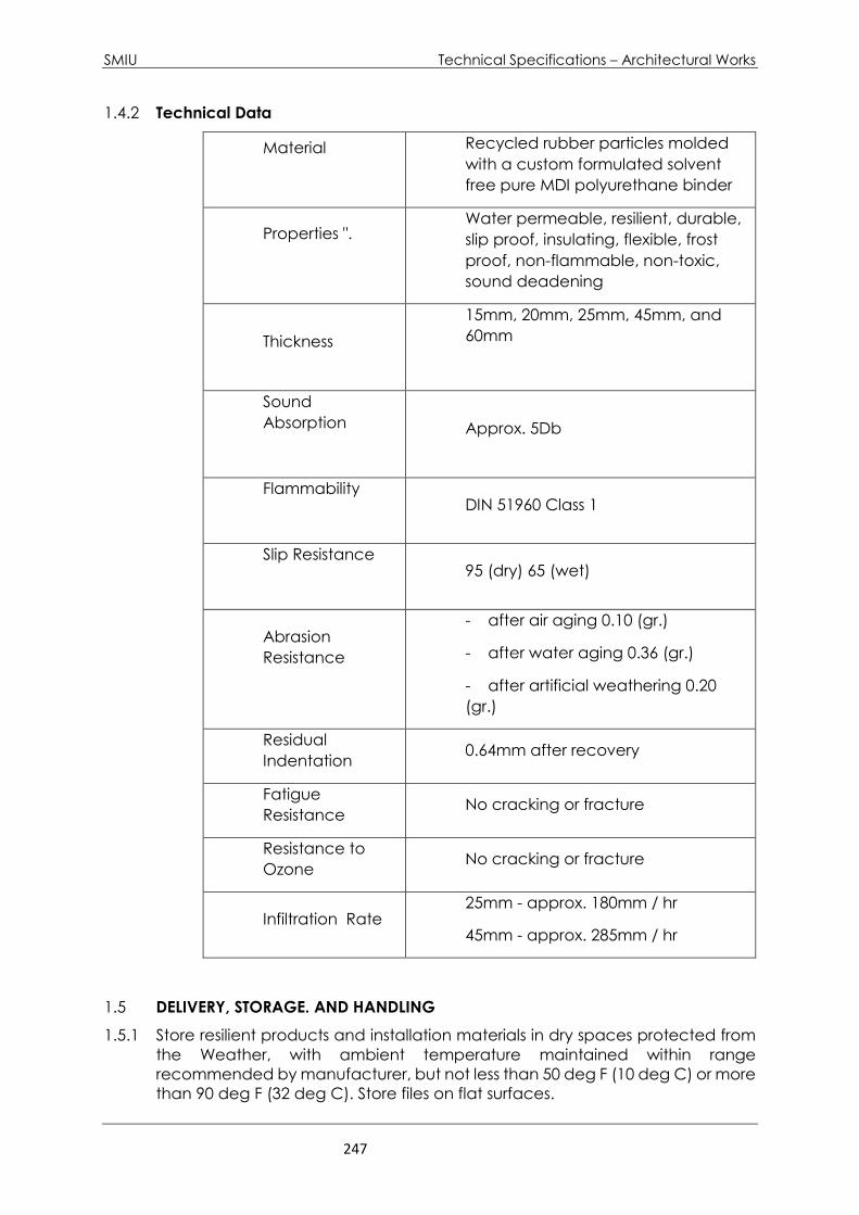
SMIU Technical Specifications – Architectural Works
247
1.4.2 Technical Data
Material
Recycled rubber particles molded
with a custom formulated solvent
free pure MDI polyurethane binder
Properties ".
Water permeable, resilient, durable,
slip proof, insulating, flexible, frost
proof, non-flammable, non-toxic,
sound deadening
Thickness
15mm, 20mm, 25mm, 45mm, and
60mm
Sound
Absorption
Approx. 5Db
Flammability
DIN 51960 Class 1
Slip Resistance
95 (dry) 65 (wet)
Abrasion
Resistance
- after air aging 0.10 (gr.)
- after water aging 0.36 (gr.)
- after artificial weathering 0.20
(gr.)
Residual
Indentation 0.64mm after recovery
Fatigue
Resistance No cracking or fracture
Resistance to
Ozone No cracking or fracture
Infiltration Rate 25mm - approx. 180mm / hr
45mm - approx. 285mm / hr
1.5 DELIVERY, STORAGE. AND HANDLING
1.5.1 Store resilient products and installation materials in dry spaces protected from
the Weather, with ambient temperature maintained within range
recommended by manufacturer, but not less than 50 deg F (10 deg C) or more
than 90 deg F (32 deg C). Store files on flat surfaces.
SMIU Technical Specifications – Architectural Works
248
1.6 PROJECT CONDITIONS
1.6.1 Maintain temperatures within range recommended by manufacturer, but not
less than
70'F, or more than 95'F, in spaces to receive floor tile during the following time
periods.
- 48 hours before installation
- During installation
- 48 hours after installation
1.6.2 After post installation period, maintain temperatures within range
recommended by manufacturer, but not less than 55' F, or more than 95'F.
1.6.3 Close spaces to traffic during floor covering installation.
1.6.4 Install resilient products after other finishing operations, including painting,
have been completed.
1.7 EXTRA MATERIAL
1.7.1 Furnish extra materials described below that match products installed and that
are
packaged with protective covering for storage and identified with labels
describing contents.
- Floor Tile: Furnish 1 box for every 50 boxes or fraction thereof, of each type,
color, and pattern of floor tile installed.
PART 2 PRODUCTS
2.1.1 MANUFACTURERS
2.1.1 Available Products: Subject to compliance with requirements, products that
may be incorporated into the Work include, but are not limited to, the products
listed in other Part 2 articles.
2.1.2 Products: Subject to compliance with requirements, provide one of the
products listed
in other part articles.
2.2 COLORS AND PATTERNS
2.2.1 Colors and Patterns: As selected by Architect from manufacturer's full
range.
2.3 INSTALLATION MATERIALS
2.3.1 Trowel able leveling and Patching Compounds: Latex modified, Portland
cement based or blended hydraulic cement based formulation provided or
approved by resilient product manufacturer for applications indicated.
2.3.2 Adhesives: Water-resistant type recommended by manufacturer to suit
resilient products and substrate conditions indicated.
SMIU Technical Specifications – Architectural Works
249
2.3.3 Metal Edge Strips: Extruded aluminum with mill Finish of width shown, of
height required to protect exposed edges of tiles, and in maximum available
lengths to minimize running joints.
PART 3 EXECUTION
3.1 EXAMINATION
3.1.1 Examine substrates with Installer present, for compliance with requirements for
installation tolerances, moisture control, and other conditions affecting
performance.
3.1.1.1 Verify that finishes of substrates comply with tolerances and other requirements
specified in other Sections and that substrates are free of cracks, ridges,
depressions, scale, and foreign deposits that might interfere with adhesion of
resilient products.
3.1.1.2 Proceed with installation only after unsatisfactory conditions have been
corrected.
3.2 PREPARATION
3.2.1 Prepare substrates according to manufacturer's written recommendations to
ensure adhesion of resilient products.
3.2.2 Concrete Substrates: Prepare according to ASTM F 710.
3.2.2.1 Verify that substrates are dry and free of curing compounds, sealers, and
hardeners.
3.2.2.2 Alkalinity and Adhesion Testing: Perform tests recommended by manufacturer.
Proceed with installation only after substrates pass testing.
3.2.2.3 Moisture Testing:
- Perform anhydrous calcium chloride test, ASTM F 1869. Proceed with
installation only after substrates have maximum moisture-vapor-emission
rate of 3 Ibs of water/1000 sq. ft. in 24-hours.
- Perform tests recommended by manufacturer. Proceed with installation
only after substrates pass testing.
3.2.3 Remove substrate coatings and other substances that are incompatible with
adhesives and that contain soap, wax, oil, or silicone, using mechanical
methods recommended by manufacturer. Do not use solvents.
3.2.4 Access Flooring Panels: Remove film of oil or other coating using method
recommended by access flooring manufacturer.
3.2.5 Use trowel able leveling and patching compound to fill cracks, holes, and
depressions in substrates.
3.2.6 Move resilient products and installation materials into spaces where they will be
installed at least 48-hours in advance of installation.
- Do not install resilient products until they are same temperature as space where they
are to be installed.
3.2.7 Sweep and vacuum clean substrates to be covered by resilient products
SMIU Technical Specifications – Architectural Works
250
immediately before installation. After cleaning, examine substrates for
moisture, alkaline sales, carbonation, and dust. Proceed with installation only
after unsatisfactory conditions have been corrected.
3.3 TILE INSTALLATION
3.3.1 Layout tiles from center marks established with principal walls, discounting
minor offsets, so
tiles at opposite edges of room are of equal width. Adjust as necessary to
avoid using cut widths that equal less than one-half tile at perimeter.
- Lay tiles in pattern indicated.
3.3.2 Match tiles for color and pattern by selecting tiles from cartons in the same
sequence as manufactured and packaged, if so numbered. Discard broken,
cracked, chipped or deformed tiles.
Lay tiles in pattern of colors and sizes indicated.
3.3.3 Scribe, cut, and fit tiles to butt neatly and tightly to vertical surfaces and
permanent fixtures including built-in furniture, cabinets, pipes, outlets edgings,
door frames, thresholds, and nosing.
3.3.4 Extend tiles into toe spaces, door reveals, closets, and similar openings.
3.3.5 Maintain reference markers, holes, and openings that are in place or marked
for future cutting by repeating on floor tiles as marked on substrates. Use chalk
or other non-permanent, constraining marking, device.
3.3.6 Install tiles on covers for telephone and electrical ducts and similar items in
finished floor areas. Maintain overall continuity of color and pattern with pieces
of tile installed on covers. Tightly adhere tile edges to substrates that abut
covers and to cover perimeters.
3.3.7 Adhere tiles to flooring substrates using a full spread of adhesive applied to
substrate to produce a completed installation without open racks, voids, raising
and puckering at joints, telegraphing of adhesive spreader marks, and other
surface imperfections.
3.4 CLEANING AND PROTECTION
3.4.1 Perform the following operations immediately after completing resilient
product installation:
3.4.1.1 Remove adhesive and other blemishes from exposed surfaces.
3.4.1.2 Sweep and vacuum surfaces thoroughly.
3.4.1.3 Damp-mop surfaces to remove marks and soil.
- Do not wash surfaces until after time period recommended by manufacturer.
3.4.2 Protect resilient products from mars, marks, indentations, and other damage
from construction operations and placement of equipment and fixtures during
remainder of construction period. Use protection methods recommended in
writing by manufacturer.
3.4.3 Apply protective floor polish to horizontal surfaces that are free from soil, visible
adhesive and surface blemishes if recommended in writing by manufacturer.
3.4.3.1 Use commercially available product acceptable to manufacturer.
SMIU Technical Specifications – Architectural Works
251
3.4.3.2 Coordinate selection of floor polish with Owner's maintenance service.
3.4.4 Cover products installed on horizontal surfaces with un-dyed, untreated
building paper until Substantial Completion.
3.4.5 Do not move heavy and sharp objects directly over surfaces. Place hardboard
or plywood panels over flooring and under objects while they are being
moved. Slide or roll objects over panels without moving panels.
PART 4 MEASUREMENTS AND PAYMENT
A. Payment for all the items under this section shall be made at the Unit rates
entered in the BOQ appended to the contract and in accordance with the
applicable conditions of the contract.
END OF SECTION
SMIU Technical Specifications – Architectural Works
252
8 SPECIALITIES
8.1 - TOILET AND BATH ACCESSORIES
PART 1 – GENERAL
1.1.1.1 RELATED DOCUMENTS
Drawing and general provisions of the contract, including general and
supplementary Conditions.
1.1.1.2 SUMMARY
- This Section includes the following:
- Toilet and bath accessories.
- Warm-air dryers.
- Related Sections include the following:
o Section "Ceramic Tile" for ceramic toilet and bath accessories.
1.1.1.3 SUBMITTALS
A. Product Data: Include construction details, material descriptions and
thicknesses, dimensions, profiles, fastening and mounting methods, specified
options, and finishes for each type of accessory specified.
B. Samples: For each accessory item to verify design, operation, and finish
requirements.
1. Approved full-size Samples will be returned and may be used in
2. the Work.
3. Setting Drawings: For cutouts required in other work; include templates,
substrate preparation instructions, and directions for preparing cutouts and
installing anchoring devices.
4. Product Schedule: Indicating types, quantities, sizes, and installation
locations by room of each accessory required. Use designations indicated
in the Toilet and Bath Accessory Schedule and room designations indicated
on Drawings in product schedule.
5. Maintenance Data: For accessories to include in maintenance manuals
specified in 1.0 section. Provide lists of replacement parts and service
recommendations.
1.1.1.4 QUALITY ASSURANCE
A. Product Options: Accessory requirements, including those for materials, finishes,
dimensions, capacities, and performance, are established by specific products
indicated in the Toilet and Bath Accessory Schedule.
B. Products of other manufacturers listed in Part 2 with equal characteristics, as
judged solely by Consultant, may be provided.
C. Other manufacturers' products with equal characteristics may be considered.
- See 1.0 Section "Substitutions."
D. Do not modify aesthetic effects, as judged solely by Consultant, except wit
E. Consultant's approval. Where modifications are proposed, submit
comprehensive explanatory data to Consultant for review.
SMIU Technical Specifications – Architectural Works
253
1.1.1.5 COORDINATION
A. Coordinate accessory locations with other work to prevent interference with
clearances required for access by disabled persons, proper installation,
adjustment, operation, cleaning, and servicing of accessories.
B. Deliver inserts and anchoring devices set into concrete or masonry as required
to prevent delaying the Work.
1.1.1.6 WARRANTY
A. General Warranty: Special warranty specified in this Article shall not deprive
Employer of other rights Employer may have under other provisions of the
Contract Documents and shall be in addition to, and run concurrent with, other
warranties made by Contractor under requirements of the Contract
Documents.
B. Manufacturer's Mirror Warranty: Written warranty, executed by mirror
manufacturer agreeing to replace mirrors that develop visible silver spoilage
defects within minimum warranty period indicated.
C. Minimum Warranty Period: 15 years from date of Substantial Completion.
PART 2 – PRODUCTS
8.1.2.1 MATERIALS
A. Stainless Steel: ASTM A 666, Type 304, with No. 4 finish (satin), in 0.8-mm minimum
nominal thickness, unless otherwise indicated.
B. Brass: ASTM B 19, leaded and unleaded flat products; ASTM B 16M, rods, shapes,
forgings, and flat products with finished edges; ASTM B 30, castings.
C. Sheet Steel: ASTM A 366/A 366M, cold rolled, commercial quality, 0.9-mm
minimum nominal thickness; surface preparation and metal pretreatment as
required for applied finish.
D. Galvanized Steel Sheet: ASTM A 653/A 653M, Z180.
E. Chromium Plating: ASTM B 456, Service Condition Number SC 2 (moderate
service), nickel plus chromium electrodeposited on base metal.
F. Baked-Enamel Finish: Factory-applied, gloss-white, baked-acrylic-enamel
coating.
G. Mirror Glass: as per requirements of 8.0, section “Mirrored Glass”.
H. Galvanized Steel Mounting Devices: ASTM A 153/A 153M, hot-dip galvanized
after fabrication.
I. Fasteners: Screws, bolts, and other devices of same material as accessory unit,
tamper and theft resistant when exposed, and of galvanized steel when
concealed.
8.1.2.2 FABRICATION
A. General: Names or labels are not permitted on exposed faces of accessories.
On interior surface not exposed to view or on back surface of each accessory,
provide printed, waterproof label or stamped nameplate indicating
manufacturer's name and product model number.
B. Surface-Mounted Toilet Accessories: Unless otherwise indicated, fabricate units
with tight seams and joints, and exposed edges rolled. Hang doors and access
panels with continuous stainless-steel hinge. Provide concealed anchorage
where possible.
C. Recessed Toilet Accessories: Unless otherwise indicated, fabricate units of all-
SMIU Technical Specifications – Architectural Works
254
welded construction, without mitered corners. Hang doors and access panels
with full-length, stainless-steel hinge. Provide anchorage that is fully concealed
when unit is closed.
D. Mirror-Unit Hangers: Provide mirror-unit mounting system that permits rigid,
tamper- and theft-resistant installation, as follows:
1. One-piece, galvanized steel, wall-hanger device with spring-action locking
mechanism to hold mirror unit in position with no exposed screws or bolts.
2. Heavy-duty wall brackets of galvanized steel, equipped with concealed
locking devices requiring a special tool to remove.
3. Keys: Provide universal keys for internal access to accessories for servicing
and resupplying. Provide minimum of six keys to Employer's representative.
PART 3 – EXECUTION
8.1.3.1 INSTALLATION
A. Install accessories according to manufacturers' written instructions, using
fasteners appropriate to substrate indicated and recommended by unit
manufacturer. Install units level, plumb, and firmly anchored in locations and at
heights indicated.
B. Secure mirrors to walls in concealed, tamper-resistant manner with special
hangers, toggle bolts, or screws. Set units level, plumb, and square at locations
indicated, according to manufacturer's written instructions for substrate
indicated.
8.1.3.2 ADJUSTING AND CLEANING
A. Remove temporary labels and protective coatings.
B. Clean and polish exposed surfaces according to manufacturer's written
recommendations.
8.1.3.3 TOILET AND BATH ACCESSORY SCHEDULE
A. Toilet Tissue Dispenser (Toilet Paper Holder): Provide toilet tissue dispenser
complying with the following:
1. Type Single-roll dispenser.
2. Mounting: Surface mounted with concealed anchorage.
3. Material: Stainless steel
4. Operation: Noncontrol delivery with mfr's standard spindle.
5. Capacity: Designed for standard diameter-core tissue rolls up to 140 mm
(6”) diameter (800 sheets)
B. Soap Dish: Stainless steel size and shape as selected by the Consultant from
manufacturer's standard range.
C. Soap Dispenser: Provide soap dispensers complying with the following:
1. Liquid Soap Dispenser, Vertical-Tank Type: Wall mounted type, minimum
1182.9 ml capacity tank with stainless steel piston, springs, and internal parts
designed to dispenses soap in measured quantity by pump action, and
stainless-steel cover with unbreakable window-type refill indicator.
a) Mounting: Designed for wall mounting.
b) Soap Valve: Designed for dispensing soap in liquid form.
D. Paper Towel Dispenser: 800 multi-hold towels capacity, stainless steel, surface
mounted.
E. Robe Hook
1. Stainless steel.

SMIU Technical Specifications – Architectural Works
255
2. Double-prong with rectangular wall bracket and back plate for
concealed mounting.
F. Grab Bar
1. Surface mounting, exposed.
2. Stainless steel.
3. 38 mm (1.5”) outside diameter and 1.20 mm minimum wall thickness
and 38 mm (1.5”) distance from inside of bar and face of wall.
4. Furnish complete with two end flanges, 3 mm (2/16”) thick minimum
and 76 mm (3”) diameter, each of three countersunk screw holes for
attachment to walls.
5. Use of flanges with snap covers is acceptable.
G. Warm-Air Dryer: Provide warm-air dryer complying with the following:
1. Touch-Button-Activated Hand Dryer: Surface-mounted, warm-air hand
dryer activated by touch button and with manufacturers' standard, white-
painted metal cover and 30-second-timed power cut-off switch.

SMIU Technical Specifications – Architectural Works
256
8.2 - TERMITE CONTROL
PART 1 – GENERAL
A. General provisions of the Contract, including Conditions of Contract apply to
this Section.
8.9.3.1 SUMMARY
B. This Section includes the following for termite control:
1. Termite prevention
2. Soil treatment
3. Wood protection
8.9.3.2 TERMITE PREVENTION
A. Avoid creation of conditions that invite termites wherever possible. Take the
following measures:
1. Remove stumps, roots, wood, and other cellulose materials from the
building site before commencing construction.
2. Remove cellulose materials from around the foundation before final
backfill.
3. Promptly remove form boards and grade stakes used in construction from
site.
4. Allow no contact between building woodwork and soil or fill material.
a) Locate exterior woodwork a minimum of 15 cm above ground and
beams in crawl spaces at least 45 cm above ground to provide ample
space to make future inspections.
b) Make foundation areas accessible for inspection if possible.
c) If wood that contacts the soil, such as fence posts and foundation
elements, use pressure treated wood.
5. Design ventilation openings in foundations to prevent dead air pockets and
to help keep the ground dry.
6. Direct water away from the structure through proper grading.
7. Assure that the roof drainage system directs all water away from the
foundation.
8. Avoid plantings near the foundation. Any tree that has the potential to grow
to a height of 12 meters or taller shall not be planted within 15 meters of the
foundation.
8.2.1.3 DEFINITIONS
A. EPA: United States Environmental Protection Agency.
B. PMP: Pest Management Professional
8.2.1.4 SUBMITTALS
A. Product Data: For termiticide and borate.
1. Include the EPA-Registered Label for termiticide and borate products.
B. Product Certificates: For termite control products, signed by product
manufacturer.
C. Qualification Data: For Installer of termite control products.
D. Soil Treatment Application Report: After application of termiticide is
completed, submit report for Owner's record information, including the
following:
1. Date and time of application.
SMIU Technical Specifications – Architectural Works
257
2. Moisture content of soil before application.
3. Brand name and manufacturer of termiticide.
4. Quantity of undiluted termiticide used.
5. Dilutions, methods, volumes, and rates of application used.
6. Areas of application.
7. Water source for application.
E. Wood Treatment Application Report: After application of borate is completed,
submit report for Owner's record information, including the following:
1. Date and time of application.
2. Brand name and manufacturer of borate.
3. Quantity of undiluted borate used.
4. Dilutions, methods, volumes, and rates of application used.
5. Areas of application.
F. Warranty: Special warranty specified in this Section.
8.2.1.5 QUALITY ASSURANCE
A. Applicator Qualifications: A PMP who is licensed according to regulations of
authorities having jurisdiction to apply termite control treatment in jurisdiction
where Project is located and who is experienced and has completed termite
control treatment similar to that indicated for this Project and whose work has
a record of successful in-service performance.
B. Regulatory Requirements: Formulate and apply termiticide, and label with a US
EPA registration number, to comply with EPA regulations and authorities having
jurisdiction.
C. Document any applicable local codes or authorities and ensure that all
relevant work is in compliance.
D. Implement applicable provisions of the Quality Control program as established
in:
- Section 01401, "Contractor Quality Control."
8.2.1.6 PROJECT CONDITIONS
TERMITE CONTROL SECTION 02361 - 3
A. Environmental Limitations: To ensure penetration, do not treat soil that is water
saturated or frozen. Do not treat soil while precipitation is occurring. Comply
with EPA-Registered Label requirements and requirements of authorities having
jurisdiction.
8.2.1.7 COORDINATION
A. Coordinate soil treatment application with excavating, filling, and grading and
concreting operations. Treat soil under footings, grade beams, and ground-
supported slabs, before construction.
8.2.1.8 WARRANTY
A. Warranty: Written warranty, signed by applicator and Contractor certifying
that termite control work, consisting of applied soil termiticide treatment, will
prevent infestation of subterranean termites. If subterranean termite activity or
damage is discovered during warranty period, retreat soil and repair or replace
damage caused by termite infestation.

SMIU Technical Specifications – Architectural Works
258
B. Warranty Period: Five years from date of Substantial Completion.
PART 2 – PRODUCTS
8.2.2.1 TERMITICIDES
A. Soil Termiticide: Provide an EPA-registered termiticide complying with
requirements of authorities having jurisdiction, in a soluble or amusable,
concentrated formulation that dilutes with water or foaming agent, and
formulated to prevent termite infestation for review and acceptance by the
COR.
1. The Department of State currently authorizes Termidor and Premise as soil
termiticide.
2. Provide quantity required for application at the label volume and rate for
the maximum termiticide concentration allowed for each specific use,
according to the product's EPA Registered Label.
B. Wood Protection Termiticide:
1. Provide an EPA-registered termiticide complying with requirements of
authorities having jurisdiction, in a soluble or emulsible, concentrated
formulation that dilutes with water or foaming agent, and formulated to
prevent termite infestation for review and acceptance by COR.
2. The Department of State currently authorizes Timber and Bora Care for
preventive wood treatment.
3. Provide quantity required for application at the label volume and rate for
the maximum termiticide concentration allowed for each specific use,
according to the product's EPA Registered Label.
4. Protect vegetation from contact with Timber and Bora Care.
END OF SECTION
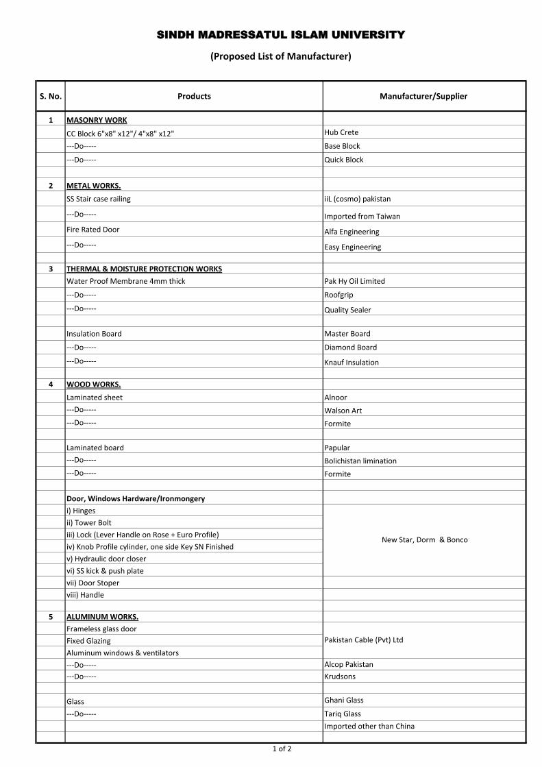
S. No. Products Manufacturer/Supplier
1 MASONRY WORK
CC Block 6"x8" x12"/ 4"x8" x12" Hub Crete
---Do----- Base Block
---Do----- Quick Block
2 METAL WORKS.
SS Stair case railing iiL (cosmo) pakistan
---Do----- Imported from Taiwan
Fire Rated Door Alfa Engineering
---Do----- Easy Engineering
3 THERMAL & MOISTURE PROTECTION WORKS
Water Proof Membrane 4mm thick Pak Hy Oil Limited
---Do----- Roofgrip
---Do----- Quality Sealer
Insulation Board Master Board
---Do----- Diamond Board
---Do----- Knauf Insulation
4 WOOD WORKS.
Laminated sheet Alnoor
---Do----- Walson Art
---Do----- Formite
Laminated board Papular
---Do----- Bolichistan limination
---Do----- Formite
Door, Windows Hardware/Ironmongery
i) Hinges
ii) Tower Bolt
iii) Lock (Lever Handle on Rose + Euro Profile)
iv) Knob Profile cylinder, one side Key SN Finished
v) Hydraulic door closer
vi) SS kick & push plate
vii) Door Stoper
viii) Handle
5 ALUMINUM WORKS.
Frameless glass door
Fixed Glazing
Aluminum windows & ventilators
---Do----- Alcop Pakistan
---Do----- Krudsons
Glass Ghani Glass
---Do----- Tariq Glass
Imported other than China
(Proposed List of Manufacturer)
SINDH MADRESSATUL ISLAM UNIVERSITY
New Star, Dorm & Bonco
Pakistan Cable (Pvt) Ltd
1 of 2
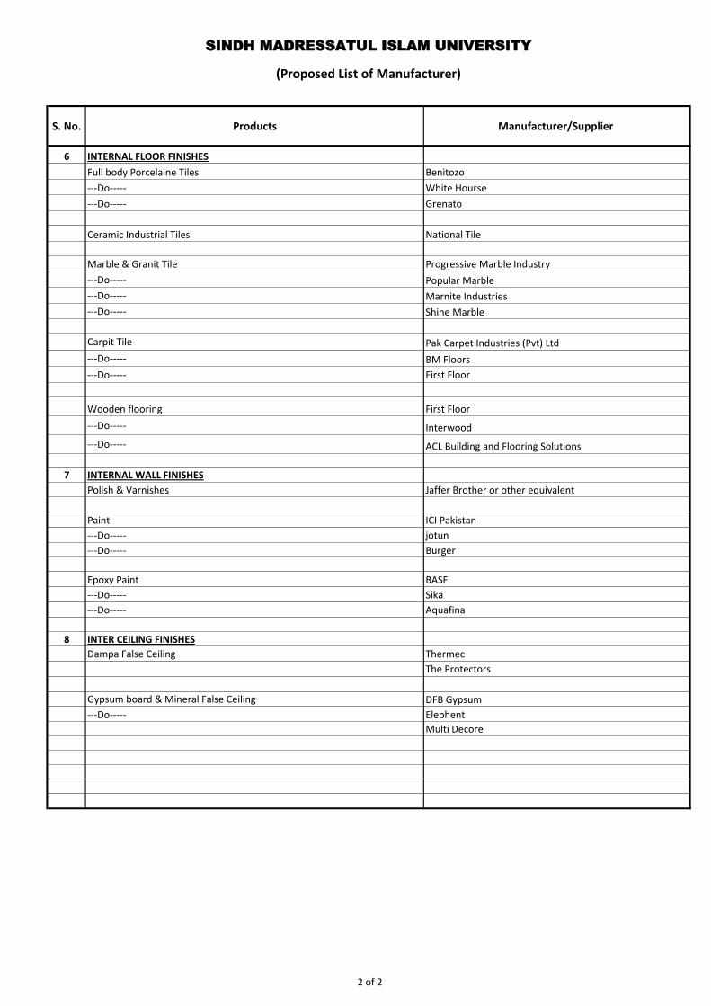
S. No. Products Manufacturer/Supplier
(Proposed List of Manufacturer)
SINDH MADRESSATUL ISLAM UNIVERSITY
6 INTERNAL FLOOR FINISHES
Full body Porcelaine Tiles Benitozo
---Do----- White Hourse
---Do----- Grenato
Ceramic Industrial Tiles National Tile
Marble & Granit Tile Progressive Marble Industry
---Do----- Popular Marble
---Do----- Marnite Industries
---Do----- Shine Marble
Carpit Tile Pak Carpet Industries (Pvt) Ltd
---Do----- BM Floors
---Do----- First Floor
Wooden flooring First Floor
---Do----- Interwood
---Do----- ACL Building and Flooring Solutions
7 INTERNAL WALL FINISHES
Polish & Varnishes Jaffer Brother or other equivalent
Paint ICI Pakistan
---Do----- jotun
---Do----- Burger
Epoxy Paint BASF
---Do----- Sika
---Do----- Aquafina
8 INTER CEILING FINISHES
Dampa False Ceiling Thermec
The Protectors
Gypsum board & Mineral False Ceiling DFB Gypsum
---Do----- Elephent
Multi Decore
2 of 2
PLUMBING

SMIU – City Campus Table of Contents – Plumbing Works
EA Consulting (Pvt.) Limited Page 1 of 1
(Sect. 15140) ‐ DOMESTIC WATER PIPING
(Sect. 15145) ‐ DOMESTIC WATER PIPING SPECIALTIES
(Sect. 15150) ‐ SANITARY WASTE, VENT AND STORM PIPING
(Sect. 15155) ‐ DRAINAGE PIPING SPECIALTIES
(Sect. 15315) ‐ FIRE PUMPS
(Sect. 15410) ‐ PLUMBING FIXTURES
(Sect. 15441) ‐ PLUMBING PUMPS

SMIU – City Campus Technical Specification – Plumbing Works
EA Consulting (Pvt.) Limited Page 1 of 7
Sect.15140 - DOMESTIC WATER PIPING
PART 1 - GENERAL
1.01 RELATED DOCUMENTS
A. Drawings and general provisions of the Contract, including General and Supplementary Conditions apply to this Section.
1.02 SUMMARY
A. This Section includes domestic water piping inside the building.
1.03 DEFINITIONS
A. CPVC: Chlorinated polyvinyl chloride plastic.
B. PEX: Crosslinked polyethylene plastic.
C. PVC: Polyvinyl chloride plastic.
D. PPR: Poly propylene Random
1.04 PERFORMANCE REQUIREMENTS
A. Provide components and installation capable of producing domestic water piping systems with 125 psig (860 kPa) unless otherwise indicated.
1.05 SUBMITTALS
A. Product Data: For pipe, tube, fittings, and couplings.
B. Water Samples:
C. Field quality-control test reports.
1.06 QUALITY ASSURANCE
A. Piping materials shall bear label, stamp, or other markings of specified testing agency.
B. Comply with NSF 14, "Plastics Piping System Components and Related Materials," for plastic, potable domestic water piping and components
SMIU – City Campus Technical Specification – Plumbing Works
EA Consulting (Pvt.) Limited Page 2 of 7
C. Comply with NSF 61, "Drinking Water System Components - Health Effects; Sections 1 through 9," for potable domestic water piping and components.
PART 2 - PRODUCTS
2.01 MANUFACTURERS
A. In other Part 2 articles where titles below introduce lists, the following requirements apply to product selection: 1. Manufacturers: Refer Approved List of Manufacturers.
2.02 PIPING MATERIALS
A. The pipe materials shall as stated below.
2.03 DOMESTIC COLD WATER BELOW AND ABOVE GRADE
1. Polypropylene pipes and pipe fitting PN20 to DIN 8077 for pipe size upto 110mm dia.
2. uPVC pipes to BS 3505 with Class E with solvent welded fittings to BS 4346 for pipe sizes above 110mm dia.
2.04 DOMESTIC HOT WATER PIPING
1. Polypropylene pipes and pipe fitting PN20 to DIN 8077 for pipe size upto 110mm dia.
2. cPVC Sch 80 pipes with solvent welded fittings for pipe sizes above 110mm dia.
2.05 IRRIGATION PIPES
1. uPVC pipes to BS 3505 with Class E with solvent welded fittings to BS 4346 for all pipe sizes.
2.06 VALVES
A. Generally, all valves of the same type shall be of the same manufacturer. All gate, globe, angle, and swing check valves as a group shall be of the same manufacturer. All valves 50 mm and smaller shall be threaded and have bronze bodies.
B. All valves 65 mm and larger shall be Cast iron type and shall be flanged (or grooved for grooved coupling joints).
SMIU – City Campus Technical Specification – Plumbing Works
EA Consulting (Pvt.) Limited Page 3 of 7
C. For PPR piping use PPR Coated valves of the same piping material and manufacturer.
D. Each valve shall be marked (engraved, stamped, or cast on each valve or metal tag, permanently attached to the valve) at the factory with the following minimum information 1. Manufacturer's Name. 2. Catalogue or Figure No. 3. Size and Pressure Class.
E. Arrows to indicate direction of flow on check, globe, angle, non-return, and eccentric plug valves.
2.07 GATE VALVES
A. [Size 50 mm and Smaller]. Furnish bronze valves with screwed-in bonnet, non-rising stem, solid wedge disc, and threaded ends. Pressure rating PN20.
B. [Size 65 mm and Larger]. Furnish Iron Body Bronze Mounted (IBBM) valves, i.e. cast iron body bronze trim valves, with bolted bonnet, non-rising stem, solid wedge disc, flanged ends, and renewable seat rings.
2.08 GLOBE VALVES.
A. [Size 50mm and Smaller]. Furnish valves designed for minimum PN20 working pressures.
B. [Size 65 mm and Larger]. Furnish valves designed for minimum PN16 working pressure.
2.09 CHECK VALVES
A. [50 mm and smaller]. Furnish swing valves designed for minimum PN20 non-shock working pressures. Valves shall have renewable discs and side plugs, integral seats.
B. [Size 65 mm and Larger Water Check Valves]. Valves shall be silent type spring loaded of the double door or wafer style. Valves shall be designed for minimum PN16 non shock water working pressure.
2.010 RELIEF VALVES.
Domestic Water Temperature and Pressure Relief Valve.
A. On hot water storage tanks provide an ASME rated thermostatic, self-closing, temperature and pressure relief valve, located in the relief valve openings of tanks. Valve shall have a minimum thermal discharge capacity equal to the input capacity of the heater standard pressure setting of 600 kPa and standard temperature setting of 100 - 140 degrees C. Relief valve pipe to discharge to floor drain.

SMIU – City Campus Technical Specification – Plumbing Works
EA Consulting (Pvt.) Limited Page 4 of 7
2.011 BALL VALVES.
A. [Size 50 mm and Smaller]. Valves shall be standard port, 2-piece construction with screwed ends. Valves shall be designed for minimum PN25. Valves shall have bronze or brass body, stainless steel ball, steel handle with vinyl grip.
B. [Size 65 mm and Larger].Valves shall be standard port, BS 5159 with flanged ends. Valves shall be designed for minimum PN16 working pressure. Valves shall have steel body, chrome or nickel plated steel or stainless steel ball.
2.012 Float Valves
A. Float valves shall be installed as indicated in the drawings to provide consistent level control in reserve supply water storage tanks. The valve shall meet the requirements of the Water Byelaws for air gaps and shall be constructed throughout in approved materials and shall prevent back siphoning. Bronze equilibrium float valves 80 and above shall be flanged end, flat faced and drilled to suit BS4504 PN16.
B. Bronze equilibrium float valves upto 50 shall be screwed end BS2779 parallel and shall be provided complete with back nut.
C. Floats for valve sizes 80mm and above shall be of copper.
2.013 Solenoid Valves
A. Electrically operated solenoid valves shall be single phase 220V and shall be rated for the system pressure
2.014 Bib Taps
A. Bib-cocks shall be in accordance with BS 1010: 1973. They shall be provided with hose union nosepiece and hand wheel operated.
2.015 Automatic Air Valves
A. Automatic air valves shall have a bronze body with bolted cover and a 9mm top outlet.
2.016 Strainers
A. Up to and including DN50 strainers shall be manufactured from bronze and shall be of the ‘Y’ type with bolted cap, PN25 temperature/pressure rating.
B. Strainers above DN50 shall be manufactured from cast iron and shall be of the ‘Y’ type with bolted cap, PN16 temperature/pressure rating and shall be complete with drilled and tapped caps complete with drain cocks.

SMIU – City Campus Technical Specification – Plumbing Works
EA Consulting (Pvt.) Limited Page 5 of 7
C. Strainers shall be provided with a medium grade screen sized such that in their clean condition the maximum pressure drop at the design flow rate shall not exceed 6kPa.
PART 3 - EXECUTION
3.01 EXCAVATION
A. Excavating, trenching, and backfilling are specified in Section "Earthwork."
3.02 PIPE AND FITTING APPLICATIONS
A. Transition and special fittings with pressure ratings at least equal to piping rating may be used in applications below, unless otherwise indicated.
B. Flanges may be used on aboveground piping, unless otherwise indicated.
C. Grooved joints may be used on aboveground grooved-end piping.
3.03 VALVE APPLICATIONS
A. Drawings indicate valve types to be used. Where specific valve types are not indicated, the following requirements apply:
1. Shutoff Duty: Use bronze ball or gate valves for piping NPS 2 (DN 50) and smaller. Use cast-iron butterfly or gate valves with flanged ends for piping NPS 2-1/2 (DN 65) and larger.
2. Hot-Water-Piping, Balancing Duty: Calibrated balancing valves. 3. Drain Duty: Hose-end drain valves.
B. PPR Coated PN-25 rated ball, butterfly, and check valves may be used in matching piping materials.
3.04 PIPING INSTALLATION
A. Install domestic water piping level without pitch and plumb.
B. Rough-in domestic water piping for water-meter installation according to utility company's requirements.
3.05 HANGER AND SUPPORT INSTALLATION
A. Install supports according to Division 15 Section "Hangers and Supports."
B. Support vertical piping and tubing at base and at each floor.
SMIU – City Campus Technical Specification – Plumbing Works
EA Consulting (Pvt.) Limited Page 6 of 7
C. Rod diameter may be reduced 1 size for double-rod hangers, to a minimum of 3/8 inch (10 mm).
D. Install hangers for PVC/cPVC/PPR and PE piping with the following maximum horizontal spacing and minimum rod diameters:
1. NPS 2 (DN 50) and Smaller: 48 inches (1200 mm) with 3/8-inch (10-mm) rod. 2. NPS 2-1/2 to NPS 3-1/2 (DN 65 to DN 90): 48 inches (1200 mm) with 1/2-inch
(13-mm) rod. 3. NPS 4 and NPS 5 (DN 100 and DN 125): 48 inches (1200 mm) with 5/8-inch
(16-mm) rod. 4. NPS 6 (DN 150): 48 inches (1200 mm) with 3/4-inch (19-mm) rod. 5. NPS 8 (DN 200): 48 inches (1200 mm) with 7/8-inch (22-mm) rod.
E. Install supports for vertical PVC/cPVC/PPR piping every 48 inches (1200 mm).
3.06 FIELD QUALITY CONTROL
A. Inspect domestic water piping as follows:
1. Do not enclose, cover, or put piping into operation until it has been inspected and approved by authorities having jurisdiction.
2. During installation, notify authorities having jurisdiction at least 24 hours before inspection must be made. Perform tests specified below in presence of authorities having jurisdiction:
a. Roughing-in Inspection: Arrange for inspection of piping before concealing or closing-in after roughing-in and before setting fixtures.
b. Final Inspection: Arrange final inspection for authorities having jurisdiction to observe tests specified below and to ensure compliance with requirements.
3. Reports: Prepare inspection reports and have them signed by authorities having jurisdiction.
B. Test domestic water piping as follows:
1. Fill domestic water piping. Check components to determine that they are not air bound and that piping is full of water.
2. Test for leaks and defects in new piping and parts of existing piping that have been altered, extended, or repaired. If testing is performed in segments, submit separate report for each test, complete with diagram of portion of piping tested.
3. Leave new, altered, extended, or replaced domestic water piping uncovered and unconcealed until it has been tested and approved. Expose work that was covered or concealed before it was tested.
4. Cap and subject piping to water pressure of 150 psi or 50 psi above operating pressure, without exceeding pressure rating of piping system materials. Isolate test source and allow to stand for four hours. Leaks and loss in test pressure constitute defects that must be repaired.

SMIU – City Campus Technical Specification – Plumbing Works
EA Consulting (Pvt.) Limited Page 7 of 7
5. Repair leaks and defects with new materials and retest piping or portion thereof until satisfactory results are obtained.
6. Prepare reports for tests and required corrective action.
END OF SECTION 15140
SMIU – City Campus Technical Specification – Plumbing Works
EA Consulting (Pvt.) Limited Page 1 of 4
Sect.15145 - DOMESTIC WATER PIPING SPECIALTIES
PART 1 - GENERAL
1.01 RELATED DOCUMENTS
A. Drawings and general provisions of the Contract, including General and Supplementary Conditions Specification Sections, apply to this Section.
1.02 SUMMARY
A. This Section includes the following domestic water piping specialties:
1. Balancing valves. 2. Strainers. 3. Outlet boxes. 4. Hose stations. 5. Hose bibs. 6. Drain valves. 7. Water hammer arresters. 8. Air vents. 9. Flexible connectors 10. Flow Sensing Devices 11. Puddle flanges
1.03 PERFORMANCE REQUIREMENTS
A. Minimum Working Pressure for Domestic Water Piping Specialties: 125 psig (860 kPa), unless otherwise indicated.
1.04 SUBMITTALS
A. Product Data: For each type of product indicated.
B. Shop Drawings:
C. Field quality-control test reports.
D. Operation and Maintenance Data: For domestic water piping specialties to include in emergency, operation, and maintenance manuals.
PART 2 - PRODUCTS
2.01 BALANCING VALVES
A. Refer Section 15140
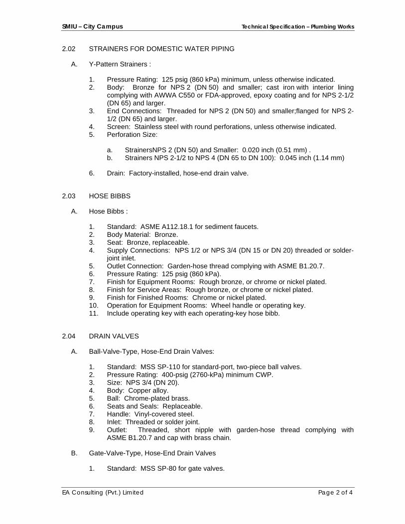
SMIU – City Campus Technical Specification – Plumbing Works
EA Consulting (Pvt.) Limited Page 2 of 4
2.02 STRAINERS FOR DOMESTIC WATER PIPING
A. Y-Pattern Strainers :
1. Pressure Rating: 125 psig (860 kPa) minimum, unless otherwise indicated. 2. Body: Bronze for NPS 2 (DN 50) and smaller; cast iron with interior lining
complying with AWWA C550 or FDA-approved, epoxy coating and for NPS 2-1/2 (DN 65) and larger.
3. End Connections: Threaded for NPS 2 (DN 50) and smaller;flanged for NPS 2-1/2 (DN 65) and larger.
4. Screen: Stainless steel with round perforations, unless otherwise indicated. 5. Perforation Size:
a. StrainersNPS 2 (DN 50) and Smaller: 0.020 inch (0.51 mm) . b. Strainers NPS 2-1/2 to NPS 4 (DN 65 to DN 100): 0.045 inch (1.14 mm)
6. Drain: Factory-installed, hose-end drain valve.
2.03 HOSE BIBBS
A. Hose Bibbs :
1. Standard: ASME A112.18.1 for sediment faucets. 2. Body Material: Bronze. 3. Seat: Bronze, replaceable. 4. Supply Connections: NPS 1/2 or NPS 3/4 (DN 15 or DN 20) threaded or solder-
joint inlet. 5. Outlet Connection: Garden-hose thread complying with ASME B1.20.7. 6. Pressure Rating: 125 psig (860 kPa). 7. Finish for Equipment Rooms: Rough bronze, or chrome or nickel plated. 8. Finish for Service Areas: Rough bronze, or chrome or nickel plated. 9. Finish for Finished Rooms: Chrome or nickel plated. 10. Operation for Equipment Rooms: Wheel handle or operating key. 11. Include operating key with each operating-key hose bibb.
2.04 DRAIN VALVES
A. Ball-Valve-Type, Hose-End Drain Valves:
1. Standard: MSS SP-110 for standard-port, two-piece ball valves. 2. Pressure Rating: 400-psig (2760-kPa) minimum CWP. 3. Size: NPS 3/4 (DN 20). 4. Body: Copper alloy. 5. Ball: Chrome-plated brass. 6. Seats and Seals: Replaceable. 7. Handle: Vinyl-covered steel. 8. Inlet: Threaded or solder joint. 9. Outlet: Threaded, short nipple with garden-hose thread complying with
ASME B1.20.7 and cap with brass chain.
B. Gate-Valve-Type, Hose-End Drain Valves
1. Standard: MSS SP-80 for gate valves.
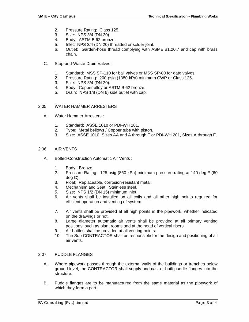
SMIU – City Campus Technical Specification – Plumbing Works
EA Consulting (Pvt.) Limited Page 3 of 4
2. Pressure Rating: Class 125. 3. Size: NPS 3/4 (DN 20). 4. Body: ASTM B 62 bronze. 5. Inlet: NPS 3/4 (DN 20) threaded or solder joint. 6. Outlet: Garden-hose thread complying with ASME B1.20.7 and cap with brass
chain.
C. Stop-and-Waste Drain Valves :
1. Standard: MSS SP-110 for ball valves or MSS SP-80 for gate valves. 2. Pressure Rating: 200-psig (1380-kPa) minimum CWP or Class 125. 3. Size: NPS 3/4 (DN 20). 4. Body: Copper alloy or ASTM B 62 bronze. 5. Drain: NPS 1/8 (DN 6) side outlet with cap.
2.05 WATER HAMMER ARRESTERS
A. Water Hammer Arresters :
1. Standard: ASSE 1010 or PDI-WH 201. 2. Type: Metal bellows / Copper tube with piston. 3. Size: ASSE 1010, Sizes AA and A through F or PDI-WH 201, Sizes A through F.
2.06 AIR VENTS
A. Bolted-Construction Automatic Air Vents :
1. Body: Bronze. 2. Pressure Rating: 125-psig (860-kPa) minimum pressure rating at 140 deg F (60
deg C). 3. Float: Replaceable, corrosion-resistant metal. 4. Mechanism and Seat: Stainless steel. 5. Size: NPS 1/2 (DN 15) minimum inlet. 6. Air vents shall be installed on all coils and all other high points required for
efficient operation and venting of system.
7. Air vents shall be provided at all high points in the pipework, whether indicated on the drawings or not.
8. Large diameter automatic air vents shall be provided at all primary venting positions, such as plant rooms and at the head of vertical risers.
9. Air bottles shall be provided at all venting points. 10. The Sub CONTRACTOR shall be responsible for the design and positioning of all
air vents.
2.07 PUDDLE FLANGES
A. Where pipework passes through the external walls of the buildings or trenches below ground level, the CONTRACTOR shall supply and cast or built puddle flanges into the structure.
B. Puddle flanges are to be manufactured from the same material as the pipework of which they form a part.
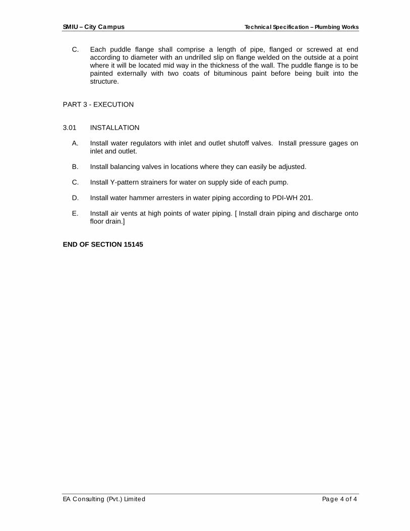
SMIU – City Campus Technical Specification – Plumbing Works
EA Consulting (Pvt.) Limited Page 4 of 4
C. Each puddle flange shall comprise a length of pipe, flanged or screwed at end according to diameter with an undrilled slip on flange welded on the outside at a point where it will be located mid way in the thickness of the wall. The puddle flange is to be painted externally with two coats of bituminous paint before being built into the structure.
PART 3 - EXECUTION
3.01 INSTALLATION
A. Install water regulators with inlet and outlet shutoff valves. Install pressure gages on inlet and outlet.
B. Install balancing valves in locations where they can easily be adjusted.
C. Install Y-pattern strainers for water on supply side of each pump.
D. Install water hammer arresters in water piping according to PDI-WH 201.
E. Install air vents at high points of water piping. [ Install drain piping and discharge onto floor drain.]
END OF SECTION 15145
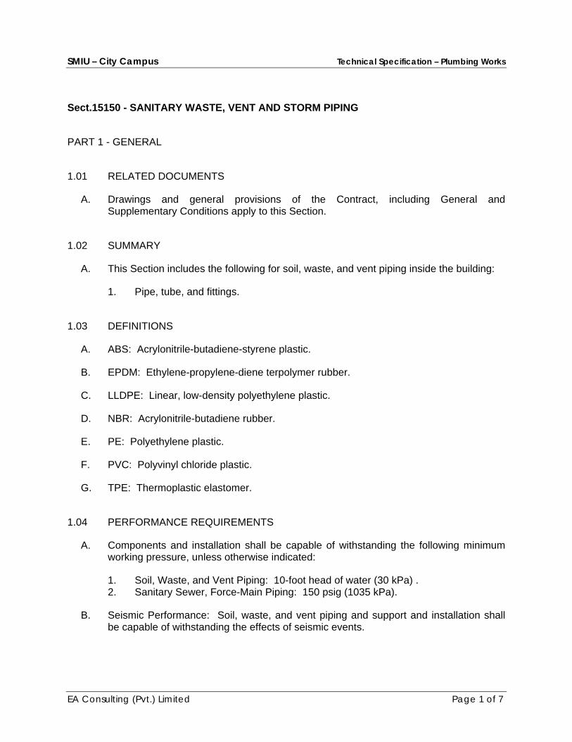
SMIU – City Campus Technical Specification – Plumbing Works
EA Consulting (Pvt.) Limited Page 1 of 7
Sect.15150 - SANITARY WASTE, VENT AND STORM PIPING
PART 1 - GENERAL
1.01 RELATED DOCUMENTS
A. Drawings and general provisions of the Contract, including General and Supplementary Conditions apply to this Section.
1.02 SUMMARY
A. This Section includes the following for soil, waste, and vent piping inside the building:
1. Pipe, tube, and fittings.
1.03 DEFINITIONS
A. ABS: Acrylonitrile-butadiene-styrene plastic.
B. EPDM: Ethylene-propylene-diene terpolymer rubber.
C. LLDPE: Linear, low-density polyethylene plastic.
D. NBR: Acrylonitrile-butadiene rubber.
E. PE: Polyethylene plastic.
F. PVC: Polyvinyl chloride plastic.
G. TPE: Thermoplastic elastomer.
1.04 PERFORMANCE REQUIREMENTS
A. Components and installation shall be capable of withstanding the following minimum working pressure, unless otherwise indicated:
1. Soil, Waste, and Vent Piping: 10-foot head of water (30 kPa) . 2. Sanitary Sewer, Force-Main Piping: 150 psig (1035 kPa).
B. Seismic Performance: Soil, waste, and vent piping and support and installation shall be capable of withstanding the effects of seismic events.

SMIU – City Campus Technical Specification – Plumbing Works
EA Consulting (Pvt.) Limited Page 2 of 7
1.05 SUBMITTALS
A. Product Data: For pipe, tube, fittings, and couplings.
B. Shop Drawings:
1. Design Calculations: Signed and sealed by a qualified professional engineer for selecting seismic restraints.
2. Drainage System: Include plans, elevations, sections, and details.
C. Field quality-control inspection and test reports.
1.06 QUALITY ASSURANCE
A. Piping materials shall bear label, stamp, or other markings of specified testing agency.
PART 2 - PRODUCTS
2.01 PIPING MATERIALS
A. Piping materials shall be as under.
2.02 ABOVE GROUND SOIL, WASTE AND VENT PIPE
A. All horizontal soil, waste pipes and rain water shall be Poly Propylene (PP) sound proof drainage pipes as per DIN 4109 and Din 4102 and fittings made of mineral-reinforced polypropylene homopolymer and copolymer. The typical density of the mineral filler shall be between 1.65 to 2.03 g/cm3 according to DIN 53479.
B. The sound isolation shall be 13 DB for 4.0 l/s flow rate in accordance with DIN 52379 and DIN 4109
C. The sound proof pipes & fittings shall be fire resistant class B2 to DIN 4102.
D. The sound proof pipes & fittings shall be fungus and bacteria resistant, and shall have smooth surface, corrosion resistant.
E. Soundproof drainage pipe system shall comply with following standards: 1. DIN 4109m sound proof, absorption standards. 2. DIN 4102, B2. Self-extinguishing flameless. 3. DIN 19560 / DIN EN 1451. Hot water resistance, 95°C (Long term), 95°C (short
term).

SMIU – City Campus Technical Specification – Plumbing Works
EA Consulting (Pvt.) Limited Page 3 of 7
4. Physical Characteristics
Density 1.65 g/cm³ DIN 53479
Elongation at break 50%
Tensile strength E-modulus Linear expansion
20N / mm²
E-modulus 3800 N / mm²
Linear expansion 0.04 mm / mk
5. The floor trap shall also be of sound proof material to DIN 4109.
2.03 BELOW GROUND SOIL AND WASTE PIPE
A. uPVC conforming to the following British Standards: 1. Pipes 110mm and 300mm diameter: uPVC pipe with solvent weld fitting as per
BS 4660 (BS EN 1401) 2. Pipes larger than 300mm diameter: to BS 3506.
2.04 STORM WATER PIPE
A. Plastic pipes shall be extruded un-plasticized PVC (UPVC) conforming to the following British Standards: 1. uPVC pipe with solvent joints (as approved by consultant) as per DIN 8061/8062
and ISO 3633 Type B
2.05 CONTENSATE DRAIN PIPING (ABOVE AND BELOW GRADE)
A. uPVC conforming to the following British Standards: 1. Pipes 20mm and 300mm diameter: Upvc class ‘E’ pipe with solvent weld fitting
as per BS 3505 (EN 1401).
2.06 PRESSURE PIPING FROM PUMPS (ABOVE AND BELOW GRADE)
A. uPVC conforming to the following British Standards:
SMIU – City Campus Technical Specification – Plumbing Works
EA Consulting (Pvt.) Limited Page 4 of 7
1. Pipes 20mm and 300mm diameter: Upvc class ‘E’ pipe with solvent weld fitting as per BS 3505 (EN 1401).
B. Alternatively (Kite Mark) pipes are acceptable only if approved by consultant.
2.07 SPECIAL PIPE FITTINGS
2.08 ENCASEMENT FOR UNDERGROUND PIPING CROSSING DRIVEWAYS
A. All Drainage pipes crossing driveways and subjected to heavy traffic shall be provided in concrete encasement.
PART 3 - EXECUTION
3.01 EXCAVATION
A. Refer to "Earthwork" for excavating, trenching, and backfilling.
3.02 PIPING INSTALLATION
A. Install cleanouts at grade and extend to where building sanitary drains connect to building sanitary sewers.
B. Install cleanout fitting with closure plug inside the building in sanitary force-main piping.
C. Make changes in direction for soil and waste drainage and vent piping using appropriate branches, bends, and long-sweep bends. Sanitary tees and short-sweep 1/4 bends may be used on vertical stacks if change in direction of flow is from horizontal to vertical. Use long-turn, double Y-branch and 1/8-bend fittings if 2 fixtures are installed back to back or side by side with common drain pipe. Straight tees, elbows, and crosses may be used on vent lines. Do not change direction of flow more than 90 degrees. Use proper size of standard increasers and reducers if pipes of different sizes are connected. Reducing size of drainage piping in direction of flow is prohibited.
D. Lay buried building drainage piping beginning at low point of each system. Install true to grades and alignment indicated, with unbroken continuity of invert. Place hub ends of piping upstream.
E. Install soil and waste drainage and vent piping at the following minimum slopes, unless otherwise indicated:
SMIU – City Campus Technical Specification – Plumbing Works
EA Consulting (Pvt.) Limited Page 5 of 7
1. Building Sanitary Drain: 2 percent downward in direction of flow for piping NPS 2 DN 50 and smaller; 1 percent downward in direction of flow for piping NPS 3 (DN 75) and larger.
2. Horizontal Sanitary Drainage Piping: 1 percent downward in direction of flow. 3. Vent Piping: 1 percent down toward vertical fixture vent or toward vent stack.
F. Install PVC soil and waste drainage and vent piping according to ASTM D 2665.
G. Install underground PVC soil and waste drainage piping according to ASTM D 2321.
H. Do not enclose, cover, or put piping into operation until it is inspected and approved by authorities having jurisdiction or Consultant.
3.03 HANGER AND SUPPORT INSTALLATION
A. Pipe hangers and supports are specified in Division 15 Section "Hangers and Supports." Install the following:
B. Install hangers for PVC piping with the following maximum horizontal spacing and minimum rod diameters:
1. NPS 1-1/2 and NPS 2 (DN 40 and DN 50): 48 inches (1200 mm) with 3/8-inch (10-mm) rod.
2. NPS 3 (DN 80): 48 inches (1200 mm) with 1/2-inch (13-mm) rod. 3. NPS 4 and 5 (DN 100 and 125): 48 inches (1200 mm) with 5/8-inch (16-mm)
rod. 4. NPS 6 (DN 150): 48 inches (1200 mm) with 3/4-inch (19-mm) rod. 5. NPS 8 to NPS 12 (DN 200 to DN 300): 48 inches (1200 mm) with 7/8-inch (22-
mm) rod.
C. Install supports for vertical PVC piping every 48 inches (1200 mm).
3.04 CONNECTIONS
A. Drawings indicate general arrangement of piping, fittings, and specialties.
B. Connect soil and waste piping to exterior sanitary sewerage piping. Use transition fitting to join dissimilar piping materials.
C. Connect drainage and vent piping to the following:
1. Plumbing Fixtures: Connect drainage piping in sizes indicated, but not smaller than required by plumbing code.
2. Plumbing Fixtures and Equipment: Connect atmospheric vent piping in sizes indicated, but not smaller than required by authorities having jurisdiction.
3. Plumbing Specialties: Connect drainage and vent piping in sizes indicated, but not smaller than required by plumbing code.
4. Equipment: Connect drainage piping as indicated.
SMIU – City Campus Technical Specification – Plumbing Works
EA Consulting (Pvt.) Limited Page 6 of 7
3.05 FIELD QUALITY CONTROL
A. During installation, notify authorities having jurisdiction at least 24 hours before inspection must be made. Perform tests specified below in presence of authorities having jurisdiction.
1. Roughing-in Inspection: Arrange for inspection of piping before concealing or closing-in after roughing-in and before setting fixtures.
2. Final Inspection: Arrange for final inspection by authorities having jurisdiction to observe tests specified below and to ensure compliance with requirements.
B. Reinspection: If authorities having jurisdiction find that piping will not pass test or inspection, make required corrections and arrange for reinspection.
C. Reports: Prepare inspection reports and have them signed by authorities having jurisdiction.
D. Test sanitary drainage and vent piping according to procedures of authorities having jurisdiction or, in absence of published procedures, as follows:
1. Test for leaks and defects in new piping and parts of existing piping that have been altered, extended, or repaired. If testing is performed in segments, submit separate report for each test, complete with diagram of portion of piping tested.
2. Leave uncovered and unconcealed new, altered, extended, or replaced drainage and vent piping until it has been tested and approved. Expose work that was covered or concealed before it was tested.
3. Roughing-in Plumbing Test Procedure: Test drainage and vent piping, except outside leaders, on completion of roughing-in. Close openings in piping system and fill with water to point of overflow, but not less than 10-foot head of water (30 kPa). From 15 minutes before inspection starts to completion of inspection, water level must not drop. Inspect joints for leaks.
4. Finished Plumbing Test Procedure: After plumbing fixtures have been set and traps filled with water, test connections and prove they are gastight and watertight. Plug vent-stack openings on roof and building drains where they leave building. Introduce air into piping system equal to pressure of 1-inch wg (250 Pa). Use U-tube or manometer inserted in trap of water closet to measure this pressure. Air pressure must remain constant without introducing additional air throughout period of inspection. Inspect plumbing fixture connections for gas and water leaks.
5. Repair leaks and defects with new materials and retest piping, or portion thereof, until satisfactory results are obtained.
6. Prepare reports for tests and required corrective action.
3.06 PROTECTION
A. Exposed PVC Piping: Protect plumbing vents exposed to sunlight with two coats of water-based latex paint.

SMIU – City Campus Technical Specification – Plumbing Works
EA Consulting (Pvt.) Limited Page 7 of 7
END OF SECTION 15150
SMIU – City Campus Technical Specification – Plumbing Works
EA Consulting (Pvt.) Limited Page 1 of 7
Sect.15155 - DRAINAGE PIPING SPECIALTIES
PART 1 - GENERAL
1.01 RELATED DOCUMENTS
A. Drawings and general provisions of the Contract, including General and Supplementary Conditions apply to this Section.
1.02 SUMMARY
A. This Section includes the following drainage piping specialties: 1. Cleanouts. 2. Floor drains. 3. Trench drains. 4. Channel drainage systems. 5. Roof drains. 6. Manhole Covers 7. Miscellaneous drainage piping specialties.
1.03 DEFINITIONS
A. ABS: Acrylonitrile-butadiene-styrene plastic.
B. FOG: Fats, oils, and greases.
C. FRP: Fiberglass-reinforced plastic.
D. HDPE: High-density polyethylene plastic.
E. PE: Polyethylene plastic.
F. PP: Polypropylene plastic.
G. PUR: Polyurethane plastic.
H. PVC: Polyvinyl chloride plastic.
1.04 SUBMITTALS
A. Product Data: For each type of product indicated above.
B. Shop Drawings: Show fabrication and installation details for frost-resistant vent terminals.
C. Field quality-control test reports.
D. Operation and Maintenance Data: For drainage piping specialties to include in emergency, operation, and maintenance manuals.
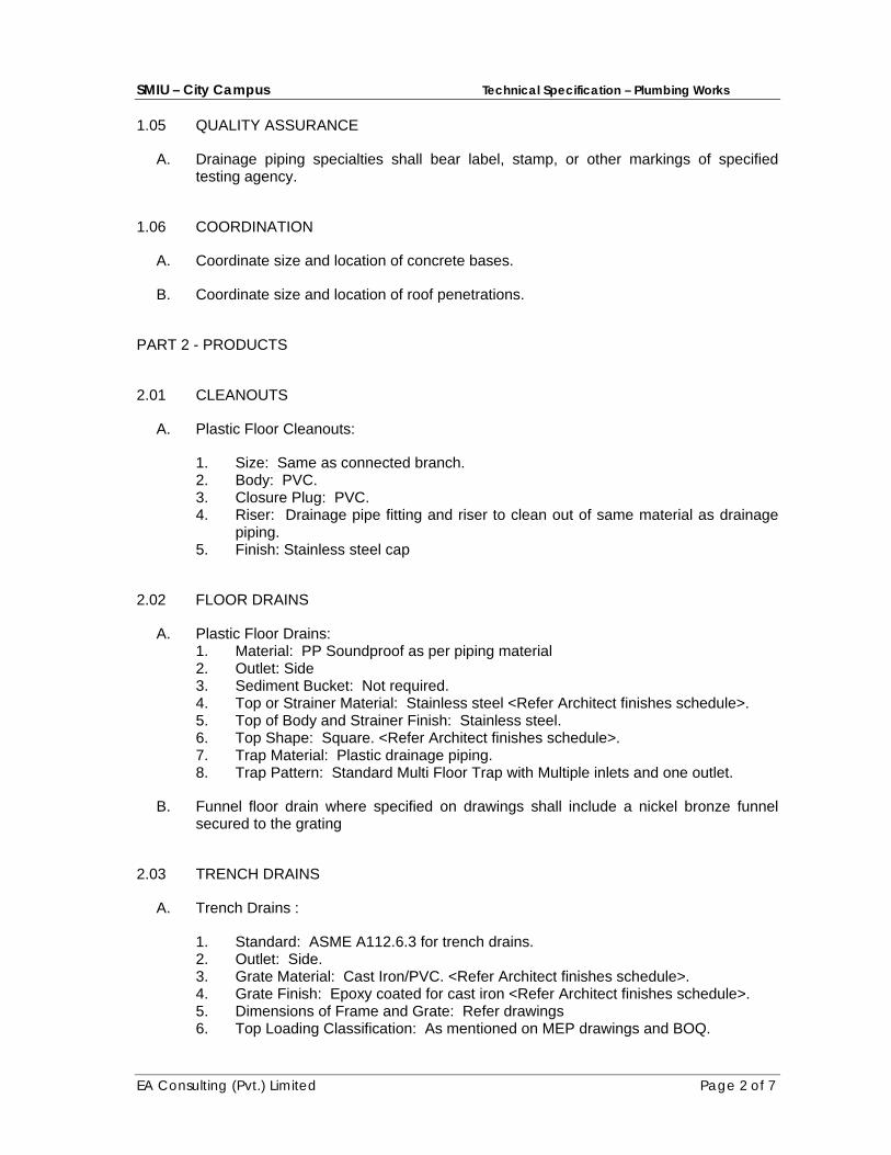
SMIU – City Campus Technical Specification – Plumbing Works
EA Consulting (Pvt.) Limited Page 2 of 7
1.05 QUALITY ASSURANCE
A. Drainage piping specialties shall bear label, stamp, or other markings of specified testing agency.
1.06 COORDINATION
A. Coordinate size and location of concrete bases.
B. Coordinate size and location of roof penetrations.
PART 2 - PRODUCTS
2.01 CLEANOUTS
A. Plastic Floor Cleanouts:
1. Size: Same as connected branch. 2. Body: PVC. 3. Closure Plug: PVC. 4. Riser: Drainage pipe fitting and riser to clean out of same material as drainage
piping. 5. Finish: Stainless steel cap
2.02 FLOOR DRAINS
A. Plastic Floor Drains: 1. Material: PP Soundproof as per piping material 2. Outlet: Side 3. Sediment Bucket: Not required. 4. Top or Strainer Material: Stainless steel <Refer Architect finishes schedule>. 5. Top of Body and Strainer Finish: Stainless steel. 6. Top Shape: Square. <Refer Architect finishes schedule>. 7. Trap Material: Plastic drainage piping. 8. Trap Pattern: Standard Multi Floor Trap with Multiple inlets and one outlet.
B. Funnel floor drain where specified on drawings shall include a nickel bronze funnel secured to the grating
2.03 TRENCH DRAINS
A. Trench Drains :
1. Standard: ASME A112.6.3 for trench drains. 2. Outlet: Side. 3. Grate Material: Cast Iron/PVC. <Refer Architect finishes schedule>. 4. Grate Finish: Epoxy coated for cast iron <Refer Architect finishes schedule>. 5. Dimensions of Frame and Grate: Refer drawings 6. Top Loading Classification: As mentioned on MEP drawings and BOQ.

SMIU – City Campus Technical Specification – Plumbing Works
EA Consulting (Pvt.) Limited Page 3 of 7
2.04 ROOF DRAINS
A. Plastic Roof Drains:
1. Standard: ASME A112.21.2M. 2. Pattern: Balcony/ Roof drain. 3. Body Material: PVC. 4. Dimensions of Body: Refer Drawings 5. Outlet: Bottom. 6. Dome Material: PVC/Stainless Steel <<Refer Architect finishes schedule>.
2.05 MISCELLANEOUS DRAINAGE PIPING SPECIALTIES
A. Vent Caps:
1. Description: PVC of same brand as of piping. 2. Size: Same as connected stack vent or vent stack.
B. Expansion Joints:
1. Standard: ASME A112.21.2M. 2. Body: Cast iron with bronze sleeve, packing, and gland. 3. End Connections: Matching connected piping. 4. Size: Same as connected soil, waste, or vent piping.
C. Manholes/gully traps covers
1. All covers shall be Cast Iron with black bitumen coating. Manhole covers shall have clear opening of 600 x 600 mm.
2. All manholes and gully traps shall be vented as per drainage department requirements.
3. Gully trap covers shall have clear opening of 300 x 300 mm.
4. All manhole covers and frames shall comply with BS 497:1976 (BS EN 124:1994)
5. Covers in paved areas shall be medium duty type having weight as per Table 1
6. Covers in plinth protection shall be light duty having weight as per Table-1
7. Covers in Driveways shall be Heavy duty having weight as per Table-1
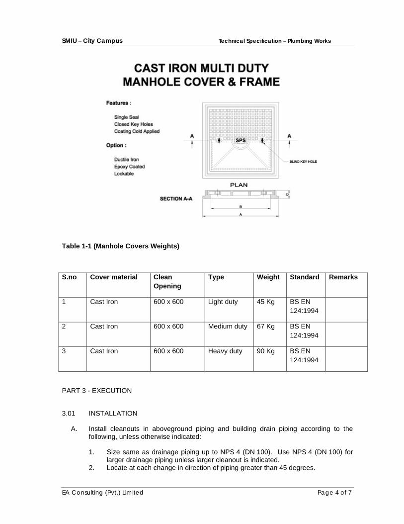
SMIU – City Campus Technical Specification – Plumbing Works
EA Consulting (Pvt.) Limited Page 4 of 7
Table 1-1 (Manhole Covers Weights)
S.no Cover material Clean Opening
Type Weight Standard Remarks
1 Cast Iron 600 x 600 Light duty 45 Kg BS EN 124:1994
2 Cast Iron 600 x 600 Medium duty 67 Kg BS EN 124:1994
3 Cast Iron 600 x 600 Heavy duty 90 Kg BS EN 124:1994
PART 3 - EXECUTION
3.01 INSTALLATION
A. Install cleanouts in aboveground piping and building drain piping according to the following, unless otherwise indicated:
1. Size same as drainage piping up to NPS 4 (DN 100). Use NPS 4 (DN 100) for larger drainage piping unless larger cleanout is indicated.
2. Locate at each change in direction of piping greater than 45 degrees.

SMIU – City Campus Technical Specification – Plumbing Works
EA Consulting (Pvt.) Limited Page 5 of 7
3. Locate at minimum intervals of 50 feet (15 m) for piping NPS 4 (DN 100) and smaller and 100 feet (30 m) for larger piping.
4. Locate at base of each vertical soil and waste stack.
B. For floor cleanouts for piping below floors, install cleanout deck plates with top flush with finished floor.
C. For cleanouts located in concealed piping, install cleanout wall access covers, of types indicated, with frame and cover flush with finished wall.
D. Install floor drains at low points of surface areas to be drained. Set grates of drains flush with finished floor, unless otherwise indicated.
1. Position floor drains for easy access and maintenance.
2. Install floor-drain flashing collar or flange so no leakage occurs between drain and adjoining flooring. Maintain integrity of waterproof membranes where penetrated.
3. Install individual traps for floor drains connected to sanitary building drain, unless otherwise indicated.
E. Install trench drains at low points of surface areas to be drained. Set grates of drains flush with finished surface, unless otherwise indicated.
F. Assemble and install ASME A112.3.1, stainless-steel channel drainage systems according to ASME A112.3.1. Install on support devices so that top will be flush with surface.
G. Install fixture air-admittance valves on fixture drain piping.
H. Install stack air-admittance valves at top of stack vent and vent stack piping.
I. Install air-admittance-valve wall boxes recessed in wall.
J. Install flashing fittings on sanitary stack vents and vent stacks that extend through roof.
K. Install through-penetration firestop assemblies in plastic stacks at floor penetrations.
L. Install floor-drain, trap-seal primer fittings on inlet to floor drains that require trap-seal primer connection.
1. Exception: Fitting may be omitted if trap has trap-seal primer connection. 2. Size: Same as floor drain inlet.
M. Install vent caps on each vent pipe passing through roof.
N. Install frost-resistant vent terminals on each vent pipe passing through roof. Maintain 1-inch (25-mm) clearance between vent pipe and roof substrate.
O. Install expansion joints on vertical stacks and conductors. Position expansion joints for easy access and maintenance.
P. Install grease interceptors, including trapping, venting, and flow-control fitting, according to authorities having jurisdiction and with clear space for servicing.

SMIU – City Campus Technical Specification – Plumbing Works
EA Consulting (Pvt.) Limited Page 6 of 7
1. Above-Floor Installation: Set unit with bottom resting on floor, unless otherwise indicated.
2. Flush with Floor Installation: Set unit and extension, if required, with cover flush with finished floor.
3. Recessed Floor Installation: Set unit in receiver housing having bottom or cradle supports, with receiver housing cover flush with finished floor.
4. Install cleanout immediately downstream from interceptors not having integral cleanout on outlet.
Q. Install grease removal devices on floor. Install trap, vent, and flow-control fitting according to authorities having jurisdiction. Install control panel adjacent to unit, unless otherwise indicated.
R. Install oil interceptors, including trapping, venting, and flow-control fitting, according to authorities having jurisdiction and with clear space for servicing.
S. Install solids interceptors with cleanout immediately downstream from interceptors that do not have integral cleanout on outlet. Install trap on interceptors that do not have integral trap and are connected to sanitary drainage and vent systems.
T. Install traps on plumbing specialty drain outlets. Omit traps on indirect wastes unless trap is indicated.
3.02 CONNECTIONS
A. Install piping adjacent to equipment to allow service and maintenance.
B. Grease Interceptors: Connect inlet and outlet to unit, and connect flow-control fitting and vent to unit inlet piping. Install valve on outlet of automatic drawoff-type unit.
C. Oil Interceptors: Connect inlet, outlet, vent, and gravity drawoff piping to unit; flow-control fitting and vent to unit inlet piping; and gravity drawoff and suction piping to oil storage tank.
3.03 LABELING AND IDENTIFYING
A. Equipment Nameplates and Signs: Install engraved plastic-laminate equipment nameplate or sign on or near each of the following: 1. Grease interceptors. 2. Oil interceptors. 3. Solids interceptors.
B. Distinguish among multiple units, inform operator of operational requirements, indicate safety and emergency precautions, and warn of hazards and improper operations, in addition to identifying unit.
3.04 FIELD QUALITY CONTROL
A. Perform tests and inspections and prepare test reports.
1. Manufacturer's Field Service: Engage a factory-authorized service representative to inspect field-assembled FOG disposal systems and grease
SMIU – City Campus Technical Specification – Plumbing Works
EA Consulting (Pvt.) Limited Page 7 of 7
removal devices and their installation, including piping and electrical connections, and to assist in testing.
B. Tests and Inspections:
1. Leak Test: After installation, charge system and test for leaks. Repair leaks and retest until no leaks exist.
2. Test and adjust controls and safeties. Replace damaged and malfunctioning controls and equipment.
3.05 PROTECTION
A. Protect drains during remainder of construction period to avoid clogging with dirt or debris and to prevent damage from traffic or construction work.
B. Place plugs in ends of uncompleted piping at end of each day or when work stops.
3.06 DEMONSTRATION
A. Engage a factory-authorized service representative to train Owner's maintenance personnel to adjust, operate, and maintain FOG disposal systems and grease removal devices.
END OF SECTION 15155

ELECTRICAL WORKS
SMIU Technical Specification – Electrical Works
EA Consulting (Pvt.) Limited Page 1 of 119
SECTION – E - 1 GENERAL SPECIFICATIONS
FOREWORD
This document is to describe the minimum requirements for the equipment and installations and to ensure that the Contractor is fully aware of his duties to perform the required works, in accordance with the terms of the Contract.
1.0 SCOPE OF WORK
The works related to the electrical system which are included in the scope of this Contract are shown on the Drawings, stated in the Particular Specifications, Bill of Quantities and explained in these specifications. The works shall broadly include but not limited to the following:
1. Low Voltage Switch Boards / Distribution Boards (Section - E - 2) 2. Low Voltage Cable and Wires (Section – E - 3) 3. Conduits and Pipes (Section – E - 4) 4. Wiring Accessories (Section – E - 5) 5. Interior Lighting Fixtures (Section – E - 6) 6. Earthing System (Section – E - 7) 7. Cable Tray, Ladder and Trunking (Section
– E - 8) 8. ESE Lightning Protection System (Section
– E - 9) 9. Diesel Generator System (Section – E - 10) 10. Telecommunication Systems (Section – E - 11) 11. Addressable Fire Alarm System (Section – E - 12) 12. Close Circuit Television (CCTV) System (Section –
E - 13) 13. Public Address System (Section – E - 14) 14. Uninterruptible Power Supply (UPS) (Section –E – 15) 15. Self-Contained Emergency Lighting Fixtures (Section -E - 16) 16. Access Control System (Section –E -17) 17. Master Clock System (Section –E -18)
All material and equipment supplied by the Contractor shall be new and in all respects conform to the high standards of Engineering design, workmanship, performance and function as here in specified and fully meet the quality level and rugged requirements of the specifications.
The Contractor shall also be responsible to supply any other equipment not specifically mentioned in these documents but which is necessary for proper operation of the works / system, shall be considered to have been so specified and accordingly shall be provided by the Contractor as part of the Contract.
SMIU Technical Specification – Electrical Works
EA Consulting (Pvt.) Limited Page 2 of 119
The Contractor shall be solely responsible for ensuring proper functional requirements of various equipment and shall also be responsible for furnishing any additional piece of equipment and for making modification in the equipment as desired and / or approved by the Owner or his representative, to achieve proper coordination with various equipment offered in the bid and also those installed by others.
Approval of the Contractor's supplied equipment / installation works shall not relieve the Contractor of any of his obligations or liabilities under the Contract, except insofar as provided under the conditions of the Contract.
2.0 RULES AND REGULATIONS
The entire electrical installation / work shall be carried out by licensed contractor, authorized to undertake such work under the provisions of Electricity Act 1910 and The Electricity Rules 1937 as adopted and modified up to date by the Government of Pakistan.
All works shall be carried out in accordance with the latest edition of the Regulations of the Electrical Equipment of Buildings issued by the Institute of Electrical Engineers - London, the Contract documents, the Electricity Rules 1937 and bye-laws that are in force from time to time. Any discrepancy between these specifications and any other rules and regulations shall be brought to the notice of Owner or his representative, and his decision shall be final and conclusive.
The Contractor shall be responsible for completing all formalities and submitting the test certificates as per prevailing rules and regulations and shall have the installation passed by the Government Electric Inspector of that region. All requirements of the Electric Inspector and the Electric Company shall be complied with.
3.0 STANDARDS
All works, equipment and materials shall conform to: On the one hand: The specification recommended practices, official standards and codes the non - restrictive List of which is given below. International Electro-technical Commission (IEC) British Standards (BS) National Electric Code (NEC) National Standards
In the event of conflict between standards, the most stringent shall prevail. Whenever the electrical equipment to be installed, does not hold national standards, the Contractor shall take into account the specific standards chosen by the Owner and make sure that the equipment he has to install, meets these standards. In addition, even if no mention is stipulated in this specification, it is implied

SMIU Technical Specification – Electrical Works
EA Consulting (Pvt.) Limited Page 3 of 119
that the equipment be tropicalized, if required, by the conditions of the site of installation.
In any case, the standards and codes to be taken into consideration are those in force at the date of delivery.
4.0 INSTALLATION AND SERVICE CONDITIONS
4.1 Site Conditions All material and equipment supplied and installed shall be designed, manufactured and tested to meet the following ambient conditions unless specifically stated otherwise for any material / equipment: a. Maximum outdoor ambient temperature: 45 degree C b. Minimum Indoor ambient temperature : 0 degree C c. Maximum relative humidity : 90 % d. Minimum relative humidity : 26 %
4.2 Service Conditions Equipment shall be designed and built for continuous service with a minimum of supervision and maintenance.
5.0 MAIN ELECTRICAL CHARACTERISTICS
5.1 Power Supply System Unless otherwise specified elsewhere, all equipment and material shall be designed to operate and function satisfactorily with the following minimum requirements without any de-rating: - Voltage 400 + 10% - Phase 3, 4 wire system - Frequency 50 Hz. +2 Hz.
5.2 Degree of Protection of Enclosures
For indoors, IP42 minimum degree of ingress protection of the enclosures against contact with line or moving parts and against ingress of solid foreign bodies or liquids, shall be selected, in accordance with IEC 60529.
6.0 GUARANTEE
The Contractor shall furnish written grantee which should clearly state that the works he will carry out as well as the materials he will supply, meet with this specification and that compliance thereto constitutes an official clause, added by implication to the general conditions of his offer when signing the Contract.
Guarantee shall also be for replacement and repair of part or whole of the equipment which may be found defective in material or workmanship. The grantee shall cover the duration of Maintenance Period as defined in the conditions of the Contract. This guarantee shall not relieve the Contractor of his obligations and he will fully be responsible for the repair or replacement of
SMIU Technical Specification – Electrical Works
EA Consulting (Pvt.) Limited Page 4 of 119
any defective material in time, so as not to cause any undue delay in carrying out the repairs and/ or replacements.
The Contractor shall acquaint himself fully with the existing conditions and limitations at site and all works necessary to complete the project under the Contract, to be carried out by the Contractor.
7.0 EXCEPTIONS TO SPECIFICATION
Any exception or deviation from this specification or the codes and standards shall be listed separately in the Contractor's "List of Deviations". Any exception, which shall not be listed, shall not be considered later.
8.0 AVAILABILITY OF SPECIFICATIONS, DRAWINGS AT SITE
The Contractor shall assume at his own cost the permanent availability of this specification and drawings on site where applicable.
9.0 DISCREPANCIES IN TENDER DOCUMENTS AND DRAWINGS
The Contractor shall carefully examine the documents and drawings and if he finds any discrepancies or omissions from the specifications, bill of quantities or drawings, or is in doubt as to the meaning, he shall at once notify the Owner or his representative for receiving his instructions before proceeding with the works. If such defective or modified work is carried out by the Contractor on his own, he shall rectify the same at his own cost.
10.0 MEASUREMENT OF WORKS
The quantities set out in the bill of quantities are the estimated quantities and they shall not be taken as actual and correct quantities of work to be executed by the Contractor. The Contractor shall carry out actual measurement of works at the site.
11.0 INSTALLATIONS DETAILS
The locations, routings, installation heights, detail etc. for electrical equipment are indicated on the drawings. If any information is not stated on the drawings or wherever modifications are required the Contractor shall obtain prior instructions from the Owner or his representative.
12.0 DRAWINGS AND DATA
The Contractor shall provide dimensional outline drawings, arrangement drawings and technical data for the equipment offered, for the approval of Owner or his representative.
13.0 PRIOR APPROVAL OF SHOP DRAWINGS, MATERIALS AND EQUIPMENT
The Contractor shall provide shop drawings for the electrical installations showing the exact routes of all underground cables and ducts, the exact run of all conduits and trunking, draw-in and junction boxes, the number and size of wires in each conduit, the final connection arrangements at distribution boards and the details of ducts for the approval of consultant / Owner's representative before commencing any portion of the works. All such working drawings shall be submitted in suitable number of copies as indicated in the particular conditions and within the periods stipulated below:
SMIU Technical Specification – Electrical Works
EA Consulting (Pvt.) Limited Page 5 of 119
a. Cable entry ducts into buildings:
Working drawings shall be submitted within two weeks of handing over the site.
b. All other working drawings shall be submitted to the Engineer against signed receipt and dated within two months of signing the Contract. Should however the Contractor be obliged to install electrical conduits prior to this period then he shall submit the relevant working drawings at least two weeks prior to the proposed date of commencement of the work. The Contractor shall submit the program indicating the dates on which coordination in different sections will take place, together with the submission of the working drawings. The Engineer shall arrange to return to the Contractor at least one week prior to the commencement of concreting of the section, his comments or approval of the working drawings.
The Contractor shall supply detailed specifications, dimensional drawings, etc., of equipment that he proposes to supply and install.
Where this Contract requires the approval of Engineer to material and goods, the Contractor must seek to obtain this approval within eight weeks after signing of the Contract. No extension of time will be granted for non-availability of material or goods if this clause is not complied with. Approval of the Engineer does not relieve the Contractor of placing his orders in due time for the materials he needs to complete the Contract on time. The approved samples shall be retained on site for comparison with commodities used in works and removed when no longer required.
14.0 MATERIAL ORIGIN AND QUALITY
The material and equipment shall be purchased from Consultant / Owner's agreed suppliers.
The consultant / owner shall retain the right to at any time demand the indication of origin of the materials, and to eventually refuse products, the origin of manufacturing of which have not been previously agreed to without consideration of quality. On specific agreement of the Owner, the materials may be delivered progressively to the field, but in such a manner as to allow sufficient time for their reception.
When choice of manufacturer is allowed for any particular commodity the Contractor shall obtain the whole quality required to complete the work from one manufacturer or obtain approval of any change in source of supply. He shall produce written evidence of sources of supply when requested to do so by the Engineer.
15.0 IDENTIFICATION OF EQUIPMENT
For each piece of equipment, identification label shall be fitted in front of the casing. The label shall have block letter 7mm high, black on white back ground of trifoliate and fixed with screws.
SMIU Technical Specification – Electrical Works
EA Consulting (Pvt.) Limited Page 6 of 119
16.0 MARKINGS
The contractor shall provide “Danger Boards “and” Shock Charts “wherever required to comply with the requirements of local Electricity Rules and according to normal practice.
17.0 FACTORY TESTS
All equipment supplied by and installed as part of the Contract such as distribution boards and like shall be fully tested at the manufacturer's works to the requirements of appropriate standards called for later in the particular specification. The Contractor shall inform the Engineer in writing about the date and time of test of each equipment at least two weeks in advance. The witnessing of test by the Owner or his representative shall not absolve the Contractor from his responsibility for the proper functioning of the equipment and for furnishing the guarantees referred to in Clause 6.0. All test results in the form of certificate of test / test record certificates, signed by all the witnesses, for each item in the scope of Contractor's supply shall be supplied to the Engineer within seven days of the test date, and in any event before delivery to the site.
All expenses for carrying out the tests and witness by the Owner or his representative shall be borne by the Contractor and deemed to have been included in the tender bid.
18.0 STORAGE
The Contractor shall store the equipment in such conditions that it can not be damaged, i.e., in a dry warehouse. As particular concerns; fragile components, these shall be stored on shelves in their original packing, fitted with identification labels so as to avoid unnecessary manipulation or handling.
The Contractor shall handle, store and fix each commodity in accordance with the manufacturer's recommendations. He shall inform the Engineer if these conflicts with any other specified requirement and submit copies of manufacturer's recommendations to the Engineer when requested to do so.
19.0 LABOR AND STAFF OF CONTRACTOR The Contractor shall provide / furnish and arrange for:
- Skilled and unskilled labor required for performing the works in accordance with the technical specifications and drawings within the agreed time schedule.
- Supervisory technical staff with appropriate experience and requisite expertise to ensure quality of work performed.
- Supervisory administration and clerical staff to ensure smooth functioning of the activities at site.
- Construction equipment, meggers, tools, etc.
The Contractor shall supply all labor, materials and equipment necessary for the installation of low voltage distribution boards, cables, lighting and power equipment, together with all other apparatus shown on the drawings and as detailed in the Particular specification.

SMIU Technical Specification – Electrical Works
EA Consulting (Pvt.) Limited Page 7 of 119
20.0 SMALL INSTALLATION MATERIAL
The Contractor shall supply all small installation and consumable materials such as nuts, bolts, washers, shims, angles, leveling materials, insulation tape, solder, PVC strap-on or heat shrinkable type cable tags, cable ties, bushes, sealing compound, Avometer, electrical testing and measuring instruments, etc., and all such other material not listed in BOQ, required for complete installation as intended by the specification and scope of works.
21.0 INSTALLATION INSTRUCTIONS - GENERAL
The Contractor shall set out the works himself as per specifications and drawings and shall properly position the equipment on specified foundation / location. In general, the manufacturer's instructions for installation shall be followed. Any defect or faulty operation of equipment due to Contractor not following the manufacturer's instructions shall be corrected and repaired by the Contractor at his own cost.
22.0 ASSOCIATED CIVIL WORKS
The expression `Associated Civil Works' shall mean civil work to be carried out by the Contractor under the direction of the Engineer in connection with the Electrical Service. The Contractor shall prepare accurate drawings giving details of all holes, fixings, bases and other civil work requirements and shall be responsible for their accuracy. The cost of preparing shop drawings shall be considered to have been so specified in the tender price.
The following is a summary of the work to be carried out by the Contractor: a. The cutting and forming of holes for conduits or pipes, or conduit or
pipe fixings through walls, floors, ceilings, partitions, roofs, etc., and making good after the work is sufficiently advanced.
b. The building of concrete and / or brick ducts in floors, walls, etc. c. The formation of concrete bases, etc., for equipment d. Excavation forming for underground services of ducts and courses and
then covers it. e. The cutting or forming of chases, recesses, etc., in floors, walls, etc., for
conduits and fittings in and making good. f. Excavation for and laying of cable carrying pipes. g. The building in of brackets and supporting bars or other form of conduit
or pipe suspensions. h. The painting of all pipes, tube and conduits etc. after fixing unless
specified to the contrary. i. The providing and building in of sleeves through slabs and walls.
In general all required holes through walls, floors and beams for pipes and ducts will be left out by the Contractor during the process of building.
Where conduits, pipes or fittings are fixed to concrete or woodwork by means of saddles or clips, the Contractor shall himself execute the work necessary
SMIU Technical Specification – Electrical Works
EA Consulting (Pvt.) Limited Page 8 of 119
and the cost of such work shall be considered to have been so specified in the price.
Cutting, fitting, repairing, patching or plastering and finishing of carpentry work shall be done by craftsmen skilled in their respective trades, when cutting is required it shall be done in such a manner as not to weaken structure, partitions or floors. The holes required to be cut must be directed without breaking out around the holes. Where patching is necessary in finished areas of building, the Engineer shall determine the extent of such patching or refinishing.
23.0 TESTING – GENERAL
Upon completion of installation, at least seven days notice is to be given of intention to perform any test. The Contractor shall perform all static, semi-dynamic (by simulation), and dynamic field testing on all the equipment and systems.
All tests shall be conducted in the presence of the Engineer for the purpose of demonstrating equipment or system compliance with specifications. The Contractor shall submit for Engineer's approval complete details of tests to be performed describing the test procedure, test observations and expected results.
The Contractor shall furnish all tools, instruments, test equipment, materials, etc., and all qualified personnel required for the testing, setting and adjustment of all electrical equipment and material including putting the same into operation.
All tests shall be made with proper regard for the protection of the personnel and equipment and the Contractor shall be responsible for adequate protection of all personnel and equipment during such tests. The cost of any damages or rectification work due to any accident during the tests shall be the sole responsibility of Contractor. The Contractor shall record all test values of the tests made by him on all equipment. Four copies of all test data and results certified by the Engineer shall be given to the Engineer for record purposes. These shall also include details of testing method, testing equipment, diagrams, etc. The witnessing of any tests by the Engineer does not relieve the Contractor of his guarantees for materials, equipment and workmanship, or as any obligations of Contract.
In addition to installation testing, the Contractor is to carry out operation testing of all sections and is to clean, set, calibrate and fully commission, demonstrate and hand over to the Owner the entire Contract works in a thoroughly complete and operational state to the satisfaction of the Engineer.
The acceptance - provisional or final- shall be made by the Owner. This reserves him the right to be represented or assisted by a representative or an

SMIU Technical Specification – Electrical Works
EA Consulting (Pvt.) Limited Page 9 of 119
organization ( whether official or not) of his choice, which may decide on his behalf any repairs deemed necessary resulting from lack of observations of this specification, or of the rules and standards. In addition, he may judge the quality of the works and the materials supplied.
This remains in force in case of sub-contracting.
The Contractor shall formally engage his direct responsibilities to the Owner or his representative, and likewise, shall assume all responsibility for work performed by sub-contractors and materials he has supplied and installed.
23.1 Insulation Resistance Test
Insulation resistance test shall be made on electrical equipment by using a megger of 1000 volts for circuits between 250 and 500 volts. The insulation resistance of distribution boards, cables, etc., shall be as per IEC, IEEE, BSS and Pakistan Electricity Rules.
The distribution boards shall be given an insulation resistance measurement test after installation, but before any wiring is connected. Insulation tests shall be made between open contacts of circuit breakers, switches and between each phase and earth.
If the insulation resistance of the circuit under test is less than specified value, the cause of the low reading shall be determined and removed. Corrective measures shall include dry-out procedure by means of heaters, if equipment is found to contain moisture. Where corrective measures are carried out, the insulation resistance readings shall be taken after the correction has been made and repeated twice at 12 hours interval. The maximum range for each reading in the three successive tests shall not exceed 20% of the average value. After all tests have been made, the equipment shall be reconnected as required.
23.2 Earth Resistance Test Earth resistance tests shall be made by contractor on the earthing system, separating and reconnecting each earth connection as may be required by the Engineer. If it is indicated that soil treatment or other corrective measures are required to lower the ground resistance values, the Engineer will determine the extent of such corrective measures.
The electrical resistance of the E.C.C. together with the resistance of the earthing lead measured from the connection with earth electrode to any other position in the completed installation shall not exceed one ohm.
Earth resistance test shall be performed as per Electrical Inspector's requirements. Where more than one earthing sets are installed, the earth resistance test between two sets shall be measured by means of Resistance Bridge Instrument. The earth resistance between two sets shall not exceed one ohm.
SMIU Technical Specification – Electrical Works
EA Consulting (Pvt.) Limited Page 10 of 119
23.3 Switchgear
Each circuit breaker shall be operated electrically and mechanically. All interlocks and control circuits shall be checked for proper connections in accordance with the wiring diagrams given by the manufacturer.
The Contractor shall properly identify the phases of all switchgear and cables for connections to give proper phase sequence. Trip circuits shall be checked for correct operation and rating of equipment served. The correct size and function of fuses, disconnect switches, number of interlocks, indicating lights and alarms shall be in accordance with approved manufacturer drawings. Nameplates shall be checked for proper designation of equipment served. Protective relays shall be tested and set at site prior to commissioning of the equipment.
23.4 Special Systems Tests
The special systems such as telephone, intercom, etc., shall be tested according to the procedures laid down in the respective sections of the technical specifications. However, any specific tests recommended by the manufacturer shall also be carried out as approved by the Engineer.
23.5 Complete Tests After any equipment has been tested, checked for operation, etc., and is accepted by the Engineer, the Contractor shall be responsible for the proper protection of that equipment so that subsequent testing of other equipment do not cause any damage to the already tested equipment.
24.0 ELECTRICAL CONNECTION
Electrical connection for each building shall be supplied by other but necessary arrangement coordination to be done by this Contractor.
25.0 SHOP DRAWINGS/ AS BUILT DRAWINGS AND SERVICE MANUALS A record shall be kept both in hard and soft copies as the work proceeds of any work not in accordance with the working drawings, and upon completion of the work, the Contractor shall prepare the following drawings and forward them to the Engineer for approval: a. Duplicate prints of as built single line diagram of the main and sub
main distribution network, indicating all cables, their size and type, and the rating of all protection devices such as circuit breakers, fuses, etc.
b. Duplicate prints of as built/shop drawings of Lighting, Power,
Telephone, Data, Fire Alarm, Public Address, CCTV, Access Control, and Queue Management systems, as applicable.
c. Duplicate prints of as fixed control and wiring diagrams for the
equipment installed as part of the Electrical Contractor works.
SMIU Technical Specification – Electrical Works
EA Consulting (Pvt.) Limited Page 11 of 119
After these drawings have been approved, the Contractor shall supply two prints on paper of each and insert these in the operating and maintenance manual specified below.
The Contractor shall submit to Engineer for approval a sample of manufacturer instructions for installation, testing, commissioning, operation and maintenance manuals including manuals of spare parts and tools of the equipment. Upon acceptance, the Contractor shall supply three copies to the Engineer for forwarding to the Owner. These manuals should be in properly bound form. At least two copies of the documents shall be submitted in original. The installation instruction shall be submitted two weeks prior to commencement of installation of each equipment, and operation and maintenance instruction at the time of commissioning. If the Contractor fails to provide the documents, the Engineer shall withhold issuance of requisite certificates and deduct suitable amount from the payments to the Contractor.
26.0 WORK COMPLETION
The Contractor shall further make good, repair, replace all defective works and clear away on completion and leave all installations in perfect working order and to the satisfaction of the Owner or his representative.
27.0 PAYMENT
No separate payment shall be made for work involved within the scope of this section unless specifically stated in the Bill of Quantities or herein.
SECTION - E - 2 LOW VOLTAGE SWITCHBOARDS / DISTRIBUTION BOARDS
1.0 GENERAL
1.1 Purpose This section together with its appending document covers the minimum requirement for the design, construction and performance of factory built assemblies of LV switchboard.

SMIU Technical Specification – Electrical Works
EA Consulting (Pvt.) Limited Page 12 of 119
1.2 Scope of Work The work under this scope consists of supplying, installation, testing, connecting and commissioning of all material and services of the complete switchboard as specified herein and/ or shown on the Tender Drawings and given in the Bill of Quantities.
The Contractor shall discuss the electrical layout with the Engineer and coordinate at site with others for exact route, location and positions of electrical lines and equipment.
1.3 Standards
Switchboards shall comply with Section - E - 1, Clause 3. Particular reference shall be made to: IEC 60027 Letter symbols to be used in Electrical technology. IEC 60051 Direct setting electrical measuring instruments. IEC 60073 Colour for indicator lights and push bottoms IEC 60158 LV Switch gear and control gear. IEC 60185 Current Transformers. IEC 60186 Voltage Transformers. IEC 60269 LV fuses. IEC 60439 Factory built assemblies of LV switch gear and control
gear. IEC 60529 Degree of protection provided by enclosures. IEC 60617 Graphic symbols for diagrams. IEC 60947-2 LV Switch gear and Control gear. BS 951 Earthing Clamps BS 1433 Hard drawn bare copper conductor for earthing. BS 2874 Nuts, Bolts, Washers and Rivets for use on copper. BS 6346 PVC Insulated Cables. CP 1013 Earthing Any other standard referred to in above standards or these specifications.
1.4 Installation and Service Conditions
For general site conditions refer to Section - E- 1, Clause 4.
Switchboard shall be installed indoor. The equipment shall be capable of operation under the prevailing ambient conditions without any deleterious effect of any kind. Switchboard shall be suitable for continuous operation at full load rating under combined variation of both voltage and frequency as stated in Section - E-1, Clause 5.1. Transient voltage depression down to 80% of rated voltage shall not affect the performance of the equipment and dip voltage must be within permissible limit.
2.0 MAIN ELECTRICAL CHARACTERISTICS
2.1 Power Supply System Main characteristics of power supply system applicable to all switchboards are:
SMIU Technical Specification – Electrical Works
EA Consulting (Pvt.) Limited Page 13 of 119
- Voltage 400 V + 10% - Phase 3 , 4 Wire. - Frequency 50 Hz. + 2 Hz. - Neutral system Solidly grounded. - Peak asymmetrical SCC To be specified by the bidders. - RMS symmetrical SCC To be specified by the bidders.
Main characteristics of auxiliary supply system are: - Control / Command system 24 VDC. - Space heater system 230 VAC.
2.2 Ratings The equipment shall be capable of carrying the specified current on a continuous basis of 24 hours / day, without exceeding the permitted temperature.
The current ratings of all equipment must be guaranteed at the specified design temperature. Equipment shall be fully rated and constructed for withstanding, making and breaking the specified short circuit duty.
Pins of auxiliary circuits shall be sized for a rated circuit of 10 Amp. Minimum.
3.0 GENERAL REQUIREMENTS
3.1 Concept The Switchboard shall be of standard, prefabricated metal clad cubicle(s), floor mounting type, totally enclosed, dead front, dust tight and vermin proof requiring front access only. It shall complete in all respects with material and accessories, factory assembled, tested and finished all according to the specifications and to normal requirements. For indoor installations the international classification shall be IP42.
The Switchboard with all components and accessories shall be suitable for front operation only and shall: - have a rated service short service breaking capacity, Ics at 400
VAC, conforming to IEC 60947-2 unless otherwise stated on the drawings.
- be provided with adequate clearance from live parts so that flash over cannot be caused by switching, vermin, pests, etc.
- have all components rated for insulation class 600-volt minimum. - be designed for flush mounting of all instruments on the front
side. - have all incoming or outgoing connections from the top or
bottom as required. Have the components mounted so as to facilitate ease of maintenance from the front. Have common lamp test facility for all lamps.
- have wiring diagram on the inside of door of the switchboard. Be labeled with nameplate on the front side of door.
- have arrangements for extension of switchboard in future.
SMIU Technical Specification – Electrical Works
EA Consulting (Pvt.) Limited Page 14 of 119
3.2 Accessibility
Switchboard shall preferably be arranged for bottom cable entries. Adequate space must be provided for cable entries and termination. It shall be possible to work easily and safely on cable of a main or control outgoing circuit in OFF position with the remainder of the board alive.
Adequate system shall be provided for installation and clamping of cables inside the cable compartment. Position of terminals and cables shall allow use of clamp ammeter.
Power and Control cable termination shall avoid obstruction to other cable termination and provide easy access for terminating cables. Cable supports shall be provided to avoid undue strain on cable termination. Easily accessible locations shall be reserved in the compartment for measuring transformers.
3.3 Name plates
On the front side, a name plate shall be provided at the top to indicate the name of manufacturer, system voltage and frequency and the current carrying capacity of switchboard.
Each breaker shall have a circuit identification label fitted below the breaker aperture or as suitable.
Drawing indicating the branch circuit names, breaker elements, cable sizes and connecting services shall be placed in a clear plastic pocket provided at the back of the front access.
Labels described shall have block letters 7 mm high on a white back ground, to be made from traffolite and be fixed with screws. Each incoming and outgoing circuit shall also be labeled with name plate 75 mm x 15 mm, as described above on the front side of door.
4.0 MECHANICAL DESIGN
4.1 General Construction The switchboard shall be fabricated, welded; grinded, finished with angle iron framework and cladded with 14 SWG MS sheet, to form a rigid, free standing, flush mounting fronted assembly.
It shall be suitably divided into panels and compartments for accommodating the required number of circuit components, instruments and accessories. Each compartment shall be fully partitioned from its neighbor both horizontally and vertically, allowing safe cable routing / termination without shutting the switchboard down.
All live parts within cubicles, compartments or modules, which have to accessible during normal maintenance operations, shall be

SMIU Technical Specification – Electrical Works
EA Consulting (Pvt.) Limited Page 15 of 119
adequately protected and / or barried to ensure protection of works and to avoid accidental contact. Barriers may be rigid, transparent, insulating material fitted with warning labels.
The doors shall be provided with hinges on the left-hand side and locking handles on the right hand side for fastening the door. The front assembly shall be fastened to the enclosure by means of self locating fasteners for quick and easy fixing.
All holes, cutouts shall be tool or jib manufactured and free from burrs and rough edges. All structural components shall be of standardized design to provide complete uniformity and inter change ability of common parts. Removable gland plated shall be provided at top and / or bottom as required.
The switchboard shall be supplied complete with foundation bolts and other installation materials as recommended by the manufacturer. Proper size cable clamping channels with galvanized steel clamps and brass cable clamps respectively for unarmoured and armoured cables shall be provided.
The cabling inside the Switchboard shall be suitably numbered and harnessed by means of straps or cords. Wiring to door mounted components shall be in flexible PVC conduit. All indicating, control and selecting equipment shall be suitably arranged and clearly labeled with indelible labels indicating the rating of fuses, switches, etc.
All metal work of the switchboard shall be cleaned down to bare shining metal, phosphate and the surfaces chemically prepared for powder coating. Then these shall be coated with powder of colour RAL 7032 and then baked in oven. The thickness of powder coating shall not be less than 120 microns.
4.2 Bus Bars
Bus bars and droppers supported on non - hygroscopic material are to be high conductivity electrolytic tinned copper, completely isolated and mechanically braced and rated to withstand the specified short circuit currents for one second duration. Bus bars and droppers shall be housed in a separate compartment and shall be clearly marked with their respective colors. Bus bars shall be provided for three phases, neutral and multi - terminal earth. The temperature rise shall not exceed 50 degree centigrade at rated current. Neutral bus assembly shall consist of outgoing screw terminals with one terminal for every MCCB / MCB. Neutral Bus bar should be of same ampere rating as phase bar.
Removable metal covers on the bus bar chamber shall be provided with suitably sized labels at regular intervals, fixed with self tapping screws and warning of live metal work.
SMIU Technical Specification – Electrical Works
EA Consulting (Pvt.) Limited Page 16 of 119
All bus connectors shall be tinned plated connections and joints. Horizontal bus bars shall be of the same current rating throughout their length.
4.3 Earthing
A copper earth bar of suitable section for the specified fault level shall extend the entire length of the Switchboard. Provisions shall be made for possible future extensions at both ends.
Earthing facilities shall be provided on each incoming and outgoing unit to permit earthing of the connections.
All metallic non-current carrying parts of the Switchboard shall be bonded together and connected to the Switchboard's earth bar.
Each circuit wiring shall be green / yellow colour. Earthing mass continuity between withdrawable parts and fixed frame shall be correctly ensured whatever the withdrawable part position. Provision shall be made adjacent to cable termination for earthing cable armour to the earth bus bar. Earthing switch shall be provided wherever mandatory as per rules and regulations / codes and standards and shall be manually operated. An interlocking system shall provide the following locking and safety functions: - Impossibility of closing the earth switch if the switching device is
closed. - Visual check of earthing switch positions to be possible. - Possibility of locking the earthing switch operating handle in
open and closed position. - The earthing of the bus bar shall be done manually by the
operator without provision of general earthing system. 5.0 DISTRIBUTION BOARDS
The enclosure of the LV Distribution Board shall be fabricated from electro-galvanized / zinc coated sheet steel. The form for distribution board to be Form-2 or as specified on single line diagrams.
The LV Distribution Board shall be fabricated with 16 SWG sheet steel recess mounting. All components shall be installed on a common component mounting plate made of 14 SWG sheet steel inside the enclosure and protected from the front with screwed sheet steel front plate. The door and dead front covers shall be made of 14 SWG sheet steel. The door shall be fully gasket with hinges on the left hand side and locking handle on the right hand side for fastening the door. The locking handle should be detachable. The dead / front assembly shall be fastened to the enclosure by means of self - locating fasteners for quick and easy fixing.
The distribution board shall be supplied complete with all installation materials as recommended by the manufacturer. The incoming and outgoing cable

SMIU Technical Specification – Electrical Works
EA Consulting (Pvt.) Limited Page 17 of 119
connections shall be according to the wiring requirements. If required, an adapter box for accommodating the cables and conduits may be provided. The box shall be of the same material and finish as the Distribution Boards. An earth bar or terminal strips shall be provided for connection of incoming and outgoing earth conductors. The earth bar or terminals shall be permanently connected to the body of Distribution Boards at two points. Flexible copper strip shall be provided for earthing of the door of Distribution Board. Neutral bus assembly shall consist of out going screw terminals with one terminal for each MCB. All holes, cutouts, etc., shall be tool or jib manufactured and free from burrs and rough edges. Removable gland plates shall be provided at both the top and / or bottom, as required. The cabling inside the distribution board shall be suitably numbered and harnessed by means of straps or cords. Wiring to door mounted components shall be in flexible PVC conduit. All indicating, control and selecting equipment shall be suitably arranged and clearly labeled with indelible labels indicating the rating of fuses, switches, etc.
All metal work of the distribution board shall be cleaned down to bare shining metal, phosphate and the surfaces chemically prepared for powder coating. Then these shall be coated with powder of colour RAL 7032 and then baked in oven. The thickness of powder coating shall not be less than 120 microns.
6.0 COMPONENTS
The switchboards shall be provided with all components as specified or shown on the Drawings and as necessary for the satisfactory operation of the Switchboard and of the electrical system. All components should comply with IEC 60947-2. Typical specifications are given hereunder:
6.1 Air Circuit Breaker (ACB)
Air circuit breaker should be draw out type with three poles / four poles as mentioned in drawing suitable for making and breaking a fault condition. Operating mechanism shall be manually or motor operated charged spring with front drive grip handle. These shall be locally operative. Mechanically operative ON-OFF-OFF indicators positively driven in both directions shall be provided to indicate the position of the unit.
Overload and over current features / relays shall be of an adjustable, manually resettable type, according to manufacturer's standard range.
Each ACB shall have built in tester with the selection of Trip or Non-Trip Functions. Also with the facility of testing the ACB in field from single phase (220VAC) supply only. Each of the above function shall have separate LED Indicators and Alarm switches for trip monitoring of Overload, Short circuit, Pre trip alarm and Ground Fault. ACB shall be

SMIU Technical Specification – Electrical Works
EA Consulting (Pvt.) Limited Page 18 of 119
having Trip Memory.
The Breaking Capacity of ACB shall be 65KA. ACB breaking capacity shall be; Icu=Ics=Icw. The circuit breaker shall have two normally open and two normally closed auxiliary contacts rated for 10 Amps. 230 VAC. The circuit breaker shall also provide for ON-TRIP-OFF indicating lamps. The circuit breaker shall have specified rupturing capacity without the use of back-up fuses. Auxiliary release and trip coils shall be provided for desired operation and / or interlocking as shown and / or stated on the Drawings.
6.2 Moulded Case Circuit Breaker
These shall be three pole 400 / 500 volts rating shown on the drawings. The breakers shall have both time delay over current and instantaneous short circuit protection.
The MCCBs shall be installed such that their switching levers are accessible through the dead front plate for operation. Circuit numbers / designation on all circuits shall be conspicuously marked to facilitate connection and maintenance.
The breaker shall have quick make - quick break toggle mechanism with positive 'ON', 'OFF' and intermediate ' Tripped ' positions.
Trip mechanism shall be trip free on overload or short circuit ensuring that the breaker will not close / remain close even if the close command is given while the circuit breaker has tripped due to short circuit or continuing overload.
6.3 Miniature Circuit Breaker (MCB)
The MCBs with current rating from 3 to 80 amperes shall be conforming to BS EN 60-898 or IEC 60947-2. The circuit breakers shall be suitable for DIN-rail mounting, maintenance-free and fully tropicalized. The MCBs shall be designed for horizontal or vertical mounting, or reverse feeding, without any adverse effect on electrical performance.
The operating mechanism shall be quick make, quick break type, trip free, with all poles opening and closing simultaneously (except for the neutral pole, which if required shall be of the advance-closing and late-opening type). The operating toggle shall clearly indicate the ON and OFF/TRIP positions.
The individual operating mechanism of each pole of a multiple MCB shall be directly linked within the MCB casing and not by the operating handle.
Each pole of the MCBs shall be provided with bimetallic thermal
SMIU Technical Specification – Electrical Works
EA Consulting (Pvt.) Limited Page 19 of 119
element for overload protection and a magnetic element for short circuit protection.
6.4 Earth Leakage Circuit Breakers (ELCB)
ELCBs shall be four pole, current operated type with tripping current of 0.3A and tripping time not more than 0. I seconds.
6.5 Load Break Switches Load Break Switches and contractors shall be of AC3 type for motor loads. Air circuit breakers above 630A shall be housed in separate cubicles. Aluminium plate shall be provided for cable entry to ACBs / MCCBs cubicles of 630A and above rating.
6.6 Air Break Contractor (ABC) The contactors shall be air break, triple pole, 400 / 500 VAC and suitable for the type of duty to be performed. The main contacts shall be silver tipped, butt type with double break per pole. Each contactor shall be provided with single phase 230 VAC operating coil and minimum one spare normally open and one normally closed auxiliary contact. The number of working auxiliary contacts shall be provided according to the system requirements.
7.0 PARTICULAR COMPONENT REQUIREMENTS
7.1 Current Transformers Current transformers shall comply with the requirements of IEC 60185 (or equivalent).
Current Transformers shall be polyester resin insulated, ring type, air cooled having transformation ratio as indicated on the drawings. The current Transformers shall be of suitable burden having accuracy class 1.0. The Current Transformers shall have rated secondary current 5A / IA as required.
Current Transformers shall mechanically and thermally withstand the specified short circuit capacity. Test terminal blocks shall be provided for current Transformer secondary circuits having short circuiting provisions to allow portable apparatus to be connected.
7.2 Voltage Transformers Voltage transformers shall comply with the requirements of IEC 60186 (or equivalent) and shall be of the same accuracy class as Current Transformers.
Voltage Transformers shall be equipped with primary fuses with an interrupting capacity of the incoming circuit breakers. Test terminal block shall be provided for each Voltage Transformer system.
7.3 Ammeters and Voltmeters
Indicating instruments shall be semi-flush Switchboard type, moving Iron, spring controlled with standard scale having white background
SMIU Technical Specification – Electrical Works
EA Consulting (Pvt.) Limited Page 20 of 119
and black graduations and markings. The front dimensions shall be 144 x 144 mm for instruments on incoming side and 96 x 96 mm on all outgoing circuits.
Indicating instruments shall be 1.0 class percent of full scale basic accuracy class in accordance with IEC 60051.
The ammeter shall be suitable for connection to 5 Amp. Secondary of Current Transformer or directly through shunt as shown on the drawings. The instruments shall have measuring range indicated on the drawings. A red mark shall be provided at the working voltage on the scale of all voltmeters.
7.4 Selector Switches
Ammeter and voltmeter selector switches shall be complete with front plate, grip handle, R-Y-B and OFF position for ammeter and RY-YB-BR-RN and OFF positions for voltmeters. The selector switches for controls shall be rotary cam type and shall be provided complete with knob and front plate, showing all positions as required.
7.5 Push Buttons
The push buttons shall be momentary make / break contact type (normally open / normally close) and suitable for flush mounting. The push button for ON and OFF switching shall be red and green respectively.
7.6 HRC Fuses HRC Fuses shall be provided complete with fuse bases, fuse, etc. The fuses shall have a fusing factor as specified for class Ql in accordance with BS 88.
7.7 Pilot Lamps
Switchboard shall be provided with phase indicating pilot lamps. The lamps shall be rated for 250 volts supply and suitable for flush mounting. The front of the lamps shall have colored rosettes for identification of phases.
7.8 Line up Terminals
Line up terminals wherever provided for Control or Power circuits shall be suitable for voltage and size of conductors as indicated on drawings. The Line up terminals for controls shall be suitable for channel mounting. All necessary accessories such as end-plates, fixing clips, transparent label holder caps and label sheets with marking shall be provided.
7.9 Secondary Wiring All wiring shall be copper conductor, thermoplastic insulated, at least 1.5 sq. mm flexible, neatly arranged and clipped in groups.
Each conductor and its termination are to be identified and marked

SMIU Technical Specification – Electrical Works
EA Consulting (Pvt.) Limited Page 21 of 119
with numbered ferrules. All live terminals are to be shrouded.
Secondary wiring for Current Transformers shall be carried out with not less than 2.5 sq. mm. Terminals shall be specially marked to avoid opening of the circuit by accident.
8.0 INSTALLATION
The LV Switchboard shall be installed at location shown on the drawing. The Contractor shall ensure coordination with civil works for providing any openings, holes, etc. to avoid any breakage to completed works. In case the provisions in civil works for the installation of electrical equipment are not made or made incorrect the same shall be rectified by the Contractor at his own cost and to the satisfaction of the Engineer. The Contractor shall provide foundation bolts and grout them in cement concrete floor using non-shrinkable material with the approval of Engineer.
All installation material for physically erecting the Switchboard, such as bolts, nuts, washers, supporting steel, etc., shall be provided and installed by the Contractor. The Switchboard shall be installed upright and in level and shall be firmly and rigidly bolted to the floor and concrete supports.
The switchboard shall be completely erected as per manufacturer's instructions and as approved by the Engineer. Loose parts dispatched by the manufacturer shall be installed and connected as per assembly drawing provided by the manufacturer. Any safety locking provided by the manufacturer for safe transportation shall be released only after the switchboard is erected in position.
The incoming and outgoing cables shall be connected as recommended by cable manufacturer. The cable armour shall be connected effectively to ground.
The Switchboard body shall be connected to earth as per instructions given in section “Earthing” of these specifications. The Switchboard shall be tested and commissioned in the presence of the Engineer. The tests to be carried out shall be tested before energizing as per instructions contained in the article " Testing " of General Specifications of Electrical Works, section E-1 of these specifications.
SECTION - E - 3
LOW VOLTAGE CABLES AND WIRES
1.0 SCOPE OF WORK
The work under this scope consists of supplying, installation, testing, connecting and commissioning of all material and services of low voltage cables and wires and the accessories as specified herein or shown on the Tender Drawings and given in the Bill of Quantities.

SMIU Technical Specification – Electrical Works
EA Consulting (Pvt.) Limited Page 22 of 119
The Contractor shall discuss the electrical layout with the Engineer and coordinate at site with others for exact route, location and positions of electrical lines and equipment.
The LV cables and wires with accessories shall also comply with the General Specifications for Electrical Works, Section E- I and with other relevant provisions of the Tender document.
2.0 GENERAL
All multicore and single core wires for light circuits, socket outlets and circuits operating upto 250 volts shall be 300 / 500 volts grade. All single core sheathed cables shall be of 450 / 750 volt grade and upto 50sqmm and above shall be of 600/1000V. Power cables for main feeders, main to sub main feeders, power equipment, etc., armoured or unarmoured shall be of 600 / 1000 volts grade. Armouring of cables shall be done with appropriate size galvanized steel wire as per codes.
The conductors shall be stranded or solid, high conductivity, soft annealed copper. Conductor of single core cables shall be circular, whereas of multicore cables may be circular or shaped according to standard practices and codes. The PVC insulation shall be extruded with a PVC compound having good flexibility, resistance to aging and ability to withstand the ambient temperatures as given in General Specifications for Electrical Works, Section E-1 of these specifications. Cable should be capable of running 125% of full load current without any damage.
3.0 STANDARDS
LV Cables and Wires shall comply with Section – E -1, Clause 3.
Particular reference shall be made to: IEC 227 Power and Lighting PVC insulated cable. IEC 228 Conductors of insulated cables
IEC 502 Extruded solid dielectric insulated power cables for rated voltages from 1 kV up to 30 kV.
IEC 331 Fire resisting characteristics of electrical cables (where specified)
IEC 332 Tests on electric cables under fire conditions. IEC 811 Common test methods for insulating and sheathing of
electrical cable.
IEC 287 Calculation of the continuous current rating of cables.
BS 4066 Test on electric cables under fire conditions. BS 6346 PVC/XLPE insulated cables for electricity supply.
BS 6004 PVC/XLPE insulated cables (non armoured) for electric power and lighting.
BS 801 Composition of lead and lead alloy sheaths of electric cables.

SMIU Technical Specification – Electrical Works
EA Consulting (Pvt.) Limited Page 23 of 119
EEMUA 133 Underground cable protected against solvent penetration and corrosive attack.
BS 5467 XLPE insulated armoured cables for electrical supply BS 6724 XLPE insulated armoured SINGLE CORE PVC INSULATED
COPPER sheathed cables BS 7211 SINGLE CORE PVC INSULATED COPPER Insulated non
armoured cables / wires.
Any other standard referred to in above standards or these specifications. 4.0 MATERIAL
4.1 General The power, lighting and control cables shall be furnished and installed in accordance with the routes and requirements shown on the drawings.
All cables shall have phase identification colours on insulation of each core. The colour code for three phase circuits shall be red, yellow and blue for phase conductors and black for neutral conductor. Where insulated earth conductor is installed, it shall have green colour insulation.
Single phase circuits shall have insulation of red colour for phase / line, black colour for neutral and green colour for earth conductor.
All DC circuits shall have insulation of red colour for positive, black colour for negative and green for earth conductor.
The ends of each length of multicore armoured or unarmoured cables shall be properly marked for clock-wise and anti clock-wise sequence of core colors.
4.2 Cables for Conduit Wiring
All cables / wiring in concealed or surface mounted PVC or steel conduits shall be single core PVC insulated of specified grade and size, unless specifically shown on the drawings or given in BOQ.
4.3 Cables on Surface / Concrete Trenches
Cables for distribution system to be installed on surface, in cable ducts, in concrete trenches or on trays shall be single or multicore PVC insulated and PVC sheathed of specified voltage grade and size, unless specifically shown on the drawings or given in BOQ.
4.4 Underground Installation
Cables for laying directly underground shall be PVC insulated, PVC sheathed and armoured with galvanized steel wire. Cables fully installed in underground ducts / pipes and mechanically protected from end to end shall be PVC insulated and PVC sheathed unless specifically shown on the drawings or given in BOQ.

SMIU Technical Specification – Electrical Works
EA Consulting (Pvt.) Limited Page 24 of 119
4.5 Cable Accessories All cable accessories shall be provided for the complete cabling and wiring system without any additional cost unless specifically mentioned in BOQ. These shall include but not limited to the items such as saddles, clamps, fixing channels, connectors, cable joints (where necessary and approved by the Engineer), clips, lugs, tapes, solder, identification tags, bushes, glands, etc.
5.0 INSTALLATION
5.1 General When the laying is effectuated by others, the contractor shall test the cable characteristics insulation and continuity, at all phases of these and communicate them in a report to the Engineer, as per recommendations of the standards according to which the cable is manufactured.
The cables shall be spaced by categories along their entire length as well as upon penetration into buildings and in their interiors, according to their following rated voltages: - 30 cm at least between a cable carrying I KV - 30KV and other
cables. - 20 cm at least between a cable carrying voltages between 50V
- 500V, and any power or control 10 cm at least between a cable carrying voltages lower than 50V and telephone or these possible being grouped.
All installation material, labour, tools and accessories for cable installation shall be furnished by the Contractor. The cable and accessories shall be installed as described in accordance with these specifications, drawings and manufacturer's instructions.
5.2 Conduit Wiring
The wiring through conduit shall be started only after the conduit system is completely installed and all outlet boxes, junction boxes, etc., are fixed in position. The filling rate inside the conduits shall not exceed 50 %. Cables directly embedded in the masonry are not accepted.
The wires shall be pulled in conduit with care, preferably without the use of any lubricant. Where necessary and if approved by the Engineer, the cable manufacturer's recommended lubricant may be used. Where several wires are to be installed in the same conduit, they shall be pulled together along with the earth conductor. All wires of same circuit shall be run in one conduit.
The wires shall not be bent to a radius less than 10 times the overall diameter of the wire, or more if otherwise recommended by the manufacturer.
The wiring shall be continuous between terminations and looping-in system shall be followed throughout. Any joint in wires shall not be
SMIU Technical Specification – Electrical Works
EA Consulting (Pvt.) Limited Page 25 of 119
allowed. The use of connectors shall only be allowed at locations where looping-in is rendered difficult. The consent of the Engineer shall be required for using connectors. The connector shall be of suitable rating having porcelain body with sunk-in screw terminals. The connector shall be wrapped with PVC insulation tape after its installation. A minimum of 150 mm extra length of cable / wire shall be provided at each termination to facilitate repairs in future.
5.3 Cables on Surface / Trenches
All cables for installation on surface of wall, column, ceiling, trenches, etc., shall be fixed to the surface by means of galvanized steel clips, secured to a steel channel using suitable stud plate, nuts and washers.
The erection of cables and position of support shall be agreed by the Engineer on site, having taken into consideration the accessibility of all such routes. These shall be so arranged that cable crossing one another be minimized if cannot be avoided.
Cables shall be fixed throughout their length by means of approved saddles, clips, etc., at every 600 mm vertically and 900 mm horizontally.
Cables and equipment fixed to a building fabric, i.e., brickwork, concrete, etc., shall be fixed by means of appropriate fixing devices, i.e., Raw bolts, Hilti fixing devices, etc., or alternatively by means of suitable fixing devices cast at site, e.g., concrete inserts. Contractor shall be responsible for all drilling of steel work, brick work and masonry where necessary for fixing clamps and brackets for supports.
Cables shall not be pulled into conduit until the conduit system has been completed, cleared and free from obstruction and sharp edges.
It shall be ensured that conduit system is clear before cable is drawn in. cables shall be put into conduits in such a manner that there will be no cuts or abrasions in the cable insulation, protective braid and jackets. There shall be no link in the conductors.
Distance of saddles shall be used for installation of cables in defined condition of the surface of wall etc.
Grease or other injurious lubricants shall not be used in pulling cables. The use of talc or non injurious lubricants is permissible, if desirable. The number of wires installed in any conduit shall be such that the resulting space factor does not exceed 50 %. Spliced wires shall not be pulled through conduits.
All conduit wiring shall be carried out in the loop - in principle from outlet box to outlet box and in no circumstances shall joints be used except in fixed base connection blocks housed in outlet boxes. The vertical clearance between two adjacent cables at any point is 50
SMIU Technical Specification – Electrical Works
EA Consulting (Pvt.) Limited Page 26 of 119
mm minimum. Common mounting, channels are to be furnished for cable along the same route. The Contractor can offer alternate cable fixing arrangement, which shall be approved by the Engineer before commencement of installation.
The wall crossings where the outdoor cables penetrate in the building shall be carefully obstructed by means of polyurethane foam. The Contractor shall be fully responsible for the perfect tightness of these cable penetrations.
5.4 Underground Cables
The Contractor shall plan and take special care to prevent any damage to existing under ground facilities such as under ground piping, cables, foundations, etc. The Contractor shall notify the Engineer of any obstruction encountered and shall provide protective support or removal of such obstructions as instructed by the Engineer. Excavation adjacent to existing facilities, such as foundations manholes, ducts, under ground pipelines and paving shall be braced and / or shored properly to protect those facilities during excavation and construction. Sufficient slack shall be left in cables for this purpose that cut lengths of cables shall allow about 3% more in the measured lengths between terminations. Cables, whether installed under ground or in concrete trenches, shall not be bent to a radius less than 10 times the diameter of the cable or as recommended by the cable manufacturer, whichever is higher. All cables shall be marked at least at each end, switch gear and equipment termination, where cable enter or leave under ground cable trenches or channels, where cable rises from one level to another, at 30M intervals with predetermined identification numbers, by means of proprietary non-deteriorating type, PVC, heat shrinkable, strap-on type or equivalent, for the identification of cable and circuit. These shall be indelibly marked with cable number and securely fixed to the cable. Where conductors are left to be terminated by another party or left to be connected later, they shall be identified. The earth continuity conductor shall be laid in the trench with the cables. Cables entering the buildings shall also be laid in protective pipes. The protective pipe ends, after installation of cables, shall be plugged water tight by means of polyurethane foam / bituminized Hessian or equivalent method as approved by the Engineer.
5.5 Cable Termination and Joints
Cables shall be terminated in a safe, neat and approved manner at the associated equipment, included that erected by others.
Compression type connectors (lugs) shall be of the correct size and approved type for the conductors concerned. Compression tools shall

SMIU Technical Specification – Electrical Works
EA Consulting (Pvt.) Limited Page 27 of 119
be supplied for specific use and shall be maintained in good order. After compression the conductor and terminal shall form a solid mass ensuring good conducting properties and mechanical strength. The compression jointing system used throughout the installation must be approved by the Owner or his representative before use.
The Contractor shall be responsible for all drilling and if necessary, tapping entries where these have not been provided by others.
When preparing cables prior to fitting glands, the gland manufacturer's instructions for cable preparation shall be observed. In all cases where armoured cables are used, care shall be taken to ensure that the lay of the armour is maintained after the gland is completely fitted.
Termination and joints shall be suitably insulated for the voltage of the circuits in which they are used. Every compression joint shall be of a type, which has been the subject of a test certificate as described in BS 4579.
Cable ends, which are not terminated immediately after cutting, shall be sealed effectively to prevent ingress of moisture and shall be protected from damage until termination.
For all cables above 6 sq. mm in section, if a substantial mechanical clamp is not provided a compression type lug or socket shall be provided. At all equipment, cable shall be installed and terminated so that no strain is imposed on the cable or gland and due allowance made to counter the effect of vibration. At all termination an ample length of 'tail' shall be left.
Where joints in cable conductors and bare conductors are required, they shall be mechanically and electrically sound and they shall be accessible for inspection. Joints in non-flexible cables shall be made either by soldering or by means of mechanical clamps or compression type socket, which shall securely retain all the wires of the conductors.
Any joint in flexible cable shall be effected by means of cable coupler. Cable couplers and connectors shall be mechanically and electrically sound and shrouded in metal, which can be earthed. Where the apparatus to be connected require earthing every cable coupler shall have adequate provision for maintaining earth continuity.
Cables of AC circuits, installed in PVC or steel conduit shall always be so bunched that the cables of all phases and the neutral conductor (if any) are contained in the same circuit. The outdoor apparatus shall normally be connected by means of cables with conduit termination down to about 30 cm below ground level or concrete foundation. The conduit shall be firmly secured down to their penetration into the trench or channel.

SMIU Technical Specification – Electrical Works
EA Consulting (Pvt.) Limited Page 28 of 119
SECTION - E - 4
CONDUITS AND PIPES
1.0 SCOPE OF WORK The work under this scope consists of supplying, installation and commissioning of all material and services of the complete Conduits and Pipes as specified herein and / or shown on the Tender Drawings and given in the Bill of Quantities.
The Contractor shall discuss the electrical layout with the Engineer and coordinate at site with others for exact route, location and positions of electrical lines and equipment.
The Conduit and Pipes with accessories shall also comply with the General Specifications for Electrical Works, Section E- I and with other relevant provisions of the Tender document.
2.0 GENERAL
The extent of works shown on the drawing does not indicate the exact position of conduit and pipes. The Contractor shall ensure exact location and route of conduit and pipes in coordination with other services drawings, as per site requirements and as directed by the Engineer.
The quality and material for the accessories of conduits and pipes such as sockets, elbows, bushings, bends, inspection / pull boxes, round boxes, etc., necessary for the completion shall be similar to that of conduit or pipes. All the accessories shall be supplied by the Contractor without any extra cost and deemed to have been included in the price of conduits / pipes.
3.0 STANDARDS
Pipes and Conduits shall comply with Section - E-1, Clause 3. Particular reference shall be made to: BS 31 Steel Conduit and accessories BS 1378 Galvanized Iron Pipes and accessories. BS 3595 PVC Pipes and accessories. BS 4607 PVC Conduits and accessories. Any other standard referred to in above standards or these specifications.
4.0 MATERIAL
4.1 PVC Conduits, Pipes and Accessories The PVC conduits and accessories for lighting and power circuits shall be furnished by the Contractor as shown in the drawings or given in BOQ. The PVC bends shall have enlarged ends to receive conduit without any reduction in the internal diameter at joint. Manufactured smooth bends shall be used where conduit changes direction. Bending of conduits by heating or otherwise will be allowed in special situations only, for which the consent of the Engineer shall be required. The use of
SMIU Technical Specification – Electrical Works
EA Consulting (Pvt.) Limited Page 29 of 119
sharp 90 degree bends and tees will not be allowed for concealed wiring.
The round PVC junction boxes for ceiling light or fan points shall have minimum dimensions of 64 mm diameter and 64 mm depth. The junction boxes for wall light points shall have minimum dimensions of 57 mm diameter and 40 mm depth. Round junction boxes shall be provided with one piece bakelite cover plate fixed to the box by means of galvanized screws.
The PVC pipe shall be rigid and shall be minimum B-Class (working pressure – 6 bar), unless otherwise stated on Drawings or Bill of Quantities. Where pipe changes direction, manufactured smooth bends shall be used. For jointing of pipe, all precautions and procedures recommended by manufacturer shall be followed.
4.2 Steel Conduit and Accessories
All conduits shall be of heavy gauge 16 SWG steel, manufactured and tested in accordance with latest relevant standards.
The conduit shall be protected by two base coats of red oxide anti-rust paint and finished in first quality black enamel paint. The coating shall be of heavy enamel, which shall not flake or crack during installation and handling. Each conduit length shall be furnished with threaded ends and a threaded coupling at one end. Soft metal bushes shall be provided at conduit termination to prevent damage to cable during pulling operation.
Junction boxes shall be 100 mm square, having minimum depths of 38 mm or 65 mm as required for accommodating the number of wires. The junction box shall be 16 SWG sheet steel provided with anti-rust paint and finished in heavy black enamel paint. The cast Iron outlet boxes for light points shall be round having 50 mm diameter and 63 mm depth. The above dimensions are given as minimum only, and the exact size shall be determined by the Contractor keeping in view the ease of Installation and maintenance. All outlet boxes and junction boxes shall be provided with one piece bakelite cover plate of suitable design.
4.3 Galvanized Iron Pipes and Accessories
The G.I. pipes shall be galvanized from inside and outside by hot dip galvanizing method. The pipes shall be free from stains, burrs or any other defect. The accessories for G.I. pipes shall be galvanized from inside and outside. The conduit shall be NPT threaded, with at least 5 complete threads and assembled with TEFLON tape.
4.4 Underground UPVC pipe
When cables cross road, paved area, other services or other cables, they shall be laid in protective pipes of required size. Underground UPVC pipes should be according to standard BS-50086. It must possess

SMIU Technical Specification – Electrical Works
EA Consulting (Pvt.) Limited Page 30 of 119
high anti current puncture strengths, and can resist upto 25kV, resist compression and impact, must have good combustion resistance, self extinguishing, moisture proof and resist biotic attack. Cables entering the substation shall also be laid in protective pipes. The protective pipes ends, after installation of cables, shall be plugged water tight by means of bituminized herisan or equivalent method as approved by the Engineer. The Contractor shall plan and take special care to prevent any damage to existing underground facilities such as underground piping, cables, foundations, etc. The Contractor shall notify the Engineer of any obstruction encountered and shall provide protective support or removal of such obstructions as instructed by the Engineer.
4.5 Inspection Boxes / Pull Boxes The rectangular inspection boxes or pull boxes shall be of 16 SWG heavy gauge, sheet steel having nipples welded to box at entry holes to receive PVC conduit with force fit. The box shall be painted inside and outside with black enamel paint over a base coat of red oxide primer paint. The minimum length of inspection box shall not be less than six times the cable manufacturer's recommended bending radius of the cable. All concealed type pull boxes shall have a white plastic sheet of appropriate size fixed to the box by means of galvanized screws.
4.6 Adaptable Boxes
Adaptable boxes shall be made of 16 SWG sheet steel box, painted and finished to the same quality as the light Distribution Board. The boxes shall be 50 mm in depth for conduits up to 25 mm diameter, 63 mm in depth for conduits up to 40 mm diameter and 87 mm in depth for conduits up to 50 mm in diameter. For conduits more than 50 mm in diameter, the minimum depth shall be two times the diameter.
4.7 Conduit / Pipe Accessories
Bushes, plugs, glands, etc., shall be of brass and all male bushes shall be of long thread pattern. Covers for boxes shall be screw fixed and finished as the boxes. Gaskets shall be fitted only when finish is galvanized unless otherwise specified.
4.8 Cable Trunking
Where required, wiring shall be run in hot-dipped galvanized (after fabrication) sheet steel cable trunking of the specified gauge complete with all fittings and accessories, manufactured and installed in accordance with BS 4678/NEMA. The trunking shall be constructed with return flanges. Trunking covers shall be secured by anchored turn-buttons and locking bars and minimum length of individual sections shall be 2.44-m. The trunking shall be suspended/supported from the structure at maximum 2-m intervals with straps and hangers fabricated from minimum 6-mm dia HDGF bars, or supported by angle-iron
SMIU Technical Specification – Electrical Works
EA Consulting (Pvt.) Limited Page 31 of 119
brackets. Conduit drips from the trunking shall also be supported with hangers. Factory made connectors shall be used at joints. Junctions (tee and 4-way) in multi-compartment trunking shall be double depth to avoid reduction in cabling space. Cable in vertical runs shall be supported by pin racks, prongs or bridging pieces. Fire barriers shall be provided at each floor level. Allowance for expansion shall be incorporated. Bonding links shall be provided at each joint and secured by screws, nuts an shockproof washers. The bonding links shall make contact with the metal of the trunking of fitting, and continuity shall not depend on contact through the screws, nor on removal on site paint finish from ferrous metal.
5.0 INSTALLATION
5.1 PVC Conduits - Concealed The conduit shall be installed concealed in roof, wall, column, etc. At all joints and bends, PVC jointing solution as manufactured by Pakistan PVC Limited or approved equivalent must be used to strengthen and to seal the joint.
Manufactured smooth bends shall be used. Bending of conduits by heating or otherwise will be allowed in special situations only, for which the consent of the Engineer shall be required. The use of 90 degree bends and tees will not be allowed.
The conduit shall have a minimum of 38 mm cover of concrete. In the reinforced cement concrete (RCC) work, the conduit shall be laid before pouring of concrete. Under no circumstances shall chases be made in the RCC structure for concealing conduit and accessories, after pouring of concrete. The concrete shall be supported on top of bottom reinforcement of slab and shall be firmly secured by tieing to the reinforcing steel in order to avoid being disturbed during pouring of concrete.
All outlet boxes to be firmly supported and installed such that they finish flush with the soffit of slab of beam.
Where conduits have to be concealed in cement concrete (CC) work after concreting, or in block masonry, chases shall be made with appropriate tools and shall not be made deeper than required. The conduit shall than be fixed firmly in the recess and covered with cement concrete mixture to have to at least 32 mm cover before plastering. The work of curing in the cement concrete work or block masonry work shall be coordinated with the civil work. The Contractor shall obtain approval from Engineer for the route, to suit the site conditions before starting chasing and cutting.

SMIU Technical Specification – Electrical Works
EA Consulting (Pvt.) Limited Page 32 of 119
The termination of conduits at or near the Switchboard / Distribution Board is shown diagrammatically on the drawing. The exact final locations of the termination shall be coordinated with the Switchboard / Distribution Board to be installed. Any extension of conduit near the Switchboard / Distribution Board to suit the site condition shall be made without any extra cost. Conduit ends pointing upwards or downwards shall be properly plugged in order to prevent the entry of foreign materials. All openings through which concrete may leak shall be carefully plugged and boxes shall be suitably protected against filling with concrete. At all termination of concrete, soft bushes shall be fixed to prevent sharp edges of conduit ends from cutting or damaging the wires or cables to be pulled through them.
The entire conduit system shall be installed and tested before wiring is carried out. Any obstruction found shall be cleared by use of cutting mandrel or other approved device and the conduit shall be cleaned out before the installation of cable.
Pull boxes / Adaptable boxes shall be provided in conduit runs wherever required to facilitate pulling operation. The drawings are diagrammatic and do not indicate the position and spacing of pull boxes or adaptable boxes. However, these shall meet the following requirements: - Pull boxes.
For straight runs the spacing shall not be more than 30 meters. For runs with one 90 degree bend, the spacing shall not be more than 15 meters.
- Adaptable boxes.
For conduits up to 25 mm diameter, the boxes shall be 50 mm in depth. For conduits up to 40 mm diameter, the boxes shall be 63 mm in depth. For conduits up to 50 mm diameter, the boxes shall be 87 mm in depth.
Wherever the conduit lengths cross the expansion joint either along the column or slab, suitable arrangement shall be provided so that when the conduit lengths in the expansion joint are stressed, the conduit neither develops any cracks nor breaks down. Bending, off setting and similar operations shall be performed through the help of proper bending tool to give a perfect bend of required angle without Desha ping of conduit to the least.
5.2 Steel and G.I Conduit The minimum size of conduit shall be 20 mm. The use of solid or inspection elbows, bends or tees will not be permitted and 120 degree bends shall be limited to one between any

SMIU Technical Specification – Electrical Works
EA Consulting (Pvt.) Limited Page 33 of 119
two drawn-in boxes. Conduit coupling joint shall not be used where conduit enter spout entry boxes. Conduit running, joints shall not be used where conduit enter conduit boxes or spout entry boxes. Equipment that is required to be removed for maintenance shall be provided with conduit unions in all conduits that enter such equipment. The use of conduit nipples shall be avoided as far as practicable. All conduits shall be cut square and reamed at the end. All conduit ends and the inside of conduits shall be clean and free from burrs. Where bushed spouts or tapped holes are not provided at conduit termination, the conduit shall be terminated in a flanged socket and a smooth bore brass hexagon bush, with a lead washer fitted between the flanged socket and the equipment or box. All exposed threads and parts where the galvanizing has become damaged shall be thoroughly cleaned and painted with galvanized paint. the exposed conduit ends shall be capped to protect threads from being damaged before installing cables. Repair painting shall take place before any making good on site or buildings is carried out. The entire conduit system shall be checked for continuity. Any observation found shall be removed without damaging the installation. The conduit system shall be installed empty with an 16 SWG steel wire drawn through the conduits for pulling of cables. Joints in underground conduits shall be avoided or reduced to the absolute minimum. Where adjustable dies are used they shall be so adjusted that threads cut with them shall be the same depths as machine made threads. The use of manufactured bends shall be avoided and instead smooth bends shall be provided by using approved type of bending tools. Flexible steel conduits shall be installed at all points locations where flexible connection is required, as directed by the Engineer. The flexible conduits when used, shall be protected by external PVC sheath, resistant to oil damages. G.I. pipes for under ground installation shall be given bituminous paint coating and wrapped with suitable paper or cloth before installation.
5.3 Underground UPVC PIPE & ACCESSORIES
Rigid PVC pipes shall be installed under roads, paved areas, at crossing with other services and at cable entering building as shown on the drawings. The depth of the pipe shall vary according to the conditions at site, and approval of Engineer shall be obtained prior to installation. In general the pipes shall be installed underground at the following
SMIU Technical Specification – Electrical Works
EA Consulting (Pvt.) Limited Page 34 of 119
depths measured from the top of the pipe: Under roads / pavement : 900 mm below finished surface When crossing other services : 250/500 mm vertical/horizontal services clearances with concrete cover The trench of required dimensions shall be excavated and the bottom of trench cleaned and leveled 100mm bed of fine sand shall be provided over which the PVC pipes installed after proper alignment. Where two or more pipes are installed in the same trench the clearance between pipes shall not less than 50mm. this shall be done by the provision of pipe range spacer as per Engineer’s approval. After laying of pipe the trench shall be back filled with clean-screened sand at least 100 mm above the top most pipes. The remaining portion and trench shall be backfilled with selected earth in layers and each layer shall be properly tamped and compacted. After installation, the ends of the pipe shall be plugged with material impervious to water and chemicals. All joints shall be sealed adequately to prevent entry of foreign elements, but water tightness shall be ensured. The installation of pipes shall be completed in all respects including its fixing at termination, before cabling work is started. All sharp edges and burrs shall be removed by using reamer or any approved device. The pipe shall be through cleaned of dirt and dust from inside; the pipes shall be installed in proper co-ordination with other works. The protective PVC pipe for cable entering building shall be installed so as to lead cable into the cable trench. The required number of pipes shall be fixed before completing the work in the plinth.if an opening is provided to the cable trench from outside, the required number of pipes shall be installed and part of the opening remained unutilized shall be properly packed and sealed using suitable packing material impervious to water and chemical to make it completely water-tight. Spare pipes shall be provided with 5 mm dia rope pulled from end to end and plugged with manufactured end cap.
5.4 Fixing of Conduits and Fittings
Conduits in process units and on steel work with "U" bolt type fixings.
Conduits in buildings shall be fixed with galvanized distance saddles. Where a number of conduits follow a single route they may be fixed to mild steel brackets.
Conduits shall be supported on both vertical and horizontal runs as follows:
SMIU Technical Specification – Electrical Works
EA Consulting (Pvt.) Limited Page 35 of 119
- Conduits size 20 mm and 25 mm maximum spacing of fixing 1000 mm.
- Conduit sizes larger than 25 mm spacing of fixing 1500 mm.
All conduit boxes that support fittings shall be securely fixed. All conduits shall be fixed 150 mm before and after every right angle or off set. All conduit fittings and equipment shall be fixed true and line able. All conduit bends shall be made with an approved conduit bending machine or hickory. The radius of curvature of the inner edge of any bend shall not be less than the following table: Conduit size Radius 20 mm (3/4") Not less than 130 mm. 25 mm( 1" ) Not less than 150 mm. 32 mm ( 1-1/4") Not less than 200 mm. 38 mm ( 1-1/2") Not less than 255 mm. 50 mm (2") Not less than 305 mm. 70 mm ( 2-1/2") Not less than 380 mm. 82 mm (3") Not less than 460 mm. 100 mm (4") Not less than 610 mm. Under ground conduit stud-up or kick pipe through concrete envelope shall be extended a minimum of 150 mm above grade and adequately braced to prevent shifting during concrete pouring work. The concrete envelope shall extend at least 76 mm above grade. Under floor conduit installation shall be at a minimum depth of 120 mm from finished floor level. The G.I. pipes / conduits shall be installed at a minimum depth of 1000 mm measured from the top of size to the finished road level.
5.5 Location of Conduits and Fittings
Before conduits are installed, confirmation shall be obtained that the conduit may be installed in that position.
Particular attention shall be given to the location of conduits to prevent the infringement of headroom and access ways.
Conduits shall be located to avoid obstructions, furnaces, hot lines and other places of high temperature.
Conduit shall not be located than 150 mm (6") where it runs parallel to or crosses hot surfaces. Under ground conduit runs shall be kept to minimum in both number and length. Conduits shall not be recessed in fair brick work.
Draw boxes shall be so positioned to enable the cables to be drawn in easily. The boxes shall not be located in the comers or other such locations and shall be positioned to avoid tight bends, bending and cable kinks.
Conduits shall not generally be installed having a greater length 12,000

SMIU Technical Specification – Electrical Works
EA Consulting (Pvt.) Limited Page 36 of 119
mm (40 feet ) between draw-in boxes. Conduit entries shall wherever possible be located in the bottom of boxes and equipment etc.

SMIU Technical Specification – Electrical Works
EA Consulting (Pvt.) Limited Page 37 of 119
SECTION - E – 5 WIRING ACCESSORIES
1.0 SCOPE OF WORK
The work under this scope consists of supplying, installation and commissioning of all material and services of the complete switches, switch sockets, etc., and miscellaneous items as specified herein and / or shown on the Tender Drawings and given in the Bill of Quantities.
The Contractor shall discuss the electrical layout with the Engineer and coordinate at site with others for exact route, location and positions of electrical lines and equipment.
The wiring accessories shall also comply with the General Specifications for Electrical Works, Section – E - I and with other relevant provisions of the Tender document.
2.0 GENERAL
The locations of the wiring accessories such as sockets, switches etc. are tentatively shown on the drawings. The Contractor shall ensure exact positions and locations of wiring accessories in coordination with other services drawings, as per site requirements and as directed by the Engineer. The Contractor shall be responsible for proper functioning of wiring accessories after installation and Commissioning.
3.0 STANDARDS
Wiring accessories and miscellaneous items shall comply with Section - E-1, Clause 3.Particular reference shall be made to: - BS 67 Ceiling roses. - BS 1363:1984 13A fused plugs and un-switched socket outlets - BS 116 Two and three terminal ceiling roses. - BS 2135 Capacitors for radio interference suppression - BS 3676 Switch for domestic and similar purposes. - BS 4934 Safety requirements for electric fans and regulators. - BS 5060 Performance of circulating fans and their regulators.
Any other standard referred to in above standards or these specifications. 4.0 MATERIAL
4.1 Switches Switches for controlling light and fan points shall be single pole, rated for 10 Amp, 250 VAC. The body of switches shall be made of poly carbonate / urea with white face plate suitable for flush mounting on sheet steel outlet box. The switches shall be gang type having silver tipped contacts and operate with snap action.
For locations where switches and fan speed regulators are installed together, single switches shall be grouped and fixed on 3 mm thick plastic sheet screwed to a sheet steel box of appropriate dimensions. The fixing of plates on outlet boxes shall be means of flat head counter
SMIU Technical Specification – Electrical Works
EA Consulting (Pvt.) Limited Page 38 of 119
sunk galvanized screws with the head of the screw finish flush with the surface of the plate. Except for switches controlling light points, all single switches for fans, sockets, etc., shall have identification symbols on the operating levers.
Two way switches shall be used to control lights from two different locations as shown on the drawings.
4.2 Switch Socket Outlets
Switch socket units shall be of flat pin type and conform to BS 1363, 13A for fused plugs and socket outlets. 2 and 3 Pin rated for 5 Amps. or 2 Pin rated for 5 Amps. Supply as specified in the bill of quantities. 3 Pin 5 Amps. Sockets shall be moulded type having white plastic face plate and also to be consulted for color and type of face plates with Architect/Engineer, suitable for mounting on a sheet steel box of appropriate dimensions. Switch sockets shall have shrouded live contacts such that the earth pin is engaged to socket earth before making with the live contacts. Where specified, the switch socket unit shall have spring loaded dust tight cover for mechanical protection.
4.3 Sheet Steel Boxes
The outlet boxes for installation of switches, fan speed regulators and socket outlets shall be 16 SWG sheet steel having appropriate dimensions. The boxes shall have suitable knockouts or welded nipples for receiving the conduits. An earth terminal shall be provided for connecting at least three earth wires of 4 sq. mm. The outlet boxes shall be given two coats of anti-rust red oxide and one coat of enamel before installation. The boxes shall be suitable for mounting flush with the surface of wall or on the surface of wall as may be required. The boxes shall not be less than 75 mm x 75 mm (3" x 3"). All boxes shall be water tight where installed in the vicinity of liquids.
4.4 Ceiling Rose
The ceiling rose shall be suitable for 5 Amps. 250V AC. It shall have white plastic moulded base plate, copper or brass terminals for connecting at least two wires of 2.5 sq. mm size. The ceiling rose shall have a cover with cable inlet hole for multicore PVC insulated and PVC sheathed cable.
4.5 Fans
4.5.1 Bracket Type
The bracket type fans shall be suitable for mounting on the wall and suitable for operation sami-horzontally. These shall operate satisfactorily on 250 volts, single phase, 50 Hz, A.C. supply with + 10 % tolerance.
The sweep of the fan shall be as given in BOQ/drawings.
The fans shall comply with BS 380 as far as constructional

SMIU Technical Specification – Electrical Works
EA Consulting (Pvt.) Limited Page 39 of 119
requirements, range of fan speed regulator, starting, radio interference, silent operation and temperature rise are concerned. For testing, BS 848 as amended shall be complied with.
4.5.2 Exhaust Fan The exhaust fans shall be three blade types, mounted on the steel/plastic structure of its own, which will be fixed to the structure by means of suitable grouted foundation bolts. The fan shall be suitable for operation on 250 VAC with + 10 % tolerance.
The sweep of the fan shall be as given in Schedule of Quantities/drawings. Fans shall be direct driven and supplied complete with electric motor, back draft dampers and anti-vermin screen. The bearings shall be ball, roller or sleeve type of permanently lubricated and sealed type. Wheels shall be heavily and rigidly constructed and accurately balanced both statically and dynamically and free from objectionable vibration or noises.
The fans shall comply with BS 380 as far as constructional requirements, range of fan speed, speed regulator starting, radio interference silent operation and temperature rise is concerned. For testing BS 848 as amended 1 960 shall be complied with.
4.5.3 Ceiling Fans
The ceiling fans shall be suitable for hanging from the ceiling. These shall operate satisfactorily on 250 volts, single phase, 50 Hz, A.C. supply with + 10 % tolerance. The fans shall comply with BS 380 as far as constructional requirements, range of fan speed regulator, starting, radio interference, capacitor size, silent operation and temperature rise are concerned. For testing, BS 848 as amended shall be complied with.
SMIU Technical Specification – Electrical Works
EA Consulting (Pvt.) Limited Page 40 of 119
SECTION - E – 6 INTERIOR LIGHTING FIXTURES
1.0 SCOPE OF WORK
The work under this scope consists of supplying, installation and commissioning of all material and services of the complete light fixtures as specified herein and / or shown on the Tender Drawings and given in the Bill of Quantities.
The Contractor shall discuss the electrical layout with the Engineer and coordinate at site with other services for exact route, location and positions of light fixtures.
The light fixtures with accessories shall also comply with the General Specifications for Electrical Works, Section - E-1 and with other relevant provisions of the Tender document.
2.0 GENERAL
The description of light fixtures in given Bill of Quantities, and stated on the drawings, and relevant material are described in this section. The determination of quality is based on certified photo-metric data covering the coefficient of utilization, light distribution curves, construction material, shape, finish, operation, etc.
The Contractor shall submit two samples of each and every light fixture specified and obtain approval of the Owner before purchasing. The quality and finishes of local make light fixtures (if mentioned in BOQ) shall be same as that of standard manufacturer. The accessories such as ballast, lamp / starter holders, starters, lamps, ignitors, etc., for all type of light fixtures shall be of Philips make.
All fixtures shall be finished in standard colour schemes as mentioned in the manufacturer's catalogue for respective fixtures, unless specifically stated in the Specifications, Drawings or Bill of Quantities or directed by the Engineer.
3.0 STANDARDS
Lighting fixtures shall comply with Section E-1, Clause 3. Particular reference shall be made to: - IEC 81 Tubular fluorescent lamps. - IEC 82 Ballast for tubular fluorescent lamps. - IEC 155 Starters for fluorescent lamps. - IEC 400 Lamp holders and starters holders for fluorescent lamps.
EC 566 Capacitors for use in TL, HP Mercury and LP sodium vapour.
- IEC 598 Luminaries. - BS 3677 Discharge lamp circuits.
Any other standard referred to in above standards or these specifications.
4.0 MATERIAL
SMIU Technical Specification – Electrical Works
EA Consulting (Pvt.) Limited Page 41 of 119
4.1 Fluorescent Light Fixtures The fluorescent light fixtures shall have lamps and ballast of proper rating as shown on the drawings. Each lamp shall be provided with independent ballast.
The fluorescent lamps shall be tubular, 1224 / 610 mm long, for TL 28 / 14 watts respectively as specified. The fluorescent colour shall be warm white characteristics with an average output of 3350 lumens (+5%) for 28 watts and 1350 lumens (+5%) for 14 watts after I 00 burning hours. The ballast shall be electronic type for 28 / 36 watts ballast. A wiring, diagram, wattage, voltage and current figures shall be printed on the body of the ballast.
The lamp holders shall be rotary lock-in type. The starters shall be glow type with radio interference suppressor / by-pass capacitor. The internal wiring of the fluorescent light fixtures shall be done with heat resistant wires at the manufacturer's factory. All light fixtures shall be provided with power factor improvement capacitor to give a minimum power factor of 0.90.
The body of the fluorescent light fixtures shall be minimum 22 SWG sheet steel, derusted, degreased, finished in heat resistant paint, stove enameled. Appropriate size bushed wire entry holes, fixing holes and earth terminals shall be provided. Connectors suitable for connecting 2.5 sq. mm cable connectors shall be provided for supply connections. An earth terminal for connection to 14 SWG copper conductor shall be provided.
The light fixtures shall be furnished with perpex diffusing panels " 040 opal acrylic” (minimum sheet thickness 3 mm), polystyrene louvers or metal grid louvers or mirror optic reflectors, etc. as specified on the drawings or in BOQ. The louvers shall be secured firmly and in level. The polystyrene louvers shall be white Egg Crate or as approved. The louvers shall be in one section and not in pieces.
The design of light fixture for recess mounting shall be coordinated with the design of false ceiling prior to commencement of manufacture. Shop drawings shall be submitted for approval of Engineer.
4.2 LED Light Fixtures
The light fixture shall be as stated on drawings and bill of quantities. The light fixture shall be finished in standard colors unless otherwise stated on drawings or directed by Engineer. All LED light fixtures shall be of international standard and quality. The type of fixtures with manufacturer catalogue reference is given on the fixture schedule and in Bill of Quantities. Equivalent fixture may be acceptable provided that the Contractor submits for review all necessary data indicating photo-metric curves to show that the fixture proposed are of the same type, construction and quality.
The lamps for light fixtures shall be Light Emitting Diodes with driver and

SMIU Technical Specification – Electrical Works
EA Consulting (Pvt.) Limited Page 42 of 119
shall be supplied and installed according to the wattage as indicated on drawings.
Weather proof light fixture shall comprise of cast aluminum body and gasketed clear glass cover secured to the body by means of galvanized nuts / screws to give a weather proof and water tight fit. The gasket shall be weather resistance type. The LED light fixtures shall be supplied complete with driver and all accessories as per light fixture schedule and shall be installed in accordance with manufacturer’s recommendations and sound engineering practice.
5.0 INSTALLATION
5.1 General The mounting heights of light fixtures are indicated on the drawings, and position of fixtures according to the mentioned scale.
The Contractor must ensure that the light fixtures are installed uniformly with respect to the dimensions of the area. Any modifications due to site conditions may be made with the approval of Engineer. All fixtures shall be carefully aligned before fixing in position. All fixing accessories such as ceiling rose, flexible cord, lamp holder, suspension rod; pipe or chain with suitable canopy, etc., shall be provided and installed.
The wiring between terminal box and the fixture shall be carried out with 3 core 0.75 sq. mm and I sq. mm copper conductor, PVC / PVC cable respectively for circuits protected by 10 amps and 15 / 20 amps MCBs. The wiring inside light fixture body shall be done with heat resistant cables or PVC insulated cable in heat resistant sleeves as approved by the Engineer. Glasses, shades, reflectors, diffuses, etc., must be in a clear condition after installation. All light fixtures shall be earthed by an earth wire connected to the earth terminal in the fitting.
5.2 Fluorescent Light Fixtures The fluorescent light fixtures on the surface of ceiling shall be installed with the back of the body flush with the ceiling surface, and in a manner so as to facilitate wiring. Nylon plugs and galvanized steel bolts or screws shall be used for fixing the light fixture to the ceiling. For light fixtures on installation on false ceiling, the installation method detail shall be coordinated with ceiling design and submitted for approval of Engineer. Care shall be taken to prevent the weight of the fixture from being transferred to the false ceiling.
Pendent light fixtures shall have two holes in the top of each casing by a 1/4" diameter galvanized pipe or any other standard method as approved by the Engineer. Wiring from ceiling rose to the fixture shall
SMIU Technical Specification – Electrical Works
EA Consulting (Pvt.) Limited Page 43 of 119
be installed through the pipe. Proper arrangements such as long threads with check nuts, etc. for minor adjustment in the mounting heights of the fixtures shall also be provided.
5.3 LED/CFL Light Fixtures
The LED and CFL light fixture shall be installed on the surface of ceiling or wall by means of nylon plugs and galvanized steel screws, such that their back finish flush with the surface for exposed conduits and flush with outlet box for concealed conduit system. Wherever convenient, screws for fixing light fixtures shall be screwed into the holes of the outlet box. The light on false ceiling shall be installed in accordance with manufacturer’s recommendations and in coordination with ceiling installation.
5.4 Outdoor Lighting For illumination around buildings during dark hours, light fittings in various arrangements shall be provided in accordance with these specifications. The items not shown on drawings or called for, but which are necessary for a complete working system as required, these shall also be provided and deemed to have been considered as such.
The Contractor shall essentially use the standard products of a manufacturer, regularly engaged in the manufacturer of the product and shall meet the requirement of the specifications.
SECTION - E - 7 EARTHING SYSTEM
1.0 SCOPE OF WORK
The work under this scope consists of supplying, installation and

SMIU Technical Specification – Electrical Works
EA Consulting (Pvt.) Limited Page 44 of 119
commissioning of all material and services of the complete earthing system as specified herein and / or shown on the Tender Drawings and given in the Bill of Quantities.
The Contractor shall discuss the electrical layout with the Engineer and coordinate at site with other services for exact route, location and positions of the electrical lines and equipment.
The Earthing system with accessories shall also comply with the General Specifications for Electrical Works, Section E- I and with other relevant provisions of the Tender document.
2.0 GENERAL
The earthing system consists of earth electrodes, earthing leads, earth connecting points, earth continuity conductors and all accessories necessary for the satisfactory operation of the associated electrical system.
3.0 STANDARDS
The latest editions of the following standards / codes shall be applicable for the materials covered within the scope of this specification:
BS 951 Earthing Clamps BS 1433 Hard drawn bare copper conductor for earthing. BS 2874 Nuts, Bolts, Washers and Rivets for use on copper. BS 6346 PVC Insulated Cables. CP 1013 Earthing
Any other standard referred to in above standards or these specifications.
4.0 MATERIAL
4.1 Earth Rod Electrodes Drive extensible rods of the same diameter into the ground, either manually or by power driven hammer, to a suitable depth to obtain low resistively in the particular soil. Weld earth connectors to the top of the rods, in sufficient number to take all incoming cables.
4.2 Earthing Lead
The earthing lead shall connect the earth electrode to earth connecting point or equipment in the building. It shall be round hard drawn bare electrolytic copper of size shown on the drawings. The cost of earthing leads deemed to have been included in the price of earth electrode & no separate pavement shall be made for it.
4.3 Earth Continuity Conductor
Earth continuity conductor (E.C.C) shall be hard drawn bare copper wire or single core PVC insulated copper conductor cable of sizes indicated on the drawings. All thimbles, lugs, sockets, nuts, washers and other accessories necessary for the complete installation of ECC shall

SMIU Technical Specification – Electrical Works
EA Consulting (Pvt.) Limited Page 45 of 119
be provided by the Contractor without any extra cost.
The specifications for single core PVC insulated cables used as E.C.C. shall be same as those given in section E - 3 of these specifications. PVC insulated cables when used as E.C.C. shall be green,
5.0 INSTALLATION
Complete earthing systems as shown on the drawing shall be installed by the Contractor. The earthing system shall give earth resistance, including resistance of soil, earth leads and E.C.C. equal to less than one ohm, this without ground pits water spraying.
The earthing system shall be loop connected with earthing cables at least 300 mm away from telephone cables. The concept of the main loops and the way they are connected shall be such that equipment / apparatus can be easily removed without requiring a complex disconnection operation nor risking interruption of / or damage to the loop itself. The fastening of the earthing conductors shall be made on a sufficient length so as to prevent crushing or cross section weakening. The parts on which they are connected shall be conveniently cleansed and surface. Leads sheaths or steel tape armours are not permitted as grounding conductors. The earthing system shall be installed to ensure that when any part of the earthing system is disconnected for the purpose of carrying out periodic testing an alternative path to earth is available.
At all connections of earth continuity conductor to LV Switchboard, LV Distribution Board or any other metallic body, proper size or brass sockets, thimbles or lugs shall be used to which the copper wire shall be connected by copper brazing. The soldering of copper wire at joints or termination shall not be allowed. All tee-off connections shall be by copper brazing using suitable socket and clamps. After brazing, the jointed surface shall be protected by oxide inhibiting compound of low electrical resistance. For connections to metallic body, the surface shall be thoroughly cleaned before bolting the lug or socket. The earth continuity conductor shall be in general run in cable trench or in conduits / pipes as shown on the drawings. For under floor runs, these shall be installed in pipe / conduit of appropriate sizes. Where laid along under ground cables, these shall be laid directly under ground in unpaved areas and in pipes under paved areas. The electrode plate shall be installed at a minimum depth of 5 meters from finished ground level or I meter below permanent water level, whichever is less. The minimum horizontal distance between earth electrodes shall be 3 meters. Proper mixture of lime and charcoal in the ratio of 1: 3 shall be made and buried along with the copper plate in the ground to increase the soil conductivity. The electrode shall be installed as per details shown on the drawings. The inspection chambers shall be constructed at locations approved by the Engineer.
A 50 mm diameter G.I. shall be provided from inspection chamber to earth

SMIU Technical Specification – Electrical Works
EA Consulting (Pvt.) Limited Page 46 of 119
plate for watering purposes. The pipe shall have 10 mm diameter holes at 500 mm center to center all along the length. At the ground level an inspection chamber with cast iron cover shall be constructed having dimensions as shown on the drawings. The inspection chamber shall have a copper supported on angle iron frame. The cover shall be hinged type, as approved by the Engineer and shall finish flush with the ground level.
The earth connecting point shall be installed at locations shown on the drawings. It shall be fixed on wall surface by means of brass screws with nuts, washers and other insulating material as instructed by the Engineer.
The earth continuity conductor of sizes shown on the drawing shall be installed all along the cable runs and connected to the earthing bar / terminals provided in the equipment. The body of all Switchboards shall be connected to earth by specified size of E.C.C. All metal work shall also be connected to earth by specified size of E.C.C.
At any joint or termination, the E.C.C. shall be connected using proper accessories. No connection shall be made by twisting of earth conductors.
SMIU Technical Specification – Electrical Works
EA Consulting (Pvt.) Limited Page 47 of 119
SECTION – E – 8 CABLE TRAY, LADDER AND TRUNKING
1.0 RELATED DOCUMENTS
Drawings and general provisions of the Contract, including General and Supplementary Conditions and Division 1 Specification Sections, apply to this Section.
2.0 SUBMITTALS General: Submit the following according to the Division 1 Specification Sections. Product data for each component. Show tray types, dimensions, and finishes. Determine the sizes of the cable trays based on the number and size of cables laid on the cable trays plus 20% space for future growth. Cables laid on cable trays shall be spaced twice their overall diameter (consider the largest cable as reference). In case of discrepancy with the contract documents this clause shall prevail, unless approved by the Engineer otherwise. Shop drawings detailing fabrication and installation of cable tray, including plans, elevations, sections, details of components, and attachments to other construction elements. Designate components and accessories, including clamps, brackets, hanger rods, splice plate’s connectors, expansion joint assemblies, straight lengths, and fittings. Co-ordination drawings, including floor plans and sections drawn to accurate scale. Show accurately scaled cable tray layout and relationships between components and adjacent structural and mechanical elements.
3.0 QUALITY ASSURANCE Manufacturer Qualifications: Select a firm experienced in manufacturing cable trays which has a record of successful in-service performance. Comply with the relevant standards of BS, NEMA and NEC. Single-Source Responsibility: All cable tray components shall be the product of a single manufacturer.
4.0 SEQUENCING AND SCHEDULING Co-ordination: Co-ordinate layout and installation of cable tray with other installations. Revise locations and elevations from those indicated as required to suit field conditions and as approved by the Engineer.
5.0 CABLE TRAYS The cable tray system shall be of one manufacturer and shall include factory made trays, tray fittings, connections and necessary accessories and supports to form a complete tray support system. The cable tray system shall include the following factory made tray elements. Straight trays and ladders, fittings and horizontal and vertical bends of various angle crosses, tees, wyes, reducers, vertical riser elements, connectors and all
SMIU Technical Specification – Electrical Works
EA Consulting (Pvt.) Limited Page 48 of 119
necessary fixing accessories. Cable trays shall be constructed from mild steel of minimum thickness 16 gauge (1.5 mm). Trays in excess of 300 mm width shall be of minimum thickness 14 gauge (2.0mm). Insert elements, bolts, screws, pins etc., shall be mild steel cadmium plated. a. Tray work shall have oval perforations. Ladder type trays shall be used
as required and/or approved by the Engineer. b. All trays (straight and fittings) to be heavy duty returned flanged type
unless specified otherwise. c. Tray component are to be accurately rolled or formed to close
tolerance and all edges rounded. Flanges are to have full round smooth edges.
d. Ladder racks of widths up to and including 300mm shall be constructed from rolled steel sections of minimum thickness 16 gauge (1.5 mm). Ladders in excess of 300 mm width shall be C Section construction with a minimum thickness of 14 gauge (2.0mm). the rungs shall be spaced at a maximum 300 mm.
e. Unless indicated otherwise on drawings, cable trays shall be used in the range 150 mm to 900 mm wide, in fire preferred standard sizes: 150, 300, 450, 600 and 900 mm.
f. Other sizes shall be used where specified or previously agreed with the Engineer.
g. Flanges shall be a minimum of 50 mm deep. h. Minimum radius at side rails, horizontal and vertical tees and crosses
shall be in accordance with the Manufacturer’s standard.
Perforated, heavy duty, return flange type, in 2.5m nominal lengths Hot dip galvanized after completion of bending and drilling, complete with all necessary purpose made bends, tees, supports and the like. Width shall be such as to permit adequate access for installation and maintenance of cables and per the requirements of KESC regulations.
6.0 CABLE TRUNKING Where required, wiring shall be run in hot-dipped galvanized (after fabrication) sheet steel cable trunking of the specified gauge complete with all fittings and accessories, manufactured and installed in accordance with BS 4678/NEMA. The trunking shall be constructed with return flanges. Trunking covers shall be secured by anchored turn-buttons and locking bars and minimum length of individual sections shall be 2.44-m. The trunking shall be suspended/supported from the structure at maximum 2-m intervals with straps and hangers fabricated from minimum 6-mm dia HDGF bars, or supported by angle-iron brackets. Conduit drips from the trunking shall also be supported with hangers. Factory made connectors shall be used at joints. Junctions (tee and 4-way) in multi-compartment trunking shall be double depth to avoid reduction in cabling space. Cable in vertical runs shall be supported by pin racks, prongs or bridging pieces. Fire barriers shall be
SMIU Technical Specification – Electrical Works
EA Consulting (Pvt.) Limited Page 49 of 119
provided at each floor level. Allowance for expansion shall be incorporated. Bonding links shall be provided at each joint and secured by screws, nuts an shockproof washers. The bonding links shall make contact with the metal of the trunking of fitting, and continuity shall not depend on contact through the screws, nor on removal on site paint finish from ferrous metal.
7.0 EXAMINATION Examine surfaces to receive cable tray, cable trunking and cable ladder for compliance with installation tolerances and other required conditions. Do not proceed with installation until unsatisfactory conditions have been corrected.
8.0 WIRING METHODS Use cable tray of complete with manufacturer's recommended covers, barrier strips, dropouts, fittings, conduit adapters, hold-down devices, grommets, and blind ends.
9.0 INSTALLATION a. Install cable tray, cable trunking and cable ladder level and plumb
according to manufacturer's written instructions, rough-in drawings, the original design, and referenced standards.
b. Remove burrs and sharp edges of cable trays. c. Make changes in direction and elevation using standard fittings. d. Make cable tray connections using standard fittings. e. Locate cable tray above piping except as required for tray
accessibility and as otherwise indicated. f. Fire stop penetrations through fire and smoke barriers, including walls,
partitions, floors, and ceilings, after cables are installed. g. Working Space: Install cable trays with sufficient space to permit
access for installing cables.
10.0 GROUNDING Connect cable trays, cable trunking and cable ladder to ground as instructed by manufacturer. Tighten connectors and terminals, including screws and bolts, according to equipment manufacturer's published torque-tightening values for equipment connectors.
11.0 CLEANING Upon completion of installation of system, including fittings, inspect exposed finish. Remove burrs, dirt, and construction debris and repair damaged finishes, including chips, scratches, and abrasions.
SECTION – E – 9 ESE LIGHTINING PROTECTION SYSTEM
1.0 RELATED DOCUMENTS
SMIU Technical Specification – Electrical Works
EA Consulting (Pvt.) Limited Page 50 of 119
Drawings and general provisions of the Contract, including General and
Supplementary Conditions and Division 1 Specification Sections, apply to this Section.
2.0 SUMMARY This Section includes lightning protection for buildings and associated
structures and requirements for lightning protection system components.
3.0 SYSTEM DESCRIPTION
Protect relevant buildings from lightning by means of a system of conductor running on the roof top and effectively grounded, in accordance with relevant codes.
The Direct Lightning strike protection system should be based on Controlled
Early Streamer Emission technology, designed to intercept the lightning by initiating an upward streamer precisely at the time of an impending lightning strike and safely convey the lightning current to earth through a known and preferred route.
The direct lightning protection system shall include components like
Controlled Early Streamer Emission enabled Air terminal (CESEAT), Mechanical support, down conductor(s), Air Terminal maintenance/function test meter, LCD based Transient Event Counter, and maintenance free earthing system based on chemical earth enhancing compound to reduce the earth resistance.
Optimum lightning protection for the site shall be determined using a Risk
Assessment software, strictly adhering to international guidelines laid by NFC 17-102 and IEC 62305. A certified representative/engineer from the manufacturing company shall be present at all times during the Design and Installation process.
4.0 SUBMITTALS
General: Submit each item in this Article according to the Conditions of the
Contract and Specification Sections-E-01.
Product Data for each component specified. Include the following: Shop Drawings detailing lightning protection system, include air terminal
locations, conductor routing and connections, and bonding and grounding provisions. Include indications for use of raceway and information on how concealment requirements will be met.
Field inspection reports indicating compliance with specified requirements. 5.0 QUALITY ASSURANCE
Manufacturer and Installer Qualifications: Engage an experienced
manufacturer who produces system components made of high quality materials as listed herein. Engage an installer who is listed or who is certified
SMIU Technical Specification – Electrical Works
EA Consulting (Pvt.) Limited Page 51 of 119
by the Lightning Protection Institute as a Master Installer. Life service of the materials used shall not be less than 30 years. Lightning protection system shall conform to BS-6651 current edition. 6.0 SEQUENCING AND SCHEDULING
Coordinate installation of lightning protection with installation of other
building systems and components, including supporting structures and building materials, metal bodies requiring bonding to lightning protection components, and building finishes.
7.0 LIGHTNING PROTECTION SYSTEM COMPONENTS: A) Essential Requirements for Air Terminals
a). Essential Requirements for Air Terminals a. The CESEAT shall be UL Listed, to be supported with the duly verified UL-
certification online access submitted against demand. b. The protection area of the air-terminal shall be determined using Rolling
Sphere Method as indicated in the following standards, IEC 62-305 and NFC 17-102
c. Components used in the LPS shall be in accordance with IEC 62305 and IEC
62651(Part 1 – 7) d. The CESEAT shall be supported with independent third party certification by
the manufacturer, certifying the compliance to the Annex C of the NFC 17-102 version 2011 along with test reports for the following tests:
• Mechanical Tests • Environmental Tests (salt mist treatment and humid sulphurous atmosphere) • Electrical Tests (High-Voltage laboratory test with a standardized waveform
10/350μs • Performance Assessment (ΔT Test in High-Voltage laboratory) • EMC Tests e. The CESEAT Advanced Triggering performances must be >10µs and <60µs.
Any CESEAT with a rating >60µs, shall be deemed unfit for operation. f. The CESEAT must be CE marked (EMC compliance to NF EN 61000-6-2 / NF EN
61000-6-3 / NF EN 55016-2-3 / NF EN 61000-4-3 / NF EN 61000-4-2) g. The CESEAT shall have been tested in a High-Voltage laboratory with a
standardized waveform 10/350μs. The CESEAT standard variations σESEAT measured in the High Voltage Laboratory vs a Single Rod (σSRAT) must be ≤0.8.
h. The air-terminal shall be tested to support a 250kA current or more. Test to be
performed in accordance to NFC 17 102 (France)
SMIU Technical Specification – Electrical Works
EA Consulting (Pvt.) Limited Page 52 of 119
i. The CESEAT shall be tested in real lightning conditions. j. The CESEAT shall be made of Stainless Steel 316 grade non-corrosive metallic
components. It shall be equipped with a central rod made of copper, copper alloy or stainless steel.
k. The rod and the CESEAT tip shall have a conductive cross-sectional area
larger than 120mm² l. The CESEAT shall guarantee a full electrical continuity between the tip and
the down-conductor. m. No external power supply shall be required for the effective working of the
system n. The CESEAT shall be active only during a storm o. The CESEAT shall ensure the emission of a streamer when a lightning strike is
occurring in the claimed protection area. p. The CESEAT shall ensure the neutralization of the space charges surrounding
its tip prior to the triggering of the upward streamer. q. Performances of the CESEAT shall not be affected by extreme climatic
conditions r. The CESEAT shall be designed to ensure its maintenance during its lifetime:
Modular design enabling to repair/replace defective components s. Plug and Play module, Testable on site, using hand-held smart remote
monitoring system. Designed to be upgradable on site to integrate a self- sustainable, solar powered “distant testing module” to facilitate distant testing on site up to 100m from the air terminal
t. Lightning strike counter and battery status information to be displayed on the
hand-held device u. Single remote programmed to monitor multiple Air terminals within the range
of 100m v. CESEAT manufacturer warranty shall be for a minimum of 5 years (60 months) 8.0 B) Air Terminal (FOR TERMINAL BUILDING) a) Type : Controlled Early Streamer Emission (CESE) Air
Terminal. b) Protection levels : Level I - 20m, Level II - 30m, Level III - 45m and
Level IV - 60m (Rolling sphere method) c) Detection of downward

SMIU Technical Specification – Electrical Works
EA Consulting (Pvt.) Limited Page 53 of 119
Streamer : Continuous measuring of Electric field gradient (ΔE/Δt)
d) Material used : Stainless Steel Water Proof Enclosure,
central rod made of Nickel plated copper e) Advanced Triggering time : Greater than 10µs and less than or equal to
60µs. f) Radius of Protection : Min. 79 Meters with Level-I protection for ΔT
of 60µs (When installed at a height of 5m above the finished roof level) g) Type of fixing arrangement : 5-meter-high fixed on GI base plate with
sound mechanical fittings & guying to take care of wind velocity suitable. h) Constructional details : Triggering device housed in a stainless steel
weather proof and non-corroding Housing. Central rod shall be surrounded by smaller electrodes to assist development of an effective early streamer
i) Internal circuits : 6 independent and synchronized modules j) Triggering devices- type : Electronic triggering device, external power
supply not required k) Sensors – type : Lower and upper series sensors
arranged around the central pick-up rod internally connected with the triggering device for the fast sensing of atmospheric charge buildup.
l) Approvals/Standards : Tested in a High voltage laboratory
confirming to NFC 17-102 Appendix–C and IEC 62 305 m) Reduction in standard deviation : 60% compared to standard deviation of
Single rod n) Testing facility : Plug and play module. Testable on site, using
hand-held smart remote control. Also, Upgradable on site to integrate a “distant testing solar module” (distant testing on site up to 100m from the air terminal)
C). Air Terminal Support
• The installation materials used should be non-corrosive and long lasting. • The installation of the tower should be at a height of min. 2 meters from the
finished roof level or the highest point on the structure • The support shall be securely bolted to other mast materials with where
necessary to enable the air termination and mast system to withstand maximum locally recorded wind velocities
• Elevation pole made of Class 'B' GI- material having ISI-marking. Consists of the following (for a typical 5m mast):

SMIU Technical Specification – Electrical Works
EA Consulting (Pvt.) Limited Page 54 of 119
a. 3mtr x 60mm dia GI pipe b. 2.5mtr x 50mm dia GI pipe c. Reducer, M20 thread d. Base plate(200x200x10mm), mounting bracket, clamps and all required
fixing accessories supplied in compliance with IEC 62305 D) Down Conductors 70sqmm bare Copper down conductor is embedded in structural columns as
indicated on the drawings. It is connected to the mesh of horizontal protective conductors on roof. The down conductor is connected via test link located at the lowest level to foundation reinforcement steel for earthing the system as indicated on the drawings. Each down conductor is to be effectively Cad welded to the foundation steel using recommended method as per codes to form an earth termination network.
The whole of the earth termination network should have a combined
resistance to earth not exceeding 10 Ohms without taking into account any bonding to other services. Provide additional rods, as required to achieve the required resistance without any additional cost.
9.0 EXECUTION EXAMINATION Examine surfaces, areas, and conditions, with Installer present, for compliance
with installation tolerances and other conditions affecting performance of lightning protection. Do not proceed with installation until unsatisfactory conditions have been corrected.
10.0 INSTALLATION Install lightning protection as indicated, according to manufacturer's written
instructions. Install conductors with direct paths from air terminal to ground connections.
Avoid sharp bends and narrow loops. Cable Connections: Use approved exothermic-welded connections for all
conductor splices and connections between conductors and other components, except those above single-ply membrane roofing.
Bond extremities of vertical metal bodies exceeding 60 feet (18m) in length to
lightning protection components.
11.0 CORROSION PROTECTION Do not combine materials that can form an electrolytic couple that will
accelerate corrosion in the presence of moisture, unless moisture is permanently excluded from the junction of such materials.
Use conductors with protective coatings where conditions would cause
deterioration or corrosion of conductors.
SMIU Technical Specification – Electrical Works
EA Consulting (Pvt.) Limited Page 55 of 119
12.0 FIELD QUALITY CONTROL Periodic Inspections: Provide the services of a qualified inspector to perform
periodic inspections during construction and at its completion.
SECTION E - 10
STANDBY DIESEL GENERATOR SET
1. SCOPE OF WORK To continue feeding electrical energy to specified main distribution board during main failure hours, an emergency diesel generating set shall be provided and installed in Generator Room as shown on the drawing. The installation shall be complete with all necessary auxiliary equipments, control and protective gears, oil tank and related piping, exhaust piping, ducting and control cabling to provide a complete operational system of emergency power supply.
2. RATING
The prime power diesel engine driven generating set shall have the following

SMIU Technical Specification – Electrical Works
EA Consulting (Pvt.) Limited Page 56 of 119
rating and electrical characteristics: a. Generating Capacity (Prime Power Rating) As indicated in the
BOQ b. Voltage 400 Volts, + 5% c. System 3 Phase 4 wire d. Frequency 50 Hz, + 2% e. Number of revolutions 1500 RPM
3. CLIMATE CONDITIONS
The diesel generating set shall be designed to withstand the climatic conditions prevailing in Turbat throughout the year and as such maximum and minimum ambient temperatures, maximum humidity and altitude shall be considered as stated in Section-1. The tender shall quote in his offer the above climatic parameters he has considered for the design of his equipment.
4. SPECIAL REQUIREMENTS
The generating set shall be designed in such a way that the capacity shall be sufficient to give 10% overload for one hour in any period of twelve hours operation.
5. OPERATION DESCRIPTION
The A.C. diesel engine driven electric generating set shall be arranged for electric starting mains within limits, the set shall stay in stand-by position.
It shall automatically start and supply power to the load within approximately 0 to 5 Second of the complete cessation of mains supply failure on one or more phases, or when the voltage is reduced by 20% of nominal, and automatically shut down the plant and re-transfer the load back to the mains supply to stabilize before retransfer of the load takes place, and shall be adjustable over the 1-10 minute range.
6. ALTERNATOR SPECIFICATIONS
a. The alternator shall be continuously rated and be of steel construction. It shall be A.C. Brushless type. The bearings shall be grease lubricated or roller bearings.
b. The rotor shall consist of dynamically balanced salient pole revolving field. The poles shall be equipped with damper windings. The field coils shall be to withstand high centrifugal stresses without developing any damage. Rotor insulation shall conform to Class-H.
c. The stator core shall be made from high grade laminated silicon steel and carefully tightened to prevent occurrence of magnetic vibrations. The stator windings shall be provided insulation conforming to Class-F. All windings shall be fully impregnated for tropical climates with high quality oil resistant varnish.

SMIU Technical Specification – Electrical Works
EA Consulting (Pvt.) Limited Page 57 of 119
d. The A.C. exciter shall have permanent magnets in its field ensuring positive voltage build-up. The rectification shall be affected by a suitably rated silicon diode assembly over-hung to the shaft. The rotating rectifier assembly shall be built to withstand vibration and centrifugal forces.
e. The inherent characteristics of the alternator shall be such to maintain the output voltage under all conditions of load, power factor and temperature, within the limits of +5% of nominal.
f. The alternator shall have self contained excitation system with transistorized automatic voltage regulator. The automatic voltage regulator and control gear shall be mounted in a component box on the side of the machine using antivibration mounting. Electrical connections to the voltage regulator shall be taken through a multi-way plug and socket.
g. The alternator shall be screen protected and drip proof. It shall have efficient cooling system using centrifugal fans. It shall be provided with a large terminal box for outgoing cable connections.
h. The alternator shall be able to suppress radio or television interference in accordance with BS 800. Line voltage waveform shall contain not more than approximately 2% total harmonic contents.
i. The temperature rise and performance shall comply with BSS 2613/1957.
7. ALTERNATOR PROTECTION
Alternator protection shall be incorporated to shut down automatically the set with a visual cum-audio alarm of the following conditions: a. Over / Short circuit current b. Over and under voltage. c. Over and under frequency d. Reverse power e. Rotor ground fault protection
8. DIESEL ENGINE SPECIFICATIONS
a. The engine shall be 6 cylinder, 4 stroke, direct injection, continuously rating as in the BOQ, water cooled industrial diesel engine.
b. The engine shall withstand a 10% overload for a period of 1 hour (in 12 hours) in accordance with BS 5514).
c. An engine driven pump shall circulate the lubricating oil under pressure and full flow filters with replace-able elements shall be fitted.
d. An inline fuel injection pump and a diaphragm type lift pump with full filters with replaceable element and a fuel solenoid shall be provided.
e. Governing shall conform to Class-A limits of BS 649/1958 and an electronic Governor shall be provided.
SMIU Technical Specification – Electrical Works
EA Consulting (Pvt.) Limited Page 58 of 119
9. ENGINE PROTECTION EQUIPMENTS
Engine protection equipment shall be incorporated to shut down automatically the set with a visual cum-audio alarm of the following conditions: a. Low lubricating oil pressure (Below a safe working value). b. High cooling water temperature c. Engine Over speed. d. With fuel oil level down engine protection system shall develop visual
cum-audio alarm. 10. GENSET CONTROL PANEL
The control panel shall be electronic solid state type. Automatic start Engine management and instrumentation system module in cubical is installed on individual bracket with anti-vibration isolator, with instruments and graphical icon in LCD display as follows. a. Generator running indicator. b. Voltage adjuster. c. Emergency stop button d. Selector Switch with key (STOP / RESET, AUTO, MANUAL). e. Manual start button. f. Common alarm indicator g. Scroll button for the display on LCD. h. Value display on LCD.
Frequency / RPM. AC voltage Line-Neutral. AC voltage Line-Line. AC line current. Oil pressure. Coolant temperature. Engine hours run. DC battery voltage.
i. Alaram indication with graphical symbol on LCD. j. Status indicator. k. Remote communication via RS 232 or RS 485 “modbus” output
11. MECHANICAL COUPLING
a. The Diesel Engine and A.C. brushless Generator shall be coupled with each other by means of flexible coupling complete with all necessary control equipment mounted on a substantially fabricated type steel base.
b. The generator end shield and the engine flywheel housing faces shall be fully machined with spigots concentric to their shafts. A fabricated steel coupling ring with both faces machined shall be flange mounted to the flywheel housing and generator end shield by steel bolts.
SMIU Technical Specification – Electrical Works
EA Consulting (Pvt.) Limited Page 59 of 119
c. A flexible coupling shall be fitted between the engine and generator to provide the drive and shall be suitable to absorb the transmissions of shock loads.
d. The distortional flexibility shall be designed to match the distortional characteristics of the system to prevent resonant conditions.
12. MOUNTING DESCRIPTION
The combined engine-generator unit shall be bolted to a separate sub-frame which shall be attached to the main frame through 'Resilient Mountings including vibration isolator so providing complete protection from the engine vibration to the control gear, and other set mounted components.
13. COOLING SYSTEM
a. The diesel engine shall be water cooled. The cooling water shall be circulated by a centrifugal pump through a tropical duty radiator, cooled by a reverse flow fan.
b. A fan cowl and hand protection guard shall be fitted. c. A thermostat shall be pass the coolant, until a pre-determined
operating temperature is reached. d. An immersion heater shall be incorporated in the cooling system. e. In order to provide sufficient air flow along the radiator a canvas / G.I
air duct shall be made from the radiator to the outside wall with out any extra cost of the owner.
f. The Contractor shall provide all material and labour that is necessary to achieve purpose.
14. STARTING SYSTEM a. The starting system shall consist of a heavy duty starter motor and
starter switch, a set of 24 volt heavy duty lead acid starting batteries of adequate capacity, all arranged for automatic electric starting.
b. The starter motor shall automatically disengage when the engine shall fire. There shall be three automatic starting attempts before the starting batteries are, should the engine fail to start due to shortage of fuel, etc.
c. Battery charging shall be provided from a suitable single-phase full wave rectification static charger. Charger shall be complete with all necessary relays, cutouts, controls, switches and instruments for automatic charging of batteries.
d. The batteries shall be housed in a cradle on the main base frame.
15. GENSET GROUNDING The genset frame shall be grounded at two points by two independent earth protected conductor and it is necessary to bond to a grounding electrode.

SMIU Technical Specification – Electrical Works
EA Consulting (Pvt.) Limited Page 60 of 119
The genset neutral earthing shall be done with PVC insulated cables and connect to grounding electrode. Earthing resistance shall be less than one ohm.
16. EXHAUST A large and efficient critical acoustic type silencer with a suitable length of flanged flexible exhaust pipe shall be installed. The pipe shall be of suitable dimensions to fit direct in the exhaust manifold to allow for the free movement of the engine alternator and to give some isolation from vibration to the surrounding fabric. The exhaust pipe shall be thermal insulated and brought outside the building to a suitable height and have a rain cap at the other end.
17. FINISH
a. All sheet steel used shall be zinc coated. b. The set shall be painted with good quality primer and finished with a
high gloss paint.
18. ACCESSORIES The AC diesel engine driven electric generating set shall be supplied with the following accessories and manuals. One - Kit of engine tools. One - Set of holding down bolts. Three - sets of installation drawings. Three - sets of circuit diagram. Three - sets of engine maintenance book. Three - sets of spare parts manual. Three - sets of generating set instruction manual.
19. FUEL STORAGE TANK
a. A fuel storage tank with a capacity of as specified in the BOQ shall be provided inside the building. The tank shall be complete with fill pipe with connection and vent pipe with cap.
b. The tank shall be provided with fuel level gauge. c. 25 mm diameter schedule 40 pipe with socket, elbow and valve etc.
for fuel filling from inside the building to fuel storage tank and fuel storage tank to genset skid base tank.
d. The fuel storage tank shall be sheet steel of 10 Gauge. e. Filling pipe with valve and flange shall be provided. The overflow pipe going back from fuel tank to the Genset Skid tank shall be of 50mm diameter.
20. AUTOMATIC SYNCHRONIZING PANEL
SMIU Technical Specification – Electrical Works
EA Consulting (Pvt.) Limited Page 61 of 119
The contractor shall provide an automatic synchronizing and load sharing system for the generators. The system shall operate fully automatically, starting, synchronizing, accepting load and load sharing within 10-15 seconds.
The synchronization panel shall be installed in the LV room and consist of but not limited to the following:
Free standing or wall mounted panel having front access and having 1- Bus Bar Circuit 2- Circuit Breakers 3- Instrumentation and Controls 4- Automatic Start / Manual Function Switch 5- Supervisory Control 6- System Status Indicators 7- Alarm Indicators 8- Start-stop and automatic mains monitoring system 9- Automatic Synchronization system 10- Load Sharing module 11- Provision for connection of a load bank (100% load)
The synchronization Panel shall incorporate the following accessories and shall include but not be limited to the following:
1- Energy Analyzer 2- Synch module 3- Emergency off push button 4- Manual speed adjusting, reset switches for alarm mounting, etc 5- Fully automatic trickle battery charger with battery voltmeter 6- Indicating lamps for ‘Mains Available’, ‘Mains on Load’, ‘Standby
Available’, ‘Standby on Load’, ‘Alarm’, ‘Main Fail’, etc Audio and Visual (flasher) Alarm System
21. GENERATOR TESTS A manufacturer’s standard test report/certificate shall be submitted, which shall include the following as a minimum:
a. Load test temperature rise 25 % load ½ hour 50 % load ½ hour 100 % load 1hour 110 % load 1hour
b. Operation of automatic starting, control sequence and all protection circuit/sensor.
c. Prior to acceptance of installation, the equipment shall be subjected to an on-site test with full load for a minimum period of 8 hours, plus one hour at 110% load.
All operating fluids (including fuel, oil, lubricants, coolant etc.) and load banks for the testing shall be provided by the contractor, who shall commission the genset, making all initial adjustment and setting required and test all the control and protection function and circuit. Three copies of the witnessed test report shall be submitted to the Employer.
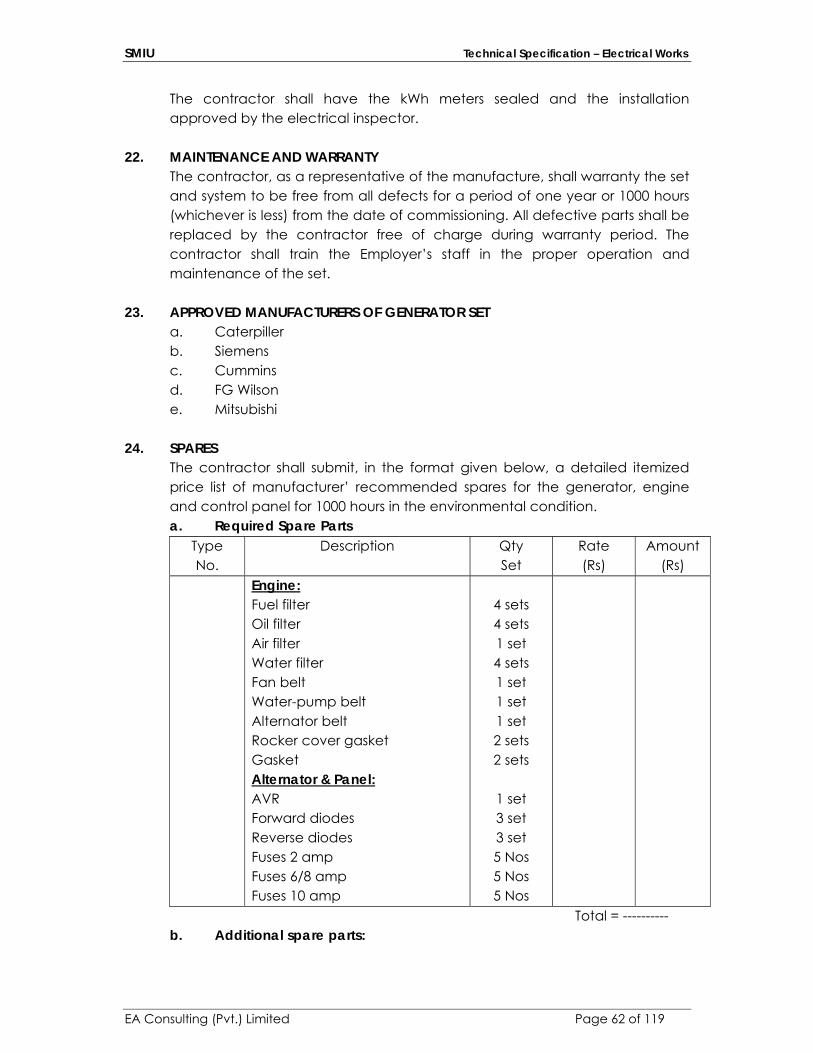
SMIU Technical Specification – Electrical Works
EA Consulting (Pvt.) Limited Page 62 of 119
The contractor shall have the kWh meters sealed and the installation approved by the electrical inspector.
22. MAINTENANCE AND WARRANTY The contractor, as a representative of the manufacture, shall warranty the set and system to be free from all defects for a period of one year or 1000 hours (whichever is less) from the date of commissioning. All defective parts shall be replaced by the contractor free of charge during warranty period. The contractor shall train the Employer’s staff in the proper operation and maintenance of the set.
23. APPROVED MANUFACTURERS OF GENERATOR SET a. Caterpiller b. Siemens c. Cummins d. FG Wilson e. Mitsubishi
24. SPARES The contractor shall submit, in the format given below, a detailed itemized price list of manufacturer’ recommended spares for the generator, engine and control panel for 1000 hours in the environmental condition. a. Required Spare Parts
Type No.
Description Qty Set
Rate (Rs)
Amount (Rs)
Engine: Fuel filter Oil filter Air filter Water filter Fan belt Water-pump belt Alternator belt Rocker cover gasket Gasket Alternator & Panel: AVR Forward diodes Reverse diodes Fuses 2 amp Fuses 6/8 amp Fuses 10 amp
4 sets 4 sets 1 set 4 sets 1 set 1 set 1 set 2 sets 2 sets
1 set 3 set 3 set 5 Nos 5 Nos 5 Nos
Total = ---------- b. Additional spare parts:

SMIU Technical Specification – Electrical Works
EA Consulting (Pvt.) Limited Page 63 of 119
Type No.
Description Qty Set
Rate (Rs)
Amount (Rs)
Total = -----------
SECTION – E - 11 TELECOMMUNICATION CABLING SYSTEM
1.0 RELATED DOCUMENTS
Drawings and general provisions of Contract, including General and Supplementary Conditions and Division-1 Specification sections, apply to work of this section.
2.0 SYSTEM DESCRIPTION
The proposed cabling system (Passive Equipment only) for the UTP and Fiber network cabling and Fiber Links shall be an open system and application and vendor independent and shall be warranted by an International Vendor for a minimum of 20 years. The contractor Installers (labor) and engineers must be trained and certified by this vendor to design and install cabling system. Active part (Switches) are the part of Client IT personal).
3.0 DATA CABLING SYSTEM
Main Data Rack will be provided in ground floor of IT Block and incoming fiber will come from server room which will also go to school IDF located at ground floor and then to remaining IDFs. Wiring system used shall be star topology i.e. each data outlet is connected directly to the IDF (Intermediate Distribution Frame) IN Cat-6 RJ45 24 port patch panel.
Vertical runs between floors extending from the Main Data Rack to IDF to each IDF using multi mode fiber optic installed on separate cable tray.
Data Processing system shall be supplied installed and tested complete in place including but not in a way of limitation, cables, socket outlets, adapters, connectors, patch panels, patch cords, wire management, floor
SMIU Technical Specification – Electrical Works
EA Consulting (Pvt.) Limited Page 64 of 119
distributors (racks/cabinets).
The Data Cabling System shall be designed using standard, proven equipment and materials with the latest Technology version or model. If there is any problem during warranty period related to the shortage of Materials, the Contractor shall supply them with no extra cost to the Project.
The design shall fully comply with TIA/ EIA 568B & ISO 11801 in a full star topology configuration.
The network data cabling systems support at least 1000 Base-T (Gigabit) Ethernet or faster protocol.
The UTP (unshielded twisted pair) Category 6 cable’s technical specifications shall be up to the highest industry standards and should have performance specifications better than 500MHz and should exceed all proposed requirements for data, video & Gigabit applications.
The UTP Category 6 cable’s technical specifications shall be up to the TIA/EIA-568B.2-1 industry standards and should have performance specifications better than 250 MHz and ample margin compared to the Category 6 Standard for performance in factors such as NEXT. The cables required from the Data Cabinet to the Data Outlet must be 4-pairs UTP Category 6 copper cables for Data. Also Cat-6A cable connectors shall be same as for Voice and CCTV Systems.
4.0 SCOPE
The contractor shall carefully examine all of the specifications to ensure that he is fully conversant therewith and has included for everything necessary therein, either expressly provided for or as would normally be expected to be provided for by a reputable contractor specializing in the type and nature of the Services described in the Contract.
The Contractor is advised that items or matters not specifically provided for, or partially described or otherwise missing from the specifications, but which are nevertheless necessary for the execution and completion of the Services, shall be deemed to have been included by the Contractor.
The Contractor shall ensure that all selected manufacturers of equipment and materials provide with appropriate warranties and guarantees for their products. Authorized and certified installers registered with their respective Manufacturers shall execute the installation of the Cabling system.
The Contractor shall also be required to submit, in their bid, a list of personnel along with their CV, certifying that the installers it intends to employ on the services have the necessary training and experience from manufacturer.
The LAN cabling system shall meet the emerging TIA/EIA 568A/B and ISO/IEC

SMIU Technical Specification – Electrical Works
EA Consulting (Pvt.) Limited Page 65 of 119
11801 Category 6AA, Class EAA specifications and shall support Gigabit Ethernet, Sonet/asynchronous transfer mode (ATM) at rates (minimum of) 1 Gbits/seconds and analog broadband video in addition to existing and multimedia technologies.
The Contractor shall carry out all the necessary surveys, design and engineering so as to provide for the Services, a whole and complete system to ensure full compatibility of the Services with any of the existing facilities pertinent to Cabling System applications & operations.
The scope of the Services include the provision of all material, labor, supervision, construction, equipment, tools, temporary, test equipment, spares, consumable and all other things and services required to IT dept of the client, engineer, design, supply, install, test and commission the Cabling System. The Contractor should submit the Fluke test and OTDR Test as well. It is the responsibility of the Contractor to make sure that the system works at the company environment. The Vendor must provide a list of project Reference within the last ten years. The Vendor must have completed a project with a minimum of 600 points or higher of Category 6AA.
5.0 SUBMITTALS
Product Data: Submit manufacturer's data on signal transmission media and components.
Shop & As Built Drawings: Submit softcopies of layout drawings of computer cable distribution system and accessories. Wiring Diagrams: Submit data transmission wiring diagrams for computer system, including rack and terminal connections.
6.0 QUALITY ASSURANCE: Manufacturer's Qualifications: Firms regularly engaged in manufacture of signal transmission media and accessories of types required, whose products have been in satisfactory use in similar service for not less than 10 years. Installer's Qualifications: Firms with at least 10 years of successful installation experience with projects utilizing systems and equipment similar to that required for this project.
Co-ordinate with other electrical work including wires/cables, electrical boxes and fittings, and raceways, to properly interface installation of data system with other work.
Sequence installation of data system with other work to minimize possibility of damage and soiling during remainder of construction.
7.0 COPPER & FIBRE OPTIC CABLE AND CONNECTORS Unshielded twisted-pair copper & fiber optic cables shall be approved &
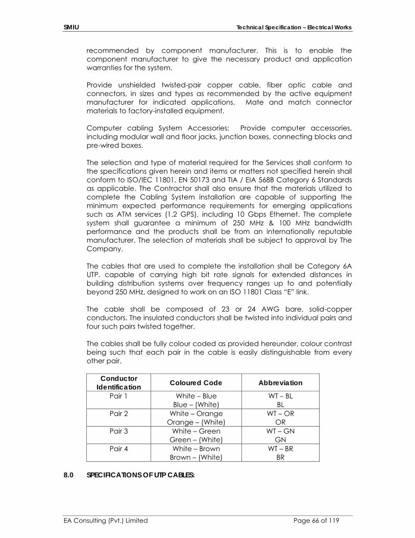
SMIU Technical Specification – Electrical Works
EA Consulting (Pvt.) Limited Page 66 of 119
recommended by component manufacturer. This is to enable the component manufacturer to give the necessary product and application warranties for the system. Provide unshielded twisted-pair copper cable, fiber optic cable and connectors, in sizes and types as recommended by the active equipment manufacturer for indicated applications. Mate and match connector materials to factory-installed equipment. Computer cabling System Accessories: Provide computer accessories, including modular wall and floor jacks, junction boxes, connecting blocks and pre-wired boxes. The selection and type of material required for the Services shall conform to the specifications given herein and items or matters not specified herein shall conform to ISO/IEC 11801, EN 50173 and TIA / EIA 568B Category 6 Standards as applicable. The Contractor shall also ensure that the materials utilized to complete the Cabling System installation are capable of supporting the minimum expected performance requirements for emerging applications such as ATM services (1.2 GPS), including 10 Gbps Ethernet. The complete system shall guarantee a minimum of 250 MHz & 100 MHz bandwidth performance and the products shall be from an internationally reputable manufacturer. The selection of materials shall be subject to approval by The Company. The cables that are used to complete the installation shall be Category 6A UTP, capable of carrying high bit rate signals for extended distances in building distribution systems over frequency ranges up to and potentially beyond 250 MHz, designed to work on an ISO 11801 Class “E” link. The cable shall be composed of 23 or 24 AWG bare, solid-copper conductors. The insulated conductors shall be twisted into individual pairs and four such pairs twisted together. The cables shall be fully colour coded as provided hereunder, colour contrast being such that each pair in the cable is easily distinguishable from every other pair.
Conductor
Identification Coloured Code Abbreviation
Pair 1
White – Blue Blue – (White)
WT – BL BL
Pair 2
White – Orange Orange – (White)
WT – OR OR
Pair 3
White – Green Green – (White)
WT – GN GN
Pair 4 White – Brown Brown – (White)
WT – BR BR
8.0 SPECIFICATIONS OF UTP CABLES:
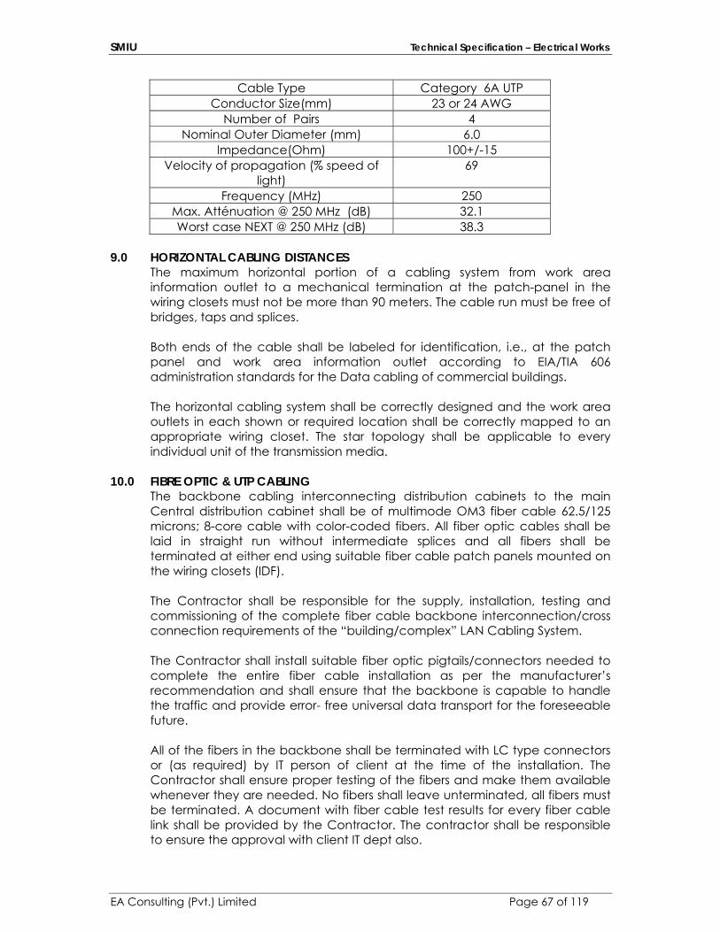
SMIU Technical Specification – Electrical Works
EA Consulting (Pvt.) Limited Page 67 of 119
Cable Type Category 6A UTP Conductor Size(mm) 23 or 24 AWG
Number of Pairs 4 Nominal Outer Diameter (mm) 6.0
Impedance(Ohm) 100+/-15 Velocity of propagation (% speed of
light) 69
Frequency (MHz) 250 Max. Atténuation @ 250 MHz (dB) 32.1 Worst case NEXT @ 250 MHz (dB) 38.3
9.0 HORIZONTAL CABLING DISTANCES
The maximum horizontal portion of a cabling system from work area information outlet to a mechanical termination at the patch-panel in the wiring closets must not be more than 90 meters. The cable run must be free of bridges, taps and splices. Both ends of the cable shall be labeled for identification, i.e., at the patch panel and work area information outlet according to EIA/TIA 606 administration standards for the Data cabling of commercial buildings. The horizontal cabling system shall be correctly designed and the work area outlets in each shown or required location shall be correctly mapped to an appropriate wiring closet. The star topology shall be applicable to every individual unit of the transmission media.
10.0 FIBRE OPTIC & UTP CABLING The backbone cabling interconnecting distribution cabinets to the main Central distribution cabinet shall be of multimode OM3 fiber cable 62.5/125 microns; 8-core cable with color-coded fibers. All fiber optic cables shall be laid in straight run without intermediate splices and all fibers shall be terminated at either end using suitable fiber cable patch panels mounted on the wiring closets (IDF).
The Contractor shall be responsible for the supply, installation, testing and commissioning of the complete fiber cable backbone interconnection/cross connection requirements of the “building/complex” LAN Cabling System. The Contractor shall install suitable fiber optic pigtails/connectors needed to complete the entire fiber cable installation as per the manufacturer’s recommendation and shall ensure that the backbone is capable to handle the traffic and provide error- free universal data transport for the foreseeable future. All of the fibers in the backbone shall be terminated with LC type connectors or (as required) by IT person of client at the time of the installation. The Contractor shall ensure proper testing of the fibers and make them available whenever they are needed. No fibers shall leave unterminated, all fibers must be terminated. A document with fiber cable test results for every fiber cable link shall be provided by the Contractor. The contractor shall be responsible to ensure the approval with client IT dept also.

SMIU Technical Specification – Electrical Works
EA Consulting (Pvt.) Limited Page 68 of 119
The Contractor shall observe the manufacturer’s specifications for maximum tension and minimum bend radius for each fiber optic cable. The contractor shall provide a copy of the manufacturer’s specifications to company prior to the commencement of the work.
Care must be taken when mechanical pulling devices are used, that maximum tension limits are not exceeded. Minimum bend radius specification shall not be violated when the cables are routed through walls or around corners. The contractor shall ensure that all installation personnel are aware of these limitations. The Contractor shall follow an intelligent numbering system based upon the destination and channel number. The numbering system shall have a prefix ‘F’ to indicate it is a fiber optic cable, followed by the destination IDF, then a hyphen and the channel within the cable. Logical labeling should be as per ANSI/TIA/EIA-606. Labels should be ring and printed type. No labels should be written by hand.
11.0 OPTICAL FIBRE CABLE TECHNICAL SPECIFICATION
Fiber optic cables within the premises shall use multimode. It shall be of 62.5/125 micron. Fibers must comply with TIA/EIA 492 specifications and OM3 fiber specification as in IS 11801 standard. It is the responsibility of the contractor that they shall consult client ‘IT dept.’ before procurement of the Fiber optic type. Fibers will have wavelength capability; transmitting at 1310 to 1510nm ranges. All fibers shall be color coded to facilitate individual fiber identification. The coating shall be mechanically strippable.
Core 8 m 3 m Core Non-Circularity: <6% Core/Cladding Concentricity Error:
<3.0 m
Numerical Aperture: 0.200 ± 0.015 Cladding diameter: 125 m ± 1 m Cladding Non-Circularity:
<2.0%
Coloured Fiber Diameter:
250 m ± 15 m
Buffering Diameter: 890 mm ± 50 mm MinimumTensile Strength:
100,000 psi
Fiber Minimum Bending Radius:
.75 in. (1.91 cm)
Cable Minimum Bending Radius: During Installation: After Installation:
Less than 15 multiply by cable diameter 20 times cable diameter 10 times cable diameter

SMIU Technical Specification – Electrical Works
EA Consulting (Pvt.) Limited Page 69 of 119
Operating Temp. Range:
32°F to 122°F (0°C to 50°C)
Storage Temp. Range:
-40°F to 149°F (-40°C to 65°C)
Maximum Fiber Loss:
3.5 dB/km at 850 NM 1.5 dB/km at 1300 NM
Minimum Bandwidth:
1500 MHz. km at 850 nm (OFL) 500 MHz .km at 1300 nm (OFL) 2000 MHz. km at 850 nm (DMD, laser) 500 MHz. km at 1300 nm (DMD, laser)
12.0 DATA OUTLET The Contractor shall provide the identification labels at each and every
information outlet with clear information of its connection. (TR, IDF no, patch panel number and port number). The labeling shall be on the faceplate of the information outlet according to TIA/EIA 606 Administration Standard.
The contractor has to provide clear identification labels for Data. In the process of installing the information outlets, if the Contractor envisages difficulty in mounting the outlet at planned location as indicated in its design/engineering drawing, the contractor shall notify the Company of this, the contractor shall not make its own discretion in modifying or changing any information provided in the approved design drawings.
The type of information outlets shall be of modular Cat 6A RJ45 of Matt Chrome/ metallic or any other approved or as required finish, 8 position, 8 conductor designed for high speed networking applications that use data transmission rates over frequency ranges up to and potentially beyond 250 MHz or higher. The 8 position/8 conductor outlet shall meet the Category 6A transmission requirements or higher for connecting hardware specified in ISO/IEC 11801 and EIA/TIA-568A/B and Class EA design guidelines.
The modular outlet shall provide maximum versatility in designing a premise distribution system. It shall be designed to snap into modular faceplate. When the outlet is inserted into the faceplate or frame, it shall lock into place and shall only be released using the dual-purpose wire insertion tool. The mounting and removal system shall allow easy installation and modification. The faceplate jacks must be shutter protected and shall include a label window required to write circuit identification number. Each port must support a color icon to identify the port function. The plastic used to construct the modular data outlet shall be of high impact, flame-retardant, made of poly ethylene oxide with flammability rating meeting UL 94V-0UL, the jack wires shall be at least 50 micro-inch lubricated gold plating over 100 micro-inch nickel under plate. The connector shall be of copper alloy, at least 100 micro-inch bright solder over 100 micro-inch nickel under plate.
SMIU Technical Specification – Electrical Works
EA Consulting (Pvt.) Limited Page 70 of 119
The insulation displacement connector shall accept 24/23 AWG solid copper wire conductors. The connector shall have multicolor labels marking wire terminals with numbers, assuring fast, accurate installation. The outlet must support wiring configuration as per T568A and T568B on the same RJ-45 jack
The connector shall be wired using the wire insertion tool (impact tool). The module shall be wired from the center to the outside and shall not untwist paired conductors more than 12.7 mm. In the process of terminating the cables in patch panels/outlets the Contractor shall ensure ISO/IEC and TIA/EIA category 5E/6 transmission performance requirements.
13.0 PATCH CORDS
The contractor shall supply patch cords for all the installed points on the network switch side as well on the workstation side. The cord length shall be of two different sizes 5-ft. [1.5 m] on the network switches side, 10 ft. [3.05 m] on the workstation side or as per site requirement. The patch cable shall meet the requirements warranted to meet ISO/IEC 11801, EN 50173 and EIA/TIA 568A/B Category 6A or higher wiring standards capable of connecting high speed information terminal devices to information outlets, to interconnect information terminal devices and 8-position modular jack panel applications. The patch cord shall be designed to provide support for extended multimedia transmission distance as frequency ranges up to and potentially beyond 100/250 MHz. The patch cord shall support the computer networking applications over frequency ranges up to and potentially beyond 250 MHz and shall be compatible with voice and information applications. The construction of the cord shall be of stranded type cordage tightly twisted, 24 AWG, 8 conductor. The cord shall be terminated to an 8-position Cat 6A RJ-45 modular plug on both ends. The cords shall support the transmission requirements warranted to meet ISO/IEC 11801 Class EA, EN 50173 or TIA/EIA 568B Category 6A, Class EA component specifications and higher standards. The Contractor supplied cord shall be of factory crimped modular plug at both ends.
14.0 PATCH CORD ORGANIZER
The Contractor shall supply and install sufficient patch cord organizers patch cord organizers that are used for routing patch cords in 19-inch (48.3-cm) frames. The patch cord organizers shall support the requirements of routing patch cords both at the equipment side as well as the Category 6A-patch panel cabling side at the wiring closets. These organizers shall be located in the 19-inch frame inside the wiring closet.
The Contractor supplied patch cord organizers patch cord organizers shall support the requirements of routing cords in both horizontal and vertical pathways.
SMIU Technical Specification – Electrical Works
EA Consulting (Pvt.) Limited Page 71 of 119
15.0 PATCH PANELS (JACK PANELS) The Contractor shall supply and install the modular patch panels to meet the full cabling system requirement of the “building/complex”. Every Category 6A cables serving the information outlets at work areas shall be terminated at the patch panels. The Contractor shall ensure that the supplied patch panels shall meet the clients ‘IT dept’ requirement and ISO/IEC 11801, EN 50173 and TIA/EIA 568 warranted component specifications and standards.
The patch panels shall be of 19-inch rack-mounted panels. The rear of the panel shall feature connecting blocks mounted on a printed wiring board. These connecting blocks shall be capable for use in terminating Category 6 station wires, equipment, or tie cables. The modular patch panel shall be capable of supporting up to 24 jack positions (ports) as required by the design drawings of the Data system and shall have the facility to write the circuit designation details at the front side of each jack. The contractor shall provide 20% spare capacity for Data.
The insulating displacement connector field in the patch panel shall be made continuous to the 8-pin modular jack field on front of the panel through printed wiring board connections to enhance the features to confirm to TIA/EIA 568A/B cabling recommendations.
The construction of the modular jack panel shall be of Category 6A – compliant and shall have the stringent requirements of connecting hardware as specified in TIA/EIA 568A/B commercial/ residential building Cabling System standards.
When the patch panels are tested in accordance with the appropriate test methods described in TIA/EIA 568 A/B and ISO/IEC 11801, EN 50173 Category 6A specifications. The modular patch panels shall meet the worst-pair near-end cross talk (NEXT) requirements over the entire frequency ranges up to and potentially beyond 100/250 MHz on all pair combinations.
Care must be taken to ensure that the cables are terminated correctly at Category 6 cross connect hardware (patch panels).
The cable conductors shall be terminated as described in TIA/EIA 568A/B and ISO/IEC 11801, EN 50173 Category 6A, Class EA wiring sequence by using the proper insertion tool (impact tool).
When terminating the cables in the insulating displacement connector field, care must be taken to ensure that the strip – back is limited only as much cable jacket as is required to perform connecting hardware terminations. The cables shall be properly secure terminations. The cables shall be properly secured to the 19” rack with cable ties as well as at the patch panels.
Each port of the patch panel must support color Icon to identify the port function.
Each port must be numbered in sequence with white printing on black background or other high contrast colors.

SMIU Technical Specification – Electrical Works
EA Consulting (Pvt.) Limited Page 72 of 119
Each port on the patch panel must have a label place holder and for the patch panel number. The package must include frame mounting screws, labels, cable ties and instruction sheet.
Fiber patch panel shall be of 24 port with LC type connector and 19” standard design suitable for all cabinets and racks with well-designed splice tray for fusion splicing. It shall comply with ISO/IEC11801:2008 and ANSI/TIA/EIA 568-C.3. Size: 450 x 375 mm x 150 mm Finishing: SPCC Insertion Loss: less than or equal to 0.3 Return Loss: greater than or equal to 45 Maximum bending space: greater than or equal to 30
16.0 CABLING CABINET (STEEL CABINET)
The Contractor shall supply and install cabling System Cabinets to house the passive and active network equipment. It is the responsibility of contractor to consult client’s IT dept. before procuring the rack. The cabinets shall be freestanding / wall mounting types.
The Contractor supplied Cabling System cabinets shall meet the requirements of accommodating the high volume of cabling 19” 24-port patch panels & LAN Equipment fully assembled with the following items.. The cabinets must meet the following specifications:
12U 600 x 800 Ready Rack
45 KG load rating 12U 1mm Safety Glass Door (On the front). 12U 1 mm steel Door (On the rear). 540 x 600 side vented top cover. 12U Panel mounting angle kit. Thermostat controlled Low Noise Fan Tray. 42U 800 x 1000 Ready Rack 500 KG load rating 42U 600 4mm Safety Glass Door (On the front). 42U 600 1.6 mm steel Door (On the rear). 800 x 100 side vented top cover. Castors heavy duty bracket. 42U Panel mounting angle kit. Thermostat controlled Low Noise Fan Tray.
A power outlet strip shall have a 2 meter flying lead, (3-wire extension cord)
SMIU Technical Specification – Electrical Works
EA Consulting (Pvt.) Limited Page 73 of 119
with a 3 prong British plug with fuse and shall have 13 amp. 250 volt 3 prong British outlets with individual on/off switch and indicator light with mounting brackets. The AC Mains distribution integral at the rear pillar of the cabinet should have at least 10 of 13 amp. Power Outlets. Cable management panel inclusive of other accessories such as earthing kits, screws, washers, grip-nuts and a removable shelf, able to resist a weight of 50 to 60 kgs. The cabinets shall be rugged and strong and all steel shall be finished scratch proof in a durable enamel Grey paint on both sides.
The cabinets must include Low Noise Thermostat controlled fans and shall automatically switch on and off according to the temperature inside the cabinets, the temperature range shall be from to 10 to 60 degrees centigrade. The fan tray shall have minimum of four fans 250 Volts AC + 6% 50 Hz. The low noise top mounted fan tray shall aid the cooling requirement of the LAN equipment installed inside the cabinets, and in the process of installing the fan tray on top of the cabinet it shall not occupy any of the usable U height in the cabinet.
The front glass door shall have at least 4 mm toughened & 50 percent light transmission smoked safety glass able to resist a weight of 80 to 100 kgs. Placed within 200 mm of the door center. The door shall be lockable and shall have a swing handle supplied with 2 keys.
The rear door shall be the same as the front except the construction of the door shall be of rugged and strong 1.6mm steel finished in durable enamel Grey paint on both sides, and without glass.
The internal panel mounting angles shall be supplied in pairs to provide 19” mounting positions with whole patterns to accept captive nuts on universal centers. In the design of the panel mounts the centers of each U height shall be notched, to make the positioning of cage nuts much simpler. The panel mounting shall be fitted onto panel mount angle supports to allow infinite adjustment throughout the depth of the track.
The cabinets shall be supplied at least with one shelf kit. The shelf should carry a load rating of 50 kgs. And shall be manufactured with holes/slots providing sufficient airflow to LAN equipment when installed inside the cabinets.
The cabinets must support the installation of fire protection units and all 19” equipment including frames for 110-punch block.
The supplied cabinets must meet the following standards: IEC 297-2 D/N 4/494 Part 7 D/N 4/491 Part 1 Load rating 500 Kg Rust proof coating EN 60950 VDE 0100 Material 1.6mm steel

SMIU Technical Specification – Electrical Works
EA Consulting (Pvt.) Limited Page 74 of 119
Paint finish according to RAL 7035 The Contractor shall also be responsible to ensure the end user requirement (IT Dept. of client before bidding).
17.0 SCOPE
The contractor shall carefully examine all of the specifications to ensure that he is fully conversant therewith and has included for everything necessary therein, either expressly provided for or as would normally be expected to be provided for by a reputable contractor specializing in the type and nature of the Services described in the Contract.
The Contractor is advised that items or matters not specifically provided for, or partially described or otherwise missing from the specifications, but which are nevertheless necessary for the execution and completion of the Services, shall be deemed to have been included by the Contractor.
The Contractor shall ensure that all selected manufacturers of equipment and materials provide with appropriate warranties and guarantees for their products. Authorized and certified installers registered with their respective Manufacturers shall execute the installation of the Cabling system.
The Contractor shall also be required to submit, in their bid, a list of personnel along with their CV, certifying that the installers it intends to employ on the services have the necessary training and experience. The Contractor shall carry out all the necessary surveys, design and engineering so as to provide for the Services, a whole and complete system to ensure full compatibility of the Services with any of the existing facilities pertinent to Cabling System applications & operations.
The scope of the Services include the provision of all material, labour, supervision, construction, equipment, tools, temporary, test equipment, spares, consumable and all other things and services required to engineer, design, supply, install, test and commission the Cabling System. It is the responsibility of the Contractor to make sure that the system works at the company environment. The Vendor must provide a list of project Reference within 10 years. Also Fluke testing of all cabling from RJ45 to Patch Panels. Also contractor shall submit the backbone and Rack shop drawings before commencement of work.
18.0 SUBMITTALS
Product Data: Submit manufacturer's data on signal transmission media and components.
Shop Drawings: Submit layout drawings of telephone cable distribution
SMIU Technical Specification – Electrical Works
EA Consulting (Pvt.) Limited Page 75 of 119
system and accessories.
Wiring Diagrams: Submit data transmission wiring diagrams for telephone system, including TJB and terminal connections.
19.0 TELEPHONE CABLING
Vertical runs between floors extending from the main data rack to each IDC blocks using 25 pair CAT 5 cables installed on cable tray as specified in drawings. Horizontal runs from IDC block to the telephone outlet using 4 Pair CAT 6A cables. Wiring system used shall be star topology i.e. each telephone outlet is connected directly to the associated floor distributor (PP).
The voice backbone cabling system shall meet the TIA / EIA 568A/B-5 and ISO 11801 Category 5, Class D specifications. The pair twist of the cables must be maintained as close to the termination at the patch panel IDC Modular outlet as possible. Cables shall not be untwisted for more than 12.7 mm. The cable conductor’s entry shall be at the center of the IDC module and the module shall be wired from the center to the outside.
20.0 IDC WIRING SYSTEM
The IDC blocks shall be used for the voice cross connect and should be 19” rack mountable type. (MDF Rack) and for Cat-5 multipair backbone connecting in each floor IDF Rack. Shall be capable to terminate 22-24 AWG solid conductors or 22-24 AWG stranded conductors. Shall be made of high-impact UL 94V-0 rated thermoplastic. Maximum insulated conductor outside diameter 0.05” Complete kit includes connecting blocks, Patch Cards (Katt to RJ 45) labels and label holders shall be used. Jumper troughs shall be used to route cable horizontally and vertically (Katt to RJ45). Also in MDF Rack the jumping should be on Katt Patch cards. The IDC connectors must be color coded to meet both T568A and T568B wiring Configuration. The IDC connector on the back of the patch panel shall support 22 to 25 AWG solid conductors’ cables.
21.0 QUALITY ASSURANCE: Manufacturer's Qualifications: Firms regularly engaged in manufacture of

SMIU Technical Specification – Electrical Works
EA Consulting (Pvt.) Limited Page 76 of 119
signal transmission media and accessories of types required, whose products have been in satisfactory use in similar service for not less than 10 years. Installer's Qualifications: Firms with at least 10 years of successful installation experience with projects utilizing systems and equipment similar to that required for this project.
Co-ordinate with other electrical work including wires/cables, electrical boxes and fittings, and raceways, to properly interface installation of data system with other work.
Sequence installation of data system with other work to minimize possibility of damage and soiling during remainder of construction.
SECTION - E - 12
ADDRESSABLE FIRE ALARM SYSTEM 1.0 SCOPE OF WORK
The work under this scope consists of supplying, installation and commissioning of all material and services of the complete Addressable Fire Alarm system as specified herein and / or shown on the Tender Drawings and given in the Bill of Quantities.
SMIU Technical Specification – Electrical Works
EA Consulting (Pvt.) Limited Page 77 of 119
The Contractor shall discuss the electrical layout with the Engineer and coordinate at site with other services for exact route, location and positions of the system.
The Fire Alarm system with accessories shall also comply with the General Specifications for Electrical Works, Section E- I and with other relevant provisions of the Tender document.
2.0 STANDARDS
The latest editions of the following standards / codes shall be applicable for the materials covered within the scope of this specification:
BS 5839, EN approved NFPA 72
Any other standard referred to in above standards or these specifications.
3.0 OPERATION
The Fire Alarm System shall be analogue addressable type complete with battery standby power.
At locations indicated in the drawings the break glass type manual station, fire alarm Control Panel, and automatic detectors shall be installed. In case of any Fire, the manual station shall be operated by pulling down the handle or breaking glass. The actuation of this station shall cause an audio as well as visual alarm at the fire alarm control and indication unit, duly indicating the location of the respective station/zone. An authorized person shall immediately visit the affected area and if after investigating, it is deemed necessary, alarm in the whole building shall be initiated from either the alarm switch located beside the fire alarm control panel by inserting a special key or the actuation of any indication at the Fire Alarm Control Panel. The general alarm shall be initiated by an authorized person after inspecting the affected location.
Circuit shall be so arranged that an open circuit in an initiating or indicating loop shall cause the individual zone and common trouble indication at the fire alarm control panel.
4.0 MATERIAL
4.1 Conduit and Conduit Accessories The specifications for conduit and conduit accessories shall be same as given for electrical conduit in Section E - 4 of these specifications.
4.2 Fire Alarm Cable
Fire Alarm Cable shall be 2 core 1.5mm2 shielded twisted pair, fire resistant, PVC insulated, 250/440 volts grade cable to be laid in concealed PVC conduit.
4.3 Power Supply

SMIU Technical Specification – Electrical Works
EA Consulting (Pvt.) Limited Page 78 of 119
The supply and operating voltages shall be 220 volts, 50 c/s and 24 volts D.C. respectively. The control stations shall be provided with sufficient capacity nickel cadmium battery with charger to operate the complete system for the least 3 hours in case of mains failure.
4.4 Fire Alarm Control and Indication Unit
The fire alarm control and indication unit shall be a Solid State Modular Unit consisting of the following Modules; suitable number of modules shall be used to provide facility for 2 loops. It shall not be possible to remove the key without turning the key to its normal position, thus resetting the alarm contacts. i. Loop Module
Loop Module shall have multiple of supervised initiating circuit with a trouble and an Alarm Lamp for each loop. Detection circuit wiring shall be two wire Class `A' and shall power all Detectors (Relay outputs and) voltage output for each zone alarm and voltage output for each zone trouble shall be provided.
ii. Audible Expander Modules
Audible Expander Modules shall provide for supervised control circuit for polarized alarm signaling devices loop activated lamp shall be provided for each loop to aid on system testing and trouble- shooting provide indicating circuits.
iii. Power Module Power Module shall supply the necessary power for the loop module and all Detectors (and shall contain a Battery Charger to charge the batteries) An AC power to Lamp shall be provided to indicate the normal condition of the panel. Individual supervisory lamps shall be provided for AC power failure indication, ground fault detection, and low battery. All controls shall be behind a key-locked door to prevent unauthorized operation. Two supervised control circuits for audible signaling shall be provided as part of this module. Common trouble and common alarm relay and logic outputs shall be provided. The panel cover shall be key-locked to prevent unauthorized access.
4.5 Addressable Manual Break Glass Station
The break-glass manual station shall be operated by pulling down on the handle. When operated, the handle shall remain down with the pre-signal alarm contacts closed until the station is reset. The general alarm contacts shall remain open until after investigation. The general alarm switch shall be operated by an authorized person with a special key. Operating Voltage Range: 8V DC to 42V DC Quiescent current: 45uA Alarm current: 9mA (pulsed)

SMIU Technical Specification – Electrical Works
EA Consulting (Pvt.) Limited Page 79 of 119
4.6 Addressable Audible Signal Unit
Fire alarm sounder with strobe shall be red color surface mounted installed where indicated on the drawings. Sound intensity shall be such that an audible signal will be heard clearly throughout the structure when the entire bells ring. The bell shall be connected in multiple cross loop conductors. Rated Voltage: 12V DC to 28V DC Operating Voltage: 10V DC to 28V DC Alarm Current: min 5 mA; max 14 mA Starting Current: 30mA for 2ms Ambient Temperature: -25°C to +60°C
4.7 Addressable Smoke Detector: The Smoke Detector is optical photoelectric type and shall be connected to the specific loop.
Quiscent current: approx. 20uA pulsed DC Voltage: 8V to 28V DC Maximum mounting height: 12m
4.8 Addressable Heat Detector: The Heat Detector is fixed temperature type connected to the specific loop. Heat Sensor: 135°F for fixed temperature type and 15°F/ minute for rate of rise type Quiscent Current: approx. 12uA Maximum mounting height: 7m Area to be monitored: 30m2 max DC Voltage: 8V DC to 28V DC Application temperature: -20°C to 50°C
4.9 Function of Addressable Fire Alarm Control Panel (FACP)
i. Design The FACP shall be solid state, modular design with integral static protection. All indicating lamps shall be long-life, low maintenance solid state light emitting diodes (LED).
ii. Enclosure
The FACP enclosure shall be semi-flush mounted. The enclosure shall be hinged from the left and the cover shall have clear windows and locking mechanism to keep the system operating and status switches from being tampered keys shall be made
SMIU Technical Specification – Electrical Works
EA Consulting (Pvt.) Limited Page 80 of 119
available to fire department and other authorized operating personnel. Finish shall be "FIRE ALARM RED" and "BLACK".
iii. Loops & Identification All controls shall be labeled, all loop locations shall be identified, and the FACP shall be provided with a set of permanently mounted operating instructions, to avoid confusion. Loop location identification shall be as approved by the Engineer Incharge and contain up to three lines of text with 1/8" minimum character heights.
iv. Components of Fire Alarm Control Panel
The FACP shall include as minimum following:
a. All hardware and software to allow the panel configuration and operation to be changed at the panel. System that require off-site programming are not acceptable.
The memory data for panel configuration and operation shall reside in non-volatile, memory provided by battery-backed RAM. Removal of the board shall not cause loss of memory contents.
Switches for panel setup, set reset, manual, evacuation alarm, silence and acknowledge. Individual supervisory LEDs shall be provided for power, run, alarm, trouble, disconnect, low battery and ground fault.
b. Indicating Loops: 2 indicating circuits shall be provided.
Each circuit shall provide power for polarized alarm signaling devices. A red LED to indicate the energized state of the circuit and a yellow LED to indicate a trouble condition shall be provided for each circuit. A disconnect switch for each circuit shall be provided to allow the FACP to be tested with sounding alarm signals. When disconnected, the FACP shall indicate both trouble condition and disconnect.
v. Manual Functions
At any time, even without an alarm condition on an indicating circuit, the operator shall provide the following manual capabilities in the FACP by means of switches located behind a key-locked cover:
a. In case of fire if a general evacuation is needed all bells
shall sound. These signals can be initiated from the main panel and secondary switch at manual fire alarm initiating device (break glass unit).
b. Silence the local audible signal. This shall also cause the
SMIU Technical Specification – Electrical Works
EA Consulting (Pvt.) Limited Page 81 of 119
LED(s) to cease flashing and to be continuously `ON'. c. Silence the alarm signals.
d. Reset the FACP, after all initiating devices have been restored to normal.
e. Disconnect any individual initiating or indicating circuit
from the alarm sequence. This action shall light a disconnect LED and cause a trouble condition.
f. Perform a complete operational test of the system
microprocessor with a visual indication of satisfactory communication with each board.
g. Test all panel LEDs for proper operation without causing a
change in the condition on any zone.
vi. System Supervision
a. Upon application of primary power, or reapplication following power failure, the FACP shall automatically be in a normal supervisory condition.
b. In the normal supervisory condition, a green "POWER" LED
shall be illuminated, indicating the presence of primary power.
c. A green "RUN" LED shall be illuminated indicating that the
microprocessor is communicating with the system and the memory contents are satisfactory.
d. The following shall be electrically supervised:
All initiating and indicating device circuits.
All plug-in circuit board shall have proper board type in the position. System that use electrical continuity to supervise the presence of plug boards, but that do not assure that board position have been exchanged, shall provide equivalent means for specified supervision, beyond that provided by the locked cover.
4.10 Shop Drawings / Technical Specifications
Prior to installation of any equipment, the Contractor shall submit for approval, shop drawings including riser and terminal wiring diagrams and specifications data sheets. Submittals indicating typical one line riser and typical specification data sheets only will not be acceptable.
The Contractor shall review the total system point to point wiring layout to assure that the correct number and type of wire and conduit sizes are installed.
Upon completion, the Contractor shall provide detailed written
SMIU Technical Specification – Electrical Works
EA Consulting (Pvt.) Limited Page 82 of 119
operation instructions and three sets of "as built" drawings including plan, layout, conduit runs and wiring diagrams as finally installed.
4.11 Test
Upon completion and at such time as the Engineer incharge may direct, the Contractor shall conduct a total system test where line supervision and each device shall be tested. All the tests shall demonstrate that the system meets the tests shall operating requirements of this specification, that individual conductors of all circuits are free of grounds, shorts and breaks, and that no grounds exist between any piece of equipment in the control unit and the cabinet. All final connections, testing, adjusting and calibrating shall be made under the direct supervision of a factory trained technician of the system supplier.
4.12 System
The fire alarm control panel (FACP) shall be installed at IT block as per drawing at a position and height as shown on drawing and as approved at site. The FACP shall match with the wall finish and shall be of neat finish, installed flush or semi-flush with the wall.
The fire alarm riser shall travel in one conduit for straight runs,
4.13 Fire Alarm Installation The Fire alarm system shall be installed as mentioned in the drawings. The system shall be connected, tested and commissioned as per manufacturer's instructions and in the presence of Engineer Incharge. The wall recessed mounting Fire alarm manual stations shall be installed at a height of 4.5' feet above finished floor level. The connections of the appropriate Contactors of the Fire alarm system shall be made as per manufacturer's instructions.
The mounting height of the sounder shall be above the false ceiling or 7' from F.F. level when false ceiling is not comes. The conduit and wiring of the Fire alarm system shall be as per installation instructions for conduits and wirings given in the relevant section of these specifications. The Fire alarm system conduit shall be laid 15 cms (6") from the electrical conduits and cross the electrical conduit at 90 degree only. The Fire alarm system conduit shall be marked with red colour at terminations in order to distinguish it from other conduit system.
4.14 Input/Output Interface modules:
Input output modules shall be provided as shown in the drawings to supervise and operate mechanical equipments. Contractor shall coordinate with all mechanical interlocking and add if required.
4.15 Monitor Modules:
SMIU Technical Specification – Electrical Works
EA Consulting (Pvt.) Limited Page 83 of 119
Supervised individually Addressable Modules shall be installed in the addressable network for monitoring the status of FM200 as mentioned in drawings, etc. These devices shall provide specific addressability to a single initiating device or multiple devices by monitoring normally open dry contacts shall cause an alarm. An open in the initiating circuit wiring shall causes a trouble to be reported at the panel.
SECTION – E – 13 IP BASED CLOSED CIRCUIT TELEVISION (CCTV) SYSTEM
1.0 GENERAL
A. All equipment and materials used shall be standard components that
are regularly manufactured and used in the manufacturer’s system.
B. All systems and components shall have been thoroughly tested and proven in actual use.
C. All systems and components shall be provided with the availability of a
toll-free, 24-hour technical assistance program (TAP) from the manufacturer. The TAP shall allow for immediate technical assistance for either the dealer/installer or the end user at no charge for as long as the product is installed.
D. All systems and components shall be provided with a one-day
turnaround repair express and 24-hour parts replacement. The repair

SMIU Technical Specification – Electrical Works
EA Consulting (Pvt.) Limited Page 84 of 119
and parts express shall be guaranteed by the manufacturer on warranty and non-warranty items.
2.0 GENERAL SPECIFICATIONS
IP MEGAPIXEL CAMERA ( WALL MOUNTED):
The camera shall be compact rugged, IR, 1.3Mega pixel 1/3 image sensor format digital color having the horizontal resolution of 1280x720 TVL or above with outstanding picture quality. The camera shall provide easy installation, digital signal processing, on screen displays, superior picture quality reliability. The camera shall accept AC or DC POE type. The camera shall provide auto-detection of lens type with lens wizard. The camera shall provide night sense feature to extend the excellent sensitivity in low light conditions. The camera shall provide automatic sensing for tracking white balance. The camera shall support bidirectional communication technology using standard video cable. The camera shall be line locked to the power line zero crossing to ensure roll free vertical interval video switching and recording.
The rated voltage shall be 12VDC, 24 VAC 50 Hz and POE option. The operating temperature shall be -20 to 50 degree Celsius. Humidity shall be 5 to 93% non condensing. Shock resistance shall be minimum 50 gm.
Signal to Noise Ratio : 50 dB Electronic shutter : AES or 1/77000 sec. White Balance : Automatic sensing, (2500 – 9000K) Video output : Composite video 1.0 Vp-p, 75 ohms. Aperture correction : Horizontal and vertical, symmetrical. BLC : Center window weighting Synchronization : Line Lock (When powered by AC only)
Synchronizes the camera to the power line zero crossing for roll-free vertical interval switching.
(When DC supply) Internal crystal. Video Compression : H. 264, multicast streaming. Networking : 10/100/1000 Mbps gigabit Ethernet,
RJ-45 Viewing Requirement : ONVIF Field Of View : 31 to 87, 25 to 880, 35 to 105
(Horizontal, Vertical & Diagonal)
Image Resolution : Main stream 1280 x 720 @ 25/30 fps. Feature: Extra stream shall be provided.
Audio Compression : Built-in Support Protocol : TCP/IP, UDP, SMTP, UPNP, FTP, HTTP or
etc. Data Storage : Video or Snapshot. Built-in (Micro SD). Low light Capabilities : 0.0013 Lux. Additional feature should
SMIU Technical Specification – Electrical Works
EA Consulting (Pvt.) Limited Page 85 of 119
be removable IR cut filter mechanism for increased sensitivity.
Lens : DC Iris. Security : Password protection, IP address
filtering, user access log. Users : 10 Simultaneous users. Video Analytic : Adaptive motion analytic to
intelligently detect motion within the field of vision and trigger an alarm. Also detects vehicles near sensitive areas longer than the users define time. Also count the objects that enter in a define zone. Also any object placed in a define zone and then trigger alarm. Cameras shall have maximum feature which shall meet clients requirements.
Imaging Device : 16:9 Aspect Ratio 1/3 inch, effect 4:3 Aspect ratio 1280 x 720 @ 1.3 MP x1.
Cabling type : Cat-6 Alarm Pan Input : 22 to 34 VAC 24 VAC nominal or
POE. Alarm I/P : 10 VDC max, 75 mA max Alarm O/P : 0 to 15 VDC max, 75 mA. Service Port : External 3 Connection 2.5 m pwds. Certification : FCC, CE, UL/UL Listed.
3.0 INDOOR TYPE IP CAMERA (DOME TYPE):
The camera shall be compact rugged, 1.3 Mega pixel 1/3 (3 to 12mm) varifocal lens & image sensor format digital color having the horizontal resolution of 1280x720 TVL or above with outstanding picture quality. The camera shall provide easy installation, digital signal processing, on screen displays, superior picture quality reliability. The camera shall accept AC or DC POE type. The camera shall provide auto-detection of lens type with lens wizard. The camera shall provide night sense feature to extend the excellent sensitivity by a factor 3 in low light conditions. Dome cameras are mounted on ceilings. The camera shall provide automatic sensing for tracking white balance. The camera shall support bidirectional communication technology using standard video cable. The camera shall be line locked to the power line zero crossing to ensure roll free vertical interval video switching and recording.
The rated voltage shall be 12VDC, 24 VAC 50 Hz and POE option. The operating temperature shall be -20 to 50 degree Celsius. Humidity shall be 5 to 93% non condensing. Shock resistance shall be minimum 50 gm.
Signal to Noise Ratio : 50 dB Electronic shutter : Automatic, 1/5 to 1 /132,000 sec.
SMIU Technical Specification – Electrical Works
EA Consulting (Pvt.) Limited Page 86 of 119
CCIR, 1/60 to 1/150000 sec. (EIA) White Balance : Automatic sensing, (2500 – 9000K) Video output : Composite video 1.0 Vp-p, 75 ohms. Aperture correction : Horizontal and vertical, symmetrical. BLC : Center window weighting Synchronization : Line Lock (When powered by AC
only) Synchronizes the camera to the power line zero crossing for roll-free vertical interval switching.
(When DC supply) Internal crystal. Video Compression : H. 264, multicast streaming. Networking : 10/100/1000 Mbps gigabit Ethernet,
RJ-45 Viewing Requirement : ONVIF Field Of View : 24 to 65, 15 to 37, 28 to 75
(Horizontal, Vertical & Diagonal) Image Resolution : Main stream 1280 x 720 @ 25/30 fps.
Feature: Extra stream shall be provided.
Audio Compression : Built-in Support Protocol : TCP/IP, UDP, SMTP, UPNP, FTP, HTTP or
etc. Data Storage : Video or Snapshot. Built-in (Micro SD). Low light Capabilities : 0.0013 Lux. Additional feature should
be removable IR cut filter mechanism for increased sensitivity.
Lens : DC Iris. Security : Password protection, IP address
filtering, user access log. Users : 10 Simultaneous users. Video Analytic : Adaptive motion analytic to
intelligently detect motion within the field of vision and trigger an alarm. Also detects vehicles near sensitive areas longer than the users define time. Also count the objects that enter in a define zone. Also any object placed in a define zone and then trigger alarm. Cameras shall have maximum feature which shall meet clients requirements.
Imaging Device : 16:9 Aspect Ratio 1/3 inch, effect 4:3 Aspect ratio 1280 x 720 @ 1.3 MP x1.
Cabling type : Cat-6 Pan I/P : 22 to 34 VAC 24 VAC nominal or
POE. Alarm I/P : 10 VDC max, 75 mA max Alarm O/P : 0 to 15 VDC max, 75 mA. Service Port : External 3 Connection 2.5 m pwds. Certification : FCC, CE, UL/UL Listed.
SMIU Technical Specification – Electrical Works
EA Consulting (Pvt.) Limited Page 87 of 119
4.0 MANUFACTURER’S WARRANTY Repair or replacement of defective parts for a period of two years from the date of shipment, installation.
5.0 IP Video Management Systems (VMS):
A. IP VMS shall support minimum 100 channel IP cameras as NVR shall be of 32 channel.
B. IP VMS shall provide 6 to 10 Mbps for recording of analog and IP video stream, play back and export.
C. IP VMS shall support recording of H.264, JPEG, and MPEG-4 IP Stream. D. IP VMS shall support third party H.264 Megapixel video stream up to
10Mps resolution with total system throughout recording of all IP & analog streams, playback and export.
E. The IP VMS shall have fully open architecture with support for both IP Specific Cameras and as well as ONVIF Compliance.
F. The VMS shall support 0.264 compression, CIF 4CIF resolution at maximum 100 IPS, 16audio input and RS422/485 PT2 Control with supplied system/ third party compatible protocol.
G. VMS shall support unlimited no’s of system connected over network. Each system shall contain 5 16GB min network ports, one for IP Camera/Encoder data, 1 for client computer access.
H. VMS shall view, managed, & playback through single user interface simultaneously with other compatible VMS through supplied PC Server & PC Client Software.
6.0 HARDWARE: A. The VMS server shall operate on 2nd generation Intel® Core i7 processor
and 8 GB of Ram or approved equivalent. B. VMS server shall utilize windows 7” ultimate 64 bit operating system or
windows based equivalent operating system. But it should not lesser than windows 7 ultimate.
C. VMS server shall have internal DVD +RW D. VMS server shall have two DV1-D ports. E. VMS server shall have expansions of IP video channel capacity through
a licensing without any modification in hardware. F. VMS server shall support multiple make/models of IP Camera and
encoders including third party manufacturer. G. VMS server shall also support audio recording in addition to third party
manufacturer’s audio recording. H. VMS server shall support recording the internal storage (Built-in)server
with additional storage utilize SCS1 attached HDD1 storage. I. VMS server shall capable of continuous scheduled alarm/event and
motion recording, pre and post alarm recording also be available and full programmable on per channel basis.
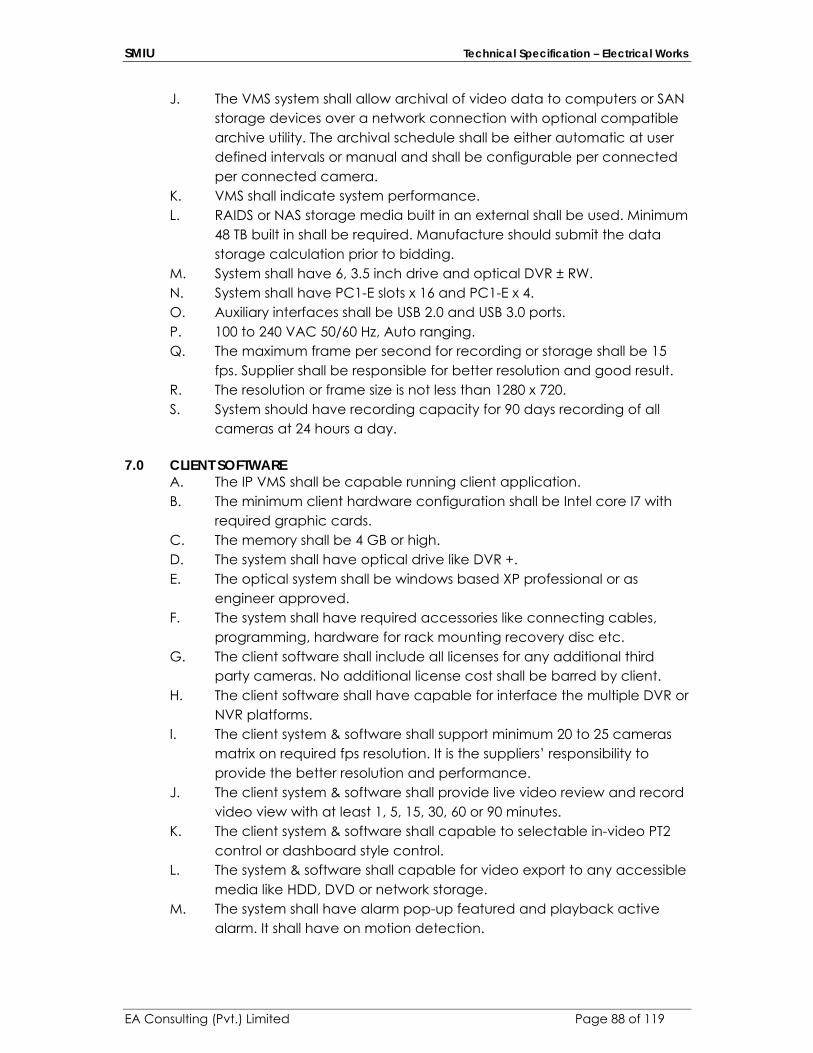
SMIU Technical Specification – Electrical Works
EA Consulting (Pvt.) Limited Page 88 of 119
J. The VMS system shall allow archival of video data to computers or SAN storage devices over a network connection with optional compatible archive utility. The archival schedule shall be either automatic at user defined intervals or manual and shall be configurable per connected per connected camera.
K. VMS shall indicate system performance. L. RAIDS or NAS storage media built in an external shall be used. Minimum
48 TB built in shall be required. Manufacture should submit the data storage calculation prior to bidding.
M. System shall have 6, 3.5 inch drive and optical DVR ± RW. N. System shall have PC1-E slots x 16 and PC1-E x 4. O. Auxiliary interfaces shall be USB 2.0 and USB 3.0 ports. P. 100 to 240 VAC 50/60 Hz, Auto ranging. Q. The maximum frame per second for recording or storage shall be 15
fps. Supplier shall be responsible for better resolution and good result. R. The resolution or frame size is not less than 1280 x 720. S. System should have recording capacity for 90 days recording of all
cameras at 24 hours a day.
7.0 CLIENT SOFTWARE A. The IP VMS shall be capable running client application. B. The minimum client hardware configuration shall be Intel core I7 with
required graphic cards. C. The memory shall be 4 GB or high. D. The system shall have optical drive like DVR +. E. The optical system shall be windows based XP professional or as
engineer approved. F. The system shall have required accessories like connecting cables,
programming, hardware for rack mounting recovery disc etc. G. The client software shall include all licenses for any additional third
party cameras. No additional license cost shall be barred by client. H. The client software shall have capable for interface the multiple DVR or
NVR platforms. I. The client system & software shall support minimum 20 to 25 cameras
matrix on required fps resolution. It is the suppliers’ responsibility to provide the better resolution and performance.
J. The client system & software shall provide live video review and record video view with at least 1, 5, 15, 30, 60 or 90 minutes.
K. The client system & software shall capable to selectable in-video PT2 control or dashboard style control.
L. The system & software shall capable for video export to any accessible media like HDD, DVD or network storage.
M. The system shall have alarm pop-up featured and playback active alarm. It shall have on motion detection.

SMIU Technical Specification – Electrical Works
EA Consulting (Pvt.) Limited Page 89 of 119
N. The system & software shall have capable for matrix functionality whereby cameras sequences creating on monitor.
ELECTRICAL: Input Voltage 100-240 VAC, 50Hz, auto ranging
Note: The active switches POE type is the responsibility of Client IT personal.
SECTION – E – 14 PUBLIC ADDRESS SYSTEM
1.0 SUMMARY This Section includes equipment for amplifying, distributing, and reproducing sound signals.
2.0 DEFINITIONS
Retain abbreviation and terms that remain after this Section has been edited. Channels: Separate parallel signal paths, from sources to speakers or loudspeaker zones, with separate amplification and switching that permit selection between paths for speaker alternative program signals. Zone: Separate group of speakers and associated supply wiring that may be arranged for selective switching between different channels. Emergency Voice Evacuation: Built in EVAC system in voice controller shall automatically announce voice evacuation message taking input from FACP.
3.0 SUBMITTALS
Product Data: For the following: Adjust list below to suit Project. Voice Alarm Controller (Preamplifier). Power amplifiers. Microphone. Equipment rack. Speakers (Wall, ceiling etc). Coordination Drawings: Reflected ceiling plans, drawn to scale, on which the following items are shown and coordinated with each other, based on input from installers of the items involved: Ceiling-mounted items including lighting fixtures, diffusers, grilles, speakers, sprinklers, access panels, and special moldings.
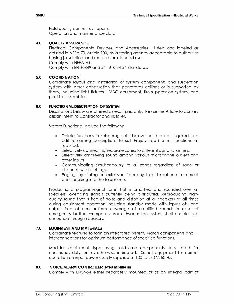
SMIU Technical Specification – Electrical Works
EA Consulting (Pvt.) Limited Page 90 of 119
Field quality-control test reports. Operation and maintenance data.
4.0 QUALITY ASSURANCE
Electrical Components, Devices, and Accessories: Listed and labeled as defined in NFPA 70, Article 100, by a testing agency acceptable to authorities having jurisdiction, and marked for intended use. Comply with NFPA 70. Comply with EN 60849 and 54-16 & 54-54 Standards.
5.0 COORDINATION
Coordinate layout and installation of system components and suspension system with other construction that penetrates ceilings or is supported by them, including light fixtures, HVAC equipment, fire-suppression system, and partition assemblies.
6.0 FUNCTIONAL DESCRIPTION OF SYSTEM Descriptions below are offered as examples only. Revise this Article to convey design intent to Contractor and Installer. System Functions: Include the following:
Delete functions in subparagraphs below that are not required and edit remaining descriptions to suit Project; add other functions as required.
Selectively connecting separate zones to different signal channels. Selectively amplifying sound among various microphone outlets and
other inputs. Communicating simultaneously to all zones regardless of zone or
channel switch settings. Paging, by dialing an extension from any local telephone instrument
and speaking into the telephone. Producing a program-signal tone that is amplified and sounded over all speakers, overriding signals currently being distributed. Reproducing high-quality sound that is free of noise and distortion at all speakers at all times during equipment operation including standby mode with inputs off; and output free of non uniform coverage of amplified sound. In case of emergency built in Emergency Voice Evacuation system shall enable and announce through speakers.
7.0 EQUIPMENT AND MATERIALS Coordinate features to form an integrated system. Match components and interconnections for optimum performance of specified functions. Modular equipment type using solid-state components, fully rated for continuous duty, unless otherwise indicated. Select equipment for normal operation on input power usually supplied at 100 to 240 V, 50 Hz.
8.0 VOICE ALARM CONTROLLER (Preamplifiers)
Comply with EN54-54 either separately mounted or as an integral part of
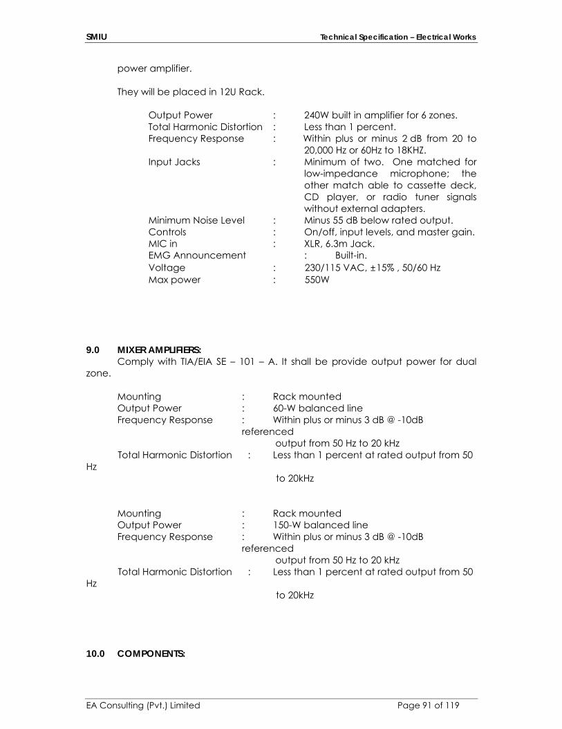
SMIU Technical Specification – Electrical Works
EA Consulting (Pvt.) Limited Page 91 of 119
power amplifier. They will be placed in 12U Rack.
Output Power : 240W built in amplifier for 6 zones. Total Harmonic Distortion : Less than 1 percent. Frequency Response : Within plus or minus 2 dB from 20 to
20,000 Hz or 60Hz to 18KHZ. Input Jacks : Minimum of two. One matched for
low-impedance microphone; the other match able to cassette deck, CD player, or radio tuner signals without external adapters.
Minimum Noise Level : Minus 55 dB below rated output. Controls : On/off, input levels, and master gain. MIC in : XLR, 6.3m Jack. EMG Announcement : Built-in. Voltage : 230/115 VAC, ±15% , 50/60 Hz Max power : 550W
9.0 MIXER AMPLIFIERS: Comply with TIA/EIA SE – 101 – A. It shall be provide output power for dual zone. Mounting : Rack mounted Output Power : 60-W balanced line
Frequency Response : Within plus or minus 3 dB @ -10dB referenced
output from 50 Hz to 20 kHz Total Harmonic Distortion : Less than 1 percent at rated output from 50 Hz to 20kHz Mounting : Rack mounted Output Power : 150-W balanced line
Frequency Response : Within plus or minus 3 dB @ -10dB referenced
output from 50 Hz to 20 kHz Total Harmonic Distortion : Less than 1 percent at rated output from 50 Hz to 20kHz 10.0 COMPONENTS:
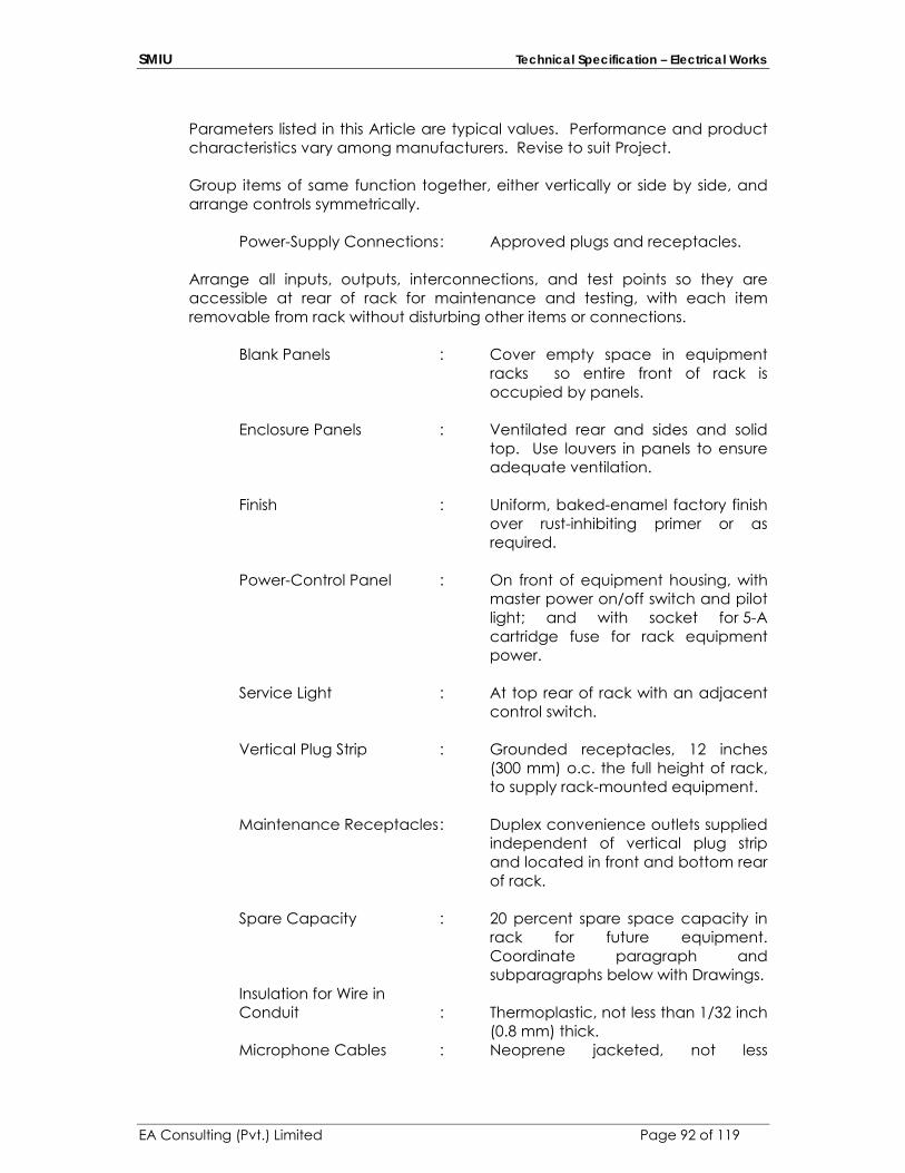
SMIU Technical Specification – Electrical Works
EA Consulting (Pvt.) Limited Page 92 of 119
Parameters listed in this Article are typical values. Performance and product characteristics vary among manufacturers. Revise to suit Project.
Group items of same function together, either vertically or side by side, and arrange controls symmetrically.
Power-Supply Connections : Approved plugs and receptacles.
Arrange all inputs, outputs, interconnections, and test points so they are accessible at rear of rack for maintenance and testing, with each item removable from rack without disturbing other items or connections.
Blank Panels : Cover empty space in equipment racks so entire front of rack is occupied by panels.
Enclosure Panels : Ventilated rear and sides and solid
top. Use louvers in panels to ensure adequate ventilation.
Finish : Uniform, baked-enamel factory finish
over rust-inhibiting primer or as required.
Power-Control Panel : On front of equipment housing, with
master power on/off switch and pilot light; and with socket for 5-A cartridge fuse for rack equipment power.
Service Light : At top rear of rack with an adjacent
control switch.
Vertical Plug Strip : Grounded receptacles, 12 inches (300 mm) o.c. the full height of rack, to supply rack-mounted equipment.
Maintenance Receptacles : Duplex convenience outlets supplied
independent of vertical plug strip and located in front and bottom rear of rack.
Spare Capacity : 20 percent spare space capacity in
rack for future equipment. Coordinate paragraph and subparagraphs below with Drawings.
Insulation for Wire in Conduit : Thermoplastic, not less than 1/32 inch
(0.8 mm) thick. Microphone Cables : Neoprene jacketed, not less
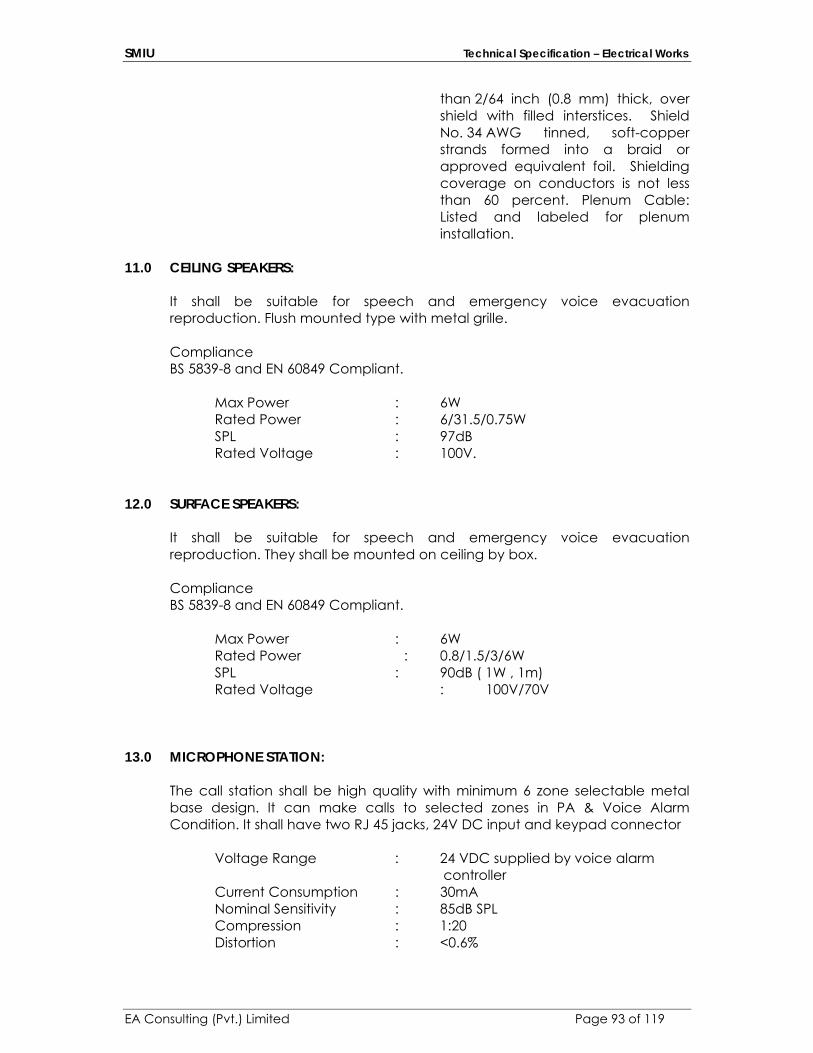
SMIU Technical Specification – Electrical Works
EA Consulting (Pvt.) Limited Page 93 of 119
than 2/64 inch (0.8 mm) thick, over shield with filled interstices. Shield No. 34 AWG tinned, soft-copper strands formed into a braid or approved equivalent foil. Shielding coverage on conductors is not less than 60 percent. Plenum Cable: Listed and labeled for plenum installation.
11.0 CEILING SPEAKERS:
It shall be suitable for speech and emergency voice evacuation reproduction. Flush mounted type with metal grille. Compliance BS 5839-8 and EN 60849 Compliant.
Max Power : 6W Rated Power : 6/31.5/0.75W SPL : 97dB Rated Voltage : 100V.
12.0 SURFACE SPEAKERS:
It shall be suitable for speech and emergency voice evacuation reproduction. They shall be mounted on ceiling by box.
Compliance BS 5839-8 and EN 60849 Compliant. Max Power : 6W Rated Power : 0.8/1.5/3/6W SPL : 90dB ( 1W , 1m) Rated Voltage : 100V/70V
13.0 MICROPHONE STATION: The call station shall be high quality with minimum 6 zone selectable metal base design. It can make calls to selected zones in PA & Voice Alarm Condition. It shall have two RJ 45 jacks, 24V DC input and keypad connector
Voltage Range : 24 VDC supplied by voice alarm controller Current Consumption : 30mA Nominal Sensitivity : 85dB SPL Compression : 1:20 Distortion : <0.6%

SMIU Technical Specification – Electrical Works
EA Consulting (Pvt.) Limited Page 94 of 119
Frequency Response : 100Hz to 16Hz Selection : Chimes any file Priorities : 7 Cable Length : As required.
Additional keypad will be required which will be extension for 6 zone call station.
14.0 EXECUTION INSTALLATION
Wiring Method Install wiring in raceways except within consoles, cabinets, desks, and counters and except in accessible ceiling spaces and in gypsum-board partitions where cable wiring method may be used. Use plenum cable in environmental air spaces including plenum ceilings. Conceal cables and raceways except in unfinished spaces. Install exposed cables parallel and perpendicular to surfaces or exposed structural members, and follow surface contours. Secure and support cables by straps, staples, or similar fittings so designed and installed to avoid damage to cables. Secure cable at intervals not exceeding 30 inches (760 mm) and not more than 6 inches (150 mm) from cabinets, boxes, or fittings.
Wiring within Enclosures Bundle, lace, and train conductors to terminal points with no excess use lacing bars in cabinets.
Control-Circuit Wiring: Install number and size of conductors as
recommended by system manufacturer for control functions indicated.
Separation of Wires Separate speaker-microphone, line-level, speaker-level, and power wiring runs. Install in separate raceways or, where exposed or in same enclosure, separate conductors at least 12 inches (300 mm) for speaker microphones and adjacent parallel power and telephone wiring. Separate other intercommunication equipment conductors as recommended by equipment manufacturer. Splices, Taps, and Terminations Arrange on numbered terminal strips in junction, pull, and outlet boxes; terminal cabinets; and equipment enclosures. Match input and output impedances and signal levels at signal interfaces. Provide matching networks where required. Identification of Conductors and Cables Color-code conductors and apply wire and cable marking tape to designate wires and cables so they identify media in coordination with system wiring diagrams.
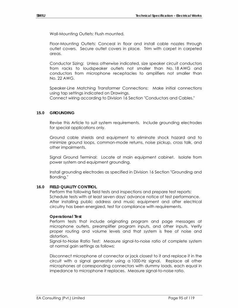
SMIU Technical Specification – Electrical Works
EA Consulting (Pvt.) Limited Page 95 of 119
Wall-Mounting Outlets: Flush mounted. Floor-Mounting Outlets: Conceal in floor and install cable nozzles through outlet covers. Secure outlet covers in place. Trim with carpet in carpeted areas. Conductor Sizing: Unless otherwise indicated, size speaker circuit conductors from racks to loudspeaker outlets not smaller than No. 18 AWG and conductors from microphone receptacles to amplifiers not smaller than No. 22 AWG. Speaker-Line Matching Transformer Connections: Make initial connections using tap settings indicated on Drawings. Connect wiring according to Division 16 Section "Conductors and Cables."
15.0 GROUNDING
Revise this Article to suit system requirements. Include grounding electrodes for special applications only. Ground cable shields and equipment to eliminate shock hazard and to minimize ground loops, common-mode returns, noise pickup, cross talk, and other impairments. Signal Ground Terminal: Locate at main equipment cabinet. Isolate from power system and equipment grounding. Install grounding electrodes as specified in Division 16 Section "Grounding and Bonding."
16.0 FIELD QUALITY CONTROL
Perform the following field tests and inspections and prepare test reports: Schedule tests with at least seven days' advance notice of test performance. After installing public address and music equipment and after electrical circuitry has been energized, test for compliance with requirements. Operational Test Perform tests that include originating program and page messages at microphone outlets, preamplifier program inputs, and other inputs. Verify proper routing and volume levels and that system is free of noise and distortion. Signal-to-Noise Ratio Test: Measure signal-to-noise ratio of complete system at normal gain settings as follows: Disconnect microphone at connector or jack closest to it and replace it in the circuit with a signal generator using a 1000-Hz signal. Replace all other microphones at corresponding connectors with dummy loads, each equal in impedance to microphone it replaces. Measure signal-to-noise ratio.

SMIU Technical Specification – Electrical Works
EA Consulting (Pvt.) Limited Page 96 of 119
Repeat test for each separately controlled zone of loudspeakers. Minimum acceptance ratio is 50 dB. Distortion Test: Measure distortion at normal gain settings and rated power. Feed signals at frequencies of 50, 200, 400, 1000, 3000, 8000, and 12,000 Hz into each preamplifier channel. For each frequency, measure distortion in the paging and all-call amplifier outputs. Maximum acceptable distortion at any frequency is 3 percent total harmonics. Acoustic Coverage Test: Feed pink noise into system using octaves centered at 500 and 4000 Hz. Use sound-level meter with octave-band filters to measure level at five locations in each zone. For spaces with seated audiences, maximum permissible variation in level is plus or minus 2 dB. In addition, the levels between locations in the same zone and between locations in adjacent zones must not vary more than plus or minus 3 dB. Power Output Test: Measure electrical power output of each power amplifier at normal gain settings of 50, 1000, and 12,000 Hz. Maximum variation in power output at these frequencies must not exceed plus or minus 1 dB. Signal Ground Test: Measure and report ground resistance at pubic address equipment signal ground. Comply with testing requirements specified in Division 16 Section "Grounding and Bonding." Retesting: Correct deficiencies, revising tap settings of speaker-line matching transformers where necessary to optimize volume and uniformity of sound levels, and retest. Prepare a written record of tests. Inspection: Verify that units and controls are properly labeled and interconnecting wires and terminals are identified. Prepare a list of final tap settings of paging speaker-line matching transformers.
17.0 ADJUSTING
On-Site engage a factory-authorized service representative to provide on-site assistance in adjusting sound levels, resetting transformer taps, and adjusting controls to meet occupancy conditions.
18.0 DEMONSTRATION
Engage a factory-authorized service representative to train Owner's maintenance personnel to adjust, operate, and maintain public address and music equipment. Refer to Division 1 Section.
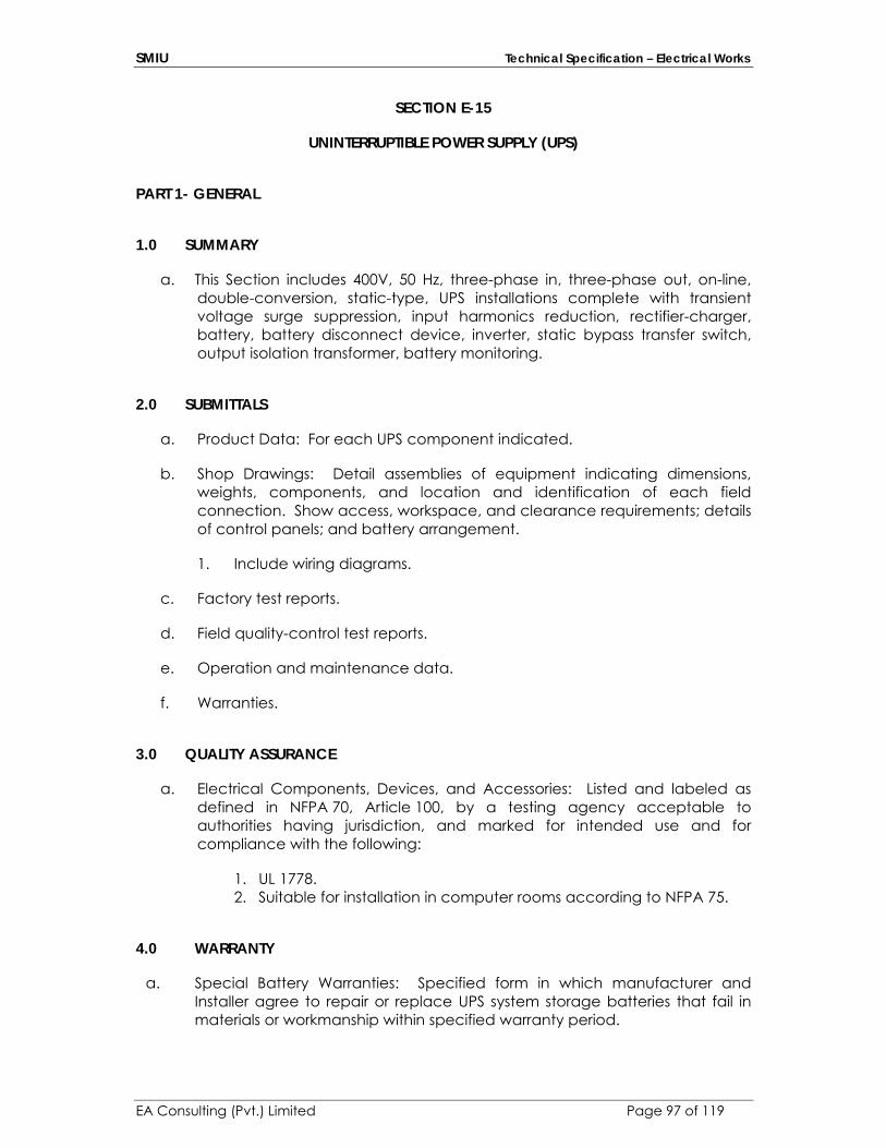
SMIU Technical Specification – Electrical Works
EA Consulting (Pvt.) Limited Page 97 of 119
SECTION E-15
UNINTERRUPTIBLE POWER SUPPLY (UPS)
PART 1- GENERAL
1.0 SUMMARY
a. This Section includes 400V, 50 Hz, three-phase in, three-phase out, on-line, double-conversion, static-type, UPS installations complete with transient voltage surge suppression, input harmonics reduction, rectifier-charger, battery, battery disconnect device, inverter, static bypass transfer switch, output isolation transformer, battery monitoring.
2.0 SUBMITTALS
a. Product Data: For each UPS component indicated.
b. Shop Drawings: Detail assemblies of equipment indicating dimensions, weights, components, and location and identification of each field connection. Show access, workspace, and clearance requirements; details of control panels; and battery arrangement.
1. Include wiring diagrams.
c. Factory test reports.
d. Field quality-control test reports.
e. Operation and maintenance data.
f. Warranties.
3.0 QUALITY ASSURANCE
a. Electrical Components, Devices, and Accessories: Listed and labeled as defined in NFPA 70, Article 100, by a testing agency acceptable to authorities having jurisdiction, and marked for intended use and for compliance with the following:
1. UL 1778. 2. Suitable for installation in computer rooms according to NFPA 75.
4.0 WARRANTY
a. Special Battery Warranties: Specified form in which manufacturer and Installer agree to repair or replace UPS system storage batteries that fail in materials or workmanship within specified warranty period.

SMIU Technical Specification – Electrical Works
EA Consulting (Pvt.) Limited Page 98 of 119
1. Warranted Cycle Life for Valve-Regulated, Lead-Acid Batteries: Equal to or greater than that represented in manufacturer's published table, including figures corresponding to the following, based on annual average battery temperature of 35 deg. C: Discharge Rate Discharge Duration Discharge End
Voltage Cycle Life
8 hours 8 hours 1.67 6 cycles 30 minutes 30 minutes 1.67 20 cycles 15 minutes 45 seconds 1.67 120 cycles
2. Warranted Cycle Life for Premium Valve-Regulated, Lead-Acid Batteries: Equal to or greater than that represented in manufacturer's published table, including figures corresponding to the following, based on annual average battery temperature of 35 deg C: Discharge Rate Discharge Duration Discharge End
Voltage Cycle Life
8 hours 8 hours 1.67 40 cycles 30 minutes 30 minutes 1.67 125 cycles 15 minutes 1.5 minutes 1.67 750 cycles
b. Special UPS Warranties: Specified form in which manufacturer and Installer agree to repair or replace components that fail in materials or workmanship within special warranty period.
1. Special Warranty Period: Three years from date of Substantial Completion.
PART 2 - PRODUCTS
1.0 MANUFACTURERS
a. In other Part 2 articles where titles below introduce lists, the following requirements apply to product selection:
1. Available Manufacturers: Subject to compliance with requirements, manufacturers offering products that may be incorporated into the Work include, but are not limited to, manufacturers specified.
2. Manufacturers: Subject to compliance with requirements, provide products by one of the manufacturers specified.
2.0 PERFORMANCE DESCRIPTION
a. Automatic operation includes the following:
1. Normal Conditions: Supply the load with ac power flowing from the normal ac power input terminals, through the rectifier-charger and
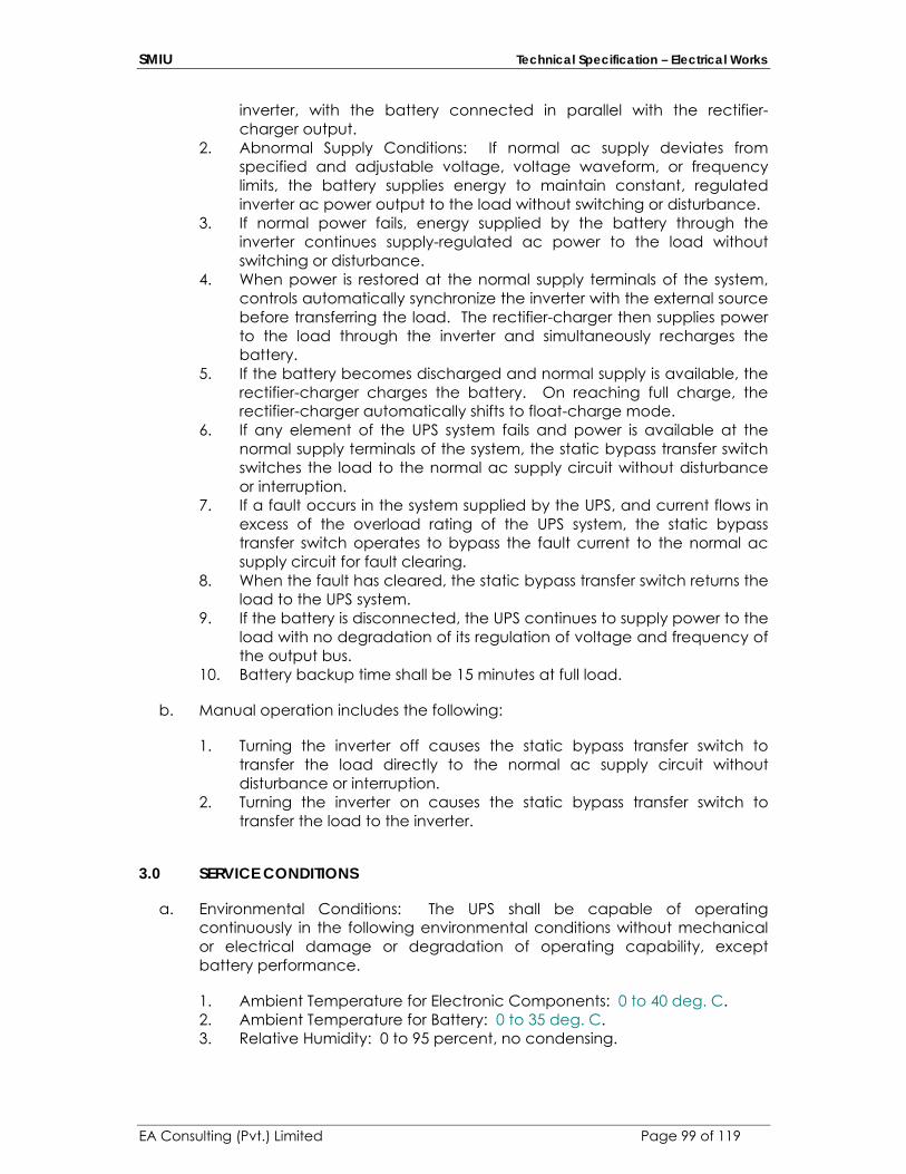
SMIU Technical Specification – Electrical Works
EA Consulting (Pvt.) Limited Page 99 of 119
inverter, with the battery connected in parallel with the rectifier-charger output.
2. Abnormal Supply Conditions: If normal ac supply deviates from specified and adjustable voltage, voltage waveform, or frequency limits, the battery supplies energy to maintain constant, regulated inverter ac power output to the load without switching or disturbance.
3. If normal power fails, energy supplied by the battery through the inverter continues supply-regulated ac power to the load without switching or disturbance.
4. When power is restored at the normal supply terminals of the system, controls automatically synchronize the inverter with the external source before transferring the load. The rectifier-charger then supplies power to the load through the inverter and simultaneously recharges the battery.
5. If the battery becomes discharged and normal supply is available, the rectifier-charger charges the battery. On reaching full charge, the rectifier-charger automatically shifts to float-charge mode.
6. If any element of the UPS system fails and power is available at the normal supply terminals of the system, the static bypass transfer switch switches the load to the normal ac supply circuit without disturbance or interruption.
7. If a fault occurs in the system supplied by the UPS, and current flows in excess of the overload rating of the UPS system, the static bypass transfer switch operates to bypass the fault current to the normal ac supply circuit for fault clearing.
8. When the fault has cleared, the static bypass transfer switch returns the load to the UPS system.
9. If the battery is disconnected, the UPS continues to supply power to the load with no degradation of its regulation of voltage and frequency of the output bus.
10. Battery backup time shall be 15 minutes at full load.
b. Manual operation includes the following:
1. Turning the inverter off causes the static bypass transfer switch to transfer the load directly to the normal ac supply circuit without disturbance or interruption.
2. Turning the inverter on causes the static bypass transfer switch to transfer the load to the inverter.
3.0 SERVICE CONDITIONS
a. Environmental Conditions: The UPS shall be capable of operating continuously in the following environmental conditions without mechanical or electrical damage or degradation of operating capability, except battery performance.
1. Ambient Temperature for Electronic Components: 0 to 40 deg. C. 2. Ambient Temperature for Battery: 0 to 35 deg. C. 3. Relative Humidity: 0 to 95 percent, no condensing.

SMIU Technical Specification – Electrical Works
EA Consulting (Pvt.) Limited Page 100 of 119
4.0 PERFORMANCE REQUIREMENTS
a. The UPS shall perform as specified in this Article while supplying rated full-load current, composed of any combination of linear and nonlinear load, up to 100 percent nonlinear load with a load crest factor of 3.0, under the following conditions or combinations of the following conditions:
b.
1. Inverter is switched to battery source. 2. Steady-state ac input voltage deviates up to plus or minus 10 percent
from nominal voltage. 3. Steady-state input frequency deviates up to plus or minus 5 percent
from nominal frequency. 4. THD of input voltage is 15 percent or more with a minimum crest factor
of 3.0, and the largest single harmonic component is a minimum of 5 percent of the fundamental value.
c. Minimum Duration of Supply: If battery is sole energy source supplying rated full UPS load current at 80 percent power factor for a period of 15 minutes.
d. Input Voltage Tolerance: System steady-state and transient output performance remains within specified tolerances when steady-state ac input voltage varies plus 10, minus 15 percent from nominal voltage.
e. Maximum Energizing Inrush Current: Six to Eight times the full-load current.
f. Maximum AC Output-Voltage Regulation for Loads up to 50 Percent Unbalanced: Plus or minus 2 percent over the full range of battery voltage.
g. Output Frequency: 50 Hz, plus or minus 0.5 percent over the full range of input voltage, load, and battery voltage.
h. Limitation of harmonic distortion of input current to the UPS shall be as follows:
1. Description: Either a tuned harmonic filter or an arrangement of rectifier-charger circuits shall limit THD to 5 percent, maximum, at rated full UPS load current, for power sources with X/R ratio between 2 and 30.
i. Maximum Harmonic Content of Output-Voltage Waveform: 5 percent RMS total and 3 percent RMS for any single harmonic, for rated full load with THD up to 50 percent, with a load crest factor of 3.0.
j. Minimum Overload Capacity of UPS at Rated Voltage: 125 percent of rated full load for 10 minutes, and 150 percent for 30 seconds in all operating modes.
k. Maximum Output-Voltage Transient Excursions from Rated Value: For the following instantaneous load changes, stated as percentages of rated full UPS load, voltage shall remain within stated percentages of rated value and

SMIU Technical Specification – Electrical Works
EA Consulting (Pvt.) Limited Page 101 of 119
recover to, and remain within, plus or minus 2 percent of that value within 100 ms:
1. 50 Percent: Plus or minus 5 percent. 2. 100 Percent: Plus or minus 5 percent. 3. Loss of AC Input Power: Plus or minus 1 percent. 4. Restoration of AC Input Power: Plus or minus 1 percent.
l. Input Power Factor: A minimum of 0.95 lagging when supply voltage and current are at nominal rated values and the UPS is supplying rated full-load current.
m. EMI Emissions: Comply with FCC Rules and Regulations, and with 47 CFR 15 for Class A equipment.
5.0 UPS SYSTEMS
a. Electronic Equipment: Solid-state devices using hermetically sealed, semiconductor elements. Devices include rectifier-charger, inverter, static bypass transfer switch, and system controls.
b. Enclosures: Comply with NEMA 250, Type 1, unless otherwise indicated.
c. Control Assemblies: Mount on modular plug-ins, readily accessible for maintenance.
d. Surge Suppression: Protect internal UPS components from surges that enter at each ac power input connection including main disconnect switch and static bypass transfer switch. Protect rectifier-charger, inverter, controls, and output components.
1. Use factory-installed surge suppressors tested according to IEEE C62.41
e. Output Circuit Neutral Bus, Conductor, and Terminal Ampacity: Rated phase current times a multiple of 1.73, minimum.
6.0 RECTIFIER-CHARGER
a. Capacity: Adequate to supply the inverter during rated full output load conditions and simultaneously recharge the battery from fully discharged condition to 95 percent of full charge within 10 times the rated discharge time for duration of supply under battery power at full load.
b. Output Ripple: Limited by output filtration to less than 0.5 percent of rated current, peak to peak.
c. Rectifier-Charger Control Circuits: Immune to frequency variations within rated frequency ranges of normal and emergency power sources.
1. Response Time: Field adjustable for maximum compatibility with local generator-set power source.

SMIU Technical Specification – Electrical Works
EA Consulting (Pvt.) Limited Page 102 of 119
d. Battery Float-Charging Conditions: Comply with battery manufacturer's written instructions for battery terminal voltage and charging current required for maximum battery life.
7.0 INVERTER
a. Description: Pulse-width modulated, with sinusoidal output.
8.0 STATIC BYPASS TRANSFER SWITCH
a. Description: Solid-state switching device providing uninterrupted transfer. A contactor or electrically operated circuit breaker automatically provides electrical isolation for the switch.
b. Switch Rating: Continuous duty at the rated full UPS load current, minimum.
9.0 BATTERY
a. Description: Valve-regulated, recombinant, lead-calcium units, factory assembled in an isolated compartment of UPS cabinet and complete with battery disconnect switch.
b. Description: Valve-regulated, premium, heavy-duty, recombinant, lead-calcium units, factory assembled in an isolated compartment or in a separate matching cabinet, complete with battery disconnect switch.
10.0 CONTROLS AND INDICATIONS
a. Description: Group displays, indications, and basic system controls on a common control panel on front of UPS enclosure.
b. Minimum displays, indicating devices, and controls include those in lists below. Provide sensors, transducers, terminals, relays, and wiring required to support listed items. Alarms include audible signals and visual displays.
c. Indications:
1. Quantitative indications shall include the following:
a. Input voltage, each phase, line to line. b. Input current, each phase, line to line. c. Bypass input voltage, each phase, line to line. d. Bypass input frequency. e. System output voltage, each phase, line to line. f. System output current, each phase. g. System output frequency. h. DC bus voltage. i. Battery current and direction (charge/discharge). j. Elapsed time discharging battery.

SMIU Technical Specification – Electrical Works
EA Consulting (Pvt.) Limited Page 103 of 119
2. Basic status condition indications shall include the following:
a. Normal operation. b. Load-on bypass. c. Load-on battery. d. Inverter off. e. Alarm condition.
3. Alarm indications shall include the following:
a. Bypass ac input overvoltage or under voltage. b. Bypass ac input over frequency or under frequency. c. Bypass ac input and inverter out of synchronization. d. Bypass ac input wrong-phase rotation. e. Bypass ac input single-phase condition. f. Bypass ac input filter fuse blown. g. Internal frequency standard in use. h. Battery system alarm. i. Control power failure. j. Fan failure. k. UPS overload. l. Battery-charging control faulty. m. Input overvoltage or undervoltage. n. Input transformer overtemperature. o. Input circuit breaker tripped. p. Input wrong-phase rotation. q. Input single-phase condition. r. Approaching end of battery operation. s. Battery under voltage shutdown. t. Maximum battery voltage. u. Inverter fuse blown. v. Inverter transformer over temperature. w. Inverter over temperature. x. Static bypass transfer switch over temperature. y. Inverter power supply fault. z. Inverter transistors out of saturation. aa. Identification of faulty inverter section/leg. bb. Inverter output overvoltage or under voltage. cc. UPS overload shutdown. dd. Inverter current sensor fault. ee. Inverter output contactor open. ff. Inverter current limit.
4. Controls shall include the following:
a. Inverter on-off. b. UPS start. c. Battery test. d. Alarm silence/reset. e. Output-voltage adjustment.
SMIU Technical Specification – Electrical Works
EA Consulting (Pvt.) Limited Page 104 of 119
d. Emergency Power off Switch: Capable of local operation and operation by means of activation by external dry contacts.
11.0 OUTPUT ISOLATION TRANSFORMER
a. Description: Unit with low forward transfer impedance up to 3 kHz, minimum. Include the following features:
1. Comply with applicable portions of UL 1561, including requirements for nonlinear load current-handling capability for a suitable K-factor.
2. Output Impedance at Fundamental Frequency: Between 3 and 4 percent.
3. Regulation: 5 percent, maximum, at rated nonlinear load current. 4. Full-Load Efficiency at Rated Nonlinear Load Current: 96 percent,
minimum. 5. Electrostatic Shielding of Windings: Independent for each winding. 6. Coil Leads: Physically arranged for minimum inter lead capacitance. 7. Shield Grounding Terminal: Separately mounted; labeled "Shield
Ground." 8. Capacitive Coupling between Primary and Secondary: 33 Pico farads,
maximum, over a frequency range of 20 Hz to 1 MHz
12.0 BASIC BATTERY MONITORING
a. Battery Ground-Fault Detector: Initiates alarm when resistance to ground of positive or negative bus of battery is less than 5000 ohms.
b. Annunciation of Alarms: At UPS control panel.
13.0 BATTERY-CYCLE WARRANTY MONITORING
a. Description: Electronic device, acceptable to battery manufacturer as a basis for warranty action, for monitoring of charge-discharge cycle history of batteries covered by cycle-life warranties.
b. Performance: Automatically measures and records each discharge event, classifies it according to duration category, and totals discharges according to warranty criteria, displaying remaining warranted battery life on front panel display.
14.0 SOURCE QUALITY CONTROL
a. Factory test complete UPS system before shipment. Use simulated battery testing. Include the following:
1. Test and demonstration of all functions, controls, indicators, sensors, and protective devices.
2. Full-load test. 3. Transient-load response test.
SMIU Technical Specification – Electrical Works
EA Consulting (Pvt.) Limited Page 105 of 119
4. Overload test. 5. Power failure test.
b. Report test results.
PART 3 - EXECUTION
1.0 INSTALLATION
a. Install system components on 100mm high concrete bases.
b. Maintain minimum clearances and workspace at equipment according to manufacturer's written instructions and NFPA 70.
c. Connections: Interconnect system components. Make connections to supply and load circuits according to manufacturer's wiring diagrams, unless otherwise indicated.
d. Separately Derived Systems: If not part of a listed power supply for a data-processing room, comply with NFPA 70 requirements for connecting to grounding electrodes and for bonding to metallic piping near isolation transformer.
e. Identify components and wiring according to relevant section of this specifications
f. Equalize charging of battery cells according to manufacturer's written instructions. Record individual-cell voltages.
2.0 FIELD QUALITY CONTROL
a. Manufacturer's Field Service: Engage a factory-authorized service representative to inspect, test, and adjust equipment installation including connections and to assist in field testing. Report results in writing.
b. Electrical Tests and Inspections: Perform tests and inspections according to manufacturer's written instructions and as listed below to demonstrate condition and performance of each UPS component:
1. Inspect interiors of enclosures, including the following:
a. Integrity of mechanical and electrical connections. b. Component type and labeling verification. c. Ratings of installed components.
2. Test manual and automatic operational features and system protective and alarm functions.
c. Retest: Correct deficiencies and retest until specified requirements are met.
SMIU Technical Specification – Electrical Works
EA Consulting (Pvt.) Limited Page 106 of 119
d. Record of Tests and Inspections: Maintain and submit documentation of tests and inspections, including references to manufacturers' written instructions and other test and inspection criteria. Include results of tests, inspections, and retests.
3.0 DEMONSTRATION
a. Engage a factory-authorized service representative to train Owner's maintenance personnel to adjust, operate, and maintain the UPS. Refer to Division 1 Section
SECTION E-16
SELF-CONTAINED EMERGENCY LIGHTING FIXTUES
1.0 GENERAL The Emergency lighting system and all its components shall be designed &
installed to meet the local civil defense requirements & the respective EN50171 & BS standards and regulations applicable on the project. The product shall bear CE certification for electromagnetic compatibility.
It shall comply with BS 5266. Emergency lighting shall fulfill the following functions: Illuminate the escape routes.
Indicate the escape route direction clearly
Provide EXIT signs on escape doors and routes to such doors.

SMIU Technical Specification – Electrical Works
EA Consulting (Pvt.) Limited Page 107 of 119
Ensure fire alarm call points, firefighting equipment and other lifesaving equipment on the premises are illuminated.
2.0 EMERGENCY AND EXIT LUMINARIES: All Exit luminaires shall have pictogram legends as per DIN 4844/CEN TC
169, EN50171 or markings as per local civil defense requirements with viewing distance of 32 meters. The luminaire shall be built according to EN 60598.
All emergency luminaries shall meet following requirements:
Self-Contained for 3 hr back up. Supply voltage 230V DC The luminaire shall comply with the requirements of EN60598 Electronic ballast shall comply with the requirements of EN60298/60294 EMC or EMI protection to EN55015
Ambient Temperature – 40 ºC. The power rating of the luminaires shall be 8W. It shall be of rating IP20 ingress protection.
IP 65 emergency luminaires shall be used as surface mounted in places as per drawings.
We would be using following emergency and exit luminaries that will be
connected with central battery system.
8W WALL MOUNTED EMERGENCY LIGHTS: We would be using 8W wall mounted luminaries in rooms as per
requirements with IP 20 ingress protection as specified in drawing.
8W CEILING RECESSED EMERGENCY LIGHTS: We would be using 8W ceiling recessed emergency luminaries in rooms as per requirements with IP 20 ingress protection as specified in drawing.
8W EXIT LIGHTS: We would be using 8W emergency luminaries to illuminate exit routes as per requirements with IP 65 ingress protection as specified in drawing with maximum viewing distance of 40 meters with polycarbonate body and housing with legend printed specifying escape route.
8W SURFACE/WALL MOUNTED EMERGENCY LIGHTS:
We would be using 8W emergency lights in areas as indicated in drawing with IP 65 ingress protection and suitable for ceiling and wall surface mount. The finishing of body should be of poly carbonate material.

SMIU Technical Specification – Electrical Works
EA Consulting (Pvt.) Limited Page 108 of 119
SECTION E-17
ACCESS CONTROL SYSTEM
1.0 STANDARDS Materials and workmanship shall conform to the latest issue of all industry
standards, publications, or regulations referenced in this section and with the following references as applicable.
NFPA 70 – National Electrical Code UL294 – Standard for Access Control Systems NFPA 72 – National Fire Alarm Code NFPA 101 - Life Safety Code.
2.0 SYSTEM DESCRIPTION The System shall be a modular and network capable access control
system. The System shall have the ability of handling controlled access with various reader technologies supported simultaneously, alarm monitoring with text and graphics based annunciation. The system control at the central computer location shall be under a single software program control, shall provide full integration of all components, and shall be alterable at any time, depending upon the facility requirements. Reconfiguration shall be accomplished on-line through system
SMIU Technical Specification – Electrical Works
EA Consulting (Pvt.) Limited Page 109 of 119
programming, without hardware changes. This shall be integrated with BMS.
The system shall support both manual and automatic responses to alarms
entering the system. Each alarm shall be capable of initiating a number of different actions, activation of remote devices and door control.
Access control functions shall include, validation based on time of day,
day of week, holiday scheduling, automatic or manual retrieval of cardholder photographs, and access validation based on positive verification of card, card/PIN, and PIN.
The system programming shall be user-friendly Windows environment (use
conventional “Title Bar”, “Menu Bar”, “Tool Bar” and “Status Bar”) and allow mouse control of key functions. The programming shall be MENU driven and include on-line “Documentation”, “Help” or “Tutorial” information. The software shall utilize combo boxes for previously entered system-required data where applicable.
The method of communication from remote locations to the central
components shall be transparent to the user. After installation, the OWNER shall be able to perform hardware
configuration changes as desired without the services of the MANUFACTURER.
Equipment repair shall be able to be accomplished on site, by module
replacement, utilizing spare components. All controller components shall utilize "Distributed-Processing" concepts. The
distributed processing shall include the ability to down-load operating parameters to any field panel, thus allowing the field panel to provide full operating functions independent of any other system component.
The system shall be capable of utilizing the existing LAN / WAN connecting
the buildings or a dedicated security Ethernet network for Controller and Client communications.
Manufacturer: The access control system shall be from a single-source
manufacturer that specializes in access control and intrusion detection systems with a minimum of 20 years’ experience.
Installer: Company specializing in access control and intrusion detection
systems with a minimum of three years’ experience on systems of similar size and scope. Technicians working on project must have been certified on the hardware and software used for this project.
3.0 SUBMITTALS
SMIU Technical Specification – Electrical Works
EA Consulting (Pvt.) Limited Page 110 of 119
Manufacturer’s Data: Submit three (3) copies of: Product Data Sheets Installation Instructions Authorized Dealer Certificate and Certified Training Certificates of installers
who will be working on this project. Shop Drawings Submit three (3) copies and digitally in AutoCAD or later format on a CD (3
copies), shop drawings, including: Layout of equipment on supplied AutoCAD drawings. Security Console elevation drawings. Field Controller equipment location wall layouts, including size
requirements. Detailed wiring diagrams of Field Controllers, Door Details, and head-end
devices. Load calculations of all security equipment for proper sizing of electrical
provided by the customer and standby emergency generator circuits. As-Built Drawings Update Shop Drawings to create final As-Built Drawings. Submit 3 copies
and digitally in AutoCad 14 or later format on a CD (3 copies). OPERATION AND MAINTENANCE MANUALS Operation Data: Include three (3) copies of the software Administrator
and Operator Manuals. UPS The UPS (Uninterruptible Power Supply) for the Server shall provide for 20
minutes of continued operation in the event of an AC Power Failure. Control Panel Specifications The control panel shall incorporate microprocessor-based, digital
technology, using high speed processing for maximum reliability. Distributed Intelligence The system shall use distributed intelligence architecture, with controllers
operating independently of one another. Regionalized functions for all controllers connected to an Xbox
communications loop shall include: Use Count, Absentee Limit, Temporary
SMIU Technical Specification – Electrical Works
EA Consulting (Pvt.) Limited Page 111 of 119
Days, Pass back, and Input/output linking and shall not require the host to be online for processing and control.
Stand Alone Operation All database information required for stand-alone operation shall be stored
at the control panel level. All decision-making shall be performed at the control panel, eliminating the need for degraded mode operation.
Proprietary software programs and control logic information used to
coordinate and drive system hardware shall be stored in Flash Downloadable Read Only Memory.
4.0 HARDWARE REQUIREMENTS
A. Controllers
There controllers shall be access control 2 door type; alarm monitoring (16 supervised inputs); and relay control with the addition of REB8 relay expansion boards and. Each controller shall have the following common features.
B. Controller Board
The controller board shall be microprocessor based, incorporating Flash ROM (firmware) downloadable from the Host Computer, RAM (User Information, System Setups, Event Transaction Buffer) and a Clock/Calendar. The ROM shall be modularly upgradeable in the field for enhancements to system features. All powered connections to the controller board shall be protected by fuses. All wiring connections to the controller board shall be to "Phoenix" type screw terminals. Each door connection shall consist of terminals for two readers, one 10 Amp rated Form C dry output relay for lock control, and one input for monitoring a status switch, a request-to-exit device, and a tamper switch. There shall be status indicator lights for active relays, as well as diagnostic indicator lights to aid in system troubleshooting. There shall be dedicated alarm output relay/s for external reporting of the following conditions: Alarm; Duress; Tamper; and Trouble.
C. Enclosure
The controller enclosure shall be a NEMA style metal cabinet designed for surface mounting. It shall have a tampered, removable hinged door with a high security key lock. It shall have conduit knockouts to allow from 25mm conduit to be used for wire entry into the cabinet.
D. Internal Power Supply
The controller shall have an internal power supply that will accept 50 Hz/ 220 - 240 VAC. The primary side of the power supply shall be protected with

SMIU Technical Specification – Electrical Works
EA Consulting (Pvt.) Limited Page 112 of 119
a fuse. The power supply shall provide 28 VDC power to the controller board, internal battery charger, selected card readers, and reader interface boards.
E. Standby Battery
The controller shall have an internal standby battery that is capable of running the system during AC power interruptions. It shall be recharged by a charging circuit incorporated into the controller board.
F. Alarm Inputs
The controller shall be capable of accepting up to 32 additional supervised alarm inputs, in increments of eight (8). The sensitivity of the line supervision shall be 2% AA Standard. The alarm expansion boards shall be mounted in the controller cabinet and connect to the controller board via an expansion bus cable. This option shall be limited to 16 additional supervised alarm inputs for the 16 zone alarm input controller (Model M16N) and none for the Model M1N. The alarm expansion board shall be Hirsch Model AEB8.
G. Intelligent Reader Interface
The control panels shall utilize an intelligent reader interface to communicate with card readers of various types. The interface shall be microprocessor based and allow data formats including ABA magnetic stripe, Proximity, Bar Code, Touch Memory, RF and Biometric. The interface shall utilize a digitizing algorithm, which will convert the card data to a unique number, thus, eliminating the need for facility codes. A single interface shall support both entrance and exit readers with keypads associated with each door. The interface shall be U.L. Listed to U.L.294. The reader interface shall be included as standard in all Scramble Pads.
5.0 CONTROLLER FIRMWARE
A. General Features
The software for the controller shall reside in Flash ROM (firmware) and be located on a plug removable module on the controller board to facilitate easy field upgradability of the features. All of the necessary software for a fully functional System is located in the controller. The controller firmware shall include the following general features at a minimum and be fully supported by the VELOCITY head-end.
3 - 15 digit keypad Code’s
Duress digit for keypad Code’s 150 Time Zones for access restriction and automatic event control 128 Access Zones for access management 256 Control Zones for alarm and relay management Assigned to 1 – 4 Holiday Schedules.

SMIU Technical Specification – Electrical Works
EA Consulting (Pvt.) Limited Page 113 of 119
Automatic daylight savings time clock adjustment 27 different functions for Code’s and cards, e.g. access, unlock, re-lock, alarm mask, relay control, add user records, tag users for annunciation at host computer 4,000 Users 1500 event, 1500 alarm transaction buffer
B. Access Control Features
1. The controller shall include the following access control features
at a minimum.
a. Restrict access by: time of day; day of week; door; holiday b. Momentary Access of door up to 8100 seconds c. Extended Access for User Definable Momentary Access
duration (requires Scramble Pad). Scramble Pad will display time remaining on the minute, and annunciate at the defined “Warning Time”
d. Special Needs Time Extension to provide additional time for Momentary Access and Door Open Too Long for selected people.
e. Unlock/Re-lock of door by CODE, card or Time Zone f. Door status monitoring shall allow for: door forced
monitoring; door-open-too-long monitoring; door-open-too-long while door is unlocked; auto-re-lock of door when opened or closed
g. Request-to-exit masks alarm and/or unlocks door
2. 2 person requirement by door. A user can be defined as Normal, A/B Rule A, A/B Rule B, Executive Override. Can be disabled by Time Zone.
3. 63 Pass back Zones. Can be disabled by Time Zone. A User can be designated with Pass back Executive Override.
4. Use Count limits on users
a. Absentee Rule limits on users b. Temporary Day limits on users c. Occupancy Counting / Minimum & Maximum limits per
Passback Zone d. Deadman CODE / Timer e. Threat Levels – 99 Levels may be defined. Based on the Level
in effect for the facility, selected readers may be disabled, dual readers in Card/Code Only during Time Zone can require

SMIU Technical Specification – Electrical Works
EA Consulting (Pvt.) Limited Page 114 of 119
dual, and selected User’s Credentials can be disabled.
C. Alarm Management Features
1. The controller shall include the following alarm management features at a minimum.
a. Momentarily mask alarm by CODE and/or card b. Mask/unmask alarm by CODE and/or card or by Time Zone c. Alarm device supervised while masked d. Tamper switch on alarm device monitored while masked e. Tamper Input may be configured to operate as a “Latch
Monitor” with the appropriate door lock hardware. f. Entry/Exit delay per alarm input g. Alarm input triggers relay/s
CARD READER/KEYPAD SPECIFICATIONS
Readers
1. The controllers shall accept all of the following reader technologies concurrently: Scrambling Keypad; Mag Stripe; Wiegand; Proximity; Bar Code; Biometrics - Retinal Scan, Hand Geometry, Fingerprint; Radio Frequency. The readers can be used for access control, alarm management, and/or relay control and shall be capable of being used alone (keypad only, card only) or a scrambling keypad and any other reader technology may be combined to operate as a dual technology reader where two valid IDs (PIN and card) are required.
Scramble Pad
1. The controller shall be capable of using scrambling keypad readers. The keypad shall incorporate the following features: Scrambling display of numbers 0 - 9 (numbers appear in different location every time it is used); +/- 4 degree horizontal and +/- 26 degree vertical viewing restriction; accept 3 - 15 digit CODEs simultaneously; be disabled for 1 minute and report CODE Tamper violation (guessing CODEs); be disabled and report Physical Tamper violation (attempt to remove keypad from mounting box); silent CODE duress; status LEDs for reporting granted, denied, and overridden transactions, AC Fail, Programming Mode active, responses to Status Request of Alarm Inputs and Relay Outputs; weather resistant; supervised by controller; and built-in diagnostics. The Scramble Pad shall include

SMIU Technical Specification – Electrical Works
EA Consulting (Pvt.) Limited Page 115 of 119
the MATCH Reader Interface functionality for connection of up to two (2) card readers.
A version of the scrambling keypad shall be available for use in high ambient lighting conditions or where the front is subject to direct sunlight. This version shall have a +/- 26 degree horizontal and +/- 40 degree vertical viewing restriction. A version of the scrambling keypad shall be available with an integrated proximity card reader. Presentation of the card shall automatically auto-start the scrambling display. The scrambling keypad with integrated proximity card reader shall be the Hirsch ScrambleProx Model DS47L-SPX. A version of the scrambling keypad with high intensity display shall be available with an integrated proximity card reader. Presentation of the card shall automatically auto-start the scrambling display.
Proximity Card Readers
1. The controller shall be capable of using proximity readers that
output a standard 26-55 Bit data format. The readers can have a short or long read range and be unidirectional or bi-directional.
PART 1 - EXECUTION 3.1 INSTALLATION
A. Install system in accordance with manufacturer's instructions. B. Install wiring for detection and signal circuit conductors in conduit. Use
22 AWG minimum size conductors. C. Make conduit and wiring connections to existing door hardware
devices as required. 3.2 TRAINING
A. The two designated System Administrators shall attend the 3 Day Factory Velocity User Class.
B. The Dealer shall coordinate with the System Administrators for two 8 hour Operator training sessions on the Operational System to be conducted on-site on the actual running system.
3.3 Field Quality Control
A. Test in accordance with Hirsch Electronics testing procedures for the
“Velocity for Windows 2000”.
SMIU Technical Specification – Electrical Works
EA Consulting (Pvt.) Limited Page 116 of 119
BIOMETRIC ATTENDANCE SYSTEM Biometric attendance system will be installed in IT building near reception. It shall operate both in standalone or integrate with access control system.
IP Engress protection: IP 54
Power Supply: POE
10 – 14V
140 mA quiescent
115 mA in sleep mode
DPI : 50
Identification time: less than 2 seconds
Enrolment time: less than 2 seconds
User capacity : 10000
Log capacity : 100,000
Template capacity: 8000 finger prints
Interfaces : TCP/IP (port 4370), RS 232, RS 485, Wiegand Output, Wiegand Input,
Alarm
Access Control: Lock drive, Egress, Door Sense, ABA/Wiegand (26,34 bit) output
Time zones: 50
Groups: 5 (3 time zones/ group)
Unlock Combinations: Up to 10
Configuration: PC Software or Embedded Web Server
Relay: 1A at 30V DC
Languages : English, French, Spanish, Dutch, Italian,

SMIU Technical Specification – Electrical Works
EA Consulting (Pvt.) Limited Page 117 of 119
SECTION E-18
MASTER CLOCK SYSTEM 1.0 PROCEDURE: Master Clock can be synchronized by GPS receiver or NTP server or both. GPS antenna will be synchronized by GPS satellites and it will provide time information to the master clock and then after receiving the time information from GPS it will synchronize all clocks. A software application will be used to monitor and configure devices. Master Clock will also be used to ring the bells as per the programming of the system. 2.0 MASTER CLOCK:
Wall / Desk Dimensions : 177 x 208 x 106 mm (W x H x D)
Rack Dimensions : 177 x 208 x 106 mm (W x H x D)
Temperature Range: From 0C to 50C
Humidity: Max 85%
Backup power in case of mains power loss and with clocks consumption: 24 Hours
Power Supply: POE, 110V AC - 230 V AC, 50-60 Hz
Accessories: GPS Receiver, POE injector, Central Management Software
Integrated Web Server

SMIU Technical Specification – Electrical Works
EA Consulting (Pvt.) Limited Page 118 of 119
3.0 NTP Slave Clocks:
Shape: Standard Round
Bracket: Mounting bracket for wall, flag and ceiling
Power Supply: NTP POE type
School bells shall be interfaced with master clock system via relay as per manufacturer specifications.
4.0 GPS:
GPS will synchronize with GPS satellites and therefore it guarantees a precision of 1 us. It works on NTP Protocol as it provides time information to master clock.
Microprocessor: RISC (32 bit) ARM micro processor
Channels: 20 (parallel)
Frequency: L1 (1575, 42 MHz)
Ethernet Interface: 10/100 Mbps
Communication Protocol: NTP, HTTP, TCP/IP, DHCP
Time to first FIX (TTFF): Less than 35 secs (with a good satellite signal)
Coverage Angle: From -90° to +90°
Installation: Wall or Pole mounted
Power Supply: Standard PoE Plus +48VDC
Maximum power consumption: 3W
Internal working state with watch dog timer
5.0 SOFTWARE:
The software shall have capability to allow master clock to offer IP addresses to those devices that request it and therefore reduces the number of steps necessary for deploying a new clock.
System monitoring consist in a constant analysis of the functioning state of the master clock and of all connected peripheral devices. A constantly active process cyclically queries the peripheral devices and therefore verifies, not just their state, but also that their configuration is correct.
SMIU Technical Specification – Electrical Works
EA Consulting (Pvt.) Limited Page 119 of 119
System shall work on SNTP and SNMP protocols, should an error occur, such as the loss of synchronization, it is possible to send an email or SNMP trap.
Software shall have capability to manage event log in which activities are registered and any problems recorded.
It shall monitor current synchronization state.
In the configuration section, it shall be possible to logically group clocks into one or more groups so as to differentiate applied parameter configurations regarding the time to be displayed. Software then automatically sends these parameters and verifies that they have been applied correctly.
6.0 SHOP DRAWINGS:
Prior to installation of any equipment, the Contractor shall submit for approval, shop drawings including riser and terminal wiring diagrams and specifications data sheets.
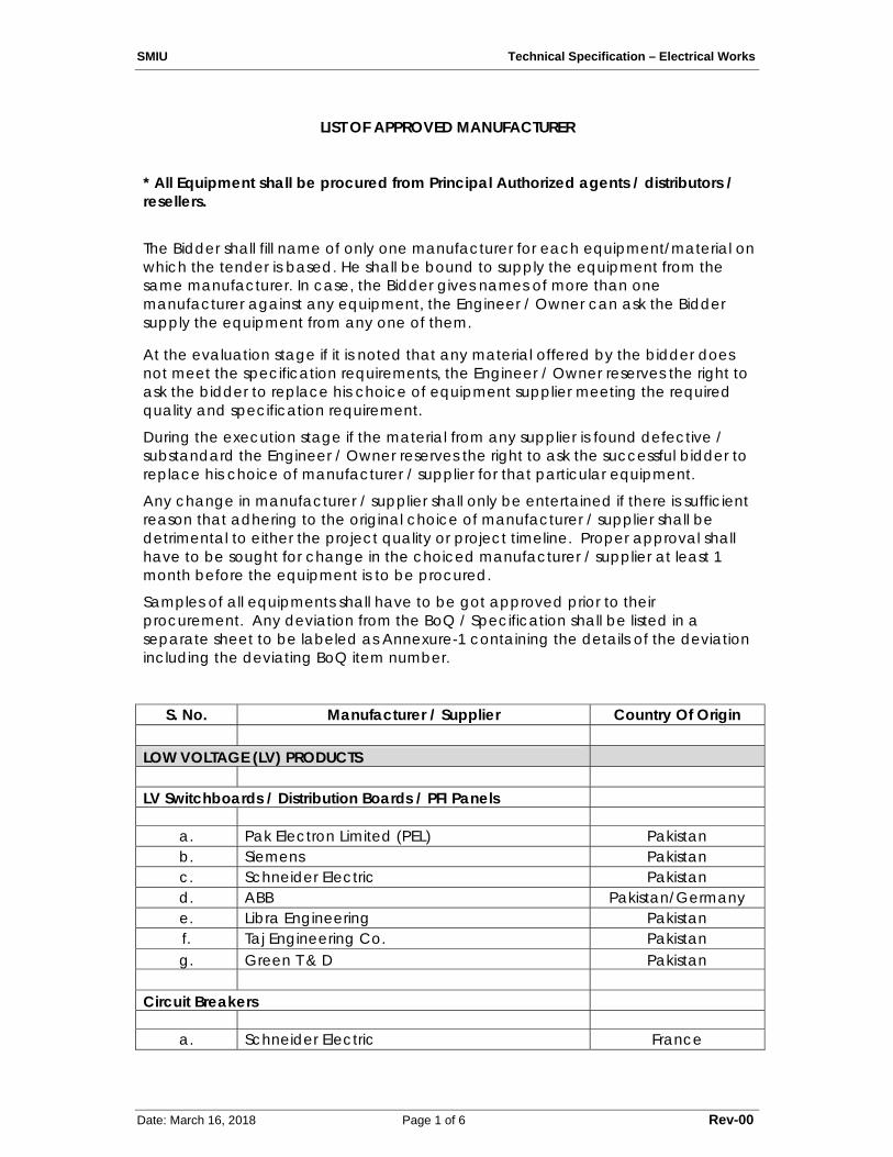
SMIU Technical Specification – Electrical Works
Date: March 16, 2018 Page 1 of 6 Rev-00
LIST OF APPROVED MANUFACTURER
* All Equipment shall be procured from Principal Authorized agents / distributors / resellers. The Bidder shall fill name of only one manufacturer for each equipment/material on which the tender is based. He shall be bound to supply the equipment from the same manufacturer. In case, the Bidder gives names of more than one manufacturer against any equipment, the Engineer / Owner can ask the Bidder supply the equipment from any one of them.
At the evaluation stage if it is noted that any material offered by the bidder does not meet the specification requirements, the Engineer / Owner reserves the right to ask the bidder to replace his choice of equipment supplier meeting the required quality and specification requirement. During the execution stage if the material from any supplier is found defective / substandard the Engineer / Owner reserves the right to ask the successful bidder to replace his choice of manufacturer / supplier for that particular equipment. Any change in manufacturer / supplier shall only be entertained if there is sufficient reason that adhering to the original choice of manufacturer / supplier shall be detrimental to either the project quality or project timeline. Proper approval shall have to be sought for change in the choiced manufacturer / supplier at least 1 month before the equipment is to be procured. Samples of all equipments shall have to be got approved prior to their procurement. Any deviation from the BoQ / Specification shall be listed in a separate sheet to be labeled as Annexure-1 containing the details of the deviation including the deviating BoQ item number.
S. No. Manufacturer / Supplier Country Of Origin
LOW VOLTAGE (LV) PRODUCTS
LV Switchboards / Distribution Boards / PFI Panels
a. Pak Electron Limited (PEL) Pakistan b. Siemens Pakistan c. Schneider Electric Pakistan d. ABB Pakistan/Germany e. Libra Engineering Pakistan f. Taj Engineering Co. Pakistan g. Green T & D Pakistan
Circuit Breakers
a. Schneider Electric France
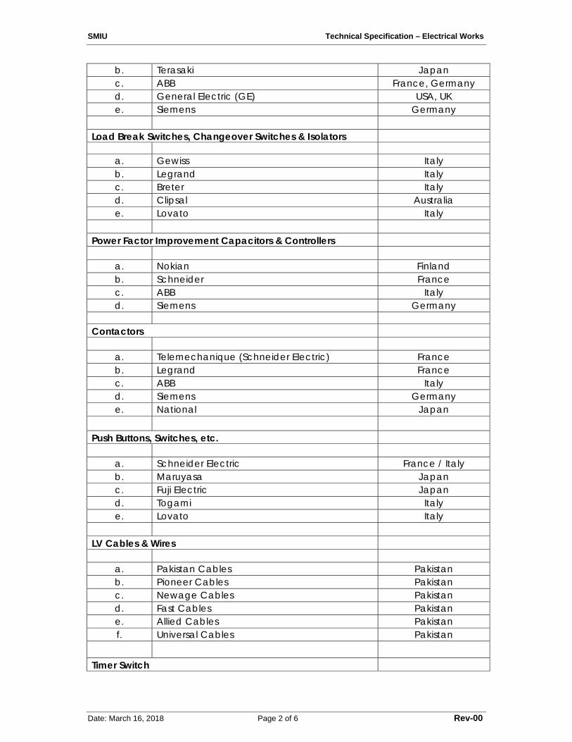
SMIU Technical Specification – Electrical Works
Date: March 16, 2018 Page 2 of 6 Rev-00
b. Terasaki Japan c. ABB France, Germany d. General Electric (GE) USA, UK e. Siemens Germany
Load Break Switches, Changeover Switches & Isolators
a. Gewiss Italy b. Legrand Italy c. Breter Italy d. Clipsal Australia e. Lovato Italy
Power Factor Improvement Capacitors & Controllers
a. Nokian Finland b. Schneider France c. ABB Italy d. Siemens Germany
Contactors
a. Telemechanique (Schneider Electric) France b. Legrand France c. ABB Italy d. Siemens Germany e. National Japan
Push Buttons, Switches, etc.
a. Schneider Electric France / Italy b. Maruyasa Japan c. Fuji Electric Japan d. Togami Italy e. Lovato Italy
LV Cables & Wires
a. Pakistan Cables Pakistan b. Pioneer Cables Pakistan c. Newage Cables Pakistan d. Fast Cables Pakistan e. Allied Cables Pakistan f. Universal Cables Pakistan
Timer Switch
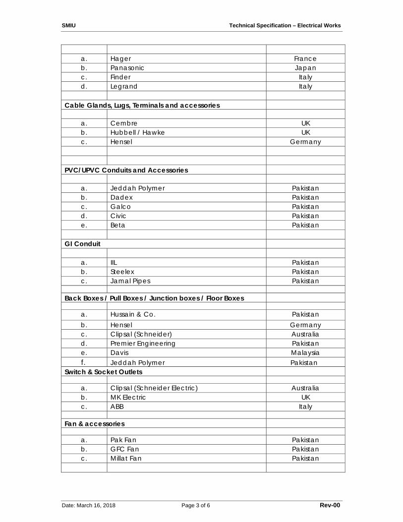
SMIU Technical Specification – Electrical Works
Date: March 16, 2018 Page 3 of 6 Rev-00
a. Hager France b. Panasonic Japan c. Finder Italy d. Legrand Italy
Cable Glands, Lugs, Terminals and accessories
a. Cembre UK b. Hubbell / Hawke UK c. Hensel Germany
PVC/UPVC Conduits and Accessories
a. Jeddah Polymer Pakistan b. Dadex Pakistan c. Galco Pakistan d. Civic Pakistan e. Beta Pakistan
GI Conduit
a. IIL Pakistan b. Steelex Pakistan c. Jamal Pipes Pakistan
Back Boxes / Pull Boxes / Junction boxes / Floor Boxes
a. Hussain & Co. Pakistan b. Hensel Germany c. Clipsal (Schneider) Australia d. Premier Engineering Pakistan e. Davis Malaysia
f. Jeddah Polymer Pakistan Switch & Socket Outlets
a. Clipsal (Schneider Electric) Australia b. MK Electric UK c. ABB Italy
Fan & accessories
a. Pak Fan Pakistan b. GFC Fan Pakistan c. Millat Fan Pakistan
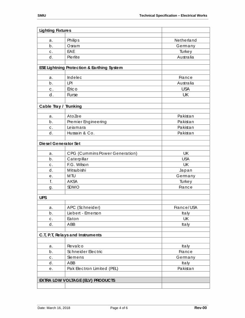
SMIU Technical Specification – Electrical Works
Date: March 16, 2018 Page 4 of 6 Rev-00
Lighting Fixtures
a. Philips Netherland b. Osram Germany c. EAE Turkey d. Pierlite Australia
ESE Lightning Protection & Earthing System
a. Indelec France b. LPI Australia
c. Erico USA d. Furse UK Cable Tray / Trunking
a. AtoZee Pakistan b. Premier Engineering Pakistan c. Leiamara Pakistan d. Hussain & Co. Pakistan
Diesel Generator Set
a. CPG (Cummins Power Generation) UK b. Caterpillar USA c. F.G. Wilson UK d. Mitsubishi Japan e. MTU Germany f. AKSA Turkey g. SDMO France
UPS
a. APC (Schneider) France/USA b. Liebert - Emerson Italy c. Eaton UK d. ABB Italy
C.T, P.T, Relays and Instruments
a. Revalco Italy b. Schneider Electric France c. Siemens Germany d. ABB Italy e. Pak Electron Limited (PEL) Pakistan
EXTRA LOW VOLTAGE (ELV) PRODUCTS
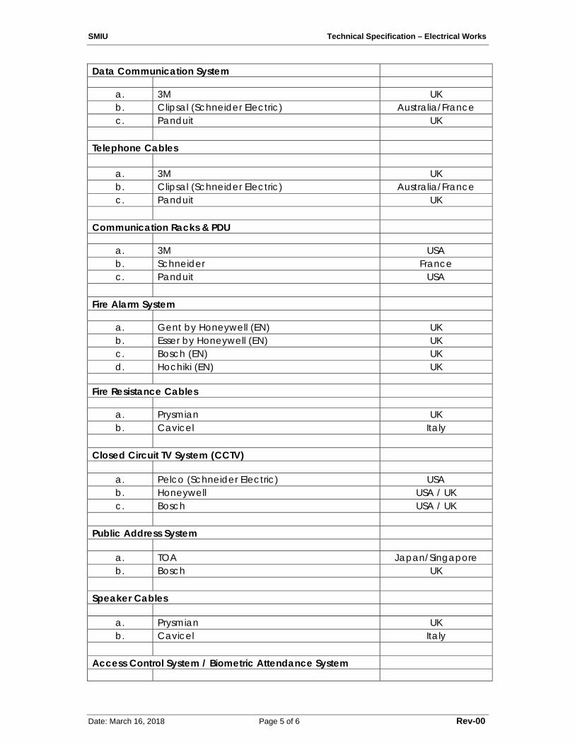
SMIU Technical Specification – Electrical Works
Date: March 16, 2018 Page 5 of 6 Rev-00
Data Communication System
a. 3M UK b. Clipsal (Schneider Electric) Australia/France c. Panduit UK
Telephone Cables
a. 3M UK b. Clipsal (Schneider Electric) Australia/France c. Panduit UK
Communication Racks & PDU
a. 3M USA b. Schneider France c. Panduit USA
Fire Alarm System
a. Gent by Honeywell (EN) UK b. Esser by Honeywell (EN) UK c. Bosch (EN) UK d. Hochiki (EN) UK
Fire Resistance Cables
a. Prysmian UK b. Cavicel Italy
Closed Circuit TV System (CCTV)
a. Pelco (Schneider Electric) USA b. Honeywell USA / UK c. Bosch USA / UK
Public Address System
a. TOA Japan/Singapore b. Bosch UK
Speaker Cables
a. Prysmian UK b. Cavicel Italy
Access Control System / Biometric Attendance System
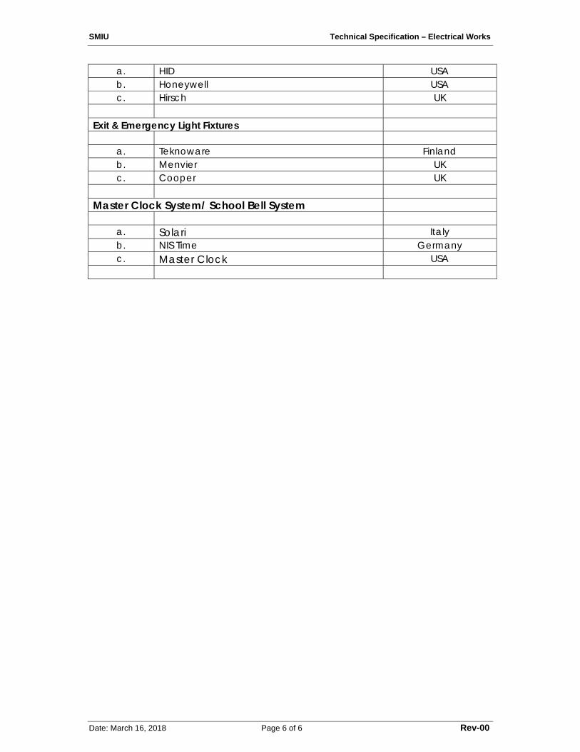
SMIU Technical Specification – Electrical Works
Date: March 16, 2018 Page 6 of 6 Rev-00
a. HID USA b. Honeywell USA c. Hirsch UK
Exit & Emergency Light Fixtures
a. Teknoware Finland b. Menvier UK c. Cooper UK
Master Clock System/ School Bell System
a. Solari Italy b. NIS Time Germany c. Master Clock USA