SINAMICS S120 SIMATIC S7-300/400 Application description ... · Applikationen & Tools Answers for...
102
Applikationen & Tools Answers for industry. Deckblatt Positioning an S120 with S7-300/400 via PROFINET in Step7 with Safety Integrated via terminal SINAMICS S120 SIMATIC S7-300/400 Application description April 2013
Transcript of SINAMICS S120 SIMATIC S7-300/400 Application description ... · Applikationen & Tools Answers for...

Applikationen & Tools
Answers for industry.
Deckblatt
Positioning an S120 with S7-300/400 via PROFINET in Step7 with Safety Integrated via terminal
SINAMICS S120 SIMATIC S7-300/400
Application description April 2013

2 SINAMICS S120 Positionieren an S7-300/400
1.0, Entry ID: 67261457
Co
pyr
igh
t
Sie
me
ns
AG
20
13
All
righ
ts r
ese
rve
d
Siemens Industry Online Support
This article originates from the Siemens Industry Online Support. The following link takes you directly to the download page for this document:
http://support.automation.siemens.com/WW/view/de/67261457
Caution: The functions and solutions described in this article are limited primarily to the implementation of the automation task Please also observe that in case of networking your plant/system area with other parts of the plant, the company network or the Internet, appropriate protective measures within the framework of industrial security must be adopted. For more information, see the article ID 50203404.
http://support.automation.siemens.com/WW/view/de/50203404

SINAMICS S120 Positionieren an S7-300/400 1.0, Entry ID: 67261457 3
Co
pyr
igh
t
Sie
me
ns
AG
20
13
All
righ
ts r
ese
rve
d
s
SIMATIC, SINAMICS
SINAMICS S120 Positioning
connected to an S7-300/400 control
Task
1
Solution
2 Configuring and commissioning the application
3
Using the application
4 Functional mechanisms of this application
5
Configuration and project engineering
6
Contact person
7
References
8
History
9

Table of contents
4 SINAMICS S120 Positionieren an S7-300/400
1.0, Entry ID: 67261457
Co
pyr
igh
t
Sie
me
ns
AG
20
13
All
righ
ts r
ese
rve
d
Warranty and liability Note The application examples in this document are not binding and do not claim to
be complete regarding configuration, equipment, and any eventuality. These application examples do not represent specific customer solutions – but are only intended to provide support when it comes to typical applications. You are responsible for the proper operation of the described products. These application examples do not relieve you of your responsibility regarding the safe handling when using, installing, operating, and maintaining the equipment. By using these application examples, you agree that Siemens cannot be made liable for possible damage beyond the mentioned liability clause. We reserve the right to make changes and revisions to these application examples at any time without prior notice. If there are any differences between the suggestions made in these application examples and other Siemens publications, such as catalogs, the contents of the other document(s) take priority.
Siemens shall not be held liable for the information provided in this document.
We accept no liability for any damage or loss caused by the examples, information, programs, planning data, or performance data described in this application example, irrespective of the legal basis for claims arising from such damage or loss, unless liability is mandatory. For example, according to the product liability law, in cases of malfeasance, gross negligence, due to endangerment of life, body or health, due to assumption of a guarantee for the properties of a product, due to malicious concealment of a defect or due to violation of basic contractual obligations. However, claims for indemnification based on breach of contract shall be limited to liability for damages to the contract-specific, foreseeable damages, provided there is no mandatory liability for intent, acts of gross negligence, harm to the life, body and health of human beings. Any change to the burden of proof to your disadvantage is not covered hereby.
Any form of duplication of these application examples or excerpts hereof is not permitted without the express consent of Siemens Industry Sector.

Table of contents
SINAMICS S120 Positionieren an S7-300/400 1.0, Entry ID: 67261457 5
Co
pyr
igh
t
Sie
me
ns
AG
20
13
All
righ
ts r
ese
rve
d
Table of contents Warranty and liability................................................................................................... 4 1 Task..................................................................................................................... 7 2 Solution............................................................................................................... 8
2.1 Overview of the overall solution ........................................................... 8 2.2 Description of the core functionality ..................................................... 9 2.2.1 Parameterizing the communication...................................................... 9
SIMATIC S7-300/400 ........................................................................... 9 SINAMICS S120................................................................................... 9
2.2.2 Data exchange ..................................................................................... 9 Cyclic process data exchange ........................................................... 10 Acyclic data exchange (parameter access) ....................................... 10
2.3 Basic positioner .................................................................................. 11 2.4 Hardware and software components used......................................... 11
Sample files and projects ................................................................... 12 3 Configuring and commissioning the application......................................... 13
3.1 Wiring ................................................................................................. 13 3.2 IP addresses and PN names ............................................................. 15 3.3 Settings at the PG/PC ........................................................................ 15 3.4 Loading the SIMATIC program .......................................................... 16 3.5 Loading the SINAMICS parameterization .......................................... 21 3.6 Loading the HMI ................................................................................. 24
4 Using the application ...................................................................................... 25 4.1 Preconditions...................................................................................... 25 4.2 Using the application via HMI............................................................. 25 4.2.1 Basic screen....................................................................................... 25 4.2.2 Selecting the axis ............................................................................... 26 4.2.3 Start screen, basic positioner............................................................. 26 4.2.4 Homing ............................................................................................... 27 4.2.5 Jogging............................................................................................... 28 4.2.6 Traversing blocks ............................................................................... 29 4.2.7 Direct setpoint specification / MDI...................................................... 32 4.3 Variable tables.................................................................................... 34 4.3.1 Reading and writing traversing blocks ............................................... 35 4.3.2 Reading and writing drive parameters ............................................... 37 4.3.3 Reading out the fault memory ............................................................ 37
5 Functional mechanisms of this application.................................................. 38 5.1 Functions of the SIMATIC S7-300/400 .............................................. 38 5.1.1 Overview ............................................................................................ 38 5.1.2 FC72: Communication using FB283 and SIEMENS
telegram 111 ...................................................................................... 39 5.1.3 FB1: Preparing data for display on the HMI....................................... 40 5.2 Basic positioner .................................................................................. 41 5.2.1 Tasks that can be addressed with the basic positioner ..................... 41 5.2.2 Properties ........................................................................................... 42 5.2.3 Operating modes................................................................................ 42
6 Configuration and project engineering ......................................................... 46 6.1 Configuring the SIMATIC S7-300/400 CPU....................................... 46 6.2 Configuration of the SINAMICS S120 drive ....................................... 53 6.3 Adding an additional SINAMICS drive to the project ......................... 72 6.3.1 Changes to the SINAMICS S120 ....................................................... 72

Table of contents
6 SINAMICS S120 Positionieren an S7-300/400
1.0, Entry ID: 67261457
Co
pyr
igh
t
Sie
me
ns
AG
20
13
All
righ
ts r
ese
rve
d
6.3.2 Changes to the SIMATIC S7-300/400................................................ 74 6.3.3 Changes to the HMI ........................................................................... 78 6.4 Position controller and basic positioner settings ................................ 79 6.4.1 Overview and settings of the position controller screen forms........... 79 6.4.2 Overview and settings of the basic positioner screen forms.............. 86
7 Contact person .............................................................................................. 101 8 References ..................................................................................................... 101 9 History............................................................................................................. 102

1 Task
SINAMICS S120 Positionieren an S7-300/400 1.0, Entry ID: 67261457 7
Co
pyr
igh
t
Sie
me
ns
AG
20
13
All
righ
ts r
ese
rve
d
1 Task Several axes connected to a drive system are to be operated with positioning functionality.
The drive should be connected to a SIMATIC control system via PROFINET.
Safety functions are to be controlled via terminals.
Overview of the automation task
The following diagram provides an overview of the automation task:
Fig. 1-1
MPI, PROFIBUS or Ethernet
PROFINETDrive-CliQ
Requirements placed on the automation task
Table 1-1
Requirement Explanation
Access to process data The SINAMICS S120 is to position several axes based on control words from the SIMATIC control system.
Access to parameters Parameters in the SINAMICS S120 are to be accessed from the S7-300/400. (e.g. reading and writing traversing blocks)
Safety functions Safety functions (Emergency Off) are to be controlled via terminal in the SINAMICS S120 drive

2 Solution
2.1 Overview of the overall solution
8 SINAMICS S120 Positionieren an S7-300/400
1.0, Entry ID: 67261457
Co
pyr
igh
t
Sie
me
ns
AG
20
13
All
righ
ts r
ese
rve
d
2 Solution The application example shows how a SINAMICS S120, with the basic positioner function module, is connected to a SIMATIC S7 300/400 CPU via PROFINET.
Up to six axes with basic positioner can be operated at a SINAMICS S120 Control Unit CU320-2 PN. In this example, two axes are used.
Setpoints and actual values are transferred with SIEMENS telegram 111. Blocks are used, such as the FB283. These can be directly used in your own application.
2.1 Overview of the overall solution
Schematic
The following schematic figure shows the most important components of the solution.
Fig. 2-1
Drive-CliQ
KTP 600S7 300/400
SINAMICS S120
PROFINET
EthernetAlternatively to
parametrization via field bus
The example shows you how...
• ...the S7-300/400 control system is parameterized.
• ...communication is programmed in the S7-300/400 control system.
• ...the SINAMICS S120 converter is parameterized using STARTER.
• …the basic positioner of the SINAMICS S120 is used.

2 Solution
2.2 Description of the core functionality
SINAMICS S120 Positionieren an S7-300/400 1.0, Entry ID: 67261457 9
Co
pyr
igh
t
Sie
me
ns
AG
20
13
All
righ
ts r
ese
rve
d
2.2 Description of the core functionality
2.2.1 Parameterizing the communication
TIA (Totally Integrated Automation)
The SIMATIC S7-300/400 program and the SINAMICS S120 parameter assignment are centrally saved in a STEP 7 project. The required editors are called from the SIMATIC Manager.
SIMATIC S7-300/400
In this example, the SIMATIC S7-300/400 is programmed using STEP 7 V5.
In the hardware configuration (HW Config), the SIMATIC S7 and the stations connected via PROFINET, are configured, e.g. the SINAMICS S120 and the communication. When inserting the SINAMICS S120 in the SIMATIC project, the peripheral addresses are also defined, which the SIMATIC S7 300/400 should use to access the SINAMICS S120.
SINAMICS S120
The SINAMICS S120 is parameterized using the STARTER commissioning tool.
For SINAMICS S120, one of several telegram types can be selected for cyclic data exchange. This defines which data are sent or received in which sequence. It is important that when parameterizing the SIMATIC S7-300/400, the same telegram type is selected as in the SINAMICS S120 drive.
2.2.2 Data exchange
Data exchange between SINAMICS S120 and SIMATIC S7-300/400 is realized in two areas:
• Process data, cyclic communication i.e. control word(s) and setpoint(s) or status word(s) and actual value(s)
• Parameter area, acyclic communication i.e. reading/writing parameter values

2 Solution
2.2 Description of the core functionality
10 SINAMICS S120 Positionieren an S7-300/400
1.0, Entry ID: 67261457
Co
pyr
igh
t
Sie
me
ns
AG
20
13
All
righ
ts r
ese
rve
d
Cyclic process data exchange
The process data are cyclically transferred, i.e. in each bus cycle. As a consequence, they are transferred as quickly as possible.
The SIMATIC S7-300/400 sends control words and setpoints to the SINAMICS S120 drives and receives from them the status words and actual values.
Depending on the particular telegram type, additional setpoints or actual values and/or extended control and/or status words can be transferred.
SIEMENS telegram 111 is used in this example.
The FB283 uses a data block for each drive, the axis DB; it takes data from this to be sent to the SINAMICS S120, and the received data are also saved here.
The process data are automatically internally interconnected in the SINAMICS S120 when selecting the telegram.
Acyclic data exchange (parameter access)
In order to be able to transfer parameters, telegram types have also been defined in which there are four additional words to transfer parameters. As these four words are always sent, just like the process data, a permanent communication load is obtained, although the parameters themselves are generally only infrequently transferred.
In addition to cyclic data exchange, PROFINET also offers the possibility of acyclic data exchange, which is only inserted when required. As a consequence, it is possible to acyclically transfer the parameter area when required, without creating a permanent communication load (communication overhead). Acyclic process data transfer takes longer than cyclic data transfer.
FB283 is used for acyclic communication in this example. Individual or also several parameters can be written or read in one operation. FB283 also allows traversing blocks to be written and read or fault and alarm buffers to be read out.

2 Solution
2.3 Basic positioner
SINAMICS S120 Positionieren an S7-300/400 1.0, Entry ID: 67261457 11
Co
pyr
igh
t
Sie
me
ns
AG
20
13
All
righ
ts r
ese
rve
d
2.3 Basic positioner
The basic positioner (EPOS) in the SINAMICS S120 is used to position linear and rotary axes in absolute/relative terms with motor encoder (indirect measuring system) or machine encoder (direct measuring system). EPOS is available in the servo and vector modes. For the basic positioner functionality, the STARTER commissioning tool provides graphic support when configuring and commissioning – and for diagnostic functions. A control panel in STARTER supports you when operating the basic positioner and when operating in the closed-loop speed controlled mode. The position control is automatically activated when activating the basic positioner using the commissioning wizards of STARTER. The required internal interconnections are automatically made.
2.4 Hardware and software components used
The application was created with the following components.
SIMATIC hardware components
Tabelle 2-1 HW-Komponenten
Component Qty Order number Note
CPU 315-2 DP/PN 1 6ES7315-2EH14-0AB0 or other S7-300/400 CPU with PROFIBUS
PS307 24V/5A POWER SUPPLY
1 6ES7307-1EA01-0AA0 or another 24 V DC power supply
MMC 128kB 1 6ES7 953-8LG20-0AA0 or larger MMC
SIMATIC panel KTP600 basic color PN
1 6AV6647-0AD11-3AX0
PROFINET connectors 6 6GK1901-1BB10-2AA0
PROFINET cable 6XV1840-2AH10
Hardware components, drive system
The SINAMICS S120 training case 6ZB2480-0CN00 can also be used.
Table 2-2 HW-Components
Component Qty Order number Note
Control Unit CU320-2 PN
1 6SL3040-1MA01-0AA0
CompactFlash card; basic
1 6SL3054-0EF00-1BA0
Smart Line Module 5.00 kW
1 6SL3130-6AE15-0AB0
Line reactor 1 6SL3000-0CE15-0AA0
3.00 A Double Motor Module
1 6SL3120-2TE13-0AA3
SMC 20 Sensor Module 1 6SL3055-0AA00-5BA3
0.40 kW synchronous servomotor
1 1FK7022-5AK71-1LG0 SERVO_02
0.40 kW synchronous 1 1FK7022-5AK71-1AG3 SERVO_03

2 Solution
2.4 Hardware and software components used
12 SINAMICS S120 Positionieren an S7-300/400
1.0, Entry ID: 67261457
Co
pyr
igh
t
Sie
me
ns
AG
20
13
All
righ
ts r
ese
rve
d
Component Qty Order number Note
servomotor
Motor power cable, 1m 2 6FX5002-5CS01-1AB0
Signal cable, 1m 1 6FX5002-2CA31-1AB0 SMC encoder
DRIVE-CLiQ cable, IP20/IP20 0,16 m
1 6SL3060-4AD00-0AA0 CU 320-2 PN - DMM
DRIVE-CLiQ cable, IP20/IP20 0.60 m
1 6SL3060-4AU00-0AA0 DMM – SMC (SERVO_03)
DRIVE-CLiQ cable, IP20/IP67 1.0m
1 6FX5002-2DC10-1AB0 DMM – SMI (SERVO_02)
Software components
Table2-3 SW-Cmponents
Component Qty Order number Note
SIMATIC STEP 7 V5.5 SP2
Floating license 6ES7810-4CC10-0YA5
STARTER V4.3.1.2
6SL3072-0AA00-0AG0
Free of charge download: see Fehler! Verweisquelle konnte nicht gefunden werden.
WinCC flexible Version: 2008 SP3
6AV6613-0AA51-3CA5
Sample files and projects
The list below contains all the files and projects used in this example Fehler! Verweisquelle konnte nicht gefunden werden..
Table 2-4 Sample files and projects
Component Note
67261457_SINAMICS_S120-PN_Positionieren_at_S7-300_v10.zip This zipped file contains the STEP 7 project with SINAMICS S120 and HMI.
67261457_SINAMICS_S120_at_S7-300400_SHORT-DOKU_v10_de.pdf Brief documentation for experienced users
67261457_SINAMICS_S120-PN_at_S7-300400_DOKU_v10_de.pdf This document
CAUTION The project sample is designed for use with the component samples listed in Chapter 2.4. If other SINAMICS S120 components are used or other motors connected without adapting the corresponding parameters, the converter and/or motor could be damaged or destroyed.
3 Configuring and commissioning the application
3.1 Wiring
SINAMICS S120 Positionieren an S7-300/400 1.0, Entry ID: 67261457 13
Co
pyr
igh
t
Sie
me
ns
AG
20
13
All
righ
ts r
ese
rve
d
3 Configuring and commissioning the application
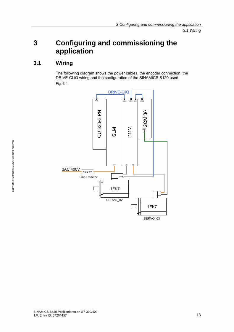
3.1 Wiring
The following diagram shows the power cables, the encoder connection, the DRIVE-CLiQ wiring and the configuration of the SINAMICS S120 used.
Fig. 3-1
X101 X200 X202 X203 X500
X2X1X1
3AC 400V
1FK7
Line Reactor
DRIVE-CliQ
X500
1FK7
X520
SERVO_02
SERVO_03

3 Configuring and commissioning the application
3.1 Wiring
14 SINAMICS S120 Positionieren an S7-300/400
1.0, Entry ID: 67261457
Co
pyr
igh
t
Sie
me
ns
AG
20
13
All
righ
ts r
ese
rve
d
The 24 V wiring, the fieldbus wiring and safety wiring of the configuration is shown in the following diagram.
Fig. 3-2
+ M
CU
320
-2 P
N
SL
M
DM
M
SC
M 2
0
+ MX124
X1221 7
X15
0
+ MX24
+X524
M
X2143
X2143
X2243
24V
M
+ M
X1X2
P1P2
P1
24V
M
PROFINET
S7
315-
2 P
N/D
P
KT
P 6
00
DC N DC N
DC P DC P
24V
M
24V
M
P2
P1
Notes • The installation guidelines in the SINAMICS S120 manuals (see Fehler! Verweisquelle konnte nicht gefunden werden.) and the SIMATIC must always be taken into consideration.

3 Configuring and commissioning the application
3.2 IP addresses and PN names
SINAMICS S120 Positionieren an S7-300/400 1.0, Entry ID: 67261457 15
Co
pyr
igh
t
Sie
me
ns
AG
20
13
All
righ
ts r
ese
rve
d
3.2 IP addresses and PN names
The following IP addresses and device names are used in the example:
Table 3-1
IP Component Device Name
192.168.0.1 S7 CPU S7 CPU
192.168.0.2 SINAMICS S120 S120-CU320-2PN
192.168.0.3 KTP600 KTP600
192.168.0.200 PG/PC
3.3 Settings at the PG/PC
Table 3-2
Action Remark
In the Window settings for the network card to be used, set the fixed TCP/IP address 192.168.0.200 and the network mask 255.255.255.0. You can also use any other free IP address (192.168.0.x).

3 Configuring and commissioning the application
3.4 Loading the SIMATIC program
16 SINAMICS S120 Positionieren an S7-300/400
1.0, Entry ID: 67261457
Co
pyr
igh
t
Sie
me
ns
AG
20
13
All
righ
ts r
ese
rve
d
3.4 Loading the SIMATIC program
This chapter describes the steps involved when installing the sample code into the SIMATIC S7-300/400.
Table 3-3
No. Action Remark
1. Connect the S7-300/400 with the PG/PC using a network cable.
You can connect the two devices directly with one another or via a switch.
2. Start the SIMATIC Manager.
3. Using "Tools > Set PG/PC interface ...“, open the settings of the online interface. Select “TCP/IP -> Network card“ with the network card that you are using.
4. Call the dialog "Edit Ethernet Node...“.

3 Configuring and commissioning the application
3.4 Loading the SIMATIC program
SINAMICS S120 Positionieren an S7-300/400 1.0, Entry ID: 67261457 17
Co
pyr
igh
t
Sie
me
ns
AG
20
13
All
righ
ts r
ese
rve
d
No. Action Remark
5. • Click "Browse ..." – Select the "S7-300"
CPU and click OK.
6. Reset the IP configuration to the factory setting. Confirm the notes.

3 Configuring and commissioning the application
3.4 Loading the SIMATIC program
18 SINAMICS S120 Positionieren an S7-300/400
1.0, Entry ID: 67261457
Co
pyr
igh
t
Sie
me
ns
AG
20
13
All
righ
ts r
ese
rve
d
No. Action Remark
7. Enter the IP address 192.168.0.1 and the network mask 255.255.255.0, and click on "Assign IP Configuration". Enter the device name: "S7-CPU" and click on "Assign name" Click "Close" to exit the dialog.

3 Configuring and commissioning the application
3.4 Loading the SIMATIC program
SINAMICS S120 Positionieren an S7-300/400 1.0, Entry ID: 67261457 19
Co
pyr
igh
t
Sie
me
ns
AG
20
13
All
righ
ts r
ese
rve
d
No. Action Remark
8. Click "Accessible Nodes".
9. • Select all blocks in the CPU using <CTRL><A> and delete them.
• Acknowledge that system blocks and system data cannot be deleted.
10. If you have still not dearchived the project, under "File > Dearchive...", select the project file (see Table 2-4) and dearchive this. Confirm that you want to open the project

3 Configuring and commissioning the application
3.4 Loading the SIMATIC program
20 SINAMICS S120 Positionieren an S7-300/400
1.0, Entry ID: 67261457
Co
pyr
igh
t
Sie
me
ns
AG
20
13
All
righ
ts r
ese
rve
d
No. Action Remark
11. • Select the SIMATIC 300 station
• Load the project to the CPU.
12. Restart the CPU after loading.
3 Configuring and commissioning the application
3.5 Loading the SINAMICS parameterization
SINAMICS S120 Positionieren an S7-300/400 1.0, Entry ID: 67261457 21
Co
pyr
igh
t
Sie
me
ns
AG
20
13
All
righ
ts r
ese
rve
d
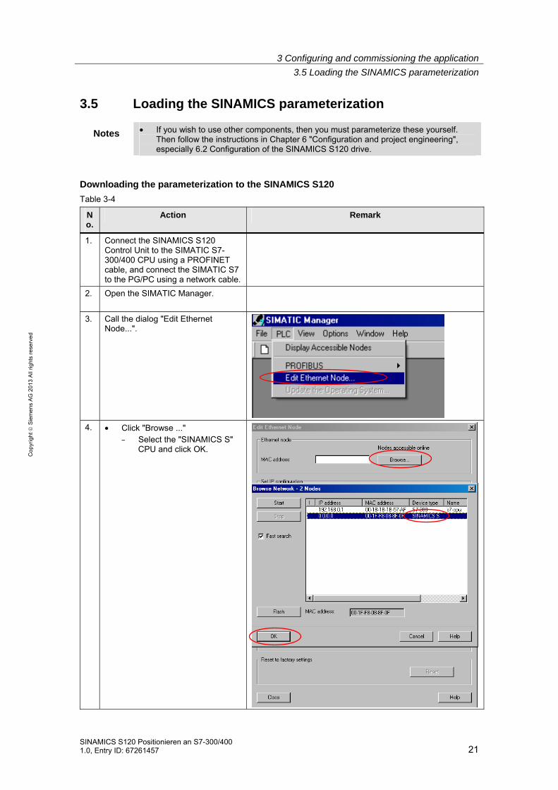
3.5 Loading the SINAMICS parameterization
Notes • If you wish to use other components, then you must parameterize these yourself. Then follow the instructions in Chapter 6 "Configuration and project engineering", especially 6.2 Configuration of the SINAMICS S120 drive.
Downloading the parameterization to the SINAMICS S120
Table 3-4
No.
Action Remark
1. Connect the SINAMICS S120 Control Unit to the SIMATIC S7-300/400 CPU using a PROFINET cable, and connect the SIMATIC S7 to the PG/PC using a network cable.
2. Open the SIMATIC Manager.
3. Call the dialog "Edit Ethernet Node...".
4. • Click "Browse ..." – Select the "SINAMICS S"
CPU and click OK.

3 Configuring and commissioning the application
3.5 Loading the SINAMICS parameterization
22 SINAMICS S120 Positionieren an S7-300/400
1.0, Entry ID: 67261457
Co
pyr
igh
t
Sie
me
ns
AG
20
13
All
righ
ts r
ese
rve
d
No.
Action Remark
5. Enter the IP address 192.168.0.2 and the network mask 255.255.255.0, and click on "Assign IP Configuration". Enter the device name: "S120-CU320-2PN" and click on "Assign name" Click "Close" to exit the dialog.
6. Open the sample project.
7. Select the SINAMICS S120 in the project tree of the SIMATIC project Open STARTER by double clicking on commissioning
8. Select the SINAMICS S120 in the project tree of STARTER Go online
9. Load the configuration into the SINAMICS S120
3 Configuring and commissioning the application
3.5 Loading the SINAMICS parameterization
SINAMICS S120 Positionieren an S7-300/400 1.0, Entry ID: 67261457 23
Co
pyr
igh
t
Sie
me
ns
AG
20
13
All
righ
ts r
ese
rve
d
No.
Action Remark
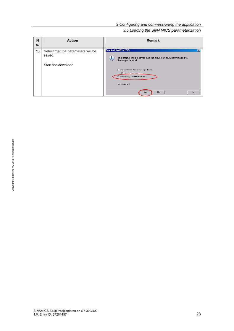
10. Select that the parameters will be saved. Start the download

3 Configuring and commissioning the application
3.6 Loading the HMI
24 SINAMICS S120 Positionieren an S7-300/400
1.0, Entry ID: 67261457
Co
pyr
igh
t
Sie
me
ns
AG
20
13
All
righ
ts r
ese
rve
d
3.6 Loading the HMI
No. Action Remark
1. Connect the S7-300/400 CPU with the KTP600 HMI using a network cable.
2. Assign the HMI IP address 192.168.0.3.
3. In the SIMATIC Manager project tree, open KTP_600 HMI. Open WinCC flexible with "Open Object" in the shortcut menu of "WinCC flexible RT"
4. The configuration of the HMI opens with WinCC flexible. Load the configuration.
4 Using the application
4.1 Preconditions
SINAMICS S120 Positionieren an S7-300/400 1.0, Entry ID: 67261457 25
Co
pyr
igh
t
Sie
me
ns
AG
20
13
All
righ
ts r
ese
rve
d
4 Using the application The application can be operated using the variable tables of the sample project or via the HMI.
4.1 Preconditions
In the sample project, basic safety functions are activated in the SINAMICS S120.
In order to be able to switch on the SINAMICS S120, 24 V must be available at the EP terminals of the motor module X21.3 and X22.3 as well as at the Control Unit X122.1.
Otherwise, the SINAMICS S120 converter pulses are inhibited.
4.2 Using the application via HMI
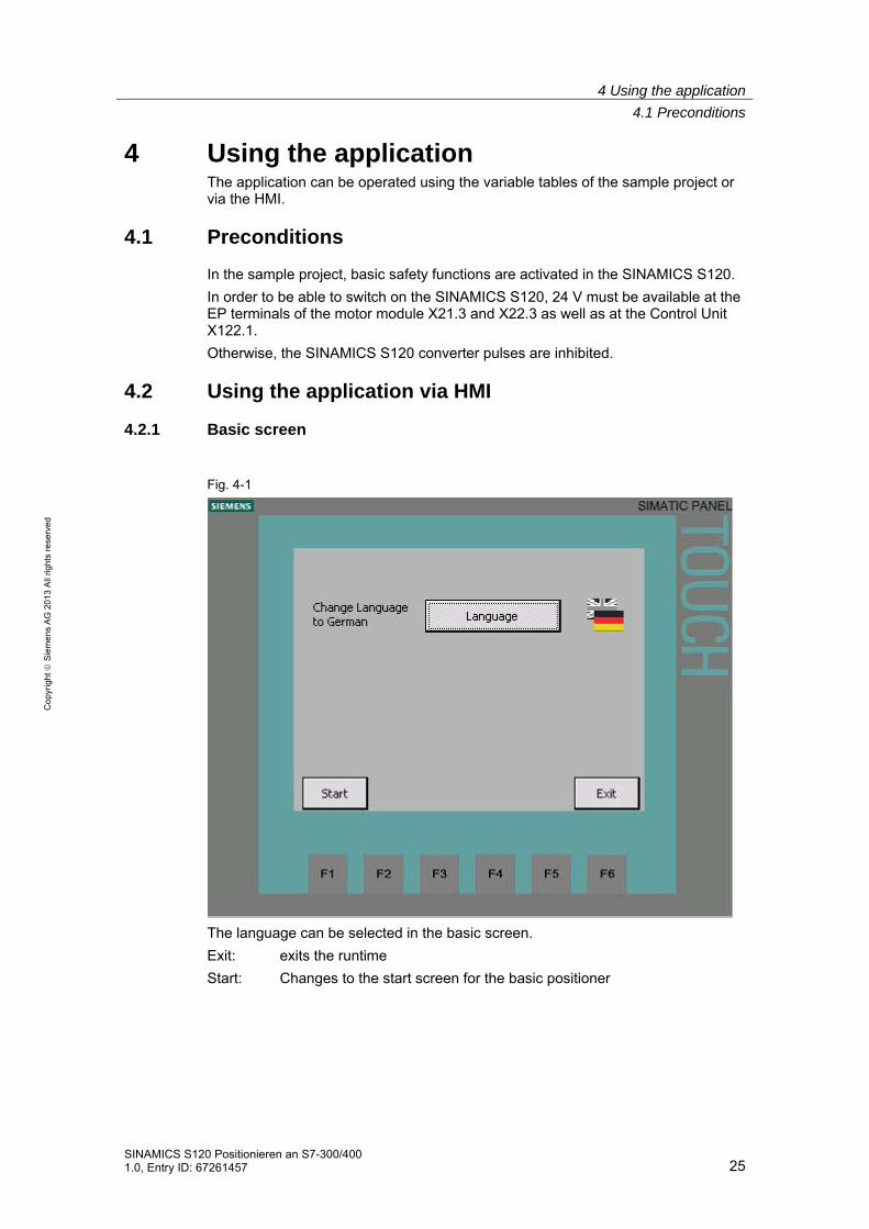
4.2.1 Basic screen
Fig. 4-1
The language can be selected in the basic screen.
Exit: exits the runtime
Start: Changes to the start screen for the basic positioner

4 Using the application
4.2 Using the application via HMI
26 SINAMICS S120 Positionieren an S7-300/400
1.0, Entry ID: 67261457
Co
pyr
igh
t
Sie
me
ns
AG
20
13
All
righ
ts r
ese
rve
d
4.2.2 Selecting the axis
In all of the following screens, the axis can be selected in the topmost line. To the right of the selection, the number of the axis DB of the selected axis is displayed. The axis selection can also be changed in the other screens.
All inputs and displays are only for the displayed axis.
4.2.3 Start screen, basic positioner
Fig. 4-2
Active faults and alarms of the SINAMICS S120 are displayed in the upper section of the screen with number and in plain text.
Active faults can be acknowledged with the "Ack" button.
The active operating modes of the basic positioner are displayed at the left.
The actual position and actual velocity of the basic positioner are displayed at the right.
The screens for the operating modes can be called in the lower section. You can return to the basic screen using the "Home symbol".
Selecting the axis

4 Using the application
4.2 Using the application via HMI
SINAMICS S120 Positionieren an S7-300/400 1.0, Entry ID: 67261457 27
Co
pyr
igh
t
Sie
me
ns
AG
20
13
All
righ
ts r
ese
rve
d
4.2.4 Homing
Absolute encoder adjustment
Fig. 4-3
Absolute encoders, as in the example for SERVO_02, must be adjusted once after commissioning. When adjusting an absolute encoder, the position actual value is set to the specified reference point coordinate.
Absolute encoder adjustment is initiated using acyclic jobs in SINAMICS S120. The status of the acyclic job is displayed at the left below "RD/WR".
When using incremental encoders, as in the example for SERVO_03, absolute encoders cannot be adjusted.
Homing
When using incremental encoders, SINAMICS S120 must be homed after each warm restart. For SERVO_03, a reference point approach to the encoder zero mark is parameterized.
Initiating the reference point approach:
Switch on the SINAMICS S120 with "On". If the SINAMICS S120 is on, the button has a green background, and the text changes to "Off".
Press "Start Homing" until "Reference point set" is lit.
Using the button "Set Reference point", the reference point can be set to the actual position Xact“.

4 Using the application
4.2 Using the application via HMI
28 SINAMICS S120 Positionieren an S7-300/400
1.0, Entry ID: 67261457
Co
pyr
igh
t
Sie
me
ns
AG
20
13
All
righ
ts r
ese
rve
d
4.2.5 Jogging
Fig. 4-4
Using the "Jog 1" and "Jog 2" buttons, the SINAMICS S120 is traversed with the parameterized speed. Incremental jogging is selected by pressing the "Jogging incremental" button.
The drive can be switched on and switched off using the "On" button.
"Xact" displays the actual position in LU
"Vact" displays the actual velocity in 1000 LU/min
Faults in the SINAMICS S120 are acknowledged using the "Ack" button.

4 Using the application
4.2 Using the application via HMI
SINAMICS S120 Positionieren an S7-300/400 1.0, Entry ID: 67261457 29
Co
pyr
igh
t
Sie
me
ns
AG
20
13
All
righ
ts r
ese
rve
d
4.2.6 Traversing blocks
Fig. 4-5
Parameterized traversing profiles can be started from this screen.
Starting traversing tasks
In the Traversing blocks screen, the basic positioner can be operated in the traversing block mode.
For traversing motion, the "No intermediate stop" and "No reject task" must be selected.
"Block number select" sets which traversing block should be started.
The SINAMICS S120 can be switched on and switched off using the "On" button.
Faults in the SINAMICS S120 are acknowledged using the "Ack" button.
The traversing block with the selected block number is started using the "Start" button.
"Xact" displays the actual position in LU
"Vact" displays the actual velocity in 1000 LU/min
"Block number active" indicates the number of the active traversing block.
The screen to read and write traversing books is called with "Editor".

4 Using the application
4.2 Using the application via HMI
30 SINAMICS S120 Positionieren an S7-300/400
1.0, Entry ID: 67261457
Co
pyr
igh
t
Sie
me
ns
AG
20
13
All
righ
ts r
ese
rve
d
The timing of the control and status signals of a traversing profile can be seen in the following diagram. The traversing profile comprises individual traversing blocks. Progressing (advancing) between the traversing blocks is "Continue with stop"
Fig. 4-6
ON/OFF1
Intermediate stop(0 signal)
Reject traversing task(0 signal)
Trav. Block selection Bit 2
Trav. Block selection Bit 3
Activate traversing task
Trav. Block selection Bit 0
Trav. Block selection Bit 1
Controlsignals
Operation enabled
Traversing command active
Target position reached
Trav. block active bit 2
Trav. block active bit 3
Trav. block active bit 0
Trav. block active bit 1
Statussignals

4 Using the application
4.2 Using the application via HMI
SINAMICS S120 Positionieren an S7-300/400 1.0, Entry ID: 67261457 31
Co
pyr
igh
t
Sie
me
ns
AG
20
13
All
righ
ts r
ese
rve
d
Reading and writing traversing blocks
Fig. 4-7
Using the editor, traversing blocks can be read and written to using acyclic jobs.
• Reading out traversing blocks: The index to be read out is set using the "-" and "+" buttons. The read job is immediately started when pressing one of the two buttons. The data of the traversing block that has been read out are displayed in the relevant fields.
• Writing a traversing block: First, select the index into which the traversing block should be written. Then enter the other data in the appropriate fields. The write job is started by pressing the "Write traversing block" button.
• Copying a traversing block: Read out the traversing block to be copied. Enter the new index using the screen keyboard, when doing this do not use the "-" or "+" buttons. The write job is started by pressing the "Write block" button.
The drive parameters are backed up in the ROM by pressing the "Save drive" button.
The status of the acyclic job is displayed with "busy" and "done" and "error".

4 Using the application
4.2 Using the application via HMI
32 SINAMICS S120 Positionieren an S7-300/400
1.0, Entry ID: 67261457
Co
pyr
igh
t
Sie
me
ns
AG
20
13
All
righ
ts r
ese
rve
d
4.2.7 Direct setpoint specification / MDI
Fig. 4-8
In the MDI screen, the basic positioner can be operated in the MDI / direct setpoint specification mode.
For traversing motion, the "No intermediate stop" and "No reject task" must be selected.
The positioning mode is set to either relative or absolute using the "relative" button.
Positioning or setting up is selected using the "Pos." button.
The setpoint transfer type is set to signal edge or continuous using the "Edge" button.
The operating mode MDI/direct setpoint specification is activated using the "MDI_selection“ button.
In the setting-up mode, the direction of rotation is specified using "pos." or "neg.".
The acceleration and deceleration override are specified in the "Acc." and "Dec." fields.
For "Vset", the setpoint velocity is entered in 1000 LU/min.
For "Xset", the setpoint position is entered in LU.
The SINAMICS S120 can be switched on and switched off using the "On" button.
Faults in the SINAMICS S120 are acknowledged using the "Ack" button.
For setpoint transfer with signal edge, positioning is started using the "Start" button.
"Xact" displays the actual position in LU
"Vact" displays the actual velocity in 1000 LU/min

4 Using the application
4.2 Using the application via HMI
SINAMICS S120 Positionieren an S7-300/400 1.0, Entry ID: 67261457 33
Co
pyr
igh
t
Sie
me
ns
AG
20
13
All
righ
ts r
ese
rve
d
The timing of the control and status signals for absolute positioning can be seen in the following diagram. The setpoint is accepted with a positive signal edge of "Setpoint acceptance".
Fig. 4-9
ON/OFF1
Intermediate stop(0 signal)
Operation enabled
MDI active
Traversing command active
Reject traversing task(0 signal)
Target position reached
Position setpoint
Velocity setpoint
0
0
1800
1000
MDI selection
Positioning type
Setpoint acceptance
Statussignals
Controlsignals

4 Using the application
4.3 Variable tables
34 SINAMICS S120 Positionieren an S7-300/400
1.0, Entry ID: 67261457
Co
pyr
igh
t
Sie
me
ns
AG
20
13
All
righ
ts r
ese
rve
d
4.3 Variable tables
Commenting out permanently controlled signals
Several signals are permanently controlled in the FB1 network 4. If these signals are to be controlled using variable tables, then the corresponding lines must be commented out.
Fig. 4-10
After changes are made in FB1, the block must be loaded into the SIMATIC S7-300/400 control.

4 Using the application
4.3 Variable tables
SINAMICS S120 Positionieren an S7-300/400 1.0, Entry ID: 67261457 35
Co
pyr
igh
t
Sie
me
ns
AG
20
13
All
righ
ts r
ese
rve
d
4.3.1 Reading and writing traversing blocks
Traversing blocks can be read out and written to acyclically using the variable tables "VAT72_TVBsingle" and "VAT72_TVBblock".
Fig. 4-11 VAT72_TVBsingle
You can use variable table VAT72_TVsingle to read or write a traversing block in SINAMICS S120.
Writing
• Job "30000" must be located in DBW 16
• The index of the traversing block is specified in DBW 18 (n+1)
• The bits of DBW 134 are used to select which data should be transferred.
• The traversing block number is specified in DBW 136.
• The position setpoint is specified in DBD 138
• The velocity setpoint is specified in DBD 142.
• The acceleration is specified in DBD 146
• The deceleration is specified in DBD 150
• The job of the traversing block is specified in DBW 154 (see the following tables)
• The job parameter is specified in DBD 156 (see the following tables)
• The traversing block mode is specified in DBW 160 (see the following tables)
• After all data has been written to the blocks, writing can be started with a positive edge of DBX 14.1

4 Using the application
4.3 Variable tables
36 SINAMICS S120 Positionieren an S7-300/400
1.0, Entry ID: 67261457
Co
pyr
igh
t
Sie
me
ns
AG
20
13
All
righ
ts r
ese
rve
d
Reading
• Job "30000" must be located in DBW 16
• The index of the traversing block is specified in DBW 18 (n+1)
• The read job is started with a positive edge at DBX 14.0.
• The values are saved in the same data area as where they were saved for the write job.
Table 4-1 Significance of DBW 154 and DBD 156
Job Job parameter
0 = error
1 = positioning
2 = fixed stop [clamping torque in Nm]
3 = endless_pos
4 = endless_neg
5 = wait [Wait time in ms]
6 = goto [jump destination]
7 = set_O [set digital output]
8 = reset_O [reset digital output]
9 = jerk jerk limitation 0 = off / 1 = on
Table 4-2 Significance of DBW 160
Bit 15-12 Bit 11-8 Bit 7-4 Bit 3-0 Significance
0000 0000 0000 0000
xxxx xxxx xxxx xxx0 Show traversing block
xxxx xxxx xxxx xxx1 Hide traversing block
xxxx xxxx 0000 xxxx End (0)
xxxx xxxx 0001 xxxx Continue with stop (1)
xxxx xxxx 0010 xxxx Continue flying (2)
xxxx xxxx 0011 xxxx Continue external (3)
xxxx xxxx 0100 xxxx Continue external wait (4)
xxxx xxxx 0101 xxxx Continue external alarm (5)
xxxx 0000 xxxx xxxx Absolute (0)
xxxx 0001 xxxx xxxx Relative (1)
xxxx 0010 xxxx xxxx ABS_POS (2)
xxxx 0011 xxxx xxxx ABS_NEG (3)
xxxx xxxx xxxx xxxx No significance
Further information in this regard may be found in the documentation of the FB283. (See Fehler! Verweisquelle konnte nicht gefunden werden.)

4 Using the application
4.3 Variable tables
SINAMICS S120 Positionieren an S7-300/400 1.0, Entry ID: 67261457 37
Co
pyr
igh
t
Sie
me
ns
AG
20
13
All
righ
ts r
ese
rve
d
4.3.2 Reading and writing drive parameters
Traversing blocks can be read out and written to acyclically using the variable tables "VAT72_Parameter" and "VAT72_Para_1_10".
Further information in this regard may be found in the documentation of the FB283. Fehler! Verweisquelle konnte nicht gefunden werden.
4.3.3 Reading out the fault memory
The fault memory of the SINAMICS S120 can be read out using the "VAT72_Faultbuffer" variable table.
Further information in this regard may be found in the documentation of the FB283. Fehler! Verweisquelle konnte nicht gefunden werden.

5 Functional mechanisms of this application
5.1 Functions of the SIMATIC S7-300/400
38 SINAMICS S120 Positionieren an S7-300/400
1.0, Entry ID: 67261457
Co
pyr
igh
t
Sie
me
ns
AG
20
13
All
righ
ts r
ese
rve
d
5 Functional mechanisms of this application
5.1 Functions of the SIMATIC S7-300/400
5.1.1 Overview
Fig. 5-1
FB283
DB283
SFB52
SFB53
SFC6
SFC14
SFC15
SFC20
SFC21
DB72
OB1
FC72
FB1
DB1
FC2
DB11
FC3
DB11
DB72 / 172
DB72
DB2
DB72 / 172
The SIMATIC S7-300/400 program comprises the following areas:
o Data exchange with the SINAMICS S120:
Cyclic process data exchange In this area, process data are sent to the SINAMICS S120 (e.g. on command and position setpoint) or received (status and actual values)
Acyclic parameter access Parameters of the SINAMICS S120 are accessed in this area. (e.g. reading or writing traversing blocks)
o Preparing data
Converting the actual velocity for display on the HMI
Splitting the traversing job parameters for display and selection on the HMI

5 Functional mechanisms of this application
5.1 Functions of the SIMATIC S7-300/400
SINAMICS S120 Positionieren an S7-300/400 1.0, Entry ID: 67261457 39
Co
pyr
igh
t
Sie
me
ns
AG
20
13
All
righ
ts r
ese
rve
d
5.1.2 FC72: Communication using FB283 and SIEMENS telegram 111
Telegram 111 includes 2 communication options. One option is pure cyclic communication using the system functions. The option involves the FB 283 available to the application, which in addition to the cyclic also has an acyclic communication option.
Communication with the FB283 is discussed in this example.
Fig. 5-2
In order that the acyclic interface can only be simultaneously executed once, the FB283 calls of the individual axes are interlocked. While the acyclic interface of an axis is "busy", the FB283 is not called for the other axis.
When calling the FB283, the following data are specified for each axis:
NR_ACHS_DB: Number of the axis DB
LADDR: Start of the I/O address LADDR_DIAG Diagnostics address of the drive WR_PZD: Target area (control words/setpoints)
RD_PZD: Target area (status words/actual values)
AXIS_NO: Axis No. (Number of the DriveObject)
Note In this example, for the first axis "SERVO_02", DB72 is used as axis DB – and for the second axis "SERVO_03", DB172.
Start of the I/O address and diagnostics address is in HW Config.
Additional information about calling FB283 is provided in the block description. Fehler! Verweisquelle konnte nicht gefunden werden.
Cyclic communication with FB283
OB1 only calls the FC 72. In FC 72, FB283 is called for each axis.
The structure for sending and receiving is saved in the user-defined data type (UDT_30008 _TLG111).
The variable tables, prepared with the application, are available to control the SINAMICS S120.
Operate the 1st axis in the traversing block mode (VAT72_TVB)
Operate the 2nd axis in the MDI mode (VAT72_MDI)

5 Functional mechanisms of this application
5.1 Functions of the SIMATIC S7-300/400
40 SINAMICS S120 Positionieren an S7-300/400
1.0, Entry ID: 67261457
Co
pyr
igh
t
Sie
me
ns
AG
20
13
All
righ
ts r
ese
rve
d
Acyclic communication with FB283
Acyclic communication is based on the FB 283 internal interface "single". It is only permissible to execute this once simultaneously. This is the reason that the FB283 calls are interlocked in the FC72 while the interface is communicating.
Using this job interface, it is possible:
• To read/write individual parameters
• Read out the fault memory (special job: tasksi= 30002)
• Read/write individual traversing blocks (special job: tasksi= 30000)
• Read/write traversing blocks (special job: tasksi=30001)
• Pre-assign traversing blocks 0…63 (special job: tasksi= 30011)
• Read/write up to 10 parameters (special job: tasksi= 30010)
Further, for individual special jobs, additional entries are required or outputs possible. A description can be found on the specified pages 13 – 15 of the FB 283 documentation. Fehler! Verweisquelle konnte nicht gefunden werden.
Within the context of the application, four prepared variable tables are available for parameter / traversing blocks, read and write function. Depending on the required function/display, these tables can also be edited.
1. Reading/writing parameters ( VAT72_Parameter)
2. Reading/writing several parameters ( VAT72_Para_1_10)
3. Reading/writing individual traversing blocks (VAT72_TVBsingle)
4. Reading/writing several traversing blocks (VAT72_TVBblock)
5.1.3 FB1: Preparing data for display on the HMI
Actual velocity
The speed actual value is transferred, scaled. The scaled value is converted into the actual velocity of the basic positioner in FB1.
To do this, when calling FB1, in addition to the number of the axis DB, the gearbox ratio, the position actual value resolution and the reference speed of the SINAMICS S120 must be specified.
Fig. 5-3
Note The specified values must coincide with the parameters in the SINAMICS S120!
The gearbox ratio is determined by the ratio between parameters p2504 and p2505.
The position actual value resolution is in parameter p2506.
The reference speed is in parameter p2000.
gear factor LU per load revolution in 1000LU
reference speed
axis-DB

5 Functional mechanisms of this application
5.2 Basic positioner
SINAMICS S120 Positionieren an S7-300/400 1.0, Entry ID: 67261457 41
Co
pyr
igh
t
Sie
me
ns
AG
20
13
All
righ
ts r
ese
rve
d
FC2 and FC3: splitting the traversing job parameters
FB283 transfers the job type, the advance (continue) condition and the visibility of a traversing block in a word. The word is split in order that these values can be individually displayed and selected. The individual values are buffered in DB11.
FC2 reads the DBW160 word of the axis DBs and writes the values into DB11.
FC3 reads the values from DB11, and writes them into word DBW160 of the axis DB.
5.2 Basic positioner
5.2.1 Tasks that can be addressed with the basic positioner
The basic positioner (EPOS) is a very comprehensive and powerful function module for closed-loop position controlled traversing of an electric drive.
It is used to position linear and rotary axes (modulo) in absolute/relative terms with motor encoder (indirect measuring system) or machine encoder (direct measuring system).
It can be activated in the SINAMICS S120 as function module.
User-friendly configuration, commissioning, and diagnostic functions for the EPOS functionality are also available in the STARTER parameterizing software.
Using the STARTER control panel, commissioning and diagnostic functionality can be controlled from a PG/PC. It is also very helpful, especially when getting to know the individual operating modes also testing the function without having to control it from a higher-level automation system.
The position controller is also activated when activating the basic positioner. This is automatically run from the STARTER drive wizard. Further, the necessary "internal interconnections" (BICO technology) are automatically established, which are required between the EPOS and position controller (e.g. setpoints from the EPOS for closed-loop position control, axis cycle correction, etc.).
The position controller essentially comprises the following parts:
• Position actual value sensing (including the lower-level measuring input evaluation and reference mark search)
• Position controller (including limits, adaptation and pre-control calculation)
• Monitoring functions (standstill, positioning and dynamic following error monitoring, cam signals)
In addition, the following functions can be carried out using the basic positioner:
Mechanical system:
• Backlash compensation
• Modulo correction
• Position tracking
5 Functional mechanisms of this application
5.2 Basic positioner
42 SINAMICS S120 Positionieren an S7-300/400
1.0, Entry ID: 67261457
Co
pyr
igh
t
Sie
me
ns
AG
20
13
All
righ
ts r
ese
rve
d
Limits:
• Velocity/acceleration/deceleration limits
• Software limit switches (traversing range limitation using position setpoint evaluation)
• Stop cams (traversing range limitation using hardware limit switch evaluation)
• Positioning/standstill monitoring
• Following error monitoring
• Two cam switching signals
5.2.2 Properties
Outstanding properties include:
• "flying" and "continuous" mode/setpoint changes while traversing
– Without having to use handshaking
– Including easy to use/connect
– Including "process-shortening" transitions without axes coming to a standstill
• Can be simply connected to higher-level SIMATIC S7-300/400 control systems, also as described in this application
• Can be simply adapted as part of the application engineering and handled
• Simple traversing block handling and implementation of "fixed" traversing blocks
• Graphic configuring, commissioning and operating screen forms (tool including control panel)
5.2.3 Operating modes
EPOS has the following four operating modes (which can be toggled between for a "stationary" axis):
• Jogging (position controlled)
• Reference point approach
• Traversing blocks
• MDI/direct setpoint specification
Including subordinate "flying homing" in the "jog", "traversing blocks" and "MDI/direct setpoint specification" modes.
Priority of the operating mode with respect to one another when simultaneously selected: Jog > Reference point approach > MDI > Traversing blocks
If a different operating mode is selected while one is already active, then an alarm is issued.
5 Functional mechanisms of this application
5.2 Basic positioner
SINAMICS S120 Positionieren an S7-300/400 1.0, Entry ID: 67261457 43
Co
pyr
igh
t
Sie
me
ns
AG
20
13
All
righ
ts r
ese
rve
d
Jogging
This involves position-controlled traversing of an axis with two modes that can be toggled between
1. Modes: Endless, position controlled with v set input (where the sign is evaluated)
2. Modes: Incremental jog ( = where the axis is traversed through a specified "increment")
...In the two modes, two selectable setpoints are available (jog 1 / 2)
Reference point approach
This is also known as "active homing".
Properties:
Fully automatic search and detection of the reference point for incremental measuring systems (encoders).
The following homing options are available:
• "Cam and encoder zero mark", "encoder zero mark" and "external zero mark (Bero)"
• "Set reference point" is also possible without travel. In this case, all operating modes must be deselected.
• Reversing cam functionality for the "cam and encoder zero mark" mode
• The start direction for the reference point approach can be specified
• Different approach velocities can be specified ("to the cams", "to the reference mark", "to the reference point"), e.g. to increase the precision for the reference mark detection
• Monitoring using maximum traversing distances/tolerance bands that can be specified, e.g. to the cam, between the cams and zero mark, distance to the zero mark
• Automatic travel for "reference point offset" regarding the reference mark and reference point coordinates that can be changed using BICO
• Automatic direction of rotation reversal at the reference cams, which means that, for example: Reversal cams or hardware limit switches (when STOP cam functionality is deactivated) can be used as reference cams (this reduces hardware costs) (in the start direction, which can be specified, the zero mark in front of the reference cam is valid as reference mark)
Flying homing ("passive homing")
This is also known as "passive homing"
Properties:
• Homing the axis during "standard" traversing using probe (standard setting) including possible continuous "post homing"
• This can be executed as subordinate function in the "jog", "traversing blocks" and "MDI/direct setpoint specification" modes

5 Functional mechanisms of this application
5.2 Basic positioner
44 SINAMICS S120 Positionieren an S7-300/400
1.0, Entry ID: 67261457
Co
pyr
igh
t
Sie
me
ns
AG
20
13
All
righ
ts r
ese
rve
d
• Can be selected for incremental and absolute measuring systems (encoder)
• Probe selection can be switched over (2 probe inputs, pos./neg. edge can be selected)
• With "flying homing" during RELATIVE positioning, you can select whether the offset value is to be taken into account for the travel path or not.
• Possible for "post homing" evaluation of a "real/incorrect" BERO signal (inner/outer position difference "window")
Traversing blocks
They support positioning using traversing blocks saved in the device (for a homed axis). It is also possible to write the traversing blocks from the SIMATIC S7-300/400 into the drive and read these out.
Here, 64 traversing blocks are possible, including continue (advance) conditions and specific jobs.
Properties:
• User-friendly traversing block editor
• For instance, position, velocity, acceleration and deceleration override can be separately set for each block.
• Jobs; for example:
"Absolute/relative positioning", "ABS_POS/_NEG" (forced direction of rotation specification for modulo axes), "Endless pos / neg", "Wait" (wait time), "GOTO" (block jump), "SET_O / RESET_O" (set/reset up to two digital outputs), set jerk value, travel to fixed stop using EPOS
• It is possible to "skip" traversing blocks
• By activating a new traversing block, a block being executed can be canceled and a flying change made into the new traversing block.
The traversing blocks can also be changed when a SINAMICS S120 is operational. The changes are directly transferred the next time that the traversing block is called.
5 Functional mechanisms of this application
5.2 Basic positioner
SINAMICS S120 Positionieren an S7-300/400 1.0, Entry ID: 67261457 45
Co
pyr
igh
t
Sie
me
ns
AG
20
13
All
righ
ts r
ese
rve
d
MDI/direct setpoint specification
Properties:
Positioning/setting up with direct setpoint specifications (e.g. process data of the SIMATIC S7-300/400); continuous influence during traversing is also possible.
"Flying and continuous" setpoint transfer while an axis is moving is possible, i.e. position, velocity setpoint and override, acceleration, deceleration, forced direction of rotation specification can be changed during operation.
"Flying" change between the modes is possible while an axis is traversing:
• Mode: Setting up (endless, closed-loop position controlled, v-set input)
• Mode: Absolute/relative positioning (for modulo, also: specified direction of rotation or the shortest path)
In this mode, also in the setting up or relative positioning mode, a non-homed axis can also be traversed.
Note The screen forms of the position controller and basic positioner are discussed in more detail in Chapter 6.4.

6 Configuration and project engineering
6.1 Configuring the SIMATIC S7-300/400 CPU
46 SINAMICS S120 Positionieren an S7-300/400
1.0, Entry ID: 67261457
Co
pyr
igh
t
Sie
me
ns
AG
20
13
All
righ
ts r
ese
rve
d
6 Configuration and project engineering Note If you only wish to load the sample program and commission it, then follow the
instructions in Chapter 3 „Configuring and commissioning the application.
The following stepping tables describe what you must do if you do not wish to/cannot use the sample code and you wish to/must configure the SINAMICS S120 and the SIMATIC S7 CPU yourself.
6.1 Configuring the SIMATIC S7-300/400 CPU
This chapter describes how the SIMATIC S7-300/400 should be configured for the sample program. Integrating the HMI and the detailed programming of the SIMATIC S7-300/400 are not explained in this chapter.
Table 6-1
No. Action Remark
1. Start STEP 7 V5.5
2. Create a new project with "File", "New..".

6 Configuration and project engineering
6.1 Configuring the SIMATIC S7-300/400 CPU
SINAMICS S120 Positionieren an S7-300/400 1.0, Entry ID: 67261457 47
Co
pyr
igh
t
Sie
me
ns
AG
20
13
All
righ
ts r
ese
rve
d
No. Action Remark
3. Enter a name for the project (e.g. “S120-CU320PN-at-S7-300“). Acknowledge with "OK"
4. Insert an "SIMATIC 300 station"
5. Open HW Config with a double click on "Hardware"

6 Configuration and project engineering
6.1 Configuring the SIMATIC S7-300/400 CPU
48 SINAMICS S120 Positionieren an S7-300/400
1.0, Entry ID: 67261457
Co
pyr
igh
t
Sie
me
ns
AG
20
13
All
righ
ts r
ese
rve
d
No. Action Remark
6. In the catalog under "SIMATIC 300" "Rack 300", select the mounting rail and drag this into the work cell
7. Select the SIMATIC CPU being used in the catalog, and drag this to the mounting rail
8. A window then opens with the Ethernet properties Create a subnet with "New..". Close the two Windows by clicking "OK"
6 Configuration and project engineering
6.1 Configuring the SIMATIC S7-300/400 CPU
SINAMICS S120 Positionieren an S7-300/400 1.0, Entry ID: 67261457 49
Co
pyr
igh
t
Sie
me
ns
AG
20
13
All
righ
ts r
ese
rve
d
No. Action Remark
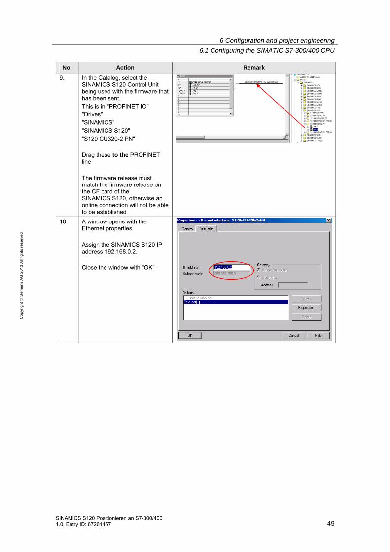
9. In the Catalog, select the SINAMICS S120 Control Unit being used with the firmware that has been sent. This is in "PROFINET IO" "Drives" "SINAMICS" "SINAMICS S120" "S120 CU320-2 PN" Drag these to the PROFINET line The firmware release must match the firmware release on the CF card of the SINAMICS S120, otherwise an online connection will not be able to be established
10. A window opens with the Ethernet properties Assign the SINAMICS S120 IP address 192.168.0.2. Close the window with "OK"

6 Configuration and project engineering
6.1 Configuring the SIMATIC S7-300/400 CPU
50 SINAMICS S120 Positionieren an S7-300/400
1.0, Entry ID: 67261457
Co
pyr
igh
t
Sie
me
ns
AG
20
13
All
righ
ts r
ese
rve
d
No. Action Remark
11. Confirm the next window with "OK"
12. Open the properties of the new object by double-clicking on "Standard telegram 1"
13. Under the "Telegrams" tab, as pre-assignment, select "SIEMENS telegram 111". Acknowledge with "OK"

6 Configuration and project engineering
6.1 Configuring the SIMATIC S7-300/400 CPU
SINAMICS S120 Positionieren an S7-300/400 1.0, Entry ID: 67261457 51
Co
pyr
igh
t
Sie
me
ns
AG
20
13
All
righ
ts r
ese
rve
d
No. Action Remark
14. Insert into slot 2 by right clicking on an object.
15. Select "V4.5" and then "Drive object"
16. Open the properties of the new object by double-clicking on "Standard telegram 1" Under the "Telegrams" tab, as pre-assignment, select "SIEMENS telegram 111". Acknowledge with "OK"
17. Click on "Save and compile" You can close HW Config.

6 Configuration and project engineering
6.1 Configuring the SIMATIC S7-300/400 CPU
52 SINAMICS S120 Positionieren an S7-300/400
1.0, Entry ID: 67261457
Co
pyr
igh
t
Sie
me
ns
AG
20
13
All
righ
ts r
ese
rve
d
18. You can use the blocks from the
project if you wish to use the sample program functions. To do this, open the project provided using the SIMATIC Manager.
19. Copy all of the blocks, with the exception of the system data and SFB functions, from the sample project into the block folder of the created project.
20. Select the SIMATIC 300- station. Load the project into the SIMATIC 300 CPU. After loading, switch the SIMATIC 300 CPU back into run

6 Configuration and project engineering
6.2 Configuration of the SINAMICS S120 drive
SINAMICS S120 Positionieren an S7-300/400 1.0, Entry ID: 67261457 53
Co
pyr
igh
t
Sie
me
ns
AG
20
13
All
righ
ts r
ese
rve
d
6.2 Configuration of the SINAMICS S120 drive
Table 6-2
No. Action Remark
1. If the STARTER commissioning software has not been installed, install it (also see Fehler! Verweisquelle konnte nicht gefunden werden.).
2. Connect the SINAMICS S120 to the SIMATIC S7-300 using a PROFINET cable – and your PG/PC to the SIMATIC S7-300.
3. Start the SIMATIC Manager and open the project created in Chapter 6.1.
4. In the SIMATIC Manager tree, select the SINAMICS S120 and open STARTER by double-clicking on the commissioning symbol.
5. Select the SINAMICS S120 in the project tree of STARTER Go online

6 Configuration and project engineering
6.2 Configuration of the SINAMICS S120 drive
54 SINAMICS S120 Positionieren an S7-300/400
1.0, Entry ID: 67261457
Co
pyr
igh
t
Sie
me
ns
AG
20
13
All
righ
ts r
ese
rve
d
No. Action Remark
6. If a target device has still not been selected, a window opens Select the SINAMICS S120, set the access point to S7_ONLINE Confirm the window with "OK"
7. Start the automatic configuration with a double click
8. Confirm the note with "Configure"
6 Configuration and project engineering
6.2 Configuration of the SINAMICS S120 drive
SINAMICS S120 Positionieren an S7-300/400 1.0, Entry ID: 67261457 55
Co
pyr
igh
t
Sie
me
ns
AG
20
13
All
righ
ts r
ese
rve
d
No. Action Remark
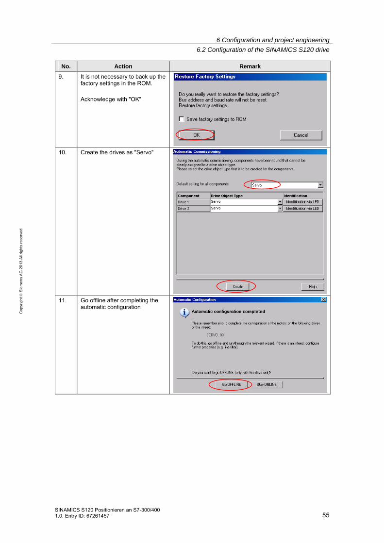
9. It is not necessary to back up the factory settings in the ROM. Acknowledge with "OK"
10. Create the drives as "Servo"
11. Go offline after completing the automatic configuration

6 Configuration and project engineering
6.2 Configuration of the SINAMICS S120 drive
56 SINAMICS S120 Positionieren an S7-300/400
1.0, Entry ID: 67261457
Co
pyr
igh
t
Sie
me
ns
AG
20
13
All
righ
ts r
ese
rve
d
Configuring SERVO_02 with electronic rating plate 12. Open SERVO_02 with a double
click Start the configuration wizard with "Configure DDS"
13. Activate the "Basic positioner" function module Change to the next window with "Next"

6 Configuration and project engineering
6.2 Configuration of the SINAMICS S120 drive
SINAMICS S120 Positionieren an S7-300/400 1.0, Entry ID: 67261457 57
Co
pyr
igh
t
Sie
me
ns
AG
20
13
All
righ
ts r
ese
rve
d
14. The automatic configuration has already selected the power unit being used. Change to the next window with "Next". Confirm the note that the operating signal must be wired.
15. The operating signal is permanently interconnected to "1" as in the configuration used, the infeed is always operational. Change to the next window with "Next".

6 Configuration and project engineering
6.2 Configuration of the SINAMICS S120 drive
58 SINAMICS S120 Positionieren an S7-300/400
1.0, Entry ID: 67261457
Co
pyr
igh
t
Sie
me
ns
AG
20
13
All
righ
ts r
ese
rve
d
16. Change to the next window with "Next".
17. Select the motor with "DRIVE-CLiQ interface" Change to the next window with "Next".
6 Configuration and project engineering
6.2 Configuration of the SINAMICS S120 drive
SINAMICS S120 Positionieren an S7-300/400 1.0, Entry ID: 67261457 59
Co
pyr
igh
t
Sie
me
ns
AG
20
13
All
righ
ts r
ese
rve
d
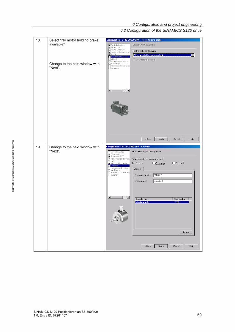
18. Select "No motor holding brake available" Change to the next window with "Next".
19. Change to the next window with "Next".

6 Configuration and project engineering
6.2 Configuration of the SINAMICS S120 drive
60 SINAMICS S120 Positionieren an S7-300/400
1.0, Entry ID: 67261457
Co
pyr
igh
t
Sie
me
ns
AG
20
13
All
righ
ts r
ese
rve
d
20. Change to the next window with "Next".
21. The mechanical system still cannot be set, as the encoder has still not been read out. Change to the next window with "Next".

6 Configuration and project engineering
6.2 Configuration of the SINAMICS S120 drive
SINAMICS S120 Positionieren an S7-300/400 1.0, Entry ID: 67261457 61
Co
pyr
igh
t
Sie
me
ns
AG
20
13
All
righ
ts r
ese
rve
d
22. Select "SIEMENS telegram 111" Change to the next window with "Next".
23. Close the wizard with "Finish"

6 Configuration and project engineering
6.2 Configuration of the SINAMICS S120 drive
62 SINAMICS S120 Positionieren an S7-300/400
1.0, Entry ID: 67261457
Co
pyr
igh
t
Sie
me
ns
AG
20
13
All
righ
ts r
ese
rve
d
Configuring SERVO_03 without electronic rating plate 24. Open SERVO_03 with a double
click Start the configuration wizard with "Configure DDS"
25. Activate the "Basic positioner" function module Change to the next window with "Next".

6 Configuration and project engineering
6.2 Configuration of the SINAMICS S120 drive
SINAMICS S120 Positionieren an S7-300/400 1.0, Entry ID: 67261457 63
Co
pyr
igh
t
Sie
me
ns
AG
20
13
All
righ
ts r
ese
rve
d
26. The automatic configuration has already selected the power unit being used. Change to the next window with "Next". Confirm the note that the operating signal must be wired.
27. The operating signal is permanently interconnected to "1" as in the configuration used, the infeed is always operational. Change to the next window with "Next".

6 Configuration and project engineering
6.2 Configuration of the SINAMICS S120 drive
64 SINAMICS S120 Positionieren an S7-300/400
1.0, Entry ID: 67261457
Co
pyr
igh
t
Sie
me
ns
AG
20
13
All
righ
ts r
ese
rve
d
28. Change to the next window with "Next".
29. Choose "Select standard motor from list" Using the order number, select the motor being used from the list Change to the next window with "Next".

6 Configuration and project engineering
6.2 Configuration of the SINAMICS S120 drive
SINAMICS S120 Positionieren an S7-300/400 1.0, Entry ID: 67261457 65
Co
pyr
igh
t
Sie
me
ns
AG
20
13
All
righ
ts r
ese
rve
d
30. Select "No motor holding brake available" Change to the next window with "Next".
31. Select the encoder being used based on the motor order number Confirm the encoder selection with "OK"

6 Configuration and project engineering
6.2 Configuration of the SINAMICS S120 drive
66 SINAMICS S120 Positionieren an S7-300/400
1.0, Entry ID: 67261457
Co
pyr
igh
t
Sie
me
ns
AG
20
13
All
righ
ts r
ese
rve
d
32. Change to the next window with "Next".
33. Change to the next window with "Next".
6 Configuration and project engineering
6.2 Configuration of the SINAMICS S120 drive
SINAMICS S120 Positionieren an S7-300/400 1.0, Entry ID: 67261457 67
Co
pyr
igh
t
Sie
me
ns
AG
20
13
All
righ
ts r
ese
rve
d
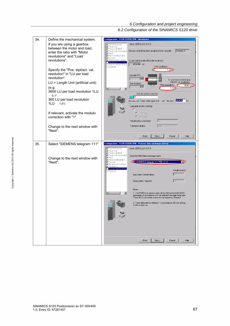
34. Define the mechanical system. If you are using a gearbox between the motor and load, enter the ratio with "Motor revolutions" and "Load revolutions". Specify the "Pos. stpt/act. val. resolution" in "LU per load revolution". LU = Length Unit (artificial unit) (e.g. 3600 LU per load revolution 1LU � 0.1° 360 LU per load revolution 1LU � 1.0°)
If relevant, activate the modulo correction with "1" Change to the next window with "Next".
35. Select "SIEMENS telegram 111" Change to the next window with "Next".

6 Configuration and project engineering
6.2 Configuration of the SINAMICS S120 drive
68 SINAMICS S120 Positionieren an S7-300/400
1.0, Entry ID: 67261457
Co
pyr
igh
t
Sie
me
ns
AG
20
13
All
righ
ts r
ese
rve
d
36. Close the wizard with "Finish"
37. From the project tree, open the "Homing" screen form of SERVO_03 Open the "Homing" block
38. As reference cams are not used in the configuration, the homing mode "Encoder zero mark" is selected. Exit the window with "Close"

6 Configuration and project engineering
6.2 Configuration of the SINAMICS S120 drive
SINAMICS S120 Positionieren an S7-300/400 1.0, Entry ID: 67261457 69
Co
pyr
igh
t
Sie
me
ns
AG
20
13
All
righ
ts r
ese
rve
d
Loading the configuration 39. Go online again
40. Load the configuration into the SINAMICS S120
41. Select "After loading, copy RAM to ROM" Confirm the window with "Yes"
Mechanical settings for SERVO_02
42. From the project tree, open the "Mechanics" screen form of SERVO_02 The encoder was read out when downloading. The mechanics can now be set. No changes have to be made for the example.

6 Configuration and project engineering
6.2 Configuration of the SINAMICS S120 drive
70 SINAMICS S120 Positionieren an S7-300/400
1.0, Entry ID: 67261457
Co
pyr
igh
t
Sie
me
ns
AG
20
13
All
righ
ts r
ese
rve
d
Activating the Safety Integrated functions 43. From the project tree, open the
"Safety Integrated" screen form of SERVO_02 Click on "Change settings"
44. Select "Basic functions via onboard terminals"
45. Interconnect the Control Unit terminal to DI0
46. Click on "Copy parameters" and then on "Activate settings"
47. You will then be prompted to change the password. The initial password is "0" In the sample project, the password was changed to "1".
6 Configuration and project engineering
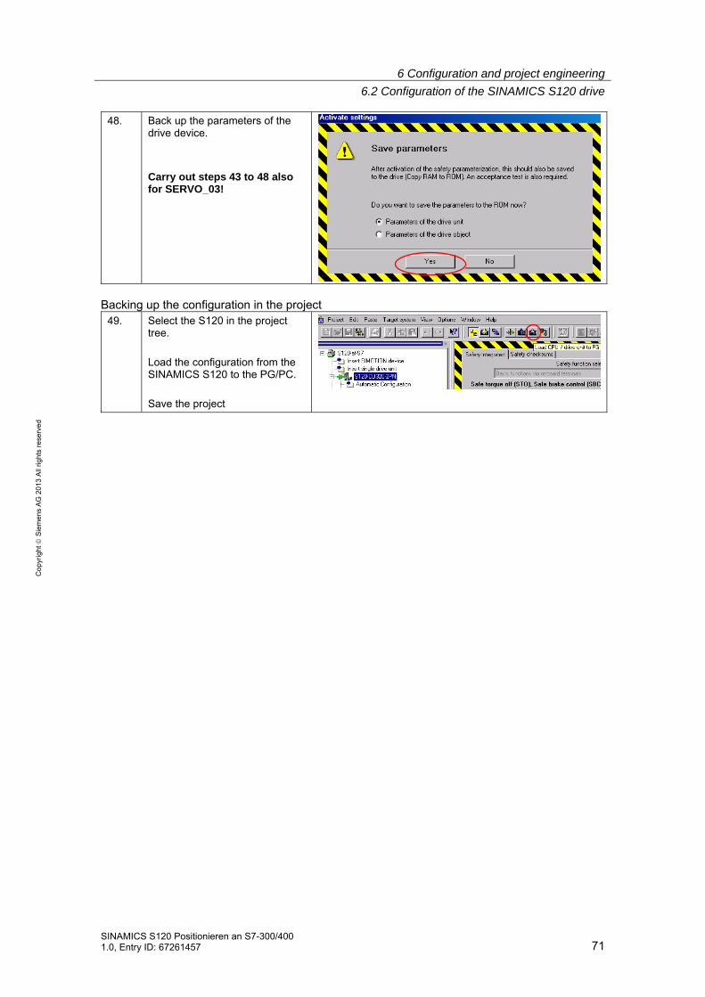
6.2 Configuration of the SINAMICS S120 drive
SINAMICS S120 Positionieren an S7-300/400 1.0, Entry ID: 67261457 71
Co
pyr
igh
t
Sie
me
ns
AG
20
13
All
righ
ts r
ese
rve
d
48. Back up the parameters of the drive device. Carry out steps 43 to 48 also for SERVO_03!
Backing up the configuration in the project
49. Select the S120 in the project tree. Load the configuration from the SINAMICS S120 to the PG/PC. Save the project

6 Configuration and project engineering
6.3 Adding an additional SINAMICS drive to the project
72 SINAMICS S120 Positionieren an S7-300/400
1.0, Entry ID: 67261457
Co
pyr
igh
t
Sie
me
ns
AG
20
13
All
righ
ts r
ese
rve
d
6.3 Adding an additional SINAMICS drive to the project
You can carry out the following steps if you wish to add additional drives to the SINAMICS S120. Otherwise, the configuration has already been completed with Chapters 6.1 and 6.2.
6.3.1 Changes to the SINAMICS S120
6.3.1.1 Changes to the configuration
Connect the additional components to the existing configuration.
DANGER
Carefully observe the safety instructions and installation instructions in the device manuals!

6 Configuration and project engineering
6.3 Adding an additional SINAMICS drive to the project
SINAMICS S120 Positionieren an S7-300/400 1.0, Entry ID: 67261457 73
Co
pyr
igh
t
Sie
me
ns
AG
20
13
All
righ
ts r
ese
rve
d
6.3.1.2 Changes to the configuration
Table 6-3
1. Open the existing project with STARTER Insert a new drive by double clicking on "Insert single drive unit"
2. Run the Wizard.
Depending on the power unit and motor being used, the same steps are required as listed in Chapter 6.2. Activate the "Basic positioner" function module Select SIEMENS telegram 111
3. After the Wizard has been
completed, load the configuration into the SINAMICS S120 Back up the data from "RAM to ROM"

6 Configuration and project engineering
6.3 Adding an additional SINAMICS drive to the project
74 SINAMICS S120 Positionieren an S7-300/400
1.0, Entry ID: 67261457
Co
pyr
igh
t
Sie
me
ns
AG
20
13
All
righ
ts r
ese
rve
d
4. If required, you can now activate the Safety Integrated functions as shown in Chapter 6.2.
6.3.2 Changes to the SIMATIC S7-300/400
Table 6-4
1. Open HW Config
2. Select the SINAMICS S120
3. A selection list opens by right
clicking on the first free slot. Click on "Insert object"
4. Click on the symbol "V4.5" and
then on "drive object"

6 Configuration and project engineering
6.3 Adding an additional SINAMICS drive to the project
SINAMICS S120 Positionieren an S7-300/400 1.0, Entry ID: 67261457 75
Co
pyr
igh
t
Sie
me
ns
AG
20
13
All
righ
ts r
ese
rve
d
5. Open the properties of the new object by double-clicking on "Standard telegram 1" Change to the Telegrams tab. For the pre-assignment, select "SIEMENS telegram 111". Exit the window with "OK"
6. Note down the starting I/O
address and the diagnostics address
7. Click on "Save and compile" Load the HW configuration into the module Restart the SIMATIC CPU after loading. You can close HW Config
8. Open the block folder of the SIMATIC CPU Copy DB72 When inserting the DB, you must rename it. Call it DB272, for example
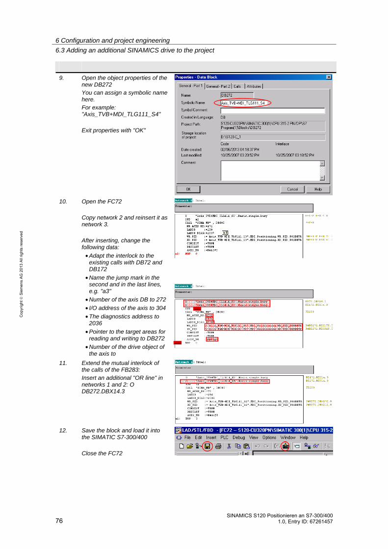
6 Configuration and project engineering
6.3 Adding an additional SINAMICS drive to the project
76 SINAMICS S120 Positionieren an S7-300/400
1.0, Entry ID: 67261457
Co
pyr
igh
t
Sie
me
ns
AG
20
13
All
righ
ts r
ese
rve
d
9. Open the object properties of the new DB272 You can assign a symbolic name here. For example: "Axis_TVB+MDI_TLG111_S4" Exit properties with "OK"
10. Open the FC72
Copy network 2 and reinsert it as network 3. After inserting, change the following data:
• Adapt the interlock to the existing calls with DB72 and DB172
• Name the jump mark in the second and in the last lines, e.g. "a3"
• Number of the axis DB to 272
• I/O address of the axis to 304
• The diagnostics address to 2036
• Pointer to the target areas for reading and writing to DB272
• Number of the drive object of the axis to
11. Extend the mutual interlock of the calls of the FB283: Insert an additional "OR line" in networks 1 and 2: O DB272.DBX14.3
12. Save the block and load it into
the SIMATIC S7-300/400 Close the FC72

6 Configuration and project engineering
6.3 Adding an additional SINAMICS drive to the project
SINAMICS S120 Positionieren an S7-300/400 1.0, Entry ID: 67261457 77
Co
pyr
igh
t
Sie
me
ns
AG
20
13
All
righ
ts r
ese
rve
d
13. Open OB1 Insert a new network. In the new network, call FB1 with DB3.
14. Generate the instance DB DB3
with "Yes"
15. Enter the
gearbox ratio position actual value resolution reference speed and the number of the axis DB.
16. Save the block and load it into
the SIMATIC Close OB1

6 Configuration and project engineering
6.3 Adding an additional SINAMICS drive to the project
78 SINAMICS S120 Positionieren an S7-300/400
1.0, Entry ID: 67261457
Co
pyr
igh
t
Sie
me
ns
AG
20
13
All
righ
ts r
ese
rve
d
6.3.3 Changes to the HMI
Table 6-5
17. Open the project with WinCC flexible
18. Open the text lists with a double click Select the "Antrieb" list
19. Write the data for the new axis in
the first free line of the list entries Value: Number of the instance DB of FB1, in this case, 3 Entry: Name of the axis
20. Save the changes.
Load the project into the HMI

6 Configuration and project engineering
6.4 Position controller and basic positioner settings
SINAMICS S120 Positionieren an S7-300/400 1.0, Entry ID: 67261457 79
Co
pyr
igh
t
Sie
me
ns
AG
20
13
All
righ
ts r
ese
rve
d
6.4 Position controller and basic positioner settings
This chapter describes the screen forms for the position controller and basic positioner settings
6.4.1 Overview and settings of the position controller screen forms
For each axis of the SINAMICS S120, the position controller settings can be found under the main item Technology.
It is subdivided into four points.
Fig. 6-1

6 Configuration and project engineering
6.4 Position controller and basic positioner settings
80 SINAMICS S120 Positionieren an S7-300/400
1.0, Entry ID: 67261457
Co
pyr
igh
t
Sie
me
ns
AG
20
13
All
righ
ts r
ese
rve
d
6.4.1.1 Mechanical system
The mechanical settings were already carried out when commissioning. As a consequence, no changes have to be made here.
Fig. 6-2
In addition to the settings already made in the quick commissioning, when required, you can change the backlash value, which is then taken into account for the closed-loop position control.
What is important for the absolute encoder is the position tracking; this ensures that encoder overruns are counted, and even for encoder overruns, the system can be correctly positioned.
For both of these topics, you can find detailed information in the SINAMICS S120 Function Manual. Fehler! Verweisquelle konnte nicht gefunden werden.
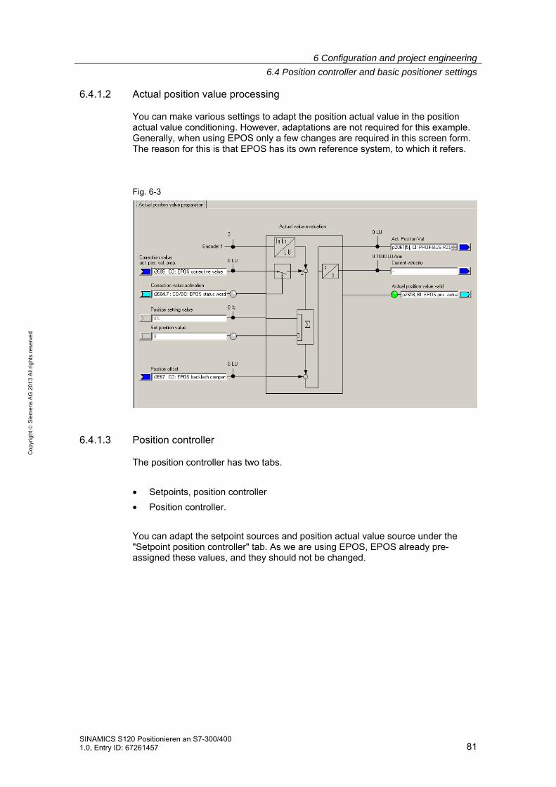
6 Configuration and project engineering
6.4 Position controller and basic positioner settings
SINAMICS S120 Positionieren an S7-300/400 1.0, Entry ID: 67261457 81
Co
pyr
igh
t
Sie
me
ns
AG
20
13
All
righ
ts r
ese
rve
d
6.4.1.2 Actual position value processing
You can make various settings to adapt the position actual value in the position actual value conditioning. However, adaptations are not required for this example. Generally, when using EPOS only a few changes are required in this screen form. The reason for this is that EPOS has its own reference system, to which it refers.
Fig. 6-3
6.4.1.3 Position controller
The position controller has two tabs.
• Setpoints, position controller
• Position controller.
You can adapt the setpoint sources and position actual value source under the "Setpoint position controller" tab. As we are using EPOS, EPOS already pre-assigned these values, and they should not be changed.

6 Configuration and project engineering
6.4 Position controller and basic positioner settings
82 SINAMICS S120 Positionieren an S7-300/400
1.0, Entry ID: 67261457
Co
pyr
igh
t
Sie
me
ns
AG
20
13
All
righ
ts r
ese
rve
d
Fig. 6-4
• Using the position setpoint filter, the position setpoint is filtered with a PT1 element with the set time constant. This reduces precontrol dynamic response and provides jerk limiting.
• For the precontrol, a percentage value (0 – 200 %) can be entered, with which the position setpoint pre-controls a speed at the speed controller, bypassing the position controller. (0 % = deactivated)
• For the precontrol symmetrization (balancing), the position setpoint signal can be filtered again in order to emulate the response of the speed control loop. To do this, a dead time filter (0.0 – 2.0), which represents a factor of the sampling time of the position controller (1s), and a PT1 element (0 – 100 ms) are available.

6 Configuration and project engineering
6.4 Position controller and basic positioner settings
SINAMICS S120 Positionieren an S7-300/400 1.0, Entry ID: 67261457 83
Co
pyr
igh
t
Sie
me
ns
AG
20
13
All
righ
ts r
ese
rve
d
Under the position controller tab, you can adapt the settings of the position controller, assign the controller enable and interconnect the outputs of the position controller.
Fig. 6-5
• You can optimize the position controller using the P gain and the integral time.
• Further, you can change the P component through adaptation. Here, the P gain can be variably scaled. This means that various position controller settings can be made to address different situations.
• The maximum permissible traversing velocity is set for the limitation.
6.4.1.4 Monitoring
The monitoring function comprises three tabs:
• Position and standstill monitoring
• Following error monitoring
• Output cam
The position monitoring can be set using these screen forms.
Note The default values refer to a mechanical system with 10000 LU per load revolution (position setpoint/actual value resolution). They must be adapted to the mechanical system being used (position setpoint/actual value resolution).

6 Configuration and project engineering
6.4 Position controller and basic positioner settings
84 SINAMICS S120 Positionieren an S7-300/400
1.0, Entry ID: 67261457
Co
pyr
igh
t
Sie
me
ns
AG
20
13
All
righ
ts r
ese
rve
d
Note The relevant monitoring functions can be deactivated by entering a 0.
The corresponding values should be parameterized under the "Positioning/standstill monitoring" tab.
Fig. 6-6

6 Configuration and project engineering
6.4 Position controller and basic positioner settings
SINAMICS S120 Positionieren an S7-300/400 1.0, Entry ID: 67261457 85
Co
pyr
igh
t
Sie
me
ns
AG
20
13
All
righ
ts r
ese
rve
d
The maximum difference between the setpoint and actual value is set under the "Following error monitoring" tab.
If the "Travel to fixed stop" function is used, if the following error is exceeded, an error is not output, but the "Fixed stop reached" bit is set.
Fig. 6-7
Two cam positions can be set under the "Cams" tab.
Fig. 6-8
The cams provide a feedback signal" 1" if the actual position is less than the value of the cam or 0, if the actual position is greater than the set value.
WARNING
Only after the axis has been homed, is it guaranteed that the cam switching signals really do have a "true" position reference when output.

6 Configuration and project engineering
6.4 Position controller and basic positioner settings
86 SINAMICS S120 Positionieren an S7-300/400
1.0, Entry ID: 67261457
Co
pyr
igh
t
Sie
me
ns
AG
20
13
All
righ
ts r
ese
rve
d
6.4.2 Overview and settings of the basic positioner screen forms
For EPOS, five sub points are available, which are used to configure the individual functions.
Fig. 6-9
6.4.2.1 Limiting
The limit screen form has two tabs. One for the traversing range limitation and one for the traversing profile limitation.
The software limit switch and the stop cams are parameterized under the traversing range limitation tab. This parameterization is only necessary if you wish to use the associated functions.
The limit switches can be activated using the "Software limit switch activation" function; however, only if the modulo correction is not active and the axis was homed. When using telegram 111, the software limit switch is activated using bit 14 of the positioning control word 2.

6 Configuration and project engineering
6.4 Position controller and basic positioner settings
SINAMICS S120 Positionieren an S7-300/400 1.0, Entry ID: 67261457 87
Co
pyr
igh
t
Sie
me
ns
AG
20
13
All
righ
ts r
ese
rve
d
Fig. 6-10
For the software limit switches, end positions are specified in LU, which the drive must not pass over. Generally, these end positions are located in front of the stop cams.
The software limit switches issue various alarms:
• A7469 or A7470 Target position in a traversing range exceeds the software limit switch range in the negative/positive direction.
• A7477 or A7478 Target position for the actual traversing motion is less than/greater than the negative/positive end position.
• A7479 or A7480 Axis is located at the negative/positive limit switch – an active traversing block was canceled.
• F7481 or F 7482 Software limit switch negative/positive was passed over
There are also the stop cams. These are generally connected with sensors to the digital inputs. The drive is stopped with a fault if the stop cams are passed over.
Note Using p2118 and p2119, the standard response "Fault" can be changed to an alarm in the expert list.
The stop cams can be activated using "Stop output cam activation. For telegram 111 this is realized using bit 15 of the positioning control word 2. In the axis DB, the stop cams can be activated with a bit 176.7.
The limits for the maximum velocity, acceleration, deceleration and jerk can be entered in the traversing profile limits tab. Just the same as for the monitoring,

6 Configuration and project engineering
6.4 Position controller and basic positioner settings
88 SINAMICS S120 Positionieren an S7-300/400
1.0, Entry ID: 67261457
Co
pyr
igh
t
Sie
me
ns
AG
20
13
All
righ
ts r
ese
rve
d
these values must be adapted. This is because a different resolution is involved than in the basic settings. Because the mechanical load is low when the motor is operating under no-load conditions, the positioning velocity can be set to the maximum speed without any problems; the acceleration and deceleration can also be appropriately increased.
The maximum velocity must be set so that the corresponding maximum speed lies below the maximum motor speed (p1082). The value converted into speed as well as the maximum speed are displayed in the screen form.
Fig. 6-11
Fig. 6-12
The maximum velocity can be calculated using the following formula:
[ ]
=
−•
min1000..max
1000
../intmin
1maxLUvel
LUresolutionvalactsetpopositionn
The acceleration allows you to define how quickly the drive accelerates. This is comparable with the ramp-up time. If you wish to convert the acceleration into a ramp-time, then you must make the following calculation:
CAUTION When the mechanical system is coupled, the load limits of the mechanical system must also be taken into account.

6 Configuration and project engineering
6.4 Position controller and basic positioner settings
SINAMICS S120 Positionieren an S7-300/400 1.0, Entry ID: 67261457 89
Co
pyr
igh
t
Sie
me
ns
AG
20
13
All
righ
ts r
ese
rve
d
[ ]stimeonaccelerati
sLUionaccelaerats
LUvelocity=
•
2
1000.maxmin
60
min1000.max
The deceleration is analogous to the acceleration. This can be converted into a ramp-down time using the same formula.
The jerk limiting defines the permissible amount of jerk when a drive accelerates. This must be separately activated as it is not active in the default setting. If it is active, then it rounds off the ramps. You can calculate the rounding time as follows:
[ ]stimeoffrounding
sLUjerk
sLUonaccelerati
=
3
2
1000.max
1000.max

6 Configuration and project engineering
6.4 Position controller and basic positioner settings
90 SINAMICS S120 Positionieren an S7-300/400
1.0, Entry ID: 67261457
Co
pyr
igh
t
Sie
me
ns
AG
20
13
All
righ
ts r
ese
rve
d
Jogging
Here, there are two tabs; one for configuring and one for diagnostics.
In the jog/configuration tab, using the selection at the top left you can toggle between the digital and analog inputs/outputs of the jog function. All settings in this screen form have already been correctly set when selecting the telegram, and must not be changed.
Figure 6-13
The configuration for the jog setpoints is opened when clicking on the jog block. Here, you can adapt the values to the mechanical system being used.

6 Configuration and project engineering
6.4 Position controller and basic positioner settings
SINAMICS S120 Positionieren an S7-300/400 1.0, Entry ID: 67261457 91
Co
pyr
igh
t
Sie
me
ns
AG
20
13
All
righ
ts r
ese
rve
d
Fig. 6-14
You can define the traversing velocity in the jog mode using the setpoint velocity values.
The traversing distance settings specify how far the drive is traversed for incremental jogging. The incremental jogging must be activated using "EPOS incremental jog"; however, it is then controlled just like normal jogging using the same inputs. (see Figure 6-13)
In the ramp-function generator, you can set an up ramp that is only applicable in the jog mode.

6 Configuration and project engineering
6.4 Position controller and basic positioner settings
92 SINAMICS S120 Positionieren an S7-300/400
1.0, Entry ID: 67261457
Co
pyr
igh
t
Sie
me
ns
AG
20
13
All
righ
ts r
ese
rve
d
An overview of all of the analog and digital inputs and outputs is displayed under the "Jog/diagnostics" tab.
Fig. 6-15

6 Configuration and project engineering
6.4 Position controller and basic positioner settings
SINAMICS S120 Positionieren an S7-300/400 1.0, Entry ID: 67261457 93
Co
pyr
igh
t
Sie
me
ns
AG
20
13
All
righ
ts r
ese
rve
d
6.4.2.2 Homing
For incremental encoders, the tabs of the Homing screen have a similar structure to that for jog.
If an absolute encoder is being used, then the absolute encoder must be adjusted once.
Two additional inputs are available, which are not covered by the standard telegram 111 in the homing/configuration tab.
These are used for the reversing cams. Here, when a search is active, the drive changes its direction and searches for the reference point in the other direction.
However, the reversing cams are not used in the example.
Fig. 6-16
The homing type can be set by opening the homing block. In the example, active homing is used and as homing mode, the encoder zero mark. In this case, when selecting homing, the drive is automatically traversed in order to search for the reference point, which is the encoder zero mark.
On the other hand, for passive homing, the axis is homed during normal traversing when the reference signal is detected.
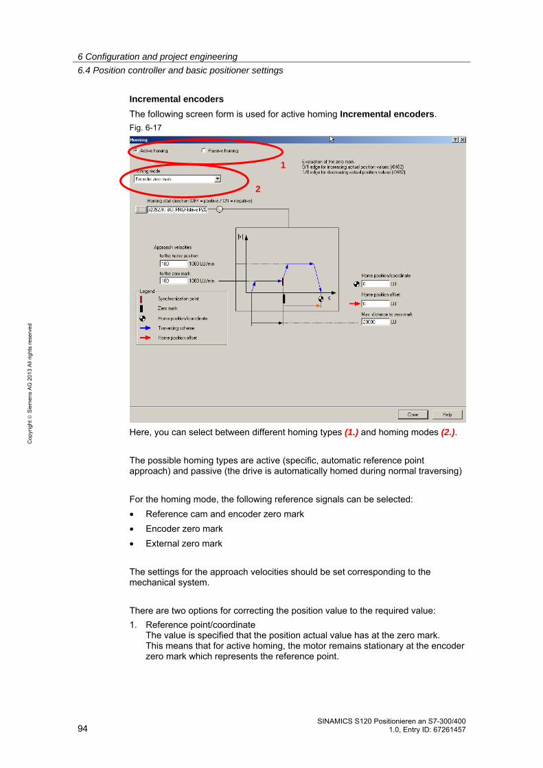
6 Configuration and project engineering
6.4 Position controller and basic positioner settings
94 SINAMICS S120 Positionieren an S7-300/400
1.0, Entry ID: 67261457
Co
pyr
igh
t
Sie
me
ns
AG
20
13
All
righ
ts r
ese
rve
d
Incremental encoders
The following screen form is used for active homing Incremental encoders.
Fig. 6-17
Here, you can select between different homing types (1.) and homing modes (2.).
The possible homing types are active (specific, automatic reference point approach) and passive (the drive is automatically homed during normal traversing)
For the homing mode, the following reference signals can be selected:
• Reference cam and encoder zero mark
• Encoder zero mark
• External zero mark
The settings for the approach velocities should be set corresponding to the mechanical system.
There are two options for correcting the position value to the required value:
1. Reference point/coordinate The value is specified that the position actual value has at the zero mark. This means that for active homing, the motor remains stationary at the encoder zero mark which represents the reference point.
2
1

6 Configuration and project engineering
6.4 Position controller and basic positioner settings
SINAMICS S120 Positionieren an S7-300/400 1.0, Entry ID: 67261457 95
Co
pyr
igh
t
Sie
me
ns
AG
20
13
All
righ
ts r
ese
rve
d
2. Reference point offset It is specified by how many LU the reference point is away from the zero mark in the positive direction.
Absolute encoder
For absolute encoders in the "Active homing" screen form, there is only one button – "Absolute encoder adjustment" – as well as an input field for the reference point coordinate. Absolute encoders have the advantage that they do not have to be re-homed after each switch on.
Note The absolute encoder must be adjusted once when commissioning the system.
Passive homing is also possible for absolute encoders.
The screen form for passive homing is the same for absolute and incremental encoders; however, it is not used for the example.
Fig. 6-18
For passive homing, two probes can be parameterized as reference point source for passive homing. For telegram 111, the active probe is selected via the fieldbus.
You can set whether the probes are used high active or low active via the edge evaluation.
You can set whether the position actual value correction is taken into account for relative positioning, or only for absolute positioning.

6 Configuration and project engineering
6.4 Position controller and basic positioner settings
96 SINAMICS S120 Positionieren an S7-300/400
1.0, Entry ID: 67261457
Co
pyr
igh
t
Sie
me
ns
AG
20
13
All
righ
ts r
ese
rve
d
You can set separate correction values when entering the inner and outer windows. This allows you to compensate for the probe width. Otherwise, this would lead to different zero positions, depending on the direction of travel.
An overview of all of the analog and digital inputs and outputs is displayed under the "Homing/diagnostics" tab.

6 Configuration and project engineering
6.4 Position controller and basic positioner settings
SINAMICS S120 Positionieren an S7-300/400 1.0, Entry ID: 67261457 97
Co
pyr
igh
t
Sie
me
ns
AG
20
13
All
righ
ts r
ese
rve
d
6.4.2.3 Traversing blocks
For the traversing blocks, there is one tab for configuring and one for diagnostics.
When selecting the telegram, all of the settings for this screen form have already been correctly set, and should not be changed.
Fig. 6-19
With the block for the traversing blocks you can access the traversing block screen form.

6 Configuration and project engineering
6.4 Position controller and basic positioner settings
98 SINAMICS S120 Positionieren an S7-300/400
1.0, Entry ID: 67261457
Co
pyr
igh
t
Sie
me
ns
AG
20
13
All
righ
ts r
ese
rve
d
Here, you can parameterize the traversing blocks. Parameters that are not required are grayed out. The sequence is defined by the block number, and not the sequence in the list. This means that for subsequent changes, a new line can be be simply inserted with the appropriate number.
Fig. 6-20
The example shown is only intended to show just how the traversing blocks could look like
The traversing blocks can also be written from the SIMATIC S7-300/400 into the SINAMICS S120. See Chapter 4.3.1
More detailed information on creating traversing programs is provided in the SINAMICS S120 Function Manual Fehler! Verweisquelle konnte nicht gefunden werden..
The traversing block diagnostics tab shows all of the quantities that are relevant for the operating mode. This provides an overview and a diagnostic capability for the current state of the traversing blocks mode.

6 Configuration and project engineering
6.4 Position controller and basic positioner settings
SINAMICS S120 Positionieren an S7-300/400 1.0, Entry ID: 67261457 99
Co
pyr
igh
t
Sie
me
ns
AG
20
13
All
righ
ts r
ese
rve
d
6.4.2.4 Direct setpoint specification / MDI
The direct setpoint specification / MDI is, just the same as the previous points, split up into two tabs for configuration and diagnostics.
When selecting the telegram, all of the settings for this screen form have already been correctly set, and should not be changed.
You can enter the input signals for MDI in the "MDI/configuration" tab. All inputs are pre-assigned as default setting via fieldbus.
Fig. 6-21
When selecting the "Positioning MDI" block, you can set 4 fixed setpoints, which are active if a setpoint is not entered via the bus.
Fig. 6-22
In this screen form, you can set setpoints, which are used if the setpoints are not entered externally. In this example, the SINAMICS S120 receives its setpoints from the control system (telegram 111); this means that changes in this screen form do not influence this particular example.

6 Configuration and project engineering
6.4 Position controller and basic positioner settings
100 SINAMICS S120 Positionieren an S7-300/400
1.0, Entry ID: 67261457
Co
pyr
igh
t
Sie
me
ns
AG
20
13
All
righ
ts r
ese
rve
d
All variables relevant for the operating mode are displayed in the "MDI/configuration" tab. This provides an overview and a diagnostic capability for the current state of the direct setpoint specification/MDI mode.

7 Contact person
SINAMICS S120 Positionieren an S7-300/400 1.0, Entry ID: 67261457 101
Co
pyr
igh
t
Sie
me
ns
AG
20
13
All
righ
ts r
ese
rve
d
7 Contact person Siemens AG
Industry Sector I DT MC PMA APC Frauenauracher Strasse 80 D - 91056 Erlangen, Germany E-mail: [email protected]
8 References This list does not purport to be complete and merely reflects a selection of suitable information.
Table 8-1
Topic Title/link
/1/ Automation with STEP 7 in STL and SCL Author: Hans Berger Publicis MCD Verlag ISBN: 978-3-89578-397-5
/2/ Automation with STEP 7 in LAD and FBD Author: Hans Berger Publicis MCD Verlag ISBN: 978-3-89578-296-1
/3/
STEP 7 SIMATIC S7-300/400
Reference manual System and Standard Functions for S7-300/400 Volume 1/2
http://support.automation.siemens.com/WW/view/de/44240604
/4/ Reference to the article
http://support.automation.siemens.com/WW/view/de/67261457
/5/ Siemens Industry Online Support
http://support.automation.siemens.com
/6/ STARTER http://support.automation.siemens.com/WW/view/en/26233208
/7/ SINAMICS S120
SINAMICS S120 Getting Started:
http://support.automation.siemens.com/WW/view/de/61604910
List Manual (parameter and error list):
http://support.automation.siemens.com/WW/view/de/49383082 Drive Functions Function Manual
http://support.automation.siemens.com/WW/view/de/59737625
Control Units and Additional System Components Manual
http://support.automation.siemens.com/WW/view/de/59714694
Booksize Power Units Manual
http://support.automation.siemens.com/WW/view/de/59715084
Commissioning Manual
http://support.automation.siemens.com/WW/view/de/61616686
/8/ FB283 Toolbox V2.1
http://support.automation.siemens.com/WW/view/de/25166781

9 History
102 SINAMICS S120 Positionieren an S7-300/400
1.0, Entry ID: 67261457
Co
pyr
igh
t
Sie
me
ns
AG
20
13
All
righ
ts r
ese
rve
d
9 History
Table 9-1
Version Date Change
V1.0 04/2013 First edition