Simulations: tools and status
22
14/01/2008 MICE CM23 - Beam Line Paralle l Session 1 Simulations: tools and status Marco Apollonio, Imperial College - London
-
Upload
thor-schroeder -
Category
Documents
-
view
25 -
download
3
description
Simulations: tools and status. Marco Apollonio, Imperial College - London. G4Beamline : see presentation ORBIT: see presentation Turtle Spreadsheets for BL. Optimising the BeamLine with MINUIT+Turtle. ( e ,P) matrix. Pros & Cons - PowerPoint PPT Presentation
Transcript of Simulations: tools and status

14/01/2008 MICE CM23 - Beam Line Parallel Session 1
Simulations:tools and statusMarco Apollonio, Imperial College - London

14/01/2008 MICE CM23 - Beam Line Parallel Session 2
- G4Beamline: see presentation- ORBIT: see presentation- Turtle- Spreadsheets for BL

14/01/2008 MICE CM23 - Beam Line Parallel Session 3
Optimising the BeamLine with MINUIT+Turtle

14/01/2008 MICE CM23 - Beam Line Parallel Session 4
(,P) matrixP(MeV/c)(mm rad)
140 200 240
2
6 (7.1,207)
10

14/01/2008 MICE CM23 - Beam Line Parallel Session 5
Pros & Cons
Turtle has been used since ever to design the reference Beam Line: P = 207 MeV/c (d.s. of the diffuser), emi_N=7 mm rad Turtle is a ray-tracing code, well established and capable of dealing with materials along the line.
It is not as sexy as G4 based codes and its I/O is pretty cumbersome, also the deck (system) is quite a pain in the neck ...
... however it works, it is fast and we don’t need a very sophisticated code at this stage
But we need the flexibility to change initial parameters of the beamline and find the currents for our magnets.
So far Optimisation has been done manually: a painstaking (and long) job

14/01/2008 MICE CM23 - Beam Line Parallel Session 6
Optimisation via MINUIT is possible albeit not straightforward
As far as I know Turtle source code is not accessible: it comes as a black box, you change the deck and run it at your convenience
To dribble this problem I have used a main code that uses Turtle (Linux) as anexternal function and changes the magnet parameters in the deck as long as the optimisation goes (via a shell script)
A routine is used to calculate:- 4D normalized emittance, beta, alpha- beta_x, alpha_x, beta_y, alpha_y- muon transmission
These quantities can be used to force the beamline to reach some goal values. In the early days the goal was increasing Transmission, here it should be possible to shape the optics of the beam (we don’t do miracles though ... )

14/01/2008 MICE CM23 - Beam Line Parallel Session 7
OUTPUT u.s.of the diffuser
INPUT: beamline u.s.Section
Q4 Q5 Q6 Q7 Q8 Q9
Q1 Q2 Q3 Sol
Beam Line is defined by 3 decks describing 3 elements of MICE BL1. Up Stream Beam Line
2. Transfer
3. Down Stream Beam Line
Dip
ole1
Dip
ole2
alpha0
alphaa0beta b0

14/01/2008 MICE CM23 - Beam Line Parallel Session 8
Up Stream BeamLine Optimisation

14/01/2008 MICE CM23 - Beam Line Parallel Session 9
100000 initial pionsNot much to optimiseThe spirit is a proof of principle

14/01/2008 MICE CM23 - Beam Line Parallel Session 10
Original Configuration After OptimisationNOTA BENE: this is the MATRIX for PIONSwhile optimisation tries to make BETA(mu) flat in the solenoid
Bsol=4.2 T Bsol=4.4 T
TRANSPORT: Matrix Evolution

14/01/2008 MICE CM23 - Beam Line Parallel Session 11
Down Stream BeamLine Optimisation

14/01/2008 MICE CM23 - Beam Line Parallel Session 12
10000 muons traced, <15 minInitial TR=4.2% Final TR = 3.7%
Some resultsDS section Q4-5-6-7-8-9 optimisedusing SIMPLEX algorithm
Aim at 0 = 82.7 cm0 = 0.44as from diffuser prescriptions
Code tries to minimise the function((-0)/0.5)2 + ((-0)/0.04)2
Initial quadrupole currents
Initial emi_N, beta (4D,x,y), alpha(4D,x,y)
Aimed values: beta0, alpha0
final emi_N, beta (4D,x,y), alpha(4D,x,y)
Minimisation seems unable to get =0.44, it sets at around 0. no matter which precision is requiredHowever reaches the required value

14/01/2008 MICE CM23 - Beam Line Parallel Session 13
''
2
2
1exp
2
2'
2
2
xxxx
xyxxNorm
x (cm)
y (cm)
********************************************** * * * Function minimization by SUBROUTINE HFITV * * Variable-metric method * * ID = 0 CHOPT = 0 * * * ********************************************** Convergence when estimated distance to minimum (EDM) .LT. 0.10E+01
FCN= 143.4691 FROM MIGRAD STATUS=CONVERGED 453 CALLS 454 TOTAL EDM= 0.12E-05 STRATEGY=1 ERROR MATRIX UNCERTAINTY= 2.9%
EXT PARAMETER STEP FIRST NO. NAME VALUE ERROR SIZE DERIVATIVE 1 P1 68.371 2.4827 -0.32050E-01 -0.21101E-03 2 P2 -0.86933 0.94910E-01 -0.39128E-03 -0.10718E-01 3 P3 4.6328 1.6825 0.48669E-02 -0.15841E-03 4 P4 3.4303 0.71097E-01 0.31790E-03 -0.14099E-01 5 P5 60.499 1.2328 0.74829E-02 0.10867E-02 6 P6 -0.15806 0.27740E-01 -0.61581E-04 -0.30442E-02
CHISQUARE = 0.1435E+01 NPFIT = 106
68.3 -0.86 4.63 3.43 60.49 -0.15 0.975016 2.07481 4.224281
********************************************** * * * Function minimization by SUBROUTINE HFITV * * Variable-metric method * * ID = 0 CHOPT = 0 * * * ********************************************** Convergence when estimated distance to minimum (EDM) .LT. 0.10E+01
FCN= 78.47191 FROM MIGRAD STATUS=CONVERGED 252 CALLS 253 TOTAL EDM= 0.23E-04 STRATEGY=1 ERROR MATRIX UNCERTAINTY= 2.9%
EXT PARAMETER STEP FIRST NO. NAME VALUE ERROR SIZE DERIVATIVE 1 P1 125.27 4.4452 0.67998E-01 0.87830E-04 2 P2 0.96546E-01 0.91543E-01 -0.15508E-02 0.70039E-02 3 P3 0.81872 0.88086 -0.22246E-02 -0.74252E-03 4 P4 3.3471 0.68870E-01 -0.13344E-02 -0.10475 5 P5 -32.680 0.59870 0.15268E-02 -0.68178E-02 6 P6 0.37815 0.21789E-01 0.38693E-03 0.77574E-01
CHISQUARE = 0.1019E+01 NPFIT = 83
125.2 0.09 0.81 3.34 32.67 0.37 0.857006 1.09118 2.22163
y’
x’

14/01/2008 MICE CM23 - Beam Line Parallel Session 14
P (GeV/c)
215 MeV/c
x (cm)
y(cm)
at the end of the line [u.s. of the diffuser]

14/01/2008 MICE CM23 - Beam Line Parallel Session 15
NO CUTSDP/P<10% (P=215 MeV/c)

14/01/2008 MICE CM23 - Beam Line Parallel Session 16
B2
Q4
Q5
Q6
Q7
Q8
Q9
PbPT
B1B2 Q4 Q5 Q6 Q7 Q9Q8
Pb.Disk
Vertical Half-width
(cm)
HorizontalHalf-width
(cm)
25
0
25
16mz
B2
Q4
Q5
Q6
Q7
Q8
Q9
PbPT
B1B2 Q4 Q5 Q6 Q7 Q9Q8
Pb.Disk
Vertical Half-width
(cm)
HorizontalHalf-width
(cm)
25
0
25
B2
Q4
Q5
Q6
Q7
Q8
Q9
PbPT
B1B2 Q4 Q5 Q6 Q7 Q9Q8
Pb.Disk
Vertical Half-width
(cm)
HorizontalHalf-width
(cm)
25
0
25
16mz
q4
q5
q6
q7
q8
q9
-25
-20
-15
-10
-5
0
5
10
15
20
25
0 1 2 3 4 5 6 7 8 9 10 11 12 13 14 15
Diffuser
B2
Q4
Q5
Q6
Q7
Q8
Q9
PbPT
B1B2 Q4 Q5 Q6 Q7 Q9Q8
Pb.Disk
Vertical Half-width
(cm)
HorizontalHalf-width
(cm)
25
0
25
16mz
B2
Q4
Q5
Q6
Q7
Q8
Q9
PbPT
B1B2 Q4 Q5 Q6 Q7 Q9Q8
Pb.Disk
Vertical Half-width
(cm)
HorizontalHalf-width
(cm)
25
0
25
B2
Q4
Q5
Q6
Q7
Q8
Q9
PbPT
B1B2 Q4 Q5 Q6 Q7 Q9Q8
Pb.Disk
Vertical Half-width
(cm)
HorizontalHalf-width
(cm)
25
0
25
16mz
q4
q5
q6
q7
q8
q9
-25
-20
-15
-10
-5
0
5
10
15
20
25
0 1 2 3 4 5 6 7 8 9 10 11 12 13 14 15
B2
Q4
Q5
Q6
Q7
Q8
Q9
PbPT
B1B2 Q4 Q5 Q6 Q7 Q9Q8
Pb.Disk
Vertical Half-width
(cm)
HorizontalHalf-width
(cm)
25
0
25
16mz
B2
Q4
Q5
Q6
Q7
Q8
Q9
PbPT
B1B2 Q4 Q5 Q6 Q7 Q9Q8
Pb.Disk
Vertical Half-width
(cm)
HorizontalHalf-width
(cm)
25
0
25
B2
Q4
Q5
Q6
Q7
Q8
Q9
PbPT
B1B2 Q4 Q5 Q6 Q7 Q9Q8
Pb.Disk
Vertical Half-width
(cm)
HorizontalHalf-width
(cm)
25
0
25
16mz
q4
q5
q6
q7
q8
q9
-25
-20
-15
-10
-5
0
5
10
15
20
25
0 1 2 3 4 5 6 7 8 9 10 11 12 13 14 15
Diffuser
http://www.isis.rl.ac.uk/accelerator/MICE/Task%20Notes%20and%20Specifications/beamline%20-%20optics/some_reference_data.htm
Beamline with Kevin’s parameters with MINUIT optimisation

14/01/2008 MICE CM23 - Beam Line Parallel Session 17
Where do we go from here?
- the idea is that this system can be used to optimise the missing beam lines
- driving parameters are the BETA,ALPHA u.s. of the diffuser (for different and P)
- force the BL to reach those values and also try to maximize transmission

14/01/2008 MICE CM23 - Beam Line Parallel Session 18
Spreadsheets for BL selection
http://mice.iit.edu/bl/Documentation/index_doc.html

14/01/2008 MICE CM23 - Beam Line Parallel Session 19
calculates the local momentumaccording to a material budget table
dE/dX table (specific for material)
magnet rescaling table

14/01/2008 MICE CM23 - Beam Line Parallel Session 20
Summary• All conventional magnets up and running• Solenoid down
– reduced rate• need to increase pion production
– target studies & improvement• tool to define beamlines by rescaling currents
currently used• tool (TTL + MINUIT) under test to optimise
future configurations
14/01/2008 MICE CM23 - Beam Line Parallel Session 21
the END
14/01/2008 MICE CM23 - Beam Line Parallel Session 22
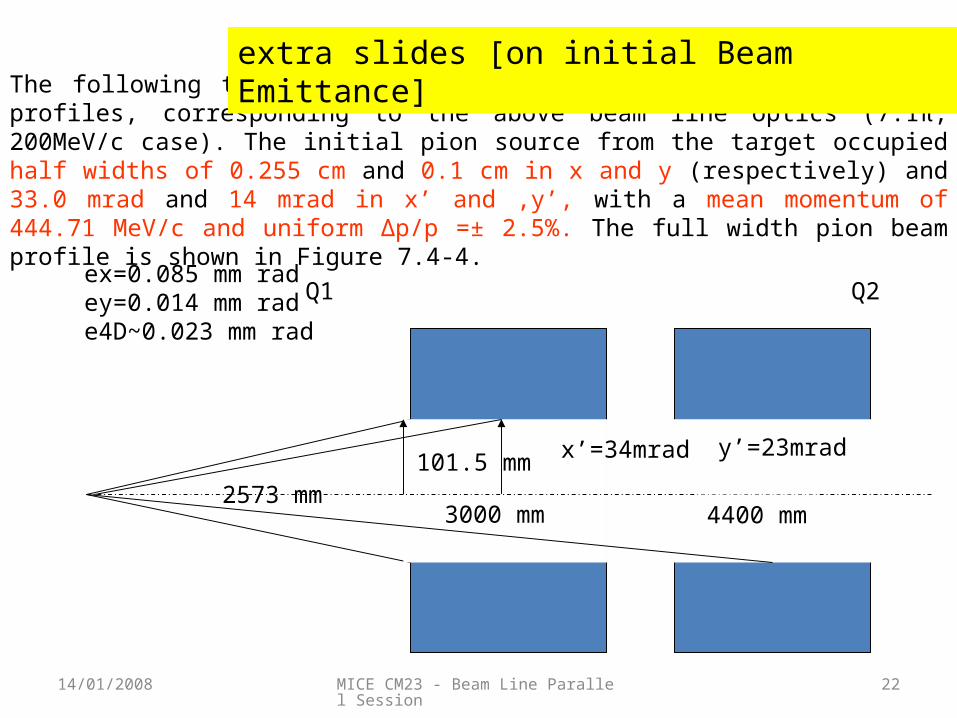
The following two figures show the second order TRANSPORT beam profiles, corresponding to the above beam line optics (7.1π, 200MeV/c case). The initial pion source from the target occupied half widths of 0.255 cm and 0.1 cm in x and y (respectively) and 33.0 mrad and 14 mrad in x’ and ,y’, with a mean momentum of 444.71 MeV/c and uniform Δp/p =± 2.5%. The full width pion beam profile is shown in Figure 7.4 4.‑
2573 mm101.5 mm
3000 mm 4400 mm
x’=34mrad y’=23mrad
ex=0.085 mm radey=0.014 mm rade4D~0.023 mm rad
extra slides [on initial Beam Emittance]
Q1 Q2