Simulation of Wheel and Rail Profile Evolution - DiVA portal7737/FULLTEXT01.pdf · Simulation of...
41
Licentiate Thesis TRITA AVE 2004:19 ISSN 1651-7660 ISBN 91-7283-806-X Simulation of Wheel and Rail Profile Evolution Wear Modelling and Validation by Roger Enblom Postal Address Royal Institute of Technology Aeronautical and Vehicle Engineering Railway Technology SE-100 44 Stockholm Visiting address Teknikringen 8 Stockholm Telephone +46 8 790 76 28 Fax +46 8 790 76 29 E-mail [email protected]
-
Upload
duongquynh -
Category
Documents
-
view
234 -
download
2
Transcript of Simulation of Wheel and Rail Profile Evolution - DiVA portal7737/FULLTEXT01.pdf · Simulation of...
Licentiate Thesis
TRITA AVE 2004:19ISSN 1651-7660
ISBN 91-7283-806-X
Simulation of Wheel and Rail Profile EvolutionWear Modelling and Validation
by
Roger Enblom
Postal Address Visiting address Telephone E-mail
Royal Institute of TechnologyAeronautical and Vehicle EngineeringRailway TechnologySE-100 44 StockholmTeknikringen 8Stockholm
+46 8 790 76 28Fax+46 8 790 76 29

Simulation of Wheel and Rail Profile Evolution - Wear Modelling and Validation
Contents
Contents. . . . . . . . . . . . . . . . . . . . . . . . . . . . . . . . . . . . . . . . . . . . . . . . . . . . . . . . . i
Preface . . . . . . . . . . . . . . . . . . . . . . . . . . . . . . . . . . . . . . . . . . . . . . . . . . . . . . . . . iii
Abstract . . . . . . . . . . . . . . . . . . . . . . . . . . . . . . . . . . . . . . . . . . . . . . . . . . . . . . . . iv
Outline of Thesis . . . . . . . . . . . . . . . . . . . . . . . . . . . . . . . . . . . . . . . . . . . . . . . . . . v
Contribution of Thesis . . . . . . . . . . . . . . . . . . . . . . . . . . . . . . . . . . . . . . . . . . . . vi
1 Introduction . . . . . . . . . . . . . . . . . . . . . . . . . . . . . . . . . . . . . . . . . . . . . . . . . . 1
2 Wear Models . . . . . . . . . . . . . . . . . . . . . . . . . . . . . . . . . . . . . . . . . . . . . . . . . 42.1 Material loss . . . . . . . . . . . . . . . . . . . . . . . . . . . . . . . . . . . . . . . . . . . . . 42.2 Lubrication . . . . . . . . . . . . . . . . . . . . . . . . . . . . . . . . . . . . . . . . . . . . . . 6
3 Wheel-Rail Profile Evolution . . . . . . . . . . . . . . . . . . . . . . . . . . . . . . . . . . . . 83.1 Prediction of profile evolution . . . . . . . . . . . . . . . . . . . . . . . . . . . . . . . 83.2 Profile design . . . . . . . . . . . . . . . . . . . . . . . . . . . . . . . . . . . . . . . . . . . 153.3 Vehicle design . . . . . . . . . . . . . . . . . . . . . . . . . . . . . . . . . . . . . . . . . . 17
4 Present Results in Summary . . . . . . . . . . . . . . . . . . . . . . . . . . . . . . . . . . . . 184.1 Contact modelling . . . . . . . . . . . . . . . . . . . . . . . . . . . . . . . . . . . . . . . 194.2 Improved wheel wear simulation . . . . . . . . . . . . . . . . . . . . . . . . . . . . 204.3 Rail profile evolution . . . . . . . . . . . . . . . . . . . . . . . . . . . . . . . . . . . . . 23
5 Future Research Directions . . . . . . . . . . . . . . . . . . . . . . . . . . . . . . . . . . . . 245.1 Contact model . . . . . . . . . . . . . . . . . . . . . . . . . . . . . . . . . . . . . . . . . . 255.2 Contact environment . . . . . . . . . . . . . . . . . . . . . . . . . . . . . . . . . . . . . 255.3 Simulation set and validation . . . . . . . . . . . . . . . . . . . . . . . . . . . . . . . 25
6 References . . . . . . . . . . . . . . . . . . . . . . . . . . . . . . . . . . . . . . . . . . . . . . . . . . 26
i

ii

Simulation of Wheel and Rail Profile Evolution - Wear Modelling and Validation
Preface
The research reported in this thesis has been carried out in the course of continued workon computer aided wheel-rail wear simulation, a part of the vehicle-track research fieldat the Royal Institute of Technology (KTH), Division of Railway Technology. Theobjective has been to refine the methods applied to uniform wheel wear simulation byinclusion of braking and improvement of the contact model. Further a tentativeapplication to uniform rail wheel simulation has been proposed and tested.
The work has been carried out during partial leave from Bombardier TransportationSweden, a courtesy thankfully appreciated.
The financial support from Banverket (The Swedish National Rail Administration), SL(Stockholm Transport), Bombardier Transportation, SJ AB, Green Cargo, and InterfleetTechnology (Sweden) is gratefully acknowledged.
Thanks to my colleagues at the division and to my supervisor Prof. Mats Berg, as well asto Prof. Evert Andersson and Doc. Ulf Olofsson for valuable discussions andsuggestions. The support of Mr. Ingemar Persson at DEsolver regarding the simulationsoftware is also appreciated.
Finally I would like to thank my wife Anita for her support and patience.
Stockholm, May 2004
Roger Enblom
iii
Abstract
Numerical procedures for reliable wheel and rail wear prediction are rare. Recentdevelopment of simulation techniques and computer power together with tribologicalknowledge do however suggest computer aided wear prediction. The objective of therelated research field at the Royal Institute of Technology (KTH) is to arrive at anumerical procedure able to simulate profile evolution due to uniform wear to a degreeof accuracy sufficient for application to vehicle dynamics simulation. Such a tool wouldbe useful for maintenance planning as well as optimisation of the transport system and itscomponents.
The research contribution accounted for in this thesis includes, in addition to a literaturereview, refinement of methods applied to uniform wheel wear simulation by inclusion ofbraking and improvement of the contact model. Further a tentative application touniform rail wheel simulation has been proposed and tested.
The first part addresses issues related to braking and wheel-rail contact conditions in thecontext of wheel wear simulation. The KTH approach includes Archard’s wear modelwith associated wear maps, vehicle dynamics simulation and railway network definition.In previous work at KTH certain variations in operating conditions have been accountedfor through empirically estimated average scaling factors. The objective of the currentresearch is to be able to include such variations in the set of simulations. In particular theinfluence of disc braking and varying friction and lubrication conditions are investigated.Both environmental factors like moist and contamination and deliberate lubrication needto be considered. As part of the associated contact analysis the influence of tangentialelastic deformation of the contacting surfaces on the sliding velocity has been separatelyinvestigated and found to be essential in case of partial slip contact conditions.
In the second part validation of the improvements related to wheel wear simulation isaddressed. Disc braking has been included in the simulation set and a wear map for moistcontact conditions based on recent tribometer tests has been drafted and tested. It hasbeen shown that the previously used braking factor accounts for the combination of thecontributions from surface elasticity and braking. Good agreement with measurementsfrom the Stockholm commuter service is achieved. It is concluded that the modelimprovements accounted for are sufficient for adequate simulation of tread wear but thatfurther development of the flange / gauge corner contact modelling may be needed.
In the final part a procedure for simulation of rail wear and corresponding profileevolution has been formulated. A simulation set is selected defining the vehicles runningon the track to be investigated, their operating conditions, and contact parameters.Several variations of input data may be included together with the correspondingoccurrence probability. Trial calculations of four non-lubricated curves with radii from303 m to 802 m show qualitatively reasonable results in terms of profile shapedevelopment and difference in wear mechanisms between gauge corner and rail head.The wear rates related to traffic tonnage are however overestimated. It is believed thatmodel refinements in terms of environmental influence and contact stress calculation areuseful to improve the quantitative results.
Keywords: contact, wear, wear prediction, wear model, wheel profile, rail profile,simulation, vehicle-track interaction, multibody simulation, MBS.
iv

Simulation of Wheel and Rail Profile Evolution - Wear Modelling and Validation
Outline of Thesis
The scope of this thesis is simulation of wheel and rail profile evolution due to wear.Railway vehicle dynamics and tribology are combined using multi body simulation andwear modelling in an iterative process. The thesis includes an introduction and summaryand the following appended papers:
A Enblom R, Berg M: Simulation of Railway Wheel Profile Development due to Wear– Influence of Disc Braking and Contact Environment. Accepted for publication inWear.
B Enblom R, Berg M: Wheel Wear Modelling Including Disc Braking and ContactEnvironment - Simulation of 18 Months of Commuter Service in Stockholm.Accepted for presentation at and to appear in the proceedings of the 14thInternational Wheelset Congress, Orlando 17 - 21 October 2004.
C Enblom R, Berg M: Tentative Formulation of Simulation of Rail Profile Evolutiondue to Uniform Wear. To be submitted for publication.
All papers have been written by Roger Enblom and reviewed by Prof. Mats Berg.
v

Contribution of Thesis
A few different approaches to simulation of wheel-rail profile evolution are reported inthe literature. The combination of Archard’s wear model, widely accepted in thetribological society, multibody simulation of the complete vehicle, systematicrepresentation of an arbitrary network or vehicle fleet, and validation by fieldmeasurements of real world applications is however not found elsewhere. The researchaccounted for in this thesis takes its starting point in the results reported by Jendel [12].Improved contact modelling, increased generality in wheel wear simulation, andpioneering efforts in rail profile evolution are detailed as follows:
• A fundamental improvement of contact modelling has been achieved by includingthe tangential flexibility of contacting surfaces in determining relative slidingvelocities and distances. This has been shown to be essential for the adequatedetermination of the wear distribution over a contact area subjected to partial slip.These additional calculations have been efficiently implemented in the numericalprocedure Fastsim by Kalker.
• For wheel wear calculation typical simulations are defined representing the net-work properties, operations, and contact conditions. This simulation set has beenextended with simulation of disc or dynamic braking. The braking effort is applieddirectly in the multibody analysis, thus the resulting creep and creep forces repre-sent the combined effect of dynamic interaction, curve negotiation, and braking. Ithas been shown that an empirical scaling factor to account for this effect is notneeded and that the scaling factor proposed by Jendel approximately represents thecombination of surface elasticity and braking.
• The generation of tribological data in terms of wear rates under different condi-tions applicable to wheel-rail contact is a tedious process. The knowledge of envi-ronmental influence on the contact conditions is however emerging and the amountof test data steadily increasing. Recent results from wear tests at high sliding veloc-ity and different levels of humidity have been used to simulate typical weather con-ditions. The efficiency of trackside lubrication has been evaluated from availablefield measurements of rail wear.
• All model improvements listed above have been applied to the Stockholm com-muter service for validation. Good agreement between simulations and availablemeasurements has been achieved using the generalised models.
• For application to rail wear simulation a general structure defining the simulationset in terms of relevant parameters and occurrence probabilities has been proposed.A three-level hierarchy is used with the vehicle definitions at the uppermost level,the desired operations at the next, and varying contact conditions at the bottomlevel.
• Rail wear prediction is more difficult than corresponding wheel wear simulationdue to the limited variation of contact conditions and corresponding averagingeffect. The results are highly sensitive to the contact modelling in particular at thegauge corner. The limited applicability of traditional elliptic contact modelling isindicated and desired improvements pointed out.
vi

Simulation of Wheel and Rail Profile Evolution - Wear Modelling and Validation
vii

Simulation of Wheel and Rail Profile Evolution - Wear Modelling and Validation
1 INTRODUCTION
Wear of wheels and rails has been of concern in the railway business for several decades.With current trends towards increased axle loads and higher speeds, the phenomenonbecomes even more accentuated despite significant achievements in materialdevelopment and vehicle design. The focus on infrastructure maintenance and rollingstock life cycle costs also draw attention to the possibilities of wear control.
In general, the course of events usually called wear is a complicated process involvingseveral modes of material deterioration and contact surface alteration. Thus may materialremoval or relocation, plastic flow and phase transformation take place at, just below, orin-between the contacting surfaces.
From a tribological point of view, the wheel-rail contact is an open system dependent onboth design features and environmental conditions. Different wear mechanisms may beactivated in response to the actual loading, slip, and lubrication. Lubrication may in thiscontext be understood as intentional or as a result of the ambient state. The process ofmetallic material removal usually obeys some threshold function of the operationparameters where a limited change may influence the rate of wear dramatically.
From a solid mechanics point of view the railway operation imposes cyclic loading onthe wheel and rail. Depending on the wheel load, contact stress distribution andsubsurface stress, plastic deformation and shake down as well as fatigue crack initiationand propagation, known as rolling contact fatigue (RCF), may occur. The initiation offatigue cracks in steel is again a threshold phenomenon.
These different mechanisms of deterioration manifest themselves through a number ofdamage patterns. Wheel damage occurs as fatigue cracks, initiated at or below thesurface, which may result in material fall-out like shelling or spalling. Micro-levelmaterial removal, possibly in combination with plastic deformation, may cause both out-of-roundness and profile alteration reasonably constant around the circumference. Raildamage shows a corresponding variety of damages like fatigue cracking, in severe casesleading to rail fracture, and longitudinally constant profile related wear. A periodicdeformation pattern, known as corrugation, is also common.
Traditionally, corrective actions in order to reduce wear have been based on experienceand measurements on in-service vehicles and track, occasionally supported by laboratorytesting. Theoretical and predictive methods are rarely developed to the level required forengineering application, in particular suitable for application in early design phases.
The focus of the current work is on the prediction of profile related wear, altering thewheel-rail profile match but considered constant around the wheel and along the track.Nevertheless, even this process only constitutes a tribological system depending onseveral parameters requiring input from different disciplines (figure 1). To assess thestates of interaction in the wheel-rail interface the forces and motions originating fromthe dynamic response of the vehicle are required. Furthermore the location of contact,contact stress distributions, and a corresponding wear model are needed. Finally theaccumulated effect of different types of services and ambient conditions shall beconsidered.
1

Section 1 - Introduction
Figure 1: Disciplines related to profile evolution prediction.
Research activities aiming at the application of numerical methods to the problem ofwheel-rail wear prediction begun to be published in the mid-eighties. An immediateconclusion became that the solution of this problem would be demanding both in termsof computer power and cross-discipline mathematical models. The early simulationswere thus limited to few degrees-of-freedom vehicle models and simplified contact andwear models, typically modelling only one of the related disciplines in some detail. Theobtained results were however classified as “promising”, showing qualitativelyreasonable behaviour.
Subsequent contributors refined the models in different aspects. The numerical modelswere allowed to grow as the computers became more powerful. Much attention was paidto find reliable relationships between contact conditions and wear rate, replacing thetraditional approach of energy dissipation in the contact patch as a measure of the wear.Others improved the contact stress modelling, especially close to the wheel flange andrail gauge face where the Hertzian assumptions may be a poor approximation. Inclusionof plasticity models has been reported only recently, basically in connection withperiodic wear pattern. There is also a trend towards improved system modelling in termsof model integration and more realistic traffic scenarios.
A particular feature of this type of simulation is the huge difference in time scalesinvolved. The vehicle dynamics problem needs to be solved with millisecond resolution,while the profile evolution time typically counts in months. Some authors have defined aformal mathematical relation between the two time-scales while others have adopted theconcept of wear step (figure 2), de-coupling the two calculations and leaving somefreedom in specifying their interaction.
The scope of the current research is prediction of uniform wear and its influence on theevolution of wheel and rail profiles. The four cornerstones of the modelling procedureare (i) definition of the service to be investigated by appropriate selection of a simulationset, (ii) dynamic simulation of the track-vehicle interaction, (iii) calculation of weardepth and profile shape, and (iv) validation through in-service measurements. Modellingof plastic deformation of the contacting surfaces is not included at this stage.
The following two sections give an overview of related published results on wearmodelling and profile evolution prediction. A more comprehensive literature survey isgiven by the author in [8].
Contact mechanics
Wear models
Traffic simulation
Surface plasticity
Profile evolution
2

Simulation of Wheel and Rail Profile Evolution - Wear Modelling and Validation
The last two sections summarise the current research and indicate future directionsrespectively.
Figure 2: General wear prediction flow chart. The dotted box indicates desirable future extension.
Operation parameter selection
Material removal Plastic flow
Wheel/rail profile updating
Contact forces, stress distribution and slip
Vehicle dynamic response
Track design geometry Track alignment Initial wheel/rail profiles Coefficient of friction Vehicle traffic conditions Traction and braking
Vehicle dynamic model Wheel/rail interaction Track dynamic model
Normal contact model Tangential contact model
Environmental parameters Wear model Surface plasticity model
Desired distance/tonnage Wear step size
Finished
New wear step
3

Section 2 - Wear Models
2 WEAR MODELS
In this section some general results are quoted addressing material loss due to adhesiveand abrasive wear as well as the influence of lubrication. Research directly related toprofile evolution is accounted for in next section.
Kimura [18] gives an overview of recent research on both wear and fatigue from atribological point of view. It is pointed out that both phenomena have elementalprocesses in common on the micro-slip level.
2.1 Material loss
Published results addressing material loss through wear may be divided into three majorcategories: field measurements, laboratory research, and theoretical prediction modeldevelopment. In model development, two main streams can be observed:
1. An one-parameter model assuming the material loss is proportional to dissipated friction energy in the contact. Different proportionality factors may be used for dif-ferent wear regimes, the transition still determined by the rate of dissipated energy.
2. A two-parameter model according to Archard [1], where the material loss is taken proportional to the normal force times the sliding distance divided by the material hardness. The proportionality factor is dependent on the wear regime expressed in terms of contact pressure and sliding velocity.
In the mid-eighties, a large amount of laboratory testing was carried out using a quarterscale simulation facility at the Illinois Institute of Technology in Chicago. Kumar et al.have studied material loss under different conditions and loading [21], [22].
In the first paper, material loss under zero angle of attack and different lateral force levelsis discussed, i.e. representing ideally radial aligned wheelsets. Earlier wear indices usingthe angle of attack as governing parameter are questioned since the wear contribution atzero angle is significant. It is also concluded that the wear-work principle is a reasonableapproach for clean contact surfaces, taking both longitudinal and lateral forces intoconsideration. Different wear coefficients should however be used for crown and gaugeside or tread and flange respectively. In case of contaminated or lubricated surfaces orwhen significant plastic flow is present, the wear-work principle should be used withcare.
In the second paper, wear rates for freight car and locomotive wheels are investigated fordifferent levels of wheel loads and adhesion coefficients. It is concluded that the wearrate can be reasonably described with a bilinear function both with respect to wheel loadand adhesion coefficient. The wear rate is approximately one magnitude higher fortractive wheels than for free rolling freight car wheels.
McEven and Harvey [32] suggest a wear prediction model for curves based on full scaletesting. The model relies on the dissipated energy hypothesis, here applied to the severewear regime. A linear relationship is proposed between the wear rate and the dissipatedenergy per unit area, amended with a constant off-set term.
Markov reports extensive laboratory testing to determine wear rates for differentoperating conditions using twin-disc equipment [31]. Wear rates are given for different
4
Simulation of Wheel and Rail Profile Evolution - Wear Modelling and Validation
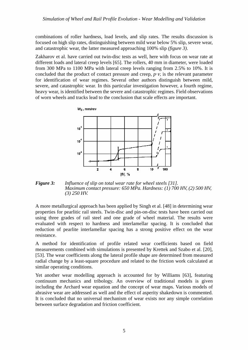
combinations of roller hardness, load levels, and slip rates. The results discussion isfocused on high slip rates, distinguishing between mild wear below 5% slip, severe wear,and catastrophic wear, the latter measured approaching 100% slip (figure 3).
Zakharov et al. have carried out twin-disc tests as well, here with focus on wear rate atdifferent loads and lateral creep levels [65]. The rollers, 40 mm in diameter, were loadedfrom 300 MPa to 1100 MPa with lateral creep levels ranging from 2.5% to 10%. It isconcluded that the product of contact pressure and creep, p·ν, is the relevant parameterfor identification of wear regimes. Several other authors distinguish between mild,severe, and catastrophic wear. In this particular investigation however, a fourth regime,heavy wear, is identified between the severe and catastrophic regimes. Field observationsof worn wheels and tracks lead to the conclusion that scale effects are important.
Figure 3: Influence of slip on total wear rate for wheel steels [31]. Maximum contact pressure: 650 MPa. Hardness: (1) 700 HV, (2) 500 HV, (3) 250 HV.
A more metallurgical approach has been applied by Singh et al. [48] in determining wearproperties for pearlitic rail steels. Twin-disc and pin-on-disc tests have been carried outusing three grades of rail steel and one grade of wheel material. The results wereevaluated with respect to hardness and interlamellar spacing. It is concluded thatreduction of pearlite interlamellar spacing has a strong positive effect on the wearresistance.
A method for identification of profile related wear coefficients based on fieldmeasurements combined with simulations is presented by Krettek and Szabo et al. [20],[53]. The wear coefficients along the lateral profile shape are determined from measuredradial change by a least-square procedure and related to the friction work calculated atsimilar operating conditions.
Yet another wear modelling approach is accounted for by Williams [63], featuringcontinuum mechanics and tribology. An overview of traditional models is givenincluding the Archard wear equation and the concept of wear maps. Various models ofabrasive wear are addressed as well and the effect of asperity shakedown is commented.It is concluded that no universal mechanism of wear exists nor any simple correlationbetween surface degradation and friction coefficient.
5

Section 2 - Wear Models
2.2 Lubrication
Lubrication of the wheel-rail contact is often deliberately applied, predominantly at thehigh rail in narrow curves, in order to reduce wear or noise. From a tribological point ofview, non-deliberate contamination and weather related moist might be considered aslubricants as well. Lubrication-related investigations often focus on efficient applicationof lubricants, properties of different lubricants, and the effect on wear and adhesion. Forthe purpose of wear prediction, however, the effect of non-deliberate contactenvironment modification is of importance as well.
Steele [52] and Reiff [43] report lubrication tests carried out on the Facility forAccelerated Service Testing (FAST) of the Association of American Railroads (AAR).
Steele has investigated the effect of lubrication of the high rail gauge face in curves. Aconsiderable reduction of wear rates measured as gauge face wear (GFW) has beeshown. In addition reduced head height loss (HHL) has been observed at both rails. Thebenefit is less pronounced for high-grade steel (figure 4).
Figure 4: Lubrication benefit ratio with respect to gauge face wear (GFW) and head-height loss (HHL) related to initial material hardness [52]. The lowermost curve for the inner rail.
Reiff has studied the efficiency of different lubricants and lubrication systems. In generalit is concluded that proper lubrication can be used both to control wear and reduce fuelconsumption (figure 5).
It is observed that the wear reduction is highly dependent on the efficiency of lubricantapplication as well as less pronounced for high-grade rail steel. Despite the typeapplication device, grease tends to migrate to the railhead reducing traction and causinglocomotive slip.
Waara [62] has been comparing the performance of environmental friendly lubricantswith that of traditional types as well as water lubricated and dry rail. It is concluded thatthe tested graphite-free environmental friendly lubricants can be used without increased
6

Simulation of Wheel and Rail Profile Evolution - Wear Modelling and Validation
risk for wear. Applied to field conditions in northern Sweden, it is assumed that thegauge face wear can be reduced 3 – 6 times by full year lubrication.
Figure 5: Effect of rail lubrication on fuel consumption, shown as engine throttle positions [43].
Nilsson reports extensive in-field follow-up of rail wear in narrow curves [35]. Bothlubricated and non-lubricated rails as well as seasonal variations have been investigated.The wear rates vary over the year probably due to changing weather conditions. Inparticular the precipitation correlates well with the wear rate for non-lubricated curves(figure 6).
Figure 6: Wear rate as function of average daily precipitation [35].
Track-side lubrication can reduce the rail wear substantially. The reported lubricationbenefit factors are approximately 9 for a 300 m curve and about 4 for the measured 600 -800 m curves. Lubrication is however effective only for a limited distance ahead of theapplication device.
7

Section 3 - Wheel-Rail Profile Evolution
Motivated by observed adhesion loss at increased speed, Ohayama undertook adhesionmeasurements under wet conditions [37]. The experiments were carried out with a large-sized rolling contact testing machine. The background was measured adhesioncoefficients for Shinkansen on wet rails, dropping significantly at high speed. The testresults were evaluated and compared to tribology based theoretical reasoning.
In a Dutch case study by Savkoor and van der Schoor [46], the effect of contaminants ontraction and braking has been investigated. A low viscosity contaminant standardised byUIC was used together with a test rig over a wide range of rolling speeds with slipranging from 0% to 80%. The results show a reduced traction coefficient at increasedspeed but also a transition to a significantly higher traction coefficient at high slip.Beyond the threshold, the traction force and the wear rate are significantly larger and thesurface becomes distinctly coarser. The threshold behaviour shows a hysteresis, possiblyan opening to design antiskid brake systems with the potential to boost traction whilekeeping the wear within acceptable limits.
3 WHEEL-RAIL PROFILE EVOLUTION
The focus of this review is prediction of profile development by numerical simulations.Chudzikiewicz has given a review of historical and current research from a tribologicalpoint of view [4]. An introduction to wear mechanisms applicable to rolling-slidingcontact is given followed by a summary of recent prediction models. The concept ofdifferent wear regimes, Archard’s wear equation, and the energy dissipation approach areaddressed. The different approaches are compared and it is concluded that a key issue isthe determination of wear coefficients.
The issue of specifying rail network and vehicle operations in general for a mixedservice is addressed by Szabó and Zobory [54]. The wheel profile evolves in interactionwith the actual rail profile which may show a wide range of worn shapes. The similarsituation is true for the rail profile evolution with respect to possible wheel profilesrunning on the track. In addition relevant combinations of both vehicle and track designparameters have to be considered. To structure this combinatorial problem a hierarchy ofprobabilities based on known statistics of the complete system is defined.
3.1 Prediction of profile evolution
Often profile measurements and monitoring of field conditions shape the basis for wearprediction, in particular for maintenance planning purposes. Such measurement data mayalso serve as validation of simulation models and determination of wear coefficients.
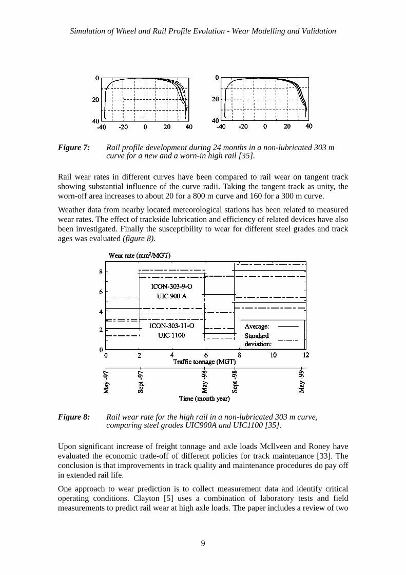
Extensive measurements of wheel and rail wear during a service period of three and ahalf years of the Stockholm commuter traffic have been reported by Nilsson [34], [35],[36] and Olofsson and Nilsson [38]. Profile wear, hardness, and geometry (figure 7) havebeen monitored and evaluated with respect to different conditions.
Two types of vehicles operate on this network, the older X1 electric multiple unit withstiff primary suspension and the more recent design X10 with softer suspension andbetter self-steering capability. Wheel wear has been measured on both types.
8
Simulation of Wheel and Rail Profile Evolution - Wear Modelling and Validation
Figure 7: Rail profile development during 24 months in a non-lubricated 303 m curve for a new and a worn-in high rail [35].
Rail wear rates in different curves have been compared to rail wear on tangent trackshowing substantial influence of the curve radii. Taking the tangent track as unity, theworn-off area increases to about 20 for a 800 m curve and 160 for a 300 m curve.
Weather data from nearby located meteorological stations has been related to measuredwear rates. The effect of trackside lubrication and efficiency of related devices have alsobeen investigated. Finally the susceptibility to wear for different steel grades and trackages was evaluated (figure 8).
Figure 8: Rail wear rate for the high rail in a non-lubricated 303 m curve, comparing steel grades UIC900A and UIC1100 [35].
Upon significant increase of freight tonnage and axle loads McIlveen and Roney haveevaluated the economic trade-off of different policies for track maintenance [33]. Theconclusion is that improvements in track quality and maintenance procedures do pay offin extended rail life.
One approach to wear prediction is to collect measurement data and identify criticaloperating conditions. Clayton [5] uses a combination of laboratory tests and fieldmeasurements to predict rail wear at high axle loads. The paper includes a review of two
9

Section 3 - Wheel-Rail Profile Evolution
decades of research in that direction and aims at validating laboratory test results againstfield measurements. In the field study wear properties of four different rail materialswere investigated in a 350 m curve. Similar conditions were created in the laboratory bytesting the same materials in a twin-disc machine. Reasonably good agreement betweenfield and laboratory results was achieved. In addition the wear rate was evaluated withrespect to material hardness and microstructure as well as contact pressure.
One conclusion is that existing general wear models are not suitable for practical use. Amore successful approach would be models with very restricted application to reduce theotherwise vast number of parameters. With respect to wear control parameters it isconcluded that the energy concept can only be useful for a given wear mechanism andfor specific materials.
Strategies to control wheel wear and understanding of the underlying control parametersare addressed by Fröhling [9]. The objective of the paper is to investigate practicalstrategies, based on experience and scientific analysis, to control and limit wheel profilewear due to dynamic wheel-rail interaction. Several wheel and rail sparing strategies arelisted. Simulations have been used to confirm the relevance of some of those actions interms of comparative wear distributions (figure 9).
Figure 9: Predicted wheel wear distributions [9]. S1: Influence of track layout, S2: Influence of primary suspension stiffness, S3: Influence of nominal track gauge, S4: Influence of curving speed.
Once the mathematical modelling of vehicle dynamics gained pace during the eighties,several attempts to simulate wear were initiated. Recent advances in contact mechanicsfacilitated some progress, reported in the early nineties.
Kalker presented a method [16] for simulation of wheel tread wear achieving reasonableresults with respect to measurements on metro operation. After an opening discussionabout contact modelling issues, the frictional work traversing one contact patch isformulated. The Fastsim algorithm is used to calculate the frictional work and
10

Simulation of Wheel and Rail Profile Evolution - Wear Modelling and Validation
corresponding wear for a number of wear steps. Instead of calculating each contactoccurrence it is possible to use the probability of the contact being at a certain lateral co-ordinate. The wear is assumed to be proportional to the frictional work and the rate ofwear was derived from field studies.
An early approach to simulate wheel profile evolution is presented by Pearce andSherratt [40]. The basis is repeated time domain simulations of one or more journeyswith profile updating in-between. The amount of wear is assumed to be proportional tothe dissipated energy in the contact zone, taken as product of creep force and creep ratio.The relationship varies depending on whether the wear is in the mild or severe wearregime or in the transition between them. The worn-off profile area is given a parabolicdistribution laterally across the contact patch. Simulated results have been compared tomeasurements in terms of development of equivalent conicity over running distance.
An investigation of the vehicle model sophistication required for wear calculations isreported by Liebig et al. [29]. The vehicle dynamic response used as input to the wearprediction was calculated by (i) a two-dimensional lateral model and (ii) a full three-dimensional model. The material removal was assumed to be proportional to thefrictional work. For the two-dimensional case the wear was rather evenly distributedover both tread and flange. For the three-dimensional cases, however, the tread wear wasdominating. It was concluded that improvements of the vehicle model are necessary tobe able to predict for instance life cycle costs.
An attempt to apply a non-iterative, non-elliptic contact model to wheel wear simulationis reported by Linder and Brauchli [30]. The shape of the contact area is taken as therigid body penetration area scaled down by a factor 0.55 – 0.65. The obtained contactpatch is subdivided into strips in the rolling direction and the contact quantities arecalculated still using Hertz’ theory for a substituting ellipse adapted to each individualstrip. The wear calculation procedure follows the concept of wear step, simulating acertain distance with constant profiles and then update. The wear coefficients are takenfrom literature and the wear is assumed to be proportional to the frictional power at thetwo levels mild oxide wear and severe metallic wear.
Wear calculation by combining complete contact theory and full scale testing is initiatedby Braghnin, Bruni, and Resta [3]. The approach is to evaluate the simulated vehicledynamic response with Kalker's code Contact [15] obtaining traction and slipdistributions over the contact area. The material removal by wear is assumed to beproportional to the frictional work. The wear rate was determined by tests carried out ona full-scale wheelset in a roller rig. Comparisons between calculated and measured wearcorresponding to a running distance of up to 10 Mm showed good agreement for thetread. The flange wear could not be captured by the calculations since the wearcoefficient was determined for the mild wear regime only.
Non-Hertzian multi-point and conformal contact models have been developed by Li[28]. Application to wear simulation is described by Li et al. [26], [27]. The wear volumeis assumed to be proportional to the frictional work. The selection of appropriate wearstep length as well as the influence of worn profiles on the dynamic response of thevehicle are briefly addressed.
A comprehensive description of a wear simulation approach covering the whole processfrom specification of operating conditions to material loss and profile updating is given
11

Section 3 - Wheel-Rail Profile Evolution
by Zobory [67]. The focus is on wheel and rail profile evolution while running onarbitrary networks and appropriate wear models, formulated in the framework ofstochastic processes. First some modelling and discretisation issues are addressed.Lumped mass vehicle models, discrete track and profile descriptions, track irregularityspectral density functions, and creep force laws are discussed. Further the wheel and railwear process is described in terms of contact occurrence frequency and debris mass flow.The contact frequency is proportional to the number of wheel revolutions or wheelpassages respectively and may be seen as stochastic realisation functions.
The material loss due to wear is again treated stochastically as a debris mass flowprocess. Since the vehicle dynamic response depends on the wheel-rail contact geometry,the profile evolution provides a very slow feed back to the system, offering thepossibility of discretisation by piece wise constant profiles. The value of the debris massflow is considered function of the energy dissipation in the contacts, distributed over thecontact area in proportion to the normal pressure. The wear coefficient is determinedempirically and takes different values for mild and severe wear as well as flange wear inpure sliding.
The application of this method to simulation of wheel and rail profile evolution isaddressed by Szabó and Zobory [57].
Figure 10: Flow chart of the proposed wheel profile prediction tool [14].
Vehicle-track interaction model
Track data:
Start wheel profiles
Load collective design
Vehicle-track simulations
wheel-rail contact response
Wear calculation
Profile updating
Desired distance attained?
Yes (finished)No (new wear step)
Wear model, wear data
design geometry
track irregularities rail profiles
Environmental parameters
Vehicle traffic conditions
Coefficient of friction
Braking and acceleration
12

Simulation of Wheel and Rail Profile Evolution - Wear Modelling and Validation
An extensive procedure for simulation of wheel profile evolution through wear has beendeveloped by Jendel [11], [12], [13], [14] (figure 10). The approach is to study a singlevehicle with a given initial wheel profile. A load collective is designed consisting of alimited set of dynamic time domain simulations representing the actual operatingconditions. In the load collective the network is primarily discretisized based on thecurve radius distribution. Other key parameters are rail profiles, track irregularities andwheel-rail coefficient of friction.
The vehicle-track interaction simulations are based on multibody models of the vehicleand track and, in particular, proper modelling of the wheel-rail contact. As output thesimulations give contact forces and motions at certain time instants. These quantities areinput to the wear modelling and calculations. The calculated wear distribution issmoothed and the wheel profile is updated according to the calculated material removal.
Since the actual wheel profile affects the contact response, the successive change ofwheel profile is discretisized into several wear steps, each starting with an updated wheelprofile.
The normal and tangential contact problems are solved with Hertz’ theory [10] andKalker’s simplified theory respectively. The numerical implementation Fastsim [17] byKalker is employed. The use of elliptical contact formulation is adequate for the treadcontact but may be questioned for the flange/gauge-corner contact. Since the wearcalculation, however, includes thousands of contact problems to be solved an averagingeffect will compensate for that deficiency and the advantage of fast execution can bemaintained.
Figure 11: Wear chart for wheel and rail steels. Dry, room tempered conditions [14].
0 0.1 0.2 0.3 0.4 0.5 0.6 0.7 0.8 0.9 10
0.5
1
1.5
2
2.5
3x 10
9
p (N/m2)
0.8H
vslip (m/s)
k1=300-400*10-4
k4=1-10*10-4k3=30-40*10-4
k2
=1-10*10-4
Flange contacts
Tread contacts
13

Section 3 - Wheel-Rail Profile Evolution
The wear modelling is based on Archard’s wear equation used together withexperimentally determined wear charts and the model is applied locally in each elementof discrete representation of the contact area.
The wear coefficient is generally a function of sliding velocity, contact pressure,temperature, contact environment etc. Laboratory tests have been performed using wheeland rail steels to determine the wear coefficient. To cover a wide range of slidingvelocities both twin-disc and pin-on-disc machines were used. The result was compiledin wear charts showing the wear coefficient as function of sliding velocity and contactpressure (figure 11).
The wheel wear simulation tool has been verified by comparing simulated wheel wear ona commuter vehicle operating the Stockholm commuter network (figure 12). Thenetwork comprises about 200 km track with many curves with radii in the range 300 –2000 m.
Figure 12: Simulated and measured wheel profile development after 200 Mm [14]. (a) Wheel profile (b) Wheel radius change.Solid line – simulation, dashed line – measurement, dash-dotted line – initial profile.
A further application, investigated by Dirks [6], is the Swedish high speed train servicebetween Stockholm and Göteborg. Simulations up to 350 Mm running distance havebeen performed. The results were compared to available wheel profile measurementswith some focus on scalar wear measurements (figure 13).
14

Simulation of Wheel and Rail Profile Evolution - Wear Modelling and Validation
Figure 13: Comparison between simulated and measured wheel wear [6].tf = flange thickness, hf = flange height, qr = flange slope, λe = equivalent conicity. Circles – measured wheel wear.
3.2 Profile design
Several attempts to modify standard wheel or rail profiles to adapt to certain operatingconditions and reduce wear and fatigue have been reported. Often the goals are singlepoint contact and increased conformity of profiles.
Leary et al. report a case study on development of a wear optimised wheel profile forfreight cars [24]. The intention was to design and evaluate a reasonable number ofcandidate profiles providing (i) reduced wheel and rail wear, (ii) increased derailmentsafety, (iii) stable running performance, and (iv) reasonable contact stresses. In additionthe chosen profile should be geometrically stable throughout its life. Two approacheswere used, one based on the average of measured worn wheels and the other based onexpansion of rail shapes to ensure single-point contact. The candidate profiles wereexperimentally evaluated with respect to rolling resistance, curving, and stabilitycharacteristics. The contact stresses were determined by calculations. The mostpromising candidate became the profile based on measured wheel shapes. This profilewas further refined, basically by reducing the equivalent conicity, and put into revenuewear test. The flange wear turned out to be about one third compared to the old 1:20conical profile.
Piotrowski et al. [42] have developed a modified wheel profile for low speed industriallocomotives. The aim was reduction of wear by ensuring one point contact. Wearsimulations were carried out using a non-Hertzian contact model by Kik and Piotrowski.
qr
tf hf
λe
15

Section 3 - Wheel-Rail Profile Evolution
Quasistatic curving was used including non-linear characteristics of axle box guidance,wheel loads, and traction or braking moments. The design criterion was the lateraldistribution of the frictional work over the profile. Field measurements on locomotiveswith the new profile showed an increase in operating period between reprofiling of about20%.
Yamada et al. report on wheel profile design to improve running stability whilemaintaining curving performance for vehicles running on worn narrow-gauge lines [64].The proposed profile is characterised by low conicity and good conformance at the treadand high conicity towards the flange. The new profile is used on commercial lines andthe interval of wheel turning is extended more than twice compared to the original 1:20conical profile.
Further experimentally based wheel profile improvements are reported by Sasaki et al.[44] and Krettek [19].
There are also proposals on how to adapt the rail profiles to the system requirements,mainly to reduce contact stresses and the likelihood of fatigue damage. Sato has studiedfatigue damage on Shinkansen lines and proposed a strategy for adapted rail grinding[45]. The profile pairing is unusual in that the rail head radius is as much as 600 mm andthe wheel tread a 1:40 cone. The proposed grinding pattern distinguishes betweentangent track, large radius curves and tight curves. Governing parameters are the contactposition and the lateral deformation of the rail. Practical experience or field test of thenew profiles are not reported.
Smallwood et al. [49] apply a different approach to reduce the problem of rail fatigue.The work is based on theoretical analysis aiming at the modification of the rail headgeometry to reduce contact stresses. An extended Hertzian theory has been usedallowing for other shapes of the contact. Flange contact has not been considered. As astarting point the contact stresses were evaluated for several measured worn profiles andthe lower stresses were found to be associated with a flattening of the rail head. The newgeometry was generated by optimising the radii in each of a chain of sections andcombine with the original gauge face geometry. The resulting profile, however, neededfurther modification to reduce grinding depth as well as equivalent conicity. Theproposed profile reduced the contact stress by up to 45% for curve radii above 1000 m.
Smith and Kalousek describe a design technique enabling wheel and rail profiles to bedeveloped having a limited range of conicity throughout their life, generate little noise,and greatly reduce corrugation [50]. When used on steered axle vehicles, together withthe described techniques of trade geometry control, the obtained profiles can be virtuallyself-perpetuating. Implementation of the designed rail profile requires grinding. Thesuccessful prototype testing indicates that there is a potential for system-specific wheel-rail profile design.
Zacharov and Zharov [66] propose a procedure for determination of optimal conformprofiles. The optimum profile pair is selected from a family of conform profiles relevantfor selected operating criteria and providing minimum mutual wear. Total flange/gauge-face wear is used as objective. The wear rate was determined by twin-disc testing usingnormal load and creep as parameters.
16

Simulation of Wheel and Rail Profile Evolution - Wear Modelling and Validation
3.3 Vehicle design
In the eighties, research on freight car running gear with focus on steering ability andwear has been reported. Schwier [47] accounts for a research project aiming at costcomparison of different running gear concepts. A cost estimation model was usedincluding fuel consumption, car maintenance, and track maintenance. With respect towheel and rail wear, radial steering is superior to stiff suspension designs. In general it isconcluded that steering running gears are economically justified only at high combinedlevels of annual utilisation and curvature.
Based on roller rig testing, Specht has developed a model for estimation of material lossthrough wear [51]. The worn-off mass is taken to be proportional to the frictional work inthe contact zone. Mild and severe wear is recognised. The transition between the tworegimes is determined by the frictional power. The material loss distribution over thewheel profile is determined by discretisation of the surface.
The method is applied to three freight car bogies (figure 14) being (i) the stiff suspensiondesign Y25, (ii), the DB steering design 665, and (iii) the South-African Scheffel design.The two latter designs are approximately comparable with respect to wear whereas thestiff design shows about 30 times higher material loss, disregarding the effect of treadbraking. A rough estimate indicates that this contribution is almost similar to the stiffbogie curving wear.
Figure 14: Comparison of material loss through creep and tread braking for three running gear designs [51].
Blokhin et al. [2] and Ushkalov et al. [61] are concerned by the trend towards increasedflange and gauge corner wear mainly in freight operations. Both research groups haveundertaken parameter studies with respect to frictional work or some wear index asfunction of running gear design parameters and geometrical tolerances. Ushkalov alsoincludes riding comfort in passenger services. Blokhin includes a semi-empiricalverification of the wear model while Ushkalov also develops an improved wheel profile
778 g
26 g 29 g
596 g 596 g 596 g
Y25 DB 665 SATS
Curving
Braking
17

Section 4 - Present Results in Summary
Szabó and Zobory have two contributions with relevance to vehicle design. The firstpaper [55] deals with maximising of the mileage performance of metro trains withrespect to wear. The second [56] is a more general study on wear simulation whenrunning on a specified network, including the significance of the axle-box guidancestiffness. In order to be able to perform an adequate investigation of the intended metrooperation, extensive pre-calculations were carried out to determine realistic wornprofiles. Firstly, a set of worn wheel profiles was calculated using a representative curvedistribution and nominal rail geometry. Secondly, worn rail profiles were generated usingthe obtained wheel profiles. Finally the wheel profile evolution could be calculated forthree metro vehicles under relevant operating conditions and with nominal running gearparameters. Mileage sensitivities with respect to longitudinal and lateral axle-boxguiding stiffness rates for three selected critical wear measures were calculated. Inaddition mileage performance of two different initial profiles were compared withrespect to flange thickness development.
In the second referenced paper [56] the aim is to formulate a formal optimisationproblem including the stochastic nature of the operating conditions. When the railwayoperation is considered as a stochastic process, the mileage performance also becomes astochastic field defined on the axle-box guidance stiffness parameters. The mileageobjective function to be maximised then becomes the expected value function of thatfield.
4 PRESENT RESULTS IN SUMMARY
Recalling the objective of the wear simulation research at the Royal Institute ofTechnology (KTH), the recent results are summarised. Future directions are indicated inthe next section.
The major goals are:
• Quantitative prediction of wheel and rail profile evolution with sufficient accuracy for use in vehicle dynamics simulations.
• Application of state-of-the-art models for both vehicle dynamics simulation and wear calculation and their interaction.
• Proposed system improvements for optimised wear performance without jeopard-izing other performance requirements.
The methods applied to achieve those goals are:
• Systematic selection of operational conditions.
• Numerical simulation of vehicle-track interaction.
• Relevant wear models.
• Validation through measurements.
18

Simulation of Wheel and Rail Profile Evolution - Wear Modelling and Validation
The following three subsections are devoted to the new achievements in terms of contactmodelling, improved wheel wear simulation, and rail profile evolution.
4.1 Contact modelling
The wear model employed relies on relative sliding velocities for determination of wearcoefficients. In Paper A it is shown that the influence of the tangential elasticdeformation of the contacting surfaces may not be neglected, in particular under partialslip conditions. Further, equations for calculation of relative sliding velocities fromquantities available in Fastsim are derived and implemented in the wear calculation step:
(1)
where
vi = sliding velocity component; i=x, y.vr = running speed.pi = tangential stress component; i=x, y.Lj = tangential flexibility parameters; j=x, y, φ.k = integration step index.x, y = contact patch co-ordinates; origin at the centre.
Figure 15: Radial wheel wear distribution considering tangential surface flexibility, friction 0.30, natural lubrication. Wheel flange towards positive lateral co-ordinate.(a) Tangent track, (b) Radius 1500 m.Bold line - elastic contribution to sliding velocity included, thin line - not included.
vxk( )
x y,( )vr
dx------ Lx px
k( )x y,( ) 1
1
qk( )
x y,( )----------------------–
⋅ ⋅ ⋅–=
vyk( )
x y,( )vr
dx------ Ly py
k( )x y,( ) 1
1
qk( )
x y,( )----------------------–
⋅ ⋅ ⋅–=
0.00
0.01
0.02(a)
−40 −20 0 20 400.00
0.05
0.10
0.15
Lateral profile co−ordinate [mm]
Wea
r de
pth
[mm
] (b)
19

Section 4 - Present Results in Summary
The influence on the wear distribution is demonstrated by examples (figure 15). A totalrunning distance of 6000 km is chosen in order to accommodate a few profile updatesalthough each case simulates a single curving situation only. The track is modelled assymmetric with respect to left and right curves with the consequence that both wheels ina wheelset experience the same wear. Results are shown for the leading axle.
The model has been applied to the Stockholm commuter service simulation accountedfor in Paper B together with the other model improvements. Taking the surface elasticityinto consideration has been shown to improve the accuracy of tread wear prediction.
4.2 Improved wheel wear simulation
In Paper A also the issue of braking simulation is addressed with the aim to replace thethe previously applied empirical scaling. Creep and creep forces due to braking arecalculated by dynamic simulation of the complete vehicle. The retardation moment issmoothly applied to all axles, representative for disc brake operation. Tread braking isnot considered. Example wear distributions over the wheel profile are calculated fortangent track (figure 16) as well as curves with radii 1500 m and 600 m. The runningdistance is 6000 km and comparison is made to the case of constant running at the initialspeed 120 km/h. Coefficient of friction and lubrication conditions are varied as well.
Figure 16: Radial wheel wear distribution on tangent track. Sliding velocity due to rigid creep only. (a) Friction 0.15, natural lubrication, (b) Friction 0.30, natural lubrication, (c) Friction 0.60, dry.Bold line - braking, thin line - no braking.
0.00
0.02
0.04
(a)
0.00
0.02
Wea
r de
pth
[mm
]
(b)
−40 −20 0 20 400.00
0.02
Lateral profile co−ordinate [mm]
(c)
20

Simulation of Wheel and Rail Profile Evolution - Wear Modelling and Validation
For wheel wear simulation the simulation set has been extended by the quantities relatedto traction and braking simulation.
In the initial version, the following parameters define the simulation set:
• Curve radius type class, including transition curves and cant.
• Vehicle speed, if applicable related to the appropriate cant deficiency.
• Selection of rail counterpart profiles.
• Coefficient of friction.
• Specified or randomly selected track irregularities.
Inclusion of braking simulation divides those cases where speed changes occur in two.The additional parameters are:
• Amount of retardation for each relevant curve class.
• Fraction of the curve class length where braking occurs.
The application of the extended simulation set to the Stockholm commuter operation isaccounted for in Paper B.
The service braking of the X10 commuter vehicle is investigated by performancesimulation assuming a retardation rate of 0.8 m/s2. Vehicle acceleration and speed arevisualized over the curve distribution to determine at which radii braking occurs (figure17).
Figure 17: Vehicle operation example. Portion close to Stockholm C of the Märsta – Södertälje line. From top: Acceleration [m/s2], speed [km/h] (thin line = speed limit), curve radius [m].
−1
0
1
Acc
[m
/s2 ]
Märsta − Södertälje
0
50
100
150
Spee
d [k
m/h
]
Solna Karlberg Stockholm C
30 31 32 33 34 35 36 37 0
1000
2000
3000
Position [km]
|Rad
ius|
[m
]
21

Section 4 - Present Results in Summary
The simulation results are compared to measurements after 200 000 km running distance(figure 18). Surface elasticity as well as braking simulations are included and goodagreement with the measurements is achieved. A selection of four different wheels areshown to demonstrate typical scatter in the measurements.
Figure 18: Results with extended simulation set compared to measured profiles. 200 000 km running distance. Surface elasticity included. Outer axles 5 and 8 and inner axles 6 and 7.
Figure 19: Results with extended simulation set compared to measured profiles. 200 000 km running distance. Updated wear map. Surface elasticity included. Outer axles 5 and 8 and inner axles 6 and 7.
−40 −20 0 20 400
2
4
6
8
10
Lateral profile co−ordinate
Rad
ial w
ear
dept
h [m
m]
Axles 5 and 8
Wheel 5LWheel 8LWheel 5RWheel 8RSimulation
−40 −20 0 20 400
2
4
6
8
10
Lateral profile co−ordinate
Axles 6 and 7
Wheel 6LWheel 7LWheel 6RWheel 7RSimulation
−40 −20 0 20 400
2
4
6
8
10
Lateral profile co−ordinate
Rad
ial w
ear
dept
h [m
m]
Axles 5 and 8
Wheel 5LWheel 8LWheel 5RWheel 8RSimulation
−40 −20 0 20 400
2
4
6
8
10
Lateral profile co−ordinate
Axles 6 and 7
Wheel 6LWheel 7LWheel 6RWheel 7RSimulation
22

Simulation of Wheel and Rail Profile Evolution - Wear Modelling and Validation
The final topic in both Paper A and Paper B is the striving to improve the description ofthe wear coefficients and compile them into wear maps for dry contact, environmentalinfluence, and lubricated conditions. Based on recent pin-on-disc test results a simulationwith an updated wear map for natural lubrication combined with some further downscaling for deliberately lubricated curves has been carried out (figure 19).
Very good agreement between simulation and measurement is achieved for the treadwear while the flange wear is somewhat underestimated. The generality of thesimulations is however improved since the wear map for natural lubrication is based onlaboratory tests and the lubrication factor on field measurements. No attempt to tune themodel to the specific application has been made.
4.3 Rail profile evolution
It is of interest to apply the wear simulation procedure to rail profile evolution as well. InPaper C a structure for a corresponding simulation process is outlined and sometentative calculations reported. The basic building blocks are the same as for wheel wearsimulation, namely simulation set, dynamic analysis of the track-vehicle interaction,wear depth calculation and profile updating.
In this case, however, each application focus on a particular location along the track,typically a circular curve loaded by a selection of different vehicles. The governingparameters are thus axle passages and accumulated traffic load. The appropriatesimulation set addresses variations in vehicle design, operating conditions, and contactenvironment. The rail wear simulation set is defined by the following parameters:
• Selection of vehicles to be simulated with corresponding occurrence probability.
• Vehicle speed and braking effort if applicable.
• Selection of wheel counterpart profiles.
• Coefficients of friction.
• Appropriate wear map selection.
• Scaling of Kalker coefficients.
• Specified or randomly selected track irregularities.
A fundamental difference between rail wear simulation and the corresponding wheelwear calculations relates to the variety of contact conditions. A vehicle traversing a largenetwork experiences a wide range of curving conditions, track alignment variations, andfriction levels. This has an averaging effect on the wear distribution and makes theprocedure less sensitive to occasionally poor contact conditions, which is not the case forthe rail. Despite possible problems due to poor contact modelling at the gauge corner, thesame methods as used for wheel wear calculation are applied as a starting point. Thetentative simulations (figure 20) generally shows higher wear rates than available fieldmeasurements.
It is concluded that a larger simulation set accounting for variations in friction andenvironmental conditions would improve results. Furthermore the limited applicabilityof traditional elliptic contact modelling calls for improved methods able to handle theactual profile geometry and non-elliptic contact patch shape. Finally continued
23

Section 5 - Future Research Directions
development of wear maps directing wear coefficients relevant to the actual wearmechanisms, transitions, and influence by environmental factors seems to be adequate.
Figure 20: Vertical wear distribution at selected non-lubricated curves of different radii. Note the different vertical scales.
5 FUTURE RESEARCH DIRECTIONS
The final goal of this research field at KTH is to provide tools able to contribute to theimprovement of the rail-vehicle system performance. In engineering work a useful toolshould provide functionality for both fast investigation of simple models and aid to carryout complete simulations with adequate accuracy. The existing procedure is proposed tobe amended in both directions.
For tentative investigations the inclusion of quasi-static curving analysis, scalar wearmeasures, and comparisons with frictional work related quantities may be useful.
In optimising any system, it is of outmost importance with a relevant and realisticformulation of the objective and governing constraints. The ultimate goal of wear relatedsystem optimisation is to reduce maintenance and increase the operative life of wheelsand rails. This by necessity also includes other deterioration mechanisms than profilerelated wear. A reasonable approach to a wear optimisation objective would be tominimise the wear depth in combination with evening out the wear distribution acrossthe profile and consider the possible trade-off between wear and surface fatigue.
The principal parameters influencing these quantities are thought to be wheel suspensioncharacteristics, wheel and rail profiles, and track stiffness properties. Furthermore thematerial properties and the presence of lubrication affect the results. Varying thoseparameters should allow for controlling the degree of profile conformity, curvenegotiation capability, and wear distribution. Constraints to comply with are at least thetraditional dynamic performance requirements being derailment safety, track forces,running stability, wheel unloading, and ride comfort.
−20 0 20 400.0
2.0
4.0
6.0
8.0
10.
Lateral profile co−ordinate
Ver
tica
l wea
r de
pth
[mm
]
Left (high) rail
R303R611R685R802
−20 0 20 400.0
0.2
0.4
0.6
0.8
1.0
Lateral profile co−ordinate
Right (low) rail
24

Simulation of Wheel and Rail Profile Evolution - Wear Modelling and Validation
With an adequate formulation along these lines it should be possible to apply numericalmethods for optimisation and sensitivity analysis.
5.1 Contact model
Further development of the flange / gauge corner contact model is desirable, in particularfor application to rail wear simulation in rather tight curves. Potential improvements arefor instance non-elliptic contact and refined tangential stress distribution. Yet a largerstep would be to include material plasticity by modelling strain hardening and materialflow. Methods for including the plastic behaviour of the surfaces are however lessmature and are suggested to be developed on a longer term basis. Inclusion of moresophisticated contact models may also make the computational effort a critical issue.
A reasonable alternative seems to be to replace Kalker’s simplified theory, realised bythe Fastsim implementation, by a novel semi-Winkler model [58], [59] able to handlenon-elliptical contact and coupled normal and tangential problems. This model may alsoserve as a basis for inclusion of material plasticity.
A more simple approach to handle non-elliptic contact is the procedure proposed byLinder and Brauchli [30] relying on a set of equivalent contact ellipses.
Tread braking is not at all considered in the current research although it is important forwheel wear in certain operations. To include this would however add a new wearmechanism entirely different from the wheel-rail contact, opening a new research area.
5.2 Contact environment
The basic tribology and contact mechanics research is carried out in parallel activities atthe Machine Element division at KTH [25], [39], [60]. Extended contact modelling in thewear prediction will rely on these results.
Tests are being carried out to determine wear rates and regime transitions for a variety ofcontact conditions. It is proposed to use these results to formulate wear maps for the typeconditions (i) dry contact, (ii) naturally lubricated (moist) contact, and (iii) deliberatelylubricated contact. Adopting this approach may improve the model consistency in thefollowing respects:
• Refined wear maps directing wear coefficients relevant to the actual wear mecha-nisms, transitions, and influence by environmental factors.
• Weighted selection of wear maps with respect to anticipated weather conditions and lubrication efficiency.
• Consistent set of wear map, coefficient of friction, and creep - creep force slope parameter.
5.3 Simulation set and validation
The selection of an adequate simulation set is a crucial interface between user andsoftware and may be made more efficient by using formal numerical methods. Instead ofrelying on a series of manual parameter studies the simulation set is suggested to bedefined by using design of experiments methodology. The selected parameter space
25

Section 6 - References
would be explored in a systematic way and as a spin-off sensitivities and coupling effectscan be calculated.
It is believed that the results may be improved by using a somewhat larger simulation setaccounting for additional variations in friction and environmental conditions. Bothseasonal variations and differences between tread and flange could be taken intoconsideration.
For general purpose vehicles or track being used by a variety of different vehicles, it maybe of advantage to select the likely operation by stochastic models as developed by TUBudapest [57].
The reliability of the wheel wear simulation facility should be further verified byapplication to other kinds of services and compared to related measurements. Recentlythe method has been successfully applied to the Swedish X2000 high speed trainoperation [6]. In that work some extended output has been generated related to scalarwear measures and single simulation contributions.
It is proposed to also simulate the Stockholm tram operation (Tvärbanan), where wheeland rail profile measurements are being carried out by Stockholm Transport (SL).Together with existing results the scope of validation would then cover the whole rangefrom light rail over commuter service to high speed intercity operation. Application tofreight traffic is more difficult since most fright cars are equipped with tread brakes. Apossible application would thus be high speed light freight, as for instance post service,where disc braked cars are being used.
To validate the proposed rail profile evolution simulation procedure the extensivemeasurements available from the Älvsjö area in the Stockholm commuter networkprovide a valuable reference.
6 REFERENCES
[1] Archard J F: Contact and Rubbing of Flat Surfaces. Journal of Applied Physics, Vol 24, pp 981-988, 1953.
[2] Blokhin E P, Psinko O M, Danovich V D, Korotenko M L: Effect of the State of Car Running Gears and Railway Track on Wheel and Rail Wear. 4th International Conference on Railway Bogies and Running Gears, Budapest 21-23 Sept 1998.
[3] Bragnin F, Bruni S, Resta F: Wear of Railway Wheel Profiles: A Comparison Between Experimental Results and a Mathematical Model. 17th IAVSD Symposium, Copenhagen 20-24 August 2001.
[4] Chudzikiewicz A: Modelling of Wheel and Rail Wear. The Archives of Transport, Vol 13 No 2, Polish Academy of Sciences, Warsaw 2001.
26

Simulation of Wheel and Rail Profile Evolution - Wear Modelling and Validation
[5] Clayton P: Predicting the Wear of Rails on Curves from Laboratory Data. Wear, Vol 181-183, 1995, Elsevier.
[6] Dirks B: Vehicle Dynamics Simulation of Wheel Wear for Swedish High-Speed Train X2000. TRITA AVE 2003:16, M.Sc. Thesis, Division of Railway Technology, Department of Aeronautical and Vehicle Engineering, Royal Institute of Technology (KTH), Stockholm, 2003.
[7] Enblom R, Berg M: Simulation of Wheel Profile Development Due to Wear - Influence of Disc Braking and Contact Environment. 6th International Conference on Contact Mechanics and Wear of Rail/Wheel Systems, Göteborg 10-13 June 2003.
[8] Enblom R: Prediction of Wheel and Rail Wear - A Literature Survey. TRITA - AVE Report 2003:27, Division of Railway Technology, Department of Aeronautical and Vehicle Engineering, Royal Institute of Technology (KTH), Stockholm 2003.
[9] Fröhling R: Strategies to Control Wheel Profile Wear. 17th IAVSD Symposium, Copenhagen 20-24 August 2001.
[10] Hertz H: Über die Berührung zweier fester, elastischer Körper. Journal für die reine und angewandte Mathematik, Vol 92, 1882.
[11] Jendel T: Prediction of Wheel and Rail Wear - A Pilot Study. TRITA - FKT Report 1999:03, Division of Railway Technology, Department of Vehicle Engineering, Royal Institute of Technology (KTH), Stockholm 1999.
[12] Jendel T: Prediction of Wheel Profile Wear - Methodology and Verification. TRITA - FKT Report 2000:49, Licentiate Thesis, Division of Railway Technology, Department of Vehicle Engineering, Royal Institute of Technology (KTH), Stockholm 2000.
[13] Jendel T, Berg M: Prediction of Wheel Profile Wear - Methodology and Verification. 17th IAVSD Symposium, Copenhagen 20-24 August 2001.
[14] Jendel T: Prediction of Wheel Profile Wear - Comparisons with Field Measurements. Wear, Vol 253, 2002, Elsevier.
[15] Kalker J J: Numerical Calculation of the Elastic Field in a Half-Space. Communications in Applied Numerical Methods, Vol 2, 1986. John Wiley & Sons.
[16] Kalker J J: Simulation of the Development of a Railway Wheel Profile Through Wear. Wear, Vol 150, 1991, Elsevier.
27

Section 6 - References
[17] Kalker J J: Rolling Contact Phenomena - Linear Elasticity. In: CISM International Centre for Mechanical Sciences, Vol 411. Springer, New York, 2001, ISBN: 3-211-83332-3
[18] Kimura Y: Wear and Fatigue in Rolling Contact. 5th International Conference on Contact Mechanics and Wear of Rail/Wheel Systems, Tokyo 25-28 July 2000.
[19] Krettek O: About the Influence of the Wheel-Profile of Self-Steering Wheel-Sets on the Amount of Wear. 2nd Mini Conference on Contact Mechanics and Wear of Rail/Wheel Systems, Budapest 29-31 July 1996.
[20] Krettek O, Szabó A, Békefi E, Zobory I: On Identification of Wear Coefficient Used in the Dissipated Energy Based Wear Hypothesis. The 2nd Mini Conference on Contact Mechanics and Wear of Rail/Wheel Systems, Budapest 29-31 July 1996.
[21] Kumar S, Krishnamoorthy P K, Prasanna Rao D L: Influence of Car Tonnage and Wheel Adhesion on Rail and Wheel Wear: A Laboratory Study. Journal of Engineering for Industry, ASME Winter Annual Meeting, Miami 17-21 November 1985.
[22] Kumar S, Prasanna Rao D L: Wheel-Rail Contact Wear, Work and Lateral Force for Zero Angle of Attack - A Laboratory Study. Journal of Dynamic Systems, Measurement and Control, Vol 106, December 1984, Transactions of the ASME.
[23] Kumar S, Rajkumar B R: Laboratory Investigation of Wheel Rail Contact Stresses for U.S. Freight Cars. Journal of Engineering for Industry, Vol 103, May 1981, Transactions of the ASME.
[24] Leary J F, Handal S N, Rajkumar B: Development of Freight Car Wheel Profiles - A Case Study. Wear, Vol 144, 1991, Elsevier.
[25] Lewis R, Olofsson U: Mapping Rail Wear Transitions. 6th International Conference on Contact Mechanics and Wear of Rail/Wheel Systems, Göteborg 10-13 June 2003.
[26] Li Z, Kalker J J: Simulation of Severe Wheel-Rail Wear. Computers in Railways VI, pp 393-402, 1998, WIT Press.
[27] Li Z, Kalker J J, Wiersma P K, Snijders E R: Non-Hertzian Wheel-Rail Wear Simulation in Vehicle Dynamical Systems. 4th International Conference on Railway Bogies and Running Gears, Budapest 21-23 Sept 1998.
[28] Li Z: Wheel-Rail Rolling Contact and Its Application to Wear Simulation. Ph.D. Thesis, Technical University Delft, 2002, Delft University Press.
28
Simulation of Wheel and Rail Profile Evolution - Wear Modelling and Validation
[29] Liebig S, Kiss Z, Quarz V: Prediction of Wheel-Wear by Means of Multibody System Simulation. 7th Mini Conference on Vehicle System Dynamics, Identification and Anomalies, Budapest 6-8 Nov 2000.
[30] Linder C, Brauchli H: Prediction of Wheel Wear. 2nd Mini Conference on Contact Mechanics and Wear of Rail/Wheel Systems, Budapest 29-31 July 1996.
[31] Markov D: Laboratory Tests for Wear of Rail and Wheels Steels. Wear, Vol 181-183, 1995, Elsevier.
[32] McEven I J, Harvey R F: Full-Scale Wheel-on-Rail Wear Testing: Comparisons with Service Wear and a Developing Theoretical Predictive Method. Lubrication Engineering, Journal of the American Society of Lubrication Engineers, Vol 41, February 1985.
[33] McIlveen E R, Roney M D: Economic Trade-offs of Rail Wear Reduction at CP Rail. The Economics and Performance of Freight Car Trucks, Montreal 25-27 Oct 1983.
[34] Nilsson R: Wheel and Rail Wear - Measured Profile and Hardness Changes During 2.5 Years for Stockholm Commuter Traffic. Railway Engineering, London 5-6 July 2000.
[35] Nilsson R: Rail Wear Development - Measurements and Evaluation. TRITA - FKT Report 2002:22, Division of Railway Technology, Department of Vehicle Engineering, Royal Institute of Technology (KTH), Stockholm 2002.
[36] Nilsson R: Wheel/Rail Wear and Surface Cracks. TRITA - MMK Report 2003:03, Licentiate Thesis, Department of Machine Design, Royal Institute of Technology (KTH), Stockholm 2003.
[37] Ohyama T: Tribological Studies on Adhesion Phenomena Between Wheel and Rail at High Speeds. Wear, Vol 144, 1991, Elsevier.
[38] Olofsson U, Nilsson R: Initial wear of a commuter train track. NORDTRIB'98, 8th International Conference on Tribology, Aarhus 8-10 June 1998.
[39] Olofsson U, Telliskivi T: Wear, Plastic Deformation and Friction of Two Rail Steels - A Full-Scale Test and a Laboratory Study. Wear, vol 254 (2003), pp 80-93.
[40] Pearce T G, Sherratt N D: Prediction of Wheel Profile Wear. Wear, Vol 144, 1991, Elsevier.
[41] Persson B N J, Bucher F, Chiaia: Elastic Contact Between Randomly Rough Surfaces: Comparison of Theory with (Exact) Numerical Results. Physical Review B, Vol 65, 184106, 2002.
29

Section 6 - References
[42] Piotrowski J, Chudzikiewicz, Nowakoski Z: Modification of Locomotive’s Wheel Profile Working in Industry Transport Conditions. 4th International Conference on Railway Bogies and Running Gears, Budapest 21-23 Sept 1998.
[43] Reiff R P: Rail/Wheel Lubrication Studies at FAST. Lubrication Engineering, Vol 42/6, June 1986, American Society of Lubrication Engineers.
[44] Sasaki K, Kageyama T, Asano K, Okumura M: Development of the Wheel Tread Profile for Commuter Train. 5th International Conference on Contact Mechanics and Wear of Rail/Wheel Systems, Tokyo 25-28 July 2000.
[45] Sato Y: Design of Rail Head Profiles with Full Use of Grinding. Wear, Vol 144, 1991, Elsevier.
[46] Savkoor A R, van der Schoor G H: Slip - Time History Influences on the Interaction Between Friction and Wear in Contaminated Rolling Contacts of Wheel-Rail Systems. Wear, Vol 162-164, 1993, Elsevier.
[47] Schwier C: The Economics of Steerable Trucks: Applicability of the Truck Design Optimisation Program to the Canadian Situation.The Economics and Performance of Freight Car Trucks, Montreal October 25-27 1983.
[48] Singh U P, Singh R K, Mangal R K: Investigation of Wheel and Rail Wear under Conditions of Sliding and Rolling - Sliding Contact. 10th International Wheelset Congress, Sydney 27 September-1 October 1992
[49] Smallwood R, Sinclair J C, Sawley K J: An Optimisation Technique to Minimise Rail Contact Stresses. Wear, Vol 144, 1991, Elsevier.
[50] Smith R E, Kalousek J: A Design Methodology for Wheel and Rail Profiles for Use on Steered Railway Vehicles. Wear, Vol 144, 1991, Elsevier.
[51] Specht W: Neue Erkentnisse über das Verschleissverhalten von Güterwagendrehgestellen. ZEV - Glasers Annalen, Vol 111, 1987, Georg Siemens Verlagsbuchhandlung.
[52] Steele R K: Rail Lubrication: The Relationship of Wear and Fatigue. Transportation Research Record 1042, 1985.
[53] Szabó A, Krettek O, Zobory I, Kiss Z: Identification of the Wheel-Profile Wear-Coefficients in the Framework of the Simplified-Combined Wear Hypothesis. 4th International Conference on Railway Bogies and Running Gears, Budapest 21-23 Sept 1998.
[54] Szabó A, Zobory I: Wheel-profile Wear Simulation in Case of Operation on a Specified Railway Network. European Railway Review, Issue 4, 2003, Russell Publishing.
30

Simulation of Wheel and Rail Profile Evolution - Wear Modelling and Validation
[55] Szabó A, Zobory I: On Simulation of Wheel/Rail Wear in Metro Operation. 7th Mini Conference on Vehicle System Dynamics, Identification and Anomalies, Budapest 6-8 Nov 2000.
[56] Szabó A, Zobory I: On Stochastic Simulation of the Wheel-Profile Wear Process of a Railway Vehicle Operating on a Specified Network. Periodica Polytechnica, Transportation Engineering, Vol 23, Technical University Budapest, 1995.
[57] Szabó A, Zobory I: On Deterministic and Stochastic Simulation of Wheel and Rail Profile Wear Process. Periodica Polytechnica, Transportation Engineering, Vol 26, Technical University Budapest, 1998.
[58] Telliskivi T, Olofsson U: Wheel-Rail Wear Simulation. 6th International Conference on Contact Mechanics and Wear of Rail/Wheel Systems, Göteborg 10-13 June 2003.
[59] Telliskivi T: Simulation of Wear in A Rolling-Sliding Contact by a Semi-Winkler Model and the Archard Wear Law. To appear in Wear, Elsevier, 2004.
[60] Telliskivi T: Wheel-Rail Interaction Analysis. TRITA - MMK Report 2003:21, Ph.D. Thesis, Department of Machine Design, Royal Institute of Technology (KTH), Stockholm 2003.
[61] Ushkalov V, Mokriy T, Shevtsov I: On Effect of Bogie Construction on Dynamic Performance of Railway Vehicles and Their Wheel Wear. 4th International Conference on Railway Bogies and Running Gears, Budapest 21-23 Sept 1998.
[62] Waara P: Nötning och friktionsegenskaper för biologiskt nedbrytbara smörjmedel (Wear and friction properties for biologically dissolvable lubricants). Summary paper, Luleå University of Technology, Sweden, 1999.
[63] Williams J A: Wear Modelling: Analytical, Computational and Mapping: A Continuum Mechanics Approach. Wear, Vol 225-229, 1999, Elsevier.
[64] Yamada K, Hayashi T, Nakata M, Isa M: New Profiled Tread Design Method and It’s Applied Tread Named “CS Tread”. 5th International Conference on Contact Mechanics and Wear of Rail/Wheel Systems, Tokyo 25-28 July 2000.
[65] Zakharov S, Komarovsky I, Zharov I: Wheel Flange / Rail Head Wear Simulation. Wear, Vol 215, 1998, Elsevier.
[66] Zakharov S M, Zharov I A: Simulation of Mutual Wheel/Rail Wear. 5th International Conference on Contact Mechanics and Wear of Rail/Wheel Systems, Tokyo 25-28 July 2000.
[67] Zobory, I: Prediction of Wheel/Rail Profile Wear. Vehicle System Dynamics, Vol 28, 1997, Swets and Zeitlinger.
31

Section 6 - References
32