Simulation of Void Fraction Profile Evolution in Subcooled Nucleate Boiling in a Vertical Annulus...
10
Simulation of Void Fraction Profile Evolution in Subcooled Nucleate Boiling in a Vertical Annulus with a Bubble-Tracking Model Ivo Kljenak * , Borut Mavko Reactor Engineering Div ision, Jozef Stefan Institute, Jamova 39, Ljubljana, Slovenia, * [email protected] Abstract A three-dimensional bubble-tracking model of subcooled nucleate boiling flow in a vertical channel at low-pressure conditions is proposed, with specific application to the case of boiling in an annulus with a central heating rod. In the model, vapour is distributed in the liquid in the form of individually tracked bubbles. The overall behaviour of the liquid-vapour system results from motion, interaction, coalescence and boiling mechanisms prescribed mostly at the level of bubbles. The wall heat transfer coefficient and the wall temperature are calculated from one-dimensional correlations. The partitioning of the heat flux, which is consumed for bubble nucleation and heating of the liquid, varies along the flow and depends on bubble size as well as on local flow conditions. Bubbles are nucleated with constant frequencies at fixed nucleation sites randomly distributed over the heated surface. Liquid temperature profiles at different axial locations are determined from steady-state energy balances. The nucleation site density is determined from a balance between vapour generation rate, bubble departure sizes and nucleation frequencies. After nucleation, bubbles slide on the heated surface, detach and then gradually migrate into the low-temperature region away from the heated surface, where they eventually condense. Both bubble detachment and migration are modelled probabilistically. Bubble lateral migration is restricted by the lift force due to the liquid velocity gradient. The proposed model was applied to experiments on subcooled boiling that were carried out at Purdue University (USA) by Bartel [1]. A good agreement between measured and calculated void fraction profiles at different axial locations was obtained. Introduction In the subcooled part of upward nucleate boiling flow in a vertical channel with a heated wall, the temperature near the wall and the bulk fluid temperature are respectively higher and lower than the saturation temperature. Subcooled boiling is thus characterized by a "higher-temperature" two-phase region near the heated surface and a "lower-temperature" single-phase liquid region away from the heated surface. The evolution of void fraction in subcooled boiling flow may be modelled using various approaches with different time and length scales. One-dimensional two- fluid models with various degrees of empiricism may predict fairly well the void fraction, averaged over the channel cross-section (Hari and Hassan [2], Konar and Mavko [3]). On the other hand, models based on local instantaneous description of the flow are at present still computationally too demanding to be applied to boiling systems which may have a complex interface structure due to the presence of up to several thousand bubbles. "Intermediate-level" models, which may be applied to nucleate boiling flows, include multidimensional two- fluid models, based on ensemble and volume averaging of local instant conservation equations (Kurul and Podowski [4], Janssens-Maenhout et al. [5], Kon ar et al. [6], Lee et al. [7]), and so-called bubble-tracking models, in which gas is distributed in the liquid in the form of individually-tracked bubbles (Mortensen and Trapp [8]). Among experimental results on subcooled boiling in channels, not many authors have measured the non- homogeneous radial distributions of two-phase flow parameters, such as void fraction and bubble size. Recently, these kinds of experiments have been carried out by Bartel [1] and Lee et al. [7]. In the present work, a three-dimensional bubble- tracking model of subcooled nucleate boiling flow in a vertical channel is presented. The behaviour of the bubble Strojniški vestnik - Journal of Mechanical Engineering 51(2005)7-8 , 436-444 UDK - UDC 536.2 Izvirni znanstven i lanek - Original scientific paper (1.01) 436
-
Upload
faisal58650 -
Category
Documents
-
view
222 -
download
0
Transcript of Simulation of Void Fraction Profile Evolution in Subcooled Nucleate Boiling in a Vertical Annulus...
8/11/2019 Simulation of Void Fraction Profile Evolution in Subcooled Nucleate Boiling in a Vertical Annulus With Bubble-trackin…
http://slidepdf.com/reader/full/simulation-of-void-fraction-profile-evolution-in-subcooled-nucleate-boiling 1/9
Simulation of Void Fraction Profile Evolution in Subcooled Nucleate Boiling in a
Vertical Annulus with a Bubble-Tracking Model
Ivo Kljenak *, Borut Mavko
Reactor Engineering Division, Jozef Stefan Institute, Jamova 39, Ljubljana, Slovenia,* [email protected]
Abstract
A three-dimensional bubble-tracking model of subcooled nucleate boiling flow in a vertical channel at low-pressureconditions is proposed, with specific application to the case of boiling in an annulus with a central heating rod. In themodel, vapour is distributed in the liquid in the form of individually tracked bubbles. The overall behaviour of theliquid-vapour system results from motion, interaction, coalescence and boiling mechanisms prescribed mostly at thelevel of bubbles. The wall heat transfer coefficient and the wall temperature are calculated from one-dimensionalcorrelations. The partitioning of the heat flux, which is consumed for bubble nucleation and heating of the liquid, variesalong the flow and depends on bubble size as well as on local flow conditions. Bubbles are nucleated with constantfrequencies at fixed nucleation sites randomly distributed over the heated surface. Liquid temperature profiles atdifferent axial locations are determined from steady-state energy balances. The nucleation site density is determinedfrom a balance between vapour generation rate, bubble departure sizes and nucleation frequencies. After nucleation,
bubbles slide on the heated surface, detach and then gradually migrate into the low-temperature region away from theheated surface, where they eventually condense. Both bubble detachment and migration are modelled probabilistically.
Bubble lateral migration is restricted by the lift force due to the liquid velocity gradient.The proposed model was applied to experiments on subcooled boiling that were carried out at Purdue University(USA) by Bartel [1]. A good agreement between measured and calculated void fraction profiles at different axiallocations was obtained.
Introduction
In the subcooled part of upward nucleate boiling flowin a vertical channel with a heated wall, the temperaturenear the wall and the bulk fluid temperature are
respectively higher and lower than the saturationtemperature. Subcooled boiling is thus characterized by a"higher-temperature" two-phase region near the heatedsurface and a "lower-temperature" single-phase liquidregion away from the heated surface.
The evolution of void fraction in subcooled boilingflow may be modelled using various approaches withdifferent time and length scales. One-dimensional two-fluid models with various degrees of empiricism may
predict fairly well the void fraction, averaged over thechannel cross-section (Hari and Hassan [2], Konar andMavko [3]). On the other hand, models based on localinstantaneous description of the flow are at present still
computationally too demanding to be applied to boiling
systems which may have a complex interface structuredue to the presence of up to several thousand bubbles."Intermediate-level" models, which may be applied tonucleate boiling flows, include multidimensional two-fluid models, based on ensemble and volume averaging
of local instant conservation equations (Kurul andPodowski [4], Janssens-Maenhout et al. [5], Konar et al.[6], Lee et al. [7]), and so-called bubble-tracking models,in which gas is distributed in the liquid in the form ofindividually-tracked bubbles (Mortensen and Trapp [8]).
Among experimental results on subcooled boiling inchannels, not many authors have measured the non-homogeneous radial distributions of two-phase flow
parameters, such as void fraction and bubble size.Recently, these kinds of experiments have been carriedout by Bartel [1] and Lee et al. [7].
In the present work, a three-dimensional bubble-tracking model of subcooled nucleate boiling flow in a
vertical channel is presented. The behaviour of the bubble
Strojniški vestnik - Journal of Mechanical Engineering 51(2005)7-8, 436-444
UDK - UDC 536.2
Izvirni znanstveni lanek - Original scientific paper (1.01)
436

8/11/2019 Simulation of Void Fraction Profile Evolution in Subcooled Nucleate Boiling in a Vertical Annulus With Bubble-trackin…
http://slidepdf.com/reader/full/simulation-of-void-fraction-profile-evolution-in-subcooled-nucleate-boiling 2/9
population is simulated by considering each bubbleseparately. The overall behaviour of the liquid-vapoursystem results from motion, interaction and boilingmechanisms prescribed mostly at the bubble level.
The proposed work represents a further developmentof a model, which has already been presented earlier. Themodel was first developed for subcooled boiling in acylindrical tube (Kljenak [9]). It was later extended toannular channels, and calculated results were comparedto experimental measurements at a single axial location(Kljenak et al. [10], Kljenak et al. [11]) which wereobtained at Seoul National University (Lee et al. [7]).
In the present work, the model was used to simulateexperiments with boiling water in a heated verticalannular channel at atmospheric pressure, which were
performed by Bartel [1]. In these experiments, flow parameters at different axial locations along the flowwere measured. Thus, experimental and simulatedevolutions of radial void fraction profiles are compared.
Physical model
In the present work, the equations apply to boilingflow in an annular channel. However, the model may beapplied to a cylindrical tube as well.
Bubble axial motion and interaction
In the proposed model, bubbles assume a rigidellipsoidal shape and move upwards with their symmetryaxis always vertical. The velocity of a bubble iscalculated by first adding the bubble relative velocity(calculated from a correlation by Peebles and Garber, ascited by Wallis [12]) to the local hypothetical“undisturbed” liquid velocity, obtained from the 1/7th
power law. Then, if some other (leading) nearby bubble isfound to be present ahead of the bubble whose velocity is
being calculated, an increase due to wake drift is added.The liquid velocity behind bubble i, which is increaseddue to wake drift, is described in, basically, the sameform as suggested by Bilicki and Kestin [13]:
+= ∞ ),,(),,( t r z wt r z w l l
)),,()(()(2
3/2
max t r z wt w z z
l iil bi
i
b∞−
−
ς (1)
where l b max denotes the bubble maximum vertical chordlength (ellipsoid vertical axis) and is an empiricalattenuation factor, set equal to 3.0, which was introducedto obtain a weaker wake drift as the velocity in the wakedecreases with distance from the wake axis.
Nomenclature
Greek letters
A channel cross-section [m2] α void fraction [-] Dh channel hydraulic diameter [m] ρ density [kg/m3]G mass flux [kg/m2⋅s] σ surface tension [N/m] Ro radius of annulus outer wall [m] standard deviation of bubble diam. dist. [m] Ri radius of annulus inner wall [m] υ thermal diffusivity [m2/s]T temperature [K] μ viscosity [Pa·s]
kinematic viscosity [m2/s]c specific heat [J/kg⋅K]d bubble equivalent diameter [m]
bubble nucleation frequency [s-1] Subscripts
g gravitational acceleration [m/s2] b bubbleh heat transfer coefficient [W/m2⋅K] bl bubble relative velocity
specific enthalpy [J/kg] d bubble departure equivalent diametervolumetric flux [m/s] g gas
k thermal conductivity [W/m⋅K] i annulus inner walll bubble vertical chord length [m] i-th bubble
pressure [Pa] l liquid probability [-] l ∞ undisturbed liquid velocityq'' heat flux [W/m2] o annulus outer wallr distance from annulus inner wall [m] p constant pressuret time [s] sat saturation conditionsw velocity in z-direction [m/s] w heated wall axial coordinate [m]
Pr l liquid Prandtl number = l / υl Other symbols
Reb bubble Reynols number = wbl · d b / l < > average over channel cross-section
Strojniški vestnik - Journal of Mechanical Engineering 51(2005) 7-8, 436-444
Simulation of void fraction profile evolution in subcooled nucleate boiling 437

8/11/2019 Simulation of Void Fraction Profile Evolution in Subcooled Nucleate Boiling in a Vertical Annulus With Bubble-trackin…
http://slidepdf.com/reader/full/simulation-of-void-fraction-profile-evolution-in-subcooled-nucleate-boiling 3/9
A necessary condition for a bubble to be influenced by a leading bubble through wake drift and eventuallycollide with it is that bubbles overlap laterally (Fig. 1) bymore than a certain critical fraction, called minimumrelative overlapping . A similar approach was already
proposed by Mortensen and Trapp [8]. If, following axial
collision, bubbles overlap in space, the upper bubble isdisplaced laterally (sideways) for a fraction of its width ifthere is no other nearby bubble to prevent the movement.Otherwise, the upper bubble is displaced upwards so that
bubbles barely stick. If bubbles still stick after collision(that is, if they were not separated due to a lengthy lateraldisplacement of the upper bubble), they remain sticking,move along together with the upper bubble's velocity andeventually merge if they do not separate earlier due toeither turbulent dispersion, subsequent movements ofeither bubble or coalescence of either bubble with someother bubble.
If separate bubbles do not overlap laterally more than
the critical fraction, the motion of the trailing bubble isnot affected by the leading bubble and bubbles behave asif they would not overlap at all. This rule was prescribedto approximate the influence of bubble agitation, whichoccurs in real bubbly flow and allows tightly packed
bubbles to overtake one another. The drawback of thisapproach is that bubbles may briefly overlap in space,which is not physically realistic.
Figure 1. Relative overlappingbetween lower and upper bubble = s/b
The two-dimensional “undisturbed” liquid velocity
profile causes bubbles located at different distances fromthe wall to move with different velocities, thus promoting
bubble collisions and coalescence.
Bubble sliding, detachment and radial motion
In various experiments on subcooled nucleate boilingof water at low-pressure conditions, it has been observedthat bubbles nucleated on a heated wall first slide alongthe wall and then tend to detach and migrate towards thetube region away from the heated surface (Bibeau andSalcudean [14], Zeitoun and Shoukri [15], Prodanovic et
al. [16]). To the authors’ knowledge, no consensusconcerning bubble sliding distance has been reached yet.
Prodanovic et al. [16] observed that bubbles usually slidea couple of diameters before detaching. In the proposedmodel, the following empirical approach was adopted,
based on above-cited experiments: after nucleation, bubbles slide along the heated surface for some distance before attempting detachment. During sliding, the
ellipsoidal bubble vertical axis is longer than the bubblehorizontal axis to approximate the bubble inclinationwhich was observed in experiments. Detachment, whichmay occur if no other bubble obstructs the radial motionaway from the heated surface, is modelled
probabilistically in the same way as bubble radialmigration (see below). After detaching from the heatedsurface, bubbles tend to migrate towards the lower-temperature region (again, if other bubbles do notobstruct their motion), where they eventually condense.After detachment, the bubble shape changes and thehorizontal axis is longer than the vertical axis.
In bubbly flow in general (that is, in boiling as well
as in adiabatic flow), bubbles are distributed over thechannel cross-section, supposedly as the result ofinteraction of different phenomena: liquid turbulent flow,transverse lift force, wall lubrication force and bubbleinteraction (Žun [17], Liu [18], Ohnuki and Akimoto[19], Okawa et al. [20]). Bubble transverse motion overthe channel cross-section is presumably partly random,due to the interaction of bubbles with turbulent eddies. A
probabilistic approach was thus implemented to model bubble radial motion (migration) towards the tube outerwall: the motion consists of finite steps that are equal to afraction of bubble width, each displacement occurringwith a certain probability. At present, the proposed model
was developed for boiling systems in which all bubblesare located between the heated inner annulus wall and themiddle of the annular gap. The lift force, which is relatedto the liquid velocity gradient, is assumed to represent arestraining force to bubble radial motion away from theheated wall. Thus, the probability of migration pm wasmodelled to increase with decreasing velocity gradientover the channel cross-section:
1/2
l
r mr
wC 1.0 p
∂
∂−= ∞ (2)
where C r is an empirical coefficient. As bubble lateralmotion may be affected by turbulent eddies of acomparable size as the bubble, bubble migration isattempted every time a bubble moves axially a distanceequal to its maximum vertical chord length.
Turbulent dispersion
The relative motion between bubbles is mainlyinfluenced by eddy motion of the length scale of bubblesize (Prince and Blanch [21]). The influence of turbulenteddies, which may affect wake drift or sticking bubbles,
is modelled as a succession of random binary events.Thus, each event may have two possible outcomes: at a
upper bubble
lowerbubble
b
s
Strojniški vestnik - Journal of Mechanical Engineering 51(2005) 7-8, 436-444
438 Kljenak I. - Mavko B.
8/11/2019 Simulation of Void Fraction Profile Evolution in Subcooled Nucleate Boiling in a Vertical Annulus With Bubble-trackin…
http://slidepdf.com/reader/full/simulation-of-void-fraction-profile-evolution-in-subcooled-nucleate-boiling 4/9
given instant, bubble motion is or is not disturbed byturbulent dispersion. Higher turbulence intensity issimulated by prescribing a higher probability ofdispersion. Intensities of turbulent dispersion are assumedto be constant over the channel cross-section. Disruptionof wake drift and of sticking bubbles by turbulent eddies
is related to the turbulence length scale and is simulatedevery time a bubble has moved in the axial direction adistance equal to 1/20 of the channel hydraulic diameter.
Bubble coalescence
Following axial collision and sideways or upwardsdisplacement of the upper bubble, bubbles which stilloverlap more than the minimum relative overlappingstick together. Bubbles eventually merge after stickingtogether for a certain time interval (so-called "rest time")if they are not dispersed by liquid turbulence or do not
move apart due to axial collisions with other bubbles.Bubble coalescence occurs instantly only if the leading bubble is sliding on the heated surface whereas thetrailing bubble is not, as the impact between bubbles is
presumably stronger due to larger velocity differences.In the present work, it was assumed that the impact
following bubble lateral collision is not strong enough tocause rupture of the vapour-liquid interface, so thatcoalescence following bubble lateral collision was notmodelled.
Liquid temperature
In the proposed model, the liquid temperature T l depends on the distance from the inner heated wall r andobeys the following law (Sekoguchi et al. [22]):
1/m
iooi
l i
R R
r
T T
T T
−=
−
− (3)
where the exponent m may depend on the flow rate. Namely, at higher flow rates, the temperature gradientnear the wall is expected to be somewhat steeper due tomore intense turbulent mixing. Liquid temperature
profiles at different axial locations along the tube areobtained using steady-state values of the average cross-sectional enthalpy <h>. The liquid temperature profilemust be such that the liquid specific enthalpy hl fulfils thecondition:
+−
=+−
A A
g g l l
A
g l
dAhdAh1
dA1h
αρ ρ α
αρ ρ α
)(
))((
(4)
where α denotes the local void fraction and integrals are
calculated over the channel cross-section. Steady-statevalues of <h> at different axial locations are obtained
from thermal energy balances. The gas phase is assumedto be at saturation conditions.
The temperature of the heated wall is assumed toincrease until it reaches a value determined from acorrelation by Shah (as cited by Kandlikar [23]):
( )2 )T (T h )230(Ghq'' sat w10.5
lg −= − (5)
where the single-phase heat transfer coefficient h1 has to be calculated from the well-known Dittus-Boeltercorrelation (Collier [24]) and hlg indicates the difference
between vapour and liquid specific enthalpies atsaturation conditions. Before reaching that value, the walltemperature is calculated from the relation:
)('' ><−= l w1 T T hq (6)
where <T l > denotes the liquid temperature, averaged over
the channel cross-section.
Partitioning of wall heat flux
In the proposed model, the wall heat flux is partitioned as follows:
slid nucl l w1l q'' q'' )T (T hC q'' ++><−= (7)
The first term on the r.h.s. of Eq. (7) represents heattransfer due to single-phase forced convection. The factor
C l accounts for the portion of the heated surface notcovered by bubbles. The term q'' nucl denotes the heat fluxconsumed for bubble nucleation. The term q'' slid , whichdenotes the heat flux consumed for growing of bubblesthat slide on the heated surface, is determined as in thework of Tsung-Chang and Bankoff [25]:
( )1/2
l
sat wl slid
)T (T 2k q
−='' (8)
The surface through which heat is transferred to the bubble is represented by a circular area with a diameter
equal to the bubble vertical axis.
Bubble nucleation
In the proposed model, bubbles are nucleated at fixednucleation sites randomly distributed over the heatedsurface, instantly reach departure size and assume anellipsoidal shape. The bubble equivalent departurediameter d d is constant at each site. Bubble diametersover nucleation sites are distributed according toGaussian distributions and are randomly generated inintervals [d d - 3 , d d + 3 ], where d d denotes the local
mean bubble equivalent diameter and the local standarddeviation. The mean bubble size was assumed to dependon local subcooling and was calculated in the same way
Strojniški vestnik - Journal of Mechanical Engineering 51(2005) 7-8, 436-444
Simulation of void fraction profile evolution in subcooled nucleate boiling 439
8/11/2019 Simulation of Void Fraction Profile Evolution in Subcooled Nucleate Boiling in a Vertical Annulus With Bubble-trackin…
http://slidepdf.com/reader/full/simulation-of-void-fraction-profile-evolution-in-subcooled-nucleate-boiling 5/9
as in the work of Konar et al. [6], using Unal’s [25]mechanistic model. Unal’s model describes the bubbledeparture diameter d d as a function of pressure, liquidsubcooling, heat flux and liquid flow velocity:
φ b
a p102.42
C d
5
bwd
709.0⋅⋅
=
−
(9)
where coefficients a, b and Φ are defined as:
pl l l
www
pl l l g lg
l sub
ck
ck
ck hC
k T hqa
ρ
ρ
ρ π ρ
φ
31
311
2
)''( ∆⋅−= (10)
( )[ ] g
0.013hchC
g l
l lg pl l
)(
Pr 37.1
lg
ρ ρ σ
µ
−= (11)
)( l g
sub
12
T b
ρ ρ −
∆= (12)
<
≥
=
m/s0.61for 1
m/s61.0for 47.0
l
l l
v
v0.61
v
φ (13)
The range of applicability of the correlation is:- pressure: 0.1 < p < 17.7 MPa,
- wall heat flux: 0.47 < q'' < 10.64 MW/m2,- liquid velocity: 0.08 < wl < 9.15 m/s,- liquid subcooling: 3.0 < ∆T sub < 86 K.
Since, in the present work, the heat flux in the consideredexperimental data is below the range of applicability ofthe correlation, the coefficient C bw was added in Eq. (9)to describe relatively large bubbles at low-pressureconditions.
The frequency of bubble nucleation at individualsites is calculated from a correlation by Cole (1960, ascited by Ivey [27]):
2
3
)(41/
l d
g l
d
g f
−=
ρ
ρ ρ (14)
Bubble evaporation and condensation
In the proposed model, bubbles may further growwhile part of them is still within the region near theheated wall where the temperature is higher than thesaturation temperature. The interfacial heat transfercoefficient hint is calculated from a correlation alreadyused by Mortensen and Trapp [8]:
( )0.4
l
0.67
b
0.5
b
b
l int )Pr 0.06Re(0.4Re2
d
k h ++= (15)
Bubbles that move laterally into the lower-temperatureregion collapse instantly if the liquid temperature at the
bubble tip closest to the heated surface is lower than thesaturation temperature.
Numerical model
Bubble behaviour
The proposed model was implemented as a computercode. Bubble axial motion is simulated with a simplediscrete time-step method, neglecting inertial effects:
t t wt z t t z biii ∆⋅+=∆+ )()()( (16)
As bubbles in the proposed model undergo significantaccelerations only briefly before axial collision with aleading bubble or after radial migration to a higher liquid-velocity region, the added mass effect is not taken intoaccount. After each axial displacement during a time step,
bubbles, which overlap more than the minimum relativeoverlapping, are adjusted if they also overlap in space.Adjustments start at the tube entrance, and upper bubblesare adjusted with respect to lower bubbles. If possible,each upper bubble moves laterally (sideways) for up to afraction of its width. If this is not possible due to the
presence of other bubbles, the upper bubble is displacedupwards (see Section “Bubble axial motion andinteraction”). This adjustment of bubbles simulates
bubble collisions and subsequent displacements of upper bubbles.
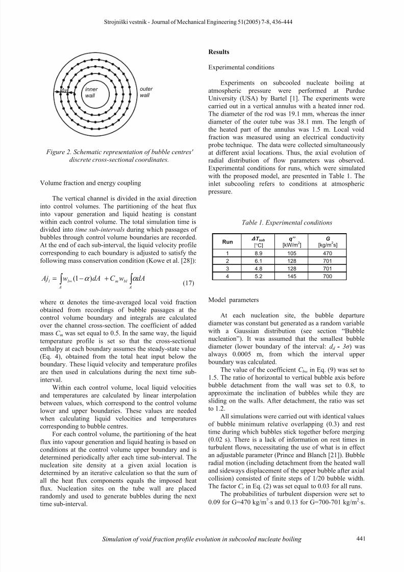
Bubbles' cross-sectional coordinates assume discretevalues, which correspond to points located on concentriccircles, centred on the annulus axis (Fig. 2). The distance
between neighbouring points along concentric circles isconstant. The distance between any neighbouring pointsmust be of the order of a fraction of the smallest bubbles'width (usually about few hundredths). Bubble lateralmovements are modelled as instantaneous jumps to other
points and occur between time steps. Mergers between bubbles, bubble condensations and bubble nucleations arealso modelled as instantaneous events which occur
between time steps.
Strojniški vestnik - Journal of Mechanical Engineering 51(2005) 7-8, 436-444
440 Kljenak I. - Mavko B.
8/11/2019 Simulation of Void Fraction Profile Evolution in Subcooled Nucleate Boiling in a Vertical Annulus With Bubble-trackin…
http://slidepdf.com/reader/full/simulation-of-void-fraction-profile-evolution-in-subcooled-nucleate-boiling 6/9
outer wall
inner wall
y
Figure 2. Schematic representation of bubble centres'discrete cross-sectional coordinates.
Volume fraction and energy coupling
The vertical channel is divided in the axial directioninto control volumes. The partitioning of the heat fluxinto vapour generation and liquid heating is constantwithin each control volume. The total simulation time isdivided into time sub-intervals during which passages of
bubbles through control volume boundaries are recorded.At the end of each sub-interval, the liquid velocity profilecorresponding to each boundary is adjusted to satisfy thefollowing mass conservation condition (Kowe et al. [28]):
+−= ∞
A A
bl ml l dAwC dAw Aj α α )1((17)
where α denotes the time-averaged local void fractionobtained from recordings of bubble passages at thecontrol volume boundary and integrals are calculatedover the channel cross-section. The coefficient of addedmass C m was set equal to 0.5. In the same way, the liquidtemperature profile is set so that the cross-sectionalenthalpy at each boundary assumes the steady-state value(Eq. 4), obtained from the total heat input below the
boundary. These liquid velocity and temperature profilesare then used in calculations during the next time sub-interval.
Within each control volume, local liquid velocitiesand temperatures are calculated by linear interpolation
between values, which correspond to the control volumelower and upper boundaries. These values are neededwhen calculating liquid velocities and temperaturescorresponding to bubble centres.
For each control volume, the partitioning of the heatflux into vapour generation and liquid heating is based onconditions at the control volume upper boundary and isdetermined periodically after each time sub-interval. Thenucleation site density at a given axial location isdetermined by an iterative calculation so that the sum ofall the heat flux components equals the imposed heatflux. Nucleation sites on the tube wall are placedrandomly and used to generate bubbles during the nexttime sub-interval.
Results
Experimental conditions
Experiments on subcooled nucleate boiling atatmospheric pressure were performed at Purdue
University (USA) by Bartel [1]. The experiments werecarried out in a vertical annulus with a heated inner rod.The diameter of the rod was 19.1 mm, whereas the innerdiameter of the outer tube was 38.1 mm. The length ofthe heated part of the annulus was 1.5 m. Local voidfraction was measured using an electrical conductivity
probe technique. The data were collected simultaneouslyat different axial locations. Thus, the axial evolution ofradial distribution of flow parameters was observed.Experimental conditions for runs, which were simulatedwith the proposed model, are presented in Table 1. Theinlet subcooling refers to conditions at atmospheric
pressure.
Table 1. Experimental conditions
Run
T sub[°C]
q’’
[kW/m2]
G
[kg/m2s]
1 8.9 105 470
2 6.1 128 701
3 4.8 128 701
4 5.2 145 700
Model parameters
At each nucleation site, the bubble departurediameter was constant but generated as a random variablewith a Gaussian distribution (see section “Bubblenucleation”). It was assumed that the smallest bubblediameter (lower boundary of the interval: d d - 3 ) wasalways 0.0005 m, from which the interval upper
boundary was calculated.The value of the coefficient C bw in Eq. (9) was set to
1.5. The ratio of horizontal to vertical bubble axis before bubble detachment from the wall was set to 0.8, toapproximate the inclination of bubbles while they are
sliding on the walls. After detachment, the ratio was setto 1.2.
All simulations were carried out with identical valuesof bubble minimum relative overlapping (0.3) and resttime during which bubbles stick together before merging(0.02 s). There is a lack of information on rest times inturbulent flows, necessitating the use of what is in effectan adjustable parameter (Prince and Blanch [21]). Bubbleradial motion (including detachment from the heated walland sideways displacement of the upper bubble after axialcollision) consisted of finite steps of 1/20 bubble width.The factor C r in Eq. (2) was set equal to 0.03 for all runs.
The probabilities of turbulent dispersion were set to
0.09 for G=470 kg/m2⋅s and 0.13 for G=700-701 kg/m2⋅s.
Strojniški vestnik - Journal of Mechanical Engineering 51(2005) 7-8, 436-444
Simulation of void fraction profile evolution in subcooled nucleate boiling 441
8/11/2019 Simulation of Void Fraction Profile Evolution in Subcooled Nucleate Boiling in a Vertical Annulus With Bubble-trackin…
http://slidepdf.com/reader/full/simulation-of-void-fraction-profile-evolution-in-subcooled-nucleate-boiling 7/9
The ratios of probabilities of turbulent dispersioncorrespond to the ratios of bulk Reynolds numbers.
The factor m in Eq. (3) (liquid temperature profile)was set to 4.0 for all runs.
For G=470 kg/m2⋅s, it was assumed that bubblesslide along the wall for a distance equal to twice their
maximum vertical chord length (that is, twice theellipsoid vertical axis) before attempting detachment. ForG=700-701 kg/m2⋅s, it was assumed that the “slidingdistance” is equal to one vertical axis. The rationale forthe difference is that bubble detachment is more likely tooccur sooner at higher mass flow rates due to theinfluence of turbulent eddies.
Simulation results
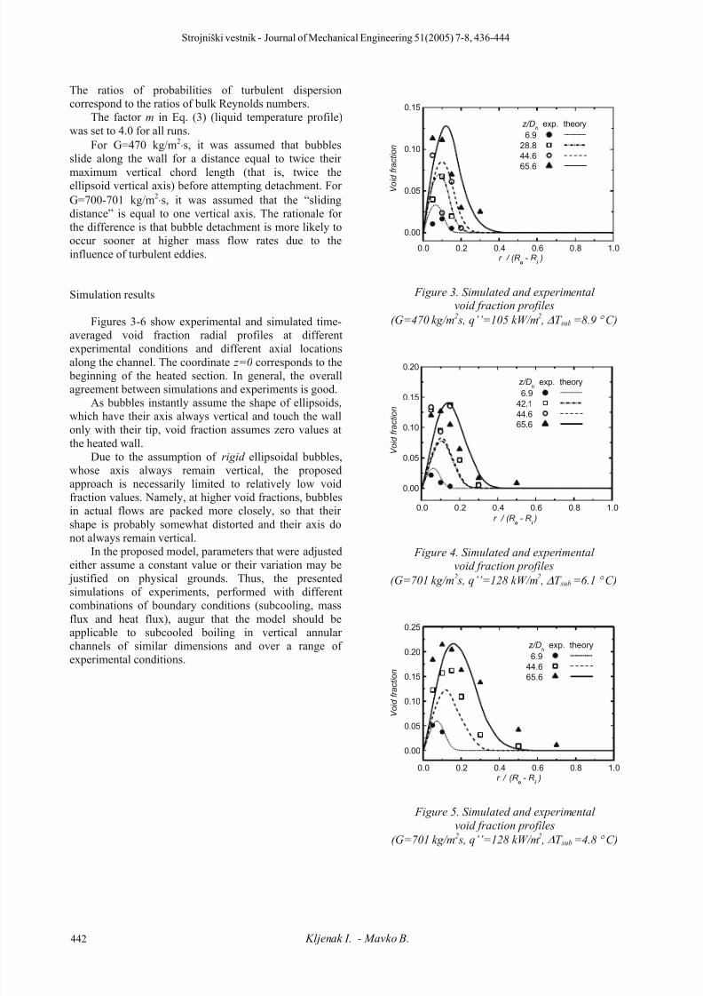
Figures 3-6 show experimental and simulated time-averaged void fraction radial profiles at different
experimental conditions and different axial locationsalong the channel. The coordinate z=0 corresponds to the
beginning of the heated section. In general, the overallagreement between simulations and experiments is good.
As bubbles instantly assume the shape of ellipsoids,which have their axis always vertical and touch the wallonly with their tip, void fraction assumes zero values atthe heated wall.
Due to the assumption of rigid ellipsoidal bubbles,whose axis always remain vertical, the proposedapproach is necessarily limited to relatively low voidfraction values. Namely, at higher void fractions, bubblesin actual flows are packed more closely, so that their
shape is probably somewhat distorted and their axis donot always remain vertical.
In the proposed model, parameters that were adjustedeither assume a constant value or their variation may be
justified on physical grounds. Thus, the presentedsimulations of experiments, performed with differentcombinations of boundary conditions (subcooling, massflux and heat flux), augur that the model should beapplicable to subcooled boiling in vertical annularchannels of similar dimensions and over a range ofexperimental conditions.
0.0 0.2 0.4 0.6 0.8 1.0
0.00
0.05
0.10
0.15
z/Dh
exp. theory
6.9
28.8
44.6
65.6
V o i d f r a c t i o n
r / (R o - R
i )
Figure 3. Simulated and experimentalvoid fraction profiles
(G=470 kg/m2 s, q’’=105 kW/m
2 , ∆T sub =8.9 ° C)
0.0 0.2 0.4 0.6 0.8 1.0
0.00
0.05
0.10
0.15
0.20
z/Dh
exp. theory
6.9
42.1
44.6
65.6
V o i d f r a c t i o n
r / (R o
- R i
)
Figure 4. Simulated and experimentalvoid fraction profiles
(G=701 kg/m2 s, q’’=128 kW/m2 , ∆T sub =6.1 ° C)
0.0 0.2 0.4 0.6 0.8 1.0
0.00
0.05
0.10
0.15
0.20
0.25
z/Dh
exp. theory
6.9
44.6
65.6
V o i d f r a c t i o n
r / (R o - R
i )
Figure 5. Simulated and experimental
void fraction profiles
(G=701 kg/m2 s, q’’=128 kW/m2 , ∆T sub =4.8 ° C)
Strojniški vestnik - Journal of Mechanical Engineering 51(2005) 7-8, 436-444
442 Kljenak I. - Mavko B.

8/11/2019 Simulation of Void Fraction Profile Evolution in Subcooled Nucleate Boiling in a Vertical Annulus With Bubble-trackin…
http://slidepdf.com/reader/full/simulation-of-void-fraction-profile-evolution-in-subcooled-nucleate-boiling 8/9
0.0 0.2 0.4 0.6 0.8 1.0
0.0
0.1
0.2
0.3
z/Dh
exp. theory
6.9
44.6
65.6
V o i d f r a c t i o n
r / (R o - R
i )
Figure 6. Simulated and experimentalvoid fraction profiles
(G=700 kg/m2 s, q’’=145 kW/m2 , ∆T sub =5.2 ° C)
Conclusions
A three-dimensional bubble-tracking model, in whichempiricism is included at a "more fundamental" level,was developed to simulate upward subcooled nucleate
boiling flow in a vertical annular tube with a centralheating rod. Bubble collective behaviour results frommotion, interaction and heat transfer mechanisms
prescribed at the level of individual bubbles.The model was used to simulate experiments
performed with water at near atmospheric pressure. Agood overall agreement between calculated and measured
radial profiles of void fraction at different axial locationsalong the channel was obtained. Although the modelcontains a number of adjustable parameters, thecomparison of simulated results with experimental dataindicates that the proposed approach captures the basicmechanisms that govern the development and evolutionof subcooled nucleate boiling along a heated channel atnear atmospheric pressure and relatively low voidfraction.
References
[1] M.D. Bartel, Experimental Investigation ofSubcooled Boiling, M.Sc.Thesis, Purdue Univ.,West Lafayette, IN, USA, 1999.
[2] S. Hari, Y.A. Hassan, Improvement of thesubcooled boiling model for low-pressureconditions in thermal-hydraulic codes, NuclearEngng. Design 216 (2002) 139-152.
[3] B. Konar, B. Mavko, Modelling of low-pressuresubcooled flow boiling using the RELAP5 code,
Nuclear Engng. Design 220 (2003) 255-273.[4] N. Kurul, M.Z. Podowski, On the modeling of
multidimensional effects in boiling channels, Proc.27th National Heat Transfer Conf., Minneapolis,
USA, 1991.
[5] G. Janssens-Maenhout, J.U. Knebel, U. Mueller,Subcooled nucleate boiling at low pressure andlow heat flux, Proc. 3rd Int.Conf. Multiphase FlowICMF'98, Lyon, France, 1998.
[6] B. Konar, I. Kljenak, B. Mavko, Modelling oflocal two-phase flow parameters in upward
subcooled flow boiling at low pressure, Int.J. HeatMass Transfer 47 (2004) 1499-1513.[7] T.H. Lee, G.C. Park, D.J. Lee, Local flow
characteristics of subcooled boiling flow of waterin a vertical concentric annulus, Int. J. MultiphaseFlow 28 (2002) 1351-1368.
[8] G.A. Mortensen, J.A. Trapp, Two-phase flowmodeling with discrete particles, Proc. ASMEHeat Transfer Div., Two-Phase Flow in EnergyExchange Systems, vol. 220, 1992, pp. 73-85.
[9] I. Kljenak, Modeling of void fraction and liquidtemperature profiles evolution in verticalsubcooled nucleate boiling flow, Proc. ASME-
ZSITS Int.Thermal Science Seminar, Bled,Slovenia, 2000.[10] I. Kljenak, G.C. Park, B. Mavko, T. Lee, Bubble-
tracking modeling of subcooled nucleate boiling ina vertical annulus, Proc. 4th Int. Conf. MultiphaseFlow, New Orleans, USA, 2001.
[11] I. Kljenak, G.C. Park, B. Mavko, T. Lee, Bubble-tracking modeling of subcooled nucleate boiling ina vertical annulus, Proc. 12th Int. Heat TransferConf., Grenoble, France, 2002.
[12] G.B. Wallis, One-Dimensional Two-Phase Flow,McGraw-Hill, 1969, pp. 248-251.
[13] Z. Bilicki, J. Kestin, Transition criteria for two-
phase flow patterns in vertical upward flow, Int.J.Multiphase Flow, 13 (1987) 283-294.[14] E.L. Bibeau, M. Salcudean, Subcooled void
growth mechanisms and prediction at low pressureand low velocity, Int.J. Multiphase Flow, 20(1994) 837-863.
[15] O. Zeitoun, M. Shoukri, Bubble behavior andmean diameter in subcooled flow boiling, Trans.ASME, J. Heat Transfer 118 (1996) 110-116.
[16] V. Prodanovic, D. Fraser, M. Salcudean, Bubble behavior in subcooled flow boiling of water at low pressures and low flow rates, Int.J. MultiphaseFlow 28 (2002) 1-19.
[17] I. Žun, The mechanism of bubble non-homogeneous distribution in two-phase shearflow, Nuclear Engng. Design 118 (1990) 155-162.
[18] T.J. Liu, Bubble size and entrance length effectson void development in a vertical channel, Int.J.Multiphase Flow 19 (1993) 99-113.
[19] A. Ohnuki, H. Akimoto, Prediction of phasedistribution under bubbly flow in a large vertical
pipe by multidimensional two-fluid model, Proc.3rd Int. Conf. Multiphase Flow ICMF'98, Lyon,France, 1998.
[20] T. Okawa, I. Kataoka, M. Mori, Numericalsimulation of lateral phase distribution in turbulent
upward bubbly two-phase flows, Nuclear Engng.Design 213 (2002) 183-197.
Strojniški vestnik - Journal of Mechanical Engineering 51(2005) 7-8, 436-444
Simulation of void fraction profile evolution in subcooled nucleate boiling 443

8/11/2019 Simulation of Void Fraction Profile Evolution in Subcooled Nucleate Boiling in a Vertical Annulus With Bubble-trackin…
http://slidepdf.com/reader/full/simulation-of-void-fraction-profile-evolution-in-subcooled-nucleate-boiling 9/9
[21] M.J. Prince, H.W. Blanch, Bubble coalescenceand break-up in air-sparged bubble columns,AIChE J. 36 (1990) 1485-1499.
[22] K. Sekoguchi, O. Tanaka, S. Esaki, T. Imasaka,Prediction of void fraction in subcooled and lowquality boiling regions, Bull. Japan Soc.
Mechanical Engineers 23 (1980) 1475-1482.[23] S.G. Kandlikar, Heat transfer characteristics in partial boiling, fully developed boiling andsignificant void flow regions of subcooled flow
boiling, Trans. ASME, J.Heat Transfer 120 (1998)395-401.
[24] J.G.Collier, Convective Boiling and Condensation,McGraw-Hill, 1981.
[25] G.Tsung-Chang, S.G. Bankoff, On the mechanismof forced-convection subcooled nucleate boiling,
Trans. ASME, J.Heat Transfer 112 (1990) 213-218.
[26] H.C. Unal, Maximum bubble diameter, maximum bubble-growth time and bubble-growth rate, Int.J.Heat Mass Transfer 10 (1967) 1023-1040.
[27] H.J.Ivey, Relationships between bubble frequency,
departure diameter and rise velocity in nucleate boiling, Int.J. Heat Mass Transfer 10 (1967) 1023-1040.
[28] R. Kowe, J.C.R. Hunt, A. Hunt., B. Couet, L.J.S.Bradbury, The effects of bubbles on the volumefluxes and the pressure gradients in unsteady andnon-uniform flow of liquids, Int.J. MultiphaseFlow 14 (1988) 587-606.
Strojniški vestnik - Journal of Mechanical Engineering 51(2005) 7-8, 436-444
444 Kljenak I. - Mavko B.