
Simulation of the Sucker Rod Column Dynamics for Different Pumping Regimes TOMA GEORGETA 11...
4
REV.CHIM.(Bucharest) ♦68♦No. 11 ♦2017 http://www.revistadechimie.ro 2593 Simulation of the Sucker Rod Column Dynamics for Different Pumping Regimes GEORGETA TOMA, ALEXANDRU PUPAZESCU, DORIN BADOIU* Petroleum-Gas University of Ploiesti, 39 Bucuresti Blvd., 100680, Ploiesti, Romania Proper functioning of the sucker rod pumping installations is strongly influenced by the sucker rod column dynamics and can be appreciated, as is well known and widely applied in practice, by the allure of the surface dynagraph. The paper presents some results concerning the simulation of the sucker rod column dynamics obtained with a computer program developed by the authors. The simulation results are compared with experimental results obtained at two pumping installations. Then, the computer program is used to study the sucker rod column dynamics for another pumping regime at one of analyzed installations. Keywords: sucker rod column, dynamics, surface dynagraph, pumping regimes It is known that most of the oil production (over 85% [1]) is extracted by pumping, the sucker rod pumping installations being the most simple pumping system to use and the most efficient for wells that can no longer ensure an eruptive exploitation. Prediction with a great degree of precision of the performances of such installations during operation is extremely difficult because of the complex interactions that exist between components, with direct influence on their dynamic behavior. Therefore, development of study models to express as accurately as the dynamics of that pumping installations and then creation of some computer programs to allow the simulation of their operation for different operating conditions can lead to optimization of working processes and of the cost of production. First researches concerning the sucker rod pumping installations that led to impressive results in their constructive and functional evolution dates back from the 70’s of last century. These were distinguished by the achievements concerning the behavior of the sucker rod pumping systems during operation, the assessment of the loads due to the vibrations of the sucker rod column and the study of the mechanism of the pumping units [2-4]. Much of further research on the design and the behavior during operation of these installations focused mainly on the study of the dynamics of the sucker rod column and on issues related to the analysis and synthesis of the mechanism of the pumping units. In this respect, a number of interesting results that have strongly helped to the achievement of the research from this paper are presented in [5-9]. It is well known in practice that the proper functioning of the sucker rod pumping installations is strongly influenced by the sucker rod column dynamics and can be appreciated by the allure of the surface dynagraph, namely the variation of the force at the polished rod according to its displacement on a cinematic cycle. Establishing the surface dynagraph is necessary for specifying the variation cycle of the loads to the design of the pumping units and is very useful to the creation of a card index of standard surface dynagraphs as to constitute a basis for comparison with the dynagraphs acquired with the dynamometer for a more precise diagnostic of the equipment operation. In this paper it is analyzed the dynamics of the sucker rod column and there are presented some simulation results obtained with a computer program developed by the * email: [email protected] authors. Surface dynagraphs obtained by simulation are compared to those obtained experimentally at two pumping installations and then the computer program is used to study the sucker rod column dynamics at one of analyzed installations for another pumping regime. Experimental part The experimental determinations were made at the wells Colibasi 256 and Tazlau 268 belonging to OMV Petrom. Measurement, experimental data acquisition and processing were performed with the equipment integrated in the system called echometer [1,10]. Dynamometer measurements were performed using the mounting scheme shown in figure 1. Fig. 1. Mounting scheme for dynamometer measurements The well Colibasi 256 has a depth of 2240 m. The component of the sucker rod column is as follows: the first segment of 480 m has sucker rods of 1 in, the second segment of 480 m has sucker rods of 7/8 in and the third segment of 1280 m is composed of sucker rods of 3/4 in. The column of tubing has the following structure: the first segment of 1000 m has extraction pipes of 3.5 in and the second segment of 1240 m is composed of extraction pipes of 2.875 in. Extraction pump used is of type RHTC 25-125- 20-4-0-0 having the piston diameter of 1.25 in. The well is served by a C-640D-365-144 pumping unit. The work angular speed of the cranks is of 4.71 rot/min. In figure 2 it is shown the surface dynagraph measured for a cinematic cycle at the well Colibasi 256. The well Tazlãu 268 has a depth of 1025 m. The sucker rod column has two segments: the first segment of 436 m has sucker rods of 7/8 in and the second segment of 589 m is composed of sucker rods of 3/4 in. The column of tubing has the following structure: the first segment of 918 m has extraction pipes of 3.5 in and the second segment of 107 m is composed of extraction pipes of 2.875 in.
Transcript of Simulation of the Sucker Rod Column Dynamics for Different Pumping Regimes TOMA GEORGETA 11...

REV.CHIM.(Bucharest)♦ 68♦ No. 11 ♦ 2017 http://www.revistadechimie.ro 2593
Simulation of the Sucker Rod Column Dynamics forDifferent Pumping Regimes
GEORGETA TOMA, ALEXANDRU PUPAZESCU, DORIN BADOIU*Petroleum-Gas University of Ploiesti, 39 Bucuresti Blvd., 100680, Ploiesti, Romania
Proper functioning of the sucker rod pumping installations is strongly influenced by the sucker rod columndynamics and can be appreciated, as is well known and widely applied in practice, by the allure of thesurface dynagraph. The paper presents some results concerning the simulation of the sucker rod columndynamics obtained with a computer program developed by the authors. The simulation results are comparedwith experimental results obtained at two pumping installations. Then, the computer program is used tostudy the sucker rod column dynamics for another pumping regime at one of analyzed installations.
Keywords: sucker rod column, dynamics, surface dynagraph, pumping regimes
It is known that most of the oil production (over 85%[1]) is extracted by pumping, the sucker rod pumpinginstallations being the most simple pumping system touse and the most efficient for wells that can no longerensure an eruptive exploitation. Prediction with a greatdegree of precision of the performances of suchinstallations during operation is extremely difficult becauseof the complex interactions that exist betweencomponents, with direct influence on their dynamicbehavior. Therefore, development of study models toexpress as accurately as the dynamics of that pumpinginstallations and then creation of some computer programsto allow the simulation of their operation for differentoperating conditions can lead to optimization of workingprocesses and of the cost of production.
First researches concerning the sucker rod pumpinginstallations that led to impressive results in theirconstructive and functional evolution dates back from the70’s of last century. These were distinguished by theachievements concerning the behavior of the sucker rodpumping systems during operation, the assessment of theloads due to the vibrations of the sucker rod column andthe study of the mechanism of the pumping units [2-4].Much of further research on the design and the behaviorduring operation of these installations focused mainly onthe study of the dynamics of the sucker rod column and onissues related to the analysis and synthesis of themechanism of the pumping units. In this respect, a numberof interesting results that have strongly helped to theachievement of the research from this paper are presentedin [5-9].
It is well known in practice that the proper functioningof the sucker rod pumping installations is stronglyinfluenced by the sucker rod column dynamics and can beappreciated by the allure of the surface dynagraph, namelythe variation of the force at the polished rod according toits displacement on a cinematic cycle. Establishing thesurface dynagraph is necessary for specifying the variationcycle of the loads to the design of the pumping units and isvery useful to the creation of a card index of standardsurface dynagraphs as to constitute a basis for comparisonwith the dynagraphs acquired with the dynamometer for amore precise diagnostic of the equipment operation.
In this paper it is analyzed the dynamics of the suckerrod column and there are presented some simulation resultsobtained with a computer program developed by the
* email: [email protected]
authors. Surface dynagraphs obtained by simulation arecompared to those obtained experimentally at twopumping installations and then the computer program isused to study the sucker rod column dynamics at one ofanalyzed installations for another pumping regime.
Experimental partThe experimental determinations were made at the
wells Colibasi 256 and Tazlau 268 belonging to OMVPetrom. Measurement, experimental data acquisition andprocessing were performed with the equipment integratedin the system called echometer [1,10]. Dynamometermeasurements were performed using the mountingscheme shown in figure 1.
Fig. 1. Mounting scheme for dynamometer measurements
The well Colibasi 256 has a depth of 2240 m. Thecomponent of the sucker rod column is as follows: thefirst segment of 480 m has sucker rods of 1 in, the secondsegment of 480 m has sucker rods of 7/8 in and the thirdsegment of 1280 m is composed of sucker rods of 3/4 in.The column of tubing has the following structure: the firstsegment of 1000 m has extraction pipes of 3.5 in and thesecond segment of 1240 m is composed of extraction pipesof 2.875 in. Extraction pump used is of type RHTC 25-125-20-4-0-0 having the piston diameter of 1.25 in. The well isserved by a C-640D-365-144 pumping unit. The workangular speed of the cranks is of 4.71 rot/min.
In figure 2 it is shown the surface dynagraph measuredfor a cinematic cycle at the well Colibasi 256.
The well Tazlãu 268 has a depth of 1025 m. The suckerrod column has two segments: the first segment of 436 mhas sucker rods of 7/8 in and the second segment of 589m is composed of sucker rods of 3/4 in. The column oftubing has the following structure: the first segment of 918m has extraction pipes of 3.5 in and the second segmentof 107 m is composed of extraction pipes of 2.875 in.

http://www.revistadechimie.ro REV.CHIM.(Bucharest)♦ 68♦ No. 11 ♦ 20172594
Extraction pump used is of type 25-175-RHBC-12-3-0-0having the piston diameter of 1.75 in. The well is served bya C-1280D-427-192 pumping unit. The work angular speedof the cranks is of 6.5 rot/min.
The surface dynagraph measured for a cinematic cycleat the well Tazlau 268 is shown in figure 3.
their determining depending on the dimensions of thecomponent link of the pumping unit, the crank angle ϕand the work angular speed of the cranks being presentedin [3,8,9]. In [8.9] it is also presented the manner ofdetermining the surface stroke S of the pumping unit andof the crank angle ϕa corresponding to the end of theupward movement of the sucker rod column; Gl is theweight of the sucker rod column when it is introduced intothe oil: Gl=b . G (b is the buoyancy factor: b=1-ρl/ρo,where and G are the density of the oil and the density ofthe steel from which are made sucker rods, and G is theweight of the sucker rod column in air, which is calculatedtaking into account its composition and the weight pereach section); Gb is the weight of the oil column, consideredas acting on the gross surface of the piston of the depthpump; Ff is the force due to the friction of the piston intothe depth pump and to the friction of the sucker rods intoextraction pipes: Ff=35 . D[kN] where the piston diameterD is expressed in meters; is the friction force into extractionpipes that occurs because of the transport of the oiltherethrough:
(5)
where: λ is the hydraulic loss coefficient (it can beconsidered λ=0.046, that is a typical value for rough pipes[5]); Ap is the net sectional area of the piston; At is theinterior passage sectional area of the extraction pipes; L isthe length of the sucker rod column and v is its speed; Fo isthe force due to the free oscillations of the sucker rodcolumn that occur when changing the conditions fromphase I to phase II and from phase III to phase IV. Whenchanging the conditions from phase I to phase II, Fo can becalculated with the relation [5]:
(6)
where: t1 is the time corresponding to the crank angle ϕ1;p is the pulsation of intrinsic oscillations of the sucker rodcolumn (it can be calculated with the formula [5]: p=8000/L); m is the total mass of the sucker rods; ν1 is the speed ofthe polished rod when the crank angle is equal to ϕ1;α=0.2. T ; (T is the period of the pumping cycle); ψ=kt / (kt + kp)where kp and kt are the elastic constants corresponding tothe sucker rod column and to the extraction pipes column,respectively:
(7)
where: kpi and kti are the elastic constants correspondingto the section i of the sucker rod column and to theextraction pipes column, respectively:
(8)
where: E is Young’s modulus of the steel from which aremade the sucker rods and the extraction pipes; lpi and ltiare the length of the section i of the sucker rod column andof the extraction pipes column, respectively, and Api andAti are the corresponding sectional areas. The relation forthe calculus of Fo when changing the conditions from phaseIII to phase IV is analogous to (6), in which the time t1 is
Fig. 2. Experimental surface dynagraph in the case of the wellColibasi 256
Fig. 3. Experimental surface dynagraph in the case of the wellTazlau 268
Establishing by calculation of the surface dynagraphThis calculation is done by considering the four basic
phases of the operating cycle of a pumping installation[5]: I) the phase corresponding to the initial deformationof the sucker rods and of the extraction pipes at thebeginning of the upward movement of the sucker rodcolumn; II) the phase corresponding to the upwardmovement of the sucker rod column; III) the phasecorresponding to the initial deformation of the sucker rodsand of the extraction pipes at the beginning of thedownward movement of the sucker rod column; IV) thephase corresponding to the downward movement of thesucker rod column after the initial deformation.
The force at the polished rod for the four phases of theoperating cycle can be calculated with the followingrelations [5]:
where: ϕ is the crank angle (fig. 1); u(ϕ), ν(ϕ)and a(ϕ)are the displacement, the speed and the acceleration,respectively, of the end of the polished rod, the manner of
(1)
(2)
(3)
(4)
REV.CHIM.(Bucharest)♦ 68♦ No. 11 ♦ 2017 http://www.revistadechimie.ro 2595
replaced by t2 corresponding to the crank angle ϕ2 and thespeed ν1 with ν2 which is the speed of the polished rodwhen the crank angle is equal to ϕ2; Fi=m . a(ϕ); is theforce due to the inertia of the sucker rods; ϕ1 is the value ofthe crank angle ϕ corresponding to the end of the firstphase. It can be calculated by solving the followingequation [5]:
(9)
where k is the elastic constant of the system composedby the sucker rods and extraction pipes:
(10)
If the extraction pipes are anchored at the lower end tothe exploitation column then: k=kp [5]. The crank angleϕ2 corresponding to the end of the third phase of theoperating cycle has the value given by the following relation[5]: ϕ2=ϕ1 +π.
By applying the relations (1)÷(4) it is obtained thevariation on a cinematic cycle of the force F at the polishedrod depending on the crank angle ϕ. Having the variationcurves F(ϕ)and u(ϕ)on a cinematic cycle, then can beobtained the surface dynagraph.
Simulation results and discussionsThe calculus algorithm presented hereinbefore has been
transposed by the authors into a computer program usingMaple programming environment [11]. The computerprogram allows determining among other of the variationcurves on a cinematic cycle of the displacement u(ϕ), ofthe speed ν(ϕ) and of the acceleration a(ϕ) of the end ofthe polished rod and also of the variation on a cinematic
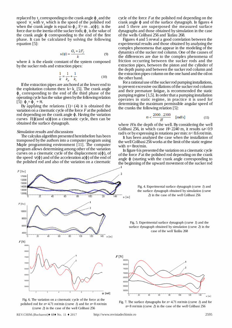
cycle of the force F at the polished rod depending on thecrank angle ϕ and of the surface dynagraph. In figures 4and 5 there are superposed the measured surfacedynagraphs and those obtained by simulation in the caseof the wells Colibasi 256 and Tazlau 268.
Figures 4 and 5 reveal a good correlation between theexperimental results and those obtained by analyzing thecomplex phenomena that appear in the modeling of thedynamics of the sucker rod column. One of the causes ofthe differences are due to the complex phenomena offriction occurring between the sucker rods and theextraction pipes, between the piston and the cylinder ofthe depth pump and between the sucker rod column andthe extraction pipes column on the one hand and the oil onthe other hand.
For a rational use of the sucker rod pumping installations,to prevent excessive oscillations of the sucker rod columnand their premature fatigue, is recommended the staticpumping regime [1,5]. In order that a pumping installationoperates in static regime, in practice it is used fordetermining the maximum permissible angular speed ofthe cranks the following relation [5]:
(11)
where H is the depth of the well. By considering the wellColibasi 256, in which case H=2240 m, it results ω<0.9rad/s or by expressing in rotations per min: n<8.6 rot/min.
It has been analyzed the case when the installation ofthe well Colibasi 256 works at the limit of the static regimewith n=8rot/min.
In figure 6 is presented the variation on a cinematic cycleof the force F at the polished rod depending on the crankangle ϕ (starting with the crank angle corresponding tothe beginning of the upward movement of the sucker rod
Fig. 4. Experimental surface dynagraph (curve 1) andthe surface dynagraph obtained by simulation (curve
2) in the case of the well Colibasi 256
Fig. 5. Experimental surface dynagraph (curve 1) and thesurface dynagraph obtained by simulation (curve 2) in the
case of the well Tazlãu 268
Fig. 7. The surface dynagraphs for n=4.71 rot/min (curve 1) and forn=8 rot/min (curve 2) in the case of the well Colibasi 256
Fig. 6. The variation on a cinematic cycle of the force at thepolished rod for n=4.71 rot/min (curve 1) and for n=8 rot/min
(curve 2) in the case of the well Colibasi 256

http://www.revistadechimie.ro REV.CHIM.(Bucharest)♦ 68♦ No. 11 ♦ 20172596
column, which in this case is of 1.528 rad) for the twocases, that of the functioning when n=4.71 rot/min (curve1) and when the installation works at the limit of the staticregime with n=8 rot/min (curve 2). Figure 7 presents thesurface dynagraphs in these two cases.
Figures 6 and 7 highlight a significant increase of themaximum value of the force at the polished rod when theinstallation works at the limit of the static regime. Fromthe two figures it also can be noticed that in the secondcase when n=8 rot/min the difference between theextreme values of the force at the polished rod is muchhigher than when n=4.71 rot/min, which leads to a morepronounced dynamic load of the sucker rod column.
From the analysis realized with the computer programmentioned before of all components involved incalculating the force at the polished rod it was seen animportant increase of the values of the force Fi due to theinertia of the sucker rods (fig. 8) and of the force Fo due tothe free oscillations of the sucker rod column that occurwhen changing the conditions from phase I to phase II(fig. 9) when the installation works at the limit of the staticregime. The variation curves in figure 8 have beenrepresented on a cinematic cycle starting with the crankangle corresponding to the beginning of the upwardmovement of the sucker rod column and those in figure 9for ϕ∈ a[ϕ1, ϕa], where ϕ1=2.24 rad and ϕa4.604 rad.
ConclusionsThe main purpose of the research conducted by the
authors and presented in this paper was to develop acomputer program with which it can be simulated thedynamics of the sucker rod column for different workregimes. The results obtained with this computer programhave been revealed a good correlation with theexperimental results. Therefore, it is an extremely usefultool for analyzing and modeling the complex phenomenathat appear during the movement of the sucker rod columnand especially for obtaining the variation on a cinematic
Fig. 8. The variation of the force Fi for n=4.71 rot/min (curve 1) andfor n=8 rot/min (curve 2) in the case of the well Colibasi 256
Fig. 9. The variation of the force Fo for n=4.71 rot/min (curve 1) andfor n=8 rot/min (curve 2) in the case of the well Colibasi 256
cycle of the force at the polished rod depending on thecrank angle and of the surface dynagraph.
References1.COLOJA, P.M., Research the wells in pumping using acousticmethods (in Roumanian), Ilex Publishing House, Roumania, 20022.GIBBS, S G., Predicting the behavior of sucker-rod pumping systems,Journal of Petroleum Technology, 1963 (July), p. 769-7783.GRAY, H E., Kinematics of oil-well pumping units, Paper presentedat the API Midcontinent Dist. Meeting, 27-29 March, 1963, AmarilloTex., USA4.GIBBS, S G., Computing gearbox torque and motor loading for beampumping units with consideration of inertia effects, Journal ofPetroleum Technology, 1975 (September), p. 1153-11595.POPOVICI, A., Equipment for the exploitation of oil wells (inRoumanian), Technical Publishing House, Bucharest, 19896.TAKACS, G. and GAJDA, M. JR., The ultimate sucker-rod string designprocedure, Paper SPE 170588-MS presented at SPE Annual TechnicalConference and Exhibition, 27-29 October, 2014, Amsterdam, TheNetherlands7.HOJJATI, M. H. and LUKASIEWICZ, S. A., Modelling of sucker rodstring, Journal of Canadian Petroleum Technology, 44 (12), 2005, p. 55-588.TOMA, G., PUPAZESCU, A., BADOIU, D., On the kinematics of somesucker rod pumping units, Petroleum-Gas University of PloiestiBulletin, Technical Series, Vol. LXVI, No. 3, 2014, p. 95-1009.TOMA, G., PUPAZESCU, A., BADOIU, D., On a synthesis problem ofthe mechanism of a sucker rod pumping unit, Petroleum-GasUniversity of Ploiesti Bulletin, Technical Series, Vol. LXV, No. 4, 2013,p. 107-11110.*** Well Analyzer Operating Manual, Echometer Company, Texas,199311.MONAGAN, M.B., GEDDES, K.O., HEAL, K.M., LABAHN, G.,VORKOETTER, S.M., MCCARRON, J., DEMARCO, P., Maple IntroductoryProgramming Guide, Maplesoft, a division of Waterloo Maple Inc.,2005
Mansucript received: 5.10.2016