Simulation of the Impact of Wind Power on the Transient Fault Behavior
10
Electric Power Systems Research 77 (2007) 135–144 Simulation of the impact of wind power on the transient fault behavior of the Nordic power system Clemens Jauch a,∗ , Poul Sørensen a , Ian Norheim b , Carsten Rasmussen c a Risø National Laboratory, Wind Energy Department, P.O. Box 49, DK-4000 Roskilde, Denmark b SINTEF Energy Research, The department of Energy Systems, Sem Sælands Vei 11, NO-7463 Trondheim, Norway c Elkraft System, 2750 Ballerup, Denmark Received 24 August 2005; received in revised form 24 January 2006; accepted 12 February 2006 Available online 24 March 2006 Abstract In this paper the effect of wind power on the transient fault behavior of the Nordic power system is investigated. The Nordic power system is the interconnected power system of the countries Norway, Sweden, Finland and Denmark. For the purpose of these investigations the wind turbines installed and connected in eastern Denmark are taken as study case. The current and future wind power situation in eastern Denmark is modeled and short circuit faults in the system simulated. The simulations yield information on (i) how the faults impact on the wind turbines and (ii) how the response of the wind turbines influences the post-fault behavior of the Nordic power system. It is concluded that an increasing level of wind power penetration leads to stronger system oscillations in case of fixed speed wind turbines. It is found that fixed speed wind turbines that merely ride through transient faults have negative impacts on the dynamic response of the system. These negative impacts can be mitigated though, if sophisticated wind turbine control is applied. © 2006 Elsevier B.V. All rights reserved. Keywords: Fault ride through; Nordic power system; Wind power; Transient fault 1. Introduction The study of the effects of growing wind power penetration on the stability and reliability of power systems is of interest in many countries in the world. Wherever wind power will be installed on a large scale such studies are carried out to pre- vent severe consequences for the power system considered [1]. Besides the commonly discussed impacts of and on the sys- tem voltage, also the system frequency plays an important role. When wind power penetration increases, wind turbines have to be involved in the control of the grid frequency. This is a rel- atively straightforward task for normal operation, where load changes cause the system frequency to deviate [2]. Frequency control is a much more demanding task for wind turbines in the wake of transient faults [3]. Under transient fault situations both ∗ Corresponding author. Tel.: +45 46 77 50 76; fax: +45 46 77 50 83. E-mail addresses: [email protected] (C. Jauch), [email protected] (P. Sørensen), [email protected] (I. Norheim), [email protected] (C. Rasmussen). the voltage and frequency have to be considered to assess the impact of wind power on the system stability [4]. This paper considers the mutual effects of wind power in power systems under transient fault situations. As study case the Nordic power system is taken. It is analyzed (i) how the wind turbines behave in the system when it experiences a transient fault and (ii) what impact the wind turbines have on the dynamic behavior of the system after a fault. The Nordic power system stretches the countries Norway, Sweden, Denmark and Finland. Not only is substantial amount of wind power already today installed in the Nordic power sys- tem, a lot more is expected to come due to the promising wind conditions in northern Europe. Characteristic for the Nordic power system is that it is geographically large, but at the same time it is of comparably small capacity, due to Norway, Sweden, Denmark and Finland being only sparsely populated countries. This makes it more vulnerable to high levels of wind power penetration if the installed turbines are uncontrolled distributed generators. Until recently wind turbines connected to the Nordic power system were not engaged in the control and support of the 0378-7796/$ – see front matter © 2006 Elsevier B.V. All rights reserved. doi:10.1016/j.epsr.2006.02.006
-
Upload
sukant-bhattacharya -
Category
Documents
-
view
214 -
download
1
description
Wind power
Transcript of Simulation of the Impact of Wind Power on the Transient Fault Behavior

A
iiat
fn©
K
1
oiivBtWbaccw
pc
0d
Electric Power Systems Research 77 (2007) 135–144
Simulation of the impact of wind power on the transient fault behaviorof the Nordic power system
Clemens Jauch a,∗, Poul Sørensen a, Ian Norheim b, Carsten Rasmussen c
a Risø National Laboratory, Wind Energy Department, P.O. Box 49, DK-4000 Roskilde, Denmarkb SINTEF Energy Research, The department of Energy Systems, Sem Sælands Vei 11, NO-7463 Trondheim, Norway
c Elkraft System, 2750 Ballerup, Denmark
Received 24 August 2005; received in revised form 24 January 2006; accepted 12 February 2006Available online 24 March 2006
bstract
In this paper the effect of wind power on the transient fault behavior of the Nordic power system is investigated. The Nordic power system is thenterconnected power system of the countries Norway, Sweden, Finland and Denmark. For the purpose of these investigations the wind turbinesnstalled and connected in eastern Denmark are taken as study case. The current and future wind power situation in eastern Denmark is modelednd short circuit faults in the system simulated. The simulations yield information on (i) how the faults impact on the wind turbines and (ii) howhe response of the wind turbines influences the post-fault behavior of the Nordic power system.
It is concluded that an increasing level of wind power penetration leads to stronger system oscillations in case of fixed speed wind turbines. It isound that fixed speed wind turbines that merely ride through transient faults have negative impacts on the dynamic response of the system. Theseegative impacts can be mitigated though, if sophisticated wind turbine control is applied.
2006 Elsevier B.V. All rights reserved.
ult
ti
pNtfb
Sot
eywords: Fault ride through; Nordic power system; Wind power; Transient fa
. Introduction
The study of the effects of growing wind power penetrationn the stability and reliability of power systems is of interestn many countries in the world. Wherever wind power will benstalled on a large scale such studies are carried out to pre-ent severe consequences for the power system considered [1].esides the commonly discussed impacts of and on the sys-
em voltage, also the system frequency plays an important role.hen wind power penetration increases, wind turbines have to
e involved in the control of the grid frequency. This is a rel-tively straightforward task for normal operation, where load
hanges cause the system frequency to deviate [2]. Frequencyontrol is a much more demanding task for wind turbines in theake of transient faults [3]. Under transient fault situations both∗ Corresponding author. Tel.: +45 46 77 50 76; fax: +45 46 77 50 83.E-mail addresses: [email protected] (C. Jauch),
[email protected] (P. Sørensen), [email protected] (I. Norheim),[email protected] (C. Rasmussen).
cptDTpg
s
378-7796/$ – see front matter © 2006 Elsevier B.V. All rights reserved.oi:10.1016/j.epsr.2006.02.006
he voltage and frequency have to be considered to assess thempact of wind power on the system stability [4].
This paper considers the mutual effects of wind power inower systems under transient fault situations. As study case theordic power system is taken. It is analyzed (i) how the wind
urbines behave in the system when it experiences a transientault and (ii) what impact the wind turbines have on the dynamicehavior of the system after a fault.
The Nordic power system stretches the countries Norway,weden, Denmark and Finland. Not only is substantial amountf wind power already today installed in the Nordic power sys-em, a lot more is expected to come due to the promising windonditions in northern Europe. Characteristic for the Nordicower system is that it is geographically large, but at the sameime it is of comparably small capacity, due to Norway, Sweden,enmark and Finland being only sparsely populated countries.his makes it more vulnerable to high levels of wind power
enetration if the installed turbines are uncontrolled distributedenerators.Until recently wind turbines connected to the Nordic powerystem were not engaged in the control and support of the

1 ystem
setttdtftm[
eolfph
tawotS
chTEp[
Ns
2
SqbaciwetlDm
scspc
waittetcdi
3p
Nmteot
biiwTwpD
ltwi
paa
3
meieZpr
e
36 C. Jauch et al. / Electric Power S
ystem. If transient faults in the system lead to considerablexcursions in voltage and/or frequency the wind turbines wereo disconnect and to reconnect only once the system has returnedo stable operation. Increasing wind power penetration leadso the problem that considerable amount of generation mightisconnect in case of a transient fault in the system, causinghe system to become unstable from an otherwise harmlessault situation. To prevent such situations newly installed windurbines have to comply with new grid connection require-
ents that demand wind turbines to ride through transient faults5].
Elkraft, which is the operator of the transmission system inastern Denmark has already today one of the world’s largestffshore wind farms connected to its system, and more evenarger offshore wind farms are expected in the near future. There-ore, Elkraft along with the other system operators in the Nordicower system, is interested in the possible consequences of localigh wind power penetration.
The model of the Nordic power system used in these inves-igations has been developed at SINTEF in Norway [6], and isn aggregation of a fully detailed transmission system model,hose validity has been proven with measurements. It is a modelf the transmission system comprising aggregations of conven-ional power plants only; no wind farms have been included atINTEF.
At Risø National Laboratory a model of the wind poweronnected to the Nordic power system in eastern Denmarkas been added to SINTEF’s Nordic power system model.his additional model has been developed in cooperation withlkraft. The simulation tool used in these investigations is theower system simulation tool PowerFactory from DIgSILENT7].
This article presents the results of joint efforts of Risøational Laboratory, SINTEF and Elkraft on the field of tran-
ient stability of wind power in the Nordic power system.
. The Nordic power system model
The Nordic power system stretches the countries Norway,weden, Denmark and Finland, and has a nominal system fre-uency of 50 Hz. It is divided into two synchronous areas. Theiggest part of the system, comprising Norway, Sweden, Finlandnd the eastern part of Denmark are one interconnected, syn-hronous AC system. The small rest of the Nordic power system,.e. western Denmark, is AC connected to the big UCTE system,hich is the interconnected AC system of central Europe. Sev-
ral HVDC links connect the Nordic synchronous system withhe central European system. There are, among others, HVDCinks between Norway and western Denmark, between easternenmark and Germany and between southern Sweden and Ger-any.Since in transient fault situations the HVDC links can be con-
idered uncontrolled voltage dependent sources and sinks, the
entral European part of the system is of no relevance for tran-ient fault simulations. Hence for simplicity the term “Nordicower system” will in the following refer to the Nordic syn-hronous system.lett
s Research 77 (2007) 135–144
The model of the Nordic power system is an aggregation,hich means that the generators, lines and loads in the model
re lumped representations of several generators lines and loadsn reality. It comprises 35 nodes and 20 synchronous genera-ors. It is a model of the transmission system only; comprisinghe voltage levels 420, 300, 150 and 135 kV. In the location ofastern Denmark, the model is extended with a simplified grido represent the connection of wind power. This simplified gridomprises all voltage levels from transmission system voltageown to generator terminal voltage. This extension is describedn the following section.
. Model of wind power installations in the Nordicower system
As mentioned earlier the purpose of the extension of theordic power system model is that wind power can be imple-ented realistically into the model. The extension considers the
ransmission and distribution system in eastern Denmark. East-rn Denmark is a remote location in the system. In the southf eastern Denmark, which is where the majority of the windurbines are connected, the grid is relatively weak.
Denmark is the country in the Nordic power system that hasy fare the highest level of wind power penetration. Therefore,t is only natural to model the wind power connected there. Its assumed that wind power in eastern Denmark is the onlyind power that has to be considered in the Nordic system.his is a sound assumption, as only faults in eastern Denmarkill be simulated. Any wind power that is installed in anotherart of the system would hardly be affected by faults in easternenmark.Inherent for wind power is that its resources are far away from
oad centers and hence almost invariable far away from strongransmission systems. This is even more applicable for offshoreind farms. The largest part of wind power that will be installed
n eastern Denmark in future will be offshore.The amount of wind power that is introduced, substitutes
ower of synchronous generators. Hence the total amount ofctive power transmitted through the system remains the same,part from the losses of the extra components.
.1. Topology of the grid in eastern Denmark
In the original model as developed by SINTEF eastern Den-ark is represented by a single busbar with a synchronous gen-
rator and a load. This busbar is called Zealand, as can be seenn Fig. 1, which shows the topology of the whole power systemxtension. The synchronous generator at busbar Zealand (SGealand) is rated 2000 MVA and represents all the conventionalower plants in eastern Denmark. The load connected to Zealandepresents the load in the northern part of eastern Denmark.
In the extension (Fig. 1) three wind farms in the south of east-rn Denmark are considered. One wind farm represents all the
and-based wind turbines, which are distributed over the south-rn islands of eastern Denmark. These turbines are aggregatedo one single induction generator. Another wind farm representshe Nysted offshore wind farm. This is one of the world’s largest
C. Jauch et al. / Electric Power Systems Research 77 (2007) 135–144 137
mode
o2l
fNt
3
n
ttd
oFct
Fig. 1. Grid diagram of the extension of the Nordic system
ffshore wind farms and has been connected to the system since003 [8]. The third wind farm is an offshore wind farm that isikely to be installed in future.
The connection between this 420 kV busbar and the windarms is modeled in a more detailed manner than the rest of theordic system. It considers all voltage levels from 420 kV down
o generator terminal voltages.
.2. Model of wind farm feeders
The wind farms in the south of eastern Denmark are con-ected to the transmission system of the Nordic power system
llsS
l introducing the wind power installed in eastern Denmark.
hrough the relatively weak grid of eastern Denmark. Therefore,he power system in eastern Denmark has to be modeled in moreetail than the transmission system.
Between the busbars Zealand and Spanager (see Fig. 1) isne transformer that steps the voltage down from 420 to 132 kV.rom Spanager, which is situated on the island of Zealand,lose to Copenhagen, to the busbar Radsted, which is situated inhe south, on the island of Lolland, are several parallel 132 kV
ines. The number of parallel lines is varied depending on theevel of wind power penetration simulated. (Different cases areimulated as will be seen in Section 4.) The distance betweenpanager and Radsted is approximately 100 km.
1 ystems Research 77 (2007) 135–144
s
fw
wasFlbtdtdm
fwlt
wocc
cpi
3
3
Twsnace
spt
3
ibcsfdT
nwf
a2w[
bvsa
•
•
•
mdw
3
atgiwopbm
38 C. Jauch et al. / Electric Power S
Connected to Radsted is a load that represents the load in theouth of eastern Denmark.
The wind farms are connected to Radsted through 132 kVeeders and medium voltage cables, representing the cable net-ork in the wind farms.The 132 kV feeder connecting the distributed land-based
ind turbines is assumed to be 25 km long. This length is anpproximate value found by considering the distance from Rad-ted to a central location between all the land-based turbines [9].rom this central location 24 parallel 11 kV cables, of 20 km
ength, represents the medium voltage cable network to the tur-ines. The length of the 11 kV cable is an average distance fromhe turbines to the central location mentioned above. Since theistributed land-based turbines are all connected to the distribu-ion system, three transformers are chosen to step the voltageown from the transmission system voltage to the generator ter-inal voltage.The connection from Radsted to the Nysted offshore wind
arm is modeled with a 29 km long 132 kV line. The cable net-ork inside the wind farm is represented by three parallel, 3.2 km
ong, 33 kV cables. The distance of 3.2 km is the average dis-ance from the turbines to the transformer platform [10].
The 132 kV feeder connecting the future offshore wind farmith Radsted is assumed to be 30 km long. Just like in the casef the Nysted offshore wind farm, also here the internal farmable network is represented by three parallel 3.2 km long, 33 kVables.
With these feeders the generators of the wind turbines areonnected to the Nordic power system. The generators and theirrime movers, i.e. the wind turbines are described in the follow-ng section.
.3. The wind farm models
.3.1. Wind modelIn this article only transient fault simulations are considered.
he simulated events last up to a few seconds, therefore, naturalind variations need not be taken into account. Rotating wind
peed variations like 3 pu (the tower shadow effect) [11] can beeglected as well, because the wind power plants considered areggregations of many single wind turbines. If many turbines areonnected together their rotating wind speed variations cancelach other out.
The wind speed is set to a constant 18 m/s, which is a windpeed that allows all turbines to produce rated power. A ratedower operating point is chosen, as this is most burdening forhe power system.
.3.2. Model of the distributed land-based wind turbinesSubstantial amount of wind power is distributed over the
slands in the south of eastern Denmark. These distributed land-ased wind turbines are aggregated and modeled by one squirrelage induction generator. The prime mover is modeled by a con-
tant mechanical torque that acts on a two masses spring andriction model, which then drives the generator (Fig. 2). Aero-ynamics and control schemes of these turbines are neglected.hey are not relevant for transient fault studies as the grid con-iaA
Fig. 2. Drive train model of wind turbine.
ection requirements that were applicable when these turbinesere installed demand them to disconnect in case of a grid
ault.The capacity of the induction generator representing the
ggregation of all the distributed land-based wind turbines is35 MW. This is a value that can be worked out from theind turbine data register of the Danish Energy Authority
9].The protection system that disconnects the land-based tur-
ines in case of a fault is implemented in the form of under-oltage, overspeed and overcurrent protection. The protectioncheme implemented in this model disconnects the generatornd its compensation unit, when
the voltage at the generator terminals drops below 0.85 pu for100 ms;the speed of the generator exceeds 104% of its rated speed(when the generator cannot export as much power as isimported through the wind, it accelerates);the current exceeds 200% rated current for 100 ms.
It is assumed that the reactive power compensation is imple-ented in such a way that only the no load reactive power
emand of the generator is compensated. This is in accordanceith the applicable grid connection requirements.
.3.3. Model of Nysted offshore wind farmThe Nysted offshore wind farm consists of 72 identical
ctive-stall wind turbines, each rated 2.3 MW [8]. Therefore,his wind farm is modeled with 72 parallel 2.3 MW inductionenerators, driven by a wind turbine model with full mechan-cal (Fig. 2) and aerodynamic representation [12]. A similarind turbine model has been verified in an islanding experimentf a real multi-megawatt active-stall turbine. This experimentroved that the model represents the behavior of the real tur-ine well [13]. Fig. 3 shows the topology of the wind turbineodel.
An active-stall controller that finds the right pitch angle dur-ng normal, fault-free operation is implemented. It optimizes thective power production at wind speeds below rated wind speed.bove rated wind speeds it limits the active power output of the

C. Jauch et al. / Electric Power Systems Research 77 (2007) 135–144 139
d turb
thffte
mfpbiv
3
abgiitairi
sttitf
4
patFtgt
4
tfn
aaRaitvfmabrao
Nireduced active power production [15]. At the same time thecompensation capacitors stay connected helping the voltage torecover.
Fig. 3. Win
urbine to its rated value [14]. The Nysted offshore wind farmas to fulfill grid connection requirements that require certainault ride through capabilities [5]. Therefore, also a transientault controller is implemented that allows the turbines to ridehrough transient faults without experiencing damaging speedxcursions [15].
In accordance with the applicable grid connection require-ents, a reactive power compensation unit has to keep the wind
arm neutral in reactive power demand at the grid connectionoint. A shunt capacitor bank is implemented at the generatorusbar, and a controller controls the number of connected capac-tors, nC, such that the steady state power factor is one at the higholtage side of the 132/33 kV transformer.
.3.4. Model of future offshore wind farmThe future offshore wind farm considered is also made of
ctive-stall wind turbines. It consists of 99 identical 2 MW tur-ines. Hence the wind farm is modeled with 99 parallel inductionenerators driven by a wind turbine model similar to the one usedn the Nysted wind farm (Fig. 3). The control of the wind turbinesn the future offshore wind farm is more sophisticated as theseurbines are not only required to ride through transient faults, butlso to contribute to the damping of grid frequency oscillationsn the wake of transient faults [3]. This is not demanded in cur-ent grid connection requirements, but if wind power penetrationncreases this will probably become a requirement.
Also here it is assumed that the wind farm controls its steadytate reactive power production such that it is neutral in reac-ive power demand at the high voltage side of the 132/33 kVransformer. For that purpose also here a shunt capacitor bank ismplemented. The switching frequency of the capacitor contac-ors is assumed to be somewhat higher than in the Nysted windarm, emulating more sophisticated technology.
. Simulations, results and discussions
Different scenarios are simulated to assess the impact of windower in the current and the future situation. The faults simulatedre 100 ms, zero impedance, three-phase short circuits on one of
he lines between Spanager and Radsted, close to Radsted (seeig. 1). The fault gets cleared by permanent disconnection ofhe faulted line. This is a fault situation described in Elkraft’srid connection requirements for wind farms connected to theransmission system [5].
ine model.
.1. Case 1
The current situation is simulated, i.e. only the land-basedurbines and the Nysted offshore wind farm are connected. Theeeder for the future offshore wind farm, as shown in Fig. 1 isot existent in this simulation.
Fig. 4 shows that the voltage at busbar Radsted drops to zero,s Radsted is closest to the fault location. Zealand is hardlyffected by this fault as the relatively weak connection betweenadsted and Zealand causes a substantial voltage drop. The volt-ge at the terminals of the land-based turbines gets suppressedn the beginning of the fault and after a few ms it drops to zero ashe protection system of these turbines disconnects them. Theoltage at Radsted recovers quickly after the clearance of theault because the land-based turbines have disconnected, whicheans that they do not consume reactive power any more. In
ddition to that the now unloaded cables in the feeder to the land-ased turbines act as capacitors generating noticeable amount ofeactive power (Fig. 7). The voltage at Nysted recovers also rel-tively quickly because of the reduced reactive power demandf the Nysted generator in the first seconds.
The fault excites the inherently flexible drive train of theysted wind turbines (Fig. 2) to oscillations, which in the first
nstances after the clearance of the fault leads to a strongly
Fig. 4. Case 1: voltage at different locations in the system.

140 C. Jauch et al. / Electric Power Systems Research 77 (2007) 135–144
wswt2ttiacwcstcFetsg
btaFitl
FF
4
fhottttatp
actttopower demand to oscillate (Fig. 6), and this in turn causes thevoltage to oscillate strongly too.
Due to the stronger connection between Zealand and Radstedthe voltage at Zealand is slightly lower than in case 1. This
Fig. 5. Case 1: speed of the Nysted wind farm generator.
Fig. 5 shows the speed of the generator of the Nysted offshoreind farm. During the fault the speed of the generator accelerates
teeply. Just after the clearance of the fault it exhibits oscillationsith the resonance frequency of the small inertia of the genera-
or rotor (Fig. 2). While these oscillations subside within the firsts after the fault, the underlying low resonance frequency of the
urbine rotor with its large inertia becomes dominant. At simula-ion time 3 s these low frequency oscillations cause a noticeablencrease in generator speed, which in turn means that the gener-tor requires more reactive power. Increasing speed in a squirrelage induction generator means increasing slip, s. From Fig. 6,hich shows the equivalent circuit diagram of such a squirrel
age induction generator, it can be seen that with increasing slip,, the overall rotor resistance decreases Rrotor = Rr/s. Lower resis-ance leads to more current flowing through the mainly inductiveircuit of the generator, causing higher reactive power demand.or these considerations it is sufficient to use the steady statequivalent circuit of the generator as shown in Fig. 6. The windurbine drive train, which causes the speed oscillations, has con-iderably larger time constants than the electrical circuit of theenerator.
Fig. 7 shows that this reactive power demand has to be coveredy SG Zealand, which produces reactive power to be transferredo Sweden (line DK-S). This reactive power surge causes a volt-ge drop between Zealand and Radsted, which can be seen inig. 4 around the simulation time 3 s. Eventually the voltages
n eastern Denmark settle to a slightly higher value because of
he extra reactive power being generated in the cables of theand-based turbines feeder.Fig. 6. Equivalent circuit diagram of a squirrel cage induction generator.
ig. 7. Case 1: reactive power at different locations in the system as shown inig. 1.
.2. Case 2.0
Here the situation is simulated that the future offshore windarm has been connected and that the turbines in this wind farmave the same control capabilities as the Nysted turbines, i.e.nly fault ride through as demanded by the current grid connec-ion requirements. The rating of the 420/132 kV transformer andhe number of lines between Spanager and Radstad are increasedo suit the extra power installed in the new wind farm. In addi-ion the dispatched power of SG Zealand is reduced by 200 MWnd its rated power is reduced by 200 MVA to reflect the situa-ion that future installed wind power will substitute conventionalower plants.
In Fig. 8 the voltage of the land-based turbines is not showns this drops to zero like in the previous case. From Fig. 8 itan be seen that the voltage at Radsted, and consequently at theerminals of the wind farms, is under considerably more strainhan in the previous case. The drive trains of the turbines in thewo offshore wind farms oscillate similarly causing the speedf the generators to oscillate (Fig. 2), which causes the reactive
Fig. 8. Case 2.0: voltage at different locations in the system.

C. Jauch et al. / Electric Power Systems Research 77 (2007) 135–144 141
FF
is
SvTbtb
4
eoss
dqjpmg
FF
tc
piiit
42
sNfloNZ
ig. 9. Case 2.0: active power at different locations in the system as shown inig. 1.
s of no consequence for the voltage in the rest of the Nordicystem.
The fault does however upset the grid frequency, becauseG Zealand exhibits strong rotor speed oscillations, which isisible in strong active power oscillations as shown in Fig. 9.hese power oscillations can only propagate through the lineetween Zealand and Sweden (called ‘line DK-S’ in Fig. 9) intohe rest of the Nordic power system and be absorbed by otherulk power plants.
.3. Case 2.1
In the case simulated here the future offshore wind farmmploys its grid frequency stabilizer to counteract the frequencyscillations caused by the short circuit [3]. This emulates theituation that in future wind turbines will be involved in thetabilization of the power system.
In the first instance these turbines have to tackle their ownrive train oscillations before they can contribute to grid fre-uency stabilization. Therefore, the rise in voltage (Fig. 10)
ust after the clearance of the fault is similar to that in therevious case. The voltage dip after simulation time 3 s isuch less severe, which is due to the pitching actions of therid frequency stabilizer. Consequently also the power oscilla-
Fig. 10. Case 2.1: voltage at different locations in the system.
antl
F
ig. 11. Case 2.1: active power at different locations in the system as shown inig. 1.
ions as plotted in Fig. 11 are less severe than in the previousase.
For better comparability of the cases 2.0 and 2.1 the activeower of SG Zealand and in line DK-S are plotted in one graphn Fig. 12. From Fig. 12 it becomes visible that the oscillationsn the rotor speed and hence the active power of SG Zealand andn line DK-S, are noticeably dampened by the control actions ofhe grid frequency stabilizer in the future offshore wind farm.
.4. Comparison of the grid frequency response of cases 1,
.0 and 2.1
As noted above, the voltage variations caused by the faults,imulated in the different cases, has a negligible impact on theordic power system. The frequency and hence the active powerow through the system gets affected though. An effective meansf comparing the consequence of the different scenarios on theordic power system is comparing the speed responses of SGealand, i.e. the grid frequency.
Fig. 13 shows the speed of SG Zealand for the cases 1, 2.0
nd 2.1. The comparison of cases 1 and 2.0, which both doot include any active frequency damping by the installed windurbines, shows that in the case of larger wind power instal-ation the speed of SG Zealand gets more upset. As shownig. 12. Active power in line DK-S and SG Zealand in the cases 2.0 and 2.1.
142 C. Jauch et al. / Electric Power System
F2
itZI
NiionliZ
tss
Zeets
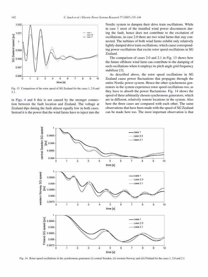
ig. 13. Comparison of the rotor speed of SG Zealand for the cases 1, 2.0 and.1.
n Figs. 4 and 8 this is not caused by the stronger connec-ion between the fault location and Zealand. The voltage atealand dips during the fault almost equally low in both cases.
nstead it is the power that the wind farms have to inject into the
ahoc
Fig. 14. Rotor speed oscillations in the synchronous generators (i) central Sw
s Research 77 (2007) 135–144
ordic system to dampen their drive train oscillations. Whilen case 1 most of the installed wind power disconnects dur-ng the fault, hence does not contribute to the excitation ofscillations, in case 2.0 there are two wind farms that stay con-ected. The turbines of both wind farms exhibit only relativelyightly damped drive train oscillations, which cause correspond-ng power oscillations that excite rotor speed oscillations in SGealand.
The comparison of cases 2.0 and 2.1 in Fig. 13 shows howhe future offshore wind farm can contribute to the damping ofuch oscillations when it employs its pitch angle grid frequencytabilizer [3].
As described above, the rotor speed oscillations in SGealand cause power fluctuations that propagate through thentire Nordic power system. Hence the other synchronous gen-rators in the system experience rotor speed oscillations too, ashey have to absorb the power fluctuations. Fig. 14 shows thepeed of three arbitrarily chosen synchronous generators, which
re in different, relatively remote locations in the system. Alsoere the three cases are compared with each other. The samebservations that have been made with the speed of SG Zealandan be made here too. The most important observation is thateden, (ii) western Norway and (iii) Finland for the cases 1, 2.0 and 2.1.

ystem
htfco
wap(
5
chpvtitpegft
wit
tblscaDftto
A
np
R
[
[
[
[
[
[
CrUphswhiwoA
PhebHtabs
C. Jauch et al. / Electric Power S
igher levels of wind power penetration lead to increased excita-ions of the power system. Also here it can be observed that theuture offshore wind farm with its grid frequency stabilizer isapable of impacting positively on the damping of system-widescillations.
When quantifying the damping effect of the future offshoreind farm it has to be kept in mind that its rating is only
bout a tenth of the rating of SG Zealand, and much less com-ared to the total active power transmitted through the system43,000 MW).
. Conclusion
Due to the location of wind resources wind farms are mostlyonnected to weak parts of the power system. A transient faultappening in such a weak part (comparably low short circuitower) has only a local impact on the system voltage. The localoltage depression can hardly be noticed in other parts of theransmission system. It does however upset the wind turbinesn the vicinity and cause their flexible drive trains to exhibitorsional oscillations. These oscillations manifest themselves inower fluctuation. Such power fluctuations are not only localffects but propagate through the system causing synchronousenerators to exhibit speed oscillations, which are effectivelyrequency oscillations. It is shown that these frequency oscilla-ions are visible in the entire system.
It has been proven that a high level of wind power penetrationith fixed speed turbines, leads to stronger power fluctuations
n the system, and hence to stronger grid frequency oscilla-ions.
Recently issued grid connection requirements demand windurbines to ride through transient faults. This requirement haseen made to avoid that substantial amount of generation isost in the wake of otherwise harmless transient faults. Theimulations show that the goal of keeping turbines operationalan be achieved. However, the simulations presented here showlso, that these requirements have an immediate disadvantage.emanding fixed speed turbines to only ride through transient
aults leads to system-wide oscillations. It has been provenhough, that wind turbines, when equipped with sufficient con-rol mechanisms can actively contribute to the damping of thesescillations.
cknowledgement
This work was supported in part by the European Commu-ity under the ‘EESD-1999’ program as part of the WILMARroject, contract No. ENK5-CT-2002-00663.
eferences
[1] C. Chompoo-inwai, W.J. Lee, P. Fuangfoo, M. Williams, J.R. Liao, System
impact study for the interconnection of wind generation and utility system,IEEE Trans. Ind. Appl. 41 (1) (2005) 163–168.[2] L. Holdsworth, J.B. Ekanayake, N. Jenkins, Power system frequencyresponse from fixed speed and doubly fed induction generator-based windturbines, Wind Energy 2004 (7) (2004) 21–35.
Ibrs
s Research 77 (2007) 135–144 143
[3] C. Jauch, T. Cronin, P. Sørensen, B. Bak-Jensen, A fuzzy logic pitch anglecontroller for power system stabilisation, Wind Energy, submitted for pub-lication.
[4] F.W. Koch, I. Erlich, F. Shewarega, U. Bachmann, Dynamic interaction oflarge offshore wind farms with the electric power system, IEEE BolognaPowerTech. (Bologna, Italy) (2003).
[5] Elkraft, ELTRA, Vindmøller Tilsluttet Net Med Spændinger Over100 kV, Dok. No. 212765v1, Elkraft System, Ballerup, DK,2004, http://www.elkraft-system.dk/Elkraft/DK/Publikationer.nsf/0/64A7CF76DB0F1B4FC1256F720037F8A2/$File/Teknisk Forskrift TF3.2.5. ny.pdf!OpenElement (available November 2005).
[6] B.H. Bakken, Technical and economical aspects of operation of thermaland hydro power systems, Report No. 16, NTNU, Trondheim, Norway,1997.
[7] DIgSILENT GmbH, Manuals DIgSILENT PowerFactory, Version 13,2004, www.digsilent.de (available March 2006).
[8] ENERGI E2, Nysted Havmøllepark, http://uk.nystedhavmoellepark.dk/frames.asp (available March 2006).
[9] Energistyrelsen, Stamdataregister for Vindmøller, 2004, http://www.ens.dk/sw1954.asp (available August 2004).
10] SEAS Wind Energy Centre, Nysted Offshore Wind Farm at Rødsand,Annual Status Report for the Environmental Monitoring Program, 2001,http://www.offshore-wind.de/media/article000336/Annual%20Status%20Report%20for%20the%20Environmental%20Monitoring%20Programm,%20Rodsand%202001.pdf (available 2004).
11] P. Sørensen, A.D. Hansen, P.A.C. Rosas, Wind models for simulation ofpower fluctuations from wind farms, J. Wind Eng. Ind. Aerodynam. (2002)1381–1402.
12] A.D. Hansen, P. Sørensen, F. Blaabjerg, J. Bech, Dynamic modelling ofwind farm grid interaction, Wind Eng. 26 (4) (2002) 191–208.
13] P. Sørensen, A. Hansen, P. Christensen, M. Meritz, J. Bech, B. Bak-Jensen, H. Nielsen, Simulation and Verification of Transient Events inLarge Wind Power Installations, Risø-R-1331(EN), Risø National Lab-oratory, Roskilde, Denmark, 2003.
14] C. Jauch, A.D. Hansen, P. Sørensen, F. Blaabjerg, Simulation model of anactive-stall fixed-speed wind turbine controller, Wind Eng. 28 (23) (2004)177–198.
15] C. Jauch, P. Sørensen, B. Bak-Jensen, Simulation model of a transientfault controller for an active-stall wind turbine, Wind Eng. 29 (1) (2005)33–48.
lemens Jauch was born in Radolfzell, Germany on 3 December 1972. Heeceived the Dipl. Ing. (FH) degree in electrical power engineering from Kielniversity of Applied Sciences, Germany, and the Høgskoleingeniør degree inower engineering from the Agder College in Grimstad, Norway. Both degreese received in 1999. In 2002 he received the M.Sc. degree in electrical powerystems from the University of Bath, Great Britain. From 1999 to 2001 he wasorking with the wind turbine manufacturer Nordex Energy in Germany. In 2002e became research assistant in the Wind Energy Department of the researchnstitute Risø National Laboratory in Roskilde, Denmark. Since 2003 he has beenorking at Risø towards his Ph.D. on transient stability of wind turbines. As partf his Ph.D. he worked for 6 months at the Curtin University in Perth, Westernustralia.
oul Sørensen was born in Kolding in Denmark, on 16 June 1958. He obtainedis M.Sc. from the Technical University of Denmark, Lyngby in 1987. He wasmployed in the Wind Energy Department of Risø National Laboratory in Octo-er 1987, where he is currently working as a senior scientist and project manager.is main field for research is integration of wind power into the power sys-
em. He was a member of the IEC working group preparing IEC 61400-21,nd is currently a member of the maintenance team MT21. He is also a mem-er of IEA annex XXI on “Dynamic models of wind farms for power systemtudies”.
an Norheim was born in Bergen, Norway on 15 February 1973. He is employedy SINTEF Energy Research as a research scientist since 2002. In 2002 heeceived his Ph.D. degree in electrical engineering at the Norwegian Univer-ity of Science and Technology. Earlier, in 1997, he received his electrical

1 ystem
eTmhh
44 C. Jauch et al. / Electric Power S
ngineering degree at the same university. Since he started to work at SIN-EF Energy Research he has been heavily involved in developing dynamicodels of various wind turbines for use in power system simulations. In
is research work he has also been involved in power system stability andarmonics.
CT2te
s Research 77 (2007) 135–144
arsten Rasmussen was born in 1970. He received his M.Sc. degree from theechnical University of Denmark in 1997 and his Ph.D. degree in 2000. Since001 he has been employed by Elkraft System where he has been working inhe Transmission Department, primarily with static and dynamic aspects of thelectrical system.