Simulation of the Dynamic Behavior of Aircraft landing ... · PDF fileAircraft landing Gear...
4
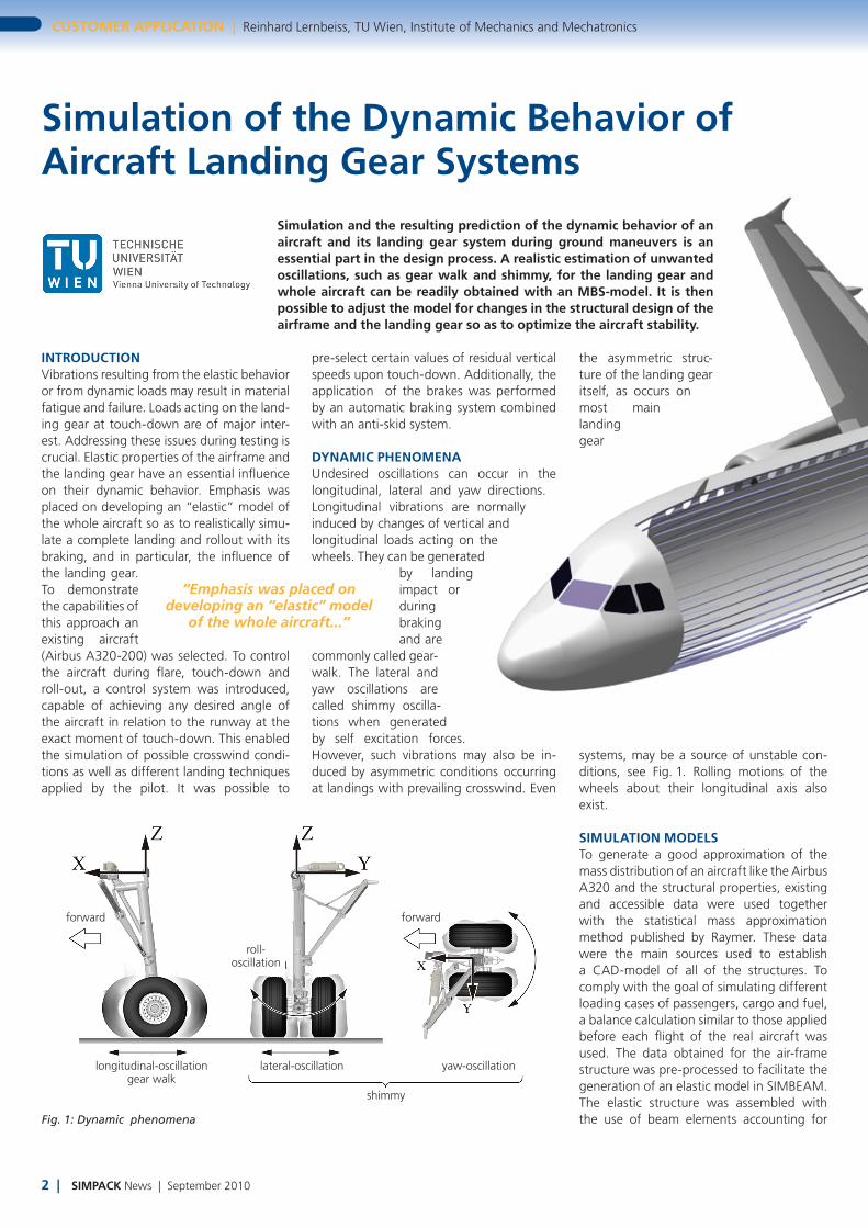
forward forward roll- oscillation longitudinal-oscillation gear walk lateral-oscillation yaw-oscillation shimmy 2 | SIMPACK News | September 2010 CUSTOMER APPLICATION | Reinhard Lernbeiss, TU Wien, Institute of Mechanics and Mechatronics Simulation of the Dynamic Behavior of Aircraft Landing Gear Systems Simulation and the resulting prediction of the dynamic behavior of an aircraft and its landing gear system during ground maneuvers is an essential part in the design process. A realistic estimation of unwanted oscillations, such as gear walk and shimmy, for the landing gear and whole aircraft can be readily obtained with an MBS-model. It is then possible to adjust the model for changes in the structural design of the airframe and the landing gear so as to optimize the aircraft stability. INTRODUCTION Vibrations resulting from the elastic behavior or from dynamic loads may result in material fatigue and failure. Loads acting on the land- ing gear at touch-down are of major inter- est. Addressing these issues during testing is crucial. Elastic properties of the airframe and the landing gear have an essential influence on their dynamic behavior. Emphasis was placed on developing an “elastic” model of the whole aircraft so as to realistically simu- late a complete landing and rollout with its braking, and in particular, the influence of the landing gear. To demonstrate the capabilities of this approach an existing aircraft (Airbus A320-200) was selected. To control the aircraft during flare, touch-down and roll-out, a control system was introduced, capable of achieving any desired angle of the aircraft in relation to the runway at the exact moment of touch-down. This enabled the simulation of possible crosswind condi- tions as well as different landing techniques applied by the pilot. It was possible to Fig. 1: Dynamic phenomena pre-select certain values of residual vertical speeds upon touch-down. Additionally, the application of the brakes was performed by an automatic braking system combined with an anti-skid system. DYNAMIC PHENOMENA Undesired oscillations can occur in the longitudinal, lateral and yaw directions. Longitudinal vibrations are normally induced by changes of vertical and longitudinal loads acting on the wheels. They can be generated by landing impact or during braking and are commonly called gear- walk. The lateral and yaw oscillations are called shimmy oscilla- tions when generated by self excitation forces. However, such vibrations may also be in- duced by asymmetric conditions occurring at landings with prevailing crosswind. Even the asymmetric struc- ture of the landing gear itself, as occurs on most main landing gear systems, may be a source of unstable con- ditions, see Fig. 1. Rolling motions of the wheels about their longitudinal axis also exist. SIMULATION MODELS To generate a good approximation of the mass distribution of an aircraft like the Airbus A320 and the structural properties, existing and accessible data were used together with the statistical mass approximation method published by Raymer. These data were the main sources used to establish a CAD-model of all of the structures. To comply with the goal of simulating different loading cases of passengers, cargo and fuel, a balance calculation similar to those applied before each flight of the real aircraft was used. The data obtained for the air-frame structure was pre-processed to facilitate the generation of an elastic model in SIMBEAM. The elastic structure was assembled with the use of beam elements accounting for “Emphasis was placed on developing an “elastic” model of the whole aircraft...”
Transcript of Simulation of the Dynamic Behavior of Aircraft landing ... · PDF fileAircraft landing Gear...
forward forward
roll- oscillation
longitudinal-oscillation gear walk
lateral-oscillation yaw-oscillation
shimmy
2 | SIMPACK News | September 2010
CuStoMer APPlICAtIon | Reinhard Lernbeiss, TU Wien, Institute of Mechanics and Mechatronics
Simulation of the Dynamic Behavior of Aircraft landing Gear Systems
Simulation and the resulting prediction of the dynamic behavior of an aircraft and its landing gear system during ground maneuvers is an essential part in the design process. A realistic estimation of unwanted oscillations, such as gear walk and shimmy, for the landing gear and whole aircraft can be readily obtained with an MBS-model. It is then possible to adjust the model for changes in the structural design of the airframe and the landing gear so as to optimize the aircraft stability.
IntroDuCtIonVibrations resulting from the elastic behavior or from dynamic loads may result in material fatigue and failure. Loads acting on the land-ing gear at touch-down are of major inter-est. Addressing these issues during testing is crucial. Elastic properties of the airframe and the landing gear have an essential influence on their dynamic behavior. Emphasis was placed on developing an “elastic” model of the whole aircraft so as to realistically simu-late a complete landing and rollout with its braking, and in particular, the influence of the landing gear. To demonstrate the capabilities of this approach an existing aircraft (Airbus A320-200) was selected. To control the aircraft during flare, touch-down and roll-out, a control system was introduced, capable of achieving any desired angle of the aircraft in relation to the runway at the exact moment of touch-down. This enabled the simulation of possible crosswind condi-tions as well as different landing techniques applied by the pilot. It was possible to
Fig. 1: Dynamic phenomena
pre-select certain values of residual vertical speeds upon touch-down. Additionally, the application of the brakes was performed by an automatic braking system combined with an anti-skid system.
DYnAMIC PHenoMenAUndesired oscillations can occur in the longitudinal, lateral and yaw directions. Longitudinal vibrations are normally induced by changes of vertical and longitudinal loads acting on the wheels. They can be generated
by landing impact or during braking and are
commonly called gear-walk. The lateral and yaw oscillations are called shimmy oscilla-tions when generated by self excitation forces. However, such vibrations may also be in-duced by asymmetric conditions occurring at landings with prevailing crosswind. Even
the asymmetric struc-ture of the landing gear itself, as occurs on most main landing gear
systems, may be a source of unstable con-ditions, see Fig. 1. Rolling motions of the wheels about their longitudinal axis also exist.
SIMulAtIon MoDelSTo generate a good approximation of the mass distribution of an aircraft like the Airbus A320 and the structural properties, existing and accessible data were used together with the statistical mass approximation method published by Raymer. These data were the main sources used to establish a CAD-model of all of the structures. To comply with the goal of simulating different loading cases of passengers, cargo and fuel, a balance calculation similar to those applied before each flight of the real aircraft was used. The data obtained for the air-frame structure was pre-processed to facilitate the generation of an elastic model in SIMBEAM. The elastic structure was assembled with the use of beam elements accounting for
“Emphasis was placed on developing an “elastic” model
of the whole aircraft...”
SIMPACK News | September 2010 | 3
Reinhard Lernbeiss, TU Wien, Institute of Mechanics and Mechatronics | CuStoMer APPlICAtIon
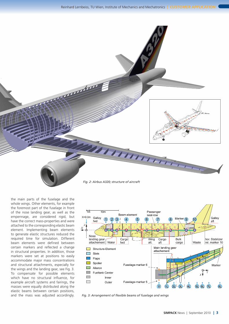
Fig. 3: Arrangement of flexible beams of fuselage and wings
Fig. 2: Airbus A320; structure of aircraft
the main parts of the fuselage and the whole wings. Other elements, for example the foremost part of the fuselage in front of the nose landing gear, as well as the empennage, are considered rigid, but have the correct mass-properties and were attached to the corresponding elastic beam element. Implementing beam elements to generate elastic structures reduced the required time for simulation. Different beam elements were defined between certain markers and reflected a change in structural properties. In addition, those markers were set at positions to easily accommodate major mass concentrations and structural attachments, especially for the wings and the landing gear, see Fig. 3. To compensate for possible elements which have no structural influence, for example aircraft systems and fairings, the masses were equally distributed along the elastic beams between certain positions, and the mass was adjusted accordingly.
data aquisition SIMPACK output
data aquisition SIMPACK
intput
output
reverse thrust
autobrake selection
yaw & roll pre-selection
aerodynamic wings
flare trajectory
aerodynamic hor. stabilizer
engine thrust
brakes & directional
control
SIMPACK model
1st Eigenmode 2nd Eigenmode
4th Eigenmode
4 | SIMPACK News | September 2010
CuStoMer APPlICAtIon | Reinhard Lernbeis, TU Wien, Institute of Mechanics and Mechatronics
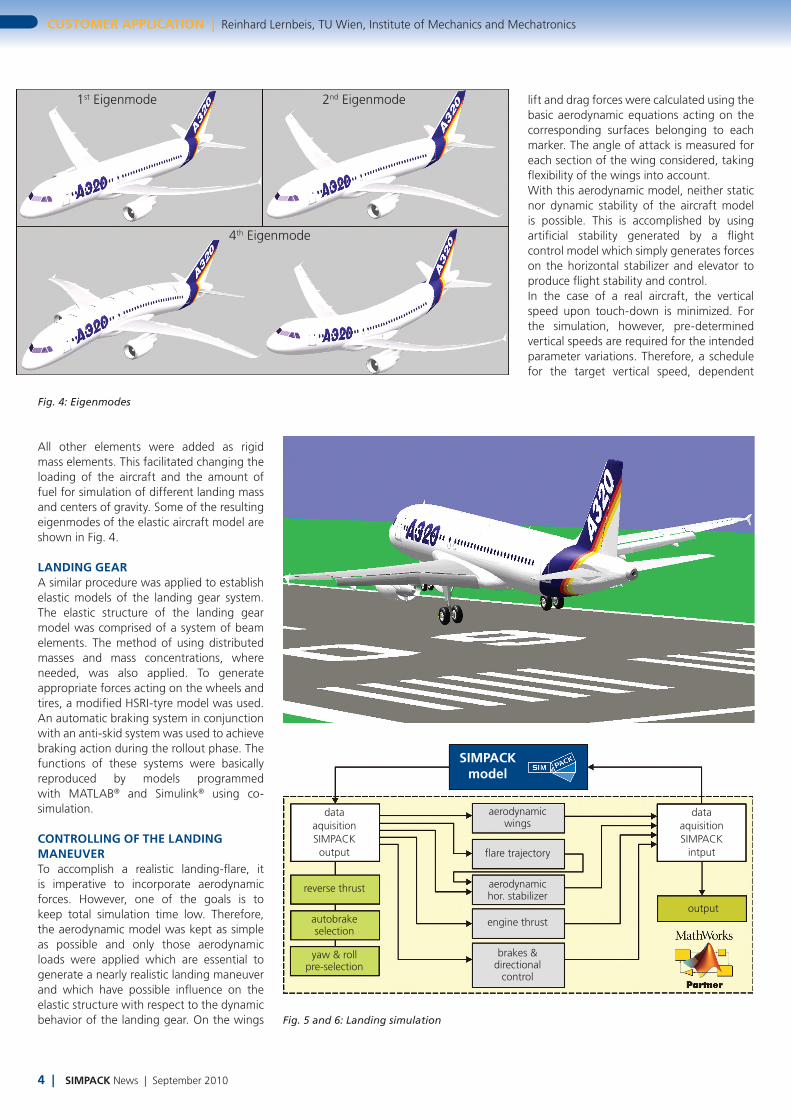
All other elements were added as rigid mass elements. This facilitated changing the loading of the aircraft and the amount of fuel for simulation of different landing mass and centers of gravity. Some of the resulting eigenmodes of the elastic aircraft model are shown in Fig. 4.
lAnDInG GeArA similar procedure was applied to establish elastic models of the landing gear system. The elastic structure of the landing gear model was comprised of a system of beam elements. The method of using distributed masses and mass concentrations, where needed, was also applied. To generate appropriate forces acting on the wheels and tires, a modified HSRI-tyre model was used. An automatic braking system in conjunction with an anti-skid system was used to achieve braking action during the rollout phase. The functions of these systems were basically reproduced by models programmed with MATLAB® and Simulink® using co-simulation.
ControllInG oF tHe lAnDInG MAneuVerTo accomplish a realistic landing-flare, it is imperative to incorporate aerodynamic forces. However, one of the goals is to keep total simulation time low. Therefore, the aerodynamic model was kept as simple as possible and only those aerodynamic loads were applied which are essential to generate a nearly realistic landing maneuver and which have possible influence on the elastic structure with respect to the dynamic behavior of the landing gear. On the wings Fig. 5 and 6: Landing simulation
Fig. 4: Eigenmodes
lift and drag forces were calculated using the basic aerodynamic equations acting on the corresponding surfaces belonging to each marker. The angle of attack is measured for each section of the wing considered, taking flexibility of the wings into account. With this aerodynamic model, neither static nor dynamic stability of the aircraft model is possible. This is accomplished by using artificial stability generated by a flight control model which simply generates forces on the horizontal stabilizer and elevator to produce flight stability and control. In the case of a real aircraft, the vertical speed upon touch-down is minimized. For the simulation, however, pre-determined vertical speeds are required for the intended parameter variations. Therefore, a schedule for the target vertical speed, dependent

SIMPACK News | September 2010 | 5
Reinhard Lernbeiss, TU Wien, Institute of Mechanics and Mechatronics | CuStoMer APPlICAtIon
Fig 7: Nose landing gear; Airbus A320
upon height, was introduced. To simulate crosswind conditions upon landing and corresponding landing techniques used by the pilot or the automatic landing system, certain angles of roll and bank were selected. These angles were kept constant during flare until touch-down of the main wheels by a separate controlling system.
SIMulAtIon Set-uPThe model of the elas-tic aircraft structure together with the land-ing gear system in the MBS-software SIMPACK was simulated with the controlling system of the aircraft, programmed in Simulink using a co-simu-lation. Simulink was used for aerodynamic forces, anti-skid, autobrake sys-tem and steering on the runway during roll out. Thrust control during flare and reverse thrust were also provided, see Fig. 5 and 6.
DroP teSt SIMulAtIonDuring the design and development process, a so-called drop test con-ducted in a laboratory is used. Here a single real landing gear unit, loaded with the appropriate mass, falls onto a rotat-ing drum which repre-sents the moving runway surface. This test is a vital source of information and the data generated are used to optimize both
the design of the landing gear and for the flight test later in the development process. Therefore, it is imperative to conduct suf-ficient simulations of that test in advance to save resources and time. In addition, the simulation of drop tests of the landing gear with flexible structure models enables a touch-down with different side slips (yaw angles) and the motion of the de-rotation of the aircraft, which is the lowering of the nose after touch-down of the main landing gear.
SIMulAtIon oF lAnDInG An AIrCrAFtIt is crucial to have sufficient model detail to gain insight into the dynamic behavior of landing gear. Fig. 8 presents a comparative study of the relative displacement and twisting of the wheel axis of the main landing gear using different modeling techniques of the elastic properties of the aircraft structure. It can be seen that the results may differ quite significantly.
ConCluSIonTo facilitate the design process, it is advan-tageous to implement and use simplified models to simulate a number of operational aspects to prevent undesired and costly but necessary improvements during flight tests. It is of utmost importance to have an easy to use and changeable model at any stage of development to predict the behavior of the landing gear. It is then possible to modify the design or to make appropriate adjustments to a shimmy damper or similar device at an early stage of design. Implementing a flexible structure in the simulation model is essential. In addition, it is possible to produce a realistic landing maneuver using only limited applica-tion of aerodynamic calculations and save
computational time to fa-cilitate the design process by testing various structural configurations early in the design process. The model presented enables the use of real-time simulations
used in flight simulators, and is necessary for aircraft that use an extensive amount of flex-ible composite components.
“It is crucial to have sufficient model detail to
gain insight into the dynamic behavior of
the landing gear.”
Fig 8: Relative displacement of the wheel axis; different levels in modeling the aircraft structure