Simulation of mechanical joining for automotive - KTH Mechanics
26
Simulation of mechanical joining for automotive applications by Johannes Gårdstam February 2006 Licentiate Thesis from Royal Institute of Technology Department of Mechanics SE-100 44 Stockholm, Sweden
Transcript of Simulation of mechanical joining for automotive - KTH Mechanics

Simulation of mechanical joining forautomotive applications
by
Johannes Gårdstam
February 2006Licentiate Thesis from
Royal Institute of TechnologyDepartment of Mechanics
SE-100 44 Stockholm, Sweden

© Johannes Gårdstam 2006

Simulation of mechanical joining for automotive applications
Johannes Gårdstam 2006Department of Mechanics, Royal Institute of TechnologySE-100 44 Stockholm, Sweden
AbstractRegarding the use of material, modern lightweight car bodies are becoming more and morecomplex than previous constructions. The materials nowadays are used for a more specificfield of application and more high strength steels are used and also other materials likealuminium, stainless steel, reinforced polymers are used more frequent. The joining of thesematerials often requires new or modified joining processes. The aim with this thesis isconcerned with the development of simulation models of the joining process as well asmechanical properties of self piercing riveted (SPR) joints and pierce nut joints. In both ofthese joining methods problems occur when introducing more high strength steel sheets. ForSPR, fractures occur in the rivet, and for pierce nut the thread will be damaged.
Since both the SPR process and the pierce nut process expose the material for plasticdeformation up to 150%, correct material properties for very large strain and a simulationprogram that could handle this was required. With the commercial finite element programDeform2D an axi-symmetric model has been built for the SPR process and the pierce nutprocess. Because of the computational time, 3D simulations were only used where it wasnecessary. The developed 3D models use the commercial finite element program ABAQUS-Explicit. All simulation models have been verified with satisfactory agreement toexperimental results.
For SPR, an axi-symmetric simulation model was used for evaluating and optimising thesetting process in the stainless steel sheets EN1.4301, HyTens 800 and HyTens 1200.Subsequently, 3D models were used for predicting the mechanical properties of new SPRjoints that have showed reduced risk for rivet cracking. In pierce nut simulations, nuts withhardness 8 and 10 have been set in the high strength steel sheet DP600. An axi-symmetricsimulation model was used for centred nut setting and two different simulation models in 3Dwere used to evaluate eccentric nut setting and torque resistance.
This work resulted in more knowledge about the fracture risk in the rivet and how to reduce it.The strain and stress, which was used as fracture indicators, were reduced to the half withmodifications of the rivet and the die geometry. Mechanical property simulations in shear andpeel load resulted in satisfactory results for new SPR joints that have showed reduced fracturerisk during rivet setting. New die and rivet designs can be developed effectively by combiningthe process and mechanical property simulations.
For a pierce nut joint in high strength steel sheets (1.5mm DP600), the simulations show thatthe cutting of the sheet in combination with eccentric setting over the die causes the threaddamage. The thread damage can be avoided by changing the dimension of the nut or byincreasing the strength of the nut material. The simulation models can also be used to developnew nut and die geometries for future applications.
Descriptors: self piercing riveting, pierce nut, mechanical joining, finite element modelling,high strength, stainless steel


PrefaceThe work that is presented in this licentiate thesis was performed at the Swedish Corrosionand Metals Research Institute between 2003 and 2005. The main purpose with this work wasto develop simulation models that could describe the process conditions in mechanical joiningwith acceptable accuracy.
The work that is done at self piercing riveting was financed by the National Swedish ProgramBoard for Automotive Research (PFF), Outokumpu stainless Research Foundation, Renault,Volvo Truck, Acciaierie Valbruna and Henrob. The national Swedish program Green car andthe companies Strömsholmen, Finnveden and Volvo Car financed the work done at Piercenut. I would like to thank all of those and their representatives.
I would also like to express my acknowledgements to Prof. Arne Melander at KIMAB for hislarge interest in my work and for valuable discussions and guidelines.
Prof. Anders Eriksson at the department of Mechanics at KTH is also acknowledged for hissupport and guidance, and for the possibility for me to perform this work in co-operation withthe Corrosion and Metals Research Institute.
My colleagues and friends at the institute and at the department of mechanics, thank you allfor a nice time during this work.
And finally I would like to thank my family, and a special thank is dedicated to my girlfriendLinda for her great support and encouragement.
Stockholm, December 2005Johannes Gårdstam
Paper I. Gårdstam J., Simulation of self piercing riveting of high strength austeniticstainless steel in 1 and 2 mm sheet thickness, Swedish Institute for MetalsResearch, report IM-2004-537
Paper II. Gårdstam J., Simulation and verification of self pierced rivet joints of stainlesssheet steels, Swedish Institute for Metals Research, report IM-2004-547
Paper III. Gårdstam J. and Melander A., Self-piercing riveting of stainless sheet steels-simulation and verification, 11th Paderborner Symposium Fügetechnik,Mechanishes Fügen und Kleben (2004) p. 135-143
Paper IV. Gårdstam J., Simulation and verification of pierce nut in high strength sheetsteels, Corrosion and Metals Research Institute, report IM-2005-118


Contents
1. INTRODUCTION ....................................................................................................................................... 1
1.1 BACKGROUND ........................................................................................................................................... 1
1.2 MECHANICAL PROPERTIES OF JOINTS......................................................................................................... 3
1.3 PROBLEMS WITH MECHANICAL JOINING IN HIGH STRENGTH STEEL SHEETS................................................ 4
1.4 CONTRIBUTION WITH THIS THESIS ............................................................................................................. 4
2 FINITE ELEMENT METHOD ................................................................................................................. 5
2.1 IMPLICIT AND EXPLICIT FEM .................................................................................................................... 5
2.2 MATERIAL MODEL..................................................................................................................................... 5
2.3 CONTACT CONDITIONS .............................................................................................................................. 7
2.4 FRACTURE SIMULATION............................................................................................................................. 8
3 SIMULATION MODELS........................................................................................................................... 9
3.1 SELF PIERCING RIVETING ........................................................................................................................... 9
3.2 PIERCE NUT.............................................................................................................................................. 11
4 CONCLUSIONS AND FUTURE WORK............................................................................................... 13
4.1 CONCLUSIONS ......................................................................................................................................... 13
4.2 FUTURE WORK......................................................................................................................................... 14
5 REFERENCES .......................................................................................................................................... 15
SUMMARY OF APPENDED PAPERS
PAPER I
PAPER II
PAPER III
PAPER IV


1
1. Introduction
1.1 BackgroundUntil recently car bodies were made from mild steel and joined mainly using spot welding [1].This was because steel is both cheap and strong, with spot welding as the cheapest method ofjoining, and for a typical car body between 3,000 and 4,000 spot welds were used. Forautomotive structures, the stiffness and the fatigue behaviour is mainly influenced by theproperties of their joints. However, the mechanical properties of the joint are not the onlyinteresting parameter. For a joining method to be attractive for the industry, it must beautomated and economically attractive or the only option for joining the selected materials.To meet the requirements of various parts of the car, modern lighter weight vehicles contain alarge number of different sheet materials of different strengths. According to [1] the drivingforces to introduce new materials are lower weight, increased safety and lower costs. Thisoften leads to more use of sheet steels with increased strength, as a consequence, the pressureto improve the joining methods has increased. Spot welding is still the most common joiningmethod. This is due to the fact that the fatigue resistance of spot welds increases only slightlywith the sheet strength. On the other hand, mechanical joining techniques are characterised byimproved fatigue properties for more high strength materials [2]. Examples of mechanicaljoining techniques are riveting and clinching, but also fasteners like screws and bolts. In a carbody there is nowadays also an increased number of different materials like stainless steel,aluminium, reinforced polymers, etc. which also require new joining methods, especially injoints with dissimilar sheet materials. Here often mechanical joining and adhesive bonding arethe only possible joining methods. New techniques have been developed to automate andsimplify the process of mechanical joining as much as possible, which is a requirement toreduce costs. Self piercing riveting (SPR), clinching and pierce nuts are three methods toautomate and reduce costs for mechanical joining. The developed techniques are oftensuitable or developed for mild steel and therefore they require some modifications when usedwith more high strength steels or with new material combinations. A simulation model forsuch modification would therefore be desirable in order to simplify the development and toreduce the development costs.
Self piercing rivetingSPR is a relatively new technology that was developed for joining aluminium, sincealuminium is difficult to spot weld due to its high thermal conductivity, low melting rangeand propensity to form oxide surface film [3].
The SPR technique joins two ormore sheet layers in a single stepwithout any pre-drilled or pre-punched holes. The rivet isdesigned to penetrate through thetop material and is spreading out inthe lower material under theinfluence of a die that is positionedbelow the lower sheet. Since thelower sheet is not pierced theresulting joint is resistant to gas andliquid from the die side andtherefore also resistant to corrosion
Figure 1. Setting process of self piercing riveting. Copy from[4]

2
from that side. Known disadvantages of SPR joints are according to [5] the requirement ofaccess to both side of the joint, the relatively large cost, the consumption of rivets, the highsetting forces that require a strong and relatively heavy C-frame for the robots, see Figure 4.and that the finished joint is not flush on both sides. Known advantages of SPR joints are thecapability to join dissimilar materials, such as aluminium to steel, the ability to joingalvanised or pre-painted materials without damaging the coating, the use in combinationwith adhesive bonding and the good fatigue properties.
ClinchingClinching is a combination of drawing and forming that locks together sheet metal layers.Multiple layers can be joined, though clinching is most commonly used for only two layers. Inclinching, a punch drives the two layers of metal into a die, the upper layer of material spreadsinto the lower layer so it cannot be pulled out, see Figure 2. The process requires use ofductile sheet metals, such as steel and aluminium. Many plastics are difficult to clinch sinceplastics tend to resume their original shape after being clinched [6]. Clinching is technicallyand economically attractive. However,manufactures are moving towardsthinner and stronger materials. This mayaffect the ductility of the sheet materialsand reduce their suitability forclinching. Optimisation or modificationof the clinching process may solve thatproblem [7]. Figure 2. Clinching process. Copy from [8]
Pierce nutScrew fasteners are labour intensive and difficult to automate and therefore expensive inmedium to high production runs. However, sometimes access to only one side is possible orunfastening of the joint may be needed during repair. This is possible with screws and nut,provided that the nut is mounted into the sheet. With screw fasteners it is also possible tocombine an unlimited number of sheets of diverse materials and thicknesses. Pierce nut,Figure 3, is a technique that punches the nut directly into and securely fixes the nut to thework piece in one operation [9]. No pre-punched or pre-drilled holes are required. The piercenut process is often integrated to the pressing line, where sheets will be formed to a beam,door, roof etc. and simultaneously as the sheet will be formed, the nut will be inserted into it.Pierce nut offers significant savings in time and costs over weld nuts that are installed outsidethe stamping line. However, the pierce nut requires a good installation to ensure optimalperformance and the performance of a pierce nut can be divided into two sections. First themechanical attachment between nut and sheet, e.g. torque and push out resistance, this iscalled for the installation perform-ance [10]. Second, the mechanicalstrength of a final joint with thescrew installed, e.g. the shear andpeel strength of the final joints. In thepresent work only the installationperformance are evaluated.
Similar to SPR and clinching, piercenuts can also be mounted with arobot and a C-frame. Robots are alsocommon when assembling thescrews in the nut.
Figure 3. Pierce nut. Copy from[11]
Figure 4. C-frame.Copy from [12]

3
1.2 Mechanical properties of jointsIf the same material is used in the top sheet and the lower sheet, clinching and SPR are incompetition with spot welding. To estimate the joint quality, two types of testing modes areuseful, shear mode and peel mode. The joint properties may also vary between static load andfatigue load. In [13], clinching and SPR joints in sheet thicknesses 1.0 + 1.0 mm have beencompared to spot welded joints in shear and peel modes to evaluate static and fatigue strength.The sheet material is ZstE340, which is a high strength steel with Rp0.2 at 340 MPa.
In Figures 5 and 6, the static shear and peel strengths can be observed. The largest values,white bars, indicate maximum static forces and the grey bars indicate the stretching forces.The stretching force is the maximum force the joint can carry before it starts yielding.
Figure 5. Static shear strength of clinched, spot-welded and SPR joints, redrawn from [13].
Figure 6. Static peel strength of clinched, spot-welded and SPR joints, redrawn from [13].
Joints performed with spot welding shows a higher shear and peel strength compared to theother joining techniques. Clinched joints show the lowest strength, both in shear and peelmode. Values from SPR joints are between the spot welded and clinched joints. However, theresults from static testing are not valid for cyclic loading, see Figures 7 and 8. The mechanicaljoints give high strength during fatigue testing. In this set up, SPR shows the best results bothin shear and peel load. Clinching also gives good results in shear mode. Depending on thedesign of the structure, the static strength or the fatigue strength is most important fordimensioning.
Figure 7. Fatigue properties for shear loadedjoints in an H-specimen. Based on data from [13].
Figure 8. Fatigue properties for peel loaded jointsin an H-specimen. Based on data from [13].

4
1.3 Problems with mechanical joining in high strength steel sheetsFor a long time there has been a trend towards using higher strength steels. In a typical Volvocar (2002) 45% of the body consists of various kinds of high strength steels [1]. With anincreasing number of high strength steel parts, difficulties occur with joining technologiespreviously used with milder steel. Even if more high strength steel will make the mechanicaljoining more difficult, it will also increase the use of mechanical joining like SPR, especiallybecause of the good fatigue properties as seen in section 1.2. The difficulties to perform aSPR joint in high strength steel sheets are related to the reduced ductility of high strengthsteels. In particular, the lower sheet requires a sufficient ductility. The higher strength of thesheet material requires a higher strength of the rivet material to avoid collapse. At the sametime, the rivet must exhibit sufficient ductility to perform a joint. Finally an increased settingforce is required, which will result in larger and heavier C-frames to maintain the parallelsurface between rivet and die. The automated robots that will carry the C-frame may haveproblems if the mass or the size of the C-frame increases too much.
During setting of pierce nuts there are other problems that occur when introducing new higherstrength materials. In industrial nut setting operations it was found that the thread of the piercenut was damaged and scatter in mechanical properties were obtained when the pierce nut RF-M6 was set in a sheet of high strength steel DP600 (Dual Phase). DP600 is a common type ofhigh strength steel used today and the number 600 stands for the limit in ultimate tensilestrength i.e. 600 MPa.[1].
1.4 Contribution with this thesisAll kinds of mechanical joining are interesting for future structures. In particular, this is thecase for mechanical joints that can be highly automated, which reduces the production costs.A method to develop, modify and optimise the joints for a specific sheet combination, orspecial sheet materials is therefore desirable.
Important factors to perform an optimised SPR joint are the combination of sheet material,rivet material, rivet geometry and die geometry. Using Finite Element Method (“FEM”)simulation, the riveting process can be optimised in an effective way, which is done in PaperI. FEM-simulation can also be used to evaluate the mechanical properties for the SPR joint,which is done in Paper II and Paper III.
The FEM can also be used to simulate the nut setting process. With a reliable simulationmodel, the simulation will give knowledge about the whole nut setting process andconsequently why thread damage occurs in the experimental trials. It is also possible todevelop new and better nut or die geometries. Three simulation models are required for thepierce nut process to evaluate all interesting parameters. First, a model for centred nut setting,secondly, a model for eccentric nut setting, and finally a model for evaluating the torqueresistance, this is done in Paper IV.
By using numerical simulation models this thesis aims to contribute to the understanding ofmechanical joining processes in high strength steels. It introduces and evaluates simulationmodels that are possible to modify and to use for development of new products.

5
2 Finite Element MethodAnalysis based on the finite element method (“FEM”) is a useful tool to simulate the processcondition as well as the mechanical properties of a joint. It is important to treat the problemcorrectly and since FEM-simulation always is an approximation it is important to use the bestapproximation. Independent of simulation software, equivalent input parameters must beinserted into the simulation programs. The correctness of the input is of great importance forthe reliability of the simulation results.
2.1 Implicit and Explicit FEMThe differential equations used in FEM can be integrated by numerical time stepping withboth implicit and explicit methods. Both methods can be used for static and dynamic analyses.In this work, two FEM Softwares are used. DEFORM-2D is used for axially symmetricsimulations. These are based on an updated Lagrangian formulation, and uses implicit timeintegration. The program is specialised for large plastic deformation and cutting of an object.A strength with DEFORM-2D is the automatic remeshing that often is required to handlelarge plastic deformations correctly. ABAQUS is used for the 3D simulations. ABAQUS givethe possibolities to solve the problem with an implicit or an explicit solver. In this workABAQUS-Explicit was used since it contains an element deletion procedure and since thesimulations will be non-linear. ABAQUS-Explicit is based on the central difference timeintegration, together with the use of lumped masses giving a diagonal mass matrix. Thesystem to be solved is therefore uncoupled and the stiffness is calculated on the element levelwithout a global stiffness matrix. Equilibrium in ABAQUS-Explicit is defined as Eq 1.
Eq 1.
where M is the diagonal mass matrix, P the external applied force, I the internal elementforces and ü the nodal acceleration [14]. In combination with the small time step required forthe explicit integration to be stable, see Paper IV, there will be many small equations to solve.Therefore the explicit solution time is linearly proportional to the number of degrees offreedom (“DOF”). Because of the opportunity to do parallel calculations it can effectively bedivided into several CPUs.
For the implicit integration rule, a global dynamic stiffness matrix is used. The equationsystem containing the stiffness matrix must be solved and the size of the stiffness matrix isrelated to the DOF in the structure. Consequently the implicit solution time is therefore relatedto DOF squared. Usually a much larger time step is used in the implicit calculations compared
to the explicit calculations. Therefore an implicitcalculation only solves one or a few very largeequations. When solving a nonlinear problem implicitly,the solution method requires several time steps since thestiffness matrix must be recalculated during the courseof the analysis [14]. This will make a nonlinear analysismuch more time consuming than a linear analysis and anexplicit solver may be preferable, since it already usessmall time steps.
Figure 9. Comparison of solution timeswith increased number of degrees offreedom
2.2 Material modelIn the SPR and the pierce nut processes the material of the objects, sheet, nut and rivet, willundergo large plastic deformations. This demands the correct flow properties to be used in the
6
simulations. Most materials are nonlinear during plasticity since a nonlinear function ratherthan a constant relate the stresses and strains. Therefore the SPR and pierce nut simulationswill be nonlinear if the material starts yielding. Several different materials are evaluated fromcompression tests and used in the simulations. For the self piercing riveting simulations theflow properties of the rivet materials and different stainless steel sheets were evaluated. Forthe pierce nut simulations the sheet material DP600 was evaluated and also three differenthardnesses of the nut material. See Figure 10 to compare the material flow properties. Thematerials show more or less strain hardening; especially the stainless sheet materials (EN1.4301, HyTens800 and HyTens1200) exhibit significant hardening. In the simulations anisotropic hardening rule was used. Isotropic hardening means that the yield surface changesits size uniformly in all directions and the yield strain in all directions will be the same, i.e. theradius of the cylinder in Figure 11 increases. The surface of the cylinder is the yield surfaceand points within the cylinder represent states of nonyielding [15]. If all stress components arepositive, or all are negative, very high stresses can occur without yielding of the material. Thisis called the hydrostatic pressure and is defined as the distance between the origin and theflow locus that is perpendicular to vector P.
Figure 10. Flow properties of sheet, nut and rivetmaterial.
Figure 11. Von Mises yield criterion in 3D-principal stress space. With loading point fromthe rivets under head radius.
Isotropic hardening is for common metals in conflict with the observed behaviour whenyielding reappears i.e. when loading is reversed [16]. An alternative to isotropic hardening isthe kinematic hardening that moves the cylinder in Figure 11 instead of increasing the radiusof it like in isotropic hardening. A stress and strain plot of isotropic and kinetmatic hardeningcan be observed in Figure 12. Since kinematichardening is only valid for elastic-plastic objects undersmall deformations [17] it is not suitable for the SPRand pierce nut simulations. In the self piercing rivetingprocess, cracks may occur in the rivets under headradius, Figure 22. It is believed that such cracks aregenerated during the first unloading sequence afterriveting. At that stage the loading point in stress spacemoves very quickly from the lower side of the flowlocus towards the upper side, see Figure 11. Akinematic hardening may then be a more appropriatedescription of the material behaviour during theunloading sequence. Figure 12. Hardening rules, redrawn
from [16]

7
2.3 Contact conditionsThe relations between objects define how different objects in a simulation interact with eachother. All objects that may come in contact with each other through the simulation must havea contact relation defined to keep the objects from penetrating each other. The relationship isoften called master-slave contact. With a master-slave relation the nodes from a master objectcan penetrate the slave surface but the slave node are not allowed to penetrate a mastersurface, see Figure 13. If the upper object is the slave surface instead the contact will be as inFigure 14. To reduce the problem with overlapping surfaces and large gaps the slave objectshould be the object with a finer mesh. From a general point of view the object of hardestmaterial should be the master object. In the case of two objects consisting of the samematerial, either can be the slave although the object expected to elastically deform the mostshould be defined as the slave [17]. It is important to define these relationships correctly tomodel a forming process accurately.
Figure 13. Master objectpenetrates slave object.
Figure 14. With opposite master-slave order, there are largegaps.
Figure 15. Balanced contact,average of two contactcalculations.
In ABAQUS-Explicit a modified master-slave contact can be used, called balanced contact.For balanced master-slave contacts none of the objects will be set as master or as slave.Instead the contact will be calculated twice for each set of surface in contact, once with thefirst surface acting as the master surface and once with the second surface acting as the mastersurface. The average of the two corrections is applied to the contact interaction, see Figure 15.This will minimise the penetration of the contact bodies and will also give a more accurateresult in most cases [14]. Balanced contact is used in the general contact algorithm. Withgeneral contact the contact domain is the only thing specified. Every face that can potentially
be involved in contact, should be included in thecontact domain, even if the element is an interiorelement. The general contact algorithm will thenactivate and deactivate faces when element fails, seeFigure 16. In Deform-2D the surfaces are constantlyrenewed so the outer surfaces of a master or slaveobject always have relations to the other surfaces.
Figure 16. New contact surfaces afterdeletion of elements. Copy from [14].
The nodes are considered to be in contact as long as the nodal forces indicate a compressivestate. When the nodes develop a tensile force, the nodes are considered to have separated fromeach other [17]. The procedure with constantly new contacts results in a non-linearsimulation. It is also the most frequent reason for non-convergence during the Deform-2Dsimulations.
When surfaces are in contact they usually transmit shear as well as normal forces across theirinterface. The relation between these two force components is the friction between thecontacting bodies. Simulation of friction is very difficult and sensitive, since contactcondition, friction model and friction coefficient will influence the result. Consequentlyfriction is an uncertainty factor. In both the Deform-2D and the ABAQUS-Explicitsimulations, the Coulomb friction model was used. The Coulomb friction model defines the

8
friction shear stress as τ = µp, where p is the normal pressure and µ the friction coefficient; µis the same in all directions i.e. isotropic. In [14] experimental trials show that the frictioncoefficient that resists the slipping from a sticking condition is higher than the friction duringslipping. Therefore, the friction should actually be divided into two parts, a “static” and a“kinetic” friction, where the static friction is higher than the kinetic friction. A maximumshear stress should also be set, since slipping may start as a result of yielding in the material.However, the friction coefficient is very difficult to estimate and therefore already anuncertainty factor. To keep the adjustable parameters to a minimum, the kinetic friction andthe maximum shear stress were omitted in the simulation models. In simulation models wherethe results should be compared it is important that the same contact and friction conditions areused, but also that identical value of the friction coefficient are used, since the contact andfriction influence the results.
2.4 Fracture simulationOne of the reasons to choose Deform-2D and ABAQUS-Explicit as simulation programs isthat the implemented fracture models give the opportunity to divide objects, the steel sheets inthese cases. The fracture criterion is evaluated in each element and when it exceeds thespecific fracture criterion the element is deleted and a crack will be simulated. Unfortunately,none of the programs support element separation. Therefore, to limit volume loss, an extrafine mesh should be used in any region where fracture is expected [17]. In [18], differentfracture models have been evaluated for SPR simulations with the conclusions that both thestrain and the difference in stresses influence where fracture of the upper sheet occurs.
In Deform-2D, a damage model called normalised Cockroft & Latham [19] is used as thedamage value Df, The model implement the strain and the difference between principal andeffective stress and it has been shown to predict fracture with reasonable accuracy, [20]. Thedamage value Df is defined by the parameters seen in Figure 17, where the maximumprincipal stress divided by the effective stress is integrated over the effective strain until Dfreaches the predefined critical value; εf is then the effective fracture strain.
In ABAQUS-Explicit there are only two different failure models that include the possibility ofelement deletion, shear- and tensile failure. The shear failure uses the equivalent plastic strainas a failure measure and the tensile failure uses the hydrostatic pressure. In the SPR and piercenut models the shear failure will be the most appropriate since the perpendicular cutting of thesheet will cause large shear stresses. In Figure 18 the shear failure can be observed. pl
fε is thestrain at failure that must be specified. When the shear failure criterion is met (W=1) at anintegration point, all the stresses will be set to zero and the material point fails [14]. Thenormalised Cockroft & Latham criterion used in Deform-2D is a more complex and a morecorrect fracture criterion according to [19].
Figure 17. Cockroft & Latham fracture criterion,used in Deform-2D.
Figure 18. Shear failure criterion, used inABAQUS-Explicit.

9
3 Simulation modelsThe main idea with the simulation models is that they should reproduce experimental resultswith reasonable accuracy in important aspects. At the same time, the models should berelatively simple to modify. It is also a requirement that the final solution should be foundwithin reasonable solution times. When this is fulfilled, the SPR and pierce nut process can beoptimised in an effective way.
3.1 Self piercing rivetingThe SPR simulations were performed with the program Deform-2D and the subsequent jointproperty simulations were performed in 3D with ABAQUS-Explicit. A similar procedure wasanalysed in [21] with the simulation program LS-DYNA.
The SPR processsimulation begins with thegeometry seen in Figure19. The riveting processinvolves large plasticdeformations. To simulatethis process, it is necessaryto use formulations thatconsider geometry changesand material nonlinearity.During the riveting sim-ulation, some elements in
Figure 19. Start geometryand the Finite element meshfor SPR joint.
Figure 20. Final geometry showingplastic deformation, 3D-view from anaxi-symmetric model.
the mesh will become distorted. Since distorted elements will give incorrect results,remeshing was necessary in order to get reliable solutions. In Deform-2D, a new mesh isgenerated automatically and the informations from the old mesh are then interpolated to thenew mesh. During a SPR process simulation, the mesh will be updated around 20 times foreach object. The final joint geometry and the effective strain results from a SPR processsimulation in 1+1mm EN 1.4301 stainless sheet steel can be observed in Figure 20.
The similarities between simulated geometry and experimental result can be observed inFigure 22. The calculated setting force can be compared to the experimental setting force inFigure 21. Differences in setting force occur in the latter part of the simulation, whichprobably depends on shortcomings of the material description for very high strains.
0
10000
20000
30000
40000
50000
60000
70000
0 1 2 3 4 5 6Displacement [mm]
Forc
e [N
]
RivetingFE-simulation
Figure 21. Setting force for experimental andsimulated setting process.
Figure 22. Experimental result, cracking inthe rivets under head radius, red circle.
In Figure 22, a crack can be observed in the rivets under head radius. With a reliablesimulation model the riveting process can be optimised and a solution to reduce the fracturerisk can be found.
10
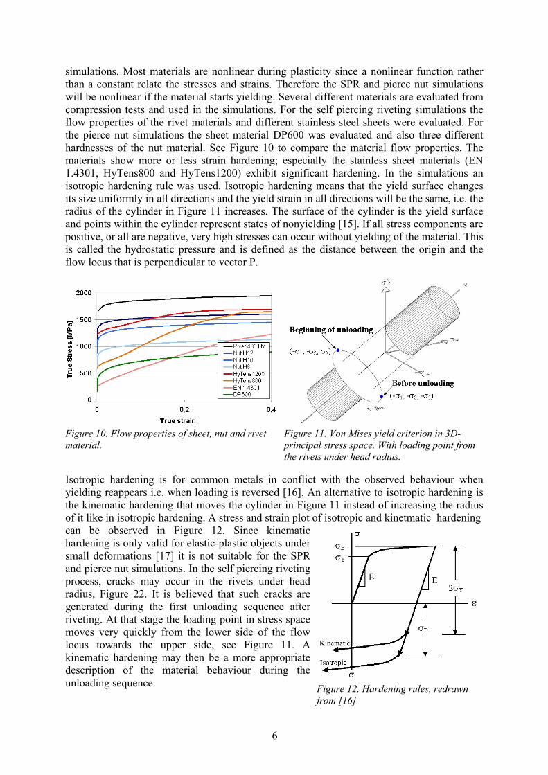
A final geometry from the process simulation in 2D was subsequently imported to ABAQUS-Explicit to evaluate the mechanical properties. Since the sheet material EN 1.4301 has showedsignificant strain hardening it is important to transfer both the final joint geometry and thestrain level from the riveting process, this is evaluated in Paper III. These were manuallytransferred to the 3D-simulation model. Residual stresses have not been transferred to themechanical testing model, which may leads to some effect on the result. To simplify themodel, virgin material properties were used for the rivet, as strain hardening for the carbonsteel rivets 480 HV is small. Because of symmetry, the simulated specimen has been split inthe middle and only half the specimen has been modelled; the shear specimen can be observedin Figure 23. As seen in experimental trial, Figure 24, the simulated and experimental jointsshowed similar fracture behaviours with the rivet pulled out from the die sheet. The joint wasalso tested in peel mode, which is described in Paper III.
Figure 23. Simulated shear specimen: rivet pulledout from die sheet.
Figure 24. Final geometry, experimental shearspecimen.
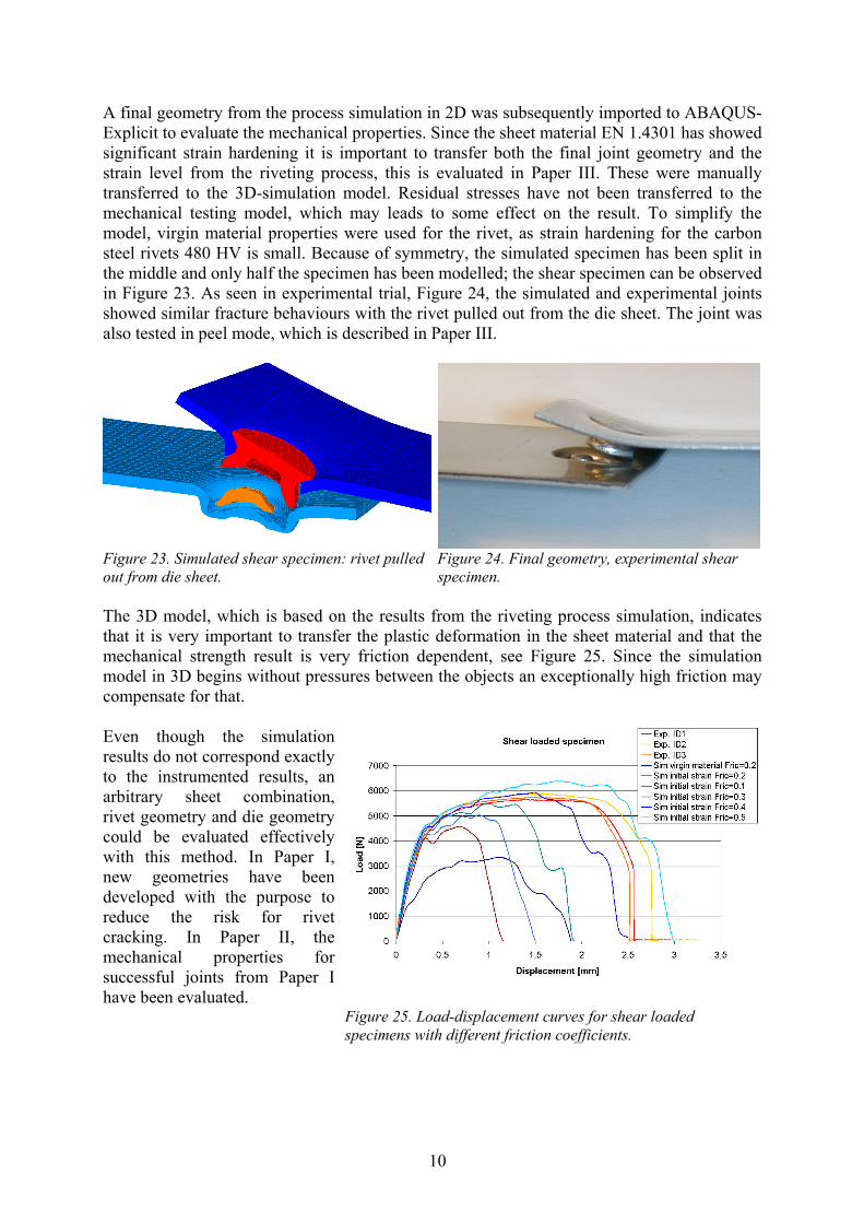
The 3D model, which is based on the results from the riveting process simulation, indicatesthat it is very important to transfer the plastic deformation in the sheet material and that themechanical strength result is very friction dependent, see Figure 25. Since the simulationmodel in 3D begins without pressures between the objects an exceptionally high friction maycompensate for that.
Even though the simulationresults do not correspond exactlyto the instrumented results, anarbitrary sheet combination,rivet geometry and die geometrycould be evaluated effectivelywith this method. In Paper I,new geometries have beendeveloped with the purpose toreduce the risk for rivetcracking. In Paper II, themechanical properties forsuccessful joints from Paper Ihave been evaluated.
Figure 25. Load-displacement curves for shear loadedspecimens with different friction coefficients.

11
3.2 Pierce nutDuring industrial production, the installation performance is of great importance. The nut isnot allowed to get loose from the sheet during any stage of the production line, and it is notallowed to rotate during assembly. Therefore, the torque resistance and push-out resistancesare important in order to reduce standstill in production. Consequently, they are evaluatedfrom the simulations.
The pierce nut process was simulated with three different models, all with different purposes.The axially symmetric simulation, Figure 26 was performed in Deform-2D. In 2D, someeffects can not be evaluated with an axi-symmetric simulation model. Therefore, two 3Dmodels were developed in ABAQUS-Explicit. The first 3D-model can be used to evaluateeccentricity of the nut, see Figure 27 and it is called the 3D-180° model. The second 3D-model, which uses cyclic symmetry, can be used to evaluate the torque resistance, since theteeth to prevent rotation, seen in Figure 29, are included. This model is called the 3D-30°model and it is seen in Figure 28. The axial symmetric model is the most time effectivesimulation, and in view of the fact that Deform-2D also is specialised on sheet cutting andlarge plastic deformation, it produces the most reliable results.
Figure 26. Axi-symmetricmodel of a nut setting process.
Figure 27. 3D-180° model of a nutsetting process.
Figure 28. 3D-30° model.Arrow indicates push-outdirection.
The material properties and the nut dimensions, with exception for the teeth that are omittedin the 2D and 3D-180° models, are identical in the simulation cases. However, theexperimental nut may deviate slightly from those dimensions.
When simulating identical problems as seen in Figure26-28, almost identical effective stresses where obtainedin the three models. Comparing the load-displacementcurves with experimental trials, Figure 30, the largestdivergence between the models is observed duringcutting of the sheet, which occurs at displacement 0.5-1.2mm. This depends on different fracture criteria andthe fact that the element sizes vary between thesimulation models. With exception for the cutting, thethree models seem to predict identical setting processes.Deviations from the experimental results come partlyfrom differences in the experimental nut geometry, sincethe nut geometry varies between individual specimens.
Figure 29. Teeth to prevent rotationinside the nut from the 3D-30° model.

12
Push-out strength was tested for thejoints. The direction of the push-outload on the nut can be observed inFigure 28. The sheet issimultaneously constrained frommoving in the vertical direction. Inthe simulations the pressure betweensheet and nut is of great importancesince the push-out resistance for thisnut geometry almost exclusivelyconsists of friction forces. Thepressure is influenced by the amountof material pushed into the nut andthe geometry of the sheet edge that iscut. Both are highly influenced bythe element deletion that representedthe cutting. As a consequence, thesimulated push-out strengths varybetween the simulation models, seePaper IV.
Figure 30. Setting forces from the three simulation modelsand corresponding experimental trial.
With a verified FEM model, FEM-simulation is an excellent way to evaluate and modify thesetting process for better joint performance. It was believed that eccentric setting was one ofthe reasons that causes thread damage and a scatter in push out resistance when the nut wasset in a high strength steel sheet. To evaluate that, the eccentricity was simulated with the 2Dand the 3D-180° models. Since the 2D model is axi-symmetric, this model actually simulatesa reduced die diameter, which is an approximation, but the “off-centred” 2D simulation willafter all give some ideas about the robustness of the nut. However, the 3D-180° modelprobably produce the best results for an off-centred nut. The damage in the nut was measuredas displacement in the thread, which is shown for different cases and models in Table 1. Byincreasing the nut strength from hardness 8 (H8) to hardness 10 (H10), which often can bedone by heat-treatment, the thread compressions (∆z) and radial thread displacements (∆r) arereduced and thread damage can probably be avoided. For a more high strength steel sheet thanDP600, geometry modifications of the nut and die are probably necessary.
Table 1. Thread movements in the simulation models [mm].ABAQUS 3D-180° ABAQUS 3D-30° Deform-2D
∆r ∆z ∆r ∆z ∆r ∆zCentred H8 0.016 0.020 0.001 0.007 0.005 0.003Off-centred 0.2mm H8 0.044 0.032 - - 0.070 0.069Off-centred 0.2mm H10 0.030 0.023 - - 0.026 0.017
Because of the element density and the accuracy in cutting the sheet, the 2D-model is themost reliable for centred nut setting. It is also the most time effective, and it will therefore beused as the first tool to develop new optimised geometries.

13
4 Conclusions and future work
4.1 ConclusionsThe industry demands are constantly increasing the hardness of the sheet steels that is used,and new materials are introduced in the structures. This leads to improved product quality, butit also gives new challenges with respect to production methods. The mechanical joiningprocess is heavily affected by the material properties. Therefore, a number of simulationmodels have been developed and verified to give more understanding of the setting processand the joints mechanical properties for SPR and pierce nut joints. The simulation models canalso be used to effectively develop new optimised joints for a specific steel sheet.
As long as everything is totally centred, the setting process of an SPR joint or a pierce nutjoint can be well described with an axi-symmetric simulation model in the commercialsoftware Deform-2D. Because of limitation with an axial-symmetric model, ABAQUS-Explicit was used to perform 3D simulations for the eccentric nut setting process, the torqueresistance for pierce nut joints and the mechanical strength for SPR joints. ABAQUS-Explicitis a more general program but is not as satisfactory as Deform-2D regarding cutting andremeshing. When developing new geometries the axial-symmetric model is the most timeeffective and most reliable simulation model.
In all simulation models, independent of simulation program, the friction coefficientinfluences the results. Similar contact conditions and surface geometry of the sheet cut is alsoimportant when simulation results are to be compared.
In experimental trials fractures were observed in the rivets under head radius when usinghigher strength sheet steels or new rivet materials in stainless steel. In the simulation modelsthe effective strain and the vertical stress were used as indicator of the fracture risk in therivet. In Paper I, simulations showed that the strain and stress could be reduced by 50%through modifications of the rivet and die geometry.
The joint geometry from the riveting simulation was transferred to a 3D-model for simulationof the mechanical strength. The mechanical properties of joints with different geometries canin this way be compared and evaluated without expensive manufacturing of new rivets.Because of hardening of the sheet material it is important to transfer the strain level from thejoining simulation to the simulation of the mechanical properties of the joints. In particular,this is important for materials that have much strain hardening.
Using the same section geometry from the SPR process simulation and only change the sheetsmaterial properties in the mechanical testing simulations i.e. the section geometry is identical,see Paper III. Simulations predict that the mechanical shear and peel strength was linearlyproportional to the yield strength Rp0.2 of the sheet. Because of shorter elongation at failure,the fracture energy was almost constant, independent of the yield strength of the material.
Tests performed at Volvo Car Corporation indicate that there are risk for thread damage andlow push-out resistance with a pierce nut RF-M6 set in a 1.45 mm DP600 sheet steel. Anumber of simulations were performed with three different simulation models. Each model isnecessary for the evaluation of all interesting parameters. The three models performedidentical setting processes except for the cutting of the sheet. The simulations indicate that anut that is set eccentrically over the die in combination with hard sheet steel causes the thread
14
damage that was observed in instrumented trials. This, however, can be avoided by increasingthe dimension of the nut or by increasing the strength of the nut material. Simulations alsoindicate that almost no mechanical locking occurs when a RF-M6 nut is set in high strengthsteel. Consequently the push-out resistance for a RF-M6 nut consists of friction forces. As aconsequence of all contact conditions during the push out of the nut, it is difficult to gettotally accurate results when simulating the push-out resistance. Comparison of results fromdifferent nut and die geometires can, however, be made. In paper IV, simulations showed thatchanging the die geometry increased the push out resistance. Experimental trials with similardie geometries to those used in the simulations verified the results.
4.2 Future workBased on the work discussed above, there are primarily three main areas to improve in furtherstudies.
Improve the simulation modelsIn this work the material properties were developed from compression tests of the material toachieve higher strains than in tensile testing. The stress-strain curves are probably sufficientlycorrect for strains up to ~0.3-0.4. However, this is still not enough since the sheet materials inthe simulations locally have strains up to 1.5. A more correct material description for veryhigh strains would therefore be desirable. Another way to improve the process simulations isto evaluate the fracture behaviour. Different materials and mesh densities influence thefracture conditions, which could be improved further. A fracture criterion that separateselements instead of deleting them will also improve the models. For the mechanical testing ofthe SPR joints, it would be desirable to revolve the axi-symmetric simulation with allparameters intact to a 3D-model for mechanical testing, using only one simulation software.Finally, with an increased computer performance a finer mesh can be used to refine thesimulation model further with the same calculation time as today.
Build more models for other mechanical joining techniquesMost mechanical joining methods use plastic deformation and locking between parts toperform the joints. With reliable material properties it is relatively simple to use the approachfrom this work to build simulation models for, e.g., clinching or folding.
Use the models to optimise and design new jointsFor new sheet materials introduced in the future, these models can be used to optimise ordevelop new rivet, nut and die geometries in a time and cost effective way. Since thesimulations give an overview of the whole process, problems can be found and newgeometries or material combinations can be tested much easier than by experimentalinvestigations. The models also give the possibilities to optimise the setting process and theresulting mechanical strengths for joints used today.

15
5 References[1] Svensson L-E., Larsson J K, Welding and joining of high performance car
bodies, Steel world, 2002 vol. 7, pp 21-26, ISSN 1362-5292
[2] Dannbauer H., Gaier C., Halaszi C., Development of model for self-piercingrivets to predict stiffness and fatigue life of aoutomotive structures, SAE 2003-01-2857
[3] Fu Maofeng., Mallick P.K., Fatigue of self-piercing riveted joints in aluminiumalloy 6111, International Journal of Fatigue, vol.25, no.3, pp183-189
[4] Aerobolts webpage, www.aerobolt.com.au, 2005-10-03
[5] Mortimer J., Jaguar uses X350 car to pioneer use of self-piercing rivets,Industrial Robot, Number 3 2001, pp192-198, ISSN 0143-991X
[6] www.machinedesign.com, 2005-10-09
[7] www.twi.co.uk, 2005-10-09
[8] www.attexorinc.com, 2005-10-09
[9] Single operation insertion of fasteners cuts costs, Sheet Metal Industries,February 1977, pp121-124
[10] Quick G. C., Automatic, self adjusting pierce nut and stud installation tooling,PMA Technical Symposium Proceedings, vol 5, 1995.
[11] Finnveden fasteners webpage, www.finnveden.com, 2005-12-09
[12] www.profil-verbindungstechnik.de, 2005-12-09
[13] Voelkner W., Jesche F., Lachmann L., Joining by forming – newerdevelopments, Journal for Technology of Plasticity, vol.27 (2002)
[14] Hibbit, Karlsson & Sorensen ABAQUS v6.4, users manual.
[15] Ugural A.C., Fenster S.K., Advanced strength and applied elasticity 3rd ed.,ISBN 0-137589-X
[16] Cook R.D., Malkus D.S., Plesha M. E., Concepts and applications of finiteelement analysis 3rd ed., ISBN 0-471-84788-7
[17] Deform-2D, users manual.
[18] Dölle N., Numerische Simulation des Fügesprozesses beim Stanznieten mitHalbhohlniet von duktilen Blechwerkstoffen (2001), ISSN 1434-6915
[19] Cockroft M.G., Latham D.J., Ductility and the workability of metals., Journal ofthe Institute of Metals 96 (1968), pp33-39
[20] Thunvik D., FE-simulation of trimming, M.Sc. Thesis, IM-2004-115
[21] Porcaro R., Hanssen A.G., Langseth M., Aalberg A., Through process modellingof self-piercing riveting, 8th International LS-DYNA User Conference

16

17
Summary of appended papers
Paper I. New sheet material and sheet combinations are constantly introduced in theautomotive industry. As a consequence of this, new joining technologies are developed andold technologies are optimised. Self piercing riveting (SPR) is a relatively new technique thathas to be optimised for a specific sheet combination. Fractures have occurred in experimentaltrials with stainless rivets joining stainless steel sheets. Finite Element simulation was used todetect the fracture limit in the stainless rivet material Val2Mon. Subsequently simulation wasused to develop new rivet and die geometries to reduce the fracture risk in the rivet.
Paper II. Manufacturing of new rivet geometry is very expensive. Due to this, themechanical shear and T-peel strength of SPR joints developed for stainless steels werepredicted using FEM simulations. The method and the accuracy of the results were verifiedwith experimental trials. The simulation was also used to evaluate the effects of joint strengthrelated to the strength of the stainless sheet steels.
Paper III. In this paper the riveting process is simulated, as well as the subsequentmechanical testing of the SPR joint in EN 1.4301 austenitic stainless steel sheets. Joints havebeen performed in instrumented trials and mechanical testing was performed on joints in shearand T-peel configurations. The agreement between calculations and experiments was checkedregarding geometry and setting forces.
Paper IV. Pierce nut is a cost effective and time saving technique mainly used in theautomotive industry. It is in most cases installed in the same presses used to stamp the sheetpart. Pierce nuts make their own hole through the sheets. According to investigations carriedout by Volvo Cars Body Components the thread inside the nut was damaged, and irregularmechanical properties were obtained when the production nut was set in a sheet of highstrength steel (DP600). Three finite element simulation models were developed to explain theproblems and to suggest solutions. Each of these was necessary to evaluate all relevantparameters. To verify the simulation models, equipment for controlled nut setting and testingof mechanical properties was built at the Corrosion and Metals Research Institute. Allsimulation models were verified with satisfactory result. By increasing some dimensions ofthe nut, or by increasing the strength of the nut material from Grade H8 to H10, the threaddamage was reduced to a reasonable level. However, the mechanical properties still showedsome scatter. The three simulation models also give the opportunity to develop new optimisedSPN joints.