Simulation of Kinematic Chains
10
I.9 Simulation of Kinematic Chains with Working Model This section serves as a tutorial to simulate the planar mechanism R-RTR shown in Figure I.9.1 by using Working Model. The mechanism has three links: the driver link (link 1), the slider (link 2), and the rocker (link 3). Step 1: Opening Working Model 1. Click on the Working Model program icon to start the program. 2. Create a new Working Model document by selecting “New” from the “File” menu. Toolbars create links, joints, and mechanism actuators. 3. Specify the units for the simulation. 4. Set up the workspace. In the “View” menu: select “Workspace”, check Coordinates and X,Y Axes from the Navigation box, and check all the objects from the Toolbars box except Simple; turn off Grid Snap and turn on Object Snap; select “Numbers and Units” and change the Unit System to SI (degrees); select “View Size” and choose the objects on the screen to be 1.0 times actual size. Step 2: Creating the Links This step creates the three moving links of the mechanism. The background serves as the fixed frame link (ground). 1. Create the driver link. Click on the rectangle tool in the toolbar to sketch out a rectangular body. Position the mouse at the first corner, click once, then move the mouse to the location of the opposite corner and click again. Four black boxes 419
-
Upload
benjaminvazquez -
Category
Documents
-
view
217 -
download
0
description
Tutorial
Transcript of Simulation of Kinematic Chains

Typeset by: CEPHA Imaging Pvt. Ltd., INDIA
[09:02 2005/1/22 Part-I/Ch09.tex] MARGHITU: Kinematic Chains and Machine Components Design Page: 419 419–432
I.9 Simulation of Kinematic Chains withWorking Model
This section serves as a tutorial to simulate the planar mechanism R-RTR shown inFigure I.9.1 by using Working Model. The mechanism has three links: the driver link(link 1), the slider (link 2), and the rocker (link 3).
Step 1: Opening Working Model1. Click on the Working Model program icon to start the program.2. Create a new Working Model document by selecting “New” from the “File” menu.
Toolbars create links, joints, and mechanism actuators.
3. Specify the units for the simulation.4. Set up the workspace.
In the “View” menu: select “Workspace”, check Coordinates and X,Y Axes from theNavigation box, and check all the objects from the Toolbars box except Simple; turn offGrid Snap and turn on Object Snap; select “Numbers and Units” and change the Unit Systemto SI (degrees); select “View Size” and choose the objects on the screen to be 1.0 timesactual size.
Step 2: Creating the LinksThis step creates the three moving links of the mechanism. The background serves as thefixed frame link (ground).
1. Create the driver link. Click on the rectangle tool in the toolbar to sketch out arectangular body. Position the mouse at the first corner, click once, then move themouse to the location of the opposite corner and click again. Four black boxes
419

Typeset by: CEPHA Imaging Pvt. Ltd., INDIA
[09:02 2005/1/22 Part-I/Ch09.tex] MARGHITU: Kinematic Chains and Machine Components Design Page: 420 419–432
φ = π/6AB = 0.1 mAC = 0.05 mCD = 0.15 mn = 50 rpmg = 9.807 m/s2
FIGURE I.9.1
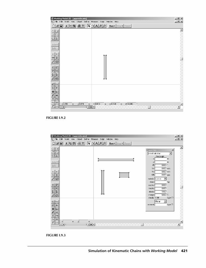
appear around the link indicating that it has been selected. Modify its dimensions atthe bottom of the screen accordingly to the height h = 0.1 m, and the widthw = 0.01 m (Fig. I.9.2).
2. Create the slider and the rocker. Click on the “Rectangle” tool in the toolbar. Thetool is now selected and it can be used multiple times. Sketch out two rectangularbodies: the rocker and the slider. Choose the widths w = 0.15 m for the rocker andw = 0.040 m for the slider. The height of the rocker is h = 0.010 m and the height ofthe slider is h = 0.020 m.The depth of all objects in Working Model is d = 0.001 m by default.
3. Change the properties of the links. Press the Shift key and click on the driver link,rocker, and slider, respectively. Select “Properties” in the “Window” menu andchange the material to Steel, the coefficients of static and kinetic friction to 0.0 (nofriction), the coefficient of restitution to 1.0 (perfect elastic), and the charge to 0.0(no charge) as shown in Figure I.9.3.
RemarkThe commands Zoom in and Zoom out can be used by clicking on the icons at the top ofthe screen in order to make the objects clearly visible.
Step 3: Connecting the Slider and the Rocker1. Move the slider over the rocker.2. Select the horizontal “Keyed Slot joint” icon at the left of the screen. The icon
appears as a rectangle riding over a horizontal slot.
420 KINEMATIC CHAINS AND MACHINE COMPONENTS DESIGN
Typeset by: CEPHA Imaging Pvt. Ltd., INDIA
[09:02 2005/1/22 Part-I/Ch09.tex] MARGHITU: Kinematic Chains and Machine Components Design Page: 421 419–432
FIGURE I.9.2
FIGURE I.9.3
Simulation of Kinematic Chains with Working Model 421
Typeset by: CEPHA Imaging Pvt. Ltd., INDIA
[09:02 2005/1/22 Part-I/Ch09.tex] MARGHITU: Kinematic Chains and Machine Components Design Page: 422 419–432
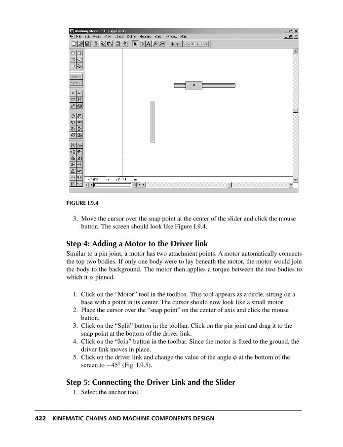
FIGURE I.9.4
3. Move the cursor over the snap point at the center of the slider and click the mousebutton. The screen should look like Figure I.9.4.
Step 4: Adding a Motor to the Driver linkSimilar to a pin joint, a motor has two attachment points. A motor automatically connectsthe top two bodies. If only one body were to lay beneath the motor, the motor would jointhe body to the background. The motor then applies a torque between the two bodies towhich it is pinned.
1. Click on the “Motor” tool in the toolbox. This tool appears as a circle, sitting on abase with a point in its center. The cursor should now look like a small motor.
2. Place the cursor over the “snap point” on the center of axis and click the mousebutton.
3. Click on the “Split” button in the toolbar. Click on the pin joint and drag it to thesnap point at the bottom of the driver link.
4. Click on the “Join” button in the toolbar. Since the motor is fixed to the ground, thedriver link moves in place.
5. Click on the driver link and change the value of the angle φ at the bottom of thescreen to −45◦ (Fig. I.9.5).
Step 5: Connecting the Driver Link and the Slider1. Select the anchor tool.
422 KINEMATIC CHAINS AND MACHINE COMPONENTS DESIGN

Typeset by: CEPHA Imaging Pvt. Ltd., INDIA
[09:02 2005/1/22 Part-I/Ch09.tex] MARGHITU: Kinematic Chains and Machine Components Design Page: 423 419–432
FIGURE I.9.5
2. Click on the driver link to anchor the link down. The anchor fixes the body to theground during construction.
3. Click on the “Pin joint” tool.4. Place the cursor over the upper end of the driver link. When an “X” appears around
the pointer, click the mouse button.5. Click on the “Split” button in the toolbar. Working Model creates two connected
overlapping pin joints.6. With the pointer tool selected, click on the pin joint and drag it to the snap point at
the center of the slider (Fig. I.9.6).7. Click on the “Join” button in the toolbar. Working Model merges the two pin joints
into a single one, moving the unanchored link into place.8. Click on the driver link. Select the “Move to front” option in the “Object” menu.
This places the link in front of the rocker, making it visible, as shown in Figure I.9.7.
Step 6: Connecting the Rocker to the Ground1. Click on the “Point element” in the toolbox. Place the cursor at any point on the
ground and click the mouse button.2. Modify the coordinates of the point accordingly to x = 0.05 m and y = 0.3. Click on the “Pin joint” in the toolbox. Place the cursor on top of the point and click
the mouse button. The pin joint is now fixed to the ground.4. Using “Split” and “Join”, connect the rocker to the pin joint.
Simulation of Kinematic Chains with Working Model 423

Typeset by: CEPHA Imaging Pvt. Ltd., INDIA
[09:02 2005/1/22 Part-I/Ch09.tex] MARGHITU: Kinematic Chains and Machine Components Design Page: 424 419–432
FIGURE I.9.6
FIGURE I.9.7
424 KINEMATIC CHAINS AND MACHINE COMPONENTS DESIGN

Typeset by: CEPHA Imaging Pvt. Ltd., INDIA
[09:02 2005/1/22 Part-I/Ch09.tex] MARGHITU: Kinematic Chains and Machine Components Design Page: 425 419–432
FIGURE I.9.8
5. Select the anchor, used to keep the driver link in position during building, and pressthe Delete key to remove it. The screen should look like that shown in Figure I.9.8.
Step 7: Adding an External Torque1. Click on the “Torque” tool from the toolbox and then click on the rocker. This will
apply an external torque to the rocker.2. Select the torque and modify its value to Mext = 100 N·m in the “Properties”
menu.
Step 8: Measuring Positions, Velocities, Accelerations, Torques,and Forces
1. Select the driver link, then go to “Measure” menu and “Position” submenu. Applythe command “Rotation graph” to measure the rotation angle of the driver.
2. Click on the “Point element” from the toolbox and then click on the end point of therocker. The point is now attached to the rocker. Go to “Measure” menu and apply thecommands “Position”, “Velocity”, and “Acceleration” to measure the position,velocity, and acceleration of the point. Click on the arrow in the right upper cornerof the measurement window to change it from graphic to numerical.
3. Select the motor, then go to “Measure” menu and apply the command “TorqueTransmitted” to measure the torque of the motor.
Simulation of Kinematic Chains with Working Model 425

Typeset by: CEPHA Imaging Pvt. Ltd., INDIA
[09:02 2005/1/22 Part-I/Ch09.tex] MARGHITU: Kinematic Chains and Machine Components Design Page: 426 419–432
4. Select the pin joint that connects the driver link to the ground. Go to “Measure” andapply the command ”Force” to measure the reaction force between the ground andthe driver.
5. Select the rigid keyed slot joint that connects the slider to the rocker. Go to“Measure” and apply the command ”Force” to measure the reaction force betweenthe slider and the rocker.
6. Select the pin joint that connects the rocker to the ground. Go to “Measure” andapply the command ”Force” to measure the reaction force between the ground andthe rocker.
7. Select the pin joint that connects the driver link to the slider. Go to “Measure” andapply the command “Force” to measure the reaction force between the slider and thedriver.
RemarkWhen you select a joint to create a meter to measure the reaction force, the meter measuresthe forces exerted on the body located at the top when the joint was created. The componentsof the forces are given in terms of the local coordinate system. In order to measure thecomponents of the pin joint forces in terms of the global coordinate systems, the angles ofthe two points that compose the pin joint are set to the value 0. The two points that composea pin joint are seen by selecting the joint and opening the “Properties” window.
An example is shown in Figure I.9.9. The pin joint between the driver link and the slider(Fig. I.9.6), denoted by Constraint[17], is composed of the two points Point[15] andPoint[16]. Select Point[15] from the window “Properties” and change its angle to the
FIGURE I.9.9
426 KINEMATIC CHAINS AND MACHINE COMPONENTS DESIGN

Typeset by: CEPHA Imaging Pvt. Ltd., INDIA
[09:02 2005/1/22 Part-I/Ch09.tex] MARGHITU: Kinematic Chains and Machine Components Design Page: 427 419–432
value 0. Then select Point[16] and change its angle to 0. Now the components of the pinjoint forces are measured in terms of the global coordinate system.
Step 9: Running the Simulation1. With the pointer tool selected, select all the bodies. Select the “Do Not Collide”
option in the “Object” menu.2. Select “Numbers and Units” in the “View” menu. Select More Options and change
the Rotational Velocity to Revs/min.3. Double-click on the motor to open the “Properties” box. Modify the velocity of the
motor to −50 rpm, as shown in Figure I.9.9.4. Click on each graph and modify its label from “Window” menu and “Appearance”
submenu.5. Click on “Run” in the toolbar.
Tape controls, which are used to run and view simulations, are located at the bottom ofthe screen.
6. Click on “Reset” in the toolbar. The simulation resets to the initial frame 0.
RemarkTo increase the Simulation Accuracy, select “Accuracy” from the “World” menu andchange the Animation Step to a larger value and the Integration Error to a smaller value.The screen should look like that shown in Figure I.9.10.
FIGURE I.9.10
Simulation of Kinematic Chains with Working Model 427
Typeset by: CEPHA Imaging Pvt. Ltd., INDIA
[09:02 2005/1/22 Part-I/Ch09.tex] MARGHITU: Kinematic Chains and Machine Components Design Page: 428 419–432
ResultsFor the R-RTR mechanism (Fig. I.9.1), the following results are obtained: the motor torqueis Mmot = −147.651 N·m; the position of the point D is rD = 0.139ı+0.121j m, the velocityof the point D is vD = 0.936ı−0.685j m/s; the acceleration of the point D is aD = −1.077ı−10.324j m/s2; the reaction force of the ground on the driver link is F01 = 1302ı − 953j N;the reaction force of the slider on the driver link is F21 = −1302.128ı + 953.180j N; thereaction force between the rocker and the slider is F23 = 1613.764 N; the reaction force ofthe ground on the rocker is F03 = −1302.15ı + 953.291j N.
428 KINEMATIC CHAINS AND MACHINE COMPONENTS DESIGN