SIMULATION OF IRON ORE REDUCTION IN A FIXED BED
40
1 SIMULATION OF IRON ORE REDUCTION IN A FIXED BED J. Aguilar, R. Fuentes, R. Viramontes * Universidad Autónoma de Nuevo León Facultad de Ingeniería Mecánica y Eléctrica Doctorado en Ingeniería de Materiales A.P. 076 "F", Monterrey, N.L. 66450 México * HYLSA, S.A. de C.V. Departamento de Investigación y Desarrollo A.P. 996, Monterrey, N.L. 64000, México 1. ABSTRACT A simulation of direct reduction in a fixed bed process of iron ore is presented. Simulation is done with a model which takes into account bed characteristics, including reaction kinetics, thermal effects, quality and flow of reducing gas. It is considered that reactor is a cylinder with wall made of layers of refractory and insulator, this reactor contains a bed of iron ore pellets which will be reduced under a flow of reducing gas in longitudinal direction (along cylinder). Finite difference method is used to solve simplified differential equations for description of heat transfer gas- pellet, gas-refractory, refractory-insulator-environment, and heat changes due to reaction inside reactor.
Transcript of SIMULATION OF IRON ORE REDUCTION IN A FIXED BED

1
SIMULATION OF
IRON ORE REDUCTION IN A FIXED BED
J. Aguilar, R. Fuentes, R. Viramontes *
Universidad Autónoma de Nuevo León
Facultad de Ingeniería Mecánica y Eléctrica
Doctorado en Ingeniería de Materiales
A.P. 076 "F", Monterrey, N.L. 66450 México
*HYLSA, S.A. de C.V.
Departamento de Investigación y Desarrollo
A.P. 996, Monterrey, N.L. 64000, México
1. ABSTRACT
A simulation of direct reduction in a fixed bed process of
iron ore is presented. Simulation is done with a model which takes
into account bed characteristics, including reaction kinetics,
thermal effects, quality and flow of reducing gas. It is
considered that reactor is a cylinder with wall made of layers of
refractory and insulator, this reactor contains a bed of iron ore
pellets which will be reduced under a flow of reducing gas in
longitudinal direction (along cylinder).
Finite difference method is used to solve simplified
differential equations for description of heat transfer gas-
pellet, gas-refractory, refractory-insulator-environment, and heat
changes due to reaction inside reactor.

2
Simulator is fitted by using reducibility tests in laboratory
and runs in a pilot plant. It is found that due to process nature,
this process is carried out almost fully in transitory stage and
that is way this simulation is necessary.
2. INTRODUCTION
At present time, direct reduction process are calling
researchers [1,2,3,4,5] attention in world, whom are looking for
an efficient reduction process which includes advantages of direct
reduction together with smelter reduction in a blast furnace, this
process has been called "Smelter Reduction Process".
Taking into account that there are process developed until
commercialization, and world trend is still including direct
reduction as part of a new process, becomes important to study
this stage by using available tools.
One of most common low cost tools used for design and test of
new plant is simulation processes. In case of chemical processes
which are batch conducted, one of the most important knowledge is
time necessary to carried out such process, that is the aim of
this work, to determinate time necessary to reduce an iron ore bed
in contact with reducing gas and to obtain a desired reduction
degree (in this case to wustite) under given operation conditions.
Fixed bed scheme is more complex than moving bed, because of
the first one includes transitory state. In this paper is
presented a model which was developed to simulate transitory
condition, after this it is uncomplicated to pass to moving bed.

3
3. GENERAL DESCRIPTION OF A NEW REDUCTION PROCESS
In a general way, new reduction process consists of a smelter
unit charged with pre-reduced iron ore that is reduced to iron by
combustion of carbon and oxygen. Combustion products have enough
reducing potential to pre-reduce iron ore to wustite, that is way
the gases are passed through a reactor with a bed of iron ore
pellets which will be pre-reduced by direct reduction process and
charged to smelter unit.
With the goal of evaluate this process some researchers [6,7]
have ran tests on pilot plant, however this model only simulates
direct reduction part (pre-reduction).
4. DEVELOPMENT
It is assumed in this work that reactor is a cylinder with
compound wall made of refractory and insulator layers (Figure 1),
iron ore (pellet) is inside of cylinder and reducing gas is
passing through from top to bottom. Gas is flowing in
unidirectional way following z axe in a plate front (turbulent
flow).
Used equations are explained below:
4.1 Heat transfer
This concept corresponds to heat transfer between gas and
pellet, and gas and refractory-insulator system in wall and
environment. This section takes into account physic properties of
gas used by process.

4
Equations which handle heat transfer are:
a) Heat transfer from gas;
b) Heat transfer to pellets;
c) Heat transfer between insulator and refractory layers in
wall;
with heat transfer coefficients for a pellet bed;
M C)T - T( A H + )T- T( A H =
zT
gg
rgrgpgpgpg
∂∂
1
M C)T- T( A H =
tT
pp
pgpgpp
∂∂
2
)T - T( pra + )T- T( pra + T pra = tT
ma6ar5f4
r
∂∂
3
)T - T( pra + )T - T( pra + T pra = t
Tma3mr2f1
a
∂∂
4
)- (1 D a
)( = C
p
a1.40.3
p
a
3
1
ρρ
ρρ
5

5
and an auxiliary function for transitory stage in wall.
4.2 Kinetics of iron ore reduction
This aspect is very important because it is an element
inherent to process due to thermal profile and chemical gas
composition are strongly related, in other words, reduction
kinetics depends on temperature and gas composition, and these
depend again on reduction kinetics.
Reduction kinetics employed in this work includes three
oxidation stages of iron, in a simultaneous reduction process
where first reduction product, which corresponds to first oxide,
is reactive for next reaction for a homogeneous process.
Equations for this section are related to two reactions, the
first one is reduction by hydrogen, and second one is reduction by
carbon monoxide. Reduction from hematite to magnetite (Fe2O3 to
Fe3O4) is described as;
)G W( C = Hg
gg0.7
g1g µα 6
K 5a +
H1
1 = H
pg
gp 7
K)T - T( H = T
b
rgbgf ε 8

6
hydrogen contribution is governed by;
and;
Same procedure is used for CO (in equation (10) term H2
related with hydrogen pressure is exchanged by CO pressure).
From reduction from magnetite to wustite (Fe3O4 to FeO) and
from wustite to iron (FeO to Fe) expressions are very similar, but
in these cases thermodynamic constants for equilibrium are taken
into account, this constants are almost zero for reduction from
hematite to magnetite (that is why for hematite to magnetite is
independent of water pressure), besides it is necessary to take
into account the reagent amount given by reaction just before,
this consideration gives the following equation for magnetite to
wustite:
and for wustite to metallic iron;
R + R = tR
mmm
ch∂∂
9
)R - (1 H A = R m2gmm hh ρ 10
)Tp R
Qmh(- fmh = Amhexp 11
)R- R( K + 1
O)H K - H( A = R wm
w
2w2
gww
h
h
hh ρ 12

7
Reduction rate is handle in same way that reaction from
hematite to magnetite, and with CO contributions (same kind that
hydrogen ones) there are enough equations to know global reduction
degree. Thermal behavior is taken from heat of reaction of each
one of involved reaction, this contribution is added to heat
transfer section. Even when the objective of this work is centered
on wustite production, this model takes into account reduction
from iron ore to metallic iron because some times it is possible
to have conditions, which permits to reach metallic iron.
4.3 Kinetics of gas conversion
In this section equilibrium degree inside of bed is
considered, with this information it is possible to work with
thermodynamic equilibrium letting gases to complete reactions, or
as an opposite way, to inhibit gas reactions away of thermodynamic
equilibrium. With these capacities the model can reproduce any
experimental conditions and know how far from equilibrium the gas-
gas reactions are taking place.
4.4 Condensation and evaporation of water
This phenomenon must be considered especially in cases where
reducing gas composition is high in hydrogen and water is a
)R- R( K + 1
O)H K - H( A = R fw
f
2f2
gff
h
h
hhρ 13

8
reaction product. This is also very important because simulation
and actually the process starts from room temperature and water
vapor is condensing, when the iron ore bed reaches water
evaporation temperature water boils and modify the temperature
profile strongly. This phenomena is handling by taking into
account pressure inside reactor and pellet temperature, thus water
change its state from liquid to vapor and backward, water amount
in this changing process depends on evaporation kinetics and
obviously it can not be grater than energy provided by heat
transfer gas-pellet.
This part is also included in heat transfer section with heat
transfer terms in equations.
5. EQUATIONS RESOLUTION PRESENTED AS SIMULATION MODEL
Flow diagram in figure 2 shows the sections above described
linked with the aim to have a fully integrate simulator. Start
point is to have general initialization values, such as ore
properties, process parameters (temperature, composition and flow
of reducing gas), reactor characteristics (dimensions and physic
properties of refractory and isolator) and data related to iron
ore bed to be reduced.
Due to fixed bed is a batch process, thermal transitory state
is taking place while reduction (required time for reduction is
less than time for reach steady state) and this condition makes
necessary to evaluate and take into consideration thermal
parameters of refractory-insulator-environment [8].

9
In accordance with equations showed before, finite
differences method uses a loop in time which contains a loop along
z axe. Adjust of right parameters in model was done by runs in
laboratory and pilot plant. Simulation model reproduces
experimental runs with different conditions, thus it is already
validated.
6. EXPERIMENTAL
6.1 Experimental design for laboratory tests
Experimentation was conducted on a fixed mass of 500 gr. of
iron ore pellets with three different temperatures (750oC, 850oC
and 950oC) and three reducing gasses of different compositions
where employed, gas flow was 55 lts/min.
Experimental design for laboratory test is listed in tables I
through IV:
Table IDesign Matrix for reduction from
hematite to magnetite
Temperature oC
H2/H2O(1)
H2/H2O(2)
H2/H2O(3)
CO/CO2
(1)CO/CO2
(2)CO/CO2
(3)
750 0.1 0.37 0.64 0.1 0.28 0.47
850 0.1 0.22 0.34 0.1 0.22 0.36
950 0.1 0.15 0.20 0.1 0.19 0.29
Table IIDesign Matrix for reduction from
magnetite to wustite

10
Temperature oC
H2/H2O(1)
H2/H2O(2)
H2/H2O(3)
CO/CO2
(1)CO/CO2
(2)CO/CO2
(3)
750 0.70 0.40 0.22 0.51 0.39 0.31
850 1.41 1.09 0.90 1.05 1.16 1.28
950 2.18 1.84 1.60 1.63 1.97 2.28
Table IIIDesign Matrix for reduction from
wustite to iron
Temperature oC
H2/H2O(1)
H2/H2O(2)
H2/H2O(3)
CO/CO2
(1)CO/CO2
(2)CO/CO2
(3)
750 2.39 2.02 1.76 1.79 2.16 2.50
850 4.13 3.56 3.18 3.05 3.78 4.54
950 6.08 5.29 4.77 4.47 5.64 6.84
Table IVComplementary Matrix design
Temperature oC
H2/H2OFe2O3 toFe3O4
CO/CO2
Fe2O3 toFe3O4
H2/H2OFe3O4 toFeO
CO/CO2
Fe3O4 toFeO
H2/H2OFeO toFe
CO/CO2FeO toFe
650 0.69 2.00 ∞
800 0.23 0.21 1.21 1.11 ∞ ∞
950 0.10 0.14 0.89 1.29 ∞ ∞
6.2 Ore
Tested ore comes from the Alzada mine, located at the Mexican
State of Colima. The mean characteristics of this ore are given in
Table V.

11
Table VMean ore characteristics
PHYSICS
Granulation + 3/8" - 5/8" (0.95-1.58 cm)
Average diameter 1.27 cm
Density 4.222 gr/cm3
Apparent density 2.200 gr/cm3
CHEMICAL
Total Fe 66.5 %
Fe+2 0.65 %
Gangue 5.3 %
CaO 37 %
MgO 11 %
SiO2 38 %
Al2O3 14 %
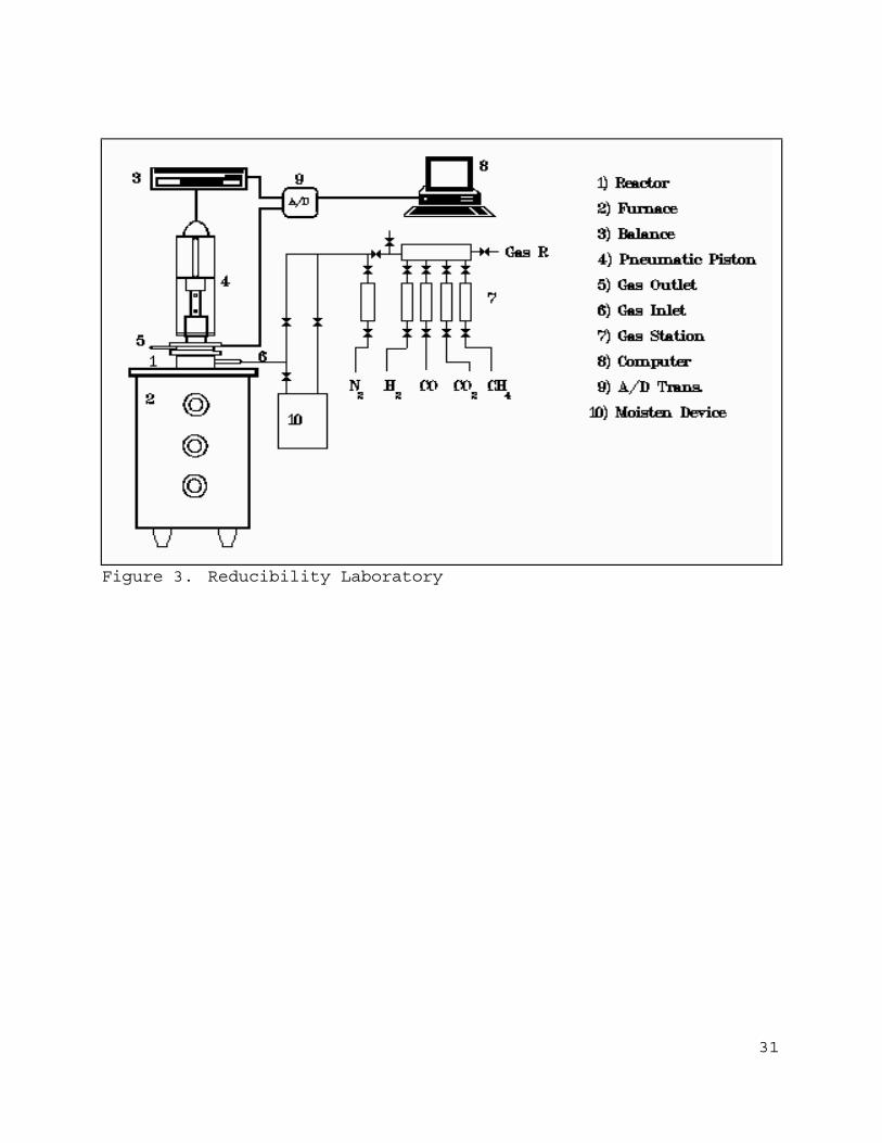
6.3 Experimental devices and procedures
Experimental tests were conducted in a rector for
reducibility tests. The equipment includes an 18 Kw furnace,
reactors to conduct iron ore reduction and control it, and
instrumentation, as it is shown in Figure 3. This laboratory is
fully prepared to make comparative reducibility ore tests. It is
possible to change the temperature, gas flow, pressure and charge
to which the pellets are exposed to.
A bed of 500 gr. of dry ore pellet were placed inside a

12
reactor. This reactor consists in two concentric tubes in such a
way that the inlet gas pass between the internal wall of the
external tube and the external wall of the internal tube, and
leaves it through the ore bed placed inside of the internal tube
(Figure 4). The reactor has a thermocouple in contact with the top
of the ore bed and another on bottom for temperature controlling.
It is important to notice that this experimental device gives
information of an iron ore bed reduced in batch process, and
simulation of bed conditions is an aim of this work. Searching for
constants is the first application of simulation model. In order
to simplify search for constants, each reducing stage was
conducted independently (Tables I through IV) so there is just one
set of constants to seek in each stage.
A 10 lts/min flow of high purity nitrogen is passed through
the sample until the testing temperature is reached and stabile,
after this is done, the appropriate gas is injected and the weight
loss is registered.
The flow control is made by calibrated flowmeters and the gas
composition is checked by chromatography analysis. The water vapor
amount in gas is indirectly measured.
During the reduction the sample looses weight until all the
oxygen has been removed. In this kind of test, the sample is
heated by radiation and conduction. In order to simulate a real
bed, in a second part alumina pellets where placed on top and
bottom of the ore bed, while the reactor walls where covered with
an insulating wool. All these avoids the instability of the gas

13
flow entering into the bed, some results are presented in figures
5 through 9.
6.4 Experimental procedures for pilot plant tests
Pilot plant consist in a vertical steel cylindrical reactor
with wall covered of refractory and insulator layers, inlet gas
which passes through pellet bed, is at top and wasted gas leaves
reactor at bottom. There are several thermocouples and takes for
gas analysis along reactor. Reactor is fully instrumented with
central data acquisition and control for temperatures, pressures,
gas flows, gas compositions.
General characteristics of this reactor are shown in Table
VI, this information is provided to simulation model. Cages of ore
sated at same positions than thermocouples and test points for gas
analysis, these cages are recovered after tests for a chemical
analysis in order to have thermal and chemical data.
Preparation for test consists of charging reactor. Depending
on the kind of test it is possible to heat the ore bed with hot
nitrogen, air or a selected gas until it reach desired
temperature. If a reducing gas is used, then a reduction will
start too. Timing for tests in this work starts when gas is
getting in reactor, thus heating and reduction starts at same
time. Selected gases are shown in Table VII. Most used gas is
shown in column three.
Normal criteria to define the end of process is taking
temperature at bottom of bed, looking evolution of gas composition

14
or flows between inlet gas and outlet gas.
Table VIGeneral Data
Item Value
Density of refractory 2300 Kg/m3
Refractory's heat capacity 1178 J/Kg oC
Density of insulator 800 Kg/m3
Insulator's heat capacity 1154 J/Kg oC
Apparent density of bed 1900 Kg/m3
Density of a single pellet 4222.2 Kg/m3
Pellet's heat capacity 957.6 J/Kg oC
Reactor's diameter 0.914 m
Radius of a single pellet 6.35 x 10⁻³ m
Thickness of refractory 0.0762 m
Thickness of insulator 0.1016 m
Pellets' thermal conductivity 0.5 W / m oC
Refractory's thermal conductivity 1.441 W / m oC
Insulator's thermal conductivity 0.255 W / m oC
Refractory and insulator masses 1.749 & 0.956 m tons
Pellet mass 3.4 m tons
Height of bed 3.20 m
Table VIIChemical analysis of used gases for reduction
and operation temperatures
Temp. 950 oC 950 oC 900 oC 800 oC 800 oC
vol %
H2 23.12 14.8 24.14 27.14 48.80
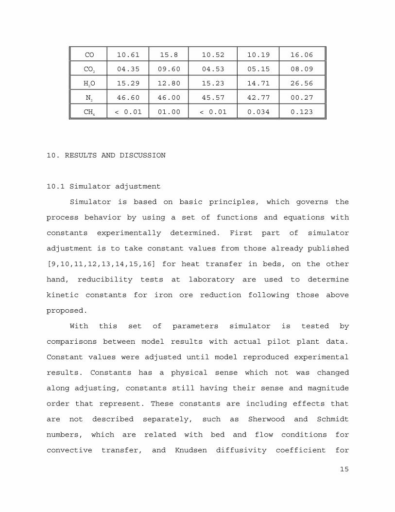
15
CO 10.61 15.8 10.52 10.19 16.06
CO2 04.35 09.60 04.53 05.15 08.09
H2O 15.29 12.80 15.23 14.71 26.56
N2 46.60 46.00 45.57 42.77 00.27
CH4 < 0.01 01.00 < 0.01 0.034 0.123
10. RESULTS AND DISCUSSION
10.1 Simulator adjustment
Simulator is based on basic principles, which governs the
process behavior by using a set of functions and equations with
constants experimentally determined. First part of simulator
adjustment is to take constant values from those already published
[9,10,11,12,13,14,15,16] for heat transfer in beds, on the other
hand, reducibility tests at laboratory are used to determine
kinetic constants for iron ore reduction following those above
proposed.
With this set of parameters simulator is tested by
comparisons between model results with actual pilot plant data.
Constant values were adjusted until model reproduced experimental
results. Constants has a physical sense which not was changed
along adjusting, constants still having their sense and magnitude
order that represent. These constants are including effects that
are not described separately, such as Sherwood and Schmidt
numbers, which are related with bed and flow conditions for
convective transfer, and Knudsen diffusivity coefficient for
16
diffusion in a pellet. Model presented in this work is a
simplification, which reproduces experimental data and gives a
very straight criteria for determining the end of process.
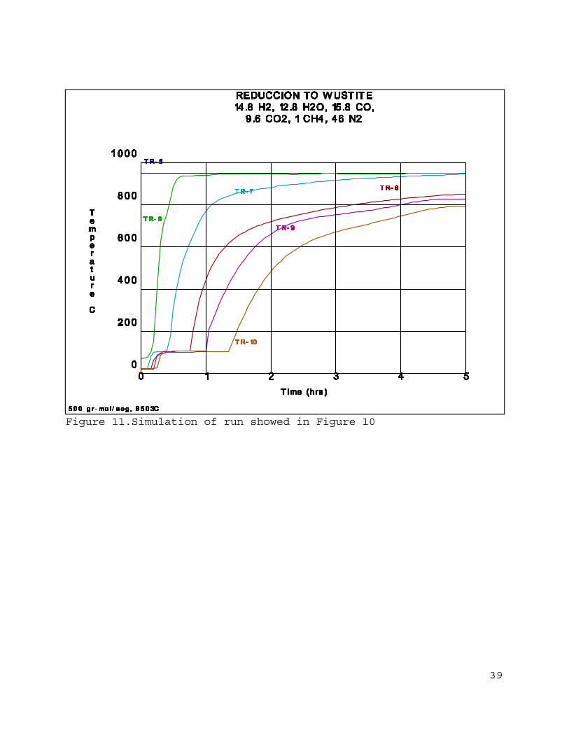
One of the experimental runs is showed on Figure 10, which
presents thermal profile of reactor at the different thermocouples
position along z axe, and its evolution with time, it is possible
to see that temperature at the beginning of test is almost
constant around boiling temperature water, thus it is shown that
it is very important to consider condensation - boiling phenomena
inside model.
Heat transfer coefficients inside simulation model are moving
in order to achieve the same temperature profiles obtained at
pilot plant, and it is necessary to take into account that could
be interactions between phenomena which are not considered in
mathematical model, but they are, as it was pointed before,
included inside of constants. Boundary phenomena such as diffusion
of gas in the layer of reaction products and interaction of the
phase-boundary reaction with diffusion in the reacting layers are
in adjusted constants because there are many effects that can not
be evaluated in a single way (combined effects of the phase-
boundary reaction, gas flow, diffusion in reacting layers, and
diffusion in the end products reaction).
Kinetic constants were evaluated from reducibility tests and
cages located inside reactor in know places (same positions than
thermocouples). Kinetic reductions are strongly important because
it has influence on temperature profiles and gas conversion

17
kinetics.
Kinetics of reduction gas conversion was calculated from
analysis of samples of gas obtained along reactor at the same
positions than thermocouples, this kinetic was adjusted until
model gives the same results than chemical analysis. All of the
profiles (bed temperature, wall temperature, iron ore reduction
degree and chemical gas composition) were reproduced.
When constants satisfy all of these conditions then the
simulation model is complete and can be used, curves in Figure 11
were obtained using the simulator and the results are in good
agreement with actual data. With this model, next step is to
calculate reduction time, and with this information it is possible
to calculate specific consumption of gas for certain given
conditions, which helps to give an advice on operation conditions.
10.2 Simulator validation
Due to the objective of this work is oriented to make
predictions about reduction time, at this point, with specific
operation conditions, different than those used for model
adjustment, this simulator gives results which had been compared
with tests carried out in pilot plant and exhibits a good
agreement. Figure 12 shows a curve for reduction time as a
function of reducing gas flow at one given temperature and
composition, this curve was obtained by using the model, and
experimental data from runs are plotted. Notice that when gas flow
is not enough to compensate heat loss the time to finish reduction

18
is too long, and when gas flow is very high there is a kinetic
frontier imposed by process.
With this information and including the reducing gas
generation it is possible to get specific consumption.
Some adjusted parameters and functions are presented in Table
VIII through XI, gas properties, thermal and thermodynamic
constants are already published in several books and papers.
Previous work [17] with this kind of atmosphere shows that
reduction with carbon monoxide is about one fifth of hydrogen,
thus in this case water shift reaction outside pellet is
considered.
Table VIIIAdjusted parameters and functions
(Kinetics)
Parameters and functions Remarks
)T
6000(- 45 = Ap
mhexp
Kinetic constant for reductionfrom hematite to magnetite withhydrogen

19
)T
2600(- 0.36 = Ap
whexp
Kinetic constant for reductionfrom magnetite to wustite withhydrogen
)T
2600(- 0.18 = Ap
f hexp
Kinetic constant for reductionfrom wustite to metallic ironwith hydrogen
5A = A m
mh
c
Kinetic constant for reductionfrom hematite to magnetite withcarbon monoxide
5A = A w
wh
c
Kinetic constant for reductionfrom magnetite to wustite withcarbon monoxide
5A = A f
fh
c
Kinetic constant for reductionfrom wustite to metallic ironwith carbon monoxide
Table IXAdjusted parameters and functions
(Kinetics)
Parameters and functions Remarks
)R-(1 H A = R m2gmm hh ρ Reduction rate forhematite to magnetite withhydrogen
K+1)R-R( O)H K-H( A = R
w
wm2w2gwm
h
hhh ρReduction rate formagnetite to wustite withhydrogen

20
K+1)R-R( O)H K-H( A = R
f
fw2f2gff
h
hhhρ
Reduction rate for wustiteto metallic iron withhydrogen
)R-(1 CO A = R mgmm cc ρ Reduction rate forhematite to magnetite withcarbon monoxide
K+1)R-R( )CO K-(CO A = R
w
wm2wgww
c
ccc ρReduction rate formagnetite to wustite withcarbon monoxide
K+1)R-R( )CO K-(CO A = R
f
fw2fgff
c
cccρ
Reduction rate for wustiteto metallic iron withcarbon monoxide
Table XAdjusted parameters and functions
(Gas-gas reactions)
Parameters and functions Remarks
)T
9000(- 2 = p
expλApparent kinetic constant forwater shift reactionCO+H2O=CO2+H2
OHH CO K = CO
2
2shiftmequilibriu
CO calculated from equilibriumof water shift reaction

21
CO+COCO-CO = CO
mequilibriu
mequilibriumdegreeequilibriu-non
CO non equilibrium degree inaccordance with water shiftreaction
)T
12000(- 0.04 = p
expβApparent kinetic constant formethane reforming reactionCH4+H2O=3H2+CO
All of this reactions have a thermal contribution on system,
this contribution is integrated to mass and heat balance
equations.
Table XIAdjusted parameters and functions
(Gas-gas reactions)
Parameters and functions Remarks
K OHH CO P = CH
reforming2
32
2
4 mequilibriu
CH4 calculated from equilibriumof methane reforming reaction
CH+CHCH-CH = CH
44
44
4
mequilibriu
mequilibriu
mdegreeequilibriu-non
CH4 non equilibrium degree inaccordance with methanereforming reaction
22
CO C = GIP mdegreeequilibriu-non2
g1 λρCO coming from water shiftreaction
CH C = BETAP 4
2
g1 mdegreeequilibriu-nonβρ
CH4 coming from methanereforming reaction
11. CONCLUSION
When reproduction of experimental data is achieved, including
thermo-chemical profiles inside reactor and time to reduction, it
is possible to say that model is already validated and its results
are in this scope reliable. It is clear that simulator represents,
under different conditions, the general behavior of reactor.
With a model of simulation of this kind there is another
potential tool for reactors design, and a very important advance
in statistic experimental designs, besides, it is possible to make
a sensibility analysis of different process variables and
operational conditions.
Even when by adjusting model it is not possible to give
values for each phenomena in pellet and bed (i.e. diffusion
resistance), adjusted parameters gave good results about bed
behavior. Further studies will permit to determine the limitations
of this simulation model and if it is necessary to made
modifications.

23
Finite difference method gives the opportunity to pass
directly to moving bed by changing elements conditions and places.
This model gives a criteria to determinate the end of a batch
process, also gives information about specific consumption of
reducing gas, and the chance to modify and test different
atmospheres at different temperatures.
11. NOMENCLATURE
ais the pellet radius.
Amhis the kinetic term for reduction from hematite to magnetite
with hydrogen.
Amcis the kinetic term for reduction from hematite to magnetite
with carbon monoxide.
Afh and Awh
are kinetic terms for reduction from wustite to iron and from
magnetite to wustite respectively with hydrogen.
Afc and Awc
are kinetic terms for reduction from wustite to iron and from
magnetite to wustite respectively with carbon monoxide.
Ap and Ar
are respectively pellet area and refractory area.
Cg and Cp
are respectively heat capacities of gas and pellet.
COis carbon monoxide partial pressure.
Dis the reactor diameter.
Ggis the gas flow.

24
H2is hydrogen partial pressure.
H2Ois partial pressure of water vapor.
Hg and Hgp
are coefficients for heat transfer in the iron ore bed and gas-
pellet.
Kb and Kp
are coefficients for heat conduction in refractory and pellet.
Kwh, Kfh, Kwc and Kfc
are thermodynamic constants for reduction from magnetite to
wustite and wustite to metallic iron with hydrogen and with
carbon monoxide respectively.
Kshiftequilibrium constant for water shift reaction.
Kmethane
equilibrium constant for methane reforming reaction.
Kfh and Kwh
are thermodynamic equilibrium constant for reduction from wustite
to iron and from magnetite to wustite respectively, with
hydrogen.
Mg and Mp
are the masses of gas and pellet.
prai
are coefficients for heat transfer coefficient of refractory-
insulator-environment system.
Qmhrepresents activation energy for reduction from hematite to
magnetite with hydrogen.

25
Rm, Rmc and Rmh
are reduction degree for hematite to magnetite, reduction degree
due to carbon monoxide and hydrogen.
Rf and Rw
are reduction degrees of reaction from wustite to iron and from
magnetite to wustite.
Ta, Tg, Tf, Tm, Tp and Tr
are respectively temperatures of insulator, gas, system wall,
environment, pellet and refractory.
tis the time coordinate
Wgis the molecular weight of gas
zis the coordinate along reactor cylinder
αgis the heat conduction coefficient of gas
εbis the refractory thickness
ρais the apparent density of iron ore bed
ρpis the pellet density
μgis the gas viscosity.
ρgis reducing gas density.
ACKNOWLEDMENTS
J. A. gives the thanks to the CONACYT (National Science and
Technology Council) for its support along this work.
REFERENCES

26
1-Lascano (A.), Villaseñor (A.), Alcántara (M.).- Alternativas de
integración de la reducción directa a un convertidor
inyectando oxígeno y carbón por el fondo dando como resultado
un nuevo proceso IMIS de producción de acero. V Seminario
Reducción Directa, Saltillo, Coah. México, 14 al 16 de
octubre, 1986.: ILAFA, 1986, p. M1-M7
2-Flickenschild (J.), Papst (G.).- El proceso COREX de fusión
reductora. V Seminario Reducción Directa, Saltillo, Coah.
México, 14 al 16 de octubre, 1986.: ILAFA, 1986, p. L1-L21
3-González (F.).- Perspectivas futuras del uso del hierro esponja
en la producción de acero. V Seminario Reducción Directa,
Saltillo, Coah. México, 14 al 16 de octubre, 1986.: ILAFA,
1986, p. B1-B2
4-Quintero (R.G.).- Up Date on HyL. ISS-AIME Ironmaking
Proceedings, 1978, v. 37, p. 137-148
5-Peña (J.M.), Viramontes (R.).- The New HyL Technology. ISS-AIME
Ironmaking Proceedings, 1980, v.39
6-Lascano (A.).- Progress made in the IMIS process for direct
steelmaking. Steel Times International, January, 1990, p.36-
38
7-Nijhawan (B.R.).- Desarrollos en la reducción directa y nuevos
procesos para la fabricación de acero, una evaluación. V
Seminario Reducción Directa, Saltillo Coah. México, 14 al 16
de octubre, 1986.: ILAFA, 1986, p. C1-C10
8-Santillán (M.).- Modelo matemático lineal aproximado en la
transferencia de calor (Caso unidimensional). Science Master

27
Degree Tesis, FIME-UANL, México, June 1992
9-Bogdandy (L.), Engell (H.J.).- The Reduction of Iron Ores.-New
York: Springer-Verlag, 1971, p.576
10-Stull (D.R.), Prophet (H.).- JANAF Thermochemical Tables,
Second Edition: National Standard Reference Data System
11-Moelwyn (H.).- The kinetics of reactions in solution, Second
Edition.- Clarendon: Press Oxford, 1947
12-Lu (W.K.), Bitsianes (G.).- Chemical kinetics of gaseous
reduction of hematite. Canadian Metallurgical Quarterly,
v.7,nº1
13-Seth (B.B.L), Ross (H.U.).- Application of a generalized rate
equation to the gaseous reduction of iron oxide. Canadian
Metallurgical Quarterly, v. 5, nº 4, p. 315-328
14-The making shaping and treating of steel 10th edition:
Association Of Iron And Steel Engineers, 1988
15-Fuentes (R.), Aguilar (J.) Núñez (C.), et al..- Heat transfer
and reduction to wustite of a bed of hematite pellets, Report
DIM/10/02-040 HYLSA, June, 1989.
16-Fuentes (R.), Aguilar (J.) Farías (L.).- Mathematical modelling
of the behavior of different gases for reduction from
hematite to wustite in the HYLSA pilot fixed bed plant,
Report DIM/01/06-073 HYLSA, November, 1989.
17-Fuentes (R.), Aguilar (J.).- Reduction from hematite to
wustite, Report DIM/01/04-22, November, 1988.

28

29
Figure 1.Scheme of a reactor of fixed bed reduction (TR-nrepresents thermocouple positions along reactor)

30
Figure 2.Flow diagram for the simulation of direct reductionprocess
31
Figure 3. Reducibility Laboratory

32
Figure 4. Reducibility reactor scheme

33
Figure 5. Experimental data reduction from hematite to magnetiteat 650oC with H2/H2O = 41/59

34
Figure 6. Experimental data reduction from magnetite to wustite at750oC with H2/H2O = 58/42

35
Figure 7. Experimental data reduction from wustite to metalliciron at 850oC with H2/H2O = 84/16

36
Figure 8. Reducibility test, 800oC, 55 liters/minute, (55% H2, 21%CO, 14% CO2, 10% N2)

37
Figure 9. Reducibility test, 950oC, 55 liters/minute (55% H2, 21%CO, 14% CO2, 10% N2)

38
Figure 10.Reduction test of pellet from hematite to wustite,charge of 4400 Kg.
39
Figure 11.Simulation of run showed in Figure 10

40
Figure 12.Reduction time against flow of reducing gas (samecomposition than figure 11)