Simulation of Flow and Heat Transfer of Humid Air in … heat transfer are needed for more power ......
5
Abstract— This paper reports a CFD investigation on flow and heat transfer of the humid air which circulates above water ponds in large installations such as spent nuclear fuel cooling ponds. The numerical methodology involves a 3-cell zone approach to enable evaporative boundary condition to be implemented. Calculations are carried out for seasonal variations of temperature and humidity which show the contributions of sensible and latent heat losses. The results presented in this paper provide useful insights into the flow development and heat transfer mechanisms present. The results may be of use in the design of ventilation systems and the description of the methodology may be useful to practitioners wishing to carryout similar investigations. Index Terms—Cooling pond, heat loss, humid air, CFD I. INTRODUCTION n many water pool applications such as swimming pools and Spent Nuclear Fuel (SNF) ponds [1], evaporation from the free water surface plays a vital role in establishing the heat transfer and flow field. Detailed data for overall flow field and heat transfer are needed for more power efficient swimming pool design [2], and obtaining a longer and safer operation condition for SNF ponds [3]. Hence it is very important to understand the mechanism of humid air distribution to be able to evaluate the amount of heat and mass loss from such ponds. Establishing a valid numerical model using CFD is the main objective of this work in order to simulate the vapour movement and to estimate the heat transfer in terms of sensible and latent heat. Furthermore, a parametric study on the effect of the seasonal climate on flow field and heat transfer process will be performed based on the typical UK average weather conditions. The introduced methodology indicates that CFD can be a reliable tool to offer a very realistic simulation which can lead to deeper understanding of complex water vapour behaviour. Also, the method can be used to evaluate the amount of heat transfer to provide data for assisting in ventilation system design and the risk associated with the excessive heating for SNF ponds. The model is an extension of our previous work presented earlier [1] and consists of two water pools connected to each Manuscript received March 17 2014; revised April 1 2014 R. Hasan is with the University of Northumbria, Newcastle, NE1 8ST, UK (corresponding author to provide phone: 0191 243 7233; fax: 0191 227 3684; (e-mail: [email protected]). J. Tudor is with the University of Northumbria, Newcastle, NE1 8ST, UK (e-mail: [email protected]). A. Ramadan was a student with the University of Northumbria, Newcastle, NE1 8ST. other by a narrow bypass. The main difference in the present investigation is that we have now focused our attention on the volume of air on top of the water surface and have included a ventilation inlet and outlet Fig. 1. Also, the geometry is a scaled down version of the SNF pool to aid us in establishing the methodology. These ponds can be described as a large water basin with concrete walls and floor, where the evaporation takes place from the free heated water surface. These two ponds are covered by a concrete building. In this paper, we propose a 3-cell zone approach to implement evaporative boundary condition. After a careful validation exercise we have performed parametric studies on flow and heat transfer for various seasonal data. Although the calculations were carried out in the context of SNF, the methodology is equally applicable for similar other applications such as leisure swimming pools. II. METHODOLOGY A. Steady State Simulation Steady state simulation was accomplished using the commercial CFD package of ANSYS FLUENT 14.5 [4]. The general methodology is well established and can be found in many textbooks such as Versteeg et al. [5]. Navier- Stokes equations were solved using the SIMPLE algorithm. In addition, energy equations were solved to take into account the heat transfer and buoyancy forces were enabled through momentum equations. Since the air considered is humid, species transport (scalar) equation has also been solved. In order to add the turbulence effect, the k-ε model with standard wall functions has been used. The boundary condition at the ventilation inlet was defined as a uniform velocity with magnitude of 0.8 m/s in X-direction (representing 0.224 Air Change per Hour, ACH), and temperature equal to the ambient value. The outflow boundary condition was imposed at ventilation exit. For wall surfaces, the convection boundary condition was applied with heat transfer coefficient of 0.25 W/m 2 -K. The side and bottom walls of the vapour source zone were considered to be at constant temperature of 26 o C which was the same as the water temperature. For all the solid zone surfaces the no-slip boundary condition was employed. Non-uniform hexahedral mesh was generated to discretise the domain and a typical grid distribution is shown in Fig. 2. The grids were concentrated in areas of steep gradients and, after a few trials, approximately 0.5 million cells were found Simulation of Flow and Heat Transfer of Humid Air in Spent Fuel Cooling Ponds Ahmed Ramadan, Reaz Hasan* and Jenna Tudor I Proceedings of the World Congress on Engineering 2014 Vol II, WCE 2014, July 2 - 4, 2014, London, U.K. ISBN: 978-988-19253-5-0 ISSN: 2078-0958 (Print); ISSN: 2078-0966 (Online) WCE 2014
Transcript of Simulation of Flow and Heat Transfer of Humid Air in … heat transfer are needed for more power ......

Abstract— This paper reports a CFD investigation on flow
and heat transfer of the humid air which circulates above water
ponds in large installations such as spent nuclear fuel cooling
ponds. The numerical methodology involves a 3-cell zone
approach to enable evaporative boundary condition to be
implemented. Calculations are carried out for seasonal
variations of temperature and humidity which show the
contributions of sensible and latent heat losses. The results
presented in this paper provide useful insights into the flow
development and heat transfer mechanisms present. The results
may be of use in the design of ventilation systems and the
description of the methodology may be useful to practitioners
wishing to carryout similar investigations.
Index Terms—Cooling pond, heat loss, humid air, CFD
I. INTRODUCTION
n many water pool applications such as swimming pools
and Spent Nuclear Fuel (SNF) ponds [1], evaporation from
the free water surface plays a vital role in establishing the heat
transfer and flow field. Detailed data for overall flow field
and heat transfer are needed for more power efficient
swimming pool design [2], and obtaining a longer and safer
operation condition for SNF ponds [3]. Hence it is very
important to understand the mechanism of humid air
distribution to be able to evaluate the amount of heat and
mass loss from such ponds.
Establishing a valid numerical model using CFD is the
main objective of this work in order to simulate the vapour
movement and to estimate the heat transfer in terms of
sensible and latent heat. Furthermore, a parametric study on
the effect of the seasonal climate on flow field and heat
transfer process will be performed based on the typical UK
average weather conditions. The introduced methodology
indicates that CFD can be a reliable tool to offer a very
realistic simulation which can lead to deeper understanding
of complex water vapour behaviour. Also, the method can
be used to evaluate the amount of heat transfer to provide
data for assisting in ventilation system design and the risk
associated with the excessive heating for SNF ponds.
The model is an extension of our previous work presented
earlier [1] and consists of two water pools connected to each
Manuscript received March 17 2014; revised April 1 2014
R. Hasan is with the University of Northumbria, Newcastle, NE1 8ST, UK (corresponding author to provide phone: 0191 243 7233; fax: 0191 227
3684; (e-mail: [email protected]).
J. Tudor is with the University of Northumbria, Newcastle, NE1 8ST, UK (e-mail: [email protected]).
A. Ramadan was a student with the University of Northumbria,
Newcastle, NE1 8ST.
other by a narrow bypass. The main difference in the present
investigation is that we have now focused our attention on
the volume of air on top of the water surface and have
included a ventilation inlet and outlet Fig. 1. Also, the
geometry is a scaled down version of the SNF pool to aid us
in establishing the methodology. These ponds can be
described as a large water basin with concrete walls and
floor, where the evaporation takes place from the free heated
water surface. These two ponds are covered by a concrete
building. In this paper, we propose a 3-cell zone approach to
implement evaporative boundary condition. After a careful
validation exercise we have performed parametric studies on
flow and heat transfer for various seasonal data. Although
the calculations were carried out in the context of SNF, the
methodology is equally applicable for similar other
applications such as leisure swimming pools.
II. METHODOLOGY
A. Steady State Simulation
Steady state simulation was accomplished using the
commercial CFD package of ANSYS FLUENT 14.5 [4].
The general methodology is well established and can be
found in many textbooks such as Versteeg et al. [5]. Navier-
Stokes equations were solved using the SIMPLE algorithm.
In addition, energy equations were solved to take into
account the heat transfer and buoyancy forces were enabled
through momentum equations. Since the air considered is
humid, species transport (scalar) equation has also been
solved. In order to add the turbulence effect, the k-ε model
with standard wall functions has been used.
The boundary condition at the ventilation inlet was
defined as a uniform velocity with magnitude of 0.8 m/s in
X-direction (representing 0.224 Air Change per Hour,
ACH), and temperature equal to the ambient value. The
outflow boundary condition was imposed at ventilation exit.
For wall surfaces, the convection boundary condition was
applied with heat transfer coefficient of 0.25 W/m2-K. The
side and bottom walls of the vapour source zone were
considered to be at constant temperature of 26 oC which was
the same as the water temperature. For all the solid zone
surfaces the no-slip boundary condition was employed.
Non-uniform hexahedral mesh was generated to discretise
the domain and a typical grid distribution is shown in Fig. 2.
The grids were concentrated in areas of steep gradients and,
after a few trials, approximately 0.5 million cells were found
Simulation of Flow and Heat Transfer of Humid
Air in Spent Fuel Cooling Ponds
Ahmed Ramadan, Reaz Hasan* and Jenna Tudor
I
Proceedings of the World Congress on Engineering 2014 Vol II, WCE 2014, July 2 - 4, 2014, London, U.K.
ISBN: 978-988-19253-5-0 ISSN: 2078-0958 (Print); ISSN: 2078-0966 (Online)
WCE 2014
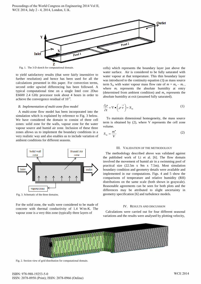
Fig. 1. The 3-D sketch for computational domain.
to yield satisfactory results (that were fairly insensitive to
further resolution) and hence has been used for all the
calculations presented in this paper. For convection terms,
second order upwind differencing has been followed. A
typical computational time on a single Intel core 2Duo
E6600 2.4 GHz processor took about 4 hours in order to
achieve the convergence residual of 10-4
.
B. Implementation of multi-zone flow model
A multi-zone flow model has been incorporated into the
simulation which is explained by reference to Fig. 3 below.
We have considered the domain to consist of three cell
zones: solid zone for the walls, vapour zone for the water
vapour source and humid air zone. Inclusion of these three
zones allows us to implement the boundary conditions in a
very realistic way and also enables us to include variation of
ambient conditions for different seasons.
For the solid zone, the walls were considered to be made of
concrete with thermal conductivity of 1.4 W/m-K. The
vapour zone is a very thin zone (typically three layers of
Fig. 2. Section view of grid distribution for computational domain.
cells) which represents the boundary layer just above the
water surface. Air is considered to be fully saturated with
water vapour at that temperature. This thin boundary layer
was introduced to the continuity equation (1) as mass source
term Sm with water vapour mass flow rate of m = mo – mi ,
where mi represents the absolute humidity at entry
(determined from ambient condition) and mo represents the
absolute humidity at exit (assumed fully saturated).
mSvt
(1)
To maintain dimensional homogeneity, the mass source
term is obtained by (2), where V represents the cell zone
volume.
V
mSm
(2)
III. VALIDATION OF THE METHODOLOGY
The methodology described above was validated against
the published work of Li et al. [6]. The flow domain
involved the movement of humid air in a swimming pool of
practical size (22.5m x 9m x 7.5m). Most simulation
boundary condition and geometry details were available and
implemented in our computations. Figs. 4 and 5 show the
comparisons of temperature and relative humidity (RH)
distributions on the same scale (both shown in grayscale).
Reasonable agreements can be seen for both plots and the
differences may be attributed to slight uncertainty in
geometry specification [6] and turbulence models.
IV. RESULTS AND DISCUSSION
Calculations were carried out for four different seasonal
variations and the results were analysed by plotting velocity,
Fig. 3. Schematic of the three domains.
Proceedings of the World Congress on Engineering 2014 Vol II, WCE 2014, July 2 - 4, 2014, London, U.K.
ISBN: 978-988-19253-5-0 ISSN: 2078-0958 (Print); ISSN: 2078-0966 (Online)
WCE 2014

temperature, relative humidity and integral values of latent
and sensible heats. Typical flow fields for winter conditions
(temperature: 5oC and RH:85%) are presented and discussed
in this section.
A. Velocity
Fig. 6. Shows the streamlines of humid air on the Z-mid
plane and shows a number of vortical structures. The first
vortex is due to the interaction between the incoming
ventilation air with buoyancy driven flow due to heat
released from the water surface. On the other hand, the
central counter-rotating vortices are a direct manifestation of
the current geometry where there is an ‘inactive’ separation
region between the two ponds. The other vortex near the exit
is just opposite to the inlet vortex. The velocity contours in
Fig. 7 clearly show that magnitudes are very small and most
of the higher velocities are concentrated near the
boundaries.
Fig. 7. Velocity contours on Z-0.4 and Z-2.3 planes.
B. Temperature
Temperature profiles at a few chosen locations in the X-
direction and along the Z-mid plane are shown in Fig. 8. It
can be observed that the temperature is slightly higher above
the water surface than at other places. The effect of the
geometry is visible on the X-mid plane.
Fig. 5(a). RH contour for the present method
Fig. 5(b). R.H contour for Li et al. [6]
Fig. 6. Streamlines on z- mid plane (aspect ratio modified for clarity).
Fig. 8. Temp. contours on Z-mid, X-4, X-mid and X-12 planes.
Fig. 4(b). Temperature distribution for Li et al. [6]
Fig. 4(a). Temperature distribution for the present method.
Proceedings of the World Congress on Engineering 2014 Vol II, WCE 2014, July 2 - 4, 2014, London, U.K.
ISBN: 978-988-19253-5-0 ISSN: 2078-0958 (Print); ISSN: 2078-0966 (Online)
WCE 2014
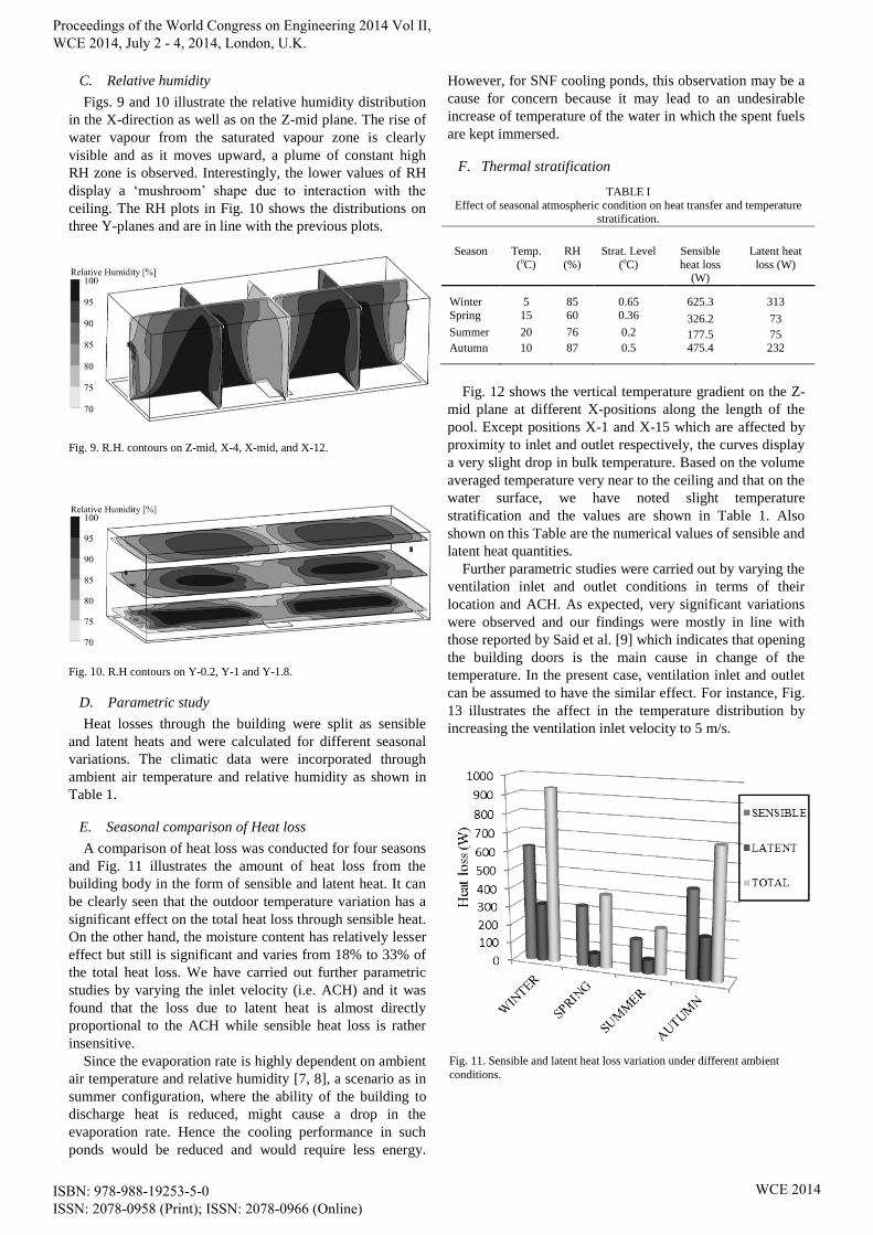
C. Relative humidity
Figs. 9 and 10 illustrate the relative humidity distribution
in the X-direction as well as on the Z-mid plane. The rise of
water vapour from the saturated vapour zone is clearly
visible and as it moves upward, a plume of constant high
RH zone is observed. Interestingly, the lower values of RH
display a ‘mushroom’ shape due to interaction with the
ceiling. The RH plots in Fig. 10 shows the distributions on
three Y-planes and are in line with the previous plots.
Fig. 9. R.H. contours on Z-mid, X-4, X-mid, and X-12.
Fig. 10. R.H contours on Y-0.2, Y-1 and Y-1.8.
D. Parametric study
Heat losses through the building were split as sensible
and latent heats and were calculated for different seasonal
variations. The climatic data were incorporated through
ambient air temperature and relative humidity as shown in
Table 1.
E. Seasonal comparison of Heat loss
A comparison of heat loss was conducted for four seasons
and Fig. 11 illustrates the amount of heat loss from the
building body in the form of sensible and latent heat. It can
be clearly seen that the outdoor temperature variation has a
significant effect on the total heat loss through sensible heat.
On the other hand, the moisture content has relatively lesser
effect but still is significant and varies from 18% to 33% of
the total heat loss. We have carried out further parametric
studies by varying the inlet velocity (i.e. ACH) and it was
found that the loss due to latent heat is almost directly
proportional to the ACH while sensible heat loss is rather
insensitive.
Since the evaporation rate is highly dependent on ambient
air temperature and relative humidity [7, 8], a scenario as in
summer configuration, where the ability of the building to
discharge heat is reduced, might cause a drop in the
evaporation rate. Hence the cooling performance in such
ponds would be reduced and would require less energy.
However, for SNF cooling ponds, this observation may be a
cause for concern because it may lead to an undesirable
increase of temperature of the water in which the spent fuels
are kept immersed.
F. Thermal stratification
Fig. 12 shows the vertical temperature gradient on the Z-
mid plane at different X-positions along the length of the
pool. Except positions X-1 and X-15 which are affected by
proximity to inlet and outlet respectively, the curves display
a very slight drop in bulk temperature. Based on the volume
averaged temperature very near to the ceiling and that on the
water surface, we have noted slight temperature
stratification and the values are shown in Table 1. Also
shown on this Table are the numerical values of sensible and
latent heat quantities. Further parametric studies were carried out by varying the
ventilation inlet and outlet conditions in terms of their
location and ACH. As expected, very significant variations
were observed and our findings were mostly in line with
those reported by Said et al. [9] which indicates that opening
the building doors is the main cause in change of the
temperature. In the present case, ventilation inlet and outlet
can be assumed to have the similar effect. For instance, Fig.
13 illustrates the affect in the temperature distribution by
increasing the ventilation inlet velocity to 5 m/s.
Fig. 11. Sensible and latent heat loss variation under different ambient
conditions.
TABLE I Effect of seasonal atmospheric condition on heat transfer and temperature
stratification.
Season Temp.
(oC)
RH
(%)
Strat. Level
(oC)
Sensible
heat loss (W)
Latent heat
loss (W)
Winter 5 85 0.65 625.3 313
Spring 15 60 0.36 326.2 73 Summer 20 76 0.2 177.5 75 Autumn 10 87 0.5 475.4 232
Proceedings of the World Congress on Engineering 2014 Vol II, WCE 2014, July 2 - 4, 2014, London, U.K.
ISBN: 978-988-19253-5-0 ISSN: 2078-0958 (Print); ISSN: 2078-0966 (Online)
WCE 2014

V. CONCLUSION AND FUTURE WORK
1) Employing the three cell zones in the model allows for
implementing the boundary conditions in a very
realistic and generalised way.
2) The model can be used to predict both sensible and
latent heat for different seasonal conditions.
3) Temperature stratification in the vertical direction has
been found to be small but not insignificant.
4) The boundary conditions need further improvement.
This can be done by considering condensation on the
walls.
5) In order to get more realistic simulation for specific
applications, accurate data about operational and
environmental conditions needs to be collected.
6) Having established the methodology, work is currently
underway to simulate the flow and heat transfer on a
full scale model of SNF pond.
REFERENCES
[1] Robinson, P., R. Hasan, and J. Tudor. Numerical Simulation of Flow and Heat Transfer in Spent Fuel Cooling Ponds. in Lecture Notes in
Engineering and Computer Science: Proceedings of the World
Congress on Engineering. 2013, pp. 1861-1864. [2] Shah, M.M., Prediction of evaporation from occupied indoor
swimming pools. Energy and buildings, 2003. 35(7): p. 707-713.
[3] Kozlov, Y.V., et al., Long-term storage and shipment of spent nuclear
fuel. Atomic Energy, 2000. 89(4): p. 792-803. [4] ANSYS FLUENT 14.5 (2014).
[5] Versteeg, H.K. and W. Malalasekera, An introduction to computational
fluid dynamics: the finite volume method. 2007: Pearson Education. [6] Li, Z., CFD Simulations for Water Evaporation and Airflow Movement
in Swimming Baths. VENTInet, 2005(14): p. 10-11.
[7] Vinnichenko, N.A., et al., Direct computation of evaporation rate at the surface of swimming pool. Recent Researches in Mechanics, 2O11,
2011: p. 120-124.
[8] M. D. Hancock, “Indoor swimming pools and leisure centres – A model to improve operational effectiveness and reduce environmental
impact,” CIBSE Technical Symposium, Sept. 6-7, 2011, De Montfort
University, Leicester, UK. [9] Said, M., R. MacDonald, and G. Durrant, Measurement of thermal
stratification in large single-cell buildings. Energy and buildings,
1996. 24(2): p. 105-115.
Fig. 12. Vertical temperature gradient on Z-mid plane.
Fig. 13. Temperature gradient on Z-mid and X-mid planes for inlet of 5 m/s.
Proceedings of the World Congress on Engineering 2014 Vol II, WCE 2014, July 2 - 4, 2014, London, U.K.
ISBN: 978-988-19253-5-0 ISSN: 2078-0958 (Print); ISSN: 2078-0966 (Online)
WCE 2014