Simulation of finite volume of hot forging process of industrial...
5
Simulation of finite volume of hot forging process of industrial gear Mahdi Maarefdoust + Islamic Azad University, Gonabad branch, Gonabad, Iran. Abstract. In this study the forging operations of gear has been modeled. This gear is a part which is manufactured with the help of hot forging. The aim of this research is utilizing computers in designing forming process, and in particular, modeling of hot forging in the gear and to inquire the stresses appeared on the mold. For this purpose Pro/Engineer software for modeling and Super forge software for analyzing the process have been used. The aim of this research is to correct the molds and the volume of the raw materials so that we can produce high qualified parts in spite of raw material low volume and low pressure on the molds. The effect of coefficient of friction and temperature on process was examined. The result show that the effective stress will increase with rising coefficient of friction and with increasing the temperature the press force decreases and effective plastic strain increases. Keywords: Hot forging, Finite volume method, Gear, Super forge software. 1. Introduction Forging process is one of the popular methods in metal forming. Many of the industrial parts are produced by this method because of its high strength and production rate of parts. Parameters such as temperature, geometry of raw material and die are effective in reducing production cost and increasing part quality. If the design and manufacturing of parts are on basis of experience that results in time waste and high cost. The prediction of material flow can be achieved completely by computer simulation. Main parameters in computer simulation are filling the die completely without leaving any defect, reducing material loss and stress in die and increasing die life. In order to reduce the cost of forging process and make it competent with other production methods, it is essential to optimize the design of part and die. Computer aided engineering (CAE) techniques have been increasingly applied with great success in metal-forming research to predict the forming load, stress and strain distribution. Mamalis et. al [1] used the implicit FE code MARC and the explicit FE code DYNA 3D to simulate the bevel gear forging process, the simulation results by MARC seem to be in good agreement with the experimental results. Lee et. al [2] analyzed the precision gear forging of a bevel gear by using the rigid-plastic finite element method. Yang [3] used FEM software DEFORM-3D to simulate the spur gear forging process. The DEFORM-3D is appropriated to simulate the forging process of gear. Yang and Hsu [4] used a finite element analysis to investigate the maximum forging force and final face width under different process parameters. Generally, application of computer to design the required steps based on analytical and experimental data has been considered excessively by other researches previously. Also, during the last decade use of simulation software has grown remarkably in the forging industry. Most of the software presented in this field is formed based on the Finite Element Method. METALFORM in 1993 [5] DIEFORGE in 1996 [6] and QFORM in 2001 [7] are among the software which are developed based on this method. Finite Volume Method are developed to analyze numerically fluid dynamic (CFD), and then it was utilized in the same field because the huge power in analyzing transient problems and large deformation. However, finite volume method (FVM) is accepted especially today as a powerful method to be used widely to analyze various bulk metal forming processes including forging. + E-mail address: [email protected] 2012 International Conference on Networks and Information (ICNI 2012) IPCSIT vol. 57 (2012) © (2012) IACSIT Press, Singapore DOI: 10.7763/IPCSIT.2012.V57.21 111
Transcript of Simulation of finite volume of hot forging process of industrial...
Simulation of finite volume of hot forging process of industrial gear
Mahdi Maarefdoust+
Islamic Azad University, Gonabad branch, Gonabad, Iran.
Abstract. In this study the forging operations of gear has been modeled. This gear is a part which is manufactured with the help of hot forging. The aim of this research is utilizing computers in designing forming process, and in particular, modeling of hot forging in the gear and to inquire the stresses appeared on the mold. For this purpose Pro/Engineer software for modeling and Super forge software for analyzing the process have been used. The aim of this research is to correct the molds and the volume of the raw materials so that we can produce high qualified parts in spite of raw material low volume and low pressure on the molds. The effect of coefficient of friction and temperature on process was examined. The result show that the effective stress will increase with rising coefficient of friction and with increasing the temperature the press force decreases and effective plastic strain increases.
Keywords: Hot forging, Finite volume method, Gear, Super forge software.
1. Introduction Forging process is one of the popular methods in metal forming. Many of the industrial parts are
produced by this method because of its high strength and production rate of parts. Parameters such as temperature, geometry of raw material and die are effective in reducing production cost and increasing part quality. If the design and manufacturing of parts are on basis of experience that results in time waste and high cost. The prediction of material flow can be achieved completely by computer simulation. Main parameters in computer simulation are filling the die completely without leaving any defect, reducing material loss and stress in die and increasing die life. In order to reduce the cost of forging process and make it competent with other production methods, it is essential to optimize the design of part and die.
Computer aided engineering (CAE) techniques have been increasingly applied with great success in metal-forming research to predict the forming load, stress and strain distribution. Mamalis et. al [1] used the implicit FE code MARC and the explicit FE code DYNA 3D to simulate the bevel gear forging process, the simulation results by MARC seem to be in good agreement with the experimental results. Lee et. al [2] analyzed the precision gear forging of a bevel gear by using the rigid-plastic finite element method. Yang [3] used FEM software DEFORM-3D to simulate the spur gear forging process. The DEFORM-3D is appropriated to simulate the forging process of gear. Yang and Hsu [4] used a finite element analysis to investigate the maximum forging force and final face width under different process parameters. Generally, application of computer to design the required steps based on analytical and experimental data has been considered excessively by other researches previously.
Also, during the last decade use of simulation software has grown remarkably in the forging industry. Most of the software presented in this field is formed based on the Finite Element Method. METALFORM in 1993 [5] DIEFORGE in 1996 [6] and QFORM in 2001 [7] are among the software which are developed based on this method. Finite Volume Method are developed to analyze numerically fluid dynamic (CFD), and then it was utilized in the same field because the huge power in analyzing transient problems and large deformation. However, finite volume method (FVM) is accepted especially today as a powerful method to be used widely to analyze various bulk metal forming processes including forging. + E-mail address: [email protected]
2012 International Conference on Networks and Information (ICNI 2012)IPCSIT vol. 57 (2012) © (2012) IACSIT Press, Singapore
DOI: 10.7763/IPCSIT.2012.V57.21
111
In this paper, hot forging process of industrial gear made up of CK45 (DIN 1.1191) in the Pro/Engineer software was simulated and then analyzed via MSC. Super forge software.
2. Method Simulation depicts an exact behavior of how metal flows inside the die. This leads us to investigate
problems such as filling of the die, the possibility of creating defects in the work piece and material flow in work piece. The results of simulation of forging processes including the stress , strain, material flow and the way of temperature distribution, one used in the estimation of final product properties. Generally, the problems which are used mostly in simulation are as follow: 1) Ensuring that the die is completely full without any defects in the finisher. 2) Reduction of wastes. 3) Increasing the dies’ life time using optimization of material flow in the die (Reduction of wear), 4) Reduction of the load on the die and preventing from losing the dies.
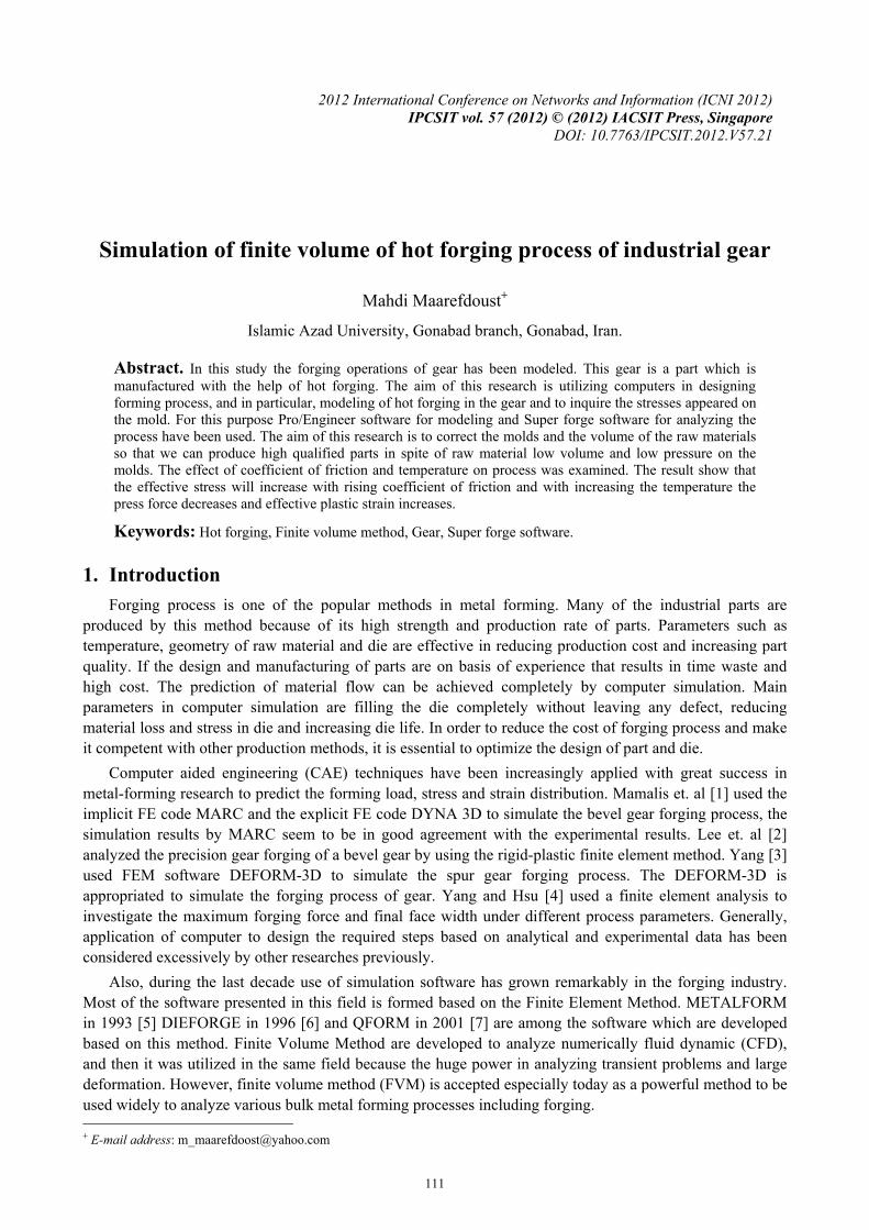
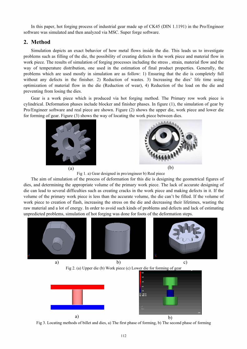
Gear is a work piece which is produced via hot forging method. The Primary row work piece is cylindrical. Deformation phases include blocker and finisher phases. In figure (1), the simulation of gear by Pro/Engineer software and real piece are shown. Figure (2) shows the upper die, work piece and lower die for forming of gear. Figure (3) shows the way of locating the work piece between dies.
(a)
(b)
Fig 1. a) Gear designed in pro/engineer b) Real piece The aim of simulation of the process of deformation for this die is designing the geometrical figures of
dies, and determining the appropriate volume of the primary work piece. The lack of accurate designing of die can lead to several difficulties such as creating cracks in the work piece and making defects in it. If the volume of the primary work piece is less than the accurate volume, the die can’t be filled. If the volume of work piece to creation of flash, increasing the stress on the die and decreasing their lifetimes, wasting the raw material and a lot of energy. In order to avoid such kinds of problems and defects and lack of estimating unpredicted problems, simulation of hot forging was done for foots of the deformation steps.
c) b) a)
Fig 2. (a) Upper die (b) Work piece (c) Lower die for forming of gear
b)
a)
Fig 3. Locating methods of billet and dies, a) The first phase of forming, b) The second phase of forming
112
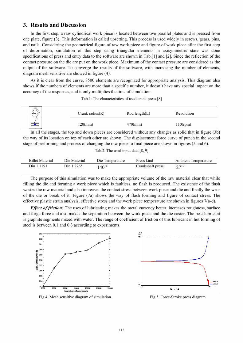
3. Results and Discussion In the first step, a raw cylindrical work piece is located between two parallel plates and is pressed from
one plate, figure (3). This deformation is called upsetting. This process is used widely in screws, gears, pins, and nails. Considering the geometrical figure of raw work piece and figure of work piece after the first step of deformation, simulation of this step using triangular elements in axisymmetric state was done specifications of press and entry data to the software are shown in Tab.[1] and [2]. Since the reflection of the contact pressure on the die are put on the work piece. Maximum of the contact pressure are considered as the output of the software. To converge the results of the software, with increasing the number of elements, diagram mesh sensitive are showed in figure (4).
As it is clear from the curve, 8500 elements are recognized for appropriate analysis. This diagram also shows if the numbers of elements are more than a specific number, it doesn’t have any special impact on the accuracy of the responses, and it only multiplies the time of simulation.
Tab.1. The characteristics of used crank press [8]
Crank radius(R)
Rod length(L)
Revolution
120(mm)
470(mm)
110(rpm)
In all the stages, the top and down pieces are considered without any changes as solid that in figure (3b) the way of its location on top of each other are shown. The displacement force curve of punch in the second stage of performing and process of changing the raw piece to final piece are shown in figures (5 and 6).
Tab.2. The used input data [8, 9]
Billet Material Die Material Die Temperature Press kind Ambient Temperature Din 1.1191 Din 1.2765 C140
Crankshaft press C27
The purpose of this simulation was to make the appropriate volume of the raw material clear that while filling the die and forming a work piece which is faultless, no flash is produced. The existence of the flash wastes the raw material and also increases the contact stress between work piece and die and finally the wear of the die or break of it. Figure (7a) shows the way of flash forming and figure of contact stress. The effective plastic strain analysis, effective stress and the work piece temperature are shown in figures 7(a-d).
Effect of friction: The uses of lubricating makes the metal currency better, increases roughness, surface and forge force and also makes the separation between the work piece and the die easier. The best lubricant is graphite segments mixed with water. The range of coefficient of friction of this lubricant in hot forming of steel is between 0.1 and 0.3 according to experiments.
6000 7000 8000 9000 10000 11000 12000353
354
355
356
357
358
359
360
361
362
363
Number of elements
Max
. Str
ess(
MP
a)
Fig 4. Mesh sensitive diagram of simulation Fig 5. Force-Stroke press diagram
113
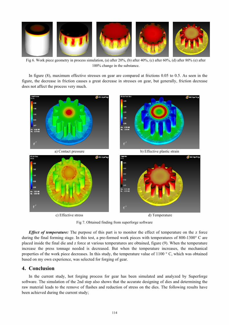
Fig 6. Work piece geometry in process simulation, (a) after 20%, (b) after 40%, (c) after 60%, (d) after 80% (e) after
100% change in the substance.
In figure (8), maximum effective stresses on gear are compared at frictions 0.05 to 0.5. As seen in the figure, the decrease in friction causes a great decrease in stresses on gear, but generally, friction decrease does not affect the process very much.
b) Effective plastic strain a) Contact pressure
d) Temperature c) Effective stress
Fig 7. Obtained finding from superforge software
Effect of temperature: The purpose of this part is to monitor the effect of temperature on the z force during the final forming stage. In this test, a pre-formed work pieces with temperatures of 800-1300° C are placed inside the final die and z force at various temperatures are obtained, figure (9). When the temperature increase the press tonnage needed is decreased. But when the temperature increases, the mechanical properties of the work piece decreases. In this study, the temperature value of 1100 ° C, which was obtained based on my own experience, was selected for forging of gear.
4. Conclusion In the current study, hot forging process for gear has been simulated and analyzed by Superforge
software. The simulation of the 2nd step also shows that the accurate designing of dies and determining the raw material leads to the remove of flashes and reduction of stress on the dies. The following results have been achieved during the current study;
114
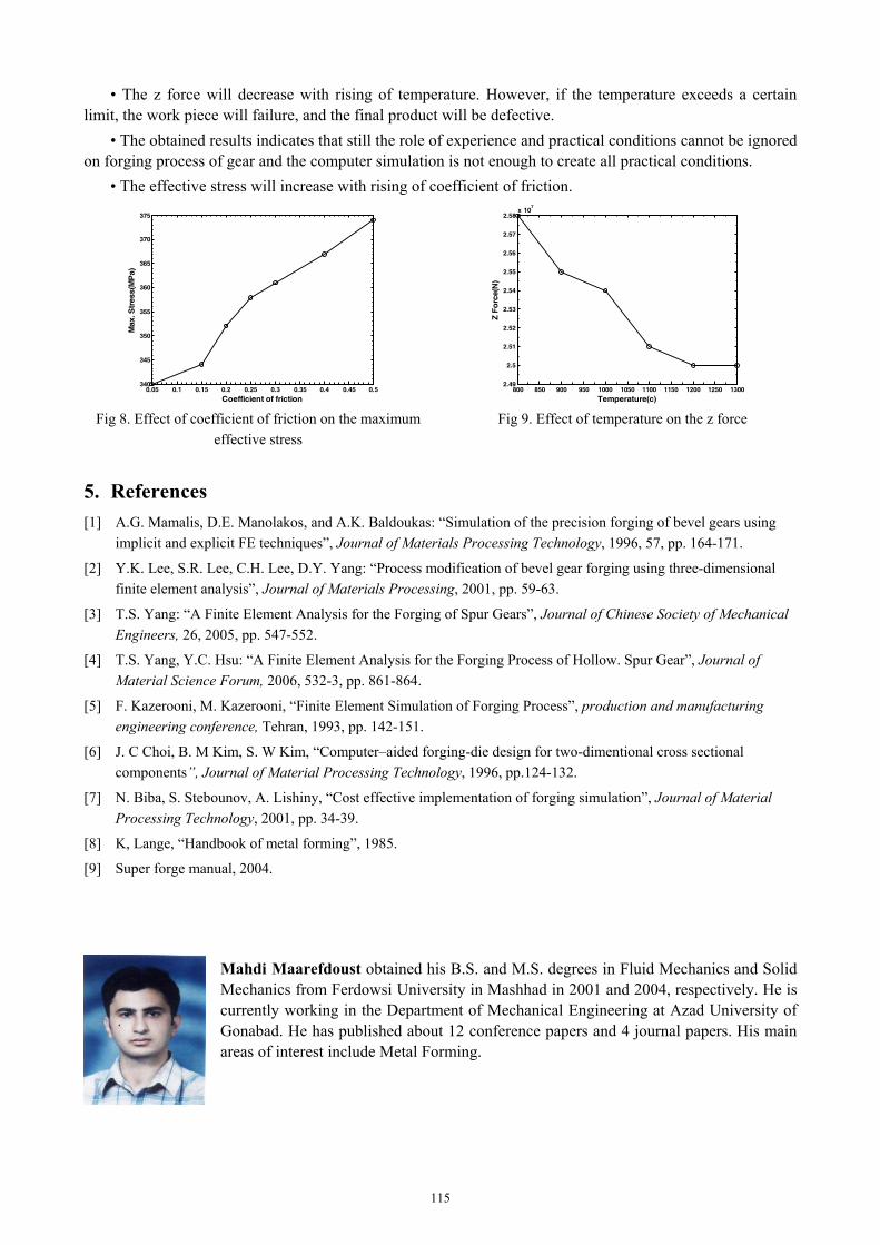
• The z force will decrease with rising of temperature. However, if the temperature exceeds a certain limit, the work piece will failure, and the final product will be defective.
• The obtained results indicates that still the role of experience and practical conditions cannot be ignored on forging process of gear and the computer simulation is not enough to create all practical conditions.
• The effective stress will increase with rising of coefficient of friction.
0.05 0.1 0.15 0.2 0.25 0.3 0.35 0.4 0.45 0.5340
345
350
355
360
365
370
375
Coefficient of friction
Max
. Str
ess(
MP
a)
800 850 900 950 1000 1050 1100 1150 1200 1250 13002.49
2.5
2.51
2.52
2.53
2.54
2.55
2.56
2.57
2.58x 10
7
Temperature(c)
Z Fo
rce(
N)
Fig 8. Effect of coefficient of friction on the maximum effective stress
Fig 9. Effect of temperature on the z force
5. References [1] A.G. Mamalis, D.E. Manolakos, and A.K. Baldoukas: “Simulation of the precision forging of bevel gears using
implicit and explicit FE techniques”, Journal of Materials Processing Technology, 1996, 57, pp. 164-171.
[2] Y.K. Lee, S.R. Lee, C.H. Lee, D.Y. Yang: “Process modification of bevel gear forging using three-dimensional finite element analysis”, Journal of Materials Processing, 2001, pp. 59-63.
[3] T.S. Yang: “A Finite Element Analysis for the Forging of Spur Gears”, Journal of Chinese Society of Mechanical Engineers, 26, 2005, pp. 547-552.
[4] T.S. Yang, Y.C. Hsu: “A Finite Element Analysis for the Forging Process of Hollow. Spur Gear”, Journal of Material Science Forum, 2006, 532-3, pp. 861-864.
[5] F. Kazerooni, M. Kazerooni, “Finite Element Simulation of Forging Process”, production and manufacturing engineering conference, Tehran, 1993, pp. 142-151.
[6] J. C Choi, B. M Kim, S. W Kim, “Computer–aided forging-die design for two-dimentional cross sectional components”, Journal of Material Processing Technology, 1996, pp.124-132.
[7] N. Biba, S. Stebounov, A. Lishiny, “Cost effective implementation of forging simulation”, Journal of Material Processing Technology, 2001, pp. 34-39.
[8] K, Lange, “Handbook of metal forming”, 1985.
[9] Super forge manual, 2004.
Mahdi Maarefdoust obtained his B.S. and M.S. degrees in Fluid Mechanics and Solid Mechanics from Ferdowsi University in Mashhad in 2001 and 2004, respectively. He is currently working in the Department of Mechanical Engineering at Azad University of Gonabad. He has published about 12 conference papers and 4 journal papers. His main areas of interest include Metal Forming.
115