Simulation of Convection and Macrosegregation in Steel Casting
21
Simulation of Convection and Macrosegregation in Steel Casting C. Beckermann* and M. C. Schneider** *Professor, Department of Mechanical Engineering, The University of Iowa **Formerly graduate student with Department of Mechanical Engineering, The University of Iowa, now with Software Development Group, MAGMA Giessereitechnologie GmbH The University of Iowa Iowa City, IA September 1996
Transcript of Simulation of Convection and Macrosegregation in Steel Casting
Simulation of Convection and Macrosegregation in Steel Casting
C. Beckermann* and M. C. Schneider**
*Professor, Department of Mechanical Engineering, The University of Iowa
**Formerly graduate student with Department of Mechanical Engineering, The University of
Iowa, now with Software Development Group, MAGMA Giessereitechnologie GmbH
The University of Iowa
Iowa City, IA
September 1996
becker
Text Box
Beckermann, C., and Schneider, M.C., “Simulation of Convection and Macrosegregation in Steel Casting,” in Proceedings of the 50th SFSA Technical and Operating Conference, Paper No. 4.2, Steel Founders' Society of America, Chicago, IL, 1996.

1. Introduction
During solidification, there can be a significant amount of fluid flow in both the bulk melt and the mushy zone. This is particularly true in heavy steel castings which have very large cross sections. The flow has two primary effects: it alters the thermal field, and it redistributes the alloying and trace elements throughout the casting, causing macrosegregation. A primary cause of fluid flow during solidification is density variation within the liquid metal in the presence of gravity. Density differences can be due to both temperature gradients (thermal convection) and concentration gradients (solutal convection) in the liquid.
There have been numerous investigations, both experimental [1-8] and numerical [9-12], of segregation phenomena in cast steel. Many of the experimental studies have focused on the factors that influence the formation of A- and V-type channel segregates in steel ingots [1-4] and were not concerned with overall macrosegregation patterns. In those studies that examined general macrosegregation, the measurements were made only along the casting center line ( i.e. one dimensional ) [5-6] or near a riser [7] and /or the casting geometry was such that numerical calculations of macrosegregation would be difficult [8]. While they have shown reasonable agreement with experimental measurements, previous efforts at modeling the formation of segregation in multicomponent steel alloys have suffered from the limitations of neglecting bulk liquid motion [9,10] or incomplete coupling of energy and species conservation in the mushy zone [11,12]. Previous models also assumed that microscopic diffusion of each element in the solid phase was either absent (Scheil type behavior) or complete (lever rule behavior), and they did not account for the peritectic transformation. Most importantly, convection and macrosegregation have never been simulated for the complex three-dimensional (3-D) geometries typical of steel castings.
In this article, a recently developed extension of an existing 3-D casting simulation code (MAGMASOFT) is described that provides the options of simulating convective flow during solidifcation and macrosegregation formation. For a detailed description of the model and governing conservation equations, the interested reader is referred to Schneider and Beckemann
2. Model Description
[13].
a. Simulation of Thermal Convection Temperature gradients that arise during the cooling and solidification of a casting lead to
liquid metal density variations (i.e. cooler liquid is denser than warmer liquid). Due to gravity, high density liquid metal will sink, while lower density liquid will rise. This movement drives fluid flow throughout the bulk melt and the mushy zone. As warmer and cooler liquid moves, the flow, in turn, alters the temperature field in the solidifying casting.
The simulation of thermal convection during solidification is more complex than the simulation of heat conduction alone. It is necessary to solve three momentum equations and a mass conservation equation to obtain the liquid velocity and pressure fields, in addition to solving the thermal energy equation to obtain the temperature field. The momentum equations contain terms that describe the density variations of the liquid metal and the permeability of the mushy zone. This permeability term decreases the flow velocity to zero as the solid fraction approaches one during solidification. At present, the explicit SOLA-VOF fluid flow solver, also used to calculate velocities during mold filling, has been modified to calculate the velocities during solidification.
An extra term must be also added to the energy equation for heat conduction to account for the effect of the fluid flow on the temperature field. This has been accomplished in the extended code by modifying the standard implicit heat conduction solver.
1

b. Simulation of Thermosolutal Convection and Macrosegregation Formation During alloy solidification there is a partitioning of the elements between the solid and
liquid phase at the microscopic solid/liquid interface. In steel, for example, only around 35% of the carbon and less than 10% of the sulfur present in the liquid is incorporated into the solid at this microscopic interface during primary solidification. Due to partitioning, the liquid near the solid/liquid interface (i.e. in the mushy zone) becomes enriched in solutes, and microscopic concentration gradients (microsegregation) develop in the growing solid. Convective flow can redistribute the solute enriched liquid within the melt, leadmg to the large scale composition variations known as macrosegregation.
Similar to temperature gradients driving thermal convection, concentration gradients in the liquid metal cause density gradients, that also drive fluid flow (solutal convection). In steel, for example, liquid enriched with carbon is lighter than liquid depleted of carbon. On the other hand, copper enriched liquid is heavier than copper depleted liquid. Therefore, carbon enriched liquid tends to rise, while copper enriched liquid tends to sink. In a solidifying casting, the liquid is enriched in or depleted of all of the alloying elements to differing extents (due to differences in partitioning between the liquid and solid), so that the total density gradient will be a combination of the thermal and solutal gradients (thermosolutal convection).
The simulation of thermosolutal convection and macrosegregation formation requires proportionally more computational effort than thermal convection. In order to account for microsegregation in the solid and to trace the redistribution of the elements in the liquid metal, solid and liquid solute conservation equations must be solved for each alloying and trace element present in the alloy. In the present code, a new implicit solute conservation solver has been implemented to solve these equations. Additionally, the density in the buoyancy term in the momentum conservation equations must be modified to account for the effects of local element concentrations on the fluid flow.
c.Prediction of Channel Segregation The liquidus temperature of a steel alloy is dependent on the concentration of the alloying
and trace elements present in the melt. Because of this dependence, solute rich liquid has a lowered liquidus temperature. As discussed above, solute rich liquid may be redistributed in the casting by convection during solidification, meaning that the liquidus temperature will also vary throughout the casting. If solute rich liquid from a cooler pomon of the casting is carried into a warmer region, remelting or the delayed formation of solid may occur. Since the resistance to flow in this remelted region is lower (because of its lower solid fraction ) than in the surrounding mushy zone, it becomes a preferred path for the flow of the solute enriched liquid. In the solidified casting, these regions show up as channel segregation (also know as ghost lines or freckles).
To predict the formation of channel segregation it is necessary to guarantee that the temperature field simultaneously satisfies the energy conservation equation and matches the liquidus temperature field, which is based on the local liquid compositions (i.e. the temperature and composition are coupled through the liquidus temperature). To meet this criteria, and provide the option of predicting the formation of channel segregation, a special procedure to calculate the local solid fraction during solidification [ 13] is also being implemented in the present extension of the code.
3. Simulation Results
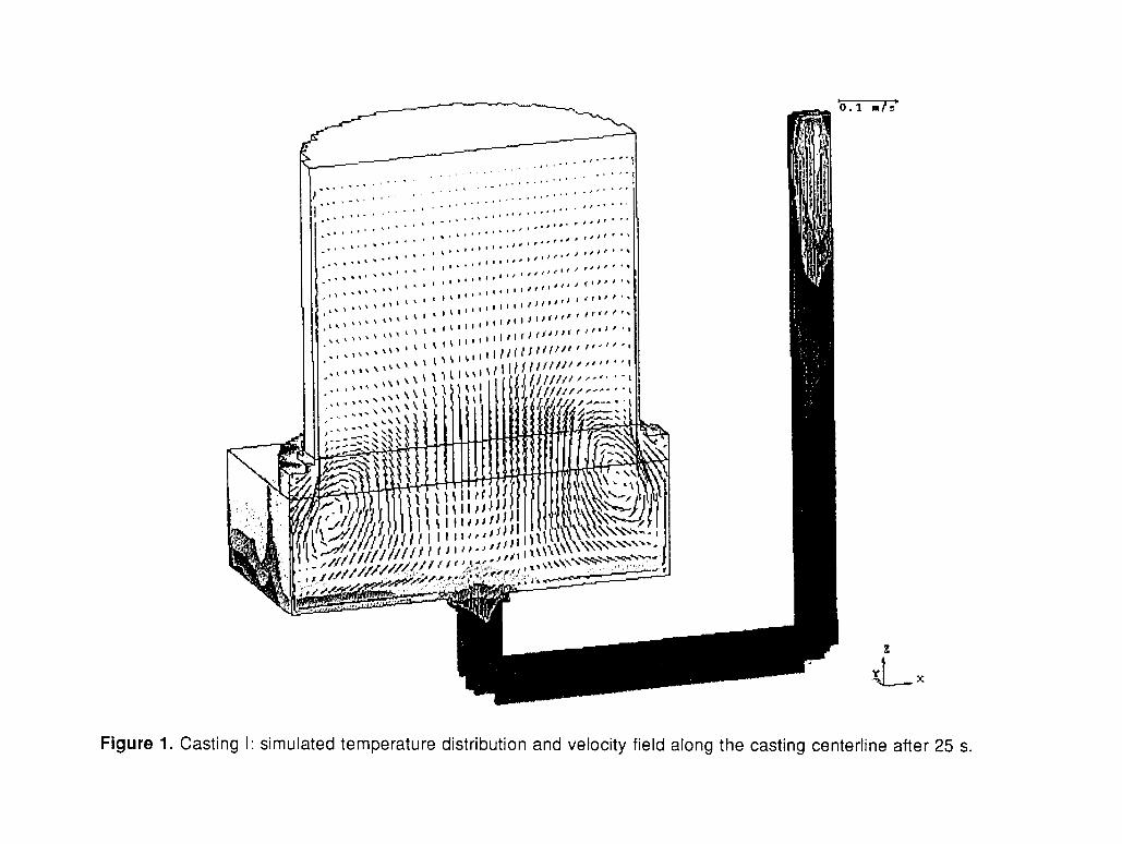
a. A Simple Test Casting (Casting I) The capabilities of the new code are first illustrated in Figures 1 through 3, which show
some results from the simulation of the solidification of a simple test casting (Casting I). The casting is a 0.75mx0.75mx 0.25m block with a riser of 0.65m diameter and 0.60m height, cast
2

with the alloy GS 34CrMo4 (0.34wt.-% C, 0.4 wt.-% Si, 0.65wt.-% Mn, 1wt.-% Cr, 0.4wt.-% Mo, 0.025wt.-% P and 0.025wt.-% S) in a green sand mold. The initial condition for the simulation was an instantaneous fill (i.e. uniform temperature).
The predicted velocity and temperature fields in Figure 1 show the effects of thermal convection after 25 s. Cooling at the vertical wall of the casting and riser walls causes a liquid density increase and drives strong downward fluid flow. This downward flow is balanced by upward flow along the center of the casting and riser. The flow carries liquid from along the walls, down into the casting, and back up into the center of the riser. The effects of convection can also be seen in the down sprue and gating, where cooler liquid has sunk to the bottom, and warmer liquid has risen to the top.
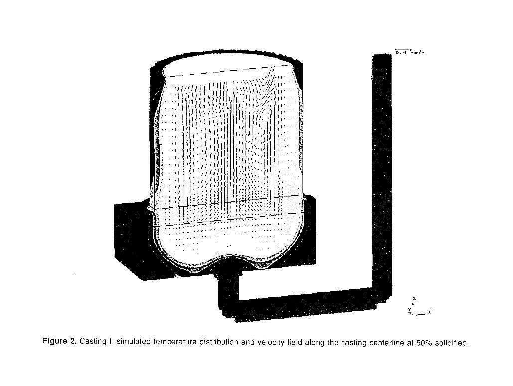
The velocity and temperature fields at 50% solidified are shown in Figure 2. At this time all of the casting and riser are under the liquidus temperature, i.e. all regions are either completely solid or solid/liquid mush. Similar to Figure 1, the flow pattern is upward in the center and downward near the walls of the casting and riser. The velocity vectors show that the flow is strongest where the solid fraction is lowest, for example in the center of the riser. Near the walls of the riser, the velocities become smaller due to the increase in the solid fraction and the corresponding decrease in the permeability of the mushy zone.
The simulated carbon distribution at the end of solidification, shown in Figure 3, illustrates how the fluid flow during solidification has redistributed the elements in the casting. The flow along the walls of the riser has carried carbon rich liquid down into the casting and back up into the center of the riser, leaving the top and slides of the riser solute poor. The bottom center of the riser and the top center of the casting, on the other hand, are highly enriched with solute. It should be noted that the simulation results shown in Figure 1 through 3 do not account for the formation of channel segregation or for shrinkage due to solid/liquid density differences. The implementation of these capabilities is part of ongoing developments.
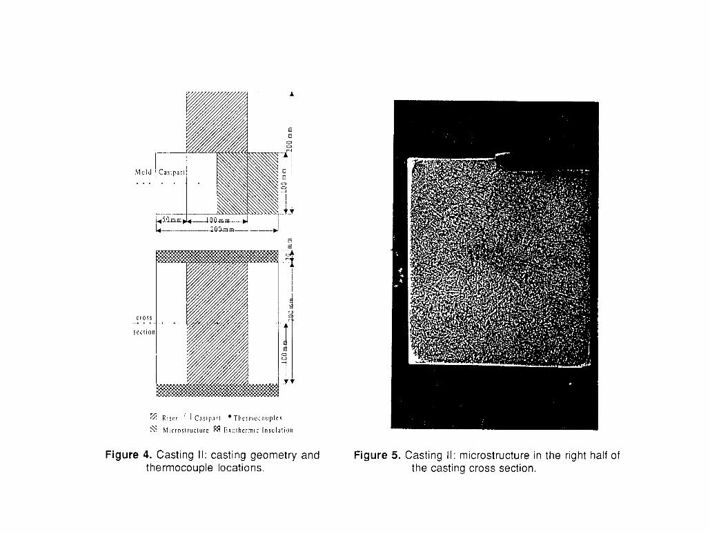
b. Experimental Validation (Casting II) An experimental investigation was undertaken [14] to validate the predictions of the present
implementation of the mathematical model [13]. For the casting (Casting II), the simple rectangular geometry with a rectangular riser in a furan mold shown in Figure 4 was chosen. An unalloyed steel of the composition 0.42% C, 0.60% Si, 0.80% Mn, 0.014% S, 0.015% P, 0.10% Cu, 0.10% Cr, 0.10% Ni, 0.02% Mo ( Tliq=1764 K) was poured at a temperature of 1893K. Cooling curves were measured in the mold and the metal (during both mold filling and solidification) using thermocouples located as shown in Figure 4. The heat transfer coefficient for the furan-steel interface was determined as a function of temperature using inverse analysis [15]. The properties of the exothermic insulation (Figure 4) were estimated by matching measured and calculated cooling curves.
Primary and secondary dendrite arm spacings for the steel were measured as a function of solidification parameters using samples solidified in a gradient furnace. Following Flemings [16] and Hunt [17], equations for the dendrite arm spacings were determined to be:
The final microstructure distribution in the casting is shown in Figure 5. While the microstructure along the walls and at the top of the casting is columnar, a large equiaxed zone is apparent in the region that solidified last at the bottom center of the casting. Using measured cooling curves, the temperature gradient and solidification velocity near the solidus temperature (=1710 K) for a region in the casting was determined, and using Eq. (2) λ2 was calculated to be 50 µm . The average measured λ 2 for the same region in the casting was 53 µm .
3

The final concentration distribution of the elements in the center cross section of the casting were measured using spectral analysis on a grid of 15x23 measuring points. The measured distribution of carbon, silicon and sulfur are shown in Figure 6.
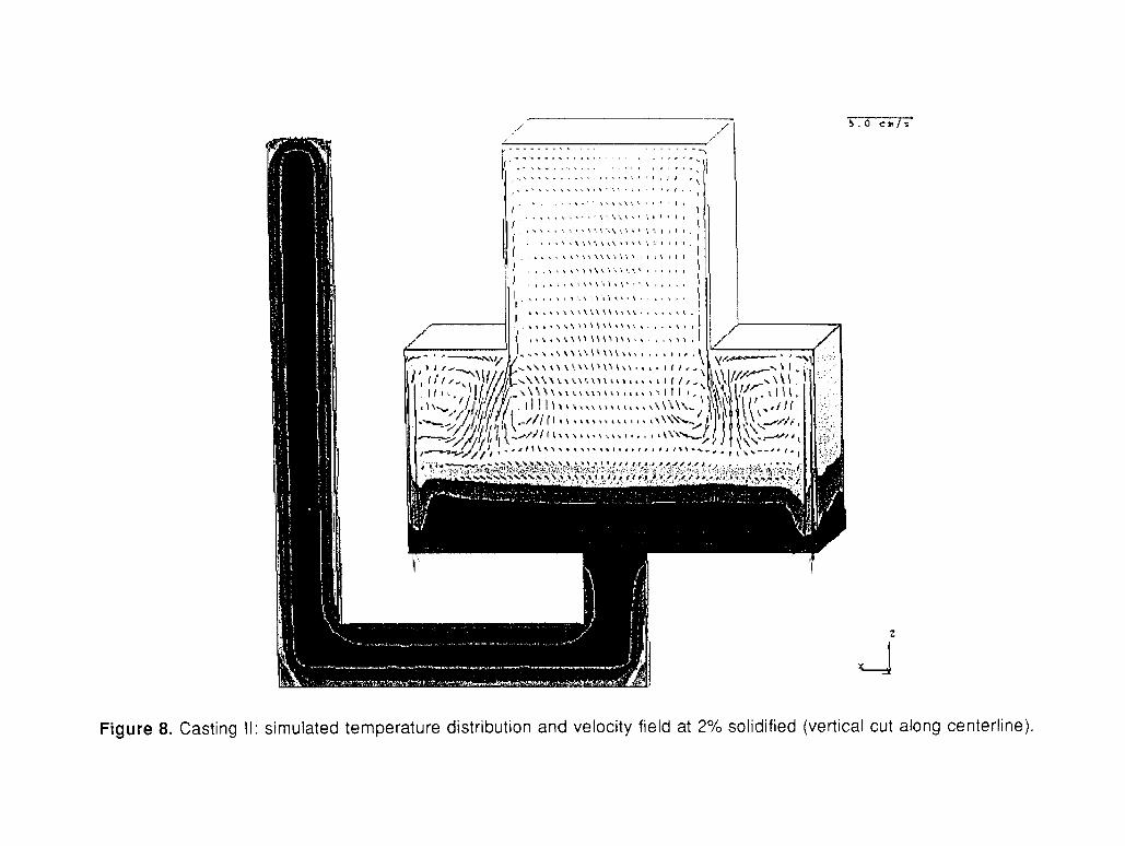
Figures 7 through 14 illustrate the simulation results for Casting 11. Figure 7 shows the predicted velocities and temperatures at the end of filling. The temperature field is fairly uniform due to the convective mixing during filling. Figures 8 and 9 illustrate the complex flow and temperature patterns a short time after filling is completed and a small fraction of the casting has already solidified. Important to notice in Figure 8 is the thermal stratification which would not have been predicted without taking convection of the liquid metal into account. Also note the relatively large magnitude of the velocities at this stage in the solidification process, and the strong thermally driven downflows adjacent to the mold walls. Figure 10 shows a well-developed recirculation in the liquid core, at a stage when 30% of the metal has solidified. Compared to Figure 8, the velocities are already smaller by about a factor of 5, but still range up to 1 cm/s. The corresponding distribution of carbon at this time is plotted in Figure 11, illustrating how the carbon is macroscopically redistributed by the flow during solidification.
The final macrosegregation patterns in the fully solidified casting are shown in Figures 12 and 13 for carbon and in Figure 14 for sulphur. The segregation patterns of each element are similar, although the extent of segregation varies strongly (e.g., sulfur is more severely segregated than carbon). In general, the measured (Figure 6) and predicted (Figures 12 to 14) macrosegre- gation distributions are in good agreement. Any differences can be attributed to measurement difficulties and some uncertainties in the model, as discussed in references [13,14].
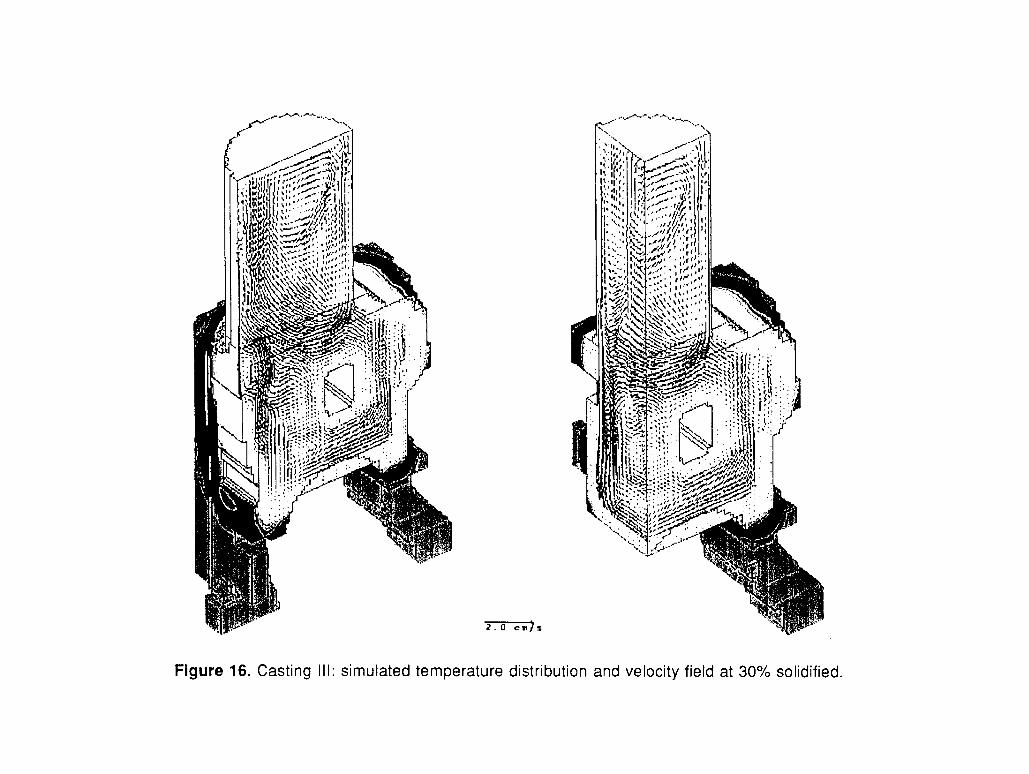
c. Simulation of a Large and Complex Part (Casting III) In order to further illustrate the application of the computer model, representative results are
shown in Figures 15 and 16 for the simulation of a large and complex production casting. The pour weight is 125 tons, the casting weight is 68 tons, and the maximum casting dimensions (without the 2m high riser) are 2.65mx2.1mx3.7m. The steel has a composition of 0.23% C, 0.4% Si, 1.0% Mn, 0.012% P, 0.0045% S, 0.052% Cr, 0.002% Mo, 0.02% Ni, and 0.001% V. The simulation was started with an instantaneous fill and an initial temperature of 1863K. Most notable in the figures are the strong convective flows during solidification leading to redistribution of the elements. As of the time of writing this paper, the simulation was still running on the computer. Plots of the final macrosegregation patterns will be presented at the conference. Nonetheless, it is clear that the neglect of convection in such a large part would not only prevent us from calculating macrosegregation, but would also result in unrealistic temperature predictions during solidification.
Conclusions
A new development in the simulation of steel castings has been described, that allows for the prediction of convection and macrosegregation during solidification. The results of sample calculations for three-dimensional part geometries have been presented. A comparison with an experiment gave good agreement between the measured and predicted macrosegregation patterns. More detailed comparisons are planned for the near future.
References
1. K. Suzuki and T. Miyamoto, On the Formation Mechanism of V-Segregation in Steel Ingots, Trans. ISIJ, 14 (1974), 296-305.
2. J.J. Flawley, The Origin of V and Inverted V Type Defects in Large Steel Castings, AFS Transactions, 89 (1981), 445-454.
4

3. K. Suzuki and K. Taniguchi, The Mechanical of Reducing A-Segregates in Steel Ingots, Trans. ISIJ, 20 (1981), 235-242.
4. L.H. Shaw, J. Beech and R.H. Hickley, Channel Segregates in Cast Steel Rolls, Ironmaking and Stee lmaking, 13 (1986), 154-160.
5. H.A.Shah and J.J. Moore, Effect of Thermal Conditions and Alloying Constituents (Ni, Cr) on Macrosegregation in Continuously Cast High-Carbon (0.8 Pct), Low- Alloy Steel, Metall. Trans. B, 20B (1989), 893-910.
6. J. Wanqi and Z. Yaohe, Formation of Hot-Top Segregation in Steel Ingot and Effect of Steel Composition, Metall Trans. B, 20B (1989), 723-730.
7. W.T. Adams and K.W. Murphy, Optimum Full Contact Top Risers to Avoid Sever Under Riser Chemical Segregation in Steel Casting, AFS Transactions, 88 (1980), 389-404.
8. A. Olsson, R. West and H. Fredriksson, Macrosegregation in Ingots, Scand. J. Metallurgy,
9. T. Fujii, D.R. Poririer and M.C. Flemings, Macrosegregation in Ingots, Metall. Trans. B, 10B
10. D.R. Poirier and M.M. Andrews, Modeling Macrosegregation and Porosity in Steel Castings, in Proceedings of 1st International Steel Foundry Congress , Des Plaines, Illinois: Steel Foundrymens’ Society of America, (1985), 307-322.
11. F. Roch, H. Combeau, I. Poitrault, J. Ch. Chevrier and G. Lesoult, Numerical Model for Prediction of Chemical-Type Segregation in Heavy Steel Ingots, in Proceedings of the 6th International Iron and Steel Congress, Vol. 1: Fundamentals, Nagoya: ISIJ, (1990), 665-672.
12. H. Vannier, H. Combeau and G. Lesoult, Numerical Model for Prediction of the Final Composition for Steel Ingots, in Numerical Methods in Industrial Forming Processes, Rotterdam: A.A. Balkema, (1992), 835-840.
13. M.C. Schneider and C. Beckemann, Formation of Macrosegregation by Multicomponent Thermal Convection during the Solidification of Steel, Metall. Trans. A, 26A (1995), 2373- 2388.
14 W.F.A. Bohmer, M.C. Schneider, C. Beckermann and P.R. Sahm, Combined Experimental and Numerical Investigation of the Formation of Macrosegregation during Multicomponent Steel Solidification, in Modelling of Casting. Welding and Advanced Solidification Processes VII, M. Cross et al., eds., TMS, Warrendal, PA, (1995), 617-624.
15 B. Unluer, Determination of Boundarv Conditions during Mold Filling and Solidification for Steel Casting, Graduation Thesis, Gieberei-Institut RWTH Aachen, 1993.
16. M.C. Flemings, Solidification Processing, New York, McGraw-Hill, 1974. 17. J.D. Hunt, Solidification and Casting of Metals , London, The Materials Society, 1979.
15 (1986), 104-112.
(1979), 331-339.
Acknowledgments
The authors thank Dr. W. Bohmer and the Eisenwerk Bohmer in Witten, Germany, for the experimental data and help with the analysis of the experiments.
5