SIMULATION BASED DESIGNING OF CONTROL SYSTEMS FOR …
6
Website: ijetms.in Issue:5, Volume No.4, September-2020 DOI: 10.46647/ijetms.2020.v04i05.019 104 Guruswamy Revana 1 , D.E.Amrutha 2 , D.Spandana 3 , D.Anusha 4 1 Associate Professor, BVRIT HYDERABAD College of Engineering for Women, Hyderabad, India. 2 B.Tech., BVRIT HYDERABAD College of Engineering for Women, Hyderabad, India 3 B.Tech., BVRIT HYDERABAD College of Engineering for Women, Hyderabad, India 4 B.Tech., BVRIT HYDERABAD College of Engineering for Women, Hyderabad, India 1 [email protected] 2 [email protected] 3 [email protected] 4 [email protected] Abstract—Wind power is a domestic source of energy, harnessing a limitless local resource and is a potential source of clean electricity generation. Wind is utilized to create electrical energy by means of the kinetic energy formed by air into movement. This energy is changed to electrical energy by wind speed turbines or also called as wind energy exchange systems. Wind speed power generation creates a progressively more significant position in the method the humans power the world. During the process of wind power generation, a variety of characteristics are to be controlled for efficient working of the system and to avoid failure of continuous power supply. In this project we are aiming to control a few such characteristic such as pitch angle, voltage sag and faults that influence wind power generation. The DC link voltage of the Doubly Fed Induction Generator (DFIG) is also monitored. In this wind turbine system consists of wind turbine, AC generator and controllers are considered. The major purpose of the paper is to find out the mathematical model of the wind turbine, authenticate it by simulation, and devise a suitable controller to present a common aim of outlook regarding the use of this type of clean energy production. Various rudiments are connected collectively and the complete arrangement is modelled and also simulated. The simulation results verify the accuracy of the mathematical models developed and can be utilized for a improved design of systems. Wind turbines make use DFIG which consists of wound rotor type induction generator and a PWM converter of IGBT bases of AC/DC/AC. The stator winding is connected directly to the 60 Hz grid while the rotor is fed at variable frequency through the AC/DC/AC converter. The DFIG machinery permits pulling out highest energy from the wind from lowest wind speeds and optimizing the speed of the turbine there by decreasing mechanical stresses on the turbine during gusts of wind. The most favourable turbine speed producing increased mechanical energy for a given speed of the wind which is directly proportional to the wind speed. The other merit of the DFIG expertise is the capability for the converters of power electronics to produce or take in reactive power, thereby reducing the need for putting in capacitor banks as done for the generators of squirrel-cage induction motor type. Keywords—Controller, DFIG, Power Quality, Simulation, Wind Power. I. INTRODUCTION With the enhanced diffusion of wind power into electrical grids, DFIG wind turbines are mostly positioned due to their changeable speed characteristics and therefore controlling system dynamics. This feature has shaped awareness in developing appropriate models for DFIG which are to be included in the power system studies. The uninterrupted tendency of having more diffusion of wind power, in current time, has made it essential to bring in new practices. For instance, grid codes are revised to make sure that wind turbines would add to be in command of both voltage and frequency and also to continue connected to the main network subsequent to a disturbance. In reaction to the current grid code requirements, a number of DFIG models were proposed recently, which includes the full- representations which is a fifth order model. These models utilize quadrature and direct components of rotor voltage in a suitable orientation edge to offer speedy regulation of voltage. The third order representation of DFIG which makes use of rotor current, but not rotor voltage as control parameter can also be useful to offer extremely quick regulation of instantaneous currents through the penalty of bringing down the accuracy. Apart from that, the third order representation can be reached by ignoring the rate of change of stator flux linkage, with the known rotor voltage as control parameter. In addition to that in order to represent back to back PWM converters, in the simplest circumstances, it is implicated that the converters are perfect and the DC-link voltage between the converters is invariable. As a result, depending on the converter control, a controllable voltage (current) source can be put into practice to correspond to the process of the converter rotor side of the representation. Nevertheless, in actuality DC SIMULATION BASED DESIGNING OF CONTROL SYSTEMS FOR WIND POWER GENERATION
Transcript of SIMULATION BASED DESIGNING OF CONTROL SYSTEMS FOR …
Website: ijetms.in Issue:5, Volume No.4, September-2020 DOI: 10.46647/ijetms.2020.v04i05.019
104
Guruswamy Revana1, D.E.Amrutha2, D.Spandana3, D.Anusha4
1Associate Professor, BVRIT HYDERABAD College of Engineering for Women, Hyderabad, India. 2B.Tech., BVRIT HYDERABAD College of Engineering for Women, Hyderabad, India 3B.Tech., BVRIT HYDERABAD College of Engineering for Women, Hyderabad, India 4B.Tech., BVRIT HYDERABAD College of Engineering for Women, Hyderabad, India
[email protected] [email protected] [email protected] [email protected]
Abstract—Wind power is a domestic source of energy,
harnessing a limitless local resource and is a potential source
of clean electricity generation. Wind is utilized to create
electrical energy by means of the kinetic energy formed by air
into movement. This energy is changed to electrical energy by
wind speed turbines or also called as wind energy exchange
systems. Wind speed power generation creates a progressively
more significant position in the method the humans power the
world. During the process of wind power generation, a variety
of characteristics are to be controlled for efficient working of
the system and to avoid failure of continuous power supply. In
this project we are aiming to control a few such characteristic
such as pitch angle, voltage sag and faults that influence wind
power generation. The DC link voltage of the Doubly Fed
Induction Generator (DFIG) is also monitored. In this wind
turbine system consists of wind turbine, AC generator and
controllers are considered.
The major purpose of the paper is to find out the
mathematical model of the wind turbine, authenticate it by
simulation, and devise a suitable controller to present a
common aim of outlook regarding the use of this type of clean
energy production. Various rudiments are connected
collectively and the complete arrangement is modelled and
also simulated. The simulation results verify the accuracy of
the mathematical models developed and can be utilized for a
improved design of systems. Wind turbines make use DFIG
which consists of wound rotor type induction generator and a
PWM converter of IGBT bases of AC/DC/AC. The stator
winding is connected directly to the 60 Hz grid while the rotor
is fed at variable frequency through the AC/DC/AC converter.
The DFIG machinery permits pulling out highest energy from
the wind from lowest wind speeds and optimizing the speed of
the turbine there by decreasing mechanical stresses on the
turbine during gusts of wind. The most favourable turbine
speed producing increased mechanical energy for a given
speed of the wind which is directly proportional to the wind
speed. The other merit of the DFIG expertise is the capability
for the converters of power electronics to produce or take in
reactive power, thereby reducing the need for putting in
capacitor banks as done for the generators of squirrel-cage
induction motor type.
Keywords—Controller, DFIG, Power Quality, Simulation,
Wind Power.
I. INTRODUCTION
With the enhanced diffusion of wind power into electrical
grids, DFIG wind turbines are mostly positioned due to
their changeable speed characteristics and therefore
controlling system dynamics. This feature has shaped
awareness in developing appropriate models for DFIG
which are to be included in the power system studies. The
uninterrupted tendency of having more diffusion of wind
power, in current time, has made it essential to bring in new
practices. For instance, grid codes are revised to make sure that wind turbines would add to be in command of both
voltage and frequency and also to continue connected to the
main network subsequent to a disturbance. In reaction to
the current grid code requirements, a number of DFIG
models were proposed recently, which includes the full-
representations which is a fifth order model. These models
utilize quadrature and direct components of rotor voltage in
a suitable orientation edge to offer speedy regulation of
voltage. The third order representation of DFIG which
makes use of rotor current, but not rotor voltage as control
parameter can also be useful to offer extremely quick
regulation of instantaneous currents through the penalty of bringing down the accuracy. Apart from that, the third
order representation can be reached by ignoring the rate of
change of stator flux linkage, with the known rotor voltage
as control parameter. In addition to that in order to
represent back to back PWM converters, in the simplest
circumstances, it is implicated that the converters are
perfect and the DC-link voltage between the converters is
invariable. As a result, depending on the converter control,
a controllable voltage (current) source can be put into
practice to correspond to the process of the converter rotor
side of the representation. Nevertheless, in actuality DC
SIMULATION BASED DESIGNING OF CONTROL
SYSTEMS FOR WIND POWER GENERATION
Website: ijetms.in Issue:5, Volume No.4, September-2020 DOI: 10.46647/ijetms.2020.v04i05.019
105
link voltage does not remain steady however starts rising
for the period of fault condition. Consequently, with the
above assumption it would not be likely to decide whether
the DFIG will in reality trip with the following a fault.
II. OBJECTIVES
The main objectives of this project are:
1. Turbine response to a change in wind speed.
2. Voltage sag Effect on the system.
3. Impact of Faults on the system.
Turbine response to a change in wind speed: Originally, wind speed is put at a certain value at a given
time, wind speed raises rapidly as the time increases. In
simulation we observe the signals and monitor the wind
turbine voltage, current, produce reactive and active
powers, turbine speed and DC bus voltage. Afterwards the
pitch angle is enhanced as of its preliminary value in order
to control the mechanical power.
Simulations of a voltage sag on the system: We will at this moment observe the effect of the voltage
sag which results from a remote fault on the system.
Firstly, we work on step block of the wind speed; we hinder the wind speed step by altering the concluding value
to beginning value. Then a voltage drop is planned to
happen at time and monitor the system voltage and current
along with the speed of the motor. Then the system for
protection trips due to the low voltage detected in the
system. By means of voltage regulation, such trips can be
barred.
Impact of Single phase to Ground Fault:
Finally, it is observed that impact of a single phase-to-
ground fault occurred on a line. It is also checked with that
of the fault planned to relate a single-phase to ground fault
at that particular time. When the voltage value is above the under-voltage protection threshold the wind farm stays in
service even under fault conditions. However, if the VAR
regulation mode is utilized with reactive power at zero, the
voltage comes down under threshold value and the under
voltage protection trips at the wind farm. It is observed that
the there is increment in the turbine speed. Therefore, the
there is a raise in pitch angle control in order to control the
speed.
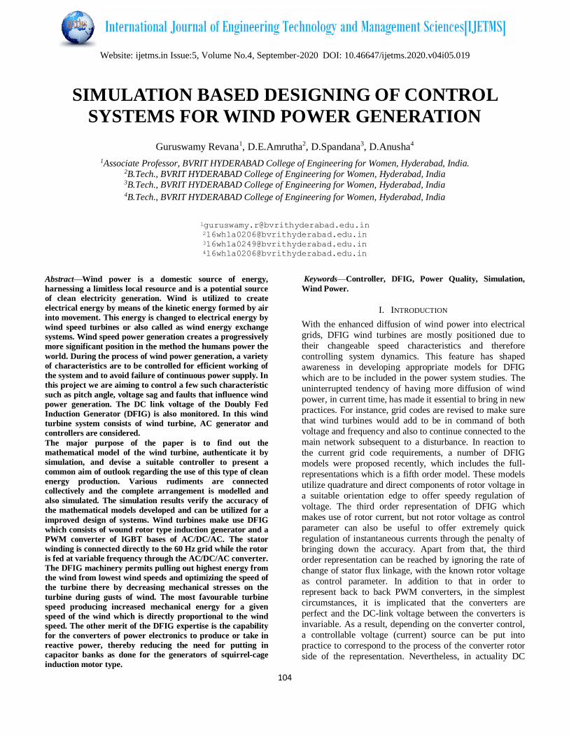
III. SIMULATION MODEL OF THE SYSTEM
We have discussed here the basic operation of DFIG and
its controls using AC/DC/AC converter. First, we
simulated a wind turbine driven isolated (not connected to
grid) induction generator. But for finest efficiency DFIG
system is utilized when it is associated to grid side and has
improved control. The converter connected to rotor side
(RSC) generally offers active and reactive power control of
the system while the converter towards grid side (GSC)
remains the voltage of the DC link steady. So in
conclusion, the simulated grid side and wind turbine side
constraints and the resultant results have been exhibited.
The simulation model is a discrete-time narration
of the Wind Turbine DFIG (Phasor Type) of
MATLAB/Sim Power Systems. Here the protection system
is taken in reflection which provides a trip signal to the system during the fault (single phase to ground fault) on
the system. The faults can happen when wind speed
decreases to a lesser cost or whenever it has unrelenting
fluctuations.
The DFIG is capable to offer a significant input to grid
voltage bear during short circuit periods. Taking into
deliberation the results, it can be concluded that DFIG
established to be more consistent and steady system when
associated to grid side with the appropriate control system
for a converter. Wind has plenty of prospective in it and if
appropriately connected then it can aid explain the energy calamity in the planet.
The learning of wind turbine and its distinctiveness
demonstrated that proper design and usage will get
maximum output. The circuitries of power electronics had
aided the perception of wind power in a large scale.
Without them the concept presented would have been too
costly and implausible. With the converters and thyristors
being utilized not only the processed are smoothened but
also the efficiency has been improved to enormous extent.

Website: ijetms.in Issue:5, Volume No.4, September-2020 DOI: 10.46647/ijetms.2020.v04i05.019
106
Fig1. Simulation Model of the System
3.1 TURBINE RESPONSE TO A CHANGE IN WIND
SPEED
In the "Wind Speed" step block specifies the wind speed.
To begin with, the speed of wind is set at 8 m/s, at the time
t = 5s, wind speed raises abruptly at 14 m/s. Simulation is
started to monitor the signals on the "Wind Turbine" scope
observing the voltage, current of wind turbine, produced
active and reactive powers, DC bus voltage and speed of
the turbine.
Fig. 2 Output 1 for Objective 1
Fig.3 Output 2 for Objective 1
At t = 5s, the produced active power begins escalating
effortlessly (along with the speed of the turbine) to arrive at
its rated value of 9 MW in about 20s. During that time period the speed of the turbine increases from 0.8 PU to
1.21 PU. Firstly, the turbine blades are zero degree for the
pitch angle and the operating point of turbine follows the
red curve in the turbine power characteristics. It is
considered up to the point D.
Afterwards the pitch angle is improved from 0 deg to 0.76
deg in order to border the mechanical power. The reactive
power is controlled to maintain a 1 PU voltage. At nominal
power, the wind turbine absorbs 0.68 MVAR (generated
Q = -0.68 MVAR) to control voltage at 1PU. If we alter the mode of process to “VAR regulation” with the “Generator
reactive power Q reference” is set to zero, it is observed
that voltage enhances to 1.021 PU after the wind turbine
produces its supposed power by unity power factor.
In this mode the wind turbine speed varies very much
starting from 0.7 PU to 1.6 PU and then tending to stabilize
at 1.0 PU. At about t= 12s there is enhancement in the
angle of pitch abruptly.

Website: ijetms.in Issue:5, Volume No.4, September-2020 DOI: 10.46647/ijetms.2020.v04i05.019
107
Fig.4 Output 3 for Objective 1
Fig .5 Output 4 for Objective 1
3.2 SIMULATION OF VOLTAGE SAG ON THE
120KV SYSTEM
It is experimentally verified that the effects of voltage sag
are result from a far-off fault on the 120KV system.
Initially, in the wind speed step block, Wind speed step is
disabled by changing the ending value from 14 to 8 m/s.
Now 120KV voltage source menu is opened. In the
constraint "Time variation of" is selected with "Amplitude"
of 0.15 PU voltage drop lasting for 0.5s is planned to take
place at t = 5s.
Fig.6 Output 1 for Objective 2
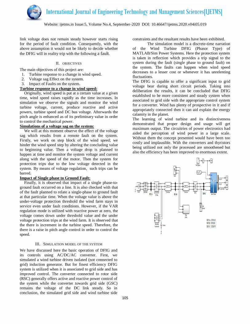
It is made certain that control mode continue to be in VAR
regulation with Qref = 0. Then the simulation is started and
opened in the "Grid" scope. It is noticed that the plant
voltage and current and also the speed of the motor. It is
clear that the wind farm generates 1.87 MW. At t = 5 s, the
voltage comes down below 0.9 PU and at t = 5.22s, the
system of protection trips the plant since an under voltage
for greater than 0.2s is detected. The plant current comes
down to zero value and the speed of the motor comes down
slowly, at the same time as the wind farm continues
producing at a power intensity of 1.87 MW. Later than the plant is tripped, 1.25 MW of power (P Bus B measured at
Bus B) is given to the grid.
Now, the wind turbine control mode is varied to "Voltage
regulation" and the investigation is repeated. It is observed
that the plant does not trip anymore. This is for the reason
that the voltage aid is offered by the 5MVAR reactive
power produced by the turbines of wind at the time of
voltage sag which the plant voltage over the 0.9PU
protection threshold. The plant voltage at the time of the
voltage sag is at the present is 0.93PU.
Website: ijetms.in Issue:5, Volume No.4, September-2020 DOI: 10.46647/ijetms.2020.v04i05.019
108
Fig.7 Output 2 for Objective 2
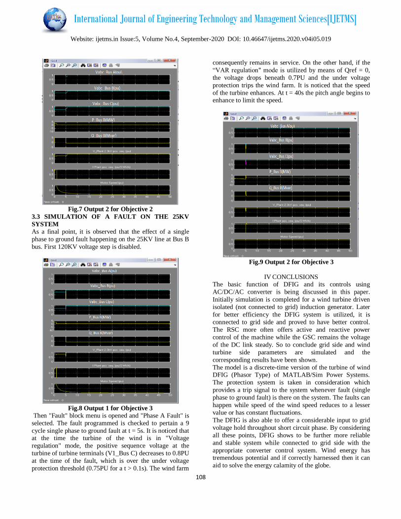
3.3 SIMULATION OF A FAULT ON THE 25KV
SYSTEM
As a final point, it is observed that the effect of a single
phase to ground fault happening on the 25KV line at Bus B
bus. First 120KV voltage step is disabled.
Fig.8 Output 1 for Objective 3
Then "Fault" block menu is opened and "Phase A Fault" is
selected. The fault programmed is checked to pertain a 9
cycle single phase to ground fault at t = 5s. It is noticed that at the time the turbine of the wind is in "Voltage
regulation" mode, the positive sequence voltage at the
turbine of turbine terminals (V1_Bus C) decreases to 0.8PU
at the time of the fault, which is over the under voltage
protection threshold (0.75PU for a t > 0.1s). The wind farm
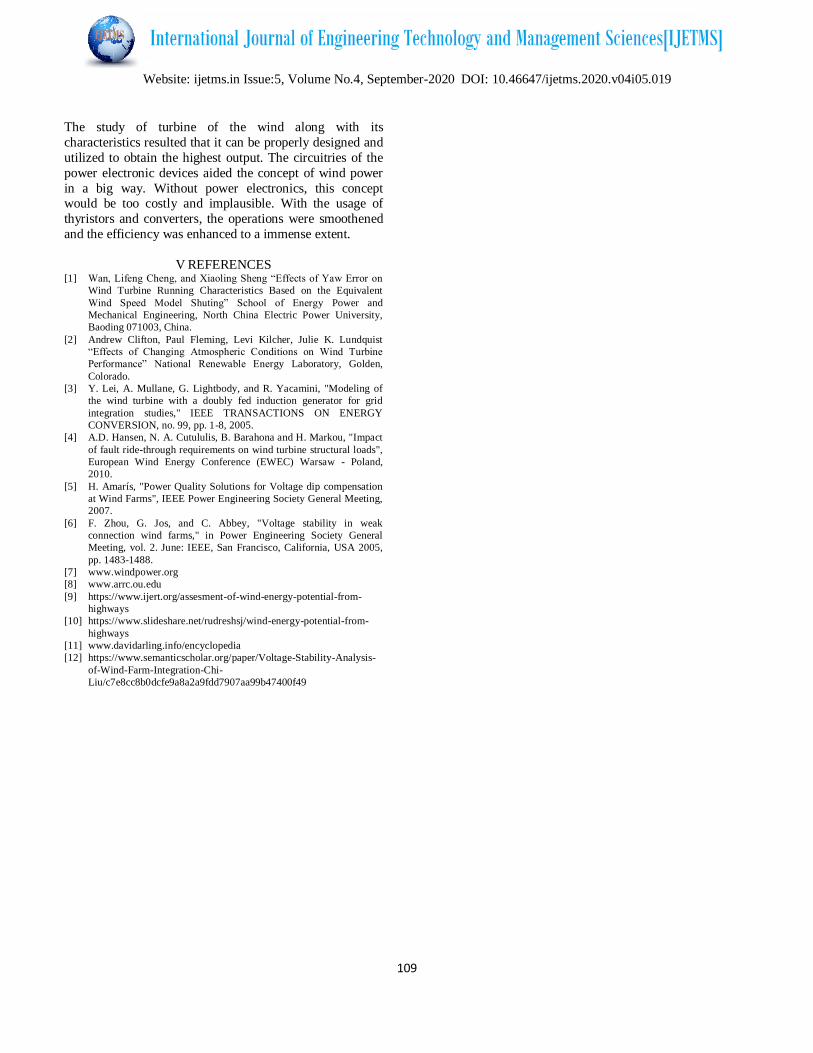
consequently remains in service. On the other hand, if the
“VAR regulation" mode is utilized by means of Qref = 0,
the voltage drops beneath 0.7PU and the under voltage
protection trips the wind farm. It is noticed that the speed
of the turbine enhances. At t = 40s the pitch angle begins to enhance to limit the speed.
Fig.9 Output 2 for Objective 3
IV CONCLUSIONS The basic function of DFIG and its controls using
AC/DC/AC converter is being discussed in this paper.
Initially simulation is completed for a wind turbine driven
isolated (not connected to grid) induction generator. Later
for better efficiency the DFIG system is utilized, it is
connected to grid side and proved to have better control.
The RSC more often offers active and reactive power
control of the machine while the GSC remains the voltage
of the DC link steady. So to conclude grid side and wind
turbine side parameters are simulated and the
corresponding results have been shown.
The model is a discrete-time version of the turbine of wind DFIG (Phasor Type) of MATLAB/Sim Power Systems.
The protection system is taken in consideration which
provides a trip signal to the system whenever fault (single
phase to ground fault) is there on the system. The faults can
happen while speed of the wind speed reduces to a lesser
value or has constant fluctuations.
The DFIG is also able to offer a considerable input to grid
voltage hold throughout short circuit phase. By considering
all these points, DFIG shows to be further more reliable
and stable system while connected to grid side with the
appropriate converter control system. Wind energy has tremendous potential and if correctly harnessed then it can
aid to solve the energy calamity of the globe.
Website: ijetms.in Issue:5, Volume No.4, September-2020 DOI: 10.46647/ijetms.2020.v04i05.019
109
The study of turbine of the wind along with its
characteristics resulted that it can be properly designed and
utilized to obtain the highest output. The circuitries of the
power electronic devices aided the concept of wind power
in a big way. Without power electronics, this concept would be too costly and implausible. With the usage of
thyristors and converters, the operations were smoothened
and the efficiency was enhanced to a immense extent.
V REFERENCES [1] Wan, Lifeng Cheng, and Xiaoling Sheng “Effects of Yaw Error on
Wind Turbine Running Characteristics Based on the Equivalent
Wind Speed Model Shuting” School of Energy Power and
Mechanical Engineering, North China Electric Power University,
Baoding 071003, China.
[2] Andrew Clifton, Paul Fleming, Levi Kilcher, Julie K. Lundquist
“Effects of Changing Atmospheric Conditions on Wind Turbine
Performance” National Renewable Energy Laboratory, Golden,
Colorado.
[3] Y. Lei, A. Mullane, G. Lightbody, and R. Yacamini, "Modeling of
the wind turbine with a doubly fed induction generator for grid
integration studies," IEEE TRANSACTIONS ON ENERGY
CONVERSION, no. 99, pp. 1-8, 2005.
[4] A.D. Hansen, N. A. Cutululis, B. Barahona and H. Markou, "Impact
of fault ride-through requirements on wind turbine structural loads",
European Wind Energy Conference (EWEC) Warsaw - Poland,
2010.
[5] H. Amarís, "Power Quality Solutions for Voltage dip compensation
at Wind Farms", IEEE Power Engineering Society General Meeting,
2007.
[6] F. Zhou, G. Jos, and C. Abbey, "Voltage stability in weak
connection wind farms," in Power Engineering Society General
Meeting, vol. 2. June: IEEE, San Francisco, California, USA 2005,
pp. 1483-1488.
[7] www.windpower.org
[8] www.arrc.ou.edu
[9] https://www.ijert.org/assesment-of-wind-energy-potential-from-
highways
[10] https://www.slideshare.net/rudreshsj/wind-energy-potential-from-
highways
[11] www.davidarling.info/encyclopedia
[12] https://www.semanticscholar.org/paper/Voltage-Stability-Analysis-
of-Wind-Farm-Integration-Chi-
Liu/c7e8cc8b0dcfe9a8a2a9fdd7907aa99b47400f49