Simulation and verification of Thomson actuator systems€¦ · Simulation and verification of...
26
Simulation and verification of Thomson actuator systems Thomson actuator systems Ara Bissal, Göran Engdahl, Ener Salinas, Magnus Öhström COMSOL Conference Paris 2010 Presented at the COMSOL Conference 2010 Paris
Transcript of Simulation and verification of Thomson actuator systems€¦ · Simulation and verification of...

Simulation and verification of Thomson actuator systemsThomson actuator systems
Ara Bissal, Göran Engdahl, Ener Salinas, Magnus Öhström
COMSOL Conference Paris 2010
Presented at the COMSOL Conference 2010 Paris

Table of contents
Introduction
Thomson Coil designs
Theory Theory
Modelling
Model verification
Conclusions
Movies
Questions

Introduction
Increased need for high speed actuators
Diverse applications like: Smart grids, electrical switches,
robotics, drilling machinery, etc…
Thomson Coils (TCs) can exert massive forces within fractions of a millisecond
It is important to model and simulate (TCs) to design or
accurately predict the performance of TC based high speed
actuators

What is a TC?
Double sided Thomson coil
Single sided
Thomson Coil
Helix- shaped
Thomson coil
Single sided Thomson Coil with a concentrator

Theory
( )c cI sini tω= ( )c cI sini tω=
( , )) ( )( c r z sinB t B tω=
( )rr siB nB tω=
( )zzsiB nB tω=
z rF i Bφ=
=TotalF ma=

Modelling
2D axisymmetric model
The Aluminum is in silver color, the coil turns are in red, thesurrounding air in light blue

Static model (DC)
10kA constant current source connected across the
terminals of a TC
Constant magnetic field will be generated
No eddy currents are induced in the aluminum disk
Surface: Magnetic flux density [T]Contour: Magnetic vector potential [Wb/m]Arrow: Magnetic flux density
Surface: Total Current density [A/m2]
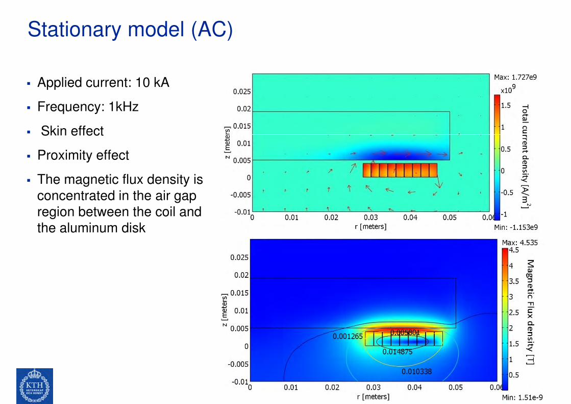
Stationary model (AC)
Applied current: 10 kA
Frequency: 1kHz
Skin effect Skin effect
Proximity effect
The magnetic flux density is
concentrated in the air gap
region between the coil and
the aluminum disk

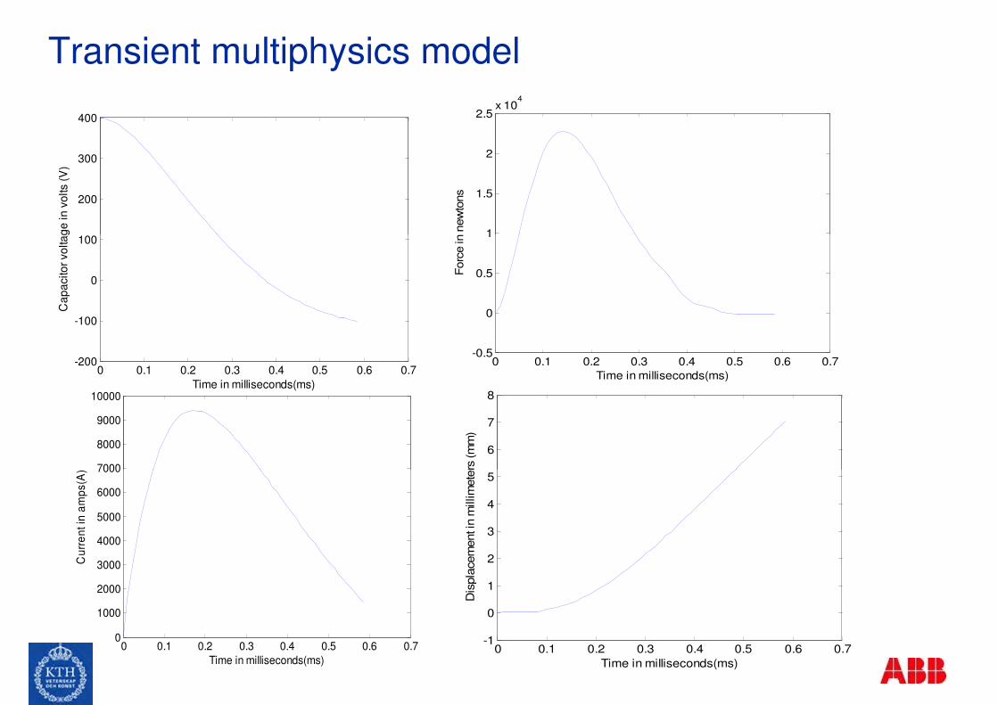
Transient multiphysics model
The single sided TC is highly dependent on position of the aluminum disk
As the disk moves away, the inductance, resistance, and induced
currents change greatly influencing the exerted forcecurrents change greatly influencing the exerted force
A multiphysics model with a moving mesh is indispensible.
COMSOL modules used: “Azimuthal induction currents”, and
“moving mesh (ALE) with dynamic remeshing”.
Setup Characteristics TC
Capacitor bank 7 mF
Initial voltage 400 V
Al Cross section area
in (mm^2)
50 x 14
Coil cross section area 2 mm x 4mm
Air gap between coil and Al 1 mm
Number of coil turns 9
Inter-distance coil turns 0.1 mm
Stray resistance 10 mΩ
Stray inductance 1 µH
Transient multiphysics model
100
200
300
400
Ca
pa
cito
r vo
lta
ge
in
vo
lts (
V)
1
1.5
2
2.5x 10
4
Forc
e in n
ew
tons
0 0.1 0.2 0.3 0.4 0.5 0.6 0.7-200
-100
0
100
Time in milliseconds(ms)
Ca
pa
cito
r vo
lta
ge
in
vo
lts (
V)
7000
8000
9000
10000
Cu
rre
nt in
am
ps(A
)
6
7
8
Dis
pla
cem
ent in
millim
ete
rs (m
m)
0 0.1 0.2 0.3 0.4 0.5 0.6 0.7-0.5
0
0.5
1
Time in milliseconds(ms)
Forc
e in n
ew
tons
0 0.1 0.2 0.3 0.4 0.5 0.6 0.70
1000
2000
3000
4000
5000
6000
7000
Time in milliseconds(ms)
Cu
rre
nt in
am
ps(A
)
0 0.1 0.2 0.3 0.4 0.5 0.6 0.7-1
0
1
2
3
4
5
Time in milliseconds(ms)
Dis
pla
cem
ent in
millim
ete
rs (m
m)

Transient multiphysics model
Time: 0.1msArrow: magnetic fieldSurface: Total current density
Time: 0.18msArrow: magnetic fieldSurface: Total current density
Surface: Total current density
Time: 0.3 msArrow: magnetic fieldSurface: Total current density

Transient multiphysics modelTime: 0.18msContour lines: A [Wb/m]Surface: Magnetic flux density [T]
Time: 0.1msContour lines: A [Wb/m]Surface: Magnetic flux density [T]
Time: 0.3msContour lines: A [Wb/m]Surface: Magnetic flux density [T]

Transient multiphysics model
Penetration depthwiith respect to time
along the blue line

TC simulation 1
© ABB Group November 23, 2010 | Slide 14

TC simulation 2
© ABB Group November 23, 2010 | Slide 15
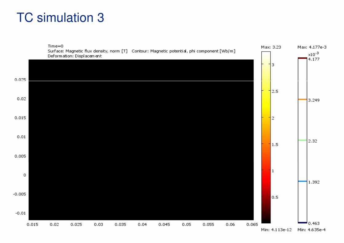
TC simulation 3
© ABB Group November 23, 2010 | Slide 16

Model verification
Experimental verification is carried out to verify the results
simulated in COMSOL.
The results are compared with two experiments:
Experiment I was already carried out at ABB Experiment I was already carried out at ABB
Experiment II is the custom built prototype of the TC
© ABB Group November 23, 2010 | Slide 17
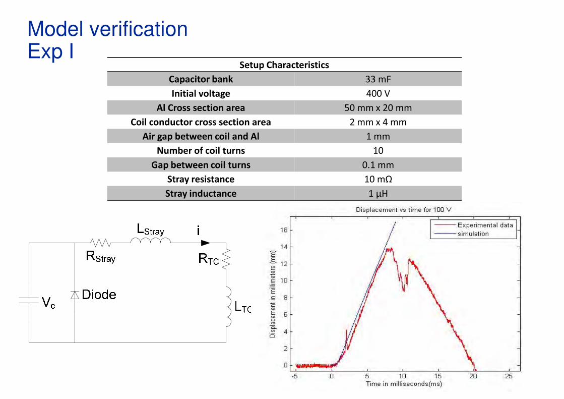
Model verificationExp I
Setup Characteristics
Capacitor bank 33 mF
Initial voltage 400 V
Al Cross section area 50 mm x 20 mm
Coil conductor cross section area 2 mm x 4 mm
Air gap between coil and Al 1 mmAir gap between coil and Al 1 mm
Number of coil turns 10
Gap between coil turns 0.1 mm
Stray resistance 10 mΩ
Stray inductance 1 µH
Model verificationExp 2
Three series of tests were carried out:
Test 1: The 33 mF capacitor bank is discharged in the coilwith no aluminum ring on top at three voltage levels: 25,with no aluminum ring on top at three voltage levels: 25,
50, and 100V
Aim: Determine the stray impedance
Step 1: The oscilloscope is used to measure the
voltage and current pulse without any influence from
the aluminum ring.
Step 2:The resistance and inductance of the coil aredetermined by running a COMSOL simulation with nodetermined by running a COMSOL simulation with no
aluminum disk.
Step3: The stray impedance can be approximated by
solving for the following differential equations inMATLAB and comparing with the voltage and current
waveforms measured in the lab:

Model verificationExp 2
1( )
Stray
C
C TC
i
V R i i
dV
dt C
diR−
= −
= −+
1000
1500
2000
2500
Current in
am
ps(A
)
Scope
Estimated
Current pulse at 50 V
( )Stray
Str
C
a
TC
y
V R i iRdt L L
−= −+
400
600
800
1000
1200
Curr
ent in
am
ps(A
)
Scope
Estimated
-2 0 2 4 6 8 10-500
0
500
Time in milliseconds(ms)
Current in
am
ps(A
)
3000
3500
4000
4500
Current in
am
ps(A
)
Scope
Estimated
-2 0 2 4 6 8 10-200
0
200
400
Time in milliseconds(ms)
Curr
ent in
am
ps(A
)
-2 0 2 4 6 8 10-500
0
500
1000
1500
2000
2500
Time in milliseconds(ms)
Current in
am
ps(A
)
Current pulse at 25 V
Current pulse at 100 V

Model verificationExp 2
Test 2: A Teflon cylinder is used to guide the aluminumring.
Test 3: The guide is removed to record the displacement of
the aluminum disk without friction.the aluminum disk without friction.
1.5
2
2.5
3
Dis
pla
ce
me
nt [m
m]
COMSOL
Lab test run 1
Lab test run 2
Lab test run 3
0 0.5 1 1.5
0
0.5
1
1.5
Time [ms]
Dis
pla
ce
me
nt [m
m]
Model verificationExp 2
The sources of error are:
The coil is modeled as concentric rings in COMSOLand not as a spiral
Air resistance is neglected Air resistance is neglected
The impedance of the coil is not 100% accurate
The stray impedance is not constant
The discharged voltage from the capacitor bank is not
100% exact
:
No need for a guide since the aluminum follows a No need for a guide since the aluminum follows a
straight trajectory.
The model predicts the exerted forces on the
aluminum disk with high accuracy.

Conclusions
Static and stationary models serve as a good start to study
the behavior and characteristics of a TC at different
frequencies
A single equivalent frequency in a stationary model is not
sufficientsufficient
This experimentally validated multiphysics finite element
transient model can be used to design a TC to meet the
needed requirements

Movies- TC 50 V No guide, No bottom damper
© ABB Group November 23, 2010 | Slide 24
Movies- TC 150 V with guide and bottom damper
© ABB Group November 23, 2010 | Slide 25

© ABB Group November 23, 2010 | Slide 26
Royal Institute of Technology