
Simulation and Measurement Technology of Combustion … · swirl intensity (rotational flow)...
7
Mitsubishi Heavy Industries Technical Review Vol. 52 No. 4 (December 2015) 15 *1 Heat Transfer Research Department, Research & Innovation Center, Technology & Innovation Headquarters *2 Combustion Research Department, Research & Innovation Center, Technology & Innovation Headquarters *3 Fluid Dynamics Research Department, Research & Innovation Center, Technology & Innovation Headquarters *4 Manager, Combustion Research Department, Research & Innovation Center, Technology & Innovation Headquarters Simulation and Measurement Technology of Combustion and Heat Transfer for Development of High-efficiency Gas Turbines SATOSHI MIZUKAMI *1 MITSUNORI ISONO *2 NAONORI NAGAI *3 KEIJIRO SAITOH *2 Mitsubishi Hitachi Power Systems, Ltd. (MHPS) is progressing with the development of highly-efficient gas turbine combined cycle (GTCC) power generation with the Research & Innovation Center of Mitsubishi Heavy Industries, Ltd. (MHI) in order to make a contribution to the conservation of the global environment and the stable supply of energy. We developed the M501J type, the world's first highly-efficient machine with a turbine inlet temperature of 1600°C by utilizing the development results acquired in the national project “Development of Element Technologies for CC Efficiency 57% Gas-Turbine,” which we took part in from fiscal 2004. The operational results of the developed machine have been accumulated. 1 For the next generation GTCC, we are currently working on the development of elemental technologies for a 1650°C-class air-cooled gas turbine such as a closed (next generation) air cooling system that was researched in collaboration with Tohoku Electric Power Co., Inc. with the aim of increasing the turbine inlet temperature. This paper presents the current progress in the development of analysis and measurement technologies in the combustion and heat transfer field for the realization of the next generation GTCC. | 1. Introduction MHPS is developing a gas turbine with a turbine inlet temperature of 1650°C-class with MHI Research & Innovation Center in order to enhance the performance of gas turbines. However, there are technological issues in terms of the combustion and heat transfer field with regard to an increase in the turbine inlet temperature, including combustion stability, the suppression of nitrogen oxide (NOx) emissions, and assuring the reliability of turbine blades. The combustor uses a premixed combustion method in order to suppress NOx emissions. NOx generation is significantly related to the local combustion temperature, and more NOx is generated when the combustion temperature is higher. When the premixed combustion method is used, however, the premixing of fuel and air can suppress the local increase of combustion temperature and results in the suppression of NOx generation. Nevertheless, there is a concern that the risk of combustion instability and flashback (backfire) may increase because of the heightened temperature. At the turbine blade, cooling is performed using the air compressed by the compressor, and therefore the power generation efficiency of the gas turbine decreases according to the air flow amount used here. To improve efficiency, it is necessary to perform cooling with the minimum necessary air flow amount that can assure reliability, and to suppress the increase in cooling air amount to the minimum level even when the turbine inlet temperature rises.
Transcript of Simulation and Measurement Technology of Combustion … · swirl intensity (rotational flow)...

Mitsubishi Heavy Industries Technical Review Vol. 52 No. 4 (December 2015) 15
*1 Heat Transfer Research Department, Research & Innovation Center, Technology & Innovation Headquarters *2 Combustion Research Department, Research & Innovation Center, Technology & Innovation Headquarters *3 Fluid Dynamics Research Department, Research & Innovation Center, Technology & Innovation Headquarters *4 Manager, Combustion Research Department, Research & Innovation Center, Technology & Innovation Headquarters
Simulation and Measurement Technology of Combustion and Heat Transfer for
Development of High-efficiency Gas Turbines
SATOSHI MIZUKAMI*1 MITSUNORI ISONO*2
NAONORI NAGAI*3 KEIJIRO SAITOH*2
Mitsubishi Hitachi Power Systems, Ltd. (MHPS) is progressing with the development of
highly-efficient gas turbine combined cycle (GTCC) power generation with the Research & Innovation Center of Mitsubishi Heavy Industries, Ltd. (MHI) in order to make a contribution tothe conservation of the global environment and the stable supply of energy. We developed the M501J type, the world's first highly-efficient machine with a turbine inlet temperature of 1600°Cby utilizing the development results acquired in the national project “Development of Element Technologies for CC Efficiency 57% Gas-Turbine,” which we took part in from fiscal 2004. The operational results of the developed machine have been accumulated.1 For the next generation GTCC, we are currently working on the development of elemental technologies for a 1650°C-class air-cooled gas turbine such as a closed (next generation) air cooling system that was researched in collaboration with Tohoku Electric Power Co., Inc. with the aim of increasing the turbine inlettemperature. This paper presents the current progress in the development of analysis andmeasurement technologies in the combustion and heat transfer field for the realization of the next generation GTCC.
|1. Introduction MHPS is developing a gas turbine with a turbine inlet temperature of 1650°C-class with MHI
Research & Innovation Center in order to enhance the performance of gas turbines. However, there are technological issues in terms of the combustion and heat transfer field with regard to anincrease in the turbine inlet temperature, including combustion stability, the suppression of nitrogenoxide (NOx) emissions, and assuring the reliability of turbine blades.
The combustor uses a premixed combustion method in order to suppress NOx emissions.NOx generation is significantly related to the local combustion temperature, and more NOx isgenerated when the combustion temperature is higher. When the premixed combustion method is used, however, the premixing of fuel and air can suppress the local increase of combustiontemperature and results in the suppression of NOx generation. Nevertheless, there is a concern thatthe risk of combustion instability and flashback (backfire) may increase because of the heightenedtemperature.
At the turbine blade, cooling is performed using the air compressed by the compressor, andtherefore the power generation efficiency of the gas turbine decreases according to the air flow amount used here. To improve efficiency, it is necessary to perform cooling with the minimumnecessary air flow amount that can assure reliability, and to suppress the increase in cooling airamount to the minimum level even when the turbine inlet temperature rises.
Mitsubishi Heavy Industries Technical Review Vol. 52 No. 4 (December 2015) 16
This paper summarizes the progress in the development of the following three technologiesaiming at the resolution of the aforementioned issues in the combustion and heat transfer field.
[1] Measurement and prediction technology of combustion instability mechanism [2] Prediction technology of flashback phenomenon [3] Prediction technology of turbine heat transfer coefficient distribution
|2. Measurement and prediction technology of combustioninstability mechanism Combustion instability is caused by an interaction between the pressure fluctuation and heat
release fluctuation. Whether combustion instability occurs under a certain condition depends on the Rayleigh criteria (R) shown in the following Formula (1). This criteria is a value obtained by integrating the pressure fluctuation p' and the heat release fluctuation q' with one time cycle. When the criteria is a positive value, it means that the pressure fluctuation grows and combustion instability occurs. For the prediction of the Rayleigh criteria, it is important to predict the phasedifference (response) between the pressure fluctuation and the heat release fluctuation.
∫ ⋅=t
dtqpR '' … Formula (1)
For the establishment of a prediction technology of the combustion instability mechanism, it is important to correctly predict the phase difference between the pressure fluctuation and the heat release fluctuation. We evaluated the phase difference between the pressure fluctuation and the heat release fluctuation of a full-scale gas turbine combustor through experimentation and analysis (simulation).2
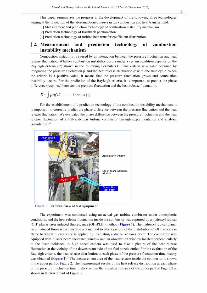
Figure 1 External view of test equipment
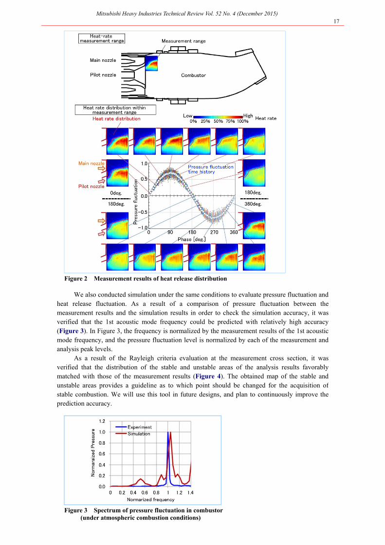
The experiment was conducted using an actual gas turbine combustor under atmosphericconditions, and the heat release fluctuation inside the combustor was captured by a hydroxyl radical (OH) planar laser induced fluorescence (OH-PLIF) method (Figure 1). The hydroxyl radical planar laser induced fluorescence method is a method to take a picture of the distribution of OH radicals inflame to which fluorescence is applied by irradiating a sheet-like laser beam. The combustor was equipped with a laser beam incidence window and an observation window located perpendicularly to the laser incidence. A high speed camera was used to take a picture of the heat release fluctuation at the vicinity of the downstream side of the fuel nozzle outlet. For the evaluation of theRayleigh criteria, the heat release distribution at each phase of the pressure fluctuation time historywas obtained (Figure 2).3 The measurement area of the heat release inside the combustor is shown in the upper part of Figure 2. The measurement results of the heat release distribution at each phase of the pressure fluctuation time history within the visualization area of the upper part of Figure 2 is shown in the lower part of Figure 2.
Mitsubishi Heavy Industries Technical Review Vol. 52 No. 4 (December 2015) 17
Figure 2 Measurement results of heat release distribution
We also conducted simulation under the same conditions to evaluate pressure fluctuation and heat release fluctuation. As a result of a comparison of pressure fluctuation between the measurement results and the simulation results in order to check the simulation accuracy, it wasverified that the 1st acoustic mode frequency could be predicted with relatively high accuracy (Figure 3). In Figure 3, the frequency is normalized by the measurement results of the 1st acoustic mode frequency, and the pressure fluctuation level is normalized by each of the measurement andanalysis peak levels.
As a result of the Rayleigh criteria evaluation at the measurement cross section, it was verified that the distribution of the stable and unstable areas of the analysis results favorablymatched with those of the measurement results (Figure 4). The obtained map of the stable and unstable areas provides a guideline as to which point should be changed for the acquisition of stable combustion. We will use this tool in future designs, and plan to continuously improve theprediction accuracy.
Figure 3 Spectrum of pressure fluctuation in combustor (under atmospheric combustion conditions)

Mitsubishi Heavy Industries Technical Review Vol. 52 No. 4 (December 2015) 18
Figure 4 Results of evaluation of combustion unstable area based on Rayleigh criteria
|3. Prediction technology of flashback phenomenon The flashback phenomenon can be classified roughly into two patterns depending on the
swirl intensity (rotational flow) generated by the swirler in the main nozzle that supplies premixed gas to the combustion chamber (Figure 5): a. flashback on the wall (flame front runs back on the wall in the boundary layer) and b. flashback into the vortex core (flame front runs back along the vortex core)
Figure 5 Schematic of flashback phenomenon
Figure 6 Schematic of model burner
Mitsubishi Heavy Industries Technical Review Vol. 52 No. 4 (December 2015) 19
We have been developing a flashback phenomenon analysis technology throughexperimentation (Figure 6)4 and numerical analysis on an elemental model burner with a simple cylindrical shape on which a swirler for premixed combustion was installed, using the swirl intensity as a parameter.5 As shown in Figure 6, the test equipment consists of a perforated plate, a swirler, ahollow glass cylinder, a flame holding rod and other components. Air and fuel are sufficiently mixedbefore entering into the perforated plate. In this test, the swirl intensity was changed by changing the representative swirl exit angle from 30 to 35, 40, 45 degrees. Flashback limit was measured based on the self-illuminating photographs of the flame while changing the fuel concentration (fuel air ratio) and the air flow rate. In addition, stereo particle image velocimetry (PIV) was performed to measurethe flow velocity distribution of the flame field.
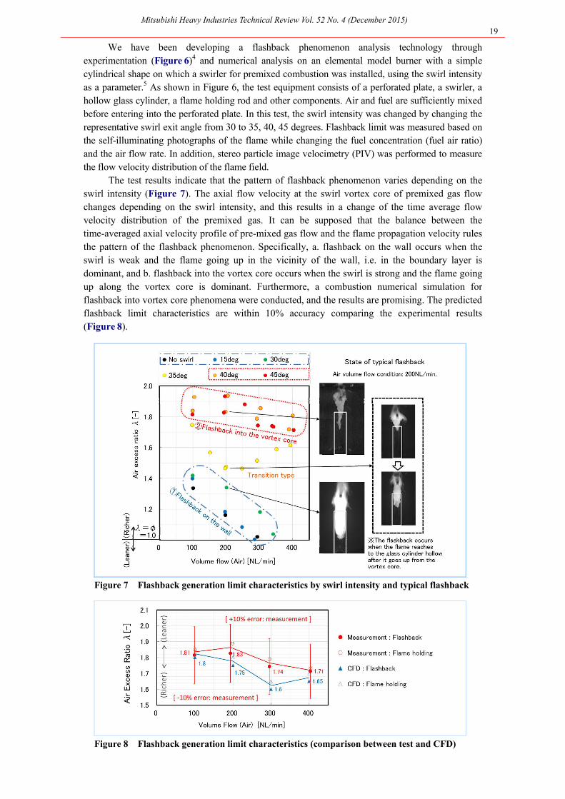
The test results indicate that the pattern of flashback phenomenon varies depending on the swirl intensity (Figure 7). The axial flow velocity at the swirl vortex core of premixed gas flowchanges depending on the swirl intensity, and this results in a change of the time average flow velocity distribution of the premixed gas. It can be supposed that the balance between the time-averaged axial velocity profile of pre-mixed gas flow and the flame propagation velocity rules the pattern of the flashback phenomenon. Specifically, a. flashback on the wall occurs when the swirl is weak and the flame going up in the vicinity of the wall, i.e. in the boundary layer is dominant, and b. flashback into the vortex core occurs when the swirl is strong and the flame goingup along the vortex core is dominant. Furthermore, a combustion numerical simulation for flashback into vortex core phenomena were conducted, and the results are promising. The predictedflashback limit characteristics are within 10% accuracy comparing the experimental results(Figure 8).
Figure 7 Flashback generation limit characteristics by swirl intensity and typical flashback
Figure 8 Flashback generation limit characteristics (comparison between test and CFD)

Mitsubishi Heavy Industries Technical Review Vol. 52 No. 4 (December 2015) 20
|4. Prediction technology of turbine blade heat transfer coefficientdistribution In turbine blade cooling design, the evaluation of the heat transfer coefficient (heat load) of
the high temperature gas is important. However, it was conventionally difficult to perform thisevaluation using numerical analysis (simulation), and therefore the cooling was designed using anempirical formula based on the measurement of an actual machine. For this reason, there was a problem with the prediction accuracy. In the case of a blade end wall, in particular, the predictionof the heat transfer coefficient using analysis or an empirical formula was difficult due to presenceof three dimensional flow as shown in Figure 9.
Figure 9 Schematic of flow field at turbine blade end wall6
Because the heat load of the 1650°C-class air-cooled gas turbine under development is even higher, more detailed evaluation of the heat transfer coefficient needs to be performed in the design phase, and therefore we are fostering the application of numerical analysis that can evaluate theheat transfer coefficient. We also used an unsteady heat transfer coefficient measurement method7
with step heating to acquire the heat transfer coefficient and performed accuracy verification ofprediction based on numerical analysis in a national project where technological development for a1700°C-class gas turbine is performed. In this test, the mainstream that had been made steady was step-heated by the heating mesh, and then the change in the test piece surface temperature resultingfrom heating was measured by an IR (infrared) camera to acquire the surface distribution of theheat transfer coefficient (Figure 10). Figure 11 shows a schematic of the test equipment. As an example of a comparison between the measured heat transfer coefficient of the turbine blade endwall and the analysis results, Figure 12 shows the comparison results for the blade front edge. Asthis figure indicates, it was verified that the accuracy required for the cooling design is assured.
It was verified that the heat transfer coefficient in the periphery of the turbine blade can beevaluated using analysis. We will realize even higher performance and greater reliability through the application of this outcome to the 1650°C-class air-cooled gas turbine.
Figure 10 Image of temperature response to step heating

Mitsubishi Heavy Industries Technical Review Vol. 52 No. 4 (December 2015) 21
Figure 11 Schematic of single stator blade end wall heat transfer test equipment
Figure 12: Comparison between test results and analysis results at blade front edge
|5. Conclusion This report introduced measurement and analysis technologies for the resolution of
technological development in the combustion and heat transfer field aiming at the realization of ahigh performance gas turbine. We will achieve performance enhancement and assure reliability through the continuous development of these technologies and application to the next generationGTCC.
References 1. Hada, et al., High-efficiency Gas Turbine Development applying 1600°C class "J" Technology, Mitsubishi
Heavy Industries Technical Review Vol.52 No.2 (2015) 2. Isono, M. et al., Numerical and Experimental Investigation of the Flame Transfer Function in the Full-Scale
Gas Turbine Combustor, IGTC2015 3. Kimura et al., Development of visualization technique for flame motion on gas turbine combustion
chamber,the 41th GTSJ Seminar material (2013) 4. Komiyama et al., Unsteady flame motion of pre-mixed combustion chamber with swirl flow, Transactions
of the JSME Series 78 (794), 1832-1840, 2012 5. Naonori Nagai. et al., “An Investigation of Flashback Phenomena into the vortex core of Swirling Premixed
Gas Flow”, IGTC2015, 2015 6. Sharma O.P. et al., Prediction of Endwall Losses and Secondary Flows in Axial Flow Turbine Cascades,
ASME Journal of Turbomachinery Vol. 109 (1987) pp. 229-236 7. Makigano, H. et al., Investigation of Heat Transfer of Vane Endwall at Equivalent Condition of Real Gas
Turbine Using Measurement and Analysis, the 43th GTSJ Seminar material (2015), A-16, 2015


![Fundamental studies of premixed combustion [PhD Thesis]](https://static.fdocuments.in/doc/165x107/563db7e7550346aa9a8f0c44/fundamental-studies-of-premixed-combustion-phd-thesis.jpg)