
Simulation and Analyses of Stage Separation of Multi-Stage Launch
27
American Institute of Aeronautics and Astronautics 1 Simulation and Analyses of Stage Separation of Two-Stage Reusable Launch Vehicles Bandu N. Pamadi, * Thomas A. Neirynck, † Nathaniel J. Hotchko, ‡ Paul V. Tartabini, § William I. Scallion, ** Kelly J. Murphy, †† and Peter F. Covell ‡‡ NASA Langley Research Center, Hampton, VA, 23681, USA NASA has initiated the development of methodologies, techniques and tools needed for analysis and simulation of stage separation of next generation reusable launch vehicles. As a part of this activity, ConSep simulation tool is being developed which is a MATLAB–based front-and-back-end to the commercially available ADAMS ‚ solver, an industry standard package for solving multi-body dynamic problems. This paper discusses the application of ConSep to the simulation and analysis of staging maneuvers of two-stage-to-orbit (TSTO) Bimese reusable launch vehicles, one staging at Mach 3 and the other at Mach 6. The proximity and isolated aerodynamic database were assembled using the data from wind tunnel tests conducted at NASA Langley Research Center. The effects of parametric variations in mass, inertia, flight path angle, altitude from their nominal values at staging were evaluated. Monte Carlo runs were performed for Mach 3 staging to evaluate the sensitivity to uncertainties in aerodynamic coefficients. Nomenclature a = angle of attack, deg Da = relative difference in angle of attack, deg C A = axial force coefficient C N = normal force coefficient C m = pitching moment coefficient C mq = damping in pitch derivative, per radian d e = elevon deflection, deg d e, bias = feedforward elevon deflection, deg g = flight path angle, deg F x , F z = aerodynamic forces in axial and normal directions, lb h = altitude, ft I xx, I yy , I zz = moment of inertia about body x, y, z axis k 1 = interpolation constant k a , k q = angle of attack and pitch rate feedback gains l ref = reference length, ft L = body length, ft M = Mach number or aerodynamic pitching moment, lb-ft q = pitch rate, rad/s q = dynamic pressure, lb/ft 2 r = density, slugs/ft 3 * Aerospace Engineer, Exploration Concept Branch, Associate Fellow AIAA. † Graduate Student, George Washington University. ‡ Project Engineer, Analytical Mechanics Associates, Hampton, VA, Member AIAA. § Aerospace Engineer, Exploration Concepts Branch, Member AIAA. ** Aerospace Engineer, Aerothermodynamics Branch. †† Aerospace Engineer, Aerothermodynamics Branch ‡‡ Aerospace Engineer, Exploration Concepts Branch, Senior Member AIAA. AIAA/CIRA 13th International Space Planes and Hypersonics Systems and Technologies AIAA 2005-3247 This material is declared a work of the U.S. Government and is not subject to copyright protection in the United States. https://ntrs.nasa.gov/search.jsp?R=20080000856 2018-11-15T12:39:01+00:00Z
Transcript of Simulation and Analyses of Stage Separation of Multi-Stage Launch

American Institute of Aeronautics and Astronautics1
Simulation and Analyses of Stage Separation of Two-StageReusable Launch Vehicles
Bandu N. Pamadi,* Thomas A. Neirynck,† Nathaniel J. Hotchko,‡
Paul V. Tartabini,§ William I. Scallion,** Kelly J. Murphy,†† and Peter F. Covell‡‡
NASA Langley Research Center, Hampton, VA, 23681, USA
NASA has initiated the development of methodologies, techniques and tools needed foranalysis and simulation of stage separation of next generation reusable launch vehicles. As apart of this activity, ConSep simulation tool is being developed which is a MATLAB–basedfront-and-back-end to the commercially available ADAMS‚ solver, an industry standardpackage for solving multi-body dynamic problems. This paper discusses the application ofConSep to the simulation and analysis of staging maneuvers of two-stage-to-orbit (TSTO)Bimese reusable launch vehicles, one staging at Mach 3 and the other at Mach 6. Theproximity and isolated aerodynamic database were assembled using the data from windtunnel tests conducted at NASA Langley Research Center. The effects of parametricvariations in mass, inertia, flight path angle, altitude from their nominal values at stagingwere evaluated. Monte Carlo runs were performed for Mach 3 staging to evaluate thesensitivity to uncertainties in aerodynamic coefficients.
Nomenclaturea = angle of attack, degDa = relative difference in angle of attack, degCA = axial force coefficient
†
CN = normal force coefficient
†
Cm = pitching moment coefficient
†
Cmq = damping in pitch derivative, per radian
de = elevon deflection, deg
†
de,bias = feedforward elevon deflection, deg
g = flight path angle, deg
†
Fx ,Fz = aerodynamic forces in axial and normal directions, lbh = altitude, ftIxx, Iyy, Izz = moment of inertia about body x, y, z axisk1 = interpolation constantka, kq = angle of attack and pitch rate feedback gainslref = reference length, ftL = body length, ftM = Mach number or aerodynamic pitching moment, lb-ft
†
q = pitch rate, rad/s
†
q = dynamic pressure, lb/ft2
r = density, slugs/ft3
* Aerospace Engineer, Exploration Concept Branch, Associate Fellow AIAA.† Graduate Student, George Washington University.‡ Project Engineer, Analytical Mechanics Associates, Hampton, VA, Member AIAA.§ Aerospace Engineer, Exploration Concepts Branch, Member AIAA.** Aerospace Engineer, Aerothermodynamics Branch.†† Aerospace Engineer, Aerothermodynamics Branch‡‡Aerospace Engineer, Exploration Concepts Branch, Senior Member AIAA.
AIAA/CIRA 13th International Space Planes and Hypersonics Systems and Technologies AIAA 2005-3247
This material is declared a work of the U.S. Government and is not subject to copyright protection in the United States.
https://ntrs.nasa.gov/search.jsp?R=20080000856 2018-11-15T12:39:01+00:00Z

American Institute of Aeronautics and Astronautics2
Sref = reference area, ft2
V = velocity, ft/sDx, Dz = relative axial and normal distances during separation, ftxcg = x-location of center of gravity, ftzcg = z-location of center of gravity, ft
Suffixes1 = vehicle 1 (booster)2 = vehicle 2 (orbiter)cmd = commandedf = isolated or free flightp = proximity or with interferencet = transitional
AcronymsADAMS® = Automatic Dynamic Analysis of Mechanical SystemsISS = International Space StationISAT = Inter-Center Systems Analysis TeamLGBB = Langley Glide Back BoosterNASA = National Aeronautics and Space AdministrationNGLT = Next Generation Launch TechnologyPD = Proportional DerivativeSEE = Synergistic Engineering EnvironmentSLI = Space Launch InitiativeSSTO = Single-Stage-To-OrbitSSME = Space Shuttle Main EngineTSTO = Two-Stage-To-OrbitUPWT = Unitary Plan Wind Tunnel
I. IntroductionHE problem of dynamic separation of two bodies within the atmosphere is complex and challenging. Oneproblem that has received significant attention in the literature is that of store separation from the aircraft.1 The
aerodynamic characteristics of the relatively small sized store are influenced by the proximity of the aircraft butthose of the aircraft are virtually not affected. A similar example is the separation of the X-15 research vehicle fromthe B-52 carrier aircraft.2 Here, the aerodynamic characteristics of the relatively smaller X-15 vehicle are influencedby the proximity of the B-52 aircraft but not vice-versa. The other class of stage separation problem involvesseparation of two vehicles of comparable sizes where the aerodynamic characteristics of one vehicle are influencedby the proximity to the other vehicle. However, in some cases the integrity of only one vehicle may be ofimportance, such as the staging of multi-stage expendable launch vehicles. The integrity of only the upper stages isof primary concern post separation. The expended stages need only to move away safely from the upper stagesbefore their eventual disintegration. For multi-stage reusable launch vehicles, the integrity of each stage is importantpost separation.
NASA studies3-7 on stage separation of multi-stage reusable launch vehicles date back to the early 1960s. Thesestudies were conducted by Decker et al and addressed the problem of separation of generic two-stage reusablelaunch vehicles. Wind tunnel tests were conducted to evaluate the mutual aerodynamic interference between the twostages for supersonic/hypersonic speeds. However, the test data were limited to very few longitudinal and normalseparation distances. Also, the simulation did not include the attachment between the stages and the releasemechanism. Recent NASA studies by Naftel et al 8-10 consider Mach 3 staging of two winged vehicles. Theymodeled the attachment of stages, the release mechanism in their simulations and used active control duringseparation but their aerodynamic data did not include the mutual interference effects. They used free-streamaerodynamic data for each vehicle.
The interest in stage-separation research has come back when it was realized during early 2000 that thetechnologies needed for the development of next generation reusable SSTO vehicle are not yet available andNASA’s Next Generation Launch Technology (NGLT) Program identified stage separation as one of the criticaltechnologies needed for successful development and operation of NASA’s next generation multistage reusable
T

American Institute of Aeronautics and Astronautics3
launch vehicles. As a step towards developing this critically needed technology, NASA has initiated acomprehensive stage separation tool development activity that includes wind tunnel testing, development andvalidation of CFD and engineering level tools. The stage separation analysis and simulation tool called ConSep isbeing developed as a part of this activity. The reusable booster, a product of the NASA in-house small launchervehicle concept study,11 is used in a bimese configuration as the baseline vehicle in this tool development activity.This reusable booster concept is referred to as the Langley Glide-Back Booster11 (LGBB). Stage separation windtunnel tests were conducted on the LGBB Bimese models at supersonic (M = 2.3, 3.0 and 4.5) and hypersonic Machnumber (M = 6) to provide data for CFD code development and validation. An overview of NASA’s stage-separation tool development activity is presented in Ref. 12.
The objective of this paper is to demonstrate the application of ConSep for the stage separation of two-stage-to-orbit (TSTO) LGBB-Bimese reusable launch vehicles. In this study, the staging of two vehicle concepts areconsidered, one which stages at Mach 3 with booster glide back to launch site and the other stages at Mach 6 with abooster that flies back to the launch site using air breathing jet engines. The two flight profiles are illustrated in Fig.1. The simulation and analyses performed in this study are limited to the stage separation events. The ascent andglideback/flyback trajectories are not addressed here. The initial conditions for the staging maneuvers used here arebased on the available ascent trajectories of similar vehicles staging at Mach 3 and Mach 6. For each vehicle, theaerodynamic database was assembled from the wind tunnel test data generated as part of the stage separation tooldevelopment activity. These two databases include the static longitudinal aerodynamic coefficients for proximityconditions and interference-free or isolated conditions. The lateral/directional motion during stage separation is notaddressed in this study.
It was found that aerodynamic separation is feasible for Mach 3 staging LGBB-Bimese vehicle. The booster andorbiter could be safely flown apart using a simple active (closed-loop feedback) control of aerodynamic surfaces(elevons). However, for Mach 6 LGBB-Bimese vehicle, aerodynamic separation was not feasible and separationmotors were used to accomplish safe separation. This study also discusses the effect of variations in mass, inertia,altitude, flight path angle at staging on the vehicle motion during stage separation. To evaluate the sensitivity of thevehicle motion to uncertainties in aerodynamic coefficients, Monte Carlo studies were performed for the LGBB-Bimese Mach 3 stage separation. Some early results of this study were presented at the a recent AIAA conference.13
II. Vehicle DescriptionThe TSTO vehicles used in this study are bimese concepts. A TSTO vehicle in which both the booster and the
orbiter have the same outer-mold-lines is called a bimese vehicle. In other words, external geometry of both thebooster and orbiter are identical. However, the “true” bimese vehicles are identical internally and externally to theextent that the role of the booster and orbiter can be switched. For the bimese vehicles used in this study, the outer-mold-lines of both the booster and orbiter are identical to that of LGBB of the small launcher11 shown in Fig. 2.However, the LGBB-Bimese vehicles do not feature canards. Furthermore, both the LGBB-Bimese booster andorbiter are approximately 4.16 times larger in size than LGBB of the small launcher. A schematic arrangement ofthe belly-to-belly LGBB-Bimese configuration is presented in Fig. 3.
The sizing of the two LGBB-Bimese vehicles used in this study was based on Mach 3 Glideback and Mach 5Flyback reference configurations developed during the NASA’s ISAT (Intercenter Systems Analysis Team) effortwhich was part of the SLI (Space Launch Initiative) program.14 The LGBB-Bimese vehicles are sized for 35,000 lbpayload to the ISS (International Space Station). For the purpose of this study, the SSME (Space Shuttle MainEngine) class engines were used for each stage. The ISAT Mach 3 configuration is very close to being considered atrue “bimese” in that: 1) The outer mold lines are exactly the same, and 2) the internal arrangement is as similar as ispractical, particularly in regards to tanks, primary structure and engines. Only the orbiter has a reentry thermalprotection system and payload provisions. The ISAT Mach 3 configuration uses fuel crossfeed from the booster toorbiter to maintain orbiter tanks full at staging. The orbiter of the ISAT Mach 5 configuration was slightly smallerthan the booster and hence was not a true “bimese” configuration. The ISAT Mach 5 configuration booster uses 6turbofan engines (20,000 lb thrust class) for flyback to the launch site, as the downrange was too great for glideback.These ISAT reference vehicles assume the state–of-the-art technology in the design. Application of advancedtechnology would reduce the vehicle size, but this was not attempted in the present study.
The Mach 3 LGBB-Bimese configuration of the present study is very similar in mass to the ISAT Mach 3configuration. However, the Mach 6 LGBB-Bimese configuration is a scaled up version of the Mach 5 ISATconfiguration, and the orbiter is grown even further to match the size of the booster. In order for this Mach 6 LGBB-Bimese configuration to meet the mission requirements, the orbiter had to use some of its internal fuel prior tostaging. Hence at separation, the orbiter’s tanks are assumed to be less than full. Such an approach can lead to a

American Institute of Aeronautics and Astronautics4
suboptimal vehicle configuration but was required to match up the sizes of the booster and the orbiter to arrive at atrue bimese TSTO configuration used in this study.
The schematic diagram of the attachment of the orbiter to the booster is shown in Fig. 4. The booster is attachedto the orbiter at two points. Prior to the release, the forward joint is assumed to be a fixed support and the aft joint isassumed to permit rotation in pitch. These struts and the gap measurements are similar in geometry to the ShuttleOrbiter and External Tank attachment system except that the rear strut has a pivot linkage that allows the rotation ofthe booster relative to the orbiter upon release of the forward joint. This separation sequence is similar to that used inRef. 10. The estimated mass properties of the two vehicles at staging are presented in Tables I and II.
A. Proximity Aerodynamic Characteristics and Development of Aerodynamic DatabaseThe longitudinal stage-separation aerodynamic coefficients depend on the relative location of the two vehicles as
characterized by three variables Dx, Dz and Da. The dependence of stage-separation aerodynamic coefficients on Dx,Dz and Da is in addition to their usual dependence on Mach and a. Sketches showing the relative locations of thetwo vehicles in the wind tunnel tests and corresponding orientations in flight are presented in Fig. 5. The separationdistances Dx, Dz are measured with respect to the orbiter coordinate system. Note that Dx is negative when thebooster is aft of the orbiter.
The proximity aerodynamic database was developed using the data from the stage separation wind tunnel testsconducted in the NASA Langley’s UPWT (Unitary Plan Wind Tunnel) at Mach 3 and the NASA Langley’s 20-InchMach 6 Tunnel. Some Mach 3 stage separation tests were also conducted in the Aerodynamic Research Facility(ARF) at NASA’s Marshall Space Flight Center (MSFC). The MSFC test data14 was used as a reference but not in thedevelopment of the aerodynamic database discussed in this study. A brief description of the Langley’s stageseparation tests in UPWT and 20-Inch Mach 6 Tunnel is presented in this paper. Detailed descriptions of the testfacilities, support hardware, models, instrumentation and test procedure are available in Ref. 12. The incrementalaerodynamic coefficients for the elevon deflections in proximity conditions were not available for either of the stageseparation tests. In view of this, Mach 3 elevon deflection data obtained from isolated LGBB model tests in theLangley UPWT (Mach range: 1.6 to 4.5) was used. Such isolated LGBB elevon data for Mach 6 was not available.In the absence of a better alternative, the available Mach 4.5 UPWT elevon deflection data was used as applicablefor Mach 6 conditions. It is possible that isolated elevon incremental coefficients differ from those in proximity.This issue was not addressed in this study.
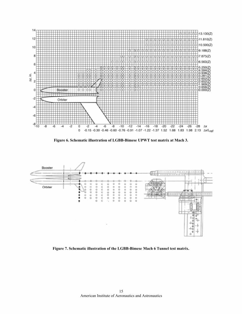
The Mach 3 stage separation tests were conducted in NASA-Langley UPWT facility. The UPWT is a closed-circuit, continuous flow, pressure tunnel with two test sections that are nominally 4 ft by 4 ft in cross section andseven ft long. The Mach number range is 1.5 to 2.86 in Test Section I and 2.3 to 4.63 in Test Section II. Two LGBB1.75% scale models were used. These correspond to 0.426% scale models of the LGBB-Bimese vehicles. OneLGBB model designated as the orbiter (bottom) model was always held at a fixed location and held fixed at a = 0.The other test model designated as the booster (top) model was moved in x (aft) and in z (vertical) directions. All thex and z traverses were done for two values of angles of attack, 0 and 5 deg. A schematic illustration of the LGBB-bimese Mach 3 test matrix is presented in Fig.6.
The Mach 6 stage separation tests were conducted in the Langley 20-Inch Mach 6 Tunnel. Two 1.21% scaleLGBB models (0.2909% LGBB-Bimese) were used, one as booster model and the other as orbiter model. All xmovements were achieved by moving the booster (top) model aft of the orbiter (bottom) model and z movements bylowering the orbiter model from the mated position. All x and z separations were run at Da = 0 and Da = 5 deg. Ateach of the nominal x and z locations, both models were simultaneously swept through an angle of attack range
Table I. Mass Properties at Staging for the Mach 3LGBB-Bimese Vehicle
Property Orbiter Booster
Weight, lb 2,909,000 300,000
Total thrust, lb 4,879,000 0
xcg, ft 197.6 130.0
Ixx, slugs-ft2 20,900,000 3,360,000
Iyy, slugs-ft2 245,000,000 39,400,000
Izz, slugs-ft2 245,000,000 39,400,000
Table II. Mass Properties at Staging for the Mach 6LGBB-Bimese Vehicle
Property Orbiter Booster
Weight, lb 2,230,000 476,000
Total thrust, lb 4,899,000.0 0
xcg, ft 197.6 130.0
Ixx, slugs-ft2 16,000,000 5,330,000
Iyy, slugs-ft2 188,000,000 62,600,000
Izz, slugs-ft2 188,000,000 62,600,000

American Institute of Aeronautics and Astronautics5
using the tunnel strut angle of attack mechanism so thata varied for each model whereas Da, Dx and Dz remainfixed at their nominal values. However, for Da = 5deg., the actual values Dx and Dz are slightly differentdue to the rotation in pitch. The angle of attack rangewas about –7 deg. to +7 deg. A schematic illustrationof the LGBB-bimese Mach 6 test matrix is presented inFig.7.
It is necessary to note that for stage separation windtunnel testing, the direction and magnitude of velocityare identical for both orbiter and booster models. Inactual flight post separation, this is not always true.The differences in velocity magnitudes amount todifferences in flight Mach numbers and the differences in directions amount to differences in flight path angles.Therefore, some errors are likely to be introduced in the simulations based on these stage separation wind tunnel testdata, specially if the Mach numbers and flight path angles of the two separating vehicles differ considerably.
The test parameters for Mach 3 and Mach 6 stage separation tests are summarized in Table III. The separationdistances Dx are negative in Table III because the booster was always located aft of the orbiter.
To illustrate the physical nature of aerodynamic interference, sample schlieren photographs are presented in Fig.8 and 9. In the mated condition (Dx = Dz = 0) for Da = 0, the mutual interference is characterized by a channel likeflow between the two bodies and the bow shock waves of each body impinge on the other resulting in multiplereflections. As the two bodies move short distance apart in x and z directions, the channel like flow is not observed.Instead, the mutual interference is mainly determined by bow shock impingements and their reflections. It isinteresting to note that the orbiter falls out of booster’s influence much earlier than the booster going out of orbiter’sinfluence. For example, for Dx = 0.4, Dz = 0.25, the orbiter is nearly out of booster’s influence whereas the booster isstill under the orbiter’s influence. The shock intersections affect surface pressure distribution causing it to rise overthe downstream part of the body resulting in significant variations in normal force and pitching moment coefficients.The flow pattern over the LGBB-Bimese models at Mach 6 has similar features but shock angles are much steeperas shown in Fig. 9.
The isolated LGBB aerodynamic coefficients at Mach 3 and Mach 6 are presented in Fig. 10. To illustrate thephysical nature of variation of longitudinal aerodynamic coefficients in proximity, the wind tunnel test data fora = 0 and Da = 0 are presented in this paper. In Figs. 11-16, the total coefficients are presented for Mach 3 case.However, the test data for Mach 6 was in the form of incremental coefficients with respect to the correspondingisolated condition and these incremental coefficients are presented in Fig. 17.
B. Simulation of Staging ManeuversThe simulation of staging maneuvers was done using ADAMS® (Automatic Dynamic Analysis of Mechanical
Systems) solver, an industry standard package for solving multi-body dynamic problems15. The user does not haveto input the governing equations of motion to ADAMS® for vehicle motion during stage separation but needs toprovide mathematical models of the aerodynamic and other external forces/moments acting on each of the vehiclesduring stage separation. ADAMS® assembles coupled/constrained equations of motion for each vehicle based on theuser supplied inputs and generates solution to those equations as per user requests. To simplify the process of usingADAMS® for solving stage separation problems, NASA Langley has developed a MATLAB-based front and backend, called ConSep to ADAMS® solver. ConSep derives its heritage from SepSim, a front-and-back-end toADAMS® for X-43A (Hyper-X) stage separation. An independent verification of the ADAMS® predictions of theX-43A stage separation16 was conducted and the two results were found to be in close agreement. This exerciseconfirms that ADAMS® sets up and solves the equations of motion for stage separation problems in an acceptablemanner.
ConSep allows the user to setup the stage separation problems in a simple manner. It converts the user inputsinto the model specifications used by ADAMS, initiates ADAMS® solver and post-processes the ADAMS® outputto express the simulation results in a convenient form. ConSep is designed to allow the user to link aerodynamicmathematical models, aerodynamic data tables, interpolation routines, model attachment points/joints, separationforces due to reaction jets or piston type devices, closed-loop proportional and derivative (PD) control, actuatordynamics, atmospheric winds, engine gimbals etc. to ADAMS® solver. ConSep is also designed to permit the user to
Table III. Summary of Wind Tunnel Test Parameters
Parameter UPWT 20-InchMach 6 Tunnel
Mach Number 3.0 6.0Reynolds Number, 106/ft 1.0-4.0 0.5-0.9Moment Reference Point 0.68 L 0.68 L
a (orbiter), deg 0.0 –7.0 to +7.0a (booster), deg 0, 5.0 –7.0 to +7.0
Da, deg 0, 5.0 0, 5.0
Dx/lref 0 to –2.1 0 to –1.0Dz/lref 0 to 1.0 0 to 0.5

American Institute of Aeronautics and Astronautics6
study the effect of variations in selected input parameters and also perform Monte Carlo studies. The mainadvantage of ConSep is that user does not have to be trained in ADAMS® to use it for solving stage separationproblems. Additional information on ConSep is available in Ref. 17.
In this study, simple aerodynamic separation aided by active closed-loop control of elevons on both vehicles wasattempted for Mach 3 staging. Separation forces or thrusters were not used. For Mach 6 staging aerodynamicseparation was not feasible and separation thrusters were used. At staging, the orbiter was assumed to be thrustingbut the booster not. The staging event starts with the release of the forward joint permitting the booster to rotate
about the aft joint. The aft joint was released when a specified event, such as Da or time reaching a specified value,occurred allowing the booster to separate.
The inputs to ConSep/ADAMS simulation of LGBB-Bimese stage separation were as follows: definition ofbody-fixed coordinate system for each vehicle in relation to the ground-fixed system (North-East-Down) defined inADAMS via Euler angles, mass, inertia, center of gravity of each vehicle in its body-fixed coordinate system, initialaltitude, velocity, flight path angle, angle of attack of each vehicle, mathematical model of aerodynamic forces andmoments in proximity and free flight, location of the moment reference point for each vehicle, tables of proximityaerodynamic forces and moment coefficients as functions of Dx, Dz, a and Da (for Mach 3 and 6), aerodynamiccoefficients for isolated or free flight conditions at Mach 3 and 6, incremental aerodynamic coefficients for elevondeflections at Mach 3 and 6, atmospheric model, location of the separation motors, magnitude and direction of netthrust, location of joints/attachment points and degrees of freedom for each joint, time/event for the partial/completerelease of front and aft joints, models of actuators for aerodynamic control surface (elevons) of each vehicle, gainsfor closed-loop PD (Proportional Derivative) controller, time for starting and stopping the integration of equations ofmotion, step size and accuracy of integration. The initial conditions and other parameters used for the stageseparation simulations are presented in Table IV.Aerodynamic Forces and Moments
The axial force, normal force and pitching moment are defined as follows:
†
Fx = -12
rV 2Sref CA (1)
†
Fz = -12
rV 2Sref CN (2)
†
M =12
rV 2Sref lref Cm (3)
where Sref = 7527.94 ft2, lref = 260.1 ft. Note that the body length (L) is used as reference length. The momentreference point was located at 0.68 lref from the nose of each vehicle. The Mach number is assumed to be constant
Table IV. Initial Conditions for LGBB-Bimese VehiclesParameter Mach 3 Staging Mach 6 StagingAltitude, ft 85000 150000.0
Velocity, ft/sec 2924.6 6586.6Dynamic Pressure, lbs/ft2 287.0 75.0Flight Path Angle
†
g , deg 53.0 30.0
†
a (booster), deg 0.0 0.0
†
a (orbiter), deg. 0.0 0.0Atmospheric Model US Standard Atmosphere 1962 US Standard Atmosphere 1962
Separation thrust 0.0 750000.0Simulation time, sec 6.0 6.0
Integration step size, sec 0.01 0.01Front Joint Release, sec 0.1 0.1Aft-Joint Rotation, sec 0.1 0.1Aft-Joint Release, sec Da = 1.0 deg Da = 1.0 deg (Baseline)
t = 0.1 sec (Nominal and all other cases)

American Institute of Aeronautics and Astronautics7
during stage separation. With this assumption, the aerodynamic coefficients in proximity during stage separation arefunctions of angle of attack, relative angle of attack and separation distances can be expressed as follows:
†
CA1p = CA1p(a1, Da , Dx, Dz) + DCA1,de1 (4)
†
CA2 p = CA2 p(a 2, Da , Dx, Dz) + DCA2,de1 (5)
†
CN 1p = CN 1p(a1, Da , Dx, Dz) + DCN 1,de1 (6)
†
CN 2 p = CN 2 p(a2, Da, Dx, Dz) + DCN 2,de2 (7)
†
Cm1p = Cm1p(a1, Da, Dx, Dz) + DCm1,de1 (8)
†
Cm2 p = Cm2 p(a2, Da, Dx, Dz) + DCm2,de2 (9)
Here, the suffixes 1 and 2 correspond to booster and orbiter respectively. In this paper, the booster is sometimesreferred to as vehicle 1 and the orbiter as vehicle 2. The suffix p denotes proximity conditions. When the twovehicles move out of the proximity range and are essentially in isolated or free flight (no interference) conditions,the aerodynamic coefficients are assumed to be given by:
†
CA1 f = CA1(a1) + DCA1,de1 (10)
†
CA2 f = CA2(a2) + DCA2,de2 (11)
†
CN 1 f = CN 1(a1) + DCN 1,de1 (12)
†
CN 2 f = CN 2(a2) + DCN 2,de1 (13)
†
Cm1 f = Cm1(a1) + DCm1,de1 (14)
†
Cm2 f = Cm2(a2) + DCm2,de2 (15)
Here, the suffix f denotes isolated or free condition. Note that CA = CAp in proximity and CA = CAf for isolated or freeflight conditions and so on.
Owing to facility/resource limitations, the Langley Mach 3 and Mach 6 proximity test data do not coversufficiently large values of Dx and Dz so that the aerodynamic coefficients transition smoothly from stage separation(proximity) coefficients to isolated (no interference or free flight) coefficients. In view of this, following assumptionwas introduced to transition from the available stage-separation aerodynamic coefficients to the isolatedaerodynamic coefficients as the vehicles move apart.
†
CA1t = k1CA1 f + (1 - k1)CA1p (16)
†
CA2t = k1CA2 f + (1 - k1)CA2 p (17)
†
CN 1t = k1CN 1 f + (1 - k1)CN 1p (18)
†
CN 2t = k1CN 2 f + (1 - k1)CN 2 p (19)

American Institute of Aeronautics and Astronautics8
†
Cm1t = k1Cm1 f + (1 - k1)Cm1p (20)
†
Cm2t = k1Cm2 f + (1 - k1)Cm2 p (21)
Here, the suffix t denotes the transition region. In the proximity region, k1 = 0 and for isolated or free flightcondition, k1 = 1. In the transition region, k1 varies linearly from 0 to 1. The transition region is assumed to consistof two concentric ellipses, an inner ellipse and an outer ellipse defined empirically using the stage separation testdata as guide. Both the ellipses are centered at the moment reference point of each vehicle and move with thevehicles. The parameter k1 is assumed to vary linearly from 0 at the inner ellipse to 1 at the outer ellipse. Theseconcepts are illustrated in Fig. 18. Note that the forward halves of the ellipses attached to the orbiter and aft halvesattached to the booster are not used in the present implementation of this concept.Constraints: The available stage separation test data are limited in a and Da values as shown in Table III. Theextrapolation outside the database limits was not permitted. In view of this, a constraint was imposed on simulationsthat each vehicle’s a and Da remain within the limits of the proximity databases, that is, 0 <a £ 5.0 deg and is0 < Da £ 5.0 deg. However, it is quite possible that safe separations can occur at angles of attack outside the limitsof the current proximity database.Criteria for Safe Separation: The criteria for a successful stage separation were as follows: (a) no vehicle recontactand, (b) booster stays out of the orbiter’s engine plume. It was estimated that the orbiter’s plume is correctlyexpanded for ambient pressure/altitude conditions for both Mach 3 and Mach 6 staging vehicles. Hence, thecombined diameter of the orbiter engines would be approximately equal to the vehicle base diameter which is 28.6ft. However, to be on the conservative side, it is assumed that the minimum Dz separation to avoid booster contactwith orbiter plume be assumed equal to two diameters (59.2 ft) or Dz/lref ≥ 0.219. For the x-separation, theacceptable separation distance was specified as Dx/lref ≥ 3.0.
It is possible that the impingement of the orbiter engine plume on the separating booster can be tolerated if theresulting aerodynamic heating effects are not critical. In such cases, it is necessary to account for the incrementalaerodynamic forces on the booster due to orbiter plume impingement during stage separation. However, this issuewas not addressed in this study.Animation of the Stage-Separation Event: The Synergistic Engineering Environment (SEE) environment wasused to create animations of the staging maneuvers. The SEE used the geometry models of the LGBB and theConSep output to generate these animations. The geometrical shape of the orbiter engine plume was assumed to be acylinder of constant diameter equal to base diameter because the exit plume was assumed to be expanded correctlyfor both Mach 3 and Mach 6 staging conditions. This plume shape was included in the geometry model of theorbiter. The animation of the staging event provides an effective means for visualization of engine plumeinteractions or collisions if any. Additional information on SEE is available in Ref. 18.
III. Results and Discussion
A. Baseline SeparationThe Mach 3 and Mach 6 separation trajectories with zero elevon deflections and zero separation-thrust are
presented in Figs. 19 and 20. These two cases are termed baseline separations. The simulation time was selected as 6sec with an integration step size of 0.01 sec. This duration and step size were considered satisfactory for thesimulation of the stage separations discussed in this study.
For both Mach 3 and Mach 6 staging, each booster experiences positive normal force coefficient and positivepitching moment coefficients in the mated conditions (Figs. 11 and 14 for Dx = Dz = 0). As a result, when theforward joint was released at t=0.1 sec, the booster starts to rotate nose-up about the aft joint and its angle of attackstarts slowly increasing. When the relative angle of attack (
†
Da ) reached 1.0 deg, the aft joint was released settingthe booster free to go. The two vehicles move away from each other and separation distances
†
Dx ,
†
Dz and
†
Da keepincreasing. However, the vehicle angles of attack go out of the database limits. In view of this, the baseline cases forboth Mach 3 and 6 were not considered to result in successful separations.
C. Nominal SeparationFor both Mach 3 and Mach 6 separations, active closed-loop, proportional-derivative (PD) control was used. The
separation thrusters were used for Mach 6 separation. No separation motors were used for Mach 3 separation. Thesetwo cases are termed nominal Mach 3 and Mach 6 separations.
American Institute of Aeronautics and Astronautics9
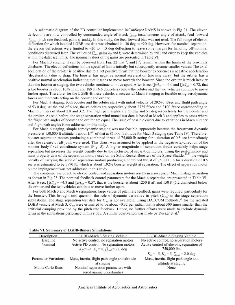
A schematic diagram of the PD controller implemented in ConSep/ADAMS is shown in Fig 21. The elevondeflections are now controlled by commanded angle of attack acmd, instantaneous angle of attack, feed forward de,bias , pitch rate feedback gains ka and kq. In this study, the feed forward bias was not used. The full range of elevondeflection for which isolated LGBB test data was obtained is –30 deg to +20 deg. However, for nominal separation,the elevon deflections were limited to –20 to +15 deg deflection to leave some margin for handling off-nominalconditions discussed later. The values of acmd gains ka and kq were determined by trial and error to keep the vehicleswithin the database limits. The nominal values of the gains are presented in Table VI.
For Mach 3 staging, it can be observed from Fig. 22 that a and Da remain within the limits of the proximitydatabases. The elevon deflections hit the specified limits initially but subsequently assume smaller values. The axialacceleration of the orbiter is positive due to a net positive thrust but the booster experiences a negative acceleration(deceleration) due to drag. The booster has negative normal acceleration (moving away) but the orbiter has apositive normal acceleration indicating that it tends to move towards the booster. Since the orbiter is much heavierthan the booster at staging, the two vehicles continue to move apart. After 6 sec, Dx/lref = –4.0 and Dz/lref = 0.72, thatis the booster is about 1038 ft aft and 189 ft (6.6 diameters) below the orbiter and the two vehicles continue to movefurther apart. Therefore, for the LGBB-Bimese vehicle, a successful Mach 3 staging is feasible using aerodynamicforces and moments acting on the booster and orbiter.
For Mach 3 staging, both booster and the orbiter start with initial velocity of 2924.6 ft/sec and flight path angleof 53.0 deg. At the end of 6 sec, the velocities are respectively about 2725 ft/sec and 3100 ft/sec corresponding toMach numbers of about 2.8 and 3.2. The flight path angles are 50 deg and 51 deg respectively for the booster andthe orbiter. As said before, the stage separation wind tunnel test data is based at Mach 3 and applies to cases wherethe flight path angles of booster and orbiter are equal. The issue of possible errors due to variations in Mach numberand flight path angles is not addressed in this study.
For Mach 6 staging, simple aerodynamic staging was not feasible, apparently because the freestream dynamicpressure at 150,000 ft altitude is about 1/4th of that at 85,000 ft altitude for Mach 3 staging (see Table IV). Therefore,booster separation motors producing a combined thrust of 75,000 lb acting for a duration of 0.5 sec immediatelyafter the release of aft joint were used. This thrust was assumed to be applied in the negative z1-direction of thebooster body-fixed coordinate system (Fig. 5). A higher magnitude of separation thrust certainly helps stageseparation but increases the weight penalty due to the inclusion of separation motors, Using the performance andmass property data of the separation motors used on the Solid Rocket Boosters of the Space Shuttle,19,20 the weightpenalty of carrying the suite of separation motors producing a combined thrust of 750,000 lb for a duration of 0.5sec was estimated to be 5770 lb, which is about 1.92% booster weight at separation. The effect of separation motorplume impingement was not addressed in this study.
The combined use of active elevon control and separation motors results in a successful Mach 6 stage separationas shown in Fig 23. The nominal feedback control parameters for the Mach 6 separation are presented in Table VI.After 6 sec, Dx/lref = –4.8 and Dz/lref = 0.57, that is the booster is about 1250 ft aft and 150 ft (5.2 diameters) belowthe orbiter and the two vehicles continue to move further apart.
For both Mach 3 and Mach 6 separations, large values of pitch rate feedback gains were required, particularly forthe booster, This brought into question the role of dynamic derivative in pitch (Cmq) in the stage separationsimulations. The stage separation test data for C mq is not available. Using DATCOM methods,21 for the isolatedLGBB vehicle at Mach 3, Cmq were estimated to be about –0.32 per radian that is about 300 times smaller than theartificial damping provided by the pitch rate feedback. Hence, no further efforts were made to include dynamicterms in the simulations performed in this study. A similar observation was made by Decker et al.5
Table VI. Summary of LGBB-Bimese Simulations
Description LGBB-Mach 3 Staging Vehicle LGBB-Mach 6 Staging VehicleBaseline No active control, no separation motors No active control, no separation motorsNominal Active PD control, No separation motors
Ka = –3, Kq = 8, acmd = 2.0 degActive control of elevons, separation of
750,000 lbs.Ka = –5, Kq = 5, acmd = 2.0 deg
Parameter Variations Mass, inertia, flight path angle and altitudeat staging
Mass, inertia, flight path angle andaltitude at staging
Monte Carlo Runs Nominal separation parameters withaerodynamic uncertainties
None

American Institute of Aeronautics and Astronautics10
C. Effect of Parametric VariationsThese studies were performed for both Mach 3 and Mach 6 staging LGBB-Bimese vehicles. However, the
results will be presented only for Mach 3 staging LGBB-Bimese vehicle because the results were similar for theMach 6 staging LGBB-Bimese vehicle. The values of the feedback gains were held fixed at their nominal values andthe full range of elevon deflections were used for vehicle control during separation.Effect of variation of mass and inertia
The mass and inertia in pitch of both vehicles varied independently by ±10% from their nominal values resultingin a combination of 9 cases for each parameter. The results are shown in Figs. 24 and 25. It may be noted that thenominal Mach 3 feedback controller is capable of handling these variations in mass and inertia and keep the vehiclea and Da within the database limits.Effect of variations in flight path angle and altitude at staging
The nominal values of flight path angle and altitude at staging are 53 deg and 85000 ft respectively. These werevaried by ±10 deg and ±5000 ft respectively. The results are shown in Figs. 26 and 27. It is noted that thesevariations can be handled by the nominal Mach 3 feedback controller satisfactorily and maintaining vehicle a andDa within the database limits.
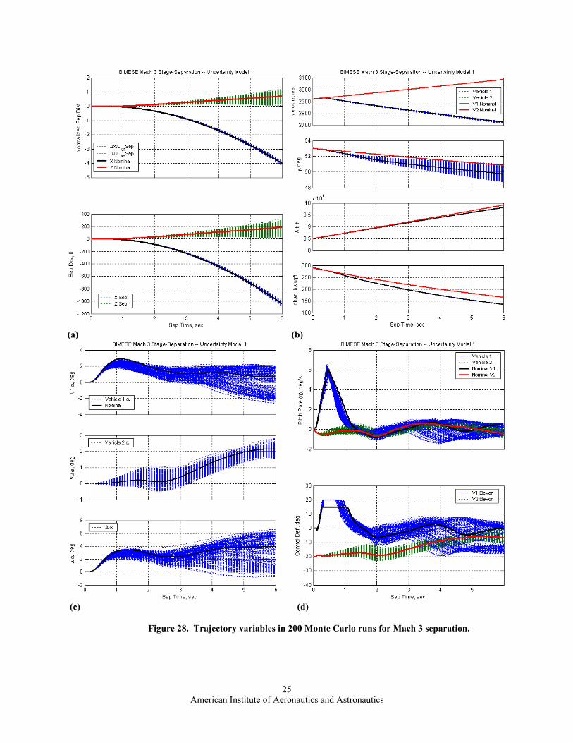
D. Monte Carlo RunsThese studies were performed to evaluate the robustness of the nominal controller to aerodynamic uncertainties
when all the other parameters assumed their nominal values. Following a recent study on aerodynamic uncertaintiesof the X-33 vehicle22 the Space Shuttle heritage23-25, two types of aerodynamic uncertainties were assumed,tolerances and variations. The tolerances are associated with measurement errors in wind tunnels. The estimatedtolerances for Mach 3 stage separation wind tunnel testing are: CN = ±0.0019, CA = ±0.0012, Cm = ±0.00022. Thedata suitable for the estimation of variations in the stage separation environment are not available. In the absence ofa better alternative, the uncertainties associated with Space Shuttle reentry flight are used as variances in this study:CN = ±0.015, CA = ±0.006, Cm = ±0.003. The total or net uncertainties were assumed to be sum of tolerances andvariances. It may be noted that these uncertainties are very conservative and are often as large as the proximityaerodynamic coefficients themselves.
The results of 200 Monte Carlo runs are presented in Fig. 28. The number of cases which resulted in successfulseparation (Dz/lref ≥ 0.2) were 184 and the failures (Dz/lref £ 0.2) were 16. The number of cases which went outsidethe database limits (Da > 5.0 deg) were 51 with a maximum Da of 6.59 deg. However, for these 51 cases, thevehicle-a were within the 5 deg limit. Considering that the estimated uncertainties were very much on theconservative side, it is believed that the nominal controller for the Mach 3 staging satisfactorily handles theaerodynamic uncertainties assumed in this study.
E. Animation of the Staging Event:The ConSep output and the LGBB-Bimese vehicle geometry models were input to SEE to produce animation
of the staging event. As said before, the engine plume was assumed to be correctly expanded for both Mach 3 andMach 6 operating altitudes and was modeled as a solid cylinder extending few diameters from the base of theorbiter. Snap shots of the animation taken at selected time intervals are shown in Fig. 29.
IV. Concluding RemarksThe analyses and simulation of the staging maneuvers of two TSTO vehicle concepts, one staging at Mach 3 and
the other staging at Mach 6 were performed to demonstrate the application of the ConSep tool which is beingdeveloped as a part of NASA’s stage separation tool development activity. The proximity aerodynamic databaseswere developed using the data from stage separation wind tunnel tests conducted at NASA Langley ResearchCenter. A passive release of the vehicles for Mach 3 and Mach 6 staging did not result in satisfactory stageseparation because the vehicle angles of attack and relative angles of attack went very much outside the databaselimits. For Mach 3 LGBB-Bimese vehicle, aerodynamic separation was feasible using active closed-loop feedbackcontroller. However, for Mach 6 LGBB-Bimese vehicle, aerodynamic staging was not feasible and separationmotors were used. Parametric variations in mass, inertia, flight path angle and altitude at staging were investigated.Monte Carlo simulations were performed to evaluate the robustness of nominal controller to aerodynamicuncertainties. The results indicate that the nominal controller satisfactorily handles off-nominal conditions in mass,inertia, flight path angle, altitude at staging and estimated uncertainties in aerodynamic coefficients.

American Institute of Aeronautics and Astronautics11
AcknowledgmentsThe authors like to gratefully acknowledge Wayne J. Borderlon and Alonzo L. Frost for MSFC stage separation
test data and schlieren photographs, Roger Lepsch for ISAT vehicle concepts, Steve Harris and Mark McMillin forgeometry, and Scott Angster for animations.
References
1Dillenius, M.F.E., Perkins, S.C., and Nixon, D., Pylon Carriage and Separation of Stores, AIAA Progress in Astronauticsand Aeronautics: Tactical Missile Aerodynamics-General Topics, M.J.Hemsch, ed., Vol. 141, 1992.
2Taylor, R.T., and Alford, W. J, Jr., A wind tunnel investigation of the carry loads and mutual interference effects of 1/40-scale models of the X-15 and B-52 airplanes in combination, NASA TM X-184, December 1959.
3Decker, J.P., and Wilhite, A. W., Technology and Methodology of Separating Two Similar Size Aerospace Vehicles Withinthe Atmosphere. AIAA Paper 1975-29, Jan. 1975.
4Decker, J. P., Experimental Aerodynamics and Analysis of the Stage Separation of Reusable Launch Vehicles. NASA-SP-148, January 1967.
5Decker, J. P., and Gera, J., An Exploratory Study of Parallel-Stage Separation of Reusable Launch Vehicles. NASA TN D-4765, October 1968.
6Decker, J. P., Aerodynamic Interference Effects Caused by Parallel-Staged Simple Aerodynamic Configuration at MachNumbers of 3 and 6. NASA TN D-5379, Aug. 1969.
7Wilhite, A. W., Analysis of Separation of the Space Shuttle Orbiter from a Large Transport Airplane. NASA TM X-3492,June 1977.
8Naftel, J. C., and Wilhite, A.W., Analysis of Separation of a Two-Stage Winged Launch Vehicle. AIAA Paper 86-0195, Jan.1986.
9Naftel, J. C., and Powell, R.W., Aerodynamic Separation and Glideback of a Mach 3 Staged Orbiter. AIAA Paper 90-0223,Jan. 1990.
10Naftel, J. C., and Powell, R. W., Analysis of the Staging Maneuver and Booster Glideback Guidance for a Two-Staged,Winged, Fully Reusable Launch Vehicle. NASA TP-3335, 1993.
11Pamadi, B.N., Tartabini, P.V., and Starr, B.R.; Ascent, Stage Separation and Glideback Performance of a PartiallyReusable Small Launch Vehicle, AIAA Paper 2004-0876.
12Murphy, K.J., Buning, P.G., Pamadi, B.N., Scallion, W.I., and Jones, K.M.; Status of Stage Separation Tool Developmentfor Next Generation Launch Vehicle Technologies. AIAA Paper 2004-2595.
13Pamadi, B.N., Neirynck, T. A., Covell, P.F., Hotchko, N.J., and Bose, D.M., Simulation and Analyses of StagingManeuvers of Next Generation Reusable Launch Vehicles, AIAA Paper 2004-5185.
14Bordelon, W.J., Frost, A.L., Reed, D.K., Stage Separation Wind Tunnel tests of a Generic Two-Stage-to-Orbit LaunchVehicle, AIAA Paper 2003-4227, July 2003.
15Using ADAMS/Solver, Mechanical Dynamics, Inc., 1999.16Tartabini, P.V., Bose, D.M., McMinn, J.D., Martin, J.G., and Stovers, B.K., Hyper-X Stage Separation Trajectory
Validation Studies, AIAA Paper 2003-5819.17Bose D.M., and Hotchko, N., Conceptual Level Stage Separation Simulation (ConSep)–Version 1.1 User’s Guide, AMA
Report No. 02-37 Rev.B, Analytical Mechanics Associates, Hampton, VA, December 2003.18Angster, S., Synergistic Engineering Environment Build II User’s Guide Revision E, AMA Report No. 03-31, Analytical
Mechanics Associates, Hampton, VA, August 2003.19Boeing. Performance Enhancement Operational Aerodynamic Design Data Book: Launch Vehicle Aerodynamic Data.
RSS98D0313, Jan. 28, 1999.20Marshal Space Flight Center. STS36: SRB Preflight Predicted Mass Properties. SRB Mass Properties Status Report No. 64,
Addendum D. Dec. 1989.21Pamadi, B.N., Performance, Stability, Dynamics and Control of Airplanes, 2nd Ed, AIAA Text Book, 2004, pp.174-175,
187-188.22Cobleigh, Brent R. Development of the X-33 Aerodynamic Uncertainty Model. NASA TP-1998-206544. April 1998.23Young, James C. and Underwood, Jimmy M. The Development of Aerodynamic Uncertainties for the Space Shuttle
Orbiter. AIAA Paper 82-0563, 1982.24Boeing Reusable Space Systems/United Space Alliance., Orbiter Operational Aerodynamic Data Book. RSS99D0001,
April 2000.25Rockwell International Space Division, Aerodynamic Design Data Book, Vol. 1, Orbiter Vehicle. Downey, CA. Rept. SD
772-SH-0060-1L, Nov. 1977.

American Institute of Aeronautics and Astronautics12
(a) (b)
Figure 1. Schematic illustration of Mach 3 and Mach 6 staging flight profiles.
Figure 2. Three-view diagram of the Langley glide-back booster (LGBB).

American Institute of Aeronautics and Astronautics13
Figure 3. Schematic diagram of the LGBB-Bimese vehicle.
Figure 4. Schematic illustration of the attachment of the booster and the orbiter (all dimensions in ft).

American Institute of Aeronautics and Astronautics14
a) Wind Tunnel Tests b) Flight
Figure 5. Relative locations of booster and orbiter in proximity.
American Institute of Aeronautics and Astronautics15
Figure 6. Schematic illustration of LGBB-Bimese UPWT test matrix at Mach 3.
Figure 7. Schematic illustration of the LGBB-Bimese Mach 6 Tunnel test matrix.

American Institute of Aeronautics and Astronautics16
(a) Dx/lref, Dz/lref = 0.0, Da = 0 (b) Dx/lref = –0.2, Dz/lref = 0.16, Da = 5
(c) Dx/lref = –0.4, Dz/lref = 0.25, Da = 5 (d) Dx/lref = –0.8, Dz/lref = 0.36, Da = 5
Figure 8. Mach 3 schlieren photographs of the LGBB bimese configurationin MSFC Aerodynamic Research Facility.4

American Institute of Aeronautics and Astronautics17
Figure 9. Schlieren Photographs of the LGBB-Bimese configuration in 20-Inch Mach 6 Tunnel.

American Institute of Aeronautics and Astronautics18
Figure 10. Isolated LGBB lift, drag and pitchingmoment coefficients at Mach 3 and 6.
Figure 11. Variation of booster normal forcecoefficient with Dx/Lref and Dz/Lref at Mach 3 fora = 0, Da = 0 deg.
Figure 12. Variation of orbiter normal forcecoefficient with Dx/Lref and Dz/Lref at Mach 3 fora = 0, Da = 0 deg.

American Institute of Aeronautics and Astronautics19
Figure 13. Variation of booster axial forcecoefficient with Dx/Lref and Dz/Lref at Mach 3 fora = 0, Da = 0 deg.
Figure 15. Variation of orbiter axial forcecoefficients with Dx/Lref and Dz/Lref at Mach 3 fora = 0, Da = 0 deg.
Figure 14. Variation of booster pitching momentcoefficient with Dx/Lref and Dz/Lref at Mach 3 fora = 0, Da = 0 deg.
Figure 16. Variation of orbiter pitching momentcoefficients with Dx/Lref and Dz/Lref at Mach 3 fora = 0, Da = 0 deg.

American Institute of Aeronautics and Astronautics20
Booster at Da = 0 deg Orbiter at Da = 0 deg
Figure 17. Proximity aerodynamic coefficients for Mach 6 at a = 0, Da = 0 deg.

American Institute of Aeronautics and Astronautics21
Figure 18. Concept of transition regions.
Figure 19. Mach 3 baseline separation. Figure 20. Mach 6 baseline separation.
Figure 21. Feedback control system implemented in ConSep.

American Institute of Aeronautics and Astronautics22
(a) (b)
(c) (d)
Figure 22. Trajectory variables in Mach 3 nominal separation.

American Institute of Aeronautics and Astronautics23
(a) (b)
(c) (d)
Figure 23. Trajectory variables in Mach 6 nominal separation.

American Institute of Aeronautics and Astronautics24
Figure 24. Effect of parametric variation in vehicle mass. Figure 25. Effect parametric variation in pitch inertia.
Figure 26. Effect of parametric variations in flight path angle. Figure 27. Effect of parametric variation in altitude.
American Institute of Aeronautics and Astronautics25
(a) (b)
(c) (d)
Figure 28. Trajectory variables in 200 Monte Carlo runs for Mach 3 separation.

American Institute of Aeronautics and Astronautics26
(a) t = 0, Mated Configuration. (b) t = 0.5 s.
(c) t = 1.0 s. (d) t = 2.0 s.

American Institute of Aeronautics and Astronautics27
(e) t = 3.0 sec. (f) t = 4.0 sec.
Figure 29. Selected snap shots showing the relative locations of booster orbiter duringMach 3 nominal separation.


