Simulating Circuits There are many simulation and design ...
13
Simulating Circuits James Lamberti ([email protected] ) 5/4/2014 There are many simulation and design platforms for circuits. The two big ones are Altium and Cadence. This tutorial will focus on Altium, which has a simpler User Interface, however still has a very steep learning curve. Here I will try to give the basics of how to use it, with the goal of designing a filter and verifying it through simulation. After opening Altium, we want to create a new schematic: Giving us: Some shortcuts in Altium are PP, which stands for Place Part, or PW which stands for Place Wire. Alternatively, you can right click, select Place→Part or Place→Wire.
Transcript of Simulating Circuits There are many simulation and design ...

Simulating Circuits James Lamberti ([email protected]) 5/4/2014 There are many simulation and design platforms for circuits. The two big ones are Altium and Cadence. This tutorial will focus on Altium, which has a simpler User Interface, however still has a very steep learning curve. Here I will try to give the basics of how to use it, with the goal of designing a filter and verifying it through simulation. After opening Altium, we want to create a new schematic:
Giving us:
Some shortcuts in Altium are PP, which stands for Place Part, or PW which stands for Place Wire. Alternatively, you can right click, select Place→Part or Place→Wire.

So a big problem in certain applications is mains hum, or power line hum, which is due to the alternating current at the frequency of the electrical line, which is 60Hz in the USA.
http://en.wikipedia.org/wiki/File:Mains_hum_spectrum.png
As a result, a notch filter is used to prevent this. The typical notch filter looks like:
http://en.wikipedia.org/wiki/File:BandReject_Filter.svg
Which has a transfer function of:

Which we can alternatively think of as:
Where Q is the dampening factor. The effect of Q is well documented by www.analog.com:
But as everyone know’s EE’s hate inductors, so instead we will use an alternative implementation, so instead there are techniques like active inductors, which replace an inductor with resistors, capacitors and OpAmps.

When designing a mains hum notch filter, we want the breakpoints to occur at 59Hz and 61Hz and attenuate 60Hz by a lot. So let’s start by implementing the TwinT Notch Filter: After typing P P, I get the following dialog:
Since I am assuming this is your first time using the software, you will not have a recently used components list, so click choose, which will bring up:
We can select Res1 from the list, click okay, then click Ok again. Now wherever we click, we will get a resistor. To rotate, use the space key. Eventually, we can make:

Now we want to place in a 3 capacitors to make the TwinT Notch Filter (repeat like resistor, but search for cap this time):
Now, we have to wire. We can use the shortcut p w standing for place wire. Alternatively, we can right click→Place→Wire or click the wire icon in the place toolbar on top. So after wiring we get:

Now we can click the little ground icon in the toolbar and connect the capacitor and resistor to ground:
We can now use the shortcut p n standing for place netlabel. Netlabels enable us to see what the voltage is in that location. So after adding netlabels, and double clicking them to rename we get:
Now we need to hook up the source before we can simulate, so we click on simulation sources and select 1Khz Sine Wave:

We connect one end of the source to Vin and the other to ground giving:
Before we can simulate the circuit we must run force annotate (Tools→Force Annotate All Schematics):

After saying yes to the changes, go to Design→Simulate→Mixed Sim:
On the general setup tab, we can choose which signals we want plotted. This is optional as it can be done later. Operating Point Analysis gives the DC bias values which is helpful if you are trying to bias transistors or debug transistor circuits. Transient analysis gives the time response of the circuit. DC Sweep isn’t really important or common to use.

AC small signal lets us simulate the circuit and get the frequency response of it. Basically we sweep our input signal from typically 1Hz to 1MHz. Make sure you set Sweep type to decade. I will also be running a pole and zero analysis on the filter, as well as a transfer function analysis of it. So when we are ready to simulate it, press Ok:
So now that I have simulation results, I have to get it for the netlabels I want. If you right click on a label in the legend, you can select edit wave and change it to what you want:
Here I will use vout, and select magnitude db on the right hand side:
If I right click on the label in legend again, I can enable cursors and use it to find the lower 3dB point of the filter:
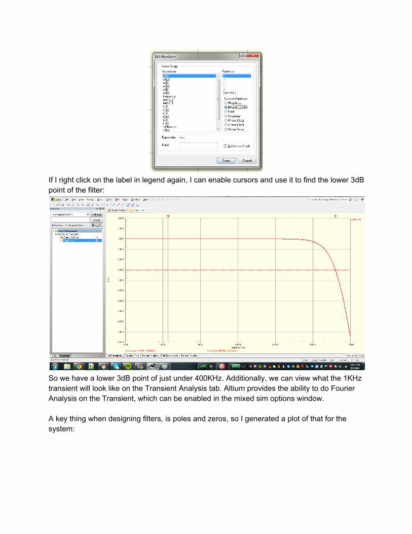
So we have a lower 3dB point of just under 400KHz. Additionally, we can view what the 1KHz transient will look like on the Transient Analysis tab. Altium provides the ability to do Fourier Analysis on the Transient, which can be enabled in the mixed sim options window. A key thing when designing filters, is poles and zeros, so I generated a plot of that for the system:
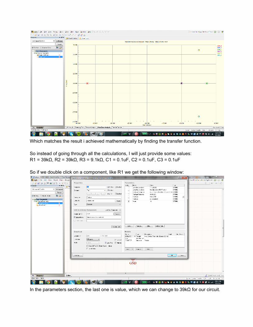
Which matches the result i achieved mathematically by finding the transfer function. So instead of going through all the calculations, I will just provide some values: R1 = 39kΩ, R2 = 39kΩ, R3 = 9.1kΩ, C1 = 0.1uF, C2 = 0.1uF, C3 = 0.1uF So if we double click on a component, like R1 we get the following window:
In the parameters section, the last one is value, which we can change to 39kΩ for our circuit.

Alternatively, we can double click the value listed next to the part and change it there:
After changing all the component values, you should get something like:
So now let’s simulate this:

I added two additional plots, right click→Add plot. The first plot is the bode plot of the circuit, the second is a phase plot, and the third is the group delay of the filter. Using the cursors, we have the notch right around 59.2Hz, which should give us some good rejection against mains hum. Now what we simulated there is a fairly simple circuit, but Altium can handle circuits much more complicated (1000+ components).