Simrad Robertson AS Telephone: +47 51 46 20 00 P.O. Box 55ww2.simrad-yachting.com/Root/Operator...
132
Transcript of Simrad Robertson AS Telephone: +47 51 46 20 00 P.O. Box 55ww2.simrad-yachting.com/Root/Operator...


Simrad Robertson AS Telephone: +47 51 46 20 00Nyåskaien Telefax: +47 51 46 20 01P.O. Box 55N-4379 Egersund, Norway
NOTE!
Simrad Robertson AS makes every effort to ensure that the information containedwithin this document is correct. However, our equipment is continuously beingimproved and updated, so we cannot assume liability for any errors which mayoccur.
The information contained within this document remains the sole property of SimradRobertson AS. No part of this document may be copied or reproduced in any form orby any means, and the information contained within is not to be passed on to a thirdparty, without the prior written consent of Simrad Robertson AS.
Warning
The equipment to which this manual applies must only be used for the purpose forwhich it was designed. Improper use or maintenance may cause damage to theequipment or injury to personnel. The user must be familiar with the contents ofthe appropriate manuals before attempting to operate or work on the equipment.
Simrad Robertson AS disclaims any responsibility for damage or injury caused byimproper installation, use or maintenance of the equipment.

Instruction Manual
22081814H 1
Instruction Manual
This manual is intended as a reference guide for operatingand correctly installing the AP300X autopilot.
Great care has been paid to simplify operation and set-upof the Robertson AP300X, however, an autopilot is acomplex electronic system. It is affected by sea conditions,speed of the vessel, hull shape and size.
Please take time to read this manual to get a thoroughunderstanding of the operation and system componentsand their relationship to a complete AP300X autopilotsystem.
Other documentation materials that is included in thismanual is a warranty card. This must be filled out by theauthorized dealer that performed the installation andmailed in to activate the warranty.

Robertson AP300X Autopilot
2 22081814H
Document revisions
Rev Date Written by Checked by Approved by– 08.04.1994 NG TT Th.H.A 03.05.1994 NG Th.H.B 27.09.1994 NG Th.H.C 24.11.1994 NG Th.H.D 10.02.1995 NG IK Th.H.E 06.11.1995 NG IK Th.H.F 17.01.1996 NG Th.H.G 28.08.1996 NG Th.H.H 25.02.1997 NG Th.H.
Document history
Rev. Action/Changes/References– Original issue.A Change of cable clamp in junction units page 71. Minor corrections in text and
displays.B Minor corrections in text and displays. Section 1 and 3 extended. Section 4-6 added.C Minor corrections in text page 72 and in text and diagram page 88. Table with NMEA
input-/output messages included.D Updated spare parts list section 7.E Page 112: Moved arrow on J3000X/J300X/J300X-40 Main PC-board to correct
EPROM. Minor corrections in text.F Operational instructions for MSD50 installations included. Operational instructions for
dodging in NAV mode added. Minor changes in explanatory text to NAV modedisplays. Interface setup table modified. Wiring of CD100 if mounted upside down.
G R2500 substituted by R3000X on page 17, 24 and 83. Added missing words page79. New Databox/J300X connection diagram included on page 86. Minor correctionsto other drawings on same page. IP code for J300X on page 119 corrected.
H Page 89: New cable for LF3000 included.
Instruction Manual
22081814H 3
Contents
1 GENERAL INFORMATION........................................................................................... 91.1 Introduction ............................................................................................................ 91.2 How to use this manual ...................................................................................... 101.3 System components ............................................................................................. 10
AP300CX Control unit......................................................................................... 11
AP300PX Control Unit ........................................................................................ 11
AP300DLX Control Unit ..................................................................................... 11
J300X, J300X-40 and J3000X Junction Units ...................................................... 12
RF300 Rudder Feedback unit ............................................................................. 13
RFC35 Electronic fluxgate compass................................................................... 141.4 Optional components .......................................................................................... 14
NI300X NMEA Interface Unit ............................................................................ 14
CI300X Compass Interface.................................................................................. 14
Rudder" indicator................................................................................................. 15
Compass" Indicator.............................................................................................. 15
CDI35 Course Detector Interface ....................................................................... 15
LF3000 Linear Feedback...................................................................................... 16
LFI3000 Linear Feedback Interface .................................................................... 16
Robnet cables ........................................................................................................ 16
R3000X Remote Control ...................................................................................... 17
S100 NFU steering lever...................................................................................... 17
S3 NFU steering lever.......................................................................................... 17
JP300 Jack Point .................................................................................................... 18
Mounting brackets ............................................................................................... 18
Top mount bezel................................................................................................... 18
Flush mount bezel................................................................................................ 18
2 AP300X AUTOPILOT OPERATION........................................................................... 192.1 Overview............................................................................................................... 192.2 AP300X with MSD50 Stern Drive unit .............................................................. 21
Zero point setting................................................................................................. 21
Operation .............................................................................................................. 212.3 ON/OFF / Standby mode .................................................................................. 22
Follow-Up steering .............................................................................................. 22

Robertson AP300X Autopilot
4 22081814H
Non-Follow-Up steering ..................................................................................... 22
NFU Steering lever............................................................................................... 22
R3000X Remote Control ...................................................................................... 242.4 Automatic Steering .............................................................................................. 24
Dodging................................................................................................................. 24
U-Turn ................................................................................................................... 26
Tacking in Auto mode......................................................................................... 262.5 Navigating with the AP300X.............................................................................. 27
Selecting a different Navigator .......................................................................... 28
Dodging in Nav. mode........................................................................................ 292.6 Wind vane steering .............................................................................................. 29
Tacking in Wind mode........................................................................................ 312.7 Automatic Speed selection.................................................................................. 31
Manual speed selection ....................................................................................... 322.8 Multiple station system....................................................................................... 322.9 Lock function ........................................................................................................ 322.10 The User Set-up Menu......................................................................................... 342.11 AP300DLX Main features ................................................................................... 35
Availability of data sources ................................................................................ 36
Use of external position sources ........................................................................ 362.12 Operation of Graphic Display ............................................................................ 37
Graphic Display Setup ........................................................................................ 38
Plot interval........................................................................................................... 39
Units and time setup............................................................................................ 39
Position calibration .............................................................................................. 40
Automatic MAGVAR calculation ...................................................................... 41
Manual input of MAGVAR ................................................................................ 42
Clearing Waypoint Database.............................................................................. 44
Displays and menu structure ............................................................................. 45
INFO and POS screens ........................................................................................ 46
Instrument displays and menu .......................................................................... 472.13 Waypoints ............................................................................................................. 48
Storing waypoints ................................................................................................ 482.14 Routes .................................................................................................................... 52
Creating a route.................................................................................................... 52
Correction of routes ............................................................................................. 54

Instruction Manual
22081814H 5
2.15 Navigating with the AP300DLX ........................................................................ 54
Navigating to a Temporary waypoint .............................................................. 55
Navigating to a stored waypoint ....................................................................... 56
Arriving at a waypoint........................................................................................ 57
Plotting with the AP300DLX .............................................................................. 58
Navigating through a route................................................................................ 59
Navigating using the MOB function ................................................................. 61
MOB (Man over Board)....................................................................................... 622.16 Glossary................................................................................................................. 63
3 INSTALLATION............................................................................................................. 653.1 General................................................................................................................... 65
Installation checklist ............................................................................................ 65
Unpacking and handling .................................................................................... 66
Determine system configuration........................................................................ 66
AP300X Basic system........................................................................................... 67
AP300X multistation system with optional drive units.................................. 67
AP300X system with compass interface options ............................................. 68
AP300X system with NAV interface options ................................................... 683.2 RF300 Rudder feedback installation.................................................................. 693.3 Junction unit installation..................................................................................... 70
Cable connections ................................................................................................ 70
Grounding and RFI.............................................................................................. 713.4 Drive unit installation.......................................................................................... 72
Connecting a reversible pump ........................................................................... 74
Connecting a hydraulic linear drive.................................................................. 74
Connecting a solenoid valve............................................................................... 743.5 Control unit installation ...................................................................................... 75
ROBNET network cables .................................................................................... 793.6 RFC35 Fluxgate Compass installation............................................................... 813.7 JP300 Jack Point installation ............................................................................... 823.8 R3000X Remote Control installation ................................................................. 833.9 S3 NFU Lever installation................................................................................... 833.10 S100 NFU Lever installation ............................................................................... 843.11 Interfacing ............................................................................................................. 84
Single NMEA input/output ............................................................................... 85
Double NMEA input/output ............................................................................. 85

Robertson AP300X Autopilot
6 22081814H
Databox/J3000X ................................................................................................... 85
Databox/J300X ..................................................................................................... 86
Radar Clock/Data................................................................................................ 86
DATALINE Instrument installation.................................................................. 86
External Alarm ..................................................................................................... 87
NI300X NMEA Interface Unit ............................................................................ 87
LF3000 Linear Feedback...................................................................................... 88
CI300X Analogue Interface Unit ........................................................................ 90
CD100 Course Detector ....................................................................................... 92
CDI35 Interface..................................................................................................... 923.12 Software Setup Procedure................................................................................... 93
Description of Installation Settings.................................................................... 93
Installation Settings Menu .................................................................................. 94
Language selection............................................................................................... 95
Dockside settings ................................................................................................. 95
Drive unit voltage selection................................................................................ 97
Rudder Feedback Calibration............................................................................. 97
Automatic Rudder Test ....................................................................................... 98
Transition Speed................................................................................................... 99
Master Reset........................................................................................................ 100
Interface Settings ................................................................................................ 100
Output signal setup ........................................................................................... 1033.13 Sea Trial ............................................................................................................... 103
Rudder zero adjust............................................................................................. 104
Compass calibration .......................................................................................... 104
Compass Offset .................................................................................................. 105
Automatic tuning ............................................................................................... 106
View parameters ................................................................................................ 107
Manual parameter adjust.................................................................................. 107
Final sea trial....................................................................................................... 109
Providing user training ..................................................................................... 109
4 MAINTENANCE........................................................................................................... 1114.1 Control unit......................................................................................................... 1114.2 Junction Unit....................................................................................................... 1114.3 Rudder Feedback ............................................................................................... 111

Instruction Manual
22081814H 7
4.4 Compass .............................................................................................................. 1114.5 Drive unit ............................................................................................................ 1114.6 Exchange of EPROMS ....................................................................................... 112
5 TROUBLE SHOOTING ............................................................................................... 1145.1 Alarms ................................................................................................................. 114NMEA Test...................................................................................................................... 1175.3 System Data Menu............................................................................................. 118
6 TECHNICAL SPECIFICATIONS .............................................................................. 1196.1 AP300X Autopilot System ................................................................................ 1196.2 Control Units (AP300CX, AP300PX, AP300DLX).......................................... 1206.3 Junction units...................................................................................................... 1206.4 RFC35 Fluxgate compass .................................................................................. 1216.5 CDI35 Course Detector Interface ..................................................................... 1216.6 RF300 Rudder Feedback.................................................................................... 1226.7 CI300X Compass Interface ................................................................................ 1226.8 NI300X NMEA Interface ................................................................................... 1226.9 LF3000 Linear Feedback.................................................................................... 1236.10 LFI3000 Feedback Interface .............................................................................. 123
7 AP300X AUTOPILOT SPARE PARTS LIST ............................................................ 125

Robertson AP300X Autopilot
8 22081814H

General Information
22081814H 9
1 GENERAL INFORMATION1.1 Introduction
Congratulations on the purchase of your new Robertson AP300Xautopilot system and thank you for selecting what we feel is the mostadvanced autopilot system available on the market today.
Simrad Robertson AS is located in Egersund on the south/west coastof Norway. The company's involvement in autopilots began in 1953with equipment for the North Sea fishing fleet. Today SimradRobertson AS manufactures a complete range of autopilots for all typesof vessels, from pleasure boats up to advanced steering systems formerchant marine vessels. Professional mariners around the worldacknowledge that the Robertson name is synonymous with theabsolute best in autopilot technology.
The AP300X series from Robertson represents yet another step forwardin autopilot technology with the intent to provide power and sailingboats from 30 to 80 feet with a host of new features. The system can beexpanded and enhanced with a selection of options and accessories.
The brain in the AP300X autopilot series is the single "intelligent"junction unit that communicates with all other system modules on theROBNET network. The ROBNET has been developed to establish areliable digital communication and power distribution networkbetween the units in the system. The ROBNET simplifies installationand enables the AP300X system to be easily expanded at any time.
Three different models of control units are available. All of them maybe used as part of a stand alone autopilot system or as a full functioncontrol unit in a multiple station installation. Any combination ofcontrol units up to a total of 7 may be used in one installation.
All AP300X systems include Nav. interface as standard withNMEA0183 input and output. The NMEA interface allows anavigation receiver or position sensor to provide input to the AP300Xsystem. All equipment connected to the ROBNET network can accessthe input data. In addition the NMEA output provides heading,rudder angle and other data depending on the autopilot configurationand the equipment that may be connected to the NMEA input. Theoptional NI300X Interface (expansion) Unit can expand the number ofNMEA input/output ports, which allows a multiple number ofperipheral navigation equipment to be interfaced.
The time proven experience of the Robertson engineers and thecomputer power in the AP300X system has made it possible toautomate and simplify the setup and installation procedures. Oneimportant feature is the capability to set up automatically the steeringparameters and select the scaling factor for speed and hull type; power(planing or displacement) or sail. Proportional rate output commandsand an adaptive sea state filter contribute to enhanced steeringperformance in any sea condition.

Robertson AP300X Autopilot
10 22081814H
1.2 How to use this manualThis manual is intended as a reference guide for operating, installingand maintaining the AP300X series of autopilots. Great care has beenpaid to simplify operation and set-up of the Robertson AP300X,however, an autopilot is a complex electronic system. It is affected bysea conditions, speed of the vessel, hull shape and size.
Please take time to read this manual to get a thorough understandingof the operation and system components and their relationship to acomplete AP300X autopilot system.
Other documentation materials that is provided with your systeminclude a warranty card. This must be filled out by the authorizeddealer that performed the installation and mailed in to activate thewarranty.
1.3 System componentsA basic AP300X autopilot system consists of: Control Unit(s), JunctionUnit, Rudder Feedback Unit, Electronic Fluxgate Compass and DriveUnit.
RFC35ELECTRONIC
FLUXGATECOMPASS
REVERSIBLEPUMP
RF300RUDDER
FEEDBACK
JUNCTIONUNIT
AP300DLXCONTROL
UNIT AP300PXCONTROL UNIT
AP300CXCONTROL UNIT
7 m (23')
15 m (49')
ROBNET Network Cable
Other cable
10 m (33')
15 m (49')
7 m (23')
MAINS P OW ER SUP PLY12/24/32 VDC

General Information
22081814H 11
AP300CX Control unitA compact autopilot control forpanel, bulkhead or bracketmounting. Large LCD displayfor readout of autopilot dataand rotary course selector. It hasthree Robnet connectors forsystem inter- connection andexpansion.
Weight: 0,4 kg (0,9 lbs)
AP300PX Control UnitPortable control unit with 7 m(20 ft.) of cable. It has all thesame autopilot functions asAP300CX, and can be used asa hand held autopilot or bemounted in a fixed, bracketmount.
Weight: 0,4 kg (0,9 lbs)
AP300DLX Control UnitControl unit with all autopilotfunction controls andROBNET connectors arrangedas on AP300CX. It has anadditional graphic display anda built in navigation computercapable of storing waypointsand route planning.
Weight 0,6 kg (1,3 lbs.)
Other features of the AP300DLX:• 7 different instrument displays with calibration capabilities• Interface to "black-box" GPS

Robertson AP300X Autopilot
12
• Plot function• Full feature demo and training software• 100 waypoints and 20 routes memory capacity
J300X, J300X-40 and J3000X Junction Units
J
W
J300XJ3000X
Weight: 1,3kg (2,9 lbs.)
22081814H
The junction unit is the central unit in the AP300X autopilot system. Itcontains the steering computer, interface circuits to all systemcomponents and drive circuits for the drive unit motor and clutch.Three models, J300X, J300X-40 and J3000X are available.
Junction unit comparison chart:
J3000X J300X (J300X-40)AP300X autopilot models CX,, PX,, DLX CX,, PX,, DLX
Supply voltage 10-28 V 10-40 V
Motor current (continuous/peak) 6/10 A 10/20A (20/40A)
Number of control units 2 7
NMEA ports 1 2
Solenoid output x xInput for NFU control x x
External alarm x
Radar clock/data interface x
300X-40
eight: 2,8kg (6,2 lbs.)

General Information
22081814H 13
RF300 Rudder Feedback unit
Rudder feedback unit with transmission link and 10 m (30 feet) ofcable. Transforms the angular travel of the rudder to a digital signalread by the autopilot steering computer.
Weight: 0,5 kg (1,1 lbs)

Robertson AP300X Autopilot
14 22081814H
RFC35 Electronic fluxgate compass
A new compact heading sensor from Robertson with 15 m (45 feet) ofcable. The direction of the earth's magnetic field is sensed by a floatingring core in a fluxgate coil and transformed to a digital signal read bythe autopilot steering computer.
1.4 Optional components
NI300X NMEA Interface Unit
This unit has 4 NMEA I/Oports for communication toother systems, and a selectableheading output for radars(Anritzu or Furuno). Includestwo ROBNET connectors forconnection to the AP300Xsystem.
Weight: 0,9 kg (2,0 lbs)
CI300X Compass InterfaceOptional unit for interface to foreign fluxgate compasses, windvanesystems with analog output and NFU levers. Input for Robertson gyrocompass type RGC50, RGC10 and RGC11. Same dimensions andweight as NI300X.
Weight: 0,9 kg (2,0 lbs)

General Information
22081814H 15
Rudder" indicator
110mm
110mm
17mm 18mm
50mm Dia.
Dataline
LightFunction
A Robertson Dataline instrument that can be connected directly to oneof the AP300X NMEA outputs. Analogue display of boat's rudderangle.
Compass" IndicatorA 12 V Dataline instrument that displays the boats heading on bothdigital and analogue format. Can be connected directly to NMEAoutput on the junction unit.
Dimensions and weight as for "Rudder" Indicator.
CDI35 Course Detector Interface
Interface unit to connect autopilot to a magnetic compass with CD100Course Detector. Provides exitation current for CD100 and converts theanalogue sin/cos signal to digital format for the autopilot steeringcomputer.
Weight: 0,9 kg (2,0 lbs)
Weight: 0,2 kg (0,4 lbs)

Robertson AP300X Autopilot
16 22081814H
LF3000 Linear FeedbackLinear feedback unit for boats with outboard engine. Transforms thelinear movement to an analogue signal. Supplied with 8,5 m cable andmounting clamps.
LFI3000 Linear Feedback InterfaceInterface unit for LF3000 Linear Feedback. Converts the analogueLF3000 signal to the standard digital feedback signal for the autopilotsteering computer.
Robnet cables
Standard Robnet cable (15 m) with one male plug.7 m (23')
Standard Robnet cable (7 m) with two male connectors.
15 m (46')
Standard Robnet cable (15 m) with two male connectors.
10 m (33')
Robnet extension cable (10 m) with male and female connector.
Weight: 0,7 kg (1,6 lbs)
Weight: 0,8 kg (1,8 lbs)

General Information
22081814H 17
R3000X Remote ControlA small handheld remote control with twopush buttons for power steering or courseselection (port and starboard) and onepush button with built-in lighted indicatorfor mode selection.
Weight: 0,4 kg (0,9 lbs.)
S100 NFU steering lever
40 (1,45")
120
(4,7
5")
Panel cut out: Ø22mm
Designed for in-door console mount. Thelever has spring loaded return tomid-position.
Weight: 0,2 kg (0,4 lbs.)
S3 NFU steering lever
105 (4.1")
83 (3..3")
111 (4.4")
132
(5.2
")
205
(8.1
")
Designed for in-doorbulkhead mount andmade of shock resistantpolyxymethylene. Thelever has spring loadedreturn to mid-position.
Weight: 0,5 kg (0,9 lbs.)

Robertson AP300X Autopilot
18 22081814H
JP300 Jack PointJack point for remote connection ofAP300PX. Robnet male connectorand 0.5 m cable with femaleconnector for daisy chainconnection.
Mounting bracketsOptional mounting bracket forAP300CX and AP300DLX.
Top mount bezel
Optional bezel for paneltop mount of AP300CX
Optional bezel for panel top mountof AP300DLX.
Flush mount bezel
Optional bezel for panelflush mount of AP300CX
Optional bezel for panel flushmount of AP300DLX.

Autopilot Operation
22081814H 19
2 AP300X AUTOPILOT OPERATIONCaution ! An autopilot is a very useful navigational aid, but DOES NOT under
any circumstance replace a human navigator.
Do not use automatic steering when:
• In heavy traffic areas or in narrow waters
• In poor visibility or extreme sea conditions
• When in areas where use of autopilot is prohibited by law
When using an autopilot:
• Do not leave the helm unattended
• Do not place any magnetic material or equipment near magnetic orfluxgate compass used in the autopilot system
• Verify at regular intervals course and position of the vessel
• Always switch to Standby mode in due time to avoid hazardoussituations
2.1 OverviewEach of the three different control units shown on the opposite pagecan operate as a stand alone unit in an autopilot system or combined ina multistation system. In a multistation system the command can easilybe transferred from one unit to another. Units not in control willdisplay "Inactive".
The AP300X system is capable of the following primary steeringmodes: STBY (manual steering), AUTO, NAV (power boats) or WIND(sailboats) and DODGE, each mode having a dedicated push button.
Each of the operation mode push buttons is clearly identified with theprimary function in large text, and a secondary function listed insmaller text. Each button provides you with the ability to access aprimary display, a secondary display and/or multiple functiondisplays.
A group of user adjustable settings are provided in the AP300X USERSETUP MENU (page 34). The settings allows adjustment of displayvisibility, selection of heading sensors, navigation and position sourcesand the ability to select between automatic or manual adjustable seastate filter.
Alarms are presented in plain text to alert you of system and externaldata failure conditions. Alarms include both audible and visualpresentations. The alarm listing is on page 114.

Robertson AP300X Autopilot
20 22081814H
STBYOFF
AUTOSPEED
NAV.SETUP
DODGETURN
NAV Push ButtonNavigation modeWind mode (sailboat)Also for: Setup menu and Installation menu
STBY (Standby) Push ButtonTurns the autopilot ON/OFFSelects STBY modeEnables/disables lock function
STBYOFF
PORT Push ButtonNFU steering to PortAlso used for scrolling backthrough menu items.
Soft KeysFunction dependenton the menu or function
Menu Push ButtonAlways returns to thetop level main menu
MENUMOB
AP300CX CONTROL UNIT
AUTO Push ButtonSelects AUTO modeSelects HI/LO speed
DODGE Push ButtonDodge modeU-turnTacking (sailboat)
DODGETURN
Autopilot LCD displayHeading (STBY mode)Set Course (AUTO mode)XTE (NAV mode)Wind angle (WIND mode)Rudder angle (STBY/AUTO)Navigator source (NAV)Also displays: User setup text Installation setup text Alarm messages
STBD Push ButtonNFU steering to Stbd.Also used for scrollingforward through menu items
AP300PX CONTROL UNIT
AP300DLX CONTROL UNIT
Rotary Course DialCourse change, Menu selection,Rudder angle command, (Follow-Up Mode)
Graphic LCD DisplayRudder angle displayHeading displayNavigation computerInstrument displaysPlot display
SPEEDAUTO
NAV.SETUP
AP300X
SPEEDAUTO NAV.
SETUP
MENUMOB
DODGETURN
STBYOFF
AP300X
DODGETURN
STBYOFF
AUTO
SETUPNAV.
SPEED
AP300X
Activates Follow-UpMode
Audible alarm reset: Press any button. Refer to page 114 for furtherinformation about alarms.

Autopilot Operation
22081814H 21
2.2 AP300X with MSD50 Stern Drive unitNote ! The information on this page applies if your autopilot is driving a Robertson
MSD50 Stern Drive.
The MSD50 Stern Drive unit has a relative feedback signal whichneeds a zero point setting after the autopilot has been turned on.Refer to page 1-1 of the MSD50 manual for further information.
Zero point setting
Note ! If you do not need a rudder angle display when leaving the dock, juststeering the boat manually on a straight course and press the AUTO button.The zero point is then set automatically.
If you prefer to use the rudder angle display when leaving the dock,proceed as follows:
After turn on press the STBY button once more to display the rudderangle.
10STBY
Display is alternating between port and starboard rudder to indicatethat the “rudder” zero point need be set.
Use the wheel to bring the “rudder” to midship position: Turn thewheel from lock to lock (H.O. to H.O.) and count the exact number ofturns. Then start from one lock position and turn the half number ofturns.
Press AUTO and then STBY two times with an interval of approx. 2seconds between the two. The zero point is now set and the displaywill read:
00STBY
OperationUse the operation instructions on the following pages. There is noneed for further zero point setting until next time you turn theautopilot on.

Robertson AP300X Autopilot
22 22081814H
2.3 ON/OFF / Standby modeA single press on the STBY button switches the system ON and thefollowing status displays are shown
Software V(ersion) and R(elease)Junction unit model
P00 M00 S000SW V1R2
* J300X ** Robertson *
Self check
Power board revision Main board revision
Software V(ersion) and R(elease)Autopilot model
HW rev. 0SW V1R12
* AP300X ** Robertson *
Hardvare revision
After approx. 5 seconds the system is operative and the unit that wasturned on will show the STBY mode Primary Display. Other units in amultistation system will display "Inactive". Control can be available atany unit by pressing the STBY button.
A long press (3-5 sec.) on the STBY button switches the system OFF.
Note ! In an emergency it is possible on a multistation system to turn OFF thesystem at any control unit by pressing down the STBY button for 3-5seconds.
STBY mode is also the mode that is used when steering the boatmanually.
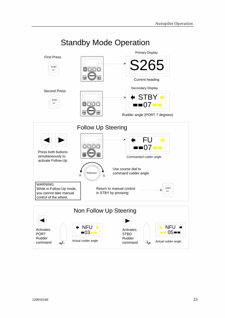
Follow-Up steeringWhen both the PORT and STBD push buttons are pressedsimultaneously the AP300X is set to Follow-Up steering mode andrudder commands can be set by the course dial. The commandedrudder angle is shown on the secondary display and the rudder willmove to the commanded angle and stop.
Non-Follow-Up steeringWhen the PORT or STBD push button is pressed separately, the actualrudder angle is shown on the secondary display and the rudder willmove as long as the button is pressed.
NFU Steering leverThe rudder will move when the lever is offset to Port or Starboard
Note ! When the NFU steering lever is operated, the control units become"Inactive".
Autopilot Operation
22081814H 23
Standby Mode Operation
STBYOFF S265
First Press
Current heading
07STBY
Second Press
Rudder angle (PORT 7 degrees)
STBYOFF
Follow Up Steering
07FU
Press both buttonssimultaneously toactivate Follow-Up
Commanded rudder angle
Use course dial to command rudder angle
WARNING: While in Follow-Up mode, you cannot take manual control of the wheel.
Return to manual controlin STBY by pressing:
RobertsonP S
Non Follow Up Steering
03NFUActivates
PORTRudder command
05NFUActivates
STBDRudder commandActual rudder angle Actual rudder angle
Primary Display
Secondary Display
STBYOFF

Robertson AP300X Autopilot
24 22081814H
R3000X Remote Control
Note ! When in AUTO mode,pressing the buttons willchange the set course 1° perpush. If you keep the buttonpressed, it will automaticallychange the course inincrements of 1°/second.
2.4 Automatic SteeringThe AUTO mode is used when the AP300X shall steer the boatautomatically on a set course. AUTO is always available from anymode or function within the AP300X by a single push on the AUTObutton. When the AUTO mode is selected, the AP300X automaticallyselects the current boat heading as the set course.
In AUTO, the AP300X is continually issuing rudder commands to thesteering gear to keep the boat on the set course. Determination of theboat heading is provided only by the RFC35 Fluxgate Compass (oroptional heading sensor) for course keeping in AUTO mode.
The AP300X will keep the boat on the set course until a new mode isselected (STBY, NAV, DODGE) or a new course is set with either thecourse dial or the PORT or STBD buttons
Once the course is changed to a new set course, the boat willautomatically turn to the new heading and continue to steer the newset course.
DodgingThe AP300X provides the capability for dodging. The Dodgingfunction allows the user to temporarily take manual control of theboat's steering, when steering automatically on a set course, and thenautomatically return to the previous set course.
Dodging is extremely useful in situations where you need to quicklytake control of the helm to steer around an obstruction, and then wishto return on the previous set heading after performing the evasivemaneuver. Dodging is activated by a single press on the DODGEbutton.
STBY-AUTO
REMOTE
R3000X
STBY/AUTO mode button.AUTO mode is when lamp is lit
Push buttons for Port andStbd NFU commands

Autopilot Operation
22081814H 25
Speed input source
Automatic Mode OperationFirst Press
Set course
AUTO
SPEED
Current heading
A265
11A- HI
LogHI speed parametersselected
AUTO
SPEED
Second Press
DODGE
TURN
AUTOSPEED
STBY
OFF
First Press
Selects AUTO modeat the previousset course
Selects AUTO modewith current headingas set course
Next Press
PORT STBDPress
U-TURN
Course changeCW: IncreaseCCW: Decrease
Course adjust1 degree/push
A265Quick double press
Press to select STBD U-turn
A085U-turn prompt New course
Boat makesSTBDU-turn
(Automatic steering by compass input only)
Dodging
U- turn
Regain manualsteering by pressing:
Decrease Increase
DODGE265
Wheel
or
or both
Non Follow Up
Follow Up
Present course
DODGETURN
Robertson
Robertson
DODGETURN
DODGETURN
Perform dodge using:
Robertson AP300X Autopilot
26 22081814H
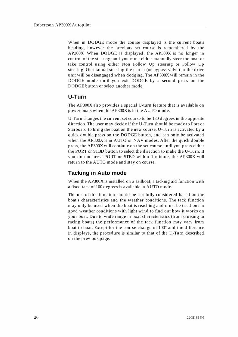
When in DODGE mode the course displayed is the current boat'sheading, however the previous set course is remembered by theAP300X. When DODGE is displayed, the AP300X is no longer incontrol of the steering, and you must either manually steer the boat ortake control using either Non Follow Up steering or Follow Upsteering. On manual steering the clutch (or bypass valve) in the driveunit will be disengaged when dodging. The AP300X will remain in theDODGE mode until you exit DODGE by a second press on theDODGE button or select another mode.
U-TurnThe AP300X also provides a special U-turn feature that is available onpower boats when the AP300X is in the AUTO mode.
U-Turn changes the current set course to be 180 degrees in the oppositedirection. The user may decide if the U-Turn should be made to Port orStarboard to bring the boat on the new course. U-Turn is activated by aquick double press on the DODGE button, and can only be activatedwhen the AP300X is in AUTO or NAV modes. After the quick doublepress, the AP300X will continue on the set course until you press eitherthe PORT or STBD button to select the direction to make the U-Turn. Ifyou do not press PORT or STBD within 1 minute, the AP300X willreturn to the AUTO mode and stay on course.
Tacking in Auto modeWhen the AP300X is installed on a sailboat, a tacking aid function witha fixed tack of 100 degrees is available in AUTO mode.
The use of this function should be carefully considered based on theboat's characteristics and the weather conditions. The tack functionmay only be used when the boat is reaching and must be tried out ingood weather conditions with light wind to find out how it works onyour boat. Due to wide range in boat characteristics (from cruising toracing boats) the performance of the tack function may vary fromboat to boat. Except for the course change of 100° and the differencein displays, the procedure is similar to that of the U-Turn describedon the previous page.

Autopilot Operation
22081814H 27
2.5 Navigating with the AP300XThe AP300X has the capability to use steering information from anexternal navigator (GPS, LORAN, Decca) or the NAV. computer inAP300DLX to direct the boat to a specific waypoint location, orthrough a route of waypoints. In the NAV mode, the AP300X uses theheading sensor as it's primary source of heading for course keeping.The steering information received from the external navigator altersthe set course to direct the AP300X to the destination waypoint.
Note ! Navigational steering must only be used in open waters. The process ofhaving an external navigation receiver direct an autopilot can be a slowacting process. By selecting the NAV mode, the AP300X is set for automaticsteering on the current set course and then waits for the user to accept thecourse change to the destination waypoint.
To obtain satisfactory navigation steering, the following points must befulfilled prior to entering the NAV mode:• The AP300X autosteering must be tested and found satsifactory.• The navigation receiver must be operating and the navigation
system (GPS, LORAN, Decca) must be in full operating mode withadequate signal characteristics for valid position and steering data.
• At least one waypoint must be entered and selected as the currentwaypoint in the navigation receiver.
• The navigation source in the AP300X USER SETUP menu must beset for the navigator that contains the current waypoint.
The AP300X is designed to steer in mixed mode operation. Thiscombines the straight steering capability of cross track error (XTE)steering in conjunction with the turning capability of bearing modesteering (CTS).
When operating the AP300DLX in NAV mode to automatically steerthrough a route of waypoints, the AP300X will steer to the firstwaypoint in the route after you accept the first waypoint as thelocation to steer to. When you arrive at the waypoint, the AP300X willdisplay an alert screen with the proposed new course informationdisplayed. You will need to verify that the upcoming course change isacceptable. Verification is performed by pressing the NAV button afterthe alert screen is displayed. If no verification is received, the AP300Xwill continue on the current set course in AUTO mode.
Note ! Steering through a route of waypoints with the AP300X allows you the totalflexibility for automatic waypoint sequencing, but combines the safetyfeature of requiring operator acknowledge for course changes in excess of 10degrees.

Robertson AP300X Autopilot
28 22081814H
Navigation Mode OperationFirst Press
(Automatic steering by compass and Nav source input)
N.02 Nm
Origin
Waypoint 2
OK:? Press NAVChg.Brg.WP: WP 002
094075
If required course changeis safe, press NAV to accept
New heading accepted automatically after NAV/SETUP button is pressed
At the arrival of each new waypoint in a route:
Waypoint arrival zone(determined by the navigator)
Waypoint 1
Third press
Prompt displayed to adviserequired course change
N .01 Nm
Regain manualsteering at anytime by pressing:
Refer to AUTO modefor details on dodging
Second press
OK:? Press NAVChg.Brg.WP: WP 001
135016 Required course change
Bearing WP-WP (leg)Waypoint Name
XTE Display
GPS1
N-HI136 1.25 Nm
Nav. Mode, HI speed param.
Bearing and distance to WP frompresent position
Nav source
XTE on WP2 track
Boat is .02 Nm to the leftof track.
NAVSETUP
NAVSETUP
NAVSETUP
NAVSETUP
STBYOFF
Selecting a different NavigatorIf you have more than one Navigation source connected to theAP300X, you will be able to choose any for Navigation. Refer to theUser Set-up menu for details on selecting a different Navigator.

Autopilot Operation
22081814H 29
Note ! If the AP300X is connected to a Nav. receiver that does not transmit amessage with bearing to next waypoint, it will pick a XTE message and steeron Cross Track Error only. In that case you have to revert to AUTO mode ateach waypoint and manually change set course to equal bearing to nextwaypoint and then select NAV mode again.
Dodging in Nav. modeFirst Press
Selects NAV modeat the current track
Selects AUTO modewith current headingas set course
Next Press
DODGE265
DODGETURN
NAVSETUP
Selects NAV mode at present position
DODGETURN
AUTOSPEED
Current heading
Wheel
or
or both
Non Follow Up
Follow UpRobertson
Perform dodge using:
2.6 Wind vane steeringIn order to enter WIND mode the AP300X system must be operating inAUTO, with valid input from the selected wind sensor. The WINDfunction is an alternative function to the NAV function and it is onlyavailable if the system has been set up for SAIL-boat in the InstallationSetup Menu, and NAV source is set to WIND under USER SETUPmenu. (Refer to page 34).
WIND function can only operate when reaching as it is necessary tohave a stable apparent wind. The sails should be trimmed so that theautopilot easily can steer the boat in AUTO mode and the signal fromthe masthead must give a stable signal.
Enter the WIND mode by pressing the NAV/SETUP button.
The pilot will take the apparent wind at the moment the WINDfunction is selected and enter it as the set apparent wind. From thatpoint the pilot will change the course to maintain this apparent windas the wind direction may change.
Note ! If the course change to maintain the apparent wind exceeds 15° from thevalue at the time the WIND mode was selected, a WIND SHIFT alarm willsound.
The primary display will show the set apparent wind angle.Adjustments to this set angle can be done by using PORT or STBDbutton, or by the rotary course selector.
When NAV button is pressed again the display will change to asecondary display showing WIND (mode) and rudder angle.

Robertson AP300X Autopilot
30 22081814H
Dodging while in the WIND mode is very similar to dodging while inthe AUTO or NAV modes. Refer to DODGE mode operation in theAUTO mode section on page 24.
Wind Vane Steering OperationFirst Press
Apparent wind angle set
Second Press
STBY
OFF
First Press
Selects WIND modeat the previousset course
Selects AUTO modewith current headingas set course
Next Press
Wind angle adjustCW: IncreaseCCW: Decrease
Adjust setwind angle1 degree/push
Quick double press
Press to select STBD Tack
Tacking prompt Wind mode on new Tack
Boat makesSTBDTack
(Automatic steering by compass and wind vane)
Dodging
Tacking
Regain manualsteering by pressing:
Decrease Increase
DODGE265
DODGETURN
Robertson
DODGETURN
DODGETURN
NAV
SETUP
NAV
SETUP
W 042
11WIND
NAV
SETUP
Selects WIND mode at the current set wind angle
DODGETURN
AUTOSPEED
W 042 W 042PORT STBD
PressTACK
Current heading
Wheel
or
or both
Non Follow Up
Follow UpRobertson
Perform dodge using:

Autopilot Operation
22081814H 31
Tacking in Wind modeIn WIND mode on sailboats there is also a tacking aid function. Thisfunction may only be used when the boat is reaching and will whenactivated take the boat from the course you are steering to thecomputed course that gives you the same apparent wind on the otherside.
This tacking function as compared to tacking in AUTO mode can onlybe used when you are sailing with the apparent wind as the reference(WIND mode), and with apparent wind angle less than 80-90 deg.
A quick double press on DODGE will activate the tack function whichwill prompt you for which way the tack should be performed. PressPORT or STBD to select the tack.
2.7 Automatic Speed selectionThe AP300X provides two different sets of steering parameters forcontrolling the response of the boat at different speeds (HI or LO)while in AUTO and NAV modes.
The AP300X always selects the HI speed steering parameters whenfirst switched on. This is a safety feature. After initial turn on, selectionof the steering parameters is done automatically, based on theavailability of input data from either an external speed log or anexternal navigator, or manually.
The AP300X automatically selects the HI or LO parameter set. Thespeed at which the AP300X changes from HI to LO (or opposite) isdetermined by the "Transition Speed" set in the Installation SetupMenu.
262422201816141210 8 6 4 2 0
HI speed parameters
LO speed parameters
Transition Speed set to 9 Knots
Example of Transition speeds withAUTOMATIC Speed parameterselection
Transition to HI parameterswith increasing speed: 10 Knots
Transition to LO parameterswith decreasing speed: 8 Knots

Robertson AP300X Autopilot
32 22081814H
Manual speed selectionSelect AUTO mode. Press the AUTO button a second time to displaythe secondary AUTO display. To toggle between HI and LO speedparameters, press the "AUTO" button two times quickly.
If you change boat speed it is recommended that you select HI or LOparameters correspondingly
Quick double press
01A- HI
MANDODGE
TURN
AUTOSPEED
01
A- LOMAN
The manually selected steering parameter set (HI or LO) will remain ineffect until you re-enter AUTO mode.
2.8 Multiple station systemIn normal operation of multiple control units, control is accessible fromevery control unit connected to the AP300X system. One control unit is"active" and provides the user with access to all functions and enablesthe user to change modes and set the course for automatic coursekeeping. All remaining control units are "inactive" and have no effecton mode changes or course selection. A single push of either the STBY(or AUTO) buttons on an "inactive" control unit will allow transfer ofcommand and make it "active".
2.9 Lock functionThe "LOCK" function is a safety feature included in the AP300X systemto disable all control units except for a single, user selected control unitlocation.
When the "lock" function is in use, no transfer of command may takeplace; only the "active" control unit stays in command.
To enable the "lock" function, select STBY mode, and make a quickdouble press on the STBY button.
DODGETURN
STBYOFF
S265
265
Key icon Alternating displays on “active unit”
The display on the "active" control unit will first show a single key iconfollowed by the primary display on which the key icon will alternatewith the mode index.
The "locked" control units in the system will show:
Quick doublepress

Autopilot Operation
22081814H 33
Inactive
S265
DODGETURN
STBYOFF
The “Lock” function is disengaged by the followingactions:
• The “active” control unit unlocks by a double presson the STBY button.
DODGETURN
STBYOFF
• The system is switched OFF by any control unit(press STBY for 3-5 seconds).
After having "unlocked" the other control stations, the "active" controlunit will show the above symbol before the display returns to normal.All other control units will return to the "inactive" state.

Robertson AP300X Autopilot
34 22081814H
2.10 The User Set-up Menu
- SETUP -
- SETUP -
- SETUP -
- SETUP -
- SETUP -
Backlight03
Contrast05
SeastateFilt.: OFF
NAV. source: GPS 1
POS. Source:GPS 1
NAVSETUP
NAVSETUP
SequencesFWD in MENU
SequencesBACK in MENU
Adjusts backlight of display and pushbuttons in 10 steps.(0 - dim, 10 - brightest). Setting is stored when system isturned off, and resets to stored level at turn on.Adjustment is local to the control head you adjust.Adjusts contrast of displays in 10 steps. Setting is storedwhen system is turned off, and resets to stored level atturn on. Adjustment is local.All steps not available at high temperature due toautomatic temperature compensation.
Selects the heading sensor used for AUTO steering.
Robertson
Scrolls through menuselections or setsvalue on menu items
Sets the Sea State filter.OFF: Provides precise steering but increases rudder activity.AUTO: Reduces rudder activity and reduces sensitivity of autopilot in rough weather automatically.MANUAL: Sets yawband manually.
OPTIONAL (only appears if configured for sailboat.Selects whether NAV mode pushbutton will activateNAVigation mode steering or WIND mode steering.
Selects the source for NAV mode steering asconfigured in the INSTALLATION SETUP. (AP300DLXalways appears even if AP300DLX is not connected in the system).
Selects the source of position data used by the AP300DLX.This option will appear whenever there is more than onenavigation receiver or position sensor connected to thesystem. Selection of POS source is required only when anAP300DLX is installed in the system, or if automatic speedselection (HI/LO) is taken from a position source.
The menu will disappear after 60 seconds if no key is pressed,or immediately if any mode key (STBY, AUTO, NAV) is pressed.
- SETUP -Select Comp.:RFC300 COMP.
- SETUP -NAV/WIND func
Navigation
Test functions for analysing system data.
NMEA TEST?
SYSTEM DATA?
Quick doublepress
Enter UserSetup Menu
Displays UserSet-up Menu
- SETUP -Backlight
03
Robertson
TOP
Robertson
Robertson
Robertson
Robertson
Robertson
Robertson
Robertson
Robertson
BACK FWD

Autopilot Operation
22081814H 35
2.11 AP300DLX Main featuresGraphic Display Section Autopilot Section
MENUMOB
Display -
NavigationComputer
RouteLibrary
Waypointstorage-bank(98 user inputwaypoints)
Data input from externalsources and AP300DLXNav. computer
N .02 NmRudder AngleHeadingSpeedDistanceWater Temp.Engine hoursWindPositionWaypoint infoRoute infoUTC timeLocal time
Position inputfrom external source(Loran C, GPS and Decca)
The AP300DLX autopilot control unit includes a variety of features inaddition to the autopilot control functions.• BAR graph presentation and digital readout of rudder angle• Digital and graphic readout of ship's heading• Digital and graphic readout of apparent and true wind• Digital readout of water depth and temperature, shallow water
alarm• Digital readout of speed log data, UTC, local time, engine hours
and water temperature• A full function navigation computer that provides the following:
− Display of ship's present position− Display of course over ground (COG) and speed over ground
(SOG)− Position source accepted from external equipment: Loran C,
GPS, Decca.− Instantaneous calculation and display of cross track error
(XTE), bearing and distance to any stored waypoint− Automatic calculation or manual input of Mag. variation (for
WPT calculations)− Save your present position as a waypoint− Storage of up to 100 waypoints in Lat/Lon (1 MOB, 1
Temporary, 98 user input).− Storage of up to 20 routes using any stored waypoints− Waypoints and route names with up to 8 alphanumeric
characters

Robertson AP300X Autopilot
36 22081814H
− Navigate directly to any previously stored waypoint or to atemporary waypoint
− Navigate through any route of waypoints stored in memory(forward or reverse)
− A unique "skip" feature to enable changing the next waypointwhen following a route
− Display of waypoint bearing in either Magnetic or True− Man over board (MOB) mode to automatically display
position, distance and bearing to MOB saved location.
• An X-Y PLOT mode that displays ships' position, waypointposition and plot line of the ship's movement.
Availability of data sourcesIn order to fully utilize the features of the AP300DLX, necessary sensordata (position, speed, depth, temperature, wind) must be available atthe system NMEA input port(s).
Use of external position sourcesThe AP300DLX navigator uses position information supplied by anexternal position source such as a Loran C or GPS as the basis for it'snavigation calculations. This is normally referred to as POS source andis the source where AP300DLX determines and displays Latitude,Longitude, Speed Over Ground (SOG) and Course Over Ground(COG). The accuracy of the calculations performed by the AP300DLXnavigator can only be as good as the position accuracy supplied by theexternal navigator.
JUNCTION UNIT
Selected position data Position data 2
AP300DLXCONTROL
UNITGPS
POSITION REFERENCESOURCE
POSITION REFERENCESOURCE
LORAN C
Position data 1
With the AP300DLX system, the possibility exists for multiple positionsources to be connected into the system. Having multiple positionsources (for example: Loran C, Decca and GPS), presents the ability toquickly switch from one navigation system to another in the event ofdegraded signal quality or position accuracy. In an instant, theAP300DLX will accept the new position sensor input, and continue toupdate the navigation calculations, both to the AP300DLX display andout to the autopilot.

Autopilot Operation
22081814H 37
2.12 Operation of Graphic DisplayThe AP300DLX Control Unit has an extra graphic LCD display.Controlled by the five push buttons under the display and autopilotcontrols, it can be programmed to show various information or to donavigation calculations and store waypoints and routes.
Softkeys
MENUMOB
Icon showing that Course Selector is transferred to graphic display operations.
RobertsonAP300X
WEST EAST
NORTH
00PLOT INSTR MOB INFO NAV
PORT STBD
Soft-keys below the LCD select the function as indicated on thedisplay. The text labels for each soft-key change to represent thefunction available under each level in the menu. The course selectorand PORT and STBD push buttons are also used for entering andselecting data in the nav computer.
Note ! When the Course Selector and PORT and STBD buttons are used to operatethe graphic display an icon will alternate with the present screen on theautopilot display. The course selector command is transferred back to theautopilot if an autopilot mode-button is pressed, or after a 60 sec. timeoutafter last operation on the graphic display
Heading and rudder information come from the autopilot system'sown sensors. Position input to the nav computer must be provided bydata from an external position source through the NMEA0183 ports inthe system.
Other information that can be presented on the graphic display mustbe provided by data from external sources through the NMEA0183ports in the system.

Robertson AP300X Autopilot
38 22081814H
The AP300DLX can access up to six different NMEA inputs and hascontrol for selecting which position source to use (one or two NMEAinputs are standard dependent on the type of junction unit installed, 4additional with optional NI300X. Incoming data is checked for statusand selected sentences of data from the selected position source arealso retransmitted on all NMEA outputs.
Graphic Display SetupWhen first initializing a system using an AP300DLX control unit, it isnecessary to set up items in addition to the autopilot setup listed in theInstallation Settings Menu.
At turn on of an AP300DLX the graphic display will show thefollowing screen for about 5 seconds followed by the MAIN DISPLAY(see previous page):
Magn. variation: None
Position source : GPS1Position offset : None
AP300DLXSoftware : V.R..
Access to the Graphic Display Setup menu is by pressing the followingsoftkeys:
PLOT INSTR MOB INFO NAV
MAINROUTE WAYPT GOTOSETUP
ESC MAIN
Magnetic Variation
ENTER
Position Correction
Waypoint Database
InstrumentsPlot interval
SETUP
Use or � to select menu item and press ENTER.
Norleiv Gudmestad
Norleiv Gudmestad
Norleiv Gudmestad
Autopilot Operation
22081814H 39
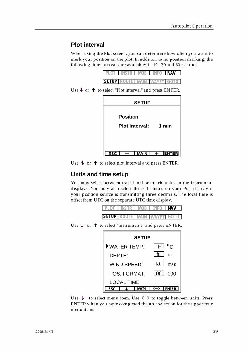
Plot intervalWhen using the Plot screen, you can determine how often you want tomark your position on the plot. In addition to no position marking, thefollowing time intervals are available: 1 - 10 - 30 and 60 minutes.
PLOT INSTR MOB INFO NAV
MAINROUTE WAYPT GOTOSETUP
Use or � to select "Plot interval" and press ENTER.
ESC MAIN ENTER
Position
Plot interval: 1 min
SETUP
Use or � to select plot interval and press ENTER.
Units and time setupYou may select between traditional or metric units on the instrumentdisplays. You may also select three decimals on your Pos. display ifyour position source is transmitting three decimals. The local time isoffset from UTC on the separate UTC time display.
PLOT IN S T R M OB INFO NAV
MAINROUTE WAYPT GOTOSETUP
Use or � to select "Instruments" and press ENTER.
ESC MAIN
WATER TEMP:
ENTER
DEPTH:
WIND SPEED:
POS. FORMAT:
SETUP
F Cft m
kt m/s
00' 000
LOCAL TIME:
Use to select menu item. Use �� to toggle between units. PressENTER when you have completed the unit selection for the upper fourmenu items.
Norleiv Gudmestad
Norleiv Gudmestad
Norleiv Gudmestad
Norleiv Gudmestad
Norleiv Gudmestad
Norleiv Gudmestad
Norleiv Gudmestad
Norleiv Gudmestad
Norleiv Gudmestad
Norleiv Gudmestad
Norleiv Gudmestad
Norleiv Gudmestad

Robertson AP300X Autopilot
40 22081814H
If you select the LOCAL TIME menu item and then press ENTER, thefollowing display will appear provided a sentence containing the UTCmessage is available at the NMEA input(s):
06
ESC MAIN ENTER
UTC TIME
LOCAL TIME24
07 40Use – or + to set your local time and press ENTER.
Position calibration
Note ! Entry of position calibration is optional and is not required unless yourposition source requires correction.
The AP300DLX has the capability to add correction toLatitude/Longitude data received from each position source. Thecorrection for each position source is entered individually and thecorrections are stored when the unit is switched off. The correction canbe made by adjusting the position to a known position, or by positionoffset specified in nautical charts.
If a position source input is corrected this will be indicated with a #when the position source is indicated.
Paper-charts very often use a different datum than the WGS84commonly used by GPS navigators. Some of the GPS' receivers havethe possibility to convert WGS84 position to the local datum used inyour chart. In case you use a "black box" GPS without this possibility,the corrections must be done by AP300DLX.
Example:
GPS position N 58°27.00', E 005°58.30' [ WGS 84 datum]
The chart is in European Datum ED50 with correction specified(relative to WGS84):
Latitude: N 0.03 Longitude: E 0.09
Added to the WGS84 it gives the ED50 position: N 58°27.03', E005°58.39'
This will be the corrected position read on AP300DLX.

Autopilot Operation
22081814H 41
To input or change a position from the main menu:
PLOT INSTR MOB INFO NAV
MAINROUTE WAYPT GOTOSETUPESC MAIN ENTER
Use or � to select "Position Correction" and press ENTER.
Position from Nav. receiver
Indicates thatposition iscorrected
ESC MAIN ENTER
GPS 1 POSITION #
N 58°27.00'E 05°58.30'
Return to SETUP menu
S 0°00.00'W 0°00.00'
SetCorrectPosition
DEL
Clear positioncorrection
Enter correct positionand leave menu
Change value,Lat., Long.
Advances cursor to next line
andchanges cursor field
Cursor
Note ! To clear the position correction, press the "DEL" key and press "ENTER".The # indication should be cleared when there is no correction.
Automatic MAGVAR calculationMagnetic variation (MAGVAR) is used in the calculation of bearing toa waypoint selected from the AP300DLX. MAGVAR is used to correctthe bearing calculation based on the type of heading sensor used inyour autopilot system. When using the RFC35 fluxgate compass or amagnetic compass, you should leave the MAGVAR set to AUTO. Thevalue is then calculated automatically, and is based on the positionfrom the POS source.
The AP300DLX also allows for manual input of MAGVAR, or to turnthe calculation of MAGVAR off. Manual input of MAGVAR may berequired in an area of the world where there is an unusual value ofmagnetic variation.
When a value of MAGVAR is used, (either AUTO or manual input),the bearing to WP and Course over Ground (COG) values will bedisplayed as magnetic values and will be identified with the letter "M"next to the course or bearing value.

Robertson AP300X Autopilot
42 22081814H
If the system includes a Robertson gyrocompass, the AP300DLX doesnot use the MAGVAR value when Gyro is selected as the currentheading sensor. COG and bearings will then be displayed as TRUEvalues, designated by the letter "T".
To view the current MAGVAR calculation method and MAGVARvalue:
PLOT INSTR MOB INFO NAV
MAINROUTE WAYPT GOTOSETUPESC MAIN ENTER
Use or � to select "Magnetic Variation" and press ENTER.
Leave the menu by pressing ESC or MAIN.
Magnetic Variation
OFFESC MAIN AUTOMANAUTO
14 WestMagnetic variation value
MAGVAR calculation mode:AUTOMANUAL
Select manualMagnetic variation Screen
Sets AUTOMATIC MAGVAR "ON"(Recommended setting)
Sets MAGVAR "OFF"
Manual input of MAGVAR
Note ! The manual input of MAGVAR is optional and only good for a limitednavigation area. As you travel to a new area (greater than 50 miles), it maybe necessary to reset the MAGVAR value. Refer to the nautical chart foryour cruising area to determine the correct MAGVAR value. Failure toinput correct MAGVAR will result in incorrect waypoint bearingcalculations.
To input or change the MAGVAR from the main menu:
PLOT INSTR MOB INFO NAV
MAINROUTE WAYPT GOTOSETUPESC MAIN ENTER
OFFESC MAN MAIN AUTO
Norleiv Gudmestad
Norleiv Gudmestad
Norleiv Gudmestad

Autopilot Operation
22081814H 43
Return SETUP toprevious menuwithout changingMAGVAR
Change Magnetic Variation 1 deg./push
Save magnetic variation and leave MENU.
Magnetic Variation
14 West
ESC MAIN EASTWEST ENTERMANUAL
To input 4° of westerly variation, press the WEST key 4 times, thenpress ENTER
Leave the menu by pressing ESC or MAIN.

Robertson AP300X Autopilot
44 22081814H
Clearing Waypoint Database
Note ! Clearing the Waypoint Database memory will wipe out all waypoint names,waypoint positions, and routes. If a single waypoint or small number ofwaypoints need to be changed or deleted, it is better to use the EDITWAYPOINTS feature. Clearing the Waypoint Database memory alsodeletes Position Offset and Depth Alarm limit!
Press ESC to cancelthe attempt to clear all waypoints
ESC MAIN
Waypoint Database:
ESC : CANCELENTER : Clear All WP
ENTER
MAINROUTE WAYPT GOTOSETUP
ESC MAIN
Waypoint Database:
INIT
INIT : Clear All WP :
Press ENTER to clear all waypoints
PLOT INSTR MOB INFO NAV
Use or to select "Waypoint Database" and press ENTER.

Autopilot Operation
22081814H 45
Displays and menu structureThe following display is presented approximately 5 seconds after theAP300DLX is turned on:
SelectX-Y plotter
Select Instruments:Compass Heading Apparent WindTrue WindSpeed and DepthTime
Memorize presentposition as "Man Over Board" position(5 second press)
Enter Nav-Computer Mode for navigation towaypoints, along routes etc.
MAIN SCREEN
Enter Waypoint Screen
WEST EAST
NORTH
05PLOT INSTR MOB INFO NAV
PORT STBD
Access to each of the submenus is indicated by prompt above each"softkey":
ESC MAIN GOTO
MOB POSITIONN 40°52.60'W 72°30.15'BRG 170 MDST 00.35 NM
ESC > < MAIN < > SCALE
PLOT GPS 1 #Position
N 40°52.60W 72°30.15
Scale32 Nm
AP300DLX Submenu Structure
INFO ScreenPLOT Screen Heading Screen MOB Screen
Pressing MAIN softkey onany menu always returns to the main menu and screen
Pressing ESC softkeyreturns to the previous level menu and screen.
HDG RUDD MAIN TIME NEXT
HEADING
180
1260
90270
RFC
MAIN
GPS 1 POSITION
N 40°52.60'W 72°30.15'
ESC
COG : - - - ° SOG : - - -Kt
POS
NAV. source: AP300DLXWP:BRG: °M DST: - - . - Nm
MENUMOB
Robertson
WEST EAST
NORTH
00
PLOT INSTR MOB INFO NAV
STBDPORT

Robertson AP300X Autopilot
46 22081814H
INFO and POS screensThe following display is accessed from the main menu by pressing theINFO softkey:
Positionsource(D denotesdifferential GPS)
Course & speed over groundcomputed bypos. source
Cross TrackError(boat 0.05Nmto the left of track).
MAIN
DGPS 1 POSITION
N 58°27.00'E 05°58.30'
0.05Nm
Own ship's present position
Bearing and distancefrom present positionto the waypoint
WP - name
Track
ESC
COG : 000° SOG : 10.00Kt
POS
NAV. source: AP300DLXWP: Buoy 4BRG: 049° DST: 0.8 Nm
Selected NAV. source
The Latitude, Longitude, COG, SOG are values supplied from theselected external position source. The Course Over Ground isdisplayed as the Magnetic course over ground when the selectedheading sensor is a fluxgate or magnetic sensor, or is shown as theTrue course when the heading sensor is selected as a gyro type. It maybe different from the instantaneous ship's heading.
By pressing the POS softkey on the WAYPOINT screen the followingdisplay is accessed:
ESC MAIN
GPS1 POSITION
N
E
58 27.0005 58.30
The Latitude and Longitude are values supplied from the externalposition source. The screen is very useful as a large digit positiondisplay.

Autopilot Operation
22081814H 47
Instrument displays and menuThe complete menu of instrument screens is shown below. The orderof appearance of the displays below the Heading Screen may vary.Press NEXT, if necessary, to find the screen you are looking for.
Press S/D key to accessShallow Water Alarm setting
Press ESC to return to Speed and Dept display
Use to set depthfor Shallow Water Alarm,then press ENTER.
Rob ertsonUse WIND to toggle between Apparent and True wind direction and speed.(True wind requires COGinput).
WEST EAST
NORTH
05PLOT INSTR MOB INFO NAV
STBDPORT
270 090
000
180
HDG RUDD MAIN TIME NEXT
RFC
HEADING
MAIN SCREEN HEADING SCREEN
Boats current heading
Rudder angle
Analogue cursor
Heading source
HDG RUDD MAIN TIME NEXT
RUDDER ANGLE
05°
TIME INSTR. DISPLAYRUDDER ANGLE INSTRUMENTDISPLAY
MAIN NEXT
SPEED
DEPTH
SHALLOWWINDLOGS/D
FT
KT
FT
MAIN
LOCAL TIME
00 00PASSAGE TIME
HDG NEXTTIMERUDD
10 22
10 032 8
MAIN ENTER
SPEED
DEPTH
SETSHALLOW
ESCFT
KT10 0FT32 8
21520.0
MAIN NEXT
LOG
WATER TEMP:WINDLOGS/D
NM
NM
F
TOTALDISTANCE
TRIPDISTANCE
ENGINE HOURS: Hr1034
73.7
0:14
MAIN
TRIP
NM
DISTANCE
TIME
0.0ESC RESET
090
000
180S/D LOG MAIN WIND NEXT
KT
090
TRUE WIND
3525
090
000
180S/D LOG MAIN WIND NEXT
KT
090
APPARENT WIND
0308
WIND INSTRUMENT DISPLAY LOG INSTRUMENT DISPLAYSPEED/DEPTHINSTRUMENT DISPLAY
Press ESC toreturn to LogInstrument Display
Press toreset theTrip display
Alarm is disabled when no value is set.
Robertson AP300X Autopilot
48 22081814H
2.13 WaypointsA waypoint is any position that you want to navigate to. It can be abuoy, the entrance to an inlet, a favorite wreck location, or anintermediate turning point 300 miles out in the ocean.
Three different types of waypoints are available in the AP300DLXnavigator:
Stored waypoints (98 are available), Temporary Waypoint (1 isavailable), and Man Over Board (MOB) waypoint.
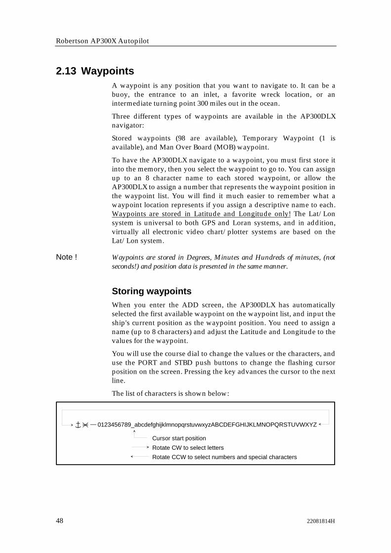
To have the AP300DLX navigate to a waypoint, you must first store itinto the memory, then you select the waypoint to go to. You can assignup to an 8 character name to each stored waypoint, or allow theAP300DLX to assign a number that represents the waypoint position inthe waypoint list. You will find it much easier to remember what awaypoint location represents if you assign a descriptive name to each.Waypoints are stored in Latitude and Longitude only! The Lat/Lonsystem is universal to both GPS and Loran systems, and in addition,virtually all electronic video chart/plotter systems are based on theLat/Lon system.
Note ! Waypoints are stored in Degrees, Minutes and Hundreds of minutes, (notseconds!) and position data is presented in the same manner.
Storing waypointsWhen you enter the ADD screen, the AP300DLX has automaticallyselected the first available waypoint on the waypoint list, and input theship's current position as the waypoint position. You need to assign aname (up to 8 characters) and adjust the Latitude and Longitude to thevalues for the waypoint.
You will use the course dial to change the values or the characters, anduse the PORT and STBD push buttons to change the flashing cursorposition on the screen. Pressing the key advances the cursor to the nextline.
The list of characters is shown below:
0123456789_abcdefghijklmnopqrstuvwxyzABCDEFGHIJKLMNOPQRSTUVWXYZ
Cursor start positionRotate CW to select lettersRotate CCW to select numbers and special characters
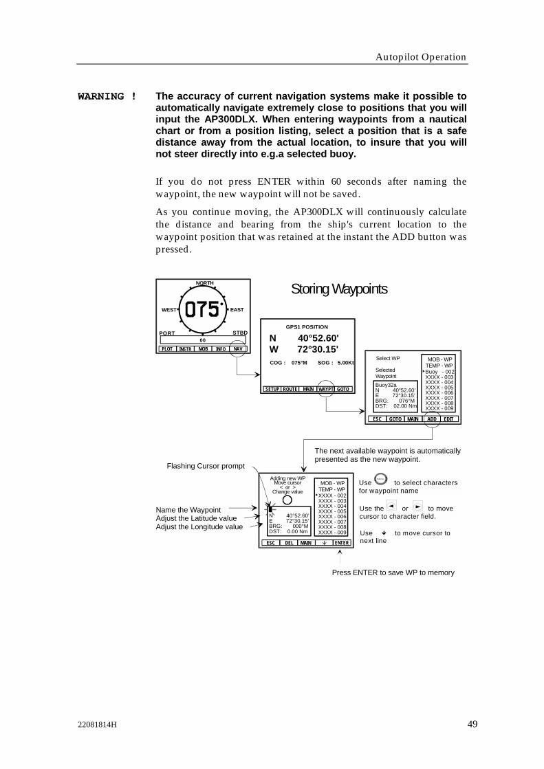
Autopilot Operation
22081814H 49
WARNING ! The accuracy of current navigation systems make it possible toautomatically navigate extremely close to positions that you willinput the AP300DLX. When entering waypoints from a nauticalchart or from a position listing, select a position that is a safedistance away from the actual location, to insure that you willnot steer directly into e.g.a selected buoy.
If you do not press ENTER within 60 seconds after naming thewaypoint, the new waypoint will not be saved.
As you continue moving, the AP300DLX will continuously calculatethe distance and bearing from the ship's current location to thewaypoint position that was retained at the instant the ADD button waspressed.
Storing Waypoints
Flashing Cursor prompt
The next available waypoint is automaticallypresented as the new waypoint.
Name the WaypointAdjust the Latitude valueAdjust the Longitude value
N 40°52.60'W 72°30.15'
MAIN
GPS1 POSITION
COG : 075°M SOG : 5.00Kt
ROUTE WAYPT GOTOSETUP
MOB - WPTEMP - WPBuoy - 002XXXX - 003XXXX - 004XXXX - 005XXXX - 006XXXX - 007XXXX - 008XXXX - 009
Buoy32aN 40°52.60'E 72°30.15'BRG: 076°MDST: 02.00 Nm
Select WP
SelectedWaypoint
ADDESC GOTO MAIN EDIT
MOB - WPTEMP - WPXXXX - 002XXXX - 003XXXX - 004XXXX - 005XXXX - 006XXXX - 007XXXX - 008XXXX - 009
ESC MAIN ENTERDEL
Adding new WPMove cursor
< or >Change value
Press ENTER to save WP to memory
WEST EAST
NORTH
00PLOT INSTR MOB INFO NAV
PORT STBD
N 40°52.60'E 72°30.15'BRG: 000°MDST: 0.00 Nm
Use to select characters for waypoint name
Robertson
Use to move cursor tonext line
Use the or to move cursor to character field.

Robertson AP300X Autopilot
50 22081814H
Saving Present Position to a Waypoint
The next available waypoint isautomatically presented as thenew waypoint with the ship'sposition that was valid at the time "ADD" was pressed.
N 40°52.60'W 72°30.15'
MAIN
GPS1 POSITION
COG : 075°M SOG : 5.00Kt
ROUTE WAYPT GOTOSETUP
MOB - WPTEMP - WPBuoy - 002XXXX - 003XXXX - 004XXXX - 005XXXX - 006XXXX - 007XXXX - 008XXXX - 009
Buoy32aN 40°52.60'E 72°30.15'BRG: 076°MDST: 02.00 Nm
Select WP
SelectedWaypoint
ADDESC GOTO MAIN EDIT
WEST EAST
NORTH
00
PLOT INSTR MOB INFO NAV
PORT STBD
Name the waypointDo not change Latitude or Longitude valuePress ENTER to save WP to memory
MOB - WPTEMP - WPXXXX - 002XXXX - 003XXXX - 004XXXX - 005XXXX - 006XXXX - 007XXXX - 008XXXX - 009
ESC MAIN ENTERDEL
Adding new WPMove cursor
< or >Change value
N 40°52.60'E 72°30.15'BRG: °MDST: Nm
Note ! SAVED waypoints are exactly the same as other stored waypoints, exceptthat the AP300DLX automatically sets the position, instead of having theuser dial in the waypoint position.

Autopilot Operation
22081814H 51
Editing Waypoints
N 40°52.60'W 72°30.15'
MAIN
GPS1 POSITION
COG : 075°M SOG : 5.00Kt
ROUTE WAYPT GOTOSETUP
MOB - WPTEMP - WPBuoy - 002XXXX - 003XXXX - 004XXXX - 005XXXX - 006XXXX - 007XXXX - 008XXXX - 009
Buoy32aN 40°52.60'E 72°30.15'BRG: °MDST: Nm
Select WP
SelectedWaypoint
ADDESC GOTO MAIN EDIT
WEST EAST
NORTH
00PLOT INSTR MOB INFO NAV
PORT STBD
Robertson
Waypoint NameWaypoint Latitude
Waypoint Longitude
Press the EDIT softkey after pointer is set to the waypointthat is to be edited.
To cancel editing and restore waypoint to previous name and position values beforethe ENTER softkey is pressed: Press "ESC" softkey.
To delete the waypoint and store a blank waypoint back to memory:Press "DEL" softkey.
Other Editing Options:
Editing allows you to change the Name, Latitude or Longitude value of a waypoint. Waypoints may be edited (changed) or deleted (erased).
Flashing Cursor prompt
Change waypointname (if desired)Adjust the Latitude valueAdjust the Longitude value
MOB - WPTEMP - WP
ESC MAIN ENTERDEL
Press ENTER to save WP to memory
Buoy 32aN 40°52.60'E 72°30.15'BRG: 000°MDST: 0.00 Nm
Select WP
SelectedWaypoint
Buoy - 002XXXX - 003XXXX - 004XXXX - 005XXXX - 006XXXX - 007XXXX - 008XXXX - 009
Use the or to move cursor to character field.
Use to move cursor tonext line
Use to scroll cursorthrough characters
Robertson
Turn to change pointerposition to point at waypoint to edit

Robertson AP300X Autopilot
52 22081814H
2.14 RoutesA route is composed of a number of waypoints that are already storedin the AP300DLX waypoint memory. The route system providesflexibility with a simple approach to adding, inserting, deletingwaypoints in any of the routes. The AP300DLX provides the ability tobuild up to 20 different routes and store the routes into memory.
You may swap the START and END points of the route, and alsospecify the NEXT point in the route. This allows you to specify thedirection to follow the route (forward or reverse), and also to skipquickly to an intermediate starting point if you do not want to followthrough the complete route.
Start
End
Route nameand waypoints
Canal1Buoy26LP BayNassau22Jessup17Noyack16
Peconic1
Waypoints are taken from the list of waypoints in the AP300DLX memory.
Forward direction
Canal1
Buoy26
LP Bay
Nassau22
Jessup17
Noyack16
Start
EndRoute: Peconic1
Following are some guidelines about the routes used in theAP300DLX:• Waypoints must be stored into the AP300DLX before a route can be
created.• Each route is identified with a name of up to 8 alphanumeric
characters.• Waypoints that are used as part of a route may be assembled in any
order.
You may edit a route to do the following:• Change the name of the route without affecting the route contents
• Add new waypoints to the end of the route.• Insert new waypoints in between any waypoints in the route.
• Delete any waypoints from the route.• Delete the entire route from memory.
Creating a routeCreation of a route involves the following steps:
• Assigning and entering a name for the route.
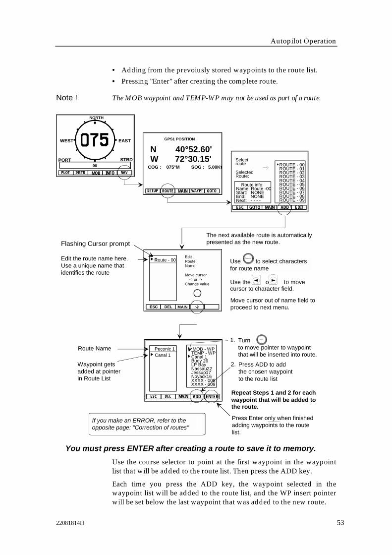
Autopilot Operation
22081814H 53
• Adding from the prevoiusly stored waypoints to the route list.• Pressing "Enter" after creating the complete route.
Note ! The MOB waypoint and TEMP-WP may not be used as part of a route.
Flashing Cursor prompt
Move cursor out of name field toproceed to next menu.
Edit the route name here.Use a unique name thatidentifies the route
Repeat Steps 1 and 2 for eachwaypoint that will be added tothe route.
Route Name
Press Enter only when finishedadding waypoints to the routelist.
Waypoint getsadded at pointerin Route List
You must press ENTER after creating a route to save it to memory.
WEST EAST
NORTH
00PLOT INSTR MOB INFO NAV
ROUTE - 00ROUTE - 01ROUTE - 02ROUTE - 03ROUTE - 04ROUTE - 05ROUTE - 06ROUTE - 07ROUTE - 08ROUTE - 09
Route info:Name: Route -00Start: NONEEnd: NONENext: - - - -
Selectroute
ESC ADD EDIT
SelectedRoute:
GOTO MAIN
The next available route is automaticallypresented as the new route.
1. Turnto move pointer to waypointthat will be inserted into route.
Robertson
Use the or to movecursor to character field.
If you make an ERROR, refer to theopposite page: "Correction of routes"
PORT STBD
Press ADD to addthe chosen waypointto the route list
2.
EditRouteName
Move cursor < or >Change value
ESC DEL MAIN
Route - 00
ESC DEL MAIN
Canal 1 MOB - WPTEMP - WPCanal 1Buoy 26LP BayNassau22Jessup17Noyack16XXXX - 008XXXX - 009
ADD ENTER
Peconic 1
Use to select charactersfor route name
Robertson
N 40°52.60'W 72°30.15'
MAIN
GPS1 POSITION
COG : 075°M SOG : 5.00Kt
ROUTE WAYPT GOTOSETUP
Use the course selector to point at the first waypoint in the waypointlist that will be added to the route list. Then press the ADD key.
Each time you press the ADD key, the waypoint selected in thewaypoint list will be added to the route list, and the WP insert pointerwill be set below the last waypoint that was added to the new route.
Robertson AP300X Autopilot
54 22081814H
Continue adding waypoints to the new route until you have createdthe complete route. Then press ENTER to save the route
Correction of routesDeleting waypoints from the route list does not affect the listing of thewaypoints in the waypoint memory. Use the PORT or STBD pushbuttons to move the pointer in the route list until you point at thewaypoint. Then press the DEL softkey. The waypoint will be removedfrom the route list, and all other waypoints in the list will be shifted upone location.
Inserting waypoints in a route list will add the new waypoint at thepointer in the route list. Present waypoint and all waypoints below willshift down one position in the list to make room for the new entry.
Replacing a waypoint in a list with a different waypoint name,requires that you add the new point and delete the old point.
When you are finished correcting the route, press ENTER to save thechanged route list.
2.15 Navigating with the AP300DLXThe AP300DLX has the ability to provide automatic navigation in thefollowing different ways:
• To a temporary waypoint (TEMP-WP)
• To a stored waypoint
• Through a route of waypoints
• To a special man overboard waypoint (MOB)
Note ! When navigating with the AP300DLX, a valid POS source must be selected.The AP300DLX will automatically be selected as NAV source whenoperating in NAV mode (ref. page 56 and 58).
WARNING ! Loran C and Decca have inaccuracies introduced by changes inthe signals when they travel overland. The corrections includedin most Loran sets to account for variations in the Lorantransmitted signals are called ASF (Additional Secondary phaseFactor) corrections. It is recommended that you verify theposition accuracy between the Loran and your actual position,and between the Loran and the GPS receiver(s) if you have morethan one position sensor on board.
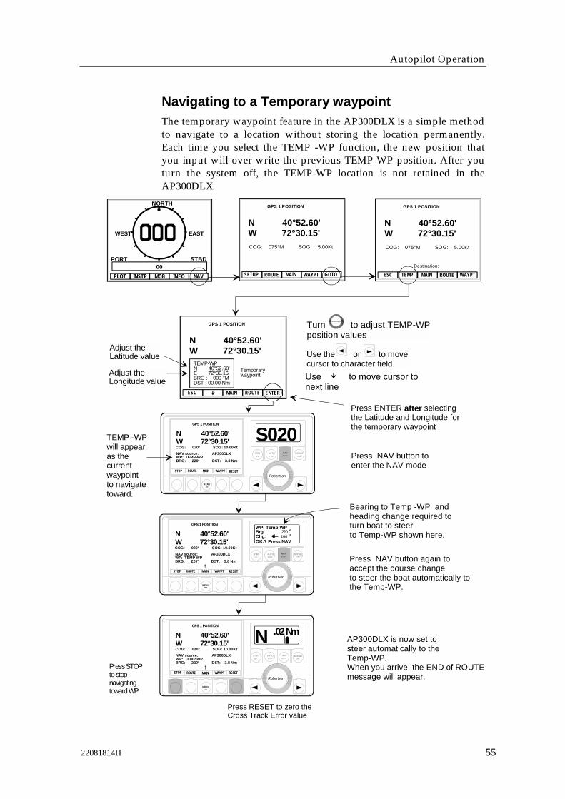
Autopilot Operation
22081814H 55
Navigating to a Temporary waypointThe temporary waypoint feature in the AP300DLX is a simple methodto navigate to a location without storing the location permanently.Each time you select the TEMP -WP function, the new position thatyou input will over-write the previous TEMP-WP position. After youturn the system off, the TEMP-WP location is not retained in theAP300DLX.
MENUMOB
Robertson
AUTOSPEED
DODGETURN
STBYOFF
S020Press NAV button toenter the NAV mode
MENUMOB
Robertson
AUTOSPEED
DODGETURN
STBYOFF
OK:? Press NAVChg.Brg.WP: Temp-WP
220160
Press ENTER after selecting the Latitude and Longitude for the temporary waypoint
Press RESET to zero the Cross Track Error value
Press STOPto stopnavigatingtoward WP
MAIN
GPS 1 POSITION
N 40°52.60'W 72°30.15'
ROUTE ENTERESC
TEMP-WPN 40°52.60'E 72°30.15'BRG : 000 °MDST : 00.00 Nm
Temporarywaypoint
AP300DLX is now set tosteer automatically to the Temp-WP.When you arrive, the END of ROUTEmessage will appear.
Bearing to Temp -WP andheading change required to turn boat to steerto Temp-WP shown here.
Press NAV button again toaccept the course changeto steer the boat automatically tothe Temp-WP.
TEMP -WPwill appearas the currentwaypointto navigatetoward.
Adjust the Latitude value
Adjust the Longitude value
NAVSETUP
NAVSETUP
MENUMOB
Robertson
AUTOSPEED
DODGETURN
NAVSETUP
STBYOFF
N .02 Nm
Turn to adjust TEMP-WPposition values
Ro bertso n
WEST EAST
NORTH
00PLOT INSTR MOB INFO NAV
PORT STBD
Use to move cursor tonext line
Use the or to move cursor to character field.
STOP MAIN RESET
GPS 1 POSITION
N 40°52.60'W 72°30.15'COG: 020° SOG: 10.00Kt
ROUTE WAYPT
NAV source: AP300DLXWP: TEMP-WPBRG: 220° DST: 3.8 Nm
STOP MAIN RESET
GPS 1 POSITION
N 40°52.60'W 72°30.15'COG: 020° SOG: 10.00Kt
ROUTE WAYPT
NAV source: AP300DLXWP: TEMP-WPBRG: 220° DST: 3.8 Nm
STOP MAIN RESET
GPS 1 POSITION
N 40°52.60'W 72°30.15'COG: 020° SOG: 10.00Kt
ROUTE WAYPT
NAV source: AP300DLXWP: TEMP-WPBRG: 220° DST: 3.8 Nm
GOTOMAIN
GPS 1 POSITION
N 40°52.60'W 72°30.15'COG: 075°M SOG: 5.00Kt
ROUTE WAYPTSETUPDestination:
TEMP MAIN
GPS 1 POSITION
N 40°52.60'W 72°30.15'
ROUTE WAYPTESC
COG: 075°M SOG: 5.00Kt

Robertson AP300X Autopilot
56 22081814H
Navigating to a stored waypoint
MENUMOB
Robertson
AUTOSPEED
DODGETURN
STBYOFF
S020Press NAV button toenter the NAV mode
MENUMOB
Robertson
AUTOSPEED
DODGETURN
STBYOFF
OK:? Press NAVChg.Brg.WP: Buoy 32a
220160
Press ENTER after the pointer is set to the correct waypoint.
Press RESET to zero the Cross Track Error value
Press STOPto stopnavigatingtoward WP
NAVSETUP
NAVSETUP
AP300DL is now set to actively steer automatically to the waypoint.When you arrive, the END of ROUTEmessage will appear.
Bearing to waypoint andheading change required to turn boat to steer to waypoint.
Press NAV button again toaccept the course changeto steer the boat automatically tothe waypoint.
WAYPOINTwill appearas the currentwaypointto navigatetoward.
N 40°52.60'W 72°30.15'BRG: °MDST: Nm
Buoy 32a
Select Wp -- >
ESC MAIN ENTER
MOB - WP
TEMP - WP
Canal1Buoy26LP BayNassau22Jessup17Buoy32aXXXX - 008
SelectedWaypoint
MENUMOB
Robertson
AUTOSPEED
DODGE
TURNNAVSETUP
STBYOFF
N .02 Nm
Turn to position pointer at waypoint you wish to steer toward.
Robertson
PORT STBD
WEST EAST
NORTH
00PLOT INSTR MOB INFO NAV GOTOMAIN
GPS 1 POSITION
N 40°52.60'W 72°30.15'COG: 075°M SOG: 5.00Kt
ROUTE WAYPTSETUPDestination:
TEMP MAIN
GPS 1 POSITION
N 40°52.60'W 72°30.15'
ROUTE WAYPTESC
COG: 075°M SOG: 5.00Kt
STOP MAIN RESET
GPS 1 POSITION
N 40°52.60'W 72°30.15'COG: 020° SOG: 10.00Kt
ROUTE WAYPT
NAV source: AP300DLXWP: Buoy32aBRG: 220° DST: 3.8 Nm
STOP MAIN RESET
GPS 1 POSITION
N 40°52.60'W 72°30.15'COG: 020° SOG: 10.00Kt
ROUTE WAYPT
NAV source: AP300DLXWP: Buoy32aBRG: 220° DST: 3.8 Nm
STOP MAIN RESET
GPS 1 POSITION
N 40°52.60'W 72°30.15'COG: 020° SOG: 10.00Kt
ROUTE WAYPT
NAV source: AP300DLXWP: Buoy32aBRG: 220° DST: 3.8 Nm

Autopilot Operation
22081814H 57
Arriving at a waypointThe AP300DLX uses one of the following criteria to determine that youhave arrived at a waypoint:
• When you are within 30 seconds of arriving at the waypoint. This isdetermined by the speed of the boat (provided by the speed overground data), and the distance to the waypoint.
or
• Passing the arrival perpendicular line to the waypoint
Waypoint
Arrival perpendicular
Waypoint passed
30 sec.Arrival zone
When you arrive at a waypoint (or pass it), the AP300DLX graphicdisplay will show the following:
ESC > < MAIN < > SCALE
PLOT GPS 1 #Position
N 40°52.60W 72°30.15
ArrivedTEMP-WPXTE : 0.05BRG : 049°MDST : 0.8 Nm
Scale32 Nm
or STOP MAIN RESET
GPS 1 POSITION
N 40°52.60'W 72°30.15'COG: 000° SOG: 10.0Kt
0.05NmROUTE WAYPT
NAV source: AP300DLXWP: ARRIVEDBRG: 049° DST: 0.8Nm
Upon arrival or passage of the waypoint, if the AP300DLX is currentlyin the NAV mode, the autopilot display will indicate END OF ROUTE.
The autopilot will then change back to the AUTO mode and accept thecurrent heading as the AUTO steering heading.

Robertson AP300X Autopilot
58 22081814H
Plotting with the AP300DLX
Zoom OUT(higher scale)
Ownship
Waypoint
Previousship's track
Plot Screen with NOwaypoint currently selected in AP300DLX
Plot Screen with waypoint (Temp-WP) selected in AP300DLX
Plot mode presents a temporary track plot of the ship's movement. Each time you access the PLOT mode, the screen is re-drawn with the boat's current position in the center of the screen.
If a waypoint is active in the AP300DLX, the ship's position and the waypoint position will automatically be shown in the lowest scale possible to display both ship and WP positions. As your position changes, the correct scale is automatically set to display both the ship's position and the waypoint position each time the SCALE key is pressed.
Ship's position
Autoscale:AP300DLX automaticallyselects the lowest scaleto display ship's positionand WP position on screen.
Zoom IN (lower scale)
Ship's position
Ownship
Previousship's track ESC > < MAIN < > SCALE
PLOT GPS 1Position
N 40°52.60W 72°30.15
Scale32 Nm
ESC > < MAIN < > SCALE
PLOT GPS 1 #Position
N 40°52.60W 72°30.15
WaypointTEMP-WPXTE : 0.05BRG : 59° MDST : 9.8 Nm
Scale32 Nm
Position marks(selectable)
Scale range: 0.5 Nm - 32 Nm
WEST EAST
NORTH
00PLOT INSTR MOB INFO NAV
PORT STBD
Note ! Each time the PLOT screen is re-drawn by changing scale, up to the last 10position marks will be automatically re-entered on the plot. The number ofre-entered position marks is dependent of the selected scale and the selectedtime interval between each position mark.

Autopilot Operation
22081814H 59
Navigating through a routeWhen you select the route screen, you are presented with a list of all ofthe available routes stored in the AP300DLX memory. The pointer (>)identifies the selected route. Turn the course dial clockwise to advancethrough the available routes, until you are pointing at the route namethat you wish to steer to.
Forward direction
Reverse direction
Canal1
Buoy26
LP Bay
Nassau22
Jessup
Noyack16
Start (end)
End (start)
Press soft key
Each time you access the route screen, you are provided with the routein a forward direction, the first waypoint in the route is the STARTpoint, and the last waypoint in the route is the END point.
You may swap the START and END points of the route by pressing.
The AP300DLX always selects the START point in the route as theNEXT point to steer to. When you change the direction of the route, theNEXT point to steer to will also change.
Press the ENTER key to begin navigating through the route.
The AP300DLX will begin calculation from the ship's current positionto the NEXT point in the route.
When the AP300DLX is advancing through a route, the only point ofinterest is the NEXT waypoint in the route. This waypoint is displayedon the graphic screen of the AP300DLX, and is the only point that isused for calculation of distance, bearing and cross track error (XTE).Each time you arrive at (or pass) a waypoint in a route, the AP300DLXwill automatically step to the following waypoint as the NEXTwaypoint in the route.
If the course change to the NEXT waypoint is more than 10 degreesfrom your present heading, the autopilot display will identify the newwaypoint by name, show the intended new heading and headingchange, and will wait for the user to press the NAV button toacknowledge the course change.

Robertson AP300X Autopilot
60 22081814H
The process that the AP300DLX sequences through waypoints in aroute is done automatically, but the autopilot commands requireoperator verification before a major course change is allowed. THIS ISA SAFETY FEATURE OF THE AP300DLX!
MENUMOB
Robertson
AUTOSPEED
DODGETURN
STBYOFF
S020Press NAV button toset the AP300DL into the NAV.mode
AP300DLX is now set to steer automatically to the NEXT WP in the route.When you arrive at each WP in the route, the previous screen will appear, on the autopilot display, again press NAV button to acknowledge the new heading.When you arrive at last WP in the route,the END of ROUTE message will appear.
Bearing to the NEXT WP andanticipated heading changerequired to turn boat to steerto NEXT WP shown here.
Press NAV button again toaccept the course changeto steer the boat automatically tothe NEXT WP in the Route.
NEXT WP inRoute will appearas the currentwaypointto navigatetoward.
M E N U
M O B
Robertson
AUTOSPEED
DODGETURN
STBYOFF
OK:? Press NAVChg.Brg.WP: Canal 1
220160
Press the ENTER softkey afterselecting the Route, setting the direction, and/or choosing next point .
M E N U
M O B
Robertson
AUTOSPEED
DODGE
TURNNAVSETUP
STBYOFF
N .02 Nm
Press RESET to zerothe Cross Track Error value
Press STOP tostop navigatingtoward WP
Select the direction to follow through the route using the <- -> softkey to swap the START and END points.
Change the next point in the route (if desired) by pressing NEXT.
Route Name
Start point in RouteEnd point in RouteNext point to steer to
Turn to move pointer to choose a Route.Robertson
Peconic1Canyon SBlock IsNantucketGardinersROUTE - 05ROUTE - 06ROUTE - 07ROUTE - 08ROUTE - 09
Selectroute
Route info:Name: Peconic1Start: Canal1End: Noyack16Next: Canal1
ESC MAIN NEXT ENTER
NAVSETUP
WEST EAST
NORTH
00PLOT INSTR MOB INFO NAV
PORT STBD
SETUPNAV
Destination:
TEMP MAIN
GPS 1 POSITION
N 40°52.60'W 72°30.15'
ROUTE WAYPTESC
COG: 075°M SOG: 5.00Kt
GOTO
GPS 1 POSITION
N 40°52.60'W 72°30.15'COG: 075°M SOG: 5.00Kt
ROUTE WAYPTSETUP
STOP MAIN RESET
GPS 1 POSITION
N 40°52.60'W 72°30.15'COG: 020° SOG: 10.00Kt
ROUTE WAYPT
NAV source: AP300DLXWP: Canal 1BRG: 220° DST: 3.8 Nm
0.02Nm
STOP MAIN RESET
GPS 1 POSITION
N 40°52.60'W 72°30.15'COG: 020° SOG: 10.00Kt
ROUTE WAYPT
NAV source: AP300DLXWP: Canal 1BRG: 220° DST: 3.8 Nm
0.02Nm
STOP MAIN RESET
GPS 1 POSITION
N 40°52.60'W 72°30.15'COG: 020° SOG: 10.00Kt
ROUTE WAYPT
NAV source: AP300DLXWP: Canal 1BRG: 220° DST: 3.8 Nm
0.02Nm
MAIN

Autopilot Operation
22081814H 61
Navigating using the MOB functionThe MOB function is a fast and easy method of temporarily savingpresent position. It is designed to be used in an emergency situationwhere it is critical to return to the exact location where an incidentoccurred.
Note ! The MOB feature will only function when the position source is operatingand sending the AP300DLX valid position data.
The use of MOB function is intended to supplement standardlifesaving measures.
In an emergency man overboard situation, the MOB function shouldonly be used if:
• It can be activated without losing eye contact with the person in thewater.
• Only if MOB can be activated without inhibiting the rescuemaneuver to turn the boat.
• Only when the position source is the best reference for navigation.
When an MOB position is entered, it can easily be selected as theGOTO position. The MOB position is also temporarily stored in thewaypoint list, and will be retained until the AP300DLX is turned OFF.
To access the MOB function from any screen or menu in theAP300DLX - Press and hold the main (MOB) push button until thefollowing screen is presented:
ESC MAIN GOTO
MOB POSITIONN 40°52.60'W 72°30.15'BRG 170 MDST 00.35 NM
To go to the MOB location - Press GOTO
Caution ! To become familiar with the operation and capability of the MOBfunction, it is recommended to use MOB in other situations whereyou want to memorize present position temporarily and return to itimmediately.

Robertson AP300X Autopilot
62 22081814H
MOB (Man over Board)
Press and hold MOB softkeyfor 5 seconds to activateMOB function.
Press GOTO to have AP300DLXset to navigate to the MOB point.
MENUMOB
Robertson
AUTOSPEED
DODGETURN
STBYOFF
STOP MAIN RESET
S020Press NAV button toenter the NAV mode
Press NAV button again toaccept the course changeto steer the boat automatically tothe MOB waypoint.
MOB screen shows the position andthe bearing and distance to the MOBpoint.
AP300DLX is now set toactively steer automaticlly to theMOB waypoint.
Bearing to MOB point andheading change required toturn boat to steer to MOB point
MENUMOB
Robertson
AUTOSPEED
DODGETURN
STBYOFF
OK:? Press NAVChg.Brg.WP: MOB
359009
STOP MAIN RESETROUTE WAYPT
MENUMOB
Robertson
AUTOSPEED
DODGETURN
NAVSETUP
STBYOFF
STOP MAIN RESETROUTE WAYPT
N .05 Nm
ESC MAIN GOTO
MOB POSITIONN 40°52.60'W 72°30.15'BRG 170 MDST 00.35 NM
NAVSETUP
MOB POSITIONN 40°52.60'W 72°30.15'
BRG 170 MDST 00.35 NM
MOB POSITIONN 40°52.60'W 72°30.15'
BRG 170 MDST 00.35 NM
MOB POSITIONN 40°52.60'W 72°30.15'
BRG 170 MDST 00.35 NM
NAVSETUP
WEST EAST
NORTH
00
PLOT INSTR MOB INFO NAV
PORT STBD

Autopilot Operation
22081814H 63
2.16 GlossaryASF corrections, Loran - Additional secondary phase factor is theamount in microseconds, by which the time difference of an actualLoran signal that has traveled over varied terrain, differs from that ofan ideal signal over an all-seaweather path. (ie. Loran signals travelslower over ground). The ASF correction is a value added (orsubtracted) to a measured Loran position, to attempt to restore theposition accuracy.
Chart Datum - A geographic reference system based on mathematicalmodels of the earth's shape is the basis for mapping and chartingpositions in Latitude and Longitude. There are a number of localreference datums, each with its own mathematical model of the earth.Therefore, the position in one reference system does not coincide withthat determined from another reference system. Each chart lists theDatum used.
COG - Course Over Ground - The actual direction of progress of avessel, between two points, with respect to the surface of the earth, Thevessels heading may differ from the course over ground due to theeffects of wind, tide, currents.
GPS - Global Positioning System - This system consists of 18 satellitesplus 3 spares in fixed orbits, circling the earth at an altitude ofapproximately 20,200 km. The system will provide the user with 24hour a day all weather position coverage, with an accuracy of 15 to 100meters.
Loran C - A complex radio navigation network developed by the UScoast guard, to assist a navigator in determining his precise location.The acronym, Loran C, stands for Long Range Navigation. It is an allweather 24 hour a day electronic system of shore based radiotransmitters.
Magnetic variation - A magnetic compass points to the magnetic northpole. The difference between this direction and true north is themagnetic variation. The amount and direction of this variation isdependent upon where on the earth you are located.
NMEA 0183 - A format (language) designed to permit communicationbetween various types of marine electronic equipment. In essence thisis a two-wire shielded, serial data link, permitting one device to talkwhile other devices listen. Numerous different sentences are available,permitting communication between various different devices.
Route - A stored sequence of waypoints. These waypoints will belisted in the order in which you desire to follow them. The AP300DLXpermits the storage of up to 20 routes.
SOG - Speed over ground is the actual speed of the vessel relative tothe ocean floor.

Robertson AP300X Autopilot
64 22081814H
Waypoint - A discrete point, stored in a navigator, located on thesurface of the earth. Normally this point will be identified by Lat/Loncoordinates although in some systems it may be shown by T.D.'s. TheAP300DLX has the capability of storing 98 waypoints.
XTE - Cross Track Error - Used to identify a vessels position relative toa straight line drawn between two waypoints. The amount the vessel isoff to the left or to the right of this line is known as the track. It isnormally displayed in hundredths of a nautical mile, equal to 60 ft.
UTC - Universal Time Coordinated - Transmitted from satellites toGPS receivers as the universal time reference for the Global PositioningSystem.

Installation
22081814H 65
3 INSTALLATION
3.1 GeneralThis section provides detailed information required to successfullyinstall AP300X Autopilot system
The AP300X system includes several modules that need to be mountedin different locations on the boat, and also need to interface with atleast three different systems on the boat:• The boat's steering system• The boats electrical system (input power)• Other equipment on board (NMEA interfacing)
In addition, the advanced capabilities of the AP300X require theinstaller to perform a series of settings and tests to verify properoperation of the system, refer to the checklist below.
Installation checklist1. Determine system configuration you are installing (Page 66)
2. Perform the hardware installation (Page 69)
3. Connect external NMEA devices (inputs and outputs, page 84)
4. Set Language (Page 95)
5. Dockside settings (Page 95)a. Boat type selectionb. Drive unit selectionc. Rudder feedback calibrationd. Automatic rudder teste. Transition Speed
6. Interface setup for Junction Unit, NI300X and CI300X if installed(Page 100)
7. Perform settings in User Setup Menu (Page 34, for NAV source andPOS source)
8. Dockside Autopilot tests (refer to Operation Instructions, page 21)a. Test all stations (if applicable) - lock/unlock - active/inactiveb. Test Non-Follow Up modec. Test Follow-Up moded. Test AUTO modee. Test NAV mode and input interfaces (if connected) including
optional heading sensorsf. Test interface outputs to external equipment (if connected)

Robertson AP300X Autopilot
66 22081814H
9. Seatrial settings (Page 103)a. Set rudder zerob. Compass calibrationc. Compass Offset adjustmentd. Automatic tuning (Optional: does not need to be done)e. Viewing parameters
10. Testing Autopilot Operation at Sea (refer to Sea Trial instructions,page 109)
11. Test the AP300DLX Navigation Computer
12. Provide the user with training (Page 109)
Unpacking and handlingCare should be taken when unpacking and handling the equipment. Avisual inspection should be made to see that the equipment has notbeen damaged during shipment and that all components and parts arepresent according to the packing list.
A standard scope of supply for an AP300X system will include:
• Control unit (AP300CX, AP300DLX, AP300PX) with standardinstallation accessories.
• Junction unit (J300X, J300X-40, J3000X) and one 15 m (49') Robnetcable.
• RFC35 Fluxgate Compass with 15 m (49') cable attached.
• RF300 Feedback unit with 10 m (33') cable attached andtransmission rod.
• Appropriate drive unit for the installation (unless the AP300X isgoing to operate an existing drive unit)
• Optional equipment that may have been ordered for theinstallation.
Determine system configurationIt is important to become familiar with the configuration of the systemprior to beginning the installation. The diagrams presented on page 67to page 68 provide sample system configuration drawings. With theflexibility of the AP300X system, your specific installation may includeall or part of one of the sample diagrams.
Pay particular attention to the junction unit/drive unit combinationson page 73 and the chart on page 12.
As many of the units are communicating on a common network(ROBNET), with identical connectors, the installation is simplified. Tryto mount the units within the standard cable length supplied with eachunit, if possible. ROBNET Extension Cable (10m) is available from yourdistributor.

Installation
22081814H 67
AP300X Basic system
RFC35ELECTRONIC
FLUXGATECOMPASS
REVERSIBLEPUMP
RF300RUDDER
FEEDBACK
JUNCTIONUNIT
AP300CXCONTROL UNIT
15 m (49')
ROBNET Network Cable
Other cable
10 m (33')
15 m (49')
MAINS POWER SUPPLY10-40 VDCNote
Note: 10 - 28 VDC Mains with J3000X
AP300X multistation system with optional driveunits
SOLENOIDVALVE
S3STEERING
LEVER
RFC35ELECTRONIC
FLUXGATECOMPASS
REVERSIBLEPUMP
RF300RUDDER
FEEDBACK
JUNCTIONUNIT
AP300DLXCONTROL
UNIT
AP300PXCONTROL UNIT
AP300CXCONTROL UNIT
7 m (23')
15 m (49')
ROBNET Network Cable
Other cable
10 m (33')
15 m (49')
7 m (23')
MAINS POWERSUPPLY
R2500REMOTE
CONTROL
HYDRAULIC LINEARDRIVE UNIT
EXTERNALALARM *
RADARCLOCK/DATA *
Only on J300X and J300X-40*

Robertson AP300X Autopilot
68 22081814H
AP300X system with compass interface options
RFC35ELECTRONIC
COMPASS
RPU160REVERSIBLE
PUMP
RF300RUDDER
FEEDBACK
JUNCTIONUNIT
AP300DLXCONTROL
UNITAP300CXCONTROL
UNIT
7 m (23')
15 m (46')
ROBNET Network Cable
Other cable
10 m (33')
15 m (46')
7 m (23')
MAINS POWER SUPPLY
BOAT'SMAGNETICCOMPASS
CI100XCOMPASS
INTERFACE
RGC50GYRO COMPASS
BOAT'SMAGNETICCOMPASS
CDI35COURSE
DETECTORINTERFACE
AP300X system with NAV interface options
RFC35ELECTRONIC
COMPASS
REVERSIBLEPUMP
RF300RUDDER
FEEDBACK
JUNCTIONUNIT
AP300DLXCONTROL
UNIT
7 m (23')
15 m (46')
10 m (33')
15 m (46')
MAINS POWER SUPPLY
GPS 1
GPS 2
LORAN C
RADAR
NI300XNMEA
INTERFACE
DATALINEDATABOX
DATALINESENSORS
WIND
DEPTH
SPEED
RUDDERINSTRUMENT
AP300DLXCONTROL
UNIT
NMEA
NMEA
NOTE! 2 NMEA input/output ports on J300X and J300X-40 only.
ROBNET Network Cable
Other cable

Installation
22081814H 69
3.2 RF300 Rudder feedback installationThe RF300 Rudder feedback unit mounts close to the rudders, and ismechanically linked to the rudder tiller arm or rudder quadrant.
Refer to Figure 3-1 for the recommended mountingarrangement. Note that the RF300 transmitter arm has two slots for thetransmission link. The slots enable maximum flexibility to provide the1:1 mechanical linkage relationship.
Note ! Do not try to remove the transmitter arm from the feedback unit. The unit isfactory adjusted and need no further adjustment at installation thandescribed below.
As a starting point, it is desirable to set the transmitter rod to the innerlimit of the outer slot if possible. (Refer to Figure 3-1). Drill andtap the rudder tiller arm so that the Y1 dimension is equal to the Y2dimension (Use 4.2 mm drill and 5 mm tap). Attach the ball joint to thetiller arm, and connect the transmitter rod to the ball joint at the ruddertiller arm.
Turn the helm wheel to set the rudder tiller arm to approximate centerposition.
Rotate the RF300 transmitter lever until it is also set to center position.(A simple method is to line up the transmitter lever to be opposite thecable entry into the feedback.)
Figure 3-1 RF300 Rudder Feedback mounting
Attach the transmitter rod to the RF300. Set the RF300 mountinglocation to be in accordance with Figure 3-1. The center of theRF300 should be in line with the center of the rudder post. Mount theRF300 to a suitable platform using the screws provided. If necessary,add blocking material under the RF300 to adjust the height of thetransmission arm to be level with the rudder tiller arm.
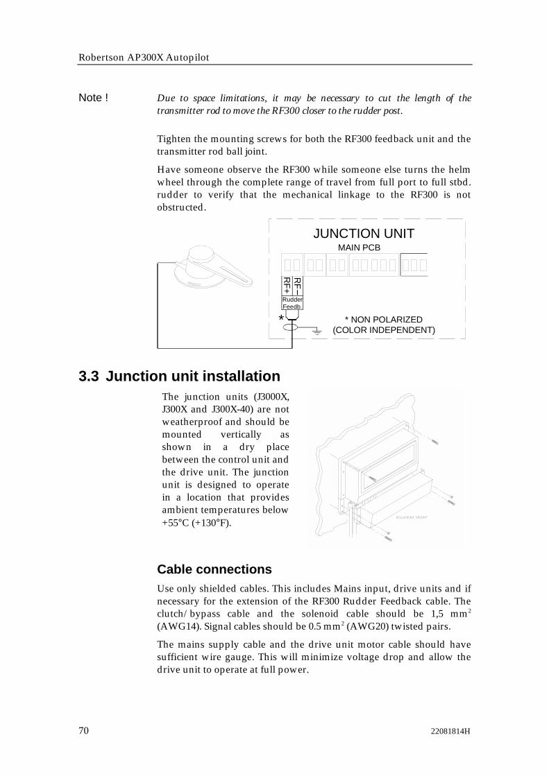
Robertson AP300X Autopilot
70 22081814H
Note ! Due to space limitations, it may be necessary to cut the length of thetransmitter rod to move the RF300 closer to the rudder post.
Tighten the mounting screws for both the RF300 feedback unit and thetransmitter rod ball joint.
Have someone observe the RF300 while someone else turns the helmwheel through the complete range of travel from full port to full stbd.rudder to verify that the mechanical linkage to the RF300 is notobstructed.
JUNCTION UNITMAIN PCB
RudderFeedb.
* * NON POLARIZED(COLOR INDEPENDENT)
RF+
RF
3.3 Junction unit installationThe junction units (J3000X,J300X and J300X-40) are notweatherproof and should bemounted vertically asshown in a dry placebetween the control unit andthe drive unit. The junctionunit is designed to operatein a location that providesambient temperatures below+55°C (+130°F).
Cable connectionsUse only shielded cables. This includes Mains input, drive units and ifnecessary for the extension of the RF300 Rudder Feedback cable. Theclutch/bypass cable and the solenoid cable should be 1,5 mm2
(AWG14). Signal cables should be 0.5 mm2 (AWG20) twisted pairs.
The mains supply cable and the drive unit motor cable should havesufficient wire gauge. This will minimize voltage drop and allow thedrive unit to operate at full power.

Installation
22081814H 71
Refer to the table below for recommended cable sizes.
Cable length Drive Unit Voltage
12 V 24V1. Distribution Board to Junction Unit.
2. Junction Unit to Drive Unit motor(Length refers to each of the twocables)
AWG mm2 AWG mm2
Up to 3 m (10 ft.) 12 2,5 12 2,5
Up to 6 m ( (20 ft.) 10 4 10 2,5
Up to 10 m (32 ft.) 8 6 10 4
Up to 16 m (52 ft.) 6 10 8 6
Grounding and RFIThe AP300X system has very good RFI protection and all units areusing the Junction Unit as common ground/shield connection. TheJunction Unit should therefore have a proper ground connection to thehull.
ROBNET cables and other signal cables (compass, feedback, NMEA)should not be run in parallel with other cables carrying RF or highcurrent, such as VHF and SSB transmitters, battery chargers/generators and winches.
Remove the bottom cover to get access to the plug-in terminals. Stripabout 1 cm (0.4") of the cable's insulation and pull the screenbackwards to cover the insulation. Position the straps as shown andthighten well to make sure the screen has good contact.
Leave sufficient free wires so that the plug-in terminals can be easilyconnected/disconnected.
Note!
The Mains input isnot polarity protectedon J300X-40.
Ground terminal

Robertson AP300X Autopilot
72 22081814H
Pull out each terminal before connecting the wires. Remove all strandsbefore putting on the terminal cover.
3.4 Drive unit installationThe relation between drive units, drive unit voltage, input voltage,drive output and interfacing to steering gear are shown in the tablebelow. The AP300X system detects whether a reversible motor or asolenoid is connected and outputs the correct drive signalautomatically.
Refer to the connecting diagram for the different drive units on page 74onwards. Pay particular attention to the difference in connecting areversible motor as compared to solenoids.
Installation instruction for the drive units are found in the manual forthe individual units.
Robertson Drive Unittype
Drive unitvoltage
Input voltage(Mains)
Drive output Interface tosteering gear
RPU80, RPU100,RPU150, RPU160,RPU300(Reversible hydraulicpump)
12V 12, 24,32V Proportionalrate
Hydraulicplumbing
RPU200,(Reversiblehydraulic pump)
24V 24, 32V Proportionalrate
Hydraulicplumbing
HLD350,HLD2000HLD2000D(Hydraulic lineardrive)
12V12V24V
12, 24, 32V12, 24, 32V24, 32V
12V to Bypass12V to Bypass12V to BypassProportionalrate to motor,
Directmechanicalconnection torudder tillerarm
MRD100(Reversiblemechanical drive)
12V24V
12, 24, 32V24V, 32V,
12V to clutch24V to clutchProportionalrate to motor
Chain/sprockets
MRD150 12V32V
12, 24V32V
12V to clutch32V to clutchProportionalrate to motor
Chain/sprocket
RPU1/RPU3(Continuous runninghydraulic pump)
12V24V32V
12V24V32V
12V24V32V(Solenoids)
Hydraulicplumbing
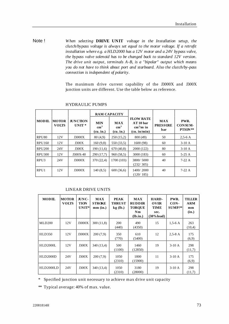
Installation
22081814H 73
Note ! When selecting DRIVE UNIT voltage in the Installation setup, theclutch/bypass voltage is always set equal to the motor voltage. If a retrofitinstallation where e.g. a HLD2000 has a 12V motor and a 24V bypass valve,the bypass valve solenoid has to be changed back to standard 12V version.The drive unit output, terminals A-B, is a "bipolar" output which meansyou do not have to think about port and starboard. Also the clutch/by-passconnection is independent of polarity.
The maximum drive current capability of the J3000X and J300Xjunction units are different. Use the table below as reference.
HYDRAULIC PUMPS
RAM CAPACITY
MODEL MOTORVOLTS
JUNCTIONUNIT *
MINcm3
(cu. in.)
MAXcm3
(cu. in.)
FLOW RATEAT 10 barcm3/m in
(cu. in/min)
MAXPRESSURE
bar
PWR.CONSUM-
PTION**
RPU80 12V J3000X 80 (4,9) 250 (15,2) 800 (49) 50 2,5-6 A
RPU160 12V J300X 160 (9,8) 550 (33,5) 1600 (98) 60 3-10 A
RPU200 24V J300X 190 (11,6) 670 (40,8) 2000 (122) 80 3-10 A
RPU300 12V J300X-40 290 (17,7) 960 (58,5) 3000 (183) 60 5-25 A
RPU3 24V J3000X 370 (22,4) 1700 (103) 3800/5000(232/305)
40 7-22 A
RPU1 12V J3000X 140 (8,5) 600 (36,6) 1400/2000(120/185)
40 7-22 A
LINEAR DRIVE UNITS
MODEL MOTORVOLTS
JUNC-TIONUNIT*
MAXSTROKEmm (in.)
PEAKTHRUSTkg (lb.)
MAXRUDDERTORQUE
Nm(lb.in.)
HARD-OVERTIME
sec.(30% load)
PWR.CON-
SUMP.**
TILLERARMmm(in.)
MLD200 12V J3000X 300 (11,8) 200(440)
490(4350)
15 1,5-6 A 263(10,4)
HLD350 12V J3000X 200 (7,9) 350(770)
610(5400)
12 2,5-8 A 175(6,9)
HLD2000L 12V J300X 340 (13,4) 500(1100)
1460(12850)
19 3-10 A 298(11,7)
HLD2000D 24V J300X 200 (7,9) 1050(2310)
1800(15900)
11 3-10 A 175(6,9)
HLD2000LD 24V J300X 340 (13,4) 1050(2310)
3180(28000)
19 3-10 A 298(11,7)
* Specified junction unit necessary to achieve max drive unit capacity
** Typical average: 40% of max. value.

Robertson AP300X Autopilot
74 22081814H
Connecting a reversible pump
Robertsonreversible
pump
JUNCTION UNITPOWER PCB
TB1 TB2 TB3 TB4 TB5
TB6
Sol. -Motor
Sol. -Motor
Connecting a hydraulic linear drive
JUNCTION UNITPOWER PCB
TB1 TB2 TB3 TB4 TB5
TB6
BypassClutch
Sol. -Motor
Sol. -Motor
TB7
HYDRAULICLINEAR DRIVE
Single poleclutch/bypass
switch
Connecting a solenoid valve
JUNCTION UNITPOWER PCB
TB1 TB2 TB3 TB4 TB5
TB6
SOLENOIDVALVE
Sol. -Motor
Sol. -Motor
Sol. gnd
TB7
Sol. Sol.Sol. gnd

Installation
22081814H 75
3.5 Control unit installationAvoid mounting the control unit(s) where it is easily exposed tosunlight, as this will shorten the lifetime of the displays. If this is notpossible, make sure the units are always covered with the whiteprotection cover when not used.
Figure 3-2 AP300CXBulkhead mounting
Figure 3-3 AP300DLX Bulkheadmounting
• Drill holes for the connectors and the 2 fastening screws (4x25mm)by using the panel mounting template as a guide. Make sure there isenough space behind the panel for the cables/connectors.
• Screw the 2 fastening screw studs into the 2 holes at the back of theControl unit (They will easily self-tap into the plastic).
• Connect the Robnet cables to the control unit connectors. Insert thescrew studs into the holes in the panel.
• Thread the two plastic "finger nuts" onto the screw studs from theback side and tighten them by hand. USE NO TOOLS!
Figure 3-4 AP300CXBracket mounting
Figure 3-5 AP300DLX Bracketmounting
• Mount the two bracket halves to the Control unit.
• Temporarily bolt together the other two halves of the bracket to thetwo other halves.

Robertson AP300X Autopilot
76 22081814H
• Hold the Control unit in place by hand and mark the 4 holes for thefixing screws on the mounting surface.
• Remove the Control unit, drill the 4 mounting holes in themounting surface.
• Unbolt the temporarily fitted bracket halves and screw them to themounting surface.
• Assemble the complete bracket again and adjust the control head tobest viewing angle and tighten up the mounting bracket bolts.
• Connect the Robnet cables to the control unit connectors
Figure 3-6 AP300CX Bezeltop mounting
Figure 3-7 AP300DLX Bezel topmounting
• Use the supplied AP300/AP300DL BEZEL MOUNTING CUT-OUTtemplate to make the exact cut out for the connectors. Fasten thebezel to the panel by the 4 (6) countersunk screws. (Numbers inbrackets are for AP300DL).
• If watertight mounting is required, add some silicon around themounting bezel flange before mounting.
• Carefully tighten the screws making sure the bezel is not bent.
• Set the large "O-Ring" around the inside lip of the control headmounting flange.
• Connect the Robnet cables to the control unit connectors.
• "Snap" the Control unit into the bezel mount.

Installation
22081814H 77

Robertson AP300X Autopilot
78 22081814H

Installation
22081814H 79
AP300XCONTROL UNIT
On-O
ff
Vsys+
JUNCTION UNITMAIN PCB
ROBNET
Bus+
Vsys
Alarm
WhBn Gn
Bus
Pnk Gry Yel
ROBNET network cablesAs most Robnet units have 2 or 3 Robnet connectors they can be usedas "jack points" for further expansion of the system. There are nodedicated "in" or "out" connectors. You may connect the cables to anyavailable Robnet connector on the specific unit.
The Robnet cables are available in 7 and 15 m length and providedwith 6 pin male connector at one or both ends. The 15 m cable to thejunction unit has connector only at the control unit end.
Optional extension cable (10 m) is available and have a male and afemale connector.
When installing a system, try to minimize total Robnet cable length byconnecting all Robnet units to the nearest available Robnet connector.
Total length of Robnet cable installed in a system should not exceed 50m (165').
Examples of interconnecting Robnet units:
CONTROLUNIT
JUNCTIONUNIT NI300X
CONTROLUNIT
CONTROLUNIT
JUNCTIONUNIT NI300X
CONTROLUNIT
Make sure that all unused Robnet plugs are fitted with the plastic capto keep the connector free of dirt and moisture.
All connectors are crimp type, which can be easily dismantled ifrequired in an installation where you can not drill holes as big as theconnector is.
See table for pin configuration and color code of the network cable. DONOT MIX THE PINS AND THE CABLE COLOURS!

Robertson AP300X Autopilot
80 22081814H
Apply a thin layer of pure Vaseline on the connector threads and makesure the connectors are properly secured to the receptacle by thecoupling ring. The connectors are weatherproof according to IP67,when properly installed.
Cablepairs
Colorcode
Pin Signal
1. pair Pink 5 V SYSTEM+
Grey 4 V SYSTEM–
2. pair Brown 1 Bus–
White 2 Bus+
3. pair Yellow 3 On - Off
Green 6 ALARM
HOW TO REMOVE PINS:
Extraction tool
Pull the wire
Insert tool in slot
Note ! For installations that require special cable length, contact your Robertsondistributor for information.
1
24
5
6
VIEWED FROM CABLE SIDE3

Installation
22081814H 81
3.6 RFC35 Fluxgate Compass installation
The heading sensor is the most important part of the AP300X systemand great care should be taken when deciding the mounting location.As the sensor heading is displayed on the AP300X Control Unit, theheading sensor can be mounted at any location where there is aminimum of magnetic interference.
Note ! An autopilot heading sensor should not be installed on the fly bridge or inthe mast.
The RFC35 compass can be deck mounted or on the bulkhead,athwartship or alongship. The heading offset feature in the AP300Xwill compensate for the mechanical offsets that may be a result of theselected location and orientation of the RFC35.
If the RFC35 is deck mounted or bulkhead mounted athwartship withthe cable gland pointing aft, little if any offset correction is required.With the cable gland pointing forward a 180° correction is required.
When mounting RFC35 on a bulkhead alongship, a +90° or -90°correction is needed dependent on whether it is a port or starboardbulkhead.
Select a location that provides a solid mounting place free fromvibration, and as close to the vessel's center of roll and pitch aspossible, i.e. close to the water line. It should be as far as possible fromdisturbing magnetic influences such as the engines (min. 2 meters),engine ignition cables, other large metal objects and particularly thedrive unit.
Use the supplied mounting kit and drill the holes through the center ofthe slots in the sensor or the mounting brackets.
The compass face- plate on the RFC35 is the TOP. Never mount itupside down! Level the sensor as close to horizontal as possible.

Robertson AP300X Autopilot
82 22081814H
RFC35FLUXGATECOMPASS
JUNCTION UNITMAIN PCB
HeadingSensor
* * NON POLARIZED(COLOR INDEPENDENT)
HS+
HS-
3.7 JP300 Jack Point installationThe JP300 is designed to be used in conjunction with the AP300PXportable control units. The JP300 provides the following:
• A quick and simple means of connection/disconnection of theAP300PX at different locations on the boat.
• A means of continuing the ROBNET network in installations thatuse an AP300PX portable control unit.
The JP300 includes awatertight connector coverwhich must be installed asshown. A 32 mm (1.26” dia.)hole needs to be drilled forflush installation, along with3 small screw holes. Asindicated, a watertightsealant must be applied tothe mating surfaces of theJP300 and the mountingpanel.
AUTOST BYOFF
NAV.AUX
DODGETURN
7m cable
JP300JACKPOINT
0.5m cable
7m cable
Robnet connectors
A second JP300 may beconnected to this cable
AP300PXCONTROL UNIT
AP300CX/AP300DLXCONTROL UNIT

Installation
22081814H 83
3.8 R3000X Remote Control installationR3000X shouldbe mounted inthe suppliedbracket thatcan be fixed byfour mountingscrews. Theunit is weatherproof and canbe mountedoutdoor.
TB6
J3000X/J300X JUNCTION UNIT
TB3 TB4 TB5
TB7
Stbd
PortG
nd
Gn R ed BluR EM O TE
T B 8
T B1 T B2
R3000XREMOTE CONTROL
Lamp
Yel
POWER PCB
3.9 S3 NFU Lever installationOpen the unit by unscrewing the two screws on the front. Mount thebackplate to bulkhead or panel. There are no screw terminals so thecable must be soldered to the microswitches according to the diagram.Interchange the port and stbd wires to the screw terminals in thejunction unit if necessary to make the direction of the lever movementcoincide with the direction of the rudder movement.
TB6
J3000X/J300X JUNCTION UNITPOWER PCB
TB3 TB4 TB5
TB7
S3STEERING LEVER
StbdPortG
nd
Gn Red B luREMOTE
TB1 TB 2
StbdPort Gnd1 13 3

Robertson AP300X Autopilot
84 22081814H
3.10 S100 NFU Lever installationThe S100 Steering Lever is for indoor mounting in panels up to 8 mm(5/16") tick. The handle has to be removed from the unit beforemounting. A 22 mm (7/8" hole should be cut in the panel. Be sure thatthe Robertson label is pointing forward to get correct direction ofrudder movement (Port/Stbd.) when operating the steering lever. S100is supplied with 2m (6,7') cable and plug. Cut the plug and connect thewires to the junction unit Power PCB as shown. An optional extensioncable is available from Simrad Robertson. Alternatively a suitable cableand junction box or terminal should be provided locally.
TB6
JUNCTION UNITPOWER PCBTB3 TB4 TB5
TB7
S100NFU
STEERING LEVER
StbdPortG
nd
Gn Red BluREMOTE
TB1 TB2
3.11 InterfacingWith the AP300X autopilot system there are several possibilities toconnect to other equipment for data exchange:
1. J3000X includes a single NMEA input/output port.
2. J300X includes two NMEA input/output ports and Clock Datainterface to Anritzu and Furuno radars.
3. The optional NI300X NMEA Interface (expansion) Unit with 4additional NMEA input/output ports.
A further interface expansion is to connect to the Robertson Databox toprovide interface to Dataline sensors, Chart plotter and GPS Receiverantenna.
The NMEA output may also drive Dataline RUDDER and COMPASSinstruments directly.
The different connecting diagrams below illustrate the interfacepossibilities.
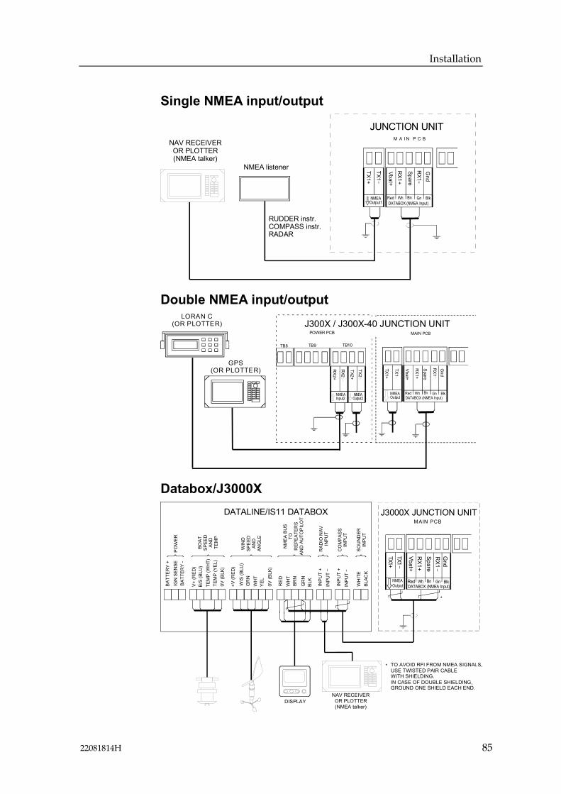
Installation
22081814H 85
Single NMEA input/output
NAV RECEIVEROR PLOTTER(NMEA talker)
NMEA listener
RUDDER instr.COMPASS instr.RADAR
RX1
RX1+
JUNCTION UNITM A I N P C B
DATABOX (NMEA Input)
Vbat+
Spare
Gnd
Red Wh Bn Gn Blk
TX1
TX1+NMEA
Output1
Double NMEA input/output
RX1
RX1+
MAIN PCB
DATABOX (NMEA Input)
Vbat+
Spare
Gnd
Red Wh Bn Gn Blk
TX1
TX1+
NMEAOutput
POWER PCB
TB8 TB9 TB10
RX2
RX
2+
GPS(OR PLOTTER)
NMEAInput2
TX2
TX2+
NMEAOutput2
LORAN C(OR PLOTTER) J300X / J300X-40 JUNCTION UNIT
Databox/J3000X
RX1
RX1+
J3000X JUNCTION UNITMAIN PCB
DATABOX (NMEA Input)
Vbat+
Spare
Gnd
Red Wh Bn Gn Blk
TX1TX1+
BATT
ERY
+IG
N S
ENSE
BATT
ERY
-
V+ (R
ED)
W/S
(BLU
)
TEM
P (W
HT)
TEM
P (Y
EL)
0V (B
LK)
+V (R
ED)
B/S
(BLU
)
GR
NW
HT
BRN
YEL
BLK
INPU
T +
INPU
T
WH
ITE
BLAC
K
0V (B
LK)
INPU
T +
INPU
T
GR
N
WH
TR
ED
SOU
ND
ERIN
PUT
CO
MPA
SSIN
PUT
RAD
IO N
AVIN
PUT
NM
EA B
US
TOR
EPEA
TER
SAN
D A
UTO
PILO
T
WIN
D
SPEE
DAN
DAN
GLE
BOAT
SPEE
DAN
DTE
MP
POW
ER
DATALINE/IS11 DATABOX
TO AVOID RFI FROM NMEA SIGNALS,USE TWISTED PAIR CABLEWITH SHIELDING.IN CASE OF DOUBLE SHIELDING,GROUND ONE SHIELD EACH END.
*
*
DISPLAYNAV RECEIVER
OR PLOTTER(NMEA talker)
NMEAOutput
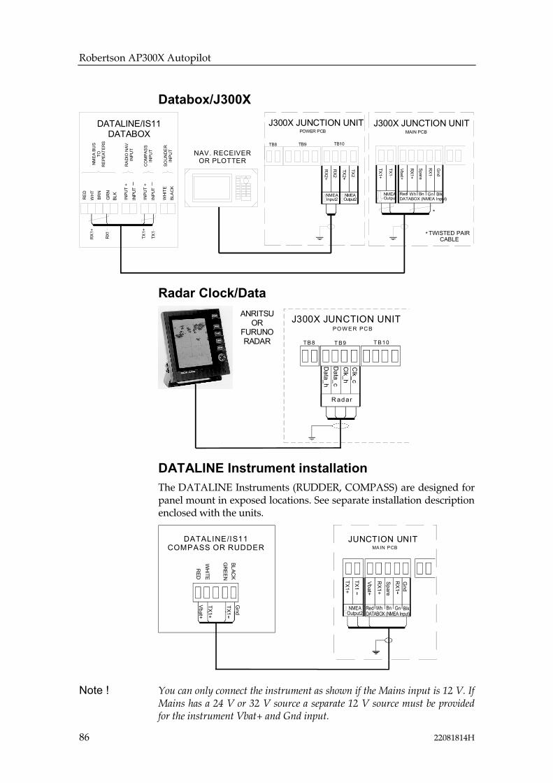
Robertson AP300X Autopilot
86 22081814H
Databox/J300XR
X1
RX1+
J300X JUNCTION UNITMAIN PCB
DATABOX (NMEA Input)
Vbat+
Spare
Gnd
Red Wh Bn Gn Blk
TX1
TX1+
NMEAOutputBR
N
BLK
INPU
T +
INPU
T
WHI
TE
BLA
CK
INPU
T +
INPU
T
GRN
WH
T
RE
D
SOU
ND
ER
INPU
T
CO
MPA
SS
INPU
T
RA
DIO
NAV
INPU
T
NMEA
BU
STO
RE
PEAT
ERS
DATALINE/IS11DATABOX
*
J300X JUNCTION UNITPOWER PCB
TB8 TB9 TB10
RX2
RX2+
NAV. RECEIVEROR PLOTTER
NMEAInput2
TX2
TX2+
NMEAOutput2
TWISTED PAIRCABLE
*
RX
1+
RX1
TX1
TX1+
Radar Clock/Data
J300X JUNCTION UNITPO W ER PC B
R adar
TB8 T B9 T B10
Data_h
Data_c
Clk_h
Clk_c
ANRITSUOR
FURUNORADAR
DATALINE Instrument installationThe DATALINE Instruments (RUDDER, COMPASS) are designed forpanel mount in exposed locations. See separate installation descriptionenclosed with the units.
RX1
RX1+
JUNCTION UNITMAIN PCB
DATABOX (NMEA Input)
Vbat+
Spare
Gnd
Red Wh Bn Gn Blk
TX1+
NMEAOutput2
TX1
GR
EEN
RED
BLACK
WHI TE
TX1
TX1+
Gnd
Vbat+
DATALINE/IS11COMPASS OR RUDDER
Note ! You can only connect the instrument as shown if the Mains input is 12 V. IfMains has a 24 V or 32 V source a separate 12 V source must be providedfor the instrument Vbat+ and Gnd input.

Installation
22081814H 87
External AlarmThe external alarm circuit has an open collector output for an externalalarm relay or buzzer. The alarm voltage is the same as the mainsupply voltage. Max. load on external alarm output is 0.9 Amp.
Ext.alarm
TB6
J300X/J300X-40 JUNCTION UNITPOWER PCB
TB7 TB8 TB9
NI300X NMEA Interface UnitThe NI300X is normally installed inside a console or locker close toNav receivers, radar and instruments to keep cables short. The unitdoes not have controls that need to be operated during installation oruse, but you should be able to take the lid off for inspections, to viewLED indication of received signals. It should be installed with the cableinlet and the Robnet connectors facing down. The NI300X is designedto operate in a location that provides ambient temperatures below +55°C (+130° F). It is fastened to the panel/bulkhead by the externalmounting brackets.
Note ! The NI300X is not weatherproof, and must be installed in a dry location!
The NI300X NMEA Interface (expansion) Unit is designed to handleinstallations where more NMEA lines have to be tied into the system.Four NMEA ports are available. An additional output data-port withDATA/CLOCK signal is capable of generating heading data in theformat used by some radar displays made by Anritzu and Furuno.This feature is thus added to the system if a J3000X Junction Unit isinstalled (J3000X has no radar Clock/Data output as compared toJ300X and J300X-40).
Configuration for Anritzu or Furuno is selected in the InstallationSetup Menu.
12V out is for driving (max. 2) 12V Dataline instruments (max 250mAload).
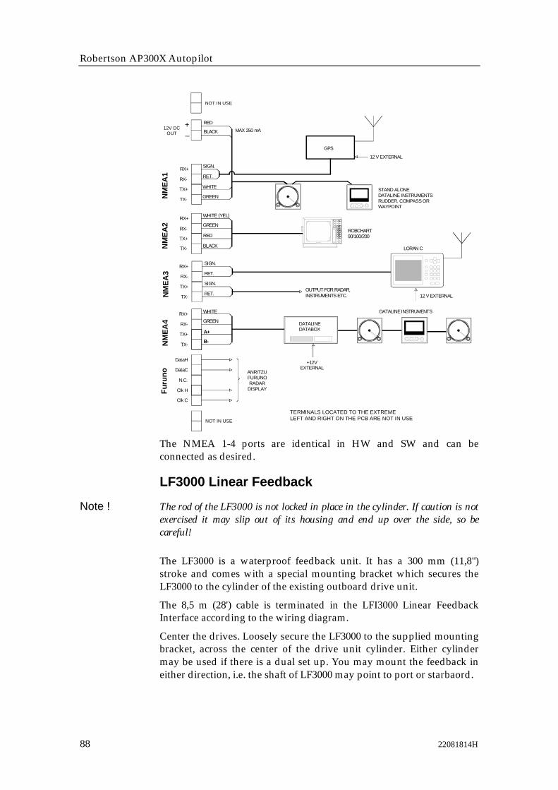
Robertson AP300X Autopilot
88 22081814H
NOT IN USE
WHITE
GREEN
SIGN.
RET.
SIGN.
RET.
GREEN
WHITE (YEL)
RED
BLACK
Furu
no ANRITZUFURUNORADAR
DISPLAY
+12VEXTERNAL
DATALINE DATABOX
STAND ALONEDATALINE INSTRUMENTSRUDDER, COMPASS ORWAYPOINT
RX+
RX-
TX+
TX-
DataH
DataC
N.C.
Clk H
Clk C
RX+
RX-
TX+
TX-
RX+
RX-
TX+
TX-
RX+
RX-
TX+
TX-
+_
12V DCOUT
RED
BLACK
DATALINE INSTRUMENTS
LORAN C
OUTPUT FOR RADAR, INSTRUMENTS ETC.
ROBCHART90/100/200
MAX 250 mA
SIGN.
RET.
WHITE
GREEN
GPS
12 V EXTERNAL
12 V EXTERNAL
NM
EA2
NMEA
3NM
EA4
NMEA
1
A+
B-
NOT IN USE
TERMINALS LOCATED TO THE EXTREMELEFT AND RIGHT ON THE PCB ARE NOT IN USE
The NMEA 1-4 ports are identical in HW and SW and can beconnected as desired.
LF3000 Linear Feedback
Note ! The rod of the LF3000 is not locked in place in the cylinder. If caution is notexercised it may slip out of its housing and end up over the side, so becareful!
The LF3000 is a waterproof feedback unit. It has a 300 mm (11,8")stroke and comes with a special mounting bracket which secures theLF3000 to the cylinder of the existing outboard drive unit.
The 8,5 m (28') cable is terminated in the LFI3000 Linear FeedbackInterface according to the wiring diagram.
Center the drives. Loosely secure the LF3000 to the supplied mountingbracket, across the center of the drive unit cylinder. Either cylindermay be used if there is a dual set up. You may mount the feedback ineither direction, i.e. the shaft of LF3000 may point to port or starbaord.

Installation
22081814H 89
Loosen the end bolt (a) used to secure the cylinder to the drive unitmount. Insert the rod retaining assembly (b) (end plate) and retighten thisbolt. Secure the feedback rod to the end plate using the two washersand cap nut provided. Adjust the location of the LF3000 LinearFeedback to allow full travel of the hydraulic cylinder without causingthe endplate of the LF3000 hitting the end of the cylinder. Check thatthe outboard motor can be tilted freely. Tighten all nuts and themounting bracket.
Turn the helm slowly by hand to the stops on either side, making surethat the rod does not bind up in any direction. Also, clamp cable toallow full engine movement to port and starboard. The mountinghardware provided with this system is meant to interface with TeleflexHC5340 cylinders and Hynautic K7 and K10 Cylinders. If you areattempting to interface to another system the hardware enclosed maynot be appropriate! Contact your dealer to obtain the correct mountingkit.
LF3000
BRACKET
CYLINDER
JUNCTION UNITMAIN PCB
RF
RF+
RudderFeedb.
LFI3000LINEAR FEEDBACK
INTERFACETB1
White
Brown
TB2
White
Brown
Green
Yellow
b
a

Robertson AP300X Autopilot
90 22081814H
Note ! A previous version of the LF3000 has been delivered with an alternativecable with a different color code. The alternative cable is connected accordingto the drawing below:
TB2
Orange
Black
BlueBlack
CI300X Analogue Interface UnitThe CI300X analog interface unit is an optional module, designed toenable a variety of different equipment to connect into AP300Xsystems. The CI300X converts the analog inputs into Robnetcompatible signals for use by AP300X system components. TheCI300X adds the following capabilities to the AP300X system, andallows connection of each of the following simultaneously:
Magnetic compass connection (Robertson APC100 or APC135 withCD100 course detector).
Gyrocompass connection for Robertson RGC50, RGC10
Analog input of SIN/COS for either one of the following:
• Fluxgate compass connection (for other manufacturers SIN/COSfluxgate compasses)
• Analog windvane (SIN/COS)
Steering lever connection for either one of the following:
• S9 Remote steering lever connection
• S3 local steering lever connection
For detailed information, see separate CI300X Manual

Installation
22081814H 91
COM
STBD
PORT
ENAB
AL1
AL2
SIN
COS
GND
Vref
SIN
HI
LO
NFU
WHITE
GREY
YELLOW
GREEN
BROWN
COSMAG
N. C
OM
PAN
ALO
GG
YRO
ALAR
M
S3 STEERING LEVER
S9 STEERING LEVER
NFU STEERING LEVER
APC100 MAGNETIC COMPASSWITH CD100 COURSE DETECTOR
FLUXGATE COMPASSWITH SINE/COSINE OUTPUT
DC SUPPLY
DC SUPPLY
RGC10/RGC50GYRO COMPASS
R1
R2
S1
S2
S3
WINDVANE
CI300 COMPASS INTERFACE
ROBNETCONNECTIONS
TB1
TB2
TB3
TB4
TB5
NOT APPLICABLE
Note ! When CD100 Course Detector is mounted upside down, the yellow and grayconductors must be interchanged

Robertson AP300X Autopilot
92 22081814H
CD100 Course DetectorOn some installations the owner may prefer to use the boats owncompass. The compass must be fully gimballed and have a flat surfaceunderneath to fit the CD100. Make hole for a 6 mm screw in the bottomof the compass and mount the CD100 as shown on the drawing. Securethe 6 mm screw through the centre hole of the CD100. Make sure thecable does not prevent the compass from moving freely in the gimbals.
1 Screw M6x25mm, nonmagnetic
2 Washer, non magnetic
3 Course detector
4 Cable clamp, nylon
5 Washer, non magnetic
6 Screw M3x10mm, nonmagnetic
Note ! Lock nut on mounting screw (pos. 1)for transportation only. To be removedbefore mounting.
CDI35 InterfaceLocate the CDI35 as close to the compass as possible so that there willbe no problem finding it in the event of a service.
Put the two fixing screws in the slots and secure the unit to thebulkhead. Open the unit to access the screw terminals.
Cut the CD100 cable to make a suitable length and connect both cablesas shown on the diagram below.
* NON-POLARIZED (COLOR INDEPENDENT)
JUNCTION UNITMAIN PCB
HS+
*
HeadingSensor
HS
CDI35 INTERFACE PCBBOAT'S
MAGNETICCOMPASS
CD100COURSE
DETECTOR
Whi
teBr
own
Gre
en
Yel
low
Gre
y
1 2 3 4 5
Note ! When CD100 Course Detector is mounted upside down, the yellow and grayconductors must be interchanged
3
2
1
4
5
6

Installation
22081814H 93
3.12 Software Setup Procedure
Description of Installation SettingsThe design of the AP300X includes advanced features that havesimplified the installation and setup of an autopilot. The principleadvantage is that manual adjustments that needed to be done onprevious models are no longer necessary with the AP300X.
Note ! The installation settings must be performed as part of the installation of theAP300X system. Failure to correctly set the values in the installationsettings may prohibit the AP300X from functioning properly!
The Installation Settings are grouped into the following functionalcategories:
• Language: Selects language used for display information
• Dockside Settings: Sets values of items to be set prior to seatrials
• Interface Setup: Sets the identification of navigation and optional equipment connected to the AP300X system
• Seatrial Settings: Determines automatic calibrations and steering parameters
• View Parameters Permits viewing, setting, or changing steering parameters
Each group is designed to focus on specific functions related to aninstallation activity, and enable quick access when changes need to bemade.
Some important points regarding the installation settings values:
• When the AP300X is delivered new from the factory, (AND ANYTIME AFTER A MASTER RESET OF MEMORIES HAS BEENPERFORMED) the Installation Settings are all reset to preset(default) values. The warning message "Installation Setup Required"will appear at turn on and if an attempt is made to access the AUTOor NAV modes.
• The Dockside, Interface and Seatrial settings can only be accessedwhen the system is in STBY mode.
• The values that are selected (also referred to as "PARAMETERS")from within the Installation Settings Menu, are stored in thememory of the AP300X system. No specific action is required to"SAVE" the selected values. Once the value is changed, it is storeduntil the next time the menu item is selected and changed.
• The Installation Settings are considered global, enabling values to beavailable to all control units in the system.

Robertson AP300X Autopilot
94 22081814H
• The values in the Seatrial Settings are dependent on successfulcompletion of the Dockside Settings.
• Before attempting to turn on the AP300X and perform anInstallation Setup, the hardware installation and electricalinstallation must be completed in accordance with the installationinstructions.
Installation Settings MenuThe Installation Settings Menu (ISM) is presented on the autopilotdisplay by pressing and holding the NAV/SETUP pushbutton for 5seconds.
Note ! The INSTALLATION SETTINGS MENU is different from the USERSETUP MENU . Refer to flow diagram on the opposite page for a pictorialview of Installation Settings Menu.
There are several actions that you can do once you have accessed theISM:
Answer YES to the question by rotating the course selector dialclockwise
Proceed to the next item in the menu by pressing the STBDpushbutton. (Proceeding to the next item when presented with aquestion is the same as answering NO to the question.)
Proceed back to the previous item in the menu by pressing the PORTbutton
Change the selected item shown rotating the course selector dial
Leave the ISM by selecting STBY, AUTO, or NAV.
On new installations, and whenever a control unit, junction unit, orsoftware is replaced in an AP300X system, it is recommended that aMASTER RESET be performed as described in the ISM prior toproceeding with the setup procedure.
When using the ISM refer to the diagram "Installation settingsMenu Flow Chart" on page 96.
STBYOFF
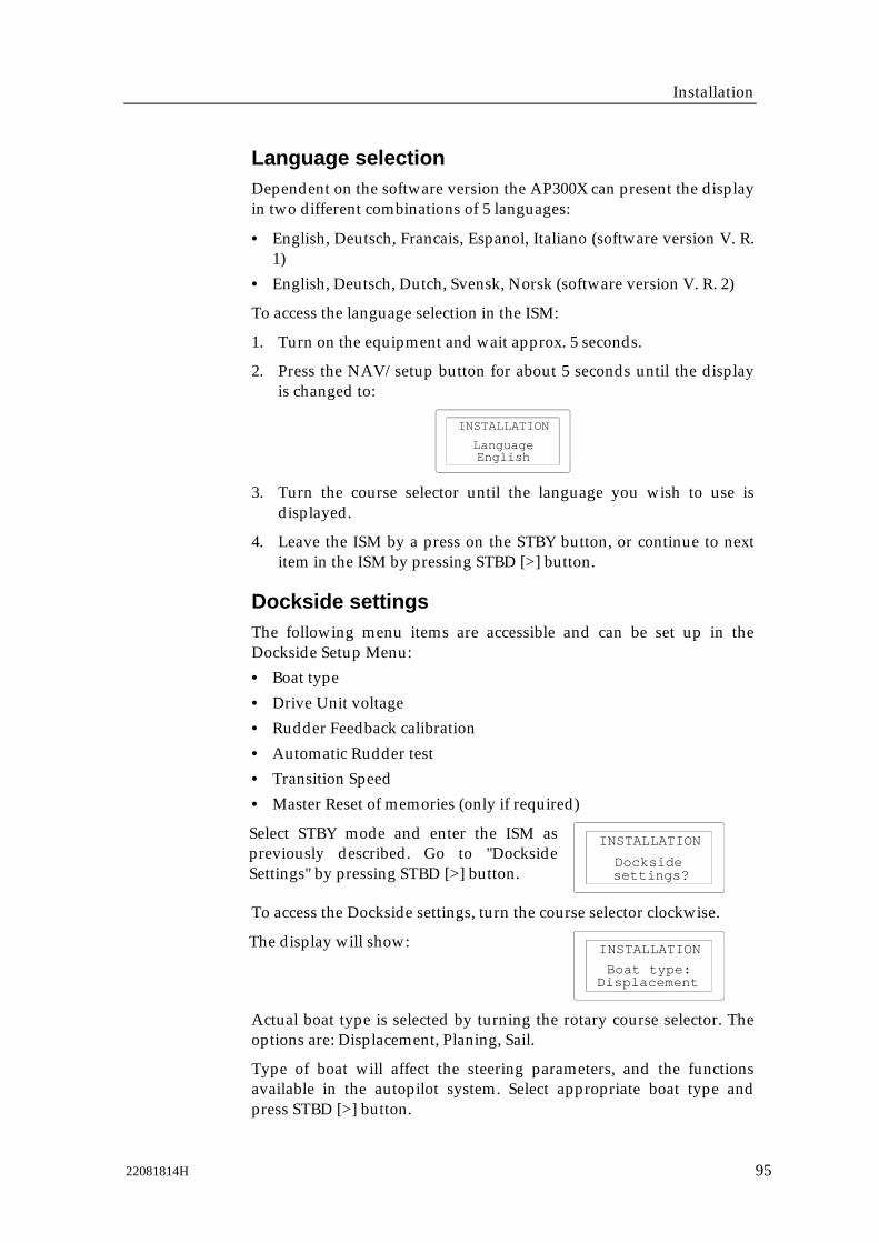
Installation
22081814H 95
Language selectionDependent on the software version the AP300X can present the displayin two different combinations of 5 languages:
• English, Deutsch, Francais, Espanol, Italiano (software version V. R.1)
• English, Deutsch, Dutch, Svensk, Norsk (software version V. R. 2)
To access the language selection in the ISM:
1. Turn on the equipment and wait approx. 5 seconds.
2. Press the NAV/setup button for about 5 seconds until the displayis changed to:
EnglishLanguage
INSTALLATION
3. Turn the course selector until the language you wish to use isdisplayed.
4. Leave the ISM by a press on the STBY button, or continue to nextitem in the ISM by pressing STBD [>] button.
Dockside settingsThe following menu items are accessible and can be set up in theDockside Setup Menu:• Boat type
• Drive Unit voltage• Rudder Feedback calibration
• Automatic Rudder test• Transition Speed
• Master Reset of memories (only if required)
Select STBY mode and enter the ISM aspreviously described. Go to "DocksideSettings" by pressing STBD [>] button. settings?
Dockside
INSTALLATION
To access the Dockside settings, turn the course selector clockwise.
The display will show:
DisplacementBoat type:
INSTALLATION
Actual boat type is selected by turning the rotary course selector. Theoptions are: Displacement, Planing, Sail.
Type of boat will affect the steering parameters, and the functionsavailable in the autopilot system. Select appropriate boat type andpress STBD [>] button.
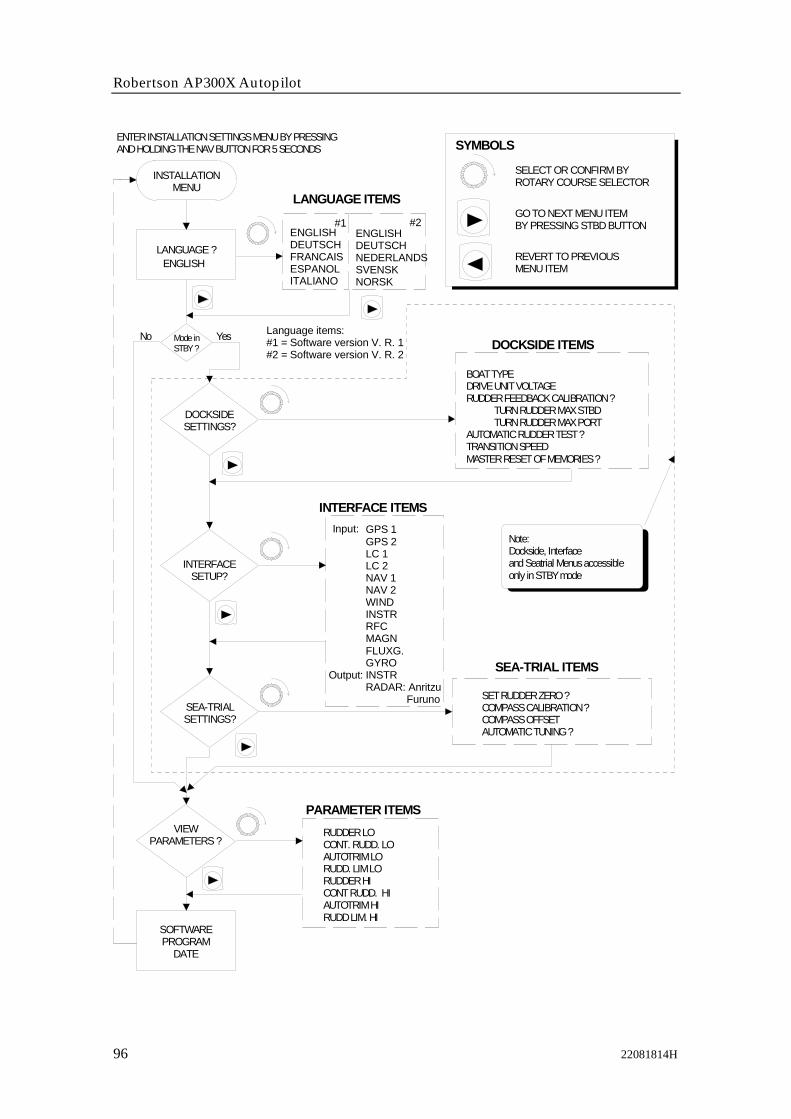
Robertson AP300X Autopilot
96 22081814H
DOCKSIDESETTINGS?
LANGUAGE ?
INTERFACESETUP?
SEA-TRIALSETTINGS?
INSTALLATIONMENU
SET RUDDER ZERO ?COMPASS CALIBRATION ?COMPASS OFFSETAUTOMATIC TUNING ?
GPS 1GPS 2LC 1LC 2NAV 1NAV 2WINDINSTRRFCMAGNFLUXG.GYROINSTRRADAR: Anritzu Furuno
BOAT TYPEDRIVE UNIT VOLTAGERUDDER FEEDBACK CALIBRATION ? TURN RUDDER MAX STBD TURN RUDDER MAX PORT AUTOMATIC RUDDER TEST ?TRANSITION SPEEDMASTER RESET OF MEMORIES ?
SEA-TRIAL ITEMS
INTERFACE ITEMS
DOCKSIDE ITEMS
ENGLISHDEUTSCHFRANCAISESPANOLITALIANO
LANGUAGE ITEMS
SELECT OR CONFIRM BYROTARY COURSE SELECTOR
GO TO NEXT MENU ITEMBY PRESSING STBD BUTTON
REVERT TO PREVIOUSMENU ITEM
SYMBOLSENTER INSTALLATION SETTINGS MENU BY PRESSINGAND HOLDING THE NAV BUTTON FOR 5 SECONDS
ENGLISH
SOFTWAREPROGRAM
DATE
VIEWPARAMETERS ?
RUDDER LOCONT. RUDD. LOAUTOTRIM LORUDD. LIM LORUDDER HICONT RUDD. HIAUTOTRIM HIRUDD LIM. HI
PARAMETER ITEMS
Note:Dockside, Interfaceand Seatrial Menus accessible only in STBY mode
Mode in STBY ?
YesNo
Output:
Input:
Language items:#1 = Software version V. R. 1#2 = Software version V. R. 2
ENGLISHDEUTSCHNEDERLANDS SVENSKNORSK
#1 #2
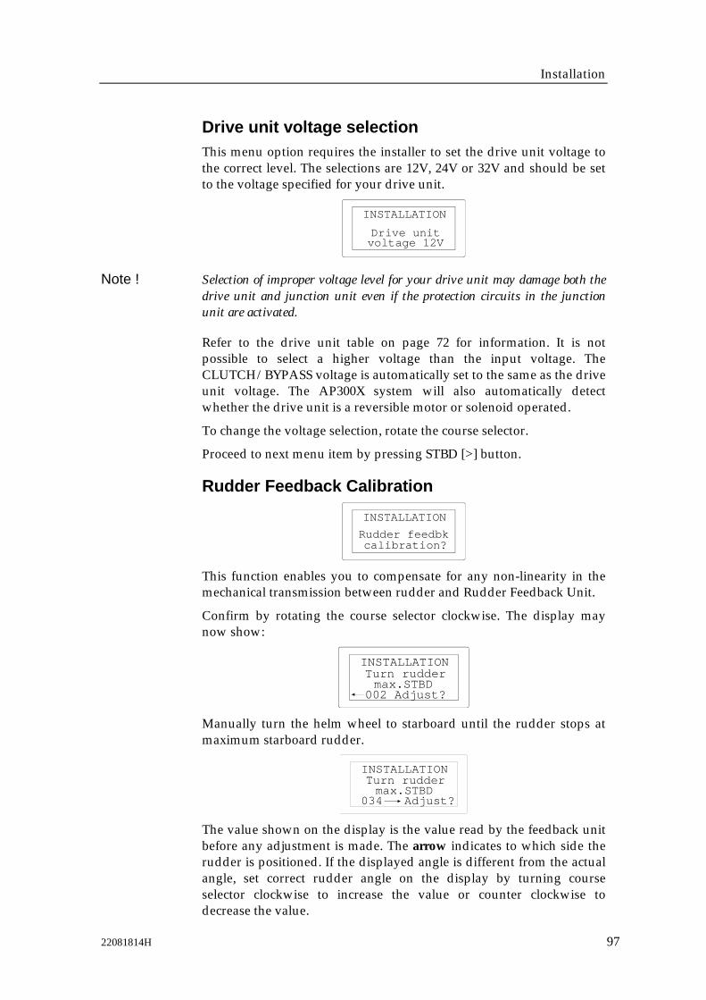
Installation
22081814H 97
Drive unit voltage selectionThis menu option requires the installer to set the drive unit voltage tothe correct level. The selections are 12V, 24V or 32V and should be setto the voltage specified for your drive unit.
voltage 12VDrive unit
INSTALLATION
Note ! Selection of improper voltage level for your drive unit may damage both thedrive unit and junction unit even if the protection circuits in the junctionunit are activated.
Refer to the drive unit table on page 72 for information. It is notpossible to select a higher voltage than the input voltage. TheCLUTCH/BYPASS voltage is automatically set to the same as the driveunit voltage. The AP300X system will also automatically detectwhether the drive unit is a reversible motor or solenoid operated.
To change the voltage selection, rotate the course selector.
Proceed to next menu item by pressing STBD [>] button.
Rudder Feedback Calibration
calibration?Rudder feedbk
INSTALLATION
This function enables you to compensate for any non-linearity in themechanical transmission between rudder and Rudder Feedback Unit.
Confirm by rotating the course selector clockwise. The display maynow show:
002 Adjust?max.STBD
INSTALLATIONTurn rudder
Manually turn the helm wheel to starboard until the rudder stops atmaximum starboard rudder.
034 Adjust?max.STBD
INSTALLATIONTurn rudder
The value shown on the display is the value read by the feedback unitbefore any adjustment is made. The arrow indicates to which side therudder is positioned. If the displayed angle is different from the actualangle, set correct rudder angle on the display by turning courseselector clockwise to increase the value or counter clockwise todecrease the value.
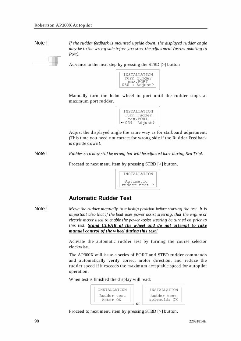
Robertson AP300X Autopilot
98 22081814H
Note ! If the rudder feedback is mounted upside down, the displayed rudder anglemay be to the wrong side before you start the adjustment (arrow pointing toPort).
Advance to the next step by pressing the STBD [>] button
030 Adjust?max.PORT
INSTALLATIONTurn rudder
Manually turn the helm wheel to port until the rudder stops atmaximum port rudder.
039 Adjust?max.PORT
INSTALLATIONTurn rudder
Adjust the displayed angle the same way as for starboard adjustment.(This time you need not correct for wrong side if the Rudder Feedbackis upside down).
Note ! Rudder zero may still be wrong but will be adjusted later during Sea Trial.
Proceed to next menu item by pressing STBD [>] button.
rudder test ?Automatic
INSTALLATION
Automatic Rudder Test
Note ! Move the rudder manually to midship position before starting the test. It isimportant also that if the boat uses power assist steering, that the engine orelectric motor used to enable the power assist steering be turned on prior tothis test. Stand CLEAR of the wheel and do not attempt to takemanual control of the wheel during this test!
Activate the automatic rudder test by turning the course selectorclockwise.
The AP300X will issue a series of PORT and STBD rudder commandsand automatically verify correct motor direction, and reduce therudder speed if it exceeds the maximum acceptable speed for autopilotoperation.
When test is finished the display will read:
Motor OKRudder test
INSTALLATION
or solenoids OKRudder test
INSTALLATION
Proceed to next menu item by pressing STBD [>] button.

Installation
22081814H 99
Transition Speed
speed: 00 knTransition
INSTALLATION
The transition speed is the speed where the AP300 will automaticallychange the steering parameter set from the HI speed to LO speedparameters, or vice versa.
The default setting of transition speed is zero, which requires thatsteering parameter selection be done manually. If a GPS, Loran, orexternal speed log input (from Dataline or other instrument systems) isconnected, it is recommended to set the transition speed to a valuegreater than 0, to enable the automatic speed selection feature in theAP300X.
It is recommended that you set the transition speed to a speed thatrepresents the speed where the hull begins to plane, or where youwould manually change the parameters from HI to LO.
The speed used for the automatic transition is obtained as follows:
1. Data from the source set in the interface setup for the S / Dchannel. If this is a valid source of VHW (speed through the water)data, then this data is used for determination of when to changeparameter sets.
2. If VHW data is not available from the S/D channel or if the S/Dchannel is not configured, the AP300X system will use the speeddata obtained from the VTG (speed over ground) sentence receivedfrom the currently selected POS source.
If no speed data is available on either the S/D channel (VHW) or thePOS source (VTG), manual speed selection is required. The AP300 willalways default to the HI speed steering parameters when the system isfirst turned on, and with speed data failure.
If manual speed selection occurs (the user manually selects HI or LOparameters), the manual parameter set will remain in effect until theAUTO mode is reselected.
Rotate the course dial clockwise until the transition speed is set to thedesired value in knots.
Proceed to next menu item by pressing STBD [>] button.

Robertson AP300X Autopilot
100 22081814H
Master Reset
of memories?Master reset
INSTALLATION
Note ! A Master Reset is part of the final test at factory and will reset the memoriesto factory settings. Unless you need to clear all stored values during theinstallation setup procedure, you should not perform a Master Reset.
The Master Reset needs a double confirmation to prevent an unwanted reset.To perform a Master Reset, rotate the course selector clockwise and observe thedisplay; then rotate the course selector counter clockwise.
Interface SettingsThe AP300X system provides a totally flexible approach to the input ofdata from optional equipment. Identification of the type of equipmentconnected to the AP300X system is performed in the Interface SetupMenu.
If your system includes connection of external equipment to theNMEA0183 data ports in Junction Unit or NI300X, or if the CI300X isinstalled with optional compass units or an optional analog wind vaneunit, they must be configured under this menu. This procedure allowsyou to assign an abbreviated name to identify the type of equipmentthat is connected to each of the available hardware ports in the AP300system.
Abbreviatedname
Description / Usage NOTES
GPS1 Primary GPS
GPS2 Backup GPS
LC 1 Primary Loran
LC 2 Backup Loran
Can be used as either NAV sourceor POS source. Also for VTG datafor automatic AUTO HI/LO speedselection
NAV1 Chart plotter
NAV2 Other Nav source like Deccaetc.
WIND Source of wind data for windinstrument and wind sailing.
Wind speed and angle fromJunction Unit, NI300X or CI300X(No speed)
INSTR Source of data for instrumentdisplays. Also for automaticHI/LO parameter selection
Uses log input (VHW) for speeddata and either DBK or DBT fordepth data

Installation
22081814H 101
Abbreviatedname
Description / Usage NOTES
RFC For use when selecting betweenRobertson fluxgate compasses
RFC : J300X, RFC35 compassconnected to junction unitRFC : RFC300, RFC300 compassconnected to ROBNET
MAGN For use with magnetic compass(APC100) with course detector(CD100)
MAGN : J300X, CDI35 + CD100connected to junction unit.MAGN : CI300X, CD100 connectedto CI300X
FLUXG For use with non-Robertsonfluxgate compasses that outputSIN/COS
Optional CI300X item. Onlyavailable if WIND has not been setto CI300X
GYRO For use with Robertson RGC50,RGC10 gyro
Optional CI300X item. True datadisplayed for HDG, COG, bearingto waypoint
OutputINSTR
For high speed NMEA outputof compass heading
HDM or HDT output increasedfrom 1 to 5 times/sec. on TX1 port
OutputRADAR
Clock/data heading output toradars
Selectable between Anritzu andFuruno. (On both J300X andNI300X)
The Interface Setup Menu presents these names so that they can beassigned to a hardware input or output port. Each abbreviated name isthen presented in appropriate locations of the USER SETUP MENU toprovide the user with choices of data sources, or identified to theAP300X where to look for various types of data.
When you assign a hardware port to an abbreviated name, you aresimply telling the AP300X system that when the user chooses anabbreviated name as a data source it should look to the hardware portassigned to the abbreviated name for the data.
It is recommended that upon completion of the ISM that theconfiguration be recorded in the Interface Setup Table on page 100.
• Enter the Interface Setup part of the ISM by pressing and holdingthe NAV/ Setup button for five seconds.
• Scroll through to the Interface setup ? prompt by pressing theSTBD [>]
The following display will be presented:
Setup?Interface
INSTALLATION
To access the Interface Setup items, turn the course selector clockwise.
The display will show:

Robertson AP300X Autopilot
102 22081814H
GPS1: -Input:
INSTALLATION
The display is now showing the first name on the list. Assign ahardware port to the name by turning the course selector until thehardware port is displayed.
Proceed to the names on the list that shall be assigned by pressingSTBD [>] button. Select appropriate NMEA ports by turning the courseselector, or exit from menu by stepping through the list of names bypushing STBD [>] button.
Note ! At the completion of the Interface Setup, the names of items that you haveassigned hardware ports to will be available as sources of data for NAV(navigation) and POS (position) in the USER SETUP MENU. It isrecommended that you access the User Setup Menu directly after completingthe Interface Setup to select the desired data. Refer to page 34 for details onchanging the items in the User Setup Menu.
Input signal setupAbbreviated Name Hardware Port Equipment connected
GPS1: J300X-1 on J3000XJ300X-2 on J300X, J300X-40
GPS2: –
LC1: –
LC2: –
NAV 1: –
NAV 2: –
WIND: J300X-1
INSTR: J300X-1
RFC: J300X
MAGN: –
FLUXG: –
GYRO: –
The listed HW ports are factory (default) assignments after a MasterReset. The names may be assigned to other HW ports as per belowdependant of the system configuration.

Installation
22081814H 103
System unit Hardware port: Display readout:
All junction units NMEA Port #1 J300X-1
J300X, J300X-40 NMEA Port #2 J300X-2
All junction units Heading Sensor J300X
NI300X NMEA Port #1 NI300-1
NI300X NMEA Port #2 NI300-2
NI300X NMEA Port #3 NI300-3
NI300X NMEA Port #4 NI300-4
CI300X ANALOGUE (otherFluxgate), MAGN.COMP, GYRO
CI300X
RFC35R, RFC300 Robnet ROBNET
Output signal setupDisplay readout Hardware Port Equipment connected
Output INSTR: J300X-1*: –
J300X-1 Note
Output RADAR: Anritsu*Furuno
RADAR
* default setting
Note ! The standard NMEA output rate is 1x/second. When Output INSTR is setto J300X-1, the Junction Unit output port #1 (TX1) will have an outputrate of 5x/second for HDM or HDT messages (heading). The RSA (rudderangle) message is always 5x/second.
3.13 Sea TrialThe Sea-trial menu can only be accessed if the Dockside Settings aredone and confirmed. It is also recommended that the Interface Setupbe performed prior to Seatrial settings.
The seatrial settings do the following:
• Rudder zero adjust (To tell the AP300 the precise midships positionof the rudder)
• Compass calibration (To automatically compensate for onboardmagnetic Deviation)
• Compass Offset (To offset the final compass heading readout)

Robertson AP300X Autopilot
104 22081814H
• Automatic tuning (An optional method of determining the steeringparameters)
Advance through the ISM until the following display is presented:
settings?Seatrial
INSTALLATION
Confirm by rotating the course dial Clockwise.
zero?Set rudder
INSTALLATION
Rudder zero adjustThe adjustment should be made in calm sea and side forces from windor current should be avoided.
• Bring the boat up to cruising speed, and head directly into the wind.
• If the boat has twin engines, synchronize the engine RPM's.
• Set the trim tabs and stabilizers to have no effect on the boatsheading.
• Steer the boat manually on a steady course.
• Confirm the rudder ZERO position by rotating the course selectorclockwise.
The display will then show:
confirmedRudder zero
INSTALLATION
Press STBD [>] to proceed to next menu item.
Compass calibrationThis function will activate the compass calibration procedure. Theprocedure will enable the RFC35 Electronic Fluxgate compass or theCDI35 Course Detector Interface to automatically correct for magneticdeviation.
Note ! If an optional magnetic compass is installed or if a GYRO compass, or othermanufacturers fluxgate connected to a CI300X is installed, refer to theOptional Compass Calibration Procedure accompanying the CI300X.
Before you begin the compass calibration procedure, make sure youhave enough open water around you to make a full clockwise turnwith the boat. Let the boat turn at idle.

Installation
22081814H 105
The calibration should be done in calm sea conditions and withminimal wind to obtain good results.
calibration?RFC COMP
INSTALLATION
RFC COMPcalibrating
INSTALLATIONCalibrationINSTALLATION
confirmed
1. Begin turning the boat to starboard.
2. Start compass calibration by turning the course selector clockwise.
3. When the calibration is completed, (after having completedapproximately 1 1/4 turns), it will be confirmed in the display.
If the compass is close to disturbing magnetic objects, the compasscalibration may fail, and the display will show:
CalibrationINSTALLATION
failed
In that case move the compass to a better location and recalibrate.
After calibration, check the compass readout against a knownreference, other compass or leading line. If the reading is correct(+/-3°) except for a fixed offset, use the COMPASS OFFSET setting toinput a fixed correction to offset the heading readout.
Press STBD [>] button to proceed to next menu item.
Compass OffsetThe compass OFFSET feature allows you to correct for a constantcompass heading offset, that may be present as a result of the RFC35being installed with a lubber line offset or a fixed offset remains afterthe calibration procedure has been completed. The value of compassoffset is specific to the heading sensor that is selected at the time theoffset is entered. (For multiple heading sensor offset procedure, refer toseparate CI300X manual).
The following display is presented when accessing the COMPASSOFFSET entry screen:
Heading : 194Offset ?: 000
INSTALLATIONRFC
Dial in the correction by turning the course dial to offset the RFC35heading to agree with the known, accurate heading. The offset valuecan be either positive or negative.
Note ! The OFFSET required may be as great as 90 degrees, caused by theorientation of the compass when installed. If an OFFSET still exists afterhaving accounted for the mechanical offset, one of the following problemsmay still exist:
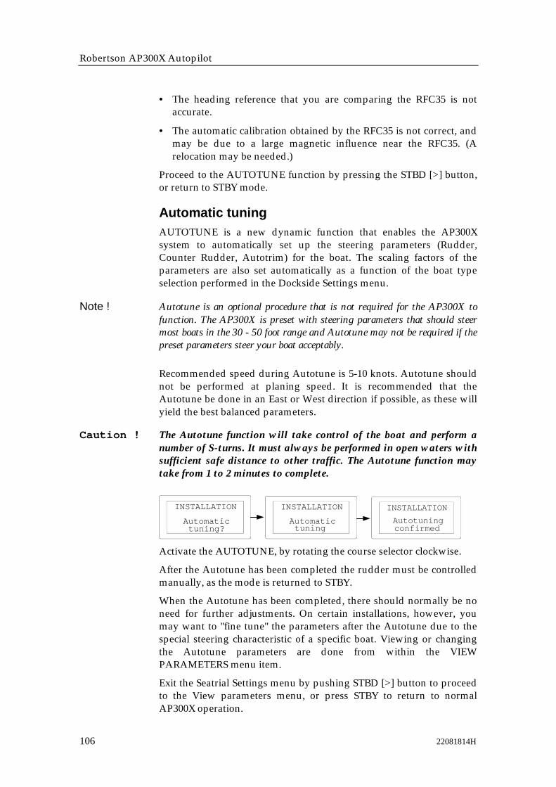
Robertson AP300X Autopilot
106 22081814H
• The heading reference that you are comparing the RFC35 is notaccurate.
• The automatic calibration obtained by the RFC35 is not correct, andmay be due to a large magnetic influence near the RFC35. (Arelocation may be needed.)
Proceed to the AUTOTUNE function by pressing the STBD [>] button,or return to STBY mode.
Automatic tuningAUTOTUNE is a new dynamic function that enables the AP300Xsystem to automatically set up the steering parameters (Rudder,Counter Rudder, Autotrim) for the boat. The scaling factors of theparameters are also set automatically as a function of the boat typeselection performed in the Dockside Settings menu.
Note ! Autotune is an optional procedure that is not required for the AP300X tofunction. The AP300X is preset with steering parameters that should steermost boats in the 30 - 50 foot range and Autotune may not be required if thepreset parameters steer your boat acceptably.
Recommended speed during Autotune is 5-10 knots. Autotune shouldnot be performed at planing speed. It is recommended that theAutotune be done in an East or West direction if possible, as these willyield the best balanced parameters.
Caution ! The Autotune function will take control of the boat and perform anumber of S-turns. It must always be performed in open waters withsufficient safe distance to other traffic. The Autotune function maytake from 1 to 2 minutes to complete.
tuning?Automatic
INSTALLATION
tuningAutomatic
INSTALLATION
Autotuning
INSTALLATION
confirmed
Activate the AUTOTUNE, by rotating the course selector clockwise.
After the Autotune has been completed the rudder must be controlledmanually, as the mode is returned to STBY.
When the Autotune has been completed, there should normally be noneed for further adjustments. On certain installations, however, youmay want to "fine tune" the parameters after the Autotune due to thespecial steering characteristic of a specific boat. Viewing or changingthe Autotune parameters are done from within the VIEWPARAMETERS menu item.
Exit the Seatrial Settings menu by pushing STBD [>] button to proceedto the View parameters menu, or press STBY to return to normalAP300X operation.

Installation
22081814H 107
View parameters
INSTALLATIONView
parameters?
INSTALLATIONRudder LO
0,45
A boats steering parameters found by Autotune can be looked at and ifneeded changed under this menu item. The steering parameters canalso be set to values manually instead of performing an Autotune. Theparameters are divided into two sets:
• HI = Steering parameters to for automatic steering at HI speed
• LO = Steering parameters for automatic steering at LO speed
Note ! As a sail boat's steering characteristic is very much dependent of sail trim,the parameters may be optimized manually from values found by Autotune.
Manual parameter adjust
Use course dialto adjustparameters
BOAT TYPE:Displayedparameter
Rudder LO
Cont Rudd LO
Autotrim LO
Rudder lim LO
HIgh speed
Rudder HI
Cont Rudd HI
Autotrim HI
Rudder lim HI
Displacement Planing Sailboat
0.5
1.4
40
20
0.35
1
40
20
0.3
1.4
40
20
0.2
1
40
20
0.5
1.4
40
20
0.35
1
40
20
LOw speed
Own boat
Autotune Manual
Use PORT andSTBD buttons tostep throughparameters
Note ! The values in the table are factory set and listed for information only. Afterhaving performed the Autotune, the values may differ from those listed inthe table. It is recommended that you write down the parameters "learned"by the Autotune prior to making any adjustments.
The two most important parameters that determine the performance ofthe automatic steering are Rudder and Counter Rudder.
Rudder sets the rudder gain which is the ratio between thecommanded angle and the heading error ( P-factor).

Robertson AP300X Autopilot
108 22081814H
• Too little Rudder and the autopilot fails to keep a steady course.
• Too much Rudder gives unstable steering and reduces speed.
• Low speed requires more rudder than high speed.
Counter Rudder is the parameter that counteracts the effect of theboats turn rate and inertia. For a short time period it is superimposedon the normal rudder response as provided by the Rudder parameter.It may sometimes appear as if it tends to make the rudder move to thewrong side (counter rudder).
The best way of checking the value of the Counter Rudder setting iswhen making turns. The figures illustrate the effects off variousCounter Rudder settings.
Autotrim standard value is 40 which should work well on most boats.On sailboats it may be preferable to set Autotrim to zero, to avoidunwanted rudder offset when changing course
Rudder Limit should be kept at 20 degrees unless there is a need formore rudder when performing dockside maneuvers.
Note ! In no event should the Rudder Limit be set to a value higher than the actualmaximum rudder angle.
Too little rudder
Too much rudder
Course to steer
Course to steer
New courseNew course
New course
Counter rudder setting too low,overshoot response
Counter rudder setting too high,sluggish and creeping response
Correct setting of counterrudder, ideal response
Installation
22081814H 109
Final sea trialAfter having completed all settings in the Installation Settings Menu,take the boat out and perform a final sea trial in open waters withsufficient distance to other traffic.
� Steer the boat on all cardinal headings in AUTO mode.
� Start with low and medium speeds to get familiar with theresponse from the AP300X.
� Try the effect of LO and HI speed settings.
� If the hardware for automatic HI/LO speed selection is connectedand configured, verify that the HI/LO transition is occurring, andthe HI/LO parameters are changing after the transition speed iscrossed (by more than 1 Knot higher or lower speed).
� Try the Dodge function and the U-turn.
� If a Non-Follow Up lever (or handheld remote) is connected, testthe mode switching and verify Port and Stbd steering commandsof the lever.
� If the installation is on a sailboat, try the specific sailboatfunctions using the owner as a consultant on the boats specificsteering characteristics when sailing. Be careful to avoidhazardous situations until you gain experience.
� Set waypoints into each navigator connected to the system, andverify that the AP300CX or AP300DLX steers in NAV mode foreach NAV source.
� Provide the owner with user training.
Providing user trainingThe user should be instructed in the "basic" operational functions, suchas:
� Turning the system on and off
� Explain how to change modes (explain briefly what takes place inthe different modes).
� Regaining manual control from any mode. Point out in whatmodes the helm is engaged by the autopilot (bypass/clutch).
� How to take command at an "inoperative" station if applicable.
� Lock mode and how to lock/unlock and how to shut the systemdown from a locked control unit if applicable.
� Show NFU and FU steering and show the difference.
� Review how to use a NFU controller if connected.
� Course change by rotary knob and buttons.
Robertson AP300X Autopilot
110 22081814H
� Go through the user SETUP menu and show how to (and why)change the settings.
� Also include Nav. source, Pos. source and Wind sensor selection ifapplicable.
� Show the owner where the compass (or compasses) is mountedand instruct him to keep magnetic items away.
� Show where the Mains circuit breaker is.
If an AP300DLX is installed, provide the user with the followingadditional instructions:
� Setting the POS source in the USER SETUP menu
� Setting the AP300DLX as the NAV source in the USER SETUPmenu.
� Go through each of the primary screens in the AP300DLX:
� How to input waypoints
• Manual input
• Saving present position
� How to steer to waypoints
• Stored waypoints
• TEMP waypoint
• MOB waypoint
� Navigating with waypoints in the AP300DLX and the pilot in NAVmode
� Building routes from previously saved waypoints
� Navigating with routes in the AP300DLX and the pilot in NAVmode

Maintenance
22081814H 111
4 MAINTENANCE
4.1 Control unitThe AP300X Control Unit will under normal use require littlemaintenance as the cases are made from high impact material(polycarbonate) to withstand the rigorous of an exposed cockpit.
If the unit requires any form of cleaning, use fresh water and a mildsoap solution (not a detergent). It is important to avoid using chemicalcleaners and hydrocarbons such as diesel, petrol etc.
Make sure that all open ROBNET connectors are fitted with aprotection cap.
It is advisable at the start of each season to check all connections to thecontrol unit head and cover with Vaseline or WD40. If the Control unitis not removed from the boat, it should be covered with the whiteprotection cover.
4.2 Junction UnitNo special maintenance is required. It is advisable, however, at thestart of each season to make a visual inspection of the internal andcheck all connections.
4.3 Rudder FeedbackMake a visual inspection at 2-3 month intervals and at the start of eachseason. Apply some grease at the ball joints when required (RF300)
4.4 CompassIf the compass is exposed to the weather, make a visual inspection at2-3 months intervals, and at the start of each season.
4.5 Drive unitRefer to the drive unit manual for maintenance instructions.

Robertson AP300X Autopilot
112 22081814H
4.6 Exchange of EPROMS
EPROM
EPROM
Junction UnitEPROM
AP300CX PC-BoardJ3000X/J300X/J300X-40Main PC-board
AP300PX PC-Board
AP300DLX PC-Board

Maintenance
22081814H 113
* WHEN INSERTING NEW EPROMS, MAKE SURETHE CUT-OFF CORNER MATCHES WITH THEONE IN THE SOCKET.PRESS IT GENTLY INTO THE SOCKET.
*
* REMOVE THE EPROM FROM THE SOCKET BYMEANS OF THE SPECIAL EXTRACTION TOOL(P/N 44139806)
SQUEEZE THE TOOL AND PULL OUTTHE EPROM
*
*
INSERT THE TOOL BY PRESSING THE TWOGRIP PINS DOWN INTO THE TWO SLOTS INTHE CORNERS OF THE SOCKET
GRIP PINS
AFTER CHANGE OF EPROM, PERFORM A MASTER RESET ASDESCRIBED ON PAGE 3-34. *
THE IDENTIFICATION TAG INDICATES:- NAME OF UNIT- ROBERTSON PART NUMBER- SOFTWARE VERSION
WARNING:MAKE SURE THAT THE RIGHT EPROM IS MOUNTED IN THE ACTUAL UNIT.
EPROM FOR ALL AP300X CONTROL UNITS:
PART NO. 22081467- LANGUAGE ITEM #1 SOFTWARE VERSION V.R. 1 (ENGLISH, GERMAN, FRENCH, SPANISH, ITALIAN)
- LANGUAGE ITEM #2 SOFTWARE VERSION V.R. 2 (ENGLISH, GERMAN, DUTCH, SWEDISH, NORWEGIAN) PART NO. 22081475
EPROM FOR J300X, J300X-40 AND J3000X JUNCTION UNITS: PART NO. 22081640
CUT-OFFCORNER
IDENTIFICATIONTAG
SLOTS
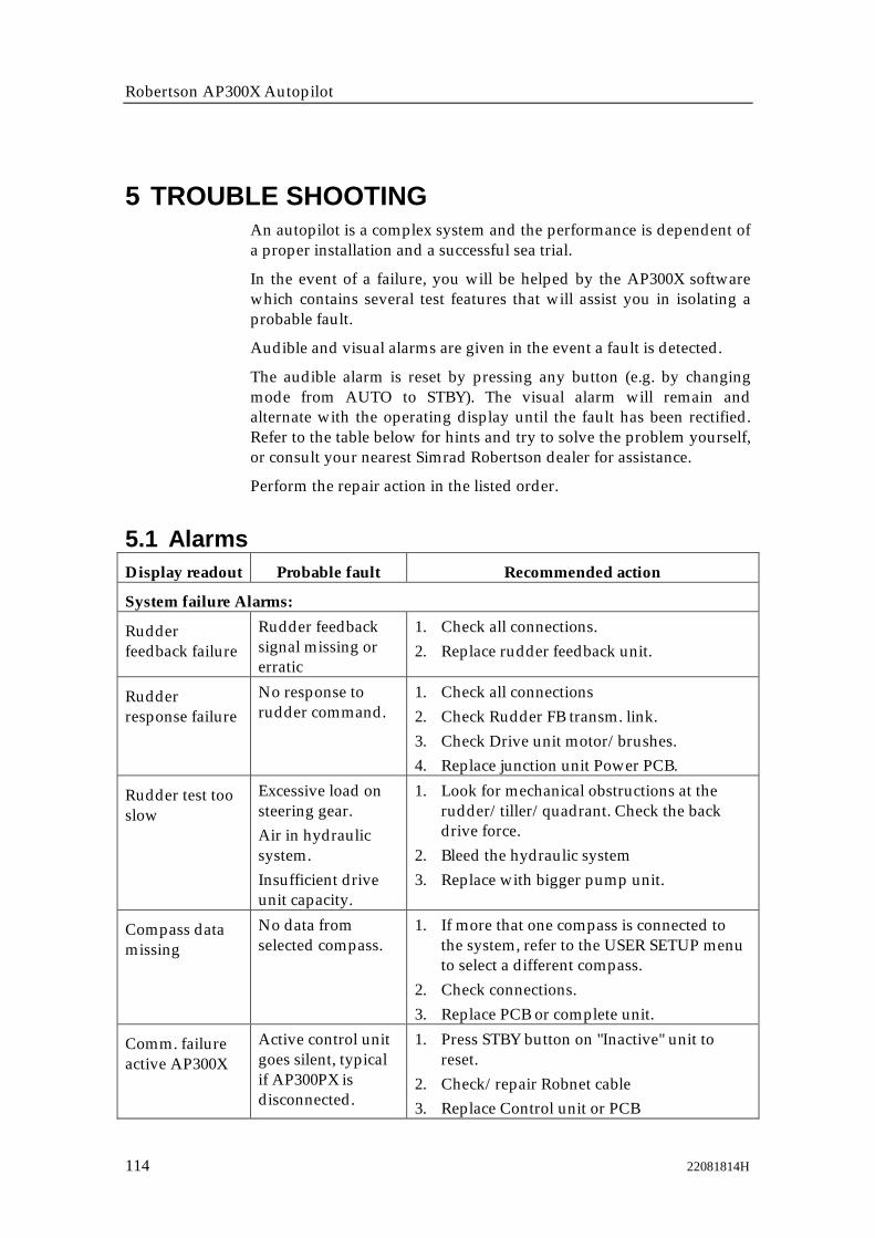
Robertson AP300X Autopilot
114 22081814H
5 TROUBLE SHOOTINGAn autopilot is a complex system and the performance is dependent ofa proper installation and a successful sea trial.
In the event of a failure, you will be helped by the AP300X softwarewhich contains several test features that will assist you in isolating aprobable fault.
Audible and visual alarms are given in the event a fault is detected.
The audible alarm is reset by pressing any button (e.g. by changingmode from AUTO to STBY). The visual alarm will remain andalternate with the operating display until the fault has been rectified.Refer to the table below for hints and try to solve the problem yourself,or consult your nearest Simrad Robertson dealer for assistance.
Perform the repair action in the listed order.
5.1 AlarmsDisplay readout Probable fault Recommended action
System failure Alarms:
Rudderfeedback failure
Rudder feedbacksignal missing orerratic
1. Check all connections.2. Replace rudder feedback unit.
Rudderresponse failure
No response torudder command.
1. Check all connections2. Check Rudder FB transm. link.3. Check Drive unit motor/brushes.4. Replace junction unit Power PCB.
Rudder test tooslow
Excessive load onsteering gear.Air in hydraulicsystem.Insufficient driveunit capacity.
1. Look for mechanical obstructions at therudder/tiller/quadrant. Check the backdrive force.
2. Bleed the hydraulic system3. Replace with bigger pump unit.
Compass datamissing
No data fromselected compass.
1. If more that one compass is connected tothe system, refer to the USER SETUP menuto select a different compass.
2. Check connections.3. Replace PCB or complete unit.
Comm. failureactive AP300X
Active control unitgoes silent, typicalif AP300PX isdisconnected.
1. Press STBY button on "Inactive" unit toreset.
2. Check/repair Robnet cable3. Replace Control unit or PCB

Trouble Shooting
22081814H 115
Display readout Probable fault Recommended action
J3XX currentoverload
Drive unit shutdown due toexcessive load orshort circuit.
1. Check Drive unit/Drive unitinstallation/Manual steering/Rudder
2. Disconnect Drive unit. If fault still present,replace junction unit Power PCB.
Low 15 volt Internal 15 Voltsupply in JunctionUnit below limit.
1. Replace junction unit Main PCB2. Replace junction unit Power PCB if Mains
voltage is 12V.
Bypass/clutchoverload
Clutch/bypasscurrent exceeds 2,5Amps (overload orshort circuit).
1. Check actual current2. Check voltage marking on coil3. Check coil resistance (through connecting
wires)
Bypass/Clutchdisengaged
Poor connection oropen circuit inbypass/clutch coil
1. Check connections2. Replace bypass/clutch if open.3. Perform new "Rudder test".
J3XX high temp. Excessivetemperature inJunction Unit(>75°C), possiblelong term overload.
1. Switch off autopilot2. Check for backload in Drive unit/ steering
system.3. Check that Junction unit specifications
matches Drive unit.
Data failureJ3XX
Wrong checksumon memoryparameters orvariables. Junctionunit will usedefault values
Perform a "Master reset" and make a new"Dockside set-up". Switch off and on again. Ifthe alarm is repeated, replace Junction unitMain PCB.
Com. failurewith J3XX
Junction Unit faultyor possible poorconnections inRobnet cable fromsame.
1. Check Robnet connectors and cable.2. Replace Junction unit Main PCB.
Low supplyvoltage
Mains voltage lessthan 9 Volts
1. Verify by System Data Menu2. Switch autopilot off, charge batteries3. Check/repair battery charger
High supplyvoltage
J300X, J300X-40Mains exceeds 44V.J3000X Mainsexceeds 29V
1. Verify by System Data Menu2. Switch autopilot off3. Check / repair battery charger

Robertson AP300X Autopilot
116 22081814H
Display readout Probable fault Recommended actionAlarms in AUTO or NAV:
The boat is offcourse
Extreme weatherconditions, tooslow speed.Boats heading isoutside fixed offcourse limit of 20deg. (Automaticreset when insidelimit.)
1. Check steering parameters (Rudder,Autotrim, Seastate-filter.
2. Increase Rudder value.3. Increase boat speed, if possible, or steer by
hand.
End of route(NAV mode)
Final waypoint inroute is passedwhen navigatingfrom AP300DLX.
Alarms in NAV/WIND
NAV. datafailure
Missing or invalidNAV data.
1. Use NMEA Test Menu2. Check Nav. receiver setup.
Wind datafailure
Missing or invalidNAV data.
1. Use NMEA Test Menu2. Check wind vane and wind data
computer/transmitter.
Wind shift Wind shiftexceeding 15°,causing headingreference change ofsame magnitude.
Automatic reset when within limit.
Alarm in all modes:
Shallow water(AP300DLXonly)
Water is shallowerthan set limit onS/D display, depthdata input missingor the depth isoutside range ofdepth sounder.Automatic resetwhen depth is safe.
Check that the set limit corresponds to theactual depth.

Trouble Shooting
22081814H 117
5.2 NMEA Test
The NMEA test menu is accessed from the User SetUp Menu (page 34). It provides you with statusinformation of the different NMEA messages used inthe system.
Decoding
The incoming signals are decoded according to a builtin priority table.
Cross Track and bearing information is taken from theNMEA messages with highest priority.
One of the following codes will be displayed:
--- No data or no NMEA sentence containingthe message needed at the input port.
OK Valid data found
INV Message with invalid information.
FRM Message has format failure such asa. Incorrect check sumb. One or more datafields are emptyc. Wrong contents in datafield(s)
Check status and set up of data source.
NMEA signal monitor
Close to the NMEA terminals in the junction unit youwill find a green LED. A flickering LED indicates thata NMEA signal is received. It does not, however,qualify the contents of the message.
NMEA hardware test
Refer to next page, System Data Menu.
- SETUP -
XTE ---
BRG ---BRG POS - WP
SOG/COG ---
WIND ---
BWW ---
POS ---
NMEA TEST?
TOP
NMEA TEST?
NMEA TEST?
NMEA TEST?
NMEA TEST?
NMEA TEST?
NMEA TEST?
NMEA TEST?SPEED ---
WATER speed
NMEA TEST?DEPTH ---
Robertson

Robertson AP300X Autopilot
118 22081814H
5.3 System Data MenuThe menu is accessed from the User Set up Menu (page 34). It providesyou with additional system data that can be useful when testing ortrouble shooting the system.
NMEA hardware test
On the main PCB in the junction unit disconnect three cables andconnect TX1+ to RX1+ and TX1– to RX1–. Similar on the Power PCBconnect the NMEA ports the same way (not available on J3000X).
Select the Loopback test menu(s) and verify that the hardware is OK. Ifnot, replace the corresponding PCB(s) to rectify.
- SETUP -
Compass Head.242,9 M
Input voltage14V
Rudder Ang.10,4
SYSTEM DATA?
TOP
SYSTEM DATA
SYSTEM DATA
SYSTEM DATA
SYSTEM DATA
SYSTEM DATA
SYSTEM DATA
SYSTEM DATA
Drive output60%
Clutch/By-passNot installed
Loopback testJ3XX Port no.1
O.K.
Loopback testJ3XX Port no.2
O.K.
SYSTEM DATAFilter Values
FC: 01s db: 03State: Waves
Compass heading readoutM = Magnetic, G = Gyro (True)
Rudder angle. Normally between zero and 45 degrees.
Mains voltage on input terminals.
Power to drive unit in percentage of full (100%).
Verifies if clutch has been activatedwhen performing the rudder test.
See NMEA hardware test.
See NMEA hardware test.
Displays values set by the automaticseastate filter.FC = Filter time constant in secondsdb = Deadband in degrees to each side of set course. Boat has to be outside db before autopilot responds.
Robertson

Technical Specifications
22081814H 119
6 TECHNICAL SPECIFICATIONS
6.1 AP300X Autopilot SystemBoat size and type: ...................................... Up to 80 feet, Power and Sail
Steering system types:...........................................Hydraulic, Mechanical
Inter-unit connection: .................................................. ROBNET network
System ON/OFF: ........................................................ From control units
Power consumption: ..................... Dependent on system configuration
Environmental Protection:
Control Units: ...................................... IP56
RFC35,RF300 ........................................ IP56
NI300X,CI300X .................................... IP44
J300X ..................................................... IP22
EMC protection: .......................................................... EN55022, EN55101
AutoSteering control:
Rudder Drive: ..................... Proportional rate or solenoid on/off
Parameter selection: ................ Automatic with manual override
Sea state control: ...................................... Adaptive sea state filter
Language selection: ............ English, French, Spanish, German, Italian
or English, German, Dutch, Swedish, Norwegian
Electronic Interface:
Navigation interface: ................................ Standard (NMEA 0183)
Input/output ports: ............................ 6 (maximum with NI300X)
Optional output: Anritzu and Furuno radar display (clock/data)
Heading sensors:
Standard: .............................. RFC35 Electronic Fluxgate compass
Options: ........................................................... Magnetic compassesRobertson RGC gyrocompasses
Course Selection: ...................................... Rotary knob and push button
Alarms: ........................................ Audible and visual, optional external
Alarm modes: ............................... Off course, system failures, overload
Steering modes: ............................ Standby, Non-follow up, Follow-up,
Auto, Nav, Wind, Dodge
Special Turn modes: ........................................................ U-turn, Tacking

Robertson AP300X Autopilot
120 22081814H
6.2 Control Units (AP300CX, AP300PX, AP300DLX)Autopilot Display:
Type: ............................................... Backlit LCD matrix displayResolution: .............................................................. 80 x 32 pixels
Graphic Display (AP300DLX only):Type:................................................. Backlit LCD matrix displayResolution:............................................................160 x 128 pixels
Push buttons: .............................................................. Tactile silicone pads
Material: ............................ High quality Bayblend(ABS/Polycarbonate)
Colour: ................................................................................................... Black
Illumination:LCD display and Push buttons: .......... Adjustable in 10 steps
Environmental Protection: .................................................................. IP56
Safe distance to compass: ................................................................... 0.4 m
Temperature:
Operating: ...................................... 0 to +55 °C (+32 to +130 °F)Storage: ......................................... -30 to +80 °C (-22 to +176 °F)
6.3 Junction unitsReverse voltage protection: ........................................ Yes (not J300X-40)
Power consumption: .................................................. 5 Watt (electronics)
Heading Sensor input: .................... Composite pulse width modulated
Rudder feedback input: ......... Frequency signal, 3400 Hz., 20 hz/deg.
Rudder feedback units: ...................................................... RF300 or RF45
External Alarm: .................................................................. Open collector
Temperature range:
Operation: ...................................... 0 to +55 °C (+32 to +130 °F)Storage: ........................................ –40 to +80 °C (-40 to +176 °F)
Mounting: ........................................................................ Bulkhead mount
Material: .............................. Anodized aluminum and black ABS cover
For other specifications please refer to pages 12 and 70.

Technical Specifications
22081814H 121
6.4 RFC35 Fluxgate compassSupply and output: ............... Polarity independent 2-wire supply with
superimposed pulse width modulation
Automatic Performance:
Calibration: ............. Automatically activated by control headGain compensation: ..... Automatically adjusted continuously
Repeatability: ..................................................................... +/- 0.5 degrees
Roll/Pitch: ........................................................................... +/- 35 degrees
Accuracy: .................................................. +/- 3 degrees after calibration
Cable supplied: ........................................................... 15 m shielded cable
Temperature range:
Operation: ..................................... 0 to +70 °C (+32 to + 158 °F)Storage: ......................................... -40 to +80 °C (-40 to +176 °F)
Environmental Protection: ................................................................... IP56
Mounting: ....................................................................... Deck or bulkhead
Material: ...................................................................................... Black ABS
6.5 CDI35 Course Detector InterfaceSupply and output: .............. Polarity independent 2-wire supply with
superimposed pulse width modulation
Automatic Performance:
Calibration: ............................ Automatically activated by control head
Gain compensation: .................... Automatically adjusted continuously
Repeatability: ..................................................................... +/- 0.5 degrees
Accuracy: .............. +/- 0,5°(not including errors from course detector)
Cable supplied: ..................................................... 15 m TP shielded cable
Dimensions: ......................................... 160 mm x 126 mm (6.3 in x 5 in.)
Weight: .................................................... 0,9 kg including cable (2,0 lbs.)
Power consumption: .................................................................... 0,9 watts
Temperature range:
Operation: ..................................... 0 to +70 °C (+32 to + 158 °F)Storage: ......................................... -30 to +80 °C (-22 to +176 °F)
Environmental Protection: .................................................................. IP56
Mounting: ....................................................................... Deck or bulkhead
Material: ...................................................................................... Black ABS
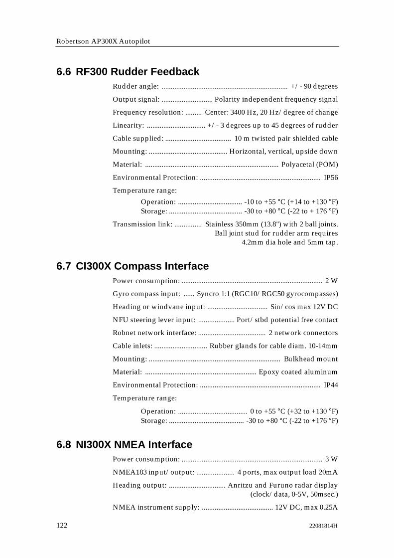
Robertson AP300X Autopilot
122 22081814H
6.6 RF300 Rudder FeedbackRudder angle: ..................................................................... +/- 90 degrees
Output signal: ............................ Polarity independent frequency signal
Frequency resolution: ......... Center: 3400 Hz, 20 Hz/degree of change
Linearity: ................................ +/- 3 degrees up to 45 degrees of rudder
Cable supplied: .................................... 10 m twisted pair shielded cable
Mounting: ........................................... Horizontal, vertical, upside down
Material: ......................................................................... Polyacetal (POM)
Environmental Protection: .................................................................. IP56
Temperature range:
Operation: ................................... -10 to +55 °C (+14 to +130 °F)Storage: ........................................ -30 to +80 °C (-22 to + 176 °F)
Transmission link: ............... Stainless 350mm (13.8") with 2 ball joints.Ball joint stud for rudder arm requires
4.2mm dia hole and 5mm tap.
6.7 CI300X Compass InterfacePower consumption: ............................................................................. 2 W
Gyro compass input: ...... Syncro 1:1 (RGC10/RGC50 gyrocompasses)
Heading or windvane input: ................................. Sin/cos max 12V DC
NFU steering lever input: .................... Port/stbd potential free contact
Robnet network interface: ..................................... 2 network connectors
Cable inlets: ............................. Rubber glands for cable diam. 10-14mm
Mounting: ........................................................................ Bulkhead mount
Material: ............................................................. Epoxy coated aluminum
Environmental Protection: .................................................................. IP44
Temperature range:
Operation: ...................................... 0 to +55 °C (+32 to +130 °F)Storage: ......................................... -30 to +80 °C (-22 to +176 °F)
6.8 NI300X NMEA InterfacePower consumption: ............................................................................. 3 W
NMEA183 input/output: ..................... 4 ports, max output load 20mA
Heading output: ............................... Anritzu and Furuno radar display(clock/data, 0-5V, 50msec.)
NMEA instrument supply: ....................................... 12V DC, max 0.25A

Technical Specifications
22081814H 123
Robnet network interface: ..................................... 2 network connectors
Cable inlets: .............................. Rubber glands for cable diam 10-14mm
Mounting: ........................................................................ Bulkhead mount
Material: ............................................................. Epoxy coated aluminum
Environmental Protection: .................................................................. IP44
Temperature range:Operation: ...................................... 0 to +55 °C (+32 to +130 °F)Storage: ......................................... -30 to +80 °C (-22 to +176 °F)
6.9 LF3000 Linear FeedbackStroke: .............................................................................................. 300 mm
Operating principle: .. Variable differential transformer, exitation and
signal conversion by separate LFI3000 Interface unit
Power: ........................................................................ Supplied by LFI3000
Dimensions: ............................................ 465 mm (18,3") x 22 (0,86") dia.
Mounting: ....................................................... Clamped to hydraulic ram
Material: ..........Rod: ..................................................................... Stainless
Tube: .....Epoxy coated sea water resistant aluminium
Environmental protection: .................................................................. IP67
6.10 LFI3000 Feedback InterfaceSupply: ......................................................................... From Junction Unit
Output signal ......................... Polarity independent variable frequency
Frequency resolution ................ Center 3400Hz, 20Hz/degree equal to1,7 mm travel
Linearity: ................................ +/- 3 degrees up to 45 degrees of rudder
Cable supplied: .................................................... 1,5 m TP shielded cable
Dimensions: ......................................... 160 mm x 126 mm (6.3 in x 5 in.)
Weight: ................................................... 0,7 kg including cable (1,6 lbs.)
Power consumption: .................................................................... 0,9 watts
Temperature range:
Operation: ..................................... 0 to +70 °C (+32 to + 158 °F)Storage: ......................................... -30 to +80 °C (-22 to +176 °F)
Environmental Protection: .................................................................. IP56
Mounting: ....................................................................... Deck or bulkhead
Material: ...................................................................................... Black ABS
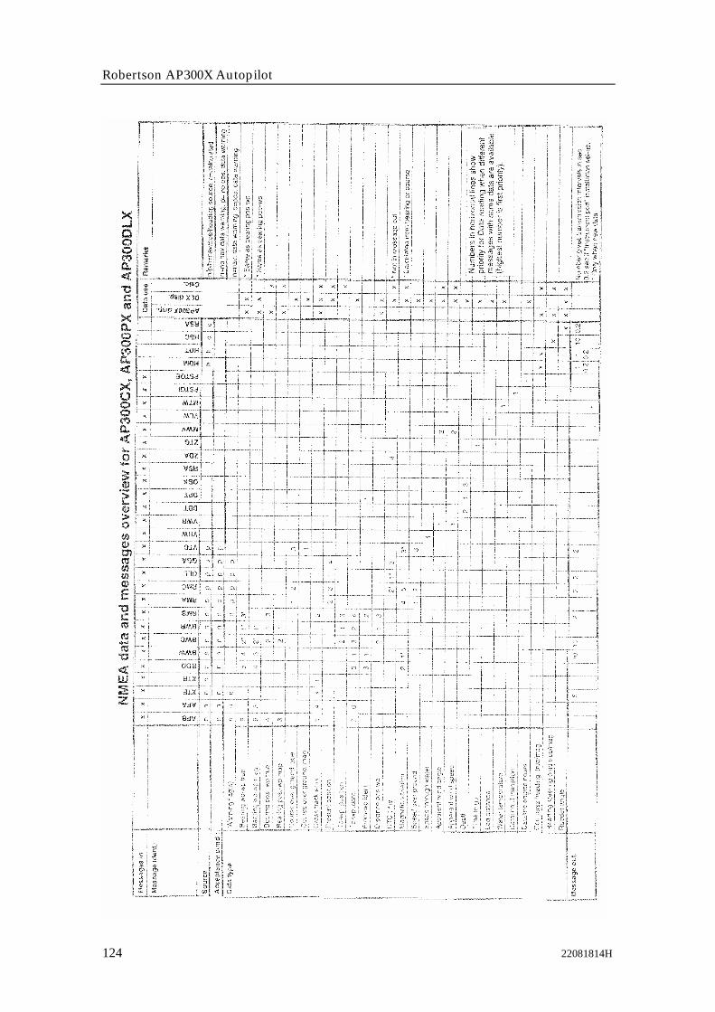
Robertson AP300X Autopilot
124 22081814H
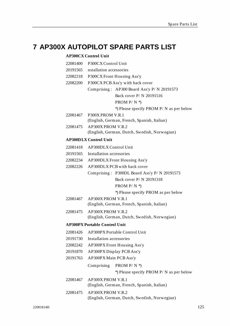
Spare Parts List
22081814H 125
7 AP300X AUTOPILOT SPARE PARTS LISTAP300CX Control Unit
22081400 P300CX Control Unit20191565 nstallation accessories22082218 P300CX Front Housing Ass'y22082200 P300CX PCB Ass'y with back cover
Comprising : AP300 Board Ass'y P/N 20191573Back cover P/N 20191516PROM P/N *)*) Please specify PROM P/N as per below
22081467 P300X PROM V.R.1(English, German, French, Spanish, Italian)
22081475 AP300X PROM V.R.2(English, German, Dutch, Swedish, Norwegian)
AP300DLX Control Unit
22081418 AP300DLX Control Unit20191565 Installation accessories22082234 AP300DLX Front Housing Ass'y22082226 AP300DLX PCB with back cover
Comprising : P300DL Board Ass'y P/N 20191573Back cover P/N 20191318PROM P/N *)*) Please specify PROM as per below
22081467 AP300X PROM V.R.1(English, German, French, Spanish, Italian)
22081475 AP300X PROM V.R.2(English, German, Dutch, Swedish, Norwegian)
AP300PX Portable Control Unit
22081426 AP300PX Portable Control Unit20191730 Installation accessories22082242 AP300PX Front Housing Ass'y20191870 AP300PX Display PCB Ass'y20191763 AP300PX Main PCB Ass'y
Comprising PROM P/N *)*) Please specify PROM P/N as per below
22081467 AP300X PROM V.R.1(English, German, French, Spanish, Italian)
22081475 AP300X PROM V.R.2(English, German, Dutch, Swedish, Norwegian)

Robertson AP300X Autopilot
126 22081814H
Junction Units
22081830 J300X Junction unit22081822 J3000X Junction unit22081954 J300X-40 Junction unit22081707 J300X Installation accessories22081855 J3000X Installation accessories22081962 J300X-40 Installation accessories22081251 J300X Power PCB Ass'y22081715 J3000X Power PCB Ass'y22081947 J300X-40 Power PCB Ass'y22081285 J300X Main PCB Ass'y (All models)22081640 PROM for all junction units22081434 J300X/J3000X Base plate22082036 J300X-40 Base plate22081350 Main cover22081368 Terminal cover
RFC35 Electronic Fluxgate Compass
22081459 RFC35 Fluxgate Compass22081442 Installation accessories consisting of:20104972 Mounting plate (2)44140762 Screw 3.5x25 (2)44140770 Screw 30x9 (4)22081376 Plug (2)22081178 RFC35 PCB Ass'y
RF300 Rudder Feedback Unit
20193462 RF300 Rudder Feedback20193470 RF300 transmission lever20193454 RF300 transmission link44133122 Transmission rod M5x325mm20193624 RF300 Ball joint Ass'y (2)
CI300X Compass Interface
22081137 CI300X Compass Interface22082044 CI300X PCB Ass'y20193256 Box20193264 Cover44138816 Cover nutknobs20191607 Robnet Cable 7m
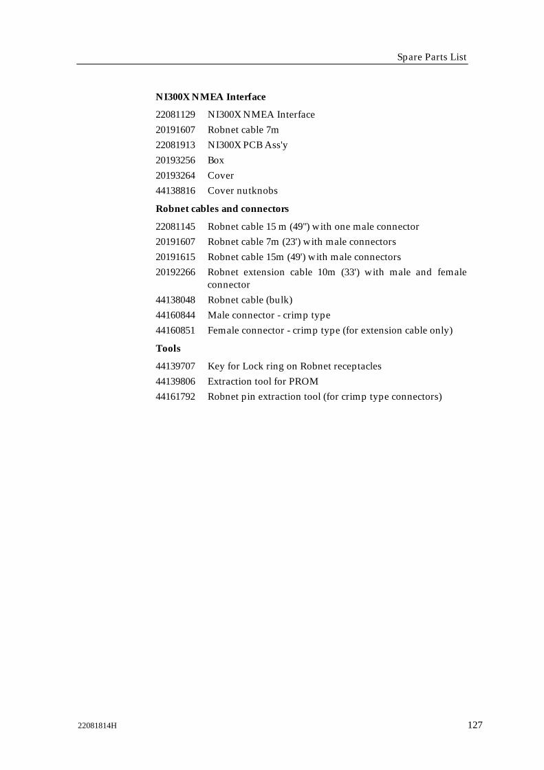
Spare Parts List
22081814H 127
NI300X NMEA Interface
22081129 NI300X NMEA Interface20191607 Robnet cable 7m22081913 NI300X PCB Ass'y20193256 Box20193264 Cover44138816 Cover nutknobs
Robnet cables and connectors
22081145 Robnet cable 15 m (49") with one male connector20191607 Robnet cable 7m (23') with male connectors20191615 Robnet cable 15m (49') with male connectors20192266 Robnet extension cable 10m (33') with male and female
connector44138048 Robnet cable (bulk)44160844 Male connector - crimp type44160851 Female connector - crimp type (for extension cable only)
Tools
44139707 Key for Lock ring on Robnet receptacles44139806 Extraction tool for PROM44161792 Robnet pin extraction tool (for crimp type connectors)
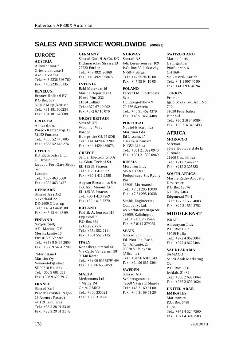
Robertson AP300X Autopilot
128 22081814H
SALES AND SERVICE WORLDWIDE (000929)
EUROPEAUSTRIAAllroundmarinGriesfeldstrasse 1A-2351 ViennaTel.: +43 2236 646 760Fax: +43 2236 63135
BENELUXBennex Holland BVP O Box 5873200 AM SpijkenisseTel.: +31 181 600234Fax: +31 181 626688
CROATIAAlmar d.o.o.Porec - Kamenarija 1251452 FuntanaTel.: +385 52 445 005Fax: +385 52 445 276
CYPRUSK.J. Electronics Ltd.G. Drosini Str.Jacovou Port Gate-Shops6-7LarnacaTel.: +357 463 6360Fax: +357 463 5427
DENMARKSimrad AS (DK)Naverland 22DK-2600 GlostrupTel.: +45 43 44 49 00Fax: +45 43 44 48 99
FINLAND(Professional)AT - Marine OYMesikukantie 16FIN 01300 VantaaTel.: +358 9 5494 2600Fax: +358 9 5494 2700
(MarineLine)Maritim OyVeneentekijäntie 1SF 00210 HelsinkiTel: +358 9 681 631Fax: +358 9 692 7917
FRANCESimrad SarlParc d’Activités Ragon23 Avenue Pasteur44 119 TreillieresTel.: +33 2 28 01 23 01Fax: +33 2 28 01 21 43
GERMANYSimrad GmbH & Co. KGDithmarscher Strasse 1326723 EmdenTel.: +49 4921 96860Fax: +49 4921 968677
ESTONIABalti MerekaatridMarine DepartmentPärnu Mnt. 23211314 TallinnTel.: +372 67 10 002Fax: +372 67 10 076
GREAT BRITAINSimrad UKWoolmer WayBordonHampshire GU35 9DETel.: +44 1420 483200Fax: +44 1420 489073
GREECESelmar Electronics S.A.14, Gian. Tzelepi Str.EL-185 31 PiraeusTel.: +30 1 411 9521Fax: +30 1 411 9588
Aegean Electronics S.A.1-3, Akti Miaouli Str.EL-185 35 PiraeusTel.: +30 1 413 7269Fax: +30 1 413 7270
ICELANDFridrik A. Jonsson HFEyjarslod 7P.O.Box 362121 ReykjavikTel.: +354 552 2111Fax: +354 552 2115
ITALYKongsberg Simrad Srl.Via Carlo Veneziani, 5800148 RomeTel.: +39 06 6557579/498Fax: +39 06 6557859
MALTAMedcomms Ltd.4 Msida Rd.Gzira GZR03Tel.: +356 335521Fax: +356 310820
NORWAYSimrad ASJoh. Berentsensvei 109P.O. Box 53, LaksevågN-5847 BergenTel.: +47 55 94 10 00Fax: +47 55 94 10 05
POLANDEscort Ltd. ElectronicsSyst.Ul. Energetyków 970-656 SzczecinTel.: +48 91 462 4379Fax: +48 91 462 4408
PORTUGALNautel-ElectronicaMaritima Lda.Ed Liscont, 1’Cais de AlcantaraP-1350 LisboaTel.: +351 21 392 0940Fax: +351 21 392 0949
RUSSIAMoretron Ltd.SIVA CenterPodgornaya Str. RybnyPort183001 MurmanskTel.: +7 51 295 10038Fax: +7 51 295 10038
Simbia EngineeringCompany, Ltd.4A Verhneozernaja Str.236008 KaliningradTel.: +7 0112 215492Fax: +7 0112 279055
SPAINSimrad Spain, SLEd. Nou Pla, Esc 6C/. Alicante, 2303570 Villajoyosa(Alicante)Tel.: +34 96 681 0149Fax: +34 96 685 2304
SWEDENSimrad ABSvalörtsgatan 1442668 Västra FrölundaTel.: +46 31 69 51 00Fax: +46 31 69 51 20
SWITZERLANDMarine PartsHeimgartnerPfäffikerstr. 6CH 8604Volketswil/ZürichTel.: +41 1 997 40 90Fax: +41 1 997 40 94
TURKEYPromarIgrip Sokak Gul Apt. No:7/281030 FenerbahceIstanbulTel.: +90 216 3460894Fax: +90 216 3461493
AFRICAMOROCCOSoremar36-38, Boulevard de laGironde21900 CasablancaTel.: +212 2 442777Fax: +212 2 305383
SOUTH AFRICAMarine Radio AcousticDevices ccP O Box 12076N1 City 7463Edgemead 7441Tel.: +27 21 559 4003Fax: +27 21 559 2752
MIDDLE EASTISRAELAlhoutyam Ltd.P.O. Box 196331019 HaifaTel.: +972 4 8620804Fax: +972 4 8627404
SAUDI ARABIASAMACOSaudi Arab MarketingCo.P.O. Box 5968Jeddah, 21432Tel.: +966 2 699 0064Fax: +966 2 699 1024
UNITED ARABEMIRATESMaritronicsP.O. Box 6488DubaiTel.: +971 4 324 7500Fax: +971 4 324 7503

Sales and Service World-wide
22081814H 129
BAHRAINMaritronics - BahrainC.R. No. 5303-03P. O. Box 5409ManamaTel.: +973 593 409Fax: +973 593 352
LEBANONSelcom Electronics SarlP.O. Box 55541Dekwaneh Main StreetBeirutTel.: +961 149 1489Fax: +961 149 5325
IRANDarya Negar Co.Office 2, 1st Floor,Bldg. No. 64Fatemi SquareTeheranTel.: +98 21 65 78 72Fax: +98 21 80 10 360
PACIFICAUSTRALIAQuin Marine Pty. Ltd.89 St Vincent StreetPort Adelaide, SA 5015Tel.: +61 88 447 1277Fax: +61 88 341 0567
NEW ZEALANDAdvance Trident Ltd.P.O. Box 4174KingslandAucklandTel.: +64 9 358 0554Fax: +64 9 358 0551
ASIASINGAPOREKongsberg Simrad Pte.Ltd.29 Intl. Business Park#01-02 Acer BuildingTower BSingapore 609923Tel.: +65 899 5800Fax: +65 899 1225
Jason Electronics Pte Ltd.Blk 194 Pandan Loop#06-05Pantech IndustrialComplexSingapore 128383Tel.: +65 872 0211Fax: +65 872 1800
HONG KONGChina Int. Trading Ent.(CITE)P.O. Box 24633,AberdeenTel.: +852 2 552 0178Fax: +852 2 873 0679
INDIA(Professional)Norinco Private Ltd.Priya Square38/265D, Karshaka Road682 016 CochinTel.: +91 484 323 675Fax: +91 484 323 694
(MarineLine)Deekay International5A, Mithila, J.B. NagarD.P. Rd. Andheri (E)Bombay 400059Tel.: +91 22 838 7874Fax: +91 22 838 9659
INDONESIAPT Sarana TeknologiSamuderaWisma Dharmala SaktiAnnexe Building 7th
FloorJL. Jenderal SudirmanKav.32Jakarta 10220Tel.: +62 21 570 61 28Fax: +62 21 837 94 096
SOUTH KOREATurn-On Electronics Co.7th fl., Dong-A Ilbo Bldg.53-11, 4-KA,Choongang-DongChoong-Ku, PusanTel.: +82 51 462 3930Fax: +82 51 462 3089
Lucky Susan Co. Ltd.K.P.O. Box 1666, SeoulTaesung B/D. #50860-17, Taepyong-Ro 1-KaChung-Ku, SeoulTel.: +82 2 736 4328Fax: +82 2 739 5689
JAPANShipmate Japan Co. Ltd.Ohsanbashi Bldg., 3rd fl.1-1 Kaigan-Dori Naka-KuYokohamaTel.: +81 4 5212 0770Fax: +81 4 5212 0771
Nippon Kaiyo Co, Ltd.9-2 Sakae-Cho, Kita-KuTokyo 114-0005Tel.: +81 3 3913 2301Fax: +81 3 3913 3479
AMERICASCANADAKongsberg SimradMesotech Ltd(Maritime Dept.)202 Brownlow AvenueDartmouth N.S. B3B 1T5Tel.: +1 902 468 2268Fax: +1 902 468 2217
USASimrad Inc.19210 33rd Avenue WestSuite ALynnwood WA 98036Tel.: +1 425 778 8821Fax: +1 425 771 7211
Simrad Inc.1500 NW 1st StreetSuite 1-EDania, FL 33004Tel.: +1 954 922 7700Fax: +1 954 922 0707
ARGENTINAR.C. InternationalAv. Corrientes 2958 11 381193 Buenos AiresTel.: +54 11 4862 5774Fax: +54 11 4862 5774
BRAZILDemo Offshore LtdaAv. Marechal Camara160Sala 614,Centro Rio de JaneiroRJ-20020-080Tel.: +55 21 524 0758Fax: +55 21 533 0552
CHILESimrad S.A.Providencia 1100Torre C.Dpto. 404ProvidenciaSantiagoTel.: +56-2-235-1068Fax: +56-2-235-8732
PERUSimrad Peru S.A.Calle Los Topacios 266-268Urb. San AntonioBellavista - CallaoTel.: +51 1 453 7477Fax: +51 1 453 7325
URUGUAYElectromaritimaUruguaya Ltda.Guatemala 126011800 MontevideoTel.: +59 8 2 924 7139Fax: +59 8 2 924 7138
The above companiesrepresent only mainimporters. Each countryis in addition served by anetwork of local serviceoutlets.
Some importersrepresent only specificmarket segmentsaccording to thefollowing codes:Professional:Coastal and Fishery marketMarineLine:Leisure market
Simrad Robertson ASP.O. Box 55N-4379 EgersundNorway
Tel: +47 51 46 20 00Fax: +47 51 46 20 01www.simrad.com

Robertson AP300X Autopilot
130 22081814H