Simplified Analytical Method for Estimating the Resistance...
40
Hindawi Publishing Corporation Journal of Applied Mathematics Volume 2012, Article ID 763849, 39 pages doi:10.1155/2012/763849 Research Article Simplified Analytical Method for Estimating the Resistance of Lock Gates to Ship Impacts Lo¨ ıc Buldgen, 1 Herv ´ e Le Sourne, 2 and Philippe Rigo 1 1 Faculty of Applied Sciences and ANAST, University of Li` ege, 1 Chemin des Chevreuils, 4000 Li` ege, Belgium 2 Mechanical Engineering Department (LE2M), ICAM Nantes Campus, 35 avenue du Champ de Manœuvres, 44470 Carquefou, France Correspondence should be addressed to Lo¨ ıc Buldgen, [email protected] Received 19 January 2012; Accepted 26 March 2012 Academic Editor: Celso P. Pesce Copyright q 2012 Lo¨ ıc Buldgen et al. This is an open access article distributed under the Creative Commons Attribution License, which permits unrestricted use, distribution, and reproduction in any medium, provided the original work is properly cited. The present paper is concerned with the design of lock gates submitted to ship impacts. In this paper, a simplified analytical method is presented to evaluate the resistance of such structures under collision. The basic idea is to assume that the resistance is first provided through a local deforming mode, corresponding to a localized crushing of some impacted structural elements. For consecutive larger deformations, the resistance is then mostly provided through a global deforming mode, corresponding to an overall movement of the entire gate. For assessing the resistance in the case of the local deforming mode, the structure is divided into a given number of large structural entities called “superelements.” For each of them, a relation between the resistance of the gate and the penetration of the striking ship is established. However, as some results are already available in the literature, this subject is not treated extensively in this paper. On the contrary, the calculation of the resistance of the gate provided through the global mode is detailed and the strategy to switch from local to global deformation is highlighted. Finally, we propose to validate our developments by making a comparison between results obtained numerically and those predicted by the present analytical approach. 1. Introduction Amongst all the loads that have to be expected for the design of lock gates, the collision of a vessel is one of the most difficult to handle. A collision may result in some minor damages to the plating or to the stiffening system of the gate, producing, for example, a local loss of water tightness. However, if the initial velocity of the striking ship is large enough, the displacements imposed to the structure may cause a complete collapse of the gate. This would result in the emptying of the damaged reach, with probably the complete sinking of the striking ship.
-
Upload
truongdiep -
Category
Documents
-
view
218 -
download
0
Transcript of Simplified Analytical Method for Estimating the Resistance...

Hindawi Publishing CorporationJournal of Applied MathematicsVolume 2012, Article ID 763849, 39 pagesdoi:10.1155/2012/763849
Research ArticleSimplified Analytical Method for Estimatingthe Resistance of Lock Gates to Ship Impacts
Loıc Buldgen,1 Herve Le Sourne,2 and Philippe Rigo1
1 Faculty of Applied Sciences and ANAST, University of Liege, 1 Chemin des Chevreuils,4000 Liege, Belgium
2 Mechanical Engineering Department (LE2M), ICAM Nantes Campus,35 avenue du Champ de Manœuvres, 44470 Carquefou, France
Correspondence should be addressed to Loıc Buldgen, [email protected]
Received 19 January 2012; Accepted 26 March 2012
Academic Editor: Celso P. Pesce
Copyright q 2012 Loıc Buldgen et al. This is an open access article distributed under the CreativeCommons Attribution License, which permits unrestricted use, distribution, and reproduction inany medium, provided the original work is properly cited.
The present paper is concerned with the design of lock gates submitted to ship impacts. In thispaper, a simplified analytical method is presented to evaluate the resistance of such structuresunder collision. The basic idea is to assume that the resistance is first provided through a localdeforming mode, corresponding to a localized crushing of some impacted structural elements.For consecutive larger deformations, the resistance is then mostly provided through a globaldeforming mode, corresponding to an overall movement of the entire gate. For assessing theresistance in the case of the local deforming mode, the structure is divided into a given number oflarge structural entities called “superelements.” For each of them, a relation between the resistanceof the gate and the penetration of the striking ship is established. However, as some results arealready available in the literature, this subject is not treated extensively in this paper. On thecontrary, the calculation of the resistance of the gate provided through the global mode is detailedand the strategy to switch from local to global deformation is highlighted. Finally, we propose tovalidate our developments by making a comparison between results obtained numerically andthose predicted by the present analytical approach.
1. Introduction
Amongst all the loads that have to be expected for the design of lock gates, the collision of avessel is one of the most difficult to handle.
A collision may result in someminor damages to the plating or to the stiffening systemof the gate, producing, for example, a local loss of water tightness. However, if the initialvelocity of the striking ship is large enough, the displacements imposed to the structure maycause a complete collapse of the gate. This would result in the emptying of the damagedreach, with probably the complete sinking of the striking ship.

2 Journal of Applied Mathematics
To deal properly with ship impact, it is of course possible to use nonlinear finiteelement methods. Nevertheless, at the predesign stage of a gate, such approaches are ratherrestrictive because of the time required to model and simulate collisions. Therefore, we pro-pose here to establish an analytical simplifiedmethod in order to verify the resistance of gatessubmitted to a ship impact.
For the moment, the development of such simplified methods is not really reportedin the literature. Some very interesting results have been established for the purpose ofanalyzing collisions between two ships. For example, the crushing resistance of web girdershas already been theoretically and experimentally studied by Wierzbicki and CulbertsonDriscoll [1], Wang and Ohtsubo [2], Simonsen [3], Zhang [4], and Hong and Amdahl [5].Each of them developed analytical formulations that may be useful for studying locally thecontact between a ship and a gate.
Additional results are also available for impacted panels, which have been investi-gated in detail by Wang [6], Wang and Ohtsubo [7], and Zhang [8]. Some references are alsouseful for evaluating the resistance of metal plates after rupture, when they are submitted totearing and cutting. For example, these phenomena have been studied byWang and Ohtsubo[7], Zhang [8], Wierzbicki [9], and Zheng [10]. In the particular case of stiffened panelssubjected to lateral loads, the developments performed by Paik [11], Cho and Lee [12], orUeda et al. [13] constitute a very accurate basis for performing analytical estimation of theresistance of such structural components.
The previous brief literature review shows that some results are already available todeal with a simplified approach of collisions between ships and gates. All these developmentsconstitute of course an invaluable help for developing simplified collision models of lockgates, but they are not sufficient. The principal reason is that the behavior of an impactedgate may not directly be assimilated to the one of an impacted vessel. Consequently, someresearches in this domain are still needed.
The aim is to develop some analysis tools, which would be time and cost-effective inthe predesign stage of gates. To achieve this goal, we will follow a similar method to the oneproposed by Le Sourne et al. [14]. The basic idea is that the total resistance of the struck gateis provided by two deforming modes:
(i) the local one, which implies a local crushing of all the impacted structural elements;
(ii) the global one, which supposes an overall deformation of the gate.
In the present paper, we try to go further into this philosophy.
2. General Description of the Problem
In this paper, we consider the exceptional situation of ship colliding with a lock gate. Thecollision scenario is depicted in Figure 1, where the general coordinate system is denotedby (X,Y,Z). For avoiding confusion in the present paper, we will use the terminology“transversal,” “vertical,” and “longitudinal” in accordance with the respective orientationof X, Y , and Z axes.
In our scenario, the vessel is coming from upstream, and, consequently, the impact islocated on the downstream gate of the lock. It is clear that this case is the least desired becausethe hydrostatic pressure is acting in the same direction as the impact force. On the contrary,if the collision was happening in the downstream reach of the lock, the resulting hydrostaticpressure would act in opposition with the impact force and would compensate it partially.

Journal of Applied Mathematics 3
Z
V0
Gate
Downstream
Upstream
ShipM0
p
q
X
Y
hb
A
ΓZb
Xb
Z
Y
X
V0
φhb
ψ
Figure 1: Plane and section views of the impact situation.
In order to derive an analytic procedure for estimating the collision resistance of thegate, we first need to describe the ship and the gate using various parameters. This is thepurpose of the subsequent sections.
2.1. Geometrical Description of the Striking Vessel
The vessel is characterized through the following: massM0 and velocity V0. In other words,we assume a certain kinetic energy M0V
20 /2 for the striking ship. These two parameters are
chosen according to the waterway class, which determines the maximal speed as well as theallowable shipping of the vessels.
From the geometric point of view, we first assume that the shape of the bow at theuppermost deck may be fairly modeled by a parabola Γ (see Figure 1) having a transversalradius p and a longitudinal radius q. Consequently, in the local axes (xb, zb) positioned inpoint A, the equation of the curve Γ is given by
Γ ≡ zb = q ·(1 − x2
b
p2
). (2.1)
In order to have a global description of the geometry of the ship, it is also required tointroduce the following parameters (see also Figure 1):
(i) the height hb between the uppermost deck and the bottom of the ship;
(ii) the side angle ψ and the stem angle φ, which are used to fix the inclination of thebow.
It is important to note that all the above mentioned properties are required input data,which have to be provided by the user before the beginning of the calculation process.

4 Journal of Applied Mathematics
Y
XZ
H
L
Figure 2: Three-dimensional representation of the considered type of gate.
2.2. Description of the Gate
In this paper, we will only focus on gates with a single plating. A three-dimensional pictureof such a structure is depicted in Figure 2, where the notations H and L are used forrepresenting, respectively, the total vertical and the total transversal extension of the gate.In fact, these gates are rather similar to large orthotropic plates, constituted by a plating (forretaining water) stiffened by the following elements (see Figures 2 and 3):
(i) the transversal frames, which may be seen as beams presenting a T-shaped cross-section; they are placed in the transversal direction (i.e., along the X axis);
(ii) the vertical frames, which are also beams with a T-shaped cross-section but arearranged in the vertical direction (i.e., along the Y axis);
(iii) the stiffeners, which are optional reinforcing beams disposed transversally on theplating in order to avoid instabilities in shells; their cross-section may exhibitvarious shapes.
The geometric data required for characterizing the stiffening system are mainly thedimensions of the different cross-sections. As shown in Figure 3, the needed values are theheight hw and thickness tw of the web, as well as the height hf and thickness tf of the flange.For the plating, it is only necessary to precise its thickness tp. With all these parametersand knowing the properties of the material constituting the gate, it is possible to derive themechanical properties of all the stiffening elements.
Another point that has to be clarified concerns the assumed support conditions ofthe structure. When the gate is closed, the contact is supposed to be established against thesupport denoted by S1, S2, and S3 in Figure 3, and, consequently, we may admit that:
(i) the gate is simply applied against the two lock walls (supports S1 and S2 inFigure 3). The translational degree of freedom in the Z direction has therefore tobe blocked along the all vertical extensions of the gate in S1 and S2;

Journal of Applied Mathematics 5
V0
ShipM0
Y
Z
1
2
3
4
Gate
Upstream
Downstream
Downstreamtf
tw
S1 S2
S3
L
H
Z
V0
hf
hw
ShipM0
34 X
1
Upstream
1- Transversal frame2- Stiener3- Vertical frame4- Plating
Figure 3: Plan and section views of the gate.
(ii) the gate is simply applied against the sill located at the bottom of the chamber(support S3 in Figure 3). Therefore, it seems to be reasonable to restrain thetranslational displacement in the Z direction along the all transversal extension ofthe gate in S3.
2.3. Description of the Material
The present paper is concerned with the resistance of a lock gate impacted by a ship. Theprimary goal is not to assess the damages caused to the vessel: we are much more interestedin the ability aspect of the structural resistance to collisions. As a consequence, we assumethat the material constituting of the striking vessel is infinitely rigid. In other words, we willnot allow any deformation in the ship structure, which is a conservative approach in theevaluation of the resistance.
On the contrary, the previous hypothesis is not valid for the gate as it is supposed to bedeformable. Nowadays, the most common material used for such structures is constructionsteel, so we will only deal with this material in the present paper. This kind of steel exhibits

6 Journal of Applied Mathematics
σ
σu
σ0
(1)
(2)
ε0 εuε
Figure 4: Real (1) and idealized (2) constitutive law of standard construction steel.
a constructive law represented by curve (1) in Figure 4 and may be defined by the followingparameters:
(i) the maximal elastic stress σ0, with which is associated the maximal elastic deforma-tion ε0;
(ii) the rupture stress σu, for which tearing is observed in the material; the correspond-ing deformation is called εu;
(iii) Young’s modulus E characterizing the stiffness of the material during the elasticphase.
In order to simplify the analytical derivation of the collision resistance, we willsuppose here that the steel has a so-called elastic-perfectly plastic behavior. This means thatthe relation between stresses and strains is idealized by curve (2) in Figure 4. Consequently,we neglect the additional resistance coming from hardening of steel, which is in fact aconservative assumption.
2.4. General Positioning in the Space
To define the collision scenario, it is still necessary to position the resistance element as wellas the striking ship within the area of space. To do so, different kinds of input data are stillrequired:
(i) the impact point E, that is, the point of the gate where the first contact betweenthe bow and the plating will be established; this point is located by its coordinate(XE, YE), as shown in Figures 5 and 6;
(ii) the transversal positions Xi of the vertical frames, that is, the position of eachvertical frame along the X axis (see Figure 5);
(iii) the vertical positions Yi of the horizontal frames, that is, the position of eachhorizontal frame along the Y axis (see Figure 5);
(iv) the total number of stiffeners distributed along the vertical heightH of the gate.
When all the previous inputs are placed, the three-dimensional configuration of thegate is completely defined.

Journal of Applied Mathematics 7
X1Z
Y
X
X2
X3X4
X5 X6 = L
Y1
Y2
Y3
Y4
Y5 = H
XE
YEE
Figure 5: Position of the resistance elements and of the impact point.
3. Methodology for Evaluating the Collision Resistance
3.1. General Principles
When a ship collides with a gate, its action on the impacted structure may be represented bya force Pt acting in the same direction as the indentation δ of the striking vessel (see Figure 6).By equilibrium, this forcemay be seen as the resistance opposed by the gate to the progressionof the ship. Therefore, the goal of our work is to assess the value of Pt for a given indentationδ of the vessel. In other words, our aim is to derive the evolution of Pt with δ by means ofsimplified analytical procedures.
When a ship is entering into a lock, it seems reasonable to admit that its initial velocityV0 is quite small. Consequently, the dynamic effects in the gate remain moderate, and wemay assume that the initial kinetic energy M0V
20 /2 of the ship is entirely dissipated by
deformation of the impacted gate Eint, that is,
12M0V
20 = Eint. (3.1)
Knowing the relation between Pt and δ, it is possible to calculate Eint simply byintegration (see Figure 7):
Eint =∫δmax
0Pt(δ) · dδ. (3.2)

8 Journal of Applied Mathematics
δδ
Pt
V0
Ship
Z Z
Y Y
E E
YE
Figure 6: Representation of the impact force.
δ
Pt
Eint
δmax
Figure 7: Evolution of the resistance of the gate with the penetration of the ship.
For a given ship of mass M0 and velocity V0, (3.1) and (3.2) give the maximalpenetration δmax, which has to be supported by the gate to withstand an impact with such avessel. According to the maximal degradation level accepted for the gate, it can be decided ifthis value of δmax may be applicable or not.
3.2. Theoretical Basis
The theoretical basis for deriving Pt(δ) is the so-called upper-bound theorem, which states that“if the work rate of a system of applied loads during any kinematically admissible collapse of a structureis equated to the corresponding internal energy dissipation rate, then that system of loads will causecollapse, or incipient collapse, of the structure.”
In the present case, it is obvious that the external dissimilation rate Eext is entirelyproduced by the force Pt applied by the ship on the gate. Therefore, we have
Eext = PtV0 = Ptδ, (3.3)

Journal of Applied Mathematics 9
Z
Y
U1
U2
U3
X
A
B
Figure 8: Definition of the displacement field.
where (˙) = ∂/∂t is the derivative with respect to time. On the other hand, if we neglect thedynamic effects in the structure, the internal dissipation rate Eint is entirely coming from thedeformation of the gate. If V is the total volume of the structure, using Einstein’s notation wehave:
Eint =∫∫∫
Vσij εijdX dY dZ, (3.4)
where σij and εij are, respectively, the stress and the strain rate tensors defined over the entirevolume V of the gate. By application of the upper-bound theorem, we have
Eext = Eint =⇒ Pt =1δ
∫∫∫Vσij εijdX dY dZ. (3.5)
Consequently, (3.5) may be useful for deriving Pt(δ), provided that we are able toestablish a relation between the deformation rate εij and the velocity δ. To do so, we need todefine the displacements over the entire volume V. For example, in Figure 8, if we supposethat pointA is moving to point B for a given value of δ, we may define the three componentsU1(X,Y,Z, δ), U2(X,Y,Z, δ), and U3(X,Y,Z, δ) of the displacement field along axis X, Y , orZ, respectively. Note that in the remaining part of this paper, we will also use the equivalentnotations (U,V,W) and (X1, X2, X3) for designating (U1, U2, U3) and (X,Y,Z).
Using the Green-Lagrange tensor, it is finally possible to find a link between thedeformation and the penetration of the ship δ:
εij =12
(∂Ui
∂Xj+∂Uj
∂Xi+∂Uk
∂Xi
∂Uk
∂Xj
). (3.6)

10 Journal of Applied Mathematics
Equation (3.6)may be rewritten in the following shorter form:
εij = fij(X,Y,Z, δ) ⇐⇒ εij =∂fij
∂δδ. (3.7)
If we want to apply formula (3.5) to obtain a relation between Pt and δ, it is alsorequired to evaluate the stresses σij as a function of δ. This may be achieved using theconstitutive laws giving a relation between σij and εij . As the evolution of εij with δ is knownby (3.6), we also have
σij = gij(X,Y,Z, δ). (3.8)
Note that U1, U2, and U3 are unknown; for a given value of δ, we have to postulate acertain displacement field. Provided that this displacement field is kinematically admissible,we may apply the upper-bound theorem and calculate the resistance Pt with formula (3.5).In fact, if we combine (3.7) and (3.8) in (3.5), we obtain
Pt =∫∫∫
Vgij(X,Y,Z, δ)
∂fij
∂δdX dY dZ. (3.9)
Equation (3.9) is the needed relation between Pt and δ. However, the crucial point inthe above-described approach is to define properly a kinematically admissible displacementfield, otherwise the upper-bound theorem may lead to an overestimation of the crushingresistance.
3.3. The Superelements Method
The integration of (3.9) has to be performed over the whole volume V of the struck structureand is rather impossible to derive analytically. As a consequence, we need to simplify theprocedure described here over, and this may be achieved by splitting the gate into superele-ments.
The basic idea is to divide the gate into different substructures (the so-called superel-ements) that we assume working independently. For the lock gate depicted in Figure 2, thestructure may be decomposed into two types of superelements.
(i) The first superelement (SE1) is a rectangular plate simply supported on its fouredges and impacted perpendicularly to its plane, undergoing therefore importantout-of-plane displacements. Such elements are typically used for modeling theplating of the gate.
(ii) The second superelement (SE2) is a beam with a T-shaped cross-section, impactedin its plane. This kind of element is therefore quite relevant for modeling transversaland horizontal frames.
The division of the gate into superelements is only based on geometric considerations.In order to illustrate this process, we can consider, for example, only a small part of the lockgate represented in Figure 2, for which the division principle is shown in Figure 9. As it canbe seen, the two previous types of elements are sufficient for analyzing the structure.

Journal of Applied Mathematics 11
(a) 2 SE1’s are used for modeling the plating
(b) 3 SE2’s are used for modeling the vertical frames
(c) 2 SE2’s are used for modeling the transver-sal frames
Figure 9: Illustration of the subdivision of a structure into superelements.
As long as there is no contact between the ship and a given superelement, this latterwill remain inactive. This means that it will not deform until it has been collided by thebow, which is a consequence of the above-mentioned hypothesis that each substructure isworking independently. After being activated, the superelement will deform and dissipatea certain amount of energy. If the gate is divided into n superelements, as each of them isdecoupled from the others, the total internal energy Eint is simply obtained by summation ofthe individual contributions coming from the n superelements, that is,
Eint =n∑k=1
E(k)int =⇒ Eint =
n∑k=1
E(k)int , k ∈ {1, . . . , n}, (3.10)

12 Journal of Applied Mathematics
whereE(k)int is the internal energy dissipated by superelement number k for a given penetration
δ of the ship. Before using (3.10), it is preliminary required to know E(k)int . To do so, formula
(3.4) is still valid, but it has to be reequated for the case of superelement k:
E(k)int =
∫∫∫Vk
σ(k)ij · ε(k)ij · dX dY dZ, k ∈ {1, . . . , n}, (3.11)
where we have introduced the following notations:
(i) σ(k)ij is the stress tensor defined on the entire volume of superelement k,
(ii) ε(k)ij is the strain rate tensor defined on the entire volume of superelement k,
(iii) Vk is the volume of superelement k.
By following a similar reasoning as for relations (3.7) and (3.8), we get finally theparticularization of (3.9):
P(k)t =
∫∫∫Vk
g(k)ij ·
∂f(k)ij
∂δ· dX dY dZ =⇒ Pt =
n∑k=1
∫∫∫Vk
g(k)ij ·
∂f(k)ij
∂δ· dX dY dZ, (3.12)
where P (k)t may be seen as the contribution of superelement k to the total resistance of the gate
(note that Einstein’s notation has been used for the subscripts i and j). In fact, relation (3.12)is of primary importance because it constitutes the fundamental basis of the present method.Of course, we still need to develop adequately the functions involved in this expression. Thiswill be done later for SE1 and SE2.
3.4. Global and Local Deforming Modes
We previously assumed that each superelement was working independently from the others.This hypothesis remains valid as long as the penetration δ is reasonably minor. However,when the penetration δ of the ship is increasing, deformations will occur in superelementsthat still have not been undertaken by the bow. Consequently, the internal energy rate forsuperelement k may not be equal to zero, although it has not been activated. This may beseen on Figure 10, where out-of-plane displacements occur in the entire gate, even if someregions have not been impacted by the striking ship bow.
In order to take this coupling into account, let us introduce the concept of local andglobal deforming modes.
(i) We say that the structure exhibits a local deforming mode (see Figure 10) whenthe developments performed in Section 3.3 may be applied. In other words, wesuppose here that the penetration of the vessel into the gate is only allowed bythe local deformations of the activated superelements. Only the area impacted bythe ship contributes to the energy dissipation; the other parts of the gate remainundeformed. Of course, it may be easily understood that the local mode is onlyvalid for quite small values of δ.
(ii) On the contrary, we say that the structure exhibits a global deforming mode (seeFigure 10) when the displacements are not confined in a small area located around

Journal of Applied Mathematics 13
Globaldeformationof the gate
Localdeformationof the gate
E E: impact location
Figure 10: Illustration of global and local deformations.
the impact point. In this case, the entire gate is involved in the energy dissipationprocess and we may no longer assume that it behaves like a set of independentsubstructures activated progressively. Consequently, the superelements method isnot valid anymore and the resisting force Pt has to be evaluated by another waythan the one discussed in Section 3.3. This is precisely the topic of Section 5.
In order to model the phenomena depicted in Figure 10, we suppose that there isa sudden switch between the two modes. At the beginning, when the striking ship startsmoving into the gate, the resistance Pt is essentially provided by the local deforming mode.This statement remains valid as long as the penetration δ does not exceed a transition valueδt, for which the global mode is activated. In fact, the switch between the two modes occurswhen the force Pt applied by the ship on the gate is sufficient to cause an overall displacementof the whole structure. As soon as δ ≤ δt two different values for Pt are computed:
(i) the value of Pt obtained by supposing a local deforming mode; it is denoted by Ploc;
(ii) the value of Pt obtained by supposing a global deforming mode; it is denoted byPglob.
For a given penetration δ, Ploc and Pglob are then compared. As long as Ploc < Pglob, theforce exerted locally by the ship is not sufficient to cause an overall displacement of the gate,so the ship continues penetrating into the structure by local indentation. However, as soon asPloc = Pglob, the force becomes sufficient and the switch from the local mode to the global oneis obtained. The corresponding value of δ is the required δt (see Figure 11). After that, for thevalues of δ greater than δt, the resistance Pt is evaluated using equations specially developedfor the global mode (see Section 5).

14 Journal of Applied Mathematics
δ
Pglob
Ploc
Pt
δt
Figure 11: Evaluation of the transition from the local to the global mode.
4. Evaluation of the Resistance in the Local Deforming Mode
In the local deforming mode, the resistance of the gate is given by (3.12), where we assumethat the total resisting force is simply obtained by adding the individual contributions of allthe activated substructures. In this section, the laws governing the behavior of the two typesof superelements introduced in Section 3.3 are detailed. However, as this topic is already welltreated in the literature (see e.g., [4]), in order to avoid any redundancy, we have made aquite concise presentation of our approach.
Note
In the two following sections, we will use the superscript (k) for characterizing any propertyof the superelement number k.
4.1. Superelement Type 1 (SE1)
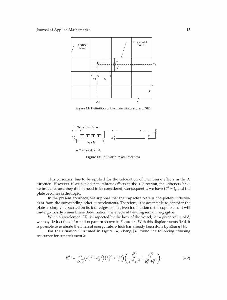
The first superelement is used for modeling the plating of the lock gate. Its boundaries aredefined by the surrounding transversal and vertical frames, as shown in Figure 12. Consid-ering the location of the impact point E, it is possible to fix the four parameters a(k)1 , a(k)2 , b(k)1 ,and b(k)2 .
The thickness of the plate is equal to the thickness tp of the plating. However, acorrection is needed for taking into account the horizontal stiffeners placed in the transversaldirection. During the collision, the stiffeners are mainly submitted to an axial extension; theywill deform along the X direction by exhibiting a membrane behavior. Consequently, theplate thickness has to be modified for taking these effects into account. If As is the total areaof all the stiffeners connected to the superelement k (see Figure 13), then we obtain
t(k)X = tp +
A(k)s
b(k)1 + b(k)2
. (4.1)
Journal of Applied Mathematics 15
X
Y
Verticalframe
Horizontalframe
b 1b 2E
a1a2
XE
YE
Figure 12: Definition of the main dimensions of SE1.
t p
Transverse frame
Total section= As
t X
Y
Z
b1 + b2
Figure 13: Equivalent plate thickness.
This correction has to be applied for the calculation of membrane effects in the Xdirection. However, if we consider membrane effects in the Y direction, the stiffeners haveno influence and they do not need to be considered. Consequently, we have t(k)Y = tp and theplate becomes orthotropic.
In the present approach, we suppose that the impacted plate is completely indepen-dent from the surrounding other superelements. Therefore, it is acceptable to consider theplate as simply supported on its four edges. For a given indentation δ, the superelement willundergo mostly a membrane deformation; the effects of bending remain negligible.
When superelement SE1 is impacted by the bow of the vessel, for a given value of δ,we may deduct the deformation pattern shown in Figure 14. With this displacements field, itis possible to evaluate the internal energy rate, which has already been done by Zhang [4].
For the situation illustrated in Figure 14, Zhang [4] found the following crushingresistance for superelement k:
P(k)t =
σ0
2√3
(a(k)1 + a(k)2
)(b(k)1 + b(k)2
)( t(k)X
a(k)1 a
(k)2
+t(k)Y
b(k)1 b
(k)2
). (4.2)

16 Journal of Applied Mathematics
a2 a1
b 2b 1
Y
X
E
δ
Figure 14: Displacement field assumed for SE1.
X
Y
Verticalframe
Horizontalframe
a1
a2
XE
YE
a1a2
Figure 15: Definition of the main dimensions of SE2.
4.2. Superelement Type 2 (SE2)
The second superelement that we will consider is used for modeling the transversal andvertical frames. The boundaries of a horizontal superelement are defined by the two adjacentvertical frames (and inversely for a vertical superelement).
The principal dimensions a(k)1 and a(k)2 (see Figure 15) of superelement k are positionedin accordance with the location of the impact point. The resisting cross-section has a T-shape,whose properties are defined in the general geometry of the gate.
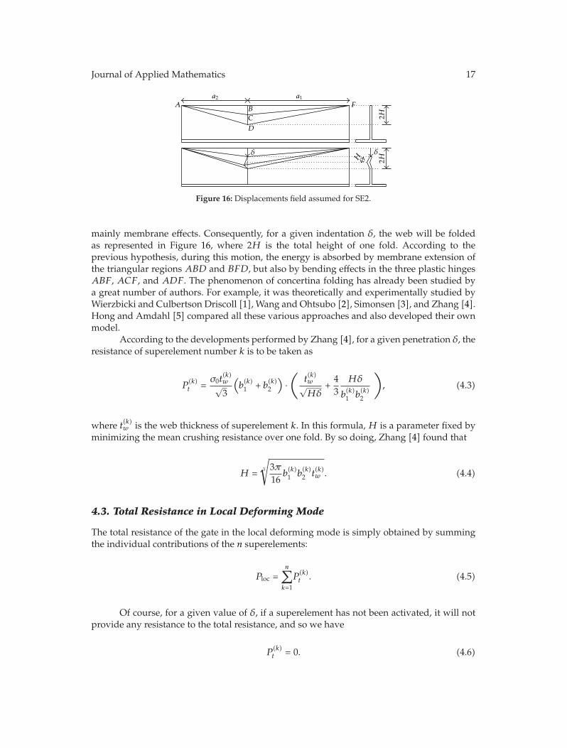
When this superelement is impacted, we suppose that it will deform like a concertina.To do so, three plastic hinges are formed. They are designated by ABF, ACF, and ADF inFigure 16. These lines allow for relative rotation between the triangular surfaces ABC, ACD,BCF, and FCD. Bending effects are therefore preponderant along these lines.
However, the rotational movement of the triangular surfaces is not free becauseit must respect the compatibility between surfaces ABD and BFD along their commonline BD. Therefore, surfaces ABD and BFD are submitted to an axial extension implying
Journal of Applied Mathematics 17
F
2H2HH
AB
C
D
δδ
a1a2
Figure 16: Displacements field assumed for SE2.
mainly membrane effects. Consequently, for a given indentation δ, the web will be foldedas represented in Figure 16, where 2H is the total height of one fold. According to theprevious hypothesis, during this motion, the energy is absorbed by membrane extension ofthe triangular regions ABD and BFD, but also by bending effects in the three plastic hingesABF, ACF, and ADF. The phenomenon of concertina folding has already been studied bya great number of authors. For example, it was theoretically and experimentally studied byWierzbicki and Culbertson Driscoll [1], Wang and Ohtsubo [2], Simonsen [3], and Zhang [4].Hong and Amdahl [5] compared all these various approaches and also developed their ownmodel.
According to the developments performed by Zhang [4], for a given penetration δ, theresistance of superelement number k is to be taken as
P(k)t =
σ0t(k)w√3
(b(k)1 + b(k)2
)·(
t(k)w√Hδ
+43
Hδ
b(k)1 b
(k)2
), (4.3)
where t(k)w is the web thickness of superelement k. In this formula,H is a parameter fixed byminimizing the mean crushing resistance over one fold. By so doing, Zhang [4] found that
H = 3
√3π16
b(k)1 b
(k)2 t
(k)w . (4.4)
4.3. Total Resistance in Local Deforming Mode
The total resistance of the gate in the local deforming mode is simply obtained by summingthe individual contributions of the n superelements:
Ploc =n∑k=1
P(k)t . (4.5)
Of course, for a given value of δ, if a superelement has not been activated, it will notprovide any resistance to the total resistance, and so we have
P(k)t = 0. (4.6)

18 Journal of Applied Mathematics
X
Y
E
YE
δ
XE
Z
(a)
YE
Y
Z
δ
(b)
Figure 17: (a) Assumed displacements field. (b) Displacement profile in the plan X = XE.
5. Evaluation of the Resistance in the Global Deforming Mode
5.1. Displacements Fields
When the global mode is activated, the gate is assumed to undergo a global motion involvingthe entire structure. The displacements field obtained in this case is plotted in Figure 17(a).As mentioned earlier, the first contact between the bow and the plating is located in pointE, with coordinates (XE, YE, 0). In the vertical plan passing through this point (i.e., the planwith equation X = XE), we suppose that the displacements are distributed along the verticalY axis as shown in Figure 17(b). The mathematical formulation of this profile is as follows:
WE(Y, δ) =
⎧⎨⎩δ · Y
YEif 0 ≤ Y < YE,
δ if YE ≤ Y ≤ H,(5.1)
whereWE indicates that we consider the displacement in the plan X = XE.The two previous formulae are only valid as long as there is no other contact between
the ship and the gate. However, as the vessel is moving forward, another contact will appearbetween the plating and the lowermost deck (see Figure 18). The particular value of δ forwhich this situation will occur is denoted by δc, and we have
δc = YE · cotφ, (5.2)
where φ is the stem angle. When δ ≥ δc, the contact between the bow and the plating iscompletely developed along the height hb (see Figure 18). Consequently, it is required to

Journal of Applied Mathematics 19
X
Y
YE
δ
XE
Z
E
hb
(a)
δ
YE
Y
Z
hb
φ
(b)
Figure 18: Assumed displacements field after second contact between the bow and the plating.
adapt the previous displacements fields in order to account for this phenomenon. Then, forδ ≥ δc, we will use the following equations:
WE(Y, δ) =
⎧⎪⎪⎪⎪⎨⎪⎪⎪⎪⎩
(δ − hb cotφ
) · Y
YE − hb if 0 ≤ Y < YE − hb,δ + (Y − YE)cotφ if YE − hb ≤ Y < YE,
δ if YE ≤ Y ≤ H.
(5.3)
5.2. Mechanical Model of the Gate
In the previous section, we have postulated a kinematically admissible displacements field.In accordance with the upper-bound method, it is now possible to use the principle of virtualvelocities in order to estimate the resistance of the structure deformed in the global mode.
Unfortunately, it is rather difficult to derive analytically the resistance of a gatesubmitted to the displacements given by (5.1), (5.3). In order to simplify the problem, wemake the assumption that the main contribution to the resistance is coming from the bending ofthe gate between the two lock walls. This hypothesis seems to be reasonable for a global mode,especially when the ratio H/L is wide, but we have to bear in mind that it may not remainvalid in some special cases. As a consequence, the resistance in the global deforming modeis mostly provided by transversal frames, the stiffeners. Therefore, the gate may be seen asa set of independent beams subjected to a given displacements field. The contribution of thevertical frames is only to apply the expected displacements to these beams; we suppose thatthey do not take part mechanically in the resistance. According to these hypotheses, we obtainthe equivalent model of the gate depicted in Figure 19.
The previously mentioned beams have a cross-section obtained by taking the grosscross-section of the transversal frames, to which the collaborating part of the plating is added(see the picture at the top of Figure 19). The values of hf , tf , hw, tw, and tp are defined as

20 Journal of Applied Mathematics
ZX
Y
t ft p
tw
hw
hp
hf
Collaborating part of the plating
Figure 19: Mechanical model of the gate for assessing the resistance in the global deforming mode.
an input of the calculation process, but the collaborating length bf has to be chosen in orderto account for the following phenomena:
(i) the shear lag effect occurring at the junction between the plating and webs oftransversal frames;
(ii) the overall buckling of the stiffened panel located between two transversal frames;this situation corresponds to the configuration (a) plotted in Figure 20.
(iii) the local buckling of the plating located between two stiffeners; this is illustratedby the configuration (b) in Figure 20.
The calculation of the effective width beff (see Figure 20) on both sides of each trans-versal frame can be achieved by applying the rules provided by Eurocode 3 for longitudinallystiffened plates.
Finally, in order to achieve the mechanical modeling of the gate, we still have to givesome details about the support conditions of the beams. As they are connected to the verticalframes, they will be mostly restrained at two levels:
(i) a rotational restriction along the transversal X axis, which will hinder the torsionaleffects in the beams;
(ii) a translational restriction along the longitudinal Z axis, which will hinder out-of-plane shearing and bending of the beams.
Of course, it is rather difficult to precisely account for these effects in an analyticalprocedure. As we are not trying to have an accurate resistance of the gate (but a goodapproximation), it is admissible to consider that each beam is simply supported at both ends.By so doing, we completely omit the additional restrains provided by the vertical frames,which is a conservative hypothesis for evaluating globally the impact resistance.
Journal of Applied Mathematics 21
l1
l2
1
2
3
1-Plating2-Stiffener3-Transverse frame
(a) (b)beff
Y
Z
Figure 20: Calculation of the effective width.
L
X
Z
WE(δ)
XE
Figure 21: Elastic deformation of a transversal frame.
5.3. Elastic Resistance
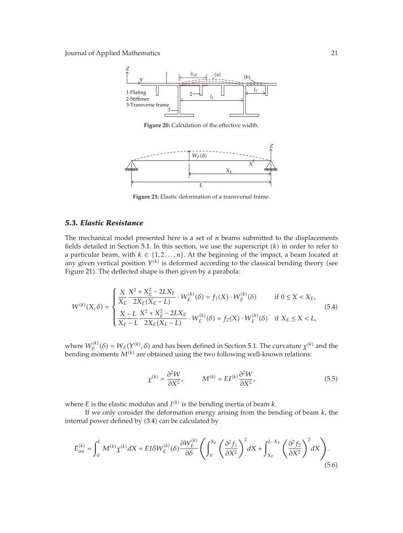
The mechanical model presented here is a set of n beams submitted to the displacementsfields detailed in Section 5.1. In this section, we use the superscript (k) in order to refer toa particular beam, with k ∈ {1, 2 . . . , n}. At the beginning of the impact, a beam located atany given vertical position Y (k) is deformed according to the classical bending theory (seeFigure 21). The deflected shape is then given by a parabola:
W (k)(X, δ) =
⎧⎪⎪⎪⎪⎨⎪⎪⎪⎪⎩
X
XE
X2 +X2E − 2LXE
2XE(XE − L) ·W (k)E (δ) = f1(X) ·W (k)
E (δ) if 0 ≤ X < XE,
X − LXE − L
X2 +X2E − 2LXE
2XE(XE − L) ·W (k)E (δ) = f2(X) ·W (k)
E (δ) if XE ≤ X < L,
(5.4)
whereW (k)E (δ) = WE(Y (k), δ) and has been defined in Section 5.1. The curvature χ(k) and the
bending momentsM(k) are obtained using the two following well-known relations:
χ(k) =∂2W
∂X2, M(k) = EI(k)
∂2W
∂X2, (5.5)
where E is the elastic modulus and I(k) is the bending inertia of beam k.If we only consider the deformation energy arising from the bending of beam k, the
internal power defined by (3.4) can be calculated by
E(k)int =
∫L0M(k)χ(k)dX = EIδW (k)
E (δ)∂W
(k)E
∂δ
⎛⎝∫XE
0
(∂2f1
∂X2
)2
dX +∫L−XE
XE
(∂2f2
∂X2
)2
dX
⎞⎠.
(5.6)
22 Journal of Applied Mathematics
bp
t pt f
bf
hw
twMp Np
σ0 σ0
Figure 22: Plastic properties of the cross-section.
By introducing (5.4) into (5.6), the individual contribution of beam k to the elasticresistance of the gate in the global deforming mode is defined by
P(k)t = EI(k)W (k)
E (δ)∂W
(k)E
∂δ· 3L
X2E(XE − L)2
. (5.7)
5.4. Plastic Resistance
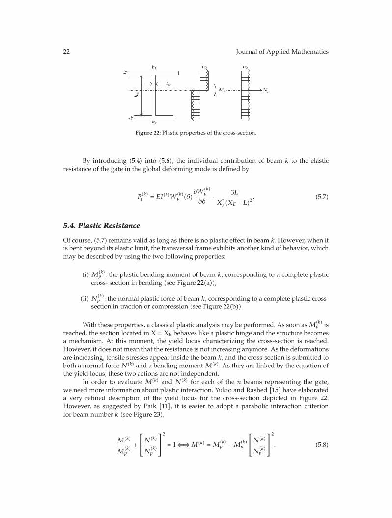
Of course, (5.7) remains valid as long as there is no plastic effect in beam k. However, when itis bent beyond its elastic limit, the transversal frame exhibits another kind of behavior, whichmay be described by using the two following properties:
(i) M(k)p : the plastic bending moment of beam k, corresponding to a complete plastic
cross- section in bending (see Figure 22(a));
(ii) N(k)p : the normal plastic force of beam k, corresponding to a complete plastic cross-
section in traction or compression (see Figure 22(b)).
With these properties, a classical plastic analysis may be performed. As soon asM(k)p is
reached, the section located in X = XE behaves like a plastic hinge and the structure becomesa mechanism. At this moment, the yield locus characterizing the cross-section is reached.However, it does not mean that the resistance is not increasing anymore. As the deformationsare increasing, tensile stresses appear inside the beam k, and the cross-section is submitted toboth a normal forceN(k) and a bending momentM(k). As they are linked by the equation ofthe yield locus, these two actions are not independent.
In order to evaluate M(k) and N(k) for each of the n beams representing the gate,we need more information about plastic interaction. Yukio and Rashed [15] have elaborateda very refined description of the yield locus for the cross-section depicted in Figure 22.However, as suggested by Paik [11], it is easier to adopt a parabolic interaction criterionfor beam number k (see Figure 23),
M(k)
M(k)p
+
⎡⎣N(k)
N(k)p
⎤⎦
2
= 1 ⇐⇒M(k) =M(k)p −M(k)
p
⎡⎣N(k)
N(k)p
⎤⎦
2
. (5.8)

Journal of Applied Mathematics 23
d∆
dθ
N
M
Mp
Np
Figure 23: Parabolic interaction criterion.
L
X
Z
WE(δ)
XE
θ1 θ2
Figure 24: Plastic deformation of a transversal frame.
If we note Δ(k) and θ(k), the axial extension and the rotation in beam k, the requiredcondition of normality is verified for the present yield locus if we have (see Figure 23)
dM(k)
dN(k)= −dΔ
(k)
dθ(k)= − Δ
(k)
θ(k)⇐⇒ −2M
(k)p N(k)(N
(k)p
)2 = − Δ(k)
θ(k). (5.9)
The extensional rate and rotational rates Δ(k) and θ(k) in beam k may be easilycalculated by geometrical considerations based on Figure 24:
θ(k) =(
1XE
+1
L −XE
)∂W
(k)E
∂δδ, Δ(k) =WE(δ)
∂W(k)E
∂δ
(1XE
+1
L −XE
)δ. (5.10)
By introducing (5.10) into (5.9), we finally get a second relation between M(k) andN(k). We then obtain the classical formula giving the membrane force in an axially restrainedbeam:
N(k) =
(N
(k)p
)2W
(k)E
2M(k)p
. (5.11)
At this stage, it is important to note that this result implies that the beam is perfectlyrestrained in the axial direction. This hypothesis implies that no transversal motions (alongdirectionX) occur at the supports whereX = 0 andX = L. This seems quite reasonable for thegate under consideration because of the action of vertical frames. However, it is important tokeep inmind that we have formulated such an assumption because even small displacementsmay reduce considerably the present foreseen resistance.

24 Journal of Applied Mathematics
The previous relation (5.11) is useful for isolating the associated bendingmomentM(k)
in (5.8). By so doing, we get:
M(k) =M(k)p −M(k)
p
⎛⎝N
(k)p W
(k)
E
2M(k)p
⎞⎠
2
. (5.12)
The two previous equations are only valid if N(k) ≤ N(k)p because it is impossible to
exceed the total plastic capacity of the cross-section. Consequently, according to (5.11), thetwo mentioned equations may still be used as long as:
W(k)E ≤ 2M(k)
p
N(k)p
. (5.13)
If this limit displacement is exceeded in beam k, we simply have N(k) = N(k)p and
M(k) = 0. Once all internal forces and displacements field are completely defined, the upper-bound theorem is applied for getting the plastic collision resistance of beam k. According toJones [16], the internal power of a transversal frame may be written as
E(k)int =
∫L0
(M(k)θ(k) +N(k)Δ(k)
)· dX. (5.14)
By introducing (5.10), (5.11), and (5.12) in (5.14), we finally get the individualcontribution of beam k to the plastic resistance of the gate in the global deforming mode:
P(k)t =
⎧⎪⎪⎪⎪⎪⎪⎨⎪⎪⎪⎪⎪⎪⎩
L
XE(L −XE)M
(k)p
∂W(k)E
∂δ·
⎡⎢⎣1 +
⎛⎝N
(k)p W
(k)E
4M(k)p
⎞⎠
2⎤⎥⎦ if W (k)
E ≤ 2M(k)p
N(k)p
,
N(k)p
L
XE(L −XE)W
(k)E
∂W(k)E
∂δif W (k)
E >2M(k)
p
N(k)p
.
(5.15)
5.5. Total Resistance in Global Deforming Mode
In Sections 5.3 and 5.4, we have established the individual contribution of each transversalframe to the total resistance of the gate. In accordance with (3.12), the total collision force issimply obtained by summation:
Pglob =n∑k=1
P(k)t , (5.16)
where P (k)t is given by (5.7) if beam k is still in the elastic regime or by (5.16) if plasticity has
already occurred. To simplify, the transition between the elastic and the plastic resistance is

Journal of Applied Mathematics 25
δt –δ0Y
Z
bf
t f
hw
δt − δ0
δ + δ0 − δtResisting section after crushingDeformation of the remaining section in global mode
Figure 25: Resistance in the global mode of a transversal frame already crushed during the local mode.
supposed to happen when the elastic bending moment in sectionX = XE reaches its maximalvalueM(k)
p .
6. Combination of Local and Global Deforming Modes
6.1. Resistance of the Beams Already Impacted during the Local Phase
The transition between local and global deforming mode has already been discussed inSection 3.4, where a sudden switch is assumed to occur when δ = δt (the so-called transitionvalue). In the present section, we give more precision on the way to combine two differentmodes. For a given value of δ, Ploc is evaluated by (4.5) and Pglob by (5.16). Two cases are thenpossible.
(i) If Ploc > Pglob, then the force applied by the ship on the gate is not sufficient foractivating the global deforming mode. Consequently, we have δ < δt and Pt = Ploc,with Ploc given by (4.5).
(ii) If Pglob = Ploc, then the global bending mode is activated and the gate starts to resistby an overall movement. So we have δ = δt; the transition value is reached.
For δ ≥ δt, we know that the global mode is valid, but the resistance Pt may nolonger be evaluated by relation (5.16). If we examine Figure 26, for example, we see thatwhen the transition occurs at δt, the third transversal frame has already been crushed over acertain length δt − δ0, where δ0 is the initial distance between the bow and the frame. As aconsequence, for beam 3, we may not assume that (5.7) and (5.15) are still valid.
It is too conservative to suppose that a beam that has already been crushed duringthe local phase does not provide any resistance during the global one. On the contrary, theuncrushed part of the cross-section is still able to develop a certain resistance by acting like amembrane. This is illustrated in Figure 25, where, for beam k, we see that the total area of theuncrushed section is
A(k)r =
(h(k)w + δ(k)0 − δt
)t(k)w + b(k)f t
(k)f , (6.1)
where h(k)w , t(k)w , b(k)f , and t(k)f are the cross-sectional dimensions for beam k, δ(k)0 is the initial
distance between the bow and beam k.

26 Journal of Applied Mathematics
1
2
3
4
Z
Y Y
δ0hw + δ0 − δt
Crushed length
δt
1
2
3
4
Z
Figure 26: Combination of local and global deforming modes.
When δ > δt − δ0, the internal power developed while producing an additionaldisplacement δ + δ0 − δt of beam k is
Eint = σ0A(k)r Δ(k), (6.2)
whereΔ(k) is the axial extension of the transversal frame caused by the displacement δ+δ0−δt:
Δ(k) =L
2·
(δ + δ(k)0 − δt
)2XE(L −XE)
⇐⇒ Δ(k) = L · δ + δ(k)0 − δtXE(L −XE)
δ. (6.3)
Finally, by introducing (6.3) into (6.2), we obtain the resistance of a transversal framealready crushed during the local phase:
P(k)t = σ0A
(k)r L · δ + δ(k)0 − δt
XE(L −XE). (6.4)
Of course, this formula has only to be applied if δt ≥ δ(k)0 , otherwise beam k is not
impacted during the local mode and the classic formulae of Section 5 remains valid. However,a correction is still needed to take into account the beginning of a new phase of motion. In fact,in (5.7) and (5.15), we have to evaluateW (k)
E and ∂W (k)E /∂δ for the actual global displacement,
that is, δ − δt and not for the total displacement δ, which also includes the displacementsduring the local phase. This concept is illustrated in Figure 27.

Journal of Applied Mathematics 27
Deformation of the gate at the end of the local modeDeformation of the gate during the global mode
Z
Y
δt
δ
δ − δt
Figure 27: Total displacement δ and global displacement δ − δt.
6.2. Total Resistance
In the previous sections, we have established all the required formulas for assessing theresistance in the local and global deforming modes. For clarity, we will now make a shortsummary of the results.
(1) At the beginning, the progression of the striking vessel into the gate is allowed bylocal deformations of the structure. During this local phase, two different forces areevaluated:
Ploc(δ) → see formula (4.5)where P (k)t is given by
(i) formula (4.2) if superelement k is of type 1,(ii) formula (4.3) if superelement k is of type 2,
Pglob(δ) → see formula (5.16), where P (k)t is given by
(i) formula (5.7) if beam k is still in the elastic regime,(ii) formula (5.15) if beam k is in the plastic regime.

28 Journal of Applied Mathematics
During the local phase, the total resistance of the gate Pt is equal to the local one,which means that Pt(δ) = P (δ).
We assume that deformations remain local as long as Pglob(δ) > Ploc(δ). Thetransition between the local and the global mode occurs at the particular value δt,for which we have Pglob(δt) = Ploc(δt).
(2) For the values of δ greater than δt, the global mode is activated. The total resistanceof the gate is still given by
Pt(δ) = Ploc(δt) +n∑k=1
P(k)t , (6.5)
where
(i) Pkt is obtained by formula (5.7) or formula (5.15) if beam k has not beenimpacted during the local phase; it should be noted that these equations areevaluated in δ − δt and not in δ (see Figure 27),
(ii) Pkt is obtained by formula (6.4) if beam k has been impacted during the localdeforming mode,
(iii) Ploc(δt) is the total resistance of the gate at the end of the local phase.
7. Numerical Validation
In order to validate all the developments described in the previous sections, we compare themto the results obtained by numerical simulations on two different gates. For each studied lockgate, two situations of collision have been considered: in the first case, the impact point E islocated in the upper part of the gate; in the second case, it is positioned in the lower part.
7.1. Numerical Model of the Striking Vessel
As mentioned above, we are only interested by the worst damages that may be caused to thegate during the collision. So far, we are not concerned by the destruction of the striking vessel.Therefore, we conservatively assume that the ship is perfectly rigid and will not deform overthe total impact duration.
For the numerical simulations, it is useless to deal with the entire ship. We only needto have a quite refined model of the bow. As explained in Section 2, the geometry of theship is fixed with help of the five parameters p, q, ϕ, ψ, and hb (see Figure 28). Its mass M0
is noted and its initial velocity V0. For the present example, we have chosen the numericalvalues listed in Table 1. These parameters have been chosen in order to represent a classicalship for the inland waterways.
The numerical model of the vessel is shown in Figure 28. It is composed of 6955Belytschko-Tsai shell elements, which are described in the LS-DYNA theoretical manual byHallquist [17]. As it can be seen in Figure 28, the mesh is more refined in the central zoneof the ship, where the contact with the gate is likely to occur. In this region, the mesh size isabout 1 cm × 1 cm. In the remaining parts of the model, as they are not supposed to developany contact with the impacted structure, the mesh is coarser.

Journal of Applied Mathematics 29
Table 1: Numerical data describing the striking vessel.
p q ϕ ψ hb M0 V0
6m 8m 84◦ 84◦ 5m 4000 t 2m/s
ϕ = 84◦
q = 8 m
p = 6 m p = 6 m
hb=
5m
ψ = 84◦hb=
5m
Y
ZZX
Y
X
Figure 28: Numerical model of the striking vessel.
Table 2: Useful properties for defining a rigid material law (only required for contact simulation).
Property Notation ValueDensity ρ 7850 kg/m3
Young’s modulus EY 210 000MPaPoisson’s ratio ν 0.33
The material used for modeling the bow is assumed to be rigid. It is defined withhelp of the classical properties of steel recalled in Table 2. These parameters are only requiredfor defining the contact conditions between the ship and the gate. They are not used forcalculating any deformation in the vessel, as the material is infinitely rigid.
7.2. Numerical Model of Gate 1
The main dimensions of the structure are plotted in Figure 29. The total height and length ofthe gate areH = 13.1m and L = 13.1m. The stiffening system of the structure is made of
(i) five transversal frames, which are irregularly distributed over the height H of thegate; their vertical positions along the vertical Y axis are shown in Figure 29(b);
(ii) six vertical frames, which are regularly placed over the length L of the gate; theirlocations along the transversal X axis are plotted in Figure 29(c);
(iii) twenty stiffeners distributed over the heightH of the gate with an average space of66 cm.
Other geometrical data are listed in Table 3. The corresponding notations are definedin accordance with the symbols introduced in Figure 3. Note that the transversal and verticalframes have a T-shaped cross-section, while the stiffeners simply have a rectangular one. Thegate is modeled with help of 204226 Belytschko-Tsai shell elements. Themesh is quite refined,with a mesh size of 5 cm × 5 cm. Of course, it may appear excessive to use such a regular meshover the entire structure, but it was required because we did not know in advance which part

30 Journal of Applied Mathematics
Y
Z
X
(a)
−13.1 m
−7.8 m
−4.8 m
−2.3 m
1 m
66 cm
Y
Z
(b)
Z
X1 m
−2.6
2m
−5.2
4m
−7.8
6m
−10.
48m
−13.
1m
(c)
Figure 29: Numerical model of gate 1.
Table 3: Geometrical data defining gate 1.
Element Property Notation Value (mm)Plating Thickness tp 10
Transversal frames
Web thickness tw 22Web height hw 1000
Flange thickness tf 22Flange width bf 300
Vertical frames
Web thickness tw 22Web height hw 1000
Flange thickness tf 22Flange width bf 500
Stiffeners
Web thickness tw 10Web height hw 200
Flange thickness tf 0Flange width bf 0
of the gate would be impacted by the ship. In order to avoid contact problems, this solutionhas been chosen.
The material used for gate 1 is defined to represent more or less the behaviour ofsteel. The elastic-plastic stress-strain curve may be divided in two distinct portions (seeFigure 30). The first part of the curve corresponds to the elastic phase. The stress-strain curveis linear, with an inclination corresponding to Young’s Modulus EY . When the yield stress

Journal of Applied Mathematics 31
σ
σ0
ε
÷EY
÷ET
Figure 30: Stress-strain relation of steel.
Table 4: Useful properties for defining the material law of steel.
Property Notation ValueDensity ρ 7850 kg/m3
Poisson’s ratio ν 0.33Yield stress σ0 240MPaYoung’s modulus EY 210 000MPaTangent modulus ET 1018MPa
σ0 is reached, the plastic phase begins. The stress-strain curve is still linear, but the slope haschanged and is given by the tangent modulus ET . In the present low velocity impact model,the strain-rate effect is not taken into account. The values of the different parameters are listedin Table 4.
The support conditions are the ones described in Section 2, that is, displacements indirection Z are blocked in X = 0, X = L, and Y = 0.
7.3. Numerical Model of Gate 2
The second gate is wider than the first one. Its total height and length are H = 15m andL = 17.1m. The main dimensions are plotted in Figure 31. (Please note that the origin ofthe axes (X,Y,Z) is correctly positioned, regarding all the previous figures.) This time, thestiffening system is more compact and made of
(i) five transversal frames, whose vertical positions along the Y axis are shown onFigure 31;
(ii) six vertical frames, regularly separated by a distance of 1.9m;
(iii) twenty-six stiffeners, regularly separated by a distance of 50 cm.
Other geometrical data are listed in Table 6. The gate is modeled by 92671 Belytschko-Tsai shell elements. The regular mesh size is 10 cm × 10 cm. The material model and thesupport conditions are the same as for gate 1.

32 Journal of Applied Mathematics
Y
Z
X
(a)
−15 m
−9.5 m
−7 m
−4.5 m
Z
Y
50 cm
(b)
X
Z1.9 m
(c)
Figure 31: Numerical model of gate 2.
Table 5: Impact location for the simulations.
Simulation 1 Simulation 2
Gate 1 XE = 6.55m XE = 6.55mYE = 8m YE = 13.1m
Gate 2 XE = 8.55m XE = 8.55mYE = 7.5m YE = 13.25m
7.4. Numerical Simulations
Four numerical simulations have been performed by using the finite-elements software LS-DYNA. Two simulations are required for each gate, according to the position of the impactpoint E. The transversal and vertical positions XE and YE of point E are listed in Table 5 forthe different collision cases considered here.
Concerning the resulting crushing force curves compared in Figures 32 and 33,simulation 1 corresponds to a ship impact happening in the lower part of the structure andsimulation 2 to an impact in the upper one.
7.5. Comparison of Numerical and Analytical Results
In order to validate the analytical developments established in the previous section, we willmake a comparison between the results provided by LS-DYNA and the ones predicted by oursimplified method. The curves of interest are those showing the evolution of the crushingforce Pt with the total penetration δ. The comparisons are plotted in Figures 32 and 33.

Journal of Applied Mathematics 33
0
2000
4000
6000
8000
10000
12000
0 0.2 0.4 0.6 0.8 1 1.2 1.4 1.6
Cru
shin
g re
sist
ancePt(k
N)
Analytical resultsNumerical results
Total penetrationδ (m)
(a)
0
2000
4000
6000
8000
10000
12000
0 0.2 0.4 0.6 0.8 1 1.2 1.4 1.6
Cru
shin
g re
sist
ancePt(k
N)
Total penetrationδ (m)
Analytical resultsNumerical results
(b)
Figure 32: Comparison of the analytical and numerical crushing forces for gate 1.
The curves referenced as “numerical results” are those obtained by LS-DYNA, while the“analytical results” are derived by the present simplified approach.
As it can be seen, the agreement between the curves is quite good. In most cases,the analytical curves provide slightly conservative results. However, for gate 2, the firstsimulation (see Figure 33(a)) exhibits a more important divergence: our simplified methodtends to underestimate the crushing resistance, especially for the great values of δ. Thisobservation is due to a quite conservative approach in the global mode. This may beexplained by the two following reasons.
(i) The resisting cross-sections are determined according to the recommendationsof Eurocode 3. It seems that these rules are quite severe in the present caseas the numerical simulations show that a greater part of the plating is actuallycollaborating to the resistance of the transversal frames.

34 Journal of Applied Mathematics
Table 6: Geometrical date defining gate 2.
Element Property Notation Value (mm)Plating Thickness tp 12
Transversal frames
Web thickness tw 12Web height hw 1800
Flange thickness tf 12Flange width bf 400
Vertical frames
Web thickness tw 12Web height hw 1400
Flange thickness tf 12Flange width bf 300
Stiffeners
Web thickness tw 12Web height hw 300
Flange thickness tf 0Flange width bf 0
(ii) We do not capture properly the deformation pattern of the vertical frames: wesuppose that their role is limited to the application of the global displacements field,but we neglect the energy also dissipated through their own global deflection.
This last point is confirmed by the curves plotted on Figure 34, where we comparethe energy dissipated by the different structural components of the gate. The numericalresults are those given by LS-DYNA, while the analytical results are those predicted by thetheoretical model of this paper. As it can be seen on this picture, the discrepancy is satisfactoryfor the plating, the stiffeners, and the transverse frames, but it is not really the case for thevertical frames. Our method underestimates the energy that these elements really dissipate,but this approximation remains conservative.
8. Conclusion
In this paper, we exposed a simplified procedure for assessing the resistance of a gate sub-mitted to a ship impact.
It is important to bear in mind the hypotheses that we have formulated for modelingthe struck gate and the striking vessel. Concerning the struck gate, our approach is devotedto
(i) gates with single plating; structures with double plating or caissons are not coveredby the present developments;
(ii) gates with a classical orthogonal stiffening system, that is, stiffeners and frames inthe transversal direction and frames in the vertical direction;
(iii) gates supported on both sides by the lock walls and by a sill at the bottom of thelock.
The three former conditions have to be fulfilled for applying themethodology exposedpreviously. Concerning the striking vessel, it is modeled by using a certain number ofparameters. The global bow shape is assumed to be a parabola, with given radii p and q,decreasing according to given stem and side angles ϕ and ψ.
The impacted structure is assumed to behave in two phases. At the beginning, whenthe indentation δ of the ship is not too wide, we suppose a localized crushing of someimpacted structural elements. The plating and the stiffening system surrounding the initial

Journal of Applied Mathematics 35
02000400060008000
10000120001400016000180002000022000
0 0.1 0.2 0.3 0.4 0.5 0.6 0.7 0.8 0.9
Cru
shin
g re
sist
ancePt(k
N)
Total penetrationδ (m)
Analytical resultsNumerical results
(a)
0
2000
4000
6000
8000
10000
12000
14000
0 0.1 0.2 0.3 0.4 0.5 0.6 0.7 0.8 0.9 1 1.1
Cru
shin
g re
sist
ancePt(k
N)
Total penetrationδ (m)
Analytical resultsNumerical results
(b)
Figure 33: Comparison of the analytical and numerical crushing forces for gate 2.
contact zone are submitted to heavy deformations, but the remaining of the gate is stillunaffected. In this case, we say that the structure withstands through a local deformingmode. For such a situation, the resistance is calculated by summing all the contributions ofthe activated superelements. As some references are already available in the literature, wehave not reproduced all the developments concerning these superelements.
When the penetration δ becomes wider, the gate withstands through an overallmovement implying the entire structure. In this case, we say that the resistance is providedthrough a global deforming mode. For the support conditions assumed presently, therequired theoretical displacements fields have been exposed in detail. We also derived anequivalent mechanical model for evaluating the resistance in such a situation.
The transition between the local and the global deforming modes is assumed to occurat a given penetration δt, for which the collision force exerted by the ship during the localphase is sufficient to produce an overall displacement of the gate.
Finally, our presentation ends with a comparison between some finite elementsnumerical results and those obtained by the present simplified approach. In most cases, the

36 Journal of Applied Mathematics
0
0.5
1
1.5
2
2.5
3
3.5
4
0 0.2 0.4 0.6 0.8 1
Inte
rnal
ene
rgy(M
J)
6
5
4
3
2
1
Total penetrationδ (m)
Energy dissipated by the plating and the stiffeners (numerical results)Energy dissipated by the plating and the stiffeners (analytical results)Energy dissipated by the transverse frames (numerical results)Energy dissipated by the transverse frames (analytical results)Energy dissipated by the vertical frames (numerical results)Energy dissipated by the vertical frames (analytical results)
(1)(2)(3)(4)(5)(6)
Figure 34: Comparison of the analytical and numerical internal energy of the various components of thegate.
procedure exposed here leads to a quite satisfactory estimation of the collision resistance. Thepredicted results are conservative, without underestimating too much the numerical values.
The main advantage of the methodology exposed here is to provide rapidly anevaluation of the collision resistance. The analytical curves plotted in Figures 32 and 33 areuseful for knowing if a lock gate is able to behave satisfactorily to an impact of a ship withgiven initial velocity V0 and mass M0. With these curves, it is in fact possible to know thetotal needed indentation δmax required for dissipating the initial kinetic energy M0V
20 /2. If
this value of δmax exceeds a given criterion, then we may suppose that the structure will notbe able to withstand satisfactorily a collision with a vessel of massM0 and velocity V0.
Of course, we have to be conscious that our simplified analytical method is onlyapplicable at the predesign stage of a lock. For more advanced stages of a project, it is stillnecessary to resort to more advanced tools, like finite elements software.
List of Notations
Lower-Case Latin Notations
a1: Horizontal or vertical dimension of a superelement defined by the impactpoint location and the supports of the struck structure
a2: Horizontal or vertical dimension of a superelement defined by the impactpoint location and the supports of the struck structure (complementary to a1)
b1: Vertical dimension of a superelement defined by the impact point location andthe supports of the struck structure

Journal of Applied Mathematics 37
b2: Vertical dimension of a superelement defined by the impact point location andthe supports of the struck structure (complementary to a2)
beff: Effective width for calculating the section properties of a transversal beambf : Flange width of a stiffener or a transversal framehb: Vertical distance between the lowermost and uppermost decks of the striking
shiphp: Collaborating width of the plating in the global deforming modehw: Web height of a stiffener or a transversal framek: Superscript used for referencing a particular property of superelement n◦kn: Total number of superelements used for modeling the entire gate(p, q): Parameters defining the parabolic dimensions of the striking ship uppermost
decktf : Flange thickness of a stiffener or a transversal beamtp: Thickness of the platingtw: Web thickness of stiffener or a transversal frametX : Equivalent plating thickness after smearing all the transversal stiffenerstY : Equivalent plating thickness after smearing all the vertical stiffeners.
Upper-Case Latin Notations
E: Young’s modulus of the steel material constituting the gateEext: External energyEint Internal energyET : Tangent modulus of steelEY : Young’s modulus of steelH: Total vertical height of the gateI: Bending inertia of a transversal beamL: Total transversal length of the gateM: Bending momentMp: Plastic bending resistance of a transversal beamM0: Mass of the striking shipN: Axial forceNp: Plastic axial resistance of a transversal beamPglob: Total resistance of the gate in the global deforming modePloc: Total resistance of the gate in the local deforming modePt: Total collision resistance of the impacted gateW(X, δ): Transversal evolution of the displacement field in the global deforming modeWE(Y, δ): Vertical evolution of the displacement field in the global deforming mode(XE, YE): Impact point location on the gate(X,Y,Z): General coordinate system.
Lower-Case Greek Notations
δ: Penetration of the striking shipδc: Penetration of the striking ship for which a second contact between the gate
and the bow is established
38 Journal of Applied Mathematics
δt: Penetration of the striking ship at the transition between the local and the globaldeforming modes
δmax: Maximal penetration of the striking ship required for completely dissipating itsinitial kinetic energy
δ0: Initial distance between the bow and a transversal beamεu: Deformation for which the ultimate stress σu is reachedε0: Deformation for which the plastic limit σ0 is reachedεij : Strain tensorθ: Cross-section rotationν: Poisson’s ratio of steelρ: Mass density of steelσu: Ultimate stress of steelσ0: Plastic limit of steelσij : Stress tensorφ: Stem angleχ: Curvature of a transversal beamψ: Side angle.
Upper-Case Greek Notations
Γ: Designation of the parabola describing the striking ship uppermost deckΔ: Total axial extension of transversal frame.
References
[1] T. Wierzbicki and J. Culbertson Driscoll, “Crushing damage of web girders under localized staticloads,” Journal of Constructional Steel Research, vol. 33, no. 3, pp. 199–235, 1995.
[2] G. Wang and H. Ohtsubo, “Deformation of ship plate subjected to very large load,” Journal of OffshoreMechanics and Arctic Engineering, vol. 119, 1997.
[3] B. C. Simonsen, “Ship grounding on rock—I. Theory,” Marine Structures, vol. 10, no. 7, pp. 519–562,1997.
[4] S. M. Zhang, The mechanics of ship collisions, Ph.D. thesis, Department of Naval Architecture andOffshore Engineering, Technical University of Denmark, 1999.
[5] L. Hong and J. Amdahl, “Crushing resistance of web girders in ship collision and grounding,”MarineStructures, vol. 21, no. 4, pp. 374–401, 2008.
[6] G. Wang, “Some recent studies on plastic behavior of plates subjected to large impact loads,” Journalof Offshore Mechanics and Arctic Engineering, vol. 124, no. 3, pp. 125–131, 2002.
[7] G. Wang and H. Ohtsubo, “An upper-bound solution to the problem of plate tearing,” Journal ofMarine Science and Technology, vol. 1, no. 1, pp. 46–51, 1995.
[8] S. Zhang, “Plate tearing and bottom damage in ship grounding,”Marine Structures, vol. 15, no. 2, pp.101–117, 2002.
[9] T. Wierzbicki, “Concertina tearing of metal plates,” International Journal of Solids and Structures, vol.32, no. 19, pp. 2923–2943, 1995.
[10] P. E. Zheng, Theorical analysis of wedge cutting through metal plates, Ph.D. thesis, Massachusetts Instituteof Technology, 1994.
[11] J. K. Paik, Ultimate Limit State Design of Steel-Plated Structures, John Wiley and Sons, Chichester, UK,2002.
[12] S. R. Cho and H. S. Lee, “Experimental and analytical investigations on the response of stiffenedplates subjected to lateral collisions,”Marine Structures, vol. 22, no. 1, pp. 84–95, 2009.

Journal of Applied Mathematics 39
[13] Y. Ueda, S. M. H. Rashed, and J. K. Paik, “Buckling and ultimate strength interaction in plates andstiffened panels under combined inplane biaxial and shearing forces,”Marine Structures, vol. 8, no. 1,pp. 1–36, 1995.
[14] H. Le Sourne, J. C. Rodet, and C. Clanet, “Crashworthiness analysis of a lock gate impacted by tworiver ships,” International Journal of Crashworthiness, vol. 7, no. 4, pp. 371–396, 2004.
[15] U. Yukio and S. M. H. Rashed, “The idealized structural unit method and its application to deepgirder structures,” Computers and Structures, vol. 18, no. 2, pp. 277–293, 1984.
[16] N. Jones, Structural Impact, Cambridge University Press, 1997.[17] J. O. Hallquist, LS-DYNA Theoretical Manual, Livermore Software Technology Corporation, 2006.

Submit your manuscripts athttp://www.hindawi.com
Hindawi Publishing Corporationhttp://www.hindawi.com Volume 2014
MathematicsJournal of
Hindawi Publishing Corporationhttp://www.hindawi.com Volume 2014
Mathematical Problems in Engineering
Hindawi Publishing Corporationhttp://www.hindawi.com
Differential EquationsInternational Journal of
Volume 2014
Applied MathematicsJournal of
Hindawi Publishing Corporationhttp://www.hindawi.com Volume 2014
Probability and StatisticsHindawi Publishing Corporationhttp://www.hindawi.com Volume 2014
Journal of
Hindawi Publishing Corporationhttp://www.hindawi.com Volume 2014
Mathematical PhysicsAdvances in
Complex AnalysisJournal of
Hindawi Publishing Corporationhttp://www.hindawi.com Volume 2014
OptimizationJournal of
Hindawi Publishing Corporationhttp://www.hindawi.com Volume 2014
CombinatoricsHindawi Publishing Corporationhttp://www.hindawi.com Volume 2014
International Journal of
Hindawi Publishing Corporationhttp://www.hindawi.com Volume 2014
Operations ResearchAdvances in
Journal of
Hindawi Publishing Corporationhttp://www.hindawi.com Volume 2014
Function Spaces
Abstract and Applied AnalysisHindawi Publishing Corporationhttp://www.hindawi.com Volume 2014
International Journal of Mathematics and Mathematical Sciences
Hindawi Publishing Corporationhttp://www.hindawi.com Volume 2014
The Scientific World JournalHindawi Publishing Corporation http://www.hindawi.com Volume 2014
Hindawi Publishing Corporationhttp://www.hindawi.com Volume 2014
Algebra
Discrete Dynamics in Nature and Society
Hindawi Publishing Corporationhttp://www.hindawi.com Volume 2014
Hindawi Publishing Corporationhttp://www.hindawi.com Volume 2014
Decision SciencesAdvances in
Discrete MathematicsJournal of
Hindawi Publishing Corporationhttp://www.hindawi.com
Volume 2014 Hindawi Publishing Corporationhttp://www.hindawi.com Volume 2014
Stochastic AnalysisInternational Journal of