Simple Program Design
364
-
Upload
cotero5234 -
Category
Documents
-
view
2.497 -
download
45
Transcript of Simple Program Design


102 Dodds StreetSouthbank Victoria 3006
Email: [email protected]: www.thomsonlearning.com.au
First published in 2003This edition published in 200610 9 8 7 6 5 4 3 209 08 07 06 05
Copyright © 2007 Nelson Australia Pty Limited.
COPYRIGHT
Reproduction and Communication for educational purposesApart from fair dealing for the purposes of study, research, criticism or review, or as permitted under Part VB of the Copyright Act, no part of this book may be reproduced by any process without permission. Copyright owners may take legal action against a person who infringes on their copyright through unauthorised copying. Enquiries should be directed to the publisher.
For details of the CAL licence for educational institutions contact:
Copyright Agency LimitedLevel 19, 157 Liverpool StreetSydney NSW 2000Telephone: (02) 9394 7600Facsimile: (02) 9394 7601E-mail: [email protected] .au
Reproduction and Communication for other purposesExcept as permitted under the Act (for example a fair dealing for the purposes of study, research, criticism or review) no part of this book may be reproduced, stored in a retrieval system, communicated or transmitted in any form or by any means without prior written permission. All inquiries should be made to the publisher at the address above.
Copyright owners may take legal action against a person who infringes on their copyright through unauthorised copying. Enquiries should be directed to the publisher.
National Library of AustraliaCataloguing-in-Publication data
Robertson, Lesley Anne.Simple program design.
5th ed.
ISBN 0 17 012851 2.
1. Computer programming – Textbooks. 2. Structured programming – Textbooks. 3. Pseudocode (Computer program language) – Textbooks. I. Title.
005.12
Publishing manager: Michael TullyPublishing editor : Elizabeth VellaProject editor : Chris WynessDevelopmental editor : Ben CocksProduction controller : Jodie TamblynCover designer: Olga LaVecchiaEditor : Marta VeroniIndexer: Russell BrooksTypeset in Melior medium 10/13pt by Polar Design Pty LtdPrinted in China by C & C Offset Pty Ltd
This title is published under the imprint of Thomson. Nelson Australia Pty Limited ACN 058 280 149 (incorporated in Victoria) trading as Thomson Learning Australia.
The URLs contained in this publication were checked for currency during the production process. Note, however, that the publisher cannot vouch for the ongoing currency of URLs.

Preface xi
Program designDescribes the steps in the program development process, and introduces current program design methodologies, procedural and object-oriented programming, algorithms, pseudocode and program data.
1.1 Steps in program development 21.2 Program design methodology 41.3 Procedural versus object-oriented programming 51.4 An introduction to algorithms and pseudocode 61.5 Program data 7Chapter summary 10
PseudocodeIntroduces common words, keywords and meaningful names when writing pseudocode. The Structure Theorem is introduced, and the three basic control structures are established. Pseudocode is used to represent each control structure.
2.1 How to write pseudocode 122.2 Meaningful names 152.3 The Structure Theorem 15Chapter summary 17
Developing an algorithmIntroduces methods of analysing a problem and developing a solution. Simple algorithms that use the sequence control structure are developed, and methods of manually checking the algorithm are determined.
3.1 Defining the problem 193.2 Designing a solution algorithm 233.3 Checking the solution algorithm 25Chapter summary 33Programming problems 33
1
2
3
Contents
v

Selection control structuresExpands the selection control structure by introducing multiple selection, nested selection and the case construct in pseudocode. Several algorithms, using variations of the selection control structure, are developed.
4.1 The selection control structure 364.2 Algorithms using selection 404.3 The case structure 48Chapter summary 51Programming problems 51
Repetition control structuresDevelops algorithms that use the repetition control structure in the form of DOWHILE, REPEAT…UNTIL, and counted repetition loops.
5.1 Repetition using the DOWHILE structure 555.2 Repetition using the REPEAT…UNTIL structure 645.3 Counted repetition 67Chapter summary 69Programming problems 70
Pseudocode algorithms using sequence, selection and repetitionDevelops algorithms to solve eight simple programming problems using combinations of sequence, selection and repetition constructs. Each problem is properly defined; the control structures required are established; a pseudocodealgorithm is developed; and the solution is manually checked for logic errors.
6.1 Eight solution algorithms 73Chapter summary 85Programming problems 85
Array processingIntroduces arrays, operations on arrays, and algorithms that manipulate arrays. Algorithms for single and two-dimensional arrays, which initialise the elements of an array, search an array and write out the contents of an array, are presented.
7.1 Array processing 897.2 Initialising the elements of an array 927.3 Searching an array 947.4 Writing out the contents of an array 967.5 Programming examples using arrays 977.6 Two-dimensional arrays 101Chapter summary 105Programming problems 105
4
5
6
7
vi Contents

First steps in modularisationIntroduces modularisation as a means of dividing a problem into subtasks. Hierarchy charts and parameter passing are introduced, and several algorithms that use a modular structure are developed.
8.1 Modularisation 1108.2 Hierarchy charts or structure charts 1148.3 Steps in modularisation 1168.4 Programming examples using modules 118Chapter summary 129Programming problems 130
General algorithms for common business problemsDevelops a general pseudocode algorithm for four common business applications. All problems are defined; a hierarchy chart is established; and apseudocode algorithm is developed, using a mainline and several subordinate modules. The topics covered include report generation with page break, a single-level control break, a multiple-level control break and a sequential file update program.
9.1 Program structure 1349.2 Report generation with page break 1359.3 Single-level control break 1379.4 Multiple-level control break 1419.5 Sequential file update 146Chapter summary 152Programming problems 153
Communication between modules, cohesion and couplingIntroduces communication between modules and develops algorithms that pass parameters between modules. Module cohesion and coupling are introduced, several levels of cohesion and coupling are described, and pseudocode examples of each level are provided.
10.1 Communication between modules 16010.2 Programming examples using parameters 16510.3 Module cohesion 17410.4 Module coupling 180Chapter summary 185Programming problems 185
8
9
10
viiContents

An introduction to object-oriented designIntroduces object-oriented design, classes and objects, attributes, responsibilities, operations, accessors and mutators, and information hiding. The steps required to create an object-oriented solution to a problem are provided and solution algorithms developed.
11.1 Introduction to object-oriented design 19211.2 Public and private access methods 19811.3 Steps in creating an object-oriented solution 20311.4 Programming examples using object-oriented design 204Chapter summary 212Programming problems 212
Object-oriented design for more than one classIntroduces relationships between classes including association, aggregation, composition and generalisation. Introduces a simplified UML language, describes polymorphism and operation overriding and lists the steps required to create an object-oriented design for a problem with more than one class.
12.1 Further object-oriented design 21612.2 Steps in creating an object-oriented solution using
more than one class 22112.3 Programming examples using more than one class 222Chapter summary 238Programming problems 238
Object-oriented design for multiple classesExpands an object-oriented solution to cater for multiple classes, inheritance and polymorphism and introduces interface and GUI design.
13.1 Object-oriented design for multiple classes 24213.2 Interface and GUI objects 256Chapter summary 259Programming problems 259
Appendix 1 Flowcharts
Introduces flowcharts for those students who prefer a more graphic approach to program design. Algorithms that use a combination of sequence, selection and repetition are developed in some detail.
Introduction to flowcharts 264The three basic control structures 265Simple algorithms that use the sequence control structure 268Flowcharts and the selection control structure 272
11
12
13
viii Contents

Simple algorithms that use the selection control structure 274The case structure expressed as a flowchart 280Flowcharts and the repetition control structure 282Simple algorithms that use the repetition control structure 283Further examples using flowcharts 291Flowcharts and modules 315
Appendix 2 Special algorithms
Contains a number of algorithms that are not included in the body of the textbook and yet may be required at some time in a programmer’s career.
Sorting algorithms 327Dynamic data structures 330
Appendix 3
Translating psuedocode into computer languages:quick reference chart 335
Glossary 342
Index 349
ixContents


With the increased popularity of programming courses in our WWuniversities, colleges and technical institutions, there is a need for an easy-to-read textbook on computer program design. There are already dozens of introductory programming texts using specific languages such as C++, Visual Basic, Pascal and COBOL, but they usually gloss over the important step of designing a solution to a given programming problem.
This textbook tackles the subject of program design by using modern pro-gramming techniques and pseudocode to develop a solution algorithm. Therecommended pseudocode has been chosen because of its closeness to writ-ten English, its versatility and ease of manipulation, and its similarity to thesyntax of most structured programming languages.
Simple Program Design, Fifth Edition is designed for programmers whowant to develop good programming skills for solving common business prob-lems. Too often, programmers, when faced with a problem, launch straightinto the code of their chosen programming language, instead of concentratingon the actual problem at hand. They become bogged down with the syntaxand format of the language, and often spend many hours getting the programto work. Using this textbook, the programmer will learn how to properlydefine the problem, how to divide it into modules, how to design a solutionalgorithm, and how to prove the algorithm’s correctness, before commenc-ing any program coding. By using pseudocode and modern programmingtechniques, the programmer can concentrate on developing a well-designedand correct solution, and thus eliminate many frustrating hours at the testingphase.
The content of the book covers program design in two distinct sections.Chapters 1 to 10 cover algorithm design in the context of traditional program-ming languages. The section begins with a basic introduction to programdesign methodology, and the steps in developing a solution algorithm. Then,concept by concept, the student is introduced to the syntax of pseudocode;methods of defining the problem; the application of basic control structuresin the development of the solution algorithm; desk-checking techniques;arrays; module design; hierarchy charts; communication between modules;parameter passing; and module cohesion and coupling.
Chapters 11 to 13 cover algorithm design in the context of object-orientedprogramming. The section introduces the concepts of object-oriented design
Preface

and the steps involved in creating an object-oriented solution to a problem.Step-by-step algorithms using object-oriented design are provided, as well asmaterial on polymorphism, operation overriding, multiple classes and inter-faces.
Each chapter thoroughly covers the topic at hand, giving practical exam-ples relating to business applications, and a consistently structured approachwhen representing algorithms and hierarchy charts.
This fifth edition has been thoroughly revised, in keeping with modernprogram design techniques. It includes an improved section on modularisa-tion and communication between modules, and a greatly expanded sectionon object-oriented design with many more step-by-step examples.
Programming problems of increasing complexity are provided at the endof most chapters, so that teachers have a choice of exercises that match thewidely varying abilities of their students. Detailed solutions are available toteachers and students on CD for half of each chapter’s problems.
I would like to thank Kim Styles and Wendy Doube, lecturers in Computingat Monash University, for their wonderful input on object-oriented designmethodology; Victor Cockrell, Curtin University, for his enthusiastic sugges-tions and his Quick Reference Chart for translating pseudocode into severalcomputer languages; and my brother, Rick Noble, for his amusing cartoons atthe beginning of each chapter.
Lesley Anne Robertson
AAbout the authorLesley Anne Robertson was introduced to pseudocode and program designmethodology when she joined IBM Australia in 1973 as a trainee programmer.Since then, she has consistently used these techniques as a programmer, sys-tems analyst, and lecturer in Computing at the University of Western Sydney,NSW, where she taught computer program design for 11 years.
Lesley now lives on a vineyard and winery in Mudgee, Australia, with herdaughters Lucy and Sally and labradoodles Milly and Molly.
xii Preface

Program design
Objectives
• To describe the steps in the program development process
• To introduce current program design methodology
• To introduce procedural and object-oriented programming
• To introduce algorithms and pseudocode
• To describe program data
Outline
1.1 Steps in program development
1.2 Program design methodology
1.3 Procedural versus object-oriented programming
1.4 An introduction to algorithms and pseudocode
1.5 Program data
Chapter summary
1

2 Simple program design
1.1 Steps in program development
Computer programming is an art. Many people believe that a programmermust be good at mathematics, have a memory for figures and technicalinformation, and be prepared to spend many hours sitting at a computer,typing programs. However, given the right tools and steps to follow, anyonecan write well-designed programs. It is a task worth doing, as it is bothstimulating and fulfilling.
Programming can be defined as the development of a solution to an identi-fied problem, and the setting up of a related series of instructions that, whendirected through computer hardware, will produce the desired results. It isthe first part of this definition that satisfies the programmer’s creative needs;that is, to design a solution to an identified problem. Yet this step is so oftenoverlooked. Leaping straight into the coding phase without first designinga proper solution usually results in a program that contains many errors.Often the programmer then needs to spend a significant amount of time find-ing these errors and correcting them. A more experienced programmer willdesign a solution to the program first, desk check this solution, and then codethe program in a chosen programming language.
There are seven basic steps in the development of a program, as follows.
1 Define the problem
This step involves carefully reading and rereading the problem until youunderstand completely what is required. To help with this initial analysis, theproblem should be divided into three separate components:
• the inputs• the outputs• the processing steps to produce the required outputs.
A defining diagram, as described in Chapter 3, is recommended in thisanalysis phase, as it helps to separate and define the three components.
2 Outline the solution
Once the problem has been defined, you may decide to break it down intosmaller tasks or steps, and establish a solution outline. This initial outline isusually a rough draft of the solution and may include:
• the major processing steps involved• the major subtasks (if any)• the user interface (if any)• the major control structures (e.g. repetition loops)• the major variables and record structures• the mainline logic.
The solution outline may also include a hierarchy or structure chart. Thesteps involved in developing this outline solution are detailed in chapters 2to 6.

3Chapter 1: Program design
3 Develop the outline into an algorithm
The solution outline developed in Step 2 is then expanded into an algorithm:a set of precise steps that describe exactly the tasks to be performed andthe order in which they are to be carried out. This book uses pseudocode (aform of structured English) to represent the solution algorithm. Flowchartsfor every pseudocode algorithm up to and including Chapter 8 are providedin Appendix 1 for those who prefer a more pictorial method of algorithmrepresentation.
4 Test the algorithm for correctness
This step is one of the most important in the development of a program, andyet it is the step most often bypassed. The main purpose of desk checking thealgorithm is to identify major logic errors early, so that they may be easilycorrected. Test data needs to be walked through each step in the algorithmto check that the instructions described in the algorithm will actually dowhat they are supposed to. The programmer ‘walks’ through the logic of thealgorithm, exactly as a computer would, keeping track of all major variableson a sheet of paper. The use of a desk check table to desk check the algorithmis introduced in Chapter 3, and many examples of its use are provided.
5 Code the algorithm into a specific programming language
Only after all design considerations in the previous four steps have been met should you actually start to code the program into your chosen programminglanguage.
6 Run the program on the computer
This step uses a program compiler and programmer-designed test data tomachine test the code for syntax errors (those detected at compile time) andlogic errors (those detected at run time). This is usually the most rewardingstep in the program development process. If the program has been welldesigned, the time-wasting frustration and despair often associated withprogram testing are reduced to a minimum. This step may need to beperformed several times until you are satisfied that the program is runningas required.
7 Document and maintain the program
Program documentation should not be listed as the last step in the programdevelopment process, as it is really an ongoing task from the initial definitionof the problem to the final test result.
Documentation includes both external documentation (such as hierarchycharts, the solution algorithm and test data results) and internal documenta-tion that may have been coded in the program. Program maintenance refersto changes that may need to be made to a program throughout its life. Often,these changes are performed by a different programmer from the one who

4 Simple program design
initially wrote the program. If the program has been well designed usingstructured programming techniques, the code will be seen as self-document-ing, resulting in easier maintenance.
1.2 Program design methodology
The fundamental principle of program design is based on the fact that aprogram accepts input data, processes that data, and then delivers the datato the program user as output. Recently, a number of different approaches toprogram design have emerged, and the most common are:
• procedure-driven• event-driven• data-driven.
Procedure-driven program design
The procedure-driven approach to program design is based on the idea thatthe most important feature of a program is what it does – its processes ortfunctions. By concentrating on what a program must do, the programmeridentifies and organises the processes in the program solution. The flow of data into and out of each process or function is then considered and a strategydeveloped to break each function into smaller and more specific flows of data.The details about the actual structure of the data are not considered until allthe high-level processes or functions of the program have been defined.
Event-driven program design
The event-driven approach to program design is based on the idea that anevent or interaction with the outside world can cause a program to changefrom one known state to another. The initial state of a program is identified,then all the triggers that represent valid events for that state are established.Each of these events results in the program changing to a new defined state,where it stays until the next event occurs. For example, when a program userdecides to click the left mouse button, click the right mouse button, drag themouse or double click the mouse, each action could trigger a different eventwithin the program and thus result in a different program state.
Data-driven program design
The data-driven approach to program design is based on the idea that thedata in a program is more stable than the processes involved. It begins withan analysis of the data and the relationships between the data, in order todetermine the fundamental data structures. Once these data structures havebeen defined, the required data outputs are examined in order to establishwhat processes are required to convert the input data to the required output.
The choice between procedure-driven, event-driven or data-drivenprogram design methodologies is usually determined by the selection of a

5Chapter 1: Program design
programming language. However, regardless of the program design methodchosen, you must develop the necessary basic skills to be able to design asolution algorithm to a given problem. These basic skills include a well-defined and disciplined approach to designing the solution algorithm andadherence to the recommended program development process:
Step 1: Define the problem.Step 2: Outline the solution (or user interface).Step 3: Develop the outline into a solution algorithm.Step 4: Test the algorithm for correctness.Step 5: Code the algorithm into a specific programming language.Step 6: Run the program on the computer.Step 7: Document and maintain the program.
1.3 Procedural versus object-orientedprogramming
Procedural programming is based on a structured, top-down approach towriting effective programs. The approach concentrates on what a program hastto do and involves identifying and organising the processes in the programsolution. The problem is usually broken down into separate tasks or functionsand includes top-down development and modular design.
Top-down development
In the top-down development of a program design, a general solution to theproblem is outlined first. This outline is then divided gradually into moredetailed steps until finally the most detailed levels have been completed. Itis only after this process of top-down development (also called functional decomposition or stepwise refinement) that the programmer starts to code.The result of this systematic, disciplined approach to program design is ahigher precision of programming than was previously possible.
Modular design
Procedural programming also incorporates the concept of modular design,which involves grouping tasks together because they all perform the samefunction (for example, calculating sales tax or printing report headings).Modular design is connected directly to top-down development, as thesteps or subtasks into which the program solution is divided actually formthe future modules of the program. Good modular design also assists in thereading and understanding of the program.
Object-oriented programming
Object-oriented programming is also based on breaking down the problem;however, the primary focus is on the things (or objects) that make up theprogram. The program is concerned with how the objects behave, so it breaks

6 Simple program design
the problem into a set of separate objects that perform actions and relateto each other. These objects have definite properties, and each object isresponsible for carrying out a series of related tasks.
This book looks at both approaches to program design, procedural andobject-oriented. It is then left to you and your choice of programming lan-guage to determine which methodology you will use. It must be noted, how-ever, that, regardless of design methodology or programming language, allprogrammers must have the basic skills to design solution algorithms. It is theintention of this book to provide these skills.
1.4 An introduction to algorithms and pseudocode
A program must be systematically and properly designed before codingbegins. This design process results in the construction of an algorithm.
What is an algorithm?
An algorithm is like a recipe: it lists the steps involved in accomplishing atask. It can be defined in programming terms as a set of detailed, unambiguousand ordered instructions developed to describe the processes necessary toproduce the desired output from a given input. The algorithm is written insimple English and is not a formal document. However, to be useful, there aresome principles that should be adhered to. An algorithm must:
• be lucid, precise and unambiguous• give the correct solution in all cases• eventually end.
For example, if you want to instruct someone to add up a list of prices ona pocket calculator, you might write an algorithm such as the following:
Turn on calculatorClear calculatorRepeat the following instructions
Key in dollar amountKey in decimal point (.)Key in cents amountPress addition (+) key
Until all prices have been enteredWrite down total priceTurn off calculator
Notice that in this algorithm the first two steps are performed once, beforethe repetitive process of entering the prices. After all the prices have beenentered and summed, the total price can be written down and the calcula-tor turned off. These final two activities are also performed only once. Thisalgorithm satisfies the desired list of properties: it lists all the steps in the

7Chapter 1: Program design
correct order from top to bottom in a definite and unambiguous fashion untila correct solution is reached. Notice that the steps to be repeated (enteringand summing the prices) are indented, both to separate them from those stepsperformed only once and to emphasise the repetitive nature of their action.It is important to use indentation when writing solution algorithms because ithelps to differentiate between the different control structures.
What is pseudocode?
Pseudocode and flowcharts are both popular ways of representing algorithms.Flowcharts are discussed in Appendix 1, while pseudocode has been chosenas the primary method of representing an algorithm because it is easy toread and write, and allows the programmer to concentrate on the logic of the problem. Pseudocode is really structured English. It is English that has beenformalised and abbreviated to look like the high-level computer languages.
There is no standard pseudocode at present. Authors seem to adopttheir own special techniques and sets of rules, which often resemble aparticular programming language. This book attempts to establish a standardpseudocode for use by all programmers, regardless of the programminglanguage they choose. Like many versions of pseudocode, this version hascertain conventions:
1 Statements are written in simple English.2 Each instruction is written on a separate line.3 Keywords and indentation are used to signify particular control
structures.4 Each set of instructions is written from top to bottom, with only one entry
and one exit.5 Groups of statements may be formed into modules, and that module given
a name.
1.5 Program data
Because programs are written to process data, you must have a goodunderstanding of the nature and structure of the data being processed. Data within a program may be a single variable, such as an integer or a character, or a group item (sometimes called an aggregate), such as an array or a file.
Variables, constants and literals
A variable is the name given to a collection of memory cells designed to storea particular data item. It is called a variable because the value stored in thosememory cells may change or vary as the program executes. For example, avariable called total_amount may contain several values during the executionof the program.
A constant is a data item with a name and a value that remain the sameduring the execution of the program. For example, the name fifty may be ygiven to a data item that contains the value 50.

8 Simple program design
A literal is a constant whose name is the written representation of itsvalue. For example, the data item may contain the literal ‘50’.
Data types
At the beginning of a program, the programmer must clearly define the formor type of the data to be collected. The data types can be elementary dataitems or data structures.
Elementary data itemsAn elementary data item is one containing a single variable that is alwaystreated as a unit. These data items are usually classified into data types. Adata type consists of a set of data values and a set of operations that can beperformed on those values. The most common elementary data types are:
integer:representing a set of whole numbers, positive, negative or zeroe.g. 3, 576, –5
real:representing a set of numbers, positive or negative, which may includevalues before or after a decimal point. These are sometimes referred toas fl oating point numberse.g. 19.2, 1.92E+01, –0.01
character:representing the set of characters on the keyboard, plus some specialcharacterse.g. ‘A’, ‘b’, ‘$’
Boolean:representing a control fl ag or switch that may contain one of only twopossible values, true or false.
Data structuresA data structure is a structure that is made up of other data items. The dataitems that it contains are its components, which may be elementary dataitems or another data structure. In a data structure, data is grouped togetherin a particular way, which reflects the situation with which the program isconcerned. The most common data structures are:
record:a collection of data items or fi elds that all bear some relationship toone another. For example, a student record may contain the student’snumber, name, address and enrolled subjects.
file:a collection of related records. For example, a student fi le may containa collection of the above student records.

9Chapter 1: Program design
array:a data structure that is made up of a number of variables or dataitems that all have the same data type and are accessed by the samename. For example, an array called scores may contain a collection of students’ exam scores. Access to the individual items in the array ismade by the use of an index or subscript beside the name of the array.For example, scores (3) represents the third score in the array calledscores.
string:a collection of characters that can be fi xed or variable. For example,the string Jenny Parker may represent a student’s name.r
Files
A popular method of storing information is to enter and store data in a file.There are several major advantages of using files:
• Several different programs can access the same data.• The data can be entered and reused several times.• The data can be easily updated and maintained.• The accuracy of the data is easier to enforce.
There are two types of files in which data can be stored:
• sequential or text files, in which data is stored and retrieved sequentially• direct or random-access files, in which data is stored and retrieved ran-
domly, using a key or index.
Sequential files may be opened to read or to write, but not both operationson the same file. Random-access files can be opened to read and write on thesame file.
Data validation
Data should always undergo a validation check before it is processed by aprogram. Different types of data require different checks and can be quitespecific; however, the most common data validation checks are as follows:
• Correct type: the input data should match the data type definition stated:at the beginning of the program.
• Correct range: the input data should be within a required set of values.:• Correct length: the input data – for example, string – should be the correct:
length.• Completeness: all required fields should be present.:• Correct date: an incoming date should be acceptable.:

10 Simple program design
Chapter summaryIn this chapter, the seven steps in program development were introduced and brieflydescribed:
1 Define the problem.2 Outline the solution.3 Develop the outline into an algorithm.4 Test the algorithm for correctness.5 Code the algorithm into a specific programming language.6 Run the program on the computer.7 Document and maintain the program.
Three different approaches to program design were introduced, namely procedure-driven, event-driven and data-driven program design. Procedural programming andobject-oriented programming were introduced, along with top-down development andmodular design.
An algorithm was defined as a set of detailed, unambiguous and ordered instruc-tions developed to describe the processes necessary to produce the desired outputfrom the given input. Pseudocode is an English language-like way of representing thealgorithm; its advantages and some conventions for its use were listed.
Programmers need to have a good understanding of the data to be processed;therefore, data variables, constants and literals were defined, and elementary dataitems, data structures, files and data validation were introduced.

Pseudocode
Objectives
• To introduce common words, keywords and meaningful names whenwriting pseudocode
• To define the three basic control structures as set out in the Structure Theorem
• To illustrate the three basic control structures using pseudocode
Outline
2.1 How to write pseudocode
2.2 Meaningful names
2.3 The Structure Theorem
Chapter summary
2

12 Simple program design
2.1 How to write pseudocode
When designing a solution algorithm, it is necessary to keep in mind the factthat a computer will eventually perform the set of instructions you write. If you use words and phrases in the pseudocode that correspond to some basiccomputer operations, the translation from the pseudocode algorithm to aspecific programming language becomes quite simple.
This chapter establishes six basic computer operations and introducescommon words and keywords used to represent these operations in pseudocode.Each operation can be represented as a straightforward instruction in English,with keywords and indentation to signify a particular control structure.
Six basic computer operations
1 A computer can receive informationWhen a computer is required to receive information or input from a particularsource, whether it be a terminal, a disk or any other device, the verbs Read andGet are used in the pseudocode. Read is usually used when the algorithm isto receive input from a record on a file, while Get is used when the algorithmis to receive input from the keyboard. For example, typical pseudocodeinstructions to receive information are:
Read student nameGet system dateRead number_1, number_2Get tax_code
Each example uses a single verb, Read or Get, followed by one or morenouns to indicate what data is to be obtained.
2 A computer can put out informationWhen a computer is required to supply information or output to a device,the verbs Print, Write, Put, Output or Display are used in the pseudocode. Print isusually used when the output is to be sent to the printer, while Write is usedwhen the output is to be written to a file. If the output is to be written to thescreen, the words Put, Output or Display are used in the pseudocode. Typicalpseudocode examples are:
Print ‘Program Completed’Write customer record to master filePut out name, address and postcodeOutput total_taxDisplay ‘End of data’
Usually an output Prompt instruction is required before an input Getinstruction. The Prompt verb causes a message to be sent to the screen, whichrequires the user to respond, usually by providing input. Examples are:
Prompt for student_markGet student_mark

13Chapter 2: Pseudocode
3 A computer can perform arithmeticMost programs require the computer to perform some sort of mathematicalcalculation, or to apply a formula, and for these a programmer may use eitheractual mathematical symbols or the words for those symbols. For instance, thesame pseudocode instruction can be expressed as either of the following:
add number to totaltotal = total + number
Both expressions clearly instruct the computer to add one value to another, so either is acceptable in pseudocode. The equal symbol ‘=’ is used to indicateassignment of a value as a result of some processing.
To be consistent with high-level programming languages, the followingsymbols can be written in pseudocode:+ for add– for subtract* for multiply/ for divide( ) for parentheses
The verbs Compute and Calculate are also available. Some examples of pseudocode instructions to perform a calculation are:
divide total_marks by student_countsales_tax = cost_price * 0.10compute C = (F – 32) * 5/9
Order of operationsWhen writing mathematical calculations for the computer, the standardmathematical order of operations applies to pseudocode and to most computerlanguages. The first operation carried out will be any calculation containedwithin parentheses. Next, any multiplication or division, as it occurs fromleft to right, will be performed. Then, any addition or subtraction, as it occursfrom left to right, will be performed.
4 A computer can assign a value to a variable or memory locationThere are three instances in which you may write pseudocode to assign avalue to a variable or memory location:
1 To give data an initial value in pseudocode, the verbs Initialise or Set are used.
2 To assign a value as a result of some processing, the symbols ‘=’ or ‘←’ are written.
3 To keep a variable for later use, the verbs Save or Store are used.
Some typical pseudocode examples are:
Initialise total_price to zeroSet student_count to 0total_price = cost_price + sales_taxtotal_price ← cost_price + sales_taxstore customer_num in last_customer_num

14 Simple program design
Note that the ‘=’ symbol is used to assign a value to a variable as a result of some processing and is not equivalent to the mathematical ‘=’ symbol. Forthis reason, some programmers prefer to use the ‘←’ symbol to represent theassign operation.
5 A computer can compare two variables and select one of twoalternative actions
An important computer operation available to the programmer is the abilityto compare two variables and then, as a result of the comparison, select oneof two alternative actions. To represent this operation in pseudocode, specialkeywords are used: IF, THEN and ELSE. The comparison of data is establishedin the IF clause, and the choice of alternatives is determined by the THEN orELSE options. Only one of these alternatives will be performed. A typicalpseudocode example to illustrate this operation is:
IF student_attendance_status is part_time THENadd 1 to part_time_count
ELSEadd 1 to full_time_count
ENDIF
In this example the attendance status of the student is investigated, with theresult that either the part_time_count or the full_time_count accumulator isincremented. Note the use of indentation to emphasise the THEN and ELSEoptions, and the use of the delimiter ENDIF to close the operation.
6 A computer can repeat a group of actionsWhen there is a sequence of processing steps that need to be repeated,two special keywords, DOWHILE and ENDDO, are used in pseudocode. Thecondition for the repetition of a group of actions is established in the DOWHILEclause, and the actions to be repeated are listed beneath it. For example:
DOWHILE student_total < 50Read student recordPrint student name, address to reportadd 1 to student_total
ENDDO
In this example it is easy to see the statements that are to be repeated,as they immediately follow the DOWHILE statement and are indented foradded emphasis. The condition that controls and eventually terminates therepetition is established in the DOWHILE clause, and the keyword ENDDO actsas a delimiter. As soon as the condition for repetition is found to be false,control passes to the next statement after the ENDDO.

15Chapter 2: Pseudocode
2.2 Meaningful names
When designing a solution algorithm, a programmer must introduce someunique names, which will be used to represent the variables or objects in the problem. All names should be meaningful. A name given to a variable issimply a method of identifying a particular storage location in the computer.
The uniqueness of a name will differentiate this location from others. Often a name describes the type of data stored in a particular variable. For instance,a variable may be one of three simple data types: an integer, a real numberor a character. The name itself should be transparent enough to adequatelydescribe the variable; for example, number1, number2 and number3 are moremeaningful names for three numbers than A, B and C.
If more than one word is used in the name of a variable, then underscoresare useful as word separators, for example sales_tax and word_count. Most programming languages do not tolerate a space in a variable name, as a spacewould signal the end of the variable name and thus imply that there were twovariables. If an underscore cannot be used, then words can be joined togetherwith the use of a capital letter as a word separator, for example salesTax and wordCount. For readability, it is not advisable to string together words allin lower case. A name such as ‘carregistration’ is much harder to read than‘carRegistration’.
2.3 The Structure Theorem
The Structure Theorem revolutionised program design by establishing astructured framework for representing a solution algorithm. The StructureTheorem states that it is possible to write any computer program by usingonly three basic control structures that are easily represented in pseudocode:sequence, selection and repetition.
The three basic control structures
1 SequenceThe sequence control structure is the straightforward execution of oneprocessing step after another. In pseudocode, this construct is represented asa sequence of pseudocode statements:
statement astatement bstatement c
The sequence control structure can be used to represent the first fourbasic computer operations listed previously: to receive information, put outinformation, perform arithmetic, and assign values. For example, a typicalsequence of statements in an algorithm might read:

16 Simple program design
add 1 to pageCountPrint heading line1Print heading line2Set lineCount to zeroRead customer record
These instructions illustrate the sequence control structure as astraightforward list of steps written one after the other, in a top-to-bottomfashion. Each instruction will be executed in the order in which it appears.
2 SelectionThe selection control structure is the presentation of a condition and thechoice between two actions, the choice depending on whether the conditionis true or false. This construct represents the decision-making abilities of thecomputer and is used to illustrate the fifth basic computer operation, namelyto compare two variables and select one of two alternative actions.
In pseudocode, selection is represented by the keywords IF, THEN, ELSEand ENDIF:
IF condition p is true THENstatement(s) in true case
ELSEstatement(s) in false case
ENDIF
If condition p is true, then the statement or statements in the true case will beexecuted, and the statements in the false case will be skipped. Otherwise (theELSE statement) the statements in the true case will be skipped and statementsin the false case will be executed. In either case, control then passes to thenext processing step after the delimiter ENDIF. A typical pseudocode examplemight read:
IF student_attendance_status is part_time THENadd 1 to part_time_count
ELSEadd 1 to full_time_count
ENDIF
The selection control structure is discussed fully in Chapter 4.
3 RepetitionThe repetition control structure can be defined as the presentation of a set of instructions to be performed repeatedly, as long as a condition is true. Thebasic idea of repetitive code is that a block of statements is executed againand again, until a terminating condition occurs. This construct representsthe sixth basic computer operation, namely to repeat a group of actions. It iswritten in pseudocode as:
DOWHILE condition p is truestatement block
ENDDO

17Chapter 2: Pseudocode
The DOWHILE loop is a leading decision loop; that is, the condition is testedbefore any statements are executed. If the condition in the DOWHILE statementis found to be true, the block of statements following that statement is executedonce. The delimiter ENDDO then triggers a return of control to the retesting of the condition. If the condition is still true, the statements are repeated, andso the repetition process continues until the condition is found to be false.Control then passes to the statement that follows the ENDDO statement. It isimperative that at least one statement within the statement block alters thecondition and eventually renders it false, because otherwise the logic mayresult in an endless loop.
Here is a pseudocode example that represents the repetition controlstructure:
Set student_total to zeroDOWHILE student_total < 50
Read student recordPrint student name, address to reportadd 1 to student_total
ENDDO
This example illustrates a number of points:
1 The variable student_total is initialised before the DOWHILE condition isexecuted.
2 As long as student_total is less than 50 (that is, the DOWHILE condition istrue), the statement block will be repeated.
3 Each time the statement block is executed, one instruction within thatblock will cause the variable student_total to be incremented.
4 After 50 iterations, student_total will equal 50, which causes the DOWHILEcondition to become false and the repetition to cease.
It is important to realise that the initialising and subsequent incrementingof the variable tested in the condition is an essential feature of the DOWHILEconstruct. The repetition control structure is discussed fully in Chapter 5.
Chapter summaryIn this chapter, six basic computer operations – to receive information, put out information,perform arithmetic, assign a value to a variable, decide between two alternative actions,and repeat a group of actions – were listed, along with the pseudocode words and keywords to represent them. Typical pseudocode examples were given as illustrations,and the importance of using meaningful names was discussed.
The Structure Theorem was introduced. It states that it is possible to write anycomputer program by using only three basic control structures: sequence, selectionand repetition. Each control structure was defined, and its association with each of the six basic computer operations was indicated. Pseudocode examples for each control structure were provided.

Developing an algorithm
Objectives
• To introduce methods of analysing a problem and developinga solution
• To develop simple algorithms using the sequence control structure
• To introduce methods of manually checking the developedsolution
Outline
3.1 Defining the problem
3.2 Designing a solution algorithm
3.3 Checking the solution algorithm
Chapter summary
Programming problems
3

19Chapter 3: Developing an algorithm
3.1 Defining the problem
Chapter 1 described seven steps in the development of a computer program.The very first step, and one of the most important, is defining the problem.This involves carefully reading and rereading the problem until you under-stand completely what is required. Quite often, additional information willneed to be sought to help resolve any ambiguities or deficiencies in the prob-lem specifications. To help with this initial analysis, the problem should bedivided into three separate components:
1 Input: a list of the source data provided to the problem.:2 Output: a list of the outputs required.:3 Processing: a list of actions needed to produce the required outputs.:
When reading the problem statement, the input and output componentsare easily identified, because they use descriptive words such as nouns andadjectives. The processing component is also identified easily. The problemstatement usually describes the processing steps as actions, using verbs andadverbs.
When dividing a problem into its three different components, analyse theactual words used in the specification, and divide them into those that aredescriptive and those that imply actions. It may help to underline the nouns,adjectives and verbs used in the specification.
In some programming problems, the inputs, processes and outputs maynot be clearly defined. In such cases, it is best to concentrate on the outputsrequired. Doing this will then determine the inputs, and the way will be setfor determining the processing steps required to produce the desired output.
At this stage, the processing section should be a list of what actions needto be performed, not how they will be accomplished. Do not attempt to find asolution until the problem has been completely defined. Let’s look at a simpleexample.
EXAMPLE 3.1 Add three numbersA program is required to read three numbers, add them together and print their total.
Tackle this problem in two stages. First, underline the nouns and adjectivesused in the specification. This will establish the input and output compo-nents, as well as any objects that are required. With the nouns and adjectivesunderlined, our example would look like this:
A program is required to read three numbers, add them together and print their total.
By looking at the underlined nouns and adjectives, it is easy to see that theinput for this problem is three numbers and the output is the total. It is help-ful to write down these first two components in a simple diagram, called adefining diagram.

20 Simple program design
Input Processing Output
number1 total
number2
number3
Second, underline (in a different colour) the verbs and adverbs used in thespecification. This will establish the actions required. Example 3.1 shouldnow look like this:
A program is required to read three numbers, add them togetherg and printp their total.
By looking at the underlined words, it can be seen that the processing verbsare ‘read’, ‘add together’ and ‘print’. These steps can now be added to ourdefining diagram to make it complete. When writing down each processingverb, also include the objects or nouns associated with each verb. The defin-ing diagram now becomes:
Input Processing Output
number1 Read three numbers total
number2 Add numbers together
number3 Print total number
Now that all the nouns and verbs in the specification have been consid-ered and the defining diagram is complete, the problem has been properlydefined. That is, we now understand the input to the problem, the output tobe produced, and the processing steps required to convert the input to theoutput.
When it comes to writing down the processing steps in an algorithm, usewords that describe the work to be done in terms of single specific tasks orfunctions. For example:
Read three numbersadd numbers togetherPrint total number
There is a pattern in the words chosen to describe these steps. Each actionis described as a single verb followed by a two-word object. Studies haveshown that if you follow this convention to describe a processing step, twobenefits will result. First, you are using a disciplined approach to definingthe problem and, second, the processing is being divided into separate tasksor functions. This simple operation of dividing a problem into separate func-tions and choosing a proper name for each function will be extremely impor-tant later, when considering algorithm modules.

21Chapter 3: Developing an algorithm
EXAMPLE 3.2 Find average temperatureA program is required to prompt the terminal operator for the maximum and minimumtemperature readings on a particular day, accept those readings as integers, and cal-culate and display to the screen the average temperature, calculated by (maximumtemperature + minimum temperature)/2.
First, establish the input and output components by underlining the nounsand adjectives in the problem statement.
A program is required to prompt the terminal operator for the maximum and minimumtemperature readingsp g on a particular day, accept those readings as integers, and cal-culate and display to the screen the average temperatureg p , calculated by (maximumtemperature + minimum temperature)/2.
The input components are the maximum and minimum temperature read-ings, and the output is the average temperature. Using meaningful names,these components can be set up in a defining diagram as follows:
Input Processing Output
max_temp avg_temp
min_temp
Now establish the processing steps by underlining the verbs in the prob-lem statement.
A program is required to promptp p the terminal operator for the maximum and minimumtemperature readings on a particular day, acceptp those readings as integers, and cal-culate and displayp y to the screen the average temperature, calculated by (maximumtemperature + minimum temperature)/2.
The processing verbs are ‘prompt’, ‘accept’, ‘calculate’ and ‘display’. By find-ing the associated objects of these verbs, the defining diagram can now becompleted, as follows:
Input Processing Output
max_temp Prompt for temperatures avg_temp
min_temp Get temperatures
Calculate average temperature
Display average temperature

22 Simple program design
EXAMPLE 3.3 Compute mowing timeA program is required to read from the screen the lengthg and width of a rectangularhouse block, and the lengthg and width of the rectangular house that has been built onthe block. The algorithm should then compute and display the mowing timeg required tocut the grass around the house, at the rate of two square metres per minute.
To establish the input and output components in this problem, the nouns orobjects have been underlined. By reading these words, you can see that theinput components are the length and width of the block, and the length andwidth of the house. The output is the mowing time to cut the grass.
The input and output components can be set up in a defining diagram, asfollows:
Input Processing Output
block_length mowing_time
block_width
house_length
house_width
Now the verbs and adverbs in the problem statement can be underlined.
A program is required to read from the screen the length and width of a rectangularhouse block, and the length and width of the rectangular house that has been built onthe block. The algorithm should then computep and displayp y the mowing time required tocut the grass around the house, at the rate of two square metres per minute.
The processing steps can now be added to the defining diagram:
Input Processing Output
block_length Prompt for block measurements mowing_time
block_width Get block measurements
house_length Prompt for house measurements
house_width Get house measurements
Calculate mowing area
Calculate mowing time
Remember that at this stage you are only concerned with the fact that themowing time is to be calculated, not how the calculation will be performed.That will come later, when the solution algorithm is established. You must beabsolutely confident of what is to be done in the program before you attemptto establish how it is to be done.

23Chapter 3: Developing an algorithm
3.2 Designing a solution algorithm
Designing a solution algorithm is the most challenging task in the life cycleof a program. Once the problem has been properly defined, you can start tooutline your solution. The first attempt at designing a solution algorithmusually does not result in a finished product. Steps may be left out, or somethat are included may later be altered or deleted. Pseudocode is useful inthis trial-and-error process, since it is relatively easy to add, delete or alteran instruction. Do not hesitate to alter algorithms, or even to discard one andstart again, if you are not completely satisfied with it. If the algorithm is notcorrect, the program will never be.
There is some argument that the work of a programmer ends with the algo-rithm design. After that, a coder or trainee programmer could take over andcode the solution algorithm into a specific programming language. In prac-tice, this usually does not happen. However, it is important that you do notstart coding until the necessary steps of defining the problem and designingthe solution algorithm have been completed.
Here are solution algorithms for the preceding three examples. All involvesequence control structures only; there are no decisions or loops, so the solu-tion algorithms are relatively simple.
EXAMPLE 3.4 Solution algorithm for Example 3.1A program is required to read three numbers, add them together and print their total.
A Defining diagram
Input Processing Output
number1 Read three numbers total
number2 Add numbers together
number3 Print total number
B Solution algorithmThe defining diagram shows what is required, and a simple calculation willestablish how. Using pseudocode and the sequence control structure establishthe solution algorithm as follows:
Add_three_numbersRead number1, number2, number3total = number1 + number2 + number3Print total
END

24 Simple program design
There are a number of points to consider in this solution algorithm:
1 A name has been given to the algorithm, namely Add_three_numbers.Algorithm names should briefly describe the function of the algorithm,and are usually expressed as a single verb followed by a two-word object.
2 An END statement at the end of the algorithm indicates that the algorithmis complete.
3 All processing steps between the algorithm name and the END statementhave been indented for readability.
4 Each processing step in the defining diagram relates directly to one ormore statements in the algorithm. For instance, ‘Read three numbers’ inthe defining diagram becomes ‘Read number1, number2, number3’ in thealgorithm; and ‘Add numbers together’ becomes ‘total = number1 + num-ber2 + number3’.
Now that the algorithm is complete, desk check the solution and onlythen translate it into a programming language. (Desk checking is covered inSection 3.3.)
EXAMPLE 3.5 Solution algorithm for Example 3.2A program is required to prompt the terminal operator for the maximum and minimumtemperature readings on a particular day, accept those readings as integers, and cal-culate and display to the screen the average temperature, calculated by (maximumtemperature + minimum temperature)/2.
A Defining diagram
Input Processing Output
max_temp Prompt for temperatures avg_temp
min_temp Get temperatures
Calculate average temperature
Display average temperature
B Solution algorithmUsing pseudocode, a simple calculation and the sequence control structure,the algorithm can be expressed as follows:
Find_average_temperaturePrompt operator for max_temp, min_tempGet max_temp, min_tempavg_temp = (max_temp + min_temp)/2Output avg_temp to the screen
END

25Chapter 3: Developing an algorithm
EXAMPLE 3.6 Solution algorithm for Example 3.3A program is required to read from the screen the length and width of a rectangularhouse block, and the length and width of the rectangular house that has been built onthe block. The algorithm should then compute and display the mowing time required to cut the grass around the house, at the rate of two square metres per minute.
A Defining diagram
Input Processing Output
block_length Prompt for block measurements mowing_time
block_width Get block measurements
house_length Prompt for house measurements
house_width Get house measurements
Calculate mowing area
Calculate mowing time
B Solution algorithmThe actions to be carried out in this algorithm are listed sequentially in theprocessing component of the defining diagram. These steps are expanded inthe solution algorithm to include actual calculations, as follows:
Calculate_mowing_timePrompt operator for block_length, block_widthGet block_length, block_widthblock_area = block_length * block_widthPrompt operator for house_length, house_widthGet house_length, house_widthhouse_area = house_length * house_widthmowing_area = block_area – house_areamowing _time = mowing_area/2Output mowing_time to screen
END
3.3 Checking the solution algorithm
After a solution algorithm has been established, it must be tested for cor-rectness. This step is necessary because most major logic errors occurduring the development of the algorithm, and if not detected these errorscan be passed on to the program. It is much easier to detect errors in thepseudocode than in the corresponding program code. This is because onceprogramming begins it is usually assumed that the logic of the algorithm

26 Simple program design
is correct. Then, when an error is detected, your attention is focused on theindividual lines of code to identify the problem, rather than on the logicexpressed in the algorithm. It is often too difficult to step back and analysethe program as a whole. As a result, many frustrating hours can be wastedduring testing, which could have been avoided by spending a few minutesdesk checking the solution algorithm.
Desk checking involves tracing through the logic of the algorithm withsome chosen test data. That is, ‘walk’ through the logic of the algorithm exactlyas a computer would, keeping track of all major variable values on a sheet of paper. This ‘playing computer’ not only helps to detect errors early, but alsohelps you to become familiar with the way the program runs. The closer youare to the execution of the program, the easier it is to detect errors.
Selecting test data
When selecting test data to desk check an algorithm, look at the programspecification and choose simple test cases that are based on the requirementsof the specification, not the algorithm. By doing this, you will still be able toconcentrate on what the program is supposed to do, nott how.
To desk check the algorithm, you need only a few simple test cases thatwill follow the major paths of the algorithm logic. A much more comprehen-sive test will be performed once the algorithm has been coded into a program-ming language.
Steps in desk checking an algorithm
There are six simple steps to follow when desk checking an algorithm:
1 Choose simple input test cases that are valid. Two or three test cases areusually sufficient.
2 Establish what the expected result should be for each test case. This is oneof the reasons for choosing simple test data in the first place: it is mucheasier to determine the total of 10, 20 and 30 than 3.75, 2.89 and 5.31!
3 Make a table on a piece of paper of the relevant variable names within thealgorithm.
4 Walk the first test case through the algorithm, line by line, keeping a step-by-step record of the contents of each variable in the table as the datapasses through the logic.
5 Repeat the walk-through process using the other test data cases, until thealgorithm has reached its logical end.
6 Check that the expected result established in Step 2 matches the actualresult developed in Step 5.
By desk checking an algorithm, you are attempting to detect errors early. Itis a good idea for someone other than the author of the solution algorithm todesign the test data for the program, as they are not influenced by the programlogic. Desk checking will eliminate most errors, but it still cannot prove thatthe algorithm is 100% correct!

27Chapter 3: Developing an algorithm
Now let’s desk check each of the algorithms developed in this chapter. Note that the statements in the algorithm have been numbered; however, this is for desk checking purposes only and is not required at any other time.
EXAMPLE 3.7 Desk check of Example 3.1A Solution algorithm
Add_three_numbers1 Read number1, number2, number32 total = number1 + number2 + number33 Print total
END
B Desk checking1 Choose two sets of input test data. The three numbers selected will be 10,
20 and 30 for the first test case and 40, 41 and 42 for the second.
First data set Second data set
number1 10 40
number2 20 41
number3 30 42
2 Establish the expected result for each test case.
First data set Second data set
total 60 123
3 Set up a table of relevant variable names, and pass each test data setthrough the solution algorithm, statement by statement. Line numbershave been used to identify each statement within the program.
Statement number number1 number2 number3 total
First pass
1 10 20 30
2 60
3 print
Second pass
1 40 41 42
2 123
3 print

28 Simple program design
4 Check that the expected results (60 and 123) match the actual results (thetotal column in the table).
This desk check, which should take no more than a few minutes, indicatesthat the algorithm is correct. You can now proceed to code the algorithm into aprogramming language. Note that if, at the end of a desk check, the actual resultsdo not match the expected results, the solution algorithm probably contains alogic error. In this case, it is necessary to go back to the solution algorithm, fixthe error, then desk check the algorithm again. (See Example 3.10.)
EXAMPLE 3.8 Desk check of Example 3.2A Solution algorithm
Find_average_temperature1 Prompt operator for max_temp, min_temp2 Get max_temp, min_temp3 avg_temp = (max_temp + min_temp)/24 Output avg_temp to the screen
END
B Desk checking1 Choose two sets of input test data. The max_temp and min_temp values
will be 30 and 10 for the first case, and 40 and 20 for the second.
First data set Second data set
max_temp 30 40
min_temp 10 20
2 Establish the expected result for each test case.
First data set Second data set
avg_temp 20 30
3 Set up a table of variable names and then pass each test data set throughthe solution algorithm, statement by statement, using the algorithm linenumbers as indicated.

29Chapter 3: Developing an algorithm
Statement number max_temp min_temp avg_temp
First pass
1, 2 30 10
3 20
4 output
Second pass
1, 2 40 20
3 30
4 output
4 Check that the expected results in Step 2 match the actual results in Step 3.
EXAMPLE 3.9 Desk check of Example 3.3A Solution algorithm
Calculate_mowing_time1 Prompt operator for block_length, block_width2 Get block_length, block_width3 block_area = block_length * block_width4 Prompt operator for house_length, house_width5 Get house_length, house_width6 house_area = house_length * house_width7 mowing_area = block_area – house_area8 mowing _time = mowing_area/29 Output mowing_time to screen
END
B Desk checking
1 Input data:
First data set Second data set
block_length 30 40
block_width 30 20
house_length 20 20
house_width 20 10

30 Simple program design
2 Expected results:
First data set Second data set
mowing_time 250 minutes 300 minutes
3 Set up a table of variable names and then pass each test data set throughthe solution algorithm, statement by statement.
Statementnumber
block_length
block_width
house_length
house_width
block_area
house_area
mowing_area
mowing_time
First pass
1, 2 30 30
3 900
4, 5 20 20
6 400
7 500
8 250
9 output
Second pass
1, 2 40 20
3 800
4, 5 20 10
6 200
7 600
8 300
9 output
4 Check that the expected results match the actual results. Yes, the expectedresult for each set of data matches the calculated result.

31Chapter 3: Developing an algorithm
EXAMPLE 3.10 Desk check of Example 3.3, which now contains a logic error
A Solution algorithm
Calculate_mowing_time1 Prompt operator for block_length, block_width2 Get block_length, block_width3 block_area = block_length * block_width4 Prompt operator for house_length, house_width5 Get house_length, house_width6 house_area = block_length * block_width7 mowing_area = block_area – house_area8 mowing_time = mowing_area / 29 Output mowing_time to screen
END
B Desk checking1 Input data:
First data set Second data set
block_length 30 40
block_width 30 20
house_length 20 20
house_width 20 10
2 Expected results:
First data set Second data set
mowing_time 250 minutes 300 minutes
3 Set up a table of variable names and then pass each test data set throughthe solution algorithm, statement by statement.

32 Simple program design
Statement number
block_length
block_width
house_length
house_width
block_area
house_area
mowing_area
mowing_time
First pass
1, 2 30 30
3 900
4, 5 20 20
6 900
7 0
8 0
9 output
Second pass
1, 2 40 20
3 800
4, 5 20 10
6 800
7 0
8 0
9 output
4 Check that the expected results match the actual results. Here, you cansee that the calculation for house_area in line 6 is incorrect, because whenhouse_area is subtracted from block_area in line 7, the result is zero, whichcannot be right. The algorithm needs to be adjusted. The statement
house_area = block_length * block_width
is changed to
house_area = house_length * house_width
Another desk check would establish that the algorithm is now correct.

33Chapter 3: Developing an algorithm
Chapter summaryThe first section of this chapter was devoted to methods of analysing and defining aprogramming problem. You must fully understand a problem before you can attemptto find a solution. The method suggested was to analyse the actual words used in thespecification with the aim of dividing the problem into three separate components: input, output and processing. Several examples were explored and the use of a defining diagram was established. It was emphasised that the processing steps should list whattasks need to be performed, rather than how they are to be accomplished.w
The second section was devoted to the establishment of a solution algorithm. After the initial analysis of the problem, you must attempt to find a solution and express thissolution as an algorithm. To do this, you must use the defining diagram, the correct pseudocode statements and the three basic control structures. Only algorithms usingthe sequence control structure were used as examples.
The third section was concerned with checking the algorithm for correctness. A method of playing computer by tracing through the algorithm step by step was intro-duced, with examples to previous problems given.
Programming problemsIn the following problems, you will need to:
• define the problem by constructing a defining diagram• create a solution algorithm using pseudocode• desk check the solution algorithm using two valid test cases.
1 Construct an algorithm that will prompt an operator to input three characters,receive those three characters, and display a welcoming message to the screen such as ‘Hello xxx! We hope you have a nice day’.
2 You require an algorithm that will receive two integer items from a terminal operator, and display to the screen their sum, difference, product and quotient.
3 You require an algorithm that will receive an integer from the screen, add 5 to it, double it, subtract 7 from it, and display the final number to the screen.
4 You require an algorithm that will read in a tax rate (as a percentage) and the prices of five items. The program is to calculate the total price of the items before tax and then the tax payable on those items. The tax payable is calculated by applying the tax rate percentage to the total price. Print the total price and the tax payable as output.
5 You require an algorithm to read in three values from a customer’s bank account: the account balance at the beginning of the month, a total of all withdrawals from the account for the month, and a total of all deposits into the account during themonth. A federal tax charge of 1% is applied to all transactions made during themonth. The program is to calculate the account balance at the end of the month

34 Simple program design
by (1) subtracting the total withdrawals from the account balance at the beginningof the month, (2) adding the total deposits to this new balance, (3) calculating thefederal tax (1% of total transactions – that is, total withdrawals + total deposits), and(4) subtracting this federal tax from the new balance. After these calculations, printthe final end-of-month balance.
6 You require a program to read in the values from an employee’s time sheet, andcalculate and print the weekly pay for that employee. The values read in are thetotal number of regular hours worked, the total overtime hours and the hourly wagerate. Weekly pay is calculated as payment for regular hours worked, plus paymentfor overtime hours worked. Payment for regular hours worked is calculated as (wagerate times regular hours worked); payment for overtime hours worked is calculatedas (wage rate times overtime hours worked times 1.5).

Selection controlstructures
Objectives
• To elaborate on the uses of simple selection, multiple selection and nestedselection in algorithms
• To introduce the case construct in pseudocode
• To develop algorithms using variations of the selection control structure
Outline
4.1 The selection control structure
4.2 Algorithms using selection
4.3 The case structure
Chapter summary
Programming problems
4

36 Simple program design
4.1 The selection control structure
The selection control structure was introduced in Chapter 2 as the secondconstruct in the Structure Theorem. This structure represents the decision-making abilities of a computer. That is, you can use the selection controlstructure in pseudocode to illustrate a choice between two or more actions,depending on whether a condition is true or false. The condition in the IFstatement is based on a comparison of two items, and is usually expressedwith one of the following relational operators:
< less than> greater than= equal to<= less than or equal to>= greater than or equal to<> not equal to
There are a number of variations of the selection structure, as follows.
1 Simple selection (simple IF statement)
Simple selection occurs when a choice is made between two alternativepaths, depending on the result of a condition being true or false. The structureis represented in pseudocode using the keywords IF, THEN, ELSE and ENDIF.For example:
IF account_balance < $300 THENservice_charge = $5.00
ELSEservice_charge = $2.00
ENDIF
Only one of the THEN or ELSE paths will be followed, depending on theresult of the condition in the IF clause.
2 Simple selection with null false branch(null ELSE statement)
The null ELSE structure is a variation of the simple IF structure. It is usedwhen a task is performed only when a particular condition is true. If thecondition is false, then no processing will take place and the IF statement willbe bypassed. For example:
IF student_attendance = part_time THENadd 1 to part_time_count
ENDIF
In this case, the part_time_count field will be altered only if the student’sattendance pattern is part-time.

37Chapter 4: Selection control structures
3 Combined selection (combined IF statement)
A combined IF statement is one that contains multiple conditions, eachconnected with the logical operators AND or OR. If the connector AND is used to combine the conditions then both conditions must be true for the combinedcondition to be true. For example:
IF student_attendance = part_timeAND student_gender = female THEN
add 1 to female_part_time_countENDIF
In this case, each student record will undergo two tests. Only those stu-dents who are female and whose attendance is registered as part-time willdbe selected, and the variable female_part_time_count will be incremented. If either condition is found to be false, the counter will remain unchanged.
If the connector OR is used to combine any two conditions then only oneof the conditions needs to be true for the combined condition to be consid-ered true. If neither condition is true, the combined condition is consideredfalse. Changing the AND in the above example to OR dramatically changesthe outcome from the processing of the IF statement.
IF student_attendance = part_timeOR student_gender = female THEN
add 1 to female_part_time_countENDIF
In this example, if either or both conditions are found to be true, the com-bined condition will be considered true. That is, the counter will be incre-mented:
1 if the student is part-time, regardless of genderor
2 if the student is female, regardless of attendance pattern.
Only those students who are not female and not part-time will be ignored.So, female_part_time_count will contain the total count of female part-timestudents, male part-time students and female full-time students. As a result,female_part_time_count is no longer a meaningful name for this variable. You must fully understand the processing that takes place when combining condi-tions with the AND or OR logical operators.
More than two conditions can be linked together with the AND or ORoperators. However, if both operators are used in the one IF statement,parentheses must be used to avoid ambiguity. Look at the following example:
IF record_code = ‘23’OR update_code = deleteAND account_balance = zero THEN
delete customer recordENDIF

38 Simple program design
The logic of this statement is confusing. It is uncertain whether the firsttwo conditions should be grouped together and operated on first, or thesecond two conditions should be grouped together and operated on first.Pseudocode algorithms should never be ambiguous. There are no precedencerules for logical operators in pseudocode, but there are precedence rulesin most programming languages. Therefore, parentheses must be used inpseudocode to avoid ambiguity as to the meaning intended, as follows:
IF (record_code = ‘23’OR update_code = delete)AND account_balance = zero THEN
delete customer recordENDIF
The IF statement is now no longer ambiguous, and it is clear whatconditions are necessary for the customer record to be deleted. The recordwill only be deleted if the account balance equals zero and either the recordcode = 23 or the update code = delete.
The NOT operatorThe NOT operator can be used for the logical negation of a condition, as fol-Tlows:
IF NOT (record_code = ‘23’) THENupdate customer record
ENDIF
Here, the IF statement will be executed for all record codes other than code‘23’, that is, for record codes not equal to ‘23’.
Note that the AND and OR operators can also be used with the NOT opera-Ttor, but great care must be taken and parentheses used to avoid ambiguity, asfollows:
IF NOT (record_code = ‘23’AND update_code = delete) THENupdate customer record
ENDIF
Here, the customer record will only be updated if the record code is not equalto ‘23’ and the update code is not equal to delete.
4 Nested selection (nested IF statement)
Nested selection occurs when the word IF appears more than once within anIF statement. Nested IF statements can be classified as linear or non-linear.
Linear nested IF statementsThe linear nested IF statement is used when a field is being tested for variousvalues and a different action is to be taken for each value.
This form of nested IF is called linear, because each ELSE immediatelyfollows the IF condition to which it corresponds. Comparisons are made until

39Chapter 4: Selection control structures
a true condition is encountered, and the specified action is executed untilthe next ELSE statement is reached. Linear nested IF statements should beindented for readability, with each IF, ELSE and corresponding ENDIF aligned. For example:
IF record_code = ‘A’ THENincrement counter_A
ELSEIF record_code = ‘B’ THEN
increment counter_BELSE
IF record_code = ‘C’ THENincrement counter_C
ELSEincrement error_counter
ENDIFENDIF
ENDIF
Note that there are an equal number of IF, ELSE and ENDIF statements,that each ELSE and ENDIF statement is positioned so that it corresponds withits matching IF statement, and that the correct indentation makes it easy toread and understand. A block of nested IF statements like this is sometimesreferred to as ‘cascading IF statements’, as they cascade like a waterfall acrossthe page.
Non-linear nested IF statementsA non-linear nested IF statement occurs when a number of different conditionsneed to be satisfied before a particular action can occur. It is termed non-linear because the ELSE statement may be separated from the IF statementwith which it is paired. Indentation is once again important when expressingthis form of selection in pseudocode. Each ELSE and ENDIF statement shouldbe aligned with the IF condition to which it corresponds.
For instance:
IF student_attendance = part_time THENIF student_gender = female THEN
IF student_age > 21 THENadd 1 to mature_female_pt_students
ELSEadd 1 to young_female_pt_students
ENDIFELSE
add 1 to male_pt_studentsENDIF
ELSEadd 1 to full_time_students
ENDIF

40 Simple program design
Note that the number of IF conditions is equal to the number of ELSE andENDIF statements. Using correct indentation helps to see which set of IF,ELSE and ENDIF statements match. However, non-linear nested IF statementsmay contain logic errors that are difficult to correct, so they should be usedsparingly in pseudocode. If possible, replace a series of non-linear nestedIF statements with a combined IF statement. This replacement is possible inpseudocode because two consecutive IF statements act like a combined IFstatement that uses the AND operator. Take as an example the following non-linear nested IF statement:
IF student_attendance = part_time THENIF student_age > 21 THEN
increment mature_pt_studentENDIF
ENDIF
This can be written as a combined IF statement:
IF student_attendance = part_timeAND student_age > 21 THEN
increment mature_pt_studentENDIF
The outcome will be the same for both pseudocode expressions, but theformat of the latter is preferred, if the logic allows it, simply because it iseasier to understand.
4.2 Algorithms using selection
Let us look at some programming examples that use the selection controlstructure. In each example, the problem will be defined, a solution algorithmwill be developed and the algorithm will be manually tested. To help definethe problem, the processing verbs in each example have been underlined.
EXAMPLE 4.1 Read three charactersDesign an algorithm that will promptp p a terminal operator for three characters, acceptpthose characters as input, sort them into ascending sequence and outputp them to thescreen.

41Chapter 4: Selection control structures
A Defining diagram
Input Processing Output
char_1 Prompt for characters char_1
char_2 Accept three characters char_2
char_3 Sort three characters char_3
Output three characters
B Solution algorithmThe solution algorithm requires a series of IF statements to sort the three char-acters into ascending sequence.
Read_three_characters1 Prompt the operator for char_1, char_2, char_32 Get char_1, char_2, char_33 IF char_1 > char_2 THEN
temp = char_1char_1 = char_2char_2 = temp
ENDIF4 IF char_2 > char_3 THEN
temp = char_2char_2 = char_3char_3 = temp
ENDIF5 IF char_1 > char_2 THEN
temp = char_1char_1 = char_2char_2 = temp
ENDIF6 Output to the screen char_1, char_2, char_3
END
In this solution, most of the logic of the algorithm is concerned with thesorting of the three characters into ascending sequence. This sorting is carriedout with the use of pseudocode that ‘swaps’ two items, as follows:
temp = char_1char_1 = char_2char_2 = temp
Here, the values in the variables char_1 and char_2 are ‘swapped’, with theuse of the temporary variable, temp. Pseudocode such as this must be writtencarefully to ensure that items are not lost in the shuffle.

42 Simple program design
To make the algorithm easier to read, this sorting logic can be performedusing modules, as demonstrated in Chapter 8.
C Desk checkingTwo sets of valid characters will be used to check the algorithm; the charac-ters k, b and g as the first set and z, s and a as the second.
1 Input data
First data set Second data set
char_1 k z
char_2 b s
char_3 g a
2 Expected results
First data set Second data set
char_1 b a
char_2 g s
char_3 k z
3 Desk check tableLine numbers have been used to identify each statement within the program.Note that when desk checking the logic each IF statement is treated as a singlestatement.
Statement number char_1 char_2 char_3 temp
First pass
1, 2 k b g
3 b k k
4 g k k
5
6 output output output
Second pass
1, 2 z s a
3 s z z
4 a z z
5 a s s
6 output output output
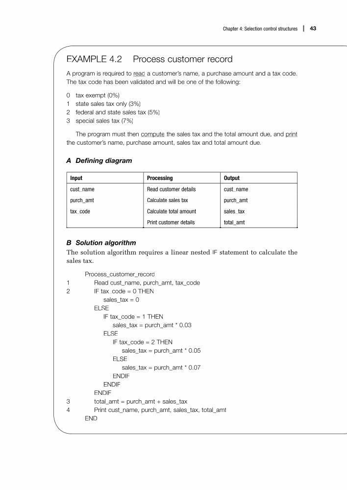
43Chapter 4: Selection control structures
EXAMPLE 4.2 Process customer recordA program is required to read a customer’s name, a purchase amount and a tax code. The tax code has been validated and will be one of the following:
0 tax exempt (0%)1 state sales tax only (3%)2 federal and state sales tax (5%)3 special sales tax (7%)
The program must then computep the sales tax and the total amount due, and printpthe customer’s name, purchase amount, sales tax and total amount due.
A Defining diagram
Input Processing Output
cust_name Read customer details cust_name
purch_amt Calculate sales tax purch_amt
tax_code Calculate total amount sales_tax
Print customer details total_amt
B Solution algorithmThe solution algorithm requires a linear nested IF statement to calculate thesales tax.
Process_customer_record1 Read cust_name, purch_amt, tax_code2 IF tax_code = 0 THEN
sales_tax = 0ELSE
IF tax_code = 1 THENsales_tax = purch_amt * 0.03
ELSEIF tax_code = 2 THEN
sales_tax = purch_amt * 0.05ELSE
sales_tax = purch_amt * 0.07ENDIF
ENDIFENDIF
3 total_amt = purch_amt + sales_tax4 Print cust_name, purch_amt, sales_tax, total_amt
END

44 Simple program design
C Desk checkingTwo sets of valid input data for purchase amount and tax code will be usedto check the algorithm.
1 Input data
First data set Second data set
purch_amt $10.00 $20.00
tax_code 0 2
2 Expected results
First data set Second data set
sales_tax 0 $1.00
total_amt $10.00 $21.00
Note that when desk checking the logic, the whole linear nested IF state-ment (13 lines of pseudocode) is counted as a single pseudocode statement.
3 Desk check table
Statement number purch_amt tax_code sales_tax total_amt
First pass
1 $10.00 0
2 0
3 $10.00
4 print print print
Second pass
1 $20.00 2
2 $1.00
3 $21.00
4 print print print
As the expected result for the two test cases matches the calculated result,the algorithm can be considered correct.
EXAMPLE 4.3 Calculate employee’s payA program is required by a company to read an employee’s number, pay rate and thenumber of hours worked in a week. The program is then to validate the pay rate fieldand the hours worked field and, if valid, computep the employee’s weekly pay and thenprintp it and the input data.
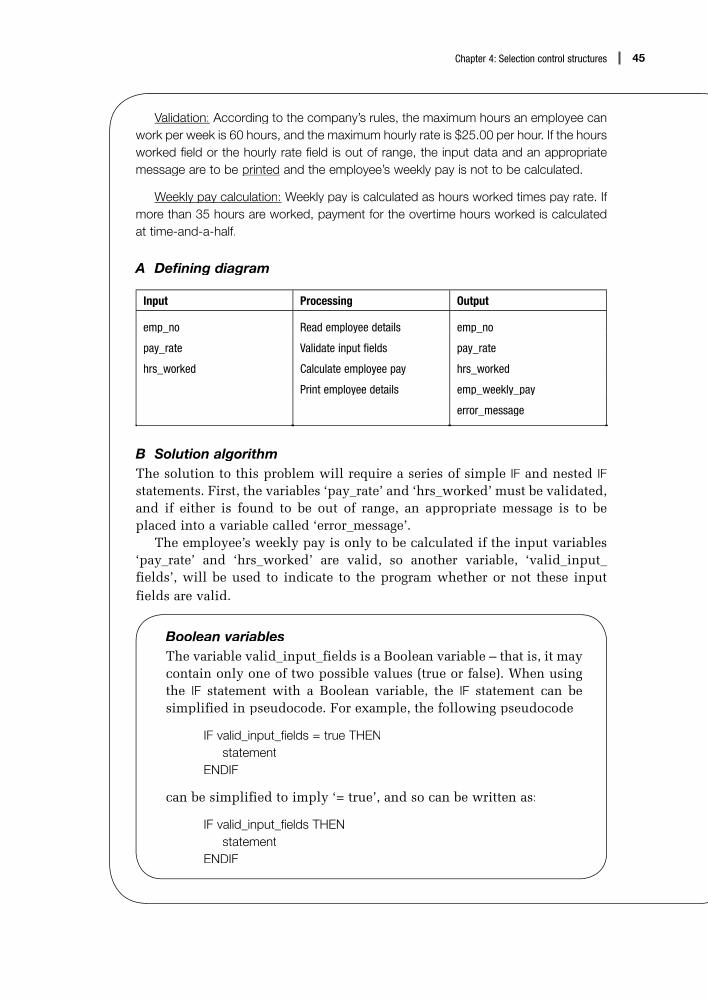
45Chapter 4: Selection control structures
Validation: According to the company’s rules, the maximum hours an employee can work per week is 60 hours, and the maximum hourly rate is $25.00 per hour. If the hoursworked field or the hourly rate field is out of range, the input data and an appropriatemessage are to be printedp and the employee’s weekly pay is not to be calculated.
Weekly pay calculationy p y : Weekly pay is calculated as hours worked times pay rate. If more than 35 hours are worked, payment for the overtime hours worked is calculatedat time-and-a-half.
A Defining diagram
Input Processing Output
emp_no Read employee details emp_no
pay_rate Validate input fields pay_rate
hrs_worked Calculate employee pay hrs_worked
Print employee details emp_weekly_pay
error_message
B Solution algorithmThe solution to this problem will require a series of simple IF and nested IFstatements. First, the variables ‘pay_rate’ and ‘hrs_worked’ must be validated,and if either is found to be out of range, an appropriate message is to beplaced into a variable called ‘error_message’.
The employee’s weekly pay is only to be calculated if the input variables‘pay_rate’ and ‘hrs_worked’ are valid, so another variable, ‘valid_input_fields’, will be used to indicate to the program whether or not these inputfields are valid.
Boolean variablesThe variable valid_input_fields is a Boolean variable – that is, it may contain only one of two possible values (true or false). When using the IF statement with a Boolean variable, the IF statement can be simplified in pseudocode. For example, the following pseudocode
IF valid_input_fields = true THENstatement
ENDIF
can be simplified to imply ‘= true’, and so can be written as:
IF valid_input_fields THENstatement
ENDIF

46 Simple program design
The variable valid_input_fields acts as an internal switch or flag to theprogram. It will initially be set to true, and will be assigned the value false if one of the input fields is found to be invalid. The employee’s weekly pay willbe calculated only if valid_input_fields is true.
Compute_employee_pay1 Set valid_input_fields to true2 Set error_message to blank3 Read emp_no, pay_rate, hrs_worked4 IF pay_rate > $25 THEN
error_message = ‘Pay rate exceeds $25.00’Print emp_no, pay_rate, hrs_worked, error_messagevalid_input_fields = false
ENDIF5 IF hrs_worked > 60 THEN
error_message = ‘Hours worked exceeds 60’Print emp_no, pay_rate, hrs_worked, error_messagevalid_input_fields = false
ENDIF6 IF valid_input_fields THEN
IF hrs_worked <= 35 THENemp_weekly_pay = pay_rate * hrs_worked
ELSEovertime_hrs = hrs_worked – 35overtime_pay = overtime_hrs * pay_rate * 1.5emp_weekly_pay = (pay_rate * 35) + overtime_pay
ENDIFPrint emp_no, pay_rate, hrs_worked, emp_weekly_pay
ENDIFEND
In this solution, there are two separate functions to be performed in the algo-rithm: the validation of the input data, and the calculation and printing of the employee’s weekly pay. These two tasks could have been separated intomodules before the algorithm was developed in pseudocode (see Chapter 8).
Similarly, if we want to test if valid_input_fields is false, we cansay in pseudocode:
IF NOT valid_input_fields THENstatement
ENDIF

47Chapter 4: Selection control structures
C Desk checkingTwo sets of valid input data for pay rate and hours worked will be used tocheck this algorithm.
1 Input data
First data set Second data set
pay_rate $10.00 $40.00
hrs_worked 40 35
2 Expected results
First data set Second data set
pay_rate $10.00 $40.00
hrs_worked 40 35
emp_weekly_pay $425.00 –
error_message blank Pay rate exceeds $25.00
3 Desk check table
Statement number
pay_ratehrs_
workedovertime_
hrsovertime_
pay
emp_weekly_
pay
valid_input_fields
error_message
First pass
1 true
2 blank
3 $10.00 40
4
5
6 5 75.00 425.00Print fi elds
Second pass
1 true
2 blank
3 $40.00 35
4 falsePay rate exceeds $25.00
Print message
5
6

48 Simple program design
4.3 The case structure
The case control structure in pseudocode is another way of expressing alinear nested IF statement. It is used in pseudocode for two reasons: it can betranslated into many high-level languages, and it makes the pseudocode easierto write and understand. Nested IFs often look cumbersome in pseudocodeand depend on correct structure and indentation for readability. Let us lookat the example used earlier in this chapter:
IF record_code = ‘A’ THENincrement counter_A
ELSEIF record_code = ‘B’ THEN
increment counter_BELSE
IF record_code = ‘C’ THENincrement counter_C
ELSEincrement error_counter
ENDIFENDIF
ENDIF
This linear nested IF structure can be replaced with a case control struc-ture. Case is not really an additional control structure. It simplifies the basicselection control structure and extends it from a choice between two valuesto a choice from multiple values. In one case structure, several alternativelogical paths can be represented. In pseudocode, the keywords CASE OF andENDCASE serve to identify the structure, with the multiple values indented,as follows:
CASE OF single variablevalue_1 : statement block_1value_2 : statement block_2
.
.
.value_n : statement block_nvalue_other : statement block_other
ENDCASE
The path followed in the case structure depends on the value of thevariable specified in the CASE OF clause. If the variable contains value_1,statement block_1 is executed; if it contains value_2, statement block_2is executed, and so on. The value_other is included in the event that thevariable contains none of the listed values. We can now rewrite the abovelinear nested IF statement with a case statement, as follows:

49Chapter 4: Selection control structures
CASE OF record_code‘A’ : increment counter_A‘B’ : increment counter_B‘C’ : increment counter_Cother : increment error_counter
ENDCASE
In both forms of pseudocode, the processing logic is exactly the same.However, the case solution is much more readable.
Let us now look again at Example 4.2. The solution algorithm for thisexample was earlier expressed as a linear nested IF statement, but it couldequally have been expressed as a CASE statement.
EXAMPLE 4.4 Process customer recordA program is required to read a customer’s name, a purchase amount and a tax code. The tax code has been validated and will be one of the following:
0 tax exempt (0%)1 state sales tax only (3%)2 federal and state sales tax (5%)3 special sales tax (7%)
The program must then compute the sales tax and the total amount due, and printthe customer’s name, purchase amount, sales tax and total amount due.
A Defining diagram
Input Processing Output
cust_name Read customer details cust_name
purch_amt Calculate sales tax purch_amt
tax_code Calculate total amount sales_tax
Print customer details total_amt
B Solution algorithmThe solution algorithm will be expressed using a CASE statement.
Process_customer_record1 Read cust_name, purch_amt, tax_code2 CASE OF tax_code
0 : sales_tax = 01 : sales_tax = purch_amt * 0.032 : sales_tax = purch_amt * 0.053 : sales_tax = purch_amt * 0.07
ENDCASE3 total_amt = purch_amt + sales_tax4 Print cust_name, purch_amt, sales_tax, total_amt
END

50 Simple program design
C Desk checkingTwo sets of valid input data for purchase amount and tax code will be usedto check the algorithm. Note that the case structure serves as a single pseudo-code statement.
1 Input data
First data set Second data set
purch_amt $10.00 $20.00
tax_code 0 2
2 Expected results
First data set Second data set
sales_tax 0 $1.00
total_amt $10.00 $21.00
3 Desk check table
Statement number purch_amt tax_code sales_tax total_amt
First pass
1 $10.00 0
2 0
3 $10.00
4 print print print
Second pass
1 $20.00 2
2 $1.00
3 $21.00
4 print print print
As the expected result matches the actual result, the algorithm is consideredcorrect.

51Chapter 4: Selection control structures
Chapter summaryThis chapter covered the selection control structure in detail. Descriptions and pseudo-code examples were given for simple selection, null ELSE, combined IF and nestedIF statements. Several solution algorithms that used the selection structure were developed.
The case structure was introduced as a means of expressing a linear nested IFstatement in a simpler and more concise form. Case is available in many high-level languages, and so is a useful construct in pseudocode.
Programming problemsConstruct a solution algorithm for the following programming problems. Your solutionshould contain:
• a defining diagram• a pseudocode algorithm• a desk check of the algorithm.
1 Design an algorithm that will receive two integer items from a terminal operator, and display to the screen their sum, difference, product and quotient. Note that thequotient calculation (first integer divided by second integer) is only to be performedif the second integer does not equal zero.
2 Design an algorithm that will read two numbers and an integer code from the screen. The value of the integer code should be 1, 2, 3 or 4. If the value of the code is 1, compute the sum of the two numbers. If the code is 2, compute the difference (first minus second). If the code is 3, compute the product of the two numbers. If thecode is 4, and the second number is not zero, compute the quotient (first dividedby second). If the code is not equal to 1, 2, 3 or 4, display an error message. Theprogram is then to display the two numbers, the integer code and the computedresult to the screen.
3 Design an algorithm that will prompt an operator for a student’s serial number and the student’s exam score out of 100. Your program is then to match the exam score to a letter grade and print the grade to the screen. Calculate the letter grade as follows:
Exam score Assigned grade
90 and above A
80–89 B
70–79 C
60–69 D
below 60 F

52 Simple program design
4 Design an algorithm that will receive the weight of a parcel and determine the deliv-ery charge for that parcel. Calculate the charges as follows:
Parcel weight (kg) Cost per kg ($)
<2.5 kg $3.50 per kg
2.5–5 kg $2.85 per kg
>5 kg $2.45 per kg
5 Design an algorithm that will prompt a terminal operator for the price of an articleand a pricing code. Your program is then to calculate a discount rate according tothe pricing code and print to the screen the original price of the article, the discountamount and the new discounted price. Calculate the pricing code and accompany-ing discount amount as follows:
Pricing code Discount rate
H 50%
F 40%
T 33%
Q 25%
Z 0%
If the pricing code is Z, the words ‘No discount’ are to be printed on the screen.If the pricing code is not H, F, T, Q or Z, the words ‘Invalid pricing code’ are to beprinted.
6 An architect’s fee is calculated as a percentage of the cost of a building. The fee ismade up as follows:8% of the first $5000.00 of the cost of a building and3% on the remainder if the remainder is less than or equal to $80 000.00 or2.5% on the remainder if the remainder is more than $80 000.00.
Design an algorithm that will accept the cost of a building and calculate anddisplay the architect’s fee.
7 A home mortgage authority requires a deposit on a home loan according to thefollowing schedule:
Loan ($) Deposit
less than $25 000 5% of loan value
$25 000–$49 999 $1250 + 10% of loan over $25 000
$50 000–$100 000 $5000 + 25% of loan over $50 000
Loans in excess of $100 000 are not allowed. Design an algorithm that will reada loan amount and compute and print the required deposit.

53Chapter 4: Selection control structures
8 Design an algorithm that will receive a date in the format dd/mm/yyyy (for example, 21/07/2006) and validate it as follows:i the month must be in the range 1 to 12, andii the day must be in the range of 1 to 31 and acceptable for the corresponding
month. (Don’t forget a leap year check for February.)9 The tax payable on taxable incomes for employees in a certain country is set out
in the following table:
Taxable income Tax payable
From $1.00 to $4461.99 Nil
From $4462.00 to $17 893.99 Nil plus 30 cents for each $ in excess of $4462.00
From $17 894.00 to $29 499.99 $4119.00 plus 35 cents for each $ in excess of $17 894.00
From $29 500.00 to $45 787.99 $8656.00 plus 46 cents for each $ in excess of $29 500.00
$45 788.00 and over $11 179.00 plus 60 cents for each $ in excess of $45 788.00
Design an algorithm that will read as input the taxable income amount andcalculate and print the tax payable on that amount.
10 A transaction record on a sales commission file contains the retail price of an itemsold, a transaction code that indicates the sales commission category to which anitem can belong, and the employee number of the person who sold the item. Thetransaction code can contain the values S, M or L, which indicate that the percent-age commission will be 5%, 7% or 10% respectively. Construct an algorithm thatwill read a record on the file, calculate the commission owing for that record, and print the retail price, commission and employee number.

Repetition control structures
Objectives
• To develop algorithms that use the DOWHILE and REPEAT…UNTIL control structures
• To introduce a pseudocode structure for counted repetitionloops
• To develop algorithms using variations of the repetitionconstruct
Outline
5.1 Repetition using the DOWHILE structure
5.2 Repetition using the REPEAT…UNTIL structure
5.3 Counted repetition
Chapter summary
Programming problems
5

55Chapter 5: Repetition control structures
5.1 Repetition using the DOWHILE structure
The solution algorithms developed so far have one characteristic in common:they show the program logic required to process just one set of input values.However, most programs require the same logic to be repeated for severalsets of data. The most efficient way to deal with this situation is to establisha looping structure in the algorithm that will cause the processing logic to berepeated a number of times.
There are three different ways in which a set of instructions can berepeated, and each way is determined by where the decision to repeat isplaced:
• at the beginning of the loop (leading decision loop)• at the end of the loop (trailing decision loop)• a counted number of times (counted loop).
Leading decision loop
In Chapter 2, the DOWHILE construct was introduced as the pseudocode rep-resentation of a repetitive loop. Its format is:
DOWHILE condition p is truestatement block
ENDDO
The DOWHILE construct is a leading decision loop – the condition is testedbefore any statements are executed. In the above DOWHILE loop, the followingprocessing takes place:
1 The logical condition p is tested.2 If condition p is found to be true, the statements within the statement
block are executed once. The delimiter ENDDO then triggers a return of control to the retesting of condition p.
3 If condition p is still true, the statements are executed again, and so therepetition process continues until the condition is found to be false.
4 If condition p is found to be false, control passes to the next statementafter the delimiter ENDDO and no further processing takes place within theloop.
There are two important considerations of which you must be aware beforedesigning a DOWHILE loop:
• The testing of the condition is at the beginning of the loop. This meansthat it may be necessary to perform some initial processing to adequatelyset up the condition before it can be tested.
• The only way to terminate the loop is to render the DOWHILE conditionfalse. This means some process must be set up within the statement blockthat will eventually change the condition so that the condition becomesfalse. Failure to do this results in an endless loop.

56 Simple program design
Using DOWHILE to repeat a set of instructions aknown number of times
When a set of instructions is to be repeated a specific number of times, acounter can be used in pseudocode, which is initialised before the DOWHILEstatement and incremented just before the ENDDO statement. Let’s look at anexample.
EXAMPLE 5.1 Fahrenheit–Celsius conversionEvery day, a weather station receives 15 temperatures expressed in degrees Fahrenheit.A program is to be written that will acceptp each Fahrenheit temperature, convert it toCelsius and displayp y the converted temperature to the screen. After 15 temperatureshave been processed, the words ‘All temperatures processed’ are to be displayedp y onthe screen.
A Defining diagram
Input Processing Output
f_temp Get Fahrenheit temperatures c_temp
(15 temperatures) Convert temperatures (15 temperatures)
Display Celsius temperatures
Display screen message
Having defined the input, output and processing, you are ready to outlinea solution to the problem. This can be done by writing down the controlstructures needed and any extra variables that are to be used in the solutionalgorithm. In this example, you need:
• a DOWHILE structure to repeat the necessary processing• a counter, called temperature_count, initialised to zero, that will control
the 15 repetitions.
B Solution algorithmFahrenheit_Celsius_conversion
1 Set temperature_count to zero2 DOWHILE temperature_count < 153 Prompt operator for f_temp4 Get f_temp5 compute c_temp = (f_temp – 32) * 5/96 Display c_temp7 add 1 to temperature_count
ENDDO8 Display ‘All temperatures processed’ to the screen
END

57Chapter 5: Repetition control structures
This solution algorithm illustrates a number of points:
1 The temperature_count variable is initialised before the DOWHILE condi-tion is executed.
2 As long as temperature_count is less than 15 (that is, the DOWHILEcondition is true), the statements between DOWHILE and ENDDO will be executed.
3 The variable temperature_count is incremented once within the loop, justbefore the ENDDO delimiter (that is, just before it is tested again in theDOWHILE condition).
4 After 15 iterations, temperature_count will equal 15, which causes theDOWHILE condition to become false and control to be passed to the state-ment after ENDDO.
C Desk checkingAlthough the program will require 15 records to process properly, at this stageit is only necessary to check the algorithm with two valid sets of data.
1 Input data
First data set Second data set
f_temp 32 50
2 Expected results
First data set Second data set
c_temp 0 10
3 Desk check table
Statement numbertemperature_
countDOWHILE condition
f_temp c_temp
1 0
2 true
3, 4 32
5 0
6 display
7 1
2 true
3, 4 50
5 10
6 display
7 2

58 Simple program design
Using DOWHILE to repeat a set of instructions anunknown number of times
1 When a trailer record or sentinel existsWhen there are an unknown number of items to process, a counter cannotbe used, so another way of controlling the repetition must be found. Often, atrailer record or sentinel signifies the end of the data. This sentinel is a specialrecord or value placed at the end of valid data to signify the end of that data.It must contain a value that is clearly distinguishable from the other data tobe processed. It is referred to as a sentinel because it indicates that no moredata follows. Let’s look at an example.
EXAMPLE 5.2 Print examination scoresA program is required to read and print a series of names and exam scores for studentsenrolled in a mathematics course. The class average is to be calculated and printed atthe end of the report. Scores can range from 0 to 100. The last record contains a blank name and a score of 999 and is not to be included in the calculations.
A Defining diagram
Input Processing Output
name Read student details name
exam_score Print student details exam_score
Calculate average score average_score
Print average score
You will need to consider the following when establishing a solution algo-rithm:
• a DOWHILE structure to control the reading of exam scores, until it reachesa score of 999
• an accumulator for total scores, namely total_score• an accumulator for the total students, namely total_students.

59Chapter 5: Repetition control structures
B Solution algorithm
Print_examination_scores1 Set total_score to zero2 Set total_students to zero3 Read name, exam_score4 DOWHILE exam_score not = 9995 add 1 to total_students6 Print name, exam_score7 add exam_score to total_score8 Read name, exam_score
ENDDO9 IF total_students not = zero THEN
average_score = total_score/total_studentsPrint average_score
ENDIFEND
In this example, the DOWHILE condition tests for the existence of the trailerrecord or sentinel (record 999). However, this condition cannot be tested untilat least one exam mark has been read. Hence, the initial processing that setsup the condition is a Read statement immediately before the DOWHILE clause (Read name, exam_score). This is known as a priming read.
The algorithm will require another Read statement, this time within thebody of the loop. Its position is also important. The trailer record or sentinelmust not be included in the calculation of the average score, so each time anexam score is read it must be tested for a 999 value before further processingcan take place. For this reason, the Read statement is placed at the end of theloop, immediately before ENDDO, so that its value can be tested when con-trol returns to the DOWHILE condition. As soon as the trailer record has beenread, control will pass from the loop to the next statement after ENDDO – the calculation of average_score.
C Desk checkingTwo valid records and a trailer record should be sufficient to desk check thisalgorithm.
1 Input data
First record Second record Third record
score 50 100 999

60 Simple program design
2 Expected results
First name, and score of 50 Second name, and score of 100 Average score 75
3 Desk check table
Statement number
total_scoretotal_
studentsexam_score
DOWHILE condition
average_score
1, 2 0 0
3 50
4 true
5 1
6 print
7 50
8 100
4 true
5 2
6 print
7 150
8 999
4 false
9 75
2 When a trailer record or sentinel does not existWhen there is no trailer record or sentinel to signify the end of the data, it isnecessary to check for an end-of-file marker (EOF). This EOF marker is addedwhen the file is created, as the last character in the file. The check for EOFis positioned in the DOWHILE clause, using one of the following equivalentexpressions:
DOWHILE more dataDOWHILE more recordsDOWHILE records existDOWHILE NOT EOF

61Chapter 5: Repetition control structures
In this case, all statements between the words DOWHILE and ENDDO will be repeated until an attempt is made to read a record but no more records exist.When this occurs, a signal is sent to the program to indicate that there are nomore records and so the ‘DOWHILE more records’ condition is rendered false.Let’s look at an example.
EXAMPLE 5.3 Process student enrolmentsA program is required that will read a file of student records, and select and print onlythe records of those students enrolled in a course unit named Programming I. Eachstudent record contains student number, name, address, postcode, gender and courseunit number. The course unit number for Programming I is 18500. Three totals are to beprinted at the end of the report: total females enrolled in the course, total males enrolled in the course, and total students enrolled in the course.
A Defining diagram
Input Processing Output
student_record Read student records selected student records
• student_no Select student records total_females_enrolled
• name Print selected records total_males_enrolled
• address Compute total females enrolled total_students_enrolled
• postcode Compute total males enrolled
• gender Compute total students enrolled
• course_unit Print totals
You will need to consider the following requirements when establishing asolution algorithm:
• a DOWHILE structure to perform the repetition• IF statements to select the required students• accumulators for the three total fields.

62 Simple program design
B Solution algorithm
Process_student_enrolments 1 Set total_females_enrolled to zero 2 Set total_males_enrolled to zero 3 Set total_students_enrolled to zero 4 Read student record 5 DOWHILE records exist 6 IF course_unit = 18500 THEN
print student detailsincrement total_students_enrolledIF student_gender = female THEN
increment total_females_enrolledELSE
increment total_males_enrolledENDIF
ENDIF 7 Read student record
ENDDO 8 Print total_females_enrolled 9 Print total_males_enrolled 10 Print total_students_enrolled
END
C Desk checkingThree valid student records should be sufficient to desk check this algorithm.Since student_no, name, address and postcode are not operated upon in thisalgorithm, they do not need to be provided as input test data.
1 Input data
First record Second record Third record
course_unit 20000 18500 18500
gender F F M
2 Expected results
Student number, name, address, postcode, F (2nd student) Student number, name, address, postcode, M (3rd student) Total females enrolled 1 Total males enrolled 1 Total students enrolled 2

63Chapter 5: Repetition control structures
3 Desk check table
Statement number
course_unit
genderDOWHILEcondition
total_females_enrolled
total_males_enrolled
total_students_enrolled
1, 2, 3 0 0 0
4 20000 F
5 true
6
7 18500 F
5 true
6 print print 1 1
7 18500 M
5 true
6 print print 1 2
7 EOF
5 false
8, 9, 10 print print print
The priming Read before the DOWHILE condition, together with the subse-quent Read within the loop, immediately before the ENDDO statement, formthe basic framework for DOWHILE repetitions in pseudocode. In general, allalgorithms using a DOWHILE construct to process a sequential file should havethe same basic pattern, as follows:
Process_sequential_fileInitial processingRead first recordDOWHILE more records exist
Process this recordRead next record
ENDDOFinal processing
END

64 Simple program design
5.2 Repetition using the REPEAT…UNTILstructure
Trailing decision loop
The REPEAT…UNTIL structure is similar to the L DOWHILE structure, in that agroup of statements is repeated in accordance with a specified condition.However, where the DOWHILE structure tests the condition at the beginningof the loop, a REPEAT…UNTIL structure tests the condition at the end of theLloop. This means that the statements within the loop will be executed oncebefore the condition is tested. If the condition is false, the statements will berepeated UNTIL the condition becomes true.L
The format of the REPEAT…UNTIL structure is:L
REPEATstatementstatement
.
.
.UNTIL condition is true
REPEAT…UNTIL is a trailing decision loop; the statements are executed onceLbefore the condition is tested. There are two considerations of which youneed to be aware before using REPEAT…UNTIL.
First, REPEAT…UNTIL loops are executed when the condition is false; itLis only when the condition becomes true that repetition ceases. Thus, thelogic of the condition clause of the REPEAT…UNTIL structure is the oppositeLof DOWHILE. For instance, ‘DOWHILE more records’ is equivalent to ‘REPEAT…UNTIL no more records’, and ‘L DOWHILE number NOT = 99’ is equivalent to‘REPEAT…UNTIL number = 99’.L
Second, the statements within a REPEAT…UNTIL structure will always beLexecuted at least once. As a result, there is no need for a priming Read whenusing REPEAT…UNTIL. One Read statement at the beginning of the loop is suf-ficient; however, an extra IF statement immediately after the Read statementmust be included, to prevent the processing of the trailer record.
Let us now compare an algorithm that uses a DOWHILE structure withthe same problem using a REPEAT…UNTIL structure. Consider the followingLDOWHILE loop:

65Chapter 5: Repetition control structures
Process_student_recordsSet student_count to zeroRead student recordDOWHILE student_number NOT = 999
Write student recordincrement student_countRead student record
ENDDOPrint student_count
END
This can be rewritten as a trailing decision loop, using the REPEAT…UNTILstructure as follows:
Process_student_recordsSet student_count to zeroREPEAT
Read student recordIF student number NOT = 999 THEN
Write student recordincrement student_count
ENDIFUNTIL student number = 999Print student_count
END
Let us look at an example.
EXAMPLE 5.4 Process inventory itemsA program is required to read a series of inventory records that contain an item number, an item description and a stock figure. The last record in the file has an item number of zero. The program is to producep a low stock items report, by printingp g only those records that have a stock figure of less than 20 items. A heading is to be printedp at the top of the report and a total low stock item count printedp at the end.
A Defining diagram
Input Processing Output
inventory record Read inventory records heading
• item_number Select low stock items selected records
• item_description Print low stock records • item_number
• stock_figure Print total low stock items • item_description
• stock_figure
total_low_stock_items

66 Simple program design
You will need to consider the following requirements when establishing asolution algorithm:
• a REPEAT…UNTIL to perform the repetitionL• an IF statement to select stock figures of less than 20• an accumulator for total_low_stock_items• an extra IF, within the REPEAT loop, to ensure the trailer record is notT
processed.
B Solution algorithm using REPEAT…UNTIL
Process_inventory_records1 Set total_low_stock_items to zero2 Print ‘Low Stock Items’ heading
REPEAT3 Read inventory record4 IF item_number > zero THEN
IF stock_figure < 20 THENPrint item_number, item_description, stock_figureincrement total_low_stock_items
ENDIFENDIF
5 UNTIL item_number = zero6 Print total_low_stock_items
END
The solution algorithm has a simple structure, with a single Read statementat the beginning of the REPEAT…UNTIL loop and an extraL IF statement withinthe loop to ensure the trailer record is not incorrectly incremented into thetotal_low_stock_items accumulator.
C Desk checkingTwo valid records and a trailer record (item number equal to zero) will beused to test the algorithm:
1 Input data
First record Second record Third record
item_number 123 124 0
stock_figure 8 25
2 Expected results Low Stock Items 123 8 (first record) Total Low Stock Items = 1

67Chapter 5: Repetition control structures
3 Desk check table
Statement number
item_number stock_figureREPEATUNTIL
total_low_stock_items
heading
1 0
2 print
3 123 8
4 print print 1
5 false
3 124 25
4
5 false
3 0
4
5 true
6 print
5.3 Counted repetition
Counted loop
Counted repetition occurs when the exact number of loop iterations is knownin advance. The execution of the loop is controlled by a loop index, andinstead of using DOWHILE, or REPEAT…UNTIL, the simple keyword DO is used as follows:
DO loop_index = initial_value to final_valuestatement block
ENDDO
The DO loop does more than just repeat the statement block. It will:
1 initialise the loop_index to the required initial_value2 increment the loop_index by 1 for each pass through the loop3 test the value of loop_index at the beginning of each loop to ensure that it
is within the stated range of values4 terminate the loop when the loop_index has exceeded the specified final_
value.
In other words, a counted repetition construct will perform the initialising,incrementing and testing of the loop counter automatically. It will alsoterminate the loop once the required number of repetitions has beenexecuted.

68 Simple program design
Let us look again at Example 5.1, which processes 15 temperatures at aweather station each day. The solution algorithm can be rewritten to use aDO loop.
EXAMPLE 5.5 Fahrenheit–Celsius conversionEvery day, a weather station receives 15 temperatures expressed in degrees Fahrenheit.A program is to be written that will acceptp each Fahrenheit temperature, convert it toCelsius and displayp y the converted temperature to the screen. After 15 temperatureshave been processed, the words ‘All temperatures processed’ are to be displayedp y onthe screen.
A Defining diagram
Input Processing Output
f_temp Get Fahrenheit temperatures c_temp
(15 temperatures) Convert temperatures (15 temperatures)
Display Celsius temperatures
Display screen message
B Solution algorithmThe solution will require a DO loop and a loop counter (temperature_count)to process the repetition.
Fahrenheit_Celsius_conversion1 DO temperature_count = 1 to 152 Prompt operator for f_temp3 Get f_temp4 compute c_temp = (f_temp – 32) * 5/95 Display c_temp
ENDDO6 Display ‘All temperatures processed’ to the screen
END
Note that the DO loop controls all the repetition:
• It initialises temperature_count to 1.• It increments temperature_count by 1 for each pass through the loop.• It tests temperature_count at the beginning of each pass to ensure that it is
within the range 1 to 15.• It automatically terminates the loop once temperature_count has exceeded
15.

69Chapter 5: Repetition control structures
C Desk checkingTwo valid records should be sufficient to test the algorithm for correctness. Itis not necessary to check the DO loop construct for all 15 records.
1 Input data
First data set Second data set
f_temp 32 50
2 Expected results
First data set Second data set
c_temp 0 10
3 Desk check table
Statement number temperature_count f_temp c_temp
1 1
2, 3 32
4 0
5 display
1 2
2, 3 50
4 10
5 display
Desk checking the algorithm with the two input test cases indicates that theexpected results have been achieved.
A requirement of counted repetition loops is that the exact number of input data items or records needs to be known before the algorithm can bewritten. Counted repetition loops are used extensively with arrays or tables,as seen in Chapter 7.
Chapter summaryThis chapter covered the repetition control structure in detail. Descriptions andpseudocode examples were given for leading decision loops (DOWHILE), trailing decisionloops (REPEAT…UNTIL) and counted loops (DO). Several solution algorithms that usedeach of the three control structures were defined, developed and desk checked.

70 Simple program design
We saw that most of the solution algorithms that used the DOWHILE structure hadthe same general pattern. This pattern consisted of:
1 some initial processing before the loop2 some processing for each record within the loop3 some final processing once the loop has been exited.
Expressed as a solution algorithm, this basic pattern was developed as a generalsolution:
Process_sequential_fileInitial processingRead first recordDOWHILE more records exist
Process this recordRead next record
ENDDOFinal processing
END
Programming problemsConstruct a solution algorithm for the following programming problems. Your solutionshould contain:• a defining diagram• a pseudocode algorithm• a desk check of the algorithm.
1 Design an algorithm that will output the seven times table, as follows:7 × 1 = 77 × 2 = 147 × 3 = 21 . . .
2 Design an algorithm that will display to the screen the first 20 numbers, with theirsquares and cubes, as follows:
Number Square Cube
1 1 1
2 4 8
3 9 27 . . .
3 Design an algorithm that will prompt for, receive and total a collection of payrollamounts entered at the terminal until a sentinel amount of 999 is entered. After thesentinel has been entered, display the total payroll amount to the screen.

71Chapter 5: Repetition control structures
4 Design an algorithm that will read a series of integers at the terminal. The first inte-ger is special, as it indicates how many more integers will follow. Your algorithm isto calculate the sum and average of the integers, excluding the first integer, and display these values to the screen.
5 Design an algorithm that will prompt for and receive the time expressed in 2400format (e.g. 2305 hours), convert it to 12-hour format (e.g. 11.05 pm) and displaythe new time to the screen. Your program is to repeat the processing until a senti-nel time of 9999 is entered.
6 Design a program that will read a file of product records, each containing the itemnumber, the item name, the quantity sold this year and the quantity sold last year. The program is to produce a product list showing the item number, the item name,and the increase or decrease in the quantity sold this year for each item.
7 The first record of a set of records contains a bank account number and an open-ing balance. Each of the remaining records in the set contains the amount of acheque drawn on that bank account. The trailer record contains a zero amount.Design a program that will read and print the bank account number and openingbalance on a statement of account report. The following cheque amounts are to be read and printed on the report, each with a new running balance. Print a closingbalance at the end of the report.
8 Design a program that will read a file of employee records containing employeenumber, employee name, hourly pay rate, regular hours worked and overtimehours worked. The company pays its employees weekly, according to the followingrules:
regular pay = regular hours worked × hourly rate of payovertime pay = overtime hours worked × hourly rate of pay × 1.5total pay = regular pay + overtime pay
Your program is to read the input data on each employee’s record and computeand print the employee’s total pay on the weekly payroll report. All input data andcalculated amounts are to appear on the report. A total payroll amount is to appearat the end of the report.
9 Design an algorithm that will process the weekly employee time cards for all theemployees of an organisation. Each employee time card will have three data items:an employee number, an hourly wage rate and the number of hours worked duringa given week. Each employee is to be paid time-and-a-half for all hours workedover 35. A tax amount of 15% of gross salary is to be deducted. The output to thescreen should display the employee’s number and net pay. At the end of the run,display the total payroll amount and the average amount paid.
10 As a form of quality control, the Pancake Kitchen has recorded, on a Pancake file,two measurements for each of its pancakes made in a certain month: the thick-ness in mm (millimetres) and the diameter in cm (centimetres). Each record on the file contains the two measurements for a pancake, thickness followed by diameter. The last record in the file contains values of 99 for each measurement. Design aprogram that will read the Pancake file, calculate the minimum, the maximum andthe average for both dimensions, and print these values on a report.

Pseudocode algorithms using
sequence, selection and repetition
Objectives
• To develop solution algorithms to eight typical programming problems using sequence, selection and repetition constructs
Outline
6.1 Eight solution algorithms
Chapter summary
Programming problems
6

73Chapter 6: Pseudocode algorithms using sequence, selection and repetition
6.1 Eight solution algorithms
This chapter develops solution algorithms to eight programming problems of increasing complexity. All the algorithms will use a combination of sequence,selection and repetition constructs. The algorithms have been designed tobe interactive or to process sequential files. Reading these algorithms willconsolidate the groundwork developed in the previous chapters.
Each programming problem will be defined, the control structures requiredwill be determined and a solution algorithm will be devised.
1 Defining the problem
It is important to divide the problem into its three components: input,output and processing. The processing component should list the tasksto be performed, that is, what needs to be done, nott how. The verbs ineach problem have been underlined to help identify the actions to be per-formed.
2 The control structures required
Once the problem has been defined, write down the control structures(sequence, selection and repetition) that may be needed, as well as any extravariables that the solution may require.
3 The solution algorithm
Having defined the problem and determined the required control structures,devise a solution algorithm and represent it using pseudocode. Each solutionalgorithm presented in this chapter is only one solution to the particularproblem; other solutions could be equally correct.
4 Desk checking
Desk check each of the algorithms with two or more test cases.
EXAMPLE 6.1 Process number pairsDesign an algorithm that will promptp p for and receive pairs of numbers from an operatorat a terminal and displayp y their sum, product and average on the screen. If the calcu-lated sum is over 200, an asterisk is to be displayedp y beside the sum. The program is toterminate when a pair of zero values is entered.
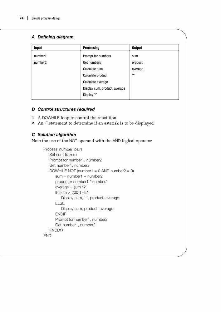
74 Simple program design
A Defining diagram
Input Processing Output
number1 Prompt for numbers sum
number2 Get numbers product
Calculate sum average
Calculate product ‘*’
Calculate average
Display sum, product, average
Display ‘*’
B Control structures required
1 A DOWHILE loop to control the repetition2 An IF statement to determine if an asterisk is to be displayed
C Solution algorithmNote the use of the NOT operand with theT AND logical operator.
Process_number_pairsSet sum to zeroPrompt for number1, number2Get number1, number2DOWHILE NOT (number1 = 0 AND number2 = 0)
sum = number1 + number2product = number1 * number2average = sum / 2IF sum > 200 THEN
Display sum, ‘*’, product, averageELSE
Display sum, product, averageENDIFPrompt for number1, number2Get number1, number2
ENDDOEND

75Chapter 6: Pseudocode algorithms using sequence, selection and repetition
EXAMPLE 6.2 Print student recordsA file of student records consists of ‘S’ records and ‘U’ records. An ‘S’ record containsthe student’s number, name, age, gender, address and attendance pattern – full-time(F/T) or part-time (P/T). A ‘U’ record contains the number and name of the unit or unitsin which the student has enrolled. There may be more than one ‘U’ record for each ‘S’ record. Design a solution algorithm that will read the file of student records and printponly the student’s number, name and address on a ‘STUDENT LIST’.
A Defining diagram
Input Processing Output
‘S’ records Print heading Heading line
• number Read student records selected student records
• name Select ‘S’ records • number
• address Print selected records • name
• age • address
• gender
• attendance_pattern
‘U’ records
B Control structures required
1 A DOWHILE loop to control the repetition2 An IF statement to select ‘S’ records
C Solution algorithm
Print_student_recordsPrint ‘STUDENT LIST’ headingRead student recordDOWHILE more records exist
IF student record = ‘S’ record THENPrint student_number, name, address
ENDIFRead student record
ENDDOEND

76 Simple program design
EXAMPLE 6.3 Print selected studentsDesign a solution algorithm that will read the same student file as in Example 6.2, andproducep a report of all female students who are enrolled part-time. The report is to beheaded ‘FEMALE PART-TIME STUDENTS’ and is to show the student’s number, name,address and age.
A Defining diagram
Input Processing Output
‘S’ records Print heading Heading line
• number Read student records selected student records
• name Select female P/T students • number
• address Print selected records • name
• age • address
• gender • age
• attendance_pattern
‘U’ records
B Control structures required
1 A DOWHILE loop to control the repetition2 An IF statement or statements to select ‘S’, female and part-time (P/T)
students
C Solution algorithmSeveral algorithms for this problem will be presented, and all are equallycorrect. The algorithms only differ in the way the IF statement is expressed. Itis interesting to compare the three different solutions.
Solution 1 uses a non-linear nested IF:
Produce_part_time_female_listPrint ‘FEMALE PART-TIME STUDENTS’ headingRead student recordDOWHILE more records
IF student record = ‘S’ record THENIF attendance_pattern = P/T THEN
IF gender = female THENPrint student_number, name, address, age
ENDIFENDIF
ENDIFRead student record
ENDDOEND

77Chapter 6: Pseudocode algorithms using sequence, selection and repetition
Solution 2 uses a nested and compound IF statement:
Produce_part_time_female_listPrint ‘FEMALE PART-TIME STUDENTS’ headingRead student recordDOWHILE more records
IF student record = ‘S’ record THENIF (attendance_pattern = P/TAND gender = female) THEN
Print student_number, name, address, ageENDIF
ENDIFRead student record
ENDDOEND
Solution 3 also uses a compound IF statement:
Produce_part_time_female_listPrint ‘FEMALE PART-TIME STUDENTS’ headingRead student recordDOWHILE more records
IF student record = ‘S’ recordAND attendance_pattern = P/TAND gender = female THEN
Print student_number, name, address, ageENDIFRead student record
ENDDOEND
EXAMPLE 6.4 Print and total selected studentsDesign a solution algorithm that will read the same student file as in Example 6.3 and producep the same ‘FEMALE PART-TIME STUDENTS’ report. In addition, at the end of the report you are to printp the number of students who have been selected and listed,and the total number of students on the file.

78 Simple program design
A Defining diagram
Input Processing Output
‘S’ records Print heading Heading line
• number Read student records selected student records
• name Select female P/T students • number
• address Print selected records • name
• age Compute total students • address
• gender Compute total selected students • age
• attendance_pattern Print totals total_students
‘U’ records total_selected_students
B Control structures required
1 A DOWHILE loop to control the repetition2 IF statements to select ‘S’, female and P/T students3 Accumulators for total_selected_students and total_students
C Solution algorithm
Produce_part_time_female_listPrint ‘FEMALE PART-TIME STUDENTS’ headingSet total_students to zeroSet total_selected_students to zeroRead student recordDOWHILE records exist
IF student record = ‘S’ record THENincrement total_studentsIF (attendance_pattern = P/TAND gender = female) THEN
increment total_selected_studentsPrint student_number, name, address, age
ENDIFENDIFRead student record
ENDDOPrint total_studentsPrint total_selected_students
END
Note the positions where the total accumulators are incremented. If thesestatements are not placed accurately within their respective IF statements, thealgorithm could produce erroneous results.

79Chapter 6: Pseudocode algorithms using sequence, selection and repetition
EXAMPLE 6.5 Print student reportDesign an algorithm that will read the same student file as in Example 6.4 and, for eachstudent, printp the name, number and attendance pattern from the ‘S’ records (studentrecords) and the unit number and unit name from the ‘U’ records (enrolled units records) as follows:
STUDENT REPORT
Student name ..............................................
Student number ..............................................
Attendance ..............................................
Enrolled units .............................................. ..............................................
.............................................. ..............................................
.............................................. ..............................................
At the end of the report, print the total number of students enrolled.
A Defining diagram
Input Processing Output
‘S’ records Print heading Heading line
• number Read student records detail lines
• name Print ‘S’ record details • name
• attendance_pattern Print ‘U’ record details • number
‘U’ records Compute total students • attendance_pattern
• unit_number Print total students • unit_number
• unit_name • unit_name
total_students
B Control structures required
1 A DOWHILE loop to control the repetition2 An IF statement to select ‘S’ or ‘U’ records3 An accumulator for total_students

80 Simple program design
C Solution algorithm
Print_student_reportPrint ‘STUDENT REPORT’ headingSet total_students to zeroRead student recordDOWHILE records exist
IF student record = ‘S’ THENadd 1 to total_studentsPrint ‘Student name’, namePrint ‘Student number’, numberPrint ‘Attendance’, attendance_patternPrint ‘Enrolled units’
ELSEIF student record = ‘U’ THEN
Print unit_number, unit_nameELSE
Print ‘student record error’ENDIF
ENDIFRead student record
ENDDOPrint ‘Total students’, total_students
END
EXAMPLE 6.6 Produce sales reportDesign a program that will read a file of sales records and producep a sales report. Eachrecord in the file contains a customer’s number and name, a sales amount and a taxcode. The tax code is to be applied to the sales amount to determine the sales tax duefor that sale, as follows:
Tax code Sales tax
0 tax exempt
1 3%
2 5%
The report is to print a heading ‘SALES REPORT’, and detail lines listing the cus-tomer number, name, sales amount, sales tax and the total amount owing.

81Chapter 6: Pseudocode algorithms using sequence, selection and repetition
A Defining diagram
Input Processing Output
sales record Print heading Heading line
• customer_number Read sales records detail lines
• name Calculate sales tax • customer_number
• sales_amt Calculate total amount • name
• tax_code Print customer details • sales_amt
• sales_tax
• total_amount
B Control structures required
1 A DOWHILE loop to control the repetition2 A case statement to calculate the sales_tax
Assume that the tax_code field has been validated and will only contain avalue of 0, 1 or 2.
C Solution algorithm
Produce_sales_reportPrint ‘SALES REPORT’ headingRead sales recordDOWHILE not EOF
CASE of tax_code0 : sales_tax = 01 : sales_tax = sales_amt * 0.032 : sales_tax = sales_amt * 0.05
ENDCASEtotal_amt = sales_amt + sales_taxPrint customer_number, name, sales_amt, sales_tax, total_amtRead sales record
ENDDOEND

82 Simple program design
EXAMPLE 6.7 Student test resultsDesign a solution algorithm that will read a file of student test results and producep astudent test grades report. Each test record contains the student number, name andtest score (out of 50). The program is to calculate for each student the test score as apercentage and to printp the student’s number, name, test score (out of 50) and lettergrade on the report. The letter grade is determined as follows:
A = 90–100% B = 80–89% C = 70–79% D = 60–69% F = 0–59%
A Defining diagram
Input Processing Output
Student test records Print heading Heading line
• student_number Read student records student details
• name Calculate test percentage • student_number
• test_score Calculate letter grade • name
Print student details • test_score
• grade
B Control structures required
1 A DOWHILE loop to control the repetition2 A formula to calculate the percentage3 A linear nested IF statement to calculate the grade
(The case construct cannot be used here, as CASE is not designed to cater fora range of values such as, 0–59%.)

83Chapter 6: Pseudocode algorithms using sequence, selection and repetition
C Solution algorithm
Print_student_resultsPrint ‘STUDENT TEST GRADES’ headingRead student recordDOWHILE not EOF
percentage = test_score * 2IF percentage >= 90 THEN
grade = ‘A’ELSE
IF percentage >= 80 THENgrade = ‘B’
ELSEIF percentage >= 70 THEN
grade = ‘C’ELSE
IF percentage >= 60 THENgrade = ‘D’
ELSEgrade = ‘F’
ENDIFENDIF
ENDIFENDIFPrint student_number, name, test_score, gradeRead student record
ENDDOEND
Note that the linear nested IF has been worded so that all alternatives havebeen considered.
EXAMPLE 6.8 Gas supply billingThe Domestic Gas Supply Company records its customers’ gas usage figures on acustomer usage file. Each record on the file contains the customer’s number, name andaddress, and their gas usage expressed in cubic metres. Design a solution algorithmthat will read the customer usage file, calculate the amount owing for gas usage foreach customer, and printp a report listing each customer’s number, name, address, gasusage and the amount owing.
The company bills its customers according to the following rate: if the customer’s usage is 60 cubic metres or less, a rate of $2.00 per cubic metre is applied; if the customer’s usage is more than 60 cubic metres, then a rate of $1.75 per cubic metre is applied for the first 60 cubic metres and $1.50 per cubic metre for the remainingusage.

84 Simple program design
At the end of the report, print the total number of customers and the total amountowing to the company.
A Defining diagram
Input Processing Output
customer usage records Print heading Heading line
• customer_number Read usage records customer details
• name Calculate amount owing • customer_number
• address Print customer details • name
• gas_usage Compute total customers • address
Compute total amount owing • gas_usage
Print totals • amount_owing
total_customers
total_amount_owing
B Control structures required
1 A DOWHILE loop to control the repetition2 An IF statement to calculate the amount_owing3 Accumulators for total_customers and total_amount_owing
C Solution algorithm
Bill_gas_customersPrint ‘CUSTOMER USAGE FIGURES’ headingSet total_customers to zeroSet total_amount_owing to zeroRead customer recordDOWHILE more records
IF usage <= 60 THENamount_owing = usage * $2.00
ELSEamount_owing = (60 * $1.75) + ((usage – 60) * $1.50)
ENDIFPrint customer_number, name, address, gas_usage, amount_owingAdd amount_owing to total_amount_owingAdd 1 to total_customersRead customer record
ENDDOPrint total_customersPrint total_amount_owing
END

85Chapter 6: Pseudocode algorithms using sequence, selection and repetition
Chapter summaryThis chapter developed solution algorithms to eight typical programming problems. Theapproach to all eight problems followed the same pattern:
1 A defining diagram was used to define the problem.2 The control structures required were written down, along with any extra variables
required.3 The solution algorithm was produced using pseudocode and the three basic control
structures: sequence, selection and repetition.
It was noted that the solution algorithms followed the same basic pattern, althoughthe statements within the pattern were different. This pattern was first introduced inChapter 5, as follows:
Process_sequential_fileInitial processingRead first recordDOWHILE more records exist
Process this recordRead next record
ENDDOFinal processing
END
Programming problemsConstruct a solution algorithm for the following programming problems. Your solutionshould contain:
• a defining diagram• a list of control structures required• a pseudocode algorithm• a desk check of the algorithm.
1 Design an algorithm that will prompt for and receive a person’s age in years andmonths and calculate and display the age in months. If the calculated months figure is more than 500, three asterisks should also appear beside the month figure. Your program is to continue processing until a sentinel of 9999 is entered.
2 Design an algorithm that will prompt for and receive the measurement for the diam-eter of a circle, and calculate and display the area and circumference of that circle. Your program is to continue processing until a sentinel of 999 is entered.
3 A file of student records contains name, sex (M or F), age (in years) and marital status (single or married) for each student. Design an algorithm that will read through the file and calculate the numbers of married men, single men, married women

86 Simple program design
and single women. Print these numbers on a student summary report. If any singlemen are over 30 years of age, print their names and ages on a separate eligiblebachelors report.
4 Design an algorithm that will read a file of employee records and produce a weeklyreport of gross earnings for those employees. Gross earnings are earnings beforetax and other deductions have been deducted. Each input record contains theemployee number, the hours worked and the hourly rate of pay. Each employee’sgross pay is calculated as the product of the hours worked and the rate of pay. Atthe end of the report, print the total gross earnings for that week.
5 Design an algorithm that will read the same file as in Problem 4, and produce aweekly report of the net earnings for those employees. Net earnings are grossearnings minus deductions. Each employee has two deductions from their grossearnings each week: tax payable (15% of gross earnings) and medical levy (1% of gross earnings). Your report is to print the gross earnings, tax payable, medical levyand net earnings for each employee. At the end of the report, print the total grossearnings, total tax, total medical levy and total net earnings.
6 A parts inventory record contains the following fields:• record code (only code 11 is valid)• part number (six characters; two alpha and four numeric, for example AA1234)• part description• inventory balance.
Design an algorithm that will read the file of parts inventory records, validate therecord code and part number on each record, and print the details of all validinventory records that have an inventory balance equal to zero.
7 Design a program that will read the same parts inventory file described in Problem6, validate the record code and part number on each record, and print the detailsof all valid records whose part numbers fall within the values AA3000 and AA3999inclusive. Also print a count of these selected records at the end of the partslisting.
8 Design a program that will produce the same report as in Problem 7, but will alsoprint at the end of the parts listing a count of all the records with part numbersbetween AA3000 and AA3999, as well as a count of all records with part numbersthat begin with AA.
9 An electricity supply authority records on an electricity usage file the amount of elec-tricity that each customer uses. This file consists of:a a header record (first record), which provides the total kilowatt hours used
during the month by all customersb a number of detail records, each containing the customer number, customer
name and electricity usage (in kilowatt hours) for the month. Design a solution algorithm that will read the electricity usage file and produce an
electricity usage report showing the customer number, customer name, electricityusage and the amount owing. The amount owing is calculated at 11 cents for eachkilowatt hour used, up to 200 hours, and 8 cents for each kilowatt hour used over200 hours. The total electricity usage in kilowatt hours is also to be accumulated.

87Chapter 6: Pseudocode algorithms using sequence, selection and repetition
At the end of the program, compare the total electricity usage accumulated inthe program with the value provided in the header record, and print an appropriatemessage if the totals are not equal.
10 Design an algorithm that will read a file of customer records showing the totalamount owing on his or her credit card, and produce a report showing the custom-er’s minimum amount due. Each customer record contains the customer’s number, name, address and postcode, and total amount owing. The minimum amount dueis calculated on the total amount owing, as follows:
If the total amount owing is less than $5.00, the total amount owing becomesthe minimum amount due. If the total amount owing is greater than $5.00, theminimum amount due is calculated to be one-quarter of the total amount owing,provided this resulting amount is not less than $5.00. If the resulting amount is lessthan $5.00, the minimum amount due is $5.00.

Array processing
Objectives
• To introduce arrays and the uses of arrays
• To develop pseudocode algorithms for common operations onarrays
• To illustrate the manipulation of single- and two-dimensionalarrays
Outline
7.1 Array processing
7.2 Initialising the elements of an array
7.3 Searching an array
7.4 Writing out the contents of an array
7.5 Programming examples using arrays
7.6 Two-dimensional arrays
Chapter summary
Programming problems
7

89Chapter 7: Array processing
7.1 Array processing
Arrays are one of the most powerful programming tools available. Theyprovide the programmer with a way of organising a collection of homogeneousdata items (that is, items that have the same type and the same length) into asingle data structure. An array, then, is a data structure that is made up of anumber of variables all of which have the same data type, for example all theexam scores for a class of 30 mathematics students. By using an array, a singlevariable name such as ‘scores’ can be associated with all 30 exam scores.
The individual data items that make up the array are referred to as theelements of the array. Elements in the array are distinguished from one anotherby the use of an index or subscript, enclosed in parentheses, following thearray name, for example ‘scores (3)’.
The subscript indicates the position of an element within the array; so,scores (3) refers to the third exam score, or the third element of the arrayscores, and scores (23) refers to the 23rd exam score.
The subscript or index may be a number or a variable, and may then beused to access any item within the valid bounds of an array, for example:
scores (6), orscores (index)
Arrays are an internal data structure; they are required only for theduration of the program in which they are defined. They are a very convenientmechanism for storing and manipulating a collection of similar data items ina program, and you should be familiar with the operations most commonlyperformed on them. Arrays are sometimes referred to as tables.
Operations on arrays
The most typical operations performed on arrays are:
• loading a set of initial values into the elements of an array• processing the elements of an array• searching an array, using a linear or binary search, for a particular
element• writing the contents of an array to a report.
Usually, the elements of an array are processed in sequence, starting withthe first element. This can be accomplished easily in pseudocode with either a DO loop or a DOWHILE loop.
Simple algorithms that manipulate arrays
The following algorithms involve the simple manipulation of arrays. Eachalgorithm is written using a DO loop. In each algorithm, the array is named‘array’, the subscript is named ‘index’ and the contents of the array and thenumber of elements have been established. The number of elements in thearray is stored in the variable number_of_elements.

90 Simple program design
EXAMPLE 7.1 Find the sum of the elements of an arrayIn this example, each element of the array is accumulated into a variable calledsum. When all elements have been added, the variable sum is printed.
Find_sum_of_elementsSet sum to zeroDO index = 1 to number_of_elements
sum = sum + array (index)ENDDOPrint sum
END
EXAMPLE 7.2 Find the mean (average) of the elementsof an array
In this example, each element of the array is accumulated into a variablecalled sum. When all elements have been added, the average of the elementsis found and printed.
Find_element_averageSet sum to zeroDO index = 1 to number_of_elements
sum = sum + array (index)ENDDOaverage = sum / number_of_elementsPrint average
END
EXAMPLE 7.3 Find the largest of the elements of an array
In this example, the elements of an array are searched to determine whichelement is the largest. The algorithm starts by putting the first element of thearray into the variable largest_element, and then looks at the other elementsof the array to see if a larger value exists. The largest value is then printed.
Find_largest_elementSet largest_element to array (1)DO index = 2 to number_of_elements
IF array (index) > largest_element THENlargest_element = array (index)
ENDIFENDDOPrint largest_element
END

91Chapter 7: Array processing
EXAMPLE 7.4 Find the smallest of the elements of an array
In this example, the elements of an array are searched to determine the small-est element. The algorithm starts by putting the first element of the array intothe variable smallest_element, and then looks at the other elements of thearray to see if a smaller value exists. The smallest value is then printed.
Find_smallest_elementSet smallest_element to array (1)DO index = 2 to number_of_elements
IF array (index) < smallest_element THENsmallest_element = array (index)
ENDIFENDDOPrint smallest_element
END
EXAMPLE 7.5 Find the range of the elements of an array
In this example, the elements of an array are searched to determine the small-est and the largest elements. The algorithm starts by putting the first elementof the array into the variables smallest_element and largest_element, and thenlooks at the other elements to see if a smaller or larger value exists. The twovalues are then printed.
Find_range_of_elementsSet smallest_element to array (1)Set largest_element to array (1)DO index = 2 to number_of_elements
IF array (index) < smallest_element THENsmallest_element = array (index)
ELSEIF array (index) > largest_element THEN
largest_element = array (index)ENDIF
ENDIFENDDOPrint the range as smallest_element followed by largest_element
END

92 Simple program design
7.2 Initialising the elements of an array
Because an array is an internal data structure, initial values must be placedinto the array before any information can be retrieved from it. These initialvalues can be assigned to the elements of the array as constants, or they canbe read into the array from a file.
Loading constant values into an array
This method should only be used when the data in the array is unlikely to bechanged – for example, the names of the 12 months of the year. To initialisesuch an array, establish an array called month_table, which contains 12elements all of the same size. Then assign the elements of the array with thenames of the months, one by one, as follows:
Initialise_month_tablemonth_table(1) = ‘January ’month_table(2) = ‘February ’
:::
month_table(12) = ‘December ’END
Note that each element of the array must be the size of the largest element– in this case September – so, the shorter month names must be padded withblanks (spaces).
Loading initial values into an array from an input file
Defining array elements as constants in a program is not recommended if thevalues change frequently, as the program will need to be changed every timean array element changes. A common procedure is to read the input valuesinto the elements of an array from an input file.
The reading of a series of values from a file into an array can be representedby a simple DOWHILE loop. The loop should terminate when either the arrayis full or the input file has reached end of file. Both of these conditions canbe catered for in the condition clause of the DOWHILE loop.
In the following pseudocode algorithm, values are read from an input fileand assigned to the elements of an array, starting with the first element, untilthere are no more input values or the array is full. The array name is ‘array’,the subscript is ‘index’, and the maximum number of elements that the arraycan hold is max_num_elements.

93Chapter 7: Array processing
Read_values_into_arraySet max_num_elements to required valueSet index to zeroRead first input valueDOWHILE (input values exist) AND (index < max_num_elements)
index = index + 1array (index) = input valueRead next input value
ENDDOIF (input values exist) AND index = max_num_elements THEN
Print ‘Array size too small’ENDIF
END
Note that the processing will terminate when either the input file has reachedEOF or the array is full. An error message will be printed if there are moreinput data items than there are elements in the array.
Arrays of variable size
In some programs, the number of entries in an array can vary. In this case,a sentinel value (for example, 9999) is used to mark the last element of thearray, both in the initialising file of data items and in the array itself. Thesentinel record will indicate the end of input records during initial processingand the last element of the array during further processing. The algorithm forloading values into an array of variable size must include a check to ensurethat no attempt is made to load more entries into the array than there areelements, as in the following example:
Read_values_into_variable_arraySet max_num_elements to required valueSet index to zeroRead first input valueDOWHILE (input value NOT = 9999) AND (index < max_num_elements)
index = index + 1array (index) = input valueRead next input value
ENDDOIF index < max_num_elements THEN
index = index + 1array (index) = 9999
ELSEPrint ‘Array size too small’
ENDIFEND
Note that the processing will terminate when either the sentinel record hasbeen read or the array is full. An error message will be printed if there aremore input data items than there are elements in the array.

94 Simple program design
Paired arrays
Many arrays in business applications are paired; that is, there are two arraysthat have the same number of elements. The arrays are paired because theelements in the first array correspond to the elements in the same positionin the second array. For example, a sales number array can be paired with asales name array. Both arrays would have the same number of elements, withcorresponding sales numbers and sales names. When you have determinedwhere in the sales number array a particular salesperson’s number appears,retrieve the salesperson’s name from the corresponding position in the salesname array. In this way, the salesperson’s number and name can appear onthe same report, without any extra keying.
In the following example, an algorithm has been designed to read a fileof product codes and corresponding selling prices for a particular companyand to load them into two corresponding arrays, named product_codes andselling_prices. In the algorithm, the subscript is ‘index’, and the field max_num_elements contains the total number of elements in each array.
Read_values_into_paired_arraysSet max_num_elements to required valueSet index to zeroRead first input recordDOWHILE (NOT EOF input record) AND (index < max_num_elements)
index = index + 1product_codes (index) = input product_codeselling_prices (index) = input selling_priceRead next record
ENDDOIF (NOT EOF input record) AND index = max_num_elements THEN
Print ‘Array size too small’ENDIF
END
7.3 Searching an array
A common operation on arrays is to search the elements of an array for aparticular data item. The reasons for searching an array may be:
• to edit an input value – that is, to check that it is a valid element of an array• to retrieve information from an array• to retrieve information from a corresponding element in a paired array.
When searching an array, it is an advantage to have the array sorted intoascending sequence, so that, when a match is found, the rest of the array doesnot have to be searched. If you find an array element that is equal to an inputentry, a match has been found and the search can be stopped. Also, if you findan array element that is greater than an input entry, no match has been foundand the search can be stopped. Note that if the larger entries of an array are

95Chapter 7: Array processing
searched more often than the smaller entries, it may be an advantage to sortthe array into descending sequence.
An array can be searched using either a linear search or a binary search.
A linear search of an array
A linear search involves looking at each of the elements of the array, one by one, starting with the first element. Continue the search until either you findthe element being looked for or you reach the end of the array. A linear searchis often used to validate data items.
The pseudocode algorithm for a linear search of an array will requirea program flag named element_found. This flag, initially set to false, willbe set to true once the value being looked for is found, that is, when thecurrent element of the array is equal to the data item being looked for. In the following algorithm, the data item being searched for is stored in the variableinput_value, and the variable max_num_elements contains the total numberof elements in the array.
Linear_search_of_an_arraySet max_num_elements to required valueSet element_found to falseSet index to 1DOWHILE (NOT element_found) AND (index <= max_num_elements)
IF array (index) = input_value THENSet element_found to true
ELSEindex = index + 1
ENDIFENDDOIF element_found THEN
Print array (index)ELSE
Print ‘value not found’, input_valueENDIF
END
A binary search of an array
When the number of elements in an array exceeds 25, and the elements aresorted into ascending sequence, a more efficient method of searching thearray is a binary search.
A binary search locates the middle element of the array first, and deter-mines if the element being searched for is in the first or second half of thetable. The search then points to the middle element of the relevant half table,and the comparison is repeated. This technique of continually halving thenumber of elements under consideration is continued until the data itembeing searched for is found, or its absence is detected.
In the following algorithm, a program flag named element_found is used toindicate whether the data item being looked for has been found. The variable

96 Simple program design
low_element indicates the bottom position of the section of the table beingsearched, and high_element indicates the top position. The maximum numberof elements that the array can hold is placed in the variable max_num_elements.
The binary search will continue until the data item has been found, orthere can be no more halving operations (that is, low_element is not less thanhigh_element).
Binary_search_of_an_arraySet element_found to falseSet low_element to 1Set high_element to max_num_elementsDOWHILE (NOT element_found) AND (low_element <= high_element)
index = (low_element + high_element) / 2IF input_value = array (index) THEN
Set element_found to trueELSE
IF input_value < array (index) THENhigh_element = index – 1
ELSElow_element = index + 1
ENDIFENDIF
ENDDOIF element_found THEN
Print array (index)ELSE
Print ‘value not found’, input_valueENDIF
END
7.4 Writing out the contents of an array
The elements of an array can be used as accumulators of data, to be written toa report. Writing out the contents of an array involves starting with the firstelement of the array and continuing until all elements have been written. Thiscan be represented by a simple DO loop.
In the following pseudocode algorithm, the name of the array is ‘array’ andthe subscript is ‘index’. The number of elements in the array is representedby number_of_elements.
Write_values_of_arrayDO index = 1 to number_of_elements
Print array (index)ENDDO
END

97Chapter 7: Array processing
7.5 Programming examples usingarrays
EXAMPLE 7.6 Process exam scoresDesign a program that will promptp p for and receive 18 examination scores from a math-ematics test, calculate the class average, and displayp y all the scores and the average score to the score screen.
A Defining diagram
Input Processing Output
18 exam scores Prompt for scores 18 exam scores
Get scores average_score
Calculate average score
Display scores
Display average score
B Control structures required
1 An array to store the exam scores – ‘scores’2 An index to identify each element in the array3 A DO loop to accept the scores4 Another DO loop to display the scores to the screen
C Solution algorithm
Process_exam_scoresSet total_score to zeroDO index = 1 to 18
Prompt operator for scoreGet scorescores (index) = scoretotal_score = total_score + scores (index)
ENDDOCompute average_score = total_score / 18DO index = 1 to 18
Display scores (index)ENDDODisplay average_score
END

98 Simple program design
EXAMPLE 7.7 Process integer arrayDesign an algorithm that will read an array of 100 integer values, calculate the averageinteger value, and count the number of integers in the array that are greater than theaverage integer value. The algorithm is to displayp y the average integer value and thecount of integers greater than the average.
A Defining diagram
Input Processing Output
100 integer values Read integer values integer_average
Compute integer average integer_count
Compute integer count
Display integer average
Display integer count
B Control structures required
1 An array of integer values – ‘numbers’2 A DO loop to calculate the average of the integers3 A DO loop to count the number of integers greater than the average
C Solution algorithm
Process_integer_arraySet integer_total to zeroSet integer_count to zeroDO index = 1 to 100
integer_total = integer_total + numbers (index)ENDDOinteger_average = integer_total / 100DO index = 1 to 100
IF numbers (index) > integer_average THENadd 1 to integer_count
ENDIFENDDODisplay integer_average, integer_count
END

99Chapter 7: Array processing
EXAMPLE 7.8 Validate sales numberDesign an algorithm that will read a file of sales transactions and validate the sales numbers on each record. As each sales record is read, the sales number on the recordis to be verified against an array of 35 sales numbers. Any sales number not found inthe array is to be flaggedgg as an error.
A Defining diagram
Input Processing Output
sales records Read sales records error_message
• sales_number Validate sales numbers
Print error message
B Control structures required
1 A previously initialised array of sales numbers – ‘sales_numbers’2 A DOWHILE loop to read the sales file3 A DOWHILE loop to perform a linear search of the array for the sales
number4 A variable element_found that will stop the search when the sales number
is found
C Solution algorithm
Validate_sales_numbersSet max_num_elements to 35Read sales recordDOWHILE sales records exist
Set element_found to falseSet index to 1DOWHILE (NOT element_found) AND (index <= max_num_elements)
IF sales_numbers (index) = input sales number THENSet element_found to true
ELSEindex = index + 1
ENDIFENDDOIF NOT element_found THEN
Print ‘invalid sales number’, input sales numberENDIFRead sales record
ENDDOEND

100 Simple program design
EXAMPLE 7.9 Calculate freight chargeDesign an algorithm that will read an input weight for an item to be shipped, search anarray of shipping weights and retrieve a corresponding freight charge. In this algorithm,two paired arrays, each containing six elements, have been established and initialised.The array ‘shipping_weights’ contains a range of shipping weights in grams, and thearray ‘freight_charges’ contains a corresponding array of freight charges in dollars, asfollows:
Shipping weights (grams) Freight charges
1–100 3.00
101–500 5.00
501–1000 7.50
1001–3000 12.00
3001–5000 16.00
5001–9999 35.00
A Defining diagram
Input Processing Output
entry weight Prompt for entry weight freight_charge
Get entry weight error_message
Search shipping weights array
Compute freight charge
Display freight charge
B Control structures required
1 Two arrays – ‘shipping_weights’ and ‘freight_charges’ – already initialised2 A DOWHILE loop to search the shipping_weights array and hence retrieve
the freight charge3 A variable element_found that will stop the search when the entry weight
is found

101Chapter 7: Array processing
C Solution algorithm
Calculate_freight_chargeSet max_num_elements to 6Set index to 1Set element_found to falsePrompt for entry weightGet entry weightDOWHILE (NOT element_found) AND (index <= max_num_elements)
IF shipping_weights (index) < entry weight THENadd 1 to index
ELSESet element_found to true
ENDIFENDDOIF element_found THEN
freight_charge = freight_charges (index)Display ‘Freight charge is’, freight_charge
ELSEDisplay ‘invalid shipping weight’, entry weight
ENDIFEND
7.6 Two-dimensional arrays
So far, all algorithms in this chapter have manipulated one-dimensionalarrays; that is, only one subscript is needed to locate an element in an array. In some business applications, for example, there is a need for multidimen-sional arrays, in which two or more subscripts are required to locate anelement in an array. The following freight charge array is an example of atwo-dimensional array, and is an extension of Example 7.9 above. It is a two-dimensional array because the calculation of the freight charge to ship an article depends on two values: the shipping weight of the article, and the geographicalarea or zone to which it is to be shipped, namely zone 1, 2, 3 or 4.
The range of shipping weights, in grams, is provided in the same one-dimensional array as in Example 7.9, as follows:
Shipping weights (grams)
1–100
101–500
501–1000
1001–3000
3001–5000
5001–9999

102 Simple program design
Freight charges ($) (by shipping zone)
1 2 3 4
2.50 3.50 4.00 5.00
3.50 4.00 5.00 6.50
4.50 6.50 7.50 10.00
10.00 11.00 12.00 13.50
13.50 16.00 20.00 27.50
32.00 34.00 35.00 38.00
In the freight charges array, any one of four freight charges may apply to aparticular shipping weight, depending on the zone to which the shipment isto be delivered. Thus, the array is set out as having rows and columns, wherethe six rows represent the six shipping weight ranges, and the four columnsrepresent the four geographical zones.
The number of elements in a two-dimensional array is calculated as theproduct of the number of rows and the number of columns – in this case,6 × 4 = 24.
An element of a two-dimensional array is specified using the name of thearray, followed by two subscripts, enclosed in parentheses and separatedby a comma. The row subscript is specified first, followed by the columnsubscript. Thus, an element of the above freight charges array would bespecified as freight_charges (row_index, column_index). So, freight_charges(5, 3) refers to the freight charge listed in the array where the fifth row andthe third column intersect – that is, a charge of $20.00.
Loading a two-dimensional array
A two-dimensional array is loaded in columns within row order; all thecolumns for row one are loaded before moving to row two and loading thecolumns for that row, and so on.
In the following pseudocode algorithm, values are read from an input fileof freight charges and assigned to a two-dimensional freight_charges array.The array has six rows, representing the six shipping weight ranges, and fourcolumns, representing the four geographical shipping zones, as in the aboveexample.
The reading of a series of values from a file into a two-dimensional arraycan be represented by a DO loop within a DOWHILE loop.

103Chapter 7: Array processing
Read_values_into_arraySet max_num_elements to 24Set row_index to zeroRead input fileDOWHILE (input values exist) AND (row_index < 6)
row_index = row_index + 1DO column_index = 1 to 4
freight_charges (row_index, column_index) = input valueRead input file
ENDDOENDDOIF (input values exist) AND row_index = 6 THEN
Print ‘Array size too small’ENDIF
END
Searching a two-dimensional array
Search method 1In the following pseudocode algorithm, the freight charges for an article areto be calculated by searching a previously initialised two-dimensional array. The input values for the algorithm are the shipping weight of the article, andthe geographical zone to which it is to be shipped.
First, the one-dimensional shipping_weights array is searched for thecorrect weight category (row_index) and then the two-dimensional freight_charges array is looked up using that weight category (row_index) and geo-graphical zone (column_index).
Calculate_Freight_ChargesSet row_index to 1Set element_found to falsePrompt for shipping_weight, zoneGet shipping_weight, zoneDOWHILE (NOT element_found) AND (row_index <= 6)
IF shipping_weights (row_index) < input shipping_weight THENadd 1 to row_index
ELSESet element_found to true
ENDIFENDDOIF element_found THEN
IF zone = (1 or 2 or 3 or 4) THENfreight_charge = freight_charges (row_index, zone)Display ‘Freight charge is’, freight_charge
ELSEDisplay ‘invalid zone’, zone
ENDIFELSE
Display ‘invalid shipping weight’, input shipping_weightENDIF
END

104 Simple program design
Search method 2In the following algorithm, an input employee number is validated againsta two-dimensional array of employee numbers, which has 10 rows and fivecolumns. The array is searched sequentially, by columns within rows, usingtwo DOWHILE loops until a match is found. If no match is found, an errormessage is printed.
Search_employee_numbersSet row_index to 1Set employee_found to falseRead input employee_numberDOWHILE (NOT employee_found) AND (row_index <=10)
Set column_index to 1DOWHILE (NOT employee_found) AND (column_index <= 5)
IF employee_number (row_index, column_index) = inputemployee_number THENSet employee_found to true
ENDIFcolumn_index = column_index + 1
ENDDOrow_index = row_index + 1
ENDDOIF NOT employee_found THEN
Print ‘invalid employee number’, input employee_numberENDIF
END
Writing out the contents of a two-dimensional array
To write out the contents of a two-dimensional array, write out the elementsin the columns within a row, before moving on to the next row. This isrepresented in pseudocode by a DO loop within another DO loop.
In the following pseudocode algorithm, the elements of a two-dimensionalarray are printed to a report, by column within row, using two subscripts.
Write_values_of_arraySet number_of_rows to required valueSet number_of_columns to required valueDO row_index = 1 to number_of_rows
DO column_index = 1 to number_of_columnsPrint array (row_index, column_index)
ENDDOENDDO
END

105Chapter 7: Array processing
Chapter summaryThis chapter defined an array as a data structure made up of a number of variables or data items that all have the same data type and are accessed by the same name. The individual elements that make up the array are accessed by the use of an index orsubscript beside the name of the array, for example scores (3).
Algorithms were developed for the most common operations on arrays, namely:
• loading a set of initial values into the elements of an array• processing the elements of an array• searching an array, using a linear or binary search, for a particular element• writing out the contents of an array to a report.
Programming examples using both one- and two-dimensional arrays were devel-oped.
Programming problemsConstruct a solution algorithm for the following programming problems. Your solution should contain:
• a defining diagram• a list of control structures required• a pseudocode algorithm• a desk check of the algorithm.
1 Design an algorithm that will read an array of 200 characters and display to the screen a count of the occurrences of each of the five vowels (a, e, i, o, u) in the array.
2 Design an algorithm that will accept a person’s name from the screen entered as surname, first name, separated by a comma. Your program is to display the name as first name, followed by three blanks, followed by the surname.
3 Design an algorithm that will prompt for and receive 10 integers from an operator at a terminal, and then count the number of integers whose value is less than the average value of the integers. Your program is to display the average integer value and the count of integers less than the average.
4 Design an algorithm that will prompt for and receive up to 20 integers from an opera-tor at a terminal and display to the screen the average of the integers. The operator is to input a sentinel of 999 after the required number of integers (up to 20) have been entered.
5 Design an algorithm that will read a file of student letter grades and corresponding grade points and load them into two paired arrays, as follows:

106 Simple program design
Letter grade Grade points
A 12
B 9
C 6
D 3
F 0
Your program is to read each record on the file (which contains a letter gradefollowed by a grade point), validate the letter grade (which must be A, B, C, D or F),check that the grade point is numeric, and load the values into the parallel arrays.Your program is to stop processing when the file reaches EOF or the arrays arefull. Print an error message if there are more records on the file than elements inthe array.
6 Design an algorithm that will read a file of student records containing the student’snumber, name, subject number and letter grade. Your program is to use the lettergrade on the student record to retrieve the corresponding grade points for that let-ter grade from the paired arrays that were established in Problem 5. Print a reportshowing each student’s number and name, the subject number and the letter gradeand grade point. At the end of the report, print the total number of students and thegrade point average (total grade points divided by the number of students).
7 Design an algorithm that will prompt for and receive an employee number from anoperator at a terminal. Your program is to search an array of valid employee num-bers to check that the employee number is valid, look up a parallel array to retrievethe corresponding employee name for that number, and display the name to thescreen. If the employee number is not valid, an error message is to be displayed.
8 An employee file contains records that show an employee’s number, name, job codeand pay code. The job codes and pay codes are three-digit codes that refer to cor-responding job descriptions and pay rates, as in the following tables:
Job code Job description
A80 Clerk
A90 Word processor
B30 Accountant
B50 Programmer
B70 Systems analyst
C20 Engineer
C40 Senior engineer
D50 Manager

107Chapter 7: Array processing
Pay code Pay rate
01 $9.00
02 $9.50
03 $12.00
04 $20.00
05 $23.50
06 $27.00
07 $33.00
Your program is to read the employee file, use the job code to retrieve the job description from the job table, use the pay code to retrieve the pay rate from the pay rate table, and print for each record the employee’s number, name, job description and pay rate. At the end of the report, print the total number of employees.
9 The ACME Oil and Gas Company needs a personnel salary report for its employ-ees, showing their expected salary increase for the next year. Each record containsthe employee’s number, name, gross salary, peer performance rating and super-visor performance rating. The percentage increase in salary to be applied to the gross salary is based on two factors: the peer performance rating and the supervi-sor performance rating, as specified in the following two-dimensional array:
Salary increase percentage table
Peerperformancerating
Supervisor performance rating
1 2 3 4 5
1 .013 .015 .017 .019 .021
2 .015 .017 .019 .021 .023
3 .017 .019 .021 .023 .027
4 .019 .021 .023 .025 .030
5 .021 .023 .025 .027 .040
Your program is to retrieve the percentage increase in salary, using the peer performance rating and the supervisor performance rating as indexes to look up the salary increase percentage table. Then calculate the new salary by applying the percentage increase to the gross salary figure. For each employee, print the employee’s number, name, this year’s gross salary and next year’s gross salary. At the end of the report, print the two total gross salary figures.
10 Fred’s Auto Dealership requires a program that will calculate the sales discount to be applied to a vehicle, based on its year of manufacture and type. The discount is extracted from a two-dimensional table as follows: the year of manufacture of the

108 Simple program design
vehicle is divided into six categories (2006, 2005, 2004, 2003, 2002 and 2001),and the type of car is divided into five categories (mini, small, medium, full-size andluxury). No discount is given for a vehicle older than 2001.
Year of manufacture
Discount percentage
Mini Small Medium Full-size Luxury
1 2 3 4 5
2006 .050 .055 .060 .065 .070
2005 .040 .045 .050 .055 .060
2004 .030 .035 .040 .045 .050
2003 .020 .025 .030 .035 .040
2002 .010 .015 .020 .025 .030
2001 .005 .010 .015 .020 .025
Your program is to read the vehicle file, which contains the customer number andname, the make of car, year of manufacture, car type code (1, 2, 3, 4 or 5) andthe sales price. Use the year of manufacture and the car type code as indexes toretrieve the discount percentage from the discount percentage table, then applythe discount percentage to the sales price to determine the discounted price of thevehicle. Print all vehicle details, including discounted price.

First steps inmodularisation
Objectives
• To introduce modularisation as a means of dividing a problem into subtasks
• To present hierarchy charts as a pictorial representation of modularprogram structure
• To develop programming examples that use a simple modularised structure
Outline
8.1 Modularisation
8.2 Hierarchy charts or structure charts
8.3 Steps in modularisation
8.4 Programming examples using modules
Chapter summary
Programming problems
8

110 Simple program design
8.1 Modularisation
Many solution algorithms have been presented in this book, and all wererelatively simple – that is, the finished algorithm was less than one page inlength. As the complexity of the programming problems increases, however,it becomes more and more difficult to consider the solution as a whole. Whenpresented with a complex problem you may need to divide the problem intosmaller parts.
To do this, first identify the major tasks to be performed, and then dividethe problem into sections that represent those tasks. These sections can beconsidered subtasks or functions. Once the major tasks in the problem havebeen identified, look at each of the subtasks and identify within them furthersubtasks, and so on. This process of identifying first the major tasks, thenfurther subtasks within them, is known as ‘top-down design’ (also known asfunctional decomposition or stepwise refinement).
By using this top-down design methodology, you are adopting a modularapproach to program design. That is, each of the subtasks or functions willeventually become a module within a solution algorithm or program. Amodule, then, can be defined as a section of an algorithm that is dedicatedto a single function. The use of modules makes the algorithm simpler, moresystematic, and more likely to be free of errors. Since each module representsa single task, you can develop the solution algorithm task-by-task, or module-by-module, until the complete solution has been devised.
Modularisation is the process of dividing a problem into separate tasks,each with a single purpose. Top-down design methodology allows you toconcentrate on the overall design of the algorithm before getting involvedwith the details of the lower-level modules.
The modularisation process
The division of a problem into smaller subtasks, or modules, is a relativelysimple process. When you are defining the problem, write down the activitiesor processing steps to be performed. These activities are then groupedtogether to form more manageable tasks or functions, which will eventuallybecome modules. The emphasis when defining the problem must still be onthe tasks or functions that need to be performed. Each function will be madeup of a number of activities, all of which contribute to the performance of asingle task.
A module must be large enough to perform its task, and must include onlythe operations that contribute to the performance of that task. It should havea single entry, and a single exit with a top-to-bottom sequence of instructions.The name of the module should describe the work to be done as a singlespecific function. The convention of naming a module by using a verbfollowed by a two-word object is particularly important here, as it helps toidentify the task or function that the module is to perform. Also, the carefulnaming of modules using this convention makes the algorithm and resultantcode easier to follow. For example, typical module names might be:

111Chapter 8: First steps in modularisation
Print_page_headingsCalculate_sales_taxValidate_input_date
By using meaningful module names, you automatically describe the taskthat the module is to perform, and anyone reading the algorithm can see whatthe module is supposed to do.
The mainline
Since each module performs a single specific task, a mainline routine mustprovide the master control that ties all the modules together and coordinatestheir activity. This program mainline should show the main processingfunctions, and the order in which they are to be performed. The mainlineshould be easy to read, be of manageable length and show sound logicstructure. Generally, you should be able to read a pseudocode mainline andsee exactly what is being done in the program.
Benefits of modular design
There are a number of benefits from using modular design.
• Ease of understanding: each module should perform just one function.• Reusable code: modules used in one program can also be used in other
programs.• Elimination of redundancy: using modules can help to avoid the repetition
of writing out the same segment of code more than once.• Efficiency of maintenance: each module should be self-contained and
have little or no effect on other modules within the program.
Let us now re-look at Example 4.1 and introduce a module into thesolution algorithm.
EXAMPLE 8.1 Process three charactersDesign a solution algorithm that will promptp p a terminal operator for three characters,acceptp those characters as input, sort them into ascending sequence and outputp them to the screen. The algorithm is to continue to read characters until ‘XXX’ is entered.
A Defining diagram
Input Processing Output
char_1 Prompt for characters char_1
char_2 Accept three characters char_2
char_3 Sort three characters char_3
Output three characters

112 Simple program design
B Original solution algorithm
Process_three_charactersPrompt the operator for char_1, char_2, char_3Get char_1, char_2, char_3DOWHILE NOT (char_1 = ‘X’ AND char_2 = ‘X’ AND char_3 = ‘X’)
IF char_1 > char_2 THENtemp = char_1char_1 = char_2char_2 = temp
ENDIFIF char_2 > char_3 THEN
temp = char_2char_2 = char_3char_3 = temp
ENDIFIF char_1 > char_2 THEN
temp = char_1char_1 = char_2char_2 = temp
ENDIFOutput to the screen char_1, char_2, char_3Prompt operator for char_1, char_2, char_3Get char_1, char_2, char_3
ENDDOEND
This solution looks cumbersome and involves some repetition of code, so itis an ideal candidate for modularisation, as follows.
C Solution algorithm using a moduleOne of the processing steps in the defining diagram is to ‘sort three characters’.In the algorithm above, this sorting process is performed by three separate IFstatements, one after the other. The mainline could have been simplifiedconsiderably if these three IF statements were put into a separate modulecalled Sort_three_characters and the module was called by the mainlinewhen required. The module would then perform the single specific task of sorting the three characters into ascending sequence. The solution algorithmwould now look like this:

113Chapter 8: First steps in modularisation
Process_three_charactersPrompt the operator for char_1, char_2, char_3Get char_1, char_2, char_3DOWHILE NOT (char_1 = ‘X’ AND char_2 = ‘X’ AND char_3 = ‘X’)
Sort_three_charactersOutput to the screen char_1, char_2, char_3Prompt operator for char_1, char_2, char_3Get char_1, char_2, char_3
ENDDOEND
Sort_three_charactersIF char_1 > char_2 THEN
temp = char_1char_1 = char_2char_2 = temp
ENDIFIF char_2 > char_3 THEN
temp = char_2char_2 = char_3char_3 = temp
ENDIFIF char_1 > char_2 THEN
temp = char_1char_1 = char_2char_2 = temp
ENDIFEND
The solution algorithm now consists of two modules: the mainline moduleProcess_three_characters, and the submodule Sort_three_characters. Whenthe mainline wants to pass control to its submodule, it simply names thatmodule. Control will then pass to the called module, and when the process-ing in that module is complete, the module will pass control back to the main-line. The resultant mainline is simple and easy to read. The mainline and its module can now be represented in a hierarchy chart.

President
Vice-president Vice-president Vice-president Vice-president Vice-president Vice-president Vice-president Vice-presidentFinance Finance Finance Finance Sales Sales Sales Personnel
Manager C Manager D Manager E Manager C Manager C Manager C Manager D Manager D Manager D Manager E Manager E Manager E Manager F Manager A Manager A Manager A Manager A Manager B Manager B Manager B
Process_three_characters
Sort_three_characters
114 Simple program design
8.2 Hierarchy charts or structurecharts
Once the tasks have been grouped into functions or modules, these modulescan be represented graphically in a diagram. This diagram is known as ahierarchy chart, as it shows not only the names of all the modules but alsotheir hierarchical relationship to each other.
A hierarchy chart may also be referred to as a structure chart or a visualtable of contents. The hierarchy chart uses a tree-like diagram of boxes; eachbox represents a module in the program and the lines connecting the boxesrepresent the relationship of the modules to others in the program hierarchy.The chart shows no particular sequence for processing the modules; only themodules themselves in the order in which they first appear in the algorithm.
At the top of the hierarchy chart is the controlling module, or mainline. Onthe next level are the modules that are called directly from the mainline – thatis, the modules immediately subordinate to the mainline. On the next levelare the modules that are subordinate to the modules on the first level, and soon. This diagrammatic form of hierarchical relationship appears similar to anorganisational chart of personnel within a large company.
The mainline will pass control to each module when it is ready for thatmodule to perform its task. The controlling module is said to invoke or callthe subordinate module. The controlling module is therefore referred toas the ‘calling module’, and the subordinate module the ‘called module’.On completion of its task, the called module returns control to the callingmodule.
The hierarchy chart for Example 8.1 is relatively simple. It shows acalling module (Process_three_characters) and a called module (Sort_three_characters):

115Chapter 8: First steps in modularisation
Example 8.1 could also have been designed to use a mainline and threemodules, one for each of the main processing steps in the defining diagram,as in Example 8.2.
EXAMPLE 8.2 Process three charactersDesign a solution algorithm that will promptp p a terminal operator for three characters,acceptp those characters as input, sort them into ascending sequence and outputp them to the screen. The algorithm is to continue to read characters until ‘XXX’ is entered.
A Defining diagram
Input Processing Output
char_1 Prompt for characters char_1
char_2 Accept three characters char_2
char_3 Sort three characters char_3
Output three characters
B Solution algorithmThe processing steps in the above diagram can be divided into three separatetasks: Read three characters, Sort three characters and Print three characters.Each of these tasks could then become a module in the solution algorithm,to be called from the mainline module. The solution algorithm would nowlook like this:
Process_three_charactersRead_three_charactersDOWHILE NOT (char_1 = ‘X’ AND char_2 = ‘X’ AND char_3 = ‘X’)
Sort_three_charactersPrint_three_charactersRead_three_characters
ENDDOEND
Read_three_charactersPrompt the operator for char_1, char_2, char_3Get char_1, char_2, char_3
END

Process_three_characters
Sort_three_ Sort_three_ Sort_three_ Sort_three_ Print_three_ Read_three_ Read_three_ Read_three_ characters characters characters characters characters characters characters characters
116 Simple program design
Sort_three_charactersIF char_1 > char_2 THEN
temp = char_1char_1 = char_2char_2 = temp
ENDIFIF char_2 > char_3 THEN
temp = char_2char_2 = char_3char_3 = temp
ENDIFIF char_1 > char_2 THEN
temp = char_1char_1 = char_2char_2 = temp
ENDIFEND
Print_three_charactersOutput to the screen char_1, char_2, char_3
END
The hierarchy chart will be made up of a mainline module and three sub-modules:
8.3 Steps in modularisation
A solution algorithm with modules requires a few more steps to be followedeach time you are presented with a programming problem. Following thesesteps will result in effective top-down modular design.
1 Define the problem by dividing it into its three components: input, out-put and processing. The processing component should consist of a list of activities to be performed.
2 Group the activities into subtasks or functions to determine the modulesthat will make up the program. Remember that a module is dedicated to

Process_sequential_file
Process_this_ Process_this_ Process_this_ Process_this_ Perform_final_Perform_initial_ Perform_initial_ Perform_initial_ record record record record processingprocessing processing processing
117Chapter 8: First steps in modularisation
the performance of a single task. Not all the activities may be identified atthis stage. Only the modules on the first level of the hierarchy chart maybe identified, with other more subordinate modules developed later.
3 Construct a hierarchy chart to illustrate the modules and their relationshipto each other. Once the structure (or organisation) of the program has beendeveloped, the order of processing of the modules can be considered.
4 Establish the logic of the mainline of the algorithm in pseudocode. Thismainline should contain some initial processing before the loop, someprocessing within the loop, and some final processing after exiting theloop. It should contain calls to the major processing modules of theprogram, and should be easy to read and understand.
5 Develop the pseudocode for each successive module in the hierarchy chart.The modularisation process is complete when the pseudocode for eachmodule on the lowest level of the hierarchy chart has been developed.
6 Desk check the solution algorithm. This is achieved by first desk checkingthe mainline, then each subordinate module in turn.
Your solution algorithm may contain many modules. The three most commonmodules are:
1 an initial processing module, containing the steps to be performed at thebeginning of the algorithm, before the loop begins;
2 a processing module inside the loop containing all the steps necessary toprocess one record or piece of data;
3 a final processing module, containing the steps to be performed at the endof the algorithm, outside the loop.
The hierarchy chart would look like this:
The mainline module would look like this:
Process_sequential_filePerform_initial_processingRead first recordDOWHILE more records exist
Process_this_recordRead next record
ENDDOPerform_final_processing
END

118 Simple program design
8.4 Programming examples using modules
The solution algorithms to the following programming examples will bedeveloped using the above six steps in modularisation. The first example,Example 8.3, Gas Supply Billing, is a modularised version of Example 6.8.
EXAMPLE 8.3 Gas supply billingThe Domestic Gas Supply Company records its customers’ gas usage figures on acustomer usage file. Each record on the file contains the customer’s number, name,address, and gas usage expressed in cubic metres. Design a solution algorithm thatwill read the customer usage file, calculate the amount owing for gas usage for eachcustomer, and then printp a report listing each customer’s number, name, address, gasusage and the amount owing.
The company bills its customers according to the following rate: if the customer’susage is 60 cubic metres or less, a rate of $2.00 per cubic metre is applied; if thecustomer’s usage is more than 60 cubic metres, then a rate of $1.75 per cubic metreis applied for the first 60 cubic metres and $1.50 per cubic metre for the remainingusage.
At the end of the report, print the total number of customers and the total amountowing to the company.
A Define the problem
Input Processing Output
customer usage records Print heading Heading line
• customer_number Read usage records customer details
• name Calculate amount owing • customer_number
• address Print customer details • name
• gas_usage Compute total customers • address
Compute total amount owing • gas_usage
Print totals • amount_owing
total_customers
total_amount_owing
B Group the activities into modulesFour modules will be used in the solution algorithm:
• a module to perform some initial processing before the loop• a module to calculate the amount owing for each customer,

Bill_gas_customers
Print_customer_details
Perform_initial_processing
Print_gas_totals
Calculate_amount_owing
119Chapter 8: First steps in modularisation
• a module to print the customer details• a module to print the totals after exiting the loop.
C Construct a hierarchy chart
D Establish the logic of the mainline of the algorithm, usingpseudocode
Bill_gas_customers 1 Perform_initial_processing 2 Read customer record 3 DOWHILE more records 4 Calculate_amount_owing 5 Print_customer_details 6 Read customer record ENDDO 7 Print_gas_totals
END
E Develop the pseudocode for each successive module in thehierarchy chart
Perform_initial_processing 8 Print ‘CUSTOMER USAGE FIGURES’ heading 9 Set total_customers to zero 10 Set total_amount_owing to zero
END
Calculate_amount_owing 11 IF usage <= 60 THEN amount_owing = usage * $2.00 ELSE amount_owing = (60 * 1.75) + ((usage – 60) * $1.50) ENDIF 12 add amount_owing to total_amount_owing
END

120 Simple program design
Print_customer_details 13 Print customer_number, name, address, gas_usage, amount_owing 14 add 1 to total_customers
END
Print_gas_totals 15 Print total_customers 16 Print total_amount_owing
END
F Desk check the solution algorithmThe desk checking of an algorithm with modules is not different from themethod developed for our previous examples:
1 Create some valid input test data.2 List the output that the input data is expected to produce.3 Use a desk check table to walk the data through the mainline of the algo-
rithm to ensure that the expected output is achieved. When a submoduleis called, walk the data through each line of that module as well and thenreturn to the calling module.
1 Input dataThree test cases will be used to test the algorithm.
Customer record gas_usage (cubic metres)
customer1 40
customer2 61
customer3 80
EOF
2 Expected results
CUSTOMER USAGE FIGURES
Customer Details Gas Usage Amount Owing
Customer1 name, address 40 $80.00
Customer2 name, address 61 $106.50
Customer3 name, address 80 $135.00
Total customers 3
Total amount owing $321.50

121Chapter 8: First steps in modularisation
3 Desk check table
Statementnumber
customer number
gas_usageDOWHILE condition
amount_owing
total_amount_
owing
total_customers
Heading
1, 8 print
9, 10 0 0
2 customer1 40
3 true
4, 11 $80.00
12 $80.00
5, 13, 14 print print print 1
6 customer2 61
3 true
4, 11 $106.50
12 $186.50
5, 13, 14 print print print 2
6 customer3 80
3 true
4, 11 $135.00
12 $321.50
5, 13, 14 print print print 3
6 EOF
3 false
7, 15, 16 print print
EXAMPLE 8.4 Calculate employee’s payA company requires a program to read an employee’s number, pay rate and the numberof hours worked in a week. The program is then to validate the pay rate field and thehours worked field and, if valid, computep the employee’s weekly pay and then printp it and the input data.
Validation: According to the company’s rules, the maximum hours an employee canwork per week is 60 hours, and the maximum hourly rate is $25.00 per hour. If the hoursworked field or the hourly rate field is out of range, the input data and an appropriatemessage are to be printedp and the employee’s weekly pay is not to be calculated.

Compute_employee_pay
Validate_input_fields
Calculate_employee_pay
Read_employee_details
Print_employee_details
122 Simple program design
Weekly pay calculationy p y : Weekly pay is calculated as hours worked times pay rate. If more than 35 hours are worked, payment for the overtime hours worked is calculatedat time-and-a-half.
A Define the problem
Input Processing Output
emp_no Read employee details emp_no
pay_rate Validate input fields pay_rate
hrs_worked Calculate employee pay hrs_worked
Print employee details emp_weekly_pay
error_message
B Group the activities into modulesEach of the processing steps in the defining diagram will become a modulein the algorithm.
C Construct a hierarchy chart
D Establish the logic of the mainline of the algorithm, usingpseudocode
When each employee record is read, the hours_worked field and hourly_ratefield must be validated before the weekly pay can be calculated. These vali-dations will be performed in a module called Validate_input_fields, using aflag called valid_input_fields, which is checked in the mainline, before theweekly pay is calculated.

123Chapter 8: First steps in modularisation
Compute_employee_pay1 Read_employee_details2 DOWHILE more records3 Validate_input_fields4 IF valid_input_fields THEN
Calculate_employee_payPrint_employee_details
ENDIF5 Read_employee_details
ENDDOEND
E Develop the pseudocode for each successive module in the hierarchy chart
Read_employee_details6 Read emp_no, pay_rate, hrs_worked
END
Validate_input_fields7 Set valid_input_fields to true8 Set error_message to blank9 IF pay_rate > $25 THEN
error_message = ‘Pay rate exceeds $25.00’Print emp_no, pay_rate, hrs_worked, error_messagevalid_input_fields = false
ENDIF10 IF hrs_worked > 60 THEN
error_message = ‘Hours worked exceeds 60’Print emp_no, pay_rate, hrs_worked, error_messagevalid_input_fields = false
ENDIFEND

124 Simple program design
Calculate_employee_pay11 IF hrs_worked <= 35 THEN
emp_weekly_pay = pay_rate * hrs_workedELSE
overtime_hrs = hrs_worked – 35overtime_pay = overtime_hrs * pay_rate * 1.5emp_weekly_pay = (pay_rate * 35) + overtime_pay
ENDIFEND
Print_employee_details12 Print emp_no, pay_rate, hrs_worked, emp_weekly_pay
END
F Desk check the solution algorithm
1 Input dataThree test cases will be used to test the algorithm.
Employee Record pay_rate hrs_worked
employee 1 $20.00 35
employee 2 $20.00 40
employee 3 $50.00 65
EOF
2 Expected results
Employee Pay Rate Hours Worked Weekly Pay Error Message
employee 1 $20.00 35 $700.00
employee 2 $20.00 40 $850.00
employee 3 $50.00 65 Pay rate exceeds $25.00
employee 3 $50.00 65 Hours worked exceeds 60

125Chapter 8: First steps in modularisation
3 Desk check table
Statementnumber
valid_input_fields
pay_ratehrs_
workedDOWHILE condition
error_message
emp_weekly_
payovt_hrs ovt_pay
1, 6 $20.00 35
2 true
3, 7–10 true blank
4
11 $700
12 print print print
5, 6 $20.00 40
2 true
3, 7–10 true blank
4
11 $850 5 $150
12 print print print
5, 6 $50.00 65
2 true
3, 7, 8 true blank
9 false print printPay rate
exceeds $25
10 false print printHours
worked exceeds 60
4
5, 6 EOF
2 false
EXAMPLE 8.5 Product orders reportThe Acme Spare Parts Company wants to produce a product orders report from itsproduct orders file. Each record on the file contains the product number of the itemordered, the product description, the number of units ordered, the retail price per unit,the freight charges per unit, and the packaging costs per unit.
Your algorithm is to read the product orders file, calculate the total amount due foreach product ordered and printp these details on the product orders report.

126 Simple program design
The amount due for each product is calculated by multiplying the number of unitsordered by the retail price of the unit. A discount of 10% is allowed on the amount duefor all orders over $100.00. The freight charges and packaging costs per unit must beadded to this resulting value to determine the total amount due.
The output report is to contain headings and column headings as specified in thefollowing chart:
ACME SPARE PARTS
ORDERS REPORT PAGE XX
PRODUCT NO PRODUCT DESCRIPTION UNITS ORDERED TOTAL AMOUNT DUE
xxxx xxxxxxxxxxx xxx xxxxx
xxxx xxxxxxxxxxx xxx xxxxx
Each detail line is to contain the product number, product description, number of units ordered and the total amount due for the order. There is to be an allowance of 45detail lines per page.
A Define the problem
Input Processing Output
Product orders record Print headings as required Main headings
• prod_number Read order record column headings
• prod_description Calculate total amount due page number
• no_of_units Print order details detail lines
• retail_price • prod_number
• freight_charge • prod_description
• packaging_cost • no_of_units
• total_amount_due
B Group the activities into modulesThe four steps in the processing component of the defining diagram willbecome the four modules in the algorithm. Note that Print_page_headingsis a reusable module that is called whenever the report needs to skip to anew page.

Produce_orders_report
Read_order_details
Calculate_total_amount_due
Print_page_headings
Print_order_details
127Chapter 8: First steps in modularisation
C Construct a hierarchy chart
D Establish the logic of the mainline of the algorithm, usingpseudocode
Produce_orders_report1 Set page_count to zero2 Print_page_headings3 Read_order_details4 DOWHILE more records5 IF line_count > 45 THEN
Print_page_headingsENDIF
6 Calculate_total_amount_due7 Print_order_details8 Read_order_details
ENDDOEND
E Develop pseudocode for each successive module in the hierarchy chart
The pseudocode for Print_page_headings is standard for a page heading rou-tine that will increment the page counter, print a series of headings and resetthe line counter.
Print_page_headings9 Add 1 to page_count
10 Print main heading ‘ACME SPARE PARTS’11 Print heading ‘ORDERS REPORT’12 Print column headings 113 Print column headings 214 Print blank line15 Set line_count to zero
END
Read_order_details16 Read product order record
END

128 Simple program design
Calculate_total_amount_due 17 amount_due = no_of_units * retail_price 18 IF amount_due > $100.00 THEN
discount = amount_due * 0.1ELSE
discount = zeroENDIF
19 amount_due = amount_due – discount 20 freight_due = freight_charge * no_of_units 21 packaging_due = packaging_charge * no_of_units 22 total_amount_due = amount_due + freight_due + packaging_due
END
Print_order_details 23 Print prod_number, prod_description, no_of_units, total_amount_due 24 add 1 to line_count
END
F Desk check the solution algorithm
1 Input dataThree test cases will be used to test the algorithm. To test for correct pageskipping, we would temporarily reduce the line limit from 45 to a conve-niently small number – for example, two.
Record prod_no prod_
descriptionno_of_units
retail_pricefreight_charge
packaging_charge
1 100 Rubber hose 10 $1.00 $0.20 $0.50
2 200 Steel pipe 20 $2.00 $0.10 $0.20
3 300 Steel bolt 100 $3.00 $0.10 $0.20
EOF
2 Expected results
ACME SPARE PARTS
ORDERS REPORT PAGE 1
PRODUCT NO PRODUCT DESCRIPTION UNITS ORDERED TOTAL AMOUNT DUE
100 Rubber hose 10 $17.00
200 Steel pipe 20 $46.00
300 Steel bolt 100 $300.00

129Chapter 8: First steps in modularisation
3 Desk check table
Statementnumber
DOWHILE condition
page_count
line_count
prod_nono_of_units
retail_price
freight_charge
pckg_charge
total_amount_
due
1 0
2, 9–15 1 0
3, 16 100 10 1.00 0.20 0.50
4 true
5
6, 17–22 17.00
7, 23–24 1 print print print
8, 16 200 20 2.00 0.10 0.20
4 true
5
6, 17–22 46.00
7, 23–24 2 print print print
8, 16 300 100 3.00 0.10 0.20
4 true
5
6, 17–22 300.00
7, 23–24 3 print print print
8 EOF
4 false
Chapter summaryThis chapter introduced a modular approach to program design. A module wasdefined as a section of an algorithm that is dedicated to the performance of a singlefunction. Top-down design was defined as the process of dividing a problem into major tasks and then into further subtasks within those major tasks until all the tasks have been identified. Programming examples were provided showing the benefits of usingmodularisation.

130 Simple program design
Hierarchy charts were introduced as a method of illustrating the structure of aprogram that contains modules. Hierarchy charts show the names of all the modulesand their hierarchical relationship to each other.
The steps in modularisation that a programmer must follow were listed. Thesewere: define the problem; group the activities into subtasks or functions; constructa hierarchy chart; establish the logic of the mainline, using pseudocode; develop thepseudocode for each successive module in the hierarchy chart; and desk check thesolution algorithm.
Programming examples using these six steps in modularisation were then developedin pseudocode.
Programming problemsConstruct a solution algorithm for the following programming problems. To obtain yourfinal solution, you should:
• define the problem• group the activities into modules• construct a hierarchy chart• establish the logic of the mainline using pseudocode• develop the pseudocode for each successive module in the hierarchy chart• desk check the solution algorithm.
1 Design an algorithm that will prompt for and accept an employee’s annual salary,and calculate the annual income tax due on that salary. Income tax is calculatedaccording to the following table and is to be displayed on the screen.
Portion of salary Income tax rate (%)
$0 to $4999.99 0
$5000 to $9999.99 6
$10 000 to $19 999.99 15
$20 000 to $29 999.99 20
$30 000 to $39 999.99 25
$40 000 and above 30
Your program is to continue to process salaries until a salary of zero is entered.2 Design an algorithm that will prompt for and accept four numbers, sort them into
ascending sequence and display them to the screen.3 Design an algorithm that will prompt for and accept a four-digit representation of the
year (for example, 2003). Your program is to determine if the year provided is a leapyear and print a message to this effect on the screen. Also print a message on thescreen if the value provided is not exactly four numeric digits. Continue processinguntil a sentinel of 0000 is entered.

131Chapter 8: First steps in modularisation
4 The members of the board of a small university are considering voting for a payincrease for their 25 faculty members. They are considering a pay increase of 8%. However, before doing so, they want to know how much this pay increase will cost.Design an algorithm that will prompt for and accept the current salary for each of the faculty members, then calculate and display their individual pay increases. At theend of the algorithm, print the total faculty payroll before and after the pay increase,and the total pay increase involved.
5 Design an algorithm that will produce an employee payroll register from an employeefile. Each input employee record contains the employee number, gross pay, income tax payable, union dues and other deductions. Your program is to read theemployee file and print a detail line for each employee record showing employeenumber, gross pay, income tax payable, union dues, other deductions and net pay. Net pay is calculated as gross pay – income tax – union dues – other deductions.At the end of the report, print the total net pay for all employees.
6 Design an algorithm that will produce an inventory report from an inventory file. Eachinput inventory record contains the item number, open inventory amount, amountpurchased and amount sold. Your program is to read the inventory file and print adetail line for each inventory record showing item number, open inventory amount,amount purchased, amount sold and final inventory amount. The final inventoryamount is calculated as opening inventory amount + purchases – sales. At the endof the report, print the total open inventory amount, the total amount purchased, thetotal amount sold and the total final inventory amount.
7 Design an algorithm that will produce a savings account balance report from a cus-tomer savings account file. Each input savings account record contains the accountnumber, balance forward, deposits (sum of all deposits), withdrawals (sum of allwithdrawals) and interest earned. Your program is to read the savings account fileand print a detail line for each savings account record showing account number, balance forward, deposits, withdrawals, interest earned and final account balance.The final account balance is calculated as balance forward + deposits – withdrawals+ interest. A heading is to appear at the top of each page and allowance is to bemade for 45 detail lines per page. At the end of the report, print the total balancesforward, total deposits, total withdrawals, total interest earned and total final accountbalances.
8 Design an algorithm that will read a file of sales volume records and print a report showing the sales commission owing to each salesperson. Each input record con-tains salesperson number, name and that person’s volume of sales for the month.The commission rate varies according to sales volume, as follows:
On sales volume ($) of Commission rate (%)
$0.00–$200.00 5
$200.01–$1000.00 8
$1000.01–$2000.00 10
$2000.01 and above 12

132 Simple program design
The calculated commission is an accumulated amount according to the salesvolume figure. For example, the commission owing for a sales volume of $1200.00would be calculated as follows:
Commission = (200 * 5%) + ((1000 – 200) * 8%) + ((1200 – 1000) * 10%))
Your program is to print the salesperson’s number, name, volume of sales andcalculated commission, with the appropriate column headings.
9 Design an algorithm that will prompt for and receive your current cheque book balance, followed by a number of financial transactions. Each transaction consistsof a transaction code and a transaction amount. The transaction code can be adeposit (‘D’) or a cheque (‘C’). Your program is to add each deposit transactionamount to the balance and subtract each cheque transaction amount. After eachtransaction is processed, a new running balance is to be displayed on the screen,with a warning message if the balance becomes negative. When there are no moretransactions, a ‘Q’ is to be entered for transaction code to signify the end of thedata. Your algorithm is then to display the initial and final balances, along with acount of the number of cheques and deposits processed.
10 At Olympic diving competition level, 10 diving judges award a single mark (with onedecimal place) for each dive attempted by a diving competitor. This mark can rangefrom 0 to 10. Design an algorithm that will receive a score from the 10 judges andcalculate the average score. The screen should display the following output:
Judge 1 2 3 4 5 6 7 8 9 10
Mark 6.7 8.1 5.8 7.0 6.6 6.0 7.6 6.1 7.2 7.0
Score for the dive 6.81

General algorithmsfor common
business problems
Objectives
• To provide general pseudocode algorithms for four common businessapplications:– report generation with page break– single-level control break– multiple-level control break– sequential file update
Outline
9.1 Program structure
9.2 Report generation with page break
9.3 Single-level control break
9.4 Multiple-level control break
9.5 Sequential file update
Chapter summary
Programming problems
9

Process_sequential_file
Process_ Process_ Process_ Process_ Perform_final_ Perform_initial_ Perform_initial_ Perform_initial_ this_record this_record this_record this_record processing processing processing processing
134 Simple program design
9.1 Program structure
The aim of this chapter is to present a number of general pseudocode solutionsfor typical programming problems, using a modular structure.
Chapter 8 introduced a general modularised solution algorithm for theprocessing of sequential files. This general solution algorithm consisted of amainline module and three subordinate modules. These are:
1 an initial processing module, containing the steps to be performed at thebeginning of the algorithm, before the loop begins;
2 a processing module inside the loop containing all the steps necessary toprocess one record or piece of data; and
3 a final processing module, containing the steps to be performed at the endof the algorithm, outside the loop.
The hierarchy chart looked like this:
The mainline module looked like this:
Process_sequential_filePerform_initial_processingRead first recordDOWHILE more records exist
Process_this_recordRead next record
ENDDOPerform_final_processing
END
Let’s now use this basic program structure to develop solution algorithmsfor four common business programming applications.

Print_report_program
Process_this_record
Initialise_variable_fields
Print_report_totals
Print_page_headings
Print_detail_lineAccumulate_total_fields
135Chapter 9: General algorithms for common business problems
9.2 Report generation with page break
Most reports require page heading lines, column heading lines, detail linesand total lines. Reports are also required to skip to a new page after a pre-determined number of detail lines have been printed.
A typical report might look like this:
GLAD RAGS CLOTHING COMPANY
12/5/2006 CURRENT ACCOUNT BALANCES PAGE: 1
CUSTOMER NUMBER
CUSTOMER NAME CUSTOMER ADDRESS ACCOUNT BALANCE
12345 Sporty’s Boutique The Mall, Redfern $300.50
12346 Slinky’s Nightwear 245 Picnic Road, Pymble $400.50
Total customers on file 200
Total customers with balance owing 150
Total balance owing $4300.00
Our general solution algorithm for processing a sequential file can beextended by the addition of three new modules to cater for these report require-ments. These new modules are Print_page_headings, Print_detail_line andAccumulate_total_fields.
A Hierarchy chart
Once the hierarchy chart has been established, the solution algorithm can bedeveloped in pseudocode.

136 Simple program design
B Solution algorithm
Mainline
Print_report_programInitialise_variable_fieldsPrint_page_headingsRead first recordDOWHILE more records exist
IF linecount > max_detail_lines THENPrint_page_headings
ENDIFProcess_this_recordRead next record
ENDDOPrint_report_totals
END
Subordinate modules
1 Initialise_variable_fi eldsset accumulators to zeroset pagecount to zeroset linecount to zeroset max_detail_lines to required value
END
2 Print_page_headingsincrement pagecountPrint main heading linesPrint column heading linesPrint blank line (if required)set linecount to zero
END
3 Process_this_recordPerform necessary calculations (if any)Print_detail_lineAccumulate_total_fields
END
4 Print_detail_linePrint detail lineincrement linecount
END
5 Accumulate_total_fi eldsincrement accumulators as required
END
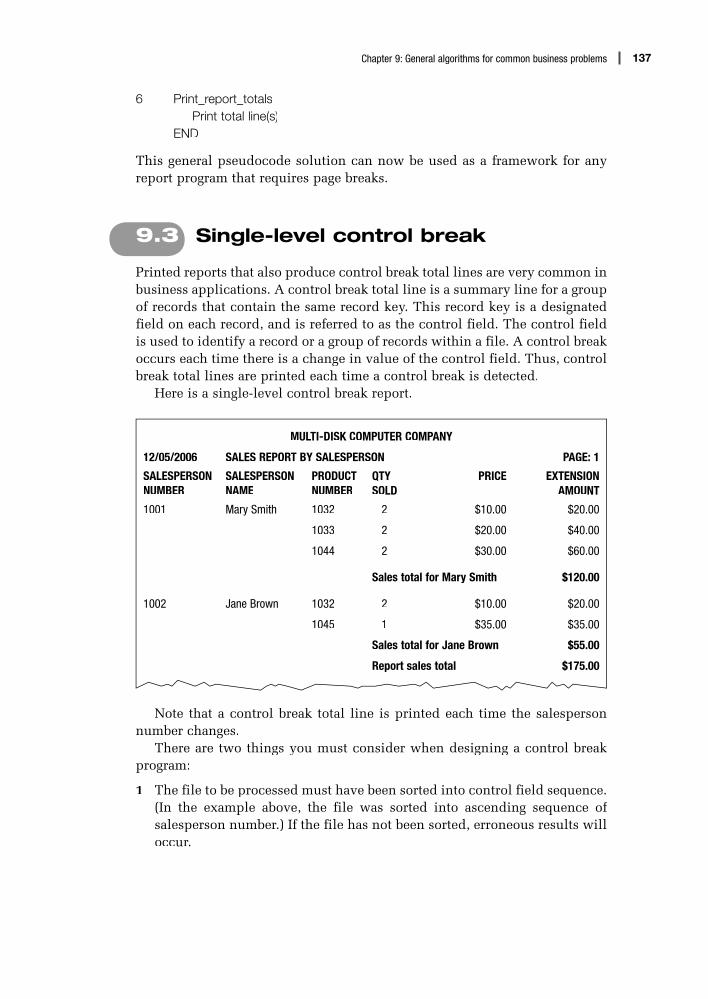
137Chapter 9: General algorithms for common business problems
6 Print_report_totalsPrint total line(s)
END
This general pseudocode solution can now be used as a framework for anyreport program that requires page breaks.
9.3 Single-level control break
Printed reports that also produce control break total lines are very common inbusiness applications. A control break total line is a summary line for a groupof records that contain the same record key. This record key is a designatedfield on each record, and is referred to as the control field. The control fieldis used to identify a record or a group of records within a file. A control breakoccurs each time there is a change in value of the control field. Thus, control break total lines are printed each time a control break is detected.
Here is a single-level control break report.
MULTI-DISK COMPUTER COMPANY
12/05/2006 SALES REPORT BY SALESPERSON PAGE: 1
SALESPERSON NUMBER
SALESPERSON NAME
PRODUCT NUMBER
QTY SOLD
PRICE EXTENSION AMOUNT
1001 Mary Smith 1032 2 $10.00 $20.00
1033 2 $20.00 $40.00
1044 2 $30.00 $60.00
Sales total for Mary Smith $120.00
1002 Jane Brown 1032 2 $10.00 $20.00
1045 1 $35.00 $35.00
Sales total for Jane Brown $55.00
Report sales total $175.00
Note that a control break total line is printed each time the salespersonnumber changes.
There are two things you must consider when designing a control breakprogram:
1 The file to be processed must have been sorted into control field sequence.(In the example above, the file was sorted into ascending sequence of salesperson number.) If the file has not been sorted, erroneous results willoccur.

Produce_single_level_control_break
Initialise_variable_fields
Print_page_headings
Process_this_record
Print_report_totals
Print_control_total_line
Print_detail_line
Reset_control_totals
Accumulate_control_totals
138 Simple program design
2 Each time a record is read from the input file, the control field on thecurrent record must be compared with the control field on the previousrecord. If the control fields are different, a control break total line must beprinted for the previous set of records, before the current record is pro-cessed.
The general solution algorithm, which was developed for a report generationprogram, can be extended by the addition of two new modules to incorporatea single-level control break. These modules are named Print_control_total_line and Reset_control_totals.
A Hierarchy chart
All control break report programs will require the following variables:
1 a variable named this_control_field, which will hold the control field of the record just read;
2 a variable named prev_control_field, which will hold the control field of the previous record. (To cater for the first record, the statements after thefirst Read statement will set the new control field to both the variablesthis_control_field and prev_control_field.)
3 one or more variables to accumulate the control break totals; and4 one or more variables to accumulate the report totals.

139Chapter 9: General algorithms for common business problems
B Solution algorithm
Mainline
Produce_single_level_control_breakInitialise_variable_fieldsPrint_page_headingsRead first recordthis_control_field = control fieldprev_control_field = control fieldDOWHILE more records exist
IF this_control_field NOT = prev_control_field THENPrint_control_total_lineprev_control_field = this_control_field
ENDIFIF linecount > max_detail_lines THEN
Print_page_headingsENDIFProcess_this_recordRead next recordthis_control_field = control field
ENDDOPrint_control_total_linePrint_report_totals
END
There are four points in this mainline algorithm that are essential for a controlbreak program to function correctly:
1 Each time a new record is read from the file, the new control field isassigned to the variable this_control_field.
2 When the first record is read, the new control field is assigned to both thevariables this_control_field and prev_control_field. This will prevent thecontrol totals printing before the first record has been processed.
3 The variable prev_control_field is updated as soon as a change in the con-trol field is detected.
4 After the end of the file has been detected, the module Print_control_total_line will print the control break totals for the last record or set of records.
Subordinate modules
1 Initialise_variable_fi eldsset control total accumulators to zeroset report total accumulators to zeroset pagecount to zeroset linecount to zeroset max_detail_lines to required value
END

140 Simple program design
2 Print_page_headingsincrement pagecountPrint main heading linesPrint column heading linesPrint blank line (if required)set linecount to zero
END
3 Process_this_recordPerform necessary calculations (if any)Print_detail_lineAccumulate_control_totals
END
4 Print_control_total_linePrint control total linePrint blank line (if required)increment linecountReset_control_totals
END
5 Print_report_totalsPrint report total line
END
6 Print_detail_linePrint detail lineincrement linecount
END
7 Accumulate_control_totalsincrement control total accumulators
END
8 Reset_control_totalsadd control total accumulators to report total accumulatorsset control total accumulators to zero
END
Notice that when a control total line is printed, the module Reset_control_totals is called. This module will add the control totals to the report totals andreset the control totals to zero for the next set of records. This general solutionalgorithm can now be used as a framework for any single-level control breakprogram.

141Chapter 9: General algorithms for common business problems
9.4 Multiple-level control break
Often reports are required to produce multiple-level control break totals. For instance, the sales report produced in Section 9.3 may require sales totals foreach salesperson in the company, as well as sales totals for each departmentwithin the company.
The monthly sales report might then look like this:
MULTI-DISK COMPUTER COMPANY
12/05/06 SALES REPORT BY SALESPERSON PAGE: 1
DEPT SALESPERSON NUMBER
SALESPERSON NAME
PRODUCT NUMBER
QTYSOLD
PRICE EXTENSION AMOUNT
01 1001 Mary Smith 1032 2 $10.00 $20.00
1033 2 $20.00 $40.00
1044 2 $30.00 $60.00
Sales total for Mary Smith $120.00
1002 Jane Brown 1032 2 $10.00 $20.00
1045 1 $35.00 $35.00
Sales total for Jane Brown $55.00
Sales total for Dept 01 $175.00
02 1050 Jenny Ponds 1033 2 20.00 $40.00
1044 2 30.00 $60.00
Sales total for Jenny Ponds $100.00
Sales total for Dept 02 $100.00
Report sales total $275.00
Note that a control break total line is printed each time the salespersonnumber changes and each time the department number changes. Thus,there are two control fields in this file: salesperson number and departmentnumber.
The concepts that applied to a single-level control break program alsoapply to a multiple-level control break program:
1 The input file must be sorted into control field sequence. When thereis more than one control field, the file must be sorted into a sequenceof minor control field within major control field. (To produce the salesreport, the sales file must have been sorted into salesperson number with-in department number.)
2 Each time a record is read from the file, the control field on the currentrecord must be compared with the control field of the previous record.

Produce_multiple_level_control_break
Initialise_variable_fields
Print_page_headings
Process_this_record
Print_major_control_totals
Print_minor_control_totals
Print_report_totals
Print_detail_line
Accumulate_control_totals
Reset_minor_control_totals
Reset_major_control_totals
142 Simple program design
If the minor control field has changed, the control totals for the previousminor control field must be printed. If the major control field has changed,the control totals for the previous minor control field and major controlfield must be printed.
The general solution algorithm that was developed for a single-levelcontrol break program can be extended by the addition of two new modulesto incorporate a two-level control break. If three control breaks were required,another two modules would be added to the solution algorithm, and so on.
The names of the modules that produce the control totals have beenchanged slightly, so that they indicate which level of control break hasoccurred. These new module names are Print_minor_control_totals, Print_major_control_totals, Reset_minor_control_totals and Reset_major_control_totals.
A Hierarchy chart

143Chapter 9: General algorithms for common business problems
B Solution algorithm
Mainline
Produce_multiple_level_control_breakInitialise_variable_fieldsPrint_page_headingsRead first recordthis_minor_control_field = minor control fieldprev_minor_control_field = minor control fieldthis_major_control_field = major control fieldprev_major_control_field = major control fieldDOWHILE more records exist
IF this_major_control_field NOT = prev_major_control_field THENPrint_minor_control_totalsprev_minor_control_field = this_minor_control_fieldPrint_major_control_totalsprev_major_control_field = this_major_control_field
ELSEIF this_minor_control_field NOT = prev_minor_control_field THEN
Print_minor_control_totalsprev_minor_control_field = this_minor_control_field
ENDIFENDIFIF linecount > max_detail_lines THEN
Print_page_headingsENDIFProcess_this_recordRead next recordthis_minor_control_field = minor control fieldthis_major_control_field = major control field
ENDDOPrint_minor_control_totalsPrint_major_control_totalsPrint_report_totals
END
The points to be noted in this mainline are:
1 Each time a new record is read from the input file, the new control fieldsare assigned to the variables this_minor_control_field and this_major_con-trol_field.
2 When the first record is read, the new control fields are assigned to boththe current and previous control field variables. This will prevent controltotals printing before the first record has been processed.
3 After the end of the input file has been detected, the two modules Print_minor_control_totals and Print_major_control_totals will print controltotals for the last minor control field record, or set of records, and the lastmajor control field set of records.

144 Simple program design
Subordinate modules
1 Initialise_variable_fi eldsset minor control total accumulators to zeroset major control total accumulators to zeroset report total accumulators to zeroset pagecount to zeroset linecount to zeroset max_detail_lines to required value
END
2 Print_page_headingsincrement pagecountPrint main heading linesPrint column heading linesPrint blank line (if required)set linecount to zero
END
3 Process_this_recordPerform necessary calculations (if any)Print_detail_lineAccumulate_control_totals
END
4 Print_minor_control_totalsPrint minor control total linePrint blank line (if required)increment linecountReset_minor_control_totals
END
5 Print_major_control_totalsPrint major control total linePrint blank line (if required)increment linecountReset_major_control_totals
END
6 Print_report_totalsPrint report total line
END
7 Print_detail_linePrint detail lineincrement linecount
END

145Chapter 9: General algorithms for common business problems
8 Accumulate_control_totalsincrement minor control total accumulators
END
9 Reset_minor_control_totalsadd minor control total accumulators to major control total accumulatorsset minor control total accumulators to zero
END
10 Reset_major_control_totalsadd major control total accumulators to report total accumulatorsset major control total accumulators to zero
END
Because the solution algorithm has simple design and good modular structure,the processing of intermediate control field breaks as well as major and minorcontrol field breaks can be handled easily. The solution algorithm wouldsimply require the addition of two new modules: Print_intermed_control_totals and Reset_intermed_control_totals. The IF statement in the mainlinewould then be expanded to include this extra condition, as follows:
IF this_major_control_field NOT = prev_major_control_field THENPrint_minor_control_totalsprev_minor_control_field = this_minor_control_fieldPrint_intermed_control_totalsprev_intermed_control_field = this_intermed_control_fieldPrint_major_control_totalsprev_major_control_field = this_major_control_field
ELSEIF this_intermed_control_field NOT = prev_intermed_control_field THEN
Print_minor_control_totalsprev_minor_control_field = this_minor_control_fieldPrint_intermed_control_totalsprev_intermed_control_field = this_intermed_control_field
ELSEIF this_minor_control_field NOT = prev_minor_control_field THEN
Print_minor_control_totalsprev_minor_control_field = this_minor_control_field
ENDIFENDIF
ENDIF
This pseudocode algorithm can now be used to process any multiple-level control break program.

Sequential update program
New master fileAudit and error
reports
Old master file Transaction file
146 Simple program design
9.5 Sequential file update
Most current file transaction update systems are real-time systems; however,for batch processing applications, sequential file updating is very common.It involves updating a master file by applying update transactions to atransaction file. Both the master file and the transaction file are sequential.A new master file that incorporates the updated transactions is produced.Usually, audit reports and error reports are also printed.
A system flowchart of a sequential update program would look like this:
System concepts
1 Master fileA master file is a file that contains permanent and semipermanent informationabout the data entities it contains. The records on the master file are insequence, according to a key field (or fields) on each record. For example,a customer master file may contain the customer’s number, name, address,phone number, credit rating and current balance, and may be in sequence of customer number. In this case, customer number would be the key.
2 Transaction fileA transaction file contains all the data and activities that are included on themaster file. If the transaction file has been designed specifically to update amaster file, there are usually three types of update transactions on this file.These are transactions to:
• add a new record• update or change an existing record• delete an existing record.
For example, a customer transaction file might contain transactions that areintended to add a new customer record, change some data on an existingcustomer record, or delete a customer record on the customer master file.The transaction file is also in sequence according to the same key field as themaster record.

147Chapter 9: General algorithms for common business problems
3 Audit reportAn audit report is a detailed list of all the transactions that were applied tothe master file. It provides an accounting trail of the update activities that takeplace, and is used for control purposes.
4 Error reportAn error report is a detailed list of errors that occurred during the processingof the update. Typical errors might be the attempted update of a record thatis not on the master file, or the addition of a record that already exists. Thiserror report will require some action to confirm and correct the identifiederrors.
Sequential update logic
The logic of a sequential update program is more difficult than the otherproblems encountered, because there are two sequential input files. Processinginvolves reading a record from each of the input files and comparing the keysof the two records. As a result of this comparison, processing falls generallyinto three categories:
1 If the key on the transaction record is less than the key on the old masterrecord, the transaction is probably an add transaction. The details on thetransaction record should be put into master record format, and the recordshould be written to the new master file. Another record should then beread from the transaction file.
2 If the key on the transaction record is equal to the key on the old masterrecord, the transaction is probably an update or delete transaction. If the transaction is an update, the master record should be amended to reflectthe required changes. If the transaction is a delete, the master recordshould not be written to the new master file. Another transaction recordshould then be read from the transaction file.
3 If the key on the transaction record is greater than the key on the old mas-ter record, there is no matching transaction for that master record. In thiscase the old master record should be written unchanged to the new master file and another record read from the old master file.
Sequential update programs also need to include logic that will handlemultiple transaction records for the same master record, and the possibilityof transaction records that are in error. The types of transaction record errorsthat can occur are:
• an attempt to add a new master record when a record with that key alreadyexists on the master file
• an attempt to update a master record when there is no record with that keyon the master file
• an attempt to delete a master record when there is no record with that keyon the master file
• an attempt to delete a master record when the current balance is not equalto zero.

148 Simple program design
Balance line algorithm
The logic of the sequential update program has fascinated programmers formany years. Authors have offered many solutions to the problem, but noneof these has been a truly general solution. Most solutions have been designedaround a specific programming language.
A good general solution algorithm written in pseudocode was presentedby Barry Dwyer in a paper entitled ‘One More Time – How to Update a MasterFile’.1 This algorithm has been referred to as the balance line algorithm. Ithandles multiple transaction records for the one master record, as well as thepossibility of transaction record errors.
A modularised version of the balance line algorithm is presented in thischapter. It introduces the concept of a current record. The current record isthe record that is currently being processed, ready for updating and writingto the new master file. The current record is established when the record keyson the two files are compared. The current record will be the record that hasthe smaller record key. Its format will be that of a new master record.
Thus, if the key on the transaction record is less than the key on theold master record, the current record will be made up of the fields on thetransaction record. If the key on the transaction record is equal to or greaterthan the key on the old master record, the old master record will become thecurrent record.
The current record will remain the current record until there are no moretransactions to be applied to that record. It will then be written to the newmaster file, and a new current record will be established.
Another variable, current_record_status, is used as a program flag toindicate whether or not the current record is available for processing. If thecurrent_record_status is active, the current record has been established andis available for updating or writing out to the new master file. If the current_record_status is inactive, the current record is not available to be up-dated orwritten to the new master file; for example, the current record may have beenmarked for deletion.
The processing of the two files will continue until end_of_job has beenreached. End_of_job will occur when both the input files have no more datato be processed. Since it is not known which file will reach end of file first,the record key of each file will be set to a high value when EOF is reached.When the record key of one of the files is high, the other file will continueto be processed, as required, until the record key on that file is assigned thesame high value. End_of_job occurs when the record keys on both the filesare the same high value.
Let us now establish a general solution algorithm for a sequential updateprogram. The logic provided will also include the printing of the audit anderror reports.
1 Barry Dwyer, ‘One More Time – How to Update a Master File’, Communications of the ACM, Vol. 124,MMNo. 1, January 1981.

Sequential_file_update_
program
Initialise_variable_
fields
Read_transaction_
record
Read_old_master_record
Apply_transaction_to_current_record
Select_current_record
Write_current_record
Print_report_totals
Read_old_master_record
Print_error_report
Read_transaction_
record
Print_audit_report
Print_error_report
Print_audit_report
Print_error_report
Print_audit_report
Print_error_report
Apply_addition_
transaction
Apply_deletion_
transaction
Apply_update_
transaction
149Chapter 9: General algorithms for common business problems
A Hierarchy chart
B Solution algorithmMainline
Sequential_file_update_programInitialise_variable_fieldsRead_transaction_recordRead_old_master_recordset current_record_status to ‘inactive’DOWHILE NOT end_of_job
Select_current_recordDOWHILE transaction_record_key = current_record_key
Apply_transaction_to_current_recordENDDOIF current_record_status = ‘active’ THEN
Write_current_recordset current_record_status to ‘inactive’
ENDIFENDDOPrint_report_totals
END

150 Simple program design
Subordinate modules
1 Initialise_variable_fi eldsset total_transaction_records to zeroset total_old_master_records to zeroset total_new_master_records to zeroset total_error_records to zeroset end_of_job to false
END
2 Read_transaction_recordRead transaction recordIF NOT EOF THEN
increment total_transaction_recordsELSE
set transaction_record_key to high valueIF old_master_record_key = high value THEN
set end_of_job to trueENDIF
ENDIFEND
3 Read_old_master_recordRead old master recordIF NOT EOF THEN
increment total_old_master_recordsELSE
set old_master_record_key to high valueIF transaction_record_key = high value THEN
set end_of_job = trueENDIF
ENDIFEND
4 Select_current_recordIF transaction_record_key < old_master_record_key THEN
set up current record with transaction record fieldsELSE
set up current record with old master record fieldsset current_record_status to ‘active’Read_old_master_record
ENDIFEND

151Chapter 9: General algorithms for common business problems
5 Apply_transaction_to_current_recordCASE OF transaction_type
addition : Apply_addition_transactiondeletion : Apply_deletion_transactionupdate : Apply_update_transactionother : error_message = ‘invalid transaction type’
Print_error_reportENDCASERead_transaction_record
END
6 Write_current_recordWrite current record to new master fileincrement total_new_master_records
END
7 Print_report_totalsPrint total_transaction_recordsPrint total_old_master_recordsPrint total_new_master_recordsPrint total_error_records
END
8 Apply_addition_transactionIF current_record_status = ‘inactive’ THEN
set current_record_status to ‘active’Print_audit_report
ELSEerror_message = ‘Invalid addition; record already exists’Print_error_report
ENDIFEND
9 Apply_deletion_transactionIF current_record_status = ‘active’ THEN
set current_record_status to ‘inactive’Print_audit_report
ELSEerror_message = ‘Invalid deletion, record not on master file’Print_error_report
ENDIFEND

152 Simple program design
10 Apply_update_transactionIF current_record_status = ‘active’ THEN
apply required change(s) to current recordPrint_audit_report
ELSEerror_message = ‘Invalid update, record not on master file’Print_error_report
ENDIFEND
11 Print_audit_reportPrint transaction details on audit reportCASE OF transaction_type
addition : print ‘record added’deletion : print ‘record deleted’update : print ‘record updated’
ENDCASEEND
12 Print_error_reportPrint transaction details on error reportPrint error_messageincrement total_error_records
END
Note that end_of_job is reached when the transaction_record_key = high valueAND the old_master_record_key = high value. This pseudocode algorithm cannow be used to process any sequential file update program.
Chapter summaryThe aim of this chapter was to develop general pseudocode algorithms to four commonbusiness applications. The applications covered were:
• report generation with page break• single-level control break• multiple-level control break• sequential file update.
In each section, the application was discussed, a hierarchy chart was developed, and ageneral solution algorithm was presented in pseudocode. These solution algorithms canbe used when writing programs that incorporate any of the above applications.

153Chapter 9: General algorithms for common business problems
Programming problemsUsing the sample solution algorithms provided in this chapter, design a solution algo-rithm for the following programming problems. Your solution should contain:
• a defining diagram• a hierarchy chart• a pseudocode algorithm• a desk check of the solution.
1 Design an algorithm to produce a list of customers from the Glad Rags ClothingCompany’s customer master file. Each record on the customer master file con-tains the customer’s number, name, address (street, city, state and postcode) andaccount balance.
Your program is to read the customer master file and print a report of all cus-tomers whose account balance is greater than zero. Each detail line is to containthe customer’s number, name, address and account balance. Print headings andcolumn headings at the top of each page, allowing for 35 detail lines per page, and at the end of the report, the total customers on file, the total customers with balanceowing, and the total balance owing, as follows:
GLAD RAGS CLOTHING COMPANY
XX/XX/XX CURRENT ACCOUNT BALANCES PAGE: XX
CUSTOMER NUMBER
CUSTOMER NAME ADDRESS ACCOUNT BALANCE
xxxxx xxxxxxxxxx xxxxxxxxxxxxxxxxxxxx 9999.99
xxxxx xxxxxxxxxx xxxxxxxxxxxxxxxxxxxx 9999.99
Total customers on file 999
Total customers with balance owing 999
Total balance owing 99999.99
2 Design an algorithm to produce a sales commission report from a company’s salesfile. Each record on the sales file contains the salesperson’s number, name and salesamount.
Your program is to read the sales file, calculate the sales commission according to the following table, and print a sales commission report.
Sales range Commission rate
$0–$499.99 No commission
$500.00–$749.99 2%
$750.00 and above 3%

154 Simple program design
Each detail line is to contain the salesperson’s number, sales amount, commis-sion rate and total commission. Print headings and column headings at the top of each page, allowing for 35 detail lines per page, and at the end of the report, thetotal commission, as follows:
SALES COMMISSIONS PAGE: XX
SALESPERSON NUMBER
SALESPERSON NAME SALES AMOUNT COMMISSION RATE
COMMISSION
xxxxx xxxxxxxxxxxxxx 9999.99 x% 999.99
xxxxx xxxxxxxxxxxxxx 9999.99 x% 999.99
Total Commission 9999.99
3 Design an algorithm that will create a validation report from a customer sales file.Each field on the sales record is to be validated as follows:
Field Format
Customer number Numeric
Customer name Alphanumeric
Street Alphanumeric
Town Alphanumeric
Postcode Numeric
Phone Alphanumeric
Fax Alphanumeric
Balance due Numeric
Credit limit Numeric (0–$1000)
If a field is found to be in error, print a line on the validation report showing thecustomer number, name, address (street, town, postcode) and an appropriate mes-sage, as indicated in the diagram below. There may be multiple messages for theone record. Print headings and column headings at the top of each page, allowingfor 45 detail lines per page.
VALIDATION REPORT
CUSTOMER SALES FILE PAGE: XX
CUSTOMER NUMBER
CUSTOMER NAME ADDRESS MESSAGE
xxxx xxxxxxxxxxxxxxx xxxxxxxxxxxxxxxxxxxx Postcode not numeric
xxxx xxxxxxxxxxxxxxx xxxxxxxxxxxxxxxxxxxx Credit limit invalid
4 The Multi-Disk computer company requires a single-level control break program toproduce a sales report by salesperson from their sales file. Design an algorithm thatwill read the sales file and create the sales report as shown below.

155Chapter 9: General algorithms for common business problems
Each record on the sales file contains the salesperson’s number, name, the product number of the product sold, the quantity sold and the price of the prod-uct. There may be more than one record for each salesperson, depending on theproducts sold that month. The sales file has been sorted into ascending sequenceof salesperson number.
Your program is to read the sales file sequentially, calculate the extension amount(price * quantity sold) for each product sold and print a detail line for each recordprocessed. Control total lines showing the sales total for each salesperson are to beprinted on change of salesperson number. Print headings and column headings atthe top of each page, allowing for 40 detail lines per page.
MULTI-DISK COMPUTER COMPANY PAGE:XX
SALES REPORT BY SALESPERSON XX/XX/XX
SALESPERSON NUMBER
SALESPERSON NAME
PRODUCTNUMBER
QTY SOLD
PRICE EXTENSION AMOUNT
xxxx xxxx xxxxxxxxx xxxxxx 99 999.99 9999.99
xxxxxx 99 999.99 9999.99
xxxxxx 99 999.99 9999.99
Sales total for xxxx xxxxxx 99999.99
Report sales total 999999.99
5 A sales file as described in Problem 4 exists, with the addition of a further field, the department number. The sales file has been sorted into ascending sequence of salesperson number within department number. Print the same sales report, with the additional requirement of printing a sales total line on change of departmentnumber, as well as on change of salesperson number.
Print the report details as per the following sales report. Print headings and col-umn headings at the top of each page, allowing for 40 detail lines per page.
MULTI-DISK COMPUTER COMPANY PAGE:XX
SALES REPORT BY SALESPERSON XX/XX/XX
DEPT SALESPERSON NUMBER
SALESPERSONNAME
PRODUCT NUMBER
QTY SOLD
PRICE EXTENSION AMOUNT
xx xxxx xxxx xxxxxxxxx xxxxxx 99 999.99 9999.99
xxxxxx 99 999.99 9999.99
xxxxxx 99 999.99 9999.99
Sales total for xxxx xxxxxxxx 99999.99
Sales total for dept xx 99999.99
Report sales total 999999.99

156 Simple program design
6 ABC University requires a single-level control break program to produce a lecturer information report by lecturer from the university’s course file. Design an algorithm that will read the course file and create the lecturer information report as shown below.
Each record on the course file contains details of a lecturer’s teaching load – thatis, the lecturer’s number, name, the course number of the course being taught, thecredit hours for that course and the class size. There may be more than one recordfor each lecturer, depending on the number of courses he or she teaches. Thecourse file has been sorted into ascending sequence of lecturer number.
Your program is to read the course file sequentially, calculate the lecturer’scontact hours ((class size/50) * credit hours), and produce the lecturer informationreport. On change of lecturer number, print control total lines showing the total con-tact hours for each lecturer. Print headings and column headings at the top of eachpage, allowing for 40 detail lines per page.
ABC UNIVERSITY
LECTURER INFORMATION REPORT
LECTURER NUMBER
LECTURERNAME
COURSE NUMBER
CREDIT HOURS
CLASSSIZE
CONTACTHOURS
xxxx xxxxxxxxxx xxxxx x xxx xxx
xxxxx x xxx xxx
xxxxx x xxx xxx
Contact hours for lecturer xxxx x xxx
Contact hours for university xx xxx
7 A course file as described in Problem 6 exists, with the addition of a further field,the university department number. The course file has been sorted into ascendingsequence of lecturer number within department number. Print the same lecturerinformation report, with the additional requirement of printing a total contact hoursline on change of department number, as well as on change of lecturer number.
Print the report details as per the following lecturer information report. Printheadings and column headings at the top of each page, allowing for 40 detail linesper page.
ABC UNIVERSITY
LECTURER INFORMATION REPORT
DEPTNUMBER
LECTURER NUMBER
LECTURER NAME
COURSE NUMBER
CREDIT HOURS
CLASS SIZE
CONTACTHOURS
xxx xxxx xxxxxxxxxx xxxxx x xxx xxx
xxxxx x xxx xxx
xxxxx x xxx xxx
Contact hours for lecturer xxxx x xxx
Contact hours for department xxx x xxx
Contact hours for university xx xxx

157Chapter 9: General algorithms for common business problems
8 A course file as described in Problem 7 exists, with the addition of a further field, the college number. The course file has been sorted into ascending sequence of lec-turer number within department number within college number. The same lecturer information report is to be printed, with the additional requirement of printing a totalcontact hours line on change of college number, as well as on change of departmentnumber and on change of lecturer number.
Print the report details as per the following lecturer information report. Print headings and column headings at the top of each page, allowing for 40 detail linesper page.
ABC UNIVERSITY
LECTURER INFORMATION REPORT
COLLEGE NUMBER
DEPTNUMBER
LECTURER NUMBER
LECTURERNAME
COURSE NUMBER
CREDIT HOURS
CLASS SIZE
CONTACT HOURS
xxxxx xxx xxxx xxxxxxxxxx xxxxx x xxx xxx
xxxxx x xxx xxx
xxxxx x xxx xxx
Contact hours for lecturer xxxx xxx
Contact hours for department xxx x xxx
Contact hours for college xxxxx xx xxx
Contact hours for university xx xxx
9 The XYZ Bank requires a program to sequentially update its savings account masterfile. A sequential file of update transactions is to be used as the input transaction file, along with the customer master file.
The customer master file contains the customer’s account number, and the bal-ance forward amount. The customer transaction update file contains three types of records, as follows:i Deposit records containing a record code of ‘D’, the account number and the
amount of a deposit.ii Withdrawal records containing a record code of ‘W’, the account number and
the amount of a withdrawal.iii Interest records containing a record code of ‘I’, the account number and the
amount of interest earned.There is a deposit record for each deposit a customer made, a withdrawal record
for each withdrawal, and an interest record if interest was credited during the period. The updating process consists of adding each deposit or interest to the balanceforward amount on the master record, and subtracting each withdrawal.
Both files have been sorted into account number sequence. There can be mul-tiple update transactions for any one savings account master record and a new savings account master file is to be created.

158 Simple program design
If a transaction record is in error, the transaction details are to be printed on thetransaction error report, with one of the following messages:
‘invalid deposit, account number not on file’‘invalid withdrawal, account number not on file’‘invalid interest record, account number not on file’
10 The Yummy Chocolates confectionery company requires a program to sequentiallyupdate its customer master file. A sequential file of update transactions is to beused as the input transaction file, along with the customer master file.
The customer master file contains the customer number, name, address(street, city, state and postcode) and account balance. The customer transactionfile also contains these fields, as well as a transaction code of ‘A’ (add), ‘D’ (delete)and ‘U’ (update).
Both files have been sorted into customer number sequence. There can bemultiple update transactions for any one customer master record and a new cus-tomer master file is to be created.
Transaction records are to be processed as follows:i If the transaction record is an ‘Add’, the transaction is to be written to the
new customer master file.ii If the transaction record is a ‘Delete’, the old master record with the same
customer number is not to be written to the new customer master file.iii If the transaction record is an update, the old master record with the same
customer number is to be updated as follows:if customer name is present, update customer nameif street is present, update streetif town is present, update townif state is present, update stateif postcode is present, update postcodeif balance paid is present, subtract balance paid from account balance on old
customer master record.As each transaction is processed, print the transaction details on the customer
master audit report, with the message, ‘record added’, ‘record deleted’ or ‘recordupdated’ as applicable.
If a transaction record is in error, the transaction details are to be printed on thecustomer update errors report, with one of the following messages:
‘invalid addition, customer already exists’‘invalid deletion, customer not on file’‘invalid update, customer not on file’.

Communication between modules,
cohesion and coupling
Objectives
• To introduce communication between modules
• To develop solution algorithms that pass parameters between modules
• To introduce cohesion as a measure of the internal strength of a module
• To introduce coupling as a measure of the extent of information interchangebetween modules
Outline
10.1 Communication between modules
10.2 Programming examples using parameters
10.3 Module cohesion
10.4 Module coupling
Chapter summary
Programming problems
10

160 Simple program design
10.1 Communication between modules
When designing solution algorithms, it is necessary to consider not onlythe division of the problem into modules but also the flow of informationbetween the modules. The fewer and simpler the communications betweenmodules, the easier it is to understand and maintain one module withoutreference to other modules. This flow of information, called ‘intermodulecommunication’, can be accomplished by the scope of the variable (local orglobal data) or the passing of parameters.
Scope of a variable
The scope of a variable is the portion of a program in which that variable hasbeen defined and to which it can be referenced. If a list is created of all themodules in which a variable can be referenced, that list defines the scope of the variable. Variables can be global, where the scope of the variable is thewhole program, or local, where the scope of the variable is simply the modulein which it is defined.
Global data
Global data is data that can be used by all the modules in a program. Thescope of a global variable is the whole program, because every module in theprogram can access and change that data. The lifetime of a global variablespans the execution of the whole program.
Local data
Variables that are defined within a submodule are called local variables.These local variables are not known to the calling module, or to any othermodule. The scope of a local variable is simply the module in which it isdefined. The lifetime of a local variable is limited to the execution of thesingle submodule in which it is defined. Using local variables can reducewhat is known as program side effects.
Side effects
A side effect is a form of cross-communication of a module with other partsof a program. It occurs when a subordinate module alters the value of aglobal variable inside a module. Side effects are not necessarily detrimental;however, they do tend to decrease the manageability of a program. Aprogrammer should be aware of their impact.
Sometimes, a programmer may need to modify an existing program, andin doing so, may make a change to a global variable. This change could causeside effects or erroneous results because the new programmer is unaware of other modules that also alter that global variable.

161Chapter 10: Communication between modules, cohesion and coupling
Passing parameters
A particularly efficient method of intermodule communication is the passingof parameters or arguments between modules. Parameters are simply dataitems transferred from a calling module to its subordinate module at the time of calling. When the subordinate module terminates and returns control toits caller, the values in the parameters may be transferred back to the callingmodule. This method of communication avoids any unwanted side effects,as the only interaction between a module and the rest of the program is viaparameters.
To pass parameters between modules, two things must happen:
1 The calling module must name the parameters that it wants to pass to thesubmodule, at the time of calling.
2 The submodule must be able to receive those parameters and return themto the calling module, if required.
In pseudocode and most programming languages, when a calling modulewants to pass parameters to a submodule, it simply lists the parameters,enclosed in parentheses, beside the name of the submodule, for example:
Print_page_headings (pageCount, lineCount)
The submodule must be able to receive those parameters, so it, too, liststhe parameters that it expects to receive, enclosed in parentheses, beside thesubmodule name when it is defined, for example:
Print_page_headings (pageNumber, lineNumber)
The names that the respective modules give to their parameters need notbe the same – in fact, they often differ because they have been written by adifferent programmer – but their number, type and order must be identical. Inthe above example, the parameter pageCount will be passed to pageNumber, and the parameter lineCount will be passed to lineNumber. In this book,parameters will be named without underscores, to differentiate them fromvariables.
Formal and actual parameters
Parameter names that appear when a submodule is defined are known asformal parameters. Variables and expressions that are passed to a submodulein a particular call are called actual parameters. A call to a submodule willinclude an actual parameter list, one variable for each formal parameter name.There is a one-to-one correspondence between formal and actual parameters,which is determined by the relative position in each parameter list. Also, theactual parameter corresponding to a formal parameter must have the samedata type as that specified in the declaration of the formal parameter.
For example, a mainline may call a module with an actual parameter list,as follows:
Calculate_amount_owing (gasFigure, amountBilled)

162 Simple program design
while the module may have been declared with the following formal param-eter list:
Calculate_amount_owing (gasUsage, amountOwing)
Although the parameter names are different, the actual and formal parameterswill correspond.
Value and reference parameters
Parameters may have one of three functions:
1 To pass information from a calling module to a subordinate module. Thesubordinate module would then use that information in its processing,but would not need to communicate any information back to the callingmodule.
2 To pass information from a subordinate module to its calling module. Thecalling module would then use that parameter in subsequent processing.
3 To fulfil a two-way communication role. The calling module may passinformation to a subordinate module, where it is amended in some fash-ion, then passed back to the calling module.
Value parametersValue parameters pass a copy of the value of a parameter from one module toanother. When a submodule is called, the value of each actual parameter isassigned to the corresponding formal parameter, and from then on, the twoparameters are independent. The called module cannot modify the value of the parameter in any way, and, when the submodule has finished processing,the value of the parameter returns to its original value. This form of parameterpassing is called ‘passing by value’.
Reference parametersReference parameters pass the memory address of a parameter from onemodule to another. When a submodule is called, the reference address of theparameter is passed to the called module and that module can then use andchange the value of the parameter. Each actual parameter is an ‘alias’ for thecorresponding formal parameter; the two parameters refer to the same object,and changes made through one are visible through the other. As a result, thevalue of the parameter may be referenced and changed during the processingof the submodule. This form of parameter passing is called ‘passing byreference’.
The requirements of the program will determine whether a parameteris passed by value or by reference. The parameter is passed by reference, if the called module is designed to change the value of the actual parameter.Conversely, the parameter is passed by value, to ensure the called routinecannot modify the parameter.
Let’s look at an example that illustrates the passing of parameters byvalue:

163Chapter 10: Communication between modules, cohesion and coupling
EXAMPLE 10.1 Calculate percentage valueDesign an algorithm that will receive a fraction in the form of a numerator and a denomi-nator, convert that fraction to a percentage and displayp y the result. Your program is touse a module to calculate the percentage.
A Defining diagram
Input Processing Output
numerator Get numerator, denominator percentage
denominator Convert fraction to percentage
Display percentage
B Solution algorithm
Calculate_percentage_valuePrompt for numerator, denominatorGet numerator, denominatorConvert_fraction_value (numerator, denominator, percentage)IF percentage NOT = 0 THEN
Output to screen, percentage, ‘%’ELSE
Output to screen ‘invalid fraction’ENDIF
END
Convert_fraction_value (numerator, denominator, calculatedPercentage)IF denominator NOT = 0
calculatedPercentage = numerator / denominator * 100ELSE
calculatedPercentage = 0ENDIF
END
In this example, copies of the numerator and denominator values are passedas parameters to the module Convert_fraction_value, which will use thosevalues to calculate the percentage. When the percentage is calculated, acopy of the value in the parameter calculatedPercentage will be passed tothe parameter percentage, which will be displayed to the screen. This is anexample of passing by value.
Now let’s look at an example that illustrates the passing of parameters byreference.

164 Simple program design
EXAMPLE 10.2 Increment two countersDesign an algorithm that will increment two counters from 1 to 10 and then outputp thosecounters to the screen. Your program is to use a module to increment the counters.
A Defining diagram
Input Processing Output
counter1 Increment counters counter1
counter2 Output counters counter2
B Solution algorithm
Increment_two_countersSet counter1, counter2 to zeroDO I = 1 to 10
Increment_counter (counter1)Increment_counter (counter2)Output to the screen counter1, counter2
ENDDOEND
Increment_counter (counter)counter = counter + 1
END
In this example, the module Increment_counter is defined with a formalparameter named counter. Increment_counter is called by the mainline,first, with the actual parameter counter1, and then with the actual parametercounter2. At the first call, the reference address of counter1 is passed to theparameter counter, and its value is changed. Then the reference address of counter2 is passed to the parameter counter, and its value is also changed.The values of counter1 and counter2 are displayed on the screen and the pro-cess is repeated, so that each time the module Increment_counter is called thevalues in the parameters counter1 or counter2 are increased by 1. The screenoutput would be as follows:
1 1 2 2 3 3 4 4 etc.
This is an example of passing parameters by reference.

For data parameters For status parameters
165Chapter 10: Communication between modules, cohesion and coupling
Hierarchy charts and parameters
Parameters that pass between modules can be incorporated into a hierarchychart or structure chart using the following symbols:
Data parameters contain the actual variables or data items that will bepassed as parameters between modules.
Status parameters act as program flags and should contain just one of twovalues: true or false. These program flags or switches are set to true or false,according to a specific set of conditions. They are then used to control furtherprocessing.
When designing modular programs, avoid using data parameters to indi-cate status as well, because this can affect the program in two ways:
1 It may confuse the reader of the program because a variable has been over-loaded; that is, it has been used for more than one purpose.
2 It may cause unpredictable errors when the program is amended at somelater date, as the maintenance programmer may be unaware of the dualpurpose of the variable.
10.2 Programming examples usingparameters
Let us now look at an example that passes both data and status parameters.This example offers an alternative solution to Example 8.4.
EXAMPLE 10.3 Calculate employee’s payA company requires a program to read an employee’s number, pay rate and the numberof hours worked in a week. The program is then to validate the pay rate field and thehours worked field and, if they are valid, to computep the employee’s weekly pay and then printp it and the input data.
Validation: According to the company’s rules, the maximum hours an employee can work per week is 60 hours, and the maximum hourly rate is $25.00 per hour. If the hoursworked field or the hourly rate field is out of range, the input data and an appropriatemessage are to be printed,p , and the employee’s weekly pay is not to be calculated.
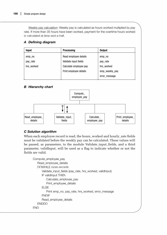
Compute_employee_pay
Calculate_employee_pay
Read_employee_details
Print_employee_details
Validate_input_fields
166 Simple program design
Weekly pay calculationy p y : Weekly pay is calculated as hours worked multiplied by payrate. If more than 35 hours have been worked, payment for the overtime hours workedis calculated at time-and-a-half.
A Defining diagram
Input Processing Output
emp_no Read employee details emp_no
pay_rate Validate input fields pay_rate
hrs_worked Calculate employee pay hrs_worked
Print employee details emp_weekly_pay
error_message
B Hierarchy chart
C Solution algorithmWhen each employee record is read, the hours_worked and hourly_rate fieldsmust be validated before the weekly pay can be calculated. These values willbe passed, as parameters, to the module Validate_input_fields, and a thirdparameter, validInput, will be used as a flag to indicate whether or not thefields are valid.
Compute_employee_payRead_employee_detailsDOWHILE more records
Validate_input_fields (pay_rate, hrs_worked, validInput)IF validInput THEN
Calculate_employee_payPrint_employee_details
ELSEPrint emp_no, pay_rate, hrs_worked, error_message
ENDIFRead_employee_details
ENDDOEND

167Chapter 10: Communication between modules, cohesion and coupling
Read_employee_detailsRead emp_no, pay_rate, hrs_worked
END
Validate_input_fields (payRate, hrsWorked, validInput)set validInput to trueSet error_message to blankIF payRate > $25 THEN
error_message = ‘Pay rate exceeds $25.00’validInput = false
ENDIFIF hrsWorked > 60 THEN
error_message = ‘Hours worked exceeds 60’validInput = false
ENDIFEND
Calculate_employee_payIF hrs_worked <= 35 THEN
emp_weekly_pay = pay_rate * hrs_workedELSE
overtime_hrs = hrs_worked – 35overtime_pay = overtime_hrs * pay_rate * 1.5emp_weekly_pay = (pay_rate * 35) + overtime_pay
ENDIFEND
Print_employee_detailsPrint emp_no, pay_rate, hrs_worked, emp_weekly_pay
END
Let us now look again at Example 8.2, this time changing the solution algo-rithm so that parameters are used to communicate between the modules.There are two solution algorithms offered for this example, the second solu-tion more elegant than the first.
EXAMPLE 10.4 Process three charactersDesign a solution algorithm that will promptp p a terminal operator for three characters,acceptp those characters as input, sort them into ascending sequence and outputp them to the screen. The algorithm is to continue to read characters until ‘XXX’ is entered.

Process_three_characters
Read_three_characters
Print_three_characters
Sort_three_characters
168 Simple program design
A Defining diagram
Input Processing Output
char_1 Prompt for characters char_1
char_2 Accept three characters char_2
char_3 Sort three characters char_3
Output three characters
B Hierarchy chart 1
C Solution Algorithm 1The mainline will call the module Read_three_characters, which will get thethree input characters (char_1, char_2, char_3) and send them to the mainlineas parameters (char1, char2, char3). These parameters will then be passed tothe module Sort_three_characters, which will sort the three characters andsend these sorted values back to the mainline as parameters. The three char-acters will then be passed to the module Print_three_characters, which willprint them.
Process_three_charactersRead_three_characters (char1, char2, char3)DOWHILE NOT (char1 = ‘X’ AND char2 = ‘X’ AND char3 = ‘X’)
Sort_three_characters (char1, char2, char3)Print_three_characters (char1, char2, char3)Read_three_characters (char1, char2, char3)
ENDDO
END
Read_three_characters (char1, char2, char3)Prompt the operator for char_1, char_2, char_3Get char_1, char_2, char_3
END

Swap_two_characters
Process_three_characters
Read_three_characters
Print_three_characters
Sort_three_characters
169Chapter 10: Communication between modules, cohesion and coupling
Sort_three_characters (char1, char2, char3)IF char1 > char2 THEN
temp = char1char1 = char2char2 = temp
ENDIFIF char2 > char3 THEN
temp = char2char2 = char3char3 = temp
ENDIFIF char1 > char2 THEN
temp = char1char1 = char2char2 = temp
ENDIFEND
Print_three_characters (char1, char2, char3)Output to the screen char1, char2, char3
END
The module Sort_three_characters above contains some repeated code. To avoid this, a new module, called Swap_two_characters, will be introduced,which is called by the module Sort_three_characters. The calling module(Sort_three_characters) will pass two characters at a time to the submodule(Swap_two_characters), which will swap the position of the parameters andreturn them to the mainline.
B Hierarchy Chart 2

170 Simple program design
C Solution Algorithm 2
Process_three_charactersRead_three_characters (char1, char2, char3)DOWHILE NOT (char1 = ‘X’ AND char2 = ‘X’ AND char3 = ‘X’)
Sort_three_characters (char1, char2, char3)Print_three_characters (char1, char2, char3)Read_three_characters (char1, char2, char3)
ENDDO
END
Read_three_characters (char1, char2, char3)Prompt the operator for char_1, char_2, char_3Get char_1, char_2, char_3
END
Sort_three_characters (char1, char2, char3)IF char1 > char_2 THEN
Swap_two_characters (char1, char2)ENDIFIF char2 > char3 THEN
Swap_two_characters (char2, char3)ENDIFIF char1 > char2 THEN
Swap_two_characters (char1, char2)ENDIF
END
Print_three_characters (char1, char2, char3)Output to the screen char1, char2, char3
END
Swap_two_characters (firstChar, secondChar)temp = firstCharfirstChar = secondCharsecondChar = temp
END
Let us now look at a more complex example that passes a data structure as aparameter.

171Chapter 10: Communication between modules, cohesion and coupling
Example 10.5 Calculate vehicle registration costsA program is required to calculate and print the registration cost of a new vehicle that acustomer has ordered. The program is to be interactive; that is, all the input details willbe provided at a terminal on the salesperson’s desk. The program is to getg the inputdetails, calculate the federal tax payable, calculate the registration costs, calculate the total amount payable and then outputp the required information to the screen.
The input details required are:
• owner’s name• vehicle make• vehicle model• vehicle weight (in kg)• body type (sedan or wagon)• private or business code (‘P’ or ‘B’)• wholesale price of vehicle.
The federal tax payable is calculated at the rate of $2.00 for each $100.00, or partthereof, of the wholesale price of the vehicle.
The vehicle registration cost is calculated as the sum of the following charges:
Registration fee $27.00
Tax levy PrivateBusiness
3% of wholesale price 5% of wholesale price
Weight tax PrivateBusiness
1% of vehicle weight (converted to $)3% of vehicle weight (converted to $)
Insurance premiumPrivateBusiness
1% of wholesale price 2% of wholesale price
The total amount payable = federal tax + total registration charges. The information tobe printed to the screen is as follows:
Vehicle make:Vehicle model:Body type:Registration fee:Tax levy:Weight tax:Insurance premium:Total registration charges:Federal tax:Total amount payable:

Calculate_registration_costs
Calculate_federal_tax
Calculate_vehicle_registration
Output_registration_ Get_vehicle_ Get_vehicle_ Get_vehicle_ Get_vehicle_ Calculate_total_ Calculate_total_ Calculate_total_ details details details details details amount–payable amount–payable amount–payable
172 Simple program design
The program is to process registration costs until an owner’s name of ‘XXX’ isentered. None of the other entry details will be required after the value ‘XXX’ has beenentered.
A Defining diagram
Input Processing Output
owners_name Get input details vehicle_make
vehicle_make Calculate federal_tax vehicle_model
vehicle_model Calculate registration_costs body_type
vehicle_weight Calculate total_amount_payable registration_fee
body_type Output details to screen tax_levy
usage_code weight_tax
wholesale_price insurance_premium
total_registration_charges
federal_tax
total_amount_payable
Each of the five steps in the processing component will become a modulein the solution algorithm.
B Hierarchy chart

173Chapter 10: Communication between modules, cohesion and coupling
C Solution AlgorithmThe module Get_vehicle_details will collect the input vehicle details into adata structure called vehicleDetails. The module Calculate_registration_costswill collect all the costs of registration into a data structure called registra-tionCosts. The total amount payable will also be put into the data structureregistrationCosts. These data structures will be passed between modules asparameters.
The module Calculate_federal_tax will calculate the federal tax, which ispayable at the rate of $2.00 for each $100.00 or part thereof of the wholesaleprice of the car. (A variable called tax_units is used to count the number of whole $100 units.)
Calculate_vehicle_registrationRead owners_nameDOWHILE owners_name NOT = ‘XXX’
Get_vehicle_details (vehicleDetails)Calculate_total_amount_payable (vehicleDetails, registrationCosts)Output_registration_details (vehicleDetails, registrationCosts)Read owners_name
ENDDOEND
Get_vehicle_details (vehicleDetails)Prompt and Get vehicle_makePrompt and Get vehicle_modelPrompt and Get vehicle_weightPrompt and Get body_typePrompt and Get usage_codePrompt and Get wholesale_price
END
Calculate_total_amount_payable (vehicleDetails, registrationCosts)Calculate_federal_tax (vehicleDetails, federalTax)Calculate_registration_costs (vehicleDetails, registrationCosts)total_amount_payable = federalTax + total_registration_charges
END
Calculate_federal_tax (vehicleDetails, federalTax)Set tax_units = zeroDOWHILE wholesale_price > $100
wholesale_price = wholesale_price – 100increment tax_units by 1
ENDDOfederalTax = (tax_units + 1) * $2.00
END

174 Simple program design
Calculate_registration_costs (vehicleDetails, registrationCosts)registration_fee = $27.00IF usage_code = ‘P’ THEN
tax_levy = wholesale_price * 0.03weight_tax = vehicle_weight * 0.01insurance_premium = wholesale_price * 0.01
ELSEtax_levy = wholesale_price * 0.05weight_tax = vehicle_weight * 0.03insurance_premium = wholesale_price * 0.02
ENDIFtotal_registration_charges = registration_fee + tax_levy + weight_tax + insurance_premium
END
Output_registration_details (vehicleDetails, registrationCosts)Output vehicle_makeOutput vehicle_modelOutput body_typeOutput registration_feeOutput tax_levyOutput weight_taxOutput insurance_premiumOutput total_registration_chargesOutput federalTaxOutput total_amount_payable
END
10.3 Module cohesion
A module has been defined as a section of an algorithm that is dedicated tothe performance of a single function. It contains a single entry and a singleexit, and the name chosen for the module should describe its function.
Programmers often need guidance in determining what makes a goodmodule. Common queries include: ‘How big should a module be?’, ‘Isthis module too small?’ and ‘Should I put all the read statements in onemodule?’
There is a method you can use to remove some of the guesswork whenestablishing modules. You can look at the cohesion of the module. Cohesionis a measure of the internal strength of a module; it indicates how closely theelements or statements of a module are associated with each other. The moreclosely the elements of a module are associated, the higher the cohesion of themodule. Modules with high cohesion are considered good modules, becauseof their internal strength.

175Chapter 10: Communication between modules, cohesion and coupling
Edward Yourdon and Larry Constantine established seven levels of cohesion and placed them in a scale from the weakest to the strongest.1
Cohesion level Cohesion attribute Resultant module strength
Coincidental Low cohesion Weakest
Logical
Temporal
Procedural
Communicational
Sequential
Functional High cohesion Strongest
Each level of cohesion in the table will be discussed in this chapter, and pseudocode examples that illustrate each level will be provided.
Coincidental cohesion
The weakest form of cohesion a module can have is coincidental cohesion.It occurs when elements are collected into a module simply because theyhappen to fall together. There is no meaningful relationship between theelements at all, and so it is difficult to concisely define the function of themodule.
Fortunately, these types of modules are rare in current programmingpractice. They typically used to occur as a result of one of the followingconditions:
• An existing program may have been arbitrarily segmented into smaller mod-ules because of hardware constrictions on the operation of the program.
• Existing modules may have been arbitrarily subdivided to conform to abadly considered programming standard (for example, that each moduleshould have no more than 50 program statements).
• A number of existing modules may have been combined into one moduleeither to reduce the number of modules in a program or to increase thenumber of statements in a module to a particular minimum number.
Here is a pseudocode example of a module that has coincidental cohesion:
File_processingOpen employee updates fileRead employee recordPrint_page_headingsOpen employee master fileSet page_count to oneSet error_flag to false
END
1 Edward Yourdon and Larry Constantine, Structured Design: Fundamentals of a Discipline of Computer Program and System Design (Prentice-Hall, 1979).

176 Simple program design
Notice that the instructions within the module have no meaningful relationshipto each other.
Logical cohesion
Logical cohesion occurs when the elements of a module are grouped togetheraccording to a certain class of activity. That is, the elements fall into somegeneral category because they all do the same kind of thing.
An example might be a module that performs all the read statements forthree different files: a sort of ‘Read_all_files’ module. In such a case, thecalling module would need to indicate which of the three files it required thecalled module to read, by sending a parameter.
A module such as this is slightly stronger than a coincidentally cohesivemodule, because the elements are somewhat related. However, logicallycohesive modules are usually made up of a number of smaller, independentsections, which should exist independently rather than be combined togetherbecause of a related activity. Often when a module such as this is called, onlya small subset of the elements within the module will be executed.
A pseudocode example for a ‘Read_all_files’ module might look like this:
Read_all_files (file_code)CASE of file_code1 : Read customer transaction record
IF not EOFincrement customer_transaction_count
ENDIF2 : Read customer master record
IF not EOFincrement customer_master_count
ENDIF3 : Read product master record
IF not EOFincrement product_master_count
ENDIFENDCASE
END
Notice that the three Read instructions in this module perform three separatefunctions.
Temporal cohesion
Temporal cohesion occurs when the elements of a module are groupedtogether because they are related by time. Typical examples are initialisationand finalisation modules in which elements are placed together becausethey perform certain housekeeping functions at the beginning or end of aprogram.
A temporally cohesive module can be considered a logically cohesivemodule, where time is the related activity. However, it is slightly stronger than

177Chapter 10: Communication between modules, cohesion and coupling
a logically cohesive module because most of the elements in a time-relatedmodule are executed each time the module is called. Usually, however, the elements are not all related to the same function.
A pseudocode example of a temporally cohesive module might look likethis:
InitialisationOpen transaction fileIssue prompt ‘Enter today’s date – DDMMYY’Read todays_dateSet transaction_count to zeroRead transaction recordIF not EOF
increment transaction_countENDIFOpen report filePrint_page_headingsSet report_total to zero
END
Notice that the elements of the module perform a number of functions.
Procedural cohesion
Procedural cohesion occurs when the elements of a module are relatedbecause they operate according to a particular procedure. That is, theelements are executed in a particular sequence so that the objectives of theprogram are achieved. As a result, the modules contain elements related moreto program procedure than to program function.
A typical example of a procedurally cohesive module is the mainline of a program. The elements of a mainline are grouped together because of aparticular procedural order.
The weakness of procedurally cohesive modules is that they cut acrossfunctional boundaries. That is, the procedure may contain only part of a function at one level, but multiple functions at a lower level, as in thepseudocode example below:
Read_student_records_and_total_student_agesSet number_of_records to zeroSet total_age to zeroRead student recordDOWHILE more records exist
add age to total_ageadd 1 to number_of_recordsRead student record
ENDDOPrint number_of_records, total_age
END

178 Simple program design
Note that the use of the word ‘and’ in the module name indicates that thismodule performs more than one function.
Communicational cohesion
Communicational cohesion occurs when the elements of a module aregrouped together because they all operate on the same (central) piece of data. Communicationally cohesive modules are commonly found in businessapplications because of the close relationship of a business program to thedata it is processing. For example, a module may contain all the validationsof the fields of a record, or all the processing required to assemble a reportline for printing.
Communicational cohesion is acceptable because it is data-related. It isstronger than procedural cohesion because of its relationship with the data,rather than the control-flow sequence.
The weakness of a communicationally cohesive module lies in the factthat usually a combination of processing for a particular piece of data isperformed, as in this pseudocode example:
Validate_product_recordIF transaction_type NOT = ‘0’ THEN
error_flag = trueerror_message = ‘invalid transaction type’Print_error_report
ENDIFIF customer_number is NOT numeric THEN
error_flag = trueerror_message = ‘invalid customer number’Print_error_report
ENDIFIF product_no = blanksOR product_no has leading blanks THEN
error_flag = trueerror_message = ‘invalid product no’Print_error_report
ENDIFEND
Sequential cohesion
Sequential cohesion occurs when a module contains elements that dependon the processing of previous elements. That is, it may contain elements inwhich the output data from one element serves as input data for the next.Thus, a sequentially cohesive module is like an assembly line – a series of sequential steps that perform successive transformations of data.
Sequential cohesion is stronger than communicational cohesion because itis more problem-oriented. Its weakness lies only in the fact that the modulemay perform multiple functions or fragments of functions.

179Chapter 10: Communication between modules, cohesion and coupling
Here is a pseudocode example of a sequentially cohesive module:
Process_purchasesSet total_purchases to zeroPrompt and Get number_of_purchasesDO loop_index = 1 to number_of_purchases
Promt and Get purchaseadd purchase to total_purchases
ENDDOsales_tax = total_purchases * sales_tax_percentamount_due = total_purchases + sales_tax
END
Note that this module first calculates total_purchases and then uses thevariable total_purchases in the subsequent calculation of amount_due.
Functional cohesion
Functional cohesion occurs when all the elements of a module contribute tothe performance of a single specific task. The module can be easily named bya single verb followed by a two-word object.
Mathematically oriented modules are a good example of functionalcohesion, as the elements making up the module form an integral part of thecalculation.
Here is a pseudocode example of a functionally cohesive module.
Calculate_sales_taxIF product is sales tax exempt THEN
sales_tax = 0ELSE
IF product_price < $50.00 THENsales_tax = product_price * 0.25
ELSEIF product_price< $100.00 THEN
sales_tax = product_price * 0.35ELSE
sales_tax = product_price * 0.5ENDIF
ENDIFENDIF
END
Summary of cohesion levels
When designing an algorithm, try to form modules that have a single problem-related function. If functional cohesion is achieved, the modules will be moreindependent, easier to read and understand, and more maintainable thanmodules with less cohesion.

2 Glenford Myers, Composite Structured Design (Van Nostrand Reinhold, 1978).
180 Simple program design
In some cases, it is not easy to construct a program where every module hasfunctional cohesion. Some modules may contain lower levels of cohesion, oreven a combination of types of cohesion. This may not be a problem. However,it is important that you can recognise the various cohesion levels and justify amodule with a lower cohesion in a particular set of circumstances.
Your prime consideration is to produce modules and programs that areeasy to understand and modify. The higher the cohesion of the modules, themore likely it is that you have achieved this aim.
10.4 Module coupling
When designing a solution algorithm, look not only at the cohesion of modules but also at the flow of information between modules. You shouldaim to achieve module independence – that is, modules that have fewerand simpler connections with other modules. These connections are calledinterfaces or couples.
Coupling is a measure of the extent of information interchange betweenmodules. Tight coupling implies large dependence on the structure of onemodule by another. Because there are many connections, there are manypaths along which errors can extend into other parts of the program.
Loose coupling is the opposite of tight coupling. Modules with loosecoupling are more independent and easier to maintain.
Glenford Myers2 devised a coupling scale similar to Yourdon andConstantine’s cohesion scale.
Coupling level Coupling attribute Resultant module design quality
Common Tight coupling Poorest
External
Control
Stamp
Data Loose coupling Best
The five levels of coupling are listed in a scale from the poorest moduledesign quality to the best. Each of the levels of coupling will be discussed,and pseudocode examples that illustrate each level will be provided. Notethat these levels of coupling are not definitive. They are merely the couplinglevels that Myers believes can exist in modular programs.
Common coupling
Common coupling occurs when modules reference the same global datastructure. (A data structure is a collection of related data items, such asa record or an array.) When modules experience common coupling, themodules share a global data structure.

Global data structure
Module B Module A
Global data variable
Module B Module A
181Chapter 10: Communication between modules, cohesion and coupling
This means that the data can be accessed and modified by any module inthe program, which can make the program difficult to read.
The following pseudocode example shows two modules that experiencecommon coupling because they access the same global data structure (thecustomer record):
A Read_customer_recordRead customer recordIF EOF THEN
set EOF_flag to trueENDIF
END
B Validate_customer_recordIF customer_number is NOT numeric THEN
error_message = ‘invalid customer number’Print_error_report
ENDIF::
END
External coupling
External coupling occurs when two or more modules access the same globaldata variable. It is similar to common coupling except that the global data isan elementary data item, rather than a data structure. Because the global datahas a simpler structure, external coupling is considered to be looser thancommon coupling.

Module B
Module A
flag
182 Simple program design
The following pseudocode example shows two modules that exhibitexternal coupling because they share the same global data item (sales_tax).
A Calculate_sales_taxIF product is sales tax exempt THEN
sales_tax = 0ELSE
IF product_price < $50.00 THENsales_tax = product_price * 0.25::
ENDIFENDIF
END
B Calculate_amount_due::amount_due = total_amount + sales_tax
END
Control coupling
Control coupling occurs when a module passes to another module a controlvariable that is intended to control the second module’s logic. These controlvariables are referred to as program flags, or switches, and are passed betweenmodules in the form of parameters.
The weakness of control-coupled modules is that the passing of the controlvariable between modules implies that one module is aware of the internallogic of the other.
The following pseudocode example shows two modules that are controlcoupled because of the passing of the parameter (input_code):
A Process_input_codeRead input_codeChoose_appropriate_action (input_code)::
END

Module B
Module A
data structure
183Chapter 10: Communication between modules, cohesion and coupling
B Choose_appropriate_action (input_code)CASE OF input_code1 : Read employee record2 : Print_page_headings3 : Open employee master file4 : Set page_count to zero5 : error_message = ‘Employee number not numeric’ENDCASE
END
Stamp couplingStamp coupling occurs when one module passes a non-global data structureto another module in the form of a parameter.
Stamp-coupled modules demonstrate loose coupling and offer good module design quality. The only relationship between the two modules is thepassing of the data structure between them; there is no need for either moduleto know the internal logic of the other.
The following pseudocode example shows two modules that are stampcoupled because of the passing of the current_record data structure.
A Process_transaction_record::IF transaction record is for a male THEN
Process_male_student (current_record)ELSE
Process_female_student (current_record)ENDIF::
END
B Process_male_student (current_record)increment male_student_countIF student_age > 21 THEN
increment mature_male_countENDIF::
END

Module B
Module A
elementary data item
184 Simple program design
Data coupling
Data coupling occurs when a module passes a non-global data variable toanother module. It is similar to stamp coupling except that the non-globaldata variable is an elementary data item, not a data structure.
Modules that are data coupled demonstrate the loosest coupling and offer thebest module design qualities. The only relationship between the two modulesis the passing of one or more elementary data items between them.
The following pseudocode example shows two modules that aredata coupled because they pass the elementary data items total_price andsales_tax.
A Process_customer_record::Calculate_sales_tax (total_price, sales_tax):
END
B Calculate_sales_tax (total_price, sales_tax)IF total_price < $10.00 THEN
sales_tax = total_price * 0.25ELSE
IF total_price < $100.00 THENsales_tax = total_price * 0.3
ELSEsales_tax = total_price * 0.4
ENDIFENDIF
END
A summary of coupling levels
When designing solution algorithms, you should aim towards module inde-pendence and a minimum of information interchange between modules.
If the programming language allows it, try to uncouple each module fromits surroundings by:
1 passing data to a subordinate module in the form of parameters, ratherthan using global data

185Chapter 10: Communication between modules, cohesion and coupling
2 writing each subordinate module as a self-contained unit that can
• accept data passed to it• operate on it without reference to other parts of the program, and• pass information back to the calling module, if required.
Chapter summaryThis chapter introduced communication between modules and parameters.
Intermodule communication was defined as the flow of information or data betweenmodules. Local and global variables were introduced, along with the scope of a variableand the side effects of using only global data.
The passing of parameters was introduced as a form of intermodule communication,and the differences between formal and actual parameters, and value and reference parameters, was explained. Programming examples using parameters were thendeveloped.
Module cohesion and module coupling were introduced and must be considered when designing modular programs. A program that has been well designed hasmodules that are independent, easy to read and easily maintained. Such modules are likely to exhibit high cohesion and loose coupling.
Cohesion is a measure of the internal strength of a module. The higher the cohesion,the stronger the module. Seven levels of cohesion were discussed, and a pseudocodeexample provided for each level.
Coupling is a measure of the extent of information interchange between modules. The fewer the connections between the modules, the more loosely they are coupled,offering good module design quality. Five levels of coupling were discussed, and apseudocode example provided for each level.
Programming problemsConstruct a solution algorithm for the following programming problems. To obtain your final solution, you should:
• define the problem• group the activities into modules (also consider the data that each module
requires)• construct a hierarchy chart• establish the logic of the mainline using pseudocode• develop the pseudocode for each successive module in the hierarchy chart• desk check the solution algorithm.

186 Simple program design
1 Design an algorithm that will produce a reorder list of products from a product inven-tory file. Each input product record contains the item number, the quantity on handfor the item, the quantity on order, the minimum inventory level for that item, and anobsolete code (‘X’ if the item is obsolete, blank if it is not).
Your program is to read the product file and determine which items are to bereordered. An item is to be reordered if it is not obsolete and if the quantity of theitem currently on hand, plus the amount on order, is less than its minimum inven-tory level. Print a detail line for each item to be reordered, listing the item number,quantity on hand, quantity on order and minimum inventory level. Print headings andcolumn headings at the top of each page, allowing for 45 detail lines per page, andat the end of the report, print the total number of items to be reordered.
2 Design an algorithm that will produce a list of selected student names from a studentfile. Each input student record contains the student’s number, the student’s name,the number of semester hours the student is currently taking, and the age of thestudent.
Your program is to read the student file and prepare a list of names of all full-timestudents (students taking 12 or more semester hours) who are 30 years of age orolder. If a student appearing on the list is taking more than 20 semester hours, placethree asterisks after the student’s name. Print a detail line for each student selected,listing student number, name, age and number of semester hours. Print headingsand column headings at the top of each page, allowing for 45 detail lines per page.Print the total number of selected students at the end of the report.
3 Design an algorithm that will produce a list of selected customers from a customerfile. Each input record contains the customer’s name, current monthly sales andyear-to-date sales. Each time the program is run, a parameter record containing adollar amount is read in as the first record in the file.
Your program is to read the parameter record, followed by the customer file, andprepare a list of customers whose purchases total at least $10 000 in the currentmonth. Customers should also be included in the list if their year-to-date sales areat least as great as the amount read in as the parameter.
Print a detail line for each customer, listing customer’s name, current monthlysales, year-to-date sales and the parameter amount. Print headings and columnheadings at the top of each page, allowing for 45 detail lines per page. Print the totalnumber of selected customers at the end of the report.
4 Design an algorithm that will produce a tax report from an employee income file.Each input record contains the employee number and the employee’s taxableincome. There is one record for each employee.
Your program is to read the employee income file and calculate the tax owing onthat employee’s taxable income, according to the following table:

187Chapter 10: Communication between modules, cohesion and coupling
Taxable income Tax payable
$0–14 999.99 20% of taxable income
$15 000–29 999.99 $3000 + 30% of amount greater than $15 000
$30 000–49 999.99 $7500 + 40% of amount greater than $30 000
$50 000–74 999.99 $15 500 + 50% of amount greater than $50 000
$75 000 and above $28 000 + 75% of amount greater than $75 000
Print a detail line for each employee, listing employee number, taxable incomeand tax payable. Print headings and column headings at the top of each page,allowing for 45 detail lines per page. Print the total taxable income and total tax payable at the end of the report.
5 Design an algorithm that will create a data validation edit report from an inventory file. Each field on the inventory record is to be validated as follows:
Field Format
Stock number Numeric
Item number Numeric (1–5000)
Description Alphanumeric
Quantity on hand Numeric (500–999)
Quantity on order Numeric (500–999)
Price per unit Numeric (10–1000)
Inventory reorder level Numeric (50–500)
If a field is found to be in error, print a line in the data validation edit report show-ing the stock number, the item number and an appropriate message, as indicatedin the diagram below. There may be multiple messages for the one record. Print headings and column headings at the top of each page, allowing for 45 detail linesper page.
Data validation edit report
Stock number Item number Message
00742 4003 Quantity on hand out of range
00853 5201 Quantity on order out of range
00932 1007 Price per unit not numeric
00932 1007 Reorder level not valid

188 Simple program design
6 Design an algorithm that will produce a list of successful applicants who haveapplied at the local Riff Raff department store for credit. Each input record containsthe applicant’s name, employment status, years in current job (if any), years atcurrent residence, monthly wage, amount of non-mortgage debt, and number of children.
Your program is to read the applicant’s file and determine whether or not eachapplicant will be granted credit. The store grants credit to a person who has workedin the same job for more than one year, as well as to someone who is employedand has lived at the same location for at least two years. However, credit is deniedif a person owes more than two months’ wages in non-mortgage debt or has morethan six children.
Print a detail line for each applicant, listing the applicant’s name and whether ornot that applicant has been granted credit. Print headings and column headings atthe top of each page, allowing for 45 detail lines per page. Print the total number of successful applicants at the end of the report.
7 Design an algorithm that will read a customer file and calculate the percentage dis-count allowed on a customer’s purchase. Each input record contains the customer’snumber and name, the class code and the number of units purchased. For whole-sale customers,the input record also contains the distance from the warehouse. Theclass code contains either ‘R’ for retail customers or ‘W’ for wholesale customers.The end-of-file is denoted by a customer number of 99999.
Your program is to read the customer file and determine the percentagediscount, if any, on a customer’s purchase, according to the following guidelines.Retail customers do not receive any discount, nor do wholesale customers whopurchase fewer than 10 units. A 10% discount is given to wholesale customerswho purchase at least 10 but fewer than 30 units and are within 50 kilometres of the distributor’s warehouse. If a wholesale customer purchases between 10 and 30units but is more than 50 kilometres away, only a 5% discount is allowed. Wholesalecustomers who purchase 30 or more units receive a 15% discount if they are within50 kilometres of the warehouse, and a 10% discount if they are more than 50 kilo-metres away.
Print a detail line for each customer, listing the customer’s number and name,the class code, the number of units purchased and the percentage discount (if any)to be applied.
Print headings and column headings at the top of each page, allowing for 45detail lines per page.
8 The Tidy Phones Telephone Company’s charges file contains records for each callmade by its Metroville subscribers during a month. Each record on the file containsthe subscriber’s name and phone number, the phone number called, the distancefrom Metroville of the number called (in kilometres) and the duration of the call (inseconds).
Design a program that will read the Tidy Phones charges file and produce atelephone charges report, as follows:

189Chapter 10: Communication between modules, cohesion and coupling
TIDY PHONES PAGE: XX
TELEPHONE CHARGES
SUBSCRIBER NAME SUBSCRIBER NUMBER PHONE NUMBER CALLED COST OF CALL
xxxx xxxxxxxxxx xxx-xxxx-xxxx 999.99
xxxx xxxxxxxxxx xxx-xxxx-xxxx 999.99
TOTAL REVENUE 9999.99
The cost of each call is calculated as follows:
Distance from Metroville Cost ($)/minute
less than 25 km 0.35
25 < km <75 0.65
75 < km < 300 1.00
300 < km < 1000 2.00
greater than 1000 km 3.00
Main headings and column headings are to be printed on the report, allowing45 detail lines per page. The total revenue line is to be printed three lines after thelast detail line.
9 Design an algorithm that will produce a payroll register from an employee file. Each input record contains the employee number, the hours worked that week and the rate of pay.
Your program is to read the employee file and, for each employee number, to retrieve the employee’s name from a table of employee numbers and names. The table contains about 100 entries, and is in sequence of employee number, with thenumber 9999 used as a sentinel to mark the end of the table. If the employee num-ber cannot be found in the table, a message is to print on the report and no more processing is to be performed for that record. The gross pay for each employee is also to be calculated as hours worked multiplied by rate of pay.
Print a detail line for each employee, listing the employee’s number, name,hours worked, rate of pay and gross pay. Print headings and column headings atthe top of each page, allowing for 45 detail lines per page. Print the total numberof employees and total gross pay at the end of the report.
10 The Mitre-11 hardware outlets require an inventory control program that is toaccept order details for an item, and generate a shipping list and a back order list.
Design an interactive program that will conduct a dialogue on the screen for theinput values, and print two reports as required. The screen dialogue is to appearas follows:
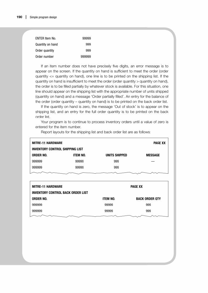
190 Simple program design
ENTER Item No. 99999
Quantity on hand 999
Order quantity 999
Order number 999999
If an item number does not have precisely five digits, an error message is toappear on the screen. If the quantity on hand is sufficient to meet the order (orderquantity <= quantity on hand), one line is to be printed on the shipping list. If thequantity on hand is insufficient to meet the order (order quantity > quantity on hand),the order is to be filled partially by whatever stock is available. For this situation, oneline should appear on the shipping list with the appropriate number of units shipped(quantity on hand) and a message ‘Order partially filled’. An entry for the balance of the order (order quantity – quantity on hand) is to be printed on the back order list.
If the quantity on hand is zero, the message ‘Out of stock’ is to appear on theshipping list, and an entry for the full order quantity is to be printed on the back order list.
Your program is to continue to process inventory orders until a value of zero isentered for the item number.
Report layouts for the shipping list and back order list are as follows:
MITRE-11 HARDWARE PAGE XX
INVENTORY CONTROL SHIPPING LIST
ORDER NO. ITEM NO. UNITS SHIPPED MESSAGE
999999 99999 999 —
999999 99999 999 —
MITRE-11 HARDWARE PAGE XX
INVENTORY CONTROL BACK ORDER LIST
ORDER NO. ITEM NO. BACK ORDER QTY
999999 99999 999
999999 99999 999

An introduction to object-oriented
design
Objectives
• To introduce object-oriented design
• To define objects, classes, attributes, operations and information hiding
• To introduce public and private operations, accessors and mutators
• To list the steps required to create an object-oriented solution to a problem
Outline
11.1 Introduction to object-oriented design
11.2 Public and private access methods
11.3 Steps in creating an object-oriented solution
11.4 Programming examples using object-oriented design
Chapter summary
Programming problems
11

192 Simple program design
11.1 Introduction to object-orienteddesign
In this book, program design has concentrated on what a program has to dotand the organisation of the processes required to achieve the desired output.In general, data has been considered only when it is required for input, out-put or calculations in algorithms. This is said to be a procedural approach tolprogram design.
This chapter introduces another style of programming called ‘object-oriented design’. Object-oriented programming uses the same concepts asprocedural programming, but the primary focus is on the things (or objects)that make up the program rather than on the processes involved. Object-oriented programming still uses variables, modules and parameters, as wellas sequence, selection and repetition structures; however, some new conceptsand new terminology are also required.
Object-oriented design asks that you interact with the problem in much thesame way that you interact with your world; that is, that you treat the problemas a set of separate objects that perform actions and relate to each other. Anobject-oriented program is a set of interacting objects, each one responsiblefor its own activities and data. When considering an object-oriented approachto a problem, you must:
1 analyse the objects in the program and the tasks to be performed on thoseobjects, and
2 pass messages to objects identifying the actions to be performed.
What is an object?
There are many objects in the real world. For example, a milk jug is an object.A milk jug can be large or small, and it can be made from a range of materials,such as china, metal or plastic, so it is said to have a set of characteristicssuch as ‘liquid capacity’ and ‘make’. There are also a number of tasks that amilk jug can perform, such as ‘filling’ and ‘pouring’. The jug has a handle,which could be considered a user-friendly interface. When you hold thehandle, you are ‘passing a message’ to the jug to indicate that an operationsuch as ‘pouring’ is to be performed.
In object-oriented programming, the milk jug is known as an ‘object’and the operations to be performed are known as ‘methods’. (In proceduralprogramming, methods are the same as procedures or modules.)
What is a class?
In object-oriented programming, the term ‘class’ is used to describe a group of objects that share some common properties. For example, a milk jug, a waterjug and a wine jug could all be objects within the class Jug. All the jugs sharesome common properties (they contain liquid and they have a handle) andeach jug is said to be an example or ‘instance’ of the class Jug.

193Chapter 11: An introduction to object-oriented design
Objects and classes
An object can be defined as a container for both a set of characteristics anda set of operations that can be performed on its data. An object has thefollowing properties:
• It has an identity that is unique for the lifetime of the object.• It has data in the form of a set of characteristics (attributes), each of which
has a value at any given point in time.• It has a set of operations (methods) that can be performed on the data.• It is an instance (example) of a class.
Consider another real-world object such as a car. Each car object has a uniqueidentity in the form of its licence number, and has a set of characteristics todescribe it – make, model, number of doors, body length, engine size, colourand speed. Cars also have a set of operations or actions that they can perform– accelerate, stop, brake and turn. A Ford Falcon could be an instance of theclass Car.
A class, then, is considered to be a category of obects. The class defines thebasic characteristics or attributes of its objects and the operations or methodsthat can be performed on its objects. A class has the following properties:
• It has a unique name. In this book an initial capital letter is used for theclass name to identify it as a class, for example Jug and Car.
• It has data in the form of a set of characteristics or attributes, which itpasses on to each object within the class.
• It has a set of operations or methods, which it passes on to each objectwithin the class.
The process of creating objects from classes is called instantiation, and manyobjects can be instantiated from a single class. Each object will contain thesame attributes, but not necessarily the same values in those attributes.
Attributes
Attributes are the set of properties or characteristics that describe a particularobject. Objects of the same class will have an identical set of attributes, eachwith the same name and data type, but the attributes of one object may con-tain different data values from those of another object. For example, a milkjug and a wine jug may both have the attribute liquid capacity; however, the values within that attribute may be different. Furthermore, those data valuesmay change at any point in an object’s lifetime.
Methods
Objects may receive messages from other objects, asking them to performservices or operations. They may also need to perform services for themselves. Thus, objects usually have a set of operations, called ‘methods’, whichperform these services. These methods include all the operations requiredto be performed on an object, and are the same as modules in proceduralprogramming.

194 Simple program design
In pseudocode, the name of the method should be meaningful andshould describe the function of the operation, such as calculateWeeklyPay()or validateStudentMark(). Convention dictates that empty parentheses areincluded after the names of methods to clearly distinguish them from thenames of variables, and to correspond to many programming languages suchas Java and C++. Parameters passed to or from the methods may be enclosedin the parentheses.
Inheritance
Object-oriented programming uses a concept called inheritance, which allowsa new object to inherit the same attributes and methods as an existing object.For example, a cream jug may inherit the same attributes and operations asmilk jug, with some additional characteristics if required. Both objects canaccess the same methods, such as fillJug() and pourContents().
Class diagram
Object-oriented programming requires classes, attributes and methods to berepresented in a class diagram. This is similar to the way in which a definingdiagram and hierarchy chart were required in procedural programming. Aclass diagram consists of a rectangular box divided into three sections, withthe name of the class at the top, the attributes of the class in the middle andthe methods at the bottom.
Class name
attribute 1
attribute 2
method 1
method 2
method 3
Although this class diagram looks new, the attribute list is similar to the inputsection of a defining diagram, and the method list is similar to the modulenames in a hierarchy chart.
Let us look at the class named Car, represented by the following diagram,which lists the name of the class, followed by its attributes and the set of operations that the class can perform.

195Chapter 11: An introduction to object-oriented design
Car
make
model
doors
bodyLength
engineSize
colour
speed
accelerate( )
stop( )
brake( )
turn(direction)
Note that the class diagram for the class Car simply lists the attributes (data)and methods (operations) for the class. It does not describe how or w when the operations are to be performed.
The Ford and Toyota objects in the diagram below are instances of the Carclass. Many car objects can be instantiated from the single Car class. Each carobject will be able to access all the Car class operations, but the values in theirattributes may be different, and can change.
RVJ635 : Car SVU478 : Car
make = ‘Ford’
model = ‘Falcon’
doors = 4
bodyLength = 300
engineSize = 6
colour = ‘blue’
speed = 0
make = ‘Toyota’
model = ‘Corolla’
doors = 5
bodyLength = 200
engineSize = 4
colour = ‘red’
speed = 60
accelerate( )
stop( )
brake( )
turn(direction)
accelerate( )
stop( )
brake( )
turn(direction)
Car objects
As you can see from the examples given, object names, attributes andoperations should be assigned meaningful names.
Encapsulation and information hiding
In the real world, objects are often said to be encapsulated. The word‘encapsulate’ means ‘to enclose together in a single indivisible unit’, as if in acapsule. For example, when you turn the ignition key of a car, you expect the carto start without really needing to know the intricate workings of the engine.

196 Simple program design
Similarly, in object-oriented programming, the way an object processes itsdata is usually hidden from other modules or programs in the system. Theobject’s internal processes and data can operate independently from the restof the system. This means that objects can be used in several places in onesystem or across several systems, possibly at the same time, and the codeinside the object can easily be maintained without impacting on the restof the system. Conversely, changes to other parts of the system should notdirectly affect the object.
In object-oriented design, each object can be regarded as a ‘black box’whose internal workings are hidden from all other objects. This principleof ‘information hiding’ simplifies the use of objects, because the rest of thesystem does not need to know how they are structured or how they performtheir operations. Information hiding is achieved through encapsulation.
The goal of information hiding is to make the object as robust andindependent as possible. It ensures that attribute values cannot accidentallybe changed by other parts of the system, and carefully controls the interactionsthat the object has with other objects.
Let us now look again at Example 10.1, which receives a fraction andconverts that fraction to a percentage.
EXAMPLE 11.1 Calculate percentage valueDesign a class that will receive a fraction in the form of a numerator and a denominator,convert that fraction to a percentage and printp the result. Your program is to use object-oriented design techniques.
In earlier chapters, to define a problem you first considered the problem state-ment and then converted the nouns to variables and the verbs to processes orfunctions to create a defining diagram, like the one below:
Input Processing Output
numerator Get numerator, denominator percentage
denominator Convert fraction to percentage
Print percentage
Object-oriented design requires that a class diagram be produced instead of adefining diagram. To create a class diagram, you need to consider the problemstatement, just as you did before. In object-oriented programming, the nounswill become objects, and the verbs will become methods. (These methods cor-respond to the processes in the defining diagram.) The words used to describethe objects will become the attributes of the objects.
Using this guide, the input ‘fraction’ will become the class ‘Fraction’ andthe numerator and denominator will become the attributes of that class. Themethods will become setFraction(), convertFraction() and printPercentage().The class diagram for the class Fraction will look like this:

197Chapter 11: An introduction to object-oriented design
Fraction
numerator
denominator
setFraction( )
convertFraction( )
printPercentage( )
As for a defining diagram, the class diagram only shows what data andmethods the class will use. Let us now look again at Example 10.3, whichuses a record, and construct a class diagram for that object.
EXAMPLE 11.2 Calculate employee’s payA company requires a program to read an employee’s number, pay rate and the numberof hours worked in a week. The program is then to validate the pay rate field and thehours worked field and, if they are valid, to computep the employee’s weekly pay and then printp it and the input data.
Validation: According to the company’s rules, the maximum hours an employee can work per week is 60 hours, and the maximum hourly rate is $25.00 per hour. If the hoursworked field or the hourly rate field is out of range, the input data and an appropriatemessage are to be printedp and the employee’s weekly pay is not to be calculated.
Weekly pay calculationy p y : Weekly pay is calculated as hours worked times pay rate. If more than 35 hours have been worked, payment for the overtime hours worked iscalculated at time-and-a-half.
In this example, the employee record will become the class Employee andthe fields on the employee record will become the attributes of the class. Themodules in the hierarchy chart for Example 10.3 will become the methods inthe following class diagram.
Employee
empNumber
payRate
hoursWorked
readEmployeeData( )
validateInputFields( )
calculateWeeklyPay( )
printEmployeeDetails( )

198 Simple program design
11.2 Public and private access methods
In object-oriented programming, it is necessary to consider whether theattributes and operations of an object are to have private or public access.This concept is called ‘visibility’.
Private access means that the attributes and methods are invisible to therest of the system. Usually the attributes of an object are specified as privateaccess, that is, the attributes can only be accessed by methods within thatclass. Public attributes are not desirable as you do not want other methods orprograms to change the data in your object, as this could lead to undesirableside effects.
The methods of an object are usually specified as public access, that is, theoperations are visible to other objects. When an operation has public access,other objects can see the specifications of that operation, which is usually itsname, its parameters, if any, and its return value, if any. These specificationsdefine what the object can do and what information it requires to performthe service; however, its implementation, or how it is going to perform theservice, remains hidden.
Within an object, there can also be private operations that are neededto perform the internal actions in an object and which cannot be accesseddirectly from outside the object.
To illustrate the concept of visibility, consider a bank account class calledBankAccount, which has an attribute called accountBalance and a number of methods, as illustrated in the following BankAccount class diagram.
BankAccount
accountBalance
displayBalance( )
deposit( )
withdraw( )
calculateInterest( )
verifySufficientFunds( )
First, the attribute accountBalance, like all attributes, must be private, as it isessential that an operation in another object or program is not able to alter acustomer’s account balance.
Second, some of the operations of the BankAccount class must be public,for example displayBalance(), deposit() and withdraw(), as these operationshelp the BankAccount class to interact with external systems such as an ATM.In pseudocode, these public operations will be preceded by a + (plus) sign inthe class diagram.
To display the current account balance, the public operationdisplayBalance() may need the services of a calculateInterest() operation.Similarly, the public operation withdraw() may need the services of a

199Chapter 11: An introduction to object-oriented design
verifySufficientFunds() operation to check that the account balance is greater than the withdrawal amount. The calculateInterest() and verifySufficientFunds() operations are not visible to the user at the ATM; in fact, they are not visible to any objects outside the BankAccount class.They are internal operations of each BankAccount class because externalobjects do not require them, and therefore they should be declared as private.In pseudocode, these private operations will be preceded by a – (minus) signin the class diagram.
Now let’s look at the BankAccount class diagram with the methodsspecified as public or private.
BankAccount
–accountBalance
+displayBalance( )
+deposit( )
+withdraw( )
–calculateInterest( )
–verifySufficientFunds( )
Let’s now at look again at Example 11.1 and provide the class diagram andthe public and private methods for the class Fraction, using pseudocode andobject-oriented design techniques. Note that the pseudocode for the methodsin this example is similar to the pseudocode for Example 10.1.
EXAMPLE 11.3 Calculate percentage valueDesign a class that will receive a fraction in the form of a numerator and adenominator, convert that fraction to a percentage and displayp y the result.Your program is to use object-oriented design techniques.
A Class diagramThe class diagram for the class Fraction is as follows:
Fraction
–numerator
–denominator
+setFraction( )
–convertFraction( )
+displayPercentage( )

200 Simple program design
B Methods for the Fraction class
class Fractionnumeratordenominator
setFraction (inNumerator, inDenominator)numerator = inNumeratordenominator = inDenominator
END
displayPercentage( )
convertFraction(percentage)IF percentage NOT = 0 THEN
Output to screen, percentage, ‘%’ELSE
Output to screen ‘invalid fraction’, numerator, denominatorENDIF
END
convertFraction (percentage)IF denominator NOT = 0
percentage = (numerator / denominator) * 100ELSE
percentage = 0ENDIF
END
The attributes numerator and denominator are private in this class. Thereis no need to declare percentage as an attribute as it will be derived from theother attributes.
There are two public methods in this class: setFraction() anddisplayPercentage(). The method setFraction() is designed to receive twoexternal values, named inNumerator and inDenominator, which are passedto the method as parameters. The method setFraction() will then assign theseexternal values to the private attributes numerator and denominator. In thisway, the data fields within the class remain private, and no outside object orprogram can alter their values. In pseudocode, methods that assign externalvalues to the attributes of a class start with the word ‘set’.
The public method displayPercentage() will call the private methodconvertFraction() and then print the percentage or an error message to thescreen. The method convertFraction() will convert the fraction to a percentageand pass this value back to the calling module as a parameter. There is noneed for other objects to know how this is achieved.

201Chapter 11: An introduction to object-oriented design
Instantiating objects
Object-oriented programs create objects that are members of a class. Everytime an object is instantiated from a class, a special operation, or set of instructions, known as a ‘constructor’ method is called or invoked. Constructorsare prewritten methods that have the same name as their class. When called,the constructor will create an object at a particular memory location and then assign initial values to the attributes of the new object. Default initial valuesare usually zero for numeric data items, and spaces (blanks) for characterfields. The general pseudocode for instantiating a new object is:
Create object-name as new Class-name( )
For example:
Create sedan as new Car( )
The keyword ‘new’ refers to the creation of a new object, sedan, within theclass Car. When sedan is instantiated as a new Car object, the sedan objectwill inherit the same attributes as car and will automatically have access to allthe methods in the Car class. By convention, class names start with an upper case, or capital letter, such as Car, and object names are written in lower case,such as sedan.
Constructors may:
• have no parameters, in which case a new object is assigned all the defaultvalues for its attributes, for example Create sedan as new Car(), or
• have parameters that initialise the attributes with specific values, forexample Create sedan as new Car(Ford, Falcon, 4, 300, 6, blue, 0).
If you do not want to use a default constructor, you may write your ownconstructor method as a list of statements that initialise the attributes, asfollows:
Car( )make = ‘’model = ‘’doors = 0bodyLength = 0engineSize = 0colour = ‘’speed = 0
END
A programmer-written constructor, as above, will have the same name asits class and will replace the default constructor. Let us now use a defaultconstructor to create two new objects, called sedan and hatchback, from theclass Car. In pseudocode, the constructors can be written as:
Create sedan as new Car( )Create hatchback as new Car( )

202 Simple program design
These statements not only create the two new objects, they also assign defaultvalues to their attributes. All the attributes will now be visible to the object’smethods, and all the methods for the class Car, such as accelerate(), stop() andbrake(), can now be accessed by the new objects. When a new object uses anexisting method from its class, it is written in pseudocode as the object namefollowed by the name of the method, separated by a period or ‘dot operator’,for example:
sedan.accelerate( )
hatchback.accelerate( )
Note that this notation can only be used to access public operations.
Accessors and mutators
Attributes are usually defined as having private access, so the values in theattributes of an object should be available to all operations used by that object,but hidden from external objects. For safety, only special public operations,known as accessors and mutators, should allow external objects to access thevalues in attributes.
Accessor operations pass attributes to external objects, but do not changethe values. By convention, accessor names start with the word ‘get’, forexample getFraction(). An accessor is simply a descriptive name for anoperation that retrieves or gets the value of an attribute.
Mutator operations enable external values to be passed to attributes. Byconvention, mutator names start with the word ‘set’, for example setPayRate().A mutator is simply a descriptive name for an operation that provides or setsthe value of an attribute.
Messages
Objects must be able to communicate and interact with other objects, andthis is achieved by the passing of messages. In most cases, a message is acall made by one object to an operation in another object. The called objecttakes responsibility for performing the services defined by that operation.As mentioned previously, this call is written in pseudocode as the name of the object followed by the name of the method, separated by a period or ‘dotoperator’, for example:
chequeAccount.displayBalance( )
In this example, the chequeAccount object has called the methoddisplayBalance() to perform the service of displaying the balance of thecheque account.
In order to produce the required services, the method may need to receiveinformation from the calling object. In some cases, the method may alsoreturn a value to the caller. In pseudocode notation, these inputs and outputsare received and sent as parameters enclosed in parentheses after the nameof the method, with the sent values first in the parameter list followed by the

203Chapter 11: An introduction to object-oriented design
returned values. For example, a message to a chequeAccount object request-ing deposit services would take the form of the following call:
chequeAccount.deposit (amount, newBalance)
In this example, the chequeAccount object has called the method deposit()and has passed the parameter ‘amount’ to it. The method deposit() willdeposit the amount, calculate the new cheque account balance and thenreturn this new balance in the parameter newBalance.
11.3 Steps in creating an object-oriented solution
This chapter has introduced many new concepts and terms that are associatedwith object-oriented design. These concepts will now be used to createobject-oriented solutions for some simple programs that use just one class.
There are three steps in creating an object-oriented solution for a problemwith just one class:
1 Identify the objects and their attributes, responsibilities and operations.2 Design the algorithms for the operations or methods, using structured
design.3 Develop a test or driver algorithm to test the solution.
To start an object-oriented design, read the problem definition carefully, looking for nouns and noun phrases. These will become the objects andthe attributes of the objects in the program. To identify the operations, lookclosely at the verbs that describe the actions performed by the nouns. It mayhelp to think about the responsibilities of the objects, and how these mighttranslate into operations. These attributes, responsibilities and operations canthen be represented in a class table that lists them horizontally, rather thanvertically as in earlier class diagrams.
A class table
Class Attributes Responsibilities Operations
class name attribute 1 operation1( )
attribute 2 operation2( )
… …
Let us look at some examples.

204 Simple program design
11.4 Programming examples using object-oriented design
EXAMPLE 11.4 Process exam scoresDesign a class that will receive four scores from a mathematics test, calculate the totaland average scores and display the total and average scores to the screen.
Step 1: Identify the objects and their attributes, responsibilities and operations
To commence the design, as before, underline the nouns and noun phrases toidentify the objects and their attributes.
Design a class that will receive four scores from a mathematics test, calculate the totaland average scoresg and display the total and average scores to the screen.
In the example, it is apparent that a MathsTest class will be required withattributes of the four scores. There is no need to make the total score or aver-age score an attribute, because these values will be derived from the inputscores. The class table will now look like this:
Class Attributes Responsibilities Operations
MathsTest score1
score2
score3
score4
Now underline the verb and verb phrases to identify the responsibilitiesand the operations that the class is required to perform.
Design a class that will receive four scores from a mathematics test, calculate the totaland average scores and displayp y the total and average scores to the screen.
The underlined verbs and verb phrases indicate that the processes orresponsibilities of the class are as follows: receive the four scores, calculatethe total score, calculate the average score and display the results. Theseresponsibilities can now be added to the class table:
Class Attributes Responsibilities Operations
MathsTest score1 Receive four scores
score2 Calculate total score
score3 Calculate average score
score4 Display final scores

205Chapter 11: An introduction to object-oriented design
Now that the responsibilities have been established, you need to create aset of operations or methods to perform these responsibilities and to indicatewhether they will have public or private access.
First, you will need a public method to receive the scores, namelysetScores(). Because it will receive the scores from an external source, thismethod will be a mutator method, so by convention it will start with the word‘set’. You will also need a public method to display the final scores, namelydisplayScores(). The calculations for the total and average scores are internal,so the two methods for these operations can be private, as other objects do notneed to know how these scores are calculated.
These operations can now be added to the class table:
Class Attributes Responsibilities Operations
MathsTest score1 Receive four scores +setScores()
score2 Calculate total score +displayScores()
score3 Calculate average score -calculateTotalScore()
score4 Display final scores -calculateAverageScore()
Step 2: Design the algorithms for the operations, using structured design
Class MathsTestscore1score2score3score4
Public operationsAn algorithm is required for each operation in the class table. The mutatorsetScores() requires the scores to be passed to it from an external source inthe form of parameters. The values in these parameters will then be passed tothe attributes of the class MathsTest.
setScores(inScore1, inScore2, inScore3, inScore4)score1 = inScore1score2 = inScore2score3 = inScore3score4 = inScore4
END
The total and average scores will be displayed to the screen by the methoddisplayScores(), which calls the private methods calculateTotalScore() andcalculateAverageScore() respectively.

206 Simple program design
displayScores()calculateTotalScore(totalScore)calculateAverageScore(totalScore, averageScore)Output to screen ‘Total Score is’, totalScoreOutput to screen ‘Average Score is’, averageScore
END
Private operationsThe private operation calculateTotalScore() will calculate the total score fromthe input scores and then return this value in a parameter.
calculateTotalScore(totalScore)totalScore = score1 + score2 + score3 + score4
END
The private operation calculateAverageScore() will receive the total scoreas a parameter, use this value to calculate the average score and then returnthis value in a parameter.
calculateAverageScore(totalScore, averageScore)averageScore = totalScore / 4
END
Step 3: Develop a test or driver algorithm to test the solutionThe problem definition stated that a class be designed, rather than a program.This is a common task in object-oriented programming. Rather than developa mainline algorithm that might drive an entire program, an object-orientedsolution often requires a test (or driver) algorithm to test all the methods inthe class.
In the test algorithm, the MathsTest class will require a constructor tocreate a mathsTest object and provide it with default values. This is achievedby the following statement:
Create mathsTest1 as new MathsTest( )
The empty parentheses indicate that default values will be assigned tothe object’s attributes. The MathsTest class can now be trialled using a testalgorithm called testMathsTest. This testMathsTest algorithm will simply testthat all the methods in the MathsTest class work correctly, as follows:
testMathsTest( )Create mathsTest1 as new MathsTest( )inScore1 = 20inScore2 = 21inScore3 = 22inScore4 = 23mathsTest1.setScores(inScore1, inScore2, inScore3, inScore4)mathsTest1.displayScores( )
END

207Chapter 11: An introduction to object-oriented design
This algorithm provides initial values for the maths test scores for theobject mathsTest1. These scores are then passed as parameters to the methodsetScores(). The method displayScores is then called, which in turn calls cal-culateTotalScore() and calculateAverageScore(). This test algorithm has nowtested all the methods and the expected output from this test is displayed:
Total Score is 86Average Score is 21.5
EXAMPLE 11.5 Print student resultsDesign a class to manage student results in a subject. A unique student number iden-tifies each student. During the course of the subject, each student completes three assignments (representing 40% of the final mark, but each scored out of 100) and anexamination (also scored out of 100). The final mark is calculated by multiplying the sumof the assignments by 0.133, and the examination score by 0.6 and then adding thetwo products together.
The class should allow a user to receive a mark for an assignment or examination,validate that mark, calculate the final mark and print the final mark along with the stu-dent number for each student.
Step 1: Identify the objects and their attributes, responsibilities and operations
To commence the design, underline the nouns and noun phrases to identifythe objects and their attributes.
Design a class to manage student results in a subject. A unique student numberq iden-tifies each student. During the course of the subject, each student completes three assignmentsg (representing 40% of the final mark, but each scored out of 100) and anexamination (also scored out of 100). The final mark is calculated by multiplying theksum of the assignments by 0.133 and the examination score by 0.6 and then addingthe two products together.
The class should allow a user to receive a mark for an assignment or examination,validate that mark, calculate the final mark and print the final mark along with the stu-dent number for each student.
In the example, it is apparent that a Student class will be needed,with attributes of unique student number, three assignment marks and anexamination mark. There is no need to make the final mark an attribute,because it can be derived from the other attributes. The class chart will nowlook like this:

208 Simple program design
Class Attributes Responsibilities Operations
Student studentNumber
asstOne
asstTwo
asstThree
examMark
Now underline the verb and verb phrases to identify the responsibilitiesand the operations that the object needs to perform.
Design a class to manage student resultsg in a subject. A unique student number iden-tifies each student. During the course of the subject, each student completes threeassignments (representing 40% of the final mark but each scored out of 100) and anexamination (also scored out of 100). The final mark is calculated by multiplying thesum of the assignments by 0.133 and the examination score by 0.6 and then addingthe two products together.
The class should allow a user to receive a mark for an assignment or examinationg ,validate the mark, calculate the final mark and k print the final markp along with the studentknumber for each student.
The underlined verbs and verb phrases indicate that the processes orresponsibilities of the class are as follows: receive an assignment mark,receive an exam mark, validate the mark, calculate the final mark and printthe final mark. These responsibilities can now be added to the class table:
Class Attributes Responsibilities Operations
Student studentNumber Receive assignment mark
asstOne Receive exam mark
asstTwo Validate mark
asstThree Calculate final mark
examMark Print final mark
Now that the responsibilities have been established, you need to create aset of operations or methods to perform these responsibilities and to indicatewhether they will have public or private access.
First, you will need a public method to receive the assignment mark,namely setAsstMark(). Because it will receive the mark from an externalsource, this method will be a mutator method, so by convention, will startwith the word ‘set’. The method setAsstMark() requires two values when it iscalled, namely the assignment number and the assignment mark.

209Chapter 11: An introduction to object-oriented design
Similarly, you will also need a public method to receive the examinationmark, namely setExamMark(), which requires an examination mark to beprovided when it is called. You also need a public method to print the finalmark, namely printFinalMark(). The operations to validate the mark andcalculate the final mark will be private as other objects do not need to knowhow these marks are calculated.
These operations can now be added to the class table:
Class Attributes Responsibilities Operations
Student studentNumber Receive assignment mark +setAsstMark(asstNum, result)
asstOne Receive exam mark +setExamMark(result)
asstTwo Validate mark –validateMark( )
asstThree Calculate final mark –calculateFinalMark( )
examMark Print final mark +printFinalMark( )
Step 2: Design the algorithms for the operations, using structured design
Class StudentstudentNumberasstOneasstTwoasstThreeexamMark
Public operationsAn algorithm is required for each operation in the object table. The mutatorsetAsstMark() requires two parameters to be passed to it: the assignment num-ber (a number from 1 to 3) and the result for each assignment. The result willbe validated by the private method validateMark(), before the mark for thatassignment is recorded in the correct attribute.
setAsstMark(inAsstNum, inResult)validateMark(inResult, validInput)IF validInput THEN
CASE OF inAsstNum1: asstOne = inResult2: asstTwo = inResult3: asstThree = inResult
OTHERPrint ‘Invalid Assignment number’, inAsstNum
ENDCASEENDIF
END

210 Simple program design
Similarly, the mutator setExamMark() will require the examination resultto be passed to it. This result will also be validated by validateMark() beforebeing used.
setExamMark(inResult)validateMark(inResult, validInput)IF validInput THEN
examMark = inResultENDIF
END
The results will be printed by the method printFinalMark(), which callsthe method calculateFinalMark() to calculate the final mark before printing.
printFinalMark( )calculateFinalMark(finalMark)Print ‘Student’, studentNumber, ‘Final mark is’, finalMark
END
Private operationsThe valid range for the assignment and examination results can be tested invalidateMark(), to ensure that no invalid marks are recorded in the attributevalues. This operation will return the parameter validInput, which indicatesif the input mark is valid.
validateMark(inResult, validInput)Set validInput to trueIF (inResult < 0 OR inResult >100) THEN
Set validInput to falsePrint ‘Input mark invalid’, inResult
ENDIFEND
The private method calculateFinalMark() will calculate the final mark andreturn this value in a parameter.
calculateFinalMark(finalMark)finalMark = (asstOne + asstTwo + asstThree) * 0.133finalMark = finalMark + (examMark * 0.6)
END
Step 3: Develop a test or driver algorithm to test the solutionAs in the previous example, the problem definition stated that a class bedesigned, rather than a program, so a test algorithm called testStudent will bedeveloped to test all the methods in the Student class.

211Chapter 11: An introduction to object-oriented design
In the test algorithm, the Student class will require a constructor to create a student object and initialise its attributes. All the attributes will be set tozero; however the value of the studentNumber attribute will be passed as aparameter to the constructor, so a special constructor will need to be writtento receive this parameter. This constructor will have the same name as itsclass and will replace the default constructor, as follows:
Student(inStudentNumber)studentNumber = inStudentNumberasstOne = 0asstTwo = 0asstThree = 0examMark = 0
END
The pseudocode to create a student object will now be:
Create student1 as new Student(studentNumber)
The Student class can now be trialled using a test algorithm called testStudent.This testStudent algorithm will simply test that all the methods in the Studentclass work correctly, as follows:
testStudent( )studentNumber = 111000Create student1 as new Student(studentNumber)asstNum = 1result = 60student1.setAsstMark(asstNum, result)asstNum = 2result = 65student1.setAsstMark(asstNum, result)asstNum = 3result = 70student1.setAsstMark(asstNum, result)result = 80student1.setExamMark(result)student1.printFinalMark( )studentNumber = 222000Create student2 as new Student(studentNumber)result = 95student2.setExamMark(result)student2.printFinalMark( )
END

212 Simple program design
This algorithm provides values for the three assignments and the examfor the object student1, and a value for the exam only for the object student2.The testStudent algorithm then tests all the methods in the Student class andproduces the following output:
Student 111000 Final mark is 74Student 222000 Final Mark is 57
Chapter summaryObject-oriented design focuses on the objects that make up a program rather than onthe processes involved. Instead of breaking up the problem into functions, the problemis broken up into the objects in the system, and the attributes and methods for eachobject are then identified.
An object can be defined as a container for both a set of characteristics and a setof operations that can be performed on the data. Objects encapsulate their data andoperations, and can be regarded as ‘black boxes’ for the purposes of large systemdesign. Objects are instantiated from classes and can inherit the same attributes andmethods as an existing object.
Operations that are accessible by external objects are described as having publicaccess, and operations that are internal to the object have private access.
The steps in designing an object-oriented solution for a simple programmingproblem are:
1 Identify the classes and their attributes, responsibilities and operations.2 Design the algorithms for the operations, using structured design.3 Develop a test or driver algorithm to test the solution.
Programming problems
1 Use object-oriented design to design a class called Circle that will receive the diam-eter of a circle, and calculate and display the circumference and the area of thatcircle.a Design the class table.b Write an algorithm for each operation.c Write a test or driver algorithm to test the solution.
2 Use object-oriented design to design a class called Rectangle that will receive thelength and breadth of a rectangle, validate the input data and calculate and displaythe area of the rectangle. a Design the class table.b Write an algorithm for each operation.c Write a test or driver algorithm to test the solution.

213Chapter 11: An introduction to object-oriented design
3 Use object-oriented design to design a class called Book that will receive the ISBN, author, title and price of a book. Your class is to select and print the details of allbooks with a price of more than $50.00.a Design the class table.b Write an algorithm for each operation.c Write a test or driver algorithm to test the solution.
4 Use object-oriented design to design a class called MathsTest that will receive anarray of 30 mathematics scores from a Mathematics exam, calculate the class aver-age from the scores and display the class average to the screen.a Design the class table.b Write an algorithm for each operation.c Write a test or driver algorithm to test the solution.
5 A parts inventory record contains the following fields:• part number (6 characters, 2 alpha and 4 numeric, e.g. AA1234)• part description• inventory balance.Use object-oriented design to design a class called Inventory that will receive theinput record, validate the part number and print the details of all valid inventory records that have an inventory balance equal to zero. a Design the class table.b Write an algorithm for each operation in the table.c Write a test or driver algorithm to test the solution.
6 Use object-oriented design to design a class called Employee that determines theweekly salary for a company’s full-time employees. Each employee record con-tains the employee’s number, name and hourly wage. Your class is to receive theemployee data, validate the hourly wage and calculate the weekly salary, assumingall employees are paid for a 40 hour week. The hourly wage validation is to check that hourly wage is less than $30.00 per week. If the wage is greater than $30.00 then it is to revert to $30.00.a Design the class table.b Write an algorithm for each operation in the table.c Write a test or driver algorithm to test the solution.
7 Use object-oriented design to design a class called PhoneBill that calculates andprints the balance owed by each customer of a phone company during the billingperiod. Your PhoneBill class is to receive the customer’s current balance and thetotal time, in minutes, of phone calls during the billing period. The input time is to bevalidated and the cost of calls is to be calculated at 25c per minute. Your class is toprint the input balance, the phone call time, the cost of the phone calls and the totalamount due.a Design the class table.b Write an algorithm for each operation in the table.c Write a test or driver algorithm to test the solution.

214 Simple program design
8 Use object-oriented design to design a class to manage a share portfolio.Shareholdings are identified by the company name, the number of shares pur-chased, the date of the purchase, the cost per share and the current price pershare. You must be able to calculate the value of current shares, the profit or lossmade on the stock purchased and be able to sell the shares.a Design the class table.b Write an algorithm for each operation.c Write a test or driver algorithm to test the class.
9 Write an algorithm for a default constructor for the Share class in Problem 8. 10 Use object-oriented design to design a class called LoanAccount that receives an
account number, an account name, the amount borrowed, the term of the loanand the interest rate. The amount borrowed must be positive and less than orequal to $100 000.00, the term must be less than 30 years and the interest ratemust be less than 15%. Your class is to validate the input data and print all the loaninformation.a Design the class table.b Write an algorithm for each operation.c Write a test or driver algorithm to test the class.

Object-oriented design for more
than one class
Objectives
• To describe relationships between classes
• To introduce a simplified unified modelling language
• To introduce polymorphism and operation overriding in object-orienteddesign
• To develop object-oriented solutions to problems using more than one class
Outline
12.1 Further object-oriented design
12.2 Steps in creating an object-oriented solution using more than one class
12.3 Programming examples using more than one class
Chapter summary
Programming problems
12

216 Simple program design
12.1 Further object-oriented design
Chapter 11 introduced some object-oriented design concepts and terminology,and provided three steps to follow when designing an object-oriented solutionto a simple problem. This chapter introduces some more concepts andterminology for problems that use more than one class, and provides an extrastep to follow when designing object-oriented solutions to these problems.
A major advantage of object-oriented programming languages is theirusefulness in constructing large programs; however, it would be very unusualfor a program to make use of only one class. In designing programs that usemore than one class, it is necessary to consider not only the individual classdesign but also the relationships between the classes and therefore betweenthe objects that are instantiated from those classes.
Notations
Object-oriented design and object-oriented programming have taken sometime to mature as methodologies. A notation called UML (Unified ModellingLanguage) has emerged from the work of Rumbaugh, Booch and Jacobsen.The notation in this chapter is based on a simplified UML standard.
UML notation allows a programmer to represent graphically therelationships between classes as well as between objects. This chapter willintroduce some of the UML graphical notation used to design classes andtheir relationships.
Relationships between classes
When more than one class is used in a program, there can be three types of relationships between the classes:
1 Two classes may be independent of each other but one class might use theservices the other provides. This relationship is called an association.
2 A class may be made up of other classes, or contain other classes that arepart of itself. This form of relationship is called either an aggregation or acomposition.
3 A class may inherit all the attributes and operations of a parent class, buttis given a unique name, as well as its own additional attributes and opera-tions. This form of relationship between a parent and child class is calledgeneralisation.
Examples will be used to expand these relationships further.
AssociationAn association between two classes is required when the classes need tointeract or communicate with each other for the program to achieve itspurpose. For example, a Car class and a Garage class are independent, althougha car may sometimes use garage services such as parking. As a result of thisassociation, objects that are instantiated from these two classes will be able

Car Garageuses �
1..2 1
RVJ635 : Car
K18 : Garage
SUV478 : Car
217Chapter 12: Object-oriented design for more than one class
to communicate by passing or receiving messages. In some circumstances, agarage object will be created without a car object, and vice versa.
Just as instances of classes are called objects, instances of associationsare called links. In a class diagram, a straight line and a small arrow indicatethe direction in which to read the description of the association, althoughassociation allows communication in both directions. Classes that have anassociation are able to communicate by passing messages; that is, one objectwill make a call to an operation in another object. The numbers at each endof the association show how many objects can have this association, when itis instantiated.
The diagram above shows the association relationship between a Car classand a Garage class. The numbers indicate that there is one garage object thatcan be used by one or two car objects. Once an object is instantiated from eachof the classes, the UML diagram may look like this:
This association relationship can be described in two ways, namely, ‘Two car objects use a garage object’, or, in the other direction, ‘A garage object is usedby 1 or 2 car objects’.
Aggregation and compositionAggregation and composition are special forms of association in whicha whole class is made up of several part classes. For example, a majordepartment store may be made up of several departments, such as ElectricalDepartment, Manchester Department etc. These are whole–part associations:one class is the whole that is made up of several parts. The class at the wholeend can have attributes and operations of its own, as well.
The mildest form of this association relationship is called aggregation, in which the part or t component classes that make up the whole are able totexist without necessarily being part of the aggregation. In UML notation, anopen diamond positioned at the whole end of the association represents anaggregation, as shown:

Manchester Department Clothing DepartmentElectrical Department
Mitsuko Department Store
Engine Steering assemblyChassis
Car
218 Simple program design
This diagram shows an aggregation relationship between the MitsukoDepartment Store and the departments that make it up, namely Manchester,Electrical and Clothing.
The strongest form of association relationship is called a composition. Itscomponent classes can only exist during the lifetime of the container objectand cannot exist outside the composition. When the whole object is created,all of the needed component objects are created. When the whole object isdestroyed, all of its component objects are also destroyed.
For example, a car is a composition of many parts, including an engine.So, every object of the Car class needs to have an object of the Engineclass to be able to work effectively; however, an object of the Engine classcannot fulfil all of its responsibilities outside its vehicle. In UML notation,a filled diamond positioned at the whole end of the association represents acomposition relationship, as shown:
This diagram shows that an Engine, a Chassis and a Steering assembly canonly exist as part of a Car, and that any Car can only have one Engine, oneChassis and one Steering assembly.
1 1 1

Vehicle
makemodel
stop( )turn( )accelerate( )
Car
trunkSize
openTrunk( )
Bicycle
frameType
219Chapter 12: Object-oriented design for more than one class
GeneralisationSometimes, one class shares features with another class, but has enoughdifferences to deserve its own identity. The first class then becomes a type of the second class. For example, cars are a type of vehicle, just as bicycles and buses are types of vehicles. Generalisation is a class hierarchy that lets usgroup the shared attributes and operations into a top-level class, and then todefine one or more lower-level classes with extra or different attributes andoperations. The top-level class, also called the parent class or superclass, has shared attributes and operations, and the child classes or subclasses, inheritthese, adding their own attributes and operations to make them distinct.
Let us look at an example that uses a Vehicle class as the parent class. TheVehicle class has a set of attributes that are shared by all vehicles, such as makeand model. It also has a set of operations that are shared by all vehicles, suchas stop(), turn() and accelerate(). The Vehicle class may have two child classessuch as Car class and Bicycle class. The Car child class will inherit all thetattributes and operations of the Vehicle superclass, but it may have additionalattributes that are particular to cars, such as trunkSize, and operations, suchas openTrunk(). Similarly, the Bicycle class will inherit all the attributes andoperations of the Vehicle superclass, but it may have an additional attributesuch as frameType. In UML notation an open-headed arrow positioned at theparent class represents this generalisation relationship, as shown:
This diagram shows that Car and Bicycle are both types of Vehicle. Generalisation notation is different from association notation in UML,because it represents a type of class hierarchy instead of an association.
Polymorphism
Polymorphism, meaning many-shaped, refers to the use of the same methodname in different classes to perform a variety of purposes. Each method isdesigned to work appropriately, based on the context in which it is used.Using the Vehicle example, the car and bicycle objects inherit all the same

Vehicle
makemodel
stop( )turn( )accelerate( )
Car
trunkSize
accelerate( )openTrunk( )
Bicycle
frameType
accelerate( )
220 Simple program design
attributes and operations as a vehicle object; however, the operation toaccelerate() for a car is quite different from accelerate() for a bicycle. Bothobjects need the operation accelerate(), but it is achieved in quite differentways for objects of each type. The Car and the Bicycle classes will each needto provide their own definition of accelerate() to be complete. This is anexample of polymorphism.
Operation overriding
Operation overriding occurs when a parent class provides an operation,gbut the inheriting child class defines its own version of that operation. Inthe above example, both Car and Bicycle inherit an accelerate() operationfrom their parent class Vehicle. The accelerate() operation in the Car objectis different from the accelerate() operation in the Bicycle object, althoughit has the same name and purpose. Both operations are probably differentfrom the accelerate() operation in Vehicle. Therefore, whenever accelerate()is called for by an object such as Car or Bicycle, the version of the operationused by that particular object will be utilised. In other words, the operationin a subclass will override the operation in the superclass. In pseudocode,the operation can be written with the dot notation, such as car.accelerate() orbicycle.accelerate().
Operation overloading
Operation overloading occurs when several operations in a single class havegthe same name, but will act differently according to the number of parametersthat are passed to the operation when it is called. For example, a bicycle classmay have two versions of the stop() operation, such as stop(handbrake) andstop(handbrake, footbrake). When a call is made to the operation stop(), thenumber of arguments in the call is evaluated and the correct stop() operationfor the object is invoked.

221Chapter 12: Object-oriented design for more than one class
Scope of the data
As soon as an object is created, the data that an object needs is brought withinits scope. Attribute values are available to all the operations within the classand are visible to each operation. For example, when a vehicle object iscreated from the Vehicle class, values are available for its attributes (make andmodel) and these attributes are visible to all its operations.
12.2 Steps in creating anobject-oriented solution usingmore than one class
In Chapter 11 there were three steps to follow when considering an object-oriented solution to a problem that uses only one class. For problems that usemore than one class, there are now four steps to follow to create an object-oriented solution:
1 Identify the classes and their attributes, responsibilities and operations.2 Determine the relationship between the objects of those classes.3 Design the algorithms for the operations or methods, using structured
design.4 Develop a test or driver algorithm to test the solution.
To start an object-oriented design, read the problem definition carefully, looking for nouns and noun phrases. These will become the objects andthe attributes of the objects in the program. To identify the operations, lookclosely at the verbs that describe the actions performed by the nouns. It mayhelp to think about the responsibilities of the objects, and how these mighttranslate into operations. These responsibilities can then be represented,along with the other sections of a class diagram, in a class table, as follows:
A class table
Class Attributes Responsibilities Operations
class name attribute 1 operation1( )
attribute 2 operation2( )
… …
The relationships between the classes can also be represented using UMLnotation. Let us now look at some examples.

222 Simple program design
12.3 Programming examples usingmore than one class
EXAMPLE 12.1 Square and cubeDesign a class named Square that will receive a value for the side of the square, validatethat value, and calculate and display the area of the square. You are then to design achild class called Cube that will use the existing methods of its parent class to receiveand validate the side of the cube and create a new method to calculate and display thevolume of the cube.
Step 1: Identify the classes and their attributes, responsibilitiesand operations
To commence the design, underline the nouns and noun phrases to identifythe objects and their attributes.
Design a class named Squareq that will receive a value for the side of the squareq , validatethat value, and calculate and display the area of the square. You are then to design achild class called Cube that will use the existing methods of its parent class to receiveand validate the side of the cube and create a new method to calculate and display thevolume of the cube.
In this example, a Square class is required with an attribute called sideLength.A Cube class is also required, which will inherit the same attribute, so there isno need to list it again in the class table. There is no need to make the area of the square or the volume of the cube an attribute, because these values will bederived from the input side length. The class table will now look like this:
Class Attributes Responsibilities Operations
Square sideLength
Cube
Now underline the verb and verb phrases to identify the responsibilitiesand the operations that the class is required to perform.
Design a class named Square that will receive a value for the side of the square, validatethat value,, and calculate and display the area of the squarep y q . You are then to design achild class called Cube that will use the existing methods of its parent class to receiveand validate the side of the cube and create a new method to calculate and display thep yvolume of the cube.
The underlined verbs and verb phrases indicate that the processes or respon-sibilities of the Square class are as follows: receive a side length value, vali-date the side length value, calculate the area of the square and display theresult. For the Cube class, the first two operations will be inherited, so theonly new process will be to calculate and display the volume of the cube.These responsibilities can now be added to the class table, as follows:

Square
–sideLength
+setSideLength( )+validateSideLength( )+calculateSquareArea( )
Cube
+calculateCubeVolume( )
223Chapter 12: Object-oriented design for more than one class
Class Attributes Responsibilities Operations
Square sideLength Receive side length
Validate side length
Calculate and display area
Cube Calculate and display volume
Now that the responsibilities have been established, you need to create a setof operations or methods to perform these responsibilities and to indicatewhether they will have public or private access.
First, you will need a public method – setSidelength() – to receive the sidelength. Because it will receive the side length from an external source, thismethod will be a mutator method and will be used by both classes.
You will also need a public method to validate the input side length,namely validateSideLength, which will also be used by both classes.
A method is required to calculate and display the area of the square, andanother method is required to calculate and display the volume of the cube.These operations can now be added to the class table, as follows:
Class Attributes Responsibilities Operations
Square sideLength Receive side length +setSideLength( )
Validate side length +validateSideLength( )
Calculate and display area +calculateSquareArea( )
Cube Calculate and display volume +calculateCubeVolume( )
Step 2: Determine the relationship between the objects of thoseclasses
The class table indicates that there are two classes, a parent Square class and a child Cube class. The following diagram shows a simplified UML notation:

224 Simple program design
Step 3: Design the algorithms for the operations, using structured design
1 Square classThe mutator setSideLength() requires the side length to be passed to it in theform of a parameter. The value in the parameter will then be passed to thesideLength attribute.
setSideLength(inSidelength)sideLength = inSideLength
END
The public operation calculateSquareArea() calls a method to validate theside length and, if it is valid, calculates the area of the square and displaysthe result.
calculateSquareArea( )
validateSideLength(validInput)IF validInput
squareArea = sideLength * sideLengthDisplay ‘Area of square of side’, sidelength, ‘is’, squareArea
ELSEDisplay ‘Invalid input’, sidelength
ENDIFEND
The public operation validateSideLength() validates the sideLength attributeand returns a parameter called validInput, which indicates if the side lengthis valid.
validateSideLength(validInput)validInput = trueIF sideLength NOT numeric THEN
validInput = falseELSE
IF sideLength < 0 THENvalidInput = false
ENDIFENDIF
END
2 Cube classThe Cube class will inherit the existing attributes and operations of the Squareclass. In addition, it requires a public operation calculateCubeVolume() thatcalls the method validateSideLength() and, if valid, calculates and displaysthe volume of the cube.

225Chapter 12: Object-oriented design for more than one class
calculateCubeVolume( )
validateSideLength(validInput)IF validInput
cubeVolume = sideLength * sideLength * sideLengthDisplay ‘Volume of cube of side’, sidelength, ‘is’, cubeVolume
ELSEDisplay ‘Invalid input’, sidelength
ENDIFEND
Step 4: Develop a test or driver algorithm to test the solutionA test algorithm, called testSquareCube() will be written to test the operationsin both classes. In the test algorithm, the Square class will require a defaultconstructor to create a square object and initialise the attribute sideLength.Similarly, the Cube class will require a constructor to create a cube object.This is achieved by the following statements:
Create square1 as new Square( )
Create cube1 as new Cube( )
The two classes can now be trialled using a test algorithm called test-SquareCube. This algorithm will simply test that all the methods in bothclasses work correctly, as follows:
testSquareCube( )
Create square1 as new Square( )
Create cube1 as new Cube( )
inSideLength = 5square1.setSideLength(inSideLength)square1.calculateSquareArea( )
cube1.setSideLength(inSideLength)cube1.calculateCubeVolume( )
END
This algorithm provides an initial value for sideLength, which will beused by the objects square1 and cube1. The test algorithm then tests the meth-ods for both classes, with the expected output as follows:
Area of square of side 5 is 25Volume of cube of side 5 is 125
EXAMPLE 12.2 Calculate employee’s payDesign a parent class named Employee that will calculate the weekly pay for a com-pany’s full-time employees. The class is to receive the employee’s number, name and hourly pay rate; validate the pay rate (the pay rate must be numeric and less than or equal to $30.00 per hour); and calculate the employee’s weekly pay, assuming that all full-time employees work a 38 hour week.

226 Simple program design
You are then to design a child class called PartTimeEmployee that will use the exist-ing attributes and methods of its parent class, Employee. The PartTimeEmployee classwill receive an extra input value for the number of hours worked, which it must validate(number of hours worked must be valid and less than 38) and then use it to calculatethe employee’s weekly pay (pay rate times number of hours). For both classes, theemployee’s number, name and weekly pay are to be displayed.
Step 1: Identify the classes and their attributes, responsibilitiesand operations
To commence the design, underline the nouns and noun phrases to identifythe objects and their attributes.
Design a parent class named Employeep y that will calculate the weekly payy p y for a com-pany’s full-time employees. The class is to receive the employee’s number, name andp y ,hourly pay ratey p y ; validate the pay rate (the pay rate must be numeric and less than orequal to $30.00 per hour); and calculate the employee’s weekly payy p y, assuming that allfull-time employees work a 38 hour week.
You are then to design a child class called PartTimeEmployeep y that will use the exist-ing attributes and methods of its parent class, Employee. The PartTimeEmployee classwill receive an extra input value for the number of hours worked, which it must validate(number of hours worked must be valid and less than 38) and then use it to calculatethe employee’s weekly payy p y (pay rate times number of hours). For both classes, theemployee’s number, name and weekly pay are to be displayed.
In this example, an Employee class is required with attributes of employeenumber, employee name and hourly pay rate. There is also a PartTimeEmployeeclass, which will inherit these attributes, with an additional attribute of num-ber of hours worked. The weekly pay is calculated by both classes and is animportant part of the output, so it will become an attribute of the Employeeclass. The class table will now look like this:
Class Attributes Responsibilities Operations
Employee employeeNumber
employeeName
payRate
weeklyPay
PartTimeEmployee hoursWorked
Now underline the verb and verb phrases to identify the responsibilitiesand the operations that the class is required to perform.
Design a parent class named Employee that will calculate the weekly payy p y for a com-pany’s full-time employees. The class is to receive the employee’s number, name andp y ,hourly pay ratey p y ; validate the pay ratep y (the pay rate must be numeric and less than or

227Chapter 12: Object-oriented design for more than one class
equal to $30.00 per hour); and calculate the employee’s weekly pay, assuming that all full-time employees work a 38 hour week.
You are then to design a child class called PartTimeEmployee that will use the exist-ing attributes and methods of its parent class, Employee. The PartTimeEmployee class will receive an extra input value for the number of hours worked, which it must validate,(number of hours worked must be valid and less than 38) and then use it to calculate the employee’s weekly pay (pay rate times number of hours). For both classes, the employee’s number, name and weekly pay are to be displayedp y .
The underlined verbs and verb phrases indicate that the responsibilitiesof the Employee class are as follows: receive employee data, validate thepay rate, calculate the weekly pay and display the complete employee data.For the PartTimeEmployee class, the operations to validate the pay rate, anddisplay the employee data will be inherited. It will require new operations toreceive and validate the number of hours worked and calculate the weeklypay. These responsibilities can now be added to the class table, as follows:
Class Attributes Responsibilities Operations
Employee employeeNumber Receive employee data
employeeName Validate pay rate
payRate Calculate weekly pay
weeklyPay Display employee data
PartTimeEmployee hoursWorked Receive employee data
Validate hours worked
Calculate weekly pay
Now that the responsibilities have been established, you need to create aset of operations or methods to perform these responsibilities and to indicatewhether they will have public or private access.
First, both classes will need a public method to receive the employeedata, namely setEmployeeData(). The two methods will have the same name;however, the method for the PartTimeEmployee class will receive an extraparameter value for the number of hours worked.
The Employee class will need a public method to validate the inputpay rate, namely validatePayRate(), and the PartTimeEmployee class willneed a public method to validate the number of hours worked, namelyvalidateHoursWorked().
Both classes will need a public method to calculate the weekly pay, namely calculateWeeklyPay(). The two methods will have the same name butcontain different calculations, depending on whether the employee object isfull-time or part-time.
The public method to display the complete employee data, namely dis-playEmpData() will be used by both classes. These operations can now beadded to the class table, as follows:

Employee
–employeeNumber–employeeName–payRate–weeklyPay
+setEmployeeData( )+validatePayRate( )+calculateWeeklyPay( )+displayEmpData( )
PartTimeEmployee
–hoursWorked
+setEmployeeData( )+validateHoursWorked( )+calculateWeeklyPay( )
228 Simple program design
Class Attributes Responsibilities Operations
Employee employeeNumber Receive employee data +setEmployeeData( )
employeeName Validate pay rate +validatePayRate( )
payRate Calculate weekly pay +calculateWeeklyPay( )
weeklyPay Display employee data +displayEmpData( )
PartTimeEmployee hoursWorked Receive employee data +setEmployeeData( )
Validate hours worked +validateHoursWorked( )
Calculate weekly pay +calculateWeeklyPay( )
Step 2: Determine the relationship between the objects of those classes
The class table indicates that there are two classes, a parent Employee classand a child PartTimeEmployee class. The following diagram shows a simpli-fied UML notation:
Step 3: Design the algorithms for the operations, using structured design
1 Employee classThe mutator setEmployeeData() requires input values for employee number,employee name and pay rate to be passed to it in the form of parameters. Thevalues in the parameters will then be passed to the appropriate attributes.

229Chapter 12: Object-oriented design for more than one class
setEmployeeData(inEmployeeNumber, inEmployeeName, inPayRate)employeeNumber = inEmployeeNumberemployeeName = inEmployeeNamepayRate = inPayRate
END
The public operation calculateWeeklyPay() calls the method validatePayRate()to validate the input pay rate attribute and, if valid, to calculate the weeklypay.
calculateWeeklyPay( )
validatePayRate(validInput)IF validInput
weeklyPay = payRate * 38displayEmpData( )
ELSEDisplay ‘Invalid pay rate’, payRate
ENDIFEND
The public method, validatePayRate(), validates the payRate attribute andreturns the parameter validInput, which indicates if the pay rate attribute isvalid.
validatePayRate(validInput)validInput = trueIF payRate NOT numeric THEN
validInput = falseELSE
IF payRate > 30 THENvalidInput = false
ENDIFENDIF
END
The public method displayEmpData() is required to display the employeedata, including the weekly pay. Both classes will use this method.
displayEmpData( )
Display employeeNumber, employeeName, weeklyPayEND
2 PartTimeEmployee classThe PartTimeEmployee class will inherit the existing attributes and opera-tions of the Employee class. In addition, it requires the hoursWorked attributeto be received and validated and then used in the calculation of the weeklypay. This means that the method setEmployeeData() for this class will

230 Simple program design
require four parameters instead of three. This is an example of operationoverloading; that is, if the calling operation sends three parameters to themethod setEmployeeData(), the Employee class method will be called, butif the calling operation sends four parameters, the PartTimeEmployee classmethod will be called. The pseudocode for this mutator is as follows:
setEmployeeData(inEmployeeNumber, inEmployeeName, inPayRate, inHoursWorked)
employeeNumber = inEmployeeNumberemployeeName = inEmployeeNamepayRate = inPayRatehoursWorked = inHoursWorked
END
Because the PartTimeEmployee class inherits all the operations of its par-ent class, the mutator could also have been written with an ‘inherit’ pseudo-code statement, to avoid the repetition of code, as follows:
setEmployeeData(inEmployeeNumber, inEmployeeName, inPayRate, inHoursWorked)
inherits Employee’s setEmployeeData (inEmployeeNumber, inEmployeeName, inPayRate)
hoursWorked = inHoursWorkedEND
The public operation calculateWeeklyPay() calls the methodsvalidatePayRate() and validateHoursWorked() to validate the input attributesand, if valid, calculates the weekly pay. This method has the same methodname as the calculateWeeklyPay() method for full-time employees and so isan example of method overriding.
calculateWeeklyPay( )
validatePayRate(validInput)IF validInput
validateHoursWorked(validInput)IF validInput
weeklyPay = payRate * hoursWorkeddisplayEmpdata( )
ELSEDisplay ‘Invalid hours worked’, hoursWorked
ENDIFELSE
Display ‘Invalid pay rate’, payRateENDIF
END

231Chapter 12: Object-oriented design for more than one class
The public method validateHoursWorked() validates the hoursWorked attribute and returns the parameter validInput.
validateHoursWorked(validInput)validInput = trueIF hoursWorked NOT numeric THEN
validInput = falseELSE
IF hoursWorked > 38 THENvalidInput = false
ENDIFENDIF
END
Step 4: Develop a test or driver algorithm to test the solutionA test algorithm, called testEmployee() will be written to test the operationsin both classes. In the test algorithm, the Employee class will requirea constructor to create an employee object and initialise the attributes.Similarly, the PartTimeEmployee class will require a constructor to create apartTimeEmployee object. This is achieved by the following statements:
Create employee1 as new Employee( )
Create partTimeEmployee1 as new PartTimeEmployee( )
The two classes can now be trialled using a test algorithm called testEmployee.This algorithm will simply test that all the methods in both classes workcorrectly:
testEmployee( )
Create employee1 as new Employee( )
inEmployeeNumber = 2121inEmployeeName = ‘Sam Jones’inPayRate = 25employee1.setEmployeeData(inEmployeeNumber, inEmployeeName, inPayRate)employee1.calculateWeeklyPay( )
Create partTimeEmployee1 as new PartTimeEmployee( )
inEmployeeNumber = 3131inEmployeeName = ‘Peter Smith’inPayRate = 26inHoursWorked = 30partTimeEmployee1.setEmployeeData(inEmployeeNumber, inEmployeeName, inPayRate, inHoursWorked)partTimeEmployee1.calculateWeeklyPay( )
END

232 Simple program design
The above test algorithm tests the methods for both classes, with the expectedoutput as follows:
2121 Sam Jones $950.003131 Peter Smith $780.00
Data validationThe first two examples in this chapter have handled the validation of theinput data as a separate operation. However an object-oriented approach todata validation places the validation of the data immediately after the datahas been received, that is, in the mutator method. Validating the input datain the mutator ensures that only valid values will be passed to the attributesof the class. This next example uses this approach.
EXAMPLE 12.3 Produce employee payslipsDesign a Payroll class to manage the employee payroll for a large company. The Payrollclass is to read a file of employee timesheets and for each employee, call on the ser-vices of a Payslip class to calculate that employee’s weekly pay and print a payslip.
The Payslip class is to receive the employee’s number, pay rate and the number of hours worked in a week. The class is to validate the pay rate field and the hours workedfield and, if valid, compute the employee’s weekly pay and then print it and the inputdata onto a payslip.
Validation: According to the company’s rules, the maximum hours an employee canwork per week is 45 hours, and the maximum hourly rate is $30.00 per hour. If the hoursworked field or the hourly rate field is out of range, the input data and an appropriatemessage are to be printed and the employee’s weekly pay is not to be calculated.
Weekly pay calculationy p y : Weekly pay is calculated as hours worked times pay rate. If more than 38 hours are worked, payment for the overtime hours worked is calculatedat time-and-a-half.
Step 1: Identify the classes and their attributes, responsibilities and operations
To commence the design, underline the nouns and noun phrases to identifythe objects and their attributes.
Design a Payroll classy to manage the employee payroll for a large company. ThePayroll class is to read a file of employee timesheetsp y and for each employee, call on theservices of a Payslip class to calculate that employee’s weekly payy p y and print a payslipp y p.
The Payslip classy p is to receive the employee’s number, pay rate and the number of p y , p yhours worked in a week. The class is to validate the pay rate field and the hours workedfield and, if valid, compute the employee’s weekly payy p y and then print it and the inputdata onto a payslip.

233Chapter 12: Object-oriented design for more than one class
Validation: According to the company’s rules, the maximum hours an employee can work per week is 45 hours, and the maximum hourly rate is $30.00 per hour. If the hours worked field or the hourly rate field is out of range, the input data and an appropriate message are to be printed and the employee’s weekly pay is not to be calculated.
Weekly pay calculationy p y : Weekly pay is calculated as hours worked times pay rate. If more than 38 hours are worked, payment for the overtime hours worked is calculated at time-and-a-half.
In this example, the Payroll class requires an attribute of the employeetimesheets, and the Payslip class requires attributes of employee number, pay rate and hours worked. The weekly pay is calculated by both classes and isan important part of the output, so it will become an attribute of the Payslipclass. The class table will now look like this:
Class Attributes Responsibilities Operations
Payroll employeeTimesheets
Payslip empNumber
payRate
hoursWorked
weeklyPay
Now underline the verb and verb phrases to identify the responsibilitiesand the operations that the class is required to perform.
Design a Payroll class to manage the employee payrollg p y p y for a large company. The Payroll class is to read a file of employee timesheetsp y and for each employee, call on the services of a Payslip class to calculate that employee’s weekly pay and print a payslip.
The Payslip class is to receive the employee’s number, pay rate and the number of p y , p yhours worked in a week. The class is to validate the payp y rate field and the hours worked field and, if valid, compute the employee’s weekly payp p y y p y and then print it and the input p pdata onto a payslipp y p.
Validation: According to the company’s rules, the maximum hours an employee can work per week is 45 hours, and the maximum hourly rate is $30.00 per hour. If the hours worked field or the hourly rate field is out of range, the input data and an appropriate message is to be printed and the employee’s weekly pay is not to be calculated.
Weekly pay calculationy p y : Weekly pay is calculated as hours worked times pay rate. If more than 38 hours are worked, payment for the overtime hours worked is calculated at time-and-a-half.
The underlined verbs and verb phrases indicate that the responsibilities of the Payroll class are to read the employee timesheets and manage the payrollby calling on the services of the Payslip class.

234 Simple program design
For each employee, the Payslip class is to receive the employee data,validate the pay rate, validate hours worked, calculate the weekly pay andprint a payslip. These responsibilities can now be added to the class table,as follows:
Class Attributes Responsibilities Operations
Payroll employee timesheets Read employee data
Manage payroll
Payslip empNumber Receive employee data
payRate Validate pay rate
hoursWorked Validate hours worked
weeklyPay Calculate weekly pay
Print payslip
Now that the responsibilities have been established, you need to create aset of operations or methods to perform these responsibilities and to indicatewhether they will have public or private access.
For the Payroll class, you will need public operations to read the employeetimesheets, namely readTimesheetFile(), and to manage the payroll, namelyrunPayroll().
For the Payslip class, you will need a public method to receive theemployee number and receive and validate the pay rate and the hours workedattributes. To do this, three mutators are required, namely setEmpNumber(),setPayRate() and setHoursWorked(). The flag, validInput, reports on the valid-ity of the input and is required in many operations, so it will also need to bean attribute of the Payslip class.
Methods are also required to calculate the weekly pay, namelycalculateWeeklyPay() and to print the payslip, namely printPayslip(). Theseoperations can now be added to the class table, as follows:
Class Attributes Responsibilities Operations
Payroll employeeTimesheets Read employee timesheet +readTimesheetFile
Manage payroll +runPayroll
Payslip empNumber Receive employee data +setEmpNumber( )
payRate Validate pay rate +setPayRate( )
hoursWorked Validate hours worked +setHoursWorked( )
weeklyPay Calculate weekly pay +calculateWeeklyPay( )
validInput Print payslip +printPayslip( )

Payroll
–employeeTimesheets
+readTimesheetFile( )+runPayroll( )
Payslip
–empNumber–payRate–hoursWorked–weeklyPay–validInput
+setEmpNumber( )+setPayRate( )+setHoursWorked( )+calculateWeeklyPay( )+printPayslip( )
uses �1..*
235Chapter 12: Object-oriented design for more than one class
Step 2: Determine the relationship between the objects of those classes
The class table developed from the problem statement has two classes. Anobject from the Payroll class uses objects from the Payslip class. The diagrambelow shows this in a simplified UML notation:
Step 3: Design the algorithms for the operations, using structured design
1 Payslip classThe mutator setEmpNumber() requires the input employee number to bepassed to it in the form of a parameter. The mutators setPayRate() andsetHoursWorked() receive input data, validate it and report the validity inthe attribute validInput. In this way, only valid values are passed to theattributes.
setEmpNumber(inEmpNumber)empNumber = inEmpNumber
END
setPayRate(inPayRate)IF inPayRate > 30 THEN
errorMessage = ‘Pay rate exceeds $30.00’Print empNumber, inPayRate, errorMessagevalidInput = false
ELSEpayRate = inPayRate
ENDIFEND

236 Simple program design
setHoursWorked(inHoursWorked)IF inHoursWorked > 45 THEN
errorMessage = ‘Hours worked exceeds 45’Print empNumber, inHoursWorked, errorMessagevalidInput = false
ELSEhoursWorked = inHoursWorked
ENDIFEND
A public operation calculateWeeklyPay() calculates the weekly pay.
calculateWeeklyPay( )
IF validInput THENIF hoursWorked <= 38 THEN
weeklyPay = payRate * hoursWorkedELSE
overtimeHours = hoursWorked – 38overtimePay = overtimeHours * payRate * 1.5weeklyPay = (payRate * 38) + overtimePay
ENDIFENDIF
ENDThe public method printPayslip() prints the employee data and weekly
pay onto the payslip.
printPayslip( )
IF validInput THENPrint empNumber, payRate, hoursWorked, weeklyPay
ENDIFEND
2 Payroll classThe Payroll class requires a public operation to read the employee timesheets,which at this stage is just one statement, as follows:
readTimesheetFileread empNumber, payRate, hoursWorked from employee timesheet
END
For each record on the employee timesheet file, the Payroll class callson the Payslip class to process that record. This call is made using a specialconstructor called Payslip(), to create a payslip object and initialise it withthe input values from the employee timesheet file, which are passed to it asparameters. This constructor will replace the default constructor and calls thethree Payslip mutators to receive and validate the input data, as follows:

237Chapter 12: Object-oriented design for more than one class
Payslip(inEmpNumber, inPayRate, inHoursWorked)empNumber = ‘’payRate = 0hoursWorked = 0weeklyPay = 0validInput = truesetEmpNumber(inEmpNumber)setPayRate(inPayRate)setHoursWorked(inHoursWorked)
END
The pseudocode to create a payslip object and invoke the Payslip con-structor will now be:
Create payslip as new Payslip(empNumber, payRate, hoursWorked)
The method to manage the payroll will call this constructor and looks justlike a mainline program, as follows:
runPayroll()read empNumber, payRate, hoursWorked from employee timesheetDOWHILE more records
Create payslip as new Payslip(empNumber, payRate, hoursWorked)payslip.calculateWeeklyPay( )
payslip.printPayslip( )
read empNumber, payRate, hoursWorked from employee timesheetENDDO
END
Step 4: Develop a test or driver algorithm to test the solutionA test algorithm, called testPayslip() will be written to test the operations inPayslip class, as follows:
testPayslip( )
inEmpNumber = 1122inPayRate = 20inHoursWorked = 40Create payslip as new Payslip(inEmpNumber, inPayRate, inHoursWorked)payslip.calculateWeeklyPay( )
payslip.printPayslip( )
inEmpNumber = 1133inPayRate = 25inHoursWorked = 25Create payslip as new Payslip(inEmpNumber, inPayRate, inHoursWorked)payslip.calculateWeeklyPay( )
payslip.printPayslip( )
END

238 Simple program design
The expected output is two payslips, as follows:
Employee number Pay rate Hours worked Weekly pay
1122 20 40 $820.00
1133 25 25 $625.00
Chapter summaryWhen object-oriented design involves more than one class, it is important to understandthe relationships between the classes. An association relationship occurs when twoclasses are independent of each other, but one class uses the services that the otherprovides. An aggregation or composition relationship occurs when a class is made upof other classes. The relationship between a parent class and a child class is calledgeneralisation.
Polymorphism refers to the same method name being used in different classesto perform a variety of purposes. Operation overriding occurs when a parent classprovides an operation, but the inheriting class defines its own version of that operation.Operation overloading occurs when several operations in a single class have the samename, but will act differently according to the number of parameters that are passed tothe operation when it is called.
There are four steps to be followed when designing an object-oriented solution fora programming problem that uses more than one class:
1 Identify the classes and their attributes, responsibilities and operations.2 Determine the relationship between the objects of those classes.3 Design the algorithms for the operations, using structured design.4 Develop a test or driver algorithm to test the solution.
Programming problems1 Use object-oriented design to design a parent class called Circle that will receive
the diameter of a circle, and calculate and display the circumference and the area of that circle. Design a child class called Sphere that will use the existing methods of its parent class and calculate and display the volume of the sphere. a Design the class table and UML diagram.b Write an algorithm for each operation.c Write a test or driver algorithm to test the solution.

239Chapter 12: Object-oriented design for more than one class
2 Use object-oriented design to design a parent class called Rectangle that will receive the length and breadth of a rectangle, validate the input data and calculate and display the area of the rectangle. Design a child class called RectangularPrism that will use the existing methods of its parent class and receive the height of the rectangular prism and calculate and display its volume. a Design the class table and UML diagram.b Write an algorithm for each operation.c Write a test or driver algorithm to test the solution.
3 Use object-oriented design to design a parent class called Book that will receive the ISBN, author, title and price of a book, and select and print the details of all books with a price of more than $50.00. Design a child class called TextBook that will use the existing methods of its parent class and receive an extra data field called grade that can be a number from 0 to 12. This class is to select and print details for all textbooks for grades 3 to 6. a Design the class table and UML diagram.b Write an algorithm for each operation.c Write a test or driver algorithm to test the solution.
4 Design a parent class called PhoneBill that calculates and prints the balance owed by each customer of a phone company during the billing period. Your PhoneBill class is to receive the customer’s current balance and the total time, in minutes, of phone calls during the billing period. The input time is to be validated and the cost of calls is to be calculated at 25c per minute. Your class is to print the input balance, the phone call time, the cost of the phone calls and the total amount due.
Design a child class called MobilePhone that will use all the operations of its par-ent class and will also receive an extra data field for the number of SMS messages sent. This class is to print all input data and phone charges, including SMS charges that are charged at 3c per message.a Design the class table and UML diagram.b Write an algorithm for each operation in the table.c Write a test or driver algorithm to test the solution.
5 Design a parent class called LoanAccount that receives an account number, an account name, the amount borrowed, the term of the loan and the interest rate. The amount borrowed must be positive and less than or equal to $100 000.00, the term must be less than 30 years and the interest rate must be less than 15%. Your class is to validate the input data and print all the loan information. Design a child class called PersonalLoan that uses all the methods from its parent class; however, the amount borrowed must be less than or equal to $10 000.00, the term must be for less than 5 years, and the interest rate must be between 5% and 15%.a Design the class table and UML diagram.b Write an algorithm for each operation.c Write a test or driver algorithm to test the class.

240 Simple program design
6 Design a class called Sales Commission that receives a sales figure and a commis-sion rate. The class is to validate the commission rate, which must be less than 10%.Two overloaded methods named calculateCommission( ) are to be created. The firstmethod receives one parameter, the sales figure and calculates the commissionto be 5% of the sales figure. The second method will receive two parameters,sales figure and commission rate, and must multiply them together to calculate thecommission.a Design the class table and UML diagram.b Write an algorithm for each operation in the table.c Write a test or driver algorithm to test the solution.
7 Design a parent class called Square that will receive data for the height and widthof a square. Your class is to validate the input data and create a method calledcalculateSurfaceArea( ) to calculate the surface area. Design a child class calledCube, which has an additional attribute called depth, and create a method tooverride the parent method, calculateSurfaceArea.a Design the class table and UML diagram.b Write an algorithm for each operation in the table.c Write a test or driver algorithm to test the solution.
8 A library needs a program to keep track of the current loans. Each book hasa title, an ISBN, an author, a publisher, a publication date, a call number and aunique accession number. Library patrons have a unique user code, a name, streetaddress, and postcode, and an overdue balance that can be changed when a fineis imposed or paid. This balance, as well as the user code and the patron’s nameand phone number can be printed. When a loan is made, the patron’s user codeand the loan item’s accession number are recorded, as well as the date borrowedand the due date. When a loan is overdue, a fine of $1 per day is charged to theborrower’s overdue balance.
Design a Book class and a BookLoan class that could be used by thisprogram.a Design the class table and UML diagram.b Write an algorithm for each operation in the table.c Write a test or driver algorithm to test the solution.

Object-oriented design for
multiple classes
Objectives
• To expand an object-oriented solution to cater for multiple classes
• To introduce interface and GUI objects
Outline
13.1 Object-oriented design for multiple classes
13.2 Interface and GUI objects
Chapter summary
Programming problems
13

242 Simple program design
13.1 Object-oriented design formultiple classes
A number of object-oriented concepts and terminology have already beencovered in the previous two chapters. This chapter develops a problemthat was encountered in Chapter 12 and extends it, step by step, to cater formultiple classes. Two examples are provided, which illustrate the conceptof inheritance, in which one class inherits the attributes and operations of another. Using inheritance:
1 saves time, because the Parent class contains attributes and methods thatalready exist; and
2 reduces errors, because the Parent class methods have already been testedand used.
The examples provided also illustrate how easy it is to extend and reuse codefrom existing classes, thus demonstrating the suitability of object-orienteddesign for larger systems.
EXAMPLE 13.1 Produce employee payslipsDesign a Payroll class to manage the employee payroll of a large company. The Payrollclass is to read a file of employee timesheets and, for each employee, call on the ser-vices of a Payslip class to calculate that employee’s weekly pay and print a payslip.
The Payslip class is to receive the employee’s number, the pay rate and the numberof hours worked in a week. The class is to validate the pay rate field and the hoursworked field and, if valid, compute the employee’s weekly pay and then print it and theinput data onto a payslip.
Validation: According to the company’s rules, the maximum number of hours anemployee can work per week is 45 hours, and the maximum hourly rate is $30.00 perhour. If the hours worked field or the hourly rate field is out of range, the input data andan appropriate message are to be printed and the employee’s weekly pay is not to becalculated.
Weekly pay calculationy p y : Weekly pay is calculated as hours worked times pay rate. If more than 38 hours are worked, payment for the overtime hours worked is calculatedat time-and-a-half.
Design a child class to the Payslip class, called ProgrammerPayslip, to produce payslips for employees who are computer programmers and are paid differently to the company’s regular employees. Programmers are not paid overtime, but are entitled to a $50 bonusfor each week that the project on which they are working is running ahead of schedule.The number of days ahead of or behind schedule is obtained from another existingclass called Project. An operation within the Project class, called getStatus(empNumber, daysAhead), returns the number of days ahead of or behind schedule.

243Chapter 13: Object-oriented design for multiple classes
A field on the input employee timesheets indicates the employee type, which is ‘E’ for regular employees and ‘P’ for programmers.
The problem definition above is the same as for Example 12.3, with anadditional paragraph requesting that a child class called ProgrammerPayslipbe created.
A class table, a UML diagram and a set of operations have already beendeveloped for the original problem, so you can use these and extend them toinclude the extra class. Note that the new paragraph also refers to an existingclass called Project. As this class already exists, its operations can be usedin this program as well as other programs that may need them. This is theconcept of reusability.
Step 1: Identify the classes and their attributes, responsibilitiesand operations
The existing class table for this problem is as follows:
Class Attributes Responsibilities Operations
Payroll employeeTimesheets Read employee timesheet +readTimesheetFile
Manage payroll +runPayroll
Payslip empNumber Receive employee data +setEmpNumber( )
payRate Validate pay rate +setPayRate( )
hoursWorked Validate hours worked +setHoursWorked( )
weeklyPay Calculate weekly pay +calculateWeeklyPay( )
validInput Print payslip +printPayslip( )
Now underline the nouns and verbs in the new part of the problem toidentify the objects, attributes, responsibilities and operations.
Design a child class to the Payslip class, called ProgrammerPayslip, to produceppayslipsp y p for employees who are computer programmers and are paid differently to the company’s regular employees. Programmersg are not paid overtime, but are entitledto a $50 bonus for each week that the project which they are working on is runningahead of schedule. The number of days aheady of or behind schedule is obtainedfrom another existing class called Projectg j . An operation within the Project class calledgetStatus(empNumber, daysAhead) receives the employee number and returns the number of days ahead of or behind schedule.
A field on the input employee timesheets indicates the employee typep y yp , which is ‘E’ for regular employees and ‘P’ for programmers.

244 Simple program design
The ProgrammerPayslip class is a child class of the Payslip class, so it willinherit its own copies of all attributes from the Payslip class. Programmersreceive a bonus, depending on the number of days the project is ahead of schedule, so daysAhead will become an attribute of the ProgrammerPayslipclass.
The ProgrammerPayslip class will also have access to all the operationsof the Payslip class, with the additional requirement of calculating the bonusbefore calculating the weekly pay. Two new operations are required, one tocalculate the bonus, calculateBonus(), and one to calculate the weekly pay,calculateWeeklyPay(), which will override the operation of the same name inthe Payslip class.
The existing Project class can be considered a ‘black box’, charged withthe responsibility of informing an external object of the number of daysthat the project is ahead of or behind schedule. This class and its operationgetStatus(empNumber, daysAhead) should also be listed.
The class table can now be extended by adding the new classes, their attri-butes, responsibilities and operations.
Class Attributes Responsibilities Operations
Payroll employeeTimesheets Read employee timesheet +readTimesheetFile
Manage payroll +runPayroll
Payslip empNumber Receive employee data +setEmpNumber( )
payRate Validate pay rate +setPayRate( )
hoursWorked Validate hours worked +setHoursWorked( )
weeklyPay Calculate weekly pay +calculateWeeklyPay( )
validInput Print payslip +printPayslip( )
ProgrammerPayslip daysAhead Calculate weekly pay +calculateWeeklyPay( )
Calculate bonus -calculateBonus(bonus)
Project Supply days ahead +getStatus(empNumber, daysAhead)
Step 2: Determine the relationship between the objects of those classes
In this inheritance relationship, ProgrammerPayslip is a child class of Payslip. This is reflected by the use of an open-headed arrow in the diagramfollowing.

Payroll
–employeeTimesheets
+readTimesheetFile( )+runPayroll( )
Payslip
–empNumber–payRate–hoursWorked–weeklyPay–validInput
+setEmpNumber( )+setPayRate( )+setHoursWorked( )+calculateWeeklyPay( )+printPayslip( )
ProgrammerPayslip
–daysAhead
+calculateWeeklyPay( )–calculateBonus(bonus)
uses �
245Chapter 13: Object-oriented design for multiple classes
Step 3: Design the algorithms for the operations, using structured design
1 Payslip classThe Payslip class already exists with a set of attributes and operations, which are listed as follows:
setEmpNumber(inEmpNumber)empNumber = inEmpNumber
END
setPayRate(inPayRate)IF inPayRate > 30 THEN
errorMessage = ‘Pay rate exceeds $30.00’Print empNumber, inPayRate, errorMessagevalidInput = false
ELSEpayRate = inPayRate
ENDIFEND

246 Simple program design
setHoursWorked(inHoursWorked)IF inHoursWorked > 45 THEN
errorMessage = ‘Hours worked exceeds 45’Print empNumber, inHoursWorked, errorMessagevalidInput = false
ELSEhoursWorked = inHoursWorked
ENDIFEND
calculateWeeklyPay( )
IF validInput THENIF hoursWorked <= 38 THEN
weeklyPay = payRate * hoursWorkedELSE
overtimeHours = hoursWorked – 38overtimePay = overtimeHours * payRate * 1.5weeklyPay = (payRate * 38) + overtimePay
ENDIFENDIF
END
printPayslip( )
IF validInput THENPrint empNumber, payRate, hoursWorked, weeklyPay
ENDIFEND
2 Project classThe Project class is already available in the system and is a ‘black box’, thatis, the internal workings of the class are unknown. Our program must createa project object, as follows:
Create project as new Project( )
and then call the operation getStatus(empNumber, daysAhead) to retrieve thedaysAhead attribute, as follows:
project.getStatus(empNumber, daysAhead)
3 ProgrammerPayslip classEach programmerPayslip object inherits the attributes and operations fromthe payslip object, but two new operations are required. The public methodcalculateWeeklyPay() will call on the private method calculateBonus(bonus)to calculate the bonus, which it will then use to calculate the weekly pay forprogrammers. This method will override the method of the same name in thePayslip class.

247Chapter 13: Object-oriented design for multiple classes
calculateWeeklyPay( )
IF validInput THENcalculateBonus(bonus)weeklyPay = (payRate * 38) + bonus
ENDIFEND
The private operation calculateBonus(bonus) uses the daysAhead attributeto calculate the programmer’s bonus, if any, and passes the bonus value to the calling module.
calculateBonus(bonus)IF daysAhead > 0 THEN
bonus = daysAhead / 7 * $50.00ELSE
bonus = 0ENDIF
END
4 Payroll classFor each record on the employee timesheet file, the Payroll class calls oneither the Payslip class or the ProgrammerPayslip class to process that record.The particular call depends on the value of the employee type field in theemployee timesheets. If the employee type is ‘E’, a payslip object is created,and if the employee type is ‘P’, a programmerPayslip object is created.
The public operation to read the employee timesheets must be changed toinclude the employee type, as follows:
readTimesheetFileRead empType, empNumber, payRate, hoursWorked from employee timesheet
END
The Payslip() constructor already exists, as follows:
Payslip(inEmpNumber, inPayRate, inHoursWorked)empNumber = ‘’payRate = 0hoursWorked = 0weeklyPay = 0validInput = truesetEmpNumber(inEmpNumber)setPayRate(inPayRate)setHoursWorked(inHoursWorked)
END

248 Simple program design
The ProgrammerPayslip() constructor inherits this constructor and requiresan extra parameter to be passed to it, namely inDaysAhead, as follows:
ProgrammerPayslip (inEmpNumber, inPayRate, inHoursWorked, inDaysAhead)Inherits Payslip (inEmpNumber, inPayRate, inHoursWorked)IF validInput THEN
daysAhead = inDaysAheadENDIF
END
Note that a child class constructor must call the parent class constructorbefore the child class constructor can operate. The pseudocode to create aprogrammerPayslip object and invoke the ProgrammerPayslip() constructorwill now be:
Create programmerPayslip as new ProgrammerPayslip(empNumber, payRate, hoursWorked, daysAhead)
The method to manage the payroll will create a payslip or programmer-Payslip object, depending on the value of the employee type on the employeetimesheet, and looks just like a mainline program, as follows:
runPayroll()Create project as new Project( )read empType, empNumber, payRate, hoursWorked from timesheetDOWHILE more records
IF empType = ‘E’ THENCreate payslip as new Payslip(empNumber, payRate, hoursWorked)payslip.calculateWeeklyPay( )
payslip.printPayslip( )
ELSEIF empType = ‘P’ THEN
project.getStatus(empNumber, daysAhead)Create programmerPayslip as new ProgrammerPayslip (empNumber, payRate, hoursWorked, daysAhead)programmerPayslip.calculateWeeklyPay( )
programmerPayslip.printPayslip( )
ENDIFENDIFread empType, empNumber, payRate, hoursWorked from timesheet
ENDDOEND

249Chapter 13: Object-oriented design for multiple classes
Step 4: Develop a test or driver algorithm to test the solutionA test algorithm, called testProgrammerPayslip(), will be written to test theoperations in the ProgrammerPayslip class, as follows:
testProgrammerPayslip( )
inEmpNumber = 1122inPayRate = 20inHoursWorked = 38inDaysAhead = 14Create programmerPayslip1 as new ProgrammerPayslip(inEmpNumber, inPayRate, inHoursWorked, inDaysAhead)programmerPayslip1.calculateWeeklyPay( )
programmerPayslip1.printPayslip( )
inEmpNumber = 1133inPayRate = 25inHoursWorked = 38inDaysAhead = 0Create programmerPayslip2 as new ProgrammerPayslip(inEmpNumber, inPayRate, inHoursWorked, inDaysAhead)programmerPayslip2.calculateWeeklyPay( )
programmerPayslip2.printPayslip( )
END
The expected output is two programmer payslips, as follows:
Employee number Pay rate Hours worked Weekly pay
1122 20 38 $860.00
1133 25 38 $950.00
Let us now extend the problem further to include two more classes.
EXAMPLE 13.2 Produce employee payslipsDesign a Payroll class to manage the employee payroll for a large company. The Payroll class is to read a file of employee timesheets and for each employee, call on the ser-vices of a Payslip class to calculate that employee’s weekly pay and print a payslip.
The Payslip class is to receive the employee’s number, pay rate and the number of hours worked in a week. The class is to validate the pay rate field and the hours workedfield and, if valid, compute the employee’s weekly pay and then print it and the inputdata onto a payslip.

250 Simple program design
Validation: According to the company’s rules, the maximum hours an employee canwork per week is 45 hours, and the maximum hourly rate is $30.00 per hour. If the hoursworked field or the hourly rate field is out of range, the input data and an appropriatemessage are to be printed and the employee’s weekly pay is not to be calculated.
Weekly pay calculationy p y : Weekly pay is calculated as hours worked times pay rate. If more than 38 hours are worked, payment for the overtime hours worked is calculatedat time-and-a-half.
Design a child class to the Payslip class, called ProgrammerPayslip, to producepayslips for employees who are computer programmers and are paid differently to thecompany’s regular employees. Programmers are not paid overtime, but are entitledto a $50 bonus for each week that the project on which they are working is runningahead of schedule. The number of days ahead of or behind schedule is obtainedfrom another existing class called Project. An operation within the Project class calledgetStatus(empNumber, daysAhead) returns the number of days ahead of or behindschedule.
Design another child class to the Payslip class, called SalesPayslip, to producepayslips for employees who are sales representatives and are paid differently tothe company’s regular employees. Sales representatives are not paid overtime, butare entitled to a commission of $200.00 if their weekly sales exceed $19 999.99,and $100.00 if their sales are in the range of $10 000.00 to $19 999.99. The weeklysales figure is obtained from another existing class called Sales that is associated witheach sales representative. An operation within the Sales class called getSales(empNumber,weeklySales) returns the weekly sales figure for that sales representative in dollarsand cents.
A field on the input employee timesheets indicates the employee type, which is ‘E’for regular employees, ‘P’ for programmers and ‘S’ for sales representatives.
The problem definition above is the same as for Example 13.1, with anadditional paragraph requesting that a SalesPayslip child class be created.Note that the new paragraph also refers to an existing class called Sales. Asthis class already exists, its operations can be used in this program as well asother programs, and illustrates the concept of reusability.

251Chapter 13: Object-oriented design for multiple classes
Step 1: Identify the classes and their attributes, responsibilities and operations
The existing class table for this problem is as follows:
Class Attributes Responsibilities Operations
Payroll employeeTimesheets Read employee timesheet +readTimesheetFile
Manage payroll +runPayroll
Payslip empNumber Receive employee data +setEmpNumber( )
payRate Validate pay rate +setPayRate( )
hoursWorked Validate hours worked +setHoursWorked( )
weeklyPay Calculate weekly pay +calculateWeeklyPay( )
validInput Print payslip +printPayslip( )
ProgrammerPayslip daysAhead Calculate weekly pay +calculateWeeklyPay( )
Calculate bonus -calculateBonus(bonus)
Project Supply days ahead +getStatus(empNumber, daysAhead)
Now underline the nouns and verbs in the new part of the problem toidentify the objects, attributes, responsibilities and operations.
Design another child class to the Payslip class, called SalesPayslip, to produceppayslipsp y p for employees who are sales representatives and are paid differently to thecompany’s regular employees. Sales representativesp are not paid overtime, but are entitled to a commission of $200.00 if their weekly sales exceed $19 999.99, and$100.00 if their sales are in the range of $10 000.00 to $19 999.99. The weekly salesyfigureg is obtained from another existing class called Salesg that is associated with eachsales representative. An operation within the Sales class called getSales(empNumber, weeklySales) returns the weekly sales figure for that sales representative in dollarsand cents.
The SalesPayslip class is a child class of the Payslip class so it will inheritits own copies of all attributes from the Payslip class. Sales representativesare paid a commission based on their weekly sales, so weeklySales willbecome an attribute of the SalesPayslip class.
The SalesPayslip class will also have access to all the operations of thePayslip class, with the additional requirement of calculating the commissionbefore calculating the weekly pay. Two new operations are required, one tocalculate the commission, calculateCommission(), and one to calculate theweekly pay, calculateWeeklyPay(), which will override the operation of thesame name in the Payslip class.

252 Simple program design
The existing Sales class can be considered a ‘black box’, charged withthe responsibility of informing an external object of the weekly sales figurefor a sales representative. This class and its operation getSales(empNumber,weeklySales) should also be listed.
We can now extend the class table, adding the new classes, their attributes,responsibilities and operations.
Class Attributes Responsibilities Operations
Payroll employeeTimesheets Read employee timesheet +readTimesheetFile
Manage payroll +runPayroll
Payslip empNumber Receive employee data +setEmpNumber( )
payRate Validate pay rate +setPayRate( )
hoursWorked Validate hours worked +setHoursWorked( )
weeklyPay Calculate weekly pay +calculateWeeklyPay( )
validInput Print payslip +printPayslip( )
ProgrammerPayslip daysAhead Calculate weekly pay +calculateWeeklyPay( )
Calculate bonus -calculateBonus(bonus)
Project Supply days ahead +getStatus(empNumber, daysAhead)
SalesPayslip weeklySales Calculate weekly pay +calculateWeeklyPay( )
Calculate commission -calculateCommission(commission)
Sales Supply weekly sales +getSales(empNumber, weeklySales)

uses �
Payroll
–employeeTimesheets
+readTimesheetFile( )+runPayroll( )
Payslip
–empNumber–payRate–hoursWorked–weeklyPay–validInput
+setEmpNumber( )+setPayRate( )+setHoursWorked( )+calculateWeeklyPay( )+printPayslip( )
ProgrammerPayslip
–daysAhead
+calculateWeeklyPay( )–calculateBonus(bonus)
SalesPayslip
-weeklySales
+calculateWeeklyPay( )-calculateCommission(commission)
253Chapter 13: Object-oriented design for multiple classes
Step 3: Design the algorithms for the operations, using structured design
1 Payslip and Project classesThe Payslip and Project classes already exist with a set of attributes andoperations, which were listed in Example 13.1.
2 Sales classThe Sales class is already available in the system and is a ‘black box’; that is,the internal workings of the class are unknown. Our program must create asales object:
Create sales as new Sales( )
and then call the operation getSales(empNumber, weeklySales) to retrieve theweeklySales attribute, as follows:
sales.getSales(empNumber, weeklySales)
3 SalesPayslip classEach salesPayslip object inherits the attributes and operations from thepayslip object, but two new operations are required. The public method
Step 2: Determine the relationship between the objects of thoseclasses
In this inheritance relationship, ProgrammerPayslip and SalesPayslip are bothchild classes of Payslip. This is reflected by the use of open headed arrows inthe diagram following.

254 Simple program design
calculateWeeklyPay() will call on the private method calculateCommission(commission) to calculate the commission, which it will then use to calcu-late the weekly pay for sales representatives. This method will override themethod of the same name in the Payslip class.
calculateWeeklyPay()IF validInput THEN
calculateCommission(commission)weeklyPay = (payRate * 38) + commission
ENDIFEND
The private operation calculateCommission(commission) uses the weekly-Sales attribute to calculate the commission, if any, for the sales representativeand passes the commission value to the calling module.
calculateCommission(commission)IF weeklySales > $19,999.99 THEN
commission = $200.00ELSE
IF weeklySales >= $10,000.00 THENcommission = $100.00
ELSEcommission = 0
ENDIFENDIF
END
4 Payroll classFor each record on the employee timesheet file, the Payroll class calls on eitherthe Payslip class, the ProgrammerPayslip class or the SalesPayslip class toprocess that record. The particular call depends on the value in the employeetype field on the employee timesheets. If the employee type is ‘E’, a payslipobject is created, if the employee type is ‘P’, then a programmerPayslip objectis created, and if the employee type is ‘S’, a salesPayslip object is created. ThePayslip() constructor already exists, as follows:
Payslip(inEmpNumber, inPayRate, inHoursWorked)empNumber = ‘’payRate = 0hoursWorked = 0weeklyPay = 0validInput = truesetEmpNumber(inEmpNumber)setPayRate(inPayRate)setHoursWorked(inHoursWorked)
END

255Chapter 13: Object-oriented design for multiple classes
The SalesPayslip() constructor inherits the Payslip() constructor and requiresan extra parameter to be passed to it, namely inWeeklySales, as follows:
SalesPayslip (inEmpNumber, inPayRate, inHoursWorked, inWeeklySales)Inherits Payslip (inEmpNumber, inPayRate, inHoursWorked)IF validInput THEN
weeklySales = inWeeklySalesENDIF
END
The pseudocode to create a salesPayslip object and invoke the SalesPayslip() constructor will now be:
Create salesPayslip as new SalesPayslip(empNumber, payRate, hoursWorked, weeklySales)
The method to manage the payroll creates a payslip, a programmerPayslipor a salesPayslip object, depending on the value of the employee type on theemployee timesheet, as follows:
runPayroll()Create project as new Project( )Create sales as new Sales( )read empType, empNumber, payRate, hoursWorked from timesheetDOWHILE more records
IF empType = ‘E’ THENCreate payslip as new Payslip(empNumber, payRate, hoursWorked)payslip.calculateWeeklyPay( )payslip.printPayslip( )
ELSEIF empType = ‘P’ THEN
project.getStatus(empNumber, daysAhead)Create programmerPayslip as new ProgrammerPayslip
(empNumber, payRate, hoursWorked, daysAhead)programmerPayslip.calculateWeeklyPay( )programmerPayslip.printPayslip( )
ELSEIF empType = ‘S’ THEN
sales.getSales(empNumber, weeklySales)Create salesPayslip as new SalesPayslip (empNumber, payRate, hoursWorked, weeklySales)salesPayslip.calculateWeeklyPay( )salesPayslip.printPayslip( )
ENDIFENDIF
ENDIFread empType, empNumber, payRate, hoursWorked from timesheet
ENDDOEND

256 Simple program design
Step 4: Develop a test or driver algorithm to test the solutionA test algorithm, called testSalesPayslip() will be written to test the opera-tions in the SalesPayslip class, as follows:
testSalesPayslip()inEmpNumber = 1122inPayRate = 20inHoursWorked = 38inWeeklySales = $20,000.00Create salesPayslip1 as new SalesPayslip(inEmpNumber, inPayRate,
inHoursWorked, inWeeklySales)salesPayslip1.calculateWeeklyPay( )
salesPayslip1.printPayslip( )
inEmpNumber = 1133inPayRate = 25inHoursWorked = 38inWeeklySales = $5,000.00Create salesPayslip2 as new SalesPayslip(inEmpNumber, inPayRate,
inHoursWorked, inWeeklySales)salesPayslip2.calculateWeeklyPay( )
salesPayslip2.printPayslip( )
END
The expected output is two sales representative payslips, as follows:
Employee number Pay rate Hours worked Weekly pay
1122 20 38 $960.00
1133 25 38 $950.00
13.2 Interface and GUI objects
An interface is a device in a program that connects the user’s responses tothe computer’s actions. Many popular programming languages provide agraphical user interface (GUI), which enables the programmer to select theelements of the program’s user interface from a pre-existing range of options.These languages are called ‘visual’ languages, and include Visual Basic,Visual C and Visual J. Java also shares these features.
Interface design is a subset of program design, as it concentrates on oneaspect of the program’s performance and implementation. Good interfacesmake the program easy and comfortable to use, and combine elements of psychology, aesthetic design and good programming techniques.

257Chapter 13: Object-oriented design for multiple classes
Interfaces are developed from predesigned classes available in the chosenprogramming language. The user interface options may include windows,buttons, menus, boxes to hold text, drop-down lists and many more. Once they have been created, the interface elements can be tailored to suit theneeds of the program. While some of the programs that provide GUIs are notstrictly object oriented in their internal functioning, the interfaces usually are,and object-oriented approaches should be used in their design.
Each user interface element provided in the visual languages is an objectwith attributes and operations. The size, shape, colour, heading labelsand modality of a window or form object on a screen are attributes. Theprogrammer defines the values of these attributes when the code for theprogram is written. The way the window behaves in response to eventsthat may come from the user, the program or the system is defined by theoperations that the programmer has chosen to use for that window.
EXAMPLE 13.3 Library locator interfaceConsider a program that supplies users with the location of a book in a library, basedon its call number. The library stores materials from 000 to 250 on the ground level,from 251 to 700 on the first level, and from 701 onwards on the second level. The userwill need to provide information to the program about the call number of the book heor she is seeking.
In the algorithm, this menu may appear as a case or nested IF statement. In a visuallanguage, the inputs for these decision structures can be expressed in at least twopossible ways: the user can be asked to enter a choice using text, or to click on oneparticular object on the screen that represents the option, such as a menu button, anoption box or radio buttons.
If a typed user input is chosen, the program will have to test for invalid inputs and report them with error messages, because the user who types a call number into aninput area could potentially make an error. This option requires the designer to prepare algorithms for error trapping and the programmer to write the corresponding code.However, a specific location on the correct floor can be provided with fewer objectspopulating the screen.
In the second approach, there is no invalid input possible. The mainline algorithm willstill be a complex decision structure that calls separate modules for each choice, butthat decision structure will be presented as a window containing objects that representthe menu choices. The user will select an option that matches his or her requirementsand the correct location can be displayed.
To design the user interface, first plan the interface layout. This can bedone on paper or on screen, according to the tools that are available. Next, using this first draft plan, create an interface object table that differs slightlyfrom the earlier object tables. Because the purpose here is interface design,

258 Simple program design
rather than program design, at this point you can ignore operations and con-centrate on the appearance of the screen objects. The interface object tablewill allow you to specify which objects are to appear and what the initialvalues of some of their attributes will be. The interface object table for thesample problem could begin like this:
Object Attributes Initial Value
Window Caption ‘Library Locater’
BackColor grey
Box 1 BackColor green
Button 1 Caption ‘000–005’
Button 2 Caption ‘006–120’
… … …
Box 2 BackColor yellow
… … …
Box 3 BackColor blue
… … …
Button n Caption ‘Quit’
This table becomes a reference for the programmer when developmentcommences. Using the interface object table to set the captions and backcolours, one possible interface could be:

259Chapter 13: Object-oriented design for multiple classes
Procedural algorithms that use repetition structures often need to test forsentinel values. In the library locator example, the selection structure willoccur inside a loop that is terminated when the user selects the ‘Quit’ option. Although the repetition algorithm will look like many procedural algorithmswith a sentinel value of ‘Quit’, the code that is produced will potentiallyinclude no repetition structures. With thoughtful interface design, the userdoes not have to type in a sentinel value to leave the program. The exit condi-tion can be represented as one of the options on the screen.
Having gone to the trouble of designing the algorithm for a programmer toimplement, don’t overlook the interface design. The choice of interface designcan have a significant impact on the complexity of your algorithm and on theway in which your algorithm is implemented in the programming language.
Chapter summaryMost object-oriented programs need more than one class. Classes can be related toeach other through association, by aggregation or composition or by inheritance. Whenclasses are related by inheritance, all subclasses or child classes inherit the attributesand operations of the parent class and supplement them with their own attributes andoperations.
Polymorphism allows several operations to have the same name, but they achievetheir purposes by different methods. Using operation overriding, a child class maysubstitute the parent class version of an operation with its own specific version.With operation overloading, several operations of the same name may have differentnumbers of parameters and different algorithms.
Interface design for visual programming languages uses object-oriented designprinciples. Interface objects have operations and attributes. The choice of interfacedesign can reduce the complexity of both an algorithm and the resulting program.
Programming problems1 Use object-oriented design to design a parent class called Circle that will receive
the diameter of a circle, and calculate and display the circumference and the area of that circle. Design a child class called Sphere that will use the existing methods of its parent class and calculate and display the volume of the sphere. Design anotherchild class called Cylinder that will receive an extra value for the height of the cylinderand then use the existing methods of its parent class to calculate and display thevolume of a cylinder. a Design the class table and UML diagram.b Write an algorithm for each operation.c Write a test or driver algorithm to test the solution.

260 Simple program design
2 Use object-oriented design to design a parent class called Book that will receive theISBN, author, title and price of a book, and select and print records for all bookswith a price of more than $50.00. Design a child class called TextBook that will usethe existing methods of its parent class and receive an extra data field called gradethat can be a number from 0 to 12. This class is to select and print records of alltextbooks of grades 3 to 6. Design another child class called PictureBook that willuse the existing methods of its parent class and receive an extra data field calledage that can be a number from 0 to 5. This class is to select and print records of allpicture books for ages 3 to 4.a Design the class table and UML diagram.b Write an algorithm for each operation.c Write a test or driver algorithm to test the solution.
3 Design a parent class called LoanAccount that receives an account number, anaccount name, the amount borrowed, the term of the loan and the interest rate.The amount borrowed must be positive and less than or equal to $100 000.00, theterm must be less than 30 years and the interest rate must be less than 15%. Yourclass is to validate the input data and print all the loan information. Design a childclass called PersonalLoan that uses all the methods from its parent class; however,the amount borrowed must be less than or equal to $10 000.00, the term must befor less than 5 years and the interest rate must be between 5% and 15%. Designanother child class called InvestmentLoan that uses all the methods from its parentclass; however, the amount borrowed must be less than $500 000.00, the termmust be less than 10 years and the interest rate must be less than 18%.a Design the class table and UML diagram.b Write an algorithm for each operation.c Write a test or driver algorithm to test the class.
4 A library needs a program to keep track of the current loans. Each book has atitle, an ISBN, an author, a publisher, publication date, call number and a uniqueaccession number. Library patrons have a unique user code, name, street address,postcode and an overdue balance that can be changed when a fine is imposedor paid. The balance, as well as the user code and the patron’s name and phonenumber can be printed. When a loan is made, the patron’s user code, the loan item’saccession number, the date borrowed and the due date are recorded. When a loanis overdue, a fine of $1 per day is charged to the borrower’s overdue balance.
Design a Book class, a BookLoan class and a Patron class that could be usedby this program.a Design the class table and UML diagram.b Write an algorithm for each operation in the table.c Write a test or driver algorithm to test the solution.
5 The library loan system in the above problem needs to be able to accommodatenon-book loans, such as videos, tapes and magazines. Magazines have a title, anISSN rather than an ISBN, a volume and number, a publisher, publication date, callnumber and a unique accession number. Videotapes have a title, a publisher, apublication date, a call number and a unique accession number. Overdue non-book

261Chapter 13: Object-oriented design for multiple classes
loans are charged at $2 per day. Modify your solution design accordingly, includingthe class diagram, class tables and algorithms where necessary.
6 Yummy Chocolates requires an object-oriented program for an online catalogue.The catalogue is to display the details of the range of handmade chocolates. Eachchocolate product has a product code, a name, a picture and the price per 100grams. Products can be added to the catalogue, deleted and modified.a Design the class table and UML diagram.b Write an algorithm for each operation in the table.c Write a test or driver algorithm to test the solution.
7 Design the interface for a program that will prompt a user for his or her astrological sign and display the current prediction for the user. Prepare the interface object tableand the interface layout.
8 Design an interface for the following problem. Design an algorithm that will promptfor and receive your current cheque book balance, followed by a number of finan-cial transactions. Each transaction consists of a transaction code and a transactionamount. The transaction code can be a deposit (‘D’) or a cheque (‘C’). Your programis to add each deposit transaction amount to the balance and subtract each cheque transaction amount. After each transaction is processed, a new running balanceis to be displayed on the screen, with a warning message if the balance becomesnegative. When there are no more transactions, a ‘Q’ is to be entered for transactioncode to signify the end of the data. Your algorithm is then to display the initial andfinal balances, as well as a count of the number of cheques and deposits processed.Prepare the interface object table and the interface layout.
9 Design the screen interface for the following problem. The Mitre-11 hardware outletsrequire an inventory control program that is to accept order details for an item andthen generate a shipping list and a back order list.
Design an interactive program that will conduct a dialogue on the screen for theinput values, and print two reports as required. The screen dialogue is to appear asfollows:
ENTER Item No. 99999
Quantity on hand 999
Order quantity 999
Order number 999999
If an item number does not have precisely five digits, an error message is toappear on the screen. If the quantity on hand is sufficient to meet the order (order quantity <= quantity on hand), one line is to be printed on the shipping list. If thequantity on hand is insufficient to meet the order (order quantity > quantity on hand),the order is to be filled partially by whatever stock is available. For this situation, oneline should appear on the shipping list with the appropriate number of units shipped(quantity on hand) and a message ‘Order partially filled’. An entry for the balance of the order (order quantity – quantity on hand) is to be printed on the back order list.

262 Simple program design
If the quantity on hand is zero, the message ‘Out of stock’ is to appear on theshipping list, and an entry for the full order quantity is to be printed on the back order list.
Your program is to continue to process inventory orders until a value of zero isentered for the item number.
Report layouts for the shipping list and back order list are as follows:
MITRE-11 HARDWARE PAGE XX
INVENTORY CONTROL SHIPPING LIST
ORDER NO. ITEM NO. UNITS SHIPPED MESSAGE
999999 99999 999 —
999999 99999 999 —
MITRE-11 HARDWARE PAGE XX
INVENTORY CONTROL BACK ORDER LIST
ORDER NO. ITEM NO. BACK ORDER QTY
999999 99999 999
999999 99999 999
Prepare the interface object table and the interface layout. Explain how the inter-face design may impact on the algorithm for this problem.

Appendix 1Flowcharts
Outline
• Introduction to flowcharts and the three basic control structures
• Simple algorithms that use the sequence control structure
• Flowcharts and the selection control structure
• Simple algorithms that use the selection control structure
• The case structure expressed as a flowchart
• Flowcharts and the repetition control structure
• Simple algorithms that use the repetition control structure
• Further examples using flowcharts
• Flowcharts and modules

264 Simple program design
Introduction to flowcharts
This appendix introduces flowcharts as an alternative method of representingalgorithms. Flowcharts are popular because they graphically represent theprogram logic by a series of standard geometric symbols and connectinglines. Flowcharts are relatively easy to learn and are an intuitive methodof representing the flow of control in an algorithm. For simplicity, just sixstandard flowchart symbols will be used to represent algorithms in this text.These are:
Terminal symbolThe terminal symbol indicates the starting or stoppingpoint in the logic. Every flowchart should begin and endwith a terminal symbol.
Input/Output symbolThe input/output symbol represents an input or outputprocess in an algorithm, such as reading input or writingoutput.
Process symbolThe process symbol represents any single process inan algorithm, such as assigning a value or performing acalculation. The flow of control is sequential.
Predefined process symbolThe predefined process symbol represents a module in analgorithm – that is, a predefined process that has its ownflowchart.
Decision symbolThe decision symbol represents a decision in the logicinvolving the comparison of two values. Alternativepaths are followed, depending on whether the decisionsymbol is true or false.
FlowlinesFlowlines connect various symbols in a flowchart, andcontain an arrowhead only when the flow of control isnot from top to bottom or left to right.
In this appendix the three basic control structures, as set out in theStructure Theorem in pseudocode, will be explained and illustrated usingflowcharts.

statement a
statement b
statement c
incrementpage_count
Printheading line
Read customer
record
Set linecountto zero
265Appendix 1: Flowcharts
The three basic control structures
1 Sequence
The sequence control structure is defined as the straightforward executionof one processing step after another. A flowchart represents this controlstructure as a series of process symbols, one beneath the other, with oneentrance and one exit.
The sequence control structure can be used to represent the first four basiccomputer operations; namely, to receive information, put out information,perform arithmetic, and assign values. For example, a typical sequence of statements in a flowchart might read:

T F
statement a statement b
condition p?
T F
incrementpart_time_count
incrementfull_time_count
student= part_time?
266 Simple program design
These instructions illustrate the sequence control structure as astraightforward list of steps, written one after the other, in a top-to-bottomfashion. Each instruction will be executed in the order in which it appears.
2 Selection
The selection control structure can be defined as the presentation of acondition, and the choice between two actions depending on whether thecondition is true or false. This construct represents the decision-makingabilities of the computer, and is used to illustrate the fifth basic computeroperation; namely, to compare two variables and select one of two alternativeactions. A flowchart represents the selection control structure with a decisionsymbol, with one line entering at the top, and two lines leaving it, followingthe true path or false path, depending on the condition. These two lines thenjoin up at the end of the selection structure.
If condition p is true, the statement or statements in the true path willbe executed. If condition p is false, the statement or statements in the falsepath will be executed. Both paths then join up to the flowline following theselection control structure. A typical flowchart might look like this:

T
F
statementblock
condition p?
T
F
statement a
condition p?
267Appendix 1: Flowcharts
A variation of the selection control structure is the null ELSE structure,which is used when a task is performed only if a particular condition is true.The flowchart that represents the null ELSE construct has no processing inthe false path.
3 Repetition
The repetition control structure can be defined as the presentation of a set of instructions to be performed repeatedly, as long as a condition is true. Thebasic idea of repetitive code is that a block of statements is executed againand again, until a terminating condition occurs. This construct representsthe sixth basic computer operation; namely, to repeat a group of actions. Aflowchart represents this structure as a decision symbol and one or moreprocess symbols to be performed while a condition is true. A flowline thentakes the flow of control back to the condition in the decision symbol, whichis tested before the process is repeated.
While condition p is true, the statements inside the process symbol willbe executed. The flowline then returns control upwards to retest condition p.When condition p is false, control will pass out of the repetition structuredown the false path to the next statement. We will now look at a flowchartthat represents the repetition control structure:

Setstudent_total
to zero
Readstudent record
Print name andaddress
incrementstudent_total
T
Fstudent_total< 50?
268 Simple program design
Simple algorithms that use the sequencecontrol structure
The following examples are the same as those represented by pseudocode inChapter 3. In each example, the problem is defined and a solution algorithmdeveloped using a flowchart. For ease in defining the problem, the processingverbs in each example have been underlined.
EXAMPLE 3.1 Add three numbersA program is required to read three numbers, add them together and printp their total.
A Defining diagram
Input Processing Output
number1 Read three numbers total
number2 Add numbers together
number3 Print total number

Read number1number2number3
Printtotal
add numbersto total
Start
Stop
269Appendix 1: Flowcharts
B Solution algorithm
EXAMPLE 3.2 Find average temperatureA program is required to promptp p the terminal operator for the maximum and minimumtemperature readings on a particular day, acceptp those readings as integers, andcalculate and displayp y to the screen the average temperature.
A Defining diagram
Input Processing Output
max_temp Prompt for temperatures average_temp
min_temp Get temperatures
Calculate average temperature
Display average temperature

Prompt formax_temp,min_temp
Getmax_temp,min_temp
Output average_temp
calculateaverage_temp
Start
Stop
270 Simple program design
B Solution algorithm
EXAMPLE 3.3 Compute mowing timeA program is required to read from the screen the length and width of a rectangularhouse block, and the length and width of the rectangular house that has been built onthe block. The algorithm should then computep and displayp y the mowing time required tocut the grass around the house, at the rate of two square metres per minute.
A Defining diagram
Input Processing Output
block_length Prompt for block measurements mowing_time
block_width Get block measurements
house_length Prompt for house measurements
house_width Get house measurements
Calculate mowing area
Calculate mowing time

Prompt forblock_lengthblock_width
Getblock_lengthblock_width
calculate block_area
Prompt forhouse_lengthhouse_width
Gethouse_lengthhouse_width
Outputmowing_time
mowing_area = block_area – house_area
mowing_time = mowing_area/2
Stop
Start
calculate house_area
271Appendix 1: Flowcharts
B Solution algorithm

T F
service_charge= $5.00
service_charge= $2.00
account_balance< $300?$
T
F
incrementpart_time_count
student_attendance =
P/T?
272 Simple program design
Flowcharts and the selection control structure
Each variation of the selection control structure developed in pseudocode inChapter 4 can be represented by a flowchart.
Simple IF statement
Simple selection occurs when a choice is made between two alternative paths,depending on the result of a condition being true or false. This structure isrepresented in a flowchart as follows:
Only one of the true or false paths will be followed, depending on theresult of the condition in the decision symbol.
Null ELSE statement
The null ELSE structure is a variation of the simple IF structure. It is usedwhen a task is performed only when a particular condition is true. If thecondition is false, no processing will take place, and the IF statement will bebypassed. For example:
In this case, the part_time_count field will only be altered if the true pathis followed, that is, when the student’s attendance pattern is part-time.

T
F
incrementfemale_part_time_count
student =P/T ANDgender
?= F???
273Appendix 1: Flowcharts
Combined IF statement
A combined IF statement is one that contains multiple conditions in thedecision symbol, each connected with the logical operators AND or OR. If theconnector AND is used to combine the conditions, then both conditions mustbe true for the combined condition to be true. For example:
In this case, each student record will undergo two tests. Only thosestudents who are female and whose attendance pattern is part-time will beselected, and the variable female_part_time_count will be incremented. If either condition is found to be false, the counter will remain unchanged.
Nested IF statement
The nested IF statement is used when a field is being tested for variousvalues, with a different action to be taken for each value. In a flowchart, thisis represented by a series of decision symbols, as follows.

T F
incrementcounter_A
record_code = ‘A’?
T F
incrementcounter_B
record_code = ‘B’?
T F
incrementcounter_C
incrementerror_counter
record_code = ‘C’?
274 Simple program design
Simple algorithms that use the selectioncontrol structure
The following examples are the same as those represented by pseudocode inChapter 4. In each example, the problem is defined and a solution algorithmdeveloped using a flowchart. For ease in defining the problem, the processingverbs in each example have been underlined.
EXAMPLE 4.1 Read three charactersDesign an algorithm that will promptp p a terminal operator for three characters, acceptpthose characters as input, sort them into ascending sequence and outputp them to thescreen.
A Defining diagram
Input Processing Output
char_1 Prompt for characters char_1
char_2 Accept three characters char_2
char_3 Sort three characters char_3
Output three characters

T F
swapchar_1, char_2
char_1 >char_2?
T F
swapchar_2, char_3
char_2 >char_3?
T F
swapchar_1, char_2
char_1 >char_2?
Prompt forchar_1,char_2,char_3
Getchar_1,char_2,char_3
Start
Outputchar_1,char_2,char_3
Stop
275Appendix 1: Flowcharts
B Solution algorithm

276 Simple program design
EXAMPLE 4.2 Process customer recordA program is required to read a customer’s name, a purchase amount and a tax code.The tax code has been validated and will be one of the following:
0 tax exempt (0%)1 state sales tax only (3%)2 federal and state sales tax (5%)3 special sales tax (7%)
The program must then compute the sales tax and the total amount due, and printthe customer’s name, purchase amount, sales tax and total amount due.
A Defining diagram
Input Processing Output
cust_name Read customer details cust_name
purch_amt Compute sales tax purch_amt
tax_code Compute total amount sales_tax
Print customer details total_amt

T F
sales_tax = 0
tax_code = 0?
T F
sales_tax =purch_amt x
0.03
tax_code = 1?
T F
sales_tax =purch_amt x
0.05
sales_tax =purch_amt x
0.07
total_amt =purch_amt +
sales_tax
tax_code = 2?
Readcust_namepurch_amttax_code
Print customer
details
Stop
Start
277Appendix 1: Flowcharts
B Solution algorithm

278 Simple program design
EXAMPLE 4.3 Calculate employee’s payA program is required by a company to read an employee’s number, pay rate and thenumber of hours worked in a week. The program is then to validate the pay rate fieldand the hours worked field and, if valid, computep the employee’s weekly pay and thenprintp it and the input data.
Validation: According to the company’s rules, the maximum hours an employee canwork per week is 60 hours, and the maximum hourly rate is $25.00 per hour. If the hoursworked field or the hourly rate field is out of range, the input data and an appropriatemessage are to be printedp and the employee’s weekly pay is not to be calculated.
Weekly pay calculationy p y : Weekly pay is calculated as hours worked times pay rate. If more than 35 hours are worked, payment for the overtime hours worked is calculatedat time-and-a-half.
A Defining diagram
Input Processing Output
emp_no Read employee details emp_no
pay_rate Validate input fields pay_rate
hrs_worked Calculate employee pay hrs_worked
Print employee details emp_weekly_pay
error_message
B Solution algorithmThe solution to this problem will require a series of decision symbols. First,the variables pay_rate and hrs_worked must be validated, and if either isfound to be out of range, an appropriate message should be printed.
The employee’s weekly pay is only to be calculated if the variablespay_rate and hrs_worked are valid, so another variable valid_input_fieldswill be used to indicate to the program whether or not these input fields arevalid.

valid_input_fields = true
error_message= blank
T F
valid_input_fields= false,
print error message
pay_rate> $25.00?
T F
valid_input_fields= false,
print error message
hrs_worked> 60?
T F
T F
valid_input_fields = true?
hours_worked� 35?
Reademployee details
Start
Printemployee details
Stop
calculateweekly pay
calculate overtime and weekly pay
279Appendix 1: Flowcharts

statement_bstatement_a statement_dstatement_c
caseof
variable
value1
value2
value3
value4
280 Simple program design
The case structure expressed as a flowchart
The case control structure is another way of expressing a nested IF statement.It is not really an additional control structure, but one that extends the basicselection control structure to be a choice between multiple values. It isexpressed in a flowchart by a decision symbol with a number of paths leadingfrom it, depending on the value of the variable, as follows:
Let us now look again at Example 4.2. The solution algorithm for thisexample was earlier expressed as a nested IF statement. However, it couldequally have been expressed as a CASE statement.
EXAMPLE 4.4 Process customer recordA program is required to read a customer’s name, a purchase amount and a tax code.The tax code has been validated and will be one of the following:
0 tax exempt (0%)1 state sales tax only (3%)2 federal and state sales tax (5%)3 special sales tax (7%)
The program must then compute the sales tax and the total amount due, and printthe customer’s name, purchase amount, sales tax and total amount due.
A Defining diagram
Input Processing Output
cust_name Read customer details cust_name
purch_amt Calculate sales tax purch_amt
tax_code Calculate total amount sales_tax
Print customer details total_amt

tax_code?
Readcustomer
details
Start
sales_tax =purchase_amt x
0.03sales_tax = 0
sales_tax = purchase_amt x
0.07
sales_tax =purchase_amt x
0.05
0 1 2 3
total_amt =purch_amt +
sales_tax
Print customer
details
Stop
281Appendix 1: Flowcharts
B Solution algorithm

T
F
statement a
condition p?
282 Simple program design
Flowcharts and the repetition control structure
In Chapter 5 the DOWHILE construct was introduced as the pseudocoderepresentation of a repetition loop. This can be represented in a flowchart asfollows:
As the DOWHILE loop is a leading decision loop, the following processingtakes place:
1 The logical condition p is tested.2 If condition p is found to be true, the statements that follow the true path
will be executed once. Control then returns upwards to the retesting of condition p.
3 If condition p is still true, the statements that follow the true path will beexecuted again, and so the repetition process continues until the conditionis found to be false.
4 If condition p is found to be false, control will follow the false path.
There are two important considerations about which a programmer mustbe aware before designing a DOWHILE loop.
• The testing of the condition is at the beginning of the loop. This means thatthe programmer may need to perform some initial processing to set up thecondition adequately before it can be tested.
• The only way to terminate the loop is to render the DOWHILE conditionfalse. This means that the programmer must set up some process withinthe repeated processing symbols that will eventually change the conditionso that the condition becomes false. Failure to do this results in an endlessloop.

283Appendix 1: Flowcharts
Simple algorithms that use the repetition control structure
The following examples are the same as those represented by pseudocode inChapter 5. In each example, the problem is defined and a solution algorithmdeveloped using a flowchart. For ease in defining the problem, the processingverbs in each example have been underlined.
EXAMPLE 5.1 Fahrenheit–Celsius conversionEvery day, a weather station receives 15 temperatures expressed in degrees Fahrenheit.A program is to be written that will acceptp each Fahrenheit temperature, convert it to Celsius and displayp y the converted temperature to the screen. After 15 temperatures have been processed, the words ‘All temperatures processed’ are to be displayedp y on the screen.
A Defining diagram
Input Processing Output
f_temp Get Fahrenheit temperatures c_temp
(15 temperatures) Convert temperatures (15 temperatures)
Display Celsius temperatures
Display screen message
In this example, the programmer will need:
• a DOWHILE structure to repeat the necessary processing• a counter, called temperature_count, initialised to zero, that will control
the 15 repetitions.

Settemperature_count
to zero
Prompt for f_temp
Display‘All temperatures
processed’ message
Getf_temp
calculatec_temp
Displayc_temp
incrementtemperature_count
by 1
T
Ftemperature_countpp _
< 15?
Start
Stop
284 Simple program design
B Solution algorithm

285Appendix 1: Flowcharts
EXAMPLE 5.2 Print examination scoresA program is required to read and printp a series of names and exam scores for studentsenrolled in a mathematics course. The class average is to be calculated and printedp at the end of the report. Scores can range from 0 to 100. The last record contains a blank name and a score of 999 and is not to be included in the calculations.
A Defining diagram
Input Processing Output
name Read student details name
exam_score Print student details exam_score
Calculate average score average_score
Print average score
The following requirements will need to be considered:
• a DOWHILE structure to control the reading of exam scores, until it reachesa score of 999
• an accumulator for total scores, namely total_score• an accumulator for the total students, namely total_students.

Settotal_score
to zero
Settotal_students
to zero
Readstudentdetails
Readstudentdetails
Printaveragescore
Printstudentdetails
incrementtotal_students
addexam_score
tototal_score
calculateaveragescore
T
T
F
F
exam_scoreNOT = 999?
total_studentsNOT = 0?
Start
Stop
286 Simple program design
B Solution algorithm

287Appendix 1: Flowcharts
EXAMPLE 5.3 Process student enrolmentsA program is required that will read a file of student records, and only select and printpthe records of those students enrolled in a course unit named Programming I. Each student record contains student number, name, address, postcode, gender and courseunit number. The course unit number for Programming I is 18500. Three totals are to beprintedp at the end of the report: total females enrolled in the course, total males enrolled in the course, and total students enrolled in the course.
A Defining diagram
Input Processing Output
student_record Read student records selected student records
• student_no Select student records total_females_enrolled
• name Print selected records total_males_enrolled
• address Compute total females enrolled total_students_enrolled
• postcode Compute total males enrolled
• gender Compute total students enrolled
• course_unit Print totals
The following requirements will need to be considered:
• a DOWHILE structure to perform the repetition• decision symbols to select the required students• accumulators for the three total fields.

Read studentrecord
incrementtotal_females_
enrolled
incrementtotal_males_
enrolled
Setall totalsto zero
Readstudentrecord
Print totals
Printstudentdetails
increment total_students_
enrolled
T
T
F
FT
F
morerecords?
course_unit= 18500?
student =female?
Start
Stop
288 Simple program design
B Solution algorithm

289Appendix 1: Flowcharts
EXAMPLE 5.4 Process inventory itemsA program is required to read a series of inventory records that contain an item number, an item description and a stock figure. The last record in the file has an item number of zero. The program is to producep a low stock items report, by printingp g only those records that have a stock figure of less than 20 items. A heading is to be printedp at the top of the report and a total low stock item count printedp at the end.
A Defining diagram
Input Processing Output
inventory record Read inventory records heading
• item_number Select low stock items selected records
• item_description Print low stock records • item_number
• stock_figure Print total low stock items • item_description
• stock_figure
total_low_stock_items
The following requirements will need to be considered:
• a DOWHILE structure to perform the repetition• a decision symbol to select stock figures of less than 20• an accumulator for total_low_stock_items.

Readinventory
record
Set total_low_stock_items
to zero
Readinventory
record
Printheading
Print total_low_
stock_items
Printdetails
increment total_low_stock_
items
T
T
F
F
item_number> 0?
stock_figure< 20?
Start
Stop
290 Simple program design
B Solution algorithm

291Appendix 1: Flowcharts
Further examples using flowcharts
The following examples are the same as those represented by pseudocodein Chapters 6 and 7. In each example, the problem is defined and a solutionalgorithm developed using a flowchart.
EXAMPLE 6.1 Process number pairsDesign an algorithm that will promptp p for and receive pairs of numbers from an operatorat a terminal and displayp y their sum, product and average on the screen. If the calculatedsum is over 200, an asterisk is to be displayedp y beside the sum. The program is to ter-minate when a pair of zero values is entered.
A Defining diagram
Input Processing Output
number1 Prompt for numbers sum
number2 Get numbers product
Calculate sum average
Calculate product ‘*’
Calculate average
Display sum, product, average
Display ‘*’
B Control structures required
1 A DOWHILE loop to control the repetition2 A decision symbol to determine if an asterisk is to be displayed

Prompt and get
number1,number2
sum = zero
Promptand get
number1,number2
Display results ‘*’ Display results
sum =number1 +number2
product =number1 xnumber2
average =sum/2
F
T
FT
number1AND number2
= 0?
sum > 200?
Start
Stop
292 Simple program design
C Solution algorithm

293Appendix 1: Flowcharts
EXAMPLE 6.2 Print student recordsA file of student records consists of ‘S’ records and ‘U’ records. An ‘S’ record containsthe student’s number, name, age, gender, address and attendance pattern: full-time (F/T) or part-time (P/T). A ‘U’ record contains the number and name of the unit or unitsin which the student has enrolled. There may be more than one ‘U’ record for each ‘S’ record. Design a solution algorithm that will read the file of student records and printponly the student’s number, name and address on a ‘STUDENT LIST’.
A Defining diagram
Input Processing Output
‘S’ records Print heading Heading line
• number Read student records selected student records
• name Select ‘S’ records • number
• address Print selected records • name
• age • address
• gender
• attendance_pattern
‘U’ records
B Control structures required
1 A DOWHILE loop to control the repetition2 A decision symbol to select ‘S’ records

Print heading
Readstudentrecord
Printstudentdetails
T
F
FT
morerecords?
record = ‘S’?
Start
Stop
Read studentrecord
294 Simple program design
C Solution algorithm

295Appendix 1: Flowcharts
EXAMPLE 6.3 Print selected studentsDesign a solution algorithm that will read the same student file as in Example 6.2, andproducep a report of all female students who are enrolled part-time. The report is to beheaded ‘FEMALE PART-TIME STUDENTS’ and is to show the student’s number, name,address and age.
A Defining diagram
Input Processing Output
‘S’ records Print heading Heading line
• number Read student records selected student records
• name Select female P/T students • number
• address Print selected records • name
• age • address
• gender • age
• attendance_pattern
‘U’ records
B Control structures required
1 A DOWHILE loop to control the repetition2 Decision symbols to select ‘S’, female and part-time (P/T) students

Printstudentdetails
FT
Readstudentrecord
Print heading
Readstudentrecord
T
F
FT
morerecords?
record = ‘S’?
student= P/T & female?
Start
Stop
296 Simple program design
C Solution algorithm

297Appendix 1: Flowcharts
EXAMPLE 6.4 Print and total selected studentsDesign a solution algorithm that will read the same student file as in Example 6.3 and producep the same ‘FEMALE PART-TIME STUDENTS’ report. In addition, at the end of the report you are to printp the number of students who have been selected and listed,and the total number of students on the file.
A Defining diagram
Input Processing Output
‘S’ records Print heading Heading line
• number Read student records selected student records
• name Select female P/T students • number
• address Print selected records • name
• age Compute total students • address
• sex Compute total selected students • age
• attendance_pattern Print totals total_students
‘U’ records total_selected_students
B Control structures required
1 A DOWHILE loop to control the repetition2 Decision symbols to select ‘S’, female and P/T students3 Accumulators for total_selected_students and total_students

Print heading
Readstudentrecord
Print total_students
Print total_selected_students
T
F
FT
morerecords?
record = ‘S’?
Start
Stop
total_students,total_selectedstudents = 0
Printstudentdetails
FT
Readstudentrecord
student= P/T & female?
incrementtotal_selected_
students
incrementtotal_
students
298 Simple program design
C Solution algorithm

299Appendix 1: Flowcharts
EXAMPLE 6.5 Print student reportDesign an algorithm that will read the same student file as in Example 6.4 and, for each student, printp the name, number and attendance pattern from the ‘S’ records (studentrecords) and the unit number and unit name from the ‘U’ records (enrolled units records) as follows.
STUDENT REPORT
Student name ...............................................
Student number ...............................................
Attendance ...............................................
Enrolled units ............................................... ...............................................
............................................... ...............................................
............................................... ...............................................
At the end of the report, print the total number of students enrolled.
A Defining diagram
Input Processing Output
‘S’ records Print heading Heading line
• number Read student records detail lines
• name Print ‘S’ record details • name
• attendance_pattern Print ‘U’ record details • number
‘U’ records Compute total students • attendance_pattern
• unit_number Print total students • unit_number
• unit_name • unit_name
total_students
B Control structures required
1 A DOWHILE loop to control the repetition2 Decision symbols to select ‘S’ or ‘U’ records3 An accumulator for total_students

FT
Print heading
Read studentrecord
Print total_students
T
F
FT
morerecords?
record = ‘S’?
record = ‘U’?
Start
Stop
incrementtotal_students
total_students= zero
Printstudentdetails
Readstudentrecord
Printunit
details
Printerror message
300 Simple program design
C Solution algorithm

301Appendix 1: Flowcharts
EXAMPLE 6.6 Produce sales reportDesign a program that will read a file of sales records and producep a sales report. Each record in the file contains a customer’s number and name, a sales amount and a tax code. The tax code is to be applied to the sales amount to determine the sales tax due for that sale, as follows:
Tax code Sales tax
0 tax exempt
1 3%
2 5%
The report is to print a heading ‘SALES REPORT’, and detail lines listing the cus-tomer number, name, sales amount, sales tax and the total amount owing.
A Defining diagram
Input Processing Output
sales record Print heading Heading line
• customer_number Read sales records detail lines
• name Calculate sales tax • customer_number
• sales_amt Calculate total amount • name
• tax_code Print customer details • sales_amt
• sales_tax
• total_amount
B Control structures required
1 A DOWHILE loop to control the repetition2 A case structure to calculate the sales_tax
Assume that the tax_code field has been validated and will only contain avalue of 0, 1 or 2.

Print heading
Readsalesrecord
T
Fmore records?
tax code?
Start
Stop
sales_tax = sales_amt × 0.03sales_tax = 0 sales_tax =
sales_amt × 0.05
0 1 2
total_amt =sales_amt +
sales_tax
Print sales
details
Read salesrecord
302 Simple program design
C Solution algorithm

303Appendix 1: Flowcharts
EXAMPLE 6.7 Student test resultsDesign a solution algorithm that will read a file of student test results and producep a student test grades report. Each test record contains the student number, name andtest score (out of 50). The program is to calculate for each student the test score as a percentage and to printp the student’s number, name, test score (out of 50) and lettergrade on the report. The letter grade is determined as follows:
A = 90–100%B = 80–89%C = 70–79%D = 60–69%F = 0–59%
A Defining diagram
Input Processing Output
Student test records Print heading Heading line
• student_number Read student records student details
• name Calculate test percentage • student_number
• test_score Calculate letter grade • name
Print student details • test_score
• grade
B Control structures required1 A DOWHILE loop to control the repetition2 Decision symbols to calculate the grade

T F
grade ‘A’
percentage� 90?
T F
grade ‘B’
percentage� 80?
T F
grade ‘C’
percentage� 70?
T F
grade ‘D’ grade ‘F’
percentage� 60?
Print heading
Read studentrecord
Printstudent details
Readstudentrecord
T
Fmorerecords?
Start
Stoppercentage =score x 2
304 Simple program design
C Solution algorithm

305Appendix 1: Flowcharts
EXAMPLE 6.8 Gas supply billingThe Domestic Gas Supply Company records its customers’ gas usage figures on a customer usage file. Each record on the file contains the customer’s number, name andaddress, and their gas usage expressed in cubic metres. Design a solution algorithmthat will read the customer usage file, calculate the amount owing for gas usage for each customer, and printp a report listing each customer’s number, name, address, gasusage and the amount owing.
The company bills its customers according to the following rate: if the customer’s usage is 60 cubic metres or less, a rate of $2.00 per cubic metre is applied; if the customer’s usage is more than 60 cubic metres, then a rate of $1.75 per cubic metre is applied for the first 60 cubic metres and $1.50 per cubic metre for the remainingusage.
At the end of the report, print the total number of customers and the total amountowing to the company.
A Defining diagram
Input Processing Output
customer usage records Print heading Heading line
• customer_number Read usage records customer details
• name Calculate amount owing • customer_number
• address Print customer details • name
• gas_usage Compute total customers • address
Compute total amount owing • gas_usage
Print totals • amount_owing
total_customers
total_amount_owing
B Control structures required
1 A DOWHILE loop to control the repetition2 A decision symbol to calculate the amount_owing3 Accumulators for total_customers and total_amount_owing

Print heading
Readcustomer
record
T
Fmore records?
usage� 60?
Start
Stop
total_customers,total_amount
= zero
calculate amount_owing
calculate amount_owing
T F
incrementtotal_customers
add amount_owingto total_amount
Print customer
details
Read customer
record
Print total_customers
Print total_amount
306 Simple program design
C Solution algorithm

307Appendix 1: Flowcharts
EXAMPLE 7.6 Process exam scoresDesign a program that will promptp p for and receive 18 examination scores from a math-ematics test, calculate the class average, and displayp y all the scores and the averagescore to the screen.
A Defining diagram
Input Processing Output
18 exam scores Prompt for scores 18 exam scores
Get scores average_score
Calculate average score
Display scores
Display average score
B Control structures required
1 An array to store the exam scores – that is, ‘scores’2 An index to identify each element in the array3 A DO loop to accept the scores4 Another DO loop to display the scores to the screen

Prompt and get scores (I)
T
T
I � 18?
I � 18?
Start
Stop
total_score= zero
I = 1
add scores (I) to total_score
Displayscores (I)
Displayaverage_score
calculateaverage
I = 1
I = I + 1
I = I + 1
F
F
308 Simple program design
C Solution algorithm

309Appendix 1: Flowcharts
EXAMPLE 7.7 Process integer arrayDesign an algorithm that will read an array of 100 integer values, calculate the averageinteger value, and count the number of integers in the array that are greater than theaverage integer value. The algorithm is to displayp y the average integer value and thecount of integers greater than the average.
A Defining diagram
Input Processing Output
100 integer values Read integer values average
Calculate integer average integer_count
Calculate integer count
Display integer average
Display integer count
B Control structures required
1 An array of integer values – ‘numbers’2 A DO loop to calculate the average of the integers3 A DO loop to count the number of integers greater than the average

incrementinteger_count
T F
T
T
I � 100?
number (I)> average?
Start
Stop
integer_total,integer_count
= zero
I = 1
add number (I) tointeger_total
Display average,integer_count
calculateaverage
I = 1
I � 100?
I = I + 1
I = I + 1
F
F
310 Simple program design
C Solution algorithm

311Appendix 1: Flowcharts
EXAMPLE 7.8 Validate sales numberDesign an algorithm that will read a file of sales transactions and validate the salesnumbers on each record. As each sales record is read, the sales number on the record is to be verified against an array of 35 sales numbers. Any sales number not found inthe array is to be flaggedgg as an error.
A Defining diagram
Input Processing Output
sales records Read sales records error_message
• sales_number Validate sales numbers
Print error message
B Control structures required
1 A previously initialised array of sales numbers – ‘sales_numbers’2 A DOWHILE loop to read the sales file3 A DOWHILE loop to perform a linear search of the array for the sales
number4 A variable element_found that will stop the search when the sales number
is found

T F
sales_num = sales (I)?
T F
F
T
element NOT found?
T F
I � 35AND NOT element_
found?
Readsales record
Readsales record
Printerror_message
T
Fmore records?
Start
Stopelement_found = F
I = 1
element_found?
I = I + 1element_found = T
312 Simple program design
C Solution algorithm

313Appendix 1: Flowcharts
EXAMPLE 7.9 Calculate freight chargeDesign an algorithm that will read an input weight for an item to be shipped, search an array of shipping weights and retrieve a corresponding freight charge. In this algorithm,two paired arrays, each containing six elements, have been established and initialised.The array, shipping_weights, contains a range of shipping weights in grams, and thearray, freight_charges, contains a corresponding array of freight charges in dollars, asfollows.
Shipping weights (grams) Freight charges
1–100 3.00
101–500 5.00
501–1000 7.50
1001–3000 12.00
3001–5000 16.00
5001–9999 35.00
A Defining diagram
Input Processing Output
entry weight Prompt for entry weight freight_charge
Get entry weight error_message
Search shipping weights array
Compute freight charge
Display freight charge
B Control structures required
1 Two arrays, ‘shipping_weights’ and ‘freight_charges’, already initialised2 A DOWHILE loop to search the shipping_weights array and hence retrieve
the freight charge3 A variable element_found that will stop the search when the entry weight
is found

T F
weights (I)< weight?
T F
F
T
element NOT found?
T F
I � 6AND NOT element_
found?
Displayerror message
Display freight
Start
Stop
element_found = F
I = 1
element_found?
element_found = TI = I + 1
Prompt and get weight
freight =freights (I)
314 Simple program design
C Solution algorithm

Process_three_characters
Sort_three_characters
315Appendix 1: Flowcharts
Flowcharts and modules
When designing a modular solution to a problem, using a flowchart, thepredefined process symbol is used to designate a process or module. Thiskeeps flowcharts simple, because, as in pseudocode, the main flowchartcontains the name of the process, or module, and each process has its ownseparate flowchart.
Let’s now look at the examples from Chapter 8, to see how flowcharts thatcontain modules are drawn.
EXAMPLE 8.1 process three charactersDesign a solution algorithm that will promptp p a terminal operator for three characters,acceptp those characters as input, sort them into ascending sequence and outputp themto the screen. The algorithm is to continue to read characters until ‘XXX’ is entered.
A Defining diagram
Input Processing Output
char_1 Prompt for characters char_1
char_2 Accept three characters char_2
char_3 Sort three characters char_3
Output three characters
B Hierarchy chart
C Solution algorithm using a predefined process symbolThe flowchart solution consists of two flowcharts: a main flowchart calledProcess_three_characters and a process flowchart called Sort_three_charac-ters. When the main flowchart wants to pass control to its process module,it simply names that process in a predefined process symbol. Control thenpasses to the process flowchart, and when the processing in that flowchart iscomplete, the module will pass control back to the main flowchart. The solu-tion flowchart is simple and easy to read.

Process_three_characters
Prompt for
characters
Getcharacters
Outputcharacters
Prompt for
characters
Getcharacters
FcharactersNOT = xxx?
Start
StopSort_three_
characters
swapchar_1,char_2
FT char_1>
char_2?
Sort_three_characters
swapchar_1,char_2
FT char_1>
char_2?
swapchar_2,char_3
FT char_2>
char_3?
Start
Stop
T
316 Simple program design

Process_three_
characters
Read_three_
characters
Print_three_
characters
Sort_three_
characters
317Appendix 1: Flowcharts
EXAMPLE 8.2 Process three charactersDesign a solution algorithm that will promptp p a terminal operator for three characters,acceptp those characters as input, sort them into ascending sequence and outputp them to the screen. The algorithm is to continue to read characters until ‘XXX’ is entered.
A Defining diagram
Input Processing Output
char_1 Prompt for characters char_1
char_2 Accept three characters char_2
char_3 Sort three characters char_3
Output three characters
B Hierarchy chart

Process_three_characters
F
T
charactersNOT = ‘xxx’?
Start
Stop
Read_three_
characters
Sort_three_
characters
Print_three_
characters
Read_three_
characters
Print_three_characters
Start
Stop
Outputcharacters
Read_three_characters
Start
Stop
Prompt for
characters
Getcharacters
Example 8.2 continued next page
318 Simple program design
C Solution algorithmThere are four modules in this algorithm, a mainline module and three subor-dinate modules, which will be represented by a flowchart, as follows:

swapchar_1,char_2
FT char_1>
char_2?
swapchar_1,char_2
FT char_1>
char_2?
swapchar_2,char_3
FT char_2>
char_3?
Start
Stop
Example 8.2 continued from previous page
319Appendix 1: Flowcharts
Sort_three_characters

Bill_gas_customers
Print_customer_details
Perform_initial_processing
Print_gas_totalsCalculate_
amount_owing
320 Simple program design
EXAMPLE 8.3 Gas supply billingThe Domestic Gas Supply Company records its customers’ gas usage figures on acustomer usage file. Each record on the file contains the customer’s number, name,address, and gas usage expressed in cubic metres. Design a solution algorithm thatwill read the customer usage file, calculate the amount owing for gas usage for eachcustomer, and printp a report listing each customer’s number, name, address, gas usageand the amount owing.
The company bills its customers according to the following rate: if the customer’susage is 60 cubic metres or less, a rate of $2.00 per cubic metre is applied; if thecustomer’s usage is more than 60 cubic metres, then a rate of $1.75 per cubic metreis applied for the first 60 cubic metres and $1.50 per cubic metre for the remainingusage.
At the end of the report, print the total number of customers and the total amountowing to the company.
A Defining diagram
Input Processing Output
customer usage records Print heading Heading line
• customer_number Read usage records customer details
• name Calculate amount owing • customer_number
• address Print customer details • name
• gas_usage Compute total customers • address
Compute total amount owing • gas_usage
Print totals • amount_owing
total_customers
total_amount_owing
B Hierarchy chart

Bill_gas_customers
Read customerrecord
Read customerrecord
Stop
Start
more records?F
Calculate_amount_owing
Perform_initial_processing
Print_customer_details
Print_gas_totals
T
Print heading
total_customers, total_amount = zero
Stop
Start
Perform_initial_processing
Example 8.3 continued next page
321Appendix 1: Flowcharts
C Solution algorithm

Print customer details
increment total_customers
Stop
Start
Print_customer_details
Start
Stop
Print total_customers, total_
amount
Print_gas_totals
calculate amount_owing
calculate amount_owing
add amount_owing tototal_amount
Stop
Start
usage <= 60?T F
Calculate_amount_owing
Example 8.3 continued from previous page
322 Simple program design

Compute_ employee_pay
Calculate_ employee_pay
Read_employee_details
Print_employee_details
Validate_input_fields
323Appendix 1: Flowcharts
EXAMPLE 8.4 Calculate employee’s payA company requires a program to read an employee’s number, pay rate and the numberof hours worked in a week. The program is then to validate the pay rate field and thehours worked field and, if valid, computep the employee’s weekly pay and then printp it and the input data.
Validation: According to the company’s rules, the maximum hours an employee can work per week is 60 hours, and the maximum hourly rate is $25.00 per hour. If the hoursworked field or the hourly rate field is out of range, the input data and an appropriatemessage are to be printedp and the employee’s weekly pay is not to be calculated.
Weekly pay calculationy p y : Weekly pay is calculated as hours worked times pay rate. If more than 35 hours are worked, payment for the overtime hours worked is calculatedat time-and-a-half.
A Define the problem
Input Processing Output
emp_no Read employee details emp_no
pay_rate Validate input fields pay_rate
hrs_worked Calculate employee pay hrs_worked
Print employee details emp_weekly_pay
error_message
B Hierarchy chart

Compute_employee_pay
Stop
Start
more records?F
Validate_ input_ fields
Read_ employee_ details
T
Calculate_ employee_pay
fields valid?T F
Example 8.4 continued next page
Print_ employee_ details
Read_ employee_
details
324 Simple program design
C Solution algorithm

Validate_input_fields
Start
valid_ input_ fields= T
valid_ input_ fields = F
pay_rate > $25?T F
Print errormessage
valid_ input_ fields = F
hours_worked > 60
T F
Print errormessage
Stop
calculate weekly paycalculate weekly +
overtime pay
Stop
Start
hours_worked <= 35?
T F
Calculate_employee_pay
Start
Stop
Read employee record
Read_employee_details
Start
Stop
Print employeedetails
Print_employee_details
Example 8.4 continued from previous page
325Appendix 1: Flowcharts

Appendix 2Special algorithms
Outline
• Sorting algorithms
• Dynamic data structures

327Appendix 2: Special algorithms
This appendix contains a number of algorithms that are not included in thebody of the book but may be required at some time in your career.
The first section contains three sorting algorithms: bubble sort, insertionsort and selection sort. The second section introduces three dynamic datastructures – queues, stacks and linked lists – and provides algorithms tomanipulate them.
Sorting algorithms
Bubble sort algorithms
This algorithm sorts an integer array into ascending order using a bubble sortmethod.
On each pass, the algorithm compares each pair of adjacent items in thearray. If the pair is out of order, they are switched; otherwise they remain inthe original order. So, at the end of the first pass, the largest element in thearray will have bubbled to the last position in the array.
The next pass will work only with the remaining elements, and will movethe next largest element to the second-last position in the array and so on.
In the algorithm:
Array = array to be sorted
number_of_elements = number of elements in the arrayelements_switched = flag to record if the elements have been switched inthe current passtemp = temporary area for holding an array element that is beingswitchedI = index for outer loopJ = index for inner loop.
Assume that the contents of Array and number_of_elements have alreadybeen established.

328 Simple program design
Bubble_sort_algorithmset I to number_of_elementsset elements_switched to trueDOWHILE (elements_switched AND I ≥ 2)
set J to 1set elements_switched to falseDOWHILE J <= I – 1
IF Array (J) > Array (J + 1) THENtemp = Array (J)Array (J) = Array (J + 1)Array (J + 1) = tempelements_switched = true
ENDIFJ = J + 1
ENDDOI = I – 1
ENDDOEND
Insertion sort algorithm
This algorithm sorts an integer array into ascending order using an insertionsort method.
In the algorithm, the array is scanned until an out-of-order element isfound. The scan is then temporarily halted while a backward scan is madeto find the correct position to insert the out-of-order element. Elementsbypassed during this backward scan are moved up one position to make roomfor the element being inserted. This method of sorting is more efficient thanthe bubble sort.
In the algorithm:
Array = array to be sorted number_of_elements = number of elements in the array temp = temporary area for holding an array element while correct position
is being searched I = current position of the element J = index for inner loop.
Assume that the contents of Array and number_of_elements have beenestablished.

329Appendix 2: Special algorithms
Insertion_sort_algorithmset I to 1DOWHILE I <= (number_of_elements – 1)
IF Array (I) > Array (I + 1) THENtemp = Array (I + 1)J = IDOWHILE (J ≥ 1 AND Array (J) > temp)
Array (J + 1) = Array (J)J = J – 1
ENDDOArray (J + 1) = temp
ENDIFI = I + 1
ENDDOEND
Selection sort algorithm
This algorithm sorts an integer array into ascending sequence using aselection sort method.
On the first pass the algorithm finds the smallest element in the array andmoves it to the first position in the array by switching it with the elementoriginally in that position. Each successive pass moves one more element intoposition. After the number of passes is one number less than the number of elements in the array, the array will be in order.
In the algorithm:
Array = array being sortednumber_of_elements = number of elements in the arraysmallest_element = area for holding the smallest element found in thatpasscurrent_smallest_position = the value of the current position in which toplace the smallest elementI = index for outer loopJ = index for inner loop.
Assume that the contents of Array and number_of_elements have beenestablished.

330 Simple program design
Selection_sort_algorithmSet current_smallest_position to 1DOWHILE current_smallest_position <= (number_of_elements – 1)
Set I to current_smallest_positionsmallest_element = Array (I)Set J = I + 1DOWHILE J <= number_of_elements
IF Array (J) < smallest_element THENI = Jsmallest_element = Array (J)
ENDIFJ = J + 1
ENDDOArray (I) = Array (current_smallest_position)Array (current_smallest_position) = smallest_elementAdd 1 to current_smallest_position
ENDDOEND
Dynamic data structures
An array is called a static data structure, because in common programminglanguages the maximum number of elements must be specified when thearray is declared. A dynamic data structure is one in which the number of elements can expand or contract as the problem requires. The elements inthese data structures are called nodes.
In building dynamic data structures, pointers are used to create newnodes, and link nodes dispose of those no longer needed. A pointer is avariable whose memory cell contains the address in memory where a dataitem resides. Therefore, a pointer provides an indirect reference to a dataitem.
This section covers several examples of dynamic data structures, includingqueues, stacks and linked lists. Algorithms that manipulate these structuresare also provided.
Queues
A queue is a data structure holding data items that are processed on a first-in-first-out basis, like a line of people going through a cafeteria: the first one inthe line is the first to reach the cash register and get out of the line.
There are two operations that can be performed on a queue: a node can beadded to the end of a queue, and a node can be removed from the head of aqueue.
Some programming languages do not support the notion of dynamic datastructures, and so do not provide a pointer type. In such cases, the easiest wayof representing a queue in an algorithm is by declaring it to be an array.

331Appendix 2: Special algorithms
The effect of a pointer is then achieved by using an integer variable tohold the subscript of the array element representing the node that is currentlybeing operated on. Pointers are required to locate the position of the head of the queue and the tail of the queue, as these must be known. Most queuesare designed so that the head of the queue wraps around to the tail whenrequired.
Names used in the algorithms are:
Queue = queue to be manipulatedmax_size = maximum number of items in the queuequeue_counter = current number of items in the queuequeue_head = position of the head of the queuequeue_tail = position at which the next item will be inserted in the queue.
The pseudocode to add an item and to delete an item from a queue is:
Add_item_to_tail_of_queueIF (queue_tail = queue_head AND queue_counter > 0) THEN
Print error message (‘queue overflow’)ELSE
Queue (queue_tail) = new itemqueue_tail = queue_tail + 1IF queue_tail > max_size THEN
queue_tail = 1ENDIFqueue_counter = queue_counter + 1
ENDIFEND
Remove_item_from_head_of_queueIF queue_counter = 0 THEN
Print error message (‘queue is empty’)ELSE
required value = Queue (queue_head)queue_head = queue_head + 1IF queue_head > max_size THEN
queue_head = 1ENDIFqueue_counter = queue_counter – 1
ENDIFEND
It is not necessary to alter the data item that is ‘removed’ from the queue,because it will simply be overwritten if its place is required.
Stacks
A stack is a data structure holding data items that are processed on a last-in-first-out basis, like a stack of trays in a cafeteria: when a tray is required, it

‘A’ ‘B’ ‘C’ ‘D’ Null
First Current
332 Simple program design
is removed from the top of the stack, and when one is added to the stack, itis also placed on the top. These operations on stack data structures are oftencalled ‘pop’ (for removing the top element) and ‘push’ (for adding a newelement to the stack).
Once again, the easiest way of representing this stack in an algorithm is bydeclaring it to be an array.
In the algorithms:
Stack = stack to be manipulated max_size = the maximum size of the stack top_of_stack = the position of the top of the stack.
Add_item_to_top_of_stack (Push)IF top_of_stack NOT = max_size THEN
top_of_stack = top_of_stack + 1Stack (top_of_stack) = new item
ELSEPrint error message (‘stack overflow’)
ENDIFEND
Remove_item_from_top_of_stack (Pop)IF top_of_stack NOT = zero THEN
value required = Stack (top_of_stack)top_of_stack = top_of_stack – 1
ELSEPrint error message (‘stack underflow’)
ENDIFEND
Once again, it is not necessary to alter the data item that is ‘removed’ fromthe stack, as it will be overwritten when the next item is added.
Linked lists
A (linear) linked list is a data structure holding a series of elements or cellsthat contain both a data item and a pointer to the next element in the list. Alinked list can be illustrated as follows:
In the diagram, the pointer called ‘First’ points to the first cell in the listand the pointer called ‘Current’ points to the current cell in the list. Thepointer in the last cell is labelled ‘Null’, as it indicates the end of the list. Nulldoes not point to a data value.

333Appendix 2: Special algorithms
The advantage of such a data structure is that the elements in the list maybe added or deleted by manipulating the pointers rather than by physicallymoving the data. The data structure thus can be maintained in a logicalsequence, without that logical sequence being physically implemented.
Again, where the programming language does not support a pointertype, the easiest way of representing a linked list is by using a technique of ‘parallel arrays’, as described in chapter 7. Here, one array holds the itemsin the list and the other array holds, at corresponding positions, the ‘link’to the (logically) next item – that is, the value of the subscript of the nextitem. An integer variable is needed to hold the subscript of the ‘first’ item (in logical order), and some convention must be adopted whereby an impossiblesubscript value is understood to be a Null pointer.
Names used in the algorithms are:
Items = an array holding the list values Links = an array holding subscripts of the next items first = the subscript of the first item in the list current = the subscript of the list item currently being operated on last = the subscript of the item ‘previous’ to the ‘current’ item continue = a Boolean variable set to true to indicate that the search for a
value is to continue.
Pseudocode examples that manipulate a singly linked linear list follow:
1 Traverse a list, printing its value
Traverse_and_printcurrent = firstDOWHILE current NOT = Null
Print items (current)current = Links (current)
ENDDOEND
2 Search a list for a particular value (‘value’)
Search_list_for_valuecurrent = firstcontinue = trueDOWHILE (continue AND current NOT = Null)
IF items (current) NOT = value THENlast = currentcurrent = Links (current)
ELSEcontinue = false
ENDIFENDDO
END
Note that continue will still be true if the value was not in the list, in whichcase current will be Null.

334 Simple program design
3 Remove a designated value from the list. (This algorithm follows on fromthe one above, where the value was located.)
Remove_value_from_listIF NOT continue THEN (i.e. the value was found on the list)
IF current = first THENfirst = Links (current)
ELSELinks (last) = Links (current)
ENDIFENDIF
END
In practice, the position of the space just freed would be recorded for lateruse. This would require the definition of an integer variable ‘free’ to hold thesubscript of the first element of free space. Then, after a remove operation, thefree list would be updated with the statements:
Links (current) = free free = current
More complex linked structures, such as binary trees and graphs, and thealgorithms to manipulate them are beyond the present scope of this book.They may be found in more advanced programming texts and introductoryComputer Science texts.

Appendix 3Translating pseudocode into computer languages: quick
reference chart
Outline
BASIC/VB/VBA
PASCAL/DELPHI
C/C++

336 Simple program design
Pseu
doco
deVB
, VBA
Pasc
al/D
elph
iC+
+
Data
type
sIn
tege
rFl
oatin
g Po
int
B ool
ean
Char
acte
rSt
ring
Inte
ger,
Long
Sing
le, D
oubl
eBo
olea
nCh
ar (V
B.Ne
t onl
y)yyst
ring
Inte
ger
Sing
le, D
oubl
eB o
olea
nCh
arst
ring
int,
long
float
, dou
ble
bool
char
strin
g
Mod
ule
decl
arat
ion
Nam
e
stat
emen
t/sEN
D
SUB
Nam
e(pa
ram
eter
sif
any)yy
stat
emen
t/sEN
D SU
B
FUNC
TION
Nam
e(pa
ram
eter
s if
any)
AS
yyda
taty
pe
stat
emen
t/sNa
me
= re
turn
Valu
eEN
DFU
NCTI
ON
PROC
EDUR
ENa
me(
para
met
ers
ifan
y);
yyBE
GIN st
atem
ent/s
;EN
D;
FUNC
TION
Nam
e(pa
ram
eter
sif
any)
:yy
data
type
;BE
GIN st
atem
ent/s
;Na
me
:=e
retu
rnVa
lue;
orRE
SULT
:=re
turn
Valu
e;EN
D;
void
Nam
e(pa
ram
eter
sif
any)yy
{ stat
emen
t/s;
}; data
type
Nam
e(pa
ram
eter
s if
any)yy
{st
atem
ent/s
;re
turn
valu
e;};
Varia
ble
decl
arat
ion
DIM
varia
bleN
ame
ASda
taty
peVA
Rva
riabl
eNam
e1, …
: dat
atyp
e;da
taty
peva
riabl
eNam
e1, .
..;
Cons
tant
dec
lara
tion
CONS
TNAM
E=
E
valu
eCO
NST
CONS
TNAM
EAS
data
type
=
eva
lue
CONS
TCO
NSTN
AME
=E
valu
e;co
nstd
atat
ype
CONS
TNAM
E=
Eva
lue;

337Appendix 3: Translating pseudocode into computer languages: quick reference chart
Pseu
doco
deVB
, VBA
Pasc
al/D
elph
iC+
+
Cond
ition
al o
pera
tors
oper
and
=op
eran
dop
eran
dNO
T=
oper
and
oper
and
<d
oper
and
oper
and
>op
eran
dop
eran
d<
=op
eran
dop
eran
d>
=op
eran
d
oper
and
=d
oper
and
oper
and
<>
oper
and
oper
and
<d
oper
and
oper
and
>op
eran
dop
eran
d<
=op
eran
dop
eran
d>
=op
eran
d
(ope
rand
=op
eran
d)dd(o
pera
nd<
>op
eran
d)dd(o
pera
nd<
oper
and)dd
(ope
rand
>op
eran
d)dd(o
pera
nd<
=op
eran
d)dd(o
pera
nd>
=op
eran
d)dd
(ope
rand
= =
oper
and)dd
(ope
rand
!=op
eran
d)dd(o
pera
nd<
oper
and)dd
(ope
rand
>op
eran
d)dd(o
pera
nd<
=op
eran
d)dd(o
pera
nd>
=op
eran
d)dd
Logi
cal o
pera
tors
oper
and
AND
oper
and
oper
and
ORop
eran
d op
eran
dNO
Top
eran
d
oper
and
AND
oper
and
oper
and
ORop
eran
dNO
T(o
pera
nd)dd
(ope
rand
AND
oper
and)dd
(ope
rand
ORop
eran
d)ddNO
T(o
pera
nd)dd
(ope
rand
&&
oper
and)dd
(ope
rand
|| d
oper
and)dd
! (op
eran
d)dd
IF (c
ondi
tion)
THE
Nn
True
sta
tem
ent/s
bl
ock
ELSE
Fals
e st
atem
ent/s
bloc
kEN
DIF
IF(c
ondi
tion)n
THE
NTr
ue s
tate
men
t/s b
lock
EL
SEFa
lse
stat
emen
t/s b
lock
ENDI
F
IF(c
ondi
tion)n
THEN
BEGI
NTr
ue s
tate
men
t/s b
lock
;kkEN
D
ELSE
BEGI
NFa
lse
stat
emen
t/s b
lock
;kkEN
D;
if(c
ondi
tion)n
{Tr
ue s
tate
men
t/s b
lock
;kk
} else
{ Fals
e st
atem
ent/s
blo
ck;kk
};

338 Simple program design
Pseu
doco
deVB
, VBA
Pasc
al/D
elph
iC+
+
CASE
OF
sing
le_v
aria
ble
valu
e_1
: sta
tem
entb
lock
_1va
lue_
2 : s
tate
men
t bl
ock_
2… va
lue_
n:s
tate
men
ttbl
ock_
n
… valu
e_ot
her:
stat
emen
ttbl
ock_
othe
rEN
DCAS
E
SELE
CT C
ASE
sing
le_v
aria
ble
CASE
valu
e_1
:sta
tem
ent b
lock
_1CA
SEva
lue_
2:s
tate
men
t blo
ck_2
CASE
valu
e_n
:sta
tem
ent b
lock
_nCA
SE E
LSE
:sta
tem
entb
lock
_oth
erEN
D SE
LECT
CASE
sing
le_v
aria
ble
OFva
lue_
1 : s
tate
men
t blo
ck_1
;va
lue_
2 : s
tate
men
t blo
ck_2
;22… va
lue_
n : s
tate
men
t blo
ck_n
;
ELSE
stat
emen
t blo
ck_o
ther
;rrEN
D;
switc
h(s
ingl
e_va
riabl
e)e{
case
valu
e_1:
stat
emen
t/s;
tt
brea
k;
case
valu
e_2:22
stat
emen
t/s;
nn
brea
k;
… case
valu
e_n:
stat
emen
t/s;
brea
k;
defa
ult:
stat
emen
t/s;
};
DOW
HILE
(con
ditio
n)nst
atem
ent/s
ENDD
O
DO W
HILE
(con
ditio
n)nst
atem
ent/s
LOOP
or WHI
LE(c
ondi
tion)n
stat
emen
t/sW
END
WHI
LE(c
ondi
tion)n
DOBE
GIN
stat
emen
t/s;
END;
whi
le(c
ondi
tion)n
{st
atem
ent/s
;
};

339Appendix 3: Translating pseudocode into computer languages: quick reference chart
Pseu
doco
deVB
, VBA
Pasc
al/D
elph
iC+
+
DO stat
emen
t/s
WHI
LE(c
ondi
tion)n
DOst
atem
ent/s
LOOP
WHI
LE(c
ondi
tion)n
REPE
AT stat
emen
t/s;
UNTI
LNO
T(c
ondi
tion)
;n
do {st
atem
ent/s
;
} whi
le(c
ondi
tion)
;n
REPE
ATst
atem
ent/s
UN
TIL
(con
ditio
n)n
DOst
atem
ent/s
LOOP
UNTI
L(c
ondi
tion)n
REPE
AT stat
emen
t/s;
UNTI
L(c
ondi
tion)
;n
do {st
atem
ent/s
;
}whi
le!(c
ondi
tion)
;n
DOco
unte
r=rbe
gin
TOen
dst
atem
ent/s
ENDD
O
FOR
coun
ter=r
begi
nTO
end
stat
emen
t/sNE
XTco
unte
r
FOR
coun
ter:
=be
gin
TOen
dDO
BEGI
Nst
atem
ent/
s;EN
D;
for(
coun
ter=r
begi
n; c
ount
er<
=r
end;dd
coun
ter+
+rr
){
stat
emen
t/s;
};
Reco
rd s
truc
ture
sr e
cord
Nam
efie
ldna
me1
field
nam
e2
… field
nam
eN
TYPE
reco
rdNa
meT
ype
field
1AS
data
type
field
2AS
data
type
… fie
ldN
ASda
taty
peEN
D TY
PE
TYPE
reco
rdNa
me
=e
RECO
RDfie
ld1:
data
type
;fie
ld2:
data
type
;
… field
N:NNda
taty
pe;
END;
stru
ctre
cord
Nam
eTyp
e{
data
type
field
1;
data
type
field
2;22
… data
type
field
N;NN
};

340 Simple program design
Pseu
doco
deVB
, VBA
Pasc
al/D
elph
iC+
+
Sequ
entia
l File
s –
Read
ing
Initi
alpr
oces
sing
READ
varia
bleN
ame
DOW
HILE
NOT
EOF
… READ
varia
bleN
ame
ENDD
OFi
nalp
roce
ssin
g
OPEN
“N
sour
cefil
e”FO
R IN
PUT
ASfil
eNo
… DO W
HILE
NOT
EOF
(file
No)o
IN
PUT
#file
No, f
ield
1,
field
2,…
22,fi
eldN
…LO
OP…
.CL
OSE
#file
No
Note
: You
can
’t do
a p
rimin
g re
ad a
s VB
uses
a re
ad a
head
met
hod.
Prog
ram
Nam
e(In
put,
Outp
ut, f
ileHa
ndle
)eVA
R fil
eHan
dle
: e
TEXT
FILE
;… BE
GIN AS
SIGN
FILE
(file
Hand
le,“
sour
cefil
e”);
RESE
T(fi
leHa
ndle
); {
eOp
en fo
r Re
adin
g}W
HILE
NOT
(EOF
(file
Hand
le)) e
DOBE
GIN
…
READ
LN(fi
leHa
ndle
, va
riabl
e);
eEN
D;
… CLOS
EFIL
E(fil
eHan
dle)
;e
END.
#inc
lude
<fs
trea
m.h
>… ifs
trea
min
File
Hand
le;
… inFi
leHa
ndle
.ope
n(“s
ourc
efile
”);
… inFi
leHa
ndle
>>
e
varia
bleN
ame;
whi
le(!i
nFile
Hand
le.e
of())
{… in
File
Hand
le>
>e
varia
bleN
ame;
}; inFi
leHa
ndle
.clo
se();
Sequ
entia
l file
s –
Writ
ing
WRI
TE v
aria
bleN
ame
OPEN
“sou
rcef
ile”
FOR
OUTP
UT A
Sfil
eNo
… OU
TPUT
#fil
eNo,
fiel
d1, f
ield
2,…
,fiel
dN …CL
OSE
#file
No
Prog
ram
Nam
e(In
put,
Outp
ut, f
ileHa
ndle
)eVA
Rfil
eHan
dle
: TEX
TFIL
E;… BE
GIN AS
SIGN
FILE
(file
Hand
le,“
sour
cefil
e”);
REW
RITE
(file
Hand
le);
{Ope
n fo
r e
Writ
ing} WRI
TELN
(file
Hand
le,v
aria
ble
orva
lue)
;e … CL
OSEF
ILE(
fileH
andl
e);
eEN
D.
#inc
lude
<fs
trea
m.h
>… of
stre
amou
tFile
Hand
le;
… outF
ileHa
ndle
.ope
n(“s
ourc
efile
”);
…
outF
ileHa
ndl
e<<
varia
bleN
ame<
<“”
;
…
outF
ileHa
ndle
.clo
se();

341Appendix 3: Translating pseudocode into computer languages: quick reference chart
Pseu
doco
deVB
, VBA
Pasc
al/D
elph
iC+
+
Decl
arin
g ar
rays
One-
dim
ensi
onal
SE
Tar
rayN
ame
(e
max
Num
Elem
ents
)sDI
Mar
rayN
ame
(e
begi
nTO
end)
dd
ASda
taty
pe
VAR
arra
yNam
e:
eAR
RAY[
begi
n..
nen
d]
ddOF
data
type
;
data
type
arr
ayNa
me
[max
Num
Elem
ents
]; s
Decl
arin
g ar
rays
Two-
dim
ensi
onal
SE
Tar
rayN
ame
(e
row
, ww
colu
mn)n
DIM
arra
yNam
e (
ebe
gin
TOm
axro
w,
wwbe
gin
TOm
axco
lum
n)nAS
data
type
VAR
arra
yNam
e:
eAR
RAY[
begi
n..
nm
axro
w,
wwbe
gin
..n
max
colu
mn]n
OFda
taty
pe;
data
type
arra
yNam
e [
ero
w][
wwco
lum
ns];s
Proc
essi
ng A
rray
Ele
men
tsAs
sign
ing
a va
lue
arra
yNam
e(
ein
dex)
=
xxva
lue
Read
ing
a Va
lue
varia
bleN
ame
=e
arra
yNam
e(in
dex)xx
arra
yNam
e (
ein
dex)
=xx
valu
e
varia
bleN
ame
=e
arra
yNam
e(in
dex)xx
arra
yNam
e [
ein
dex]
:=xx
valu
e;
varia
bleN
ame
:=e
arra
yNam
e [
ein
dex]
;xx
arra
yNam
e[
ein
dex]
=xx
valu
e;
varia
bleN
ame
=
ear
rayN
ame
[e
inde
x];
xx
This
cha
rt is
sup
plie
d co
urte
sy o
f Vic
tor
Cock
rell,
Cur
tin U
nive
rsity
, Wes
tern
Aus
tral
ia

342
Glossary
actual parameterA parameter that is passed to a subordinate module in a particular call.
accessorA descriptive name for an operation that retrieves or ‘gets’ the value of anattribute.
algorithmA set of detailed, unambiguous and ordered instructions developed to describethe processes necessary to produce the desired output from given input.
arrayA data structure made up of a number of variables that all have the same datatype and are accessed by the same name.
attributeA characteristic or property of an object.
audit reportA detailed list of all transactions that occurred during the life of theprogram.
binary searchA search that involves halving the number of elements to search for each timethe logic is executed, until an element is found or its absence is detected.
Boolean variableA variable that can contain only one of two possible values: true or false.
CASE control structureA structure that extends the basic selection control structure from a choicebetween two values to a choice from multiple values.
classA template or pattern that defines the basic attributes, relationships andoperations available to its objects.
cohesionA measure of the internal strength of a module – that is, how closely theelements or statements of a module are associated with each other. The higherthe cohesion, the better the module.

343Glossary
constantA data item with a name and a value that remain the same during theexecution of a program.
constructorA set of instructions that creates an object and initialises its attributes.
control structuresThe Structure Theorem states that it is possible to write any program usingonly three basic control structures:
1 Sequence: the straightforward execution of one processing step afteranother.
2 Selection: the presentation of a condition, and the choice between twoactions, depending on whether the condition is true or false.
3 Repetition: the presentation of a set of instructions to be performedrepeatedly, as long as a condition is true.
counted repetitionA loop in an algorithm where the exact number of loop iterations is knownin advance.
couplingA measure of the extent of information interchange between modules. Thefewer the connections between modules, the more loosely they are coupled.The looser the coupling, the better the module.
data-driven designA design methodology based on the idea that the data in a program is morestable than the processes involved.
data structureA collection of elementary data items.
data typeA set of values and a set of operations that can be performed on thosevalues.
defining diagramA diagram that arranges the input, output and processing components of a problem into separate columns. It is constructed when the programmerdefines the problem.
desk checkingA method of manually tracing through the logic of a program with some chosen test data.
direct access fileA file where data is stored and retrieved randomly, using a key or index.

344
dynamic data structureA structure in which the number of elements can expand or contract as theproblem requires.
elementary data itemOne containing a single variable that is always treated as a unit.
error reportA detailed list of the errors that occurred during the life of the program.
event-driven designA design methodology based on the idea that an event can cause a program tochange from one known state to another.
fileA collection of related records.
flowchartA graphical representation of program logic, using a series of standardgeometric symbols and lines.
formal parameterA parameter that appears when a subordinate module is defined.
functional decompositionThe division of a problem into separate tasks or functions as the first steptowards designing the solution algorithm. Each function will be dedicated tothe performance of a single specific task.
global dataData that is known to the whole program.
graphical user interface (GUI)An interface that enables the programmer to select the program’s interfacefrom a pre-existing range of options.
hierarchy chartA diagram that shows the name of each module in the solution algorithm andits hierarchical relationship to the other modules.
information hidingA term used in object-oriented design whereby the structure of the data andthe performance of its operations are ‘hidden’ from the user.
instantiationThe process of creating objects from classes. Each object will contain the sameattributes, but not necessarily the same values in those attributes.
interfaceA device in a program connecting a user’s responses with the program’sactions.
intermodule communicationThe flow of information or data between modules.
Glossary

345Glossary
leading decision loopA loop in an algorithm in which the condition is tested before any statementsare executed.
linear searchA search that involves looking at the elements one by one until an element isfound or the end of the input is reached.
linked listA data structure that holds a series of elements containing both a data itemand a pointer to the next item in the list.
literalA constant whose name is the written representation of its value.
local dataData that is defined within the module in which it will be referenced and isnot known outside that module.
mainlineThe controlling module of a solution algorithm, which ties all the modulestogether and coordinates their activity.
master fileA file that contains permanent and semipermanent information about thedata entities it contains.
modular designGrouping tasks together because they all perform the same function. Modular design is directly connected to top-down development, as the tasks intowhich you divide the problem will actually form the future modules of theprogram.
moduleA section of an algorithm that is dedicated to the performance of a single taskor function.
multidimensional arrayAn array constructed in such a way that two or more subscripts are requiredto locate an element in the array.
mutatorA descriptive name for an operation that provides or ‘sets’ the value of anattribute.
objectA container for a set of data, and the operations that need to be performed onthat data.
object-oriented designA methodology that views the system as a collection of interacting objects,rather than functions, whose internal structure is hidden from the user.

346
operationA set of services that an object can perform. Public operations are thoseproducing services requested by other objects. Private operations are thoseperforming internal operations in an object and cannot be accessed directlyfrom outside the object.
operation overridingA term used in object-oriented design to refer to the situation in which aparent class provides an operation, but the inheriting child class defines itsown version of that operation.
overloadingA term used in object-oriented design to refer to operations in a single classthat have the same name.
paired arraysTwo arrays that contain the same number of elements and whose elementscorrespond in the same position.
parameterA variable, literal or constant, that is used to communicate between themodules of a program.
• Data parameters contain the actual variables or data items that will bepassed between modules.
• Status parameters act as program flags and should contain just one of twovalues: true or false.
pointerA variable whose memory cell contains the address in memory where a dataitem resides.
polymorphismA term used in object-oriented design to refer to the use of operations of thesame name for a variety of purposes.
priming readA statement that appears immediately before the DOWHILE condition in asolution algorithm.
private accessThe attributes and methods that are invisible to the rest of the system. In aclass diagram a minus sign is used in front of the name.
public accessOperations that are visible to other objects. Other objects can see thespecifications of that operation. In a class diagram a plus sign is used in frontof the name.
procedure-driven designA design methodology based on the idea that the most important feature of aprogram is its processes or functions.
Glossary

347Glossary
pseudocodeA subset of English that has been formalised and abbreviated to look like ahigh-level computer language. Keywords and indentation are used to signifyparticular control structures.
queueA data structure holding data items that are processed on a first-in-first-outbasis.
recordA collection of data items or fields that all bear some relationship to eachother.
reference parameterA parameter whose reference address is passed to a subordinate module andthus can be modified.
scope of a variableThe portion of a program in which a variable has been defined and can bereferred to; that is, a list of all the modules in which that variable can bereferenced.
sentinelA special record placed at the end of valid data to signify the end of that data.It is also known as a trailer record.
sequential fileA file where the data is stored and retrieved sequentially.
sequential file updateAn update of a sequential master file, using a sequential file of updatetransactions.
side effectAn event that occurs when a subordinate module alters the value of a globalvariable inside that module.
stackA data structure holding data items that are processed on a last-in-first-outbasis.
stringA collection of characters.
Structure TheoremThe Structure Theorem states that it is possible to write any computerprogram by using only three basic control structures. These control structuresare simple sequence, selection and repetition.
structured programmingA method of writing programs so that each instruction obeys the StructureTheorem. Structured programming also incorporates top-down developmentand modular design.

348
top-down designThe division of a problem into separate tasks as the first step towardsdesigning the solution algorithm. The programmer develops an algorithmthat incorporates the major tasks first, and only considers the more detailedsteps when all the major tasks have been completed.
trailing decision loopA loop in an algorithm in which the condition is tested at the end of the loop,after the statements in the loop have been executed once.
transaction fileA file that contains transactions designed to update a master file.
value parameterA parameter whose value is passed to a subordinate module, but whichcannot be modified.
variableA collection of memory cells that store a particular data item.
visibilityA term used in object-oriented design to refer to the public or private natureof an operation. An operation is visible if it can interact with the rest of theprogram.
Glossary

Index
accessor operations 202actual parameters 161–2aggregation 217–18algorithms
balance line 148–52bubble sort 327–8coding into a specific programming
language 3definition 6–7desk checking 3, 24, 26–32, 73, 117insertion sort 328–9that manipulate arrays 89and outline development 3and repetition control structure
283–90and selection control structure
274–9selection sort 329–30and sequence control structure
268–72sorting 327–30special 326–34testing for correctness 3using selection 40–7see also solution algorithms
algorithms, simplethat manipulate arrays 89–91repetition control structure 283–90selection control structure 274–9sequence control structure 268–72
AND operators 38arithmetic 13array(s) 9
binary search 95–6definition 9, 88initialising the elements of an 92–4linear search 95
load initial values 92loading constant values 92loading two-dimensional 102–3operations on 89paired 94
processing 89–91programming examples 97–101searching 94–6, 103–4simple algorithms that manipulate
89two-dimensional 101–4of variable size 93writing out the contents 96, 104
association 216–17attributes 193audit report 147
balance line algorithm 148–52Boolean 8
variables 45–7bubble sort algorithms 327–8
case control structure 48–50expressed as a flowchart 280–1
CASE OF 48character 8classes
diagram 194–5and object-oriented solution 221classes and objects 193
multiple, object-oriented design for 242–56
programming examples 222–38 relationships between 216–19
cohesioncoincidental 175–6communicational 178functional 179levels, summary of 179–80logical 176module 174–80procedural 177–8sequential 178–9temporal 176–7
cohesion levels 148–9coincidental cohesion 175–6common coupling 180–1

communicational cohesion 178composition 217–18computer languages
and pseudocode 7, 13visual 256
computer operations, 12–14constant values, arrays and loading 91constants 7–8constructors 201control break
multiple-level 141–5single-level 137–40
control coupling 182–3counted loop 67–8counted repetition 67–9coupling
common 180–1control 182–3data 184external 181–2levels, summary of 184–5module 180–5stamp 183
datacoupling 184global 160local 160parameters 165scope of the 221structure, internal 88structures 8–9structures, dynamic 330–4test, selecting 26types 8–9validation 9, 232
data-driven program design 4–5defining diagram 2, 19, 73, 194235design, object-oriented 188–93, 203–7,
213–16, 232desk checking 3, 24, 26–32, 73, 117DO loop 89DOWHILE
loop 17, 55, 64–5, 89, 92, 102–3, 104, 282
and pseudocode 14, 16–17, 92repeat a set of instructions a known
number of times 56–7repeat a set of instructions an
unknown number of times 58–63structure 64structure, repetition using 55–63
dynamic data structures 330–4
elementary data items 8ELSE statement 39
null 272encapsulation 195–6ENDCASE 48ENDDO 14, 16, 17, 55ENDIF statement 39end-of-file marker (EOF) 60error report 147event-driven program design 4external coupling 181–2
filemaster 146transaction 146update, sequential 146–52
files 8, 9flowcharts 7, 264, 291–314
basic control structures 265–8case structure 280–1and modules 315–25and repetition control structure 282and selection control structure
272–4formal parameters 161–2functional cohesion 179functional decomposition 110
generalisation 219global data 160graphical user interface (GUI) objects
256–9
hierarchy charts 3, 134, 135, 138, 142, 149, 194
and modularisation 114–15, 117, 134
and parameters 165
IF statementcombined 37–8, 273nested 38–40, 273–4and selection control statement
36–8simple 36, 272
information, receiving and output of 12–13
information hiding 195–6inheritance 194initial values, arrays and loading 92
Index350

351
input 19, 73insertion sort algorithms 328–9instantiation 193, 201–2integer 8interface 256–9internal data structure 88
leading decision loop 55linked lists 332–4literals 7–8local data 160logical cohesion 176
master file 146meaningful names 15memory location, assigning a value
13–14messages 202–3modular design 5, 110
benefits 111top-down 110, 116
modularisation 110–13, definition 110and hierarchy charts 114–15,
117mainline routine 111, 117process 110–11, 117steps in 116–17,
module cohesion 174–80module coupling 180–5modules
communication between 160–5and flowcharts 315–25programming examples using
118–29multiple classes
object-oriented design with 242–56programming examples with 222–
38multiple-level control break 141–5mutator operations 202
nested IF statements 38–40,linear 38–9non-linear 39–40
NOT operator 38notations 216null ELSE statement 272
and selection control statement 36
object-orientedprograms and data validation 232solution 203, 221
versus procedural programming 5–6
object-oriented design 192–6, 216–21for more than one class 215–40for multiple classes 242–56notations 216operation overloading 220operation overriding 220polymorphism 219–20programming examples 204–12public and private access methods
198–203relationships between classes
216–19scope of the data 221
objects 193instantiating 201–2
operation overloading 220operation overriding 220operations 192, 193–6, 198–9, 202,
203, 219–20, 242OR operators 38order of operations 13outline development 3output 19, 73overloading 220
paired arrays 94parameters
actual 161–2data 165formal 161–2function of 161and hierarchy charts 165passing 161programming examples 165–74reference 162status 165value 162
polymorphism 219–20problem(s)
complex 110defining the 2, 19–22, 73programming 116
procedural cohesion 177–8procedural versus object-oriented
programming 5–6procedure-driven program design 4processing 19, 73program data 7–9program design
data-driven 4–5
Index
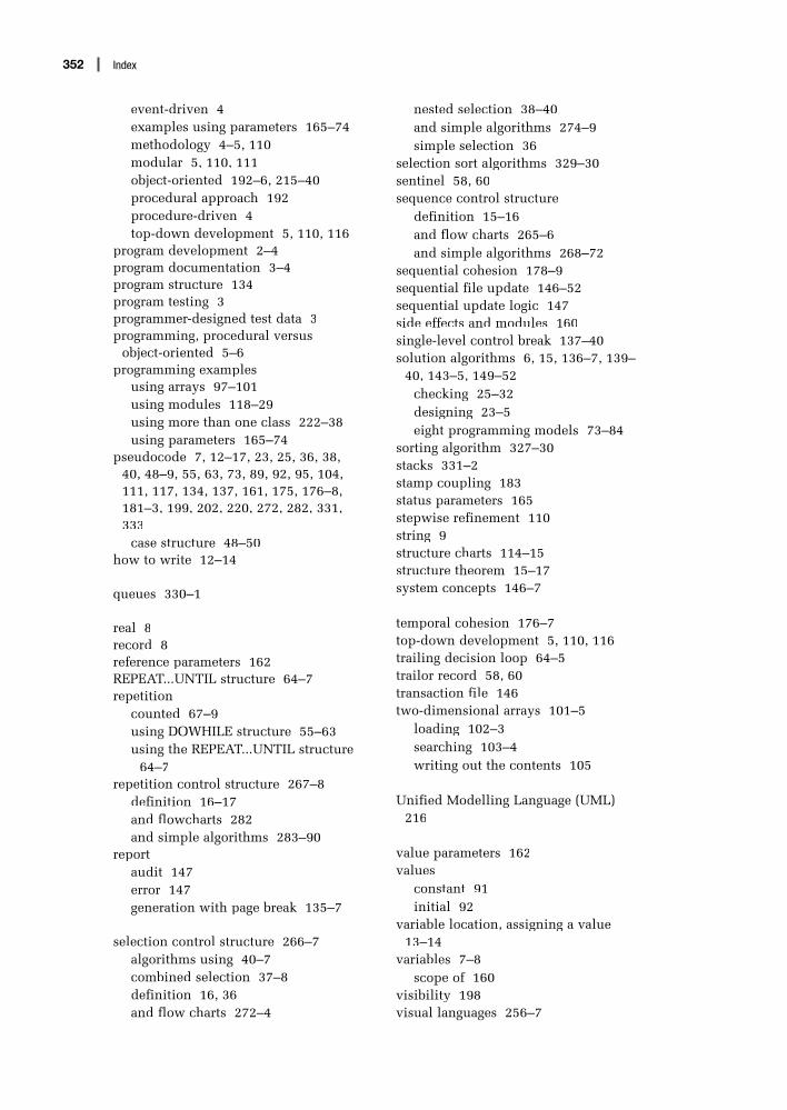
event-driven 4examples using parameters 165–74methodology 4–5, 110modular 5, 110, 111object-oriented 192–6, 215–40procedural approach 192procedure-driven 4top-down development 5, 110, 116
program development 2–4program documentation 3–4program structure 134program testing 3programmer-designed test data 3programming, procedural versus
object-oriented 5–6programming examples
using arrays 97–101using modules 118–29using more than one class 222–38using parameters 165–74
pseudocode 7, 12–17, 23, 25, 36, 38, 40, 48–9, 55, 63, 73, 89, 92, 95, 104, 111, 117, 134, 137, 161, 175, 176–8, 181–3, 199, 202, 220, 272, 282, 331, 333
case structure 48–50how to write 12–14
queues 330–1
real 8record 8reference parameters 162REPEAT...UNTIL structure 64–7repetition
counted 67–9using DOWHILE structure 55–63using the REPEAT...UNTIL structure
64–7repetition control structure 267–8
definition 16–17and flowcharts 282and simple algorithms 283–90
reportaudit 147error 147generation with page break 135–7
selection control structure 266–7algorithms using 40–7combined selection 37–8definition 16, 36and flow charts 272–4
nested selection 38–40and simple algorithms 274–9simple selection 36
selection sort algorithms 329–30sentinel 58, 60sequence control structure
definition 15–16and flow charts 265–6and simple algorithms 268–72
sequential cohesion 178–9sequential file update 146–52sequential update logic 147side effects and modules 160single-level control break 137–40solution algorithms 6, 15, 136–7, 139–
40, 143–5, 149–52checking 25–32designing 23–5eight programming models 73–84
sorting algorithm 327–30stacks 331–2stamp coupling 183status parameters 165stepwise refinement 110string 9structure charts 114–15structure theorem 15–17system concepts 146–7
temporal cohesion 176–7top-down development 5, 110, 116trailing decision loop 64–5trailor record 58, 60transaction file 146two-dimensional arrays 101–5
loading 102–3searching 103–4writing out the contents 105
Unified Modelling Language (UML) 216
value parameters 162values
constant 91initial 92
variable location, assigning a value 13–14
variables 7–8scope of 160
visibility 198visual languages 256–7
Index352