Simple Core-SOL-Divertor Model To Investigate Plasma Operation Space Joint Meeting of US-Japan JIFT...
18
Simple Core-SOL-Divertor Mo del To Investigate Plasma O peration Space Joint Meeting of US-Japan JIFT Workshop on Theory-Based Modeling and Integrated Simulation o f Burning Plasma and 21 COE Workshop on Plasma Theory Kyodai-Kaikan, Kyoto, 2003/12/15-17 . esearch Institute of Electric Power Industry (CRIEPI), Tokyo 201-85 i, K.Okano, Y.Asaoka f Science and Technology, Keio University, Yokohama 223-8511, Japan a, A.Hatayama, of Plasma Physics, Chinese Academy of Sciences, Hefei, P.R.China Institute for Fusion Science, Toki 509-5292, Japan
-
Upload
dennis-bruce -
Category
Documents
-
view
221 -
download
4
Transcript of Simple Core-SOL-Divertor Model To Investigate Plasma Operation Space Joint Meeting of US-Japan JIFT...

Simple Core-SOL-Divertor Model To Investigate Plasma Operation Space
Joint Meeting of US-Japan JIFT Workshop onTheory-Based Modeling and Integrated Simulation of Burning Plasma
and 21 COE Workshop on Plasma Theory
Kyodai-Kaikan, Kyoto, 2003/12/15-17
. Central Research Institute of Electric Power Industry (CRIEPI), Tokyo 201-8511, JapanR.Hiwatari, K.Okano, Y.Asaoka Faculty of Science and Technology, Keio University, Yokohama 223-8511, JapanY.Kuzuyama, A.Hatayama,Institute of Plasma Physics, Chinese Academy of Sciences, Hefei, P.R.ChinaS.ZhuNational Institute for Fusion Science, Toki 509-5292, JapanY.Tomita
2003/12/16US-Japan JIFT Workshop
Motivation
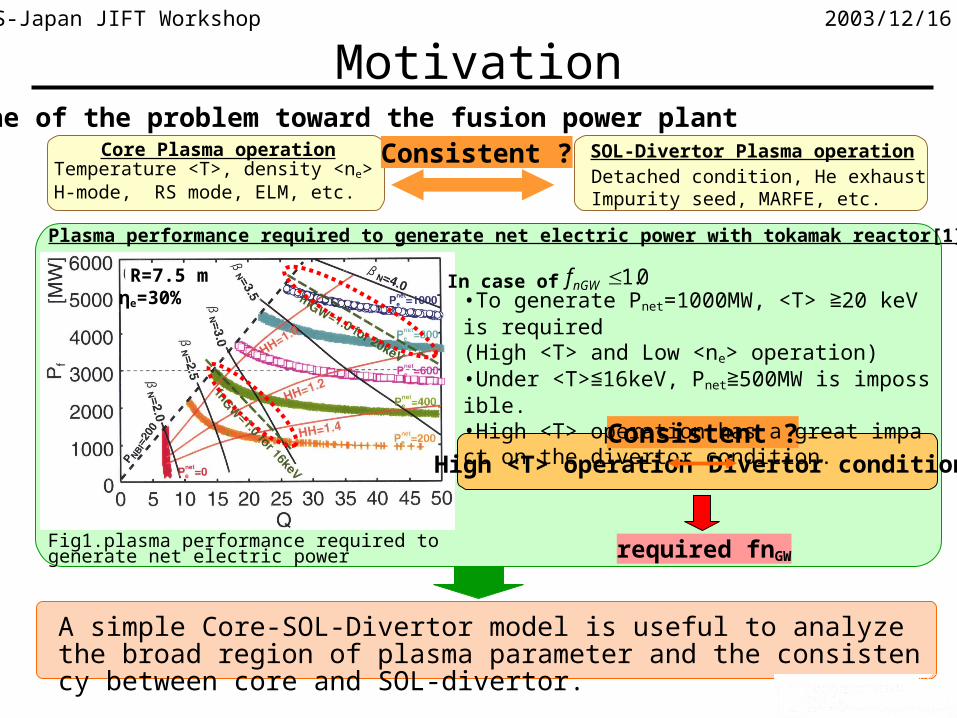
A simple Core-SOL-Divertor model is useful to analyze the broad region of plasma parameter and the consistency between core and SOL-divertor.
Consistent ?One of the problem toward the fusion power plant
SOL-Divertor Plasma operationCore Plasma operationTemperature <T>, density <ne>H-mode, RS mode, ELM, etc.
Detached condition, He exhaustImpurity seed, MARFE, etc.
Consistent ?
Plasma performance required to generate net electric power with tokamak reactor[1]
R=7.5 mηe=30%
In case of 0.1nGWf•To generate Pnet=1000MW, <T> 20 keV is required≧(High <T> and Low <ne> operation)•Under <T> 16keV, P≦ net 500MW is impossible.≧•High <T> operation has a great impact on the divertor condition.
Divertor condition
Fig1.plasma performance required to generate net electric power
High <T> operation
required fnGW

2003/12/16US-Japan JIFT Workshop
To develop the core-SOL-divertor model (C-S-D model) to investigate core and SOL-divertor plasma operational space.
Concept of the C-S-D model[2]
SOL-Divertor PlasmaCore Plasma0D core plasma model ofITER physics guidelines[3]
Two-point model[4]
Output parameter Input parameter
•Heat flux across the separatrix:q⊥•Upstream SOL density:ns
•Heat flux across the separatrix:q⊥
•Particle flux across the separatrix:Γ⊥
Problem : How to derive the upstream SOL density ns ?
•To solve the particle balance for the SOL-divertor region (C-S-D model)
combine
Time dependent modelTransport time scale: sec order
Steady state modelTransport time scale: msec order
Because of the difference of transport time scale, the steady state SOL-divertor transport model is applicable to the time-dependent core transport model .
Objectives

2003/12/16US-Japan JIFT Workshop
Contents
• Physical model of C-S-D model
•Comparison with B2-EIRENE results
•Application to HT-7U and ITER
•Summary

2003/12/16US-Japan JIFT Workshop
0D plasma model based on ITER physics guidelines[3]
),( HeejSn
dt
dn
PPPPPW
dt
dW
jpj
jj
syncBradauxOHE
pp
Charge neutrality conditionScaling law of energy confinement timeParticle confinement time:τPj=CPjτE
Each definition from ITER physics guidelines
LH transition condition[5]
When the total input power within the separatrix (Pin) becomes larger than LH threshold power (P
thr), L to H transition occurs.When the total input power becomes smaller than the half of the LH threshold power, H to L transition occurs.
syncBradauxOHin
tthr
PPPPPPaRnBMP
76.023.177.020
92.0176.2
thrin PP thrin PP2
1
L to H transition case H to L transition case
Core Plasma Model

2003/12/16US-Japan JIFT Workshop
Two-point model[4]
dddssdivmom
divmom TnMTnfzTznzMf 22 1111
•momentum balance in SOL-divertor region
•global energy balance in SOL-divertor region
•radial energy transport in SOL region
•electron thermal transport along the field lines
•Constant temperature in SOL region•Include convection in the electron thermal transport
dddsddsimp TMhTCMnqLf 2'12
7
sssX
sss
dd LTC
MTn
T
TTqL
24
51
49
4
2
12/7
2/702
q
Tn ss2
5
Ls Ld
Mach number M(z)
temperature T(z)
density n(z)
SOL divertor
X-pointDivertor plate
ns
ndnX
TsTd
Md=1MX
Along the field line
Z0
0
0
Fig.2 The basic features of density, temperature, and Mach number in the SOL-divertor region.
SOL-Divertor Model
Relationship among the density and temperature of SOL and divertor regions

2003/12/16US-Japan JIFT Workshop
All neutral particle source rate at the edge region Nn including gas puff term Npuff
puffndsddn NRhTCMnN sin2
Core
SOL divertor
corenS
divnSSOL
nS
core
div||
exhaust
Neutral particle source rate at the divertor region is proportional to the particle flux to the divertor plate.
Fig.3 The model of steady state particle balance.
n
divion
SOLion
coren
ndivion
SOLion
SOLn
ndivion
divn
NffSNffS
NfS
111
With this simple neutral model, particle balance of divertor region is considered.
Neutral Transport Model[6]
sin1 expdiv d
ion divion
Lf
div nion
d
v
n v
•ionization rate in the divertor region
2003/12/16US-Japan JIFT Workshop
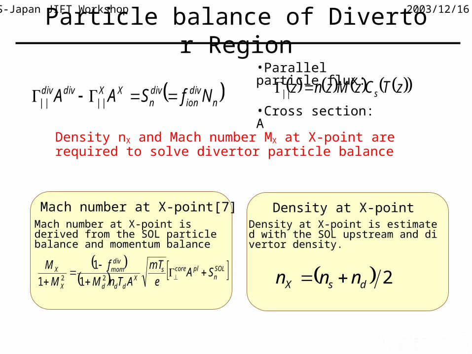
•Parallel particle flux:
•Cross section: A ndiv
iondivn
XXdivdiv NfSAA |||| zTCzMznz s||
Density nX and Mach number MX at X-point are required to solve divertor particle balance
Particle balance of Divertor Region
Density at X-point is estimated with the SOL upstream and divertor density.
2dsX nnn
Density at X-point
SOL
nplcores
Xddd
divmom
X
X SAe
mT
ATnM
f
M
M
22 1
1
1
Mach number at X-point is derived from the SOL particle balance and momentum balance
Mach number at X-point[7]

2003/12/16US-Japan JIFT Workshop
JT-60U simulation result for attached state [8]
•We focus on the inner divertor.•The fraction of the power entering inner SOL across the separatrix to the total power is Pin/Pall =0.34.•The percentage of the total radiation power to the input power fimp is about 30 %
Te
ne
Fig.4 Te and ne of B2-EIRENE
Comparison with B2-EIRENE
C-S-D model B2-EIRENE[5]
SOL density ns [m-3] 1.3×10¹⁹ ~1×10¹⁹
SOL Temp. Ts [eV] 62.5 ~55
Div density nd [m-3] 2.6×10¹⁹ ~3×10¹⁹
Div Temp. Td [eV] 15.9 ~16

2003/12/16US-Japan JIFT Workshop
HighRecycling
LowRecycling
Transition to High Recycling State
fion~1.0fion<<1.0
Transition from low recycling state to high recycling state is theoretically predicted[9] and also observed in the experiments[10]
This C-S-D model can reproduce the transition phenomena from low recycling to high recycling.
•Particle flux multiplication factor R=divX
•JT-60U plasma configuration•Total particle and energy flux into SOL region Pin and in

2003/12/16US-Japan JIFT Workshop
Case Fat-D
Shape Double-null
R/a (m) 1.97/0.5
κ 1.6
Divertor Outer&lower
τE (s) 0.15 (H-mode)
State High Recycling
Table 2: HT-7U parameter[7]
Application to HT-7U
•CSD model•Input parameters, Qin and in
•Divertor heat load is defined as ( ) sin sind B d d d sdq k T n M C
Divertor heat load for HT-7U
In the first phase of HT-7U project, current drive will be carried out by LH current drive and low density is preferable, but heat load to the divertor has to be decreased with high recycling state.

2003/12/16US-Japan JIFT Workshop
Application to HT-7U
*
*20
0.122
lne
p LHCD
T jI P
Rn p
3
2in e B e E oh LHCD ICRF
in e p p
Q n k T P P P
n V
E= fHEITER89
in=f(IP)Qin
LH current driving property for HT-7U
Preliminary result: heating power is restricted to ~3.5MW by LH heating
Linear relationship is obtained
Operation mode with other heating method andrelationship with LH transition condition are future work.

2003/12/16US-Japan JIFT Workshop
ne~6×10¹⁹
ne~2×10¹⁹
qd<3.5MW/m2
qd<5MW/m2
HT-7U Operational space for LH current driving
Fig.?: HT-7U Operational Space
Application ot HT-7U
There is operational space around 2x10¹⁹m-3

2003/12/16US-Japan JIFT Workshop
Time evolution of ITER plasma parameters
•Plasma parameters at t=250 sec are almost the same as the reference parameters of ITER inductive operation scenario for the fusion power Pfus=400 MW case.•At t=100 sec, plasma parameters are also similar to the reference parameters of ITER.•Density increases at t=95 sec.•Auxiliary heating is added at t=100 sec.•LH transition occurs at t=104 sec.
Fig8. reference scenario of ITER inductive operation[7].Fig.7 ITER LH transition phase by C-S-D model
Application to ITER LH Transition

2003/12/16US-Japan JIFT Workshop
Application to ITER LH Transition
•Divertor density oscillates around LH transition.•Is there any effect on the divertor operation ?•Good effect or bad effect ?
Is such divertor density oscillation observed at present ?
•Not yet install the detached plasma effect into two-point model•Calibrate particle confinement time to reproduce the design parameter of upstream SOL density at the steady state.
SOL-Divertor parameters
Calculation conditions

2003/12/16US-Japan JIFT Workshop
Time (sec)
Time (sec)
Time (sec)
Time (sec)
tJTth BnnP 5.0
1919
60 4.12.0
Application to JT-60U ConfigurationAccoding to H data, divertor density doesn’t oscillate[12]
Same calculation with JT-60U
•Plasma configuration. Bt=2.5 T, q95=4.0 Ip=1.2MA, k=1.5•LH threshold power is based on the experimental data[11] (parameter region: Ip = 0.9 ~ 2.4MA , B t= 1.5 ~ 4.0T)
Divertor density not oscillates but decreases.Consistent with experimental observation.
In the ITER, there is a possibility to observe nd oscillation.Further investigation is required.

2003/12/16US-Japan JIFT Workshop
Summary
•We developed a simple Core-SOL-Divertor (C-S-D) model
•The comparison with B2-EIRENE is carried out and the result
from CSD model looks good.
•We apply this C-S-D model to HT-7U operation space for LHC
D and found there is operational space around ne~2.0x10¹⁹ m-3
•We apply to ITER LH transition phase and found there is a possi
bility to oscillate the divertor density.

2003/12/16US-Japan JIFT Workshop
Reference[1]R.Hiwatari, et.al., Plasma Performance Required for a Tokamak Reactor to Generate Net Electric Power, J.Plasma Fusion Res. 78(2002)991, R.Hiwatari, et.al., To generate net electric power with a tokamak reactor under the foreseeable physical and engineering conditions, Nucl. Fusion, in press.
[2]R.Hiwatari et al., “Simple-Core-SOL-Divertor Model TO Imvestigate Plasma Operational Space”, Contrib. Submitted to Contrib. Plasma Phys.
[3]N.Uckan and ITER Physics Group, ITER Physics Design Guidelines:1989
[4] K.Borass, Nucl. Fusion 31(1991)1035, N.Hayashi, et al., J. Phys. Soc. Jpn. 66(1997)3815.
[5]ITER Physics Expert Groups, ITER Physics Basis Editors, Nucl. Fusion 39(1999)2175, T.Yamamoto, et al., Fusion Eng. Des. 39-40(1998)143
[6] M.Sugihara, et al., J.Nucl. Mater. 241-243(1997)299, N.Hayashi, et al., J. Phys. Soc. Jpn.66(1997)3815.
[7]K.Nagashima, et al., JAERI-RESEARCH-95-52 1995
[8] A.Hatayama, et al., Nucl. Fusion 40(2000)2009, J. Nucl. Mater. 290-293(2001)407
[9]M.Sugihara, et al., J.Nucl. Mater. 128-129(1984)114
[10]T.Takizuka, et al., JAERI-RESEARCH2003-010 2003
[11]K.Tuchiya, et al., Plasma Phys. Control. Fusion 38(1996)1295
[12] private communication with T.Takizuka (2003)