Simple calculation model for evaluating the fire ...
58
Espinos A, Romero ML, Hospitaler A. Simple calculation model for evaluating the fire resistance of unreinforced concrete filled tubular columns. Eng Struct. 2012;42:231-44. doi: 10.1016/j.engstruct.2012.04.022 1 Simple calculation model for evaluating the fire resistance of unreinforced concrete filled tubular columns Ana Espinos a , Manuel L. Romero a, *, Antonio Hospitaler a a Instituto de Ciencia y Tecnología del Hormigón (ICITECH), Universitat Politècnica de València, Valencia, Spain * Corresponding author. e-mail address: [email protected] ABSTRACT This paper presents a method for calculating the fire resistance of unreinforced axially loaded concrete filled circular hollow section columns, based on the guidelines of Eurocode 4 Part 1.2 for the fire design of composite columns. The different design approaches which are currently available worldwide are reviewed in this paper, focusing in particular on the European code, which is discussed and analysed in depth. Several of the aspects which are nowadays missing or thought to be arguable by researchers in the Eurocode 4 method are studied and on the basis of parametric studies a new proposal is developed, so that designers can easily apply the code in the future. The parametric studies investigate the main factors affecting the fire resistance of unreinforced concrete filled tubular (CFT) columns, such as the outer diameter, the thickness of the steel tube wall, the relative slenderness of the column at room temperature and the fire exposure time, widely covering the range of values which can be found in practice. From the results of these parametric studies, equations for obtaining the equivalent temperatures of steel and concrete are developed, and appropriate flexural stiffness reduction coefficients are integrated in the simple calculation model of Eurocode 4. The method presented here is valid for centrally loaded circular CFT columns filled with
Transcript of Simple calculation model for evaluating the fire ...

Espinos A, Romero ML, Hospitaler A. Simple calculation model for evaluating the fire resistance of unreinforced concrete
filled tubular columns. Eng Struct. 2012;42:231-44. doi: 10.1016/j.engstruct.2012.04.022
1
Simple calculation model for evaluating the fire resistance of
unreinforced concrete filled tubular columns
Ana Espinos a, Manuel L. Romero a,*, Antonio Hospitaler a
a Instituto de Ciencia y Tecnología del Hormigón (ICITECH),
Universitat Politècnica de València, Valencia, Spain
* Corresponding author. e-mail address: [email protected]
ABSTRACT
This paper presents a method for calculating the fire resistance of unreinforced axially
loaded concrete filled circular hollow section columns, based on the guidelines of Eurocode 4
Part 1.2 for the fire design of composite columns. The different design approaches which are
currently available worldwide are reviewed in this paper, focusing in particular on the
European code, which is discussed and analysed in depth. Several of the aspects which are
nowadays missing or thought to be arguable by researchers in the Eurocode 4 method are
studied and on the basis of parametric studies a new proposal is developed, so that designers
can easily apply the code in the future. The parametric studies investigate the main factors
affecting the fire resistance of unreinforced concrete filled tubular (CFT) columns, such as the
outer diameter, the thickness of the steel tube wall, the relative slenderness of the column at
room temperature and the fire exposure time, widely covering the range of values which can
be found in practice. From the results of these parametric studies, equations for obtaining the
equivalent temperatures of steel and concrete are developed, and appropriate flexural stiffness
reduction coefficients are integrated in the simple calculation model of Eurocode 4. The
method presented here is valid for centrally loaded circular CFT columns filled with

Espinos A, Romero ML, Hospitaler A. Simple calculation model for evaluating the fire resistance of unreinforced concrete
filled tubular columns. Eng Struct. 2012;42:231-44. doi: 10.1016/j.engstruct.2012.04.022
2
unreinforced normal strength concrete, and makes possible the calculation of slender
columns, extending the current limitations in buckling length of the European code.
Keywords: Fire resistance; Concrete filled tubular columns; Eurocode 4; Simple calculation
model
Espinos A, Romero ML, Hospitaler A. Simple calculation model for evaluating the fire resistance of unreinforced concrete
filled tubular columns. Eng Struct. 2012;42:231-44. doi: 10.1016/j.engstruct.2012.04.022
3
NOTATION
Aa Cross-sectional area of the steel profile at the temperature
Ac Cross-sectional area of the concrete at the temperature
Am/V Section factor
CFT Concrete filled tube
D Outer diameter of the circular section
Ea Modulus of elasticity of steel at the temperature
Ec Tangent modulus of concrete at the temperature
Ec,sec Secant modulus of concrete at the temperature
(EI)fi,eff Effective flexural stiffness in the fire situation
EC4 Eurocode 4
fc Compressive cylinder strength of concrete at room temperature
fy Yield strength of structural steel at room temperature
Ia Second moment of area of the steel profile at the temperature
Ic Second moment of area of the concrete at the temperature
ki Reduction factor for a material property at elevated temperature
L Length of the column
Buckling length of the column in the fire situation
N Applied axial load
NF French National Annex to Eurocode 4 Part 1-2
Nfi,cr Elastic critical load in the fire situation
Nfi,pl,Rd Design cross-sectional plastic resistance to axial compression in fire
Nfi,Rd Design axial buckling load of the column in the fire situation
R Standard fire resistance
t Thickness of the steel tube
Imperfection factor for the buckling curves
Temperature
Relative slenderness of the column at room temperature
Relative slenderness of the column in the fire situation
Relative error
i, Reduction coefficient to make allowance for the effect of thermal stresses
Member slenderness reduction factor (Nfi,Rd / Nfi,pl,Rd)

Espinos A, Romero ML, Hospitaler A. Simple calculation model for evaluating the fire resistance of unreinforced concrete
filled tubular columns. Eng Struct. 2012;42:231-44. doi: 10.1016/j.engstruct.2012.04.022
4
1. INTRODUCTION
The fire resistance of the structural elements is one of the factors that must be taken into
account during the design process of a building. Depending on several factors related to the
future use and characteristics of the building itself, the required fire resistance time will be
higher or lower, ranging from 30 to 180 minutes. Therefore, calculation tools are sought by
designers in order to obtain an estimation of the fire resistance that the different structural
elements within the building can achieve, or conversely to be able to determine the minimum
dimensions of the structural member which fulfil the required fire resistance period.
In particular, the interest in the use and development of simple methods for calculating
the fire resistance of concrete filled tubular (CFT) columns is growing, due to the increased
usage of this structural typology.
Authors as Zhao et al. [1] or Rush et al. [2] have reviewed the current methods that exist
for calculating the fire resistance of CFT columns. Several codes are in use nowadays, which
are a result of numerical and experimental investigations carried out by the main groups
working in this field of research.
The Chinese Code DBJ13-51 [3] establishes an equation to calculate the thickness of
the external fire protection required to achieve a certain fire resistance time and is based on a
research carried out by Han et al. [4] [5]. Also a method for calculating the ultimate strength
of unprotected concrete filled steel tubular columns subjected to standard fire was developed
by this research group [4].
Another approach, which is in use in North America, was developed by Kodur and co-
workers [6] [7] [8] at the National Research Council of Canada (NRCC) and has been
incorporated into the National Building Code of Canada [9], ASCE/SFPE 29-99 [10], ACI
216 [11] and AISC Steel Design Guide 19 [12]. This approach consists of a single design
equation which includes the main parameters affecting the fire resistance of CFT columns.

Espinos A, Romero ML, Hospitaler A. Simple calculation model for evaluating the fire resistance of unreinforced concrete
filled tubular columns. Eng Struct. 2012;42:231-44. doi: 10.1016/j.engstruct.2012.04.022
5
Other design equations in use presently include the one in the design guide manual for
CFT columns published by the Association of New Urban Housing Technology (ANUHT) in
Japan [13] [14].
In Europe, the most extended methods for calculating the fire resistance of CFT
columns are those included in EN 1994-1-2 [15], comprising three levels of design: a)
tabulated data, b) simple calculation models and c) advanced calculation models. Option a) is
available in Clause 4.2.3.4 in the form of a selection table which provides the minimum cross-
sectional dimensions and reinforcement that a CFT column must have in order to achieve a
rated standard fire resistance time under a certain load level. This approach is the most
simplistic and its results are highly conservative as pointed out by Rush et al. [2]. Option b),
simple calculation models, are the most widespread, and amongst them a full method is
presented for calculating the fire resistance of composite columns in Clause 4.3.5.1 based on
the elastic buckling theory. A specific method for columns composed of unprotected concrete
filled hollow sections is also given in Annex H of the same code. Finally, advanced
calculation models (option c) allow the use of finite element models capable to simulate the
realistic fire behaviour of the element based on the modelling of the actual thermo-mechanical
problem. This last approach can provide a more accurate approximation of the behaviour, but
is generally out of reach of practitioners and often due to limited time or resources it is only
applied to very specific design situations.
Authors as Wang [16] [17] [18], Leskela [19], Aribert et al. [20], Ribeiro et al. [21] and
Espinos et al. [22] [23] have focused on the study of the simple calculation model in EC4
(option b). Because of the complexity of the specific method in Annex H and after having
been proved that it produces unsafe results for slender columns [16] [20], authors are more
inclined to follow the general principles in Clause 4.3.5.1, which cover all types of composite
columns. However, in the case of CFT columns, only a few studies have been carried out so

Espinos A, Romero ML, Hospitaler A. Simple calculation model for evaluating the fire resistance of unreinforced concrete
filled tubular columns. Eng Struct. 2012;42:231-44. doi: 10.1016/j.engstruct.2012.04.022
6
far to investigate the applicability of the general method in Clause 4.3.5.1. The work by the
CTICM group in France [20] [24] has led to the rules published in the French National Annex
to EN 1994-1-2 [25]. The authors of the present paper have also carried out some previous
work in this direction [23].
Several design guides have been developed on the calculation of the fire resistance of
CFT columns, amongst which one can find the Corus Tubes guide [26] and the CIDECT
guide [27]. In the latter of these guides, practitioners can find a number of design charts valid
for the more commonly used cross-sectional dimensions, where the load bearing capacity of
the column for a certain fire exposure time is given as a function of its buckling length, cross-
sectional dimensions and percentage of reinforcement. Nevertheless, the number of charts
available in the technical guides is limited and it would be rather desirable to have a unique
and robust method which would be easy to use by designers and readily implemented in any
design software.
In this paper, the current provisions of the simple calculation model in EN 1994-1-2
[15] and their modifications included in the French National Annex [25] are discussed, and by
means of the results of an extensive parametric study a new proposal is presented, which
improves the accuracy of the method and extends its current field of application. Appropriate
values of the flexural stiffness reduction coefficients, missing in the actual version of EN
1994-1-2 for concrete filled tubular columns, are developed in this paper, as well as
expressions for the equivalent temperatures of the steel tube and concrete core at different
standard fire periods, which will facilitate the fire design of such columns. The proposed
method is applicable to unprotected CFT columns of circular shape and filled with normal
strength plain concrete. It covers a wide range of column slenderness, with buckling lengths at
elevated temperature up to 10 m (corresponding to relative slenderness values in fire from 0.5
to 4.5), diameters from 139.7 mm to 508 mm and standard fire classes from R30 to R120.
Espinos A, Romero ML, Hospitaler A. Simple calculation model for evaluating the fire resistance of unreinforced concrete
filled tubular columns. Eng Struct. 2012;42:231-44. doi: 10.1016/j.engstruct.2012.04.022
7
The new proposal is verified against experimental results and also compared with other
methods available in the literature and which are being used worldwide [4] [6] [13], and
finally a design example which illustrates the use of the method is presented.
2. REVIEW OF EXISTING DESIGN GUIDANCE
2.1. Simple calculation model in Annex H of EN 1994-1-2 [15]
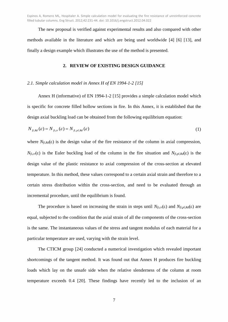
Annex H (informative) of EN 1994-1-2 [15] provides a simple calculation model which
is specific for concrete filled hollow sections in fire. In this Annex, it is established that the
design axial buckling load can be obtained from the following equilibrium equation:
)()()( ,,,, RdplficrfiRdfi NNN (1)
where Nfi,Rd() is the design value of the fire resistance of the column in axial compression,
Nfi,cr() is the Euler buckling load of the column in the fire situation and Nfi,pl,Rd() is the
design value of the plastic resistance to axial compression of the cross-section at elevated
temperature. In this method, these values correspond to a certain axial strain and therefore to a
certain stress distribution within the cross-section, and need to be evaluated through an
incremental procedure, until the equilibrium is found.
The procedure is based on increasing the strain in steps until Nfi,cr() and Nfi,pl,Rd() are
equal, subjected to the condition that the axial strain of all the components of the cross-section
is the same. The instantaneous values of the stress and tangent modulus of each material for a
particular temperature are used, varying with the strain level.
The CTICM group [24] conducted a numerical investigation which revealed important
shortcomings of the tangent method. It was found out that Annex H produces fire buckling
loads which lay on the unsafe side when the relative slenderness of the column at room
temperature exceeds 0.4 [20]. These findings have recently led to the inclusion of an
Espinos A, Romero ML, Hospitaler A. Simple calculation model for evaluating the fire resistance of unreinforced concrete
filled tubular columns. Eng Struct. 2012;42:231-44. doi: 10.1016/j.engstruct.2012.04.022
8
amendment to the existing Annex H which states that the relative slenderness of the columns
should be limited to 5.0 for the use of the method.
The method in Annex H can only be applied to columns with buckling lengths in the
fire situation m 5.4 , diameter of cross-section 140 mm ≤ D ≤ 400 mm, concrete grades
C20/25 – C40/50 and standard fire resistance R ≤ 120 min.
2.2. General method for composite columns in Clause 4.3.5.1 of EN 1994-1-2 [15]
While the method in Annex H has revealed to produce unsafe results for slender
columns [20] and has duly been criticised because of its complexity, the general calculation
method in Clause 4.3.5.1 can be used instead, as it is done for other type of composite
columns. In fact, the method in Annex G of the same code for partially encased steel sections
follows the general rules given in Clause 4.3.5.1.
In this method, the design value of the resistance of composite columns in axial
compression exposed to fire (Nfi,Rd) is calculated as:
RdplfiRdfi NN ,,, (2)
where is the reduction coefficient for buckling curve “c” given in Clause 6.3.1.2 of EN
1993-1-1 [28] (obtained from the value of the relative slenderness at elevated temperature)
and Nfi,pl,Rd is the design value of the plastic resistance of the cross-section to axial
compression in fire.
The design value of the plastic resistance of the cross-section in fire (Nfi,pl,Rd),
considering that the column has no reinforcement, is given by:
m
cfiMcc
j
afiMyaRdplfi fAfAN ,,,,,,,,,, /)(/)( (3)
Espinos A, Romero ML, Hospitaler A. Simple calculation model for evaluating the fire resistance of unreinforced concrete
filled tubular columns. Eng Struct. 2012;42:231-44. doi: 10.1016/j.engstruct.2012.04.022
9
where Ai, is the area of each element of the cross-section to which a certain temperature is
attributed and subscripts “a” and “c” refer to the steel profile and concrete core, respectively.
M,fi,i are the partial factors for the materials in the fire situation.
The effective flexural stiffness of the column can be calculated through:
m
ccc
j
aaaefffi IEIEEI )()()( ,sec,,,,,,, (4)
where Ii, is the second moment of area of each element of the cross-section to which a certain
temperature is attributed, i, is a reduction coefficient depending on the effect of thermal
stresses and Ec,sec, is the secant modulus of concrete at the temperature . For composite
columns with partially encased steel sections, the reduction coefficients have been defined in
Annex G of EN 1994-1-2 [15]. However, for concrete filled sections, the values of these
reduction coefficients still have to be established.
The flexural stiffness reduction coefficients were introduced in this formulation to
account for the effect of the self-equilibrated thermal stresses caused by the non-uniform
temperature distribution within the composite cross-section and the unequal thermal
expansion of steel and concrete [29]. In the absence of predefined values for these
coefficients, as it is the case of CFT columns, a common approach in practice is to take them
as equal to unity [29]. Only few studies have been carried out so far on the suitable values of
the coefficients, those of the CTICM group [20] [24] and that of the authors of this paper [23].
Once the effective flexural stiffness is calculated, the Euler buckling load in the fire
situation is obtained:
2
,
2
, /)( effficrfi EIN (5)
where is the effective length of the column at a certain temperature
The relative slenderness of the column at elevated temperatures is given by:
Espinos A, Romero ML, Hospitaler A. Simple calculation model for evaluating the fire resistance of unreinforced concrete
filled tubular columns. Eng Struct. 2012;42:231-44. doi: 10.1016/j.engstruct.2012.04.022
10
crfiRplfi NN ,,, / (6)
where Nfi,pl,R is the value of Nfi,pl,Rd when the material factors are taken as 1.0. This value of
the relative slenderness is used to enter to the buckling curve “c”, from where the reduction
coefficient needed for determining the buckling load is finally obtained.
2.3. French National Annex to EN 1994-1-2 [25]
The French National Annex to EN 1994-1-2 (NF EN 1994-1-2/NA) [25] is based on the
general method described in Clause 4.3.5.1 of EN 1994-1-2 [15]. In this National Annex,
specific values for the flexural stiffness reduction coefficients have been included to account
for the effect of the differential thermal stresses within the composite cross-section. These
values are a result of an extensive parametric investigation carried out at the CTICM [24]. For
the concrete core, a reduction coefficient of 0.8 is specified, resulting in c, = 1.2, which
includes implicitly the use of the initial tangent modulus of concrete (calculated as 3/2 times
the secant modulus, therefore 0.8 × 3/2 = 1.2 for direct application over the secant modulus),
while for the steel hollow section the value of the reduction coefficient a, depends on the
fire duration and the size (B or D) of the steel section, according to Clause 4(2) of NF EN
1994-1-2/NA.
The method included in the French National Annex establishes also specific buckling
curves with a discontinuity at a certain value of the relative slenderness, called the “transition
relative slenderness”. This transition value is dependent on the fire exposure time, and is
equal to 1.0 for R30 and 1.35 for R60 in the case of unreinforced columns. Before reaching
the transition value, the buckling curve follows the shape of the EN 1993-1-1 [28] curves but
with a different imperfection factor for the different fire periods ( = 0.21 for R30 and =
0.265 for R60). For relative slenderness values above the transition slenderness, the method
makes use of specific buckling curves.
Espinos A, Romero ML, Hospitaler A. Simple calculation model for evaluating the fire resistance of unreinforced concrete
filled tubular columns. Eng Struct. 2012;42:231-44. doi: 10.1016/j.engstruct.2012.04.022
11
The French method is limited to buckling lengths in the fire situation 30/ D ,
concrete grades C20/25 – C60/75, D ≤ 610 mm, and for centrally loaded unreinforced CFT
columns a minimum dimension is required depending on the fire resistance class: D > 100
mm for R30 and D > 150 mm for R60. For unreinforced columns longer fire resistance times
cannot be evaluated by this method, since a minimum percentage of reinforcement is required
for achieving a R90 or higher fire resistance class.
2.4. Simplified design equation proposed by Kodur [6] [8]
Kodur [6] [8] proposed a simplified equation based on the results of parametric studies
supported by an experimental program carried out in the Institute for Research in
Construction, NRCC (Canada) [30] on circular and square concrete filled tubular columns
under fire. This approach is used in the United States and Canada after having been
incorporated into several building codes [9], [10], [11] and design guides [12].
Kodur’s design equation directly provides the fire resistance time of the column in
minutes as a function of different parameters such as the concrete strength, the column
diameter and effective length, the type of concrete filling, cross-sectional shape and
percentage of steel reinforcement.
The fire resistance time of a column can be evaluated by the following equation as a
function of the different parameters:
N
DD
ffR c 2
1000
20
(7)
where R is the fire resistance time in minutes, fc is the concrete strength at the age of 28 days
in MPa, D is the outside diameter of the column in mm (also applicable to square columns if
the width is used instead), N is the applied load in kN, is the effective buckling length of
the column in mm and f is a coefficient which includes the effect of the rest of the parameters,

Espinos A, Romero ML, Hospitaler A. Simple calculation model for evaluating the fire resistance of unreinforced concrete
filled tubular columns. Eng Struct. 2012;42:231-44. doi: 10.1016/j.engstruct.2012.04.022
12
given in [6]. This coefficient is tabulated as a function of the type of concrete filling (plain,
bar-reinforced or fibre-reinforced concrete), the type of aggregate used (carbonate or
siliceous), the percentage of reinforcement, the thickness of the concrete cover, and the cross-
sectional shape of the column (circular or square).
The applicability of equation (7) is limited to fc = 20 - 40 MPa, D = 140 - 410 mm, R ≤
120 min and = 2000 - 4000 mm for columns without any reinforcement. Therefore, the
method cannot be applied to columns with a high slenderness.
2.5. Strength index formulation proposed by Han [4]
Han and co-workers [4] proposed a formulation which makes possible to determine the
strength index (SI) of CFT columns based on the results of parametric and experimental
studies carried out at the Tianjin Fire Research Institute (China). The formulation was
obtained by using regression analysis, and is valid for circular hollow steel columns without
fire protection, filled with plain concrete. Also columns with external fire protection were
investigated, and the design equations developed were incorporated in the Chinese code
DBJ13-51 [3]. For simplicity, the formulation of the method has not been transcribed here,
but it can be found in [4]. The validity limits of Han’s design equation are: t ≤ 180 min, D =
150 - 2000 mm, fy = 200 - 500 MPa, fc = 20 - 60 MPa and = 15 - 80 (slenderness ratio
defined here as = 4L/D).
2.6. Fire resistance design formula used in Japan [13]
The actual state of the fire design codes in Japan was reviewed by Harada [14].
Regarding concrete-filled steel tubular columns, the Association of New Urban Housing
Technology (ANUHT) in Japan published a design guide manual [13] where a simple
equation for obtaining the ultimate load of the column under a certain fire period can be
found. For circular columns, the expression is as follows:
Espinos A, Romero ML, Hospitaler A. Simple calculation model for evaluating the fire resistance of unreinforced concrete
filled tubular columns. Eng Struct. 2012;42:231-44. doi: 10.1016/j.engstruct.2012.04.022
13
214.063.25,1··10·75.5
tf
fA
Nc
cc
Rdfi (8)
where Ac is the cross-sectional area of concrete in mm2, fc is the specified 28 day concrete
strength in MPa and t is the fire resistance time in minutes.
3. NUMERICAL MODEL AND PARAMETRIC STUDIES
3.1. Description of the numerical model
A previously validated numerical model developed by the authors with the finite
element analysis package ABAQUS [31] is available. This model is capable to simulate with
enough accuracy the fire behaviour of slender concrete filled circular hollow section columns.
The details of the model and its validation process are described in [22], where the numerical
model was validated against fire tests available in the literature [30]. The average value of the
error in the predictions of the fire resistance time, evaluated as test/prediction, was 1.08 with a
standard deviation equal to 0.19. The range of diameters analysed is this validation stage
varied between 141.3 mm and 273.1 mm, and the room temperature relative slenderness of
the columns ranged from 0.29 to 0.98. Recently, a second validation stage of the model was
carried out against fire tests performed by the own authors [32], where columns with high
relative slenderness and different types of concrete infill were analysed. In this second
validation stage, for those columns filled with normal strength concrete, an average error in
the predictions equal to 1.09 was obtained, with a 0.16 standard deviation. The cross-sectional
dimensions of the columns were constant in this case, while the concrete grade, reinforcement
type and load level were varied. The room temperature relative slenderness of the columns
tested in this experimental research ranged from 0.61 to 0.88.
By means of the numerical model, a sequentially coupled thermal-stress analysis can be
performed. First, a pure heat transfer analysis is conducted for computing the temperature

Espinos A, Romero ML, Hospitaler A. Simple calculation model for evaluating the fire resistance of unreinforced concrete
filled tubular columns. Eng Struct. 2012;42:231-44. doi: 10.1016/j.engstruct.2012.04.022
14
evolution along the column and afterwards a stress/deformation analysis is run for calculating
the structural response. Nodal temperatures are stored as a function of time in the heat transfer
analysis results and then read into the stress analysis as a predefined field.
The standard ISO-834 [33] fire curve is applied to the exposed surface of the CFT
column specimens as a thermal load, through the convection and radiation heat transfer
mechanisms. The values recommended in EN 1991-1-2 [34] are used for the main heat
transfer parameters. The entire length of the columns is considered to be exposed to the fire.
The thermal resistance at the boundary between the steel tube and the concrete core is taken
into account through a gap conductance value of 200 W/m2K, as was used in previous
investigations [22]. It was proved through a sensitivity analysis that, despite it is known that
the gap clearance size and therefore the thermal resistance at the steel-concrete interface vary
during the evolution of the fire, a constant value can be assumed obtaining satisfactory results.
Once the thermal problem is solved, a nonlinear stress analysis is subsequently
conducted, accounting for the previously calculated nodal temperature-time curves.
The numerical model takes into account an initial out-of-straightness of the columns
equal to L/1000, which is a result of a sensitivity analysis carried out in previous
investigations [22]. Pin-ended boundary conditions are considered. Owing to symmetry of
both the geometry and the boundary conditions, only a quarter of the column needs to be
modelled. Fig. 1 shows the finite element mesh for one of the column specimens analysed.
The steel tube and concrete core are meshed using three-dimensional eight-noded solid
elements, with a maximum element size of 20 mm, which had been proved to be sufficient to
predict with enough accuracy the fire behaviour of CFT columns [22]. The steel end plate is
modelled as a discrete rigid part with all nodes coupled to a reference point, located at the
column axis. The axial load is applied to the rigid plate through its reference node and
Espinos A, Romero ML, Hospitaler A. Simple calculation model for evaluating the fire resistance of unreinforced concrete
filled tubular columns. Eng Struct. 2012;42:231-44. doi: 10.1016/j.engstruct.2012.04.022
15
maintained constant during the fire history. The rigid plate is meshed using four-noded three-
dimensional bilinear rigid quadrilateral elements, with a maximum element size of 20 mm.
The selected material models are a result of an extensive sensitivity analysis carried out
in previous research [22]. For concrete, the stress-strain curves at elevated temperatures
proposed by Lie [35] are employed. The high temperature thermal properties for concrete are
taken from EN 1992-1-2 [36], except for the thermal expansion coefficient, which is given a
value of c = 6 × 10⁻⁶ ºC-1 as recommended by Hong and Varma [37] and subsequently
verified by the authors in the sensitivity analysis [22]. For structural steel, the temperature
dependent thermal and mechanical properties recommended in EN 1993-1-2 [38] are adopted.
A moisture content of 3% in concrete weight is considered in this research, which is taken
into account through a peak value of 2020 J/kgK in the specific heat formulation of concrete.
3.2. Parametric studies
Parametric studies were performed by means of the numerical model described in the
previous section. The main parameters affecting the buckling resistance of unreinforced CFT
columns at elevated temperatures were investigated through these parametric studies. The
parameters studied are the outer diameter of the column (D), the thickness of the steel tube
wall (t), the relative slenderness of the column at room temperature ( ) and the standard fire
period (R), widely covering the range of values which can be found in practice. A summary of
the cases analysed in this parametric study is shown in Table 1.
The composite sections analysed in this parametric study considered a steel yield
strength of 355 MPa as most commonly used, and concrete compressive strength of 30 MPa,
since this study is limited to normal strength concrete. Six different circular section sizes of
commercially available dimensions were employed: 139.7, 193.7, 273, 323.9, 406.4 and 508
mm. For each diameter, two steel tube wall thicknesses were selected: the minimum and
maximum commercially available values, although it is noteworthy that the minimum

Espinos A, Romero ML, Hospitaler A. Simple calculation model for evaluating the fire resistance of unreinforced concrete
filled tubular columns. Eng Struct. 2012;42:231-44. doi: 10.1016/j.engstruct.2012.04.022
16
thickness was chosen as the first value which produced a class 3 section (thin-walled sections
were not included in this study). For each cross-section, five different column lengths were
used, corresponding to slenderness values at room temperature of 0.3, 0.5, 1, 1.5 and 2. The
relative slenderness values of the columns at room temperature were calculated in accordance
with Clause 6.7.3.3 of EN 1994-1-1 [39] assuming hinged end conditions. The influence of
enhanced concrete confinement was not considered in the room temperature calculations.
The maximum slenderness analysed for each cross-section was selected in such a way
that the associated buckling length of the column did not exceed 10 meters, in order to reduce
the computational cost of this study. Therefore, the combinations of diameters and member
slenderness were as follows: D = 139.7 mm ( = 0.3, 0.5, 1, 1.5, 2); D = 193.7 mm ( = 0.3,
0.5, 1, 1.5, 2); D = 273 mm ( = 0.3, 0.5, 1, 1.5); D = 323.9 mm ( = 0.3, 0.5, 1); D = 406.4
mm ( = 0.3, 0.5, 1); 508 mm ( = 0.3, 0.5).
For each column, four different standard fire resistance classes were considered: 30, 60,
90 and 120 minutes (hereafter referred to as R30, R60, R90 and R120), which are the
common values prescribed in the design codes. Each column specimen employed a different
combination of the specified values of the variables shown in Table 1. In total, the number of
specimens analysed in this parametric study was 176.
The procedure employed in this research to calculate the buckling resistances which
correspond to the different fire exposure times analysed (30, 60, 90 and 120 minutes) was as
follows. In a first step, the fire resistance time of the column was obtained by means of the
numerical model under several values of the applied axial load (in general, 10 different values
were used), so as to be able to build up a curve of the evolution of the buckling load versus
the fire exposure time. In a second step, the value of the buckling load corresponding to the
desired standard time (R30, R60, R90 or R120) was obtained from this curve by using linear

Espinos A, Romero ML, Hospitaler A. Simple calculation model for evaluating the fire resistance of unreinforced concrete
filled tubular columns. Eng Struct. 2012;42:231-44. doi: 10.1016/j.engstruct.2012.04.022
17
interpolation. Special care was taken in the vicinity of the standard fire times, where the curve
was refined, so that the error in the interpolation was minimum.
Fig. 2 explains graphically the process followed for obtaining the buckling resistance of
a column at the specified standard fire times. As can be seen, this procedure requires an
elevated number of calculations to perform for each column specimen, which limits the
extension of this parametric analysis.
3.3. Analysis of results
From the results of all the calculations performed in the parametric studies, the
numerical buckling coefficient was computed. It was defined as the column axial buckling
resistance obtained from the numerical simulation divided by the design value of the cross-
sectional plastic resistance, both in the fire situation: Rdplfi
NUM
RdfiNUM
N
N
,,
, . This value was
plotted against the relative slenderness at elevated temperature crfiRplfi NN ,,, / ,
calculated as described in Section 2.2 and using reduction coefficients equal to unity. Fig. 3
shows the results for all the columns analysed in this research, were buckling curve “c” has
been superimposed for comparison purposes. As can be seen, most of the values lie below the
buckling curve “c” being therefore unsafe, except for columns with high relative slenderness
values (generally corresponding to specimens with room temperature slenderness over 1.5)
and columns with a very small slenderness. It becomes clear from this graph that columns
with intermediate slenderness deviate from the theoretical buckling curve at elevated
temperatures and therefore need another consideration. This result suggests that a set of
flexural stiffness reduction coefficients i, must be developed for CFT columns in
combination with a possible revision of the buckling curve which provides a better fit to the
data, matter that will be studied in depth throughout this paper.

Espinos A, Romero ML, Hospitaler A. Simple calculation model for evaluating the fire resistance of unreinforced concrete
filled tubular columns. Eng Struct. 2012;42:231-44. doi: 10.1016/j.engstruct.2012.04.022
18
Another important aspect can be observed from Fig. 3. In the range of low slenderness,
for each diameter of the columns analysed, the buckling coefficient of the columns with the
maximum wall thickness of the tube (reduced D/t values) appeared to be smaller than the
values of the columns with the minimum wall thickness and thus having a higher D/t; e.g. the
points for columns of 406.4×16 mm section lie below the points corresponding to columns of
406.4×8 mm section). This result was more evident in stocky columns ( ≤ 0.5), while for
slender columns the difference was not so clear. It is worth noting that this phenomenon was
found when comparing buckling coefficients (where the buckling load is referred to the cross-
sectional plastic resistance) and not with the absolute value of the buckling load, which
resulted generally in higher values for the columns with a higher steel tube wall thickness.
The explanation of this may reside in the fact that for a given section size, lower
thicknesses of the steel tube wall allow more quantity of concrete to fill the column and thus
contributing to delay its heating and as a consequence being able to sustain a higher load. This
behaviour holds true for this particular range of columns, where the fire response is highly
influenced by the amount of concrete filling. However, the more slender columns show the
inverse response, since their failure is initiated by the local buckling of the steel tube at an
early stage when it is still sustaining the load without the contribution of the concrete core.
The slenderness of the unfilled steel tube (and thus its thickness) is therefore a relevant factor
in this case, whereas the amount of concrete filling does not play an important role here. This
phenomenon was already addressed in previous numerical investigations carried out by the
authors [23] and other groups [8], and has also been observed in real fire tests [30].

Espinos A, Romero ML, Hospitaler A. Simple calculation model for evaluating the fire resistance of unreinforced concrete
filled tubular columns. Eng Struct. 2012;42:231-44. doi: 10.1016/j.engstruct.2012.04.022
19
4. STUDY AND DISCUSSION OF EUROCODE 4 PART 1.2
On the basis of the results of the parametric studies presented above, a comparison is
done in this section between the current calculation methods available in the Eurocode 4 Part
1.2 [15] for CFT columns. Four different approaches will be studied (see sections 2.1, 2.2, 2.3
from this paper): Clause 4.3.5.1 with flexural stiffness reduction coefficients equal to unity
(EC4(1)), Clause 4.3.5.1 with the reduction coefficients proposed by Aribert et al. [20]
(EC4(2)), Annex H (EC4(H)), and French National Annex [25] (EC4(NF)). For each method,
the numerical temperature field obtained at the standard fire resistance classes (R30, R60,
R90 and R120 minutes) was applied, and following the code provisions the buckling load was
calculated.
Fig. 4 shows a comparison between the predictions and the numerical simulations in
terms of normalised buckling load (divided by the theoretical cross-sectional plastic
resistance). Fig. 5 plots the relative error of the predictions against the relative slenderness
of the columns at room temperature, for each of the design approaches studied. The relative
error was computed as follows:
NUM
Rdfi
NUM
Rdfi
PRED
Rdfi
N
NN
,
,,1
(9)
where Nfi,RdPRED is the predicted buckling resistance with the calculation method employed
and Nfi,RdNUM is the numerical simulation result, which here is taken as the reference value.
Therefore, values greater than 1 mean safe predictions, while values lower than 1 mean unsafe
predictions.
As can be seen in Fig. 4a and Fig. 5a, EC4(1) yields unsafe results with a high
dispersion of values for all the range of slenderness studied, except for = 2, when the
predictions become safe and the dispersion is much lower. Therefore, to neglect the flexural
stiffness reduction coefficients when applying Clause 4.3.5.1 of EC4 to CFT columns

Espinos A, Romero ML, Hospitaler A. Simple calculation model for evaluating the fire resistance of unreinforced concrete
filled tubular columns. Eng Struct. 2012;42:231-44. doi: 10.1016/j.engstruct.2012.04.022
20
produces inadmissible errors. Nevertheless, when the French coefficients are used in
combination with Clause 4.3.5.1, Fig. 4b and Fig. 5b (EC4(2)), safe results are obtained in all
the range of slenderness studied (except for some cases with ≤ 0.5), but with high errors
and an elevated dispersion of results. As the slenderness is increased, the predictions become
safer but the errors produced by this method are higher. Annex H predictions (EC4(H)) turn
from safe at low slenderness ( = 0.3) to unsafe for intermediate slenderness ( = 0.5 - 1.5)
and close to the reference value again at = 2, Fig. 4c and Fig. 5c. This confirms the results
from the CTICM group [20] [24], who found that the method in Annex H is unsafe for
slenderness values over 0.4. Note that in these two figures, those cases which are out of the
applicability limits of Annex H (buckling length > 4.5 m) have been plotted with an empty
mark. The magnitude of the error produced by Annex H is lower, but still leading to high
errors, which in most of the cases are over a 25%. Finally, EC4(NF) produces safe results for
all the cases analysed, but with a high error which increases with the slenderness, Fig. 4d and
Fig. 5d. Note that the number of points plotted in these two last figures is lower, since some
column specimens are out of the applicability limits of the French method (only R30 and R60
are allowed for unreinforced columns).
The results obtained in this section confirm and extend the conclusions drawn by the
authors in previous research [23].
5. DEVELOPMENT OF A NEW SIMPLE CALCULATION MODEL FOR AXIALLY
LOADED CONCRETE FILLED TUBULAR COLUMNS
5.1. Simplified cross-sectional temperature field
In both Annex H and Clause 4.3.5.1 of EN 1994-1-2 [15] it is required that the designer
obtains the cross-sectional temperature field in the composite cross-section after a given
duration of fire exposure prior to applying the method to calculate the design axial buckling

Espinos A, Romero ML, Hospitaler A. Simple calculation model for evaluating the fire resistance of unreinforced concrete
filled tubular columns. Eng Struct. 2012;42:231-44. doi: 10.1016/j.engstruct.2012.04.022
21
load. Nevertheless, no simplified method for the temperature evaluation is given in the code
which helps the designer obtain easily this temperature field. In order to help practitioners in
the future, a simple method for evaluating the temperature field within the cross-section of a
CFT column of any dimensions is proposed here.
It would be desirable to obtain a uniform equivalent temperature for the whole concrete
core (c,eq) and another one for the steel tube (a,eq) so as to obtain the same fire resistance of
the column as by using the real non-uniform temperature distribution. This approach is
already used in Annex G of EN 1994-1-2 [15] for composite columns with partially encased
steel sections. The benefit of this approach is that the designer can evaluate the fire resistance
of the column by using a single strength and stiffness value for each component of the
composite cross-section corresponding to its temperature. A calculation procedure was
proposed by Leskela [19], whose recommendations are followed hereafter.
Calculation of the equivalent temperature for the concrete core
The concrete cross-section is subdivided in a number of n layers, being Ac, i the area of
a particular layer i at the temperature and Ic, i the second moment of area of that same layer.
The equivalent temperature representing the whole concrete core can be found through two
different approaches:
a) Plastic resistance approach
The plastic resistance to axial compression of the concrete core in the fire situation is
equal to:
n
i
icicc
n
i
cicic
n
i
iciccRdplfi kAffkAfAN1
,,,,
1
,,,,
1
,,,,,,, )()()( (10)
A single equivalent temperature is needed, which produces the same plastic resistance
through its corresponding reduction factor when applied to the whole concrete core:

Espinos A, Romero ML, Hospitaler A. Simple calculation model for evaluating the fire resistance of unreinforced concrete
filled tubular columns. Eng Struct. 2012;42:231-44. doi: 10.1016/j.engstruct.2012.04.022
22
c
n
i
icic
eqcccceqcc
n
i
icicccRdplfiA
kA
kAfkkAfN
1
,,,,
1,,1,,
1
,,,,,,,
)(
)()()(
(11)
Once this reduction coefficient is calculated, the equivalent temperature c,eq1
representing the whole concrete core can be found through Table 3.3 in EN 1994-1-2 [15] by
using linear interpolation.
b) Flexural stiffness approach
The flexural stiffness of the concrete core in the fire situation is equal to:
n
i
iciEcc
n
i
ic
cu
icu
ic
cu
cn
i
ic
icu
icn
i
iciccfi IkEIkf
If
IEEI1
,,,,,sec
1
,,,,
,,
1
,,
,,
,,
1
,,,,sec,, )()(
(12)
with icucuiciEc kk ,,,,,, / .
It is required to obtain an equivalent temperature which produces the same flexural
stiffness through its corresponding reduction factor when applied to the whole concrete core:
c
n
i
iciEc
eqcEccceqcEc
n
i
iciEcccfiI
Ik
kIEkIkEEI
1
,,,,
2,,sec,2,,
1
,,,,sec,, )()()(
(13)
Once this coefficient is calculated, the equivalent temperature c,eq2 representing the
whole concrete core can be found through Table 3.3 in EN 1994-1-2 [15] by using linear
interpolation and considering ,,, / cucucEc kk .
Conservatively, the equivalent temperature of the concrete core will be defined as the
maximum of the temperatures obtained through the two approaches described above:
2,1,, , max eqceqceqc (14)

Espinos A, Romero ML, Hospitaler A. Simple calculation model for evaluating the fire resistance of unreinforced concrete
filled tubular columns. Eng Struct. 2012;42:231-44. doi: 10.1016/j.engstruct.2012.04.022
23
The previous procedure was applied to the different cross-sections used in the
parametric studies, for which the temperature field had been calculated by means of the
numerical model. The diameters studied covered a wide range of section factor values (from
7.87 to 28.63). In this research, the number of layers n within the concrete cross-section was
chosen in such a way that the width of the individual layers did not exceed 20 mm. Therefore,
as the diameter of the column increases, a higher number of layers is required. The equivalent
temperature of the concrete core was obtained for four different standard fire resistance
classes: R30, R60, R90 and R120. The evolution of the equivalent temperature of the concrete
core with the section factor of the columns is plotted in Fig. 6. As expected, as the fire
exposure time increases, the equivalent temperatures also increase. The equivalent
temperatures are also affected by the section factor of the columns, reaching higher values for
those columns with higher section factors (i.e. small diameters), which expose a relatively
high surface to the fire for the same volume and thus heat up faster. For each section factor
and fire period, two points are plotted, corresponding to the two different steel tube wall
thicknesses analysed. It can be observed that no significant influence is obtained with a
change in the steel tube wall thickness, and therefore this parameter will not be taken into
account in the development of the equivalent temperature proposal.
For each of the standard fire resistance classes studied, a regression curve was fitted to
the data, as can be seen in Fig. 6. With the aid of the regression equations, a selection chart
was built up (Table 2) to facilitate designers obtain the equivalent temperature of the concrete
core for a particular fire period directly from the value of the section factor of the column. For
intermediate values of the section factor, linear interpolation can be used. Note that the
section factor of a circular CFT column is calculated as 4/D (m-1).

Espinos A, Romero ML, Hospitaler A. Simple calculation model for evaluating the fire resistance of unreinforced concrete
filled tubular columns. Eng Struct. 2012;42:231-44. doi: 10.1016/j.engstruct.2012.04.022
24
It is worth noting that the temperatures close to 1000 ºC which are obtained at R120 for
the smaller diameters (high section factors) are only indicative, nevertheless they cannot be
reached in practice, since they would correspond to columns loaded at a very low level.
A unique equation for the equivalent temperature of concrete valid for any fire
resistance period was also developed by using a multiple nonlinear regression analysis, which
includes the effect of Am/V and R:
VARVAVARR mmmeqc /·14.0)/(32.0/577.22026.0764.544.186 22
, (15)
This equation can be used as an alternative to the selection chart.
Calculation of the equivalent temperature for the steel tube
In the case of the steel tube, the equivalent temperature corresponding to each of the
columns for a standard fire time was obtained directly from the numerical analysis without the
need of employing the procedure described above, since its temperature remains almost
uniform through the wall thickness for each fire period.
The equivalent temperatures for the steel tube (a,eq) have been included in Table 2, for
the different values of the section factor and the four standard fire resistance classes. For
intermediate values of the section factor, linear interpolation can be used.
An alternative equation for the equivalent temperature of the steel section was
developed by using a multiple nonlinear regression analysis, including the effect of Am/V and
R and therefore valid for any fire resistance period:
VARVARR mmeqa /·025.0/922.3044.077.101.342 2
, (16)
The temperature obtained through this equation can be used instead of the one obtained
by means of the selection chart.

Espinos A, Romero ML, Hospitaler A. Simple calculation model for evaluating the fire resistance of unreinforced concrete
filled tubular columns. Eng Struct. 2012;42:231-44. doi: 10.1016/j.engstruct.2012.04.022
25
5.2. Flexural stiffness reduction coefficients
The applicability of the general principles in Clause 4.3.5.1 of EC4 [15] has been
studied in Section 4 by comparing the predictions of the method (with some assumptions
regarding the reduction coefficients) to the results obtained by means of the numerical model.
It has been revealed that the predicted buckling loads result in most cases unsafe when the
reduction coefficients are assumed to be equal to unity, which confirms the findings of
previous work [22] [23].
Thus, a set of flexural stiffness reduction coefficients different to unity should be
applied. Also the buckling curve should be revised as suggested by other authors [17] [19]
[20].
Through the results of the parametric studies presented in this paper, the values of these
coefficients will be derived for the standard fire exposure times. The procedure employed to
calculate the theoretical values of the coefficients is described next.
In what follows, the value of the concrete flexural stiffness reduction coefficient will be
taken as c, = 0.8 and the initial tangent stiffness will be used (calculated as 3/2 times the
secant modulus), as the researchers from CTICM [20] [24] proposed. In fact, the value of 0.8
is already being used in Annex G of EN 1994-1-2 for composite columns with partially
encased steel sections. If the secant modulus of concrete is used, as it is specified in Clause
4.3.5.1 of EN 1994-1-2, the coefficient c, should be taken as 1.2. This value accounts for the
effect of the differential thermal stresses produced by the unequal temperature field along the
width of the concrete cross-section, which other authors have reported in their research [16]
[20] [40]. The reduction coefficient for the steel tube will be then derived from the numerical
data and assuming the concrete contribution to be known.

Espinos A, Romero ML, Hospitaler A. Simple calculation model for evaluating the fire resistance of unreinforced concrete
filled tubular columns. Eng Struct. 2012;42:231-44. doi: 10.1016/j.engstruct.2012.04.022
26
By means of the numerical simulations results, the buckling coefficient corresponding
to each column is obtained as the computed buckling resistance divided by the theoretical
cross-sectional plastic resistance at the time of failure.
Rdplfi
NUM
RdfiNUM
N
N
,,
, (17)
Once the buckling coefficient NUM is calculated, the relative slenderness of the column
at elevated temperature NUM
can be obtained from the corresponding buckling curve (here,
buckling curve “a” was used, since it showed to produce a better fit to the data). With this
value, the elastic critical load in the fire situation can be derived from equation (6):
2,,
,NUM
RplfiNUM
crfi
NN
(18)
where Nfi,pl,R can be calculated with equation (3).
Buckling curve “a” was not chosen for the elevated temperature design by chance; in
fact this curve was selected as an intend of using the same buckling curve as in the main part
of Eurocode 4 for room temperature design (EN 1994-1-1 [39]), which employs buckling
curve “a” for CFT columns with a percentage of reinforcement under a 3%. As later on will
be demonstrated, this buckling curve provided a better fit to the analysis data. Wang [17] also
defended the use of column buckling curve “a” instead of “c” on his work, proving that more
accurate results were obtained when using the elevated temperature material models in the
main text of Eurocode 4 Part 1.2 [15].
Using now the definition of the Euler buckling load (equation 5), the numerical value of
the effective flexural stiffness of the column in the fire situation can be determined:
m
ccc
j
aaa
NUM
crfiNUM
efffi IEIEN
EI )()(·
)( ,,,,,,2
2
,
,
(19)
which is set equal with the summation of the contribution of the different layers.

Espinos A, Romero ML, Hospitaler A. Simple calculation model for evaluating the fire resistance of unreinforced concrete
filled tubular columns. Eng Struct. 2012;42:231-44. doi: 10.1016/j.engstruct.2012.04.022
27
Through this value and being known ,, aa IE for the steel tube layers and ,, cc IE for the
different layers within the concrete core, the reduction coefficient for steel can be obtained,
provided that a fixed value is assigned to the reduction coefficient of concrete, which here
was equalled to 0.8, and considering only one layer in the steel tube wall.
,,
,,,,
,
)()(
aa
m
ccc
NUM
efffi
aIE
IEEI (20)
Following this procedure, the numerical value of the steel flexural stiffness reduction
coefficient was obtained for each of the columns analysed in the parametric study. Through a
statistical study of the values obtained, it became clear that this coefficient is a complex
function of the different variables that interact in the problem, such as the member
slenderness (trough or D/ ), cross-sectional slenderness (D/t) and section factor (Am/V),
and cannot be readily transformed into a unique value of the coefficient or a simple analytical
expression. Therefore, an equation depending on the different parameters or alternatively a set
of tabulated data must be developed.
A correlation analysis was first performed in order to investigate the strength of the
dependency between a, and the independent variables. The results showed that there was a
high correlation with the relative slenderness (an therefore with D/ ) and a moderated
correlation with D/t and A/V. Nevertheless, no correlation was found with the standard fire
exposure time, and therefore this variable was not used in the development of the design
equation.
Design equation
On a first instance, the shape of the relationship of a, with each of the independent
variables was studied by means of univariant analysis, and afterwards a more complex

Espinos A, Romero ML, Hospitaler A. Simple calculation model for evaluating the fire resistance of unreinforced concrete
filled tubular columns. Eng Struct. 2012;42:231-44. doi: 10.1016/j.engstruct.2012.04.022
28
equation which used the three independent variables was built up, in the form of a product of
three factors:
)/()/()/( 3,2,1,, DVAtD amaaa (21)
where the first term represents the influence of the cross-sectional slenderness, the second
term the effect of the section factor (which determines the temperature field pattern within the
cross-section) and the third term measures the influence of the member slenderness.
Based on the results of the previous statistical analysis, the following shape of the
functions was proposed:
22 )/·()/·()/( 10101,,
ba
maa DbbVAaatD (22)
The first factor a,1 was found to have only a moderate effect for the stocky columns
( 12/ D ), whereas for slender columns it did not show an important influence, therefore it
was designed as a correction factor which must only be applied to columns with low
slenderness.
A multiple nonlinear regression analysis of the simulated data was conducted in order to
obtain the coefficients associated with the proposed equation. The corresponding regression
equation results:
1)/·(0133.00813.0)/·(48.1747.2)/( 097.108.0
1,, DVAtD maa (23)
In this equation, the reduction coefficient a, is a product of two partial reduction
coefficients lower than unity, a,2 and a,3, which are corrected by the factor a,1 as a
function of D/t only for stocky columns ( 12/ D ), using the values tabulated in Table 3.
For 12/ D , the factor a,1 is equal to unity.

Espinos A, Romero ML, Hospitaler A. Simple calculation model for evaluating the fire resistance of unreinforced concrete
filled tubular columns. Eng Struct. 2012;42:231-44. doi: 10.1016/j.engstruct.2012.04.022
29
For 46/ D , which corresponds to columns with relative slenderness at room
temperature around 2, the total factor a, can be taken as equal to unity, which means that
the reduction coefficient for the steel tube can be neglected.
Once the reduction coefficients have been calculated through the proposed equation, the
general principles in Clause 4.3.5.1 of EN 1994-1-2 [15] can be followed, with the only
particularity of using buckling curve “a” instead of “c”.
The design equation presented here was applied to all the data available from the
parametric studies in order to obtain the predicted values of the buckling resistance, and for
each case specimen the error was measured with the expression in (9), obtaining an average
value of the error equal to 1.09 (safe) and a standard deviation of 0.11.
Tabulated data
A more simplistic proposal was also developed, in the form of a selection table where
the values of the reduction coefficient a, can be obtained as a function of the section factor
Am/V and the elevated temperature slenderness, measured as D/ . The values of the
reduction coefficient for the steel tube for different combinations of the two parameters can be
found in Table 4. For intermediate values of D/ , linear interpolation may be used. To
account for the effect of the cross-sectional slenderness of the steel tube, the resulting
coefficient must be corrected by the factor a,1 as a function of D/t if 12/ D , using the
values tabulated in Table 3. Again, for higher values of D/ , no correction is needed.
The reduction coefficient of concrete c, must be taken as a constant value equal to 0.8
and used with the tangent modulus. With these values, the general principles in Clause 4.3.5.1
of EN 1994-1-2 [15] can be followed, using buckling curve “a” as mentioned before. With the
tabulated method, a mean error equal to 1.04 with a standard deviation of 0.11 was obtained.

Espinos A, Romero ML, Hospitaler A. Simple calculation model for evaluating the fire resistance of unreinforced concrete
filled tubular columns. Eng Struct. 2012;42:231-44. doi: 10.1016/j.engstruct.2012.04.022
30
It is worth noting that the resulting coefficients are much lower for steel than for
concrete, which means that the flexural stiffness of the steel tube is more highly affected than
the concrete core in the fire situation as compared to their theoretical values. The explanation
to the low values of the steel reduction coefficient is that it incorporates the effect of the
overload of the steel tube during the early stages of the fire exposure. To the authors’ point of
view, more than representing the possible effect of the thermal stresses, in the case of steel,
this coefficient acts as a reduction factor to account for this overload, which is generally not
taken into account and reduces significantly the fire resistance of the column. How this
overload affects the fire performance of the column is a complex combination of different
factors such as the member slenderness, the cross-sectional dimensions and the fire exposure
time, which are included in the proposed equations. Nevertheless, in the case of concrete, the
reduction coefficient represents the effect of the differential thermal stresses developed as a
result of the non-uniform temperature distribution within the concrete core, which other
authors have explained before [16] [20] [40].
Fig. 7a shows a comparison between the predictions and the numerical simulations in
terms of normalised buckling load (divided by the theoretical plastic resistance) and Fig. 7b
plots the errors of the predictions against the relative slenderness of the columns at room
temperature, for the proposed method using the design equation (23) and buckling curve “a”.
Fig. 8 presents the evolution of the buckling coefficient with the relative slenderness at
elevated temperature. As can be seen, there is a good agreement between the predicted and
reference values, with a maximum relative error of a 25% (only exceeded in a few number of
cases which lay on the safe side) and a reasonably uniform distribution of the prediction
errors for all the range of relative slenderness studied. Using the proposed coefficients,
obtained by means of the design equation (23), or alternatively through the tables, the data
follow closely the reference buckling curve “a”, as can be seen in Fig. 8, with an excellent

Espinos A, Romero ML, Hospitaler A. Simple calculation model for evaluating the fire resistance of unreinforced concrete
filled tubular columns. Eng Struct. 2012;42:231-44. doi: 10.1016/j.engstruct.2012.04.022
31
agreement for the higher slenderness and a moderated dispersion for intermediate slenderness
but still following the shape of the normalised buckling curve and remaining on the safe side
for short columns.
The frequency histogram plotted in Fig. 9 shows that the prediction errors follow the
shape of a normal distribution, with the mean value located on the safe side (where the most
repeated values can be found) and a narrow dispersion.
The proposed calculation method can only be applied in the following conditions:
- Buckling length in the fire situation: 50/ D and m 10 *
- Diameter of the cross-section: 139.7 mm ≤ D ≤ 508 mm
- Normal strength concrete: C20/25 – C40/50
- Standard fire resistance: R ≤ 120 min
* Note that a buckling length equal to 10 meters in the fire situation corresponds to a column
with a real length equal to 20 meters placed on an intermediate storey, according to Clause
4.3.5.1(10) in EN 1994-1-2 [15].
6. COMPARISON OF THE PROPOSED METHOD WITH EXPERIMENTS
The proposed method is compared in this section with real fire tests carried out recently
by the authors in the laboratories of AIDICO (Valencia, Spain) [32] and also against the tests
available in the literature from the experimental program conducted at the Institute for
Research in Construction, National Research Council of Canada (NRCC) [30].
From both sources, only those column specimens within the range of application of the
method were selected, i.e. columns of circular cross-section, filled with plain (unreinforced)
normal strength concrete (C20-C40) and centrally loaded. Fig. 10 compares the results of all
the tests against the predictions of the method, in terms of the failure load. For the Canadian
tests, the equivalent temperatures for steel and concrete were obtained for the failure time
reported at the tests as described in Section 5.1 and afterwards the method in Section 5.2 was

Espinos A, Romero ML, Hospitaler A. Simple calculation model for evaluating the fire resistance of unreinforced concrete
filled tubular columns. Eng Struct. 2012;42:231-44. doi: 10.1016/j.engstruct.2012.04.022
32
applied using the calculated temperatures. It can be seen in Fig. 10 that the accuracy of the
method was reasonable given the uncertainties that one can find when using data from
external tests, and in general the predictions were conservative.
For comparing with the own tests by the authors, two options were considered: using
the calculated equivalent temperatures for steel and concrete and using the real temperatures
measured at the tests. As can be observed in Fig. 10, a better approximation was obviously
obtained under the second option, since the real temperatures were employed; in any case
using the simplified equivalent temperatures produced safe results for all the specimens
compared, what confirms that the method described in Section 5.1 for obtaining the simplified
cross-sectional temperature field can be safely applied in combination with the general
principles in Clause 4.3.5.1 of EN 1994-1-2 [15], with the flexural stiffness reduction
coefficients calculated as described in Section 5.2 and the use of buckling curve “a”.
Fig. 11 compares the results of the proposed method with the values of the predictions
obtained by means of other three methods which are being used worldwide and which were
previously described in Section 2: the design equation proposed by Kodur [6] (used in North
America), the strength index formulation proposed by Han [4] (used in China) and the method
from ANUHT 2004 [13] (used in Japan). As can be seen, the proposed method results
generally safer than the rest of the methods. A wide dispersion of results is found under all the
methods when comparing with real fire tests, being higher for the formulations from Han and
Kodur, while the Japanese method seems to provide a narrower dispersion and more accurate
predictions. Compared to the rest of the methods, it can be concluded that the proposed
method provides a reasonable accuracy in the predictions and tends to be on the safe side.

Espinos A, Romero ML, Hospitaler A. Simple calculation model for evaluating the fire resistance of unreinforced concrete
filled tubular columns. Eng Struct. 2012;42:231-44. doi: 10.1016/j.engstruct.2012.04.022
33
7. DESIGN EXAMPLE
The following design example illustrates the application of the proposed simple
calculation model for obtaining the buckling resistance of an axially loaded CFT column for a
specified standard fire period.
Consider that the designer wants to calculate the maximum axial load that a column
placed on the top floor of a building can sustain during a period of 60 minutes of fire
exposure. The column has the following characteristics:
- Column length: L = 3000 mm
- Cross-sectional dimensions: D × t = 159 × 6 mm
- Steel yield strength: fy = 355 MPa
- Compressive strength of concrete: fc = 30 MPa
First, the following parameters must be calculated:
- Section factor of the column: Am/V = 4/D = 4/159 × 1000 = 25.16 m-1
- Member slenderness in the fire situation: 13.21 = 3000)/159 × *(0.7 =/ D
- Cross-sectional slenderness: D/t = 159/6 = 26.5
*According to Clause 4.3.5.1(10) of EN 1994-1-2, for a column on the top floor of a building,
the buckling length in the fire situation is calculated as 0.7 times the column length.
Note that the column in this example is being verified for axial loading conditions,
which requires that the loads transferred to the column are balanced and do not introduce any
bending effects at the top of the column.
On a first stage, the equivalent temperatures for the steel tube and concrete core must be
obtained, by means of the proposed equations, or alternatively using the values in Table 2.
For the section factor of the column and the required standard fire period R60, the
proposed equations (15) and (16) produce the following values, for the concrete core:

Espinos A, Romero ML, Hospitaler A. Simple calculation model for evaluating the fire resistance of unreinforced concrete
filled tubular columns. Eng Struct. 2012;42:231-44. doi: 10.1016/j.engstruct.2012.04.022
34
Cº 61.642
16.256014.016.2532.016.25577.2260026.060764.544.186 22
,
eqc
and for the steel tube:
Cº 84.89016.2560025.016.25922.360044.06077.101.342 2
, eqa
Alternatively, linear interpolation can be used in Table 2, obtaining 650.74 ºC for the
concrete core and 903.35 ºC for the steel tube. The temperatures obtained through the
equations will be used in this case.
Once the equivalent temperatures of steel and concrete are known for the specified fire
period, the design values of the cross-sectional plastic resistance and effective flexural
stiffness of the column can be calculated, following the rules in Clause 4.3.5.1 of EN 1994-1-
2 [15] and considering only one layer for the steel tube and concrete core:
kN 72.262N 17.262721303861.067.169713550646.098.2883
MPa 30)61.642(mm 67.16971MPa 355)84.890(mm 98.2883 22
,,,,
cy
eqccceqayaRdplfi
kk
fAfAN
The partial factors for the materials in the fire situation,M,fi,i have been taken as unity,
as established in Clause 2.3 of EN 1994-1-2 [15].
Prior to obtaining the effective flexural stiffness, the values of the reduction coefficients
a, and c, must be determined. The reduction coefficient of the concrete core is equal to
0.8, and the reduction coefficient for the steel tube can be obtained from equation (23),
resulting:
26.031.083.01
)21.13·0133.00813.0()16.25·48.1747.2(1 097.108.0
3,2,1,,
aaaa
Note that in this case the correction factor depending on the cross-sectional slenderness
a,1 is not needed, since 12/ D , therefore it is equal to unity.
Espinos A, Romero ML, Hospitaler A. Simple calculation model for evaluating the fire resistance of unreinforced concrete
filled tubular columns. Eng Struct. 2012;42:231-44. doi: 10.1016/j.engstruct.2012.04.022
35
The reduction coefficient for the steel tube can also be obtained from Table 4, where a
value of 0.27 is found by using linear interpolation.
The effective flexural stiffness of the column after 60 minutes of fire exposure is:
2
4
4
,,,,,
N·mm 1.44486233379
22921299.6 025.0/303861.02/30.88451869.910696.021000026.0
mm 22921299.6)61.642(/MPa 30)61.642(2/30.8
mm 8451869.91)84.890(MPa 21000026.0
)(
cuc
E
ceqcccaeqaaaefffi
k
k
IEIEEI
Now, the Euler buckling load in the fire situation can be calculated as:
kN 4.001N 98.100401)30007.0(1.44486233379)( 222
,
2
, effficrfi EIN
and the relative slenderness of the column at elevated temperature therefore results:
62.14.100/72.622/ ,,, crfiRplfi NN
This value of the relative slenderness is used to enter to the buckling curve “a”, from
where the reduction coefficient needed for determining the buckling load is obtained, which
in this case is = 0.32.
Finally, the design value of the resistance of the column to axial compression after a
period of 60 minutes results:
kN 07.84kN 72.62232.0 ,,, RdplfiRdfi NN
8. SUMMARY AND CONCLUSIONS
This paper reviewed the current design guidelines which are available worldwide for
calculating the fire resistance of CFT columns, specially focusing on the Eurocode 4 Part 1.2
approach. Given the inaccuracy and limitations of the Annex H on this code, a new proposal
based on the general rules for composite columns in Clause 4.3.5.1 was developed.

Espinos A, Romero ML, Hospitaler A. Simple calculation model for evaluating the fire resistance of unreinforced concrete
filled tubular columns. Eng Struct. 2012;42:231-44. doi: 10.1016/j.engstruct.2012.04.022
36
Parametric studies were carried out by means of a validated numerical model in order to
investigate the main parameters affecting the fire behaviour of CFT columns, and through
their results, design equations and tables were proposed for defining the appropriate values of
the flexural stiffness reduction coefficients for the steel tube and concrete core.
A flexural stiffness reduction coefficient equal to 0.8 applied over the initial tangent
modulus of concrete can be assumed to account for the thermal stresses, while for the steel
tube more conservative coefficients are needed, in order to include the overload effect. The
equations and tables proposed in this paper can be used in combination with buckling curve
“a” to obtain a good estimation of the buckling resistance of CFT columns.
There was a good agreement between the proposed method predictions and the
numerical simulations, with a uniform distribution of the error for all the range of relative
slenderness studied, which clearly improves the accuracy of the currently available methods
in Eurocode 4 Part 1.2.
Expressions and tables for obtaining the equivalent temperatures for the steel tube and
concrete core were also developed, in order to facilitate the designer to apply the method
without the need of using advanced heat transfer calculation tools.
It was demonstrated that the proposed method provides a good estimation of the
buckling resistance of CFT columns at elevated temperatures as compared with real fire tests,
producing safe predictions in the majority of the cases.
ACKNOWLEDGEMENTS
The authors would like to express their sincere gratitude to the Spanish “Ministerio de
Ciencia e Innovación” for the help provided through the Project BIA2009-9411 and to the
European Union through the FEDER funds.
Espinos A, Romero ML, Hospitaler A. Simple calculation model for evaluating the fire resistance of unreinforced concrete
filled tubular columns. Eng Struct. 2012;42:231-44. doi: 10.1016/j.engstruct.2012.04.022
37
REFERENCES
[1] Zhao XL, Han LH, Lu H. Concrete-filled tubular members and connections. Spon Press;
2010.
[2] Rush D, Bisby L, Melandinos A, Lane B. Fire resistance design of unprotected concrete
filled steel hollow sections: meta-analysis of available furnace test data. International
Association of Fire Safety Science; 2011.
[3] DBJ13-51-2003: Technical specification for concrete-filled steel tubular structures (in
Chinese). Fuzhou: The Construction Department of Fujian Province; 2003.
[4] Han LH, Zhao XL, Yang YF, Feng JB. Experimental study and calculation of the fire
resistance of concrete-filled hollow steel columns. Journal of Structural Engineering,
ASCE 2003; 129(3):346-356.
[5] Han LH, Yang YF, Xu L. An experimental study and calculation on the fire resistance of
concrete-filled SHS columns. Journal of Constructional Steel Research 2003; 59(4):427-
452.
[6] Kodur VKR. Performance-based fire resistance design of concrete-filled steel columns.
Journal of Constructional Steel Research 1999; 51:21-36.
[7] Kodur VKR. Guidelines for fire resistant design of concrete-filled steel HSS columns –
State-of-the-art and research needs. Steel Structures 2007; 7:173-182.
[8] Kodur VKR, MacKinnon DH. Design of concrete-filled hollow structural steel columns
for fire endurance. Engineering Journal-AISC 2000; 37(1):13-24.
[9] Canadian Commission on Building and Fire Codes. NBCC, National Building Code of
Canada. Ottawa, Canada: National Research Council of Canada (NRCC); 2005.
[10] ASCE, ASCE/SFPE 29-99: Standard Calculation Method for Structural Fire Protection.
Reston, USA: American Society of Civil Engineers; 1999.

Espinos A, Romero ML, Hospitaler A. Simple calculation model for evaluating the fire resistance of unreinforced concrete
filled tubular columns. Eng Struct. 2012;42:231-44. doi: 10.1016/j.engstruct.2012.04.022
38
[11] ACI, ACI 216.1M-07: Standard Method for Determining Fire Resistance of Concrete and
Masonry Construction Assemblies. Detroit, USA: American Concrete Institute; 2007.
[12] Ruddy JL, Marlo JP, Ioannides SA, Alfawakhiri F. Fire Resistance of Structural Steel
Framing. Steel Design Guide 19. Chicago, USA: American Institute of Steel
Construction; 2003.
[13] Association of New Urban Housing Technology (ANUHT). Fire resistance design of
non-insulated CFT columns – Guidelines, technical explanations and design examples (in
Japanese); 2004.
[14] Harada K. Actual state of the codes on fire design in Japan. Proceedings of the Workshop
“Fire Design of Concrete Structures: What now? What next?”. Milan, Italy, December 2-
3, 2004. Brescia, Italy: Starrylink Editrice; 2004.
[15] CEN. EN 1994-1-2, Eurocode 4: Design of composite steel and concrete structures. Part
1-2: General rules - Structural fire design. Brussels, Belgium: Comité Européen de
Normalisation; 2005.
[16] Wang YC, Orton AH. Fire resistant design of concrete filled tubular steel columns. The
Structural Engineer 2008; 7:40-45.
[17] Wang YC. Some considerations in the design of unprotected concrete-filled steel tubular
columns under fire conditions. Journal of Constructional Steel Research 1997; 44(3):203-
223.
[18] Wang YC. A simple method for calculating the fire resistance of concrete-filled CHS
columns. Journal of Constructional Steel Research 2000; 54:365-386.
[19] Leskela MV. Inconsistencies in the fire design rules of composite columns to EN 1994-1-
2. Steel Concrete Composite and Hybrid Structures, pp. 489-494. Leeds, England; 2009.

Espinos A, Romero ML, Hospitaler A. Simple calculation model for evaluating the fire resistance of unreinforced concrete
filled tubular columns. Eng Struct. 2012;42:231-44. doi: 10.1016/j.engstruct.2012.04.022
39
[20] Aribert JM, Renaud C, Zhao B. Simplified fire design for composite hollow-section
columns. Structures & Buildings 2008; 161:325-336.
[21] Ribeiro JCL, Fakury RH, de Las Casas EB. Eurocode structural fire design and its
application for composite circular hollow section columns. Journal of the Brazilian
Society of Mechanical Science and Engineering 2008; 30(1):39-46.
[22] Espinos A, Romero ML, Hospitaler A. Advanced model for predicting the fire response
of concrete filled tubular columns. Journal of Constructional Steel Research 2010;
66:1030-1046.
[23] Espinos A, Gardner L, Romero M, Hospitaler A. Fire behaviour of concrete filled
elliptical steel columns. Thin-Walled Structures 2011; 49(2):239-255.
[24] Renaud C, Joyeux D, Kruppa J. Improvement and extension of the simple calculation
method for fire resistance of unprotected concrete filled hollow columns. CIDECT
Research Project 15Q-12/03. Saint-Rémy-lès-Chevreuse, France: Centre Technique
Industriel de la Construction Métallique (CTICM); 2004.
[25] AFNOR. Calcul simplifié de la résistance au feu des profils creux remplis de béton
exposés aux conditions d’incendie normalisé. Annexe PCRB, pp. 9-16, NF-EN 1994-1-
2/NA. Paris, France: Association Française de Normalisation; 2007.
[26] Hicks SJ, Newman GM. Design guide for SHS concrete filled columns. Corus Tubes;
2002.
[27] Twilt L, Hass R, Klingsch W, Edwards M, Dutta D. Design guide for structural hollow
section columns exposed to fire. Cologne, Germany: Comité International pour le
Développement et l'Etude de la Construction Tubulaire (CIDECT); 1996.
[28] CEN. EN 1993-1-1, Eurocode 3: Design of steel structures. Part 1-1: General rules and
rules for buildings. Brussels, Belgium: Comité Européen de Normalisation; 2005.

Espinos A, Romero ML, Hospitaler A. Simple calculation model for evaluating the fire resistance of unreinforced concrete
filled tubular columns. Eng Struct. 2012;42:231-44. doi: 10.1016/j.engstruct.2012.04.022
40
[29] Lennon T, Moore DB, Wang YC, Bailey CG. Designers´ guide to EN 1991-1-2, EN
1992-1-2, EN 1993-1-2 and EN 1994-1-2. Thomas Telford Limited; 2007.
[30] Lie TT, Chabot M. Experimental studies on the fire resistance of hollow steel columns
filled with plain concrete. Internal report No. 611. Ottawa, Canada: Institute for Research
in Construction, National Research Council of Canada (NRCC); 1992.
[31] ABAQUS. ABAQUS/Standard Version 6.6 User’s Manual: Volumes I-III. Pawtucket,
Rhode Island: Hibbit, Karlsson & Sorenson, Inc.; 2005.
[32] Romero ML, Moliner V, Espinos A, Ibañez C, Hospitaler A. Fire behavior of axially
loaded slender high strength concrete-filled tubular columns. Journal of Constructional
Steel Research 2011; 67(12):1953-1965.
[33] ISO (International Standards Organization). ISO 834: Fire resistance tests, elements of
building construction. Switzerland: International Standards Organisation; 1980.
[34] CEN. EN 1991-1-2, Eurocode 1: Actions on structures. Part 1-2: General actions -
Actions on structures exposed to fire. Brussels, Belgium: Comité Européen de
Normalisation; 2002.
[35] Lie TT. Fire resistance of circular steel columns filled with bar-reinforced concrete.
ASCE Journal of Structural Engineering 1994; 120(5):1489-1509.
[36] CEN. EN 1992-1-2, Eurocode 2: Design of concrete structures. Part 1-2: General rules –
Structural fire design. Brussels, Belgium: Comité Européen de Normalisation; 2004.
[37] Hong S, Varma AH. Analytical modeling of the standard fire behavior of loaded CFT
columns. Journal of Constructional Steel Research 2009; 65:54-69.
[38] CEN. EN 1993-1-2, Eurocode 3: Design of steel structures. Part 1-2: General rules –
Structural fire design. Brussels, Belgium: Comité Européen de Normalisation; 2005.

Espinos A, Romero ML, Hospitaler A. Simple calculation model for evaluating the fire resistance of unreinforced concrete
filled tubular columns. Eng Struct. 2012;42:231-44. doi: 10.1016/j.engstruct.2012.04.022
41
[39] CEN. EN 1994-1-1, Eurocode 4: Design of composite steel and concrete structures. Part
1-1: General rules and rules for buildings. Brussels, Belgium: Comité Européen de
Normalisation; 2004
[40] Bailey C. Effective lengths of concrete-filled steel square hollow sections in fire.
Proceedings of the ICE – Structures and Buildings 2000; 140(2):169-178.

Espinos A, Romero ML, Hospitaler A. Simple calculation model for evaluating the fire resistance of unreinforced concrete
filled tubular columns. Eng Struct. 2012;42:231-44. doi: 10.1016/j.engstruct.2012.04.022
42
Fig. 1. Finite element mesh of the model for one of the columns analysed.

Espinos A, Romero ML, Hospitaler A. Simple calculation model for evaluating the fire resistance of unreinforced concrete
filled tubular columns. Eng Struct. 2012;42:231-44. doi: 10.1016/j.engstruct.2012.04.022
43
0
30000
60000
90000
0 30 60 90 120 150
Time (min)
Nfi
,Rd (
N)
Nf i,Rd60
Nf i,Rd120
Nf i,Rd30
Nf i,Rd90
Fig. 2. Process for obtaining the buckling resistance of the columns at the different standard
fire periods.

Espinos A, Romero ML, Hospitaler A. Simple calculation model for evaluating the fire resistance of unreinforced concrete
filled tubular columns. Eng Struct. 2012;42:231-44. doi: 10.1016/j.engstruct.2012.04.022
44
0.0
0.1
0.2
0.3
0.4
0.5
0.6
0.7
0.8
0.9
1.0
1.1
0.0 0.5 1.0 1.5 2.0 2.5 3.0 3.5 4.0 4.5 5.0
(
Nfi
,RdN
UM / N
fi,p
l,R
d)
C139.7x3.2
C139.7x12.5
C193.7x5
C193.7x16
C273x5
C273x16
C323.9x6.3
C323.9x16
C406.4x8
C406.4x16
C508x10
C508x16
Buckling curve "c"
Fig. 3. Evolution of the buckling coefficient with the relative slenderness at elevated
temperature (neglecting the flexural stiffness reduction coefficients).

Espinos A, Romero ML, Hospitaler A. Simple calculation model for evaluating the fire resistance of unreinforced concrete
filled tubular columns. Eng Struct. 2012;42:231-44. doi: 10.1016/j.engstruct.2012.04.022
45
0.0
0.2
0.4
0.6
0.8
1.0
0.0 0.2 0.4 0.6 0.8 1.0
NUM
P
RE
D
UNSAFE
SAFE
+ 25%
- 25%
0.0
0.2
0.4
0.6
0.8
1.0
0.0 0.2 0.4 0.6 0.8 1.0
NUM
P
RE
D
UNSAFE
SAFE
+ 25%
- 25%
0.0
0.2
0.4
0.6
0.8
1.0
0.0 0.2 0.4 0.6 0.8 1.0
NUM
P
RE
D
UNSAFE
SAFE
+ 25%
- 25%
0.0
0.2
0.4
0.6
0.8
1.0
0.0 0.2 0.4 0.6 0.8 1.0
NUM
P
RE
D
UNSAFE
SAFE
+ 25%
- 25%
Fig. 4. Comparison between the different approaches studied in terms of the normalised buckling
resistance: a) EC4(1), b) EC4(2), c) EC4(H), d) EC4(NF).
a) b)
c) d)
EC4(1) EC4(2)
EC4(H) EC4(NF)
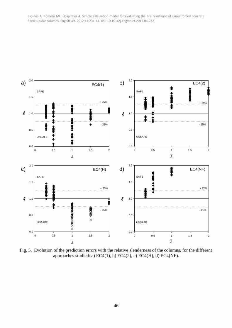
Espinos A, Romero ML, Hospitaler A. Simple calculation model for evaluating the fire resistance of unreinforced concrete
filled tubular columns. Eng Struct. 2012;42:231-44. doi: 10.1016/j.engstruct.2012.04.022
46
0.0
0.5
1.0
1.5
2.0
0 0.5 1 1.5 2
-
UNSAFE
SAFE
+ 25%
- 25%
0.0
0.5
1.0
1.5
2.0
0 0.5 1 1.5 2
-
UNSAFE
SAFE
+ 25%
- 25%
0.0
0.5
1.0
1.5
2.0
0 0.5 1 1.5 2
+ -
UNSAFE
SAFE
+ 25%
- 25%
0.0
0.5
1.0
1.5
2.0
0 0.5 1 1.5 2
-
UNSAFE
SAFE
+ 25%
- 25%
Fig. 5. Evolution of the prediction errors with the relative slenderness of the columns, for the different
approaches studied: a) EC4(1), b) EC4(2), c) EC4(H), d) EC4(NF).
a) b)
c) d)
EC4(1) EC4(2)
EC4(H) EC4(NF)
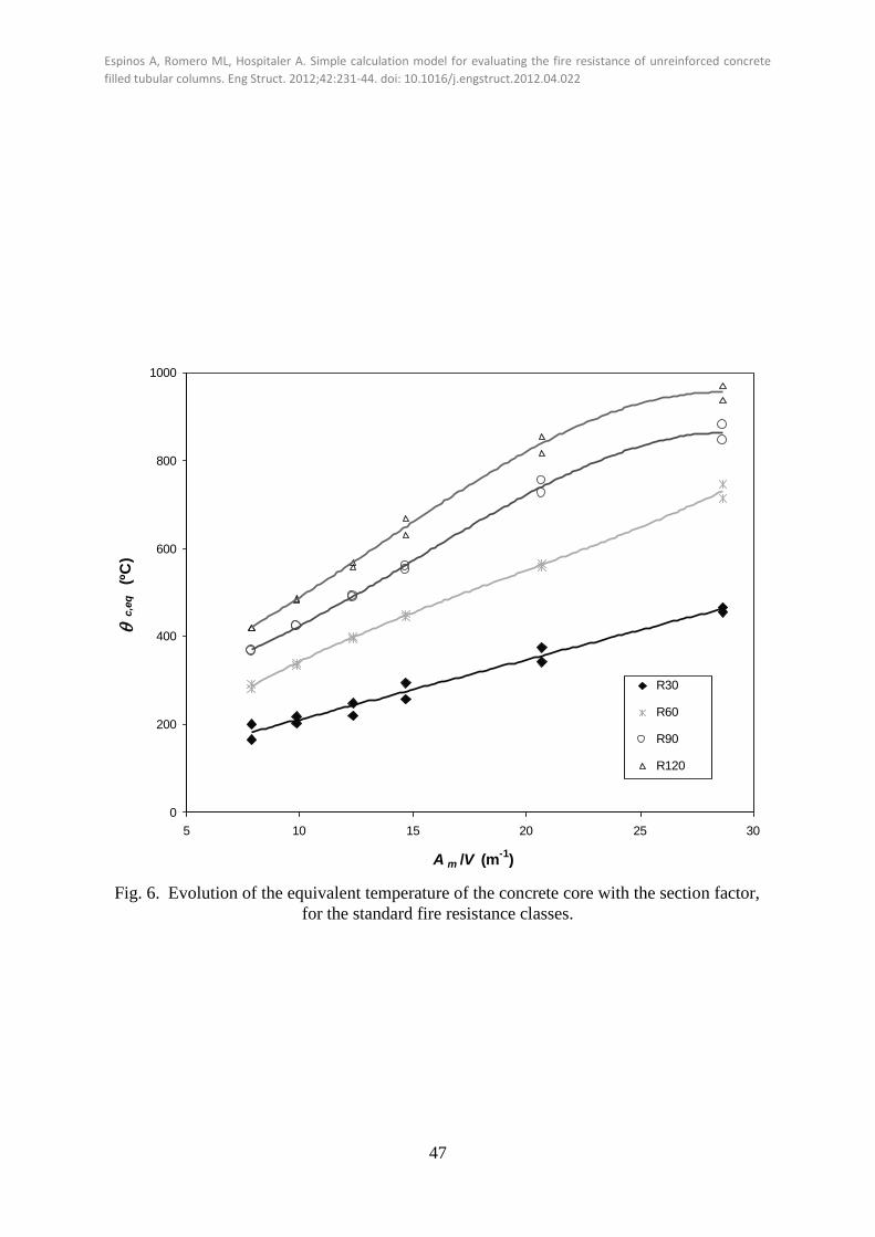
Espinos A, Romero ML, Hospitaler A. Simple calculation model for evaluating the fire resistance of unreinforced concrete
filled tubular columns. Eng Struct. 2012;42:231-44. doi: 10.1016/j.engstruct.2012.04.022
47
0
200
400
600
800
1000
5 10 15 20 25 30
A m /V (m-1
)
c
,eq
(º
C)
R30
R60
R90
R120
Polinómic
a (R30)Polinómic
a (R60)Polinómic
a (R90)Polinómic
a (R120)
-
Fig. 6. Evolution of the equivalent temperature of the concrete core with the section factor,
for the standard fire resistance classes.

Espinos A, Romero ML, Hospitaler A. Simple calculation model for evaluating the fire resistance of unreinforced concrete
filled tubular columns. Eng Struct. 2012;42:231-44. doi: 10.1016/j.engstruct.2012.04.022
48
0.0
0.2
0.4
0.6
0.8
1.0
0.0 0.2 0.4 0.6 0.8 1.0
NUM
P
RE
D
UNSAFE
SAFE
+ 25%
- 25%
0.0
0.5
1.0
1.5
2.0
0 0.5 1 1.5 2
+ -
UNSAFE
SAFE
+ 25%
- 25%
Fig. 7. Comparison between the proposed method and numerical
simulations: a) Normalised buckling load, b) Relative error.
a)
b)

Espinos A, Romero ML, Hospitaler A. Simple calculation model for evaluating the fire resistance of unreinforced concrete
filled tubular columns. Eng Struct. 2012;42:231-44. doi: 10.1016/j.engstruct.2012.04.022
49
0.0
0.1
0.2
0.3
0.4
0.5
0.6
0.7
0.8
0.9
1.0
1.1
0.0 0.5 1.0 1.5 2.0 2.5 3.0 3.5 4.0 4.5 5.0
(
Nfi
,RdN
UM/ N
fi,p
l,R
d)
Buckling curve "a"
Fig. 8. Evolution of the buckling coefficient with the relative slenderness at elevated
temperature, calculated with the proposed method.

Espinos A, Romero ML, Hospitaler A. Simple calculation model for evaluating the fire resistance of unreinforced concrete
filled tubular columns. Eng Struct. 2012;42:231-44. doi: 10.1016/j.engstruct.2012.04.022
50
Fig. 9. Frequency histogram for the prediction error obtained
with the proposed method.
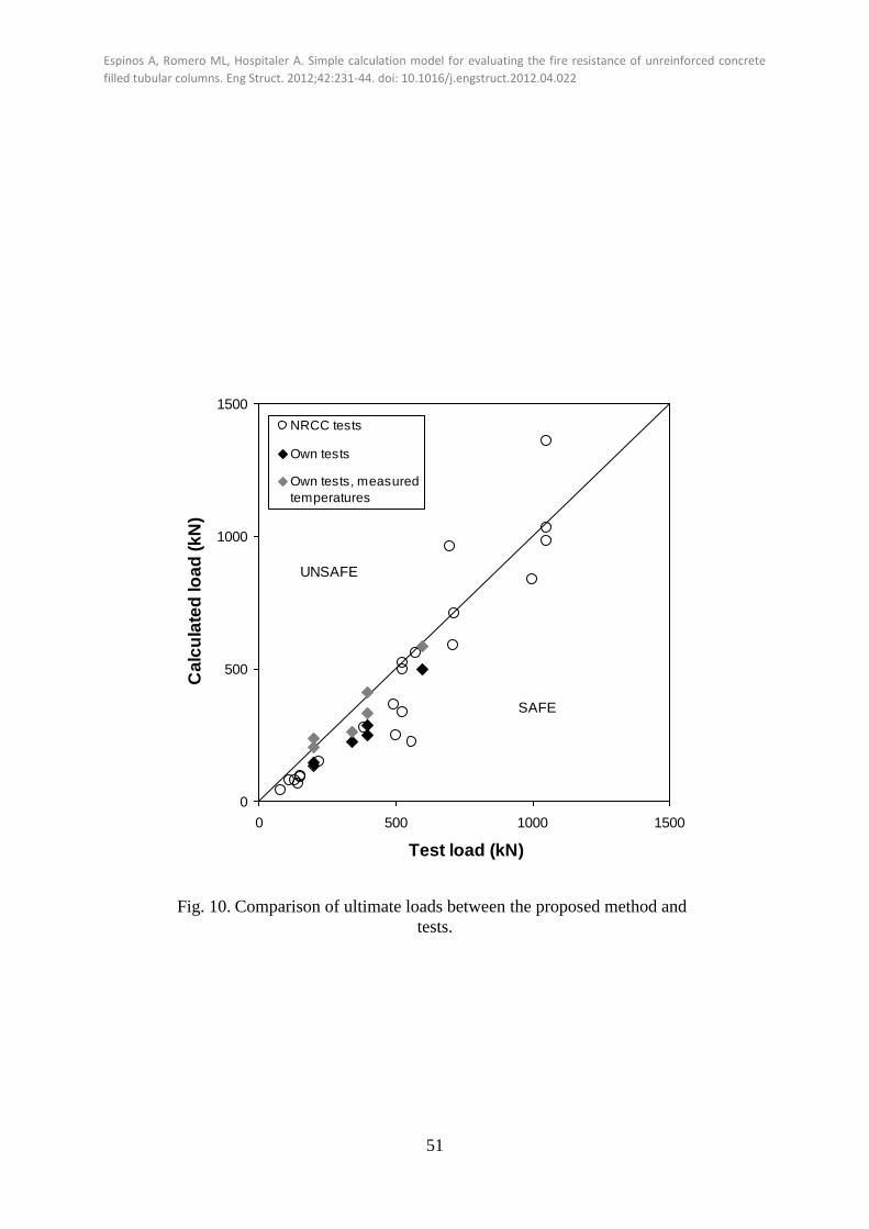
Espinos A, Romero ML, Hospitaler A. Simple calculation model for evaluating the fire resistance of unreinforced concrete
filled tubular columns. Eng Struct. 2012;42:231-44. doi: 10.1016/j.engstruct.2012.04.022
51
0
500
1000
1500
0 500 1000 1500
Test load (kN)
Ca
lcu
late
d lo
ad
(k
N)
NRCC tests
Own tests
Own tests, measured
temperatures
SAFE
UNSAFE
Fig. 10. Comparison of ultimate loads between the proposed method and
tests.
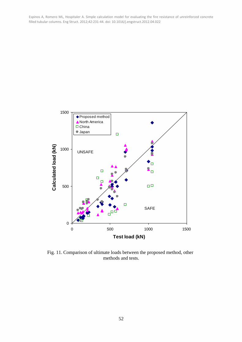
Espinos A, Romero ML, Hospitaler A. Simple calculation model for evaluating the fire resistance of unreinforced concrete
filled tubular columns. Eng Struct. 2012;42:231-44. doi: 10.1016/j.engstruct.2012.04.022
52
0
500
1000
1500
0 500 1000 1500
Test load (kN)
Ca
lcu
late
d lo
ad
(k
N)
Proposed method
North America
China
Japan
SAFE
UNSAFE
Fig. 11. Comparison of ultimate loads between the proposed method, other
methods and tests.
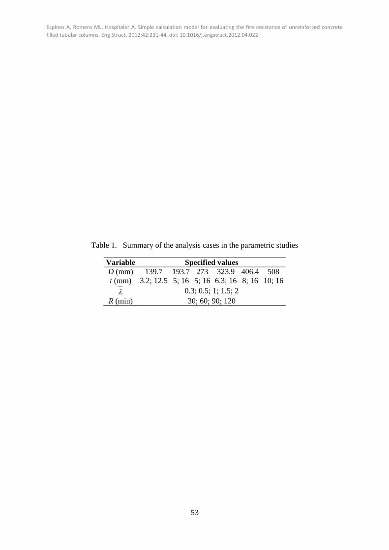
Espinos A, Romero ML, Hospitaler A. Simple calculation model for evaluating the fire resistance of unreinforced concrete
filled tubular columns. Eng Struct. 2012;42:231-44. doi: 10.1016/j.engstruct.2012.04.022
53
Table 1. Summary of the analysis cases in the parametric studies
Variable Specified values
D (mm) 139.7 193.7 273 323.9 406.4 508
t (mm) 3.2; 12.5 5; 16 5; 16 6.3; 16 8; 16 10; 16
0.3; 0.5; 1; 1.5; 2
R (min) 30; 60; 90; 120

Espinos A, Romero ML, Hospitaler A. Simple calculation model for evaluating the fire resistance of unreinforced concrete
filled tubular columns. Eng Struct. 2012;42:231-44. doi: 10.1016/j.engstruct.2012.04.022
54
Table 2. Values of the equivalent temperatures for concrete (c,eq) and steel (a,eq) in function
of the section factor
R30 R60 R90 R120
c,eq (ºC) a,eq (ºC) c,eq (ºC) a,eq (ºC) c,eq (ºC) a,eq (ºC) c,eq (ºC) a,eq (ºC)
Am/V
(m-1)
5 141 636 197 857 316 957 344 1013
10 210 652 342 869 422 964 487 1018
15 278 669 453 880 571 971 659 1024
20 346 686 549 891 721 978 819 1030
25 413 703 647 903 831 985 928 1035
30 480 719 764 914 860 992 947 1041

Espinos A, Romero ML, Hospitaler A. Simple calculation model for evaluating the fire resistance of unreinforced concrete
filled tubular columns. Eng Struct. 2012;42:231-44. doi: 10.1016/j.engstruct.2012.04.022
55
Table 3. Values of the partial reduction coefficient for steel a,to include in the design
equation for stocky columns ( 12/ D )
D/t a,
< 15 0.75
15 – 35 1
35 – 45 1.25
> 45 2.5
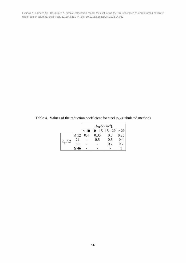
Espinos A, Romero ML, Hospitaler A. Simple calculation model for evaluating the fire resistance of unreinforced concrete
filled tubular columns. Eng Struct. 2012;42:231-44. doi: 10.1016/j.engstruct.2012.04.022
56
Table 4. Values of the reduction coefficient for steel a, (tabulated method)
Am/V (m-1)
< 10 10 - 15 15 - 20 > 20
D/
≤ 12 0.4 0.35 0.3 0.25
24 - 0.5 0.5 0.4
36 - - 0.7 0.7
≥ 46 - - - 1
Espinos A, Romero ML, Hospitaler A. Simple calculation model for evaluating the fire resistance of unreinforced concrete
filled tubular columns. Eng Struct. 2012;42:231-44. doi: 10.1016/j.engstruct.2012.04.022
57
LIST OF FIGURE CAPTIONS
Fig. 1. Finite element mesh of the model for one of the columns analysed.
Fig. 2. Process for obtaining the buckling resistance of the columns at the different
standard fire periods.
Fig. 3. Evolution of the buckling coefficient with the relative slenderness at elevated
temperature (neglecting the flexural stiffness reduction coefficients).
Fig. 4. Comparison between the different approaches studied in terms of the normalised
buckling resistance: a) EC4(1), b) EC4(2), c) EC4(H), d) EC4(NF).
Fig. 5. Evolution of the prediction errors with the relative slenderness of the columns, for
the different approaches studied: a) EC4(1), b) EC4(2), c) EC4(H), d) EC4(NF).
Fig. 6. Evolution of the equivalent temperature of the concrete core with the section factor,
for the standard fire resistance classes.
Fig. 7. Comparison between the proposed method and numerical simulations: a)
Normalised buckling load, b) Relative error.
Fig. 8. Evolution of the buckling coefficient with the relative slenderness at elevated
temperature, calculated with the proposed method.
Fig. 9. Frequency histogram for the prediction error obtained with the proposed method.
Fig. 10. Comparison of ultimate loads between the proposed method and tests.
Fig. 11. Comparison of ultimate loads between the proposed method, other methods and
tests.

Espinos A, Romero ML, Hospitaler A. Simple calculation model for evaluating the fire resistance of unreinforced concrete
filled tubular columns. Eng Struct. 2012;42:231-44. doi: 10.1016/j.engstruct.2012.04.022
58
LIST OF TABLE CAPTIONS
Table 1. Summary of the analysis cases in the parametric studies
Table 2. Values of the equivalent temperatures for concrete (c,eq) and steel (a,eq) in
function of the section factor
Table 3. Values of the partial reduction coefficient for steel a,to include in the design
equation for stocky columns ( 12/ D )
Table 4. Values of the reduction coefficient for steel a, (tabulated method)