simodrive & masterdrives - Transmotor · 02.2004 Edition Synchronous Servomotors 1FT6 SIMODRIVE 611...
228
Planning Guide 02/2004 Edition simodrive & masterdrives SIMODRIVE 611/MASTERDRIVES MC Synchronous Servomotors 1FT6
-
Upload
truongthuy -
Category
Documents
-
view
262 -
download
3
Transcript of simodrive & masterdrives - Transmotor · 02.2004 Edition Synchronous Servomotors 1FT6 SIMODRIVE 611...

Planning Guide 02/2004 Edition
simodrive & masterdrives
SIMODRIVE 611/MASTERDRIVES MC Synchronous Servomotors 1FT6

02.2004 Edition
Synchronous Servomotors1FT6
SIMODRIVE 611MASTERDRIVES MC
Planning Guide
Motor Description 1
Technical Data andCharacteristics 2
Motor Components(Options) 3
Dimension Drawings 4
References A
Index
Designation of the documentation
Printing history
Brief details of this edition and previous editions are listed below.
The status of each edition is shown by the code in the ”Remarks” column.
Status code in the ”Remarks” column:
A New documentation. . . . . B Unrevised reprint with new Order No.. . . . . C Revised edition with new status. . . . .
Edition Order No. for 1FT6 Remarks
02.04 6SN1197–0AD02–0BP0 A
This Manual is part of the documentation on CD–ROM (DOCONCD)Edition Order No. Remarks03.04 6FC5 298–7CA00–0BG0 C
TrademarksSIMATIC, SIMATIC HMI, SIMATIC NET, SIROTEC, SINUMERIK, SIMODRIVE, SIMOVERTMASTERDRIVES and MOTION–CONNECT are registered trademarks of Siemens AG. Other names inthis publication might be trademarks whose use by a third party for his own purposes may violate the rightsof the registered holder.
For further information please visit us at:http://www.ad.siemens.de/mc
This publication was produced with Interleaf V 7
The reproduction, transmission or use of this document or itscontents is not permitted without express written authority. Offenderswill be liable for damages. All rights, including rights created by patentgrant or registration of a utility model or design, are reserved.
Siemens AG 2004. All rights reserved.
The controller may support functions that are not described in thisdocumentation. The customer is not, however, entitled to thesefunctions in the event of the system being replaced or serviced.
We have checked the contents of this document to ensure that theycoincide with the described hardware and software. Since deviationscannot be precluded entirely, we cannot guarantee completeconformance. However, the data in this manual are reviewed regularlyand any necessary changes included in subsequent editions. Wewelcome suggestions for improvement.
We reserve the right to make technical changes.
Siemens–AktiengesellschaftOrder No.6SN1197–0AD02–0BP0Printed in the Federal Republic of Germany
3ls
v Siemens AG 2004 All rights reservedSynchronous Servomotors, 1FT6 (PFT6) – 02.04 Edition
Foreword
Information on the documentation
This document is part of the Technical Customer Documentation which has beendeveloped for SIMODRIVE and SIMOVERT MASTERDRIVES drive convertersystems. All of the documents are available individually. You can obtain the com-plete list of documentation encompassing all Advertising Brochures, Catalogs,Overviews, Short Descriptions, Operating Instructions and Technical Descriptionswith Order No., ordering address and price from your local Siemens office.
For reasons of transparency, this document does not include detailed informationabout all of the product types. Further, it cannot take into account every con-ceivable installation, operation or service/maintenance situation.
We would also like to point–out that the contents of this document are neither partof nor modify any prior or existing agreement, commitment or contractual relation-ship. The sales contract contains the entire obligation of Siemens. The warrantycontained in the contract between the parties is the sole warranty of Siemens. Anystatements contained herein neither create new warranties nor modify the existingwarranty.
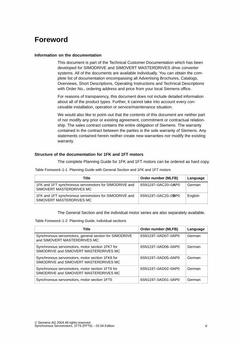
Structure of the documentation for 1FK and 1FT motors
The complete Planning Guide for 1FK and 1FT motors can be ordered as hard copy.
Table Foreword–1-1 Planning Guide with General Section and 1FK and 1FT motors
Title Order number (MLFB) Language
1FK and 1FT synchronous servomotors for SIMODRIVE andSIMOVERT MASTERDRIVES MC
6SN1197–0AC20–0AP0 German
1FK and 1FT synchronous servomotors for SIMODRIVE andSIMOVERT MASTERDRIVES MC
6SN1197–0AC20–0BP0 English
The General Section and the individual motor series are also separately available.
Table Foreword–1-2 Planning Guide, individual sections
Title Order number (MLFB) Language
Synchronous servomotors, general section for SIMODRIVEand SIMOVERT MASTERDRIVES MC
6SN1197–0AD07–0AP0 German
Synchronous servomotors, motor section 1FK7 forSIMODRIVE and SIMOVERT MASTERDRIVES MC
6SN1197–0AD06–0AP0 German
Synchronous servomotors, motor section 1FK6 forSIMODRIVE and SIMOVERT MASTERDRIVES MC
6SN1197–0AD05–0AP0 German
Synchronous servomotors, motor section 1FT6 forSIMODRIVE and SIMOVERT MASTERDRIVES MC
6SN1197–0AD02–0AP0 German
Synchronous servomotors, motor section 1FT5 6SN1197–0AD01–0AP0 German
Foreword
vi Siemens AG 2004 All rights reserved
Synchronous Servomotors, 1FT6 (PFT6) – 02.04 Edition
Hotline
If you have any further questions, please call our Hotline:
A&D Technical Support Tel.: +49 (180) 5050–222Fax: +49 (180) 5050–223eMail: [email protected]
Please send any questions regarding the documentation (suggestions, corrections)by fax to the following number:
+49 (9131) 98–2176
Fax form: Refer to the reply form at the end of this Manual
Engineering software for the SIMOVERT MASTERDRIVES drive units
The PATH Plus engineering software provides and user–friendly engineering soft-ware.
Using this program, SIMOVERT MASTERDRIVES Vector Control and Motion Con-trol frequency drive inverters can be separately and quickly engineered.
PATH plus is a powerful engineering tool that supports the user in all of the engi-neering steps – from the supply to the motor.
Order No. for the full version of PATH Plus: 6SW1710–0JA00–2FC0
Start–up software for SIMODRIVE
Additional start–up software is available to commission three–phase induction mo-tors connected to the SIMODRIVE drive converter system.
Order No. [MLFB] for software 6SN1153–2AX10–AB5Order No. [MLFB] for documentation 6SN1197–0AA30–0B
NCSD Configurator
You simply tell the configurator the requirements placed on your SINUMERIK/SIMODRIVE System and under which conditions you wish to operate the system.The configurator implements these tasks and provides you with the complete con-trol and drive configuration optimized for your particular application. In addition, thetool will recommend which which accessories should be used in order to ensure asafe, reliable connection between the various components.
For more detailed information and how to download the tool, refer to the Siemens Intranet: www.siemens.de/intranet/mc orInternet: www.siemens.de/motioncontrol
Enter in the index, ”NCSD Configurator”!
Foreword
vii Siemens AG 2004 All rights reservedSynchronous Servomotors, 1FT6 (PFT6) – 02.04 Edition
Definition of qualified personnel
For the purpose of this document and product labels, a qualified person is a personwho is familiar with the installation, mounting, start–up and operation of the equip-ment and hazards involved. He or she must have the following qualifications:
Trained and authorized to energize, de–energize, ground and tag circuits andequipment in accordance with established safety procedures.
Trained in the proper care and use of protective equipment in accordance withestablished safety procedures.
Trained in rendering first aid.
Foreword
viii Siemens AG 2004 All rights reserved
Synchronous Servomotors, 1FT6 (PFT6) – 02.04 Edition
Explanation of symbols
The following danger and warning concept is used in this document:
!Danger
This symbol indicates that death, severe personal injury, or substantial propertydamage will result if proper precautions are not taken.
!Warning
This symbol indicates that death, severe personal injury, or substantial propertydamage may result if proper precautions are not taken.
!Caution
This symbol indicates that minor personal injury or property damage may result ifproper precautions are not taken.
Caution
The warning note (without a warning triangle) means that material damage canoccur if proper precautions are not taken.
Notice
This warning note indicates that an undesirable result or an undesirable status canoccur if the appropriate information is not observed.
Note
In the sense of this document there is a possible advantage/benefit if the note textis observed.
Foreword
ix Siemens AG 2004 All rights reservedSynchronous Servomotors, 1FT6 (PFT6) – 02.04 Edition
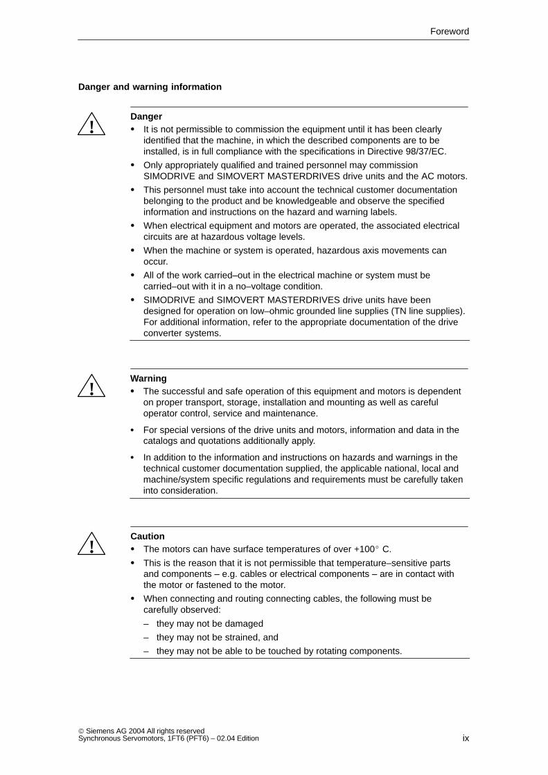
Danger and warning information
!Danger It is not permissible to commission the equipment until it has been clearly
identified that the machine, in which the described components are to beinstalled, is in full compliance with the specifications in Directive 98/37/EC.
Only appropriately qualified and trained personnel may commissionSIMODRIVE and SIMOVERT MASTERDRIVES drive units and the AC motors.
This personnel must take into account the technical customer documentationbelonging to the product and be knowledgeable and observe the specifiedinformation and instructions on the hazard and warning labels.
When electrical equipment and motors are operated, the associated electricalcircuits are at hazardous voltage levels.
When the machine or system is operated, hazardous axis movements canoccur.
All of the work carried–out in the electrical machine or system must becarried–out with it in a no–voltage condition.
SIMODRIVE and SIMOVERT MASTERDRIVES drive units have beendesigned for operation on low–ohmic grounded line supplies (TN line supplies).For additional information, refer to the appropriate documentation of the driveconverter systems.
!Warning The successful and safe operation of this equipment and motors is dependent
on proper transport, storage, installation and mounting as well as carefuloperator control, service and maintenance.
For special versions of the drive units and motors, information and data in thecatalogs and quotations additionally apply.
In addition to the information and instructions on hazards and warnings in thetechnical customer documentation supplied, the applicable national, local andmachine/system specific regulations and requirements must be carefully takeninto consideration.
!Caution The motors can have surface temperatures of over +100 C.
This is the reason that it is not permissible that temperature–sensitive partsand components – e.g. cables or electrical components – are in contact withthe motor or fastened to the motor.
When connecting and routing connecting cables, the following must becarefully observed:
– they may not be damaged
– they may not be strained, and
– they may not be able to be touched by rotating components.
Foreword
x Siemens AG 2004 All rights reserved
Synchronous Servomotors, 1FT6 (PFT6) – 02.04 Edition
Caution Motors should be connected–up according to the circuit diagram supplied. They
must not be connected directly to the three–phase supply because this willdamage them.
SIMODRIVE and SIMOVERT MASTERDRIVES drive units with AC motors aresubject to a voltage test in compliance with EN 50178 as part of the routinetest. According to EN 60204–1, Section 19.4, while electrical equipment ofindustrial machines are being subject to a voltage test, all of the SIMODRIVEand SIMOVERT MASTERDRIVES drive unit connections must bedisconnected/withdrawn in order to avoid damaging the SIMODRIVE andSIMOVERT MASTERDRIVES drive units.
Note
SIMODRIVE and SIMOVERT MASTERDRIVES drive units with AC motorsfulfill, in the operational state and in dry operating areas, the Low–VoltageDirective 73/23/EEC.
SIMODRIVE and SIMOVERT MASTERDRIVES drive units with AC motorsfulfill, in the configurations which are specified in the associated EC Declarationof Conformity, the EMC Directive 89/336/EEC.
Foreword
xi Siemens AG 2004 All rights reservedSynchronous Servomotors, 1FT6 (PFT6) – 02.04 Edition
ESDS information and instructions
!Caution
ElectroStatic Discharge Sensitive devices (ESDS) are individual components,integrated circuits or modules which could be damaged as a result of electrostaticfields or electrostatic discharge.
Handling ESDS boards:
The human body, working area and packaging should be well grounded whenhandling ESDS components!
Electronic components may only be touched by people in ESDS areas withconductive flooring if
– they are grounded through an ESDS wrist strap and
– they are wearing ESDS shoes or ESDS shoe grounding strips.
Electronic boards should only be touched when absolutely necessary.
Electronic boards may not come into contact with synthetic materials andclothing manufactured out of man–made fibers.
Electronic boards may only be placed down on conductive surfaces (table withESDS surface, conductive ESDS foam rubber, ESDS packing bag, ESDStransport containers).
Electronic boards may not be brought close to data terminals, monitors ortelevision sets (minimum clearance to screen > 10 cm).
Measuring work may only be carried out on the electronic boards if
– the measuring device is grounded (e.g. via the protective conductor) or
– for floating measuring equipment, the probe is briefly discharged beforemaking measurements (e.g. a bare control housing is touched).
Foreword
xii Siemens AG 2004 All rights reserved
Synchronous Servomotors, 1FT6 (PFT6) – 02.04 Edition
Space for your notes
1FT6-13 Siemens AG 2004 All rights reservedSynchronous Servomotors, 1FT6 (PFT6) – 02.04 Edition
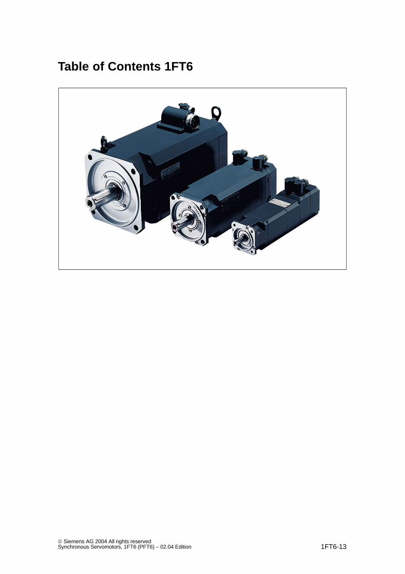
Table of Contents 1FT6
Table of Contents 1FT6
1FT6-14 Siemens AG 2004 All rights reserved
Synchronous Servomotors, 1FT6 (PFT6) – 02.04 Edition
1 Motor Description 1FT6/1-15. . . . . . . . . . . . . . . . . . . . . . . . . . . . . . . . . . . . . . . . . . . . . .
1.1 Applications and features 1FT6/1-15. . . . . . . . . . . . . . . . . . . . . . . . . . . . . . . . .
1.2 Technical design, 1FT6 motor 1FT6/1-16. . . . . . . . . . . . . . . . . . . . . . . . . . . . .
1.3 Technical design, options, supplements 1FT6/1-17. . . . . . . . . . . . . . . . . . . .
1.4 Order designation 1FT6/1-18. . . . . . . . . . . . . . . . . . . . . . . . . . . . . . . . . . . . . . .
1.5 Technical data 1FT6/1-21. . . . . . . . . . . . . . . . . . . . . . . . . . . . . . . . . . . . . . . . . .
1.6 Armature short–circuit braking 1FT6/1-27. . . . . . . . . . . . . . . . . . . . . . . . . . . .
1.7 Cooling 1FT6/1-32. . . . . . . . . . . . . . . . . . . . . . . . . . . . . . . . . . . . . . . . . . . . . . . . 1.7.1 Force ventilation 1FT6/1-32. . . . . . . . . . . . . . . . . . . . . . . . . . . . . . . . . . . . . . . . 1.7.2 Water–cooling 1FT6/1-34. . . . . . . . . . . . . . . . . . . . . . . . . . . . . . . . . . . . . . . . . .
1.8 Electrical connections 1FT6/1-39. . . . . . . . . . . . . . . . . . . . . . . . . . . . . . . . . . . . 1.8.1 Connector assignment 1FT6/1-39. . . . . . . . . . . . . . . . . . . . . . . . . . . . . . . . . . . 1.8.2 Connection, terminal box 1FT6/1-40. . . . . . . . . . . . . . . . . . . . . . . . . . . . . . . . .
1.9 Drive–out coupling 1FT6/1-42. . . . . . . . . . . . . . . . . . . . . . . . . . . . . . . . . . . . . . .
2 Technical Data and Characteristics 1FT6/2-45. . . . . . . . . . . . . . . . . . . . . . . . . . . . . .
2.1 Speed–torque diagrams 1FT6/2-45. . . . . . . . . . . . . . . . . . . . . . . . . . . . . . . . . . 2.1.1 1FT6 series, non–ventilated 1FT6/2-46. . . . . . . . . . . . . . . . . . . . . . . . . . . . . . 2.1.2 1FT6 series, force ventilated 1FT6/2-106. . . . . . . . . . . . . . . . . . . . . . . . . . . . . . 2.1.3 1FT6 series, water cooled 1FT6/2-138. . . . . . . . . . . . . . . . . . . . . . . . . . . . . . . .
2.2 Cantilever force diagrams 1FT6/2-172. . . . . . . . . . . . . . . . . . . . . . . . . . . . . . . .
2.3 Axial forces 1FT6/2-177. . . . . . . . . . . . . . . . . . . . . . . . . . . . . . . . . . . . . . . . . . . . .
3 Motor Components (Options) 1FT6/3-179. . . . . . . . . . . . . . . . . . . . . . . . . . . . . . . . . . .
3.1 Thermal motor protection 1FT6/3-179. . . . . . . . . . . . . . . . . . . . . . . . . . . . . . . . .
3.2 Encoder 1FT6/3-181. . . . . . . . . . . . . . . . . . . . . . . . . . . . . . . . . . . . . . . . . . . . . . . . 3.2.1 Incremental encoders 1FT6/3-182. . . . . . . . . . . . . . . . . . . . . . . . . . . . . . . . . . . . 3.2.2 Absolute value encoder 1FT6/3-184. . . . . . . . . . . . . . . . . . . . . . . . . . . . . . . . . . 3.2.3 Resolver 1FT6/3-186. . . . . . . . . . . . . . . . . . . . . . . . . . . . . . . . . . . . . . . . . . . . . . .
3.3 Holding brake 1FT6/3-188. . . . . . . . . . . . . . . . . . . . . . . . . . . . . . . . . . . . . . . . . . .
3.4 Gearbox 1FT6/3-189. . . . . . . . . . . . . . . . . . . . . . . . . . . . . . . . . . . . . . . . . . . . . . . 3.4.1 Planetary gearbox, 1–stage 1FT6/3-189. . . . . . . . . . . . . . . . . . . . . . . . . . . . . . . 3.4.2 Planetary gearbox, 2–stage 1FT6/3-191. . . . . . . . . . . . . . . . . . . . . . . . . . . . . . .
4 Dimension Drawings 1FT6/4-195. . . . . . . . . . . . . . . . . . . . . . . . . . . . . . . . . . . . . . . . . . . .
4.1 Non–ventilated 1FT6 motors 1FT6/4-196. . . . . . . . . . . . . . . . . . . . . . . . . . . . . .
4.2 Force–ventilated 1FT6 motors 1FT6/4-205. . . . . . . . . . . . . . . . . . . . . . . . . . . .
4.3 Water–cooled 1FT6 motors 1FT6/4-211. . . . . . . . . . . . . . . . . . . . . . . . . . . . . . .
4.4 Cooling water connections for shaft height 60 to 100 1FT6/4-218. . . . . . . . .
A References 1FT6/A-219. . . . . . . . . . . . . . . . . . . . . . . . . . . . . . . . . . . . . . . . . . . . . . . . . . . . .
Index Index–223. . . . . . . . . . . . . . . . . . . . . . . . . . . . . . . . . . . . . . . . . . . . . . . . . . . . . . . . . .
1FT6/1-15 Siemens AG 2004 All rights reservedSynchronous Servomotors, 1FT6 (PFT6) – 02.04 Edition
Motor Description
1.1 Applications and features
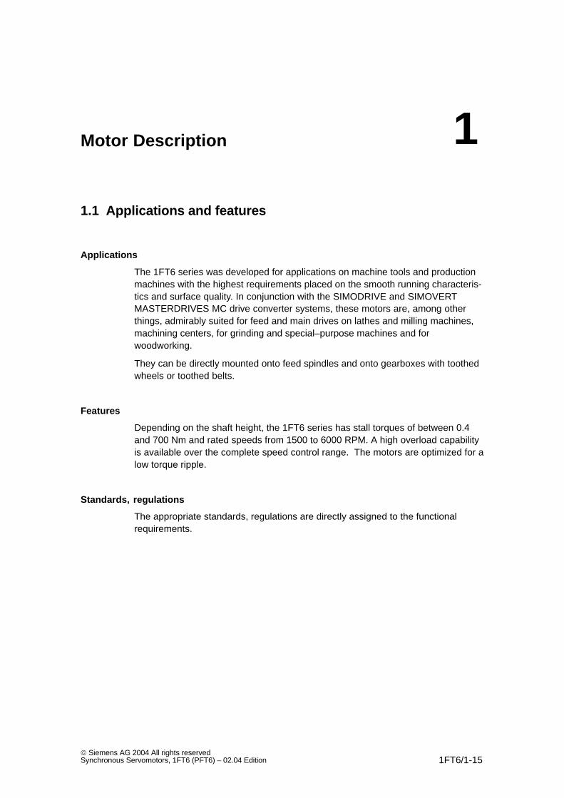
Applications
The 1FT6 series was developed for applications on machine tools and productionmachines with the highest requirements placed on the smooth running characteris-tics and surface quality. In conjunction with the SIMODRIVE and SIMOVERTMASTERDRIVES MC drive converter systems, these motors are, among otherthings, admirably suited for feed and main drives on lathes and milling machines,machining centers, for grinding and special–purpose machines and forwoodworking.
They can be directly mounted onto feed spindles and onto gearboxes with toothedwheels or toothed belts.
Features
Depending on the shaft height, the 1FT6 series has stall torques of between 0.4and 700 Nm and rated speeds from 1500 to 6000 RPM. A high overload capabilityis available over the complete speed control range. The motors are optimized for alow torque ripple.
Standards, regulations
The appropriate standards, regulations are directly assigned to the functionalrequirements.
1
Motor Description
1.2 Technical design, 1FT6 motor
1FT6/1-16 Siemens AG 2004 All rights reserved
Synchronous Servomotors, 1FT6 (PFT6) – 02.04 Edition
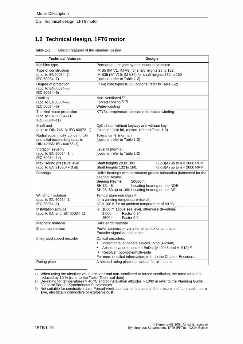
1.2 Technical design, 1FT6 motor
Table 1-1 Design features of the standard design
Technical features Design
Machine type Permanent–magnet synchronous servomotor
Type of construction (acc. to EN60034–7; IEC 60034–7)
IM B5 (IM V1, IM V3) for shaft heights 28 to 132IM B35 (IM V15, IM V36) for shaft heights 132 to 160(options, refer to Table 1-2)
Degree of protection (acc. to EN60034–5; IEC 60034–5)
IP 64; core types IP 65 (options, refer to Table 1-2)
Cooling (acc. to EN60034–6; IEC 60034–6)
Non–ventilated 2)
Forced cooling 2) 3)
Water–cooling
Thermal motor protection(acc. to EN 60034–11; IEC 60034–11)
KTY84 temperature sensor in the stator winding
Shaft end(acc. to DIN 748–3; IEC 60072–1)
Cylindrical; without keyway and without key; tolerance field k6, (option, refer to Table 1-2)
Radial eccentricity, concentricityand axial eccentricity (acc. to DIN 42955; IEC 60072–1)
Tolerance N (normal)(options, refer to Table 1-2)
Vibration severity(acc. to EN 60034–14; IEC 60034–14)
Level N (normal)(options, refer to Table 1-2)
Max. sound pressure level(acc. to EN 21680) + 3 dB
Shaft heights 28 to 100: 72 dB(A) up to n = 2000 RPMShaft heights 132 to 160: 73 dB(A) up to n = 2000 RPM
Bearings Roller bearings with permanent grease lubrication (lubricated for thebearing lifetime)Bearing lifetime: 20000 hSH 36, 48: Locating bearing on the NDESH 28, 63 up to 160: Locating bearing on the DE
Winding insulation(acc. to EN 60034–1; IEC 60034–1)
Temperature rise class Ffor a winding temperature rise of ∆T = 100 K for an ambient temperature of 40 °C.
Installation altitude(acc. to EN and IEC 60034–1)
1000 m above sea level, otherwise de–rating2)
2,000 m Factor 0.942500 m Factor 0.9
Magnetic material Rare earth material
Electr. connection Power connection via a terminal box or connectorEncoder signal via connector
Integrated speed encoder Optical encoders: Incremental encoders sin/cos 1Vpp (I–2048) Absolute value encoders EnDat (A–2048 and A–512) 1)
Resolver, two–pole/multi–poleFor more detailed information, refer to the Chapter Encoders.
Rating plate A second rating plate is provided for all motors
1) When using the absolute value encoder and non–ventilated or forced ventilation, the rated torque isreduced by 10 % (refer to the Table, Technical data)
2) De–rating for temperatures > 40 °C and/or installation altitudes > 1000 m refer to the Planning Guide”General Part for Synchronous Servomotors”
3) Not suitable for conductive dust. Forced ventilation cannot be used in the presence of flammable, corro-sive, electrically conductive or explosive dust.
Motor Description
1.3 Technical design, options, supplements
1FT6/1-17 Siemens AG 2004 All rights reservedSynchronous Servomotors, 1FT6 (PFT6) – 02.04 Edition
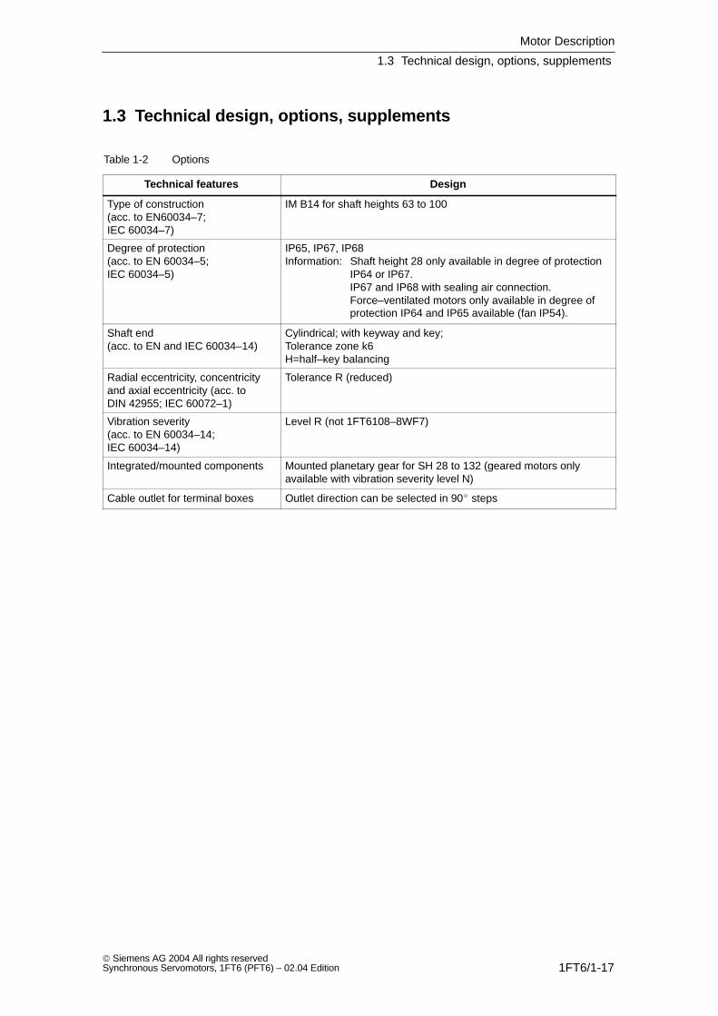
1.3 Technical design, options, supplements
Table 1-2 Options
Technical features Design
Type of construction (acc. to EN60034–7; IEC 60034–7)
IM B14 for shaft heights 63 to 100
Degree of protection (acc. to EN 60034–5; IEC 60034–5)
IP65, IP67, IP68Information: Shaft height 28 only available in degree of protection
IP64 or IP67.IP67 and IP68 with sealing air connection.Force–ventilated motors only available in degree ofprotection IP64 and IP65 available (fan IP54).
Shaft end(acc. to EN and IEC 60034–14)
Cylindrical; with keyway and key;Tolerance zone k6H=half–key balancing
Radial eccentricity, concentricityand axial eccentricity (acc. to DIN 42955; IEC 60072–1)
Tolerance R (reduced)
Vibration severity(acc. to EN 60034–14; IEC 60034–14)
Level R (not 1FT6108–8WF7)
Integrated/mounted components Mounted planetary gear for SH 28 to 132 (geared motors onlyavailable with vibration severity level N)
Cable outlet for terminal boxes Outlet direction can be selected in 90 steps
Motor Description
1.4 Order designation
1FT6/1-18 Siemens AG 2004 All rights reserved
Synchronous Servomotors, 1FT6 (PFT6) – 02.04 Edition
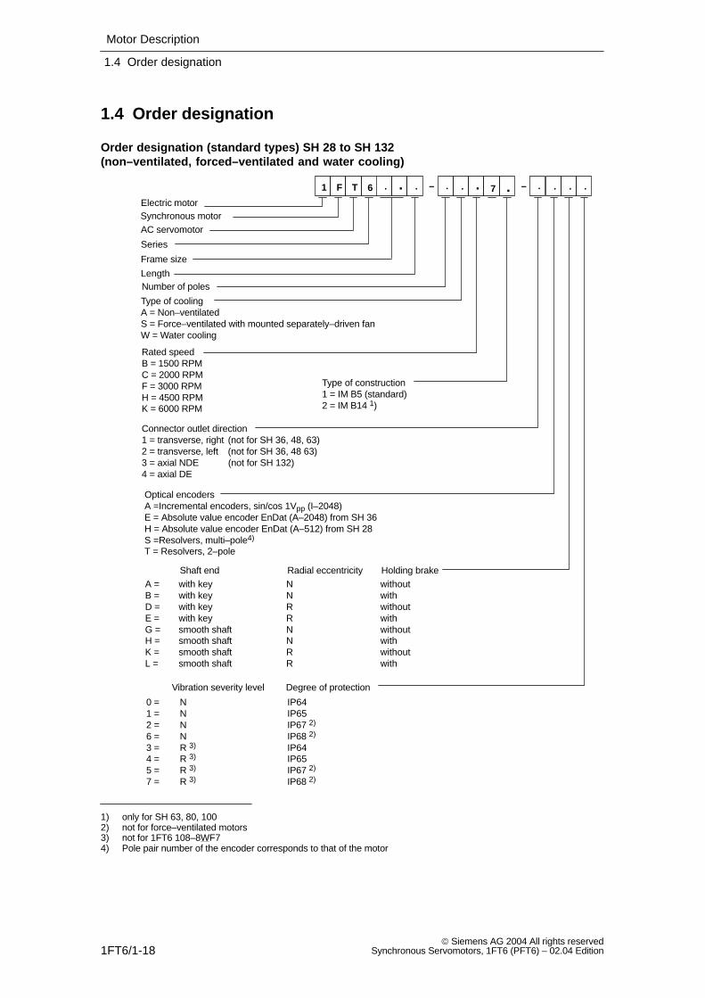
1.4 Order designation
Order designation (standard types) SH 28 to SH 132 (non–ventilated, forced–ventilated and water cooling)
. .. – .. .
Electric motorSynchronous motorAC servomotor
Series
Frame size
LengthNumber of poles
Type of coolingA = Non–ventilatedS = Force–ventilated with mounted separately–driven fanW = Water cooling
Rated speedB = 1500 RPMC = 2000 RPMF = 3000 RPMH = 4500 RPMK = 6000 RPM
Type of construction1 = IM B5 (standard)2 = IM B14 1)
Connector outlet direction1 = transverse, right (not for SH 36, 48, 63)2 = transverse, left (not for SH 36, 48 63)3 = axial NDE (not for SH 132)4 = axial DE
–F T 6 . . 7 . ..
Shaft end Radial eccentricity Holding brakeA = with key N withoutB = with key N withD = with key R withoutE = with key R withG = smooth shaft N withoutH = smooth shaft N withK = smooth shaft R withoutL = smooth shaft R with
Vibration severity level Degree of protection
0 = N IP641 = N IP652 = N IP67 2)
6 = N IP68 2)
3 = R 3) IP644 = R 3) IP655 = R 3) IP67 2)
7 = R 3) IP68 2)
Optical encodersA =Incremental encoders, sin/cos 1Vpp (I–2048)E = Absolute value encoder EnDat (A–2048) from SH 36H = Absolute value encoder EnDat (A–512) from SH 28S =Resolvers, multi–pole4)
T = Resolvers, 2–pole
1
1) only for SH 63, 80, 1002) not for force–ventilated motors3) not for 1FT6 108–8WF74) Pole pair number of the encoder corresponds to that of the motor
Motor Description
1.4 Order designation
1FT6/1-19 Siemens AG 2004 All rights reservedSynchronous Servomotors, 1FT6 (PFT6) – 02.04 Edition
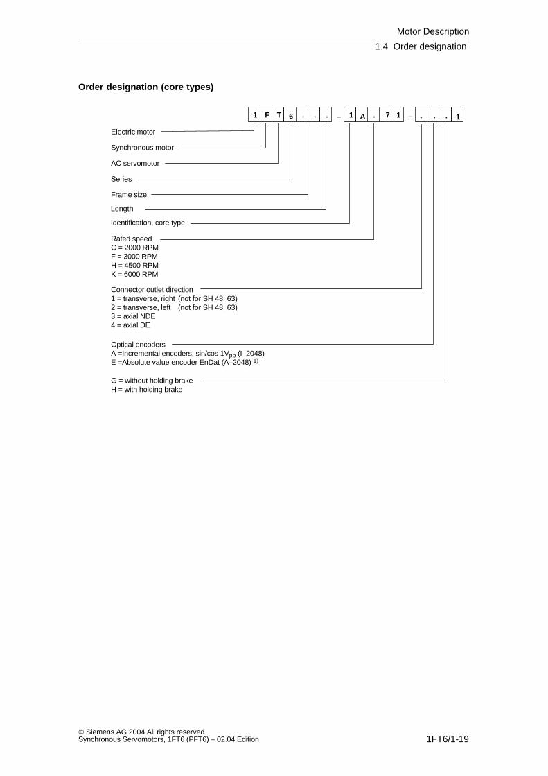
Order designation (core types)
– . .. 7 1 . 11
Electric motor
Synchronous motor
AC servomotor
Series
Frame size
Length
Identification, core type
Rated speedC = 2000 RPMF = 3000 RPMH = 4500 RPMK = 6000 RPM
Connector outlet direction1 = transverse, right (not for SH 48, 63)2 = transverse, left (not for SH 48, 63)3 = axial NDE4 = axial DE
G = without holding brakeH = with holding brake
–1 F T 6 . . A .
Optical encodersA =Incremental encoders, sin/cos 1Vpp (I–2048)E =Absolute value encoder EnDat (A–2048) 1)
Motor Description
1.4 Order designation
1FT6/1-20 Siemens AG 2004 All rights reserved
Synchronous Servomotors, 1FT6 (PFT6) – 02.04 Edition
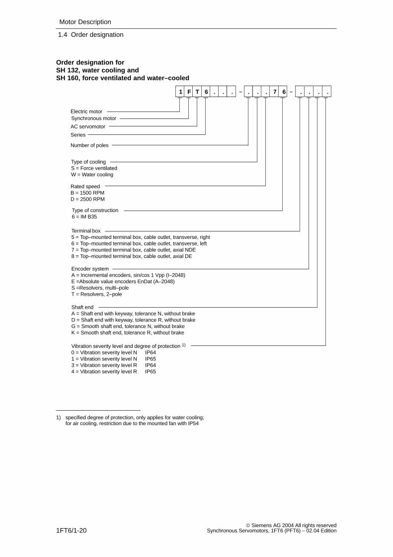
Order designation for SH 132, water cooling andSH 160, force ventilated and water–cooled
Terminal box5 = Top–mounted terminal box, cable outlet, transverse, right6 = Top–mounted terminal box, cable outlet, transverse, left7 = Top–mounted terminal box, cable outlet, axial NDE8 = Top–mounted terminal box, cable outlet, axial DE
––
Electric motorSynchronous motor
AC servomotor
Series
Type of coolingS = Force ventilatedW = Water cooling
Rated speedB = 1500 RPMD = 2500 RPM
Type of construction6 = IM B35
1 F T 6 . .. . 7. 6 . . . ..
Encoder systemA = Incremental encoders, sin/cos 1 Vpp (I–2048)E =Absolute value encoders EnDat (A–2048)S =Resolvers, multi–poleT = Resolvers, 2–pole
Shaft endA = Shaft end with keyway, tolerance N, without brakeD = Shaft end with keyway, tolerance R, without brakeG = Smooth shaft end, tolerance N, without brakeK = Smooth shaft end, tolerance R, without brake
Vibration severity level and degree of protection 1)
0 = Vibration severity level N1 = Vibration severity level N3 = Vibration severity level R4 = Vibration severity level R
IP64IP65IP64IP65
Number of poles
1) specified degree of protection, only applies for water cooling;for air cooling, restriction due to the mounted fan with IP54
Motor Description
1.5 Technical data
1FT6/1-21 Siemens AG 2004 All rights reservedSynchronous Servomotors, 1FT6 (PFT6) – 02.04 Edition
1.5 Technical data
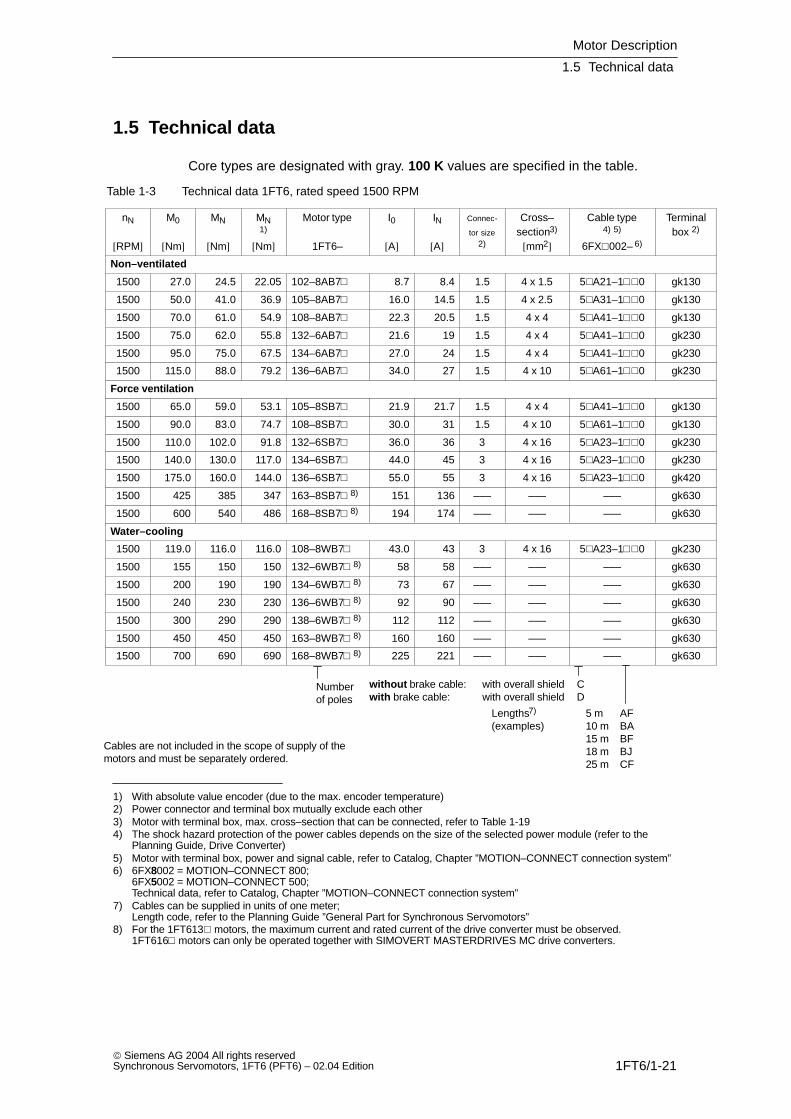
Core types are designated with gray. 100 K values are specified in the table.
Table 1-3 Technical data 1FT6, rated speed 1500 RPM
nN
[RPM]
M0
[Nm]
MN
[Nm]
MN1)
[Nm]
Motor type
1FT6–
I0
[A]
IN
[A]
Connec-
tor size2)
Cross–section3)
[mm2]
Cable type4) 5)
6FX002– 6)
Terminalbox 2)
Non–ventilated
1500 27.0 24.5 22.05 102–8AB7 8.7 8.4 1.5 4 x 1.5 5A21–10 gk130
1500 50.0 41.0 36.9 105–8AB7 16.0 14.5 1.5 4 x 2.5 5A31–10 gk130
1500 70.0 61.0 54.9 108–8AB7 22.3 20.5 1.5 4 x 4 5A41–10 gk130
1500 75.0 62.0 55.8 132–6AB7 21.6 19 1.5 4 x 4 5A41–10 gk230
1500 95.0 75.0 67.5 134–6AB7 27.0 24 1.5 4 x 4 5A41–10 gk230
1500 115.0 88.0 79.2 136–6AB7 34.0 27 1.5 4 x 10 5A61–10 gk230
Force ventilation
1500 65.0 59.0 53.1 105–8SB7 21.9 21.7 1.5 4 x 4 5A41–10 gk130
1500 90.0 83.0 74.7 108–8SB7 30.0 31 1.5 4 x 10 5A61–10 gk130
1500 110.0 102.0 91.8 132–6SB7 36.0 36 3 4 x 16 5A23–10 gk230
1500 140.0 130.0 117.0 134–6SB7 44.0 45 3 4 x 16 5A23–10 gk230
1500 175.0 160.0 144.0 136–6SB7 55.0 55 3 4 x 16 5A23–10 gk420
1500 425 385 347 163–8SB7 8) 151 136 ––– ––– ––– gk630
1500 600 540 486 168–8SB7 8) 194 174 ––– ––– ––– gk630
Water–cooling
1500 119.0 116.0 116.0 108–8WB7 43.0 43 3 4 x 16 5A23–10 gk230
1500 155 150 150 132–6WB7 8) 58 58 ––– ––– ––– gk630
1500 200 190 190 134–6WB7 8) 73 67 ––– ––– ––– gk630
1500 240 230 230 136–6WB7 8) 92 90 ––– ––– ––– gk630
1500 300 290 290 138–6WB7 8) 112 112 ––– ––– ––– gk630
1500 450 450 450 163–8WB7 8) 160 160 ––– ––– ––– gk630
1500 700 690 690 168–8WB7 8) 225 221 ––– ––– ––– gk630
Numberof poles
without brake cable: with overall shield Cwith brake cable: with overall shield D
Lengths7) 5 m AF(examples) 10 m BA
15 m BF18 m BJ25 m CF
Cables are not included in the scope of supply of themotors and must be separately ordered.
1) With absolute value encoder (due to the max. encoder temperature)2) Power connector and terminal box mutually exclude each other3) Motor with terminal box, max. cross–section that can be connected, refer to Table 1-194) The shock hazard protection of the power cables depends on the size of the selected power module (refer to the
Planning Guide, Drive Converter)5) Motor with terminal box, power and signal cable, refer to Catalog, Chapter ”MOTION–CONNECT connection system”6) 6FX8002 = MOTION–CONNECT 800;
6FX5002 = MOTION–CONNECT 500; Technical data, refer to Catalog, Chapter ”MOTION–CONNECT connection system”
7) Cables can be supplied in units of one meter; Length code, refer to the Planning Guide ”General Part for Synchronous Servomotors”
8) For the 1FT613 motors, the maximum current and rated current of the drive converter must be observed. 1FT616 motors can only be operated together with SIMOVERT MASTERDRIVES MC drive converters.
Motor Description
1.5 Technical data
1FT6/1-22 Siemens AG 2004 All rights reserved
Synchronous Servomotors, 1FT6 (PFT6) – 02.04 Edition
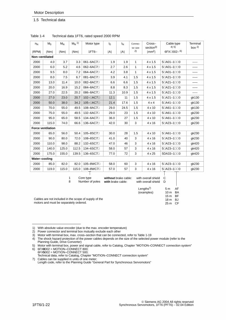
Table 1-4 Technical data 1FT6, rated speed 2000 RPM
nN
[RPM]
M0
[Nm]
MN
[Nm]
MN 1)
[Nm]
Motor type
1FT6–
I0
[A]
IN
[A]
Connec-
tor size2)
Cross–section3)
[mm2]
Cable type4) 5)
6FX002– 6)
Terminalbox 2)
Non–ventilated
2000 4.0 3.7 3.3 061–6AC7 1.9 1.9 1 4 x 1.5 5A01–10 –––
2000 6.0 5.2 4.6 062–6AC7 2.7 2.6 1 4 x 1.5 5A01–10 –––
2000 9.5 8.0 7.2 064–6AC7 4.2 3.8 1 4 x 1.5 5A01–10 –––
2000 8.0 7.5 6.7 081–8AC7 3.9 4.1 1.5 4 x 1.5 5A21–10 –––
2000 13.0 11.4 10.0 082–8AC7 6.6 6.6 1.5 4 x 1.5 5A21–10 –––
2000 20.0 16.9 15.2 084–8AC7 8.8 8.3 1.5 4 x 1.5 5A21–10 –––
2000 27.0 22.5 20.2 086–8AC7 11.3 10.9 1.5 4 x 1.5 5A21–10 –––
2000 27.0 23.0 20.7 102–AC7 12.1 11 1.5 4 x 1.5 5A21–10 gk130
2000 50.0 38.0 34.2 105–AC7 21.4 17.6 1.5 4 x 4 5A41–10 gk130
2000 70.0 55.0 49.5 108–8AC7 29.0 24.5 1.5 4 x 10 5A61–10 gk130
2000 75.0 55.0 49.5 132–6AC7 29.0 23 1.5 4 x 10 5A61–10 gk230
2000 95.0 65.0 58.5 134–6AC7 36.0 27 1.5 4 x 10 5A61–10 gk230
2000 115.0 74.0 66.6 136–6AC7 42.0 30 3 4 x 16 5A23–10 gk230
Force ventilation
2000 65.0 56.0 50.4 105–8SC7 30.0 28 1.5 4 x 10 5A61–10 gk230
2000 90.0 80.0 72.0 108–8SC7 41.0 40 3 4 x 16 5A23–10 gk230
2000 110.0 98.0 88.2 132–6SC7 47.0 46 3 4 x 16 5A23–10 gk420
2000 140.0 125.0 112.5 134–6SC7 58.0 57 3 4 x 16 5A23–10 gk420
2000 175.0 155.0 139.5 136–6SC7 77.0 72 3 4 x 25 5DA33–10 gk420
Water–cooling
2000 85.0 82.0 82.0 105–8WC7 58.0 60 3 4 x 16 5A23–10 gk230
2000 119.0 115.0 115.0 108–8WC7 57.0 57 3 4 x 16 5A23–10 gk230
1 Core type8 Number of poles
without brake cable: with overall shield Cwith brake cable: with overall shield D
Lengths7) 5 m AF(examples) 10 m BA
15 m BF18 m BJ25 m CF
Cables are not included in the scope of supply of themotors and must be separately ordered.
1) With absolute value encoder (due to the max. encoder temperature)2) Power connector and terminal box mutually exclude each other3) Motor with terminal box, max. cross–section that can be connected, refer to Table 1-194) The shock hazard protection of the power cables depends on the size of the selected power module (refer to the
Planning Guide, Drive Converter)5) Motor with terminal box, power and signal cable, refer to Catalog, Chapter ”MOTION–CONNECT connection system”6) 6FX8002 = MOTION–CONNECT 800;
6FX5002 = MOTION–CONNECT 500; Technical data, refer to Catalog, Chapter ”MOTION–CONNECT connection system”
7) Cables can be supplied in units of one meter; Length code, refer to the Planning Guide ”General Part for Synchronous Servomotors”
Motor Description
1.5 Technical data
1FT6/1-23 Siemens AG 2004 All rights reservedSynchronous Servomotors, 1FT6 (PFT6) – 02.04 Edition
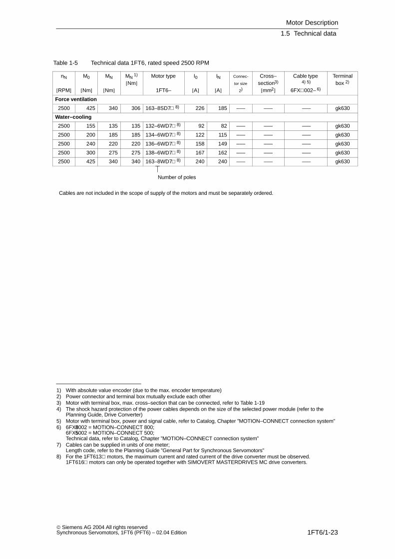
Table 1-5 Technical data 1FT6, rated speed 2500 RPM
nN
[RPM]
M0
[Nm]
MN
[Nm]
MN 1)
[Nm]Motor type
1FT6–
I0
[A]
IN
[A]
Connec-
tor size
2)
Cross–section3)
[mm2]
Cable type 4) 5)
6FX002– 6)
Terminalbox 2)
Force ventilation
2500 425 340 306 163–8SD7 8) 226 185 ––– ––– ––– gk630
Water–cooling
2500 155 135 135 132–6WD7 8) 92 82 ––– ––– ––– gk630
2500 200 185 185 134–6WD7 8) 122 115 ––– ––– ––– gk630
2500 240 220 220 136–6WD7 8) 158 149 ––– ––– ––– gk630
2500 300 275 275 138–6WD7 8) 167 162 ––– ––– ––– gk630
2500 425 340 340 163–8WD7 8) 240 240 ––– ––– ––– gk630
Number of poles
Cables are not included in the scope of supply of the motors and must be separately ordered.
1) With absolute value encoder (due to the max. encoder temperature)2) Power connector and terminal box mutually exclude each other3) Motor with terminal box, max. cross–section that can be connected, refer to Table 1-194) The shock hazard protection of the power cables depends on the size of the selected power module (refer to the
Planning Guide, Drive Converter)5) Motor with terminal box, power and signal cable, refer to Catalog, Chapter ”MOTION–CONNECT connection system”6) 6FX8002 = MOTION–CONNECT 800;
6FX5002 = MOTION–CONNECT 500; Technical data, refer to Catalog, Chapter ”MOTION–CONNECT connection system”
7) Cables can be supplied in units of one meter; Length code, refer to the Planning Guide ”General Part for Synchronous Servomotors”
8) For the 1FT613 motors, the maximum current and rated current of the drive converter must be observed. 1FT616 motors can only be operated together with SIMOVERT MASTERDRIVES MC drive converters.
Motor Description
1.5 Technical data
1FT6/1-24 Siemens AG 2004 All rights reserved
Synchronous Servomotors, 1FT6 (PFT6) – 02.04 Edition
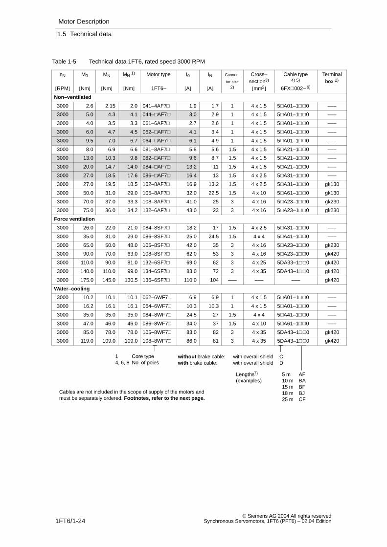
Table 1-5 Technical data 1FT6, rated speed 3000 RPM
nN
[RPM]
M0
[Nm]
MN
[Nm]
MN 1)
[Nm]
Motor type
1FT6–
I0
[A]
IN
[A]
Connec-
tor size2)
Cross–section3)
[mm2]
Cable type4) 5)
6FX002– 6)
Terminalbox 2)
Non–ventilated
3000 2.6 2.15 2.0 041–4AF7 1.9 1.7 1 4 x 1.5 5A01–10 –––
3000 5.0 4.3 4.1 044–AF7 3.0 2.9 1 4 x 1.5 5A01–10 –––
3000 4.0 3.5 3.3 061–6AF7 2.7 2.6 1 4 x 1.5 5A01–10 –––
3000 6.0 4.7 4.5 062–AF7 4.1 3.4 1 4 x 1.5 5A01–10 –––
3000 9.5 7.0 6.7 064–AF7 6.1 4.9 1 4 x 1.5 5A01–10 –––
3000 8.0 6.9 6.6 081–8AF7 5.8 5.6 1.5 4 x 1.5 5A21–10 –––
3000 13.0 10.3 9.8 082–AF7 9.6 8.7 1.5 4 x 1.5 5A21–10 –––
3000 20.0 14.7 14.0 084–AF7 13.2 11 1.5 4 x 1.5 5A21–10 –––
3000 27.0 18.5 17.6 086–AF7 16.4 13 1.5 4 x 2.5 5A31–10 –––
3000 27.0 19.5 18.5 102–8AF7 16.9 13.2 1.5 4 x 2.5 5A31–10 gk130
3000 50.0 31.0 29.0 105–8AF7 32.0 22.5 1.5 4 x 10 5A61–10 gk130
3000 70.0 37.0 33.3 108–8AF7 41.0 25 3 4 x 16 5A23–10 gk230
3000 75.0 36.0 34.2 132–6AF7 43.0 23 3 4 x 16 5A23–10 gk230
Force ventilation
3000 26.0 22.0 21.0 084–8SF7 18.2 17 1.5 4 x 2.5 5A31–10 –––
3000 35.0 31.0 29.0 086–8SF7 25.0 24.5 1.5 4 x 4 5A41–10 –––
3000 65.0 50.0 48.0 105–8SF7 42.0 35 3 4 x 16 5A23–10 gk230
3000 90.0 70.0 63.0 108–8SF7 62.0 53 3 4 x 16 5A23–10 gk420
3000 110.0 90.0 81.0 132–6SF7 69.0 62 3 4 x 25 5DA33–10 gk420
3000 140.0 110.0 99.0 134–6SF7 83.0 72 3 4 x 35 5DA43–10 gk420
3000 175.0 145.0 130.5 136–6SF7 110.0 104 ––– ––– ––– gk420
Water–cooling
3000 10.2 10.1 10.1 062–6WF7 6.9 6.9 1 4 x 1.5 5A01–10 –––
3000 16.2 16.1 16.1 064–6WF7 10.3 10.3 1 4 x 1.5 5A01–10 –––
3000 35.0 35.0 35.0 084–8WF7 24.5 27 1.5 4 x 4 5A41–10 –––
3000 47.0 46.0 46.0 086–8WF7 34.0 37 1.5 4 x 10 5A61–10 –––
3000 85.0 78.0 78.0 105–8WF7 83.0 82 3 4 x 35 5DA43–10 gk420
3000 119.0 109.0 109.0 108–8WF7 86.0 81 3 4 x 35 5DA43–10 gk420
1 Core type4, 6, 8 No. of poles
without brake cable: with overall shield Cwith brake cable: with overall shield D
Lengths7) 5 m AF(examples) 10 m BA
15 m BF18 m BJ25 m CF
Cables are not included in the scope of supply of the motors andmust be separately ordered. Footnotes, refer to the next page.
Motor Description
1.5 Technical data
1FT6/1-25 Siemens AG 2004 All rights reservedSynchronous Servomotors, 1FT6 (PFT6) – 02.04 Edition
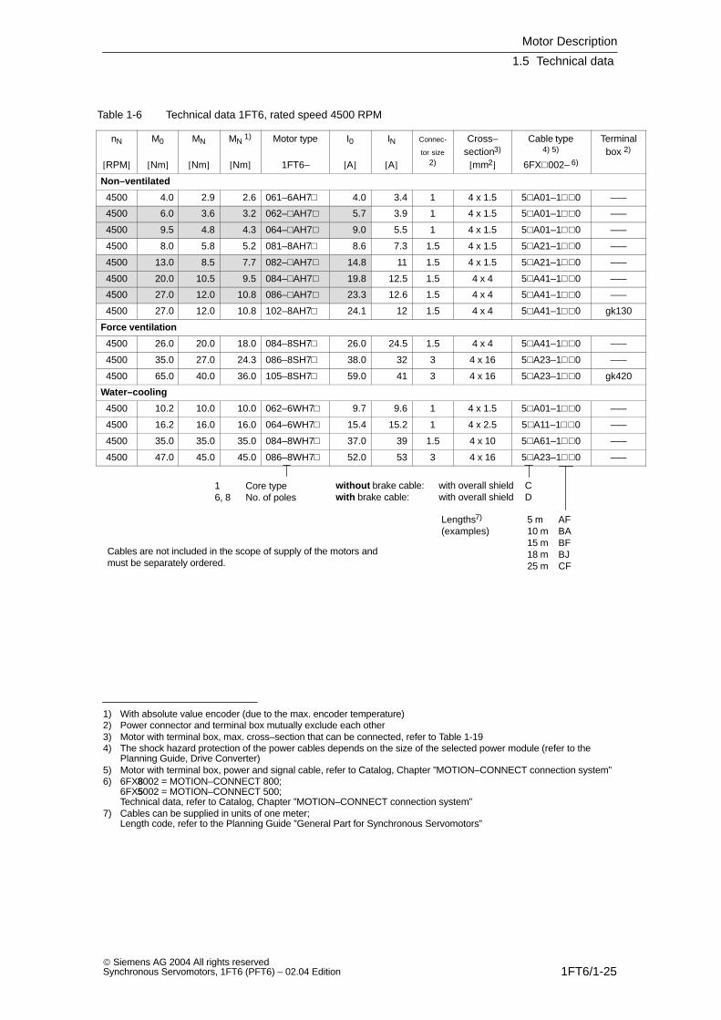
Table 1-6 Technical data 1FT6, rated speed 4500 RPM
nN
[RPM]
M0
[Nm]
MN
[Nm]
MN 1)
[Nm]
Motor type
1FT6–
I0
[A]
IN
[A]
Connec-
tor size2)
Cross–section3)
[mm2]
Cable type4) 5)
6FX002– 6)
Terminalbox 2)
Non–ventilated
4500 4.0 2.9 2.6 061–6AH7 4.0 3.4 1 4 x 1.5 5A01–10 –––
4500 6.0 3.6 3.2 062–AH7 5.7 3.9 1 4 x 1.5 5A01–10 –––
4500 9.5 4.8 4.3 064–AH7 9.0 5.5 1 4 x 1.5 5A01–10 –––
4500 8.0 5.8 5.2 081–8AH7 8.6 7.3 1.5 4 x 1.5 5A21–10 –––
4500 13.0 8.5 7.7 082–AH7 14.8 11 1.5 4 x 1.5 5A21–10 –––
4500 20.0 10.5 9.5 084–AH7 19.8 12.5 1.5 4 x 4 5A41–10 –––
4500 27.0 12.0 10.8 086–AH7 23.3 12.6 1.5 4 x 4 5A41–10 –––
4500 27.0 12.0 10.8 102–8AH7 24.1 12 1.5 4 x 4 5A41–10 gk130
Force ventilation
4500 26.0 20.0 18.0 084–8SH7 26.0 24.5 1.5 4 x 4 5A41–10 –––
4500 35.0 27.0 24.3 086–8SH7 38.0 32 3 4 x 16 5A23–10 –––
4500 65.0 40.0 36.0 105–8SH7 59.0 41 3 4 x 16 5A23–10 gk420
Water–cooling
4500 10.2 10.0 10.0 062–6WH7 9.7 9.6 1 4 x 1.5 5A01–10 –––
4500 16.2 16.0 16.0 064–6WH7 15.4 15.2 1 4 x 2.5 5A11–10 –––
4500 35.0 35.0 35.0 084–8WH7 37.0 39 1.5 4 x 10 5A61–10 –––
4500 47.0 45.0 45.0 086–8WH7 52.0 53 3 4 x 16 5A23–10 –––
1 Core type6, 8 No. of poles
without brake cable: with overall shield Cwith brake cable: with overall shield D
Lengths7) 5 m AF(examples) 10 m BA
15 m BF18 m BJ25 m CF
Cables are not included in the scope of supply of the motors andmust be separately ordered.
1) With absolute value encoder (due to the max. encoder temperature)2) Power connector and terminal box mutually exclude each other3) Motor with terminal box, max. cross–section that can be connected, refer to Table 1-194) The shock hazard protection of the power cables depends on the size of the selected power module (refer to the
Planning Guide, Drive Converter)5) Motor with terminal box, power and signal cable, refer to Catalog, Chapter ”MOTION–CONNECT connection system”6) 6FX8002 = MOTION–CONNECT 800;
6FX5002 = MOTION–CONNECT 500; Technical data, refer to Catalog, Chapter ”MOTION–CONNECT connection system”
7) Cables can be supplied in units of one meter; Length code, refer to the Planning Guide ”General Part for Synchronous Servomotors”
Motor Description
1.5 Technical data
1FT6/1-26 Siemens AG 2004 All rights reserved
Synchronous Servomotors, 1FT6 (PFT6) – 02.04 Edition
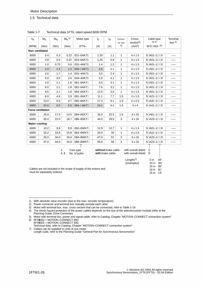
Table 1-7 Technical data 1FT6, rated speed 6000 RPM
nN
[RPM]
M0
[Nm]
MN
[Nm]
MN 1)
[Nm]
Motor type
1FT6–
I0
[A]
IN
[A]
Connec-
tor size2)
Cross–section3)
[mm2]
Cable type4) 5)
6FX002– 6)
Terminalbox 2)
Non–ventilated
6000 0.4 0.3 0.22 021–6AK71 1.25 1.1 1 4 x 1.5 5A01–10 –––
6000 0.8 0.5 0.37 024–6AK71 1.25 0.9 1 4 x 1.5 5A01–10 –––
6000 1.0 0.75 0.6 031–4AK71 1.4 1.2 1 4 x 1.5 5A01–10 –––
6000 2.0 1.4 1.2 034–AK71 2.6 2.1 1 4 x 1.5 5A01–10 –––
6000 2.6 1.7 1.4 041–4AK71 3.0 2.4 1 4 x 1.5 5A01–10 –––
6000 5.0 3.0 2.6 044–4AK71 5.9 4.1 1 4 x 1.5 5A01–10 –––
6000 4.0 2.1 1.8 061–6AK7 5.0 3.1 1 4 x 1.5 5A01–10 –––
6000 6.0 2.1 1.8 062–6AK7 7.6 3.2 1 4 x 1.5 5A01–10 –––
6000 9.5 2.1 1.8 064–6AK7 12.0 3.5 1 4 x 1.5 5A01–10 –––
6000 8.0 4.6 3.9 081–8AK7 11.1 7.7 1.5 4 x 1.5 5A21–10 –––
6000 13.0 5.5 4.7 082–8AK7 17.3 9.1 1.5 4 x 2.5 5A31–10 –––
6000 20.0 6.5 5.5 084–AK7 24.1 9.2 1.5 4 x 4 5A41–10 –––
Force ventilation
6000 26.0 17.0 14.5 084–8SK7 35.0 25.5 1.5 4 x 10 5A61–10 –––
6000 35.0 22.0 18.7 086–8SK7 44.0 29.0 3 4 x 16 5A23–10 –––
Water–cooling
6000 10.2 9.8 9.8 062–6WK7 12.9 12.7 1 4 x 1.5 5A01–10 –––
6000 16.2 15.8 15.8 064–6WK7 20.5 20 1 4 x 2.5 5A11–10 –––
6000 35.0 34.0 34.0 084–8WK7 47.0 51 3 4 x 16 5A23–10 –––
6000 47.0 44.0 44.0 086–8WK7 59.0 58 3 4 x 16 5A23–10 –––
1 Core type4, 8 No. of poles
without brake cable: with overall shield Cwith brake cable: with overall shield D
Lengths7) 5 m AF(examples) 10 m BA
15 m BF18 m BJ25 m CF
Cables are not included in the scope of supply of the motors andmust be separately ordered.
1) With absolute value encoder (due to the max. encoder temperature)2) Power connector and terminal box mutually exclude each other3) Motor with terminal box, max. cross–section that can be connected, refer to Table 1-194) The shock hazard protection of the power cables depends on the size of the selected power module (refer to the
Planning Guide, Drive Converter)5) Motor with terminal box, power and signal cable, refer to Catalog, Chapter ”MOTION–CONNECT connection system”6) 6FX8002 = MOTION–CONNECT 800;
6FX5002 = MOTION–CONNECT 500; Technical data, refer to Catalog, Chapter ”MOTION–CONNECT connection system”
7) Cables can be supplied in units of one meter; Length code, refer to the Planning Guide ”General Part for Synchronous Servomotors”
Motor Description
1.6 Armature short–circuit braking
1FT6/1-27 Siemens AG 2004 All rights reservedSynchronous Servomotors, 1FT6 (PFT6) – 02.04 Edition
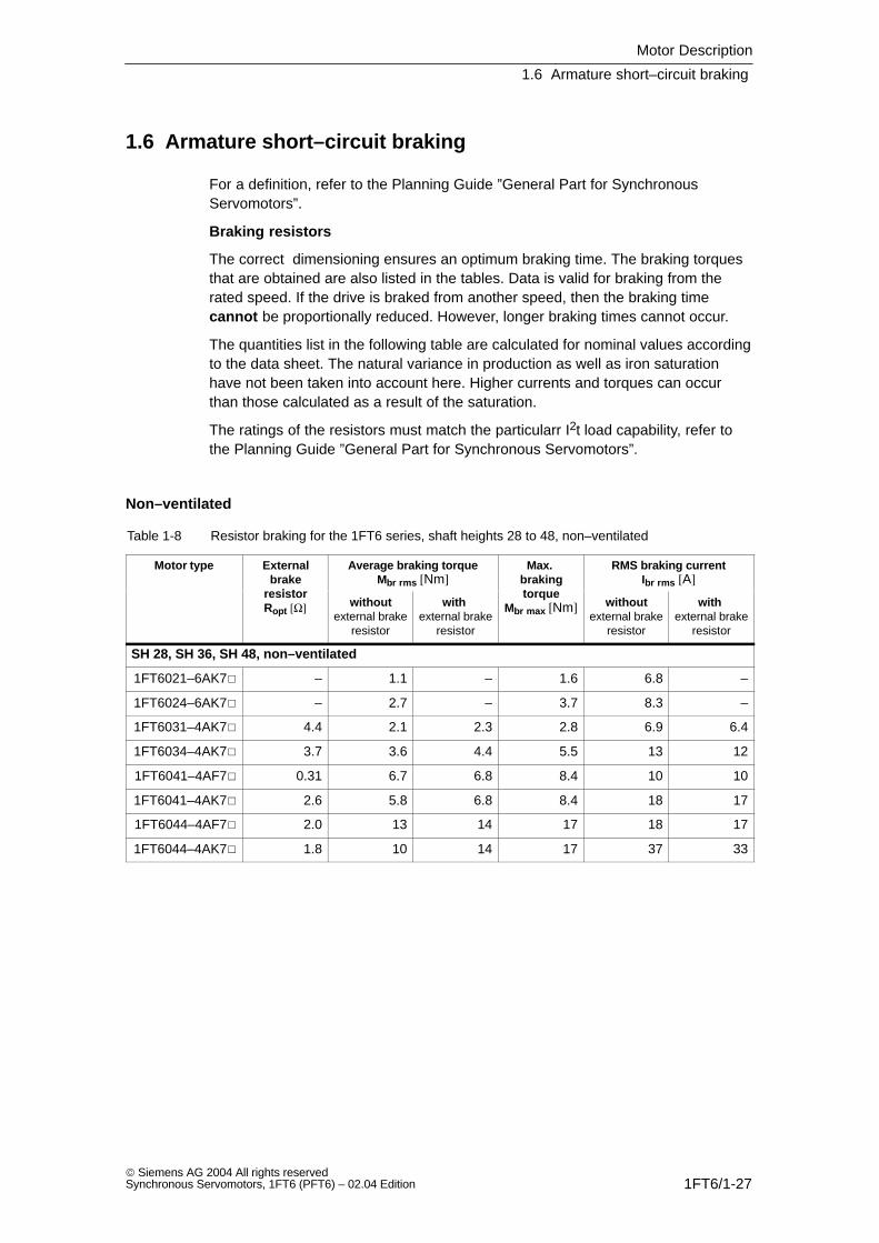
1.6 Armature short–circuit braking
For a definition, refer to the Planning Guide ”General Part for SynchronousServomotors”.
Braking resistors
The correct dimensioning ensures an optimum braking time. The braking torquesthat are obtained are also listed in the tables. Data is valid for braking from therated speed. If the drive is braked from another speed, then the braking timecannot be proportionally reduced. However, longer braking times cannot occur.
The quantities list in the following table are calculated for nominal values accordingto the data sheet. The natural variance in production as well as iron saturationhave not been taken into account here. Higher currents and torques can occurthan those calculated as a result of the saturation.
The ratings of the resistors must match the particularr I2t load capability, refer tothe Planning Guide ”General Part for Synchronous Servomotors”.
Non–ventilated
Table 1-8 Resistor braking for the 1FT6 series, shaft heights 28 to 48, non–ventilated
Motor type Externalbrake
resistor
Average braking torqueMbr rms [Nm]
Max. brakingtorque
RMS braking currentIbr rms [A]
resistorRopt [Ω] without
external brakeresistor
with external brake
resistor
torqueMbr max [Nm] without
external brakeresistor
with external brake
resistor
SH 28, SH 36, SH 48, non–ventilated
1FT6021–6AK7 – 1.1 – 1.6 6.8 –
1FT6024–6AK7 – 2.7 – 3.7 8.3 –
1FT6031–4AK7 4.4 2.1 2.3 2.8 6.9 6.4
1FT6034–4AK7 3.7 3.6 4.4 5.5 13 12
1FT6041–4AF7 0.31 6.7 6.8 8.4 10 10
1FT6041–4AK7 2.6 5.8 6.8 8.4 18 17
1FT6044–4AF7 2.0 13 14 17 18 17
1FT6044–4AK7 1.8 10 14 17 37 33
Motor Description
1.6 Armature short–circuit braking
1FT6/1-28 Siemens AG 2004 All rights reserved
Synchronous Servomotors, 1FT6 (PFT6) – 02.04 Edition
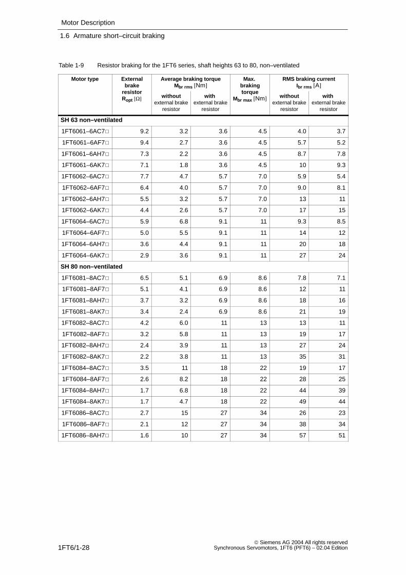
Table 1-9 Resistor braking for the 1FT6 series, shaft heights 63 to 80, non–ventilated
Motor type Externalbrake
resistor
Average braking torqueMbr rms [Nm]
Max. brakingtorque
RMS braking currentIbr rms [A]
resistorRopt [Ω] without
external brakeresistor
with external brake
resistor
torqueMbr max [Nm] without
external brakeresistor
with external brake
resistor
SH 63 non–ventilated
1FT6061–6AC7 9.2 3.2 3.6 4.5 4.0 3.7
1FT6061–6AF7 9.4 2.7 3.6 4.5 5.7 5.2
1FT6061–6AH7 7.3 2.2 3.6 4.5 8.7 7.8
1FT6061–6AK7 7.1 1.8 3.6 4.5 10 9.3
1FT6062–6AC7 7.7 4.7 5.7 7.0 5.9 5.4
1FT6062–6AF7 6.4 4.0 5.7 7.0 9.0 8.1
1FT6062–6AH7 5.5 3.2 5.7 7.0 13 11
1FT6062–6AK7 4.4 2.6 5.7 7.0 17 15
1FT6064–6AC7 5.9 6.8 9.1 11 9.3 8.5
1FT6064–6AF7 5.0 5.5 9.1 11 14 12
1FT6064–6AH7 3.6 4.4 9.1 11 20 18
1FT6064–6AK7 2.9 3.6 9.1 11 27 24
SH 80 non–ventilated
1FT6081–8AC7 6.5 5.1 6.9 8.6 7.8 7.1
1FT6081–8AF7 5.1 4.1 6.9 8.6 12 11
1FT6081–8AH7 3.7 3.2 6.9 8.6 18 16
1FT6081–8AK7 3.4 2.4 6.9 8.6 21 19
1FT6082–8AC7 4.2 6.0 11 13 13 11
1FT6082–8AF7 3.2 5.8 11 13 19 17
1FT6082–8AH7 2.4 3.9 11 13 27 24
1FT6082–8AK7 2.2 3.8 11 13 35 31
1FT6084–8AC7 3.5 11 18 22 19 17
1FT6084–8AF7 2.6 8.2 18 22 28 25
1FT6084–8AH7 1.7 6.8 18 22 44 39
1FT6084–8AK7 1.7 4.7 18 22 49 44
1FT6086–8AC7 2.7 15 27 34 26 23
1FT6086–8AF7 2.1 12 27 34 38 34
1FT6086–8AH7 1.6 10 27 34 57 51

Motor Description
1.6 Armature short–circuit braking
1FT6/1-29 Siemens AG 2004 All rights reservedSynchronous Servomotors, 1FT6 (PFT6) – 02.04 Edition
Table 1-10 Resistor braking for the 1FT6 series, shaft heights 100 to 132, non–ventilated
Motor type Externalbrake
resistor
Average braking torqueMbr rms [Nm]
Max. brakingtorque
RMS braking currentIbr rms [A]
resistorRopt [Ω] without
external brakeresistor
with external brake
resistor
torqueMbr max [Nm] without
external brakeresistor
with external brake
resistor
SH 100 non–ventilated
1FT6102–8AB7 3.9 13 24 30 18 16
1FT6102–8AC7 2.8 11 24 30 25 23
1FT6102–8AF7 2.3 8.1 24 30 35 31
1FT6102–8AH7 1.7 6.5 24 30 51 46
1FT6105–8AB7 2.2 21 43 54 33 29
1FT6105–8AC7 1.7 17 43 54 44 39
1FT6105–8AF7 1.2 13 43 54 65 58
1FT6108–8AB7 1.4 32 71 88 53 47
1FT6108–8AC7 1.2 26 71 88 68 61
1FT6108–8AF7 0.9 21 71 88 99 89
SH 132 non–ventilated
1FT6132–6AB7 1.0 1) 37 83 105 56 50
1FT6132–6AC7 1.2 1) 32 83 105 75 67
1FT6132–6AF7 0.8 1) 23 83 105 110 100
1FT6134–6AB7 1.2 1) 47 110 140 72 65
1FT6134–6AC7 0.9 1) 40 110 140 99 89
1FT6136–6AB7 0.9 1) 55 130 170 91 82
1FT6136–6AC7 0.8 1) 45 130 170 115 105
1) When utilized according to M0 (100 K) a series braking resistor must be used in order to prevent partial de–magnetization.When utilized according to M0 (60 K), the additional braking resistor is not required.
Motor Description
1.6 Armature short–circuit braking
1FT6/1-30 Siemens AG 2004 All rights reserved
Synchronous Servomotors, 1FT6 (PFT6) – 02.04 Edition
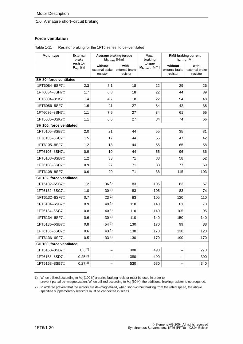
Force ventilation
Table 1-11 Resistor braking for the 1FT6 series, force–ventilated
Motor type Externalbrake
resistor
Average braking torqueMbr rms [Nm]
Max. brakingtorque
RMS braking currentIbr rms [A]
resistorRopt [Ω] without
external brakeresistor
with external brake
resistor
torqueMbr max [Nm] without
external brakeresistor
with external brake
resistor
SH 80, force ventilated
1FT6084–8SF7 2.3 8.1 18 22 29 26
1FT6084–8SH7 1.7 6.8 18 22 44 39
1FT6084–8SK7 1.4 4.7 18 22 54 48
1FT6086–8SF7 1.6 11 27 34 42 38
1FT6086–8SH7 1.1 7.5 27 34 61 55
1FT6086–8SK7 1.1 6.6 27 34 74 66
SH 100, force ventilated
1FT6105–8SB7 2.0 21 44 55 35 31
1FT6105–8SC7 1.5 17 44 55 47 42
1FT6105–8SF7 1.2 13 44 55 65 58
1FT6105–8SH7 0.9 10 44 55 96 86
1FT6108–8SB7 1.2 33 71 88 58 52
1FT6108–8SC7 0.9 27 71 88 77 69
1FT6108–8SF7 0.6 20 71 88 115 103
SH 132, force ventilated
1FT6132–6SB7 1.2 36 1) 83 105 63 57
1FT6132–6SC7 1.0 30 1) 83 105 83 74
1FT6132–6SF7 0.7 23 1) 83 105 120 110
1FT6134–6SB7 0.9 49 1) 110 140 81 73
1FT6134–6SC7 0.8 40 1) 110 140 105 95
1FT6134–6SF7 0.6 30 1) 110 140 150 140
1FT6136–6SB7 0.8 54 1) 130 170 99 88
1FT6136–6SC7 0.6 43 1) 130 170 130 120
1FT6136–6SF7 0.5 33 1) 130 170 190 170
SH 160, force ventilated
1FT6163–8SB7 0.3 2) – 380 490 – 270
1FT6163–8SD7 0.25 2) – 380 490 – 390
1FT6168–8SB7 0.27 2) – 530 680 – 340
1) When utilized according to M0 (100 K) a series braking resistor must be used in order to prevent partial de–magnetization. When utilized according to M0 (60 K), the additional braking resistor is not required.
2) In order to prevent that the motors are de–magnetized, when short–circuit braking from the rated speed, the abovespecified supplementary resistors must be connected in series.
Motor Description
1.6 Armature short–circuit braking
1FT6/1-31 Siemens AG 2004 All rights reservedSynchronous Servomotors, 1FT6 (PFT6) – 02.04 Edition
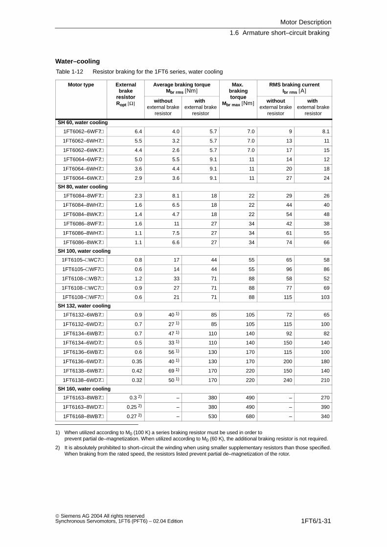
Water–cooling
Table 1-12 Resistor braking for the 1FT6 series, water cooling
Motor type Externalbrake
resistor
Average braking torqueMbr rms [Nm]
Max. brakingtorque
RMS braking currentIbr rms [A]
resistorRopt [Ω] without
external brakeresistor
with external brake
resistor
torqueMbr max [Nm] without
external brakeresistor
with external brake
resistor
SH 60, water cooling
1FT6062–6WF7 6.4 4.0 5.7 7.0 9 8.1
1FT6062–6WH7 5.5 3.2 5.7 7.0 13 11
1FT6062–6WK7 4.4 2.6 5.7 7.0 17 15
1FT6064–6WF7 5.0 5.5 9.1 11 14 12
1FT6064–6WH7 3.6 4.4 9.1 11 20 18
1FT6064–6WK7 2.9 3.6 9.1 11 27 24
SH 80, water cooling
1FT6084–8WF7 2.3 8.1 18 22 29 26
1FT6084–8WH7 1.6 6.5 18 22 44 40
1FT6084–8WK7 1.4 4.7 18 22 54 48
1FT6086–8WF7 1.6 11 27 34 42 38
1FT6086–8WH7 1.1 7.5 27 34 61 55
1FT6086–8WK7 1.1 6.6 27 34 74 66
SH 100, water cooling
1FT6105–WC7 0.8 17 44 55 65 58
1FT6105–WF7 0.6 14 44 55 96 86
1FT6108–WB7 1.2 33 71 88 58 52
1FT6108–WC7 0.9 27 71 88 77 69
1FT6108–WF7 0.6 21 71 88 115 103
SH 132, water cooling
1FT6132–6WB7 0.9 40 1) 85 105 72 65
1FT6132–6WD7 0.7 27 1) 85 105 115 100
1FT6134–6WB7 0.7 47 1) 110 140 92 82
1FT6134–6WD7 0.5 33 1) 110 140 150 140
1FT6136–6WB7 0.6 56 1) 130 170 115 100
1FT6136–6WD7 0.35 40 1) 130 170 200 180
1FT6138–6WB7 0.42 69 1) 170 220 150 140
1FT6138–6WD7 0.32 50 1) 170 220 240 210
SH 160, water cooling
1FT6163–8WB7 0.3 2) – 380 490 – 270
1FT6163–8WD7 0.25 2) – 380 490 – 390
1FT6168–8WB7 0.27 2) – 530 680 – 340
1) When utilized according to M0 (100 K) a series braking resistor must be used in order to prevent partial de–magnetization. When utilized according to M0 (60 K), the additional braking resistor is not required.
2) It is absolutely prohibited to short–circuit the winding when using smaller supplementary resistors than those specified.When braking from the rated speed, the resistors listed prevent partial de–magnetization of the rotor.
Motor Description
1.7 Cooling
1FT6/1-32 Siemens AG 2004 All rights reserved
Synchronous Servomotors, 1FT6 (PFT6) – 02.04 Edition
1.7 Cooling
Cooling types
The different cooling types are defined in the Planning Guide ”General Part forSynchronous Servomotors”.
1.7.1 Force ventilation
Degree of protection IP54 (acc. to EN 60529). The degrees of protection IP64, IP65, IP67 and IP68 cannot be fulfilled.
The hot discharged air may not be drawn–in again.
!Caution
Forced ventilation cannot be used in the presence of flammable, corrosive,electrically conductive or explosive dust.
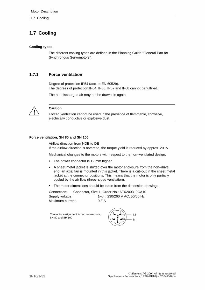
Force ventilation, SH 80 and SH 100
Airflow direction from NDE to DEIf the airflow direction is reversed, the torque yield is reduced by approx. 20 %.
Mechanical changes to the motors with respect to the non–ventilated design:
The power connector is 12 mm higher.
A sheet metal jacket is shifted over the motor enclosure from the non–driveend; an axial fan is mounted in this jacket. There is a cut–out in the sheet metaljacket at the connector positions. This means that the motor is only partiallycooled by the air flow (three–sided ventilation).
The motor dimensions should be taken from the dimension drawings.
Connection: Connector, Size 1, Order No.: 6FX2003–0CA10Supply voltage: 1–ph. 230/260 V AC, 50/60 HzMaximum current: 0.3 A
L1
N
Connector assignment for fan connections,SH 80 and SH 100
1
24
56
Motor Description
1.7 Cooling
1FT6/1-33 Siemens AG 2004 All rights reservedSynchronous Servomotors, 1FT6 (PFT6) – 02.04 Edition
Force ventilated, SH 132
Air flow direction from ND to NDE.The air is blow through the enclosure corners of the extruded profile using amounted radial fan.
Connection: Through the terminal boxSupply voltage: 3–ph. 400/480 V AC, 50/60 HzMaximum current: 0.4 A
Force ventilated, SH 160
Air flow direction from ND to NDE.The air is blow through the enclosure corners of the extruded profile using amounted radial fan.
Connection: Through the terminal boxSupply voltage: 3–ph. 400/480 V AC, 50/60 HzMaximum current: 0.8 A
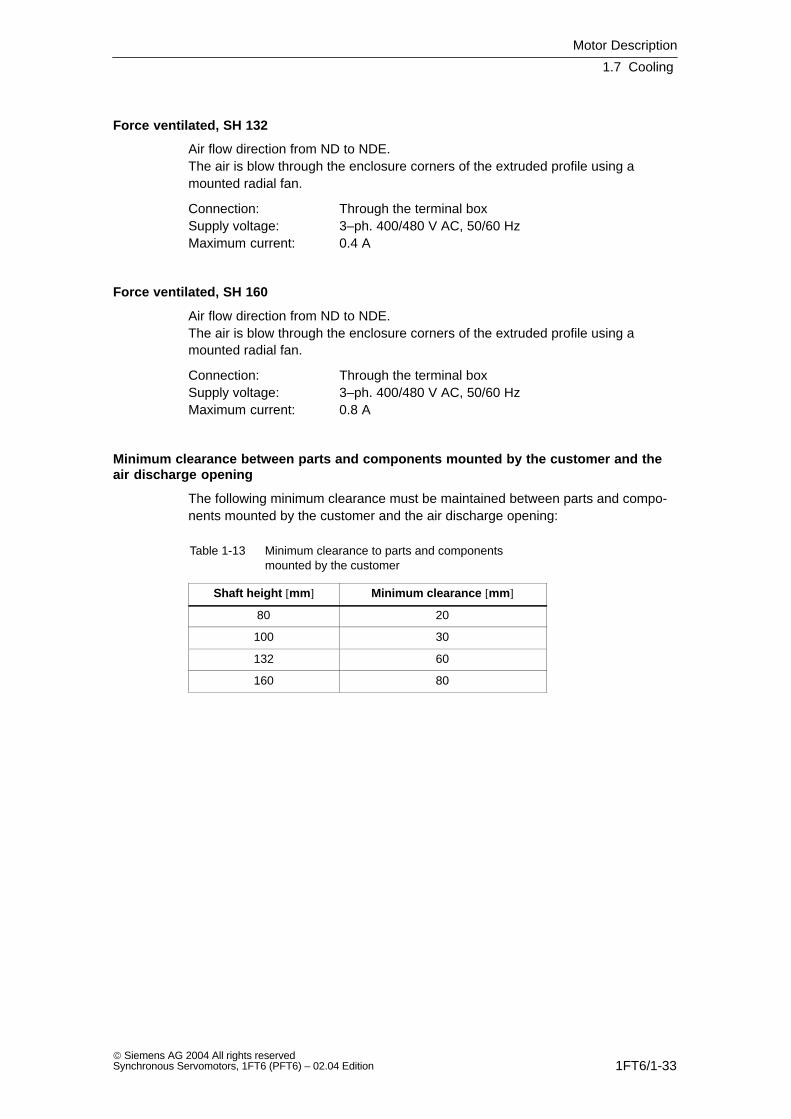
Minimum clearance between parts and components mounted by the customer and theair discharge opening
The following minimum clearance must be maintained between parts and compo-nents mounted by the customer and the air discharge opening:
Table 1-13 Minimum clearance to parts and componentsmounted by the customer
Shaft height [mm] Minimum clearance [mm]
80 20
100 30
132 60
160 80
Motor Description
1.7 Cooling
1FT6/1-34 Siemens AG 2004 All rights reserved
Synchronous Servomotors, 1FT6 (PFT6) – 02.04 Edition
1.7.2 Water–cooling
The power loss generated by the motor is dissipated using the water cooling. Themachinery construction company must connect–up a cooling system (e.g. heatexchanger).
The motor rated torques, specified in the data sheets apply for water–cooledoperational and a water intake temperature of < 30 °C.
Notice
If the motor is operated without water cooling, then the rated motor torque isreduced as a function of the heat losses which can be dissipated by convectionand radiation. In this case, the data for non–ventilated operations apply.
Note
It is not possible to retrofit water cooling.
The cooling medium must be pre–cleaned and filtered in order to prevent thecooling circuit from becoming blocked. The maximum permissible particle sizeafter filtering 100 µm.
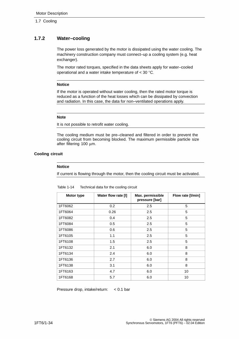
Cooling circuit
Notice
If current is flowing through the motor, then the cooling circuit must be activated.
Table 1-14 Technical data for the cooling circuit
Motor type Water flow rate [l] Max. permissiblepressure [bar]
Flow rate [l/min]
1FT6062 0.2 2.5 5
1FT6064 0.26 2.5 5
1FT6082 0.4 2.5 5
1FT6084 0.5 2.5 5
1FT6086 0.6 2.5 5
1FT6105 1.1 2.5 5
1FT6108 1.5 2.5 5
1FT6132 2.1 6.0 8
1FT6134 2.4 6.0 8
1FT6136 2.7 6.0 8
1FT6138 3.1 6.0 8
1FT6163 4.7 6.0 10
1FT6168 5.7 6.0 10
Pressure drop, intake/return: < 0.1 bar
Motor Description
1.7 Cooling
1FT6/1-35 Siemens AG 2004 All rights reservedSynchronous Servomotors, 1FT6 (PFT6) – 02.04 Edition
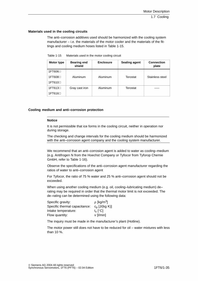
Materials used in the cooling circuits
The anti–corrosion additives used should be harmonized with the cooling systemmanufacturer – i.e. the materials of the motor cooler and the materials of the fit-tings and cooling medium hoses listed in Table 1-15.
Table 1-15 Materials used in the motor cooling circuit
Motor type Bearing endshield
Enclosure Sealing agent Connectionplate
1FT606
1FT608 Aluminum Aluminum Terostat Stainless steel
1FT610
1FT613 Gray cast iron Aluminum Terostat –––
1FT616
Cooling medium and anti–corrosion protection
Notice
It is not permissible that ice forms in the cooling circuit, neither in operation norduring storage.
The checking and change intervals for the cooling medium should be harmonizedwith the anti–corrosion agent company and the cooling system manufacturer.
We recommend that an anti–corrosion agent is added to water as cooling–medium(e.g. Antifrogen N from the Hoechst Company or Tyfocor from Tyforop ChemieGmbH, refer to Table 1-16).
Observe the specifications of the anti–corrosion agent manufacturer regarding theratios of water to anti–corrosion agent
For Tyfocor, the ratio of 75 % water and 25 % anti–corrosion agent should not beexceeded.
When using another cooling medium (e.g. oil, cooling–lubricating medium) de–rating may be required in order that the thermal motor limit is not exceeded. Thede–rating can be determined using the following data:
Specific gravity: ρ [kg/m3]Specific thermal capacitance: cp [J/(kg K)]Intake temperature: tv [°C]Flow quantity: v [l/min]
The inquiry must be made in the manufacturer’s plant (Hotline).
The motor power still does not have to be reduced for oil – water mixtures with lessthan 10 %.
Motor Description
1.7 Cooling
1FT6/1-36 Siemens AG 2004 All rights reserved
Synchronous Servomotors, 1FT6 (PFT6) – 02.04 Edition
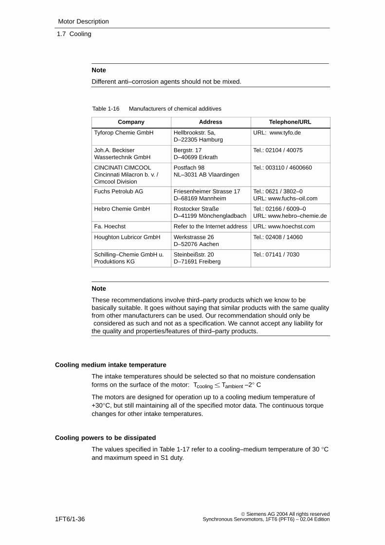
Note
Different anti–corrosion agents should not be mixed.
Table 1-16 Manufacturers of chemical additives
Company Address Telephone/URL
Tyforop Chemie GmbH Hellbrookstr. 5a, D–22305 Hamburg
URL: www.tyfo.de
Joh.A. BeckiserWassertechnik GmbH
Bergstr. 17D–40699 Erkrath
Tel.: 02104 / 40075
CINCINATI CIMCOOLCincinnati Milacron b. v. / Cimcool Division
Postfach 98NL–3031 AB Vlaardingen
Tel.: 003110 / 4600660
Fuchs Petrolub AG Friesenheimer Strasse 17D–68169 Mannheim
Tel.: 0621 / 3802–0URL: www.fuchs–oil.com
Hebro Chemie GmbH Rostocker StraßeD–41199 Mönchengladbach
Tel.: 02166 / 6009–0URL: www.hebro–chemie.de
Fa. Hoechst Refer to the Internet address URL: www.hoechst.com
Houghton Lubricor GmbH Werkstrasse 26D–52076 Aachen
Tel.: 02408 / 14060
Schilling–Chemie GmbH u.Produktions KG
Steinbeißstr. 20D–71691 Freiberg
Tel.: 07141 / 7030
Note
These recommendations involve third–party products which we know to bebasically suitable. It goes without saying that similar products with the same qualityfrom other manufacturers can be used. Our recommendation should only be considered as such and not as a specification. We cannot accept any liability forthe quality and properties/features of third–party products.
Cooling medium intake temperature
The intake temperatures should be selected so that no moisture condensationforms on the surface of the motor: Tcooling Tambient –2° C
The motors are designed for operation up to a cooling medium temperature of+30°C, but still maintaining all of the specified motor data. The continuous torquechanges for other intake temperatures.
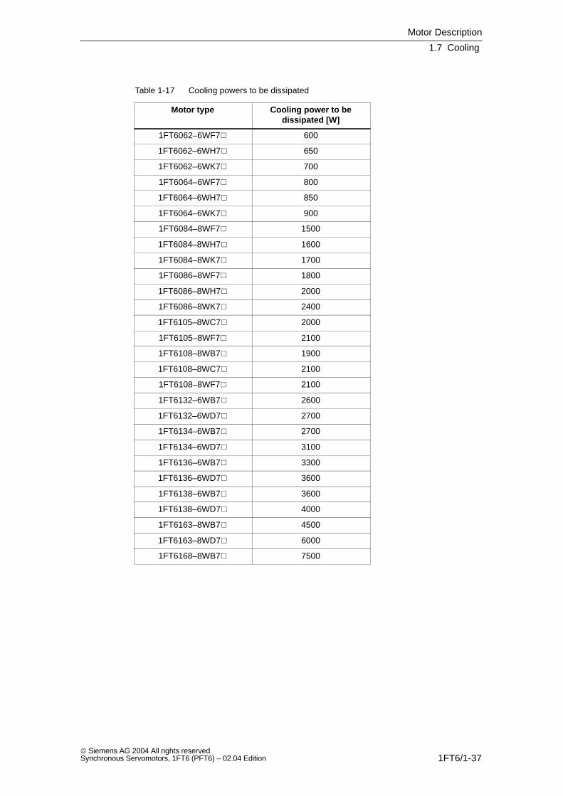
Cooling powers to be dissipated
The values specified in Table 1-17 refer to a cooling–medium temperature of 30 °Cand maximum speed in S1 duty.
Motor Description
1.7 Cooling
1FT6/1-37 Siemens AG 2004 All rights reservedSynchronous Servomotors, 1FT6 (PFT6) – 02.04 Edition
Table 1-17 Cooling powers to be dissipated
Motor type Cooling power to bedissipated [W]
1FT6062–6WF7 600
1FT6062–6WH7 650
1FT6062–6WK7 700
1FT6064–6WF7 800
1FT6064–6WH7 850
1FT6064–6WK7 900
1FT6084–8WF7 1500
1FT6084–8WH7 1600
1FT6084–8WK7 1700
1FT6086–8WF7 1800
1FT6086–8WH7 2000
1FT6086–8WK7 2400
1FT6105–8WC7 2000
1FT6105–8WF7 2100
1FT6108–8WB7 1900
1FT6108–8WC7 2100
1FT6108–8WF7 2100
1FT6132–6WB7 2600
1FT6132–6WD7 2700
1FT6134–6WB7 2700
1FT6134–6WD7 3100
1FT6136–6WB7 3300
1FT6136–6WD7 3600
1FT6138–6WB7 3600
1FT6138–6WD7 4000
1FT6163–8WB7 4500
1FT6163–8WD7 6000
1FT6168–8WB7 7500
Motor Description
1.7 Cooling
1FT6/1-38 Siemens AG 2004 All rights reserved
Synchronous Servomotors, 1FT6 (PFT6) – 02.04 Edition
Cooling system
A cooling system (i.e. heat exchanger) must be used in order to guarantee a coo-ling medium intake temperature of +30 °C. It is possible to operate several motorsfrom a single cooling system. The cooling system is not included in the scope ofsupply.
Cooling system manufacturer, refer to the Catalog.
The cooling power is calculated from the sum of the power losses of the connectedmotors. The power of the pump and the distribution to different cooling circuitsshould be engineered corresponding to the specified flow and the pressure lossesof the individual cooling circuits.
If one pump is used with distribution to several cooling circuits, then it may be ne-cessary to use a flow controller.
Motor Description
1.8 Electrical connections
1FT6/1-39 Siemens AG 2004 All rights reservedSynchronous Servomotors, 1FT6 (PFT6) – 02.04 Edition
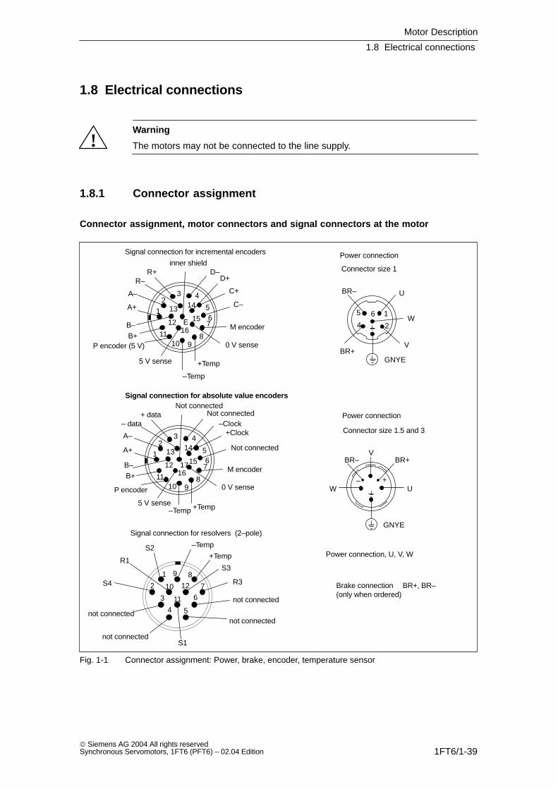
1.8 Electrical connections
!Warning
The motors may not be connected to the line supply.
1.8.1 Connector assignment
Connector assignment, motor connectors and signal connectors at the motor
2
1
10 12
11 63
9 8
7
4 5not connected
S2
S3
R3
R1
–Temp
+Temp
Brake connection BR+, BR–(only when ordered)
Signal connection for resolvers (2–pole)
Power connection
not connected
not connected
1
24
5 6
U
V
Power connection, U, V, W
U
V
W
BR+BR–
BR–
BR+
W
GNYE
– +
GNYE
Signal connection for incremental encoders
S4
not connected
4
567
8910
11
12
3
14
E 15
1612
13
inner shieldD–
D+
C+
C–A–
A+
B+B–
R–R+
M encoder
P encoder (5 V) 0 V sense
5 V sense
–Temp
+Temp
4
567
8910
11
12
3
14
1715
1612
13
Not connectedNot connected
–Clock+Clock
Not connected
M encoder
0 V sense
+Temp–Temp5 V sense
P encoder
B+B–
A+
A–
– data+ data
Signal connection for absolute value encoders
S1
Power connection
Connector size 1.5 and 3
Connector size 1
Fig. 1-1 Connector assignment: Power, brake, encoder, temperature sensor
Motor Description
1.8 Electrical connections
1FT6/1-40 Siemens AG 2004 All rights reserved
Synchronous Servomotors, 1FT6 (PFT6) – 02.04 Edition
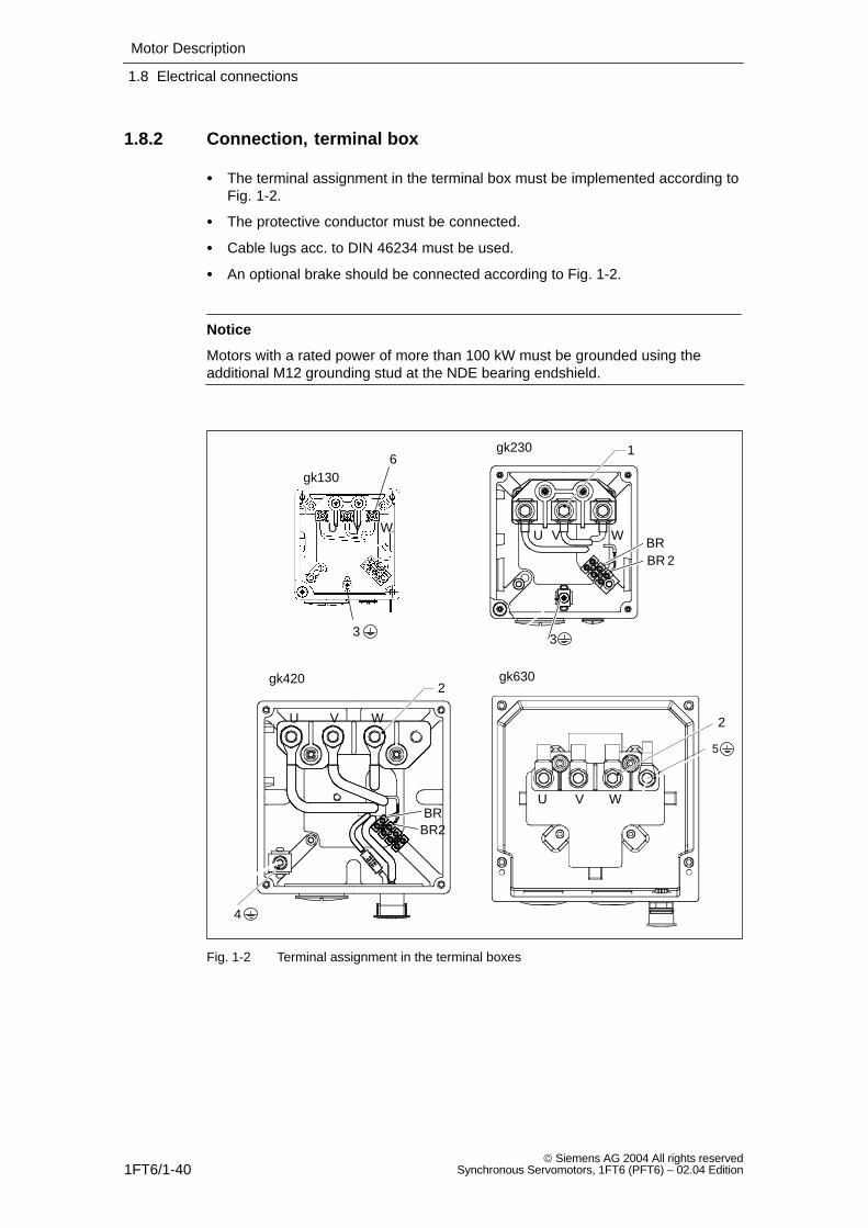
1.8.2 Connection, terminal box
The terminal assignment in the terminal box must be implemented according toFig. 1-2.
The protective conductor must be connected.
Cable lugs acc. to DIN 46234 must be used.
An optional brake should be connected according to Fig. 1-2.
Notice
Motors with a rated power of more than 100 kW must be grounded using theadditional M12 grounding stud at the NDE bearing endshield.
U WBRBR 2
BRBR2
1
2
2
5
4
3
gk420 gk630
gk230
gk130
VU WV
U WV
U WV
6
3
Fig. 1-2 Terminal assignment in the terminal boxes
Motor Description
1.8 Electrical connections
1FT6/1-41 Siemens AG 2004 All rights reservedSynchronous Servomotors, 1FT6 (PFT6) – 02.04 Edition
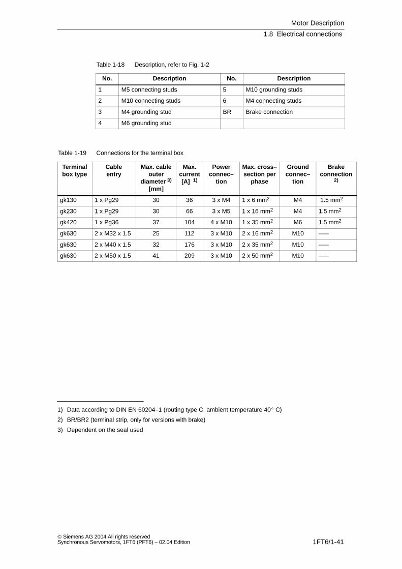
Table 1-18 Description, refer to Fig. 1-2
No. Description No. Description
1 M5 connecting studs 5 M10 grounding studs
2 M10 connecting studs 6 M4 connecting studs
3 M4 grounding stud BR Brake connection
4 M6 grounding stud
Table 1-19 Connections for the terminal box
Terminalbox type
Cableentry
Max. cableouter
diameter 3)
[mm]
Max.current[A] 1)
Powerconnec–
tion
Max. cross–section per
phase
Groundconnec–
tion
Brakeconnection
2)
gk130 1 x Pg29 30 36 3 x M4 1 x 6 mm2 M4 1.5 mm2
gk230 1 x Pg29 30 66 3 x M5 1 x 16 mm2 M4 1.5 mm2
gk420 1 x Pg36 37 104 4 x M10 1 x 35 mm2 M6 1.5 mm2
gk630 2 x M32 x 1.5 25 112 3 x M10 2 x 16 mm2 M10 –––
gk630 2 x M40 x 1.5 32 176 3 x M10 2 x 35 mm2 M10 –––
gk630 2 x M50 x 1.5 41 209 3 x M10 2 x 50 mm2 M10 –––
1) Data according to DIN EN 60204–1 (routing type C, ambient temperature 40 C)
2) BR/BR2 (terminal strip, only for versions with brake)
3) Dependent on the seal used
Motor Description
1.9 Drive–out coupling
1FT6/1-42 Siemens AG 2004 All rights reserved
Synchronous Servomotors, 1FT6 (PFT6) – 02.04 Edition
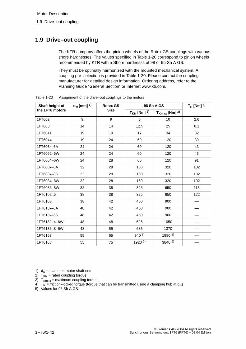
1.9 Drive–out coupling
The KTR company offers the pinion wheels of the Rotex GS couplings with variousshore hardnesses. The values specified in Table 1-20 correspond to pinion wheelsrecommended by KTR with a Shore hardnesss of 98 or 95 Sh A GS.
They must be optimally harmonized with the mounted mechanical system. Acoupling pre–selection is provided in Table 1-20. Please contact the couplingmanufacturer for detailed design information. Ordering address, refer to thePlanning Guide ”General Section” or Internet www.ktr.com.
Table 1-20 Assignment of the drive–out couplings to the motors
Shaft height ofthe 1FT6 motors
dw [mm] 1) Rotex GSSize
98 Sh A GS TR [Nm] 4)
the 1FT6 motorsw
SizeTKN [Nm] 2) TKmax [Nm] 3)
R
1FT602 9 9 5 10 2.6
1FT603 14 14 12.5 25 8.1
1FT6041 19 19 17 34 32
1FT6044 19 24 60 120 39
1FT606x–6A 24 24 60 120 43
1FT6062–6W 24 24 60 120 43
1FT6064–6W 24 28 60 120 91
1FT608x–8A 32 28 160 320 102
1FT608x–8S 32 28 160 320 102
1FT6084–8W 32 28 160 320 102
1FT6086–8W 32 38 325 650 113
1FT6102..5 38 38 325 650 122
1FT6108 38 42 450 900 ––
1FT613x–6A 48 42 450 900 ––
1FT613x–6S 48 42 450 900 ––
1FT6132..4–6W 48 48 525 1050 ––
1FT6136..8–6W 48 55 685 1370 ––
1FT6163 55 65 940 5) 1880 5) ––
1FT6168 55 75 1920 5) 3840 5) ––
1) dw = diameter, motor shaft end2) TKN = rated coupling torque3) TKmax = maximum coupling torque4) TR = friction–locked torque (torque that can be transmitted using a clamping hub at dw) 5) Values for 95 Sh A GS
Motor Description
1.9 Drive–out coupling
1FT6/1-43 Siemens AG 2004 All rights reservedSynchronous Servomotors, 1FT6 (PFT6) – 02.04 Edition
!Warning
The accelerating torque may not exceed the friction–locked torque of thecoupling!
Notice
We cannot accept any liability for the quality and properties/features of third–partyproducts.
Motor Description
1.9 Drive–out coupling
1FT6/1-44 Siemens AG 2004 All rights reserved
Synchronous Servomotors, 1FT6 (PFT6) – 02.04 Edition
Space for your notes
1FT6/2-45 Siemens AG 2004 All rights reservedSynchronous Servomotors, 1FT6 (PFT6) – 02.04 Edition
Technical Data and Characteristics
2.1 Speed–torque diagrams
Note
Refer to the Planning Guide ”General Section for Synchronous Servomotors” for adescription of the shift of the voltage limiting characteristics.
The specified thermal S3 limiting characteristics are referred to T= 100 K for a 1 min duty cycle.
2

Technical Data and Characteristics
2.1 Speed–torque diagrams
1FT6/2-46 Siemens AG 2004 All rights reserved
Synchronous Servomotors, 1FT6 (PFT6) – 02.04 Edition
2.1.1 1FT6 series, non–ventilated
Table 2-1 1FT6021 non–ventilated
1FT6021
Technical data Code Units –6AK71
Engineering data
Rated speedNumber of polesRated torque (100K)Rated current (100K)Standstill torque (60K)Standstill torque (100K)Standstill current (60K)Standstill current (100K)Moment of inertia (with brake)Moment of inertia (without brake)
nN2pMN (100K)IN (100K)M0 (60K)M0 (100K)I0 (60K)I0 (100K)JmotJmot
RPM
NmANmNmAA10–4 kgm2
10–4 kgm2
600060.31.10.330.401.01.250.280.21
Optimum operating point
Optimum speedOptimum power
noptPopt
RPMkW
60000.19
Limiting data
Max. perm. speed (mech.)Maximum torqueMaximum current
nmaxMmaxImax
RPMNmA
120001.55
Physical constants
Torque constantVoltage constantWinding resistance at 20CRotating field inductanceElectrical time constantShaft torsional stiffnessMechanical time constantThermal time constantWeight with brakeWeight without brake
kTkERphLDTelctTmechTthmm
Nm/AV/1000 RPM OhmmHmsNm/radmsminkgkg
0.3220.57.240.5630004.4151.41.2
Technical Data and Characteristics
2.1 Speed–torque diagrams
1FT6/2-47 Siemens AG 2004 All rights reservedSynchronous Servomotors, 1FT6 (PFT6) – 02.04 Edition
0
0.2
0.4
0.6
0.8
1
1.2
1.4
1.6
0 2000 4000 6000 8000 10000 12000
S1 (100K)S1 (60K)
S3 – 25%S3 – 40%S3 – 60%
n [RPM]
M [N
m]
Limiting characteristic lies outside themax. permissible speed range.
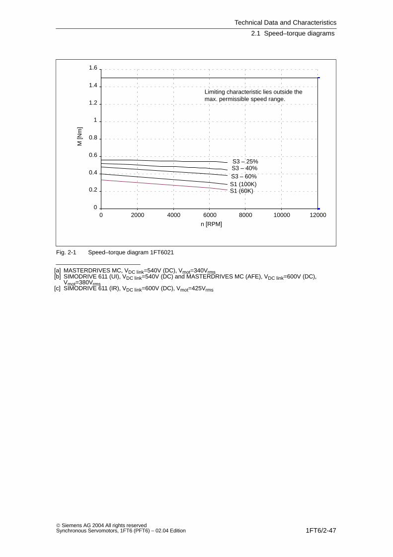
Fig. 2-1 Speed–torque diagram 1FT6021
[a] MASTERDRIVES MC, VDC link=540V (DC), Vmot=340Vrms[b] SIMODRIVE 611 (UI), VDC link=540V (DC) and MASTERDRIVES MC (AFE), VDC link=600V (DC),
Vmot=380Vrms[c] SIMODRIVE 611 (IR), VDC link=600V (DC), Vmot=425Vrms

Technical Data and Characteristics
2.1 Speed–torque diagrams
1FT6/2-48 Siemens AG 2004 All rights reserved
Synchronous Servomotors, 1FT6 (PFT6) – 02.04 Edition
Table 2-2 1FT6024 non–ventilated
1FT6024
Technical data Code Units –6AK71
Engineering data
Rated speedNumber of polesRated torque (100K)Rated current (100K)Standstill torque (60K)Standstill torque (100K)Standstill current (60K)Standstill current (100K)Moment of inertia (with brake)Moment of inertia (without brake)
nN2pMN (100K)IN (100K)M0 (60K)M0 (100K)I0 (60K)I0 (100K)JmotJmot
RPM
NmANmNmAA10–4 kgm2
10–4 kgm2
600060.50.90.660.81.01.250.410.34
Optimum operating point
Optimum speedOptimum power
noptPopt
RPMkW
60000.31
Limiting data
Max. perm. speed (mech.)Maximum torqueMaximum current
nmaxMmaxImax
RPMNmA
120003.155
Physical constants
Torque constantVoltage constantWinding resistance at 20CRotating field inductanceElectrical time constantShaft torsional stiffnessMechanical time constantThermal time constantWeight with brakeWeight without brake
kTkERphLDTelctTmechTthmm
Nm/AV/1000 RPM OhmmHmsNm/radmsminkgkg
0.634110.970.6430002.8152.32.1
Technical Data and Characteristics
2.1 Speed–torque diagrams
1FT6/2-49 Siemens AG 2004 All rights reservedSynchronous Servomotors, 1FT6 (PFT6) – 02.04 Edition
0
0.5
1
1.5
2
2.5
3
3.5
0 1000 2000 3000 4000 5000 6000 7000 8000 9000 10000
S1 (100K)S1 (60K)
S3 – 25%S3 – 40%S3 – 60%
a b c
n [RPM]
M [N
m]
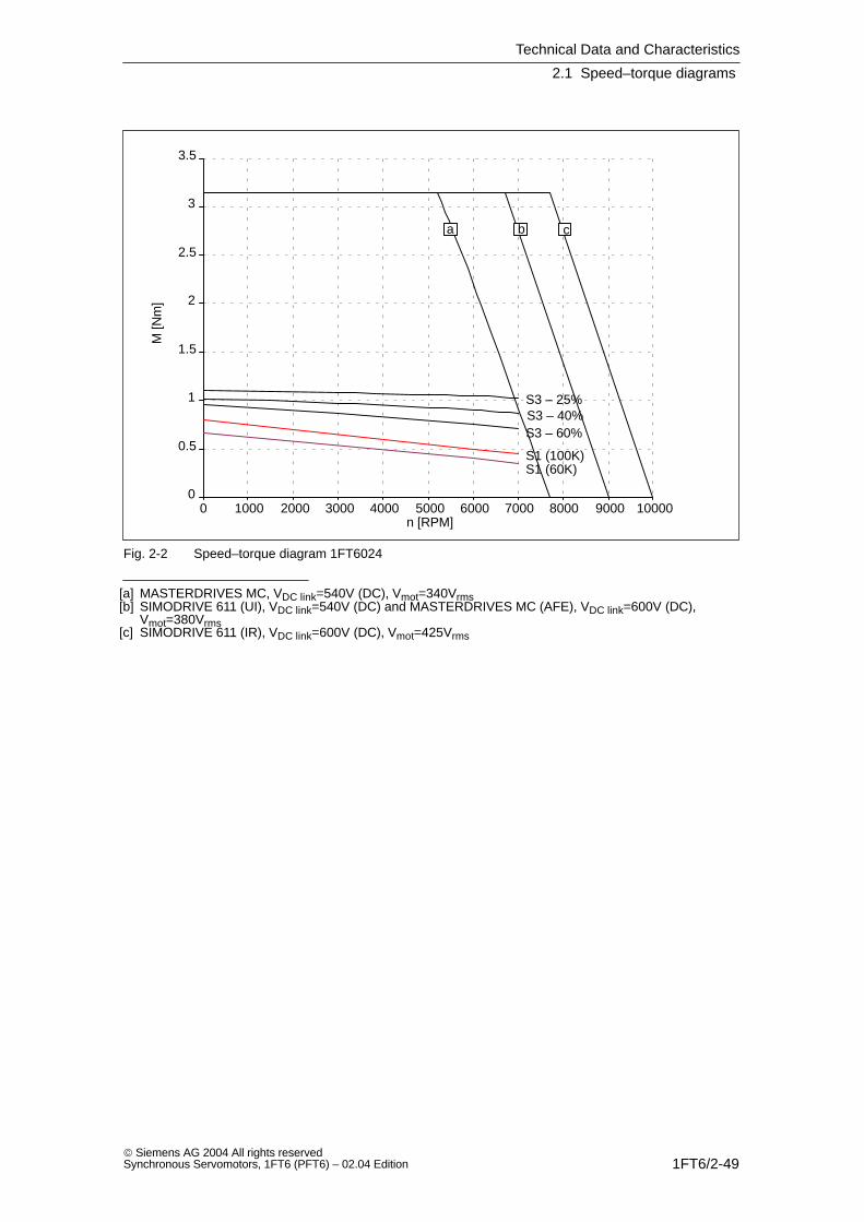
Fig. 2-2 Speed–torque diagram 1FT6024
[a] MASTERDRIVES MC, VDC link=540V (DC), Vmot=340Vrms[b] SIMODRIVE 611 (UI), VDC link=540V (DC) and MASTERDRIVES MC (AFE), VDC link=600V (DC),
Vmot=380Vrms[c] SIMODRIVE 611 (IR), VDC link=600V (DC), Vmot=425Vrms
Technical Data and Characteristics
2.1 Speed–torque diagrams
1FT6/2-50 Siemens AG 2004 All rights reserved
Synchronous Servomotors, 1FT6 (PFT6) – 02.04 Edition
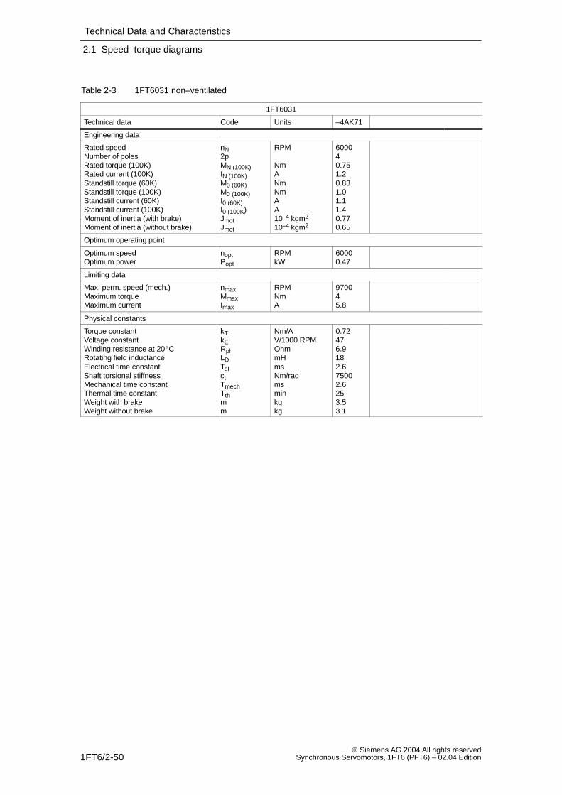
Table 2-3 1FT6031 non–ventilated
1FT6031
Technical data Code Units –4AK71
Engineering data
Rated speedNumber of polesRated torque (100K)Rated current (100K)Standstill torque (60K)Standstill torque (100K)Standstill current (60K)Standstill current (100K)Moment of inertia (with brake)Moment of inertia (without brake)
nN2pMN (100K)IN (100K)M0 (60K)M0 (100K)I0 (60K)I0 (100K)JmotJmot
RPM
NmANmNmAA10–4 kgm2
10–4 kgm2
600040.751.20.831.01.11.40.770.65
Optimum operating point
Optimum speedOptimum power
noptPopt
RPMkW
60000.47
Limiting data
Max. perm. speed (mech.)Maximum torqueMaximum current
nmaxMmaxImax
RPMNmA
970045.8
Physical constants
Torque constantVoltage constantWinding resistance at 20CRotating field inductanceElectrical time constantShaft torsional stiffnessMechanical time constantThermal time constantWeight with brakeWeight without brake
kTkERphLDTelctTmechTthmm
Nm/AV/1000 RPM OhmmHmsNm/radmsminkgkg
0.72476.9182.675002.6253.53.1
Technical Data and Characteristics
2.1 Speed–torque diagrams
1FT6/2-51 Siemens AG 2004 All rights reservedSynchronous Servomotors, 1FT6 (PFT6) – 02.04 Edition
0
0.5
1
1.5
2
2.5
3
3.5
4
4.5
0 1000 2000 3000 4000 5000 6000 7000 8000 9000
S1 (100K)S1 (60K)
S3 – 25%
S3 – 40%S3 – 60%
a cb
n [RPM]
M [N
m]
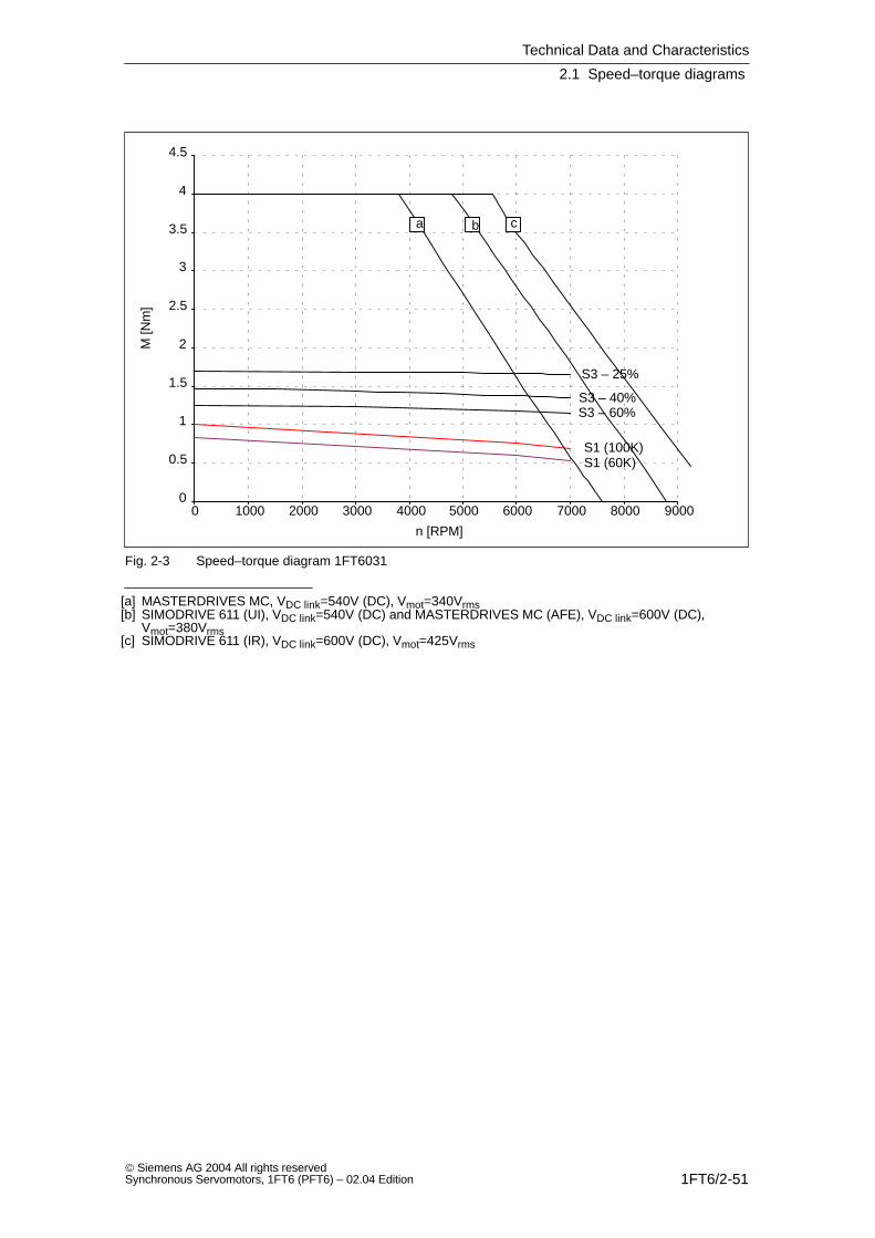
Fig. 2-3 Speed–torque diagram 1FT6031
[a] MASTERDRIVES MC, VDC link=540V (DC), Vmot=340Vrms[b] SIMODRIVE 611 (UI), VDC link=540V (DC) and MASTERDRIVES MC (AFE), VDC link=600V (DC),
Vmot=380Vrms[c] SIMODRIVE 611 (IR), VDC link=600V (DC), Vmot=425Vrms
Technical Data and Characteristics
2.1 Speed–torque diagrams
1FT6/2-52 Siemens AG 2004 All rights reserved
Synchronous Servomotors, 1FT6 (PFT6) – 02.04 Edition
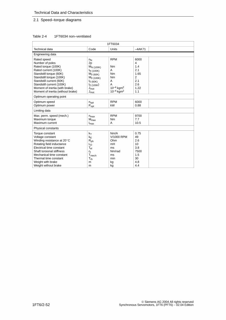
Table 2-4 1FT6034 non–ventilated
1FT6034
Technical data Code Units –4AK71
Engineering data
Rated speedNumber of polesRated torque (100K)Rated current (100K)Standstill torque (60K)Standstill torque (100K)Standstill current (60K)Standstill current (100K)Moment of inertia (with brake)Moment of inertia (without brake)
nN2pMN (100K)IN (100K)M0 (60K)M0 (100K)I0 (60K)I0 (100K)JmotJmot
RPM
NmANmNmAA10–4 kgm2
10–4 kgm2
600041.42.11.6522.12.61.221.1
Optimum operating point
Optimum speedOptimum power
noptPopt
RPMkW
60000.88
Limiting data
Max. perm. speed (mech.)Maximum torqueMaximum current
nmaxMmaxImax
RPMNmA
97007.710.5
Physical constants
Torque constantVoltage constantWinding resistance at 20CRotating field inductanceElectrical time constantShaft torsional stiffnessMechanical time constantThermal time constantWeight with brakeWeight without brake
kTkERphLDTelctTmechTthmm
Nm/AV/1000 RPM OhmmHmsNm/radmsminkgkg
0.75492.6103.875001.5304.84.4
Technical Data and Characteristics
2.1 Speed–torque diagrams
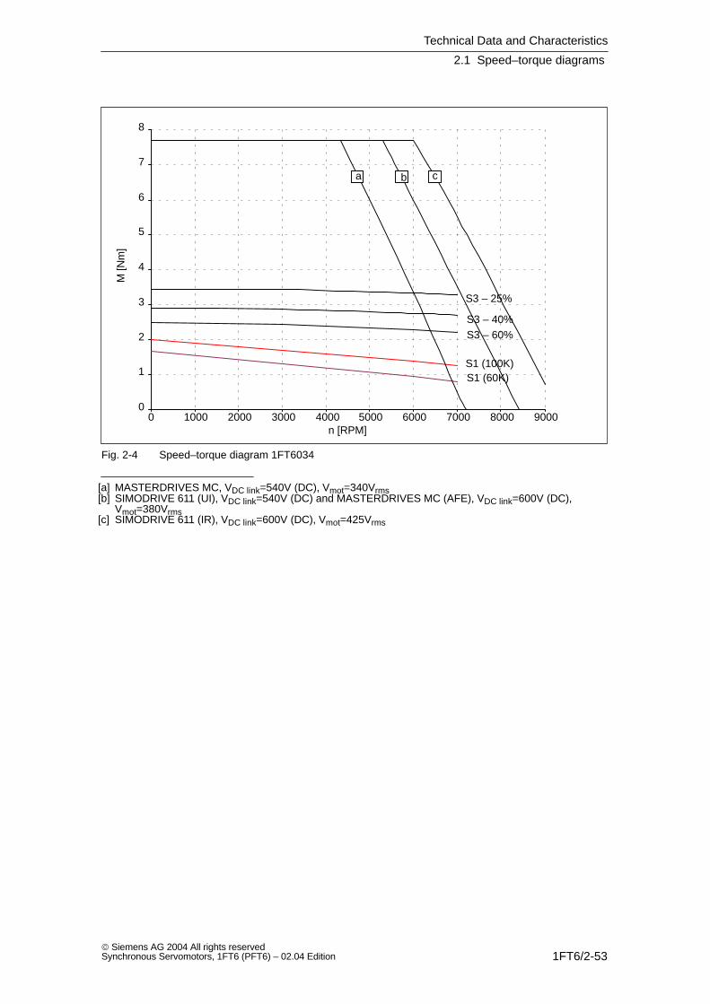
1FT6/2-53 Siemens AG 2004 All rights reservedSynchronous Servomotors, 1FT6 (PFT6) – 02.04 Edition
0
1
2
3
4
5
6
7
8
0 1000 2000 3000 4000 5000 6000 7000 8000 9000
S1 (100K)S1 (60K)
S3 – 25%
S3 – 40%S3 – 60%
a cb
n [RPM]
M [N
m]
Fig. 2-4 Speed–torque diagram 1FT6034
[a] MASTERDRIVES MC, VDC link=540V (DC), Vmot=340Vrms[b] SIMODRIVE 611 (UI), VDC link=540V (DC) and MASTERDRIVES MC (AFE), VDC link=600V (DC),
Vmot=380Vrms[c] SIMODRIVE 611 (IR), VDC link=600V (DC), Vmot=425Vrms

Technical Data and Characteristics
2.1 Speed–torque diagrams
1FT6/2-54 Siemens AG 2004 All rights reserved
Synchronous Servomotors, 1FT6 (PFT6) – 02.04 Edition
Table 2-5 1FT6041 non–ventilated
1FT6041
Technical data Code Units –4AF71 –4AK71
Engineering data
Rated speedNumber of polesRated torque (100K)Rated current (100K)Standstill torque (60K)Standstill torque (100K)Standstill current (60K)Standstill current (100K)Moment of inertia (with brake)Moment of inertia (without brake)
nN2pMN (100K)IN (100K)M0 (60K)M0 (100K)I0 (60K)I0 (100K)JmotJmot
RPM
NmANmNmAA10–4 kgm2
10–4 kgm2
300042.151.72.152.61.51.93.982.9
600041.72.42.152.62.53.03.982.9
Optimum operating point
Optimum speedOptimum power
noptPopt
RPMkW
30000.68
60001.07
Limiting data
Max. perm. speed (mech.)Maximum torqueMaximum current
nmaxMmaxImax
RPMNmA
7700107.7
77001012.8
Physical constants
Torque constantVoltage constantWinding resistance at 20CRotating field inductanceElectrical time constantShaft torsional stiffnessMechanical time constantThermal time constantWeight with brakeWeight without brake
kTkERphLDTelctTmechTthmm
Nm/AV/1000 RPMOhmmHmsNm/radmsminkgkg
1.38906.6223.3140003307.86.6
0.83542.3783.4140003307.86.6
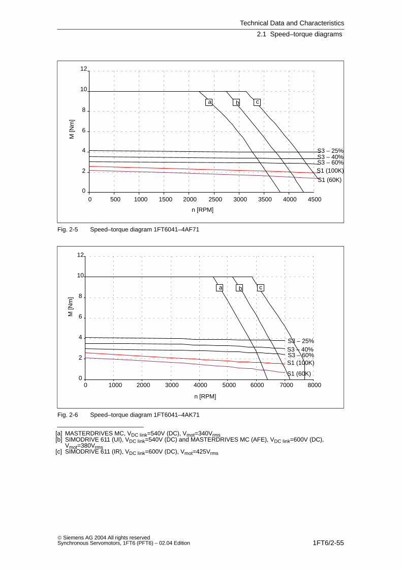
Technical Data and Characteristics
2.1 Speed–torque diagrams
1FT6/2-55 Siemens AG 2004 All rights reservedSynchronous Servomotors, 1FT6 (PFT6) – 02.04 Edition
0
2
4
6
8
10
12
0 500 1000 1500 2000 2500 3000 3500 4000 4500
S3 – 25%S3 – 40%S3 – 60%S1 (100K)
S1 (60K)
a cb
n [RPM]
M [N
m]
Fig. 2-5 Speed–torque diagram 1FT6041–4AF71
0
2
4
6
8
10
12
0 1000 2000 3000 4000 5000 6000 7000 8000
S1 (100K)
S1 (60K)
S3 – 25%S3 – 40%S3 – 60%
a cb
n [RPM]
M [N
m]
Fig. 2-6 Speed–torque diagram 1FT6041–4AK71
[a] MASTERDRIVES MC, VDC link=540V (DC), Vmot=340Vrms[b] SIMODRIVE 611 (UI), VDC link=540V (DC) and MASTERDRIVES MC (AFE), VDC link=600V (DC),
Vmot=380Vrms[c] SIMODRIVE 611 (IR), VDC link=600V (DC), Vmot=425Vrms

Technical Data and Characteristics
2.1 Speed–torque diagrams
1FT6/2-56 Siemens AG 2004 All rights reserved
Synchronous Servomotors, 1FT6 (PFT6) – 02.04 Edition
Table 2-6 1FT6044 non–ventilated
1FT6044
Technical data Code Units –AF71 –4AK71
Engineering data
Rated speedNumber of polesRated torque (100K)Rated current (100K)Standstill torque (60K)Standstill torque (100K)Standstill current (60K)Standstill current (100K)Moment of inertia (with brake)Moment of inertia (without brake)
nN2pMN (100K)IN (100K)M0 (60K)M0 (100K)I0 (60K)I0 (100K)JmotJmot
RPM
NmANmNmAA10–4 kgm2
10–4 kgm2
300044.32.94.25.02.43.06.185.1
600043.04.14.25.04.85.96.185.1
Optimum operating point
Optimum speedOptimum power
noptPopt
RPMkW
30001.35
60001.88
Limiting data
Max. perm. speed (mech.)Maximum torqueMaximum current
nmaxMmaxImax
RPMNmA
77001811
77001822
Physical constants
Torque constantVoltage constantWinding resistance at 20CRotating field inductanceElectrical time constantShaft torsional stiffnessMechanical time constantThermal time constantWeight with brakeWeight without brake
kTkERphLDTelctTmechTthmm
Nm/AV/1000 RPMOhmmHmsNm/radmsminkgkg
1.681093.05165.2110001.7409.58.3
0.85550.784.15.3110001.7409.58.3
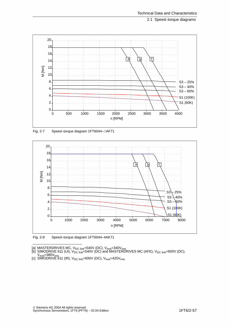
Technical Data and Characteristics
2.1 Speed–torque diagrams
1FT6/2-57 Siemens AG 2004 All rights reservedSynchronous Servomotors, 1FT6 (PFT6) – 02.04 Edition
0
2
4
6
8
10
12
14
16
18
20
0 500 1000 1500 2000 2500 3000 3500 4000
S1 (100K)
S1 (60K)
S3 – 25%S3 – 40%S3 – 60%
a cb
n [RPM]
M [N
m]
Fig. 2-7 Speed–torque diagram 1FT6044–AF71
0
2
4
6
8
10
12
14
16
18
20
0 1000 2000 3000 4000 5000 6000 7000 8000
S1 (100K)
S1 (60K)
S3 – 25%
S3 – 40%S3 – 60%
a cb
n [RPM]
M [N
m]
Fig. 2-8 Speed–torque diagram 1FT6044–4AK71
[a] MASTERDRIVES MC, VDC link=540V (DC), Vmot=340Vrms[b] SIMODRIVE 611 (UI), VDC link=540V (DC) and MASTERDRIVES MC (AFE), VDC link=600V (DC),
Vmot=380Vrms[c] SIMODRIVE 611 (IR), VDC link=600V (DC), Vmot=425Vrms

Technical Data and Characteristics
2.1 Speed–torque diagrams
1FT6/2-58 Siemens AG 2004 All rights reserved
Synchronous Servomotors, 1FT6 (PFT6) – 02.04 Edition
Table 2-7 1FT6061 non–ventilated
1FT6061
Technical data Code Units –6AC7 –6AF7
Engineering data
Rated speedNumber of polesRated torque (100K)Rated current (100K)Standstill torque (60K)Standstill torque (100K)Standstill current (60K)Standstill current (100K)Moment of inertia (with brake)Moment of inertia (without brake)
nN2pMN (100K)IN (100K)M0 (60K)M0 (100K)I0 (60K)I0 (100K)JmotJmot
RPM
NmANmNmAA10–4 kgm2
10–4 kgm2
200063.71.93.34.01.61.99.36
300063.52.63.34.02.22.79.36
Optimum operating point
Optimum speedOptimum power
noptPopt
RPMkW
20000.77
30001.1
Limiting data
Max. perm. speed (mech.)Maximum torqueMaximum current
nmaxMmaxImax
RPMNmA
91001610
91001614
Physical constants
Torque constantVoltage constantWinding resistance at 20CRotating field inductanceElectrical time constantShaft torsional stiffnessMechanical time constantThermal time constantWeight with brakeWeight without brake
kTkERphLDTelctTmechTthmm
Nm/AV/1000 RPMOhmmHmsNm/radmsminkgkg
2.071329.3596.3340003.9279.58
1.48944.71306.4340003.9279.58
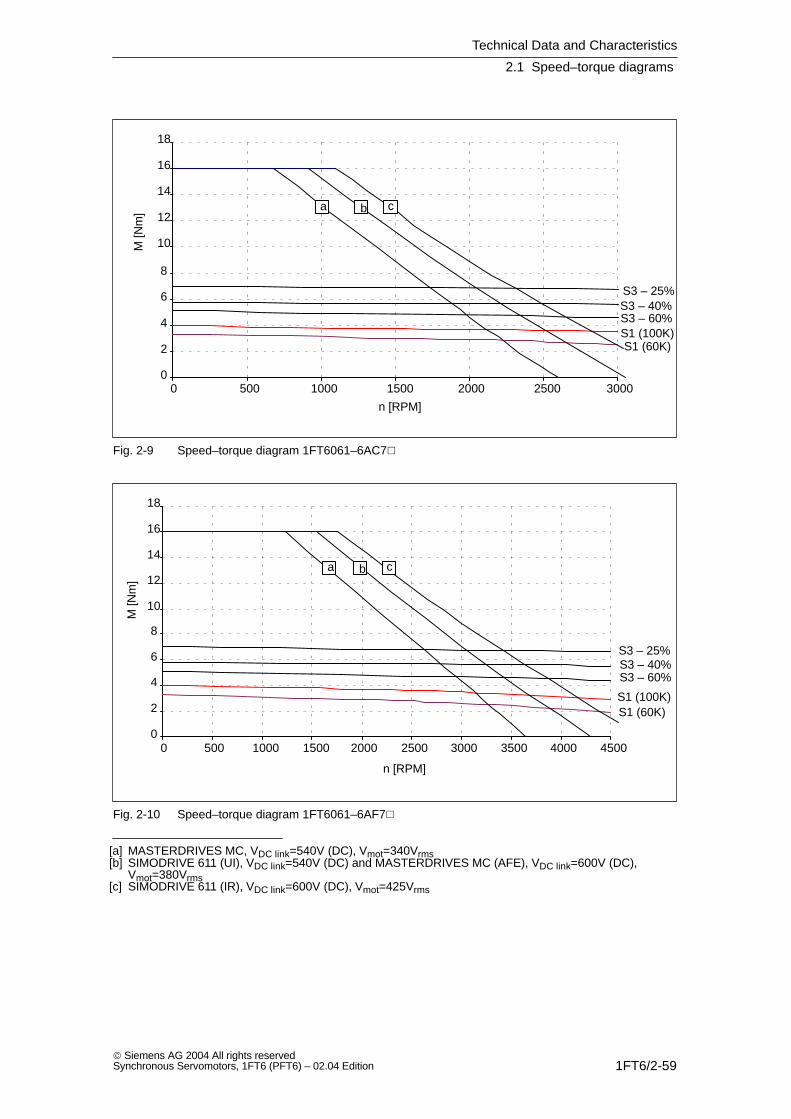
Technical Data and Characteristics
2.1 Speed–torque diagrams
1FT6/2-59 Siemens AG 2004 All rights reservedSynchronous Servomotors, 1FT6 (PFT6) – 02.04 Edition
0
2
4
6
8
10
12
14
16
18
0 500 1000 1500 2000 2500 3000
S1 (100K)S1 (60K)
S3 – 25%S3 – 40%S3 – 60%
a cb
n [RPM]
M [N
m]
Fig. 2-9 Speed–torque diagram 1FT6061–6AC7
0
2
4
6
8
10
12
14
16
18
0 500 1000 1500 2000 2500 3000 3500 4000 4500
S1 (100K)S1 (60K)
S3 – 25%S3 – 40%S3 – 60%
a cb
n [RPM]
M [N
m]
Fig. 2-10 Speed–torque diagram 1FT6061–6AF7
[a] MASTERDRIVES MC, VDC link=540V (DC), Vmot=340Vrms[b] SIMODRIVE 611 (UI), VDC link=540V (DC) and MASTERDRIVES MC (AFE), VDC link=600V (DC),
Vmot=380Vrms[c] SIMODRIVE 611 (IR), VDC link=600V (DC), Vmot=425Vrms

Technical Data and Characteristics
2.1 Speed–torque diagrams
1FT6/2-60 Siemens AG 2004 All rights reserved
Synchronous Servomotors, 1FT6 (PFT6) – 02.04 Edition
Table 2-8 1FT6061 non–ventilated
1FT6061
Technical data Code Units –6AH7 –6AK7
Engineering data
Rated speedNumber of polesRated torque (100K)Rated current (100K)Standstill torque (60K)Standstill torque (100K)Standstill current (60K)Standstill current (100K)Moment of inertia (with brake)Moment of inertia (without brake)
nN2pMN (100K)IN (100K)M0 (60K)M0 (100K)I0 (60K)I0 (100K)JmotJmot
RPM
NmANmNmAA10–4 kgm2
10–4 kgm2
450062.93.43.343.349.36
600062.13.13.34459.36
Optimum operating point
Optimum speedOptimum power
noptPopt
RPMkW
45001.37
50001.38
Limiting data
Max. perm. speed (mech.)Maximum torqueMaximum current
nmaxMmaxImax
RPMNmA
91001621
91001626
Physical constants
Torque constantVoltage constantWinding resistance at 20CRotating field inductanceElectrical time constantShaft torsional stiffnessMechanical time constantThermal time constantWeight with brakeWeight without brake
kTkERphLDTelctTmechTthmm
Nm/AV/1000 RPMOhmmHmsNm/radmsminkgkg
0.99632.113.36.3340003.9279.58
0.80511.4296.3340004.0279.58
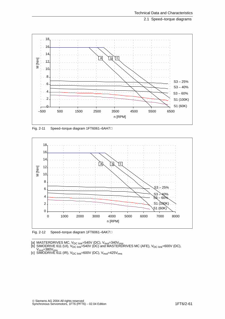
Technical Data and Characteristics
2.1 Speed–torque diagrams
1FT6/2-61 Siemens AG 2004 All rights reservedSynchronous Servomotors, 1FT6 (PFT6) – 02.04 Edition
0
2
4
6
8
10
12
14
16
18
–500 500 1500 2500 3500 4500 5500 6500
S1 (100K)
S1 (60K)
S3 – 25%
S3 – 40%
S3 – 60%
a cb
n [RPM]
M [N
m]
Fig. 2-11 Speed–torque diagram 1FT6061–6AH7
0
2
4
6
8
10
12
14
16
18
0 1000 2000 3000 4000 5000 6000 7000 8000
S1 (100K)S1 (60K)
S3 – 25%
S3 – 40%S3 – 60%
a cb
n [RPM]
M [N
m]
Fig. 2-12 Speed–torque diagram 1FT6061–6AK7
[a] MASTERDRIVES MC, VDC link=540V (DC), Vmot=340Vrms[b] SIMODRIVE 611 (UI), VDC link=540V (DC) and MASTERDRIVES MC (AFE), VDC link=600V (DC),
Vmot=380Vrms[c] SIMODRIVE 611 (IR), VDC link=600V (DC), Vmot=425Vrms

Technical Data and Characteristics
2.1 Speed–torque diagrams
1FT6/2-62 Siemens AG 2004 All rights reserved
Synchronous Servomotors, 1FT6 (PFT6) – 02.04 Edition
Table 2-9 1FT6062 non–ventilated
1FT6062
Technical data Code Units –6AC7 –6AF7
Engineering data
Rated speedNumber of polesRated torque (100K)Rated current (100K)Standstill torque (60K)Standstill torque (100K)Standstill current (60K)Standstill current (100K)Moment of inertia (with brake)Moment of inertia (without brake)
nN2pMN (100K)IN (100K)M0 (60K)M0 (100K)I0 (60K)I0 (100K)JmotJmot
RPM
NmANmNmAA10–4 kgm2
10–4 kgm2
200065.22.6562.22.711.88.5
300064.73.4563.34.111.88.5
Optimum operating point
Optimum speedOptimum power
noptPopt
RPMkW
20001.09
30001.48
Limiting data
Max. perm. speed (mech.)Maximum torqueMaximum current
nmaxMmaxImax
RPMNmA
91002415
91002422
Physical constants
Torque constantVoltage constantWinding resistance at 20CRotating field inductanceElectrical time constantShaft torsional stiffnessMechanical time constantThermal time constantWeight with brakeWeight without brake
kTkERphLDTelctTmechTthmm
Nm/AV/1000 RPMOhmmHmsNm/radmsminkgkg
2.221415.8437.4320003.030119.5
1.48942.57197.4320003.030119.5
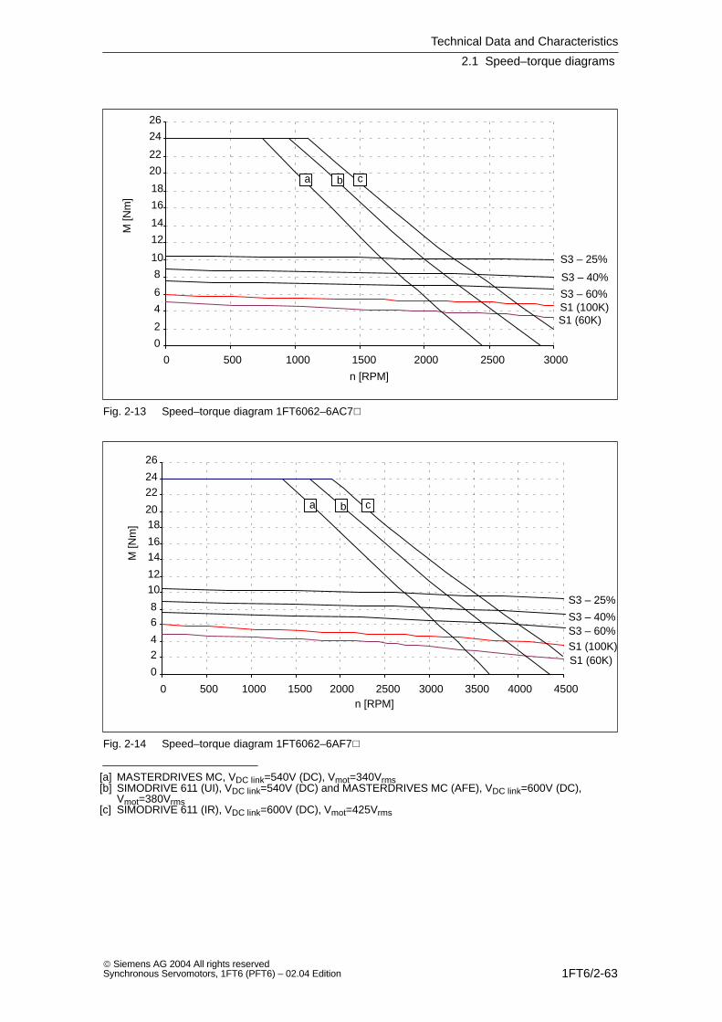
Technical Data and Characteristics
2.1 Speed–torque diagrams
1FT6/2-63 Siemens AG 2004 All rights reservedSynchronous Servomotors, 1FT6 (PFT6) – 02.04 Edition
0
2
4
6
8
10
12
14
16
18
20
22
24
26
0 500 1000 1500 2000 2500 3000
S1 (100K)S1 (60K)
S3 – 25%
S3 – 40%
S3 – 60%
a cb
n [RPM]
M [N
m]
Fig. 2-13 Speed–torque diagram 1FT6062–6AC7
0
24
68
1012
1416
1820
2224
26
0 500 1000 1500 2000 2500 3000 3500 4000 4500
S1 (100K)S1 (60K)
S3 – 25%
S3 – 40%S3 – 60%
a cb
n [RPM]
M [N
m]
Fig. 2-14 Speed–torque diagram 1FT6062–6AF7
[a] MASTERDRIVES MC, VDC link=540V (DC), Vmot=340Vrms[b] SIMODRIVE 611 (UI), VDC link=540V (DC) and MASTERDRIVES MC (AFE), VDC link=600V (DC),
Vmot=380Vrms[c] SIMODRIVE 611 (IR), VDC link=600V (DC), Vmot=425Vrms

Technical Data and Characteristics
2.1 Speed–torque diagrams
1FT6/2-64 Siemens AG 2004 All rights reserved
Synchronous Servomotors, 1FT6 (PFT6) – 02.04 Edition
Table 2-10 1FT6062 non–ventilated
1FT6062
Technical data Code Units –6AH7 –6AK7
Engineering data
Rated speedNumber of polesRated torque (100K)Rated current (100K)Standstill torque (60K)Standstill torque (100K)Standstill current (60K)Standstill current (100K)Moment of inertia (with brake)Moment of inertia (without brake)
nN2pMN (100K)IN (100K)M0 (60K)M0 (100K)I0 (60K)I0 (100K)JmotJmot
RPM
NmANmNmAA10–4 kgm2
10–4 kgm2
450063.63.9564.75.711.88.5
600062.13.2566.27.611.88.5
Optimum operating point
Optimum speedOptimum power
noptPopt
RPMkW
45001.70
45001.70
Limiting data
Max. perm. speed (mech.)Maximum torqueMaximum current
nmaxMmaxImax
RPMNmA
91002431
91002441
Physical constants
Torque constantVoltage constantWinding resistance at 20CRotating field inductanceElectrical time constantShaft torsional stiffnessMechanical time constantThermal time constantWeight with brakeWeight without brake
kTkERphLDTelctTmechTthmm
Nm/AV/1000 RPMOhmmHmsNm/radmsminkgkg
1.05671.319.77.4320003.030119.5
0.79500.745.57.4320003.030119.5
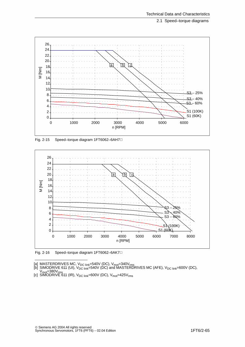
Technical Data and Characteristics
2.1 Speed–torque diagrams
1FT6/2-65 Siemens AG 2004 All rights reservedSynchronous Servomotors, 1FT6 (PFT6) – 02.04 Edition
0
2
4
6
8
10
1214
1618
2022
2426
0 1000 2000 3000 4000 5000 6000
S1 (100K)S1 (60K)
S3 – 25%
S3 – 40%S3 – 60%
a b c
n [RPM]
M [N
m]
Fig. 2-15 Speed–torque diagram 1FT6062–6AH7
0
24
68
1012
1416
1820
2224
26
0 1000 2000 3000 4000 5000 6000 7000 8000
S1 (100K)S1 (60K)
S3 – 25%S3 – 40%S3 – 60%
a b c
n [RPM]
M [N
m]
Fig. 2-16 Speed–torque diagram 1FT6062–6AK7
[a] MASTERDRIVES MC, VDC link=540V (DC), Vmot=340Vrms[b] SIMODRIVE 611 (UI), VDC link=540V (DC) and MASTERDRIVES MC (AFE), VDC link=600V (DC),
Vmot=380Vrms[c] SIMODRIVE 611 (IR), VDC link=600V (DC), Vmot=425Vrms

Technical Data and Characteristics
2.1 Speed–torque diagrams
1FT6/2-66 Siemens AG 2004 All rights reserved
Synchronous Servomotors, 1FT6 (PFT6) – 02.04 Edition
Table 2-11 1FT6064 non–ventilated
1FT6064
Technical data Code Units –6AC7 –6AF7
Engineering data
Rated speedNumber of polesRated torque (100K)Rated current (100K)Standstill torque (60K)Standstill torque (100K)Standstill current (60K)Standstill current (100K)Moment of inertia (with brake)Moment of inertia (without brake)
nN2pMN (100K)IN (100K)M0 (60K)M0 (100K)I0 (60K)I0 (100K)JmotJmot
RPM
NmANmNmAA10–4 kgm2
10–4 kgm2
200068.03.87.99.53.44.216.313
300067.04.97.99.54.96.116.313
Optimum operating point
Optimum speedOptimum power
noptPopt
RPMkW
20001.68
30002.20
Limiting data
Max. perm. speed (mech.)Maximum torqueMaximum current
nmaxMmaxImax
RPMNmA
91003823
91003833
Physical constants
Torque constantVoltage constantWinding resistance at 20CRotating field inductanceElectrical time constantShaft torsional stiffnessMechanical time constantThermal time constantWeight with brakeWeight without brake
kTkERphLDTelctTmechTthmm
Nm/AV/1000 RPMOhmmHmsNm/radmsminkgkg
2.261442.93289.6270002.2351312.5
1.571001.4013.59.6270002.2351312.5
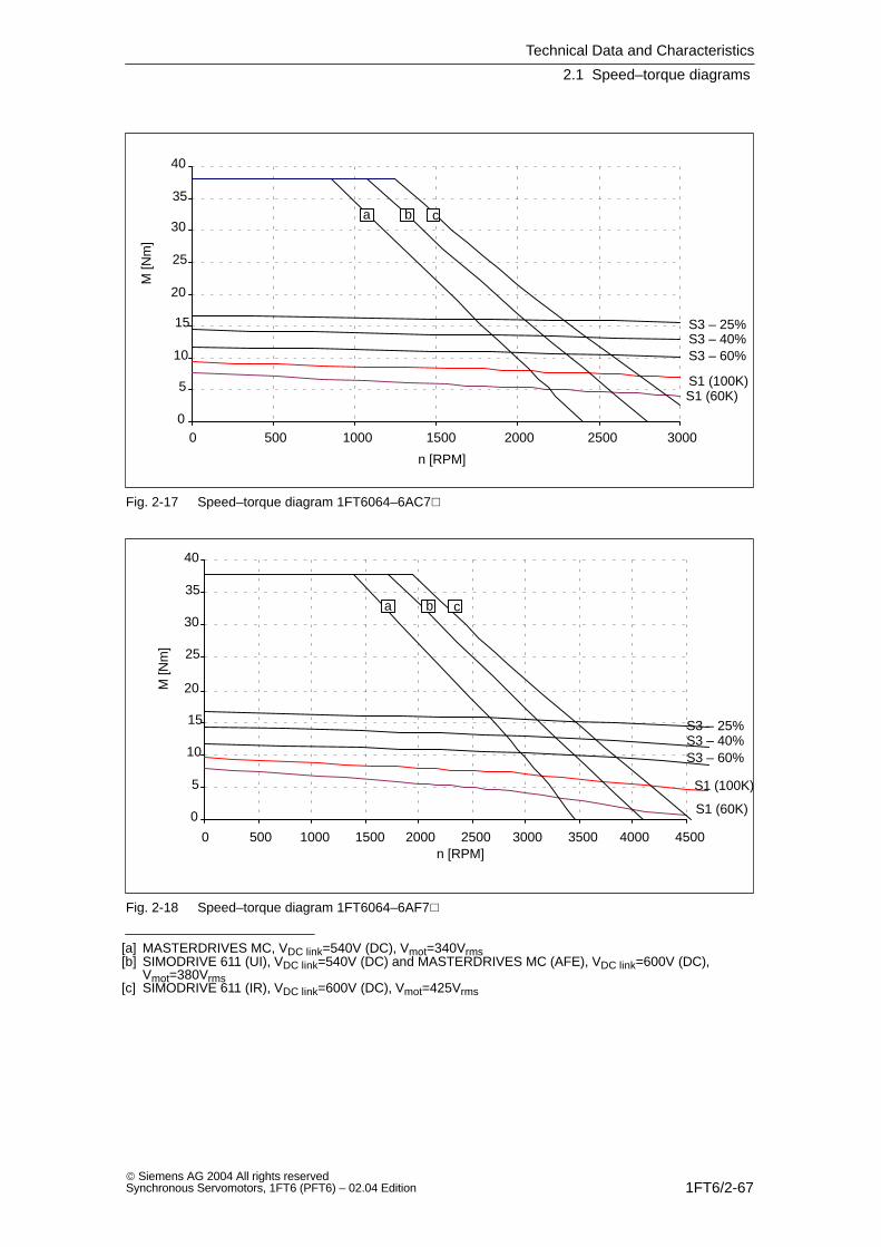
Technical Data and Characteristics
2.1 Speed–torque diagrams
1FT6/2-67 Siemens AG 2004 All rights reservedSynchronous Servomotors, 1FT6 (PFT6) – 02.04 Edition
0
5
10
15
20
25
30
35
40
0 500 1000 1500 2000 2500 3000
S1 (100K)S1 (60K)
S3 – 25%S3 – 40%S3 – 60%
a b c
n [RPM]
M [N
m]
Fig. 2-17 Speed–torque diagram 1FT6064–6AC7
0
5
10
15
20
25
30
35
40
0 500 1000 1500 2000 2500 3000 3500 4000 4500
S1 (100K)
S1 (60K)
S3 – 25%S3 – 40%S3 – 60%
a b c
n [RPM]
M [N
m]
Fig. 2-18 Speed–torque diagram 1FT6064–6AF7
[a] MASTERDRIVES MC, VDC link=540V (DC), Vmot=340Vrms[b] SIMODRIVE 611 (UI), VDC link=540V (DC) and MASTERDRIVES MC (AFE), VDC link=600V (DC),
Vmot=380Vrms[c] SIMODRIVE 611 (IR), VDC link=600V (DC), Vmot=425Vrms
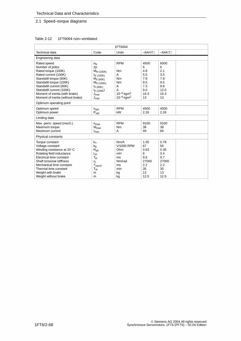
Technical Data and Characteristics
2.1 Speed–torque diagrams
1FT6/2-68 Siemens AG 2004 All rights reserved
Synchronous Servomotors, 1FT6 (PFT6) – 02.04 Edition
Table 2-12 1FT6064 non–ventilated
1FT6064
Technical data Code Units –6AH7 –6AK7
Engineering data
Rated speedNumber of polesRated torque (100K)Rated current (100K)Standstill torque (60K)Standstill torque (100K)Standstill current (60K)Standstill current (100K)Moment of inertia (with brake)Moment of inertia (without brake)
nN2pMN (100K)IN (100K)M0 (60K)M0 (100K)I0 (60K)I0 (100K)JmotJmot
RPM
NmANmNmAA10–4 kgm2
10–4 kgm2
450064.85.57.99.57.39.016.313
600062.13.57.99.59.812.016.313
Optimum operating point
Optimum speedOptimum power
noptPopt
RPMkW
45002.26
45002.26
Limiting data
Max. perm. speed (mech.)Maximum torqueMaximum current
nmaxMmaxImax
RPMNmA
91003849
91003866
Physical constants
Torque constantVoltage constantWinding resistance at 20CRotating field inductanceElectrical time constantShaft torsional stiffnessMechanical time constantThermal time constantWeight with brakeWeight without brake
kTkERphLDTelctTmechTthmm
Nm/AV/1000 RPMOhmmHmsNm/radmsminkgkg
1.05670.6369.5270002.2351312.5
0.79500.353.49.7270002.2351312.5
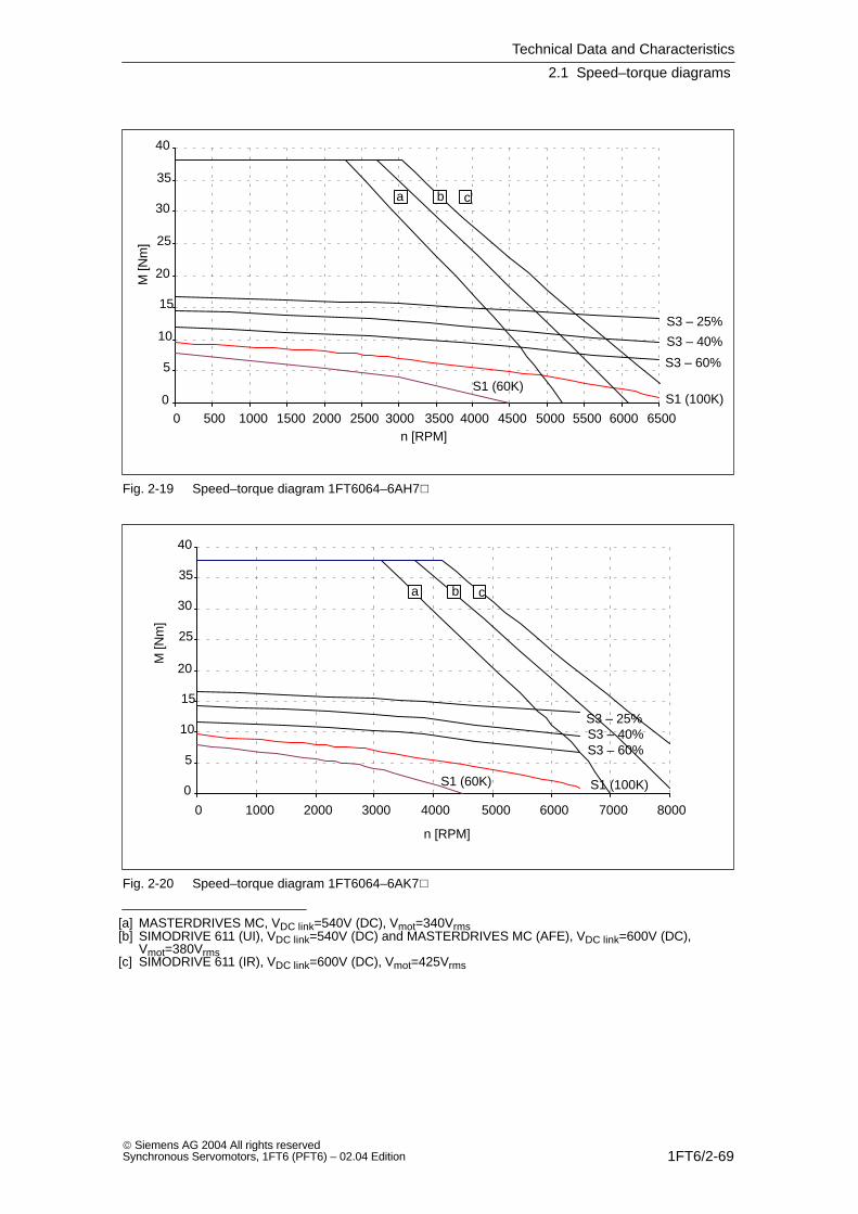
Technical Data and Characteristics
2.1 Speed–torque diagrams
1FT6/2-69 Siemens AG 2004 All rights reservedSynchronous Servomotors, 1FT6 (PFT6) – 02.04 Edition
0
5
10
15
20
25
30
35
40
0 500 1000 1500 2000 2500 3000 3500 4000 4500 5000 5500 6000 6500
S1 (100K)S1 (60K)
S3 – 25%
S3 – 40%
S3 – 60%
a b c
n [RPM]
M [N
m]
Fig. 2-19 Speed–torque diagram 1FT6064–6AH7
0
5
10
15
20
25
30
35
40
0 1000 2000 3000 4000 5000 6000 7000 8000
S1 (100K)S1 (60K)
S3 – 25%S3 – 40%S3 – 60%
a b c
n [RPM]
M [N
m]
Fig. 2-20 Speed–torque diagram 1FT6064–6AK7
[a] MASTERDRIVES MC, VDC link=540V (DC), Vmot=340Vrms[b] SIMODRIVE 611 (UI), VDC link=540V (DC) and MASTERDRIVES MC (AFE), VDC link=600V (DC),
Vmot=380Vrms[c] SIMODRIVE 611 (IR), VDC link=600V (DC), Vmot=425Vrms

Technical Data and Characteristics
2.1 Speed–torque diagrams
1FT6/2-70 Siemens AG 2004 All rights reserved
Synchronous Servomotors, 1FT6 (PFT6) – 02.04 Edition
Table 2-13 1FT6081 non–ventilated
1FT6081
Technical data Code Units –8AC7 –8AF7
Engineering data
Rated speedNumber of polesRated torque (100K)Rated current (100K)Standstill torque (60K)Standstill torque (100K)Standstill current (60K)Standstill current (100K)Moment of inertia (with brake)Moment of inertia (without brake)
nN2pMN (100K)IN (100K)M0 (60K)M0 (100K)I0 (60K)I0 (100K)JmotJmot
RPM
NmANmNmAA10–4 kgm2
10–4 kgm2
200087.54.16.68.03.13.924.821
300086.95.66.68.04.75.824.821
Optimum operating point
Optimum speedOptimum power
noptPopt
RPMkW
20001.57
30002.17
Limiting data
Max. perm. speed (mech.)Maximum torqueMaximum current
nmaxMmaxImax
RPMNmA
79002616.5
79002624.5
Physical constants
Torque constantVoltage constantWinding resistance at 20CRotating field inductanceElectrical time constantShaft torsional stiffnessMechanical time constantThermal time constantWeight with brakeWeight without brake
kTkERphLDTelctTmechTthmm
Nm/AV/1000 RPMOhmmHmsNm/radmsminkgkg
2.071323.08237.51000004.5301412.5
1.38881.3710.37.51000004.5301412.5
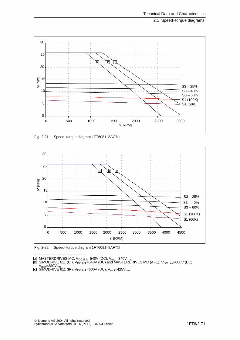
Technical Data and Characteristics
2.1 Speed–torque diagrams
1FT6/2-71 Siemens AG 2004 All rights reservedSynchronous Servomotors, 1FT6 (PFT6) – 02.04 Edition
0
5
10
15
20
25
30
0 500 1000 1500 2000 2500 3000
S1 (100K)S1 (60K)
S3 – 25%S3 – 40%S3 – 60%
a b c
n [RPM]
M [N
m]
Fig. 2-21 Speed–torque diagram 1FT6081–8AC7
0
5
10
15
20
25
30
0 500 1000 1500 2000 2500 3000 3500 4000 4500
S1 (100K)
S1 (60K)
S3 – 25%
S3 – 40%S3 – 60%
a b c
n [RPM]
M [N
m]
Fig. 2-22 Speed–torque diagram 1FT6081–8AF7
[a] MASTERDRIVES MC, VDC link=540V (DC), Vmot=340Vrms[b] SIMODRIVE 611 (UI), VDC link=540V (DC) and MASTERDRIVES MC (AFE), VDC link=600V (DC),
Vmot=380Vrms[c] SIMODRIVE 611 (IR), VDC link=600V (DC), Vmot=425Vrms

Technical Data and Characteristics
2.1 Speed–torque diagrams
1FT6/2-72 Siemens AG 2004 All rights reserved
Synchronous Servomotors, 1FT6 (PFT6) – 02.04 Edition
Table 2-14 1FT6081 non–ventilated
1FT6081
Technical data Code Units –8AH7 –8AK7
Engineering data
Rated speedNumber of polesRated torque (100K)Rated current (100K)Standstill torque (60K)Standstill torque (100K)Standstill current (60K)Standstill current (100K)Moment of inertia (with brake)Moment of inertia (without brake)
nN2pMN (100K)IN (100K)M0 (60K)M0 (100K)I0 (60K)I0 (100K)JmotJmot
RPM
NmANmNmAA10–4 kgm2
10–4 kgm2
450085.87.36.68.07.08.624.821
600084.67.76.68.08.911.124.821
Optimum operating point
Optimum speedOptimum power
noptPopt
RPMkW
45002.73
60002.89
Limiting data
Max. perm. speed (mech.)Maximum torqueMaximum current
nmaxMmaxImax
RPMNmA
79002637
79002646
Physical constants
Torque constantVoltage constantWinding resistance at 20CRotating field inductanceElectrical time constantShaft torsional stiffnessMechanical time constantThermal time constantWeight with brakeWeight without brake
kTkERphLDTelctTmechTthmm
Nm/AV/1000 RPMOhmmHmsNm/radmsminkgkg
0.93590.614.67.51000004.4301412.5
0.72460.3837.91000004.6301412.5
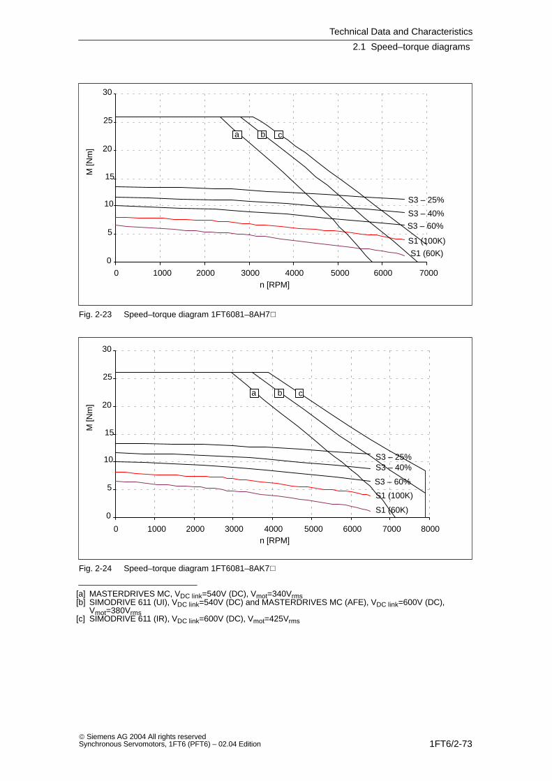
Technical Data and Characteristics
2.1 Speed–torque diagrams
1FT6/2-73 Siemens AG 2004 All rights reservedSynchronous Servomotors, 1FT6 (PFT6) – 02.04 Edition
0
5
10
15
20
25
30
0 1000 2000 3000 4000 5000 6000 7000
S1 (100K)
S1 (60K)
S3 – 25%
S3 – 40%
S3 – 60%
a b c
n [RPM]
M [N
m]
Fig. 2-23 Speed–torque diagram 1FT6081–8AH7
0
5
10
15
20
25
30
0 1000 2000 3000 4000 5000 6000 7000 8000
S1 (100K)
S1 (60K)
S3 – 25%S3 – 40%
S3 – 60%
a b c
n [RPM]
M [N
m]
Fig. 2-24 Speed–torque diagram 1FT6081–8AK7
[a] MASTERDRIVES MC, VDC link=540V (DC), Vmot=340Vrms[b] SIMODRIVE 611 (UI), VDC link=540V (DC) and MASTERDRIVES MC (AFE), VDC link=600V (DC),
Vmot=380Vrms[c] SIMODRIVE 611 (IR), VDC link=600V (DC), Vmot=425Vrms

Technical Data and Characteristics
2.1 Speed–torque diagrams
1FT6/2-74 Siemens AG 2004 All rights reserved
Synchronous Servomotors, 1FT6 (PFT6) – 02.04 Edition
Table 2-15 1FT6082 non–ventilated
1FT6082
Technical data Code Units –8AC7 –AF7
Engineering data
Rated speedNumber of polesRated torque (100K)Rated current (100K)Standstill torque (60K)Standstill torque (100K)Standstill current (60K)Standstill current (100K)Moment of inertia (with brake)Moment of inertia (without brake)
nN2pMN (100K)IN (100K)M0 (60K)M0 (100K)I0 (60K)I0 (100K)JmotJmot
RPM
NmANmNmAA10–4 kgm2
10–4 kgm2
2000811.46.610.8135.46.633.830
3000810.38.710.8137.89.633.830
Optimum operating point
Optimum speedOptimum power
noptPopt
RPMkW
20002.39
30003.24
Limiting data
Max. perm. speed (mech.)Maximum torqueMaximum current
nmaxMmaxImax
RPMNmA
79004228
79004241
Physical constants
Torque constantVoltage constantWinding resistance at 20CRotating field inductanceElectrical time constantShaft torsional stiffnessMechanical time constantThermal time constantWeight with brakeWeight without brake
kTkERphLDTelctTmechTthmm
Nm/AV/1000 RPMOhmmHmsNm/radmsminkgkg
1.961251.4813.69.2900003.53516.515
1.35860.696.29.0900003,43516.515
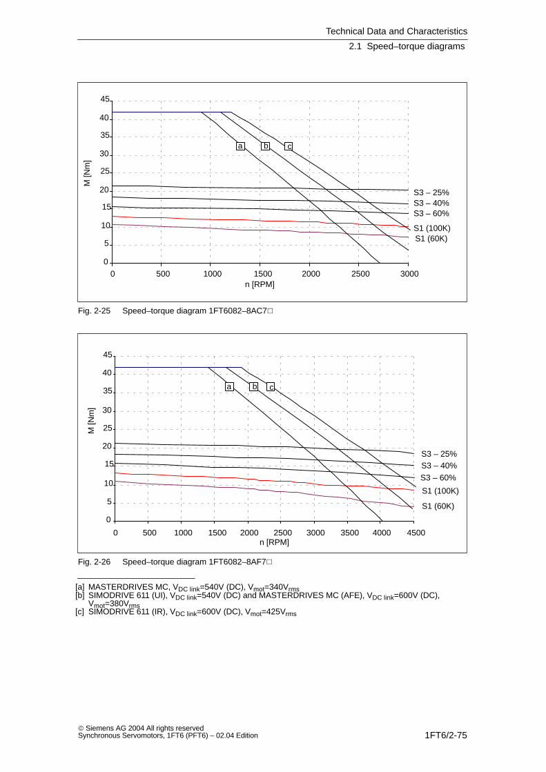
Technical Data and Characteristics
2.1 Speed–torque diagrams
1FT6/2-75 Siemens AG 2004 All rights reservedSynchronous Servomotors, 1FT6 (PFT6) – 02.04 Edition
0
5
10
15
20
25
30
35
40
45
0 500 1000 1500 2000 2500 3000
S1 (100K)S1 (60K)
S3 – 25%S3 – 40%S3 – 60%
a b c
n [RPM]
M [N
m]
Fig. 2-25 Speed–torque diagram 1FT6082–8AC7
0
5
10
15
20
25
30
35
40
45
0 500 1000 1500 2000 2500 3000 3500 4000 4500
S1 (100K)
S1 (60K)
S3 – 25%S3 – 40%
S3 – 60%
a b c
n [RPM]
M [N
m]
Fig. 2-26 Speed–torque diagram 1FT6082–8AF7
[a] MASTERDRIVES MC, VDC link=540V (DC), Vmot=340Vrms[b] SIMODRIVE 611 (UI), VDC link=540V (DC) and MASTERDRIVES MC (AFE), VDC link=600V (DC),
Vmot=380Vrms[c] SIMODRIVE 611 (IR), VDC link=600V (DC), Vmot=425Vrms

Technical Data and Characteristics
2.1 Speed–torque diagrams
1FT6/2-76 Siemens AG 2004 All rights reserved
Synchronous Servomotors, 1FT6 (PFT6) – 02.04 Edition
Table 2-16 1FT6082 non–ventilated
1FT6082
Technical data Code Units –8AH7 –8AK7
Engineering data
Rated speedNumber of polesRated torque (100K)Rated current (100K)Standstill torque (60K)Standstill torque (100K)Standstill current (60K)Standstill current (100K)Moment of inertia (with brake)Moment of inertia (without brake)
nN2pMN (100K)IN (100K)M0 (60K)M0 (100K)I0 (60K)I0 (100K)JmotJmot
RPM
NmANmNmAA10–4 kgm2
10–4 kgm2
450088.51110.81312.014.833.830
600085.59.110.813.014.017.333.830
Optimum operating point
Optimum speedOptimum power
noptPopt
RPMkW
45004.01
45004.01
Limiting data
Max. perm. speed (mech.)Maximum torqueMaximum current
nmaxMmaxImax
RPMNmA
79004260
79004273
Physical constants
Torque constantVoltage constantWinding resistance at 20CRotating field inductanceElectrical time constantShaft torsional stiffnessMechanical time constantThermal time constantWeight with brakeWeight without brake
kTkERphLDTelctTmechTthmm
Nm/AV/1000 RPMOhmmHmsNm/radmsminkgkg
0.88560.302.99.7900003.53516.515
0.75480.211.99.0900003,43516.515
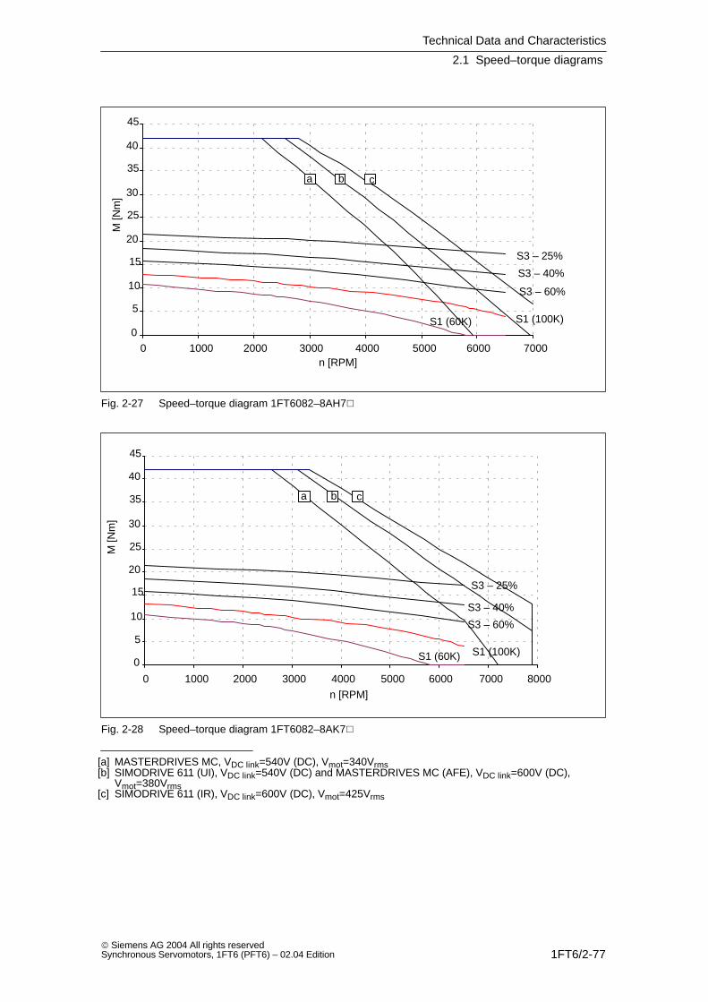
Technical Data and Characteristics
2.1 Speed–torque diagrams
1FT6/2-77 Siemens AG 2004 All rights reservedSynchronous Servomotors, 1FT6 (PFT6) – 02.04 Edition
0
5
10
15
20
25
30
35
40
45
0 1000 2000 3000 4000 5000 6000 7000
S1 (100K)S1 (60K)
S3 – 25%
S3 – 40%
S3 – 60%
a b c
n [RPM]
M [N
m]
Fig. 2-27 Speed–torque diagram 1FT6082–8AH7
0
5
10
15
20
25
30
35
40
45
0 1000 2000 3000 4000 5000 6000 7000 8000
S1 (100K)S1 (60K)
S3 – 25%
S3 – 40%
S3 – 60%
a b c
n [RPM]
M [N
m]
Fig. 2-28 Speed–torque diagram 1FT6082–8AK7
[a] MASTERDRIVES MC, VDC link=540V (DC), Vmot=340Vrms[b] SIMODRIVE 611 (UI), VDC link=540V (DC) and MASTERDRIVES MC (AFE), VDC link=600V (DC),
Vmot=380Vrms[c] SIMODRIVE 611 (IR), VDC link=600V (DC), Vmot=425Vrms

Technical Data and Characteristics
2.1 Speed–torque diagrams
1FT6/2-78 Siemens AG 2004 All rights reserved
Synchronous Servomotors, 1FT6 (PFT6) – 02.04 Edition
Table 2-17 1FT6084 non–ventilated
1FT6084
Technical data Code Units –8AC7 –AF7
Engineering data
Rated speedNumber of polesRated torque (100K)Rated current (100K)Standstill torque (60K)Standstill torque (100K)Standstill current (60K)Standstill current (100K)Moment of inertia (with brake)Moment of inertia (without brake)
nN2pMN (100K)IN (100K)M0 (60K)M0 (100K)I0 (60K)I0 (100K)JmotJmot
RPM
NmANmNmAA10–4 kgm2
10–4 kgm2
2000816.98.316.6207.28.861.148
3000814.71116.62010.713.261.148
Optimum operating point
Optimum speedOptimum power
noptPopt
RPMkW
20003.54
30004.62
Limiting data
Max. perm. speed (mech.)Maximum torqueMaximum current
nmaxMmaxImax
RPMNmA
79006538
79006556
Physical constants
Torque constantVoltage constantWinding resistance at 20CRotating field inductanceElectrical time constantShaft torsional stiffnessMechanical time constantThermal time constantWeight with brakeWeight without brake
kTkERphLDTelctTmechTthmm
Nm/AV/1000 RPMOhmmHmsNm/radmsminkgkg
2.261440.9110.411.4760002.6422420.5
1.52970.414.811.7760002,6422420.5
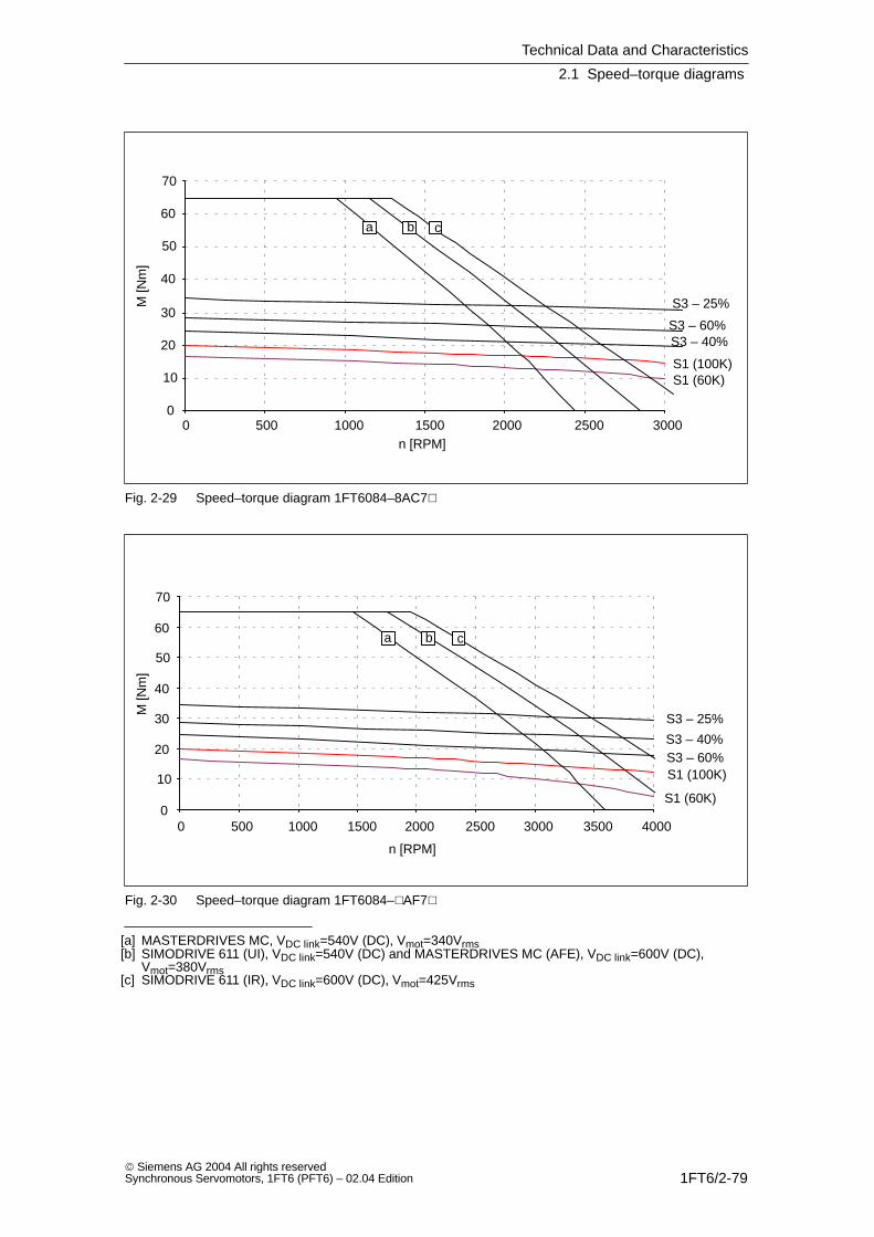
Technical Data and Characteristics
2.1 Speed–torque diagrams
1FT6/2-79 Siemens AG 2004 All rights reservedSynchronous Servomotors, 1FT6 (PFT6) – 02.04 Edition
0
10
20
30
40
50
60
70
0 500 1000 1500 2000 2500 3000
S1 (100K)S1 (60K)
S3 – 25%
S3 – 40%S3 – 60%
a b c
n [RPM]
M [N
m]
Fig. 2-29 Speed–torque diagram 1FT6084–8AC7
n [RPM]
M [N
m]
0
10
20
30
40
50
60
70
0 500 1000 1500 2000 2500 3000 3500 4000
a b c
S1 (100K)
S1 (60K)
S3 – 25%
S3 – 40%S3 – 60%
Fig. 2-30 Speed–torque diagram 1FT6084–AF7
[a] MASTERDRIVES MC, VDC link=540V (DC), Vmot=340Vrms[b] SIMODRIVE 611 (UI), VDC link=540V (DC) and MASTERDRIVES MC (AFE), VDC link=600V (DC),
Vmot=380Vrms[c] SIMODRIVE 611 (IR), VDC link=600V (DC), Vmot=425Vrms
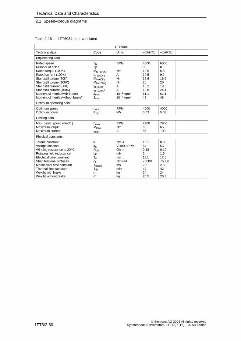
Technical Data and Characteristics
2.1 Speed–torque diagrams
1FT6/2-80 Siemens AG 2004 All rights reserved
Synchronous Servomotors, 1FT6 (PFT6) – 02.04 Edition
Table 2-18 1FT6084 non–ventilated
1FT6084
Technical data Code Units –AH7 –AK7
Engineering data
Rated speedNumber of polesRated torque (100K)Rated current (100K)Standstill torque (60K)Standstill torque (100K)Standstill current (60K)Standstill current (100K)Moment of inertia (with brake)Moment of inertia (without brake)
nN2pMN (100K)IN (100K)M0 (60K)M0 (100K)I0 (60K)I0 (100K)JmotJmot
RPM
NmANmNmAA10–4 kgm2
10–4 kgm2
4500810.512.516.62016.219.861.148
600086.59.216.62019.524.161.148
Optimum operating point
Optimum speedOptimum power
noptPopt
RPMkW
40005.03
40005.03
Limiting data
Max. perm. speed (mech.)Maximum torqueMaximum current
nmaxMmaxImax
RPMNmA
79006586
790065100
Physical constants
Torque constantVoltage constantWinding resistance at 20CRotating field inductanceElectrical time constantShaft torsional stiffnessMechanical time constantThermal time constantWeight with brakeWeight without brake
kTkERphLDTelctTmechTthmm
Nm/AV/1000 RPMOhmmHmsNm/radmsminkgkg
1.01640.18211.1760002.5422420.5
0.83530.121.512.5760002,5422420.5
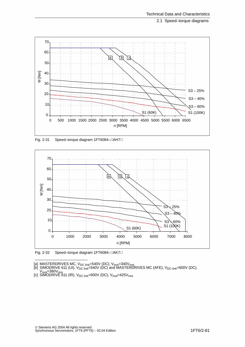
Technical Data and Characteristics
2.1 Speed–torque diagrams
1FT6/2-81 Siemens AG 2004 All rights reservedSynchronous Servomotors, 1FT6 (PFT6) – 02.04 Edition
0
10
20
30
40
50
60
70
0 500 1000 1500 2000 2500 3000 3500 4000 4500 5000 5500 6000 6500
S1 (100K)S1 (60K)
S3 – 25%
S3 – 40%
S3 – 60%
a b c
n [RPM]
M [N
m]
Fig. 2-31 Speed–torque diagram 1FT6084–AH7
0
10
20
30
40
50
60
70
0 1000 2000 3000 4000 5000 6000 7000 8000
S1 (100K)S1 (60K)
S3 – 25%
S3 – 40%
S3 – 60%
a b c
n [RPM]
M [N
m]
Fig. 2-32 Speed–torque diagram 1FT6084–AK7
[a] MASTERDRIVES MC, VDC link=540V (DC), Vmot=340Vrms[b] SIMODRIVE 611 (UI), VDC link=540V (DC) and MASTERDRIVES MC (AFE), VDC link=600V (DC),
Vmot=380Vrms[c] SIMODRIVE 611 (IR), VDC link=600V (DC), Vmot=425Vrms

Technical Data and Characteristics
2.1 Speed–torque diagrams
1FT6/2-82 Siemens AG 2004 All rights reserved
Synchronous Servomotors, 1FT6 (PFT6) – 02.04 Edition
Table 2-19 1FT6086 non–ventilated
1FT6086
Technical data Code Units –8AC7
Engineering data
Rated speedNumber of polesRated torque (100K)Rated current (100K)Standstill torque (60K)Standstill torque (100K)Standstill current (60K)Standstill current (100K)Moment of inertia (with brake)Moment of inertia (without brake)
nN2pMN (100K)IN (100K)M0 (60K)M0 (100K)I0 (60K)I0 (100K)JmotJmot
RPM
NmANmNmAA10–4 kgm2
10–4 kgm2
2000822.510.922.4279.211.379.666.5
Optimum operating point
Optimum speedOptimum power
noptPopt
RPMkW
20004.71
Limiting data
Max. perm. speed (mech.)Maximum torqueMaximum current
nmaxMmaxImax
RPMNmA
79009048
Physical constants
Torque constantVoltage constantWinding resistance at 20CRotating field inductanceElectrical time constantShaft torsional stiffnessMechanical time constantThermal time constantWeight with brakeWeight without brake
kTkERphLDTelctTmechTthmm
Nm/AV/1000 RPMOhmmHmsNm/radmsminkgkg
2.391520.65812.3650002.3502925.5
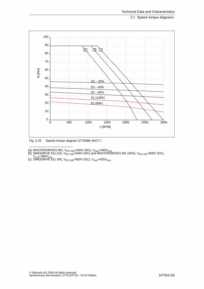
Technical Data and Characteristics
2.1 Speed–torque diagrams
1FT6/2-83 Siemens AG 2004 All rights reservedSynchronous Servomotors, 1FT6 (PFT6) – 02.04 Edition
0
10
20
30
40
50
60
70
80
90
100
0 500 1000 1500 2000 2500 3000
S1 (100K)
S1 (60K)
S3 – 25%
S3 – 40%
S3 – 60%
a b c
n [RPM]
M [N
m]
Fig. 2-33 Speed–torque diagram 1FT6086–8AC7
[a] MASTERDRIVES MC, VDC link=540V (DC), Vmot=340Vrms[b] SIMODRIVE 611 (UI), VDC link=540V (DC) and MASTERDRIVES MC (AFE), VDC link=600V (DC),
Vmot=380Vrms[c] SIMODRIVE 611 (IR), VDC link=600V (DC), Vmot=425Vrms

Technical Data and Characteristics
2.1 Speed–torque diagrams
1FT6/2-84 Siemens AG 2004 All rights reserved
Synchronous Servomotors, 1FT6 (PFT6) – 02.04 Edition
Table 2-20 1FT6086 non–ventilated
1FT6086
Technical data Code Units –AF7 –AH7
Engineering data
Rated speedNumber of polesRated torque (100K)Rated current (100K)Standstill torque (60K)Standstill torque (100K)Standstill current (60K)Standstill current (100K)Moment of inertia (with brake)Moment of inertia (without brake)
nN2pMN (100K)IN (100K)M0 (60K)M0 (100K)I0 (60K)I0 (100K)JmotJmot
RPM
NmANmNmAA10–4 kgm2
10–4 kgm2
3000818.51322.42713.316.479.666.5
450081212.622.42718.923.379.666.5
Optimum operating point
Optimum speedOptimum power
noptPopt
RPMkW
30005.81
30005.81
Limiting data
Max. perm. speed (mech.)Maximum torqueMaximum current
nmaxMmaxImax
RPMNmA
79009071
790090102
Physical constants
Torque constantVoltage constantWinding resistance at 20CRotating field inductanceElectrical time constantShaft torsional stiffnessMechanical time constantThermal time constantWeight with brakeWeight without brake
kTkERphLDTelctTmechTthmm
Nm/AV/1000 RPMOhmmHmsNm/radmsminkgkg
1.651050.313.812.3650002,3502925.5
1.16740.151.812650002,2502925.5
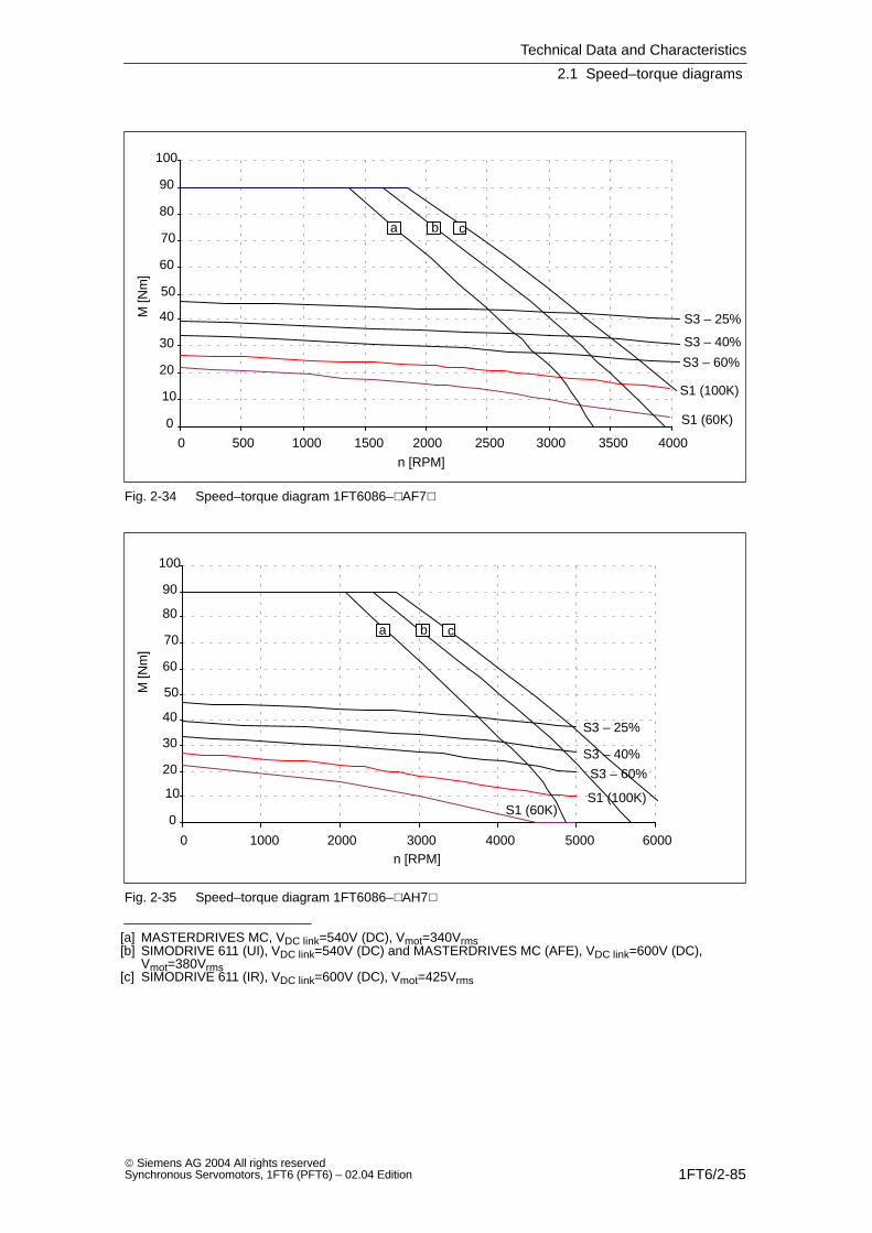
Technical Data and Characteristics
2.1 Speed–torque diagrams
1FT6/2-85 Siemens AG 2004 All rights reservedSynchronous Servomotors, 1FT6 (PFT6) – 02.04 Edition
0
10
20
30
40
50
60
70
80
90
100
0 500 1000 1500 2000 2500 3000 3500 4000
S1 (100K)
S1 (60K)
S3 – 25%
S3 – 40%
S3 – 60%
a b c
n [RPM]
M [N
m]
Fig. 2-34 Speed–torque diagram 1FT6086–AF7
0
10
20
30
40
50
60
70
80
90
100
0 1000 2000 3000 4000 5000 6000
S1 (100K)S1 (60K)
S3 – 25%
S3 – 40%
S3 – 60%
a b c
n [RPM]
M [N
m]
Fig. 2-35 Speed–torque diagram 1FT6086–AH7
[a] MASTERDRIVES MC, VDC link=540V (DC), Vmot=340Vrms[b] SIMODRIVE 611 (UI), VDC link=540V (DC) and MASTERDRIVES MC (AFE), VDC link=600V (DC),
Vmot=380Vrms[c] SIMODRIVE 611 (IR), VDC link=600V (DC), Vmot=425Vrms

Technical Data and Characteristics
2.1 Speed–torque diagrams
1FT6/2-86 Siemens AG 2004 All rights reserved
Synchronous Servomotors, 1FT6 (PFT6) – 02.04 Edition
Table 2-21 1FT6102 non–ventilated
1FT6102
Technical data Code Units –8AB7 –AC7
Engineering data
Rated speedNumber of polesRated torque (100K)Rated current (100K)Standstill torque (60K)Standstill torque (100K)Standstill current (60K)Standstill current (100K)Moment of inertia (with brake)Moment of inertia (without brake)
nN2pMN (100K)IN (100K)M0 (60K)M0 (100K)I0 (60K)I0 (100K)JmotJmot
RPM
NmANmNmAA10–4 kgm2
10–4 kgm2
1500824.58.422.4277.08.713099
20008231122.4279.812.113099
Optimum operating point
Optimum speedOptimum power
noptPopt
RPMkW
15003.85
20004.82
Limiting data
Max. perm. speed (mech.)Maximum torqueMaximum current
nmaxMmaxImax
RPMNmA
56008042
56008059
Physical constants
Torque constantVoltage constantWinding resistance at 20CRotating field inductanceElectrical time constantShaft torsional stiffnessMechanical time constantThermal time constantWeight with brakeWeight without brake
kTkERphLDTelctTmechTthmm
Nm/AV/1000 RPMOhmmHmsNm/radmsminkgkg
3.111980.8215.1181370002.5453227.5
2.231420.427.7181370002,5453227.5
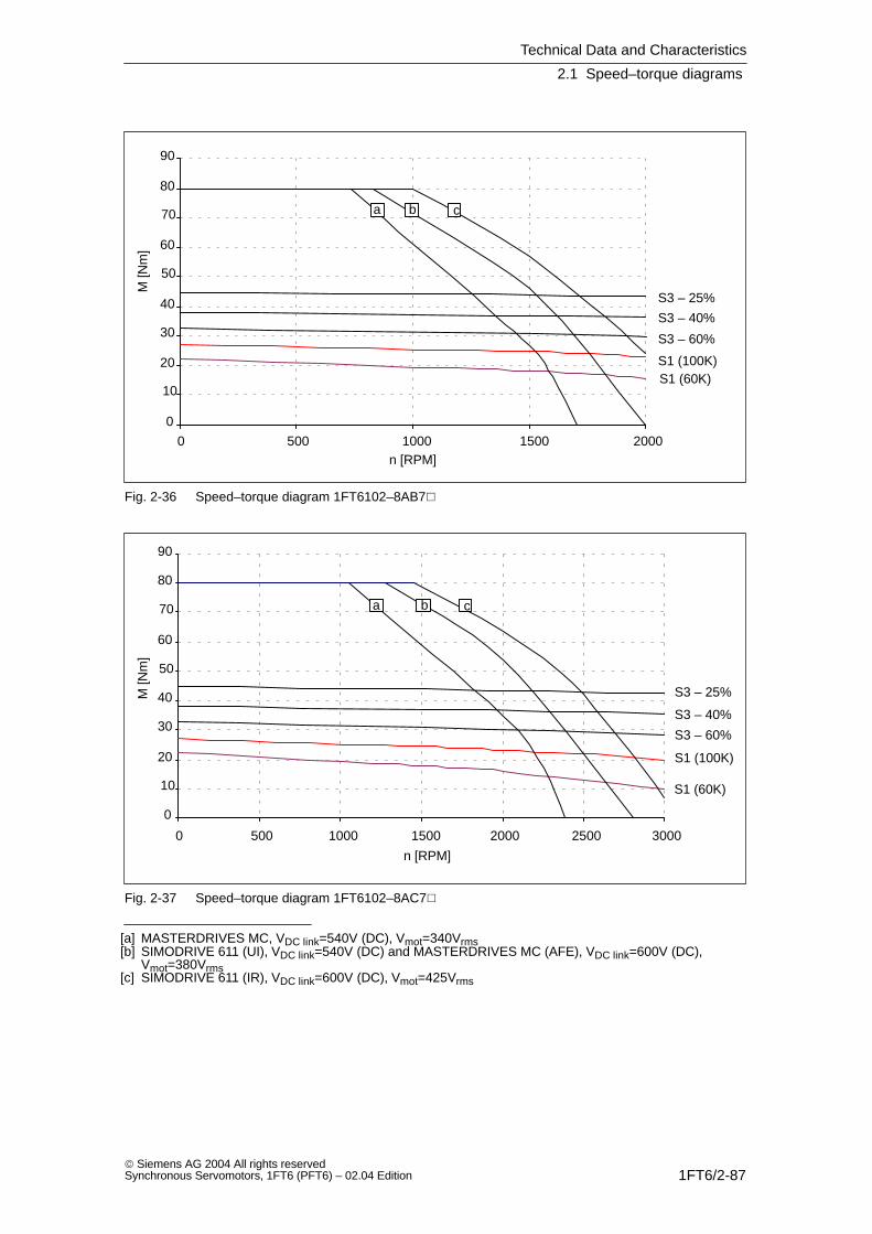
Technical Data and Characteristics
2.1 Speed–torque diagrams
1FT6/2-87 Siemens AG 2004 All rights reservedSynchronous Servomotors, 1FT6 (PFT6) – 02.04 Edition
0
10
20
30
40
50
60
70
80
90
0 500 1000 1500 2000
S1 (100K)S1 (60K)
S3 – 25%
S3 – 40%
S3 – 60%
a b c
n [RPM]
M [N
m]
Fig. 2-36 Speed–torque diagram 1FT6102–8AB7
0
10
20
30
40
50
60
70
80
90
0 500 1000 1500 2000 2500 3000
S1 (100K)
S1 (60K)
S3 – 25%
S3 – 40%
S3 – 60%
a b c
n [RPM]
M [N
m]
Fig. 2-37 Speed–torque diagram 1FT6102–8AC7
[a] MASTERDRIVES MC, VDC link=540V (DC), Vmot=340Vrms[b] SIMODRIVE 611 (UI), VDC link=540V (DC) and MASTERDRIVES MC (AFE), VDC link=600V (DC),
Vmot=380Vrms[c] SIMODRIVE 611 (IR), VDC link=600V (DC), Vmot=425Vrms

Technical Data and Characteristics
2.1 Speed–torque diagrams
1FT6/2-88 Siemens AG 2004 All rights reserved
Synchronous Servomotors, 1FT6 (PFT6) – 02.04 Edition
Table 2-22 1FT6102 non–ventilated
1FT6102
Technical data Code Units –8AF7 –8AH7
Engineering data
Rated speedNumber of polesRated torque (100K)Rated current (100K)Standstill torque (60K)Standstill torque (100K)Standstill current (60K)Standstill current (100K)Moment of inertia (with brake)Moment of inertia (without brake)
nN2pMN (100K)IN (100K)M0 (60K)M0 (100K)I0 (60K)I0 (100K)JmotJmot
RPM
NmANmNmAA10–4 kgm2
10–4 kgm2
3000819.513.222.42713.716.913099
45008121222.42719.724.113099
Optimum operating point
Optimum speedOptimum power
noptPopt
RPMkW
30006.13
30006.13
Limiting data
Max. perm. speed (mech.)Maximum torqueMaximum current
nmaxMmaxImax
RPMNmA
56008082
560080118
Physical constants
Torque constantVoltage constantWinding resistance at 20CRotating field inductanceElectrical time constantShaft torsional stiffnessMechanical time constantThermal time constantWeight with brakeWeight without brake
kTkERphLDTelctTmechTthmm
Nm/AV/1000 RPMOhmmHmsNm/radmsminkgkg
1.601020.224181370002.6453227.5
1.12710.111.9171370002.6453227.5
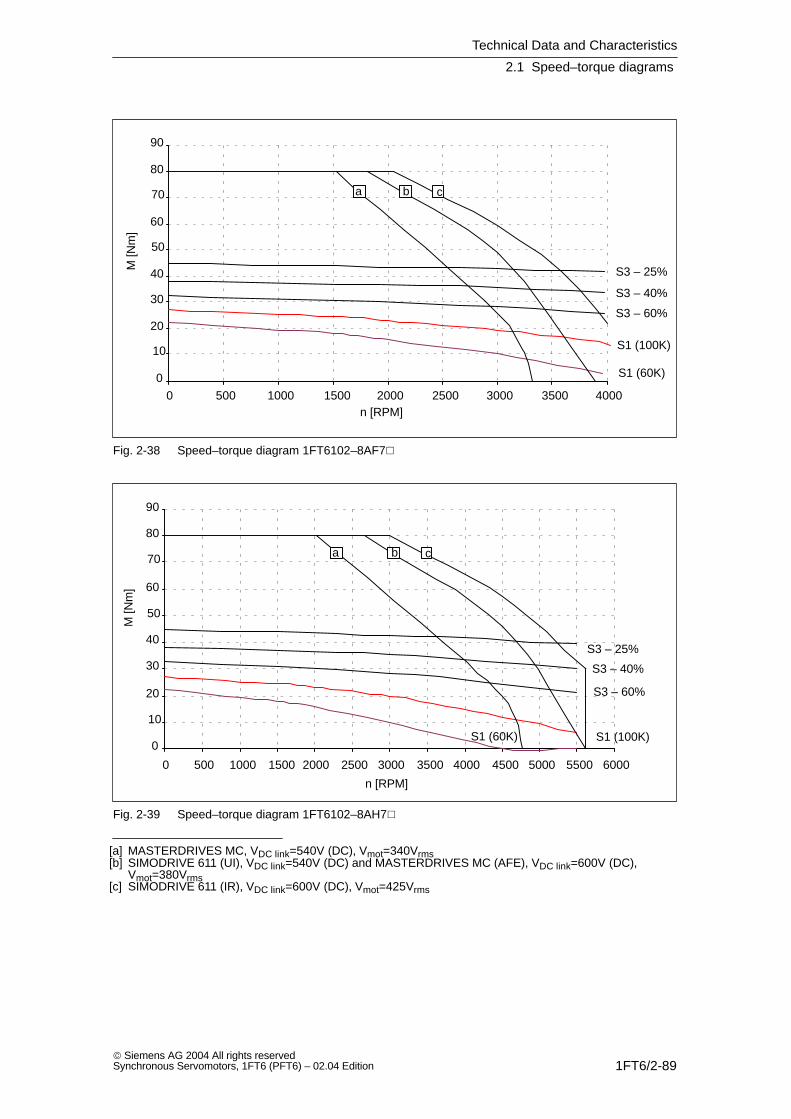
Technical Data and Characteristics
2.1 Speed–torque diagrams
1FT6/2-89 Siemens AG 2004 All rights reservedSynchronous Servomotors, 1FT6 (PFT6) – 02.04 Edition
0
10
20
30
40
50
60
70
80
90
0 500 1000 1500 2000 2500 3000 3500 4000
S1 (100K)
S1 (60K)
S3 – 25%
S3 – 40%
S3 – 60%
a b c
n [RPM]
M [N
m]
Fig. 2-38 Speed–torque diagram 1FT6102–8AF7
0
10
20
30
40
50
60
70
80
90
0 500 1000 1500 2000 2500 3000 3500 4000 4500 5000 5500 6000
S1 (100K)S1 (60K)
S3 – 25%
S3 – 40%
S3 – 60%
a b c
n [RPM]
M [N
m]
Fig. 2-39 Speed–torque diagram 1FT6102–8AH7
[a] MASTERDRIVES MC, VDC link=540V (DC), Vmot=340Vrms[b] SIMODRIVE 611 (UI), VDC link=540V (DC) and MASTERDRIVES MC (AFE), VDC link=600V (DC),
Vmot=380Vrms[c] SIMODRIVE 611 (IR), VDC link=600V (DC), Vmot=425Vrms

Technical Data and Characteristics
2.1 Speed–torque diagrams
1FT6/2-90 Siemens AG 2004 All rights reserved
Synchronous Servomotors, 1FT6 (PFT6) – 02.04 Edition
Table 2-23 1FT6105 non–ventilated
1FT6105
Technical data Code Units –8AB7 –AC7
Engineering data
Rated speedNumber of polesRated torque (100K)Rated current (100K)Standstill torque (60K)Standstill torque (100K)Standstill current (60K)Standstill current (100K)Moment of inertia (with brake)Moment of inertia (without brake)
nN2pMN (100K)IN (100K)M0 (60K)M0 (100K)I0 (60K)I0 (100K)JmotJmot
RPM
NmANmNmAA10–4 kgm2
10–4 kgm2
150084114.5425013.116199168
200083817.6425017.621.4199168
Optimum operating point
Optimum speedOptimum power
noptPopt
RPMkW
15006.44
20007.96
Limiting data
Max. perm. speed (mech.)Maximum torqueMaximum current
nmaxMmaxImax
RPMNmA
560014077
5600140103
Physical constants
Torque constantVoltage constantWinding resistance at 20CRotating field inductanceElectrical time constantShaft torsional stiffnessMechanical time constantThermal time constantWeight with brakeWeight without brake
kTkERphLDTelctTmechTthmm
Nm/AV/1000 RPMOhmmHmsNm/radmsminkgkg
3.131990.398.4221130002.0504439.5
2.341490.224.7211130002,0504439.5
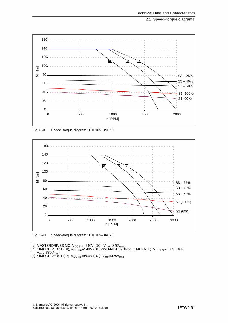
Technical Data and Characteristics
2.1 Speed–torque diagrams
1FT6/2-91 Siemens AG 2004 All rights reservedSynchronous Servomotors, 1FT6 (PFT6) – 02.04 Edition
0
20
40
60
80
100
120
140
160
0 500 1000 1500 2000
S1 (100K)S1 (60K)
S3 – 25%
S3 – 40%S3 – 60%
a b c
n [RPM]
M [N
m]
Fig. 2-40 Speed–torque diagram 1FT6105–8AB7
0
20
40
60
80
100
120
140
160
0 500 1000 1500 2000 2500 3000
S1 (100K)
S1 (60K)
S3 – 25%
S3 – 40%
S3 – 60%
a b c
n [RPM]
M [N
m]
Fig. 2-41 Speed–torque diagram 1FT6105–8AC7
[a] MASTERDRIVES MC, VDC link=540V (DC), Vmot=340Vrms[b] SIMODRIVE 611 (UI), VDC link=540V (DC) and MASTERDRIVES MC (AFE), VDC link=600V (DC),
Vmot=380Vrms[c] SIMODRIVE 611 (IR), VDC link=600V (DC), Vmot=425Vrms

Technical Data and Characteristics
2.1 Speed–torque diagrams
1FT6/2-92 Siemens AG 2004 All rights reserved
Synchronous Servomotors, 1FT6 (PFT6) – 02.04 Edition
Table 2-24 1FT6105 non–ventilated
1FT6105
Technical data Code Units –8AF7
Engineering data
Rated speedNumber of polesRated torque (100K)Rated current (100K)Standstill torque (60K)Standstill torque (100K)Standstill current (60K)Standstill current (100K)Moment of inertia (with brake)Moment of inertia (without brake)
nN2pMN (100K)IN (100K)M0 (60K)M0 (100K)I0 (60K)I0 (100K)JmotJmot
RPM
NmANmNmAA10–4 kgm2
10–4 kgm2
300083122.542502632199168
Optimum operating point
Optimum speedOptimum power
noptPopt
RPMkW
30009.74
Limiting data
Max. perm. speed (mech.)Maximum torqueMaximum current
nmaxMmaxImax
RPMNmA
5600140155
Physical constants
Torque constantVoltage constantWinding resistance at 20CRotating field inductanceElectrical time constantShaft torsional stiffnessMechanical time constantThermal time constantWeight with brakeWeight without brake
kTkERphLDTelctTmechTthmm
Nm/AV/1000 RPMOhmmHmsNm/radmsminkgkg
1.56990.0982.1211130002,0504439.5
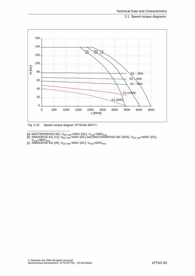
Technical Data and Characteristics
2.1 Speed–torque diagrams
1FT6/2-93 Siemens AG 2004 All rights reservedSynchronous Servomotors, 1FT6 (PFT6) – 02.04 Edition
0
20
40
60
80
100
120
140
160
0 500 1000 1500 2000 2500 3000 3500 4000 4500
S1 (100K)
S1 (60K)
S3 – 25%
S3 – 40%
S3 – 60%
a b c
n [RPM]
M [N
m]
Fig. 2-42 Speed–torque diagram 1FT6105–8AF7
[a] MASTERDRIVES MC, VDC link=540V (DC), Vmot=340Vrms[b] SIMODRIVE 611 (UI), VDC link=540V (DC) and MASTERDRIVES MC (AFE), VDC link=600V (DC),
Vmot=380Vrms[c] SIMODRIVE 611 (IR), VDC link=600V (DC), Vmot=425Vrms

Technical Data and Characteristics
2.1 Speed–torque diagrams
1FT6/2-94 Siemens AG 2004 All rights reserved
Synchronous Servomotors, 1FT6 (PFT6) – 02.04 Edition
Table 2-25 1FT6108 non–ventilated
1FT6108
Technical data Code Units –8AB7 –8AC7
Engineering data
Rated speedNumber of polesRated torque (100K)Rated current (100K)Standstill torque (60K)Standstill torque (100K)Standstill current (60K)Standstill current (100K)Moment of inertia (with brake)Moment of inertia (without brake)
nN2pMN (100K)IN (100K)M0 (60K)M0 (100K)I0 (60K)I0 (100K)JmotJmot
RPM
NmANmNmAA10–4 kgm2
10–4 kgm2
150086120.5587018.122.3291260
200085524.5587023.529291260
Optimum operating point
Optimum speedOptimum power
noptPopt
RPMkW
15009.58
200011.5
Limiting data
Max. perm. speed (mech.)Maximum torqueMaximum current
nmaxMmaxImax
RPMNmA
5600220107
5600220139
Physical constants
Torque constantVoltage constantWinding resistance at 20CRotating field inductanceElectrical time constantShaft torsional stiffnessMechanical time constantThermal time constantWeight with brakeWeight without brake
kTkERphLDTelctTmechTthmm
Nm/AV/1000 RPMOhmmHmsNm/radmsminkgkg
3.142000.225.224920001.7606055.5
2.421540.133.124920001,7606055.5
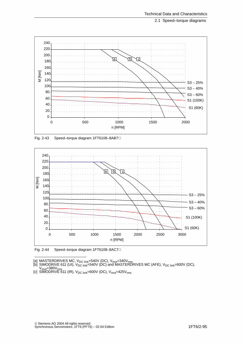
Technical Data and Characteristics
2.1 Speed–torque diagrams
1FT6/2-95 Siemens AG 2004 All rights reservedSynchronous Servomotors, 1FT6 (PFT6) – 02.04 Edition
0
20
40
60
80
100
120
140
160
180
200
220
240
0 500 1000 1500 2000
S1 (100K)
S1 (60K)
S3 – 25%
S3 – 40%
S3 – 60%
a b c
n [RPM]
M [N
m]
Fig. 2-43 Speed–torque diagram 1FT6108–8AB7
0
20
40
60
80
100
120
140
160
180
200
220
240
0 500 1000 1500 2000 2500 3000
S1 (100K)
S1 (60K)
S3 – 25%
S3 – 40%
S3 – 60%
a b c
n [RPM]
M [N
m]
Fig. 2-44 Speed–torque diagram 1FT6108–8AC7
[a] MASTERDRIVES MC, VDC link=540V (DC), Vmot=340Vrms[b] SIMODRIVE 611 (UI), VDC link=540V (DC) and MASTERDRIVES MC (AFE), VDC link=600V (DC),
Vmot=380Vrms[c] SIMODRIVE 611 (IR), VDC link=600V (DC), Vmot=425Vrms
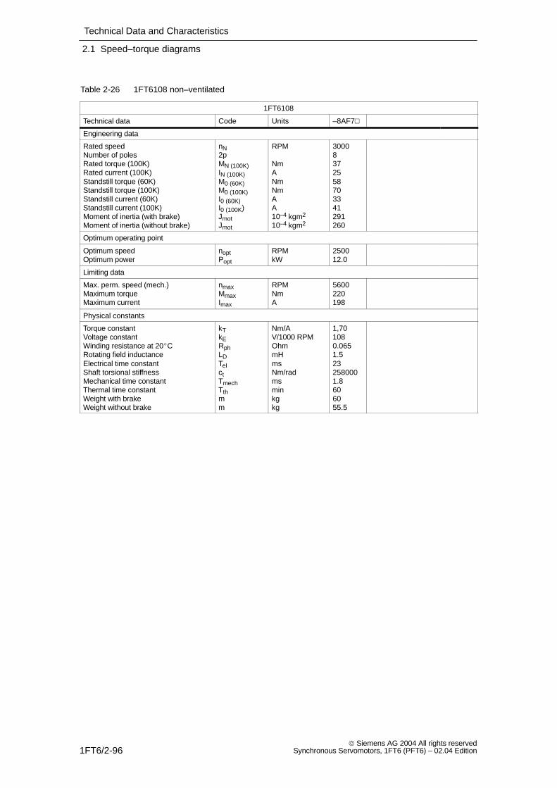
Technical Data and Characteristics
2.1 Speed–torque diagrams
1FT6/2-96 Siemens AG 2004 All rights reserved
Synchronous Servomotors, 1FT6 (PFT6) – 02.04 Edition
Table 2-26 1FT6108 non–ventilated
1FT6108
Technical data Code Units –8AF7
Engineering data
Rated speedNumber of polesRated torque (100K)Rated current (100K)Standstill torque (60K)Standstill torque (100K)Standstill current (60K)Standstill current (100K)Moment of inertia (with brake)Moment of inertia (without brake)
nN2pMN (100K)IN (100K)M0 (60K)M0 (100K)I0 (60K)I0 (100K)JmotJmot
RPM
NmANmNmAA10–4 kgm2
10–4 kgm2
30008372558703341291260
Optimum operating point
Optimum speedOptimum power
noptPopt
RPMkW
250012.0
Limiting data
Max. perm. speed (mech.)Maximum torqueMaximum current
nmaxMmaxImax
RPMNmA
5600220198
Physical constants
Torque constantVoltage constantWinding resistance at 20CRotating field inductanceElectrical time constantShaft torsional stiffnessMechanical time constantThermal time constantWeight with brakeWeight without brake
kTkERphLDTelctTmechTthmm
Nm/AV/1000 RPMOhmmHmsNm/radmsminkgkg
1,701080.0651.5232580001.8606055.5
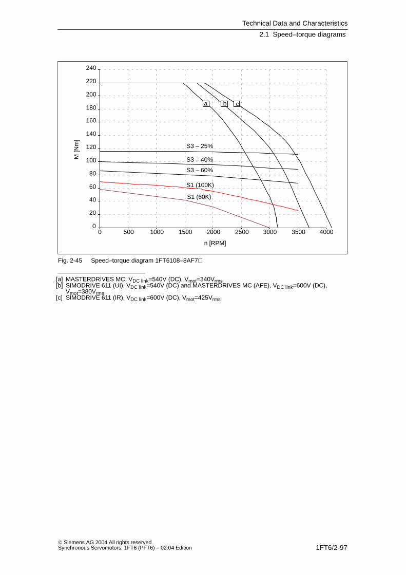
Technical Data and Characteristics
2.1 Speed–torque diagrams
1FT6/2-97 Siemens AG 2004 All rights reservedSynchronous Servomotors, 1FT6 (PFT6) – 02.04 Edition
0
20
40
60
80
100
120
140
160
180
200
220
240
0 500 1000 1500 2000 2500 3000 3500 4000
S1 (100K)
S1 (60K)
S3 – 25%
S3 – 40%
S3 – 60%
a b c
n [RPM]
M [N
m]
Fig. 2-45 Speed–torque diagram 1FT6108–8AF7
[a] MASTERDRIVES MC, VDC link=540V (DC), Vmot=340Vrms[b] SIMODRIVE 611 (UI), VDC link=540V (DC) and MASTERDRIVES MC (AFE), VDC link=600V (DC),
Vmot=380Vrms[c] SIMODRIVE 611 (IR), VDC link=600V (DC), Vmot=425Vrms
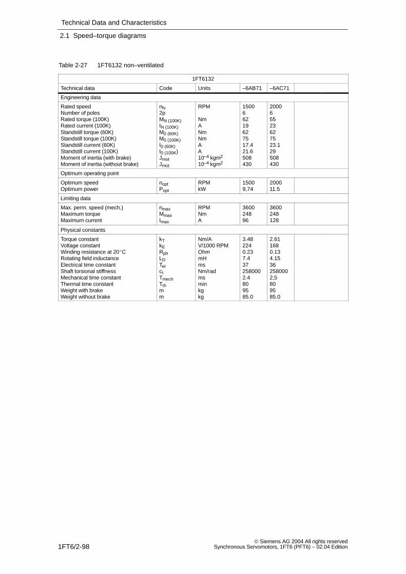
Technical Data and Characteristics
2.1 Speed–torque diagrams
1FT6/2-98 Siemens AG 2004 All rights reserved
Synchronous Servomotors, 1FT6 (PFT6) – 02.04 Edition
Table 2-27 1FT6132 non–ventilated
1FT6132
Technical data Code Units –6AB71 –6AC71
Engineering data
Rated speedNumber of polesRated torque (100K)Rated current (100K)Standstill torque (60K)Standstill torque (100K)Standstill current (60K)Standstill current (100K)Moment of inertia (with brake)Moment of inertia (without brake)
nN2pMN (100K)IN (100K)M0 (60K)M0 (100K)I0 (60K)I0 (100K)JmotJmot
RPM
NmANmNmAA10–4 kgm2
10–4 kgm2
150066219627517.421.6508430
200065523627523.129508430
Optimum operating point
Optimum speedOptimum power
noptPopt
RPMkW
15009,74
200011.5
Limiting data
Max. perm. speed (mech.)Maximum torqueMaximum current
nmaxMmaxImax
RPMNmA
360024896
3600248128
Physical constants
Torque constantVoltage constantWinding resistance at 20CRotating field inductanceElectrical time constantShaft torsional stiffnessMechanical time constantThermal time constantWeight with brakeWeight without brake
kTkERphLDTelctTmechTthmm
Nm/AV/1000 RPMOhmmHmsNm/radmsminkgkg
3.482240.237.4372580002.4809585.0
2.611680.134.15362580002,5809585.0
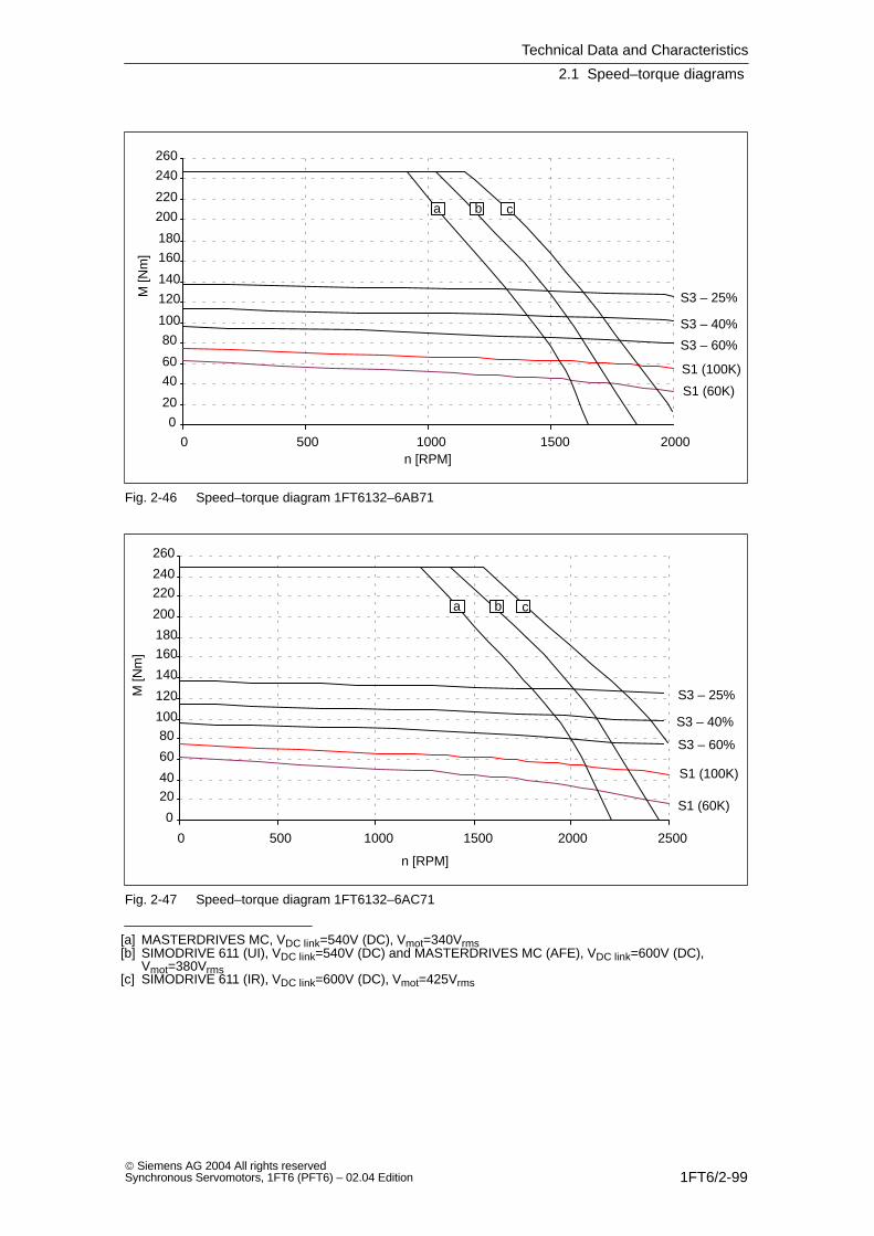
Technical Data and Characteristics
2.1 Speed–torque diagrams
1FT6/2-99 Siemens AG 2004 All rights reservedSynchronous Servomotors, 1FT6 (PFT6) – 02.04 Edition
0
20
40
60
80
100
120
140
160
180
200
220
240
260
0 500 1000 1500 2000
S1 (100K)
S1 (60K)
S3 – 25%
S3 – 40%
S3 – 60%
a b c
n [RPM]
M [N
m]
Fig. 2-46 Speed–torque diagram 1FT6132–6AB71
0
2040
60
80100
120
140
160180
200
220240
260
0 500 1000 1500 2000 2500
S1 (100K)
S1 (60K)
S3 – 25%
S3 – 40%
S3 – 60%
a b c
n [RPM]
M [N
m]
Fig. 2-47 Speed–torque diagram 1FT6132–6AC71
[a] MASTERDRIVES MC, VDC link=540V (DC), Vmot=340Vrms[b] SIMODRIVE 611 (UI), VDC link=540V (DC) and MASTERDRIVES MC (AFE), VDC link=600V (DC),
Vmot=380Vrms[c] SIMODRIVE 611 (IR), VDC link=600V (DC), Vmot=425Vrms

Technical Data and Characteristics
2.1 Speed–torque diagrams
1FT6/2-100 Siemens AG 2004 All rights reserved
Synchronous Servomotors, 1FT6 (PFT6) – 02.04 Edition
Table 2-28 1FT6132 non–ventilated
1FT6132
Technical data Code Units –6AF71
Engineering data
Rated speedNumber of polesRated torque (100K)Rated current (100K)Standstill torque (60K)Standstill torque (100K)Standstill current (60K)Standstill current (100K)Moment of inertia (with brake)Moment of inertia (without brake)
nN2pMN (100K)IN (100K)M0 (60K)M0 (100K)I0 (60K)I0 (100K)JmotJmot
RPM
NmANmNmAA10–4 kgm2
10–4 kgm2
30006362362753543508430
Optimum operating point
Optimum speedOptimum power
noptPopt
RPMkW
250012.0
Limiting data
Max. perm. speed (mech.)Maximum torqueMaximum current
nmaxMmaxImax
RPMNmA
3600248192
Physical constants
Torque constantVoltage constantWinding resistance at 20CRotating field inductanceElectrical time constantShaft torsional stiffnessMechanical time constantThermal time constantWeight with brakeWeight without brake
kTkERphLDTelctTmechTthmm
Nm/AV/1000 RPMOhmmHmsNm/radmsminkgkg
1,741120.0571.85372580002.4809585.0
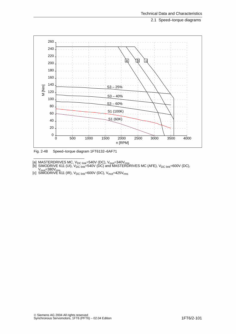
Technical Data and Characteristics
2.1 Speed–torque diagrams
1FT6/2-101 Siemens AG 2004 All rights reservedSynchronous Servomotors, 1FT6 (PFT6) – 02.04 Edition
0
20
40
60
80
100
120
140
160
180
200
220
240
260
0 500 1000 1500 2000 2500 3000 3500 4000
S1 (100K)
S1 (60K)
S3 – 25%
S3 – 40%
S3 – 60%
a b c
n [RPM]
M [N
m]
Fig. 2-48 Speed–torque diagram 1FT6132–6AF71
[a] MASTERDRIVES MC, VDC link=540V (DC), Vmot=340Vrms[b] SIMODRIVE 611 (UI), VDC link=540V (DC) and MASTERDRIVES MC (AFE), VDC link=600V (DC),
Vmot=380Vrms[c] SIMODRIVE 611 (IR), VDC link=600V (DC), Vmot=425Vrms

Technical Data and Characteristics
2.1 Speed–torque diagrams
1FT6/2-102 Siemens AG 2004 All rights reserved
Synchronous Servomotors, 1FT6 (PFT6) – 02.04 Edition
Table 2-29 1FT6134 non–ventilated
1FT6134
Technical data Code Units –6AB71 –6AC71
Engineering data
Rated speedNumber of polesRated torque (100K)Rated current (100K)Standstill torque (60K)Standstill torque (100K)Standstill current (60K)Standstill current (100K)Moment of inertia (with brake)Moment of inertia (without brake)
nN2pMN (100K)IN (100K)M0 (60K)M0 (100K)I0 (60K)I0 (100K)JmotJmot
RPM
NmANmNmAA10–4 kgm2
10–4 kgm2
150067524799521,727625547
20006652779953036625547
Optimum operating point
Optimum speedOptimum power
noptPopt
RPMkW
150011.8
200013.6
Limiting data
Max. perm. speed (mech.)Maximum torqueMaximum current
nmaxMmaxImax
RPMNmA
3600316125
3600316170
Physical constants
Torque constantVoltage constantWinding resistance at 20CRotating field inductanceElectrical time constantShaft torsional stiffnessMechanical time constantThermal time constantWeight with brakeWeight without brake
kTkERphLDTelctTmechTthmm
Nm/AV/1000 RPMOhmmHmsNm/radmsminkgkg
3.542280.175.8342340002.285110100
2.611680.0943.1332340002,385110100
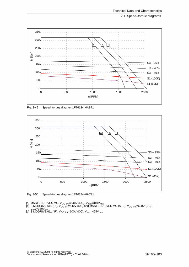
Technical Data and Characteristics
2.1 Speed–torque diagrams
1FT6/2-103 Siemens AG 2004 All rights reservedSynchronous Servomotors, 1FT6 (PFT6) – 02.04 Edition
0
50
100
150
200
250
300
350
0 500 1000 1500 2000
S1 (100K)
S1 (60K)
S3 – 25%
S3 – 40%
S3 – 60%
a b c
n [RPM]
M [N
m]
Fig. 2-49 Speed–torque diagram 1FT6134–6AB71
0
50
100
150
200
250
300
350
0 500 1000 1500 2000 2500
S1 (100K)
S1 (60K)
S3 – 25%
S3 – 40%S3 – 60%
a b c
n [RPM]
M [N
m]
Fig. 2-50 Speed–torque diagram 1FT6134–6AC71
[a] MASTERDRIVES MC, VDC link=540V (DC), Vmot=340Vrms[b] SIMODRIVE 611 (UI), VDC link=540V (DC) and MASTERDRIVES MC (AFE), VDC link=600V (DC),
Vmot=380Vrms[c] SIMODRIVE 611 (IR), VDC link=600V (DC), Vmot=425Vrms

Technical Data and Characteristics
2.1 Speed–torque diagrams
1FT6/2-104 Siemens AG 2004 All rights reserved
Synchronous Servomotors, 1FT6 (PFT6) – 02.04 Edition
Table 2-30 1FT6136 non–ventilated
1FT6136
Technical data Code Units –6AB71 –6AC7
Engineering data
Rated speedNumber of polesRated torque (100K)Rated current (100K)Standstill torque (60K)Standstill torque (100K)Standstill current (60K)Standstill current (100K)Moment of inertia (with brake)Moment of inertia (without brake)
nN2pMN (100K)IN (100K)M0 (60K)M0 (100K)I0 (60K)I0 (100K)JmotJmot
RPM
NmANmNmAA10–4 kgm2
10–4 kgm2
150068827951152734742664
200067430951153442742664
Optimum operating point
Optimum speedOptimum power
noptPopt
RPMkW
150013.8
200015.5
Limiting data
Max. perm. speed (mech.)Maximum torqueMaximum current
nmaxMmaxImax
RPMNmA
3600380146
3600380183
Physical constants
Torque constantVoltage constantWinding resistance at 20CRotating field inductanceElectrical time constantShaft torsional stiffnessMechanical time constantThermal time constantWeight with brakeWeight without brake
kTkERphLDTelctTmechTthmm
Nm/AV/1000 RPMOhmmHmsNm/radmsminkgkg
3.402190.124.4412140002.190125117
2,721750.0752.8412140002,090125117
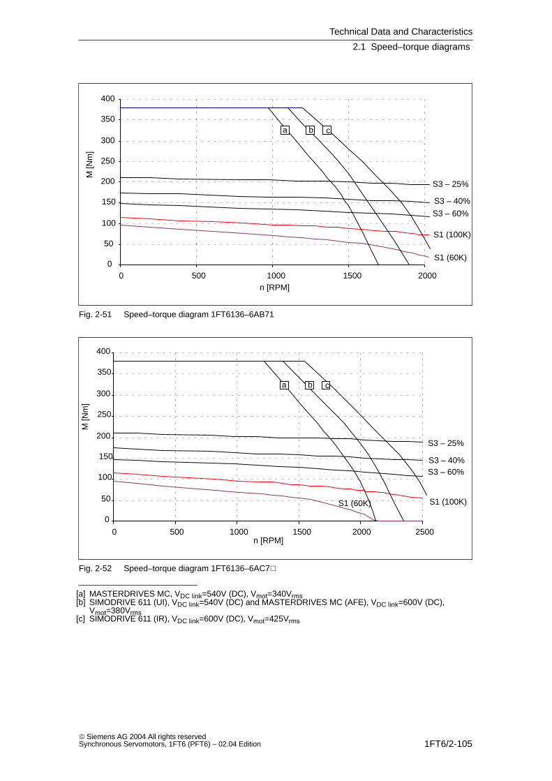
Technical Data and Characteristics
2.1 Speed–torque diagrams
1FT6/2-105 Siemens AG 2004 All rights reservedSynchronous Servomotors, 1FT6 (PFT6) – 02.04 Edition
0
50
100
150
200
250
300
350
400
0 500 1000 1500 2000
S1 (100K)
S1 (60K)
S3 – 25%
S3 – 40%
S3 – 60%
a b c
n [RPM]
M [N
m]
Fig. 2-51 Speed–torque diagram 1FT6136–6AB71
0
50
100
150
200
250
300
350
400
0 500 1000 1500 2000 2500
S1 (100K)S1 (60K)
S3 – 25%
S3 – 40%S3 – 60%
a b c
n [RPM]
M [N
m]
Fig. 2-52 Speed–torque diagram 1FT6136–6AC7
[a] MASTERDRIVES MC, VDC link=540V (DC), Vmot=340Vrms[b] SIMODRIVE 611 (UI), VDC link=540V (DC) and MASTERDRIVES MC (AFE), VDC link=600V (DC),
Vmot=380Vrms[c] SIMODRIVE 611 (IR), VDC link=600V (DC), Vmot=425Vrms
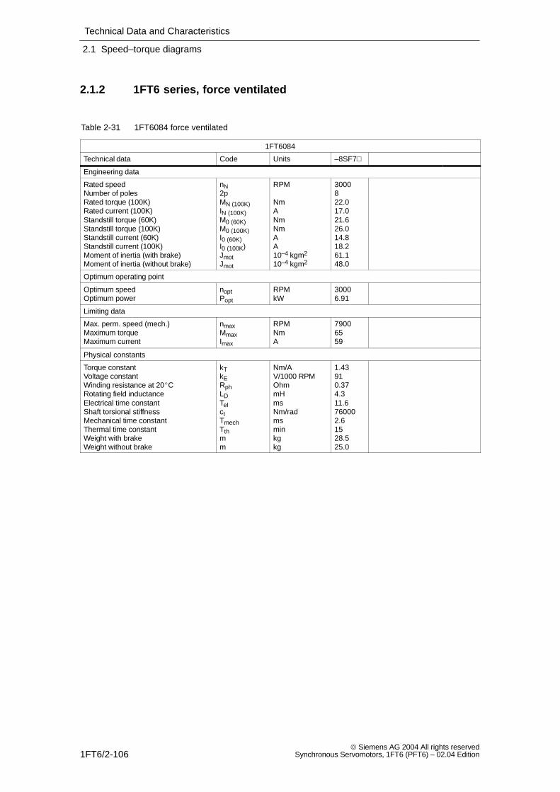
Technical Data and Characteristics
2.1 Speed–torque diagrams
1FT6/2-106 Siemens AG 2004 All rights reserved
Synchronous Servomotors, 1FT6 (PFT6) – 02.04 Edition
2.1.2 1FT6 series, force ventilated
Table 2-31 1FT6084 force ventilated
1FT6084
Technical data Code Units –8SF7
Engineering data
Rated speedNumber of polesRated torque (100K)Rated current (100K)Standstill torque (60K)Standstill torque (100K)Standstill current (60K)Standstill current (100K)Moment of inertia (with brake)Moment of inertia (without brake)
nN2pMN (100K)IN (100K)M0 (60K)M0 (100K)I0 (60K)I0 (100K)JmotJmot
RPM
NmANmNmAA10–4 kgm2
10–4 kgm2
3000822.017.021.626.014.818.261.148.0
Optimum operating point
Optimum speedOptimum power
noptPopt
RPMkW
30006.91
Limiting data
Max. perm. speed (mech.)Maximum torqueMaximum current
nmaxMmaxImax
RPMNmA
79006559
Physical constants
Torque constantVoltage constantWinding resistance at 20CRotating field inductanceElectrical time constantShaft torsional stiffnessMechanical time constantThermal time constantWeight with brakeWeight without brake
kTkERphLDTelctTmechTthmm
Nm/AV/1000 RPMOhmmHmsNm/radmsminkgkg
1.43910.374.311.6760002.61528.525.0
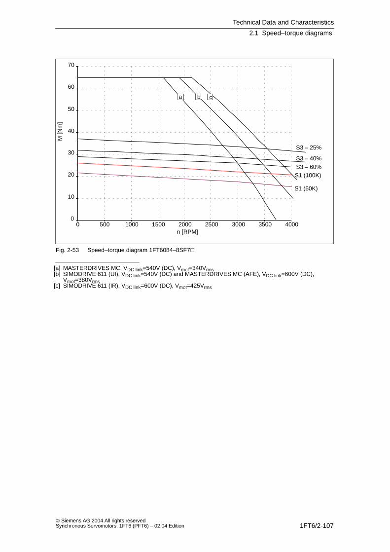
Technical Data and Characteristics
2.1 Speed–torque diagrams
1FT6/2-107 Siemens AG 2004 All rights reservedSynchronous Servomotors, 1FT6 (PFT6) – 02.04 Edition
0
10
20
30
40
50
60
70
0 500 1000 1500 2000 2500 3000 3500 4000
S1 (100K)
S1 (60K)
S3 – 25%
S3 – 40%S3 – 60%
a b c
n [RPM]
M [N
m]
Fig. 2-53 Speed–torque diagram 1FT6084–8SF7
[a] MASTERDRIVES MC, VDC link=540V (DC), Vmot=340Vrms[b] SIMODRIVE 611 (UI), VDC link=540V (DC) and MASTERDRIVES MC (AFE), VDC link=600V (DC),
Vmot=380Vrms[c] SIMODRIVE 611 (IR), VDC link=600V (DC), Vmot=425Vrms

Technical Data and Characteristics
2.1 Speed–torque diagrams
1FT6/2-108 Siemens AG 2004 All rights reserved
Synchronous Servomotors, 1FT6 (PFT6) – 02.04 Edition
Table 2-32 1FT6084 force ventilated
1FT6084
Technical data Code Units –8SH7 –8SK7
Engineering data
Rated speedNumber of polesRated torque (100K)Rated current (100K)Standstill torque (60K)Standstill torque (100K)Standstill current (60K)Standstill current (100K)Moment of inertia (with brake)Moment of inertia (without brake)
nN2pMN (100K)IN (100K)M0 (60K)M0 (100K)I0 (60K)I0 (100K)JmotJmot
RPM
NmANmNmAA10–4 kgm2
10–4 kgm2
4500820.024.521.626.021.026.061.148.0
6000817.025.521.626.029.035.061.148.0
Optimum operating point
Optimum speedOptimum power
noptPopt
RPMkW
45009.42
600010.68
Limiting data
Max. perm. speed (mech.)Maximum torqueMaximum current
nmaxMmaxImax
RPMNmA
79006586
790065112
Physical constants
Torque constantVoltage constantWinding resistance at 20CRotating field inductanceElectrical time constantShaft torsional stiffnessMechanical time constantThermal time constantWeight with brakeWeight without brake
kTkERphLDTelctTmechTthmm
Nm/AV/1000 RPMOhmmHmsNm/radmsminkgkg
1.01640.182.011.1760002,51528.525.0
0,74470.11.212.0760002,61528.525.0
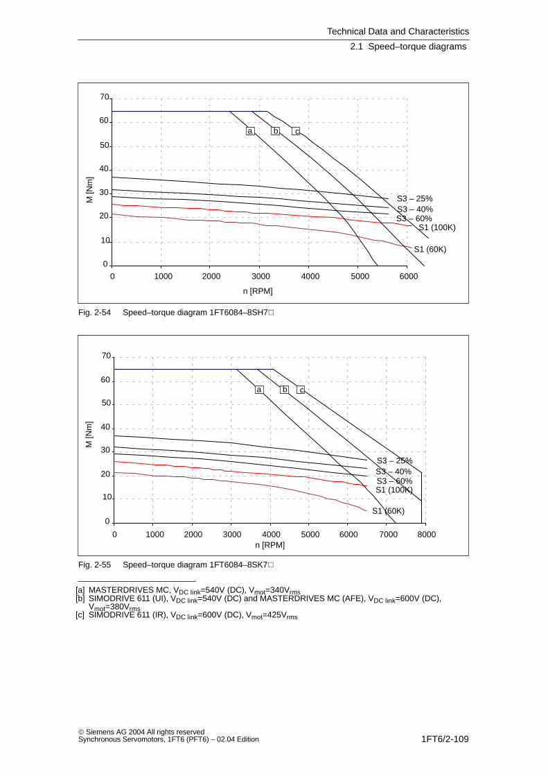
Technical Data and Characteristics
2.1 Speed–torque diagrams
1FT6/2-109 Siemens AG 2004 All rights reservedSynchronous Servomotors, 1FT6 (PFT6) – 02.04 Edition
0
10
20
30
40
50
60
70
0 1000 2000 3000 4000 5000 6000
S1 (100K)
S1 (60K)
S3 – 25%S3 – 40%S3 – 60%
a b c
n [RPM]
M [N
m]
Fig. 2-54 Speed–torque diagram 1FT6084–8SH7
0
10
20
30
40
50
60
70
0 1000 2000 3000 4000 5000 6000 7000 8000
S1 (100K)
S1 (60K)
S3 – 25%S3 – 40%S3 – 60%
a b c
n [RPM]
M [N
m]
Fig. 2-55 Speed–torque diagram 1FT6084–8SK7
[a] MASTERDRIVES MC, VDC link=540V (DC), Vmot=340Vrms[b] SIMODRIVE 611 (UI), VDC link=540V (DC) and MASTERDRIVES MC (AFE), VDC link=600V (DC),
Vmot=380Vrms[c] SIMODRIVE 611 (IR), VDC link=600V (DC), Vmot=425Vrms
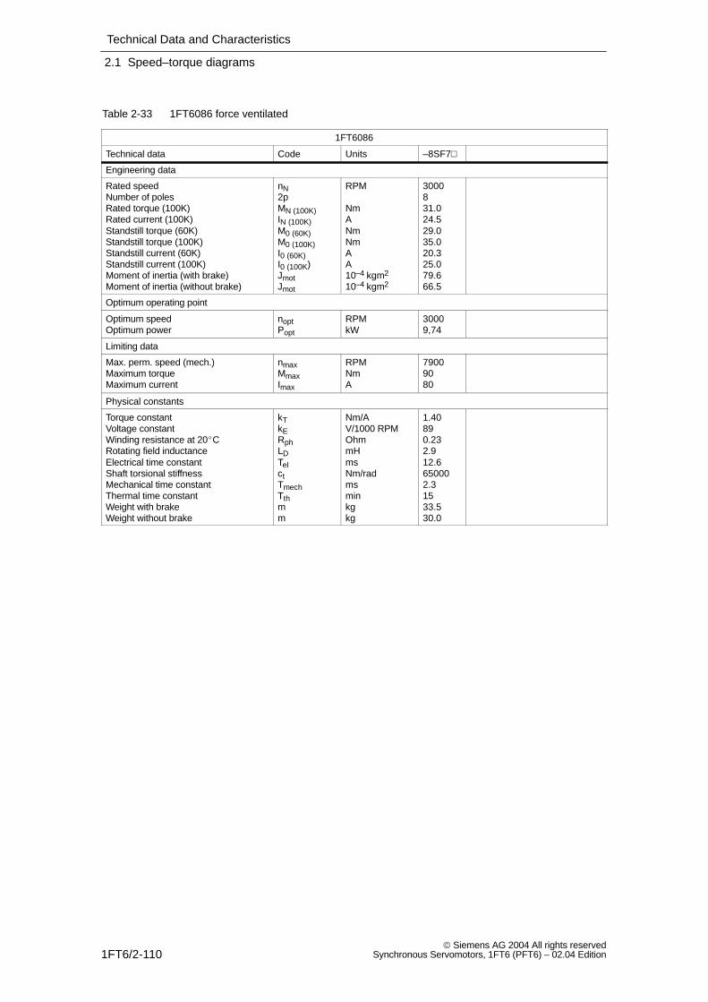
Technical Data and Characteristics
2.1 Speed–torque diagrams
1FT6/2-110 Siemens AG 2004 All rights reserved
Synchronous Servomotors, 1FT6 (PFT6) – 02.04 Edition
Table 2-33 1FT6086 force ventilated
1FT6086
Technical data Code Units –8SF7
Engineering data
Rated speedNumber of polesRated torque (100K)Rated current (100K)Standstill torque (60K)Standstill torque (100K)Standstill current (60K)Standstill current (100K)Moment of inertia (with brake)Moment of inertia (without brake)
nN2pMN (100K)IN (100K)M0 (60K)M0 (100K)I0 (60K)I0 (100K)JmotJmot
RPM
NmANmNmAA10–4 kgm2
10–4 kgm2
3000831.024.529.035.020.325.079.666.5
Optimum operating point
Optimum speedOptimum power
noptPopt
RPMkW
30009,74
Limiting data
Max. perm. speed (mech.)Maximum torqueMaximum current
nmaxMmaxImax
RPMNmA
79009080
Physical constants
Torque constantVoltage constantWinding resistance at 20CRotating field inductanceElectrical time constantShaft torsional stiffnessMechanical time constantThermal time constantWeight with brakeWeight without brake
kTkERphLDTelctTmechTthmm
Nm/AV/1000 RPMOhmmHmsNm/radmsminkgkg
1.40890.232.912.6650002.31533.530.0
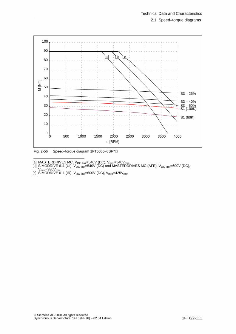
Technical Data and Characteristics
2.1 Speed–torque diagrams
1FT6/2-111 Siemens AG 2004 All rights reservedSynchronous Servomotors, 1FT6 (PFT6) – 02.04 Edition
0
10
20
30
40
50
60
70
80
90
100
0 500 1000 1500 2000 2500 3000 3500 4000
S1 (100K)
S1 (60K)
S3 – 25%
S3 – 40%S3 – 60%
a b c
n [RPM]
M [N
m]
Fig. 2-56 Speed–torque diagram 1FT6086–8SF7
[a] MASTERDRIVES MC, VDC link=540V (DC), Vmot=340Vrms[b] SIMODRIVE 611 (UI), VDC link=540V (DC) and MASTERDRIVES MC (AFE), VDC link=600V (DC),
Vmot=380Vrms[c] SIMODRIVE 611 (IR), VDC link=600V (DC), Vmot=425Vrms
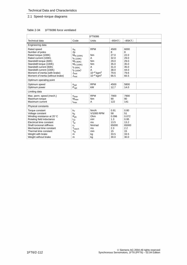
Technical Data and Characteristics
2.1 Speed–torque diagrams
1FT6/2-112 Siemens AG 2004 All rights reserved
Synchronous Servomotors, 1FT6 (PFT6) – 02.04 Edition
Table 2-34 1FT6086 force ventilated
1FT6086
Technical data Code Units –8SH7 –8SK7
Engineering data
Rated speedNumber of polesRated torque (100K)Rated current (100K)Standstill torque (60K)Standstill torque (100K)Standstill current (60K)Standstill current (100K)Moment of inertia (with brake)Moment of inertia (without brake)
nN2pMN (100K)IN (100K)M0 (60K)M0 (100K)I0 (60K)I0 (100K)JmotJmot
RPM
NmANmNmAA10–4 kgm2
10–4 kgm2
4500827.032.029.035.031.038.079.666.5
6000822.029.029.035.035.044.079.666.5
Optimum operating point
Optimum speedOptimum power
noptPopt
RPMkW
450012,7
580014.0
Limiting data
Max. perm. speed (mech.)Maximum torqueMaximum current
nmaxMmaxImax
RPMNmA
790090122
790090141
Physical constants
Torque constantVoltage constantWinding resistance at 20CRotating field inductanceElectrical time constantShaft torsional stiffnessMechanical time constantThermal time constantWeight with brakeWeight without brake
kTkERphLDTelctTmechTthmm
Nm/AV/1000 RPMOhmmHmsNm/radmsminkgkg
0.91580.0961.313.5650002.31533.530.0
0.80510.0720.9513.2650002.21533.530.0
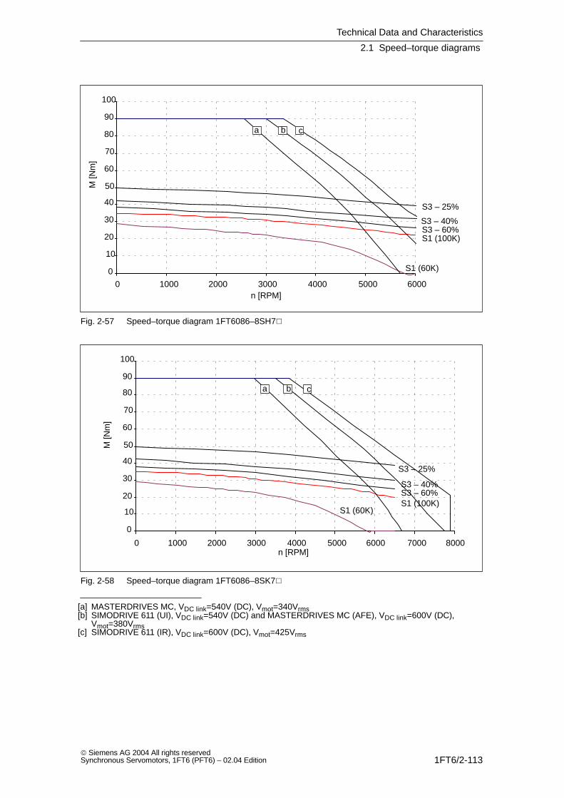
Technical Data and Characteristics
2.1 Speed–torque diagrams
1FT6/2-113 Siemens AG 2004 All rights reservedSynchronous Servomotors, 1FT6 (PFT6) – 02.04 Edition
0
10
20
30
40
50
60
70
80
90
100
0 1000 2000 3000 4000 5000 6000
S1 (100K)
S1 (60K)
S3 – 25%
S3 – 40%S3 – 60%
a b c
n [RPM]
M [N
m]
Fig. 2-57 Speed–torque diagram 1FT6086–8SH7
0
10
20
30
40
50
60
70
80
90
100
0 1000 2000 3000 4000 5000 6000 7000 8000
S1 (100K)S1 (60K)
S3 – 25%
S3 – 40%S3 – 60%
a b c
n [RPM]
M [N
m]
Fig. 2-58 Speed–torque diagram 1FT6086–8SK7
[a] MASTERDRIVES MC, VDC link=540V (DC), Vmot=340Vrms[b] SIMODRIVE 611 (UI), VDC link=540V (DC) and MASTERDRIVES MC (AFE), VDC link=600V (DC),
Vmot=380Vrms[c] SIMODRIVE 611 (IR), VDC link=600V (DC), Vmot=425Vrms

Technical Data and Characteristics
2.1 Speed–torque diagrams
1FT6/2-114 Siemens AG 2004 All rights reserved
Synchronous Servomotors, 1FT6 (PFT6) – 02.04 Edition
Table 2-35 1FT6105 force ventilated
1FT6105
Technical data Code Units –8SB7 –8SC7
Engineering data
Rated speedNumber of polesRated torque (100K)Rated current (100K)Standstill torque (60K)Standstill torque (100K)Standstill current (60K)Standstill current (100K)Moment of inertia (with brake)Moment of inertia (without brake)
nN2pMN (100K)IN (100K)M0 (60K)M0 (100K)I0 (60K)I0 (100K)JmotJmot
RPM
NmANmNmAA10–4 kgm2
10–4 kgm2
1500859.021,754.065.017.821.9199168
2000856.028.054.065.024.230.0199168
Optimum operating point
Optimum speedOptimum power
noptPopt
RPMkW
15009.27
200011,73
Limiting data
Max. perm. speed (mech.)Maximum torqueMaximum current
nmaxMmaxImax
RPMNmA
560014081
5600140110
Physical constants
Torque constantVoltage constantWinding resistance at 20CRotating field inductanceElectrical time constantShaft torsional stiffnessMechanical time constantThermal time constantWeight with brakeWeight without brake
kTkERphLDTelctTmechTthmm
Nm/AV/1000 RPMOhmmHmsNm/radmsminkgkg
2.971890.357.521.01130002.0205045.5
2.181390.194.122.01130002,0205045.5
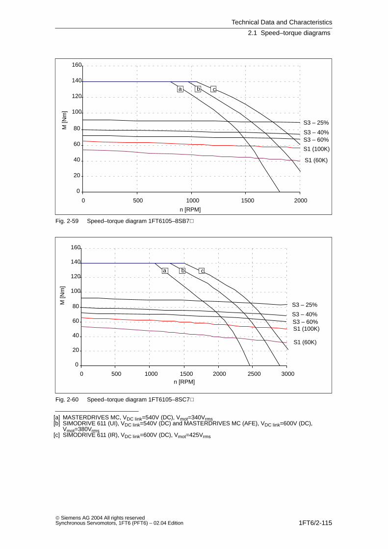
Technical Data and Characteristics
2.1 Speed–torque diagrams
1FT6/2-115 Siemens AG 2004 All rights reservedSynchronous Servomotors, 1FT6 (PFT6) – 02.04 Edition
0
20
40
60
80
100
120
140
160
0 500 1000 1500 2000
S1 (100K)
S1 (60K)
S3 – 25%
S3 – 40%S3 – 60%
a b c
n [RPM]
M [N
m]
Fig. 2-59 Speed–torque diagram 1FT6105–8SB7
0
20
40
60
80
100
120
140
160
0 500 1000 1500 2000 2500 3000
S1 (100K)
S1 (60K)
S3 – 25%
S3 – 40%S3 – 60%
a b c
n [RPM]
M [N
m]
Fig. 2-60 Speed–torque diagram 1FT6105–8SC7
[a] MASTERDRIVES MC, VDC link=540V (DC), Vmot=340Vrms[b] SIMODRIVE 611 (UI), VDC link=540V (DC) and MASTERDRIVES MC (AFE), VDC link=600V (DC),
Vmot=380Vrms[c] SIMODRIVE 611 (IR), VDC link=600V (DC), Vmot=425Vrms

Technical Data and Characteristics
2.1 Speed–torque diagrams
1FT6/2-116 Siemens AG 2004 All rights reserved
Synchronous Servomotors, 1FT6 (PFT6) – 02.04 Edition
Table 2-36 1FT6105 force ventilated
1FT6105
Technical data Code Units –8SF7 –8SH7
Engineering data
Rated speedNumber of polesRated torque (100K)Rated current (100K)Standstill torque (60K)Standstill torque (100K)Standstill current (60K)Standstill current (100K)Moment of inertia (with brake)Moment of inertia (without brake)
nN2pMN (100K)IN (100K)M0 (60K)M0 (100K)I0 (60K)I0 (100K)JmotJmot
RPM
NmANmNmAA10–4 kgm2
10–4 kgm2
3000850.035.054.065.034.042.0199168
4500840.041.054.065.048.059.0199168
Optimum operating point
Optimum speedOptimum power
noptPopt
RPMkW
300015,7
450018.8
Limiting data
Max. perm. speed (mech.)Maximum torqueMaximum current
nmaxMmaxImax
RPMNmA
5600140155
5600140221
Physical constants
Torque constantVoltage constantWinding resistance at 20CRotating field inductanceElectrical time constantShaft torsional stiffnessMechanical time constantThermal time constantWeight with brakeWeight without brake
kTkERphLDTelctTmechTthmm
Nm/AV/1000 RPMOhmmHmsNm/radmsminkgkg
1.56990.0982.121.01130002.0205045.5
1.10700.0481.021.01130002,0205045.5
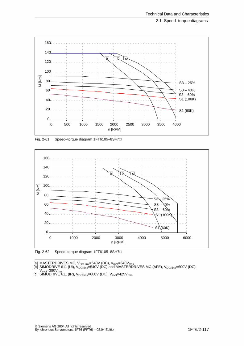
Technical Data and Characteristics
2.1 Speed–torque diagrams
1FT6/2-117 Siemens AG 2004 All rights reservedSynchronous Servomotors, 1FT6 (PFT6) – 02.04 Edition
0
20
40
60
80
100
120
140
160
0 500 1000 1500 2000 2500 3000 3500 4000
S1 (100K)
S1 (60K)
S3 – 25%
S3 – 40%S3 – 60%
a b c
n [RPM]
M [N
m]
Fig. 2-61 Speed–torque diagram 1FT6105–8SF7
0
20
40
60
80
100
120
140
160
0 1000 2000 3000 4000 5000 6000
S1 (100K)
S1 (60K)
S3 – 25%
S3 – 40%S3 – 60%
a b c
n [RPM]
M [N
m]
Fig. 2-62 Speed–torque diagram 1FT6105–8SH7
[a] MASTERDRIVES MC, VDC link=540V (DC), Vmot=340Vrms[b] SIMODRIVE 611 (UI), VDC link=540V (DC) and MASTERDRIVES MC (AFE), VDC link=600V (DC),
Vmot=380Vrms[c] SIMODRIVE 611 (IR), VDC link=600V (DC), Vmot=425Vrms

Technical Data and Characteristics
2.1 Speed–torque diagrams
1FT6/2-118 Siemens AG 2004 All rights reserved
Synchronous Servomotors, 1FT6 (PFT6) – 02.04 Edition
Table 2-37 1FT6108 force ventilated
1FT6108
Technical data Code Units –8SB7 –8SC7
Engineering data
Rated speedNumber of polesRated torque (100K)Rated current (100K)Standstill torque (60K)Standstill torque (100K)Standstill current (60K)Standstill current (100K)Moment of inertia (with brake)Moment of inertia (without brake)
nN2pMN (100K)IN (100K)M0 (60K)M0 (100K)I0 (60K)I0 (100K)JmotJmot
RPM
NmANmNmAA10–4 kgm2
10–4 kgm2
15008833175902531291260
20008804075903441291260
Optimum operating point
Optimum speedOptimum power
noptPopt
RPMkW
150013.0
200016.8
Limiting data
Max. perm. speed (mech.)Maximum torqueMaximum current
nmaxMmaxImax
RPMNmA
5600220116
5600220154
Physical constants
Torque constantVoltage constantWinding resistance at 20CRotating field inductanceElectrical time constantShaft torsional stiffnessMechanical time constantThermal time constantWeight with brakeWeight without brake
kTkERphLDTelctTmechTthmm
Nm/AV/1000 RPMOhmmHmsNm/radmsminkgkg
2.911950.194.423.0920001.8206661.5
2.181390.112.523.0920001.8206661.5
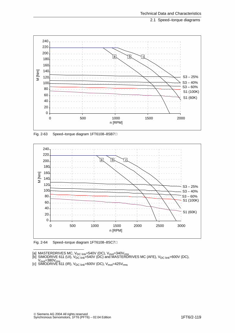
Technical Data and Characteristics
2.1 Speed–torque diagrams
1FT6/2-119 Siemens AG 2004 All rights reservedSynchronous Servomotors, 1FT6 (PFT6) – 02.04 Edition
0
20
40
60
80
100
120
140
160
180
200
220
240
0 500 1000 1500 2000
S1 (100K)
S1 (60K)
S3 – 25%
S3 – 40%S3 – 60%
a b c
n [RPM]
M [N
m]
Fig. 2-63 Speed–torque diagram 1FT6108–8SB7
0
20
40
60
80
100
120
140
160
180
200
220
240
0 500 1000 1500 2000 2500 3000
S1 (100K)
S1 (60K)
S3 – 25%S3 – 40%S3 – 60%
a b c
n [RPM]
M [N
m]
Fig. 2-64 Speed–torque diagram 1FT6108–8SC7
[a] MASTERDRIVES MC, VDC link=540V (DC), Vmot=340Vrms[b] SIMODRIVE 611 (UI), VDC link=540V (DC) and MASTERDRIVES MC (AFE), VDC link=600V (DC),
Vmot=380Vrms[c] SIMODRIVE 611 (IR), VDC link=600V (DC), Vmot=425Vrms

Technical Data and Characteristics
2.1 Speed–torque diagrams
1FT6/2-120 Siemens AG 2004 All rights reserved
Synchronous Servomotors, 1FT6 (PFT6) – 02.04 Edition
Table 2-38 1FT6108 force ventilated
1FT6108
Technical data Code Units –8SF7
Engineering data
Rated speedNumber of polesRated torque (100K)Rated current (100K)Standstill torque (60K)Standstill torque (100K)Standstill current (60K)Standstill current (100K)Moment of inertia (with brake)Moment of inertia (without brake)
nN2pMN (100K)IN (100K)M0 (60K)M0 (100K)I0 (60K)I0 (100K)JmotJmot
RPM
NmANmNmAA10–4 kgm2
10–4 kgm2
30008705375905162291260
Optimum operating point
Optimum speedOptimum power
noptPopt
RPMkW
300022.0
Limiting data
Max. perm. speed (mech.)Maximum torqueMaximum current
nmaxMmaxImax
RPMNmA
5600220231
Physical constants
Torque constantVoltage constantWinding resistance at 20CRotating field inductanceElectrical time constantShaft torsional stiffnessMechanical time constantThermal time constantWeight with brakeWeight without brake
kTkERphLDTelctTmechTthmm
Nm/AV/1000 RPMOhmmHmsNm/radmsminkgkg
1.45920.0481.123.0920001.8206661.5
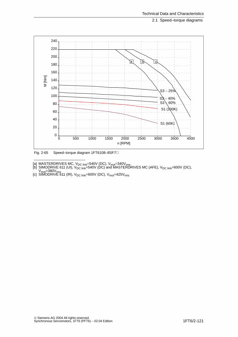
Technical Data and Characteristics
2.1 Speed–torque diagrams
1FT6/2-121 Siemens AG 2004 All rights reservedSynchronous Servomotors, 1FT6 (PFT6) – 02.04 Edition
0
20
40
60
80
100
120
140
160
180
200
220
240
0 500 1000 1500 2000 2500 3000 3500 4000
S1 (100K)
S1 (60K)
S3 – 25%
S3 – 40%S3 – 60%
a b c
n [RPM]
M [N
m]
Fig. 2-65 Speed–torque diagram 1FT6108–8SF7
[a] MASTERDRIVES MC, VDC link=540V (DC), Vmot=340Vrms[b] SIMODRIVE 611 (UI), VDC link=540V (DC) and MASTERDRIVES MC (AFE), VDC link=600V (DC),
Vmot=380Vrms[c] SIMODRIVE 611 (IR), VDC link=600V (DC), Vmot=425Vrms

Technical Data and Characteristics
2.1 Speed–torque diagrams
1FT6/2-122 Siemens AG 2004 All rights reserved
Synchronous Servomotors, 1FT6 (PFT6) – 02.04 Edition
Table 2-39 1FT6132 force ventilated
1FT6132
Technical data Code Units –6SB71 –6SC71
Engineering data
Rated speedNumber of polesRated torque (100K)Rated current (100K)Standstill torque (60K)Standstill torque (100K)Standstill current (60K)Standstill current (100K)Moment of inertia (with brake)Moment of inertia (without brake)
nN2pMN (100K)IN (100K)M0 (60K)M0 (100K)I0 (60K)I0 (100K)JmotJmot
RPM
NmANmNmAA10–4 kgm2
10–4 kgm2
1500610236911102936508430
200069846911103847508430
Optimum operating point
Optimum speedOptimum power
noptPopt
RPMkW
150016.0
200020.5
Limiting data
Max. perm. speed (mech.)Maximum torqueMaximum current
nmaxMmaxImax
RPMNmA
3600248108
3600248144
Physical constants
Torque constantVoltage constantWinding resistance at 20CRotating field inductanceElectrical time constantShaft torsional stiffnessMechanical time constantThermal time constantWeight with brakeWeight without brake
kTkERphLDTelctTmechTthmm
Nm/AV/1000 RPMOhmmHmsNm/radmsminkgkg
3.051960.175,7382580002.42510191
2.321490.103.3372580002.42510191
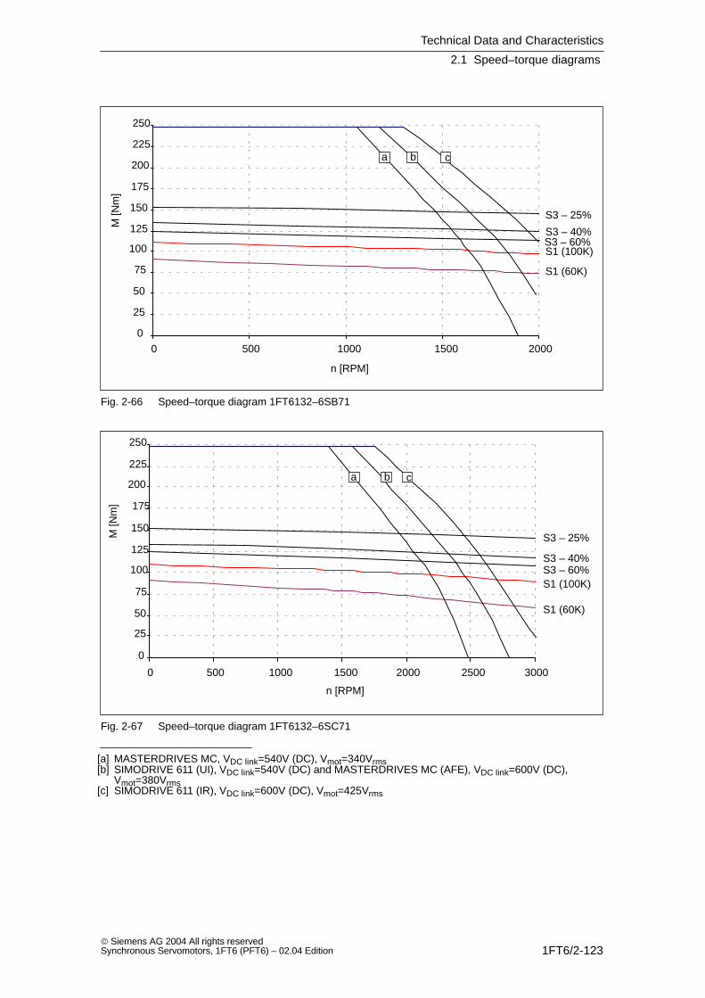
Technical Data and Characteristics
2.1 Speed–torque diagrams
1FT6/2-123 Siemens AG 2004 All rights reservedSynchronous Servomotors, 1FT6 (PFT6) – 02.04 Edition
0
25
50
75
100
125
150
175
200
225
250
0 500 1000 1500 2000
S1 (100K)
S1 (60K)
S3 – 25%
S3 – 40%S3 – 60%
a b c
n [RPM]
M [N
m]
Fig. 2-66 Speed–torque diagram 1FT6132–6SB71
0
25
50
75
100
125
150
175
200
225
250
0 500 1000 1500 2000 2500 3000
S1 (100K)
S1 (60K)
S3 – 25%
S3 – 40%S3 – 60%
a b c
n [RPM]
M [N
m]
Fig. 2-67 Speed–torque diagram 1FT6132–6SC71
[a] MASTERDRIVES MC, VDC link=540V (DC), Vmot=340Vrms[b] SIMODRIVE 611 (UI), VDC link=540V (DC) and MASTERDRIVES MC (AFE), VDC link=600V (DC),
Vmot=380Vrms[c] SIMODRIVE 611 (IR), VDC link=600V (DC), Vmot=425Vrms
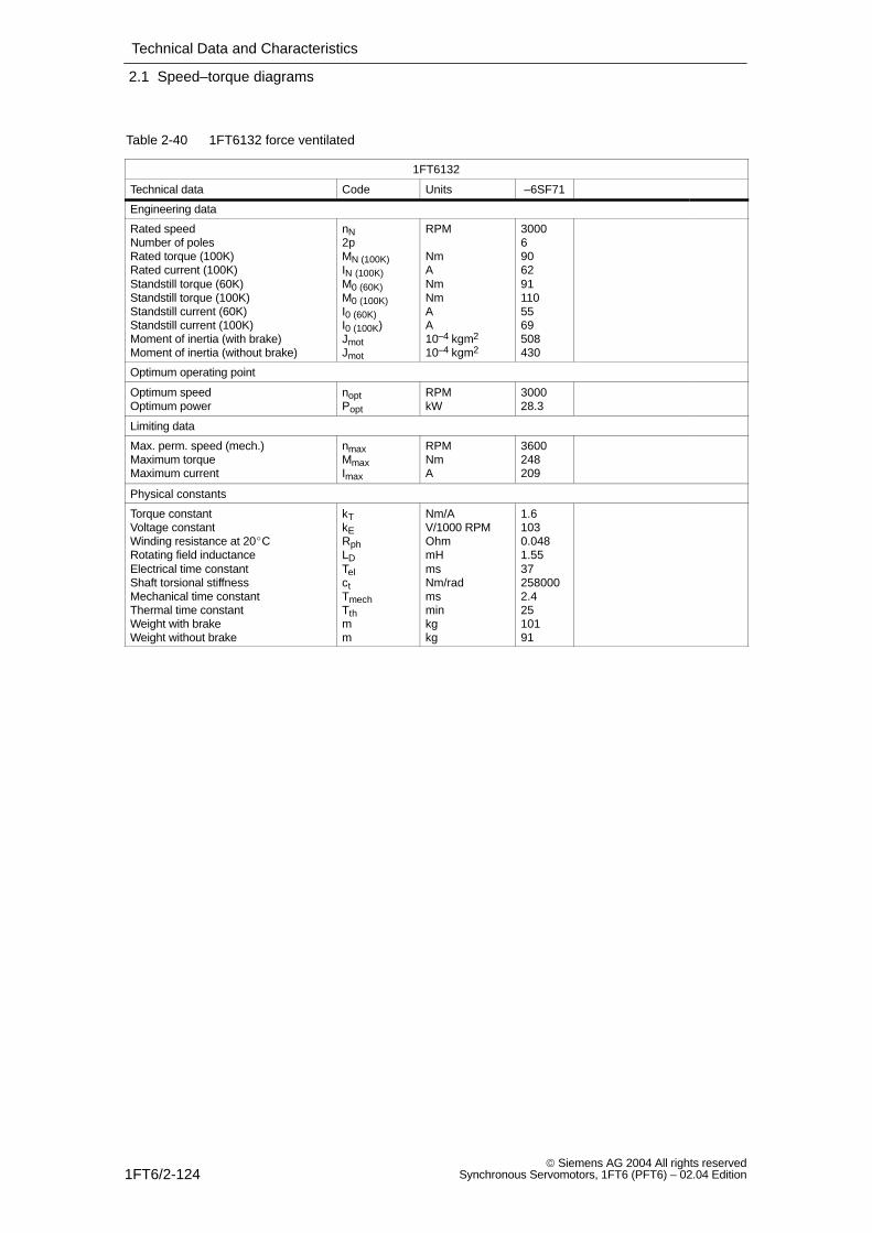
Technical Data and Characteristics
2.1 Speed–torque diagrams
1FT6/2-124 Siemens AG 2004 All rights reserved
Synchronous Servomotors, 1FT6 (PFT6) – 02.04 Edition
Table 2-40 1FT6132 force ventilated
1FT6132
Technical data Code Units –6SF71
Engineering data
Rated speedNumber of polesRated torque (100K)Rated current (100K)Standstill torque (60K)Standstill torque (100K)Standstill current (60K)Standstill current (100K)Moment of inertia (with brake)Moment of inertia (without brake)
nN2pMN (100K)IN (100K)M0 (60K)M0 (100K)I0 (60K)I0 (100K)JmotJmot
RPM
NmANmNmAA10–4 kgm2
10–4 kgm2
300069062911105569508430
Optimum operating point
Optimum speedOptimum power
noptPopt
RPMkW
300028.3
Limiting data
Max. perm. speed (mech.)Maximum torqueMaximum current
nmaxMmaxImax
RPMNmA
3600248209
Physical constants
Torque constantVoltage constantWinding resistance at 20CRotating field inductanceElectrical time constantShaft torsional stiffnessMechanical time constantThermal time constantWeight with brakeWeight without brake
kTkERphLDTelctTmechTthmm
Nm/AV/1000 RPMOhmmHmsNm/radmsminkgkg
1.61030.0481.55372580002.42510191
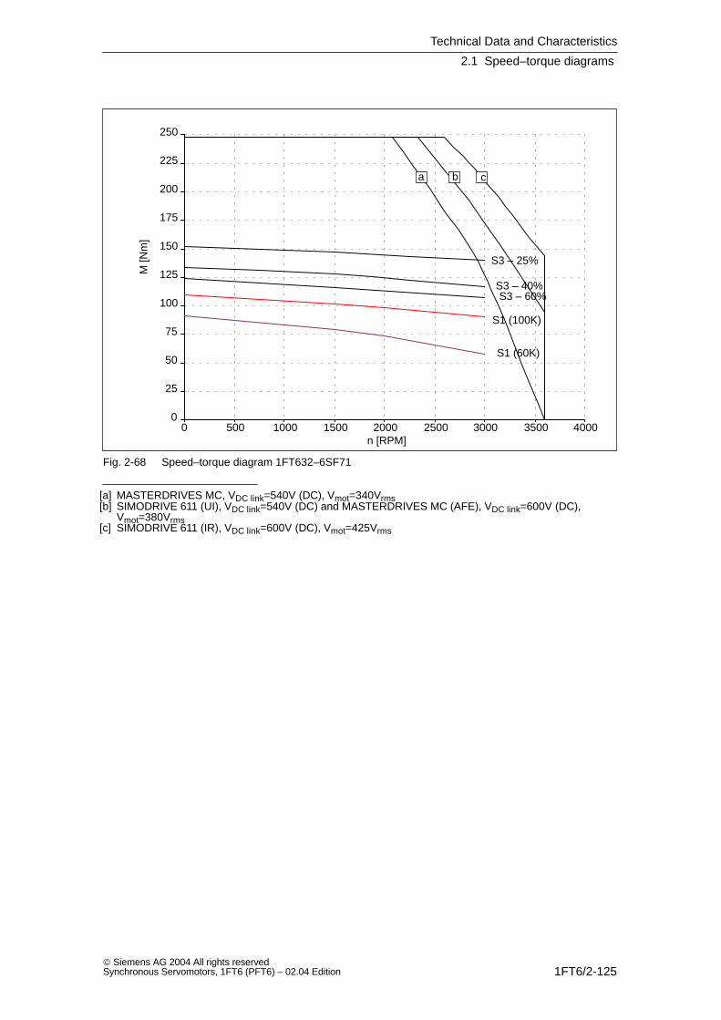
Technical Data and Characteristics
2.1 Speed–torque diagrams
1FT6/2-125 Siemens AG 2004 All rights reservedSynchronous Servomotors, 1FT6 (PFT6) – 02.04 Edition
0
25
50
75
100
125
150
175
200
225
250
0 500 1000 1500 2000 2500 3000 3500 4000
S1 (100K)
S1 (60K)
S3 – 25%
S3 – 40%S3 – 60%
a b c
n [RPM]
M [N
m]
Fig. 2-68 Speed–torque diagram 1FT632–6SF71
[a] MASTERDRIVES MC, VDC link=540V (DC), Vmot=340Vrms[b] SIMODRIVE 611 (UI), VDC link=540V (DC) and MASTERDRIVES MC (AFE), VDC link=600V (DC),
Vmot=380Vrms[c] SIMODRIVE 611 (IR), VDC link=600V (DC), Vmot=425Vrms

Technical Data and Characteristics
2.1 Speed–torque diagrams
1FT6/2-126 Siemens AG 2004 All rights reserved
Synchronous Servomotors, 1FT6 (PFT6) – 02.04 Edition
Table 2-41 1FT6134 force ventilated
1FT6134
Technical data Code Units –6SB71 –6SC71
Engineering data
Rated speedNumber of polesRated torque (100K)Rated current (100K)Standstill torque (60K)Standstill torque (100K)Standstill current (60K)Standstill current (100K)Moment of inertia (with brake)Moment of inertia (without brake)
nN2pMN (100K)IN (100K)M0 (60K)M0 (100K)I0 (60K)I0 (100K)JmotJmot
RPM
NmANmNmAA10–4 kgm2
10–4 kgm2
15006130451161403644625547
20006125571161404758625547
Optimum operating point
Optimum speedOptimum power
noptPopt
RPMkW
150020.4
200026.2
Limiting data
Max. perm. speed (mech.)Maximum torqueMaximum current
nmaxMmaxImax
RPMNmA
3600316140
3600316182
Physical constants
Torque constantVoltage constantWinding resistance at 20CRotating field inductanceElectrical time constantShaft torsional stiffnessMechanical time constantThermal time constantWeight with brakeWeight without brake
kTkERphLDTelctTmechTthmm
Nm/AV/1000 RPMOhmmHmsNm/radmsminkgkg
3.172040.144.6332340002.325116106
2.431560.0812,7332340002.325116106
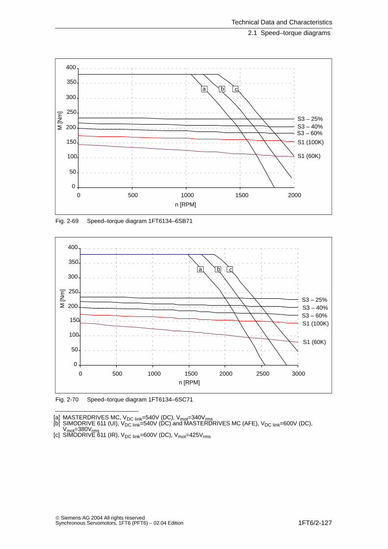
Technical Data and Characteristics
2.1 Speed–torque diagrams
1FT6/2-127 Siemens AG 2004 All rights reservedSynchronous Servomotors, 1FT6 (PFT6) – 02.04 Edition
0
50
100
150
200
250
300
350
400
0 500 1000 1500 2000
S1 (100K)
S1 (60K)
S3 – 25%S3 – 40%S3 – 60%
a b c
n [RPM]
M [N
m]
Fig. 2-69 Speed–torque diagram 1FT6134–6SB71
0
50
100
150
200
250
300
350
400
0 500 1000 1500 2000 2500 3000
S1 (100K)
S1 (60K)
S3 – 25%S3 – 40%S3 – 60%
a b c
n [RPM]
M [N
m]
Fig. 2-70 Speed–torque diagram 1FT6134–6SC71
[a] MASTERDRIVES MC, VDC link=540V (DC), Vmot=340Vrms[b] SIMODRIVE 611 (UI), VDC link=540V (DC) and MASTERDRIVES MC (AFE), VDC link=600V (DC),
Vmot=380Vrms[c] SIMODRIVE 611 (IR), VDC link=600V (DC), Vmot=425Vrms
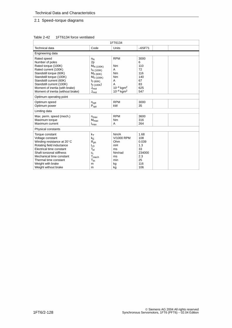
Technical Data and Characteristics
2.1 Speed–torque diagrams
1FT6/2-128 Siemens AG 2004 All rights reserved
Synchronous Servomotors, 1FT6 (PFT6) – 02.04 Edition
Table 2-42 1FT6134 force ventilated
1FT6134
Technical data Code Units –6SF71
Engineering data
Rated speedNumber of polesRated torque (100K)Rated current (100K)Standstill torque (60K)Standstill torque (100K)Standstill current (60K)Standstill current (100K)Moment of inertia (with brake)Moment of inertia (without brake)
nN2pMN (100K)IN (100K)M0 (60K)M0 (100K)I0 (60K)I0 (100K)JmotJmot
RPM
NmANmNmAA10–4 kgm2
10–4 kgm2
30006110721161406783625547
Optimum operating point
Optimum speedOptimum power
noptPopt
RPMkW
300035
Limiting data
Max. perm. speed (mech.)Maximum torqueMaximum current
nmaxMmaxImax
RPMNmA
3600316264
Physical constants
Torque constantVoltage constantWinding resistance at 20CRotating field inductanceElectrical time constantShaft torsional stiffnessMechanical time constantThermal time constantWeight with brakeWeight without brake
kTkERphLDTelctTmechTthmm
Nm/AV/1000 RPMOhmmHmsNm/radmsminkgkg
1.681080.0391.3332340002.325116106
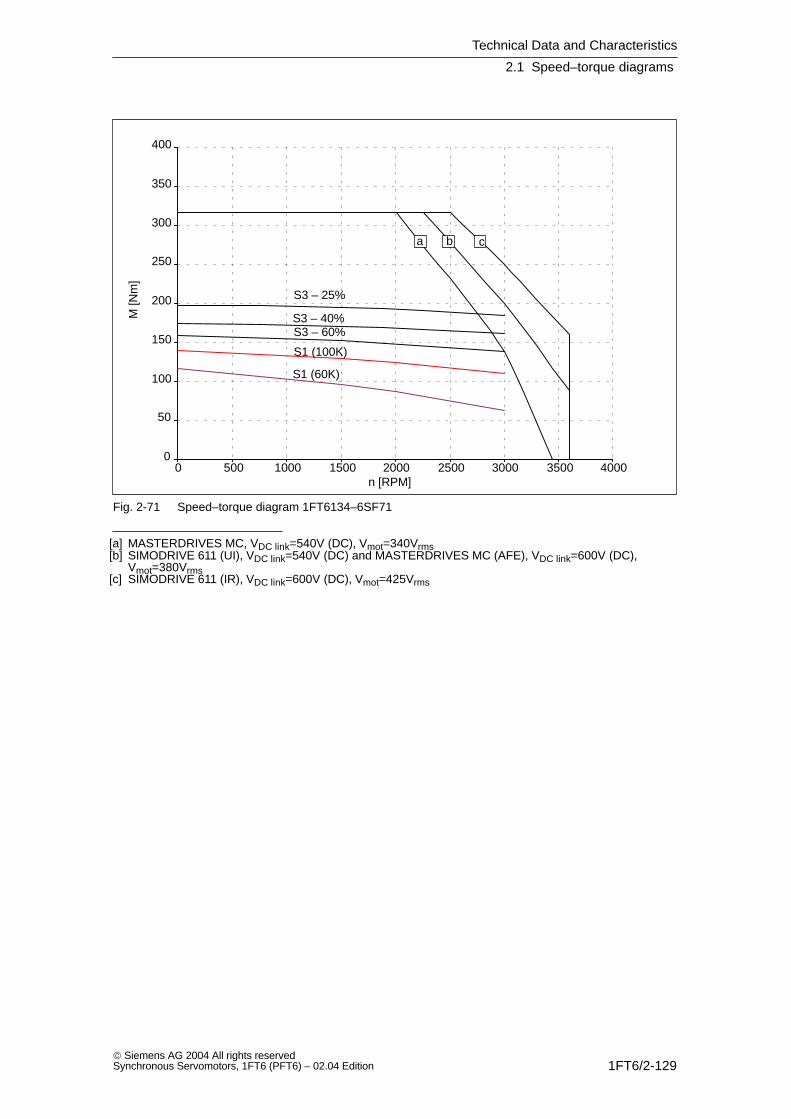
Technical Data and Characteristics
2.1 Speed–torque diagrams
1FT6/2-129 Siemens AG 2004 All rights reservedSynchronous Servomotors, 1FT6 (PFT6) – 02.04 Edition
0
50
100
150
200
250
300
350
400
0 500 1000 1500 2000 2500 3000 3500 4000
S1 (100K)
S1 (60K)
S3 – 25%
S3 – 40%S3 – 60%
a b c
n [RPM]
M [N
m]
Fig. 2-71 Speed–torque diagram 1FT6134–6SF71
[a] MASTERDRIVES MC, VDC link=540V (DC), Vmot=340Vrms[b] SIMODRIVE 611 (UI), VDC link=540V (DC) and MASTERDRIVES MC (AFE), VDC link=600V (DC),
Vmot=380Vrms[c] SIMODRIVE 611 (IR), VDC link=600V (DC), Vmot=425Vrms
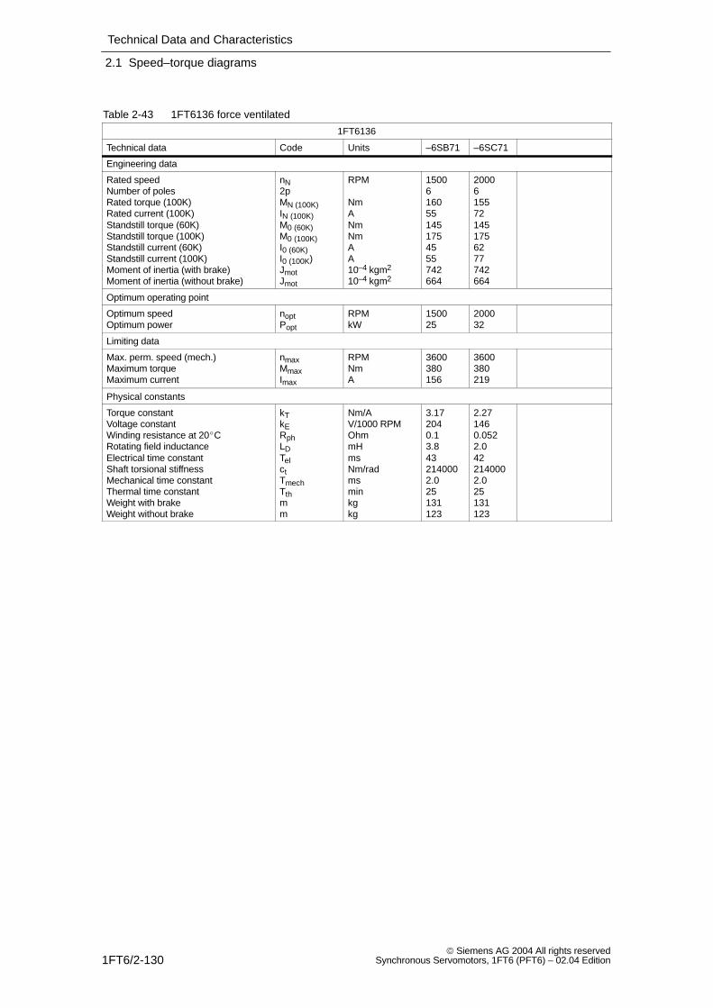
Technical Data and Characteristics
2.1 Speed–torque diagrams
1FT6/2-130 Siemens AG 2004 All rights reserved
Synchronous Servomotors, 1FT6 (PFT6) – 02.04 Edition
Table 2-43 1FT6136 force ventilated
1FT6136
Technical data Code Units –6SB71 –6SC71
Engineering data
Rated speedNumber of polesRated torque (100K)Rated current (100K)Standstill torque (60K)Standstill torque (100K)Standstill current (60K)Standstill current (100K)Moment of inertia (with brake)Moment of inertia (without brake)
nN2pMN (100K)IN (100K)M0 (60K)M0 (100K)I0 (60K)I0 (100K)JmotJmot
RPM
NmANmNmAA10–4 kgm2
10–4 kgm2
15006160551451754555742664
20006155721451756277742664
Optimum operating point
Optimum speedOptimum power
noptPopt
RPMkW
150025
200032
Limiting data
Max. perm. speed (mech.)Maximum torqueMaximum current
nmaxMmaxImax
RPMNmA
3600380156
3600380219
Physical constants
Torque constantVoltage constantWinding resistance at 20CRotating field inductanceElectrical time constantShaft torsional stiffnessMechanical time constantThermal time constantWeight with brakeWeight without brake
kTkERphLDTelctTmechTthmm
Nm/AV/1000 RPMOhmmHmsNm/radmsminkgkg
3.172040.13.8432140002.025131123
2.271460.0522.0422140002.025131123
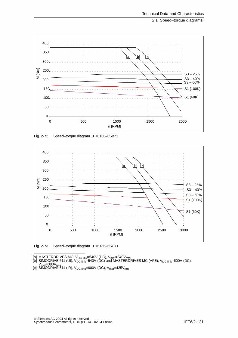
Technical Data and Characteristics
2.1 Speed–torque diagrams
1FT6/2-131 Siemens AG 2004 All rights reservedSynchronous Servomotors, 1FT6 (PFT6) – 02.04 Edition
0
50
100
150
200
250
300
350
400
0 500 1000 1500 2000
S1 (100K)
S1 (60K)
S3 – 25%S3 – 40%S3 – 60%
a b c
n [RPM]
M [N
m]
Fig. 2-72 Speed–torque diagram 1FT6136–6SB71
0
50
100
150
200
250
300
350
400
0 500 1000 1500 2000 2500 3000
S1 (100K)
S1 (60K)
S3 – 25%S3 – 40%S3 – 60%
a b c
n [RPM]
M [N
m]
Fig. 2-73 Speed–torque diagram 1FT6136–6SC71
[a] MASTERDRIVES MC, VDC link=540V (DC), Vmot=340Vrms[b] SIMODRIVE 611 (UI), VDC link=540V (DC) and MASTERDRIVES MC (AFE), VDC link=600V (DC),
Vmot=380Vrms[c] SIMODRIVE 611 (IR), VDC link=600V (DC), Vmot=425Vrms
Technical Data and Characteristics
2.1 Speed–torque diagrams
1FT6/2-132 Siemens AG 2004 All rights reserved
Synchronous Servomotors, 1FT6 (PFT6) – 02.04 Edition
Table 2-44 1FT6136 force ventilated
1FT6136
Technical data Code Units –6SF71
Engineering data
Rated speedNumber of polesRated torque (100K)Rated current (100K)Standstill torque (60K)Standstill torque (100K)Standstill current (60K)Standstill current (100K)Moment of inertia (with brake)Moment of inertia (without brake)
nN2pMN (100K)IN (100K)M0 (60K)M0 (100K)I0 (60K)I0 (100K)JmotJmot
RPM
NmANmNmAA10–4 kgm2
10–4 kgm2
3000614510414517589110742664
Optimum operating point
Optimum speedOptimum power
noptPopt
RPMkW
300046
Limiting data
Max. perm. speed (mech.)Maximum torqueMaximum current
nmaxMmaxImax
RPMNmA
3600380313
Physical constants
Torque constantVoltage constantWinding resistance at 20CRotating field inductanceElectrical time constantShaft torsional stiffnessMechanical time constantThermal time constantWeight with brakeWeight without brake
kTkERphLDTelctTmechTthmm
Nm/AV/1000 RPMOhmmHmsNm/radmsminkgkg
1.591020.0250.96442140002.025131123
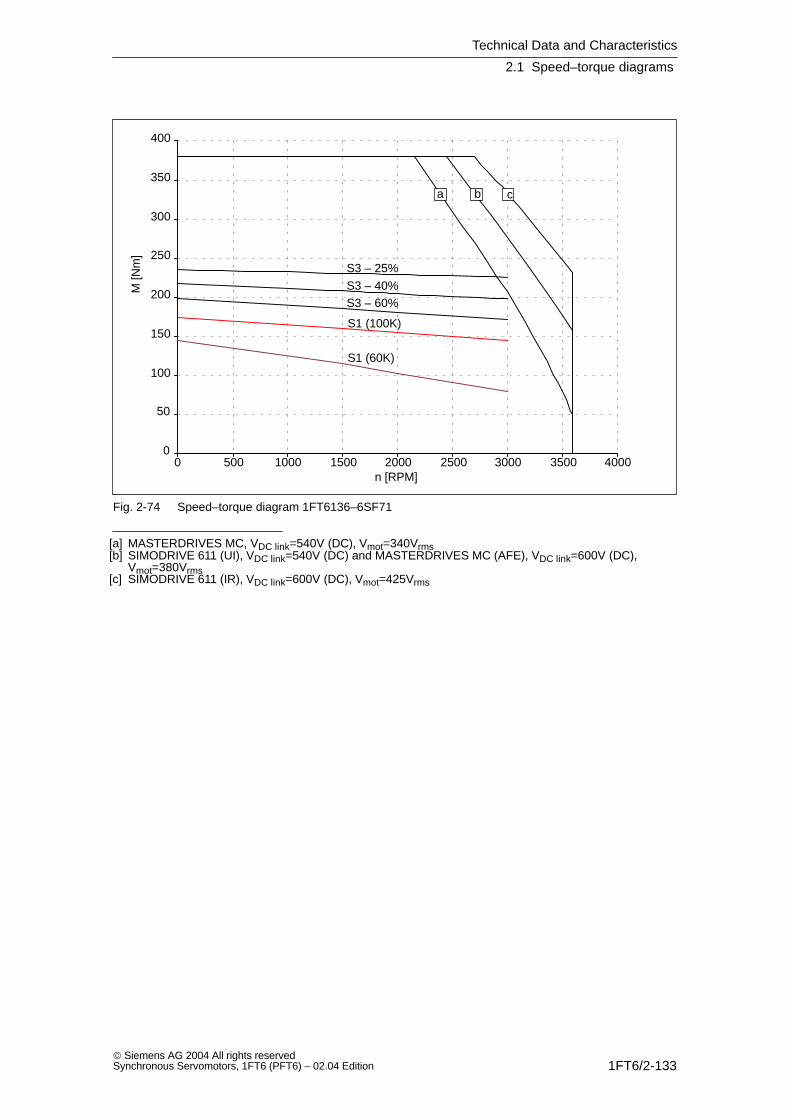
Technical Data and Characteristics
2.1 Speed–torque diagrams
1FT6/2-133 Siemens AG 2004 All rights reservedSynchronous Servomotors, 1FT6 (PFT6) – 02.04 Edition
0
50
100
150
200
250
300
350
400
0 500 1000 1500 2000 2500 3000 3500 4000
S1 (100K)
S1 (60K)
S3 – 25%
S3 – 40%S3 – 60%
a b c
n [RPM]
M [N
m]
Fig. 2-74 Speed–torque diagram 1FT6136–6SF71
[a] MASTERDRIVES MC, VDC link=540V (DC), Vmot=340Vrms[b] SIMODRIVE 611 (UI), VDC link=540V (DC) and MASTERDRIVES MC (AFE), VDC link=600V (DC),
Vmot=380Vrms[c] SIMODRIVE 611 (IR), VDC link=600V (DC), Vmot=425Vrms

Technical Data and Characteristics
2.1 Speed–torque diagrams
1FT6/2-134 Siemens AG 2004 All rights reserved
Synchronous Servomotors, 1FT6 (PFT6) – 02.04 Edition
Table 2-45 1FT6163 force ventilated
1FT6163 1)
Technical data Code Units –8SB7 –8SD7
Engineering data
Rated speedNumber of polesRated torque (100K)Rated current (100K)Standstill torque (60K)Standstill torque (100K)Standstill current (60K)Standstill current (100K)Moment of inertia (with brake)Moment of inertia (without brake)
nN2pMN (100K)IN (100K)M0 (60K)M0 (100K)I0 (60K)I0 (100K)JmotJmot
RPM
NmANmNmAA10–4 kgm2
10–4 kgm2
15008385136360425124151––2300
2500 2)
8340 2)
185 2)
360425186226––2300
Optimum operating point
Optimum speedOptimum power
noptPopt
RPMkW
150060.5
250089.0
Limiting data
Max. perm. speed (mech.)Maximum torqueMaximum current
nmaxMmaxImax
RPMNmA
3100900372
3100900558
Physical constants
Torque constantVoltage constantWinding resistance at 20CRotating field inductanceElectrical time constantShaft torsional stiffnessMechanical time constantThermal time constantWeight with brakeWeight without brake
kTkERphLDTelctTmechTthmm
Nm/AV/1000 RPMOhmmHmsNm/radmsminkgkg
2.811860.0260.81314721002.310––170
1.881240.0120.36304721002.310––170
1) only valid for MASTERDRIVES MC2) only valid for MASTERDRIVES MC (AFE)
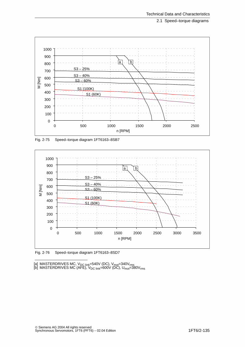
Technical Data and Characteristics
2.1 Speed–torque diagrams
1FT6/2-135 Siemens AG 2004 All rights reservedSynchronous Servomotors, 1FT6 (PFT6) – 02.04 Edition
0
100
200
300
400
500
600
700
800
900
1000
0 500 1000 1500 2000 2500
S1 (100K)
S1 (60K)
S3 – 40%
S3 – 25%
S3 – 60%
a b
n [RPM]
M [N
m]
Fig. 2-75 Speed–torque diagram 1FT6163–8SB7
0
100
200
300
400
500
600
700
800
900
1000
0 500 1000 1500 2000 2500 3000 3500
S1 (100K)S1 (60K)
S3 – 25%
S3 – 40%S3 – 60%
n [RPM]
M [N
m]
a b
Fig. 2-76 Speed–torque diagram 1FT6163–8SD7
[a] MASTERDRIVES MC, VDC link=540V (DC), Vmot=340Vrms[b] MASTERDRIVES MC (AFE), VDC link=600V (DC), Umot=380Vrms
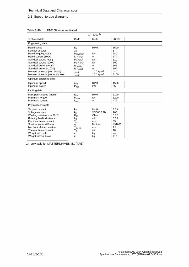
Technical Data and Characteristics
2.1 Speed–torque diagrams
1FT6/2-136 Siemens AG 2004 All rights reserved
Synchronous Servomotors, 1FT6 (PFT6) – 02.04 Edition
Table 2-46 1FT6168 force ventilated
1FT6168 1)
Technical data Code Units –8SB7
Engineering data
Rated speedNumber of polesRated torque (100K)Rated current (100K)Standstill torque (60K)Standstill torque (100K)Standstill current (60K)Standstill current (100K)Moment of inertia (with brake)Moment of inertia (without brake)
nN2pMN (100K)IN (100K)M0 (60K)M0 (100K)I0 (60K)I0 (100K)JmotJmot
RPM
NmANmNmAA10–4 kgm2
10–4 kgm2
15008540174510600165194––3100
Optimum operating point
Optimum speedOptimum power
noptPopt
RPMkW
150085
Limiting data
Max. perm. speed (mech.)Maximum torqueMaximum current
nmaxMmaxImax
RPMNmA
31001200479
Physical constants
Torque constantVoltage constantWinding resistance at 20CRotating field inductanceElectrical time constantShaft torsional stiffnessMechanical time constantThermal time constantWeight with brakeWeight without brake
kTkERphLDTelctTmechTthmm
Nm/AV/1000 RPMOhmmHmsNm/radmsminkgkg
3.092030.020.69354316001.910––210
1) only valid for MASTERDRIVES MC (AFE)
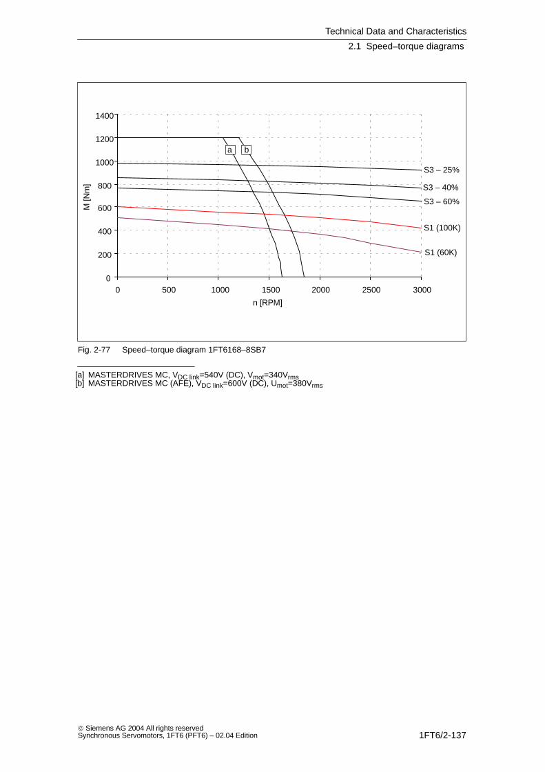
Technical Data and Characteristics
2.1 Speed–torque diagrams
1FT6/2-137 Siemens AG 2004 All rights reservedSynchronous Servomotors, 1FT6 (PFT6) – 02.04 Edition
0
200
400
600
800
1000
1200
1400
0 500 1000 1500 2000 2500 3000
S1 (100K)
S1 (60K)
S3 – 40%
S3 – 25%
S3 – 60%
a b
n [RPM]
M [N
m]
Fig. 2-77 Speed–torque diagram 1FT6168–8SB7
[a] MASTERDRIVES MC, VDC link=540V (DC), Vmot=340Vrms[b] MASTERDRIVES MC (AFE), VDC link=600V (DC), Umot=380Vrms
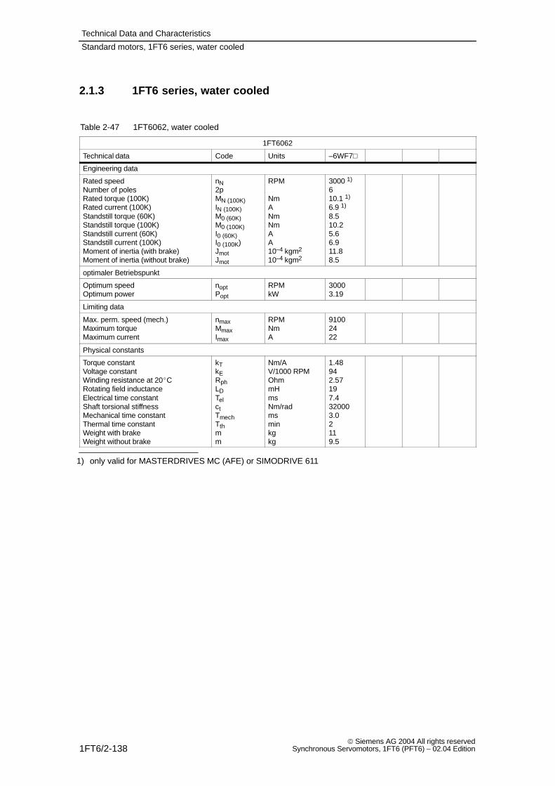
Technical Data and Characteristics
1FT6/2-138 Siemens AG 2004 All rights reserved
Synchronous Servomotors, 1FT6 (PFT6) – 02.04 Edition
2.1.3 1FT6 series, water cooled
Table 2-47 1FT6062, water cooled
1FT6062
Technical data Code Units –6WF7
Engineering data
Rated speedNumber of polesRated torque (100K)Rated current (100K)Standstill torque (60K)Standstill torque (100K)Standstill current (60K)Standstill current (100K)Moment of inertia (with brake)Moment of inertia (without brake)
nN2pMN (100K)IN (100K)M0 (60K)M0 (100K)I0 (60K)I0 (100K)JmotJmot
RPM
NmANmNmAA10–4 kgm2
10–4 kgm2
3000 1)
610.1 1)
6.9 1)
8.510.25.66.911.88.5
optimaler Betriebspunkt
Optimum speedOptimum power
noptPopt
RPMkW
30003.19
Limiting data
Max. perm. speed (mech.)Maximum torqueMaximum current
nmaxMmaxImax
RPMNmA
91002422
Physical constants
Torque constantVoltage constantWinding resistance at 20CRotating field inductanceElectrical time constantShaft torsional stiffnessMechanical time constantThermal time constantWeight with brakeWeight without brake
kTkERphLDTelctTmechTthmm
Nm/AV/1000 RPMOhmmHmsNm/radmsminkgkg
1.48942.57197.4320003.02119.5
1) only valid for MASTERDRIVES MC (AFE) or SIMODRIVE 611
Standard motors, 1FT6 series, water cooled
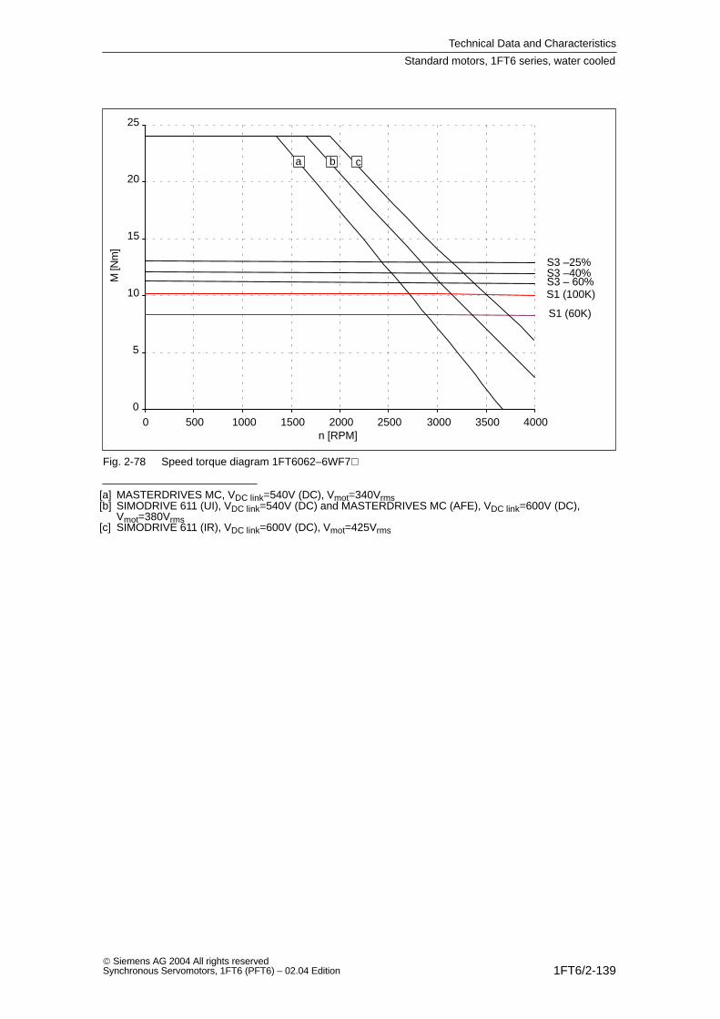
Technical Data and Characteristics
1FT6/2-139 Siemens AG 2004 All rights reservedSynchronous Servomotors, 1FT6 (PFT6) – 02.04 Edition
0
5
10
15
20
25
0 500 1000 1500 2000 2500 3000 3500 4000
S1 (100K)
S1 (60K)
S3 –25%S3 –40%S3 – 60%
a b c
n [RPM]
M [N
m]
Fig. 2-78 Speed torque diagram 1FT6062–6WF7
[a] MASTERDRIVES MC, VDC link=540V (DC), Vmot=340Vrms[b] SIMODRIVE 611 (UI), VDC link=540V (DC) and MASTERDRIVES MC (AFE), VDC link=600V (DC),
Vmot=380Vrms[c] SIMODRIVE 611 (IR), VDC link=600V (DC), Vmot=425Vrms
Standard motors, 1FT6 series, water cooled

Technical Data and Characteristics
1FT6/2-140 Siemens AG 2004 All rights reserved
Synchronous Servomotors, 1FT6 (PFT6) – 02.04 Edition
Table 2-48 1FT6062, water cooled
1FT6062
Technical data Code Units –6WH7 –6WK7
Engineering data
Rated speedNumber of polesRated torque (100K)Rated current (100K)Standstill torque (60K)Standstill torque (100K)Standstill current (60K)Standstill current (100K)Moment of inertia (with brake)Moment of inertia (without brake)
nN2pMN (100K)IN (100K)M0 (60K)M0 (100K)I0 (60K)I0 (100K)JmotJmot
RPM
NmANmNmAA10–4 kgm2
10–4 kgm2
4500 1)
610 1)
9.6 1)
8.510.27.99.711.88.5
6000 1)
69.8 1)
12.7 1)
8.510.210.612.911.88.5
Optimum operating point
Optimum speedOptimum power
noptPopt
RPMkW
45004.71
60006.16
Limiting data
Max. perm. speed (mech.)Maximum torqueMaximum current
nmaxMmaxImax
RPMNmA
91002431
91002441
Physical constants
Torque constantVoltage constantWinding resistance at 20CRotating field inductanceElectrical time constantShaft torsional stiffnessMechanical time constantThermal time constantWeight with brakeWeight without brake
kTkERphLDTelctTmechTthmm
Nm/AV/1000 RPMOhmmHmsNm/radmsminkgkg
1.05671.319.77.4320003.02119.5
0.79500.745.57.4320003.02119.5
1) only valid for MASTERDRIVES MC (AFE) or SIMODRIVE 611
Standard motors, 1FT6 series, water cooled
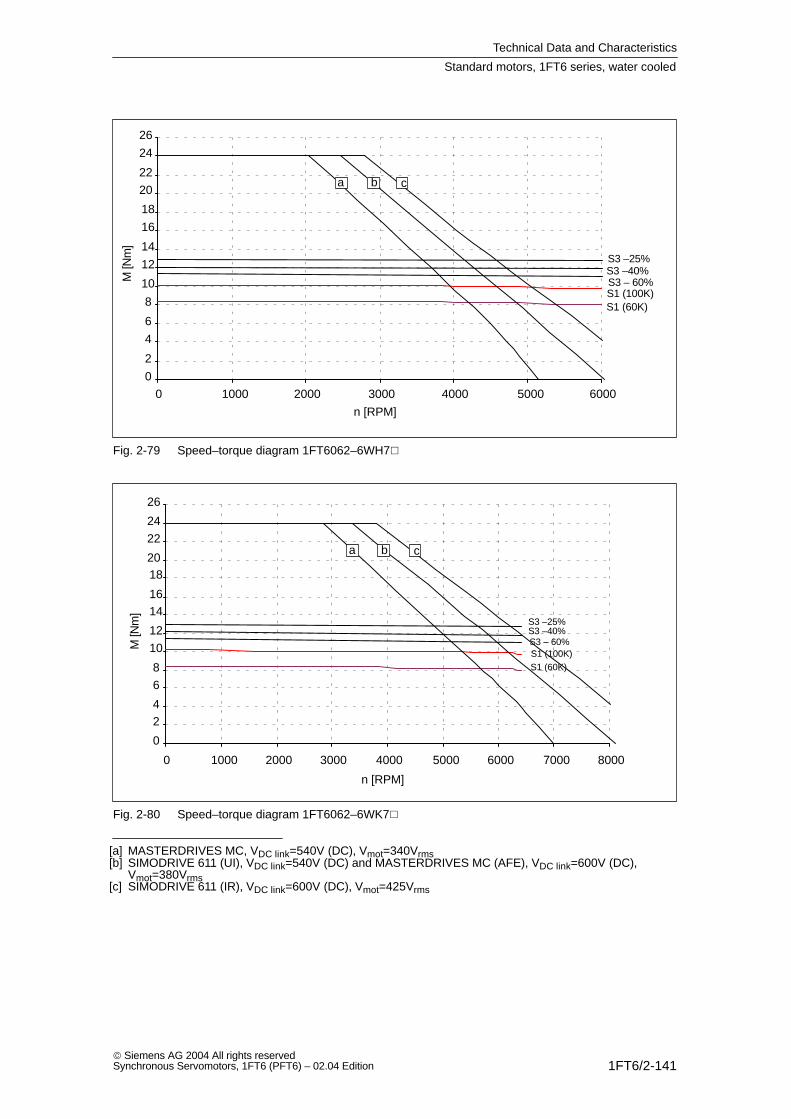
Technical Data and Characteristics
1FT6/2-141 Siemens AG 2004 All rights reservedSynchronous Servomotors, 1FT6 (PFT6) – 02.04 Edition
0
2
4
6
8
10
12
14
16
18
20
22
24
26
0 1000 2000 3000 4000 5000 6000
S1 (100K)S1 (60K)
S3 –25%S3 –40%S3 – 60%
a b c
n [RPM]
M [N
m]
Fig. 2-79 Speed–torque diagram 1FT6062–6WH7
0
24
6
8
10
12
1416
1820
22
24
26
0 1000 2000 3000 4000 5000 6000 7000 8000
S1 (100K)S1 (60K)
S3 –25%S3 –40%S3 – 60%
a b c
n [RPM]
M [N
m]
Fig. 2-80 Speed–torque diagram 1FT6062–6WK7
[a] MASTERDRIVES MC, VDC link=540V (DC), Vmot=340Vrms[b] SIMODRIVE 611 (UI), VDC link=540V (DC) and MASTERDRIVES MC (AFE), VDC link=600V (DC),
Vmot=380Vrms[c] SIMODRIVE 611 (IR), VDC link=600V (DC), Vmot=425Vrms
Standard motors, 1FT6 series, water cooled
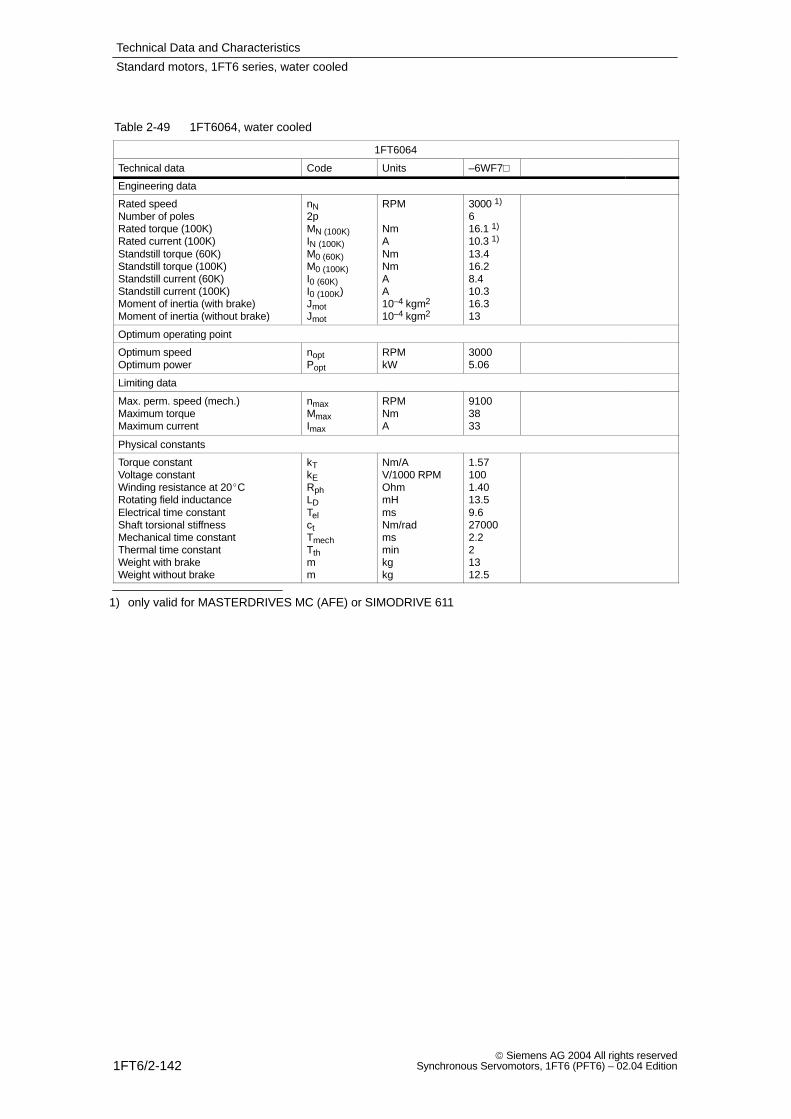
Technical Data and Characteristics
1FT6/2-142 Siemens AG 2004 All rights reserved
Synchronous Servomotors, 1FT6 (PFT6) – 02.04 Edition
Table 2-49 1FT6064, water cooled
1FT6064
Technical data Code Units –6WF7
Engineering data
Rated speedNumber of polesRated torque (100K)Rated current (100K)Standstill torque (60K)Standstill torque (100K)Standstill current (60K)Standstill current (100K)Moment of inertia (with brake)Moment of inertia (without brake)
nN2pMN (100K)IN (100K)M0 (60K)M0 (100K)I0 (60K)I0 (100K)JmotJmot
RPM
NmANmNmAA10–4 kgm2
10–4 kgm2
3000 1)
616.1 1)
10.3 1)
13.416.28.410.316.313
Optimum operating point
Optimum speedOptimum power
noptPopt
RPMkW
30005.06
Limiting data
Max. perm. speed (mech.)Maximum torqueMaximum current
nmaxMmaxImax
RPMNmA
91003833
Physical constants
Torque constantVoltage constantWinding resistance at 20CRotating field inductanceElectrical time constantShaft torsional stiffnessMechanical time constantThermal time constantWeight with brakeWeight without brake
kTkERphLDTelctTmechTthmm
Nm/AV/1000 RPMOhmmHmsNm/radmsminkgkg
1.571001.4013.59.6270002.221312.5
1) only valid for MASTERDRIVES MC (AFE) or SIMODRIVE 611
Standard motors, 1FT6 series, water cooled
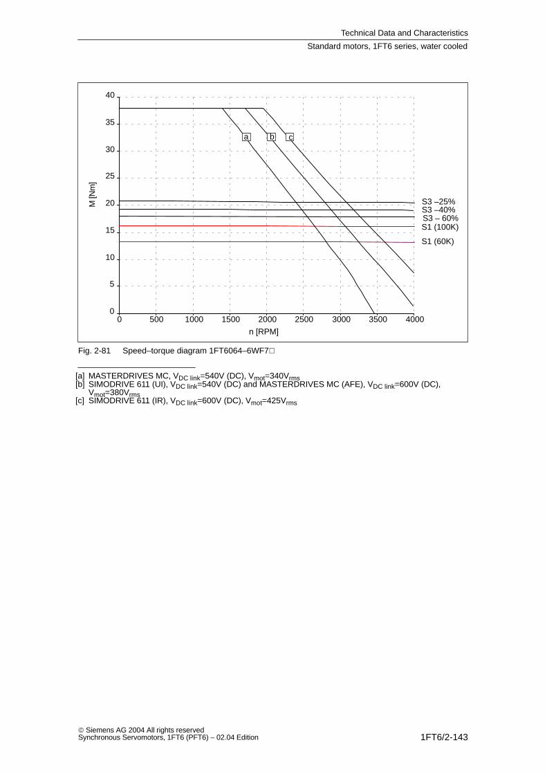
Technical Data and Characteristics
1FT6/2-143 Siemens AG 2004 All rights reservedSynchronous Servomotors, 1FT6 (PFT6) – 02.04 Edition
0
5
10
15
20
25
30
35
40
0 500 1000 1500 2000 2500 3000 3500 4000
S1 (100K)
S1 (60K)
S3 –25%S3 –40%S3 – 60%
a b c
n [RPM]
M [N
m]
Fig. 2-81 Speed–torque diagram 1FT6064–6WF7
[a] MASTERDRIVES MC, VDC link=540V (DC), Vmot=340Vrms[b] SIMODRIVE 611 (UI), VDC link=540V (DC) and MASTERDRIVES MC (AFE), VDC link=600V (DC),
Vmot=380Vrms[c] SIMODRIVE 611 (IR), VDC link=600V (DC), Vmot=425Vrms
Standard motors, 1FT6 series, water cooled
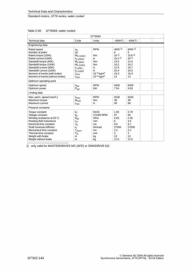
Technical Data and Characteristics
1FT6/2-144 Siemens AG 2004 All rights reserved
Synchronous Servomotors, 1FT6 (PFT6) – 02.04 Edition
Table 2-50 1FT6064, water cooled
1FT6064
Technical data Code Units –6WH7 –6WK7
Engineering data
Rated speedNumber of polesRated torque (100K)Rated current (100K)Standstill torque (60K)Standstill torque (100K)Standstill current (60K)Standstill current (100K)Moment of inertia (with brake)Moment of inertia (without brake)
nN2pMN (100K)IN (100K)M0 (60K)M0 (100K)I0 (60K)I0 (100K)JmotJmot
RPM
NmANmNmAA10–4 kgm2
10–4 kgm2
4500 1)
616 1)
15.2 1)
13.416.212.515.416.313
6000 1)
615.8 1)
20 1)
13.416.216.720.516.313
Optimum operating point
Optimum speedOptimum power
noptPopt
RPMkW
45007.54
60009.93
Limiting data
Max. perm. speed (mech.)Maximum torqueMaximum current
nmaxMmaxImax
RPMNmA
91003849
91003866
Physical constants
Torque constantVoltage constantWinding resistance at 20CRotating field inductanceElectrical time constantShaft torsional stiffnessMechanical time constantThermal time constantWeight with brakeWeight without brake
kTkERphLDTelctTmechTthmm
Nm/AV/1000 RPMOhmmHmsNm/radmsminkgkg
1.05670.6369.5270002.221312.5
0.79500.353.49.7270002.221312.5
1) only valid for MASTERDRIVES MC (AFE) or SIMODRIVE 611
Standard motors, 1FT6 series, water cooled
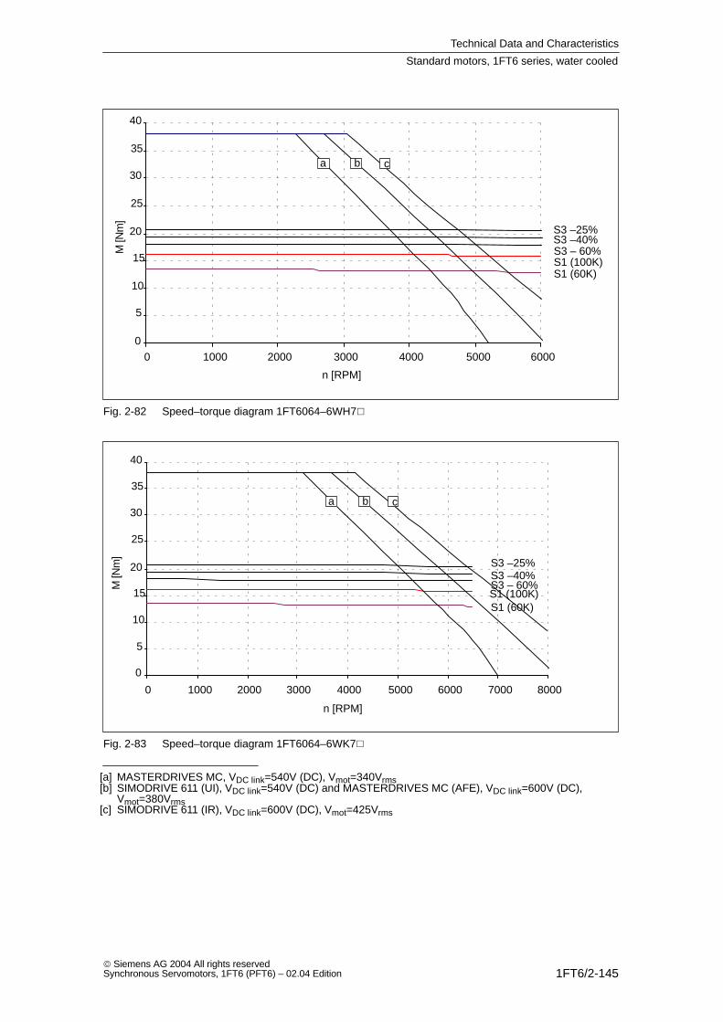
Technical Data and Characteristics
1FT6/2-145 Siemens AG 2004 All rights reservedSynchronous Servomotors, 1FT6 (PFT6) – 02.04 Edition
0
5
10
15
20
25
30
35
40
0 1000 2000 3000 4000 5000 6000
S1 (100K)S1 (60K)
S3 –25%S3 –40%S3 – 60%
a b c
n [RPM]
M [N
m]
Fig. 2-82 Speed–torque diagram 1FT6064–6WH7
0
5
10
15
20
25
30
35
40
0 1000 2000 3000 4000 5000 6000 7000 8000
S1 (100K)S1 (60K)
S3 –25%S3 –40%S3 – 60%
a b c
n [RPM]
M [N
m]
Fig. 2-83 Speed–torque diagram 1FT6064–6WK7
[a] MASTERDRIVES MC, VDC link=540V (DC), Vmot=340Vrms[b] SIMODRIVE 611 (UI), VDC link=540V (DC) and MASTERDRIVES MC (AFE), VDC link=600V (DC),
Vmot=380Vrms[c] SIMODRIVE 611 (IR), VDC link=600V (DC), Vmot=425Vrms
Standard motors, 1FT6 series, water cooled

Technical Data and Characteristics
1FT6/2-146 Siemens AG 2004 All rights reserved
Synchronous Servomotors, 1FT6 (PFT6) – 02.04 Edition
Table 2-51 1FT6084, water cooled
1FT6084
Technical data Code Units –8WF7
Engineering data
Rated speedNumber of polesRated torque (100K)Rated current (100K)Standstill torque (60K)Standstill torque (100K)Standstill current (60K)Standstill current (100K)Moment of inertia (with brake)Moment of inertia (without brake)
nN2pMN (100K)IN (100K)M0 (60K)M0 (100K)I0 (60K)I0 (100K)JmotJmot
RPM
NmANmNmAA10–4 kgm2
10–4 kgm2
3000 1)
835 1)
27 1)
293519.924.561.148
Optimum operating point
Optimum speedOptimum power
noptPopt
RPMkW
300011.0
Limiting data
Max. perm. speed (mech.)Maximum torqueMaximum current
nmaxMmaxImax
RPMNmA
79006559
Physical constants
Torque constantVoltage constantWinding resistance at 20CRotating field inductanceElectrical time constantShaft torsional stiffnessMechanical time constantThermal time constantWeight with brakeWeight without brake
kTkERphLDTelctTmechTthmm
Nm/AV/1000 RPMOhmmHmsNm/radmsminkgkg
1.43910.374.311.6760002.61.524.521
1) only valid for MASTERDRIVES MC (AFE) or SIMODRIVE 611
Standard motors, 1FT6 series, water cooled
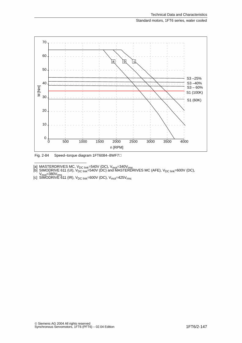
Technical Data and Characteristics
1FT6/2-147 Siemens AG 2004 All rights reservedSynchronous Servomotors, 1FT6 (PFT6) – 02.04 Edition
0
10
20
30
40
50
60
70
0 500 1000 1500 2000 2500 3000 3500 4000
S1 (100K)
S1 (60K)
S3 –25%S3 –40%S3 – 60%
a b c
n [RPM]
M [N
m]
Fig. 2-84 Speed–torque diagram 1FT6084–8WF7
[a] MASTERDRIVES MC, VDC link=540V (DC), Vmot=340Vrms[b] SIMODRIVE 611 (UI), VDC link=540V (DC) and MASTERDRIVES MC (AFE), VDC link=600V (DC),
Vmot=380Vrms[c] SIMODRIVE 611 (IR), VDC link=600V (DC), Vmot=425Vrms
Standard motors, 1FT6 series, water cooled

Technical Data and Characteristics
1FT6/2-148 Siemens AG 2004 All rights reserved
Synchronous Servomotors, 1FT6 (PFT6) – 02.04 Edition
Table 2-52 1FT6084, water cooled
1FT6084
Technical data Code Units –8WH7 –8WK7
Engineering data
Rated speedNumber of polesRated torque (100K)Rated current (100K)Standstill torque (60K)Standstill torque (100K)Standstill current (60K)Standstill current (100K)Moment of inertia (with brake)Moment of inertia (without brake)
nN2pMN (100K)IN (100K)M0 (60K)M0 (100K)I0 (60K)I0 (100K)JmotJmot
RPM
NmANmNmAA10–4 kgm2
10–4 kgm2
4500 1)
835 1)
39 1)
2935303761.148
6000 1)
834 1)
51 1)
2935384761.148
Optimum operating point
Optimum speedOptimum power
noptPopt
RPMkW
450016.5
600021.4
Limiting data
Max. perm. speed (mech.)Maximum torqueMaximum current
nmaxMmaxImax
RPMNmA
79006590
790065112
Physical constants
Torque constantVoltage constantWinding resistance at 20CRotating field inductanceElectrical time constantShaft torsional stiffnessMechanical time constantThermal time constantWeight with brakeWeight without brake
kTkERphLDTelctTmechTthmm
Nm/AV/1000 RPMOhmmHmsNm/radmsminkgkg
0.96610.171.911.2760002.71.52421
0.74470.11.212.0760002.61.52621
1) only valid for MASTERDRIVES MC (AFE) or SIMODRIVE 611
Standard motors, 1FT6 series, water cooled
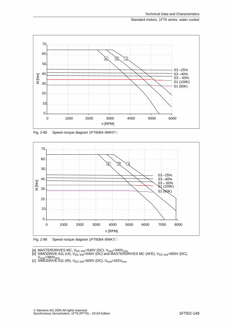
Technical Data and Characteristics
1FT6/2-149 Siemens AG 2004 All rights reservedSynchronous Servomotors, 1FT6 (PFT6) – 02.04 Edition
0
10
20
30
40
50
60
70
0 1000 2000 3000 4000 5000 6000
S1 (100K)S1 (60K)
S3 –25%S3 –40%S3 – 60%
a b c
n [RPM]
M [N
m]
Fig. 2-85 Speed–torque diagram 1FT6084–8WH7
0
10
20
30
40
50
60
70
0 1000 2000 3000 4000 5000 6000 7000 8000
S1 (100K)S1 (60K)
S3 –25%S3 –40%S3 – 60%
a b c
n [RPM]
M [N
m]
Fig. 2-86 Speed–torque diagram 1FT6084–8WK7
[a] MASTERDRIVES MC, VDC link=540V (DC), Vmot=340Vrms[b] SIMODRIVE 611 (UI), VDC link=540V (DC) and MASTERDRIVES MC (AFE), VDC link=600V (DC),
Vmot=380Vrms[c] SIMODRIVE 611 (IR), VDC link=600V (DC), Vmot=425Vrms
Standard motors, 1FT6 series, water cooled
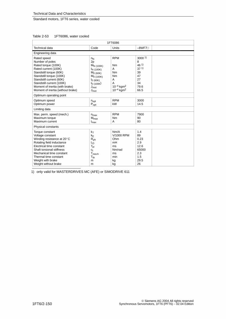
Technical Data and Characteristics
1FT6/2-150 Siemens AG 2004 All rights reserved
Synchronous Servomotors, 1FT6 (PFT6) – 02.04 Edition
Table 2-53 1FT6086, water cooled
1FT6086
Technical data Code Units –8WF7
Engineering data
Rated speedNumber of polesRated torque (100K)Rated current (100K)Standstill torque (60K)Standstill torque (100K)Standstill current (60K)Standstill current (100K)Moment of inertia (with brake)Moment of inertia (without brake)
nN2pMN (100K)IN (100K)M0 (60K)M0 (100K)I0 (60K)I0 (100K)JmotJmot
RPM
NmANmNmAA10–4 kgm2
10–4 kgm2
3000 1)
846 1)
37 1)
3947273479.666.5
Optimum operating point
Optimum speedOptimum power
noptPopt
RPMkW
300014.5
Limiting data
Max. perm. speed (mech.)Maximum torqueMaximum current
nmaxMmaxImax
RPMNmA
79009080
Physical constants
Torque constantVoltage constantWinding resistance at 20CRotating field inductanceElectrical time constantShaft torsional stiffnessMechanical time constantThermal time constantWeight with brakeWeight without brake
kTkERphLDTelctTmechTthmm
Nm/AV/1000 RPMOhmmHmsNm/radmsminkgkg
1.4890.232.912.6650002.31.529.526
1) only valid for MASTERDRIVES MC (AFE) or SIMODRIVE 611
Standard motors, 1FT6 series, water cooled
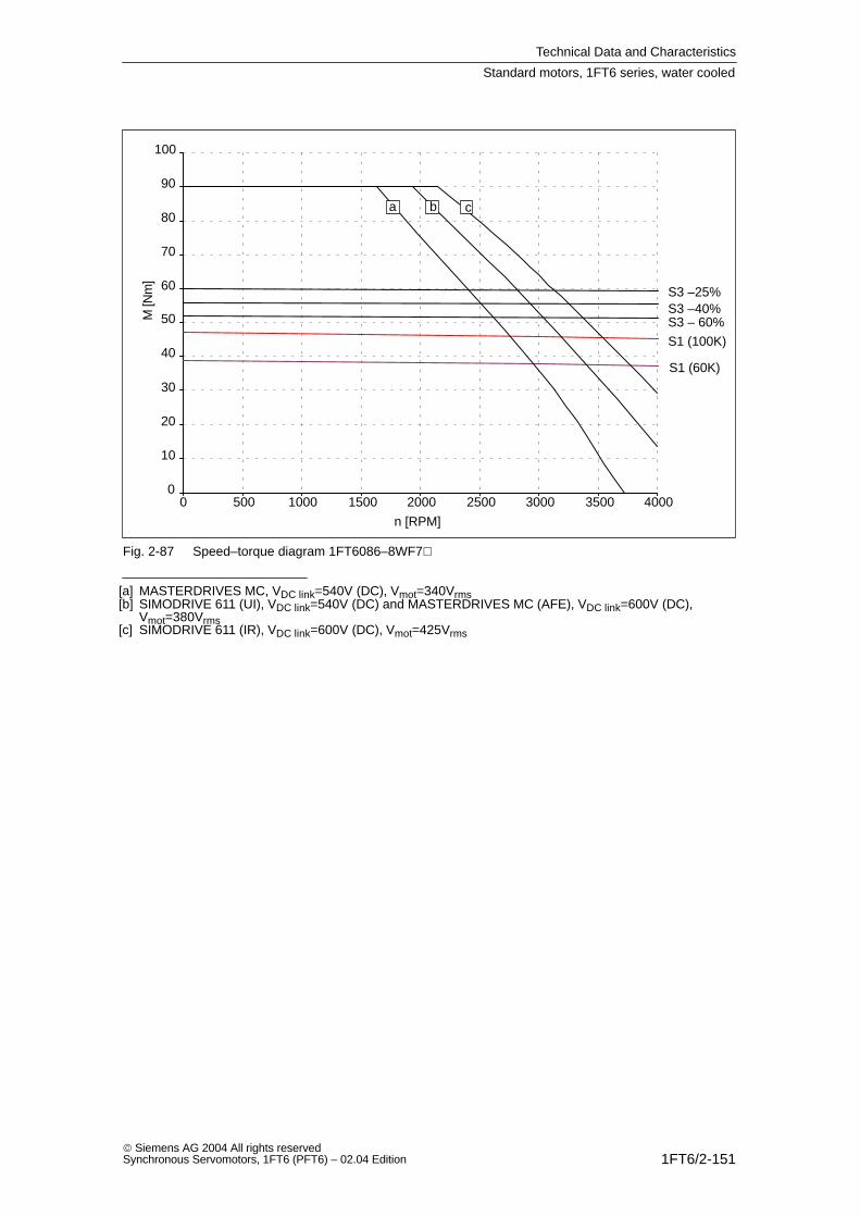
Technical Data and Characteristics
1FT6/2-151 Siemens AG 2004 All rights reservedSynchronous Servomotors, 1FT6 (PFT6) – 02.04 Edition
0
10
20
30
40
50
60
70
80
90
100
0 500 1000 1500 2000 2500 3000 3500 4000
S1 (100K)
S1 (60K)
S3 –25%S3 –40%S3 – 60%
a b c
n [RPM]
M [N
m]
Fig. 2-87 Speed–torque diagram 1FT6086–8WF7
[a] MASTERDRIVES MC, VDC link=540V (DC), Vmot=340Vrms[b] SIMODRIVE 611 (UI), VDC link=540V (DC) and MASTERDRIVES MC (AFE), VDC link=600V (DC),
Vmot=380Vrms[c] SIMODRIVE 611 (IR), VDC link=600V (DC), Vmot=425Vrms
Standard motors, 1FT6 series, water cooled
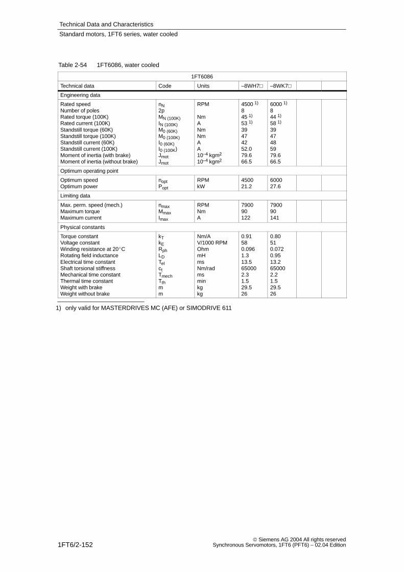
Technical Data and Characteristics
1FT6/2-152 Siemens AG 2004 All rights reserved
Synchronous Servomotors, 1FT6 (PFT6) – 02.04 Edition
Table 2-54 1FT6086, water cooled
1FT6086
Technical data Code Units –8WH7 –8WK7
Engineering data
Rated speedNumber of polesRated torque (100K)Rated current (100K)Standstill torque (60K)Standstill torque (100K)Standstill current (60K)Standstill current (100K)Moment of inertia (with brake)Moment of inertia (without brake)
nN2pMN (100K)IN (100K)M0 (60K)M0 (100K)I0 (60K)I0 (100K)JmotJmot
RPM
NmANmNmAA10–4 kgm2
10–4 kgm2
4500 1)
845 1)
53 1)
39474252.079.666.5
6000 1)
844 1)
58 1)
3947485979.666.5
Optimum operating point
Optimum speedOptimum power
noptPopt
RPMkW
450021.2
600027.6
Limiting data
Max. perm. speed (mech.)Maximum torqueMaximum current
nmaxMmaxImax
RPMNmA
790090122
790090141
Physical constants
Torque constantVoltage constantWinding resistance at 20CRotating field inductanceElectrical time constantShaft torsional stiffnessMechanical time constantThermal time constantWeight with brakeWeight without brake
kTkERphLDTelctTmechTthmm
Nm/AV/1000 RPMOhmmHmsNm/radmsminkgkg
0.91580.0961.313.5650002.31.529.526
0.80510.0720.9513.2650002.21.529.526
1) only valid for MASTERDRIVES MC (AFE) or SIMODRIVE 611
Standard motors, 1FT6 series, water cooled
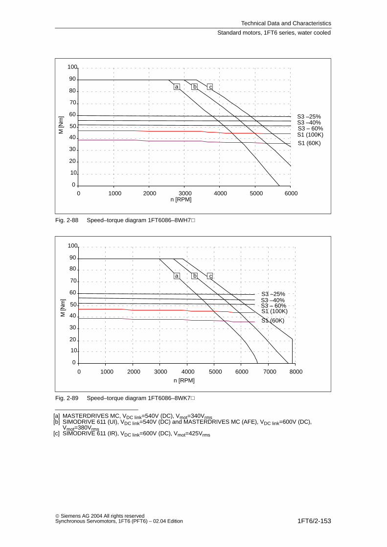
Technical Data and Characteristics
1FT6/2-153 Siemens AG 2004 All rights reservedSynchronous Servomotors, 1FT6 (PFT6) – 02.04 Edition
0
10
20
30
40
50
60
70
80
90
100
0 1000 2000 3000 4000 5000 6000
S1 (100K)S1 (60K)
S3 –25%S3 –40%S3 – 60%
a b c
n [RPM]
M [N
m]
Fig. 2-88 Speed–torque diagram 1FT6086–8WH7
0
10
20
30
40
50
60
70
80
90
100
0 1000 2000 3000 4000 5000 6000 7000 8000
S1 (100K)
S1 (60K)
S3 –25%S3 –40%S3 – 60%
a b c
n [RPM]
M [N
m]
Fig. 2-89 Speed–torque diagram 1FT6086–8WK7
[a] MASTERDRIVES MC, VDC link=540V (DC), Vmot=340Vrms[b] SIMODRIVE 611 (UI), VDC link=540V (DC) and MASTERDRIVES MC (AFE), VDC link=600V (DC),
Vmot=380Vrms[c] SIMODRIVE 611 (IR), VDC link=600V (DC), Vmot=425Vrms
Standard motors, 1FT6 series, water cooled
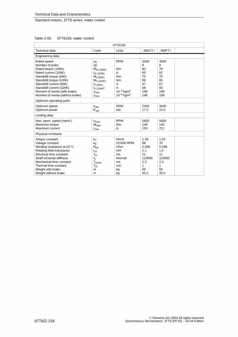
Technical Data and Characteristics
1FT6/2-154 Siemens AG 2004 All rights reserved
Synchronous Servomotors, 1FT6 (PFT6) – 02.04 Edition
Table 2-55 1FT6105, water cooled
1FT6105
Technical data Code Units –8WC7 –8WF7
Engineering data
Rated speedNumber of polesRated torque (100K)Rated current (100K)Standstill torque (60K)Standstill torque (100K)Standstill current (60K)Standstill current (100K)Moment of inertia (with brake)Moment of inertia (without brake)
nN2pMN (100K)IN (100K)M0 (60K)M0 (100K)I0 (60K)I0 (100K)JmotJmot
RPM
NmANmNmAA10–4 kgm2
10–4 kgm2
20008826070854758199168
30008788270856783199168
Optimum operating point
Optimum speedOptimum power
noptPopt
RPMkW
200017.2
300024.5
Limiting data
Max. perm. speed (mech.)Maximum torqueMaximum current
nmaxMmaxImax
RPMNmA
5600140155
5600140221
Physical constants
Torque constantVoltage constantWinding resistance at 20CRotating field inductanceElectrical time constantShaft torsional stiffnessMechanical time constantThermal time constantWeight with brakeWeight without brake
kTkERphLDTelctTmechTthmm
Nm/AV/1000 RPMOhmmHmsNm/radmsminkgkg
1.45990.0982.1211130002.315045.5
1.02700.0481.0211130002.315045.5
Standard motors, 1FT6 series, water cooled
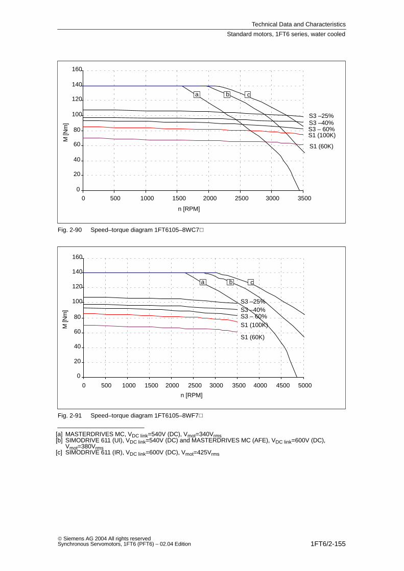
Technical Data and Characteristics
1FT6/2-155 Siemens AG 2004 All rights reservedSynchronous Servomotors, 1FT6 (PFT6) – 02.04 Edition
0
20
40
60
80
100
120
140
160
0 500 1000 1500 2000 2500 3000 3500
S1 (100K)
S1 (60K)
S3 –25%S3 –40%S3 – 60%
a b c
n [RPM]
M [N
m]
Fig. 2-90 Speed–torque diagram 1FT6105–8WC7
0
20
40
60
80
100
120
140
160
0 500 1000 1500 2000 2500 3000 3500 4000 4500 5000
S1 (100K)
S1 (60K)
S3 –25%S3 –40%S3 – 60%
a b c
n [RPM]
M [N
m]
Fig. 2-91 Speed–torque diagram 1FT6105–8WF7
[a] MASTERDRIVES MC, VDC link=540V (DC), Vmot=340Vrms[b] SIMODRIVE 611 (UI), VDC link=540V (DC) and MASTERDRIVES MC (AFE), VDC link=600V (DC),
Vmot=380Vrms[c] SIMODRIVE 611 (IR), VDC link=600V (DC), Vmot=425Vrms
Standard motors, 1FT6 series, water cooled

Technical Data and Characteristics
1FT6/2-156 Siemens AG 2004 All rights reserved
Synchronous Servomotors, 1FT6 (PFT6) – 02.04 Edition
Table 2-56 1FT6108, water cooled
1FT6108
Technical data Code Units –8WB7 –8WC7
Engineering data
Rated speedNumber of polesRated torque (100K)Rated current (100K)Standstill torque (60K)Standstill torque (100K)Standstill current (60K)Standstill current (100K)Moment of inertia (with brake)Moment of inertia (without brake)
nN2pMN (100K)IN (100K)M0 (60K)M0 (100K)I0 (60K)I0 (100K)JmotJmot
RPM
NmANmNmAA10–4 kgm2
10–4 kgm2
1500 1)
8116 1)
43 1)
981193543291260
2000 1)
8115 1)
57 1)
981194657291260
Optimum operating point
Optimum speedOptimum power
noptPopt
RPMkW
150018.2
200024.1
Limiting data
Max. perm. speed (mech.)Maximum torqueMaximum current
nmaxMmaxImax
RPMNmA
5600220116
5600220154
Physical constants
Torque constantVoltage constantWinding resistance at 20CRotating field inductanceElectrical time constantShaft torsional stiffnessMechanical time constantThermal time constantWeight with brakeWeight without brake
kTkERphLDTelctTmechTthmm
Nm/AV/1000 RPMOhmmHmsNm/radmsminkgkg
2.761850.194.423920001.916661.5
2.071390.112.523920002.016661.5
1) only valid for MASTERDRIVES MC (AFE) or SIMODRIVE 611
Standard motors, 1FT6 series, water cooled
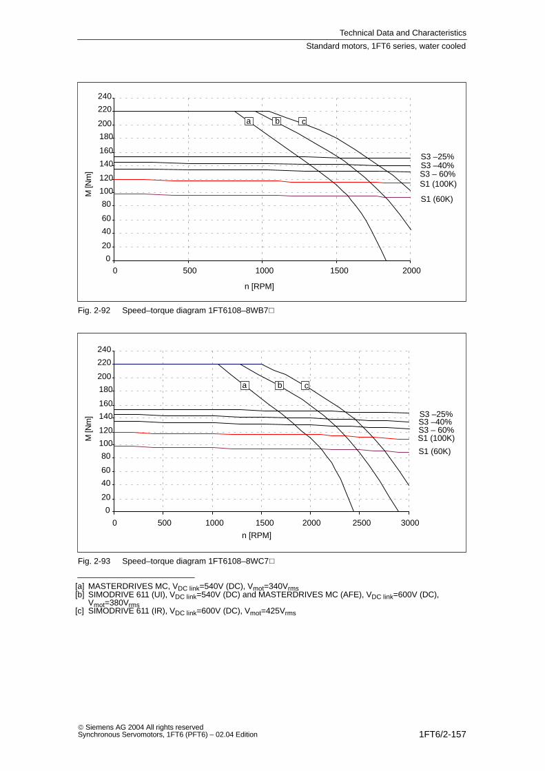
Technical Data and Characteristics
1FT6/2-157 Siemens AG 2004 All rights reservedSynchronous Servomotors, 1FT6 (PFT6) – 02.04 Edition
0
20
40
60
80
100
120
140
160
180
200
220
240
0 500 1000 1500 2000
S1 (100K)
S1 (60K)
S3 –25%S3 –40%S3 – 60%
a b c
n [RPM]
M [N
m]
Fig. 2-92 Speed–torque diagram 1FT6108–8WB7
0
20
40
60
80
100
120
140
160
180
200
220
240
0 500 1000 1500 2000 2500 3000
S1 (100K)
S1 (60K)
S3 –25%S3 –40%S3 – 60%
a b c
n [RPM]
M [N
m]
Fig. 2-93 Speed–torque diagram 1FT6108–8WC7
[a] MASTERDRIVES MC, VDC link=540V (DC), Vmot=340Vrms[b] SIMODRIVE 611 (UI), VDC link=540V (DC) and MASTERDRIVES MC (AFE), VDC link=600V (DC),
Vmot=380Vrms[c] SIMODRIVE 611 (IR), VDC link=600V (DC), Vmot=425Vrms
Standard motors, 1FT6 series, water cooled

Technical Data and Characteristics
1FT6/2-158 Siemens AG 2004 All rights reserved
Synchronous Servomotors, 1FT6 (PFT6) – 02.04 Edition
Table 2-57 1FT6108, water cooled
1FT6108
Technical data Code Units –8WF7
Engineering data
Rated speedNumber of polesRated torque (100K)Rated current (100K)Standstill torque (60K)Standstill torque (100K)Standstill current (60K)Standstill current (100K)Moment of inertia (with brake)Moment of inertia (without brake)
nN2pMN (100K)IN (100K)M0 (60K)M0 (100K)I0 (60K)I0 (100K)JmotJmot
RPM
NmANmNmAA10–4 kgm2
10–4 kgm2
3000810981981197086291260
Optimum operating point
Optimum speedOptimum power
noptPopt
RPMkW
300034
Limiting data
Max. perm. speed (mech.)Maximum torqueMaximum current
nmaxMmaxImax
RPMNmA
5600220231
Physical constants
Torque constantVoltage constantWinding resistance at 20CRotating field inductanceElectrical time constantShaft torsional stiffnessMechanical time constantThermal time constantWeight with brakeWeight without brake
kTkERphLDTelctTmechTthmm
Nm/AV/1000 RPMOhmmHmsNm/radmsminkgkg
1.38920.0481.123920002.016661.5
Standard motors, 1FT6 series, water cooled
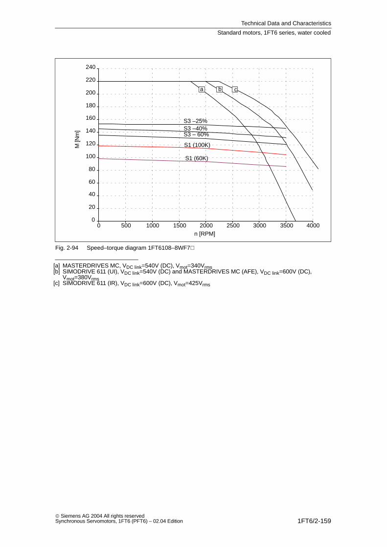
Technical Data and Characteristics
1FT6/2-159 Siemens AG 2004 All rights reservedSynchronous Servomotors, 1FT6 (PFT6) – 02.04 Edition
0
20
40
60
80
100
120
140
160
180
200
220
240
0 500 1000 1500 2000 2500 3000 3500 4000
S1 (100K)
S1 (60K)
S3 –25%S3 –40%S3 – 60%
a b c
n [RPM]
M [N
m]
Fig. 2-94 Speed–torque diagram 1FT6108–8WF7
[a] MASTERDRIVES MC, VDC link=540V (DC), Vmot=340Vrms[b] SIMODRIVE 611 (UI), VDC link=540V (DC) and MASTERDRIVES MC (AFE), VDC link=600V (DC),
Vmot=380Vrms[c] SIMODRIVE 611 (IR), VDC link=600V (DC), Vmot=425Vrms
Standard motors, 1FT6 series, water cooled

Technical Data and Characteristics
1FT6/2-160 Siemens AG 2004 All rights reserved
Synchronous Servomotors, 1FT6 (PFT6) – 02.04 Edition
Table 2-58 1FT6132, water cooled
1FT6132
Technical data Code Units –6WB7 –6WD7
Engineering data
Rated speedNumber of polesRated torque (100K)Rated current (100K)Standstill torque (60K)Standstill torque (100K)Standstill current (60K)Standstill current (100K)Moment of inertia (with brake)Moment of inertia (without brake)
nN2pMN (100K)IN (100K)M0 (60K)M0 (100K)I0 (60K)I0 (100K)JmotJmot
RPM
NmANmNmAA10–4 kgm2
10–4 kgm2
1500 1)
6150 1)
58 1)
1201554558––430
2500 1)
6135 1)
82 1)
1201557192––430
Optimum operating point
Optimum speedOptimum power
noptPopt
RPMkW
150023.6
250035.3
Limiting data
Max. perm. speed (mech.)Maximum torqueMaximum current
nmaxMmaxImax
RPMNmA
3600250124.5
3600250197 2)
Physical constants
Torque constantVoltage constantWinding resistance at 20CRotating field inductanceElectrical time constantShaft torsional stiffnessMechanical time constantThermal time constantWeight with brakeWeight without brake
kTkERphLDTelctTmechTthmm
Nm/AV/1000 RPMOhmmHmsNm/radmsminkgkg
2.671770.154.5302623002.76––90
1.681120.0571.8322623002.66––90
1) only valid for MASTERDRIVES MC (AFE) or SIMODRIVE 6112) Observe the maximum drive converter current
Standard motors, 1FT6 series, water cooled
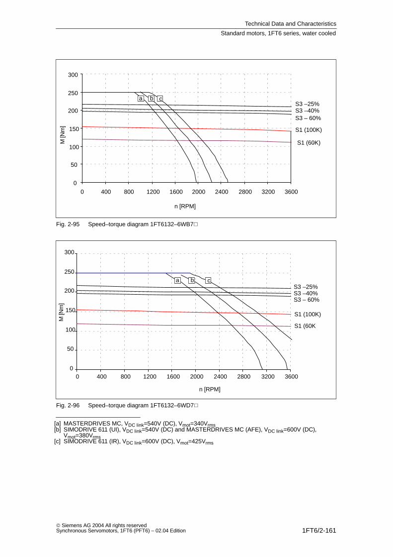
Technical Data and Characteristics
1FT6/2-161 Siemens AG 2004 All rights reservedSynchronous Servomotors, 1FT6 (PFT6) – 02.04 Edition
0
50
100
150
200
250
300
0 400 800 1200 1600 2000 2400 2800 3200 3600
S1 (100K)
S3 –25%S3 –40%S3 – 60%
a b c
n [RPM]
M [N
m]
S1 (60K)
Fig. 2-95 Speed–torque diagram 1FT6132–6WB7
0
50
100
150
200
250
300
0 400 800 1200 1600 2000 2400 2800 3200 3600
S1 (60K)
S3 –25%S3 –40%S3 – 60%
a b c
n [RPM]
M [N
m]
S1 (100K)
Fig. 2-96 Speed–torque diagram 1FT6132–6WD7
[a] MASTERDRIVES MC, VDC link=540V (DC), Vmot=340Vrms[b] SIMODRIVE 611 (UI), VDC link=540V (DC) and MASTERDRIVES MC (AFE), VDC link=600V (DC),
Vmot=380Vrms[c] SIMODRIVE 611 (IR), VDC link=600V (DC), Vmot=425Vrms
Standard motors, 1FT6 series, water cooled
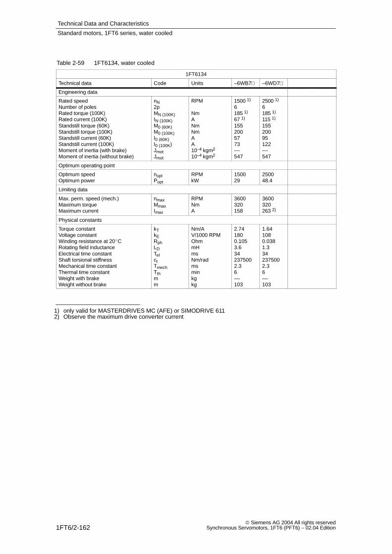
Technical Data and Characteristics
1FT6/2-162 Siemens AG 2004 All rights reserved
Synchronous Servomotors, 1FT6 (PFT6) – 02.04 Edition
Table 2-59 1FT6134, water cooled
1FT6134
Technical data Code Units –6WB7 –6WD7
Engineering data
Rated speedNumber of polesRated torque (100K)Rated current (100K)Standstill torque (60K)Standstill torque (100K)Standstill current (60K)Standstill current (100K)Moment of inertia (with brake)Moment of inertia (without brake)
nN2pMN (100K)IN (100K)M0 (60K)M0 (100K)I0 (60K)I0 (100K)JmotJmot
RPM
NmANmNmAA10–4 kgm2
10–4 kgm2
1500 1)
6185 1)
67 1)
1552005773––547
2500 1)
6185 1)
115 1)
15520095122––547
Optimum operating point
Optimum speedOptimum power
noptPopt
RPMkW
150029
250048.4
Limiting data
Max. perm. speed (mech.)Maximum torqueMaximum current
nmaxMmaxImax
RPMNmA
3600320158
3600320263 2)
Physical constants
Torque constantVoltage constantWinding resistance at 20CRotating field inductanceElectrical time constantShaft torsional stiffnessMechanical time constantThermal time constantWeight with brakeWeight without brake
kTkERphLDTelctTmechTthmm
Nm/AV/1000 RPMOhmmHmsNm/radmsminkgkg
2.741800.1053.6342375002.36––103
1.641080.0381.3342375002.36––103
1) only valid for MASTERDRIVES MC (AFE) or SIMODRIVE 6112) Observe the maximum drive converter current
Standard motors, 1FT6 series, water cooled
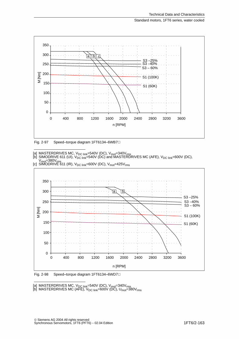
Technical Data and Characteristics
1FT6/2-163 Siemens AG 2004 All rights reservedSynchronous Servomotors, 1FT6 (PFT6) – 02.04 Edition
0
50
100
150
200
250
300
350
0 400 800 1200 1600 2000 2400 2800 3200 3600
S1 (100K)
S1 (60K)
S3 –25%S3 –40%S3 – 60%
a b c
n [RPM]
M [N
m]
Fig. 2-97 Speed–torque diagram 1FT6134–6WB7
[a] MASTERDRIVES MC, VDC link=540V (DC), Vmot=340Vrms[b] SIMODRIVE 611 (UI), VDC link=540V (DC) and MASTERDRIVES MC (AFE), VDC link=600V (DC),
Vmot=380Vrms[c] SIMODRIVE 611 (IR), VDC link=600V (DC), Vmot=425Vrms
n [RPM]
M [N
m]
0
50
100
150
200
250
300
350
0 400 800 1200 1600 2000 2400 2800 3200 3600
S1 (100K)
S1 (60K)
S3 – 60%
a b
S3 –25%S3 –40%
Fig. 2-98 Speed–torque diagram 1FT6134–6WD7
[a] MASTERDRIVES MC, VDC link=540V (DC), Vmot=340Vrms[b] MASTERDRIVES MC (AFE), VDC link=600V (DC), Umot=380Vrms
Standard motors, 1FT6 series, water cooled
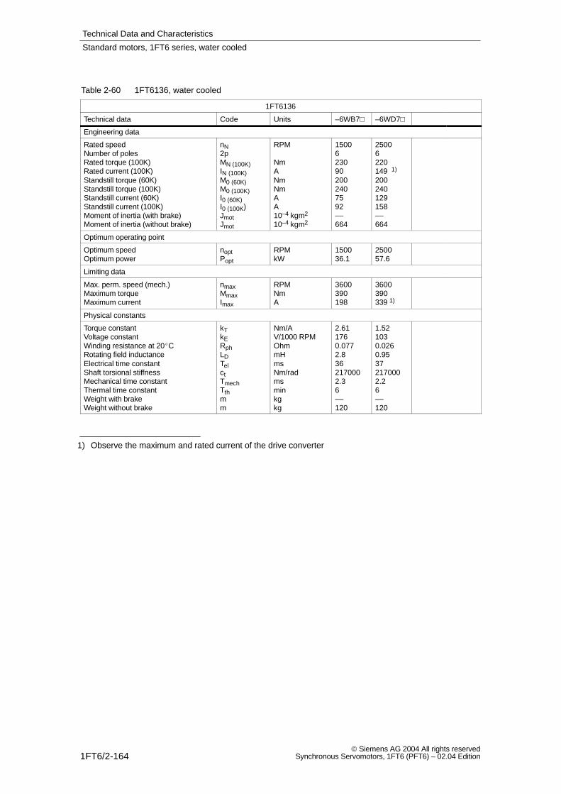
Technical Data and Characteristics
1FT6/2-164 Siemens AG 2004 All rights reserved
Synchronous Servomotors, 1FT6 (PFT6) – 02.04 Edition
Table 2-60 1FT6136, water cooled
1FT6136
Technical data Code Units –6WB7 –6WD7
Engineering data
Rated speedNumber of polesRated torque (100K)Rated current (100K)Standstill torque (60K)Standstill torque (100K)Standstill current (60K)Standstill current (100K)Moment of inertia (with brake)Moment of inertia (without brake)
nN2pMN (100K)IN (100K)M0 (60K)M0 (100K)I0 (60K)I0 (100K)JmotJmot
RPM
NmANmNmAA10–4 kgm2
10–4 kgm2
15006230902002407592––664
25006220149 1)
200240129158––664
Optimum operating point
Optimum speedOptimum power
noptPopt
RPMkW
150036.1
250057.6
Limiting data
Max. perm. speed (mech.)Maximum torqueMaximum current
nmaxMmaxImax
RPMNmA
3600390198
3600390339 1)
Physical constants
Torque constantVoltage constantWinding resistance at 20CRotating field inductanceElectrical time constantShaft torsional stiffnessMechanical time constantThermal time constantWeight with brakeWeight without brake
kTkERphLDTelctTmechTthmm
Nm/AV/1000 RPMOhmmHmsNm/radmsminkgkg
2.611760.0772.8362170002.36––120
1.521030.0260.95372170002.26––120
1) Observe the maximum and rated current of the drive converter
Standard motors, 1FT6 series, water cooled
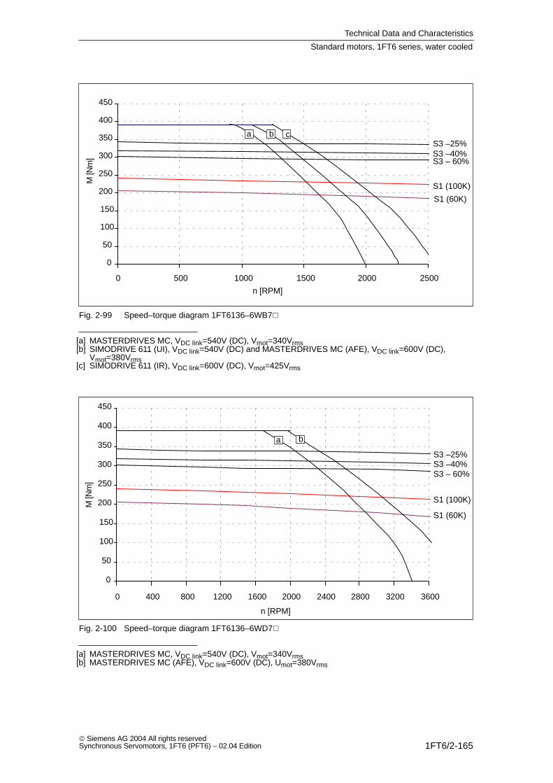
Technical Data and Characteristics
1FT6/2-165 Siemens AG 2004 All rights reservedSynchronous Servomotors, 1FT6 (PFT6) – 02.04 Edition
0
50
100
150
200
250
300
350
400
450
0 500 1000 1500 2000 2500
S1 (100K)
S1 (60K)
S3 –25%S3 –40%S3 – 60%
a b c
n [RPM]
M [N
m]
Fig. 2-99 Speed–torque diagram 1FT6136–6WB7
[a] MASTERDRIVES MC, VDC link=540V (DC), Vmot=340Vrms[b] SIMODRIVE 611 (UI), VDC link=540V (DC) and MASTERDRIVES MC (AFE), VDC link=600V (DC),
Vmot=380Vrms[c] SIMODRIVE 611 (IR), VDC link=600V (DC), Vmot=425Vrms
n [RPM]
M [N
m]
0
50
100
150
200
250
300
350
400
450
0 400 800 1200 1600 2000 2400 2800 3200 3600
S1 (100K)
S1 (60K)
S3 –25%S3 –40%S3 – 60%
a b
Fig. 2-100 Speed–torque diagram 1FT6136–6WD7
[a] MASTERDRIVES MC, VDC link=540V (DC), Vmot=340Vrms[b] MASTERDRIVES MC (AFE), VDC link=600V (DC), Umot=380Vrms
Standard motors, 1FT6 series, water cooled

Technical Data and Characteristics
1FT6/2-166 Siemens AG 2004 All rights reserved
Synchronous Servomotors, 1FT6 (PFT6) – 02.04 Edition
Table 2-61 1FT6138, water cooled
1FT6138
Technical data Code Units –6WB7 –6WD7
Engineering data
Rated speedNumber of polesRated torque (100K)Rated current (100K)Standstill torque (60K)Standstill torque (100K)Standstill current (60K)Standstill current (100K)Moment of inertia (with brake)Moment of inertia (without brake)
nN2pMN (100K)IN (100K)M0 (60K)M0 (100K)I0 (60K)I0 (100K)JmotJmot
RPM
NmANmNmAA10–4 kgm2
10–4 kgm2
1500629011223230087112––845
25006275162 1)
232300129167––845
Optimum operating point
Optimum speedOptimum power
noptPopt
RPMkW
150045.5
250072
Limiting data
Max. perm. speed (mech.)Maximum torqueMaximum current
nmaxMmaxImax
RPMNmA
3600500263 1)
3600500395 1)
Physical constants
Torque constantVoltage constantWinding resistance at 20CRotating field inductanceElectrical time constantShaft torsional stiffnessMechanical time constantThermal time constantWeight with brakeWeight without brake
kTkERphLDTelctTmechTthmm
Nm/AV/1000 RPMOhmmHmsNm/radmsminkgkg
2.681680.0522381920001.86––137
1.801120.0230.87381920001.86––137
1) Observe the maximum and rated current of the drive converter
Standard motors, 1FT6 series, water cooled
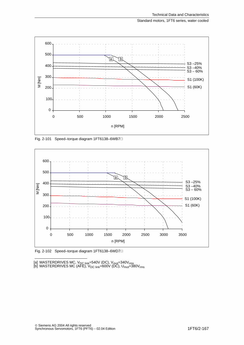
Technical Data and Characteristics
1FT6/2-167 Siemens AG 2004 All rights reservedSynchronous Servomotors, 1FT6 (PFT6) – 02.04 Edition
n [RPM]
M [N
m]
0
100
200
300
400
500
600
0 500 1000 1500 2000 2500
S1 (100K)
S1 (60K)
S3 –25%S3 –40%S3 – 60%
a b
Fig. 2-101 Speed–torque diagram 1FT6138–6WB7
S1 (100K)
S1 (60K)
n [RPM]
M [N
m] S3 –25%
S3 –40%S3 – 60%
0
100
200
300
400
500
600
0 500 1000 1500 2000 2500 3000 3500
a b
Fig. 2-102 Speed–torque diagram 1FT6138–6WD7
[a] MASTERDRIVES MC, VDC link=540V (DC), Vmot=340Vrms[b] MASTERDRIVES MC (AFE), VDC link=600V (DC), Umot=380Vrms
Standard motors, 1FT6 series, water cooled
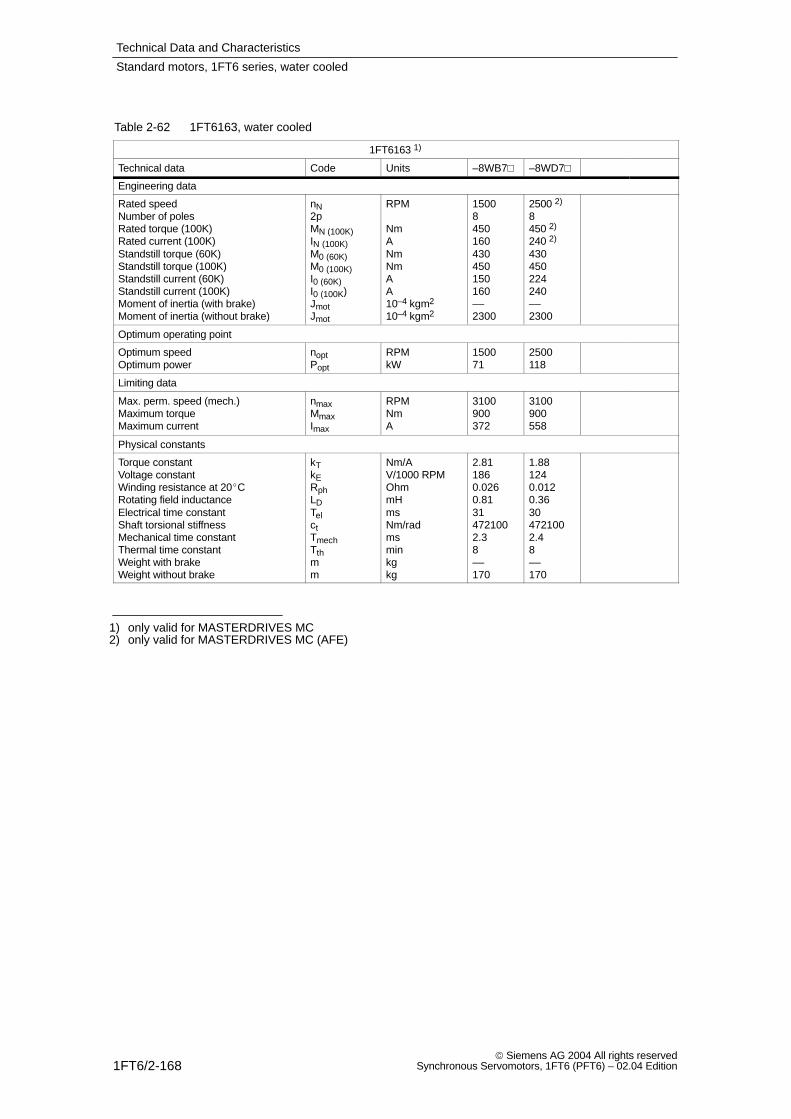
Technical Data and Characteristics
1FT6/2-168 Siemens AG 2004 All rights reserved
Synchronous Servomotors, 1FT6 (PFT6) – 02.04 Edition
Table 2-62 1FT6163, water cooled
1FT6163 1)
Technical data Code Units –8WB7 –8WD7
Engineering data
Rated speedNumber of polesRated torque (100K)Rated current (100K)Standstill torque (60K)Standstill torque (100K)Standstill current (60K)Standstill current (100K)Moment of inertia (with brake)Moment of inertia (without brake)
nN2pMN (100K)IN (100K)M0 (60K)M0 (100K)I0 (60K)I0 (100K)JmotJmot
RPM
NmANmNmAA10–4 kgm2
10–4 kgm2
15008450160430450150160––2300
2500 2)
8450 2)
240 2)
430450224240––2300
Optimum operating point
Optimum speedOptimum power
noptPopt
RPMkW
150071
2500118
Limiting data
Max. perm. speed (mech.)Maximum torqueMaximum current
nmaxMmaxImax
RPMNmA
3100900372
3100900558
Physical constants
Torque constantVoltage constantWinding resistance at 20CRotating field inductanceElectrical time constantShaft torsional stiffnessMechanical time constantThermal time constantWeight with brakeWeight without brake
kTkERphLDTelctTmechTthmm
Nm/AV/1000 RPMOhmmHmsNm/radmsminkgkg
2.811860.0260.81314721002.38––170
1.881240.0120.36304721002.48––170
1) only valid for MASTERDRIVES MC2) only valid for MASTERDRIVES MC (AFE)
Standard motors, 1FT6 series, water cooled
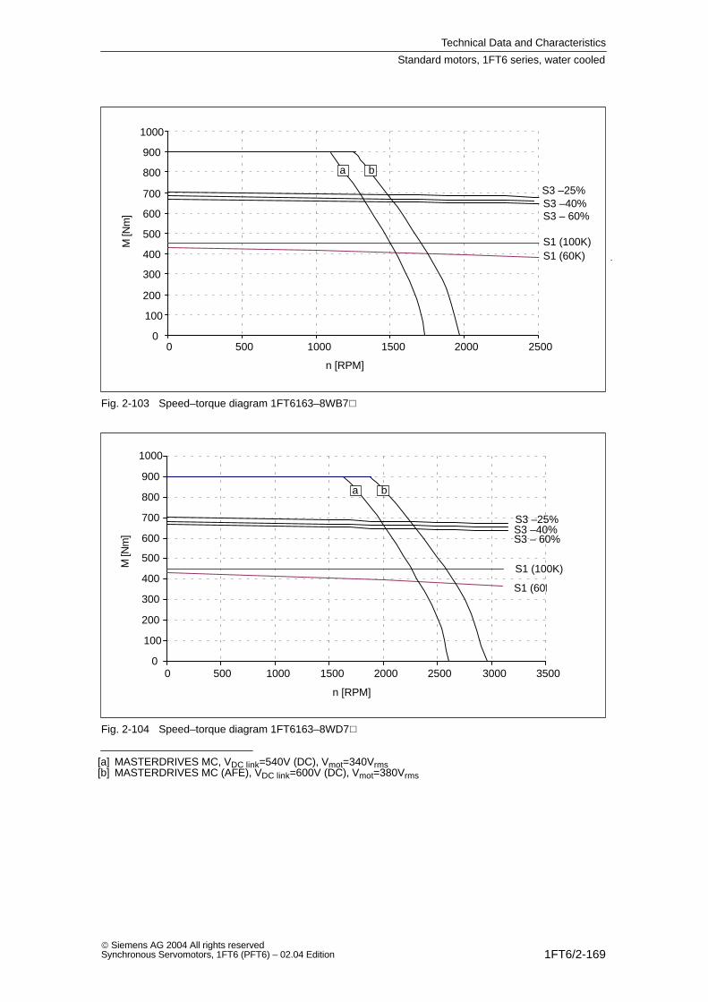
Technical Data and Characteristics
1FT6/2-169 Siemens AG 2004 All rights reservedSynchronous Servomotors, 1FT6 (PFT6) – 02.04 Edition
n [RPM]
M [N
m]
0
100
200
300
400
500
600
700
800
900
1000
0 500 1000 1500 2000 2500
a b
S3 –25%S3 –40%S3 – 60%
S1 (100K)S1 (60K)
Fig. 2-103 Speed–torque diagram 1FT6163–8WB7
n [RPM]
M [N
m]
0
100
200
300
400
500
600
700
800
900
1000
0 500 1000 1500 2000 2500 3000 3500
S1 (60K)
a b
S3 –25%S3 –40%S3 – 60%
S1 (100K)
Fig. 2-104 Speed–torque diagram 1FT6163–8WD7
[a] MASTERDRIVES MC, VDC link=540V (DC), Vmot=340Vrms[b] MASTERDRIVES MC (AFE), VDC link=600V (DC), Vmot=380Vrms
Standard motors, 1FT6 series, water cooled
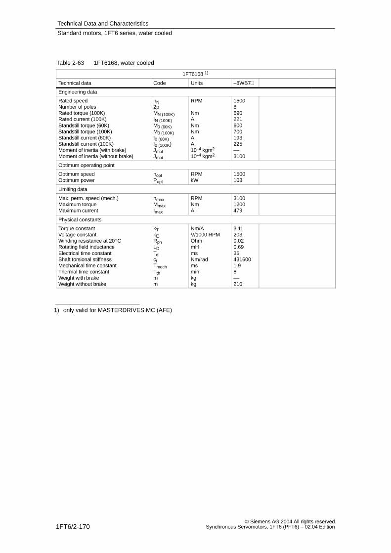
Technical Data and Characteristics
1FT6/2-170 Siemens AG 2004 All rights reserved
Synchronous Servomotors, 1FT6 (PFT6) – 02.04 Edition
Table 2-63 1FT6168, water cooled
1FT6168 1)
Technical data Code Units –8WB7
Engineering data
Rated speedNumber of polesRated torque (100K)Rated current (100K)Standstill torque (60K)Standstill torque (100K)Standstill current (60K)Standstill current (100K)Moment of inertia (with brake)Moment of inertia (without brake)
nN2pMN (100K)IN (100K)M0 (60K)M0 (100K)I0 (60K)I0 (100K)JmotJmot
RPM
NmANmNmAA10–4 kgm2
10–4 kgm2
15008690221600700193225––3100
Optimum operating point
Optimum speedOptimum power
noptPopt
RPMkW
1500108
Limiting data
Max. perm. speed (mech.)Maximum torqueMaximum current
nmaxMmaxImax
RPMNmA
31001200479
Physical constants
Torque constantVoltage constantWinding resistance at 20CRotating field inductanceElectrical time constantShaft torsional stiffnessMechanical time constantThermal time constantWeight with brakeWeight without brake
kTkERphLDTelctTmechTthmm
Nm/AV/1000 RPMOhmmHmsNm/radmsminkgkg
3.112030.020.69354316001.98––210
1) only valid for MASTERDRIVES MC (AFE)
Standard motors, 1FT6 series, water cooled
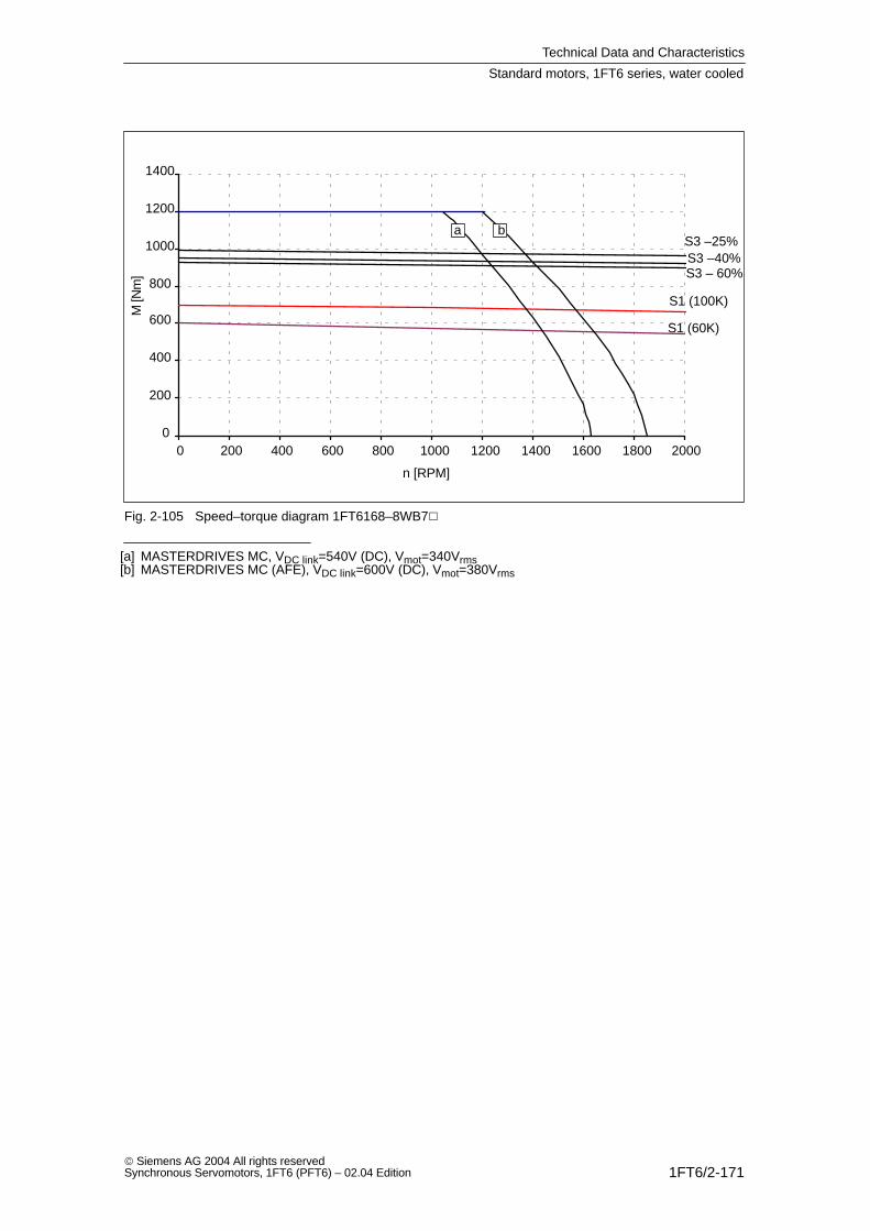
Technical Data and Characteristics
1FT6/2-171 Siemens AG 2004 All rights reservedSynchronous Servomotors, 1FT6 (PFT6) – 02.04 Edition
n [RPM]
M [N
m]
0
200
400
600
800
1000
1200
1400
0 200 400 600 800 1000 1200 1400 1600 1800 2000
S1 (100K)
S1 (60K)
S3 –40%S3 –25%
a b
S3 – 60%
Fig. 2-105 Speed–torque diagram 1FT6168–8WB7
[a] MASTERDRIVES MC, VDC link=540V (DC), Vmot=340Vrms[b] MASTERDRIVES MC (AFE), VDC link=600V (DC), Vmot=380Vrms
Standard motors, 1FT6 series, water cooled
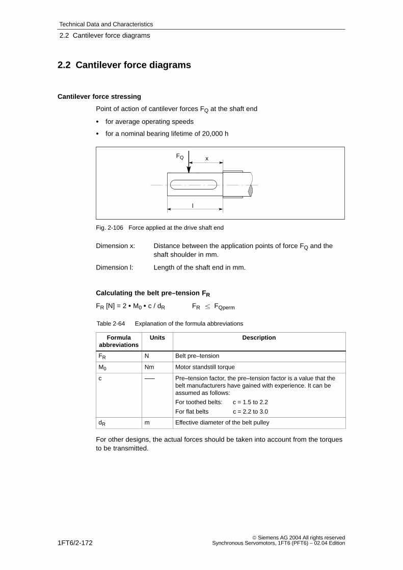
Technical Data and Characteristics
2.2 Cantilever force diagrams
1FT6/2-172 Siemens AG 2004 All rights reserved
Synchronous Servomotors, 1FT6 (PFT6) – 02.04 Edition
2.2 Cantilever force diagrams
Cantilever force stressing
Point of action of cantilever forces FQ at the shaft end
for average operating speeds
for a nominal bearing lifetime of 20,000 h
FQ x
l
Fig. 2-106 Force applied at the drive shaft end
Dimension x: Distance between the application points of force FQ and the shaft shoulder in mm.
Dimension l: Length of the shaft end in mm.
Calculating the belt pre–tension FR
FR [N] = 2 M0 c / dR FR FQperm
Table 2-64 Explanation of the formula abbreviations
Formulaabbreviations
Units Description
FR N Belt pre–tension
M0 Nm Motor standstill torque
c ––– Pre–tension factor, the pre–tension factor is a value that thebelt manufacturers have gained with experience. It can beassumed as follows:
For toothed belts: c = 1.5 to 2.2
For flat belts c = 2.2 to 3.0
dR m Effective diameter of the belt pulley
For other designs, the actual forces should be taken into account from the torquesto be transmitted.
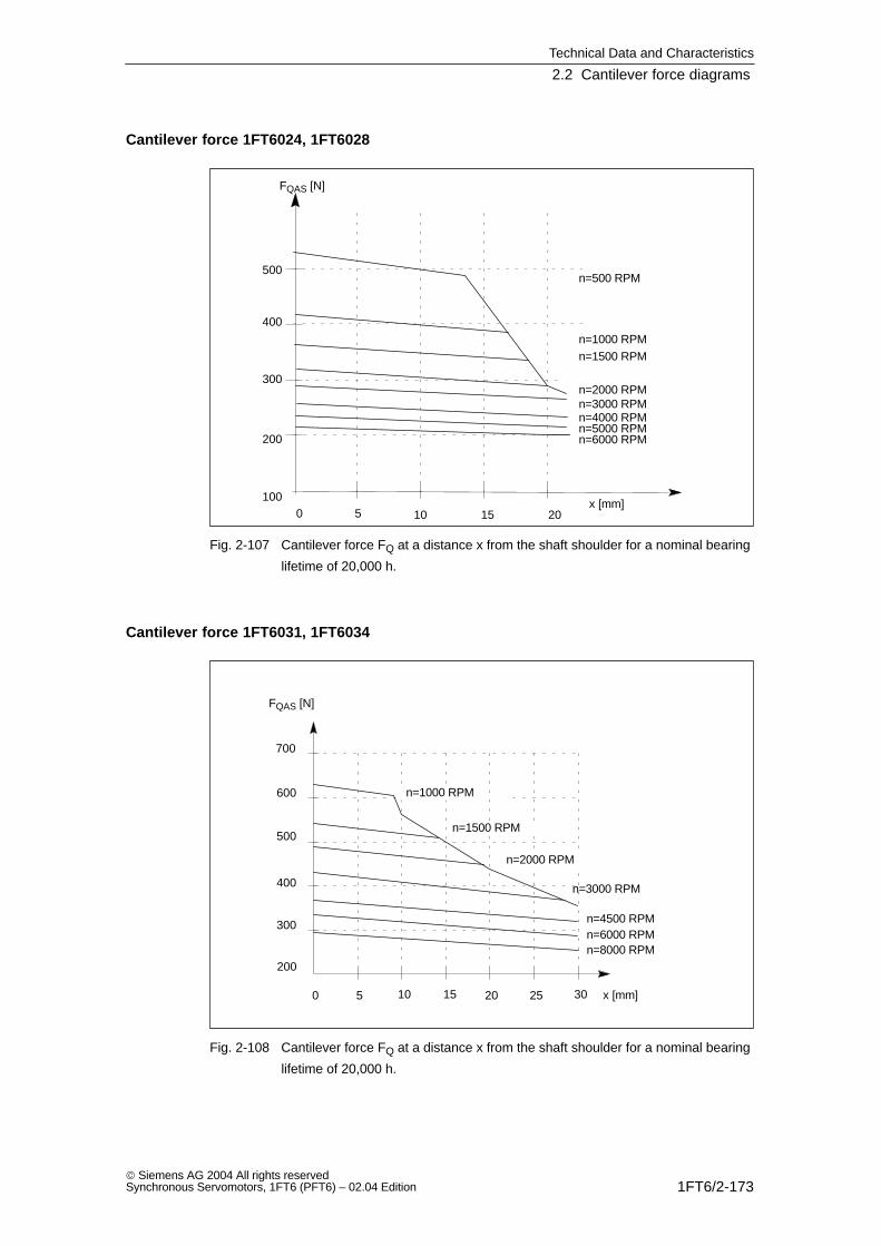
Technical Data and Characteristics
2.2 Cantilever force diagrams
1FT6/2-173 Siemens AG 2004 All rights reservedSynchronous Servomotors, 1FT6 (PFT6) – 02.04 Edition
Cantilever force 1FT6024, 1FT6028
x [mm]
300
400
500
15 2010
n=6000 RPM
FQAS [N]
50
200
n=4000 RPMn=3000 RPM
n=1500 RPM
n=500 RPM
n=2000 RPM
n=1000 RPM
100
n=5000 RPM
Fig. 2-107 Cantilever force FQ at a distance x from the shaft shoulder for a nominal bearing
lifetime of 20,000 h.
Cantilever force 1FT6031, 1FT6034
x [mm]
300
400
500
600
700
15 2010
n=8000 RPM
FQAS [N]
5 25 300
200
n=6000 RPMn=4500 RPM
n=2000 RPM
n=1000 RPM
n=3000 RPM
n=1500 RPM
Fig. 2-108 Cantilever force FQ at a distance x from the shaft shoulder for a nominal bearing
lifetime of 20,000 h.
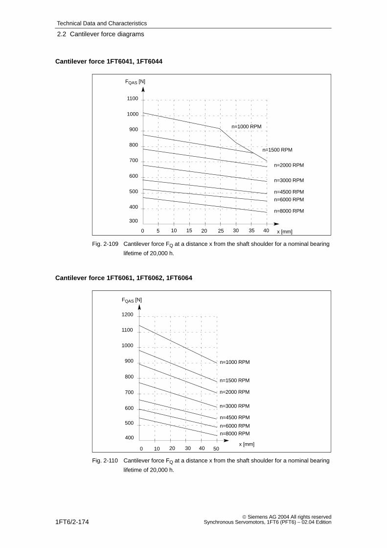
Technical Data and Characteristics
2.2 Cantilever force diagrams
1FT6/2-174 Siemens AG 2004 All rights reserved
Synchronous Servomotors, 1FT6 (PFT6) – 02.04 Edition
Cantilever force 1FT6041, 1FT6044
x [mm]40
400
500
600
700
800
15 2010
n=8000 RPM
FQAS [N]
5 25 300
300
n=6000 RPM
n=4500 RPM
n=2000 RPM
n=3000 RPM
n=1000 RPM900
1000
1100
35
n=1500 RPM
Fig. 2-109 Cantilever force FQ at a distance x from the shaft shoulder for a nominal bearing
lifetime of 20,000 h.
Cantilever force 1FT6061, 1FT6062, 1FT6064
x [mm]50
n=8000 RPM
500
600
700
800
900
30 4020
FQAS [N]
100
400
n=6000 RPM
n=4500 RPM
n=2000 RPM
n=3000 RPM
n=1500 RPM
n=1000 RPM
1000
1100
1200
Fig. 2-110 Cantilever force FQ at a distance x from the shaft shoulder for a nominal bearing
lifetime of 20,000 h.
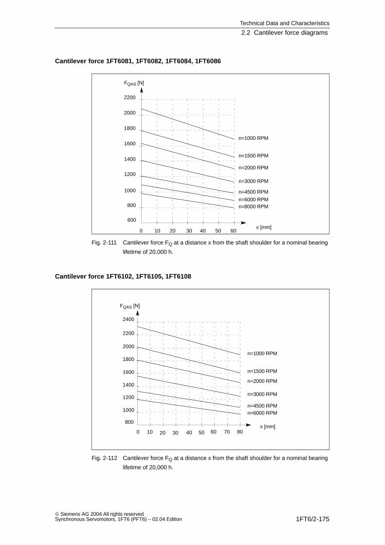
Technical Data and Characteristics
2.2 Cantilever force diagrams
1FT6/2-175 Siemens AG 2004 All rights reservedSynchronous Servomotors, 1FT6 (PFT6) – 02.04 Edition
Cantilever force 1FT6081, 1FT6082, 1FT6084, 1FT6086
x [mm]60
800
1000
1200
1400
1600
30 4020
n=8000 RPM
FQAS [N]
10 500
600
n=6000 RPM
n=4500 RPM
n=2000 RPM
n=3000 RPM
n=1500 RPM
n=1000 RPM
1800
2000
2200
Fig. 2-111 Cantilever force FQ at a distance x from the shaft shoulder for a nominal bearing
lifetime of 20,000 h.
Cantilever force 1FT6102, 1FT6105, 1FT6108
x [mm]80
1000
1200
1400
1600
1800
30 4020
FQAS [N]
10 50 600
800
n=6000 RPMn=4500 RPM
n=2000 RPM
n=3000 RPM
n=1000 RPM2000
2200
2400
70
n=1500 RPM
Fig. 2-112 Cantilever force FQ at a distance x from the shaft shoulder for a nominal bearing
lifetime of 20,000 h.
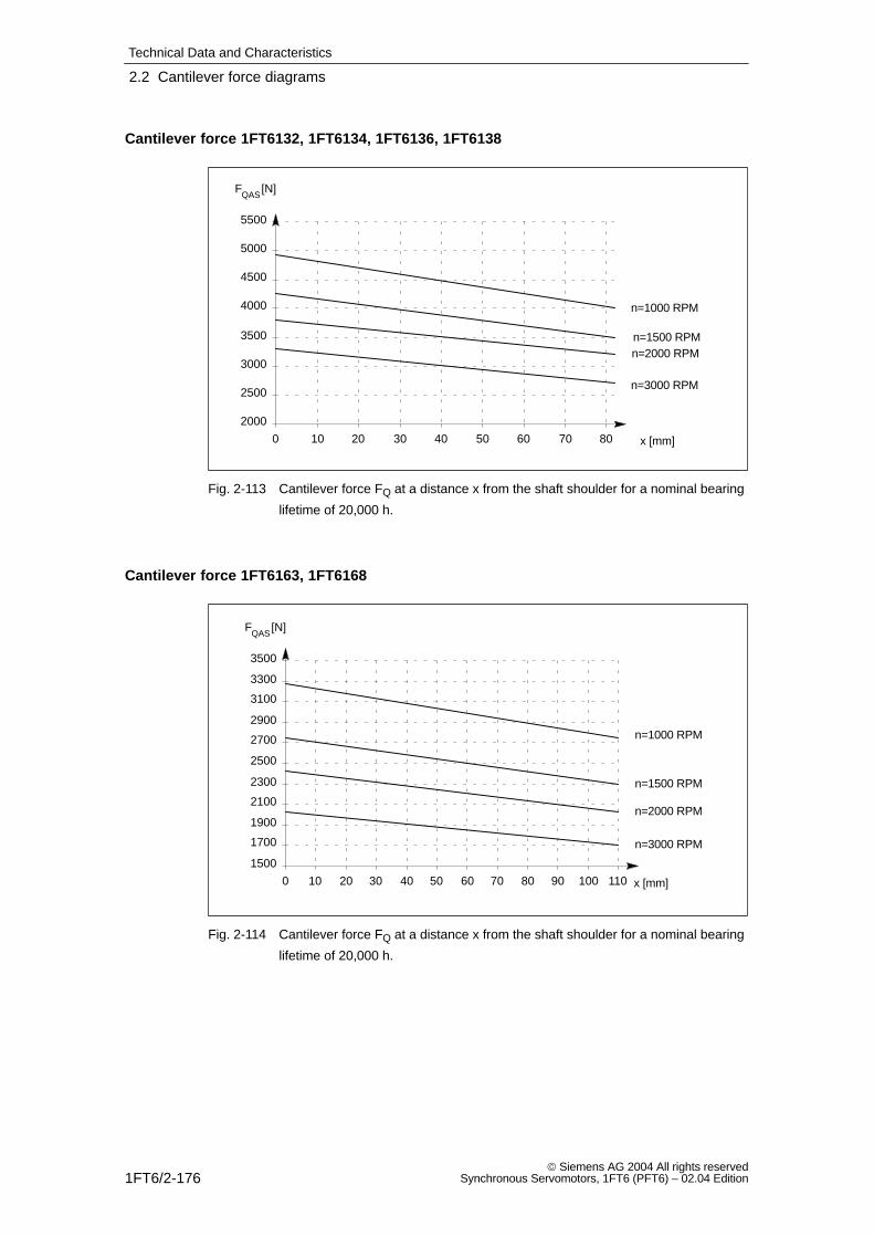
Technical Data and Characteristics
2.2 Cantilever force diagrams
1FT6/2-176 Siemens AG 2004 All rights reserved
Synchronous Servomotors, 1FT6 (PFT6) – 02.04 Edition
Cantilever force 1FT6132, 1FT6134, 1FT6136, 1FT6138
2000
2500
3000
3500
4000
4500
5000
5500
0 10 20 30 40 50 60 70 80 x [mm]
FQAS
[N]
n=1000 RPM
n=1500 RPMn=2000 RPM
n=3000 RPM
Fig. 2-113 Cantilever force FQ at a distance x from the shaft shoulder for a nominal bearing
lifetime of 20,000 h.
Cantilever force 1FT6163, 1FT6168
1500
1700
1900
2100
2300
2500
2700
2900
3100
3300
3500
0 10 20 30 40 50 60 70 80 90 100 110 x [mm]
FQAS
[N]
n=1000 RPM
n=1500 RPM
n=2000 RPM
n=3000 RPM
Fig. 2-114 Cantilever force FQ at a distance x from the shaft shoulder for a nominal bearing
lifetime of 20,000 h.
Technical Data and Characteristics
2.3 Axial forces
1FT6/2-177 Siemens AG 2004 All rights reservedSynchronous Servomotors, 1FT6 (PFT6) – 02.04 Edition
2.3 Axial forces
Axial force stressing
!Warning
Motors with integrated holding brake cannot be subject to axial forces!
When using, for example, helical toothed wheels as drive element, in addition tothe radial force, there is also an axial force on the motor bearings. For axial forces,the spring loading of the bearing system can be overcome so that the rotor movescorresponding to the available axial bearing play (up to 0.2 mm).
The permissible axial force can be approximately calculated using the followingformula:
FA = 0.35 FQ
Technical Data and Characteristics
2.3 Axial forces
1FT6/2-178 Siemens AG 2004 All rights reserved
Synchronous Servomotors, 1FT6 (PFT6) – 02.04 Edition
Space for your notes
1FT6/3-179 Siemens AG 2004 All rights reservedSynchronous Servomotors, 1FT6 (PFT6) – 02.04 Edition
Motor Components (Options)
3.1 Thermal motor protection
A temperature–dependent resistor is integrated in the stator winding as tempera-ture sensor. This temperature sensor monitors the motor temperature.
Table 3-1 Features and technical data
Type KTY 84
Resistance when cold (20 °C) approx. 580 Ohm
Resistance when hot (100 °C): approx. 1000 Ohm
Connection via signal cable
Response temperature Alarm at 120 °CShutdown at 155 °C 5 °C
The resistance of the KTY 84 thermistor changes proportionally to the windingtemperature change (refer to Fig. 3-1).
The temperature signal is sensed and evaluated in the drive converter whose clo-sed–loop control takes into account the temperature characteristic of the motorresistances.
When a fault occurs, an appropriate message is output at the drive converter. Beisteigender Motortemperatur wird eine Meldung ”Vorwarnung Motorübertemperatur”ausgelöst, die extern ausgewertet werden kann. If this signal is not observed, thedrive converter shuts down with the appropriate fault message when the motor li-miting temperature or the shutdown temperature is exceeded.
!Warning
If the user carries–out an additional high–voltage test, then the ends of thetemperature sensor cables must be short–circuited before the test is carried–out!
If the test voltage is connected to a temperature sensor terminal, then it will bedestroyed.
The polarity must be carefully observed.
The temperature sensor has been designed so that the DIN/EN requirements forprotective electrical separation are fulfilled.
3
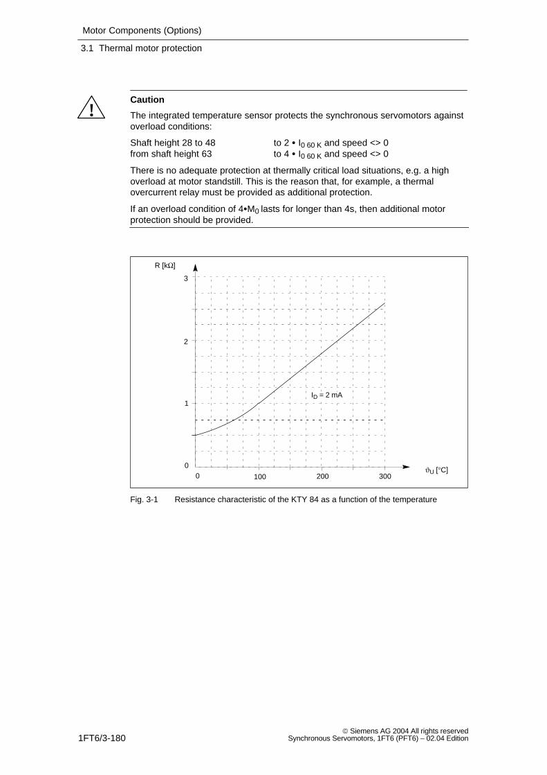
Motor Components (Options)
3.1 Thermal motor protection
1FT6/3-180 Siemens AG 2004 All rights reserved
Synchronous Servomotors, 1FT6 (PFT6) – 02.04 Edition
!Caution
The integrated temperature sensor protects the synchronous servomotors againstoverload conditions:
Shaft height 28 to 48 to 2 I0 60 K and speed <> 0from shaft height 63 to 4 I0 60 K and speed <> 0
There is no adequate protection at thermally critical load situations, e.g. a highoverload at motor standstill. This is the reason that, for example, a thermalovercurrent relay must be provided as additional protection.
If an overload condition of 4M0 lasts for longer than 4s, then additional motorprotection should be provided.
3
2
0
1
0
200 300100
ID = 2 mA
R [kΩ]
ϑU [°C]
Fig. 3-1 Resistance characteristic of the KTY 84 as a function of the temperature
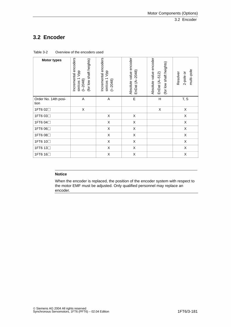
Motor Components (Options)
3.2 Encoder
1FT6/3-181 Siemens AG 2004 All rights reservedSynchronous Servomotors, 1FT6 (PFT6) – 02.04 Edition
3.2 Encoder
Table 3-2 Overview of the encoders used
Motor types
Incr
emen
tal e
ncod
ers
sin/
cos
1 V
pp
(for
low
sha
ft he
ight
s)
(I–2
048)
Incr
emen
tal e
ncod
ers
sin/
cos
1 V
pp(I
–204
8)
Abs
olut
e va
lue
enco
der
EnD
at (
A–2
048)
Abs
olut
e va
lue
enco
der
EnD
at (
A–5
12)
(for
low
sha
ft he
ight
s)
Res
olve
r
2-po
le o
r
mul
ti–po
le
Order No. 14th posi-tion
A A E H T, S
1FT6 02 X X X
1FT6 03 X X X
1FT6 04 X X X
1FT6 06 X X X
1FT6 08 X X X
1FT6 10 X X X
1FT6 13 X X X
1FT6 16 X X X
Notice
When the encoder is replaced, the position of the encoder system with respect tothe motor EMF must be adjusted. Only qualified personnel may replace anencoder.
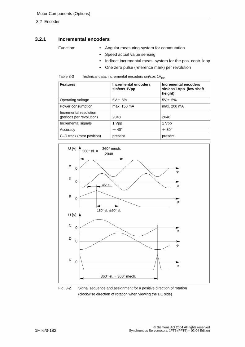
Motor Components (Options)
3.2 Encoder
1FT6/3-182 Siemens AG 2004 All rights reserved
Synchronous Servomotors, 1FT6 (PFT6) – 02.04 Edition
3.2.1 Incremental encoders
Function: Angular measuring system for commutation
Speed actual value sensing
Indirect incremental meas. system for the pos. contr. loop
One zero pulse (reference mark) per revolution
Table 3-3 Technical data, incremental encoders sin/cos 1Vpp
Features Incremental encoderssin/cos 1Vpp
Incremental encoderssin/cos 1Vpp (low shaftheight)
Operating voltage 5V 5% 5V 5%
Power consumption max. 150 mA max. 200 mA
Incremental resolution(periods per revolution) 2048 2048
Incremental signals 1 Vpp 1 Vpp
Accuracy 40’’ 80’’
C–D track (rotor position) present present
180° el. 90° el.
45° el.
360° el. =360° mech.
360° el. = 360° mech.
U [V]
ϕ
ϕ
ϕ
ϕ
ϕ
ϕ
2048
0
0
0
0
0
0
U [V]
A
B
R
C
D
R
Fig. 3-2 Signal sequence and assignment for a positive direction of rotation
(clockwise direction of rotation when viewing the DE side)
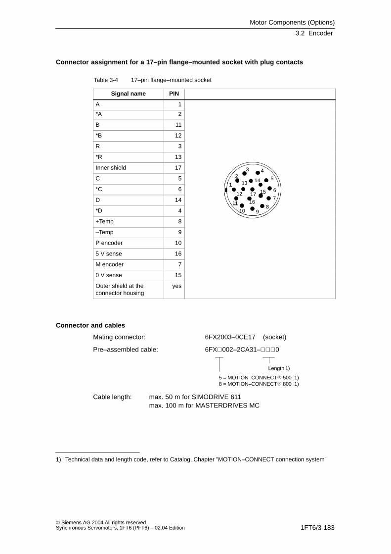
Motor Components (Options)
3.2 Encoder
1FT6/3-183 Siemens AG 2004 All rights reservedSynchronous Servomotors, 1FT6 (PFT6) – 02.04 Edition
Connector assignment for a 17–pin flange–mounted socket with plug contacts
Table 3-4 17–pin flange–mounted socket
Signal name PIN
A 1
*A 2
B 11
*B 12
R 3
*R 13
Inner shield 17 42
3
C 54
51
23
1413*C 6 6
114
17 1512
13
D 14
6
7
811
17 15
16
12
*D 48
91011 16
+Temp 8
9
–Temp 9
P encoder 10
5 V sense 16
M encoder 7
0 V sense 15
Outer shield at theconnector housing
yes
Connector and cables
Mating connector: 6FX2003–0CE17 (socket)
Pre–assembled cable: 6FX002–2CA31–0
Length 1)
5 = MOTION–CONNECT 500 1)8 = MOTION–CONNECT 800 1)
Cable length: max. 50 m for SIMODRIVE 611max. 100 m for MASTERDRIVES MC
1) Technical data and length code, refer to Catalog, Chapter ”MOTION–CONNECT connection system”
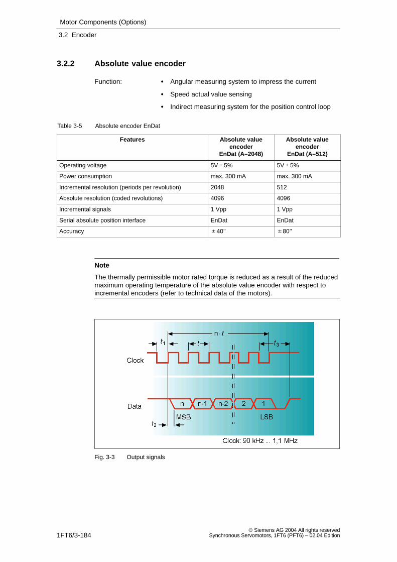
Motor Components (Options)
3.2 Encoder
1FT6/3-184 Siemens AG 2004 All rights reserved
Synchronous Servomotors, 1FT6 (PFT6) – 02.04 Edition
3.2.2 Absolute value encoder
Function: Angular measuring system to impress the current
Speed actual value sensing
Indirect measuring system for the position control loop
Table 3-5 Absolute encoder EnDat
Features Absolute valueencoder
EnDat (A–2048)
Absolute valueencoder
EnDat (A–512)
Operating voltage 5V5% 5V5%
Power consumption max. 300 mA max. 300 mA
Incremental resolution (periods per revolution) 2048 512
Absolute resolution (coded revolutions) 4096 4096
Incremental signals 1 Vpp 1 Vpp
Serial absolute position interface EnDat EnDat
Accuracy 40’’ 80’’
Note
The thermally permissible motor rated torque is reduced as a result of the reducedmaximum operating temperature of the absolute value encoder with respect toincremental encoders (refer to technical data of the motors).
Fig. 3-3 Output signals
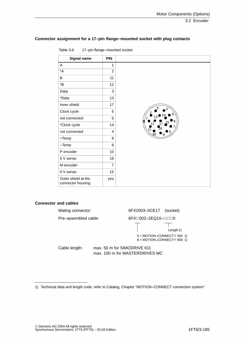
Motor Components (Options)
3.2 Encoder
1FT6/3-185 Siemens AG 2004 All rights reservedSynchronous Servomotors, 1FT6 (PFT6) – 02.04 Edition
Connector assignment for a 17–pin flange–mounted socket with plug contacts
Table 3-6 17–pin flange–mounted socket
Signal name PIN
A 1
*A 2
B 11
*B 12
Data 3
*Data 13
Inner shield 1743
Clock cycle 54
523
1413not connected 65
61
214
1512
13
*Clock cycle 146
711
17 15
16
12
not connected 47
8910
11 16
+Temp 8910
–Temp 9
P encoder 10
5 V sense 16
M encoder 7
0 V sense 15
Outer shield at theconnector housing
yes
Connector and cables
Mating connector: 6FX2003–0CE17 (socket)
Pre–assembled cable: 6FX002–2EQ10–0
Length 1)
5 = MOTION–CONNECT 500 1)8 = MOTION–CONNECT 800 1)
Cable length: max. 50 m for SIMODRIVE 611max. 100 m for MASTERDRIVES MC
1) Technical data and length code, refer to Catalog, Chapter ”MOTION–CONNECT connection system”
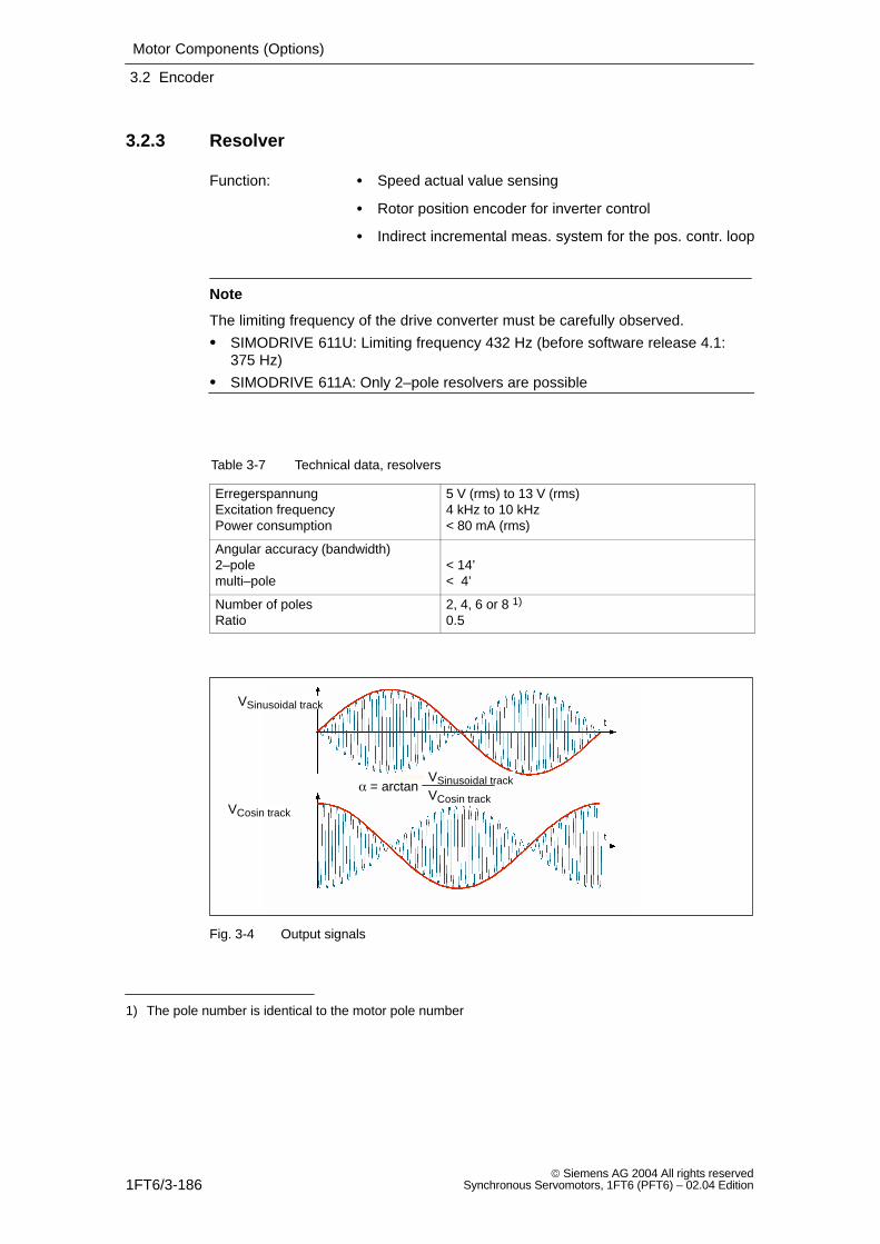
Motor Components (Options)
3.2 Encoder
1FT6/3-186 Siemens AG 2004 All rights reserved
Synchronous Servomotors, 1FT6 (PFT6) – 02.04 Edition
3.2.3 Resolver
Function: Speed actual value sensing
Rotor position encoder for inverter control
Indirect incremental meas. system for the pos. contr. loop
Note
The limiting frequency of the drive converter must be carefully observed.
SIMODRIVE 611U: Limiting frequency 432 Hz (before software release 4.1:375 Hz)
SIMODRIVE 611A: Only 2–pole resolvers are possible
Table 3-7 Technical data, resolvers
ErregerspannungExcitation frequencyPower consumption
5 V (rms) to 13 V (rms)4 kHz to 10 kHz< 80 mA (rms)
Angular accuracy (bandwidth) 2–polemulti–pole
< 14’< 4’
Number of polesRatio
2, 4, 6 or 8 1)
0.5
= arctanVSinusoidal track
VCosin track
VSinusoidal track
VCosin track
Fig. 3-4 Output signals
1) The pole number is identical to the motor pole number
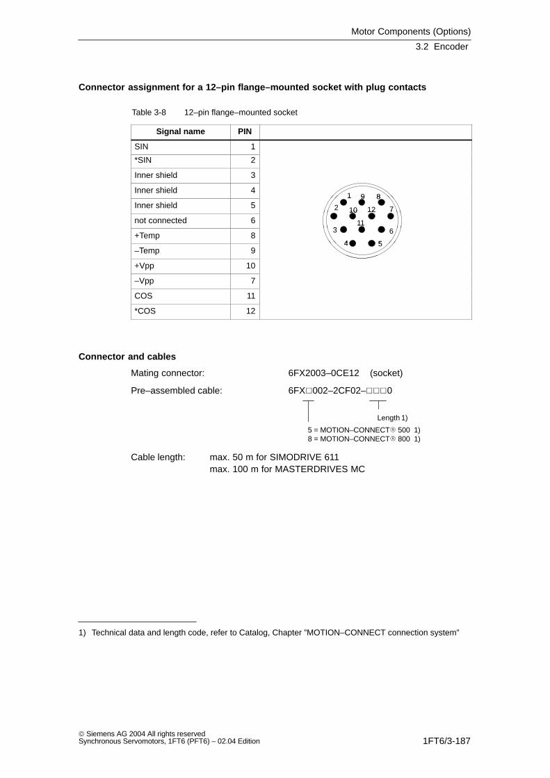
Motor Components (Options)
3.2 Encoder
1FT6/3-187 Siemens AG 2004 All rights reservedSynchronous Servomotors, 1FT6 (PFT6) – 02.04 Edition
Connector assignment for a 12–pin flange–mounted socket with plug contacts
Table 3-8 12–pin flange–mounted socket
Signal name PIN
SIN 1
*SIN 2
Inner shield 3
Inner shield 41 9 8
Inner shield 5 2
1
10 12
9 8
7
not connected 6
2 10 12
1163
7
+Temp 8
1163
4 5–Temp 9
4 5
+Vpp 10
–Vpp 7
COS 11
*COS 12
Connector and cables
Mating connector: 6FX2003–0CE12 (socket)
Pre–assembled cable: 6FX002–2CF02–0
Length 1)
5 = MOTION–CONNECT 500 1)8 = MOTION–CONNECT 800 1)
Cable length: max. 50 m for SIMODRIVE 611max. 100 m for MASTERDRIVES MC
1) Technical data and length code, refer to Catalog, Chapter ”MOTION–CONNECT connection system”
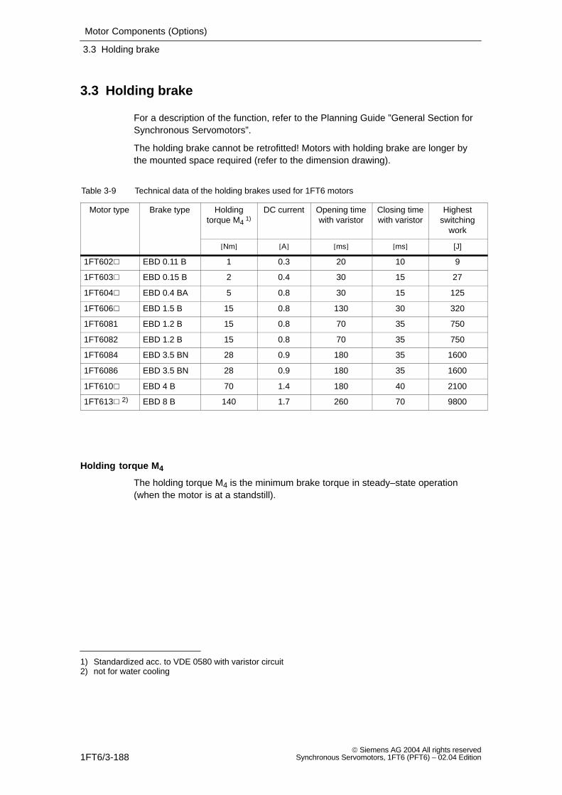
Motor Components (Options)
3.3 Holding brake
1FT6/3-188 Siemens AG 2004 All rights reserved
Synchronous Servomotors, 1FT6 (PFT6) – 02.04 Edition
3.3 Holding brake
For a description of the function, refer to the Planning Guide ”General Section forSynchronous Servomotors”.
The holding brake cannot be retrofitted! Motors with holding brake are longer bythe mounted space required (refer to the dimension drawing).
Table 3-9 Technical data of the holding brakes used for 1FT6 motors
Motor type Brake type Holdingtorque M4 1)
DC current Opening timewith varistor
Closing timewith varistor
Highestswitching
work
[Nm] [A] [ms] [ms] [J]
1FT602 EBD 0.11 B 1 0.3 20 10 9
1FT603 EBD 0.15 B 2 0.4 30 15 27
1FT604 EBD 0.4 BA 5 0.8 30 15 125
1FT606 EBD 1.5 B 15 0.8 130 30 320
1FT6081 EBD 1.2 B 15 0.8 70 35 750
1FT6082 EBD 1.2 B 15 0.8 70 35 750
1FT6084 EBD 3.5 BN 28 0.9 180 35 1600
1FT6086 EBD 3.5 BN 28 0.9 180 35 1600
1FT610 EBD 4 B 70 1.4 180 40 2100
1FT613 2) EBD 8 B 140 1.7 260 70 9800
Holding torque M4
The holding torque M4 is the minimum brake torque in steady–state operation(when the motor is at a standstill).
1) Standardized acc. to VDE 0580 with varistor circuit2) not for water cooling
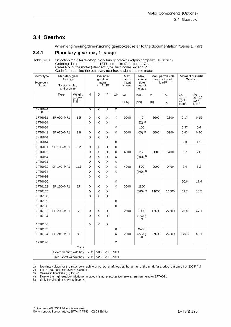
Motor Components (Options)
3.4 Gearbox
1FT6/3-189 Siemens AG 2004 All rights reservedSynchronous Servomotors, 1FT6 (PFT6) – 02.04 Edition
3.4 Gearbox
When engineering/dimensioning gearboxes, refer to the documentation ”General Part”
3.4.1 Planetary gearbox, 1–stage
Table 3-10 Selection table for 1–stage planetary gearboxes (alpha company, SP series)Ordering data: 1FT6–A7––Z 5)
Order No. of the motor (standard type) with codes –Z and V
Code for mounting the planetary gearbox assigned to the motor
Motor type
Non–ven-tilated
Planetary gear1–stage
Torsional play 4 arcmin2)
Available gearbox
ratios i = 4...10
Max.perm.inputspeed
Max.permis-
sibleoutputtorque
Max. permissibledrive out shaft
load1)
Moment of inertiaGearbox
Type Weightapprox.[kg]
4 5 7 10 nG1
[RPM]
MG2
[Nm]
Fr
[N]
Fa
[N]
JG at i=410–4
kgm2
JG at i=1010–4
kgm2
1FT60244)
X X X X
1FT6031 SP 060–MF1 1.5 X X X X 6000 40 2600 2300 0.17 0.15
1FT6034 X X X (32) 3)
1FT6034 X 100 0.57 0.4
1FT6041 SP 075–MF1 2.8 X X X X 6000 (80) 3) 3800 3200 0.63 0.46
1FT6044 X X X
1FT6044 X 2.0 1.3
1FT6061 SP 100–MF1 6.2 X X X X
1FT6062 X X X X 4500 250 6000 5400 2.7 2.0
1FT6064 X X X X (200) 3)
1FT6081 X X X X
1FT6082 SP 140–MF1 11.5 X X X X 4000 500 9000 9400 8.4 6.2
1FT6084 X X X X (400) 3)
1FT6086 X X X
1FT6086 X 30.6 17.4
1FT6102 SP 180–MF1 27 X X X X 3500 1100
1FT6105 X X X (880) 3) 14000 13500 31.7 18.5
1FT6108 X X X
1FT6105 X
1FT6108 X
1FT6132 SP 210–MF1 53 X X X 2500 1900 18000 22500 75.8 47.1
1FT6134 X X X (1520)3)
1FT6136 X X X
1FT6132 X 3400
1FT6134 SP 240–MF1 80 X 2200 (2720)3)
27000 27800 146.3 83.1
1FT6136 X
Code
Gearbox shaft with key V02 V03 V05 V09
Gear shaft without key V22 V23 V25 V29
1) Nominal values for the max. permissible drive–out shaft load at the center of the shaft for a drive–out speed of 300 RPM2) For SP 060 and SP 075: 6 arcmin3) Values in brackets (...) for i=104) Due to the high gearbox frictional torque, it is not practical to make an assignment for 1FT60215) Only for vibration severity level N
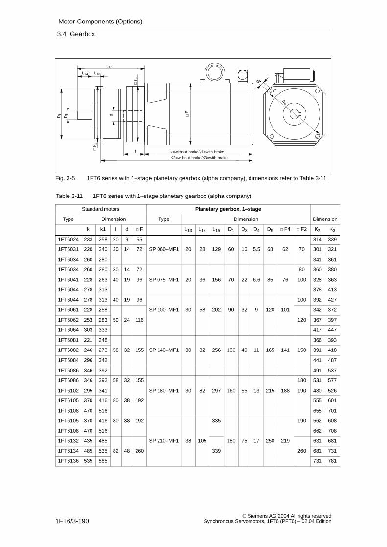
Motor Components (Options)
3.4 Gearbox
1FT6/3-190 Siemens AG 2004 All rights reserved
Synchronous Servomotors, 1FT6 (PFT6) – 02.04 Edition
l
K2=without brake/K3=with brake
d
k=without brake/k1=with brake
L13L14
L15
Fig. 3-5 1FT6 series with 1–stage planetary gearbox (alpha company), dimensions refer to Table 3-11
Table 3-11 1FT6 series with 1–stage planetary gearbox (alpha company)
Standard motors Planetary gearbox, 1–stage
Type Dimension Type Dimension Dimension
k k1 l d F L13 L14 L15 D1 D3 D4 D9 F4 F2 K2 K3
1FT6024 233 258 20 9 55 314 339
1FT6031 220 240 30 14 72 SP 060–MF1 20 28 129 60 16 5.5 68 62 70 301 321
1FT6034 260 280 341 361
1FT6034 260 280 30 14 72 80 360 380
1FT6041 228 263 40 19 96 SP 075–MF1 20 36 156 70 22 6.6 85 76 100 328 363
1FT6044 278 313 378 413
1FT6044 278 313 40 19 96 100 392 427
1FT6061 228 258 SP 100–MF1 30 58 202 90 32 9 120 101 342 372
1FT6062 253 283 50 24 116 120 367 397
1FT6064 303 333 417 447
1FT6081 221 248 366 393
1FT6082 246 273 58 32 155 SP 140–MF1 30 82 256 130 40 11 165 141 150 391 418
1FT6084 296 342 441 487
1FT6086 346 392 491 537
1FT6086 346 392 58 32 155 180 531 577
1FT6102 295 341 SP 180–MF1 30 82 297 160 55 13 215 188 190 480 526
1FT6105 370 416 80 38 192 555 601
1FT6108 470 516 655 701
1FT6105 370 416 80 38 192 335 190 562 608
1FT6108 470 516 662 708
1FT6132 435 485 SP 210–MF1 38 105 180 75 17 250 219 631 681
1FT6134 485 535 82 48 260 339 260 681 731
1FT6136 535 585 731 781
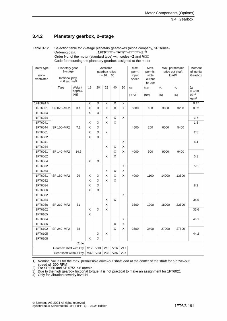
Motor Components (Options)
3.4 Gearbox
1FT6/3-191 Siemens AG 2004 All rights reservedSynchronous Servomotors, 1FT6 (PFT6) – 02.04 Edition
3.4.2 Planetary gearbox, 2–stage
Table 3-12 Selection table for 2–stage planetary gearboxes (alpha company, SP series)Ordering data: 1FT6–A7––Z 4)
Order No. of the motor (standard type) with codes –Z and V
Code for mounting the planetary gearbox assigned to the motor
Motor type
non–ventilated
Planetary gear2–stage
Torsional play 6 arcmin2)
Available gearbox ratios i = 16 ... 50
Max.perm.inputspeed
Max.permis-
sibleoutputtorque
Max. permissibledrive out shaft
load1)
Momentof inertiaGearbox
Type Weightapprox.[kg]
16 20 28 40 50 nG1
[RPM]
MG2
[Nm]
Fr
[N]
Fa
[N]
JG at i=2010–4
kgm2
1FT6024 3) X X X X X 0.47
1FT6031 SP 075–MF2 3.1 X X X X X 6000 100 3800 3200 0.52
1FT6034 X X
1FT6034 X X X 1.7
1FT6041 X X X X 1.8
1FT6044 SP 100–MF2 7.1 X X 4500 250 6000 5400
1FT6061 X X X 2.5
1FT6062 X X
1FT6041 X 4.4
1FT6044 X X X
1FT6061 SP 140–MF2 14.5 X X 4000 500 9000 9400
1FT6062 X X 5.1
1FT6064 X X
1FT6062 X 5.5
1FT6064 X X X
1FT6081 SP 180–MF2 29 X X X X X 4000 1100 14000 13500
1FT6082 X X X X
1FT6084 X X 8.2
1FT6086 X X
1FT6082 X
1FT6084 X X 34.5
1FT6086 SP 210–MF2 51 X 3500 1900 18000 22500
1FT6102 X X X 35.6
1FT6105 X
1FT6084 X 43.1
1FT6086 X X
1FT6102 SP 240–MF2 78 X X 3500 3400 27000 27800
1FT6105 X X 44.2
1FT6108 X X
Code
Gearbox shaft with key V12 V13 V15 V16 V17
Gear shaft without key V32 V33 V35 V36 V37
1) Nominal values for the max. permissible drive–out shaft load at the center of the shaft for a drive–outspeed of 300 RPM
2) For SP 060 and SP 075: 8 arcmin3) Due to the high gearbox frictional torque, it is not practical to make an assignment for 1FT60214) Only for vibration severity level N
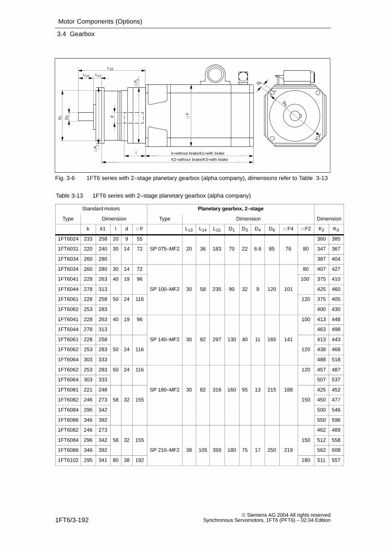
Motor Components (Options)
3.4 Gearbox
1FT6/3-192 Siemens AG 2004 All rights reserved
Synchronous Servomotors, 1FT6 (PFT6) – 02.04 Edition
l
K2=without brake/K3=with brake
d
k=without brake/k1=with brake
L13L14
L15
Fig. 3-6 1FT6 series with 2–stage planetary gearbox (alpha company), dimensions refer to Table 3-13
Table 3-13 1FT6 series with 2–stage planetary gearbox (alpha company)
Standard motors Planetary gearbox, 2–stage
Type Dimension Type Dimension Dimension
k k1 l d F L13 L14 L15 D1 D3 D4 D9 F4 F2 K2 K3
1FT6024 233 258 20 9 55 360 385
1FT6031 220 240 30 14 72 SP 075–MF2 20 36 183 70 22 6.6 85 76 80 347 367
1FT6034 260 280 387 404
1FT6034 260 280 30 14 72 80 407 427
1FT6041 228 263 40 19 96 100 375 410
1FT6044 278 313 SP 100–MF2 30 58 235 90 32 9 120 101 425 460
1FT6061 228 258 50 24 116 120 375 405
1FT6062 253 283 400 430
1FT6041 228 263 40 19 96 100 413 448
1FT6044 278 313 463 498
1FT6061 228 258 SP 140–MF2 30 82 297 130 40 11 165 141 413 443
1FT6062 253 283 50 24 116 120 438 468
1FT6064 303 333 488 518
1FT6062 253 283 50 24 116 120 457 487
1FT6064 303 333 507 537
1FT6081 221 248 SP 180–MF2 30 82 316 160 55 13 215 188 425 452
1FT6082 246 273 58 32 155 150 450 477
1FT6084 296 342 500 546
1FT6086 346 392 550 596
1FT6082 246 273 462 489
1FT6084 296 342 58 32 155 150 512 558
1FT6086 346 392 SP 210–MF2 38 105 359 180 75 17 250 219 562 608
1FT6102 295 341 80 38 192 180 511 557
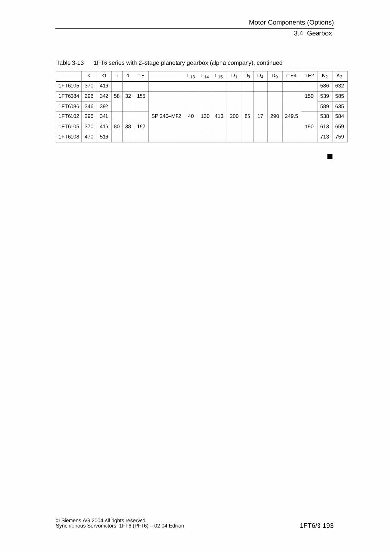
Motor Components (Options)
3.4 Gearbox
1FT6/3-193 Siemens AG 2004 All rights reservedSynchronous Servomotors, 1FT6 (PFT6) – 02.04 Edition
Table 3-13 1FT6 series with 2–stage planetary gearbox (alpha company), continued
K3K2 F2 F4D9D4D3D1L15L14L13 Fdlk1k
1FT6105 370 416 586 632
1FT6084 296 342 58 32 155 150 539 585
1FT6086 346 392 589 635
1FT6102 295 341 SP 240–MF2 40 130 413 200 85 17 290 249.5 538 584
1FT6105 370 416 80 38 192 190 613 659
1FT6108 470 516 713 759
Motor Components (Options)
3.4 Gearbox
1FT6/3-194 Siemens AG 2004 All rights reserved
Synchronous Servomotors, 1FT6 (PFT6) – 02.04 Edition
Space for your notes
1FT6/4-195 Siemens AG 2004 All rights reservedSynchronous Servomotors, 1FT6 (PFT6) – 02.04 Edition
Dimension Drawings
Note
Siemens AG reserves the right to change the dimensions of the motors as part ofmechanical design improvements without prior notice. Dimension drawings can goout–of–date.
Current dimension drawings can be requested at no charge from your localSIEMENS office.
4
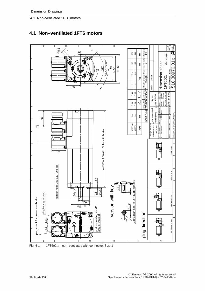
Dimension Drawings
4.1 Non–ventilated 1FT6 motors
1FT6/4-196 Siemens AG 2004 All rights reserved
Synchronous Servomotors, 1FT6 (PFT6) – 02.04 Edition
4.1 Non–ventilated 1FT6 motors
with
out
non–
vent
ilate
d /
IMB
5
plug
ver
sion
with
out
brak
ew
ith b
rake
193
233
28 28
0.34
0.21
0.41
0.28
2.1
1.2
2.3
1.4
mm k1
flang
e an
d sh
aft
tole
ranc
es a
cc.
to
DIN
429
55
not
tole
ranc
ed
dim
ensi
ons
±1 m
m
900.
3102
1.01
plug
dire
ctio
n:
tran
sver
se –
rig
httr
ansv
erse
– l
eft
axia
l – N
DE
axia
l – D
E
aC
orre
ctio
n, m
om.o
f in
ert.
29.0
3.00
Ki/T
sch
b
port
for
seal
ing
air
M5
bÒ
.M. 5
0073
019
.08.
03M
G/M
J
only
at i
p67/
6890
4x90
(=36
0 )
56
14.5
14.5
14
36
71
45 55
10.2
3
2.5
9.8
20±0
,4 4
12
20±0
,5
9k6
40j6
63
5.8
60
32
k= w
ithou
t bra
ke/ k
1= w
ith b
rake
32
vers
ion
with
key
devi
atio
n ac
c. to
DIN
688
5 sh
eet 1
DE
SIG
N
Sig
raph
1FT
602.
tota
lsh
eets
shee
tN
o.
EDCBA
43
2
87
65
43
2
FEDCA
1
11S
iem
ens
AG
repl
acem
ent
for:
Kie
ûner
30.1
1.99
dept
.: A
&D
MC
EW
N K
T2
repo
ns.:
nam
e:da
te:
nam
e/re
spon
s.da
tein
form
atio
nin
dex
scal
e:
dim
ensi
on s
heet
1FT
6021
1FT
6024
218
258
Mue
ller
510.
3097
6.01
cent
er h
ole
DIN
332
–DR
M8
plug
siz
e 1
for
pow
er a
nd b
rake
plug
for
sign
al p
ort
type
mm
x10
kgm
kgm
m
shaf
t hei
ghtm
omen
t of i
nert
iaw
eigh
tw
ithou
t br
ake
with
bra
kew
ithou
t br
ake
with
bra
kek
–42
0
Fig. 4-1 1FT602 non–ventilated with connector, Size 1
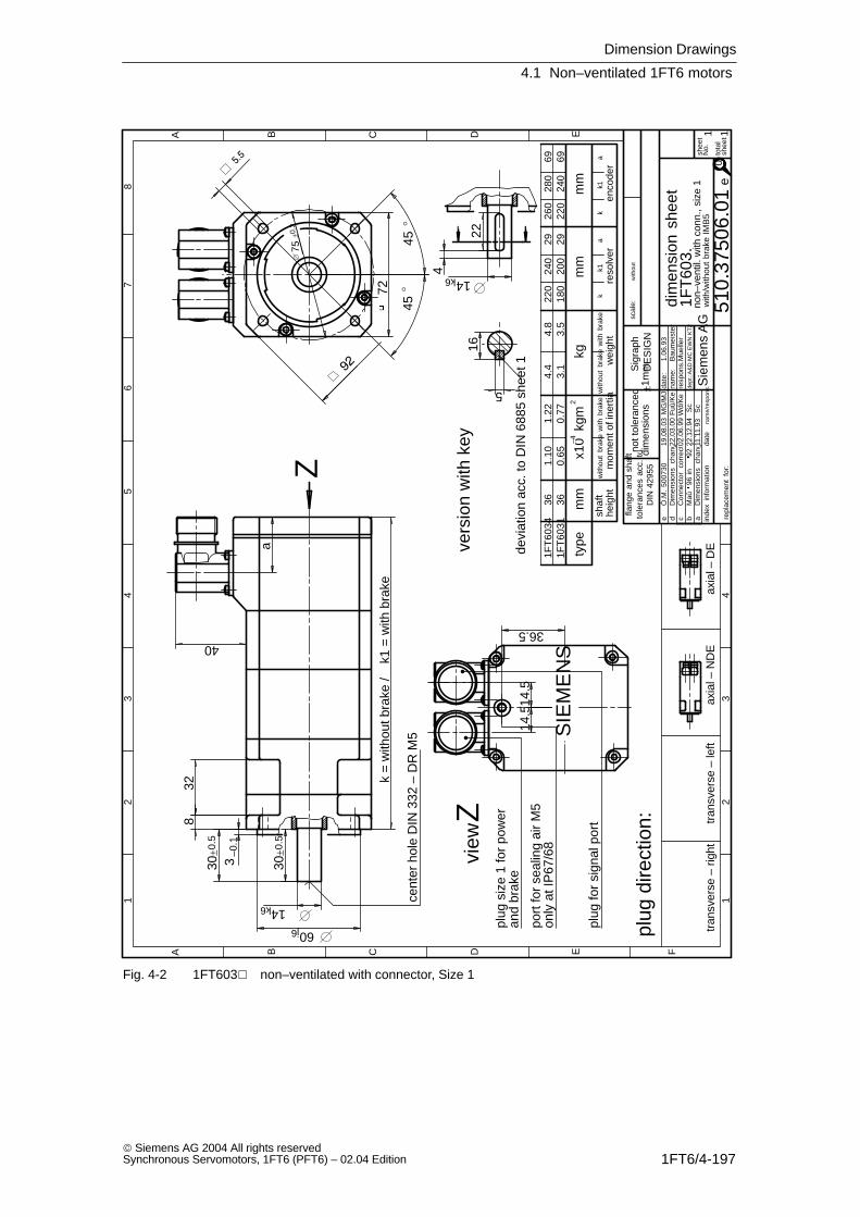
Dimension Drawings
4.1 Non–ventilated 1FT6 motors
1FT6/4-197 Siemens AG 2004 All rights reservedSynchronous Servomotors, 1FT6 (PFT6) – 02.04 Edition
bM
aû96
in
92 g
eö.
22.1
2.94
Sc
cC
onne
ctor
co
rrec
ted02
.06.
99W
d/K
e
a
40
4
22
14k6
14k6
30±0
.5
3–0
.1
8
30±0
.5
60j6
32
72
75±0
.3
k =
with
out b
rake
/k1
= w
ith b
rake
14.5
14.5
45
45
16
5
devi
atio
n ac
c. to
DIN
688
5 sh
eet 1
non–
vent
il. w
ith c
onn.
, siz
e 1
with
/with
out
brak
e IM
B5
1FT
6031
1FT
6034
36360.
651.
100.
771.
223.
14.
43.
54.
818
022
020
024
02929
220
260
240
280
6969
vers
ion
with
key
cent
er h
ole
DIN
332
– D
R M
5
Z
view
Zpl
ug s
ize
1 fo
r po
wer
plug
for
sign
al p
ort
scal
e:w
ithou
t
SIE
ME
NS
heig
ht
aD
imen
sion
s ch
ange
d11
.11.
93S
c
1
A B C D E F
23
45
67
8
12
34
A B C D E
shee
t N
o.
tota
lsh
eets
inde
xin
form
atio
nda
tena
me/
resp
ons.da
te:
nam
e:re
spon
s.:
dept
.:A&
D M
C E
WN
KT
2
1.06
.93
Bau
mei
ster
repl
acem
ent
for:
Sie
men
s A
G
dim
ensi
on s
heet
510.
3750
6.01
1 1
1FT
603.
Sig
raph
DE
SIG
N
e
Mue
ller
shaf
tm
omen
t of i
nert
ia
plug
dire
ctio
n:
tran
sver
se –
rig
httr
ansv
erse
– le
ftax
ial –
ND
Eax
ial –
DE
flang
e an
d sh
aft
tole
ranc
es a
cc.
toD
IN 4
2955
not t
oler
ance
ddi
men
sion
s±1
mm
dD
imen
sion
s ch
ange
dF
uû/K
e22
.03.
00
port
for
seal
ing
air
M5
eÒ
.M.
5007
3019
.08.
03M
G/M
J
with
out
brak
ew
ith b
rake
wei
ght
with
out
brak
ew
ith b
rake
reso
lver
enco
der
mm
x10
kgm
–42
kgm
mm
mty
pe
kk1
ak
k1a
and
brak
e
only
at I
P67
/68
36.5
0
Fig. 4-2 1FT603 non–ventilated with connector, Size 1
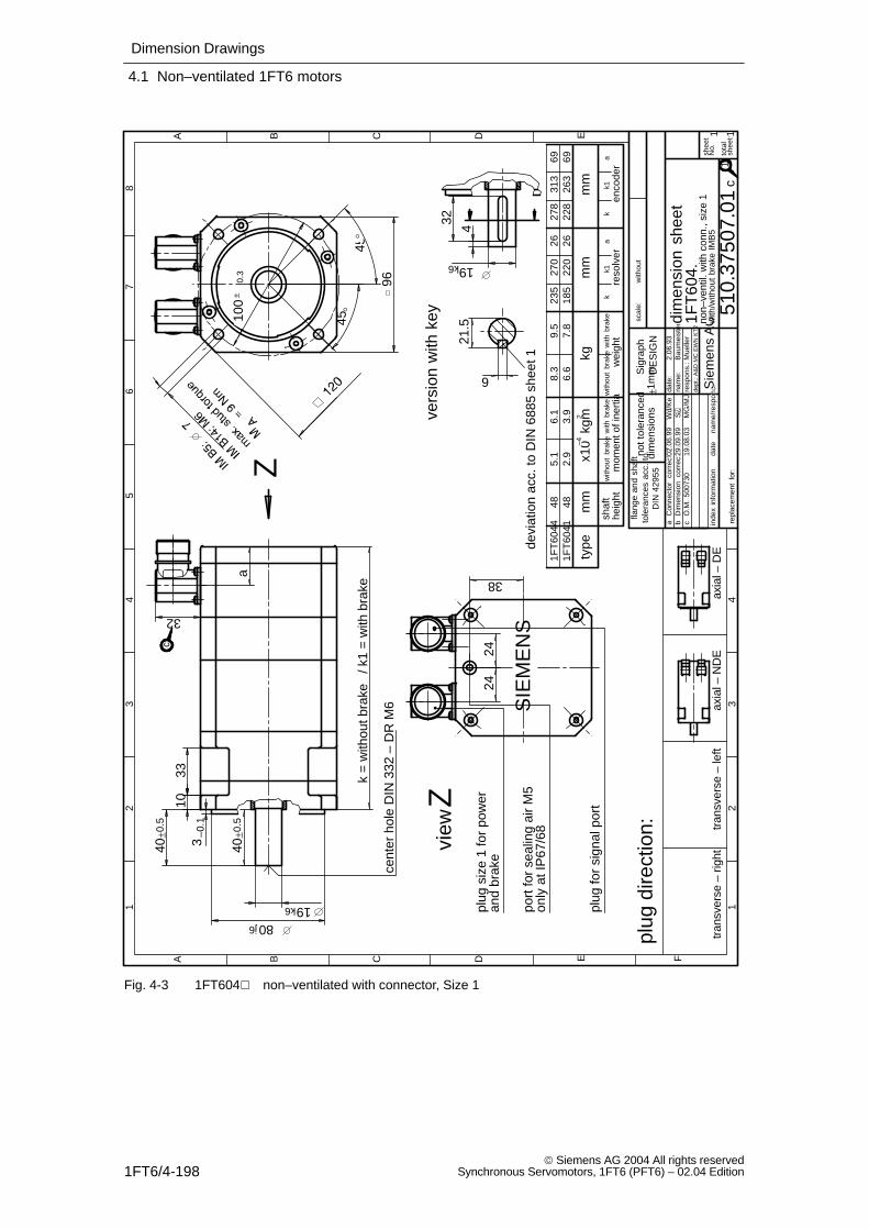
Dimension Drawings
4.1 Non–ventilated 1FT6 motors
1FT6/4-198 Siemens AG 2004 All rights reserved
Synchronous Servomotors, 1FT6 (PFT6) – 02.04 Edition
aC
onne
ctor
co
rrec
ted
02.0
6.99
Wd/
Ke
bD
imen
sion
co
rrec
tion
29.0
9.99
S
port
for
seal
ing
air
M5
cÒ
.M.
5007
3019
.08.
03M
G/M
J
and
brak
e
only
at I
P67
/68
38
heig
htsh
aft
mom
ent o
f ine
rtia
with
out
brak
ew
ith b
rake
wei
ght
with
out
brak
ew
ith b
rake
reso
lver
enco
der
mm
x10
kgm
–42
kgm
mm
mty
pe
kk1
ak
k1a
c
1
4
32
19k6
100
±0.
3
96
45
45
2424
1033
3–0
.1
40±0
.5
40±0
.5
19k6
80j6
k =
with
out b
rake
/ k1
= w
ith b
rake
a
32
21.5
6
devi
atio
n ac
c. to
DIN
688
5 sh
eet 1
with
/with
out
brak
e IM
B5
1FT
6041
1FT
6044
48 485.
12.
96.
13.
98.
36.
69.
57.
823
518
527
022
026 26
278
228
313
263
69 69
vers
ion
with
key
Z
view
Z
cent
er h
ole
DIN
332
– D
R M
6
plug
for
sign
al p
ort
plug
siz
e 1
for
pow
er
scal
e:w
ithou
t
SIE
ME
NS
1
A B C D E F
23
45
67
8
12
34
A B C D E
shee
tN
o.
tota
lsh
eets
inde
xin
form
atio
nda
tena
me/
resp
ons.da
te:
nam
e:re
spon
s.:
dept
.: A
&D
MC
EW
N K
T2
2.06
.93
Bau
mei
ster
repl
acem
ent
for:
Sie
men
s A
Gdim
ensi
on s
heet
non–
vent
il. w
ith c
onn.
, siz
e 1
510.
3750
7.01
1 1
1FT
604.
Sig
raph
DE
SIG
N
c
Mue
ller
plug
dire
ctio
n:
tran
sver
se –
rig
httr
ansv
erse
– le
ftax
ial –
ND
Eax
ial –
DE
flang
e an
d sh
aft
tole
ranc
es a
cc.
toD
IN 4
2955
not t
oler
ance
ddi
men
sion
s±1
mm
Fig. 4-3 1FT604 non–ventilated with connector, Size 1
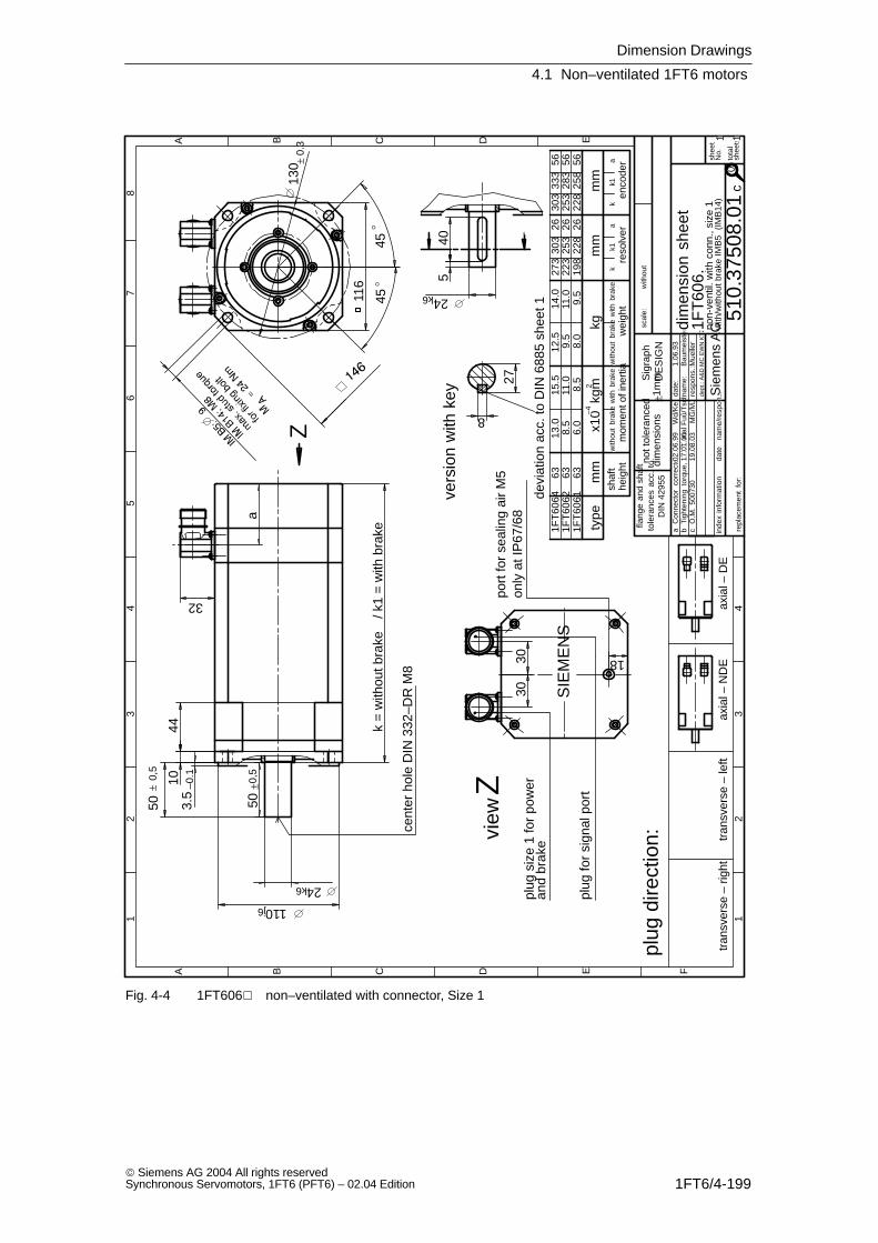
Dimension Drawings
4.1 Non–ventilated 1FT6 motors
1FT6/4-199 Siemens AG 2004 All rights reservedSynchronous Servomotors, 1FT6 (PFT6) – 02.04 Edition
aC
onne
ctor
co
rrec
ted02
.06.
99W
d/K
e
port
for
seal
ing
air
M5
cÒ
.M.
5007
3019
.08.
03M
G/M
J
283
and
brak
e
only
at I
P67
/68
18
bF
uû/T
sch
Tigh
teni
ng t
orqu
e, a
dditi
onal
17.0
1.00
0
heig
htsh
aft
mom
ent o
f ine
rtia
with
out
brak
ew
ith b
rake
wei
ght
with
out
brak
ew
ith b
rake
reso
lver
enco
der
mm
x10
kgm
–42
kgm
mm
mty
pek
k1a
kk1
a
k =
with
out b
rake
/ k1
= w
ith b
rake
3.5
–0.110
44
540
50±0
,5
24k6
110j6
50±
0,5
116
a
3030
45
45
24k6
32
130 ±
0.3
27
8
devi
atio
n ac
c. to
DIN
688
5 sh
eet 1
cent
er h
ole
DIN
332
–DR
M8
vers
ion
with
key
plug
dire
ctio
n:
non-
vent
il. w
ith c
onn.
, siz
e 1
with
/with
out
brak
e IM
B5
(IM
B14
)
1FT
6061
1FT
6062
1FT
6064
63 63 63 6
.0 8
.513
.015
.511
.0 8
.5
12.5
9.5
8.0
9.5
11.0
14.0
273
223
198
303
253
228
26 26 26
303
253
228
258
333
56 56 56
tran
sver
se –
rig
httr
ansv
erse
– le
ftax
ial –
ND
Eax
ial –
DE
Z
view
Zpl
ug s
ize
1 fo
r po
wer
plug
for
sign
al p
ort
with
out
SIE
ME
NS
scal
e:
1
A B C D E F
23
45
67
8
12
34
A B C D E
shee
tN
o.
tota
lsh
eets
inde
xin
form
atio
nda
tena
me/
resp
ons.da
te:
nam
e:re
spon
s.:
dept
.: A
&D
MC
EW
N K
T2
1.06
.93
Bau
mei
ster
repl
acem
ent
for:
Sie
men
s A
Gdim
ensi
on s
heet
510.
3750
8.01
1 1
1FT
606.
Sig
raph
DE
SIG
N
c
Mue
ller
flang
e an
d sh
aft
tole
ranc
es a
cc.
toD
IN 4
2955
not t
oler
ance
ddi
men
sion
s±1
mm
Fig. 4-4 1FT606 non–ventilated with connector, Size 1
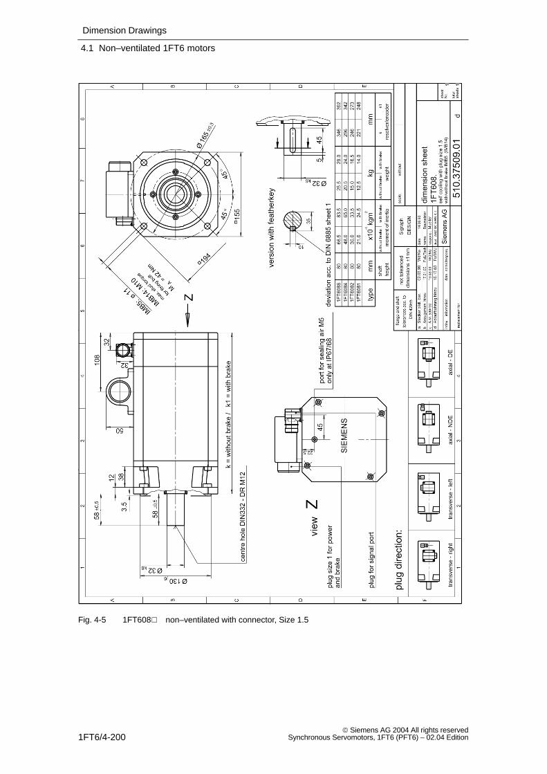
Dimension Drawings
4.1 Non–ventilated 1FT6 motors
1FT6/4-200 Siemens AG 2004 All rights reserved
Synchronous Servomotors, 1FT6 (PFT6) – 02.04 Edition
Fig. 4-5 1FT608 non–ventilated with connector, Size 1.5
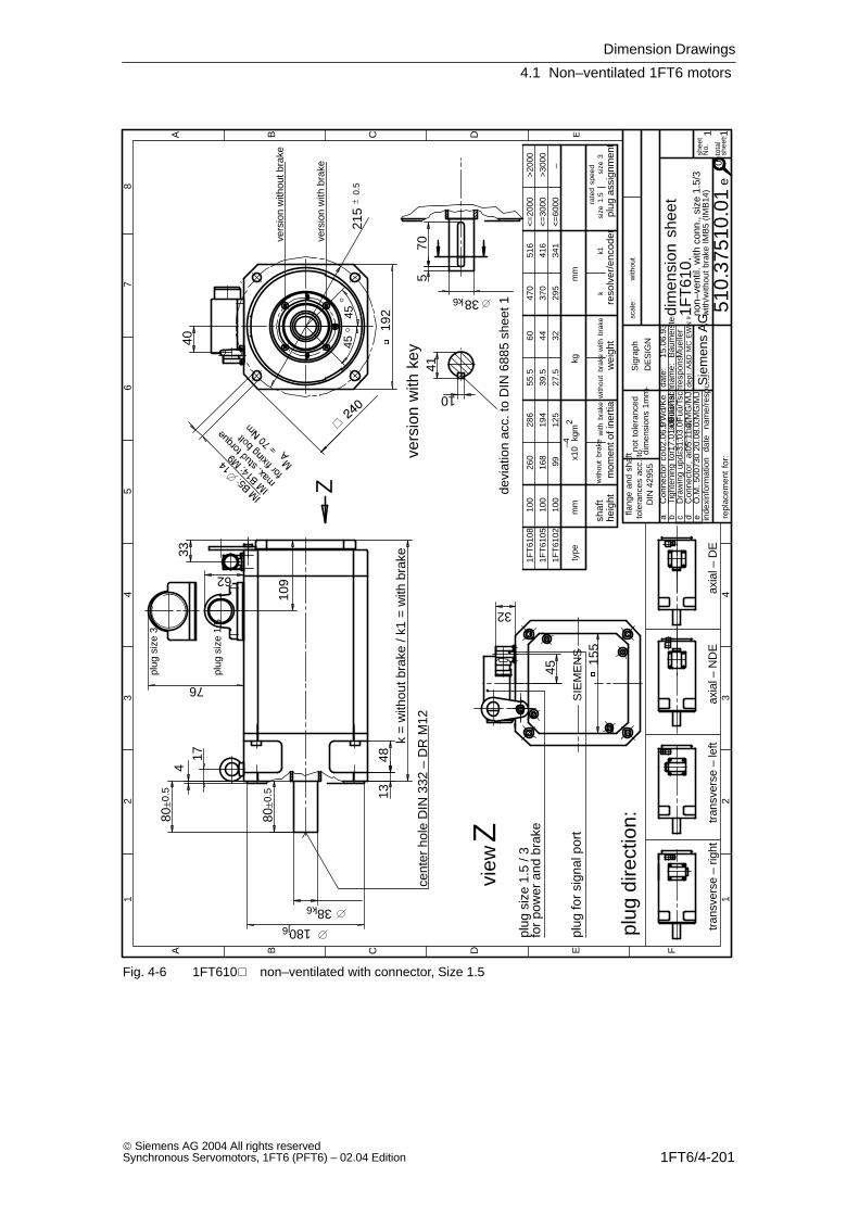
Dimension Drawings
4.1 Non–ventilated 1FT6 motors
1FT6/4-201 Siemens AG 2004 All rights reservedSynchronous Servomotors, 1FT6 (PFT6) – 02.04 Edition
aC
onne
ctor
cor
rect
ed02
.06.
99W
d/K
e
cD
raw
ing
upda
ted
31.0
3.00
Fuû
/Tsc
h
plug
siz
e 1.
5
dC
onne
ctor
, ad
ditio
nal
05.1
1.02
MG
/MJ
plug
siz
e 1.
5 / 3
for
pow
er a
nd b
rake
eÒ
.M. 5
0073
020
.08.
03M
G/M
J
plug
ass
ignm
ent
size
1.5
size
3ra
ted
spee
d
<=
6000
<=
3000
<=
2000
>20
00
>30
00
–
33
76
62
32
192
155
80±0
.5
109
13k
= w
ithou
t bra
ke /
k1 =
with
bra
ke
45
1740 45
45
38k6
180j6
4
48
80±0
.5
570
38k6
215
±0.
5
41
10
devi
atio
n ac
c. to
DIN
688
5 sh
eet 1
cent
er h
ole
DIN
332
– D
R M
12
non–
vent
il. w
ith c
onn.
, siz
e 1.
5/3
with
/with
out
brak
e IM
B5
(IM
B14
)
1FT
6102
1FT
6105
1FT
6108
100
100
100
260
168
99
286
194
125
55.5
39.5
27.5
60 44 32
470
370
295
516
416
341
vers
ion
with
key
Z
plug
for
sign
al p
ort
view
Z
SIE
ME
NS
vers
ion
with
bra
ke
vers
ion
with
out b
rake
1
A B C D E F
23
45
67
8
12
34
A B C D E
shee
tN
o.
tota
lsh
eets
scal
e:w
ithou
t
inde
xinf
orm
atio
nda
tena
me/
resp
ons.
date
:na
me:
resp
ons.
:de
pt.:A
&D
MC
EW
N K
T2
15.0
6.93
Bau
mei
ster
repl
acem
ent
for:
Sie
men
s A
G
dim
ensi
on s
heet
510.
3751
0.01
1 1
1FT
610.
Sig
raph
DE
SIG
N
e
Mue
ller
plug
dire
ctio
n:
tran
sver
se –
rig
httr
ansv
erse
– le
ftax
ial –
ND
Eax
ial –
DE
flang
e an
d sh
aft
tole
ranc
es a
cc.
toD
IN 4
2955
not
tole
ranc
eddi
men
sion
s+
1mm
bF
uû/T
sch
Tigh
teni
ng t
orqu
e, a
dditi
onal
17.0
1.00
plug
siz
e 3
heig
htsh
aft
mom
ent o
f ine
rtia
with
out
brak
ew
ith b
rake
wei
ght
with
out
brak
ew
ith b
rake
reso
lver
/enc
oder
mm
x10
kgm
–42
kgm
mty
pe
kk1
0
Fig. 4-6 1FT610 non–ventilated with connector, Size 1.5
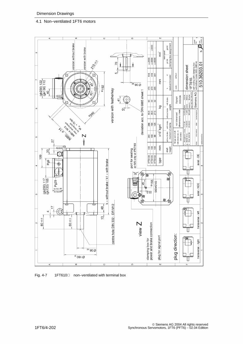
Dimension Drawings
4.1 Non–ventilated 1FT6 motors
1FT6/4-202 Siemens AG 2004 All rights reserved
Synchronous Servomotors, 1FT6 (PFT6) – 02.04 Edition
Fig. 4-7 1FT610 non–ventilated with terminal box
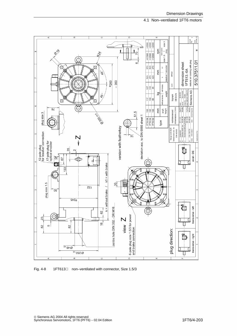
Dimension Drawings
4.1 Non–ventilated 1FT6 motors
1FT6/4-203 Siemens AG 2004 All rights reservedSynchronous Servomotors, 1FT6 (PFT6) – 02.04 Edition
Fig. 4-8 1FT613 non–ventilated with connector, Size 1.5/3
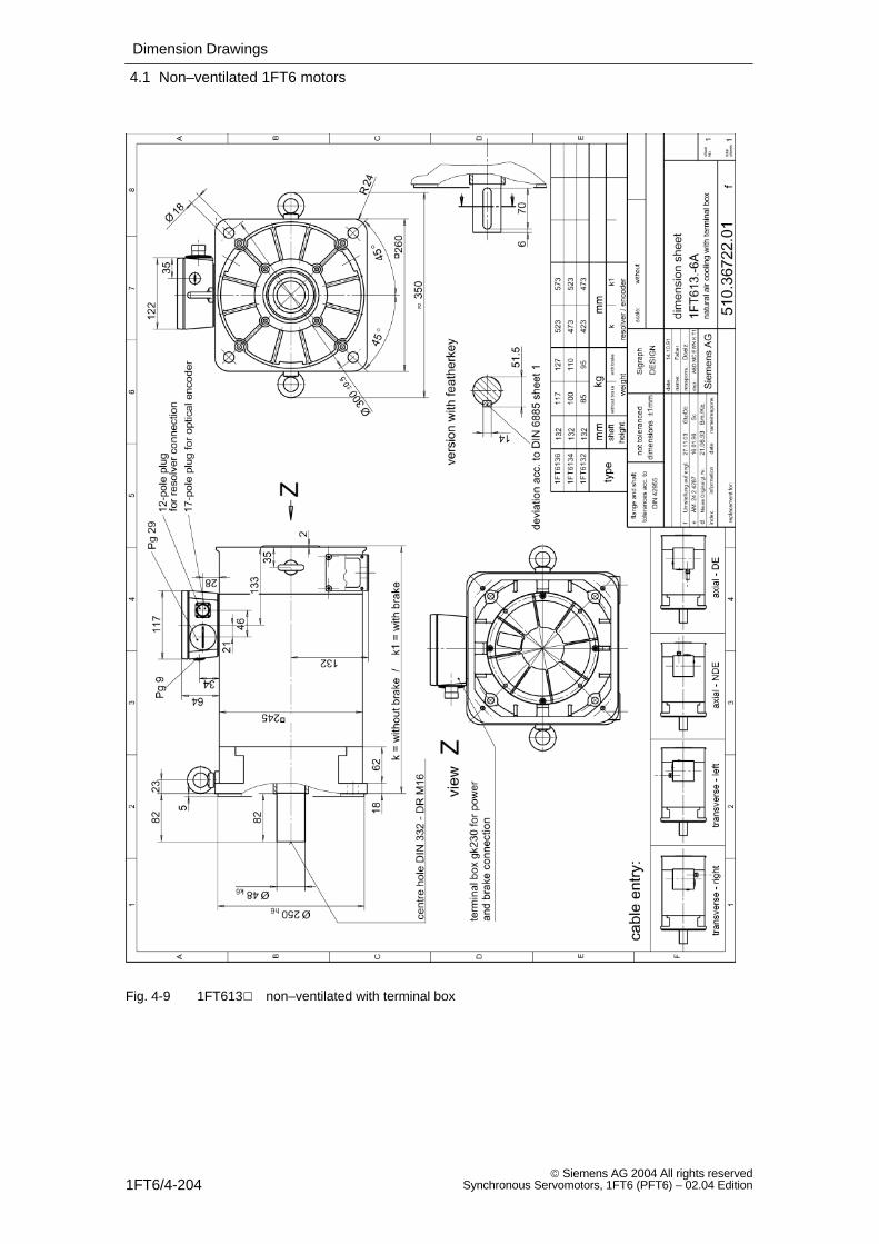
Dimension Drawings
4.1 Non–ventilated 1FT6 motors
1FT6/4-204 Siemens AG 2004 All rights reserved
Synchronous Servomotors, 1FT6 (PFT6) – 02.04 Edition
Fig. 4-9 1FT613 non–ventilated with terminal box
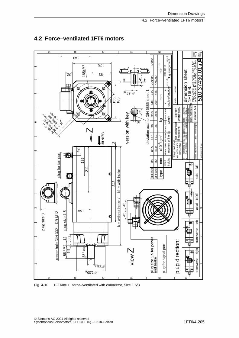
Dimension Drawings
4.2 Force–ventilated 1FT6 motors
1FT6/4-205 Siemens AG 2004 All rights reservedSynchronous Servomotors, 1FT6 (PFT6) – 02.04 Edition
4.2 Force–ventilated 1FT6 motors
min
–1
plug
ass
ignm
ent
rate
d sp
eed
size
1.5
size
3
–an
d br
ake
3.5
12
32k6
58±
0.5
58±
0.5
130j6
93
155
194
45
35
10
185
343
2k
= w
ithou
t bra
ke /
k1 =
with
bra
ke
175
140
32
4213
521
1
45
545
32k6
38
165±
0.3
154
devi
atio
n ac
c. to
DIN
688
5 sh
eet 1
plug
for
fan
port
cent
er h
ole
DIN
332
– D
R M
12
plug
siz
e 1.
5 fo
r po
wer
with
/with
out b
rake
IMB
5 (
IMB
14)
1FT
6084
1FT
6086
80 8066
.548
.083
.565
.030 25
33.5
28.5
449
399
495
445
vers
ion
with
key
Z
view
Z
plug
for
sign
al p
ort
air
entr
y
dÒ
.M.
5007
3018
.08.
03M
G/M
J
<=
3000
<=
6000
>30
00
plug
siz
e 1.
5
plug
siz
e 3
1
A B C D E F
23
45
67
8
12
34
A B C D E
shee
tN
o.
tota
lsh
eet
scal
e:w
ithou
t
inde
xin
form
atio
nda
tena
me/
resp
ons.da
te:
nam
e:re
spon
s.:
dept
.: A
&D
MC
EW
N K
T2
25.0
3.93
Bal
ling
repl
acem
ent
for:
Sie
men
s A
G
dim
ensi
on s
heet
forc
e-ve
ntil.
with
con
n., s
ize
1.5/
3
510.
3743
0.01
1 1
1FT
608.
Sig
raph
DE
SIG
N
d
Mue
ller
flang
e an
d sh
aft
tole
ranc
es a
cc.
toD
IN 4
2955
plug
dire
ctio
n:
tran
sver
se –
rig
httr
ansv
erse
– le
ftax
ial –
ND
Eax
ial –
DE
not t
oler
ance
ddi
men
sion
s±1
mm
cF
uû/T
sch
Tigh
teni
ng t
orqu
e, a
dditi
onal
17.0
1.00
heig
htsh
aft
mom
ent o
f ine
rtia
with
out
brak
ew
ith b
rake
wei
ght
with
out
brak
ew
ith b
rake
reso
lver
/enc
oder
mm
x10
kgm
–42
kgm
mty
pek
k1
0
Fig. 4-10 1FT608 force–ventilated with connector, Size 1.5/3
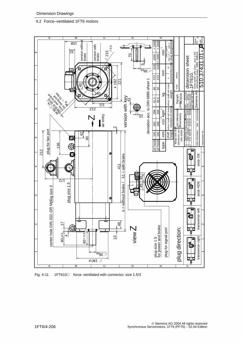
Dimension Drawings
4.2 Force–ventilated 1FT6 motors
1FT6/4-206 Siemens AG 2004 All rights reserved
Synchronous Servomotors, 1FT6 (PFT6) – 02.04 Edition
1500
dTa
ble
chan
ged
12.0
5.03
Ke/
MJ
rate
d sp
eed
size
1.5
size
3
–1
eÒ
.M.
5007
3019
.08.
03M
G/M
J
for
pow
er a
nd b
rake
brak
e
brak
e
1348
38k6
80±
0.5
480
±0.5
180j6
241
1k
= w
ithou
t bra
ke /
k1 =
with
bra
ke
42
136
212
17
41
10
40
240
192
221
111212
32
158
45
90
455
70
38k6
215 ±
0.5
172
devi
atio
n ac
c. to
DIN
688
5 sh
eet 1
cent
er h
ole
DIN
332
–DR
M12
with
/with
out
brak
e I
MB
5 (
IMB
14)
vers
ion
with
vers
ion
with
out
vers
ion
with
key
1FT
6105
1FT
6108
100
100
260
168
194
286
61.5
45.5
506657
347
361
951
9
Z
view
Z
plug
siz
e 1.
5
plug
for
sign
al p
ort
plug
for
fan
port
air
entr
y
<=
200
0>
200
0>
150
0
plug
siz
e 3
plug
siz
e 1.
5
1
A B C D E F
23
45
67
8
12
34
A B C D E
shee
tN
o.
tota
lsh
eets
scal
e:w
ithou
t
inde
xin
form
atio
nda
tena
me/
resp
ons.da
te:
nam
e:re
spon
s.:
dept
.:A&
D M
C E
WN
KT
2
25.0
3.93
Bal
ling
repl
acem
ent
for:
Sie
men
s A
G
dim
ensi
on s
heet
forc
e-ve
ntil.
with
con
n.,
size
1.5
/3
510.
3743
1.01
1 1
1FT
610.
Sig
raph
DE
SIG
N
e
Mue
ller
flang
e an
d sh
aft
tole
ranc
es a
cc.
toD
IN 4
2955
plug
dire
ctio
n:
tran
sver
se–r
ight
tran
sver
se–l
eft
axia
l–N
DE
axia
l–D
E
not t
oler
ance
ddi
men
sion
s±1
mm
cF
uû/T
sch
Tigh
teni
ng t
orqu
e, a
dditi
onal
17.0
1.00
heig
htsh
aft
mom
ent o
f ine
rtia
with
out
brak
ew
ith b
rake
wei
ght
with
out
brak
ew
ith b
rake
reso
lver
/enc
oder
plug
ass
ignm
ent
mm
x10
kgm
–42
kgm
mm
inty
pek
k1
0
Fig. 4-11 1FT610 force–ventilated with connector, size 1.5/3
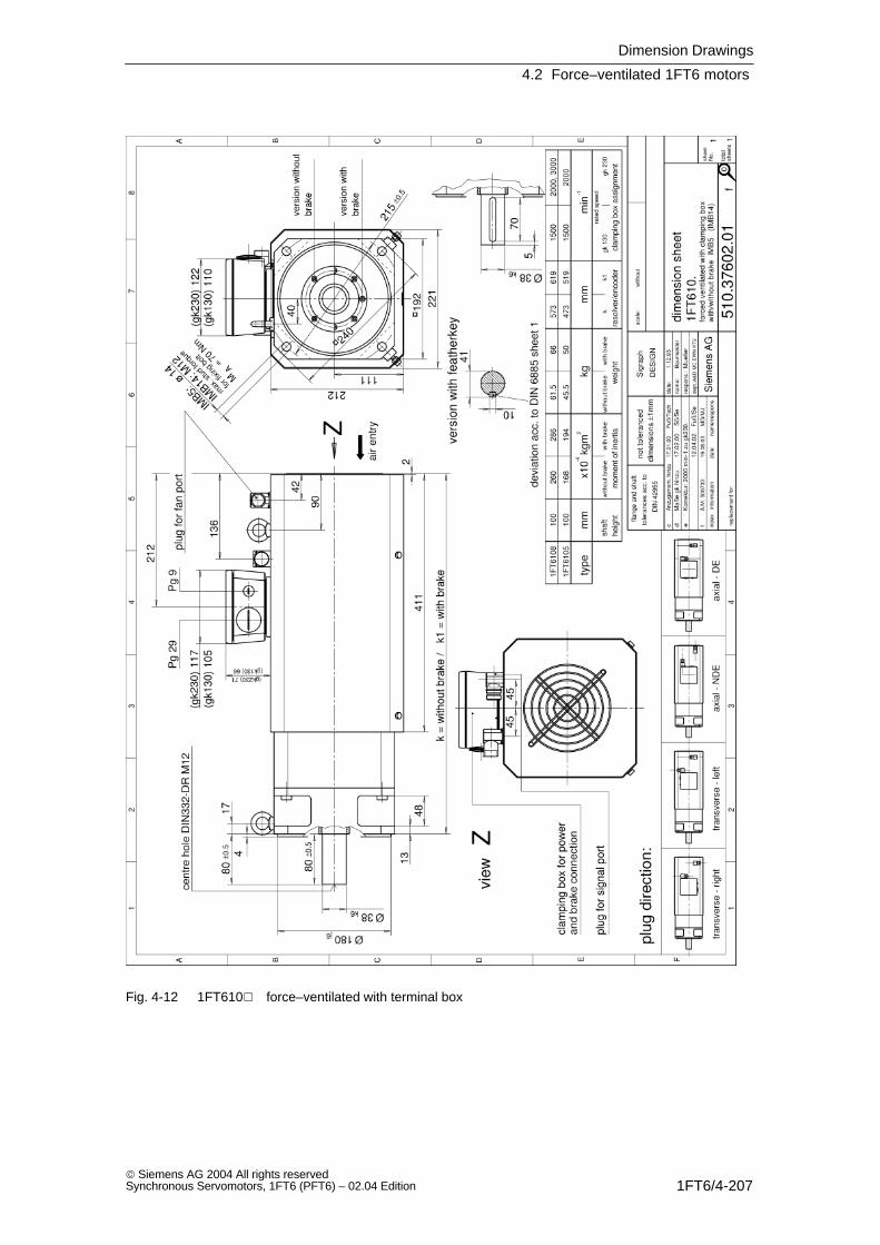
Dimension Drawings
4.2 Force–ventilated 1FT6 motors
1FT6/4-207 Siemens AG 2004 All rights reservedSynchronous Servomotors, 1FT6 (PFT6) – 02.04 Edition
Fig. 4-12 1FT610 force–ventilated with terminal box
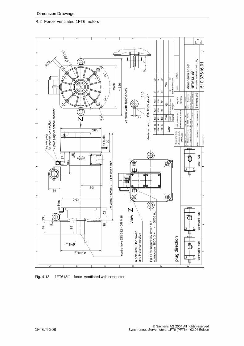
Dimension Drawings
4.2 Force–ventilated 1FT6 motors
1FT6/4-208 Siemens AG 2004 All rights reserved
Synchronous Servomotors, 1FT6 (PFT6) – 02.04 Edition
Fig. 4-13 1FT613 force–ventilated with connector
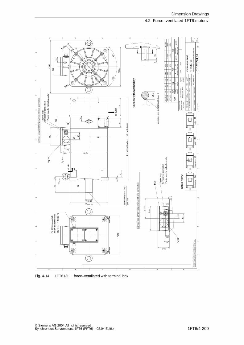
Dimension Drawings
4.2 Force–ventilated 1FT6 motors
1FT6/4-209 Siemens AG 2004 All rights reservedSynchronous Servomotors, 1FT6 (PFT6) – 02.04 Edition
Fig. 4-14 1FT613 force–ventilated with terminal box
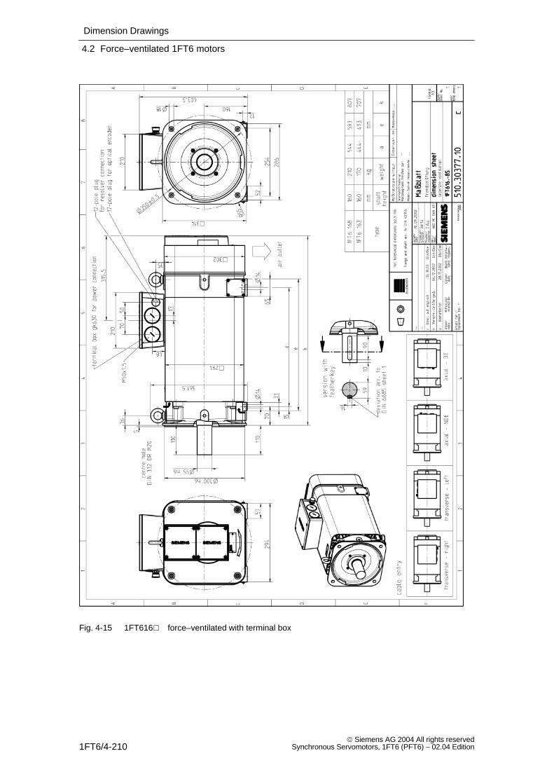
Dimension Drawings
4.2 Force–ventilated 1FT6 motors
1FT6/4-210 Siemens AG 2004 All rights reserved
Synchronous Servomotors, 1FT6 (PFT6) – 02.04 Edition
Fig. 4-15 1FT616 force–ventilated with terminal box
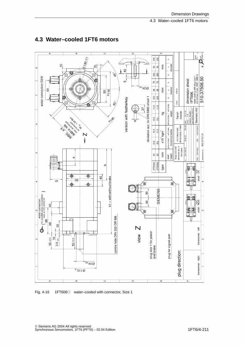
Dimension Drawings
4.3 Water–cooled 1FT6 motors
1FT6/4-211 Siemens AG 2004 All rights reservedSynchronous Servomotors, 1FT6 (PFT6) – 02.04 Edition
4.3 Water–cooled 1FT6 motors
Fig. 4-16 1FT606 water–cooled with connector, Size 1
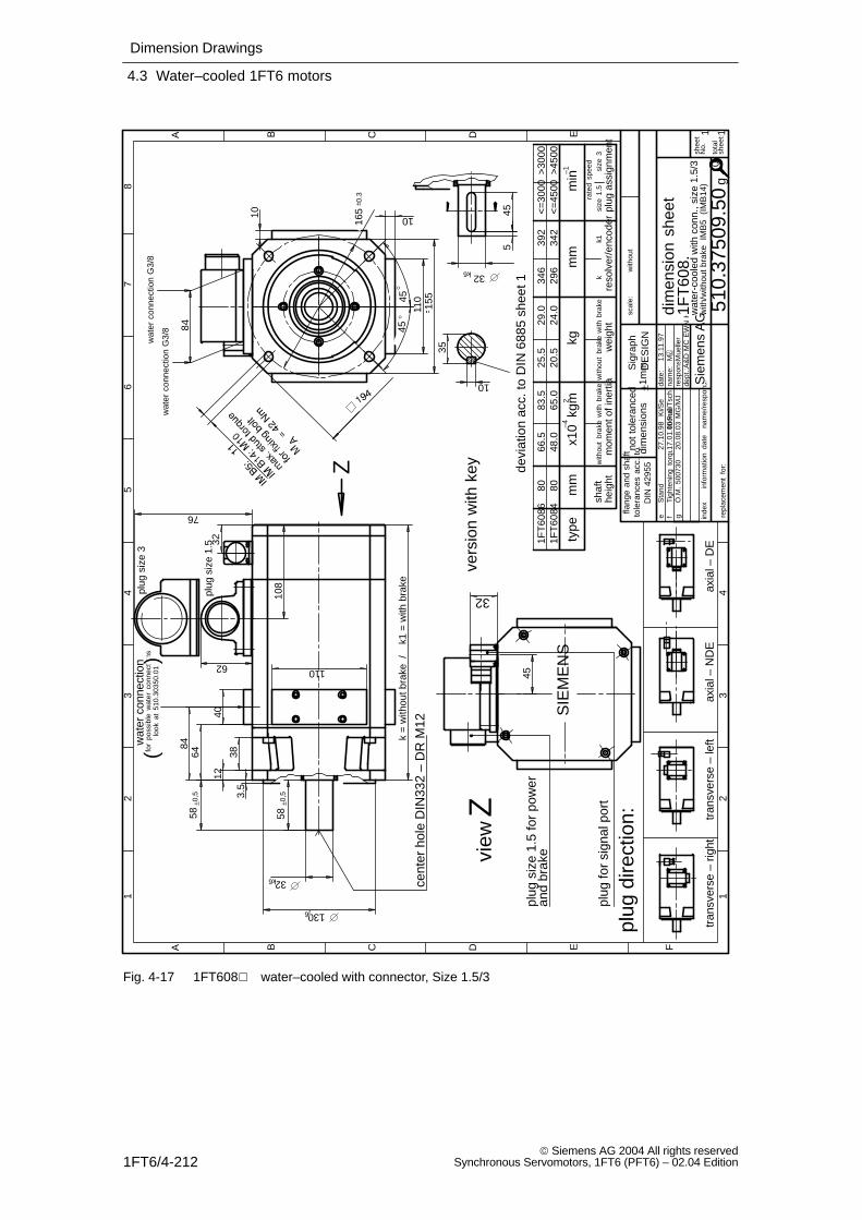
Dimension Drawings
4.3 Water–cooled 1FT6 motors
1FT6/4-212 Siemens AG 2004 All rights reserved
Synchronous Servomotors, 1FT6 (PFT6) – 02.04 Edition
eS
tand
27.1
0.98
Ki/S
e
plug
siz
e 3
plug
siz
e 1.
5
gÒ
.M.
5007
3020
.08.
03M
G/M
J
plug
ass
ignm
ent
size
1.5
size
3ra
ted
spee
d
<=
4500
<=
3000
>30
00>
4500
min–1
wat
er c
onne
ctio
nfo
r po
ssib
le w
ater
con
nect
ions
()
40
110
10 10
64
110
84
76
84
35
10
455
32k6
32
wat
er c
onne
ctio
n G
3/8
wat
er c
onne
ctio
n G
3/8
look
at
510.
3035
0.01
devi
atio
n ac
c. to
DIN
688
5 sh
eet 1
45
155
62
32
108
k =
with
out b
rake
/k1
= w
ith b
rake
58±0
,5
32k6
130j6
3.5
12
38
58±0
,5
45
45
165
± 0.3
Z
view
Z
cent
er h
ole
DIN
332
– D
R M
12
with
/with
out
brak
e I
MB
5 (
IMB
14)
scal
e:w
ithou
t
1FT
6084
1FT
6086
80 8066
.548
.083
.565
.025
.520
.529
.024
.034
629
639
234
2
vers
ion
with
key
plug
for
sign
al p
ort
plug
siz
e 1.
5 fo
r po
wer
and
brak
e
SIE
ME
NS
1
A B C D E F
23
45
67
8
12
34
A B C D E
shee
tN
o.
tota
lsh
eets
inde
xin
form
atio
nda
tena
me/
resp
ons.da
te:
nam
e:re
spon
s.:
dept
.:A&
D M
C E
WN
KT
2
13.1
1.97
M
repl
acem
ent
for:
Sie
men
s A
Gdim
ensi
on s
heet
wat
er-c
oole
d w
ith c
onn.
, siz
e 1.
5/3
510.
3750
9.50
1 1
1FT
608.
Sig
raph
DE
SIG
N
g
Mue
ller
plug
dire
ctio
n:
tran
sver
se –
rig
httr
ansv
erse
– le
ftax
ial –
ND
E
flang
e an
d sh
aft
tole
ranc
es a
cc.
toD
IN 4
2955
not t
oler
ance
ddi
men
sion
s±1
mm
axia
l – D
E
fF
uû/T
sch
Tigh
teni
ng t
orqu
e, a
dditi
onal
17.0
1.00
heig
htsh
aft
mom
ent o
f ine
rtia
with
out
brak
ew
ith b
rake
wei
ght
with
out
brak
ew
ith b
rake
reso
lver
/enc
oder
mm
x10
kgm
–42
kgm
mty
pe
kk1
0
Fig. 4-17 1FT608 water–cooled with connector, Size 1.5/3

Dimension Drawings
4.3 Water–cooled 1FT6 motors
1FT6/4-213 Siemens AG 2004 All rights reservedSynchronous Servomotors, 1FT6 (PFT6) – 02.04 Edition
eS
tatu
s27
.10.
98K
i/Se
plug
siz
e 3
plug
siz
e 1.
5
and
brak
e
gÒ
.M 5
0073
020
.08.
03M
G/M
J
1FT
6108
100
260
286
55.5
6047
051
6
plug
ass
igm
ent
size
1.5
size
3ra
ted
spee
d
<=
3000
<=
3000
min
–1–4
––
wat
er c
onne
ctio
nfo
r po
ssib
le w
ater
con
nect
ions
()
76
40
110
10
110
10
84
76
96
32
wat
er c
onne
ctio
n G
3/8
wat
er c
onne
ctio
n G
3/8
look
at 5
10.3
0350
.01
192
155
2733
80±0
.5
109
13k
= w
ithou
t bra
ke /
k1 =
with
bra
ke
62
45
17
40 45
45
38k6
180j6
4
48
80±0
.5
570
38k6
215
±0.
5
41
10
devi
atio
n ac
c. to
DIN
688
5 sh
eet 1
cent
er h
ole
DIN
332
– D
R M
12
wat
er1–
cool
ed w
ith c
onn.
, siz
e 1.
5/3
with
/with
out
brak
e I
MB
5 (
IMB
14)
1FT
6105
100
168
194
39.5
4437
041
6
vers
ion
with
key
Z
plug
for
sign
al p
ort
plug
siz
e 1.
5 fo
r po
wer
view
Z
SIE
ME
NS
vers
ion
with
bra
ke
vers
ion
with
out b
rake
1
A B C D E F
23
45
67
8
12
34
A B C D E
shee
tN
o.
tota
lsh
eets
scal
e:w
ithou
t
inde
xin
form
atio
nda
tena
me/
resp
ons.da
te:
nam
e:re
spon
s.:
dept
.:A&
D M
C E
WN
KT
2
13.1
1.97
M
repl
acem
ent
for:
Sie
men
s A
Gdim
ensi
on s
heet
510.
3751
0.50
1 1
1FT
610.
Sig
raph
DE
SIG
N
g
Mue
ller
plug
dire
ctio
n:
tran
sver
se –
rig
httr
ansv
erse
– le
ftax
ial –
ND
E
flang
e an
d sh
aft
tole
ranc
es a
cc.
toD
IN 4
2955
not t
oler
ance
ddi
men
sion
s±1
mm
axia
l – D
E
fF
uû/T
sch
Tigh
teni
ng t
orqu
e, a
dditi
onal
17.0
1.00
heig
htsh
aft
mom
ent o
f ine
rtia
with
out
brak
ew
ith b
rake
wei
ght
with
out
brak
ew
ith b
rake
reso
lver
/enc
oder
mm
x10
kgm
2kg
mm
type
kk1
0
Fig. 4-18 1FT610 water–cooled with connector, Size 1.5/3
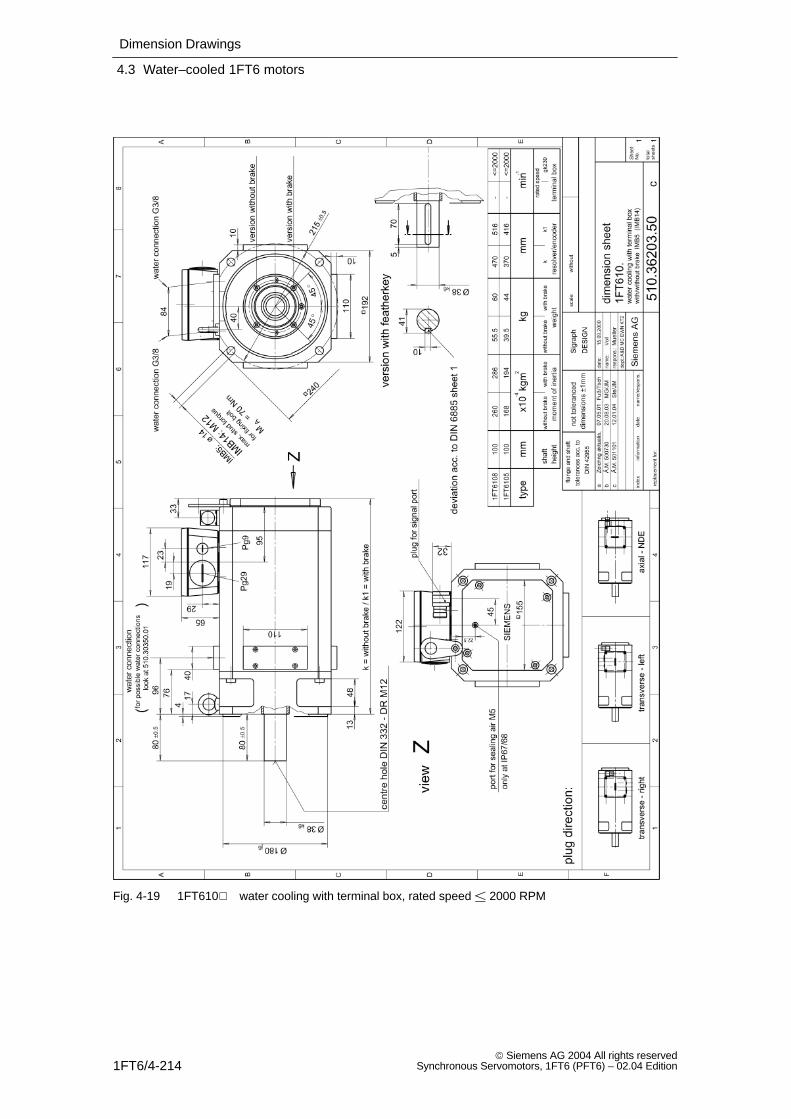
Dimension Drawings
4.3 Water–cooled 1FT6 motors
1FT6/4-214 Siemens AG 2004 All rights reserved
Synchronous Servomotors, 1FT6 (PFT6) – 02.04 Edition
Fig. 4-19 1FT610 water cooling with terminal box, rated speed 2000 RPM
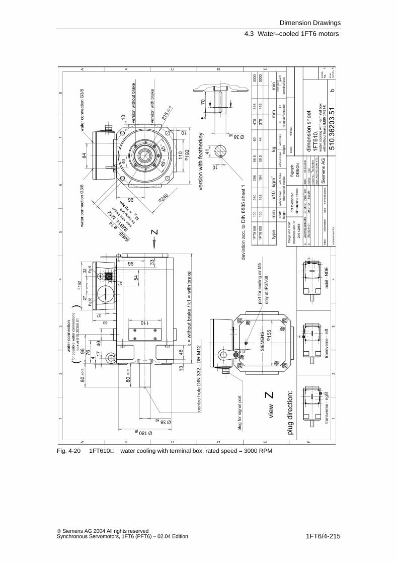
Dimension Drawings
4.3 Water–cooled 1FT6 motors
1FT6/4-215 Siemens AG 2004 All rights reservedSynchronous Servomotors, 1FT6 (PFT6) – 02.04 Edition
Fig. 4-20 1FT610 water cooling with terminal box, rated speed = 3000 RPM
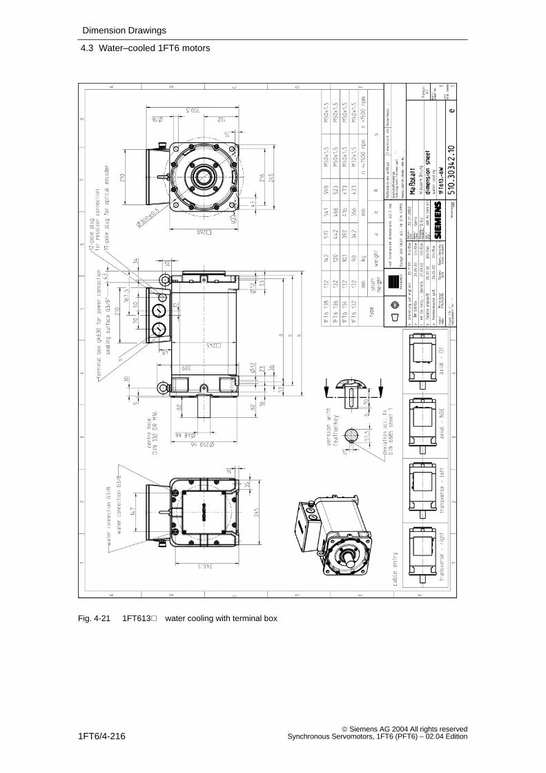
Dimension Drawings
4.3 Water–cooled 1FT6 motors
1FT6/4-216 Siemens AG 2004 All rights reserved
Synchronous Servomotors, 1FT6 (PFT6) – 02.04 Edition
Fig. 4-21 1FT613 water cooling with terminal box
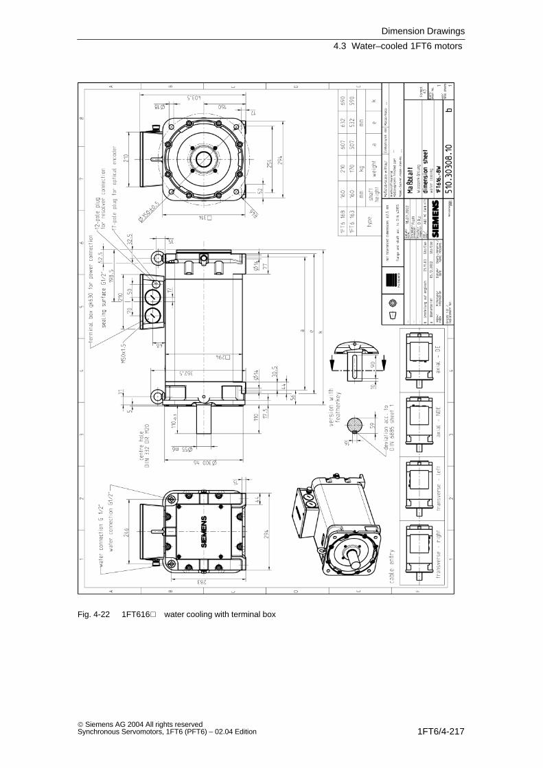
Dimension Drawings
4.3 Water–cooled 1FT6 motors
1FT6/4-217 Siemens AG 2004 All rights reservedSynchronous Servomotors, 1FT6 (PFT6) – 02.04 Edition
Fig. 4-22 1FT616 water cooling with terminal box
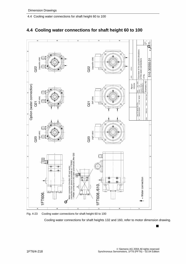
Dimension Drawings
4.4 Cooling water connections for shaft height 60 to 100
1FT6/4-218 Siemens AG 2004 All rights reserved
Synchronous Servomotors, 1FT6 (PFT6) – 02.04 Edition
4.4 Cooling water connections for shaft height 60 to 100
Fig. 4-23 Cooling water connections for shaft height 60 to 100
Cooling water connections for shaft heights 132 and 160, refer to motor dimension drawing.
1FT6/A-219 Siemens AG 2004 All rights reservedSynchronous Servomotors, 1FT6 (PFT6) – 02.04 Edition
References
General Documentation
/BU/ Catalog NC 60
Automation Systems for Machine ToolsOrder No.: E86060–K4460–A101–A9Order No.: E86060–K4460–A101–A9–7600 (English)
/DA65.3/ SIMOVERT MASTERDRIVES
Synchronous and Induction Servomotors for SIMOVERT MASTERDRIVESOrder No.: E86060–K5465–A301–A1Order No.: E86060–K5465–A301–A1–7600 (English)
Electronic Documentation
/CD1/ DOC ON CD
The SINUMERIK System (includes all SINUMERIK 840D/810D and SIMODRIVE 611D documents)Order No: 6FC5298–7CA00–0BG0
Manufacturer/Service Documentation
/PJM2/ Planning Guide, Synchronous Servomotors
SIMODRIVE 611, MASTERDRIVES MCContents: General Section, 1FT5, 1FT6, 1FK6, 1FK7Order No: 6SN1197–0AC20–0BP0
/PJAL/ Planning Guide, Synchronous Servomotors
SIMODRIVE 611, MASTERDRIVES MCSynchronous Servomotors General SectionOrder No: 6SN1197–0AD07–0BP1
References
1FT6/A-220 Siemens AG 2004 All rights reserved
Synchronous Servomotors, 1FT6 (PFT6) – 02.04 Edition
/PFK7/ Planning Guide, Synchronous Servomotors
SIMODRIVE 611, MASTERDRIVES MCSynchronous Servomotors 1FK7Order No: 6SN1197–0AD06–0BP0
/PFK7/ Planning Guide, Synchronous Servomotors
SIMODRIVE 611, MASTERDRIVES MCSynchronous Servomotors 1FK6Order No: 6SN1197–0AD05–0BP0
/PFT6/ Planning Guide, Synchronous Servomotors
SIMODRIVE 611, MASTERDRIVES MCSynchronous Servomotors 1FK6Order No: 6SN1197–0AD02–0BP0
/PFT6/ Planning Guide, Synchronous Servomotors
SIMODRIVESynchronous Servomotors 1FT5Order No: 6SN1197–0AD01–0BP0
/PFS6/ Planning Guide, Synchronous Servomotors
MASTERDRIVES MCSynchronous Servomotors 1FS6, Explosion ProtectedOrder No: 6SN1197–0AD08–0BP0
/PFU/ Planning Guide, Synchronous Motor
SINAMICS, MASTERDRIVES, MICROMASTERSIEMOSYN Synchronous Motor 1FU8 Order No: 6SN1197–0AC80–0BP0
/PJAS/ Planning Guide, Induction Motors
SIMODRIVE 611, MASTERDRIVES VC/MCInduction MotorsContents: General Section, 1PH2, 1PH4, 1PH7, 1PL6Order No: 6SN1197–0AC61–0BP0
/ASAL/ Planning Guide, Induction Motors
SIMODRIVE 611, MASTERDRIVES VC/MCInduction Motors, General SectionOrder No: 6SN1197–0AC62–0BP0
References
1FT6/A-221 Siemens AG 2004 All rights reservedSynchronous Servomotors, 1FT6 (PFT6) – 02.04 Edition
/APH2/ Planning Guide, Induction Motors
SIMODRIVE 611Induction Motors, 1PH2Order No: 6SN1197–0AC63–0BP0
/APH4/ Planning Guide, Induction Motors
SIMODRIVE 611Induction Motors, 1PH4Order No: 6SN1197–0AC64–0BP0
/APH7S/ Planning Guide, Induction Motors
SIMODRIVE 611Induction Motors, 1PH7Order No: 6SN1197–0AC65–0BP0
/APH7S/ Planning Guide, Induction Motors
MASTERDRIVESInduction Motors, 1PH7Order No: 6SN1197–0AC66–0BP0
/APL6/ Planning Guide, Induction Motors
MASTERDRIVES VC/MCInduction Motors, 1PH6Order No: 6SN1197–0AC67–0BP0
/PPM/ Planning Guide Hollow Shaft Motors
SIMODRIVEHollow Shaft Motors for Main Spindle Drives1PM6 and 1PM4Order No: 6SN1197–0AD03–0BP0
/PJFE/ Planning Guide, Synchronous Build–in Motors
SIMODRIVEAC Motors for Main Spindle DrivesSynchronous Build–In Motors 1FE1Order No: 6SN1197–0AC00–0BP4
References
1FT6/A-222 Siemens AG 2004 All rights reserved
Synchronous Servomotors, 1FT6 (PFT6) – 02.04 Edition
/PMS/ Planning Guide, Motor Spindle
SIMODRIVEECO Motor Spindle 2SP1Order No: 6SN1197–0AD04–0BP1
/PJTM/ Planning Guide, Build–in Torque Motors
SIMODRIVE1FW6 Build–in Torque MotorsOrder No: 6SN197–0AD00–0BP1
/PJLM/ Planning Guide, Linear Motors
SIMODRIVE1FN1 and 1FN3 Linear MotorsOrder No: 6SN1197–0AB70–0BP3
/PJU/ Planning Guide, Drive Converters
SIMODRIVE 611Drive ConvertersOrder No: 6SN1197–0AA00–0BP5
/EMV/ Planning Guide, EMC Design Guidelines
SINUMERIK, SIROTEC, SIMODRIVEOrder No: 6FC5297–0AD30–0BP1
Operating Instructions
Operating Instructions 1FT6
Order No.: 610.43410.21
Index–223 Siemens AG 2004 All rights reservedSynchronous Servomotors, 1FT6 (PFT6) – 02.04 Edition
Index
AAbsolute value encoder, 1FT6/3-184Additive, 1FT6/1-36Applications, 1FT6/1-15Armature short–circuit braking, 1FT6/1-27Axial force stressing, 1FT6/2-177
BBraking resistors, 1FT6/1-27
CCantilever force diagrams, 1FT6/2-172Cantilever force stressing, 1FT6/2-172Characteristics, 1FT6/2-45Connector assignment
Brake, 1FT6/1-39Encoder, 1FT6/1-39Power, 1FT6/1-39
Cooling, 1FT6/1-32Cooling medium, 1FT6/1-35Cooling powers to be dissipated, 1FT6/1-36
DDanger and warning information, viiiDesign features, 1FT6/1-16Drive–out coupling, 1FT6/1-42
EEncoder, 1FT6/3-181Engineering software, viESDS information and instructions, xi
FFeatures, 1FT6/1-15
GGearbox
1–stage, 1FT6/3-1892–stage, 1FT6/3-191
HHolding brake, 1FT6/3-188Hotline, vi
IIncremental encoders, 1FT6/3-182Interfaces, 1FT6/1-39
NNCSD Configurator, vi
OOptions, 1FT6/1-17Order designation
Core types, 1FT6/1-19Standard types, 1FT6/1-18
RReferences, 1FT6/A-219Resistor braking, 1FT6/1-27
Force–ventilated, 1FT6/1-30Non–ventilated, 1FT6/1-27Water cooling, 1FT6/1-31
Resolver, 1FT6/3-186
Index
Index–224 Siemens AG 2004 All rights reserved
Synchronous Servomotors, 1FT6 (PFT6) – 02.04 Edition
SSpeed–torque diagrams
Force ventilated, 1FT6/2-106Non–ventilated, 1FT6/2-46Water cooling, 1FT6/2-138
Standard engineering, 1FT6/1-15Start–up software, viSupplements, 1FT6/1-17
TTechnical data
nN 1500 RPM, 1FT6/1-21nN 2000 RPM, 1FT6/1-22nN 2500 RPM, 1FT6/1-23nN 4500 RPM, 1FT6/1-25nN 6000 RPM, 1FT6/1-26
Technical design, 1FT6/1-16Temperature sensor, KTY 84, 1FT6/3-179
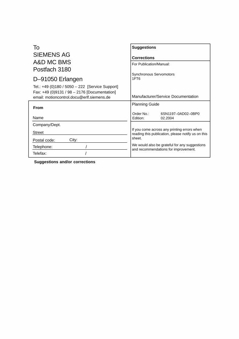
From
Name
Company/Dept.
Street
Postal code: City:
Telephone: /
Suggestions
Corrections
For Publication/Manual:
Synchronous Servomotors1FT6
Manufacturer/Service Documentation
Planning Guide
Order No.: 6SN1197–0AD02–0BP0Edition: 02.2004
If you come across any printing errors whenreading this publication, please notify us on thissheet.
We would also be grateful for any suggestionsand recommendations for improvement.
To SIEMENS AGA&D MC BMSPostfach 3180
D–91050 ErlangenTel.: +49 (0)180 / 5050 – 222 [Service Support]Fax: +49 (0)9131 / 98 – 2176 [Documentation]email: [email protected]
Telefax: /
Suggestions and/or corrections

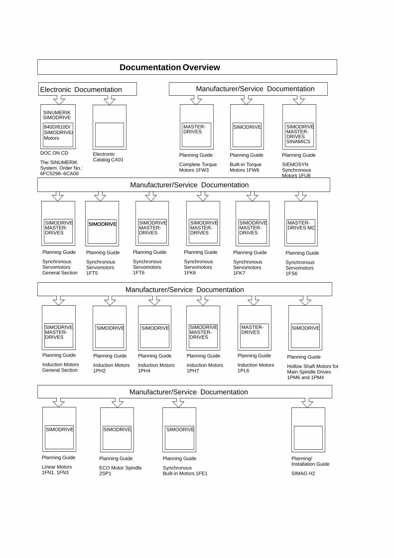
Documentation Overview
Electronic Documentation
Manufacturer/Service Documentation
Manufacturer/Service Documentation
ElectronicCatalog CA01
Planning Guide
SynchronousServomotors 1FT5
Planning Guide
Hollow Shaft Motors forMain Spindle Drives1PM6 and 1PM4
SINUMERIKSIMODRIVE
DOC ON CD
The SINUMERIKSystem, Order No.:6FC5298–6CA00
840D/810D/SIMODRIVE/Motors
Planning Guide
SynchronousServomotors 1FT6
Planning Guide
SynchronousServomotors 1FK6
Planning Guide
SynchronousServomotors 1FK7
Planning Guide
Complete TorqueMotors 1FW3
Planning Guide
SynchronousServomotors General Section
Manufacturer/Service Documentation
Planning Guide
SynchronousServomotors 1FS6
Planning Guide
Induction Motors1PH4
Planning Guide
Built-in TorqueMotors 1FW6
Planning Guide
Induction Motors1PH2
Planning Guide
Induction Motors1PH7
n
Planning Guide
Induction Motors 1PL6
Planning Guide
Induction MotorsGeneral Section
SIMODRIVEMASTER-DRIVES
SIMODRIVESIMODRIVESIMODRIVESIMODRIVEMASTER-DRIVES
SIMODRIVEMASTER-DRIVES
MASTER-DRIVES
SIMODRIVEMASTER-DRIVES
SIMODRIVEMASTER-DRIVES
SIMODRIVEMASTER-DRIVES
SIMODRIVE
MASTER-DRIVES
SIMODRIVE MASTER-DRIVES MC
SIMODRIVE
Planning Guide
SIEMOSYNSynchronousMotors 1FU8
SIMODRIVEMASTER-DRIVESSINAMICS
Manufacturer/Service Documentatio
Planning Guide
SynchronousBuilt-in Motors 1FE1
Planning Guide
Linear Motors1FN1, 1FN3
Planning Guide
ECO Motor Spindle2SP1
Planning/Installation Guide
SIMAG H2
SIMODRIVESIMODRIVESIMODRIVE

© Siemens AG 2004Subject to change without prior notice
Order No.: 6SN1197-0AD02-0BP0
ens AG atisierungs- und Antriebstechnik
otion Control Systems
www.ad.siemens.de
Siem
Autom
M
Postfach 3180, D – 91050 Erlangen
Bundesrepublik Deutschland
Printed in the Federal Republic of Germany