Sime - Ecomfort HE & Ecomfort System HE · 3 1.1 INTRODUCTION “ECOMFORT” is a boiler that has a...
40
Ecomfort Installation and servicing instructions GB
-
Upload
duongkhuong -
Category
Documents
-
view
214 -
download
0
Transcript of Sime - Ecomfort HE & Ecomfort System HE · 3 1.1 INTRODUCTION “ECOMFORT” is a boiler that has a...
Ecomfort
Installation and servicing instructions
GB

Ecomfort System 25 HE: Ecomfort 25 HE:
Gas Council number 41-283-04 Gas Council number 47-283-06
Ecomfort 30 HE: Ecomfort 35 HE:
Gas Council number 47-719-25 Gas Council number 47-283-04
These appliances comply with the S.E.D.B.U.K. scheme, band “B”
Please refer to commissioning instructions for filling in the log book
Note: All CORGI registered installers carry a CORGI ID Card. You can check your installer is CORGI Registered by calling 01256 372300
CONTENTS
1 DESCRIPTION OF THE BOILER . . . . . . . . . . . . . . . . . . . . . . . . . . . . . . . . . . . . . . . . . . . . . . . . . . . . . . . . . . . . . . . . . . . . . . . . pag. 32 INSTALLATION . . . . . . . . . . . . . . . . . . . . . . . . . . . . . . . . . . . . . . . . . . . . . . . . . . . . . . . . . . . . . . . . . . . . . . . . . . . . . . . . . . . . . . . pag. 73 CHARACTERISTICS . . . . . . . . . . . . . . . . . . . . . . . . . . . . . . . . . . . . . . . . . . . . . . . . . . . . . . . . . . . . . . . . . . . . . . . . . . . . . . . . . . . pag. 154 USE AND MAINTENANCE . . . . . . . . . . . . . . . . . . . . . . . . . . . . . . . . . . . . . . . . . . . . . . . . . . . . . . . . . . . . . . . . . . . . . . . . . . . . pag. 185 FAULT FINDING . . . . . . . . . . . . . . . . . . . . . . . . . . . . . . . . . . . . . . . . . . . . . . . . . . . . . . . . . . . . . . . . . . . . . . . . . . . . . . . . . . . . . . pag. 216 REPLACEMENT OF PARTS . . . . . . . . . . . . . . . . . . . . . . . . . . . . . . . . . . . . . . . . . . . . . . . . . . . . . . . . . . . . . . . . . . . . . . . . . . . . pag. 247 EXPLODED VIEWS . . . . . . . . . . . . . . . . . . . . . . . . . . . . . . . . . . . . . . . . . . . . . . . . . . . . . . . . . . . . . . . . . . . . . . . . . . . . . . . . . . . pag. 26
SIME COMBINATION BOILERSInstaller checklist
Please remember to carry out the following checks after installation. This will achieve complete customer satisfaction,
and avoid unnecessary service calls. A charge will be made for a service visit where the fault is not due to a manufac-
turing defect.
– Has a correct by-pass been fitted and adjusted?
– Has the system and boiler been flushed?
– Is the system and boiler full of water, and the correct pressure showing on the pressure gauge?
– Is the Auto Air Vent open?
– Has the pump been rotated manually?
– Is the gas supply working pressure correct?
– Is the boiler wired correctly? (See installation manual).
– Has the D.H.W. flow rate been set to the customer requirements?
– Has the customer been fully advised on the correct use of the boiler, system and controls?
– Has the log book provided been completed?
– Has the Aquaguard Filter been cleaned (see 4.9)?
– Has the condensate trap been filled (see section 2)?
IPX4D
3
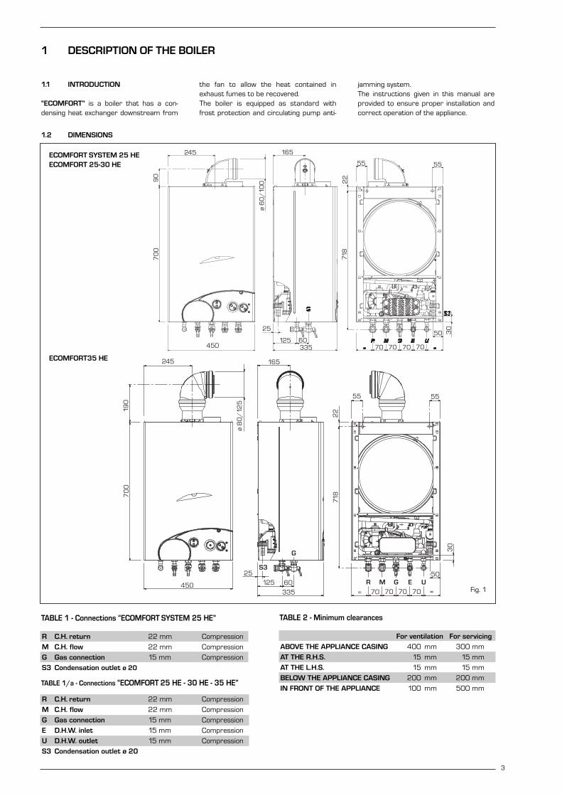
1.1 INTRODUCTION
“ECOMFORT” is a boiler that has a con-densing heat exchanger downstream from
the fan to allow the heat contained inexhaust fumes to be recovered. The boiler is equipped as standard withfrost protection and circulating pump anti-
jamming system.The instructions given in this manual areprovided to ensure proper installation andcorrect operation of the appliance.
1 DESCRIPTION OF THE BOILER
70 70 70 70
50 30
5555
22
718
25
125 60335450
245 165
ø 6
0/
1009
07
00
1.2 DIMENSIONS
TABLE 1/a - Connections “ECOMFORT 25 HE - 30 HE - 35 HE”
R C.H. return 22 mm Compression
M C.H. flow 22 mm Compression
G Gas connection 15 mm Compression
E D.H.W. inlet 15 mm Compression
U D.H.W. outlet 15 mm Compression
S3 Condensation outlet ø 20
TABLE 2 - Minimum clearances
For ventilation For servicing
ABOVE THE APPLIANCE CASING 400 mm 300 mm
AT THE R.H.S. 15 mm 15 mm
AT THE L.H.S. 15 mm 15 mm
BELOW THE APPLIANCE CASING 200 mm 200 mm
IN FRONT OF THE APPLIANCE 100 mm 500 mm
TABLE 1 - Connections “ECOMFORT SYSTEM 25 HE”
R C.H. return 22 mm Compression
M C.H. flow 22 mm Compression
G Gas connection 15 mm Compression
S3 Condensation outlet ø 20
245
190
ø 8
0/
125
165
55 55
22
30
50
70
0
450
25125 60
335 70 70 70 70 ==
R M G E U
S3
718
G
Fig. 1
ECOMFORT SYSTEM 25 HEECOMFORT 25-30 HE
ECOMFORT35 HE

4
1.3 TECHNICAL FEATURES
ECOMFORT SYSTEM 25 HE 25 HE 30 HE 35 HE
Heat output nominal (80-60°C) kW 24.7 24.7 29.1 33.5
Heat output nominal (50-30°C) kW 26.5 26.5 31.2 36.0
Heat output minimum (80-60°C) kW 9.5 9.5 12.7 12.5
Heat output minimum (50-30°C) kW 10.0 10.0 13.6 13.0
Heat input nominal kW 25.5 25.5 30.0 34.8
Heat input minimum kW 10.2 10.2 13.5 13.5
Efficiency min./nom. output (80-60°C) % 93.6/97.0 93.6/97.0 94.4/96.9 92.7/96.3
Efficiency min./nom. output (50-30°C) % 98.2/103.9 98.2/103.9 100.5/103.9 96.7/103.4
Seasonal efficiency rating (SEDBUK) (B) (B) (B) (B)
Termal efficiency (CEE 92/42 directive)
Class NOx 3 3 3 3
Smokes temperature maximum (80-60°C) °C 78 78 80 88
Smokes temperature minimum (80-60°C) °C 74 74 74 80
Smokes temperature maximum (50-30°C) °C 50 50 51 55
Smokes temperature minimum (50-30°C) °C 42 42 44 48
Smokes flow kg/h 57.3 57.3 65.0 71.0
CO2 maximum/minimum G20 % 6.1/2.2 6.1/2.2 7.3/3.1 7.3/2.6
CO2 maximum/minimum G30/G31 % 7.5/2.8 7.5/2.8 8.5/3.5 8.8/3..1
Adsorbed power consumption W 150 150 160 160
Electrical protection grade IP X4D X4D X4D X4D
CE certification n° 1312BQ4473 1312BQ4473 1312BQ4473 1312BQ4473
Category II2H3+ II2H3+ II2H3+ II2H3+
Type B22-52/C12-32-42-52-82 B22-52/C12-32-42-52-82 B22-52/C12-32-42-52-82 B22-52/C12-32-42-52-82
WEIGHT kg 41 43 43 43
CENTRAL HEATING
Maximum water head bar 3 3 3 3
Maximum temperature °C 85 85 85 85
Water content boiler l 5.0 5.0 5.0 5.0
C.H. setting range °C 30/80 30/80 30/80 30/80
Expansion vessel capacity l 8 8 8 8
Expansion vessel pressure bar 1 1 1 1
DOMESTIC HOT WATER
Minimum/Maximum pressure bar - 0.5/7.0 0.5/7.0 0.5/7.0
D.H.W. flow rate (EN 625) l/min - 11.5 13.0 14.7
Continuous D.H.W. flow rate ∆t 30°C l/min - 11.8 13.8 15.8
Continuous D.H.W. flow rate ∆t 35°C l/min - 10.1 11.9 13.0
D.H.W. setting range °C - 30/60 30/60 30/60
GAS PRESSURE AND NOZZLES
Gas supply pressure G20 mbar 20 20 20 20
Gas supply pressure G30 mbar 28-30 28-30 28-30 28-30
Gas supply pressure G31 mbar 37 37 37 37
Nozzles quantity n° 12 12 14 15
Nozzles diameter G20 ø 1.30 1.30 1.30 1.30
Nozzles diameter G30/G31 ø 0.77 0.77 0.77 0.80
Burner gas pressure min./max. G20 mbar 2.0/11.5 2.0/11.5 2.6/11.5 2.2/13.5
Burner gas pressure min./max. G30 mbar 4.8/28.5 4.8/28.5 6.3/28.5 4.5/28.2
Burner gas pressure min./max. G31 mbar 4.8/36.5 4.8/36.5 6.3/36.2 4.5/36.2
C.H gas consumption G20 m3/h 2.70 2.70 3.17 3.68
C.H. gas consumption G30 kg/h 2.01 2.01 2.37 2.74
C.H. gas consumption G31 kg/h 1.98 1.98 2.33 2.70

123
45
7 8
911
1415
13
181920
25 2624
17
16
S3
RMG
5
20
1921
22 23 24 25 26
RMGEU
18
1415
1311
12
910
7 86
54
123
17
S3
16
KEY1 Post-condenser2 Smoke stat 95°3 Fan 4 Main exchanger5 SM sensor (thermister)6 Aqua Guard Filter System7 Safety stat 100°8 Thermometer sensor9 Gas valve
10 D.H.W. exchanger 11 Water flow switch12 Divertor valve13 Automatic by-pass14 Circulating pump15 Auto air vent16 Expansion vessel17 Condensation water trap18 Safety valve19 Temperature/pressure gauge20 Boiler drain21 D.H.W. filter23 D.H.W. inlet cock24 Gas cock25 C.H. flow cock26 C.H. return cock
R C.H. returnM C.H. flowG Gas connectionE D.H.W. inletU D.H.W. outletS3 Condensation outlet ø 20
1.4 FUNCTIONAL DIAGRAM
Fig. 2
ECOMFORT SYSTEM 25 HE
ECOMFORT 25 - 30 - 35 HE
6
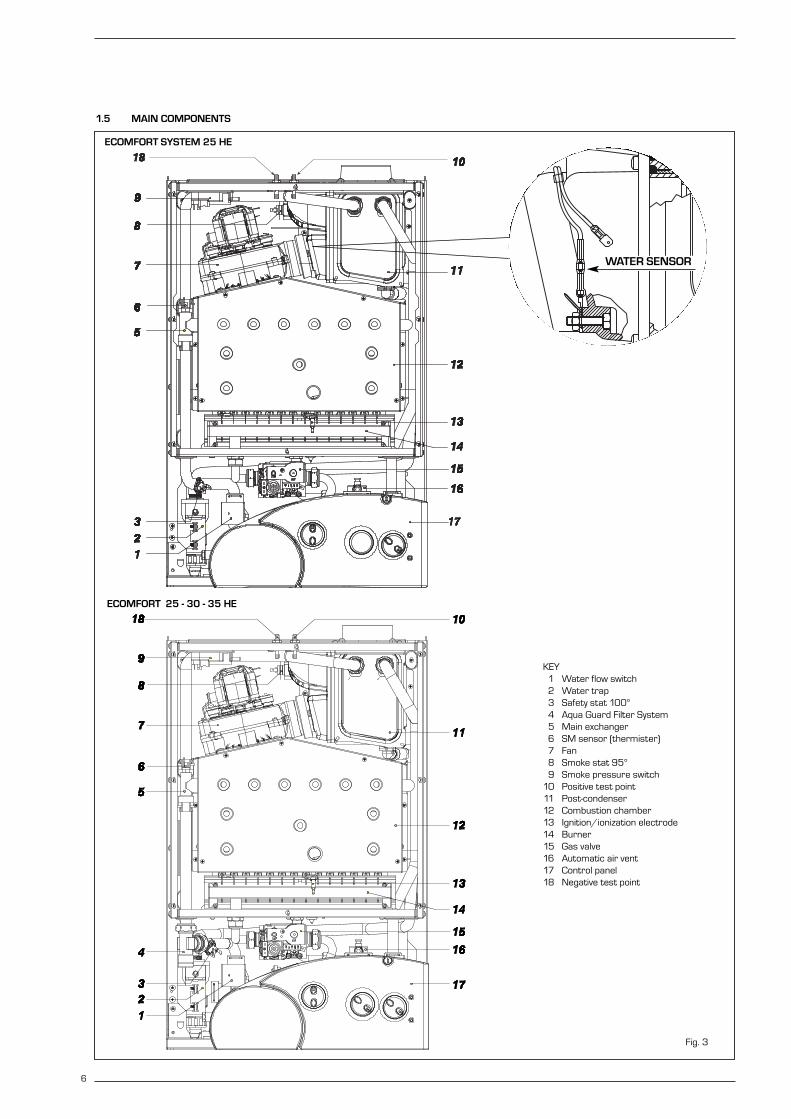
1.5 MAIN COMPONENTS
Fig. 3
KEY1 Water flow switch2 Water trap3 Safety stat 100°4 Aqua Guard Filter System5 Main exchanger6 SM sensor (thermister)7 Fan8 Smoke stat 95°9 Smoke pressure switch
10 Positive test point11 Post-condenser12 Combustion chamber13 Ignition/ionization electrode14 Burner15 Gas valve16 Automatic air vent17 Control panel18 Negative test point
WATER SENSOR
ECOMFORT SYSTEM 25 HE
ECOMFORT 25 - 30 - 35 HE

7
The boiler must be installed in a fixed loca-tion and only by specialized and qualified per-son in compliance with all instructions con-tained in this manual. The boiler should beinstalled in accordance with the Gas SafetyRegulations.It is important that the condensate trapbe filled prior to operating the boiler. Thetrap can be filled by pouring water care-fully into the inner flue connection prior toinstallation of the flue. Care should betaken not to allow any water to enter theouter flue.
2.1 VENTILATION REQUIREMENTS
Detailled recommendations for air supplyare given in BS5440:2. The following notesare for general guidance:– It is not necessary to have a purpose pro-
vided air vent in the room or compart-ment in which the appliance is installed.
2.3 CONNECTING UP SYSTEM
Before proceeding to connect up the boiler,you are recommended to flush out the sys-tem in order to eliminate any foreign bodiesthat might be detrimental to the operatingefficiency of the appliance. When makingthe hydraulic connections, make sure thatthe clearances indicated in fig. 1 arerespected. To facilitate the hydraulic con-nections the boiler is equipped with a valvepack code 5184817 complete with instruc-tions sheet. A safety valve set at 3 bar isfitted to the appliance, the discharge pipeprovided should be extended to terminatesafely away from the appliance and wherea discharge would not cause damage topersons or property but would be detect-ed. The pipe should be a minimum of 15mm Ø and should be able to withstandboiling water, any should avoid sharp cor-ners or upward pipe runs where watermay be retained.The gas connection must be made usingseamless steel or copper pipe(Mannesmann type), galvanized and withthreaded joints provided with gaskets,excluding three-piece connections, exceptfor initial and end connections. Where thepiping has to pass through walls, a suitableinsulating sleeve must be provided. Whensizing gas piping, from the meter to the boil-er, take into account both the volume flowrates (consumption) in m3/h and the rela-tive density of the gas in question. The sec-tions of the piping making up the systemmust be such as to guarantee a supply ofgas sufficient to cover the maximumdemand, limiting pressure loss between thegas meter and any apparatus being used tonot greater than 1.0 mbar for family IIgases (natural gas). An adhesive data badgeis sited inside the front panel; it contains allthe technical data identifying the boiler andthe type of gas for which the boiler isarranged.
2.3.1 Connection of condensation water trap
The drip board and its water trap must beconnected to a civil drain through a pipewith a slope of at least 5 mm per metre toensure drainage of condensation water.The plastic pipes normally used for civildrains are the only type of pipe which isappropriate for conveying condensationto the building’s sewer pipes.
2.3.2 Requirements forsealed water systems
The heating system design should be basedon the following information:a) The available pump head is given in fig. 16.b) The burner starts when the C.H. flow
reaches 400÷450 l/h. This safety con-dition is ensured by the flow switch.
c) The appliance is equipped with an inter-nal by-pass that operates with systemheads (H) greater than 3 m. The maxi-mum flow through the by-pass is about300 l/h. If thermostatic radiator valvesare to be installed, at least one radiatorshould be without a thermostatic valve(usually the bathroom radiator).
d) A sealed system must only be filled by acompetent person using one of theapproved methods shown in fig. 4. Thesystem design should incorporate theconnections appropriate to one of thesemethods.
2.4 CHARACTERISTICS OF FEEDWATER
– All recirculatory systems will be subjectto corrosion unless an appropriatewater treatment is applied. This meansthat the efficiency of the system willdeteriorate as corrosion sludge accu-
mulates within the system, risking dam-age to pump and valves, boiler noiseand circulation problems.
– For optimum performance after installa-tion this boiler and its associated centralheating system must be f lushed inaccordance with the guidelines given inBS 7593 “Treatment of water in domes-tic hot water central heating systems”.
– This must involve the use of a propri-etary cleanser, such as Sentinel X300or X400, or Fernox Super f loc. Fullinstructions are supplied with the prod-ucts, but for immediate informationplease contact GE Betz (0151 4209563) or Fernox (01799 550 811)directly.
– For long term protection against corro-sion and scale, after flushing it is rec-ommended that an inhibitor such asSentinel X100, or Fernox MB-1 or Copalis dosed in accordance with the guide-lines given in BS 7593.Failure to flush and add inhibitor tothe system may invalidate the appli-ance warranty.
– It is important to check the inhibitorconcentration after installation, systemmodification and at every service inaccordance with the manufacturer’sinstructions. (Test kits are availablefrom inhibitor stockists).
– At every service the Aquaguard Filter(4.9) should be checked and cleaned.
2.5 COAXIAL DUCT ø 60/100(only for “25-30 HE models”)
The air inlet-smoke outlet assembly, code8096250, is included in the standard sup-ply of the appliance complete with mountinginstructions.NOTE: to use only special accessories forcondensing boilers.
2 INSTALLATION
ALTERNATIVE METHODS OF FILLING A SEALED SYSTEM
Fig. 4

2.5.1 Coaxial flue diaphragm
The boiler is normally supplied with ø 87.5diaphragm (fig. 4/a).
ATTENTION: the diaphragm should beused only when the length of the coaxialduct is below 1 m (only for “25 HE”model).
2.5.2 Coaxial duct accessories
The accessories to be used for this type ofinstallation and some of the connecting sys-tems that may be adopted are illustrated infig. 5.
With the pipe bend included in the kit, themaximum length of the piping should notexceed 3.0 meter. When the verticalextension code 8086950 is used, the ter-minal part of the pipe must always comeout horizontally.
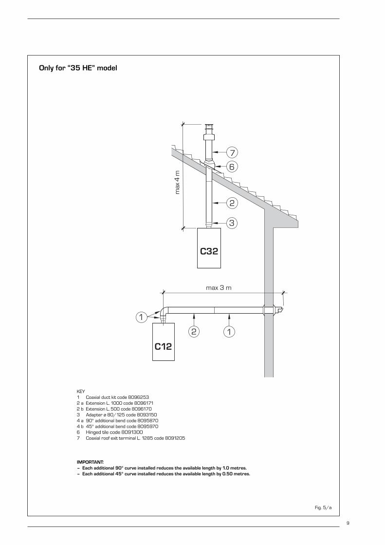
2.6 COAXIAL DUCT ø 80/125(only for “35 HE” model)
The air inlet-smoke outlet assembly ø80/125 is supplied in a kit code 8096253complete with mounting instructions.With the pipe bend included in the kit, themaximum length of the piping should notexceed 3.0 meter.The diagrams in fig. 7/a illustrate a num-ber of examples of different coaxial outletsø 80/125.
Fig. 5
KEY1a-b Coaxial duct kit code 80962502 Extension L. 1000 code 80961503 Vertical extension L. 140
with take-off point code 80869504 a 90° additional bend code 80958504 b 45° additional bend code 8095950
max 3.0 m
NOTE: Place the duct horizontally.
NOTE: Before instal-l ing accessories,lubricate the internalpart of gaskets withsi l icon-based pro-ducts. Avoid usingoils and greases.
IMPORTANT: – Each additional 90° curve installed reduces
the available length by 1.0 metres.– Each additional 45° curve installed reduces
the available length by 0.50 metres.
ONLY FOR “25 HE” MODEL
Fig. 4/a
8
Only for “25-30 HE” models
9
C12
C32
C42
2
7
64
1
2
max
4 m
3
x
y
x + y = max 3 m
3
2
1
max 3 m
Fig. 5/a
KEY1 Coaxial duct kit code 80962532 a Extension L. 1000 code 80961712 b Extension L. 500 code 80961703 Adapter ø 80/125 code 80931504 a 90° additional bend code 80958704 b 45° additional bend code 80959706 Hinged tile code 80913007 Coaxial roof exit terminal L. 1285 code 8091205
IMPORTANT: – Each additional 90° curve installed reduces the available length by 1.0 metres.– Each additional 45° curve installed reduces the available length by 0.50 metres.
Only for “35 HE” model

2.7 POSITIONING THE OUTLET TERMINALS
The outlet terminals for forced-draughtappliances may be located in the external
perimeter walls of the building.To provide some indications of possible solu-tions, Table 3 gives the minimum distancesto be observed, with reference to the typeof building shown in fig. 6.
2.8 SEPARATE PIPES ø 80(Optional alternative twin pipe system)
A special kit may be used to separate the
10
Terminal position Minimum spacingA Directly below an openable window, air vent
or any other ventilation opening 300 mm 12 inB Below guttering, drain pipes or soil pipes 75 mm 3 inC/D Below eaves, balconies or carport roof 200 mm 8 inE From vertical drain pipes or soil pipes 75 mm 3 inF From internal or external corners 300 mm 12 inG Above adjacent ground, roof or balcony level 300 mm 12 inH From a surface facing the terminal 600 mm 24 inI From a terminal facing the terminal 1,200 mm 48 inJ From an opening in the carport
(eg door, window into dwelling) 1,200 mm 48 inK Vertically from a terminal on the same wall 1,500 mm 60 inL Horizontally from a terminal on the same wall 300 mm 12 inM Horizontally from a vertical terminal to a wall 300 mm 12 inN Horizontally from an openable window or other opening 300 mm 12 inP Above an openable window or other opening 300 mm 12 in
TABLE 3
– If the terminal discharges into a pathway or passageway check that combus-tion products will not cause nuisance and that the terminal will not obstructthe passageway.
– Where the lowest part of the terminal is fitted less than 2 m (78 in) aboveground, above a balcony or above a flat roof to which people have access, theterminal MUST be protected by a purpose designed guard. Terminal guardsare available from Quinnell, Barrett, and Quinnell, Old Kent Road, London. Statemodel C2, (G.C. Part No 382946).
– Where the terminal is fitted within 850 mm (34 in) of a plastic or painted gut-ter, or 450 mm (18 in) of painted eaves, an aluminium shield at least 1,500mm (59 in) long must be fitted to the underside of the painted surface.
– The air inlet/outlet flue duct MUST NOT be closer than 25 mm (1 in) to com-bustible material.
– In certain weather conditions the terminal may emit a plume of steam. This isnormal but positions where this would cause a nuisance should be avoided.
Fig. 6

11
flue gas outlet from the fresh air intake (fig.7).
The maximum overall length of the intakeand exhaust ducts depends on the headlosses of the single fittings installed(excluding the doublers) and must not begreater than 9.0 mm H2O (“25 HE”model) - 7.0 mm H2O (“30 HE” model) and4.0 mm H2O (“35 HE” model).
For head losses in the fittings, refer to Table4.
NOTE: To use only special accessories forcondensing boilers.
2.8.1 Separate pipe accessories
Kit code 8089912 is supplied for this pur-pose (fig. 8).
2.9 ELECTRICAL CONNECTION
The boiler is supplied with an electric cable.Should this require replacement, it must bepurchased exclusively from SIME. The electric power supply to the boiler mustbe 230V - 50Hz single-phase through afused main switch, with at least 3 mm spac-ing between contacts. Respect the L and N polarities and theearth connection.
NOTE: SIME declines all responsibility forinjury or damage to persons, animals orproperty, resulting from the failure to pro-vide for proper earthing of the appliance.
2.9.1 Electrical board (fig. 12)
Before performing any kind of operation,
disconnect the unit from the power supply
using the bipolar switch of the plant.
Placing the boiler selector in position “OFF”
does not disconnect the electric board
from the power supply.
Remove the three screws (9) fixing the con-
trol board, and pull forward the panel until it
tilts downwards. In order to gain access to
the electrical board components, unscrew
the four screws fixing the control panel
cover.
2.9.2 Room thermostat (fig. 12)
After having removed the jumper, connectelectrically the room thermostat to termi-nals 1-2 of the junction box (8).
In order to have better room comfort andtemperature control, we suggest you touse a room thermostat belonging toClass I I , as specif ied by standardEN60730.1 (clean contact).
KEY1 Gasket ø 125/952 Fixing screw3 Flue outlet flange4 Inlet air diaphragm
115
ø 8
0
ø 8
011
0
165
25
5
100245
Fig. 7
TABLE 4
Accessories ø 80 Head loss (mm H2O) “25 HE” model Head loss (mm H2O) “30/35 HE” model
Inlet Outlet Roof outlet Inlet Outlet Roof outlet
90° elbow MF 0.30 0.40 – 0.30 0.45 –45° elbow MF 0.20 0.30 – 0.20 0.35 –Extension L. 1000 (horizontal) 0.20 0.30 – 0.20 0.35 –Extension L. 1000 (vertical) 0.30 0.20 – 0.30 0.25 –Outlet terminal – 0.30 – – 0.35 –Inlet terminal 0.10 – – 0.10 – –Doubler fitting 0.20 – – 0.30 – –Roof outlet terminal L. 1381 – – 0.50 – – 0.55
1
2
3
4
N° segments Total load loss mm H2Oto remove “25 HE” model
- 0 ÷ 2,0n° 1 2,0 ÷ 3,0
da n° 1 a 3 3,0 ÷ 4,0da n° 1 a 4 4,0 ÷ 5,0da n° 1 a 5 5,0 ÷ 6,0da n° 1 a 7 6,0 ÷ 7,0da n° 1 a 9 7,0 ÷ 8,0
without diaphragm 8,0 ÷ 9,0
Fig. 8
N° segments Total load loss mm H2Oto remove “30 HE” modeln° 1 e 2 0 ÷ 2,0
da n° 1 a 3 2,0 ÷ 3,0da n° 1 a 4 3,0 ÷ 4,0da n° 1 a 6 4,0 ÷ 5,0da n° 1 a 8 5,0 ÷ 6,0
without diaphragm 6,0 ÷ 7,0
N° segments Total load loss mm H2Oto remove “35 HE” model
da n° 1 a 8 0 ÷ 1,0da n° 1 a 9 1,0 ÷ 2,0
da n° 1 a 10 2,0 ÷ 3,0without diaphragm 3,0 ÷ 4,0

12
8
1 2 5
46 7
9
Fig. 12
ATTENTION: After having removed the three screws (9) tiltthe panel downwards to gain access.
KEY1 Thermohydrometer2 Time programmer (optional)4 Main PCB5 Earth faston6 Control panel protection7 Cover (TA)8 Connector (TA)9 Fixing screw
IMPORTANT Before performing any kind of operation, disconnect the unit from the power supply using the bipolar switch of the plant.
Placing the boiler selector in position “OFF” does not disconnect the electric board from the power supply.

13
JUMPERS
JP4CN1CN6 (cód. 6299987)
CN7 (cód. 6299924)
CN2 (cód. 6299988)
WHITE
GREY
95 °C SMOKE STAT
TERMINALBOARD
100 °C SAFETY STAT
RELAY
Fig. 13
2.9.3 ECOMFORT SYSTEM 25 HE wiring diagram
NOTE:– The room thermostat (TA) may be connected to the terminals 1.– To remote control the boiler connect an external clock to the terminals 1-2 (24 V) of the “TA” connector and set the
built-in clock to “constant” mode (see user instructions for details).
JUMPERS POSITION AND FEATURES
JUMPER POSITION AND FEATURE SUPPLY POSITIONCLOSED OPEN
JP4 - METANO/GPL Ready to function with LPG Ready to function with natural gas Open
WATER SENSOR

14
JUMPERS
JP4CN1CN6 (cód. 6299923)
CN7 (cód. 6299924)
CN2 (cód. 6299988)
95 °C SMOKE STAT
TERMINALBOARD
100 °C SAFETY STAT
Fig. 13/a
2.9.4 ECOMFORT 25 - 30 - 35 HE wiring diagram
NOTE:– The room thermostat may be connected to the terminals 15-16 (CN1) of the “TA” connector after having removed the
link.– To remote control the boiler connect an external clock to the terminals 1-2 (24 V) of the “TA” connector and set the
built-in clock to “constant” mode (see user instructions for details).
JUMPERS POSITION AND FEATURES
JUMPER POSITION AND FEATURE SUPPLY POSITIONCLOSED OPEN
JP4 - METANO/GPL Ready to function with LPG Ready to function with natural gas Open
WATER SENSOR

15
3.1 ELECTRONIC BOARD
The electronic board is manufactured incompliance with the EEC 73/23 low-volta-ge directives. It is supplied with 230V. Theelectronic components are guaranteedagainst a temperature range of 0 up to+60°C. An automatic and continuousmodulation system enables the boiler toadjust power to the various system requi-rements or the user’s needs.
3.1.1 Fault and malfunction signaling
The indicator LEDS signaling irregularand/or incorrect operation of the equip-ment are indicated in fig. 14.
3.1.2 Devices
The electronic board is equipped with thefollowing devices (fig. 15):
– Connector “JP4” (4)With the connector disconnected, theboiler is ready to function with METHANE;with the connector connected with GPL.
ATTENTION: It is essential that the opera-tions described above be carried out byauthorized technical staff.
3.2 TEMPERATURE SENSOR
Antifreeze system managed by active hea-ting NTC sensor when water temperatureis 6°C. The heating sensor works also as a
limit thermostat which switches off the bur-ner when temperature is over 90°C. When sensor (SM) is interrupted, neitherof the boiler's heating services will func-tion.
Table 5 shows the resistance values (Ω)obtained on the heating sensor as the tem-perature varies.
3 CHARACTERISTICS
Fig. 14
1
2
1045
3
78
9
Fig. 15
TABLE 5
Temperature (°C) Resistance (Ω)20 12.09030 8.31340 5.82850 4.16160 3.02170 2.22980 1.669
KEY1 Jumper JP22 Fuse (1,6 AT)3 D.H.W. potentiometer4 Connector “JP4”5 Rotay switch7 Block red led8 C.H. potentiometer9 Bi-colour led gree/orange
10 Connector “TA”
Bi-colour green led off if power is cut-off.
Bi-colour orange led: C.H. sensor (SM) fault.
Green led flashing: fan/smoke pressure switch.
Flashing orange led no water circulation.
Flashing red led indicates a problem in the line post-condenser.
Red led on, ignition blocked/safety stat /smoke stat tripped: turn the rotary switch in the position ( )
to restore functioning

16
3.3 ELECTRONIC IGNITION
Ignition and flame detection is controlled bya sole electrode located on the burner. Itguarantees maximum safety with interven-tion times, for accidental switching off orgas failure, within one second.
3.3.1 Operating cycle
Rotate the selector knob to summer or win-ter, and verify that green LED ( ) lights upto confirm the presence of voltage.The burner must be ignited within 10seconds max. However, it is possible for ignition failures tooccur, with consequent activation of “lockedout” signal:
– Gas failureThe electrode continues spark dischargefor a maximum of 10 sec. If the burnerdoes not light, the board - after a 5second ventilation stop - reactivatesdischarge for further 10 seconds. Thiscycle will be repeated 5 times, after that,the lock-out red LED will light up.
This may occur upon first ignition or afterlong periods of boiler lay-off when there isair in the pipes. It may be caused by the gas cock beingclosed or by one of the valve coils havinga break in the winding, so that the valvecannot open.
– Ignition electrode fails to sparkThe electrode continues spark dischargefor a maximum of 10 sec. If the burnerdoes not light, the board - after a 5second ventilation stop - reactivatesdischarge for further 10 seconds. Thiscycle will be repeated 5 times, after that,the lock-out red LED will light up.
This may be due to a break in the wire ofthe electrode or to the wire not properlyfastened to the ignition transformer ter-minal.The electrode itself may touch earth ormay be heavily worn out and needs repla-cing. The electronic board is defective.
When there is a sudden voltage failure, theburner shuts down immediately; when thepower supply returns, the boiler will startup again automatically.
3.4 FLOW SWITCH SAFETY VALVE
A flow switch safety valve (8 fig. 2) interve-
nes, blocking the operation of the burner ifthe boiler is without water due to the for-mation of air bubbles in the heat exchangeror if the circulator is not working correctlyor because the “Aqua Guard” heating cir-cuit filter is clogged.
3.5 SYSTEM AVAILABLE HEAD
The head available for the heating plant isshown as a function of the flow in graph infig. 16. To obtain the maximum head available tothe system, turn off the by-pass by turningthe union to the vertical position (fig. 16/a).
0 100 800700600500400300200
PORTATA (l/h)
PR
EVA
LEN
ZA
RES
IDU
A (m
bar) 500
400
100
200
300
Form
at.z
ip P
C
600
By-pass inseritoBy-pass escluso
900 1000 1100
25 30-35
25
30-35
Fig. 16
By-pass inserito
By-pass escluso
Fig. 16/a
BY-PASS ON
BY-PASS OFF
D.H.W. FLOW RATE ADJUSTER(it does not include SYSTEM 25 HE)
Flow rate (l/sec)
Ava
ilabl
e he
ad (
mba
r)
By-pass onBy-pass off
17
3.6 SMOKE PRESSURE SWITCH
The air pressure switch is factory set tothe values 42-52 Pa (“25 HE” model),52-62 Pa (“30 HE” model) and 65-75 Pa(“35 HE” model) to guarantee boiler func-tioning even with intake and flue pipes atthe maximum permitted length. The value of the signal to the pressure
switch is measured using a special instru-ment connected to the pressure intake(10-18 fig. 3).
3.7 ELECTRICITY CONNECTION FOR ZONE SYSTEMS
When installing a system of this type, use a
separate electrical line to which room ther-mostats with their local valves will be con-nected. Connect micro switches or relay contactson terminals 15-16 of the “TA” connectorof the electronic card after removing theexisting jumper (fig. 17).
L
CR1CR
Connettore "TA"
Fig. 17
L
N
TA TA1
VZ R VZ1 R1
KEYTA-TA1 Zone room statVZ-VZ1 Zone valveR-R1 Zone relayCR-CR1 Relay contact or micro zone valve
NOTE: Relays are used only if the areavalves have no microswitches.
“TA” connector

18
SIME SUPPORT THE BENCHMARK INITIATIVE
All relevant sections of the logbook must befilled in at the time of installation and there-after service information on the back pageof the logbook. Commissioning of the boileris not complete until the logbook is filled in.
4.1 FILLING THE WATER SYSTEM
– Open the flow and return valves.– Loosen the automatic air vent cap.– Open all radiator valves and system air
vents. Fill the system with water usingone of the approved methods describedin sect ion 2.3.2 to about 0.5 bargreater than the system design pres-sure. Close all air vents. Do not closethe A.A.V.
– Check the system for water soundness.– Completely drain the appliance and heat-
ing system, thoroughly flush the system,and refill the system design pressure.
– Before refillimg check and clean the Aqua-guard filter (4.9).
4.1.1 Flow Rate Adjustment
The DHW flow rate should be set using theflow rate adjuster (see fig. 16/a) to thevalue shown in section 1.3.
4.2 GAS VALVE
The boilers are equipped standard with theSIT 845 SIMGA/HONEYWELL VK 4105M/SIEMENS VGU 50 gas valve (fig. 21). The gas valve is set at two pressure values:maximum and minimum. According to thetype of gas burnt, these correspond to thevalues given in Table 6. The gas pressures at the maximum andminimum values, are factory set. Conse-quently they must not be altered. Only whenyou switch the appliance from one type ofgas supply (methane) to another (butane orpropane), it is permitted to alter the opera-ting pressure.
4.3 GAS CONVERSION
This operation must be performed byauthorised personnel using original Simecomponents.
To convert from natural gas to LPG or viceversa, perform the following operations (fig.22):– Close the gas cock.– Disassemble the burner manifold (3).– Replace the main nozzles (6) supplied in
a kit, inserting the copper washer (4).Use a ø 7 spanner to perform this ope-ration.
– Remove the “METANO/GPL” connectorlink on the card and set it in the posi-
tion corresponding to the gas to beused (4 fig. 15).
– To set the values of maximum and mini-mum gas pressure, follow the instruc-tions given in section 4.5.1.
– After have ultimated the conversion ofthe boiler, please stick onto the casingpanel the plate showing the relevant fee-ding gas which is included into the kit.
NOTE: When reassembling componentswhich you have removed, replace gasseals; test all gas connections afterassembly using soapy water or a productmade specifically for the purpose, beingsure not to use open flame.
4.5.1 Adjusting valve pressure
Set maximum and minimum pressure ongas valves as follows (fig. 22/a):– Connect the column or a manometer to
the intake downstream of the gas valve. Disconnect the valve VENT pressure testpoint tube (5 fig. 21).
– Remove the cap (1) from the modulator.– Place the hot tap water potentiometer
knob at the maximum position. – Turn on the boiler using the four-way
switch and turn on a hot water tap allthe way.
– Remember that rotating clockwise willincrease pressure while rotating anti-
4 USE AND MAINTENANCE
3
4
2
1
5
6
12
43 5
SIT 845 SIGMA HONEYWELL VK 4105M
KEY1 Modulator2 EV1-EV2 coils3 Pressure inlet upstream4 Pressure inlet downstream5 VENT pressure test point
TABLE 6
Burner Modulator Burner Modulator
Type of gas max. pressure mbar current min. pressure mbar current
25 HE 30 HE 35 HE mA 25 HE 30 HE 35 HE mA
G20 * 11.5 11.5 13.5 130 2.0 2.6 2.2 0
G30 28.5 28.3 28.2 165 4.8 6.3 4.5 0
G31 36.5 36.2 36.2 165 4.8 6.3 4.5 0
(*) Max. burner pressure is guaranteed only when the supply pressure exceeds the max. burner pressure by atleast 3 mbar.
Fig. 21
Fig. 22
KEY1 Swivel connection 1/2”2 Locknut 1/2”3 Burner manifold4 Washer ø 6.15 Burners6 Nozzle M67 Screw
WARNING: To ensure a perfect seal,always use the washer (4) suppliedin the kit when replacing nozzles,even in burner units for which it isnot specified.
12
3 4 5
SIEMENS VGU 50
19
clockwise will diminish it. – Adjust maximum pressure using the nut
(3) with a wrench to the maximum pres-sure value indicated in Table 6.
– Do not adjust minimum pressure untilyou have adjusted maximum pressure.
– Turn off the supply power to the modula-tor, and keep the hot water tap turned on.
– Lock the nut (3) in place, turn the screw/nut (2) to the minimum pressure indi-cated in Table 6.
– Turn off the boiler and turn it back onagain several times, keeping the hot watertap turned on at all times and checkingthat the maximum and minimum pressu-re values correspond to the establishedvalues; correct the settings if necessary.
– Adjust, checking that you have restoredthe power to the modulator.
– Put the pipe back on the valve VENTpressure test point.
– Remove the manometer, rememberingto tighten the screw for closing the pres-sure test point.
– Put the plastic cap (1) back on the modu-lator and seal with a drop of colouredsealant if necessary.
4.8 REMOVAL OF OUTER CASING
It is possible to completely disassemble theshell for an easy maintenance of the boileras showed in fig. 21.
4.9 CLEANING AND MAINTENANCE
Preventive maintenance and checking ofefficient operation of equipment and safetydevices must be carried out exclusively byauthorized technical personnel.
4.10 CLEANING THE C.H. WATER FILTER “AQUA GUARD” (fig. 22)
To clean the filter, close the flow/return val-ves, turn off the power to the control panel,remove the casing and empty the boilerusing the drain provided until the hydrome-ter shows “zero”. Place a container for col-lection underneath the filter, unscrew thecap and proceed to clean the filter, remo-ving impurities and limestone deposits.Check the seal o-ring before reassemblingthe cap with the filter.
1
2
Fig. 21Fig. 22
Fig. 22/a
3
2
1
KEY1 Plastic tap2 Minimum pressure adjusting nut3 Maximum pressure adjusting nut
SIT 845 SIGMA HONEYWELL VK 4105M SIEMENS VGU 50

20
4.11 CHIMNEY SWEEP FUNCTION(fig. 23)
To carry out the verification of combustionin the boiler turn the selector and stop onthe position ( ) until the green/orange ledstarts to flash intermittently.From that moment the boiler will start func-tioning in heating mode at the maximumpower, with switching off at 80°C andrestarting at 70°C.Before activating the chimney sweep func-tion make sure that the radiator valves oreventual zone valves are open.The test may be carried out also during hot-water service functioning.To do so it is enough, after having activatedthe chimney sweep function, to take somehot water from one or more cocks. Even in this condition the boiler functions atthe maximum temperature always with theprimary controlled between 80°C and 70°C.During the entire duration of the testing thehot water taps must remain open.After verifying the combustion the boilershould be switched off by placing the selec-tor on the OFF position; then return theselector to the desired function.
ATTENTION: After about 15 minutes, oronce the hot water request has been ful-filled, the chimney sweep function auto-matically deactivates.
4.12 BOILER SERVICING
4.12.1 Routine Servicing
To ensure continued efficient operation ofthe appliance, it is recommended that it ischecked and serviced at regular intervals.The frequency of service will depend on theparticular installation and conditions ofusage, but in general once a year should beadequate.It is the law that a competent person suchas a CORGi registered engineer, must carryout any service work.
4.12.2 Combustion Check
Incorporated into the flue elbow or verticaladaptor is a sampling point.The grey plastic cap should be unscrewedand the flue gas sampled using a flue gasanalyser.During the test the boiler can be operatedin “chimney sweep mode” see 4.11.The correct CO2 reading can be found insection 1.3.
4.12.3 Burner inspection
Remove the burner as described in section6.3.Inspect the burner and if necessary cleanusing a soft brush.
Check the Ignition/ionisation electrode,check the gap (4mm+/- 0.5mm)
4.12.4 Combustion Chamber
Remove any loose debris from the combu-stion chamber using a soft brush and avacuum cleaner.Take care not to damage the rear insulationpanel.
4.12.5 Condensate Trap
The condensate trap would not normallyrequire removal during service, but it can bechecked.Water should be poured into the inner flue.Great care must be taken to ensure nowater enters the outer flue.Check that the water flows freely to thedrain.Should it require removal, firstly removewire clip securing the condensate drain rub-ber pipe to the condensate trap.Remove the pipe.Remove the two screws securing the con-densate trap bracket.Clean the trap and refit in reverse order.
4.12.6 Flow Switch
The operation of the flow switch should bechecked at each service.Remove small cover retaining screw andremove the cover.When the pump is running and water isflowing around the boiler, the actuator liftsoff the microswitch.Check the operation of the actuator. Ensurethat it is free and that it lifts and returns.If necessary lubricate the pivot point of theactuator.Isolate the boiler.Drain it using the drain provided.Remove the microswitch by carefully pullingit forward off its mounting pins.Remove the screw securing the mountingplate, then pull off the plate.Pull out the actuator pin.
Lubricate the centre “O” ring.Refit the actuator ensuring that the flat sideof the round section is to the bottom.Re-assemble remaining parts. (see 4.12.6before refilling the boiler).
4.12.7 Aquaguard Filter
It is recommended that the aquaguard filteris checked at each service.See section 4.10.
Spia lampeggianteverde/arancio
2
4
5
3
Fig. 23
Bi-colour green/orange flashing led

21
If an electrical fault occurs on the appliancethe preliminary electrical system checkscontained in the British Gas MultimeterInstruction Booklet must be carried outfirst. When any service or replacement ofelectrical components which has requiredthe breaking and re-making of electricalconnections has taken place, the followingtests must be repeated:– earth continuity;– short circuit;– polarity;– resistance to earth.
5.1 EARTH CONTINUITY CHECK
Appliances must be electrically disconnect-ed, meter set on Ω (ohm) x 1 scale andadjust zero if necessary. Tests leads fromany appliance earth point (e.g. inside controlbox) see wiring diagrams (section 7) toearth pin on plug. Resistance should be lessthan 1 Ω (ohm). If the resistance is greaterthan 1 Ω (ohm) check all earth wires forcontinuity and all contacts are clean andtight. If the resistance to earth is stillgreater than 1 Ω (ohm) then this should beinvestigated futher.
5.2 SHORT CIRCUIT CHECK
Switches turned FULL ON - meter set on Ω(ohms) x 1 scale. Test leads from L to N onappliance terminal block, if meter reads 0then there is a short circuit.Meter set on Ω (ohm) x 100 scale. Repeatit with leads from L to E. If meter reads lessthan infinity (∞) there is a fault.
NOTE: Should it be found that the fuse hasfailed but no fault is indicated, a detailedcontinuity check (i.e. by disconnecting andchecking each component) is required totrace the faulty component.It is possible that a fault could occur as aresult of local burning/arcing but no faultcould be found under test. However, adetailed visual inspection should revealevidence of burning around the fault.
5.3 POLARITY CHECK
Appliance reconnected to mains supply andmeter set on 300 V ac scale. Test at appli-ance terminal block.– Test leads from L to N meter reads
approx.: 240 V ac.– Test leads from L to E “ ” meter reads
approx. 240 V ac.– Test leads from N to E “ ” meter reads
from 0 to 15 V ac.
5.4 RESISTANCE TO EARTH CHECK
Appliance must be disconnected from mainsupply and meter on Ω (ohm) x 100 scale. All switches including thermostat on testleads from L to E - if meter reads other thaninfinity (∞) there is a fault which should beisolated. A detailed continuity check is required totrace the faulty component.
IMPORTANT: These series of checks are the first elec-trical checks to be carried out during afault finding procedure. On completionof the service/fault finding task whichhas required the breaking and remakingof electrical connections then thechecks 5.1 Earth continuity, 5.3 Polarityand 5.4 Resistance to earth must berepeated.
5 FAULT FINDING

22
5.5 C.H. MODE - FAULT FINDING
Start from cold Rotary switch set to WINTER position.Room thermostat (if fitted) calling for heat and all D.H.W. taps off.C.H. thermostat set to maximum position.Clock in the on position (if fitted).
NOTE:After completing fault finding reset the room thermostat (if fitted) to the required setting. If the appliance will not function check the wiringto the clock and if necessary, replace the clock.
Is there power at the external
socket?
Make power
available
Does the pump
start?
Does the fan start?
Turn the clock in the right
position
Is fuse at mains plug OK?
Is the clock in the correct band time?
Is there voltageavailable
to the fan?
Replace the clock
Replace fuse inmains plug
Check the time clock does
his contacts open and closewhen the clock
turns?
Replacethe fan
Make it free torotate
Put a jumper on the room thermostat connection
Check thepower supply
cable
Is pump shaft free to rotate?
Is there voltageavailable
to the pump?
Replace the pump
Check pump connection
Does the boilerlock-out without
starting theburner?
The boilerlock-outstarting
the burner
Is there a sparkat the ignition
electrode?
Is the ionizationprobe connectedto the main PCBand the ground?
Check thegas supply
Check for continu-ity between ignitionelectrode and igni-tion transformer
The gap betweenignition electrode
and hoodis correct?
Fit correctly theignition electrode
Is the gasavailable?
Check theconnection of
the gas valve onthe control board
PCB
Is there voltage atthe gas valve?
Replace thegas valve
Yes
No
Is there a jumperon the room thermostat connection?
No
Yes
No
YesNo
Yes Yes
Yes
Yes
No
Yes
No
Yes
YesYes
No
No
Yes
YesYes
No
No
Yes
No
No
No
No
Yes
No
Verify that thesafety and fumethermostats are
working correctly?
Replace the thermostats
No
Is the connection ofthe fume and
safety thermostats
correct?
Reset the connection
No
Yes
Restore theconnection
Verify that thesafety and fumethermostats are
working correctly?
No
Yes
YesCheck the
connection of the thermostats
Replace the thermostats
No
Yes

23
5.6 D.H.W. MODE - FAULT FINDING
Start from cold - rotary switch set to SUMMER position, D.H.W. thermostat set to maximum, and all D.H.W. taps OFF.
Is there power at the external
socket?
Make power
available
Open any tap.Is there an
adequate flowrate of D.H.W.
available?
Does themicroswitch of the
divertor valveoperate correctly?
Does the fan start?
Is fuses at mains plug OK?
Clean or replacethe divertor valve
Is there voltageavailable
to the fan?
Replace fuses inmains plug
Does the pump
start?
Replacethe fan
Make it free torotate
Replace themicrointerruptor
Check thepower supply
cable
Is pump shaft free to rotate?
Check pumpconnection
Replace the pump
Does the boilerlock-out without
starting theburner?
The boilerlock-outstarting
the burner
Is there a sparkat the ignition
electrode?
Is the ionizationprobe connectedto the main PCBand the ground?
Check thegas supply
Check for continu-ity between ignitionelectrode and igni-tion transformer
The gap betweenignition electrode
and hoodis correct?
Fit correctly theignition electrode
Is the gasavailable?
Restore theconnection
Check theconnection of gas valve on
the control boardPCB
Is there voltage atthe gas valve?
Replace thegas valve
Yes
No
No
Yes
No
No
YesNo
Yes Yes
Yes
Yes
Yes No
YesNo
No
Yes
Yes
No
Yes
No
No
No
Is there voltageavailable
to the pump?
No
Yes
Yes
No
Yes
Yes
Verify that thesafety and fumethermostats are
working correctly?
Replace the thermostats
No
Is the connection ofthe fume and
safety thermostats
correct?
Reset the connection
No
Yes Yes No
Verify that thesafety and fumethermostats are
working correctly?
YesCheck the
connection of the thermostats
Replace the thermostats
No

24
Note: Use silicone grease to ease the fit-ting of any push fit connections.
6.1 Expansion Vessel
– Isolate power supply– Remove boiler cover– Isolate flow and return valves– Drain boiler using fitted drain vent– Disconnect expansion pipe– Remove expansion vessel securing nut– Remove vessel– Check new vessel for correct pressure
1- 1.25 bar– Refit in reverse order
6.2 Ignition/Ionisation electrode
– Isolate power supply– Remove boiler cover– Remove sealed chamber cover– Remove PCB cover– Disconnect ignition lead– Carefully remove lead through PCB
cover and burner compartment– Remove electrode fixing screw and
remove electrode from burner– Replace in reverse order
6.3 Main Burner
– Isolate power supply– Isolate gas supply– Remove boiler cover– Remove sealed chamber cover– Remove burner cover– Disconnect gas connection to burner– Remove locknut securing burner assem-
bly– Remove ignition/ionisation electrode– Carefully lift out burner assembly– Refit in reverse order– Test for gas soundness
6.4 Fan assembly
– Isolate power supply– Remove boiler cover– Remove sealed chamber cover– Disconnect wiring to fan– Remove two fan fixing screws– Carefully pull fan forward and to the
right to disconnect fan from post con-denser
– Remove air pressure switch sensingtube
– Apply light coating of silicone grease tonozzle of new fan
– Refit in reverse order
6.5 Main Heat Exchanger
– Isolate power supply– Isolate gas supply– Isolate flow and return valves
– Drain boiler using drain vent– Remove fan assembly as described in
6.4– Remove 4 screws and remove fan
mount ing plate– Disconnect thermistor (SM sensor)– Disconnect flow and return connections– Lift out heat exchanger– Refit in reverse order
6.6 95°C Limit stat
– Isolate power supply– Remove boiler cover– Remove sealed chamber cover– Remove fan as described in 6.4– Remove wires from 95°C stat– Remove stat fixing screws– Apply heat sink compound to new stat– Refit in reverse order
6.7 Air Pressure Switch
– Isolate power supply– Remove boiler cover– Remove sealed chamber cover– Remove screws securing air pressure
switch– Note position of wires before removal– Note position of sensing tube before
removal– Refit in reverse order
6.8 100°C Safety Stat
– Isolate power supply– Remove boiler cover– Disconnect 100°C safety stat– Remove fixing screws– Refit in reverse order
6.9 Thermistor (SM sensor)
– Isolate power supply– Remove boiler cover– Remove sealed chamber cover– Isolate flow and return valves– Drain boiler using drain vent– Disconnect thermistor– Unscrew thermistor (catch any water
lost)– Refit in reverse
6.10 Gas Valve
– Isolate power supply– Isolate gas supply– Remove boiler cover– Disconnect wiring from gas valve– Disconnect sensing tube– Remove gas valve – Refit in reverse order ensuring seals are
replaced as required– Recommission boiler and adjust gas
pressures as described in section 4.5.1
– Check for gas soundness
6.11 Circuit Board (PCB)
– Isolate power supply– Remove screws securing control panel– Lower panel to horizontal position– Remove PCB cover– Disconnect all wiring– Remove control knobs– Remove PCB fixing screws– Transfer trimmer spindles to new board– Ensure PCB links are matched to old
board– Refit in reverse order– Recommission boiler
6.12 Pump Motor
– Isolate power supply– Remove boiler cover– Isolate flow and return valves– Drain boiler using drain vent– Remove plug connection– Remove 4 x fixing screws, catch any lost
water– Refit in reverse using new washers
6.13 Diverter Valve Microswitch
– Isolate power supply– Remove boiler cover– Pull microswitch assembly forward off
the diverter valve head – Refit in reverse order
6.14 Domestic Hot Water Heat exchanger
– Isolate power supply– Isolate flow and return– Turn on DHW tap– Close cold water supply isolation valve– Drain boiler using drain vent– Remove diverter valve microswitch as
described in 6.13– Remove microswitch actuator from top
of diverter valve– Remove 3 x heat exchanger fixing
screws – Remove plate heat exchanger, catch any
water lost– Ensure that the four “O” rings are remo-
ved from the technil assembly– Fit the new “O” ring supplied with the
new heat exchanger to the heat exchan-ger
– Refit in reverse order
6.15 Diverter Valve
– Remove Diverter valve microswitch asdescribed in 6.13
– Remove plate heat exchanger as descri-bed in 6.14
6 REPLACEMENT OF PARTS

25
– Remove the securing clip at retainingthe plug at the LHS of diverter assemblyNOTE: a internal spring will push off theplug. Retain
– Remove internal bush from spindle– Remove diverter valve head securing
clip– Pull diverter valve head from assembly– Remove spindle from assembly comple-
te with bush and spacer– Replace in reverse order replacing “O”
rings as required
6.16 Auto Air Vent (AAV)
– Isolate power supply– Isolate flow and return valves– Remove boiler cover– Drain boiler using drain vent
– Remove AAV– Replace in reverse order
6.17 Safety Valve
– Isolate power supply– Isolate flow and return valves– Remove boiler cover– Drain boiler using drain vent– Disconnect pipe from safety valve– Remove safety valve securing clip– Remove safety valve, catch any water
lost– Refit in reverse
6.18 Pressure / Temperature Gauge
– Isolate power supply
– Isolate flow and return valves– Remove boiler cover– Drain boiler using drain vent– Remove the clip securing the pressure
sensor– Remove the clip securing thermometer
bulb– Carefully remove the gauge– Refit in reverse order

26
7 EXPLODED VIEWS
7.1 ECOMFORT SYSTEM 25 HE
COD. TYPE DATE PAGE3830017/388 ECOMFORT SYSTEM 25 HE 17.09.2007 1/3

27
Fon
der
ie S
ime
S.p
.A. -
Via
Ga
rbo
, 27
- 3
70
45
Leg
na
go
(V
ero
na
) - T
el. +
39
-04
42
-63
1111
- Fa
x +
39
-04
42
-63
129
2 -
ww
w.s
ime.
it
PO
SIT
ION
CO
DE
DES
CR
IPTI
ON
MO
DEL
NO
TE
CO
D.
TY
PE
DAT
EPA
GE
• R
ecom
men
ded
stoc
k pa
rts
- Co
mp
on
enti
da
ten
ere
a s
cort
a
PO
SIT
ION
CO
DE
DES
CR
IPTI
ON
MO
DEL
NO
TE
161
38
57
0S
ide
fram
e pa
rt
261
38
771
Fram
e as
sem
bly
uppe
r su
ppor
t3
62
55
43
1Ex
pans
ion
vess
el lo
wer
sup
port
4•
513
913
0Ex
pans
ion
vess
el l.
8 -
3/
8”
M
561
46
30
5B
rass
Nut
3/
8”
66
28
812
0S
eale
d ch
ambe
r re
ar p
anel
7
60
341
53
Con
dens
ate
drai
nage
pip
e8
62
57
52
1C
ombu
stio
n ch
ambe
r lo
wer
air
def
lect
or9
60
108
27
Pos
t-con
dens
er fi
bra
cket
10
63
00
80
0P
ost-c
onde
nser
116
24
88
55
P.C
. inl
et/
oule
t sm
okes
gas
ket
1261
123
20
P.C
. sm
okes
sta
t ex
tens
ion
136
22
64
43
O-R
ing
Ø 1
1,5
x 1
,5
1461
46
72
29
5°C
saf
ety
stat
156
25
75
22
Air
def
lect
or
166
28
84
30
Com
bust
ion
cham
ber
rear
pan
el
1751
90
70
0M
ain
burn
er a
ssem
bly
18•
62
35
93
1Ig
nitio
n-io
nisa
tion
elec
trod
e 19
614
63
01
Bra
ss n
ut 1
/2
”2
06
28
851
0C
ombu
st. c
ham
ber
righ
t ha
nd s
ide
pane
l2
16
28
861
0C
ombu
st. c
ham
ber
left
han
d si
de p
anel
2
261
39
77
3C
ombu
stio
n ch
ambe
r re
ar in
sula
tion
23
613
97
92
Com
bust
ion
cham
ber
side
insu
latio
n2
46
25
751
9C
omb.
cha
mbe
r ri
ght/
left
air
def
lect
or2
56
02
87
07
Air
inta
ke g
aske
t 2
66
28
80
00
Air
inta
ke2
761
742
43
Hea
t ex
chan
ger
28
•6
23
1351
Plu
nged
sen
sor
29
•6
02
20
10S
enso
r ga
sket
3
06
26
061
6S
mok
e ch
ambe
r up
per
pane
l 3
16
22
56
30
Fan
32
62
88
72
0C
ombu
stio
n ch
ambe
r fr
ont
pane
l3
361
39
78
6C
ombu
stio
n ch
ambe
r fr
ont
insu
latio
n 3
46
26
48
31
C.H
. ret
urn
pipe
35
•6
22
641
2O
-rin
g 3
06
8
36
62
26
616
Pip
e fix
ing
spri
ng3
76
22
72
10Ex
chan
ger-
post
con
dens
er in
let
pipe
3
8•
62
26
60
1S
prin
g fo
r he
at e
xcha
nger
con
nect
ion
39
20
05
20
1S
crew
“H
I-LO
” TS
P 3
x12
40
62
64
73
1C
.H. f
low
pip
e41
62
47
36
0C
ap fo
r tim
e pr
ogra
mm
er
42
20
30
22
8G
aske
t Ø
17
x24
x24
3•
614
67
01
100
°C s
afet
y st
at
44
•6
27
72
04
Wat
er t
rap
45
618
95
74W
ater
tra
p fix
ing
brac
ket
46
62
26
612
Pip
e fix
ing
doub
le s
prin
g 4
7•
60
173
10Fl
exib
le p
ipe
48
62
26
414
O-r
ing
117
Ø 1
3,1
x2,6
2 E
P8
514
92
03
02
26
Gas
ket
Ø 1
0,2
x14
,8x2
50
613
88
80
Fram
e as
sem
bly
low
er s
ide
5161
46
30
2B
rass
nut
3/
4”
52
62
26
60
7P
ipe
fixin
g sp
ring
53
60
28
70
5G
aske
t EP
70
9 fo
r D
ab5
42
00
02
01
Scr
ew M
5x4
0
55
•6
04
02
01
Pre
ssur
e re
lief v
alve
5
661
00
20
2O
give
for
pipe
Ø 1
5
57
616
84
01
Lock
ing
nut
for
pipe
Ø 1
5
58
•6
22
66
02
Pip
e fix
ing
spri
ng5
96
28
82
00
Sea
led
cham
ber
side
pan
el
60
•6
22
57
24
Air
pre
ssur
e sw
itch
52
-62
Pa
616
28
05
00
3-w
ays
junc
t. w
ith p
ress
. tes
t ni
pple
6
26
28
05
50
Cap
for
3-w
ays
junc
tion
63
614
63
03
Bra
ss N
ut 1
/8
”6
46
24
38
20
SIT
gas
val
ve t
ype
84
5 S
IGM
A6
56
22
68
50
Gas
inle
t pi
pe6
66
22
69
45
Pip
e co
nnec
ting
gas
valv
e-m
ain
burn
er
67
20
30
22
7G
aske
t Ø
12
x18
x26
86
28
98
18C
ontr
ol p
anel
6
96
27
32
10G
uide
light
- 2
way
s ou
t 7
0•
62
170
03
Tem
pera
ture
and
pre
ssur
e ga
uge
716
30
140
0M
ain
PC
B7
26
20
150
5Tr
imm
er s
pind
le Ø
6
73
62
015
02
Trim
mer
spi
ndle
Ø 6
74
22
1161
0Ea
rth
fast
on7
5•
62
69
810
Igni
tion
cabl
e7
66
28
99
00
Con
trol
pan
el p
rote
ctin
g co
ver
38
30
017
/3
88
ECO
MFO
RT
SY
STE
M 2
5 H
E17
.09
.20
07
2
/3

28
Fo
nd
eri
e S
ime
S.p
.A.
- V
ia G
arb
o,
27
- 3
70
45
Le
gn
ag
o (
Ve
ron
a)
- Te
l. +
39
-04
42
-63
1111
- F
ax
+3
9-0
44
2-6
31
29
2 -
ww
w.s
ime
.it
PO
SIT
ION
CO
DE
DES
CR
IPTI
ON
MO
DEL
NO
TE
CO
D.
T
YP
ED
ATE
PA
GE
• R
ecom
men
ded
stoc
k pa
rts
- Co
mp
on
en
ti d
a t
en
ere
a s
co
rta
PO
SIT
ION
CO
DE
DES
CR
IPTI
ON
MO
DEL
NO
TE
77
62
90
30
0C
ontr
ol p
anel
cab
le c
over
7
86
29
02
00
Roo
m s
tat
con
nec
tion
cov
er7
96
29
010
0W
hite
kno
b Ø
40
8
06
00
95
85
Con
trol
pan
el b
rack
et
81
•6
1314
01
Mic
rosw
itch
for
flow
me
ter
82
60
09
55
7R
elay
fix
ing
brac
ket
83
62
47
32
6C
ap f
or k
nob
hole
8
46
29
00
14Fl
ap d
oor
85
62
26
60
5Fi
spr
ing
86
20
5110
0R
eta
inin
g sp
ring
87
62
88
310
Sea
led
cham
ber
fron
t pa
nel
88
60
012
10P
eeph
ole
89
62
87
33
1C
asin
g9
02
013
30
2Fa
sten
er f
or s
elf
tapp
ing
scre
w
91
20
04
510
Scr
ew 8
Px7
/8
” 9
26
112
42
0C
ontr
ol p
anel
scr
ew
93
•6
02
86
24
Air
dia
phra
gm Ø
87.
59
46
154
40
2M
ain
burn
er n
ozzl
e N
P 1
30
nat
ural
gas
9
4A
615
441
0M
ain
burn
er n
ozzl
e N
P 7
7 G
LP9
56
177
50
5B
all c
ock
3/
4”
x 2
2
96
60
22
00
4C
oppe
r w
ashe
r Ø
6
97
617
75
30
Gas
coc
k 3
/4
” F
x 15
98
615
76
02
Pre
ssur
e re
lief
valv
e dr
ain
pip
e9
9•
519
26
00
Dab
VA
55
pum
p ki
t 10
06
28
152
1Fl
ange
+ O
R f
or D
ab p
ump
101
519
22
00
Gas
ket
for
seal
ed c
ham
ber
102
62
63
912
Fan
pres
sure
tes
t po
int
103
•6
149
30
3Fl
ow w
ater
sw
itch
104
62
27
52
0P
ipe
con
nec
ting
wat
er f
low
sw
itch
105
•6
190
40
3R
elay
Om
ron
G2
R-1
-T
106
22
110
04
Term
inal
str
ip10
76
29
03
50
Term
inal
str
ip p
rote
ctio
n c
over
10
8•
60
172
10M
anua
l air
ven
t 1
/4
”10
9•
60
1310
1A
utom
atic
air
ven
t11
06
29
69
16B
y-pa
ss
111
62
815
00
Str
aigh
t fit
ting
3/
4”
518
48
18Fi
ttin
g co
cks
kit
518
73
70
Tech
nyl h
ydra
ulic
gro
up
519
118
5C
ompl
ete
con
trol
pan
el6
03
120
6M
ain
cabl
e L=
20
00
6
29
99
24
6 p
ole
Sto
cko
conn
ecto
r C
N7
6
29
99
87
14 p
ole
Lum
berg
cab
le c
onne
cto
62
99
98
84
pol
e Lu
mbe
rg c
able
con
nect
or51
44
719
L.P.
G. c
onve
rsio
n k
it
Pro
duct
s re
fere
nce:
810
40
10: E
com
roft
sys
tem
25
HE
Che
ck t
he c
orre
spon
denc
e w
ith
the
boile
r da
ta p
late
.
38
30
01
7/
38
8E
CO
MF
OR
T S
YS
TE
M 2
5 H
E1
7.0
9.2
00
73
/3

29
7.2 ECOMFORT 25-30-35 HE
COD. TYPE DATE PAGE3830008/394 ECOMFORT 25-30-35 HE 10.09.2007 1/3

30
Fon
der
ie S
ime
S.p
.A. -
Via
Ga
rbo
, 27
- 3
70
45
Leg
na
go
(V
ero
na
) - T
el. +
39
-04
42
-63
1111
- Fa
x +
39
-04
42
-63
129
2 -
ww
w.s
ime.
it
PO
SIT
ION
CO
DE
DES
CR
IPTI
ON
MO
DEL
NO
TE
CO
D.
TY
PE
DAT
EPA
GE
• R
ecom
men
ded
stoc
k pa
rts
- Co
mp
on
enti
da
ten
ere
a s
cort
a
PO
SIT
ION
CO
DE
DES
CR
IPTI
ON
MO
DEL
NO
TE
161
38
57
0S
ide
fram
e pa
rt
261
38
771
Fram
e as
sem
bly
uppe
r su
ppor
t3
62
55
43
1Ex
pans
ion
vess
el lo
wer
sup
port
4•
513
913
0Ex
pans
ion
vess
el l.
8 -
3/
8”
M
561
46
30
5B
rass
Nut
3/
8”
66
28
812
0S
eale
d ch
ambe
r re
ar p
anel
7
60
341
53
Con
dens
ate
drai
nage
pip
e8
62
57
52
1C
ombu
stio
n ch
ambe
r lo
wer
air
def
lect
or9
60
108
27
Pos
t-con
dens
er fi
bra
cket
10
63
00
80
0P
ost-c
onde
nser
116
24
88
55
P.C
. inl
et/
oule
t sm
okes
gas
ket
1261
123
20
P.C
. sm
okes
sta
t ex
tens
ion
136
22
64
43
O-R
ing
Ø 1
1,5
x 1
,5
1461
46
72
29
5°C
saf
ety
stat
25
-30
14A
614
67
01
100
°C s
afet
y st
at3
515
62
57
52
2A
ir d
efle
ctor
16
62
88
43
0C
ombu
stio
n ch
ambe
r re
ar p
anel
17
519
07
52
Mai
n bu
rner
ass
embl
y3
0
17A
519
07
00
Mai
n bu
rner
ass
embl
y2
5
17B
519
07
60
Mai
n bu
rner
ass
embl
y3
5
18•
62
35
93
1Ig
nitio
n-io
nisa
tion
elec
trod
e 19
614
63
01
Bra
ss n
ut 1
/2
”2
06
28
851
0C
ombu
st. c
ham
ber
righ
t ha
nd s
ide
pane
l2
5-3
02
0A
62
88
511
Com
bust
. cha
mbe
r ri
ght
hand
sid
e pa
nel
35
2
16
28
861
0C
ombu
st. c
ham
ber
left
han
d si
de p
anel
2
5-3
02
1A
62
88
611
Com
bust
. cha
mbe
r le
ft h
and
side
pan
el
35
2
261
39
77
3C
ombu
stio
n ch
ambe
r re
ar in
sula
tion
23
613
97
92
Com
bust
ion
cham
ber
side
insu
latio
n2
46
25
751
9C
omb.
cha
mbe
r ri
ght/
left
air
def
lect
or2
56
02
87
07
Air
inta
ke g
aske
t 2
66
28
80
00
Air
inta
ke2
761
742
43
Hea
t ex
chan
ger
28
•6
23
1351
Plu
nged
sen
sor
29
•6
02
20
10S
enso
r ga
sket
3
06
26
061
6S
mok
e ch
ambe
r up
per
pane
l 3
16
22
56
30
Fan
32
62
88
72
0C
ombu
stio
n ch
ambe
r fr
ont
pane
l3
361
39
78
6C
ombu
stio
n ch
ambe
r fr
ont
insu
latio
n
34
62
64
83
1C
.H. r
etur
n pi
pe3
5•
62
26
412
O-r
ing
30
68
3
66
22
661
6P
ipe
fixin
g sp
ring
37
62
27
210
Exch
ange
r-po
st c
onde
nser
inle
t pi
pe
38
•6
22
66
01
Spr
ing
for
heat
exc
hang
er c
onne
ctio
n3
96
26
474
6P
ipe
conn
. C.H
. filt
er-C
.H. e
xcha
nger
4
06
26
474
8C
.H. f
low
pip
e41
•6
29
55
00
C.H
. filt
er 3
/4
”M x
3/
4”M
4
22
03
02
28
Gas
ket
Ø 1
7x2
4x2
43
•61
46
70
110
0°C
saf
ety
stat
4
4•
62
77
20
4W
ater
tra
p4
561
89
574
Wat
er t
rap
fixin
g br
acke
t 4
66
22
661
2P
ipe
fixin
g do
uble
spr
ing
47
•6
017
310
Flex
ible
pip
e 4
86
22
641
4O
-rin
g 11
7 Ø
13
,1x2
,62
EP
851
49
20
30
22
6G
aske
t Ø
10
,2x1
4,8
x25
061
38
88
0Fr
ame
asse
mbl
y lo
wer
sid
e 51
614
63
02
Bra
ss n
ut 3
/4
”5
26
22
66
07
Pip
e fix
ing
spri
ng5
36
02
87
05
Gas
ket
EP7
09
for
Dab
54
20
00
20
1S
crew
M5
x40
5
5•
60
40
20
1P
ress
ure
relie
f val
ve
56
610
02
02
Ogi
ve fo
r pi
pe Ø
15
5
761
68
40
1Lo
ckin
g nu
t fo
r pi
pe Ø
15
5
8•
62
26
60
2P
ipe
fixin
g sp
ring
59
62
88
20
0S
eale
d ch
ambe
r si
de p
anel
6
0•
62
25
715
Air
pre
ssur
e sw
itch
30
6
0A
•6
22
57
24
Air
pre
ssur
e sw
itch
52
-62
Pa
25
6
0B
•6
22
571
3A
ir p
ress
ure
switc
h 3
5
616
28
05
00
3-w
ays
junc
t. w
ith p
ress
. tes
t ni
pple
6
26
28
05
50
Cap
for
3-w
ays
junc
tion
63
614
63
03
Bra
ss N
ut 1
/8
”6
46
24
38
20
SIT
gas
val
ve t
ype
84
5 S
IGM
A6
56
22
68
50
Gas
inle
t pi
pe6
66
22
69
45
Pip
e co
nnec
ting
gas
valv
e-m
ain
burn
er
67
20
30
22
7G
aske
t Ø
12
x18
x26
86
28
98
17C
ontr
ol p
anel
6
96
27
32
10G
uide
light
- 2
way
s ou
t
38
30
00
8/
39
4EC
OM
FOR
T2
5-3
0-3
5 H
E1
0.0
9.2
00
7
2/
3

31
Fon
der
ie S
ime
S.p
.A. -
Via
Ga
rbo
, 27
- 3
70
45
Leg
na
go
(V
ero
na
) - T
el. +
39
-04
42
-63
1111
- Fa
x +
39
-04
42
-63
129
2 -
ww
w.s
ime.
it
PO
SIT
ION
CO
DE
DES
CR
IPTI
ON
MO
DEL
NO
TE
CO
D.
TY
PE
DAT
EPA
GE
• R
ecom
men
ded
stoc
k pa
rts
- Co
mp
on
enti
da
ten
ere
a s
cort
a
PO
SIT
ION
CO
DE
DES
CR
IPTI
ON
MO
DEL
NO
TE
70
•6
217
00
5Te
mpe
ratu
re a
nd p
ress
ure
gaug
e71
63
014
00
Mai
n P
CB
72
62
015
05
Trim
mer
spi
ndle
Ø 6
7
36
20
150
2Tr
imm
er s
pind
le Ø
6
742
211
610
Eart
h fa
ston
75
•6
26
98
10Ig
nitio
n ca
ble
76
62
89
90
0C
ontr
ol p
anel
pro
tect
ing
cove
r7
76
29
03
00
Con
trol
pan
el c
able
cov
er
78
62
90
20
0R
oom
sta
t co
nnec
tion
cove
r7
96
29
010
0W
hite
kno
b Ø
40
8
06
00
95
85
Con
trol
pan
el b
rack
et
81
•61
314
01
Mic
rosw
itch
for
flow
met
er
82
519
190
0D
iver
tor
valv
e m
icro
switc
h +
sup
port
84
62
90
014
Flap
doo
r 8
56
22
66
05
Fixi
ng s
prin
g 8
62
051
100
Ret
aini
ng s
prin
g8
76
28
83
10S
eale
d ch
ambe
r fr
ont
pane
l8
86
00
1210
Pee
phol
e8
96
28
73
31
Cas
ing
90
20
133
02
Fast
ener
for
self
tapp
ing
scre
w
91
20
04
510
Scr
ew 8
Px7
/8
” 9
261
124
20
Con
trol
pan
el s
crew
9
3•
60
28
62
4A
ir d
iaph
ragm
Ø 8
7.5
25
-30
94
614
23
30
Qua
rter
ben
d 1
/2
” x
159
561
77
50
5B
all c
ock
3/
4”
x 2
2
96
617
75
06
Bal
l coc
k 1
/2
” x
15
97
617
75
30
Gas
coc
k 3
/4
” F
x 15
98
615
76
02
Pre
ssur
e re
lief v
alve
dra
in p
ipe
99
•51
92
60
1D
ab V
A6
5 c
ircu
latin
g pu
mp
kit
30
-35
99
A•
519
26
00
Dab
VA
55
pum
p ki
t 2
5
100
62
815
21
Flan
ge +
OR
for
Dab
pum
p10
151
92
20
0G
aske
t fo
r se
aled
cha
mbe
r 10
26
26
39
12Fa
n pr
essu
re t
est
poin
t 10
36
22
64
29
O-r
ing
121
104
•6
013
101
Aut
omat
ic a
ir v
ent
105
•6
28
152
214
pla
te h
eat
exch
ange
r ki
t 2
5-3
010
5A
•6
28
152
516
pla
te h
eat
exch
ange
r ki
t 3
5
106
•6
22
64
21
O-r
ing
Dal
mar
R12
107
62
815
00
Str
aigh
t fit
ting
3/
4”
108
62
815
01
Str
aigh
t fit
ting
1/
2”
109
•6
017
210
Man
ual a
ir v
ent
1/
4”
110
•6
28
150
2Fl
ow w
ater
sw
itch
spar
e pa
rts
111
•6
28
150
4D
iver
tor
valv
e11
26
28
1512
Wat
er r
ate
adju
ster
11
36
02
20
04
Cop
per
was
her
Ø 6
11
461
54
40
2M
ain
burn
er n
ozzl
e N
P 1
30
nat
ural
gas
11
4A
615
441
0M
ain
burn
er n
ozzl
e N
P 7
7 G
LP2
5-3
011
4B
615
44
06
Mai
n bu
rner
noz
zle
NP
0,8
03
5
115
62
47
36
0C
ap fo
r tim
e pr
ogra
mm
er
116
20
05
20
1S
crew
“H
I-LO
” TS
P 3
x12
518
73
23
Tech
nyl h
ydra
ulic
gro
up
25
-30
519
118
0C
ompl
ete
cont
rol p
anel
612
72
10M
ain
cabl
e L=
20
00
6
29
99
23
14 p
ole
Lum
berg
cab
le c
onne
ctor
CN
6
62
99
92
46
pol
e S
tock
o co
nnec
tor
CN
7
62
99
92
54
pol
e Lu
mbe
rg c
able
con
nect
or fo
r tim
e cl
ock
25
-30
62
99
98
84
pol
e Lu
mbe
rg c
able
con
nect
or•
62
33
50
6Fu
se T
1,6
A 2
50
V
62
815
23
C.H
. Tec
hnyl
man
ifold
6
28
152
4D
.H.W
. Tec
hnyl
man
ifold
8
08
56
06
90
°el
bow
with
tak
e-of
f poi
nts
25
-30
810
211
0G
aske
t an
d fla
nge
kit
25
-30
62
89
58
0C
able
+ e
lect
rode
P.C
. res
ista
nce
518
48
17Fi
ttin
g co
cks
kit
•51
44
716
Con
vers
ion
kit
to L
PG
3
5
518
73
25
Tech
nyl h
ydra
ulic
gro
up
35
51
44
719
Con
vers
ion
kit
to L
PG
25
-30
Pro
duct
s re
fere
nce:
810
40
02
: Eco
mfo
rt 3
0 H
E 8
104
00
3: E
com
fort
25
HE
8
104
00
5: E
com
fort
35
HE
Che
ck t
he c
orre
spon
denc
e w
ith t
he b
oile
r da
ta p
late
.
38
30
00
8/
39
4EC
OM
FOR
T2
5-3
0-3
5 H
E1
0.0
9.2
00
73
/3

Cod
. 62
72
27
2C
- 0
9/
07
- D
ocum
enta
tion
Dpt
.
Sime Ltd
Unit D2 Enterprise Way, Bradford Road, Bradford, West Yorkshire, BD10 8EW
Tel. 0870 9911114 - Fax 0870 9911115
www.sime.ltd.uk - e-mail: [email protected]

Ecomfort 30 HE
User instructions
GB
PLEASE LEAVE THIS INSTRUCTION
WITH THE USER


1
OPERATING INSTRUCTIONS FOR THE USER
1.1 INTRODUCTION . . . . . . . . . . . . . . . . . . . . . . . . . . . . . . . . . . . . . . . . . . . . . . . . . . . . . . . . . . . . . . . . . . . . . . . . . . . . . . . . . 2
1.2 APPLIANCE OPERATION
1.3 OPERATING INSTRUCTIONS
1.4 MINIMUM CLEARANCES . . . . . . . . . . . . . . . . . . . . . . . . . . . . . . . . . . . . . . . . . . . . . . . . . . . . . . . . . . . . . . . . . . . . . . . . . 3
1.5 ROUTINE SERVICING
1.6 GENERAL INFORMATION
1.7 SAFETY . . . . . . . . . . . . . . . . . . . . . . . . . . . . . . . . . . . . . . . . . . . . . . . . . . . . . . . . . . . . . . . . . . . . . . . . . . . . . . . . . . . . . . . . . 4
1.8 TIMER PROGRAMMER
These appliances comply with the S.E.D.B.U.K. scheme, band “B”
CONTENTS
VERY IMPORTANT!
PLEASE MAKE SURE YOUR LOG BOOK ENCLOSED IS FILLED IN CORRECTLY.
ALL CORGI REGISTERED INSTALLERS CARRY A CORGI ID CARD.
BOTH SHOULD BE RECORDED IN YOUR CENTRAL HEATING LOG BOOK.
YOU CAN CHECK YOUR INSTALLER IS CORGI REGISTERED
BY CALLING ON 01256 372300

2
OPERATING INSTRUCTIONS FOR THE USER
Fig. 1
KEYA Temperature/pressure gaugeB Time programmerC Selector switch summer/winterD D.H.W. thermostatE C.H. thermostat
THE GAS SAFETY (INSTALLATION AND USE) REGULATIONS1996. It is the law that all gas appliances are installed by aregistered person, in accordance with the above regulations.Failure to install appliances correctly could lead to prosecu-tion. It is in your own interest, and that of safety, to ensurethat the law is complied with.It is essential that the appliance is correctly earthed. Anelectricity supply of 240 V - 50 Hz fused at 3 A is required.Read these instructions carefully before attempting to oper-ate the appliance.
1.1 INTRODUCTION
The Sime “ECOMFORT 30 HE” is a fully automatic, wallmounted, room sealed, fan assisted combination boiler. Whenoperating in winter mode, the appliance provides central heat-ing as required and produces instantaneous hot water upondemand. When operating in summer mode, the central heating is notoperational however the appliance continues to supply hotwater whenever it is required. The heat output is automati-cally controlled by the fully modulating gas valve (within its pre-set limits), and there are user adjustable potentiometers tocontrol the temperature of both central heating and domes-tic hot water. A temperature/pressure gauge is fitted and anoverheat thermostat is incorporated to protect against faultconditions.
1.2 APPLIANCE OPERATION
A demand of hot water will be sensed by the appliancedetecting water flow (providing that the flow rate is above 2l/m - 0.5 gal/min).The fan will start and the burner will light at full output. If
the draw off rate is near the maximum design flow ratethe appliance will run continuously at full output until a tapis either turned off or the flow rate is reduced in whichcase the heat output will reduce accordingly to maintain asteady temperature.Hot water is made available almost immediately at the appli-ance outlet, but the final temperature and time taken for thehot water to reach a tap depends upon the potentiometersetting, the rate at which water is drawn off, and the lengthof the pipe between the boiler and the tap. When the tap is turned off, the appliance will revert to C.H.mode (if set on winter position) otherwise the burner will beextinguished pending the next demand for hot water.
1.3 OPERATING INSTRUCTIONS
1.3.1 To light the appliance (see fig. 1)
– Check that the electricity supply is off and that the D.H.W.isolation valve is in the open position (lever vertical). Checkthat the gas supply is on.
– Turn the selector switch summer/winter (C) to SUMMER(water only) position “ ”.
– Switch on the electricity supply and full open any D.H.W.tap. The burner will light. If the burner fails to light, turn the selector switch sum-mer/winter to “ “ position and release it immediately;then turn it to the SUMMER position: the burner shouldnow light. Turn off the tap.
– Check that the room thermostat and time clock are call-ing for heat. Turn the heating potentiometer (E) to maxi-mum (fully clockwise).
– Turn the selector switch summer/winter to the WINTERposition “ " and the burner will light to serve the heating load.Set the required temperature for the C.H. and D.H.W. by
A EC
F
B D
DHWISOLATION VALVE
3
rotating the potentiometers (D - E) clockwise to increaseor anticlockwise to decrease the temperature.
NOTE: when operating in winter mode, priority is auto-matically given to providing hot water when the demandarises.
1.3.2 To turn off the appliance (see fig. 1)
– For short periods:Set the selector switch (C) to the OFF position and urn offthe DHW Isolation valve. When required, restore turn theselector switch to either the SUMMER or WINTER posi-tion and turn on the DHW Isolation valve.
– For longer periods:Set the selector switch (C) to the OFF position, turn offthe DHW Isolation valve, turn off the gas isolation cock.When required, manually rotate the pump, open the gasisolation cock, turn on the DHW Isolation valve and turnthe selector switch to either the SUMMER or WINTERposition.
NOTE: If frost protection is required-turn the selectorswitch to the summer position, do not isolate the gassupply, turn off the DHW Isolation valve.
1.4 MINIMUM CLEARANCES
The following MINIMUM CLEARANCES must be available for
servicing the appliance:
1.5 ROUTINE SERVICING
To ensure continued efficient operation of the appliance, it isrecommended that it is checked and serviced as necessary atregular intervals. The frequency of servicing will depend uponthe particular installation conditions and usage but in generalonce a year should be adequate. It is the law that any servicework must be carried out by a registerd person (C.O.R.G.I.).
1.6 GENERAL INFORMATION
1.6.1 Fault finding indicators (LEDS)
The appliance is fitted with a safety cut-out thermostat. Inthe event of overheating this will interrupt the power supplyand prevent the appliance from functioning. If this occurs,allow the appliance to cool, turn the selector switch sum-mer/winter to “ “ position, then turn it back to the previousposition (see fig. 2). If the cut-out condition is repeated, turnoff the electrical supply and consult your installer or serviceengineer.
For ventilation For servicing
ABOVE THE APPLIANCE CASING 400 mm 300 mm
AT THE R.H.S. 15 mm 15 mm
AT THE L.H.S. 15 mm 15 mm
BELOW THE APPLIANCE CASING 200 mm 200 mm
IN FRONT OF THE APPLIANCE 100 mm 500 mm
Fig. 2
Bi-colour green led off if power is cut-off.
Bi-colour orange led: C.H. sensor (SM) fault.
Green led flashing: fan/smoke pressure switch.
Flashing orange led no water circulation.
Flashing red led indicates a problem in the line post-condenser.
Red led on, ignition blocked/safety stat/smoke stat tripped: turn the rotary switch in the position ( )
to restore functioning

4
1.6.2 Temperature/pressure gauge
The gauge (A fig. 1) on the facia panel indicates the approxi-mate system pressure. The normal operating pressure isbetween 1 and 1.5 bar. If the normal running pressure isseen to decrease over a period of time there is a water leakand you should consult your installer or service engineer.
1.6.3 Electrical supply
The mains plug used must be a 3 pin type to BS1363, andfused at 3 A. THIS APPLIANCE MUST BE EARTHED.
NOTE: an interruption in the electricity supply whilst the burneris alight may cause the overheat thermostat to operate. Ifthis is suspected, turn the rotary switch to “ “ position,then turn it back to the previous position.
TO CONNECT A PLUG
As the colour of wires in the mains lead of this appliance maynot correspond with the coloured markings identifying theterminals in your plug, proceed as follows:the wire which is coloured green and yellow must be con-nected to the terminal in the plug which is marked with theletter E or by the earth symbol - or coloured green and yel-low; the wire which is coloured blue must be connected tothe terminal marked with the letter N or coloured black; thewire which is coloured brown must be connected to the ter-minal marked with the letter L or coloured red.1.6.4 Ventilation
If the appliance is installed in a cabinet, the latter MUST NOTbe used for storage purposes. Any ventilation provided forthe appliance during installation MUST NOT be blocked and aperiodic check must be made to ensure that the vents arefree from obstructions.
1.6.5 Cleaning
Use only a damp cloth and mild detergent to clean the appli-ance outer casing. DO NOT use abrasive cleaners.
1.7 SAFETY
It is essential that the instructions in this booklet are strict-ly followed for the safe and economical operation of thisappliance. The appliance functions as a fan assisted bal-anced flue unit. The flue terminal MUST NOT BE OBSTRUCT-ED under any circumstances. If damaged, turn off the appli-ance and consult the installer, service engineer, or gas suppli-
er. If it is known or suspected that a fault exists on the appli-ance it MUST NOT be used until the fault has been rectifiedby a competent person.WARNING: IF A GAS LEAK IS SUSPECTED OR EXISTS,TURN OFF THE GAS SUPPLY TO THE APPLIANCE AT THEGAS SERVICE COCK. DO NOT OPERATE ANY ELECTRICALSWITCHES. DO NOT OPERATE ANY ELECTRICAL APPLI-ANCE. OPEN ALL WINDOWS AND DOORS. DO NOTSMOKE. EXTINGUISH ALL NAKED LIGHTS. CONTACT THEGAS SUPPLIER IMMEDIATELY.
1.7 TIMER PROGRAMMER (Fig. 3)
Setting the timeThe time of day can be set by grasping the outer edge of theblack dial and turning it in a clockwise direction until the cor-rect time is in line with the white pointer.
Setting the “switching time”The “ON” periods are set by sliding the blue tappets, adjacentto the time periods required, to the outer edge of the dial.The tappets that remain at the centre of the dial will be the“OFF” periods.
N.B.: The smallest switching time (ON or OFF) is 15 minutes.
– To select “Timed” mode move the selector switch in themiddle of the clock face to the “ ” position
– To select “Constant” mode move the selector switch in themiddle of the clock face to the “I” position.
– To select “OFF” mode move the selector switch in the mid-dle of the clock face to the “O” position.
MECHANICAL 24 hr VERSION
Slide blue tappets
OUT for ON period
Slide blue tappets IN for OFF period
Mode selector switch
Fig. 3

All descriptions and illustrations provided in this manual have been carefully prepared but we reserve the right to make changesand improvements in our products that may affect the accuracy of the information contained in this manual.

Cod
. 62
72
27
3 -
03
/0
6 -
Doc
umen
tati
on D
pt.
Sime Ltd
Unit D2 Enterprise Way, Bradford Road, Bradford, West Yorkshire, BD10 8EW
Tel. 0870 9911114 - Fax 0870 9911115
www.sime.ltd.uk - e-mail: [email protected]