
SIMATIC TI505/TI500 MODNIM User Manual - … PUBLICATION HISTORY SIMATIC TI505/TI500 MODNIM User...
91
SIMA TIC TI505/TI500 MODNIM User Manual Order Number: PPX:505-8122-1 Manual Assembly Number: 2586546-0083 Original Edition
Transcript of SIMATIC TI505/TI500 MODNIM User Manual - … PUBLICATION HISTORY SIMATIC TI505/TI500 MODNIM User...

SIMATIC TI505/TI500
MODNIM
User Manual
Order Number: PPX:505-8122-1Manual Assembly Number: 2586546-0083Original Edition

01/21/92
Copyright 1993 by Siemens Industrial Automation, Inc.All Rights Reserved — Printed in USA
Reproduction, transmission or use of this document orcontents is not permitted without express consent ofSiemens Industrial Automation, Inc. All rights, including rightscreated by patent grant or registration of a utility model ordesign, are reserved.
Since Siemens Industrial Automation, Inc. does not possessfull access to data concerning all of the uses and applicationsof customer’s products, we do not assume responsibility eitherfor customer product design or for any infringements of patentsor rights of others which may result from our assistance.
Technical data is subject to change.
We check the contents of every manual for accuracy at thetime it is approved for printing; however, there may beundetected errors. Any errors found will be corrected insubsequent editions. Any suggestions for improvement arewelcomed.
MANUAL PUBLICATION HISTORY
SIMATIC TI505/TI500 MODNIM User ManualOrder Manual Number: PPX:505-8122-1
Refer to this history in all correspondence and/or discussion about this manual.
Event Date Description
Original Issue 03/93 Original Issue (2801280–0001), Software Release 3.0

LIST OF EFFECTIVE PAGES
Pages Description Pages Description
Cover/Copyright OriginalHistory/Effective Pages Originaliii — ix Original
1-1 — 1-20 Original2-1 — 2-39 OriginalA-1 — A-4 OriginalB-1 — B-2 OriginalC-1 — C-3 OriginalD-1 — D-6 OriginalIndex-1 — Index-3 Original
Registration Original
Contents iii
Contents
Preface
Chapter 1 Installation and Set-up1.1 Modbus Communications Overview 1-2. . . . . . . . . . . . . . . . . . . . . . . . . . . . . . . . . . . . . . . . . . . . .
Modbus Network Characteristics 1-2. . . . . . . . . . . . . . . . . . . . . . . . . . . . . . . . . . . . . . . . . . . . . . . . Modbus Protocol 1-2. . . . . . . . . . . . . . . . . . . . . . . . . . . . . . . . . . . . . . . . . . . . . . . . . . . . . . . . . . . . . . . Transmission Modes 1-2. . . . . . . . . . . . . . . . . . . . . . . . . . . . . . . . . . . . . . . . . . . . . . . . . . . . . . . . . . . . .
1.2 Quick Reference Installation Steps 1-4. . . . . . . . . . . . . . . . . . . . . . . . . . . . . . . . . . . . . . . . . . . . . . . General Requirements 1-4. . . . . . . . . . . . . . . . . . . . . . . . . . . . . . . . . . . . . . . . . . . . . . . . . . . . . . . . . . Procedures 1-4. . . . . . . . . . . . . . . . . . . . . . . . . . . . . . . . . . . . . . . . . . . . . . . . . . . . . . . . . . . . . . . . . . . . . Handling the Module 1-5. . . . . . . . . . . . . . . . . . . . . . . . . . . . . . . . . . . . . . . . . . . . . . . . . . . . . . . . . . . Inspecting the Module 1-5. . . . . . . . . . . . . . . . . . . . . . . . . . . . . . . . . . . . . . . . . . . . . . . . . . . . . . . . . . Getting Started with Configuration and Installation 1-5. . . . . . . . . . . . . . . . . . . . . . . . . . . . . . .
1.3 Setting the Dipswitches 1-6. . . . . . . . . . . . . . . . . . . . . . . . . . . . . . . . . . . . . . . . . . . . . . . . . . . . . . . . . . Dipswitch Functions 1-6. . . . . . . . . . . . . . . . . . . . . . . . . . . . . . . . . . . . . . . . . . . . . . . . . . . . . . . . . . . . . Setting the Network Address 1-6. . . . . . . . . . . . . . . . . . . . . . . . . . . . . . . . . . . . . . . . . . . . . . . . . . . . . Selecting Network Configuration Parameters 1-7. . . . . . . . . . . . . . . . . . . . . . . . . . . . . . . . . . . . . Data Transmission Rate 1-7. . . . . . . . . . . . . . . . . . . . . . . . . . . . . . . . . . . . . . . . . . . . . . . . . . . . . . . . . . Stopbit Selection 1-7. . . . . . . . . . . . . . . . . . . . . . . . . . . . . . . . . . . . . . . . . . . . . . . . . . . . . . . . . . . . . . . . Parity/No Parity Selection 1-7. . . . . . . . . . . . . . . . . . . . . . . . . . . . . . . . . . . . . . . . . . . . . . . . . . . . . . . . Odd/Even Parity Selection 1-7. . . . . . . . . . . . . . . . . . . . . . . . . . . . . . . . . . . . . . . . . . . . . . . . . . . . . . ASCII/RTU Mode Selection 1-7. . . . . . . . . . . . . . . . . . . . . . . . . . . . . . . . . . . . . . . . . . . . . . . . . . . . . . . RTS/CTS Handshaking 1-7. . . . . . . . . . . . . . . . . . . . . . . . . . . . . . . . . . . . . . . . . . . . . . . . . . . . . . . . . . . Y/C Coil Selection 1-7. . . . . . . . . . . . . . . . . . . . . . . . . . . . . . . . . . . . . . . . . . . . . . . . . . . . . . . . . . . . . .
1.4 Installing the MODNIM 1-10. . . . . . . . . . . . . . . . . . . . . . . . . . . . . . . . . . . . . . . . . . . . . . . . . . . . . . . . . . Installing the Series 505 MODNIM in the I/O Base 1-10. . . . . . . . . . . . . . . . . . . . . . . . . . . . . . . . . . Installing the Series 500 MODNIM in the I/O Base 1-12. . . . . . . . . . . . . . . . . . . . . . . . . . . . . . . . . .
1.5 Switches and Indicator Lights 1-14. . . . . . . . . . . . . . . . . . . . . . . . . . . . . . . . . . . . . . . . . . . . . . . . . . . . Switches and Buttons 1-14. . . . . . . . . . . . . . . . . . . . . . . . . . . . . . . . . . . . . . . . . . . . . . . . . . . . . . . . . . . Reset Button 1-14. . . . . . . . . . . . . . . . . . . . . . . . . . . . . . . . . . . . . . . . . . . . . . . . . . . . . . . . . . . . . . . . . . . . Test Button 1-14. . . . . . . . . . . . . . . . . . . . . . . . . . . . . . . . . . . . . . . . . . . . . . . . . . . . . . . . . . . . . . . . . . . . . Local/Remote Switch 1-14. . . . . . . . . . . . . . . . . . . . . . . . . . . . . . . . . . . . . . . . . . . . . . . . . . . . . . . . . . . Status Indicator Lights 1-15. . . . . . . . . . . . . . . . . . . . . . . . . . . . . . . . . . . . . . . . . . . . . . . . . . . . . . . . . . .
1.6 Diagnostic Tests 1-16. . . . . . . . . . . . . . . . . . . . . . . . . . . . . . . . . . . . . . . . . . . . . . . . . . . . . . . . . . . . . . . . . Built-in Diagnostic Tests 1-16. . . . . . . . . . . . . . . . . . . . . . . . . . . . . . . . . . . . . . . . . . . . . . . . . . . . . . . . . . Power-up Self Test 1-16. . . . . . . . . . . . . . . . . . . . . . . . . . . . . . . . . . . . . . . . . . . . . . . . . . . . . . . . . . . . . . . Run-time Self Tests 1-17. . . . . . . . . . . . . . . . . . . . . . . . . . . . . . . . . . . . . . . . . . . . . . . . . . . . . . . . . . . . . . . User-Initiated Self Test 1-18. . . . . . . . . . . . . . . . . . . . . . . . . . . . . . . . . . . . . . . . . . . . . . . . . . . . . . . . . . .

iv Contents
1.7 Establishing Communications 1-19. . . . . . . . . . . . . . . . . . . . . . . . . . . . . . . . . . . . . . . . . . . . . . . . . . . Verifying that the MODNIM is Logged into the PLC 1-19. . . . . . . . . . . . . . . . . . . . . . . . . . . . . . . . Connecting the Network Cables 1-20. . . . . . . . . . . . . . . . . . . . . . . . . . . . . . . . . . . . . . . . . . . . . . . . Recommended Communication Cables 1-20. . . . . . . . . . . . . . . . . . . . . . . . . . . . . . . . . . . . . . . . . Building a Cable 1-20. . . . . . . . . . . . . . . . . . . . . . . . . . . . . . . . . . . . . . . . . . . . . . . . . . . . . . . . . . . . . . . .
Chapter 2 Modbus Commands2.1 Modbus Protocol Overview — ASCII Transmission Mode 2-2. . . . . . . . . . . . . . . . . . . . . . . . . . .
Modbus Protocol 2-2. . . . . . . . . . . . . . . . . . . . . . . . . . . . . . . . . . . . . . . . . . . . . . . . . . . . . . . . . . . . . . . The ASCII Transmission Frame 2-2. . . . . . . . . . . . . . . . . . . . . . . . . . . . . . . . . . . . . . . . . . . . . . . . . . . . The Start Field 2-2. . . . . . . . . . . . . . . . . . . . . . . . . . . . . . . . . . . . . . . . . . . . . . . . . . . . . . . . . . . . . . . . . . . The Address Field 2-2. . . . . . . . . . . . . . . . . . . . . . . . . . . . . . . . . . . . . . . . . . . . . . . . . . . . . . . . . . . . . . . The Function Field 2-2. . . . . . . . . . . . . . . . . . . . . . . . . . . . . . . . . . . . . . . . . . . . . . . . . . . . . . . . . . . . . . . The Data Field 2-3. . . . . . . . . . . . . . . . . . . . . . . . . . . . . . . . . . . . . . . . . . . . . . . . . . . . . . . . . . . . . . . . . . The LRC Field 2-3. . . . . . . . . . . . . . . . . . . . . . . . . . . . . . . . . . . . . . . . . . . . . . . . . . . . . . . . . . . . . . . . . . . The EOF Field 2-3. . . . . . . . . . . . . . . . . . . . . . . . . . . . . . . . . . . . . . . . . . . . . . . . . . . . . . . . . . . . . . . . . . . The Ready Field 2-3. . . . . . . . . . . . . . . . . . . . . . . . . . . . . . . . . . . . . . . . . . . . . . . . . . . . . . . . . . . . . . . . .
2.2 Modbus Protocol Overview — RTU Transmission Mode 2-4. . . . . . . . . . . . . . . . . . . . . . . . . . . . . The RTU Transmission Frame 2-4. . . . . . . . . . . . . . . . . . . . . . . . . . . . . . . . . . . . . . . . . . . . . . . . . . . . . . The RTU Frame Fields 2-4. . . . . . . . . . . . . . . . . . . . . . . . . . . . . . . . . . . . . . . . . . . . . . . . . . . . . . . . . . . . Message Delineation 2-4. . . . . . . . . . . . . . . . . . . . . . . . . . . . . . . . . . . . . . . . . . . . . . . . . . . . . . . . . . . Checksum 2-5. . . . . . . . . . . . . . . . . . . . . . . . . . . . . . . . . . . . . . . . . . . . . . . . . . . . . . . . . . . . . . . . . . . . . Invalid Characters and Messages 2-5. . . . . . . . . . . . . . . . . . . . . . . . . . . . . . . . . . . . . . . . . . . . . . . .
2.3 Comparing Modbus Functions with TIWAY I Network Commands 2-6. . . . . . . . . . . . . . . . . . . Modbus Functions vs. TIWAY Commands 2-6. . . . . . . . . . . . . . . . . . . . . . . . . . . . . . . . . . . . . . . . . Addressing 2-7. . . . . . . . . . . . . . . . . . . . . . . . . . . . . . . . . . . . . . . . . . . . . . . . . . . . . . . . . . . . . . . . . . . . . Address Limits 2-7. . . . . . . . . . . . . . . . . . . . . . . . . . . . . . . . . . . . . . . . . . . . . . . . . . . . . . . . . . . . . . . . . . .
2.4 Modbus Function Descriptions 2-8. . . . . . . . . . . . . . . . . . . . . . . . . . . . . . . . . . . . . . . . . . . . . . . . . . . Introduction 2-8. . . . . . . . . . . . . . . . . . . . . . . . . . . . . . . . . . . . . . . . . . . . . . . . . . . . . . . . . . . . . . . . . . . . Code 01 — Read Coil Status 2-8. . . . . . . . . . . . . . . . . . . . . . . . . . . . . . . . . . . . . . . . . . . . . . . . . . . . Code 02 — Read Input Status 2-10. . . . . . . . . . . . . . . . . . . . . . . . . . . . . . . . . . . . . . . . . . . . . . . . . . . Code 03 — Read Output Registers 2-12. . . . . . . . . . . . . . . . . . . . . . . . . . . . . . . . . . . . . . . . . . . . . . . Code 04 — Read Input Registers 2-13. . . . . . . . . . . . . . . . . . . . . . . . . . . . . . . . . . . . . . . . . . . . . . . . . Code 05 — Write a Single Coil 2-14. . . . . . . . . . . . . . . . . . . . . . . . . . . . . . . . . . . . . . . . . . . . . . . . . . . Code 06 — Write a Single Register 2-16. . . . . . . . . . . . . . . . . . . . . . . . . . . . . . . . . . . . . . . . . . . . . . . Code 07 — Read Exception Status 2-17. . . . . . . . . . . . . . . . . . . . . . . . . . . . . . . . . . . . . . . . . . . . . . . Code 08 — Execute Diagnostics 2-19. . . . . . . . . . . . . . . . . . . . . . . . . . . . . . . . . . . . . . . . . . . . . . . . . Code 11 — Get Comms Event Counter 2-30. . . . . . . . . . . . . . . . . . . . . . . . . . . . . . . . . . . . . . . . . . Code 12 — Get Comms Event Log 2-31. . . . . . . . . . . . . . . . . . . . . . . . . . . . . . . . . . . . . . . . . . . . . . Code 15 — Write Multiple Coils 2-33. . . . . . . . . . . . . . . . . . . . . . . . . . . . . . . . . . . . . . . . . . . . . . . . . . Code 16 — Write Multiple Registers 2-35. . . . . . . . . . . . . . . . . . . . . . . . . . . . . . . . . . . . . . . . . . . . . . Code 17 — Report Slave ID 2-36. . . . . . . . . . . . . . . . . . . . . . . . . . . . . . . . . . . . . . . . . . . . . . . . . . . . . .
2.5 Error Responses 2-38. . . . . . . . . . . . . . . . . . . . . . . . . . . . . . . . . . . . . . . . . . . . . . . . . . . . . . . . . . . . . . . . .

Contents v
Appendix A Network Cable CommunicationsA.1 Network Cables A-2. . . . . . . . . . . . . . . . . . . . . . . . . . . . . . . . . . . . . . . . . . . . . . . . . . . . . . . . . . . . . . . .
Recommended Communication Cables A-2. . . . . . . . . . . . . . . . . . . . . . . . . . . . . . . . . . . . . . . . . Building Cables A-2. . . . . . . . . . . . . . . . . . . . . . . . . . . . . . . . . . . . . . . . . . . . . . . . . . . . . . . . . . . . . . . . . Cable Pinouts A-2. . . . . . . . . . . . . . . . . . . . . . . . . . . . . . . . . . . . . . . . . . . . . . . . . . . . . . . . . . . . . . . . . .
A.2 Communications Parameters A-4. . . . . . . . . . . . . . . . . . . . . . . . . . . . . . . . . . . . . . . . . . . . . . . . . . . . RS-232-C Pin Assignments A-4. . . . . . . . . . . . . . . . . . . . . . . . . . . . . . . . . . . . . . . . . . . . . . . . . . . . . . . . Recommended Communications Parameters A-4. . . . . . . . . . . . . . . . . . . . . . . . . . . . . . . . . . . .
Appendix B Exception CodesB.1 Exception Codes Supported by the MODNIM B-2. . . . . . . . . . . . . . . . . . . . . . . . . . . . . . . . . . . . .
Appendix C SpecificationsC.1 Environmental Specifications C-2. . . . . . . . . . . . . . . . . . . . . . . . . . . . . . . . . . . . . . . . . . . . . . . . . . . .
C.2 MODNIM Communications Specifications C-3. . . . . . . . . . . . . . . . . . . . . . . . . . . . . . . . . . . . . . . .
Appendix D Using the MODASST ProgramD.1 Getting Started D-2. . . . . . . . . . . . . . . . . . . . . . . . . . . . . . . . . . . . . . . . . . . . . . . . . . . . . . . . . . . . . . . . .
Overview D-2. . . . . . . . . . . . . . . . . . . . . . . . . . . . . . . . . . . . . . . . . . . . . . . . . . . . . . . . . . . . . . . . . . . . . . . Hardware Requirements D-2. . . . . . . . . . . . . . . . . . . . . . . . . . . . . . . . . . . . . . . . . . . . . . . . . . . . . . . . Running the Program from the Floppy Disk D-2. . . . . . . . . . . . . . . . . . . . . . . . . . . . . . . . . . . . . . . Running the Program from the Hard Disk D-3. . . . . . . . . . . . . . . . . . . . . . . . . . . . . . . . . . . . . . . . .
D.2 Starting Program Operation D-4. . . . . . . . . . . . . . . . . . . . . . . . . . . . . . . . . . . . . . . . . . . . . . . . . . . . . Setting the Communication Port Options D-4. . . . . . . . . . . . . . . . . . . . . . . . . . . . . . . . . . . . . . . . . Setting the Remaining Options D-4. . . . . . . . . . . . . . . . . . . . . . . . . . . . . . . . . . . . . . . . . . . . . . . . . .
D.3 Using Program Options D-5. . . . . . . . . . . . . . . . . . . . . . . . . . . . . . . . . . . . . . . . . . . . . . . . . . . . . . . . . . Setup Options D-5. . . . . . . . . . . . . . . . . . . . . . . . . . . . . . . . . . . . . . . . . . . . . . . . . . . . . . . . . . . . . . . . . . Run Diagnostics D-5. . . . . . . . . . . . . . . . . . . . . . . . . . . . . . . . . . . . . . . . . . . . . . . . . . . . . . . . . . . . . . . . . Find Module Settings D-6. . . . . . . . . . . . . . . . . . . . . . . . . . . . . . . . . . . . . . . . . . . . . . . . . . . . . . . . . . . . Talk to Module D-6. . . . . . . . . . . . . . . . . . . . . . . . . . . . . . . . . . . . . . . . . . . . . . . . . . . . . . . . . . . . . . . . . . Batch Send from File D-6. . . . . . . . . . . . . . . . . . . . . . . . . . . . . . . . . . . . . . . . . . . . . . . . . . . . . . . . . . . . Verifying Communications D-6. . . . . . . . . . . . . . . . . . . . . . . . . . . . . . . . . . . . . . . . . . . . . . . . . . . . . . .

vi Contents
List of Figures
Figure 1-1 Multidrop and Point-to-point Configurations 1-3. . . . . . . . . . . . . . . . . . . . . . . . . . . . . . . . . . Figure 1-2 Quick Reference Installation Procedures 1-4. . . . . . . . . . . . . . . . . . . . . . . . . . . . . . . . . . . . . Figure 1-3 Address Setting Examples 1-6. . . . . . . . . . . . . . . . . . . . . . . . . . . . . . . . . . . . . . . . . . . . . . . . . . . Figure 1-4 Dipswitch Settings for Network Data Transmission Rates 1-7. . . . . . . . . . . . . . . . . . . . . . . Figure 1-5 Series 505 MODNIM Switches and LEDs 1-8. . . . . . . . . . . . . . . . . . . . . . . . . . . . . . . . . . . . . . . Figure 1-6 Series 500 MODNIM Switches and LEDs 1-9. . . . . . . . . . . . . . . . . . . . . . . . . . . . . . . . . . . . . . . Figure 1-7 Installing the Series 505 MODNIM in the I/O Base 1-10. . . . . . . . . . . . . . . . . . . . . . . . . . . . . . Figure 1-8 Series 505 MODNIM Example Dipswitch Settings 1-11. . . . . . . . . . . . . . . . . . . . . . . . . . . . . . Figure 1-9 Keying the I/O Base Slot for the Series 500 MODNIM 1-12. . . . . . . . . . . . . . . . . . . . . . . . . . . Figure 1-10 Installing the Series 500 MODNIM in the I/O Base 1-13. . . . . . . . . . . . . . . . . . . . . . . . . . . . . Figure 1-11 Series 505 and 500 MODNIM Indicator Lights 1-15. . . . . . . . . . . . . . . . . . . . . . . . . . . . . . . . Figure 1-12 LED Status during Power-Up Self Test 1-16. . . . . . . . . . . . . . . . . . . . . . . . . . . . . . . . . . . . . . . . Figure 1-13 LED Status during Normal Run-Time Operation 1-17. . . . . . . . . . . . . . . . . . . . . . . . . . . . . . . Figure 1-14 Sample I/O Definition Chart 1-19. . . . . . . . . . . . . . . . . . . . . . . . . . . . . . . . . . . . . . . . . . . . . . . .
Figure 2-1 ASCII Transmission Frame 2-2. . . . . . . . . . . . . . . . . . . . . . . . . . . . . . . . . . . . . . . . . . . . . . . . . . . . Figure 2-2 RTU Transmission Frame 2-4. . . . . . . . . . . . . . . . . . . . . . . . . . . . . . . . . . . . . . . . . . . . . . . . . . . . . . Figure 2-3 Bit Orientation 2-6. . . . . . . . . . . . . . . . . . . . . . . . . . . . . . . . . . . . . . . . . . . . . . . . . . . . . . . . . . . . . . Figure 2-4 Read Coil Status Example — Request 2-8. . . . . . . . . . . . . . . . . . . . . . . . . . . . . . . . . . . . . . . . Figure 2-5 Read Coil Status Example — Response 2-9. . . . . . . . . . . . . . . . . . . . . . . . . . . . . . . . . . . . . . . Figure 2-6 Read Coil Status Example — Data Field 2-9. . . . . . . . . . . . . . . . . . . . . . . . . . . . . . . . . . . . . . Figure 2-7 Read Input Status Example — Request 2-10. . . . . . . . . . . . . . . . . . . . . . . . . . . . . . . . . . . . . . . Figure 2-8 Read Input Status Example — Response 2-10. . . . . . . . . . . . . . . . . . . . . . . . . . . . . . . . . . . . . Figure 2-9 Read Input Status Example — Data Field 2-11. . . . . . . . . . . . . . . . . . . . . . . . . . . . . . . . . . . . . Figure 2-10 Read Output Register Example — Request 2-12. . . . . . . . . . . . . . . . . . . . . . . . . . . . . . . . . . Figure 2-11 Read Output Register Example — Response 2-12. . . . . . . . . . . . . . . . . . . . . . . . . . . . . . . . . Figure 2-12 Read Input Register Example — Request 2-13. . . . . . . . . . . . . . . . . . . . . . . . . . . . . . . . . . . . Figure 2-13 Read Input Register Example — Response 2-13. . . . . . . . . . . . . . . . . . . . . . . . . . . . . . . . . . Figure 2-14 Write a Single Coil Example — Request 2-14. . . . . . . . . . . . . . . . . . . . . . . . . . . . . . . . . . . . . . Figure 2-15 Read Input Register Example — Response 2-15. . . . . . . . . . . . . . . . . . . . . . . . . . . . . . . . . . Figure 2-16 Write a Single Register Example — Request 2-16. . . . . . . . . . . . . . . . . . . . . . . . . . . . . . . . . . Figure 2-17 Write a Single Register Example — Response 2-16. . . . . . . . . . . . . . . . . . . . . . . . . . . . . . . . Figure 2-18 Read Exception Status Example — Request 2-17. . . . . . . . . . . . . . . . . . . . . . . . . . . . . . . . . Figure 2-19 Read Exception Status Example — Response 2-17. . . . . . . . . . . . . . . . . . . . . . . . . . . . . . . . Figure 2-20 Exception Status Bits 2-18. . . . . . . . . . . . . . . . . . . . . . . . . . . . . . . . . . . . . . . . . . . . . . . . . . . . . . . Figure 2-21 Execute Diagnostics Example — Request 2-19. . . . . . . . . . . . . . . . . . . . . . . . . . . . . . . . . . . Figure 2-22 Execute Diagnostics Example — Response 2-19. . . . . . . . . . . . . . . . . . . . . . . . . . . . . . . . . . Figure 2-23 Get Comms Event Counter Example — Request 2-30. . . . . . . . . . . . . . . . . . . . . . . . . . . . . Figure 2-24 Get Comms Event Counter Example — Response 2-30. . . . . . . . . . . . . . . . . . . . . . . . . . . Figure 2-25 Get Comms Event Log Example — Request 2-31. . . . . . . . . . . . . . . . . . . . . . . . . . . . . . . . . Figure 2-26 Get Comms Event Log Example — Response 2-31. . . . . . . . . . . . . . . . . . . . . . . . . . . . . . . . Figure 2-27 Write Multiple Coils Example — Request 2-33. . . . . . . . . . . . . . . . . . . . . . . . . . . . . . . . . . . . .

Contents vii
Figure 2-28 Coil Bit Pattern 2-34. . . . . . . . . . . . . . . . . . . . . . . . . . . . . . . . . . . . . . . . . . . . . . . . . . . . . . . . . . . . Figure 2-29 Write Multiple Coils Example — Response 2-34. . . . . . . . . . . . . . . . . . . . . . . . . . . . . . . . . . . Figure 2-30 Write Multiple Registers Example — Request 2-35. . . . . . . . . . . . . . . . . . . . . . . . . . . . . . . . . Figure 2-31 Write Multiple Registers Example — Response 2-35. . . . . . . . . . . . . . . . . . . . . . . . . . . . . . . Figure 2-32 Report Slave ID Example — Request 2-36. . . . . . . . . . . . . . . . . . . . . . . . . . . . . . . . . . . . . . . . Figure 2-33 Report Slave ID Example — Response 2-36. . . . . . . . . . . . . . . . . . . . . . . . . . . . . . . . . . . . . . . Figure 2-34 Exception Response Frame— ASCII Mode 2-38. . . . . . . . . . . . . . . . . . . . . . . . . . . . . . . . . . . Figure 2-35 Exception Response Frame — RTU Mode 2-38. . . . . . . . . . . . . . . . . . . . . . . . . . . . . . . . . . . .
Figure A-1 MODNIM to Host (without Handshaking) A-2. . . . . . . . . . . . . . . . . . . . . . . . . . . . . . . . . . . . . Figure A-2 MODNIM to Host (with Handshaking) A-3. . . . . . . . . . . . . . . . . . . . . . . . . . . . . . . . . . . . . . . . Figure A-3 MODNIM to Commercial Modem (with Handshaking) A-3. . . . . . . . . . . . . . . . . . . . . . . .
Figure D-1 First Configuration Screen after Start-Up D-3. . . . . . . . . . . . . . . . . . . . . . . . . . . . . . . . . . . . . Figure D-2 MODASST Setup Menu D-5. . . . . . . . . . . . . . . . . . . . . . . . . . . . . . . . . . . . . . . . . . . . . . . . . . . . . .

viii Contents
List of Tables
Table 1-1 Transmission Mode Characteristics 1-3. . . . . . . . . . . . . . . . . . . . . . . . . . . . . . . . . . . . . . . . . . . . Table 1-2 Status of Indicator Lights 1-15. . . . . . . . . . . . . . . . . . . . . . . . . . . . . . . . . . . . . . . . . . . . . . . . . . . . . Table 1-3 Indicator Status after User-Initiated Test 1-18. . . . . . . . . . . . . . . . . . . . . . . . . . . . . . . . . . . . . . . Table 1-4 Standard Communication Cables 1-20. . . . . . . . . . . . . . . . . . . . . . . . . . . . . . . . . . . . . . . . . . . .
Table 2-1 Modbus Functions Supported 2-3. . . . . . . . . . . . . . . . . . . . . . . . . . . . . . . . . . . . . . . . . . . . . . . . Table 2-2 RTU Mode Timing 2-4. . . . . . . . . . . . . . . . . . . . . . . . . . . . . . . . . . . . . . . . . . . . . . . . . . . . . . . . . . . . Table 2-3 Terminology Differences 2-6. . . . . . . . . . . . . . . . . . . . . . . . . . . . . . . . . . . . . . . . . . . . . . . . . . . . . Table 2-4 Diagnostic Codes Supported 2-20. . . . . . . . . . . . . . . . . . . . . . . . . . . . . . . . . . . . . . . . . . . . . . . . Table 2-5 Diagnostic Bits 2-22. . . . . . . . . . . . . . . . . . . . . . . . . . . . . . . . . . . . . . . . . . . . . . . . . . . . . . . . . . . . . . . Table 2-6 Event Byte Types 2-32. . . . . . . . . . . . . . . . . . . . . . . . . . . . . . . . . . . . . . . . . . . . . . . . . . . . . . . . . . . . Table 2-7 Function Code 17 Response Options 2-37. . . . . . . . . . . . . . . . . . . . . . . . . . . . . . . . . . . . . . . . . Table 2-8 Exception Responses 2-39. . . . . . . . . . . . . . . . . . . . . . . . . . . . . . . . . . . . . . . . . . . . . . . . . . . . . . . .
Table A-1 RS-232-C Connector Pin Assignments A-4. . . . . . . . . . . . . . . . . . . . . . . . . . . . . . . . . . . . . . . . . Table A-2 Communications Parameters A-4. . . . . . . . . . . . . . . . . . . . . . . . . . . . . . . . . . . . . . . . . . . . . . . .
Table B-1 Exception Codes B-2. . . . . . . . . . . . . . . . . . . . . . . . . . . . . . . . . . . . . . . . . . . . . . . . . . . . . . . . . . . .
Table C-1 Environmental Specifications C-2. . . . . . . . . . . . . . . . . . . . . . . . . . . . . . . . . . . . . . . . . . . . . . . . Table C-2 MODNIM Specifications C-3. . . . . . . . . . . . . . . . . . . . . . . . . . . . . . . . . . . . . . . . . . . . . . . . . . . . . Table C-3 Modbus Codes vs. TIWAY Primitives Chart C-3. . . . . . . . . . . . . . . . . . . . . . . . . . . . . . . . . . . . .

Preface ixSIMATIC TI505/TI500 MODNIM User Manual
Preface
This manual provides the following information on the Series 505 andSeries 500 MODNIM (Modbus Network Interface Module), modelnumbers PPX:505–5184 and PPX:500–5184.
• Basic features of the MODNIM
• Installation and configuration
• Diagnostic self-testing procedures
• Operating instructions
• Modbus commands and error responses
• MODNIM specifications
The following publications contain related information which supplementthis manual.
Series 505 Manuals
• SIMATIC� TI505 Programming Reference Manual
• SIMATIC TI505 TISOFT User Manual
• SIMATIC� TI525 /TI535 Hardware and Installation Manual
• SIMATIC� TI545 System Manual
Series 500 Manuals
• SIMATIC� TI520C /TI530C Programmable Controller Manual
• Series 500 I/O Base User’s Manual
• SIMATIC� TI560 /TI565 Programming Manual
The following Gould Modicon publications are also recommended.
• Gould Modbus Protocol (part no. PI-MBUS-300 Rev B)
• Modbus System Planning (part no. PI-MBUS-PLN)
• Gould Modicon J474/J475 Interface (part no. PI-J475-001 Rev B)
If you need information that is not included in this manual, or if you haveproblems using the module, contact your Siemens Industrial Automation,Inc. distributor or sales office. If you need assistance in contacting yourdistributor or sales office in the United States, call 1–800–964-4114.
Purpose of thisManual
Related Manuals
TechnicalAssistance

Installation and Set-up 1-1SIMATIC TI505/TI500 MODNIM User Manual
Chapter 1
Installation and Set-up
1.1 Modbus Communications Overview 1-2. . . . . . . . . . . . . . . . . . . . . . . . . . . . . . . . . . . . . . . . . . . . . Modbus Network Characteristics 1-2. . . . . . . . . . . . . . . . . . . . . . . . . . . . . . . . . . . . . . . . . . . . . . . . Modbus Protocol 1-2. . . . . . . . . . . . . . . . . . . . . . . . . . . . . . . . . . . . . . . . . . . . . . . . . . . . . . . . . . . . . . . Transmission Modes 1-2. . . . . . . . . . . . . . . . . . . . . . . . . . . . . . . . . . . . . . . . . . . . . . . . . . . . . . . . . . . . .
1.2 Quick Reference Installation Steps 1-4. . . . . . . . . . . . . . . . . . . . . . . . . . . . . . . . . . . . . . . . . . . . . . . General Requirements 1-4. . . . . . . . . . . . . . . . . . . . . . . . . . . . . . . . . . . . . . . . . . . . . . . . . . . . . . . . . . Procedures 1-4. . . . . . . . . . . . . . . . . . . . . . . . . . . . . . . . . . . . . . . . . . . . . . . . . . . . . . . . . . . . . . . . . . . . . Handling the Module 1-5. . . . . . . . . . . . . . . . . . . . . . . . . . . . . . . . . . . . . . . . . . . . . . . . . . . . . . . . . . . Inspecting the Module 1-5. . . . . . . . . . . . . . . . . . . . . . . . . . . . . . . . . . . . . . . . . . . . . . . . . . . . . . . . . . Getting Started with Configuration and Installation 1-5. . . . . . . . . . . . . . . . . . . . . . . . . . . . . . .
1.3 Setting the Dipswitches 1-6. . . . . . . . . . . . . . . . . . . . . . . . . . . . . . . . . . . . . . . . . . . . . . . . . . . . . . . . . . Dipswitch Functions 1-6. . . . . . . . . . . . . . . . . . . . . . . . . . . . . . . . . . . . . . . . . . . . . . . . . . . . . . . . . . . . . Setting the Network Address 1-6. . . . . . . . . . . . . . . . . . . . . . . . . . . . . . . . . . . . . . . . . . . . . . . . . . . . . Selecting Network Configuration Parameters 1-7. . . . . . . . . . . . . . . . . . . . . . . . . . . . . . . . . . . . . Data Transmission Rate 1-7. . . . . . . . . . . . . . . . . . . . . . . . . . . . . . . . . . . . . . . . . . . . . . . . . . . . . . . . . . Stopbit Selection 1-7. . . . . . . . . . . . . . . . . . . . . . . . . . . . . . . . . . . . . . . . . . . . . . . . . . . . . . . . . . . . . . . . Parity/No Parity Selection 1-7. . . . . . . . . . . . . . . . . . . . . . . . . . . . . . . . . . . . . . . . . . . . . . . . . . . . . . . . Odd/Even Parity Selection 1-7. . . . . . . . . . . . . . . . . . . . . . . . . . . . . . . . . . . . . . . . . . . . . . . . . . . . . . ASCII/RTU Mode Selection 1-7. . . . . . . . . . . . . . . . . . . . . . . . . . . . . . . . . . . . . . . . . . . . . . . . . . . . . . . RTS/CTS Handshaking 1-7. . . . . . . . . . . . . . . . . . . . . . . . . . . . . . . . . . . . . . . . . . . . . . . . . . . . . . . . . . . Y/C Coil Selection 1-7. . . . . . . . . . . . . . . . . . . . . . . . . . . . . . . . . . . . . . . . . . . . . . . . . . . . . . . . . . . . . .
1.4 Installing the MODNIM 1-10. . . . . . . . . . . . . . . . . . . . . . . . . . . . . . . . . . . . . . . . . . . . . . . . . . . . . . . . . . Installing the Series 505 MODNIM in the I/O Base 1-10. . . . . . . . . . . . . . . . . . . . . . . . . . . . . . . . . . Installing the Series 500 MODNIM in the I/O Base 1-12. . . . . . . . . . . . . . . . . . . . . . . . . . . . . . . . . .
1.5 Switches and Indicator Lights 1-14. . . . . . . . . . . . . . . . . . . . . . . . . . . . . . . . . . . . . . . . . . . . . . . . . . . . Switches and Buttons 1-14. . . . . . . . . . . . . . . . . . . . . . . . . . . . . . . . . . . . . . . . . . . . . . . . . . . . . . . . . . . Reset Button 1-14. . . . . . . . . . . . . . . . . . . . . . . . . . . . . . . . . . . . . . . . . . . . . . . . . . . . . . . . . . . . . . . . . . . . Test Button 1-14. . . . . . . . . . . . . . . . . . . . . . . . . . . . . . . . . . . . . . . . . . . . . . . . . . . . . . . . . . . . . . . . . . . . . Local/Remote Switch 1-14. . . . . . . . . . . . . . . . . . . . . . . . . . . . . . . . . . . . . . . . . . . . . . . . . . . . . . . . . . . Status Indicator Lights 1-15. . . . . . . . . . . . . . . . . . . . . . . . . . . . . . . . . . . . . . . . . . . . . . . . . . . . . . . . . . .
1.6 Diagnostic Tests 1-16. . . . . . . . . . . . . . . . . . . . . . . . . . . . . . . . . . . . . . . . . . . . . . . . . . . . . . . . . . . . . . . . . Built-in Diagnostic Tests 1-16. . . . . . . . . . . . . . . . . . . . . . . . . . . . . . . . . . . . . . . . . . . . . . . . . . . . . . . . . . Power-up Self Test 1-16. . . . . . . . . . . . . . . . . . . . . . . . . . . . . . . . . . . . . . . . . . . . . . . . . . . . . . . . . . . . . . . Run-time Self Tests 1-17. . . . . . . . . . . . . . . . . . . . . . . . . . . . . . . . . . . . . . . . . . . . . . . . . . . . . . . . . . . . . . . User-Initiated Self Test 1-18. . . . . . . . . . . . . . . . . . . . . . . . . . . . . . . . . . . . . . . . . . . . . . . . . . . . . . . . . . .
1.7 Establishing Communications 1-19. . . . . . . . . . . . . . . . . . . . . . . . . . . . . . . . . . . . . . . . . . . . . . . . . . . Verifying that the MODNIM is Logged into the PLC 1-19. . . . . . . . . . . . . . . . . . . . . . . . . . . . . . . . Connecting the Network Cables 1-20. . . . . . . . . . . . . . . . . . . . . . . . . . . . . . . . . . . . . . . . . . . . . . . . Recommended Communication Cables 1-20. . . . . . . . . . . . . . . . . . . . . . . . . . . . . . . . . . . . . . . . . Building a Cable 1-20. . . . . . . . . . . . . . . . . . . . . . . . . . . . . . . . . . . . . . . . . . . . . . . . . . . . . . . . . . . . . . . .

Installation and Set-up1-2 SIMATIC TI505/TI500 MODNIM User Manual
1.1 Modbus Communications Overview
The Modbus system is a Local Area Network (LAN) designed to work in anindustrial environment. It is a master/slave network in which a number ofslave nodes (e.g., Programmable Logic Controllers, or PLCs) are connectedto a Master Node, which is a host computer.
The Modbus protocol determines how messages are passed between the hostcomputer and the secondary nodes. Up to 247 slaves can reside on a singlenetwork. Each node in that network must have a unique address rangingfrom 1 to 247.
Because it is a master/slave network, each request is paired to one response.The exception to this is broadcast mode, when no response is returned. Thismode is only valid for Modbus functions 5, 6, 8, 15, and 16.
NOTE: Only the master can initiate a message in a Modbus network.
The following two types of messages are used.
• The Request/Response type, where a single node is addressed.
• The Broadcast/No Response type, where all nodes are addressed butnone respond.
The Modbus message consists of an “envelope” which contains differenttypes of data. The envelope enables the data to be directed to the correctaddress on the network. It also contains information to determine if thecontents were received correctly and instructions about what to do with thedata.
Two modes of data transmission are available for a given network; however,only one mode can be selected at a given time, and every node on thenetwork must conform to that mode. Usually, the requirements of the hostcomputer determine which mode should be selected. The two modes are thefollowing.
• ASCII (American Standard Code for Information Interchange)
• RTU (Remote Terminal Unit)
The MODNIM can be set to operate in either mode.
Modbus NetworkCharacteristics
Modbus Protocol
TransmissionModes
Installation and Set-up 1-3SIMATIC TI505/TI500 MODNIM User Manual
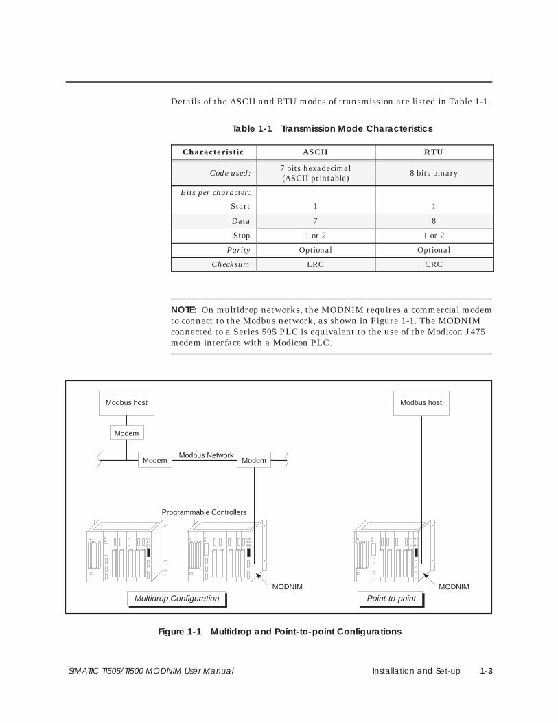
Details of the ASCII and RTU modes of transmission are listed in Table 1-1.
Table 1-1 Transmission Mode Characteristics
Characteristic ASCII RTU
Code used: 7 bits hexadecimal(ASCII printable)
8 bits binary
Bits per character:
Start 1 1
Data 7 8
Stop 1 or 2 1 or 2
Parity Optional Optional
Checksum LRC CRC
NOTE: On multidrop networks, the MODNIM requires a commercial modemto connect to the Modbus network, as shown in Figure 1-1. The MODNIMconnected to a Series 505 PLC is equivalent to the use of the Modicon J475modem interface with a Modicon PLC.
Programmable Controllers
Modbus NetworkModem Modem
Multidrop Configuration
Modem
MODNIM
Modbus host Modbus host
MODNIM
Point-to-point
Figure 1-1 Multidrop and Point-to-point Configurations

Installation and Set-up1-4 SIMATIC TI505/TI500 MODNIM User Manual
1.2 Quick Reference Installation Steps
In order to install and use the MODNIM module correctly, you must meetthe following requirements.
• Ensure that you have the appropriate MODNIM model.
• The communications configurations of all devices attached to thenetwork must match; i.e., they must all have the same baud rate, stopbits, parity, handshaking, and transmission mode (ASCII or RTU).
Figure 1-2 provides a quick reference list of the basic steps for installing theMODNIM.
Insert module into selected I/O slot (Series 505) or two adjacent slots (Series 500).
Set configuration dipswitches.
Power up the I/O base.
Check MODNIM indicator lights.
Verify MODNIM is logged into PLC.
Connect network cables.
Disconnect power to the I/O base.
Install power and I/O cabling.
Figure 1-2 Quick Reference Installation Procedures
GeneralRequirements
Procedures

Installation and Set-up 1-5SIMATIC TI505/TI500 MODNIM User Manual
Many integrated circuit (IC) devices are susceptible to damage by thedischarge of static electricity. Follow the suggestions listed below to reducethe probability of damage to these devices when you are handling thisNetwork Interface module, the PLC, a base controller, or any of the I/Omodules.
Both the module and the person handling the module should be at the sameground potential. Also, follow these guidelines.
• Transport the module in an anti-static container or antistatic material.
• Ensure that the work area has a conductive pad with a lead connectingit to a common ground.
• Ground yourself by making contact with the conductive pad and/or bywearing a grounded wrist strap.
Inspect the module for any visible damage before setting any selectablefeatures. If damage is detected, contact your distributor or sales office forfurther instructions.
The following sections describe the procedures for configuring the module,installing the module in the base, connecting the communications cables tothe MODNIM, and initializing the system for operation. Before installingthe MODNIM, make sure that the PLC is installed and the programmingdevice is connected to the system.
Handling theModule
Inspecting theModule
Getting Startedwith Configurationand Installation

Installation and Set-up1-6 SIMATIC TI505/TI500 MODNIM User Manual
1.3 Setting the Dipswitches
The MODNIM module has two blocks of dipswitches.
• The block of 8 dipswitches is used to select the MODNIM’s address onthe network.
• The block of 10 dipswitches is used to configure the networkcommunications parameters.
NOTE: The configuration and address switch settings are read only oncefollowing a power-up or RESET. Be sure to reset the MODNIM followingany change in dipswitch settings or PLC memory configuration. In addition,be aware that when the MODNIM is reset, no communication can occurfrom the host to the module for several seconds.
Each node on a Modbus network must have a unique address. The range ofvalid addresses is 1 to 247 (0000 0001 to 1111 0111). The address is set inbinary numbers using the block of 8 dipswitches.
NOTE: Addresses 0 or 248 to 255 (0000 0000 or 1111 1000 to 1111 1111) areinvalid addresses and, if selected, cause the module to go into Test mode.
Figure 1-3 shows examples of network addresses and their correspondingdipswitch settings. (With the Series 505 MODNIM, hold the module withthe faceplate pointing upward, as shown in Figure 1-5. For the Series 500MODNIM, refer to Figure 1-6 for dipswitch orientation.)
1248
163264
128
BitWeight
1(0000 0001)
0 1
Address
12
34
56
781
248
163264
128
25(0001 1001)
0 1
Address1
23
45
67
81248
163264
128
203(1100 1011)
0 1
Address
12
34
56
78
Represents direction to slide a sliding-type switch, orside of switch to press down on a rocker-type switchon Series 505 MODNIM.
=
00
01
10
01
00
00
00
01
11
00
10
11
Figure 1-3 Address Setting Examples
DipswitchFunctions
Setting the NetworkAddress

Installation and Set-up 1-7SIMATIC TI505/TI500 MODNIM User Manual
The block of 10 dipswitches is used to configure the network communicationparameters, which include data transmission rate, stopbit selection, parity,transmission mode, RTS/CTS handshaking, and output coil mapping.(NOTE: For all Series 500 MODNIM dipswitch settings, see Figure 1-6.)
Switches 1 through 4 are used to set the data transmission rate. All deviceson the network must be configured to communicate at the same data rate.Switch settings for each of the available data rates are shown in Figure 1-4.
0 0 0 0 – 500 0 0 1 – 500 0 1 0 – 750 0 1 1 – 1100 1 0 0 – 1500 1 0 1 – 2000 1 1 0 – 3000 1 1 1 – 6001 0 0 0 – 12001 0 0 1 – 18001 0 1 0 – 24001 0 1 1 – 36001 1 0 0 – 48001 1 0 1 – 72001 1 1 0 – 96001 1 1 1 – 19200
Switches1 2 3 4 Baud
10987654321
DataRate
10
Network ConfigurationDipswitches
For Series 505:
01For Series 500:
Figure 1-4 Dipswitch Settings for Network Data Transmission Rates
Switch 5 is used to select 1 or 2 stopbits. Set switch to the left for 1 stopbit,to the right for 2 stopbits (on Series 505; for Series 500, see Figure 1-6).
Switch 6 is used to select Parity or No Parity when communicating over anRS-232-C data link. To select Parity, set switch to the left, then determinewhether you need odd or even parity and set switch 7 accordingly.
If you selected Parity with switch 6, then you must also select either Odd orEven Parity using switch 7. This switch is active only if switch 6 is set toParity. Set switch to the left for Even parity, to the right for Odd parity.
Switch 8 is used to select ASCII or RTU mode of transmission. Slide switchto the left for ASCII mode, to the right for RTU mode.
Switch 9 is used to enable or disable RTS/CTS handshaking. If you areusing point-to-point connections without using modems, you can disableRTS/CTS handshaking by setting switch 9 to the left. Set switch 9 to theright to select RTS/CTS handshaking for use with modems.
Switch 10 is used to determine whether the MODNIM collects data from thePLC’s Discrete Output (Y) memory or the Control Relay (C) memory. Setswitch to the left for C coils, to the right for Y outputs.
Selecting NetworkConfigurationParameters
Data TransmissionRate
Stopbit Selection
Parity/No ParitySelection
Odd/Even ParitySelection
ASCII/RTU ModeSelection
RTS/CTSHandshaking
Y/C Coil Selection

Installation and Set-up1-8 SIMATIC TI505/TI500 MODNIM User Manual
Setting the Dipswitches (continued)
NIM GOOD —Base power andMODNIM operating status
XMT —Data Transmit indicator
ON LINE —Connected to the Modbus network.Continuous ON indicates remote mode;flashing indicates local mode
PC GOOD —PLC/MODNIMcommunicationlink status
REC —Receiving Dataindicator
TEST —Test mode status
Series 505 MODNIM
Dipswitches
Network Configuration
Network Address
Side View of Module,Faceplate Up
10987654321
87654321
Y OUTPUTRTS/CTS: ONRTU MODEPARITY: ODDPARITY: OFFSTOPBITS: 21111
DATARATESELECT
C COILSRTS/CTS: OFF
ASCII MODEPARITY: EVEN
PARITY: ONSTOPBITS: 1
0000
Push DownLeft
0
Push DownRight
505-5184
NIMGOOD
PCGOOD
XMT REC
ONLINE TEST
REMOTE
LOCAL
TEST
RESET
PORT A
PORT B
NetworkAddress
Dipswitch Settings Data TransmissionRate Settings
0 0 0 0 – 500 0 0 1 – 500 0 1 0 – 750 0 1 1 – 1100 1 0 0 – 1500 1 0 1 – 2000 1 1 0 – 3000 1 1 1 – 6001 0 0 0 – 12001 0 0 1 – 18001 0 1 0 – 24001 0 1 1 – 36001 1 0 0 – 48001 1 0 1 – 72001 1 1 0 – 96001 1 1 1 – 19200
Switches1 2 3 4 Baud
MODNIM
1248
163264
128
Figure 1-5 Series 505 MODNIM Switches and LEDs

Installation and Set-up 1-9SIMATIC TI505/TI500 MODNIM User Manual
Reset
Self-Test
Local/Remote
• Push to reset
Remote control (on-line)
Local control (off-line)
NIM GOOD
PC/NIM COMM GOOD
ONLINE
RECEIVE
TRANSMIT
TEST MODE
Reset
Self-Test
Local/Remote
ConfigurationSwitches
NetworkAddress
Switches
Series 500 MODNIM
1. Select Local control2. Remove network cables3. Install Loopback connectors4. Press Reset and Self-Test
together and hold 5 seconds.
DIPSWITCH Settings
10987654321
87654321
Y OUTPUTSRTS/CTS: ON
RTU MODEPARITY: ODDPARITY: OFFSTOPBITS: 2
1111
DATARATESELECT
1248
163264
128
C COILSRTS/CTS: OFFASCII MODEPARITY: EVENPARITY: ONSTOPBITS: 10000
0NetworkAddress
Data Transmission Rates
0 0 0 0 – 500 0 0 1 – 500 0 1 0 – 750 0 1 1 – 1100 1 0 0 – 1500 1 0 1 – 2000 1 1 0 – 3000 1 1 1 – 6001 0 0 0 – 12001 0 0 1 – 18001 0 1 0 – 24001 0 1 1 – 36001 1 0 0 – 48001 1 0 1 – 72001 1 1 0 – 96001 1 1 1 – 19200
Switches1 2 3 4 Baud01
Figure 1-6 Series 500 MODNIM Switches and LEDs

Installation and Set-up1-10 SIMATIC TI505/TI500 MODNIM User Manual
1.4 Installing the MODNIM
To install the Series 505 MODNIM in the selected slot of the I/O base, followthese steps.
To avoid the possibility of personal injury, damage to the module,altering the PLC memory, or causing a PLC fatal error, disconnectpower to the base’s power supply and to any modules installed inthe base before inserting or removing the MODNIM.
1. Disconnect power to the I/O base.
2. Set the dipswitches, as described in Section 1.3. (See also Figure 1-8 forexample dipswitch configuration settings.)
3. Position the module so that the front bezel is facing you.
4. Hold the top and bottom of the bezel and carefully slide the module intothe slot, pushing it all the way into the base connector. (See Figure 1-7.)
5. Ensure that the edge card connector is firmly seated in the I/O baseconnector.
6. Tighten the screws at the top and bottom of the faceplate with a flat-bladed screwdriver. (These screws also ground the module to the base.)
Minimum torque: 2.61 in-lb (0.3 N-m)
Maximum torque: 5.22 in-lb (0.6 N-m)
Figure 1-7 Installing the Series 505 MODNIM in the I/O Base
Installing theSeries 505 MODNIMin the I/O Base
WARNING!

Installation and Set-up 1-11SIMATIC TI505/TI500 MODNIM User Manual
C coils/Y outputs
RTS/CTS: OFF/ON
Mode RTU/ASCII
Parity ODD/EVEN
Parity OFF/ON
Stop bits 2 or 1
Baud Rate(19200 shown)
Network AddressNetworkConfiguration
1 2 4 8 16 32 64 1281
0
Note: � = side ofswitch to press down.
Network address isdetermined by thesum of the values ofselected switches.
(Address 2 shown)
Figure 1-8 Series 505 MODNIM Example Dipswitch Settings

Installation and Set-up1-12 SIMATIC TI505/TI500 MODNIM User Manual
Installing the MODNIM (continued)
You can key the Series 500 MODNIM module to prevent another I/O modulefrom being inserted by mistake into the two slots reserved for the MODNIMmodule.
To do this, insert the three keys provided in the right slot of the two slotsoccupied by the module so that they fit into the notches in the edge card ofthe module. (See Figure 1-9.)
To avoid the possibility of personal injury, damage to the module,altering the PLC memory, or causing a PLC fatal error, disconnectpower to the base’s power supply and to any modules installed inthe base before inserting or removing the MODNIM or the I/O slotkeys.
Figure 1-9 Keying the I/O Base Slot for the Series 500 MODNIM
Installing theSeries 500 MODNIMin the I/O Base
WARNING!

Installation and Set-up 1-13SIMATIC TI505/TI500 MODNIM User Manual
Once the I/O slot keys are in place, you can insert the module as follows.
1. Set the dipswitches, described in Section 1.3.
2. Position the module so that the front bezel is facing you.
3. Hold the top and bottom of the bezel and carefully slide the module intothe slot, pushing it all the way into the base connector. When themodule is fully seated in the I/O base, locking tabs will hold the modulein place. (See Figure 1-10.)
Locking tabs
Locking tabs
Figure 1-10 Installing the Series 500 MODNIM in the I/O Base
4. To remove the module, pull the tabs away from the module and slide itout of the base, being careful not to damage the edge card.

Installation and Set-up1-14 SIMATIC TI505/TI500 MODNIM User Manual
1.5 Switches and Indicator Lights
The three switches located on the face of the module behind the access doorare Reset, Self Test, and Local/Remote, and are described in the followingparagraphs.
The Reset button is a momentary-contact switch which initializes theMODNIM and initiates the power-up self test. When you press Reset, all theindicators turn on for approximately 1 second. Then, all indicators exceptTEST go off for about 5 seconds. During this time, the MODNIM runs aseries of diagnostic tests to verify that the hardware components of themodule are operating properly. In addition, buffers and counters thatservice the Modbus Diagnostic Functions are initialized.
If the tests have been successfully completed, only the NIM GOOD and thePC GOOD (PC/NIM COMM GOOD) indicators will turn back on, while theTEST indicator turns off. If, however, the TEST indicator remains on, runthe User Initiated Self-Test to determine the source of the error.
NOTE: Always press the Reset button after you change any of theconfiguration dipswitches or address selection dipswitches. In addition, beaware that when the MODNIM is reset, no communication can occur fromthe host to the module for several seconds.
The Test button initiates a series of diagnostic tests when it is held down for3 seconds after a Reset operation. Before running the diagnostic tests,disconnect all communications cables and install loopback connectors on theRS-232-C communications ports. These tests are described in more detail inSection 1.6.
When set to Remote, this two-position toggle switch enables the MODNIMto perform write operations to PLC memory. In the Local position, theMODNIM cannot write to the PLC.
In either position, the MODNIM can monitor PLC memory and mode ofoperation. After the MODNIM is set to Online state, local or remote statusis indicated as follows.
• Local mode is indicated by a flashing ONLINE indicator.
• Remote mode is indicated by a steady ONLINE indicator.
When set to Local mode, only the Read functions 1, 2, 3, 4, 7, 11, 12, and 17plus diagnostics function 8 can be performed. All other functions (writeoperations) will be rejected with Exception Code 01.
Switches andButtons
Reset Button
Test Button
Local/RemoteSwitch

Installation and Set-up 1-15SIMATIC TI505/TI500 MODNIM User Manual
The MODNIM has six indicator lights (or LEDs) located on the faceplate ofthe module (see Figure 1-11). These lights indicate the operational ordiagnostic status of the module as described below.
NIM GOOD
PC/NIM COMM GOOD
ONLINE
RECEIVE
TRANSMIT
TEST MODE
NIMGOOD
PCGOOD
XMT REC
ONLINE TEST
Series 500 MODNIMSeries 505 MODNIM
Figure 1-11 Series 505 and 500 MODNIM Indicator Lights
Table 1-2 shows how to interpret the status of the six indicator lights on thefaceplate of the MODNIM during normal operation. Section 1.6 describesadditional interpretations of the indicator lights during diagnostic testing.
Table 1-2 Status of Indicator Lights
Indicator Status Description
NIM GOOD OnAll power-on, reset, or run-time diagnostictests have been passed successfully;MODNIM operating correctly.
PC/NIM COMM GOOD(PC GOOD)
On Communicating successfully with PLC
ONLINEOn
Flashing
Connected to the network: Remote mode
Connected to the network: Local mode
RECEIVE (REC) On Receiving data over the network
TRANSMIT (XMT) On Transmitting data over the network
TEST MODE (TEST)
On
On
Flashing
MODNIM in Test mode
Failure detected after power-up diagnostics
Tests completed
Status IndicatorLights
Installation and Set-up1-16 SIMATIC TI505/TI500 MODNIM User Manual
1.6 Diagnostic Tests
The MODNIM has the following three levels of self tests available.
• Power-up Self Tests
• Run-time Self Tests
• User-initiated Self Tests
The MODNIM executes a Power-up Self Test in the following cases.
• Immediately after you apply +5 VDC power from the I/O base as part ofinitialization.
• Any time the Reset button is pressed.
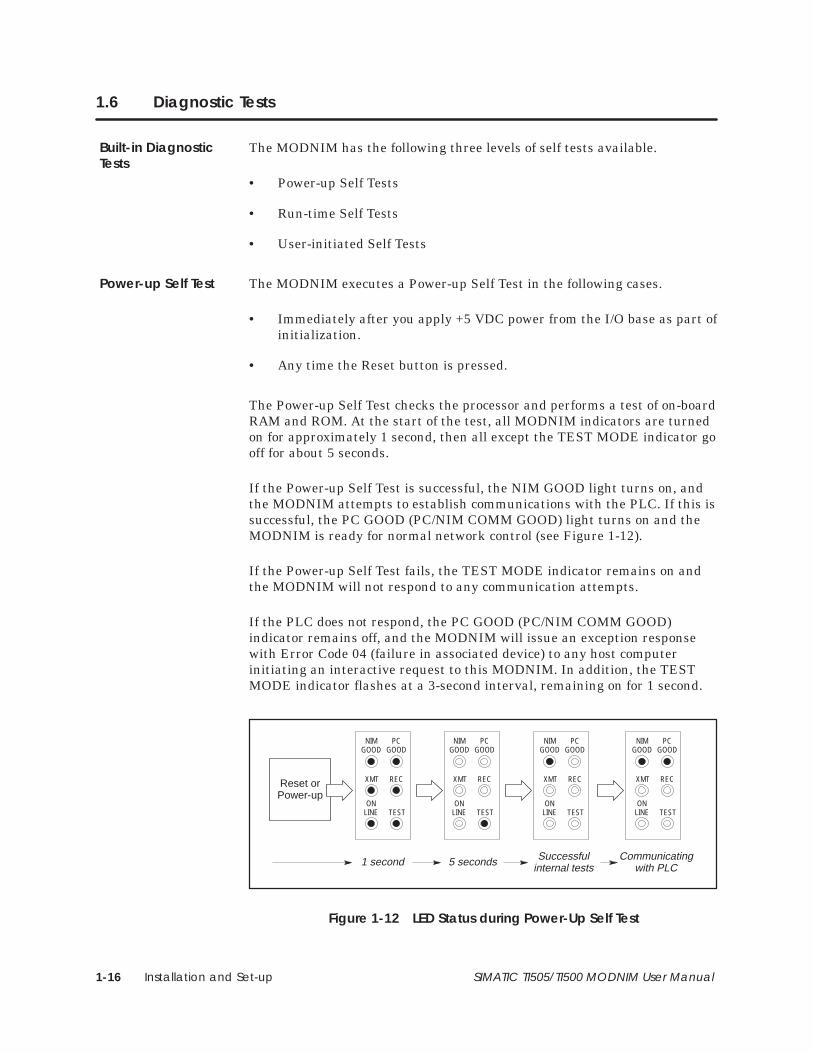
The Power-up Self Test checks the processor and performs a test of on-boardRAM and ROM. At the start of the test, all MODNIM indicators are turnedon for approximately 1 second, then all except the TEST MODE indicator gooff for about 5 seconds.
If the Power-up Self Test is successful, the NIM GOOD light turns on, andthe MODNIM attempts to establish communications with the PLC. If this issuccessful, the PC GOOD (PC/NIM COMM GOOD) light turns on and theMODNIM is ready for normal network control (see Figure 1-12).
If the Power-up Self Test fails, the TEST MODE indicator remains on andthe MODNIM will not respond to any communication attempts.
If the PLC does not respond, the PC GOOD (PC/NIM COMM GOOD)indicator remains off, and the MODNIM will issue an exception responsewith Error Code 04 (failure in associated device) to any host computerinitiating an interactive request to this MODNIM. In addition, the TESTMODE indicator flashes at a 3-second interval, remaining on for 1 second.
Reset orPower-up
NIMGOOD
PCGOOD
XMT REC
ONLINE TEST
NIMGOOD
PCGOOD
XMT REC
ONLINE TEST
1 second 5 seconds
NIMGOOD
PCGOOD
XMT REC
ONLINE TEST
Successfulinternal tests
NIMGOOD
PCGOOD
XMT REC
ONLINE TEST
Communicatingwith PLC
Figure 1-12 LED Status during Power-Up Self Test
Built-in DiagnosticTests
Power-up Self Test

Installation and Set-up 1-17SIMATIC TI505/TI500 MODNIM User Manual
The MODNIM monitors itself continuously during normal operation asfollows.
• The operating system continuously performs a ROM integrity test as abackground process.
• The MODNIM periodically verifies that it is capable of communicatingwith the PLC.
• A Watchdog Timer circuit in the MODNIM guards against softwarelockup.
If any failures are detected in the ROM integrity test, the NIM GOODindicator light turns off and the MODNIM is forced into the failed state. Inthis condition, the module goes into the Offline Mode and will not respond toany requests. (See Figure 1-13.)
When the MODNIM is in its normal operating mode but fails tocommunicate with the PLC, it reports this failure to the host computer withan exception response. Error code 04 (failure in associated device) is sent,and the PC GOOD (PC/NIM COMM GOOD) indicator goes out. (SeeFigure 1-13.) If communication is re-established, the MODNIM returns tonormal mode and the PC GOOD indicator goes back on.
NOTE: The first time a valid request is received, the ON LINE indicatorgoes on and remains on as long as everything is operating properly.
NIMGOOD
PCGOOD
XMT REC
ONLINE TEST
NIMGOOD
PCGOOD
XMT REC
ONLINE TEST
NIMGOOD
PCGOOD
XMT REC
ONLINE TEST
ROM Integrity Failure:goes to Offline Mode
Not Communicating withPLC: reports Error Code 04
All Run-timetests OK
Figure 1-13 LED Status during Normal Run-Time Operation
The Watchdog Timer circuit provides an extra measure of protection againstnetwork lockup due to a failed MODNIM. This circuit will force a RESET ifthe operating software fails to execute normally.
Run-time Self Tests
Installation and Set-up1-18 SIMATIC TI505/TI500 MODNIM User Manual
Diagnostic Tests (continued)
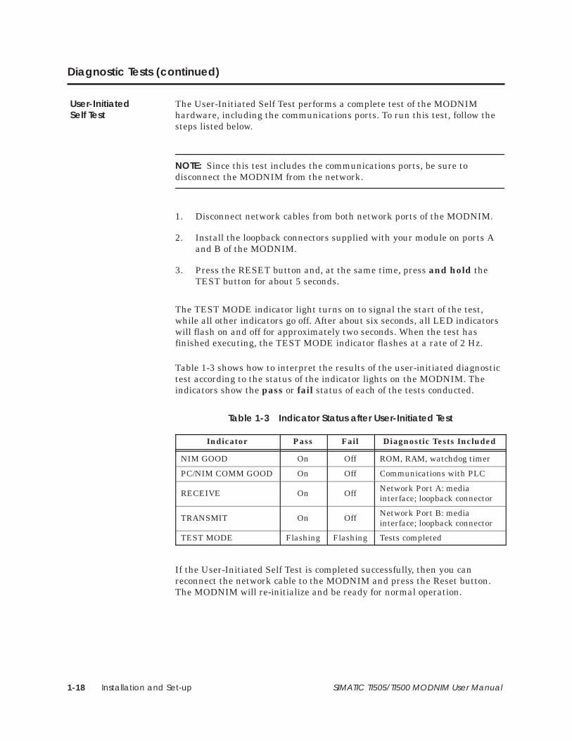
The User-Initiated Self Test performs a complete test of the MODNIMhardware, including the communications ports. To run this test, follow thesteps listed below.
NOTE: Since this test includes the communications ports, be sure todisconnect the MODNIM from the network.
1. Disconnect network cables from both network ports of the MODNIM.
2. Install the loopback connectors supplied with your module on ports Aand B of the MODNIM.
3. Press the RESET button and, at the same time, press and hold theTEST button for about 5 seconds.
The TEST MODE indicator light turns on to signal the start of the test,while all other indicators go off. After about six seconds, all LED indicatorswill flash on and off for approximately two seconds. When the test hasfinished executing, the TEST MODE indicator flashes at a rate of 2 Hz.
Table 1-3 shows how to interpret the results of the user-initiated diagnostictest according to the status of the indicator lights on the MODNIM. Theindicators show the pass or fail status of each of the tests conducted.
Table 1-3 Indicator Status after User-Initiated Test
Indicator Pass Fail Diagnostic Tests Included
NIM GOOD On Off ROM, RAM, watchdog timer
PC/NIM COMM GOOD On Off Communications with PLC
RECEIVE On Off Network Port A: mediainterface; loopback connector
TRANSMIT On Off Network Port B: mediainterface; loopback connector
TEST MODE Flashing Flashing Tests completed
If the User-Initiated Self Test is completed successfully, then you canreconnect the network cable to the MODNIM and press the Reset button.The MODNIM will re-initialize and be ready for normal operation.
User-InitiatedSelf Test
Installation and Set-up 1-19SIMATIC TI505/TI500 MODNIM User Manual
1.7 Establishing Communications
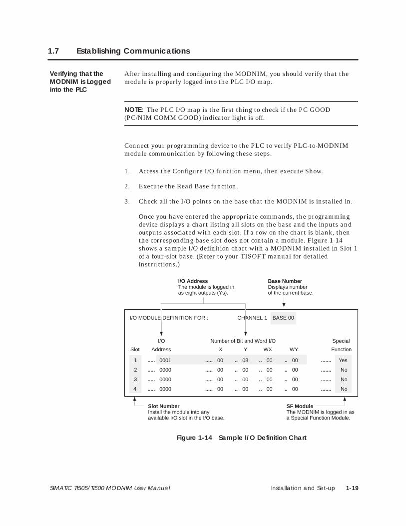
After installing and configuring the MODNIM, you should verify that themodule is properly logged into the PLC I/O map.
NOTE: The PLC I/O map is the first thing to check if the PC GOOD(PC/NIM COMM GOOD) indicator light is off.
Connect your programming device to the PLC to verify PLC-to-MODNIMmodule communication by following these steps.
1. Access the Configure I/O function menu, then execute Show.
2. Execute the Read Base function.
3. Check all the I/O points on the base that the MODNIM is installed in.
Once you have entered the appropriate commands, the programmingdevice displays a chart listing all slots on the base and the inputs andoutputs associated with each slot. If a row on the chart is blank, thenthe corresponding base slot does not contain a module. Figure 1-14shows a sample I/O definition chart with a MODNIM installed in Slot 1of a four-slot base. (Refer to your TISOFT manual for detailedinstructions.)
I/O MODULE DEFINITION FOR : CHANNEL 1 BASE 00
Slot Address X Y WX WY Function
I/O Number of Bit and Word I/O Special
1
2
3
4
.....
.....
.....
.....
0001
0000
0000
0000
.....
.....
.....
.....
00
00
00
00
..
..
..
..
08
00
00
00
..
..
..
..
00
00
00
..
..
..
..
00
00
00
.......
.......
.......
.......
Yes
No
No
No
00 00
Base NumberDisplays number of the current base.
Slot Number Install the module into anyavailable I/O slot in the I/O base.
I/O AddressThe module is logged inas eight outputs (Ys).
SF ModuleThe MODNIM is logged in asa Special Function Module.
Figure 1-14 Sample I/O Definition Chart
Verifying that theMODNIM is Loggedinto the PLC

Installation and Set-up1-20 SIMATIC TI505/TI500 MODNIM User Manual
Establishing Communications (continued)
4. Look at the chart for the number corresponding to the slot occupied bythe MODNIM module. If an S or SF (Special Function) and wordmemory locations (or 8 Ys) appear on this line, the module is registeredin the PLC memory. Assign a unique I/O address to the module andexecute a Write PC function. You can now begin to communicate withthe MODNIM.
If the data on the line is incorrect, first check to see if the module isfirmly seated in the I/O base and enter the command again. If you stillcannot verify the module login, contact your local Siemens IndustrialAutomation, Inc. distributor.
Network cabling should already be in place before you begin installing theMODNIM.
The MODNIM has two communication ports. Only one port communicatesat a time, but two are provided for cabling redundancy.
For high-noise environments, it is recommended that you use a standardSiemens communications cable with your MODNIM. (Refer to Table 1-4.)Either cable is compatible with the MODNIM; the requirements of your hostcomputer may determine which cable you should select. These cables areavailable through your Siemens Industrial Automation, Inc. distributor.
Table 1-4 Standard Communication Cables
Cable Description Cable P/N Adapter at Module
9-pin to 9-pin Standard 9-pin null modem 2601094–8001 9F–to–25M pin port adapter
25-pin serial Standard 25-pin null modem VPU200–3605 None required
If you prefer to build your own 25-pin cable, refer to Appendix A for thepinouts. Ensure that the following requirements are met.
• Cable conductors — 26 AWG, tinned and stranded copper wire, withone uninsulated 26 AWG tinned copper drain wire
• Cable shield — AL foil or aluminum-polyester foil and a 65% minimumtinned copper braid shield
• Outer jacket — polyvinyl chloride (PVC) or equivalent material, with aUL rating of 30V, 60°C minimum
• Connectors — 25-pin male D-connector, with contact pins of copperalloy with gold flashing over nickel plate
Connecting theNetwork Cables
RecommendedCommunicationCables
Building a Cable

Modbus Commands 2-1SIMATIC TI505/TI500 MODNIM User Manual
Chapter 2
Modbus Commands
2.1 Modbus Protocol Overview — ASCII Transmission Mode 2-2. . . . . . . . . . . . . . . . . . . . . . . . . . . Modbus Protocol 2-2. . . . . . . . . . . . . . . . . . . . . . . . . . . . . . . . . . . . . . . . . . . . . . . . . . . . . . . . . . . . . . . The ASCII Transmission Frame 2-2. . . . . . . . . . . . . . . . . . . . . . . . . . . . . . . . . . . . . . . . . . . . . . . . . . . . The Start Field 2-2. . . . . . . . . . . . . . . . . . . . . . . . . . . . . . . . . . . . . . . . . . . . . . . . . . . . . . . . . . . . . . . . . . . The Address Field 2-2. . . . . . . . . . . . . . . . . . . . . . . . . . . . . . . . . . . . . . . . . . . . . . . . . . . . . . . . . . . . . . . The Function Field 2-2. . . . . . . . . . . . . . . . . . . . . . . . . . . . . . . . . . . . . . . . . . . . . . . . . . . . . . . . . . . . . . . The Data Field 2-3. . . . . . . . . . . . . . . . . . . . . . . . . . . . . . . . . . . . . . . . . . . . . . . . . . . . . . . . . . . . . . . . . . The LRC Field 2-3. . . . . . . . . . . . . . . . . . . . . . . . . . . . . . . . . . . . . . . . . . . . . . . . . . . . . . . . . . . . . . . . . . . The EOF Field 2-3. . . . . . . . . . . . . . . . . . . . . . . . . . . . . . . . . . . . . . . . . . . . . . . . . . . . . . . . . . . . . . . . . . . The Ready Field 2-3. . . . . . . . . . . . . . . . . . . . . . . . . . . . . . . . . . . . . . . . . . . . . . . . . . . . . . . . . . . . . . . . .
2.2 Modbus Protocol Overview — RTU Transmission Mode 2-4. . . . . . . . . . . . . . . . . . . . . . . . . . . . . The RTU Transmission Frame 2-4. . . . . . . . . . . . . . . . . . . . . . . . . . . . . . . . . . . . . . . . . . . . . . . . . . . . . . The RTU Frame Fields 2-4. . . . . . . . . . . . . . . . . . . . . . . . . . . . . . . . . . . . . . . . . . . . . . . . . . . . . . . . . . . . Message Delineation 2-4. . . . . . . . . . . . . . . . . . . . . . . . . . . . . . . . . . . . . . . . . . . . . . . . . . . . . . . . . . . Checksum 2-5. . . . . . . . . . . . . . . . . . . . . . . . . . . . . . . . . . . . . . . . . . . . . . . . . . . . . . . . . . . . . . . . . . . . . Invalid Characters and Messages 2-5. . . . . . . . . . . . . . . . . . . . . . . . . . . . . . . . . . . . . . . . . . . . . . . .
2.3 Comparing Modbus Functions with TIWAY I Network Commands 2-6. . . . . . . . . . . . . . . . . . . Modbus Functions vs. TIWAY Commands 2-6. . . . . . . . . . . . . . . . . . . . . . . . . . . . . . . . . . . . . . . . . Addressing 2-7. . . . . . . . . . . . . . . . . . . . . . . . . . . . . . . . . . . . . . . . . . . . . . . . . . . . . . . . . . . . . . . . . . . . . Address Limits 2-7. . . . . . . . . . . . . . . . . . . . . . . . . . . . . . . . . . . . . . . . . . . . . . . . . . . . . . . . . . . . . . . . . . .
2.4 Modbus Function Descriptions 2-8. . . . . . . . . . . . . . . . . . . . . . . . . . . . . . . . . . . . . . . . . . . . . . . . . . . Introduction 2-8. . . . . . . . . . . . . . . . . . . . . . . . . . . . . . . . . . . . . . . . . . . . . . . . . . . . . . . . . . . . . . . . . . . . Code 01 — Read Coil Status 2-8. . . . . . . . . . . . . . . . . . . . . . . . . . . . . . . . . . . . . . . . . . . . . . . . . . . . Code 02 — Read Input Status 2-10. . . . . . . . . . . . . . . . . . . . . . . . . . . . . . . . . . . . . . . . . . . . . . . . . . . Code 03 — Read Output Registers 2-12. . . . . . . . . . . . . . . . . . . . . . . . . . . . . . . . . . . . . . . . . . . . . . . Code 04 — Read Input Registers 2-13. . . . . . . . . . . . . . . . . . . . . . . . . . . . . . . . . . . . . . . . . . . . . . . . . Code 05 — Write a Single Coil 2-14. . . . . . . . . . . . . . . . . . . . . . . . . . . . . . . . . . . . . . . . . . . . . . . . . . . Code 06 — Write a Single Register 2-16. . . . . . . . . . . . . . . . . . . . . . . . . . . . . . . . . . . . . . . . . . . . . . . Code 07 — Read Exception Status 2-17. . . . . . . . . . . . . . . . . . . . . . . . . . . . . . . . . . . . . . . . . . . . . . . Code 08 — Execute Diagnostics 2-19. . . . . . . . . . . . . . . . . . . . . . . . . . . . . . . . . . . . . . . . . . . . . . . . . Code 11 — Get Comms Event Counter 2-30. . . . . . . . . . . . . . . . . . . . . . . . . . . . . . . . . . . . . . . . . . Code 12 — Get Comms Event Log 2-31. . . . . . . . . . . . . . . . . . . . . . . . . . . . . . . . . . . . . . . . . . . . . . Code 15 — Write Multiple Coils 2-33. . . . . . . . . . . . . . . . . . . . . . . . . . . . . . . . . . . . . . . . . . . . . . . . . . Code 16 — Write Multiple Registers 2-35. . . . . . . . . . . . . . . . . . . . . . . . . . . . . . . . . . . . . . . . . . . . . . Code 17 — Report Slave ID 2-36. . . . . . . . . . . . . . . . . . . . . . . . . . . . . . . . . . . . . . . . . . . . . . . . . . . . . .
2.5 Error Responses 2-38. . . . . . . . . . . . . . . . . . . . . . . . . . . . . . . . . . . . . . . . . . . . . . . . . . . . . . . . . . . . . . . . .

Modbus Commands2-2 SIMATIC TI505/TI500 MODNIM User Manual
2.1 Modbus Protocol Overview — ASCII Transmission Mode
This chapter examines the Modbus protocol for both ASCII and RTU modesof transmission. The MODNIM-supported functions are then described indetail, with examples of requests and responses for each function code.
Each frame in the ASCII transmission mode begins with a colon ( : ) andends with CR LF (Carriage Return/Line Feed), shown in Figure 2-1.
2 characters n x 2 char 2 char
Address Function Data LRCStart EOF
� 2 characters CR LF
Ready
Figure 2-1 ASCII Transmission Frame
Each of the fields in the transmission frame is described in the paragraphsbelow.
The Start field is a colon (: = 3A hex), and marks the start of the message.This is the first character transmitted.
The Address field identifies the node to which this message is being sentand is a number in the range of 1 to 247. Each node on any one networkmust have a unique address. Only those nodes addressed will respondunless the broadcast address 0 is used. In that case, each slave will readand act on the message but not respond.
The Function field is a 2-character (16-bit) code that determines the actionthat a slave takes when receiving the message. The function codessupported by the MODNIM are summarized in Table 2-1 and described inmore detail with examples in section 2.4.
Modbus Protocol
The ASCIITransmission Frame
The Start Field
The Address Field
The Function Field

Modbus Commands 2-3SIMATIC TI505/TI500 MODNIM User Manual
Table 2-1 Modbus Functions Supported
Code Type Description
01 Read Coil Status Get current status of a group of coils.
02 Read Input Status Get current status of a group of discreteinputs.
03 Read Holding Register Get current values from holding registers.
04 Read Input Register Get current values from input registers.
05 Force a Single Coil Change the state of a logic coil to On or Off,forced On or forced Off, or unforced.
06 Write a Single Register Write a value into a holding register.
07 Read Exception Status Get the 8 internal status coil values.
08 Execute Diagnostics Send diagnostic tests to a slave.
11 Get CommunicationsEvent Counter
Enable the success or failure of a query tobe determined.
12 Get CommunicationsEvent Log
Get the communications log for Modbusnetwork transactions.
15 Write Multiple Coils Change a number of consecutive coils.
16 Write Multiple Registers Write values into a series of consecutiveholding registers.
17 Report Slave I.D. Get the slave type and the condition of itsrun light.
����� The highlighted function codes (5, 6, 8, 15, and 16) are supported by Broadcast mode,for which no response is returned.
The Data field contains the information needed by the specified node toperform the required operation, or the information returned by the node tothe host computer. The data is in multiple bytes, with two ASCII characterbytes representing a hexadecimal value (1 . . . 9 and A . . . F or a . . . f).
The Longitudinal Redundancy Checking (LRC) is the method employed byASCII mode to ensure that the message transmitted by the host is the sameas the one that arrives at the secondary (and vice versa). The characters arepassed to a mathematical algorithm creating a checksum of 2 characters inlength that can be duplicated at either end for comparison. The calculationof this checksum is described in the Modbus Protocol Reference Manual.
The End of File (EOF) marker, CR (carriage return) indicates the end of thedata and is the point up to which the LRC is generated.
The Ready field, LF (line feed) indicates that the sender is now ready forany reply. This character can be changed using Function Code 08, withDiagnostic code 03. Unless there is a compelling reason to change thischaracter, it should be left as the default value (LF).
The Data Field
The LRC Field
The EOF Field
The Ready Field

Modbus Commands2-4 SIMATIC TI505/TI500 MODNIM User Manual
2.2 Modbus Protocol Overview — RTU Transmission Mode
The RTU mode determines the start and finish of a message based on a timeperiod of silence (no transmission) equivalent to the time it would take totransmit 3.5 characters at the chosen baud rate. The RTU transmissionframe is shown in Figure 2-2.
8 bits 8 bits n x 8 bits 16 bits
Address Function Data Checksum
T1 T2 T3
T1 T2 T3 . . . represents a time of 3.5 characters at given baud rate.
No data
Figure 2-2 RTU Transmission Frame
The RTU mode of transmission is more efficient than the ASCII mode as itonly uses 8 bits for each field (except for the checksum) and the end of themessage is detected by timing. The body of the message (address, functioncode, and data field) is the same with both modes; therefore, only themessage delineation and the checksum are discussed in the followingparagraphs.
The start and finish of a message is determined by timing in RTU mode.Any time period longer than 3.5 character lengths marks the end of atransmission. The next character after that would then mark the start ofthe next message. This time period is dependent on the baud rate. Table 2-2shows the effect of baud rate on the time delay period.
Table 2-2 RTU Mode Timing
Baud Rate 3.5 Character Time Delay (ms)*
1920096007200480036002400180012006003002001501107550
2.24.45.98.8
11.717.523.335.070.0
140.0210.0280.0381.8560.0840.0
*Assuming longest delay with 2 stop bits & parity enabled
The RTUTransmission Frame
The RTU FrameFields
MessageDelineation

Modbus Commands 2-5SIMATIC TI505/TI500 MODNIM User Manual
The checksum needs 16 bits and uses the Cyclic Redundancy Checksum(CRC) method. The calculation of this checksum is described in the ModbusProtocol Reference Manual.
The MODNIM ignores messages that contain invalid characters. Messagescontaining the following errors are also ignored.
• Incorrect checksum
• Parity error
• Framing errors
• Frame too long
• Incomplete transmission
Checksum
Invalid Charactersand Messages

Modbus Commands2-6 SIMATIC TI505/TI500 MODNIM User Manual
2.3 Comparing Modbus Functions with TIWAY I Network Commands
This section outlines some of the differences between Modbus andTIWAY I network commands.
• Whereas Modbus uses Functions Codes, TIWAY I uses Primitives.Primitives differ from Function codes in one important way: primitivesuse TT-types to allow one primitive to address different types of data.With Modbus a different function code is required for each type of data.
• With SIMATIC� TI� PLCs, the first address for each type of memory isalways 1. By comparison, Modbus PLCs allow 0 as the first legaladdress.
• If each system were to return one byte (8 bits) representing eightdiscrete coils, they would each be positioned as shown in Figure 2-3.
8 7 6 5 4 3 2 1 87654321
Coil No. Coil No.
Modbus PLCsor SIMATIC TI PLCs via MODNIM
SIMATIC TI PLCsvia TIWAY
MSB LSB< < < MSB LSB< < <
Figure 2-3 Bit Orientation
• Terminology is another area in which differences occur. Some of thedifferences in terms are given in Table 2-3. (Refer also to Appendix C,Table C-3 for a list of the TIWAY primitive equivalents to the Modbusfunction codes.)
Table 2-3 Terminology Differences
Modbus-based PLCs SIMATIC TI PLCs
Coil Discrete output (Y) or Control Relay (C)
Input Register Word Image Register (WX/WY)
Holding Register Variable Memory (V-memory)
Slave Secondary Node
P/C (Programmable Controller) PLC
Function code Primitive
Modbus TIWAY I
Disabled (coil) Forced
Enabled (coil) Unforced
Modbus Functionsvs. TIWAYCommands

Modbus Commands 2-7SIMATIC TI505/TI500 MODNIM User Manual
The MODNIM uses the absolute position of the data for the address. Thatis, if you want to address the 3066th coil, then that is the address you passwith the command (as hexadecimal value BFA). The maximum address is65535 (FFFF hex). All current PLCs are within this limit.
For example, if you want to access 1000 coils starting at the 703rd coil, theFunction Code 01 would be as follows:
: 01 01 02 BF 03 E8 52 CR LF [ASCII mode]
01 01 02 BF 03 E8 0C E8 [RTU mode]
Modbus imposes a buffer size limit of 256 bytes. Because of this restriction,MODNIM requests have been limited to the following values.
Function Code Quantity
010203041516
2000 coils2000 discrete inputs125 output registers125 input registers800 coils100 registers
In the process of mapping Modbus commands against those used bySIMATIC TI PLCs, when an appropriate command was absent, it hasbecome necessary to make multiple passes with a single command. Inpractical terms, this means that when the maximum amount of data for aparticular command is requested, the MODNIM must wait for several PLCcycles before sufficient data can be collected. This latent time increases foraddresses greater than 1024 (extended addressing).
The command checking will reject requests for data greater than the limitsshown above. What the checking does not do is check the request againstthe available PLC memory. When a request goes beyond the memory of aparticular PLC, the command will be rejected by the PLC and the MODNIMwill notify the host computer with Exception Code 02.
Addressing
Address Limits

Modbus Commands2-8 SIMATIC TI505/TI500 MODNIM User Manual
2.4 Modbus Function Descriptions
In the descriptions that follow, each function starts on a separate page andincludes the TIWAY primitive sent to the secondary in square brackets. Foreach function, an example of request and response is given.
NOTE: As Mode-specific data is not given, each of these examples omits theheader ( : ) and tail (CR/LF) of ASCII mode.
Code 01 enables the user to read the On/Off values of logic coils. The datapassed with this command is the start address and the number of coils to beread. Addressing is sequential up to the maximum memory size for aparticular PLC. The maximum number of coils that can be addressed withone command is 2000. If more are requested, the whole command will berejected with an Exception code 03.
SIMATIC TI PLCs number memory locations starting at address 1.Modbus PLCs number areas of memory starting from address 0.Failure to alter host computer application programs may result inthe wrong bits being read.
Example:
Request: 07 01 000A 0005 XXXXChecksum (XXXX)Number of points (0005)Start point (000A)Function code (01)Slave address (07)
Figure 2-4 Read Coil Status Example — Request
This request is asking the MODNIM to return the data from 5 coils (On/Off)starting at the 10th coil.
[This is equivalent to sending a TIWAY Primitive 20 request using TT-type 7(Packed Discrete Outputs or Ys) or TT-type 8 (Packed Cs), depending on theposition of Switch 10 of the network dipswitch bank in the MODNIM.]
Introduction
Code 01 — ReadCoil Status
CAUTION!

Modbus Commands 2-9SIMATIC TI505/TI500 MODNIM User Manual
Response: 07 01 01 1A XXXXChecksum (XXXX)Data (1A)Number of bytes (01)Function code (01)Slave address (07)
Figure 2-5 Read Coil Status Example — Response
The response returns in the data field a single byte (1A) which contains the1’s or 0’s for the 5 coils, packed out with zeros for the three high bits.
1A = 0 0 0 1 1 0 1 0Coil 0A (OFF)Coil 0B (ON)Coil 0C (OFF)Coil 0D (ON)Coil 0E (ON)Packed with zeros (000)
Figure 2-6 Read Coil Status Example — Data Field

Modbus Commands2-10 SIMATIC TI505/TI500 MODNIM User Manual
Modbus Function Descriptions (continued)
Code 02 allows the application to read a series of discrete inputs. Thecommand includes the start address and the number of points to be read.
Addressing is sequential up to the maximum memory size for a particularPLC. The maximum number of inputs that can be addressed with onecommand is 2000. If more are requested, the whole command will berejected with an Exception code 03.
Example:
Request: 07 02 000A 0005 XXXXChecksum (XXXX)Number of points (0005)Start point (000A)Function code (02)Slave address (07)
Figure 2-7 Read Input Status Example — Request
This request is for the data from 5 discrete inputs (On/Off) starting at the10th input.
[This command is equivalent to sending a TIWAY I Primitive 20 requestusing TT-type 6 (Packed Discrete Inputs, or Packed Xs)].
Response: 07 02 01 1A XXXXChecksum (XXXX)Data (1A)Number of bytes (01)Function code (02)Slave address (07)
Figure 2-8 Read Input Status Example — Response
Code 02 — ReadInput Status
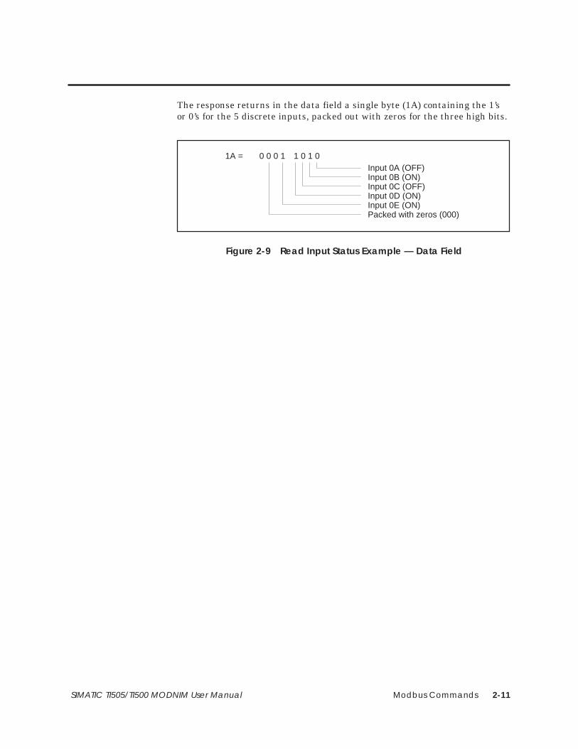
Modbus Commands 2-11SIMATIC TI505/TI500 MODNIM User Manual
The response returns in the data field a single byte (1A) containing the 1’sor 0’s for the 5 discrete inputs, packed out with zeros for the three high bits.
1A = 0 0 0 1 1 0 1 0Input 0A (OFF)Input 0B (ON)Input 0C (OFF)Input 0D (ON)Input 0E (ON)Packed with zeros (000)
Figure 2-9 Read Input Status Example — Data Field

Modbus Commands2-12 SIMATIC TI505/TI500 MODNIM User Manual
Modbus Function Descriptions (continued)
Code 03 allows you to read the contents of holding registers in the attachedsecondary device. The data field of this command includes the start addressof the registers and the number of registers to be read.
Addressing is sequential up to the maximum memory size for a particularPLC. The maximum number of registers that can be addressed with onecommand is 125. If more are requested, the whole command will be rejectedwith an Exception code 03.
[This command is equivalent to issuing a TIWAY I Primitive 20 request witha TT-type 01 (Variable Memory)].
Example:
Request: 07 03 0064 0003 XXXXChecksum (XXXX)Number of registers (0003)Address of first register (0064)Function code (03)Slave address (07)
Figure 2-10 Read Output Register Example — Request
This request is for secondary address 7 to read the contents of registers0064, 0065, and 0066 (100, 101, and 102 decimal).
Response: 07 03 06 032C 0001 0030 XXXXChecksum (XXXX)3rd register value (0030)2nd register value (0001)1st register value (032C)Number of bytes (06)Function code (03)Slave address (07)
Figure 2-11 Read Output Register Example — Response
The response has returned the number of bytes of data (06) and the valuesfor the requested registers; these are 032C, 0001, and 0030 respectively(812, 1, and 48 decimal).
Code 03 — ReadOutput Registers

Modbus Commands 2-13SIMATIC TI505/TI500 MODNIM User Manual
Code 04 allows you to read the contents of input registers in the attachedPLC. These registers hold the values returned by the I/O devices. The datafield of this command includes the start address of the registers and thenumber of registers to be read.
Addressing is sequential up to the maximum memory size for a particularPLC. The maximum number of registers that can be addressed with onecommand is 125. If more are requested, the whole command will be rejectedwith an Exception code 03.
[This command is equivalent to issuing a TIWAY I Primitive 20 request witha TT-type 09 (Word input WX)].
Example:
Request: 07 04 0008 0001 XXXXChecksum (XXXX)Number of registers (0001)Address of first register (0008)Function code (04)Slave address (07)
Figure 2-12 Read Input Register Example — Request
This request is for secondary address 7 to read and return the value storedin input register 0008.
Response: 07 04 02 0020 XXXX
Checksum (XXXX)Input register value (0020)Number of bytes (02)Function code (04)Slave address (07)
Figure 2-13 Read Input Register Example — Response
The response has returned the number of bytes of data (02) and the value0020 (32 decimal) from the requested input register (0008).
Code 04 — ReadInput Registers
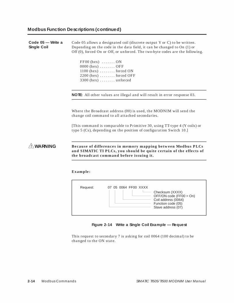
Modbus Commands2-14 SIMATIC TI505/TI500 MODNIM User Manual
Modbus Function Descriptions (continued)
Code 05 allows a designated coil (discrete output Y or C) to be written.Depending on the code in the data field, it can be changed to On (1) orOff (0), forced On or Off, or unforced. The two-byte codes are the following.
FF00 (hex) ON. . . . . . . 0000 (hex) OFF. . . . . . . . 1100 (hex) forced ON. . . . . . . . 2200 (hex) forced OFF. . . . . . . . 3300 (hex) unforced. . . . . . . .
NOTE: All other values are illegal and will result in error response 03.
Where the Broadcast address (00) is used, the MODNIM will send thechange coil command to all attached secondaries.
[This command is comparable to Primitive 30, using TT-type 4 (Y coils) ortype 5 (Cs), depending on the position of configuration Switch 10.]
Because of differences in memory mapping between Modbus PLCsand SIMATIC TI PLCs, you should be quite certain of the effects ofthe broadcast command before issuing it.
Example:
Request: 07 05 0064 FF00 XXXXChecksum (XXXX)OFF/ON code (FF00 = On)Coil address (0064)Function code (05)Slave address (07)
Figure 2-14 Write a Single Coil Example — Request
This request to secondary 7 is asking for coil 0064 (100 decimal) to bechanged to the ON state.
Code 05 — Write aSingle Coil
WARNING!

Modbus Commands 2-15SIMATIC TI505/TI500 MODNIM User Manual
Response: 07 05 0064 FF00 XXXXChecksum (XXXX)OFF/ON code (FF00 = ON)Coil address (0064)Function code (05)Slave address (07)
Figure 2-15 Read Input Register Example — Response
The response to Function Code 05 is to return the request as received. Inthe case of a broadcast request, there is no response.

Modbus Commands2-16 SIMATIC TI505/TI500 MODNIM User Manual
Modbus Function Descriptions (continued)
Code 06 allows the contents of a holding register to be changed. Addressingis sequential up to the maximum memory size for a particular PLC. Thisfunction is limited to integer values contained in V-memory. The MODNIMwill also direct any broadcast address (00) to all attached secondaries.
[This command is comparable to a TIWAY I request using Primitive 30 andTT-type 01 (Variable memory)].
Because of differences in memory mapping between Modbus PLCsand SIMATIC TI PLCs, you should be quite certain of the effects ofthe broadcast command before issuing it.
Example:
Request: 07 06 0064 0220 XXXXChecksum (XXXX)Data value (0220)Register address (0064)Function code (06)Slave address (07)
Figure 2-16 Write a Single Register Example — Request
This request to secondary 7 is asking for the value of holding register 0064(100 decimal) to be changed to 0220 (544 decimal).
Response: 07 06 0064 0220 XXXXChecksum (XXXX)Data value (0220)Register address (0064)Function code (06)Slave address (07)
Figure 2-17 Write a Single Register Example — Response
The response to Function Code 06 is to return the request as received. Inthe case of a broadcast request, there is no response.
Code 06 — Write aSingle Register
WARNING!

Modbus Commands 2-17SIMATIC TI505/TI500 MODNIM User Manual
Code 07 instructs the MODNIM to read 8 predefined coils within asecondary.
This implementation will read the first 8 coils (first 8 Ys or first 8 Cs,depending on the position of the dipswitch) in the discrete image register ina secondary and pack them into one data byte.
NOTE: The programmer of a non-Modbus PLC must make certain that theapplication program running within the PLC will place meaningful data inthese locations. This data can reflect status information.
[This command is equivalent to TIWAY Primitive 20 using TT types 04, 07(Y unpacked, packed) or TT types 05, 08 (C unpacked, packed), fromlocations 1 – 8, depending on the position of configuration Switch 10.]
Example:
Request: 11 07 XXXX
Checksum (XXXX)Function code (07)Slave address (11)
Figure 2-18 Read Exception Status Example — Request
This request to secondary 17 (decimal) is asking for exception status data.
Response: 11 07 3B XXXX
Checksum (XXXX)Data value (3B)Function code (07)Slave address (11)
Figure 2-19 Read Exception Status Example — Response
Code 07 — ReadException Status

Modbus Commands2-18 SIMATIC TI505/TI500 MODNIM User Manual
Modbus Function Descriptions (continued)
The response shows that 3B (hex) has been returned. If the individual bitsare examined, they indicate the status of each bit.
Coil 1 (ON)Coil 2 (ON)Coil 3 (OFF)Coil 4 (ONCoil 5 (ON)Coil 6 (ON)Coil 7 (OFF)Coil 8 (OFF)
0 0 1 1 1 0 1 1
Coils3B (hex)
Figure 2-20 Exception Status Bits

Modbus Commands 2-19SIMATIC TI505/TI500 MODNIM User Manual
Code 08 enables diagnostic information to be retrieved to conduct networktesting. This function does not affect the operation of the PLC, but may havesignificant effects on the operation of the MODNIM. Where these effectsimpact upon the operation of the MODNIM, they are described with thedetails for that diagnostic code.
Because of differences in memory mapping between Modbus PLCsand SIMATIC TI PLCs, you should be quite certain of the effects ofthe broadcast command before issuing it.
Example:
Request: 02 08 0000 B405 XXXXChecksum (XXXX)Information Field (B405)Diagnostic code (0000)Function code (08)Slave address (02)
Figure 2-21 Execute Diagnostics Example — Request
This example shows a request to conduct diagnostic test 0000. This is theloopback query, where the outgoing message field is returned unchanged.
Response: 02 08 0000 B405 XXXXChecksum (XXXX)Information Field (B405)Diagnostic code (0000)Function code (08)Slave address (02)
Figure 2-22 Execute Diagnostics Example — Response
Code 08 —ExecuteDiagnostics
WARNING!

Modbus Commands2-20 SIMATIC TI505/TI500 MODNIM User Manual
Modbus Function Descriptions (continued)
Table 2-4 details the diagnostic codes supported.
Table 2-4 Diagnostic Codes Supported
Code(hex)
Diagnostic Description Is CodeSupported?
00 Return request message Yes
01 Restart communications with the slave Yes
02 Return diagnostics register Yes
03 Change message end character Yes
04 Set slave in Listen Only Mode Yes
0A Clear counters and diagnostics Yes
0B Return message count Yes
0C Return checksum error count Yes
0D Return exception count Yes
0E Return slave message count Yes
0F Return slave no-response count No
10 Return slave NAK count No
11 Return slave busy count No
12 Return character overrun count Yes
13 Return overrun error count No
14 Clear character overrun count Yes

Modbus Commands 2-21SIMATIC TI505/TI500 MODNIM User Manual
The diagnostics codes supported are described in the following paragraphs.
Diagnostic Code — 00
0000 | any data
Diagnostic code
Information frame
When Function Code 08 uses diagnostic code 0000, any data passed in theinformation field is returned to the host computer by the addressedsecondary node without change.
The purpose of this command is to determine if the communications arefunctioning correctly, and may be used in conjunction with diagnostic testsdescribed later.
This code has no effect on the functioning of the MODNIM.
Diagnostic Code — 01
0001 | 00 000001 | FF 00
Diagnostic code
Information frame
or
When Function Code 08 uses diagnostic code 0001, the information framecan contain 0000 or FF00.
This function causes the MODNIM to clear all internal counters andregisters. If the MODNIM had been in Listen Only Mode (LOM), it will bereturned to normal operating mode at the successful conclusion of thecommand. If the information frame contains FF00, the CommunicationsEvent Log will be cleared. If any other value is passed in the informationfield, the Communications Event Log will not be cleared, and no responsewill be returned.
This code has significant effect on the functioning of the MODNIM.

Modbus Commands2-22 SIMATIC TI505/TI500 MODNIM User Manual
Modbus Function Descriptions (continued)
Diagnostic Code — 02
0002 | 00 00
Diagnostic code
Information frame
When Function Code 08 uses diagnostic code 0002, the information fieldmay contain any value (00 00 shown). The MODNIM returns a 16-bit wordcontaining diagnostic data about the attached device. The meaning of eachbit is given in Table 2-5.
Table 2-5 Diagnostic Bits
Bit Description
0 O. S. RAM parity error
1 Program RAM parity error
2 O. S. fatal error
3 Watchdog timeout error
4 Dynamic program memory diagnostic
5 Illegal Op code
6 RAM diagnostics failure
7 ROM diagnostics failure
8 Scan diagnostic failure
9 I/O fatal error
10 Scan overrun error
11 Abnormal power loss
12 Unidentified board failure
13 EEPROM card RAM download error
14 Not used
15 Not used
If the bit contains a 1, then the error associated with that bit is current.
This code has no effect on the functioning of the MODNIM.

Modbus Commands 2-23SIMATIC TI505/TI500 MODNIM User Manual
Diagnostic Code — 03
0003 | Char 00
Diagnostic code
Information frame
When Function Code 08 uses diagnostic code 0003, the ASCII charactergiven in the information field is then used as the delimiter of an ASCIImode message replacing the standard LF (line feed) character.
NOTE: Avoid using the following characters as alternative ‘Ready’ fieldmarkers:
:, 0 to 9, a to f, A to F, or CR
You also need to be aware that while the request must be sent with theexisting ‘ready’ character (default: LF), this response, and all future oneswill be returned with the new character until a RESET or a power cycle.
This code has significant effects on the operation of the MODNIM.
Diagnostic Code — 04
0004 | 00 00
Diagnostic code
Information frame
When Function Code 08 uses diagnostic code 0004 and any value in theinformation field (00 00 shown), the secondary node will be forced intoListen Only Mode. In this mode, while the node may be listening to thetraffic on the network, it will only react to a Function 8, diagnostic code 01command, which returns the MODNIM to normal operation. The MODNIMalso returns to normal operating mode if the RESET button is pressed orthe power is cycled. When the MODNIM enters Listen Only Mode, theONLINE indicator goes off.
This code has a significant effect on the operation of the MODNIM.

Modbus Commands2-24 SIMATIC TI505/TI500 MODNIM User Manual
Modbus Function Descriptions (continued)
Diagnostic Code — 0A
000A | 00 00
Diagnostic code
Information frame
When Function Code 08 uses diagnostic code 000A and any value in theinformation field (00 00 shown), all diagnostic registers and counters withinthe MODNIM will be cleared. This also happens when the power is cycled orthe RESET button is pressed.
This code has a significant effect on the operation of the MODNIM.
Diagnostic Code — 0B
000B | 00 00
Diagnostic code
Information frame
When Function Code 08 uses diagnostic code 000B and any value in theinformation field (00 00 shown), the information field will return thenumber of processed messages received by the MODNIM since the lastRESET or power-up. The counter will increment to a value of FFFF (65535)and will then return to zero (0).
This code has no effect on the operation of the MODNIM.

Modbus Commands 2-25SIMATIC TI505/TI500 MODNIM User Manual
Diagnostic Code — 0C
000C | 00 00
Diagnostic code
Information frame
When Function Code 08 uses diagnostic code 000C and any value in theinformation field (00 00 shown), the information field will return thenumber of checksum errors detected by the MODNIM since the last RESETor power-up. The counter will increment to a value of FFFF (65535) and willthen return to zero (0).
This code has no effect on the operation of the MODNIM.
Diagnostic Code — 0D
000D | 00 00
Diagnostic code
Information frame
When Function Code 08 uses diagnostic code 000D and any value in theinformation field (00 00 shown), the information field will return thenumber of exceptions detected by the MODNIM since the last RESET orpower-up. The counter will increment to a value of FFFF (65535) and willthen return to zero (0).
This code has no effect on the operation of the MODNIM.
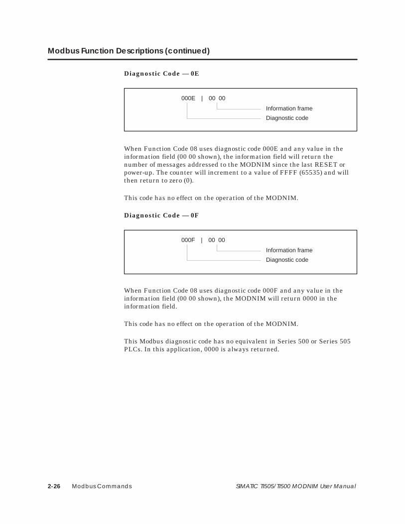
Modbus Commands2-26 SIMATIC TI505/TI500 MODNIM User Manual
Modbus Function Descriptions (continued)
Diagnostic Code — 0E
000E | 00 00
Diagnostic code
Information frame
When Function Code 08 uses diagnostic code 000E and any value in theinformation field (00 00 shown), the information field will return thenumber of messages addressed to the MODNIM since the last RESET orpower-up. The counter will increment to a value of FFFF (65535) and willthen return to zero (0).
This code has no effect on the operation of the MODNIM.
Diagnostic Code — 0F
000F | 00 00
Diagnostic code
Information frame
When Function Code 08 uses diagnostic code 000F and any value in theinformation field (00 00 shown), the MODNIM will return 0000 in theinformation field.
This code has no effect on the operation of the MODNIM.
This Modbus diagnostic code has no equivalent in Series 500 or Series 505PLCs. In this application, 0000 is always returned.

Modbus Commands 2-27SIMATIC TI505/TI500 MODNIM User Manual
Diagnostic Code — 10
0010 | 00 00
Diagnostic code
Information frame
When Function Code 08 uses diagnostic code 0010 and any value in theinformation field (00 00 shown), the MODNIM will return 0000 in theinformation field.
This code has no effect on the operation of the MODNIM.
This Modbus diagnostic code has no equivalent in Series 500 or Series 505PLCs. In this application, 0000 is always returned.
Diagnostic Code — 11
0011 | 00 00
Diagnostic code
Information frame
When Function Code 08 uses diagnostic code 0011 and any value in theinformation field (00 00 shown), the MODNIM will return 0000 in theinformation field.
This code has no effect on the operation of the MODNIM.
This Modbus diagnostic code has no equivalent in Series 500 or Series 505PLCs. In this application, 0000 is always returned.

Modbus Commands2-28 SIMATIC TI505/TI500 MODNIM User Manual
Modbus Function Descriptions (continued)
Diagnostic Code — 12
0012 | 00 00
Diagnostic code
Information frame
When Function Code 08 uses diagnostic code 0012 and any value in theinformation field (00 00 shown), the information field will return thenumber of character overruns detected by the MODNIM since the lastRESET or power-up. This indicates the number of times that charactershave arrived faster than the UART can store them without loss. Thecounter will increment to a value of FFFF (65535) and will then return tozero (0).
This code has no effect on the operation of the MODNIM.
Diagnostic Code — 13
0013 | 00 00
Diagnostic code
Information frame
When Function Code 08 uses diagnostic code 0013 and any value in theinformation field (00 00 shown), the MODNIM will return 0000 in theinformation field.
This code has no effect on the operation of the MODNIM.
This Modbus diagnostic code has no equivalent in Series 500 or Series 505PLCs. In this application, 0000 is always returned.

Modbus Commands 2-29SIMATIC TI505/TI500 MODNIM User Manual
Diagnostic Code — 14
0014 | 00 00
Diagnostic code
Information frame
When Function Code 08 uses diagnostic code 0014 and any value in theinformation field (00 00 shown), the MODNIM will clear the characteroverrun counter.
This command affects the operation of the MODNIM.
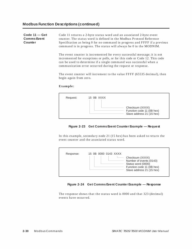
Modbus Commands2-30 SIMATIC TI505/TI500 MODNIM User Manual
Modbus Function Descriptions (continued)
Code 11 returns a 2-byte status word and an associated 2-byte eventcounter. The status word is defined in the Modbus Protocol ReferenceSpecification as being 0 for no command in progress and FFFF if a previouscommand is in progress. The status will always be 0 in the MODNIM.
The event counter is incremented for every successful message; it is notincremented for exceptions or polls, or for this code or Code 12. This codecan be used to determine if a single command was successful when acommunication error occurred during the request or response.
The event counter will increment to the value FFFF (65535 decimal), thenbegin again from zero.
Example:
Request: 15 0B XXXX
Checksum (XXXX)Function code 11 (0B hex)Slave address 21 (15 hex)
Figure 2-23 Get Comms Event Counter Example — Request
In this example, secondary node 21 (15 hex) has been asked to return theevent counter and the associated status word.
Response: 15 0B 0000 0143 XXXXChecksum (XXXX)Number of events (0143)Status word (0000)Function code 11 (0B hex)Slave address 21 (15 hex)
Figure 2-24 Get Comms Event Counter Example — Response
The response shows that the status word is 0000 and that 323 (decimal)events have occurred.
Code 11 — GetComms EventCounter
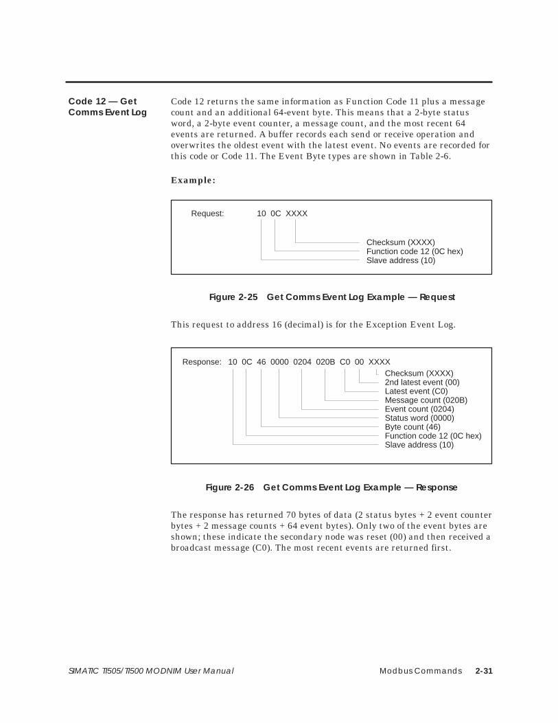
Modbus Commands 2-31SIMATIC TI505/TI500 MODNIM User Manual
Code 12 returns the same information as Function Code 11 plus a messagecount and an additional 64-event byte. This means that a 2-byte statusword, a 2-byte event counter, a message count, and the most recent 64events are returned. A buffer records each send or receive operation andoverwrites the oldest event with the latest event. No events are recorded forthis code or Code 11. The Event Byte types are shown in Table 2-6.
Example:
Request: 10 0C XXXX
Checksum (XXXX)Function code 12 (0C hex)Slave address (10)
Figure 2-25 Get Comms Event Log Example — Request
This request to address 16 (decimal) is for the Exception Event Log.
10 0C 46 0000 0204 020B C0 00 XXXXChecksum (XXXX)2nd latest event (00)Latest event (C0)Message count (020B)Event count (0204)Status word (0000)Byte count (46)Function code 12 (0C hex)Slave address (10)
Response:
Figure 2-26 Get Comms Event Log Example — Response
The response has returned 70 bytes of data (2 status bytes + 2 event counterbytes + 2 message counts + 64 event bytes). Only two of the event bytes areshown; these indicate the secondary node was reset (00) and then received abroadcast message (C0). The most recent events are returned first.
Code 12 — GetComms Event Log

Modbus Commands2-32 SIMATIC TI505/TI500 MODNIM User Manual
Modbus Function Descriptions (continued)
Table 2-6 Event Byte Types
Event Byte Bit Definitions
Slave Bus Receive. Bytestored on receipt of message
Bit 0 – ReservedBit 1 – Set if communications errorBit 2 – ReservedBit 3 – ReservedBit 4 – Set if character overrunBit 5 – Set if in Listen Only modeBit 6 – Set if BroadcastBit 7 – 1
Slave Bus Transmit. Bytestored when message sent
Bit 0 – Set if an exception (1–3) is sentBit 1 – Set if secondary abort exception (6) is sentBit 2 – Set if secondary busy exception (6) is sentBit 3 – Not usedBit 4 – Set if write timeout occurredBit 5 – Set if in Listen Only modeBit 6 – 1Bit 7 – 0
Entered Listen OnlyMode. Byte stored whenLOM mode entered
Bit 0 – 0Bit 1 – 0Bit 2 – 1Bit 3 – 0Bit 4 – 0Bit 5 – 0Bit 6 – 0Bit 7 – 0
Initiate CommunicationsRESET. Complete log is setto zeros.
Bit 0 – 0Bit 1 – 0Bit 2 – 0Bit 3 – 0Bit 4 – 0Bit 5 – 0

Modbus Commands 2-33SIMATIC TI505/TI500 MODNIM User Manual
Code 15 allows the host computer to write multiple coils. When thiscommand is given, successive coils are changed by an associated bit patternto the indicated state, where each bit indicates: 1 = ON 0 = OFF
Addressing is sequential up to the maximum memory size for a particularsecondary. The maximum number of coils that can be addressed with onecommand is 800. If more are given, the whole command will be rejected withan Exception code 03.
The broadcast address (00) can be used to change the same coils in allnetworked programmable controllers.
[This command is equivalent to TIWAY Primitive 30 using data types 04, 07(Y unpacked, packed) or data types 05, 08 (C unpacked, packed), dependingon the position of configuration Switch 10.]
Because of differences in memory mapping between Modbus PLCsand SIMATIC TI PLCs, you should be quite certain of the effects ofthe broadcast command before issuing it.
Example:
Request: 07 0F 0012 000C 02 DC08 XXXXChecksum (XXXX)Coil status (DC08)Number of bytes (02)Number of coils (000C)Start coil address (0012)Function code 15 (0F hex)Slave address (07)
Figure 2-27 Write Multiple Coils Example — Request
Code 15 — WriteMultiple Coils
WARNING!

Modbus Commands2-34 SIMATIC TI505/TI500 MODNIM User Manual
Modbus Function Descriptions (continued)
This request is for the secondary node to change the values of 12 (0C hex)coils starting at address 12 (18 decimal) to the states given by the followingbit pattern.
1 1 0 1
D
1 1 1 0
C
0 0 0 0
0
1 0 0 0
8
Coil 25 (ON) Coil 18 (OFF) Coil 29 (ON)
Coil 26 (OFF)192021222324 313233 30 272825 18 29 26
Figure 2-28 Coil Bit Pattern
The bit pattern indicates that coils 19, 20, 21, 22, 24, 25, and 29 are to bechanged to ON and 18, 23, 26, 27, and 28 changed to OFF.
Response: 07 0F 0012 000C XXXX
Checksum (XXXX)Number of coils (000C)Start coil address (0012)Function code 15 (0F hex)Slave address (07)
Figure 2-29 Write Multiple Coils Example — Response

Modbus Commands 2-35SIMATIC TI505/TI500 MODNIM User Manual
Code 16 allows the host computer to write multiple values into successiveregisters. Addressing is sequential up to the maximum memory size for aparticular PLC. The maximum number of registers that can be addressedwith one command is 100. If more are given, the whole command will berejected with an Exception code 03.
[This command is equivalent to a TIWAY I request using Primitive 30 withTT-type 01 (Variable memory)].
Because of differences in memory mapping between Modbus PLCsand SIMATIC TI PLCs, you should be quite certain of the effects ofthe broadcast command before issuing it.
Example:
02 10 0078 0002 04 000B 0201 XXXX
Checksum (XXXX)2nd register data (0201)1st register data (000B)Number of bytes (04)Number of registers (0002)Start register address (0078)Function code 16 (10 hex)Slave address (02)
Request:
Figure 2-30 Write Multiple Registers Example — Request
This request to the secondary node is to change the values of 2 holdingregisters, starting at address 0078 (120 decimal) to 11 and 513 respectively.
Response: 02 10 0078 0002 XXXX
Checksum (XXXX)Number of registers (0002)Start register address (0078)Function code 16 (10 hex)Slave address (02)
Figure 2-31 Write Multiple Registers Example — Response
The response to this command is to return the address, code, startingaddress, and the numbers of registers to be changed.
Code 16 — WriteMultiple Registers
WARNING!

Modbus Commands2-36 SIMATIC TI505/TI500 MODNIM User Manual
Modbus Function Descriptions (continued)
Code 17 permits the user to get information from the slave concerning itstype, run mode, and other device-dependent data.
[This command has no direct equivalent to a TIWAY I request, but elementsof this function are contained in Primitives 02 and 03 (Status primitive andConfiguration primitive).]
The MODNIM returns a number in the Slave ID field determined by thetype of PLC connected and responds with the state of the RUN light. Inaddition, it returns the HH status field, the EE auxiliary power source field,the communications port in use, and the software version number.
Example:
Request: 03 11 XXXX
Checksum (XXXX)Function code 17 (11 hex)Slave address (03)
Figure 2-32 Report Slave ID Example — Request
This example shows a request to secondary address 03 to report its ID andassociated data.
03 11 06 3C FF 01 00 0A 30 XXXXChecksum (XXXX)Release 3.0Port A operational (0A)Auxiliary power (00)Operational mode (01)Run light (FF = On)Slave ID (3C = TI530C)Number of bytes (06)Function code 17 (11 hex)Slave address 030)
Response:
Figure 2-33 Report Slave ID Example — Response
This response indicates that 6 bytes have been returned. These bytes showthat the Slave ID is a TI530C PLC, the RUN light is On, the operationalmode is 01, auxiliary power is good, and the operational port is A. The lastbyte contains the software version number (see Table 2-7).
Code 17 — ReportSlave ID
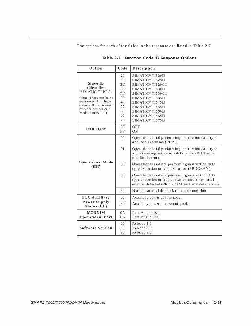
Modbus Commands 2-37SIMATIC TI505/TI500 MODNIM User Manual
The options for each of the fields in the response are listed in Table 2-7.
Table 2-7 Function Code 17 Response Options
Option Code Description
Slave ID(Identifies
SIMATIC TI PLC)
(Note: There can be noguarantee that thesecodes will not be usedby other devices on aModbus network.)
20252C303C354555606575
SIMATIC� TI520SIMATIC� TI525SIMATIC� TI520CSIMATIC� TI530SIMATIC� TI530CSIMATIC� TI535SIMATIC� TI545SIMATIC� TI555SIMATIC� TI560SIMATIC� TI565SIMATIC� TI575
Run Light 00FF
OFFON
00 Operational and performing instruction data typeand loop execution (RUN).
Oper tio ode
01 Operational and performing instruction data typeand executing with a non-fatal error (RUN withnon-fatal error).
Operational Mode(HH)
03 Operational and not performing instruction datatype execution or loop execution (PROGRAM).
05 Operational and not performing instruction datatype execution or loop execution and a non-fatalerror is detected (PROGRAM with non-fatal error).
80 Not operational due to fatal error condition.
PLC AuxiliaryPower Supply
Status (EE)
00
80
Auxiliary power source good.
Auxiliary power source not good.
MODNIMOperational Port
0A0B
Port A is in use.Port B is in use.
Software Version002030
Release 1.0Release 2.0Release 3.0

Modbus Commands2-38 SIMATIC TI505/TI500 MODNIM User Manual
2.5 Error Responses
Errors such as illegal addressing or failure of communications with a PLCare reported by exception responses. Exception responses replace theexpected response to a request and are recognized by the Function Codewith the top bit set high (see examples in Figure 2-34 and Figure 2-35).
07 00000041 AD
Address Function Data LRCStart EOF
� 01 CR LF
Ready
Request:
07 02 76
Address Function Except. Code LRCStart EOF
� 81 CR LF
Ready
Response:
Figure 2-34 Exception Response Frame— ASCII Mode
07 01 00000041 XXXX
Address Function Data CRCRequest:
07 81 02 XXXX
Address Function Exception Code CRCResponse:
Figure 2-35 Exception Response Frame — RTU Mode
In this example, the request is for secondary node 07 to return the data for65 (41 hex) coils starting at address 00, which is an illegal address for aSIMATIC TI PLC. The response is an exception indicated by the FunctionCode 81 (01 with the high bit set), with the exception code 02 indicating thatthe data address was illegal.
NOTE: The TIWAY I network uses Exception Primitives. Exceptions sent bySIMATIC TI PLCs are mapped to Modbus Exception Codes.

Modbus Commands 2-39SIMATIC TI505/TI500 MODNIM User Manual
Table 2-8 list the exception responses that apply to the functions supportedby the MODNIM.
Table 2-8 Exception Responses
Code Name Description
01 Illegal Function The function received is not defined for thisapplication [equivalent to SIMATIC TIexception codes 00, 01, 06, 15].
02 Illegal Data Address The address contained in the data field is notvalid for the secondary being addressed[equivalent to SIMATIC TI code 02]
03 Illegal Data Value The value passed in the data field is notallowable for the secondary being addressed[equivalent to SIMATIC TI codes 10, 19, 1D].
04 Failure in associateddevice
The secondary address has failed to respond, ora command has aborted [equivalent toSIMATIC TI codes 0A, 0B, 0D, 17, 1A].
06 Memory parity error If during a read of memory, a parity erroroccurs, this exception response is returned.

Network Cable Communications A-1SIMATIC TI505/TI500 MODNIM User Manual
Appendix A
Network Cable Communications
A.1 Network Cables A-2. . . . . . . . . . . . . . . . . . . . . . . . . . . . . . . . . . . . . . . . . . . . . . . . . . . . . . . . . . . . . . . . Recommended Communication Cables A-2. . . . . . . . . . . . . . . . . . . . . . . . . . . . . . . . . . . . . . . . . Building Cables A-2. . . . . . . . . . . . . . . . . . . . . . . . . . . . . . . . . . . . . . . . . . . . . . . . . . . . . . . . . . . . . . . . . Cable Pinouts A-2. . . . . . . . . . . . . . . . . . . . . . . . . . . . . . . . . . . . . . . . . . . . . . . . . . . . . . . . . . . . . . . . . .
A.2 Communications Parameters A-4. . . . . . . . . . . . . . . . . . . . . . . . . . . . . . . . . . . . . . . . . . . . . . . . . . . . RS-232-C Pin Assignments A-4. . . . . . . . . . . . . . . . . . . . . . . . . . . . . . . . . . . . . . . . . . . . . . . . . . . . . . . . Recommended Communications Parameters A-4. . . . . . . . . . . . . . . . . . . . . . . . . . . . . . . . . . . .

Network Cable CommunicationsA-2 SIMATIC TI505/TI500 MODNIM User Manual
A.1 Network Cables
The following cables are available through your Siemens distributor.
Cable P/N Description Adapter at Module
2601094–8001 Standard 9-pin null modem 9-pin (F) to 25-pin (M) port adapter
VPU200–3605 Standard 25-pin null modem None required
If you prefer to build your own 25-pin cable, ensure that the followingrequirements are met to minimize the possibility of noise interference.
• Cable conductors — 26 AWG, tinned and stranded copper wire, withone uninsulated 26 AWG tinned copper drain wire
• Cable shield — AL foil or aluminum-polyester foil and a 65% minimumtinned copper braid shield
• Outer jacket — polyvinyl chloride (PVC) or equivalent material, with aUL rating of 30V, 60°C minimum
• Connectors — 25-pin male D-connector, with contact pins of copperalloy with gold flashing over nickel plate
Figure A-1, Figure A-2, and Figure A-3 show the cable connections whichcan be used for both ASCII and RTU modes of transmission.
1
2
3
4
5
6
208
7
1
2
3
4
5
6
208
7
(DTE) (DTE)Shield
9 9
10 10
11 11
12 12
13 13
Host Series 505 or 500 MODNIM
14 14TD TD
RD RD
RTS RTS
CTS CTS
GND
DSR
DCD
DSR
DCD
25 25
DTR DTR
Figure A-1 MODNIM to Host (without Handshaking)
RecommendedCommunicationCables
Building Cables
Cable Pinouts

Network Cable Communications A-3SIMATIC TI505/TI500 MODNIM User Manual
1
2
3
4
5
6
208
7
1
2
3
4
5
6
208
7
(DTE) (DTE)Shield
9 9
10 10
11 11
12 12
13 13
Host Series 505 or 500 MODNIM
14 14TD TD
RD RD
RTS RTS
CTS CTS
GND
DSR
DCD
DSR
DCD
25 25
DTR DTR
Figure A-2 MODNIM to Host (with Handshaking)
1
2
3
4
5
6
208
7
1
2
3
4
5
6
208
7
(DCE) (DTE)Shield
9 9
10 10
11 11
12 12
13 13
Commercial Modem Series 505 or 500 MODNIM
14 14RD TD
TD RD
RTS RTS
CTS CTS
GND
DSR
DCD
DSR
DCD
25 25
DTR DTR
Figure A-3 MODNIM to Commercial Modem (with Handshaking)

Network Cable CommunicationsA-4 SIMATIC TI505/TI500 MODNIM User Manual
A.2 Communications Parameters
The modem interface is a standard Type E DTE configuration as defined inthe EIA RS-232-C standard. This interface uses a male 25-pin D-typeconnector plug on the communication cable. The pin assignments are listedin Table A-1.
Table A-1 RS-232-C Connector Pin Assignments
Pin # Description
2 Transmit Data (TXD)
3 Receive Data (RXD)
4 Request to Send (RTS)
5 Clear to Send (CTS)
6 Data Set Ready (DSR)
7 Signal Ground
8 Receive Line Signal Detector/Data Carrier Detect (RLSD/DCD)
20 Data Terminal Ready (DTR)
The following communications parameters are suggested as a starting pointfor each mode of transmission when first establishing a connection.
Table A-2 Communications Parameters
Parameters RTU ASCII
Baud Rate 19,200 bps 19,200 bps
Parity None Even
Stop bits 1 1
Data bits 8 (auto selected) 7 (auto selected)
RS-232-C PinAssignments
RecommendedCommunicationsParameters

Exception Codes B-1SIMATIC TI505/TI500 MODNIM User Manual
Appendix B
Exception Codes
B.1 Exception Codes Supported by the MODNIM B-2. . . . . . . . . . . . . . . . . . . . . . . . . . . . . . . . . . . . .

Exception CodesB-2 SIMATIC TI505/TI500 MODNIM User Manual
B.1 Exception Codes Supported by the MODNIM
Table B-1 lists the subset of SIMATIC TI Exception Codes that are mappedto the Modbus exception codes.
Table B-1 Exception Codes
ExceptionCode (hex) Definition
00 The primitive is not implemented.
01 Data type is not defined in the attached device.
02 Data element location is out of range.
06 Device in wrong mode for primitive execution.
07 User program in device has disabled communications to NIM(Lockout Bit)
0A Device fails to respond.
0B Primitive aborted due to fatal error condition in attached device.
0D Error encountered while executing the requested primitive.
10 The number of locations requested exceeds the maximum allowed.
15 Primitive not allowed while device is in local mode.
17 The attached device did not respond properly (communicationsproblem).
19 The resulting data element location formed by the starting addressplus the number of data elements to access, is out of range.
1A Communications has not been established with the attacheddevice.
1D The number of locations to access is zero.

Specifications C-1SIMATIC TI505/TI500 MODNIM User Manual
Appendix C
Specifications
C.1 Environmental Specifications C-2. . . . . . . . . . . . . . . . . . . . . . . . . . . . . . . . . . . . . . . . . . . . . . . . . . . .
C.2 MODNIM Communications Specifications C-3. . . . . . . . . . . . . . . . . . . . . . . . . . . . . . . . . . . . . . . .

SpecificationsC-2 SIMATIC TI505/TI500 MODNIM User Manual
C.1 Environmental Specifications
The Series 505 I/O subsystem is tested against some of the most stringentstandards in the world. Table C-1 lists specifications that are common toSeries 505 I/O devices.
Table C-1 Environmental Specifications
Operating Temperature 0° to 60°C (32° to 140°F)
Storage Temperature –40° to +70°C (–40° to 158°F)
Relative Humidity 5% to 95% non-condensing
Pollution Degree 2, IEC 664, 664A
VibrationSinusoidal
Random
IEC 68-2-6, Test Fc;0.15 mm, peak-to-peak, 10–57 Hz;1.0 g 57–150 Hz
NAVMAT P-9492 or IEC 68-2-34Test Fdc with 0.04 g2/Hz, 80–350 Hz, and3 dB/octave rolloff, 80–20 Hz and350–2000 Hz at 10 min/axis
Impact Shock IEC, 68-2-27, Test Ea; Half sine, 15 g 11 ms
Electric Noise Immunity Conducted noise: IEC 801, Part 4, Level 3
MIL STD 461B, Part 4; CS01, CS02, CS06IEC 255-4EEC 4517/79 Com(78) 766 Final, Part 4IEEE 472, 2.5 kV
Radiated noise: IEC 801, Part 3, Level 3MIL STD 461B, Part 4; RS01, RS02
Electrostatic discharge: IEC 801, Part 2, Level 4, (15 kV)
System Isolation Isolation (user-side to controller-side): 1500 Vrms
Torque for bezel screws 0.3 N-m (2.61 in.-lbs.) minimum0.6 N-m (5.22 in.-lbs.) maximum
Corrosion Protection All parts are of corrosion resistant material or areplated or painted as corrosion protection.
Agency Approvals UL� Listed (UL508 industrial control equipment)CSA� Certified (CSA142 process control equipment)FM Approved (Class I, Div. 2, Hazardous locations)

Specifications C-3SIMATIC TI505/TI500 MODNIM User Manual
C.2 MODNIM Communications Specifications
Table C-2 lists communication and other specifications of the MODNIM.
Table C-2 MODNIM Specifications
Item Description
Model Number PPX:505–5184; PPX:500–5184
Media Dual RS-232-C/423
I/O Slots 1 slot (Series 505); 2 slots (Series 500)
Data Rates 50, 75, 110, 150, 200, 300, 600, 1200, 1800,2400, 3600, 4800, 7200, 9600, 19200
RS-232-C/423 Ports Configured as DTE, asynchronous,with or without RTS/CTS handshaking;external modem support
Data Link Protocol ASCII and RTU
Network Media Appropriate cable for RS-232-C
Maximum power from base 8 W, +5 VDC
Weight, dimensions of unpackedmodule
1 lb., 3 oz; 10.5″ × 8.0″ × 0.8″
Weight, dimensions of packed module 2 lbs., 9 oz; 12.75″ × 13.5″ × 3.75″
Table C-3 lists the TIWAY primitives that correspond to the Modbus codes.
Table C-3 Modbus Codes vs. TIWAY Primitives Chart
Code Modbus Description Code TIWAY Primitive Description
01 Read Coil Status TT=7TT=8
Read discrete outputs packed (Y)Read coils packed (C)
02 Read Input Status TT=6 Read discrete inputs packed (X)
03 Read Holding Register TT=1 Read V memory (V)04 Read Input Register TT=9 Read word input (WX)05 Force a Single Coil TT=4
TT=5Write a single discrete output (Y) Write a single discrete coil (C)
06 Write a Single Register TT=1 Write a single V memory (V)
07 Read Exception Status TT=4,7TT=5,8
Read 1st 8 discrete outputs (Y) Read 1st 8 C coils 1 – 8 (C)
08 Execute Diagnostics
11 Get Comms. Event Cntr.12 Get Comms. Event Log
15 Write Multiple Coils TT=4,7TT=5,8
Write mult. discr. outputs packed (Y)Write mult. discrete coils packed (C)
16 Write Multiple Registers TT=1 Write multiple V memory (V)17 Report Slave I.D.

Using the MODASST Program D-1SIMATIC TI505/TI500 MODNIM User Manual
Appendix D
Using the MODASST Program
D.1 Getting Started D-2. . . . . . . . . . . . . . . . . . . . . . . . . . . . . . . . . . . . . . . . . . . . . . . . . . . . . . . . . . . . . . . . . Overview D-2. . . . . . . . . . . . . . . . . . . . . . . . . . . . . . . . . . . . . . . . . . . . . . . . . . . . . . . . . . . . . . . . . . . . . . . Hardware Requirements D-2. . . . . . . . . . . . . . . . . . . . . . . . . . . . . . . . . . . . . . . . . . . . . . . . . . . . . . . . Running the Program from the Floppy Disk D-2. . . . . . . . . . . . . . . . . . . . . . . . . . . . . . . . . . . . . . . Running the Program from the Hard Disk D-3. . . . . . . . . . . . . . . . . . . . . . . . . . . . . . . . . . . . . . . . .
D.2 Starting Program Operation D-4. . . . . . . . . . . . . . . . . . . . . . . . . . . . . . . . . . . . . . . . . . . . . . . . . . . . . Setting the Communication Port Options D-4. . . . . . . . . . . . . . . . . . . . . . . . . . . . . . . . . . . . . . . . . Setting the Remaining Options D-4. . . . . . . . . . . . . . . . . . . . . . . . . . . . . . . . . . . . . . . . . . . . . . . . . .
D.3 Using Program Options D-5. . . . . . . . . . . . . . . . . . . . . . . . . . . . . . . . . . . . . . . . . . . . . . . . . . . . . . . . . . Setup Options D-5. . . . . . . . . . . . . . . . . . . . . . . . . . . . . . . . . . . . . . . . . . . . . . . . . . . . . . . . . . . . . . . . . . Run Diagnostics D-5. . . . . . . . . . . . . . . . . . . . . . . . . . . . . . . . . . . . . . . . . . . . . . . . . . . . . . . . . . . . . . . . . Find Module Settings D-6. . . . . . . . . . . . . . . . . . . . . . . . . . . . . . . . . . . . . . . . . . . . . . . . . . . . . . . . . . . . Talk to Module D-6. . . . . . . . . . . . . . . . . . . . . . . . . . . . . . . . . . . . . . . . . . . . . . . . . . . . . . . . . . . . . . . . . . Batch Send from File D-6. . . . . . . . . . . . . . . . . . . . . . . . . . . . . . . . . . . . . . . . . . . . . . . . . . . . . . . . . . . . Verifying Communications D-6. . . . . . . . . . . . . . . . . . . . . . . . . . . . . . . . . . . . . . . . . . . . . . . . . . . . . . .

Using the MODASST ProgramD-2 SIMATIC TI505/TI500 MODNIM User Manual
D.1 Getting Started
MODASST is a Configuration and Diagnostic Assistant software programwhich can be used to help set up and use your MODNIM or TIWAY Gatewayproduct. This program is provided to assist you in configuring the modulesand verifying that the module is communicating. The program can also helpverify that your MODNIM or TIWAY Gateway is operational when you areinstalling it.
The MODASST program provides diagrams of cable pin-outs, dipswitchsettings, and a facility to communicate with the MODNIM or TIWAYGateway.
You will need the following components to run this program.
• IBM� PC-compatible computer
• The MODASST program
• Serial communications port on your computer. (A mouse is optional.)
• RS-232-C null-modem cable (the same cable as the one used fromMODNIM to Host, connected directly without modems).
To set up the hardware to use this program, find out the COM port numberyou will use to communicate with the module, then follow these steps.
1. Connect the cable from your computer communications port to eitherone of the 25-pin connectors on the module.
2. When safe to do so, power up the MODNIM and its associated PLC orpower up the TIWAY Gateway module.
3. Turn on the power on your computer.
This program does not require any special installation to use. You may runthis program directly from the floppy disk or from a hard drive.
To run this program from the floppy disk, follow these steps.
1. Insert the disk into the appropriate slot in your computer.
2. At the DOS prompt on your machine, type:
a: Enter
modasst Enter
You will now see the start-up screen. Press Enter to continue. The programstarts your configuration setup with the screen as shown in Figure D-1.
Overview
HardwareRequirements
Running theProgram from theFloppy Disk

Using the MODASST Program D-3SIMATIC TI505/TI500 MODNIM User Manual
To set up this program on your computer’s hard drive, follow these steps.
1. Insert the disk into the appropriate slot in your computer.
2. At the DOS prompt on your machine, type:
c: Enter
cd\ Enter
md\modasst Enter
cd\modasst Enter
copy a:*.* c:\modasst Enter
To run the program on your computer’s hard drive, at the DOS prompt type:
c: Enter
cd\modasst Enter
modasst Enter
You will now see the start-up screen. Press Enter to continue. The programstarts your configuration setup with the screen as shown in Figure D-1.
Setups Run Diags Find Module Settings Talk to Module Batch, Send from File
Alt-X Exit F10 Top Menu Press F1 for Help
COMM PORT # ADVANCED OPTIONS
( ) COM1( ) COM2( ) COM3( ) COM4
Comm Port on PC
( ) Std IRQ( ) IRQ2( ) IRQ3( ) IRQ4( ) Std Address( ) Addr 0x3F8( ) Addr 0x2F8( ) Addr 0x3E8( ) Addr 0x2E8
OK Cancel Help
[ � ]
• •
•
Figure D-1 First Configuration Screen after Start-Up
Running theProgram from theHard Disk

Using the MODASST ProgramD-4 SIMATIC TI505/TI500 MODNIM User Manual
D.2 Starting Program Operation
When the program begins, you will be prompted for the communicationsport number that you wish to use to communicate from your computer tothe MODNIM or TIWAY Gateway module.
Use the up and down arrows on your keyboard to select the communicationsport from COM1 to COM4. If you don’t need to set up advanced options foryour COM port, press Enter to continue.
If you need to set up advanced options, press TAB to move the cursor fromthe COM Port box to the Advanced Options box. Use the up/down arrowkeys to select the desired IRQ, then press TAB to move the cursor to theaddress option. Again, select the desired option and press Enter when yourselections are complete.
After setting the communication port options, the first of seven additionaloption windows is displayed to help you complete your configurationsettings. These set-up windows are the following.
• Output Type Mapping: Y outputs or C coils
• RTS/CTS Handshaking Selection: Enable or Disable
• Transmission Mode: RTU or ASCII
• Parity Selection: Even, Odd, or No parity
• Stop Bit Selection: 1 or 2 stop bits
• Baud Rate: 50 to 19200
• Network Address: type in the appropriate address number if other thanthe default address 1.
For each of these set-up windows, use the arrow keys if you want to select achoice other than the highlighted default, then press Enter to continue to thenext selection. You can also press TAB to move the highlight cursor to theOK, Cancel , or Help options at the bottom of each window.
In each panel, press TAB to move from one field of the screen to the nextand the arrow keys to move the selection dots from one choice to another.Press Enter to accept your choice and exit the screen. To exit a screenwithout choosing anything or to cancel the selections made, press Esc . Youcan also use a mouse to select menu options by placing the mouse cursor onthe option or selection and pressing the left mouse button. Press F1 atany time to access Help screens.
After entering the last set-up option, the screen is empty except for the topand bottom menus. Press ALT and one of the highlighted letters on the toprow of the screen to select the function option you want. To exit theMODASST program, press ALT and X together.
Setting theCommunicationPort Options
Setting theRemaining Options

Using the MODASST Program D-5SIMATIC TI505/TI500 MODNIM User Manual
D.3 Using Program Options
Figure D-2 shows the first menu and the sub-menu available after pressingALT S to choose the Setups option from the top menu. You can also press
F10 to access the top menu, and, since Setups is the default, press Enter .
Alt-X Exit F10 Top Menu Press F1 for Help
Direct Host to MODNIMModem connection to MODNIMGateway Direct Host ConnectionGateway Modem Host ConnectionTIWAY Connection
Setups Run Diags Find Module Settings Talk to Module Batch, Send from File
Port SetupCommunications ParametersDip Switch Setup ❯
Cable Pin-Outs ❯
Figure D-2 MODASST Setup Menu
Under Setups, you can choose one of the following options.
• Port Setup allows you to change the computer Com Port that youselected when the program started.
• Communications Parameters allows you to reset the parameters tocommunicate with the MODNIM or TIWAY Gateway module.
• Dip Switch Setup displays the dipswitches that need to be selected toconfigure the MODNIM or TIWAY Gateway module for the settingschosen using the Parameters option.
• Cable Pin-Outs displays the cable pin-outs required to connect theMODNIM or TIWAY Gateway modules to a host computer or a modem.
The Run Diags option lists the MODNIM diagnostics available usingfunction code 08. You can select and run a diagnostic function by using theup/down arrows and pressing Enter . This option uses the communicationsparameters selected on the Setup menu item to run diagnostics.
Setup Options
Run Diagnostics

Using the MODASST ProgramD-6 SIMATIC TI505/TI500 MODNIM User Manual
Using Program Options (continued)
The Find Module option is available when you want to communicate with aMODNIM or TIWAY Gateway module and the communications parametersare not known. This selection tries the various parameter combinationsuntil either a successful match of communications parameters is found, orall combinations have been tried. This option then displays on the screenthe communications parameters determined and an option to choose thoseas the parameters to use for module setup.
The Talk to Module option tries to communicate with the MODNIM or theTIWAY Gateway module using one of the following choices.
• Check Module Communications sends a few read requests to themodule and displays on the screen if communications were successful.
• Prompt for Info to Send prompts for the function to send and foreach of the function fields. (These are described in Chapter 2 of theuser manual.) The function is then packaged properly and sent to theMODNIM or TIWAY Gateway module.
• Expert, Send Specific Request allows you to type a completefunction request on the screen. Refer to Chapter 2 for request format.(The start field, LRC or CRC field, and Ready field do not need to beentered; they will be computed before being sent.) The program thensends the request to the module. The response from the module isdisplayed exactly as it is returned from the module. All fields aredisplayed.
This option will Batch Send a file to the module. It prompts for the input filename and for the output file name. If you do not change them, it assumesmodasst.tst as the input file name and modasst.log as the output filename.
After using the MODASST program to verify that communications with theMODNIM or Gateway are functional and properly configured, you may stillfind that network communications are not operating in your installation. Inthat case, the network cabling from the MODNIM or TIWAY Gatewaymodule to the host computer or the host computer itself may need to beevaluated to determine the source of the problem.
Find ModuleSettings
Talk to Module
Batch Send fromFile
VerifyingCommunications

Index-1
Index
AAddress, setting network address, 1-6
Address 0, 2-8
Address 1, 2-8
Address field, 2-2
Addressing, limits, 2-7
ASCII transmission mode, 1-2–1-3, 2-2–2-3
ASCII/RTU mode selection, 1-7
BBaud rate, 1-8, 1-9
Broadcast mode, 1-2, 2-3, 2-14, 2-16, 2-19, 2-31,2-33, 2-35
Building communication cables, 1-20, A-2
CCable connections, A-2–A-3
Cablesbuilding your own, 1-20, A-2connecting, 1-20, A-2ordering information, 1-20, A-2recommended, 1-20, A-2
Checksum, 2-5
Coil type selection (Y/C), 1-7
Communications parameters, 1-3, A-4
Communications specifications, C-3
Configuring the module, 1-6–1-9, D-2–D-6
Connecting network cables, 1-20, D-2–D-6
DData field, 2-3
Data transmission rate, 1-7
Diagnostic bits, 2-22
Diagnostic codes, 2-20–2-29
Diagnostic testspower-up, 1-16run-time, 1-17user-initiated, 1-18, D-2–D-6
DipswitchesASCII/RTU mode selection, 1-7data transmission rate, 1-7example setting, 1-11handshaking selection, 1-7location, 1-8, 1-9, 1-11network address, 1-6parity selection, 1-7Series 500, 1-9, D-2–D-6Series 505, 1-8, D-2–D-6stopbit selection, 1-7Y output/C coil selection, 1-7
Distributor, information, ix
EEnvironmental specifications, C-2
EOF field, 2-3
Error responses, 2-38–2-39
Event bytes, 2-32
Exception codes, B-2
Exception responses, 2-39
Execute diagnostics, 2-19
FFunction field, 2-2
GGet comms event counter, 2-30
Get comms event log, 2-31
HHandling the module, 1-5

Index-2
HandshakingMODNIM to host, A-3MODNIM to modem, A-3
Helpcontacting distributor, 1-5distributor, sales office, ix
II/O definition chart, 1-19–1-21
I/O slot keys, 1-12
Inspecting the module, 1-5
Installationgetting started, 1-5quick reference steps, 1-4Series 500 MODNIM, 1-12Series 505 MODNIM, 1-10
Invalid characters and messages, 2-5
KKeying I/O base slot, 1-12
LLEDs, status indicators, 1-8, 1-9, 1-15
Local/remote switch, 1-14
Loopbackconnectors, 1-18diagnostics, 1-18
LRC field, 2-3
MManuals, related, ix
Master node, 1-2
Message delineation, 2-4
MODASST configuration & diagnosticsassistant program, D-1–D-6
Modbus codes vs. TIWAY primitives, C-3
Modbus commandsfunction code descriptions, 2-8–2-37protocol, 2-2–2-7
Modbus functions supported, 2-3
Modbus manuals, ix
Modbus network characteristics, 1-2
Modbus protocol, 1-2ASCII transmission mode, 1-2–1-3, 2-2–2-3RTU transmission mode, 1-2–1-3, 2-4–2-5
Modbus vs. TIWAY, 2-6–2-7
Modems, 1-3, D-5
Modulehandling, 1-5inspecting, 1-5
Module log-in verification, 1-19–1-21
Multi-drop configuration, 1-3
NNetwork cable, A-2–A-3
Network configuration, 1-7
NIM Good LED, 1-16, 1-18
OOffline mode, 1-17
On Line LED, 1-15, 1-17
Operational mode, 2-36, 2-37
Output type selection (Y/C), 1-7
PParameters, communications, 1-3, A-4
Parity selection, 1-7
PC Good LED, 1-17, 1-18
Pin assignments, RS-232-C, A-4
Point-to-point configuration, 1-3
Power-up test, 1-16
Primitives, 2-6TIWAY, C-3
Index-3
QQuick reference installation, 1-4
RRead coil status, 2-8
Read exception status, 2-17
Read input registers, 2-13
Read input status, 2-10
Read output registers, 2-12
Ready field, 2-3, 2-23
Receive LED, 1-18
Related manuals, ix
Report slave ID, 2-36–2-37
Reset button, 1-14, 1-18
Response options, 2-37
ROM integrity test, 1-17
RS-232-C cable pin assignments, A-4
RTS/CTS handshaking selection, 1-7
RTU transmission mode, 1-2–1-3, 2-4–2-5
Run-time test, 1-17
SSecondary node, 1-2
Self test, 1-16, 1-17, 1-18
Slave ID report, 2-36, 2-37
Slave node, 1-2
Software version, 2-36, 2-37
Specificationscommunications, C-3environmental, C-2
Start field, 2-2
Static electricity, 1-5
Status indicator lights, 1-8, 1-9, 1-15
Stopbit selection, 1-7
Switchesfunction, 1-14location, 1-8, 1-9
Switches and indicator lights, 1-14–1-15
TTechnical assistance, ix
Test button, 1-14
Test mode LED, 1-15, 1-16, 1-18
TISOFT, ix, 1-19
TIWAYprimitives, 2-6, C-3vs. Modbus, 2-6–2-7, C-3
Transmission modesASCII, 1-2–1-3RTU, 1-2–1-3
Transmit LED, 1-18
UUser-initiated test, 1-18
Using the MODASST program, D-1–D-6
VVerifying module log-in, 1-19–1-21
Version of software, 2-36, 2-37
WWrite a single coil, 2-14
Write a single register, 2-16
Write multiple coils, 2-33
Write multiple registers, 2-35
YY/C coil selection, 1-7

SIMATIC is a registered trademark of Siemens AG.
MODNIM, Series 500, Series 505, 5TI, PM550, PM550C, TISOFT, and TIWAY are trademarks of Siemens Industrial Automation, Inc.
Modbus is a trademark of Modicon, Inc.
Texas Instruments and TI are registered trademarks of Texas Instruments Incorporated.
TI500, TI505, TI520, TI520C, TI530, TI530C, TI525, TI535, TI545, TI555, TI560, TI565, and TI575 are trademarks of Texas InstrumentsIncorporated.
IBM is a registered trademark of International Business Machines Corporation.
UL is a registered trademark of Underwriters Laboratories.
CSA is a registered trademark of the Canadian Standards Association.

Customer Registration
We would like to know what you think about our user manuals so that we can serve you better.How would you rate the quality of our manuals?
Excellent Good Fair Poor
AccuracyOrganizationClarityCompletenessOverall designSizeIndex
Would you be interested in giving us more detailed comments about our manuals?
Yes! Please send me a questionnaire.
No. Thanks anyway.
Your Name:
Title:
Telephone Number: ( )
Company Name:
Company Address:
Manual Name: SIMATIC TI505/TI500 MODNIM User Manual Edition: Original
Manual Assembly Number: 2586546-0083 Date: 03/93
Order Number: PPX:505-8122-1

BUSINESS REPLY MAILFIRST CLASS PERMIT NO.3 JOHNSON CITY, TN
FOLD
FOLD
POSTAGE WILL BE PAID BY ADDRESSEE
NO POSTAGENECESSARYIF MAILED
IN THEUNITED STATES
SIEMENS INDUSTRIAL AUTOMATION, INC. 3000 BILL GARLAND RD.P.O. BOX 1255JOHNSON CITY TN 37605–1255
ATTN: Technical Communications M/S 3519