SIMATIC LOGO!Soft Comfort V5stest1.etnetera.cz/.../_v5_0/manual_logo_soft_comfort_v5_0_en.pdf ·...
268
LOGO!Soft Comfort V5.0 A5E00266631-02 (b) i Contents 1 LOGO!Soft Comfort V5.0 1-1 1.1 Welcome to LOGO!Soft Comfort V5.0! ............................................................. 1-1 1.2 CD Contents ...................................................................................................... 1-2 1.3 What's new in LOGO!Soft Comfort V5.0? ......................................................... 1-3 1.4 Ladder Diagram (LAD) and Function Block Diagram (FBD) ............................. 1-4 1.5 LOGO! and LOGO!Soft Comfort on the Internet ............................................... 1-5 1.6 Compatibility...................................................................................................... 1-6 1.7 LOGO! with AS Interface................................................................................... 1-7 1.7.1 AS Interface ......................................................................................................1-7 1.7.2 AS interface inputs ............................................................................................1-9 1.7.3 AS interface outputs ..........................................................................................1-9 2 User interface 2-1 2.1 User interface - Overview.................................................................................. 2-1 2.2 Description of the Info Window ......................................................................... 2-5 2.3 Description of the status bar ............................................................................. 2-6 2.4 Function keys and shortcuts ............................................................................. 2-7 2.5 Toolbars ............................................................................................................ 2-9 2.5.1 Simulation toolbox and status window ..............................................................2-9 2.5.2 Standard toolbar ..............................................................................................2-11 2.5.2.1 Standard toolbar - Overview ...........................................................................2-11 2.5.2.2 File -> New......................................................................................................2-12 2.5.2.3 File -> Open... .................................................................................................2-13 2.5.2.4 File -> Close....................................................................................................2-14 2.5.2.5 File -> Save.....................................................................................................2-14 2.5.2.6 File -> Print .....................................................................................................2-15 2.5.2.7 Edit -> Cut .......................................................................................................2-16 2.5.2.8 Edit -> Copy ....................................................................................................2-16 2.5.2.9 Edit -> Paste ...................................................................................................2-16 2.5.2.10 Edit -> Delete ..................................................................................................2-16 2.5.2.11 Edit -> Undo ....................................................................................................2-17 2.5.2.12 Edit -> Redo ....................................................................................................2-17 2.5.2.13 Format -> Align: Automatically ........................................................................2-18 2.5.2.14 Format -> Align: Vertical .................................................................................2-18 2.5.2.15 Format -> Align: Horizontal .............................................................................2-18 2.5.2.16 Tools -> Transfer: Switch LOGO! Mode..........................................................2-19 2.5.2.17 Tools -> Transfer: PC -> LOGO! .....................................................................2-19 2.5.2.18 Tools -> Transfer: LOGO! -> PC .....................................................................2-20 2.5.2.19 View - > Select Lines ......................................................................................2-21 2.5.2.20 View -> Zoom in ..............................................................................................2-21 2.5.2.21 View -> Zoom out ............................................................................................2-21 2.5.2.22 File -> Properties.............................................................................................2-22 2.5.2.23 File -> Convert (LAD > FBD) ...........................................................................2-22 2.5.2.24 File -> Convert (FBD > LAD) ...........................................................................2-23 2.5.2.25 Help -> Context-sensitive help ........................................................................2-23
Transcript of SIMATIC LOGO!Soft Comfort V5stest1.etnetera.cz/.../_v5_0/manual_logo_soft_comfort_v5_0_en.pdf ·...
LOGO!Soft Comfort V5.0 A5E00266631-02 (b) i
Contents
1 LOGO!Soft Comfort V5.0 1-1
1.1 Welcome to LOGO!Soft Comfort V5.0! .............................................................1-1 1.2 CD Contents......................................................................................................1-2 1.3 What's new in LOGO!Soft Comfort V5.0?.........................................................1-3 1.4 Ladder Diagram (LAD) and Function Block Diagram (FBD).............................1-4 1.5 LOGO! and LOGO!Soft Comfort on the Internet...............................................1-5 1.6 Compatibility......................................................................................................1-6 1.7 LOGO! with AS Interface...................................................................................1-7 1.7.1 AS Interface ......................................................................................................1-7 1.7.2 AS interface inputs ............................................................................................1-9 1.7.3 AS interface outputs..........................................................................................1-9
2 User interface 2-1
2.1 User interface - Overview..................................................................................2-1 2.2 Description of the Info Window .........................................................................2-5 2.3 Description of the status bar .............................................................................2-6 2.4 Function keys and shortcuts .............................................................................2-7 2.5 Toolbars ............................................................................................................2-9 2.5.1 Simulation toolbox and status window..............................................................2-9 2.5.2 Standard toolbar..............................................................................................2-11 2.5.2.1 Standard toolbar - Overview...........................................................................2-11 2.5.2.2 File -> New......................................................................................................2-12 2.5.2.3 File -> Open... .................................................................................................2-13 2.5.2.4 File -> Close....................................................................................................2-14 2.5.2.5 File -> Save.....................................................................................................2-14 2.5.2.6 File -> Print .....................................................................................................2-15 2.5.2.7 Edit -> Cut.......................................................................................................2-16 2.5.2.8 Edit -> Copy ....................................................................................................2-16 2.5.2.9 Edit -> Paste ...................................................................................................2-16 2.5.2.10 Edit -> Delete ..................................................................................................2-16 2.5.2.11 Edit -> Undo ....................................................................................................2-17 2.5.2.12 Edit -> Redo ....................................................................................................2-17 2.5.2.13 Format -> Align: Automatically ........................................................................2-18 2.5.2.14 Format -> Align: Vertical .................................................................................2-18 2.5.2.15 Format -> Align: Horizontal .............................................................................2-18 2.5.2.16 Tools -> Transfer: Switch LOGO! Mode..........................................................2-19 2.5.2.17 Tools -> Transfer: PC -> LOGO!.....................................................................2-19 2.5.2.18 Tools -> Transfer: LOGO! -> PC.....................................................................2-20 2.5.2.19 View - > Select Lines ......................................................................................2-21 2.5.2.20 View -> Zoom in ..............................................................................................2-21 2.5.2.21 View -> Zoom out ............................................................................................2-21 2.5.2.22 File -> Properties.............................................................................................2-22 2.5.2.23 File -> Convert (LAD > FBD)...........................................................................2-22 2.5.2.24 File -> Convert (FBD > LAD)...........................................................................2-23 2.5.2.25 Help -> Context-sensitive help ........................................................................2-23
Contents
LOGO!Soft Comfort V5.0 ii A5E00266631-02 (b)
2.5.3 Programming toolbox ......................................................................................2-24 2.5.3.1 The programming toolbox - Overview ............................................................2-24 2.5.3.2 Catalog of circuit program elements...............................................................2-25 2.5.3.3 Selection tool ..................................................................................................2-25 2.5.3.4 Text tool ..........................................................................................................2-25 2.5.3.5 Cut/Join...........................................................................................................2-26 2.5.3.6 Connector tool ................................................................................................2-26 2.5.3.7 Constants and terminals - Overview...............................................................2-27 2.5.3.8 Basic functions (FBD Editor only) - Overview.................................................2-28 2.5.3.9 Special functions - Overview ..........................................................................2-29 2.5.3.10 Simulation toolbox and status window............................................................2-32 2.5.3.11 Tools -> Online Test........................................................................................2-34 2.6 Menu bar .........................................................................................................2-36 2.6.1 Menu bars - Overview .....................................................................................2-36 2.6.2 File menu.........................................................................................................2-36 2.6.2.1 File menu - Overview......................................................................................2-36 2.6.2.2 File -> New......................................................................................................2-37 2.6.2.3 File -> Open... .................................................................................................2-37 2.6.2.4 File -> Close....................................................................................................2-38 2.6.2.5 File -> Close all ...............................................................................................2-38 2.6.2.6 File -> Save.....................................................................................................2-39 2.6.2.7 File -> Save As... ............................................................................................2-39 2.6.2.8 File -> Page format .........................................................................................2-40 2.6.2.9 File -> Print preview........................................................................................2-40 2.6.2.10 File -> Print......................................................................................................2-41 2.6.2.11 File -> Properties.............................................................................................2-42 2.6.2.12 File -> Properties: General..............................................................................2-42 2.6.2.13 File -> Properties: Comment ...........................................................................2-42 2.6.2.14 File -> Properties: Statistics ............................................................................2-42 2.6.2.15 File -> Properties: Page format .......................................................................2-43 2.6.2.16 File -> Properties: Parameter..........................................................................2-43 2.6.2.17 File -> Compare circuit programs....................................................................2-44 2.6.2.18 File -> Convert (LAD > FBD)...........................................................................2-46 2.6.2.19 File -> Convert (FBD > LAD)...........................................................................2-46 2.6.2.20 File -> Exit .......................................................................................................2-47 2.6.3 Edit menu ........................................................................................................2-48 2.6.3.1 Edit menu - Overview .....................................................................................2-48 2.6.3.2 Edit -> Undo....................................................................................................2-49 2.6.3.3 Edit -> Redo....................................................................................................2-49 2.6.3.4 Edit -> Delete ..................................................................................................2-49 2.6.3.5 Edit -> Cut.......................................................................................................2-49 2.6.3.6 Edit -> Copy ....................................................................................................2-49 2.6.3.7 Edit -> Paste ...................................................................................................2-50 2.6.3.8 Edit -> Select all..............................................................................................2-50 2.6.3.9 Edit -> Go to block ..........................................................................................2-50 2.6.3.10 Edit -> Bring to front ........................................................................................2-50 2.6.3.11 Edit -> Send to back........................................................................................2-50 2.6.3.12 Edit -> Input/Output Names ............................................................................2-51 2.6.3.13 Edit -> Block properties... ................................................................................2-51 2.6.3.14 Edit -> Block properties (all blocks).................................................................2-52 2.6.3.15 Edit -> Cut connections... ................................................................................2-53 2.6.4 Format menu...................................................................................................2-54 2.6.4.1 Format menu - Overview ................................................................................2-54 2.6.4.2 Format -> Font ................................................................................................2-54 2.6.4.3 Format -> Align ...............................................................................................2-54 2.6.4.4 Format -> Format grid.....................................................................................2-55 2.6.4.5 Format -> Snap to grid....................................................................................2-55
Contents
LOGO!Soft Comfort V5.0 A5E00266631-02 (b) iii
2.6.5 View menu.......................................................................................................2-56 2.6.5.1 View menu - Overview....................................................................................2-56 2.6.5.2 View -> Zoom..................................................................................................2-56 2.6.5.3 View -> Zoom in..............................................................................................2-56 2.6.5.4 View -> Zoom out............................................................................................2-57 2.6.5.5 View -> Toolbars.............................................................................................2-57 2.6.5.6 View - > Select Lines ......................................................................................2-57 2.6.5.7 View -> Info Window.......................................................................................2-57 2.6.5.8 View -> Status bar ..........................................................................................2-57 2.6.5.9 View -> Tooltips ..............................................................................................2-58 2.6.6 Tools menu......................................................................................................2-59 2.6.6.1 Tools menu - Overview...................................................................................2-59 2.6.6.2 Tools -> Transfer ............................................................................................2-59 2.6.6.3 Tools -> Transfer: PC -> LOGO! ....................................................................2-60 2.6.6.4 Tools -> Transfer: LOGO! -> PC ....................................................................2-61 2.6.6.5 Tools -> Transfer: Switch LOGO! Mode .........................................................2-61 2.6.6.6 Tools -> Transfer: Set Clock...........................................................................2-62 2.6.6.7 Tools -> Transfer: Summer time/Winter time... ..............................................2-62 2.6.6.8 Tools -> Transfer: Hours Counter...................................................................2-62 2.6.6.9 Tools -> Determine LOGO!.............................................................................2-63 2.6.6.10 Tools -> Select Hardware... ............................................................................2-63 2.6.6.11 Tools -> Simulation .........................................................................................2-63 2.6.6.12 Input functions.................................................................................................2-64 2.6.6.13 Tools -> Online Test........................................................................................2-66 2.6.6.14 Tools -> Options: General...............................................................................2-67 2.6.6.15 Tools -> Options: Editor ..................................................................................2-68 2.6.6.16 Tools -> Options: Language............................................................................2-68 2.6.6.17 Tools -> Options: Document view...................................................................2-68 2.6.6.18 Tools -> Options: Screen ................................................................................2-69 2.6.6.19 Tools -> Options: Print ....................................................................................2-69 2.6.6.20 Tools -> Options: Cut Connections... ..............................................................2-70 2.6.6.21 Tools -> Options: Interface..............................................................................2-70 2.6.6.22 Tools -> Options: Simulation...........................................................................2-70 2.6.6.23 Tools -> Options: Colors .................................................................................2-70 2.6.6.24 Tools -> Options: Look & Feel ........................................................................2-71 2.6.7 Window menu .................................................................................................2-72 2.6.7.1 Window menu - Overview...............................................................................2-72 2.6.7.2 Window -> Arrange Vertical............................................................................2-72 2.6.7.3 Window -> Arrange Horizontal........................................................................2-72 2.6.7.4 Window -> Cascade........................................................................................2-72 2.6.7.5 Window -> Split Vertical..................................................................................2-73 2.6.7.6 Window -> Split Horizontal .............................................................................2-73 2.6.7.7 Window -> Undo Split .....................................................................................2-73 2.6.7.8 Window -> Selection list .................................................................................2-73 2.6.8 Help menu.......................................................................................................2-74 2.6.8.1 Help menu - Overview ....................................................................................2-74 2.6.8.2 Help -> Content...............................................................................................2-74 2.6.8.3 Help -> Context-sensitive help........................................................................2-75 2.6.8.4 Help -> Update Center....................................................................................2-75 2.6.8.5 Help -> About..................................................................................................2-77

Contents
LOGO!Soft Comfort V5.0 iv A5E00266631-02 (b)
3 Tutorial 3-1
3.1 Prerequisites for working with the tutorial .........................................................3-1 3.2 Getting started with program creation...............................................................3-1 3.2.1 Introducing the creation of circuit programs......................................................3-1 3.2.2 User interface - Overview..................................................................................3-2 3.2.3 Creating a circuit program.................................................................................3-5 3.2.3.1 Creating a new circuit program.........................................................................3-5 3.2.3.2 Selecting blocks................................................................................................3-6 3.2.3.3 Placing blocks...................................................................................................3-7 3.2.3.4 Editing blocks....................................................................................................3-8 3.2.3.5 Connecting blocks ............................................................................................3-9 3.2.3.6 Availability of blocks........................................................................................3-12 3.2.4 Editing the layout.............................................................................................3-13 3.2.4.1 Editing and optimizing the layout ....................................................................3-13 3.2.4.2 Selecting objects.............................................................................................3-13 3.2.4.3 Editing selected objects ..................................................................................3-14 3.2.4.4 Replacing blocks.............................................................................................3-15 3.2.4.5 Cut connections ..............................................................................................3-15 3.2.5 Documentation and saving..............................................................................3-18 3.2.5.1 Documentation of the circuit program.............................................................3-18 3.2.5.2 Opening and saving the circuit program.........................................................3-20 3.3 Simulation of a circuit program .......................................................................3-21 3.3.1 Tools -> Simulation .........................................................................................3-21 3.3.2 Description of the Info Window .......................................................................3-22 3.3.3 Simulation toolbox and status window............................................................3-23 3.3.4 Circuit program simulation ..............................................................................3-25 3.3.4.1 Layout of inputs ..............................................................................................3-25 3.3.4.2 Input functions ................................................................................................3-26 3.3.4.3 Layout of the outputs ......................................................................................3-27 3.3.4.4 Set output........................................................................................................3-28 3.3.4.5 Power failure ...................................................................................................3-28 3.3.4.6 Layout of message texts.................................................................................3-29 3.3.4.7 Parameter assignment in simulation mode ....................................................3-31 3.3.4.8 Alternative operation.......................................................................................3-32 3.3.4.9 Simulation toolbox and status window............................................................3-33 3.4 Practical example............................................................................................3-35 3.4.1 Practical example: Introduction .......................................................................3-35 3.4.2 The task...........................................................................................................3-35 3.4.3 Layout of the solution ......................................................................................3-37 3.4.4 Solution with LOGO! .......................................................................................3-38 3.4.5 Input of project data ........................................................................................3-40 3.4.6 Placing blocks .................................................................................................3-41 3.4.7 Connecting blocks...........................................................................................3-43 3.4.8 "Cleaning up" the programming interface .......................................................3-45 3.4.9 Optimizing the view .........................................................................................3-47 3.4.10 Starting the simulation.....................................................................................3-49 3.4.11 Testing the circuit program..............................................................................3-50 3.4.12 Circuit program documentation .......................................................................3-51 3.4.13 Transferring the circuit program......................................................................3-52
Contents
LOGO!Soft Comfort V5.0 A5E00266631-02 (b) v
4 Sample applications 4-1
4.1 Sample applications - Overview........................................................................4-1 4.2 Dual-function switch ..........................................................................................4-2 4.3 Air-conditioning system .....................................................................................4-3 4.4 Factory door ......................................................................................................4-5 4.5 Heating control ..................................................................................................4-7
5 Reference material 5-1
5.1 Constants and connectors ................................................................................5-1 5.1.1 Constants and terminals - Overview .................................................................5-1 5.1.2 FBD ...................................................................................................................5-2 5.1.2.1 Inputs ................................................................................................................5-2 5.1.2.2 Cursor keys.......................................................................................................5-3 5.1.2.3 Outputs .............................................................................................................5-3 5.1.2.4 Permanent logical levels...................................................................................5-3 5.1.2.5 Shift register bits ...............................................................................................5-3 5.1.2.6 Open connectors ..............................................................................................5-4 5.1.2.7 Flags .................................................................................................................5-4 5.1.2.8 Analog inputs ....................................................................................................5-5 5.1.2.9 Analog outputs ..................................................................................................5-5 5.1.2.10 Flags..................................................................................................................5-6 5.1.3 LAD ...................................................................................................................5-6 5.1.3.1 Break contact ....................................................................................................5-6 5.1.3.2 Make contact ....................................................................................................5-7 5.1.3.3 Analog contacts ................................................................................................5-7 5.1.3.4 Relay coil ..........................................................................................................5-8 5.1.3.5 Inverted output ..................................................................................................5-8 5.1.3.6 Analog output....................................................................................................5-8 5.1.3.7 Internal flag .......................................................................................................5-8 5.2 Basic functions (only FBD Editor) .....................................................................5-9 5.2.1 Basic functions (FBD Editor only) - Overview...................................................5-9 5.2.2 AND.................................................................................................................5-10 5.2.3 AND with edge evaluation...............................................................................5-11 5.2.4 NAND ..............................................................................................................5-12 5.2.5 NAND with edge evaluation ............................................................................5-13 5.2.6 OR...................................................................................................................5-14 5.2.7 NOR ................................................................................................................5-15 5.2.8 XOR.................................................................................................................5-15 5.2.9 NOT.................................................................................................................5-16 5.3 Special functions .............................................................................................5-17 5.3.1 Special functions - Overview...........................................................................5-17 5.3.2 Times...............................................................................................................5-20 5.3.2.1 On-delay .........................................................................................................5-20 5.3.2.2 Off-delay .........................................................................................................5-22 5.3.2.3 On-/Off-delay ..................................................................................................5-24 5.3.2.4 Retentive on-delay..........................................................................................5-26 5.3.2.5 Wiping relay (pulse output) .............................................................................5-27 5.3.2.6 Edge triggered wiping relay ............................................................................5-28 5.3.2.7 Symmetrical pulse generator ..........................................................................5-29 5.3.2.8 Asynchronous pulse generator .......................................................................5-29 5.3.2.9 Random generator..........................................................................................5-31 5.3.2.10 Stairway lighting switch ...................................................................................5-32 5.3.2.11 Multiple function switch ...................................................................................5-34 5.3.2.12 Weekly timer ...................................................................................................5-36 5.3.2.13 Yearly timer .....................................................................................................5-38
Contents
LOGO!Soft Comfort V5.0 vi A5E00266631-02 (b)
5.3.3 Counter............................................................................................................5-41 5.3.3.1 Up/Down counter ............................................................................................5-41 5.3.3.2 Hours counter .................................................................................................5-43 5.3.3.3 Threshold trigger.............................................................................................5-46 5.3.4 Analog .............................................................................................................5-48 5.3.4.1 Analog threshold trigger..................................................................................5-48 5.3.4.2 Analog differential trigger................................................................................5-51 5.3.4.3 Analog comparator .........................................................................................5-53 5.3.4.4 Analog value monitoring .................................................................................5-56 5.3.4.5 Analog amplifier ..............................................................................................5-58 5.3.4.6 Analog multiplexer ..........................................................................................5-60 5.3.5 Analog value processing .................................................................................5-62 5.3.5.1 Basics .............................................................................................................5-62 5.3.5.2 Setting possibilities with LOGO!Soft Comfort .................................................5-65 5.3.5.3 Setting possibilities with LOGO! .....................................................................5-67 5.3.5.4 Example ..........................................................................................................5-68 5.3.5.5 0BA0 to 0BA4 .................................................................................................5-70 5.3.6 Control and Regulate ......................................................................................5-71 5.3.6.1 Control and regulate basics ............................................................................5-71 5.3.6.2 Controller basics .............................................................................................5-74 5.3.6.3 Description of the individual parameters ........................................................5-78 5.3.6.4 PI controller.....................................................................................................5-80 5.3.6.5 Ramp control ..................................................................................................5-84 5.3.7 Miscellaneous .................................................................................................5-86 5.3.7.1 Latching relay .................................................................................................5-86 5.3.7.2 Pulse relay ......................................................................................................5-87 5.3.7.3 Message text ..................................................................................................5-89 5.3.7.4 Softkey............................................................................................................5-93 5.3.7.5 Shift register....................................................................................................5-95 5.3.8 Additional functions of the LAD Editor ............................................................5-97 5.3.8.1 AND with edge evaluation ..............................................................................5-97 5.3.8.2 NAND with edge evaluation............................................................................5-97 5.4 Circuit programs..............................................................................................5-98 5.4.1 Circuit programs - Introduction........................................................................5-98 5.4.2 LOGO! Hardware ............................................................................................5-99 5.4.3 Memory .........................................................................................................5-102 5.4.3.1 Memory requirements...................................................................................5-102 5.4.3.2 Memory space ..............................................................................................5-104 5.4.4 Blocks and block numbers ............................................................................5-106 5.4.4.1 Blocks ...........................................................................................................5-106 5.4.4.2 Block numbers ..............................................................................................5-106
6 Tips and Tricks 6-1
6.1 How to maintain an overview during simulation................................................6-1 6.2 A quick and easy way of selecting blocks and placing these into
your circuit program ..........................................................................................6-2 6.3 A quick and easy way of connecting blocks in large circuit programs..............6-3 6.4 How to use the Info Window texts for your documentation...............................6-3 6.5 A quick and easy way of increasing/reducing the size of the Info Window ......6-4 6.6 How to display a corresponding tooltip for a function key.................................6-4 6.7 How to identify your circuit program version .....................................................6-4 6.8 How to access functions via the shortcut menu................................................6-5 6.9 A quick and easy way of zooming your circuit program window.......................6-5 6.10 A quick way of changing block parameters.......................................................6-5 6.11 A quick way of closing LOGO!Soft Comfort without saving the data ................6-5 6.12 How to establish the cycle time.........................................................................6-6
LOGO!Soft Comfort V5.0 A5E00266631-02 (b) 1-1
1 LOGO!Soft Comfort V5.0
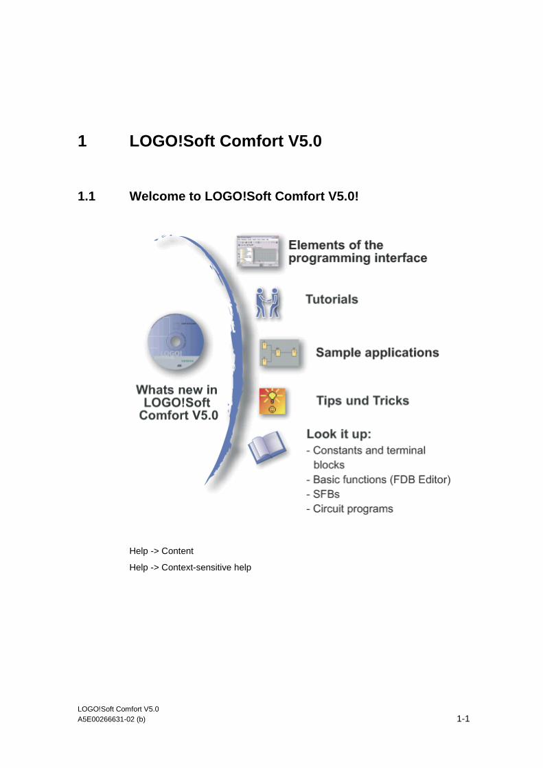
1.1 Welcome to LOGO!Soft Comfort V5.0!
Help -> Content
Help -> Context-sensitive help

LOGO!Soft Comfort V5.0
LOGO!Soft Comfort V5.0 1-2 A5E00266631-02 (b)
1.2 CD Contents
The CD ROM
The CD-ROM included with your installation software for LOGO!Soft Comfort V5.0 contains additional useful information.
The ReadMe file, which contains important information regarding installation, is located in the ..\Readme directory of the CD.
Start.html
Thus file guides you through the contents of the CD-ROM. It helps you to:
• Install LOGO!Soft Comfort
• Start LOGO!Soft Comfort
The file also provides you with access to:
• CAD drawings
• Manuals
• Drivers
• and many more items
The directories
• CAD drawings of the LOGO! devices are found in the ..\CAD directory
• The current LOGO! manual in AcrobatReader format is found in the..\Manuals directory
• The ..\Sample directory contains a few sample applications, which give you a solution incentive for the many fields of applications of the versatile LOGO!.
• The ..\Linux\Acrobat, ..\Mac\acrobat or ..\Windows\Tools\Acrobat directories contain the Adobe AcrobatReader, which you need to view and print out the electronic manual on the CD.
• The ..\Linux\Tools\Application, ..\Mac\Tools\Application or ..\Windows\Tools\ Application directories on the full version CD-ROM you will find an installed version of LOGO!Soft Comfort for each one of these operating systems. As an alternative to an installation LOGO!Soft Comfort, simply copy the corresponding ..\Tools\Application directory to your hard disk drive and start LOGO!Soft Comfort by calling ..\Application\LOGOComfort.
LOGO!Soft Comfort V5.0
LOGO!Soft Comfort V5.0 A5E00266631-02 (b) 1-3
1.3 What's new in LOGO!Soft Comfort V5.0?
New SFBs
PI Controller
Ramp control
Analog multiplexer
New Functionalities
Set output (in simulation mode)
View - > Select Lines
Tools -> Options: Print
• Suppress empty pages
• Print circuit program enlarged or reduced.
Tools -> Options: Screen There are some interesting new functions here.
Tools -> Options: Colors You can change the color of the selected lines.
File -> Properties: Parameter
• Assign and change the password for a circuit program
• Set output values for the analog outputs if the LOGO! is in STOP mode
• Set what should be displayed on the LOGO! after switch-on.
Changed Functionalities
Tools -> Transfer: PC -> LOGO!: .Prior to transferring to LOGO!, you will be prompted to enter a password.
Analog connections to blocks and analog connections are shown in bold.
The Exit dialog has been modified. File -> Exit
In Simulation mode, the message window has new functions. Layout of message texts
With analogous special functions the Gain parameter may also show negative values. Application example: Compare the interior and exterior temperatures when you use LOGO! to control heating.
New Online Help Contents
Basics of processing the analog value
Control and regulate basics
How to establish the cycle time
Heating control

LOGO!Soft Comfort V5.0
LOGO!Soft Comfort V5.0 1-4 A5E00266631-02 (b)
1.4 Ladder Diagram (LAD) and Function Block Diagram (FBD)
LOGO!Soft Comfort provides you with two options of creating circuit programs:
• As ladder diagram (LAD), or
• As function block diagram (FBD).
Who will use the ladder diagram (LAD)?
Users who are used to working with circuit diagrams.
Who will use the function block diagram (FBD)?
Users who are familiar with the logic boxes of Boolean algebra.
Differences between LAD and FBD in the Online Help
The Online Help basically describes the FBD Editor, because its functionality is closely related to that of the LAD Editor. Differences are explained separately and indicated either in the header or with the help of bitmap graphic shown below:
Converting circuit programs
Information on the conversion of circuit programs from LAD to FDB is found here.
Information on the conversion of circuit programs from FBD to LAD is found here.
Switching between LAD und FDB
Information on this topic is found here.

LOGO!Soft Comfort V5.0
LOGO!Soft Comfort V5.0 A5E00266631-02 (b) 1-5
1.5 LOGO! and LOGO!Soft Comfort on the Internet
www.siemens.com/logo/
At this Internet URL you will find abundant information about LOGO! and LOGO!Soft Comfort:
• Updates and upgrades for LOGO!Soft Comfort
• Further language packages, if the LOGO!Soft Comfort CD-ROM does not contain your language
• Numerous sample programs and applications
• FAQs (frequently asked questions)
• Downloads of current manuals and training documentation
• News
• and lots more
You are welcome to visit this site!

LOGO!Soft Comfort V5.0
LOGO!Soft Comfort V5.0 1-6 A5E00266631-02 (b)
1.6 Compatibility
Compatibility with previous LOGO! Hardware series
LOGO!Soft Comfort V5.0 is optimized for LOGO! devices of the 0BA5 series (indicated by the order number).
You may, of course, use the current LOGO!Soft Comfort version to create circuit programs for the previous LOGO! Hardware series. Any differences concerning the operation of LOGO!Soft Comfort and based on differences between the previous series and the current LOGO!s series 0BA5 are described separately. The following bitmap graphic describes the differences:
Compatibility with previous versions of LOGO!Soft Comfort
LOGO!Soft Comfort V5.0 is, of course, upward compatible. You can therefore edit and expand circuit programs written with older version using your current LOGO!Soft Comfort version.
LOGO! Devices with AS Interface
You can connect the modular LOGO! via a communication module to an AS Interface bus.
In doing so, the AS inputs and outputs behave just like standard inputs and outputs.
See also
AS Interface
Here you’ll find important information about LOGO! devices with integrated AS interfaces.
LOGO! Hardware
Here you’ll find information about the individual hardware series. This also includes a table from which you can see which basic and special functions are available as of which hardware series.

LOGO!Soft Comfort V5.0
LOGO!Soft Comfort V5.0 A5E00266631-02 (b) 1-7
1.7 LOGO! with AS Interface
1.7.1 AS Interface
Contents
Here you’ll discover what you must note when using a LOGO! with integrated AS Interface.
Converting circuit programs
Circuit programs containing AS Interface inputs or AS Interface outputs which were created for previous versions of the modular LOGO! are converted in the following operations:
• When the circuit program is assigned to a modular LOGO! via Tools -> Select Hardware...
• When the circuit program is downloaded without changes to a modular LOGO!
If one or more AS interface inputs or outputs are cut out of an older circuit program and pasted into the circuit program for a modular LOGO!, the inserted I/Os are also converted in the new circuit program.
Conversion rules
The inputs Ia1 to Ia4 are converted to I13 to I16. If the target inputs for the conversion are occupied otherwise, the source is converted to the next free input with the lowest block number.
Outputs Qa1 to Qa4 are converted to Q9 to Q12. If the target outputs for the conversion are occupied otherwise, the source is converted to the next free output with the lowest block number.
After conversion, the Info window shows you which AS Interface I/Os were converted to I/Os of the modular LOGO!. If the conversion is not compatible to your physical hardware structure, you must adapt the block numbers of the relevant I/Os via the block properties dialog.

LOGO!Soft Comfort V5.0
LOGO!Soft Comfort V5.0 1-8 A5E00266631-02 (b)
Additional constants and connecting terminals
Note that LOGO! versions 0BA0 to 0BA2 do not distinguish between standard inputs and AS interface inputs. Due to the modular structure of the devices as of version 0BA3, the block number of a digital, analog or AS Interface block is determined by the slot position of the expansion module.
AS Interface inputs
The relevant LOGO! versions are also equipped with Ia inputs used for the ASi bus.
Modular LOGO! devices as of the series 0BA3 do not distinguish between normal inputs and AS interface inputs. The user determines the type of input based on the modules used and the order in which they are installed. This is why AS interface inputs are here displayed only as I input.
AS Interface outputs
Outputs for the AS Interface bus outputs for the ASi bus can be identified by the letter Qa (only available for the relevant LOGO! versions). Modular LOGO! devices as of the series 0BA3 do not distinguish between normal inputs and AS interface inputs. The user determines the type of the input, based on the inserted modules and the order in which they are installed. This is why AS Interface outputs are here indicated only by the letter Q.
LOGO!Soft Comfort V5.0
LOGO!Soft Comfort V5.0 A5E00266631-02 (b) 1-9
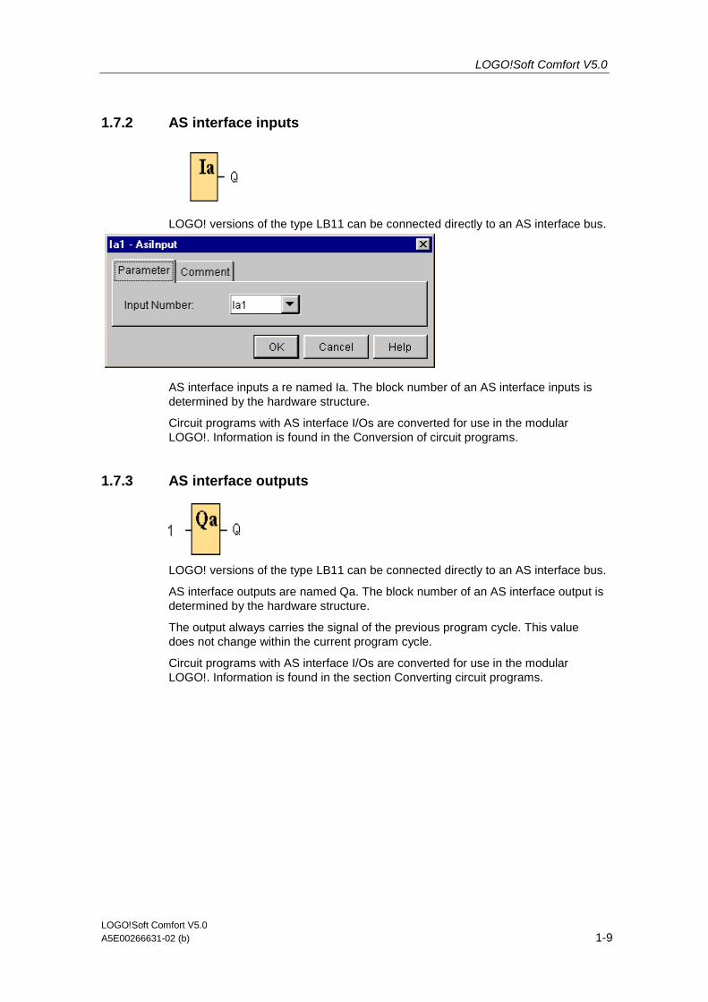
1.7.2 AS interface inputs
LOGO! versions of the type LB11 can be connected directly to an AS interface bus.
AS interface inputs a re named Ia. The block number of an AS interface inputs is determined by the hardware structure.
Circuit programs with AS interface I/Os are converted for use in the modular LOGO!. Information is found in the Conversion of circuit programs.
1.7.3 AS interface outputs
LOGO! versions of the type LB11 can be connected directly to an AS interface bus.
AS interface outputs are named Qa. The block number of an AS interface output is determined by the hardware structure.
The output always carries the signal of the previous program cycle. This value does not change within the current program cycle.
Circuit programs with AS interface I/Os are converted for use in the modular LOGO!. Information is found in the section Converting circuit programs.

LOGO!Soft Comfort V5.0
LOGO!Soft Comfort V5.0 1-10 A5E00266631-02 (b)

LOGO!Soft Comfort V5.0 A5E00266631-02 (b) 2-1
2 User interface
2.1 User interface - Overview
Help
For help on the elements of the user interface, refer to the context-sensitive help.
User interface and programming interface
LOGO!Soft Comfort V5.0 starts with the empty user interface of von LOGO!Soft Comfort. Click on this icon:
Result: LOGO!Soft Comfort creates a new, empty circuit program.
You now see the complete user interface of LOGO!Soft Comfort. The programming interface for creating your circuit programs occupies the greater part of the screen. The icons and logical links of the circuit program are arranged on this programming interface.
User interface
LOGO!Soft Comfort V5.0 2-2 A5E00266631-02 (b)
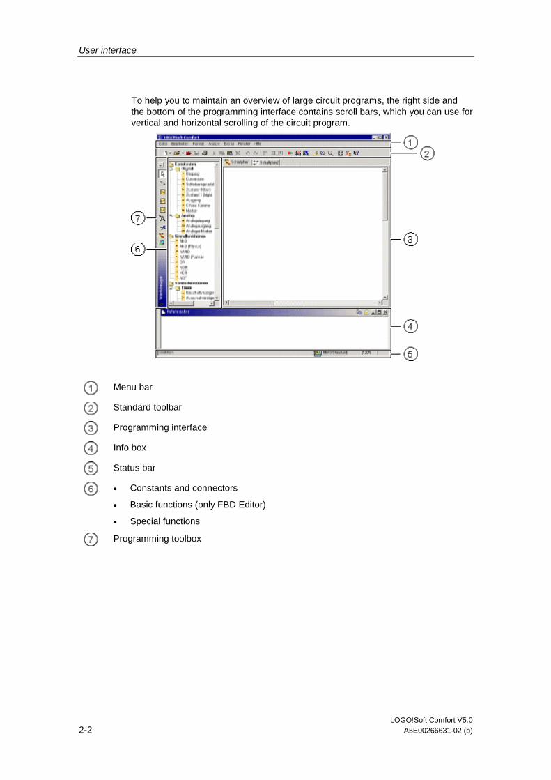
To help you to maintain an overview of large circuit programs, the right side and the bottom of the programming interface contains scroll bars, which you can use for vertical and horizontal scrolling of the circuit program.
Menu bar
Standard toolbar
Programming interface
Info box
Status bar
• Constants and connectors
• Basic functions (only FBD Editor)
• Special functions
Programming toolbox
User interface
LOGO!Soft Comfort V5.0 A5E00266631-02 (b) 2-3
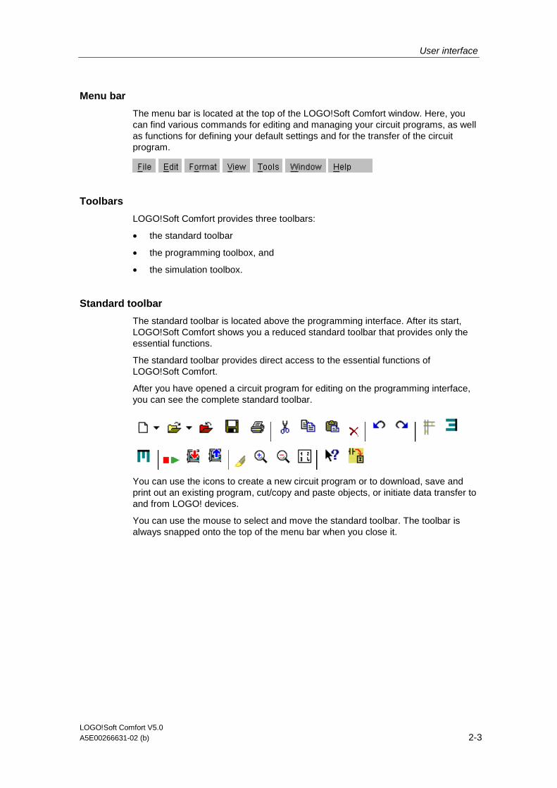
Menu bar
The menu bar is located at the top of the LOGO!Soft Comfort window. Here, you can find various commands for editing and managing your circuit programs, as well as functions for defining your default settings and for the transfer of the circuit program.
Toolbars
LOGO!Soft Comfort provides three toolbars:
• the standard toolbar
• the programming toolbox, and
• the simulation toolbox.
Standard toolbar
The standard toolbar is located above the programming interface. After its start, LOGO!Soft Comfort shows you a reduced standard toolbar that provides only the essential functions.
The standard toolbar provides direct access to the essential functions of LOGO!Soft Comfort.
After you have opened a circuit program for editing on the programming interface, you can see the complete standard toolbar.
You can use the icons to create a new circuit program or to download, save and print out an existing program, cut/copy and paste objects, or initiate data transfer to and from LOGO! devices.
You can use the mouse to select and move the standard toolbar. The toolbar is always snapped onto the top of the menu bar when you close it.

User interface
LOGO!Soft Comfort V5.0 2-4 A5E00266631-02 (b)
Programming toolbox
The programming toolbox is located at the bottom of the screen. Its icons can be used to change to other editing modes, or for quick and easy creation or editing of a circuit program.
or
You can drag and drop the programming toolbox to another location with the mouse. The toolbox is always snapped onto the top of the menu bar when you close it.
The LAD Editor no longer contains the Basic function (SF) icon, because you create logical "AND" and "OR" links by interconnecting individual blocks.
Simulation toolbox
This toolbox is only relevant for the simulation of circuit programs. Further information is found here.
Info box
The Info Window, located at the bottom of the programming interface, displays information and notes, as well as the LOGO! devices recommended via the Tools -> Determine LOGO! function for use in your circuit program.
Status bar
The status bar is located at the bottom of the program window. It shows the currently active tool, the program status, the set zoom factor, the page number of the circuit diagram and the selected LOGO! device.
User interface
LOGO!Soft Comfort V5.0 A5E00266631-02 (b) 2-5
2.2 Description of the Info Window
Content
The info window shows in particular:
• Error messages generated at the start of simulation
• LOGO! devices determined via the Tools -> Determine LOGO! menu command or the function key [F2]
• The date and time of the message
• The name of the circuit program for which the message was generated.
If you have opened more than one circuit program, you can determine to which program the message belongs to.
At the start of simulation mode, the function analyzes the circuit program with regard to its resources and the LOGO! to be used. The resources used and errors occurred are displayed in the info window.
The info window displays all information in successive order. Use the scroll bar to browse all the information pages. All information is deleted from the info window when you close LOGO!Soft Comfort.
Operation
You can open and close the Info Window via View -> Info window or the [F4] function key. The Info window is usually positioned at the bottom of the programming interface. You can move it with the mouse, and snap it onto the top of the programming interface, in the same way as you move the toolbars. You can move the window via drag and drop, or move it out of LOGO!Soft Comfort to open it as a separate window.
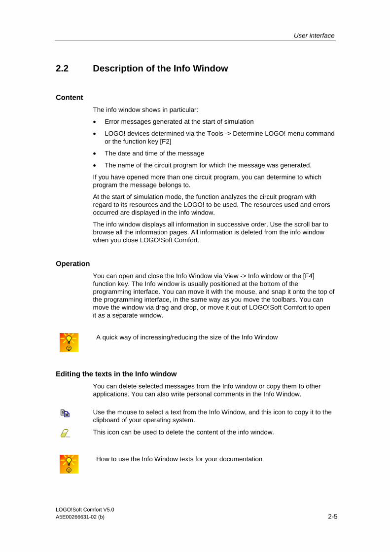
A quick way of increasing/reducing the size of the Info Window
Editing the texts in the Info window
You can delete selected messages from the Info window or copy them to other applications. You can also write personal comments in the Info Window.
Use the mouse to select a text from the Info Window, and this icon to copy it to the clipboard of your operating system.
This icon can be used to delete the content of the info window.
How to use the Info Window texts for your documentation
User interface
LOGO!Soft Comfort V5.0 2-6 A5E00266631-02 (b)
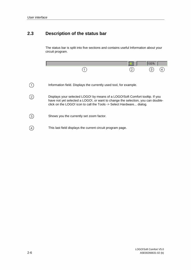
2.3 Description of the status bar
The status bar is split into five sections and contains useful Information about your circuit program.
Information field. Displays the currently used tool, for example.
Displays your selected LOGO! by means of a LOGO!Soft Comfort tooltip. If you have not yet selected a LOGO!, or want to change the selection, you can double-click on the LOGO! icon to call the Tools -> Select Hardware... dialog.
Shows you the currently set zoom factor.
This last field displays the current circuit program page.
User interface
LOGO!Soft Comfort V5.0 A5E00266631-02 (b) 2-7
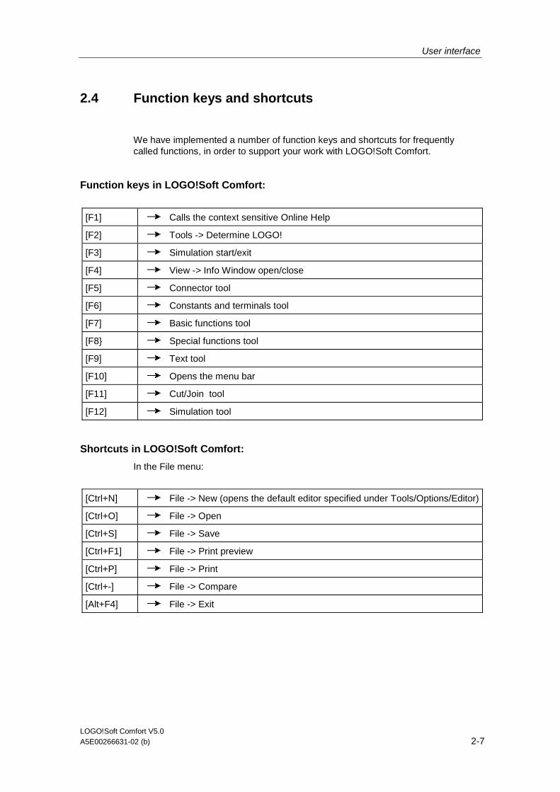
2.4 Function keys and shortcuts
We have implemented a number of function keys and shortcuts for frequently called functions, in order to support your work with LOGO!Soft Comfort.
Function keys in LOGO!Soft Comfort:
[F1] Calls the context sensitive Online Help
[F2] Tools -> Determine LOGO!
[F3] Simulation start/exit
[F4] View -> Info Window open/close
[F5] Connector tool
[F6] Constants and terminals tool
[F7] Basic functions tool
[F8} Special functions tool
[F9] Text tool
[F10] Opens the menu bar
[F11] Cut/Join tool
[F12] Simulation tool
Shortcuts in LOGO!Soft Comfort:
In the File menu:
[Ctrl+N] File -> New (opens the default editor specified under Tools/Options/Editor)
[Ctrl+O] File -> Open
[Ctrl+S] File -> Save
[Ctrl+F1] File -> Print preview
[Ctrl+P] File -> Print
[Ctrl+-] File -> Compare
[Alt+F4] File -> Exit
User interface
LOGO!Soft Comfort V5.0 2-8 A5E00266631-02 (b)
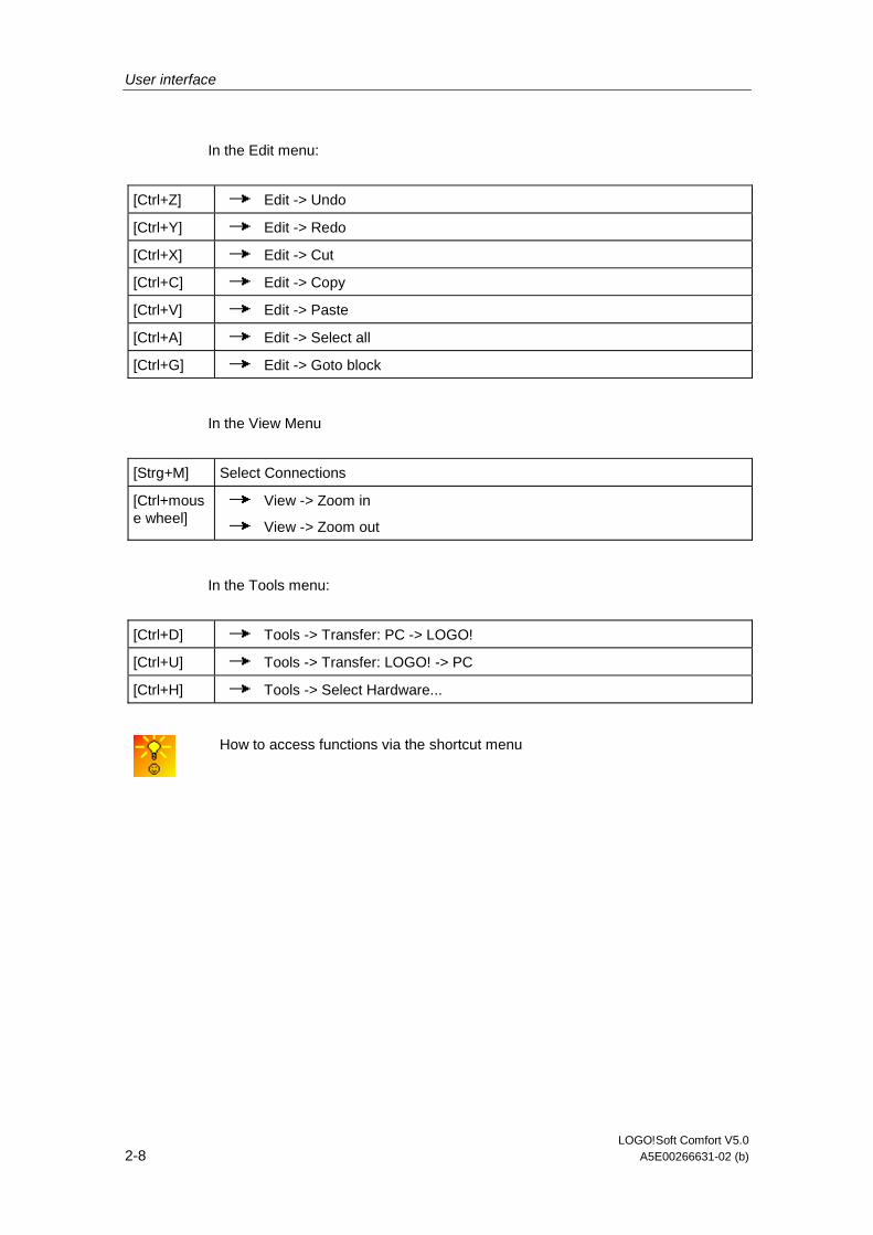
In the Edit menu:
[Ctrl+Z] Edit -> Undo
[Ctrl+Y] Edit -> Redo
[Ctrl+X] Edit -> Cut
[Ctrl+C] Edit -> Copy
[Ctrl+V] Edit -> Paste
[Ctrl+A] Edit -> Select all
[Ctrl+G] Edit -> Goto block
In the View Menu
[Strg+M] Select Connections
[Ctrl+mouse wheel]
View -> Zoom in
View -> Zoom out
In the Tools menu:
[Ctrl+D] Tools -> Transfer: PC -> LOGO!
[Ctrl+U] Tools -> Transfer: LOGO! -> PC
[Ctrl+H] Tools -> Select Hardware...
How to access functions via the shortcut menu
User interface
LOGO!Soft Comfort V5.0 A5E00266631-02 (b) 2-9
2.5 Toolbars
2.5.1 Simulation toolbox and status window
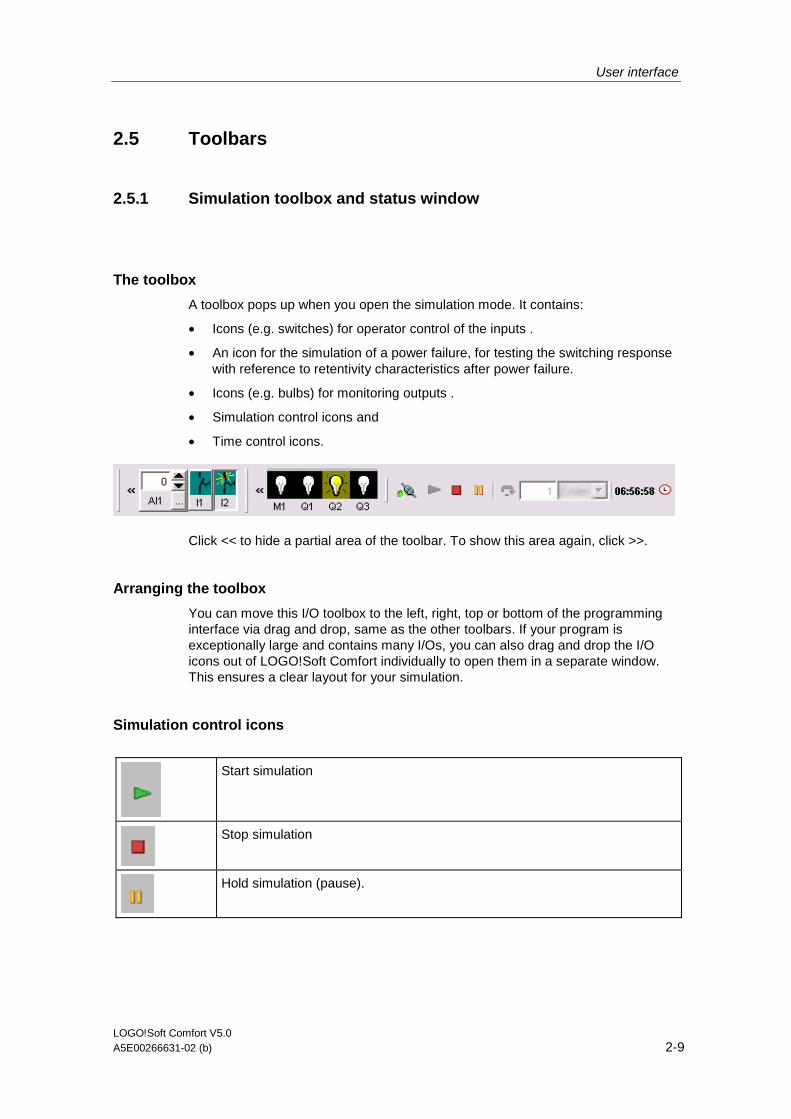
The toolbox
A toolbox pops up when you open the simulation mode. It contains:
• Icons (e.g. switches) for operator control of the inputs .
• An icon for the simulation of a power failure, for testing the switching response with reference to retentivity characteristics after power failure.
• Icons (e.g. bulbs) for monitoring outputs .
• Simulation control icons and
• Time control icons.
Click << to hide a partial area of the toolbar. To show this area again, click >>.
Arranging the toolbox
You can move this I/O toolbox to the left, right, top or bottom of the programming interface via drag and drop, same as the other toolbars. If your program is exceptionally large and contains many I/Os, you can also drag and drop the I/O icons out of LOGO!Soft Comfort individually to open them in a separate window. This ensures a clear layout for your simulation.
Simulation control icons
Start simulation
Stop simulation
Hold simulation (pause).
User interface
LOGO!Soft Comfort V5.0 2-10 A5E00266631-02 (b)
Time control
If you have programmed a time-sensitive circuit, you should use the time control to monitor the reaction of your circuit program.
Start simulation for e specific time or number of cycles.
Set the period and the number of cycles using the following icons.
Setting the period and the time base for a time limited simulation or setting a specific number of cycles
Display of the current time in LOGO!Soft Comfort
Modification of the current time in LOGO!Soft Comfort
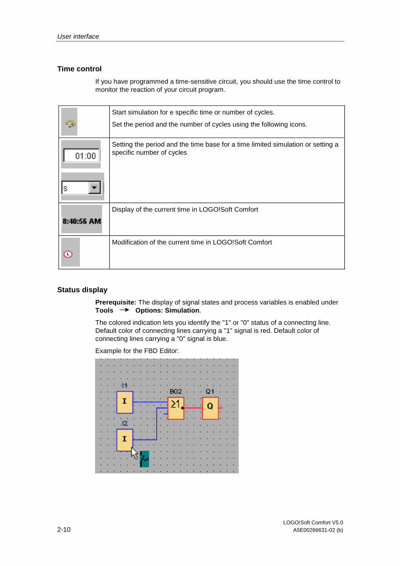
Status display
Prerequisite: The display of signal states and process variables is enabled under Tools Options: Simulation.
The colored indication lets you identify the "1" or "0" status of a connecting line. Default color of connecting lines carrying a "1" signal is red. Default color of connecting lines carrying a "0" signal is blue.
Example for the FBD Editor:
User interface
LOGO!Soft Comfort V5.0 A5E00266631-02 (b) 2-11
2.5.2 Standard toolbar
2.5.2.1 Standard toolbar - Overview
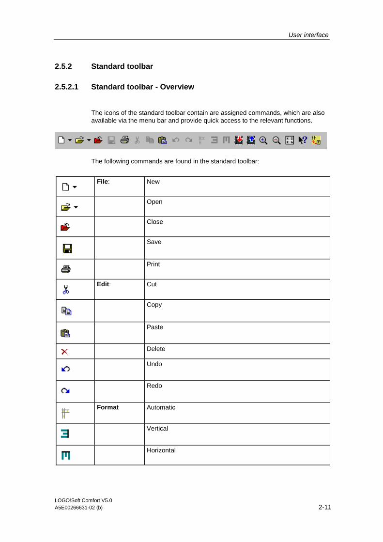
The icons of the standard toolbar contain are assigned commands, which are also available via the menu bar and provide quick access to the relevant functions.
The following commands are found in the standard toolbar:
File: New
Open
Close
Save
Edit: Cut
Copy
Paste
Delete
Undo
Redo
Format Automatic
Vertical
Horizontal

User interface
LOGO!Soft Comfort V5.0 2-12 A5E00266631-02 (b)
Tools: Switch LOGO! Mode
PC -> LOGO! (Download)
LOGO! -> PC (Upload)
View: Select Lines
Zoom in
Zoom out
File: Properties -> Page format
Convert (LAD > FBD) Convert (FBD > LAD)
Help: Context-sensitive help
2.5.2.2 File -> New
Menu command New
The command opens a new window with an empty programming interface for programming in LAD or FBD, depending on your set mode. Depending on your default setting, a window opens with a number of tabs in which you can specify the properties of the circuit program you are going to create. This window can also be called later to either enter or modify the properties via the File -> Properties... menu.
Program sections that have previously been placed on the clipboard by means of the cut or copy functions remain on the clipboard and can be pasted into the new circuit program.
An icon for this menu command is also found in the standard toolbar.
Switching between LAD and FBD
The editor used to create a new circuit program is set under Tools -> Options: Editor.
Select to create the circuit program either in LAD or in FBD by clicking on the small arrow on the right side of the "New" icon.
User interface
LOGO!Soft Comfort V5.0 A5E00266631-02 (b) 2-13
2.5.2.3 File -> Open...
File Open
The command opens a dialog box from which you can select and open a previously created circuit program for further editing on the programming interface. Circuit programs created in LOGO!Soft Comfort have the file extension *.lsc. The loaded circuit program is opened in a new window.
An icon for this menu command is also available in the standard toolbar
Circuit programs of LOGO!Soft Standard
The user can also import files created with LOGO!Soft Standard (filename extension = *.lgo). Use the "File type" menu item to select the type of file you want to have displayed. Missing information concerning the graphical layout of the circuit program is appropriately complemented by LOGO!Soft Comfort.
Alternatives
• In Windows you can also drag and drop a LOGO!Soft Comfort circuit program file to the programming interface. When you "release" this file on the programming interface, it is opened in a new window.
• A double-click on a file with the extension *.lsc or *.lld in the file manager automatically opens LOGO!Soft Comfort with this file.
What happens with the clipboard content?
• Program objects previously copied to the clipboard via the cut or copy functions are stored in the clipboard and can be pasted into the new circuit program.
Last opened files
At end of the File menu you are displayed a list of the last files opened in LOGO!Soft Comfort.
User interface
LOGO!Soft Comfort V5.0 2-14 A5E00266631-02 (b)
2.5.2.4 File -> Close
File Close
Click on the Close menu command to close the active window. If you do not yet saved the current circuit program, you are prompted to do so.
The standard toolbar also contains an icon for this menu command.
As an alternative, you can right-click on the tab of a circuit program and select the Close menu command from the shortcut menu.
2.5.2.5 File -> Save
File Save
When you initially save a newly created program, a window opens in which you can specify the path and filename under which you want to save your circuit program. Details are found under File -> Save as... .
If you are saving a modified version of an existing program, a Quick Save is performed. The old version of the circuit program is overwritten by the revised version, i.e. the new program is saved to the same path and name as the source file.
The standard toolbar also contains an icon for this menu command.
As an alternative, you can right-click on the tab of a circuit program and select the Save menu command from the shortcut menu.
User interface
LOGO!Soft Comfort V5.0 A5E00266631-02 (b) 2-15
2.5.2.6 File -> Print
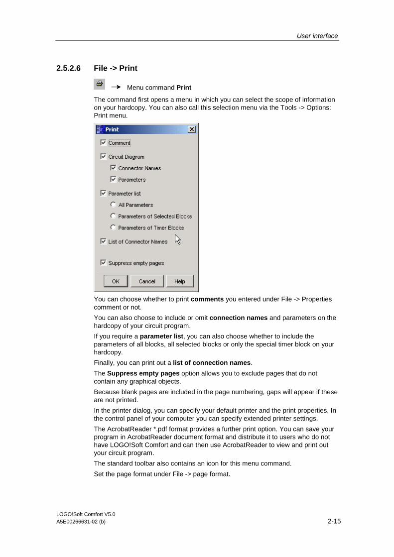
Menu command Print
The command first opens a menu in which you can select the scope of information on your hardcopy. You can also call this selection menu via the Tools -> Options: Print menu.
You can choose whether to print comments you entered under File -> Properties comment or not.
You can also choose to include or omit connection names and parameters on the hardcopy of your circuit program.
If you require a parameter list, you can also choose whether to include the parameters of all blocks, all selected blocks or only the special timer block on your hardcopy.
Finally, you can print out a list of connection names.
The Suppress empty pages option allows you to exclude pages that do not contain any graphical objects.
Because blank pages are included in the page numbering, gaps will appear if these are not printed.
In the printer dialog, you can specify your default printer and the print properties. In the control panel of your computer you can specify extended printer settings.
The AcrobatReader *.pdf format provides a further print option. You can save your program in AcrobatReader document format and distribute it to users who do not have LOGO!Soft Comfort and can then use AcrobatReader to view and print out your circuit program.
The standard toolbar also contains an icon for this menu command.
Set the page format under File -> page format.
User interface
LOGO!Soft Comfort V5.0 2-16 A5E00266631-02 (b)
2.5.2.7 Edit -> Cut
Edit Cut
The command deletes one or more selected objects, i.e. blocks and/or connecting lines, from the programming interface and copies them to the clipboard.
The standard toolbar also contains an icon for this menu command.
2.5.2.8 Edit -> Copy
Edit Copy
The command is used to copy one or more selected objects, i.e. blocks/texts/connecting lines, to the clipboard.
The standard toolbar also contains an icon for this menu command.
2.5.2.9 Edit -> Paste
Copies the clipboard content to the programming interface. The insert position is either below the previously selected object, or a position determined with a mouse click.
The standard toolbar also contains an icon for this menu command.
Edit Paste
You can only paste the clipboard content if sufficient resources are available. Blocks require a certain amount of resources, depending on the block type. An error message is generated if your system does not provide sufficient resources.
Connecting lines with open ends can only be pasted. These can only be pasted if they connect two blocks and were copied to the clipboard together with those.
2.5.2.10 Edit -> Delete
Edit Delete
The command deletes selected objects, without copying them to the clipboard. You can retrieve deleted objects by means of the Undo function.

User interface
LOGO!Soft Comfort V5.0 A5E00266631-02 (b) 2-17
2.5.2.11 Edit -> Undo
Edit Undo
This command allows you to undo actions carried out on the programming interface, i.e. this is always the last action. Position your mouse pointer on the undo menu command and hold it there briefly. The tooltip opens and shows you the actions you can undo by clicking on the menu item. Currently you can undo up to 30 actions.
The standard toolbar also contains an icon for this menu command.
2.5.2.12 Edit -> Redo
Edit Redo
The redo reverts the last undo action. Click on the menu command to view the tooltip for the action to be redone.
The standard toolbar also contains an icon for this menu command.
User interface
LOGO!Soft Comfort V5.0 2-18 A5E00266631-02 (b)
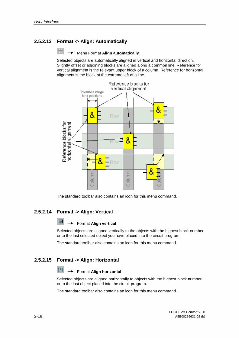
2.5.2.13 Format -> Align: Automatically
Menu Format Align automatically
Selected objects are automatically aligned in vertical and horizontal direction. Slightly offset or adjoining blocks are aligned along a common line. Reference for vertical alignment is the relevant upper block of a column. Reference for horizontal alignment is the block at the extreme left of a line.
The standard toolbar also contains an icon for this menu command.
2.5.2.14 Format -> Align: Vertical
Format Align vertical
Selected objects are aligned vertically to the objects with the highest block number or to the last selected object you have placed into the circuit program.
The standard toolbar also contains an icon for this menu command.
2.5.2.15 Format -> Align: Horizontal
Format Align horizontal
Selected objects are aligned horizontally to objects with the highest block number or to the last object placed into the circuit program.
The standard toolbar also contains an icon for this menu command.
User interface
LOGO!Soft Comfort V5.0 A5E00266631-02 (b) 2-19
2.5.2.16 Tools -> Transfer: Switch LOGO! Mode
Tools -> Transfer - > Switch LOGO! Mode
This special function is only available with devices as of hardware series 0BA4.
When you click on this symbol you change the mode of a connected LOGO! from STOP mode to RUN mode or from RUN mode to STOP mode.
2.5.2.17 Tools -> Transfer: PC -> LOGO!
Tools Transfer: PC -> LOGO!
This command is used to download a circuit program created on the PC in LOGO!Soft Comfort to the LOGO! module. The name of the program transferred to LOGO! is specified in the File -> Properties... menu.
The standard toolbar also contains an icon for this menu command.
Preparations
Prior to the download, the system determines the LOGO! version at least required for your circuit program. The modular LOGO! always provides all available resources for your circuit program at the I/Os. It is up to the user to install an appropriate number of expansion modules in the base device.
Error messages
If the circuit program cannot be downloaded to the available LOGO!, the transfer is aborted and an error message is displayed. The user is informed of unknown LOGO! versions and then has the choice of continuing or canceling the download. A message in the status bar reports the successful download.
Transfer messages are displayed in the status bar and in the Info Window.
Detailed error messages are displayed in the Info Window.
Password
If you have assigned a password to your circuit program, then you will be asked to enter this password before you transfer to LOGO!. The circuit program will then only be transferred to LOGO! if you have entered the correct password.

User interface
LOGO!Soft Comfort V5.0 2-20 A5E00266631-02 (b)
2.5.2.18 Tools -> Transfer: LOGO! -> PC
Tools Tranfer LOGO! -> PC
The circuit program is imported from LOGO! to LOGO!Soft Comfort. Transfer messages are displayed in the status bar and on the Info Window.
The standard toolbar also contains an icon for this menu command.
Missing graphical information
A program imported from LOGO! to LOGO!Soft Comfort does not contain any graphical information for the block layout on the programming interface. A suitable layout for the circuit program is therefore generated automatically. The generated circuit diagram corresponds with the layout in the LOGO!Soft block diagram, except that multiple instances of the same block are not displayed, but are instead identified by means of the block connectors.
The blocks are always arranged at the top left corner of the programming interface. If necessary, the user should use the scroll bars to bring the circuit program into view.
Cutting connections
If you have set the "Cut connections during import/upload" check box under Tools -> Options: Cut connections, the relevant connections are cut during the upload from LOGO! to the PC, according to the rules set in this dialog.
Password
At the start of the upload of a password protected circuit program from the LOGO! to the PC, the user is prompted to enter the password. If the wrong or no password is entered, the transfer is aborted with an error message.
User interface
LOGO!Soft Comfort V5.0 A5E00266631-02 (b) 2-21
2.5.2.19 View - > Select Lines
View Select Lines
With this setting all connections (= lines) that lead to or away from a selected block are shown in color.
If you select a single connection with this setting, then the selected connection is highlighted in color.
Under Tools > Options > Screen you can set whether the connections should also be labeled. Under Tools > Options > Colors you can set which colors the connections should be displayed in.
Tools -> Options: Screen
Tools -> Options: Colors
2.5.2.20 View -> Zoom in
View Zoom
The zoom factor is increased defined steps:
25 (min) 50 75 100 (standrd) 150 200 250 300 400 (max)
The standard toolbar also contains an icon for this menu command.
A quick and easy way of zooming your circuit program window
2.5.2.21 View -> Zoom out
View Zoom out
The zoom factor is reduced in defined steps:
400 (Max) 300 250 200 150 100 (standard) 75 50 25 (Min)
The standard toolbar also contains an icon for this menu command.
A quick and easy way of zooming your circuit program window
User interface
LOGO!Soft Comfort V5.0 2-22 A5E00266631-02 (b)
2.5.2.22 File -> Properties...
The properties dialog contains the following tabs:
• Common properties
• Comment
• Statistics
• Page format
• Properties Parameter
2.5.2.23 File -> Convert (LAD > FBD)
Use this function to convert your circuit diagram from LAD to FBD.
The following rules apply to the conversion from LAD to FBD:
• A series circuit of contacts is converted into an AND block
• A parallel circuit of contacts is converted into an OR block
• User-defined comments are not included, as their position in the circuit diagram can not be defined based on blocks
• Crosslinks, i.e. connections of a block output to multiple block inputs and at least one of the inputs is connected to multiple block outputs, are converted into an OR block. Inputs for the OR block are all block outputs of the crosslink. The output of the OR block is connected to all block inputs of the crosslink.
• Internal flags are resolved, and the current paths are linked.
Overview: File -> Convert (FBD > LAD)
User interface
LOGO!Soft Comfort V5.0 A5E00266631-02 (b) 2-23
2.5.2.24 File -> Convert (FBD > LAD)
Use this function to convert your circuit diagram from FBD to LAD.
The following rules apply to the FBD to LAD conversion:
• An AND block is converted into a series contact circuit
• An OR block is converted into a parallel contact circuit
• Comments for basic functions are not applied in LAD, as a basic function is converted into multiple contacts. Thus, the comment cannot be assigned definitely.
• In LAD, input comments are assigned to all contacts of this input.
• User-defined comments are not included, as their position in the circuit diagram can not be defined based on blocks
• XOR blocks must be converted into corresponding LAD logic consisting of positive and negative contacts.
Note
When converting, the total number of blocks in your circuit program can sometimes increase. This could cause the permitted number of blocks for your LOGO! to exceed.
It is therefore not always possible to convert from FBD to LAD.
Remedy: Under Tools > Select Hardware… select the hardware series 0BA5. Start converting to LAD. Then under Tools > Determine LOGO!, see which hardware series is compatible with the circuit program.
Overview: File -> Convert (FBD > LAD)
2.5.2.25 Help -> Context-sensitive help
Help Context-sensitive help
To call a help file on an object, first click on the context-sensitive help icon (see above) and then on the object.
Result: A window opens with information on this object.
You can also right-click on objects on the programming interface call a corresponding help. The help entry in the shortcut menu called provides you with the required support.
The standard toolbar also contains an icon for this menu command.
User interface
LOGO!Soft Comfort V5.0 2-24 A5E00266631-02 (b)
2.5.3 Programming toolbox
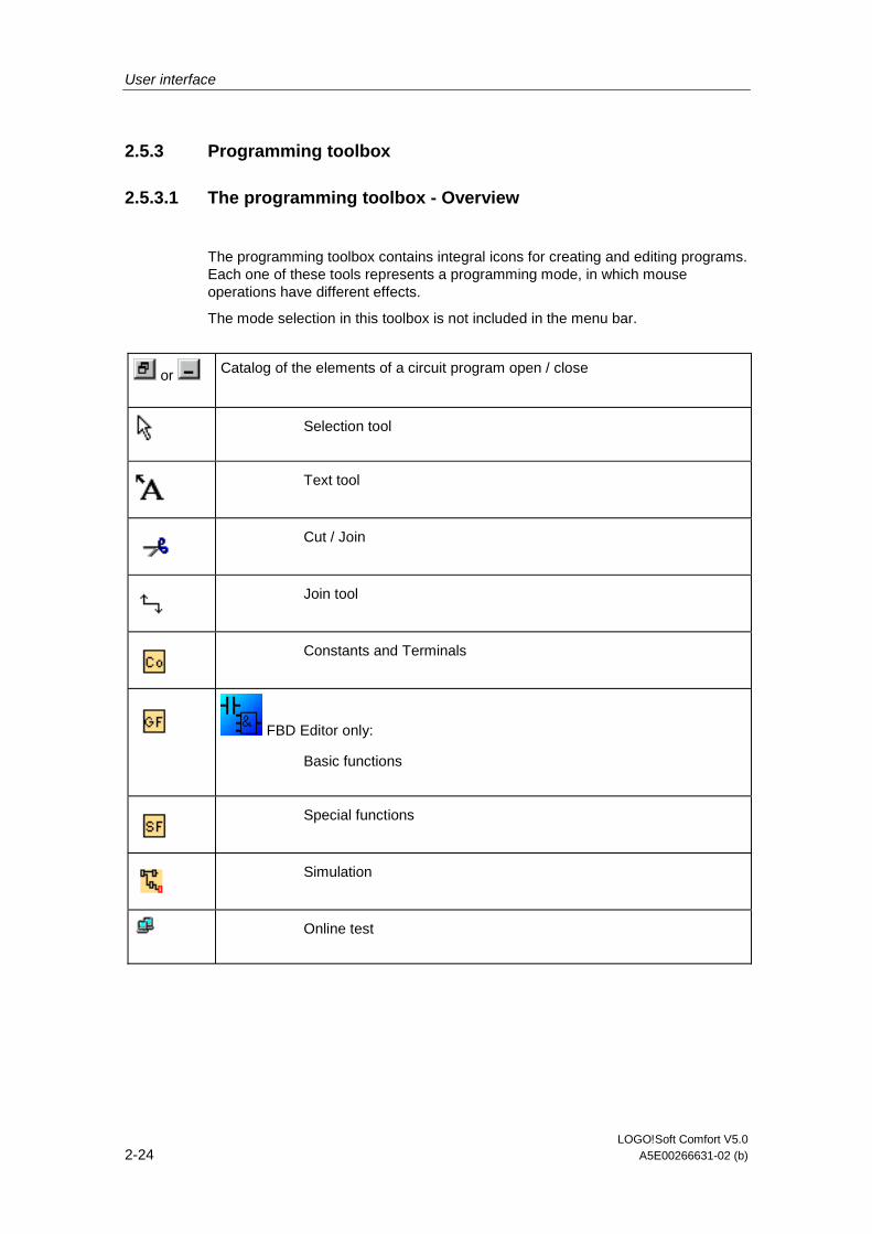
2.5.3.1 The programming toolbox - Overview
The programming toolbox contains integral icons for creating and editing programs. Each one of these tools represents a programming mode, in which mouse operations have different effects.
The mode selection in this toolbox is not included in the menu bar.
or Catalog of the elements of a circuit program open / close
Selection tool
Text tool
Cut / Join
Join tool
Constants and Terminals
FBD Editor only:
Basic functions
Special functions
Simulation
Online test
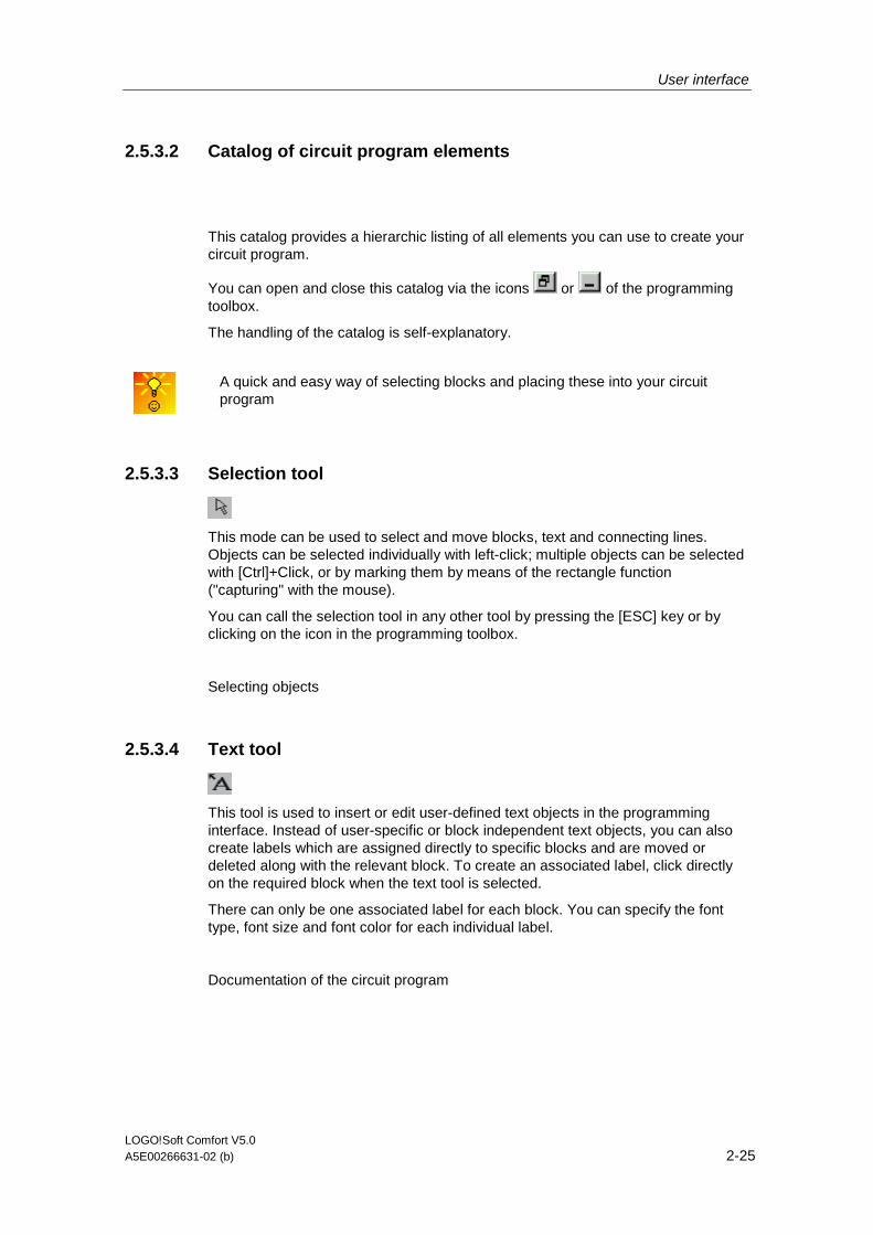
User interface
LOGO!Soft Comfort V5.0 A5E00266631-02 (b) 2-25
2.5.3.2 Catalog of circuit program elements
This catalog provides a hierarchic listing of all elements you can use to create your circuit program.
You can open and close this catalog via the icons or of the programming toolbox.
The handling of the catalog is self-explanatory.
A quick and easy way of selecting blocks and placing these into your circuit program
2.5.3.3 Selection tool
This mode can be used to select and move blocks, text and connecting lines. Objects can be selected individually with left-click; multiple objects can be selected with [Ctrl]+Click, or by marking them by means of the rectangle function ("capturing" with the mouse).
You can call the selection tool in any other tool by pressing the [ESC] key or by clicking on the icon in the programming toolbox.
Selecting objects
2.5.3.4 Text tool
This tool is used to insert or edit user-defined text objects in the programming interface. Instead of user-specific or block independent text objects, you can also create labels which are assigned directly to specific blocks and are moved or deleted along with the relevant block. To create an associated label, click directly on the required block when the text tool is selected.
There can only be one associated label for each block. You can specify the font type, font size and font color for each individual label.
Documentation of the circuit program
User interface
LOGO!Soft Comfort V5.0 2-26 A5E00266631-02 (b)
2.5.3.5 Cut/Join
This tool is used to cut and join connections between blocks. To cut a connection, select the relevant line with left-click while the Cut/Join tool is active. The connection is replaced at the blocks by a reference to the partner block. The reference is labeled with the page number, block number and the I/O of the partner block.
Cut connections
2.5.3.6 Connector tool
This tool is used to connect the block I/Os. To do so, move the mouse pointer to a block input or output and press the left mouse button. Keep the mouse button pressed, drag the mouse pointer from your selected source terminal to the target terminal. Now release the mouse button to anchor the connecting line to both terminals. While the connecting line is being drawn, it is shown as a straight line between the first terminal and the mouse pointer. Once it is anchored, it appears as a combination of horizontal and vertical lines, which can be manipulated using the selection tool.
Connecting blocks
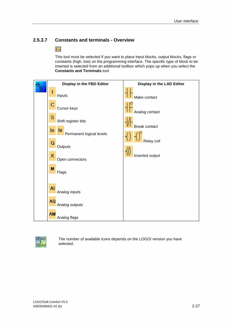
User interface
LOGO!Soft Comfort V5.0 A5E00266631-02 (b) 2-27
2.5.3.7 Constants and terminals - Overview
This tool must be selected if you want to place input blocks, output blocks, flags or constants (high, low) on the programming interface. The specific type of block to be inserted is selected from an additional toolbox which pops up when you select the Constants and Terminals tool.
Display in the FBD Editor
Inputs
Cursor keys
Shift register bits
Permanent logical levels
Outputs
Open connectors
Flags
Analog inputs
Analog outputs
Analog flags
Display in the LAD Editor
Make contact
Analog contact
Break contact
Relay coil
Inverted output
The number of available icons depends on the LOGO! version you have selected.
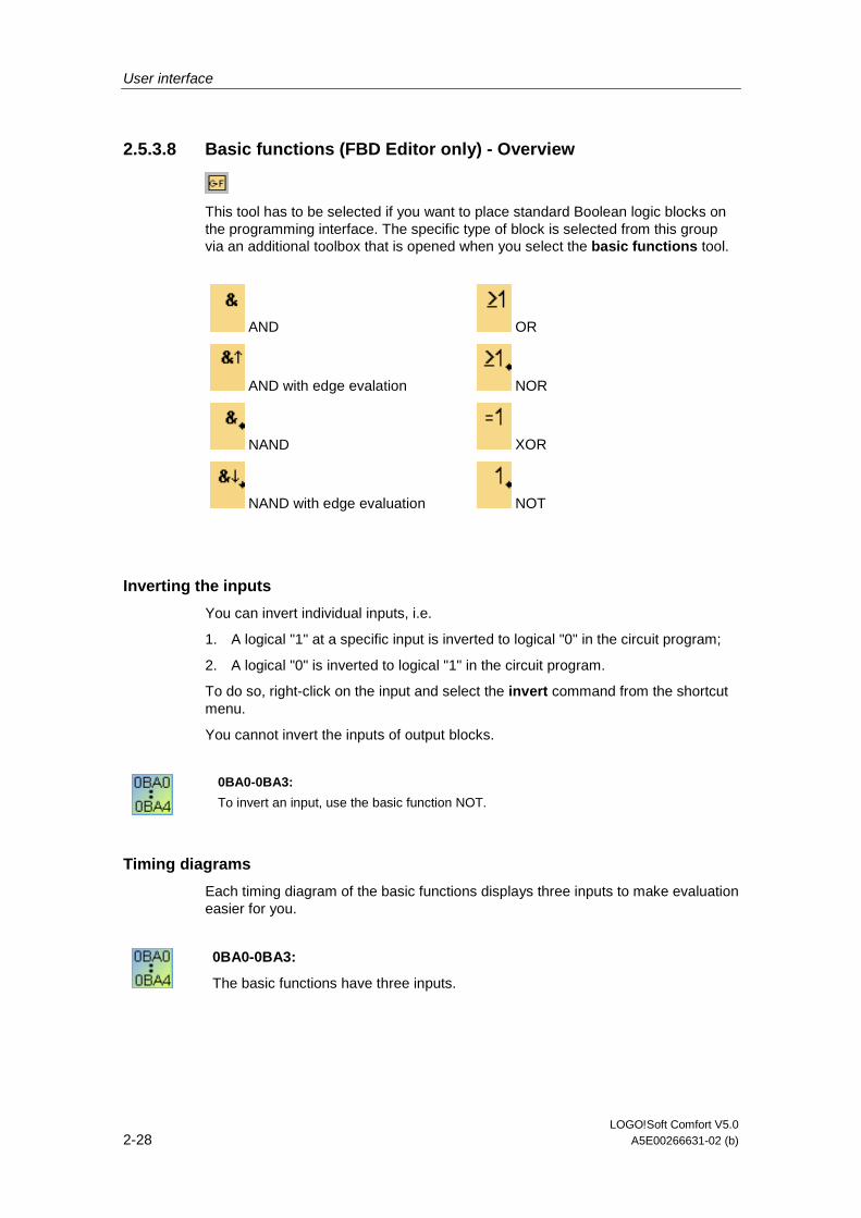
User interface
LOGO!Soft Comfort V5.0 2-28 A5E00266631-02 (b)
2.5.3.8 Basic functions (FBD Editor only) - Overview
This tool has to be selected if you want to place standard Boolean logic blocks on the programming interface. The specific type of block is selected from this group via an additional toolbox that is opened when you select the basic functions tool.
AND
AND with edge evalation
NAND
NAND with edge evaluation
OR
NOR
XOR
NOT
Inverting the inputs
You can invert individual inputs, i.e.
1. A logical "1" at a specific input is inverted to logical "0" in the circuit program;
2. A logical "0" is inverted to logical "1" in the circuit program.
To do so, right-click on the input and select the invert command from the shortcut menu.
You cannot invert the inputs of output blocks.
0BA0-0BA3:
To invert an input, use the basic function NOT.
Timing diagrams
Each timing diagram of the basic functions displays three inputs to make evaluation easier for you.
0BA0-0BA3:
The basic functions have three inputs.
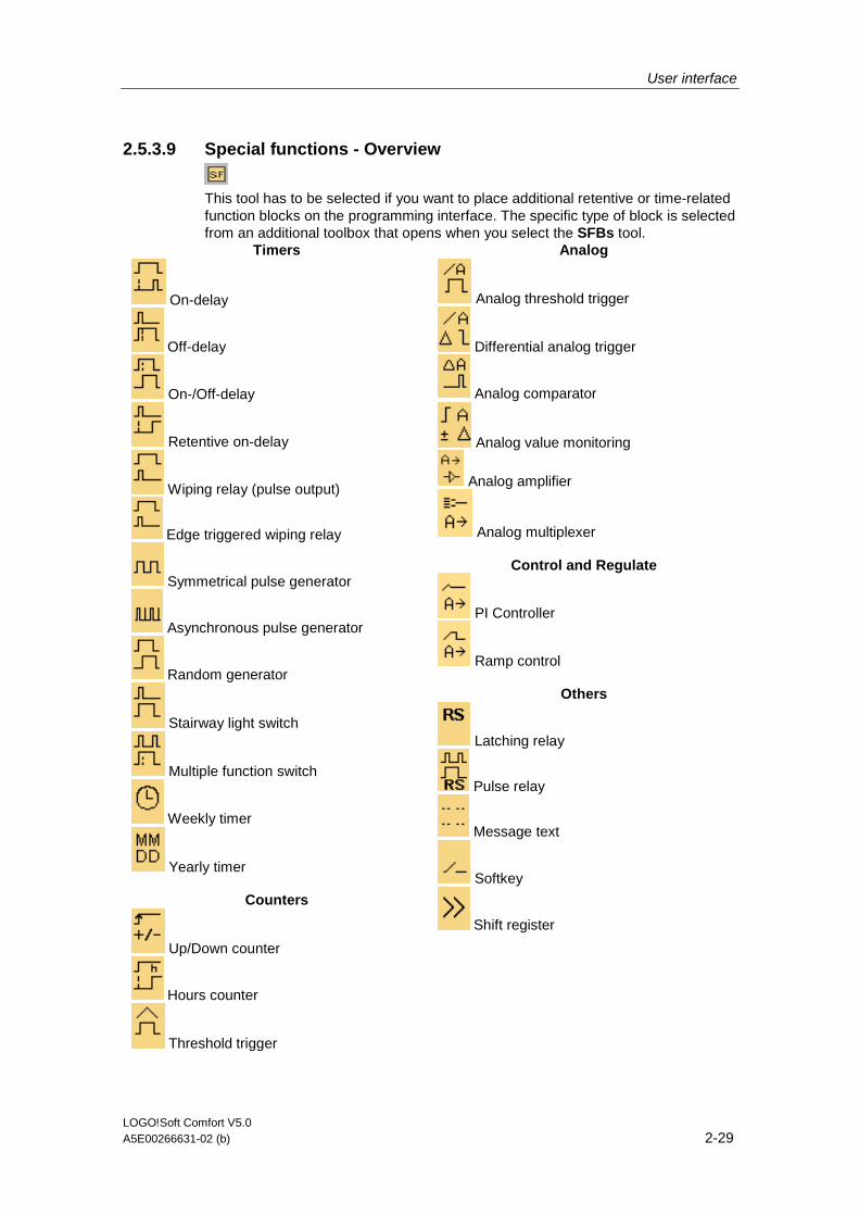
User interface
LOGO!Soft Comfort V5.0 A5E00266631-02 (b) 2-29
2.5.3.9 Special functions - Overview
This tool has to be selected if you want to place additional retentive or time-related function blocks on the programming interface. The specific type of block is selected from an additional toolbox that opens when you select the SFBs tool.
Timers
On-delay
Off-delay
On-/Off-delay
Retentive on-delay
Wiping relay (pulse output)
Edge triggered wiping relay
Symmetrical pulse generator
Asynchronous pulse generator
Random generator
Stairway light switch
Multiple function switch
Weekly timer
Yearly timer
Counters
Up/Down counter
Hours counter
Threshold trigger
Analog
Analog threshold trigger
Differential analog trigger
Analog comparator
Analog value monitoring
Analog amplifier
Analog multiplexer
Control and Regulate
PI Controller
Ramp control
Others
Latching relay
Pulse relay
Message text
Softkey
Shift register
User interface
LOGO!Soft Comfort V5.0 2-30 A5E00266631-02 (b)
The LAD Editor offers you the following additional functions:
AND with edge evaluation
NAND with edge evaluation
FBD editor: description of the blocks of special functions
The description of the blocks of special functions in the circuit diagram begins with timer blocks ("T"), with counter blocks ("C") and with the remaining blocks ("SF").
The LOGO! version you have selected determines:
• The available blocks and
• The parameters you can set.
Inverting inputs
You can invert individual inputs, i.e.
1. A logical "1" at a specific input is inverted to logical "0" in the circuit program;
2. A logical "0" is inverted to logical "1" in the circuit program.
To do so, right-click on the input and select the invert command from the shortcut menu.
You cannot invert the inputs of output blocks.
0BA0-0BA3:
To invert an input, use the basic function NOT.
Block configuration
The block properties dialog provides you with an easy means of setting the various block parameters.
You can also assign parameters to blocks by means of other blocks.
If you click on the Reference button alongside a parameter in the block properties window, you can select which other block you would like to assign the parameters to.
This way it is possible, for example, to assign the time of an off-delay with an analog value.
A quick way of changing block parameters

User interface
LOGO!Soft Comfort V5.0 A5E00266631-02 (b) 2-31
Protection
If a Protected check box exists for the protection of a block parameter, you can enable or lock the display and editing of this parameter in LOGO! configuration mode.
Retentivity
The switching state and counter values of SFBs can be held retentive. This means that the current data are retained, for example after a power failure, so that the function is resumed at the break position after renewed power on. Hence, a timer is not reset, but instead the time-to-go expires.
However, to enable this feature for the relevant function, retentivity needs to be set. There are two possible settings:
• on: Current data are retained
• off: Current data are not retained (default).
The hours counter forms an exception, because it is principally retentive.
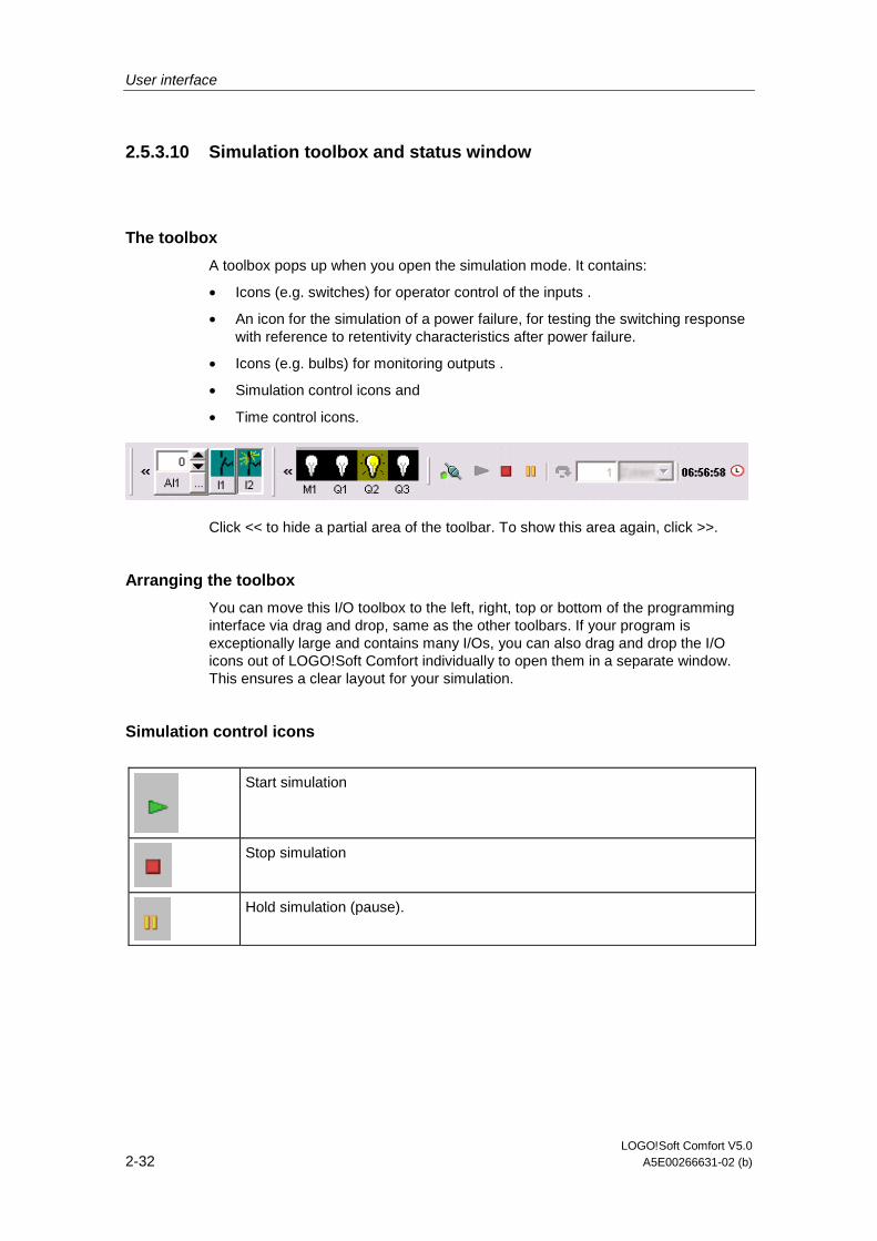
User interface
LOGO!Soft Comfort V5.0 2-32 A5E00266631-02 (b)
2.5.3.10 Simulation toolbox and status window
The toolbox
A toolbox pops up when you open the simulation mode. It contains:
• Icons (e.g. switches) for operator control of the inputs .
• An icon for the simulation of a power failure, for testing the switching response with reference to retentivity characteristics after power failure.
• Icons (e.g. bulbs) for monitoring outputs .
• Simulation control icons and
• Time control icons.
Click << to hide a partial area of the toolbar. To show this area again, click >>.
Arranging the toolbox
You can move this I/O toolbox to the left, right, top or bottom of the programming interface via drag and drop, same as the other toolbars. If your program is exceptionally large and contains many I/Os, you can also drag and drop the I/O icons out of LOGO!Soft Comfort individually to open them in a separate window. This ensures a clear layout for your simulation.
Simulation control icons
Start simulation
Stop simulation
Hold simulation (pause).

User interface
LOGO!Soft Comfort V5.0 A5E00266631-02 (b) 2-33
Time control
If you have programmed a time-sensitive circuit, you should use the time control to monitor the reaction of your circuit program.
Start simulation for e specific time or number of cycles.
Set the period and the number of cycles using the following icons.
Setting the period and the time base for a time limited simulation or setting a specific number of cycles
Display of the current time in LOGO!Soft Comfort
Modification of the current time in LOGO!Soft Comfort
Status display
Prerequisite: The display of signal states and process variables is enabled under Tools Options: Simulation.
The colored indication lets you identify the "1" or "0" status of a connecting line. Default color of connecting lines carrying a "1" signal is red. Default color of connecting lines carrying a "0" signal is blue.
Example for the FBD Editor:

User interface
LOGO!Soft Comfort V5.0 2-34 A5E00266631-02 (b)
2.5.3.11 Tools -> Online Test
Difference to simulation mode
The online test and simulation modes allow you to monitor the execution of your circuit program and how it reacts to the various input states.
In simulation mode you execute your circuit program on the PC. To do so, you donot require a LOGO!. The status of inputs can be preset on the PC.
During an online test, the circuit program is executed on a LOGO!. The user monitors this "work" of the LOGO!. The status of the inputs corresponds with the actual states at the LOGO! inputs.
Prerequisite for an online test
Your PC must be linked to a LOGO!.
The circuit program to be tested must be in FBD format and transferred to LOGO!.
The circuit programs in LOGO!Soft Comfort and on the LOGO! must be identical. Upload the program from the LOGO! to your PC if necessary.
You can monitor the parameters of up to 30 blocks. The number of blocks you can monitor simultaneously decreases when you monitor blocks that contain a high number of parameters (e.g.: analog SFBs).
To start the online test
1. Select the Tools Online Test menu command
2. If the LOGO! is in STOP, start it via the Start button Result: The LOGO! executes your circuit program.
3. Now start the monitoring mode.
4. Select the blocks whose parameters you want to monitor. Result: You are shown "live" how the parameters of the selected blocks change.

User interface
LOGO!Soft Comfort V5.0 A5E00266631-02 (b) 2-35
Switching the LOGO! to STOP
if you want to stop the LOGO! via LOGO!Soft Comfort, click on the Stop icon .
• Devices as of the OBA4 series support Online tests.
Possible errors
• Your LOGO! does not support the online test. Remedy: Install a LOGO! device of the latest series.
• Inconsistency of the programs on your PC and on the LOGO!. Remedy: Upload the circuit program from the LOGO! to your PC.
• You are attempting to monitor too many parameters/blocks simultaneously. Remedy: Reduce the number of simultaneously monitored parameters/blocks.
• The communication between your PC and LOGO! goes down. Remedy: Re-establish the connection.
• The circuit program is not available in FBD. Remedy: convert the circuit program to FBD.

User interface
LOGO!Soft Comfort V5.0 2-36 A5E00266631-02 (b)
2.6 Menu bar
2.6.1 Menu bars - Overview
The menu bar commands, for example, contains administrative and editing functions for the circuit program of your LOGO! and a context-sensitive help.
• File menu
• Edit menu
• Format menu
• View menu
• Tools menu
• Window menu
• Help menu
2.6.2 File menu
2.6.2.1 File menu - Overview
The File menu command contains commands for file management. Included are also commands for the download, saving or creation of circuit programs, setting general file properties and for printing.
• New
• Open...
• Close
• Close All
• Save
• Save As...
• Page Setup...
• Print Preview
• Print...
• Properties...
• Compare
• Exit
Available in the LAD Editor only: Convert (LAD > FBD) Available in the FBD Editor only: Convert (FBD > LAD)

User interface
LOGO!Soft Comfort V5.0 A5E00266631-02 (b) 2-37
2.6.2.2 File -> New
Menu command New
The command opens a new window with an empty programming interface for programming in LAD or FBD, depending on your set mode. Depending on your default setting, a window opens with a number of tabs in which you can specify the properties of the circuit program you are going to create. This window can also be called later to either enter or modify the properties via the File -> Properties... menu.
Program sections that have previously been placed on the clipboard by means of the cut or copy functions remain on the clipboard and can be pasted into the new circuit program.
An icon for this menu command is also found in the standard toolbar.
Switching between LAD and FBD
The editor used to create a new circuit program is set under Tools -> Options: Editor.
Select to create the circuit program either in LAD or in FBD by clicking on the small arrow on the right side of the "New" icon.
2.6.2.3 File -> Open...
File Open
The command opens a dialog box from which you can select and open a previously created circuit program for further editing on the programming interface. Circuit programs created in LOGO!Soft Comfort have the file extension *.lsc. The loaded circuit program is opened in a new window.
An icon for this menu command is also available in the standard toolbar
Circuit programs of LOGO!Soft Standard
The user can also import files created with LOGO!Soft Standard (filename extension = *.lgo). Use the "File type" menu item to select the type of file you want to have displayed. Missing information concerning the graphical layout of the circuit program is appropriately complemented by LOGO!Soft Comfort.
Alternatives
• In Windows you can also drag and drop a LOGO!Soft Comfort circuit program file to the programming interface. When you "release" this file on the programming interface, it is opened in a new window.
• A double-click on a file with the extension *.lsc or *.lld in the file manager automatically opens LOGO!Soft Comfort with this file.
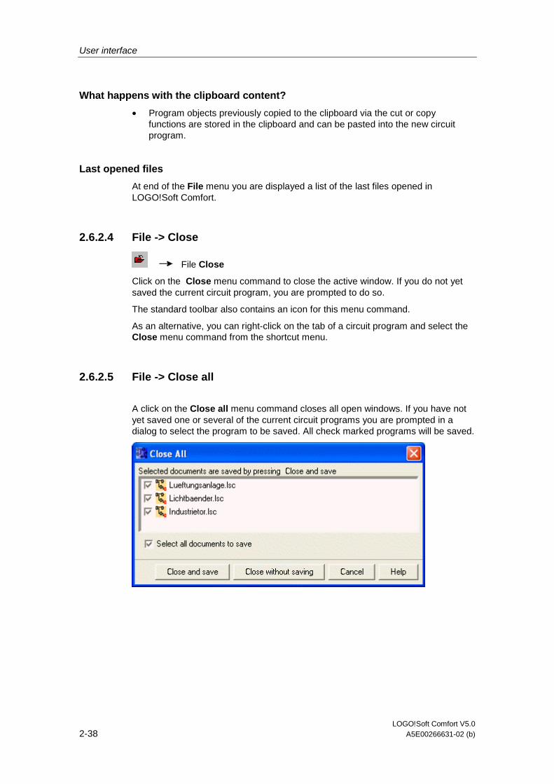
User interface
LOGO!Soft Comfort V5.0 2-38 A5E00266631-02 (b)
What happens with the clipboard content?
• Program objects previously copied to the clipboard via the cut or copy functions are stored in the clipboard and can be pasted into the new circuit program.
Last opened files
At end of the File menu you are displayed a list of the last files opened in LOGO!Soft Comfort.
2.6.2.4 File -> Close
File Close
Click on the Close menu command to close the active window. If you do not yet saved the current circuit program, you are prompted to do so.
The standard toolbar also contains an icon for this menu command.
As an alternative, you can right-click on the tab of a circuit program and select the Close menu command from the shortcut menu.
2.6.2.5 File -> Close all
A click on the Close all menu command closes all open windows. If you have not yet saved one or several of the current circuit programs you are prompted in a dialog to select the program to be saved. All check marked programs will be saved.

User interface
LOGO!Soft Comfort V5.0 A5E00266631-02 (b) 2-39
2.6.2.6 File -> Save
File Save
When you initially save a newly created program, a window opens in which you can specify the path and filename under which you want to save your circuit program. Details are found under File -> Save as... .
If you are saving a modified version of an existing program, a Quick Save is performed. The old version of the circuit program is overwritten by the revised version, i.e. the new program is saved to the same path and name as the source file.
The standard toolbar also contains an icon for this menu command.
As an alternative, you can right-click on the tab of a circuit program and select the Save menu command from the shortcut menu.
2.6.2.7 File -> Save As...
A dialog box opens for you to specify the path and filename under which the current circuit program is to be saved. This allows you to save modified programs under a different name or directory, and thus keep previous versions for retrieval.
• LOGO!Soft Comfort file FBD(*.Isc)
• LOGO!Soft Comfort file LAD (*.lld)
• LOGO!Soft Standard file (*.lgo)
• Portable Document Format (*.pdf)
• JPG file (*.jpg)
• Bitmap file (*.bmp)
The default LOGO!Soft Comfort filename extension for FBD programs is *.lsc or *.lld for LAD programs. You can also export your program to an older LOGO!Soft version if you select the file type *.lgo, the program format of LOGO!Soft Standard. Additional information such as graphic information on block positions is here not taken into account. If your circuit program contains functions not supported in LOGO!Soft Standard, LOGO!Soft generates an export error message.
You can also save the circuit program in a graphical format, e.g. *.jpg, *.bmp or *.pdf, the AcrobatReader document format for program documentation and presentation. However, note that such files do not contain logic elements, i.e. you cannot reopen these in LOGO!Soft Comfort.
The AcrobatReader format offers a special feature. Saving your circuit program in *.pdf format gives you an AcrobatReader document that is absolutely identical to the hardcopy of your program. For example, you could distribute this document to users who do not have LOGO!Soft Comfort, and thus enable them to view your project in AcrobatReader and make hardcopies.
As an alternative, you can right-click on the tab of a circuit program and select the Save as menu command from the shortcut menu.

User interface
LOGO!Soft Comfort V5.0 2-40 A5E00266631-02 (b)
2.6.2.8 File -> Page format
This command opens a dialog box in which you can specify the page settings for creating circuit programs. Here you can specify the paper format, page margins or whether to print in portrait or landscape format.
LOGO!Soft Comfort offers multi-page printout feature, with the position of page breaks indicated on-screen. The print area is user-definable.
You can paginate your circuit program via the File -> properties menu.
The settings made at this point have no effect on the printer settings. Select the printer setup command via the File -> Print menu. Finally, you can specify the scope of your hardcopies via Tools -> Options: Print.
2.6.2.9 File -> Print preview
The print preview option shows what a hardcopy of your circuit program is going to look like. Choose the relevant icons to scroll the pages, zoom the window or to start printing directly.

User interface
LOGO!Soft Comfort V5.0 A5E00266631-02 (b) 2-41
2.6.2.10 File -> Print
Menu command Print
The command first opens a menu in which you can select the scope of information on your hardcopy. You can also call this selection menu via the Tools -> Options: Print menu.
You can choose whether to print comments you entered under File -> Properties comment or not.
You can also choose to include or omit connection names and parameters on the hardcopy of your circuit program.
If you require a parameter list, you can also choose whether to include the parameters of all blocks, all selected blocks or only the special timer block on your hardcopy.
Finally, you can print out a list of connection names.
The Suppress empty pages option allows you to exclude pages that do not contain any graphical objects.
Because blank pages are included in the page numbering, gaps will appear if these are not printed.
In the printer dialog, you can specify your default printer and the print properties. In the control panel of your computer you can specify extended printer settings.
The AcrobatReader *.pdf format provides a further print option. You can save your program in AcrobatReader document format and distribute it to users who do not have LOGO!Soft Comfort and can then use AcrobatReader to view and print out your circuit program.
The standard toolbar also contains an icon for this menu command.
Set the page format under File -> page format.
User interface
LOGO!Soft Comfort V5.0 2-42 A5E00266631-02 (b)
2.6.2.11 File -> Properties...
The properties dialog contains the following tabs:
• Common properties
• Comment
• Statistics
• Page format
• Properties Parameter
2.6.2.12 File -> Properties: General
In the general data dialog, you can enter details of the current circuit program. There are input boxes for project-related and internal company data. You can quickly and easily specify the version of your circuit programs with the help of this dialog.
You can specify to load your company logo in *.gif or *.jpg format to the input field for your company name. This feature lets you create a very individual layout of your program files.
By setting the Show with new file check box, you are displayed a flag that indicates where to input the specifications described above each time you create a new circuit program.
How to identify your circuit program version
2.6.2.13 File -> Properties: Comment
In the Comment tab, you can enter a description of the circuit program or notes relating to it. This tab is called under the File -> Print menu, and you can here determine to output the comment on a separate printed page.
2.6.2.14 File -> Properties: Statistics
The Statistics tab shows the date of creation circuit program and the last author.

User interface
LOGO!Soft Comfort V5.0 A5E00266631-02 (b) 2-43
2.6.2.15 File -> Properties: Page format
Menu command Page format
In the Page Layout tab, you can specify how and on how many numbers of pages to print your circuit program. You can preview the pagination in this tab. If you choose more than one program page, the page breaks are indicated by white lines on the programming interface. Your circuit program is later printed out according to this pagination. Please note that connections extending to other pages are simply cut off when you print the hardcopy. We recommend you create cross-references by splitting the file at this position with the help of the Cut/Join tool. In the File -> Page format menu you can specify the paper size, page alignment and margins.
The standard toolbar also contains an icon for this menu command.
2.6.2.16 File -> Properties: Parameter
When the circuit program is transferred, all Parameter tab specifications are also transferred to LOGO! and then saved there.
In the Program name field, a program name with up to 16 characters can be entered for the circuit program. After transfer, the circuit program will then be shown on the LOGO! display under this name.
You can assign a password to your circuit program or change or delete an already assigned password. In order to assign a new password, you must enter the password in the two text boxes New password and then confirm with OK. The password can have a maximum of 10 characters. To change the password, you must first enter the existing password in the text box Old password and the new password in the two boxes New password and then confirm with OK. You can delete your assigned password at any time. To do this, enter the existing password in the box Old password and leave the two New password boxes empty. Then confirm with OK.
The password protects your circuit program on LOGO!. A circuit program protected with a password can be opened and processed again at any time on the computer without the password prompt. The password is required in order to view or change a password-protected circuit program on LOGO!, or to load the circuit program from LOGO! into the computer.
With Display content on LOGO! after power on you can set what is shown on the LOGO! display when you switch LOGO on.
With Conduct of analog outputs in STOP mode you can set what the analog outputs of LOGO! should issue when LOGO! is in STOP mode.
The LOGO! version you have chosen depends on:
• if and when the register is available,
• which settings are available.
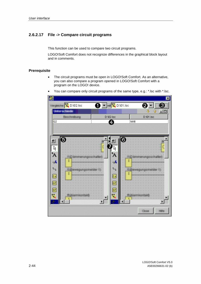
User interface
LOGO!Soft Comfort V5.0 2-44 A5E00266631-02 (b)
2.6.2.17 File -> Compare circuit programs
This function can be used to compare two circuit programs.
LOGO!Soft Comfort does not recognize differences in the graphical block layout and in comments.
Prerequisite
• The circuit programs must be open in LOGO!Soft Comfort. As an alternative, you can also compare a program opened in LOGO!Soft Comfort with a program on the LOGO! device.
• You can compare only circuit programs of the same type, e.g.: *.lsc with *.lsc.
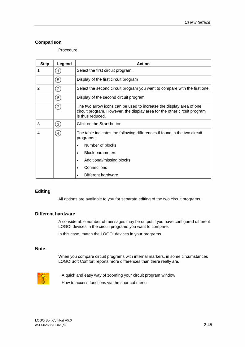
User interface
LOGO!Soft Comfort V5.0 A5E00266631-02 (b) 2-45
Comparison
Procedure:
Step Legend Action
1 Select the first circuit program.
Display of the first circuit program
2 Select the second circuit program you want to compare with the first one.
Display of the second circuit program
The two arrow icons can be used to increase the display area of one circuit program. However, the display area for the other circuit program is thus reduced.
3 Click on the Start button
4 The table indicates the following differences if found in the two circuit programs:
• Number of blocks
• Block parameters
• Additional/missing blocks
• Connections
• Different hardware
Editing
All options are available to you for separate editing of the two circuit programs.
Different hardware
A considerable number of messages may be output if you have configured different LOGO! devices in the circuit programs you want to compare.
In this case, match the LOGO! devices in your programs.
Note
When you compare circuit programs with internal markers, in some circumstances LOGO!Soft Comfort reports more differences than there really are.
A quick and easy way of zooming your circuit program window
How to access functions via the shortcut menu

User interface
LOGO!Soft Comfort V5.0 2-46 A5E00266631-02 (b)
2.6.2.18 File -> Convert (LAD > FBD)
Use this function to convert your circuit diagram from LAD to FBD.
The following rules apply to the conversion from LAD to FBD:
• A series circuit of contacts is converted into an AND block
• A parallel circuit of contacts is converted into an OR block
• User-defined comments are not included, as their position in the circuit diagram can not be defined based on blocks
• Crosslinks, i.e. connections of a block output to multiple block inputs and at least one of the inputs is connected to multiple block outputs, are converted into an OR block. Inputs for the OR block are all block outputs of the crosslink. The output of the OR block is connected to all block inputs of the crosslink.
• Internal flags are resolved, and the current paths are linked.
Overview: File -> Convert (FBD > LAD)
2.6.2.19 File -> Convert (FBD > LAD)
Use this function to convert your circuit diagram from FBD to LAD.
The following rules apply to the FBD to LAD conversion:
• An AND block is converted into a series contact circuit
• An OR block is converted into a parallel contact circuit
• Comments for basic functions are not applied in LAD, as a basic function is converted into multiple contacts. Thus, the comment cannot be assigned definitely.
• In LAD, input comments are assigned to all contacts of this input.
• User-defined comments are not included, as their position in the circuit diagram can not be defined based on blocks
• XOR blocks must be converted into corresponding LAD logic consisting of positive and negative contacts.
Note
When converting, the total number of blocks in your circuit program can sometimes increase. This could cause the permitted number of blocks for your LOGO! to exceed.
It is therefore not always possible to convert from FBD to LAD.
Remedy: Under Tools > Select Hardware… select the hardware series 0BA5. Start converting to LAD. Then under Tools > Determine LOGO!, see which hardware series is compatible with the circuit program.
Overview: File -> Convert (FBD > LAD)

User interface
LOGO!Soft Comfort V5.0 A5E00266631-02 (b) 2-47
2.6.2.20 File -> Exit
LOGO!Soft Comfort will be closed.
If you are actually editing a circuit program or haven’t yet saved it, a window opens open exit.
In this window you can state which circuit programs are to be saved. Alternatively, you can exit LOGO!Soft Comfort without saving circuit programs. To do this, click Close without saving.
A quick way of closing LOGO!Soft Comfort without saving the data

User interface
LOGO!Soft Comfort V5.0 2-48 A5E00266631-02 (b)
2.6.3 Edit menu
2.6.3.1 Edit menu - Overview
In the Edit menu you will find commands for editing your circuit program. Basic commands for the creation and editing of a circuit program are included in the icons of the programming toolbox.
• Undo
• Redo
• Delete
• Cut
• Copy
• Paste
• Select All
• Goto block
• Bring to front
• Send to back
• Connector names...
• Block properties...
• Block properties (all blocks)...
• Cut connections...
User interface
LOGO!Soft Comfort V5.0 A5E00266631-02 (b) 2-49
2.6.3.2 Edit -> Undo
Edit Undo
This command allows you to undo actions carried out on the programming interface, i.e. this is always the last action. Position your mouse pointer on the undo menu command and hold it there briefly. The tooltip opens and shows you the actions you can undo by clicking on the menu item. Currently you can undo up to 30 actions.
The standard toolbar also contains an icon for this menu command.
2.6.3.3 Edit -> Redo
Edit Redo
The redo reverts the last undo action. Click on the menu command to view the tooltip for the action to be redone.
The standard toolbar also contains an icon for this menu command.
2.6.3.4 Edit -> Delete
Edit Delete
The command deletes selected objects, without copying them to the clipboard. You can retrieve deleted objects by means of the Undo function.
2.6.3.5 Edit -> Cut
Edit Cut
The command deletes one or more selected objects, i.e. blocks and/or connecting lines, from the programming interface and copies them to the clipboard.
The standard toolbar also contains an icon for this menu command.
2.6.3.6 Edit -> Copy
Edit Copy
The command is used to copy one or more selected objects, i.e. blocks/texts/connecting lines, to the clipboard.
The standard toolbar also contains an icon for this menu command.

User interface
LOGO!Soft Comfort V5.0 2-50 A5E00266631-02 (b)
2.6.3.7 Edit -> Paste
Copies the clipboard content to the programming interface. The insert position is either below the previously selected object, or a position determined with a mouse click.
The standard toolbar also contains an icon for this menu command.
Edit Paste
You can only paste the clipboard content if sufficient resources are available. Blocks require a certain amount of resources, depending on the block type. An error message is generated if your system does not provide sufficient resources.
Connecting lines with open ends can only be pasted. These can only be pasted if they connect two blocks and were copied to the clipboard together with those.
2.6.3.8 Edit -> Select all
The command is used to select all objects on the programming interface, i.e., the blocks, connecting lines and labels.
2.6.3.9 Edit -> Go to block
You can view a list of all blocks used, which contains information about the block number and block type. For example, you can view the SFBs you have used. In the Block number line you can enter a short description of the block, e.g. I1, I2, B04, ... If used in the circuit program, the specified block is displayed in the list and highlighted in your circuit program.
A block selected from this list is also highlighted on your programming interface.
2.6.3.10 Edit -> Bring to front
You can use this command to bring one of a number of overlapping objects to the foreground.
2.6.3.11 Edit -> Send to back
You can use this command to bring one of a number of overlapping objects to the background.
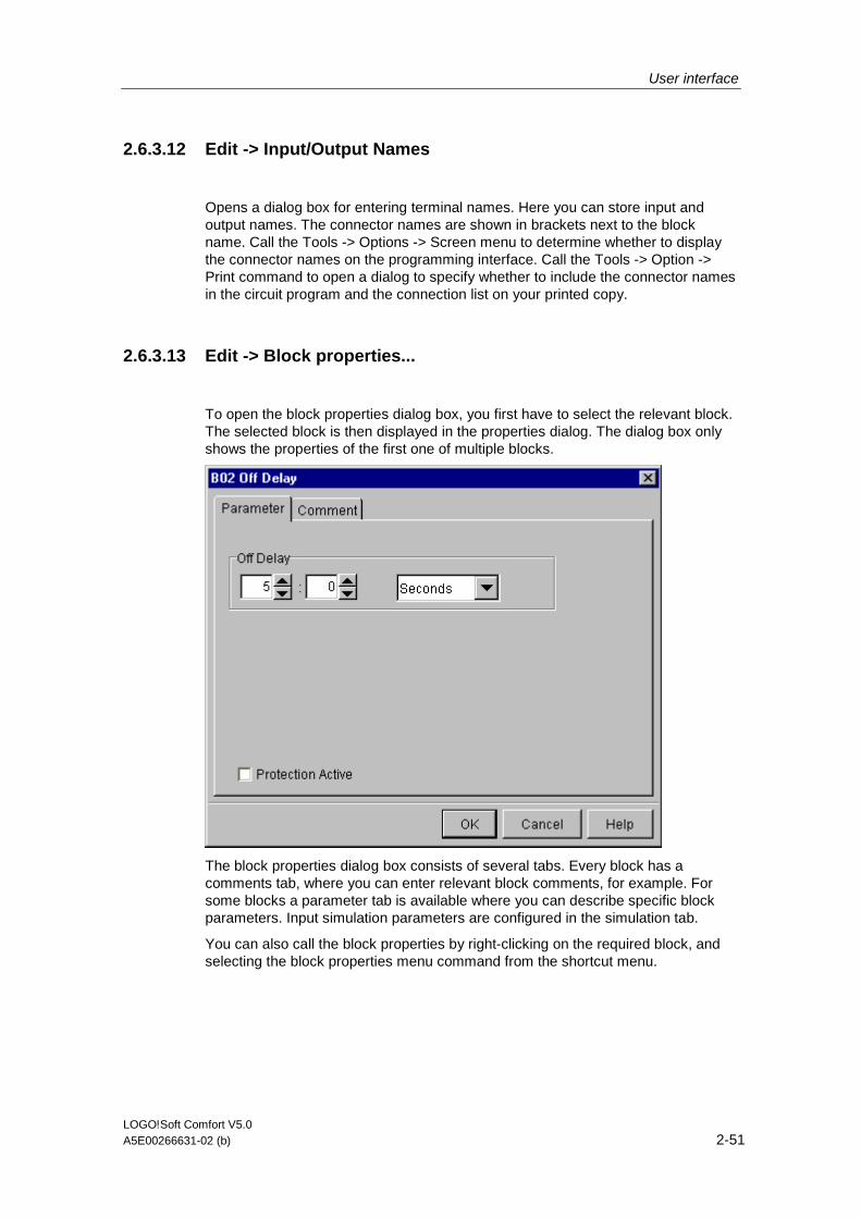
User interface
LOGO!Soft Comfort V5.0 A5E00266631-02 (b) 2-51
2.6.3.12 Edit -> Input/Output Names
Opens a dialog box for entering terminal names. Here you can store input and output names. The connector names are shown in brackets next to the block name. Call the Tools -> Options -> Screen menu to determine whether to display the connector names on the programming interface. Call the Tools -> Option -> Print command to open a dialog to specify whether to include the connector names in the circuit program and the connection list on your printed copy.
2.6.3.13 Edit -> Block properties...
To open the block properties dialog box, you first have to select the relevant block. The selected block is then displayed in the properties dialog. The dialog box only shows the properties of the first one of multiple blocks.
The block properties dialog box consists of several tabs. Every block has a comments tab, where you can enter relevant block comments, for example. For some blocks a parameter tab is available where you can describe specific block parameters. Input simulation parameters are configured in the simulation tab.
You can also call the block properties by right-clicking on the required block, and selecting the block properties menu command from the shortcut menu.

User interface
LOGO!Soft Comfort V5.0 2-52 A5E00266631-02 (b)
2.6.3.14 Edit -> Block properties (all blocks)...
A window with two sections is opened with this command. In the left section, you can see all the blocks used in your program. Click on a block to view its corresponding parameters in the right column. You can now edit these parameters and set the changes with a click on the Apply button.
The modified block is displayed in blue color in the selection list, if you do not accept the parameter changes made and select another block. All changes are discarded by clicking on the Cancel button. You confirm your entries and exit the dialog with OK.
Each block you call via the "select block from drawing" options box is highlighted in the circuit diagram.
Special functions
Basic functions
Constants and Terminals
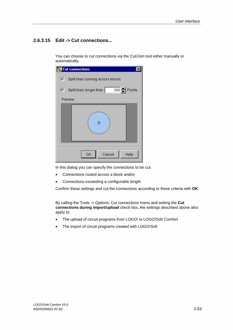
User interface
LOGO!Soft Comfort V5.0 A5E00266631-02 (b) 2-53
2.6.3.15 Edit -> Cut connections...
You can choose to cut connections via the Cut/Join tool either manually or automatically.
In this dialog you can specify the connections to be cut:
• Connections routed across a block and/or
• Connections exceeding a configurable length
Confirm these settings and cut the connections according to these criteria with OK.
By calling the Tools -> Options: Cut connections menu and setting the Cut connections during import/upload check box, the settings described above also apply to:
• The upload of circuit programs from LOGO! to LOGO!Soft Comfort
• The import of circuit programs created with LOGO!Soft
User interface
LOGO!Soft Comfort V5.0 2-54 A5E00266631-02 (b)
2.6.4 Format menu
2.6.4.1 Format menu - Overview
This menu provides formatting options for labels and function groups. You can define the font, the font size and style as well as the alignment of selected objects.
• Font...
• Align
• Format Grid
• Snap to Grid
2.6.4.2 Format -> Font
Here you can specify the font type, size, style, and the text color. To redefine the format of existing text objects, you first have to select them. You can then specify the font attributes to suit requirements and click on OK to apply the new formats.
You can choose to set particular default formats. New text objects are then displayed with these default settings. To return to the standard settings, click the Standard button.
2.6.4.3 Format -> Align
This command offers various options of aligning labels and function blocks.
Vertical
Horizontal
Automatic

User interface
LOGO!Soft Comfort V5.0 A5E00266631-02 (b) 2-55
2.6.4.4 Format -> Format grid
This tool helps you to organize the various objects of your circuit program on the programming interface. The grid is switched on by default.
You can adjust the grid pattern (spacing) in increments of 5 points.
If you have enabled the snap-to-grid function, the objects are aligned with the relevant grid intersections. This helps you to avoid a vertical or horizontal offset of the objects. To fine position objects on your programming interface, you need to disable the snap-to-grid function.
You can hide the grid by via the Visibility check box.
2.6.4.5 Format -> Snap to grid
If you have made changes to the grid pattern, or inserted objects while the grid was disabled, the position of objects may be offset when they are aligned to the grid points. Call this command to correct the offset of selected objects and to realign these.

User interface
LOGO!Soft Comfort V5.0 2-56 A5E00266631-02 (b)
2.6.5 View menu
2.6.5.1 View menu - Overview
In the View menu, you can set the zoom factor for the display of your circuit, and decide to show or hide various display windows.
• Zoom...
• Zoom In
• Zoom Out
• Toolbars
• Select Lines
• Info Window
• Status bar
• Tooltips
2.6.5.2 View -> Zoom
LOGO!Soft Comfort offers a variety of options for enlarging or reducing the size of the circuit program display. By selecting Zoom, you open a dialog box in which you can set the zoom factor from a default list or in the relevant box.
If you choose an unfavorable zoom factor, the objects may appear out of focus on your screen. You should therefore use the default zoom factors wherever possible. This effect has no influence on the layout of the printed circuit program.
A quick and easy way of zooming your circuit program window
2.6.5.3 View -> Zoom in
View Zoom
The zoom factor is increased defined steps:
25 (min) 50 75 100 (standrd) 150 200 250 300 400 (max)
The standard toolbar also contains an icon for this menu command.
A quick and easy way of zooming your circuit program window
User interface
LOGO!Soft Comfort V5.0 A5E00266631-02 (b) 2-57
2.6.5.4 View -> Zoom out
View Zoom out
The zoom factor is reduced in defined steps:
400 (Max) 300 250 200 150 100 (standard) 75 50 25 (Min)
The standard toolbar also contains an icon for this menu command.
A quick and easy way of zooming your circuit program window
2.6.5.5 View -> Toolbars
This command lets you hide or show selected toolbars.
• Standard: Hide/show the standard toolbar on
• Tools: Hide/show the programming toolbar
2.6.5.6 View - > Select Lines
View Select Lines
With this setting all connections (= lines) that lead to or away from a selected block are shown in color.
If you select a single connection with this setting, then the selected connection is highlighted in color.
Under Tools > Options > Screen you can set whether the connections should also be labeled. Under Tools > Options > Colors you can set which colors the connections should be displayed in.
Tools -> Options: Screen
Tools -> Options: Colors
2.6.5.7 View -> Info Window
This menu command can be used to show or hide the Info Window. You can also use the function key [F4].
2.6.5.8 View -> Status bar
This menu command can be used to hide or show the status bar.
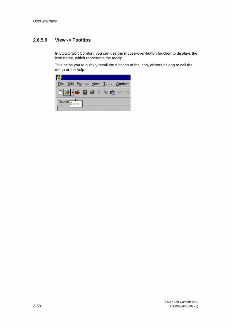
User interface
LOGO!Soft Comfort V5.0 2-58 A5E00266631-02 (b)
2.6.5.9 View -> Tooltips
In LOGO!Soft Comfort, you can use the mouse-over-button function to displays the icon name, which represents the tooltip.
This helps you to quickly recall the function of the icon, without having to call the menu or the help.

User interface
LOGO!Soft Comfort V5.0 A5E00266631-02 (b) 2-59
2.6.6 Tools menu
2.6.6.1 Tools menu - Overview
The options menu provides the following menu commands:
• Transfer
• Determine LOGO!
• Select Hardware...
• Simulation
• Simulation parameters...
• Online test
• Options...
2.6.6.2 Tools -> Transfer
Prerequisite for data transfer
The serial interface used to link LOGO! to the PC must be configured via the Tools -> Options: Interface menu.
• Otherwise LOGO!Soft Comfort will return an appropriate error message. Click on the Select interface... button to open the options dialog for the configuration of the used interface. If the wrong or no interface is set, you can determine the PC interface LOGO! is connected to or you can start a search for the interface
• For further information on how to connect the LOGO! to your PC via USB interface, refer to the LOGO! manual.
• The LOGO! must be connected to the PC with the PC cable.
• LOGO! may neither be in RUN nor in editing mode.
0BA0-0BA3:
The LOGO! must be prepared for data transfer via the PC/Card -> PC <-> LOGO! setting. For further information, refer to the LOGO! manual.
User interface
LOGO!Soft Comfort V5.0 2-60 A5E00266631-02 (b)
Menu commands
The Tools Transfer menu contains the following menu commands:
Tools -> Transfer: PC -> LOGO!
Tools -> Transfer: LOGO! -> PC
Switch LOGO! Mode
Tools -> Transfer: Set clock...
Tools -> Transfer: Summer/Winter time...
Tools -> Transfer: Hours counter
2.6.6.3 Tools -> Transfer: PC -> LOGO!
Tools Transfer: PC -> LOGO!
This command is used to download a circuit program created on the PC in LOGO!Soft Comfort to the LOGO! module. The name of the program transferred to LOGO! is specified in the File -> Properties... menu.
The standard toolbar also contains an icon for this menu command.
Preparations
Prior to the download, the system determines the LOGO! version at least required for your circuit program. The modular LOGO! always provides all available resources for your circuit program at the I/Os. It is up to the user to install an appropriate number of expansion modules in the base device.
Error messages
If the circuit program cannot be downloaded to the available LOGO!, the transfer is aborted and an error message is displayed. The user is informed of unknown LOGO! versions and then has the choice of continuing or canceling the download. A message in the status bar reports the successful download.
Transfer messages are displayed in the status bar and in the Info Window.
Detailed error messages are displayed in the Info Window.
Password
If you have assigned a password to your circuit program, then you will be asked to enter this password before you transfer to LOGO!. The circuit program will then only be transferred to LOGO! if you have entered the correct password.
User interface
LOGO!Soft Comfort V5.0 A5E00266631-02 (b) 2-61
2.6.6.4 Tools -> Transfer: LOGO! -> PC
Tools Tranfer LOGO! -> PC
The circuit program is imported from LOGO! to LOGO!Soft Comfort. Transfer messages are displayed in the status bar and on the Info Window.
The standard toolbar also contains an icon for this menu command.
Missing graphical information
A program imported from LOGO! to LOGO!Soft Comfort does not contain any graphical information for the block layout on the programming interface. A suitable layout for the circuit program is therefore generated automatically. The generated circuit diagram corresponds with the layout in the LOGO!Soft block diagram, except that multiple instances of the same block are not displayed, but are instead identified by means of the block connectors.
The blocks are always arranged at the top left corner of the programming interface. If necessary, the user should use the scroll bars to bring the circuit program into view.
Cutting connections
If you have set the "Cut connections during import/upload" check box under Tools -> Options: Cut connections, the relevant connections are cut during the upload from LOGO! to the PC, according to the rules set in this dialog.
Password
At the start of the upload of a password protected circuit program from the LOGO! to the PC, the user is prompted to enter the password. If the wrong or no password is entered, the transfer is aborted with an error message.
2.6.6.5 Tools -> Transfer: Switch LOGO! Mode
Tools -> Transfer - > Switch LOGO! Mode
This special function is only available with devices as of hardware series 0BA4.
When you click on this symbol you change the mode of a connected LOGO! from STOP mode to RUN mode or from RUN mode to STOP mode.

User interface
LOGO!Soft Comfort V5.0 2-62 A5E00266631-02 (b)
2.6.6.6 Tools -> Transfer: Set Clock...
This menu option can be used to view and set the date and time of the connected LOGO!.
Click on current time to apply the system time of the PC in LOGO!Soft Comfort.
Manual input of values
You can enter the values via the keyboard, by clicking on the number input box instead of clicking on the arrow icons of the date and time setting function. LOGO!Soft Comfort automatically corrects any invalid date values.
2.6.6.7 Tools -> Transfer: Summer time/Winter time...
This menu command lets you set an automatic conversion of the summer and winter time for the LOGO! clock.
You can specify a country-specific time conversion (United States of America: US, United Kingdom of Great Britain and Northern Ireland: UK) or regional conversion (European Union: EU), or customize the date and the time zones for the conversion.
Note that this function is only supported in LOGO! devices as of the series 0BA3.
2.6.6.8 Tools -> Transfer: Hours Counter
Use this menu command to read the hours counter of LOGO!.
You can also fetch the hours counter from LOGO! devices with password protected program without having to enter a password.
Only the LOGO! devices => version 0BA3 support this function. Also, you can only transfer the hours counter of a LOGO! that is not equipped with a red module, because you delete the LOGO! program if you remove this module..
User interface
LOGO!Soft Comfort V5.0 A5E00266631-02 (b) 2-63
2.6.6.9 Tools -> Determine LOGO!
When you click on this menu command, LOGO!Soft Comfort calculates the minimum LOGO! version requirements for the LOGO! circuit program. The result is shown in the status bar. The Info window displays all versions to which you can download the program. You can also use the function key [F2] to execute this menu command.
2.6.6.10 Tools -> Select Hardware...
You have two options of selecting the device when you create your program in LOGO!Soft Comfort:
1. You can first create your program and then determine the required LOGO! via the Tools -> Determine LOGO! dialog.
2. You can first determine the LOGO! version for which you want to create your circuit program by calling the Tools Select Hardware… dialog. You can also call the device selection dialog by double-clicking on the LOGO! icon in the status bar.
The device selection dialog shows you which blocks and memory resources are available to you.
If you have already created a circuit program or are using some blocks, the hardware selection dialog offers you only the LOGO! devices you can operate with the currently used blocks.
2.6.6.11 Tools -> Simulation
Introduction
The program simulation function allows you to test a program and modify its parameters. This ensures the download of a fully functioning and optimized program to your LOGO!.
Simulation mode
Click on the Simulation icon in the programming toolbox to start the simulation. This changes the program to simulation mode.
Simulation
The active icon is highlighted in simulation mode. By clicking once again on the Simulation icon, or on any other icon of the programming toolbox, you exit simulation mode and open another tool mode (e.g. for selecting or inserting blocks).
At the start of simulation mode, the program is verified and the results are output to the info window.
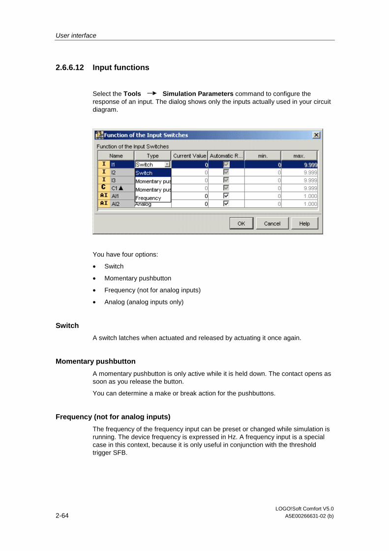
User interface
LOGO!Soft Comfort V5.0 2-64 A5E00266631-02 (b)
2.6.6.12 Input functions
Select the Tools Simulation Parameters command to configure the response of an input. The dialog shows only the inputs actually used in your circuit diagram.
You have four options:
• Switch
• Momentary pushbutton
• Frequency (not for analog inputs)
• Analog (analog inputs only)
Switch
A switch latches when actuated and released by actuating it once again.
Momentary pushbutton
A momentary pushbutton is only active while it is held down. The contact opens as soon as you release the button.
You can determine a make or break action for the pushbuttons.
Frequency (not for analog inputs)
The frequency of the frequency input can be preset or changed while simulation is running. The device frequency is expressed in Hz. A frequency input is a special case in this context, because it is only useful in conjunction with the threshold trigger SFB.

User interface
LOGO!Soft Comfort V5.0 A5E00266631-02 (b) 2-65
Analog (analog inputs only)
You can preset the value for the Analog Input or modify it while running in simulation mode. The unit of the analog value to be set corresponds with the default process variable. The range corresponds with the specified measurement range, provided the option "Auto range " is selected. The value range corresponds in this case with the measurement range of the function connected to the input. The analog input represents a special case, because it should only be used for analog SFBs.
When simulation is active, you can change the switch settings of a digital input per mouse click on the input. In the simulation tab of the block properties menu you can select the input switch setting (Switch/Pushbutton/Frequency). Enter your settings with "Apply".
Please refer to the information in the Analog value processing section for help on analog block parameters.
"Name" column
Digital inputs are designated I.
Analog inputs are designated AI.
Settings
When you save your circuit program, the settings for circuit simulation are included. Thus, you do not need to enter the simulation parameters once again when you exit and re-open your circuit program.
While simulation mode is active, you can right-click on a digital input to change its settings. In the simulation tab of the block properties menu, you can select the switching action of the input (switch/momentary pushbutton/frequency). The setting is input by clicking on the Apply button.

User interface
LOGO!Soft Comfort V5.0 2-66 A5E00266631-02 (b)
2.6.6.13 Tools -> Online Test
Difference to simulation mode
The online test and simulation modes allow you to monitor the execution of your circuit program and how it reacts to the various input states.
In simulation mode you execute your circuit program on the PC. To do so, you not require a LOGO!. The status of inputs can be preset on the PC.
During an online test, the circuit program is executed on a LOGO!. The user monitors this "work" of the LOGO!. The status of the inputs corresponds with the actual states at the LOGO! inputs.
Prerequisite for an online test
Your PC must be linked to a LOGO!.
The circuit program to be tested must be in FBD format and transferred to LOGO!.
The circuit programs in LOGO!Soft Comfort and on the LOGO! must be identical. Upload the program from the LOGO! to your PC if necessary.
You can monitor the parameters of up to 30 blocks. The number of blocks you can monitor simultaneously decreases when you monitor blocks that contain a high number of parameters (e.g.: analog SFBs).
To start the online test
1. Select the Tools Online Test menu command
2. If the LOGO! is in STOP, start it via the Start button Result: The LOGO! executes your circuit program.
3. Now start the monitoring mode.
4. Select the blocks whose parameters you want to monitor. Result: You are shown "live" how the parameters of the selected blocks change.

User interface
LOGO!Soft Comfort V5.0 A5E00266631-02 (b) 2-67
Switching the LOGO! to STOP
if you want to stop the LOGO! via LOGO!Soft Comfort, click on the Stop icon .
• Devices as of the OBA4 series support Online tests.
Possible errors
• Your LOGO! does not support the online test. Remedy: Install a LOGO! device of the latest series.
• Inconsistency of the programs on your PC and on the LOGO!. Remedy: Upload the circuit program from the LOGO! to your PC.
• You are attempting to monitor too many parameters/blocks simultaneously. Remedy: Reduce the number of simultaneously monitored parameters/blocks.
• The communication between your PC and LOGO! goes down. Remedy: Re-establish the connection.
• The circuit program is not available in FBD. Remedy: convert the circuit program to FBD.
2.6.6.14 Tools -> Options: General
Here you can select the dialog language for the menus and for the Online Help.
• Standard Editor
• Language
• Document view
• Screen
• Cut connections
• Interface
• Simulation
• Colors
• Look & Feel
User interface
LOGO!Soft Comfort V5.0 2-68 A5E00266631-02 (b)
2.6.6.15 Tools -> Options: Editor
Here you define the default editor, i.e. the FBD or LAD editor.
2.6.6.16 Tools -> Options: Language
Here you set the dialog language for LOGO!Soft Comfort.
To set and apply a new language, you need to close and restart LOGO!Soft Comfort.
2.6.6.17 Tools -> Options: Document view
Here you determine whether to display the circuit programs in LOGO!Soft Comfort in as dialog tab or as a window.
Of advantage of the window view is, that you can arrange several circuit programs next to each other for easy comparison.
In the tab view, you can right-click on the tab to open a shortcut menu with the following menu items:
• Close
• Save
• Save as ...
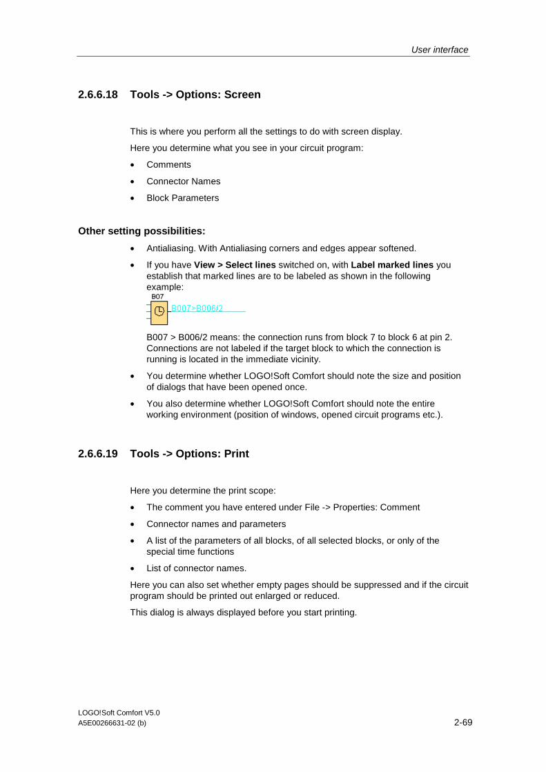
User interface
LOGO!Soft Comfort V5.0 A5E00266631-02 (b) 2-69
2.6.6.18 Tools -> Options: Screen
This is where you perform all the settings to do with screen display.
Here you determine what you see in your circuit program:
• Comments
• Connector Names
• Block Parameters
Other setting possibilities:
• Antialiasing. With Antialiasing corners and edges appear softened.
• If you have View > Select lines switched on, with Label marked lines you establish that marked lines are to be labeled as shown in the following example:
B007 > B006/2 means: the connection runs from block 7 to block 6 at pin 2. Connections are not labeled if the target block to which the connection is running is located in the immediate vicinity.
• You determine whether LOGO!Soft Comfort should note the size and position of dialogs that have been opened once.
• You also determine whether LOGO!Soft Comfort should note the entire working environment (position of windows, opened circuit programs etc.).
2.6.6.19 Tools -> Options: Print
Here you determine the print scope:
• The comment you have entered under File -> Properties: Comment
• Connector names and parameters
• A list of the parameters of all blocks, of all selected blocks, or only of the special time functions
• List of connector names.
Here you can also set whether empty pages should be suppressed and if the circuit program should be printed out enlarged or reduced.
This dialog is always displayed before you start printing.
User interface
LOGO!Soft Comfort V5.0 2-70 A5E00266631-02 (b)
2.6.6.20 Tools -> Options: Cut Connections...
Here you will find the following check boxes.
• A check box you can set to cut all connections routed across blocks and/or exceed a defined length.
• A check box to set the criteria for cutting connections during the import or transfer (upload) of circuit programs from LOGO! to the PC.
• A check box you can set to determine whether to cut connections during the import or transfer (upload) of circuit programs from LOGO! to the PC. The criteria for cutting connections are defined under Edit -> Cut Connections... .
2.6.6.21 Tools -> Options: Interface
The following options are available:
• Specify the interface, if you know exactly which one links the LOGO!.
• If you do not know exactly to which interface the LOGO! is connected, leave it to LOGO!Soft Comfort to determine the relevant interface.
2.6.6.22 Tools -> Options: Simulation
In simulation mode you can here switch the display of signal states and process variables on or off. Switching it off improves the performance of your simulation because when you disable the display of signal states and process variables, there is no need for LOGO!Soft Comfort to calculate these values continuously.
2.6.6.23 Tools -> Options: Colors
Here you can define the color settings:
• The desktop color
• The colors of signal lines carrying a logical "1" or "0" signal in simulation mode
• The color of a selected line. You can set the color of a selected connection for each of the 4 maximum possible inputs and for the output of a block separately.
To restore the original settings, click the Standard button.

User interface
LOGO!Soft Comfort V5.0 A5E00266631-02 (b) 2-71
2.6.6.24 Tools -> Options: Look & Feel
Here you can personalize the layout of the LOGO!Soft Comfort user interface. Try it out!
How to display a corresponding tooltip for a function key

User interface
LOGO!Soft Comfort V5.0 2-72 A5E00266631-02 (b)
2.6.7 Window menu
2.6.7.1 Window menu - Overview
In this windows dialog, you can arrange your circuit program windows on the desktop You can duplicate existing circuit programs and split the windows in order to obtain a clearer overview of large programs.
• Arrange Vertical
• Arrange Horizontal
• Cascade
• Split Vertical
• Split Horizontal
• Undo Split
2.6.7.2 Window -> Arrange Vertical
You can tile several windows containing circuit program vertically on the programming interface.
This menu command is only available if you have set the window view instead of the dialog tab view via the Tools -> Options: Document view dialog.
2.6.7.3 Window -> Arrange Horizontal
You can tile several windows containing circuit program horizontally on the programming interface.
This menu command is only available if you have set the window view instead of the dialog tab view via the Tools -> Options: Document view dialog.
2.6.7.4 Window -> Cascade
You can cascade several open windows containing circuit programs on your programming interface, starting on the upper left corner.
This menu command is only available if you have set the window view instead of the dialog tab view via the Tools -> Options: Document view dialog.

User interface
LOGO!Soft Comfort V5.0 A5E00266631-02 (b) 2-73
2.6.7.5 Window -> Split Vertical
If you have a large circuit program and want to view and compare widely distributed circuit object, you can split the window vertically. The split, of course, affects only the window, but not your circuit program. You can use the scroll bars in the split windows to view or modify the various elements of your circuit diagram.
You can also split the window into several partitions, if you consider it necessary. You can split each window several, both in horizontal and in vertical direction., whereby only the partition is affected in which the last mouse operation has taken place.
You can modify your circuit program in any area of the split window. These changes are, of course, executed throughout the circuit program, because only the window was split, and not the circuit program.
2.6.7.6 Window -> Split Horizontal
If you have a large circuit program and want to view and compare widely distributed circuit object, you can split the window horizontally. The split, of course, affects only the window, but not your circuit program. You can use the scroll bars in the split windows to view or modify the various elements of your circuit diagram.
You can also split the window into several partitions, if you consider it necessary. You can split each window several, both in horizontal and in vertical direction., whereby only the partition is affected in which the last mouse operation has taken place.
You can modify your circuit program in any area of the split window. These changes are, of course, executed throughout the circuit program, because only the window was split, and not the circuit program.
2.6.7.7 Window -> Undo Split
You can use this menu command to undo all splits of a circuit program window.
2.6.7.8 Window -> Selection list
The selection list at the end of the Window menu shows you all the windows you have opened on the programming interface. You can use this selection list to quickly change between windows.

User interface
LOGO!Soft Comfort V5.0 2-74 A5E00266631-02 (b)
2.6.8 Help menu
2.6.8.1 Help menu - Overview
This menu provides you with help and information on LOGO!Soft Comfort.
• Content
• Context-sensitive help
• Update Center...
• About...
2.6.8.2 Help -> Content
The Online Help
The Online Help provides you quickly and reliably with information about program configuration, tools and the creation of circuit programs under LOGO!Soft Comfort.
Topics of the Online Help
The user interface section describes the user interface with its toolbars and the LOGO!Soft Comfort menus in detail.
Refer to the tutorial for a quick and easy introduction to the basics of operating LOGO!Soft Comfort and its circuit programming features.
Towards the end of this section you will find an extensive practical example that takes you through all the steps of circuit program creation.
The sample applications section introduces a few applications for LOGO!.
The reference chapter contains the following subsections:
• In the subsection circuit programs in LOGO!Soft Comfort , you will find a knowledge base containing information on memory requirements, circuit program limits for LOGO! or details on blocks.
• The constants and terminals, basic functions (only FBD editor) and special functions subsections provide you with information about the various elements of a circuit program.
In the Tips and Tricks section we have gathered information that supports your daily tasks with LOGO!Soft Comfort.
The Online Help naturally includes an index as well as a full text search feature for keyword and terminology based searches.
User interface
LOGO!Soft Comfort V5.0 A5E00266631-02 (b) 2-75
Help for blocks
If you double click on a block in the circuit diagram, you receive a window with parameters and settings for the block. If you then click on the Help button in this window you receive the Help for this block in its own window. This Help window is
missing the following symbols:
Remedy: right mouse click on the block in the circuit diagram and select the Help menu command.
2.6.8.3 Help -> Context-sensitive help
Help Context-sensitive help
To call a help file on an object, first click on the context-sensitive help icon (see above) and then on the object.
Result: A window opens with information on this object.
You can also right-click on objects on the programming interface call a corresponding help. The help entry in the shortcut menu called provides you with the required support.
The standard toolbar also contains an icon for this menu command.
2.6.8.4 Help -> Update Center...
Update Center
The Update Center helps you to install additional languages, program add-ons, service packs and new versions for your LOGO!Soft Comfort.
Update and Upgrade
If you update the software within the same main version, then this is an update. For example, LOGO!Soft Comfort Version 4.0 is updated to Version 4.1. It is only possible to update via the Internet.
If you update the software to a higher main version, then this is an upgrade. E.g. LOGO!Soft Comfort Version 4.0 is upgraded to Version 5.0. You can upgrade either via the Update Center or from a CD-ROM.

User interface
LOGO!Soft Comfort V5.0 2-76 A5E00266631-02 (b)
How to use the Update Center
1. Select whether you want to update LOGO!Soft Comfort via the Internet or using your local file system (CD-ROM, floppy or hard disk drive).
2. If you choose to update LOGO!Soft Comfort from your local file system, then you are prompted to enter the directory path in which the updates / upgrades are saved. If you update LOGO!Soft Comfort via the Internet, then the correct Internet address is already preset in the Settings Internet Update. If you are not connected directly to the Internet, then you must specify use a Proxy Server. Consult your network administrator in this regard. An Internet connection is then created.
3. You are then shown all the updates / upgrades available for your software version. Select the desired updates / upgrades. If you are updating LOGO!Soft Comfort via the Internet, then your selected updates / upgrades will be downloaded.
4. Your selected updates / upgrades are then installed.
5. Your selected updates / upgrades are then installed.
6. If you are updating LOGO!Soft Comfort via the Internet, you are prompted to manually close the Internet connection when you have completed these actions.
7. LOGO!Soft Comfort is closed automatically when the update / upgrade is completed. The functionality of the installed update / upgrade is available to you after you restart LOGO!Soft Comfort.
Possible Errors
If, when installing an upgrade / update, you receive the error message Does not agree with magic figure, this means the upgrade / update file Setup.exe has not been executed in full.
In this case, download the upgrade / update file from the Internet again and ensure the file is transferred in full.

User interface
LOGO!Soft Comfort V5.0 A5E00266631-02 (b) 2-77
2.6.8.5 Help -> About...
The General tab displays the version number and the release version of your LOGO!Soft Comfort software.
The System tab provides you with information on the version of the Java Runtime environment used, the program paths, the installed operating system and on the memory used.

User interface
LOGO!Soft Comfort V5.0 2-78 A5E00266631-02 (b)

LOGO!Soft Comfort V5.0 A5E00266631-02 (b) 3-1
3 Tutorial
3.1 Prerequisites for working with the tutorial
We assume you are familiar with PC operation and that you know how to create a function block diagram. To download your circuit programs, you also need the PC cable for connecting the serial PC interface to your LOGO! device.
3.2 Getting started with program creation
3.2.1 Introducing the creation of circuit programs
You are going to learn the basics of working with LOGO!Soft Comfort, by creating a simple circuit program and simulating it on your PC. Towards the end of this chapter, you will find a few sample applications for LOGO!Soft Comfort, and information on how to prepare, transfer and archive your application. In the subsequent chapters, these functions are once again explained in full detail.
Factory door
Dual-function switch
Air-conditioning system
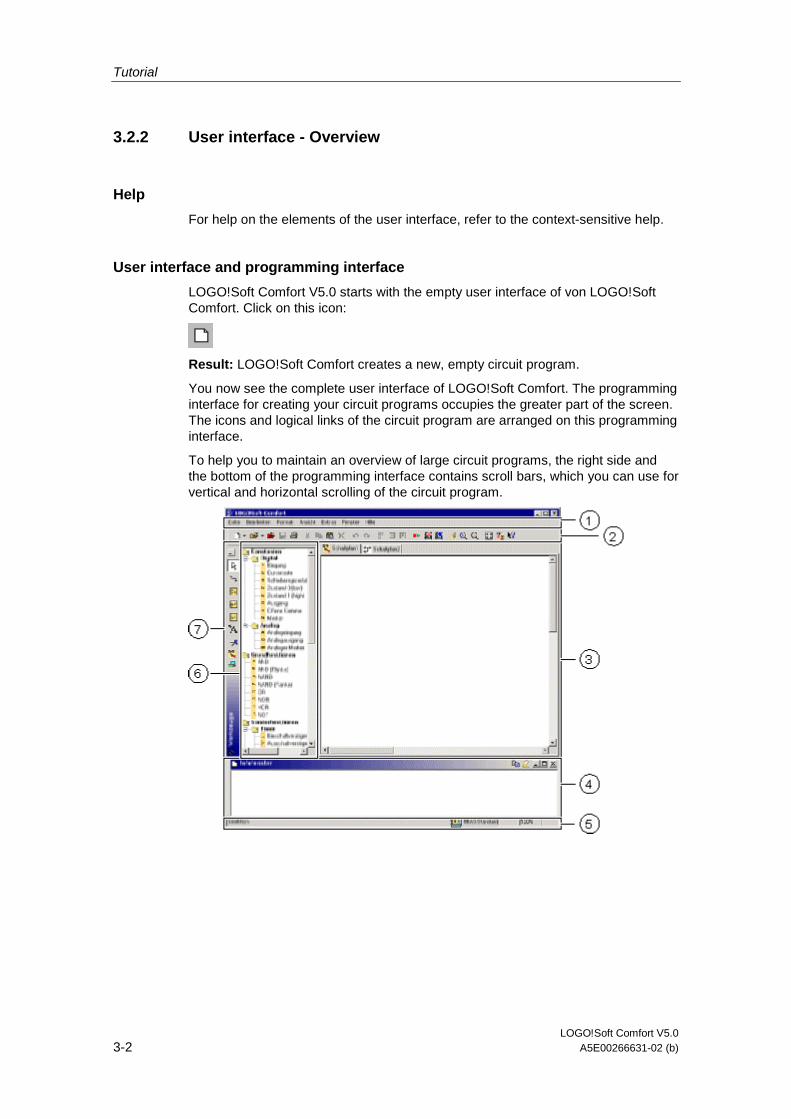
Tutorial
LOGO!Soft Comfort V5.0 3-2 A5E00266631-02 (b)
3.2.2 User interface - Overview
Help
For help on the elements of the user interface, refer to the context-sensitive help.
User interface and programming interface
LOGO!Soft Comfort V5.0 starts with the empty user interface of von LOGO!Soft Comfort. Click on this icon:
Result: LOGO!Soft Comfort creates a new, empty circuit program.
You now see the complete user interface of LOGO!Soft Comfort. The programming interface for creating your circuit programs occupies the greater part of the screen. The icons and logical links of the circuit program are arranged on this programming interface.
To help you to maintain an overview of large circuit programs, the right side and the bottom of the programming interface contains scroll bars, which you can use for vertical and horizontal scrolling of the circuit program.
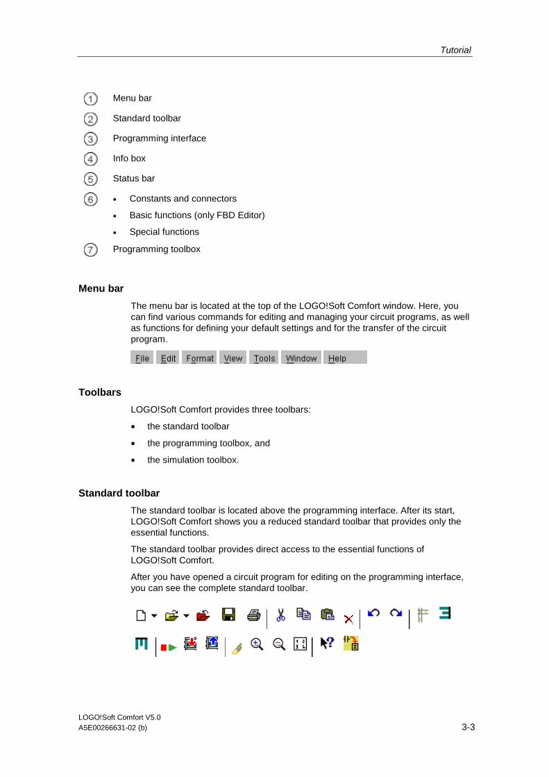
Tutorial
LOGO!Soft Comfort V5.0 A5E00266631-02 (b) 3-3
Menu bar
Standard toolbar
Programming interface
Info box
Status bar
• Constants and connectors
• Basic functions (only FBD Editor)
• Special functions
Programming toolbox
Menu bar
The menu bar is located at the top of the LOGO!Soft Comfort window. Here, you can find various commands for editing and managing your circuit programs, as well as functions for defining your default settings and for the transfer of the circuit program.
Toolbars
LOGO!Soft Comfort provides three toolbars:
• the standard toolbar
• the programming toolbox, and
• the simulation toolbox.
Standard toolbar
The standard toolbar is located above the programming interface. After its start, LOGO!Soft Comfort shows you a reduced standard toolbar that provides only the essential functions.
The standard toolbar provides direct access to the essential functions of LOGO!Soft Comfort.
After you have opened a circuit program for editing on the programming interface, you can see the complete standard toolbar.

Tutorial
LOGO!Soft Comfort V5.0 3-4 A5E00266631-02 (b)
You can use the icons to create a new circuit program or to download, save and print out an existing program, cut/copy and paste objects, or initiate data transfer to and from LOGO! devices.
You can use the mouse to select and move the standard toolbar. The toolbar is always snapped onto the top of the menu bar when you close it.
Programming toolbox
The programming toolbox is located at the bottom of the screen. Its icons can be used to change to other editing modes, or for quick and easy creation or editing of a circuit program.
or
You can drag and drop the programming toolbox to another location with the mouse. The toolbox is always snapped onto the top of the menu bar when you close it.
The LAD Editor no longer contains the Basic function (SF) icon, because you create logical "AND" and "OR" links by interconnecting individual blocks.
Simulation toolbox
This toolbox is only relevant for the simulation of circuit programs. Further information is found here.
Info box
The Info Window, located at the bottom of the programming interface, displays information and notes, as well as the LOGO! devices recommended via the Tools -> Determine LOGO! function for use in your circuit program.
Status bar
The status bar is located at the bottom of the program window. It shows the currently active tool, the program status, the set zoom factor, the page number of the circuit diagram and the selected LOGO! device.

Tutorial
LOGO!Soft Comfort V5.0 A5E00266631-02 (b) 3-5
3.2.3 Creating a circuit program
Creating programs with the help of the toolboxes
In this intro section you require only the toolboxes and standard toolbars.
Drag the mouse pointer onto the toolbox icon and left click to select it. This selection is indicated.
To create a circuit program
1. Create a new circuit program
2. Select the blocks required
3. Place the blocks
4. Configure and comment the blocks
5. Connect the blocks
6. Optimize the circuit program
7. Save the circuit program
Please note that not all blocks are available at all times.
3.2.3.1 Creating a new circuit program
You can start to create a new circuit program immediately after you have started LOGO!Soft Comfort.
To do so, click on the File new icon in the standard toolbar.
File new
LOGO!Soft Comfort then opens the FBD Editor (or the default editor specified under Tools/Options/Editor), and you can create the new circuit program in a new window on the programming interface.
Click on the small arrow on the right side of the File new icon to open the LAD or FBD Editor.
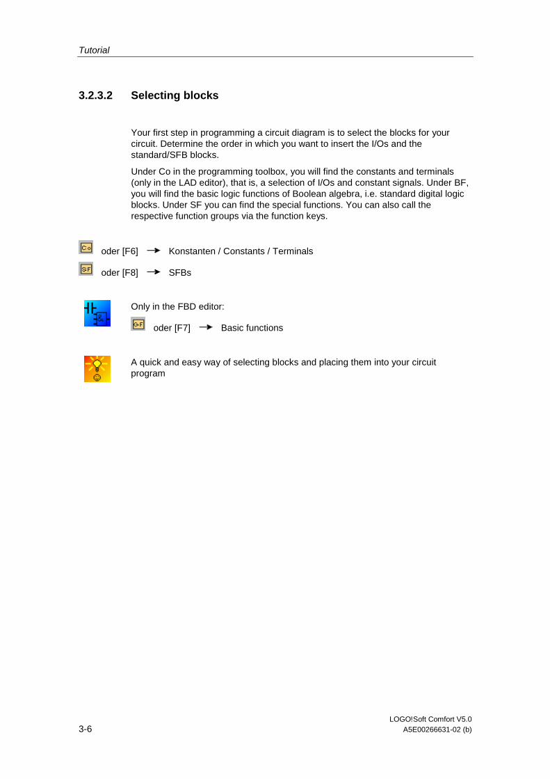
Tutorial
LOGO!Soft Comfort V5.0 3-6 A5E00266631-02 (b)
3.2.3.2 Selecting blocks
Your first step in programming a circuit diagram is to select the blocks for your circuit. Determine the order in which you want to insert the I/Os and the standard/SFB blocks.
Under Co in the programming toolbox, you will find the constants and terminals (only in the LAD editor), that is, a selection of I/Os and constant signals. Under BF, you will find the basic logic functions of Boolean algebra, i.e. standard digital logic blocks. Under SF you can find the special functions. You can also call the respective function groups via the function keys.
oder [F6] Konstanten / Constants / Terminals
oder [F8] SFBs
Only in the FBD editor:
oder [F7] Basic functions
A quick and easy way of selecting blocks and placing them into your circuit program
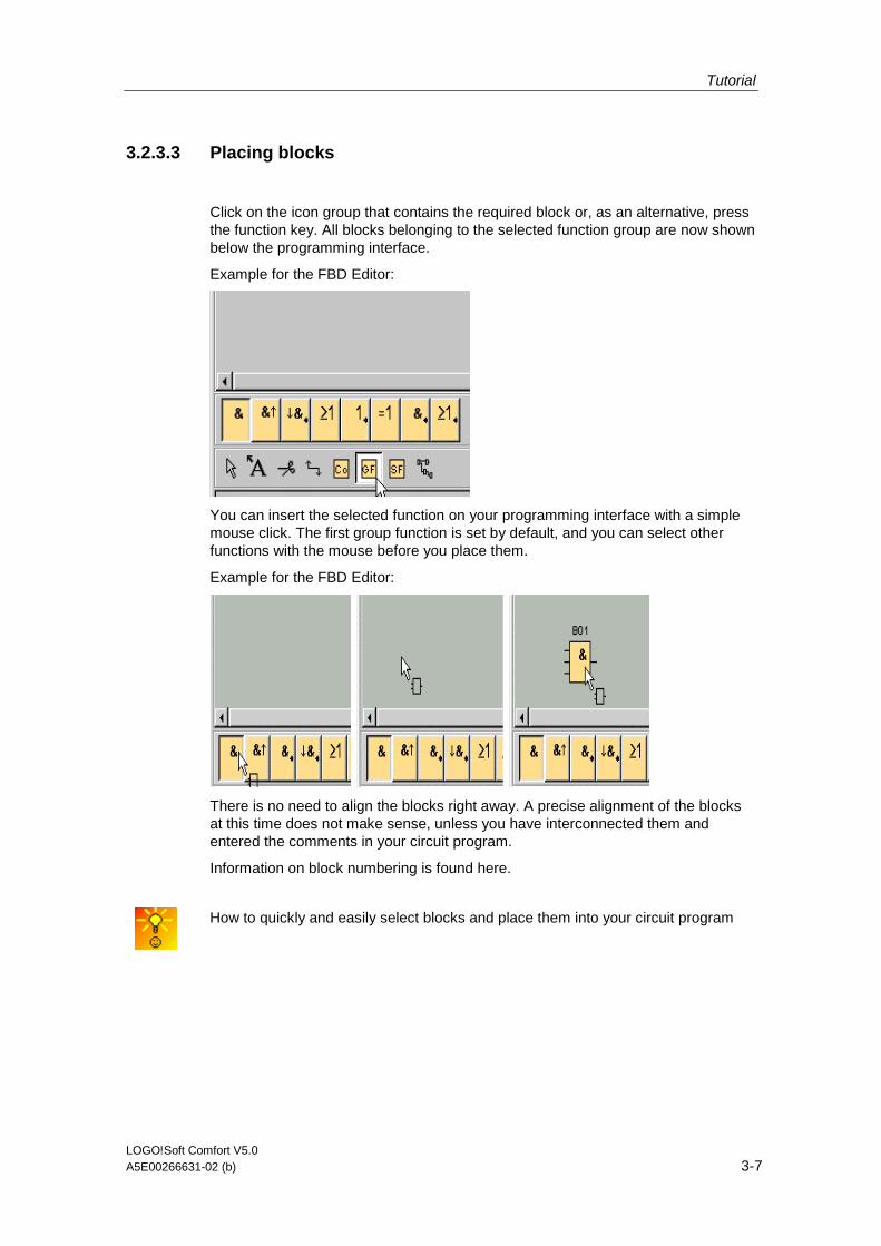
Tutorial
LOGO!Soft Comfort V5.0 A5E00266631-02 (b) 3-7
3.2.3.3 Placing blocks
Click on the icon group that contains the required block or, as an alternative, press the function key. All blocks belonging to the selected function group are now shown below the programming interface.
Example for the FBD Editor:
You can insert the selected function on your programming interface with a simple mouse click. The first group function is set by default, and you can select other functions with the mouse before you place them.
Example for the FBD Editor:
There is no need to align the blocks right away. A precise alignment of the blocks at this time does not make sense, unless you have interconnected them and entered the comments in your circuit program.
Information on block numbering is found here.
How to quickly and easily select blocks and place them into your circuit program
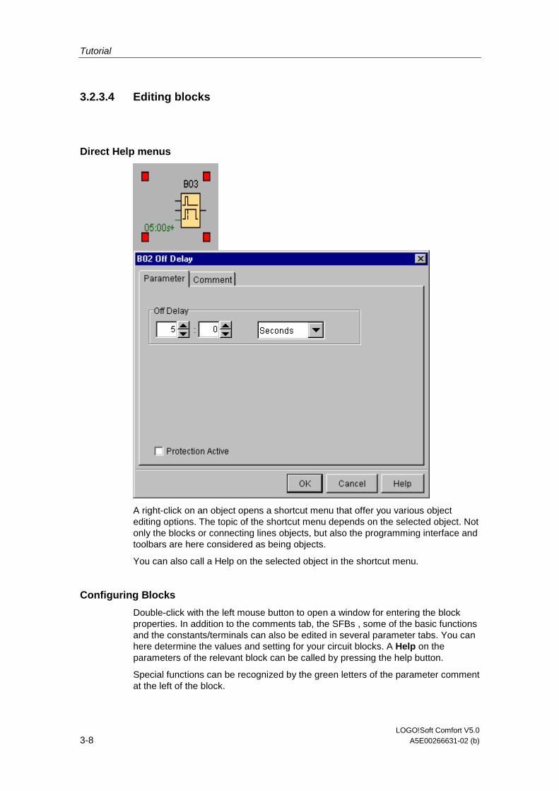
Tutorial
LOGO!Soft Comfort V5.0 3-8 A5E00266631-02 (b)
3.2.3.4 Editing blocks
Direct Help menus
A right-click on an object opens a shortcut menu that offer you various object editing options. The topic of the shortcut menu depends on the selected object. Not only the blocks or connecting lines objects, but also the programming interface and toolbars are here considered as being objects.
You can also call a Help on the selected object in the shortcut menu.
Configuring Blocks
Double-click with the left mouse button to open a window for entering the block properties. In addition to the comments tab, the SFBs , some of the basic functions and the constants/terminals can also be edited in several parameter tabs. You can here determine the values and setting for your circuit blocks. A Help on the parameters of the relevant block can be called by pressing the help button.
Special functions can be recognized by the green letters of the parameter comment at the left of the block.
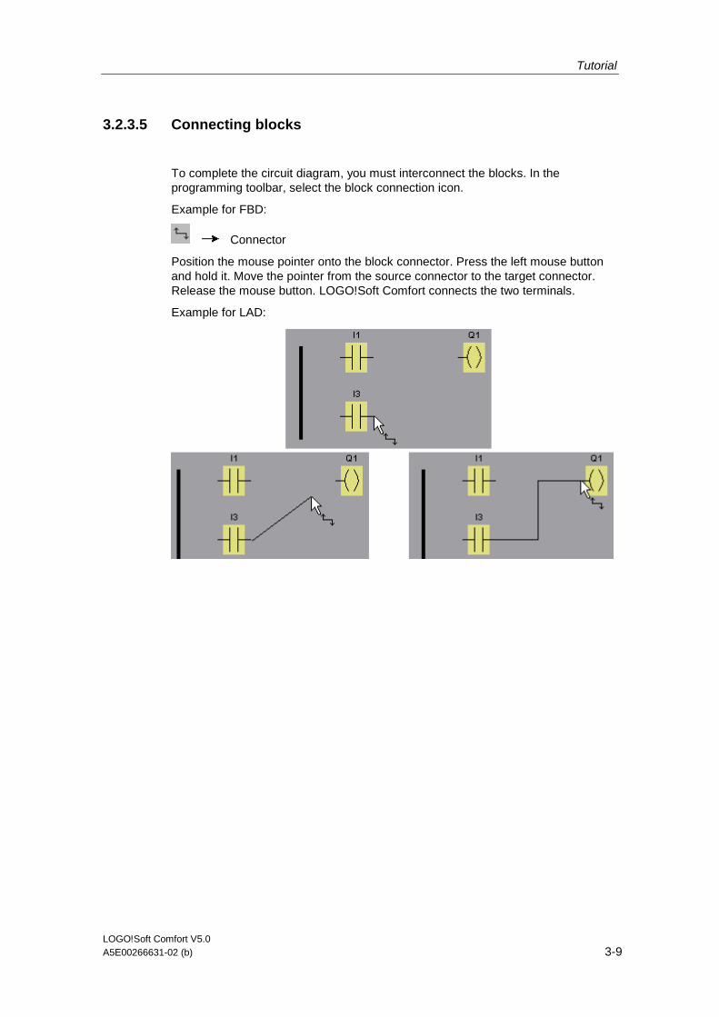
Tutorial
LOGO!Soft Comfort V5.0 A5E00266631-02 (b) 3-9
3.2.3.5 Connecting blocks
To complete the circuit diagram, you must interconnect the blocks. In the programming toolbar, select the block connection icon.
Example for FBD:
Connector
Position the mouse pointer onto the block connector. Press the left mouse button and hold it. Move the pointer from the source connector to the target connector. Release the mouse button. LOGO!Soft Comfort connects the two terminals.
Example for LAD:
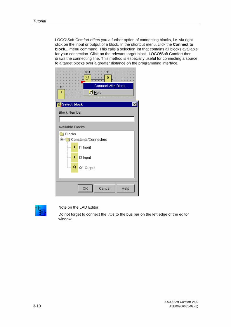
Tutorial
LOGO!Soft Comfort V5.0 3-10 A5E00266631-02 (b)
LOGO!Soft Comfort offers you a further option of connecting blocks, i.e. via right-click on the input or output of a block. In the shortcut menu, click the Connect to block... menu command. This calls a selection list that contains all blocks available for your connection. Click on the relevant target block. LOGO!Soft Comfort then draws the connecting line. This method is especially useful for connecting a source to a target blocks over a greater distance on the programming interface.
Note on the LAD Editor:
Do not forget to connect the I/Os to the bus bar on the left edge of the editor window.
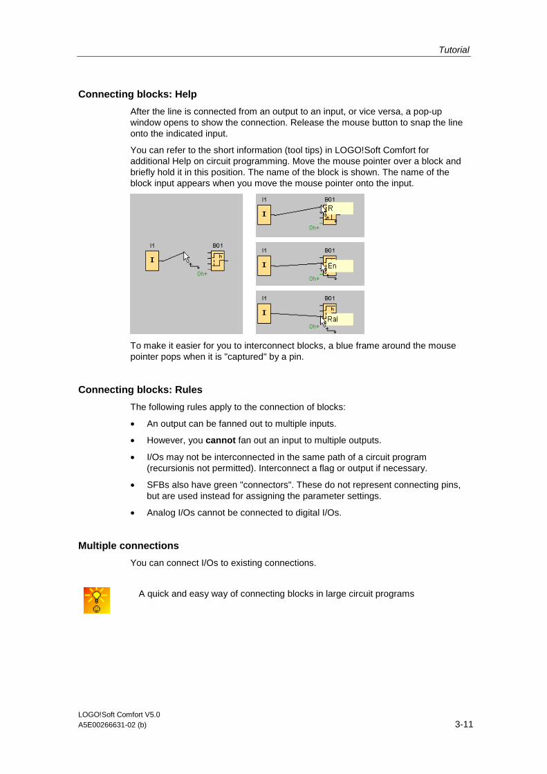
Tutorial
LOGO!Soft Comfort V5.0 A5E00266631-02 (b) 3-11
Connecting blocks: Help
After the line is connected from an output to an input, or vice versa, a pop-up window opens to show the connection. Release the mouse button to snap the line onto the indicated input.
You can refer to the short information (tool tips) in LOGO!Soft Comfort for additional Help on circuit programming. Move the mouse pointer over a block and briefly hold it in this position. The name of the block is shown. The name of the block input appears when you move the mouse pointer onto the input.
To make it easier for you to interconnect blocks, a blue frame around the mouse pointer pops when it is "captured" by a pin.
Connecting blocks: Rules
The following rules apply to the connection of blocks:
• An output can be fanned out to multiple inputs.
• However, you cannot fan out an input to multiple outputs.
• I/Os may not be interconnected in the same path of a circuit program (recursionis not permitted). Interconnect a flag or output if necessary.
• SFBs also have green "connectors". These do not represent connecting pins, but are used instead for assigning the parameter settings.
• Analog I/Os cannot be connected to digital I/Os.
Multiple connections
You can connect I/Os to existing connections.
A quick and easy way of connecting blocks in large circuit programs
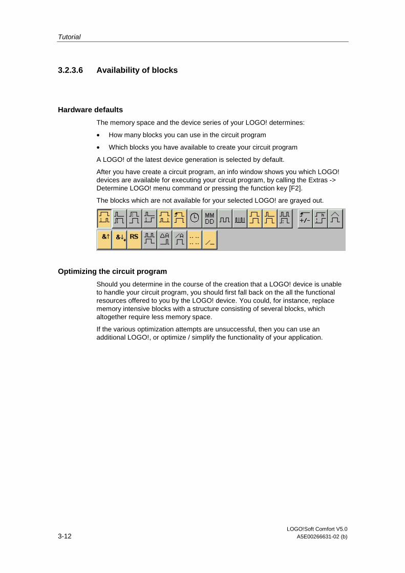
Tutorial
LOGO!Soft Comfort V5.0 3-12 A5E00266631-02 (b)
3.2.3.6 Availability of blocks
Hardware defaults
The memory space and the device series of your LOGO! determines:
• How many blocks you can use in the circuit program
• Which blocks you have available to create your circuit program
A LOGO! of the latest device generation is selected by default.
After you have create a circuit program, an info window shows you which LOGO! devices are available for executing your circuit program, by calling the Extras -> Determine LOGO! menu command or pressing the function key [F2].
The blocks which are not available for your selected LOGO! are grayed out.
Optimizing the circuit program
Should you determine in the course of the creation that a LOGO! device is unable to handle your circuit program, you should first fall back on the all the functional resources offered to you by the LOGO! device. You could, for instance, replace memory intensive blocks with a structure consisting of several blocks, which altogether require less memory space.
If the various optimization attempts are unsuccessful, then you can use an additional LOGO!, or optimize / simplify the functionality of your application.
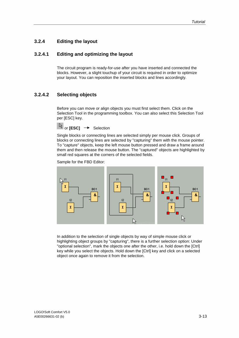
Tutorial
LOGO!Soft Comfort V5.0 A5E00266631-02 (b) 3-13
3.2.4 Editing the layout
3.2.4.1 Editing and optimizing the layout
The circuit program is ready-for-use after you have inserted and connected the blocks. However, a slight touchup of your circuit is required in order to optimize your layout. You can reposition the inserted blocks and lines accordingly.
3.2.4.2 Selecting objects
Before you can move or align objects you must first select them. Click on the Selection Tool in the programming toolbox. You can also select this Selection Tool per [ESC] key.
or [ESC] Selection
Single blocks or connecting lines are selected simply per mouse click. Groups of blocks or connecting lines are selected by "capturing" them with the mouse pointer. To "capture" objects, keep the left mouse button pressed and draw a frame around them and then release the mouse button. The "captured" objects are highlighted by small red squares at the corners of the selected fields.
Sample for the FBD Editor:
In addition to the selection of single objects by way of simple mouse click or highlighting object groups by "capturing", there is a further selection option: Under "optional selection", mark the objects one after the other, i.e. hold down the [Ctrl] key while you select the objects. Hold down the [Ctrl] key and click on a selected object once again to remove it from the selection.
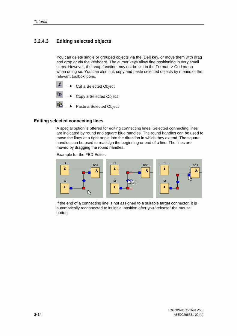
Tutorial
LOGO!Soft Comfort V5.0 3-14 A5E00266631-02 (b)
3.2.4.3 Editing selected objects
You can delete single or grouped objects via the [Del] key, or move them with drag and drop or via the keyboard. The cursor keys allow fine positioning in very small steps. However, the snap function may not be set in the Format -> Grid menu when doing so. You can also cut, copy and paste selected objects by means of the relevant toolbox icons.
Cut a Selected Object
Copy a Selected Object
Paste a Selected Object
Editing selected connecting lines
A special option is offered for editing connecting lines. Selected connecting lines are indicated by round and square blue handles. The round handles can be used to move the lines at a right angle into the direction in which they extend. The square handles can be used to reassign the beginning or end of a line. The lines are moved by dragging the round handles.
Example for the FBD Editor:
If the end of a connecting line is not assigned to a suitable target connector, it is automatically reconnected to its initial position after you "release" the mouse button.
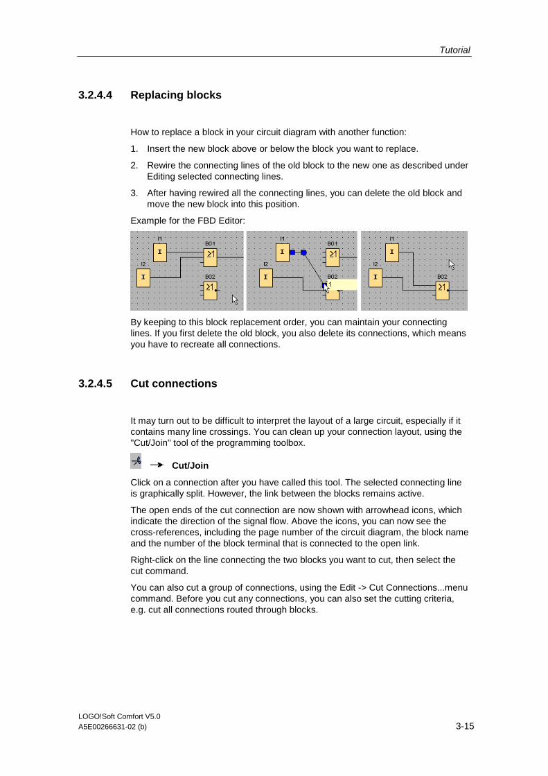
Tutorial
LOGO!Soft Comfort V5.0 A5E00266631-02 (b) 3-15
3.2.4.4 Replacing blocks
How to replace a block in your circuit diagram with another function:
1. Insert the new block above or below the block you want to replace.
2. Rewire the connecting lines of the old block to the new one as described under Editing selected connecting lines.
3. After having rewired all the connecting lines, you can delete the old block and move the new block into this position.
Example for the FBD Editor:
By keeping to this block replacement order, you can maintain your connecting lines. If you first delete the old block, you also delete its connections, which means you have to recreate all connections.
3.2.4.5 Cut connections
It may turn out to be difficult to interpret the layout of a large circuit, especially if it contains many line crossings. You can clean up your connection layout, using the "Cut/Join" tool of the programming toolbox.
Cut/Join
Click on a connection after you have called this tool. The selected connecting line is graphically split. However, the link between the blocks remains active.
The open ends of the cut connection are now shown with arrowhead icons, which indicate the direction of the signal flow. Above the icons, you can now see the cross-references, including the page number of the circuit diagram, the block name and the number of the block terminal that is connected to the open link.
Right-click on the line connecting the two blocks you want to cut, then select the cut command.
You can also cut a group of connections, using the Edit -> Cut Connections...menu command. Before you cut any connections, you can also set the cutting criteria, e.g. cut all connections routed through blocks.
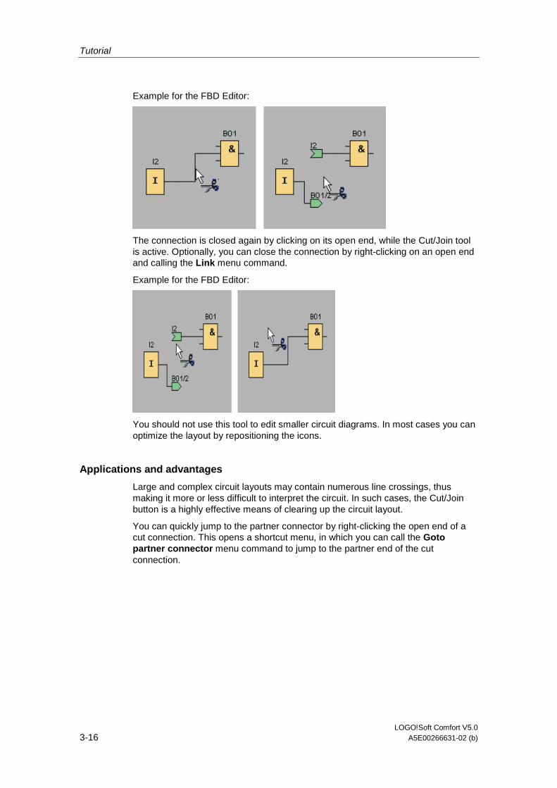
Tutorial
LOGO!Soft Comfort V5.0 3-16 A5E00266631-02 (b)
Example for the FBD Editor:
The connection is closed again by clicking on its open end, while the Cut/Join tool is active. Optionally, you can close the connection by right-clicking on an open end and calling the Link menu command.
Example for the FBD Editor:
You should not use this tool to edit smaller circuit diagrams. In most cases you can optimize the layout by repositioning the icons.
Applications and advantages
Large and complex circuit layouts may contain numerous line crossings, thus making it more or less difficult to interpret the circuit. In such cases, the Cut/Join button is a highly effective means of clearing up the circuit layout.
You can quickly jump to the partner connector by right-clicking the open end of a cut connection. This opens a shortcut menu, in which you can call the Goto partner connector menu command to jump to the partner end of the cut connection.
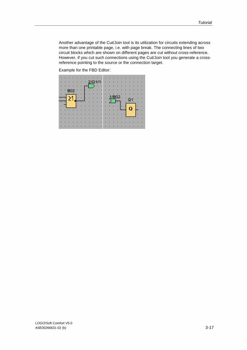
Tutorial
LOGO!Soft Comfort V5.0 A5E00266631-02 (b) 3-17
Another advantage of the Cut/Join tool is its utilization for circuits extending across more than one printable page, i.e. with page break. The connecting lines of two circuit blocks which are shown on different pages are cut without cross-reference. However, if you cut such connections using the Cut/Join tool you generate a cross-reference pointing to the source or the connection target.
Example for the FBD Editor:
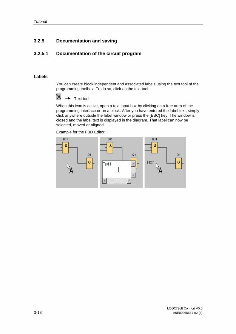
Tutorial
LOGO!Soft Comfort V5.0 3-18 A5E00266631-02 (b)
3.2.5 Documentation and saving
3.2.5.1 Documentation of the circuit program
Labels
You can create block independent and associated labels using the text tool of the programming toolbox. To do so, click on the text tool.
Text tool
When this icon is active, open a text input box by clicking on a free area of the programming interface or on a block. After you have entered the label text, simply click anywhere outside the label window or press the [ESC] key. The window is closed and the label text is displayed in the diagram. That label can now be selected, moved or aligned.
Example for the FBD Editor:
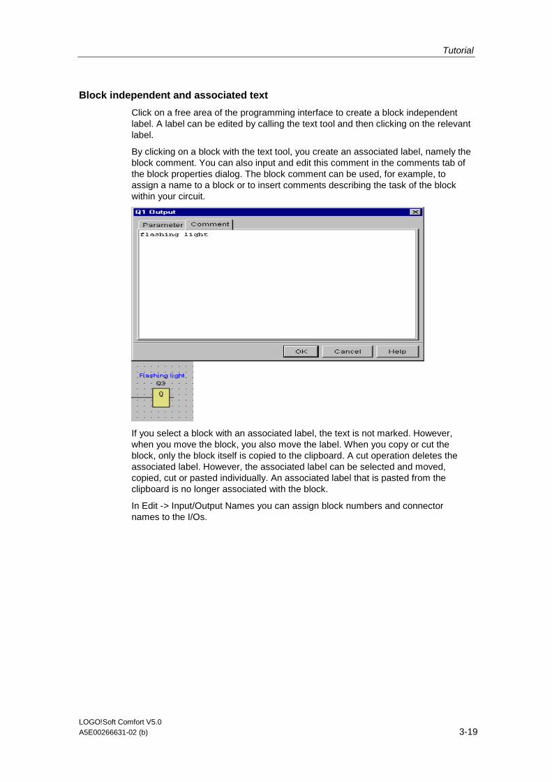
Tutorial
LOGO!Soft Comfort V5.0 A5E00266631-02 (b) 3-19
Block independent and associated text
Click on a free area of the programming interface to create a block independent label. A label can be edited by calling the text tool and then clicking on the relevant label.
By clicking on a block with the text tool, you create an associated label, namely the block comment. You can also input and edit this comment in the comments tab of the block properties dialog. The block comment can be used, for example, to assign a name to a block or to insert comments describing the task of the block within your circuit.
If you select a block with an associated label, the text is not marked. However, when you move the block, you also move the label. When you copy or cut the block, only the block itself is copied to the clipboard. A cut operation deletes the associated label. However, the associated label can be selected and moved, copied, cut or pasted individually. An associated label that is pasted from the clipboard is no longer associated with the block.
In Edit -> Input/Output Names you can assign block numbers and connector names to the I/Os.

Tutorial
LOGO!Soft Comfort V5.0 3-20 A5E00266631-02 (b)
3.2.5.2 Opening and saving the circuit program
Saving the circuit program
Click on the save icon in the standard toolbar to save the circuit program.
File Save
The circuit program is saved under the name it was opened with, while older versions are overwritten. When you initially save it, you are prompted to specify a program path and name.
Opening a circuit program
You can always open a circuit program for further editing, by clicking on the File open icon. You open a list of recently opened programs by clicking on the arrow icon on the right side of the button.
File Open
Tutorial
LOGO!Soft Comfort V5.0 A5E00266631-02 (b) 3-21
3.3 Simulation of a circuit program
3.3.1 Tools -> Simulation
Introduction
The program simulation function allows you to test a program and modify its parameters. This ensures the download of a fully functioning and optimized program to your LOGO!.
Simulation mode
Click on the Simulation icon in the programming toolbox to start the simulation. This changes the program to simulation mode.
Simulation
The active icon is highlighted in simulation mode. By clicking once again on the Simulation icon, or on any other icon of the programming toolbox, you exit simulation mode and open another tool mode (e.g. for selecting or inserting blocks).
At the start of simulation mode, the program is verified and the results are output to the info window.

Tutorial
LOGO!Soft Comfort V5.0 3-22 A5E00266631-02 (b)
3.3.2 Description of the Info Window
Content
The info window shows in particular:
• Error messages generated at the start of simulation
• LOGO! devices determined via the Tools -> Determine LOGO! menu command or the function key [F2]
• The date and time of the message
• The name of the circuit program for which the message was generated.
If you have opened more than one circuit program, you can determine to which program the message belongs to.
At the start of simulation mode, the function analyzes the circuit program with regard to its resources and the LOGO! to be used. The resources used and errors occurred are displayed in the info window.
The info window displays all information in successive order. Use the scroll bar to browse all the information pages. All information is deleted from the info window when you close LOGO!Soft Comfort.
Operation
You can open and close the Info Window via View -> Info window or the [F4] function key. The Info window is usually positioned at the bottom of the programming interface. You can move it with the mouse, and snap it onto the top of the programming interface, in the same way as you move the toolbars. You can move the window via drag and drop, or move it out of LOGO!Soft Comfort to open it as a separate window.
A quick way of increasing/reducing the size of the Info Window
Editing the texts in the Info window
You can delete selected messages from the Info window or copy them to other applications. You can also write personal comments in the Info Window.
Use the mouse to select a text from the Info Window, and this icon to copy it to the clipboard of your operating system.
This icon can be used to delete the content of the info window.
How to use the Info Window texts for your documentation
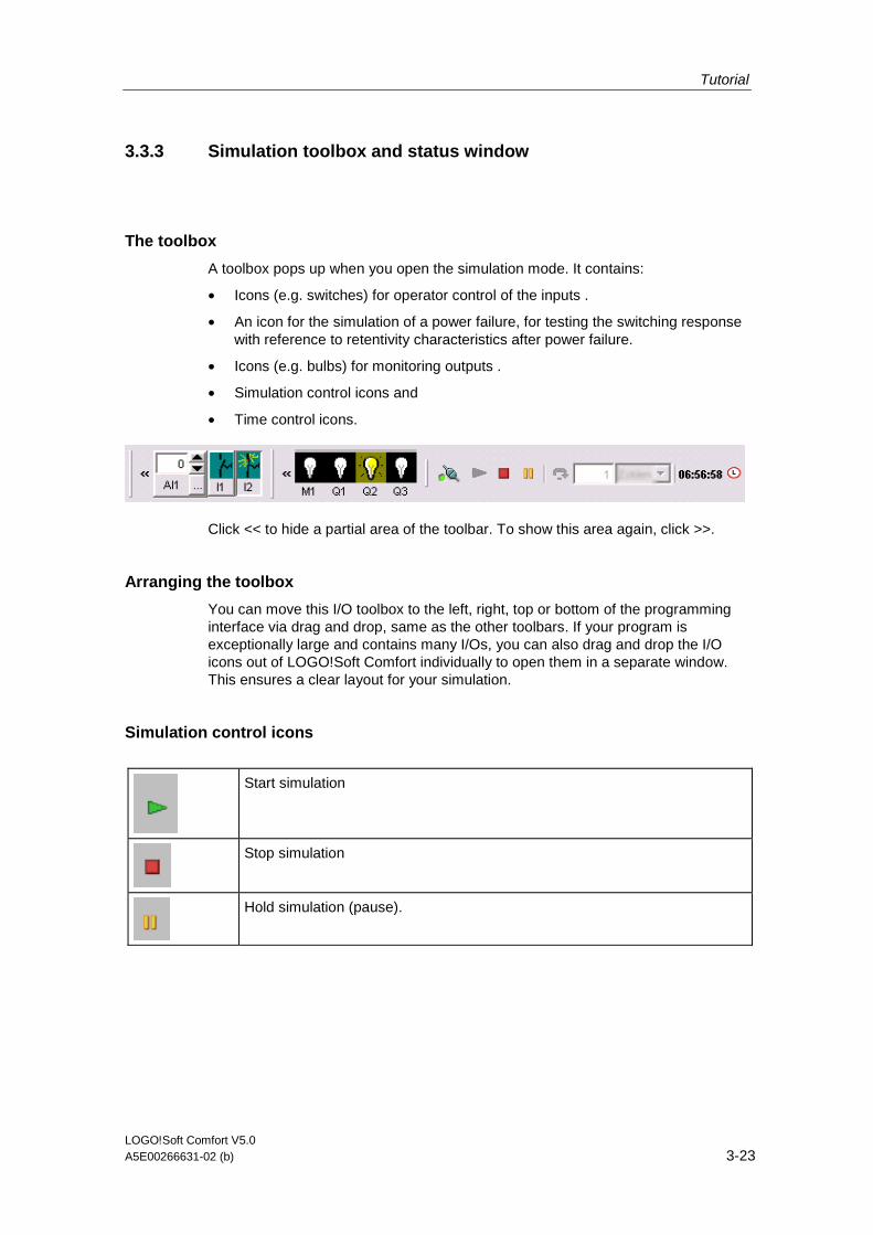
Tutorial
LOGO!Soft Comfort V5.0 A5E00266631-02 (b) 3-23
3.3.3 Simulation toolbox and status window
The toolbox
A toolbox pops up when you open the simulation mode. It contains:
• Icons (e.g. switches) for operator control of the inputs .
• An icon for the simulation of a power failure, for testing the switching response with reference to retentivity characteristics after power failure.
• Icons (e.g. bulbs) for monitoring outputs .
• Simulation control icons and
• Time control icons.
Click << to hide a partial area of the toolbar. To show this area again, click >>.
Arranging the toolbox
You can move this I/O toolbox to the left, right, top or bottom of the programming interface via drag and drop, same as the other toolbars. If your program is exceptionally large and contains many I/Os, you can also drag and drop the I/O icons out of LOGO!Soft Comfort individually to open them in a separate window. This ensures a clear layout for your simulation.
Simulation control icons
Start simulation
Stop simulation
Hold simulation (pause).

Tutorial
LOGO!Soft Comfort V5.0 3-24 A5E00266631-02 (b)
Time control
If you have programmed a time-sensitive circuit, you should use the time control to monitor the reaction of your circuit program.
Start simulation for e specific time or number of cycles.
Set the period and the number of cycles using the following icons.
Setting the period and the time base for a time limited simulation or setting a specific number of cycles
Display of the current time in LOGO!Soft Comfort
Modification of the current time in LOGO!Soft Comfort
Status display
Prerequisite: The display of signal states and process variables is enabled under Tools Options: Simulation.
The colored indication lets you identify the "1" or "0" status of a connecting line. Default color of connecting lines carrying a "1" signal is red. Default color of connecting lines carrying a "0" signal is blue.
Example for the FBD Editor:
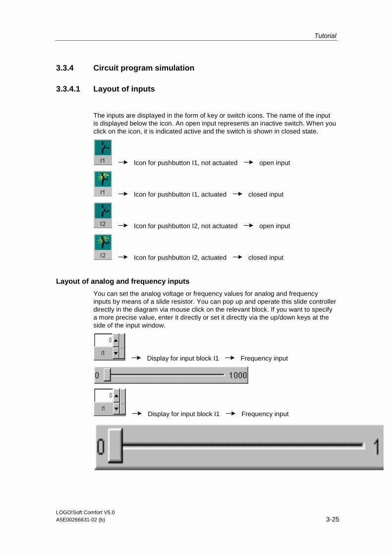
Tutorial
LOGO!Soft Comfort V5.0 A5E00266631-02 (b) 3-25
3.3.4 Circuit program simulation
3.3.4.1 Layout of inputs
The inputs are displayed in the form of key or switch icons. The name of the input is displayed below the icon. An open input represents an inactive switch. When you click on the icon, it is indicated active and the switch is shown in closed state.
Icon for pushbutton I1, not actuated open input
Icon for pushbutton I1, actuated closed input
Icon for pushbutton I2, not actuated open input
Icon for pushbutton I2, actuated closed input
Layout of analog and frequency inputs
You can set the analog voltage or frequency values for analog and frequency inputs by means of a slide resistor. You can pop up and operate this slide controller directly in the diagram via mouse click on the relevant block. If you want to specify a more precise value, enter it directly or set it directly via the up/down keys at the side of the input window.
Display for input block I1 Frequency input
Display for input block I1 Frequency input
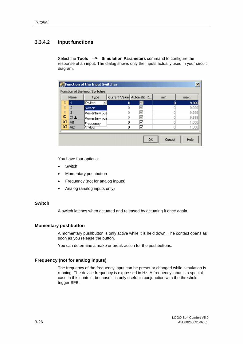
Tutorial
LOGO!Soft Comfort V5.0 3-26 A5E00266631-02 (b)
3.3.4.2 Input functions
Select the Tools Simulation Parameters command to configure the response of an input. The dialog shows only the inputs actually used in your circuit diagram.
You have four options:
• Switch
• Momentary pushbutton
• Frequency (not for analog inputs)
• Analog (analog inputs only)
Switch
A switch latches when actuated and released by actuating it once again.
Momentary pushbutton
A momentary pushbutton is only active while it is held down. The contact opens as soon as you release the button.
You can determine a make or break action for the pushbuttons.
Frequency (not for analog inputs)
The frequency of the frequency input can be preset or changed while simulation is running. The device frequency is expressed in Hz. A frequency input is a special case in this context, because it is only useful in conjunction with the threshold trigger SFB.
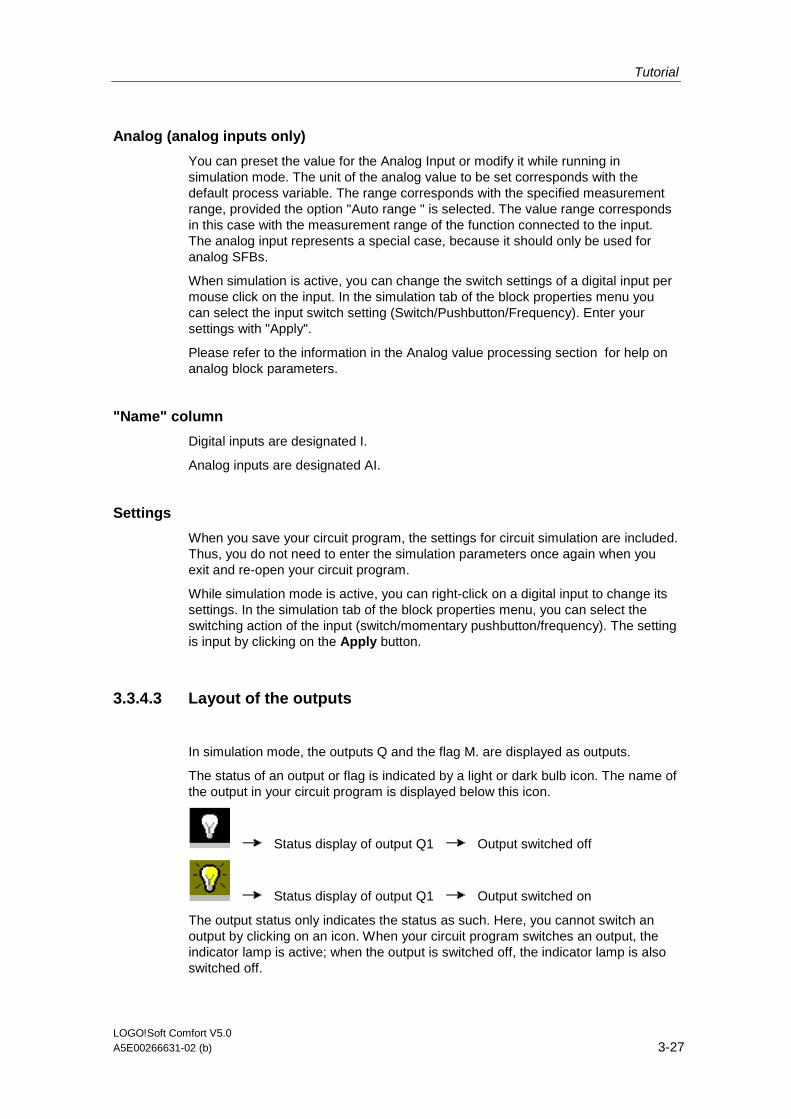
Tutorial
LOGO!Soft Comfort V5.0 A5E00266631-02 (b) 3-27
Analog (analog inputs only)
You can preset the value for the Analog Input or modify it while running in simulation mode. The unit of the analog value to be set corresponds with the default process variable. The range corresponds with the specified measurement range, provided the option "Auto range " is selected. The value range corresponds in this case with the measurement range of the function connected to the input. The analog input represents a special case, because it should only be used for analog SFBs.
When simulation is active, you can change the switch settings of a digital input per mouse click on the input. In the simulation tab of the block properties menu you can select the input switch setting (Switch/Pushbutton/Frequency). Enter your settings with "Apply".
Please refer to the information in the Analog value processing section for help on analog block parameters.
"Name" column
Digital inputs are designated I.
Analog inputs are designated AI.
Settings
When you save your circuit program, the settings for circuit simulation are included. Thus, you do not need to enter the simulation parameters once again when you exit and re-open your circuit program.
While simulation mode is active, you can right-click on a digital input to change its settings. In the simulation tab of the block properties menu, you can select the switching action of the input (switch/momentary pushbutton/frequency). The setting is input by clicking on the Apply button.
3.3.4.3 Layout of the outputs
In simulation mode, the outputs Q and the flag M. are displayed as outputs.
The status of an output or flag is indicated by a light or dark bulb icon. The name of the output in your circuit program is displayed below this icon.
Status display of output Q1 Output switched off
Status display of output Q1 Output switched on
The output status only indicates the status as such. Here, you cannot switch an output by clicking on an icon. When your circuit program switches an output, the indicator lamp is active; when the output is switched off, the indicator lamp is also switched off.
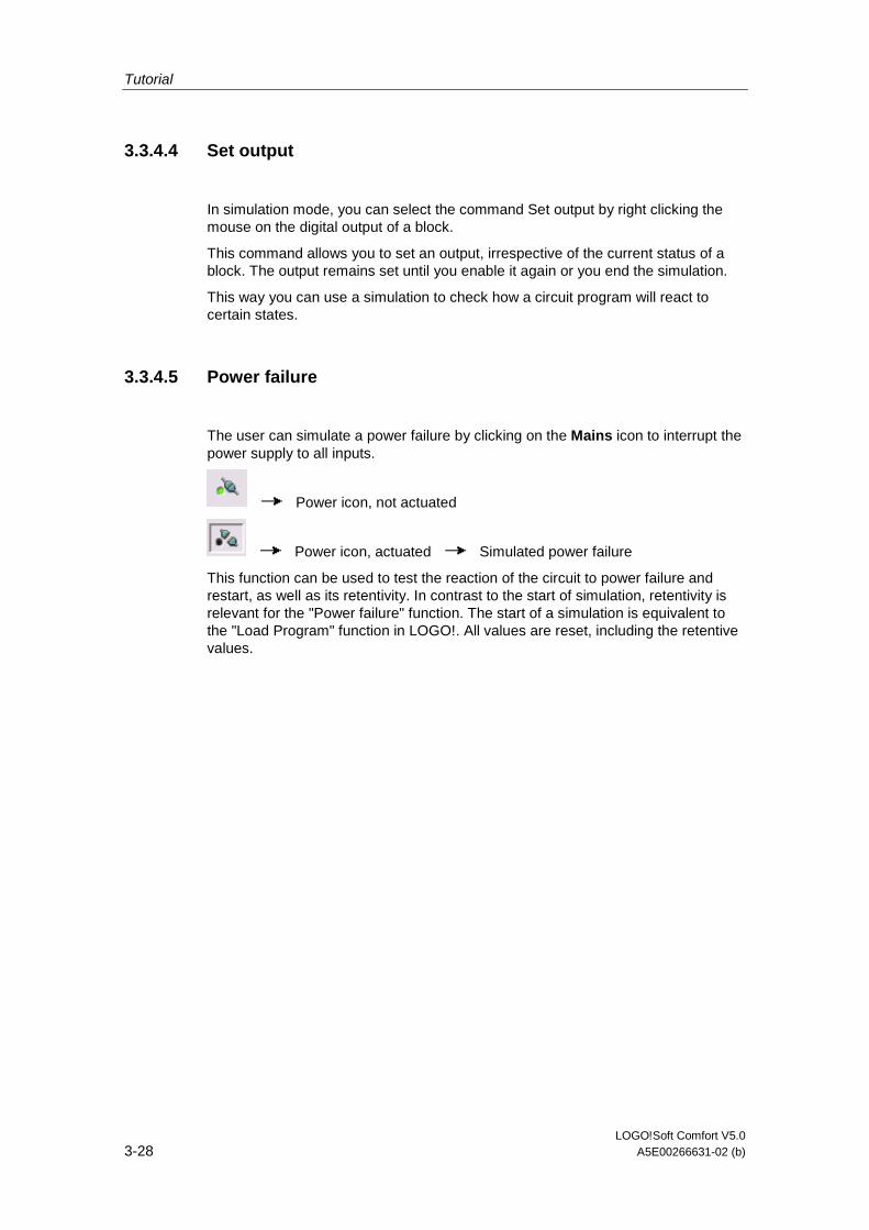
Tutorial
LOGO!Soft Comfort V5.0 3-28 A5E00266631-02 (b)
3.3.4.4 Set output
In simulation mode, you can select the command Set output by right clicking the mouse on the digital output of a block.
This command allows you to set an output, irrespective of the current status of a block. The output remains set until you enable it again or you end the simulation.
This way you can use a simulation to check how a circuit program will react to certain states.
3.3.4.5 Power failure
The user can simulate a power failure by clicking on the Mains icon to interrupt the power supply to all inputs.
Power icon, not actuated
Power icon, actuated Simulated power failure
This function can be used to test the reaction of the circuit to power failure and restart, as well as its retentivity. In contrast to the start of simulation, retentivity is relevant for the "Power failure" function. The start of a simulation is equivalent to the "Load Program" function in LOGO!. All values are reset, including the retentive values.
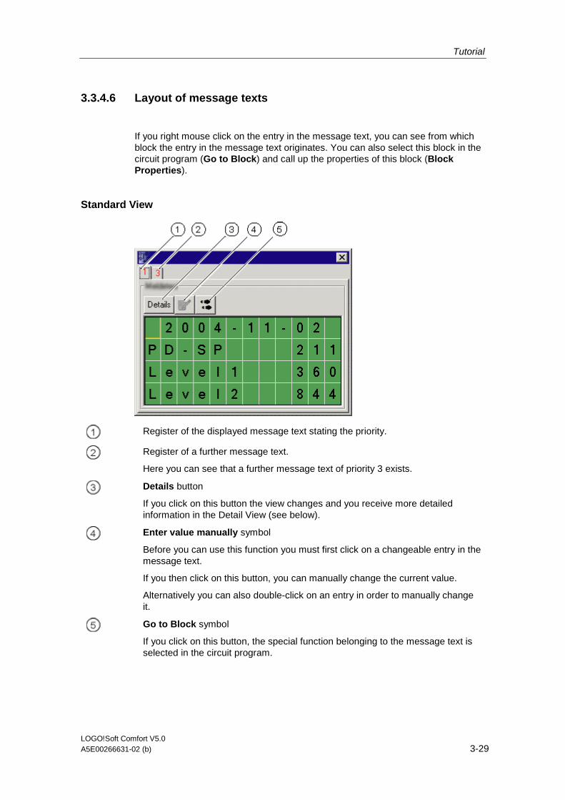
Tutorial
LOGO!Soft Comfort V5.0 A5E00266631-02 (b) 3-29
3.3.4.6 Layout of message texts
If you right mouse click on the entry in the message text, you can see from which block the entry in the message text originates. You can also select this block in the circuit program (Go to Block) and call up the properties of this block (Block Properties).
Standard View
Register of the displayed message text stating the priority.
Register of a further message text.
Here you can see that a further message text of priority 3 exists.
Details button
If you click on this button the view changes and you receive more detailed information in the Detail View (see below).
Enter value manually symbol
Before you can use this function you must first click on a changeable entry in the message text.
If you then click on this button, you can manually change the current value.
Alternatively you can also double-click on an entry in order to manually change it.
Go to Block symbol
If you click on this button, the special function belonging to the message text is selected in the circuit program.
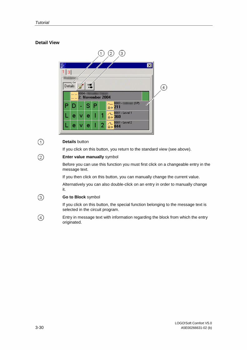
Tutorial
LOGO!Soft Comfort V5.0 3-30 A5E00266631-02 (b)
Detail View
Details button
If you click on this button, you return to the standard view (see above).
Enter value manually symbol
Before you can use this function you must first click on a changeable entry in the message text.
If you then click on this button, you can manually change the current value.
Alternatively you can also double-click on an entry in order to manually change it.
Go to Block symbol
If you click on this button, the special function belonging to the message text is selected in the circuit program.
Entry in message text with information regarding the block from which the entry originated.
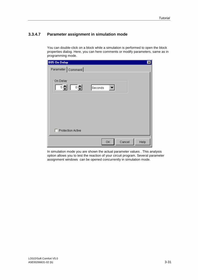
Tutorial
LOGO!Soft Comfort V5.0 A5E00266631-02 (b) 3-31
3.3.4.7 Parameter assignment in simulation mode
You can double-click on a block while a simulation is performed to open the block properties dialog. Here, you can here comments or modify parameters, same as in programming mode.
In simulation mode you are shown the actual parameter values . This analysis option allows you to test the reaction of your circuit program. Several parameter assignment windows can be opened concurrently in simulation mode.
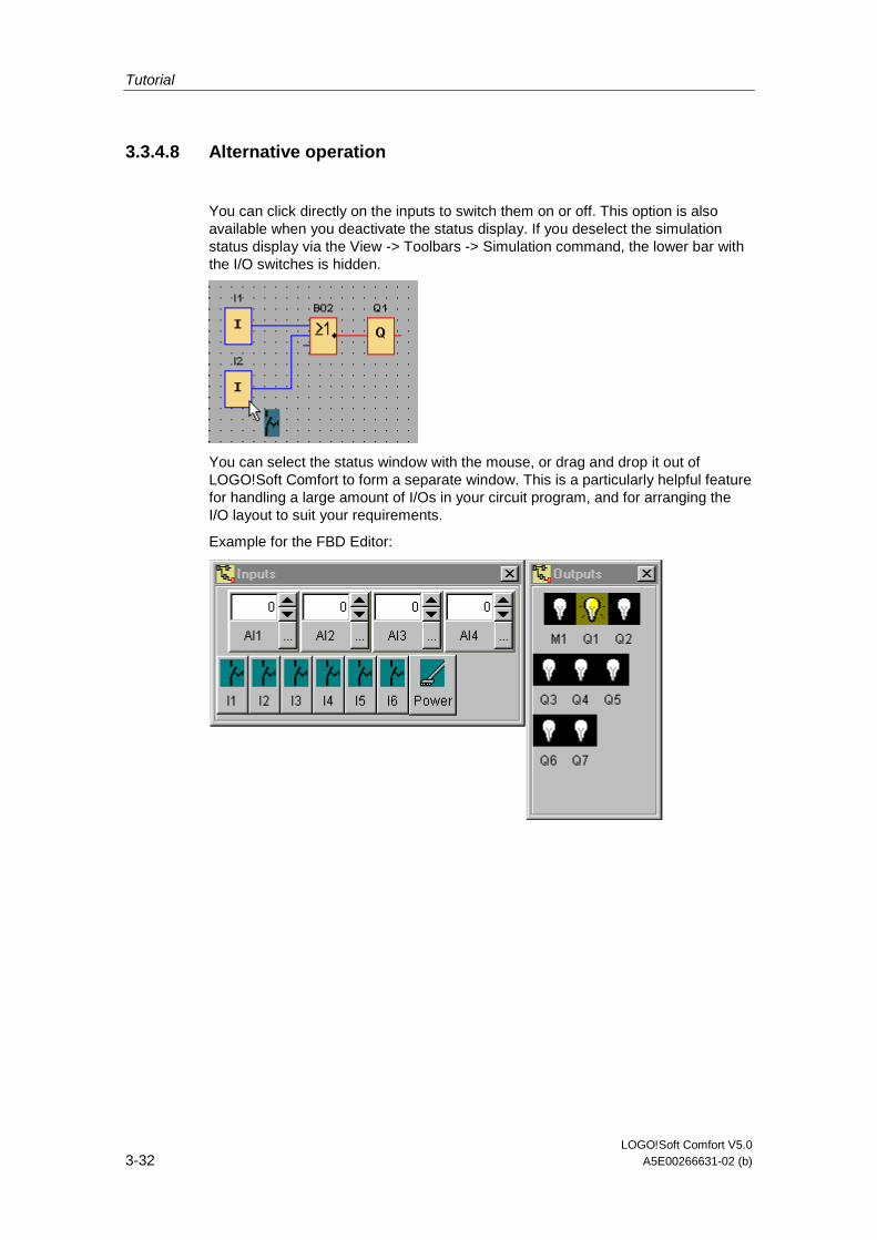
Tutorial
LOGO!Soft Comfort V5.0 3-32 A5E00266631-02 (b)
3.3.4.8 Alternative operation
You can click directly on the inputs to switch them on or off. This option is also available when you deactivate the status display. If you deselect the simulation status display via the View -> Toolbars -> Simulation command, the lower bar with the I/O switches is hidden.
You can select the status window with the mouse, or drag and drop it out of LOGO!Soft Comfort to form a separate window. This is a particularly helpful feature for handling a large amount of I/Os in your circuit program, and for arranging the I/O layout to suit your requirements.
Example for the FBD Editor:
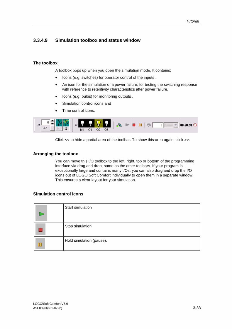
Tutorial
LOGO!Soft Comfort V5.0 A5E00266631-02 (b) 3-33
3.3.4.9 Simulation toolbox and status window
The toolbox
A toolbox pops up when you open the simulation mode. It contains:
• Icons (e.g. switches) for operator control of the inputs .
• An icon for the simulation of a power failure, for testing the switching response with reference to retentivity characteristics after power failure.
• Icons (e.g. bulbs) for monitoring outputs .
• Simulation control icons and
• Time control icons.
Click << to hide a partial area of the toolbar. To show this area again, click >>.
Arranging the toolbox
You can move this I/O toolbox to the left, right, top or bottom of the programming interface via drag and drop, same as the other toolbars. If your program is exceptionally large and contains many I/Os, you can also drag and drop the I/O icons out of LOGO!Soft Comfort individually to open them in a separate window. This ensures a clear layout for your simulation.
Simulation control icons
Start simulation
Stop simulation
Hold simulation (pause).
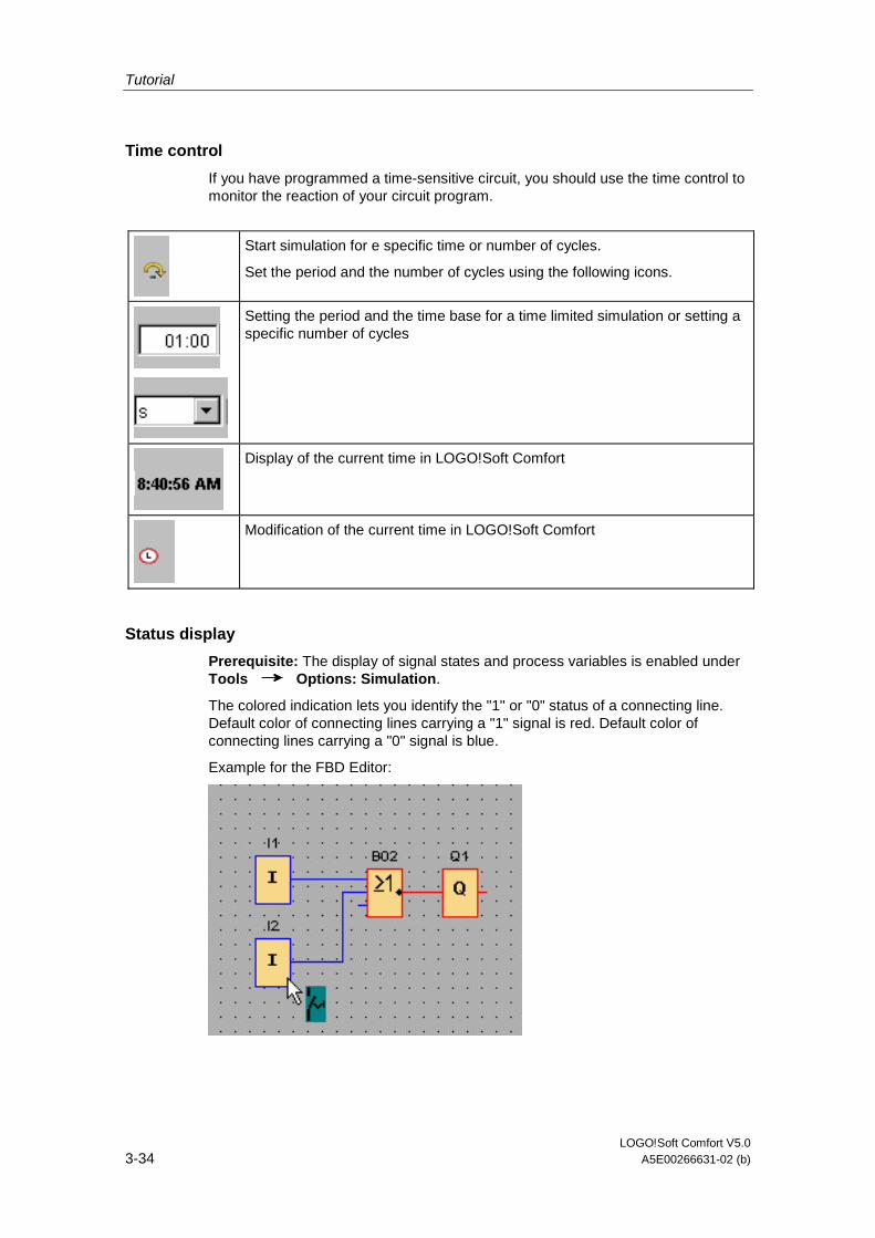
Tutorial
LOGO!Soft Comfort V5.0 3-34 A5E00266631-02 (b)
Time control
If you have programmed a time-sensitive circuit, you should use the time control to monitor the reaction of your circuit program.
Start simulation for e specific time or number of cycles.
Set the period and the number of cycles using the following icons.
Setting the period and the time base for a time limited simulation or setting a specific number of cycles
Display of the current time in LOGO!Soft Comfort
Modification of the current time in LOGO!Soft Comfort
Status display
Prerequisite: The display of signal states and process variables is enabled under Tools Options: Simulation.
The colored indication lets you identify the "1" or "0" status of a connecting line. Default color of connecting lines carrying a "1" signal is red. Default color of connecting lines carrying a "0" signal is blue.
Example for the FBD Editor:
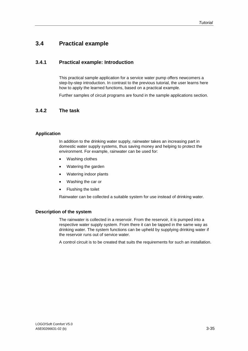
Tutorial
LOGO!Soft Comfort V5.0 A5E00266631-02 (b) 3-35
3.4 Practical example
3.4.1 Practical example: Introduction
This practical sample application for a service water pump offers newcomers a step-by-step introduction. In contrast to the previous tutorial, the user learns here how to apply the learned functions, based on a practical example.
Further samples of circuit programs are found in the sample applications section.
3.4.2 The task
Application
In addition to the drinking water supply, rainwater takes an increasing part in domestic water supply systems, thus saving money and helping to protect the environment. For example, rainwater can be used for:
• Washing clothes
• Watering the garden
• Watering indoor plants
• Washing the car or
• Flushing the toilet
Rainwater can be collected a suitable system for use instead of drinking water.
Description of the system
The rainwater is collected in a reservoir. From the reservoir, it is pumped into a respective water supply system. From there it can be tapped in the same way as drinking water. The system functions can be upheld by supplying drinking water if the reservoir runs out of service water.
A control circuit is to be created that suits the requirements for such an installation.
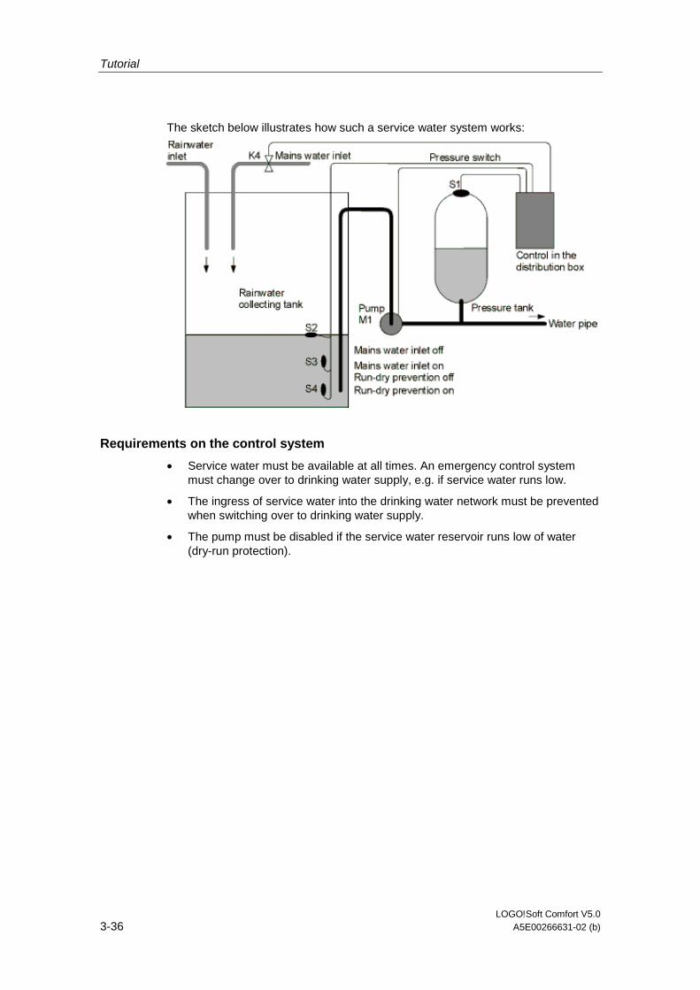
Tutorial
LOGO!Soft Comfort V5.0 3-36 A5E00266631-02 (b)
The sketch below illustrates how such a service water system works:
Requirements on the control system
• Service water must be available at all times. An emergency control system must change over to drinking water supply, e.g. if service water runs low.
• The ingress of service water into the drinking water network must be prevented when switching over to drinking water supply.
• The pump must be disabled if the service water reservoir runs low of water (dry-run protection).
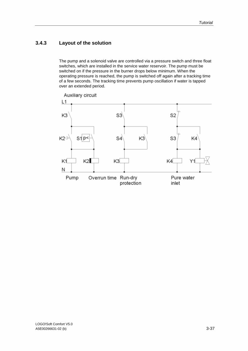
Tutorial
LOGO!Soft Comfort V5.0 A5E00266631-02 (b) 3-37
3.4.3 Layout of the solution
The pump and a solenoid valve are controlled via a pressure switch and three float switches, which are installed in the service water reservoir. The pump must be switched on if the pressure in the burner drops below minimum. When the operating pressure is reached, the pump is switched off again after a tracking time of a few seconds. The tracking time prevents pump oscillation if water is tapped over an extended period.
Tutorial
LOGO!Soft Comfort V5.0 3-38 A5E00266631-02 (b)
3.4.4 Solution with LOGO!
Connecting field devices
In addition to the LOGO! device, all you need is the pressure switch and the float switches to control the pump. If you are using a 3-phase AC motor, a contactor relay is required for switching the pump. In systems with single-phase AC pumps, you must install a contactor relay if the current of the AC pump exceeds the switching capacity of the output relay Q1. A solenoid valve can usually be controlled directly, due to its low power consumption.
Connection diagram
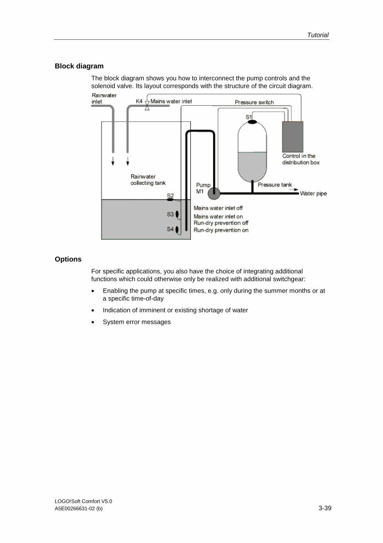
Tutorial
LOGO!Soft Comfort V5.0 A5E00266631-02 (b) 3-39
Block diagram
The block diagram shows you how to interconnect the pump controls and the solenoid valve. Its layout corresponds with the structure of the circuit diagram.
Options
For specific applications, you also have the choice of integrating additional functions which could otherwise only be realized with additional switchgear:
• Enabling the pump at specific times, e.g. only during the summer months or at a specific time-of-day
• Indication of imminent or existing shortage of water
• System error messages
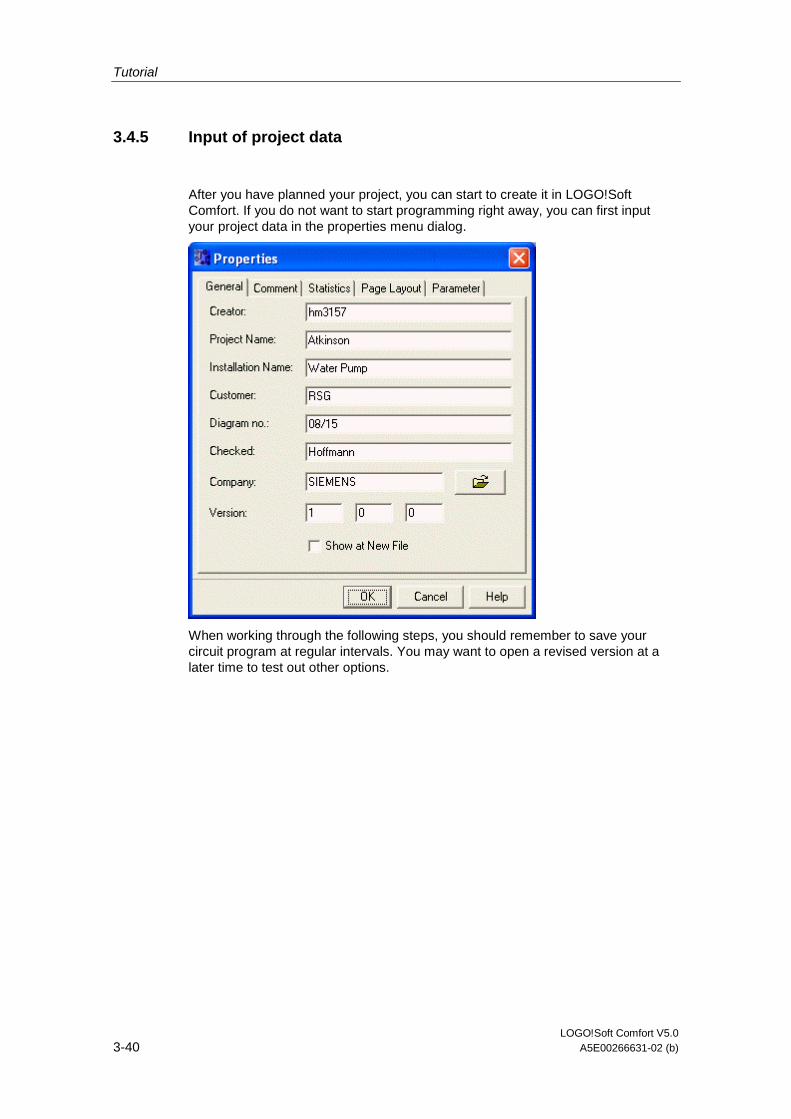
Tutorial
LOGO!Soft Comfort V5.0 3-40 A5E00266631-02 (b)
3.4.5 Input of project data
After you have planned your project, you can start to create it in LOGO!Soft Comfort. If you do not want to start programming right away, you can first input your project data in the properties menu dialog.
When working through the following steps, you should remember to save your circuit program at regular intervals. You may want to open a revised version at a later time to test out other options.
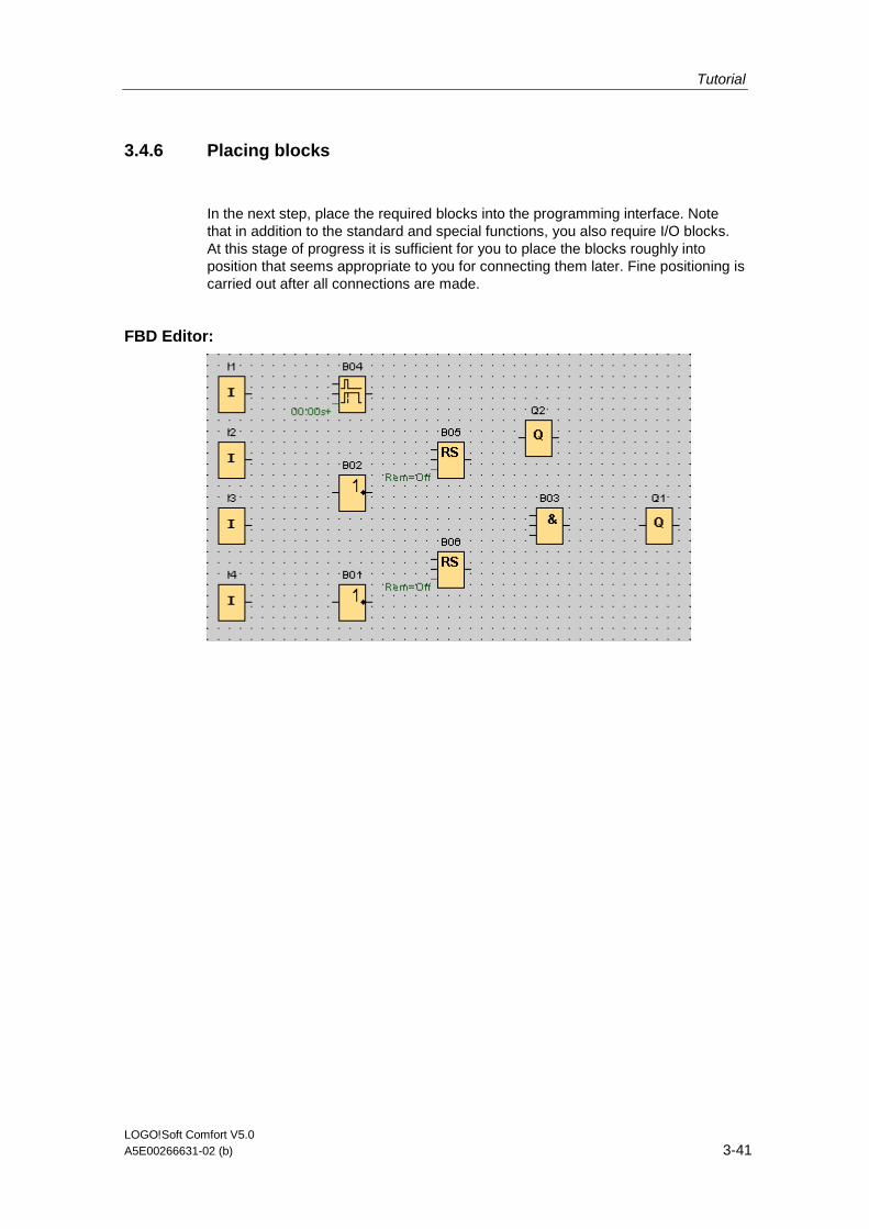
Tutorial
LOGO!Soft Comfort V5.0 A5E00266631-02 (b) 3-41
3.4.6 Placing blocks
In the next step, place the required blocks into the programming interface. Note that in addition to the standard and special functions, you also require I/O blocks. At this stage of progress it is sufficient for you to place the blocks roughly into position that seems appropriate to you for connecting them later. Fine positioning is carried out after all connections are made.
FBD Editor:
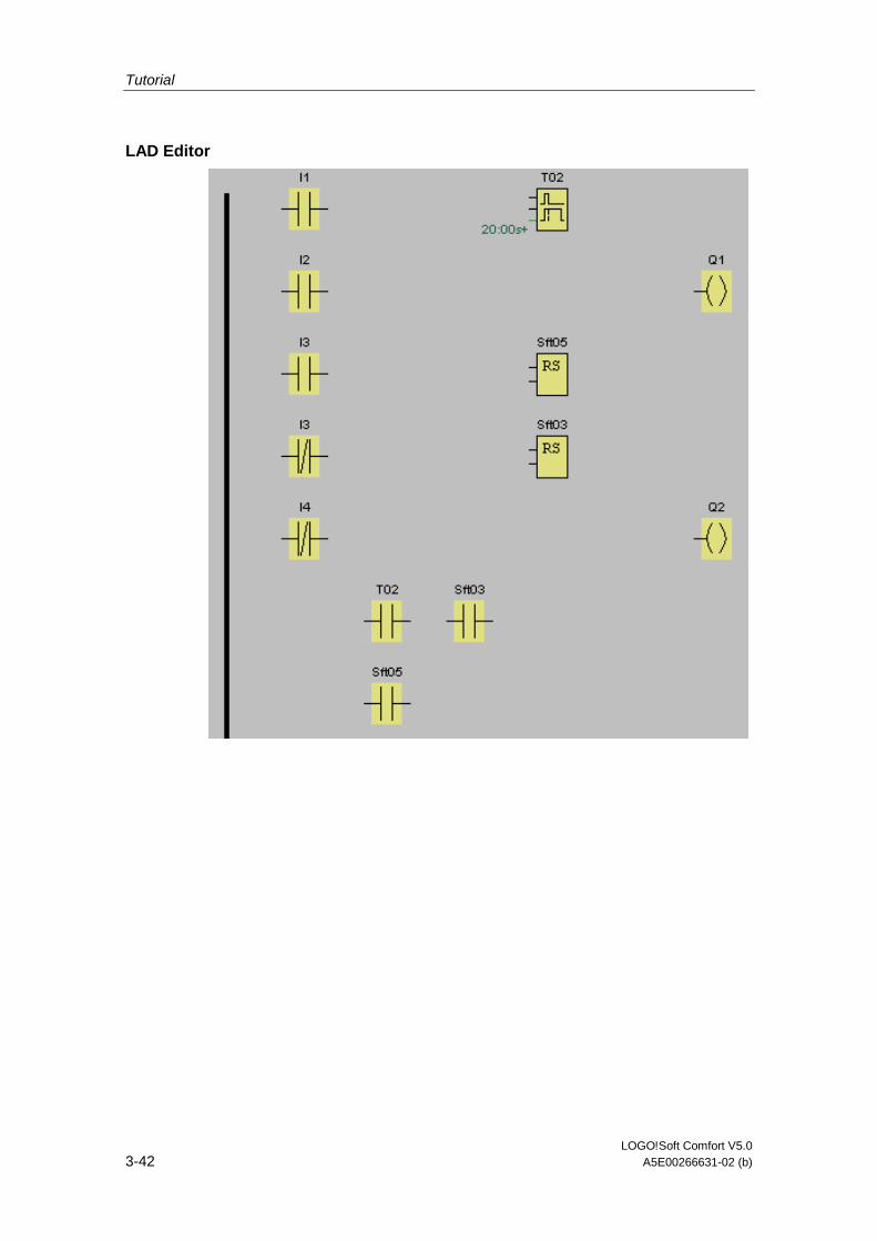
Tutorial
LOGO!Soft Comfort V5.0 3-42 A5E00266631-02 (b)
LAD Editor
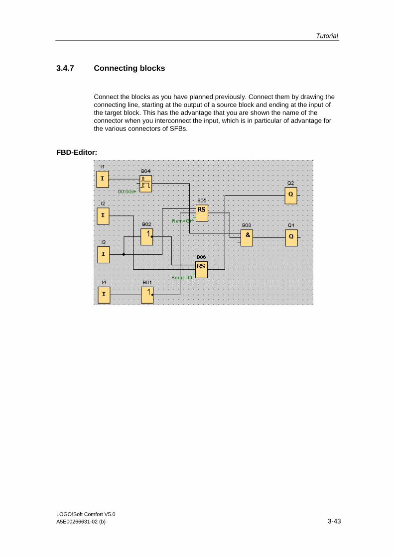
Tutorial
LOGO!Soft Comfort V5.0 A5E00266631-02 (b) 3-43
3.4.7 Connecting blocks
Connect the blocks as you have planned previously. Connect them by drawing the connecting line, starting at the output of a source block and ending at the input of the target block. This has the advantage that you are shown the name of the connector when you interconnect the input, which is in particular of advantage for the various connectors of SFBs.
FBD-Editor:
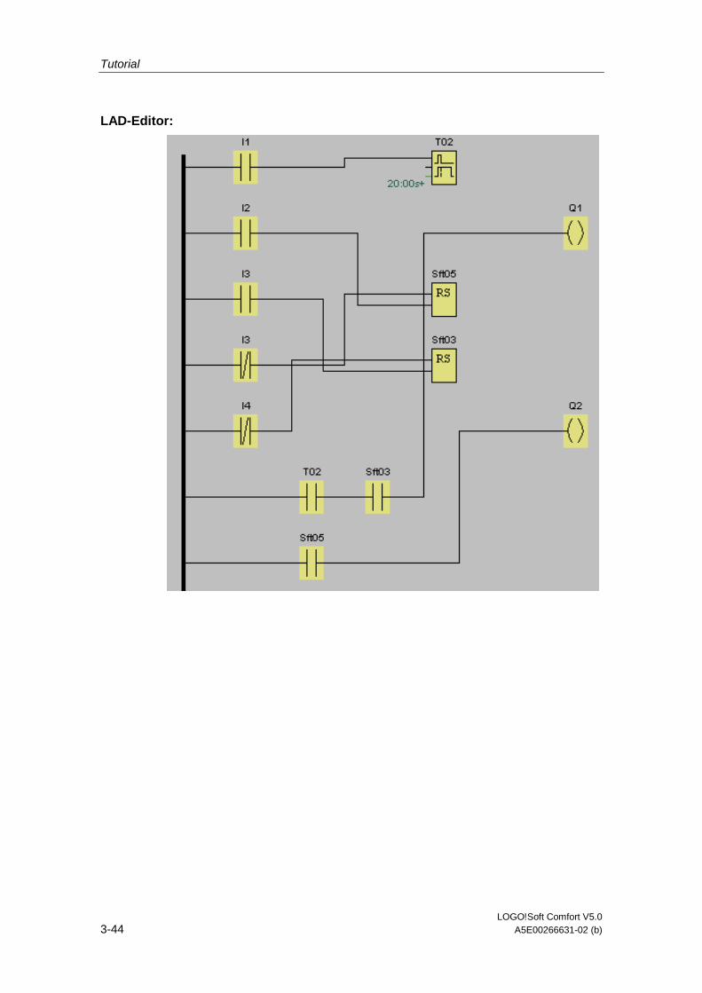
Tutorial
LOGO!Soft Comfort V5.0 3-44 A5E00266631-02 (b)
LAD-Editor:
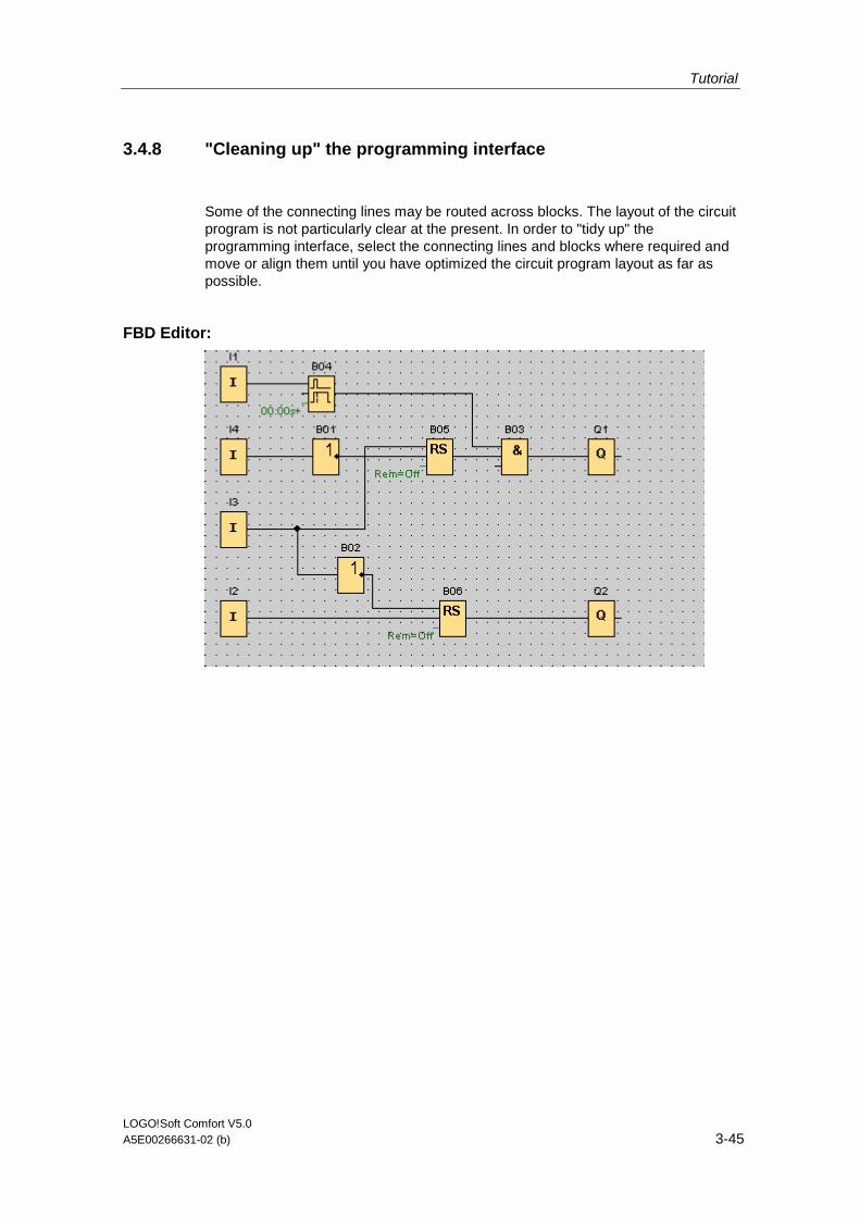
Tutorial
LOGO!Soft Comfort V5.0 A5E00266631-02 (b) 3-45
3.4.8 "Cleaning up" the programming interface
Some of the connecting lines may be routed across blocks. The layout of the circuit program is not particularly clear at the present. In order to "tidy up" the programming interface, select the connecting lines and blocks where required and move or align them until you have optimized the circuit program layout as far as possible.
FBD Editor:
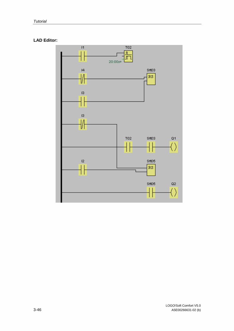
Tutorial
LOGO!Soft Comfort V5.0 3-46 A5E00266631-02 (b)
LAD Editor:
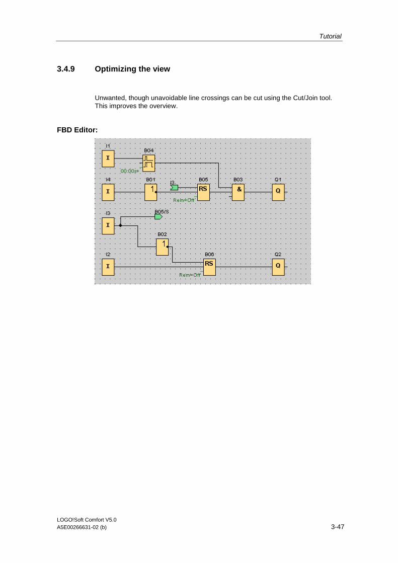
Tutorial
LOGO!Soft Comfort V5.0 A5E00266631-02 (b) 3-47
3.4.9 Optimizing the view
Unwanted, though unavoidable line crossings can be cut using the Cut/Join tool. This improves the overview.
FBD Editor:
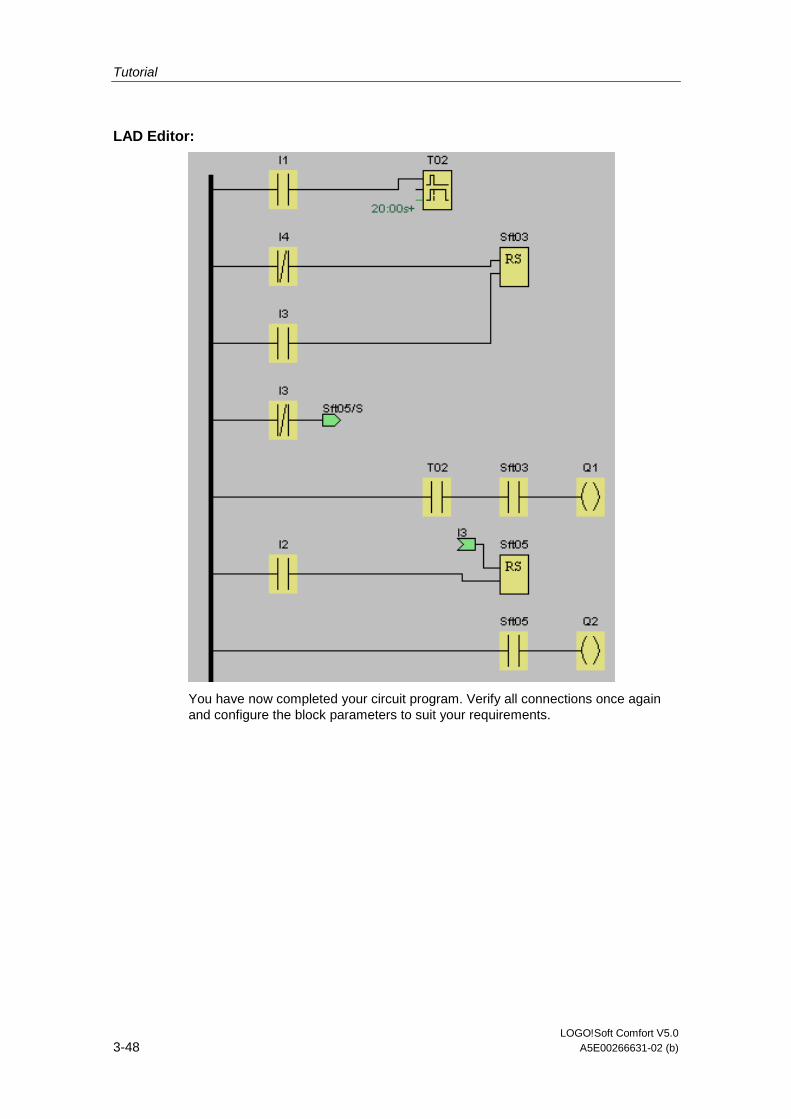
Tutorial
LOGO!Soft Comfort V5.0 3-48 A5E00266631-02 (b)
LAD Editor:
You have now completed your circuit program. Verify all connections once again and configure the block parameters to suit your requirements.
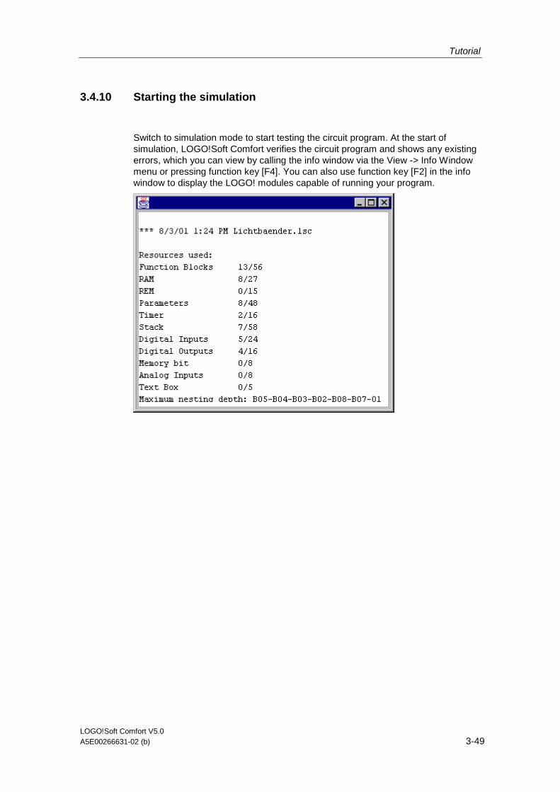
Tutorial
LOGO!Soft Comfort V5.0 A5E00266631-02 (b) 3-49
3.4.10 Starting the simulation
Switch to simulation mode to start testing the circuit program. At the start of simulation, LOGO!Soft Comfort verifies the circuit program and shows any existing errors, which you can view by calling the info window via the View -> Info Window menu or pressing function key [F4]. You can also use function key [F2] in the info window to display the LOGO! modules capable of running your program.
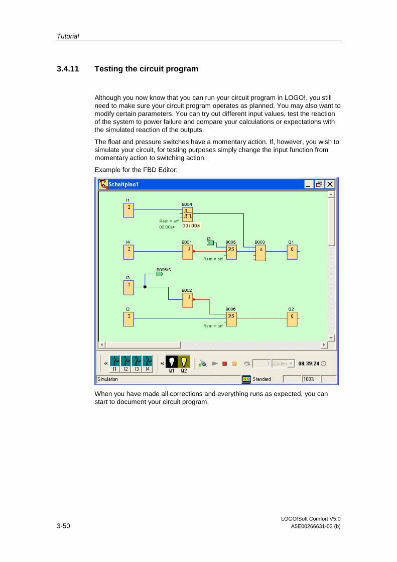
Tutorial
LOGO!Soft Comfort V5.0 3-50 A5E00266631-02 (b)
3.4.11 Testing the circuit program
Although you now know that you can run your circuit program in LOGO!, you still need to make sure your circuit program operates as planned. You may also want to modify certain parameters. You can try out different input values, test the reaction of the system to power failure and compare your calculations or expectations with the simulated reaction of the outputs.
The float and pressure switches have a momentary action. If, however, you wish to simulate your circuit, for testing purposes simply change the input function from momentary action to switching action.
Example for the FBD Editor:
When you have made all corrections and everything runs as expected, you can start to document your circuit program.
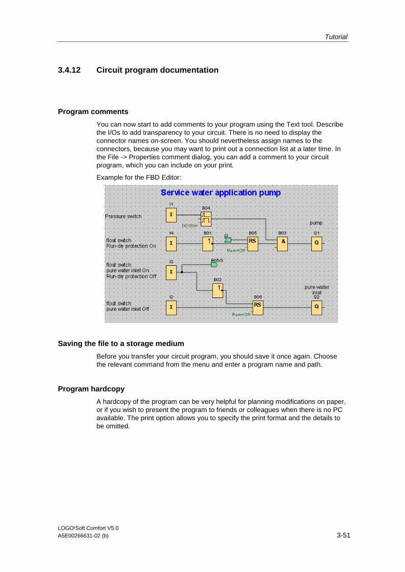
Tutorial
LOGO!Soft Comfort V5.0 A5E00266631-02 (b) 3-51
3.4.12 Circuit program documentation
Program comments
You can now start to add comments to your program using the Text tool. Describe the I/Os to add transparency to your circuit. There is no need to display the connector names on-screen. You should nevertheless assign names to the connectors, because you may want to print out a connection list at a later time. In the File -> Properties comment dialog, you can add a comment to your circuit program, which you can include on your print.
Example for the FBD Editor:
Saving the file to a storage medium
Before you transfer your circuit program, you should save it once again. Choose the relevant command from the menu and enter a program name and path.
Program hardcopy
A hardcopy of the program can be very helpful for planning modifications on paper, or if you wish to present the program to friends or colleagues when there is no PC available. The print option allows you to specify the print format and the details to be omitted.

Tutorial
LOGO!Soft Comfort V5.0 3-52 A5E00266631-02 (b)
3.4.13 Transferring the circuit program
Password Protection
To protect your know-how and prevent unauthorized access to your circuit program, you can assign a password before you transfer it to LOGO!.
To assign this password, call the File -> Properties Parameter . Enter your password and confirm it with OK.
Password protection is included when you transfer the circuit program to LOGO! and is activated when LOGO! exits transfer mode.
The password protects your circuit program in LOGO!. Editing values and parameters, or viewing the circuit program in LOGO!, or uploading the circuit program from LOGO! to the PC is now only possible after you have entered the password.
Transferring the circuit program
Finally, transfer your circuit program to a suitable LOGO! version and then connect the module. Connect LOGO! with the consumer devices in your project.
You have created the circuit program under LOGO!Soft Comfort within a very short time and, compared with conventional methods, you have saved yourself a considerable amount of time and effort.

LOGO!Soft Comfort V5.0 A5E00266631-02 (b) 4-1
4 Sample applications
4.1 Sample applications - Overview
Introduction
To give you an impression of the versatility of LOGO!, we have provided a small collection of applications, in addition to the service water pump application shown in the tutorial. The examples referred to in this section are an extract from the LOGO! manual. The LOGO! manual describes these in more detail, i.e. it shows the conventional solution and compares it with the efficient LOGO! solution.
This LOGO!Soft Comfort Online Help describes the tasks only briefly and presents the relevant solution with LOGO!Soft Comfort. The circuit programs shown, as well as many others, are found on your LOGO!Soft Comfort CD-ROM in the ..\Samples directory. Included is an extensive documentation for the various samples.
Note
LOGO! sample applications are available free of charge to our customers. These are provided without guarantee, and are intended for general information about the possible fields of application for LOGO! modules and LOGO!Soft Comfort software. Custom solutions may be different.
The user operates the system at his own responsibility. We also refer to local standards and system-related installation regulations.
Dual-function switch
Air-conditioning system
Factory door
Heating control
Please also note the rain water pump sample.

Sample applications
LOGO!Soft Comfort V5.0 4-2 A5E00266631-02 (b)
4.2 Dual-function switch
Requirements for stairway lighting systems The basic requirements for a stairway lighting system are as follows:
• When someone is using the stairs, the stairway lights should be on.
• If no one is in the stairway, the lights should go out in order to save energy.
The standard solution Up to now two methods were known to control such a lighting system:
• Pulse relay: When the lights are off, press any of the pushbuttons to switch on the lights. When the lights are on, press any of the pushbuttons to switch off the lights again. Disadvantage: People often forget to switch off the lights
• Automatic stairway light switch: Press any one of the pushbuttons to switch on the lights. The lights switch off again automatically when a preset off delay time has expired. Disadvantage: You can't keep the lights switched on over an extended period of time. The permanent on switch, usually installed inside the stairway lighting timer unit, may be difficult or impossible to access.
The wiring is the same for both systems.
LOGO!Soft Comfort solution
The LOGO! system can replace the automatic stairway light switch or the pulse relay.
LOGO! also lets you create a simple automatic stairway light switch via the stairway light switch SFB.
You can also implement both functions (off delay timer and pulse relay) in a single unit. What is more, you can incorporate extra functions without making any alterations to the wiring. In our example program, we have combined the advantages of both the current impulse relay and the automatic stairway lighting timer as follows:
• Actuate the pushbutton The light is switched on and switched off again on expiration of a predefined time.
• Hold the pushbutton down Switches on continuous lighting
• Press the pushbutton once more Switches off the lighting
The wiring of a lighting system with LOGO! is the same as for standard corridor or stairway lighting systems. Only the automatic lighting timer/pulse relay is replaced.
LOGO! lets you quickly and easily combine all those functions in a single dual-function switch SFB, without additional wiring and expenditure.
Air-conditioning system
Factory door

Sample applications
LOGO!Soft Comfort V5.0 A5E00266631-02 (b) 4-3
4.3 Air-conditioning system
Requirements for an air-conditioning system
An air-conditioning system supplies fresh air into a room and exhausts the contaminated air. Let us look at the following sample system:
• A room contains an extractor fan and a fresh-air fan.
• Each fan is monitored by means of a flow sensor.
• The pressure in the room may rise above the atmospheric pressure.
• The fresh-air fan may only be switched on if the flow sensor signals the safe operational state of the extractor fan.
• A warning lamp indicates failure of one of the fans.
Standard solution
The fans are monitored by means of flow sensors. If no air flow is registered after a short delay time has expired, the system is switched off and an error message is generated, which can be acknowledged by pressing the off button.
Fan monitoring requires an analyzer circuit with several switching devices, in addition to the flow sensors. A single LOGO! device can replace this analyzer circuit.
LOGO!Soft Comfort solution
The use of LOGO! reduces the amount of switchgear. Thus, you save installation time and space in the control cabinet. You may even be able to use as a smaller control cabinet.
With LOGO! you can also switch off of the fans sequentially after the system is switched off.
The circuit in LOGO!Soft Comfort
The system is switched on and off at the inputs I1 and I2. The fans are connected to outputs Q1 and Q2, the flow sensors are connected to the inputs I3 and I4. Blocks B07 and B10 are used to set the watchdog times after which the flow sensors should send a signal to the fault output Q3.
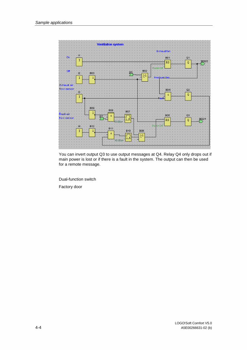
Sample applications
LOGO!Soft Comfort V5.0 4-4 A5E00266631-02 (b)
You can invert output Q3 to use output messages at Q4. Relay Q4 only drops out if main power is lost or if there is a fault in the system. The output can then be used for a remote message.
Dual-function switch
Factory door
Sample applications
LOGO!Soft Comfort V5.0 A5E00266631-02 (b) 4-5
4.4 Factory door
Requirements for a gate control system
In many cases a factory entrance is closed with roll gates. Those gates are only opened when vehicles need to enter or leave the factory grounds. The gate is controlled by the porter.
• The sliding gate is opened and closed by means of a pushbutton control in the gatehouse. The porter can monitor the gate operation.
• The roll gate is normally fully opened or it is closed. However, gate movements can always be interrupted.
• A flashing light is activated five seconds before the gate moves, and while the gate is in motion.
• A safety pressure strip ensures that people are not injured and that no objects are trapped and damaged when the gate is closing.
Standard solution
There are many different control systems for operating automatic gates. The OPEN and CLOSE buttons initiate gate movements into the relevant direction, provided it is not already moving in the opposite direction. Movement of the gate is terminated either by means of the STOP button or the relevant limit switch.
LOGO!Soft Comfort solution
A LOGO! circuit provides a further feature compared to standard controls: The actuation of a safety bar interrupts the closing motion of the gate. Five seconds before the gate is opens or closes, a flashing light is activated and signals the start of the movement. It continues flashing until the gate has stopped.
In contrast to standard solutions, LOGO! offers an easy and economic means of modifying the control system.
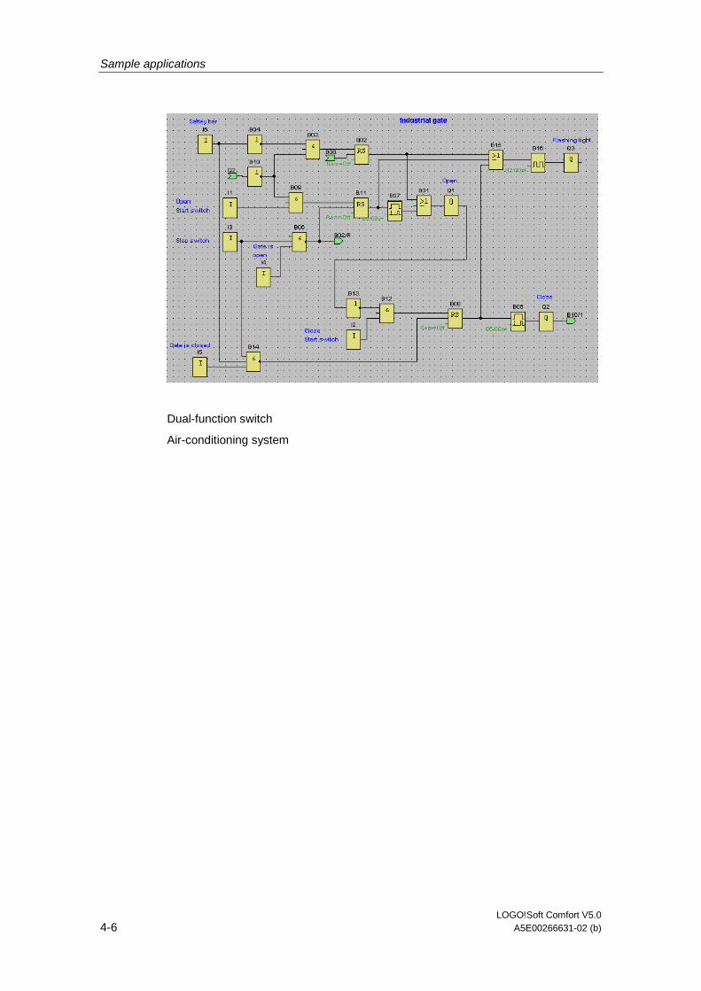
Sample applications
LOGO!Soft Comfort V5.0 4-6 A5E00266631-02 (b)
Dual-function switch
Air-conditioning system
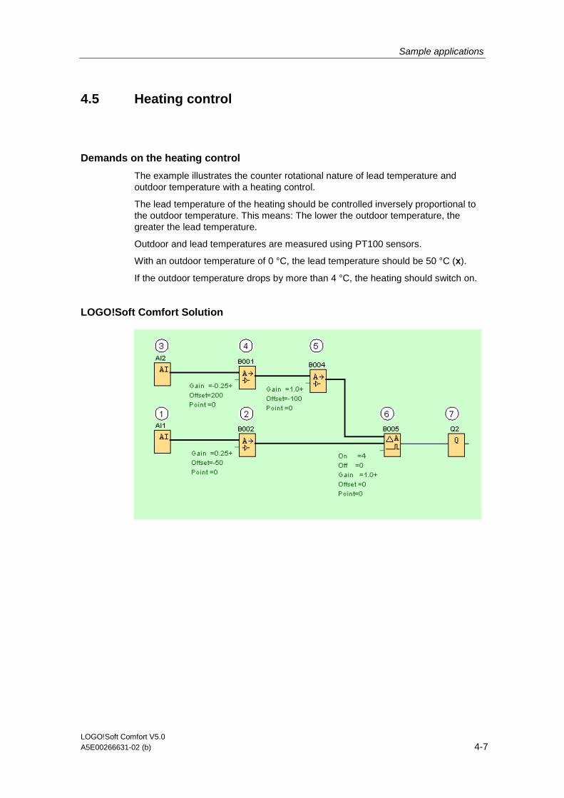
Sample applications
LOGO!Soft Comfort V5.0 A5E00266631-02 (b) 4-7
4.5 Heating control
Demands on the heating control
The example illustrates the counter rotational nature of lead temperature and outdoor temperature with a heating control.
The lead temperature of the heating should be controlled inversely proportional to the outdoor temperature. This means: The lower the outdoor temperature, the greater the lead temperature.
Outdoor and lead temperatures are measured using PT100 sensors.
With an outdoor temperature of 0 °C, the lead temperature should be 50 °C (x).
If the outdoor temperature drops by more than 4 °C, the heating should switch on.
LOGO!Soft Comfort Solution
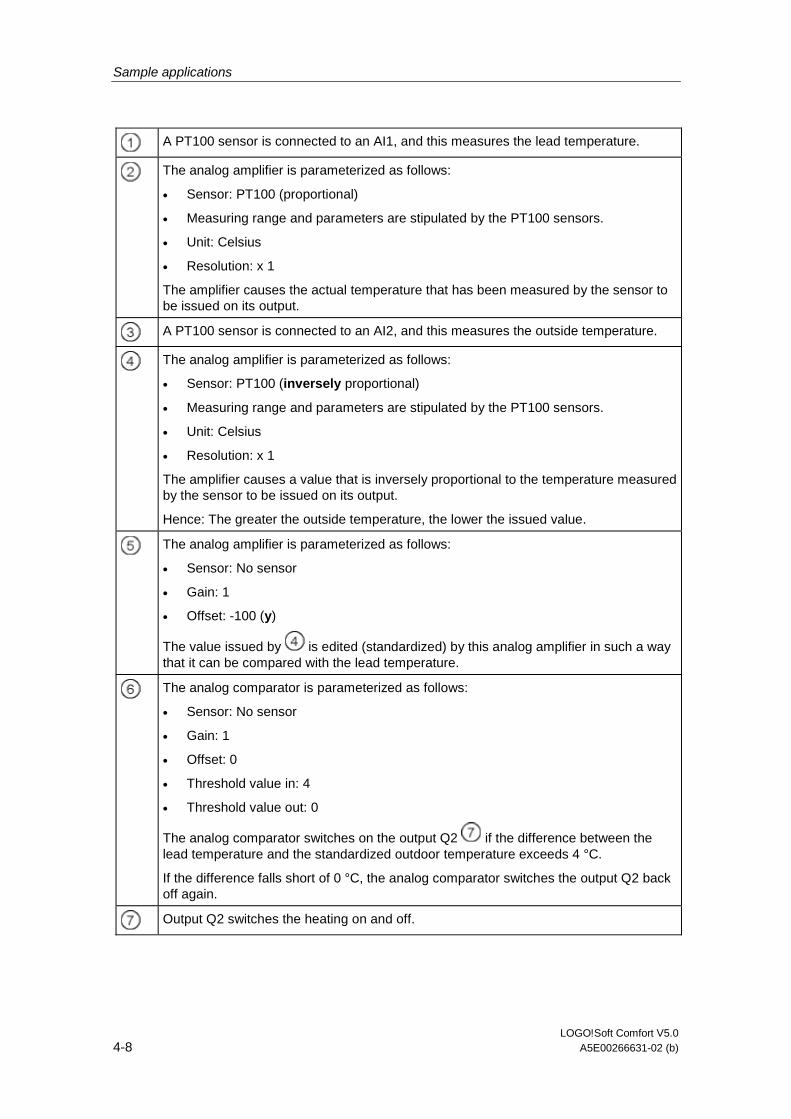
Sample applications
LOGO!Soft Comfort V5.0 4-8 A5E00266631-02 (b)
A PT100 sensor is connected to an AI1, and this measures the lead temperature.
The analog amplifier is parameterized as follows:
• Sensor: PT100 (proportional)
• Measuring range and parameters are stipulated by the PT100 sensors.
• Unit: Celsius
• Resolution: x 1
The amplifier causes the actual temperature that has been measured by the sensor to be issued on its output.
A PT100 sensor is connected to an AI2, and this measures the outside temperature.
The analog amplifier is parameterized as follows:
• Sensor: PT100 (inversely proportional)
• Measuring range and parameters are stipulated by the PT100 sensors.
• Unit: Celsius
• Resolution: x 1
The amplifier causes a value that is inversely proportional to the temperature measured by the sensor to be issued on its output.
Hence: The greater the outside temperature, the lower the issued value.
The analog amplifier is parameterized as follows:
• Sensor: No sensor
• Gain: 1
• Offset: -100 (y)
The value issued by is edited (standardized) by this analog amplifier in such a way that it can be compared with the lead temperature.
The analog comparator is parameterized as follows:
• Sensor: No sensor
• Gain: 1
• Offset: 0
• Threshold value in: 4
• Threshold value out: 0
The analog comparator switches on the output Q2 if the difference between the lead temperature and the standardized outdoor temperature exceeds 4 °C.
If the difference falls short of 0 °C, the analog comparator switches the output Q2 back off again.
Output Q2 switches the heating on and off.
Sample applications
LOGO!Soft Comfort V5.0 A5E00266631-02 (b) 4-9
Mode of operation
The outside temperature drops; this causes the value issued on the analog
amplifier to increase to the same extent. The difference on the analog comparator between the lead and the outside temperature increases.
If the difference exceeds 4 °C the heating is switched on.
By switching on the heating the lead temperature increases. Because of this, the difference on the analog comparator between the lead and the outside temperature lowers (provided the outside temperature drops more slowly than the lead temperature increases).
If the difference falls short of 0 °C, the heating is switched off.
Changing parameters
The Offset (y) parameter with the analog amplifier depends on your desired lead temperature (x) with 0 °C outside temperature. The parameter is calculated as follows:
y = x -150
Furthermore, the switch-on threshold and the switch-off threshold of the heating
can change by means of the threshold value of the analog comparator .
Note
You can save block if you adapt the threshold value in the analog comparator accordingly.
Try it out!
The example can be found as a circuit program on the LOGO!Soft Comfort CD-ROM. Load the circuit program in LOGO!Soft Comfort and try out the instructions above in simulation mode.

Sample applications
LOGO!Soft Comfort V5.0 4-10 A5E00266631-02 (b)
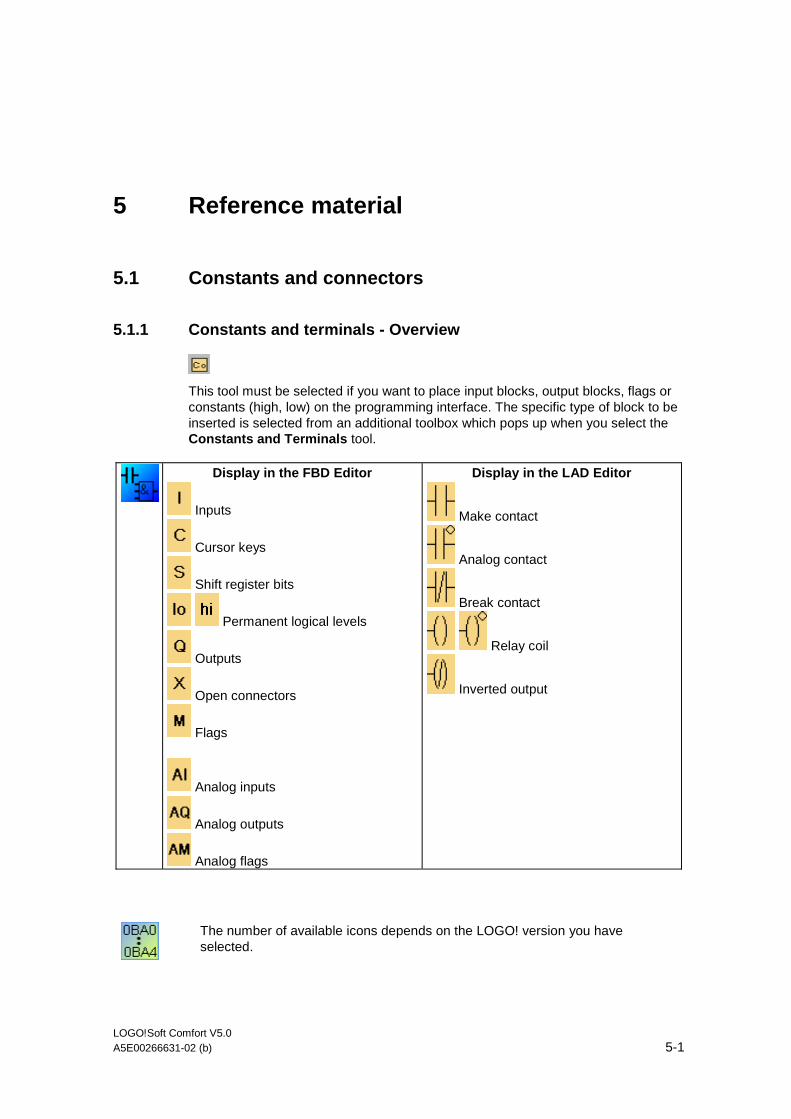
LOGO!Soft Comfort V5.0 A5E00266631-02 (b) 5-1
5 Reference material
5.1 Constants and connectors
5.1.1 Constants and terminals - Overview
This tool must be selected if you want to place input blocks, output blocks, flags or constants (high, low) on the programming interface. The specific type of block to be inserted is selected from an additional toolbox which pops up when you select the Constants and Terminals tool.
Display in the FBD Editor
Inputs
Cursor keys
Shift register bits
Permanent logical levels
Outputs
Open connectors
Flags
Analog inputs
Analog outputs
Analog flags
Display in the LAD Editor
Make contact
Analog contact
Break contact
Relay coil
Inverted output
The number of available icons depends on the LOGO! version you have selected.
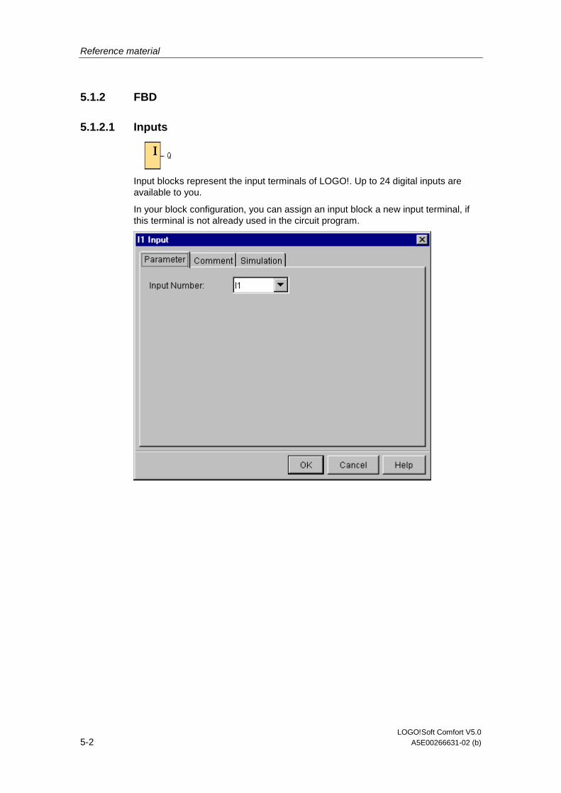
Reference material
LOGO!Soft Comfort V5.0 5-2 A5E00266631-02 (b)
5.1.2 FBD
5.1.2.1 Inputs
Input blocks represent the input terminals of LOGO!. Up to 24 digital inputs are available to you.
In your block configuration, you can assign an input block a new input terminal, if this terminal is not already used in the circuit program.
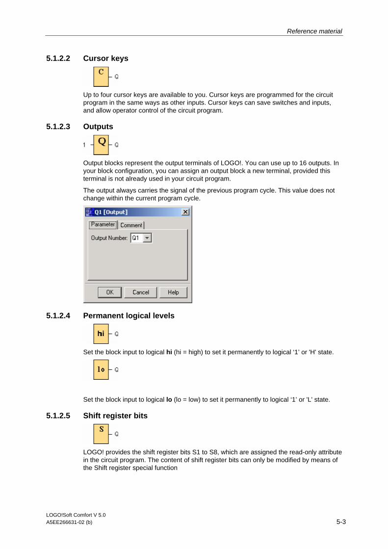
Reference material
LOGO!Soft Comfort V 5.0 A5EE266631-02 (b) 5-3
5.1.2.2 Cursor keys
Up to four cursor keys are available to you. Cursor keys are programmed for the circuit program in the same ways as other inputs. Cursor keys can save switches and inputs, and allow operator control of the circuit program.
5.1.2.3 Outputs
Output blocks represent the output terminals of LOGO!. You can use up to 16 outputs. In your block configuration, you can assign an output block a new terminal, provided this terminal is not already used in your circuit program.
The output always carries the signal of the previous program cycle. This value does not change within the current program cycle.
5.1.2.4 Permanent logical levels
Set the block input to logical hi (hi = high) to set it permanently to logical ‘1’ or 'H' state.
Set the block input to logical lo (lo = low) to set it permanently to logical ‘1’ or 'L' state.
5.1.2.5 Shift register bits
LOGO! provides the shift register bits S1 to S8, which are assigned the read-only attribute in the circuit program. The content of shift register bits can only be modified by means of the Shift register special function

Reference material
LOGO!Soft Comfort V5.0 5-4 A5E00266631-02 (b)
5.1.2.6 Open connectors
Interconnect the output of an unused block (e.g.: for message texts) with the "open connector" block.
5.1.2.7 Flags
Flag blocks output their input signal. LOGO! provides 24 digital flags M1 ... M24 and 6 analog flags AM1 ... AM6.
0BA3, 0BA2: 8 digital flags M1 ... M8
0BA1: 4 digital flags M1 ... M4
0BA0: 0 flags
In your block configuration, you can assign a new number to the flag, provided this flag number does not already exist in your circuit program.
The output always carries the signal of the previous program cycle. This value doe not change within the current program cycle.
Startup flag M8
The M8 flag is set in the first cycle of the user program and can thus be used in your circuit program as startup flag. It is reset after the first program execution cycle.
In the subsequent cycles, the M8 flag reacts in the same way as the M1 to M7 flags.
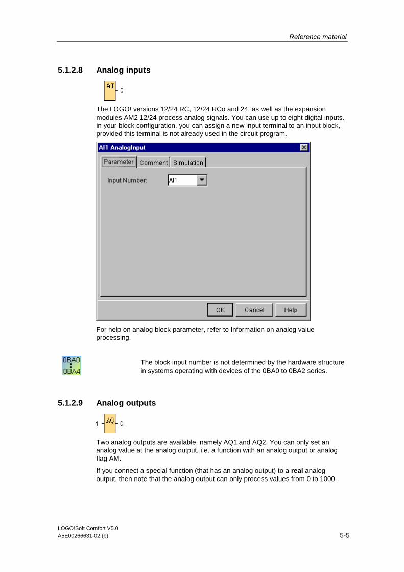
Reference material
LOGO!Soft Comfort V5.0 A5E00266631-02 (b) 5-5
5.1.2.8 Analog inputs
The LOGO! versions 12/24 RC, 12/24 RCo and 24, as well as the expansion modules AM2 12/24 process analog signals. You can use up to eight digital inputs. in your block configuration, you can assign a new input terminal to an input block, provided this terminal is not already used in the circuit program.
For help on analog block parameter, refer to Information on analog value processing.
The block input number is not determined by the hardware structure in systems operating with devices of the 0BA0 to 0BA2 series.
5.1.2.9 Analog outputs
Two analog outputs are available, namely AQ1 and AQ2. You can only set an analog value at the analog output, i.e. a function with an analog output or analog flag AM.
If you connect a special function (that has an analog output) to a real analog output, then note that the analog output can only process values from 0 to 1000.
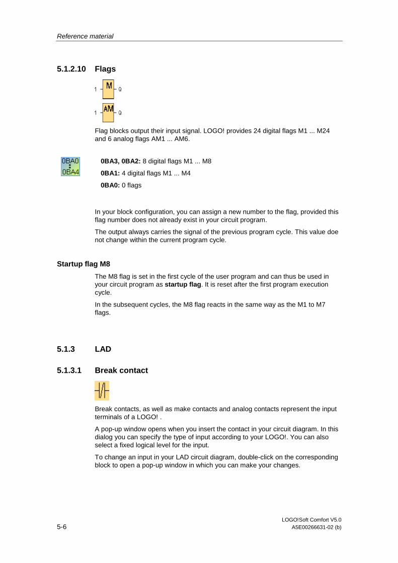
Reference material
LOGO!Soft Comfort V5.0 5-6 A5E00266631-02 (b)
5.1.2.10 Flags
Flag blocks output their input signal. LOGO! provides 24 digital flags M1 ... M24 and 6 analog flags AM1 ... AM6.
0BA3, 0BA2: 8 digital flags M1 ... M8
0BA1: 4 digital flags M1 ... M4
0BA0: 0 flags
In your block configuration, you can assign a new number to the flag, provided this flag number does not already exist in your circuit program.
The output always carries the signal of the previous program cycle. This value doe not change within the current program cycle.
Startup flag M8
The M8 flag is set in the first cycle of the user program and can thus be used in your circuit program as startup flag. It is reset after the first program execution cycle.
In the subsequent cycles, the M8 flag reacts in the same way as the M1 to M7 flags.
5.1.3 LAD
5.1.3.1 Break contact
Break contacts, as well as make contacts and analog contacts represent the input terminals of a LOGO! .
A pop-up window opens when you insert the contact in your circuit diagram. In this dialog you can specify the type of input according to your LOGO!. You can also select a fixed logical level for the input.
To change an input in your LAD circuit diagram, double-click on the corresponding block to open a pop-up window in which you can make your changes.
Reference material
LOGO!Soft Comfort V5.0 A5E00266631-02 (b) 5-7
5.1.3.2 Make contact
Make contacts, as well as break contacts and analog contacts represent the input terminals of a LOGO! .
A pop-up window opens when you place the contact into your circuit diagram. In this dialog, you can specify the type of input according to the LOGO! used. You can also select a fixed logical level for the input.
To change an input in your LAD circuit diagram, double-click on the corresponding block to open the relevant pop-up dialog.
5.1.3.3 Analog contacts
Analog contacts, same as break contacts and make contacts represent the input terminals of a LOGO! device.
A pop-up window opens when you insert the contact in your circuit diagram. In this dialog you can specify the type of input according to your LOGO! device.
To change an input in your LAD circuit diagram, double-click on the corresponding block in your circuit diagram to open a pop-up window in which you can make your changes.
Reference material
LOGO!Soft Comfort V5.0 5-8 A5E00266631-02 (b)
5.1.3.4 Relay coil
Relay coils represent the output terminals like inverted outputs and analog outputs on a LOGO!.
To change an output in your LAD circuit diagram, double-click on the corresponding block to open a pop-up window in which you can assign various functions to the output.
5.1.3.5 Inverted output
Inverted outputs, same as, represent the output terminals of a LOGO! device.
Inverted outputs represent the output terminals like relay coils and inverted output on a LOGO!.
To change an output in your LAD circuit diagram, double-click on the corresponding block to open a pop-up window in which you can assign various functions to the output.
5.1.3.6 Analog output
Analog outputs represent the output terminals like relay coils and inverted output on a LOGO!.
To change an output in your LAD circuit diagram, double-click on the corresponding block to open a pop-up window in which you can assign various functions to the output.
If you connect a special function (that has an analog output) to a real analog output, then note that the analog output can only process values from 0 to 1000.
5.1.3.7 Internal flag
You can use an internal flag to terminate a current path and continue it in a new path.
Contrary to the flag block, this does not use a flag resource in your LOGO! device.
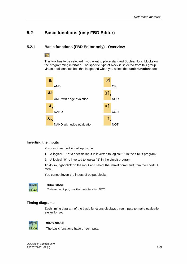
Reference material
LOGO!Soft Comfort V5.0 A5E00266631-02 (b) 5-9
5.2 Basic functions (only FBD Editor)
5.2.1 Basic functions (FBD Editor only) - Overview
This tool has to be selected if you want to place standard Boolean logic blocks on the programming interface. The specific type of block is selected from this group via an additional toolbox that is opened when you select the basic functions tool.
AND
AND with edge evalation
NAND
NAND with edge evaluation
OR
NOR
XOR
NOT
Inverting the inputs
You can invert individual inputs, i.e.
1. A logical "1" at a specific input is inverted to logical "0" in the circuit program;
2. A logical "0" is inverted to logical "1" in the circuit program.
To do so, right-click on the input and select the invert command from the shortcut menu.
You cannot invert the inputs of output blocks.
0BA0-0BA3:
To invert an input, use the basic function NOT.
Timing diagrams
Each timing diagram of the basic functions displays three inputs to make evaluation easier for you.
0BA0-0BA3:
The basic functions have three inputs.

Reference material
LOGO!Soft Comfort V5.0 5-10 A5E00266631-02 (b)
5.2.2 AND
The output of an AND function is only 1 if all inputs are 1, i.e. when they are closed.
A block input that is not used (x) is assigned: x = 1.
Logic table of the AND block:
Input 1 Input 2 Input 3 Input 4 Output
0 0 0 0 0
0 0 0 1 0
0 0 1 0 0
0 0 1 1 0
0 1 0 0 0
0 1 0 1 0
0 1 1 0 0
0 1 1 1 0
1 0 0 0 0
1 0 0 1 0
1 0 1 0 0
1 0 1 1 0
1 1 0 0 0
1 1 0 1 0
1 1 1 0 0
1 1 1 1 1
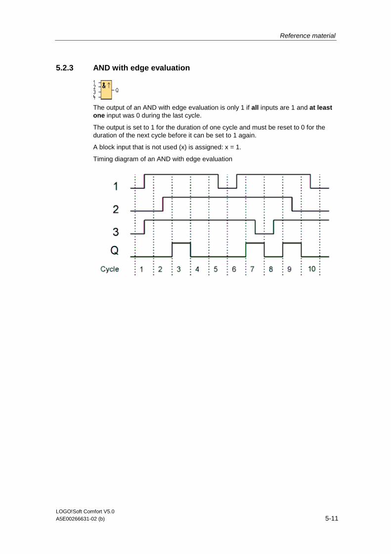
Reference material
LOGO!Soft Comfort V5.0 A5E00266631-02 (b) 5-11
5.2.3 AND with edge evaluation
The output of an AND with edge evaluation is only 1 if all inputs are 1 and at least one input was 0 during the last cycle.
The output is set to 1 for the duration of one cycle and must be reset to 0 for the duration of the next cycle before it can be set to 1 again.
A block input that is not used (x) is assigned: x = 1.
Timing diagram of an AND with edge evaluation

Reference material
LOGO!Soft Comfort V5.0 5-12 A5E00266631-02 (b)
5.2.4 NAND
The output of an NAND function is only 0 if all inputs are 1, i.e. when they are closed.
A block input that is not used (x) is assigned: x = 1.
Logic table of the NAND block:
Input 1 Input 2 Input 3 Input 4 Output
0 0 0 0 1
0 0 0 1 1
0 0 1 0 1
0 0 1 1 1
0 1 0 0 1
0 1 0 1 1
0 1 1 0 1
0 1 1 1 1
1 0 0 0 1
1 0 0 1 1
1 0 1 0 1
1 0 1 1 1
1 1 0 0 1
1 1 0 1 1
1 1 1 0 1
1 1 1 1 0
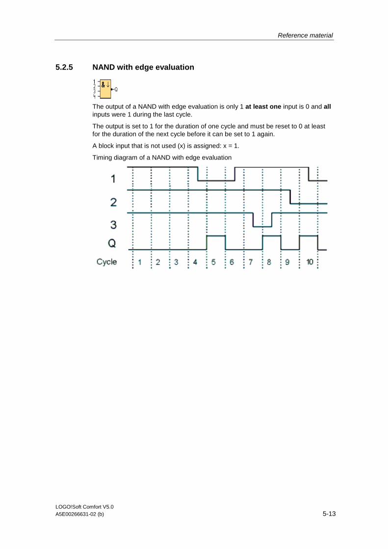
Reference material
LOGO!Soft Comfort V5.0 A5E00266631-02 (b) 5-13
5.2.5 NAND with edge evaluation
The output of a NAND with edge evaluation is only 1 at least one input is 0 and all inputs were 1 during the last cycle.
The output is set to 1 for the duration of one cycle and must be reset to 0 at least for the duration of the next cycle before it can be set to 1 again.
A block input that is not used (x) is assigned: x = 1.
Timing diagram of a NAND with edge evaluation
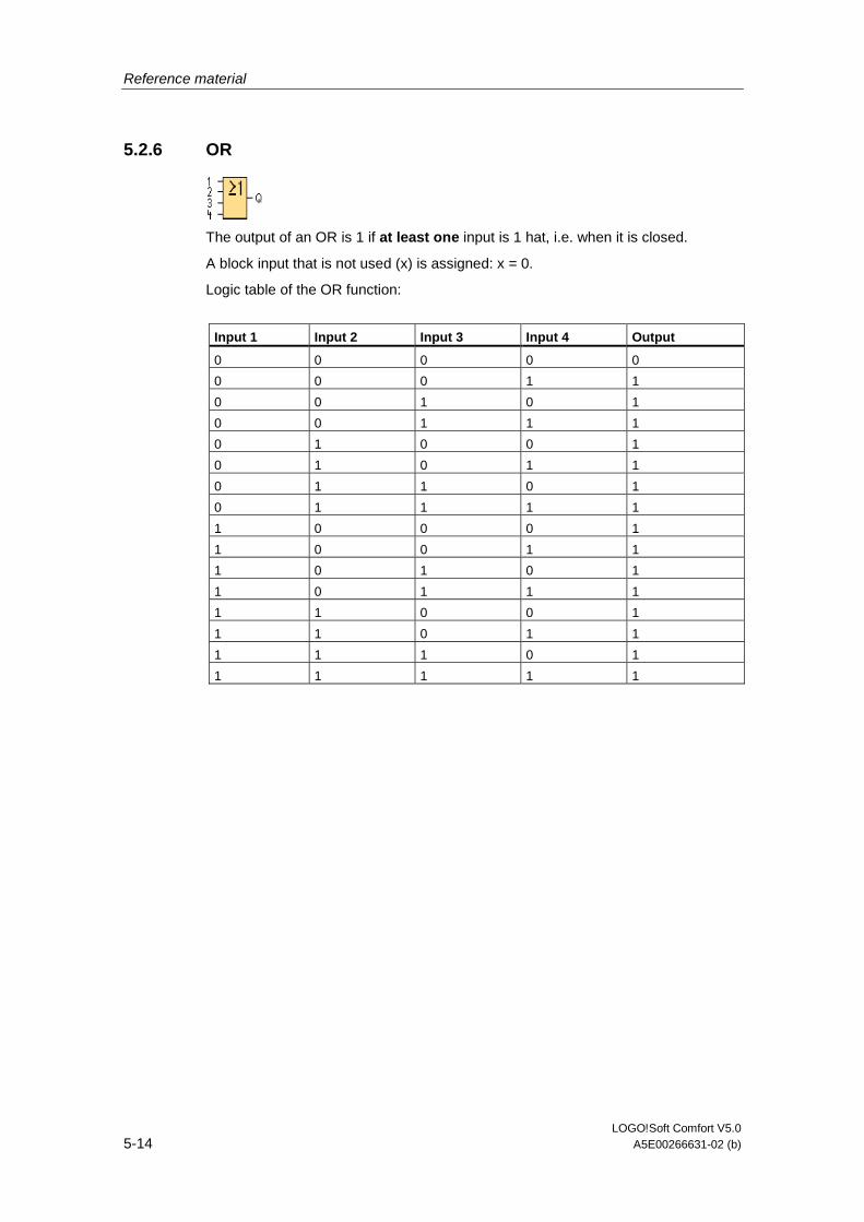
Reference material
LOGO!Soft Comfort V5.0 5-14 A5E00266631-02 (b)
5.2.6 OR
The output of an OR is 1 if at least one input is 1 hat, i.e. when it is closed.
A block input that is not used (x) is assigned: x = 0.
Logic table of the OR function:
Input 1 Input 2 Input 3 Input 4 Output
0 0 0 0 0
0 0 0 1 1
0 0 1 0 1
0 0 1 1 1
0 1 0 0 1
0 1 0 1 1
0 1 1 0 1
0 1 1 1 1
1 0 0 0 1
1 0 0 1 1
1 0 1 0 1
1 0 1 1 1
1 1 0 0 1
1 1 0 1 1
1 1 1 0 1
1 1 1 1 1
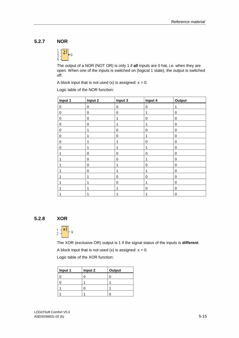
Reference material
LOGO!Soft Comfort V5.0 A5E00266631-02 (b) 5-15
5.2.7 NOR
The output of a NOR (NOT OR) is only 1 if all inputs are 0 hat, i.e. when they are open. When one of the inputs is switched on (logical 1 state), the output is switched off.
A block input that is not used (x) is assigned: x = 0.
Logic table of the NOR function:
Input 1 Input 2 Input 3 Input 4 Output
0 0 0 0 1
0 0 0 1 0
0 0 1 0 0
0 0 1 1 0
0 1 0 0 0
0 1 0 1 0
0 1 1 0 0
0 1 1 1 0
1 0 0 0 0
1 0 0 1 0
1 0 1 0 0
1 0 1 1 0
1 1 0 0 0
1 1 0 1 0
1 1 1 0 0
1 1 1 1 0
5.2.8 XOR
The XOR (exclusive OR) output is 1 if the signal status of the inputs is different.
A block input that is not used (x) is assigned: x = 0.
Logic table of the XOR function:
Input 1 Input 2 Output
0 0 0
0 1 1
1 0 1
1 1 0
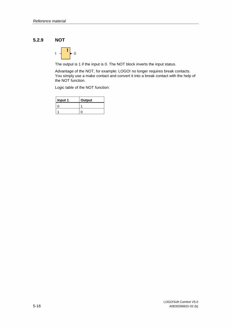
Reference material
LOGO!Soft Comfort V5.0 5-16 A5E00266631-02 (b)
5.2.9 NOT
The output is 1 if the input is 0. The NOT block inverts the input status.
Advantage of the NOT, for example: LOGO! no longer requires break contacts. You simply use a make contact and convert it into a break contact with the help of the NOT function.
Logic table of the NOT function:
Input 1 Output
0 1
1 0
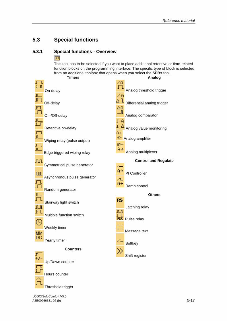
Reference material
LOGO!Soft Comfort V5.0 A5E00266631-02 (b) 5-17
5.3 Special functions
5.3.1 Special functions - Overview
This tool has to be selected if you want to place additional retentive or time-related function blocks on the programming interface. The specific type of block is selected from an additional toolbox that opens when you select the SFBs tool.
Timers
On-delay
Off-delay
On-/Off-delay
Retentive on-delay
Wiping relay (pulse output)
Edge triggered wiping relay
Symmetrical pulse generator
Asynchronous pulse generator
Random generator
Stairway light switch
Multiple function switch
Weekly timer
Yearly timer
Counters
Up/Down counter
Hours counter
Threshold trigger
Analog
Analog threshold trigger
Differential analog trigger
Analog comparator
Analog value monitoring
Analog amplifier
Analog multiplexer
Control and Regulate
PI Controller
Ramp control
Others
Latching relay
Pulse relay
Message text
Softkey
Shift register
Reference material
LOGO!Soft Comfort V5.0 5-18 A5E00266631-02 (b)
The LAD Editor offers you the following additional functions:
AND with edge evaluation
NAND with edge evaluation
FBD editor: description of the blocks of special functions
The description of the blocks of special functions in the circuit diagram begins with timer blocks ("T"), with counter blocks ("C") and with the remaining blocks ("SF").
The LOGO! version you have selected determines:
• The available blocks and
• The parameters you can set.
Inverting inputs
You can invert individual inputs, i.e.
1. A logical "1" at a specific input is inverted to logical "0" in the circuit program;
2. A logical "0" is inverted to logical "1" in the circuit program.
To do so, right-click on the input and select the invert command from the shortcut menu.
You cannot invert the inputs of output blocks.
0BA0-0BA3:
To invert an input, use the basic function NOT.
Block configuration
The block properties dialog provides you with an easy means of setting the various block parameters.
You can also assign parameters to blocks by means of other blocks.
If you click on the Reference button alongside a parameter in the block properties window, you can select which other block you would like to assign the parameters to.
This way it is possible, for example, to assign the time of an off-delay with an analog value.
A quick way of changing block parameters

Reference material
LOGO!Soft Comfort V5.0 A5E00266631-02 (b) 5-19
Protection
If a Protected check box exists for the protection of a block parameter, you can enable or lock the display and editing of this parameter in LOGO! configuration mode.
Retentivity
The switching state and counter values of SFBs can be held retentive. This means that the current data are retained, for example after a power failure, so that the function is resumed at the break position after renewed power on. Hence, a timer is not reset, but instead the time-to-go expires.
However, to enable this feature for the relevant function, retentivity needs to be set. There are two possible settings:
• on: Current data are retained
• off: Current data are not retained (default).
The hours counter forms an exception, because it is principally retentive.
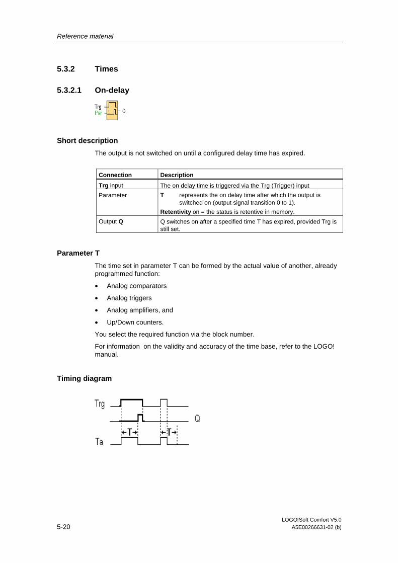
Reference material
LOGO!Soft Comfort V5.0 5-20 A5E00266631-02 (b)
5.3.2 Times
5.3.2.1 On-delay
Short description
The output is not switched on until a configured delay time has expired.
Connection Description
Trg input The on delay time is triggered via the Trg (Trigger) input
Parameter T represents the on delay time after which the output is switched on (output signal transition 0 to 1).
Retentivity on = the status is retentive in memory.
Output Q Q switches on after a specified time T has expired, provided Trg is still set.
Parameter T
The time set in parameter T can be formed by the actual value of another, already programmed function:
• Analog comparators
• Analog triggers
• Analog amplifiers, and
• Up/Down counters.
You select the required function via the block number.
For information on the validity and accuracy of the time base, refer to the LOGO! manual.
Timing diagram

Reference material
LOGO!Soft Comfort V5.0 A5E00266631-02 (b) 5-21
Description of the function
The time Ta (the current time in LOGO!) is triggered with the 0 to 1 transition at input Trg.
If the status at input Trg stays 1 at least for the duration of the configured time T, the output is set to 1 when this time has expired (the on signal of the output follows the on signal of the input with delay).
The time is reset if the status at input Trg changes to 0 again before the time T has expired.
The output is reset to 0 when input Trg is 0.
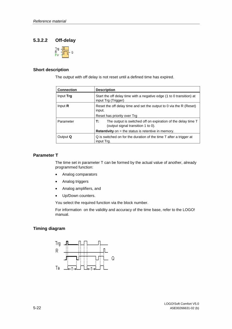
Reference material
LOGO!Soft Comfort V5.0 5-22 A5E00266631-02 (b)
5.3.2.2 Off-delay
Short description
The output with off delay is not reset until a defined time has expired.
Connection Description
Input Trg Start the off delay time with a negative edge (1 to 0 transition) at input Trg (Trigger)
Input R Reset the off delay time and set the output to 0 via the R (Reset) input.
Reset has priority over Trg
Parameter T: The output is switched off on expiration of the delay time T (output signal transition 1 to 0).
Retentivity on = the status is retentive in memory.
Output Q Q is switched on for the duration of the time T after a trigger at input Trg.
Parameter T
The time set in parameter T can be formed by the actual value of another, already programmed function:
• Analog comparators
• Analog triggers
• Analog amplifiers, and
• Up/Down counters.
You select the required function via the block number.
For information on the validity and accuracy of the time base, refer to the LOGO! manual.
Timing diagram

Reference material
LOGO!Soft Comfort V5.0 A5E00266631-02 (b) 5-23
Description of the function
Output Q is set to 1 instantaneously with a 0 to 1 transition at input Trg.
At the 1 to 0 transition at input Trg, LOGO! retriggers the current time T, and the output remains set. The output Q is reset to 0 when Ta reaches the value specified in T (Ta=T) (off delay).
A one-shot at input Trg retriggers the time Ta.
You can reset the time Ta and the output via the input R (Reset) before the time Ta has expired.
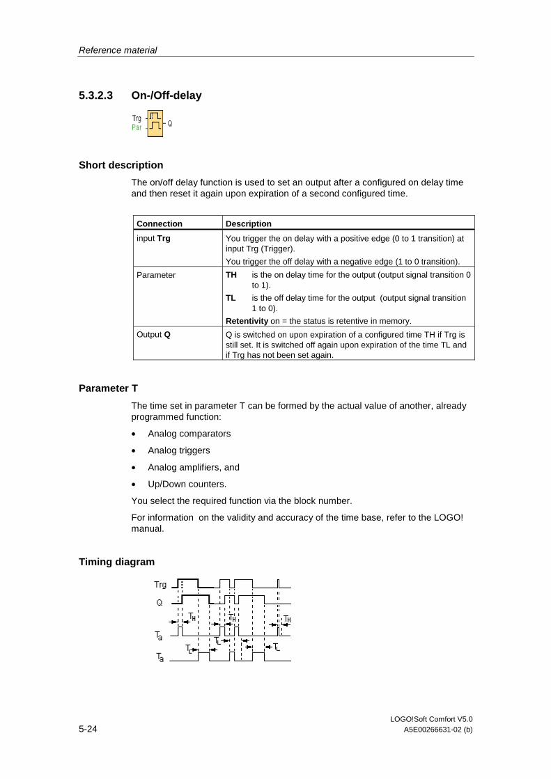
Reference material
LOGO!Soft Comfort V5.0 5-24 A5E00266631-02 (b)
5.3.2.3 On-/Off-delay
Short description
The on/off delay function is used to set an output after a configured on delay time and then reset it again upon expiration of a second configured time.
Connection Description
input Trg You trigger the on delay with a positive edge (0 to 1 transition) at input Trg (Trigger).
You trigger the off delay with a negative edge (1 to 0 transition).
Parameter TH is the on delay time for the output (output signal transition 0 to 1).
TL is the off delay time for the output (output signal transition 1 to 0).
Retentivity on = the status is retentive in memory.
Output Q Q is switched on upon expiration of a configured time TH if Trg is still set. It is switched off again upon expiration of the time TL and if Trg has not been set again.
Parameter T
The time set in parameter T can be formed by the actual value of another, already programmed function:
• Analog comparators
• Analog triggers
• Analog amplifiers, and
• Up/Down counters.
You select the required function via the block number.
For information on the validity and accuracy of the time base, refer to the LOGO! manual.
Timing diagram

Reference material
LOGO!Soft Comfort V5.0 A5E00266631-02 (b) 5-25
Description of the function
The time TH is triggered with a 0 to 1 transition at input Trg.
If the status at input Trg is 1 at least for the duration of the configured time TH, the output is set to logical 1 upon expiration of this time (output is on delayed to the input signal).
The time TH is reset if the status at input Trg is reset to 0 before this time has expired.
The time TL is triggered with the 1 to 0 transition at the output.
If the status at input Trg remains 0 at least for the duration of a configured time TL, the output is reset to 0 upon expiration of this time (output is off delayed to the input signal).
The time TL is reset if the status at input Trg is returns to 1 before this time has expired.
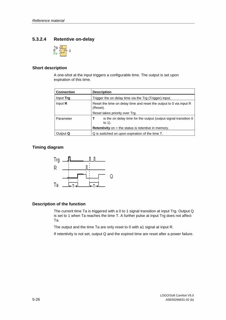
Reference material
LOGO!Soft Comfort V5.0 5-26 A5E00266631-02 (b)
5.3.2.4 Retentive on-delay
Short description
A one-shot at the input triggers a configurable time. The output is set upon expiration of this time.
Connection Description
Input Trg Trigger the on delay time via the Trg (Trigger) input.
Input R Reset the time on delay time and reset the output to 0 via input R (Reset).
Reset takes priority over Trg.
Parameter T is the on delay time for the output (output signal transition 0 to 1).
Retentivity on = the status is retentive in memory.
Output Q Q is switched on upon expiration of the time T.
Timing diagram
Description of the function
The current time Ta is triggered with a 0 to 1 signal transition at input Trg. Output Q is set to 1 when Ta reaches the time T. A further pulse at input Trg does not affect Ta.
The output and the time Ta are only reset to 0 with a1 signal at input R.
If retentivity is not set, output Q and the expired time are reset after a power failure.
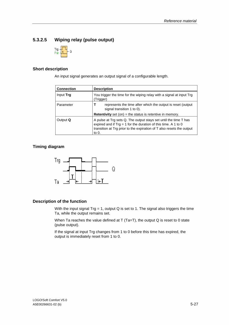
Reference material
LOGO!Soft Comfort V5.0 A5E00266631-02 (b) 5-27
5.3.2.5 Wiping relay (pulse output)
Short description
An input signal generates an output signal of a configurable length.
Connection Description
Input Trg You trigger the time for the wiping relay with a signal at input Trg (Trigger)
Parameter T represents the time after which the output is reset (output signal transition 1 to 0).
Retentivity set (on) = the status is retentive in memory.
Output Q A pulse at Trg sets Q. The output stays set until the time T has expired and if Trg = 1 for the duration of this time. A 1 to 0 transition at Trg prior to the expiration of T also resets the output to 0.
Timing diagram
Description of the function
With the input signal Trg = 1, output Q is set to 1. The signal also triggers the time Ta, while the output remains set.
When Ta reaches the value defined at T (Ta=T), the output Q is reset to 0 state (pulse output).
If the signal at input Trg changes from 1 to 0 before this time has expired, the output is immediately reset from 1 to 0.
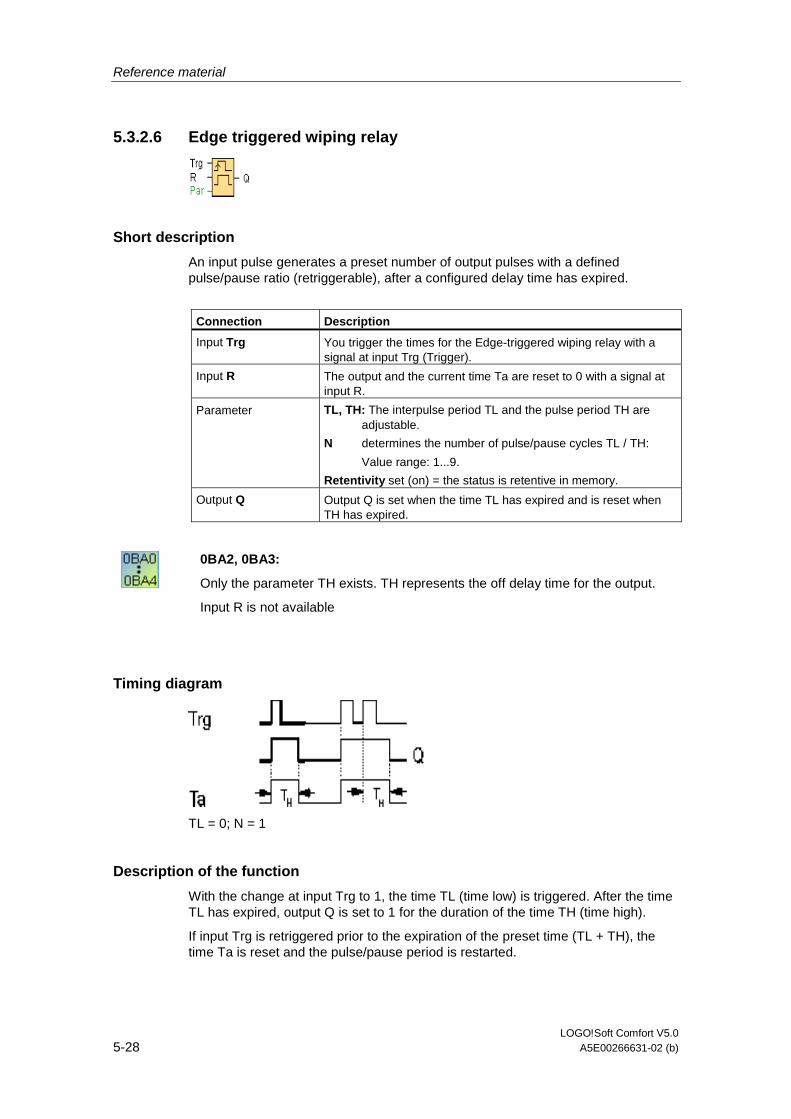
Reference material
LOGO!Soft Comfort V5.0 5-28 A5E00266631-02 (b)
5.3.2.6 Edge triggered wiping relay
Short description
An input pulse generates a preset number of output pulses with a defined pulse/pause ratio (retriggerable), after a configured delay time has expired.
Connection Description
Input Trg You trigger the times for the Edge-triggered wiping relay with a signal at input Trg (Trigger).
Input R The output and the current time Ta are reset to 0 with a signal at input R.
Parameter TL, TH: The interpulse period TL and the pulse period TH are adjustable.
N determines the number of pulse/pause cycles TL / TH:
Value range: 1...9.
Retentivity set (on) = the status is retentive in memory.
Output Q Output Q is set when the time TL has expired and is reset when TH has expired.
0BA2, 0BA3:
Only the parameter TH exists. TH represents the off delay time for the output.
Input R is not available
Timing diagram
TL = 0; N = 1
Description of the function
With the change at input Trg to 1, the time TL (time low) is triggered. After the time TL has expired, output Q is set to 1 for the duration of the time TH (time high).
If input Trg is retriggered prior to the expiration of the preset time (TL + TH), the time Ta is reset and the pulse/pause period is restarted.
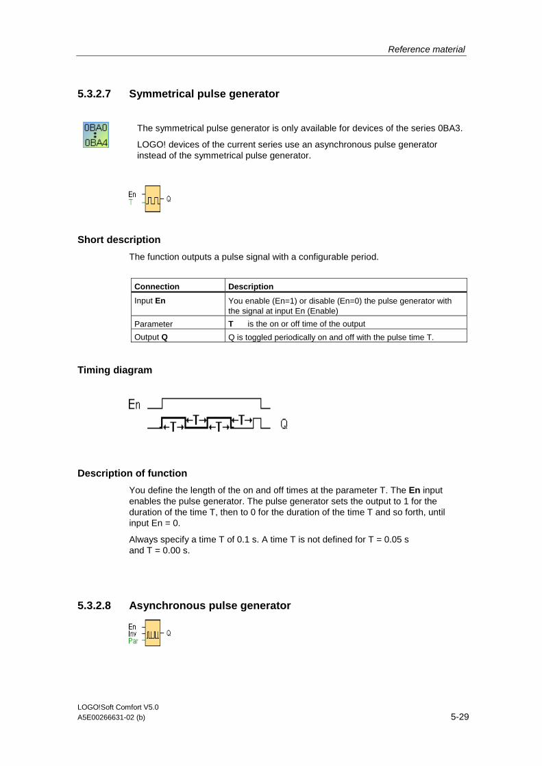
Reference material
LOGO!Soft Comfort V5.0 A5E00266631-02 (b) 5-29
5.3.2.7 Symmetrical pulse generator
The symmetrical pulse generator is only available for devices of the series 0BA3.
LOGO! devices of the current series use an asynchronous pulse generator instead of the symmetrical pulse generator.
Short description
The function outputs a pulse signal with a configurable period.
Connection Description
Input En You enable (En=1) or disable (En=0) the pulse generator with the signal at input En (Enable)
Parameter T is the on or off time of the output
Output Q Q is toggled periodically on and off with the pulse time T.
Timing diagram
Description of function
You define the length of the on and off times at the parameter T. The En input enables the pulse generator. The pulse generator sets the output to 1 for the duration of the time T, then to 0 for the duration of the time T and so forth, until input En = 0.
Always specify a time T of 0.1 s. A time T is not defined for T = 0.05 s and T = 0.00 s.
5.3.2.8 Asynchronous pulse generator
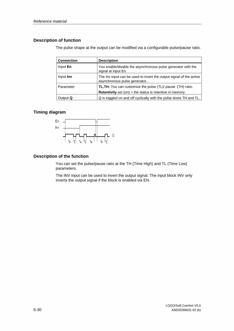
Reference material
LOGO!Soft Comfort V5.0 5-30 A5E00266631-02 (b)
Description of function
The pulse shape at the output can be modified via a configurable pulse/pause ratio.
Connection Description
Input En You enable/disable the asynchronous pulse generator with the signal at input En.
Input Inv The Inv input can be used to invert the output signal of the active asynchronous pulse generator..
Parameter TL,TH: You can customize the pulse (TL)/ pause (TH) ratio.
Retentivity set (on) = the status is retentive in memory.
Output Q Q is toggled on and off cyclically with the pulse times TH and TL.
Timing diagram
Description of the function
You can set the pulse/pause ratio at the TH (Time High) and TL (Time Low) parameters.
The INV input can be used to invert the output signal. The input block INV only inverts the output signal if the block is enabled via EN.
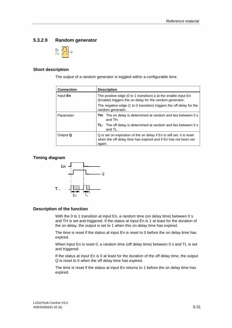
Reference material
LOGO!Soft Comfort V5.0 A5E00266631-02 (b) 5-31
5.3.2.9 Random generator
Short description
The output of a random generator is toggled within a configurable time.
Connection Description
Input En The positive edge (0 to 1 transition) a at the enable input En (Enable) triggers the on delay for the random generator.
The negative edge (1 to 0 transition) triggers the off delay for the random generator.
Parameter TH: The on delay is determined at random and lies between 0 s and TH.
TL: The off delay is determined at random and lies between 0 s and TL.
Output Q Q is set on expiration of the on delay if En is still set. it is reset when the off delay time has expired and if En has not been set again.
Timing diagram
Description of the function
With the 0 to 1 transition at input En, a random time (on delay time) between 0 s and TH is set and triggered. If the status at input En is 1 at least for the duration of the on delay, the output is set to 1 when this on delay time has expired.
The time is reset if the status at input En is reset to 0 before the on delay time has expired.
When input En is reset 0, a random time (off delay time) between 0 s and TL is set and triggered.
If the status at input En is 0 at least for the duration of the off delay time, the output Q is reset to 0 when the off delay time has expired.
The time is reset if the status at input En returns to 1 before the on delay time has expired.
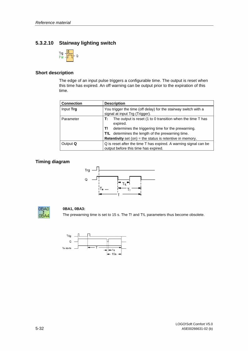
Reference material
LOGO!Soft Comfort V5.0 5-32 A5E00266631-02 (b)
5.3.2.10 Stairway lighting switch
Short description
The edge of an input pulse triggers a configurable time. The output is reset when this time has expired. An off warning can be output prior to the expiration of this time.
Connection Description
Input Trg You trigger the time (off delay) for the stairway switch with a signal at input Trg (Trigger).
Parameter T: The output is reset (1 to 0 transition when the time T has expired.
T! determines the triggering time for the prewarning. T!L determines the length of the prewarning time. Retentivity set (on) = the status is retentive in memory.
Output Q Q is reset after the time T has expired. A warning signal can be output before this time has expired.
Timing diagram
0BA1, 0BA3:
The prewarning time is set to 15 s. The T! and T!L parameters thus become obsolete.

Reference material
LOGO!Soft Comfort V5.0 A5E00266631-02 (b) 5-33
Changing the time base
You can change the prewarning time base and the period.
Time base T Prewarning time Prewarning period
Seconds* 750 ms 50 ms
Minutes 15 s 1 s
Hours 15 min 1 min
* makes sense only for programs with a cycle time of < 25 ms
Description of the function
Output Q is set to 1 with a 0 to 1 signal transition at input Trg. The 1 to 0 transition at input Trg triggers the current time and output Q remains set.
Output Q is reset to 0 when Ta reaches the time T. Before the off delay time (T - T!) has expired, you can output a prewarning that resets Q for the duration of the off prewarning time T!L.
Ta is retriggered (optional) at the next high/low transition at input Trg and if Ta is expiring.
Scan cycle time
For information on how to determine the scan cycle time of a LOGO!, refer to the appendix of the LOGO! manual.
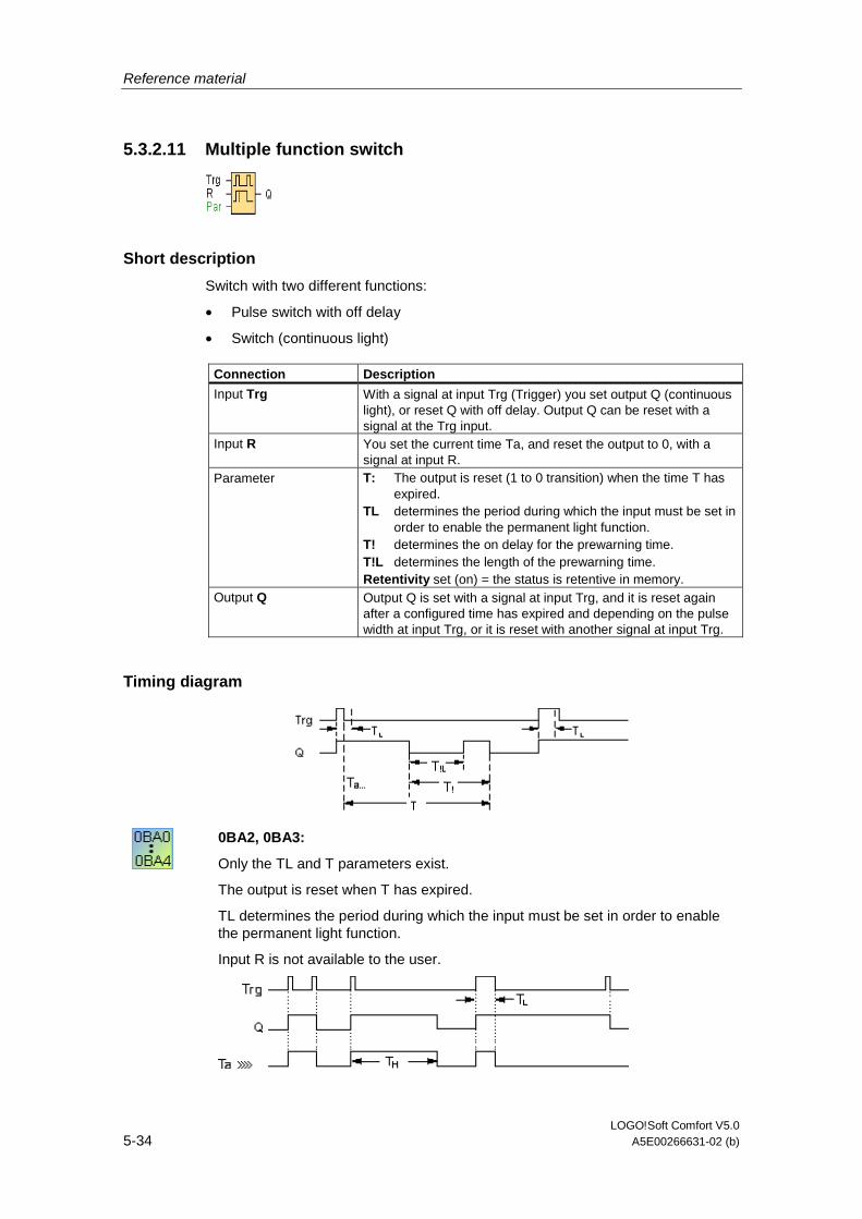
Reference material
LOGO!Soft Comfort V5.0 5-34 A5E00266631-02 (b)
5.3.2.11 Multiple function switch
Short description
Switch with two different functions:
• Pulse switch with off delay
• Switch (continuous light)
Connection Description
Input Trg With a signal at input Trg (Trigger) you set output Q (continuous light), or reset Q with off delay. Output Q can be reset with a signal at the Trg input.
Input R You set the current time Ta, and reset the output to 0, with a signal at input R.
Parameter T: The output is reset (1 to 0 transition) when the time T has expired.
TL determines the period during which the input must be set in order to enable the permanent light function.
T! determines the on delay for the prewarning time. T!L determines the length of the prewarning time. Retentivity set (on) = the status is retentive in memory.
Output Q Output Q is set with a signal at input Trg, and it is reset again after a configured time has expired and depending on the pulse width at input Trg, or it is reset with another signal at input Trg.
Timing diagram
0BA2, 0BA3:
Only the TL and T parameters exist.
The output is reset when T has expired.
TL determines the period during which the input must be set in order to enable the permanent light function.
Input R is not available to the user.

Reference material
LOGO!Soft Comfort V5.0 A5E00266631-02 (b) 5-35
Description of the function
Output Q is set to 1 with a 0 to 1 signal transition at Trg.
If output Q = 0, and input Trg is set hi at least for the duration of TL, the permanent lighting function is enabled and output Q is set accordingly.
The off delay time T is triggered when the status at input Trg changes to 0 before the time TL has expired.
Output Q is reset when the Ta = T.
Before the off delay time (T - T!) has expired, you can output an off prewarning that resets Q for the duration of the off preqarning time T!L. A further signal at input Trg always resets T and output Q.
Caution
The time base for the T, T! and T!L must be identical.
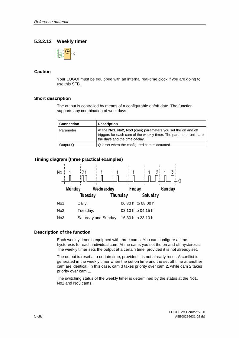
Reference material
LOGO!Soft Comfort V5.0 5-36 A5E00266631-02 (b)
5.3.2.12 Weekly timer
Caution
Your LOGO! must be equipped with an internal real-time clock if you are going to use this SFB.
Short description
The output is controlled by means of a configurable on/off date. The function supports any combination of weekdays.
Connection Description
Parameter At the No1, No2, No3 (cam) parameters you set the on and off triggers for each cam of the weekly timer. The parameter units are the days and the time-of-day.
Output Q Q is set when the configured cam is actuated.
Timing diagram (three practical examples)
No1: Daily: 06:30 h to 08:00 h
No2: Tuesday: 03:10 h to 04:15 h
No3: Saturday and Sunday: 16:30 h to 23:10 h
Description of the function
Each weekly timer is equipped with three cams. You can configure a time hysteresis for each individual cam. At the cams you set the on and off hysteresis. The weekly timer sets the output at a certain time, provided it is not already set.
The output is reset at a certain time, provided it is not already reset. A conflict is generated in the weekly timer when the set on time and the set off time at another cam are identical. In this case, cam 3 takes priority over cam 2, while cam 2 takes priority over cam 1.
The switching status of the weekly timer is determined by the status at the No1, No2 and No3 cams.
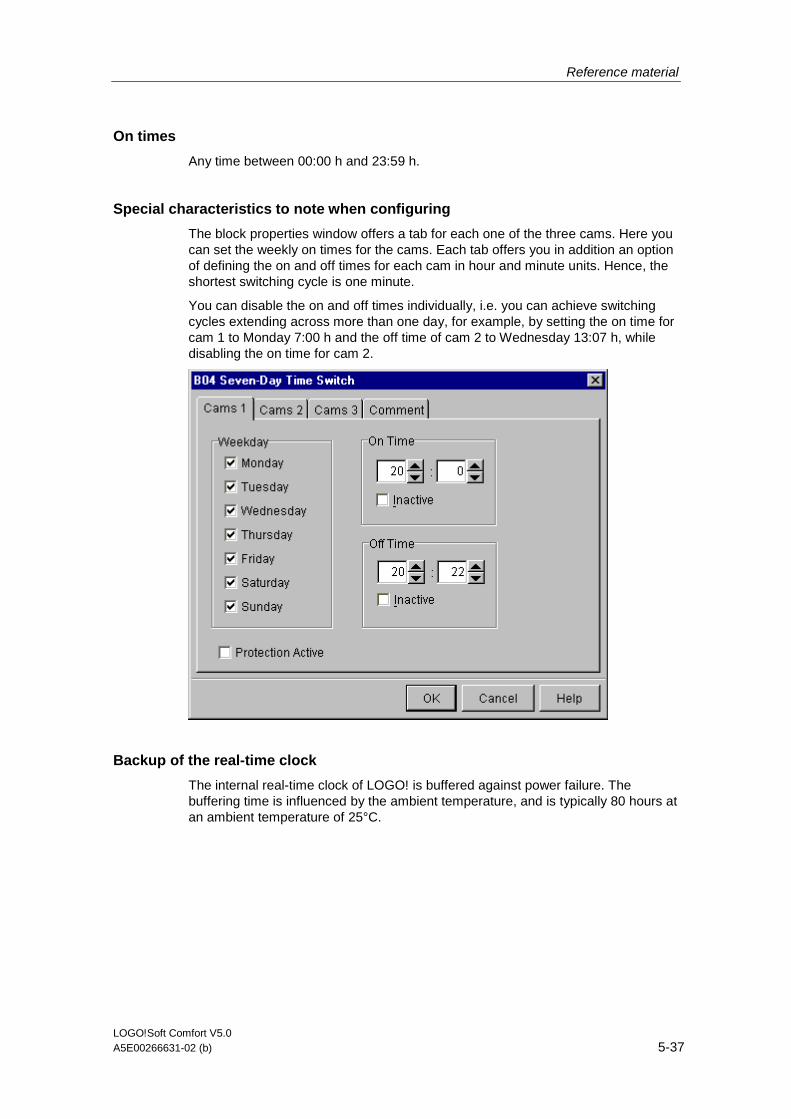
Reference material
LOGO!Soft Comfort V5.0 A5E00266631-02 (b) 5-37
On times
Any time between 00:00 h and 23:59 h.
Special characteristics to note when configuring
The block properties window offers a tab for each one of the three cams. Here you can set the weekly on times for the cams. Each tab offers you in addition an option of defining the on and off times for each cam in hour and minute units. Hence, the shortest switching cycle is one minute.
You can disable the on and off times individually, i.e. you can achieve switching cycles extending across more than one day, for example, by setting the on time for cam 1 to Monday 7:00 h and the off time of cam 2 to Wednesday 13:07 h, while disabling the on time for cam 2.
Backup of the real-time clock
The internal real-time clock of LOGO! is buffered against power failure. The buffering time is influenced by the ambient temperature, and is typically 80 hours at an ambient temperature of 25°C.
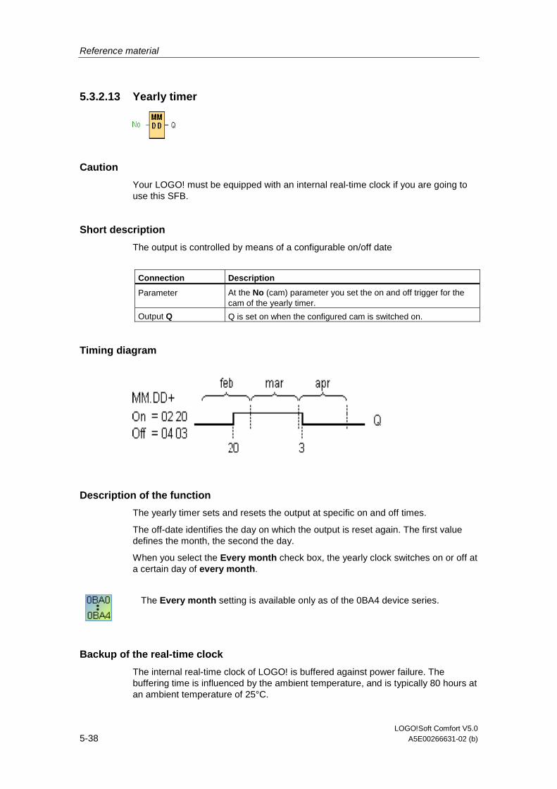
Reference material
LOGO!Soft Comfort V5.0 5-38 A5E00266631-02 (b)
5.3.2.13 Yearly timer
Caution
Your LOGO! must be equipped with an internal real-time clock if you are going to use this SFB.
Short description
The output is controlled by means of a configurable on/off date
Connection Description
Parameter At the No (cam) parameter you set the on and off trigger for the cam of the yearly timer.
Output Q Q is set on when the configured cam is switched on.
Timing diagram
Description of the function
The yearly timer sets and resets the output at specific on and off times.
The off-date identifies the day on which the output is reset again. The first value defines the month, the second the day.
When you select the Every month check box, the yearly clock switches on or off at a certain day of every month.
The Every month setting is available only as of the 0BA4 device series.
Backup of the real-time clock
The internal real-time clock of LOGO! is buffered against power failure. The buffering time is influenced by the ambient temperature, and is typically 80 hours at an ambient temperature of 25°C.
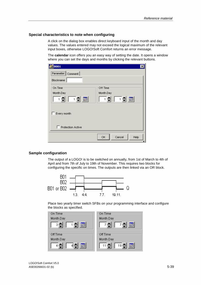
Reference material
LOGO!Soft Comfort V5.0 A5E00266631-02 (b) 5-39
Special characteristics to note when configuring
A click on the dialog box enables direct keyboard input of the month and day values. The values entered may not exceed the logical maximum of the relevant input boxes, otherwise LOGO!Soft Comfort returns an error message.
The calendar icon offers you an easy way of setting the date. It opens a window where you can set the days and months by clicking the relevant buttons.
Sample configuration
The output of a LOGO! is to be switched on annually, from 1st of March to 4th of April and from 7th of July to 19th of November. This requires two blocks for configuring the specific on times. The outputs are then linked via an OR block.
Place two yearly timer switch SFBs on your programming interface and configure the blocks as specified.

Reference material
LOGO!Soft Comfort V5.0 5-40 A5E00266631-02 (b)
Create a logical link of the blocks via a standard OR block. The OR output is 1 if at least one of the yearly timer switches is set.
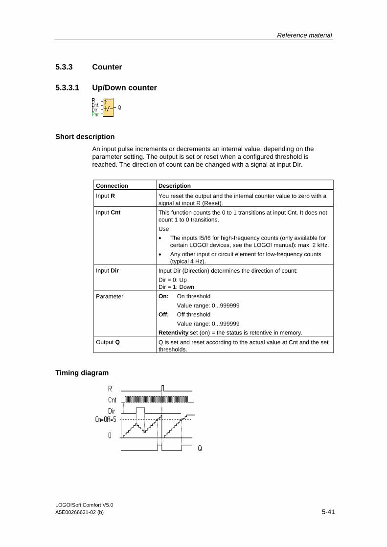
Reference material
LOGO!Soft Comfort V5.0 A5E00266631-02 (b) 5-41
5.3.3 Counter
5.3.3.1 Up/Down counter
Short description
An input pulse increments or decrements an internal value, depending on the parameter setting. The output is set or reset when a configured threshold is reached. The direction of count can be changed with a signal at input Dir.
Connection Description
Input R You reset the output and the internal counter value to zero with a signal at input R (Reset).
Input Cnt This function counts the 0 to 1 transitions at input Cnt. It does not count 1 to 0 transitions.
Use
• The inputs I5/I6 for high-frequency counts (only available for certain LOGO! devices, see the LOGO! manual): max. 2 kHz.
• Any other input or circuit element for low-frequency counts (typical 4 Hz).
Input Dir Input Dir (Direction) determines the direction of count:
Dir = 0: Up Dir = 1: Down
Parameter On: On threshold
Value range: 0...999999
Off: Off threshold
Value range: 0...999999
Retentivity set (on) = the status is retentive in memory.
Output Q Q is set and reset according to the actual value at Cnt and the set thresholds.
Timing diagram

Reference material
LOGO!Soft Comfort V5.0 5-42 A5E00266631-02 (b)
Description of the function
The function increments (Dir = 0) or decrements (Dir = 1) the internal counter by one count with every positive edge at input Cnt.
You can reset the internal counter value to '000000', with a signal at the reset input R. As long as R=1, the output is 0 and the pulses at input Cnt are not counted.
Output Q is set and reset according to the actual value at Cnt and the set thresholds. See the following rules for calculation.
Calculation rule
• If the on threshold >= off threshold, then: Q = 1, if Cnt >= On Q = 0, if Cnt < Off.
• If the on threshold < off threshold, then: Q = 1, if On <= Cnt < Off.
0BA0-0BA3:
The off parameter does not exist. The calculation rule is therefore void.
Preset On/Off parameters
The preset limit values for the on and/or off parameters can also be derived from the actual value of another, already configured function. You can use the actual values of the following functions:
• Analog comparator (actual value Ax - Ay)
• Analog trigger (actual value Ax)
• Analog amplifier (actual value Ax) and
• Up/down counter (actual value Cnt).
Select the required function via the block number.
Caution
The function polls the limit value of the counter once in each cycle.
Thus, if the pulses at the fast inputs I5/I6 are faster than the scan cycle time, the SFB might not switch until the so specified limit has been exceeded.
Example: Up to 100 pulses per cycle can be counted; 900 pulses have been counted so far. On = 950; Off = 10000. The output is set in the next cycle, after the value has reached 1000.
The output would not be set at all if the value Off = 980
Scan cycle time
For information on how to determine the scan cycle time of a LOGO!, refer to the appendix in the LOGO! manual.
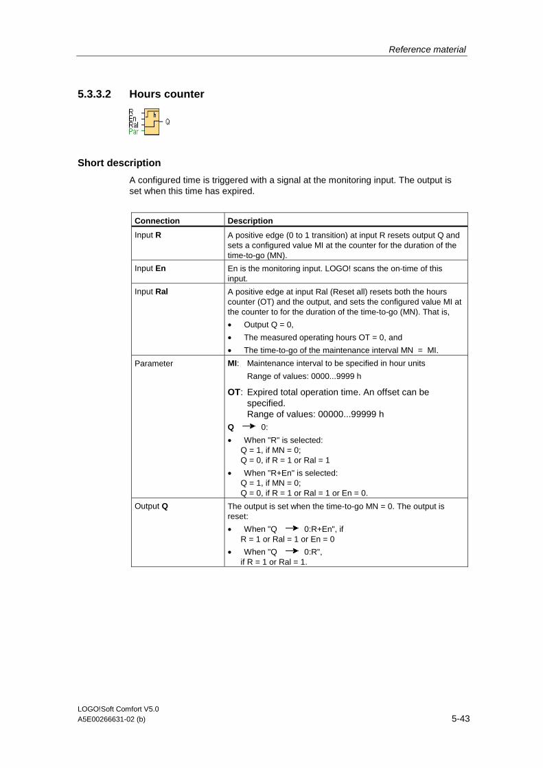
Reference material
LOGO!Soft Comfort V5.0 A5E00266631-02 (b) 5-43
5.3.3.2 Hours counter
Short description
A configured time is triggered with a signal at the monitoring input. The output is set when this time has expired.
Connection Description
Input R A positive edge (0 to 1 transition) at input R resets output Q and sets a configured value MI at the counter for the duration of the time-to-go (MN).
Input En En is the monitoring input. LOGO! scans the on-time of this input.
Input Ral A positive edge at input Ral (Reset all) resets both the hours counter (OT) and the output, and sets the configured value MI at the counter to for the duration of the time-to-go (MN). That is,
• Output Q = 0,
• The measured operating hours OT = 0, and
• The time-to-go of the maintenance interval MN = MI.
Parameter MI: Maintenance interval to be specified in hour units
Range of values: 0000...9999 h
OT: Expired total operation time. An offset can be specified. Range of values: 00000...99999 h
Q 0:
• When "R" is selected: Q = 1, if MN = 0; Q = 0, if R = 1 or Ral = 1
• When "R+En" is selected: Q = 1, if MN = 0; Q = 0, if R = 1 or Ral = 1 or En = 0.
Output Q The output is set when the time-to-go MN = 0. The output is reset:
• When "Q 0:R+En", if R = 1 or Ral = 1 or En = 0
• When "Q 0:R", if R = 1 or Ral = 1.

Reference material
LOGO!Soft Comfort V5.0 5-44 A5E00266631-02 (b)
Timing diagram
MI = Configured time interval
MN = Time-to-go
OT = Total time expired since the last 1 signal at the Ral input
These values are principally held retentive!
Description of the function
The hours counter monitors input En. As long as the status at this input is 1, LOGO! calculates the time expired and the time-to-go MN. LOGO! displays these times when set to configuration mode. The output is set to 1 when the time-to-go is equal to zero.
You reset output Q and the time-to-go counter to the specified value MI with a signal at input R. The operation hour counter OT remains unaffected.
You reset output Q and the time-to-go counter to the specified value MI with a signal at input Ral. The operation hour counter OT is reset to 0.
Depending on your configuration of the Q parameter, the output is either reset with a reset signal at input R or Ral ("Q R"), or when the reset signal is 1 or the En signal is 0 ("Q R+En").
Viewing the MI, MN and OT values
In LOGO!Soft Comfort you can fetch the hours counter via the Tools -> Transfer: Hours counter menu command.
Limit value of OT
The value of the operating hours in OT are retained when you reset the hours counter with a signal at input R. The hours counter OT continues the count as long as En = 1, irrespective of the status at the reset input R. The counter limit of OT is 99999 h. The hours counter stops when it reaches this value.
In programming mode, you can set the initial value of OT. The counter starts operation at any value other than zero. MN is automatically calculated at the START, based on the MI and OT values.
Example: MI = 100, OT = 130, the result is MN = 70

Reference material
LOGO!Soft Comfort V5.0 A5E00266631-02 (b) 5-45
Parameter preset
In LOGO!Soft Comfort, you can define MI and an OT start value.
You determine that Q does not depend on En by selecting the corresponding check box.
Retentivity with the hours counter
The hours counter in the LOGO! is generally retentive.
However, if the values of the hours counter are lost after a power failure, then select the respective block in your circuit program. Right mouse click on the hours counter and select Block Properties > Parameters. The option Retentivity must be activated and not changeable (grayed out).
If the Retentivity option is not available, then delete the block and insert a new special function hours counter at the same position.
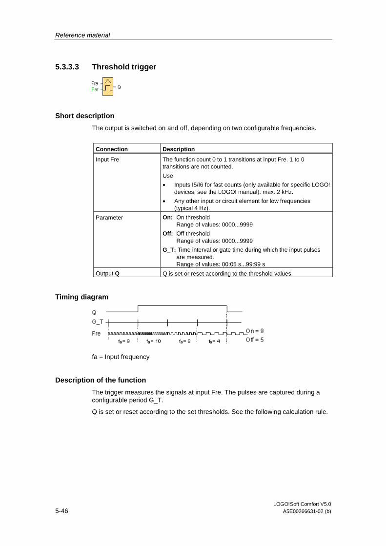
Reference material
LOGO!Soft Comfort V5.0 5-46 A5E00266631-02 (b)
5.3.3.3 Threshold trigger
Short description
The output is switched on and off, depending on two configurable frequencies.
Connection Description
Input Fre The function count 0 to 1 transitions at input Fre. 1 to 0 transitions are not counted.
Use
• Inputs I5/I6 for fast counts (only available for specific LOGO! devices, see the LOGO! manual): max. 2 kHz.
• Any other input or circuit element for low frequencies (typical 4 Hz).
Parameter On: On threshold Range of values: 0000...9999
Off: Off threshold Range of values: 0000...9999
G_T: Time interval or gate time during which the input pulses are measured. Range of values: 00:05 s...99:99 s
Output Q Q is set or reset according to the threshold values.
Timing diagram
fa = Input frequency
Description of the function
The trigger measures the signals at input Fre. The pulses are captured during a configurable period G_T.
Q is set or reset according to the set thresholds. See the following calculation rule.

Reference material
LOGO!Soft Comfort V5.0 A5E00266631-02 (b) 5-47
Calculation rule
• If the threshold (On) > threshold (Off), then: Q = 1, if fa >= On Q = 0, if fa < Off.
• If the threshold (On) < threshold (Off), then Q = 1, if On <= fa < Off.
0BA0-0BA3:
The following calculation rules apply
• If fre > threshold (On), then: Q = 1
• If fre <= threshold (Off), then: Q = 0

Reference material
LOGO!Soft Comfort V5.0 5-48 A5E00266631-02 (b)
5.3.4 Analog
5.3.4.1 Analog threshold trigger
Short description
The output is set or reset depending on two configurable thresholds (hysteresis).
Connection Description
Input Ax Input the analog signal to be evaluated at input Ax.
Use the analog inputs AI1...AI8, the analog flags AM1...AM6, the block number of a function with analog output, or the analog outputs AQ1 and AQ2.
0 - 10 V is proportional to 0 - 1000 (internal value).
Parameter A: Gain Range of values: +- 10.00
B: Zero offset Range of values: +- 10,000
On: On threshold Range of values: +- 20,000
Off: Off threshold Range of values: +- 20,000
p: Number of decimals Range of values: 0, 1, 2, 3
Output Q Q is set or reset depending on the set thresholds.
0BA4:
A: Gain
Range of values 0.00...10.00
0BA2, 0BA3:
These parameters apply:
G: Gain in [%]
Range of values 0..1,000 %
O: Offset
Range of values ±999
On: On threshold Range of values 0..9,999
Off: Off threshold Range of values 0..9,999
Parameter p (number of decimals)
Applies only to the display of On, Off and Ax values in a message text.
Does not apply to the comparison of On and Off values! (The compare function ignores the decimal point.)

Reference material
LOGO!Soft Comfort V5.0 A5E00266631-02 (b) 5-49
Timing diagram
Description of the function
The function reads the value of the signal at the analog input Ax.
This value is multiplied by the value of parameter A (gain). Parameter B (offset) is added to the product, hence
(Ax * Gain) + Offset = Actual value Ax.
Output Q is set or reset depending on the set threshold values. See the following calculation rule.
0BA2, 0BA3:
The function is as follows
The offset parameter is added to the read analog value. The sum is multiplied by the value of the gain parameter.
Value = (AI+offset)*gain
Output Q is set to 1 if the calculated value exceeds the on threshold (TH high).
Q is reset to 0 when the value reaches or drops below the off threshold (TH low).
Calculation rule
• If threshold (On) >= threshold (Off), then: Q = 1, if the actual value Ax > On Q = 0, if the actual value Ax <= Off.
• If threshold (On) < threshold (Off), then Q = 1, if On <= the actual value Ax < Off.
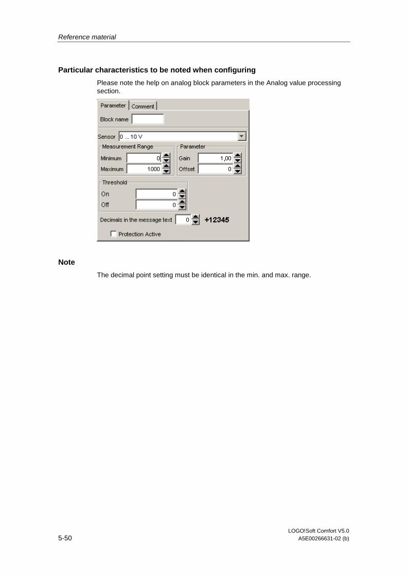
Reference material
LOGO!Soft Comfort V5.0 5-50 A5E00266631-02 (b)
Particular characteristics to be noted when configuring
Please note the help on analog block parameters in the Analog value processing section.
Note
The decimal point setting must be identical in the min. and max. range.

Reference material
LOGO!Soft Comfort V5.0 A5E00266631-02 (b) 5-51
5.3.4.2 Analog differential trigger
Short description
The output is set and reset depending on a configurable threshold and a differential value.
Connection Description
Input Ax You apply the analog signal to be analyzed at input Ax.
Use the analog inputs AI1...AI8, the analog flags AM1...AM6, the block number of a function with analog output, or the analog outputs AQ1 and AQ2.
0 - 10 V is proportional to 0 - 1000 (internal value).
Parameter A: Gain Range of values: +- 10.00
B: Zero offset Range of values: +- 10,000
On: On threshold Range of values: +- 20,000
Delta: Differential value for calculating the off parameter Range of values: +- 20,000
p: Number of decimals Range of values: 0, 1, 2, 3
Output Q Q is set or reset, depending on the threshold and difference values.
0BA4:
A: Gain
Range of values 0.00...10.00
Parameter p (number of decimals)
Applies only to the display of On, Off and Ax values in a message text.
Does not apply to the comparison of On and Off values! (The compare function ignores the decimal point.)
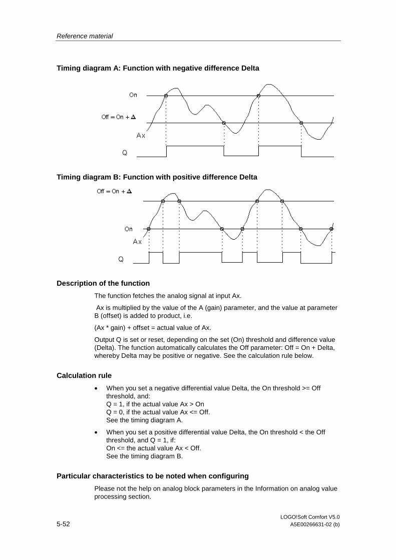
Reference material
LOGO!Soft Comfort V5.0 5-52 A5E00266631-02 (b)
Timing diagram A: Function with negative difference Delta
Timing diagram B: Function with positive difference Delta
Description of the function
The function fetches the analog signal at input Ax.
Ax is multiplied by the value of the A (gain) parameter, and the value at parameter B (offset) is added to product, i.e.
(Ax * gain) + offset = actual value of Ax.
Output Q is set or reset, depending on the set (On) threshold and difference value (Delta). The function automatically calculates the Off parameter: Off = On + Delta, whereby Delta may be positive or negative. See the calculation rule below.
Calculation rule
• When you set a negative differential value Delta, the On threshold >= Off threshold, and: Q = 1, if the actual value Ax > On Q = 0, if the actual value Ax <= Off. See the timing diagram A.
• When you set a positive differential value Delta, the On threshold < the Off threshold, and Q = 1, if: On <= the actual value Ax < Off. See the timing diagram B.
Particular characteristics to be noted when configuring
Please not the help on analog block parameters in the Information on analog value processing section.

Reference material
LOGO!Soft Comfort V5.0 A5E00266631-02 (b) 5-53
5.3.4.3 Analog comparator
Short description
The output is set and reset depending on the difference Ax - Ay and on two configurable thresholds.
Connection Description
Inputs Ax, Ay Input the analog signals of which you want to determine the delta at the inputs Ax and Ay.
Use the analog inputs AI1...AI8, the analog flags AM1...AM6, the block number of a function with analog output, or the analog outputs AQ1 and AQ2.
AI1..AI8: 0 - 10 V corresponds with 0 - 1000 (internal value).
Parameter A: Gain Range of values: +- 10.00
B: Zero offset Range of values: +- 10,000
On: On threshold Range of values: +- 20,000
Off: Off threshold Range of values: +- 20,000
p: Number of decimals Range of values: 0, 1, 2, 3
Output Q Q is set or reset depending on the set thresholds.
0BA4:
A: Gain
Range of values 0.00...10.00
0BA0-0BA3:
The following parameters apply:
G : Gain in [%]
Range of values: 0..1000 %
O : Offset
Range of values: ±999
delta : Threshold
Q is set to 1 when the difference Ax-Ay exceeds the threshold.
Parameter p (number of decimals)
Applies only to Ax, Ay, Delta, On and Off values displayed in a message text.
Does not apply to the comparison of on and off values! (The compare function ignores the decimal point.)

Reference material
LOGO!Soft Comfort V5.0 5-54 A5E00266631-02 (b)
Timing diagram
Q for Ax - Ay > 200, On = Off = 200
Description of the function
The function reads the value of the signal at the analog input Ax.
This value is multiplied by the value of parameter A (gain). Parameter B (offset) is added to the product, hence
(Ax * gain) + offset = Actual value Ax.
(Ay * gain) + offset = Actual value Ay.
Output Q is set or reset depending on the difference of the actual values Ax - Ay and the set thresholds. See the following calculation rule.
Calculation rule
• If threshold On >= Threshold Off, then: Q = 1, if (actual value Ax - actual value Ay) > On Q = 0, if (actual value Ax - actual value Ay) <= Off.
• If threshold On < Threshold Off, then Q = 1, falls: On <= (actual value Ax - actual value Ay) < Off.
0BA2, 0BA3:
The following functions/calculation rules apply
The function adds the relevant specified offset to the analog values Ax and Ay. The sum is multiplied with the value of the gain parameter. The difference is formed of both calculated values.
Output Q is set if this difference between these values exceeds the threshold you have configured under delta.
Calculation rule:
Q = 1, if:
((Ax + offset) * gain) - ((Ay + offset)*gain)>threshold delta
Q is reset to 0 when the threshold reaches or drops below delta.

Reference material
LOGO!Soft Comfort V5.0 A5E00266631-02 (b) 5-55
Reducing the input sensitivity of the analog comparator
You can delay the output of the analog comparator selectively by means of the "on delay" and "off delay" SFBs. By doing so, you determine that output Q is only set if the input trigger length Trg (= output of the analog comparator) exceeds the defined on delay time.
This way you can set a virtual hysteresis, which renders the input less sensitive to short changes.
Particular characteristics to be noted when configuring
For help on analog block parameters, refer to the Analog value processing section.

Reference material
LOGO!Soft Comfort V5.0 5-56 A5E00266631-02 (b)
5.3.4.4 Analog value monitoring
Short description
This special function saves the process variable of an analog input to memory, and sets the output when the output variable exceeds or drops below this stored value plus a configurable offset.
Connection Description
Input En A positive edge (0 to 1 transition) at input En saves the analog value at input Ax ("Aen") to memory and starts monitoring of the analog range Aen +- Delta.
Input Ax You apply the analog signal to be monitored at input Ax.
Use the analog inputs AI1...AI8, the analog flags AM1...AM6, the block number of a function with analog output, or the analog outputs AQ1 and AQ2.
0 - 10 V is proportional to 0 - 1000 (internal value).
Parameter A: Gain Range of values: +- 10.00
B: Zero offset Range of values: +- 10,000
Delta: Difference value for the Aen on/off threshold Range of values: +- 20,000
p: Number of decimals Range of values: 0, 1, 2, 3
Output Q Q is set/reset, depending on the stored analog value and the offset.
0BA4:
A: Gain
Range of values 0.00...10.00
Parameter p (number of decimals)
Applies only to the display of Aen, Ax and Delta values in a message text.
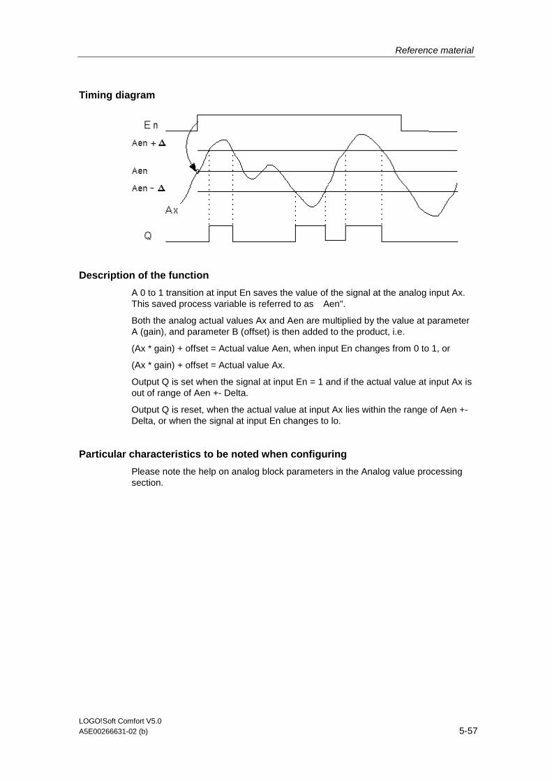
Reference material
LOGO!Soft Comfort V5.0 A5E00266631-02 (b) 5-57
Timing diagram
Description of the function
A 0 to 1 transition at input En saves the value of the signal at the analog input Ax. �
This saved process variable is referred to as Aen".
Both the analog actual values Ax and Aen are multiplied by the value at parameter A (gain), and parameter B (offset) is then added to the product, i.e.
(Ax * gain) + offset = Actual value Aen, when input En changes from 0 to 1, or
(Ax * gain) + offset = Actual value Ax.
Output Q is set when the signal at input En = 1 and if the actual value at input Ax is out of range of Aen +- Delta.
Output Q is reset, when the actual value at input Ax lies within the range of Aen +- Delta, or when the signal at input En changes to lo.
Particular characteristics to be noted when configuring
Please note the help on analog block parameters in the Analog value processing section.

Reference material
LOGO!Soft Comfort V5.0 5-58 A5E00266631-02 (b)
5.3.4.5 Analog amplifier
Short description
This SFB amplifies an analog input value and returns it at the analog output.
Connection Description
Input Ax Input the analog signal to be amplified at input Ax.
Use the analog inputs AI1...AI8, the analog flags AM1...AM6, the block number of a function with analog output, or the analog outputs AQ1 and AQ2.
AI1..AI8: 0 - 10 V corresponds with 0 - 1000 (internal value).
Parameter A: Gain Range of values: +- 10.00
B: Zero offset Range of values: +- 10000
p: Number of decimals Range of values: 0, 1, 2, 3
Output AQ Analog output
Value range for AQ: -32768...+32767
0BA4:
A: Gain
Range of values 0.00...10.00
Parameter p (number of decimals)
Applies only to the display of Ax and Ay values in a message text.
Does not apply to the comparison of On and Off values! (The compare function ignores the decimal point.)
Description of the function
The function reads the value of an analog signal at the analog input Ax.
This value is multiplied by the gain parameter A. Parameter B (offset) is added to the product, i.e.
(Ax * gain) + offset = Actual value Ax.
The actual value Ax is output at AQ.
Particular characteristics to be noted when configuring
For help on analog block parameters, refer to the Analog value processing section.

Reference material
LOGO!Soft Comfort V5.0 A5E00266631-02 (b) 5-59
Analog output
If you connect this special function to a real analog output, then note that the analog output can only process values from 0 to 1000. To do this, connect an additional amplifier between the analog output of the special function and the real analog output. With this amplifier you standardize the output range of the special function to a value range of 0 to 1000.
Example: additional amplifier behind an analog multiplexer.
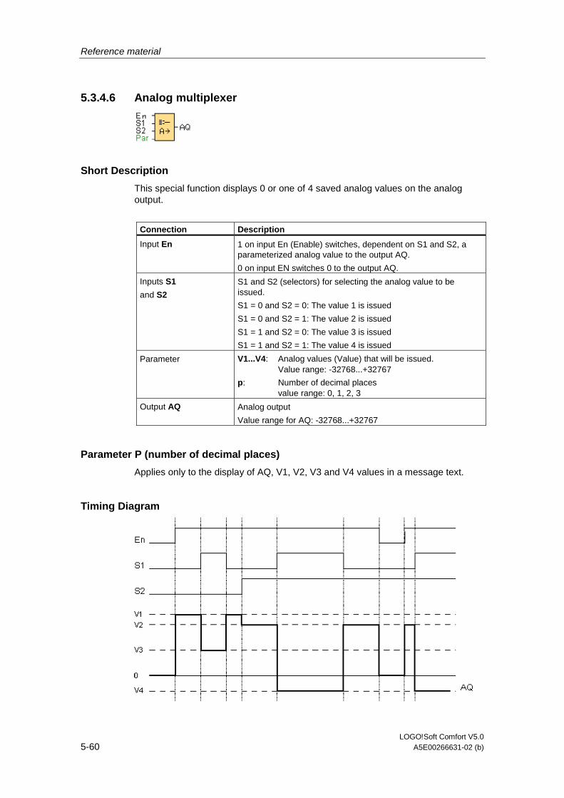
Reference material
LOGO!Soft Comfort V5.0 5-60 A5E00266631-02 (b)
5.3.4.6 Analog multiplexer
Short Description
This special function displays 0 or one of 4 saved analog values on the analog output.
Connection Description
Input En 1 on input En (Enable) switches, dependent on S1 and S2, a parameterized analog value to the output AQ.
0 on input EN switches 0 to the output AQ.
Inputs S1
and S2
S1 and S2 (selectors) for selecting the analog value to be issued.
S1 = 0 and S2 = 0: The value 1 is issued
S1 = 0 and S2 = 1: The value 2 is issued
S1 = 1 and S2 = 0: The value 3 is issued
S1 = 1 and S2 = 1: The value 4 is issued
Parameter V1...V4: Analog values (Value) that will be issued. Value range: -32768...+32767
p: Number of decimal places value range: 0, 1, 2, 3
Output AQ Analog output
Value range for AQ: -32768...+32767
Parameter P (number of decimal places)
Applies only to the display of AQ, V1, V2, V3 and V4 values in a message text.
Timing Diagram

Reference material
LOGO!Soft Comfort V5.0 A5E00266631-02 (b) 5-61
Description of Function
If input En is set, then the function issues one of 4 possible analog values V1 to V4 at the output AQ, depending on the parameters S1 and S2.
If the input En is not set, then the function issues the analog value 0 at output AQ.
Particular characteristics to be noted when configuring
For help on analog block parameters, refer to the Analog value processing section.
Analog output
If you connect this special function to a real analog output, then note that the analog output can only process values from 0 to 1000. To do this, connect an additional amplifier between the analog output of the special function and the real analog output. With this amplifier you standardize the output range of the special function to a value range of 0 to 1000.
Example: additional amplifier behind an analog multiplexer.
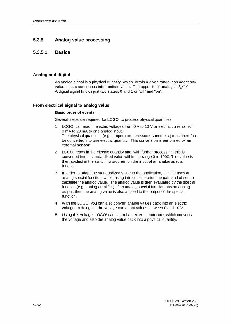
Reference material
LOGO!Soft Comfort V5.0 5-62 A5E00266631-02 (b)
5.3.5 Analog value processing
5.3.5.1 Basics
Analog and digital
An analog signal is a physical quantity, which, within a given range, can adopt any value – i.e. a continuous intermediate value. The opposite of analog is digital. A digital signal knows just two states: 0 and 1 or "off" and "on".
From electrical signal to analog value
Basic order of events
Several steps are required for LOGO! to process physical quantities:
1. LOGO! can read in electric voltages from 0 V to 10 V or electric currents from 0 mA to 20 mA to one analog input. The physical quantities (e.g. temperature, pressure, speed etc.) must therefore be converted into one electric quantity. This conversion is performed by an external sensor.
2. LOGO! reads in the electric quantity and, with further processing, this is converted into a standardized value within the range 0 to 1000. This value is then applied in the switching program on the input of an analog special function.
3. In order to adapt the standardized value to the application, LOGO! uses an analog special function, while taking into consideration the gain and offset, to calculate the analog value. The analog value is then evaluated by the special function (e.g. analog amplifier). If an analog special function has an analog output, then the analog value is also applied to the output of the special function.
4. With the LOGO! you can also convert analog values back into an electric voltage. In doing so, the voltage can adopt values between 0 and 10 V.
5. Using this voltage, LOGO! can control an external actuator, which converts the voltage and also the analog value back into a physical quantity.
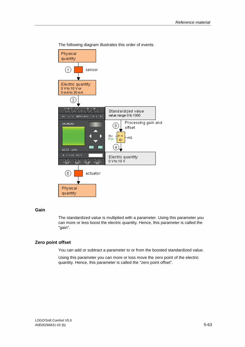
Reference material
LOGO!Soft Comfort V5.0 A5E00266631-02 (b) 5-63
The following diagram illustrates this order of events.
Gain
The standardized value is multiplied with a parameter. Using this parameter you can more or less boost the electric quantity. Hence, this parameter is called the "gain".
Zero point offset
You can add or subtract a parameter to or from the boosted standardized value.
Using this parameter you can more or loss move the zero point of the electric quantity. Hence, this parameter is called the "zero point offset".

Reference material
LOGO!Soft Comfort V5.0 5-64 A5E00266631-02 (b)
Gain and offset
The analog value is therefore calculated as follows:
Analog value = (standardized value x gain) + offset
The following diagram illustrates this formula and the significance of gain and offset:
The straight line in the graphic describes which standardized value is being converted into which analog value. Gain corresponds to the slope of the straight line and offset to the movement of the zero passage of the straight line on the y-axis.
Analog output
If you connect a special function (that has an analog output) to a real analog output, then note that the analog output can only process values from 0 to 1000.
Setting possibilities with LOGO!Soft Comfort
Setting possibilities with LOGO!
Example
Heating control
0BA0 to 0BA4
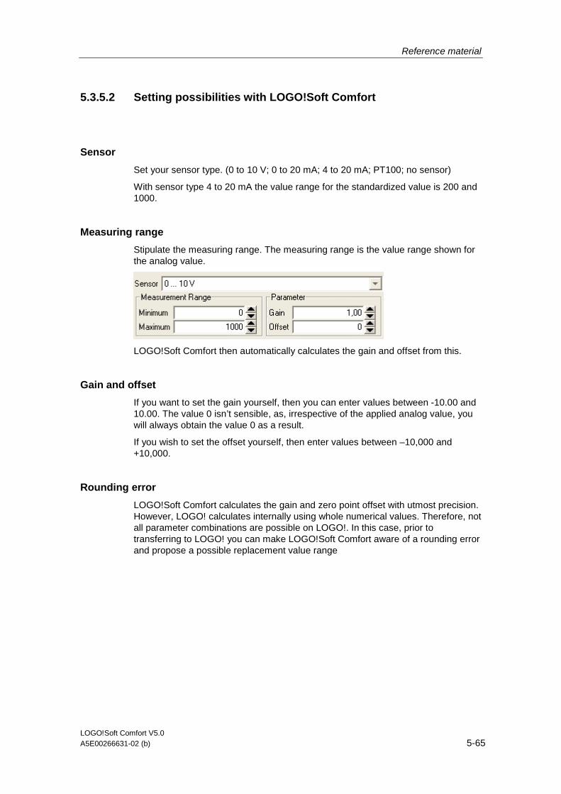
Reference material
LOGO!Soft Comfort V5.0 A5E00266631-02 (b) 5-65
5.3.5.2 Setting possibilities with LOGO!Soft Comfort
Sensor
Set your sensor type. (0 to 10 V; 0 to 20 mA; 4 to 20 mA; PT100; no sensor)
With sensor type 4 to 20 mA the value range for the standardized value is 200 and 1000.
Measuring range
Stipulate the measuring range. The measuring range is the value range shown for the analog value.
LOGO!Soft Comfort then automatically calculates the gain and offset from this.
Gain and offset
If you want to set the gain yourself, then you can enter values between -10.00 and 10.00. The value 0 isn’t sensible, as, irrespective of the applied analog value, you will always obtain the value 0 as a result.
If you wish to set the offset yourself, then enter values between –10,000 and +10,000.
Rounding error
LOGO!Soft Comfort calculates the gain and zero point offset with utmost precision. However, LOGO! calculates internally using whole numerical values. Therefore, not all parameter combinations are possible on LOGO!. In this case, prior to transferring to LOGO! you can make LOGO!Soft Comfort aware of a rounding error and propose a possible replacement value range
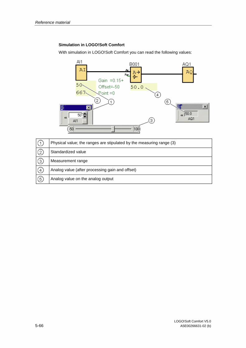
Reference material
LOGO!Soft Comfort V5.0 5-66 A5E00266631-02 (b)
Simulation in LOGO!Soft Comfort
With simulation in LOGO!Soft Comfort you can read the following values:
Physical value; the ranges are stipulated by the measuring range (3)
Standardized value
Measurement range
Analog value (after processing gain and offset)
Analog value on the analog output
Reference material
LOGO!Soft Comfort V5.0 A5E00266631-02 (b) 5-67
5.3.5.3 Setting possibilities with LOGO!
If you directly program your switching program on the LOGO!, then you can only enter the gain and offset parameters. You can calculate the gain and offset as follows:
External value range minSensor - maxSensor
Range of a physical quantity that the sensor can measure.
Standardized value range minnorm - maxnorm:
Value range of the standardized values.
With sensors that provide 0 to 10 V or 0 to 20 mA, the standardized value range is 0 – 1000.
With sensors that provide 4 to 20 mA, the standardized range is 200 – 1000.
So for gain and offset it follows:
Gain = (maxSensor - minSensor) / (maxnorm – minnorm)
Offset = [(minSensor x maxnorm) – (maxSensor x minnorm)] / (maxnorm – minnorm)
If you have calculated either the gain or the offset in accordance with the formulae above, you can then calculate the respective other value in accordance with the following formula:
Gain = (minSensor - Offset) / minnorm
Offset = (minSensor – (Gain x minnorm)
Reference material
LOGO!Soft Comfort V5.0 5-68 A5E00266631-02 (b)
5.3.5.4 Example
Prerequisites
Sensor: temperature sensor, measuring range –50 to 100°C
Temperature to be measured 25°C
Order of events with LOGO!Soft Comfort
1. The sensor converts the temperature from 25°C to a voltage value of 5.0 V.
2. LOGO! converts the 5.0 V to the standardized value 500.
3. Using the sensor and measuring range data, LOGO! ascertains for the gain the value 0.15 and for the offset the value –50. According to the formula Analog value = (standardized value x gain) + offset LOGO! calculates as analog value: Analog value = (500 x 0.15) - 50 = 25
Order of events with LOGO!
1. The sensor converts the temperature from 25°C to a voltage value of 5.0 V.
2. LOGO! converts the 5.0 V to the standardized value 500.
3. From the sensor and measuring range data you must establish the values for gain and offset. According to the formulae: Gain = (maxSensor - minSensor) / (maxnorm – minnorm) and Offset = minSensor – (Gain x minnorm) it follows that Gain = (100 – (-50)) / (1000 – 0) = 0.15 Offset = -50 – (0.15 x 0) = -50
4. According to the formula Analog value = (standardized value x gain) + offset LOGO! calculates as analog value: Analog value = (500 x 0.15) - 50 = 25
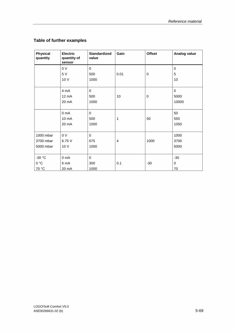
Reference material
LOGO!Soft Comfort V5.0 A5E00266631-02 (b) 5-69
Table of further examples
Physical quantity
Electric quantity of sensor
Standardized value
Gain Offset Analog value
0 V
5 V
10 V
0
500
1000
0.01
0
0
5
10
4 mA
12 mA
20 mA
0
500
1000
10
0
0
5000
10000
0 mA
10 mA
20 mA
0
500
1000
1
50
50
550
1050
1000 mbar
3700 mbar
5000 mbar
0 V
6.75 V
10 V
0
675
1000
4
1000
1000
3700
5000
-30 °C
0 °C
70 °C
0 mA
6 mA
20 mA
0
300
1000
0.1
-30
-30
0
70
Reference material
LOGO!Soft Comfort V5.0 5-70 A5E00266631-02 (b)
5.3.5.5 0BA0 to 0BA4
Restriction for device family 0BA4
Gain cannot assign negative values.
Calculation with the device families 0BA0 to 0BA3
With LOGO! devices from these device families the parameter offset is added or subtracted to or from the standardized value before the value is multiplied with the parameter gain.
Hence, the following formulae apply:
Analog value = (standardized value + offset) x (gain x 100)
Gain (in percent) = (maxSensor - minSensor) / [(maxnorm – minnorm) x 100]
Offset = [(minSensor x maxnorm) – (maxSensor x minnorm)] / (maxSensor – minSensor)
Gain (in percent) = minSensor / [(minnorm + offset) x 100]
Offset = [maxSensor / (gain x 100)] - maxnorm
Gain
This parameter is given in %.
Gain cannot assign negative values.
Zero point offset
Here you can enter values between -999 and + 999.
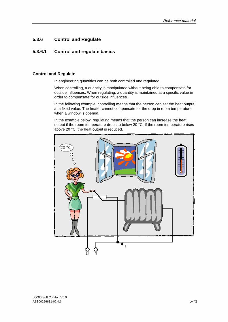
Reference material
LOGO!Soft Comfort V5.0 A5E00266631-02 (b) 5-71
5.3.6 Control and Regulate
5.3.6.1 Control and regulate basics
Control and Regulate
In engineering quantities can be both controlled and regulated.
When controlling, a quantity is manipulated without being able to compensate for outside influences. When regulating, a quantity is maintained at a specific value in order to compensate for outside influences.
In the following example, controlling means that the person can set the heat output at a fixed value. The heater cannot compensate for the drop in room temperature when a window is opened.
In the example below, regulating means that the person can increase the heat output if the room temperature drops to below 20 °C. If the room temperature rises above 20 °C, the heat output is reduced.
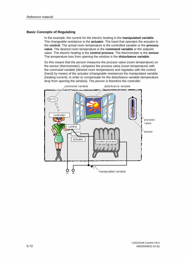
Reference material
LOGO!Soft Comfort V5.0 5-72 A5E00266631-02 (b)
Basic Concepts of Regulating
In the example, the current for the electric heating is the manipulated variable. The changeable resistance is the actuator. The hand that operates the actuator is the control. The actual room temperature is the controlled variable or the process value. The desired room temperature is the command variable or the setpoint value. The electric heating is the control process. The thermometer is the sensor. The temperature loss from opening the window is the disturbance variable.
So this means that the person measures the process value (room temperature) on the sensor (thermometer), compares the process value (room temperature) with the command variable (desired room temperature) and regulates with the control (hand) by means of the actuator (changeable resistance) the manipulated variable (heating current), in order to compensate for the disturbance variable (temperature drop from opening the window). The person is therefore the controller.
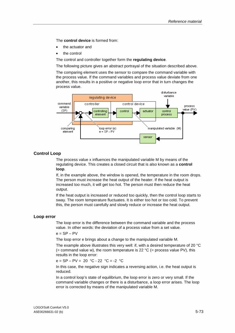
Reference material
LOGO!Soft Comfort V5.0 A5E00266631-02 (b) 5-73
The control device is formed from:
• the actuator and
• the control
The control and controller together form the regulating device.
The following picture gives an abstract portrayal of the situation described above.
The comparing element uses the sensor to compare the command variable with the process value. If the command variables and process value deviate from one another, this results in a positive or negative loop error that in turn changes the process value.
Control Loop The process value x influences the manipulated variable M by means of the regulating device. This creates a closed circuit that is also known as a control loop.
If, in the example above, the window is opened, the temperature in the room drops. The person must increase the heat output of the heater. If the heat output is increased too much, it will get too hot. The person must then reduce the heat output.
If the heat output is increased or reduced too quickly, then the control loop starts to sway. The room temperature fluctuates. It is either too hot or too cold. To prevent this, the person must carefully and slowly reduce or increase the heat output.
Loop error The loop error is the difference between the command variable and the process value. In other words: the deviation of a process value from a set value.
e = SP – PV
The loop error e brings about a change to the manipulated variable M.
The example above illustrates this very well: if, with a desired temperature of 20 °C (= command value w), the room temperature is 22 °C (= process value PV), this results in the loop error:
e = SP – PV = 20 °C - 22 °C = -2 °C
In this case, the negative sign indicates a reversing action, i.e. the heat output is reduced.
In a control loop’s state of equilibrium, the loop error is zero or very small. If the command variable changes or there is a disturbance, a loop error arises. The loop error is corrected by means of the manipulated variable M.
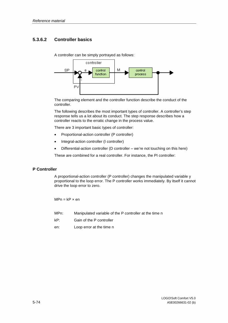
Reference material
LOGO!Soft Comfort V5.0 5-74 A5E00266631-02 (b)
5.3.6.2 Controller basics
A controller can be simply portrayed as follows:
The comparing element and the controller function describe the conduct of the controller.
The following describes the most important types of controller. A controller’s step response tells us a lot about its conduct. The step response describes how a controller reacts to the erratic change in the process value.
There are 3 important basic types of controller:
• Proportional-action controller (P controller)
• Integral-action controller (I controller)
• Differential-action controller (D controller – we’re not touching on this here)
These are combined for a real controller. For instance, the PI controller:
P Controller
A proportional-action controller (P controller) changes the manipulated variable y proportional to the loop error. The P controller works immediately. By itself it cannot drive the loop error to zero.
MPn = kP × en
MPn: Manipulated variable of the P controller at the time n
kP: Gain of the P controller
en: Loop error at the time n
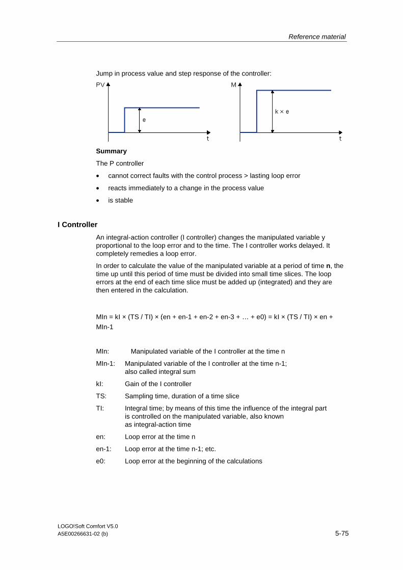
Reference material
LOGO!Soft Comfort V5.0 A5E00266631-02 (b) 5-75
Jump in process value and step response of the controller:
Summary
The P controller
• cannot correct faults with the control process > lasting loop error
• reacts immediately to a change in the process value
• is stable
I Controller
An integral-action controller (I controller) changes the manipulated variable y proportional to the loop error and to the time. The I controller works delayed. It completely remedies a loop error.
In order to calculate the value of the manipulated variable at a period of time n, the time up until this period of time must be divided into small time slices. The loop errors at the end of each time slice must be added up (integrated) and they are then entered in the calculation.
MIn = kI × (TS / TI) × (en + en-1 + en-2 + en-3 + … + e0) = kI × (TS / TI) × en +
MIn-1
MIn: Manipulated variable of the I controller at the time n
MIn-1: Manipulated variable of the I controller at the time n-1; also called integral sum
kI: Gain of the I controller
TS: Sampling time, duration of a time slice
TI: Integral time; by means of this time the influence of the integral part is controlled on the manipulated variable, also known as integral-action time
en: Loop error at the time n
en-1: Loop error at the time n-1; etc.
e0: Loop error at the beginning of the calculations

Reference material
LOGO!Soft Comfort V5.0 5-76 A5E00266631-02 (b)
Jump in process value and step response of the controller:
Summary
The I controller
• sets the process value exactly to the command variable
• in doing so, tends to oscillate > is unstable
• requires more time to carry out the control action than the P controller
PI Controller
A PI controller reduces the loop error immediately and will eventually drive the loop error to zero.
Mn = MPn + MIn = kP × en + kI × (TS / TI) × en + MIn-1
Mn: Manipulated variable at the time n
MPn: Proportional part of the manipulated variable
MIn: Integral part of the manipulated variable
MIn-1: Manipulated variable of the I controller at the time n-1; also called integral sum
kP: Gain of the P controller
kI: Gain of the I controller
TS: Sampling time, duration of a time slice
TI: Integral time; by means of this time the influence of the integral part is controlled on the manipulated variable, also known as the integral-action time
en: Loop error at the time n

Reference material
LOGO!Soft Comfort V5.0 A5E00266631-02 (b) 5-77
Jump in process value and step response of the controller:
Summary
With PI controllers
• the P controller components quickly intercept an occurring loop error
• then the I controller components remedy the remaining loop error
• the controller components supplement each other so that the PI controller works quickly and precisely
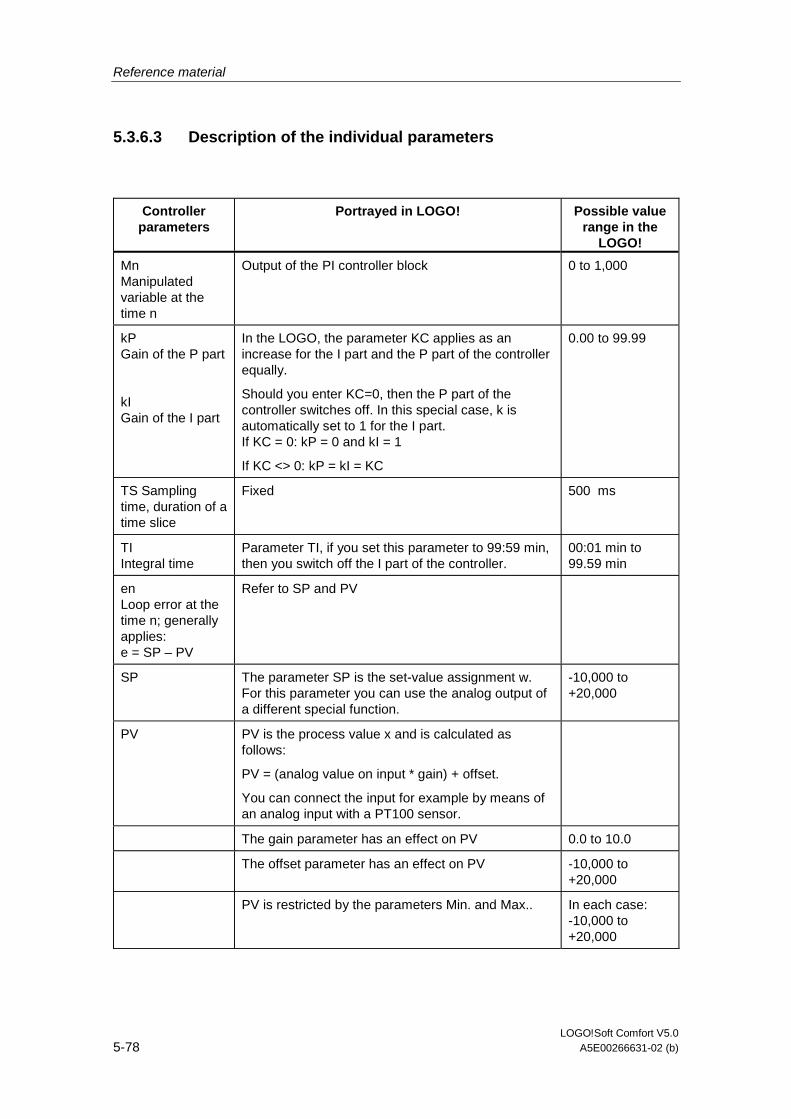
Reference material
LOGO!Soft Comfort V5.0 5-78 A5E00266631-02 (b)
5.3.6.3 Description of the individual parameters
Controller parameters
Portrayed in LOGO! Possible value range in the
LOGO!
Mn Manipulated variable at the time n
Output of the PI controller block 0 to 1,000
kP Gain of the P part
kI Gain of the I part
In the LOGO, the parameter KC applies as an increase for the I part and the P part of the controller equally.
Should you enter KC=0, then the P part of the controller switches off. In this special case, k is automatically set to 1 for the I part. If KC = 0: kP = 0 and kI = 1
If KC <> 0: kP = kI = KC
0.00 to 99.99
TS Sampling time, duration of a time slice
Fixed 500 ms
TI Integral time
Parameter TI, if you set this parameter to 99:59 min, then you switch off the I part of the controller.
00:01 min to 99.59 min
en Loop error at the time n; generally applies: e = SP – PV
Refer to SP and PV
SP The parameter SP is the set-value assignment w. For this parameter you can use the analog output of a different special function.
-10,000 to +20,000
PV PV is the process value x and is calculated as follows:
PV = (analog value on input * gain) + offset.
You can connect the input for example by means of an analog input with a PT100 sensor.
The gain parameter has an effect on PV 0.0 to 10.0
The offset parameter has an effect on PV -10,000 to +20,000
PV is restricted by the parameters Min. and Max.. In each case: -10,000 to +20,000
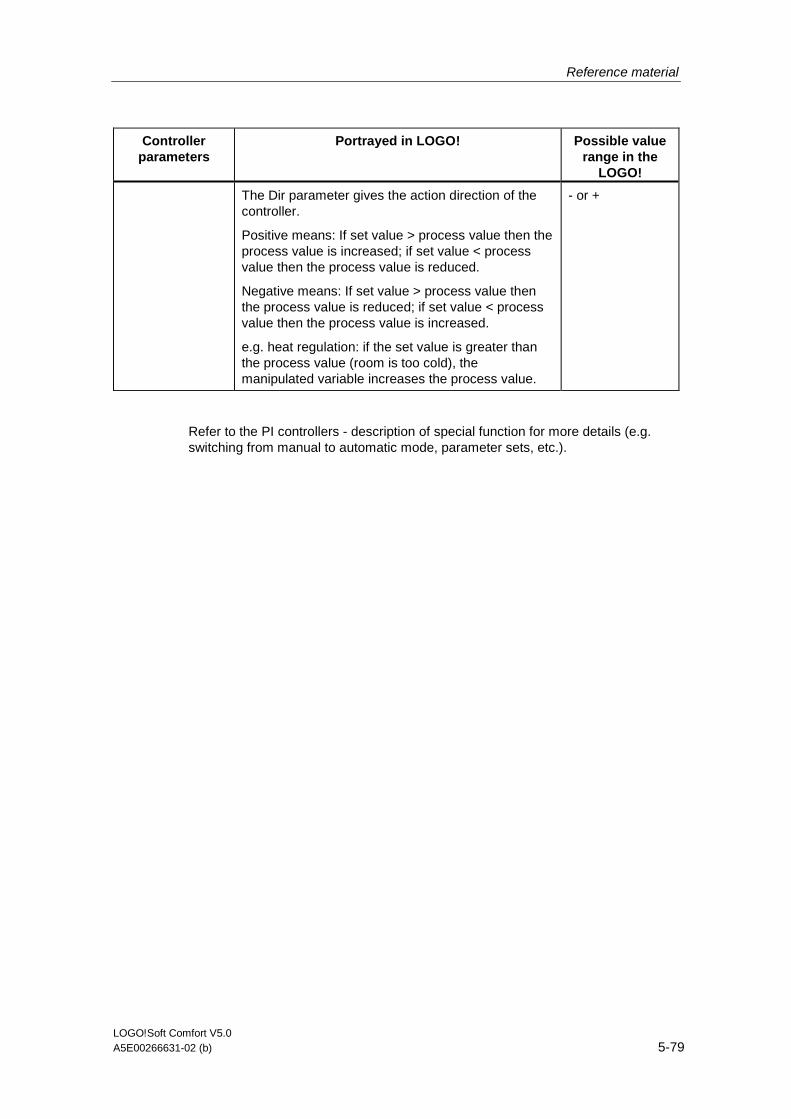
Reference material
LOGO!Soft Comfort V5.0 A5E00266631-02 (b) 5-79
Controller parameters
Portrayed in LOGO! Possible value range in the
LOGO!
The Dir parameter gives the action direction of the controller.
Positive means: If set value > process value then the process value is increased; if set value < process value then the process value is reduced.
Negative means: If set value > process value then the process value is reduced; if set value < process value then the process value is increased.
e.g. heat regulation: if the set value is greater than the process value (room is too cold), the manipulated variable increases the process value.
- or +
Refer to the PI controllers - description of special function for more details (e.g. switching from manual to automatic mode, parameter sets, etc.).
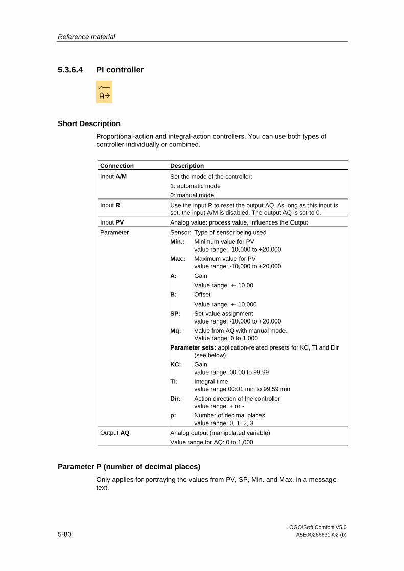
Reference material
LOGO!Soft Comfort V5.0 5-80 A5E00266631-02 (b)
5.3.6.4 PI controller
Short Description
Proportional-action and integral-action controllers. You can use both types of controller individually or combined.
Connection Description
Input A/M Set the mode of the controller:
1: automatic mode
0: manual mode
Input R Use the input R to reset the output AQ. As long as this input is set, the input A/M is disabled. The output AQ is set to 0.
Input PV Analog value: process value, Influences the Output
Parameter Sensor: Type of sensor being used
Min.: Minimum value for PV value range: -10,000 to +20,000
Max.: Maximum value for PV value range: -10,000 to +20,000
A: Gain
Value range: +- 10.00
B: Offset
Value range: +- 10,000
SP: Set-value assignment value range: -10,000 to +20,000
Mq: Value from AQ with manual mode. Value range: 0 to 1,000
Parameter sets: application-related presets for KC, TI and Dir (see below)
KC: Gain value range: 00.00 to 99.99
TI: Integral time value range 00:01 min to 99:59 min
Dir: Action direction of the controller value range: + or -
p: Number of decimal places value range: 0, 1, 2, 3
Output AQ Analog output (manipulated variable)
Value range for AQ: 0 to 1,000
Parameter P (number of decimal places)
Only applies for portraying the values from PV, SP, Min. and Max. in a message text.
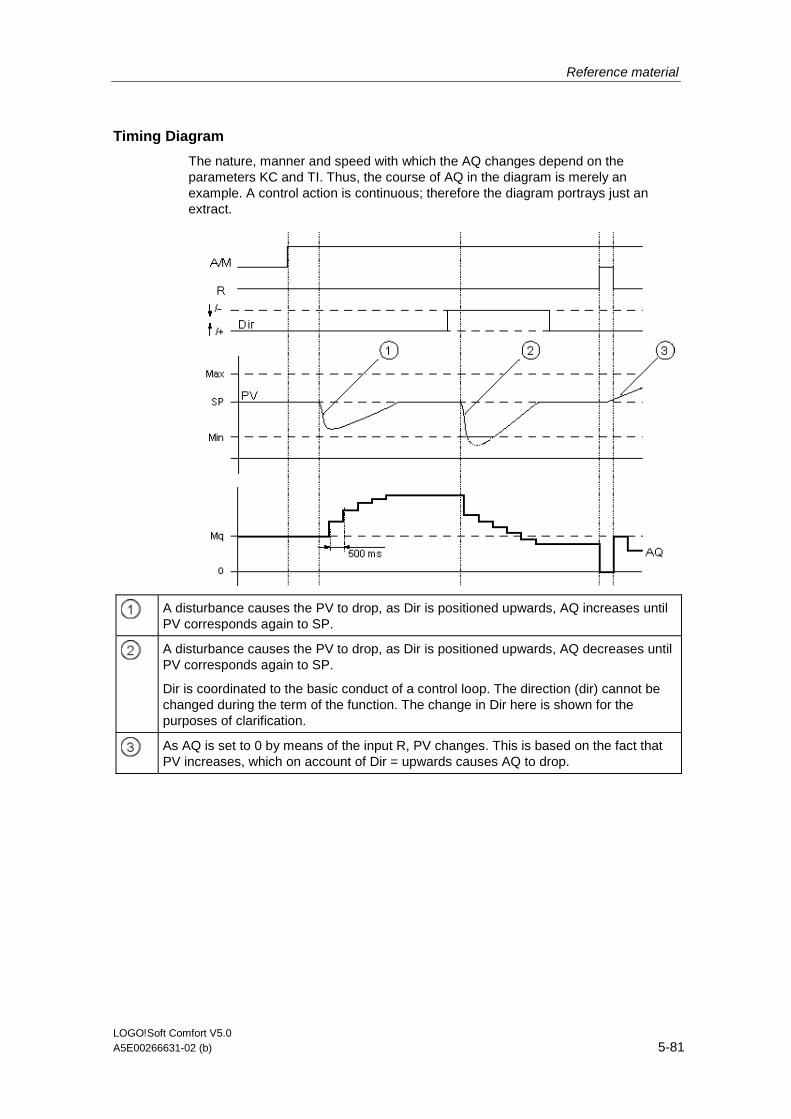
Reference material
LOGO!Soft Comfort V5.0 A5E00266631-02 (b) 5-81
Timing Diagram
The nature, manner and speed with which the AQ changes depend on the parameters KC and TI. Thus, the course of AQ in the diagram is merely an example. A control action is continuous; therefore the diagram portrays just an extract.
A disturbance causes the PV to drop, as Dir is positioned upwards, AQ increases until PV corresponds again to SP.
A disturbance causes the PV to drop, as Dir is positioned upwards, AQ decreases until PV corresponds again to SP.
Dir is coordinated to the basic conduct of a control loop. The direction (dir) cannot be changed during the term of the function. The change in Dir here is shown for the purposes of clarification.
As AQ is set to 0 by means of the input R, PV changes. This is based on the fact that PV increases, which on account of Dir = upwards causes AQ to drop.

Reference material
LOGO!Soft Comfort V5.0 5-82 A5E00266631-02 (b)
Description of Function
If the input A/M is set to 0, then the special function issues output AQ with the value that you set with parameter Mq.
If the input A/M is set to 1, then automatic mode commences. As an integral sum the value Mq is adopted, the controller function begins the calculations in accordance with the formulas given in Control and regulate basics. The updated value PV is used to calculate in the formulas.
Updated value PV = (PV * gain) + offset
If the updated value PV = SP, then the special function does not change the value of AQ.
Dir = upwards/+ (timing diagram numbers 1 and 3)
• If the updated value PV > SP, then the special function reduces the value of AQ.
• If the updated value PV < SP, then the special function increases the value of AQ.
Dir = downwards/- (timing diagram number 2)
• If the updated value PV > SP, then the special function increases the value of AQ.
• If the updated value PV < SP, then the special function reduces the value of AQ.
With a disturbance, AQ continues to increase / decrease until the updated value PV again corresponds to SP. The speed with which AQ changes depends on the parameters KC and TI.
If the input PV exceeds the parameter Max., then the updated value PV is set to the value of Max.. If the PV falls short of the parameter Min., then the updated value PV is set to the value of Min.
If the input R is set to 1, then the AQ output is reset. As long as R is set, the input A/M is disabled.
Sampling Time
The sampling time is fixed at 500 ms.
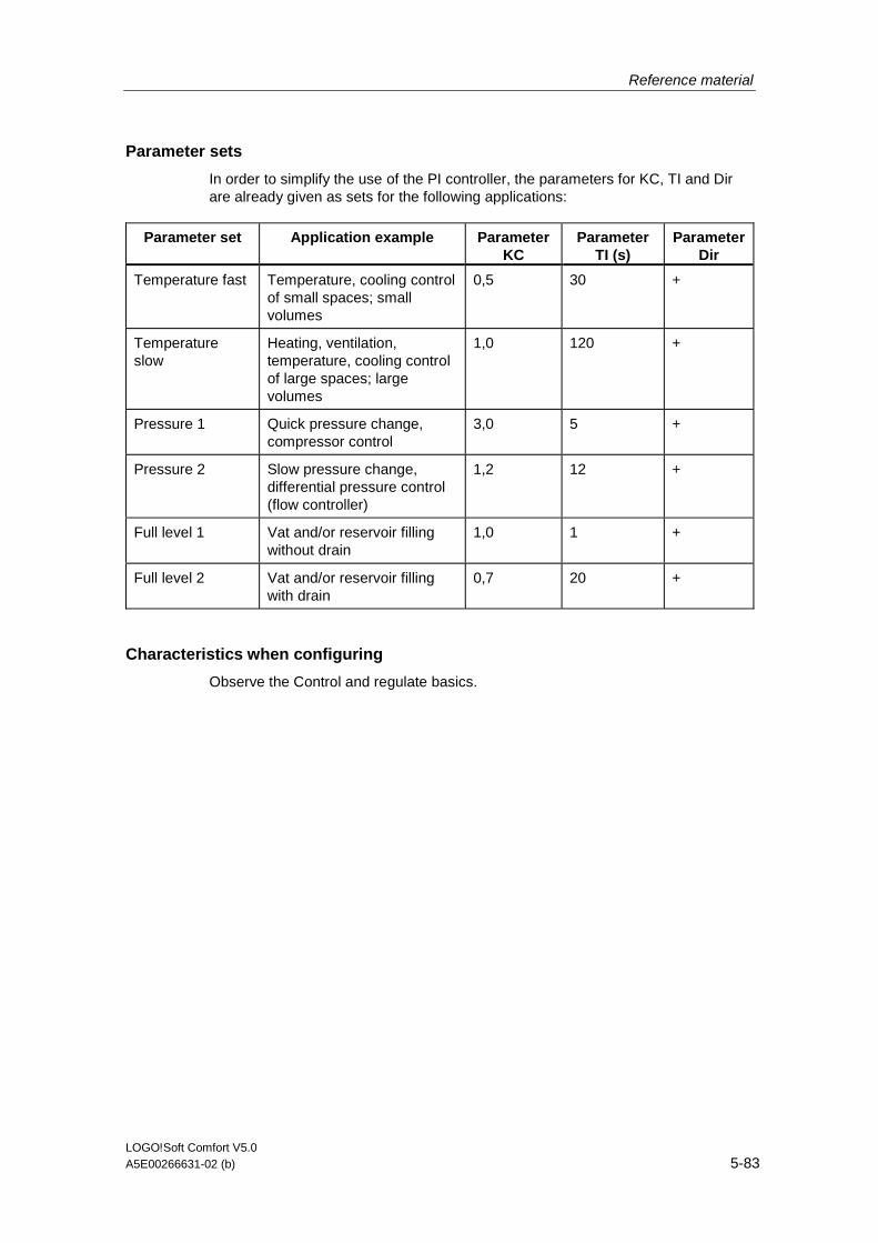
Reference material
LOGO!Soft Comfort V5.0 A5E00266631-02 (b) 5-83
Parameter sets
In order to simplify the use of the PI controller, the parameters for KC, TI and Dir are already given as sets for the following applications:
Parameter set Application example Parameter KC
Parameter TI (s)
Parameter Dir
Temperature fast Temperature, cooling control of small spaces; small volumes
0,5 30 +
Temperature slow
Heating, ventilation, temperature, cooling control of large spaces; large volumes
1,0 120 +
Pressure 1 Quick pressure change, compressor control
3,0 5 +
Pressure 2 Slow pressure change, differential pressure control (flow controller)
1,2 12 +
Full level 1 Vat and/or reservoir filling without drain
1,0 1 +
Full level 2 Vat and/or reservoir filling with drain
0,7 20 +
Characteristics when configuring
Observe the Control and regulate basics.
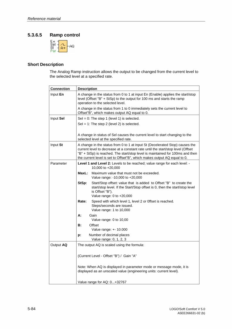
Reference material
5-84 LOGO!Soft Comfort V 5.0 A5EE266631-02 (b)
5.3.6.5 Ramp control
Short Description The Analog Ramp instruction allows the output to be changed from the current level to the selected level at a specified rate.
Connection Description Input En A change in the status from 0 to 1 at input En (Enable) applies the start/stop
level (Offset "B" + StSp) to the output for 100 ms and starts the ramp operation to the selected level. A change in the status from 1 to 0 immediately sets the current level to Offset"B", which makes output AQ equal to 0.
Input Sel SeI = 0: The step 1 (level 1) is selected. SeI = 1: The step 2 (level 2) is selected. A change in status of Sel causes the current level to start changing to the selected level at the specified rate.
Input St A change in the status from 0 to 1 at input St (Decelerated Stop) causes the current level to decrease at a constant rate until the start/stop level (Offset "B" + StSp) is reached. The start/stop level is maintained for 100ms and then the current level is set to Offset"B", which makes output AQ equal to 0.
Parameter Level 1 and Level 2: Levels to be reached; value range for each level: -10,000 to +20,000
MaxL: Maximum value that must not be exceeded. Value range: -10,000 to +20,000
StSp: Start/Stop offset: value that is added to Offset "B" to create the start/stop level. If the Start/Stop offset is 0, then the start/stop level is Offset "B"). Value range: 0 to +20,000
Rate: Speed with which level 1, level 2 or 0ffset is reached. Steps/seconds are issued. Value range: 1 to 10,000
A: Gain Value range: 0 to 10,00
B: Offset Value range: +- 10.000
p: Number of decimal places Value range: 0, 1, 2, 3
Output AQ The output AQ is scaled using the formula: (Current Level - Offset "B") / Gain "A" Note: When AQ is displayed in parameter mode or message mode, it is displayed as an unscaled value (engineering units: current level). Value range for AQ: 0...+32767
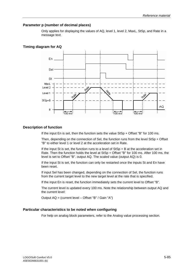
Reference material
LOGO!Soft Comfort V5.0 5-85 A5E00266631001 (b)
Parameter p (number of decimal places) Only applies for displaying the values of AQ, level 1, level 2, MaxL, StSp, and Rate in a message text.
Timing diagram for AQ
Description of function If the input En is set, then the function sets the value StSp + Offset "B" for 100 ms.
Then, depending on the connection of Sel, the function runs from the level StSp + Offset "B" to either level 1 or level 2 at the acceleration set in Rate.
If the input St is set, the function runs to a level of StSp + B at the acceleration set in Rate. Then the function holds the level at StSp + Offset "B" for 100 ms. After 100 ms, the level is set to Offset "B". output AQ. The scaled value (output AQ) is 0.
If the input St is set, the function can only be restarted once the inputs St and En have been reset.
If input Sel has been changed, depending on the connection of Sel, the function runs from the current target level to the new target level at the rate that is specified.
If the input En is reset, the function immediately sets the current level to Offset "B".
The current level is updated every 100 ms. Note the relationship between output AQ and the current level:
Output AQ = (current level – Offset "B" / Gain "A")
Particular characteristics to be noted when configuring For help on analog block parameters, refer to the Analog value processing section.
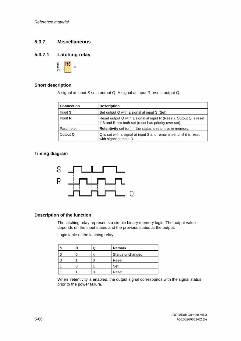
Reference material
LOGO!Soft Comfort V5.0 5-86 A5E00266631-02 (b)
5.3.7 Miscellaneous
5.3.7.1 Latching relay
Short description
A signal at input S sets output Q. A signal at input R resets output Q.
Connection Description
Input S Set output Q with a signal at input S (Set).
Input R Reset output Q with a signal at input R (Reset). Output Q is reset if S and R are both set (reset has priority over set).
Parameter Retentivity set (on) = the status is retentive in memory.
Output Q Q is set with a signal at input S and remains set until it is reset with signal at input R.
Timing diagram
Description of the function
The latching relay represents a simple binary memory logic. The output value depends on the input states and the previous status at the output.
Logic table of the latching relay:
S R Q Remark
0 0 x Status unchanged
0 1 0 Reset
1 0 1 Set
1 1 0 Reset
When retentivity is enabled, the output signal corresponds with the signal status prior to the power failure.
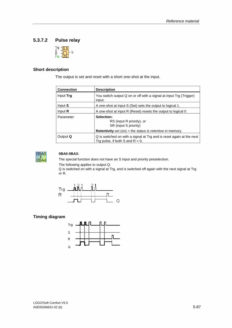
Reference material
LOGO!Soft Comfort V5.0 A5E00266631-02 (b) 5-87
5.3.7.2 Pulse relay
Short description
The output is set and reset with a short one-shot at the input.
Connection Description
Input Trg You switch output Q on or off with a signal at input Trg (Trigger) input.
Input S A one-shot at input S (Set) sets the output to logical 1.
Input R A one-shot at input R (Reset) resets the output to logical 0
Parameter Selection: RS (input R priority), or SR (input S priority)
Retentivity set (on) = the status is retentive in memory.
Output Q Q is switched on with a signal at Trg and is reset again at the next Trg pulse, if both S and R = 0.
0BA0-0BA3:
The special function does not have an S input and priority preselection.
The following applies to output Q: Q is switched on with a signal at Trg, and is switched off again with the next signal at Trg or R.
Timing diagram

Reference material
LOGO!Soft Comfort V5.0 5-88 A5E00266631-02 (b)
Description of the function
The status of output Q changes with each 0 to 1 transition at input Trg and if both S and R = 0, i.e. the output is switched on or off.
Input Trg does not influence the SFB when S = 1 or R = 1.
A one-shot at input S sets the pulse relay, i.e. the output is set to logical 1.
A one-shot at input R resets the pulse relay to its initial state, i.e. the output is set to logical 0.
Either the input R takes priority over input S (i.e. the signal at input S has no effect as long as R = 1), or the input S takes priority over input R (i.e. the signal at input R has no effect as long as S = 1), depending on your configuration.
0BA0-0BA3:
The valid function is:
The status at output Q is toggled with each 0 to 1 transition at input Trg, i.e. the output is switched on or off.
You reset the pulse relay to its initial state with a one-shot at input, i.e. the output is reset to 0.
The pulse relay is reset and output Q = 0 after power on or by a reset signal.
Caution
If Trg = 0 and Par = RS, the "Pulse relay" SFB corresponds with the "Latching relay" SFB function.
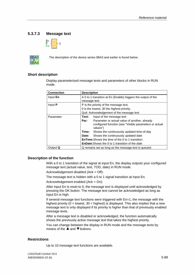
Reference material
LOGO!Soft Comfort V5.0 A5E00266631-02 (b) 5-89
5.3.7.3 Message text
The description of the device series 0BA3 and earlier is found below.
Short description
Display parameterized message texts and parameters of other blocks in RUN mode.
Connection Description
Input En A 0 to 1 transition at En (Enable) triggers the output of the message text.
Input P P is the priority of the message text. 0 is the lowest, 30 the highest priority. Quit: Acknowledgement of the message text
Parameter Text: Input of the message text Par: Parameter or actual value of another, already
configured function (see "Visible parameters or actual values")
Time: Shows the continuously updated time-of-day Date: Shows the continuously updated date EnTime:Shows the time of the 0 to 1 transition EnDate:Shows the 0 to 1 transition of the date
Output Q Q remains set as long as the message text is queued.
Description of the function With a 0 to 1 transition of the signal at input En, the display outputs your configured message text (actual value, text, TOD, date) in RUN mode.
Acknowledgement disabled (Ack = Off):
The message text is hidden with a 0 to 1 signal transition at input En.
Acknowledgement enabled (Ack = On):
After input En is reset to 0, the message text is displayed until acknowledged by pressing the OK button. The message text cannot be acknowledged as long as input En is high.
If several message text functions were triggered with En=1, the message with the highest priority (0 = lowest, 30 = highest) is displayed. This also implies that a new message text is only displayed if its priority is higher than that of previously enabled message texts.
After a message text is disabled or acknowledged, the function automatically shows the previously active message text that takes the highest priority.
You can change between the display in RUN mode and the message texts by means of the and buttons.
Restrictions
Up to 10 message text functions are available.
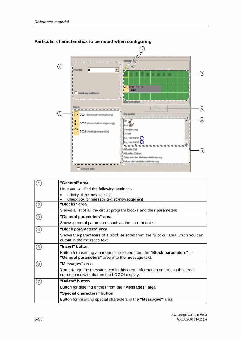
Reference material
LOGO!Soft Comfort V5.0 5-90 A5E00266631-02 (b)
Particular characteristics to be noted when configuring
"General" area
Here you will find the following settings:· • Priority of the message text • Check box for message text acknowledgement
"Blocks" area
Shows a list of all the circuit program blocks and their parameters.
"General parameters" area
Shows general parameters such as the current date.
"Block parameters" area
Shows the parameters of a block selected from the "Blocks" area which you can output in the message text.
"Insert" button
Button for inserting a parameter selected from the "Block parameters" or "General parameters" area into the message text.
"Messages" area
You arrange the message text in this area. Information entered in this area corresponds with that on the LOGO! display.
"Delete" button
Button for deleting entries from the "Messages" area
"Special characters" button
Button for inserting special characters in the "Messages" area
Reference material
LOGO!Soft Comfort V5.0 A5E00266631-02 (b) 5-91
To arrange the message text
1. From the "Blocks" area, select the block whose parameters you want to output.
2. Drag and drop the parameters required from the "Block parameters" to the "Messages" area. You may also use the "Insert" button to do so.
3. In the "Messages" area, you can add parameter data as required.
Simulation mode
Layout of message texts
0BA0-0BA3:
The following specifications apply:
Short description
Display of a configured message text in RUN mode
Connection Description
Input En The message text is output with a 0 to 1 transition at input En (Enable).
Parameter P P is the priority of the message text.
0 is the lowest, 9 the highest priority.
Parameter Par: Parameter or actual value of another, already programmed function (see "Displayable parameters or actual values")
Output Q Q remains set as long as the message text is queued.
Description of the function
In RUN mode, a 0 to 1 transition of the signal at input En triggers the output of your configured message text on the display. The message text is closed after a 1 to 0 transition at input En and if the acknowledgment attribute is not set. If the acknowledgment attribute is set, the message text is not closed until input En=0 and the message is acknowledged at the LOGO! with OK. The status at output Q remains 1 as long as the message text is displayed.
Of several message text functions triggered with En=1, the one with the highest priority is displayed. Low-priority messages can also by displayed by pressing the
button on the LOGO!.
You can switch between the standard display and the message text display by means of the LOGO! buttons and .
Restrictions
Up to five message text functions are available.

Reference material
LOGO!Soft Comfort V5.0 5-92 A5E00266631-02 (b)
Particular characteristics to be noted when configuring
The message text can be configured in the block properties dialog. You can enter up to 4 lines for each message text (the text display of the LOGO! has four rows) and set the priority. You can move to the next line using the cursor keys or the mouse. Hit the [ENTER] key to confirm all your entries in the block properties dialog and to close the dialog.
You may also enter the actual values of other blocks in the text lines. To do so, select the relevant block from the Block dialog. A Parameter dialog opens to display a list of all parameters available for the selected block. The block parameter you select in this dialog is written to the selected text line. The actual parameter value is now included when you call the message text.
Set the "Acknowledge message" attribute to specify whether a message is be acknowledged before it is closed.
Simulation mode
Layout of message texts
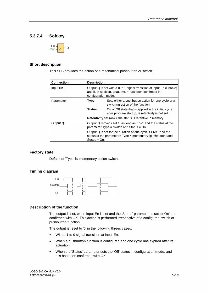
Reference material
LOGO!Soft Comfort V5.0 A5E00266631-02 (b) 5-93
5.3.7.4 Softkey
Short description
This SFB provides the action of a mechanical pushbutton or switch.
Connection Description
Input En Output Q is set with a 0 to 1 signal transition at input En (Enable) and if, in addition, 'Status=On' has been confirmed in configuration mode.
Parameter Type: Sets either a pushbutton action for one cycle or a switching action of the function.
Status: On or Off state that is applied in the initial cycle after program startup, is retentivity is not set.
Retentivity set (on) = the status is retentive in memory.
Output Q Output Q remains set 1, as long as En=1 and the status at the parameter Type = Switch and Status = On.
Output Q is set for the duration of one cycle if EN=1 and the status at the parameters Type = momentary (pushbutton) and Status = On.
Factory state
Default of 'Type' is 'momentary action switch'.
Timing diagram
Description of the function
The output is set, when input En is set and the 'Status' parameter is set to 'On' and confirmed with OK. This action is performed irrespective of a configured switch or pushbutton function.
The output is reset to '0' in the following threes cases:
• With a 1 to 0 signal transition at input En.
• When a pushbutton function is configured and one cycle has expired after its actuation.
• When the 'Status' parameter sets the 'Off' status in configuration mode, and this has been confirmed with OK.

Reference material
LOGO!Soft Comfort V5.0 5-94 A5E00266631-02 (b)
Particular characteristics to be noted when configuring
The softkey can be used both with momentary pushbutton or switching action. At the status parameter you can define the on (actuated) or off state for the switch/pushbutton.
If the softkey is assigned a pushbutton action, the output is always set for the duration of one cycle with a 0 to 1 transition at input En when the pushbutton is in on state, or if the pushbutton state changes from Off to On when En=1.
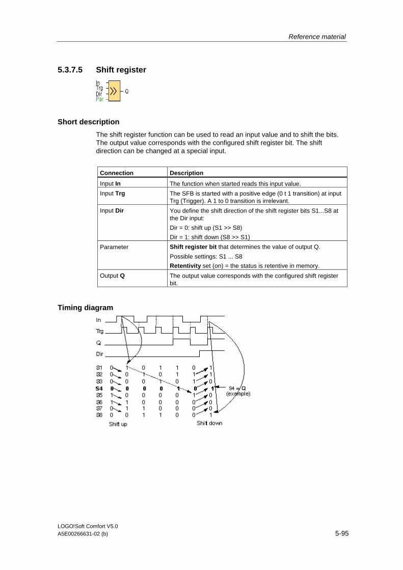
Reference material
LOGO!Soft Comfort V5.0 A5E00266631-02 (b) 5-95
5.3.7.5 Shift register
Short description
The shift register function can be used to read an input value and to shift the bits. The output value corresponds with the configured shift register bit. The shift direction can be changed at a special input.
Connection Description
Input In The function when started reads this input value.
Input Trg The SFB is started with a positive edge (0 t 1 transition) at input Trg (Trigger). A 1 to 0 transition is irrelevant.
Input Dir You define the shift direction of the shift register bits S1...S8 at the Dir input:
Dir = 0: shift up (S1 >> S8)
Dir = 1: shift down (S8 >> S1)
Parameter Shift register bit that determines the value of output Q.
Possible settings: S1 ... S8
Retentivity set (on) = the status is retentive in memory.
Output Q The output value corresponds with the configured shift register bit.
Timing diagram

Reference material
LOGO!Soft Comfort V5.0 5-96 A5E00266631-02 (b)
Description of the function
The function reads the value of input In with a positive edge (0 to 1 transition) at input Trg (Trigger).
This value is written to shift register bits S1 or S8, depending on the set shift direction:
• Shift up: S1 accepts the value of input In; the previous value of S1 is shifted to S2, S2 is shifted to S3, etc.
• Shift down: S8 accepts the value of input In; the previous value of S8 is shifted to S7, S7 is shifted to S6, etc.
Q outputs the value of the configured shift register bits.
If retentivity is not enabled, the shift function restarts at S1 or S8 after a power failure.
Note
The special function shift register can be used only once in the circuit program.
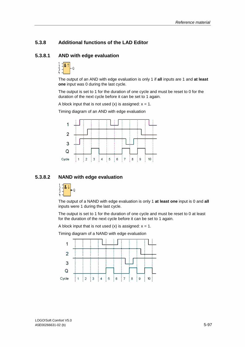
Reference material
LOGO!Soft Comfort V5.0 A5E00266631-02 (b) 5-97
5.3.8 Additional functions of the LAD Editor
5.3.8.1 AND with edge evaluation
The output of an AND with edge evaluation is only 1 if all inputs are 1 and at least one input was 0 during the last cycle.
The output is set to 1 for the duration of one cycle and must be reset to 0 for the duration of the next cycle before it can be set to 1 again.
A block input that is not used (x) is assigned: x = 1.
Timing diagram of an AND with edge evaluation
5.3.8.2 NAND with edge evaluation
The output of a NAND with edge evaluation is only 1 at least one input is 0 and all inputs were 1 during the last cycle.
The output is set to 1 for the duration of one cycle and must be reset to 0 at least for the duration of the next cycle before it can be set to 1 again.
A block input that is not used (x) is assigned: x = 1.
Timing diagram of a NAND with edge evaluation

Reference material
LOGO!Soft Comfort V5.0 5-98 A5E00266631-02 (b)
5.4 Circuit programs
5.4.1 Circuit programs - Introduction
With LOGO!Soft Comfort you can start right away to design your own circuit programs. The tutorial section provides you with detailed information about the creation and simulation of circuit programs.
You first use the LOGO!Soft Comfort software to write your programs, and secondly let it calculate which LOGO! version you need at least to put your ideas into practice!
Any particular program settings are not required.
The type of LOGO! device you can use to put your ideas into practice depends on a number of factors:
• The number of I/Os to be used
• Memory requirements of the circuit program
• The use of particular SFBs
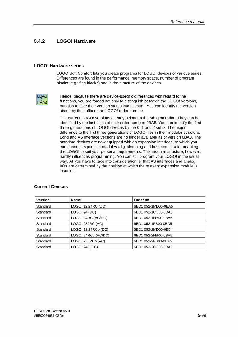
Reference material
LOGO!Soft Comfort V5.0 A5E00266631-02 (b) 5-99
5.4.2 LOGO! Hardware
LOGO! Hardware series
LOGO!Soft Comfort lets you create programs for LOGO! devices of various series. Differences are found in the performance, memory space, number of program blocks (e.g.: flag blocks) and in the structure of the devices.
Hence, because there are device-specific differences with regard to the functions, you are forced not only to distinguish between the LOGO! versions, but also to take their version status into account. You can identify the version status by the suffix of the LOGO! order number.
The current LOGO! versions already belong to the 6th generation. They can be identified by the last digits of their order number: 0BA5. You can identify the first three generations of LOGO! devices by the 0, 1 and 2 suffix. The major difference to the first three generations of LOGO! lies in their modular structure. Long and AS interface versions are no longer available as of version 0BA3. The standard devices are now equipped with an expansion interface, to which you can connect expansion modules (digital/analog and bus modules) for adapting the LOGO! to suit your personal requirements. This modular structure, however, hardly influences programming. You can still program your LOGO! in the usual way. All you have to take into consideration is, that AS interfaces and analog I/Os are determined by the position at which the relevant expansion module is installed.
Current Devices
Version Name Order no.
Standard LOGO! 12/24RC (DC) 6ED1 052-1MD00-0BA5
Standard LOGO! 24 (DC) 6ED1 052-1CC00-0BA5
Standard LOGO! 24RC (AC/DC) 6ED1 052-1HB00-0BA5
Standard LOGO! 230RC (AC) 6ED1 052-1FB00-0BA5
Standard LOGO! 12/24RCo (DC) 6ED1 052-2MD00-0B54
Standard LOGO! 24RCo (AC/DC) 6ED1 052-2HB00-0BA5
Standard LOGO! 230RCo (AC) 6ED1 052-2FB00-0BA5
Standard LOGO! 240 (DC) 6ED1 052-2CC00-0BA5
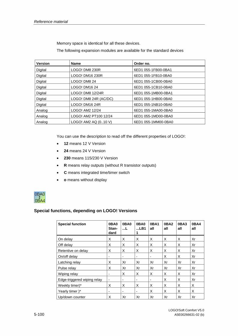
Reference material
LOGO!Soft Comfort V5.0 5-100 A5E00266631-02 (b)
Memory space is identical for all these devices.
The following expansion modules are available for the standard devices
Version Name Order no.
Digital LOGO! DM8 230R 6ED1 055-1FB00-0BA1
Digital LOGO! DM16 230R 6ED1 055-1FB10-0BA0
Digital LOGO! DM8 24 6ED1 055-1CB00-0BA0
Digital LOGO! DM16 24 6ED1 055-1CB10-0BA0
Digital LOGO! DM8 12/24R 6ED1 055-1MB00-0BA1
Digital LOGO! DM8 24R (AC/DC) 6ED1 055-1HB00-0BA0
Digital LOGO! DM16 24R 6ED1 055-1NB10-0BA0
Analog LOGO! AM2 12/24 6ED1 055-1MA00-0BA0
Analog LOGO! AM2 PT100 12/24 6ED1 055-1MD00-0BA0
Analog LOGO! AM2 AQ (0..10 V) 6ED1 055-1MM00-0BA0
You can use the description to read off the different properties of LOGO!:
• 12 means 12 V Version
• 24 means 24 V Version
• 230 means 115/230 V Version
• R means relay outputs (without R transistor outputs)
• C means integrated time/timer switch
• o means without display
Special functions, depending on LOGO! Versions
Special function 0BA0 Stan- dard
0BA0 ...L
0BA0 ...LB11
0BA1 all
0BA2 all
0BA3 all
0BA4 all
On delay X X X X X X Xr
Off delay X X X X X X Xr
Retentive on delay X X X X X X Xr
On/off delay - - - - X X Xr
Latching relay X Xr Xr Xr Xr Xr Xr
Pulse relay X Xr Xr Xr Xr Xr Xr
Wiping relay - X X X X X Xr
Edge-triggered wiping relay - - - - X X Xr
Weekly timer)* X X X X X X X
Yearly timer )* - - - X X X X
Up/down counter X Xr Xr Xr Xr Xr Xr

Reference material
LOGO!Soft Comfort V5.0 A5E00266631-02 (b) 5-101
Special function 0BA0 Stan- dard
0BA0 ...L
0BA0 ...LB11
0BA1 all
0BA2 all
0BA3 all
0BA4 all
Hours counter - Xr Xr Xr Xr Xr Xr
Symmetrical pulse generator X X X X X X X
Asynchronous pulse generator
- - - X X X Xr
Random generator - - - - X X X
Analog threshold trigger - X X X X X X
Analog trigger - - - - X X X
Analog comparator - - - - X X X
Stairway lighting switch - - - - X X Xr
Multiple function switch - - - - X X Xr
Message text - - - - X X X
Softkey - - - - - Xr Xr
Shift register - - - - - - Xr
Analog value monitoring - - - - - - Xr
Analog amplifier - - - - - - X
Analog Differential trigger SFBs
- - - - - - X
Analog multiplexer - - - - - - -
Controller - - - - - - -
Ramp control - - - - - - -
X = Yes; - = No
)* = Use of this function only makes sense for LOGO! versions with integrated real-time clock.
R= retentive
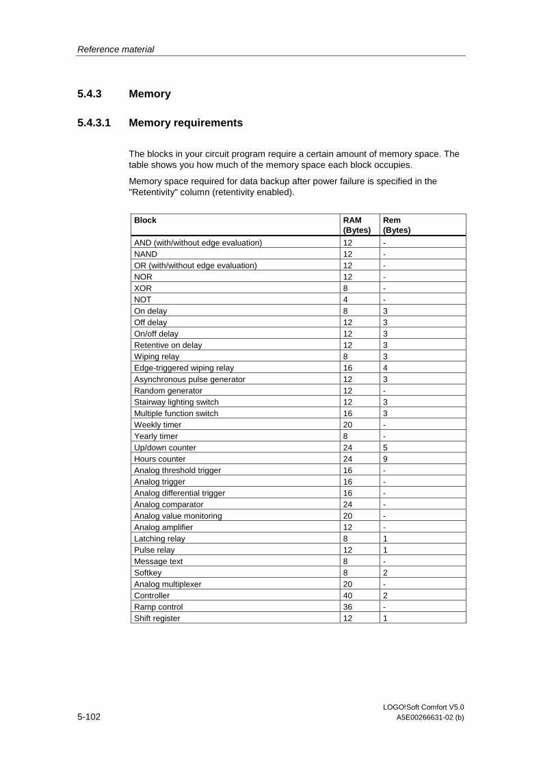
Reference material
LOGO!Soft Comfort V5.0 5-102 A5E00266631-02 (b)
5.4.3 Memory
5.4.3.1 Memory requirements
The blocks in your circuit program require a certain amount of memory space. The table shows you how much of the memory space each block occupies.
Memory space required for data backup after power failure is specified in the "Retentivity" column (retentivity enabled).
Block RAM
(Bytes) Rem (Bytes)
AND (with/without edge evaluation) 12 - NAND 12 - OR (with/without edge evaluation) 12 - NOR 12 - XOR 8 - NOT 4 - On delay 8 3 Off delay 12 3 On/off delay 12 3 Retentive on delay 12 3 Wiping relay 8 3 Edge-triggered wiping relay 16 4 Asynchronous pulse generator 12 3 Random generator 12 - Stairway lighting switch 12 3 Multiple function switch 16 3 Weekly timer 20 - Yearly timer 8 - Up/down counter 24 5 Hours counter 24 9 Analog threshold trigger 16 - Analog trigger 16 - Analog differential trigger 16 - Analog comparator 24 - Analog value monitoring 20 - Analog amplifier 12 - Latching relay 8 1 Pulse relay 12 1 Message text 8 - Softkey 8 2 Analog multiplexer 20 - Controller 40 2 Ramp control 36 - Shift register 12 1

Reference material
LOGO!Soft Comfort V5.0 A5E00266631-02 (b) 5-103
0BA0-0BA3: The following specifications apply:
The blocks in your circuit program require a certain amount of memory space. The table below shows you how much memory space the blocks use in the various memory areas:
Block Par RAM Timer REM
Basic functions 0 0 0 0
On delay 1 1 1 0
Off delay 2 1 1 0
On/off delay 2 1 1 0
Retentive on delay 2 1 1 0
Wiping relay 1 1 1 0
Edge-triggered wiping relay 1 1 1 0
Symmetrical pulse generator 1 1 1 0
Asynchronous pulse generator 3 1 1 0
Random generator 2 1 1 0
Stairway lighting switch 1 1 1 0
Dual-function switch 2 1 1 0
Weekly timer 6 2 0 0
Yearly timer 2 0 0 0
Up/down counter* 2 (2) 0 (2)
Hours counter 2 0 0 4
Threshold trigger 3 3 1 0
Analog trigger 4 2 0 0
Analog comparator 3 4 0 0
Latching relay* 0 (1) 0 (1)
Pulse relay* 0 (1) 0 (1)
Message texts 1 0 0 0
Softkey* 1 (1) 0 (1)
*: Depending on the whether the function is configured with or without retentivity, it occupies the following memory space:
• Retentivity off: The function occupies RAM space
• Retentivity on: The function occupies REM space
Here you will find information on memory space provide by LOGO!.
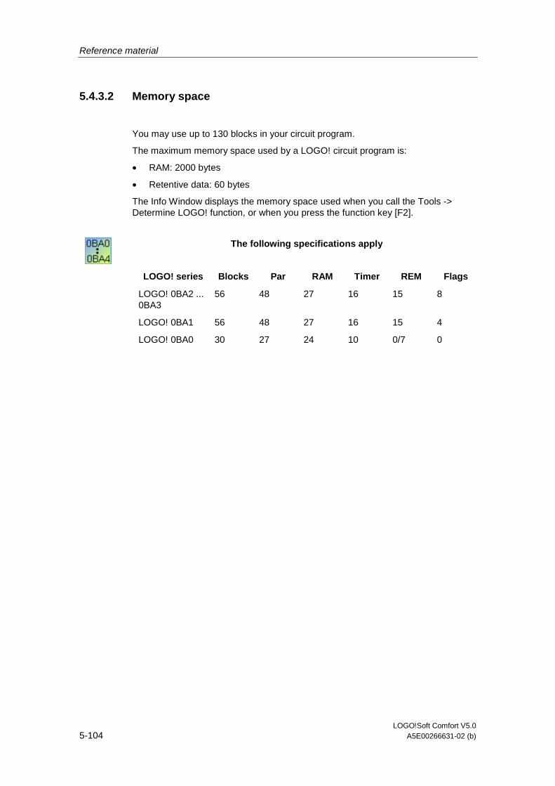
Reference material
LOGO!Soft Comfort V5.0 5-104 A5E00266631-02 (b)
5.4.3.2 Memory space
You may use up to 130 blocks in your circuit program.
The maximum memory space used by a LOGO! circuit program is:
• RAM: 2000 bytes
• Retentive data: 60 bytes
The Info Window displays the memory space used when you call the Tools -> Determine LOGO! function, or when you press the function key [F2].
The following specifications apply
LOGO! series Blocks Par RAM Timer REM Flags
LOGO! 0BA2 ... 0BA3
56 48 27 16 15 8
LOGO! 0BA1 56 48 27 16 15 4
LOGO! 0BA0 30 27 24 10 0/7 0

Reference material
LOGO!Soft Comfort V5.0 A5E00266631-02 (b) 5-105
Program path
A program path consists of a number of blocks, which start with an input and end with an output.
Nesting depth (LOGO! series 0BA0, 0BA1)
The number of blocks in a program path describes the nesting depth.
I/Os in the sense of nesting depth are:
• Inputs (I , AI)
• High, Low (Hi, Lo)
• Memory markers (M)
• Outputs (Q)
Blocks in the sense of nesting depth are:
• Basic functions
• Special functions
Further inputs/outputs according to the nesting depth are:
• Inputs AS Interface (Ia)
• Outputs AS Interface (Qa)
LOGO! restricts the nesting depth for your circuit program. Your circuit program has a maximum nesting depth of 58 objects.
This determines the following::
+ +
1 input 56 blocks 1 output
max. depth of the program path:: = 58 objects
During a simulation or download the system returns an error message if you enter a program path in LOGO!Soft Comfort that exceeds the maximum nesting depth
Implementing longer program paths
Longer program paths can be implemented by means of signal recursion. This is done by appending a flag block to the end of the path. The remaining blocks are connected to the output of the flag block. LOGO! interprets the flag as output of the first program path and also as terminal block of the downstream blocks. LOGO! interprets the long path with flag as two separate paths. If no more flags are available, you can use an output block instead.
Reference material
LOGO!Soft Comfort V5.0 5-106 A5E00266631-02 (b)
5.4.4 Blocks and block numbers
5.4.4.1 Blocks
Blocks represent terminals or functions. LOGO!Soft Comfort distinguishes between various types of block and identifies these by means of an abbreviation.
Block type Identifier Block type Identifier
Input I Flag M
Output Q High Hi
Function B Low Lo
5.4.4.2 Block numbers
Block number assignment
LOGO!Soft Comfort assigns every block you insert in the circuit program a block number. LOGO! displays the number of the current block at the top right of the display. LOGO!Soft Comfort displays the block number directly above the inserted block.
Block numbers are used for orientation on the LOGO! display and for the assignment of logical links. In LOGO!Soft Comfort you can also track cut connections by means of their indicated block number.
The corresponding terminal name on the LOGO! or a simple block name replaces the block number at constants and terminals. Each input, output and flag can be assigned further block identifiers via comments. The high and low signal blocks do not have a block number.
Determination of block numbers on a LOGO!
LOGO! has no default position for analog inputs or digital outputs. The respective block number is determined by the hardware structure.
On a LOGO! without modular structure, the position of an analog or digital output is fixed, for example.

LOGO!Soft Comfort V5.0 A5E00266631-02 (b) 6-1
6 Tips and Tricks
6.1 How to maintain an overview during simulation
It may be difficult in simulation mode to maintain a clear overview of large circuit programs and/or when working on low resolution screens. We advise the following procedure:
1. Maximize the LOGO!Soft Comfort application window to full screen size.
2. Close the Info Window and the catalog.
3. Position the mouse pointer onto the small strip, directly at the left side of the icons of the circuit program inputs. Keep the left mouse button pressed and drag and drop the input toolbox out of the LOGO!Soft Comfort application window to the top edge of the screen.
4. Do the same with the toolbox of your circuit program outputs, as described under 3.
Advantage: The space for editing the circuit program has increased. You can still access the I/O toolbars without restriction, since they always remain in the foreground.
Note: You can restore the I/O toolbars to their original position by left-clicking the small cross icon in the upper right corner of the toolbox.

Tips and Tricks
LOGO!Soft Comfort V5.0 6-2 A5E00266631-02 (b)
6.2 A quick and easy way of selecting blocks and placing these into your circuit program
You have two alternatives to the standard selection of blocks via the programming toolbox icons:
Alternative 1
1. Open the catalog via the programming toolbox.
2. Click on the required block in the catalog to select it.
3. In your circuit program, left-click the block insert position. The block appears at the correct position.
4. To insert further instances of this block, left-click on the relevant insert positions.
5. To insert a further block, select it from the catalog and proceed as described under item 3 and 4.
Advantage: When you change between constants/terminals, basic functions an SFBs, you save yourself having to click the relevant icons in the programming toolbox.
Alternative 2
1. Open the catalog of the programming toolbox.
2. Click on any block in the catalog to select it.
3. If you are creating a large program, you can close the catalog and also hide the programming toolbox.
4. Hold down the Ctrl key and left-click the block insert position in your circuit program. You are displayed a mask with block list, from which you can select the required block with a double-click.
5. Tip: In the mask header, you will also find an input field. You could, for example, enter the initial letter of the required SFB to restrict the display in the mask to a list of blocks with this initial. You thus do not have to browse the entire mask, and you can quickly find the relevant block. The block is inserted at the correct position in your circuit program.
6. To insert further instances of this block, left-click on the relevant insert positions.
7. To insert a further block, select it from the catalog and proceed as described previously.
Advantage: You do not depend on the catalog and the programming toolbox to create large programs. You can thus close and hide these to provide more screen space for your circuit program.

Tips and Tricks
LOGO!Soft Comfort V5.0 A5E00266631-02 (b) 6-3
6.3 A quick and easy way of connecting blocks in large circuit programs
In addition to the conventional method of creating connections by means of the programming toolbox icons, you have a further alternative:
1. After you have placed the blocks into the circuit program, double-click on the input or output of a block.
2. A mask opens with a list of the target blocks. Select a block with double-click. Tipp: In the mask header you will find an input field. You could, for example, enter the initial letter of the required SFB to restrict the display in the mask to a list of blocks with this initial. You thus do not have to browse the entire mask, and you can quickly find the relevant block. By the way, you can also use wildcards such as * or ?.
3. The connection is made.
Advantage: Particularly when you are handling large circuit programs, this method provides you with a quick and easy means of creating connections.
6.4 How to use the Info Window texts for your documentation
1. Use the mouse to mark the text you want to copy to your documentation.
2. Click the icon . The selected text is copied to the clipboard of your operating system.
3. Change to your documentation editor.
4. Call the Edit menu and select the Paste command to insert the den text from the clipboard into your documentation.
Tips and Tricks
LOGO!Soft Comfort V5.0 6-4 A5E00266631-02 (b)
6.5 A quick and easy way of increasing/reducing the size of the Info Window
Double-click the title bar of the Info Window to switch the window to full-screen mode in the LOGO!Soft Comfort application window. Double-click the title bar of the Info Window to restore it to its original size.
6.6 How to display a corresponding tooltip for a function key
Prerequisite: The tooltips are enabled.
Under Tools -> Options: Look & Feel, select Metal or Extended Windows Look and Feel.
With the help of the mouse-over-icon function, LOGO!Soft Comfort does not only show the tooltip for this icon, but also the corresponding function key (if available).
Here you will find an overview of the shortcuts.
6.7 How to identify your circuit program version
The first 16 characters you enter in the Project name field in the File -> Properties: General dialog are downloaded to the LOGO!. The version identifier included with these 16 characters is maintained when you download and upload the circuit program between the PC <-> LOGO!.
This special function is only available with devices as of hardware series 0BA2.

Tips and Tricks
LOGO!Soft Comfort V5.0 A5E00266631-02 (b) 6-5
6.8 How to access functions via the shortcut menu
Right-click on an object to open a context sensitive window that offers you all the major functions.
6.9 A quick and easy way of zooming your circuit program window
Press [CTRL] and turn the mouse wheel.
Result: The size of your circuit program window changes
6.10 A quick way of changing block parameters
Click the parameter field you want to change. Press [CTRL] and turn the mouse wheel.
Result: The parameter changes
6.11 A quick way of closing LOGO!Soft Comfort without saving the data
Open the File menu, press [CTRL] and click the Close menu command.
Result: LOGO!Soft Comfort is closed without prompt.
Caution: New or changed circuit programs will not be saved.

Tips and Tricks
LOGO!Soft Comfort V5.0 6-6 A5E00266631-02 (b)
6.12 How to establish the cycle time
The cycle time is the pure program processing time (reading inputs, executing programs and writing outputs).
The cycle time of each function is less than 0.1 ms. The cycle time of the circuit program can be established using a test program. Refer to the LOGO! manual, appendix B for more information.
With the LOGO! hardware series 0BA3 or older no statements can be made regarding the cycle time of individual functions. The cycle times are different for each function. You can only establish the time for one program cycle. Refer to the manual in appendix B for more information. You can download this from the LOGO! homepage on the Internet.