SIMATIC ET 200S Distributed I/O System - · PDF fileiii ET 200S Distributed I/O System...
650
Preface, Contents Product Overview 1 Brief Instructions on Commissioning ET 200S 2 Configuration Options 3 Installation 4 Wiring and Fitting 5 Commissioning and Diagnostics 6 General Technical Specifications 7 Interface Modules 8 Terminal Modules 9 Power Modules 10 Digital Electronic Modules 11 Analog Electronic Modules 12 4 IQ-SENSE 13 RESERVE Modules 14 Appendices Glossary, Index Edition 12/2004 EWA-4NEB 780602402-12 ET 200S Distributed I/O System Manual SIMATIC This manual is part of the documentation package with the order number 6ES7151-1AA10-8BA0 The following supplement is part of this documentation: No. Designation Drawing number Edition 1 Product Information A5E00352937-02 01/2005 2 Product Information A5E00437368-01 04/2005
Transcript of SIMATIC ET 200S Distributed I/O System - · PDF fileiii ET 200S Distributed I/O System...

Preface, Contents
Product Overview1
Brief Instructions onCommissioning ET 200S
2
Configuration Options3
Installation4
Wiring and Fitting5
Commissioning and Diagnostics6
General Technical Specifications7
Interface Modules8
Terminal Modules9
Power Modules10
Digital Electronic Modules11
Analog Electronic Modules12
4 IQ-SENSE13
RESERVE Modules14
Appendices
Glossary, Index
Edition 12/2004EWA-4NEB 780602402-12
ET 200SDistributed I/O System
Manual
SIMATIC
This manual is part of the documentationpackage with the order number6ES7151-1AA10-8BA0
The following supplement is part of this documentation:
No. Designation Drawing number Edition 1 Product Information A5E00352937-02 01/2005 2 Product Information A5E00437368-01 04/2005

!Danger
indicates that death, severe personal injury or substantial property damage will result if proper precautionsare not taken.
!Warning
indicates that death, severe personal injury or substantial property damage can result if properprecautions are not taken.
!Caution
indicates that minor personal injury can result if proper precautions are not taken.
Caution
indicates that property damage can result if proper precautions are not taken.
Notice
draws your attention to particularly important information on the product, handling the product, or to aparticular part of the documentation.
Qualified PersonnelOnly qualified personnel should be allowed to install and work on this equipment. Qualified persons aredefined as persons who are authorized to commission, to ground and to tag circuits, equipment, andsystems in accordance with established safety practices and standards.
Correct UsageNote the following:
!Warning
This device and its components may only be used for the applications described in the catalog or thetechnical description, and only in connection with devices or components from other manufacturers whichhave been approved or recommended by Siemens.
This product can only function correctly and safely if it is transported, stored, set up, and installedcorrectly, and operated and maintained as recommended.
TrademarksSIMATIC, SIMATIC HMI and SIMATIC NET are registered trademarks of SIEMENS AG.
Third parties using for their own purposes any other names in this document which refer to trademarksmight infringe upon the rights of the trademark owners.
Safety GuidelinesThis manual contains notices intended to ensure personal safety, as well as to protect the products andconnected equipment against damage. These notices are highlighted by the symbols shown below andgraded according to severity by the following texts:
We have checked the contents of this manual for agreementwith the hardware and software described. Since deviationscannot be precluded entirely, we cannot guarantee fullagreement. However, the data in this manual are reviewedregularly and any necessary corrections included insubsequent editions. Suggestions for improvement arewelcomed.
Disclaim of LiabilityCopyright Siemens AG 2004 All rights reserved
The reproduction, transmission or use of this document or itscontents is not permitted without express written authority.Offenders will be liable for damages. All rights, including rightscreated by patent grant or registration of a utility model ordesign, are reserved.
Siemens AGBereich Automation and DrivesGeschaeftsgebiet Industrial Automation SystemsPostfach 4848, D-90327 Nuernberg
Siemens AG 2004Technical data subject to change.
Siemens Aktiengesellschaft EWA-4NEB 780602402-12

iiiET 200S Distributed I/O SystemEWA-4NEB 780602402-12
Preface
Purpose of the Manual
The information in this manual is intended to enable you to operate the ET 200SDistributed I/O System
• as a DP slave on the PROFIBUS DP
• as a PROFINET I/O device on PROFINET
Required level of knowledge
Knowledge of the field of automation engineering is required to understand themanual.
Scope of the manual
This manual is valid for the components of the ET 200S distributed I/O systemspecified in Appendix A.
This manual contains a description of the components that were valid at the timethe manual was published. We reserve the right to enclose a Product Informationbulletin containing up-to-date information about new components and new versionsof components.
Changes since the previous version
The following changes/additions have been made since the previous version of themanual:
• enhanced functions in the IM151-1 STANDARD and IM151-1 FO STANDARDinterface modules
• 4AI I 2WIRE Standard analog electronic module added

Preface
ivET 200S Distributed I/O System
EWA-4NEB 780602402-12
Certification
See Section 7.1 Standards, certificates and approvals
CE Mark of Conformity
See Section 7.1 Standards, certificates and approvals
Identification for Australia (C-tick mark)
See Section 7.1 Standards, certificates and approvals
Standards
See Section 7.1 Standards, certificates and approvals

Preface
vET 200S Distributed I/O SystemEWA-4NEB 780602402-12
Position in the information landscapeThe following list shows a summary of the documentation packages or manualsfor the ET 200S:
• Installing and wiring the ET 200S
• Commissioning anddiagnostics for the ET 200S
• Technical specifications of theIM151-1, digitaland analog electronic modules
• Order numbers for the ET 200S
ET 200S distributedI/O system
ET 200SProcess-Related
Functions
• 1Count 24V/100kHz
• 1Count 5V/500kHz
• 1SSI
• 2PULSE
ET 200S IM151-7 CPU interface moduleand operation list
SIMATIC ET 200S motor starterfail-safe motor starter
SIGUARD safety equipment
• Installing and wiringmotor starters
• Commissioning anddiagnostics for motor starters
• Technical specificationsof motor starters
• Fail-Safe Motor Starter
• Safety-integrated SIGUARD
• Order numbers for motor starters
• Addressing of the IM151-7 CPU
• ET 200S with IM151-7 CPU in thePROFIBUS network
• Commissioning and diagnostics for theIM151-7 CPU
• Technical specifications of the IM151-7 CPU
ET 200S Positioning
• EM 1STEP 5V/204kHz
• 1POS INC/Digital
• 1POS SSI/Digital
• 1POS INC/Analog
• 1POS SSI/Analog
ET 200S serial interfacesand modules
• 1SI 3964/ASCII
• 1SI MODBUS/USS
6ES7151-1AA10-8xA01)
1) x = language designation for order numbers
The documentation packages or manuals can only be ordered in German and English. In addition, French, Spanish and Italianare available in the Internet (see Service & Support in the Internet)
PROFINETSystem -
Description
• Basicsof PROFINET
• Network componentsand structures
• Data interchangeandcommunication
• PROFINETEngineering
From PROFIBUSDP to PROFINET IO
• Differences
• Blocks
• Systemstatus lists
• Diagnostics
ET 200S FC frequencyconverter
Operating manual
• Installation
• Commissioning
• Control and regulation processes
• Protection and monitoring functions
• Technical specifications
ET 200S FC frequencyconverterlist manual
• Parameter list
• Function plans
• Interrupts,error messages

Preface
viET 200S Distributed I/O System
EWA-4NEB 780602402-12
Note
The ET 200S distributed I/O system manual is included in theET 200S FC frequency converter documentation package.The fail-safe modules are described in theET 200S distributed I/O system fail-safe modules manual. This manual and othermanuals for the fail-safe modules can be downloaded from the Internet.
A documentation overview for implementation of the ET 200S as an I/O device isgiven below.
PROFINET
PROFINET System Description
Network components SIMATIC S7 and ET 200
Documentation for SIMATIC NET
Documentation for the switches(e.g. SCALANCE)
Documentation for the IE/PB Link
Integration of PCs
Documentation for the CP 1616
Documentation for SOFTNET PNIO
Documentation forindustrial communications withprogramming device/PC
Component-based Automation
Documentation forComponent-based Automation
Documentation for SIMATIC iMap
STEP 7
Documentation for STEP 7
Documentation for NCM
Documentation for CPU 31x3 PN/DP
Documentation for the CPs:
443-1 Advanced and331-1 Advanced
From PROFIBUS DP to PROFINET IO
You are reading this documentation now:
Documentation for ET 200S

Preface
viiET 200S Distributed I/O SystemEWA-4NEB 780602402-12
GuideYou can quickly access specific information in the manual by using the followingaids:
• At the start of the manual you will find a complete table of contents and a list ofthe diagrams and tables that appear in the manual.
• An overview of the contents of each section is provided in the left-hand columnon each page of each chapter.
• Following the appendices, you will find a glossary in which important technicalterms used in the manual are defined.
• At the end of the manual you will find a comprehensive index enabling rapidaccess to the information you are looking for.
• Language identification for the order numbers of the manuals, for example,6ES7 151-1AA10-8xA0
x is for : A = German,B = English
Special note
In addition to this manual, you will also need the manual for the DP master orPROFINET I/O controller (see Appendix A).
Note
You will find a complete list of the contents of the ET 200S manuals in Section1.4of this manual. We recommend that you begin by reading this section so as to findout which parts of which manuals are most relevant to you in helping you to dowhat you want to do.
Recycling and disposal
Due to the fact that it is low in contaminants, the ET 200S is recyclable. Contact acertified electronic-waste disposal company to recycle and dispose of your oldequipment in an environmentally-friendly manner.

Preface
viiiET 200S Distributed I/O System
EWA-4NEB 780602402-12
Contact persons
See product information Technical Support, Contact Persons and Training
Training
See product information Technical Support, Contact Persons and Training
SIMATIC Technical Support
See product information Technical Support, Contact Persons and Training
Service & Support on the Internet
See product information Technical Support, Contact Persons and Training

ixET 200S Distributed I/O SystemEWA-4NEB 780602402-12
Contents
1 Product Overview 1-1. . . . . . . . . . . . . . . . . . . . . . . . . . . . . . . . . . . . . . . . . . . . . . . . . . .
1.1 What are distributed I/O systems? 1-1. . . . . . . . . . . . . . . . . . . . . . . . . . . . . .
1.2 What is PROFINET IO? 1-4. . . . . . . . . . . . . . . . . . . . . . . . . . . . . . . . . . . . . . .
1.3 What is the ET 200S distributed I/O system? 1-5. . . . . . . . . . . . . . . . . . . . .
1.4 Guide to the ET 200S manuals 1-12. . . . . . . . . . . . . . . . . . . . . . . . . . . . . . . . .
2 Brief Instructions on Commissioning ET 200S 2-1. . . . . . . . . . . . . . . . . . . . . . . . .
2.1 Commissioning on PROFIBUS DP 2-1. . . . . . . . . . . . . . . . . . . . . . . . . . . . . .
2.2 Commissioning on the PROFINET IO 2-10. . . . . . . . . . . . . . . . . . . . . . . . . . .
3 Configuration Options 3-1. . . . . . . . . . . . . . . . . . . . . . . . . . . . . . . . . . . . . . . . . . . . . . .
3.1 Finely-graduated modular system 3-2. . . . . . . . . . . . . . . . . . . . . . . . . . . . . .
3.2 Power supply of the ET 200S 3-4. . . . . . . . . . . . . . . . . . . . . . . . . . . . . . . . . .
3.3 Placement and connection to common potential of power modules 3-5. .
3.4 Configuration options of the interface modules 3-7. . . . . . . . . . . . . . . . . . .
3.5 Configuration options between the terminal modulesand electronic modules 3-10. . . . . . . . . . . . . . . . . . . . . . . . . . . . . . . . . . . . . . . .
3.6 Direct data exchange on the PROFIBUS DP 3-27. . . . . . . . . . . . . . . . . . . . .
3.7 Clocking on PROFIBUS DP 3-28. . . . . . . . . . . . . . . . . . . . . . . . . . . . . . . . . . .
3.8 Option handling on PROFIBUS DP 3-34. . . . . . . . . . . . . . . . . . . . . . . . . . . . .
3.9 Identification data 3-42. . . . . . . . . . . . . . . . . . . . . . . . . . . . . . . . . . . . . . . . . . . .
3.10 Limitations on the number of modules thatcan be connected/maximum configuration 3-45. . . . . . . . . . . . . . . . . . . . . . .
4 Installation 4-1. . . . . . . . . . . . . . . . . . . . . . . . . . . . . . . . . . . . . . . . . . . . . . . . . . . . . . . . . .
4.1 Installation rules, installation position, rail, installation measurementsand clearances 4-2. . . . . . . . . . . . . . . . . . . . . . . . . . . . . . . . . . . . . . . . . . . . . . .
4.2 Installing the interface module 4-4. . . . . . . . . . . . . . . . . . . . . . . . . . . . . . . . . .
4.3 Installing the TM-P and TM-E terminal modules 4-6. . . . . . . . . . . . . . . . . .
4.4 Replacing the terminal box on the terminal module 4-8. . . . . . . . . . . . . . . .
4.5 Installing the terminating module 4-10. . . . . . . . . . . . . . . . . . . . . . . . . . . . . . .
4.6 Installing the shield contact 4-11. . . . . . . . . . . . . . . . . . . . . . . . . . . . . . . . . . . .
4.7 Applying slot number labels and color identification labels 4-13. . . . . . . . . .
4.8 Setting the PROFIBUS address 4-15. . . . . . . . . . . . . . . . . . . . . . . . . . . . . . . .

Contents
xET 200S Distributed I/O System
EWA-4NEB 780602402-12
5 Wiring and Fitting 5-1. . . . . . . . . . . . . . . . . . . . . . . . . . . . . . . . . . . . . . . . . . . . . . . . . . .
5.1 General rules and regulations for operating the ET 200S 5-1. . . . . . . . . . .
5.2 Operating the ET 200S on a grounded supply 5-3. . . . . . . . . . . . . . . . . . . .
5.3 Electrical design of the ET 200S 5-6. . . . . . . . . . . . . . . . . . . . . . . . . . . . . . . .
5.4 Wiring the ET 200S 5-7. . . . . . . . . . . . . . . . . . . . . . . . . . . . . . . . . . . . . . . . . . .5.4.1 Wiring a terminal module with screw-type terminals 5-8. . . . . . . . . . . . . . .5.4.2 Wiring a terminal module with spring terminals 5-8. . . . . . . . . . . . . . . . . . .5.4.3 Wiring terminal modules with Fast Connect 5-10. . . . . . . . . . . . . . . . . . . . . .5.4.4 Wiring terminal modules 5-13. . . . . . . . . . . . . . . . . . . . . . . . . . . . . . . . . . . . . . .5.4.5 Wiring the IM151-1 BASIC, IM151-1 STANDARD and
IM151-1 HIGH FEATURE interface modules 5-18. . . . . . . . . . . . . . . . . . . . .5.4.6 Wiring the IM151-3 PN interface module 5-19. . . . . . . . . . . . . . . . . . . . . . . . .5.4.7 Wiring the IM151-1 FO STANDARD interface module 5-21. . . . . . . . . . . . .
5.5 Inserting and identifying the electronic modules 5-24. . . . . . . . . . . . . . . . . . .
5.6 Assigning device names for the I/O device 5-30. . . . . . . . . . . . . . . . . . . . . . .
6 Commissioning and Diagnostics 6-1. . . . . . . . . . . . . . . . . . . . . . . . . . . . . . . . . . . . .
6.1 Commissioning and diagnostics on PROFIBUS DP 6-1. . . . . . . . . . . . . . .6.1.1 Configuring the ET 200S on PROFIBUS DP 6-2. . . . . . . . . . . . . . . . . . . . .6.1.2 Commissioning and startup of the ET 200S on PROFIBUS DP 6-10. . . . .6.1.3 Diagnosis using the LEDs 6-12. . . . . . . . . . . . . . . . . . . . . . . . . . . . . . . . . . . . .6.1.4 Diagnostic messages of the electronic modules 6-22. . . . . . . . . . . . . . . . . .6.1.5 Evaluating the interrupts of the ET 200S 6-23. . . . . . . . . . . . . . . . . . . . . . . . .6.1.6 Diagnostics using STEP 5 and STEP 7 6-25. . . . . . . . . . . . . . . . . . . . . . . . . .
6.1.6.1 Reading out the diagnosis 6-25. . . . . . . . . . . . . . . . . . . . . . . . . . . . . . . . . . . . .6.1.6.2 Structure of slave diagnostic data 6-29. . . . . . . . . . . . . . . . . . . . . . . . . . . . . . .6.1.6.3 Station statuses 1 to 3 6-31. . . . . . . . . . . . . . . . . . . . . . . . . . . . . . . . . . . . . . . .6.1.6.4 Master PROFIBUS Address 6-33. . . . . . . . . . . . . . . . . . . . . . . . . . . . . . . . . . .6.1.6.5 Manufacturer ID 6-33. . . . . . . . . . . . . . . . . . . . . . . . . . . . . . . . . . . . . . . . . . . . . .6.1.6.6 Module diagnosis 6-34. . . . . . . . . . . . . . . . . . . . . . . . . . . . . . . . . . . . . . . . . . . . .6.1.6.7 Module information 6-36. . . . . . . . . . . . . . . . . . . . . . . . . . . . . . . . . . . . . . . . . . .6.1.6.8 Channel-specific diagnosis 6-38. . . . . . . . . . . . . . . . . . . . . . . . . . . . . . . . . . . .6.1.6.9 Interrupts 6-48. . . . . . . . . . . . . . . . . . . . . . . . . . . . . . . . . . . . . . . . . . . . . . . . . . . .6.1.6.10 Diagnostics in the case of invalid ET 200S configuration states
on the PROFIBUS DP 6-56. . . . . . . . . . . . . . . . . . . . . . . . . . . . . . . . . . . . . . . .
6.2 Commissioning and diagnostics on PROFINET IO 6-57. . . . . . . . . . . . . . . .6.2.1 Configuring the ET 200S on PROFINET IO 6-57. . . . . . . . . . . . . . . . . . . . . .6.2.2 Commissioning and startup of the ET 200S on PROFINET IO 6-59. . . . . .6.2.3 Diagnosis using the LEDs 6-61. . . . . . . . . . . . . . . . . . . . . . . . . . . . . . . . . . . . .6.2.4 Diagnostic messages of the electronic modules 6-64. . . . . . . . . . . . . . . . . .6.2.5 Evaluating the interrupts of the ET 200S 6-65. . . . . . . . . . . . . . . . . . . . . . . . .6.2.6 Diagnostics with STEP 7 6-66. . . . . . . . . . . . . . . . . . . . . . . . . . . . . . . . . . . . . .
6.2.6.1 Reading out the diagnosis 6-67. . . . . . . . . . . . . . . . . . . . . . . . . . . . . . . . . . . . .6.2.6.2 Channel diagnostics 6-68. . . . . . . . . . . . . . . . . . . . . . . . . . . . . . . . . . . . . . . . . .6.2.6.3 Diagnostics in the case of invalid ET 200S configuration states
on the PROFINET IO 6-70. . . . . . . . . . . . . . . . . . . . . . . . . . . . . . . . . . . . . . . . .6.2.6.4 Diagnostics in the case of interruption of the ET 200S backplane bus 6-706.2.6.5 Diagnostics in the case of failure of the load voltage
from the power module 6-71. . . . . . . . . . . . . . . . . . . . . . . . . . . . . . . . . . . . . . . .6.2.6.6 Diagnosis after a STOP of the I/O controller or after restart
of the O/O device 6-71. . . . . . . . . . . . . . . . . . . . . . . . . . . . . . . . . . . . . . . . . . . .

Contents
xiET 200S Distributed I/O SystemEWA-4NEB 780602402-12
7 General Technical Specifications 7-1. . . . . . . . . . . . . . . . . . . . . . . . . . . . . . . . . . . . .
7.1 Standards, certificates, and approvals 7-2. . . . . . . . . . . . . . . . . . . . . . . . . . .
7.2 Electromagnetic compatibility, shipping and storage conditions 7-6. . . . .
7.3 Mechanical and climatic environmental conditions 7-8. . . . . . . . . . . . . . . .
7.4 Information on insulation testing, safety class,degree of protection, and rated voltage of the ET 200S 7-10. . . . . . . . . . . .
7.5 Variations in technical data for theET 200S FC frequency converter 7-11. . . . . . . . . . . . . . . . . . . . . . . . . . . . . . .
8 Interface Modules 8-1. . . . . . . . . . . . . . . . . . . . . . . . . . . . . . . . . . . . . . . . . . . . . . . . . . .
8.1 Parameters for interface modules 8-1. . . . . . . . . . . . . . . . . . . . . . . . . . . . . . .
8.2 IM151-1 BASIC interface module (6ES7 151-1CA00-0AB0) 8-8. . . . . . . .
8.3 IM151-1 STANDARD interface module (6ES7 151-1AA04-0AB0) 8-11. . .
8.4 IM151-1 FO STANDARD interface module (6ES7 151-1AB03-0AB0) 8-15
8.5 IM151-1 HIGH FEATURE interface module (6ES7 151-1BA00-0AB0) 8-19
8.6 IM151-3 PN interface module (6ES7 151-3AA00-0AB0) 8-23. . . . . . . . . . .
9 Terminal Module 9-1. . . . . . . . . . . . . . . . . . . . . . . . . . . . . . . . . . . . . . . . . . . . . . . . . . . . .
9.1 TM-P15S23-A1, TM-P15C23-A1 and TM-P15N23-A1 terminal module;(6ES7 193 4CCx0-0AA0) 9-5. . . . . . . . . . . . . . . . . . . . . . . . . . . . . . . . . . . . . .
9.2 TM-P15S23-A0, TM-P15C23-A0 and TM-P15N23-A0 terminal module;(6ES7 193-4CDx0-0AA0) 9-8. . . . . . . . . . . . . . . . . . . . . . . . . . . . . . . . . . . . . .
9.3 TM-P15S22-01, TM-P15C22-01 and TM-P15N22-01 terminal module;(6ES7 193-4CEx0-0AA0) 9-10. . . . . . . . . . . . . . . . . . . . . . . . . . . . . . . . . . . . . .
9.4 TM-P30S44-A0 and TM-P30C44-A0 terminal module;(6ES7 193-4CKx0-0AA0) 9-12. . . . . . . . . . . . . . . . . . . . . . . . . . . . . . . . . . . . . .
9.5 TM-PF30S47-F1 terminal module (for PM-D F DC 24V);(3RK1 903-3AA00) 9-15. . . . . . . . . . . . . . . . . . . . . . . . . . . . . . . . . . . . . . . . . . .
9.6 TM-E15S26-A1, TM-E15C26-A1 and TM-E15N26-A1 universal terminalmodule; (6ES7 193-4CAx0-0AA0) 9-17. . . . . . . . . . . . . . . . . . . . . . . . . . . . . .
9.7 TM-E15S24-A1, TM-E15C24-A1 and TM-E15N24-A1 terminal module;(6ES7 193-4CAx0-0AA0) 9-20. . . . . . . . . . . . . . . . . . . . . . . . . . . . . . . . . . . . . .
9.8 TM-E15S24-01, TM-E15C24-01 and TM-E15N24-01 terminal module;(6ES7 193-4CBx0-0AA0) 9-22. . . . . . . . . . . . . . . . . . . . . . . . . . . . . . . . . . . . . .
9.9 TM-E15S23-01, TM-E15C23-01 andTM-E15N23-01 terminal module; (6ES7 193-4CBx0-0AA0) 9-24. . . . . . . .
9.10 TM-E15S24-AT and TM-E15C24-AT terminal module;(6ES7 193-4CLx0-0AA0) 9-26. . . . . . . . . . . . . . . . . . . . . . . . . . . . . . . . . . . . . .
9.11 TM-E30S44-01 and TM-E30C44-01 terminal module;(6ES7 193-4CGx0-0AA0) 9-28. . . . . . . . . . . . . . . . . . . . . . . . . . . . . . . . . . . . . .
9.12 TM-E30S46-A1 and TM-E30C46-A1 terminal module;(6ES7 193-4CFx0-0AA0) 9-30. . . . . . . . . . . . . . . . . . . . . . . . . . . . . . . . . . . . . .

Contents
xiiET 200S Distributed I/O System
EWA-4NEB 780602402-12
10 Power Modules 10-1. . . . . . . . . . . . . . . . . . . . . . . . . . . . . . . . . . . . . . . . . . . . . . . . . . . . . .
10.1 Parameters for power modules 10-2. . . . . . . . . . . . . . . . . . . . . . . . . . . . . . . . .
10.2 PM-E 24 VDC power module (6ES7 138-4CA00-0AA0) 10-3. . . . . . . . . . . .
10.3 PM-E 24-48 VDC power module (6ES7 138-4CA50-0AA0) 10-7. . . . . . . . .
10.4 PM-E 24--48 VDC/24--230 VAC (6ES7 138-4CB10-0AB0) 10-11. . . . . . . . . .
11 Digital Electronic Modules 11-1. . . . . . . . . . . . . . . . . . . . . . . . . . . . . . . . . . . . . . . . . . .
11.1 Parameters for digital electronic modules 11-2. . . . . . . . . . . . . . . . . . . . . . . .
11.2 2DI 24 VDC ST digital electronic module (6ES7 131-4BB00-0AA0) 11-7. .
11.3 4DI 24 VDC ST digital electronic module(6ES7 131-4BD00-0AA0) 11-11. . . . . . . . . . . . . . . . . . . . . . . . . . . . . . . . . . . . . .
11.4 4DI 24 VDC/SRC ST digital electronic module(6ES7 131-4BD50-0AA0) 11-15. . . . . . . . . . . . . . . . . . . . . . . . . . . . . . . . . . . . . .
11.5 2DI 24 VDC High Feature digital electronic module(6ES7 131-4BB00-0AB0) 11-19. . . . . . . . . . . . . . . . . . . . . . . . . . . . . . . . . . . . . .
11.6 4DI 24 VDC High Feature digital electronic module(6ES7 131-4BD00-0AB0) 11-23. . . . . . . . . . . . . . . . . . . . . . . . . . . . . . . . . . . . . .
11.7 4DI 24--48 VUC High Feature digital electronic module(6ES7 131-4CD00-0AB0) 11-28. . . . . . . . . . . . . . . . . . . . . . . . . . . . . . . . . . . . . .
11.8 4DI NAMUR digital electronic module(6ES7 131-4RD00-0AB0) 11-33. . . . . . . . . . . . . . . . . . . . . . . . . . . . . . . . . . . . . .
11.9 2DI 120 VAC Standard digital electronic module(6ES7 131-4EB00-0AB0) 11-41. . . . . . . . . . . . . . . . . . . . . . . . . . . . . . . . . . . . . .
11.10 2DI 230 VAC Standard digital electronic module(6ES7 131-4FB00-0AB0) 11-44. . . . . . . . . . . . . . . . . . . . . . . . . . . . . . . . . . . . . .
11.11 2DO 24 VDC/0.5 A Standard digital electronic module(6ES7 132-4BB00-0AA0) 11-47. . . . . . . . . . . . . . . . . . . . . . . . . . . . . . . . . . . . . .
11.12 4DO 24 VDC/0.5 A Standard digital electronic module(6ES7 132-4BD00-0AA0) 11-52. . . . . . . . . . . . . . . . . . . . . . . . . . . . . . . . . . . . . .
11.13 2DO 24 VDC/0.5 A High Feature digital electronic module(6ES7 132-4BB00-0AB0) 11-56. . . . . . . . . . . . . . . . . . . . . . . . . . . . . . . . . . . . . .
11.14 2DO 24 VDC/2 A ST digital electronic module(6ES7 132-4BB30-0AA0) 11-60. . . . . . . . . . . . . . . . . . . . . . . . . . . . . . . . . . . . . .
11.15 4DO 24 VDC/2 A Standard digital electronic module(6ES7 132-4BD30-0AA0) 11-64. . . . . . . . . . . . . . . . . . . . . . . . . . . . . . . . . . . . . .
11.16 2DO 24 VDC/2 A High Feature digital electronic module(6ES7 132-4BB30-0AB0) 11-68. . . . . . . . . . . . . . . . . . . . . . . . . . . . . . . . . . . . . .
11.17 2DO 24--230 VAC digital electronic module (6ES7 132-4FB00-0AB0) 11-72
11.18 2RO NO 24--120 VDC/5 A 24--230 VAC/5 A digital electronic module(6ES7 132-4HB00-0AB0) 11-76. . . . . . . . . . . . . . . . . . . . . . . . . . . . . . . . . . . . . .
11.19 Digital electronic module 2RO NO/NC 24--48 VDC/5 A24--230 VAC/5 A (6ES7 132-4HB10-0AB0) 11-81. . . . . . . . . . . . . . . . . . . . . .

Contents
xiiiET 200S Distributed I/O SystemEWA-4NEB 780602402-12
12 Analog Electronic Modules 12-1. . . . . . . . . . . . . . . . . . . . . . . . . . . . . . . . . . . . . . . . . . .
12.1 Analog value visualization 12-2. . . . . . . . . . . . . . . . . . . . . . . . . . . . . . . . . . . . .12.1.1 Analog Value Representation for measuring ranges with SIMATIC S7 12-412.1.2 Analog value visualization for measurement ranges
of the analog input modules in SIMATIC S7 format 12-5. . . . . . . . . . . . . . . .12.1.3 Analog value visualization for measurement ranges
of the analog output modules in SIMATIC S7 format 12-15. . . . . . . . . . . . . .
12.2 Basics of Analog Value Processing 12-17. . . . . . . . . . . . . . . . . . . . . . . . . . . . .12.2.1 Connecting sensors 12-17. . . . . . . . . . . . . . . . . . . . . . . . . . . . . . . . . . . . . . . . . .12.2.2 Connecting Thermocouples 12-21. . . . . . . . . . . . . . . . . . . . . . . . . . . . . . . . . . . .12.2.3 Instructions and circuits for unused channels of the
analog input modules 12-26. . . . . . . . . . . . . . . . . . . . . . . . . . . . . . . . . . . . . . . . .
12.3 Response of the Analog Modules during Operation and ifFaults Occur 12-26. . . . . . . . . . . . . . . . . . . . . . . . . . . . . . . . . . . . . . . . . . . . . . . . .
12.4 Parameters for analog electronic modules 12-29. . . . . . . . . . . . . . . . . . . . . . .
12.5 2AI U Standard analog electronic module (6ES7 134-4FB00-0AB0) 12-42.
12.6 2AI U High Feature analog electronic module(6ES7 134-4LB00-0AB0) 12-46. . . . . . . . . . . . . . . . . . . . . . . . . . . . . . . . . . . . . .
12.7 2AI U High Speed analog electronic module(6ES7 134-4FB51-0AB0) 12-50. . . . . . . . . . . . . . . . . . . . . . . . . . . . . . . . . . . . . .
12.8 2AI I 2WIRE Standard analog electronic module(6ES7 134-4GB00-0AB0) 12-54. . . . . . . . . . . . . . . . . . . . . . . . . . . . . . . . . . . . . .
12.9 4AI I 2WIRE Standard analog electronic module(6ES7 134-4GD00-0AB0) 12-58. . . . . . . . . . . . . . . . . . . . . . . . . . . . . . . . . . . . .
12.10 2AI I 2WIRE High Speed analog electronic module(6ES7 134-4GB51-0AB0) 12-62. . . . . . . . . . . . . . . . . . . . . . . . . . . . . . . . . . . . . .
12.11 2AI I 2WIRE Standard analog electronic module(6ES7 134-4GB10-0AB0) 12-66. . . . . . . . . . . . . . . . . . . . . . . . . . . . . . . . . . . . . .
12.12 2AI I 2/4WIRE High Feature analog electronic module(6ES7 134-4MB00-0AB0) 12-70. . . . . . . . . . . . . . . . . . . . . . . . . . . . . . . . . . . . .
12.13 2AI I 4WIRE High Speed analog electronic module(6ES7 134-4GB61-0AB0) 12-74. . . . . . . . . . . . . . . . . . . . . . . . . . . . . . . . . . . . . .
12.14 2AI RTD Standard analog electronic module (6ES7 134-4JB50-0AB0) 12-78
12.15 2AI RTD High Feature analog electronic module(6ES7 134-4NB50-0AB0) 12-82. . . . . . . . . . . . . . . . . . . . . . . . . . . . . . . . . . . . . .
12.16 2AI TC Standard analog electronic module (6ES7 134-4JB00-0AB0) 12-90
12.17 2AI TC High Feature analog electronic module(6ES7 134-4NB00-0AB0) 12-95. . . . . . . . . . . . . . . . . . . . . . . . . . . . . . . . . . . . . .
12.18 2AO U Standard analog electronic module (6ES7 135-4FB00-0AB0) 12-99
12.19 2AO U High Feature analog electronic module(6ES7 135-4LB01-0AB0) 12-103. . . . . . . . . . . . . . . . . . . . . . . . . . . . . . . . . . . . . .
12.20 2AO I Standard analog electronic module (6ES7 135-4GB00-0AB0) 12-107.
12.21 2AO I High Feature analog electronic module(6ES7 135-4MB01-0AB0) 12-111. . . . . . . . . . . . . . . . . . . . . . . . . . . . . . . . . . . . .

Contents
xivET 200S Distributed I/O System
EWA-4NEB 780602402-12
13 4 IQ-SENSE 13-1. . . . . . . . . . . . . . . . . . . . . . . . . . . . . . . . . . . . . . . . . . . . . . . . . . . . . . . . .
13.1 Parameters for 4 IQ-SENSE 13-3. . . . . . . . . . . . . . . . . . . . . . . . . . . . . . . . . . .13.1.1 Group diagnostics parameter 13-4. . . . . . . . . . . . . . . . . . . . . . . . . . . . . . . . . .13.1.2 Synchronization group parameters 13-4. . . . . . . . . . . . . . . . . . . . . . . . . . . . . .13.1.3 Sensor type parameter 13-5. . . . . . . . . . . . . . . . . . . . . . . . . . . . . . . . . . . . . . . .13.1.4 Differential travel parameter 13-6. . . . . . . . . . . . . . . . . . . . . . . . . . . . . . . . . . .13.1.5 Time functions, time value parameter 13-7. . . . . . . . . . . . . . . . . . . . . . . . . . .13.1.6 Teach-in block parameter 13-8. . . . . . . . . . . . . . . . . . . . . . . . . . . . . . . . . . . . . .
13.2 Control (PIQ) and feedback interface (PII) 13-9. . . . . . . . . . . . . . . . . . . . . . .13.2.1 Standard 13-10. . . . . . . . . . . . . . . . . . . . . . . . . . . . . . . . . . . . . . . . . . . . . . . . . . . .13.2.2 Enhanced 13-10. . . . . . . . . . . . . . . . . . . . . . . . . . . . . . . . . . . . . . . . . . . . . . . . . . .
13.3 Terminal assignment 13-15. . . . . . . . . . . . . . . . . . . . . . . . . . . . . . . . . . . . . . . . . .
13.4 Block diagram 13-16. . . . . . . . . . . . . . . . . . . . . . . . . . . . . . . . . . . . . . . . . . . . . . .
13.5 Technical specifications 13-17. . . . . . . . . . . . . . . . . . . . . . . . . . . . . . . . . . . . . . .
14 RESERVE modules 14-1. . . . . . . . . . . . . . . . . . . . . . . . . . . . . . . . . . . . . . . . . . . . . . . . . .
A Order Numbers A-1. . . . . . . . . . . . . . . . . . . . . . . . . . . . . . . . . . . . . . . . . . . . . . . . . . . . . .
B Dimension Drawings B-1. . . . . . . . . . . . . . . . . . . . . . . . . . . . . . . . . . . . . . . . . . . . . . . . .
C Address Space of the Input and Outputs of the ET 200S C-1. . . . . . . . . . . . . . . .
D Response Times D-1. . . . . . . . . . . . . . . . . . . . . . . . . . . . . . . . . . . . . . . . . . . . . . . . . . . . .
D.1 Response times at the DP master D-1. . . . . . . . . . . . . . . . . . . . . . . . . . . . . .
D.2 Response times for the ET 200S D-2. . . . . . . . . . . . . . . . . . . . . . . . . . . . . . .
D.3 Response times for the digital input modules D-5. . . . . . . . . . . . . . . . . . . . .
D.4 Response times for the digital output modules D-5. . . . . . . . . . . . . . . . . . . .
D.5 Response times for analog input modules D-6. . . . . . . . . . . . . . . . . . . . . . .
D.6 Response times for analog output modules D-7. . . . . . . . . . . . . . . . . . . . . .
D.7 Response times for a 4 IQ-SENSE electronic module D-8. . . . . . . . . . . . .
D.8 Response times for process-related modules D-8. . . . . . . . . . . . . . . . . . . . .
D.9 Response times of PROFINET IO D-9. . . . . . . . . . . . . . . . . . . . . . . . . . . . . .
E Determining the Leakage Resistance of an ET 200S Station E-1. . . . . . . . . . . .
F Special Measures for Interference-Free Operation F-1. . . . . . . . . . . . . . . . . . . . . .
Glossary Glossary-1. . . . . . . . . . . . . . . . . . . . . . . . . . . . . . . . . . . . . . . . . . . . . . . . . . . . . . .
Index Index-1. . . . . . . . . . . . . . . . . . . . . . . . . . . . . . . . . . . . . . . . . . . . . . . . . . . . . . . . . .

Contents
xvET 200S Distributed I/O SystemEWA-4NEB 780602402-12
Figures
1-1 Typical PROFIBUS DP network structure 1-3. . . . . . . . . . . . . . . . . . . . . . . .1-2 A typical PROFINET IO network structure 1-4. . . . . . . . . . . . . . . . . . . . . . .1-3 View of the ET 200S distributed I/O system 1-6. . . . . . . . . . . . . . . . . . . . . .1-4 Components and the manuals required for them 1-12. . . . . . . . . . . . . . . . . .1-5 Components and the manuals required for them (continued) 1-13. . . . . . .2-1 Components for the example on PROFIBUS DP 2-2. . . . . . . . . . . . . . . . . .2-2 Setting PROFIBUS Address 3 2-3. . . . . . . . . . . . . . . . . . . . . . . . . . . . . . . . .2-3 Wire the example on the PROFIBUS DP 2-4. . . . . . . . . . . . . . . . . . . . . . . .2-4 Components for the example on PROFINET IO 2-11. . . . . . . . . . . . . . . . . .2-5 Wire the example on the PROFINET IO 2-12. . . . . . . . . . . . . . . . . . . . . . . . .3-1 Placement and connection to common potential of power modules 3-5. .3-2 Fiber-optic cable network with the IM151-1 FO STANDARD 3-9. . . . . . . .3-3 Selecting terminal modules for power modules 3-18. . . . . . . . . . . . . . . . . . .3-4 Selecting terminal modules for electronic modules 3-22. . . . . . . . . . . . . . . .3-5 Direct Communication with the IM151-1 HIGH FEATURE 3-27. . . . . . . . . .3-6 Clocked interrupts dialog box 3-30. . . . . . . . . . . . . . . . . . . . . . . . . . . . . . . . . .3-7 Options dialog box 3-31. . . . . . . . . . . . . . . . . . . . . . . . . . . . . . . . . . . . . . . . . . . .3-8 DP slave properties dialog box 3-32. . . . . . . . . . . . . . . . . . . . . . . . . . . . . . . . .3-9 How option handling works 3-35. . . . . . . . . . . . . . . . . . . . . . . . . . . . . . . . . . . .3-10 Example of the use of the RESERVE modules 3-37. . . . . . . . . . . . . . . . . . .3-11 Control (PIQ) and feedback interface (PII) 3-40. . . . . . . . . . . . . . . . . . . . . . .4-1 Minimum clearances 4-4. . . . . . . . . . . . . . . . . . . . . . . . . . . . . . . . . . . . . . . . . .4-2 Installing the interface module 4-5. . . . . . . . . . . . . . . . . . . . . . . . . . . . . . . . . .4-3 Installing the terminal module 4-6. . . . . . . . . . . . . . . . . . . . . . . . . . . . . . . . . .4-4 Removing the terminal module (from the right) 4-7. . . . . . . . . . . . . . . . . . .4-5 Replacing the terminal box on the terminal module 4-9. . . . . . . . . . . . . . . .4-6 Installing the terminating module 4-10. . . . . . . . . . . . . . . . . . . . . . . . . . . . . . .4-7 Installing the shield contact 4-12. . . . . . . . . . . . . . . . . . . . . . . . . . . . . . . . . . . .4-8 Applying slot number labels and color identification labels 4-14. . . . . . . . . .4-9 Setting the PROFIBUS Address 4-15. . . . . . . . . . . . . . . . . . . . . . . . . . . . . . . .5-1 Configuring the ET 200S with grounded reference potential 5-5. . . . . . . .5-2 Potentials of the ET 200S with IM151-1 5-6. . . . . . . . . . . . . . . . . . . . . . . . .5-3 Wiring the spring terminal 5-9. . . . . . . . . . . . . . . . . . . . . . . . . . . . . . . . . . . . .5-4 Block diagram of the terminal module with Fast Connect 5-10. . . . . . . . . . .5-5 Releasing the wiring of the terminal module with Fast Connect 5-12. . . . .5-6 Removing the locking mechanism from the terminal module 5-12. . . . . . . .5-7 Wiring terminal modules for power modules 5-14. . . . . . . . . . . . . . . . . . . . . .5-8 Wiring terminal modules for electronic modules 5-15. . . . . . . . . . . . . . . . . . .5-9 Wiring terminal modules for electronic modules, continued 5-16. . . . . . . . .5-10 Connecting cable shields 5-17. . . . . . . . . . . . . . . . . . . . . . . . . . . . . . . . . . . . . .5-11 Wiring the IM151-1 BASIC, IM151-1 STANDARD
and IM151-1 HIGH FEATURE interface modules 5-18. . . . . . . . . . . . . . . . .5-12 IM151-3 PN wiring 5-20. . . . . . . . . . . . . . . . . . . . . . . . . . . . . . . . . . . . . . . . . . . .5-13 Wiring the IM151-1 FO STANDARD 5-24. . . . . . . . . . . . . . . . . . . . . . . . . . . .5-14 Inserting and identifying the electronic modules 5-25. . . . . . . . . . . . . . . . . . .5-15 Removing electronic modules 5-26. . . . . . . . . . . . . . . . . . . . . . . . . . . . . . . . . .5-16 Removing the code element 5-27. . . . . . . . . . . . . . . . . . . . . . . . . . . . . . . . . . .5-17 Assigning device names in HW CONFIG 5-30. . . . . . . . . . . . . . . . . . . . . . . .5-18 Send device name online to the IM151-3 PN 5-31. . . . . . . . . . . . . . . . . . . . .5-19 ”Assign device name” window before name assignment 5-31. . . . . . . . . . .5-20 ”Assign device name” window after name assignment 5-32. . . . . . . . . . . . .

Contents
xviET 200S Distributed I/O System
EWA-4NEB 780602402-12
6-1 Grouping of input modules in a single byte 6-6. . . . . . . . . . . . . . . . . . . . . . .6-2 Grouping of digital output modules in a single byte 6-7. . . . . . . . . . . . . . . .6-3 Grouping of motor starters within a byte 6-8. . . . . . . . . . . . . . . . . . . . . . . . .6-4 Setup of the ET 200S 6-8. . . . . . . . . . . . . . . . . . . . . . . . . . . . . . . . . . . . . . . . .6-5 Configuring the ET 200S on PROFIBUS DP 6-11. . . . . . . . . . . . . . . . . . . . .6-6 LED display on the IM151-1 interface module 6-12. . . . . . . . . . . . . . . . . . . .6-7 LED display on the power module 6-14. . . . . . . . . . . . . . . . . . . . . . . . . . . . . .6-8 LED Display on the Digital Electronic Modules 6-14. . . . . . . . . . . . . . . . . . . .6-9 LED Display on the Analog Electronic Modules 6-15. . . . . . . . . . . . . . . . . . .6-10 LED display on the 1COUNT 24 V/100 kHz 6-15. . . . . . . . . . . . . . . . . . . . . .6-11 LED display on the 1COUNT 5 V/500 kHz 6-16. . . . . . . . . . . . . . . . . . . . . . .6-12 LED display on the EM 1SSI 6-17. . . . . . . . . . . . . . . . . . . . . . . . . . . . . . . . . . .6-13 LEDs on the EM 1STEP 5 V/204 kHz 6-17. . . . . . . . . . . . . . . . . . . . . . . . . . .6-14 LED display on the 2PULSE 6-18. . . . . . . . . . . . . . . . . . . . . . . . . . . . . . . . . . .6-15 LEDs on the 1POS INC/Digital, 1POS SSI/Digital, 1POS INC/Analog,
1POS SSI/Analog 6-19. . . . . . . . . . . . . . . . . . . . . . . . . . . . . . . . . . . . . . . . . . . .6-16 LEDs on the 1SI 3964/ASCII, 1SI Modbus/USS 6-20. . . . . . . . . . . . . . . . . .6-17 LEDs on the 4 IQSENSE electronic module 6-21. . . . . . . . . . . . . . . . . . . . . .6-18 Start information of the OB 40: which event has triggered
a process interrupt with digital input modules 6-24. . . . . . . . . . . . . . . . . . . . .6-19 Start information of the OB 40: which event has triggered
a process interrupt with analog input modules 6-24. . . . . . . . . . . . . . . . . . . .6-20 Structure of slave diagnostic data 6-29. . . . . . . . . . . . . . . . . . . . . . . . . . . . . . .6-21 Structure of the ID-related diagnosis for the ET 200S
with the IM151-1 BASIC 6-34. . . . . . . . . . . . . . . . . . . . . . . . . . . . . . . . . . . . . . .6-22 Structure of the ID-related diagnosis for the ET 200S with the IM151-1
STANDARD, IM151-1 FO STANDARD and IM151-1 HIGH FEATURE 6-356-23 Structure of the module status for the ET 200S
with the IM151-1 BASIC 6-36. . . . . . . . . . . . . . . . . . . . . . . . . . . . . . . . . . . . . . .6-24 Structure of the module status for ET 200S with the IM151-1 STANDARD;
IM151 FO STANDARD and IM151 HIGH FEATURE 6-37. . . . . . . . . . . . . .6-25 Structure of the channel-specific diagnosis for the ET 200S
with IM151-1 BASIC 6-38. . . . . . . . . . . . . . . . . . . . . . . . . . . . . . . . . . . . . . . . . .6-26 Structure of the channel.specific diagnosis for the ET 200S
with the IM151-1 STANDARD, IM151-1 FO STANDARDand IM151-1 HIGH FEATURE 6-39. . . . . . . . . . . . . . . . . . . . . . . . . . . . . . . . .
6-27 Structure of the interrupt status of the interrupt section 6-49. . . . . . . . . . . .6-28 Structure of bytes x+4 to x+7 for diagnostic interrupt 6-50. . . . . . . . . . . . . .6-29 Structure as of byte x+8 for diagnostic frame 6-51. . . . . . . . . . . . . . . . . . . . .6-30 Example of a Diagnostic Interrupt 6-52. . . . . . . . . . . . . . . . . . . . . . . . . . . . . . .6-31 Example of a diagnostic interrupt (continued) 6-53. . . . . . . . . . . . . . . . . . . . .6-32 Structure as of byte x+4 for hardware interrupt (digital input) 6-54. . . . . . .6-33 Structure as of byte x+4 and byte x+5 for hardware interrupt
(analog input) 6-54. . . . . . . . . . . . . . . . . . . . . . . . . . . . . . . . . . . . . . . . . . . . . . . .6-34 Structure starting at byte x+4 for remove/insert interrupts 6-55. . . . . . . . . .6-35 Configuring the ET 200S on PROFINET IO 6-60. . . . . . . . . . . . . . . . . . . . . .6-36 LED display on the IM151-3 PN interface module 6-61. . . . . . . . . . . . . . . . .6-37 Structure of the channel diagnostics for the ET 200S
with the IM151-3 PN 6-69. . . . . . . . . . . . . . . . . . . . . . . . . . . . . . . . . . . . . . . . . .8-1 Block diagram for the IM151-1 BASIC interface module 8-9. . . . . . . . . . .8-2 Block diagram for the IM151-1 STANDARD interface module 8-12. . . . . . .8-3 Block diagram for the IM151-1 FO STANDARD interface module 8-16. . .8-4 Block diagram for the IM151--1 HIGH FEATURE interface module 8-20. .8-5 Block diagram for the IM151-3 PN interface module 8-24. . . . . . . . . . . . . . .8-6 Position of the module slot for the MMC card on the IM151-3 PN 8-27. . .

Contents
xviiET 200S Distributed I/O SystemEWA-4NEB 780602402-12
9-1 Terminal assignment of the TM-P15S23-A1, TM-P15C23-A1 andTM-P15N23-A1 terminal module 9-6. . . . . . . . . . . . . . . . . . . . . . . . . . . . . . .
9-2 Block diagram of the TM-P15S23-A0, TM-P15C23-A0and TM-P15N23-A0 terminal module 9-9. . . . . . . . . . . . . . . . . . . . . . . . . . . .
9-3 Block diagram of the TM-P15S22-01, TM-P15C22-01and TM-P15N22-01 terminal module 9-11. . . . . . . . . . . . . . . . . . . . . . . . . . . .
9-4 Block diagram of the TM-P30S44-A0and TM-P30C44-A0 terminal module 9-14. . . . . . . . . . . . . . . . . . . . . . . . . . . .
9-5 Block diagram of the TM-PF30S47-F1 terminal module 9-16. . . . . . . . . . . .9-6 Block diagram of the TM-E15S26-A1, TM-E15C26-A1
and TM-E15N26-A1 terminal module 9-19. . . . . . . . . . . . . . . . . . . . . . . . . . . .9-7 Block diagram of the TM-E15S24-A1, TM-E15C24-A1
and TM-E15N24-A1 terminal module 9-21. . . . . . . . . . . . . . . . . . . . . . . . . . . .9-8 Block diagram of the TM-E15S24-01, TM-E15C24-01
and TM-E15N24-01 terminal module 9-23. . . . . . . . . . . . . . . . . . . . . . . . . . . .9-9 Block diagram of the TM-E15S23-01, TM-E15C23-01
and TM-E15N23-01 terminal module 9-25. . . . . . . . . . . . . . . . . . . . . . . . . . . .9-10 Block diagram of the TM-E15S24-AT
and TM-E15C24-AT terminal module 9-27. . . . . . . . . . . . . . . . . . . . . . . . . . . .9-11 Block diagram of the TM-E30S44-01
and TM-E30C44-01 terminal module 9-29. . . . . . . . . . . . . . . . . . . . . . . . . . . .9-12 Block diagram of the TM-E30S46-A1
and TM-E30C46-A1 terminal module 9-32. . . . . . . . . . . . . . . . . . . . . . . . . . . .10-1 Block diagram of the PM-E 24 VDC power module 10-5. . . . . . . . . . . . . . . .10-2 Block diagram of the PM-E 24--48 VDC power module 10-9. . . . . . . . . . . .10-3 Replacing fuse 10-11. . . . . . . . . . . . . . . . . . . . . . . . . . . . . . . . . . . . . . . . . . . . . . .10-4 Block diagram of the PM-E 24--48 VDC/24--230 VAC power module 10-13.11-1 Principle of Pulse Stretching 11-5. . . . . . . . . . . . . . . . . . . . . . . . . . . . . . . . . . .11-2 Principle of Flutter Monitoring 11-7. . . . . . . . . . . . . . . . . . . . . . . . . . . . . . . . . .11-3 Block diagram of the 2DI 24 VDC Standard 11-9. . . . . . . . . . . . . . . . . . . . . .11-4 Block diagram of the 4DI 24 VDC Standard 11-13. . . . . . . . . . . . . . . . . . . . . .11-5 Block diagram of the 4DI 24 VDC/SRC Standard 11-17. . . . . . . . . . . . . . . . .11-6 Block diagram of the 2DI 24 VDC High Feature 11-21. . . . . . . . . . . . . . . . . . .11-7 Block diagram of the 4DI 24 VDC High Feature 11-26. . . . . . . . . . . . . . . . . . .11-8 Terminal assignment of the 4DI 24--48 VUC High Feature 11-31. . . . . . . . . .11-9 Block diagram of the 4D NAMUR 11-36. . . . . . . . . . . . . . . . . . . . . . . . . . . . . . .11-10 Assignment in the process image of the inputs with 4DI NAMUR 11-39. . . .11-11 Block diagram of the 2DI 120 VAC Standard 11-43. . . . . . . . . . . . . . . . . . . . .11-12 Block diagram of the 2DI 230 VAC Standard 11-46. . . . . . . . . . . . . . . . . . . . .11-13 Block diagram of the 2DO 24 VDC/0.5 A Standard 11-50. . . . . . . . . . . . . . .11-14 Block diagram of the 4DO 24 VDC/0.5 A Standard 11-54. . . . . . . . . . . . . . .11-15 Block diagram of the 2DO 24 VDC/0.5 A High Feature 11-58. . . . . . . . . . . .11-16 Block diagram of the 2DO 24 VDC/2 A Standard 11-62. . . . . . . . . . . . . . . . .11-17 Block diagram of the 4DO 24 VDC/2 A Standard 11-66. . . . . . . . . . . . . . . . .11-18 Block diagram of the 2DO 24 VDC/2 A High Feature 11-70. . . . . . . . . . . . . .11-19 Block diagram of the 2DO 24--230 VAC 11-74. . . . . . . . . . . . . . . . . . . . . . . . .11-20 Block diagram of the 2RO NO 24--120 VDC/5 A 24--230 VAC/5 A 11-78. . .11-21 Block diagram of the 2RO NO/NC 24--48 VDC/5 A 24--230 VAC/5 A 11-83.12-1 Connection of isolated sensors to an isolated analog input module. 12-19.12-2 Connection of non-isolated sensors to an equipotentially
bonded analog input module. 12-20. . . . . . . . . . . . . . . . . . . . . . . . . . . . . . . . . .12-3 Compensation by 2AI RTD 12-23. . . . . . . . . . . . . . . . . . . . . . . . . . . . . . . . . . . .12-4 Example of the Configuration of Reference Junctions 12-24. . . . . . . . . . . . .

Contents
xviiiET 200S Distributed I/O System
EWA-4NEB 780602402-12
12-5 Smoothing with 2AI U Standard, 2AI U High Feature,2AI I 2WIRE Standard, 2AI I 4WIRE Standard,2AI I 2/4WIRE High Feature, 2AI RTD Standard, 2AI RTD High Feature,2AI TC Standard, 2AI TC High Feature 12-39. . . . . . . . . . . . . . . . . . . . . . . . . .
12-6 Smoothing with 2AI U High Speed, 2AI I 2WIRE High Speed,2AI I 4WIRE High Speed 12-40. . . . . . . . . . . . . . . . . . . . . . . . . . . . . . . . . . . . . .
12-7 Block diagram of the 2AI U Standard 12-44. . . . . . . . . . . . . . . . . . . . . . . . . . . .12-8 Block diagram of the 2AI U High Feature 12-48. . . . . . . . . . . . . . . . . . . . . . . .12-9 Block diagram of the 2AI U High Speed 12-52. . . . . . . . . . . . . . . . . . . . . . . . .12-10 Block diagram of the 2AI I 2WIRE Standard 12-56. . . . . . . . . . . . . . . . . . . . . .12-11 Block diagram of the 4AI I 2WIRE Standard 12-59. . . . . . . . . . . . . . . . . . . . . .12-12 Block diagram of the 2AI I 2WIRE High Speed 12-64. . . . . . . . . . . . . . . . . . .12-13 Block diagram of the 2AI I 4WIRE Standard 12-68. . . . . . . . . . . . . . . . . . . . . .12-14 Block diagram of the 2AI I 2/4WIRE High Feature 12-72. . . . . . . . . . . . . . . .12-15 Block diagram of the 2AI I 4WIRE High Speed 12-76. . . . . . . . . . . . . . . . . . .12-16 Block diagram of the 2AI RTD Standard 12-80. . . . . . . . . . . . . . . . . . . . . . . . .12-17 Block diagram of the 2AI RTD High Feature 12-85. . . . . . . . . . . . . . . . . . . . . .12-18 Block diagram of the 2AI TC Standard 12-92. . . . . . . . . . . . . . . . . . . . . . . . . .12-19 Block diagram of the 2AI TC High Feature 12-96. . . . . . . . . . . . . . . . . . . . . . .12-20 Block diagram of the 2AO U Standard 12-101. . . . . . . . . . . . . . . . . . . . . . . . . . .12-21 Block diagram of the 2AO U High Feature 12-105. . . . . . . . . . . . . . . . . . . . . . .12-22 Block diagram of the 2AO I Standard 12-109. . . . . . . . . . . . . . . . . . . . . . . . . . .12-23 Block diagram of the 2AO I High Feature 12-113. . . . . . . . . . . . . . . . . . . . . . . .13-1 Synchronization group 13-5. . . . . . . . . . . . . . . . . . . . . . . . . . . . . . . . . . . . . . . .13-2 Reflection light probe 13-6. . . . . . . . . . . . . . . . . . . . . . . . . . . . . . . . . . . . . . . . .13-3 Reflection light barrier 13-6. . . . . . . . . . . . . . . . . . . . . . . . . . . . . . . . . . . . . . . . .13-4 Differential travel parameter 13-7. . . . . . . . . . . . . . . . . . . . . . . . . . . . . . . . . . .13-5 Time value, time functions parameter 13-8. . . . . . . . . . . . . . . . . . . . . . . . . . .13-6 Mode of Operation: Preset of a sensitivity/distance value (IntelliTeach) 13-1313-7 Mode of Operation: Teach-in 13-14. . . . . . . . . . . . . . . . . . . . . . . . . . . . . . . . . . .13-8 Block diagram of the 4 IQ-SENSE 13-16. . . . . . . . . . . . . . . . . . . . . . . . . . . . . .A-1 Explanation of the abbreviated designation A-2. . . . . . . . . . . . . . . . . . . . . .B-1 Minimum clearances B-1. . . . . . . . . . . . . . . . . . . . . . . . . . . . . . . . . . . . . . . . . .B-2 IM151-1 interface module dimension drawing B-2. . . . . . . . . . . . . . . . . . . .B-3 Interface Module IM151-3 PN dimension drawing B-2. . . . . . . . . . . . . . . . .B-4 Dimension drawing for terminal modules (screw-type/spring terminals)
with an electronic module inserted B-3. . . . . . . . . . . . . . . . . . . . . . . . . . . . . .B-5 Dimension drawing for terminal modules (screw-type/spring terminals)
with an electronic module inserted B-4. . . . . . . . . . . . . . . . . . . . . . . . . . . . . .B-6 Dimension drawing for terminal modules (screw-type/spring terminals)
with an electronic module inserted B-5. . . . . . . . . . . . . . . . . . . . . . . . . . . . . .B-7 Dimensioned drawing of a terminal module (screw-type terminal)
with an electronic module inserted B-5. . . . . . . . . . . . . . . . . . . . . . . . . . . . . .B-8 Dimensioned drawing of terminal modules (Fast Connect)
with an electronic module inserted B-6. . . . . . . . . . . . . . . . . . . . . . . . . . . . . .B-9 Dimensioned drawing of terminal modules (Fast Connect)
with an electronic module inserted B-7. . . . . . . . . . . . . . . . . . . . . . . . . . . . . .B-10 Terminating module dimensioned drawing B-8. . . . . . . . . . . . . . . . . . . . . . .B-11 Shield contact dimension drawing B-8. . . . . . . . . . . . . . . . . . . . . . . . . . . . . .D-1 Response times between DP master and ET 200S D-1. . . . . . . . . . . . . . .D-2 Example setup for calculating the response time in the case
of the IM151-1 BASIC D-2. . . . . . . . . . . . . . . . . . . . . . . . . . . . . . . . . . . . . . . . .D-3 Example of the calculation of the response time in the case
of the IM151-1 STANDARD, IM 151-1 FO STANDARD D-3. . . . . . . . . . . .
Contents
xixET 200S Distributed I/O SystemEWA-4NEB 780602402-12
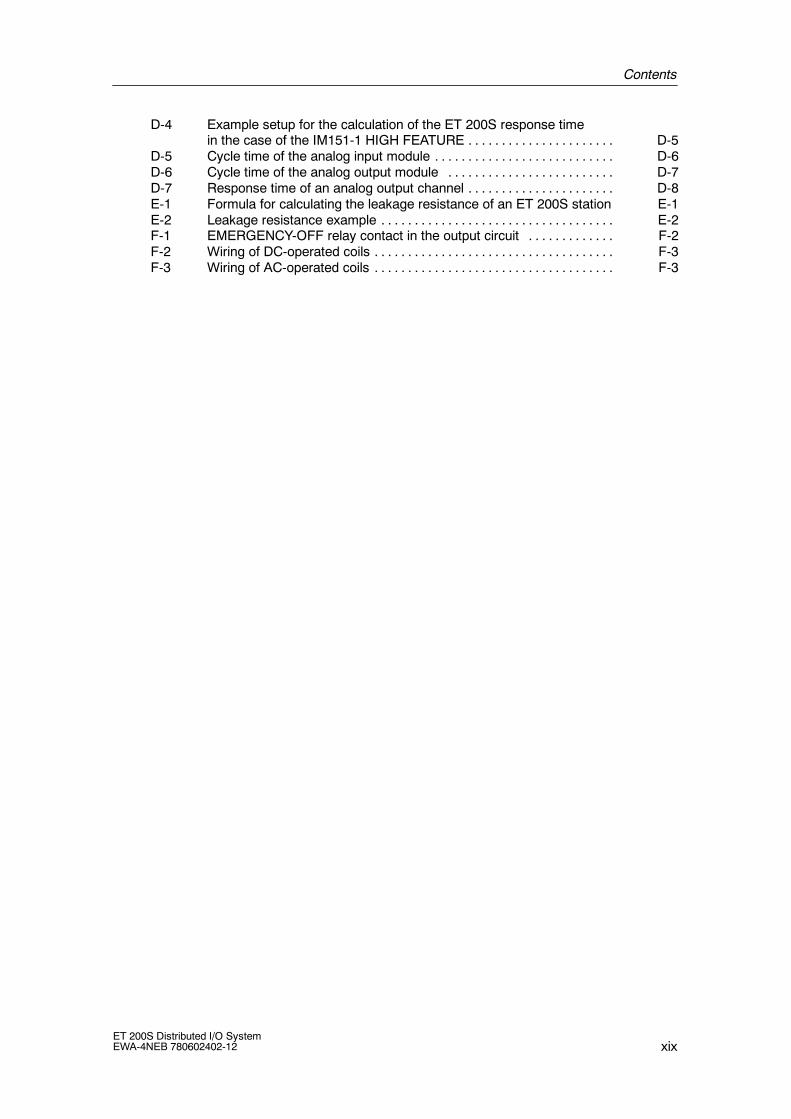
D-4 Example setup for the calculation of the ET 200S response timein the case of the IM151-1 HIGH FEATURE D-5. . . . . . . . . . . . . . . . . . . . . .
D-5 Cycle time of the analog input module D-6. . . . . . . . . . . . . . . . . . . . . . . . . . .D-6 Cycle time of the analog output module D-7. . . . . . . . . . . . . . . . . . . . . . . . .D-7 Response time of an analog output channel D-8. . . . . . . . . . . . . . . . . . . . . .E-1 Formula for calculating the leakage resistance of an ET 200S station E-1E-2 Leakage resistance example E-2. . . . . . . . . . . . . . . . . . . . . . . . . . . . . . . . . . .F-1 EMERGENCY-OFF relay contact in the output circuit F-2. . . . . . . . . . . . .F-2 Wiring of DC-operated coils F-3. . . . . . . . . . . . . . . . . . . . . . . . . . . . . . . . . . . .F-3 Wiring of AC-operated coils F-3. . . . . . . . . . . . . . . . . . . . . . . . . . . . . . . . . . . .

Contents
xxET 200S Distributed I/O System
EWA-4NEB 780602402-12
Tables
1-1 ET 200S components 1-7. . . . . . . . . . . . . . . . . . . . . . . . . . . . . . . . . . . . . . . . .1-2 Features and benefits of the ET 200S 1-10. . . . . . . . . . . . . . . . . . . . . . . . . . .1-3 Topics of the manuals in the ET 200S manual package 1-14. . . . . . . . . . . .2-1 Configuration in HWCONFIG for PROFIBUS DP 2-5. . . . . . . . . . . . . . . . .2-2 Configuration in HW CONFIG for PROFINET IO 2-14. . . . . . . . . . . . . . . . .3-1 Examples of ET 200S setups 3-2. . . . . . . . . . . . . . . . . . . . . . . . . . . . . . . . . .3-2 Power supply of the ET 200S 3-4. . . . . . . . . . . . . . . . . . . . . . . . . . . . . . . . . .3-3 Interface modules and the applications for which they are suited 3-7. . . .3-4 Electronic modules and the applications for which they are suitable 3-10.3-5 Assignment of TM-P terminal modules and power modules 3-13. . . . . . . .3-6 Assignment of TM-E terminal modules and electronic modules 3-14. . . . .3-7 Terminal modules for power modules 3-19. . . . . . . . . . . . . . . . . . . . . . . . . . . .3-8 Terminal modules for electronic modules 3-23. . . . . . . . . . . . . . . . . . . . . . . .3-9 Control interface 3-41. . . . . . . . . . . . . . . . . . . . . . . . . . . . . . . . . . . . . . . . . . . . .3-10 Feedback interface 3-41. . . . . . . . . . . . . . . . . . . . . . . . . . . . . . . . . . . . . . . . . .3-11 Troubleshooting for option handling 3-41. . . . . . . . . . . . . . . . . . . . . . . . . . . .3-12 Structure of DS 248 for ET 200S 3-42. . . . . . . . . . . . . . . . . . . . . . . . . . . . . . .3-13 Principle structure of data sets with identification data 3-43. . . . . . . . . . . .3-14 Identification data 3-44. . . . . . . . . . . . . . . . . . . . . . . . . . . . . . . . . . . . . . . . . . . .3-15 Parameter length in bytes 3-46. . . . . . . . . . . . . . . . . . . . . . . . . . . . . . . . . . . . .3-16 Maximum configuration per potential group 3-47. . . . . . . . . . . . . . . . . . . . . .4-1 Installation measurements 4-3. . . . . . . . . . . . . . . . . . . . . . . . . . . . . . . . . . . . .5-1 Removing and inserting electronic modules 5-28. . . . . . . . . . . . . . . . . . . . . .6-1 Integrating the device database file in your configuration software 6-3. . .6-2 Configuration and address space 6-9. . . . . . . . . . . . . . . . . . . . . . . . . . . . . . .6-3 Software requirements for commissioning on PROFIBUS DP 6-10. . . . . .6-4 Requirements for commissioning the ET 200S on PROFIBUS DP 6-10. .6-5 Procedure for commissioning the DP slave 6-10. . . . . . . . . . . . . . . . . . . . . .6-6 Status and error displays using LEDs on the IM151-1 BASIC / IM151-1
STANDARD/ IM151-1 FO STANDARD / IM151-1 HIGH FEATURE 6-12. .6-7 Reading the diagnosis out using STEP 7 and STEP 5
on PROFIBUS DP 6-26. . . . . . . . . . . . . . . . . . . . . . . . . . . . . . . . . . . . . . . . . . . .6-8 Structure of station status 1 (byte 0) 6-31. . . . . . . . . . . . . . . . . . . . . . . . . . . .6-9 Structure of station status 2 (byte 1) 6-32. . . . . . . . . . . . . . . . . . . . . . . . . . . .6-10 Structure of station status 3 (byte 2) 6-32. . . . . . . . . . . . . . . . . . . . . . . . . . . .6-11 Structure of the manufacturer ID (Bytes 4, 5) 6-33. . . . . . . . . . . . . . . . . . . . .6-12 Power module error types 6-40. . . . . . . . . . . . . . . . . . . . . . . . . . . . . . . . . . . . .6-13 Digital electronic module error types 6-40. . . . . . . . . . . . . . . . . . . . . . . . . . . .6-14 Analog input module error types 6-42. . . . . . . . . . . . . . . . . . . . . . . . . . . . . . . .6-15 Analog output module error types 6-43. . . . . . . . . . . . . . . . . . . . . . . . . . . . . . .6-16 1SSI 6-43. . . . . . . . . . . . . . . . . . . . . . . . . . . . . . . . . . . . . . . . . . . . . . . . . . . . . . . .6-17 1Count 24V/100kHz 6-44. . . . . . . . . . . . . . . . . . . . . . . . . . . . . . . . . . . . . . . . . .6-18 1Count 5V/500kHz 6-44. . . . . . . . . . . . . . . . . . . . . . . . . . . . . . . . . . . . . . . . . . .6-19 1STEP 5V/204kHz 6-44. . . . . . . . . . . . . . . . . . . . . . . . . . . . . . . . . . . . . . . . . . .6-20 2PULSE 6-45. . . . . . . . . . . . . . . . . . . . . . . . . . . . . . . . . . . . . . . . . . . . . . . . . . . .6-21 1POS INC/Digital, 1POS SSI/Digital, 1POS INC/Analog,
1POS SSI/Analog 6-46. . . . . . . . . . . . . . . . . . . . . . . . . . . . . . . . . . . . . . . . . . . .6-22 1SI 3964/ASCII, 1SI Modbus/USS 6-46. . . . . . . . . . . . . . . . . . . . . . . . . . . . . .6-23 4 IQ-SENSE 6-47. . . . . . . . . . . . . . . . . . . . . . . . . . . . . . . . . . . . . . . . . . . . . . . . .6-24 Integrating the device database file in your configuration software 6-58. . .6-25 Software requirements for commissioning on PROFINET IO 6-59. . . . . . .6-26 Requirements for commissioning the ET 200S on PROFINET IO 6-59. . .6-27 Steps for commissioning the I/O device 6-59. . . . . . . . . . . . . . . . . . . . . . . . .6-28 Status and error displays of the IM151-3 PN 6-61. . . . . . . . . . . . . . . . . . . . .
Contents
xxiET 200S Distributed I/O SystemEWA-4NEB 780602402-12
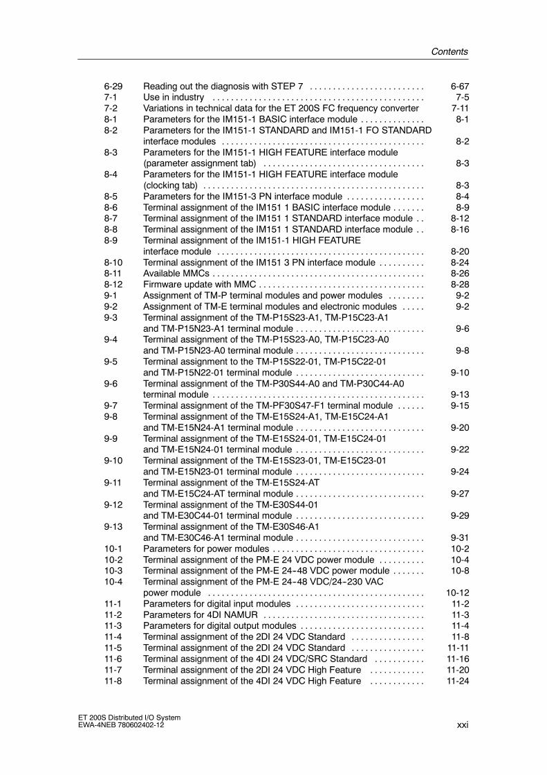
6-29 Reading out the diagnosis with STEP 7 6-67. . . . . . . . . . . . . . . . . . . . . . . . .7-1 Use in industry 7-5. . . . . . . . . . . . . . . . . . . . . . . . . . . . . . . . . . . . . . . . . . . . . .7-2 Variations in technical data for the ET 200S FC frequency converter 7-118-1 Parameters for the IM151-1 BASIC interface module 8-1. . . . . . . . . . . . . .8-2 Parameters for the IM151-1 STANDARD and IM151-1 FO STANDARD
interface modules 8-2. . . . . . . . . . . . . . . . . . . . . . . . . . . . . . . . . . . . . . . . . . . .8-3 Parameters for the IM151-1 HIGH FEATURE interface module
(parameter assignment tab) 8-3. . . . . . . . . . . . . . . . . . . . . . . . . . . . . . . . . . .8-4 Parameters for the IM151-1 HIGH FEATURE interface module
(clocking tab) 8-3. . . . . . . . . . . . . . . . . . . . . . . . . . . . . . . . . . . . . . . . . . . . . . . .8-5 Parameters for the IM151-3 PN interface module 8-4. . . . . . . . . . . . . . . . .8-6 Terminal assignment of the IM151 1 BASIC interface module 8-9. . . . . . .8-7 Terminal assignment of the IM151 1 STANDARD interface module 8-12. .8-8 Terminal assignment of the IM151 1 STANDARD interface module 8-16. .8-9 Terminal assignment of the IM151-1 HIGH FEATURE
interface module 8-20. . . . . . . . . . . . . . . . . . . . . . . . . . . . . . . . . . . . . . . . . . . . .8-10 Terminal assignment of the IM151 3 PN interface module 8-24. . . . . . . . . .8-11 Available MMCs 8-26. . . . . . . . . . . . . . . . . . . . . . . . . . . . . . . . . . . . . . . . . . . . . .8-12 Firmware update with MMC 8-28. . . . . . . . . . . . . . . . . . . . . . . . . . . . . . . . . . . .9-1 Assignment of TM-P terminal modules and power modules 9-2. . . . . . . .9-2 Assignment of TM-E terminal modules and electronic modules 9-2. . . . .9-3 Terminal assignment of the TM-P15S23-A1, TM-P15C23-A1
and TM-P15N23-A1 terminal module 9-6. . . . . . . . . . . . . . . . . . . . . . . . . . . .9-4 Terminal assignment of the TM-P15S23-A0, TM-P15C23-A0
and TM-P15N23-A0 terminal module 9-8. . . . . . . . . . . . . . . . . . . . . . . . . . . .9-5 Terminal assignment to the TM-P15S22-01, TM-P15C22-01
and TM-P15N22-01 terminal module 9-10. . . . . . . . . . . . . . . . . . . . . . . . . . . .9-6 Terminal assignment of the TM-P30S44-A0 and TM-P30C44-A0
terminal module 9-13. . . . . . . . . . . . . . . . . . . . . . . . . . . . . . . . . . . . . . . . . . . . . .9-7 Terminal assignment of the TM-PF30S47-F1 terminal module 9-15. . . . . .9-8 Terminal assignment of the TM-E15S24-A1, TM-E15C24-A1
and TM-E15N24-A1 terminal module 9-20. . . . . . . . . . . . . . . . . . . . . . . . . . . .9-9 Terminal assignment of the TM-E15S24-01, TM-E15C24-01
and TM-E15N24-01 terminal module 9-22. . . . . . . . . . . . . . . . . . . . . . . . . . . .9-10 Terminal assignment of the TM-E15S23-01, TM-E15C23-01
and TM-E15N23-01 terminal module 9-24. . . . . . . . . . . . . . . . . . . . . . . . . . . .9-11 Terminal assignment of the TM-E15S24-AT
and TM-E15C24-AT terminal module 9-27. . . . . . . . . . . . . . . . . . . . . . . . . . . .9-12 Terminal assignment of the TM-E30S44-01
and TM-E30C44-01 terminal module 9-29. . . . . . . . . . . . . . . . . . . . . . . . . . . .9-13 Terminal assignment of the TM-E30S46-A1
and TM-E30C46-A1 terminal module 9-31. . . . . . . . . . . . . . . . . . . . . . . . . . . .10-1 Parameters for power modules 10-2. . . . . . . . . . . . . . . . . . . . . . . . . . . . . . . . .10-2 Terminal assignment of the PM-E 24 VDC power module 10-4. . . . . . . . . .10-3 Terminal assignment of the PM-E 24--48 VDC power module 10-8. . . . . . .10-4 Terminal assignment of the PM-E 24--48 VDC/24--230 VAC
power module 10-12. . . . . . . . . . . . . . . . . . . . . . . . . . . . . . . . . . . . . . . . . . . . . . .11-1 Parameters for digital input modules 11-2. . . . . . . . . . . . . . . . . . . . . . . . . . . .11-2 Parameters for 4DI NAMUR 11-3. . . . . . . . . . . . . . . . . . . . . . . . . . . . . . . . . . .11-3 Parameters for digital output modules 11-4. . . . . . . . . . . . . . . . . . . . . . . . . . .11-4 Terminal assignment of the 2DI 24 VDC Standard 11-8. . . . . . . . . . . . . . . .11-5 Terminal assignment of the 2DI 24 VDC Standard 11-11. . . . . . . . . . . . . . . .11-6 Terminal assignment of the 4DI 24 VDC/SRC Standard 11-16. . . . . . . . . . .11-7 Terminal assignment of the 2DI 24 VDC High Feature 11-20. . . . . . . . . . . .11-8 Terminal assignment of the 4DI 24 VDC High Feature 11-24. . . . . . . . . . . .

Contents
xxiiET 200S Distributed I/O System
EWA-4NEB 780602402-12
11-9 Terminal assignment of the 4DI 24 VUC High Feature 11-29. . . . . . . . . . . .11-10 Terminal assignment of NAMUR sensors or sensors as per DIN 19234 11-3311-11 Terminal assignment of NAMUR changeover contacts or sensors as
per DIN 19234 11-34. . . . . . . . . . . . . . . . . . . . . . . . . . . . . . . . . . . . . . . . . . . . . . .11-12 Terminal assignment of single contact with 10 kΩ
(mechanical NO contact) 11-34. . . . . . . . . . . . . . . . . . . . . . . . . . . . . . . . . . . . . .11-13 Terminal assignment of changeover contact with 10 kΩ
(mechanical changeover contact) 11-35. . . . . . . . . . . . . . . . . . . . . . . . . . . . . . .11-14 Terminal Assignment of a Single Contact without Load Resistance
(Mechanical NO Contact with Single Contact) 11-35. . . . . . . . . . . . . . . . . . . .11-15 Terminal Assignment of a Changeover Contact without Load Resistance
(Mechanical Changeover Contact) 11-36. . . . . . . . . . . . . . . . . . . . . . . . . . . . . .11-16 Changeover Contact Diagnostics 11-40. . . . . . . . . . . . . . . . . . . . . . . . . . . . . . .11-17 Terminal assignment of the 2DI 24 VDC Standard 11-41. . . . . . . . . . . . . . . .11-18 Terminal assignment of the 2DI 230 VAC Standard 11-45. . . . . . . . . . . . . . .11-19 Terminal assignment of the 2DO 24 VDC/0.5 A Standard 11-48. . . . . . . . . .11-20 Terminal assignment of the 4DO 24 VDC/0.5 A Standard 11-52. . . . . . . . . .11-21 Terminal assignment of the 2DO 24 VDC/0.5 A High Feature 11-56. . . . . .11-22 Terminal assignment of the 2DO 24 VDC/2 A Standard 11-60. . . . . . . . . . .11-23 Terminal assignment of the 4DO 24 VDC/2 A Standard 11-64. . . . . . . . . . .11-24 Terminal assignment of the 2DO 24 VDC/2 A High Feature 11-68. . . . . . . .11-25 Terminal assignment of the 2DO 24--230 VAC 11-72. . . . . . . . . . . . . . . . . . . .11-26 Terminal assignment of the 2RO NO 24--120 VDC/5 A 24--230 VAC/5 A
(from product level 2) 11-77. . . . . . . . . . . . . . . . . . . . . . . . . . . . . . . . . . . . . . . . .11-27 Switching capacity and service life of relay contacts 11-80. . . . . . . . . . . . . .11-28 Terminal assignment of the
2RO NO/NC 24--48 VDC/5 A 24--230 VAC/5 A 11-82. . . . . . . . . . . . . . . . . . .11-29 Switching capacity and service life of contacts 11-85. . . . . . . . . . . . . . . . . . .12-1 Measured Values in the Event of Wire Break Dependent on Enabled
Diagnostics 12-3. . . . . . . . . . . . . . . . . . . . . . . . . . . . . . . . . . . . . . . . . . . . . . . . . .12-2 Analog Value Representation (SIMATIC S7 Format) 12-4. . . . . . . . . . . . . . .12-3 Measured Value Resolution of the Analog Values
(SIMATIC S7 Format) 12-4. . . . . . . . . . . . . . . . . . . . . . . . . . . . . . . . . . . . . . . . .12-4 SIMATIC S7 Format: Measuring ranges
80 mV, 2.5 V, 5 V and 10 V 12-5. . . . . . . . . . . . . . . . . . . . . . . . . . . . .12-5 SIMATIC S7 Format: Measuring ranges 1 to 5 V, 0 to 20 mA, 4
to 20 mA 12-6. . . . . . . . . . . . . . . . . . . . . . . . . . . . . . . . . . . . . . . . . . . . . . . . . . . .12-6 SIMATIC S7 Format: Measuring range 20 mA 12-6. . . . . . . . . . . . . . . . . .12-7 SIMATIC S7 Format: Measuring ranges
150 Ω, 300 Ω, 600 Ω, 3000 Ω 12-7. . . . . . . . . . . . . . . . . . . . . . . . . . . . . . . . . .12-8 SIMATIC S7 Format: Measuring Ranges
Pt 100, 200, 500, 1000 Standard in °C and °F 12-8. . . . . . . . . . . . . . . . . . . .12-9 SIMATIC S7 Format: Measuring Ranges
Pt 100, 200, 500, 1000 Climatic in °C and °F 12-8. . . . . . . . . . . . . . . . . . . . .12-10 SIMATIC S7 Format: Measuring Ranges
Ni 100, 200, 500, 1000 Standard in °C and °F 12-9. . . . . . . . . . . . . . . . . . . .12-11 SIMATIC S7 Format: Measuring Ranges
Ni 100, 120, 200, 500, 1000 Climatic in °C and °F 12-9. . . . . . . . . . . . . . . . .12-12 SIMATIC S7 Format: Measuring Ranges
Cu 10 Standard in °C and °F 12-10. . . . . . . . . . . . . . . . . . . . . . . . . . . . . . . . . . .12-13 SIMATIC S7 Format: Measuring Ranges
Cu 10 Climatic in °C and °F 12-10. . . . . . . . . . . . . . . . . . . . . . . . . . . . . . . . . . . .12-14 SIMATIC S7 Format: Measuring Range Type B in °C and °F 12-11. . . . . . .12-15 SIMATIC S7 Format: Measuring Range Type C in °C and °F 12-11. . . . . . .12-16 SIMATIC S7 Format: Measuring Range Type E in °C and °F 12-12. . . . . . .

Contents
xxiiiET 200S Distributed I/O SystemEWA-4NEB 780602402-12
12-17 SIMATIC S7 Format: Measuring Range Type J in °C and °F 12-12. . . . . . . .12-18 SIMATIC S7 Format: Measuring range type K in °C and °F 12-13. . . . . . . . .12-19 SIMATIC S7 Format: Measuring Range Type L in °C and °F 12-13. . . . . . . .12-20 SIMATIC S7 Format: Measuring Range Type N in °C and °F 12-14. . . . . . .12-21 SIMATIC S7 Format: Measuring Range Type R, S in °C and °F 12-14. . . . .12-22 SIMATIC S7 Format: Measuring Range Type T in °C and °F 12-15. . . . . . .12-23 SIMATIC S7 format: Output ranges 5 V; 10 V; 20 mA 12-16. . . . . . . .12-24 SIMATIC S7 Format: Output ranges 1 to 5 V; 4 to 20 mA 12-16. . . . . . . . . .12-25 Compensation of the Reference Junction Temperature 12-21. . . . . . . . . . . .12-26 Reference Junction Parameters 12-24. . . . . . . . . . . . . . . . . . . . . . . . . . . . . . . .12-27 Dependence of the Input and Output Values on the Operating State
of the PLC (CPU of the DP Master)and the Power Supply Voltage L + 12-27. . . . . . . . . . . . . . . . . . . . . . . . . . . . .
12-28 Response of the Analog Modules, Dependingon the Location of the Analog Input Value in the Range of Values 12-28. .
12-29 Response of the Analog Modules, Depending on the Locationof the Analog Output Value in the Range of Values 12-28. . . . . . . . . . . . . . .
12-30 Parameters for analog input modules U, I ST 12-29. . . . . . . . . . . . . . . . . . . .12-31 Parameters for analog input modules U, I High Feature 12-30. . . . . . . . . . . .12-32 Parameters for analog input modules U, I High Speed 12-31. . . . . . . . . . . .12-33 Parameters RTD, TC analog electronic modules 12-32. . . . . . . . . . . . . . . . . .12-34 Parameters for 2AI RTD High Feature analog electronic module 12-34. . . .12-35 Parameters for analog output modules U, I 12-38. . . . . . . . . . . . . . . . . . . . . .12-36 Terminal assignment of the 2AI U Standard 12-42. . . . . . . . . . . . . . . . . . . . . .12-37 Terminal assignment of the 2AI U High Feature 12-46. . . . . . . . . . . . . . . . . . .12-38 Terminal assignment of the 2AI U High Speed 12-50. . . . . . . . . . . . . . . . . . .12-39 Terminal assignment of the 2AI I 2WIRE Standard 12-54. . . . . . . . . . . . . . .12-40 Terminal assignment of the 4AI I 2WIRE Standard 12-58. . . . . . . . . . . . . . .12-41 Terminal assignment of the 2AI I 2WIRE High Speed 12-62. . . . . . . . . . . . .12-42 Terminal assignment of the 2AI I 4WIRE Standard 12-67. . . . . . . . . . . . . . . .12-43 Terminal assignment of the 2AI I 2/4WIRE High Feature 12-70. . . . . . . . . .12-44 Terminal assignment of the 2AI I 4WIRE High Speed 12-75. . . . . . . . . . . . . .12-45 Terminal assignment of the 2AI RTD Standard 12-79. . . . . . . . . . . . . . . . . . .12-46 Terminal assignment of the 2AI RTD High Feature 12-83. . . . . . . . . . . . . . .12-47 Terminal assignment of the 2AI TC Standard 12-90. . . . . . . . . . . . . . . . . . . .12-48 Terminal assignment of the 2AI TC High Feature 12-95. . . . . . . . . . . . . . . . .12-49 Terminal assignment of the 2AO U Standard 12-100. . . . . . . . . . . . . . . . . . . . .12-50 Terminal assignment of the 2AO U High Feature 12-104. . . . . . . . . . . . . . . . . .12-51 Terminal assignment of the 2AO I Standard 12-107. . . . . . . . . . . . . . . . . . . . . .12-52 Terminal assignment of the 2AO I High Feature 12-111. . . . . . . . . . . . . . . . . .13-1 Parameters for 4 IQ-SENSE 13-3. . . . . . . . . . . . . . . . . . . . . . . . . . . . . . . . . . .13-2 Standard feedback interface 13-10. . . . . . . . . . . . . . . . . . . . . . . . . . . . . . . . . . .13-3 Enhanced feedback interface 13-10. . . . . . . . . . . . . . . . . . . . . . . . . . . . . . . . . .13-4 Enhanced control interface 13-12. . . . . . . . . . . . . . . . . . . . . . . . . . . . . . . . . . . .13-5 Terminal assignment of the 4 IQ-SENSE 13-15. . . . . . . . . . . . . . . . . . . . . . . .A-1 Interface module order numbers A-1. . . . . . . . . . . . . . . . . . . . . . . . . . . . . . . .A-2 Terminal module order numbers A-2. . . . . . . . . . . . . . . . . . . . . . . . . . . . . . .A-3 Power module order numbers A-3. . . . . . . . . . . . . . . . . . . . . . . . . . . . . . . . . .A-4 Digital electronic module order numbers A-3. . . . . . . . . . . . . . . . . . . . . . . .A-5 Analog electronic module order numbers A-5. . . . . . . . . . . . . . . . . . . . . . . .A-6 Process-related module order numbers A-5. . . . . . . . . . . . . . . . . . . . . . . . .A-7 Reserve module order numbers A-6. . . . . . . . . . . . . . . . . . . . . . . . . . . . . . . .A-8 ET 200S accessories order numbers A-6. . . . . . . . . . . . . . . . . . . . . . . . . . .A-9 Network components (PROFIBUS DP) for ET 200S order numbers A-7.A-10 Network components (PROFINET I/O) for ET 200S order numbers A-8.

Contents
xxivET 200S Distributed I/O System
EWA-4NEB 780602402-12
A-11 Fuse for digital input module and power module A-8. . . . . . . . . . . . . . . . . .A-12 Connecting cable for 4 IQ-SENSE electronic module A-8. . . . . . . . . . . . . .A-13 ET 200S documentation packages or manuals A-9. . . . . . . . . . . . . . . . . . .A-14 STEP 7 and SIMATIC S7 manuals A-10. . . . . . . . . . . . . . . . . . . . . . . . . . . . .A-15 STEP 7 and SIMATIC S7 manuals A-12. . . . . . . . . . . . . . . . . . . . . . . . . . . . . .A-16 Technical Guide to PROFIBUS DP and SIMATIC S7 A-12. . . . . . . . . . . . . .C-1 Inputs and outputs for the ET 200S C-1. . . . . . . . . . . . . . . . . . . . . . . . . . . .

1-1ET 200S Distributed I/O SystemEWA-4NEB 780602402-12
Product Overview
Chapter overview
The product overview tells you:
• The place of the ET 200S distributed I/O system in the ET 200 distributed I/Osystem.
• The place of ET 200S as an I/O device in PROFINET IO.
• The components that make up the ET 200S distributed I/O system
• Which of the manuals in the ET 200S manual package contains the informationyou require.
Chapter overview
Chapter Description Page
1.1 What are distributed I/O systems? 1-1
1.2 What is PROFINET IO? 1-4
1.3 What is the ET 200S distributed I/O system? 1-5
1.4 Guide to the ET 200S manuals 1-12
1.1 What are distributed I/O systems?
Distributed I/O systems -- area of application
When a system is set up, the inputs and outputs from and to the process are oftenlocated centrally in the programmable logic controller.
If there are inputs and outputs at considerable distances from the programmablelogic controller, there may be long runs of cabling which are not immediatelycomprehensible, and electromagnetic interference may impair reliability.
Distributed I/O systems are the ideal solution in such cases:
• The controller CPU is located centrally.
• The I/O systems (inputs and outputs) operate locally on a distributed basis.
• The high-performance PROFIBUS DP bus system with its high datatransmission rates ensures that the PLC’s CPU and the I/O systemscommunicate smoothly.
1

Product Overview
1-2ET 200S Distributed I/O System
EWA-4NEB 780602402-12
What is PROFIBUS DP?
PROFIBUS DP is an open bus system based on theIEC 61784-1:2002 Ed1 CP 3/1 standard with the ”DP” transmission protocol(DP stands for distributed I/O).
PROFIBUS DP is physically either an electrical network based on a shieldedtwo-wire line or an optical network based on a fiber-optic cable.
The ”DP” transmission protocol allows a rapid, cyclic exchange of data betweenthe controller CPU and the distributed I/O systems.
What are DP masters and DP slaves?
The DP master links the controller CPU with the distributed I/O systems. The DPmaster exchanges data with the distributed I/O systems and monitors thePROFIBUS DP bus system via PROFIBUS DP.
The distributed I/O systems (= DP slaves) prepare the data of the sensors andactuators locally so that they can be transmitted to the PLC CPU byPROFIBUS DP.
Which devices can be connected to the PROFIBUS DP?
An extremely wide range of devices can be connected to the PROFIBUS as DPmasters or DP slaves, provided their behavior complies withIEC 61784-1:2002 Ed1 CP 3/1. The devices that can be used include the following:
• SIMATIC S5
• SIMATIC S7/M7/C7
• SIMATIC programming device/PC
• SIMATIC human-machine interface, or HMI (operator panel, OP; operatorstation, OS; and text display, TD)
• Devices from other manufacturers

Product Overview
1-3ET 200S Distributed I/O SystemEWA-4NEB 780602402-12
Structure of a PROFIBUS DP network
The figure below illustrates a typical PROFIBUS DP network structure. The DPmasters are integrated into the relevant device -- for example, the S7 400 has aPROFIBUS DP interface and the IM 308-C is inserted in an S5-115U. The DPslaves are the distributed I/O systems connected to the DP masters byPROFIBUS DP.
DP-master
DP-slaves
PROFIBUS DP
S7-400 Programming device/PC
ET 200L ET 200M ET 200B S5-95U-DP
Other field devices
with IM 308-CS5-115U
ET 200X OP/OS
S7-200Drive DP/AS-I LINKET 200S
Figure 1-1 Typical PROFIBUS DP network structure

Product Overview
1-4ET 200S Distributed I/O System
EWA-4NEB 780602402-12
1.2 What is PROFINET IO?
PROFINET IO is the open transmission with realtime functions defined inaccordance with the PROFINET standard.The standard defines a manufacturer-independent communication, automation andengineering model.Industrial quality connection designs are available for wiring the PROFINETcomponents.
• PROFINET does not use the hierarchical PROFIBUS master-slave principle. Aprovider-consumer principle is used instead. The planning process specifieswhich modules of an I/O device will be subscribed to an I/O controller.
• The quantities are extended in accordance with the options offered by thePROFINET IO. Parameter limits are not exceeded during configuration.
• The transmission rate is 100 Mbps.
• The user view during configuration is generally the same as that on thePROFIBUS DP (STEP 7 → HWCONFIG is used for configuration).
Structure of a PROFINET IO network
The figure below illustrates a typical PROFINET IO network structure. ExistingPROFIBUS slaves can be integrated by an IE/PB link.
I/O controllerS7-300
I/O deviceET 200S
ProgrammingdeviceOP 25
I/O deviceET 200S
max. 100 mPROFINET IO
(IndustrialEthernet)
Switch SwitchSwitchSwitchSwitch
IE/PBlink
PROFIBUS DP
Figure 1-2 A typical PROFINET IO network structure

Product Overview
1-5ET 200S Distributed I/O SystemEWA-4NEB 780602402-12
1.3 What is the ET 200S distributed I/O system?
Definition
The ET 200S distributed I/O system is a highly modular, extremely flexibleDP slave I/O device with IP20 degree of protection.
Area of application
You can connect virtually any number of I/O modules in virtually any combinationright next to the interface module that transfers the data to the DP master and I/Ocontroller. This means you can adjust the configuration to suit local requirements.
Depending on the interface module, each ET 200S can consist of up to 63modules -- for example, power modules, I/O modules, and motor starters.
The fact that motor starters can be integrated (switching and protecting anythree-phase load up to 7.5 kW) ensures that the ET 200S can be quickly adaptedto suit virtually any process-related use of your machine.
The fail-safe modules of the ET 200S ensure the fail-safe reading and output ofdata to safety category 4 (EN 954-1)
Terminal modules and electronic modules
The ET 200S distributed I/O system is
• connected to PROFIBUS DP at the IM151 interface module by a plugconnector for PROFIBUS DP
• connected to PROFINET IO at the IM151-3 PN interface module by a plugconnector for PROFINET IO
Every ET 200S distributed I/O system is
• a DP slave on the PROFIBUS DP or
• an I/O device on the PROFINET IO.

Product Overview
1-6ET 200S Distributed I/O System
EWA-4NEB 780602402-12
View
The figure below shows an example of an ET 200S configuration.
ET 200S interface moduleIM151-1
PM-E power modulefor electronicmodules
Electronic modules Power module for PM-Dmotor starters
Direct-on-line starter Reversible starters
TM-E terminalmodules forelectronic modules
Power bus
Terminating module
TM-P terminalmodules forpower modules
A8
A4
Figure 1-3 View of the ET 200S distributed I/O system

Product Overview
1-7ET 200S Distributed I/O SystemEWA-4NEB 780602402-12
ET 200S components
The following table provides you with an overview of the most importantcomponents of the ET 200S:
Table 1-1 ET 200S components
Component Function Drawing
Rail ...carries the ET 200S. Youmount the ET 200S on therail.
Interface module
• IM151-1BASIC
• IM151-1STANDARD
• IM151-1 FOSTANDARD
• IM151-1 HIGHFEATURE
...connects the ET 200S withthe DP master and preparesthe data for the electronicmodules and motor starters.
IM151-1BASIC
IM151-1STANDARD
IM151-1HIGHFEATURE
IM151-1 FOSTANDARD
RS485interface
Fiber opticinterface
Interface module
• IM151-3 PN
...connects the ET 200S withPROFINET IO controllersand prepares the data for theelectronic modules and motorstarters.
PROFINETinterface

Product Overview
1-8ET 200S Distributed I/O System
EWA-4NEB 780602402-12
Table 1-1 ET 200S components
Component DrawingFunction
Terminal module ...carries the wiring andreceives the power andelectronic modules. Terminalmodules are available in thefollowing variants:
• For power modules
• For electronic modules
• With screw-type terminal
• With spring terminal
• With Fast Connect(quick connectionmethod, no strippingrequired)
Power module ...monitors the voltage for allthe electronic modules in thepotential group. The followingpower modules are available:
• For a 24 VDC supply withdiagnostics
• For a 24 to 48 VDCsupply with diagnostics
• For a 24 to 48 VDC, 24 to230 VAC supply withdiagnostics and fuse
Electronic module ...is connected to the terminalmodule and determines thefunction:
• Digital input modules with24 VDC, 120/230 VACand NAMUR
• Digital output moduleswith 24 VDC and 120/230VAC
• Relay modules
• Analog input modules withvoltage, current, andresistance measurement;thermal resistance; andthermocouples
• Analog output modules forvoltage and current
• Process-related modules
• Fail-safe modules
• RESERVE
Terminatingmodule
...terminates the ET 200S andcan be used to carry 6reserve fuses (5 mm x 20mm).

Product Overview
1-9ET 200S Distributed I/O SystemEWA-4NEB 780602402-12
Table 1-1 ET 200S components
Component DrawingFunction
Shield contact ...for connecting cableshields.
Labeling sheet(DIN A4,perforated, foil)
...for machine labeling orprinting
• 80 strips per labelingsheet
Slot number labels ...for identifying the slots onthe terminal module.
1 2 62 63
Color identificationlabels
...permit customer andcountry-specific identificationof the terminals on theterminal module
PROFIBUS cablewith bus connector
... connects nodes of aPROFIBUS DP configurationto each other.
Fiber optic duplexline with simplexconnector(in plug adapter forIM151-1 FOSTANDARD)
... connects nodes of aPROFIBUS DP configurationto each other.
PROFINETconnector as perthe specificationsin the PROFINETInstallation Guideand IndustrialEthernet FCinstallation lines
... connects nodes of aPROFINET IO configurationto each other.

Product Overview
1-10ET 200S Distributed I/O System
EWA-4NEB 780602402-12
Features and benefits of the ET 200S
Table 1-2 Features and benefits of the ET 200S
Features Benefits
Structure
Finely-graduated modular design
• 1/2/4 channel electronic modules
• Power modules
• Integrated motor starters
• Function-oriented, cost-optimized stationdesign
• Considerable reduction in outlay forconfiguration and documentation
• Space savings due to arbitraryarrangement of the modules
Extensive range of electronic modules Broad area of application
System-integrated motor starter withcommunications capability: Direct andreversing starter up to 7.5 kW
PLC inputs and outputs, terminal blocks,circuit breakers and contactors in a plug-inmodule save space and the effort involvedin wiring
Permanent wiring due to the separation ofmechanical and electronic components
• Prewiring possible
• Module replacement during operation ofthe ET 200S (”hot swapping”)
Individual connection of power modules tocommon potential
• Individual formation of potential groups(identifiable by color coding of the TM-Pterminal modules for power modules)
• Simple load interruption
Robust structure for rough industrialconditions (5 g vibration resistance)
High operating reliability when mounteddirectly on the machine, high availability

Product Overview
1-11ET 200S Distributed I/O SystemEWA-4NEB 780602402-12
Table 1-2 Features and benefits of the ET 200S
Features Benefits
Connection system
Integrated voltage buses Reduced effort required for wiring
Power bus up to 50 A for motor starters Minimization of wiring in 400 V range
Screw-type terminals, spring terminals andFast Connect
A change in terminal connection method isnot necessary
• and 3-wire connection, or
• 2, 3 and 4 line connection
Optimal selection on grounds of space andcost
Fast Connect • Quick connection method with nostripping required
• Saves time with wiring
Terminal box in terminal module replaceable No need to remove the terminal module inthe event of terminal damage
Automatic coding of the I/O modules Quick and reliable module replacement
Large label plate Adequate space for clear identification
High data transmission speed of up to12 Mbps on PROFIBUS DP and 100 Mbpson PROFINET IO
Short response times
Integrated safety functions
With motor starters up to safetycategory 4 in accordance with EN 954-1
Saves spending money on costly safetyequipment
Fail-safe modules To detect and output fail-safe-signals viaPROFIBUS (PROFIsafe) up to safetycategory 4 (EN 954-1)

Product Overview
1-12ET 200S Distributed I/O System
EWA-4NEB 780602402-12
1.4 Guide to the ET 200S manuals
You are using the following components ...
The components of ET 200S are described in various manuals. They are parts ofvarious documentation packages. The figure below shows possible configurationvariants of the ET 200S and the necessary manuals in the documentationpackages.
The ET 200S consists of thefollowing components:
You will require the informationcontained in the following manuals:
ET 200S DistributedI/O SystemIM
151-
1
PM
-E
2DO
2A
I
2A
O
ET 200S DistributedI/O System
PM
-E
2DO
2A
I
2A
O
IM15
1-7
CP
U
IM151-7 CPUinterface module
+
ET 200S DistributedI/O System
IM15
1-1
2DO
1SS
I
2PU
LS
E
ET 200SProcess-RelatedFunctions
+
ET 200S DistributedI/O System
PM
-E
2DO
2A
I
Mo
db
us/
US
S
IM15
1-1
ET 200S Serial InterfaceModule
+
ET 200S DistributedI/O System
PM
-E
2DO
1Po
sIn
c/D
igit
al
1Po
sIn
c/A
nal
og
IM15
1-1
ET 200SPositioning
+
PM
-E
Order numbers forthe necessarydocumentationpackages ormanuals
6ES7 151-1AA10-8xA0
6ES7 151-1AA10-8xA0
6ES7 151-1AC00-8xA0
6ES7 151-1AA10-8xA0
6ES7 151-1AD00-8xA0
6ES7 151-1AE00-8xA0
6ES7 151-1AA10-8xA0
6ES7 151-1AA10-8xA0
6ES7 151-1AB00-8xA0
ET 200S DistributedI/O System
PM
-E
2DO
2A
I
2A
O
IM15
1-3
PN
PROFINET SystemDocumentation
+
6ES7 151-1AA10-8xA0
Figure 1-4 Components and the manuals required for them

Product Overview
1-13ET 200S Distributed I/O SystemEWA-4NEB 780602402-12
The ET 200S consists of thefollowing components:
You will require theinformation contained inthe following manuals:
Order numbers forthe necessarydocumentationpackages or manuals
IM 151PM
ET 200S motor starterFail-safe motor starter
Safety-integratedSIGUARD
ET 200S DistributedI/O System
+
DS DS
IM15
1-1
PM
-E
2DO
2A
O
PM
-D
ET 200S Distributed I/OSystem
PM
-E
2DO
F-D
I
F-D
O
IM15
1-1
ET 200S Distributed I/OsystemFail-Safe modules
+
2DO
PM
-E
6ES7 151-1AA10-8xA0
6ES7 151-1AA10-8xA0
F-DS 1 e-x F-DS 1e-x
IM15
1-1
PM
-E
FD
I
FD
O
PM
-DF
PR
OF
Isaf
e
ET 200S Distributed I/OSystem
6ES7 151-1AA10-8xA0
ET 200S Distributed I/OsystemFail-Safe modules
available in the Internet
ET 200S motor starterFail-safe motor starter
Safety-integrated SIGUARD
+
+
6ES7 151-1AA10-8xA0
6SL3 298-0CA12-0xP0+
ET 200S FC frequency converterOperating manual
ET 200S FC frequency converterList manual
ET 200S Distributed I/O System
+
+
ET 200S FC frequency converterOperating manual
ET 200S FC frequency converterList manual
6SL3 298-0CA12-1xP0
1) ICU24F for fail-safe frequency converter
available in the Internet
In preparation:
Figure 1-5 Components and the manuals required for them (continued)

Product Overview
1-14ET 200S Distributed I/O System
EWA-4NEB 780602402-12
Where do you find what information?
The table below will help you get your bearings and find the information you needquickly. It tells you which manual you need to refer to and which chapter deals withthe topic you are interested in.
Table 1-3 Topics of the manuals in the ET 200S manual package
Manual
Description
ET
200S
Dis
trib
uted
I/OS
yste
m
ET
200S
mot
orst
arte
rF
ail-s
afe
mot
orst
arte
r
IM15
1-7
CP
Uin
terf
ace
mod
ule
ET
200S
Pro
cess
-Rel
ated
Fun
ctio
ns
ET
200S
Pos
ition
ing
ET
200S
Ser
ialI
nter
face
Mod
ule
ET
200S
Dis
trib
uted
I/OS
yste
mF
ail-S
afe
Mod
ules
Saf
ety
Equ
ipm
ent
Sys
tem
Des
crip
tion
S7
Dis
trib
uted
Saf
ety
Con
figur
atio
nan
dP
rogr
amm
ing
ET
200S
FC
FC
freq
uenc
yco
nver
ter
Ope
ratin
gm
anua
l
ET
200S
FC
freq
uenc
yco
nver
ter
List
man
ual
ET 200Scomponents
1 1 1 2 2 2 1/2
Brief Instructions onCommissioning
2 2 2
ConfigurationOptions
3 1 4,5 3 3 1 1
Communication 4 4/5
Configuration 4 7 3 1
Addressing 4 3 5 3
Installation 4 3 5 2
Electricalconfiguration andwiring of the ET200S
5 6
Programming 8 5 6 1
Commissioning andDiagnostics
6 4 7 7 6--8 3
Functions 8 6--8
General TechnicalSpecifications
7 5 8 9
Technicalspecifications
10 2--5 2 2,3 2
Terminal modules 9 6,10--12
2
Power modules 10 7,10,12
Direct starters andsoft starters
8
Reversible starters 9

Product Overview
1-15ET 200S Distributed I/O SystemEWA-4NEB 780602402-12
Table 1-3 Topics of the manuals in the ET 200S manual package
Manual
Description
ET
200S
FC
FC
freq
uenc
yco
nver
ter
Ope
ratin
gm
anua
l
ET
200S
FC
freq
uenc
yco
nver
ter
List
man
ual
S7
Dis
trib
uted
Saf
ety
Con
figur
atio
nan
dP
rogr
amm
ing
Saf
ety
Equ
ipm
ent
Sys
tem
Des
crip
tion
ET
200S
Dis
trib
uted
I/OS
yste
mF
ail-S
afe
Mod
ules
ET
200S
Ser
ialI
nter
face
Mod
ule
ET
200S
Pos
ition
ing
ET
200S
Pro
cess
-Rel
ated
Fun
ctio
ns
IM15
1-7
CP
Uin
terf
ace
mod
ule
ET
200S
mot
orst
arte
rF
ail-s
afe
mot
orst
arte
r
ET
200S
Dis
trib
uted
I/OS
yste
m
Safety-integrated
ET 200SSIGUARD
10
Interface Modules 8
Electronic modules 11,12
Positioning module 3--6
Expansionmodules
11 2/3
Fail-safemodules
12 9 2/3
Monitoring, cycleandreaction times
9 12 9
Order Numbers A A 11
Dimension Drawings B B 10 A1
Applications C--F C
Glossary Gl Gl Gl 13 10 9 A2
ET 200S fail-safe modules
The ET 200S Distributed I/O System Fail-Safe Modules manual is available on theInternet (see Technical Support, Contacts and Training product information ).
ET 200S on the PROFINET IO
More information on the operation of the ET 200S as an I/O device can be found inthe PROFINET System Description and in the From PROFIBUS DP toPROFINET IO programming manual.

Product Overview
1-16ET 200S Distributed I/O System
EWA-4NEB 780602402-12

2-1ET 200S Distributed I/O SystemEWA-4NEB 780602402-12
Brief Instructions on CommissioningET 200S
2.1 Commissioning on PROFIBUS DP
Introduction
The following simple example teaches you step by step how to commission theET 200S on PROFIBUS DP:
• Installing and wiring the ET 200S
• Configuration with STEP 7 using the device database file
• Integration in the user program
• Switching the ET 200S on
• Evaluating the diagnosis:
-- Removal and insertion of modules
-- Switching off the load voltage on the power module
-- Wire break of the actuator wiring on the digital output module
2

Brief Instructions on Commissioning ET 200S
2-2ET 200S Distributed I/O System
EWA-4NEB 780602402-12
The following figure illustrates the ET 200S components you require for theexample on PROFIBUS DP:
DI DI
IM151-1
PM DI DI DO DOPM DO DO
Rail
Terminating module
4 x TM-E15N24-A1 terminal module and2DO 24 VDC/0.5 A High Featureelectronic module
TM-P15N23-A1 terminal module andPM-E 24 VDC power module
4 x TM-E15N24-A1 terminal module and 2DI 24 VDCHigh Feature electronic module
TM-P15N23-A1 terminal module and PM-E 24 VDC power module
IM151-1 STANDARD interface module
PROFIBUS bus connector
1 2 3 4 5 6 7 8 9 10 Slot
Figure 2-1 Components for the example on PROFIBUS DP
Order numbers for the example on PROFIBUS DP
Quantity Order information Order number
1 ¢ Standard rail 35 mm (e.g. 483 mm length) 6ES5 710-8MA11
1 ¢ IM151-1 STANDARD interface module and terminating module,1 unit
6ES7 151-1AA03-0AB0
2 ¢ TM-P15N23-A1 Fast Connect terminal module, 1 unit 6ES7 193-4CC70-0AA0
2 ¢ TM-E15N24-A1 Fast Connect terminal module, 5 units 6ES7 193-4CA70-0AA0
2 ¢ PM-E 24 VDC, 1 unit 6ES7 138-4CA00-0AA0
1 ¢ 2DI 24 VDC High Feature, 5 units 6ES7 131-4BB00-0AB0
1 ¢ 2DO 24 VDC/0.5 A High Feature, 5 units 6ES7 132-4BB00-0AB0
1 ¢ Bus connector 6ES7 972-0BA10-0XA0

Brief Instructions on Commissioning ET 200S
2-3ET 200S Distributed I/O SystemEWA-4NEB 780602402-12
Prerequisites
• You must have set up an S7 station consisting of a power supply module and aDP master (for example, CPU 315-2 DP). A CPU 315-2 DP was used as theDP master in this example. However, any other DP master (IEC 61784-1:2002Ed1 CP 3/1) could be used instead.
• STEP 7 (V 5.0 with ServicePack 3 or higher) is fully installed on yourprogramming device (PG). You must be familiar with STEP 7.
• The programming device must be connected to the DP master.
Installation
1. Mount the rail (35 mm x 7.5 mm or 15 mm) with a length of at least 210 mm ona solid base.
2. Install the various modules on the rail beginning on the left (hook on, swing in,move to the left). Adhere to the following sequence:
-- IM151-1 STANDARD interface module
-- TM-P15N23-A1 terminal module
-- 4 x TM-E15N24-A1 terminal modules
-- TM-P15N23-A1 terminal module
-- 4 x TM-E15N24-A1 terminal modules
-- Terminating module
3. Set the PROFIBUS address 3 on the IM 151-1 STANDARD interface module.
643216
8421
ONOFF
PROFIBUS address 3
Figure 2-2 Setting PROFIBUS Address 3

Brief Instructions on Commissioning ET 200S
2-4ET 200S Distributed I/O System
EWA-4NEB 780602402-12
Wiring and Fitting
1. Wire the ET 200S as shown below:
2
3
AUX1
3
6
7
1 5
2
3
6
7
1 5
2
3
6
7
1 5
2
3
6
7
1 5
2
3
AUX1
3
6
7
1 5
2
3
6
7
1 5
2
3
6
7
1 5
2
3
6
7
1 51L+ 1M
24 VDC
Electronicsupply
24 VDC
Sensor supplypotential group 1
24 VDC
Load supplypotential group 2
6
7
26
7
4 8 8 88 8 8 888
2
4 4 4 44 4 4 4A4
A8
Figure 2-3 Wire the example on the PROFIBUS DP
2. Use the PROFIBUS bus connector to connect the DP master with the ET 200S.The PROFIBUS DP interface is located on the IM 151-1 STANDARD.
3. Insert the power and electronic modules into the terminal modules.
4. Switch on the voltage supply for the DP master.
5. Watch the status LEDs on the DP master.CPU 315-2 DP:
-- 5 VDC ! lights up
-- SF DP ! off
-- BUSF ! flashes

Brief Instructions on Commissioning ET 200S
2-5ET 200S Distributed I/O SystemEWA-4NEB 780602402-12
Configuration
1. Start SIMATIC Manager, and create a new project with a DP master(CPU 315-2 DP, for example). Create OB 1 and OB 82 for the project.
2. Create the PROFIBUS subnet.
3. Connect the PROFIBUS subnet with the DP master in HWCONFIG.
4. Take the ET 200S from the hardware catalog and put it on the PROFIBUS.
5. Set the PROFIBUS address 3 for the ET 200S.
6. Drag the various ET 200S modules from the hardware catalog to theconfiguration table.
7. Mark the electronic modules in the configuration table, and click the ”Packaddresses” button.
Table 2-1 Configuration table in HWCONFIG for PROFIBUS DP
Module/DPidentifier
Order number Iaddress
Oaddress
Comment
1 6ES7 138-4CA00-0AA0 PM-E 24 VDC Power module
2 6ES7 131-4BB00-0AB0 2DI 24 VDC 0 Bits 0.0 and 0.1
3 6ES7 131-4BB00-0AB0 2DI 24 VDC Bits 0.2 and 0.3
4 6ES7 131-4BB00-0AB0 2DI 24 VDC Bits 0.4 and 0.5
5 6ES7 131-4BB00-0AB0 2DI 24 VDC Bits 0.6 and 0.7
6 6ES7 138-4CA00-0AA0 PM-E 24 VDC Power module
7 6ES7 132-4BB00-0AB0 2DO 24 VDC 0 Bits 0.0 and 0.1
8 6ES7 132-4BB00-0AB0 2DO 24 VDC Bits 0.2 and 0.3
9 6ES7 132-4BB00-0AB0 2DO 24 VDC Bits 0.4 and 0.5
10 6ES7 132-4BB00-0AB0 2DO 24 VDC Bits 0.6 and 0.7
8. Set the following parameters:
-- In the DP slave properties dialog box for ET 200S:
Start at Preset <> Actual configuration enabled
Replace modules during operation: enabled
-- In the DP slave properties dialog box for the PM-E 24 VDC, module/DP ID 1(in the configuration table)
Diagnosis: Load voltage not present
-- In the slave DP properties dialog box for 2 DO 24 VDC, module/DP ID 7(in the configuration table)
Diagnosis: wire break A0
9. Save the configuration.

Brief Instructions on Commissioning ET 200S
2-6ET 200S Distributed I/O System
EWA-4NEB 780602402-12
Integration in the user program
1. Create the OB 1 user program in the LAD/STL/FBD editor.
Example 1: Reading an input and controlling an output:
STL Explanation
A I 0.0A M 2.0S Q 0.0
If input bit 0.0 andmemory bit 2.0 are set, thenset output bit 0.0
Example 2: Transferring an input byte to an output byte:
STL Explanation
L PIB 0
T PQB 0
Load I/O byte 0 in the accumulator (bits 0.0to 0.7)
Transfer the contents of the accumulator toI/O output byte 0 (bits 0.0 to 0.7)
2. Save the project in SIMATIC Manager.
3. Load the configuration in the DP master.
Switching on
1. Switch on all the power supplies of the ET 200S.
2. Watch the status LEDs on the DP master and ET 200S.
-- CPU 315-2 DP:
DC 5V: lit
SF DP: off
BUSF: off
-- ET 200S:
SF: Off
BF: Off
ON: lit

Brief Instructions on Commissioning ET 200S
2-7ET 200S Distributed I/O SystemEWA-4NEB 780602402-12
Diagnostics
1. In the event of a fault, OB 82 is started. Evaluate the start information inOB 82.
Tip: In OB 82 call SFC 13 and evaluate the diagnostic frame.See Section 6.1.6.1
Removing and inserting the 2 DI 24 VDC High Feature digital electronic module
1. Remove the 2 DI 24 VDC High Feature electronic module from the terminalmodule during operation.
2. Watch the status LEDs on the IM 151--1 STANDARD:
-- SF: lit ⇒ diagnostic message exists.
-- BF: Off
-- ON: lit
Result: The ET 200S continues to operate problem-free.
3. Evaluate the diagnostic message.
Result:
-- Station status 1 (byte 0): Bit 3 is set ⇒ External diagnostics
-- ID-related diagnostics: Byte 7.1 is set ⇒ slot 2
-- Module status: Byte 19.2 / 19.3: 11B ⇒ no module
4. Insert the removed electronic module in the terminal module again.
Result:
-- Status LEDs on the IM151-1 STANDARD:
SF: Off
BF: Off
ON: lit
-- The diagnostic message is deleted.

Brief Instructions on Commissioning ET 200S
2-8ET 200S Distributed I/O System
EWA-4NEB 780602402-12
Switching off the load voltage on the power module
1. Switch off the load voltage on the PM-E 24 VDC (slot 1).
2. Watch the status LEDs.
IM 151 STANDARD:
-- SF: lit
Power module:
-- PWR: off ⇒ No load voltage at power module
-- SF: lit ⇒ diagnostic message exists.
I/O modules in the potential group:
-- LEDs: lit
3. Evaluate the diagnosis.
Result:
-- Station status 1 (byte 0): Bit 3 is set ⇒ External diagnostics
-- ID-related diagnostics: Byte 7.0 is set ⇒ slot 1
-- Channel-specific diagnosis:
Byte 35.0 to 35.5: 000000B ⇒ slot 1
Byte 37.0 to 37.4: 10001B ⇒ encoder or load voltage missing
4. Switch on the load voltage on the power module again, and evaluate thediagnosis again.
Result:
-- Status LEDs on the IM151-1 STANDARD:
SF: Off
-- Status LEDs on the power module:
PWR: on
SF: Off
-- Status LEDs on the I/O module:
LEDs: Off
-- The diagnostic message is deleted.
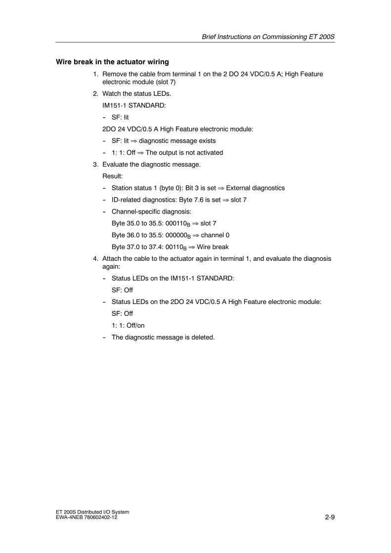
Brief Instructions on Commissioning ET 200S
2-9ET 200S Distributed I/O SystemEWA-4NEB 780602402-12
Wire break in the actuator wiring
1. Remove the cable from terminal 1 on the 2 DO 24 VDC/0.5 A; High Featureelectronic module (slot 7)
2. Watch the status LEDs.
IM151-1 STANDARD:
-- SF: lit
2DO 24 VDC/0.5 A High Feature electronic module:
-- SF: lit ⇒ diagnostic message exists
-- 1: 1: Off ⇒ The output is not activated
3. Evaluate the diagnostic message.
Result:
-- Station status 1 (byte 0): Bit 3 is set ⇒ External diagnostics
-- ID-related diagnostics: Byte 7.6 is set ⇒ slot 7
-- Channel-specific diagnosis:
Byte 35.0 to 35.5: 000110B ⇒ slot 7
Byte 36.0 to 35.5: 000000B ⇒ channel 0
Byte 37.0 to 37.4: 00110B ⇒ Wire break
4. Attach the cable to the actuator again in terminal 1, and evaluate the diagnosisagain:
-- Status LEDs on the IM151-1 STANDARD:
SF: Off
-- Status LEDs on the 2DO 24 VDC/0.5 A High Feature electronic module:
SF: Off
1: 1: Off/on
-- The diagnostic message is deleted.

Brief Instructions on Commissioning ET 200S
2-10ET 200S Distributed I/O System
EWA-4NEB 780602402-12
2.2 Commissioning on the PROFINET IO
Introduction
The following simple example teaches you step by step how to commission theET 200S on PROFINET IO:
• Installing and wiring the ET 200S
• Configuration with STEP 7 using the device database file
• Integration in the user program
• Switching the ET 200S on
• Evaluation of interrupts and diagnoses:
-- Removal and insertion of modules
-- Switching off the load voltage on the power module
-- Wire break of the actuator wiring on the digital output module

Brief Instructions on Commissioning ET 200S
2-11ET 200S Distributed I/O SystemEWA-4NEB 780602402-12
The following figure illustrates the ET 200S components you require for theexample on PROFINET IO:
DI DIIM151-3
PN
PM DI DI DO DOPM DO DO
Rail
Terminating module
4 x TM-E15N24-A1 terminal module and2DO 24 VDC/0.5 A High Featureelectronic module
TM-P15N23-A1 terminal module andPM-E 24 VDC power module
4 x TM-E15N24-A1 terminal module and 2DI 24 VDCHigh Feature electronic module
TM-P15N23-A1 terminal module and PM-E 24 VDC power module
IM151-3 PN interface module
Industrial Ethernet FC installation cable with PROFINET connector
1 2 3 4 5 6 7 8 9 10 Slot
Figure 2-4 Components for the example on PROFINET IO
Order numbers for the example on PROFINET IO
Quantity Order information Order number
1 ¢ Standard rail 35 mm (e. g. 483 mm length) 6ES5 710-8MA11
1 ¢ IM151-3 PN interface module and terminating module, 1 unit 6ES7 151-3AA00-0AB0
1 ¢ MMC (e. g. 64k) 6ES7 953-8LF11-0AA0
2 ¢ TM-P15N23-A1 Fast Connect terminal module, 1 unit 6ES7 193-4CC70-0AA0
2 ¢ TM-E15N24-A1 Fast Connect terminal module, 5 units 6ES7 193-4CA70-0AA0
2 ¢ PM-E 24 VDC, 1 unit 6ES7 138-4CA00-0AA0
1 ¢ 2DI 24 VDC High Feature, 5 units 6ES7 131-4BB00-0AB0
1 ¢ 2DO 24 VDC/0.5 A High Feature, 5 units 6ES7 132-4BB00-0AB0
PROFINET connector (conforming to the specifications in thePROFINET Installation Guide)
Suitable installation cables:
• FC Standard Cable
• FC Trailing Cable
• FC Marine Cable
6XV1 840-2AH10
6XV1 840-3AH10
6XV1 840-4AH10

Brief Instructions on Commissioning ET 200S
2-12ET 200S Distributed I/O System
EWA-4NEB 780602402-12
Prerequisites
• You must have set up an S7 station consisting of a power supply module andan I/O controller (for example, CPU 317-2 PN/DP). A CPU 317-2 PN/DP wasused as the I/O controller in this example.
• STEP 7 (V 5.3 with ServicePack 1 or higher) is fully installed on yourprogramming device (PG). You must be familiar with STEP 7.
• The programming device is connected to the PROFINET IO.
Installation
1. Mount the rail (35 mm x 7.5 mm or 15 mm) with a length of at least 210 mm ona solid base.
2. Install the various modules on the rail beginning on the left (hook on, swing in,move to the left). Adhere to the following sequence:
-- IM151-3 PN interface module
-- TM-P15N23-A1 terminal module
-- 4 x TM-E15N24-A1 terminal modules
-- TM-P15N23-A1 terminal module
-- 4 x TM-E15N24-A1 terminal modules
-- Terminating module
Wiring and Fitting
1. Wire the ET 200S as shown below:
2
3
AUX1
3
6
7
1 5
2
3
6
7
1 5
2
3
6
7
1 5
2
3
6
7
1 5
2
3
AUX1
3
6
7
1 5
2
3
6
7
1 5
2
3
6
7
1 5
2
3
6
7
1 51L+ 1M
24 VDC
Electronicsupply
24 VDC
Sensor supplypotential group 1
24 VDC
Load supplypotential group 2
6
7
26
7
4 8 8 88 8 8 888
2
4 4 4 44 4 4 4A4
A8
Figure 2-5 Wire the example on the PROFINET IO

Brief Instructions on Commissioning ET 200S
2-13ET 200S Distributed I/O SystemEWA-4NEB 780602402-12
2. Connect the ET 200S (IO device) to the I/O controller with the PROFINETconnector via a switch. The PROFINET interface is located on theIM 151-3 PN.
3. Insert the power and electronic modules into the terminal modules.
4. Switch on the voltage supply for the I/O controller.
5. Watch the status LEDs on the I/O controller.CPU 317-2 PN/DP:
-- 5 VDC ! lights up
-- SF ! Off
-- BF2 ! flashes

Brief Instructions on Commissioning ET 200S
2-14ET 200S Distributed I/O System
EWA-4NEB 780602402-12
Configuration
1. Start SIMATIC Manager, and create a new project with an I/O controller(CPU 317-2 PN/DP, for example). Create OB 1, OB 82 and OB 83 for theproject.
2. In HW CONFIG open the window Properties -- Ethernet interface and createa subnet, for example, Ethernet(1).
3. From the hardware catalog add the IM151-3 PN from the ET 200S catalog onEthernet(1):PROFINET IO system (100).
4. Drag the various ET 200S modules from the hardware catalog to theconfiguration table.
Table 2-2 Configuration table in HW CONFIG for PROFINET IO
Module Order number Iaddress
Oaddress
Comment
0 6ES7 151-3AA00-0AB0 IM151-3 PN
1 6ES7 138-4CA00-0AA0 PM-E 24 VDC Power module
2 6ES7 131-4BB00-0AB0 2DI 24 VDC 0 Bits 0.0 and 0.1
3 6ES7 131-4BB00-0AB0 2DI 24 VDC 1 Bits 1.0 and 1.1
4 6ES7 131-4BB00-0AB0 2DI 24 VDC 2 Bits 2.0 and 2.1
5 6ES7 131-4BB00-0AB0 2DI 24 VDC 3 Bits 3.0 and 3.1
6 6ES7 138-4CA00-0AA0 PM-E 24 VDC Power module
7 6ES7 132-4BB00-0AB0 2DO 24 VDC 0 Bits 0.0 and 0.1
8 6ES7 132-4BB00-0AB0 2DO 24 VDC 1 Bits 1.0 and 1.1
9 6ES7 132-4BB00-0AB0 2DO 24 VDC 2 Bits 2.0 and 2.1
10 6ES7 132-4BB00-0AB0 2DO 24 VDC 3 Bits 3.0 and 3.1
5. Set the following parameters:
-- In the properties IO device dialog box for the PM-E 24 VDC,module 1 (in the configuration table)
Diagnosis: Load voltage not present
-- In the I/O device properties dialog box for 2 DO 24 VDC,Module 7 (in the configuration table)
Diagnosis: wire break A0
6. Compile and save the configuration.

Brief Instructions on Commissioning ET 200S
2-15ET 200S Distributed I/O SystemEWA-4NEB 780602402-12
Assigning device names for the I/O device
1. Install the MMC in the IM151-3 PN.
2. Switch on the voltage supply for the IM151-3 PN.
3. In HW CONFIG open the Properties -- IM151-3 PN window and enter thedevice name for the I/O device.
4. An online PROFINET connection from the programming device to the I/Odevice via a switch is required to send the name to the IM151-3 PN.
The device name is transferred to the IM151-3 PN via Destination system >Ethernet > Assign device name. You must press the Assign name button inthe Assign device name window. The device name is saved to the MMC in theIM151-3 PN interface module.After assignment of the name the device name that you have assigned appearsin the window.

Brief Instructions on Commissioning ET 200S
2-16ET 200S Distributed I/O System
EWA-4NEB 780602402-12
Integration in the user program
1. Create the OB 1 user program in the LAD/STL/FBD editor.
Example 1: Reading an input and controlling an output:
STL Explanation
A I 0.0A M 2.0S Q 0.0
If input bit 0.0 andmemory bit 2.0 are set, thenset output bit 0.0
Example 2: Transferring an input byte to an output byte:
STL Explanation
L PIB 0
T PQB 0
Load I/O byte 0 in the accumulator (bits 0.0to 0.7)
Transfer the contents of the accumulator toI/O output byte 0 (bits 0.0 to 0.7)
2. Save the project in SIMATIC Manager.
3. Load the configuration in the I/O controller.
Switching on
1. Switch on all the power supplies of the ET 200S.
2. Observe the status LEDs on the I/O controller, ET 200S and switch.
-- CPU 317-2 PN/DP:
DC 5V: lit
SF: off
BF2: off
LINK: lit
-- ET 200S:
SF: Off
BF: Off
ON: lit
LINK: lit
-- Switch:
LINK: lit
100MB: lit

Brief Instructions on Commissioning ET 200S
2-17ET 200S Distributed I/O SystemEWA-4NEB 780602402-12
Interrupts, for example, removing and inserting the 2 DI 24 VDC High Featuredigital electronic module
1. Remove the 2 DI 24 VDC High Feature electronic module (e.g. from slot 2)from the terminal module during operation.
2. Watch the status LEDs on the IM 151-3 PN:
-- SF: lit ⇒ diagnostic message exists.
-- BF: Off
-- ON: lit
Result: The ET 200S continues to operate problem-free.
3. OB 83 is started in the event of a remove interrupt. In OB 83 start SFB 52.Evaluate the diagnostic data set E002H.
Byte Contents Meaning
Header information
0 and 1 8104H Data record with discrepancies between the expected andactual configuration
2 and 3 0014H 20 bytes follow
4 and 5 0100H Version 1.0
6 and 7 0001H 0001H if the preset deviates from the actual configuration
IO device header information
8 and 9 0000H Fixed
10 and 11 0000H Fixed
12 and 13 0001H Number of slots in which there is a discrepancy between theexpected and actual configuration
Configuration data of slots
14 and 15 0002H Slot number of the slot with a discrepancy betweenexpected and actual configuration
16 to 19 XXXXXXXXH Identification of the inserted module
20 and 21 0000H No module inserted
22 and 23 0000H Number of submodule slots with preset/actual deviationBecause the content is 0000H, there are no additionalsubmodule data.

Brief Instructions on Commissioning ET 200S
2-18ET 200S Distributed I/O System
EWA-4NEB 780602402-12
4. Insert the removed electronic module in the terminal module again.
Result:
-- Status LEDs on the IM151-3 PN:
SF: Off
BF: Off
ON: lit
-- After insertion of the module the diagnostic data set E002H no longer showsa preset/actual deviation for any slot.

Brief Instructions on Commissioning ET 200S
2-19ET 200S Distributed I/O SystemEWA-4NEB 780602402-12
Diagnostics
In the event of a fault, OB 82 is started. In OB 82 start SFB 52. Evaluate thediagnostic data set C00AH.
Switching off the load voltage on the power module
1. Switch off the load voltage on the PM-E 24VDC (slot 1).
2. Monitor the status LEDs
IM151-3 PN:
-- SF: lit
Power module:
-- PWR: off ⇒ No load voltage at power module
-- SF: lit ⇒ diagnostic message exists.
I/O modules in the potential group:
-- LEDs: lit
3. Evaluate diagnostic data set C00AH.
Byte Contents Meaning
Header information
0 and 1 0010H Data record with channel diagnostics
2 and 3 0012H 18 bytes follow
4 and 5 0100H Version 1.0
Channel diagnostic data
6 and 7 0001H Slot 1
8 and 9 0001H Submodule slot 1
10 and 11 8000H Error on submodule
12 08H Entering state
13 00H Reserved
14 and 15 8000H Submodule diagnostic information exists
Channel diagnostic data record 0 with detailed information on the problem
16 and 17 0000H Channel 0
18 28H Error entering state at an input
19 01H Data format: 1 bits
20 and 21 0011H Encoder or load voltage missing

Brief Instructions on Commissioning ET 200S
2-20ET 200S Distributed I/O System
EWA-4NEB 780602402-12
4. Switch on the load voltage on the power module again, and evaluate thediagnosis again.
Result:
Status LED IM151-3 PN:
-- SF: Off
Status LEDs on the power module:
-- PWR: on
-- SF: Off
Status LEDs on the I/O modules:
-- LEDs: Off
-- The diagnosis is deleted.

Brief Instructions on Commissioning ET 200S
2-21ET 200S Distributed I/O SystemEWA-4NEB 780602402-12
Wire break in the actuator wiring
1. Remove the cable from terminal 1 on the 2DO 24 VDC/0.5A HF electronicmodule (slot 7)
2. Monitor the status LEDs
IM151-3 PN:
-- SF: lit
2DO 24 VDC/0.5A HF electronic module:
-- SF: lit ⇒ diagnostic message exists
-- 1: Off ⇒ The output is not activated
3. Evaluate diagnostic data set C00AH.
Byte Contents Meaning
Header information
0 and 1 0010H Data record with channel diagnostics
2 and 3 0012H 18 bytes follow
4 and 5 0100H Version 1.0
Channel diagnostic data
6 and 7 0007H Slot 7
8 and 9 0001H Submodule slot 1
10 and 11 8000H Error on submodule
12 08H entering state
13 00H Reserved
14 and 15 8000H Submodule diagnostic information exists
Channel diagnostic data record 0 with detailed information on the problem
16 and 17 0000H Channel 0
18 48H Error entering state at an output
19 01H Data format: 1 bits
20 and 21 0006H Wire break
4. Attach the cable to the actuator again in terminal 1 and evaluate the diagnosisagain:
Status LED IM151-3 PN:
-- SF: Off
Status LEDs on the 2DO 24 VDC/0.5A High Feature electronic module:
-- SF: Off
-- 1: off/on
-- The diagnosis is deleted.

Brief Instructions on Commissioning ET 200S
2-22ET 200S Distributed I/O System
EWA-4NEB 780602402-12

3-1ET 200S Distributed I/O SystemEWA-4NEB 780602402-12
Configuration Options
Chapter overview
Chapter Description Page
3.1 Finely-graduated modular system 3-2
3.2 Power supply of the ET 200S 3-4
3.3 Placement and connection to common potential of power modules 3-5
3.4 Configuration options of the interface modules 3-7
3.5 Configuration options between the terminal modules andelectronic modules
3-10
3.6 Direct data exchange on the PROFIBUS DP 3-27
3.7 Clocking on PROFIBUS DP 3-28
3.8 Option handling on PROFIBUS DP 3-34
3.9 Identification data 3-42
3.10 Limitations on the number of modules that can be connected/maximumconfiguration
3-45
3

Configuration Options
3-2ET 200S Distributed I/O System
EWA-4NEB 780602402-12
3.1 Finely-graduated modular system
Fine modular in the ET 200S means: The structure of the ET 200S can be adaptedexactly to your application.
The figure below shows you a number of examples of ET 200S distributed I/Osystem configurations:
Table 3-1 Examples of ET 200S setups
Example Structure
ET 200S with
• Digitalelectronicmodules
• Analogelectronicmodules
• Technologymodules In
terf
ace
mo
du
le
PM
-Ep
ow
erm
od
ule
2DI2
4V
DC
Sta
nd
ard
2DI2
4V
DC
Sta
nd
ard
2AO
US
tan
dar
d
2AIR
TD
Sta
nd
ard
1Co
un
t24
V/1
00kH
z
1SS
I
Co
mp
leti
on
SSI
1 2 3 754 6 Slot
ET 200S withmotor starters
PM
-Dp
ow
erm
od
ule
Co
mp
leti
on
M3~
M3~
3~
Slot1 2 3
DS DS
Inte
rfac
em
od
ule

Configuration Options
3-3ET 200S Distributed I/O SystemEWA-4NEB 780602402-12
Table 3-1 Examples of ET 200S setups
Example Structure
ET 200S with
• Electronicmodules
• Motor starters
Co
mp
leti
on
2DI2
4V
DC
Sta
nd
ard
2DI2
4V
DC
Sta
nd
ard
2DI2
4V
DC
Sta
nd
ard
2DI2
4V
DC
Sta
nd
ard
M3~
M3~
3~
Slot1 52 3 4 6 7 98
1) Mandatory
PM
-Ep
ow
erm
od
ule
PM
-Ep
ow
erm
od
ule
1)
PM
-Dp
ow
erm
od
ule DS DS
Inte
rfac
em
od
ule

Configuration Options
3-4ET 200S Distributed I/O System
EWA-4NEB 780602402-12
3.2 Power supply of the ET 200S
The following power supplies are available for the ET 200S
• DC 24 V on the interface module (see table 3-2).
Table 3-2 Power supply of the ET 200S
Power supply Configuration (example)
24 VDCon the interface module
PM
-Ep
ow
erm
od
ule
2DI2
4V
DC
2DI2
4V
DC
2AO
U
2AIR
TD
1Co
un
t24
V/1
00kH
z
1SS
I
Co
mp
leti
on
SSI
1 2 3 754 6 Slot
Inte
rfac
em
od
ule
24 VDC

Configuration Options
3-5ET 200S Distributed I/O SystemEWA-4NEB 780602402-12
3.3 Placement and connection to common potential of powermodules
Placement and connection to common potential
You can choose where to position the power modules in the ET 200S. Each TM-Pterminal module (for a power module) that you install in the ET 200S opens a newpotential group. All the sensors and load supplies of the downstream electronicmodules/motor starters are fed from this TM-P terminal module (for a powermodule). If you place an additional TM-P terminal module after an electronicmodule/motor starter, you interrupt the voltage buses (P1/P2) and simultaneouslyopen a new potential group. This permits connection to common potential ofsensor and load supplies.
AUX(iliary) bus (AUX 1)
A TM-P terminal module (for a power module) allows you to connect additionalpotential (up to the maximum rated load voltage of the module), which you canapply by means of the AUX(iliary) bus. You can set the AUX(iliary) bus individuallyas:
• A protective ground bar
• Additionally required voltage
Placement and connection to common potential of power modules
Inte
rfac
em
od
ule
Co
mp
leti
on
Po
wer
mo
du
le
EM EM
Po
wer
mo
du
le
EM
EM
Po
wer
mo
du
le
EM EM
EM EM
EM
Potential group 1 Potential group 2 Potential group 3
Supply voltage 1 Supply voltage 2 Supply voltage 3
Protective conductor
Additionallyrequired voltage
P1/ P2 power busesAUX1 bus
Figure 3-1 Placement and connection to common potential of power modules

Configuration Options
3-6ET 200S Distributed I/O System
EWA-4NEB 780602402-12
!Warning
If you connect the AUX1 bus to common potential independently of the P1/P2buses (different voltages), there is no safe electrical isolation between the AUX1bus and the P1/P2 buses.
Connecting different potentials to the AUX1 bus
Note
If you apply different potentials to the AUX1 bus in an ET 200S station, you mustisolate the potential groups by means of a power module with the terminal moduleTM-P15S23-A0.

Configuration Options
3-7ET 200S Distributed I/O SystemEWA-4NEB 780602402-12
3.4 Configuration options of the interface modules
The interface module to suit your application:
Table 3-3 Interface modules and the applications for which they are suited
Applications Interface module
• Connecting the PROFIBUS DP by means of theRS 485 interface
• Operation as a DPV0 slave.
• Direct Data Exchange
• Bus length of the ET 200S: irrelevant
• Number of modules: max. 12
Transmission rates:9.6; 19.2; 45.45; 93.75;187.5; 500 kbps,1.5 ; 3; 6; 12 Mbps
IM151-1 BASIC
• Connecting the PROFIBUS DP by means of theRS 485 interface
• Operation as a DPV0 slave.
• Direct Data Exchange
• Bus length of the ET 200S: max. 2 m(configurable)
• Number of modules: max. 63
• Option handling and status byte forpower modules
from 6ES7 151-1AA04-0AB0 additionally:
• Operation as a DPV1 slave.
-- Acyclic data exchange (read/write data record):
-- Diagnostics Interrupts
-- Process Alarms
-- Removal/Insertion Interrupt
• Firmware update via PROFIBUS DP
• Identification data
Transmission rates:9.6; 19.2; 45.45; 93.75;187.5; 500 kbps,1.5 ; 3; 6; 12 Mbps
IM151-1 STANDARD
• Connecting the PROFIBUS DP by means offiber-optic cable
• Operation as a DPV0 slave.
• Direct Data Exchange
• Bus length of the ET 200S: max. 2 m(configurable)
• Number of modules: max. 63
• Option handling and status byte forpower modules
from 6ES7 151-1AB03-0AB0 additionally:
• Operation as a DPV1 slave.
-- Acyclic data exchange (read/write data record):
-- Diagnostics Interrupts
-- Process Alarms
-- Removal/Insertion Interrupt
• Firmware update via PROFIBUS DP
• Identification data
Transmission rates:9.6; 19.2; 45.45; 93.75;187.5; 500 kbps, 1.5 ;12 Mbps
IM 151-1 FOSTANDARD

Configuration Options
3-8ET 200S Distributed I/O System
EWA-4NEB 780602402-12
Table 3-3 Interface modules and the applications for which they are suited
Applications Interface module
• Connecting the PROFIBUS DP by means of theRS 485 interface
• Use of fail-safe modules
• Clocking as of 1.5 Mbps
• Direct Data Exchange
• The firmware can be updated via PROFIBUS DPusing HWCONFIG.
• Operation as a DPV0 slave.
-- Acyclic data exchange (read/write data record):class 2 services
• Operation as a DPV1 slave.
-- Acyclic data exchange (read/write data record):
-- Diagnostics Interrupts
-- Process Alarms
-- Removal/Insertion Interrupt
• Bus length of the ET 200S: max. 1 m (164 ft)
• Number of modules: max. 63
Transmission rates:9.6; 19.2; 45.45; 93.75;187.5; 500 kbps,1.5 ; 3; 6; 12 Mbps
IM151-1 HIGHFEATURE
• Connecting the PROFINET
• Operation as I/O device
-- Start data records
-- Output data with provider status of theI/O controller
-- Input data with provider status of theI/O device
-- Diagnostics Interrupts
-- Process Alarms
-- Removal/Insertion Interrupt
• Bus length of the ET 200S: max. 2 m (164 ft)
• Number of modules: max. 63
• Status byte for power modules
Transmission rate:100 MbpsAutosensing
IM151-3 PN

Configuration Options
3-9ET 200S Distributed I/O SystemEWA-4NEB 780602402-12
Rules for setting up a fiber-optic cable network with the IM 151-1 FO STANDARD
For a fiber-optic cable network with nodes that have integrated fiber-optic cableinterfaces, note the following:
• The fiber-optic cable network can be set up only as a line segment.
• If you remove the fiber-optic cable from an integrated fiber-optic cable interface,or the supply voltage to the IM151-1 FO STANDARD fails, all the downstreamnodes are no longer accessible.
Example configuration of a fiber-optic cable network with the IM151-1 FOSTANDARD
Figure 3-2 provides an example of setting up a fiber-optic network with theET 200S and the IM151-1 FO STANDARD as the interface module.
Distributed I/OET 200S with IM151-1 FOSTANDARD
S7-400H programmable logic controllerwith IM 467 FO as DP master
Fiber optic duplex line
Figure 3-2 Fiber-optic cable network with the IM151-1 FO STANDARD
Rules for the structure of a PROFINET network
For information on the structure and commissioning of PROFINET see thePROFINET System Documentation.

Configuration Options
3-10ET 200S Distributed I/O System
EWA-4NEB 780602402-12
3.5 Configuration options between the terminal modules andelectronic modules
The electronic modules to suit your application:
Table 3-4 Electronic modules and the applications for which they are suitable
Applications Electronic module
• Evaluating switches,proximity switches(BEROs), sensors, andencoders
24 VDC 2DI 24 VDC Standard
2DI 24 VDC High Feature
4DI 24 VDC Standard
4DI 24 VDC High Feature
4DI 24 VDC/SRC Standard
24--48 VUC 4DI 24--48 VUC High Feature
• Evaluating NAMURsensors
• Evaluating connected,unconnected mechanicalsensors
4 input channels 4DI NAMUR
• Evaluating switches,proximity switches
120 VAC 2DI 120 VAC Standardp y(BEROs), sensors, andencoders
230 VAC 2DI 230 VAC Standard
• Switching solenoid valves,DC and AC contactors,indicator lights, actuators
VDC up to 0.5 A 2DO 24 VDC/0.5 A Standard
2DO 24 VDC/0.5 A High Feature
4DO 24 VDC/0.5 A Standard
VDC up to 2 A 2DO 24 VDC/2 A Standard
2DO 24 VDC/2 A High Feature
4DO 24 VDC/2 A Standard
VAC up to 1 A 2DO 24--230 VAC/1 A
Up to 120 VDC/up to 230VAC up to 5 A
2RO NO 24--120 VDC/5 A 24--230VAC/5 A
Up to 48 VDC/up to 230VAC up to 5 A
2RO NO/NC 24--48 VDC/5 A 24--230VAC/5 A
• Measuring voltages 10V/ 5V/ 1 to 5V 2AI U Standard
• Measuring voltages withhigh resolution
10V/ 5V/ 1 to 5V 2AI U High Feature
• Time-critical measuring ofvoltages
10V/ 5V/ 2.5V/ 2AI U High Speed
• Measuring of currents withtwo-wire measuringtransducers
4 to 20 mA 2AI I 2WIRE ST4AI I 2WIRE ST
• Time-critical measuring ofcurrents with two-wiremeasuring transducers
4 to 20mA0 to 20 mA
2AI I 2WIRE High Speed

Configuration Options
3-11ET 200S Distributed I/O SystemEWA-4NEB 780602402-12
Table 3-4 Electronic modules and the applications for which they are suitable
Applications Electronic module
• Measuring of currents withfour-wire measuringtransducers
20mA/ 4 to 20 mA 2AI I 4WIRE Standard
• Measuring of currents withtwo-wire, four-wiremeasuring transducers andhigh resolution
20mA/ 4 to 20 mA 2AI I 2/4WIRE High Feature
• Time-critical measuring ofcurrents with four-wiremeasuring transducers
4 to 20mA0 to 20mA”20mA
2AI I 4WIRE High Speed
• Measuring temperatureswith resistancethermometers and resistors
Pt100/ Ni100150 Ω/300 Ω/600 Ω
2AI RTD Standard
• Measuring referencejunction temperatures inthermocouple applications
• Measuring temperatureswith resistancethermometers and resistors
• Measuring referencejunction temperatures inthermocouple applications
• High degree of accuracy
• Temperature coefficient canbe parameterized
Pt100/ Ni100/ Pt 200/Ni 120/ Pt 500/ Ni 500/Pt 1000/ Ni 1000150 Ω/ 300 Ω/ 600 Ω/ PTC
2AI RTD High Feature
• Measuring temperatureswith thermocouples andvoltages
Type E/N/J/K/L/S/R/B/T” 80 mV
2AI TC Standard
• Measuring temperatureswith thermocouples andvoltages
• Internal reference junctionin connection withTM-E15S24-AT
Type E/N/J/K/L/S/R/B/T/C” 80 mV
2AI TC High Feature
• Output of voltages 10V/ 1 to 5V 2AO U Standard
• Output of voltages with highresolution
10V/ 1 to 5V 2AO U High Feature
• Output of currents 20mA/ 4 to 20V 2AO I Standard
• Output of currents with highresolution
20mA/ 4 to 20V 2AO I High Feature
• Photoelectricproximity switch
Reflex sensor and diffusesensor with the IQ-SENSE
4 IQ-SENSE
• Counting of pulses,measurement of frequency,operating speed or period
24 V signals up to 100 kHz 1COUNT 24V/100kHz
operating speed, or periodtime by means ofincremental encoders
5 V signals up to 500 kHz 1Count 5V/500kHz

Configuration Options
3-12ET 200S Distributed I/O System
EWA-4NEB 780602402-12
Table 3-4 Electronic modules and the applications for which they are suitable
Applications Electronic module
• Detection and evaluation ofpath positions by means ofabsolute position encoders
Absolute position encoder:13 bits/21 bits/25 bits
1SSI
absolute position encoders(SSI)
• Simple positioning tasks
• Driving power circuits ofstepper motors
• Positioning stepper motors
5 V pulses up to 204 kHz EM 1STEP 5V/204kHz
• Output of pulses in 4different operating modes
Min. pulse duration of200 µs
2PULSE
• Controlled positioning,incremental encoder5V differential signals
Drive controlled by meansof digital outputs: travelminus, travel plus, rapidtraverse/creep speed
1POS INC/Digital
Drive controlled by meansof analog output+10 V
1POS INC/Analog
• Controlled positioning, SSIsensor
Drive controlled by meansof digital outputs: travelminus, travel plus, rapidtraverse/creep speed
1POS INC/Digital
Drive controlled by meansof analog output+10 V
1POS INC/Analog
• RS232C/RS422/RS485i l d t t i i
ASCII and 3964(R) protocol 1SI 3964/ASCIIserial data transmission
Protocol mode and USS 1SI Modbus/USS
• Reservation of a slot forl i d l
Width 15 mm RESERVEany electronic module Width 30 mm

Configuration Options
3-13ET 200S Distributed I/O SystemEWA-4NEB 780602402-12
The electronic modules you can use on the various terminal modules:
You can combine the terminal modules in the ET 200S configuration.
Table 3-5 Assignment of TM-P terminal modules and power modules
Power modules TM-P terminal modules for power modules
Screw-type term. 15S23-A1 15S23-A0 15S22-01 30S44-A0 F30S47-F1
Order number6ES7193...
...4CC20-0AA0 ...4CD20-0AA0 ...4CE00-0AA0 ...4CK20-0AA0 3RK1903-3AA00
Spring terminal:
O d b
15C23-A1 15C23-A0 15C22-01 30C44-A0-- -- --
Order number6ES7193...
...4CC30-0AA0 ...4CD30-0AA0 ...4CE10-0AA0 ...4CK30-0AA0-- -- --
Fast Connect
O d b
15N23-A1 15N23-A0 15N22-01-- -- -- -- -- --
Order number6ES7193...
...4CC70-0AA0 ...4CD70-0AA0 ...4CE60-0AA0-- -- -- -- -- --
PM-E 24 VDC ~ ~ ~
PM-E 24--48 VDC ~ ~ ~
PM-E 24--48VDC/24--230VAC
~ ~ ~
PM-E F pm 24VDCPROFIsafe*
~
PM-E F pp 24VDCPROFIsafe*
~
PM-D F 24VDCPROFIsafe*
~
* See ET 200S Fail-Safe Modules manual

Configuration Options
3-14ET 200S Distributed I/O System
EWA-4NEB 780602402-12
Table 3-6 Assignment of TM-E terminal modules and electronic modules
Electronic modules TM-E terminal modules for electronic modules
Screw-type term. 15S26-A1 15S24-A1 15S24-01 15S23-01 15S24-AT 30S44-01 30S46-A1
Order number6ES7193...
...4CA40-0AA0
...4CA20-0AA0
...4CB20-0AA0
...4CB00-0AA0
...4CL20-0AA0
...4CG20-0AA0
...4CF40-0AA0
Spring terminal: 15C26-A1 15C24-A1 15C24-01 15C23-01 15C24-AT 30C44-01 30C46-A1
Order number6ES7193...
...4CA50-0AA0
...4CA30-0AA0
...4CB30-0AA0
...4CB10-0AA0
...4CL30-0AA0
...4CG30-0AA0
...4CF50-0AA0
Fast Connect 15N26-A1 15N24-A1 15N24-01 15N23-01
Order number6ES7193...
...4CA80-0AA0
...4CA70-0AA0
...4CB70-0AA0
...4CB60-0AA0
-- -- -- -- -- -- -- -- --
2DI 24 VDC Standard
2DI 24 VDC HighFeature
4DI 24 VDC Standard
4DI 24 VDC HighFeature
4DI 24 VDC/SRCStandard
~ ~ ~ ~
4DI 24--48 VUC HighFeature
~ ~ ~ ~
4DI NAMUR ~ ~ ~ ~
2DI 120 VAC Standard ~ ~ ~ ~
2DI 230 VAC Standard ~ ~ ~ ~
2DO 24 VDC/0.5 AStandard
2DO 24 VDC/0.5 AHigh Feature
4DO 24 VDC/0.5 AStandard
~ ~ ~ ~
2DO 24 VDC/2 AStandard
2DO 24 VDC/2 A HighFeature
4DO 24 VDC/2 AStandard
~ ~ ~ ~
2DO 24--230 VAC/2 A ~ ~ ~ ~
2RO NO 24--120VDC/5 A 24--230VAC/5 A
2RO NO/NC 24--48VDC/5 A 24--230VAC/5 A
~ ~ ~ ~
2AI U Standard
2AI U High Feature
2AI U High Speed
~ ~ ~ ~
2AI I 2WIRE Standard
2AI I 2WIRE HighSpeed
~ ~ ~ ~

Configuration Options
3-15ET 200S Distributed I/O SystemEWA-4NEB 780602402-12
Table 3-6 Assignment of TM-E terminal modules and electronic modules, continued
Electronic modules TM-E terminal modules for electronic modules
Order number6ES7193...
30S46-A130S44-0115S24-AT15S23-0115S24-0115S24-A115S26-A1Screw-type term.
Order number6ES7193...
...4CF40-0AA0
...4CG20-0AA0
...4CL20-0AA0
...4CB00-0AA0
...4CB20-0AA0
...4CA20-0AA0
...4CA40-0AA0
Screw-type term.
Spring terminal: 30C46-A130C44-0115C24-AT15C23-0115C24-0115C24-A115C26-A1
Order number6ES7193...
Spring terminal:
...4CF50-0AA0
...4CG30-0AA0
...4CL30-0AA0
...4CB10-0AA0
...4CB30-0AA0
...4CA30-0AA0
...4CA50-0AA0
Order number6ES7193...
Fast Connect-- -- ---- -- ---- -- --
15N23-0115N24-0115N24-A115N26-A1
Order number6ES7193...
Fast Connect-- -- ---- -- ---- -- --
...4CB60-0AA0
...4CB70-0AA0
...4CA70-0AA0
...4CA80-0AA0
Order number6ES7193...
4AI I 2WIRE ST ~ ~
2AI I 2/4WIRE HighFeature
~ ~
2AI I 4WIRE Standard
2AI I 4WIRE HighSpeed
~ ~
2AI RTD Standard ~ ~
2AI RTD High Feature ~ ~ ~ ~
2AI TC Standard ~ ~ ~ ~
2AI TC High Feature ~
2AO U Standard
2AO U High Feature
~ ~
2AO I Standard
2AO I High Feature
~ ~ ~ ~
4 IQ-SENSE ~ ~
1Count 24V/100kHz ~ ~
1Count 5V/500kHz ~
1SSI ~ ~
EM 1STEP 5V/204kHz ~ ~
2PULSE ~ ~
1POS INC/Digital ~
1POS INC/Digital ~
1POS INC/Analog ~
1POS INC/Analog ~
1SI 3964/ASCII ~ ~
1SI Modbus/USS ~ ~
4/8 F--DI 24 VDCPROFIsafe*
~ ~
4 F--DO 24 VDC/2APROFIsafe*
~ ~
RESERVE(width 15 mm)
~ ~ ~ ~ ~

Configuration Options
3-16ET 200S Distributed I/O System
EWA-4NEB 780602402-12
Table 3-6 Assignment of TM-E terminal modules and electronic modules, continued
Electronic modules TM-E terminal modules for electronic modules
Order number6ES7193...
30S46-A130S44-0115S24-AT15S23-0115S24-0115S24-A115S26-A1Screw-type term.
Order number6ES7193...
...4CF40-0AA0
...4CG20-0AA0
...4CL20-0AA0
...4CB00-0AA0
...4CB20-0AA0
...4CA20-0AA0
...4CA40-0AA0
Screw-type term.
Spring terminal: 30C46-A130C44-0115C24-AT15C23-0115C24-0115C24-A115C26-A1
Order number6ES7193...
Spring terminal:
...4CF50-0AA0
...4CG30-0AA0
...4CL30-0AA0
...4CB10-0AA0
...4CB30-0AA0
...4CA30-0AA0
...4CA50-0AA0
Order number6ES7193...
Fast Connect-- -- ---- -- ---- -- --
15N23-0115N24-0115N24-A115N26-A1
Order number6ES7193...
Fast Connect-- -- ---- -- ---- -- --
...4CB60-0AA0
...4CB70-0AA0
...4CA70-0AA0
...4CA80-0AA0
Order number6ES7193...
RESERVE(width 30 mm)
~ ~
* See ET 200S Fail-Safe Modules manual

Configuration Options
3-17ET 200S Distributed I/O SystemEWA-4NEB 780602402-12
The power modules you can use with the various electronic modules:
Power modules Electronic modules
PM-E 24 VDC Can be used with all electronic modules except the 2DI 120 VAC Standard, 2DI230 VAC Standard, and 2DO 120/230 VAC.
PM-E 24-48 VDC Can be used with all electronic modules except the 2DI 120 VAC Standard, 2DI230 VAC Standard, and 2DO 120/230 VAC.
PM-E 24-48 VDC/24-230 VAC
Can be used with all electronic modules.
PM-E F pm 24 VDCPROFIsafe
For the fail-safe modules.
See ET 200S Distributed I/O System Fail-Safe Modules manual
PM-E F pp 24 VDCPROFIsafe
See ET 200S Distributed I/O System Fail Safe Modules manual
PM-D F 24 VDCPROFIsafe

Configuration Options
3-18ET 200S Distributed I/O System
EWA-4NEB 780602402-12
How to find the right terminal module for a power module for yourapplication:
Screw-type terminal:TM-P15S22-01(2x2 terminals)
No
Yes
Do youneed access at this
terminal module to the AUX1bus by means of terminals (for
example, for protective conductors oradditional supply of potential up tothe maximum load voltage of the
module)
?
Spring terminal:TM-P15C22-01(2x2 terminals)
Do youwant to interrupt the
AUX1 bus with this terminalmodule and thus open a new potential
group
?
NoNoNoNo
Screw-type terminal:TM-P15S23-A1(2x3 terminals)
Spring terminal:TM-P15C23-A1(2x3 terminals)
YesScrew-type terminal:TM-P30S44-A0(2x3 and 2x4terminals)
Spring terminal:TM-P30C44-A0(2x3 and 2x4terminals)
Yes
Do youwant to use fail-safe
modules in this new potentialgroup
?
NoNoNoNo
Screw-type terminal:TM-P15S23-A0(2x3 terminals)
Spring terminal:TM-P15C23-A0(2x3 terminals)
Yes
Fast Connect:TM-P15N22-01(2x2 terminals)
Fast Connect:TM-P15N23-A1(2x3 terminals)
Spring terminal:TM-P15N23-A0(2x3 terminals)
Screw-typeterminal:TM-PF30S47-F1(2x2 terminals)
Figure 3-3 Selecting terminal modules for power modules

Configuration Options
3-19ET 200S Distributed I/O SystemEWA-4NEB 780602402-12
Configuration examples of terminal modules for power modules
Table 3-7 Terminal modules for power modules
Terminalmodule
Structure
TM-P15S22-01
TM-P15C22-01
TM-P15N22-01
3 7
2 6
PM EM EM EM
3 7
2 6
PM EM EM EM EM EM
AUX1
Backplane busP1P2
Potential group 1 Potential group 2
TM-P15S23-A1
TM-P15C23-A1
TM-P15N23-A1
3 7
4 8
2 6
PM EM EM EM
3 7
2 6
PM EM EM EM EM EM
AUX1(PE)
Potential group 1 Potential group 2Backplane busP1P2
Access by means ofterminals to AUX1
4 8A AAA

Configuration Options
3-20ET 200S Distributed I/O System
EWA-4NEB 780602402-12
Table 3-7 Terminal modules for power modules
Terminalmodule
Structure
TM-P15S23-A0
TM-P15C23-A0
TM-P15N23-A0
3 7
4 8
2 6
PM EM EM EM
3 7
4 8
2 6
PM EM EM EM EM EM
AUX1
Potential group 1 Potential group 2Backplane busP1P2
Access by means ofterminals to AUX1
Open new potential group by means of AUX1
AA A A
TM-P30S44-A0
TM-P30C44-A0
3 7
2 6
PM EM
3 7
4 8
2 6
PM EM
AUX1
Potential group 1 Potential group 2Backplane busP1P2
Access by means ofterminals to AUX1
Open new potential group by means of AUX1
A A
1 5
2 6
3 7
4 8
1 5
2 6
3 7
4 8AA
4 8

Configuration Options
3-21ET 200S Distributed I/O SystemEWA-4NEB 780602402-12
Table 3-7 Terminal modules for power modules
Terminalmodule
Structure
TM-PF30S47-F1
PM EM PM EM
AUX1
Potential group 1 Potential group 2Backplane busP1P2
2 2
2 2
0
1
7
8
2 2
2 2
0
1
7
8

Configuration Options
3-22ET 200S Distributed I/O System
EWA-4NEB 780602402-12
How to find the right terminal module for a electronic module for yourapplication:
No
Do you needa terminal module with access
via terminals to the AUX1 bus (for example, forprotective conductors or the use of additional potential up to
the maximum rated load voltageof the module)
?
Do you needterminals 4 and 8 :
-- functionality of a module (e.g. counter module)-- connection of non-required signal lines with the same
potential as P1/P2 (e.g. connection ofnon-equivalent sensors)
?
Yes
No
Yes 1
1 Not for electronic modules with technological functions
No
Yes
Do you needa terminal module that is
suitable for all electronic modules(width 15 mm) and that provides access to
the AUX1 bus via terminals
?
Spring terminal:TM-E15C26-A1 (2x6 terminals)
No
No
Do youneed a terminal module
with an internal reference junctionfor temperature compensation
?
Yes
Do youneed a terminal module
for the fail-safe modules?
Yes
No
Screw-type terminal:TM-E15S23-A1 (2x6 terminals)
Fast Connect:TM-E15N26-A1 (2x6 terminals)
Spring terminal:TM-E15C24-A1 (2x4 terminals)
Screw-type terminal:TM-E15S24-A1 (2x4 terminals)
Fast Connect:TM-E15N24-A1 (2x4 terminals)
Screw-type terminal:TM-E15S24-01 (2x4 terminals)
TM-E30S44-01 (4x4 terminals)
Spring terminal:TM-E15C24-01 (2x4 terminals)
TM-E30C44-01 (4x4 terminals)
Fast Connect:TM-E15N24-01 (2x4 terminals)
Spring terminal:TM-E15C24-AT (2x4 terminals)
Screw-type terminal:TM-E15S24-AT (2x4 terminals)
Spring terminal:TM-E30S46-A1 (4x6 terminals)
Screw-type terminal:TM-E30S46-A1 (4x6 terminals)
Spring terminal:TM-E15C23-01 (2x3 terminals)
Screw-type terminal:TM-E15S23-01 (2x3 terminals)
Fast Connect:TM-E15N23-01 (2x3 terminals)
Figure 3-4 Selecting terminal modules for electronic modules

Configuration Options
3-23ET 200S Distributed I/O SystemEWA-4NEB 780602402-12
Configuration examples of terminal modules for electronic modules
Table 3-8 Terminal modules for electronic modules
Terminal modules Structure
TM-E15S26-A1
TM-E15C26-A1
TM-E15N26-A1
PM
AUX1
Potential group 1 Potential group 2
1 5
3 7
4 8
2 6
PM
1 5
3 7
4 8
2 6
EM
1 5
3 7
4 8
2 6
EM
1 5
3 7
4 8
2 6
1 5
3 7
4 8
2 6
EM
1 5
3 7
4 8
2 6
EM
1 5
3 7
4 8
2 6
EM
1 5
3 7
4 8
2 6
EM
Backplane busP1P2
EM EM
4 8
3 7
Access via terminals to AUX 1
4 8
3 7
A A
A A
A A
A A
TM-E15S24-A1
TM-E15C24-A1
TM-E15N24-A1
PM
1 5
3 7
4 8
2 6
1 5
3 7
4 8
2 6
EM
1 5
3 7
4 8
2 6
EM PM
1 5
3 7
4 8
2 6
1 5
3 7
4 8
2 6
1 5
3 7
4 8
2 6
EM
1 5
3 7
4 8
2 6
EM
1 5
3 7
4 8
2 6
EM
AUX1
Potential group 2Potential group 1
EM
Backplane busP1P2
Access by means ofterminals to AUX1
EM EM
A A A A A A A A A A A A A A A A

Configuration Options
3-24ET 200S Distributed I/O System
EWA-4NEB 780602402-12
Table 3-8 Terminal modules for electronic modules, continued
Terminal modules Structure
TM-E15S24-01
TM-E15C24-01
TM-E15N24-01
PM
AUX1
Potential group 1 Potential group 2
1 5
3 7
4 8
2 6
PM
1 5
3 7
4 8
2 6
EM
1 5
3 7
4 8
2 6
EM
1 5
3 7
4 8
2 6
1 5
3 7
4 8
2 6
EM
1 5
3 7
4 8
2 6
EM
1 5
3 7
4 8
2 6
EM
1 5
3 7
4 8
2 6
EM
Backplane busP1P2
EM EM
TM-E15S23-01
TM-E15C23-01
TM-E15N23-01
1 5
3 7
2 6
EMPM
1
3
2
EM
1
3
2
EM PM
1
3
2
EM
1
3
2
EM
1
3
2
EM
1
3
2
EM
1
3
2
EM
AUX1
Potential group 1 Potential group 2Backplane busP1P2
5
7
65
7
65
7
65
7
65
7
65
7
65
7
6
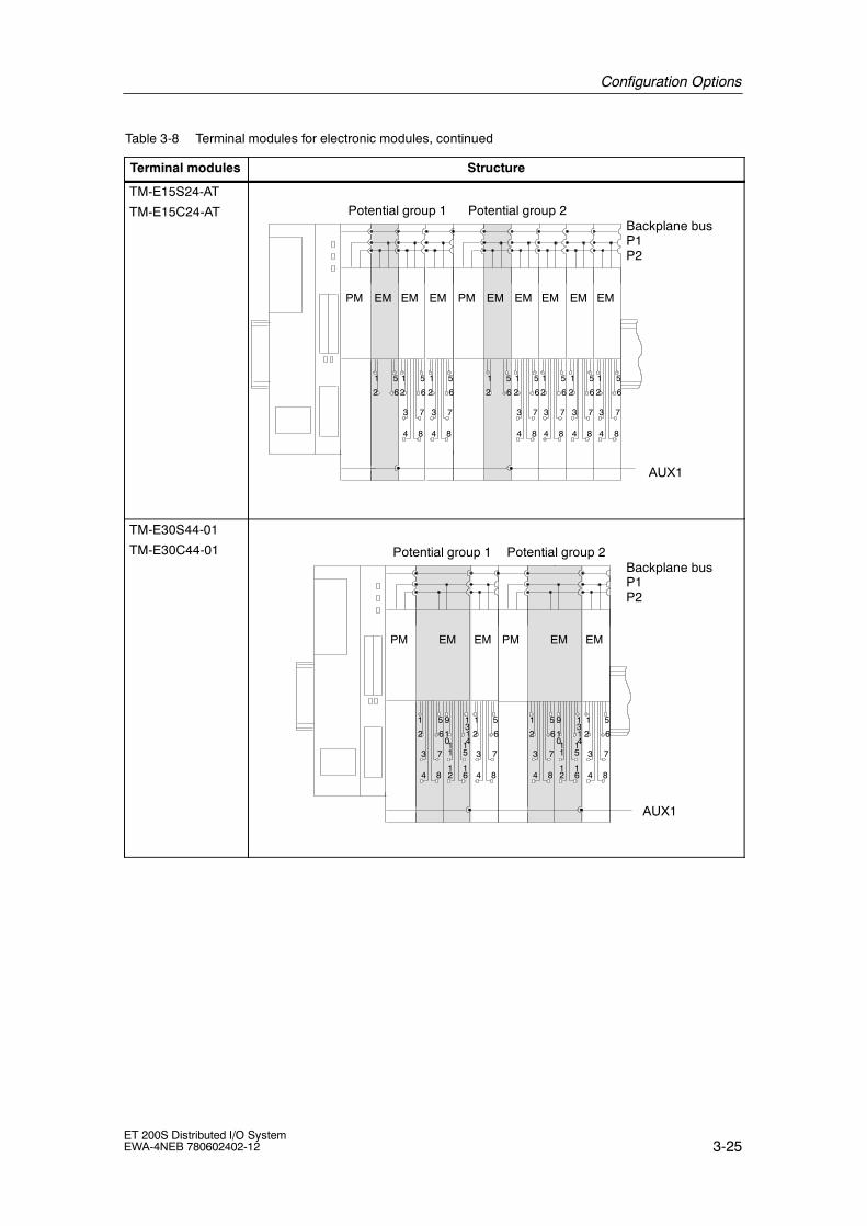
Configuration Options
3-25ET 200S Distributed I/O SystemEWA-4NEB 780602402-12
Table 3-8 Terminal modules for electronic modules, continued
Terminal modules Structure
TM-E15S24-AT
TM-E15C24-AT
PM
AUX1
Potential group 1 Potential group 2
1 5
2 6
PM
1 5
3 7
4 8
2 6
EM
1 5
3 7
4 8
2 6
EM
1 5
2 6
1 5
3 7
4 8
2 6
EM
1 5
3 7
4 8
2 6
EM
1 5
3 7
4 8
2 6
EM
1 5
3 7
4 8
2 6
EM
Backplane busP1P2
EM EM
TM-E30S44-01
TM-E30C44-01
AUX1
Potential group 1
1 5
3 7
4 8
2 6
PM
9 1
1 1
1 1
1 1
1 5
3 7
4 8
2 6
EM
Backplane busP1P2
EM
01
2
3
45
6
Potential group 2
1 5
3 7
4 8
2 6
PM
9 1
1 1
1 1
1 1
1 5
3 7
4 8
2 6
EMEM
01
2
3
45
6

Configuration Options
3-26ET 200S Distributed I/O System
EWA-4NEB 780602402-12
Table 3-8 Terminal modules for electronic modules, continued
Terminal modules Structure
TM-E30S46-A1
TM-E30C46-A1
AUX1
Potential group 1
1 5
3 7
4 8
2 6
PM
9 1
1 1
1 1
1 1
1 5
3 7
4 8
2 6
EM
Backplane busP1P2
EM
01
2
3
45
6
Potential group 2
1 5
3 7
4 8
2 6
PM
9 1
1 1
1 1
1 1
1 5
3 7
4 8
2 6
EMEM
01
2
3
45
6A16A15
A11
A16A15
A11
A12
A8
A7
A3
A4
A12
A8
A7
A3
A4

Configuration Options
3-27ET 200S Distributed I/O SystemEWA-4NEB 780602402-12
3.6 Direct data exchange on the PROFIBUS DP
Prerequisites
• The ET 200S can be used as the sender (publisher) for direct communication.
• The DP master being used must, of course, also support direct communication.You will find information on this in the description of the DP master.
Principle
Direct communication is characterized by the fact that PROFIBUS DP nodesmonitor the data sent back by a DP slave to its DP master.By means of this mechanism the monitoring node (recipient/subscriber) candirectly access changes to the input data of remote DP slaves.
During configuration in STEP 7 you specify by means of the relevant I/O inputaddresses the address area of the recipient in which the data of the sender is to beplaced.
Example
Figure 3-5 gives an example of the direct-communication relationships you canconfigure with an ET 200S as the sender and which nodes as possible recipientscan monitor data sent back by DP slaves to the DP master.
PROFIBUS
CPU 31x-2 asDP master 1
CPU 31x-2
DP slave
DP mastersystem 1 DP master
system 2
CPU 31x-2 asDP master 2
CPU 31x-2asDP slaveET 200S
ET 200S
ET 200S
Figure 3-5 Direct Communication with the IM151-1 HIGH FEATURE

Configuration Options
3-28ET 200S Distributed I/O System
EWA-4NEB 780602402-12
3.7 Clocking on PROFIBUS DP
Features
Reproducible response times (i.e. of equal length) are achieved in SIMATIC withan equidistant DP bus cycle, synchronization of the user program on the DP buscycle, and the clocked transfer of I/O data to the I/O modules. The clockedsections of the user program are processed synchronously to the DP bus cycle bymeans of clocked interrupts (OB 61 to OB 64). The I/O data are transferred atdefined and constant (clocked) intervals via the backplane bus of the DP slave tothe I/O modules and switched through synchronously to the terminal.
In other words, clocking results in the synchronization of all the previously cyclicsingle cycles from the user program in the CPU to the DP cycle on the PROFIBUSsubnetwork, to the cycle in the DP slave and, finally, to the cycle in the I/Omodules of the DP slaves. The maximum jitter is 10 µs.
Prerequisites
• Clocking is possible with the IM 151-1 HIGH FEATURE with the followingSTEP 7 versions and modules:
STEP 7version
Module Order number As ofproductversion
As of V5.1 withS i P k 3
2DI 24 VDC High Feature 6ES7 131-4BB00-0AB0 1ServicePack 3and Hotfix 1
4DI 24 VDC High Feature 6ES7 131-4BD00-0AB0 1and Hotfix 1
2DO 24 VDC/0.5 A High Feature 6ES7 132-4BB00-0AB0 1
2DO 24 VDC/2 A High Feature 6ES7 132-4BB30-0AB0 1
As of V5.1with
1Count 24V/100kHz 6ES7 138-4DA03-0AB0 1withServicePack 4 1Count 5V/500kHz 6ES7 138-4DE01-0AB0 1
1SSI 6ES7 138-4DB01-0AB0 1
As of V5.2 4DI 24-48 VUC High Feature 6ES7 131-4CD00-0AB0 1
2AI U High Speed 6ES7 134-4FB51-0AB0 2
2AI 2WIRE HS 6ES7 134-4GB51-0AB0 2
2AI 4WIRE HS 6ES7 134-4GB61-0AB0 2
2AO I High Feature 6ES7 135-4MB01-0AB0 1
2AO U High Feature 6ES7 135-4LB01-0AB0 1
Other modules are possible in the ET 200S configuration but these do not supportclocking.

Configuration Options
3-29ET 200S Distributed I/O SystemEWA-4NEB 780602402-12
• The transmission rate of the PROFIBUS DP is at least 1.5 Mbps (shorterequidistance times can be achieved with higher transmission rates).
• The maximum equidistance is 32 ms.
• The equidistance master (class 1) must be a class 1 DP master. In other words,a programming device (PG)/PC cannot be an equidistance master.
• In equidistant operation, only one DP master (class 1) can be active in thePROFIBUS DP bus system. PGs or PCs (class 2) can also be connected.
• Clocking can only be activated on the ET 200S if the equidistant bus cycle hasbeen activated on the DP master system and at least one electronic modulewith synchronization support has been configured.
• No clocking (equidistance) is possible with the ET 200S during removal orinsertion of electronic modules.
• In equidistant operation, the ET 200S requires a starting time of approx. 150 DPcycles to ensure clocking right through to the terminals.
Optimizing the equidistant time
• The longest delays for the digital input/output modules (parameterizable in thecase of inputs) are decisive in determining the length of the equidistant DPcycle. Tip: During clocking make sure that all the digital modules in the ET 200Sstation have the same input delay.
• The shorter the input delays you set for the HIGH FEATURE digital inputmodules, the shorter the equidistance times that can be achieved. Tip: Ifpossible, set an input delay of 0.1 ms for the HIGH FEATURE digital inputmodules.
• The processing time of the modules should be taken into account in the case ofmodules that support clocking.
• The minimum equidistance time depends on the number of modules in theET 200S. Tip: If possible, use 4-channel HIGH FEATURE digital input modulesto reduce the number of modules.You can also achieve shorter equidistance times if you distribute the modules ofan ET 200S (with a large number of modules) between two ET 200S stations.
• The equidistance time is reduced if you increase the transmission rate.Tip: Set the fastest transmission rate possible.

Configuration Options
3-30ET 200S Distributed I/O System
EWA-4NEB 780602402-12
Procedure for parameterizing clocking
1. Carry out settings on the CPU:
”Object Properties” of the CPU> ”Clocked interrupts” tab
-- Set the CPU clocked interrupt
-- Select the DP master system used.
-- Select the desired partial process image.
Memory Interrupts Interrupts Cyclic interrupts Diagnostics/clock
Generalinformation
Startup Clocked interrupts Cycle / clock memory Retentivity
OB 61:
PriorityDP master-systemno.
Partial processimage(s) (e. g.: 1.4) Time lag
1 1 ms
Default
3.0002525
Time-of-dayinterrupts
Figure 3-6 Clocked interrupts dialog box
2. Carry out settings on the DP master system:
”Object Properties” of the DP master > ”General” tab > ”Properties” button >”Parameters” tab > ”Properties” button > ”Network Settings” tab > ”Options”button
-- Activate equidistance on the DP master system
-- Set the length of the equidistant DP cycle (max. 32 ms).
-- Set ”Times Ti and To same for all Slaves” (results in synchronization of theI/O data of the different DP slaves)
-- You can set the Ti and To times separately. Recommendation: Accept thedefault settings for Ti and To.
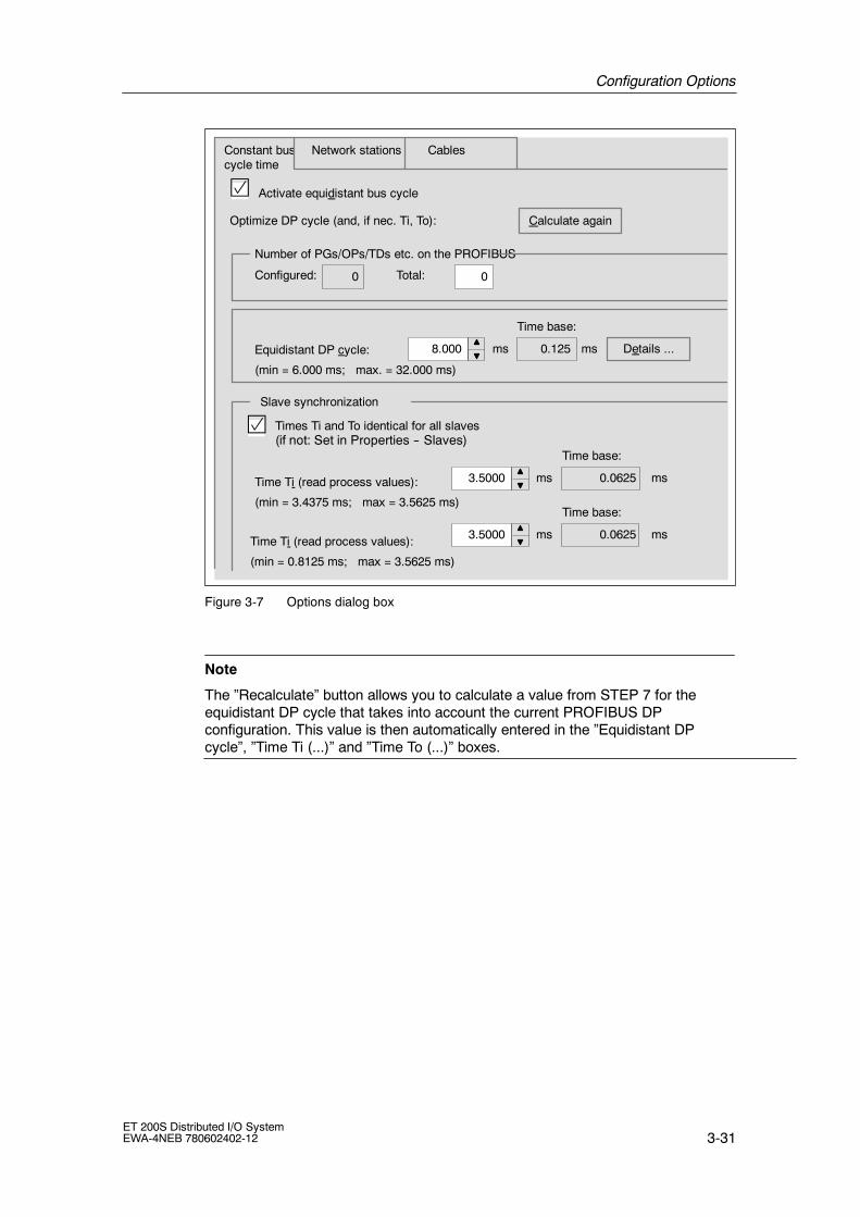
Configuration Options
3-31ET 200S Distributed I/O SystemEWA-4NEB 780602402-12
Constant buscycle time
Network stations Cables
8.000
Activate equidistant bus cycle
Number of PGs/OPs/TDs etc. on the PROFIBUS
Configured: Total:
Equidistant DP cycle:
(min = 6.000 ms; max. = 32.000 ms)
Time base:
ms ms Details ...
00
0.125
Times Ti and To identical for all slaves(if not: Set in Properties -- Slaves)
Time Ti (read process values):
(min = 3.4375 ms; max = 3.5625 ms)
Slave synchronization
3.5000
Time base:
ms ms0.0625
Time Ti (read process values):
(min = 0.8125 ms; max = 3.5625 ms)
3.5000
Time base:
ms ms0.0625
Calculate againOptimize DP cycle (and, if nec. Ti, To):
Figure 3-7 Options dialog box
Note
The ”Recalculate” button allows you to calculate a value from STEP 7 for theequidistant DP cycle that takes into account the current PROFIBUS DPconfiguration. This value is then automatically entered in the ”Equidistant DPcycle”, ”Time Ti (...)” and ”Time To (...)” boxes.

Configuration Options
3-32ET 200S Distributed I/O System
EWA-4NEB 780602402-12
3. Carry out settings on the DP slave:
”Object Properties” of the DP slave > ”Clocking” tab
-- Enable ”Synchronize DP slave with DP cycle”.
-- Enter the times Ti and To (if ”Times Ti and To same for all slaves” has notbeen set on the DP master system). Recommendation: Accept the defaultsettings for Ti and To.
-- Select the electronic modules to be synchronized, and assign them on the”Addresses” tab to the partial process image defined in the CPU.
Generalinformation
Time Ti (read process values):
(min = 4.2500 ms; max = 4.2500ms)
3.5000 Time base:ms ms
Time Ti (read process values):
(min = 1.0000 ms; max = 1,000 ms)
3.5000 Time base:ms ms
Synchronize DP slave to equidistant DP cycle (the same Ti/To for all slaves)
Properties -- DP slave
Equidistant DP cycle:
(min = 6.072 ms; max = 32.000 ms)
8.000 ms
Slaveparameters
Clocking
Module Clocked operation
Slot/name
(1) 2DI 24 VDC HF
(2) 4DI 24 VDC HF
(3) 2AI 2WIRE HS
(4) 2AI 4WIRE HS
OK Cancel Help
Figure 3-8 DP slave properties dialog box
Note
If you choose ”Clocking” from the ”Edit” menu, a configuration overview of theclocked modules appears.

Configuration Options
3-33ET 200S Distributed I/O SystemEWA-4NEB 780602402-12
4. Create a user program:
-- Create OB 61.
-- At the beginning of OB 61, SFC 126 must be called to upgrade the partialprocess image of the inputs.
-- At the end of OB 61, SFC 127 must be called to upgrade the partial processimage of the outputs.
-- The partial process image to be used is the one parameterized in the CPU(”Clocked Interrupts” tab).
Troubleshooting in clocking
Action Cause Correction
Station failure of theET 200S
Errored clocking (more than10 lost or interruptedcycles).
Check the parameterassignment.
The equidistance times aretoo long.
The input delays of theHIGH FEATURE digital inputmodules are not optimallyset.
Decrease the input delay ofthe HIGH FEATURE digitalinput modules.
No clockedsignal detection/output.
Wrong process imagepartition used
Neg. RET_VAL in the caseof SFCs 126/127
Check whether the sameprocess image partition wasused in the OB 61 userprogram (or up to OB 64)when SFCs 126/127 arecalled and in theconfiguration of the DPmaster/DP slave.
Further information
You can find additional information on clocking in the STEP 7 help system and inthe Isochrone Mode manual.

Configuration Options
3-34ET 200S Distributed I/O System
EWA-4NEB 780602402-12
3.8 Option handling on PROFIBUS DP
Features
Option handling enables you to set up the ET 200S for future expansions (options).Option handling means that you install, wire, configure, and program the plannedmaximum configuration of the ET 200S. The electronic modules you require forthis are initially replaced with inexpensive RESERVE modules which are then latersimply exchanged for the required electronic modules.
This means that the ET 200S can be completely prewired (master wiring) becausethe RESERVE module is not connected to the terminals of the terminal module ortherefore the process.
The RESERVE modules for future expansion at the right-hand end of the stationare optional. In this case, preparatory installation and wiring are possible but not aprerequisite.
Note
You can find information on the removal and insertion of electronic modules inSection 5.5.
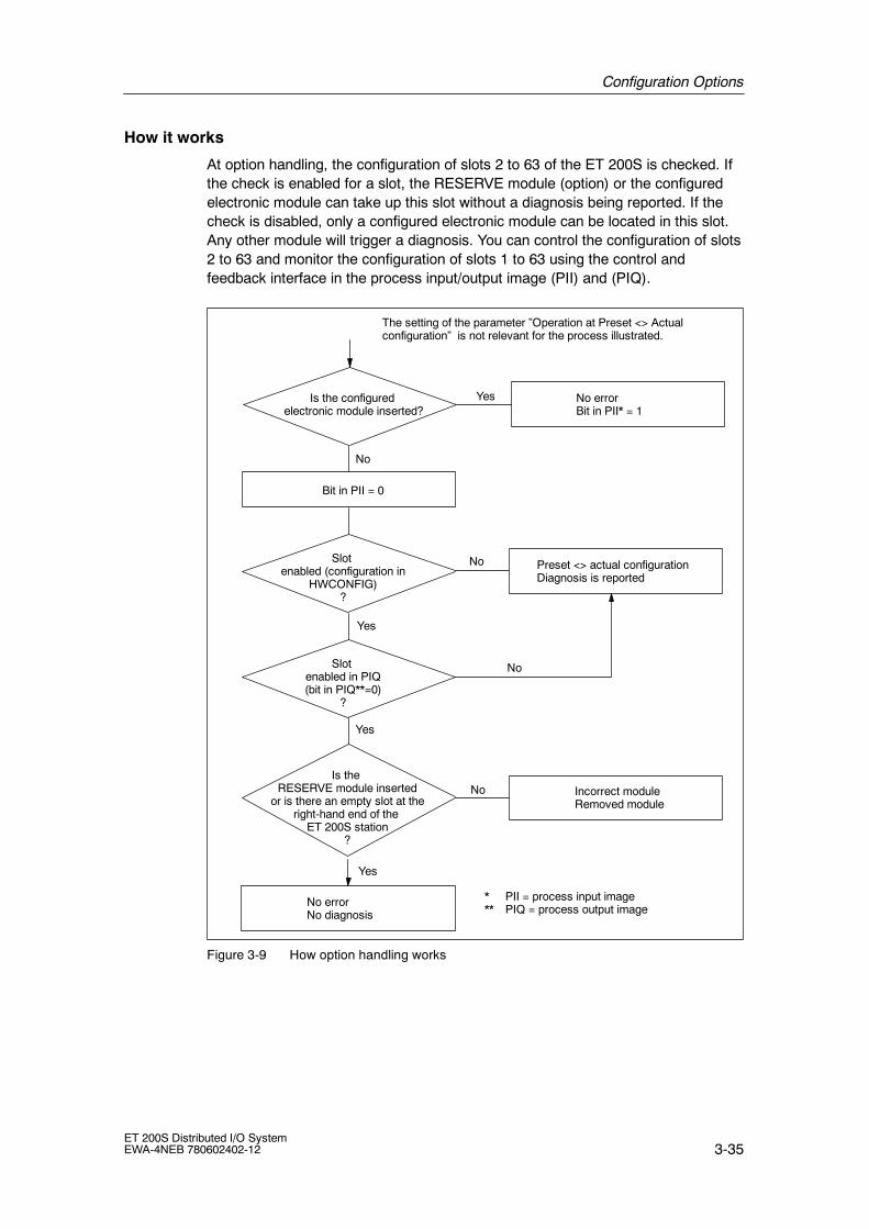
Configuration Options
3-35ET 200S Distributed I/O SystemEWA-4NEB 780602402-12
How it works
At option handling, the configuration of slots 2 to 63 of the ET 200S is checked. Ifthe check is enabled for a slot, the RESERVE module (option) or the configuredelectronic module can take up this slot without a diagnosis being reported. If thecheck is disabled, only a configured electronic module can be located in this slot.Any other module will trigger a diagnosis. You can control the configuration of slots2 to 63 and monitor the configuration of slots 1 to 63 using the control andfeedback interface in the process input/output image (PII) and (PIQ).
Bit in PII = 0
Is the configuredelectronic module inserted?
Slotenabled (configuration in
HWCONFIG)?
Slotenabled in PIQ(bit in PIQ**=0)
?
Is theRESERVE module inserted
or is there an empty slot at theright-hand end of the
ET 200S station?
No errorNo diagnosis
No errorBit in PII* = 1
Preset <> actual configurationDiagnosis is reported
Incorrect moduleRemoved module
Yes
No
No
No
Yes
Yes
Yes
No
* PII = process input image** PIQ = process output image
The setting of the parameter ”Operation at Preset <> Actualconfiguration” is not relevant for the process illustrated.
Figure 3-9 How option handling works

Configuration Options
3-36ET 200S Distributed I/O System
EWA-4NEB 780602402-12
Prerequisites
For option handling you require:
• IM 151-1 STANDARD (from 6ES7 151-1AA03-0AB0) or IM 151-1 FOSTANDARD interface module (from 6ES7 151-1AB02-0AB0)
• for configuring the GSD file as per the table below
DPV0 operation DPV0/DPV1 operation
SI02806A.GSx SI02806B.GSx SI03806A.GSx SI03806B.GSx
from 07/2003 (from V1.0)
6ES7 151-1AA03-0AB0 X -- -- --
6ES7 151-1AB02-0AB0 -- X -- --
6ES7 151-1AA04-0AB0 X -- X --
6ES7 151-1AB03-0AB0 -- X -- X
Note
You do not require a GSD file for option handling in STEP 7:
• as of STEP 7 V5.2 Service Pack 1 and
• the current HW update for the interface and power modules. Integrate the HWupdate in HWCONFIG using the Options > Install HW Updates manucommand. You can download the HW updates from Customer Support on theInternet.
You can find the description of option handling in the STEP 7 help system.
•At least one PM E 24-48 VDC or PM E 24-48 VDC/24-230 VAC power modulemust be present in the configuration.
• RESERVE modules as replacements for future electronic modules
Note
If the actual configuration of an ET 200S station does not match the configuredpreset, a diagnosis is reported if the check for the slots is not enabled.

Configuration Options
3-37ET 200S Distributed I/O SystemEWA-4NEB 780602402-12
Example of the use of the RESERVE modules
Option 1 Option 2Basicconfig.
IM15
1-1
STA
ND
AR
D
PM
-E24
-48
VD
C2D
I24
VD
C
2DO
2DI2
4V
DC
2DO
2DO
2DO
PM
E-2
4V
DC
4DI
4DI
Bus
term
inat
ion
4DI
2DO
2DO
2DO
2DO
2AIU
PM
E-2
4V
DC
PM
-E24
-48
VD
C2D
I24
VD
C
RE
SE
RV
E
2DI2
4V
DC
RE
SE
RV
E
RE
SE
RV
E
RE
SE
RV
E
PM
E-2
4V
DC
4DI
4DI
4DI
RE
SE
RV
E
RE
SE
RV
ER
ES
ER
VE
RE
SE
RV
E
2AIU
IM15
1-1
STA
ND
AR
D
PM
E-2
4V
DC
Bus
term
inat
ion
Basic config.
Sensors/actuators
This setupmust beconfigured(HWCONFIG,COMPROFIBUS)
Futureplannedmaximumconfigurationof the ET200S
PM
-E24
-48
VD
C2D
I24
VD
C
RE
SE
RV
E
2DI2
4V
DC
RE
SE
RV
E
RE
SE
RV
E
RE
SE
RV
EP
ME
-24
VD
C4D
I
4DI
4DI
2AIU
PM
E-2
4V
DC
Sensors/actuators
IM15
1-1
STA
ND
AR
D
Bus
term
inat
ion
1st version:
PreparationusingRESERVEmodules andprewiring
2nd version:
PreparationusingRESERVEmodules andprewiring. TheRESERVEmodules at theright-hand endof the stationare not present.
You must installand wire thisconfiguration
OROR
You must installand wire thisconfiguration
Figure 3-10 Example of the use of the RESERVE modules

Configuration Options
3-38ET 200S Distributed I/O System
EWA-4NEB 780602402-12
Option handling parameter assignment
Note the following prerequisites when assigning parameters:
• In STEP 7 or COM PROFIBUS, parameterize the electronic modules you wantto use for future applications, such as 4DI HF, on the slots of the RESERVEmodules (or the expansion modules at the right-hand end of the station):
-- Drag the electronic module to the configuration table
-- Set the parameters
• Using one of the following entries, drag a PM E 24-48 VDC or PM E 24-48VDC/24-230 VAC power module to the configuration table.
-- ...O (option handling) or
-- ...SO (status byte + option handling)
Note
There can only be one power module with the ending ...O or ...SO in the ET 200Sconfiguration.

Configuration Options
3-39ET 200S Distributed I/O SystemEWA-4NEB 780602402-12
• Parameterize the interface module as follows:
Interface module Parameters Setting Description
IM 151-1STANDARD
or
Optionhandling,general
Enable Option handling is activatedfor the whole ET 200S.
or
IM 151-1 FOSTANDARD
Optionhandling: Slots2 to 63
Enable (all theslots on whichRESERVEmodules can belocated)
There is a RESERVE moduleor configured electronicmodule on the slot. Adiagnosis is not reported.
Note
If ”Operation at Preset < > Actual Configuration” is blocked at parameterassignment, the following occurs:
• The ET 200S does not start up if a module is missing or if an incorrect moduleis inserted. A diagnostic report is output to the effect that there is no module orthe module is incorrect.
• The ET 200S starts up if you enable option handling for the slot of an insertedRESERVE module. A diagnosis is not reported.
If you have parameterized an electronic module for the RESERVE module, thefollowing substitute values are reported:
-- Digital Input Modules: 0
-- Analog Input Modules: 7FFFH
-- Function Module: 0

Configuration Options
3-40ET 200S Distributed I/O System
EWA-4NEB 780602402-12
Controlling and monitoring options
You can use the control feedback interface (PIQ) and feedback interface (PII) tocontrol and monitor the options with the user program.
Recommendation: Before you use the optional expansion of the ET 200S, checkusing the feedback interface (see Table 3-10) whether all the configured electronicmodules are inserted.
Note
Using SFCs 14/15 it is possible to consistently access the control and feedbackinterface.
The control and feedback interface is in the process image of the inputs andoutputs of the PM E 24-48 VDC or PM E 24-48 VDC/24-230 VAC power modules.It is only available if you have selected the entries with the ending ...O or ...SO inthe configuration software for that power module (see also Appendix C).
There is one bit for each slot of theelectronic or RESERVE modules in theET 200S.
Control interface:Slots 2 to 63
Feedback interface:Slots 1 to 63
Bit no.IB/QB xIB/QB x+1
7 136 5 4 2 0
IB/QB x+2IB/QB x+3IB/QB x+4IB/QB x+5IB/QB x+6IB/QB x+7
6 *25 4 3 17
15 14 1213 1011 9 8
17181922 21 20 16
27
23
352628293031
3334
25 243839 3637
46
32
404547
4849
4244 43 41
52 515355 5460
50
5761 5859 5662
* Not applicable
63
Figure 3-11 Control (PIQ) and feedback interface (PII)
Control interface PIQ (AB x to AB x+7):
Using these bytes (8 bytes) you can control the diagnostic behavior of the slotsyou have enabled in HWCONFIG for option handling.
Only the bits of the slots you have enabled at parameter assignment for optionhandling are evaluated (they are marked with ”0”).

Configuration Options
3-41ET 200S Distributed I/O SystemEWA-4NEB 780602402-12
Table 3-9 Control interface
Slot Value of thebit
Response
2 to 63 0 Parameter assignment for option handling applies.RESERVE modules are permitted:
• The station is engaged in data transfer.
• A diagnosis is not reported.
• The SF LED on the interface module is off.
1 Parameter assignment for option handling is cancelled.RESERVE modules are not accepted on this slot:
• The station is engaged in data transfer.
• The diagnosis ”Incorrect module” is reported.
• The SF LED lights up on the interface module
Feedback interface PII (IB x to IB x+7):
The feedback interface (8 bytes) tells you which module is actually on each slot.
All slots are reported. Even slots that you have not enabled for option handling.
Table 3-10 Feedback interface
Slot Value of thebit
Response
1 to 63 0 The RESERVE module or an incorrect module is on theslot or a module has been removed.
1 The configured module is on the slot.
Troubleshooting for option handling
Table 3-11 Troubleshooting for option handling
Action Cause Correction
ET 200S does not start up;configuration error
There are several entries ofpower modules ending in
Check and correct theconfiguration ing p g
...O or ...SO in the ET 200Sconfiguration.
gHWCONFIG.
There is no power moduleentry ending in ...O or ...SOin the ET 200Sconfiguration.
Use a power module entryending in ...O or ...SOin HWCONFIG.

Configuration Options
3-42ET 200S Distributed I/O System
EWA-4NEB 780602402-12
3.9 Identification data
Identification data is information stored in a module that supports the user with thefollowing:
• verification of the system configuration
• detection of HW changes in the system
• system troubleshooting
Modules can be precisely identified online with the identification data. In the caseof the IM151-1 STANDARD (from 6ES7 151-1AA04-0AB0) andIM151-1 FO STANDARD (from 6ES7 151-1AB03-0AB0) the data are available onthe ET 200S.In STEP 7 the identification data are displayed in the tabs ”Module Status --IM 151” and ”Properties -- DP Slave” (see STEP 7 online help).
Reading the identification data
The user can access specific identification data with Read data set. This requiresaccess in two stages:
1. A directory which contains the data set numbers for the various indices isstored in data set 248 (see Table 3-12).
Table 3-12 Structure of DS 248 for ET 200S
Contents Length (byte) Coding (hex)
Header information
ID of table of contents 2 00 01
Index of table of contents 2 00 00
Length of subsequent blocks in bytes 2 00 08
Number of blocks 2 00 05

Configuration Options
3-43ET 200S Distributed I/O SystemEWA-4NEB 780602402-12
Table 3-12 Structure of DS 248 for ET 200S, continued
Contents Coding (hex)Length (byte)
Block information for identification data
SZL-IDAssociated data set numberLength of data setIndex
2222
F1 1100 E700 4000 01
SZL-IDAssociated data set numberLength of data setIndex
2222
F1 1100 E800 4000 02
SZL-IDAssociated data set numberLength of data setIndex
2222
F1 1100 E900 4000 03
SZL-IDAssociated data set numberLength of data setIndex
2222
F1 1100 EA00 4000 04
8 bytes block information for additional data set objects
Σ: 48
2. The component of the identification data assigned to the relevant index can befound under the associated data set number (see Table 3-14).
-- All data sets with identification data have a length of 64 bytes.
-- The data sets are structures as per the principle shown in Table 3-13.
Table 3-13 Principle structure of data sets with identification data
Contents Length (byte) Coding (hex)
Header information
SSL-ID 2 F111
Index 2 00 0x
Length of identification data 2 00 38
Number of blocks with identification data 2 00 01
Identification data
Index 2 00 0x
Identification data for the specific index(see Table 3-14)
54

Configuration Options
3-44ET 200S Distributed I/O System
EWA-4NEB 780602402-12
The identification data are assigned to the indices as per Table 3-14.The data structures in data sets 231 to 234 correspond to the specifications of thePROFIBUS Guideline -- Order No. 3.502, Version 1.1, May 2003.
Table 3-14 Identification data
Identification data Access Default setting Explanation
Identification data 0: Index 1 (data record 231)
MANUFACTURER_ID read (2 bytes) 2A hex (=42 dec) The name of the manufacturer isstored here. (42 dec = SIEMENSAG)
ORDER_ID read (20 bytes) depends on themodule
Order number of the module
SERIAL_NUMBER read (16 bytes) irrelevant
HARDWARE_REVISION read (2 bytes) irrelevant
SOFTWARE_REVISION read (4 bytes) Firmware version This indicates the firmwareversion of the module.
REVISION_COUNTER read (2 bytes) -- Provides information on theparameterchanges on the module. REVISION_COUNTER increments with eachchange.
PROFILE_ID read (2 bytes) F600 hex Generic Device
PROFILE_SPECIFIC_TYPE
read (2 bytes) 0005 hex on interface modules
IM_VERSION read (2 bytes) 0101 hex Shows the version of theidentification data(0101 hex = Version 1.1)
IM_SUPPORTED read (2 bytes) 000E hex Provides information on availableidentification data (index 2 to 4)
Maintenance data 1: Index 2 (data record 232)
TAG_FUNCTION read / write (32bytes)
-- Enter a unique tag for the modulehere.
TAG_LOCATION read / write (22bytes)
-- Enter the installation location of themodule here.
Maintenance data 2: Index 3 (data record 233)
INSTALLATION_DATE read / write (16bytes)
-- Enter the installation date of themodule here.
RESERVED read / write (38bytes)
-- Reserved
Maintenance data 3: Index 4 (data record 234)
DESCRIPTOR read / write (54bytes)
-- Enter a comment describing themodule here.

Configuration Options
3-45ET 200S Distributed I/O SystemEWA-4NEB 780602402-12
3.10 Limitations on the number of modules that can beconnected/maximum configuration
• Number of modules:
-- ET 200S with IM151-1 BASIC: max. 12 modules.
-- ET 200S with IM151-1 STANDARD; IM151-1 FO STANDARD;IM151-1 HIGH FEATURE; IM151-3 PN:max. 63 modules.
This includes power modules, electronic modules, RESERVE modules, andmotor starters.
• Bus length of the ET 200S:
-- Not relevant to the IM151-1 BASIC (see Section 4.1).
-- max. 2 m (configurable): on IM151-1 STANDARD;IM151-1 FO STANDARD; IM151-3 PN
-- max. 1 m: with IM 151-1 HIGH FEATURE
• Parameter length:
-- with PROFIBUS DP: depends on the DP master used (maximum 244 bytes)
-- with PROFINET IO: not applicable for maximum structure

Configuration Options
3-46ET 200S Distributed I/O System
EWA-4NEB 780602402-12
Table 3-15 Parameter length in bytes
Module Parameterlength
IM151-1 BASIC 19 byte
IM151-1 STANDARD
IM151-1 FO STANDARD
27 bytes
IM151-1 HIGH FEATURE 27 bytes
56 bytes*
IM151-3 PN --
PM-E 24 VDC
PM-E 24-48 VDC
PM-E 24-48 VDC/24-230 VAC
3 bytes
2DI 24 VDC High Feature
4DI 24 VDC High Feature
3 bytes
3 bytes
2DI 24 VDC Standard
4DI 24 VDC Standard
4DI 24 VDC/SRC Standard
1 bytes
4DI NAMUR 12 bytes
2DI 120 VAC Standard 3 bytes
2DI 230 VAC Standard 3 bytes
2DO 24 VDC/0.5 A High Feature 3 bytes
2DO 24 VDC/0.5 A Standard
4DO 24 VDC/0.5 A Standard
1 bytes
2DO 24 VDC/2 A High Feature 3 bytes
2DO 24 VDC/2 A Standard
4DO 24 VDC/2 A Standard
1 bytes
2DO 24-230 VAC/1 A 3 bytes
2RO NO 24-120 VDC/5 A 24-230VAC/5 A
3 bytes
2RO NO/NC 24-48 VDC/5 A24-230 VAC/5 A
3 bytes
2AI U Standard
2AI U High Feature
4 bytes
2AI U High Speed 12 bytes(4 bytes*****)
RESERVE ------
2AI I 2WIRE Standard
4AI I 2WIRE ST
4 bytes
7 bytes
Module Parameterlength
2AI I 2WIRE High Speed 12 bytes(4 bytes***)
2AI I 4WIRE Standard
2AI I 2/4WIRE High Feature
4 bytes
2AI I 4WIRE High Speed 12 bytes(4 bytes****)
2AI RTD Standard 4 bytes
2AI RTD High Feature 7 bytes(4 bytes**)
2AI TC Standard
2AI TC High Feature
4 bytes
2AO U Standard
2AO U High Feature
7 bytes
2AO I Standard
2AO I High Feature
7 bytes
1Count 24V/100kHz 16 bytes
1Count 5V/500kHz 16 bytes
1SSI 8 byte
EM 1STEP 5V/204kHz 7 bytes
2PULSE 16 bytes
1POS INC/Digital
1POS INC/Digital
1POS INC/Analog
1POS INC/Analog
16 bytes
1SI 3964/ASCII
1SI Modbus/USS
4/8 bytes
4 IQ-SENSE 16 bytes
Motor starter STANDARD 3 bytes
Motor starterHIGH FEATURE
12 bytes
* Clocking is activated.** When used as 2AI RTD Standard*** When used as 6ES7 134 4GB50-0AB0**** When used as 6ES7 134 4GB50-0AB0***** When used as 6ES7 134 4GB50-0AB0

Configuration Options
3-47ET 200S Distributed I/O SystemEWA-4NEB 780602402-12
• Address space
on the PROFIBUS DP (depends on the DP master)
-- IM151-1 BASIC interface module supports a maximum of 88 input bytes and88 output bytes.
-- IM151-1 STANDARD and IM151-1 FO STANDARD interface modulessupport:
-- maximum 128 input bytes and 128 output bytes(up to 6ES7 151-1AA03-0AB0 or 6ES7 151-1AB02-0AB0)
-- maximum 244 input bytes and 244 output bytes(up to 6ES7 151-1AA04-0AB0 or 6ES7 151-1AB03-0AB0)
-- The IM151-1 HIGH FEATURE interface module supports a maximum of 244input bytes and 244 output bytes.
on the PROFINET IO
-- The IM151-3 PN interface module supports a maximum of 256 input bytesand 256 output bytes.
• Power modules: Maximum configuration per potential group
Table 3-16 Maximum configuration per potential group
Power modules Maximumcurrent-carrying
capacity
Connectable modules
PM-E 24 VDC powermodule
10A The number of modules that can beconnected depends on the total current ofall the modules in this potential group.This must not exceed 10 A in total. Thetotal current is decisively affected by thedigital output modules:
PM-E power module24..48 VDC
10Adigital output modules:
• 2DO 24 VDC/0.5 A Standard
• 2DO 24 VDC/0.5 A High Feature
• 4DO 24 VDC/0.5 A Standard
• 4DO 24 VDC/0.5 A High Feature
PM-E power module24..48 VDC/24..230 VAC
10 A (24 VDC)8 A (120/230 VAC)
O C/0 5 g eatu e
• 2DO 24 VDC/2 A Standard
• 2DO 24 VDC/2 A High Feature
• 4DO 24 VDC/2 A Standard
• 4DO 24 VDC/2 A High Feature
• 2DO 24-230 VAC/2 A
• Number of identifiers: one identifier per module (max. 63 identifiers)
• You can use the ET 200S with DP masters with a diagnostic frame length of 32bytes because you can set the length of the diagnostic frame in all the interfacemodules (see Sections 6.1.6.2 and 8.1).

Configuration Options
3-48ET 200S Distributed I/O System
EWA-4NEB 780602402-12

4-1ET 200S Distributed I/O SystemEWA-4NEB 780602402-12
Installation
Important information
!Warning
Open operating equipment
The modules of an ET 200S are open operating equipment. This means that youcan only install the ET 200S in cases, cabinets or electrical plant rooms wherethey will only be accessible with a key or a tool. Only trained or authorizedpersonnel should have access to the cases, cabinets or electrical plant rooms.
Simple installation
The ET 200S distributed I/O system is designed for simple installation.
Chapter overview
Chapter Description Page
4.1 Installation rules, installation position, rail, installation measurementsand clearances
4-2
4.2 Installing the interface module 4-4
4.3 Installing the TM-P and TM-E terminal modules 4-6
4.4 Replacing the terminal box on the terminal module 4-8
4.5 Installing the terminating module 4-10
4.6 Installing the shield contact 4-11
4.7 Applying slot number labels and color identificationlabels
4-13
4.8 Setting the PROFIBUS Address 4-15
4

Installation
4-2ET 200S Distributed I/O System
EWA-4NEB 780602402-12
4.1 Installation rules, installation position, rail, installationmeasurements and clearances
Installation rules
• The ET 200S distributed I/O system starts with an interface module.
• There is a power module after the interface module or at the beginning of eachpotential group.
• After a power module, come digital, analog, process-related, or RESERVEmodules.
• The ET 200S distributed I/O system ends with the terminating module.
• The maximum configuration of the distributed I/O system is as follows:
-- IM151-1 BASIC: max. 13 modules (including interface module). The lengthof the bus is not relevant.
-- IM151-1 STANDARD / IM151-1 FO STANDARD / IM151-3 PN:max. 64 modules (including interface module) or max. 2 m bus length.
-- IM151-1 HIGH FEATURE: max. 64 modules (including interface module) ormax. 1 m bus length.
Installation position
The preferred installation position is horizontal on a vertical wall. Any otherinstallation position is also possible; however, there are limitations with regard toambient temperature.
Rail
The ET 200S distributed I/O system is installed on a zinc-plated rail to EN 50022(35× 7.5 mm or 35× 15 mm).
Note
If the ET 200S distributed IO device is exposed to increased vibrations and shock,we recommend that you screw the rail to the mounting surface at intervals of 200mm.
To prevent the ET 200S distributed I/O system from slipping to the side, werecommend that you fit a mechanical stop (for example, with a ground terminal,8WA2 011-1PH20) at both ends of the device.
If you install the rail on grounded, zinc-plated mounting plates, there is no need toground the rail separately.

Installation
4-3ET 200S Distributed I/O SystemEWA-4NEB 780602402-12
Installation measurements
Table 4-1 Installation measurements
Measurements
Installation width
• Interface module: 45 mm
• Terminal modules with electronic modules: 15 mm or 30 mm
• Bus terminating module: 7.5 mm
Installationheight
• Interface module: 119.5 mm
• Electronic module with terminal module:
-- 3 levels with screw-type or spring terminals: 119.5 mm
-- 3 levels with Fast Connect: 143 mm
-- 3 levels with screw-type or spring terminals and shield contact:151.5 mm
-- 3 levels with Fast Connect and shield contact: 175 mm
-- 4 levels with screw-type or spring terminals: 132 mm
-- 4 levels with Fast Connect: 164 mm
-- 4 levels with screw-type or spring terminals and shield contact: 164 mm
-- 4 levels with Fast Connect and shield contact: 196 mm
-- 6 levels with screw-type or spring terminals: 157 mm
-- 6 levels with Fast Connect: 204 mm
-- 6 levels with screw-type or spring terminals and shield contact: 189 mm
-- 6 levels with Fast Connect and shield contact: 236 mm
-- 7 levels with screw-type terminal: 196.5 mm
Installationdepth
• ET 200S on rail with 7.5 mm depth: 75 mm
• ET 200S on rail with 15 mm depth: 82.5 mm

Installation
4-4ET 200S Distributed I/O System
EWA-4NEB 780602402-12
Minimum clearances for installation, wiring, and ventilation
When installing the ET 200S in a housing, ensure that the distance to the lid of thehousing or the front door is at least 2 mm.
PM EM EM PM EM EMEM EM
35 mm
15 mm 35 mm15 mm
20 mm20 mm
35 mm
Figure 4-1 Minimum clearances
4.2 Installing the interface module
Features
• The interface module connects the ET 200S with the PROFIBUS DP/PROFINET IO.
• The interface module transfers data between the higher-level controller and theI/O modules.
Prerequisites
• The rail must be installed.
• All the terminal modules must be installed to the right of the interface module.The maximum configuration of the ET 200S distributed I/O system is 12/63modules (including power modules, I/O modules, reserve modules, and motorstarters).

Installation
4-5ET 200S Distributed I/O SystemEWA-4NEB 780602402-12
Tool required
3 mm screwdriver
Installing the interface module
1. Hang the interface module on the rail.
2. Tip the interface module back until you hear the locking mechanism engage.
2
1
Figure 4-2 Installing the interface module
Removing the interface module
The interface module is wired, and the terminal modules are on the right:
1. Switch off the supply voltage on the interface module.
2. Disconnect the wiring and the bus connector on the interface module.
3. Use a screwdriver to push the locking mechanism on the interface moduledown until the mechanism stops, and move the interface module to the left.
Note: the locking mechanism is under the interface module.
4. With the locking mechanism depressed, tip the interface module so that itcomes off the rail.

Installation
4-6ET 200S Distributed I/O System
EWA-4NEB 780602402-12
4.3 Installing the TM-P and TM-E terminal modules
Features
• The terminal modules receive the I/O modules and power modules.
• The terminal modules can be prewired (without I/O modules).
• All the terminal modules must be installed to the right of the interface module.
Prerequisites
• The rail must be installed.
Tool required
3 mm screwdriver
Installing the terminal module
1. Hang the terminal module on the rail.
2. Tip the terminal module back until you hear the locking mechanism engage.
3. Move the terminal module to the left until you hear it snap into place at theprevious interface module (if already installed) or the terminal module.
1
2
3
Figure 4-3 Installing the terminal module

Installation
4-7ET 200S Distributed I/O SystemEWA-4NEB 780602402-12
Removing the terminal module
The terminal module is wired, and there are other terminal modules on the rightand left.
A terminal module in the ET 200S distributed I/O system can only be removedwhen there is a clearance of around 8 mm to the adjacent terminal modules (youachieve this clearance by moving the adjacent modules).
1. Switch off the supply voltage on the terminal module and, if applicable, thepower module.
2. Disconnect the wiring on the terminal module.
3. Removal from the right: Use a screwdriver to push the locking mechanism onthe previous terminal module/interface module (on the left) down until themechanism stops, and move the terminal module to the right.
Removal from the left: Use a screwdriver to push the locking mechanism on theterminal module down until the mechanism stops, and move the terminalmodule to the left.
Note: the locking mechanism is under the terminal module.
4. With the locking mechanism depressed, tip the terminal module so that itcomes off the rail.
3
3
4Locking mechanism
Figure 4-4 Removing the terminal module (from the right)
Note
It is not necessary to remove the terminal module in order to replace the terminalbox. See Section 4.4

Installation
4-8ET 200S Distributed I/O System
EWA-4NEB 780602402-12
4.4 Replacing the terminal box on the terminal module
Features
The terminal box is part of the terminal module. If necessary, you can replace theterminal box.
Prerequisites
It is not necessary to remove the terminal module.
Tool required
3 mm screwdriver

Installation
4-9ET 200S Distributed I/O SystemEWA-4NEB 780602402-12
Replacing the terminal box on the terminal module
The terminal module is installed, wired, and fitted with an electronic module.
1. Switch off the supply voltage on the terminal module and, if applicable, thepower module.
2. Disconnect the wiring on the terminal module.
3. Simultaneously press the upper and lower release buttons of the electronicmodule, and remove it from the terminal module.
4. There is a small opening directly under the slot number label. Push thescrewdriver into this opening diagonally from below, and at the same time pullthe terminal box downward until it stops. Then pull the terminal box upward andout of the terminal module.
5. Replace the terminal box, and insert the new one into the terminal module fromabove (position: see Figure 4-5 Then push the terminal box upward until itsnaps into place.
6. Insert the electronic module in the terminal module.
7. Wire the terminal module.
8. Switch on the supply voltage on the terminal module and, if applicable, thepower module.
4
4
Slot number label
Figure 4-5 Replacing the terminal box on the terminal module

Installation
4-10ET 200S Distributed I/O System
EWA-4NEB 780602402-12
4.5 Installing the terminating module
Features
The ET 200S distributed I/O system is completed by the terminating module on theright-hand side. If you have not connected a terminating module, the ET 200S isnot ready for operation.
Prerequisites
• The last terminal module must be installed.
Installing the terminating module
1. Hook the terminating module on the rail to the right of the last terminal module.
2. Tip the terminating module back on the rail.
3. Move the terminating module to the left until you hear it snap into place againstthe last terminal module.
1
2
3
Figure 4-6 Installing the terminating module

Installation
4-11ET 200S Distributed I/O SystemEWA-4NEB 780602402-12
Removing the terminating module
1. Use a screwdriver to push the locking mechanism on the last terminal moduledown until the mechanism stops, and move the terminating module to the right.
2. Tip the terminating module so that it comes off the rail.
Note
If
• the terminal module of the ET 200S is removed or replaced under power or
• while the ET 200S backplane bus is interrupted during operation , e. g. at aterminal module, and restored to function,
the complete power supply of the ET 200S must be switched off and on to achievea defined station status.
4.6 Installing the shield contact
Features
• You need the shield contact to connect cable shields (for example, analogelectronic modules, 1COUNT 24V/100kHz electronic module and 1SSIelectronic module).
• Fit the shield contact on the terminal module.
• The shield contact consists of a shield contact element, a conductor rail, (3 x 10mm), a shield terminal, and a ground connection terminal.
Prerequisites
• The terminal modules must be installed.
Tool required
• 3 mm screwdriver
• Metal-cutting saw

Installation
4-12ET 200S Distributed I/O System
EWA-4NEB 780602402-12
Installing the shield contact
1. Push the shield contact element onto the first terminal module from below.
2. Push the shield contact element onto the last terminal module from below.
In order to achieve stability of the conductor rail between two shield contactelements during installation, you must connect an additional shield contactelement after every sixth terminal module (given a width of 15 mm).
3. Saw off the correct length from the conductor rail. The length of the rail is: thedistance between the shield contact + 45 mm.
4. Push the conductor rail into the shield contact element. After installation, theconductor rail must protrude from the shield contact element by 15 mmon the left or right.
5. Attach the shield terminals on the conductor rail (between the shieldcontact elements).
6. Attach the ground connection terminal to the protruding conductor rail.
Shield contact elements
Shield terminals
Conductor rail
Ground connection terminal
Figure 4-7 Installing the shield contact

Installation
4-13ET 200S Distributed I/O SystemEWA-4NEB 780602402-12
4.7 Applying slot number labels and color identificationlabels
Features
• The slot number labels identify the individual I/O modules with a slot (1 to 63).
• The color identification labels permit individual color coding of the terminals inaccordance with company or national conventions. The color identificationlabels are available in white, red, blue, brown, yellow, yellow-green, andturquoise. Each terminal on the terminal module can have a color identificationlabel.
Prerequisites
• The terminal modules must be installed.
• There must be no electronic modules connected when you apply the slotnumber labels.
• The terminal modules should not be wired when you apply the coloridentification labels.
• The slot number labels and color identification labels are applied onto theterminal modules.
-- Position of slot number label: under the coding element on the terminalmodule.
-- Position of color identification labels: right next to each terminal on theterminal box.
Tool required
3 mm screwdriver (for removal only)

Installation
4-14ET 200S Distributed I/O System
EWA-4NEB 780602402-12
Applying slot number labels and color identification labels
Slot number labels:
1. Break the slot number label (1 to 63) off the strip.
2. Use your finger to press the slot number label onto the terminal module.
Color identification labels:
1. You can place the color identification labels in the opening next to the terminalwhile they are still on the strip and then bend the strip back to pull them off.
2. Use your finger to press the color identification labels onto the terminal module.
Slot numberlabel
Color-identificationlabels
2
2 2
Figure 4-8 Applying slot number labels and color identification labels
Removing slot number labels and color identification labels
Slot number label:
1. Remove the electronic module from the terminal module.
2. Lever the slot number label out of its mount.
Color identification labels: Use a screwdriver to lever the color identification labelsout of their mounts.

Installation
4-15ET 200S Distributed I/O SystemEWA-4NEB 780602402-12
4.8 Setting the PROFIBUS address
Features
The PROFIBUS address defines the address at which the ET 200S distributed I/Osystem is found on the PROFIBUS DP.
Prerequisites
• The PROFIBUS DP address for the ET 200S is set on the IM151-1 interfacemodule by means of DIP switches. The DIPswitches are on the front of theinterface module, protected by a sliding window.
• The permitted PROFIBUS DP addresses are 1 to 125.
• Each address can be assigned only once on the PROFIBUS DP.
Tool required
3 mm screwdriver
Setting the PROFIBUS DP address
1. Slide the window on the interface module upward.
2. Use a screwdriver on the DIP switches to set the desired PROFIBUS DPaddress.
3. Close the window.
64
32
16
8
4
21
ON
Interface module
OFF Example:
DP address =
64
+ 32
+ 2
+ 1
= 99
_______
ET 200S
*
* Only with IM151-1 STANDARD, IM151-1 FO STANDARD:Reserved for future upgrades. This switch must be in the OFF position.
Figure 4-9 Setting the PROFIBUS Address

Installation
4-16ET 200S Distributed I/O System
EWA-4NEB 780602402-12
Changing the PROFIBUS DP address
You change the PROFIBUS DP address in exactly the same way as you set it. Achange to the PROFIBUS DP address takes effect after power on at the interfacemodule of the ET 200S.

5-1ET 200S Distributed I/O SystemEWA-4NEB 780602402-12
Wiring and Fitting
Prewiring
The ET 200S distributed I/O system allows you to prewire the terminal moduleswith screw-type or spring terminals.
Chapter overview
Chapter Description Page
5.1 General rules and regulations for operating the ET 200S 5-1
5.2 Operating the ET 200S on a grounded supply 5-3
5.3 Electrical design of the ET 200S 5-6
5.4 Wiring the ET 200S 5-7
5.5 Inserting and identifying the electronic modules 5-24
5.1 General rules and regulations for operating the ET 200S
Introduction
When operating the ET 200S distributed I/O system as a component part of a plantor system, certain rules and regulations have to be followed depending on wherethe device is to be used.
This chapter provides an overview of the most important rules you have to observewhen integrating the ET 200S distributed I/O system in a plant or system.
Specific applications
Note the safety and accident prevention regulations that apply to specificapplications (for example, the Machine Directive).
EMERGENCY STOP devices
Emergency stop devices complying with IEC 204 (which corresponds to DIN VDE113) must remain effective in all the operating modes of the plant or system.
5

Wiring and Fitting
5-2ET 200S Distributed I/O System
EWA-4NEB 780602402-12
Startup of the system after specific events
The following table tells you what you should do when the system starts up afterthe occurrence of specific events.
If ... then ...
Startup follows a voltage drop orfailure
Startup of the ET 200S followsan interruption of buscommunication
No dangerous operating states must occur. Ifnecessary, force an emergency stop.
Startup follows unlocking of theemergency stop device
There must not be an uncontrolled orundefined start-up.
Line voltage
The following table tells you what you have to do with regard to the line voltage.
With ... Requirements
Permanently installed plants or systemswithout all-pole line disconnect switches
There must be a line disconnect switch or afuse in the building installation system.
Load power supplies, power supplymodules
The set rated voltage range mustcorrespond to the local line voltage.
All circuits of the ET 200S distributed I/Osystem
Any fluctuation/deviation in the line voltagefrom the rated value must be within thepermitted tolerances (see Section 7.4)

Wiring and Fitting
5-3ET 200S Distributed I/O SystemEWA-4NEB 780602402-12
24 VDC supply
The following table tells you what you have to do with regard to the 24 VDC supply.
With ... Pay attention to ...
Buildings Outdoor lightningprotection
Take lightning protectionprecautions
24 VDC supply lines,signal lines
Indoor lightningprotection
(for example, lightningconductors)
24 VDC supply Safe (electrical) isolation of extra-low voltage
Protection against outside electrical influences
The following table tells you what to do to provide protection against electricalinfluences or faults.
With ... You must ensure that...
All plants or systems inwhich the ET 200S isintegrated
The plant or system is connected to a protectiveconductor for diverting electromagnetic interference.
Supply, signal, and buslines
The wiring arrangement and installation are correct.
Signal and bus lines Any break of a line or conductor does not result inundefined states of the plant or system.
5.2 Operating the ET 200S on a grounded supply
In this section, you will find information on the overall setup of an ET 200Sdistributed I/O system on a grounded supply (TN-S system). The specific subjectsdiscussed are:
• Circuit-breaking devices, short-circuit and overload protection in accordancewith DIN VDE 0100 and DIN VDE 0113
• Load power supplies and load circuits
Definition: Grounded mains
In a grounded supply, the neutral conductor of the system is grounded. A mereground fault between a live conductor and ground or a grounded section of theplant causes the protective devices to trip.

Wiring and Fitting
5-4ET 200S Distributed I/O System
EWA-4NEB 780602402-12
Components and protective measures
Various components and protective measures are prescribed when setting up anentire plant. The types of component and the degree to which the protectivemeasures are binding depend on the DIN VDE regulation that applies to your plantsetup. The following table refers to Figure 5-1.
Compare ... Refer toFigure 5-1
DIN VDE 0100 DIN VDE 0113
Circuit-breaking devicefor PLC, sensors andactuators
¡ ... Part 460:Main switch
... Part 1:Disconnector
Short-circuit and overloadprotection:Grouped for sensors andactuators
©
¢
... Part 725:Single-poleprotection ofcircuits
... Part 1:
• With grounded secondarypower circuit: single-poleprotection
• Otherwise: all-poleprotection
Load power supply forAC load circuits withmore than fiveelectromagnetic devices
©
¢
Isolation bytransformerrecommended
Isolation by transformerrecommended
Safe electrical isolation
Safe electrical isolation must be provided for:
• Modules that must be operated at the following voltages:≤60 VDC or≤25VAC
• 24 VDC operating current circuits
Setting up the ET 200S with ungrounded reference potential
From IM151-1 BASIC (6ES7 151-1CA00-0AB0), IM151-1 STANDARD(6ES7 151-1AA02-0AB0), IM151-1 FO STANDARD (6ES7 151-1AB01-0AB0),IM151-1 HIGH FEATURE (6ES7 151-1BA00-0AB0) and IM151-3 PN(6ES7 151-3AA00-0AB0) the reference potential M connected to the nominalsupply voltage of the IM151-x at the rail (protective conductor) through an RCcombination and so allows an ungrounded layout.
To divert interference current, the reference potential of the IM151-1 is connectedinternally to the rail (protective conductor) via an RC combination (R = 10 MΩ / C =22 nF). High-frequency interference currents are thus discharged, and staticcharge is prevented.

Wiring and Fitting
5-5ET 200S Distributed I/O SystemEWA-4NEB 780602402-12
Overall configuration of the ET 200S
Figure 5-1 shows the overall configuration of the ET 200S distributed I/O system(load voltage supply and grounding concept) with supply from a TN-S system.
Ground bus
L1L2L3N
¡
Load circuit400 VAC for motor starters
24 VDC load circuit for electronic modules andmotor starters
©
AC
DC
¢
Low-voltage distribution -- TN-Ssystem, for example (3× 400 V)
PE
AC
DC
©
©
1L+
1M
ET 200S
PE (AUX1)
Shield contact for cable shields
FG FG FG FG FG FG FG FG
Rail
FE: Functional earth for direct dischargeof interference to the mounting rail bymeans of spring-loaded contact.
120 VAC/230 VAC load circuit forAC modules
AC
AC
¢©
Figure 5-1 Configuring the ET 200S with grounded reference potential

Wiring and Fitting
5-6ET 200S Distributed I/O System
EWA-4NEB 780602402-12
5.3 Electrical design of the ET 200S
Isolation between ...
• The load circuits/process and all other circuit components of the ET 200S
• The PROFIBUS DP interface in the IM151-1 interface module and all othercircuit components
• The PROFIBUS DP interface in the IM151-3 PN interface module and all othercircuit components
The following figure shows the potentials of the ET 200S. Only the most importantcomponents are shown.
1 L+ 1MIM151 24 VDC M 24 VDC M
Bus interface
Isolation
Electronics,backplane bus
Term
inat
ing
mod
ule
Processelectroniccomponents
Processelectroniccomponents
Processelectroniccomponents
ET 200S backplane bus
Isolation Isolation Isolation Isolation
PE
Bus interface Bus interface Bus interface Bus interfaceRail
PE
Potential logic circuitryPotential DP interfacePotential I/O
Isolation
DPinterface
Powermodule
Electronicmodule
Electronicmodule
Powermodule
Electronicmodule
Figure 5-2 Potentials of the ET 200S with IM151-1

Wiring and Fitting
5-7ET 200S Distributed I/O SystemEWA-4NEB 780602402-12
5.4 Wiring the ET 200S
Section Description Page
5.4.1 Wiring a terminal module with screw-type terminals 5-8
5.4.2 Wiring a terminal module with spring terminals 5-8
5.4.3 Wiring a terminal module with Fast Connect 5-10
5.4.4 Wiring terminal modules 5-13
5.4.5 Wiring the IM151-1 BASIC, IM151-1 STANDARD andIM151-1 HIGH FEATURE interface modules
5-18
5.4.6 Wiring the IM151-3 PN interface module 5-19
5.4.7 Wiring the IM151-1 FO STANDARD interface module 5-21
Wiring rules for the ET 200S
Wiring rules for ... Interface module(supply voltage)
Terminal modules(spring andscrew-typeterminals)
Terminal modules(Fast Connect)
Connectable wire cross-sections for rigid lines
No 0.14 to 2.5 mm2 0.5 to 1.5 mm2
Connectablewire
ti
Without wireend ferrule
0.25 to 2.5 mm2 0.14 to 2.5 mm2 0.5 to 1.5 mm2
cross-sectionsfor flexible lines
With wire endferrule
0.25 to 1.5 mm2 0.14 to 1.5 mm2 ------
Number of wires per connection 1 or a combination of 2 wires up to1.5 mm2 (sum) in a common wire end ferrule
1
Maximum external diameter ofthe wire’s insulation
∅ 3.8 mm ∅ 3.1 mm at 1.5 mm2
∅ 3.8 mmat 2.5 mm2
∅ 3.2 mmat 1.5 mm2
Stripping length of the wires 11 mm ------Stripping length of the wires 11 mm ------
Wire endferrules toDIN 46228
Withoutinsulatingcollar
Design A,8 to 12 mm long
Design A,up to 12 mm long
------
Withinsulatingcollar 0.25 to1.5 mm2
Design E, up to 12 mm long ------

Wiring and Fitting
5-8ET 200S Distributed I/O System
EWA-4NEB 780602402-12
5.4.1 Wiring a terminal module with screw-type terminals
Features
• In terminal modules with screw-type terminals, the individual wires are screwedinto the terminal.
• No wire end ferrules are required.
Prerequisites
Adhere to the wiring rules.
Tool required
3 mm screwdriver
Wiring a terminal module with a screw-type terminal
1. Strip 11 mm of insulation from the wires.
2. Insert the individual wires in the terminal.
3. Screw the ends of the individual wires onto the terminal module(torque: 0.4...0.7 Nm).
5.4.2 Wiring a terminal module with spring terminals
Features
In terminal modules with spring terminals, the individual wires are held securelywhen you simply insert them in the terminal.
Prerequisites
Adhere to the wiring rules.
Tool required
3 mm screwdriver

Wiring and Fitting
5-9ET 200S Distributed I/O SystemEWA-4NEB 780602402-12
Wiring a terminal module with spring terminals
1. Strip 11 mm of insulation from the wires.
2. Insert the screwdriver in the upper (round) opening of the terminal.
3. Insert the wire until it stops in the lower (square) opening of the terminal.
4. Release the terminal by pushing the screwdriver into the opening.
5. Push the wire into the released spring terminal, and pull the screwdriver out.
Insert the screwdriver.
Insert the wire in the spring-typeterminal until it stops.
Pull out the screwdriver; the wireis clamped on the contact.
Figure 5-3 Wiring the spring terminal

Wiring and Fitting
5-10ET 200S Distributed I/O System
EWA-4NEB 780602402-12
5.4.3 Wiring terminal modules with Fast Connect
Features
• In the case of terminal modules with Fast Connect, the individual wires areattached using a quick connection method that requires no stripping.
• Fast Connect is a connection method that requires no preparation (i.e. theconductor does not have to be stripped).
• Each terminal of the terminal module with Fast Connect has a test opening (formeasuring the voltage, for example). The test opening is suitable for testprobes with a maximum diameter of∅ 1.5 mm.
• Wire end ferrules are not permitted.
• Diagram of the Fast Connect terminal module
Locking mechanism closed (the cable is connected)
Locking mechanism open (the cable can be inserted)
Opening for 1 conductor: 0.5 ... 1.5 mm2
Opening for measurement, testing: max.∅1.5 mm
Terminal moduleFast Connect
Figure 5-4 Block diagram of the terminal module with Fast Connect
Prerequisites
Adhere to the wiring rules.
Tool required
3 mm screwdriver

Wiring and Fitting
5-11ET 200S Distributed I/O SystemEWA-4NEB 780602402-12
Connectable cables
You can connect rigid and flexible cables with PVC insulation with a conductorcross-section of 0.5 mm2 to 1.5 mm2 (max. external diameter 3.2 mm). If thecross-section of the conductors is the same, they can be wired fifty times. You canfind a list of tested conductors at:http://www.idc2.de
Cables and connections complying with UL
Wiring range for insulating piercing connection 22 --16 AWG solid/stranded PVCinsulated conductors, UL style no. 1015 only.
Wiring terminal modules with Fast Connect
1. Insert the unstripped cable in the round opening until it stops (the insulation andconductor must form a flat surface).
2. Insert the screwdriver into the opening above the locking mechanism until itstops.
3. Press the screw driver downwards until the locking mechanism reaches theend.
Result: The cable is connected.
1
323 mm
Note
If you want to reconnect a cable that has already been connected, you must firstcut it off.

Wiring and Fitting
5-12ET 200S Distributed I/O System
EWA-4NEB 780602402-12
Releasing the wiring of the terminal module with Fast Connect
1. Insert the screwdriver into the opening below the locking mechanism until itstops.
2. Use the screwdriver to lever and push the locking mechanism upwards.
3. The wiring is disconnected: remove the wire.
13
4
2
Figure 5-5 Releasing the wiring of the terminal module with Fast Connect
Removing any remains of the conductor (only if necessary)
To remove any remains of the conductor (insulation), you can deinstall the lockingmechanism from the terminal module (see Step 3). To do this, the lockingmechanism must be open (upper position). You can only insert the lockingmechanism in the upper position (see Step 4).
1. Insert the screwdriver in the opening below the locking mechanism (the tip ofthe screwdriver is on the lip of the locking mechanism).
2. Press the screwdriver downwards to lever the locking mechanism out of theterminal module.
3. Remove the locking mechanism from the terminal module. Remove anyremains of the conductor from the locking mechanism.
4. Use your fingers to press the locking mechanism back into the opening.Important: Make sure the locking mechanism is inserted in the correct position,otherwise you can damage the clamping unit.
4
21Note the position of thmechanism
3
Figure 5-6 Removing the locking mechanism from the terminal module

Wiring and Fitting
5-13ET 200S Distributed I/O SystemEWA-4NEB 780602402-12
5.4.4 Wiring terminal modules
Features
The ET 200S distributed I/O system comprises terminal modules for powermodules and electronic modules:
• At the terminal modules for the power modules you connect the supply/loadvoltage for the respective potential group.
• Terminal modules for electronic modules connect the ET 200S with the process.
• At the terminal modules for electronic modules you can connect cable shieldsby means of a shield contact.
Prerequisites
• You must wire the terminal modules with the supply/load voltage switched off atthe power module and the load voltage switched off at the electronic module.
• Adhere to the wiring rules.
Tool required
3 mm screwdriver

Wiring and Fitting
5-14ET 200S Distributed I/O System
EWA-4NEB 780602402-12
Wiring terminal modules for power modulesThe terminal assignment of the terminal module depends on which power moduleis inserted. You will find information on this in the following chapters:
• Terminal modules in Chapter 9
• Power modules in Chapter 10
AUX1 (PE)AUX1 (PE)
P2P2
P1P1
P2
P1
AUX1 (PE)
P2
P1
AUX1 (PE)
P2
P1 P1
P22
3
6
7
2
3
6
7
2
3
TM-P15S23-A1 andpower module
TM-P15S23-A0 andpower module
TM-P15S22-01 andpower module
AUX1 bus (PE) fedthrough. Connection toterminals A4 and A8.
AUX1 bus fedthrough. Noconnection to theterminals of theterminal module.
AUX1 AUX1AUX1
6
A
4
A
8
A
4
A
8
2
3
6
7
1
0
1
1
1
2
1
3
1
4
1
5
1
6
9
A
4
A
8
TM-P30S44-A0 andpower module
7
AUX1 bus (PE)interrupted. Connectionto terminals A4 and A8.
AUX1 bus (PE) interrupted.Connection to terminals A4 and A8.
AUX1 (PE)
P2
P1
CH0Channel 0
CH1Channel 1
4 8AA
4 8AA
4 8AA
2
1
2
8
2
7
2
0
AUX1 bus fed through. No connection to theterminals of the terminal module.
VDC
M
TM-PF30S47-F0 andPM-D F DC24V*
* Terminal assignmentsee the ET 200SFail-Safe Modules manual
Figure 5-7 Wiring terminal modules for power modules

Wiring and Fitting
5-15ET 200S Distributed I/O SystemEWA-4NEB 780602402-12
Wiring terminal modules for digital, analog, and process-related modulesThe terminal assignment of the terminal module depends on which electronicmodule is inserted. You will find information on this in the following chapters:
• Terminal modules in Chapter 9
• Digital electronic modules in Chapter 11
• Analog electronic modules in Chapter 12
• Process-related modules: See the process-related functions manual
2
3
6
7
1 5
2
3
4
6
7
8
1 5
2
3
6
7
1 5
TM-E15S24-A1 andelectronic module
TM-E15S23-01 andelectronic module/process-relatedmodule
TM-E15S23-01 andelectronic module
Channel 0 Channel 1
AUX1 bus (PE) fed through.Connection to terminals A4 and A8.
AUX1 bus (PE) fed through. Noconnection to terminals 4 and 8.
AUX1 bus fed through.No connection to theterminals.
CH0 CH1
Channel 0/2CH0/2
Channel 1/3CH1/3
Channel 1CH0
Channel 0CH1
Channel 1CH0
Channel 0CH1
Channel 1CH0
Channel 1/3CH1/3
Channel 0/2CH0/2
Channel 0/2CH0/2
Channel 1/3CH1/3
TM-E15S26-A1 and electronicmodule/process-relatedmodule
Channel 0 Channel 1
AUX1 bus (PE) fed through. Connection toterminals A4, A8 and A3, A7.
CH0 CH1
Channel 0/2CH0/2
Channel 1/3CH1/3
2
3
4
6
7
8
1 5
A
4
A
3
A
8
A
7
A
4
A
8
2 6
1 5
TM-E15S24-AT and2AI TC HF
Channel 0 Channel 1
AUX1 bus (PE) fed through. No connectionto the terminals of the terminal module.
CH0 CH1
Figure 5-8 Wiring terminal modules for electronic modules

Wiring and Fitting
5-16ET 200S Distributed I/O System
EWA-4NEB 780602402-12
A
4
A
3
A
8
A
7
TM-E30S46-A1 andfail-safe module*
1
2
3
4
5
6
7
8
1
0
1
1
1
2
1
3
1
4
1
5
1
6
9
AUX1 bus (PE) fed through. Connection toterminals A4, A8 and A3, A7 or A12, A16 and A11and A15.
A12A11
A16A15
F-DO
FD-I
F-DO
FD-I
* Terminal assignment see ET 200S Fail-Safe Modules manual
TM-E30S44-01 andprocess-related module
1
2
3
4
5
6
7
8
1
0
1
1
1
2
1
3
1
4
1
5
1
6
9
Channel 0CH0 CH1
Channel 1
AUX1 bus (PE) fed through. No connection toterminals 4 and 8 or 12 and 16.
Figure 5-9 Wiring terminal modules for electronic modules, continued

Wiring and Fitting
5-17ET 200S Distributed I/O SystemEWA-4NEB 780602402-12
Connecting cable shields
We recommend you use the shield contact to connect cable shields (in the case ofanalog electronic modules, the 1COUNT 24V/100kHz electronic module and the1SSI electronic module, for example).
1. Remove the insulation material from the area around the shield terminal, andclamp the cable shield in the shield terminal (above the conductor rail). Theshield terminal is suitable for one cable with a max. ∅ of 8 mm or two cableswith a max. ∅ of 4 mm each.
2. Tighten the shield terminal (approximately 0.5 Nm)
3. Repeat steps 1 and 2 if you want to connect additional cable shields.
4. Strip the insulation from the ground wire (from 6 mm to 25 mm2), and insert it inthe ground connection terminal (under the conductor rail). Tighten the groundconnection terminal (2 Nm to 2.5 Nm).
5. Attach the other end to the ground bus.
Shield terminal
Ground connection terminal
Cable to the ground busCable to the sensor
Insulation material removed
Figure 5-10 Connecting cable shields
Note
To stabilize the shield contact, you must mount and screw in at least one shieldterminal over the shield contact element.

Wiring and Fitting
5-18ET 200S Distributed I/O System
EWA-4NEB 780602402-12
5.4.5 Wiring the IM151-1 BASIC, IM151-1 STANDARD andIM151-1 HIGH FEATURE interface modules
Features
You can connect the supply voltage and the bus connector (RS 485) to theinterface modules IM151-1 BASIC, IM151-1 STANDARD and IM151-1 HIGHFEATURE.
Prerequisites
• Wire the interface module with the supply voltage switched off.
• Adhere to the wiring rules (see Section 5.4).
Tool required
3 mm screwdriver
Wiring interface module IM151-1
To connect the supply voltage:
1. Strip the insulation from the wires for the supply voltage of the interface module.
2. Tighten the individual wires in the screw-type terminal.
Connecting the PROFIBUS DP:
1. Insert the bus connector in the PROFIBUS DP port.
2. Tighten the screws of the bus connector.
PROFIBUS DP
Supply voltage
(1L+, 2L+, 1M, 2M)
Labeling strip
ET 200S
Figure 5-11 Wiring the IM151-1 BASIC, IM151-1 STANDARD and IM151-1 HIGH
FEATURE interface modules

Wiring and Fitting
5-19ET 200S Distributed I/O SystemEWA-4NEB 780602402-12
5.4.6 Wiring the IM151-3 PN interface module
Features
Connect the supply voltage and bus connection plug to the IM151-3 interfacemodule.
Prerequisites
• Wire the interface module with the supply voltage switched off.
• Adhere to the wiring rules (see Section 5.4).
Tool required
• 3 mm screwdriver
• Industrial Ethernet Fast Connect Stripping Tool (6GK1 901-1GA00)(stripping tool for Industrial Ethernet Fast Connect installation lines)
Required accessories
• PROFINET connector conforming to the specifications in thePROFINET Installation Guide
• Industrial Ethernet Fast Connect installation lines
The following are suitable:
-- Fast Connect Standard Cable 6XV1 840-2AH10
-- Fast Connect Trailing Cable 6XV1 840-3AH10
-- Fast Connect Marine Cable 6XV1 840-4AH10
Installing bus terminal connector
Install the PROFINET connector in accordance with the directions in thePROFINET Installation Guide.
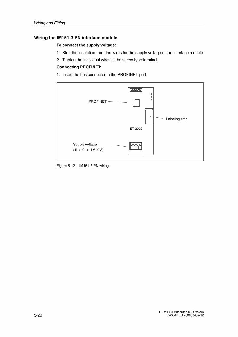
Wiring and Fitting
5-20ET 200S Distributed I/O System
EWA-4NEB 780602402-12
Wiring the IM151-3 PN interface module
To connect the supply voltage:
1. Strip the insulation from the wires for the supply voltage of the interface module.
2. Tighten the individual wires in the screw-type terminal.
Connecting PROFINET:
1. Insert the bus connector in the PROFINET port.
PROFINET
Supply voltage
(1L+, 2L+, 1M, 2M)
Labeling strip
ET 200S
Figure 5-12 IM151-3 PN wiring

Wiring and Fitting
5-21ET 200S Distributed I/O SystemEWA-4NEB 780602402-12
5.4.7 Wiring the IM151-1 FO STANDARD interface module
Features
Connect the supply voltage and the fiber-optic cable to the IM151-1 FOSTANDARD interface module by means of a simplex connector.
Prerequisites
• Wire the interface module with the supply voltage switched off.
• Adhere to the wiring rules (see Section 5.4).
Tool required
3 mm screwdriver
Required accessories
• Packing with simplex connectors and polishing sets (6GK1901-0FB00-0AA0)
• Packing with plug adapters (6ES7 195-1BE00-0XA0)
• Fiber-optic duplex line see IK PI catalog
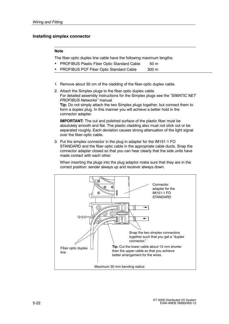
Wiring and Fitting
5-22ET 200S Distributed I/O System
EWA-4NEB 780602402-12
Installing simplex connector
Note
The fiber-optic duplex line cable have the following maximum lengths:
• PROFIBUS Plastic Fiber Optic Standard Cable 50 m
• PROFIBUS PCF Fiber Optic Standard Cable 300 m
1. Remove about 30 cm of the cladding of the fiber-optic duplex cable.
2. Attach the Simplex plugs to the fiber-optic duplex cable.For detailed assembly instructions for the Simplex plugs see the ”SIMATIC NETPROFIBUS Networks” manualTip: Do not simply attach the two Simplex plugs together, but connect them toform a duplex plug. In this manner you will achieve a better hold in theconnector adapter.
IMPORTANT: The cut and polished surface of the plastic fiber must beabsolutely smooth and flat. The plastic cladding also must not stick out or beseparated roughly. Each deviation causes strong attenuation of the light signalover the fiber-optic cable.
3. Put the simplex connector in the plug-in adapter for the IM151-1 FOSTANDARD and the fiber-optic cable in the appropriate cable ducts. Snap theconnector adapter closed so that you can hear clearly that the side units havemade contact with each other.
When inserting the plugs into the plug adaptor make sure that they are in thecorrect position: sender always up and receiver always down.
Connectoradapter for theIM151-1 FOSTANDARD
Snap the two simplex connectorstogether such that you get a ”duplexconnector.”
Fiber optic duplexline
Maximum 30 mm bending radius
Tip: Cut the lower cable about 10 mm shorterthan the upper cable so that you achievebetter arrangement for the wires.

Wiring and Fitting
5-23ET 200S Distributed I/O SystemEWA-4NEB 780602402-12
Bending radius for the fiber-optic cable
When placing the fiber-optic cable duplex core into the connector adapter andwhen placing things on top of them, make sure that you do not go below thepermitted bending radius of 30 mm. Also read the installation guidelines forfiber-optic cables in the ET 200S Distributed I/O System Manual or in theSIMATIC NET -- PROFIBUS networks manual.
Using the fiber-optic cable again
Note
If you place used fiber-optic cable in the connector adapter, you must shorten bothcores of the fiber-optic cable by the bent lengths and remount the simplexconnectors.In this manner you avoid possible attenuation losses from parts of the fiber-opticcable duplex core that have been bent again and highly stressed.
Wiring the IM151-1 FO STANDARD interface module
To connect the supply voltage:
1. Strip the insulation from the wires for the supply voltage of the interface module.
2. Tighten the individual wires in the screw-type terminal.
Connecting the PROFIBUS DP:
1. Insert the fiber-optic cable with the mounted connector adapters in the IM151-1FO STANDARD.
2. Push up the handle of the connector adapter that is sticking out.
Make sure they are in the correct position: the sender fiber-optic cable is pluggedinto the receiver socket and the receiver fiber-optic cable into the sender socket ofthe fiber-optic interface of the IM151-1 FO STANDARD.
If the IM151-1 FO STANDARD is the last node of the fiber-optic cable network, youmust close the unoccupied fiber-optic cable interface with filler plugs (which are inplace when the IM151-1 FO STANDARD is delivered).

Wiring and Fitting
5-24ET 200S Distributed I/O System
EWA-4NEB 780602402-12
!Caution
Do not look directly into the opening of the transmission diodes.The light beam that comes out could damage your eyes.
PROFIBUS DP(fiber-optic cable)
Supply voltage
(1L+, 2L+, 1M, 2M)
Labeling strip
ET 200S
Receiver
TransmitterHandle
Simplex connector
1
2
Figure 5-13 Wiring the IM151-1 FO STANDARD
5.5 Inserting and identifying the electronic modules
Features
• The electronic modules are inserted in the terminal modules.
• A labeling strip allows you to identify the electronic modules.
• Electronic modules are:
-- Self-coding
-- Type-coded
The first time you insert an electronic module, a code element engages on theterminal module. This mechanically prevents the wrong electronic module frombeing inserted.
Prerequisites
Adhere to the rules below for inserting electronic modules. See Section 3.5 (Theelectronic modules you can use on the various terminal modules).

Wiring and Fitting
5-25ET 200S Distributed I/O SystemEWA-4NEB 780602402-12
Inserting and identifying the electronic modules
1. Insert the electronic module in the terminal module until you hear it snap intoplace.
2. Pull the labeling strip up out of the electronic module in order to identify it.
3. Then put the labeling strip back into the electronic module.
1
2
3
Figure 5-14 Inserting and identifying the electronic modules

Wiring and Fitting
5-26ET 200S Distributed I/O System
EWA-4NEB 780602402-12
Removing electronic modules
1. Simultaneously press the two release buttons on the top and bottom of theelectronic module.
2. Pull the electronic module out from the terminal module at the front.
1
1
2
Figure 5-15 Removing electronic modules

Wiring and Fitting
5-27ET 200S Distributed I/O SystemEWA-4NEB 780602402-12
Changing the type of an electronic module
You have already removed the electronic module:
1. Use a screwdriver to push the code element out of the terminal module.
2. Put the code element on the used electronic module again.
3. Insert the new electronic module (different type) in the terminal module until youhear it snap into place.
4. Identify the new electronic module.
Code element3
Figure 5-16 Removing the code element
!Warning
When you make changes to the code, it can lead to dangerous states in yoursystem.
Replacing a defective electronic module
You have already removed the electronic module:
1. Remove the code element from bottom of the new electronic module.
2. Insert the new electronic module (same type) in the terminal module until youhear it snap into place.
3. Identify the new electronic module.

Wiring and Fitting
5-28ET 200S Distributed I/O System
EWA-4NEB 780602402-12
Removing and inserting electronic modules during operation
ET 200S supports the removal and insertion of modules during operation (duringthe RUN operating mode). The ET 200S remains in RUN mode when an electronicmodule is removed. The protective conductor connections of the ET 200S are notinterrupted.
Note• You cannot remove and insert modules during operation unless the
corresponding parameters have been assigned. See Section 8.1
• You can remove and insert modules during operation as of the IM151-1 BASIC,IM151-1 STANDARD (6ES7 151-1AA01-0AB0), IM151-1 FO STANDARD,IM151-1 HIGH FEATURE, and IM151-3 PN.
• If one module is missing (gap) and the ET 200S is switched on, the station willnot start up (see Section 6.1.6.10 and 6.2.6.3).
• The removal and insertion of modules affects the clocking (equidistance).
If you replace more than one module, only one gap can result.
The following table indicates which modules you can remove and insert underwhich conditions:
Table 5-1 Removing and inserting electronic modules
Modules Removing andinserting
Conditions
Interface module No ------
Power modules Yes The load voltage must beswitched off.
Digital electronic modules (input) Yes ------
Digital electronic modules (output) Yes The load voltage must beswitched off by means of anexternal switch/fuse.
Analog electronic modules Yes ------
4 IQ-SENSE Yes The sensors can also bereplaced during operation.These are thenparameterized automaticallyby the electronic module.

Wiring and Fitting
5-29ET 200S Distributed I/O SystemEWA-4NEB 780602402-12
Table 5-1 Removing and inserting electronic modules
Modules ConditionsRemoving andinserting
1Count 24V/100kHz Yes The load voltage must beit h d ff b f
1Count 5V/500kHzswitched off by means of anexternal switch/fuse.
1SSIexternal switch/fuse.
EM 1STEP 5V/204kHz
2PULSE
1POS INC/Digital
1POS SSI/Digital
1POS INC/Analog
1POS SSI/Analog
1SI 3964/ASCII Yes ------
1SI Modbus/USS Yes ------
RESERVE Yes ------

Wiring and Fitting
5-30ET 200S Distributed I/O System
EWA-4NEB 780602402-12
5.6 Assigning device names for the I/O device
Features
Every PROFINET device has a unique factory-assigned device identification (MACaddress).Every ET 200S IO device is addressed with its device name during configurationand in the user program.
For detailed information on addressing in the PROFINET IO see the PROFINETsystem description.
Assigning device names
1. Install an empty MMC in the IM151-3 PN.
2. Switch on the voltage supply for the IM151-3 PN.
3. In HW Config, open the Properties -- IM151-3 PN dialog box and enter thedevice name for your IO device.
Figure 5-17 Assigning device names in HW CONFIG

Wiring and Fitting
5-31ET 200S Distributed I/O SystemEWA-4NEB 780602402-12
4. To assign a name to the IM151 PN an online PROFINET connection from theprogramming device to the IO device via a switch is required.Use Target system > Ethernet > Assign device name to send the devicename to the IM151-3 PN.
Figure 5-18 Send device name online to the IM151-3 PN
Click the Assign name button in the Assign device name dialog box. Thedevice name is saved to the MMC in the IM151-3 PN interface module.
Figure 5-19 ”Assign device name” window before name assignment

Wiring and Fitting
5-32ET 200S Distributed I/O System
EWA-4NEB 780602402-12
The dialog box indicates the device name you assigned.
Figure 5-20 ”Assign device name” window after name assignment
Forwarding the device name on replacement of the interface module
The device name of the IO device is saved to the MMC.To transfer the name if the IM151-3 PN interface module is replaced, remove theMMC from the ”old” IM151-3 PN and install it in the ”new” one.It will import the device name from the MMC after the power to the IO device hasbeen switched off and on again. Then the station can be addressed again and willoperate in the same way as before the replacement.
Device flash test
When using more than one IO device, the system shows all of them in the Assigndevice name dialog box. In this case, compare the MAC address of the devicewith the indicated MAC address, then select the relevant IO device.
Identification of the IO devices is simplified by a device flash test. Enable the flashtest as follows:
1. Select one of the displayed IO devices in the Assign device name window.
2. Select the flash duration you want to use.
3. Press the Flash on button.
The LINK LED on the selected device flashes (open front doors of theIM151-3 PN).

6-1ET 200S Distributed I/O SystemEWA-4NEB 780602402-12
Commissioning and Diagnostics
Chapter overview
Chapter Description Page
6.1 Commissioning and diagnostics on PROFIBUS DP 6-1
6.2 Commissioning and diagnostics on PROFINET IO 6-57
Running tests
Note
You must make sure that your setup is safe. A complete function test and therelevant safety tests must be conducted before final commissioning of a setup.The tests must also include possible predictable errors. This will prevent danger topersons or the setup during operation.
6.1 Commissioning and diagnostics on PROFIBUS DP
Chapter overview
Chapter Description Page
6.1.1 Configuring the ET 200S on PROFIBUS DP 6-2
6.1.2 Commissioning and startup of the ET 200S on PROFIBUS DP 6-10
6.1.3 Diagnostics with LED display 6-12
6.1.4 Diagnostic messages of the electronic modules 6-22
6.1.5 Evaluating the interrupts of the ET 200S 6-23
6.1.6 Diagnostics using STEP 5 and STEP 7 6-25
6
Commissioning and Diagnostics
6-2ET 200S Distributed I/O System
EWA-4NEB 780602402-12
6.1.1 Configuring the ET 200S on PROFIBUS DP
Introduction
This chapter describes how to configure and assign parameters to the ET 200S.
• Configuring: The systematic arrangement of the different ET 200S modules(setup)
• Configuration: setting the ET 200S parameters using the configuration software
Note
The ET 200S is included in the hardware catalog of HWCONFIG:
• IM151-1 BASIC: from STEP 7 V5.2
• IM151-1 STANDARD: from STEP 7 V5.0 with ServicePack 3
• IM151-1 FO STANDARD: from STEP 7 V5.1 with ServicePack 1
• IM151-1 HIGH FEATURE: from STEP 7 V5.1 with ServicePack 3
You will not need a device database file (*.GSD file). Advantages:
• Simplified grouping of the modules (by means of the ”Pack Addresses” buttonin HW CONFIG)
• Plausibility checking of the parameters
The STEP 7 online help provides more detailed information on how to proceed.
DPV1 operation
If IM151-1 STANDARD (from 6ES7 151-1AA04-0AB0) or IM151-1 FO STANDARD(from 6ES7 151-1AB03-0AB0) is to be used on an S7 CPU that does not support aremove/insert interrupt, the ”Operation with preset <> actual setup” parametermust not be enabled in STEP 7. Otherwise if a module is removed (module failure)the station will fail (OB 86).
If ”Operation with preset <> actual setup” must be enabled, either DPV0 operationmust be selected or IM151-1/FO STANDARD must be configured with the GSD file(in the STEP 7 hardware catalog under ”Additional bay units I/O”). ”Operation withpreset <> actual setup” is thus also possible with a blocked remove/insert interrupt.The S7 CPU will not register removal (module failure) or insertion. These eventscan only be detected by cyclic reading of the diagnostic message and evaluation ofthe module status.

Commissioning and Diagnostics
6-3ET 200S Distributed I/O SystemEWA-4NEB 780602402-12
GSD file
You configure the ET 200S distributed I/O system using the device database file(*.GSD file). The ET 200S is integrated in your system as a standard slave bymeans of the device database file. You can download the *.GSD file in either of thefollowing ways:
• From the Internet at http://www.ad.siemens.de/csi_e/gsd
The following *.GSD files are available:
• IM151-1 BASIC: ”SIEM80F3.GSx”
• IM151-1 STANDARD: ”SI03806A.GSx”
• IM151-1 FO STANDARD: ”SI03806B.GSx”
• IM151-1 HIGH FEATURE: ”SI0180E0.GSx”
Integrating the device database file in your configuration software
Table 6-1 below describes how to integrate the DDB file in SIMATIC S7 orSIMATIC S5 (COM PROFIBUS).
Table 6-1 Integrating the device database file in your configuration software
Step STEP 7 as of V5.0, ServicePack 3 COM PROFIBUS, as of V5.1,ServicePack 2, Hotfix 11)
1 Start STEP 7, and call theOptions " Install New *.GSD Filesmenu command from HW Config.
Copy the DDB file from ET 200S into theCOM PROFIBUS directory:...CPBV51\GSD (default)
The bitmap file is copied to the directory:...CPBV51\BITMAPS
2 From the next dialog box, select theGSD file you want to install andconfirm with OK.Result: The field device is displayedin the hardware catalog in thePROFIBUS DP directory.
Start COM PROFIBUS, and call the File" Read device database file menucommand. Result: The ET 200S isdisplayed in the hardware catalog in theslave configuration section.
3 Configure the ET 200S usingSTEP 7 (refer to the help system inSTEP 7).
Configure the ET 200S using COMPROFIBUS (refer to the integrated helpsystem in COM PROFIBUS).
1) When using a different configuration program: see the relevant documentation

Commissioning and Diagnostics
6-4ET 200S Distributed I/O System
EWA-4NEB 780602402-12
Configuration
The ET 200S has maximum address space of
• IM151-1 BASIC: up to 88 bytes for inputs and 88 bytes for outputs.
• IM151-1 STANDARD (up to 6ES7 151-1AA03-0AB0), IM151-1 FO STANDARD(up to 6ES7 151-1AB02-0AB0): up to 128 bytes for inputs and 128 bytes foroutputs.
• IM151-1 STANDARD (up to 6ES7 151-1AA04-0AB0), IM151-1 FO STANDARD(up to 6ES7 151-1AB03-0AB0), IM151-1 HIGH FEATURE: up to 244 bytes forinputs and 244 bytes for outputs.
To better exploit the available address space of the DP master and reduce datatransfer between the ET 200S and the DP master, you can group severalelectronic modules/load feeders in a single byte in the input or output area of theprocess image. This is achieved by the systematic arrangement and designation ofthe ET 200S electronic modules/motor starters.
In Appendix C you will find a table giving the address space required for theindividual modules.
You can group the following module types in a single byte:
• Digital input modules
• Digital output modules
• Motor starters (direct-on-line starters and reversing starters)
How to proceed with groupable modules using the DDB file
1. Integrate the device database file in your configuration software.
Result: In the hardware catalog of your configuration software you canrecognize groupable modules by the fact that they are available in duplicate.The modules differ from each other only by a ”*” in the designation.
2. Configure the ET 200S setup, adhering to the following rules:
-- The modules that you can group in a single byte must be of the samemodule type (see above).
-- IM151-1 STANDARD, 6ES7 151-1AA00-0AB0 interface module withproduct level 1 to 4: The modules that can be grouped within a byte mustbe immediately adjacent. There can be only power modules between theelectronic modules. Power modules do not open a new byte.
-- As of IM151-1 BASIC; IM151-1 STANDARD, 6ES7 151-1AA00-0AB0interface module with product level 5, 6ES7 151-1AA01-0AB0; IM151-1FO STANDARD and IM151-1 HIGH FEATURE: Any other module typescan be inserted between the groupable modules.

Commissioning and Diagnostics
6-5ET 200S Distributed I/O SystemEWA-4NEB 780602402-12
Note
if the modules are grouped in DPV1 operation in STEP 7 applications withIM151-1 STANDARD, IM151-1 FO STANDARD or IM151-1 HIGH FEATURE,
• No insert/remove-module interrupts (OB 83) are triggered for these modules. Inthis case, you can recognize a module that has been removed from the modulestatus in the diagnostic frame in the cyclic user program.
• Each grouped module then receives its own diagnostic address.
-- There can be a total of no more than 8 channels (1 byte).
3. Select from the hardware catalog of your configuration software the moduledesignation without ”*”. Result: you open a byte and store the first modulethere.
4. Select from the hardware catalog of your configuration software the moduledesignation with ”*”. Result: in the open byte, you store additional modules untilall the bits are occupied.
5. If a byte is filled, you must configure a module again (that is, open a new bytewithout ”*”).
Note
Configuration with the device database file: The configuration software doesnot check whether the modules have been grouped correctly. If you configuremore than 8 channels in one byte, the modules that exceed the byte limit arereported as being incorrectly configured in the diagnosis:
Module status → 10B: wrong module; invalid user data
These modules are not addressed.

Commissioning and Diagnostics
6-6ET 200S Distributed I/O System
EWA-4NEB 780602402-12
Grouping of digital input modules
2DI
7 0
2DI 2 AI 2DI 2 AI 4DI4DI 2 AOStructure:
Designation:
Inputbyte:
Outputbytes:
7 0 7 0DI DI DI
2 AI 2 AI
2 AO
1. Step 2. Step 3. Step
Without ”*” Without ”*”
With ”*”Without ”*”
With ”*”
2DI 2DI 2DI 4DI4DI 2DIStructure:
Designation:
1. Step 2. Step 3. Step
Without ”*” Without ”*”With ”*”
Without ”*”With ”*”
7 0Inputbyte:
7 0 7 0DI DI DI
7 0
IM151-1 STANDARD, 6ES7 151-1AA00-0AB0 with product level 1 to 4:
As of IM151-1 BASIC; IM151-1 STANDARD, 6ES7 151-1AA00-0AB0 with product level 5,6ES7 151-1AA01-0AB0; IM151-1 FO STANDARD and IM151-1 HIGH FEATURE:
2DI
With ”*”
Figure 6-1 Grouping of input modules in a single byte

Commissioning and Diagnostics
6-7ET 200S Distributed I/O SystemEWA-4NEB 780602402-12
Grouping of digital output modules
7 0
Structure:
Designation:
Inputbyte:
Outputbytes:
7 0 7 0DO DO DO
2 AI 2 AI
1. Step 2. Step 3. Step
Structure:
Designation:
1. Step 2. Step 3. Step
Without ”*”
7 0Outputbyte:
7 0 7 0DI DI DI
7 0 7 0
4DO
Without ”*”
2DO 2DO
With ”*”
Without ”*”
2 AI 2 AO4DO2DO 2DO
With ”*” With ”*”
2 AO
7 0
Without ”*”
4DO
Without ”*”
2DO
With ”*”
Without ”*”
2 AI2DO 4DO
With ”*”
Without ”*”
2DO
Without ”*”
2DO
IM151-1 STANDARD, 6ES7 151-1AA00-0AB0 with product level 1 to 4:
As of IM151-1 BASIC; IM151-1 STANDARD, 6ES7 151-1AA00-0AB0 with product level 5,6ES7 151-1AA01-0AB0; IM151-1 FO STANDARD and IM151-1 HIGH FEATURE:
Figure 6-2 Grouping of digital output modules in a single byte

Commissioning and Diagnostics
6-8ET 200S Distributed I/O System
EWA-4NEB 780602402-12
Grouping of motor starters
MS MS MSStructure:
Designation:
1. Step 2. Step
Without ”*” Without ”*”With ”*”
7 0Input byte: 7 0DI DI
7 0Outputbyte:
7 0DO DO
Figure 6-3 Grouping of motor starters within a byte
Configuration example
The following example describes how to configure an ET 200S setup:
Setup of the ET 200S
Inte
rfac
em
odul
e
PM
-E24
VD
C
2DI2
4V
DC
4DO
24V
DC
2DI2
4V
DC
4DI2
4V
DC
2DO
24V
DC
2RO
2AIU
2AO
I
2DO
24V
DC
PM
-D
DS
DS
DS B
uste
rmin
ator
Slot
1 2 3 4 5 6 7 8 9 10 11 13 14
Grouping in a single byte
PM
-E24
VD
C
2DO
24V
DC
2DO
230
V
PM
-E12
0--2
30V
AC
2DO
230
V
15 16 17 18 1912
2AIU
2AO
I
20 21
*
* As of IM151-1 BASIC; IM151-1 STANDARD 6ES7 151-1AA00-0AB0 with product level 5,6ES7151-1AA01-0AB0, IM151-1 FO STANDARD and IM151-1 HIGH FEATURE
Figure 6-4 Setup of the ET 200S

Commissioning and Diagnostics
6-9ET 200S Distributed I/O SystemEWA-4NEB 780602402-12
Configuration table in your configuration software and address space
The byte addresses of the inputs and outputs can be freely selected (if theconfiguration software supports this). The bit addresses result automatically fromthe sequence of the grouped modules.
Table 6-2 Configuration table and address space
Slot Module Grouping I/O address
Inputs Outputs
1 6ES7 138-4CA00-0AA0 PM-E 24 VDC ------ ------ ------
2 6ES7 131-4BB00-0AB0 2DI 24 VDC Yes 0.0 to 0.1
3 6ES7 131-4BB00-0AB0*2DI 24 VDC 0.2 to 0.3
4 6ES7 134-4FB00-0AB0 2AI U No 1 to 4
5 6ES7 135-4GB00-0AB0 2AO I No 0 to 3
6 6ES7 131-4BD00-0AA0*4DI 24 VDC Yes 0.4 to 0.7
7 6ES7 132-4BD00-0AA0 4DO 24 VDC Yes 4.0 to 4.3
8 6ES7 132-4BB00-0AB0*2DO 24 VDC 4.4 to 4.5
9 6ES7 132-4HB00-0AB0*2DO Rel. 4.6 to 4.7
10 6ES7 134-4FB00-0AB0 2AI U No 5 to 8
11 6ES7 135-4GB00-0AB0 2AO I No 5 to 8
12 6ES7 138-4CA00-0AA0 PM-E 24 VDC ------ ------ ------
13 6ES7 132-4BB30-0AB0 2DO 24 VDC Yes 9.0 to 9.1
14 6ES7 132-4BB30-0AB0* 2DO 24 VDC Yes 9.2 to 9.3
15 6ES7 138-4CA00-0AA0 PM-E 230 VAC ------ ------ ------
16 6ES7 132-4FB00-0AB0* 2DO 230 V Yes 9.4 to 9.5
17 6ES7 132-4FB00-0AB0* 2DO 230 V Yes 9.6 to 9.7
18 3RK1903-0BA00 PM-D ------ ------ ------
19 3RK1301-xxB00-0AA0 DS Yes 9.0 to 9.3 10.0 to 10.3
20 3RK1301-xxB00-0AA0 *DS 9.4 to 9.7 10.4 to 10.7
21 3RK1301-xxB00-0AA0 DS Yes 10.0 to 10.3 11.0 to 11.3
No grouping
If you do not want to group the configuration of the ET 200S distributed I/O systemdigital input/output modules and motor starters in a single byte, use only thosemodule designations without ”*” in the hardware catalog of your configurationsoftware.
Each electronic module/motor starter will then occupy one byte in the input oroutput area of the process image.

Commissioning and Diagnostics
6-10ET 200S Distributed I/O System
EWA-4NEB 780602402-12
6.1.2 Commissioning and startup of the ET 200S on PROFIBUS DP
Software requirement NONE
Table 6-3 Software requirements for commissioning on PROFIBUS DP
Engineering softwareused
Version Notes
STEP 7 As of Version 5.0and ServicePack 3
You are using HW Config. As of ServicePack 3 theET 200S is included in the hardware catalog.
COM PROFIBUS As of Version 5.1,ServicePack 2,Hotfix 1
You have integrated the device database file of ET 200Sin COM PROFIBUS.
Configuration softwarefor a different DPmaster
You need the device database file of ET 200S.
Requirements for commissioning the ET 200S
Table 6-4 Requirements for commissioning the ET 200S on PROFIBUS DP
Prior Activity See ...
1. DP slave installed Chapter 4
2. PROFIBUS address set on the DP slave Section 4.8
3. DP slave wired Chapter 5
4. DP slave configured (configured and parameters assigned) Section 6.1.1
5. Supply voltage switched on for DP master DP master manual
6. DP master set to RUN mode DP master manual
Commissioning the ET 200S
Table 6-5 Procedure for commissioning the DP slave
Step Procedure See .
1. Switch on the supply voltage for the DP slave. Section 8.2
2. Switch on the supply voltage for the load as necessary.

Commissioning and Diagnostics
6-11ET 200S Distributed I/O SystemEWA-4NEB 780602402-12
Startup of the ET 200S
Switch on the supply voltagefor the DP slave.
DP slave receives configurationdata from the DP master.
DP slave sets outputs to ”0”and accepts the setPROFIBUS address.
”BF” LED off;inputs and outputs
are enabled;data transfer possible.
Yes
NoDoes the configurationdata correspond to the
actual setup?
Remedy: Alignment of onlineand offline configuration data
The ”ON” LED comes onand the ”BF” LED flashes.
”Startup when expected < > actualconfiguration” parameter disabled (onlyin the case of DPV 0)
Figure 6-5 Configuring the ET 200S on PROFIBUS DP
Note
All interface modules support the default startup. In other words, you do not haveto carry out configuration using the DDB file or HWCONFIG.
In this case the following conditions apply:
• The default parameters are used (see the parameters for the electronicmodules).
• AKF (general identifier format in compliance with the PROFIBUS standard) inthe configuration frame
• Grouping (packing) of the electronic modules is not possible withoutparameterization.
• All supply voltages must be switched on at the power modules.
• It is not possible to remove or insert modules during operation.

Commissioning and Diagnostics
6-12ET 200S Distributed I/O System
EWA-4NEB 780602402-12
6.1.3 Diagnosis using the LEDs
Interface module
SF
BF
ON
Group error (red)
Bus error (red)
Power supply (green)
ET 200S
Figure 6-6 LED display on the IM151-1 interface module
Status and error displays using LEDs on the IM151-1 BASIC / IM151-1STANDARD/ IM151-1 FO STANDARD / IM151-1 HIGH FEATURE
Table 6-6 Status and error displays using LEDs on the IM151-1 BASIC / IM151-1 STANDARD/IM151-1 FO STANDARD / IM151-1 HIGH FEATURE
SF: redBF: redON:green
SFBFON
LEDs Meaning Remedy
SF BF ON
Off Off Off There is no voltage applied to theinterface module, or the interfacemodule has a hardware defect.
Switch on the 24 VDC supply voltageat the interface module.
* * on There is voltage applied to theinterface module.
--
* flashes on The interface module is not configuredor is configured incorrectly. No datatransfer is taking place between theDP master and the interface module.
Causes:
• The PROFIBUS address isincorrect.
• Configuration error
• Parameter assignment error
• Check the interface module.
• Check the configuration data andparameters.
• Check the PROFIBUS address.

Commissioning and Diagnostics
6-13ET 200S Distributed I/O SystemEWA-4NEB 780602402-12
Table 6-6 Status and error displays using LEDs on the IM151-1 BASIC / IM151-1 STANDARD/IM151-1 FO STANDARD / IM151-1 HIGH FEATURE
SF: redBF: redON:green
SFBFON
LEDs Meaning Remedy
SF BF ON
* on on Transmission rate detection, illegalPROFIBUS address, or bottom DIPswitch (PROFIBUS address) not in theOFF position.
Causes:
• The response monitoring time haselapsed.
• Bus communication to theinterface module via PROFIBUSDP has been interrupted.
Set a valid PROFIBUS address(1 to 125) at the interface module, orcheck the bus configuration.
• Check that the bus connector iscorrectly inserted.
• Check if the interconnecting cableto the DP master has beeninterrupted.
• Switch the 24 VDC supply voltageon and off again at the interfacemodule.
on * on The configured setup of the ET 200Sdoes not match the actual setup of theET 200S.
Check the setup of the ET 200S,whether a module is missing ordefective, or whether an unconfiguredmodule is inserted.
Check the configuration (using COMPROFIBUS or STEP 7, for example),and correct the parameter assignmenterror.
There is an error in an I/O module, orthe interface module is defective.
Replace the interface module, or get intouch with your Siemens contactperson.
Off Off on Data transfer is taking place betweenthe DP master and the ET 200S.
The target configuration and actualconfiguration of the ET 200S match.
--
* Not relevant

Commissioning and Diagnostics
6-14ET 200S Distributed I/O System
EWA-4NEB 780602402-12
Power modules
SF
Group error(red)
PWR
Load voltage(green)
FSG
Fuse1)
(green)
1) Only with the PM-E 24--48 VDC/120--230 VAC
LEDs
SF FSG PWR
Meaning Remedy
on No parameterassignment orincorrect moduleinserted. There is adiagnostic message.
Check the parameterassignment.Evaluate thediagnosticinformation.
Off The fuse in thepower module hastripped.
Replace the fuse.
Off There is no loadvoltage at the powermodule.
Check the loadvoltage.
Figure 6-7 LED display on the power module
Digital Electronic Modules
SF
Group error(red)1)
1 5
Status indicator forinput/output (green)
1) only in the case of the 2DI DC24V HF, 4DI DC24V HF, 2DO DC24V/0,5A HF,2DO DC24V/2A HF and 4DI NAMUR
2 ) only in the case of the 4DI DC24V ST, 4DI DC24V HF, 4DO DC24V/0,5A ST,4DO DC24V/2A ST, 4DI UC24..48V HF and 4DI NAMUR
LEDs
SF 1 5
Meaning Remedy
on No parameterassignment orincorrect moduleinserted. No loadvoltage. There is adiagnosticmessage.
Check theparameterassignment.Check the loadvoltage. Evaluatethe diagnosticinformation.
on Input/output onchannel 0activated
on Input/output onchannel 1activated
2 6
Status indicator forthe input/output(green)2)
2 6
on Input/output atchannel 2 (only for4DI/DO) activated
on Input/output atchannel 3 (only for4DI/4DO) activated
Figure 6-8 LED Display on the Digital Electronic Modules

Commissioning and Diagnostics
6-15ET 200S Distributed I/O SystemEWA-4NEB 780602402-12
Analog electronic modules
SF
Group error(red)
LED
SF
Meaning Remedy
on No parameterassignment orincorrect moduleinserted. No loadvoltage. There is adiagnosticmessage.
Check theparameterassignment.Check the loadvoltage. Evaluatethe diagnosticinformation.
Figure 6-9 LED Display on the Analog Electronic Modules
1COUNT 24V/100kHz
SF
4 8
UP DN
LEDs
DN 4 8
Meaning Remedy
on
No parameterassignment. Thereis a diagnosticmessage.
Check the parameterassignment. Evaluatethe diagnosticinformation.
on
Status of thecounter’s low bit ifthe counter iscounting up
on
Status of thecounter’s invertedlow bit if thecounter iscounting down
SF
on
UP
on
DO (direct control,comparatoroutput) activated.
DI (HW gate,synchronization,latch) activated.
Status indicatorcounting dir. (green)
Status indicator fordigital input/digitaloutput (green)
Grouperror (red)
Figure 6-10 LED display on the 1COUNT 24 V/100 kHz

Commissioning and Diagnostics
6-16ET 200S Distributed I/O System
EWA-4NEB 780602402-12
1COUNT 5V/500kHz
SF
SYN
9 13
LEDs
DN SYN 9
Meaning Remedy
on
No parameter assignment.There is a diagnosticmessage.
Check the parameterassignment. Evaluate thediagnostic information.
on
Status of the counter’s lowbit if the counter iscounting up
on
Status of the counter’sinverted low bit if thecounter is counting down
SFon
UP
on
DO 1 is activated
DI is activated
Status indicator fordigital output (green)
Status indicator forsynchronization(green)
Grouperror (red)
UP DN
16
Status indicator fordigital input (green)
Status indicatorcounting dir. (green)
13 16
on
on
Synchronization isexecuted (only in countmodes; image ofSTS_SYN feedback bit)
DO 2 is activated
Figure 6-11 LED display on the 1COUNT 5 V/500 kHz

Commissioning and Diagnostics
6-17ET 200S Distributed I/O SystemEWA-4NEB 780602402-12
1SSI
SF
7
UP DN
LEDs
DN 7
Meaning Remedy
on
No parameterassignment. Thereis a diagnosticmessage.
Check the parameterassignment. Evaluatethe diagnosticinformation.
on
At value changefrom smaller tolarger sensorvalues (includingzero-crossing)At value changefrom larger tosmaller sensorvalues (includingzero-crossing)
SF
on
UP
on
DI (latch)activated.
At comparatorresult CMP 1
Status indicatorchange insensor value(green)
Statusindicator fordigital input
(green)
Grouperror (red)
CMP
on
CMP
Statusindicatorresult ofcomparison
Figure 6-12 LED display on the EM 1SSI
1STEP 5V/204kHz
SF
3
REF RDY
LEDs
RDY 3
Meaning Remedy
on
No parameterassignment. Thereis a diagnosticmessage.
Check the parameterassignment. Evaluatethe diagnosticinformation.
on
REF activated
If parameters wereassigned to themodule correctlyand pulse enablehas beenactivated.
SF
on
REF
on
DI activated
When apositioningoperation isrunning
Ready forpositioningjob (green)
Statusindicator fordigital input
DI (green)
Grouperror (red)
POS
onPOS
Positioning inoperation(green)
Statusindic. fordigitalinputREF(green)
Figure 6-13 LEDs on the EM 1STEP 5 V/204 kHz

Commissioning and Diagnostics
6-18ET 200S Distributed I/O System
EWA-4NEB 780602402-12
2PULSE
SF
4 8
1 5
LEDs5 4 8
Meaning Remedy
on
No parameterassignment. Thereis a diagnosticmessage.
Check the parameterassignment. Evaluatethe diagnosticinformation.
on
Input onchannel 0 isactivated
on
Input onchannel 1 isactivated
SFon
1
on
Output onchannel 0 isactivatedOutput onchannel 1 isactivated
Status indicator fordigital input (green)
Status indicator forthe digital output(green)
Grouperror (red)
Figure 6-14 LED display on the 2PULSE

Commissioning and Diagnostics
6-19ET 200S Distributed I/O SystemEWA-4NEB 780602402-12
1POS INC/Digital, 1POS SSI/Digital, 1POS INC/Analog, 1POS SSI/Analog
SF
POS
9 13
LEDs
DN POS 9
Meaning Remedy
on
No parameters set. Diagnosticmessage pending.
Check the parameter assignment.Evaluate the diagnosis.
on
In the case of a change fromlower to higher actual values
on
SFon
UP
on
DI 0 is activated
DI 2 is activated
Positioning inoperation (green)
Grouperror (red)
UP DN
14
Status indicators fordigital inputs (green)Status indic. for a
change in an actualvalue (green)
13 14
on
on
Digital: positioning is takingplace, and one of the 3 digitaloutputs is set.
Analogously to: positioning istaking place, and a voltage notequal to 0 V is being output atthe analog output.
DI 1 is activated
In the case of a change fromhigher to lower actual values
Figure 6-15 LEDs on the 1POS INC/Digital, 1POS SSI/Digital, 1POS INC/Analog, 1POS SSI/Analog

Commissioning and Diagnostics
6-20ET 200S Distributed I/O System
EWA-4NEB 780602402-12
Serial interface module 1SI 3964/ASCII, 1SI Modbus/USS
SF
TX RX
LEDs
SF TX
Meaning Remedy
Hardware fault
Firmware error
Parameter assignmenterror
Wire break or loose cablebetween the module andthe communicationpartner 1)
Communication error
Check the module.
Check the parameterassignment. Evaluate thediagnostic information.
Check the wiring.
Check the communicationsettings.
on
on
The module is sendingdata via the interface.
The module is receivingdata via the interface.
Status indicator
Grouperror (red)
RX
on
1) Only detected in the case of RS422 interface connections when thedefault for the receive line is set to R(A) 5V/R(B) 0V
Figure 6-16 LEDs on the 1SI 3964/ASCII, 1SI Modbus/USS

Commissioning and Diagnostics
6-21ET 200S Distributed I/O SystemEWA-4NEB 780602402-12
4 IQ-SENSE
SF
Group error(red)
1 5
LEDs
SF 1 5
Meaning Remedy
on No parameterassignment.
There is adiagnosticmessage.
Excess gain lowerlimit violated.
Teach-in processrunning.
Check the parameterassignment.
Evaluate thediagnosis.
Adjust thereflex sensor.Clean theoptical system.Replacethe sensor.
Terminate theteach-in process.
on Input on channel 0is activated
on Input on channel 1is activated
2 6
Status indicator forthe input(green)
2 6
on Input on channel 2is activated
on Input on channel3 is activated
Figure 6-17 LEDs on the 4 IQSENSE electronic module

Commissioning and Diagnostics
6-22ET 200S Distributed I/O System
EWA-4NEB 780602402-12
6.1.4 Diagnostic messages of the electronic modules
Actions after a diagnostic message in DPV0 operation
The error is entered in the diagnostic frame in the channel-specific diagnosis:
• The SF LED on the interface module comes on.
• Several simultaneous diagnostic messages are possible.
Actions after a diagnostic message in DPV1 operation
Every diagnostic message leads to the following actions:
• Diagnoses can be reported as diagnostic interrupts in DPV1 operation.
• After a diagnostic message this is:
-- Entered in the diagnostic frame as a diagnostic interrupt block(always only one interrupt)
-- Stored in the diagnostic buffer of the CPU
• The SF LED on the interface module comes on.
• The OB 82 is called. If OB 82 is not available, the CPU goes into STOP mode.
• Acknowledgment of the diagnostic interrupt (following this a new interrupt ispossible).
Causes of Errors and Remedies
The causes of the errors and the action to be taken when specific diagnosticmessages appear are described in Section 6.1.6.8.
Commissioning and Diagnostics
6-23ET 200S Distributed I/O SystemEWA-4NEB 780602402-12
6.1.5 Evaluating the interrupts of the ET 200S
Introduction
At specific process states or errors the DP slave saves an interrupt block with therelevant information in the diagnostic messages (DPV1 interrupt mechanism).Independent of this the DP slave diagnostic status is executed in the ID-relateddiagnostics, in the module status and the channel-related diagnostics.
Interrupts in DPV0 operation
No interrupts are defined for DPV0 operation under the PROFIBUS standard.Therefore, an interface module in DPV0 operation does not trigger an interrupt.
Interrupts in DPV1 operation
The ET 200S supports the following interrupts:
• Diagnostics Interrupts
• Process Alarms
• Insert/remove-module interrupts
Requirement: Interrupts are only supported if the ET 200S is operated with theIM151-1 STANDARD (as of 6ES7 151-1AA04-0AB0), IM151-1 FO STANDARD(as of 6ES7 151-1AB03-0AB0) and IM151-1 HIGH FEATURE interface modules inDPV1 operation.
In the event of an interrupt, interrupt OBs are automatically executed in the CPU ofthe DP master (see the programming manual System Software for S7300/ S7400,Program Design).
Triggering of a diagnostic interrupt
When an incoming or outgoing event (for example wire break) is registered, themodule triggers a diagnostic interrupt if ”Enable: Diagnostic interrupt” is set.
The CPU interrupts the processing of the user program and processes the OB 82diagnostic block. The result that triggered the interrupt is added to the OB 82 startinformation.
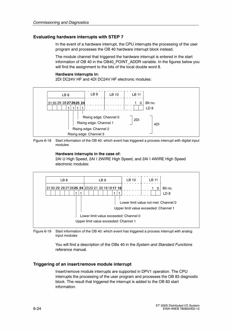
Commissioning and Diagnostics
6-24ET 200S Distributed I/O System
EWA-4NEB 780602402-12
Evaluating hardware interrupts with STEP 7
In the event of a hardware interrupt, the CPU interrupts the processing of the userprogram and processes the OB 40 hardware interrupt block instead.
The module channel that triggered the hardware interrupt is entered in the startinformation of OB 40 in the OB40_POINT_ADDR variable. In the figures below youwill find the assignment to the bits of the local double word 8.
Hardware interrupts in:2DI DC24V HF and 4DI DC24V HF electronic modules:
1
Bit no.3130 29 28 27 26
LD 81
LB 8 LB 9
25 24
Rising edge: Channel 2
Rising edge: Channel 0
Rising edge: Channel 3
LB 11
01
Rising edge: Channel 1
11
LB 10
2DI4DI
Figure 6-18 Start information of the OB 40: which event has triggered a process interrupt with digital inputmodules
Hardware interrupts in the case of:2AI U High Speed, 2AI I 2WIRE High Speed, and 2AI I 4WIRE High Speedelectronic modules:
1
Bit no.3130 29 28 27 26
LD 81
LB 8
25 24
Lower limit value exceeded: Channel 0
Upper limit value exceeded: Channel 1
LB 11
01
LB 10
1
2322 21 20 19 18
1
LB 9
17 16
Lower limit value not met: Channel 0
Upper limit value exceeded: Channel 1
Figure 6-19 Start information of the OB 40: which event has triggered a process interrupt with analoginput modules
You will find a description of the OBs 40 in the System and Standard Functionsreference manual.
Triggering of an insert/remove module interrupt
Insert/remove module interrupts are supported in DPV1 operation. The CPUinterrupts the processing of the user program and processes the OB 83 diagnosticblock. The result that triggered the interrupt is added to the OB 83 startinformation.

Commissioning and Diagnostics
6-25ET 200S Distributed I/O SystemEWA-4NEB 780602402-12
6.1.6 Diagnostics using STEP 5 and STEP 7
In chapter Description Page
6.1.6.1 Reading Diagnostics Data 6-25
6.1.6.2 Structure of slave diagnostic data 6-29
6.1.6.3 Station Status 1 to 3 6-31
6.1.6.4 Master PROFIBUS Address 6-33
6.1.6.5 Manufacturer’s ID 6-33
6.1.6.6 ID-related diagnostics 6-34
6.1.6.7 Module status 6-36
6.1.6.8 Channel-specific diagnostics 6-38
6.1.6.9 Interrupts 6-48
6.1.6.10 Diagnostics in the case of invalid ET 200S configuration states onthe PROFIBUS DP
6-56
Slave diagnostics
The slave diagnosis complies with IEC 61784-1:2002 Ed1 CP 3/1. Depending onthe DP master, it can be read out with STEP 5 or STEP 7 for all DP slaves thatcomply with the standard.
The reading out and structure of the slave diagnosis is described in the followingsections.
6.1.6.1 Reading out the diagnosis
Length of the diagnostic message frame
• The maximum message frame length for the ET 200S is as follows:
-- IM151-1 BASIC: 43 bytes
-- IM151-1 STANDARD, IM151-1 FO STANDARD, IM151-1 HIGH FEATURE(DPV0 operation): 64 bytes
-- IM151-1 STANDARD, IM151-1 FO STANDARD(DPV1 operation): 110 bytes
-- IM151-1 HIGH FEATURE(DPV1 operation): 128 bytes
• The minimum frame length is
-- 6 bytes (module diagnosis, module status, and channel-specific diagnosisblocked by parameter assignment).

Commissioning and Diagnostics
6-26ET 200S Distributed I/O System
EWA-4NEB 780602402-12
Ways of reading the diagnosis
Table 6-7 Reading the diagnosis out using STEP 7 and STEP 5 on PROFIBUS DP
Programmable logiccontroller with DP
master
Block orregister inSTEP 7
Application See .
SIMATIC S7/M7 ”DP SlaveDiagnostics” tab
Slave diagnosis in plain-text formon the STEP 7 user interface
The section on hardwarediagnostics in the STEP 7online help system
SFC 13”DP NRM_DG”
Read out slave diagnosis(store in data area of the userprogram)
For the structure, seeSection 6.1.6.2; for SFC,see the STEP 7 onlinehelp system
SFC 59”RD_REC”
Read data records of the S7diagnosis (store in the data area ofthe user program)
See the system andstandard functionsreference manual
SFB 52”RDREC”
Read data records from the DPslave
For SFB, see the STEP 7online help system(system functions/systemfunction blocks)
SFB 54”RALRM” 1)
Receive interrupts from theinterrupt OBs
For SFB, see the STEP 7online help system(system functions/systemfunction blocks)
SIMATIC S5 withIM308-C as DP master
FB 192”IM308C”
Read out slave diagnosis(store in data area of the user
)
For the structure, seeSection 6.1.6.2; for FBs,
th ET 200SIMATIC S5 withS5-95U PLC as DPmaster
FB 230”S_DIAG”
program) see the ET 200Distributed I/O Systemmanual
1) Only with S7-400 as of V3.0 and with CPU 318 as of V3.0
Example of reading the slave diagnosis using FB 192 ”IM308C”
Here you will find an example of how to use FB 192 to read out the slave diagnosisfor a DP slave in the STEP 5 user program.
Assumptions
The following assumptions apply to this STEP 5 user program:
• The IM 308-C operating in DP master mode uses the page frames 0 to 15(number 0 of IM 308-C).
• The DP slave has the PROFIBUS address 3.
• The slave diagnosis is to be stored in DB20. However, you can also use anyother data block for this.
• The slave diagnosis consists of a maximum 64 bytes (IM151-1 STANDARD).

Commissioning and Diagnostics
6-27ET 200S Distributed I/O SystemEWA-4NEB 780602402-12
STEP 5 user program
STL Explanation
:A DB 30:SPA FB 192
Name :IM308CDPAD : KH F800IMST : KY 0, 3FCT : KC SDGCGR : KM 0TYP : KY 0, 20STAD : KF +1LENG : KF -1ERR : DW 0
Default address area of the IM 308-CIM no. = 0, PROFIBUS address of DP slave = 3Function: Read slave diagnosticsNot evaluatedS5 data area: DB 20Diagnostic data from data word 1Diagnosis length = joker length (all permittedbytes)Error code stored in DW0 of DB30

Commissioning and Diagnostics
6-28ET 200S Distributed I/O System
EWA-4NEB 780602402-12
Example of reading the S7 diagnosis using SFC13 ”DP NRM_DG”
Here you will find an example of how to use SFC 13 to read out the slavediagnosis for a DP slave in the STEP 7 user program.
Assumptions
The following assumptions apply to this STEP 7 user program:
• The diagnostic address of the ET 200S is 1022 (3FEH).
• The slave diagnostic information is to be stored in DB 82: starting at address0.0, length 64 bytes.
• The slave diagnostics is max. 64 bytes (IM151-1 STANDARD in DPV0operation).
STEP 7 user program
STL Explanation
CALL SFC 13
REQ :=TRUELADDR :=W#16#3FERET_VAL :=MW0RECORD :=P#DB82.DBX 0.0 BYTE 64BUSY :=M2.0
Read requestDiagnostic address of the ET 200SRET_VAL of SFC13Data mailbox for the diagnosis in DB82Read operation runs over several OB1 cycles

Commissioning and Diagnostics
6-29ET 200S Distributed I/O SystemEWA-4NEB 780602402-12
6.1.6.2 Structure of slave diagnostic data
Structure of slave diagnostic data
Byte 0Byte 1 Station Status 1 to 3Byte 2
Byte 3
Byte 4Byte 5 Low byte
High byteManufacturer’s ID
Byte 6:
Modulediagnosis
Byte 14
Byte 35 9 channel-related diagnoses(3 bytes per channel)(15 with IM151-1 High Feature inDPV1 operation)The channel-relateddiagnostics is variablefrom 0 to 27 bytes. This dependson the number ofchannel-specific diagnoses.
Master PROFIBUS Address
Byte 15ModulestatusByte 34
:
Byte 37
Byte 36
up to max.byte 109
Mor
ein
form
atio
n
* These diagnoses can be disabled or enabled by parameter. If you disable the diagnoses,they are removed from the diagnostic frame.
** Only with IM151-1 STANDARD (as of 6ES7 151-1AA04-0AB0), IM151-1 FO STANDARD(as of 6ES7 151-1AB03-0AB0) and IM151-1 HIGH FEATURE in DPV1 operation.
Interrupts(only 1 interrupt possible foreach slave diagnostic frame)
IM151-1 STANDARDIM151-1 FO STANDARDIM151-1 HIGH FEATURE
Byte 61
:
:Up to 48bytes
*
*
*
* **
Byte 0Byte 1Byte 2
Byte 3
Byte 4Byte 5
Byte 6:
Byte 8
Byte 16
Byte 9
Byte 15:
Byte 18
Byte 17
Byte 42
:
IM151-1 BASIC
*
*
*
Figure 6-20 Structure of slave diagnostic data

Commissioning and Diagnostics
6-30ET 200S Distributed I/O System
EWA-4NEB 780602402-12
Note
The length of the diagnostic message frame varies:
• Between 6 and 43 bytes in the IM151-1 BASIC
• with IM151-1 STANDARD, IM151-1 FO STANDARD and IM151-1 HIGHFEATURE (depending on configuration)
-- between 6 and 62 bytes in DPV0 operation
-- between 6 and 110 bytes in DPV0 operation (STANDARD)
-- between 6 and 128 bytes in DPV0 operation (HIGH FEATURE)
You can find out the length of the last diagnostic message frame received in:
• STEP 7 from the RET_VAL parameter of the SFC 13.
• STEP 5 from the ERR parameter of the FB 192.

Commissioning and Diagnostics
6-31ET 200S Distributed I/O SystemEWA-4NEB 780602402-12
6.1.6.3 Station statuses 1 to 3
Definition
Station statuses 1 to 3 provide an overview of the status of a DP slave.
Station status 1
Table 6-8 Structure of station status 1 (byte 0)
Bit Meaning Cause/remedy
0 1: The DP slave cannot be addressedby the DP master.
• Correct PROFIBUS address set on theDP slave
• Bus connector connected?
• Voltage at DP slave?
• RS 485 repeater set correctly?
• Reset carried out on DP slave?
1 1: The DP slave is not yet ready toexchange data.
• Wait while the DP slave starts up.
2 1: The configuration data sent by theDP master to the DP slave does notcorrespond to the setup of the DPslave.
• Correct station type or correct setup of theDP slave entered in the configurationsoftware?
3 1: External diagnosis available.(Group diagnosis indication)
• Evaluate the module diagnosis, the modulestatus and/or the channel-specificdiagnosis. Bit 3 is reset as soon as all thefaults have been rectified. The bit is resetwhen there is a new diagnostic message inthe bytes of the diagnostics mentionedabove.
4 1: The required function is notsupported by the DP slave (forexample, changing the PROFIBUSaddress by means of software).
• Check the configuration.
5 1: The DP master cannot interpret theresponse from the DP slave.
• Check the bus configuration.
6 1: The DP slave type does notcorrespond to the software configu-ration.
• Correct station type entered in theconfiguration software?
7 1: Parameters have been assigned tothe DP slave by a different DPmaster (not the one that currentlyhas access to the DP slave).
• The bit is always 1, for example, if youaccess the DP slave with the programmingdevice or another DP master.
The PROFIBUS address of the DP masterthat assigned parameters to the DP slave islocated in the ”master PROFIBUS address”diagnostic byte.

Commissioning and Diagnostics
6-32ET 200S Distributed I/O System
EWA-4NEB 780602402-12
Station status 2
Table 6-9 Structure of station status 2 (byte 1)
Bit Meaning
0 1: New parameters have to be assigned to the DP slave.
1 1: A diagnostic message has been issued. The DP slave will not work untilthe fault has been corrected (static diagnostic message).
2 1: The bit is always set to ”1” in the DP slave.
3 1: Response monitoring has been enabled for this DP slave.
4 1: The DP slave has received the ”FREEZE” control command1.
5 1: The DP slave has received the ”SYNC” control command1.
6 0: The bit is always at 0.
7 1: The DP slave has been disabled, that is, it has been removed from theprocessing in progress.
1 The bit is updated only if another diagnostic message changes, too.
Station status 3
Table 6-10 Structure of station status 3 (byte 2)
Bit Meaning
0 to 6 0: The bits are always at 0.
7 1: • There are more diagnostic messages than the DP slave canstore.
• The DP master cannot enter all the diagnostic messages sent bythe DP slave in its diagnostic buffer (channel-specific diagnosis).

Commissioning and Diagnostics
6-33ET 200S Distributed I/O SystemEWA-4NEB 780602402-12
6.1.6.4 Master PROFIBUS Address
Definition
The master PROFIBUS address diagnostic byte contains the PROFIBUS addressof the DP master that:
• Assigned parameters to the DP slave and
• Has read and write access to the DP slave
The master PROFIBUS address is in byte 3 of the slave diagnosis.
6.1.6.5 Manufacturer ID
Definition
The manufacturer ID contains a code that describes the type of the DP slave.
Manufacturer ID
Table 6-11 Structure of the manufacturer ID (Bytes 4, 5)
Byte 4 Byte 5 Manufacturer ID for
80H F3H ET 200S with IM151-1 BASIC
80H 6AH ET 200S with IM151-1 STANDARD
80H 6BH ET 200S with IM151-1 FO STANDARD
80H E0H ET 200S with IM151-1 HIGH FEATURE

Commissioning and Diagnostics
6-34ET 200S Distributed I/O System
EWA-4NEB 780602402-12
6.1.6.6 Module diagnosis
Definition
The module diagnosis indicates whether or not modules of the ET 200S haveerrors/faults. The module diagnosis begins as of byte 6 and comprises:
• 3 bytes in the case of the IM151-1 BASIC
• 9 bytes in the case of the IM151-1 STANDARD; IM151-1 FO STANDARD andIM151-1 HIGH FEATURE.
Module diagnosis
The module diagnosis for the ET 200S with the IM151-1 BASIC is structured asfollows:
Byte 6
Bit no.Byte 7Byte 8
7 136 5 4 2 0
Module: 1 to 8Module: 9 to 12
7 136 5 4 28
1112 10 9
Events on thecorresponding moduleare indicated by set bits.
7 0 Bit no.
Length of the module diagnosisincluding byte 6 (= 3 bytes)
Code for ID-related diagnostics
0 1
6 5
110000
** * *
* Always ”0”
Figure 6-21 Structure of the ID-related diagnosis for the ET 200S with the IM151-1 BASIC

Commissioning and Diagnostics
6-35ET 200S Distributed I/O SystemEWA-4NEB 780602402-12
The module diagnosis for the ET 200S with the IM151-1 STANDARD, IM151-1 FOSTANDARD and IM151-1 HIGH FEATURE is structured as follows:
Byte 6
Bit no.Byte 7Byte 8
7 136 5 4 2 0
Byte 9Byte 10Byte 11Byte 12Byte 13Byte 14
Module: 1 to 8Module: 9 to 16Module: 17 to 24Module: 25 to 32Module: 33 to 40Module: 41 to 48Module: 49 to 56Module: 57 to 63
7 136 5 4 28
16 15 1314 1112 10 9
18192023 22 21 17
28
24
362729303132
3435
26 253940 3738
47
33
414648
4950
4345 44 42
53 525456 5561
51
5862 5960 5763
Events on thecorresponding moduleare indicated by set bits.
7 0 Bit no.
Length of the module diagnosisincluding byte 6 (= 9 bytes)
Code for ID-related diagnostics
0 1
6 5
100100
* Always ”0”
*
Figure 6-22 Structure of the ID-related diagnosis for the ET 200S with the IM151-1
STANDARD, IM151-1 FO STANDARD and IM151-1 HIGH FEATURE
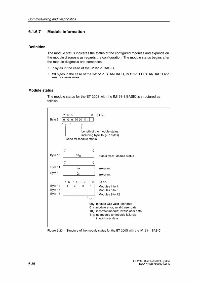
Commissioning and Diagnostics
6-36ET 200S Distributed I/O System
EWA-4NEB 780602402-12
6.1.6.7 Module information
Definition
The module status indicates the status of the configured modules and expands onthe module diagnosis as regards the configuration. The module status begins afterthe module diagnosis and comprises:
• 7 bytes in the case of the IM151-1 BASIC
• 20 bytes in the case of the IM151-1 STANDARD, IM151-1 FO STANDARD andIM151-1 HIGH FEATURE.
Module status
The module status for the ET 200S with the IM151-1 BASIC is structured asfollows:
Byte 9
Byte 10
7 0
Byte 11
7 0
82H
0H
0H
7 6 5 4 13 2 0Byte 13
Byte 12
Bit no.
Modules 1 to 4Byte 14 Modules 5 to 8Byte 15 Modules 9 to 12
00B: module OK; valid user data01B: module error; invalid user data10B: incorrect module; invalid user data11B: no module (or module failure);
invalid user data
Status type: Module Status
irrelevant
irrelevant
7 0 Bit no.
Code for module status
0 0
56
Length of the module statusincluding byte 15 (= 7 bytes)
1 11000
1234
Figure 6-23 Structure of the module status for the ET 200S with the IM151-1 BASIC

Commissioning and Diagnostics
6-37ET 200S Distributed I/O SystemEWA-4NEB 780602402-12
The module status for the ET200S with the IM151-1 STANDARD, IM151-1 FOSTANDARD, and IM151-1 HIGH FEATURE is structured as follows:
Byte 15
Byte 16
7 0
Byte 17
7 0
82H
0H
0H
7 6 5 4 13 2 0Byte 19
Byte 18
Bit no.
Modules 1 to 4Byte 20 Modules 5 to 8Byte 21 Modules 9 to 12Byte 22 Modules 13 to 16Byte 23 Modules 17 to 20Byte 24 Modules 21 to 24Byte 25 Modules 25 to 28Byte 26 Modules 29 to 32Byte 27 Modules 33 to 36Byte 28 Modules 37 to 40Byte 29 Modules 41 to 44Byte 30 Modules 45 to 48Byte 31 Modules 49 to 52Byte 32 Modules 53 to 56Byte 33 Modules 57 to 60Byte 34 Modules 61 to 63
Status type: Module Status
irrelevant
irrelevant
7 0 Bit no.
Code for module status
0 0
56
Length of the module statusincluding byte 15 (= 20 bytes)
0 01010
1234
00B: module OK; valid user data01B: module error; invalid user data10B: incorrect module; invalid user data11B: no module (or module failure);
invalid user data
*
* always ”00”
Figure 6-24 Structure of the module status for ET 200S with the IM151-1 STANDARD;
IM151 FO STANDARD and IM151 HIGH FEATURE

Commissioning and Diagnostics
6-38ET 200S Distributed I/O System
EWA-4NEB 780602402-12
6.1.6.8 Channel-specific diagnosis
Definition
The channel-specific diagnosis gives information on channel errors of modules andexpands on the module diagnosis. The channel-specific diagnosis starts after themodule status (if the parameters are preset accordingly). The maximum length islimited by the total maximum length of the slave diagnosis from 43/62 bytes inDPV0 mode or 110/128 bytes in DPV1 mode. The channel-specific diagnosis doesnot affect the module status.
A maximum of 9 (in DPV0 mode) or 15 (in DPV1 mode with IM151-1HIGH FEATURE) channel-specific diagnostic messages are possible (see alsostation status 3, bit 7).
Channel-specific diagnostics
The channel-specific diagnosis for the ET 200S with the IM151-1 BASIC isstructured as follows:
7 Bit no.1 0
6 5 4 13 2
000000B up to 001100B: Module slot that sends thechannel-specific diagnosis.
0
7 Bit no.6 5 4 13 2 0Byte 17
000000B up to 000011B: Number of the channel that sends thediagnosis
7 Bit no.6 5 4 13 2 0Byte 18
Error type (see Table 6-12 to Table 6-23)
Channeltype:
Byte 16
001B: Bit
010B: 2 bits
011B: 4 bits
100B: Byte
101B: Word
110B: 2 words
01B: Input channel
10B: Output channel
11B: Input/output channel
Bytes 19to 42
Next channel-specific diagnostic message(assignment as for bytes 16 to 18)
Code for channel-specific diagnosis
Figure 6-25 Structure of the channel-specific diagnosis for the ET 200S with IM151-1
BASIC

Commissioning and Diagnostics
6-39ET 200S Distributed I/O SystemEWA-4NEB 780602402-12
The channel-specific diagnosis for the ET 200S with the IM151-1 STANDARD,IM151-1 FO STANDARD and IM151-1 HIGH FEATURE is structured as follows:
7 Bit no.1 0
6 5 4 13 2
000000B up to 111111B: Module slot that sends thechannel-specific diagnosis.
0
7 Bit no.6 5 4 13 2 0Byte 36
000000B up to 000011B: Number of the channel that sends thediagnosis
7 Bit no.6 5 4 13 2 0Byte 37
Error type (see Table 6-12 to Table 6-23)
Channeltype:
Byte 35
001B: Bit
010B: 2 bits
011B: 4 bits
100B: Byte
101B: Word
110B: 2words
01B: Input channel
10B: Output channel
11B: Input/output channel
Bytes 38to 40
Next channel-specific diagnostic message(assignment as for bytes 35 to 37)
Max. byte 61
Code for channel-specific diagnosis
..
in DPV0 mode: IM151-1, IM151-1 FO STANDARD, IM151-1HIGH FEATURE
max. byte 109max. byte 127
in DPV1 mode: IM151-1, IM151-1 FO STANDARD,in DPV1 mode: IM151-1 HIGH FEATURE
Figure 6-26 Structure of the channel.specific diagnosis for the ET 200S with the IM151-1
STANDARD, IM151-1 FO STANDARD and IM151-1 HIGH FEATURE
Note
The module slot is encrypted in byte 16/35, bit 0 to 5. The following applies:displayed number +1≙ slot of the module (0≙ slot 1; 1≙ slot 2; 3≙ slot 4,etc.)
In bits 6/7 of byte 17/36, 00B is output if a power module reports achannel-specific diagnosis.

Commissioning and Diagnostics
6-40ET 200S Distributed I/O System
EWA-4NEB 780602402-12
Power module error types
The diagnostic message is reported on channel 0 and applies to the whole module.
Table 6-12 Power module error types
Power modules electronicmodules
Error type Meaning Remedy
PM-E 24--48VDC/120--230 VAC
PM-E 24VDC
PM-E24--48 VDC
17D 10001: Encoder orload voltage missing
No supply voltage,or inadequatesupply voltage.
Correct the processwiring. Check thesupply voltage.
------ 18D 10010: Fuse defect The fuse in thepower module hastripped.
Replace the fuse.
Digital electronic module error types
Table 6-13 Digital electronic module error types
Digital electronicmodules
Error type Meaning Remedy
2DI 24 VDC HighFeature
1D 00001: Short-circuit Short circuit of thesensor supply. Thediagnostic messageis issued on channel0 and applies to thewhole module.
Correct the processwiring (sensorwiring).
4DI 24 VDC HighFeature
1D 00001: Short-circuit
(in connection withIM151-1 BASIC /IM151-1 STANDARD,as of6ES7 151-1AA02 0AB0,IM151-1 FOSTANDARD, as of6ES7 151-1AB01-0AB0)or IM151-1 HIGHFEATURE
Short circuit of thesensor supply. Thediagnostic messageis issued on channel0 and applies to thewhole module.
Correct the processwiring (sensorwiring).
26D 11010: Externalerror/fault
(in connection withIM151-1 STANDARD, to6ES7 151-1AA01-0AB0or IM151-1 FOSTANDARD, to6ES7 151-1AB00-0AB0)

Commissioning and Diagnostics
6-41ET 200S Distributed I/O SystemEWA-4NEB 780602402-12
Table 6-13 Digital electronic module error types
Digital electronicmodules
RemedyMeaningError type
4DI 24--48 VUC HighFeature
26D 11010: Externalerror/fault
Line to the actuatorinterrupted.
Correct the processwiring.
No supply voltage, orinadequate supplyvoltage.
Correct the processwiring. Check thesupply voltage.
Fuse triggered. Replace the fuse.
2DO 24 VDC/0.5 AHigh Feature
2DO 24 VDC/2 A High
1D 00001: Short-circuit Short circuit of theactuator supply toground.
Correct the processwiring.
2DO 24 VDC/2 A HighFeature 6D 00110: Wire break Line to the actuator
interrupted.
4DI NAMUR 1D 00001: Short-circuit Short circuit in signalline to sensor
Correct the processwiring
Defective encoder Replace the sensor
Wrong encoder typeset
Correct theparameterassignment
Load impedance toolow.
Use a sensor withincreasedimpedance.
6D 00110: Wire break Signal line to asensor interrupted.
Correct the processwiring
Defective encoder Replace the sensor
Wrong encoder typeset
Correct theparameterassignment.
Load impedance toolow.
Use a sensor withincreasedimpedance.
9D 01001: Error Internal module erroroccurred.
Replace the module
Sensor signal flutters. Eliminate cause
16D 10000: Parameterassignment error
Parameterassignment error
Correct theparameter settings
26D 11010: External/f lt
Sensor error. Replace the sensorerror/fault
Changeover contacterror.
Correct the processwiring

Commissioning and Diagnostics
6-42ET 200S Distributed I/O System
EWA-4NEB 780602402-12
Analog input module error types
Table 6-14 Analog input module error types
Analog input modules Error type Meaning Remedy
2AI UHighSpeed
2AI UStandard
2AI U HighFeature
2AI I 2WIREStandard
4AI I 2WIREST
2AI I 2WIREHigh Speed
2AI I 4WIREStandard
2AI I 2/4WIREHigh Feature
2AI I 4WIRE
2AI TCStandard
2AI TCHighFeature
16D 10000:Parameterassignmenterror
Module cannot use theparameter for thechannel:
Inserted module doesnot match the oneconfigured.
Parameter assignmenterror.
Correct theconfiguration(compare actualand desiredconfiguration).
Correct theparameterassignment(parameterassignment ofwire breakdiagnosis onlywith thepermittedmeasuringranges).
2AI I 4WIREHigh Speed
2AI RTDStandard
2AI RTD HighFeature
9D 01001: Error Internal module errorhas occurred(diagnostic messageon channel 0 appliesto the whole module).
Replace themodule.
Feature7D 00111: Violation
of hi limitValue is above theoverrange.
Correct themodule/actuatormatch.
8D 01000:Violation of lolimit
Value is below theunderrange.
Correct themodule/actuatormatch.
------ 6D 00110:Open circuit1)
Line to the sensorinterrupted.
Correct theprocess wiring.
------ ------ 21D 10101:Referencechannel error2)
Error on the referencechannel
Check thereferencemodule (2AIRTD Standard).
1) In the case of the 2AI RTD High Feature, a wire break is reported for the measuring and constant-currentlines of the sensor.
2) The following applies for the 2AI TC Standard and 2AI TC High Feature modules:during configuration with the device database file reference channel errors are not reported if the referencechannel is incorrectly configured (not Pt100 climate range).

Commissioning and Diagnostics
6-43ET 200S Distributed I/O SystemEWA-4NEB 780602402-12
Analog output module error types
Table 6-15 Analog output module error types
Analog outputmodules
Error type Meaning Remedy
2AO UStandard
2AO UHighFeature
2AO IStandard
2AO IHighFeature
16D 10000:Parameterassignmenterror
Module cannot use theparameter for the channel:
Inserted module does notmatch the one configured.
Parameter assignment error.
Correct the configuration(compare actual anddesired configuration).
Correct the parameterassignment (parameterassignment of wire breakdiagnosis only with thepermitted measuringranges).
9D 01001: Error Internal module error hasoccurred (diagnosticmessage on channel 0applies to the wholemodule).
Replace the module.
------ 1D 00001:Short-circuit
Short circuit of the actuatorsupply.
Correct the process wiring.
------ 2AO IStandard
2AO IHighFeature
6D 00110: Wirebreak
Line to the actuatorinterrupted.
Correct the process wiring.
1SSI
Table 6-16 1SSI
Error type Meaning Remedy
1D 00001: Short-circuit Short circuit of the supply to theabsolute position encoder.
Correct the process wiring.
9D 01001: Error Internal module error occurred.
Load voltage from the powermodule is too low.
Replace the module.
Correct the process wiring.Check the load voltage.
16D 10000: Parameterassignment error
Parameters have not beenassigned to the module.
Adjust the parameterassignment.
26D 11010: External error/fault Start/stop bit error (absolutesensor error): Wire break in thesensor cable or sensor cable isnot connected. Sensor type,transmission rate, and monofloptime do not correspond to thesensor connected;programmable sensors do notcorrespond to the settings on the1SSI EM. Sensor is defective orthere are faults.
Replace the sensor; correct theprocess wiring.
Correct the parameter settings

Commissioning and Diagnostics
6-44ET 200S Distributed I/O System
EWA-4NEB 780602402-12
1COUNT 24V/100kHz
Table 6-17 1Count 24V/100kHz
Error type Meaning Remedy
1D 00001: Short-circuit Short circuit of the sensorsupply or the actuator.
Check the wiring to the sensor.Correct the process wiring.
5D 00101: Overtemperature Digital output is overloaded. Correct the process wiring.
6D 00110: Wire break Line to the actuator interrupted. Correct the process wiring.
9D 01001: Error Internal module error occurred.
Load voltage from the powermodule is too low.
Replace the module.
Correct the process wiring.Check the load voltage.
16D 10000: Parameterassignment error
Parameters have not beenassigned to the module.
Adjust the parameterassignment.
1COUNT 5V/500kHz
Table 6-18 1Count 5V/500kHz
Error type Meaning Remedy
1D 00001: Short-circuit Short circuit of the sensorsupply or the actuator.
Check the wiring to the sensor.Correct the process wiring.
5D 00101: Overtemperature Digital output is overloaded. Correct the process wiring.
6D 00110: Wire break Line to the actuator interrupted. Correct the process wiring.
9D 01001: Error Internal module error occurred. Replace the module.
16D 10000: Parameterassignment error
Parameters have not beenassigned to the module.
Adjust the parameterassignment.
26D 11010: External error/fault Wire break/short circuit of the 5V sensor signals:A, /A, B, /B, N, /N,
Correct the parameter settings
1STEP 5V/204kHz
Table 6-19 1STEP 5V/204kHz
Error type Meaning Remedy
1D 00001: Short-circuit Short circuit of the sensorsupply.
Check the wiring to theswitches. Correct the processwiring.
9D 01001: Error Internal module error occurred. Replace the module.
16D 10000: Parameterassignment error
Parameters have not beenassigned to the module.
Adjust the parameterassignment.

Commissioning and Diagnostics
6-45ET 200S Distributed I/O SystemEWA-4NEB 780602402-12
2Pulse
Table 6-20 2PULSE
Error type Meaning Remedy
1D 00001: Short-circuit Short circuit of the sensorsupply or the actuator.
Check the wiring to themomentary-contact switchesand the actuators. Correct theprocess wiring.
9D 01001: Error Internal module error occurred. Replace the module.
16D 10000: Parameterassignment error
Parameters have not beenassigned to the module.
Adjust the parameterassignment.

Commissioning and Diagnostics
6-46ET 200S Distributed I/O System
EWA-4NEB 780602402-12
1POS INC/Digital, 1POS SSI/Digital, 1POS INC/Analog, 1POS SSI/Analog
Table 6-21 1POS INC/Digital, 1POS SSI/Digital, 1POS INC/Analog, 1POS SSI/Analog
Error type Meaning Remedy
1D 00001: Short circuit Short circuit of the sensorsupply.
Check the wiring to the sensor.Correct the process wiring.
16D 10000: Parameterassignment error
Parameters have not beenassigned to the module.
Adjust the parameterassignment.
17D 10001: Load voltage 2L+missing
Only applies to the 1POSINC/Digital and 1POSSSI/Digital:No supply voltage, orinadequate supply voltage.
Correct the process wiring.Check the supply voltage.
26D 11010: External fault Wire break/short circuit of thesensor signals.
Wire break in the sensor cableor sensor cable is notconnected.
Sensor is defective or there arefaults.
Sensor type, transmission rate,and monoflop time do notcorrespond to the sensorconnected; programmablesensors do not correspond tothe settings on the module.
Correct the process wiring
Correct the parameter settings
Replace the sensor.
Serial interface module 1SI 3964/ASCII, 1SI Modbus/USS
Table 6-22 1SI 3964/ASCII, 1SI Modbus/USS
Error type Meaning Remedy
6D 00110: Open circuit Wire broken or disconnected. Check the wiring to theterminals. Check the cable tothe partner.
7D 00111: Upper limitviolation
Buffer overflow; messagelength overflow
The P_RCV FB must be calledmore frequently.
8D 01000: Lower limitviolation
Message of length 0 sent1 Check why the communicationpartner is sending frameswithout user data.
9D 01001: Error Internal module error occurred. Replace the module.
16D 10000: Parameterassignment error
Parameters have not beenassigned to the module.
Correct the parameterassignment.
22D 10110: Message error Frame error, parity error Check the communicationsettings.
1 EM 1SI: only with 3964(R)

Commissioning and Diagnostics
6-47ET 200S Distributed I/O SystemEWA-4NEB 780602402-12
4 IQ-SENSE
Table 6-23 4 IQ-SENSE
Error type Meaning Remedy
1D 00001: Short circuit Short circuit of the linesbetween the electronic moduleand sensor
Check the wiring to the sensor.Correct the process wiring.
6D 00110: Open circuit Line to the actuator interrupted.
No sensor connected.
Sensor does not respond.
Correct the process wiring.
Connect the sensor.
Replace the fuse.
8D 01000: Lower limitviolation
Maintenance requirement(signal quality < 130 %, excessgain), sensor-dependent
Adjust the reflex sensor.
Clean the optical system.
9D 01001: Error Communication error betweenthe electronic module andsensor
Replace the electronic moduleor the sensor.
Check the wiring.
16D 10000: Parameterassignment error
Parameter assignment error.
Inserted module does notmatch the one configured.
Teach-in error (a new valuecould not bedetermined/obtained)
Inserted sensor does not matchconfigured sensor.
Adjust the parameterassignment.
Correct the configuration(compare actual and desiredconfiguration).
Repeat teach-in.
Correct the configuration, orinsert a different sensor type.
26D 11010: External fault Excess gain lower limit violated(signal quality < 110 %) orsensor error, sensor-dependent
Adjust the reflex sensor.
Clean the optical system.
Replace the sensor.
27D 11011: Unclear error Teach-in process running.
Alignment tool is active.
Terminate the teach-in process.
Terminate the alignment tool.

Commissioning and Diagnostics
6-48ET 200S Distributed I/O System
EWA-4NEB 780602402-12
6.1.6.9 Interrupts
The information in this section is applicable for IM151-1 STANDARD (up to6ES7 151-1AA04-0AB0), IM151-1 FO STANDARD (up to 6ES7 151-1AB03-0AB0),IM151-1 HIGH FEATURE:
Definition
The interrupt section of the slave diagnosis provides information on the interrupttype and the cause that led to the triggering of the interrupt. The interrupt sectionconsists of a maximum of 48 bytes.
Position in the diagnostic frame
The position of the interrupt section is after the channel-specific diagnosis(DPV1 mode only).
Example: If there are three items of channel-related diagnostic information, theinterrupt section starts at byte 44.
Data records
The diagnostic data of a module can be up to 44 bytes in length and is located indata records 0 and 1:
• Data record 0 contains 4 bytes of diagnostic data describing the current statusof a programmable logic controller. Data record 0 (DS0) is part of the headerinformation of OB 82 (local data bytes 8 to 11).
• Data record 1 contains the 4 bytes of diagnostic data that is also contained indata record 0 and, in addition, up to 40 bytes of module-specific diagnosticdata.
You can read out data records 0 and 1 (DS0 and DS1) by means of SFC59”RD_REC”.
Contents
The content of the interrupt information depends on the interrupt type:
• In the case of diagnostic interrupts, diagnostic data record 1 ( up to 44 bytes) issent as the interrupt status information (as of byte x+4).
• In the case of hardware interrupts, the interrupt status information is 4 bytes inlength.
• With remove/insert interrupts the length of the interrupt status information is
-- 5 byes with IM151-1 HIGH FEATURE
-- 0 bytes with IM151-1 STANDARD (as of 6ES7 151-1AA04-0AB0) andIM151-1 FO STANDARD (as of 6ES7 151-1AB03-0AB0)

Commissioning and Diagnostics
6-49ET 200S Distributed I/O SystemEWA-4NEB 780602402-12
Interrupts
If the configuration was done with STEP 7, the interrupt data will be evaluated andsent to the relevant organization function blocks (OBs).
The interrupt section for the ET 200S is structured as follows:
Byte x7 6 05 4 3 2 1
Code for device-specific diagnosisLength of the interrupt section incl. byte x (= max. 48 bytes)
01 0 0 00 00
Byte x+17 6 05 4 3 2 1
Interrupt type0000001B: Diagnostic interrupt
0000010B: Process interrupt0000011B: Remove interrupt0000100B: Insertion interrupt
0
Byte x+37 6 05 4 3 2 1
0
Interrupt sequencenumber (1 to 31)
Diagnostic interrupt: 01B: at least one error ispending10B: going error11B: Reserved
Process interrupt: 00B
Remove interrupt: 00B forIM151-1 HIGH FEATURE01B forIM151-1 STANDARD andIM151-1 FO STANDARD
Insertion interrupt: 10B: correct moduleinserted11B: wrong moduleinserted
Byte x+27 6 05 4 3 2 1
00: IM151-1 (STANDARD, HIGH FEATURE) sends interrupt01 to 63: Slot of the module returning the interrupt
Slot numbers
:
Byte x+4 to... ... byte x+43 ... Byte x+7 ... Byte x+8...Diagnostic data(contents of datarecord 1)
Processinterrupt data
• Remove/insertion interruptdata for IM151-1 HIGHFEATURE
• not withIM151-1 STANDARD andIM151-1 FO STANDARD
Figure 6-27 Structure of the interrupt status of the interrupt section

Commissioning and Diagnostics
6-50ET 200S Distributed I/O System
EWA-4NEB 780602402-12
Diagnostic interrupt, byte x+4 to x+7
Byte x+47 6 05 4 3 2 1
Internal error in module
Module problem (i.e. error detected)
00 00
Byte x+6
7 6 05 4 3 2 1
Module class:0100B for IM151-1 (STANDARD, HIGH FEATURE)1001B for digital electronic module: as of byte x+80101B for analog electronic module: as of byte x+81000B for process-related module: as of byte x+81101B for power module: as of byte x+8
0
External error: Module not responding
Channel error in module
0
Channel information available (always ”1”)
User information available (always ”0”)
Byte x+5
7 0Always ”0”
Byte x+77 0
Always ”0”
Incoming diagnosis: 1101BGoing diagnosis: 0000B
Figure 6-28 Structure of bytes x+4 to x+7 for diagnostic interrupt

Commissioning and Diagnostics
6-51ET 200S Distributed I/O SystemEWA-4NEB 780602402-12
Diagnostic interrupt of the modules
7 6 05 4 3 2 1Bytex+8...
Channel type7BH: Input channel7CH: Output channel7DH: Process-related module, motor starter, power module, fail-safe module
Byte x+9 Length of the channel-specific diagnosis
Byte x+10 Number of channels per module
Byte x+11
Diagnostic event on channel 0 of the moduleDiagnostic event on channel 1 of the module
Diagnostic event on channel 2 of the moduleDiagnostic event on channel 3 of the module
Byte x+12 34 2 1 07 56
Short-circuit
Overtemperature
Violation of hi limit
Byte x+13 1112 10 9 815 1314
ErrorViolation of lo limit
Byte x+14 1920 18 17 1623 2122
Parameter assignment error
Fuse defect
Reference channel errorMessage error
Byte x+15 2728 26 25 2431 2930
Actuator shutdownSafety-related shutdown
Unclear error
Byte x+16 to x+19 error type on channel 1: see bytes x+12 to x+15
Byte x+20 to x+23 error type on channel 2: see bytes x+12 to x+15
Byte x+24 to x+27 error type on channel 3: see bytes x+12 to x+15
Wire break
Sensor or load voltage missing
External fault
Communication problem
Overload
0
Figure 6-29 Structure as of byte x+8 for diagnostic frame

Commissioning and Diagnostics
6-52ET 200S Distributed I/O System
EWA-4NEB 780602402-12
Example of a Diagnostic Interrupt
Byte x7 6 05 4 3 2 1
Length of the interrupt section = 27 bytes
11 0 1 10 00
Example:The 4DI electronic module reports the ”short circuit” diagnostic interrupt on channel 2
Byte x+17 6 05 4 3 2 1
Diagnostic interrupt
00 0 0 10 00
Digital electronic module
Byte x+27 6 05 4 3 2 1
Slot number 10
10 0 1 00 00
Byte x+37 6 05 4 3 2 1
Interrupt sequence number = 1
10 0 0 10 00
Byte x+47 6 05 4 3 2 1
Channel error
10 0 0 00 00
Byte x+57 6 05 4 3 2 1
Channel information available
11 1 1 10 00
There is at least 1 error
Byte x+6 and x+7 always ”0”
Figure 6-30 Example of a Diagnostic Interrupt

Commissioning and Diagnostics
6-53ET 200S Distributed I/O SystemEWA-4NEB 780602402-12
Byte x+8...7 6 05 4 3 2 1
Input channel = 7BH
11 0 1 10 11
Byte x+97 6 05 4 3 2 1
Length of the channel-specific diagnosis = 32 bits
00 0 0 00 10
Byte x+207 6 05 4 3 2 1
Bit x+20.1 = error type 1 on channel 2 = short circuit
00 0 1 00 00
Byte x+107 6 05 4 3 2 1
Number of channels per module = 4
00 1 0 00 00
Byte x+12 to x+15 ”0” (channel 0)
Byte x+16 to x+19 ”0” (channel 1)
Byte x+21 to x+23 ”0” (channel 2)
Byte x+24 to x+27 ”0” (channel 3)
Byte x+117 6 05 4 3 2 1
Diagnostic event on channel 2
00 1 0 00 00
Figure 6-31 Example of a diagnostic interrupt (continued)

Commissioning and Diagnostics
6-54ET 200S Distributed I/O System
EWA-4NEB 780602402-12
Hardware interrupt of digital input modules
Byte x+47 6 05 4 3 2 1
Rising edge on channel 0
Rising edge on channel 1
Rising edge on channel 2
Rising edge on channel 3
Byte x+5, x+6 and x+7 always 00H
Figure 6-32 Structure as of byte x+4 for hardware interrupt (digital input)
Hardware interrupt of analog input modules
Byte x+47 6 05 4 3 2 1
Lower limit value exceeded: Channel 0
Byte x+6 and x+7 always 00H
Upper limit value exceeded: Channel 1
Byte x+57 6 05 4 3 2 1
Lower limit value not met: Channel 0
Upper limit value exceeded: Channel 1
Figure 6-33 Structure as of byte x+4 and byte x+5 for hardware interrupt (analog input)

Commissioning and Diagnostics
6-55ET 200S Distributed I/O SystemEWA-4NEB 780602402-12
Remove/insertion interrupt by IM151-1 HIGH FEATURE
Byte x+4Byte x+5Byte x+6
7 6 05 4 3 2 1Byte x+7
Bytex+8...
irrelevant
Type ID of the module; high byte
Type ID of the module; low byte
SKF-ID (STEP 7)
Legend: Type ID of a removed module: 8FC0H (empty slot)
Figure 6-34 Structure starting at byte x+4 for remove/insert interrupts
Byte x+4 to x+8 contains the ID of the module that has been removed or inserted.
The interrupt type in byte x+1 indicates whether the modules have been removedor inserted (see Figure 6-27).

Commissioning and Diagnostics
6-56ET 200S Distributed I/O System
EWA-4NEB 780602402-12
6.1.6.10 Diagnostics in the case of invalid ET 200S configuration stateson the PROFIBUS DP
Invalid configuration states
The following invalid configuration states of the ET 200S lead to station failure ofthe ET 200S or prevent entry into data interchange. These responses occurirrespective of whether the IM parameters ”Operation at Preset <> ActualConfiguration”, ”Replacement of Modules during Operation”, and ”Startup whenExpected <> Actual Configuration” have been enabled.
• Two missing modules
• Bus termination module missing
• Number of modules exceeds maximum configuration
• Module missing in slot 1 (in the case of the IM151-1 STANDARD,6ES7 151-1AA00-0AB0)
• Faulty backplane bus (for example, terminal module is defective)
NoteAs of IM151-1 BASIC / IM151-1 STANDARD (6ES7 151-1AA01-0AB0), IM151-1FO STANDARD and IM151-1 HIGH FEATURE: If one module is missing (gap) andthe ET 200S is switched on, the station will not start up (see diagnosis below).
Diagnostics
The following diagnosis indicates all the invalid configuration states:
Interface module ID-related diagnostics Module status
IM151-1 BASIC All 12 bits set • 01B: ”Module error; invalid user data” forall modules (slots) until the cause of the
IM151-1 STANDARDIM151-1 FO STANDARDIM151-1 HIGH FEATURE
All 63 bits setall modules (slots) until the cause of theerror is found
• 11B: ”No module; invalid user data” oncethe cause of the error is found

Commissioning and Diagnostics
6-57ET 200S Distributed I/O SystemEWA-4NEB 780602402-12
6.2 Commissioning and diagnostics on PROFINET IO
Chapter overview
Chapter Description Page
6.2.1 Configuring the ET 200S on PROFINET IO 6-57
6.2.2 Commissioning and startup of the ET 200S on PROFINET IO 6-59
6.2.3 Diagnostics with LED display 6-61
6.2.4 Diagnostic messages of the electronic modules 6-64
6.2.5 Evaluating the interrupts of the ET 200S 6-65
6.2.6 Diagnostics with STEP 7 6-66
6.2.1 Configuring the ET 200S on PROFINET IO
Introduction
The IM151-3 PN interface module must have the device name assigned (seeSection 5.6).Configuration is the configuration and parameter setting of the ET 200S.
• Configuring: The systematic arrangement of the different ET 200S modules(setup)
• Configuration: setting the ET 200S parameters using the configuration software
Note
The ET 200S is included in the hardware catalog of HWCONFIG:
• IM151-3 PN: as of STEP 7 V5.3 and Service Pack 1
The STEP 7 online help provides more detailed information on how to proceed.

Commissioning and Diagnostics
6-58ET 200S Distributed I/O System
EWA-4NEB 780602402-12
GSD file
You configure the ET 200S distributed I/O system using the device database file(*.GSD file). The ET 200S is added to your system as an I/O device with this file.You can download the *.GSD file in either of the following ways:
• From the Internet at http://www.ad.siemens.de/csi_e/gsd
The following device database file is available for the IM151-3 PN:
• GSDML-V1.0-Siemens-ET200S-”date in yyyymmdd format”.xml
Integrating the device database file in your configuration software
Table 6-24 below describes how you integrate the device database file inSIMATIC S7.
Table 6-24 Integrating the device database file in your configuration software
Step STEP 7 as of V5.0, ServicePack 1
1 Start STEP 7, and call the Options " Install New *.GSD Files menu commandfrom HW Config.
2 From the next dialog box, select the GSD file you want to install and confirm withOK.Result: The IO device is displayed in the hardware catalog in the PROFINET IOdirectory.
3 Configure the ET 200S using STEP 7 (refer to the help system in STEP 7).

Commissioning and Diagnostics
6-59ET 200S Distributed I/O SystemEWA-4NEB 780602402-12
6.2.2 Commissioning and startup of the ET 200S on PROFINET IO
Software requirements
Table 6-25 Software requirements for commissioning on PROFINET IO
Engineering softwareused
Version Notes
STEP 7 As of Version 5.3and ServicePack 1
You use HWCONFIG and the supplied device databasefile.
Configuration softwarefor a different I/Ocontroller
You need the device database file of ET 200S.
Requirements for commissioning the ET 200S
Table 6-26 Requirements for commissioning the ET 200S on PROFINET IO
Prior Activity See
1. I/O device installed Section 4
2. I/O device wired Section 5
3. MMC inserted; I/O device configured with device name(configured and parameters set)
Section 6.2.1
4. Supply voltage switched on for I/O controller Manual for I/O controller
5. I/O controller switched to RUN mode Manual for I/O controller
Commissioning the ET 200S
Table 6-27 Steps for commissioning the I/O device
Step Procedure See
1. Switch on the supply voltage for the I/O device. Section 8.6
2. Switch on the supply voltage for the load as necessary.

Commissioning and Diagnostics
6-60ET 200S Distributed I/O System
EWA-4NEB 780602402-12
Startup of the ET 200S
Switch on supply voltagefor I/O device
I/O device receivesconnect telegram and
startup data setsfrom the I/O controller
I/O device sets outputs toto ”0” and imports the
configured device namefrom the MMC
”BF” LED off;inputs and outputs
are enabled;data transfer possible.
Yes
NoAre the subscribedmodules present?
Remedy: Alignment of onlineand offline configuration data
”ON” LED lights”BF” LED flashes
(with connection to switch)”BF” LED lights
(without connection to switch)
Figure 6-35 Configuring the ET 200S on PROFINET IO
Note
The IM151-3 PN interface module supports the default startup.
In this case the following conditions apply:
• The default parameters are used (see the parameters for the electronicmodules).
• All supply voltages must be switched on at the power modules.

Commissioning and Diagnostics
6-61ET 200S Distributed I/O SystemEWA-4NEB 780602402-12
6.2.3 Diagnosis using the LEDs
Interface module
SF
BF
ON
Group error (red)
Bus error (red)
Power supply (green)
ET 200S LINK
RX/TX
I/O controller not available (green)
Data exchange (yellow)
IM151-3 PN with open front doorThe LINK and RX/TX LEDs are under the front door.
Figure 6-36 LED display on the IM151-3 PN interface module
Status and error displays with LEDs on IM151-3 PN
Table 6-28 Status and error displays of the IM151-3 PN
SF: redBF: redON: greenLINK: greenRX/TX: yellow
SF
BF
ON
LINKRX/TX
LEDs Meaning Remedy
SF BF ON
Off Off Off There is no voltage applied to theinterface module, or the interfacemodule has a hardware defect.
Switch on the 24 VDC supply voltageat the interface module.
* * on There is voltage applied to theinterface module.
--
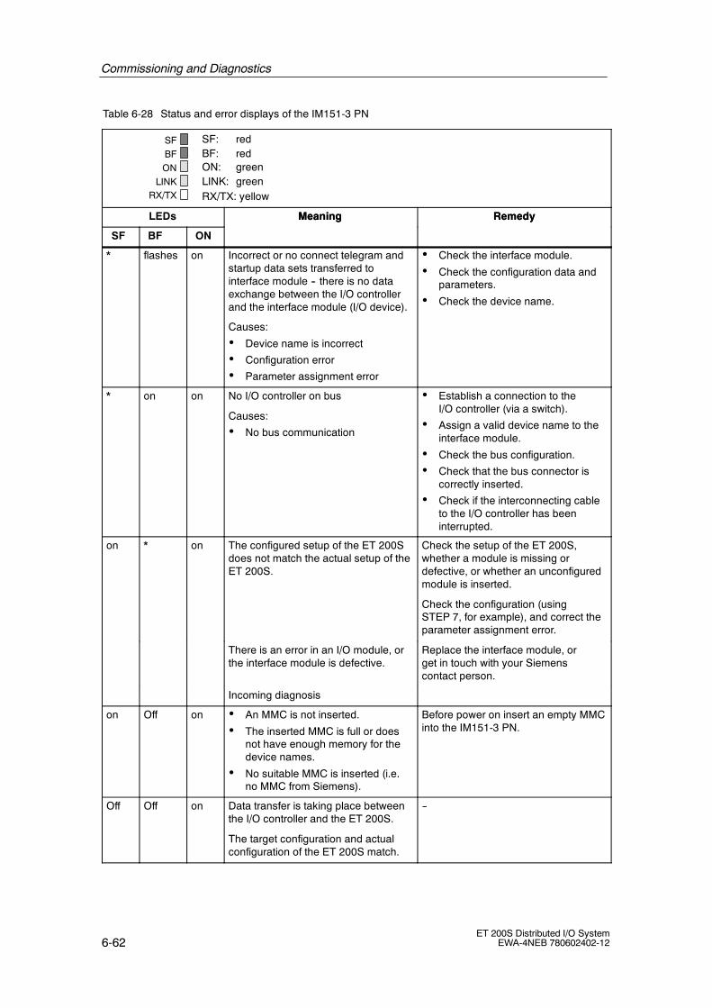
Commissioning and Diagnostics
6-62ET 200S Distributed I/O System
EWA-4NEB 780602402-12
Table 6-28 Status and error displays of the IM151-3 PN
SF: redBF: redON: greenLINK: greenRX/TX: yellow
SF
BF
ON
LINKRX/TX
LEDs RemedyMeaning
SF
RemedyMeaning
ONBF
* flashes on Incorrect or no connect telegram andstartup data sets transferred tointerface module -- there is no dataexchange between the I/O controllerand the interface module (I/O device).
Causes:
• Device name is incorrect
• Configuration error
• Parameter assignment error
• Check the interface module.
• Check the configuration data andparameters.
• Check the device name.
* on on No I/O controller on bus
Causes:
• No bus communication
• Establish a connection to theI/O controller (via a switch).
• Assign a valid device name to theinterface module.
• Check the bus configuration.
• Check that the bus connector iscorrectly inserted.
• Check if the interconnecting cableto the I/O controller has beeninterrupted.
on * on The configured setup of the ET 200Sdoes not match the actual setup of theET 200S.
Check the setup of the ET 200S,whether a module is missing ordefective, or whether an unconfiguredmodule is inserted.
Check the configuration (usingSTEP 7, for example), and correct theparameter assignment error.
There is an error in an I/O module, orthe interface module is defective.
Replace the interface module, orget in touch with your Siemenscontact person.
Incoming diagnosis
on Off on • An MMC is not inserted.
• The inserted MMC is full or doesnot have enough memory for thedevice names.
• No suitable MMC is inserted (i.e.no MMC from Siemens).
Before power on insert an empty MMCinto the IM151-3 PN.
Off Off on Data transfer is taking place betweenthe I/O controller and the ET 200S.
The target configuration and actualconfiguration of the ET 200S match.
--
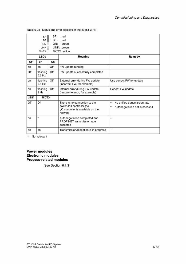
Commissioning and Diagnostics
6-63ET 200S Distributed I/O SystemEWA-4NEB 780602402-12
Table 6-28 Status and error displays of the IM151-3 PN
SF: redBF: redON: greenLINK: greenRX/TX: yellow
SF
BF
ON
LINKRX/TX
LEDs RemedyMeaning
SF
RemedyMeaning
ONBF
on on Off FW update running
Off flashing0.5 Hz
Off FW update successfully completed
on flashing0.5 Hz
Off External error during FW update(incorrect FW, for example)
Use correct FW for update
on flashing2 Hz
Off Internal error during FW update(read/write error, for example)
Repeat FW update
LINK RX/TX
Off Off There is no connection to theswitch/I/O controller (noI/O controller is available on thenetwork)
• No unified transmission rate
• Autonegotiation not successful
on * Autonegotiation completed andPROFINET transmission rateaccepted
--
on on Transmission/reception is in progress --
* Not relevant
Power modulesElectronic modulesProcess-related modules
See Section 6.1.3

Commissioning and Diagnostics
6-64ET 200S Distributed I/O System
EWA-4NEB 780602402-12
6.2.4 Diagnostic messages of the electronic modules
Actions after a diagnosis message
Every diagnostic message leads to the following actions:
• The SF LED on the interface module comes on.
• Several simultaneous diagnostic messages are possible.
• Diagnoses are reported as diagnosis interrupts and can be read via data sets.
• After a diagnosis message it is saved in the diagnosis buffer of the I/Ocontroller.
• The OB 82 is called. If OB 82 is not available, the I/O controller goes into STOPmode.
• Acknowledgment of the diagnostic interrupt (following this a new interrupt ispossible).
Causes of Errors and Remedies
The causes of the errors and the action to be taken when specific diagnosticmessages appear are described in Chapter 6.2.6.2.

Commissioning and Diagnostics
6-65ET 200S Distributed I/O SystemEWA-4NEB 780602402-12
6.2.5 Evaluating the interrupts of the ET 200S
Introduction
Interrupts are triggered by the I/O device in the event of specific errors occurring.Interrupt evaluation differs depending on the I/O controller used.
Evaluate interrupt with I/O controller
The ET 200S supports the following interrupts:
• Diagnostics Interrupts
• Process Alarms
• Insert/remove-module interrupts
In the event of an interrupt, interrupt OBs are automatically executed in the CPU ofthe I/O controller (see the System Software programming manual for S7300/S7400, Program Design).
The OB number and the start information contain information on the cause of theerror and the error type.For detailed information on the error event see the error OB with the 54 RALRMSFB (read additional interrupt information).
Triggering of a diagnostic interrupt
When an incoming or outgoing event (for example wire break) is registered, themodule triggers a diagnostic interrupt if ”Enable: Diagnostic interrupt” is set.
The CPU interrupts the processing of the user program and processes the OB 82diagnostic block. The result that triggered the interrupt is added to the OB 82 startinformation.
Triggering a process interrupt
In the event of a process interrupt the CPU interrupts the processing of the userprogram and processes the OB 40 process interrupt block. The result thattriggered the interrupt is added to the OB 40 start information.
Triggering of an insert/remove-module interrupt
The CPU interrupts the processing of the user program and processes the OB 83diagnostic block. The result that triggered the interrupt is added to the OB 83 startinformation.

Commissioning and Diagnostics
6-66ET 200S Distributed I/O System
EWA-4NEB 780602402-12
”Process interrupts lost” diagnosis
For the modules
• 2DI 24 VDC High Feature (6ES7 131-4BB00-0AB0)
• 4DI 24 VDC High Feature (6ES7 131-4BD00-0AB0) and
• 4DI 24--48 VUC High Feature (6ES7 131-4CD00-0AB0)
the ”Process interrupt lost” diagnosis is not currently available. This function will beimplemented in a future product level of the IM151-3 PN.
Note
Process interrupts should not be used for process-related purposes (such asperiodic generation of process interrupts), because they may be lost in the overallsystem.
6.2.6 Diagnostics with STEP 7
In chapter Description Page
6.2.6.1 Reading Diagnostics Data 6-67
6.2.6.2 Channel diagnostics 6-68
6.2.6.3 Diagnostics in the case of invalid ET 200S configuration states onthe PROFINET IO
6-70
6.2.6.4 Diagnostics in the case of interruption of the ET 200S backplanebus
6-70
6.2.6.5 Diagnostics in the case of failure of the load voltage from the powermodule
6-71

Commissioning and Diagnostics
6-67ET 200S Distributed I/O SystemEWA-4NEB 780602402-12
6.2.6.1 Reading out the diagnosis
Ways of reading the diagnosis
Table 6-29 Reading out the diagnosis with STEP 7
PLC system withI/O controller
Block orregister in STEP 7
Application See .
SIMATIC S7 Open inHWCONFIG viastation > online
Device diagnosis as plaintext on STEP 7 interface(in the fast view,diagnostics view ormodule status)
The section on hardwarediagnostics in the STEP 7 onlinehelp system
SFB 52”RDREC”
Read data sets from theI/O device
For SFB, see the STEP 7 onlinehelp system (system functions/system function blocks)
SFB 54”RALRM”
Interrupt received fromI/O device
For SFB, see the STEP 7 onlinehelp system (system functions/system function blocks)

Commissioning and Diagnostics
6-68ET 200S Distributed I/O System
EWA-4NEB 780602402-12
6.2.6.2 Channel diagnostics
Definition
The channel diagnostics show information on channel errors in modules
Channel errors are shown as channel diagnoses in I/O diagnostics data sets. Onedata set contains 10 bytes.
All diagnoses for a submodular slot, slot, slots to which an I/O controller isassigned in a device, or for a device can be read. The decision is made by the dataset number:
800AH channel diagnostics for a submodular slotC00AH channel diagnostics for a slotE00AH channel diagnostics to which an I/O controller is assigned
slots in a deviceF00AH channel diagnostics for a device
The data set is read with the 52 RDREC SFB (read data set).
Structure of data sets
You can find the structure of the data sets in the Internet at:
http://www.siemens.com/automation/service.
Search for the entry with the number 19327300.

Commissioning and Diagnostics
6-69ET 200S Distributed I/O SystemEWA-4NEB 780602402-12
Channel diagnostics
The channel diagnostics for the ET 200S with the IM151-3 PN are structured asfollows:
Bit no.
Bits 2 and 3
Bits 4 and 5
Error type:(see Table 6-12 to 6-23)
Bits 0 and 1
Byte 6
Byte 7
Bits 8 and 9
0123456789101112131415
Slot numbers
Bit no.0123456789101112131415
Submodule slot number
Bit no.0123456789101112131415
Channel number
Bit no.01234567
000
ReservedChannel type:000B: reserved001B: input channel010B: output channel011B: input/output
channel
Error type:00B reserved01B: coming error10B: going error11B: going error, additional errors on the channel
Bit no.01234567
000
Reserved Data format:000B Free data format001B: Bit010B: 2 Bit011B: 4 Bit100B: Byte101B: Word110B: 2 words111B: 4 words
00
Bit no.0123456789101112131415
Device diagnosisavailable
Figure 6-37 Structure of the channel diagnostics for the ET 200S with the IM151-3 PN

Commissioning and Diagnostics
6-70ET 200S Distributed I/O System
EWA-4NEB 780602402-12
Power module error typesDigital electronic module error typesAnalog electronic module error typesProcess-related module error types
See Tables 6-12 to 6-23
6.2.6.3 Diagnostics in the case of invalid ET 200S configuration stateson the PROFINET IO
Invalid configuration states
The following invalid configuration states of the ET 200S lead to failure of theET 200S I/O device or prevent entry into data interchange.
• Two missing modules
• Bus termination module missing
• Number of modules exceeds maximum configuration
• Faulty backplane bus (for example, terminal module is defective)
NoteIf one module is missing (gap) and the ET 200S is switched on, the I/O device willnot start up.
6.2.6.4 Diagnostics in the case of interruption of the ET 200Sbackplane bus
If the ET 200S does not start or data interchange is interrupted, the cause of thisbehavior could be a faulty terminal module. The faulty terminal module physicallyinterrupts the ET 200S backplane bus.
There is a 35-byte long manufacturer-specific diagnosis for the IM151-3 PN (slot 0)for localizing a bus interruption. The module status and the ID-related diagnosis isshown, as know with the PROFIBUS DP.
Contents of the manufacturer-specific diagnosis:Byte 0 to 5: reservedByte 6 to 14: ID-related diagnosis (see Figure 6-22)Byte 15 to 34: Module status (see Figure 6-24)
No interrupt is generated if the ET 200S backplane bus is interrupted. The usermust specifically read this information. The data set with the index F00BH isavailable for this.

Commissioning and Diagnostics
6-71ET 200S Distributed I/O SystemEWA-4NEB 780602402-12
6.2.6.5 Diagnostics in the case of failure of the load voltage from thepower module
Load voltage failure
If the power module load voltage fails, electronic modules with their own controllers(i.e. analog and process-related modules) behave as follows:
• If such a module is removed during a load voltage failure, a remove-moduleinterrupt is triggered.
• If such a module is inserted during a load voltage failure, the associatedinsertion interrupt is only triggered when the load voltage is restored and themodule has started.
Restoration of load voltage
After restoration of the load voltage and startup of the electronic modules with theirown controllers, the parameters of the modules are reset with the saved startupparameters by the IM151-3 PN.
Note
If the parameters of an electronic module with its own controller have beenchanged, the data with the new parameters is no longer available after restorationof the load voltage.
6.2.6.6 Diagnosis after a STOP of the I/O controller or after restart ofthe O/O device
If diagnoses are received from the I/O device in STOP status of the I/O controller,these diagnoses will not cause the corresponding organization blocks to start afterstartup of the I/O controller. You must generate an image of the status of thedevice yourself in the OB 100.
On restart of an I/O device data record E00CH must be read with SFB 52. Thisshows all diagnoses for the slots assigned to an I/O controller in one device.

Commissioning and Diagnostics
6-72ET 200S Distributed I/O System
EWA-4NEB 780602402-12

7-1ET 200S Distributed I/O SystemEWA-4NEB 780602402-12
General Technical Specifications
What are general technical specifications?
The general technical specifications comprise the standards and test specificationswith which the ET 200S distributed I/O system complies, as well as the criteria onthe basis of which the ET 200S distributed I/O system was tested.
Chapter overview
Chapter Description Page
7.1 Standards, certificates, and approvals 7-2
7.2 Electromagnetic compatibility, shipping and storage conditions 7-6
7.3 Mechanical and climatic environmental conditions 7-8
7.4 Information on insulation testing, safety class, degree of protection, andrated voltage of the ET 200S
7-10
7.5 Variations in technical data for the ET 200S FC frequency converter 7-11
7

General Technical Specifications
7-2ET 200S Distributed I/O System
EWA-4NEB 780602402-12
7.1 Standards, certificates, and approvals
CE Mark of Conformity
The ET 200S distributed I/O system meets the requirements and protectionobjectives of the following EC Directives and complies with the harmonizedEuropean Standards (EN) for programmable logic controllers published in theOfficial Gazettes of the European Community:
• 73/23/EEC ”Electrical Equipment for Use within Fixed Voltage Ranges”(Low-Voltage Directive)
• 89/336/EEC ”Electromagnetic Compatibility” (EMC Directive)
• 94/9/EC ”Equipment and protective systems intended for use in potentiallyexplosive atmospheres” (Guidelines for Explosion Protection)
The EC declarations of conformity are kept available for the responsible authoritiesat the following address:
Siemens AktiengesellschaftAutomation and DrivesA&D AS RD4Postfach 1963D-92209 Amberg, Germany

General Technical Specifications
7-3ET 200S Distributed I/O SystemEWA-4NEB 780602402-12
UL Approval
Underwriters Laboratories Inc. in accordance with
• UL 508 (Industrial Control Equipment)
CSA Approval
Canadian Standards Association in accordance with
• C22.2 No. 142 (Process Control Equipment)
or
Underwriters Laboratories Inc. in accordance with
• UL 508 (Industrial Control Equipment)
• CSA C22.2 No. 142, (Process Control Equipment)
or
Underwriters Laboratories Inc. in accordance with
• UL 508 (Industrial Control Equipment)
• CSA C22.2 No. 142, (Process Control Equipment)
• UL 1604 (Hazardous Location)
• CSA-213 (Hazardous Location)
APPROVED for use inClass I, Division 2, Group A, B, C, D Tx;Class I, Zone 2, Group IIC Tx
The ET 200S motor starters do not have CULUS for HAZ. LOC.
Note
You can find the currently valid certificates and approvals on the type plate ofeach module.
HAZ. LOC.

General Technical Specifications
7-4ET 200S Distributed I/O System
EWA-4NEB 780602402-12
FM Approval
Factory Mutual Research (FM) in accordance withApproval Standard Class Number 3611, 3600, 3810APPROVED for use inClass I, Division 2, Group A, B, C, D Tx;Class I, Zone 2, Group IIC Tx
The ET 200S motor starters do not have FM approval. All the other modulesof the ET 200S have FM approval.
In accordance with EN 50021 (Electrical apparatus for potentially explosiveatmospheres; Type of protection ”n”)
II 3 G EEx nA II T4..T5
!Warning
Personal injury and material damage may be incurred.
Personal injury and material damage may be incurred in hazardous areas if youdisconnect plug-in connections while the ET 200S distributed I/O device is inoperation.
Always deenergize the ET 200S in hazardous areas before disconnecting plug-inconnections.
Identification for Australia
The ET 200S Distributed I/O System fulfills the requirements of AS/NZS 2064(Class A).
IEC 61131
The ET 200S distributed I/O system meets the requirements and criteria of theIEC 61131-2 standard (Programmable Logic Controllers, part 2: equipmentrequirements and tests.)
PROFIBUS standard
The ET 200S distributed I/O system is based on IEC 617841:2002 Ed1 CP 3/1.

General Technical Specifications
7-5ET 200S Distributed I/O SystemEWA-4NEB 780602402-12
Shipbuilding Approval
Classifying organizations:
• ABS (American Bureau of Shipping)
• BV (Bureau Veritas)
• DNV (Det Norske Veritas)
• GL (Germanischer Lloyd)
• LRS (Lloyds Register of Shipping)
• Class NK (Nippon Kaiji Kyokai)
Use in industry
SIMATIC products designed for use in industry.
Table 7-1 Use in industry
Area of application Requirement for
Emitted interference Interferenceimmunity
Industry EN 50081-2: 1993 EN 50082-2: 1995
Use in residential areas
If you use the ET 200S in residential areas, you must adhere to limit value class Bin accordance with EN 55011 regarding the emission of radio interference.
Suitable measures to achieve a level of radio interference corresponding to limitvalue class B are:
• Installation of the ET 200S in grounded switch cabinets/switch boxes
• Use of filters in supply lines

General Technical Specifications
7-6ET 200S Distributed I/O System
EWA-4NEB 780602402-12
7.2 Electromagnetic compatibility, shipping and storageconditions
Definition
Electromagnetic compatibility is the capability of an electrical device to functionsatisfactorily in its electromagnetic environment without interfering with thisenvironment.
The ET 200S distributed I/O system also meets the requirements of the EuropeanUnion’s EMC legislation. A requirement for this is that the ET 200S distributed I/Osystem meets the specifications and directives concerning electrical installation.
Pulse-shaped interference
The following table shows the electromagnetic compatibility of the ET 200Sdistributed I/O system when confronted with pulse-shaped interference.
Pulse-shaped interference Tested with Corresponds toseverity
Electrostatic dischargeAccording to IEC 61000-4-2
8 kVkV
3 (air discharge)2 (contact discharge)
Burst pulses (rapid, transientinterference) toIEC 61000-4-4.
2 kV (power supplyline)
2 kV (signal line)
3
3
Surge to IEC 61000-4-5Only with lightning conductors(see the DP master manual and the SIMATIC NET PROFIBUSNetwork description)
• Asymmetrical interconnection 2 kV (power supplyline)
2 kV (signal/dataline)
3
• Symmetrical interconnection 1 kV (power supplyline)
1 kV (signal/dataline)

General Technical Specifications
7-7ET 200S Distributed I/O SystemEWA-4NEB 780602402-12
Sine-shaped interference
The following table shows the electromagnetic compatibility of the ET 200Sdistributed I/O system when confronted with sinusoidal interference.
RF irradiation to IEC 61000-4-3electromagnetic RF field
RF coupling toIEC 61000-4-6
Amplitude-modulated Pulse-modulated
80 to 1000 MHz 900 MHz5 MHz 0.15 to 80 MHz
10 V/m 10 Veff unmodulated
80% AM (1 kHz) 50% ED 80% AM (1 kHz)
200 Hz repetition frequency 150 Ω source impedance
Emission of radio interference
Emission of electromagnetic fields to EN 55011: Limit class A, group 1 (measuredat a distance of 10 m.)
Frequency Emitted interference
From 30 MHz to 230 MHz < 40dB (mV/m)Q
From 230 MHz to 1000 MHz < 47dB (mV/m)Q
Shipping and storage conditions
The ET 200S distributed I/O system exceeds the requirements of IEC 61131-2 asregards shipping and storage conditions. The following specifications apply tomodules shipped or stored in their original packaging.
Type of condition Permitted range
Free fall ≤ 1 m
Temperature from --40 _C to + 70 _C
Temperature change 20 K/h
Air pressure From 1080 hPa to 660 hPa (corresponds toan altitude of --1000 m to 3500 m)
Relative humidity From 5 % to 95 %, without condensation

General Technical Specifications
7-8ET 200S Distributed I/O System
EWA-4NEB 780602402-12
7.3 Mechanical and climatic environmental conditions
Climatic environmental conditionsThe following climatic environmental conditions apply:
Environmental conditions Operating ranges Remarks
Temperature from 0 to 60_C For horizontal installation
from 0 to 40_C For all other mounting positions
From 0 to 55_C(see restrictions below)*
For vertical installation
Temperature change 10 K/h
Relative humidity From 15 % to maximum 95 % Without condensation
Air pressure From 1080 hPa to 795 hPa Corresponds to an altitude of--1000 m to 2000 m
Contaminant concentrationSO2: < 0.5 ppm;rel. humidity < 60 %, no dewingH2S: < 0.1 ppm;rel. humidity < 60 %, no dewing
Test:10 ppm; 4 days
1 ppm; 4 days
* Restrictions for the operating range of 0 to 55_C in a vertical position
The operating range of 0 to 55_C in a vertical installation position is only permittedfor the following modules:
• IM151-1 STANDARD: 6ES7 151-1AA02-0AB0
• PM-E 24 VDC: 6ES7 138-4CA00-0AA0
• 2DI 24 VDC Standard: 6ES7 131-4BB00-0AA0
• 2DI 24 VDC High Feature: 6ES7 131-4BB00-0AB0
• 4DI 24 VDC Standard: 6ES7 131-4BD00-0AA0
• 4DI 24 VDC High Feature: 6ES7 131-4BD00-0AB0
• 2DO 24 VDC/0.5 A Standard: 6ES7 132-4BB00-0AA0
• 2DO 24 VDC/0.5 A High Feature: 6ES7 132-4BB00-0AB0
• 4DO 24 VDC/0.5 A High Feature: 6ES7 132-4BD00-0AA0
• 2DO 24 VDC/2 A Standard: 6ES7 132-4BB30-0AA0
• 2DO 24 VDC/2 A High Feature: 6ES7 132-4BB30-0AB0
• 4DO 24 VDC/2 A Standard: 6ES7 132-4BD30-0AA0
• 2RO NO 24-120 VDC/5 A 24-230 VAC/5 A: 6ES7 132-4HB00-0AB0
Note
All of the supply and load voltages of the ET 200S must not exceed 24 VDC. Thisvoltage limit must be enforced.

General Technical Specifications
7-9ET 200S Distributed I/O SystemEWA-4NEB 780602402-12
Mechanical environmental conditions
The mechanical environmental conditions are shown in the following table in theform of sinusoidal oscillations.
ET 200S modules Frequencyrange
Permanent Occasional
Everything except motorstarters
10≤ f≤ 58Hz 0.15 mm amplitude 0.35 mm amplitude
58≤ f≤ 150Hz 2g constant acceleration 5g constant acceleration
Testing mechanical environmental conditions
The following table provides information on the type and extent of tests ofmechanical environmental conditions.
Test for ... Test Standard Terminal modules and electronic modules
Oscillations Oscillation test inaccordance withIEC 60068-2-6
Vibration type: Frequency sweep with a rate of change of 1 octave/min-ute.10 Hz≤ f≤ 58 Hz, constant amplitude 0.35 mm58 Hz≤ f≤ 150 Hz, constant acceleration 5gVibration duration: 20 frequency sweeps per axis in each of the3 mutually vertical axes
Shock Shock tested toIEC 60068-2-27
Type of shock: Half-sineType of shock: 15 g peak value, duration of 11 msType of shock: 3 shocks each in +/-- direction in each of the3 mutually vertical axes
Repetitiveshock
Shock tested toIEC 60068-29
Type of shock: Half-sineType of shock: 25 g peak value, duration of 6 msType of shock: 10003 shocks each in +/-- direction in each of the 3mutually vertical axes

General Technical Specifications
7-10ET 200S Distributed I/O System
EWA-4NEB 780602402-12
7.4 Information on insulation testing, safety class,degree of protection, and rated voltage of the ET 200S
Test voltage
Insulation strength is demonstrated in the type test with the following test voltage inaccordance with IEC 61131-2:
Circuits with a rated voltage of Ue toother circuits or ground
Test voltage
< 50 V 500 VDC
< 150 V 2500 VDC
< 250 V 4000 VDC
Pollution severity/overvoltage category in accordance with IEC 61131
• Pollution severity 2
• Overvoltage category
-- When UN = 120/ 230 VAC: III
-- at Vr = 24 V DC: II
Safety class
Safety class I as per IEC 60536
Degree of protection IP20
IP 20 protection in accordance with IEC 60529 for all ET 200S modules, whichmeans:
• Protection against contact with standard test probes
• Protection against foreign bodies with a diameter greater than 12.5 mm
• No special protection against water

General Technical Specifications
7-11ET 200S Distributed I/O SystemEWA-4NEB 780602402-12
Rated voltage for operation
The ET 200S distributed I/O system works with the rated voltage andcorresponding tolerances specified in the following table.
ET 200S modules Rated voltage Tolerance range
Everything exceptt t t
24 VDC 20.4 to 28.8 VDC 1)
motor starters18.5 to 30.2 VDC 2)
120 VAC VAC to 132 VAC (47 Hz to 63 Hz)
230 VAC VAC to 264 VAC (47 Hz to 63 Hz)
1) static value: generation as functional extra-low voltage with safe electricalisolation as per IEC 60364-4-41
2) dynamic value: including ripple e. g. with three-phase bridge rectification
7.5 Variations in technical data for theET 200S FC frequency converter
The following table shows variations in the general technical data for theET 200S FC frequency converter compared to the ET 200S.
Table 7-2 Variations in technical data for the ET 200S FC frequencyconverter
Chapter different values
Standards, certificates and approvals The frequency converter is not approvedunder
• cULus for HAZ.LOC.
• FM (Factory Mutual Research)
• shipbuilding
Shipping and storage conditions Free fall: ≤ 0.35 m
Climatic ambient conditions Temperature for horizontal installation:from 0 to 60 °C
Temperature for vertical installation:from 0 to 40 °C
Mechanical ambient conditions See operating manual for ET 200S FCfrequency converter
Rated operational voltagefrequency converter(6SL3 298-0CA12-0xP0)
Use in Zone 2 The ET 200S FC frequency converter is notapproved for operation in Zone 2 hazardousatmosphere.

General Technical Specifications
7-12ET 200S Distributed I/O System
EWA-4NEB 780602402-12
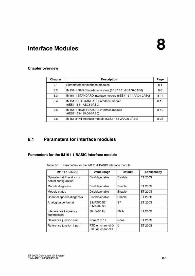
8-1ET 200S Distributed I/O SystemEWA-4NEB 780602402-12
Interface Modules
Chapter overview
Chapter Description Page
8.1 Parameters for interface modules 8-1
8.2 IM151-1 BASIC interface module (6ES7 151-1CA00-0AB0) 8-8
8.3 IM151-1 STANDARD interface module (6ES7 151-1AA04-0AB0) 8-11
8.4 IM151-1 FO STANDARD interface module(6ES7 151-1AB03-0AB0)
8-15
8.5 IM151-1 HIGH FEATURE interface module(6ES7 151-1BA00-0AB0)
8-19
8.6 IM151-3 PN interface module (6ES7 151-3AA00-0AB0) 8-23
8.1 Parameters for interface modules
Parameters for the IM151-1 BASIC interface module
Table 8-1 Parameters for the IM151-1 BASIC interface module
IM151-1 BASIC Value range Default Applicability
Operation at Preset -- <>Actual configuration
Disable/enable Disable ET 200S
Module diagnosis Disable/enable Enable ET 200S
Module status Disable/enable Enable ET 200S
Channel-specific diagnosis Disable/enable Enable ET 200S
Analog-value format SIMATIC S7SIMATIC S5
S7 ET 200S
Interference frequencysuppression
50 Hz/60 Hz 50Hz ET 200S
Reference junction slot None/2 to 12 None ET 200S
Reference junction input RTD on channel 0/RTD on channel 1
0 ET 200S
8

Interface Modules
8-2ET 200S Distributed I/O System
EWA-4NEB 780602402-12
Parameters for the IM151-1 STANDARD and IM151-1 FO STANDARD interfacemodules
Table 8-2 Parameters for the IM151-1 STANDARD and IM151-1 FO STANDARD interfacemodules
IM151-1 STANDARD/IM151-1FO STANDARD
Value range Default4) Applicability
DP interrupt mode DPV0/DPV1 DPV0 ET 200S
Bus length ≤ 1 m / > 1 m ≤1 m ET 200S
Operation with Set and <>Actual Configuration1)
Disable/enable Disable ET 200S
Diagnostic interrupt3) Disable/enable disable ET 200S
Process interrupt3) Disable/enable disable ET 200S
Insert/Remove moduleinterrupt2) 3)
Disable/enable disable ET 200S
Module diagnosis Disable/enable enabled ET 200S
Module status Disable/enable enabled ET 200S
Channel-specific diagnostics Disable/enable enabled ET 200S
Option handling, general Disable/enable disable ET 200S
Option handling: Slots 2 to 63 Disable/enable disable Module
Analog-value format SIMATIC S7/SIMATIC S5
S7 ET 200S
Interference FrequencySuppression
50 Hz/60 Hz 50 Hz ET 200S
Reference junction slot None/2 to 63 none ET 200S
Reference junction input RTD on channel 0/RTD on channel 1
0 ET 200S
1) Note also the option handling parameters (see Chapter 3.8).2) In the device database file, the default setting of the parameter is ”Disable”.3) Only configurable in DPV1 mode.4) The default settings are applicable for the default startup (if no other parameters are specified
by the DP master).

Interface Modules
8-3ET 200S Distributed I/O SystemEWA-4NEB 780602402-12
Parameters for the IM151-1 HIGH FEATURE interface module
Table 8-3 Parameters for the IM151-1 HIGH FEATURE interface module(parameter assignment tab)
IM151-1 HIGH FEATURE Value range Default3) Effective range
DP interrupt mode DPV0/DPV1 DPV1 ET 200S
Operation at Preset -- <>Actual configuration
Disable/enable enabled ET 200S
Diagnostics interrupt2) Disable/enable enabled ET 200S
Hardware interrupt2) Disable/enable enabled ET 200S
Insert/Remove moduleinterrupt1) 2)
Disable/enable enabled ET 200S
Module diagnosis Disable/enable enabled ET 200S
Module status Disable/enable enabled ET 200S
Channel-specific diagnostics Disable/enable enabled ET 200S
Analog-value format SIMATIC S7/SIMATIC S5
S7 ET 200S
Interference FrequencySuppression
50 Hz/60 Hz 50 Hz ET 200S
Reference junction slot None/2 to 63 none ET 200S
Reference junction input RTD on channel 0/RTD on channel 1
0 ET 200S
1) In the device database file, the default setting of the parameter is ”Disable”.2) Only configurable in DPV1 mode.3) The default settings are applicable for the default startup (if no other parameters are
specified by the DP master).
Table 8-4 Parameters for the IM151-1 HIGH FEATURE interface module (clocking tab)
IM151-1 HIGHFEATURE
Value range Default setting Effective range
Synchronize DP slavewith DP cycle1)
Disable/enable disable ET 200S
Time Ti (read inprocess values)1)
(Values are preset bySTEP 7)
(Value is preset bySTEP 7)
ET 200S
Time To (outputprocess values)1)
(Values are preset bySTEP 7)
(Value is preset bySTEP 7)
ET 200S
1) Only parameterizable as of STEP 7 V5.1 with ServicePack 3

Interface Modules
8-4ET 200S Distributed I/O System
EWA-4NEB 780602402-12
Parameters for the IM151-3 PN interface module
Table 8-5 Parameters for the IM151-3 PN interface module
IM151-3 PN Value range Defaultsetting
Effective range
Bus length ≤ 1 m / > 1 m ≤1 m ET 200S
Interference FrequencySuppression
50 Hz/60 Hz 50 Hz ET 200S
Reference junction slot None/2 to 63 none ET 200S
Reference junction input RTD on channel 0/RTD on channel 1
0 ET 200S
DP interrupt mode (only with IM151-1 STANDARD (from 6ES7 151-1AA04-0AB0),IM151-1 FO STANDARD (from 6ES7 151-1AB03-0AB0)and IM151-1 HIGH FEATURE)
This parameter allows you to enable or disable DPV1 operation of the ET 200S. IfDPV1 mode is enabled, data sets and interrupts are supported via class 1 servicesand class 2 services (configurable).
Requirements:
• The DP master also support DPV1.
Bus length
≤ 1 m: default, the maximum bus length is 1 m.
> 1 m: the bus length of the ET 200S is > 1 m and can be a maximum 2 m. Thissetting will, however, increase the response time of the ET 200S (see Appendix D).
Operation at Preset <> Actual configuration
If the parameter is enabled and:
• Modules are removed and inserted during operation, this does not lead to astation failure of the ET 200S.
• The actual configuration differs from the expected configuration, the ET 200Scontinues to exchange data with the DP master.
If the parameter is disabled and:
• Modules are removed and inserted during operation, this leads to a stationfailure of the ET 200S.
• The actual configuration differs from the expected configuration, there is nodata transfer between the DP master and the ET 200S. Exception: optionhandling with RESERVE modules (see Chapter 3.8).

Interface Modules
8-5ET 200S Distributed I/O SystemEWA-4NEB 780602402-12
Option handling, general
Using this parameter you can enable or disable the option handling parameter forthe entire ET 200S.
Option handling: Slots 2 to 63
Using this parameter you can enable or disable the checking of the configuration.
• Slot 2 to 63 is enabled. A RESERVE module can also be inserted into the slotinstead of the configured electronic module without triggering a diagnosis.
• Slot 2 to 63 is disabled: Only the configured module may be inserted in the slot.RESERVE modules are treated as incorrect modules. Depending on the settingof the ”Operation at Preset <> Actual Configuration” parameter, the ET 200Swill either fail or remain in data transfer.
Diagnostic interrupt
This parameter allows you to enable or disable diagnostic interrupts.Diagnostic interrupts are supported
• on the PROFIBUS DP, if the ET 200S is in DPV1 mode.
• on the PROFINET IO.
Hardware interrupt
This parameter allows you to enable or disable hardware interrupts.Hardware interrupts are supported
• on the PROFIBUS DP, if the ET 200S is in DPV1 mode.
• on the PROFINET IO.
Insert/remove module interrupts
This parameter allows you to enable or disable insert/remove module interrupts.Insert/remove module interrupts are supported
• on the PROFIBUS DP, if the ET 200S is in DPV1 mode.
• on the PROFINET IO.
Analog-value format
Here you set the number format for all analog electronic modules.

Interface Modules
8-6ET 200S Distributed I/O System
EWA-4NEB 780602402-12
Interference Frequency Suppression
The frequency of your alternating voltage system can affect measured valuesnegatively, particularly in the case of both measurements in small voltage rangesand thermocouples. Specify here the dominant line frequency in your system(50 Hz or 60 Hz).
The interference frequency suppression parameter is valid for all analog electronicmodules. The integration time and conversion time of the individual modules arealso set by means of this parameter. See the technical specifications of the analogelectronic modules in Chapter 12.
Reference junction slot
See chapter 12.2.2.
Reference junction input
See chapter 12.2.2.
Synchronize DP slave with DP cycle
You can use this parameter to enable or disable clocking.
If you enable clocking, the I/Os of the ET 200S are synchronized with the globalcontrol frame of the master (as an equidistance clocking).
Requirements: See Section 3.7
Time Ti (read in process values)
This value can only be set provided you have enabled the ”Synchronize DP slavewith DP cycle” parameter.
Ti is the time reserved for reading in the input data at the ET 200S. At thebeginning of Ti, the input data is converted at the terminals and stored in a buffervia the backplane bus of the ET 200S. Ti ends at the beginning of the next,equidistant DP cycle (i.e. with the global control frame).
At this point, the most recent, most up-to-date input data must be available to beread in on the PROFIBUS subnet. The time Ti must take into account theprocessing and delay times in the modules and in the backplane bus of theET 200S and, in the case of modular slaves, is therefore dependent on theconfiguration.
The time Ti can only be set in the specified increments between the minimum andmaximum values. Normally, the default values should be accepted.

Interface Modules
8-7ET 200S Distributed I/O SystemEWA-4NEB 780602402-12
Time To (output process values)
This value can only be set provided you have enabled the ”Synchronize DP slavewith DP cycle” parameter.
The end of the To time is the point at which the output data is switched to themodule terminals in its converted form. The time To includes the following:
• Distribution of the output data via the PROFIBUS DP bus system to the slaves(= cyclic data-exchange master slave)
• Distribution of the output data to the modules via the backplane bus of the slave
• Conversion and transfer of the output data to the output terminals of the module
To starts with the arrival of the global control frame. Like Ti, the time can be set inthe specified increments between the minimum and maximum values. Normally,you should accept the default values.

Interface Modules
8-8ET 200S Distributed I/O System
EWA-4NEB 780602402-12
8.2 IM151-1 BASIC interface module (6ES7 151-1CA00-0AB0)
Order number
6ES7 151-1CA00-0AB0
Features
The IM151 1 BASIC interface module has the following features:
• It connects the ET 200S with PROFIBUS DP via the RS485 interface.
• It prepares the data for the electronic modules and motor starters that are fitted.
• It supplies the backplane bus.
• The PROFIBUS DP address of the ET 200S can be set by means of switches.
• If the 24 VDC power supply is disconnected, the IM151-1 BASIC interfacemodule is also disconnected.
• The maximum address space is 88 bytes for inputs and 88 bytes for outputs.
• The reference potential M of the rated supply voltage of the IM151 1 BASIC tothe rail (protective conductor) is connected by means of an RC combination,thus permitting an ungrounded configuration.
• Operation as a DPV0 slave.
• A maximum of 12 modules can be operated with the IM151 1 BASIC.
• The maximum bus length is not relevant.

Interface Modules
8-9ET 200S Distributed I/O SystemEWA-4NEB 780602402-12
Terminal assignment
The following table shows the terminal assignment of the IM151 1 BASIC interfacemodule for the 24 VDC voltage supply and PROFIBUS DP:
Table 8-6 Terminal assignment of the IM151 1 BASIC interface module
View Signal name Name
1 -- --
2 -- --
53 RxD/TxD--P Data line B
543
98
4 RTS Request To Send32
876
5 M5V2 Data reference potential (station)216 6 P5V2 Supply plus (station)
7 -- --
8 RxD/TxD--N Data line A
9
2L+ 1M 2M1L+ 1L+ VDC
2L+ VDC (for loop through)
1M Chassis ground
2M Ground (for loop through)
Block diagram
6 (P1)2 (P1)
7 (P2)3 (P2)
Bac
kpla
nebu
s
ET
200S
back
plan
ebu
sin
terf
ace
conn
ectio
n
Electroniccomponents
Internal powersupply
A1A2B1B2
PROFIBUS DPconnection
ElectricalisolationBF ONSF
PROFIBUSaddress
Figure 8-1 Block diagram for the IM151-1 BASIC interface module
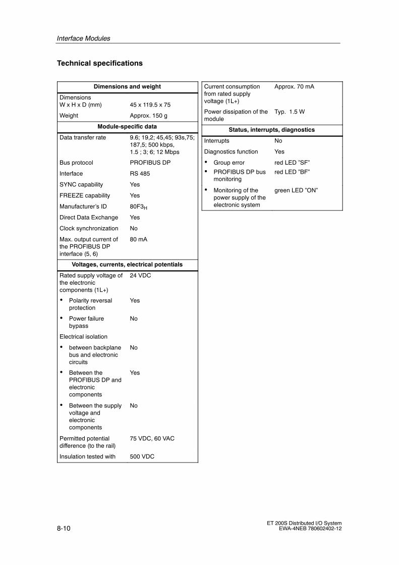
Interface Modules
8-10ET 200S Distributed I/O System
EWA-4NEB 780602402-12
Technical specifications
Dimensions and weight
DimensionsW x H x D (mm) 45 x 119.5 x 75
Weight Approx. 150 g
Module-specific data
Data transfer rate 9.6; 19,2; 45,45; 93s,75;187,5; 500 kbps,1.5 ; 3; 6; 12 Mbps
Bus protocol PROFIBUS DP
Interface RS 485
SYNC capability Yes
FREEZE capability Yes
Manufacturer’s ID 80F3H
Direct Data Exchange Yes
Clock synchronization No
Max. output current ofthe PROFIBUS DPinterface (5, 6)
80 mA
Voltages, currents, electrical potentials
Rated supply voltage ofthe electroniccomponents (1L+)
24 VDC
• Polarity reversalprotection
Yes
• Power failurebypass
No
Electrical isolation
• between backplanebus and electroniccircuits
No
• Between thePROFIBUS DP andelectroniccomponents
Yes
• Between the supplyvoltage andelectroniccomponents
No
Permitted potentialdifference (to the rail)
75 VDC, 60 VAC
Insulation tested with 500 VDC
Current consumptionfrom rated supplyvoltage (1L+)
Approx. 70 mA
Power dissipation of themodule
Typ. 1.5 W
Status, interrupts, diagnostics
Interrupts No
Diagnostics function Yes
• Group error
• PROFIBUS DP busmonitoring
red LED ”SF”
red LED ”BF”
• Monitoring of thepower supply of theelectronic system
green LED ”ON”

Interface Modules
8-11ET 200S Distributed I/O SystemEWA-4NEB 780602402-12
8.3 IM151-1 STANDARD interface module(6ES7 151-1AA04-0AB0)
Order number
6ES7 151-1AA04-0AB0
Properties
The IM151-1 STANDARD interface module has the following features:
• It connects the ET 200S with PROFIBUS DP via the RS485 interface.
• It prepares the data for the electronic modules and motor starters that are fitted.
• It supplies the backplane bus.
• The PROFIBUS DP address of the ET 200S can be set by means of switches.
• If the 24 VDC power supply is disconnected, the IM151-1 STANDARD interfacemodule is also disconnected.
• The maximum address space is 244 bytes for inputs, and 244 bytes for outputs.
• The reference potential M of the rated supply voltage of theIM151-1 STANDARD to the rail (protective conductor) is connected by meansof an RC combination, thus permitting an ungrounded configuration.
• Operation as a DPV0 slave.
• A maximum of 63 modules can be operated with the IM151-1 STANDARD.
• The maximum bus length is 2 m (can be set).
• Supports option handling (see Chapter 3.8) and the status byte for powermodules.
Supplementary properties compared to the IM151-1 STANDARD interface module(up to 6ES7 151-1AA03-0AB0):
• Operation as a DPV1 slave.
-- Acyclic data exchange (read/write data record):class 2 services and class 1 services
-- Diagnostics Interrupts
-- Process Alarms
-- Removal/Insertion Interrupt
• Firmware update via PROFIBUS DP
• Identification data (see Sec. 3.9)

Interface Modules
8-12ET 200S Distributed I/O System
EWA-4NEB 780602402-12
Terminal assignment
The following table shows the terminal assignment of the IM151 1 STANDARDinterface module for the 24 VDC voltage supply and PROFIBUS DP:
Table 8-7 Terminal assignment of the IM151 1 STANDARD interface module
View Signal name Name
1 -- --
2 -- --
53 RxD/TxD--P Data line B
543
98
4 RTS Request To Send32
876
5 M5V2 Data reference potential (station)216 6 P5V2 Supply plus (station)
7 -- --
8 RxD/TxD--N Data line A
9
2L+ 1M 2M1L+ 1L+ 24 VDC
2L+ VDC (for loop through)
1M Chassis ground
2M Ground (for loop through)
Block diagram
6 (P1)2 (P1)
7 (P2)3 (P2)
Bac
kpla
nebu
s
ET
200S
back
plan
ebu
sin
terf
ace
conn
ectio
n
Electroniccomponents
Internal powersupply
A1A2B1B2
PROFIBUS DPconnection
ElectricalisolationBF ONSF
PROFIBUSaddress
Figure 8-2 Block diagram for the IM151-1 STANDARD interface module

Interface Modules
8-13ET 200S Distributed I/O SystemEWA-4NEB 780602402-12
Technical specifications
Dimensions and weight
DimensionsW×H×D (mm) 45 x 119.5 x 75
Weight Approx. 150 g
Module-specific data
Data transfer rate 9,6; 19,2; 45,45; 93s,75;187,5; 500 kbps,1,5 ; 3; 6; 12 Mbps
Bus protocol PROFIBUS DP
Interface RS 485
SYNC capability Yes
FREEZE capability Yes
Manufacturer’s ID 806AH
Direct Data Exchange Yes
Clock synchronization No
Max. output current ofthe PROFIBUS DPinterface (5, 6)
80 mA
Voltages, currents, electrical potentials
Rated supply voltage ofthe electroniccomponents (1L+)
24 VDC
• Polarity reversalprotection
Yes
• Power failurebypass
Min. 20 ms
Electrical isolation
• between backplanebus and electroniccircuits
No
• Between thePROFIBUS DP andelectroniccomponents
Yes
• Between the supplyvoltage andelectroniccomponents
No
Permitted potentialdifference (to the rail)
75 VDC, 60 VAC
Insulation tested with 500 VDC
Current consumptionfrom rated supplyvoltage (1L+)
Approx. 200 mA
Power dissipation of themodule
Typical 3.3 W
Status, interrupts, diagnostics
Interrupts Yes
Diagnostics function Yes
• Group error
• PROFIBUS DP busmonitoring
red LED ”SF”
red LED ”BF”
• Monitoring of thepower supply of theelectronic system
green LED ”ON”

Interface Modules
8-14ET 200S Distributed I/O System
EWA-4NEB 780602402-12
Updating the firmware of the IM151-1 STANDARD
Properties
• As of STEP 7 V5.1, ServicePack 3, you can update the firmware of the IM151-1STANDARD (via available devices).
• To update the firmware you receive files (*.UPD) with the current firmware.
Prerequisites
• The IM151-1 STANDARD at the station whose firmware should be updatedmust be online.
• The files with the current firmware version must be available in the file systemof your programming device or PC.
Procedure
The STEP 7 online help system provides information on how to proceed.
Note
We recommend you update the firmware using PROFIBUS DP.

Interface Modules
8-15ET 200S Distributed I/O SystemEWA-4NEB 780602402-12
8.4 IM151-1 FO STANDARD interface module(6ES7 151-1AB03-0AB0)
Order number
6ES7 151-1AB03-0AB0
Properties
The IM151-1 FO STANDARD interface module has the following features:
• It connects the ET 200S with PROFIBUS DP via the fiber-optic interface.
• It prepares the data for the electronic modules and motor starters that are fitted.
• It supplies the backplane bus.
• The PROFIBUS DP address of the ET 200S can be set by means of switches.
• If the 24 VDC power supply is disconnected, the IM151-1 FO STANDARDinterface module is also disconnected.
• The maximum address space is 244 bytes for inputs, and 244 bytes for outputs.
• The reference potential M of the supply voltage of the IM151-1 FO STANDARDto the rail (protective conductor) is connected by means of an RC combination,thus permitting an ungrounded configuration.
• Operation as a DPV0 slave.
• A maximum of 63 modules can be operated with the IM151-1 FO STANDARD.
• The maximum bus length is 2 m (can be set).
• Supports option handling (see Chapter 3.8) and the status byte for powermodules.
Supplementary properties compared to the IM151-1 FO STANDARD interfacemodule (up to 6ES7 151-1AB02-0AB0):
• Operation as a DPV1 slave.
-- Acyclic data exchange (read/write data record):class 2 services and class 1 services
-- Diagnostics Interrupts
-- Process Alarms
-- Removal/Insertion Interrupt
• Firmware update via PROFIBUS DP
• Identification data (see Sec. 3.9)

Interface Modules
8-16ET 200S Distributed I/O System
EWA-4NEB 780602402-12
Terminal assignment
The following table shows the terminal assignment of the IM151-1 FO STANDARDinterface module for the 24 VDC voltage supply andPROFIBUS DP with fiber-optic cable interface:
Table 8-8 Terminal assignment of the IM151 1 STANDARD interface module
View Signal name Name
Receiving stations Receiving stations
Fiber-optic interfaceFiber-optic interface
Transmitter Transmitter
2L+ 1M 2M1L+1L+ 24 VDC
2L+ 1M 2M1L+2L+ VDC (for loop through)
1M Chassis ground
2M Ground (for loop through)
Block diagram
6 (P1)2 (P1)
7 (P2)3 (P2)
Bac
kpla
nebu
s
ET
200S
back
plan
ebu
sin
terf
ace
conn
ectio
n
Electroniccomponents
Internal powersupply
PROFIBUS DPconnection
(fiber-optics)BF ONSF
PROFIBUSaddress
Fiber-opticinterface
ABAB
Figure 8-3 Block diagram for the IM151-1 FO STANDARD interface module

Interface Modules
8-17ET 200S Distributed I/O SystemEWA-4NEB 780602402-12
Technical specifications
Dimensions and weight
DimensionsW x H x D (mm) 45 x 119.5 x 75
Weight Approx. 150 g
Module-specific data
Data transfer rate 9,6; 19,2; 45,45; 93,75;187.5; 500 kbps,1,5 ; 12 Mbps
Bus protocol PROFIBUS DP
Interface Fiber-optic cable
SYNC capability Yes
FREEZE capability Yes
Manufacturer’s ID 806BH
Direct Data Exchange Yes
Clock synchronization No
Voltages, currents, electrical potentials
Rated supply voltage ofthe electroniccomponents (1L+)
24 VDC
• Polarity reversalprotection
Yes
• Power failurebypass
min. 20 ms
Electrical isolation
• between backplanebus and electroniccircuits
No
• Between the supplyvoltage andelectroniccomponents
No
Current consumptionfrom rated supplyvoltage (1L+)
Approx. 200 mA
• Power supply for theET 200S backplanebus
Max. 700 mA
Power dissipation of themodule
Typical 3.3 W
Status, interrupts, diagnostics
Interrupts Yes
Diagnostics function Yes
• Group error
• PROFIBUS DP busmonitoring
red LED ”SF”
red LED ”BF”
• Monitoring of thepower supply of theelectronic system
green LED ”ON”

Interface Modules
8-18ET 200S Distributed I/O System
EWA-4NEB 780602402-12
Updating the firmware of the IM151-1 FO STANDARD
Properties
• As of STEP 7 V5.1, ServicePack 3, you can update the firmware of the IM151-1FO STANDARD (via available devices).
• To update the firmware you receive files (*.UPD) with the current firmware.
Prerequisites
• The IM151-1 FO STANDARD at the station whose firmware should be updatedmust be online.
• The files with the current firmware version must be available in the file systemof your programming device or PC.
Procedure
The STEP 7 online help system provides information on how to proceed.
Note
We recommend you update the firmware using PROFIBUS DP.

Interface Modules
8-19ET 200S Distributed I/O SystemEWA-4NEB 780602402-12
8.5 IM151-1 HIGH FEATURE interface module(6ES7 151-1BA00-0AB0)
Order number
6ES7 151-1BA00-0AB0
Features
The IM151-1 HIGH FEATURE interface module has the following features:
• It connects the ET 200S with the PROFIBUS DP
• It prepares the data for the electronic modules and motor starters that are fitted.
• It supplies the backplane bus.
• It can be synchronized with the DP cycle (clocking).
• The firmware can be updated via PROFIBUS DP using HWCONFIG.
• The PROFIBUS DP address of the ET 200S can be set by means of switches.
• If the 24 VDC power supply is disconnected, the IM151-1 HIGH FEATUREinterface module is also disconnected.
• The maximum address space is 244 bytes for inputs, and 244 bytes for outputs.
• The reference potential M of the rated supply voltage of the IM151-1 HIGHFEATURE to the rail (protective conductor) is connected by means of an RCcombination, thus permitting an ungrounded configuration.
• Operation as a DPV0 slave.
-- Acyclic data exchange (read/write data record):class 2 services
• Operation as a DPV1 slave.
-- Acyclic data exchange (read/write data record):class 2 services and class 1 services
-- Diagnostics Interrupts
-- Process Alarms
-- Removal/Insertion Interrupt
• A maximum of 63 modules can be operated with the IM151-1 HIGH FEATURE.
• The maximum bus length is 1 m.

Interface Modules
8-20ET 200S Distributed I/O System
EWA-4NEB 780602402-12
Terminal assignment
The following table shows the terminal assignment of the IM151-1 HIGHFEATURE interface module for the 24 VDC voltage supply andPROFIBUS DP:
Table 8-9 Terminal assignment of the IM151-1 HIGH FEATURE interface module
View Signal name Name
1 -- --
2 -- --
53 RxD/TxD--P Data line B
543
98
4 RTS Request To Send32
876
5 M5V2 Data reference potential (station)216
6 P5V2 Supply plus (station)
7 -- --
8 RxD/TxD--N Data line A
9
2L+ 1M 2M1L+ 1L+ 24 VDC
2L+ VDC (for loop through)
1M Chassis ground
2M Ground (for loop through)
Block diagram
6 (P1)2 (P1)
7 (P2)3 (P2)
Bac
kpla
nebu
s
ET
200S
back
plan
ebu
sin
terf
ace
conn
ectio
n
Electroniccomponents
Internal powersupply
A1A2B1B2
PROFIBUS DPconnection
ElectricalisolationBF ONSF
PROFIBUSaddress
Figure 8-4 Block diagram for the IM151--1 HIGH FEATURE interface module

Interface Modules
8-21ET 200S Distributed I/O SystemEWA-4NEB 780602402-12
Technical specifications
Dimensions and weight
DimensionsW x H x D (mm) 45 x 119.5 x 75
Weight Approx. 150 g
Module-specific data
Data transfer rate 9,6; 19,2; 45,45; 93s,75;187,5; 500 kbps,1,5 ; 3; 6; 12 Mbps
Bus protocol PROFIBUS DP
Interface RS 485
SYNC capability Yes
FREEZE capability Yes
Manufacturer’s ID 80E0H
Direct Data Exchange Yes
Clock synchronization Yes1)
Max. output current ofthe PROFIBUS DPinterface (5, 6)
80 mA
Voltages, currents, electrical potentials
Rated supply voltage ofthe electroniccomponents (1L+)
24 VDC
• Polarity reversalprotection
Yes
• Power failurebypass
min. 20 ms
Electrical isolation
• Between thebackplane bus andelectroniccomponents
No
• Between thePROFIBUS DP andelectroniccomponents
Yes
• Between the supplyvoltage andelectroniccomponents
No
Permitted potentialdifference (to the rail)
75 VDC, 60 VAC
Insulation tested with 500 VDC
Current consumptionfrom rated supplyvoltage (1L+)
Approx. 200 mA
Power dissipation of themodule
Typical 3.3 W
Status, interrupts, diagnostics
Interrupts Yes
Diagnostics function Yes
• Group error
• PROFIBUS DP busmonitoring
red LED ”SF”
red LED ”BF”
• Monitoring of thepower supply of theelectronic system
green LED ”ON”
1) from 1.5 Mbps

Interface Modules
8-22ET 200S Distributed I/O System
EWA-4NEB 780602402-12
Updating the firmware of the IM151-1 HIGH FEATURE
Properties
• As of STEP 7 V5.1, ServicePack 3, you can update the firmware of theIM151-1 HIGH FEATURE.
• To update the firmware you receive files (*.UPD) with the current firmware.
Prerequisites
• The IM151-1 HIGH FEATURE in the station whose firmware is to be updatedmust be accessible online.
• The files with the current firmware version must be available in the file systemof your programming device or PC.
Procedure
The STEP 7 online help system provides information on how to proceed.
Note
We recommend you update the firmware using PROFIBUS DP.
Restrictions when operating the modules with the IM 151 HIGH FEATURE
The following modules cannot be used with the IM 151 HIGH FEATURE:
Module Up to order number Up to productversion
1Count 24V/100kHz 6ES7 138-4DA02-0AB0 1
1Count 5V/500kHz 6ES7 138-4DE00-0AB0 1
1SSI 6ES7 138-4DB00-0AB0 3
EM 1STEP 5V/204kHz 6ES7 138-4DC00-0AB0 3
1SI serial interface module 6ES7 138-4DF00-0AB0 1
Modbus/USS serial interface module 6ES7 138-4DF10-0AB0 1
2AI U; HIGH FEATURE 6ES7 134-4LB00-0AB0 1
2AI I 2/4DMU; HIGH FEATURE 6ES7 134-4MB00-0AB0 1
2AO U; HIGH FEATURE 6ES7 135-4LB00-0AB0 1

Interface Modules
8-23ET 200S Distributed I/O SystemEWA-4NEB 780602402-12
8.6 IM151-3 PN interface module (6ES7 151-3AA00-0AB0)
Order number
6ES7 151-3AA00-0AB0
Features
The IM151-3 PN interface module has the following features:
• It connects the ET 200S with the PROFINET IO
• It prepares the data for the electronic modules and motor starters that are fitted.
• It supplies the backplane bus.
• It manages import of the device name and backup on MMC
• Updating firmware via MMC
• The maximum address size is 256 bytes.
• The reference potential M of the rated supply voltage of the IM151 3 PN to therail (protective conductor) is connected by means of an RC combination, thuspermitting an ungrounded configuration.
• It supports Ethernet services
-- PROFINET I/O
-- Network diagnostics (SNMP)
• Interrupts
-- Diagnostics Interrupts
-- Process Alarms
-- Insert/remove module interrupts
• A maximum of 63 modules can be operated with the IM151-3 PN.
• The maximum bus length at the backplane bus is 2 m.

Interface Modules
8-24ET 200S Distributed I/O System
EWA-4NEB 780602402-12
Terminal assignment
The following table shows the terminal assignment of the IM151 3 PN interfacemodule for the 24 VDC voltage supply and PROFINET IO:
Table 8-10 Terminal assignment of the IM151 3 PN interface module
View Signal name Name
Shield1 TD Transmit Data +
Shield2 TD_N Transmit Data --
13 RD Receive Data +
1
4 GND Ground
8
5 GND Ground8
6 RD_N Receive Data --
7 GND Ground
8 GND Ground
2L+ 1M 2M1L+ 1L+ 24 VDC
2L+ VDC (for loop through)
1M Chassis ground
2M Ground (for loop through)
Block diagram
6 (P1)2 (P1)
7 (P2)3 (P2)
Bac
kpla
nebu
s
ET
200S
back
plan
ebu
sin
terf
ace
conn
ectio
n
Electroniccomponents
Internal powersupply
PROFINETconnection
ElectricalisolationBF ONSF
RJ45
RX/TXLINK
MMC
Figure 8-5 Block diagram for the IM151-3 PN interface module

Interface Modules
8-25ET 200S Distributed I/O SystemEWA-4NEB 780602402-12
Technical specifications
Dimensions and weight
DimensionsW x H x D (mm) 45 x 119.5 x 75
Weight Approx. 135 g
Module-specific data
Data transfer rate 100 Mbps full duplex
Transmission procedure 100BASE-TX
Autonegotiation Yes
Bus protocol PROFINET I/O
It supports Ethernetservices
PROFINET IO (device),
TCP/IP Protocol Suite:
• Networkmanagementfunctions
• ping
• arp
Network diagnostics(SNMP)
PROFINET interface RJ45
Manufacturer ID(VendorID)
002AH
Device ID(DeviceID)
0301H
Voltages, currents, electrical potentials
Rated supply voltage ofthe electroniccomponents (1L+)
24 VDC
• Polarity reversalprotection
Yes
• Power failurebypass
min. 20 ms
Electrical isolation
• Betweenthe backplane busand electroniccomponents
No
• Between thebackplane bus andelectroniccomponents
Yes
• Betweenthe supply voltageand electroniccomponents
No
Permitted potentialdifference(to the rail)
75 VDC, 60 VAC
Insulation tested with 500 VDC
Current consumptionfrom rated supplyvoltage (1L+)
Approx. 200 mA
Power dissipation of themodule
Approx. 2 W
Status, interrupts, diagnostics
Interrupts Yes
Diagnostics function Yes
• Group error
• Bus monitoringPROFINET IO
red LED ”SF”
red LED ”BF”
• Monitoring of thepower supply of theelectronic system
green LED ”ON”
• Existing connectionto network
Green ”LINK” LED
• Transmitting/receiving overnetwork
Yellow ”RX/TX” LED

Interface Modules
8-26ET 200S Distributed I/O System
EWA-4NEB 780602402-12
SIMATIC Micro Memory Card
A SIMATIC Micro Memory Card (MMC) is used as the memory medium for theIM151-3 PN. The MMC can be used as a portable data medium.The following data are saved on the MMC:
• Process-related data (device names)
• Data for a firmware update
Note
You can save either process-related data or update data on one MMC.
Life of an MMC
The life of an MMC depends on the following major factors:
1. The number of delete or programming cycles
2. External influences, such as the ambient temperature
At an ambient temperature up to 60 ° C, the MMC has a useful life of 10 years atmaximum 100,000 deletion and write operations.
!Caution
Always ensure that the maximum number of delete/write cycles is not exceeded toprevent data loss.
Available SIMATIC Micro Memory Cards
The following memory modules are available:
Table 8-11 Available MMCs
Type Order Numbers
MMC 64k 6ES7 953-8LF11-0AA0
MMC 128k 6ES7 953-8LG11-0AA0
MMC 512k 6ES7 953-8LJ11-0AA0
MMC 2M 6ES7 953-8LL11-0AA0
MMC 4M 6ES7 953-8LM11-0AA0
MMC 8M 6ES7 953-8LP11-0AA0
A 64k MMC is enough to save the device name; MMCs from 2 MB and up arerequired for a firmware update.

Interface Modules
8-27ET 200S Distributed I/O SystemEWA-4NEB 780602402-12
Inserting/changing the card
The MMC is designed for removal and insertion under power. The slanted cornerof the MMC prevents it from being inserted the wrong way round (reverse voltageprotection).
The module slot is behind the front door on the IM151-3. The front door has anextended edge at the bottom for opening.
The module slot has an ejector mechanism for removing the card. Press theejector mechanism with a small screwdriver or ballpoint pen to eject the card.
6ES7 953-8Lx00-0AA0Micro
Mem
oryC
ard
SIMATIC
SIEMENS
Ejector
MMC
Module slot
ET 200S
Figure 8-6 Position of the module slot for the MMC card on the IM151-3 PN

Interface Modules
8-28ET 200S Distributed I/O System
EWA-4NEB 780602402-12
Updating the firmware of the IM151-3 PN
Properties
• As of STEP 7 V5.3, ServicePack 1, you can update the firmware of theIM151-3 PN.
• To update the firmware you receive files (*.UPD) with the current firmware.
Procedure
Update the firmware as follows:
Table 8-12 Firmware update with MMC
Step Proceed as follows: The following happens in theIM131-3 PN:
1. Upload update files with STEP 7and your programming device toan empty MMC (≥ 2 MB).
--
2. Switch off power to the IM151-3PN and insert the MMC with theFW update.
--
3. Switch on power. The IM151-3 PN automaticallydetects the MMC with the FWupdate and starts the FW updateprocess.
During the FW update the SF andBF LEDs are in and the ON LEDis off.
On completion of the FW updatethe BF LED flashes at a rate of 0.5Hz.
4. Switch off power to the IM151-3PN and remove the MMC with theFW update.
--
5. Insert the MMC with the devicename and switch on the voltagesupply again.
The IM151-3 PN starts up with thenew firmware and is then ready foroperation.

Interface Modules
8-29ET 200S Distributed I/O SystemEWA-4NEB 780602402-12
Restrictions with the operation of the modules with IM 151-3 PN
The following modules cannot be used with the IM 151 PN:
Module Up to order number Up to productversion
2AO U; HIGH FEATURE 6ES7 135-4LB01-0AB0 3
2AO I; HIGH FEATURE 6ES7 135-4MB01-0AB0 3
1SI serial interface module 6ES7 138-4DF00-0AB0 4
Modbus/USS serial interfacemodule
6ES7 138-4DF10-0AB0 4

Interface Modules
8-30ET 200S Distributed I/O System
EWA-4NEB 780602402-12

9-1ET 200S Distributed I/O SystemEWA-4NEB 780602402-12
Terminal Module
Chapter overview
Chapter Topic Page
9.1 TM-P15S23-A1, TM-P15C23-A1 and TM-P15N23-A1 terminal module;(6ES7 193-4CCx0-0AA0)
9-5
9.2 TM-P15S23-A0, TM-P15C23-A0 and TM-P15N23-A0 terminal module;(6ES7 193-4CDx0-0AA0)
9-8
9.3 TM-P15S22-01, TM-P15C22-01 and TM-P15N22-01 terminal module;(6ES7 193-4CEx0-0AA0)
9-10
9.4 TM-P30S44-A0 and TM-P30C44-A0 terminal module;(6ES7 193-4CKx0-0AA0)
9-12
9.5 TM-PF30S47-F1 terminal module (for PM-D F DC 24 V);(3RK1 903-3AA00)
9-15
9.6 TM-E15S26-A1, TM-E15C26-A1 and TM-E15N26-A1 universal terminalmodule; (6ES7 193-4CAx0-0AA0)
9-17
9.7 TM-E15S24-A1, TM-E15C24-A1 and TM-E15N24-A1 terminal module;(6ES7 193-4CAx0-0AA0)
9-20
9.8 TM-E15S24-01, TM-E15C24-01 and TM-E15N24-01 terminal module;(6ES7 193-4CBx0-0AA0)
9-22
9.9 TM-E15S23-01, TM-E15C23-01 and TM-E15N23-01 terminal module;(6ES7 193-4CBx0-0AA0)
9-24
9.10 TM-E15S24-AT and TM-E15C24-AT terminal module;(6ES7 193-4CLx0-0AA0)
9-26
9.11 TM-E30S44-01 and TM-E30C44-01 terminal module;(6ES7 193-4CGx0-0AA0)
9-28
9.12 TM-E30S46-A1 and TM-E30C46-A1 terminal module;(6ES7 193-4CFx0-0AA0)
9-30
Layout of terminal modules and electronic modules
The following table described which electronic modules you can use on the variousterminal modules:
9

Terminal Module
9-2ET 200S Distributed I/O System
EWA-4NEB 780602402-12
Table 9-1 Assignment of TM-P terminal modules and power modules
Power modules TM-P terminal modules for power modules
O d b
Screw-type term. 15S23-A1 15S23-A0 15S22-01 30S44-A0 F30S47-F1
Order number6ES7193... 4CC20-0AA0 4CD20-0AA0 4CE00-0AA0 4CK20-0AA0 3RK1 903-3AA00
Spring terminal:
O d b
15C23-A1 15C23-A0 15C22-01 30C44-A0-- -- --
Order number6ES7193...
4CC30-0AA0 4CD30-0AA0 4CE10-0AA0 4CK30-0AA0-- -- --
Fast Connect
O d b
15N23-A1 15N23-A0 15N22-01-- -- -- -- -- --
Order number6ES7193...
4CC70-0AA0 4CD70-0AA0 4CE60-0AA0-- -- -- -- -- --
PM-E 24 VDC ~ ~ ~
PM-E 24--48 VDC ~ ~ ~
PM-E 24--48 VDC/120--230 VDC
~ ~ ~
PM-E F pm 24 VDCPROFIsafe*
~
PM-E F pp 24 VDCPROFIsafe *
~
PM-D F 24 VDCPROFIsafe *
~
See ET 200S Fail-Safe Modules manual
Table 9-2 Assignment of TM-E terminal modules and electronic modules
Electronic modules TM-E terminal modules for electronics modules
Screw-type term. 15S26-A1 15S24-A1 15S24-01 15S23-01 15S24-AT 30S44-01 30S46-A1
Order number6ES7193...
4CA40-0AA0
4CA20-0AA0
4CB20-0AA0
4CB00-0AA0
4CL20-0AA0
4CG20-0AA0
4CF40-0AA0
Spring terminal: 15C26-A1 15C24-A1 15C24-01 15C23-01 15C24-AT 30C44-01 30C46-A1
Order number6ES7193...
4CA50-0AA0
4CA30-0AA0
4CB30-0AA0
4CB10-0AA0
4CL30-0AA0
4CG30-0AA0
4CF50-0AA0
Fast Connect 15N26-A1 15N24-A1 15N24-01 15N23-01
Order number6ES7193...
4CA80-0AA0
4CA70-0AA0
4CB70-0AA0
4CB60-0AA0
-- -- -- -- -- -- -- -- --
2DI 24 VDC Standard
2DI 24 VDC HighFeature
4DI 24 VDC Standard
4DI 24 VDC HighFeature
4DI 24 VDC/SRCStandard
~ ~ ~ ~
4DI 24--48 VUC HighFeature
~ ~ ~ ~
4DI NAMUR ~ ~ ~ ~
2DI 120 VAC Standard ~ ~ ~ ~

Terminal Module
9-3ET 200S Distributed I/O SystemEWA-4NEB 780602402-12
Table 9-2 Assignment of TM-E terminal modules and electronic modules, continued
Electronic modules TM-E terminal modules for electronics modules
Order number6ES7193...
30S46-A130S44-0115S24-AT15S23-0115S24-0115S24-A115S26-A1Screw-type term.
Order number6ES7193...
4CF40-0AA0
4CG20-0AA0
4CL20-0AA0
4CB00-0AA0
4CB20-0AA0
4CA20-0AA0
4CA40-0AA0
Screw-type term.
Spring terminal: 30C46-A130C44-0115C24-AT15C23-0115C24-0115C24-A115C26-A1
Order number6ES7193...
Spring terminal:
4CF50-0AA0
4CG30-0AA0
4CL30-0AA0
4CB10-0AA0
4CB30-0AA0
4CA30-0AA0
4CA50-0AA0
Order number6ES7193...
Fast Connect-- -- ---- -- ---- -- --
15N23-0115N24-0115N24-A115N26-A1
Order number6ES7193...
Fast Connect-- -- ---- -- ---- -- --
4CB60-0AA0
4CB70-0AA0
4CA70-0AA0
4CA80-0AA0
Order number6ES7193...
2DI 230 VAC Standard ~ ~ ~ ~
2DO 24 VDC/0.5 AStandard
2DO 24 VDC/0.5 AHigh Feature
4DO 24 VDC/0.5 AStandard
~ ~ ~ ~
2DO 24 VDC/2 AStandard
2DO 24 VDC/2 A HighFeature
4DO 24 VDC/2 AStandard
~ ~ ~ ~
2DO 24--230 VAC/2 A ~ ~ ~ ~
2RO NO 24--120VDC/5 A 24--230VAC/5 A
2RO NO/NC 24--48VDC/5 A 24--230VAC/5 A
~ ~ ~ ~
2AI U Standard,
2AI U High Feature,
2AI U High Speed
~ ~ ~ ~
2AI I 2WIRE Standard,
2AI I 2WIRE HighSpeed
~ ~ ~ ~
4AI I 2WIRE ST ~ ~
2AI 2/4WIRE HighFeature
~ ~
2AI I 4WIRE Standard,2AI I 4WIRE HighSpeed
~ ~
2AI RTD Standard ~ ~
2AI RTD High Feature ~ ~ ~ ~
2AI TC Standard ~ ~ ~ ~
2AI TC High Feature ~

Terminal Module
9-4ET 200S Distributed I/O System
EWA-4NEB 780602402-12
Table 9-2 Assignment of TM-E terminal modules and electronic modules, continued
Electronic modules TM-E terminal modules for electronics modules
Order number6ES7193...
30S46-A130S44-0115S24-AT15S23-0115S24-0115S24-A115S26-A1Screw-type term.
Order number6ES7193...
4CF40-0AA0
4CG20-0AA0
4CL20-0AA0
4CB00-0AA0
4CB20-0AA0
4CA20-0AA0
4CA40-0AA0
Screw-type term.
Spring terminal: 30C46-A130C44-0115C24-AT15C23-0115C24-0115C24-A115C26-A1
Order number6ES7193...
Spring terminal:
4CF50-0AA0
4CG30-0AA0
4CL30-0AA0
4CB10-0AA0
4CB30-0AA0
4CA30-0AA0
4CA50-0AA0
Order number6ES7193...
Fast Connect-- -- ---- -- ---- -- --
15N23-0115N24-0115N24-A115N26-A1
Order number6ES7193...
Fast Connect-- -- ---- -- ---- -- --
4CB60-0AA0
4CB70-0AA0
4CA70-0AA0
4CA80-0AA0
Order number6ES7193...
2AO U Standard
2AO U High Feature
~ ~
2AO I Standard
2AO I High Feature
~ ~ ~ ~
4 IQ-SENSE ~ ~
1Count 24V/100kHz ~ ~
1Count 5V/500kHz ~
1SSI ~ ~
EM 1STEP 5V/204kHz ~ ~
2PULSE ~ ~
1POS INC/Digital ~
1POS INC/Digital ~
1POS INC/Analog ~
1POS INC/Analog ~
1SI 3964/ASCII ~ ~
1SI Modbus/USS ~ ~
4/8 F-DI 24 VDCPROFIsafe*
~ ~
4 F-DO 24 VDC/2APROFIsafe*
~ ~
RESERVE(width 15 mm)
~ ~ ~ ~ ~
RESERVE(width 30 mm)
~ ~
* See ET 200S Fail-Safe Modules manual

Terminal Module
9-5ET 200S Distributed I/O SystemEWA-4NEB 780602402-12
9.1 TM-P15S23-A1, TM-P15C23-A1 and TM-P15N23-A1terminal module; (6ES7 193 4CCx0-0AA0)
Order number
6ES7 193 4CC20-0AA0 (screw-type terminal)6ES7 193 4CC30-0AA0 (spring terminal)6ES7 193 4CC70-0AA0 (Fast Connect)
Properties
• Terminal module for power module
• Power supply for a new potential group to the next TM-P terminal module
• Connection with screw-type terminal with TM-P15S23-A1
• Connection with spring terminal with TM-P15C23-A1
• Connection with Fast Connect with TM-P15N23-A1
• 2 x 3 terminals
• Basic wiring of the terminal module
• Build-as-you-go interference conductor from electronics module to standardmounting rail over spring contact
• Inserting a shield connection element
• Continuous AUX1 rail with connection to terminals A4 and A8

Terminal Module
9-6ET 200S Distributed I/O System
EWA-4NEB 780602402-12
Terminal assignment
See the following table for the terminal assignment of the terminal module:
Table 9-3 Terminal assignment of the TM-P15S23-A1, TM-P15C23-A1 andTM-P15N23-A1 terminal module
View Terminal Name
2 L+/L Rated load voltage for inserted powermodule and associated potential
3 M/Nmodule and associated potentialgroup
AUX14 8
AA
A4 AUX1 Any terminal for PE orpotential rail up to maximum ratedload voltage of the module
L+/LL+/L2 6
4 8
6 L+/L Rated load voltage for inserted powermodule and associated potential
M/NM/N2
3
6
7
7 M/Nmodule and associated potentialgroup
AUX13
4
7
8
AUX1AAA8 AUX1 Any terminal for PE or
potential rail up to maximum ratedload voltage of the module
Block diagram
3 7
4 8
2 6
PM-E
Terminals interconnected with the power module
Continuous AUX1 rail with connection toterminals A4 and A8
Use of terminals A4 and A8 as protectiveconductor or any potential terminals
Power supply of power rails to the electronic modules
Backplane bus
AA
Figure 9-1 Terminal assignment of the TM-P15S23-A1, TM-P15C23-A1 and
TM-P15N23-A1 terminal module
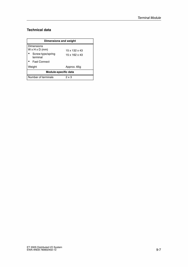
Terminal Module
9-7ET 200S Distributed I/O SystemEWA-4NEB 780602402-12
Technical data
Dimensions and weight
DimensionsW x H x D (mm)
• Screw-type/springterminal
• Fast Connect
15 x 132 x 43
15 x 162 x 43
Weight Approx. 65g
Module-specific data
Number of terminals 2 x 3

Terminal Module
9-8ET 200S Distributed I/O System
EWA-4NEB 780602402-12
9.2 TM-P15S23-A0, TM-P15C23-A0 and TM-P15N23-A0terminal module; (6ES7 193-4CDx0-0AA0)
Order number
6ES7 193-4CD20-0AA0 (screw-type terminal)6ES7 193-4CD30-0AA0 (spring terminal)6ES7 193-4CD70-0AA0 (Fast Connect)
Properties
• Terminal module for power module
• Power supply for a new potential group to the next TM-P terminal module
• Connection with screw-type terminal with TM-P15S23-A0
• Connection with spring terminal with TM-P15C23-A0
• Connection with Fast Connect with TM-P15N23-A0
• 2 x 3 terminals
• Basic wiring of the terminal module
• Build-as-you-go interference conductor from electronics module to standardmounting rail over spring contact
• Inserting a shield connection element
• Interrupted AUX1 rail with connection to terminals A4 and A8
Table 9-4 Terminal assignment of the TM-P15S23-A0, TM-P15C23-A0 andTM-P15N23-A0 terminal module
View Terminal Name
2 L+/L Rated load voltage for inserted powermodule and associated potential
3 M/Nmodule and associated potentialgroup
AUX1
8AA
A4 AUX1 Any terminal for PE or potential railup to the maximum rated loadvoltage of the module
L+/LL+/L4 8
AA
6 L+/L Rated load voltage for inserted powermodule and associated potential
M/N
L+/L
M/N
/2 6 7 M/N
module and associated potentialgroup
M/N
AUX1
M/N3
4
7
8AUX1AA
A8 AUX1 Any terminal for PE or potential railup to the maximum rated loadvoltage of the module

Terminal Module
9-9ET 200S Distributed I/O SystemEWA-4NEB 780602402-12
Block diagram
3 7
4 8
2 6
PM-E
Terminals interconnected with the power module
Power supply of the AUX1 rail via terminalsA4 and A8
Use of terminals A4 and A8 as protectiveconductor or any potential terminals
Power supply of power rails to the electronic modulesBackplane bus
AA
Figure 9-2 Block diagram of the TM-P15S23-A0, TM-P15C23-A0 and TM-P15N23-A0
terminal module
Technical data
Dimensions and weight
DimensionsW x H x D (mm)
• Screw-type/springterminal
• Fast Connect
15 x 132 x 43
15 x 162 x 43
Weight Approx. 65g
Module-specific data
Number of terminals 2 x 3

Terminal Module
9-10ET 200S Distributed I/O System
EWA-4NEB 780602402-12
9.3 TM-P15S22-01, TM-P15C22-01 and TM-P15N22-01terminal module; (6ES7 193-4CEx0-0AA0)
Order number
6ES7 193-4CE00-0AA0 (screw-type terminal)6ES7 193-4CE10-0AA0 (spring terminal)6ES7 193-4CE60-0AA0 (Fast Connect)
Properties
• Terminal module for power module
• Power supply for a new potential group to the next TM-P terminal module
• Connection via screw-type terminal with TM-P15S22-01
• Connection via spring terminal with TM-P15C22-01
• Connection with Fast Connect with TM-P15N22-01
• 2 x 2 terminals
• Basic wiring of the terminal module
• Build-as-you-go interference conductor from electronics module to standardmounting rail over spring contact
• Inserting a shield connection element
• Uninterrupted AUX1 bus without a connection to the terminals
Terminal assignment
See the following table for the terminal assignment of the terminal module:
Table 9-5 Terminal assignment to the TM-P15S22-01, TM-P15C22-01 andTM-P15N22-01 terminal module
View Signal name Name
2 L+/L Rated load voltage for inserted powermodule and associated potentialgroup
AUX1
3 M/Ngroup
L+/L L+/L2
AUX16 L+/L Rated load voltage for inserted power
module and associated potentialgroup
M/N2
3
6
7
M/N 7 M/Ngroup

Terminal Module
9-11ET 200S Distributed I/O SystemEWA-4NEB 780602402-12
Block diagram
3 7
2 6
PM-E
Power supply of power rails to the electronic modules
Terminals interconnected with the power module
Uninterrupted AUX1 bus without aconnection to the terminals
Backplane bus
Figure 9-3 Block diagram of the TM-P15S22-01, TM-P15C22-01 and TM-P15N22-01
terminal module
Technical data
Dimensions and weight
DimensionsW x H x D (mm)
• Screw-type/springterminal
• Fast Connect
15 x 119.5 x 43
15 x 142 x 43
Weight Approx. 55g
Module-specific data
Number of terminals 2 x 2

Terminal Module
9-12ET 200S Distributed I/O System
EWA-4NEB 780602402-12
9.4 TM-P30S44-A0 and TM-P30C44-A0 terminal module;(6ES7 193-4CKx0-0AA0)
Order number
6ES7 193-4CK20-0AA0 (screw-type terminal)6ES7 193-4CK30-0AA0 (spring terminal)
Properties
• Terminal module for fail-safe PM-E F 24 VDC PROFIsafe power module
• Power supply for new potential group to the next TM-P terminal module
• Wiring is possible for fail-safe digital output of the PM-E F DC 24V PROFIsafe
• Prewiring possible
• Build-as-you-go interference conductor from electronics module to standardmounting rail over spring contact
• Inserting a shield connection element
• Interrupted AUX1 rail with connection to terminals A4 and A8

Terminal Module
9-13ET 200S Distributed I/O SystemEWA-4NEB 780602402-12
Terminal assignment
See the following table for the terminal assignment of the terminal module:
Table 9-6 Terminal assignment of the TM-P30S44-A0 and TM-P30C44-A0 terminalmodule
View Terminal Name
2 24 VDC 24 VDC load voltage for: insertedpower module, associated potential group.DO 0 and DO 1 and P1 and P2 potentialrails
3 M Chassis ground
198
AA
A4 AUX 1 Any terminal for PE or potential rail up tothe maximum rated load voltage of themodule
2
3
6
7
1
0
1
1
3
1
4
1
5
94 8AA
6 24 VDC 24 VDC load voltage for: insertedpower module, associated potential group.DO 0 and DO 1 and P1 and P2 potentialrails3 7 1
1
5
1A A 7 M Chassis ground1
2
1
64 8 A8 AUX 1 Any terminal for PE or potential rail up tothe maximum rated load voltage of themodule
9 DO 0 P Terminals for fail-safe digital output 0(P M i hi )10 DO 0 M
g p(P--M switching)
11 DO 2 P Terminals (relay contacts) for fail-safeswitching of the P1 and P2 potential rails.P1 and P2 can also be used as DO 2 M
12 DO 2 MP1 and P2 can also be used as DO 2 Mand DO 2 P (for wiring diagram seeET 200S Manual, Fail-safe Modules).
13 DO 1 P Terminals for fail-safe digital output 0 (P--Mi hi )14 DO 1 M
g p (switching)
15 DO 2 P Terminals (relay contacts) for fail-safeswitching of the P1 and P2 potential rails.P1 and P2 can also be used as DO 2 M
16 DO 2MP1 and P2 can also be used as DO 2 Mand DO 2 P (for wiring diagram seeET 200S Manual, Fail-safe Modules).
!Caution
If high currents are encountered at DO 2 P and DO 2 M, terminals 11 and 15(DO 2 P) and 12 and 16 (DO 2 M) must be wired in parallel.Otherwise terminal overheating caused by the current load cannot be excluded.

Terminal Module
9-14ET 200S Distributed I/O System
EWA-4NEB 780602402-12
Block diagram
3 7
4 8
2 6
Electrical.ModuleEM
Uninterrupted power rails from the power module
Terminals interconnected with the electronic module
Backplane bus
9 1
1 1
1 1
1 10
1
2
3
4
5
6
Use of terminals A4 and A8 as protectiveconductor or any potential terminals
AA
Power supply of the AUX1 rail via terminalsA4 and A8
Figure 9-4 Block diagram of the TM-P30S44-A0 and TM-P30C44-A0 terminal module
Technical data
Dimensions and weight
DimensionsW x H x D (mm)
30 x 132 x 43
Weight Approx. 116 g(TM-P30S44-A0)
Approx. 100 g(TM-P30C44-A0)
Module-specific data
Number of terminals 14
Description of the PM-E F DC 24V PROFIsafe power module
The description of the PM-E F DC 24V PROFIsafe power module, which can beused with the above terminal modules, can be found in theET 200S Distributed I/O System Fail-safe Modules manual.

Terminal Module
9-15ET 200S Distributed I/O SystemEWA-4NEB 780602402-12
9.5 TM-PF30S47-F1 terminal module (for PM-D F DC 24V);(3RK1 903-3AA00)
Order number
3RK1 903-3AA00 (screw-type terminal)
Properties
• Terminal module for fail-safe PM-D F 24 VDC PROFIsafe power module
• Power supply for a new potential group to the next TM-P terminal module
• Basic wiring of the terminal module
• Build-as-you-go interference conductor from electronics module to standardmounting rail over spring contact
• Inserting a shield connection element
• Uninterrupted AUX1 bus without a connection to the terminals
Terminal assignment
See the following table for the terminal assignment of the terminal module:
Table 9-7 Terminal assignment of the TM-PF30S47-F1 terminal module
View Terminal Name
20 24 VDC 24 VDC rated load voltage: forinserted power module and SG 1 toSG 6 and U 1 potential rails
21 M Chassis ground
22
27 24 VDC 24 VDC rated load voltage: forinserted power module and SG 1 toSG 6 and U 1 potential rails
2
1
2
8
2
7
2
0 28 M Chassis ground

Terminal Module
9-16ET 200S Distributed I/O System
EWA-4NEB 780602402-12
Block diagram
Electrical.ModuleEM
Uninterrupted AUX1 bus without a connection tothe terminals
Uninterrupted power rails from the power module
Terminals interconnected with the electronic module
Backplane bus
2 2
2 2
.
0
1
7
8
Figure 9-5 Block diagram of the TM-PF30S47-F1 terminal module
Technical data
Dimensions and weight
DimensionsW x H x D (mm) 30 x 196.5 x 102
Weight Approx. 300g
Module-specific data
Number of terminals 4

Terminal Module
9-17ET 200S Distributed I/O SystemEWA-4NEB 780602402-12
9.6 TM-E15S26-A1, TM-E15C26-A1 and TM-E15N26-A1universal terminal module; (6ES7 193-4CAx0-0AA0)
Order number
6ES7 193-4CA40-0AA0 (screw-type terminal)6ES7 193-4CA50-0AA0 (spring terminal)6ES7 193-4CA80-0AA0 (Fast Connect)
Properties
• Universal terminal module for the electronic modules
• Connection with screw-type terminal with TM-E15S26-A1
• Connection with spring terminal with TM-E15C26-A1
• Connection with Fast Connect with TM-E15N26-A1
• 2 x 6 terminals
• Basic wiring of the terminal module
• Build-as-you-go interference conductor from electronics module to standardmounting rail over spring contact
• Inserting a shield connection element
• Uninterrupted AUX1 rail with connection to terminals A4, A8 and A3, A7

Terminal Module
9-18ET 200S Distributed I/O System
EWA-4NEB 780602402-12
Terminal assignment
• Terminal assignment of the TM-E15S26-A1, TM-E15C26-A1 andTM-E15N26-A1 terminal module with the 4-channel digital electronic modules:
View Terminal Name
1 DI0/DO0 DI: Digital input
O2 DI2/DO2DO: Digital output
24 VDC: Sensor3 24 VDC for DI0/ M for DO0
24 VDC: Sensorsupply
4 24 VDC for DI2/ M for DO2M : Load power supplyground
5 DI1/DO1
ground
1 5 6 DI3/DO3
2 67 24 VDC for DI1/ M for DO12
3
6
78 24 VDC for DI3/ M for DO3
3
4
7
8
A44 8
A AA3
AUX1 bus fed through Connection to terminals A44
A
8
AA8
AUX1 bus fed through. Connection to terminals A4,A8 and A3, A7.
A
3
A
7 A7
• Terminal assignment of the TM-E15S26-A1, TM-E15C26-A1 andTM-E15N26-A1 terminal module with the 2-channel electronic modules andprocess-related modules:
The terminal assignment of terminals 1 to 8 corresponds to the TM-E15S24-01,TM-E15C24-01 or TM-E15N24-01 terminal module. See the technicalspecifications for the various electronic modules for the different terminalassignments.
For the terminal assignment of terminals A4, A8 and A3, A7 see the tableabove.

Terminal Module
9-19ET 200S Distributed I/O SystemEWA-4NEB 780602402-12
Block diagram
1 5
3 7
4 8
2 6
Ele
ctric
al.
Mod
ule
EM
Uninterrupted AUX1 rail with connection toterminals A4, A8 and A3, A7
Uninterrupted power rails from the power module
Terminals interconnected with the electronic module
Backplane bus
3 7
4 8
A4 A8
A3 A7
Figure 9-6 Block diagram of the TM-E15S26-A1, TM-E15C26-A1 and TM-E15N26-A1
terminal module
Technical data
Dimensions and weight
DimensionsW x H x D (mm)
• Screw-type/springterminal
• Fast Connect
15 x 157 x 43
15 x 202 x 43
Weight Approx. 70 g(TM-E15C26-A1)
Approx. 83 g(TM-E15S26-A1)
Approx. 95 g(TM-E15N26-A1)
Module-specific data
Number of terminals 2 x 6

Terminal Module
9-20ET 200S Distributed I/O System
EWA-4NEB 780602402-12
9.7 TM-E15S24-A1, TM-E15C24-A1 and TM-E15N24-A1terminal module; (6ES7 193-4CAx0-0AA0)
Order number
6ES7 193-4CA20-0AA0 (screw-type terminal)6ES7 193-4CA30-0AA0 (spring terminal)6ES7 193-4CA70-0AA0 (Fast Connect)
Properties
• Terminal modules for electronic modules
• Connection with screw-type terminal with TM-E15S24-A1
• Connection with spring terminal with TM-E15C24-A1
• Connection with Fast Connect with TM-E15N24-A1
• 2 x 4 terminals
• Basic wiring of the terminal module
• Build-as-you-go interference conductor from electronics module to standardmounting rail over spring contact
• Inserting a shield connection element
• Continuous AUX1 rail with connection to terminals A4 and A8
Terminal assignment
See the following table for the terminal assignment of the terminal module:
Table 9-8 Terminal assignment of the TM-E15S24-A1, TM-E15C24-A1 andTM-E15N24-A1 terminal module
View Terminal Name
1 The assignment depends on the inserted electronicd l
2module
3
1 5
A4 AUX1 Any terminal for PE or potential railup to the maximum rated loadvoltage of the module
2 65 The assignment depends on the inserted electronic
d l2
3
6
76
module
3 7
AA7
4 8AA
A8 AUX1 Any terminal for PE or potential railup to the maximum rated loadvoltage of the module

Terminal Module
9-21ET 200S Distributed I/O SystemEWA-4NEB 780602402-12
Block diagram
1 5
3 7
A8
2 6
Ele
ctric
alM
odul
eE
M
Traversing AUX1 rail with connection to terminalsA4 and A8
Uninterrupted power rails from the power module
Use of terminals A4 and A8 as protectiveconductor or any potential terminals
Terminals interconnected with the electronic module
Backplane bus
4A
Figure 9-7 Block diagram of the TM-E15S24-A1, TM-E15C24-A1 and TM-E15N24-A1
terminal module
Technical data
Dimensions and weight
DimensionsW x H x D (mm)
• Screw-type/springterminal
• Fast Connect
15 x 132 x 43
15 x 162 x 43
Weight Approx. 65 g(TM-E15S24-A1 andTM-E15C24-A1)
Approx. 72g(TM-E15N24-A1)
Module-specific data
Number of terminals 2 x 4

Terminal Module
9-22ET 200S Distributed I/O System
EWA-4NEB 780602402-12
9.8 TM-E15S24-01, TM-E15C24-01 and TM-E15N24-01terminal module; (6ES7 193-4CBx0-0AA0)
Order number
6ES7 193-4CB20-0AA0 (screw-type terminal)6ES7 193-4CB30-0AA0 (spring terminal)6ES7 193-4CB70-0AA0 (Fast Connect)
Properties
• Terminal modules for electronic modules
• Connection via screw-type terminal with TM-P15S24-01
• Connection via spring terminal with TM-P15C24-01
• Connection with Fast Connect with TM-P15N24-01
• 2 x 4 terminals
• Basic wiring of the terminal module
• Build-as-you-go interference conductor from electronics module to standardmounting rail over spring contact
• Inserting a shield connection element
• Traversing AUX1 rail without connection to terminals 4 and 8
Terminal assignment
See the following table for the terminal assignment of the terminal module:
Table 9-9 Terminal assignment of the TM-E15S24-01, TM-E15C24-01 andTM-E15N24-01 terminal module
View Terminal Name
1 The assignment depends on the inserted electronicmodule
2module
No access to AUX1 rail.
3 Terminals that are not used by the electronic modulecan be used for attaching terminal wires that are not
1 5
4can be used for attaching terminal wires that are notrequired. This means that the approved potentialcorresponds to the potential of the electronic module in
2 6
1 5
5corresponds to the potential of the electronic module inuse.
2
3
6
7
63
4
7
8
74 8
8

Terminal Module
9-23ET 200S Distributed I/O SystemEWA-4NEB 780602402-12
Block diagram
1 5
3 7
4 8
2 6
Ele
ctric
alM
odul
eE
M
Traversing AUX1 rail without connection to terminals4 and 8
Uninterrupted power rails from the power module
Terminals interconnected with the electronic module
Backplane bus
Figure 9-8 Block diagram of the TM-E15S24-01, TM-E15C24-01 and TM-E15N24-01
terminal module
Technical data
Dimensions and weight
DimensionsW x H x D (mm)
• Screw-type/springterminal
• Fast Connect
15 x 132 x 43
15 x 162 x 43
Weight Approx. 65 g(TM-E15S24-01 andTM-E15C24-01)
Approx. 72 g(TM-E15N24-01)
Module-specific data
Number of terminals 2 x 4

Terminal Module
9-24ET 200S Distributed I/O System
EWA-4NEB 780602402-12
9.9 TM-E15S23-01, TM-E15C23-01 andTM-E15N23-01 terminal module; (6ES7 193-4CBx0-0AA0)
Order number
6ES7 193-4CB00-0AA0 (screw-type terminal)6ES7 193-4CB10-0AA0 (spring terminal)6ES7 193-4CB60-0AA0 (Fast Connect)
Properties
• Terminal modules for electronic modules
• Connection via screw-type terminal with TM-E15S23-01
• Connection via spring terminal with TM-E15C23-01
• Connection with Fast Connect with TM-E15N23-01
• 2 x 3 terminals
• Basic wiring of the terminal module
• Build-as-you-go interference conductor from electronics module to standardmounting rail over spring contact
• Inserting a shield connection element
• Uninterrupted AUX1 bus without a connection to the terminals
Terminal assignment
See the following table for the terminal assignment of the terminal module:
Table 9-10 Terminal assignment of the TM-E15S23-01, TM-E15C23-01 andTM-E15N23-01 terminal module
View Terminal Name
1 The assignment depends on the inserted electronicmodule
2module
N t AUX1 il3
No access to AUX1 rail.
1 5 5
2 6 6
3 7 7

Terminal Module
9-25ET 200S Distributed I/O SystemEWA-4NEB 780602402-12
Block diagram
1
6
3
5
2
7
Ele
ctric
alM
odul
eE
M
Uninterrupted AUX1 bus without aconnection to the terminals
Uninterrupted power rails from the power module
Terminals interconnected with the electronic module
Backplane bus
Figure 9-9 Block diagram of the TM-E15S23-01, TM-E15C23-01 and TM-E15N23-01
terminal module
Technical data
Dimensions and weight
DimensionsW x H x D (mm)
• Screw-type/springterminal
• Fast Connect
15 x 120 x 43
15 x 142 x 43
Weight Approx. 55 g(TM-E15S23-01 andTM-E15C23-01)
Approx. 60 g(TM-E15N23-01)
Module-specific data
Number of terminals 2 x 3
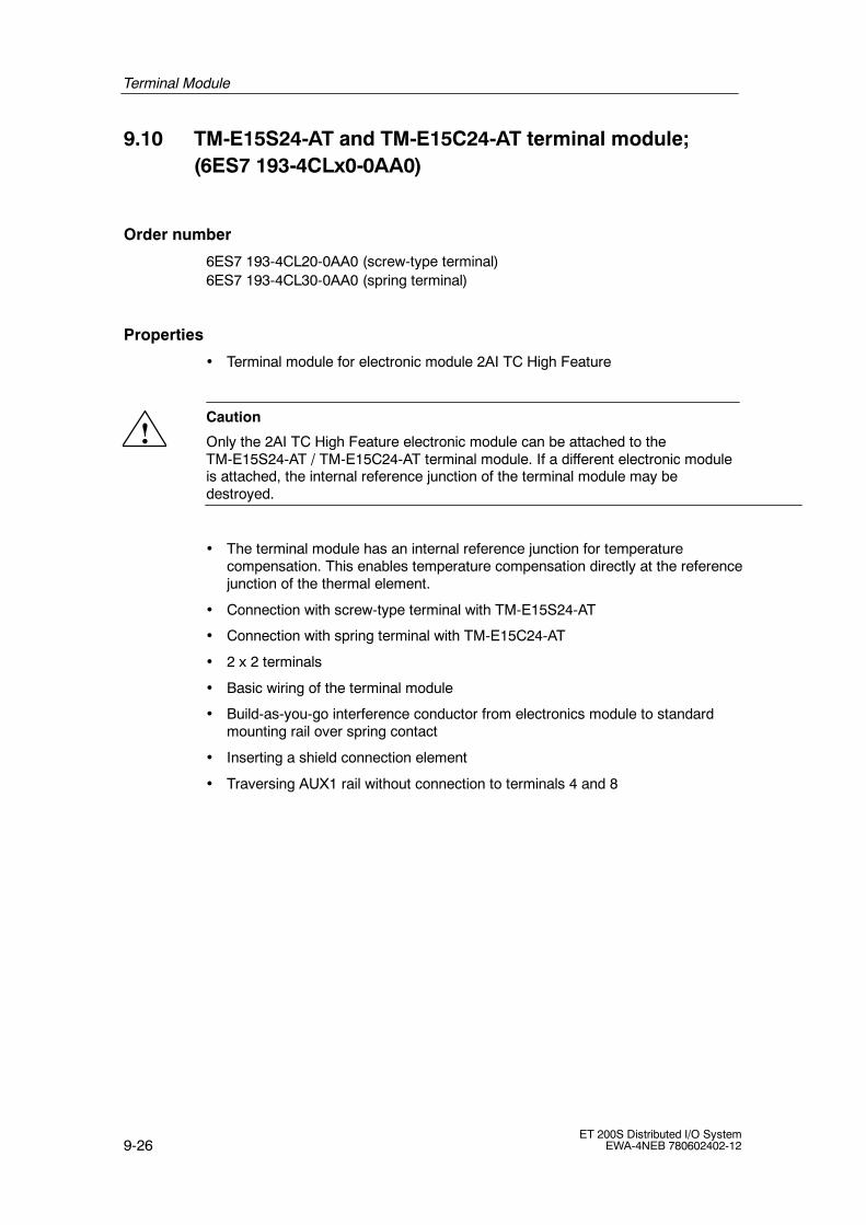
Terminal Module
9-26ET 200S Distributed I/O System
EWA-4NEB 780602402-12
9.10 TM-E15S24-AT and TM-E15C24-AT terminal module;(6ES7 193-4CLx0-0AA0)
Order number
6ES7 193-4CL20-0AA0 (screw-type terminal)6ES7 193-4CL30-0AA0 (spring terminal)
Properties
• Terminal module for electronic module 2AI TC High Feature
!Caution
Only the 2AI TC High Feature electronic module can be attached to theTM-E15S24-AT / TM-E15C24-AT terminal module. If a different electronic moduleis attached, the internal reference junction of the terminal module may bedestroyed.
• The terminal module has an internal reference junction for temperaturecompensation. This enables temperature compensation directly at the referencejunction of the thermal element.
• Connection with screw-type terminal with TM-E15S24-AT
• Connection with spring terminal with TM-E15C24-AT
• 2 x 2 terminals
• Basic wiring of the terminal module
• Build-as-you-go interference conductor from electronics module to standardmounting rail over spring contact
• Inserting a shield connection element
• Traversing AUX1 rail without connection to terminals 4 and 8

Terminal Module
9-27ET 200S Distributed I/O SystemEWA-4NEB 780602402-12
Terminal assignment
See the following table for the terminal assignment of the terminal module:
Table 9-11 Terminal assignment of the TM-E15S24-AT and TM-E15C24-AT terminalmodule
View Terminal Name
1 Assignment: see 2AI TC High Feature electronicmodule
2module
3 not available
1 5
41 5
5 Assignment: see 2AI TC High Feature electronicmodule2 6
6module
7 not available
8
Block diagram
1 5
2 6
Ele
ctric
alM
odul
eE
M
Uninterrupted AUX1 bus without aconnection to the terminals
Uninterrupted power rails from the power module
Terminals interconnected with the electronic module
Backplane bus
Figure 9-10 Block diagram of the TM-E15S24-AT and TM-E15C24-AT terminal module

Terminal Module
9-28ET 200S Distributed I/O System
EWA-4NEB 780602402-12
Technical data
Dimensions and weight
Dimensions W x H x D(mm)
15 x 132 x 43
Weight Approx. 55g
Module-specific data
Number of terminals 2 x 2
Note
For the precision information on the internal reference junction see Section 12.17
9.11 TM-E30S44-01 and TM-E30C44-01 terminal module;(6ES7 193-4CGx0-0AA0)
Order number
6ES7 193-4CG20-0AA0 (screw-type terminal)6ES7 193-4CG30-0AA0 (spring terminal)
Properties
• Terminal module for electronic modules 30 mm installation width and fail-safeelectronic modules
• Connection via screw-type terminal with TM-E30S44-01
• Connection via spring terminal with TM-E30C44-01
• 4 x 4 terminals
• Basic wiring of the terminal module
• Build-as-you-go interference conductor from electronics module to standardmounting rail over spring contact
• Inserting a shield connection element
• Traversing AUX1 rail without connection to terminals 4 and 8 or 12 and 16

Terminal Module
9-29ET 200S Distributed I/O SystemEWA-4NEB 780602402-12
Terminal assignment
See the following table for the terminal assignment of the terminal module:
Table 9-12 Terminal assignment of the TM-E30S44-01 and TM-E30C44-01 terminalmodule
View Terminal Name
1 The assignment depends on the inserted electronicd l2
g pmodule
N t AUX1 il3 No access to AUX1 rail.
T i l th t t d b th l t i d l4
Terminals that are not used by the electronic modulecan be used for attaching terminal wires that are not
5can be used for attaching terminal wires that are notrequired. This means that the approved potential
1 51
39 6required. This means that the approved potentialcorresponds to the potential of the electronic module in
1
2
5
61
3
1
9
7use.
2 6 0
1
4
18
3 71
1
1
5 9
4 8
1
1
5
1 104 8 2 6 11
12
13
14
15
16
Block diagram
1 5
3 7
4 8
2 6
Electrical.ModuleEM
Traversing AUX1 rail without connection toterminals 4 and 8 or 12 and 16
Uninterrupted power rails from the power module
Terminals interconnected with the electronic module
Backplane bus
9 1
1 1
1 1
1 10
1
2
3
4
5
6
Figure 9-11 Block diagram of the TM-E30S44-01 and TM-E30C44-01 terminal module

Terminal Module
9-30ET 200S Distributed I/O System
EWA-4NEB 780602402-12
Technical data
Dimensions and weight
Dimensions W x H x D(mm)
30 x 132 x 43
Weight Approx. 110 g(TM-E30C44-01)
Approx. 125 g(TM-E30S44-01)
Module-specific data
Number of terminals 4 x 4
9.12 TM-E30S46-A1 and TM-E30C46-A1 terminal module;(6ES7 193-4CFx0-0AA0)
Order number
6ES7 193-4CF40-0AA0 (screw-type terminal)6ES7 193-4CF50-0AA0 (spring terminal)
Properties
• Terminal module for fail-safe 4/8 F-DI DC 24 V PROFIsafeand 4 F-DO DC 24 V/2A PROFIsafe electronic module.
• Connection with screw-type terminal with TM-E30S46-A1
• Connection with spring terminal with TM-E30C46-A1
• 6 x 4 terminals
• Basic wiring of the terminal module
• Build-as-you-go interference conductor from electronics module to standardmounting rail over spring contact
• Inserting a shield connection element
• Uninterrupted AUX1 rail with connection to terminals A4, A8, A3, A7 or A12,A16, A11, A15.

Terminal Module
9-31ET 200S Distributed I/O SystemEWA-4NEB 780602402-12
Terminal assignment
See the following table for the terminal assignment of the terminal module:
Table 9-13 Terminal assignment of the TM-E30S46-A1 and TM-E30C46-A1 terminalmodule
View Terminal F-DI F-DO Name
1 DI 0 DO 0 P DI: Digital input
2 Vs1 DO 0 M
g p
DO P and DO M: Terminal for
3 DI 2 --
DO P and DO M: Terminal forfail-safe digital output (P--Mswitching)
4 Vs1 --switching)
Vs1: internal encoder power5 DI 1 DO 1 P
Vs1: internal encoder powersupply 1 for DI 0 to DI 3
6 Vs1 DO 1 Msupply 1 for DI 0 to DI 3
Vs2: internal encoder power
1 5 9
1
37 DI 3 --
Vs2: internal encoder powersupply 2 for DI 4 to DI 7
1 5 9 3
1 1 8 Vs1 --2 6 0 4
1 19 DI 4 DO 2 P
3 7
1
1
1
5 10 Vs2 DO 2 M3 7 1 5
1 1 11 DI 6 --4 8
A A
2 6A A 12 Vs2 --
A
4
A
8
A12
A16 13 DI 5 DO 3 P4
A
3
8
A
7
2A1
6A1 14 Vs2 DO 3 M
3 711
15 15 DI 7 --
16 Vs 2 --
A4, A3,A8, A7
AUX1 AUX1 bus fed through.Connection to terminals A4,A8 and A3, A7.
A12; A11,A16, A15
AUX1 AUX1 bus fed through.Connection to terminals A12,A11 and A16, A15.

Terminal Module
9-32ET 200S Distributed I/O System
EWA-4NEB 780602402-12
Block diagram
1 5
3 7
4 8
2 6
Electrical.ModuleEM
Uninterrupted power rails from the power module
Terminals interconnected with the electronic module
Backplane bus
9 1
1 1
1 1
1 10
1
2
3
4
5
6
Uninterrupted AUX1 rail with connection toterminals A4, A3, A8, A7 or A12, A11, A16,A15.
Use of terminals A4, A8, A3, A7 or A12, A16;A11, A15 as protective conductor or anypotential terminals
A4
A12
A16
A11
A15
A3
A7
A8
Figure 9-12 Block diagram of the TM-E30S46-A1 and TM-E30C46-A1 terminal module
Technical data
Dimensions and weight
Dimensions W x H x D(mm)
30 x 157 x 43
Weight Approx. 158 g(TM-E30S46-A1)
Approx. 131 g(TM-E30C46-A1)
Module-specific data
Number of terminals 6 x 4
Description of the electronic modules
For the description of the F-DI DC 24V PROFIsafe and 4 F-DO DC 24V/2APROFIsafe electronic modules 4/8 that can be used with the above terminalmodules see the ET 200S Distributed I/O System Fail-safe Modules manual.
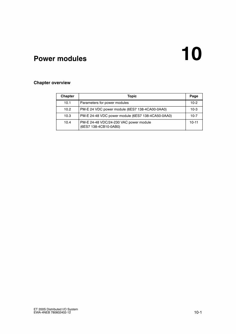
10-1ET 200S Distributed I/O SystemEWA-4NEB 780602402-12
Power modules
Chapter overview
Chapter Topic Page
10.1 Parameters for power modules 10-2
10.2 PM-E 24 VDC power module (6ES7 138-4CA00-0AA0) 10-3
10.3 PM-E 24-48 VDC power module (6ES7 138-4CA50-0AA0) 10-7
10.4 PM-E 24-48 VDC/24-230 VAC power module(6ES7 138-4CB10-0AB0)
10-11
10

Power modules
10-2ET 200S Distributed I/O System
EWA-4NEB 780602402-12
10.1 Parameters for power modules
Parameter
The following table describes the parameters for the power modules.
Table 10-1 Parameters for power modules
Power moduleV l D f lt Eff ti
PM E24 VDC
PM-E24--48 VDC
PM-E 24--48VDC/
24--230 VAC
Valuerange
Defaultsettings
Effectiverange
Diagnostics:No loadvoltage
Diagnostics:No loadvoltage
Diagnostics:No loadvoltage
Disable/enable
disable Powermodule
------ ------ Diagnosis:fuse cases
Disable/enable
disable Powermodule
------ ------ Voltage type DC/AC DC Powermodule
Diagnosis: Load voltage not present
The parameter is used to enable a diagnostic message as a result of no loadvoltage.
If there is no load voltage only the diagnostic message from the affected powermodule is sent to the DP master. The SF error LEDs of all modules in the affectedpotential group are lit.
Diagnosis: fuse cases
The parameter is used to enable a diagnostic message as a result of fuse cases.
If there is a fuse problem only the diagnostic message from the affected powermodule is sent to the DP master. The SF error LEDs of all modules in the affectedpotential group are lit.
Voltage type
This parameter is used to select the load voltage that is connected to the powermodule: direct voltage or alternating voltage.
This enables the correct diagnosis if there is no load voltage or if there is a fuseproblem.

Power modules
10-3ET 200S Distributed I/O SystemEWA-4NEB 780602402-12
10.2 PM-E 24 VDC power module (6ES7 138-4CA00-0AA0)
Order number
6ES7 138-4CA00-0AA0
Properties
• The PM-E 24 VDC power module monitors the supply voltage for all electronicsmodules which are part of the potential group. The supply voltage is suppliedvia the TM-P terminal module
• All electronic modules can be inserted in the potential group of the PM-E 24VDC power module, except for 2DI AC120V ST, 2DI AC230V ST and2DO 24--230 VAC/1 A.
!Caution
Only apply the specified rated load voltage of 24 VDC to the TM-P terminalmodule of the power module.
The rated load voltage applied must correspond to the power supply of theelectronic modules in the potential group.
• The current status of the power module is saved in the process image of theinputs (PII) via the status byte. The update is independent of enabling the ”Noload voltage” diagnosis (see Appendix C).

Power modules
10-4ET 200S Distributed I/O System
EWA-4NEB 780602402-12
Terminal assignment
The following table shows the terminal assignment of the PM-E 24 VDC powermodule for the various terminal modules:
Table 10-2 Terminal assignment of the PM-E 24 VDC power module
View Terminal assignment Remarks
AUX1AUX1
MM
VDCVDCVDC
TM-P15S23-A1 and PM-E 24 VDC
2
3
6
7
AUX1
84A A
4 8AA
24 VDC: Rated loadvoltage
M : Chassis ground
AUX1: can be used asprotective conductorterminal or any potentialrail up to the total loadvoltage.
AUX1AUX1
VDC
TM-P15S23-A0 and PM-E 24 VDC
MM
VDCVDC 2
3
6
7
AUX1
84A A
4 8AA
24 VDC: Rated loadvoltage
M : Chassis ground
AUX1: can be used asprotective conductorterminal or any potentialrail up to the total loadvoltage.
AUX1 is used as PE.
MM
VDCVDCVDC
TM-P15S22-01 and PM-E 24 VDC
2
3
6
7
AUX1
24 VDC: Rated loadvoltage
M : Chassis ground

Power modules
10-5ET 200S Distributed I/O SystemEWA-4NEB 780602402-12
Block diagram
Bac
kpla
nebu
s
ET
200S
back
plan
ebu
sin
terf
ace
conn
ectio
n
Load
volta
gem
onito
ring
62
73
PWR
P2P1
24 VDC
M
Figure 10-1 Block diagram of the PM-E 24 VDC power module

Power modules
10-6ET 200S Distributed I/O System
EWA-4NEB 780602402-12
Technical data
Dimensions and weight
DimensionsW x H x D (mm)
Weight
15 x 81 x 52
Approx. 35g
Voltages, currents, electrical potentials
Rated load voltage 24 V DC
• Overvoltageprotection
No
Fusing with externalminiaturecircuit-breakers
yes, trippingcharacteristic C
max. current carryingcapacity (up to 60 °C)
10A
• Short-circuitprotection
No
Electrical isolation
• Between rated loadvoltage andbackplane bus
Yes
• Between thepower modules
Yes
Insulation tested with 500 V DC
Current consumption
• From load voltageL+ (without load)
max. 4mA (164 ft)
Power loss of themodule
Typ. 100 mW
Status, interrupts, diagnostics
Diagnostics function Yes
• Group error
• Rated load voltagemonitoring
red LED ”SF”
Green LED ”PWR”
• Reading ofdiagnostic data
Yes

Power modules
10-7ET 200S Distributed I/O SystemEWA-4NEB 780602402-12
10.3 PM-E 24-48 VDC power module (6ES7 138-4CA50-0AA0)
Order number
6ES7 138-4CA50-0AA0
Properties
• The PM-E 24--48 VDC power module monitors the supply voltage for allelectronics modules which are part of the potential group. The supply voltage issupplied via the TM-P terminal module
• All electronic modules can be inserted in the potential group of the PM-E 24--48VDC power module, except for 2DI 120 VAC ST, 2DI 230 VAC ST and2DO 24--230 VAC/1 A.
• Control (PIQ) and feedback interface (PII) in the process image for optionhandling (see Appendix C).
• The current status of the power module is saved in the process image of theinputs (PII) via the status byte. The update is independent of enabling the ”Noload voltage” diagnosis (see Appendix C).
• The PM-E 24--48 VDC power module is suitable for fail-safe modules.
!Caution
Only apply the specified rated load voltage of 24--48 VDC to the TM-P terminalmodule of the power module.
The rated load voltage applied must correspond to the power supply of theelectronic modules in the potential group.

Power modules
10-8ET 200S Distributed I/O System
EWA-4NEB 780602402-12
Terminal assignment
The following table shows the terminal assignment of the PM-E 24--48 VDC powermodule for the various terminal modules:
Table 10-3 Terminal assignment of the PM-E 24--48 VDC power module
View Terminal assignment Remarks
AUX1AUX1
MM
24--48 VDC24--48 VDC24--48 VDC
TM-P15S23-A1 and PM-E 24--48 VDC
2
3
6
7
AUX1
84A A
4 8AA
24--48 VDC:Rated load voltage
M : Chassis ground
AUX1: can be used asprotective conductorterminal or any potentialrail up to the total loadvoltage.
AUX1AUX1
24--48 VDC
TM-P15S23-A0 and PM-E 24--48 VDC
MM
24--48 VDC24--48 VDC 2
3
6
7
AUX1
84A A
4 8AA
24--48 VDC:Rated load voltage
M : Chassis ground
AUX1: can be used asprotective conductorterminal or any potentialrail up to the total loadvoltage.
AUX1 is used as PE.
MM
24--48VDC
24--48 VDC24--48 VDC
TM-P15S22-01 and PM-E 24--48 VDC
2
3
6
7
AUX1
24--48 VDC:Rated load voltage
M : Chassis ground

Power modules
10-9ET 200S Distributed I/O SystemEWA-4NEB 780602402-12
Block diagram
Bac
kpla
nebu
s
ET
200S
back
plan
ebu
sin
terf
ace
conn
ectio
n
Loadvoltage
monitoring 62
73
PWR
P2P1
24 VDC
M
Figure 10-2 Block diagram of the PM-E 24--48 VDC power module

Power modules
10-10ET 200S Distributed I/O System
EWA-4NEB 780602402-12
Technical data
Dimensions and weight
DimensionsW x H x D (mm)
Weight
15 x 81 x 52
Approx. 35g
Voltages, currents, electrical potentials
Rated load voltage 24--48 VDC
• Polarity reversalprotection
Yes
• Overvoltageprotection
No
Fusing with externalminiaturecircuit-breakers
yes, trippingcharacteristic B, C
max. current carryingcapacity (up to 60 °C)
10A
• Short-circuitprotection
No
Electrical isolation
• Between rated loadvoltage andbackplane bus
Yes
• Between thepower modules
Yes
Insulation tested with 500 V DC
Current consumption
• From load voltageL+ (without load)
max. 12mA (164 ft)
Power loss of themodule
Typ. 500 mW
Status, interrupts, diagnostics
Diagnostics function Yes
• Group error
• Rated load voltagemonitoring
red LED ”SF”
Green LED ”PWR”
• Reading ofdiagnostic data
Yes

Power modules
10-11ET 200S Distributed I/O SystemEWA-4NEB 780602402-12
10.4 PM-E 24--48 VDC/24--230 VAC(6ES7 138-4CB10-0AB0)
Order number
6ES7 138-4CB10-0AB0
Properties
The PME power module 24--48 VDC/24--230 VAC
• monitors the power supply voltage for all the electronic modules in the potentialgroup. The supply voltage is supplied via the TM-P terminal module
• can be used anywhere and can be configured for DC and AC load voltage foroperation with every electronic module.
• with the ET 200S is required at least once (right beside the interface module).
• Control (PIQ) and feedback interface (PII) in the process image for optionhandling (see Appendix C).
• The current status of the power module is saved in the process image of theinputs (PII) via the status byte. The update is independent of enabling the ”Noload voltage” diagnosis (see Appendix C).
• is also fitted with a removable fuse (5 x 20 mm).
Screwdriver with 3 mmblade Fuses
Figure 10-3 Replacing fuse

Power modules
10-12ET 200S Distributed I/O System
EWA-4NEB 780602402-12
Note
The PM-E 24--48 VDC/24--230 VAC power module (6ES7 138-4CB10-0AB0) is nota direct replacement for the device with the order number 6ES7 138-4CB00-0AB0for AC applications, because either AC or DC power supply must be specified. Thenew module is a direct replacement with DC applications, because the default forthe new parameter is ”DC”. If you wish to use the 6ES7 138-4CB00-0AB0 devicefor AC applications, a new hardware configuration must be set up and the value”AC” must be specified for the ”Load voltage type” parameter.
If the hardware configuration is not changed for AC applications, the SF statusLED remains on continuously. If the ”Lo load voltage” diagnostic alarm is activated,multiple interrupts are activated in every AC cycle. However, the electronicmodules connected to the potential group of this PM-E operate normally.
Terminal assignment
The following table shows the terminal assignment of the PM-E 24--48VDC/24--230 VAC power module for the various terminal modules:
Table 10-4 Terminal assignment of the PM-E 24--48 VDC/24--230 VAC power module
View Terminal assignment Remarks
M/NM/N
AUX1
24--48 VDC/ L1
AUX1
AC∽
TM-P15S23-A1 and PM-E 24--48 VDC/24--230 VAC
2
3
4
6
7
8
AUX1
24--48 VDC/ L124V DC
AA
4 8AA
24--48 VDC/ L1: Ratedload voltage
M/ N: Ground/neutralconductor
AUX1: can be used asprotective conductorterminal or anypotential rail up to thetotal load voltage.
AC∽
AUX1 AUX1
TM-P15S23-A0 and PM-E 24--48 VDC/24--230 VAC
2
3
4
6
7
8
AUX1
24--48 VDC/ L1 24--48 VDC/ L1
M/NM/N24V DC
AA
4 8AA
24--48 VDC/ L1: Ratedload voltage
M/ N: Ground/neutralconductor
AUX1: can be used asprotective conductorterminal or anypotential rail up to thetotal load voltage.
AUX1 is used as PE.

Power modules
10-13ET 200S Distributed I/O SystemEWA-4NEB 780602402-12
Table 10-4 Terminal assignment of the PM-E 24--48 VDC/24--230 VAC power module, continued
View RemarksTerminal assignment
AC∽
TM-P15S22-01 and PM-E 24--48 VDC/24--230 VAC
2
3
6
7
AUX1
24--48 VDC/ L1 24--48 VDC/ L1
M/NM/N
24V DC
24--48 VDC/ L1: Ratedload voltage
M/ N: Ground/neutralconductor
Block diagram
Bac
kpla
nebu
s
ET 200Sbackplane
buscircuit
24 VDC/ L1
M/N
P2
Fusemonitoring
Loadvoltage
monitoring
26
P1
FSG
PWR
Fuses 37
Figure 10-4 Block diagram of the PM-E 24--48 VDC/24--230 VAC power module

Power modules
10-14ET 200S Distributed I/O System
EWA-4NEB 780602402-12
Technical data
Dimensions and weight
DimensionsW x H x D (mm)
Weight
15 x 81 x 52
34g
Voltages, currents, electrical potentials
Rated load voltage 24--56.7 VDC24--48 VAC/120 V/230 VAC
• Overvoltage protection Yes
Max. current capacity 10A
• for 24--56.7 VDC to 30°C: max. 10A(164 ft)
to 40°C: max. 9A(164 ft)
to 60°C: max. 7A(164 ft)
• for 24--48/120/230 VAC to 30°C: max. 8A(164 ft)
to 40°C: max. 7A(164 ft)
to 60°C: max. 5A(164 ft)
• Short-circuit protection yes, IEC 127-2/1,250 V, 10 A,fast-acting fuse(5 x 20 mm),replaceable1)
Electrical isolation
• Between rated loadvoltage and backplanebus
Yes
• Between thepower modules
Yes
Insulation tested with 1500 VAC
Current consumption
From the backplane bus max. 9.5mA (164 ft)
• From load voltage L1/L+(without load)
max. 9mA (164 ft)
Power loss of the module Max. 5W
Status, alarms, diagnostics
Diagnostics function Yes
• Group error
• Rated load voltagemonitoring
red LED ”SF”
Green LED ”PWR”
• Fuses Green LED ”FSG”
• Reading of diagnosticdata
Yes
1) The fuses on this module are only auxiliaryfuses; external overcurrent protection (suitablefor branch circuits depending on the localelectrotechnical regulations) is required in thepower supply cables of the load current circuit.

11-1ET 200S Distributed I/O SystemEWA-4NEB 780602402-12
Digital Electronic Modules
Introduction
The range of the digital electronic modules (EM) includes input and output modulesfor 24 VDC. Input and output modules are also available for 120/230 VAC.
A relay module is used for switching voltages for AC and DC.
Chapter overview
Chapter Topic Page
11.1 Parameters for digital electronic modules 11-2
11.2 2DI 24 VDC ST digital electronic module (6ES7 131-4BB00-0AA0) 11-7
11.3 4DI 24 VDC ST digital electronic module (6ES7 131-4BB00-0AA0) 11-11
11.4 4DI 24 VDC/SRC ST digital electronic module(6ES7 131-4BD00-0AA0)
11-15
11.5 2DI 24 VDC High Feature digital electronic module(6ES7 131-4BB00-0AB0)
11-19
11.6 4DI 24 VDC High Feature digital electronic module(6ES7 131-4BD00-0AB0)
11-23
11.7 4DI 24--48 VUC High Feature digital electronic module(6ES7 131-4CD00-0AB0)
11-28
11.8 4DI NAMUR digital electronic module (6ES7 131 4RD00-0AB0) 11-33
11.9 2DI 120 VAC ST digital electronic module (6ES7 131-4EB00-0AB0) 11-41
11.10 2DI 230 VAC ST digital electronic module (6ES7 131-4FB00-0AB0) 11-44
11.11 2DO 24 VDC/0.5 A ST digital electronic module(6ES7 132-4BB00-0AA0)
11-47
11.12 4DO 24 VDC/0.5 A ST digital electronic module(6ES7 132-4BD00-0AA0)
11-52
11.13 2DO 24 VDC/0.5 A High Feature digital electronic module(6ES7 132-4BB00-0AB0)
11-56
11.14 2DO 24 VDC/2 A ST digital electronic module(6ES7 132-4BB00-0AA0)
11-60
11.15 4DO 24 VDC/2 A ST digital electronic module(6ES7 132-4BD30-0AA0)
11-64
11.16 2DO 24 VDC/2 A High Feature digital electronic module(6ES7 132-4BB30-0AB0)
11-68
11.17 2DO 24--230 VAC digital electronic module(6ES7 132-4FB00-0AB0)
11-72
11.18 2RO NO 24--120 VDC/5 A 24--230 VAC/5 A digital electronicmodule (6ES7 132-4HB00-0AB0)
11-76
11.19 Digital electronic module 2RO NO/NC 24--48 VDC/5 A24--230 VAC/5 A (6ES7 132-4HB10-0AB0)
11-81
11

Digital Electronic Modules
11-2ET 200S Distributed I/O System
EWA-4NEB 780602402-12
11.1 Parameters for digital electronic modules
Parameters for digital input modules
Table 11-1 Parameters for digital input modules
2DI24 VDC
4DI24 VDC
4DI24--48 VUC
2DI/4DI 24 VDCStandard
Value range Defaultsetting
Effectiverange
HighFeature
HighFeature
HighFeature
4DI 24 VDC/SRCStandard
g g
2DI 120 VACStandard
2DI 230 VACStandard
Hardware interrupt3) ------ ------ • disable
• enabled
disable Module
------ Diagnosticalarm
------ • disable
• enabled
disable Module
Input delay1) ------ ------ • 0.1 ms
• 0.5 ms
• 3 ms
• 15 ms
3 ms Module
Diagnosis: Short circuit asper M2)
------ ------ • disable
• enabled
disable Module
------ Diagnosis:wire break4)
------ • disable
• enabled
disable Module
------ Diagnosis:Fuse defect
------ • disable
• enabled
disable Module
------ Diagnosis:no loadvoltage
------ • disable
• enabled
disable Module
Trigger forprocessinterrupt
Trigger forprocessinterrupt
------ ------ • disable
• enabled
disable Channel 0
interrupt,risingedge3)
interrupt,risingedge3)
Channel 1
------
g
Channel 2
Channel 31) The input delay applies to ”0” after ”1” and to ”1” after ”0”2) Short circuit of the sensor supply3) Configurable only with IM151-1 HIGH FEATURE and IM151-7 CPU interface module4) If the wire-break test is enabled, all free inputs must be stabilized so they do not trigger a module wire
break. This requires a resistor between terminal 24/48 V(3, A4, 7, A8) and the free input. The resistor must supply an input current of at least 0.5 mA (see”Sensor circuit” in the technical specifications table). This ensures that sufficient current will flow toprevent wire-break detection.When switched off the sensor must supply at least 0.5 mA (otherwise a wire-break will be detectedwhen switched off). Alternatively a resistor can be installed parallel to the sensor terminals (currentmust be at least 0.5 mA).

Digital Electronic Modules
11-3ET 200S Distributed I/O SystemEWA-4NEB 780602402-12
Parameters for 4DI NAMUR
Table 11-2 Parameters for 4DI NAMUR
4DI NAMUR V l D f l i Eff i4DI NAMUR Value range Default setting Effective range4DI NAMUR Value range Default setting Effective rangeg g g
Diagnostic alarm • enabled
• disable
disable Module
Sensor type • Channel disabled
• NAMUR sensor
• Single contactwithout load resistance
• Single contact with 10 kΩwith load resistance
• NAMUR changeovercontact
• Changeover contactwithout load resistance
• Changeover contact with10 kΩwith load resistance
disable Channel
Pulse stretching • No
• 0.5 s
• 1 s
• 2 s
No Channel
Diagnostics
No sensor power supply
• enabled
• disable
disable Module
Wire break diagnostics • enabled
• disable
disable Channel
Short-circuit diagnostics • enabled
• disable
disable Channel
Flutter monitoring:
Monitoring window1)
• 0.5 s
• 1 s to 100s (can be set in1 s increments)
0.5 s Channel
Flutter monitoring:
Number of signal changes
• disable
• 2 to 31
disable Channel
1) Parameters can only be set if the number of signal changes for flutter monitoring is enabled

Digital Electronic Modules
11-4ET 200S Distributed I/O System
EWA-4NEB 780602402-12
Parameters for digital output modules
Table 11-3 Parameters for digital output modules
2DO 24VDC/
0.5A HighFeature
2DO 24--230VAC/1A
2RO NO NC24--48 VDC/5 A24--230 VAC/5 A
2DO/ 4DO24 VDC/0.5 A ST
Value range Defaulttti
Effective
2DO 24VDC/
2A HighFeature
2RO NO24--120 VDC/5 A 24--230
VAC/5 A
2DO/ 4DO24 VDC/2 A ST
setting range
Response at CPU/master STOP ------ • applysubstitutevalue
• hold lastvalue
applysubstitutevalue
Module
Substitute value 1) ------ • ”0”
• ”1”
”0” Channel
------ • disable
• enabled
disable Module
Diagnosis:Wire break2)
------ • disable
• enabled
disable Channel
Diagnosis:Short circuitas per M
------ • disable
• enabled
disable Channel
1) If the interface module is without power, the digital output module does not output substitute values. Outputvalue = 0.
2) Wire break is only detected when the output is switched off.
Process alarm
This parameter enables the process interrupts for the module.
Input delay
Signal interference can be suppressed with this parameter. Changes in the signalare only detected after the specified time.
Trigger for process interrupt, rising edge
This parameter can be used in channels to enable a process interrupt with a risingedge (a signal status change).

Digital Electronic Modules
11-5ET 200S Distributed I/O SystemEWA-4NEB 780602402-12
Pulse stretching
The pulse stretching is a function used to modify a digital input signal. A pulse at adigital input is stretched to at least the length set in the parameters. If the inputpulse is already longer than the selected length, it is not changed
Principle of Pulse Stretching
The figure below shows a few examples of input pulse modification.
Pulse stretching parameter = T1
Process signal
”processed”input signal
Pulse is shorter than T1,and is stretched to T1 .
Pulse is longer than T1 andis thus not changed.
Process signal
”processed”input signal
The second pulse output during activepulse stretching is shifted until thecurrent stretching period has expired.
Short pulses output within apulse stretching cycle areignored.
T1 for 0 > 1 edge T1 for 1 > 0 edge
Figure 11-1 Principle of Pulse Stretching
Note
If you set pulse stretching for an input channel, this also affects the fluttermonitoring enabled for this channel. The ”pulse stretched” signal is the input signalfor flutter monitoring. You should therefore adapt the pulse stretching parametersand flutter monitoring functions to each other. Select appropriate parameter valuesin order to tune the functions to your process.

Digital Electronic Modules
11-6ET 200S Distributed I/O System
EWA-4NEB 780602402-12
Flutter monitoring
Flutter monitoring is a process control function for digital input signals. It detectsand reports unusual process control signal patterns, for example, frequentfluctuation of the ”0” and ”1” input signal. Such signal activities are an indicationthat a sensor is defective or that the process is unstable.
Enabling flutter monitoring
Enable flutter monitoring by setting the number of signal transitions to a value otherthan ”0.”
Detection of unusual signal patterns
A configurable monitoring window is available for each input channel. Themonitoring window is started at the first transition of the input signal. If the numberof input signal transitions within the monitoring window exceeds the set number,the system detects a flutter error. If a flutter error is not detected within themonitoring window, the monitoring window is started again at the next signalchange.
Reporting a Flutter Error
If a flutter error occurs, the current signal state is entered in the process image andthe value status of the signal is set to ”invalid”. The diagnostic information ”fluttererror” is entered and a diagnostic interrupt entering the state is triggered.
You must evaluate and process the value status and the diagnostic information inthe user program.
Resetting a Flutter Error
If no further fluttering of the input signal is detected during the triple monitoringwindow, the diagnostic entry is removed and an outgoing diagnostic interrupt istriggered. The value status of the current signal in the process image is set to”valid”.

Digital Electronic Modules
11-7ET 200S Distributed I/O SystemEWA-4NEB 780602402-12
Principle
The following figure illustrates the principle behind flutter monitoring.
Incoming ”flutter error” modulediagnosis= message
Module diagnostics”Flutter error” going= reset
Diagnostics
Processsignal
Detection
3 x monitoring window t = 3xParameter for monitoring window t = x
Parameter for the number of signal transitions = 9
Figure 11-2 Principle of Flutter Monitoring
11.2 2DI 24 VDC ST digital electronic module(6ES7 131-4BB00-0AA0)
Order number
6ES7 131-4BB00-0AA0
Features
• Digital electronic module with two inputs
• Rated input voltage 24 V DC
• Suitable for switches and proximity switches (BEROs)
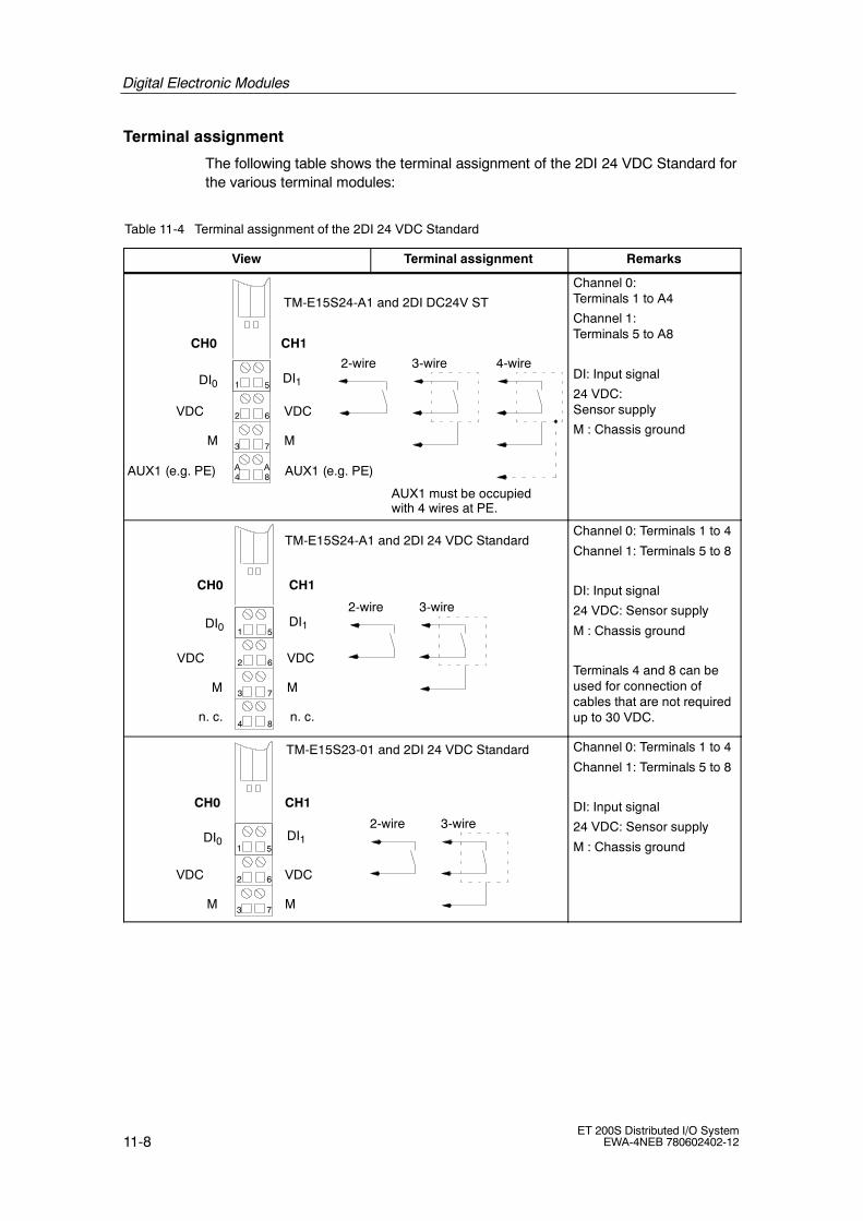
Digital Electronic Modules
11-8ET 200S Distributed I/O System
EWA-4NEB 780602402-12
Terminal assignment
The following table shows the terminal assignment of the 2DI 24 VDC Standard forthe various terminal modules:
Table 11-4 Terminal assignment of the 2DI 24 VDC Standard
View Terminal assignment Remarks
MM
VDCVDC
AUX1 (e.g. PE)
2
3
4
6
7
8
1 5DI1DI0
AUX1 (e.g. PE)
2-wire 3-wire 4-wire
TM-E15S24-A1 and 2DI DC24V ST
CH1CH0
AUX1 must be occupiedwith 4 wires at PE.
AA
Channel 0:Terminals 1 to A4
Channel 1:Terminals 5 to A8
DI: Input signal
24 VDC:Sensor supply
M : Chassis ground
MM
VDCVDC 2
3
4
6
7
8
1 5
2-wire 3-wire
TM-E15S24-A1 and 2DI 24 VDC Standard
CH1CH0
DI1DI0
n. c.n. c.
Channel 0: Terminals 1 to 4
Channel 1: Terminals 5 to 8
DI: Input signal
24 VDC: Sensor supply
M : Chassis ground
Terminals 4 and 8 can beused for connection ofcables that are not requiredup to 30 VDC.
MM
VDCVDC 2
3
6
7
1 5
2-wire 3-wire
TM-E15S23-01 and 2DI 24 VDC Standard
CH1CH0
DI1DI0
Channel 0: Terminals 1 to 4
Channel 1: Terminals 5 to 8
DI: Input signal
24 VDC: Sensor supply
M : Chassis ground

Digital Electronic Modules
11-9ET 200S Distributed I/O SystemEWA-4NEB 780602402-12
Table 11-4 Terminal assignment of the 2DI 24 VDC Standard
View RemarksTerminal assignment
MM
VDCVDC 2
3
4
6
7
8
1 5
2-wire 3-wire
TM-E15S26-A1 and 2DI 24 VDC Standard
CH1CH0
DI1DI0
AUX1A
4
A
3
A
8
A
7AUX1
AUX1
AUX1
n. c.n. c.
4-wire
AUX1 must be occupiedwith 4 wires at PE.
Channel 0:Terminals 1 to A3
Channel 1:Terminals 5 to A7
DI: Input signal
24 VDC:Sensor supply
M : Chassis ground
Terminals 4 and 8 can beused for connection ofcables that are not requiredup to 30 VDC.
Block diagram
Bac
kpla
nebu
s
ET 200Sbackplane
buscircuit
L+
1MP1
Inputelectronics
Inputelectronics
1
5
3
7
2
6P2
Figure 11-3 Block diagram of the 2DI 24 VDC Standard

Digital Electronic Modules
11-10ET 200S Distributed I/O System
EWA-4NEB 780602402-12
Technical data
Dimensions and weight
Dimensions W x H x D (mm) 15 x 81 x 52
Weight Approx. 35 g
Module-specific data
Number of inputs 2
Cable length
• Unshielded max. 600 m(164 ft)
• shielded max. 1,000 m(164 ft)
Voltages, currents, electrical potentials
Rated supply voltage (frompower module)
24 VDC
• Polarity reversalprotection
Yes
Electrical isolation
• Between the channels No
• Between channels andbackplane bus
Yes
Permissible potential differ-ence
• Between different circuits 75 VDC / 60 VAC
Insolation tested with 500 VDC
Current consumption
• From power supply Dependent on thesensor
Power loss of the module Typical 0.4 W
Status, interrupts, diagnostics
Status display Green LED perchannel
Diagnostic functions No
Sensor power supply output
Output voltage
• Loaded Min. L+ (--0.5 V)
Output current
• Rated value 500 mA
• Permitted range 0 to 500 mA
Data for selecting an sensor
Input voltage
• Rated value
• for ”1” signal
• for ”0” signal
24 VDC
15 to 30 V
--30 to 5 V
Input current
• For signal ”1” Typ. 7 mA(at 24 V)
Input delay
• ”0” to ”1” transition Typ. 3 ms(2.0 to 4.5 ms)
• ”1” to ”0” transition Typ. 3 ms(2.0 to 4.5 ms)
Input characteristic curve To IEC 61131,type 1
Connection of 2wire BEROs possible
• permitted quiescentcurrent
max. 1.5 mA

Digital Electronic Modules
11-11ET 200S Distributed I/O SystemEWA-4NEB 780602402-12
11.3 4DI 24 VDC ST digital electronic module(6ES7 131-4BD00-0AA0)
Order number
6ES7 131-4BD00-0AA0
Features
• Digital electronics module with four inputs
• Rated input voltage 24 V DC
• Suitable for switches and proximity switches (BEROs)
Terminal assignment
The following table shows the terminal assignment of the 4DI 24 VDC Standard forthe various terminal modules:
Table 11-5 Terminal assignment of the 2DI 24 VDC Standard
View Terminal assignment Remarks
VDCVDC
AUX1 (e.g. PE)
2
3
4
6
7
8
1 5
AUX1 (e.g. PE)
2-wire
TM-E15S24-A1 and 4DI 24 VDC Standard
CH1CH0
DI1DI0
DI2 DI3
CH2 CH3
AA
Channel 0: Terminals 1and 3
Channel 1: Terminals 5and 7
Channel 2: Terminals 2and 3
Channel 3: Terminals 6and 7
DI: Input signal
24 VDC: Sensor supply
VDC
2
3
4
6
7
8
1 5
2-wire
TM-E15S24-01 and 4DI 24 VDC Standard
CH1CH0
DI1DI0
DI2 DI3
CH2 CH3
VDC
VDC
VDC
Channel 0: Terminals 1and 3
Channel 1: Terminals 5and 7
Channel 2: Terminals 2and 4
Channel 3: Terminals 6and 8
DI: Input signal
24 VDC: Sensor supply

Digital Electronic Modules
11-12ET 200S Distributed I/O System
EWA-4NEB 780602402-12
Table 11-5 Terminal assignment of the 2DI 24 VDC Standard, continued
View RemarksTerminal assignment
2
3
6
7
1 5
TM-E15S23-01 and 4DI 24 VDC Standard
VDC
CH0
DI0
DI2
CH2CH1
DI1
DI3
CH3
VDC
2-wire
Channel 0: Terminals 1and 3
Channel 1: Terminals 5and 7
Channel 2: Terminals 2and 3
Channel 3: Terminals 6and 7
DI: Input signal
24 VDC: Sensor supply
VDC
2
3
4
6
7
8
1 5
2-wire
TM-E15S26-A1 and 4DI 24 VDC Standard
CH1CH0
DI1DI0
DI2 DI3
CH2 CH3
VDC
VDC
VDC
AUX1 (e.g. M) A
4
A
3
A
8
A
7AUX1 (e.g. M)
AUX1 (e.g. M)
AUX1 (e.g. M)
3-wire
Channel 0: Terminals 1and 3
Channel 1: Terminals 5and 7
Channel 2: Terminals 2and 4
Channel 3: Terminals 6and 8
DI: Input signal
24 VDC: Sensor supply

Digital Electronic Modules
11-13ET 200S Distributed I/O SystemEWA-4NEB 780602402-12
Block diagram
Bac
kpla
nebu
s
ET 200Sbackplane
buscircuit
L+
1MP1
Inputelectronics
1
P2
Inputelectronics
2
Inputelectronics
5
Inputelectronics
6
* 24 VDC only with TM-E15S24-01
37
8*4*
Figure 11-4 Block diagram of the 4DI 24 VDC Standard

Digital Electronic Modules
11-14ET 200S Distributed I/O System
EWA-4NEB 780602402-12
Technical data
Dimensions and weight
Dimensions W x H x D (mm) 15 x 81 x 52
Weight Approx. 35 g
Module-specific data
Number of inputs 4
Cable length
• Unshielded max. 600 m(164 ft)
• shielded max. 1,000 m(164 ft)
Voltages, currents, electrical potentials
Rated supply voltage (frompower module)
24 VDC
• Polarity reversalprotection
Yes
Electrical isolation
• Between the channels No
• Between channels andbackplane bus
Yes
Permissible potential differ-ence
• Between different circuits 75 VDC / 60 VAC
Insolation tested with 500 VDC
Current consumption
• From power supply Dependent on thesensor
Power loss of the module Typical 0.7 W
Status, interrupts, diagnostics
Status display Green LED perchannel
Diagnostic functions No
Sensor power supply output
Output voltage
• Loaded Min. L+ (--0.5 V)
Output current
• Rated value 500 mA
• Permitted range 0 to 500 mA
Data for selecting an sensor
Input voltage
• Rated value
• for ”1” signal
• for ”0” signal
24 VDC
15 to 30 V
--30 to 5 V
Input current
• For signal ”1” Typ. 7 mA(at 24 V)
Input delay
• ”0” to ”1” transition Typ. 3 ms(2.0 to 4.5 ms)
• ”1” to ”0” transition Typ. 3 ms(2.0 to 4.5 ms)
Input characteristic curve To IEC 61131,type 1
Connection of 2wire BEROs possible
• permitted quiescentcurrent
max. 1.5 mA

Digital Electronic Modules
11-15ET 200S Distributed I/O SystemEWA-4NEB 780602402-12
11.4 4DI 24 VDC/SRC ST digital electronic module(6ES7 131-4BD50-0AA0)
Order number
6ES7 131-4BD50-0AA0
Features
• Digital electronics module with four inputs
• M read
• Rated input voltage 24 V DC
• Suitable for switches and proximity switches (BEROs)

Digital Electronic Modules
11-16ET 200S Distributed I/O System
EWA-4NEB 780602402-12
NULLConnection assignment
The following table shows the terminal assignment of the 4DI 24 VDC/SRCStandard for the various terminal modules:
Table 11-6 Terminal assignment of the 4DI 24 VDC/SRC Standard
View Terminal assignment Remarks
MM
AUX1 (e.g. 24 VDC)
2-wire
TM-E15S24-A1 and4DI 24 VDC/SRC Standard
CH1CH0
DI1DI0
DI2 DI3
CH2 CH3
2
3
4
6
7
8
1 5
AA AUX1 (e.g. 24 VDC)
Channel 0: Terminals 1and 3
Channel 1: Terminals 5and 7
Channel 2: Terminals 2and 3
Channel 3: Terminals 6and 7
DI: Input signal
M : Sensor supply
M
2
3
4
6
7
8
1 5
2-wire
TM-E15S24-01 and4DI 24 VDC/SRC Standard
CH1CH0
DI1DI0
DI2 DI3
CH2 CH3
M
M
M
Channel 0: Terminals 1and 3
Channel 1: Terminals 5and 7
Channel 2: Terminals 2and 4
Channel 3: Terminals 6and 8
DI: Input signal
M : Sensor supply
2
3
6
7
1 5
TM-E15S23-01 and4DI 24 VDC/SRC Standard
M
CH0
DI0
DI2
CH2CH1
DI1
DI3
CH3
M
2-wire
Channel 0: Terminals 1and 3
Channel 1: Terminals 5and 7
Channel 2: Terminals 2and 3
Channel 3: Terminals 6and 7
DI: Input signal
M : Sensor supply
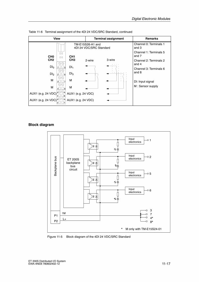
Digital Electronic Modules
11-17ET 200S Distributed I/O SystemEWA-4NEB 780602402-12
Table 11-6 Terminal assignment of the 4DI 24 VDC/SRC Standard, continued
View RemarksTerminal assignment
M
2
3
4
6
7
8
1 5
2-wire
TM-E15S26-A1 and4DI 24 VDC/SRC Standard
CH1CH0
DI1DI0
DI2 DI3
CH2 CH3
M
M
M
AUX1 (e.g. 24 VDC) A
4
A
3
A
8
A
7
3-wire
AUX1 (e.g. 24 VDC)
AUX1 (e.g. 24 VDC)
AUX1 (e.g. 24 VDC)
Channel 0: Terminals 1and 3
Channel 1: Terminals 5and 7
Channel 2: Terminals 2and 4
Channel 3: Terminals 6and 8
DI: Input signal
M : Sensor supply
Block diagram
Bac
kpla
nebu
s
ET 200Sbackplane
buscircuit
1MP1
Inputelectronics
1
P2
Inputelectronics
2
Inputelectronics
5
Inputelectronics
6
* M only with TM-E15S24-01
37
8*4*L+
Figure 11-5 Block diagram of the 4DI 24 VDC/SRC Standard

Digital Electronic Modules
11-18ET 200S Distributed I/O System
EWA-4NEB 780602402-12
Technical data
Dimensions and weight
Dimensions W x H x D (mm) 15 x 81 x 52
Weight Approx. 35 g
Module-specific data
Number of inputs 4
Cable length
• Unshielded max. 600 m (164ft)
• shielded max. 1,000 m(164 ft)
Voltages, currents, electrical potentials
Rated supply voltage (frompower module)
24 VDC
• Polarity reversalprotection
Yes
Electrical isolation
• Between the channels No
• Between channels andbackplane bus
Yes
Permissible potential differ-ence
• Between different circuits 75 VDC / 60 VAC
Insolation tested with 500 VDC
Current consumption
• From power supply Dependent on thesensor
Power loss of the module Typical 0.7 W
Status, interrupts, diagnostics
Status display Green LED perchannel
Diagnostic functions No
Sensor power supply output
Output voltage
• Loaded Max. M +0.5 V
Output current
• Rated value 500 mA
• Permitted range 0 to 500 mA
Data for selecting an sensor
Input voltage
• Rated value
• for ”1” signal
• for ”0” signal
24 VDC
--15 to --30 V1)
30 to --5 V1)
Input current
• For signal ”1” Typ. 7 mA(at 24 V)
Input delay
• ”0” to ”1” transition Typ. 3 ms(2.0 to 4.5 ms)
• ”1” to ”0” transition Typ. 3 ms(2.0 to 4.5 ms)
Input characteristic curve To IEC 61131,type 1
Connection of 2wire BEROs possible
• permitted quiescentcurrent
max. 1.5 mA
1) Reference potential is L+

Digital Electronic Modules
11-19ET 200S Distributed I/O SystemEWA-4NEB 780602402-12
11.5 2DI 24 VDC High Feature digital electronic module(6ES7 131-4BB00-0AB0)
Order number
6ES7 131-4BB00-0AB0
Features
• Digital electronic module with two inputs
• Rated input voltage 24 V DC
• Suitable for switches and proximity switches (BEROs)
• Supports clock synchronized mode
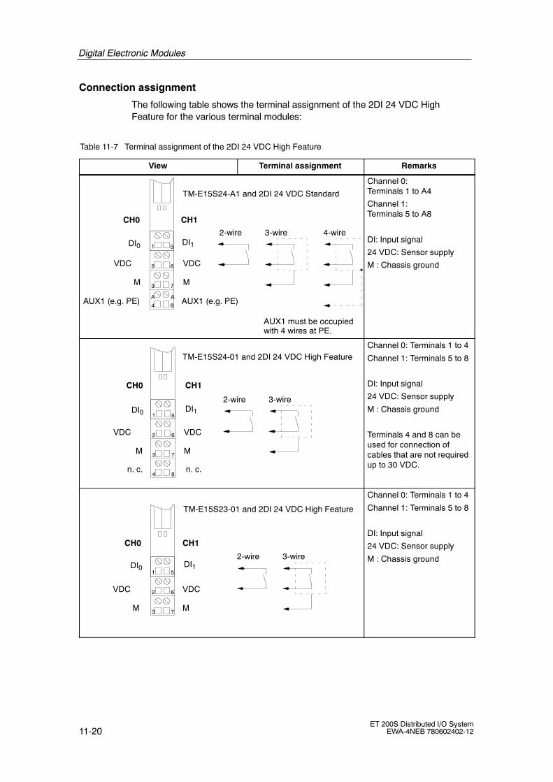
Digital Electronic Modules
11-20ET 200S Distributed I/O System
EWA-4NEB 780602402-12
Connection assignment
The following table shows the terminal assignment of the 2DI 24 VDC HighFeature for the various terminal modules:
Table 11-7 Terminal assignment of the 2DI 24 VDC High Feature
View Terminal assignment Remarks
MM
VDCVDC
AUX1 (e.g. PE)
2
3
4
6
7
8
1 5DI1DI0
AUX1 (e.g. PE)
2-wire 3-wire 4-wire
TM-E15S24-A1 and 2DI 24 VDC Standard
CH1CH0
AUX1 must be occupiedwith 4 wires at PE.
AA
Channel 0:Terminals 1 to A4
Channel 1:Terminals 5 to A8
DI: Input signal
24 VDC: Sensor supply
M : Chassis ground
MM
VDCVDC 2
3
4
6
7
8
1 5
2-wire 3-wire
TM-E15S24-01 and 2DI 24 VDC High Feature
CH1CH0
DI1DI0
n. c.n. c.
Channel 0: Terminals 1 to 4
Channel 1: Terminals 5 to 8
DI: Input signal
24 VDC: Sensor supply
M : Chassis ground
Terminals 4 and 8 can beused for connection ofcables that are not requiredup to 30 VDC.
MM
VDCVDC 2
3
6
7
1 5
2-wire 3-wire
TM-E15S23-01 and 2DI 24 VDC High Feature
CH1CH0
DI1DI0
Channel 0: Terminals 1 to 4
Channel 1: Terminals 5 to 8
DI: Input signal
24 VDC: Sensor supply
M : Chassis ground

Digital Electronic Modules
11-21ET 200S Distributed I/O SystemEWA-4NEB 780602402-12
Table 11-7 Terminal assignment of the 2DI 24 VDC High Feature, continued
View RemarksTerminal assignment
MM
VDCVDC 2
3
4
6
7
8
1 5
2-wire 3-wire
TM-E15S26-A1 and 2DI 24 VDC High Feature
CH1CH0
DI1DI0
AUX1A
4
A
3
A
8
A
7AUX1
AUX1
AUX1
n. c.n. c.
4-wire
AUX1 must beoccupied with 4 wires atPE.
Channel 0: Terminals 1 toA3
Channel 1: Terminals 5 toA7
DI: Input signal
24 VDC: Sensor supply
M : Chassis ground
Terminals 4 and 8 can beused for connection ofcables that are not requiredup to 30 VDC.
Block diagram
Bac
kpla
nebu
s
ET 200Sbackplane
buscircuit
L+
1MP1
Inputelectronics
Inputelectronics
Short-circuitprotection
Polarity reversalprotection
1
5
3
7
26
P2
Figure 11-6 Block diagram of the 2DI 24 VDC High Feature

Digital Electronic Modules
11-22ET 200S Distributed I/O System
EWA-4NEB 780602402-12
Technical data
Dimensions and weight
Dimensions W x H x D(mm)
15 x 81 x 52
Weight Approx. 35 g
Module-specific data
Supports clock synchro-nized mode
Yes
Number of inputs 2
Cable length
• Unshielded max. 600 m (164 ft)
• shielded max. 1,000 m (164ft)
Voltages, currents, electrical potentials
Rated supply voltage (frompower module)
24 VDC
• Polarity reversalprotection
Yes
Electrical isolation
• Between the channels No
• Between channels andbackplane bus
Yes
Permissible potential differ-ence
• Between differentcircuits
75 VDC / 60 VAC
Insolation tested with 500 VDC
Current consumption
• From power supply Dependent on thesensor
Power loss of the module Typical 0.4 W
Status, interrupts, diagnostics
Status display Green LED perchannel
Interrupts
• Process alarm Configurable
Diagnostic functions
• Group error red LED ”SF”
• Reading of diagnosticdata
Yes
Sensor power supply output
Output voltage
• Loaded Min. L+ (--0.5 V)
Output current
• Rated value 500 mA
• Permitted range 0 to 500 mA
Short-circuit protection Yes, electronic1)
Data for selecting an sensor
Input voltage
• Rated value
• for ”1” signal
• for ”0” signal
24 VDC
11 to 30 V
--30 to 5 V
Input current
• For signal ”1” Typical 8 mA
Input delay(configurable)
• ”0” to ”1” transition 0.1 ms(0.05 to 0.15 ms)0.5 ms(0.4 to 0.6 ms)3 ms(2.7 to 3.3 ms)15 ms(14.85 to 15.15 ms)
• ”1” to ”0” transition 0.1 ms(0.05 to 0.15 ms)0.5 ms(0.4 to 0.6 ms)3 ms(2.7 to 3.3 ms)15 ms(14.85 to 15.15 ms)
Input characteristic curve To IEC 61131,type 1
Connection of 2wireBEROs
possible
• permitted quiescentcurrent
max. 1.5 mA
1) per module

Digital Electronic Modules
11-23ET 200S Distributed I/O SystemEWA-4NEB 780602402-12
11.6 4DI 24 VDC High Feature digital electronic module(6ES7 131-4BD00-0AB0)
Order number
6ES7 131-4BD00-0AB0
Features
• Digital electronics module with four inputs
• Rated input voltage 24 V DC
• Suitable for switches and proximity switches (BEROs)
• Supports clock synchronized mode

Digital Electronic Modules
11-24ET 200S Distributed I/O System
EWA-4NEB 780602402-12
Connection assignment
The following table shows the terminal assignment of the 4DI 24 VDC HighFeature for the various terminal modules:
Table 11-8 Terminal assignment of the 4DI 24 VDC High Feature
View Terminal assignment Remarks
VDCVDC
AUX1 (e.g. M)
2
3
4
6
7
8
1 5
AUX1 (e.g. M)
2-wire
TM-E15S24-A1 and 4DI 24 VDC High Feature
CH1CH0
DI1DI0
DI2 DI3
CH2 CH3
AA
Channel 0: Terminals 1and 3
Channel 1: Terminals 5and 7
Channel 2: Terminals 2and 3
Channel 3: Terminals 6and 7
DI: Input signal
24 VDC: Sensor supply
VDC
2
3
4
6
7
8
1 5
2-wire
TM-E15S24-01 and 4DI 24 VDC High Feature
CH1CH0
DI1DI0
DI2 DI3
CH2 CH3
VDC
VDC
VDC
Channel 0: Terminals 1and 3
Channel 1: Terminals 5and 7
Channel 2: Terminals 2and 4
Channel 3: Terminals 6and 8
DI: Input signal
24 VDC: Sensor supply
2
3
6
7
1 5
TM-E15S23-01 and 4DI 24 VDC High Feature
VDC
CH0
DI0
DI2
CH2CH1
DI1
DI3
CH3
VDC
2-wire
Channel 0: Terminals 1and 3
Channel 1: Terminals 5and 7
Channel 2: Terminals 2and 3
Channel 3: Terminals 6and 7
DI: Input signal
24 VDC: Sensor supply

Digital Electronic Modules
11-25ET 200S Distributed I/O SystemEWA-4NEB 780602402-12
Table 11-8 Terminal assignment of the 4DI 24 VDC High Feature, continued
View RemarksTerminal assignment
VDC
2
3
4
6
7
8
1 5
2-wire
TM-E15S26-A1 and 4DI 24 VDC High Feature
CH1CH0
DI1DI0
DI2 DI3
CH2 CH3
VDC
VDC
VDC
AUX1 (e.g. M)A
4
A
3
A
8
A
7AUX1 (e.g. M)
AUX1 (e.g. M)
AUX1 (e.g. M)
3-wire
Channel 0: Terminals 1and 3
Channel 1: Terminals 5and 7
Channel 2: Terminals 2and 4
Channel 3: Terminals 6and 8
DI: Input signal
24 VDC: Sensor supply

Digital Electronic Modules
11-26ET 200S Distributed I/O System
EWA-4NEB 780602402-12
Block diagram
Bac
kpla
nebu
s
ET 200Sbackplane
buscircuit
L+
1MP1
Inputelectronics
Short-circuitprotection
Polarity reversalprotection
1
4*8*P2
Inputelectronics
1
Inputelectronics
2Inputelectronics
Inputelectronics
5Inputelectronics
Inputelectronics
6Inputelectronics
73
* 24 VDC only with TM-E15S24-01 and TM-E15S26-A1
Figure 11-7 Block diagram of the 4DI 24 VDC High Feature

Digital Electronic Modules
11-27ET 200S Distributed I/O SystemEWA-4NEB 780602402-12
Technical data
Dimensions and weight
Dimensions W x H x D (mm) 15 x 81 x 52
Weight Approx. 35 g
Module-specific data
Supports clock synchronizedmode
Yes
Number of inputs 4
Cable length
• Unshielded max. 600 m(164 ft)
• shielded max. 1,000 m(164 ft)
Voltages, currents, electrical potentials
Rated supply voltage (frompower module)
24 VDC
• Polarity reversalprotection
Yes
Electrical isolation
• Between the channels No
• Between channels andbackplane bus
Yes
Permissible potential differ-ence
• Between different circuits 75 VDC / 60 VAC
Insolation tested with 500 VDC
Current consumption
• From power supply Dependent on thesensor
Power loss of the module Typical 0.7 W
Status, interrupts, diagnostics
Status display Green LED perchannel
Interrupts
• Process alarm Configurable
Diagnostic functions
• Group error red LED ”SF”
• Reading of diagnosticdata
Yes
Sensor power supply output
Output voltage
• Loaded Min. L+ (--0.5 V)
Output current
• Rated value 500 mA
• Permitted range 0 to 500 mA
Short-circuit protection Yes, electronic1)
Data for selecting a sensor
Input voltage
• Rated value
• for ”1” signal
• for ”0” signal
24 VDC
11 to 30 V
--30 to 5 V
Input current
• For signal ”1” Typical 8 mA
Input delay (configurable)
• ”0” to ”1” transition 0.1 ms(0.05 to 0.15 ms)0.5 ms(0.4 to 0.6 ms)3 ms(2.7 to 3.3 ms)15 ms (14.85 to15.15 ms)
• ”1” to ”0” transition 0.1 ms(0.05 to 0.15 ms)0.5 ms(0.4 to 0.6 ms)3 ms(2.7 to 3.3 ms)15 ms (14.85 to15.15 ms)
Input characteristic curve To IEC 61131,type 1
Connection of 2wire BEROs possible
• permitted quiescentcurrent
max. 1.5 mA
1) per module

Digital Electronic Modules
11-28ET 200S Distributed I/O System
EWA-4NEB 780602402-12
11.7 4DI 24--48 VUC High Feature digital electronic module(6ES7 131-4CD00-0AB0)
Order number
6ES7 131-4CD00-0AB0
Features
• Digital electronics module with four inputs
• Rated input voltage 24.48 VAC/VDC
• Configuration length: 3 bytes
• Diagnosis: Wire break
• Diagnosis: fuse cases
• Diagnosis: no load voltage
• Suitable for switches and proximity switches (BEROs)
• Supports clock synchronized mode

Digital Electronic Modules
11-29ET 200S Distributed I/O SystemEWA-4NEB 780602402-12
Terminal assignment
The following table shows the terminal assignment of the 4DI 24--48 VUC HighFeature for the various terminal modules:
Table 11-9 Terminal assignment of the 4DI 24 VUC High Feature
View Terminal assignment Remarks
AUX1 (PE)
2
3
4
6
7
8
1 5DI1DI0
24/48 VAC/VDC
2-wire 3-wire
TM-E15S24-A1 and4DI 24--48 VUC High Feature
CH1CH3
CH0CH2
DI2 DI3
24/48 VAC/VDC
AUX1 (PE) AA
Channel 0:terminals 1 and 3
Channel 1:terminals 5 and 7
Channel 2.terminals 2 and 3Channel 3:terminals 6 and 7
DI: Input signal
24 V DC sensor powersupply
PE: Chassis ground
2
3
4
6
7
8
1 5
2-wire
TM-E15S24-01 and4DI 24--48 VUC High Feature
CH1CH3
CH0CH2
DI1DI0
DI2 DI3
24/48 VAC/VDC
24/48 VAC/VDC
24/48 VAC/VDC
24/48 VAC/VDC
Channel 0:terminals 1 and 3
Channel 1:terminals 5 and 7
Channel 2:terminals 2 and 4
Channel 3:terminals 6 and 8
DI: Input signal
24 V DC sensor powersupply

Digital Electronic Modules
11-30ET 200S Distributed I/O System
EWA-4NEB 780602402-12
Table 11-9 Terminal assignment of the 4DI 24 VUC High Feature, continued
View RemarksTerminal assignment
2
3
6
7
1 5
2-wire 3-wire
TM-E15S23-01 and4DI 24--48 VUC High Feature
CH1CH3
CH0CH2
DI1DI0
DI2 DI3
24/48 VAC/VDC 24/48 VAC/VDC
Channel 0:terminals 1 and 3
Channel 1:terminals 5 and 7
Channel 2:terminals 2 and 3
Channel 3:terminals 6 and 7
DI: Input signal
24 V DC sensor powersupply
2
3
4
6
7
8
1 5
2-wire 3-wire
TM-E15S26A1 and 4DI 24--48 VUC High Feature
CH1CH3
CH0CH2
DI1DI0
DI2 DI3
24/48 VAC/VDC
24/48 VAC/VDC
24/48 VAC/VDC
24/48 VAC/VDC
8
7
44
3
A
A A
A
AUX1 (PE) AUX1 (PE)
AUX1 (PE) AUX1 (PE)
Channel 0:terminals 1 and 3
Channel 1:terminals 5 and 7
Channel 2:terminals 2 and 4
Channel 3:terminals 6 and 8
DI: Input signal
24 V DC sensor powersupply
AUX: Terminals A4, A3,A8 DC/AC and A7 can beused for free cables up toDC30 V.

Digital Electronic Modules
11-31ET 200S Distributed I/O SystemEWA-4NEB 780602402-12
Block diagram
Bac
kpla
nebu
s
ET 200Sbackplane bus
interfaceconnection
L+
1MP1
Inputelectronics
1
P2
Inputelectronics
2
Inputelectronics
5
Inputelectronics
6
34
87
Short-circuitprotection
Reversepolarityprotection
Figure 11-8 Terminal assignment of the 4DI 24--48 VUC High Feature

Digital Electronic Modules
11-32ET 200S Distributed I/O System
EWA-4NEB 780602402-12
Technical dataDimensions and weight
Dimensions W x H x D 15 x 81 x 52 (mm)
Weight Approx. 35 g
Module-specific data
Supports clocksynchronized mode
Yes
Number of inputs 4
Cable length
• Unshielded max. 600 m (164 ft)
• shielded max. 1,000 m(164 ft)
Voltages, currents, electrical potentials
Rated supply voltage (frompower module)
24/--48 VAC/VDC
• horizontal installationup to 60 °C
• vertical installationup to 40 °C
• Polarity reversalprotection
Ac or DCautomatically
Electrical isolation
• Between the channels No
• Between channels andbackplane bus
Yes
Permitted potentialdifference
• Between differentcircuits
75 VDC, 60 VAC
Insolation tested with 2500 V DC
Current consumption
• from powersupply L+
Dependent on thesensor
• From the backplane bus max. 10 mA
Power loss of the module Typical 0.7 W
Status, interrupts, diagnostics
Status display green LEDs perchannel
Diagnostic functions
• Group error display
Configurable
red LEDs (SF)
Sensor Power Supply Outputs
Output voltage
• Loaded Min. L+ (--0.5 V)
Output current
• Rated value 500 mA
• Permitted range
Short-circuit protection
0 to 500 mA
Yes, by module
Data for selecting a sensor
Input voltage
• Rated value 24 to 48 VUC
• for ”1” signal --15 VDCup to --57.6 VDC15 V DCup to 57.6 V DC15 V ACup to 48 V AC
• for ”0” signal --6 VDCup to 6 VDC0 VAC up to 5 VAC
• Frequency range 47 Hz to 63 Hz
Input current
• For signal ”1”
from 4 mA to10 mA
Input delay
• ”0” to ”1” transition
• ”1” to ”0” transition
Max. 15 ms
Max. 15 ms
Input characteristic1)
Connection of 2wireBEROs
possible
• permitted quiescentcurrent
max. 0.5 up to 2mA2)
Sensor circuit
Resistor circuit of sensor towire-break monitor
• Rated voltage24 V (15 V to 35 V)
• Rated voltage48 V (30 V to 60 V)
18 kΩ
39 kΩ
1) IEC 61131 does not provide specification for UCmodules. However, the values comply withIEC 61131 to the extent possible.
2) A minimum load current is required withwire-break monitoring.

Digital Electronic Modules
11-33ET 200S Distributed I/O SystemEWA-4NEB 780602402-12
11.8 4DI NAMUR digital electronic module(6ES7 131-4RD00-0AB0)
Order number
6ES7 131-4RD00-0AB0
Properties
S Digital electronics module with four inputs
S 8.2 VDC sensor supply
S Suitable for NAMUR sensors and wired and unwired mechanical contacts
Terminal assignment of NAMUR sensors or sensors as per DIN 19234
Table 11-10 Terminal assignment of NAMUR sensors or sensors as per DIN 19234
View Terminal assignment Remarks
2
3
4
6
7
8
1 5DI1DI0
Example of a channel 0connection
1
3
orDI2 DI3
TM-E15S24-A1 and 4DI NAMUR
Vs
AUX 1 (PE) AUX 1 (PE)
Vs
CH0 CH1
CH2 CH3
A A
Sensor 1:
Channel 0: Terminals 1 and 3
Sensor 2:
Channel 1: Terminals 5 and 7
Sensor 3:
Channel 2: Terminals 2 and 3
Sensor 4:
Channel 3: Terminals 6 and 7
DI: Input signal
Vs: Sensor supply

Digital Electronic Modules
11-34ET 200S Distributed I/O System
EWA-4NEB 780602402-12
Terminal assignment of NAMUR changeover contacts or sensors as perDIN 19234
Table 11-11 Terminal assignment of NAMUR changeover contacts or sensors as per DIN 19234
View Terminal assignment Remarks
2
3
4
6
7
8
1 5
Example for connectionof channel 0
1
3
5or
NC contact
NO contact
15
3
DI0
DI2
DI1
DI3
TM-E-15S24-01 and 4DI NAMUR
Vs
Vs Vs
Vs
CH0 CH1
CH2 CH3
Changeover contact 1.
Terminals 1, 5 and 3
Changeover contact 2
Terminals 2, 6 and 7
DI: Input signal
Vs: Sensor supply
Terminal assignment of single contact with 10 kΩ (mechanical NO contact)
Table 11-12 Terminal assignment of single contact with 10 kΩ (mechanical NO contact)
View Terminal assignment Remarks
2
3
6
7
1 5
DI1DI0
Example for connection ofchannel 0
1
3
10 kDI2 DI3
Vs Vs
TM-E-15S23-01 and 4DI NAMUR
CH0 CH1
CH2 CH3
Single contact 1:
Channel 0: Terminals 1and 3
Single contact 2:
Channel 1: Terminals 5and 7
Single contact 3:
Channel 2: Terminals 2and 3
Single contact 4:
Channel 3: Terminals 6and 7
DI: Input signal
Vs: Sensor supply

Digital Electronic Modules
11-35ET 200S Distributed I/O SystemEWA-4NEB 780602402-12
Terminal assignment of changeover contact with 10 kΩ (mechanical changeovercontact)
Table 11-13 Terminal assignment of changeover contact with 10 kΩ (mechanical changeover contact)
View Terminal assignment Remarks
1
3
5
10 k
Example for connection ofchannel 0 and channel 1
2
3
4
6
7
8
1 5DI0 DI1
DI2
Vs
Vs Vs
Vs
DI3
TM-E-15S24-01 and 4DI NAMUR
CH0 CH1
CH2 CH3
Changeover contact 1:Terminals 1, 5 and 3
Changeover contact 2:Terminals 2, 6 and 7
DI: Input signal
Vs: Sensor supply
Terminal Assignment of a Single Contact without Load Resistance (MechanicalNO Contact with Single Contact)
Table 11-14 Terminal Assignment of a Single Contact without Load Resistance (Mechanical NO Contactwith Single Contact)
View Terminal assignment Remarks
1
3
2
3
4
6
7
8
1 5DI0 DI1
Example for connectionof channel 0
DI2 DI3
Vs
Vs
Vs
Vs
TM-E-15S24-01 and 4DI NAMUR
CH0 CH1
CH2 CH3
Single contact 1:
Channel 0: Terminals 1and 3
Single contact 2:
Channel 1: Terminals 5and 7
Single contact 3:
Channel 2: Terminals 2and 4
Single contact 4:
Channel 3: Terminals 6and 8
DI: Input signal
Vs: Encoder supply
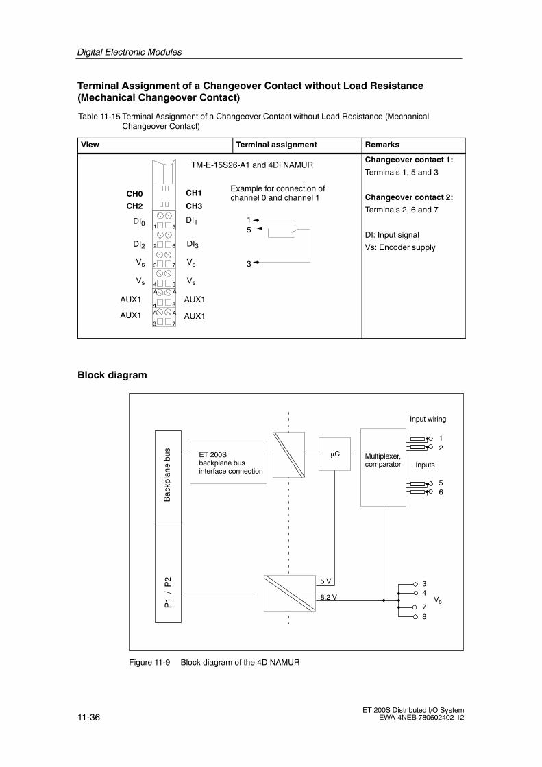
Digital Electronic Modules
11-36ET 200S Distributed I/O System
EWA-4NEB 780602402-12
Terminal Assignment of a Changeover Contact without Load Resistance(Mechanical Changeover Contact)
Table 11-15 Terminal Assignment of a Changeover Contact without Load Resistance (MechanicalChangeover Contact)
View Terminal assignment Remarks
1
3
5
Example for connection ofchannel 0 and channel 1
TM-E-15S26-A1 and 4DI NAMUR
2
3
4
6
7
8
1 5
CH1CH0
DI1DI0
DI2 DI3
8
7
44
3
A
A A
A
AUX1 AUX1
AUX1 AUX1
CH2 CH3
Vs
Vs
Vs
Vs
Changeover contact 1:
Terminals 1, 5 and 3
Changeover contact 2:
Terminals 2, 6 and 7
DI: Input signal
Vs: Encoder supply
Block diagram
Bac
kpla
nebu
sP
1/
P2 5 V
8.2 V
µC Multiplexer,comparator
Vs
ET 200Sbackplane businterface connection
Inputs
Input wiring
12
34
56
78
Figure 11-9 Block diagram of the 4D NAMUR

Digital Electronic Modules
11-37ET 200S Distributed I/O SystemEWA-4NEB 780602402-12
Technical dataDimensions and weight
Dimensions W x H x D(mm)
15 x 81 x 52
Weight Approx. 35 g
Module-specific data
Number of inputs 4
Cable length
• shielded max. 200 m (164 ft)
Voltages, currents, electrical potentials
Number of inputs that canbe addressedsimultaneously
4
• horizontal installation upto 60 °C
4
• all other installationpositions up to 40 °C
4
Electrical isolation
• Between the channels No
• Between channels andbackplane bus
Yes
• Between channels andload voltage
Yes
• Between load voltageand backplane bus
Yes
Approved potentialdifference
• Between differentcircuits
75 VDC, 60 VAC
Insulation tested at:
• Channels againstbackplane bus and loadvoltage
500 V DC
• Load voltage againstbackplane bus
500 V DC
Current consumption
• with load voltage L+ Dependent on theencoder
Power loss of the module Typically 1.6 W
Status, interrupts, diagnostics
Status display Green LED pro
Channel
Interrupts
• Process alarm
• Diagnostic alarm
No
Yes, configurable
Diagnostic functions
• Group error display
• Reading of diagnosticdata
red LED ”SF”
possible
Monitoring function
• Short-circuit
• Wire break
I > 7 mA*
I < 0.35 mA*
* Only for NAMUR encoders andcontacts with load resistance.

Digital Electronic Modules
11-38ET 200S Distributed I/O System
EWA-4NEB 780602402-12
Data for selecting an encoder
Input current for NAMURencoder
to NAMUR or EN50227
• For signal ”1”
• For signal ”0”
2.1 mA to 7 mA
0.35 mA to 1.2 mA
Input current for a switchedcontact
• For signal ”1” 2.1 mA to 7 mA
• for ”0” signal 0.35 mA to 1.2 mA
Input current for annon-switched contact
• For signal ”1” Typical 8 mA
• permitted quiescentcurrent
0.5 mA
Input delay
• ”0” to ”1” transition Max. 4.6 ms
• ”1” to ”0” transition Max. 4.6 ms
Tolerated settling time forchangeover contacts
300 ms
Parallel wiring of inputs No
Sensor Power Supply Outputs
Number of outputs 1
Output voltage
• Loaded Min. 8.2 V
Output current
• Rated value 45 mA
Additional (redundant)supply
Not permitted
Short-circuit protection Yes, electronic
Value status
The value status is additional binary information on a digital input signal. The valuestatus is input to the process image of the inputs at the same time as the signaland supplied information on the validity of the input signal. The value status isinfluenced by:
S Wire-break test / short circuit
S Flutter monitoring
S Pulse stretching
S Validity check of encoder type changeover contact
Significance of value status:
S ”1”: Input signal is valid
S ”0”: Input signal is invalid

Digital Electronic Modules
11-39ET 200S Distributed I/O SystemEWA-4NEB 780602402-12
Assignment in process image of inputs
The data are transferred to the process image in 2 byes (16 bits).
Byte 07 6 05 4 3 2 1
Input signal for channel 0
Input signal for channel 1*
Input signal for channel 2
Input signal for channel 3*
Byte 1 Unassigned
Value status for channel 0
Value status for channel 1*
Value status for channel 2
Value status for channel 3*
* Channel not for encoder type changeover contact
Meaning 1: Signal valid0: Signal invalid
Figure 11-10 Assignment in the process image of the inputs with 4DI NAMUR

Digital Electronic Modules
11-40ET 200S Distributed I/O System
EWA-4NEB 780602402-12
Diagnostics with the changeover encoder type
With the diagnostic functions for the changeover encoder type, the digitalelectronic module monitors the changeover between two input channels. If there isno signal transition at the NC contact when the specified changeover time (seetechnical specifications) has expired, the module outputs diagnostics information.
Purpose
You can use the diagnostics function to
S analyze the encoder
S verify that the switch has changed between the NO contact and the NC contact.
Principle
If the digital inputs of a channel group are configured as ”changeover contacts”, themodule for this channel group carries out a diagnostics for the changeover contacttype of sensor. The tolerated changeover time between the two channels is set tothe fixed value of 300 ms.
If the plausibility check returns a negative result,
S The module identifies the value status of the normally open contact channel as”invalid”.
S The module creates a diagnostic entry for the normally open contact channel.
S A diagnostics interrupt is triggered.
The digital input signal and the value status are updated only for the NO channel(channel 0, 2). For the NC channel (channel 1, 3), the digital input signal is set tothe fixed value ”zero,” and the value status is ”invalid” because this channel is usedonly for the validation of the sensor.
Note the following points in the diagnosis for the changeover contact type ofsensor:
• If there is already an error on the normally open contact channel (a wire break,for example), the module no longer performs diagnostics for changeovercontact errors. Changeover errors are still monitored on the other channel.
• You will find further details in the table below:
Table 11-16 Changeover Contact Diagnostics
Changeover contact Negative check means ...
Changeover switch asNAMUR
• Short-circuit or
• Wire break
Also:
Changeover error ort l (i DP
changeover switch withload resistance
• Sensor defective or short-circuit
No distinction between a defective sensor andshort-circuit is possible.
external error (in DPdiagnostics)
changeover switch withoutR-circuit
Important: no differentiation possible between
• ”0” signal and wire break
• ”1” signal and short-circuit

Digital Electronic Modules
11-41ET 200S Distributed I/O SystemEWA-4NEB 780602402-12
11.9 2DI 120 VAC Standard digital electronic module(6ES7 131-4EB00-0AB0)
Order number
6ES7 131-4EB00-0AB0
Properties
• Digital electronic module with two inputs
• Rated input voltage 120 V AC
• Suitable for switches
Connection assignment
The following table shows the terminal assignment of the 2DI 120 VAC Standardfor the various terminal modules:
Table 11-17 Terminal assignment of the 2DI 24 VDC Standard
View Terminal assignment Remarks
NN
L1L1 2
3
4
6
7
8
1 5DI1DI0
AUX1 (e.g. PE) AUX1 (e.g. PE)
2-wire 4-wire3-wire
TM-E15S24-A1 and 2DI 120 VAC Standard
CH1CH0
AUX1 must be occupied with4 wires at PE
AA
Channel 0:Terminals 1 to A4
Channel 1:Terminals 5 to A8
DI: Input signal
L1: Sensor supply
N: Neutral wire
NN
L1L1 2
3
4
6
7
8
1 5DI1DI0
2-wire 3-wire
TM-E15S24-01 and 2DI 120 VAC Standard
CH1CH0
n. c.n. c.
Channel 0: Terminals 1 to4
Channel 1: Terminals 5 to8
DI: Input signal
L1: Sensor supply
N: Neutral wire
Terminals 4 and 8 can beused for connection ofcables that are notrequired up to 120 VAC.

Digital Electronic Modules
11-42ET 200S Distributed I/O System
EWA-4NEB 780602402-12
Table 11-17 Terminal assignment of the 2DI 24 VDC Standard, continued
View RemarksTerminal assignment
NN
L1L1 2
3
6
7
1 5DI1DI0
2-wire 3-wire
TM-E15S23-01 and 2DI 120 VAC Standard
CH1CH0
Channel 0: Terminals 1 to3
Channel 1: Terminals 5 to7
DI: Input signal
L1: Sensor supply
N: Neutral wire
NN
L1L1 2
3
4
6
7
8
1 5DI1DI0
2-wire 3-wire
TM-E15S26-A1 and 2DI 120 VAC Standard
CH1CH0
AUX1A
4
A
3
A
8
A
7AUX1
AUX1
AUX1
n. c.n. c.
4-wire
AUX1 must be occupied with4 wires at PE
Channel 0: Terminals 1 toA3
Channel 1: Terminals 5 toA7
DI: Input signal
L1: Sensor supply
N: Neutral wire
Terminals 4 and 8 can beused for connection ofcables that are notrequired up to 120 VAC.

Digital Electronic Modules
11-43ET 200S Distributed I/O SystemEWA-4NEB 780602402-12
Block diagram
Bac
kpla
nebu
s
ET 200Sbackplanebus circuit
L1
NP1
1
3726
5
P2
Figure 11-11 Block diagram of the 2DI 120 VAC Standard

Digital Electronic Modules
11-44ET 200S Distributed I/O System
EWA-4NEB 780602402-12
Technical data
Dimensions and weight
Dimensions W x H x D (mm) 15 x 81 x 52
Weight Approx. 31 g
Module-specific data
Supports clock synchronizedmode
No
Number of inputs 2
Cable length
• Unshielded max. 600 m (164ft)
• shielded max. 1,000 m(164 ft)
Voltages, currents, electrical potentials
Power supply (from the powermodule)
120 VAC
• Frequency 47 to 63 Hz
Electrical isolation
• Between the channels No
• Between channels andbackplane bus
Yes
Permissible potential differ-ence
• Between Minternal and theinputs
1500 VAC
Insolation tested with 2500 VDC
Power loss of the module Typical 0.5 W
Status, interrupts, diagnostics
Status display Green LED perchannel
Diagnostic functions No
Data for selecting a sensor
Input voltage
• Rated value
• for ”1” signal
• for ”0” signal
120 VAC
79 V to 132 V AC
0 V to 20 V AC
Input current
• For signal ”1” 3 to 9 mA
Input delay
• ”0” to ”1” transition 15 ms
• ”1” to ”0” transition 25 ms
Input characteristic curve To IEC 61131,type 1
Connection of 2wire BEROs No
• permitted quiescentcurrent
max. 1 mA
11.10 2DI 230 VAC Standard digital electronic module(6ES7 131-4FB00-0AB0)
Order number
6ES7 131-4FB00-0AB0
Properties
• Digital electronic module with two inputs
• Rated input voltage 230 V AC
• Suitable for switches

Digital Electronic Modules
11-45ET 200S Distributed I/O SystemEWA-4NEB 780602402-12
Connection assignment
The following table shows the terminal assignment of the 2DI 230 VAC Standardfor the various terminal modules:
Table 11-18 Terminal assignment of the 2DI 230 VAC Standard
View Terminal assignment Remarks
NN
L1L1 2
3
4
6
7
8
1 5DI1DI0
AUX1 (e.g. PE) AUX1 (e.g. PE)
2-wire 4-wire3-wire
TM-E15S24-A1 and 2DI 230 VAC Standard
CH1CH0
AUX1 must be occupiedwith 4 wires at PE
AA
Channel 0:Terminals 1 to A4
Channel 1:Terminals 5 to A8
DI: Input signal
L1: Sensor supply
N: Neutral wire
NN
L1L1 2
3
4
6
7
8
1 5DI1DI0
2-wire 3-wire
TM-E15S24-01 and 2DI 230 VAC Standard
CH1CH0
n. c.n. c.
Channel 0: Terminals 1 to 4
Channel 1: Terminals 5 to 8
DI: Input signal
L1: Sensor supply
N: Neutral wire
Terminals 4 and 8 can beused for connection ofcables that are not requiredup to 230 VAC.
NN
L1L1 2
3
6
7
1 5DI1DI0
2-wire 3-wire
TM-E15S23-01 and 2DI 230 VAC Standard
CH1CH0
Channel 0: Terminals 1 to 3
Channel 1: Terminals 5 to 7
DI: Input signal
L1: Sensor supply
N: Neutral wire

Digital Electronic Modules
11-46ET 200S Distributed I/O System
EWA-4NEB 780602402-12
Table 11-18 Terminal assignment of the 2DI 230 VAC Standard, continued
View RemarksTerminal assignment
NN
L1L1 2
3
4
6
7
8
1 5DI1DI0
2-wire 3-wire
TM-E15S26-A1 and 2DI 230 VAC Standard
CH1CH0
AUX1A
4
A
3
A
8
A
7AUX1
AUX1
AUX1
n. c.n. c.
4-wire
AUX1 must beoccupied with 4 wires atPE
Channel 0: Terminals 1 toA3
Channel 1: Terminals 5 toA7
DI: Input signal
L1: Sensor supply
N: Neutral wire
Terminals 4 and 8 can beused for connection ofcables that are not requiredup to 230 VAC.
Block diagram
Bac
kpla
nebu
s
ET 200Sbackplane
buscircuit
L1
NP1
1
3726
5
P2
Figure 11-12 Block diagram of the 2DI 230 VAC Standard

Digital Electronic Modules
11-47ET 200S Distributed I/O SystemEWA-4NEB 780602402-12
Technical data
Dimensions and weight
Dimensions W x H x D (mm) 15 x 81 x 52
Weight Approx. 31 g
Module-specific data
Supports clock synchronizedmode
No
Number of inputs 2
Cable length
• Unshielded max. 600 m(164 ft)
• shielded max. 1,000 m(164 ft)
Voltages, currents, electrical potentials
Power supply (from the powermodule)
230 VAC
• Frequency 47 to 63 Hz
Electrical isolation
• Between the channels No
• Between channels andbackplane bus
Yes
Permissible potential differ-ence
• Between Minternal and theinputs
1500 VAC
Insolation tested with 4000 VDC
Power loss of the module Typical 0.7 W
Status, interrupts, diagnostics
Status display Green LED perchannel
Diagnostic functions No
Data for selecting a sensor
Input voltage
• Rated value
• for ”1” signal
• for ”0” signal
230 VAC
164 V to 264 VAC
0 V to 40 V AC
Input current
• For signal ”1” 5 to 15 mA
Input delay
• ”0” to ”1” transition 15 ms
• ”1” to ”0” transition 45 ms
Input characteristic curve To IEC 61131,type 1
Connection of 2wire BEROs No
• permitted quiescentcurrent
max. 2 mA
11.11 2DO 24 VDC/0.5 A Standard digital electronic module(6ES7 132-4BB00-0AA0)
Order number
6ES7 132-4BB00-0AA0
Properties
• Digital electronic module with two outputs
• Output current 0.5 A per output
• A nominal load voltage of 24 V DC
• Suitable for solenoids, DC current protection and warning lights

Digital Electronic Modules
11-48ET 200S Distributed I/O System
EWA-4NEB 780602402-12
Special feature
When the rated load voltage of 24 VDC is connected at the power module via amechanica contact, the digital outputs carry a ”1” signal for approx. 50 µs becauseof the circuit type. This must be considered when the module is connected to fastcounters.
Connection assignment
The following table shows the terminal assignment of the 2DO 24 VDC/0.5 AStandard for the various terminal modules:
Table 11-19 Terminal assignment of the 2DO 24 VDC/0.5 A Standard
View Terminal assignment Remarks
MM
VDCVDC
AUX1 (e.g. PE)
DO1DO0
AUX1 (e.g. PE)
2-wire 3-wire 4-wire
TM-E15S24-A1 and 2DO 24 VDC/o.5 A Standard
CH1CH0
2
3
4
6
7
8
1 5
AUX1 must be occupiedwith 4 wires at PE.
AA
Channel 0:Terminals 1 to A4
Channel 1:Terminals 5 to A8
DO: Output signal(max. 0.5 A per channel)
24 VDC: Sensor supply
M : Load power supplyground
MM
VDCVDC
DO1DO0
2-wire 3-wire
TM-E15S24-01 and 2DO 24 VDC/0.5 A Standard
CH1CH0
2
3
4
6
7
8
1 5
n. c.n. c.
Channel 0: Terminals 1 to 4
Channel 1: Terminals 5 to 8
DO: Output signal(max. 0.5 A per channel)
24 VDC: Sensor supply
M : Load power supplyground
Terminals 4 and 8 can beused for connection ofcables that are not requiredu to 30 VDC.

Digital Electronic Modules
11-49ET 200S Distributed I/O SystemEWA-4NEB 780602402-12
Table 11-19 Terminal assignment of the 2DO 24 VDC/0.5 A Standard, continued
View RemarksTerminal assignment
MM
VDCVDC 2
3
6
7
1 5DO1DO0
2-wire 3-wire
TM-E15S23-01 and 2DO 24 VDC/0.5 A Standard
CH1CH0
Channel 0: Terminals 1 to 3
Channel 1: Terminals 5 to 7
DO: Output signal(max. 0.5 A per channel)
24 VDC: Sensor supply
M : Load power supplyground
MM
VDCVDC
DO1DO0
2-wire 3-wire
TM-E15S26-A1 and 2DO 24 VDC/0.5 A Standard
CH1CH0
2
3
4
6
7
8
1 5
AUX1 (e.g. M)A
4
A
3
A
8
A
7AUX1 (e.g. M)
AUX1 (e.g. M)
AUX1 (e.g. M)
n. c.n. c.
Channel 0: Terminals 1 to A3
Channel 1: Terminals 5 to A7
DO: Output signal(max. 0.5 A per channel)
24 VDC: Sensor supply
M : Load power supplyground
Terminals 4 and 8 can beused for connection ofcables that are not requiredu to 30 VDC.

Digital Electronic Modules
11-50ET 200S Distributed I/O System
EWA-4NEB 780602402-12
Block diagram
Bac
kpla
nebu
s
ET 200Sbackplane
buscircuit
L+
1MP1P2
Reverse polarityprotection and internalpower supply 2
6
73
1
5
Figure 11-13 Block diagram of the 2DO 24 VDC/0.5 A Standard

Digital Electronic Modules
11-51ET 200S Distributed I/O SystemEWA-4NEB 780602402-12
Technical data
Dimensions and weight
DimensionsW x H x D (mm) 15 x 81 x 52
Weight Approx. 40 g
Module-specific data
Supports clocksynchronized mode
No
Number of outputs 2
Cable length
• Unshielded max. 600 m (164 ft)
• shielded max. 1,000 m(164 ft)
Voltages, currents, electrical potentials
Rated load voltage L+ (frompower module)
24 VDC
• Polarity reversalprotection
Yes1)
Total current of outputs (permodule)
1 A
Electrical isolation
• Between the channels No
• Between channels andbackplane bus
Yes
Permissible potential differ-ence
• Between differentcircuits
75 VDC / 60 VAC
Isolation tested 500 VDC
Current consumption
• From load voltage L+(without load)
max. 5 mA perchannel
Power loss of the module Typical 0.4 W
Status, interrupts, diagnostics
Status display Green LED proChannel
Diagnostic functions No
Data for selection of an actuator
Output voltage
• For signal ”1” min. L+ (--1 V)
Output current
• For signal ”1”
-- Rated value
-- Permitted range
0.5 A
7 mA to 600 mA
• For signal ”0” (residualcurrent)
max. 0.3 mA
Output delay (with ohmicload)
• ”0” to ”1” transition max. 200µs
• ”1” to ”0” transition Max. 1.3 ms
Load resistor range 48 Ω up to 3.4 kΩ
Lamp load max. 5 W
Connecting 2 outputs inparallel
• For redundant triggeringof a load
Yes (per module)
• To increaseperformance
No
Actuation of a digital input Yes
Switching frequency
• with ohmic load 100 Hz
• with inductive load 2 Hz
• With lamp load 10 Hz
Limitation (internal) of theinductive disconnectionvoltage
Typically L+(--55 to --60 V)
Reverse voltage protection Yes, when using thesame load voltageas at the powermodule
Short-circuit protection ofthe output
Yes2)
• Response threshold Typically 0.7 to 1.8 A
1) Polarity reversal can cause interconnectionof the digital outputs
2) Per channel

Digital Electronic Modules
11-52ET 200S Distributed I/O System
EWA-4NEB 780602402-12
11.12 4DO 24 VDC/0.5 A Standard digital electronic module(6ES7 132-4BD00-0AA0)
Order number
6ES7 132-4BD00-0AA0
Properties
• Digital electronic module with four outputs
• Output current 0.5 A per output
• 24 VDC rated load voltage
• Suitable for solenoids, DC current protection and warning lights
Special feature
When the rated load voltage of 24 VDC is connected at the power module via amechanical contact, the digital outputs carry a ”1” signal for approx. 50 µs becauseof the circuit type. This must be considered when the module is connected to fastcounters.
Connection assignment
The following table shows the terminal assignment of the 4DO 24 VDC/0.5 AStandard for the various terminal modules:
Table 11-20 Terminal assignment of the 4DO 24 VDC/0.5 A Standard
View Terminal assignment Remarks
MM
AUX1 (e.g. PE)AUX1 (e.g. PE)
2-wire
TM-E15S24-A1 and 4DO 24 VDC/0.5 A Standard
2
3
4
6
7
8
1 5
CH1CH0
DO1DO0
DO2 DO3
CH2 CH3
AA
Channel 0: Terminals 1and 3
Channel 1: Terminals 5and 7
Channel 2: Terminals 2and 3
Channel 3: Terminals 6and 7
DO: Output signal (max.0.5 A per channel)
M : Load power supplyground

Digital Electronic Modules
11-53ET 200S Distributed I/O SystemEWA-4NEB 780602402-12
Table 11-20 Terminal assignment of the 4DO 24 VDC/0.5 A Standard, continued
View RemarksTerminal assignment
MM
2-wire
TM-E15S24-01 and 4DO 24 VDC/0.5 A Standard
2
3
4
6
7
8
1 5
MM
CH1CH0
DO1DO0
DO2 DO3
CH2 CH3
Channel 0: Terminals 1and 3
Channel 1: Terminals 5and 7
Channel 2: Terminals 2and 4
Channel 3: Terminals 6and 8
DO: Output signal(max. 0.5 A per channel)
M : Load power supplyground
MM
2
3
6
7
1 5
TM-E15S24-01 and 4DO 24 VDC/0.5 A Standard
2-wire
CH1CH0
DO1DO0
DO2 DO3
CH2 CH3
Channel 0: Terminals 1and 3
Channel 1: Terminals 5and 7
Channel 2: Terminals 2and 3
Channel 3: Terminals 6and 7
DO: Output signal (max.0.5 A per channel)
M : Load power supplyground
MM
2-wire
TM-E15S26-A1 and 4DO 24 VDC/0.5 A Standard
2
3
4
6
7
8
1 5
MM
CH1CH0
DO1DO0
DO2 DO3
CH2 CH3
A
4
A
3
A
8
A
7
AUX1 (e.g. PE)
AUX1 (e.g. PE)
AUX1 (e.g. PE)
AUX1 (e.g. PE)
Channel 0: Terminals 1and 3
Channel 1: Terminals 5and 7
Channel 2: Terminals 2and 4
Channel 3: Terminals 6and 8
DO: Output signal (max.0.5 A per channel)
M : Load power supplyground

Digital Electronic Modules
11-54ET 200S Distributed I/O System
EWA-4NEB 780602402-12
Block diagram
Bac
kpla
nebu
s
ET 200Sbackplane
buscircuit
L+
1MP1P2
Reverse polarityprotection andinternal power supply 3
7
8*4*
1
2
5
6
* M only with TM-E15S24-01
Figure 11-14 Block diagram of the 4DO 24 VDC/0.5 A Standard

Digital Electronic Modules
11-55ET 200S Distributed I/O SystemEWA-4NEB 780602402-12
Technical data
Dimensions and weight
DimensionsW x H x D (mm) 15 x 81 x 52
Weight Approx. 40 g
Module-specific data
Supports clocksynchronized mode
No
Number of outputs 4
Cable length
• Unshielded max. 600 m (164 ft)
• shielded max. 1,000 m(164 ft)
Voltages, currents, electrical potentials
Rated load voltage L+ (frompower module)
24 VDC
• Polarity reversalprotection
Yes1)
Total current of outputs (permodule)
2 A
Electrical isolation
• Between the channels No
• Between channels andbackplane bus
Yes
Permissible potential differ-ence
• Between differentcircuits
75 VDC / 60 VAC
Isolation tested 500 VDC
Current consumption
• From load voltage L+(without load)
max. 5 mA perchannel
Power loss of the module Typical 0.8 W
Status, interrupts, diagnostics
Status display Green LED proChannel
Diagnostic functions No
Data for selection of an actuator
Output voltage
• For signal ”1” min. L+ (--1 V)
Output current
• For signal ”1”
-- Rated value
-- Permitted range
0.5 A
7 mA to 600 mA
• For signal ”0” (residualcurrent)
max. 0.3mA (164 ft)
Output delay (with ohmicload)
• ”0” to ”1” transition max. 100µs
• ”1” to ”0” transition max. 300µs
Load resistor range 48 Ω up to 3.4 kΩ
Lamp load max. 5 W
Connecting 2 outputs inparallel
• For redundant triggeringof a load
Yes (per module)
• To increaseperformance
No
Actuation of a digital input Yes
Switching frequency
• with ohmic load 100 Hz
• with inductive load 2 Hz
• With lamp load 10 Hz
Limitation (internal) of theinductive disconnectionvoltage
Typically L+(--55 to --60 V)
Reverse voltage protection Yes, when using thesame load voltageas at the powermodule2)
Short-circuit protection ofthe output
Yes3)
• Response threshold Typically 0.7 to 1.5 A
1) Polarity reversal can cause interconnectionof the digital outputs
2) The module must be supplied with power.3) Per channel

Digital Electronic Modules
11-56ET 200S Distributed I/O System
EWA-4NEB 780602402-12
11.13 2DO 24 VDC/0.5 A High Feature digital electronic module(6ES7 132-4BB00-0AB0)
Order number
6ES7 132-4BB00-0AB0
Properties
• Digital electronic module with two outputs
• Output current 0.5 A per output
• 24 VDC rated load voltage
• Suitable for solenoids, DC current protection and warning lights
• Supports clock synchronized mode
Special feature
When the rated load voltage of 24 VDC is connected at the power module via amechanical contact, the digital outputs carry a ”1” signal for approx. 50 µs becauseof the circuit type. This must be considered when the module is connected to fastcounters.
Connection assignment
The following table shows the terminal assignment of the 2DO 24 VDC/0.5 A HighFeature for the various terminal modules:
Table 11-21 Terminal assignment of the 2DO 24 VDC/0.5 A High Feature
View Terminal assignment Remarks
MM
VDCVDC
AUX1 (e.g. PE)
DO1DO0
AUX1 (e.g. PE)
2-wire 3-wire 4-wire
TM-E15S24-A1 and 2DO 24 VDC/0.5 A High Feature
CH1CH0
2
3
4
6
7
8
1 5
AUX1 must be occupiedwith 4 wires at PE.
AA
Channel 0:Terminals 1 to A4
Channel 1:Terminals 5 to A8
DO: Output signal(max. 0.5 A per channel)
24 VDC: Sensor supply
M : Load power supplyground

Digital Electronic Modules
11-57ET 200S Distributed I/O SystemEWA-4NEB 780602402-12
Table 11-21 Terminal assignment of the 2DO 24 VDC/0.5 A High Feature, continued
View RemarksTerminal assignment
MM
VDCVDC
DO1DO0
2-wire 3-wire
TM-E15S24-01 and 2DO 24 VDC/0.5 A High Feature
CH1CH0
2
3
4
6
7
8
1 5
n. c.n. c.
Channel 0: Terminals 1 to 4
Channel 1: Terminals 5 to 8
DO: Output signal(max. 0.5 A per channel)
24 VDC: Sensor supply
M : Load power supplyground
Terminals 4 and 8 can beused for connection ofcables that are not requiredu to 30 VDC.
MM
VDCVDC 2
3
6
7
1 5DO1DO0
2-wire 3-wire
TM-E15S23-01 and 2DO 24 VDC/0.5 A High Feature
CH1CH0
Channel 0: Terminals 1 to 3
Channel 1: Terminals 5 to 7
DO: Output signal(max. 0.5 A per channel)
24 VDC: Sensor supply
M : Load power supplyground
MM
VDCVDC
DO1DO0
2-wire 3-wire
TM-E15S26-A1 and 2DO 24 VDC/0.5 A High Feature
CH1CH0
2
3
4
6
7
8
1 5
AUX1A
4
A
3
A
8
A
7AUX1
AUX1
AUX1
n. c.n. c.
Channel 0: Terminals 1 to A7
Channel 1: Terminals 5 to A3
DO: Output signal(max. 0.5 A per channel)
24 VDC: Sensor supply
M : Load power supplyground
Terminals 4 and 8 can beused for connection ofcables that are not requiredu to 30 VDC.

Digital Electronic Modules
11-58ET 200S Distributed I/O System
EWA-4NEB 780602402-12
Block diagram
Bac
kpla
nebu
s
ET 200Sbackplane
buscircuit
L+
1MP1P2
Reverse polarityprotection and internalpower supply 2
6
73
1
5
Figure 11-15 Block diagram of the 2DO 24 VDC/0.5 A High Feature

Digital Electronic Modules
11-59ET 200S Distributed I/O SystemEWA-4NEB 780602402-12
Technical data
Dimensions and weight
DimensionsW x H x D (mm)
15 x 81 x 52
Weight Approx. 40 g
Module-specific data
Supports clocksynchronized mode
Yes
Number of outputs 2
Cable length
• Unshielded max. 600 m (164 ft)
• shielded max. 1,000 m (164ft)
Voltages, currents, electrical potentials
Rated load voltage L+ (frompower module)
24 VDC
• Polarity reversalprotection
Yes1)
Total current of outputs (permodule)
1A
Electrical isolation
• Between the channels No
• Between channels andbackplane bus
Yes
Permissible potential differ-ence
• Between differentcircuits
75 VDC / 60 VAC
Isolation tested 500 VDC
Current consumption
• From load voltage L+(without load)
max. 5 mA perchannel
Power loss of the module Typical 0.4 W
Status, interrupts, diagnostics
Status display Green LED proChannel
Diagnostic functions
• Group error red LED ”SF”
• Reading of diagnosticsfunctions
Yes
Data for selection of an actuator
Output voltage
• For signal ”1” min. L+ (--1 V)
Output current
• For signal ”1”
-- Rated value
-- Permitted range
0.5 A
7 mA to 600 mA
• For signal ”0” (residualcurrent)
max. 0.3 mA
Output delay (with ohmicload)
• ”0” to ”1” transition max. 100 µs
• ”1” to ”0” transition max. 400 µs
Load resistor range 48 Ω up to 3.4 kΩ
Lamp load max. 2.5 W
Connecting 2 outputs inparallel
• For redundant triggeringof a load
Yes (per module)
• To increaseperformance
No
Actuation of a digital input Yes
Switching frequency
• with ohmic load 100 Hz
• with inductive load 2 Hz
• With lamp load 10 Hz
Limitation (internal) of theinductive disconnectionvoltage
Typically L+(--55 to --60 V)
Reverse voltage protection Yes, when using thesame load voltageas at the powermodule
Short-circuit protection ofthe output
Yes2)
• Response threshold Typical 1.5 A
1) Polarity reversal can cause interconnectionof the digital outputs
2) Per channel

Digital Electronic Modules
11-60ET 200S Distributed I/O System
EWA-4NEB 780602402-12
11.14 2DO 24 VDC/2 A ST digital electronic module(6ES7 132-4BB30-0AA0)
Order number
6ES7 132-4BB30-0AA0
Properties
• Digital electronic module with two outputs
• Output current 2 A per output
• 24 VDC rated load voltage
• Suitable for solenoids, DC current protection and warning lights
Special feature
When the rated load voltage of 24 VDC is connected at the power module via amechanical contact, the digital outputs carry a ”1” signal for approx. 50 µs becauseof the circuit type. This must be considered when the module is connected to fastcounters.
Connection assignment
The following table shows the terminal assignment of the 2DO 24 VDC/2 AStandard for the various terminal modules:
Table 11-22 Terminal assignment of the 2DO 24 VDC/2 A Standard
View Terminal assignment Remarks
MM
VDCVDC
AUX1 (e.g. PE)
DO1DO0
AUX1 (e.g. PE)
2-wire 3-wire 4-wire
TM-E15S24-A1 and 2DO 24 VDC/2 A Standard
CH1CH0
2
3
4
6
7
8
1 5
AUX1 must be occupiedwith 4 wires at PE.
AA
Channel 0:Terminals 1 to A4
Channel 1:Terminals 5 to A8
DO: Output signal(max. 2 A per channel)
24 VDC: Sensor supply
M : Load power supplyground

Digital Electronic Modules
11-61ET 200S Distributed I/O SystemEWA-4NEB 780602402-12
Table 11-22 Terminal assignment of the 2DO 24 VDC/2 A Standard, continued
View RemarksTerminal assignment
MM
VDCVDC
DO1DO0
2-wire 3-wire
TM-E15S24-01 and 2DO 24 VDC/2 A Standard
CH1CH0
2
3
4
6
7
8
1 5
n. c.n. c.
Channel 0: Terminals 1 to 4
Channel 1: Terminals 5 to 8
DO: Output signal(max. 2 A per channel)
24 VDC: Sensor supply
M : Load power supplyground
Terminals 4 and 8 can beused for connection ofcables that are not requiredu to 30 VDC.
MM
VDCVDC 2
3
6
7
1 5DO1DO0
2-wire 3-wire
TM-E15S23-01 and 2DO 24 VDC/2 A Standard
CH1CH0
Channel 0: Terminals 1 to 3
Channel 1: Terminals 5 to 7
DO: Output signal(max. 2 A per channel)
24 VDC: Sensor supply
M : Load power supplyground
MM
VDCVDC
DO1DO0
2-wire 3-wire
TM-E15S26-A1 and 2DO 24 VDC/2 A Standard
CH1CH0
2
3
4
6
7
8
1 5
AUX1A
4
A
3
A
8
A
7AUX1
AUX1
AUX1
n. c.n. c.
Channel 0: Terminals 1 to A3
Channel 1: Terminals 5 to A7
DO: Output signal(max. 2 A per channel)
24 VDC: Sensor supply
M : Load power supplyground
Terminals 4 and 8 can beused for connection ofcables that are not requiredu to 30 VDC.

Digital Electronic Modules
11-62ET 200S Distributed I/O System
EWA-4NEB 780602402-12
Block diagram
Bac
kpla
nebu
s
ET 200Sbackplanebus circuit
L+
1MP1P2
Reverse polarityprotection and internalpower supply 2
6
73
1
5
Figure 11-16 Block diagram of the 2DO 24 VDC/2 A Standard
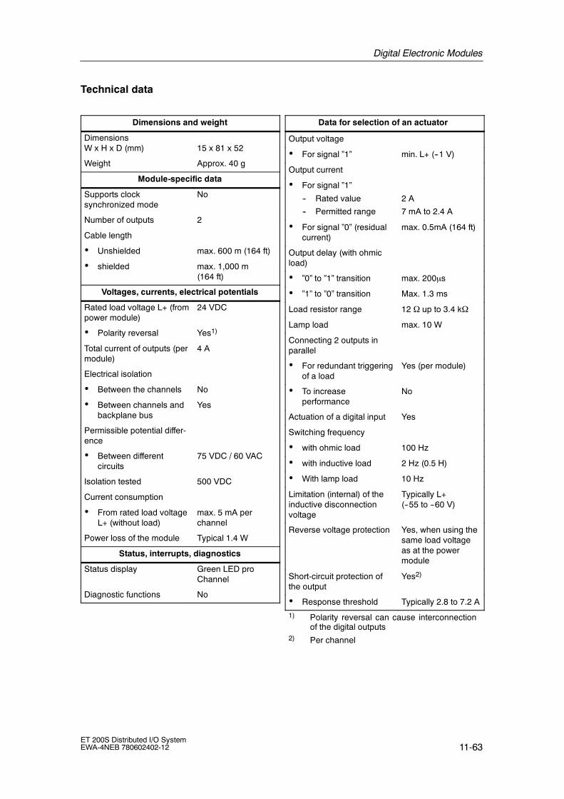
Digital Electronic Modules
11-63ET 200S Distributed I/O SystemEWA-4NEB 780602402-12
Technical data
Dimensions and weight
DimensionsW x H x D (mm) 15 x 81 x 52
Weight Approx. 40 g
Module-specific data
Supports clocksynchronized mode
No
Number of outputs 2
Cable length
• Unshielded max. 600 m (164 ft)
• shielded max. 1,000 m(164 ft)
Voltages, currents, electrical potentials
Rated load voltage L+ (frompower module)
24 VDC
• Polarity reversal Yes1)
Total current of outputs (permodule)
4 A
Electrical isolation
• Between the channels No
• Between channels andbackplane bus
Yes
Permissible potential differ-ence
• Between differentcircuits
75 VDC / 60 VAC
Isolation tested 500 VDC
Current consumption
• From rated load voltageL+ (without load)
max. 5 mA perchannel
Power loss of the module Typical 1.4 W
Status, interrupts, diagnostics
Status display Green LED proChannel
Diagnostic functions No
Data for selection of an actuator
Output voltage
• For signal ”1” min. L+ (--1 V)
Output current
• For signal ”1”
-- Rated value
-- Permitted range
2 A
7 mA to 2.4 A
• For signal ”0” (residualcurrent)
max. 0.5mA (164 ft)
Output delay (with ohmicload)
• ”0” to ”1” transition max. 200µs
• ”1” to ”0” transition Max. 1.3 ms
Load resistor range 12 Ω up to 3.4 kΩ
Lamp load max. 10 W
Connecting 2 outputs inparallel
• For redundant triggeringof a load
Yes (per module)
• To increaseperformance
No
Actuation of a digital input Yes
Switching frequency
• with ohmic load 100 Hz
• with inductive load 2 Hz (0.5 H)
• With lamp load 10 Hz
Limitation (internal) of theinductive disconnectionvoltage
Typically L+(--55 to --60 V)
Reverse voltage protection Yes, when using thesame load voltageas at the powermodule
Short-circuit protection ofthe output
Yes2)
• Response threshold Typically 2.8 to 7.2 A
1) Polarity reversal can cause interconnectionof the digital outputs
2) Per channel
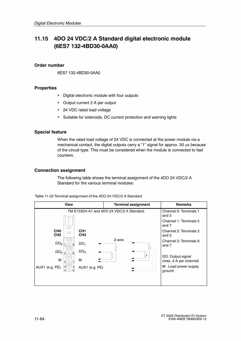
Digital Electronic Modules
11-64ET 200S Distributed I/O System
EWA-4NEB 780602402-12
11.15 4DO 24 VDC/2 A Standard digital electronic module(6ES7 132-4BD30-0AA0)
Order number
6ES7 132-4BD30-0AA0
Properties
• Digital electronic module with four outputs
• Output current 2 A per output
• 24 VDC rated load voltage
• Suitable for solenoids, DC current protection and warning lights
Special feature
When the rated load voltage of 24 VDC is connected at the power module via amechanical contact, the digital outputs carry a ”1” signal for approx. 50 µs becauseof the circuit type. This must be considered when the module is connected to fastcounters.
Connection assignment
The following table shows the terminal assignment of the 4DO 24 VDC/2 AStandard for the various terminal modules:
Table 11-23 Terminal assignment of the 4DO 24 VDC/2 A Standard
View Terminal assignment Remarks
MM
AUX1 (e.g. PE)AUX1 (e.g. PE)
2-wire
TM-E15S24-A1 and 4DO 24 VDC/2 A Standard
2
3
4
6
7
8
1 5
CH1CH0
DO1DO0
DO2 DO3
CH2 CH3
AA
Channel 0: Terminals 1and 3
Channel 1: Terminals 5and 7
Channel 2: Terminals 2and 3
Channel 3: Terminals 6and 7
DO: Output signal(max. 2 A per channel)
M : Load power supplyground

Digital Electronic Modules
11-65ET 200S Distributed I/O SystemEWA-4NEB 780602402-12
Table 11-23 Terminal assignment of the 4DO 24 VDC/2 A Standard, continued
View RemarksTerminal assignment
MM
2-wire
TM-E15S24-01 and 4DO 24 VDC/2 A Standard
2
3
4
6
7
8
1 5
MM
CH1CH0
DO1DO0
DO2 DO3
CH2 CH3
Channel 0: Terminals 1and 3
Channel 1: Terminals 5and 7
Channel 2: Terminals 2and 4
Channel 3: Terminals 6and 8
DO: Output signal(max. 2 A per channel)
M : Load power supplyground
2
3
6
7
1 5
TM-E15S23-01 and 4DO 24 VDC/2 A Standard
2-wire
MM
CH1CH0
DO1DO0
DO2 DO3
CH2 CH3
Channel 0: Terminals 1and 3
Channel 1: Terminals 5and 7
Channel 2: Terminals 2and 3
Channel 3: Terminals 6and 7
DO: Output signal(max. 2 A per channel)
M : Load power supplyground
MM
2-wire
TM-E15S26-A1 and 4DO 24 VDC/2 A Standard
2
3
4
6
7
8
1 5
MM
CH1CH0
DO1DO0
DO2 DO3
CH2 CH3
AUX1 (e.g. PE)A
4
A
3
A
8
A
7AUX1 (e.g. PE)
AUX1 (e.g. PE)
AUX1 (e.g. PE)
Channel 0: Terminals 1and 3
Channel 1: Terminals 5and 7
Channel 2: Terminals 2and 4
Channel 3: Terminals 6and 8
DO: Output signal(max. 2 A per channel)
M : Load power supplyground

Digital Electronic Modules
11-66ET 200S Distributed I/O System
EWA-4NEB 780602402-12
Block diagram
Bac
kpla
nebu
s
ET 200Sbackplanebus circuit
L+
1MP1P2
Reverse polarityprotection and internalpower supply 3
7
8*4*
1
2
5
6
* M only with TM-E15S24-01
Figure 11-17 Block diagram of the 4DO 24 VDC/2 A Standard

Digital Electronic Modules
11-67ET 200S Distributed I/O SystemEWA-4NEB 780602402-12
Technical data
Dimensions and weight
DimensionsW x H x D (mm)
15 x 81 x 52
Weight Approx. 40 g
Module-specific data
Supports clocksynchronized mode
No
Number of outputs 4
Cable length
• Unshielded max. 600 m (164 ft)
• shielded max. 1,000 m(164 ft)
Voltages, currents, electrical potentials
Rated load voltage L+ (frompower module)
24 VDC
• Polarity reversal Yes1)
Total current of outputs (permodule)
4 A
Electrical isolation
• Between the channels No
• Between channels andbackplane bus
Yes
Permissible potential differ-ence
• Between differentcircuits
75 VDC / 60 VAC
Isolation tested 500 VDC
Current consumption
• From rated load voltageL+ (without load)
max. 5 mA perchannel
Power loss of the module Typical 1.6 W
Status, interrupts, diagnostics
Status display Green LED proChannel
Diagnostic functions No
Data for selection of an actuator
Output voltage
• For signal ”1” min. L+ (--1 V)
Output current
• For signal ”1”
-- Rated value
-- Permitted range
2 A
7 mA to 2.4 A
• For signal ”0”(residual current)
max. 0.5mA (164 ft)
Output delay (with ohmicload)
• ”0” to ”1” transition max. 200µs
• ”1” to ”0” transition Max. 1.3 ms
Load resistor range 12 Ω up to 3.4 kΩ
Lamp load max. 10 W
Connecting 2 outputs inparallel
• For redundant triggeringof a load
Yes (per module)
• To increaseperformance
No
Actuation of a digital input Yes
Switching frequency
• with ohmic load 100 Hz
• with inductive load 2 Hz (0.5 H)
• With lamp load 10 Hz
Limitation (internal) of theinductive disconnectionvoltage
Typically L+(--55 to --60 V)
Reverse voltage protection Yes, when using thesame load voltageas at the powermodule
Short-circuit protection ofthe output
Yes2)
• Response threshold Typically 2.8 to 7.2 A
1) Polarity reversal can cause interconnectionof the digital outputs
2) Per channel

Digital Electronic Modules
11-68ET 200S Distributed I/O System
EWA-4NEB 780602402-12
11.16 2DO 24 VDC/2 A High Feature digital electronic module(6ES7 132-4BB30-0AB0)
Order number
6ES7 132-4BB30-0AB0
Properties
• Digital electronic module with two outputs
• Output current 2 A per output
• 24 VDC rated load voltage
• Suitable for solenoids, DC current protection and warning lights
• Supports clock synchronized mode
Special feature
When the rated load voltage of 24 VDC is connected at the power module via amechanical contact, the digital outputs carry a ”1” signal for approx. 50 µs becauseof the circuit type. This must be considered when the module is connected to fastcounters.
Connection assignment
The following table shows the terminal assignment of the 2DO 24 VDC/2 A HighFeature for the various terminal modules:
Table 11-24 Terminal assignment of the 2DO 24 VDC/2 A High Feature
View Terminal assignment Remarks
MM
VDCVDC
AUX1 (e.g. PE)
DO1DO0
AUX1 (e.g. PE)
2-wire 3-wire 4-wire
TM-E15S24-A1 and 2DO 24 VDC/2 A High Feature
CH1CH0
2
3
4
6
7
8
1 5
AUX1 must be occupiedwith 4 wires at PE.
AA
Channel 0:Terminals 1 to A4
Channel 1:Terminals 5 to A8
DO: Output signal(max. 2 A per channel)
24 VDC: Sensor supply
M : Load power supplyground

Digital Electronic Modules
11-69ET 200S Distributed I/O SystemEWA-4NEB 780602402-12
Table 11-24 Terminal assignment of the 2DO 24 VDC/2 A High Feature, continued
View RemarksTerminal assignment
MM
VDCVDC
DO1DO0
2-wire 3-wire
TM-E15S24-01 and 2DO 24 VDC/2 A High Feature
CH1CH0
2
3
4
6
7
8
1 5
n. c.n. c.
Channel 0: Terminals 1 to 4
Channel 1: Terminals 5 to 8
DO: Output signal (max. 2 Aper channel)
24 VDC: Sensor supply
M : Load power supplyground
Terminals 4 and 8 can beused for connection ofcables that are not requiredu to 30 VDC.
MM
VDCVDC 2
3
6
7
1 5DO1DO0
2-wire 3-wire
TM-E15S23-01 and 2DO 24 VDC/2 A High Feature
CH1CH0
Channel 0: Terminals 1 to 3
Channel 1: Terminals 5 to 7
DO: Output signal(max. 2 A per channel)
24 VDC: Sensor supply
M : Load power supplyground
MM
VDCVDC
DO1DO0
2-wire 3-wire
TM-E15S26-A1 and 2DO 24 VDC/2 A High Feature
CH1CH0
2
3
4
6
7
8
1 5
AUX1A
4
A
3
A
8
A
7AUX1
AUX1
AUX1
n. c.n. c.
Channel 0: Terminals 1 to A3
Channel 1: Terminals 5 to A7
DO: Output signal(max. 2 A per channel)
24 VDC: Sensor supply
M : Load power supplyground
Terminals 4 and 8 can beused for connection ofcables that are not requiredu to 30 VDC.

Digital Electronic Modules
11-70ET 200S Distributed I/O System
EWA-4NEB 780602402-12
Block diagram
Bac
kpla
nebu
s
ET 200Sbackplanebus circuit
L+
1MP1P2
Reverse polarityprotection and internalpower supply 2
6
73
1
5
Figure 11-18 Block diagram of the 2DO 24 VDC/2 A High Feature

Digital Electronic Modules
11-71ET 200S Distributed I/O SystemEWA-4NEB 780602402-12
Technical data
Dimensions and weight
DimensionsW x H x D (mm) 15 x 81 x 52
Weight Approx. 40 g
Module-specific data
Supports clocksynchronized mode
Yes
Number of outputs 2
Cable length
• Unshielded max. 600 m (164 ft)
• shielded max. 1,000 m(164 ft)
Voltages, currents, electrical potentials
Rated load voltage L+ (frompower module)
24 VDC
• Polarity reversal Yes1
Total current of outputs (permodule)
4 A
Electrical isolation
• Between the channels No
• Between channels andbackplane bus
Yes
Permissible potential differ-ence
• Between differentcircuits
75 VDC / 60 VAC
Isolation tested 500 VDC
Current consumption
• From rated load voltageL+ (without load)
max. 5 mA perchannel
Power loss of the module Typical 1.4 W
Status, interrupts, diagnostics
Status display Green LED proChannel
Diagnostic functions
• Group error red LED ”SF”
• Reading of diagnosticsfunctions
Yes
Data for selection of an actuator
Output voltage
• For signal ”1” min. L+ (--1 V)
Output current
• For signal ”1”
-- Rated value
-- Permitted range
2A
7 mA to 2.4 A
• For signal ”0” (residualcurrent)
max. 0.5 mA
Output delay (with ohmicload)
• ”0” to ”1” transition max. 100µs
• ”1” to ”0” transition max. 400µs
Load resistor range 12 Ω up to 3.4 kΩ
Lamp load max. 5 W
Connecting 2 outputs inparallel
• For redundant triggeringof a load
Yes (per module)
• To increaseperformance
No
Actuation of a digital input Yes
Switching frequency
• with ohmic load 100 Hz
• with inductive load 2 Hz (0.5 H)
• With lamp load 10 Hz
Limitation (internal) of theinductive disconnectionvoltage
Typically L+(--55 to --60 V)
Reverse voltage protection Yes, when using thesame load voltageas at the powermodule
Short-circuit protection ofthe output
Yes2
• Response threshold Typical 4 A
1 Polarity reversal can cause interconnectionof the digital outputs
2 Per channel

Digital Electronic Modules
11-72ET 200S Distributed I/O System
EWA-4NEB 780602402-12
11.17 2DO 24--230 VAC digital electronic module(6ES7 132-4FB00-0AB0)
Order number
6ES7 132-4FB00-0AB0
Properties
• Digital electronic module with two outputs
• Output current 2 A per output
• Rated load voltage 24--48/120/230 VAC
• Substitute value
• Configuration length: 3 bytes
• Suitable for solenoids, AC current protection and warning lights
Connection assignment
The following table shows the terminal assignment of the2DO 24--230 VAC for the various terminal modules:
Table 11-25 Terminal assignment of the 2DO 24--230 VAC
View Terminal assignment Remarks
NN
2
3
4
6
7
8
1 5DO1DO0
AUX1 (e.g. PE) AUX1 (e.g. PE)
TM-E15S24-A1 and 2DO 24--230 VAC
CH1CH0
AUX1 must be assigned to PE.
AA
Channel 0:Terminals 1 to 3
Channel 1:Terminals 5 to 7
DO: Output signal (max. 2 Aper channel)
N: Neutral wire

Digital Electronic Modules
11-73ET 200S Distributed I/O SystemEWA-4NEB 780602402-12
Table 11-25 Terminal assignment of the 2DO 24--230 VAC
View RemarksTerminal assignment
NN
2
3
4
6
7
8
1 5DO1DO0
TM-E15S24-01 and 2DO 24--230 VAC
CH1CH0
Channel 0: Terminals 1 to 3
Channel 1: Terminals 5 to 7
DO: Output signal(max. 2 A per channel)
N: Neutral wire
Terminals 4 and 8 can beused for connection ofcables that are not requiredup to 230 VAC.
NN
2
3
6
7
1 5DO1DO0
TM-E15S23-01 and 2DO 24--230 VAC
CH1CH0
Channel 0: Terminals 1 to 3
Channel 1: Terminals 5 to 7
DO: Output signal(max. 2 A per channel)
N: Neutral wire
NN
2
3
4
6
7
8
1 5DO1DO0
TM-E15S26-A1 and 2DO 24--230 VAC
CH1CH0
AUX1A
4
A
3
A
8
A
7AUX1
AUX1
AUX1
n. c.n. c.
n. c.n. c.
Channel 0: Terminals 1 to 3
Channel 1: Terminals 5 to 7
DO: Output signal(max. 2 A per channel)
N: Neutral wire
Terminals 4 and 8 can beused for connection ofcables that are not requiredup to 230 VAC.

Digital Electronic Modules
11-74ET 200S Distributed I/O System
EWA-4NEB 780602402-12
Block diagram
Bac
kpla
nebu
s
ET 200Sbackplane
buscircuit
L1
NP1
1
37
5
P2
ZC
ZC
Figure 11-19 Block diagram of the 2DO 24--230 VAC
Technical data
Dimensions and weight
DimensionsW x H x D (mm)
15 x 81 x 52
Weight Approx. 37 g
Module-specific data
Supports clocksynchronized mode
No
Number of outputs 2
Cable length
• Unshielded max. 600 m (164 ft)
• shielded max. 1,000 m(164 ft)
Voltages, currents, electrical potentials
Rated load voltage L1 (frompower module)
24--230 VAC
• Frequency 47 to 63 Hz
Total current of outputs (permodule)
• to 40°C Max. 2 A*
• to 60°C Max. 1 A*
Electrical isolation
• Between the channels No
• Between channels andbackplane bus
Yes
Isolation tested 2500 VDC
Current consumption
• From the backplane bus max. 18 mA
• From rated load voltageL1 (without load)
max. 15 mA perchannel
Power loss of the module max. 4 W

Digital Electronic Modules
11-75ET 200S Distributed I/O SystemEWA-4NEB 780602402-12
Status, interrupts, diagnostics
Status display Green LED proChannel
Diagnostic functions No
Data for selection of an actuator
Output voltage
• For signal ”1” min. L (--1.5 V)
Output current (per chan-nel)
• For signal ”1”
-- Rated value
-- Permitted range
2 A
0.1 mA to 2.2 A
• For signal ”0” (residualcurrent)
max. 3 mA
Output delay (with ohmicload)
• ”0” to ”1” transition Max. 15 ms
• ”1” to ”0” transition Max. 15 ms
Zero crossover Max. 25 V
Motor starter size
• to 40°C Max. size as perNEMA: 5
• to 60°C Max. size as perNEMA: 4
Lamp load max. 100 W
Connecting 2 outputs inparallel
• For redundant triggeringof a load
Yes (per module)
• To increaseperformance
No
Actuation of a digital input possible
Switching frequency
• with ohmic load Max. 10 Hz
• with inductive load Max. 0.5 Hz
• With lamp load Max. 1 Hz
Short-circuit protection ofthe output
Yes, via fuse in pow-er module
* Total current of outputs (per module)
Temperature
Total currentper module
1 A 1.5 A 2 A
60 °C
50 °C
40 °C

Digital Electronic Modules
11-76ET 200S Distributed I/O System
EWA-4NEB 780602402-12
11.18 2RO NO 24--120 VDC/5 A 24--230 VAC/5 A digitalelectronic module (6ES7 132-4HB00-0AB0)
Order number
6ES7 132-4HB00-0AB0
Note
If an SELV/PELF low voltage is connected to a channel of the 2RO NO 24--120VDC/5 A 24--230 VAC/5 A, only one SELV/ PELF low voltage can be connected tothe other channel.
From product level 2 of the 2RO NO 24--120 VDC/5 24--230 VAC/5 A the internalbridge between terminals 2 and 6 is not installed. If you require this bridge, it canbe replaced by an external bridge between terminals 3 and 7 (see Figure 11-20).
Features
• Digital electronic module with two relay outputs
• Output current 5 A per output
• Rated load voltage up to 120 VDC/230 VAC
• Suitable for solenoids, DC current protection and warning lights
• Potential isolated to power supply
!Caution
The rated power supply of the 2RO NO 24--120 VDC/5 A 24--230 VAC/5 A is24 VDC. The 2RO NO 24--120 VDC/5 A 24--230 VAC/5 A must only be in a
potential group with 24 VDC (from the power module).

Digital Electronic Modules
11-77ET 200S Distributed I/O SystemEWA-4NEB 780602402-12
Terminal assignment
The following table shows the terminal assignment of the 2RO NO 24--120 VDC/5A 24--230 VAC/5A for the various terminal modules:
Table 11-26 Terminal assignment of the 2RO NO 24--120 VDC/5 A 24--230 VAC/5 A (from product level 2)
View Terminal assignment Remarks
14
AUX1 (e.g. PE)
2
3
4
6
7
8
1 5
AUX1 (e.g. PE)
≃ ≃
TM-E15S24-A1 and 2RO NO 24--120VDC/5 A 24--230 VAC/5 A
CH1CH0
AUX1 rail must beassigned to PE.
13
14
23
24
24
A A
Channel 0:Terminals 1 to 3
Channel 1:Terminals 5 to 7
13, 14: Channel 0 NOcontact
23, 24: Channel 1 NOcontact
Internal bridge betweenterminal 2 and 3, 6 and 7
2
3
4
6
7
8
1 5
≃
TM-E15S24-01 and 2RO NO24--120 VDC/5 A 24--230 VAC/5 A
CH1CH0
14
13
14
23
24
24
n. c.n. c.
Channel 0: Terminals 1 to 3
Channel 1: Terminals 5 to 7
13, 14: Channel 0 NOcontact
23, 24: Channel 1 NOcontact
Terminals 4 and 8 can beused for connection ofcables that are not requiredup to the amount of the loadvoltage in use.
Internal bridge betweenterminal 2 and 3, 6 and 7
2
3
6
7
1 5
≃
TM-E15S23-01 and 2RO NO24--120 VDC/5 A 24--230 VAC/5 A
CH1CH0
14
13
14
23
24
24
Channel 0: Terminals 1 to 3
Channel 1: Terminals 5 to 7
13, 14: Channel 0 NOcontact
23, 24: Channel 1 NOcontact
Internal bridge betweenterminal 2 and 3, 6 and 7

Digital Electronic Modules
11-78ET 200S Distributed I/O System
EWA-4NEB 780602402-12
Table 11-26 Terminal assignment of the 2RO NO 24--120 VDC/5 A 24--230 VAC/5 A (from product level 2)
View RemarksTerminal assignment
2
3
4
6
7
8
1 5
≃
TM-E15S26-A1 and 2RO NO24--120 VDC/5 A 24--230 VAC/5 A
CH1CH0
14
13
14
23
24
24
AUX1A
4
A
3
A
8
A
7AUX1
AUX1
AUX1
n. c.n. c.
Channel 0: Terminals 1 to 3
Channel 1: Terminals 5 to 7
13, 14: Channel 0 NOcontact
23, 24: Channel 1 NOcontact
Terminals 4 and 8 can beused for connection ofcables that are not requiredup to the amount of the loadvoltage in use.
Internal bridge betweenterminal 2 and 3, 6 and 7
Block diagram
Bac
kpla
nebu
s
ET 200Sbackplane
buscircuit
L+
1MP1P2
Polarity reversalprotection
1
2
5
6
22
3*
7*
* From product level 2 of the 2RO NO 24--120 VDC/5 24--230 VAC/5 A the internalbridge between terminals 2 and 6 is not installed. If you require this bridge, it can bereplaced by an external bridge between terminals 3 and 7.
Figure 11-20 Block diagram of the 2RO NO 24--120 VDC/5 A 24--230 VAC/5 A

Digital Electronic Modules
11-79ET 200S Distributed I/O SystemEWA-4NEB 780602402-12
Technical data
Dimensions and weight
DimensionsW x H x D (mm)
15 x 81 x 52
Weight Approx. 50 g
Module-specific data
Supports clock synchro-nized mode
No
Number of outputs 2
Cable length
• Unshielded max. 600 m (164 ft)
• shielded max. 1,000 m(164 ft)
Voltages, currents, electrical potentials
Rated power supply voltageL+ (from power module)
24 V DC
Reverse polarity protectioncurrent per channel
Yes
• to 50°C Max. 5 A
• to 60°C Max. 4 A
Electrical isolation
• Between the channels Yes
• Between channels andbackplane bus
Yes
• Between channels andbackplane bus
Yes
• Between power supplyvoltage and backplanebus
Yes
Permissible potential differ-ence
• Between power supplyvoltage and backplanebus
75 VDC / 60 VAC
• Between channels andbackplane bus
240 VAC
• Between channels andpower supply voltage
240 VAC
Isolation tested Yes
• Between power supplyvoltage and backplanebus
500 VDC
• Between channels andbackplane bus
1500 VAC
• Between channels andpower supply voltage
1500 VAC
Current consumption
• from L+ power supply max. 30 mA
Power loss of the module Typical 0.6 W
Status, interrupts, diagnostics
Status display Green LED proChannel
Diagnostic functions No
Data for selection of an actuator
Output current
• Continuous thermalcurrent
Max. 5 A
• Minimum load current 8 mA
• Minimum voltage 17 V
Connecting 2 outputs inparallel
• For redundant triggeringof a load
No
• To increaseperformance
No
Actuation of a digital input Yes
Switching frequency
• with ohmic load 2 Hz
• with inductive load 0.5 Hz
• With lamp load 2 Hz
Limitation (internal) of theinductive disconnectionvoltage
No
Short-circuit protection ofthe output1)
No
1) The relay outputs must be fuse-protected with6 A externally.

Digital Electronic Modules
11-80ET 200S Distributed I/O System
EWA-4NEB 780602402-12
Switching capacity and service life of contacts
An external protective circuit offers a higher service life that that given in the table:
Table 11-27 Switching capacity and service life of relay contacts
Resistive load Voltage Current Switching cycles(typical)
For resistive load 24 VDC 5.0 A 0.1 million
4.0 A 0.2 million
2.0 A 0.5 million
1.0 A 1.6 million
0.5 A 4 million
0.1 A 7 million
60 VDC 0.5 A 1.6 million
120 VDC 0.2 A 1.6 million
48 VAC 2.0 A 1.6 million
60 VAC 2.0 A 1.2 million
120 VAC 5.0 A 0.1 million
3.0 A 0.2 million
2.0 A 0.4 million
1.0 A 0.8 million
0.5 A 1.5 million
230 VAC 5.0 A 0.1 million
3.0 A 0.2 million
2.0 A 0.4 million
1.0 A 0.8 million
0.5 A 1.5 million
For inductuve loadIEC 947 5 1
24 VDC 2.0 A 0.1 millionas per IEC 947-5-1DC 13/ AC 15
1.0 A 0.2 millionDC 13/ AC 15
0.5 A 0.5 million
60 VDC 0.5 A 0.2 million
120 VDC 0.2 A 0.5 million
48 VAC 1.0 A 0.7 million
60 VAC 1.0 A 0.5 million
120 VAC 2.0 A 0.1 million
1.0 A 0.3 million
0.5 A 1 million
0.1 A 2 million
For inductuve loadIEC 947 5 1
230 VAC 2.0 A 0.1 millionas per IEC 947-5-1DC 13/ AC 15
1.0 A 0.3 millionDC 13/ AC 15
0.5 A 1 million

Digital Electronic Modules
11-81ET 200S Distributed I/O SystemEWA-4NEB 780602402-12
11.19 Digital electronic module 2RO NO/NC 24--48 VDC/5 A24--230 VAC/5 A (6ES7 132-4HB10-0AB0)
Note
If a low voltage (SELV/PELF) is connected to a channel of the relay module, onlyone low voltage (SELV/PELF) can be connected to the other channel.
Features
• Digital electronic module with two relay outputs
• Output current 5 A per output
• Substitute value
• Configuration length: 3 bytes
• Suitable for solenoids, DC current protection and warning lights
• Potential isolated to power supply
• NO contacts and NC contacts

Digital Electronic Modules
11-82ET 200S Distributed I/O System
EWA-4NEB 780602402-12
Terminal assignment
The following table shows the terminal assignment of the 2RO NO/NC 24--48VDC/5 A 24--230 VAC/5A for the various terminal modules:
Table 11-28 Terminal assignment of the 2RO NO/NC 24--48 VDC/5 A 24--230 VAC/5 A
View Terminal assignment Remarks
NO contact
AUX1 (e.g. PE)
2
3
4
6
7
8
1 5
AUX1 (e.g. PE)
TM-E15S24-A1 and 2RO NO/NC24--120 VDC/5 A 24--230 VAC/5 A
CH1CH0
AUX1 rail must beassigned to PE.
Common
NC contact
Common
NO contact
NC contact
A A
≃ ≃
Channel 0:Terminals 1 to 3
Channel 1:Terminals 5 to 7
1, 2: Channel 0 NO contact
1, 3: NC contact channel 0
5, 6: Channel 1 NO contact
5, 7: NC contact channel 1
2
3
4
6
7
8
1 5
TM-E15S24-01 and 2RO NO/NC24--120 VDC/5 A 24--230 VAC/5 A
CH1CH0
Common
NOcontactNCcontact
Common
NOcontactNCcontact
≃
Channel 0: Terminals 1 to 3
Channel 1: Terminals 5 to 7
1, 2: Channel 0 NO contact
1, 3: NC contact channel 0
5, 6: Channel 1 NO contact
5, 7: NC contact channel 1
2
3
6
7
1 5
TM-E15S23-01 and 2RO NO/NC24--24 VDC/5 A 24--230 VAC/5 A
CH1CH0
Common
NOcontactNCcontact
Common
NOcontactNCcontact
≃
Channel 0: Terminals 1 to 3
Channel 1: Terminals 5 to 7
1, 2: Channel 0 NO contact
1, 3: NC contact channel 0
5, 6: Channel 1 NO contact
5, 7: NC contact channel 1

Digital Electronic Modules
11-83ET 200S Distributed I/O SystemEWA-4NEB 780602402-12
Table 11-28 Terminal assignment of the 2RO NO/NC 24--48 VDC/5 A 24--230 VAC/5 A, continued
View RemarksTerminal assignment
2
3
4
6
7
8
1 5
TM-E15S26-A1 and 2RO NO/NC24--48 VDC/5 A 24--230 VAC/5 A
CH1CH0
AUX1A
4
A
3
A
8
A
7AUX1
AUX1
AUX1
Common
NOcontactNCcontact
NO contact
Common
NCcontact
≃
Channel 0: Terminals 1 to 3
Channel 1: Terminals 5 to 7
1, 2: Channel 0 NO contact
1, 3: NC contact channel 0
5, 6: Channel 1 NO contact
5, 7: NC contact channel 1
Block diagram
Bac
kpla
nebu
s
ET 200Sbackplane bus
interfaceconnection
L+
1MP1P2
Polarityreversalprotection
1
2
5
6
22
3
7
Figure 11-21 Block diagram of the 2RO NO/NC 24--48 VDC/5 A 24--230 VAC/5 A

Digital Electronic Modules
11-84ET 200S Distributed I/O System
EWA-4NEB 780602402-12
Technical specifications
Dimensions and weight
Dimensions W x H x D 15 x 81 x 52 (mm)
Weight Approx. 50 g
Module-specific data
Supports clocksynchronized mode
No
Number of outputs 2
Cable length
• Unshielded max. 600 m (164 ft)
• shielded max. 1,000 m(164 ft)
Voltages, currents, electrical potentials
Rated power supply voltageL+ (from power module)
24 VDC
Reverse polarity protectioncurrent per channel
Yes
• up to 50°C Max. 5 A
• to 60°C Max. 4 A
Electrical isolation
• Between the channels Yes
• Between channels andbackplane bus
Yes
• Between channels andpower supply voltage
Yes
• Between power supplyvoltage and backplanebus
Yes
Approved potentialdifference
• Between power supplyvoltage and backplanebus
75 VDC, 60 VAC
• Between channels andbackplane bus
240 VAC
• Between channels andpower supply voltage
240 VAC
Isolation tested
• Between power supplyvoltage and backplanebus
500 VDC
• Between channels andbackplane bus
2500 VDC
• Between channels andpower supply voltage
2500 VDC
Current consumption
• From powersupply L+
max. 30 mA
• From the backplane bus max. 10 mA
Power loss of the module Typical 0.6 W
Status, interrupts, diagnostics
Status display Green LEDs proChannel
Diagnostic functions No
Data for Selecting an Actuator
Output current
• Continuous thermalcurrent
Max. 5 A
• Minimum load current 8 mA
Connecting 2 outputs inparallel
• For redundant triggeringof a load
No
• To increaseperformance
No
Actuation of a digital input Yes
Switching frequency
• with ohmic load 2 Hz
• with inductive load 0.5 Hz
• With lamp load
Limitation (internal) of theinductive disconnectionvoltage
Short-circuit protection ofthe output1)
2 Hz
No
No
1) The relay outputs must be externally fused with6 A.When installed in a hazardous zone as per theNational Electric Code (NEC) the fuse mustonly be removed with a suitable tool if themodule is not in the explosive zone.

Digital Electronic Modules
11-85ET 200S Distributed I/O SystemEWA-4NEB 780602402-12
Switching capacity and service life of contacts
An external protective circuit offers a higher service life that that given in the tablebelow:
The NO and NC contacts of the relay have a different service life.
Table 11-29 Switching capacity and service life of contacts
Resistive load Voltage Current Operatingcycles (typical)
NO contacts
Operatingcycles (typical)
NC contacts
For resistive load 24 VDC 5.0 A 0.1 million 0.15 million
4.0 A 0.2 million 0.175 million
2.0 A 0.45 million 0.3 million
0.5 A 1.4 million 1.1 million
0.1 A 1.5 million 1.5 million
48 V DC 2.0 A 0.15 million 0.11 million
1.0 A 0.3 million 0.2 million
0.5 A 0.6 million 0.6 million
0.1 A 0.8 million 0.6 million
48 VAC 2.0 A 0.45 million 0.35 million
60 VAC 2.0 A 0.45 million 0.35 million
120 VAC 5.0 A 0.1 million 0.1 million
3.0 A 0.2 million 0.2 million
2.0 A 0.4 million 0.3 million
1.0 A 0.8 million 0.6 million
0.5 A 1.5 million 1.0 million
230 VAC 5.0 A 0.1 million 0.1 million
3.0 A 0.2 million 0.2 million
2.0 A 0.4 million 0.3 million
1.0 A 0.8 million 0.6 million
0.5 A 1.5 million 1.0 million

Digital Electronic Modules
11-86ET 200S Distributed I/O System
EWA-4NEB 780602402-12
Table 11-29 Switching capacity and service life of contacts, continued
Resistive load Operatingcycles (typical)
NC contacts
Operatingcycles (typical)
NO contacts
CurrentVoltage
With inductive loadIEC
24 VDC 2.0 A 0.1 million 0.1 millionas per IEC947-5-1, DC 13/AC
1.0 A 0.2 million 0.2 million947-5-1, DC 13/AC15 0.5 A 0.5 million 0.5 million
48 V DC 2.0 A 0.07 million 0.05 million
1.0 A 0.15 million 0.1 million
0.5 A 0.4 million 0.25 million
48 VAC 1.0 A 0.5 million 0.3 million
60 VAC 1.0 A 0.5 million 0.3 million
120 VAC 2.0 A 0.1 million 0.1 million
1.0 A 0.3 million 0.1 million
0.5 A 0.9 million 0.6 million
0,1 A 1.5 million 1.0 million
230 VAC 2.0 A 0.1 million 0.1 million
1.0 A 0.5 million 0.3 million
0.5 A 0.9 million 0.6 million
0.1 A 1.0 million 1.0 million

12-1ET 200S Distributed I/O SystemEWA-4NEB 780602402-12
Analog Electronic Modules
Introduction
The range of analog electronic modules (EM) includes modules for measuringvoltages and currents. HIGH SPEED modules can be used to measure voltagesand currents. HIGH FEATURE modules have greater resolution and precision.
Modules for connection to thermal elements and resistive thermometers orresistors are also available.
The range is completed with modules for connection of loads and actuators tocurrent and voltage outputs.
Chapter overview
Chapter Topic Page
12.1 Analog value visualization 12-2
12.2 Basics of Analog Value Processing 12-17
12.3 Response of the Analog Modules during Operationand if Faults Occur
12-26
12.4 Parameters for analog electronic modules 12-29
12.5 2AI U Standard analog electronic module(6ES7 134-4FB00-0AB0)
12-42
12.6 2AI U High Feature analog electronic module(6ES7 134-4LB00-0AB0)
12-46
12.7 2AI U High Speed analog electronic module(6ES7 134-4FB51-0AB0)
12-50
12.8 2AI I 2WIRE analog electronic module (6ES7 134-4GB00-0AB0) 12-54
12.9 4AI I 2WIRE Standard analog electronic module(6ES7 134-4GD00-0AB0)
12-58
12.10 2AI I 2WIRE High Speed analog electronic module(6ES7 134-4GB51-0AB0)
12-62
12.11 2AI I 2WIRE Standard analog electronic module(6ES7 134-4GB10-0AB0)
12-66
12.12 2AI I 2/4WIRE High Feature analog electronic module(6ES7 134-4MB00-0AB0)
12-70
12.13 2AI I 4WIRE High Speed analog electronic module(6ES7 134-4GB61-0AB0)
12-74
12.14 2AI RTD Standard analog electronic module(6ES7 134-4JB50-0AB0)
12-78
12

Analog Electronic Modules
12-2ET 200S Distributed I/O System
EWA-4NEB 780602402-12
Chapter PageTopic
12.15 2AI RTD High Feature analog electronic module(6ES7 134-4NB50-0AB0)
12-82
12.16 2AI TC Standard analog electronic module(6ES7 134-4JB00-0AB0)
12-90
12.17 2AI TC High Feature analog electronic module(6ES7 134-4NB00-0AB0)
12-95
12.18 2AO U Standard analog electronic module(6ES7 135-4FB00-0AB0)
12-99
12.19 2AO U High Feature analog electronic module(6ES7 135-4LB01-0AB0)
12-103
12.20 2AO I Standard analog electronic module(6ES7 135-4GB00-0AB0)
12-107
12.21 2AO I High Feature analog electronic module(6ES7 135-4MB01-0AB0)
12-111
12.1 Analog value visualization
In chapter Description Page
12.1.1 Analog Value Representation for Measuring Ranges withSIMATIC S7
12-4
12.1.2 Analog value visualization for measurement ranges of the analoginput in SIMATIC S7 format
12-5
12.1.3 Analog value visualization for measurement ranges of the analogoutput in SIMATIC S7 format
12-15
Electronic modules with analog inputs
With the electronics module with analog inputs, continuously variable signals, suchas those occurring in temperature measurement and pressure measurement, canbe acquired, evaluated, and converted to digital values for further processing.
Electronic modules with analog outputs
With the electronics modules with analog outputs, digital values set by a controllercan be converted to a corresponding analog signal (current) in an analog outputmodule and used to control suitable actuators (setpoint input for speed controllers,temperature controllers and similar).

Analog Electronic Modules
12-3ET 200S Distributed I/O SystemEWA-4NEB 780602402-12
Measured Values in the Event of Wire Break Dependent on Enabled Diagnostics
For the measuring range tables
• 1 to 5 V, 4 to 20 mA
• Temperature sensor Pt xxx Standard and Climatic, Ni xx Standard and Climatic,
Cu 10 Standard and Climatic
• Thermocouple type E, N, J, K, L, S, R, B, T, U
the following supplements and rules apply:
Table 12-1 Measured Values in the Event of Wire Break Dependent on Enabled Diagnostics
Format Parameter assignment Measured Values Explanation
decimal hexadecimal
S7 • ”Wire-break” diagnosisenabled (at 1 to 5 V, 4 to20 mA, RTD)1)
32767 7FFFH • Diagnostics message ”wirebreak”
• ”Wire-break test”diagnosis enabled(with TC)
32767 7FFFH • Diagnostics message ”wirebreak”
• ”Wire-break” diagnosisblocked (at 1 to 5 V, 4 to20 mA, RTD)1)
• ”Overflow/underflow”diagnostics enabled
--32767 8000H • Measured value afterleaving the undershootrange
• ”Value under low limit”diagnostic message
• ”Wire-break” diagnosisblocked (at 1 to 5 V, 4 to20 mA, RTD)1)
• ”Overflow/underflow”diagnostics disabled
--32767 8000H • Measured value afterleaving the undershootrange
• ”Wire-break test”diagnosis blocked(with TC)
------ ------ • Open input: Undefinedmeasured value
1) Measurement range limits for detection of wire break/underflow:1 to 5 V: at 0. 296 V4 to 20 mA: at 1.185 mA

Analog Electronic Modules
12-4ET 200S Distributed I/O System
EWA-4NEB 780602402-12
12.1.1 Analog Value Representation for measuring ranges withSIMATIC S7
Analog value visualization
With the same nominal range, the digitized analog value is the same for input andoutput values. Analog values are represented in two’s complement.
The following table shows the analog value representation of the analogelectronics modules.
Table 12-2 Analog Value Representation (SIMATIC S7 Format)
Resolution Analog Value
Bit number 15 14 13 12 11 10 9 8 7 6 5 4 3 2 1 0
Significance of the bits S 214 213 212 211 210 29 28 27 26 25 24 23 22 21 20
Sign
The sign (S) of the analog value is always in bit number 15:
• ”0”→+
• ”1”→−
Measured Value Resolution
The following table shows the representation of the binary analog values and thecorresponding decimal and hexadecimal representation of the units of the analogvalues.
The table12-3 shows the resolutions 11, 12, 13, and 15 bit + sign are shown. Eachanalog value is entered left aligned in the ACCU. The bits marked with ”x” are setto ”0”.
Table 12-3 Measured Value Resolution of the Analog Values (SIMATIC S7 Format)
Units Analog Value
Resolution in Bits decimal hexadeci-mal
high byte low byte
11+S 16 10H S 0 0 0 0 0 0 0 0 0 0 1 x x x x
12+S 8 8H S 0 0 0 0 0 0 0 0 0 0 0 1 x x x
13+S 4 4H S 0 0 0 0 0 0 0 0 0 0 0 0 1 x x
15+S 1 1H S 0 0 0 0 0 0 0 0 0 0 0 0 0 0 1
Note: This resolution does not apply for temperature values. The convertedtemperature values are the result of a conversion in the analog electronics module(see table 12-3).
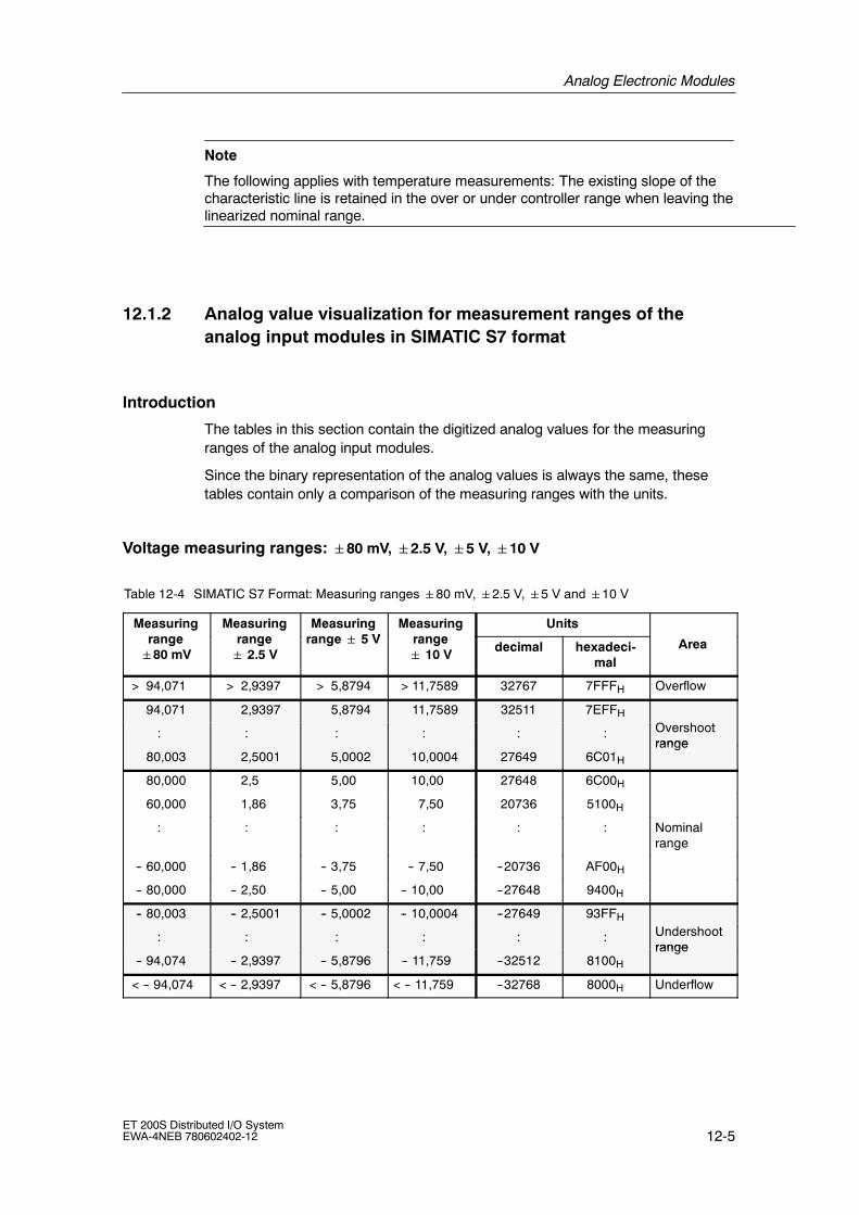
Analog Electronic Modules
12-5ET 200S Distributed I/O SystemEWA-4NEB 780602402-12
Note
The following applies with temperature measurements: The existing slope of thecharacteristic line is retained in the over or under controller range when leaving thelinearized nominal range.
12.1.2 Analog value visualization for measurement ranges of theanalog input modules in SIMATIC S7 format
Introduction
The tables in this section contain the digitized analog values for the measuringranges of the analog input modules.
Since the binary representation of the analog values is always the same, thesetables contain only a comparison of the measuring ranges with the units.
Voltage measuring ranges: 80 mV,2.5 V,5 V,10 V
Table 12-4 SIMATIC S7 Format: Measuring ranges80 mV,2.5 V,5 V and10 V
Measuring Measuring Measuring 5 V
Measuring Unitsrange80 mV
range 2.5 V
range 5 V range 10 V decimal hexadeci-
malArea
> 94,071 > 2,9397 > 5,8794 > 11,7589 32767 7FFFH Overflow
94,071 2,9397 5,8794 11,7589 32511 7EFFH
: : : : : : Overshootrange
80,003 2,5001 5,0002 10,0004 27649 6C01H
range
80,000 2,5 5,00 10,00 27648 6C00H
60,000 1,86 3,75 7,50 20736 5100H
: : : : : : Nominalrange
-- 60,000 -- 1,86 -- 3,75 -- 7,50 --20736 AF00H
-- 80,000 -- 2,50 -- 5,00 -- 10,00 --27648 9400H
-- 80,003 -- 2,5001 -- 5,0002 -- 10,0004 --27649 93FFH
: : : : : : Undershootrange
-- 94,074 -- 2,9397 -- 5,8796 -- 11,759 --32512 8100H
range
< -- 94,074 < -- 2,9397 < -- 5,8796 < -- 11,759 --32768 8000H Underflow

Analog Electronic Modules
12-6ET 200S Distributed I/O System
EWA-4NEB 780602402-12
Measuring ranges for voltage and current: 1 to 5 V, 0 to 20 mA, 4 to 20 mA
Table 12-5 SIMATIC S7 Format: Measuring ranges 1 to 5 V, 0 to 20 mA, 4 to 20 mA
Measuring Measuring Measuring Unitsrange1 to 5 V
range0 to 20 mA
range4 to 20 mA decimal hexadeci-
malArea
> 5,704 > 23,5178 > 22,8142 32767 7FFFH Overflow
5,704 23,5178 22,8142 32511 7EFFH
: : : : : Overshootrange
5,000145 20,0007 20,0005 27649 6C01H
range
5,000 20,0000 20,0000 27648 6C00H
4,000 15,0000 16,0000 20736 5100H
: : : : : Nominalrange
1,000 0,0000 4,0000 0 0H
0,999855 3,9995 --1 FFFFH
: Negativevalues are
: : Undershootrange
0,296values arenot possible 1,1852 --4864 ED00H
range
< 0,296
not possible
< 1,1852 --32768 8000H Underflow
Measuring range for current: 20 mA
Table 12-6 SIMATIC S7 Format: Measuring range20 mA
Measuring range20 A
UnitsArea20 mA
decimal hexadecimalArea
> 23,5150 32767 7FFFH Overflow
23,5150 32511 7EFFH
: : : Overshoot range
20,0007 27649 6C01H
g
20,0000 27648 6C00H
14,9980 20736 5100H
: : : Nominal range
-- 14,9980 --20736 AF00H
-- 20,0000 --27648 9400H
-- 20,0007 --27649 93FFH
: : : Undershoot range
-- 23,5160 --32512 8100H
g
< -- 23,5160 --32768 8000H Underflow

Analog Electronic Modules
12-7ET 200S Distributed I/O SystemEWA-4NEB 780602402-12
Measuring ranges for resistive sensors: 150 Ω, 300 Ω, 600 Ω, 3000 Ω
Table 12-7 SIMATIC S7 Format: Measuring ranges 150 Ω, 300 Ω, 600 Ω, 3000 Ω
Measuring Measuring Measuring Measuring Unitsrange150 Ω
range300 Ω
range600 Ω
range3000 Ω
decimal hexadeci-mal
Area
> 176.38 > 352,77 > 705,53 > 3527,67 32767 7FFFH Overflow
176,38 352,77 705,53 3527,67 32511 7EFFH
: : : : : : Overshootrange
150,005 300,01 600,02 3000,11 27649 6C01H
range
150,00 300,00 600,00 3000,00 27648 6C00H
112,50 225,00 450,00 2250,00 20736 5100H
: : : : : : Nominalrange
0,00 0,00 0,00 0,00 0 0H
--1 FFFFH
(negative values are not physically possible): : Undershoot
range*( g p y y p )
--4864 ED00H
range
--32768 8000H Underflow*
* With faulty connection of terminators

Analog Electronic Modules
12-8ET 200S Distributed I/O System
EWA-4NEB 780602402-12
Measuring range of resistive thermometer Pt x100 Standard
Table 12-8 SIMATIC S7 Format: Measuring Ranges Pt 100, 200, 500, 1000 Standard in °C and °F
Pt x100Standard in
Units Pt x100Standard in
UnitsStandard in
°C(1 digit =
0.1°C)
decimal hexadecimal
Standard in°F
(1 digit =0.1 °F)
decimal hexadecimal
Area
> 1000,0 32767 7FFFH > 1832,0 32767 7FFFH Overflow
1000,0
:
850,1
10000
:
8501
2710H
:
2135H
1832,0
:
1562,1
18320
:
15621
4790H
:
3D05H
Overshoot range
850,0
:
--200,0
8500
:
--2000
2134H
:
F830H
1562,0
:
--328,0
15620
:
--3280
3D04H
:
F330H
Nominal range
--200,1
:
--243,0
--2001
:
--2430
F82FH
:
F682H
--328,1
:
--405,4
--3281
:
--4054
F32FH
:
F02AH
Undershoot range
< -- 243,0 --32768 8000H < -- 405,4 --32768 8000H Underflow
Measuring range of resistive thermometer Pt x100 Climatic
Table 12-9 SIMATIC S7 Format: Measuring Ranges Pt 100, 200, 500, 1000 Climatic in °C and °F
Pt x100Climatic
Units Pt x100Climate
UnitsClimatic
in °C(1 digit =0.01°C)
decimal hexadecimal
Climatein °F
(1 digit =0.01 °F)
decimal hexadecimal
Area
> 155,00 32767 7FFFH > 311,00 32767 7FFFH Overflow
155,00
:
130,01
15500
:
13001
3C8CH
:
32C9H
311,00
:
266,01
31100
:
26601
797CH
:
67E9H
Overshoot range
130,00
:
--120,00
13000
:
--12000
32C8H
:
D120H
266,00
:
--184,00
26600
:
--18400
67E8H
:
B820H
Nominal range
--120,01
:
--145,00
--12001
:
--14500
D11FH
:
C75CH
--184,01
:
--229,00
--18401
:
--22900
B81FH
:
A68CH
Undershoot range
< -- 145,00 --32768 8000H < -- 229,00 --32768 8000H Underflow

Analog Electronic Modules
12-9ET 200S Distributed I/O SystemEWA-4NEB 780602402-12
Measuring range of resistive thermometer Ni x100 Standard
Table 12-10 SIMATIC S7 Format: Measuring Ranges Ni 100, 200, 500, 1000 Standard in °C and °F
Ni x00Standard in
Units Ni x00Standard in
UnitsStandard in
°C(1 digit =
0.1°C)
decimal hexadecimal
Standard in°F
(1 digit =0.1 °F)
decimal hexadecimal
Area
> 295,0 32767 7FFFH > 563,0 32767 7FFFH Overflow
295,0 2950 B86H 563,0 5630 15FEH
: : : : : : Overshoot range
250,1 2501 9C5H 482,1 4821 12D5H
g
250,0 2500 9C4H 482,0 4820 12D4H
: : : : : : Nominal range
--60,0 --600 FDA8H --76,0 --760 FDA8H
--60,1 --601 FDA7H --76,1 --761 FD07H
: : : : : : Undershoot range
--105,0 --1050 FBE6H --157,0 --1570 F9DEH
g
< --105,0 --32768 8000H < --157,0 --32768 8000H Underflow
Measuring range of resistive thermometer Ni x00 Climatic
Table 12-11 SIMATIC S7 Format: Measuring Ranges Ni 100, 120, 200, 500, 1000 Climatic in °C and °F
Ni x00Climatic
Units Ni x00Climatic
UnitsClimatic
in °C(1 digit =0.01°C)
decimal hexadecimal
Climaticin °F
(1 digit =0.01 °F)
decimal hexadecimal
Area
> 295,00 32767 7FFFH > 325,11 32767 7FFFH Overflow
295,00
:
250,01
29500
:
25001
733CH
:
61A9H
327,66
:
280,01
32766
:
28001
7FFEH
:
6D61H
Overshoot range
250,00
:
--60,00
25000
:
--6000
61A8H
:
E890H
280,00
:
--76,00
28000
:
--7600
6D60H
:
E250H
Nominal range
--60,01
:
--105,00
--6001
:
--10500
E88FH
:
D6FCH
--76,01
:
--157,00
--7601
:
--15700
E24FH
:
C2ACH
Undershoot range
< -- 105,00 --32768 8000H < -- 157,00 --32768 8000H Underflow

Analog Electronic Modules
12-10ET 200S Distributed I/O System
EWA-4NEB 780602402-12
Measuring ranges of resistive thermometer Cu 10 Standard
Table 12-12 SIMATIC S7 Format: Measuring Ranges Cu 10 Standard in °C and °F
Cu 10Standard
Units Cu 10Standard
UnitsStandard
in °C(1 digit =
0.1°C)
decimal hexadecimal
Standardin °F
(1 digit =0.1°F)
decimal hexadecimal
Area
> 312,0 32767 7FFFH > 593,6 32767 7FFFH Overflow
312,0
:
260,1
3120
:
2601
C30H
:
A29H
593,6
:
500,1
5936
:
5001
1730H
:
12D5H
Overshoot range
260,0
:
--200,0
2600
:
--2000
A28H
:
F830H
500,0
:
--328,0
5000
:
--3280
1389H
:
F330H
Nominal range
--200,1
:
--240,0
--2001
:
--2400
F82FH
:
F6A0H
--328,1
:
--400,0
--3281
:
--4000
F32FH
:
F060H
Undershoot range
< -- 240,0 --32768 8000H < -- 400,0 --32768 8000H Underflow
Measuring ranges of resistive thermometer Cu 10 Climatic
Table 12-13 SIMATIC S7 Format: Measuring Ranges Cu 10 Climatic in °C and °F
Cu 10Climatic
Units Cu 10Climatic
UnitsClimatic
in °C(1 digit =0.01°C)
decimal hexadecimal
Climaticin °F
(1 digit =0.01 °F)
decimal hexadecimal
Area
> 180,00 32767 7FFFH > 325,11 32767 7FFFH Overflow
180,00
:
150,01
18000
:
15001
4650H
:
3A99H
327,66
:
280,01
32766
:
28001
7FFEH
:
6D61AH
Overshoot range
150,00
:
--50,00
15000
:
--5000
3A98H
:
EC78H
280,00
:
--58,00
28000
:
--5800
6D60H
:
E958H
Nominal range
--50,01
:
--60,00
--5001
:
--6000
EC77H
:
E890H
--58,01
:
--76,00
--5801
:
--7600
E957H
:
E250H
Undershoot range
< -- 60,00 --32768 8000H < -- 76,00 --32768 8000H Underflow

Analog Electronic Modules
12-11ET 200S Distributed I/O SystemEWA-4NEB 780602402-12
Measuring Range for Thermocouple: Type B
Table 12-14 SIMATIC S7 Format: Measuring Range Type B in °C and °F
T pe BUnits
T pe BUnits
Type Bin °C decimal hexa
decimal
Type Bin °F decimal hexa
decimalArea
> 2070,0 32767 7FFFH > 3276,6 32767 7FFFH Overflow
2070,0
:
1820,1
20700
:
18201
50DCH
:
4719H
3276,6
:
2786,6
32766
:
27866
7FFEH
:
6CDAH
Overshoot range
1820,0
:
0,0
18200
:
0
4718H
:
0000H
2786,5
:
32
27865
:
320
6CD9H
:
0140H
Nominal range
--0,1
:
--120,0
--1
:
--1200
FFFFH
:
FB50H
31,9
:
--184,0
319
:
--1840
013FH
:
F8D0H
Undershoot range
< --120,0 --32768 8000H < --184,0 --32768 8000H Underflow
Measuring Range for Thermocouple: Type C
Table 12-15 SIMATIC S7 Format: Measuring Range Type C in °C and °F
T pe CUnits
T pe CUnits
Type Cin °C decimal hexa
decimal
Type Cin °F decimal hexa
decimalArea
> 2500,0 32767 7FFFH > 3276,6 32767 7FFFH Overflow
2500,0
:
2315,1
25000
:
23151
61A8H
:
5A6FH
3276,6
:
2786,6
32766
:
27866
7FFEH
:
6CDAH
Overshoot range
2315,0
:
0,0
23150
:
0
5A6EH
:
0000H
2786,5
:
32,0
27865
:
320
6CD9H
:
0140H
Nominal range
0,1
:
--120,0
--1
:
--1200
FFFFH
:
FB50H
31,9
:
--184,0
319
:
--1840
013FH
:
F8D0H
Undershoot range
< --120,0 --32768 8000H < --184,0 --32768 8000H Underflow

Analog Electronic Modules
12-12ET 200S Distributed I/O System
EWA-4NEB 780602402-12
Measuring range for thermocouple type E
Table 12-16 SIMATIC S7 Format: Measuring Range Type E in °C and °F
T pe EUnits
T pe EUnits
Type Ein °C decimal hexa
decimal
Type Ein °F decimal hexa
decimalArea
> 1200,0 32767 7FFFH > 2192,0 32767 7FFFH Overflow
1200,0
:
1000,1
12000
:
10001
2EE0H
:
2711H
2192,0
:
1832,1
21920
:
18321
55A0H
:
4791H
Overshoot range
1000,0
:
--270,0
10000
:
--2700
2710H
:
F574H
1832,0
:
--454,0
18320
:
--4540
4790H
:
EE44H
Nominal range
< --270,0 -- 32768 8000H < --454,0 -- 32768 8000H Underflow
Measuring range for thermocouple type J
Table 12-17 SIMATIC S7 Format: Measuring Range Type J in °C and °F
T pe JUnits
T pe JUnits
Type Jin °C decimal hexa
decimal
Type Jin °F decimal hexa
decimalArea
> 1450,0 32767 7FFFH > 2642,0 32767 7FFFH Overflow
1450,0
:
1200,1
14500
:
12010
38A4H
:
2EEAH
2642,0
:
2192,1
26420
:
21921
6734H
:
55A1H
Overshoot range
1200,0
:
--210,0
12000
:
--2100
2EE0H
:
F7CCH
2192,0
:
--346,0
21920
:
--3460
55A0H
:
F27CH
Nominal range
< --210,0 -- 32768 8000H < --346,0 -- 32768 8000H Underflow

Analog Electronic Modules
12-13ET 200S Distributed I/O SystemEWA-4NEB 780602402-12
Measuring range for thermocouple type K
Table 12-18 SIMATIC S7 Format: Measuring range type K in °C and °F
T pe KUnits
T pe KUnits
Type Kin °C decimal hexa
decimal
Type Kin °F decimal hexa
decimalArea
> 1622,0 32767 7FFFH > 2951,6 32767 7FFFH Overflow
1622,0
:
1372,1
16220
:
13721
3F5CH
:
3599H
2951,6
:
2501,7
29516
:
25062
734CH
:
61B9H
Overshoot range
1372,0
:
--270,0
13720
:
--2700
3598H
:
F574H
2501,6
:
--454,0
25061
:
--4540
61B8H
:
EE44H
Nominal range
< --270,0 -- 32768 8000H < --454,0 -- 32768 8000H Underflow
Measuring range for thermocouple type L
Table 12-19 SIMATIC S7 Format: Measuring Range Type L in °C and °F
T pe LUnits
T pe LUnits
Type Lin °C decimal hexa
decimal
Type Lin °F decimal hexa
decimalArea
> 1150,0 32767 7FFFH > 2102,0 32767 7FFFH Overflow
1150,0
:
900,1
11500
:
9001
2CECH
:
2329H
2102,0
:
1652,1
21020
:
16521
521CH
:
4089H
Overshoot range
900,0
:
--200,0
9000
:
--2000
2328H
:
F830H
1652,0
:
--328,0
16520
:
--3280
4088H
:
F330H
Nominal range
< --200,0 --32768 8000H < --328,0 --32768 8000H Underflow
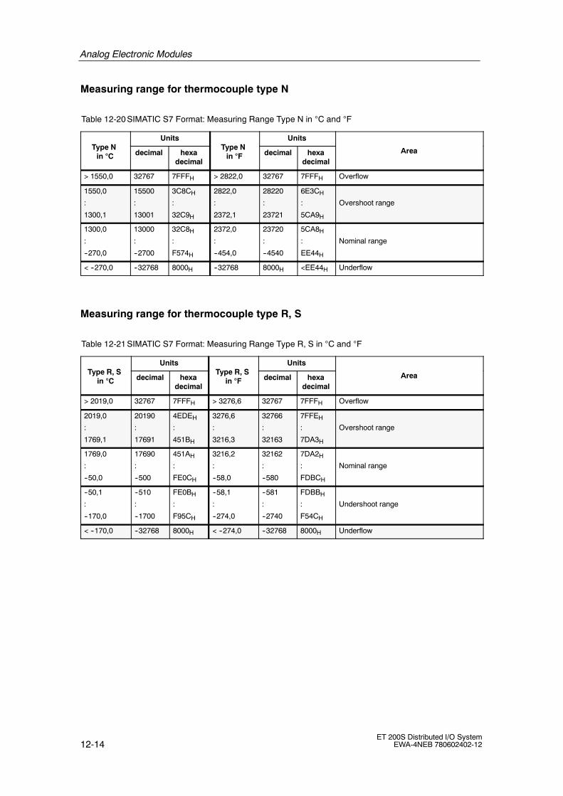
Analog Electronic Modules
12-14ET 200S Distributed I/O System
EWA-4NEB 780602402-12
Measuring range for thermocouple type N
Table 12-20 SIMATIC S7 Format: Measuring Range Type N in °C and °F
T pe NUnits
T pe NUnits
Type Nin °C decimal hexa
decimal
Type Nin °F decimal hexa
decimalArea
> 1550,0 32767 7FFFH > 2822,0 32767 7FFFH Overflow
1550,0
:
1300,1
15500
:
13001
3C8CH
:
32C9H
2822,0
:
2372,1
28220
:
23721
6E3CH
:
5CA9H
Overshoot range
1300,0
:
--270,0
13000
:
--2700
32C8H
:
F574H
2372,0
:
--454,0
23720
:
--4540
5CA8H
:
EE44H
Nominal range
< --270,0 --32768 8000H --32768 8000H <EE44H Underflow
Measuring range for thermocouple type R, S
Table 12-21 SIMATIC S7 Format: Measuring Range Type R, S in °C and °F
T pe R SUnits
T pe R SUnits
Type R, Sin °C decimal hexa
decimal
Type R, Sin °F decimal hexa
decimalArea
> 2019,0 32767 7FFFH > 3276,6 32767 7FFFH Overflow
2019,0
:
1769,1
20190
:
17691
4EDEH
:
451BH
3276,6
:
3216,3
32766
:
32163
7FFEH
:
7DA3H
Overshoot range
1769,0
:
--50,0
17690
:
--500
451AH
:
FE0CH
3216,2
:
--58,0
32162
:
--580
7DA2H
:
FDBCH
Nominal range
--50,1
:
--170,0
--510
:
--1700
FE0BH
:
F95CH
--58,1
:
--274,0
--581
:
--2740
FDBBH
:
F54CH
Undershoot range
< --170,0 --32768 8000H < --274,0 --32768 8000H Underflow

Analog Electronic Modules
12-15ET 200S Distributed I/O SystemEWA-4NEB 780602402-12
Measuring range for thermocouple type T
Table 12-22 SIMATIC S7 Format: Measuring Range Type T in °C and °F
T pe TUnits
T pe TUnits
Type Tin °C decimal hexa
decimal
Type Tin °F decimal hexa
decimalArea
> 540,0 32767 7FFFH > 1004,0 32767 7FFFH Overflow
540,0
:
400,1
5400
:
4001
1518H
:
0FA1H
1004,0
752,1
10040
7521
2738H
1DC1H
Overshoot range
400,0
:
--270,0
4000
:
--2700
0FA0H
:
F574H
752,0
:
--454,0
7520
:
--4540
1D60H
:
EE44H
Nominal range
< --270,0 --32768 8000H < --454,0 --32768 8000H Underflow
12.1.3 Analog value visualization for measurement ranges of theanalog output modules in SIMATIC S7 format
Introduction
The table in this section contains the digitized analog values for the measuringranges of the analog output modules.
Since the binary representation of the analog values is always the same, thesetables contain only a comparison of the measuring ranges with the units.

Analog Electronic Modules
12-16ET 200S Distributed I/O System
EWA-4NEB 780602402-12
Output ranges for voltage and current:5 V;10 V;20 mA
Table 12-23 SIMATIC S7 format: Output ranges5 V;10 V;20 mA
Output range5 V
Output range10 V
Output range20 A
Units Area5 V 10 V 20 mA
decimal hexadecimal
0 0 0 > 32511 > 7EFFH Overflow
5,8800 11,7589 23,5150 32511 7EFFH
: : : : : Overshootrange
5,0002 10,0004 20,0007 27649 6C01H
range
5,0000 10,0000 20,0000 27648 6C00H
3,7500 7,5000 14,9980 20736 5100H
: : : : : Nominal range
-- 3,7500 -- 7,5000 -- 14,9980 --20736 AF00H
-- 5,0000 -- 10,0000 -- 20,0000 --27648 9400H
-- 5,0002 -- 10,0004 -- 20,0007 --27649 93FFH
: : : : : Undershootrange
-- 5,8800 -- 11,7589 -- 23,5160 --32512 8100H
range
0 0 < -- 23,5160 < --32512 <8100H Underflow
Output ranges for voltage and current: 1 to 5 V; 4 to 20 mA
Table 12-24 SIMATIC S7 Format: Output ranges 1 to 5 V; 4 to 20 mA
Output range1 t 5 V
Output range4 t 20 A
UnitsArea1 to 5 V 4 to 20 mA
decimal hexadecimalArea
0 0 > 32511 > 7EFFH Overflow
5,7000 22,8100 32511 7EFFH
: : : : Overshootrange
5,0002 20,0005 27649 6C01H
range
5,0000 20,0000 27648 6C00H
: : : : Nominal range
1,0000 4,0000 0 0H
0,9998 3,9995 --1 FFFFH
: : : : Undershootrange
0 0 --6912 E500H
range
0 0 < --6913 < E4FFH Underflow

Analog Electronic Modules
12-17ET 200S Distributed I/O SystemEWA-4NEB 780602402-12
12.2 Basics of Analog Value Processing
12.2.1 Connecting sensors
Introduction
Depending on the module various sensors can be connected to the analog inputmodules:
• Voltage sensor
• Current sensor as
-- 2-wire measuring transducer
-- 4-wire measuring transducer
• Resistance
This chapter describes how to connect the sensors and what you must considerwhen connecting the sensors.
Cables for analog signals
Shielded and twisted-pair cables must be used for the analog signals. This reducesinfluences from interference. The shield for the analog cables must be grounded atboth ends of the cable. If there are potential differences between the ends of thecable, an equipotential bonding current flows through the shield, which mayinterfere with the analog signals. In this case the shield should be grounded at oneend only.
Analog input modules
The analog input modules are isolated:
• Between logic and backplane bus
• Between load voltage and the channels. There are the following differences:
-- (no galvanic isolation). connection between MANA and the central groundpoint
-- Electrical isolation: no connection between MANA and the central groundpoint (UISO)

Analog Electronic Modules
12-18ET 200S Distributed I/O System
EWA-4NEB 780602402-12
Analog Output Modules
The analog output modules are generally isolated
• Between logic and backplane bus
• Between load voltage and MANA.
Note
Make sure that the potential difference UISO does not exceed the approved value.If there is a possibility of exceeding the approved value connect the MANA terminaland the central ground point.
Connecting sensors to analog inputs
Only a limited potential difference UCM (common mode voltage/common mode) ispermitted between measurement cables M-- of the input channels and thereference point of the measuring circuit MANA. To ensure that the approved value isnot exceeded, various actions must be implemented depending in the sensorpotential connection (isolated, non-isolated). The actions required are explained inthis chapter.
However, the general rule is that there must not be a connection from M-- to MANAwhen connecting 2-wire measurement transducers and resistor sensors. Thisapplies for correspondingly configured but unused inputs.
Note
Unused analog inputs on the 2AI U, 2AI RTD and 2AI TC analog input modulesmust be short-circuited.
Abbreviations used
The abbreviations used in the following diagrams have the following meanings:
M +: measuring line (positive)
M --: measuring line (negative)
MANA: reference potential of the analog measuring circuit
M: ground connection
L +: 24 VDC rated load voltage
UCM: potential difference between inputs and reference potentialof the MANA measuring circuit
UISO: potential difference between MANA and the central ground point

Analog Electronic Modules
12-19ET 200S Distributed I/O SystemEWA-4NEB 780602402-12
Isolated sensors
The isolated sensors are not connected to the local ground potential. They can beoperated potential-free. Local conditions or interference can cause potentialdifferences UCM (static or dynamic) between the M-- measuring lines of the inputchannels and the reference point of the measuring circuit MANA.
The following applies to ensure that the approved value for UCM is not exceededduring operation in areas with high EMC interference:
• with the 2AI U, 2AI I 4WIRE and 2AI TC analog input modules: Connect M--with MANA!
• There must not be a connection from M-- to MANA when connecting 2-wiremeasurement transducers for current measurement and resistor sensors.
Isolated sensors, continued
Figure 12-1 shows the general connection of isolated sensors to the isolatedanalog input modules..
Isolatedsensors
M+:
M
L+
M--
MANA
M+:M-- Backplane bus
ADC
Grounding busbarUISO
Recommendedconnection UCM
Central ground point
Logi
c
Figure 12-1 Connection of isolated sensors to an isolated analog input module.

Analog Electronic Modules
12-20ET 200S Distributed I/O System
EWA-4NEB 780602402-12
Non-isolated sensors
The non-isolated sensors are locally connected to the ground potential. MANA mustbe connected to the ground potential. Depending on local conditions orinterference potential differences UCM (static or dynamic) may be encounteredbetween the locally distributed measuring points.
If the permitted value for UCM is exceeded, equipotential bonding lines must beinstalled between the sensor locations.
Figure 12-2 shows the general connection of non-isolated sensors to anequipotentially bonded analog input module.
Non-isolatedsensors
M+:
M
L+
M--
MANA
M+:M-- Backplane bus
UCM
ADC
Grounding busbar
UISO
Equipotentialbondingcable
Logi
c
Figure 12-2 Connection of non-isolated sensors to an equipotentially bonded analog inputmodule.
Operating 4-wire measuring transducers (MU) at external power supply
If the MU output and power supply is isolated, the MU can be connected to the 2AII 4WIRE without any additional connections.
If the MU output and power supply is not isolated, the MU can be connected to the2AI I 4WIRE only if the power supply voltages have the same reference potentialsconnections.
If the interference is increased, we recommend a connection between M-- andMana to the terminal module of the 2AI I 4WIRE.

Analog Electronic Modules
12-21ET 200S Distributed I/O SystemEWA-4NEB 780602402-12
12.2.2 Connecting Thermocouples
Introduction
This section contains additional information on connecting thermocouples.
Compensation of the Reference Junction Temperature
There are several ways in which you can measure the reference junctiontemperature to obtain an absolute temperature value from the difference intemperature between the reference junction and the measurement junction.
Table 12-25 Compensation of the Reference Junction Temperature
Option Explanation Reference junctionparameter
No compensation You obtain not only the temperatureof the measurement junction. Thetemperature of the reference junction(transition from copper line tothermocouple line) influences thethermal voltage. The measuredvalue is thus faulty.
No
Using acompensation unitin the input linesof a singlethermocouple
They are compensated via acompensation unit. Thecompensation unit is the transitionpoint of Cu wire to the thermocouplecable. No additional processing bythe 2AI TC ST is required.
No
Use of aresistancethermometerPt100 climaterange to measurethe referencejunctiontemperature(practical method)
You can measure the referencejunction temperature using aresistance thermometer (Pt100climate range). With suitableparameter settings, this temperaturevalue is distributed to the 2AI TCStandard modules in the ET 200Sand is used to correct the measuredtemperature value of themeasurement junction in themodules.
Number of reference junctions: 1
The parameters of IM151-1and of the 2AI TC must beadapted:
• 2AI RTD Standardconfigured to Pt100climate range in thecorrect slot;
• 2AI TC Standard:Reference junction: RTD;select reference junctionnumber 1
• IM :assignment of junction to aslot with 2AI RTDStandard; selection of achannel;
Internalcompensationwith 2AI TC HighFeature
A temperature sensor is installed inthe TM-E15S24-AT andTM-E15C24-AT terminal modules.The temperature sensor reports theterminal temperature to the 2AI TCHigh Feature. This value iscomputed with the measured valueof the channel of the electronicmodule.
• 2AI TC High Feature:Reference junction: Yes

Analog Electronic Modules
12-22ET 200S Distributed I/O System
EWA-4NEB 780602402-12
Extension to a reference junction
The thermocouples can be extended from their connection side by compensationcables as far as the reference junction (transition to copper wiring). The referencejunction can also be an ET 200S terminal module.
The compensation cables are made of the same material as the wires of thethermocouple. The connecting cables are made of copper. Make sure that you donot reverse polarity.
Use of a compensation unit
The influence of the temperature on the reference junction of a thermocouple (e.g.terminal box) can be compensated with a compensation unit.
The compensation unit contains a bridge circuit that is compensated for a specificreference junction temperature (compensation temperature). The thermocouples ortheir compensation wiring are connected to the compensation unit. Thecompensation unit then forms the reference junction.
If the actual reference temperature deviates from the compensation temperature,the temperature-dependent bridge resistance changes. A positive or negativecompensation voltage is generated and added to the thermal voltage.
Compensation units with the reference junction temperature of 0 °C must beused for compensation of the analog input module.
Note:
• The compensation unit must have an isolated power supply.
• The power unit must have sufficient interference filtering, e.g. by a groundedshield winding.
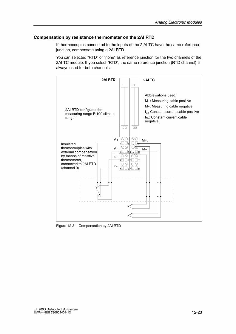
Analog Electronic Modules
12-23ET 200S Distributed I/O SystemEWA-4NEB 780602402-12
Compensation by resistance thermometer on the 2AI RTD
If thermocouples connected to the inputs of the 2 AI TC have the same referencejunction, compensate using a 2AI RTD.
You can selected ”RTD” or ”none” as reference junction for the two channels of the2AI TC module. If you select ”RTD”, the same reference junction (RTD channel) isalways used for both channels.
IC+
M--
M+:
IC--
M--
M+:
2
3
4
6
7
8
1 5
2
3
4
6
7
8
1 5
2AI RTD 2AI TC
Abbreviations used:
M+: Measuring cable positive
M--: Measuring cable negative
IC+ Constant current cable positive
IC--: Constant current cablenegative
Insulatedthermocouples withexternal compensationby means of resistivethermometer,connected to 2AI RTD(channel 0)
2AI RTD configured formeasuring range Pt100 climaterange
Figure 12-3 Compensation by 2AI RTD

Analog Electronic Modules
12-24ET 200S Distributed I/O System
EWA-4NEB 780602402-12
Configuring the reference junction with 2AI TC and interface module
You can set the reference junctions for the 2AI TC electronics modules using thefollowing parameters:
Table 12-26 Reference Junction Parameters
Parameters Module Value range Description
Reference junction slot IM 151 none, 2 to 12(IM151-1 BASIC)
none, 2 to 63(IM151-1 HIGHFEATURE)
IM 151-1 STANDARD
IM 151-1FOSTANDARD
With this parameter, you canassign a slot (none, 2 to 12 or 2to 63) on which the channels forreference temperaturemeasurement are situated(calculating the compensationvalue).
Reference junctioninput
IM 151 RTD on channel 0
RTD on channel 1
With this parameter you specifythe channel (0/1) for referencetemperature measurement(calculating the compensationvalue) for the relevant slot.
Reference junction E0and reference junctionE1
2AI TC none, RTD With these parameters, you canenable the use of the referencejunction.
Reference junctionnumber
2AI TC 1 With this parameter, you assignthe reference junction (1)containing the referencetemperature (compensationvalue).
Example of the Configuration of Reference Junctions
• Structure: To simplify the situation, the following figure 12-4 shows only RTDand TC modules:
2AIR
TD
E0
E1
2AIT
CE
0
E1
2AIT
CE
0
E1
2AIT
CE
0
E1
3 5 8 11 Slot
... ... ... ... ...
Referencejunction
Compensation via 2AI RTD modules
Example
Figure 12-4 Example of the Configuration of Reference Junctions

Analog Electronic Modules
12-25ET 200S Distributed I/O SystemEWA-4NEB 780602402-12
• Relevant parameters for interface module
Parameters Value
Reference junction slot 3
Reference junction input RTD on channel 0
• Relevant parameters for 2AI RTD and 2AI TC:
Slot Parameters Value
8 (2AI RTD) Measurement type / range I0 RTD-4L Pt100 terminal
5 (2AI TC) Reference junction I0 RTD
Reference junction E1 No
Reference junction number 1
Measurement type / range I0 TC-EL type...
Measurement type / range I1 (any)
8 (2AI TC) Reference junction I0 RTD
Reference junction E1 RTD
Reference junction number 1
Measurement type / range I0 TC-EL type...
Measurement type / range I1 TC-EL type...
11 (2AI TC) Reference junction I0 No
Reference junction E1 RTD
Reference junction number 1
Measurement type / range I0 (any)
Measurement type / range I1 TC-EL type...
Non-insulated thermocouples
If you use non-insulated thermocouples, make sure that you adhere to thepermitted common mode voltage.

Analog Electronic Modules
12-26ET 200S Distributed I/O System
EWA-4NEB 780602402-12
12.2.3 Instructions and circuits for unused channels of theanalog input modules
• ”Disable” unused input channels in the configuration.
• A disabled channel always return the value 7FFFH.
• The cycle time of the modules is halved with the standard modules 2AI U, 2AI I2WIRE, 2AI I 4WIRE, 2AI RTD Standard, 2AI RTD High Feature and 2AI TCStandard, 2AI TC High Feature.
• The cycle time remains unchanged with the 4AI I 2WIRE standard module.
• The cycle time remains unchanged at 1 ms with the 2AI U, 2AI I 2WIRE and2AI I 4WIRE high-speed modules.
• To maintain the approved potential differences (UCM) bridges must be wired tothe terminal module on the unused channels. This is required for the followingmodules:
Analog input module TM connection terminal
Channel 0 Channel 1
1 2 3 4 5 6 7 8
2AI U Standard
2AI RTD Standard, 2AI RTD HighFeature,2AI TC High Feature
2AI TC Standard
2AI U High Speed
12.3 Response of the Analog Modules during Operation and ifFaults Occur
This chapter describes:
• The dependence of the analog input and output values on the supply voltage ofthe electronic module and the operating states of the PLC.
• The response of the analog electronic modules depending on the state of theanalog values in the specific value range.
• The influence of errors on the analog inputs and outputs.
• Use of the shield.

Analog Electronic Modules
12-27ET 200S Distributed I/O SystemEWA-4NEB 780602402-12
Influence of the Power Supply and the Operating State
The input and output values of the analog modules are dependent on the powersupply for electronics/sensors and on the operating state of the PLC (CPU of theDP master).
Table 12-27 Dependence of the Input and Output Values on the Operating State of the PLC (CPU of theDP Master) and the Power Supply Voltage L +
Operating Stateof the PLC (CPUof the DP Master)
Power supplyL + at ET 200S(power mod-
ule)
Input Value of the ElectronicsModule with Analog Inputs
(Evaluation Possible on theCPU of the DP Master)
Output Value of the Electron-ics Module with Analog Out-
puts
POWERON
RUN L + present Process values PLC valuesON
7FFFH until first conversionafter startup, or afterassignment of parameters forthe module is completed.
Until first value output:
• After startup, a signal of 0 Vis output.
• Dependent on theparameter ”CPU/ masterSTOP”
L + missing 7FFFH --
POWERON
STOP L + present Process value Dependent on the parameter”CPU/ master STOP”
L + missing 7FFFH --
POWEROFF
-- L + present -- Dependent on the parameter”CPU/ master STOP”
L + missing -- --
Influence of the Value Range on the Analog Input
The response of the electronics modules with analog inputs depends on the part ofthe value range in which the input values are located. The following table 12-28illustrates the relationship.

Analog Electronic Modules
12-28ET 200S Distributed I/O System
EWA-4NEB 780602402-12
Table 12-28 Response of the Analog Modules, Depending on the Location of the Analog Input Value in theRange of Values
Measured value is in Input value in SIMATIC S7Format
Input value in SIMATIC S5Format
Nominal range Measured value Measured value
Overshoot / undershoot range Measured value Measured value
Overflow 7FFFH End of the overshoot range +1plus overflow bit
Underflow 8000H End of the undershoot range --1plus overflow bit
Before configuration or withincorrect configuration1)
7FFFH 7FFFH
1) With 2AI U ST, 2AI I 2WIRE ST, 2AI I 4WIRE ST, 2AI RTD ST, 2AI TC ST with product level 1 the followingapplies: If you trigger the configuration error diagnostic message as a result of incorrect configuration (e.g.wire break at measuring range 20 mA), the SF-LED on the module lights and you can evaluate thediagnosis. Correct input values are sent to the DP master in this status.
Influence of the Value Range on the Analog Output
The response of the electronics modules with analog outputs depends on the partof the value range in which the output values are located. The following tableillustrates the relationship.
Table 12-29 Response of the Analog Modules, Depending on the Location of the Analog Output Value inthe Range of Values
Output Value is in Output value in SIMATIC S5/S7 format
Nominal range Value from DP master
Overshoot / undershoot range Value from DP master
Overflow 0--signal
Underflow 0--signal
Before configuration or with incorrect configuration1) 0--signal
1) With 2AO U ST, 2AO I ST with product level 1 the following applies: If the configured substitute values areoutside the nominal range, a configuration error diagnostic message is registered and the SF-LED lights.In this status the output values sent from the DP master are output at the analog output modules.
Use of the shield
We recommend the following with the analog modules to prevent interference:
• Use shielded cables to the sensors and actuators.
• Connect cable shields to the shield component.
• Connect the shield to the ground collector cable.

Analog Electronic Modules
12-29ET 200S Distributed I/O SystemEWA-4NEB 780602402-12
12.4 Parameters for analog electronic modules
Parameters for
• 2AI U Standard analog electronic module
• 2AI I 2WIRE Standard electronic module
• 4AI I 2WIRE Standard electronic module
• 2AI I 4WIRE Standard electronic module
Table 12-30 Parameters for analog input modules U, I ST
2AI UStandard
2AI I 2WIREStandard
4AI I 2WIRE ST
2AI I 4WIREStandard
Value range Default setting Effectiverange
Group diagnostics (configuration error, internal error) • disable
• enabled
disable Module
Diagnosis: underflow/overflow • disable
• enabled
disable Module
Diagnosis:wire break2)
Diagnosis:Wire break
Diagnosis:Wire break1)
• disable
• enabled
disable Channel
Smoothing • No
• weak
• medium
• strong
No Channel
Measurementtype / range
------ ------ • disabled
• ¦ 5 V
• 1 to 5V
• ¦ 10 V
10 V Channel
------ Measurementtype / range
------ • disabled
• 2WIRE: 4 to20mA
2WIRE: 4 to20mA
Channel
------ ------ Measurementtype / range
• disabled
• 4WIRE: 4 to20mA
• 4WIRE:¦20 mA
2WIRE: 4 to20 mA
Channel
1) Only in 4 to 20 mA measurement range2) Only in 1 to 5 V measurement range

Analog Electronic Modules
12-30ET 200S Distributed I/O System
EWA-4NEB 780602402-12
Parameters for
• 2AI U High Feature analog electronic module
• 2AI I 2/4WIRE High Feature analog electronic module
Table 12-31 Parameters for analog input modules U, I High Feature
2AI U High Feature 2AI I 2/4WIRE HighFeature
Value range Default setting Effectiverange
Group diagnostics (configuration error,internal error)
• disable
• enabled
disable Module
Diagnosis: underflow/overflow • disable
• enabled
disable Module
------ Diagnosis: wirebreak1)
• disable
• enabled
disable Channel
Smoothing • No
• weak
• medium
• strong
No Channel
Measurement type /range
------ • disabled
• 5 V
• 1 to 5V
• 10 V
10 V Channel
------ Measurement type /range
• disabled
• 4 to 20mA
• 20 mA
4 to 20mA Channel
Interference Frequency Suppression • disable
• enabled
disable Module
Run time calibration • disable
• enabled
disable Module
1) Only in 4 to 20 mA measurement range

Analog Electronic Modules
12-31ET 200S Distributed I/O SystemEWA-4NEB 780602402-12
Parameters for
• 2AI U High Speed analog electronic module
• 2AI I 2WIRE High Speed electronic module
• 2AI I 4WIRE High Speed electronic module
Table 12-32 Parameters for analog input modules U, I High Speed
2AI U HighSpeed
2AI I 2WIREHigh Speed
2AI I 4WIREHigh Speed
Value range Default setting Effective range
Group diagnostics(configuration error, internal error)
• disable
• enabled
disable Module
Diagnosis: underflow/overflow • disable
• enabled
disable Module
------ Diagnosis:Wire break
Diagnosis:Wire break
• disable
• enabled
disable Channel
Smoothing • No
• weak
• medium
• strong
No Channel
Measurementtype / range
------ ------ • disabled
• 10 V
• 5 V
• 2.5 V
• 1 to 5 V
10 V Channel
------ Measurementtype / range
------ • disabled
• 4 to 20 mA
• 0 to 20 mA
4 to 20 mA Channel
------ ------ Measurementtype / range
• disabled
• 4 to 20 mA
• 0 to 20 mA
• 20 mA
4 to 20 mA Channel
Note
If you disable a channel of the High Speed modules, this will not increase speedbecause of the measuring process in use.

Analog Electronic Modules
12-32ET 200S Distributed I/O System
EWA-4NEB 780602402-12
Parameters for
• 2AI RTD Standard analog electronic module
• 2AI TC Standard analog electronic module
• 2AI TC High Feature analog electronic module
Table 12-33 Parameters RTD, TC analog electronic modules
2AI RTDStandard
2AI TCStandard
2AI TC HighFeature
Value range Defaultsetting
Effectiverange
Group diagnostics(configuration error, internal error)
• disable
• enabled
disable Module
Diagnosis: underflow/overflow • disable
• enabled
disable Module
Diagnosis:wire break2)
Diagnosis: wire-break test1) • disable
• enabled
disable Channel
Smoothing • No
• weak
• medium
• strong
No Channel
TemperatureUnit
• Centigrade
• Fahrenheit
Centigrade Module
------ Referencejunction
------ • No
• RTD
No Channel
------ Referencejunction
• No
• Yes (means internal)
No Channel
------ Referencejunctionnumber
------ • No
• 1 to 8(with IM151-1STANDARD, IM151-1FO STANDARD)
No Module
FO STANDARD)
• 1(with IM151-1 BASIC,IM151-1 HIGHFEATURE)
Measurementtype / range
------ • disabled
• 150 ohms
• 300 ohms
• 600 ohms
• Pt100 climate range
• Ni100 climate range
• Pt100 standard range
• Ni100 standard range
Pt100standardrange
Channel

Analog Electronic Modules
12-33ET 200S Distributed I/O SystemEWA-4NEB 780602402-12
Table 12-33 Parameters RTD, TC analog electronic modules
2AI RTDStandard
Effectiverange
Defaultsetting
Value range2AI TC HighFeature
2AI TCStandard
------ Measurementtype/range
------ • disabled
• Voltage ¦ 80 mV
• TC-EL Type T (Cu-CuNi)
• TC-EL Type K (NiCr-Ni)
• TC-EL Type B(PtRh-PtRh)
• TC-EL Type N(NiCrSi-NiSi)
• TC-EL Type E(NiCr-CuNi)
• TC-EL Type R (PtRh-Pt)
• TC-EL Type S (PtRh-Pt)
• TC-EL Type J(Fe-Cu-Ni)
• TC-EL Type L(Fe-Cu-Ni)
TC-ELType K(NiCr-Ni)
Channel
Measurementtype /range
• disabled
• Voltage ¦ 80 mV
• TC-EL Type T (Cu-CuNi)
• TC-EL Type K (NiCr-Ni)
• TC-EL Type B(PtRh-PtRh)
• TC-EL Type C(WRe-WRe)
• TC-EL Type N(NiCrSi-NiSi)
• TC-EL Type E(NiCr-CuNi)
• TC-EL Type R (PtRh-Pt)
• TC-EL Type S (PtRh-Pt)
• TC-EL Type J(Fe-Cu-Ni)
• TC-EL Type L(Fe-Cu-Ni)
TC-ELType K(NiCr-Ni)
Channel
1) With thermocouples only. A configuration error occurs when wire-break diagnostics and voltagemeasuring range are enabled. The module does not start.
2) Wire break is only detected with the constant current cables.

Analog Electronic Modules
12-34ET 200S Distributed I/O System
EWA-4NEB 780602402-12
Parameters for
• 2AI RTD High Feature analog electronic module
Table 12-34 Parameters for 2AI RTD High Feature analog electronic module
Parameters Value range Default setting Effectiverange
Group diagnostics • disable
• enabled
disable Module
Diagnosis: underflow/overflow • disable
• enabled
disable Module
Diagnosis: Wire break • Disable1)
• enabled
disable Channel
Smoothing • No
• weak
• medium
• strong
No Channel
Temperature Unit • Centigrade
• Fahrenheit
Centigrade Module
Measurement type • disabled
• 4-wire resistor
• 3-wire resistor
• 2-wire resistor
• 4-wire thermal resistor
• 3-wire thermal resistor
• 2-wire thermal resistor
Thermalresistor 4-wire
Channel
Temperature coefficient • Pt 0.003850
• Pt 0.003916
• Pt 0.003902
• Pt 0.003920
• Pt 0.003851
• Ni 0.006180
• Ni 0.006720
• Ni 0.005000
• Cu 0.00427
Pt 0.003851 Channel

Analog Electronic Modules
12-35ET 200S Distributed I/O SystemEWA-4NEB 780602402-12
Table 12-34 Parameters for 2AI RTD High Feature analog electronic module
Parameters Effectiverange
Default settingValue range
Measuring range • 150 Ω• 300 Ω• 600 Ω• 3000 Ω• PTC
• Pt100 climate range
• Ni100 climate range
• Pt100 standard range
• Ni100 standard range
• Pt500 standard range
• Pt1000 standard range
• Ni1000 standard range
• Pt200 climate range
• Pt500 climate range
• Pt1000 climate range
• Ni1000 climate range
• Pt200 standard range
• Ni120 standard range
• Ni120 climate range
• Cu10 climate range
• Cu10 standard range
• Ni200 standard range
• Ni200 climate range
• Ni500 standard range
• Ni500 climate range
Pt100 standard Channel
1) Wire-break diagnostics is blocked if-- measuring type = ”disabled” or-- measuring range = ” PTC” have been configured.

Analog Electronic Modules
12-36ET 200S Distributed I/O System
EWA-4NEB 780602402-12
Measuring range -- temperature coefficient -- measuring range
The following table shows which temperature coefficients and which measuringranges can be configured for the specific measuring type:
Measurement type Temperature coefficient Measuring range
disabled -- --
4-wire resistor
3-wire resistor
-- 150 Ω / 300 Ω / 600 Ω / 3000 Ω
2-wire resistor -- 150 Ω / 300 Ω / 600 Ω / 3000 Ω /PTC
3-wire thermal resistor Pt 0.003850/ Pt 0.003916 /Pt 0.003902 / Pt 0.003920 /Pt 0.0038511)
Pt100 climate range /Pt100 standard range /Pt200 climate range /Pt200 standard range /Pt200 standard range /Pt500 climate range /Pt500 standard range /Pt1000 climate range /Pt1000 standard range
Ni 0.0061801) / Ni 0.006720 Ni100 climate range /NI100 standard range /Ni120 climate range /Ni120 standard range /Ni200 climate range /Ni200 standard range /Ni500 climate range /Ni500 standard range /Ni1000 climate range /Ni1000 standard range
Ni 0.005000 Ni 1000 climate range2)
Ni 1000 standard range2)
Cu 0.004271) Cu10 climate range /Cu10 standard range
1) The preceding temperature coefficient are applicable for Europe.

Analog Electronic Modules
12-37ET 200S Distributed I/O SystemEWA-4NEB 780602402-12
Measurement type Measuring rangeTemperature coefficient
2-wire thermal resistor
4-wire thermal resistor
Pt 0.003850 / Pt 0.003916 /Pt 0.003902 / Pt 0.003920 /Pt 0.003851
Pt100 climate rangePt100 standard rangePt200 climate range /Pt200 standard range /Pt500 climate range /Pt500 standard range /Pt1000 climate range /Pt1000 standard range
Ni 0.006180 / Ni 0.006720 Ni100 climate range /Ni100 standard range /Ni120 climate range /Ni120 standard range /Ni200 climate range /Ni200 standard range /Ni500 climate range /Ni500 standard range /Ni1000 climate range /Ni1000 standard range
Ni 0.005000 Ni 1000 climate range2)
Ni 1000 standard range2)
1) The preceding temperature coefficient are applicable for Europe.2) For LG-Ni 1000 sensors from Siemens Building Ltd (Landis & Stäfa)

Analog Electronic Modules
12-38ET 200S Distributed I/O System
EWA-4NEB 780602402-12
Temperature coefficient
The correction factor for the temperature coefficients (α value) indicates therelative change of the resistance of a specified material if the temperatureincreases by 1_C.
The temperature coefficient depends on the chemical composition of the material.In Europe only one value is used per sensor type (default value).
The additional values enabled sensor-specific adjustment of the temperaturecoefficients and therefore even greater precision.
Parameters for
• 2AO U Standard, 2AO U High Feature analog electronic module
• 2AO I Standard, 2AO I High Feature analog electronic module
Table 12-35 Parameters for analog output modules U, I
2AO UStandard
2AO U HighFeature
2AO IStandard
2AO I HighFeature
Value range Default setting Effective range
Group diagnostics(configuration error, internalerror)
• disable
• enabled
disable Module
Diagnosis:Short circuitas per M
------ • disable
• enabled
disable Channel
------ Diagnosis:Wire break
• disable
• enabled
disable Channel
Response at CPU/masterSTOP
• Output without current andvoltage
• apply substitute value
• hold last value
Output withoutcurrent andvoltage
Module
Output type /range
------ • disabled
• 1 to 5 V
• 10 V
10 V Channel
------ Output type /range
• disabled
• 4 to 20 mA
• 20 mA
4 to 20 mA Channel
Substitute value 1) 0 to 65535 (value range mustbe within the nominal range)
10 V/20 V:0 V
4 to 20 mA: 4 mA
1 to 5 V: 1 V
Channel
1) If the power to the IM is disconnected and the analog output modules are still powered, the configuredsubstitute values are output. Substitute values must be within the nominal range. Values from --27648 to+27648 are configured (when configured with the GSD file).

Analog Electronic Modules
12-39ET 200S Distributed I/O SystemEWA-4NEB 780602402-12
Smoothing
The individual measured values are smoothed by means of digital filters. Thesmoothing can be configured in four levels, in which the smoothing factor multipliedby the cycle time of the electronic module corresponds to the time constant of thesmoothing filter. The greater the smoothing the greater the time constant of thefilter.
The following diagrams show the jump response with the various smoothingfactors depending on the number of module cycles.
• Smoothing with 2AI U Standard, 2AI U High Feature, 2AI I 2WIRE Standard,2AI I 4WIRE Standard, 2AI I 2/4WIRE High Feature, 2AI RTD Standard,2AI RTD High Feature, 2AI TC Standard, 2AI TC High Feature
0.5
1
0
0.63
50 100 150Module cycles
None: k=1 weak: k=4 medium: k=32 strong: k=64
200 250 300
Ste
pre
spon
se
Figure 12-5 Smoothing with 2AI U Standard, 2AI U High Feature, 2AI I 2WIRE Standard,
2AI I 4WIRE Standard,
2AI I 2/4WIRE High Feature, 2AI RTD Standard, 2AI RTD High Feature, 2AI
TC Standard, 2AI TC High Feature

Analog Electronic Modules
12-40ET 200S Distributed I/O System
EWA-4NEB 780602402-12
• Smoothing with 4AI I 2WIRE Standard
0.5
1
0
0.63
25 50 75Module cycles
None: k=1 weak: k=4 medium: k=16 strong: k=32
100 125 150
Ste
pre
spon
se
• Smoothing with 2AI U High Speed, 2AI I 2WIRE High Speed, 2AI I 4WIRE HighSpeed
0.5
1
0
0.63
100 200 300Module cycles
400 500 600
None: k=1 weak: k=64 medium: k=128 strong: k=512
Ste
pre
spon
se
Figure 12-6 Smoothing with 2AI U High Speed, 2AI I 2WIRE High Speed, 2AI I 4WIRE
High Speed

Analog Electronic Modules
12-41ET 200S Distributed I/O SystemEWA-4NEB 780602402-12
Interference Frequency Suppression
The 2AI U High Feature and 2AI I 2/4WIRE High Feature analog input modulessupport the setting of interference frequency suppression (50 Hz or 60 Hz) with theinterface module. These analog input modules (HIGH FEATURE) also allowblocking of interference frequency suppression; this means that this setting can beignored on the interface module. If interference frequency suppression is blocked,the conversion and cycle times of these modules are improved.
Runtime calibration
• 2AI U High Feature
When configuring the module the runtime calibration can be enabled for the 2AIU High Feature analog electronic module to compensate for componentchanges resulting from changes in the ambient temperature. The update of newdata is delayed by 250 ms during the calibration interval. A calibration isconducted at every change of 5° C in the ambient temperature.
• 2AI I 2/4WIRE High Feature
When calibrating the module a runtime calibration for the 2AI I 2WIRE HighFeature analog electronic module can be enabled for periodic compensation ofthe error voltage change of the A/D converter. The update of new data isdelayed by 200 ms during the calibration interval. The precision limits of themodule are reached without run time calibration.
Reference junction
See chapter 12.2.2.
Reference junction number:
See chapter 12.2.2

Analog Electronic Modules
12-42ET 200S Distributed I/O System
EWA-4NEB 780602402-12
12.5 2AI U Standard analog electronic module(6ES7 134-4FB00-0AB0)
Order number
6ES7 134-4FB00-0AB0
Properties
• 2 inputs for voltage measuring
• Input ranges:
¦ 10 V, resolution 13 bits + sign
¦ 5 V, resolution 13 bits + sign
1 to 5 V, resolution 13 bits
• Isolated for load voltage L+
• Allowable common-mode voltage 2 VACSS
Terminal assignment
The following table shows the terminal assignment of the 2AI U Standard for thevarious terminal modules:
Table 12-36 Terminal assignment of the 2AI U Standard
View Terminal assignment Remarks
Mana
M1--M0--
AUX1 (e.g. PE)
2
3
4
6
7
8
1 5M1+M0+
AUX1 (e.g. PE)
V V
Mana
TM-E15S24-A1 and 2DA U Standard
CH1CH0
AUX1 must beassigned to PE
AA
Channel 0: Terminals 1 to A4
Channel 1: Terminals 5 to A8
M+: Input signal ”+”
M--: Input signal ”--”
Mana: Module ground

Analog Electronic Modules
12-43ET 200S Distributed I/O SystemEWA-4NEB 780602402-12
Table 12-36 Terminal assignment of the 2AI U Standard
View RemarksTerminal assignment
M1--M0-- 2
3
4
6
7
8
1 5M1+M0+
V
ManaMana
TM-E15S24-01 and 2AI U Standard
CH1CH0
n. c.n. c.
Channel 0: Terminals 1 to 4
Channel 1: Terminals 5 to 8
M+: Input signal ”+”
M--: Input signal ”--”
Mana: Module ground
Terminals 4 and 8 can beused for connection of cablesthat are not required up to30 VDC.
M1--M0-- 2
3
6
7
1 5M1+M0+
V
ManaMana
TM-E15S23-01 and 2AI U Standard
CH1CH0
Channel 0: Terminals 1 to 3
Channel 1: Terminals 5 to 7
M+: Input signal ”+”
M--: Input signal ”--”
Mana: Module ground
M1--M0-- 2
3
4
6
7
8
1 5M1+M0+
V
ManaMana
TM-E15S26-A1 and 2AI U Standard
CH1CH0
AUX1A
4
A
3
A
8
A
7AUX1
AUX1
AUX1
n. c.n. c.
Channel 0: Terminals 1 to A3
Channel 1: Terminals 5 to A7
M+: Input signal ”+”
M--: Input signal ”--”
Mana: Module ground
Terminals 4 and 8 can beused for connection of cablesthat are not required up to30 VDC.

Analog Electronic Modules
12-44ET 200S Distributed I/O System
EWA-4NEB 780602402-12
Block diagram
Bac
kpla
nebu
s
ET 200Sbackplane bus
interfaceconnection
ADC
MANA24VL+
1M
1
2
5
6
3
7
P1P2
MUX
Figure 12-7 Block diagram of the 2AI U Standard
Technical data
Dimensions and weight
DimensionsW x H x D (mm) 15 x 81 x 52
Weight Approx. 40 g
Module-specific data
Supports clock synchro-nized mode
No
Number of inputs 2
Cable length
• shielded max. 200 m (164 ft)
Voltages, currents, electrical potentials
Rated load voltage L+(from power module)
24 VDC
• Polarity reversalprotection
Yes
Electrical isolation
• Between channels andbackplane bus
Yes
• Between channels andload voltage L+
Yes
• Between the channels No
Permitted potential differ-ence
• Between inputs andMANA (UCM)
2 VACSS
• Between MANA and thecentral ground point(UISO)
75 VDC / 60 VAC
Isolation tested 500 VDC
Current consumption
• with load voltage L+ max. 30 mA
Power loss of the module Typical 0.6 W
Status, interrupts, diagnostics
Diagnostic functions
• Group error red LED ”SF”
• Reading of diagnosticsfunctions
Yes

Analog Electronic Modules
12-45ET 200S Distributed I/O SystemEWA-4NEB 780602402-12
Analog Value Formation
Measurement principle integrating
Integration and cycle time /resolution per channel:
• Integration timeselectable
Yes
• Interference frequencysuppression in Hz
60 50
• Integration time in ms 16,7 20
• Conversion time in ms 55 65
• Cycle time in ms Number of activechannels permodule ¢
conversion time
• Resolution (incl.overshoot range)
¦ 10 V/ 13 Bit + VZ
¦ 5 V/ 13 Bit + VZ
1 to 5 V/13 bits
Interference Suppression, Error Limits
Interference voltage sup-pression for f= n x (f1¦1%), (f1 = interference fre-quency)
• Common modeinterference (USS)
• Common modeinterference(peak value ofinterference < ratedvalue of the input range)
• Crosstalk betweeninputs
min. 90 dB
min. 70 dB
min. --50 dB
Operational error limits(across complete tempera-ture range, in relation to in-put range)
0.6 %
Basic error limit (operationalerror limit at 25 _C, relatedto the input range)
0.4 %
Temperature error (in rela-tion to input range)
0.01 %/K
Linearity error (relative tothe input range)
0.01 %
Repetition accuracy(in transient state at 25 _C,relative to input range)
0.05 %
Data for selection of the sensor
Input range (ratedvalue)/input resistance
• Voltage 5 V/min. 100 kΩ1 up to 5 V/min.100kΩ10 V/min. 100 kΩ
Permitted continuous inputvoltage (destruction limit)
35 V continuous,75 V for max. 1 ms(sampling ratio 1:20)
Smoothing of measuredvalues
Yes, configurable in4 stages by digitalfiltering
Level
No
weak
medium
strong
Time constant
1 x cycle time
4 x cycle time
32 x cycle time
64 x cycle time

Analog Electronic Modules
12-46ET 200S Distributed I/O System
EWA-4NEB 780602402-12
12.6 2AI U High Feature analog electronic module(6ES7 134-4LB00-0AB0)
Order number
6ES7 134-4LB00-0AB0
Features
• 2 Inputs for voltage measurement
• Input ranges:
-- 10V, resolution 15 bits + sign
-- 5V, resolution 15 bits + sign
-- 1 to 5 V, resolution 15 bits
• Isolated for load voltage L+
• allowable common-mode voltage between the channels 100 VAC
Terminal assignment
The following table shows the terminal assignment of the 2AI U for the variousterminal modules:
Table 12-37 Terminal assignment of the 2AI U High Feature
View Terminal assignment Remarks
M1--M0--
AUX1 (e.g. PE)
2
3
4
6
7
8
1 5M1+M0+
AUX1 (e.g. PE)
V V
TM-E15S24-A1 and 2AI U High Feature
CH1CH0
AUX1 must be assigned to PE.
n. c.n. c.
AA
Channel 0: Terminals 1 to A4
Channel 1: Terminals 5 to A8
M+: Input signal ”+”
M--: Input signal ”--”

Analog Electronic Modules
12-47ET 200S Distributed I/O SystemEWA-4NEB 780602402-12
Table 12-37 Terminal assignment of the 2AI U High Feature
View RemarksTerminal assignment
M1--M0-- 2
3
4
6
7
8
1 5M1+M0+
V
TM-E15S24-01 and 2AI U High Feature
CH1CH0
n. c.n. c.
n. c.n. c.
Channel 0: Terminals 1 to 4
Channel 1: Terminals 5 to 8
M+: Input signal ”+”
M--: Input signal ”--”
Terminals 4 and 8 can beused for connection of cablesthat are not required up to30 VDC.
M1--M0-- 2
3
6
7
1 5M1+M0+
V
TM-E15S23-01 and 2AI U High Feature
CH1CH0
n. c.n. c.
Channel 0: Terminals 1 to 3
Channel 1: Terminals 5 to 7
M+: Input signal ”+”
M--: Input signal ”--”
Terminals 4 and 8 can beused for connection of cablesthat are not required up to30 VDC.
M1--M0-- 2
3
4
6
7
8
1 5M1+M0+
V
TM-E15S26-A1 and 2AI U High Feature
CH1CH0
AUX1A
4
A
3
A
8
A
7AUX1
AUX1
AUX1
n. c.n. c.
n. c.n. c.
Channel 0: Terminals 1 to A3
Channel 1: Terminals 5 to A7
M+: Input signal ”+”
M--: Input signal ”--”
Terminals 4 and 8 can beused for connection of cablesthat are not required up to30 VDC.

Analog Electronic Modules
12-48ET 200S Distributed I/O System
EWA-4NEB 780602402-12
Block diagram
ADC
24VL+
1M
1
2
5
6
P1P2
MUX
MANA
Bac
kpla
nebu
s
ET 200Sbackplane bus
interfaceconnection
Figure 12-8 Block diagram of the 2AI U High Feature
Technical data
Dimensions and weight
Dimensions W x H x D(mm)
15 x 81 x 52
Weight Approx. 40 g
Module-specific data
Supports clocksynchronized mode
No
Number of inputs 2
Cable length
• shielded max. 200 m (164 ft)
Voltages, currents, electrical potentials
Rated load voltage L+ (frompower module)
24 VDC
• Polarity reversalprotection
Yes
Electrical isolation
• Between the channelsand backplane bus
Yes
• Between the channelsand load voltage L+
• Between the channelsand PE
Yes
Yes
• Between the channels No
Permitted potentialdifference
• Between the channels 140 VDC/100 VAC
Isolation tested 500 VDC
Current consumption
• with load voltage L+ max. 53 mA
Power loss of the module Typical 0.85 W
Status, interrupts, diagnostics
Diagnostic functions
• Group error red LED ”SF”
• Diagnostic function canbe read (wire-breakdiagnostics notsupported in thismodule)
Yes

Analog Electronic Modules
12-49ET 200S Distributed I/O SystemEWA-4NEB 780602402-12
Analog Value Formation
Measurement principle Integrating
Integration and cycle time /resolution per channel
• Integration timeselectable
Yes
• Interference frequencysuppression in Hz
60 50 no
• Integration time in ms 16,67 20 7,5
• Conversion time in ms
-- 1 channel permodule active
-- 2 channels activeper module
25 30 10
58,3 70 26
• Cycle time in ms
-- 1 channel permodule active
-- 2 channels activeper module
75 90 30
175 210 78
• Resolution (incl.overshoot range)
10 V/ 15 Bit +VZ
5 V/ 15 Bit + VZ
1 to 5 V/15 bits
Interference Suppression, Error Limits
Interference voltagesuppression forf= n x (f1¦ 0.5%),(f1 = interferencefrequency)
• Common modeinterference (USS)
• Common modeinterference (peak valueof interference < ratedvalue of the input range)
• Crosstalk betweeninputs
min. 100 dB
min. 90 dB
min. --100 dB
Operational limits(in the entire temperaturerange, relative to the inputrange 1)
0.1 %
Operational error limits(across completetemperature range, inrelation to input range;calibration blocked)
0.5 %
Basic error limit (operationalerror limit at 25_C, relativeto input range; calibrationenabled1)
0.05 %
Temperature error (basedon input range; calibrationenabled1)
0.003 %/K
Temperature error (inrelation to input range;calibration blocked)
0.015 %/K
Linearity error (relative tothe input range)
0.03 %
Repetition accuracy(in transient state at 25 _C,relative to input range)
0.01 %
Data for selection of the sensor
Input range (ratedvalue)/input resistance
• Voltage 10 V/min. 1 MΩ5 V/min. 1 MΩ1 to 5 V/min.1 MΩ
Permitted continuous inputvoltage (destruction limit)
35 V continuous,75 V for max. 1 ms
Smoothing of measuredvalues
Yes, configurable in4 stages by digitalfiltering
Level
No
weak
medium
strong
Time constant
1 x cycle time
4 x cycle time
32 x cycle time
64 x cycle time
1) When configuring modules the runtimecalibration can be enabled to compensate forcomponent changes resulting from changes inthe ambient temperature. The update of newdata is delayed by 250 ms during thecalibration interval. A calibration is conductedat every change of 5°C in the ambienttemperature.

Analog Electronic Modules
12-50ET 200S Distributed I/O System
EWA-4NEB 780602402-12
12.7 2AI U High Speed analog electronic module(6ES7 134-4FB51-0AB0)
Order number
6ES7 134-4FB51-0AB0
Properties
• 2 inputs for voltage measuring
• Input ranges:
¦ 10 V, resolution 13 bits + sign
5 V, resolution 13 bits + sign
2.5 V, resolution 13 bits + sign
1 to 5 V, resolution 13 bits
• Isolated for load voltage L+
• Allowable common-mode voltage 100 VACSS
• Supports clock synchronized mode
-- Minimum possible time for the clock-synchronized DP cycle (TDPmin): 2.5 ms
-- Minimum possible conversion time of the input module (TWEmin): 1.1 ms
Terminal assignment
The following table shows the terminal assignment of the 2AI U High Speed for thevarious terminal modules:
Table 12-38 Terminal assignment of the 2AI U High Speed
View Terminal assignment Remarks
Mana
M1--M0--
AUX1 (e.g. PE)
2
3
4
6
7
8
1 5M1+M0+
AUX1 (e.g. PE)
V V
Mana
TM-E15S24-A1 and 2AI U High Speed
CH1CH0
AUX1 must beassigned to PE
AA
Channel 0: Terminals 1 to A4
Channel 1: Terminals 5 to A8
M+: Input signal ”+”
M--: Input signal ”--”
Mana: Module ground

Analog Electronic Modules
12-51ET 200S Distributed I/O SystemEWA-4NEB 780602402-12
Table 12-38 Terminal assignment of the 2AI U High Speed, continued
View RemarksTerminal assignment
M1--M0-- 2
3
4
6
7
8
1 5M1+M0+
V
ManaMana
TM-E15S24-01 and 2AI U High Speed
CH1CH0
n. c.n. c.
Channel 0: Terminals 1 to 4
Channel 1: Terminals 5 to 8
M+: Input signal ”+”
M--: Input signal ”--”
Mana: Module ground
Terminals 4 and 8 can beused for connection of cablesthat are not required up to30 VDC.
M1--M0-- 2
3
6
7
1 5M1+M0+
V
ManaMana
TM-E15S23-01 and 2AI U High Speed
CH1CH0
Channel 0: Terminals 1 to 3
Channel 1: Terminals 5 to 7
M+: Input signal ”+”
M--: Input signal ”--”
Mana: Module ground
M1--M0-- 2
3
4
6
7
8
1 5M1+M0+
V
ManaMana
TM-E15S26-A1 and 2AI U High Speed
CH1CH0
AUX1A
4
A
3
A
8
A
7AUX1
AUX1
AUX1
n. c.n. c.
Channel 0: Terminals 1 to A3
Channel 1: Terminals 5 to A7
M+: Input signal ”+”
M--: Input signal ”--”
Mana: Module ground
Terminals 4 and 8 can beused for connection of cablesthat are not required up to30 VDC.

Analog Electronic Modules
12-52ET 200S Distributed I/O System
EWA-4NEB 780602402-12
Block diagram
Bac
kpla
nebu
s
ET 200Sbackplane bus
interfaceconnection
ADC
MANA24V
L+
1M
1
2
5
6
3
7
P1P2
MUX
Figure 12-9 Block diagram of the 2AI U High Speed
Technical data
Dimensions and weight
Dimensions W x H x D(mm)
15 x 81 x 52
Weight Approx. 40 g
Module-specific data
Supports clock synchro-nized mode
Yes
Number of inputs 2
Cable length
• shielded max. 200 m (164 ft)
Voltages, currents, electrical potentials
Rated load voltage L+ (frompower module)
24 VDC
• Polarity reversalprotection
Yes
Electrical isolation
• Between channels andbackplane bus
Yes
• Between channels andload voltage L+
Yes
• Between the channels No
Permitted potential differ-ence
• Between inputs andMANA (UCM)
100 VACSS
• Between MANA and thecentral ground point(UISO)
75 VDC / 60 VAC
Isolation tested 500 VDC
Current consumption
• Power supply andload voltage L+(without load)
max. 35 mA
Power loss of the module Typical 0.8 W
Status, interrupts, diagnostics
Interrupts
• Process alarm Configurable1)
Diagnostic functions
• Group error display red LED ”SF”
• Reading of diagnosticdata
possible2)

Analog Electronic Modules
12-53ET 200S Distributed I/O SystemEWA-4NEB 780602402-12
Analog Value Formation
Measurement principle Momentary valueencryption
Cycle time/resolution:
• Conversion time in ms(per channel)
0.1
• Cycle time in ms(per module)
1
• Resolution (incl.overshoot range)
10 V/ 13 Bit + VZ
5 V/13 Bit + VZ
2.5 V/13 Bit + VZ
1 to 5 V/13 bits
Interference Suppression, Error Limits
• Commonmodeinterference(Ucm < 100 VSS)
> 70 dB
Crosstalk between inputs > 50 dB
Operational error limits(across complete tempera-ture range, in relation toinput range)
0.3 %
Basic error limit (operationalerror limit at 25 _C, relatedto the input range)
0.2 %
Temperature error(in relation to input range)
0.01 %/K
Linearity error (relative tothe input range)
0.01 %
Repetition accuracy(in transient state at 25 _C,relative to input range)
0.05 %
Data for selection of the sensor
Input ranges (ratedvalue)/input resistance
• Voltage 10 V/min. 100 kΩ5 V/min. 100 kΩ2.5 V/min. 100 kΩ1 -- 5 V/min. 100 kΩ
Permitted input voltage forvoltage input (destructionlimit)
50 V continuous,100 V for max. 1 ms(sampling ratio 1:20)
Connection of signalgenerators
• With voltage measuringpossible
Smoothing of measuredvalues
Yes, configurable in4 stages by digitalfiltering
Level
No
weak
medium
strong
Time constant
1 x cycle time
64 x cycle time
128 x cycle time
512 x cycle time
1) DPV1 only2) Configuration error
Violation of lower limit valueViolation of upper limit valueOpen circuit (1 to 5 V only)Process interrupt lost

Analog Electronic Modules
12-54ET 200S Distributed I/O System
EWA-4NEB 780602402-12
12.8 2AI I 2WIRE Standard analog electronic module(6ES7 134-4GB00-0AB0)
Order number
6ES7 134-4GB00-0AB0
Properties
• 2 inputs for current measuring
• Input range:
4 to 20 mA, resolution 13 bits
Terminal assignment
The following table shows the terminal assignment of the 2AI I 2WIRE Standard forthe various terminal modules:
Table 12-39 Terminal assignment of the 2AI I 2WIRE Standard
View Terminal assignment Remarks
M1--M0--
AUX1 (e.g. PE)
2
3
4
6
7
8
1 5M1+M0+
AUX1 (e.g. PE)
ManaMana
TM-E15S24-A1 and 2AI I Standard
CH1CH0
mA mA
AUX1 must beassigned to PE.
AA
Channel 0: Terminals 1 to A4
Channel 1: Terminals 5 to A8
M+: Input signal ”+”
M--: Input signal ”--”
Mana: Ground (from powermodule)
The 2-wire transducers arepowered over themeasurement leads.
M1--M0-- 2
3
4
6
7
8
1 5M1+M0+
ManaMana
TM-E15S24-01 and 2AI I 2WIRE Standard
CH1CH0
mA
n. c.n. c.
Channel 0: Terminals 1 to 4
Channel 1: Terminals 5 to 8
M+: Input signal ”+”
M--: Input signal ”--”
Mana: Ground (from powermodule)
The 2-wire transducers arepowered over themeasurement leads.
Terminals 4 and 8 can beused for connection of cablesthat are not required up to30 VDC.

Analog Electronic Modules
12-55ET 200S Distributed I/O SystemEWA-4NEB 780602402-12
Table 12-39 Terminal assignment of the 2AI I 2WIRE Standard, continued
View RemarksTerminal assignment
M1--M0-- 2
3
6
7
1 5M1+M0+
ManaMana
TM-E15S23-01 and 2AI I 2WIRE Standard
CH1CH0
mA
Channel 0: Terminals 1 to 3
Channel 1: Terminals 5 to 7
M+: Input signal ”+”
M--: Input signal ”--”
Mana: Ground (from powermodule)
The 2-wire transducers arepowered over themeasurement leads.
M1--M0-- 2
3
4
6
7
8
1 5M1+M0+
ManaMana
TM-E15S26-A1 and 2AI I Standard
CH1CH0
mA
AUX1A
4
A
3
A
8
A
7AUX1
AUX1
AUX1
n. c.n. c.
Channel 0: Terminals 1 to A3
Channel 1: Terminals 5 to A7
M+: Input signal ”+”
M--: Input signal ”--”
Mana: Ground (from powermodule)
The 2-wire transducers arepowered over themeasurement leads.
Terminals 4 and 8 can beused for connection of cablesthat are not required up to30 VDC.

Analog Electronic Modules
12-56ET 200S Distributed I/O System
EWA-4NEB 780602402-12
Block diagram
Bac
kpla
nebu
s
ET 200Sbackplane bus
interfaceconnection
ADC
MANA24VL+
1M
1
2
5
6
7
3
Currentlimiting
P1P2
MUX
Figure 12-10 Block diagram of the 2AI I 2WIRE Standard
Technical data
Dimensions and weight
Dimensions W x H x D(mm)
15 x 81 x 52
Weight Approx. 40 g
Module-specific data
Supports clock synchro-nized mode
No
Number of inputs 2
Cable length
• shielded max. 200 m (164 ft)
Voltages, currents, electrical potentials
Rated load voltage L+ (frompower module)
24 VDC
• Polarity reversalprotection
Yes
Transducer power supply Yes
• Short-circuit protection Yes (destruction limit35 mA per channel)
Electrical isolation
• Between channels andbackplane bus
Yes
• Between channels andload voltage L+
No
• Between the channels No
Isolation tested 500 VDC
Current consumption
• with load voltage L+ max. 80 mA
Power loss of the module Typical 0.6 W
Status, interrupts, diagnostics
Diagnostic functions
• Group error red LED ”SF”
• Reading of diagnosticsfunctions
Yes

Analog Electronic Modules
12-57ET 200S Distributed I/O SystemEWA-4NEB 780602402-12
Analog Value Formation
Measurement principle integrating
Integration and cycle time /resolution per channel:
• Integration timeselectable
Yes
• Interference frequencysuppression in Hz
60 50
• Integration time in ms 16,7 20
• Conversion time in ms 55 65
• Cycle time in ms Number of activechannels permodule ¢
conversion time
• Resolution (incl.overshoot range)
4 to 20 mA/13 bits
Interference Suppression, Error Limits
Interference voltage sup-pression for f= n x (f11%),(f1 = interference frequen-cy)
• Common modeinterference(peak value ofinterference < ratedvalue of the input range)
min. 70 dB
Crosstalk between inputs min. --50 dB
Operational error limits(across complete tempera-ture range, in relation to in-put range)
0.6 %
Basic error limit (operationalerror limit at 25 _C, relatedto the input range)
0.4 %
Temperature error (in rela-tion to input range)
0.005 %/K
Linearity error (relative tothe input range)
0.01 %
Repetition accuracy(in transient state at 25 _C,relative to input range)
0.05 %
Data for selection of the sensor
Input range (ratedvalue)/input resistance
• Current 4 to 20 mA/50 Ω
Permitted continuous inputcurrent (destruction limit)
40 mA
Load of the 2-wiretransducer
max. 750Ω
Smoothing of measuredvalues
Yes, configurable in4 stages by digitalfiltering
Level
No
weak
medium
strong
Time constant
1 x cycle time
4 x cycle time
32 x cycle time
64 x cycle time

Analog Electronic Modules
12-58ET 200S Distributed I/O System
EWA-4NEB 780602402-12
12.9 4AI I 2WIRE Standard analog electronic module(6ES7 134-4GD00-0AB0)
Order number
6ES7 134-4GD00-0AB0
Properties
• 4 inputs for current measuring
• Input range:
4 to 20 mA, resolution 13 bits
Terminal assignment
The following table shows the terminal assignment of the 4AI I 2WIRE Standard forthe various terminal modules:
Table 12-40 Terminal assignment of the 4AI I 2WIRE Standard
View Terminal assignment Remarks
M1--M0-- 2
3
4
6
7
8
1 5M1+M0+
M3+M2+
TM-E15S24-01 and 4AI I 2WIRE Standard
CH1CH0 mA
M3--M2--
CH3CH2
Channel 0: Terminals 1 and 2
Channel 1: Terminals 5 and 6
Channel 2: Terminals 3 and 4
Channel 3: Terminals 7 and 8
M+: Input signal ”+”
M--: Input signal ”--”
The 2-wire transducers arepowered over themeasurement leads.

Analog Electronic Modules
12-59ET 200S Distributed I/O SystemEWA-4NEB 780602402-12
Table 12-40 Terminal assignment of the 4AI I 2WIRE Standard, continued
View RemarksTerminal assignment
M1--M0-- 2
3
4
6
7
8
1 5M1+M0+
M3+M2+
TM-E15S26-A1 and 4AI I 2WIRE Standard
CH1CH0 mA
AUX1A
4
A
3
A
8
A
7AUX1
AUX1
AUX1
M3--M2--
CH3CH2
Channel 0: Terminals 1 and 2
Channel 1: Terminals 5 and 6
Channel 2: Terminals 3 and 4
Channel 3: Terminals 7 and 8
M+: Input signal ”+”
M--: Input signal ”--”
The 2-wire transducers arepowered over themeasurement leads.
Block diagram
Bac
kpla
nebu
s
ET 200Sbackplane bus
interfaceconnection
MANA
DC/DC converterL+
1M
1256
Short-circuitprotection
P1P2
ADC3478
M0+M0--M1+M1--M2+M2--M3+M3--
Input currentlimit
I I I I
Electricalisolation
Figure 12-11 Block diagram of the 4AI I 2WIRE Standard

Analog Electronic Modules
12-60ET 200S Distributed I/O System
EWA-4NEB 780602402-12
Technical data
Dimensions and weight
Dimensions W x H x D(mm)
15 x 81 x 52
Weight Approx. 40 g
Module-specific data
Supports clock synchro-nized mode
No
Number of inputs 4
Cable length
• shielded max. 200 m (164 ft)
Voltages, currents, electrical potentials
Rated load voltage L+ (frompower module)
24 VDC
• Polarity reversalprotection
Yes
Transducer power supply Yes
• Short-circuit protection Yes (approx.200 mA for module)
Electrical isolation
• Between channels andbackplane bus
Yes
• Between channels andload voltage L+
No
• Between the channels No
Isolation tested 500 VDC
Power consumption of module
• From load voltage L+(with sensor powersupply)
max. 125 mA
Power loss of the module Typical 0.6 W
Status, interrupts, diagnostics
Diagnostic functions
• Group error red LED ”SF”
• Reading of diagnosticsfunctions
Yes

Analog Electronic Modules
12-61ET 200S Distributed I/O SystemEWA-4NEB 780602402-12
Analog Value Formation
Measurement principle integrating
Integration and cycle time /resolution per channel:
• Integration timeselectable
Yes
• Interference frequencysuppression in Hz
60 50
• Integration time in ms 16,7 20
• Cycle time per modulein ms
33 40
• Resolution (incl.overshoot range)
4 to 20 mA/13 bits
Interference Suppression, Error Limits
Interference voltage sup-pression for f= n x (f11%),(f1 = interference frequen-cy)
• Common modeinterference(peak value ofinterference < ratedvalue of the input range)
min. 70 dB
Crosstalk between inputs min. --50 dB
Operational error limits(across complete tempera-ture range, in relation to in-put range)
0.4 %
Basic error limit (operationalerror limit at 25 _C, relatedto the input range)
0.3 %
Temperature error (in rela-tion to input range)
0.003 %/K
Linearity error (relative tothe input range)
0.01 %
Repetition accuracy(in transient state at 25 _C,relative to input range)
0.05 %
Data for selection of the sensor
Input range (ratedvalue)/input resistance
• Current 4 to 20 mA/25 Ω
Permitted continuous inputcurrent (destruction limit)
approx. 30 mA(electronicallylimited)
Load of the 2-wiretransducer
max.750 Ω
Smoothing of measuredvalues
yes, configurable in4 levels
Level
No
weak
medium
strong
Time constant
1 x cycle time
4 x cycle time
16 x cycle time
32 x cycle time

Analog Electronic Modules
12-62ET 200S Distributed I/O System
EWA-4NEB 780602402-12
12.10 2AI I 2WIRE High Speed analog electronic module(6ES7 134-4GB51-0AB0)
Order number
6ES7 134-4GB51-0AB0
Properties
• 2 inputs for current measuring
• Current-limited sensor power supply (90 mA)
• Input ranges:
4 to 20 mA, resolution 13 bits
0 to 20 mA, resolution 13 bits
• Supports clock synchronized mode
-- Minimum possible time for the clock-synchronized DP cycle (TDPmin): 2.5 ms
-- Minimum possible conversion time of the input module (TWEmin): 1.1 ms
Terminal assignment
The following table shows the terminal assignment of the 2AI I 2WIRE High Speedfor the various terminal modules:
Table 12-41 Terminal assignment of the 2AI I 2WIRE High Speed
View Terminal assignment Remarks
M1--M0--
AUX1 (e.g. PE)
2
3
4
6
7
8
1 5M1+M0+
AUX1 (e.g. PE)
ManaMana
TM-E15S24-A1 and 2AI I 2WIRE High Speed
CH1CH0
mA mA
AUX1 must beassigned to PE.
AA
Channel 0: Terminals 1 to A4
Channel 1: Terminals 5 to A8
M+: Input signal ”+”
M--: Input signal ”--”
Mana: Ground (from powermodule)
The 2-wire transducers arepowered over themeasurement leads.

Analog Electronic Modules
12-63ET 200S Distributed I/O SystemEWA-4NEB 780602402-12
Table 12-41 Terminal assignment of the 2AI I 2WIRE High Speed, continued
View RemarksTerminal assignment
M1--M0-- 2
3
4
6
7
8
1 5M1+M0+
ManaMana
TM-E15S24-01 and 2AI I 2WIRE High Speed
CH1CH0
mA
n. c.n. c.
Channel 0: Terminals 1 to 4
Channel 1: Terminals 5 to 8
M+: Input signal ”+”
M--: Input signal ”--”
Mana: Ground (from powermodule)
The 2-wire transducers arepowered over themeasurement leads.
Terminals 4 and 8 can beused for connection of cablesthat are not required up to30 VDC.
M1--M0-- 2
3
6
7
1 5M1+M0+
ManaMana
TM-E15S23-01 and 2AI I 2WIRE High Speed
CH1CH0
mA
Channel 0: Terminals 1 to 3
Channel 1: Terminals 5 to 7
M+: Input signal ”+”
M--: Input signal ”--”
Mana: Ground (from powermodule)
The 2-wire transducers arepowered over themeasurement leads.
M1--M0-- 2
3
4
6
7
8
1 5M1+M0+
ManaMana
TM-E15S26-A1 and 2AI I 2WIRE High Speed
CH1CH0
mA
AUX1A
4
A
3
A
8
A
7AUX1
AUX1
AUX1
n. c.n. c.
Channel 0: Terminals 1 to A3
Channel 1: Terminals 5 to A7
M+: Input signal ”+”
M--: Input signal ”--”
Mana: Ground (from powermodule)
The 2-wire transducers arepowered over themeasurement leads.
Terminals 4 and 8 can beused for connection of cablesthat are not required up to30 VDC.

Analog Electronic Modules
12-64ET 200S Distributed I/O System
EWA-4NEB 780602402-12
Block diagram
Bac
kpla
nebu
s
ET 200Sbackplane bus
interfaceconnection
ADC
MANA24 VL+
1M
1
2
5
6
7
3
Current limit
P1P2
MUX
Figure 12-12 Block diagram of the 2AI I 2WIRE High Speed
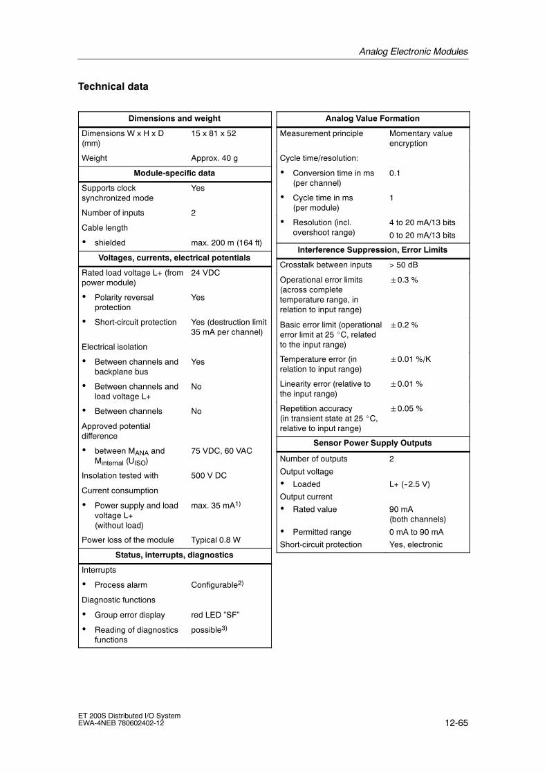
Analog Electronic Modules
12-65ET 200S Distributed I/O SystemEWA-4NEB 780602402-12
Technical data
Dimensions and weight
Dimensions W x H x D(mm)
15 x 81 x 52
Weight Approx. 40 g
Module-specific data
Supports clocksynchronized mode
Yes
Number of inputs 2
Cable length
• shielded max. 200 m (164 ft)
Voltages, currents, electrical potentials
Rated load voltage L+ (frompower module)
24 VDC
• Polarity reversalprotection
Yes
• Short-circuit protection Yes (destruction limit35 mA per channel)
Electrical isolation
• Between channels andbackplane bus
Yes
• Between channels andload voltage L+
No
• Between channels No
Approved potentialdifference
• between MANA andMinternal (UISO)
75 VDC, 60 VAC
Insolation tested with 500 V DC
Current consumption
• Power supply and loadvoltage L+(without load)
max. 35 mA1)
Power loss of the module Typical 0.8 W
Status, interrupts, diagnostics
Interrupts
• Process alarm Configurable2)
Diagnostic functions
• Group error display red LED ”SF”
• Reading of diagnosticsfunctions
possible3)
Analog Value Formation
Measurement principle Momentary valueencryption
Cycle time/resolution:
• Conversion time in ms(per channel)
0.1
• Cycle time in ms(per module)
1
• Resolution (incl.overshoot range)
4 to 20 mA/13 bits
0 to 20 mA/13 bits
Interference Suppression, Error Limits
Crosstalk between inputs > 50 dB
Operational error limits(across completetemperature range, inrelation to input range)
0.3 %
Basic error limit (operationalerror limit at 25 _C, relatedto the input range)
0.2 %
Temperature error (inrelation to input range)
0.01 %/K
Linearity error (relative tothe input range)
0.01 %
Repetition accuracy(in transient state at 25 _C,relative to input range)
0.05 %
Sensor Power Supply Outputs
Number of outputs
Output voltage
• Loaded
Output current
• Rated value
• Permitted range
Short-circuit protection
2
L+ (--2.5 V)
90 mA(both channels)
0 mA to 90 mA
Yes, electronic

Analog Electronic Modules
12-66ET 200S Distributed I/O System
EWA-4NEB 780602402-12
Data for selection of the sensor
Input range (ratedvalue/input resistance)
• Current 4 to 20 mA/50 Ω
0 to 20 mA/50 Ω
Connection of signalgenerators
• for current measuring as2-wire measuringtransducer
possible
Load of the 2-wiretransducer
max. 670Ω
Permitted current at currentinput (destruction limit)
60 mA
Smoothing of measuredvalues
Yes, configurable in4 stages by digitalfiltering
Level
No
weak
medium
strong
Time constant
1 x cycle time
64 x cycle time
128 x cycle time
512 x cycle time
1) without sensor power supply2) DPV1 only3) configuration error
violation of lower limit valueviolation of upper limit valueopen circuit (at 4 to 20mA only)process interrupt lost
12.11 2AI I 2WIRE Standard analog electronic module(6ES7 134-4GB10-0AB0)
Order number
6ES7 134-4GB10-0AB0
Properties
• 2 inputs for current measuring
• Input ranges:
-- ¦ 20 mA, resolution 13 bits + sign
-- 4 to 20 mA, resolution 13 bits
• Allowable common-mode voltage 2 VACSS

Analog Electronic Modules
12-67ET 200S Distributed I/O SystemEWA-4NEB 780602402-12
Terminal assignment
The following table shows the terminal assignment of the 2AI I 4WIRE Standard forthe various terminal modules:
Table 12-42 Terminal assignment of the 2AI I 4WIRE Standard
View Terminal assignment Remarks
M1--M0-- 2
3
4
6
7
8
1 5M1+M0+
mA
ManaMana
TM-E15S24-01 and 2AI I 4WIRE Standard
24 VDC24 VDC
4-wireCH0 CH1
mA
Channel 0: Terminals 1 to 4
Channel 1: Terminals 5 to 8
M+: Input signal ”+”
M--: Input signal ”--”
DC 24V: Power supply for4-wire measuring transducer
Mana: Ground (from powermodule)
The 4-wire transducers arepowered from the module.
M1--M0-- 2
3
4
6
7
8
1 5M1+M0+
mA
ManaMana
TM-E15S26-A1 and 2AI I 4WIRE Standard
24 VDC24 VDC
4-wireCH0 CH1
mA
AUX1A
4
A
3
A
8
A
7AUX1
AUX1
AUX1
Channel 0: Terminals 1 to A3
Channel 1: Terminals 5 to A7
M+: Input signal ”+”
M--: Input signal ”--”
DC 24V: Power supply for4-wire measuring transducer
Mana: Ground (from powermodule)
The 4-wire transducers arepowered from the module.

Analog Electronic Modules
12-68ET 200S Distributed I/O System
EWA-4NEB 780602402-12
Block diagram
Bac
kpla
nebu
s
ET 200Sbackplane bus
interfaceconnection
ADC
MANA24VL+
1M
1
2
5
6
73Current
limiting84
P1P2
MUX
Figure 12-13 Block diagram of the 2AI I 4WIRE Standard
Technical data
Dimensions and weight
Dimensions W×H×D(mm)
15 x 81 x 52
Weight Approx. 40 g
Module-specific data
Supports clock synchro-nized mode
No
Number of inputs 2
Cable length
• shielded max. 200 m (164 ft)
Voltages, currents, electrical potentials
Rated load voltage L+ (frompower module)
24 VDC
• Polarity reversalprotection
Yes
Transducer power supply Yes
• Short-circuit protection Yes, 60 mA (for bothchannels)
Electrical isolation
• Between channels andbackplane bus
Yes
• Between channels andload voltage L+
No
• Between the channels No
Isolation tested 500 VDC
Current consumption
• with load voltage L+ max. 30 mA
Power loss of the module Typical 0.6 W
Status, interrupts, diagnostics
Diagnostic functions
• Group error red LED ”SF”
• Reading of diagnosticsfunctions
Yes

Analog Electronic Modules
12-69ET 200S Distributed I/O SystemEWA-4NEB 780602402-12
Analog Value Formation
Measurement principle integrating
Integration and cycle time /resolution per channel:
• Integration timeselectable
Yes
• Interference frequencysuppression in Hz
60 50
• Integration time in ms 16,7 20
• Conversion time in ms 55 65
• Cycle time in ms Number of activechannels permodule ¢
conversion time
• Resolution (incl.overshoot range)
¦ 20 mA/13 Bit + VZ
4 to 20 mA/13 bits
Interference Suppression, Error Limits
Interference voltage sup-pression for f= n x (f11%),(f1 = interference frequen-cy)
• Common modeinterference(peak value ofinterference < ratedvalue of the input range)
min. 70 dB
Crosstalk between inputs min. -- 50 dB
Operational error limits(across the temperaturerange, in relation to inputrange)
0.6 %
Basic error limit (operationalerror limit at 25 _C, relatedto the input range)
0.4 %
Temperature error (in rela-tion to input range)
0.005 %/K
Linearity error (relative tothe input range)
0.01 %
Repetition accuracy(in transient state at 25 _C,relative to input range)
0.05 %
Data for selection of the sensor
Input range (ratedvalue)/input resistance
• Current 20 mA/50 Ω4 to 20 mA/50 Ω
Permitted continuous inputcurrent (destruction limit)
40 mA
Smoothing of measuredvalues
Yes, configurable in4 stages by digitalfiltering
Level
No
weak
medium
strong
Time constant
1 x cycle time
4 x cycle time
32 x cycle time
64 x cycle time

Analog Electronic Modules
12-70ET 200S Distributed I/O System
EWA-4NEB 780602402-12
12.12 2AI I 2/4WIRE High Feature analog electronic module(6ES7 134-4MB00-0AB0)
Order number
6ES7 134-4MB00-0AB0
Properties
• 2 Input for current measuring
• Input ranges:
-- 20 mA, resolution 15 Bit + sign
-- 4 to 20 mA, resolution 15 Bit
• Isolated for load voltage L+
• Allowable common-mode voltage between the channels 100 VAC
• Supports 2-wire or 4-wire transducer
Terminal assignment
The following table shows the terminal assignment of the 2AI I 2/4WIRE HighFeature
Table 12-43 Terminal assignment of the 2AI I 2/4WIRE High Feature
View Terminal assignment Remarks
M1--M0-- 2
3
4
6
7
8
1 5M1+M0+
mA
TM-E15S24-01 and 2AI I 2/4WIRE High Feature
+24 V DC+24 V DC
4-wireCH0 CH1
mA
--24 V DC--24 V DC
4-wire measuring transducer
Channel 0: Terminals 1 to 4
Channel 1: Terminals 5 to 8
M+ : input signal ”+”
M--: Input signal ”--”
+ 24 VDC: Power supply for4-wire measuring transducer
-- 24 VDC: Return circuit fortransducer power supply
4-wire transducers can bepowered through the module.
An external power supply forone of the transducers must beused to ensure isolationbetween the channels.

Analog Electronic Modules
12-71ET 200S Distributed I/O SystemEWA-4NEB 780602402-12
Table 12-43 Terminal assignment of the 2AI I 2/4WIRE High Feature, continued
View RemarksTerminal assignment
M1--M0-- 2
3
4
6
7
8
1 5M1+M0+
TM-E15S24-01 and 2AI I 2/4WIRE High Feature
(Alternative terminal assignment for 2WIRE)
+24 V DC+24 V DC
2-wireCH0 CH1
mA
--24 V DC--24 V DC
2-wire measuring transducer
Channel 0: Terminals 1 to 4
Channel 1: Terminals 5 to 8
M+ : input signal ”--”
M-- : connect to -- 24 VDC
+ 24 VDC: Input signal ”+”
The 2-wire transducers arepowered over themeasurement leads.
A mixture of 2-wire and 4-wiretransducers is allowable.
An external power supply forone of the transducers must beused to ensure isolationbetween the channels.
M1--M0-- 2
3
4
6
7
8
1 5M1+M0+
mA
TM-E15S26-01 and 2AI I 2/4WIRE High Feature
+24 V DC+24 V DC
4-wireCH0 CH1
mA
--24 V DC--24 V DC
4-wire measuring transducer
AUX1A
4
A
3
A
8
A
7AUX1
AUX1
AUX1
Channel 0: Terminals 1 to A3
Channel 1: Terminals 5 to A7
M+ : input signal ”+”
M--: Input signal ”--”
+ 24 VDC: Power supply for4-wire measuring transducer
-- 24 VDC: Return circuit fortransducer power supply
4-wire transducers can bepowered through the module.
An external power supply forone of the transducers must beused to ensure isolationbetween the channels.

Analog Electronic Modules
12-72ET 200S Distributed I/O System
EWA-4NEB 780602402-12
Table 12-43 Terminal assignment of the 2AI I 2/4WIRE High Feature, continued
View RemarksTerminal assignment
M1--M0-- 2
3
4
6
7
8
1 5M1+M0+
TM-E15S26-01 and 2AI I 2/4WIRE High Feature
(Alternative terminal assignment for2WIRE)
+24 V DC+24 V DC
2-wireCH0 CH1
mA
--24 V DC--24 V DC
2-wire measuring transducer
AUX1A
4
A
3
A
8
A
7AUX1
AUX1
AUX1
Channel 0: Terminals 1 to A3
Channel 1: Terminals 5 to A7
M+ : input signal ”--”
M-- : connect to -- 24 VDC
+ 24 VDC: Input signal ”+”
The 2-wire transducers arepowered over themeasurement leads.
A mixture of 2-wire and 4-wiretransducers is allowable.
An external power supply forone of the transducers must beused to ensure isolationbetween the channels.
Block diagram
ADC
MANA24VL+
1M
1
2
5
6
73
84
P1P2
MUX
Bac
kpla
nebu
s
ET 200Sbackplane bus
interfaceconnection
Currentlimiting
Figure 12-14 Block diagram of the 2AI I 2/4WIRE High Feature

Analog Electronic Modules
12-73ET 200S Distributed I/O SystemEWA-4NEB 780602402-12
Technical data
Dimensions and weight
Dimensions W x H x D(mm)
15 x 81 x 52
Weight Approx. 40 g
Module-specific data
Supports clocksynchronized mode
No
Number of inputs 2
Cable length
• shielded max. 200 m (164 ft)
Voltages, currents, electrical potentials
Rated load voltage L+ (frompower module)
24 VDC
• Polarity reversalprotection
Yes
Transducer power supply Yes
• Short-circuit protection Yes, 60 mA (for bothchannels)
Electrical isolation
• Between the channelsand backplane bus
Yes
• Between channels andload voltage L+
Yes
• Between the channelsand PE
Yes
• Between the channels No
Permitted potentialdifference
• Between the channels 140 VDC/100 VAC(with isolatedpower supply for thetransducers)
Isolation tested 500 VDC
Current consumption
• with load voltage L+ max. 53 mA
Power loss of the module Typical 0.85 W
Status, interrupts, diagnostics
Diagnostic functions
• Group error red LED ”SF”
• Reading of diagnosticsfunctions
Yes
Analog Value Formation
Measurement principle Integrating
Integration and cycle time /resolution per channel:
• Integration timeselectable
Yes
• Interference frequencysuppression in Hz
60 50 no
• Integration time in ms 16,67 20 7,5
• Conversion time in ms
-- 1 channel permodule active
-- 2 channels permodule active
25 30 10
58,3 70 26
• Cycle time in ms
-- 1 channel permodule active
-- 2 channels permodule active
75 90 30
175 210 78
• Resolution (incl.overshoot range)
20 mA/15 Bit + VZ
4 to 20 mA/15 bits
Interference Suppression, Error Limits
Interference voltagesuppression forf = n x (f10.5%),(f1 = interferencefrequency)
• Common modeinterference (USS)
• Common modeinterference(peak value ofinterference < ratedvalue of the input range)
min. 100 dB
min. 90 dB
Crosstalk between inputs min. --100 dB
Operational error limits1)
(across completetemperature range, inrelation to input range)
0.1 %

Analog Electronic Modules
12-74ET 200S Distributed I/O System
EWA-4NEB 780602402-12
Basic error limit1)
(operational error limit at25 _C, related to the inputrange)
0.05 %
Temperature error (inrelation to input range)
0.003 %/K
Linearity error (relative tothe input range)
0.03 %
Repetition accuracy(in transient state at 25 _C,relative to input range)
0.01 %
Data for selection of the sensor
Input range (ratedvalue)/input resistance
• Current 20 mA/50 Ω4 to 20 mA/50 Ω
Permitted continuous inputcurrent (destruction limit)
40 mA (on onesingle channel)
Load of the 2-wiretransducer
max. 750Ω
Smoothing of measuredvalues
Yes, configurable in4 stages by digitalfiltering
Level
No
weak
medium
strong
Time constant
1 x cycle time
4 x cycle time
32 x cycle time
64 x cycle time
1) When configuring modules the runtimecalibration can be enabled for periodiccompensation of error voltage changes of theA/D converter. The update of new data isdelayed by 200 ms during the calibrationinterval. The precision limits of the module arereached without runtime calibration.
12.13 2AI I 4WIRE High Speed analog electronic module(6ES7 134-4GB61-0AB0)
Order number
6ES7 134-4GB61-0AB0
Properties
• 2 inputs for current measuring
• Current-limited sensor power supply (90 mA)
• Input ranges:
-- 4 to 20 mA, resolution 13 bits
-- 0 to 20 mA, resolution 13 bits
-- 20 mA, resolution 13 bits + sign
• Supports clock synchronized mode
-- Minimum possible time for the clock-synchronized DP cycle (TDPmin): 2.5 ms
-- Minimum possible conversion time of the input module (TWEmin): 1.1 ms

Analog Electronic Modules
12-75ET 200S Distributed I/O SystemEWA-4NEB 780602402-12
Terminal assignment
The following table shows the terminal assignment of the 2AI I 4WIRE High Speedfor the various terminal modules:
Table 12-44 Terminal assignment of the 2AI I 4WIRE High Speed
View Terminal assignment Remarks
M1--M0-- 2
3
4
6
7
8
1 5M1+M0+
mA
ManaMana
TM-E15S24-01 and 2AI I 4WIRE High Speed
24 VDC24 VDC
4-wireCH0 CH1
mA
Channel 0: Terminals 1 to 4
Channel 1: Terminals 5 to 8
M+: Input signal ”+”
M--: Input signal ”--”
DC 24V: Power supply for4-wire measuring transducer
Mana: Ground (from powermodule)
The 4-wire transducers arepowered from the module.
M1--M0-- 2
3
4
6
7
8
1 5M1+M0+
mA
ManaMana
TM-E15S26-A1 and 2AI I 4WIRE High Speed
24 VDC24 VDC
4-wireCH0 CH1
mA
AUX1A
4
A
3
A
8
A
7AUX1
AUX1
AUX1
Channel 0: Terminals 1 to A3
Channel 1: Terminals 5 to A7
M+: Input signal ”+”
M--: Input signal ”--”
DC 24V: Power supply for4-wire measuring transducer
Mana: Ground (from powermodule)
The 4-wire transducers arepowered from the module.

Analog Electronic Modules
12-76ET 200S Distributed I/O System
EWA-4NEB 780602402-12
Block diagram
Bac
kpla
nebu
s
ET 200Sbackplane bus
interfaceconnection
ADC
MANA24 VL+
1M
1
2
5
6
73
Current limit
84
P1P2
MUX
Figure 12-15 Block diagram of the 2AI I 4WIRE High Speed
Technical data
Dimensions and weight
Dimensions W x H x D(mm)
15 x 81 x 52
Weight Approx. 40 g
Module-specific data
Supports clock synchro-nized mode
Yes
Number of inputs 2
Cable length
• shielded max. 200 m (164 ft)
Voltages, currents, electrical potentials
Rated load voltage L+ (frompower module)
24 VDC
• Polarity reversalprotection
Yes
Electrical isolation
• Between channels andbackplane bus
Yes
• Between channels andload voltage L+
No
• Between channels No
Permitted potentialdifference
• between MANA andMinternal (UISO)
75 VDC, 60 VAC
Isolation tested with 500 V DC
Current consumption
• Power supply and loadvoltage L+ (withoutload)
max. 35 mA1)
Power loss of the module Typical 0.8 W
Status, interrupts, diagnostics
Interrupts
• Process alarm Configurable2)
Diagnostic functions
• Group error display red LED ”SF”
• Reading of diagnosticdata
possible3)

Analog Electronic Modules
12-77ET 200S Distributed I/O SystemEWA-4NEB 780602402-12
Analog Value Formation
Measurement principle Momentary valueencryption
Cycle time/resolution:
• Conversion time in ms(per channel)
0.1
• Cycle time in ms (permodule)
1
• Resolution (incl.overshoot range)
4 to 20 mA/13 bits0 to 20 mA/13 bits20 mA/13 bits +sign
Interference Suppression, Error Limits
Crosstalk between inputs > 50 dB
Operational error limits(across completetemperature range, inrelation to input range)
0.3 %
Basic error limit (operationalerror limitat 25 _C, related to theinput range)
0.2 %
Temperature error (inrelation to input range)
0.01 %/K
Linearity error (relative tothe input range)
0.01 %
Repetition accuracy(in transient state at 25 _C,relative to input range)
0.05 %
Sensor Power Supply Outputs
Number of outputs
Output voltage
• Loaded
Output current
• Rated value
• Permitted range
Short-circuit protection
2
L+ (--2.5 V)
90 mA(both channels)
0 mA to 90 mA
Yes, electronic
Data for selection of the sensor
Input range (ratedvalue)/input resistance
• Current 4 to 20 mA/50 Ω0 to 20 mA/50 Ω20 mA/50 Ω
Connection of signalgenerators
• for current measuring as2-wire measuringtransducer
possible
Load of the 2-wiretransducer
max. 670Ω
Permitted current at currentinput (destruction limit)
60 mA
Smoothing of measuredvalues
Yes, configurable in4 stages by digitalfiltering
Level
No
weak
medium
strong
Time constant
1 x cycle time
64 x cycle time
128 x cycle time
512 x cycle time
1) without sensor power supply2) DPV1 only3) configuration error
violation of lower limit valueviolation of upper limit valueopen circuit (at 4 to 20mA only)process interrupt lost

Analog Electronic Modules
12-78ET 200S Distributed I/O System
EWA-4NEB 780602402-12
12.14 2AI RTD Standard analog electronic module(6ES7 134-4JB50-0AB0)
Order number
6ES7 134-4FB50-0AB0
Properties
• 2 inputs for resistance thermometer or resistance measurement
• Input ranges:
-- Resistance thermometer: Pt100; Ni100; resolution 15 bits + sign
-- Resistance measurement: 150 Ω; 300 Ω ; 600 Ω,resolution max. 15 bits + sign
• Isolated for load voltage L+
• Linearization of the sensor characteristic curves
Terminal assignment
The resistance thermometer/resistances are measured in 4-wire connection. Aconstant current is fed to the resistance thermometers/resistances through theterminals IC + and IC --. The voltage at the resistance thermometer/resistance ismeasured through terminals M + and M --. This provides a high degree of precisionin the measurement results with the 4-wire terminal.
With the 2-3-wire terminal appropriate bridges are required on the module betweenM+ and Ic+ or M-- and Ic--. However, this involves a loss of precision in themeasurement results.

Analog Electronic Modules
12-79ET 200S Distributed I/O SystemEWA-4NEB 780602402-12
The following table shows the terminal assignment of the 2AI RTD Standard at theterminal module.
Table 12-45 Terminal assignment of the 2AI RTD Standard
View Terminal assignment Remarks
2
3
4
6
7
8
1 5
IC1+
M1--
M1+
IC1--
IC0+
M0--
M0+
IC0--
2-wire 3-wire
TM-E15S24-01 and 2AI RTD Standard
CH0 CH1 4-wire
Channel 0: Terminals 1 to 4
Channel 1: Terminals 5 to 8
M+: Measuring cable positive
IC--: Constant current cablenegative
M--: Measuring cablenegative
IC+ Constant current cablepositive
2
3
4
6
7
8
1 5
IC1+
M1--
M1+
IC1--
IC0+
M0--
M0+
IC0--
2-wire 3-wire
TM-E15S26-A1 and 2AI RTD Standard
CH0 CH1 4-wire
AUX1A
4
A
3
A
8
A
7AUX1
AUX1
AUX1
Channel 0: Terminals 1 to A3
Channel 1: Terminals 5 to A7
M+: Measuring cable positive
IC--: Constant current cablenegative
M--: Measuring cablenegative
IC+ Constant current cablepositive
Note
A wire break in the measuring wires of the temperature sensor is not detected witha 3 or 4-wire terminal (terminals 1 and 2 or 5 and 6). Undefined words may bereturned.

Analog Electronic Modules
12-80ET 200S Distributed I/O System
EWA-4NEB 780602402-12
Block diagram
Bac
kpla
nebu
s
ET 200Sbackplane bus
interfaceconnection
ADC
MANA24VL+
1M
1
2
5
6
73
84
P1P2
MUX
MUX
Figure 12-16 Block diagram of the 2AI RTD Standard
Technical data
Dimensions and weight
Dimensions W x H x D(mm)
15 x 81 x 52
Weight Approx. 40 g
Module-specific data
Supports clock synchro-nized mode
No
Number of inputs 2
Cable length
• shielded max. 200 m (164 ft)
Voltages, currents, electrical potentials
Rated load voltage L+ (frompower module)
24 VDC
• Polarity reversalprotection
Yes
Transducer power supply Yes
• Constant power supplyfor resistive sensors
Approx. 1.5 mA
• Short-circuit protection Yes
Electrical isolation
• Between channels andbackplane bus
Yes
• Between channels andload voltage L+
Yes
• Between the channels No
Permitted potential differ-ence
• Between MANA and thecentral ground point(UISO)
75 VDC / 60 VAC
Isolation tested 500 VDC
Current consumption
• with load voltage L+ max. 30 mA
Power loss of the module Typical 0.6 W
Status, interrupts, diagnostics
Diagnostic functions
• Group error red LED ”SF”
• Reading of diagnosticsfunctions
Yes

Analog Electronic Modules
12-81ET 200S Distributed I/O SystemEWA-4NEB 780602402-12
Analog Value Formation
Measurement principle integrating
Integration and cycle time /resolution per channel:
• Integration timeselectable
Yes
• Interference frequencysuppression in Hz
60 50
• Integration time in ms 16.7 20
• Conversion time in ms 110 130
• Cycle time in ms Number of activechannels permodule x conversiontime
• Resolution (incl.overshoot range)
Pt100, Ni100/ 15 Bit+ VZ
150 Ω/14 Bit/300 Ω, 600 Ω/15 Bit
Interference Suppression, Error Limits
Interference voltage sup-pression for f= n x (f11%),(f1 = interference frequen-cy)
• Common modeinterference (USS)
• Common modeinterference(peak value ofinterference < ratedvalue of the input range)
min. 90 dB
min. 70 dB
Crosstalk between inputs min. --50 dB
Operational error limits(across the temperaturerange, in relation to inputrange)
0.6 %
Basic error limit (operationalerror limit at 25 _C, relatedto the input range)
0.4 %
Temperature error (in rela-tion to input range)
0.005 %/K
Linearity error (relative tothe input range)
0.01 %
Repetition accuracy(in transient state at 25_C,relative to input range)
0.05 %
Data for selection of the sensor
Input range (ratedvalue)/input resistance
• Resistance 150 Ω/min. 2 MΩ300 Ω/min. 2 MΩ600 Ω/min. 2 MΩ
• Resistive thermo-meter
Pt100/min. 2 MΩNi100/min. 2 MΩ
Permitted continuous inputvoltage (destruction limit)
Max. 9 V
Connection of signalgenerators
• for measuringresistance
-- 2 and 3-wireconnection
-- 4-wire connection
Yes, wireresistances are alsomeasured, bridgeson TR
Yes
Characteristics linearization Yes, configurable forPt100, Ni100
Smoothing of measuredvalues
Yes, configurable in4 stages by digitalfiltering
Level
No
weak
medium
strong
Time constant
1 x cycle time
4 x cycle time
32 x cycle time
64 x cycle time

Analog Electronic Modules
12-82ET 200S Distributed I/O System
EWA-4NEB 780602402-12
12.15 2AI RTD High Feature analog electronic module(6ES7 134-4NB50-0AB0)
Order number
6ES7 134-4NB50-0AB0
Features
• 2 inputs for resistance thermometer or resistance measurement
• Input ranges:
-- Resistance thermometer: Pt100; Ni100; Ni120; Pt200; Ni200; Pt500; Ni500;Pt1000; Ni1000; Cu10;resolution max. 15 bits + sign
-- Resistance measurement: 150 Ω; 300 Ω; 600 Ω; 3000 Ω; PTC;resolution max. 15 bits
• Automatic compensation of wire resistances with 3-wire connection.
• Configurable temperature coefficient with resistive sensors
• High degree of accuracy
• Isolated for load voltage
• Linearization of the sensor characteristic curves
• Parameter length 7 bytes
• Allowable common-mode voltage 2 VACss
• Recording of the reference junction temperature (in connection with the 2AI TCStandard electronic module)
• Compatible with 2AI RTD Standard (6ES7 134-4JB50-0AB0)
Note
The 2AI RTD High Feature electronic module can replace a 2AI RTD Standard inan existing system.
• Changes to the wiring are not required. The additional bridges on the 2AI RTDStandard terminal module need not be removed.
• No change in the configuration (hardware or GSD file) is required. In this caseonly the new functions of the 2AI RTD High Feature are not configurable.
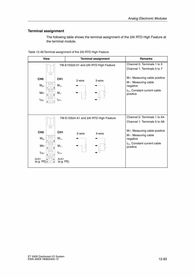
Analog Electronic Modules
12-83ET 200S Distributed I/O SystemEWA-4NEB 780602402-12
Terminal assignment
The following table shows the terminal assignment of the 2AI RTD High Feature atthe terminal module.
Table 12-46 Terminal assignment of the 2AI RTD High Feature
View Terminal assignment Remarks
IC1+
M1--
M1+
IC0+
M0--
M0+
2-wire 3-wire
TM-E15S23-01 and 2AI RTD High Feature
CH0 CH1
2
3
6
7
1 5
Channel 0: Terminals 1 to 3
Channel 1: Terminals 5 to 7
M+: Measuring cable positive
M--: Measuring cablenegative
IC+ Constant current cablepositive
IC1+
M1--
M1+
IC0+
M0--
M0+
AUX1(e.g. PE)
2-wire 3-wire
TM-E15S24-A1 and 2AI RTD High Feature
CH0 CH1
2
3
4
6
7
8
1 5
AUX1(e.g. PE)
AA
Channel 0: Terminals 1 to A4
Channel 1: Terminals 5 to A8
M+: Measuring cable positive
M--: Measuring cablenegative
IC+ Constant current cablepositive

Analog Electronic Modules
12-84ET 200S Distributed I/O System
EWA-4NEB 780602402-12
Table 12-46 Terminal assignment of the 2AI RTD High Feature, continued
View RemarksTerminal assignment
2
3
4
6
7
8
1 5
IC1+
M1--
M1+
IC1--
IC0+
M0--
M0+
IC0--
2-wire 3-wire
TM-E15S24-01 and 2AI RTD High Feature
CH0 CH1 4-wire
Channel 0: Terminals 1 to 4
Channel 1: Terminals 5 to 8
M+: Measuring cable positive
IC--: Constant current cablenegative
M--: Measuring cablenegative
IC+ Constant current cablepositive
2
3
4
6
7
8
1 5
IC1+
M1--
M1+
IC1--
IC0+
M0--
M0+
IC0--
2-wire 3-wire
TM-E15S26-A1 and 2AI RTD High Feature
CH0 CH1 4-wire
AUX1A
4
A
3
A
8
A
7AUX1
AUX1
AUX1
Channel 0: Terminals 1 to A3
Channel 1: Terminals 5 to A7
M+: Measuring cable positive
IC--: Constant current cablenegative
M--: Measuring cablenegative
IC+ Constant current cablepositive

Analog Electronic Modules
12-85ET 200S Distributed I/O SystemEWA-4NEB 780602402-12
Block diagram
Bac
kpla
nebu
s
ET 200Sbackplane bus
interfaceconnection
ADC
MANA24VL+
1M
1
2
5
6
73
84
P1P2
MUX
MUX
Figure 12-17 Block diagram of the 2AI RTD High Feature
Technical data
Dimensions and weight
Dimensions W x H x D(mm)
15 x 81 x 52
Weight Approx. 40 g
Module-specific data
Supports clock synchro-nized mode
No
Number of inputs 2
Cable length
• shielded max. 200 m (164 ft)
Voltages, currents, electrical potentials
Rated load voltage L+ (frompower module)
24 VDC
• Polarity reversalprotection
Yes
Transducer power supply Yes
• Constant power supplyfor resistive sensors
Approx. 1.25 mA
• Short-circuit protection Yes
Electrical isolation
• Between channels andbackplane bus
Yes
• Between channels andload voltage L+
Yes
• Between the channels No
Permitted potentialdifference
• Between MANA and thecentral ground point(UISO)
75 VDC / 60 VAC
Isolation tested 500 VDC
Current consumption
• with load voltage L+ max. 30 mA
Power loss of the module Typical 0.6 W
Status, interrupts, diagnostics
Diagnostic functions
• Group error red LED ”SF”
• Reading of diagnosticsfunctions
Yes

Analog Electronic Modules
12-86ET 200S Distributed I/O System
EWA-4NEB 780602402-12
Analog Value Formation
Measurement principle integrating (Sigma-Delta)
Integration and cycle time /resolution per channel:
• Integration timeselectable
Yes
• Interference frequencysuppression in Hz
60 50
• Integration time in ms 16.7 20
• Basic conversion timeincl. integration time inms
50 60
• Additional conversiontime for wire breakdiagnostics in ms
5 5
• Additional conversiontime for wirecompensation with3-wire connection in ms
50 60
• Cycle time in ms Number of activechannels permodule x conversiontime
• Resolution (incl.overshoot range)
Pt100; Ni100; Ni120;Pt200; Ni200; Pt500;Ni500; Pt1000;Ni1000; Cu10 /15 bits + sign
150 Ω; 300 Ω;600 Ω; 3000 Ω; /15 bits
PTC1) / 1 bit
Interference Suppression, Error Limits
Interference voltage sup-pression for f= n x (f11%),(f1 = interference frequen-cy)
• Common modeinterference (USS)
• Common modeinterference(peak value ofinterference < ratedvalue of the input range)
min. 90 dB
min. 70 dB
Crosstalk between inputs min. --50 dB
Operational error limits(across the temperaturerange, in relation to inputrange)
• Resistive encoder 0.1 %
• Pt100, Pt200, Pt500,Pt1000 Standard
1.0 K
• Pt100, Pt200, Pt500,Pt1000 Climatic
0.25 K
• Ni100, Ni120, Ni200,Ni500, Ni 1000Standard and Climatic
0.4 K
• Cu10 1.5 K
Basic error limit forresistive sensor (operation-al error limit at 25 _C, re-lated to the input range)
• Resistive encoder 0.05 %
• Pt100, Pt200, Pt500,Pt1000 Standard
0.6 K
• Pt100, Pt200, Pt500,Pt1000 Climatic
0.13 K
• Ni100, Ni120, Ni200,Ni500, Ni1000 Standardand Climatic
0.2 K
• Cu10 1.0 K
Temperature error (in rela-tion to input range)
0.0009 %/K
Linearity error (relative tothe input range)
0.01 %
Repetition accuracy(in transient state at 25_C,relative to input range)
0.05 %

Analog Electronic Modules
12-87ET 200S Distributed I/O SystemEWA-4NEB 780602402-12
Data for selection of the sensor
Input range (ratedvalue)/input resistance
• Resistance 150 Ω/min. 10 MΩ300 Ω/min. 10 MΩ600 Ω/min. 10 MΩ3000 Ω/min. 10 MΩPTC min 10 MΩ
• Resistive thermo-meter
Pt100/min. 10 MΩNi100/min. 10 MΩNi120/min. 10 MΩPt200/min. 10 MΩNi200/min. 10 MΩPt500/min. 10 MΩNi500/min. 10 MΩPt1000/min. 10 MΩNi1000/min. 10 MΩCu10/min. 10 MΩ
Permitted continuous inputvoltage (destruction limit)
Max. 9 V
Connection of signalgenerators
• For resistancemeasuring
-- 2-wire connection
-- 3-wire connection
Yes,
internalcompensation ofwire resistances
-- 4-wire connection Yes
Characteristics linearization Yes, configurable forPtxxx, Nixxx
Smoothing of measuredvalues
Yes, configurable in4 stages by digitalfiltering
Level
No
weak
medium
strong
Time constant
1 x cycle time
4 x cycle time
32 x cycle time
64 x cycle time
1) As per VDE 0660 Part 302/303, Type A
Use of Cu10 sensors
• Select ”Thermal resistance 3-wire” and ”Cu10” during configuration.
• Wire the Cu10 sensor in 3-wire connection technology
• During operation the wire resistance of the missing measuring wire isautomatically compensated internally.
Note
For optimum wire compensation with Cu10 please observe the following:
• The total of wire resistance and measuring resistance must not exceed 31 Ω.
• The resistance of the wire must be a maximum of 8 Ω if you want to use thetemperature range up to above 312 _C. Example: A 200 m long Cu cable witha cross-section of 0.5 mm2 has about 7 Ω, a small cross section reduces theallowable cable length accordingly.

Analog Electronic Modules
12-88ET 200S Distributed I/O System
EWA-4NEB 780602402-12
Use of PTC resistances
PTCs are suitable for temperature monitoring or as a thermal protective device forcomplex drives and transformer windings.
• Select ”Resistance 2-wire” and ”PTC” during configuration.
• Connect the PTC in 2-wire technology.
• Use PTC resistances of Type A (PTC thermistor) as perDIN / VDE 0660, Part 302.
• Sensor data for PTC resistance:
Feature Technicalspecifications
Remarks
Switching points Switch on/release
max. 750Ω
Measured resistance < Response value
• SIMATIC S7: Bit 0 = ”0” (in PII)
• SIMATIC S5: Bit 3 = ”0” (in PII)
Powering-down
from 1650 Ω to 4000 Ω
Temperature rise
Measured resistance > Response value
• SIMATIC S7: Bit 0 = ”1” (in PII)
• SIMATIC S5: Bit 3 = ”1” (in PII)
Switch on/release
from 1650 Ω to 750 Ω
Temperature fall
Measured resistance < Response value
• SIMATIC S7: Bit 0 = ”0” (in PII)
• SIMATIC S5: Bit 3 = ”0” (in PII)
(TNF--5) _C
(TNF+5) _C
(TNF+15) _C
Measuring circuitvoltage
Voltage at PTC
max. 550Ω
Min. 1330 Ω
Min. 4000 Ω
Max. 7.5 V
TNF = rated response temperature
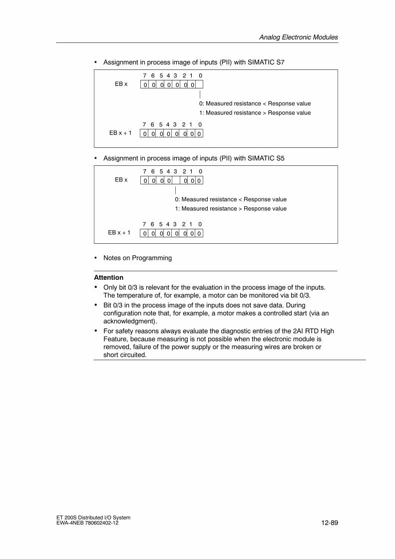
Analog Electronic Modules
12-89ET 200S Distributed I/O SystemEWA-4NEB 780602402-12
• Assignment in process image of inputs (PII) with SIMATIC S7
EB x7 6 02
0: Measured resistance < Response value
1: Measured resistance > Response value
1345
0000000
EB x + 17 6 02 1345
00000000
• Assignment in process image of inputs (PII) with SIMATIC S5
EB x7 6 02
0: Measured resistance < Response value
1: Measured resistance > Response value
1345
000000
EB x + 17 6 02 1345
00000000
0
• Notes on Programming
Attention• Only bit 0/3 is relevant for the evaluation in the process image of the inputs.
The temperature of, for example, a motor can be monitored via bit 0/3.
• Bit 0/3 in the process image of the inputs does not save data. Duringconfiguration note that, for example, a motor makes a controlled start (via anacknowledgment).
• For safety reasons always evaluate the diagnostic entries of the 2AI RTD HighFeature, because measuring is not possible when the electronic module isremoved, failure of the power supply or the measuring wires are broken orshort circuited.

Analog Electronic Modules
12-90ET 200S Distributed I/O System
EWA-4NEB 780602402-12
12.16 2AI TC Standard analog electronic module(6ES7 134-4JB00-0AB0)
Order number
6ES7 134-4JB00-0AB0
Properties
• 2 inputs for thermocouples or voltage measurement
• Input ranges:
-- Voltage measurement: ¦ 80 mA, resolution 15 bits + sign
-- Thermocouples: Type E, N, J, K, L, S, R, B, T, resolution 15 bits + sign
• Isolated for load voltage L+
• Linearization of the sensor characteristic curves
• Allowable common-mode voltage 2 VACSS
Terminal assignment
The following table shows the terminal assignment of the 2AI TC Standard for thevarious terminal modules:
Voltage measuring as with 2AI U Standard (see Chap. 12.5).
Table 12-47 Terminal assignment of the 2AI TC Standard
View Terminal assignment Remarks
M1--M0--
AUX1 (e.g. PE)
2
3
4
6
7
8
1 5M1+M0+
AUX1 (e.g. PE)
ManaMana
TM-E15S24-A1 and 2DA TC Standard
CH0 CH1
AUX1 must beassigned to PE.
AA
Channel 0: Terminals 1 to A4
Channel 1: Terminals 5 to A8
M+: Measuring cable positive
M--: Measuring cablenegative
Mana: Module ground

Analog Electronic Modules
12-91ET 200S Distributed I/O SystemEWA-4NEB 780602402-12
Table 12-47 Terminal assignment of the 2AI TC Standard, continued
View RemarksTerminal assignment
2
3
4
6
7
8
1 5
ManaMana
TM-E15S24-01 and 2AI TC Standard
M1--M0--
M1+M0+
CH0 CH1
n. c.n. c.
Channel 0: Terminals 1 to 4
Channel 1: Terminals 5 to 8
M+: Measuring cable positive
M--: Measuring cablenegative
Mana: Module ground
Terminals 4 and 8 can beused for connection of cablesthat are not required up to30 VDC.
2
3 7
1 5
ManaMana
TM-E15S23-01 and 2AI TC Standard
M1--M0--
M1+M0+
CH0 CH1
6
Channel 0: Terminals 1 to 3
Channel 1: Terminals 5 to 7
M+: Measuring cable positive
M--: Measuring cablenegative
Mana: Module ground
2
3
4
6
7
8
1 5
ManaMana
TM-E15S26-A1 and 2DA TC Standard
M1--M0--
M1+M0+
CH0 CH1
AUX1A
4
A
3
A
8
A
7AUX1
AUX1
AUX1
n. c.n. c.
Channel 0: Terminals 1 to A3
Channel 1: Terminals 5 to A7
M+: Measuring cable positive
M--: Measuring cablenegative
Mana: Module ground
Terminals 4 and 8 can beused for connection of cablesthat are not required up to30 VDC.

Analog Electronic Modules
12-92ET 200S Distributed I/O System
EWA-4NEB 780602402-12
Block diagram
Bac
kpla
nebu
s
ET 200Sbackplane bus
interfaceconnection
ADC
MANA24VL+
1M
1
2
5
6
3
7
P1P2
MUX
Figure 12-18 Block diagram of the 2AI TC Standard
Technical data
Dimensions and weight
Dimensions W x H x D(mm)
15 x 81 x 52
Weight Approx. 40 g
Module-specific data
Supports clock synchro-nized mode
No
Number of inputs 2
Cable length
• shielded max. 50 m (164 ft)
Voltages, currents, electrical potentials
Rated load voltage L+ (frompower module)
24 VDC
• Polarity reversalprotection
Yes
Electrical isolation
• Between channels andbackplane bus
Yes
• Between channels andload voltage L+
Yes
• Between the channels No
• Between channels and24 V power supply
Yes
Permitted potential differ-ence
• Between MANA and thecentral ground point(Uiso)
75 VDC / 60 VAC
• Between inputs andMANA (UCM)
2 VACSS
Isolation tested 500 VDC
Current consumption
• with load voltage L+ max. 30 mA
Power loss of the module Typical 0.6 W
Status, interrupts, diagnostics
Diagnostic functions
• Group error red LED ”SF”
• Reading of diagnosticsfunctions
Yes

Analog Electronic Modules
12-93ET 200S Distributed I/O SystemEWA-4NEB 780602402-12
Analog Value Formation
Measurement principle integrating
Integration / conversiontime / resolution perchannel:
• Integration timeselectable
Yes
• Interference frequencysuppression in Hz
60 50
• Integration time in ms 16.7 20
• Basic conversion timeincl. integration time inms
55 65
• Additional conversiontime for wire breakdiagnostics in ms
20 20
• Cycle time in ms Number of activechannels permodule x conversiontime
• Resolution (incl.overshoot range)
15 bits + sign
Interference Suppression, Error Limits
Interference voltage sup-pression for f= n x (f11%),(f1 = interferencefrequency)
• Common modeinterference (USS)
• Common modeinterference(peak value ofinterference < ratedvalue of the input range)
min. 90 dB
min. 70 dB
Crosstalk between inputs min. --50 dB
Operational error limits(across complete tempera-ture range, in relation to in-put range)1
0.6 %
Basic error limit (operationalerror limit at 25 _C, relatedto the input range)1)
0.4 %
Temperature error (in rela-tion to input range)
0.005 %/K
Linearity error (relative tothe input range)
0.01 %
Repetition accuracy(in transient state at 25_C,relative to input range)
0.05 %
Data for selection of the sensor
Input range (ratedvalue)/input resistance
• Voltage 80 mV/min. 1 MΩ
• Thermocouple Type E, N, J, K, L, S,R, B, T/min. 1 M
Permitted continuous inputvoltage (destruction limit)
10 V, continuous
Connection of signalgenerators
• For voltagemeasurement
possible
Characteristics linearization Yes, configurable forType E, N, J, K, L, S,R, B, T as perIEC 584
Temperature compensation
• Internal temperaturecompensation
Not possible
• External temperaturecompensation bylooping a compensationunit into the measuringcircuit
Possible, oneexternalcompensationunit per channel
• External compensationby means oftemperature valueacquired at an analogmodule of the sameET 200S station
Yes
Smoothing of measuredvalues
Yes, configurable in4 stages by digitalfiltering
Level
No
weak
medium
strong
Time constant
1 x cycle time
4 x cycle time
32 x cycle time
64 x cycle time
1) with Type N: from --150 _C, Type B:from 200 _C,Type T: from --230 _C

Analog Electronic Modules
12-94ET 200S Distributed I/O System
EWA-4NEB 780602402-12
Compensation of thermocouples with a compensation unit
In addition to the error limits of the 2AI TC Standard electronic module (see”Technical Specifications” table in this chapter), you must also consider theprecision of the compensation unit.
Compensation of thermocouples with a Pt100 on the 2AI RTD Standard
Factors that influence the precision of the temperature measurement
Rules for wiring Make sure that there is a good thermal contact betweenthe reference junction and the Pt100 used forcompensation.
We recommend wiring the Pt100 with a 4-wire connection.
Supplementary technicalspecifications for the errorli it f th 2A TC
The precision of the thermal resistor (Pt100) used forcompensation must be considered.*
limits of the 2A TCThe errors of the measuring input (2AI RTD Standard)used for compensation must be considered*
* This error can result in a greater measurement deviation when using thermocouples witha very low rise of the thermocouple characteristic.With the following thermocouples this results in a restriction of the input range of thethermocouple for which the precision specifications of the manual apply:Type N: --100 °CType K: --230 °CType E: --230 °C

Analog Electronic Modules
12-95ET 200S Distributed I/O SystemEWA-4NEB 780602402-12
12.17 2AI TC High Feature analog electronic module(6ES7 134-4NB00-0AB0)
Order number
6ES7 134-4NB00-0AB0
Properties
• 2 inputs for thermocouples or voltage measurement
• Input ranges:
-- Voltage measurement: ¦ 80 mA, resolution 15 bits + sign
-- Thermocouples: Type E, N, J, K, L, S, R, B, T, C, resolution 15 bits + sign
• 2AI TC High Feature is inserted on TM-E15S24-AT or TM-E15C24-AT
• Isolated for load voltage L+
• Linearization of the sensor characteristic curves
• Allowable common.mode voltage 140 VDC/100 VAC
• Internal reference junction in connection with TM-E15S24-AT or TM-E15C24-AT
Terminal assignment
The following table contains the terminal assignment of the 2AI TC High Featurefor the TM-E15S24-AT or TM-E15C24-AT terminal module
Voltage measuring as with 2AI U Standard (see Chap. 12.5).
Table 12-48 Terminal assignment of the 2AI TC High Feature
View Terminal assignment Remarks
TM-E15S24-A1 and 2AI TC High Feature
M1--M0--
M1+M0+
CH0 CH1
2 6
1 5
Channel 0: Terminals 1 to 2
Channel 1: Terminals 5 to 6
M+: Measuring cable positive
M--: Measuring cablenegative

Analog Electronic Modules
12-96ET 200S Distributed I/O System
EWA-4NEB 780602402-12
Block diagram
Bac
kpla
nebu
s
ET 200Sbackplane bus
interfaceconnection
ADC
MANA24VL+
1M
1
2
5
6
P1P2
MUX
5 V
Internal
referencejunction
TM-E15S24-AT
Figure 12-19 Block diagram of the 2AI TC High Feature
Technical data
Dimensions and weight
Dimensions W x H x D(mm)
15 x 81 x 52
Weight Approx. 40 g
Module-specific data
Supports clock synchro-nized mode
No
Number of inputs 2
Cable length
• shielded max. 50 m (164 ft)
Voltages, currents, electrical potentials
Rated load voltage L+ (frompower module)
24 V DC
• Polarity reversalprotection
Yes
Electrical isolation
• Between channels andbackplane bus
Yes
• Between channels andload voltage L+
Yes
• Between the channels No
• Between channels and24 V power supply
Yes
Permitted potential differ-ence
• Between MANA and thecentral ground point(Uiso)
75 VDC / 60 VAC
• Between inputs andMANA (UCM)
140 VDC / 100 VAC
Isolation tested 500 VDC
Current consumption
• with load voltage L+ max. 30 mA
Power loss of the module Typical 0.6 W
Status, interrupts, diagnostics
Diagnostic functions
• Group error red LED ”SF”
• Reading of diagnosticsfunctions
Yes

Analog Electronic Modules
12-97ET 200S Distributed I/O SystemEWA-4NEB 780602402-12
Analog Value Formation
Measurement principle integrating
Integration / conversiontime / resolution per chan-nel:
• Integration timeselectable
Yes
• Interference frequencysuppression in Hz
60 50
• Integration time in ms 16.7 20
• Basic conversion timeincl. integration time inms
66 80
• Additional conversiontime for wire breakdiagnostics in ms
5 5
• Cycle time in ms Number of activechannels permodule x conversiontime
• Resolution (incl.overshoot range)
15 bits + sign
Interference Suppression, Error Limits
Interference voltage sup-pression for f= n x(f11 %), (f1 = interferencefrequency)
• Common modeinterference (USS)
• Common modeinterference(peak value ofinterference < ratedvalue of the input range)
min. 90 dB
min. 70 dB
Crosstalk between inputs min. --50 dB
Operational error limit for80 mV (across completetemperature range, in rela-tion to input range)
0.1 %
Operational error limit forthermocouple (across com-plete temperature range, inrelation to input range)1)
1.5 K
Operational error limit forthermocouple Type C(across complete tempera-ture range, in relation to in-put range)1)
7 K
Basic error limit for80 mV(operational error limit at25_C, related to the inputrange)
0.05 %
Basic error limit for thermo-couples (operational errorlimit at 25_C, related to theinput range)1)
1 K
Basic error limit for thermo-couple Type C (operationalerror limit at 25_C, relatedto the input range)1)
5 K
Temperature error (in rela-tion to input range)
0.005 %/K
Linearity error (relative tothe input range)
0.01 %
Repetition accuracy(in transient state at 25_C,relative to input range)
0.05 %
Total errors limits when us-ing internal compensation
• Operational error limit(over completetemperature range instatic thermal state,ambient temperaturefluctuation< 0.3 K/min)2)
2.5 K
• Basic error limit(operational error limit at25 _C in static thermalstate, ambienttemperature fluctuation< 0.3 K/min)3)
1.5 K

Analog Electronic Modules
12-98ET 200S Distributed I/O System
EWA-4NEB 780602402-12
Data for selection of the sensor
Input range (ratedvalue)/input resistance
• Voltage 80 mV/min. 1 MΩ
• Thermocouple Type E, N, J, K, L, S,R, B, T, C/min. 1 MΩ
Permitted continuous inputvoltage (destruction limit)
20 V, continuous
Connection of signalgenerators
• For voltagemeasurement
possible
Characteristics linearization Yes, configurable forType E, N, J, K, L, S,R, B, T, C as perIEC 584
Temperature compensation
• Internal temperaturecompensation
Possible, withTM-E15S24-ATTM-E15C24-AT
• External temperaturecompensation bylooping a compensationunit into the measuringcircuit
Possible, oneexternalcompensationunit per channel
Smoothing of measuredvalues
Yes, configurable in4 stages by digitalfiltering
Level
No
weak
medium
strong
Time constant
1 x cycle time
4 x cycle time
32 x cycle time
64 x cycle time
1) the specified error limits apply as of the followingtemperatures:thermocouple type T: --200 _Cthermocouple type K: --100 _Cthermocouple type B: +700 _Cthermocouple type N: --150 _Cthermocouple type E: --150 _Cthermocouple type R: +200 _Cthermocouple type S: +100 _C
2) With thermocouple Type C:8 K
3) With thermocouple Type C:6 K
Compensation of thermocouples with a compensation unit
In addition to the error limits of the 2AI TC High Feature electronic module(see ”Technical Specifications” table in this chapter), you must also consider theprecision of the compensation unit.

Analog Electronic Modules
12-99ET 200S Distributed I/O SystemEWA-4NEB 780602402-12
Internal compensation with TM-E 15S24-AT or TM-E15C24-AT
Factors that influence the precision of the temperature measurement
Rules for use of the internaltemperature compensation
The connected channel with internal compensation mustbe configured separately.
Do not install the 2AI TC High Feature immediatelyadjacent to a power module with high infeed current(> 3 A). With an infeed current of 10 A an additional errorof2 K may occur.
Supplementary technicalspecifications for the errorli it f th 2A TC Hi h
The station must be in a static state* to reach the specifiedprecision.
limits of the 2A TC HighFeature
The precision is reached 30 minutes after entry to thestatic state.
The total error of the channel results from the addition ofthe input error and the error from the internalcompensation.
* The static state is defined with a virtually constant ambient temperature (e.g. there is no airflow in the enclosed switch cabinet).
12.18 2AO U Standard analog electronic module(6ES7 135-4FB00-0AB0)
Order number
6ES7 135-4FB00-0AB0
Properties
• 2 outputs for voltage output
• Output range:
-- ¦ 10 V, resolution 13 bits + sign
-- 1 to 5 V, resolution 12 bits
• Isolated for load voltage L+

Analog Electronic Modules
12-100ET 200S Distributed I/O System
EWA-4NEB 780602402-12
Terminal assignment
The following table shows the terminal assignment of the 2AO U Standard for theterminal module:
Table 12-49 Terminal assignment of the 2AO U Standard
View Terminal assignment Remarks
2
3
4
6
7
8
1 5
S0+
QV0
S0--
2-wire
S1+
QV1
S1--
4-wire
ManaMana
TM-E15S24-01 and 2AO U Standard
CH0 CH1
Channel 0: Terminals 1 to 4
Channel 1: Terminals 5 to 8
CR: Analog output voltage(output voltage)
S+: Positive feeler line
Mana: Module ground
S--: Negative feeler line
2
3
4
6
7
8
1 5
S0+
QV0
S0--
2-wire
S1+
QV1
S1--
4-wire
ManaMana
TM-E15S26-A1 and 2AO U Standard
CH0 CH1
AUX1A
4
A
3
A
8
A
7AUX1
AUX1
AUX1
Channel 0: Terminals 1 to A3
Channel 1: Terminals 5 to A7
CR: Analog output voltage(output voltage)
S+: Positive feeler line
Mana: Module ground
S--: Negative feeler line

Analog Electronic Modules
12-101ET 200S Distributed I/O SystemEWA-4NEB 780602402-12
Block diagram
Bac
kpla
nebu
s
ET 200Sbackplane bus
interfaceconnection
DAC
24VL+
1M
DAC
12
43
MANA
56
87
MANA
MANAP1P2
Figure 12-20 Block diagram of the 2AO U Standard
Technical data
Dimensions and weight
Dimensions W x H x D(mm)
15 x 81 x 52
Weight Approx. 40 g
Module-specific data
Supports clock synchro-nized mode
No
Number of outputs 2
Cable length
• shielded max. 200 m (164 ft)
Voltages, currents, electrical potentials
Rated load voltage L+ (frompower module)
24 VDC
• Polarity reversalprotection
Yes
Electrical isolation
• Between channels andbackplane bus
Yes
• Between channels andload voltage L+
Yes
• Between the channels No
Permitted potential differ-ence
• Between MANA and thecentral ground point(Uiso)
75 VDC / 60 VAC
Isolation tested 500 VDC
Current consumption
• with load voltage L+ max. 130 mA
Power loss of the module max. 2 W
Status, interrupts, diagnostics
Diagnostic functions
• Group error red LED ”SF”
• Reading of diagnosticsfunctions
Yes

Analog Electronic Modules
12-102ET 200S Distributed I/O System
EWA-4NEB 780602402-12
Analog Value Formation
Resolution (incl. overshootrange)
¦ 10 V/ 13 Bit + VZ
1 to 5 V/12 bits
Cycle time Max. 1.5 ms
Settling time
• For resistive load 0.1 ms
• For capacitive load 0.5 ms
• For inductive load 0.5 ms
Substitute value configur-able
Yes
Interference Suppression, Error Limits
Crosstalk between outputs min. --40 dB
Operational error limits(across the temperaturerange, in relation to outputrange)
0.4 %
Basic error limit (operationalerror limit at 25 _C, relatedto the output range)
0.2 %
Temperature error (in rela-tion to output range)
0.01 %/K
Linearity error (in relation tooutput range)
0.02 %
Repetition accuracy(in transient state at 25 _C,relative to output range)
0.05 %
Output ripple (in relation tooutput range, bandwidth 0to 50 kHz)
0.02 %
Data for selection of the actuator
Output range (nominalvalue)
10 V
1 to 5 V
Load resistance Min. 1.0 kΩ
• For capacitive load max. 1 µF
• Short-circuit protection Yes
• Short-circuit current Approx. 25 mA
Destruction limit for exter-nally applied voltages/cur-rents
• Voltage measuredbetween the outputsand MANA
Max. 15 Vcontinuous, 75 V formax. 1 s (samplingratio 1:20)
• Current max. DC 50 mA
Connection of actuators
• 2-wire connection Possible, withoutcompensation ofcable resistance
• 4-wire connection Yes

Analog Electronic Modules
12-103ET 200S Distributed I/O SystemEWA-4NEB 780602402-12
12.19 2AO U High Feature analog electronic module(6ES7 135-4LB01-0AB0)
Order number
6ES7 135-4LB01-0AB0
Properties
• 2 outputs for voltage output
• Output range:
-- ¦ 10 V, resolution 15 bits + sign
-- 1 to 5 V, resolution 14 bits
• Isolated for load voltage L+
• Supports clock synchronized mode
-- Minimum possible time for the clock-synchronized DP cycle (TDPmin): 3.75ms
-- Minimum possible conversion time of output modules: (TWAmin): 1.5 ms

Analog Electronic Modules
12-104ET 200S Distributed I/O System
EWA-4NEB 780602402-12
Terminal assignment
The following table shows the terminal assignment of the 2AO U High Feature forthe terminal module:
Table 12-50 Terminal assignment of the 2AO U High Feature
View Terminal assignment Remarks
2
3
4
6
7
8
1 5
S0+
QV0
S0--
S1+
QV1
S1--
ManaMana
TM-E15S24-01 and 2AO U High Feature
CH0 CH1 2-wire 4-wire
Channel 0: Terminals 1 to 4
Channel 1: Terminals 5 to 8
CR: Analog output voltage(output voltage)
S+: Positive feeler line
Mana: Module ground
S--: Negative feeler line
2
3
4
6
7
8
1 5
S0+
QV0
S0--
S1+
QV1
S1--
ManaMana
TM-E15S26-A1 and 2AO U High Feature
CH0 CH1 2-wire 4-wire
AUX1A
4
A
3
A
8
A
7AUX1
AUX1
AUX1
Channel 0: Terminals 1 to A3
Channel 1: Terminals 5 to A7
CR: Analog output voltage(output voltage)
S+: Positive feeler line
Mana: Module ground
S--: Negative feeler line

Analog Electronic Modules
12-105ET 200S Distributed I/O SystemEWA-4NEB 780602402-12
Block diagram
Bac
kpla
nebu
s
ET 200Sbackplane bus
interfaceconnection
DAC
24VL+
1M
DAC
12
43
MANA
56
87
MANA
MANAP1P2
Figure 12-21 Block diagram of the 2AO U High Feature
Technical data
Dimensions and weight
Dimensions W x H ≦ D(mm)
15 x 81 x 52
Weight Approx. 40 g
Module-specific data
Supports clocksynchronized mode
Yes
Number of outputs 2
Cable length
• shielded max. 200 m (164 ft)
Voltages, currents, electrical potentials
Rated load voltage L+ (frompower module)
24 VDC
• Polarity reversalprotection
Yes
Electrical isolation
• Between channels andbackplane bus
Yes
• Between channels andload voltage L+
Yes
• Between the channels No
Permitted potentialdifference
• Between MANA and thecentral ground point(Uiso)
75 VDC / 60 VAC
Isolation tested 500 VDC
Current consumption
• with load voltage L+ max. 130 mA
Power loss of the module max. 2 W
Status, interrupts, diagnostics
Diagnostic functions
• Group error display red LED ”SF”
• Reading of diagnosticdata
possible
Interconnectablesubstitution values
Yes, configurable
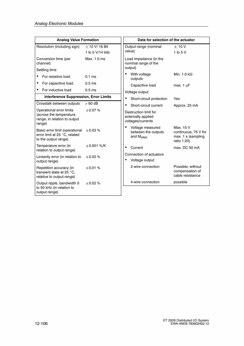
Analog Electronic Modules
12-106ET 200S Distributed I/O System
EWA-4NEB 780602402-12
Analog Value Formation
Resolution (including sign) ¦ 10 V/ 16 Bit
1 to 5 V/14 bits
Conversion time (perchannel)
Max. 1.0 ms
Settling time
• For resistive load 0.1 ms
• For capacitive load 0.5 ms
• For inductive load 0.5 ms
Interference Suppression, Error Limits
Crosstalk between outputs > 60 dB
Operational error limits(across the temperaturerange, in relation to outputrange)
0.07 %
Basic error limit (operationalerror limit at 25 _C, relatedto the output range)
0.03 %
Temperature error (inrelation to output range)
0.001 %/K
Linearity error (in relation tooutput range)
0.02 %
Repetition accuracy (intransient state at 25 _C,relative to output range)
0.01 %
Output ripple, bandwidth 0to 50 kHz (in relation tooutput range)
0.02 %
Data for selection of the actuator
Output range (nominalvalue)
10 V
1 to 5 V
Load impedance (in thenominal range of theoutput)
• With voltageoutputs
Min. 1.0 kΩ
Capacitive load max. 1 µF
Voltage output
• Short-circuit protection Yes
• Short-circuit current Approx. 25 mA
Destruction limit forexternally appliedvoltages/currents
• Voltage measuredbetween the outputsand MANA
Max. 15 Vcontinuous, 75 V formax. 1 s (samplingratio 1:20)
• Current max. DC 50 mA
Connection of actuators
• Voltage output
2-wire connection Possible, withoutcompensation ofcable resistance
4-wire connection possible

Analog Electronic Modules
12-107ET 200S Distributed I/O SystemEWA-4NEB 780602402-12
12.20 2AO I Standard analog electronic module(6ES7 135-4GB00-0AB0)
Order number
6ES7 135-4GB00-0AB0
Properties
• 2 current outputs
• Output range:
-- ¦ 20 mA, resolution 13 bits + sign
-- 4 to 20 mA, resolution 13 bits
• Isolated for load voltage L+
Terminal assignment
The following table shows the terminal assignment of the 2AO I TC Standard forthe various terminal modules:
Table 12-51 Terminal assignment of the 2AO I Standard
View Terminal assignment Remarks
AUX1 (e.g. PE)
2
3
4
6
7
8
1 5 QI1QI0
AUX1 (e.g. PE)
ManaMana
TM-E15S24-A1 and 2AO I Standard
CH1CH0
n. c.n. c.
AA
Channel 0: Terminals 1 to A4
Channel 1: Terminals 5 to A8
QI: analog output current
Mana: Module ground
Terminals 2 and 6 can beused for connection of cablesthat are not required up to30 VDC.

Analog Electronic Modules
12-108ET 200S Distributed I/O System
EWA-4NEB 780602402-12
Table 12-51 Terminal assignment of the 2AO I Standard
View RemarksTerminal assignment
2
3
4
6
7
8
1 5QI1QI0
ManaMana
TM-E15S24-01 and 2AO I Standard
CH1CH0
n. c.n. c.
n. c.n. c.
Channel 0: Terminals 1 to 4
Channel 1: Terminals 5 to 8
QI: analog output current
Mana: Module ground
Terminals 2 and 6, 4 and 8can be used for connection ofcables that are not requiredup to 30 VDC.
2
3
6
7
1 5QI1QI0
ManaMana
TM-E15S23-01 and 2AO I Standard
CH1CH0
n. c.n. c.
Channel 0: Terminals 1 to 3
Channel 1: Terminals 5 to 7
QI: analog output current
Mana: Module ground
Terminals 2 and 6 can beused for connection of cablesthat are not required up to30 VDC.
2
3
4
6
7
8
1 5QI1QI0
ManaMana
TM-E15S26-A1 and 2AO I Standard
CH1CH0
AUX1A
4
A
3
A
8
A
7AUX1
AUX1
AUX1
n. c.n. c.
n. c.n. c.
Channel 0: Terminals 1 to A3
Channel 1: Terminals 5 to A7
QI: analog output current
Mana: Module ground
Terminals 2 and 6, 4 and 8can be used for connection ofcables that are not requiredup to 30 VDC.

Analog Electronic Modules
12-109ET 200S Distributed I/O SystemEWA-4NEB 780602402-12
Block diagram
Bac
kpla
nebu
s
ET 200Sbackplane bus
interfaceconnection
DAC
24VL+
1M
DAC
1
3MANA
5
7MANA
MANAP1P2
Figure 12-22 Block diagram of the 2AO I Standard

Analog Electronic Modules
12-110ET 200S Distributed I/O System
EWA-4NEB 780602402-12
Technical data
Dimensions and weight
Dimensions W x H x D(mm)
15 x 81 x 52
Weight Approx. 40 g
Module-specific data
Supports clock synchro-nized mode
No
Number of outputs 2
Cable length
• shielded max. 200 m (164 ft)
Voltages, currents, electrical potentials
Rated load voltage L+ (frompower module)
24 VDC
• Polarity reversalprotection
Yes
Electrical isolation
• Between channels andbackplane bus
Yes
• Between channels andload voltage
Yes
• Between the channels No
Permitted potential differ-ence
• Between MANA and thecentral ground point(Uiso)
75 VDC / 60 VAC
Isolation tested 500 VDC
Current consumption
• from L+ power supply max. 150 mA
Power loss of the module max. 2 W
Status, alarms, diagnostics
Diagnostic functions
• Group error red LED ”SF”
• Reading of diagnosticsfunctions
Yes
Analog Value Formation
Resolution (incl. overshootrange)
¦ 20 mA/13 Bit + VZ
4 to 20 mA/13 bits
Cycle time Max. 1.5 ms
Settling time
• For resistive load 0.1 ms
• For capacitive load 0.5 ms
• For inductive load 0.5 ms
Interconnectable substitu-tion values
Yes
Interference Suppression, Error Limits
Crosstalk between outputs min. --40 dB
Operational error limits(across the temperaturerange, in relation to outputrange)
0.5 %
Basic error limit (operationalerror limit at 25 _C, relatedto the output range)
0.3 %
Temperature error (in rela-tion to output range)
0.01 %/K
Linearity error (in relation tooutput range)
0.02 %
Repetition accuracy(in transient state at 25 _C,relative to output range)
0.05 %
Output ripple (in relation tooutput range, bandwidth 0to 50 kHz)
0.02 %
Data for selection of the actuator
Output range (nominalvalue)
20 mA
4 to 20 mA
Load resistance max. 500Ω
• For inductive load 1 mH
• No-load voltage 18 V
Destruction limit for exter-nally applied voltages/cur-rents
• Voltage measuredbetween the outputsand MANA
Max. 15 Vcontinuous, 75 V formax. 1 s (samplingratio 1:20)
• Current max. DC 50 mA
Connection of actuators
• 2-wire connection Yes
• 4-wire connection No

Analog Electronic Modules
12-111ET 200S Distributed I/O SystemEWA-4NEB 780602402-12
12.21 2AO I High Feature analog electronic module(6ES7 135-4MB01-0AB0)
Order number
6ES7 135-4MB01-0AB0
Properties
• 2 current outputs
• Output range:
-- ¦ 20 mA, resolution 15 bits + sign
-- 4 to 20 mA, resolution 15 bits
• Isolated for load voltage L+
• Supports clock synchronized mode
-- Minimum possible time for the clock-synchronized DP cycle (TDPmin):3.75 ms
-- Minimum possible conversion time of output modules: (TWAmin): 1.5 ms
Terminal assignment
The following table shows the terminal assignment of the 2AO I High Feature forthe various terminal modules.
Table 12-52 Terminal assignment of the 2AO I High Feature
View Terminal assignment Remarks
AUX1 (e.g. PE)
2
3
4
6
7
8
1 5 QI1QI0
AUX1 (e.g. PE)
ManaMana
TM-E15S24-A1 and 2AO I High Feature
CH1CH0
n. c.n. c.
AA
Channel 0: Terminals 1 to A4
Channel 1: Terminals 5 to A8
QI: analog output current
Mana: Module ground
Terminals 2 and 6 can beused for connection of cablesthat are not required up to30 VDC.

Analog Electronic Modules
12-112ET 200S Distributed I/O System
EWA-4NEB 780602402-12
Table 12-52 Terminal assignment of the 2AO I High Feature, continued
View RemarksTerminal assignment
2
3
4
6
7
8
1 5QI1QI0
ManaMana
TM-E15S24-01 and 2AO I High Feature
CH1CH0
n. c.n. c.
Channel 0: Terminals 1 to 4
Channel 1: Terminals 5 to 8
QI: analog output current
Mana: Module ground
Terminals 2 and 6, 4 and 8can be used for connection ofcables that are not requiredup to 30 VDC.
2
3
6
7
1 5QI1QI0
ManaMana
TM-E15S23-01 and 2AO I High Feature
CH1CH0
n. c.n. c.
Channel 0: Terminals 1 to 3
Channel 1: Terminals 5 to 7
QI: analog output current
Mana: Module ground
Terminals 2 and 6 can beused for connection of cablesthat are not required up to30 VDC.
2
3
4
6
7
8
1 5QI1QI0
ManaMana
TM-E15S26-A1 and 2AO I High Feature
CH1CH0
AUX1A
4
A
3
A
8
A
7AUX1
AUX1
AUX1
n. c.n. c.
n. c.n. c.
Channel 0: Terminals 1 to A3
Channel 1: Terminals 5 to A7
QI: analog output current
Mana: Module ground
Terminals 2 and 6, 4 and 8can be used for connection ofcables that are not requiredup to 30 VDC.

Analog Electronic Modules
12-113ET 200S Distributed I/O SystemEWA-4NEB 780602402-12
Block diagram
Bac
kpla
nebu
s
ET 200Sbackplane bus
interfaceconnection
DAC
24VL+
1M
DAC
1
3MANA
5
7MANA
MANAP1P2
Figure 12-23 Block diagram of the 2AO I High Feature
Technical data
Dimensions and weight
DimensionsW x H x D (mm) 15 x 81 x 52
Weight Approx. 40 g
Module-specific data
Supports clocksynchronized mode
Yes
Number of outputs 2
Cable length
• shielded max. 200 m (164 ft)
Voltages, currents, electrical potentials
Rated power supply of theelectronics L+
24 VDC
• Polarity reversalprotection
Yes
Electrical isolation
• Between channels andbackplane bus
Yes
• Between channels andelectronics powersupply
Yes
• Between the channels No
Permitted potentialdifference
• between MANA andMinternal (UISO)
75 VDC / 60 VAC
Isolation tested 500 VDC
Current consumption
• from L+ power supply max. 150 mA
Power loss of the module max. 2 W
Status, interrupts, diagnostics
Diagnostic functions
• Group error display red LED ”SF”
• Reading of diagnosticdata
Yes
Interconnectablesubstitution values
yes, configurable

Analog Electronic Modules
12-114ET 200S Distributed I/O System
EWA-4NEB 780602402-12
Analog Value Formation
Resolution (including sign) ¦ 20 mA/ 16 Bit
4 to 20 mA/15 bits
Conversion time (perchannel)
Max. 1.0 ms
Settling time
• For resistive load 0.25 ms
• For capacitive load 1.0 ms
• For inductive load 0.5 ms
Interference Suppression, Error Limits
Crosstalk between outputs > 60 dB
Operational error limits(across the temperaturerange, in relation to outputrange)
0.07 %(at 250 Ω loadresistance)0.3 %(at all other loadresistances)
Basic error limit(operational error limit at25 _C, related to the inputrange)
0.03 %(at 250 Ω loadresistance)0.26 %(at all other loadresistances)
Temperature error (inrelation to output range)
0.001 %/K
Linearity error (in relationto output range)
0.02 %
Repetition accuracy(in transient state at 25 _C,relative to output range)
0.01 %
Output ripple (in relation tooutput range, bandwidth 0to 50 kHz)
0.02 %
Data for selection of the actuator
Output range (nominalvalue)
20 mA
4 to 20 mA
Load impedance (in thenominal range of theoutput)
• For current outputs max. 500Ω
For inductive load 1 mH
Current output
• No-load voltage 18 V
Destruction limit forexternally appliedvoltages/currents
• Voltage measuredbetween the outputsand MANA
Max. 15 Vcontinuous; 75 V formax. 1 s (samplingratio 1:20)
• Current max. DC 50 mA
Connection of actuators
• Current output
2-wire connection possible

13-1ET 200S Distributed I/O SystemEWA-4NEB 780602402-12
4 IQ-SENSE
Chapter overview
Chapter Topic Page
13.1 Parameters for 4 IQ-SENSE 13-3
13.2 Control and feedback interface 13-9
13.3 Terminal assignment 13-15
13.4 Block diagram 13-16
13.5 Technical specifications 13-17
13

4 IQ-SENSE
13-2ET 200S Distributed I/O System
EWA-4NEB 780602402-12
Order number
6ES7 138-4GA00-0AB0
Features
The 4 IQ-SENSE has the following features:
• Connection of sensors with IQ-SENSER, photo-electric proximity switches: e.g.reflection light barriers, reflection light and laser probes.
• Up to 4 sensors can be connected to every module. One 2-wire cable isrequired per sensor.
• Function reserve and monitoring
• Configurable time functions, differential travel, synchronization groups
• Specification of sensitivity and distance values (IntelliTeach via FB ”IQ-SENSEOpto”)
• Teach-in
• Removal and insertion of module during operation (restart of Teach-in via”IQ-SENSE Opto” function module or button on sensor required)
• Removal and insertion of sensors during operation (automatic reconfiguration)
• Supports sensors with alignment assistance
• The 4 IQ-SENSE is a single-width (15 mm) electronic module and can be usedwith the following terminal modules:
-- TM-E15S24-01, TM-E15C24-01 or TM-E15N24-01
-- TM-E15S26-A1, TM-E15C26-A1 or TM-E15N26-A1
Parameter assignment
The parameters for the 4 IQ-SENSE are configured with the STEP7.
Configuration rules
STEP 7 as of V5.1, ServicePack 3 STEP 7 as of V5.0, ServicePack 3 or otherconfiguration software
Included in the hardware catalog ofHWConfig A GSD file is not required.
IM151-1 BASIC: GSD file SIEM80F3.GSx asof 09/02 (from V1.0)
IM151-1 STANDARD: GSD fileSIEM806A.GSx as of 10/01 (from V1.10)
IM151-1 FO STANDARD: GSD fileSIEM806B.GSx as of 10/01 (from V1.5)
IM151-1 HIGH FEATURE: GSD fileSIR380E0.GSx as of 12/01 (from V1.0)

4 IQ-SENSE
13-3ET 200S Distributed I/O SystemEWA-4NEB 780602402-12
13.1 Parameters for 4 IQ-SENSE
Parameters
Table 13-1 Parameters for 4 IQ-SENSE
Parameters Value range Default setting Effective range
Group diagnostics • disable
• enabled
disable Module
Synchronizationgroup
• 1
• 2
• 3
• 4
1 Module
Sensor type • Reflection lightbarrier
• Reflection lightprobe
• disabled
Reflection lightbarrier
Channel
Differential travel • 5 %
• 10 %
• 20 %
• 50 %
20 % Channel
Time functions • None
• Resetting time
• Pickup delay
• Pickup and resettingdelay
• Momentary impulse
None Channel
Time value • 5 ms
• 10 ms
• 20 ms
• 50 ms
• 100 ms
• 200 ms
• 500 ms
• 1 s
• 2 s
• 5 s
• 10 s
5 ms Channel
Teach-in block • Teach-in with buttonpossible
• Teach-in with buttonnot possible
Teach-in withbutton possible
Channel

4 IQ-SENSE
13-4ET 200S Distributed I/O System
EWA-4NEB 780602402-12
Note
Unused channels of the module must be disabled, otherwise the diagnostics willreport wire break.
Parameter measuring type: disabled• All diagnostics are suppressed.
• Sensitivity/distance values and switching states are set to ”0”.
• The sensor is switched off.
13.1.1 Group diagnostics parameter
If you enable group diagnostics, a pending diagnostic message is registered (seeChapter 6.1.6.8 or 6.2.6.2).
13.1.2 Synchronization group parameters
Features
• Sensors between different modules of the 4 IQ-SENSE may influence oneanother (e.g. by scattered light).
• To prevent this interference from adjacent sensors on different modules you canassign every module to a separate synchronization group with this parameter.Modules with different synchronization groups do not influence each other.
• Sensors on the same module cannot interfere with one another.

4 IQ-SENSE
13-5ET 200S Distributed I/O SystemEWA-4NEB 780602402-12
Function principle
The diagram below clarifies the functioning of the synchronization groupparameter:
4 IQ-SENSEPMInterfacemodule
1 2 3 4 1 Parameters
Synchronizationgroup
Slot1 2 3 4 5 6
Mutual interference is only possible between thesensors on the modules in slot 2 and 6, because theyare both in synchronization group 1.
Figure 13-1 Synchronization group
Note
Sensors in the same synchronization groups must be installed so they are at theminimum distance apart (see sensor package insert) to ensure that mutualinterference is prevented.
13.1.3 Sensor type parameter
Features
This parameter is used to specify the sensor type per channel:
• Reflection light barrier or
• reflection light probe or
• disabled

4 IQ-SENSE
13-6ET 200S Distributed I/O System
EWA-4NEB 780602402-12
Reflection light probe
Transmitter
Object
Switching status 0: No object detected, i.e.the object is not in the light beam. Thereceiver does not detect any light.
Switching status 1: Object detected, i.e. theobject is in the light beam. The receiverdetects light.
Receivingstations
Transmitter
Receivingstations
Reflection light probe
Figure 13-2 Reflection light probe
Reflection light barrier
Object
Switching status 0: No object detected, i.e.the object is not in the light beam. Thereceiver detects light.
Switching status 1: Object detected, i.e. theobject is in the light beam. The receiverdoes not detect any light.
Transmitter
Receivingstations
Transmitter
Receivingstations
Reflection light barrier
Figure 13-3 Reflection light barrier
13.1.4 Differential travel parameter
Features
”Signal flutter” may occur as a result of interference at the reflection light probe orduring the production process. The measured value will swing around the switchingthreshold of 100% (object detected -- object not detected). This flutter at theswitching threshold can be prevented with the differential travel parameter. Thiswill ensure a stable output signal at the sensor.
The ranges 5/ 10/ 20/ 50% can be configured as differential travel.
Prerequisites
The differential travel parameter can only be configured for reflection light probeswith background shielding.

4 IQ-SENSE
13-7ET 200S Distributed I/O SystemEWA-4NEB 780602402-12
Function principle
Receiving level
100 %
1
0
Switching output on sensor
Time t
Time t
Differential travel 5/10/20/50%
Switchingthreshold
Figure 13-4 Differential travel parameter
13.1.5 Time functions, time value parameter
Features
This parameter can be used to configure the electronic module for the specificapplication.

4 IQ-SENSE
13-8ET 200S Distributed I/O System
EWA-4NEB 780602402-12
Function principle
Timer Switching status Curve
1
0
None
(default)
Momentaryimpulse
Pickup andresetting delay
Pickup delayed
Reset delayed
Switching stateon sensor
Object detected
Object not detected
T = time value parameter
1
0
1
0
1
0
1
1
0
T T T
T T T
T T
T T
Figure 13-5 Time value, time functions parameter
13.1.6 Teach-in block parameter
Features
This parameter can be used to block the Teach-in button at the sensor.

4 IQ-SENSE
13-9ET 200S Distributed I/O SystemEWA-4NEB 780602402-12
13.2 Control (PIQ) and feedback interface (PII)
The addressing scope of the control and feedback interface of the 4 IQ-SENSEcan be configured. You can select between Standard and Enhanced.
Standard properties
• The 4 IQ-SENSE occupies 4 bits in the feedback interface.
• The switching state for every channel can be evaluated via the feedbackinterface.
Enhanced properties
• The 4 IQ-SENSE occupies 1 byte in the control interface and 1 byte in thefeedback interface
• The sensitivity/distance values for every channel can be preset with the controlinterface (IntelliTeach via FB ”IQ-SENSE Opto”) and Teach-in conducted.
• The learnt sensitivity/distance value /switching threshold) and the switchingstate can be evaluated for every channel via the feedback interface.
Requirements:
• The ”IQ-SENSE Opto” function block can be used. The function block enableseasy access to the control and feedback interface.
• Please note that in this case PII is the same as PIQ.
• The function block and the associated product information can be downloadedfrom http://www.ad.siemens.de/csi_e/gsd.
Configuring address space
Addressspace
STEP 7 as of V5.1, ServicePack 3 STEP 7 as of V4.2 or COMPROFIBUS or other
configuration software
Standard Select the entry 4IQ-SENSE Opto Sin the HW CONFIG hardware
Select the entryS 6ES7 138-4GA00-0AB0in the HW CONFIG hardware
catalogS 6ES7 138-4GA00-0AB0IQ-SENSE Opto from the GSD file
Enhanced Select the entry 4IQ-SENSE Opto Ein the HW CONFIG hardware
Select the entryE 6ES7 138-4GA00-0AB0in the HW CONFIG hardware
catalogE 6ES7 138-4GA00-0AB0IQ-SENSE Opto from the GSD file

4 IQ-SENSE
13-10ET 200S Distributed I/O System
EWA-4NEB 780602402-12
13.2.1 Standard
Feedback interface (PII)
Table 13-2 Standard feedback interface
Address Assignment
Byte 0 Bit 7: 0 (not assigned)
Bit 6: 0 (not assigned)
Bit 5: 0 (not assigned)
Bit 4: 0 (not assigned)
Bit 3: sensor switching status on channel 3
1: object detected
0: object not detected
Bit 2: sensor switching status on channel 2
1: object detected
0: object not detected
Bit 1: sensor switching status on channel 1
1: object detected
0: object not detected
Bit 0: sensor switching status on channel 0
1: object detected
0: object not detected
13.2.2 Enhanced
Feedback interface (PII)
Table 13-3 Enhanced feedback interface
Address Assignment Designation on”IQ-SENSE Opto”
function block
Byte 0 Bit 0: sensor switching status on channel 0 Q CH0Byte 0 Bit 0: sensor switching status on channel 0 Q_CH0Byte 0 Bit 0: sensor switching status on channel 0
1: object detected
Q_CH0
1: object detected1: object detected
0 object not detected0: object not detected0: object not detected
Bit 1 to bit 7:
Learned sensitivity/distance valueon channel 0 by Teach-in *
TEACH_VAL_OUT

4 IQ-SENSE
13-11ET 200S Distributed I/O SystemEWA-4NEB 780602402-12
Table 13-3 Enhanced feedback interface
Address Designation on”IQ-SENSE Opto”
function block
Assignment
Byte 1 Bit 0: sensor switching status on channel 1 Q CH1Byte 1 Bit 0: sensor switching status on channel 1 Q_CH1Byte 1 Bit 0: sensor switching status on channel 1
1: object detected
Q_CH1
1: object detected1: object detected
0 bj t t d t t d0: object not detected0: object not detected
Bit 1 to bit 7:
Learned sensitivity/distance valueon channel 1 by Teach-in *
TEACH_VAL_OUT
Byte 2 Bit 0: sensor switching status on channel 2 Q CH2Byte 2 Bit 0: sensor switching status on channel 2 Q_CH2Byte 2 Bit 0: sensor switching status on channel 2
1: object detected
Q_CH2
1: object detected1: object detected
0 bj t t d t t d0: object not detected0: object not detected
Bit 1 to bit 7:
Learned sensitivity/distance valueon channel 2 by Teach-in *
TEACH_VAL_OUT
Byte 3 Bit 0: sensor switching status on channel 3 Q CH3Byte 3 Bit 0: sensor switching status on channel 3 Q_CH3Byte 3 Bit 0: sensor switching status on channel 3
1: object detected
Q_CH3
1: object detected1: object detected
0 bj t t d t t d0: object not detected0: object not detected
Bit 1 to bit 7:
Learned sensitivity/distance valueon channel 3 by Teach-in *
TEACH_VAL_OUT
* The current sensitivity/distance value is registered:-- after completion of Teach-in at the sensor-- after completion of Teach-in via the ”IQ-SENSE Opto” function block

4 IQ-SENSE
13-12ET 200S Distributed I/O System
EWA-4NEB 780602402-12
Control interface (PIQ)
Table 13-4 Enhanced control interface
Address Assignment Designation on”IQ-SENSE Opto”
function block
Byte 0 Set sensitivity/distance value at channel 0
• Bit 0:1: Sensitivity/distance value transferred tosensor on channel 0(by rising edge)0: disabled
WR_TEACH_VAL
• Bit 1 to bit 7:sensitivity/distance valueat channel 0 1 to 126, (sensor-dependent)
TEACH_VAL_IN
Teach-in at sensor channel 0
• Bit 0:1: Start Teach-in at sensor channel 0 (byrising edge)0: disabled
• Bit 1 to bit 7: 0
START_TEACH
Byte 1 Set sensitivity/distance value at channel 1y y
• Bit 0:1 S iti it /di t l t f d t1: Sensitivity/distance value transferred tosensor on channel 1
WR_TEACH_VALsensor on channel 1(by rising edge)( y g g )0: disabled
• Bit 1 to bit 7• Bit 1 to bit 7:sensitivity/distance value TEACH VAL INsensitivity/distance valueat channel 1 1 to 126 (sensor-dependent)
TEACH_VAL_IN
Teach-in at sensor channel 1
• Bit 0:1: Start Teach-in at sensor channel 1 (byrising edge)0: disabled
• Bit 1 to bit 7: 0
START_TEACH
Byte 2 Set sensitivity/distance value at channel 2y y
• Bit 0:1 Sensiti it /distance al e transferred to1: Sensitivity/distance value transferred tosensor on channel 2
WR_TEACH_VALsensor on channel 2(by rising edge)( y g g )0: disabled
• Bit 1 to bit 7 TEACH VAL IN• Bit 1 to bit 7:sensitivity/distance value
TEACH_VAL_INsensitivity/distance valueat channel 2 1 to 126 (sensor-dependent)
Teach-in at channel 2
• Bit 0:1: Start Teach-in at sensor channel 2 (byrising edge)0: disabled
• Bit 1 to bit 7: 0
START_TEACH

4 IQ-SENSE
13-13ET 200S Distributed I/O SystemEWA-4NEB 780602402-12
Table 13-4 Enhanced control interface
Address Designation on”IQ-SENSE Opto”
function block
Assignment
Byte 3 Set sensitivity/distance value at channel 3y y
• Bit 0:1: Sensitivity/distance value transferred to
WR_TEACH_VAL1: Sensitivity/distance value transferred tosensor on channel 3sensor on channel 3(by rising edge)
di bl d( y g g )0: disabled
• Bit 1 to bit 7: TEACH VAL IN• Bit 1 to bit 7:sensitivity/distance value
TEACH_VAL_INsensitivity/distance valueat channel 3 1 to 126 (sensor-dependent)
Teach-in at sensor channel 3
• Bit 0:1: Start Teach-in at sensor channel 3 (byrising edge)0: disabled
• Bit 1 to bit 7: 0
START_TEACH
Mode of Operation: Preset of a sensitivity/distance value (IntelliTeach)
Standard mode(valid sensitivity/distance value)
Preset sensitivity/distancevalue (1 to 126)at bit 1 to 7 in the PIQ
Sensitivity/distance valuetransferred to sensor by risingedgeat bit 0 in the PIQ
Figure 13-6 Mode of Operation: Preset of a sensitivity/distance value (IntelliTeach)

4 IQ-SENSE
13-14ET 200S Distributed I/O System
EWA-4NEB 780602402-12
Mode of Operation: Teach-in
Teach-in endedby falling edge at
bit 0 in the PIQ
Normal operation
Set value ”0” at bit 1 to 7 inPIQ
Start Teach-in byrising edge atbit 0 in the PIQ
Teach-in error:Learned sensitivity/distance value = 0(bit 1 to 7 in the PII)
Preset of asensitivity/distancevalue (IntelliTeach)
No valid sensitivity/distance value detected
Valid sensitivity/distance value detected
1. Option
2. Option
Teach-in is executed
Figure 13-7 Mode of Operation: Teach-in

4 IQ-SENSE
13-15ET 200S Distributed I/O SystemEWA-4NEB 780602402-12
13.3 Terminal assignment
The following table shows the terminal assignment of the 4 IQ-SENSE for thevarious terminal modules:
Table 13-5 Terminal assignment of the 4 IQ-SENSE
View Terminal assignment Remarks
2
3
4
6
7
8
1 5
TM-E15S24-01 and 4 IQ-SENSE
CH1CH0
M0+
CH2 CH3
M2+
M0--
M2--
M1+
M3+
M1--
M3--
Sensor
Sensor
Channel 0: Terminals 1and 3
Channel 1: Terminals 5and 7
Channel 2: Terminals 2and 4
Channel 3: Terminals 6and 8
M+: Input signal ”+”
M--: Input signal ”--”
2
3
4
6
7
8
1 5
TM-E15S26-A1 and 4 IQ-SENSE
CH1CH0CH2 CH3
A
4
A
3
A
8
A
7
AUX1
AUX1
M0+
M2+
M0--
M2--
M1+
M3+
M1--
M3--
AUX1
AUX1
Sensor
Sensor
Channel 0: Terminals 1and 3
Channel 1: Terminals 5and 7
Channel 2: Terminals 2and 4
Channel 3: Terminals 6and 8
M+: Input signal ”+”
M--: Input signal ”--”
Note• The connections to the sensors cannot be reversed.
• The minimum wiring cross secton for the sensors is 0.25 mm2
• Connecting cables for the sensors can be found in Chapter A.

4 IQ-SENSE
13-16ET 200S Distributed I/O System
EWA-4NEB 780602402-12
13.4 Block diagramB
ackp
lane
bus
ET 200Sbackplane
buscircuit
L+
1MP1
P2
µC
MUX
Cur
rent
limit
Internalpowersupply
1
2
5
6
3
4
7
8
Figure 13-8 Block diagram of the 4 IQ-SENSE

4 IQ-SENSE
13-17ET 200S Distributed I/O SystemEWA-4NEB 780602402-12
13.5 Technical specifications
Dimensions and weight
Dimensions W x H x D (mm) 15 x 81 x 52
Weight Approx. 35g
Module-specific data
Number of inputs 4
Cable length
• Unshielded max. 50m (164 ft)
• shielded max. 50m (164 ft)
Voltages, currents, electrical potentials
Rated supply voltage (frompower module)
24 VDC
• Polarity reversalprotection
Yes
Electrical isolation
• Between the channels No
• Between channels andbackplane bus
Yes
Permissible potential differ-ence
• Between different circuits 75 VDC, 60 VAC
Insulation tested with 500 VDC
Current consumption
• From powersupply
max. 0.3A (164 ft)
Power loss of the module Typically 0.85 W
Status, interrupts, diagnostics
Status display Green LED perchannel
Diagnostic functions
• Group error red LED ”SF”
• Reading of diagnosticdata
Yes
Data for selecting an sensor
Connectable sensors Photoelectricproximity switchwith IQ-SENSE
Reaction times
Cycle time max. 3.24 ms

4 IQ-SENSE
13-18ET 200S Distributed I/O System
EWA-4NEB 780602402-12

14-1ET 200S Distributed I/O SystemEWA-4NEB 780602402-12
RESERVE modules
Order number
6ES7 138-4AA00-0AA0 (installation width 15 mm)
6ES7 138-4AA10-0AA0 (installation width 30 mm)
Features
The RESERVE module has the following features:
• suitable for all TM-E terminal modules (installation width 15 mm and 30 mm)
• reserved for a slot on any electronic module. Insert the RESERVE module intothe reserved slot of the ET 200S configuration.
Note• Note the following with the IM 151 (6ES7 151-1AA01-0AB0,
6ES7 151-1AA02-0AB0), IM 151 FO (6ES7 151-1AB00-0AB0,6ES7 151-1AB01-0AB0) and IM 151/ CPU (6ES7 151-7AA00-0AB0):If an electronic module is removed and replaced with a RESERVE modulewhile the ET 200S is operating, the power supply must be cycled at thePOWER ON/POWER OFF interface module.
• Note the following with the IM 151 (6ES7 151-1AA00-0AB0):The RESERVE module cannot be installed in the ET 200S.
Configuration (without option handling)
• In STEP 7 or COM PROFIBUS configure the desired electronic module in theRESERVE module slot that you want to use for future applications, e. g.4DI DC High Feature.
-- Drag the module to the configuration table
-- Set the parameters
14

RESERVE modules
14-2ET 200S Distributed I/O System
EWA-4NEB 780602402-12
• Configure the interface module as follows:
Parameters Setting
Operation at Preset <> Actualconfiguration
enabled
• If you have configured an electronic module with inputs for the RESERVEmodule, the following substitute values are reported:
-- Digital Input Modules: 0
-- Analog Input Modules: 7FFFH
-- Function Module: 0
Note
If you use the RESERVE module,
• the SF LED lights up on the interface module
• a channel-related diagnosis and module status ”10B: incorrect module” isreturned for that slot of the RESERVE module.
For the functioning and configuration with option handling see Chapter 3.8.
Terminal assignment
The RESERVE module is not connected to the terminals of the TM-E terminalmodule. This means that the TM-E terminal module can be fully wired andprepared for the future application.
Technical data
Dimensions and weight
DimensionsW x H x D (mm)
Weight
15 x 81 x 52
30 x 81 x 52
approx. 33 g(installation width15 mm)
approx. 55g (installationwidth 30 mm)
Voltages, currents, electrical potentials
Power loss of themodule
Typically 0.025 W
Status, Interrupts, Diagnostics
Status display No
Diagnostic functions No

A-1ET 200S Distributed I/O SystemEWA-4NEB 780602402-12
Order Numbers
Introduction
You will find below the order numbers for the ET 200S distributed I/O system andthe PROFIBUS accessories that you may need to use with the ET 200S.
Interface module
Table A-1 Interface module order numbers
Designation Order number
IM151-1 BASIC interface module andterminating module, 1 unit
6ES7 151-1CA00-0AB0
IM151-1 STANDARD interface module andterminating module, 1 unit
6ES7 151-1AA04-0AB0
IM151-1 FO STANDARD interface module andterminating module, 1 unit
6ES7 151-1AB03-0AB0
IM151-1 HIGH FEATURE interface module andterminating module, 1 unit
6ES7 151-1BA00-0AB0
IM151-3 PN interface module and terminating module,1 unit
6ES7 151-3AA00-0AB0
A

Order Numbers
A-2ET 200S Distributed I/O System
EWA-4NEB 780602402-12
Terminal module
TM-P 15S24-01
01: Uninterrupted AUX1 bus without a connection to theterminalsA1: Uninterrupted AUX1 bus with connection to theterminalsA0: Interrupted AUX1 bus with connection to theterminals
Number of terminals (columns x rows)
S: Screw-typeterminal C: SpringterminalN: Fast ConnectWidth in millimeters
P: Power moduleE: Electronicmodule
Terminal module
Explanation of the abbreviated designation
Figure A-1 Explanation of the abbreviated designation
Table A-2 Terminal module order numbers
Designation Order number
TM-P15S23-A1 (screw-type terminal), 1 unit 6ES7 193-4CC20-0AA0
TM-P15S23-A1 (spring terminal), 1 unit 6ES7 193-4CC30-0AA0
TM-P15N23-A1 (Fast Connect), 1 unit 6ES7 193-4CC70-0AA0
TM-P15S23-A0 (screw-type terminal), 1 unit 6ES7 193-4CD20-0AA0
TM-P15C23-A0 (spring terminal), 1 unit 6ES7 193-4CD30-0AA0
TM-P15N23-A0 (Fast Connect), 1 unit 6ES7 193-4CD70-0AA0
TM-P15S22-01 (screw-type terminal), 1 unit 6ES7 193-4CE00-0AA0
TM-P15C22-01 (spring terminal), 1 unit 6ES7 193-4CE10-0AA0
TM-P15N22-01 (Fast Connect), 1 unit 6ES7 193-4CE60-0AA0
TM-P30S44-A0 (screw-type terminal), 1 unit 6ES7 193-4CK20-0AA0
TM-P30C44-A0 (screw-type terminal), 1 unit 6ES7 193-4CK30-0AA0
TM-PF30S47-F1 (screw-type terminal), 1 unit 3RK1 903-3AA00
TM-E15S26-A1 (screw-type terminal), 5 units 6ES7 193-4CA40-0AA0
TM-E15C26-A1 (spring terminal), 5 units 6ES7 193-4CA50-0AA0
TM-E15N26-A1 (Fast Connect), 5 units 6ES7 193-4CA80-0AA0
TM-E15S24-A1 (screw-type terminal), 5 units 6ES7 193-4CA20-0AA0
TM-E15C24-A1 (spring terminal), 5 units 6ES7 193-4CA30-0AA0

Order Numbers
A-3ET 200S Distributed I/O SystemEWA-4NEB 780602402-12
Table A-2 Terminal module order numbers, continued
Designation Order number
TM-E15N24-A1 (Fast Connect), 5 units 6ES7 193-4CA70-0AA0
TM-E15S24-01 (screw-type terminal), 5 units 6ES7 193-4CB20-0AA0
TM-E15C24-01 (spring terminal), 5 units 6ES7 193-4CB30-0AA0
TM-E15N24-01 (Fast Connect), 5 units 6ES7 193-4CB70-0AA0
TM-E15S23-01 (screw-type terminal), 5 units 6ES7 193-4CB00-0AA0
TM-E15C23-01 (spring terminal), 5 units 6ES7 193-4CB10-0AA0
TM-E15N23-01 (Fast Connect), 1 unit 6ES7 193-4CB60-0AA0
TM-E15S24-AT (screw-type terminal), 5 units 6ES7 193-4CL20-0AA0
TM-E15C24-AT (spring terminal), 5 units 6ES7 193-4CL30-0AA0
TM-E30S44-01 (screw-type terminal), 1 unit 6ES7 193-4CG20-0AA0
TM-E30C44-01 (screw-type terminal), 1 unit 6ES7 193-4CG30-0AA0
TM-E30S46-A1 (screw-type terminal), 1 unit 6ES7 193-4CF40-0AA0
TM-E30C46-A1 (spring terminal), 1 unit 6ES7 193-4CF50-0AA0
Power modules
Table A-3 Power module order numbers
Name Order number
PM--E 24 VDC, 1 unit 6ES7 138-4CA00-0AA0
PM--E 24--48 VDC/24--230 VAC, 1 unit 6ES7 138-4CB10-0AB0
PM--E 24--48 VDC, 1 unit 6ES7 138-4CA50-0AB0
Digital Electronic Modules
Table A-4 Digital electronic module order numbers
Name Order number
2DI 24 VDC Standard, 5 units 6ES7 131-4BB00-0AA0
4DI 24 VDC Standard, 5 units 6ES7 131-4BD00-0AA0
4DI 24 VDC/SRC Standard, 5 units 6ES7 131-4BD50-0AA0
2DI 24 VDC High Feature, 5 units 6ES7 131-4BB00-0AB0
4DI 24 VDC High Feature, 5 units 6ES7 131-4BD00-0AB0
4DI 24--48 VUC High Feature, 5 units 6ES7 131-4CD00-0AB0
4DI NAMUR 6ES7 131-4RD00-0AB0
2DI 120 VAC Standard, 5 units 6ES7 131-4EB00-0AB0
2DI 230 VAC Standard, 5 units 6ES7 131-4FB00-0AB0
2DO 24 VDC/0.5 A Standard, 5 units 6ES7 132-4BB00-0AA0
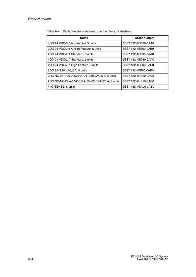
Order Numbers
A-4ET 200S Distributed I/O System
EWA-4NEB 780602402-12
Table A-4 Digital electronic module order numbers, Fortsetzung
Name Order number
4DO 24 VDC/0.5 A Standard, 5 units 6ES7 132-4BD00-0AA0
2DO 24 VDC/0.5 A High Feature, 5 units 6ES7 132-4BB00-0AB0
2DO 24 VDC/2 A Standard, 5 units 6ES7 132-4BB30-0AA0
4DO 24 VDC/2 A Standard, 5 units 6ES7 132-4BD30-0AA0
2DO 24 VDC/2 A High Feature, 5 units 6ES7 132-4BB30-0AB0
2DO 24--230 VAC/2 A, 5 units 6ES7 132-4FB00-0AB0
2RO NO 24--120 VDC/5 A, 24--230 VAC/5 A, 5 units 6ES7 132-4HB00-0AB0
2RO NO/NC 24--48 VDC/5 A, 24--230 VAC/5 A, 5 units 6ES7 132-4HB10-0AB0
4 IQ-SENSE, 5 units 6ES7 138-4GA00-0AB0

Order Numbers
A-5ET 200S Distributed I/O SystemEWA-4NEB 780602402-12
Analog electronic modules
Table A-5 Analog electronic module order numbers
Name Order number
2AI U Standard, 1 unit 6ES7 134-4FB00-0AB0
2AI U High Feature, 1 unit 6ES7 134-4LB00-0AB0
2AI U High Speed, 1 unit 6ES7 134-4FB51-0AB0
2AI I 2WIRE Standard, 1 unit 6ES7 134-4GB00-0AB0
4AI I 2WIRE Standard, 1 unit 6ES7 134-4GD00-0AB0
2AI I 2WIRE High Speed, 1 unit 6ES7 134-4GB51-0AB0
2AI I 4WIRE Standard, 1 unit 6ES7 134-4GB10-0AB0
2AI I 2/4WIRE High Feature, 1 unit 6ES7 134-4MB00-0AB0
2AI I 4WIRE High Speed, 1 unit 6ES7 134-4GB61-0AB0
2AI RTD Standard, 1 unit 6ES7 134-4JB50-0AB0
2AI RTD High Feature, 1 unit 6ES7 134-4NB50-0AB0
2AI TC Standard, 1 unit 6ES7 134-4JB00-0AB0
2AI TC High Feature, 1 unit 6ES7 134-4NB00-0AB0
2AO U Standard, 1 unit 6ES7 135-4FB00-0AB0
2AO U High Feature, 1 unit 6ES7 135-4LB01-0AB0
2AO I Standard, 1 unit 6ES7 135-4GB00-0AB0
2AO I High Feature, 1 unit 6ES7 135-4MB01-0AB0
Process-related modules
Table A-6 Process-related module order numbers
Name Order number
1Count 24V/100kHz, 1 unit 6ES7 138-4DA03-0AB0
1Count 5V/500kHz, 1 unit 6ES7 138-4DE01-0AB0
1 SSI, 1 unit 6ES7 138-4DB01-0AB0
1 STEP 5 V/204 kHz, 1 unit 6ES7 138-4DC00-0AB0
2PULSE, 1 unit 6ES7 138-4DD00-0AB0
1POS INC/Digital 6ES7 138-4DG00-0AB0
1POS SSI/Digital 6ES7 138-4DH00-0AB0
1POS INC/Analog 6ES7 138-4DJ00-0AB0
1POS INC/Analog 6ES7 138-4DK00-0AB0
1SI 3964/ASCII serial interface module 6ES7 138-4DF00-0AB0
1SI Modbus/USS serial interface module 6ES7 138-4DF10-0AB0
SIWAREX CS approximation module 7MH4 910-0AA01

Order Numbers
A-6ET 200S Distributed I/O System
EWA-4NEB 780602402-12
RESERVE modules
Table A-7 Reserve module order numbers
Name Order number
RESERVE (with 15mm), 5 unit 6ES7 138-4AA00-0AA0
RESERVE (with 30 mm), 1 unit 6ES7 138-4AA10-0AA0
ET 200S accessories
Table A-8 ET 200S accessories order numbers
Name Order number
Shield contact:
Shield contact element, 5 units
Power rail, 1 units at 1 m, 3x10 mm
Shield terminal, 5 units
Ground connection terminal
6ES7 193-4GA00-0AA0
8WA2 842
6ES7 193-4GB00-0AA0
8WA2 868
DIN A4 labeling sheet, white, 10 units 6ES7 193-4BA00-0AA0
DIN A4 labeling sheet, red, 10 units 6ES7 193-4BD00-0AA0
DIN A4 labeling sheet, yellow, 10 units 6ES7 193-4BB00-0AA0
DIN A4 labeling sheet, petrol, 10 units 6ES7 193-4BH00-0AA0
Color identification labels (10 strips each containing 20items in each color)
• White
• Red
• Yellow
• yellow-green
• Brown
• Blue
• Turquoise
6ES7 193-4LA10-0AA0
6ES7 193-4LD10-0AA0
6ES7 193-4LB10-0AA0
6ES7 193-4LC10-0AA0
6ES7 193-4LG10-0AA0
6ES7 193-4LF10-0AA0
6ES7 193-4LH10-0AA0
Slot number labels, 10x (1 to 20), 200 units 8WA8 861-0AB
Slot number labels, 5x (1 to 40), 200 units 8WA8 861-0AC
Terminating module, 1 unit 6ES7 193-4JA00-0AA0

Order Numbers
A-7ET 200S Distributed I/O SystemEWA-4NEB 780602402-12
Network components for the ET 200S
The tables below list all the network components for the ET 200 distributed I/Osystem that you may require to use the ET 200S.
Table A-9 Network components (PROFIBUS DP) for ET 200S order numbers
Name Order number
RS 485 repeater, PROFIBUS DP, IP20 6ES7 972-0AA00-0XA0
PROFIBUS bus connector (12 Mbps)
• Anthracite (without programming port)
• Anthracite (with programming port)
6ES7 972-0BA11-0XA0
6ES7 972-0BB11-0XA0
Bus cable
• Normal
• Drum cable
• Direct-buried cable
6XV1 830-0EH10
6XV1 830-3BH10
6XV1 830-3AH10
Repeater adapter 6GK1 510-1AA00
Active RS 485 terminating element 6ES7 972-0DA00-0AA0
Optical link modules for glass fiber-optic cable 6GK1 502-3AB10
6GK1 502-4AB10
PROFIBUS connecting cable 6ES7 901-4BD00-0XA0
Fiber-optic cable
• SIMATIC NET PROFIBUS plastic fiber-optic,duplex core (50 m ring)
6XV1 821-2AN50
• SIMATIC NET PROFIBUS plastic fiber-optic,standard cableby the meter50 m ring100 m ring
6XV1 821-0AH106XV1 821-0AN506XV1 821-0AT10
• SIMATIC NET PROFIBUS PCF fiber-optic,standard cablevarious lengths from 50 m to 300 m
6XV1 821-1Bxxx
Plugs for fiber-optic cable
• Package of 100 simplex plugs and5 polishing sets
6GK1 901-0FB00-0AA0
• Package of 50 plug adapters 6ES7 195-1BE00-0XA0

Order Numbers
A-8ET 200S Distributed I/O System
EWA-4NEB 780602402-12
Table A-10 Network components (PROFINET I/O) for ET 200S order numbers
Name Order number
Industrial Ethernet FC RJ45 plug 90(RJ45-connector for Industrial Ethernet withrobust metal case and integrated insulation-piercing contacts for connection of Industrial EthernetFC installation cables; with 90° cable outlet
• 1 unit
• 10 units
• 50 units
6GK1 901-1BB20-2AA0
6GK1 901-1BB20-2AB0
6GK1 901-1BB20-2AE0
Industrial Ethernet Fast Connect installation lines
• Fast Connect standard cable
• Fast Connect trailing cable
• Fast Connect marine cable
6XV1 840-2AH10
6XV1 840-3AH10
6XV1 840-4AH10
Industrial Ethernet Fast Connect stripping tool 6GK1 901-1GA00
Spare parts
Table A-11 Fuse for digital input module and power module
Name Order number
Fuse for 4DI 24--48 VUC HF
• ET200S Spare Fuse Kit 1 A, (10 ea.) 6ES7 193-4KA00-0AA0
Fuse for PM-E 24--48 VDC/24--230 VAC
• ET200S Spare Fuse Kit 10 A, (ea.) 6ES7 193-4KA10-0AA0
Connecting cable for 4 IQ-SENSE electronic module
The following table contains the connecting cables for the sensors on the 4IQ-SENSE electronic module. You will also find these connecting cables in the NSBERO catalog (in the chapter on 3RX1 plug connections).
Table A-12 Connecting cable for 4 IQ-SENSE electronic module
Name Order number
Cable box (M12) for screw-type attachment with 5 mPUR connecting cable 3 x 0.34 mm2
3RX1 533
Cable box (M12) for screw-type attachment with 5 mPUR connecting cable 4 x 0.34 mm2
3RX1 536

Order Numbers
A-9ET 200S Distributed I/O SystemEWA-4NEB 780602402-12
Distributed I/O system ET 200S manuals
Table A-13 ET 200S documentation packages or manuals
Name Order number
The ET 200S documentation package consists of
• ET 200S Distributed I/O System manual
• ET 200S Motor Starter manual
• PROFINET system description
• From PROFIBUS DP to PROFINET I/Oprogramming manual
6ES7 151-1AA10-8xA01)
ET 200S Interface Module IM 151-7 CPU manual
and operation list
6ES7 151-1AB00-8xA01)
ET 200S Technological Functions manual 6ES7 151-1AC00-8xA01)
ET 200S Positioning manual 6ES7 151-1AD00-8xA01)
ET 200S Serial Interface Module manual 6ES7 151-1AE00-8xA01)
ET 200S Distributed I/O System Fail-safe Modulesmanual
available in the Internet only
ET 200S Frequency Converter FC documentationpackage consisting of
• ET 200S FC Frequency Converter OperatingManual
• ET 200S Frequency Converter FC List manual
(In preparation)
6SL3 298-0CA12-0xP01)
ET 200S Frequency Converter FC documentationpackage consisting of
• ET 200S Distributed I/O System manual
• ET 200S FC Frequency Converter OperatingManual
• ET 200S Frequency Converter FC List manual
(In preparation)
6SL3 298-0CA12-1xP01)
1) x= language designation for order numbersThe documentation packages or manuals can only be ordered in German and English. Inaddition, the languages French, Spanish and Italian are available in the Internet(see Service & Support in the Internet)

Order Numbers
A-10ET 200S Distributed I/O System
EWA-4NEB 780602402-12
STEP 7 and SIMATIC S7 manuals
To program and commission the ET 200S with STEP 7, you require one of thefollowing manuals.
Table A-14 STEP 7 and SIMATIC S7 manuals
Name Contents
S7 300 Programmable Controllerdocumentation package consisting of:
For example,
• Reference manual
-- CPU data:CPU 312 IFM to 318-2 DPand operation list
-- CPU Data:CPU 31xC and CPU 31xand operation list
• Operating instructions and adescription of the functions andtechnical specifications of the CPUs
• List of the instruction set of CPUs andtheir execution times.List of executable blocks and theirexecution times
• Manual
-- CPU 31xC: Process-relatedfunctions including CD with examples
• Description of the differentprocess-related functions
• Installation manual
-- Automation system S7-300:Installation: CPU 312 IFM to 318-2 DP
-- Automation system S7-300:Installation: CPU 31xC and CPU 31x
• Description of the configuration,mounting, wiring, networking andcommissioning of an S7-300
• Reference manual:
-- S7-300 Programmable ControllerModule Specifications
• Functional descriptions and technicalspecifications of the signal modules,power supply modules and interfacemodules
• Getting Started • Examples of different commissioningsteps leading up to a functionalapplication

Order Numbers
A-11ET 200S Distributed I/O SystemEWA-4NEB 780602402-12
Table A-14 STEP 7 and SIMATIC S7 manuals, continued
Name Contents
S7 F/FH Programmable Controllers manual For example,
• Description of the tasks that have tobe executed to create andcommission a fail-safe S7 F Systemssystem
S7 Distributed Safety Configuration andProgramming manual
For example,
• Description of the tasks that have tobe executed to create andcommission a fail-safe S7 DistributedSafety system
Automation systems S7-400, M7-400
Hardware and Installation
For example,
• Description of the PROFIBUS DPmaster interface in S7-400 andM7-400
• Structure of a PROFIBUS DP network
• RS 485 repeater
System software for S7-300/400
Program Design
Programming Manual
Among other things:
Description of addressing and diagnosticsin SIMATIC S7
System software for S7-300/400
System and standard functions
Reference manual
Description of the SFCs in STEP 7
Description SIMATIC NET PROFIBUS networkslaying of lines and cables (primarily)

Order Numbers
A-12ET 200S Distributed I/O System
EWA-4NEB 780602402-12
ET 200 manual in SIMATIC S5
To program and commission the ET 200S with STEP 7 and COM PROFIBUS, youneed the following manual.
Table A-15 STEP 7 and SIMATIC S7 manuals
Name Contents
ET 200 Distributed I/O System For example,
• Description of the IM308-C master interfacefor S5-115U/H, S5-135U, and S5-155U/H
• Description of the S5-95U with thePROFIBUS DP master interface
• Description of the procedure for installing aDP system and an FMS system with theCP 5412 (A2) as master
• Handling COM PROFIBUS
• Working with the FB IM308C/FB 230
Technical guide to PROFIBUS DP with SIMATIC S7 and STEP 7
Table A-16 Technical Guide to PROFIBUS DP and SIMATIC S7
Technical guide Order Numbers Contents
Decentralizing with PROFIBUS DP
-- Aufbau, Projektierung und Einsatzdes PROFIBUS--DP mit SIMATIC S7(Structure, Configuration, and Use ofthe PROFIBUS DP with theSIMATIC S7)
Josef Weigmann, Gerhard Kilian
Publicis MCD Verlag, 1998
In bookshops:ISBN 3-89578-074-X
At your SIEMENSbranch:A19100-L531-B714
Instruction manual for asimple introduction tothe PROFIBUS DP andimplementation ofautomation tasks withthe PROFIBUS DP andSIMATIC S7.
Use of the PROFIBUSDP is illustrated for theSIMATIC S7 with a largenumber of practicalexamples.

B-1ET 200S Distributed I/O SystemEWA-4NEB 780602402-12
Dimension Drawings
Introduction
You will find below dimension drawings of the most important components of theET 200S.
Minimum clearances for installation, wiring, and ventilation
PM EM EM PM EM EMEM EM
35 mm
15 mm 35 mm15 mm
20 mm20 mm
35 mm
Figure B-1 Minimum clearances
B

Dimension Drawings
B-2ET 200S Distributed I/O System
EWA-4NEB 780602402-12
Interface modules
45
66.5
53
67
119.
5Railsupport
Figure B-2 IM151-1 interface module dimension drawing
45
66.5
53
67
119.
5Railsupport
Figure B-3 Interface Module IM151-3 PN dimension drawing

Dimension Drawings
B-3ET 200S Distributed I/O SystemEWA-4NEB 780602402-12
Terminal modules (screw-type/spring terminals) with an electronic moduleinserted
The dimensions of the terminal modules with the power module inserted areidentical.
66.5
65.5
67
132Rail
support
3
15
66,5
533
67
119.
5Railsupport
15
Figure B-4 Dimension drawing for terminal modules (screw-type/spring terminals) with an
electronic module inserted

Dimension Drawings
B-4ET 200S Distributed I/O System
EWA-4NEB 780602402-12
90.5
67
Railsupport
15
66.5
3
157
65.5
30
66.5
3
67
132Rail
support
Figure B-5 Dimension drawing for terminal modules (screw-type/spring terminals) with an
electronic module inserted

Dimension Drawings
B-5ET 200S Distributed I/O SystemEWA-4NEB 780602402-12
90.5
30
66.5
3
67
Railsupport
157
Figure B-6 Dimension drawing for terminal modules (screw-type/spring terminals) with an
electronic module inserted
130
30
66.5
3
67
Railsupport
196.
5
Figure B-7 Dimensioned drawing of a terminal module (screw-type terminal) with an
electronic module inserted

Dimension Drawings
B-6ET 200S Distributed I/O System
EWA-4NEB 780602402-12
Terminal modules (Fast Connect) with an electronic module inserted
The dimensions of the terminal modules with the power module inserted areidentical.
66.5
95.5
3
15 67
Railsupport
162
66.5
75.5
3
15 67
Railsupport
142
Figure B-8 Dimensioned drawing of terminal modules (Fast Connect) with an electronic
module inserted

Dimension Drawings
B-7ET 200S Distributed I/O SystemEWA-4NEB 780602402-12
66.5
135.
53
67
Railsupport
202
15
Figure B-9 Dimensioned drawing of terminal modules (Fast Connect) with an electronic
module inserted

Dimension Drawings
B-8ET 200S Distributed I/O System
EWA-4NEB 780602402-12
Terminating module
66.5
39.5
31
106Rail
support
7.5
Figure B-10 Terminating module dimensioned drawing
Shield contact
15
48
32
Figure B-11 Shield contact dimension drawing

C-1ET 200S Distributed I/O SystemEWA-4NEB 780602402-12
Address Space of the Input and Outputs ofthe ET 200S
Address area of the modules
Table C-1 Inputs and outputs for the ET 200S
Module Address space of theinputs
Address space of theoutputs
Withoutgrouping
Withgrouping1)
Withoutgrouping
Withgrouping1)
Power modules
With status byte (S)2) 1 byte ------
With option handling (O)2) 8 byte 8 byte
With status byte andoption handling (SO)2)
9 byte 9 bytes (9th byte not relevant)
Digital input modules 1 byte 2 bits (2DI)
4 bits (4DI)
------ ------
4DI NAMUR 2 bytes ------
Digital output modules ------ ------ 1 bytes 2 bits (2DO)
4 bits (4DO)
Analog input modules 4 bytes (2AI)
8 bytes (4AI)
------ ------
Analog output modules ------ ------ 4 bytes
1Count 24V/100kHz 8 byte 8 byte
1Count 5V/500kHz 8 byte 8 byte
1SSI 8 bytes 8 bytes
1SSI fast 4 bytes ------
EM 1STEP 5V/204kHz 8 byte 8 byte
2PULSE 8 byte 8 byte
1POS INC/Digital 8 byte 8 byte
1POS SSI/Digital 8 byte 8 byte
1POS INC/Analog 8 byte 8 byte
1POS SSI/Analog 8 bytes 8 bytes
1SI 3964/ASCII serialinterface module
4/8 bytes 4/8 bytes
1SI Modbus/USS serialinterface module
4/8 bytes 4/8 bytes
C

Address Space of the Input and Outputs of the ET 200S
C-2ET 200S Distributed I/O System
EWA-4NEB 780602402-12
Table C-1 Inputs and outputs for the ET 200S, Fortsetzung
Module Address space of theoutputs
Address space of theinputs
Module
Withgrouping1)
Withoutgrouping
Withgrouping1)
Withoutgrouping
4 IQ-SENSE (standard) 1 bytes ------ ------
4 IQ-SENSE (Enhanced) 4 bytes 4 bytes
ET 200S FC frequencyconverter
8 bytes 8 bytes
1) See Section 6.1.1 (Configuring the ET 200S on the PROFIBUS DP)2) Additional optional entries you can select from the DBB file
Address area for option handling and status byte
You can control and monitor option handling, and evaluate the status byte of thepower module using the control (PIQ) and feedback interface (PII).
The address range of the control (PIQ) and feedback interface (PII) depends onthe configuration or selection of the corresponding entry in the configurationsoftware.
In STEP 7, HWCONFIGor COM PROFIBUS or
other configurationsoftware
Control interface(PIQ)
Feedback interface (PII)
Usual entry for thePower module
Ends in ...S
Ends in ...O
Ends in ...SO
ABx:ABx+7
Optionhandling
ABx:ABx+7
Optionhandling
ABx+8 Not applicable
------
EBx:EBx+7
Optionhandling
EBx Status Byte
EBx:EBx+7
Optionhandling
EBx+8 Status Byte
------
------

Address Space of the Input and Outputs of the ET 200S
C-3ET 200S Distributed I/O SystemEWA-4NEB 780602402-12
Option handling in PIQ/PII
Bit no.QB/IB xQB/IB x+1
7 136 5 4 2 0
QB/IB x+2QB/IB x+3QB/IB x+4QB/IB x+5QB/IB x+6QB/IB x+7
7 136 5 4 2 *
815 1314 1112 10 9
18192023 22 21 17
28
16
3627293031 24
3435
26 2539 323738
47
33
4146 40
4950
4345 44 42
53 5254 485561
51
5862 5960 5763 56
PIQ: AB x to AB x+7
PII: : EB x to EB x+7
* Not applicable
Slots 2 to 63 0: Parameter assignment for option handling applies.RESERVE modules are permitted:
• The station is engaged in data transfer.
• A diagnosis is not reported.
• The SF LED on the interface module is off.
1: Parameter assignment for option handling iscancelled. RESERVE modules are not accepted onthis slot:
• The station is engaged in data transfer.
• The diagnosis ”Incorrect module” is reported.
• The SF LED lights up on the interface module
Slots 1 to 63 0: The RESERVE module or an incorrect module is onthe slot or a module has been removed.
1: The configured module is on the slot.
Status byte power modules
Bit no.
IB x+8
7 136 5 4 2 0
00 0
0: load voltage present1: no load voltage
1: Sensor or load voltage is missing(present in all PM-E power modules)
1: defective fuse (only in the case of the PM-E 24--48VDC/120--230 VAC)
Diagnostic bits of thepower modules

Address Space of the Input and Outputs of the ET 200S
C-4ET 200S Distributed I/O System
EWA-4NEB 780602402-12

D-1ET 200S Distributed I/O SystemEWA-4NEB 780602402-12
Response Times
Introduction
The figure below shows the different response times between the DP master andthe ET 200S.
DP master
DPinterface
DP cycle
DP slave
ET 200S
ET 200S
DI DO AI AOIM
CPU
1SSI
Figure D-1 Response times between DP master and ET 200S
D.1 Response times at the DP master
You will find information on the response times in the manual for the DP master.
D

Response Times
D-2ET 200S Distributed I/O System
EWA-4NEB 780602402-12
D.2 Response times for the ET 200S
Calculation of response time with IM151-1 BASIC
The following formula enables you to make an approximate calculation of theET 200S response time:
Response time [ms] = 156 · m +33 · do + 486 · ai + 374 · ao + 1633 · t + 934
Explanation of the parameters:
• m: Total number of all modules (power modules, digital electronic modules,analog electronic modules, IQ-SENSE electronic modules, process-relatedmodules, and motor starters)
• do: Sum of all digital output modules
• ai: Sum of all analog input modules and 1SSI fast electronic modules
• ao: Sum of all analog output modules
• t: Number of all process-related modules (except 1SSI fast)
Example for calculation of the ET 200S response time in the case of the IM151-1BASIC
IM15
1-1
BA
SIC
PM
-E24
VD
C
2DI2
4V
DC
4DO
24V
DC
2DI2
4V
DC
4DI2
4V
DC
2DO
24V
DC
PM
-D
DS
DS
DS B
uste
rmin
ator
2AIU
2AO
I
Slot
1 2 3 4 5 6 7 8 9 10 11 12
m = 12; do=2; ai=1; ao=1; t=0
Response time = 156 · m +33 · do + 486 · ai + 374 · ao + 1633 · t + 934
Response time = 156 · 12 +33 · 2 + 486 · 1 + 374 · 1 + 1633 · 0 + 934
Response time = 3732 ms
Figure D-2 Example setup for calculating the response time in the case of the
IM151-1 BASIC

Response Times
D-3ET 200S Distributed I/O SystemEWA-4NEB 780602402-12
Calculation of the response time with the IM151-1 STANDARD and IM151-1 FOSTANDARD
The following formula enables you to make an approximate calculation of the ET200S response time:
Response time [ms]* = 55 · m +110 · a + 400 · t + 190
* Parameter bus length > 1m: The response also increases by 40%.
Explanation of the parameters:
• m: Total number of all modules (power modules, digital electronic modules,analog electronic modules, IQ-SENSE electronic modules, process-relatedmodules, and motor starters)
• a: Sum of all analog electronic modules, 4 IQ-SENSE electronic modules, and1SSI fast electronic modules
• t: Number of all process-related modules (except 1SSI fast)
Note
The formula specified applies to cyclic data transfer. The following prerequisitesmust be fulfilled:
• No diagnoses are reported.
• No modules are removed and inserted.
Example for calculation of the ET 200S response with the IM151-1 STANDARDand IM151-1 FO STANDARD
IM15
1-1
STA
ND
AR
D
PM
-E24
VD
C
2DI2
4V
DC
4DO
24V
DC
2DI2
4V
DC
4DI2
4V
DC
2DO
24V
DC
2RO
1SS
I
1SS
Ifas
t
2DO
24V
DC
PM
-D
DS
DS
DS B
uste
rmin
ator
PM
-E24
VD
C
2DO
24V
DC
2DO
230
V
PM
-E23
0A
C
2DO
230
V
2AIU
2AO
I
Slot
1 2 3 4 5 6 7 8 9 10 11 13 14 15 16 17 18 1912 20 21
m = 21; a = 3; t = 1
Response time = 55 · m +110 · a + 400 · t + 190
Response time = 55 · 21 +110 · 3 + 400 · 1 + 190
Response time = 2075 ms
Figure D-3 Example of the calculation of the response time in the case of the IM151-1
STANDARD, IM 151-1 FO STANDARD

Response Times
D-4ET 200S Distributed I/O System
EWA-4NEB 780602402-12
Calculation of the response time in the case of the IM151-1 HIGH FEATURE
When you calculate the ET 200S response time, you have to choose between 2setup variants:
1. If you only have power modules, digital electronic modules and motor starters inyour ET 200S system (exception: no motor starters; High Feature), use thefollowing formula:
Response time [ms] = response time PII + response time PIQ + 1000*
Response time PII [ms] = 55 · m +130
Response timePIQ [ms] = 10 · mdo +90
2. If your ET 200S setup differs from no.1, the following formula applies:
Response time [ms] = response time PII + response time PIQ + 1000*
Response timePII [ms] = 55 · m +125 · ai + 175 · t +250
Response timePIQ [ms] = 10 · mdo +125 · ao + 175 · t +130
Explanation of the parameters:
• m: Total number of all modules (power modules, digital electronic modules,analog electronic modules, IQ-SENSE electronic modules, process-relatedmodules, and motor starters)
• mdo: Slot number of the last digital output module, 4 IQ-SENSE electronicmodule, or motor starter in the ET 200S setup. You should place these modulesor motor starters on the front slots to improve the response time.
• ai: Sum of all analog output modules
• ao: Sum of all analog output modules
• t: Number of all process-related modules
• *: In the case of clocking, this value can be increased by configuration (settingson the DP master system in HWCONFIG equidistant DP cycle). Note: Thisvalue (1000 µs) must be included in the calculation even if you have not setclocking.

Response Times
D-5ET 200S Distributed I/O SystemEWA-4NEB 780602402-12
Example of the calculation of the ET 200S response time in the case of theIM151-1 HIGHFEATURE
IM15
1-1
HIG
HF
EA
TU
RE
PM
-E24
VD
C
2DO
24V
DC
4DI2
4V
DC
2DO
24V
DC
2RO
2DI2
4V
DC
2DI2
4V
DC
2DI2
4V
DC
2DI2
4V
DC
4DI2
4V
DC
Bus
term
inat
or
PM
-E24
VD
C
4DI2
4V
DC
4DI2
4V
DC
4DI2
4V
DC
4DI2
4V
DC
2RO
2RO
Slot
1 2 3 4 5 6 7 8 9 10 11 13 14 15 16 1712
m = 17; mdo=6
Response timePII [ms] = 55 · m +130 = 55 · 17 +130 = 1065 ms
Response timePIQ [ms] = 10 · mdo +90 = 10 · 6 +90 = 150 ms
Response time [ms] = response time PII + response time PIQ + 1000
Response time [ms] = 1065 + 150 + 1000 = 2215 ms
Figure D-4 Example setup for the calculation of the ET 200S response time in the case of
the IM151-1 HIGH FEATURE
D.3 Response times for the digital input modules
Input delay
The response times of the digital input modules depend on the input delay. See thetechnical data in chapter 11.
D.4 Response times for the digital output modules
Output delay
The response times correspond to the output delay. See the technicalspecifications in Chapter 11.

Response Times
D-6ET 200S Distributed I/O System
EWA-4NEB 780602402-12
D.5 Response times for analog input modules
Conversion time
The conversion time comprises the basic conversion time and the processing timefor the wire break monitoring diagnosis (see the technical specifications for the2AI TC STANDARD in Section 12.16 and 2AI TC HIGH FEATURE, Section 12.17).
In integrative conversion processes, the integration time is included directly in theconversion time.
Cycle time
The analog/digital conversion and the transfer of the digitized measured values tomemory or to the backplane bus take place sequentially. In other words, the analoginput channels are converted one after the other. The cycle time, that is, the timeuntil an analog output value is converted again, is the sum of the conversion timesof all the activated analog output channels of the analog input modules. You shoulddeactivate unused analog input channels during parameter assignment in order toreduce the cycle time. The conversion and integration time for a deactivatedchannel is 0.
Fig. D-5 provides an overview of how the cycle time for an n-channel analog inputmodule is made up.
Channel 0 conversion time
Channel 1 conversion timeCycle time
Figure D-5 Cycle time of the analog input module

Response Times
D-7ET 200S Distributed I/O SystemEWA-4NEB 780602402-12
D.6 Response times for analog output modules
Conversion time
The conversion time of the analog output channels comprises the time for thetransfer of the digitized output values from internal memory and the digital/analogconversion.
Cycle time
The conversion of the analog output channels for the module takes place with aprocessing time and sequentially with a conversion time for channels 0 and 1.
The cycle time, that is, the time until an analog output value is converted again, isthe sum of the conversion times of all the activated analog output channels and ofthe processing time of the analog output module.
Fig. D-6 provides an overview of how the cycle time for an analog output module ismade up.
Channel 0 conversion time
Channel 1 conversion time
Cycle time
Module processing time
Figure D-6 Cycle time of the analog output module
Settling time
The settling time (t2 to t3) -- that is, the time from the application of the convertedvalue until the specified value is obtained at the analog output -- depends on theload. A distinction must be drawn between resistive, capacitive, and inductiveloads.

Response Times
D-8ET 200S Distributed I/O System
EWA-4NEB 780602402-12
Response time
The response time (t1 to t3) -- that is, the time from the application of the digitaloutput values in internal memory until the specified value is obtained at the analogoutput -- is, in the most unfavorable case, the sum of the cycle time and the settlingtime. The most unfavorable case is when the analog channel is converted shortlybefore the transfer of a new output value and is not converted again until after theconversion of the other channels (cycle time).
Fig. D-7 shows the response time of an analog output channel.
tA
tC
tI
t1 t2
tA= response time
tC = cycle time according to the processing time of the module andconversion time of the channel
tI = settling time
t1 = a new digital output value is queued
t2 = output value accepted and processed
t3 = specified output value reached
t3
Figure D-7 Response time of an analog output channel
D.7 Response times for a 4 IQ-SENSE electronic module
The response time of the 4 IQ-SENSE electronic module is specified as a cycletime in the technical specifications.
D.8 Response times for process-related modules
The response times of the process-related modules are indicated as response timeor update rate in the technical specifications. See the ET 200S Process-RelatedFunctions manual

Response Times
D-9ET 200S Distributed I/O SystemEWA-4NEB 780602402-12
D.9 Response times of PROFINET IO
The response time of PROFINET IO generally corresponds to the response time ofPROFIBUS DPV1 with 1.5 Mbps transfer rate.
Depending in the ET 200S setup this extends the device cycle with IM151-3 PN byapproximately 25% to 100% compared to an ET 200S with IM151-1 HIGHFEATURE.

Response Times
D-10ET 200S Distributed I/O System
EWA-4NEB 780602402-12

E-1ET 200S Distributed I/O SystemEWA-4NEB 780602402-12
Determining the Leakage Resistance of anET 200S Station
Ohmic resistance
When determining the leakage resistance for an ET 200S station (for aground-fault detector, for example), you must take into account the ohmicresistance from the RC combination of each module:
Module Ohmic resistance from RC network
Interface module 10 MΩ (−5%)
PM-E 24 VDC power module 10 MΩ (−5%)
PM-E 24 VDC / 120/230 VAC power module ------
Formula
You can use the following formula to calculate the leakage resistance of an ET200S station if you secure all the modules listed above with one ground-faultdetector:
RET 200S =RModul
N
Rmodule
RIM 151
RPM-E 24 VDC
Leakage resistance of a module
Leakage resistance of the IM1511 interface module
Leakage resistance of the PM-E 24 VDC power module
N Number of power/interface modules in the ET 200S station
RIM 151 = RPM−E DC24V= RModul= 9.5 MΩ
RET 200S Leakage resistance of the ET 200S station
Figure E-1 Formula for calculating the leakage resistance of an ET 200S station
If you secure the modules listed above in an ET 200S station with a number ofground-fault detectors, you must obtain the leakage resistance for eachground-fault detector.
E

Determining the Leakage Resistance of an ET 200S Station
E-2ET 200S Distributed I/O System
EWA-4NEB 780602402-12
Example
An ET 200S configuration contains an IM151-1 STANDARD, two PM-E 24 VDCpower modules, and various input and output modules. The entire ET 200S stationis equipped with one ground-fault detector:
RET 200S =9, 5 MΩ
3= 3.17 MΩ
Figure E-2 Leakage resistance example

F-1ET 200S Distributed I/O SystemEWA-4NEB 780602402-12
Special Measures for Interference-FreeOperation
Inductive voltages
Overvoltage occurs when sources of inductance are switched off. Examples of thisare relay coils and contactors.
Integrated overvoltage protection
The digital output modules of the ET 200S have an integrated overvoltageprotection device.
Additional overvoltage protection
Inductance can only be wired with additional overvoltage protection devices in thefollowing cases:
• If digital output circuits can be switched off by additionally installed contacts,such as relay contacts.
• If the inductance cannot be controlled by digital output modules.
Note: Request information on relevant surge protection rating from the supplier ofinductive devices.
F

Special Measures for Interference-Free Operation
F-2ET 200S Distributed I/O System
EWA-4NEB 780602402-12
Example
The following figure shows an output circuit that requires additional overvoltageprotection devices.
A8
A4
M
VDC
Contact in the output circuit
Inductance requires a circuit(see the following figures)
Figure F-1 EMERGENCY-OFF relay contact in the output circuit

Special Measures for Interference-Free Operation
F-3ET 200S Distributed I/O SystemEWA-4NEB 780602402-12
Wiring of DC-operated coils
DC-operated coils are wired with diodes and Zener diodes as illustrated in thefollowing figure.
+
--
+
--
With diode With Zener diode
Figure F-2 Wiring of DC-operated coils
A circuit with diodes/Zener diodes has the following features:
• Switching overvoltages can be completely avoided.
A Zener diode has higher circuit interruption voltage.
• Long switch-off delay (6 to 9 times longer than without a protective circuit).
A Zener diode switches off quicker than a diode circuit
Wiring of AC-operated coils
AC-operated coils are wired with varistors or RC elements as illustrated in thefigure.
With varistor With RC element
~
~
~
~
Figure F-3 Wiring of AC-operated coils
A circuit with a varistor has the following features:
• The amplitude of the switching overvoltage is limited but not dampened.
• The gradient of the overvoltage remains the same.
• The switch-off delay is short.
A circuit with RC elements has the following properties:
• The amplitude and gradient of the switching overvoltage are reduced.
• The switch-off delay is short.

Special Measures for Interference-Free Operation
F-4ET 200S Distributed I/O System
EWA-4NEB 780602402-12

Glossary-1ET 200S Distributed I/O SystemEWA-4NEB 780602402-12
Glossary
Aggregate current
The sum of the currents of all the output channels of a digital output module.
AUX1 bus
Power modules permit you to connect additional potentials (up to 230 VAC), whichyou can apply by means of the AUX(iliary) bus. You can set the AUX(iliary) busindividually as:
• A protective ground bar
• Additionally required voltage
Backplane bus
The backplane bus is a serial data bus via which the IM151-1 interfacecommunicates with the electronic modules/motor starters, supplying them with therequired voltage. The connection between the individual modules is established bymeans of the terminal modules.
Bus
A common transfer route connecting all notes and having two defined ends.
In the case of the ET 200, the bus is a two-wire or fiber-optic cable.
Bus connector
A physical connection between the bus nodes and the bus line.
Chassis ground
Chassis ground refers to all the interconnected inactive parts of a piece ofequipment that, even in the event of a fault, cannot carry voltage that is dangerousto the touch.

Glossary
Glossary-2ET 200S Distributed I/O System
EWA-4NEB 780602402-12
Configuration
The systematic arrangement of the different ET 200S modules (setup)
Device names
Before an I/O device can be addressed by an I/O controller, it must have a devicename. This procedure is selected in PROFINET, because names are easier tohandle than complex IP addresses.
The assignment of a device name for a physical I/O device can be compared withsetting the PROFIBUS address on a DP slave.
An I/O device is delivered without a device name. An I/O device can only beaddressed by an I/O controller, e.g. for transmission of configuration data(including the IP address) or for interchange of user data in cyclic operation, after adevice name has been assigned.
Diagnostics
Diagnostics involves the identification, localization, classification, display, andfurther evaluation of errors, faults, and messages.
Diagnostics includes monitoring functions that run automatically while the systemis in operation. This increases the availability of systems by reducing setup timesand downtimes.
Direct-on-line starter
A direct-on-line starter is a → motor starter that switches a motor on or off directly.It consists of a circuit breaker and a contactor.
Distributed I/O systems
These are input/output units that are not located in the base unit; instead, they aredistributed at some distance from the CPU.
• ET 200M, ET 200X, ET 200L, ET 200S
• DP/AS-I Link
• S5-95U with PROFIBUS DP slave interface
• Other DP slaves from either Siemens or other vendors
The distributed I/O systems are connected to the DP master by means ofPROFIBUS DP.
DP standard
The DP standard is the bus protocol of the ET 200 distributed I/O system inaccordance with IEC 61784-1:2002 Ed1 CP 3/1.

Glossary
Glossary-3ET 200S Distributed I/O SystemEWA-4NEB 780602402-12
DP master
A → master that complies with IEC 61784-1:2002 Ed1 CP 3/1 is known as aDP master.
DP slave
A → slave running on the PROFIBUS on the basis of the PROFIBUS DP protocolin accordance with IEC 61784-1:2002 Ed1 CP 3/1 is known as a DP slave.
Equipotential bonding
Electrical connection (equipotential bonding conductor) that brings the exposedconductive parts of electrical equipment and other conductive parts to the same orapproximately the same potential in order to prevent troublesome or dangerousvoltages arising between these parts.
ET 200
The ET 200 distributed I/O system with the PROFIBUS-DP protocol enablesdistributed I/O devices to be connected to a CPU or an appropriate DP master. Afeature of the ET 200 is its fast response times, since only a small amount of data(bytes) is transferred.
The ET 200 is based on IEC 61784-1:2002 Ed1 CP 3/1.
The ET 200 works on the master/slave principle. Examples of DP masters are theIM308-C master interface or the CPU 315-2 DP.
DP slaves can be the distributed I/O devices ET 200M, ET 200X, ET 200L,or ET 200S or DP slaves from Siemens or other vendors.
FREEZE
This is a control command of the DP master to a group of DP slaves.
When a DP slave receives the FREEZE control command, it freezes the currentstatus of the inputs and transfers them cyclically to the DP master.
After each subsequent FREEZE control command, the DP slave freezes the statusof the inputs again.
The input data is not transferred from the DP slave to the DP master againcyclically until the DP master sends the UNFREEZE control command.
Ground
The conductive mass of earth, the electrical potential of which is equivalent tozero. In the vicinity of grounding electrodes, the potential may not be zero. Theterm “reference ground” is often used here.

Glossary
Glossary-4ET 200S Distributed I/O System
EWA-4NEB 780602402-12
Grounding
Grounding means connecting an electrically conductive part to a groundingelectrode by means of a grounding system.
Grouping
The opening of a new potential group by a power module. This permits theindividual grouping of the sensor and load supplies.
GSD file
The properties of a PROFINET device are described in a GSD file (General StationDescription), which contains all information required for configuration.
Just as with PROFIBUS, you can integrate a PROFINET device in STEP 7 with aGSD file.
In PROFINET I/O the GSD file is in XM format. The structure of the GSD filecomplies with ISO 15734, the world standard for device descriptions.
In PROFIBUS the GSD file in in ASCII format (compliant with IEC 61784-1:2002Ed1 CP 3/1).
Hot Swapping
This is the removal and insertion of modules during the operation of the ET 200S.
Isolated
In the case of isolated input/output modules, the reference potentials of the controland load circuit are galvanically isolated -- for example, by means of opticalisolators, relays, or transformers. Input/output circuits can be grouped.
MAC address
A unique device identification is assigned to every PROFINET device at thefactory. The 6-byte-long device identification is the MAC address.
The MA address is divided into:
• 3 bytes manufacturer ID and
• 3 bytes device ID (sequential number).
The MAC address is generally placed on the front of the device for easy access.For Example. : 08–00–06–6B–80–C0
Master
When it has a token, a master can send data to and request data from other nodes(= active participants). Examples of DP masters are the CPU 315-2 DP or theIM308-C.

Glossary
Glossary-5ET 200S Distributed I/O SystemEWA-4NEB 780602402-12
Motor starter (MS)
Motor starter is the generic term for → direct-on-line and → reversing starters. Thestartup and direction of rotation of a motor are determined by motor starters.
Node
A device that can send, receive, or repeat data on the bus (for example, aDP master, DP slave, or RS 485 repeater).
Non-isolated
In the case of non-isolated input/output modules, the reference potentials of thecontrol and load circuit are electrically connected.
Parameter assignment
Parameter assignment is the transfer of slave parameters from the DP master tothe DP slave.
PELV
Protective Extra Low Voltage = functional extra-low voltage with safe disconnection
Potential group
A group of electronic modules supplied by a power module.
Power buses (P1/ P2)
Two internal buses (P1 and P2) that supply the electronic modules with voltage.The power buses are fed by the power module and connected by means of theterminal modules.
Prewiring
The wiring of the terminal modules before the electronic modules are inserted.
Process image
The process image is a component of the system memory of the DP master. Thesignal states of the input modules are transferred to the process-image input areaat the beginning of the cyclic program. At the end of the cyclic program, the valuesof the process-image output area are transferred to the DP slave as the signalstates.

Glossary
Glossary-6ET 200S Distributed I/O System
EWA-4NEB 780602402-12
Process-related modules
Modules that are equipped with technological functions, such as counting pulses,positioning, and controlling stepping motor power units.
PROFIBUS
PROcess FIeld BUS, process and field-bus standard, which is defined inIEC 61784-1:2002 Ed1 CP 3/1. It defines the functional, electrical and mechanicalproperties for a bit-serial field-bus system.
PROFIBUS is available with the protocols DP (which stands for distributedperipherals, that is, distributed or remote I/O), FMS (which stands for field busmessage specification), PA (= process automation), or TF (= technology functions).
PROFIBUS address
Each bus node must receive a PROFIBUS address to identify it uniquely on thePROFIBUS.
The PC/programming device has the PROFIBUS address “0”.
The PROFIBUS addresses 1 to 125 are permitted for the ET 200S distributed I/Osystem.
PROFINET
In the field of Totally Integrated Automation (TIA) PROFINET is the logicalextension of:
• PROFIBUS DP, the established field bus, and
• Industrial Ethernet, the communications bus for the cell level.
The experience from both systems have been are are being integrated inPROFINET.
PROFINET, as an Ethernet-based automation standard of PROFIBUSInternational (formerly PROFIBUS Nutzerorganisation e.V. [user organization]),defines a manufacturer-independent communication, automation and engineeringmodel.

Glossary
Glossary-7ET 200S Distributed I/O SystemEWA-4NEB 780602402-12
PROFINET components
A PROFINET component includes the complete data of the hardwareconfiguration, the parameters of the modules, and the associated user program.The PROFINET component consists of the following:
• Technological function
The (optional) technological (software) function includes the interface to otherPROFINET components in the form of switchable inputs and outputs.
• Device
The device is the manifestation of the physical automation device or field device,including the distributed devices, sensors and actuators, mechanics, and thedevice firmware.
PROFINET device
A PROFINET device always has at least one Industrial Ethernet terminal. APROFINET device can also have a PROFIBUS terminal and can act as a masterwith proxy functions. In exceptional cases a PROFINET device can also havemultiple PROFIBUS terminals (such as CP 5614).
PROFINET I/O
PROFINET I/O as a subset of PROFINET is a communications concept for theimplementation of modular, distributed applications.
PROFINET I/O can be used to establish automation solutions similar to thoseknown and made familiar under PROFIBUS.
PROFINET I/O is implemented by the PROFINET standard for automatic devicesand also by the STEP 7 engineering tool.
This means that in STEP 7 you have the same application view -- regardless ofwhether you are configuring PROFINET devices or PROFIBUS devices.You program your user program in the same way for both PROFINET I/O andPROFIBUS DP if you use the blocks and system status lists enhanced forPROFINET I/O.
PROFINET I/O Controller
Device that is addressed via the connected I/O devices. This means that the I/Ocontroller exchanges input and output signals with associated field devices. Withthe I/O controller this often means the controller in which the automation programis running.
PROFINET I/O device
Distributed field device to which the I/O controller is assigned (for example, remoteI/O, valve blocks, frequency converter, switches)

Glossary
Glossary-8ET 200S Distributed I/O System
EWA-4NEB 780602402-12
Programmable controller
A programmable controller is a programmable logic controller consisting of at leastone CPU, various input and output modules, and operator interfaces.
Provider-Consumer principle
On the PROFINET I/O, unlike PROFIBUS DP, both partners are independentproviders in the transmission of data.
Real time
Real time means that a system processes external events in a defined time.
Determinism means that a system responds predictably (deterministic).
Both requirements are important in industrial networks. PROFINET meets theserequirements. PROFINET is therefore designed as a deterministic real-timenetwork as follows:
• Transmission of time-critical data between different stations over a network in adefined time interval is guaranteed.
PROFINET offers an optimized communication channel for real-timecommunication: Real Time (RT).
• The time of transmission can be determined exactly (prediction).
• It ensures that smooth communications can take place in the same network viaother standard protocols, such as industrial communication for PC/programmingdevice.
Reference potential
Potential from which the voltages of the circuits involved can be observed and/ormeasured.
Reversing starter
A reversing starter is a → motor starter that determines the direction of rotation ofa motor. It consists of a circuit breaker and two contactors.
Segment
The bus line between two terminating resistors forms a segment. A segmentcontains 0 to 32 → bus nodes. Segments can be interconnected by means ofRS 485 repeaters.
SELV
Protective Extra Low Voltage = safe low voltage

Glossary
Glossary-9ET 200S Distributed I/O SystemEWA-4NEB 780602402-12
Slave
A slave can only exchange data with a → master when requested by it to do so. Byslaves we mean, for example, all DP slaves such as ET 200X, ET 200M, ET 200S,etc.
SNMP
SNMP (Simple Network Management Protocol) is the standardized program fordiagnosis and setting parameters on the Ethernet infrastructure
Devices from many different manufacturers support SNMP on the Ethernet in theoffice and in automation engineering.
Applications based on SNMP can be run in parallel with applications onPROFINET on the same network.
The scope of supported functions varies depending on the device type. Forexample, a switch has more functions than a CP 1616.
SSI
The position information is transferred synchronously on the basis of the SSI(synchronous serial interface) protocol. The SSI protocol is used with absoluteencoders.
Stationary wiring
All the wiring-carrying elements (terminal modules) are mounted on a rail. Thepower and electronic modules are inserted in the terminal modules.
Switch
PROFIBUS is a linear network. The communication devices are connected by apassive cable -- the bus.
In contrast, the Industrial Ethernet consists of point-to-point connections: everycommunication device is directly connected to exactly one other communicationdevice.
If a communication device is connected to multiple communication devices, thiscommunication device is connected to the port of an active network components --the switch. Now additional communication devices (including switches) can beconnected to the other ports of the switch. The connection between acommunication device and the switch remains a point-to-point connection.
A switch also regenerates and distributes received signals. The switch “learns” theEthernet address(es) of a connected PROFINET device and other switches andonly forwards the signals that are directed to the connected PROFINET device orthe connected switch.
A switch has a specific number of terminals (ports). Connect a maximum of onePROFINET device or another switch to every port.

Glossary
Glossary-10ET 200S Distributed I/O System
EWA-4NEB 780602402-12
SYNC
This is a control command of the DP master to a group of DP slaves.
By means of the SYNC control command, the DP master causes the DP slave tofreeze the current statuses of the outputs. With the subsequent frames, the DPslave stores the output data, but the statuses of the outputs remain unchanged.
After each new SYNC control command, the DP slave sets the outputs that it hasstored as output data. The outputs are not cyclically updated again until the DPmaster sends the UNSYNC control command.
Terminating module
The ET 200S distributed I/O system is completed by the terminating module. If youhave not connected a terminating module, the ET 200S is not ready for operation.
Transmission rate
The transmission rate of a data transfer is measured in bits transmitted persecond.
In the case of the ET 200S, transmission rates of 9.6 kbps to 12 Mbps arepossible.

Index-1ET 200S Distributed I/O SystemEWA-4NEB 780602402-12
Index
Numbers1Count 24V/100kHz, 6-15, 6-441Count 5V/500kHz, 6-16, 6-441POS INC/Digital, 1POS SSI/Digital, 1POS
INC/Analog, 1POS SSI/Analog, 6-19, 6-461SI 3964/ASCII serial interface module, 6-461SSI, 6-17, 6-4324 VDC supply, 5-32AI I 2/4WIRE High Feature analog electronic
module, 12-70Block diagram, 12-72Features, 12-70Technical specifications, 12-73Terminal assignment, 12-70
2AI I 2WIRE High Speed electronic module,12-62Block diagram, 12-64Features, 12-62Technical specifications, 12-65Terminal assignment, 12-62
2AI I 2WIRE Standard electronic module,12-54, 12-58Block diagram, 12-56Features, 12-54Technical specifications, 12-56Terminal assignment, 12-54
2AI I 4WIRE High Speed electronic module,12-74Block diagram, 12-76Features, 12-74Technical specifications, 12-76Terminal assignment, 12-75
2AI I 4WIRE Standard electronic module,12-66Block diagram, 12-68Features, 12-66Technical specifications, 12-68Terminal assignment, 12-67
2AI I Standard analog electronic module,12-107Block diagram, 12-109Features, 12-107Technical specifications, 12-110Terminal assignment, 12-107
2AI RTD High Feature analog electronicmodule, 12-82Technical specifications, 12-85
2AI RTD Standard analog electronic module,12-78Block diagram, 12-80Features, 12-78Technical specifications, 12-80Terminal assignment, 12-78
2AI TC High Feature analog electronic module,12-95Block diagram, 12-96Features, 12-95Technical specifications, 12-96Terminal assignment, 12-95
2AI TC Standard analog electronic module,12-90Block diagram, 12-92Features, 12-90Technical specifications, 12-92Terminal assignment, 12-90
2AI U High Feature analog electronic module,12-46Block diagram, 12-48Features, 12-46Technical specifications, 12-48Terminal assignment, 12-46
2AI U High Speed analog electronic module,12-50Block diagram, 12-52Features, 12-50Technical specifications, 12-52Terminal assignment, 12-50
2AI U Standard analog electronic module,12-42, 12-99Block diagram, 12-44, 12-101Features, 12-42, 12-99Technical specifications, 12-44, 12-101Terminal assignment, 12-42, 12-100
2AO I High Feature analog electronic module,12-111Block diagram, 12-113Features, 12-111Technical specifications, 12-113Terminal assignment, 12-111

Index
Index-2ET 200S Distributed I/O System
EWA-4NEB 780602402-12
2AO U High Feature analog electronic module,12-103Block diagram, 12-105Features, 12-103Technical specifications, 12-105Terminal assignment, 12-104
2DI 120 VAC Standard digital electronicmodule, 11-41Block diagram, 11-43Features, 11-41Technical specifications, 11-44Terminal assignment, 11-41
2DI 230 VAC Standard digital electronicmodule, 11-44Block diagram, 11-46Features, 11-44Technical specifications, 11-47Terminal assignment, 11-45
2DI 24 VDC High Feature digital electronicmodule, 11-19Block diagram, 11-21Technical specifications, 11-22Terminal assignment, 11-20
2DI 24 VDC ST digital electronic module, 11-11Block diagram, 11-13Technical specifications, 11-14Terminal assignment, 11-11
2DI 24--48 VUC High Feature digital electronicmodule, 11-28Block diagram, 11-31Features, 11-28Technical specifications, 11-32Terminal assignment, 11-29
2DI DC24V ST digital electronic module, 11-7Block diagram, 11-9Technical specifications, 11-10Terminal assignment, 11-8
2DO 24 VDC/0.5 A High Feature electronicmodule, 11-47, 11-56Block diagram, 11-58Features, 11-56Technical specifications, 11-59Terminal assignment, 11-56
2DO 24 VDC/0.5 A Standard digital electronicmoduleBlock diagram, 11-50Features, 11-47Technical specifications, 11-51Terminal assignment, 11-48
2DO 24 VDC/2 A High Feature electronicmodule, 11-68Block diagram, 11-70Features, 11-68Technical specifications, 11-71Terminal assignment, 11-68
2DO 24 VDC/2 A Standard digital electronicmodule, 11-60Block diagram, 11-62Features, 11-60Technical specifications, 11-63Terminal assignment, 11-60
2DO 24--230 VAC digital electronic module,11-72Block diagram, 11-74Features, 11-72Technical specifications, 11-74Terminal assignment, 11-72
2PULSE, 6-18, 6-452RO NO 24--120 VDC/5 A 24--230 VAC/5 A
digital electronic module, 11-76Block diagram, 11-78Switching capacity and service life of
contacts, 11-80Technical specifications, 11-79Terminal assignment, 11-77
2RO NO 24--48 VDC/5 A 24--230 VAC/5 Adigital electronic module, 11-81
2RO NO/NC 24--48 VDC/5 A 24--230 VAC/5 Adigital electronic moduleBlock diagram, 11-83Switching capacity and service life of
contacts, 11-85Technical specifications, 11-84Terminal assignment, 11-82
4 IQ-SENSE, 6-21, 6-47, 13-14-Wire-measuring transducer, 12-204AI I 2WIRE Standard electronic module
Block diagram, 12-59Features, 12-58Technical specifications, 12-60Terminal assignment, 12-58
4DI 24 VDC High Feature digital electronicmodule, 11-23Block diagram, 11-26Technical specifications, 11-27Terminal assignment, 11-24

Index
Index-3ET 200S Distributed I/O SystemEWA-4NEB 780602402-12
4DI 24 VDC/SRC ST digital electronic module,11-15Block diagram, 11-17Technical specifications, 11-18Terminal assignment, 11-16
4DI NAMUR digital electronic module, 11-33Block diagram, 11-36Features, 11-33Technical specifications, 11-37Terminal assignment, 11-33
4DO 24 VDC/0.5 A Standard digital electronicmoduleBlock diagram, 11-54Features, 11-52Technical specifications, 11-55Terminal assignment, 11-52
4DO 24 VDC/2 A Standard digital electronicmodule, 11-64Block diagram, 11-66Features, 11-64Technical specifications, 11-67Terminal assignment, 11-64
AAddress space, 3-47, 6-4, C-1Analog electronic modules, 6-15, 12-1Analog input module error types, 6-42Analog Input Modules, 12-17Analog output module error types, 6-43Analog Output Modules, 12-18Analog output modules in SIMATIC S7-format,
12-15Analog value visualization, 12-2, 12-17
For resistive thermometers, 12-8, 12-9,12-10
for thermocouple, 12-11, 12-12, 12-13,12-14, 12-15
Applicability, iiiof the manual, iii
Applications, 3-7, 3-10Approval
CE, 7-2CSA, 7-3FM, 7-4shipbuilding, 7-5UL, 7-3
Assigning device names, 5-30AUX(iliary) bus (AUX 1), 3-5
BBasic principles, 12-17Brief Instructions on Commissioning
ET 200S on PROFIBUS DP, 2-1ET 200S on the PROFINET IO, 2-10
Burst pulses, 7-6Bus cable, 1-9
CCables for analog signals, 12-17Calculation of the response time, D-4CE, Approval, 7-2Changes, to the manual, iiiChanges to the manual, iiiChanging the PROFIBUS address, 4-16Channel diagnostics, 6-68Channel--specific diagnostics, 6-38Climatic environmental conditions, 7-8color identification labels, 1-9Commissioning, 6-1, 6-10, 6-59
Requirements, 6-3, 6-59Commissioning the ET 200S, 6-10, 6-59Compensation of the Reference Junction
Temperature, 12-21Components and protective measures, 5-4Configuration, 6-2, 6-4, 6-57
ET 200S, 6-2, 6-57Configuration example, 6-8Configuration examples of terminal modules for
electronic modules, 3-23Configuration examples of terminal modules for
power modules, 3-19Configuration Options, 3-1Configuration options of the interface modules,
3-7Configuring the reference junction, 12-24Connecting, 12-17, 12-21Connecting cable shields, 5-17Connecting PROFINET, 5-20Connecting sensors to analog inputs, 12-18Connecting the PROFIBUS DP:, 5-18, 5-23Connecting the supply voltage, 5-18, 5-20,
5-23Control interface, 3-40Conversion time, D-7CSA, Approval, 7-3Cycle time, D-6, D-7

Index
Index-4ET 200S Distributed I/O System
EWA-4NEB 780602402-12
DDefinition
of electromagnetic compatibility, 7-6station status, 6-31
Degree of protection IP20, 7-10Diagnostics, 6-1, 6-25, 6-66Diagnostics using LEDs, 6-12, 6-61Digital electronic module error types, 6-40Digital electronic modules, 6-14, 11-1Digital input modules, 6-4Digital output modules, 6-4Dimension Drawings, B-1Distributed I/O systems -area of application,
1-1DO 24 VDC/0.5 A High Feature digital
electronic module, 11-52DP-master, 1-2DP-slave, 1-2
EElectromagnetic compatibility, 7-6Electronic module, 1-8, 3-10, 5-27
changing type, 5-27replacing, 5-27
Electronic modules, 3-14, 5-27identifying, 5-24inserting, 5-24removing, 5-26removing and inserting during operation,
5-28Electronic modules and applications, 3-10Electronics modules, 5-24, 5-26, 5-28, 9-2Electrostatic discharge, 7-6EM 1STEP 5V/204kHz, 6-17, 6-44EMC, 7-6EMERGENCY-OFF -equipment, 5-1Emission of radio interference, 7-7ET 200S, 5-3, 5-4, 5-5, 5-6, 6-2, 6-10, 6-57,
6-59configuring, 6-2, 6-57electrical design, 5-6features and benefits, 1-10operating on a grounded supply, 5-3overall configuration, 5-5with grounded reference potential, 5-4
ET 200S components, 1-7ET 200S Distributed I/O System
area of application, 1-5Definition, 1-5Terminal- and Electronic Modules, 1-5View, 1-6
Example configuration of a fiber--optic cablenetwork with the IM151--1 FO STANDARD,3-9
Examples of ET 200S setups, 3-2
FFB192, 6-26Feedback interface, 3-41Fiber optic-duplex line, 1-9Fiber--optic cable
bending radius, 5-23Order number, A-7
Finely--graduated modular system, 3-2FM, Approval, 7-4FOC, Cable lengths, 5-22
GGeneral rules, 5-1General Technical Specifications, 7-1Grounded supply, 5-3Grouping, 3-5GSD file, 6-58GSD-file, 6-3Guide, to the manual, vii
IIdentification data, 3-42Identification for Australia, 7-4IEC 204, 5-1IEC 61131, 7-4IEC 61784--1:2002 Ed1 CP 3/1, 1-2IM151--1 BASIC/IM151--1
STANDARD/IM151--1 FOSTANDARD/IM151--1 HIGH FEATURE,6-12Status and error displays, 6-12
IM151--1 FO STANDARD, Plug adapters, 5-22IM151--3 PN
Micro Memory Card, 8-26Status and error displays, 6-61Technical specifications, 8-25Terminal assignment, 8-24Updating the firmware, 8-28
IM151-3 PN interface module, 1-7Implementation of a GSD file into the
engineering software, 6-3, 6-58

Index
Index-5ET 200S Distributed I/O SystemEWA-4NEB 780602402-12
Installation, 4-1, 4-4, 4-10, 4-11, 4-12, 4-13color identification labels, 4-13Interface module, 4-4Shield contact, 4-11, 4-12slot number labels, 4-13Terminating module, 4-10
Installation measurements, 4-3Installation position, 4-2Installation rules, 4-2Installing simplex connectors, 5-22Insulation testing, 7-10Interface module, 3-7Interface module IM151--1 BASIC, 8-8, 8-9
Block diagram, 8-9Parameters, 8-1Technical specifications, 8-10Terminal assignment, 8-9
Interface module IM151--1 FO STANDARD,8-15, 8-16Block diagram, 8-16Technical specifications, 8-17Terminal assignment, 8-16
Interface module IM151--1 HIGH FEATURE,8-19, 8-20Block diagram, 8-20Parameters, 8-3Technical specifications, 8-21
Interface module IM151--1 STANDARD, 8-11,8-12Block diagram, 8-12Technical specifications, 8-13Terminal assignment, 8-12
Interface module IM151--3 PN, 8-23, 8-24Block diagram, 8-24Parameters, 8-4
Interface module IM151-1, 1-7Interface Modules, 8-1Interface modules and applications, 3-7interface modules IM151--1 STANDARD and
IM151--1 FO STANDARD, Parameters, 8-2Interference Frequency Suppression, 12-41Isolated sensors, 12-19Isolation, 5-6
LLabeling sheet, 1-9Leakage resistance, E-1Length of the diagnostic message frame, 6-25Life of an MMC, 8-26
MManual, purpose, iiiManual-Package, 1-14Manuals, other, viiManufacturer ID, 6-33Master PROFIBUS address, 6-33Maximum configuration, 3-45Measured Value Resolution, 12-4Measuring range with SIMATIC S7, 12-4Measuring ranges of the analog input modules
in S7-format, 12-5Mechanical environmental conditions, 7-9Minimum clearances, 4-4Minimum clearances for installation, wiring,
and ventilation, B-1Interface module, B-2Shield contact, B-8Terminal modules with an electronic module
inserted, B-3terminal modules with an electronic module
inserted, B-6Terminating module, B-8
MMC, Life, 8-26Module diagnosis, 6-34Module status, 6-36Motor starters, 6-4
NNo grouping, 6-9Non--isolated sensors, 12-20
OOption handling, 3-34
Features, 3-34How it works, 3-35parameter assignment, 3-38Prerequisites, 3-36
Options, 6-26, 6-67controlling, 3-40monitoring, 3-40

Index
Index-6ET 200S Distributed I/O System
EWA-4NEB 780602402-12
Order Numbers, A-1Analog electronic modules, A-5Digital Electronic Modules, A-3ET 200 manual in SIMATIC S5, A-12ET 200S accessories, A-6Interface module, A-1network components for the ET 200, A-7Power modules, A-3Process--related modules, A-5RESERVE modules, A-6STEP 7 and SIMATIC S7 manuals, A-9,
A-10Technical guide to PROFIBUS DP with
SIMATIC S7 and STEP 7, A-12Terminal modules, A-2
Order numbers for the brief guide, 2-2, 2-11Oscillations, 7-9Output ranges:, 12-15Overvoltage protection
Additional, F-1Integrated, F-1
PParameter length in bytes, 3-46Parameters, 8-1, 10-2
for 4DI NAMUR, 11-3for analog electronic modules, 12-29for digital electronic modules, 11-2for digital input modules, 11-2for digital output modules, 11-4for power modules, 10-2Interface module IM151--1 BASIC, 8-1Interface module IM151--1 HIGH
FEATURE, 8-3Interface module IM151--3 PN, 8-4interface modules IM151--1 STANDARD
and IM151--1 FO STANDARD, 8-2PII, 3-41PIQ, 3-40Placement and connection to common
potential, 3-5Placement and connection to common
potential of power modules, 3-5Plug adapters
for IM151--1 FO STANDARD, 5-22Order number, A-7
PM-E 24 VDC, 3-17
PM-E 24 VDC power module, 10-3Block diagram, 10-5Properties, 10-3Technical specifications, 10-6Terminal assignment, 10-4
PM-E 24--28 VDC, Properties, 10-7PM-E 24--48 VDC power module, 10-7
Block diagram, 10-9Technical specifications, 10-10Terminal assignment, 10-8
PM-E 24--48 VDC/120--230 VAC, 3-17PM-E power module 24--48 VDC/24--230 VAC,
10-11Block diagram, 10-13Properties, 10-11Technical specifications, 10-14Terminal assignment, 10-12
Pollution severity, 7-10Potential group, 3-5Potentials of the ET 200S with IM151--1, 5-6Power module, 1-8Power module error types, 6-40Power modules, 3-13, 6-14, 9-2, 10-1Power supply, 3-4Prewiring, 5-1PROFIBUS standard, 7-4PROFIBUS-DP, 1-2
devices, 1-2PROFIBUS-DP-network, Structure, 1-3PROFINET IO
Assigning device names, 5-30Network structure, 1-4
Protection against outside electrical influences,5-3
Pulse--shaped interference, 7-6
RRail, 1-7, 4-2Rated voltage, 7-11Reaction times, PROFINET IO, D-9Reading Diagnostics Data, 6-25, 6-26, 6-67Regulations, 5-1Removing and inserting electronic modules,
5-28Removing the code element, 5-27Repetitive shock, 7-9

Index
Index-7ET 200S Distributed I/O SystemEWA-4NEB 780602402-12
Replacing the terminal box on the terminalmodule, 4-8
Required level of knowledge, iiiRESERVE, Technical specifications, 14-2RESERVE modules, 14-1
use of, 3-37Response of the analog modules, 12-26
Operation, 12-26When a fault occurs, 12-26
Response time, D-8Response Times, D-1
4 IQ--SENSE, D-8analog input modules, D-6analog output modules, D-7digital input modules, D-5digital output modules, D-5DP master, D-1for the ET 200S, D-2Process--related modules, D-8
Rules for fiber--optic cable network, 3-9Rules for PROFINET network, 3-9
SSafe electrical isolation, 5-4Safety class, 7-10Selecting terminal modules for electronic
modules, 3-22Selecting terminal modules for power modules,
3-18Self--coding, 5-24Sensors, 12-17Serial interface module 1SI 3964/ASCII, 1SI
Modbus/USS, 6-20Setting the PROFIBUS address, 4-15Settling time, D-7SFC13, 6-28Shield contact, 1-9, 12-28shipbuilding, Approval, 7-5Shipping conditions, 7-6Shock, 7-9SIMATIC Micro Memory Card, Available
MMCs, 8-26Simplex connector, Order number, A-7Sine--shaped interference, 7-7Slave diagnostics, 6-25, 6-29slot number labels, 1-9Smoothing, 12-39Software requirements, 6-10, 6-59Specific applications, 5-1Standards, Standards, 7-2Standards, certificates, and approvals, 7-2Startup, 6-10, 6-59Startup of the ET 200S, 6-11, 6-60Startup of the system after specific events, 5-2
Station statuses 1 to 3, 6-31Status and error displays, 6-12
IM151--1 BASIC/IM151--1STANDARD/IM151--1 FOSTANDARD/IM151--1 HIGH FEATURE,6-12
IM151--3 PN, 6-61STEP 5, 6-25STEP 5-user program, 6-27STEP 7, 6-25, 6-66Storage conditions, 7-6Structure, 6-29Structure of station status 1, 6-31Structure of station status 2, 6-32Structure of station status 3, 6-32
TTechnical specifications
climatic environmental conditions, 7-8mechanical environmental conditions, 7-8of electromagnetic compatibility, 7-6Shipping and storage conditions, 7-6
Temperature, 7-7Terminal module, 1-8, 5-8, 5-9, 5-10
wiring with Fast Connect, 5-10wiring with screw--type terminals, 5-8wiring with spring terminals, 5-8, 5-9
Terminal Modules, 9-1Terminal modules, 5-11, 5-14, 5-15
Wiring for digital, analog, and technologymodules, 5-15
wiring for power modules, 5-14wiring with Fast Connect, 5-11
Terminal modules and electronic modules,3-14, 9-2
Terminal modules and power modules, 3-13,9-2
Terminating module, 1-8Test voltage, 7-10Thermocouples:, 12-21TM-E installation, 4-6
TM-P terminal modules, 4-6TM-E15S23-01, TM-E15C23-01 and
TM-E15N23-01 terminal module, 9-24Block diagram, 9-25Properties, 9-24Technical specifications, 9-25Terminal assignment, 9-24
TM-E15S24-01, TM-E15C24-01 andTM-E15N24-01 terminal module, 9-22Block diagram, 9-23Properties, 9-22Technical specifications, 9-23Terminal assignment, 9-22

Index
Index-8ET 200S Distributed I/O System
EWA-4NEB 780602402-12
TM-E15S24-A1, TM-E15C24-A1 andTM-E15N24-A1 terminal module, 9-20Properties, 9-20, 9-21Technical specifications, 9-21Terminal assignment, 9-20
TM-E15S24-AT and TM-E15C24-AT terminalmodule, 9-26Block diagram, 9-27Properties, 9-26Technical specifications, 9-28Terminal assignment, 9-27
TM-E15S26-A1, TM-E15C26-A1 andTM-E15N26-A1 universal terminal module,9-17Block diagram, 9-19Properties, 9-17Technical specifications, 9-19
TM-E30S44-01 and TM-E30C44-01 terminalmodule, 9-28Block diagram, 9-14, 9-29, 9-32Properties, 9-28Technical specifications, 9-14, 9-30, 9-32Terminal assignment, 9-29
TM-E30S46-A1 and TM-E30C46-A1, 9-30Properties, 9-12, 9-30Terminal assignment, 9-13, 9-31
TM-P15S22-01, TM-P15C22-01 andTM-P15N22-01 terminal module, 9-10Block diagram, 9-11Properties, 9-10Technical specifications, 9-11Terminal assignment, 9-10
TM-P15S23-A0, TM-P15C23-A0 andTM-P15N23-A0 terminal module, 9-8Block diagram, 9-9Properties, 9-8Technical specifications, 9-9
TM-P15S23-A1, TM-P15C23-A1 andTM-P15N23-A1 terminal module, 9-5Block diagram, 9-6Properties, 9-5Technical specifications, 9-7Terminal assignment, 9-6
TM-P30S44-A0 and TM-P30C44-A0 terminalmodule, 9-12
TM-PF30S47-F1 terminal module, 9-15Properties, 9-15Technical specifications, 9-16Terminal assignment, 9-15
TM-PF30S47-F1 terminal module , Blockdiagram, 9-16
Type--coded, 5-24
UUL, Approval, 7-3Use in industry, 7-5Use in residential areas, 7-5
VVentilation, 4-4
WWiring, 5-18, 5-19, 5-21
Interface module IM151--1 BASIC, 5-18Interface module IM151--1 FO STANDARD,
5-21Interface module IM151--1 HIGH
FEATURE, 5-18Interface module IM151--1 STANDARD,
5-18Interface module IM151--3 PN, 5-19
Wiring and Fitting, 5-1Wiring rules, 5-7Wiring terminal modules, 5-13

s
Copyright © Siemens AG 2005
Siemens Aktiengesellschaft A5E00352937-02
SIMATIC
Product Information 01/2005
Use of subassemblies/modules in a Zone 2 Hazardous Area
Language Titel Page
Deutsch Einsatz der Baugruppen/Module im explosionsgeschützten Bereich Zone 2 3
English Use of subassemblies/modules in a Zone 2 Hazardous Area 5
Français Utilisation des modules / coupleurs dans la zone à risque d'explosion 2 7
Español Aplicación de los módulos / tarjetas en áreas con peligro de explosión, zona 2 9
Italiano Impiego delle unità/moduli nell'area a pericolo di esplosione zona 2 11
Nederlands Gebruik van de componenten/modulen in het explosief gebied zone 2 13
Dansk Brug af komponenter/moduler i det eksplosionsfarlige område zone 2 15
Suomi Rakenneryhmien/moduulien käyttö räjähdysvaarannetuilla alueilla, vyöhyke 2 17
Svenska Användning av komponentgrupperna/modulerna i explosionsriskområde zon 2 19
Português Uso de grupos construtivos/módulos em área exposta ao perigo de explosão 2 21
Ελληνικά Χρήση των δοµικών συγκροτηµάτων/µονάδων σε επικίνδυνη για έκρηξη περιοχή, ζώνη 2 23
Česky Použití konstrukčních skupin / modulů v prostředí s nebezpečím výbuchu Zóna 2 25
Estnisch Sõlmede/moodulite kasutamine plahvatusohtliku piirkonna tsoonis 2 27
Latviski Ierīču/moduļu pielietojums sprādzienbīstamas teritorijas zonā 2 29
Lietuviška Konstrukcinių grupių/modulių panaudojimas sprogioje 2 zonos aplinkoje 31
Magya A főegységek/modulok alkalmazása a 2. zóna robbanásveszélyes környezetben 33
Malti Tqegħid tal-Komponenti / Modules fiż-Żona 2, fejn hemm Riskju ta' Splużjoni 35
Polski Zastosowanie grup konstrukcyjnych / modułów w 2 strefie zagrożenia wybuchem 37
Slovensky Použitie konštrukčných skupín / modulov v prostredí s nebezpečenstvom výbuchu zóny 2 39
Slovensko Uporaba sklopov/modulov v eksplozivno ogroženem območju cone 2 41
Türkçe Patlama tehlikesi olan Alan 2 bölgesinde ünite gruplarının/modüllerin kullanılması 43

Product Information on the Use of subassemblies/modules in a Zone 2 Hazardous Area 2 A5E00352937-02
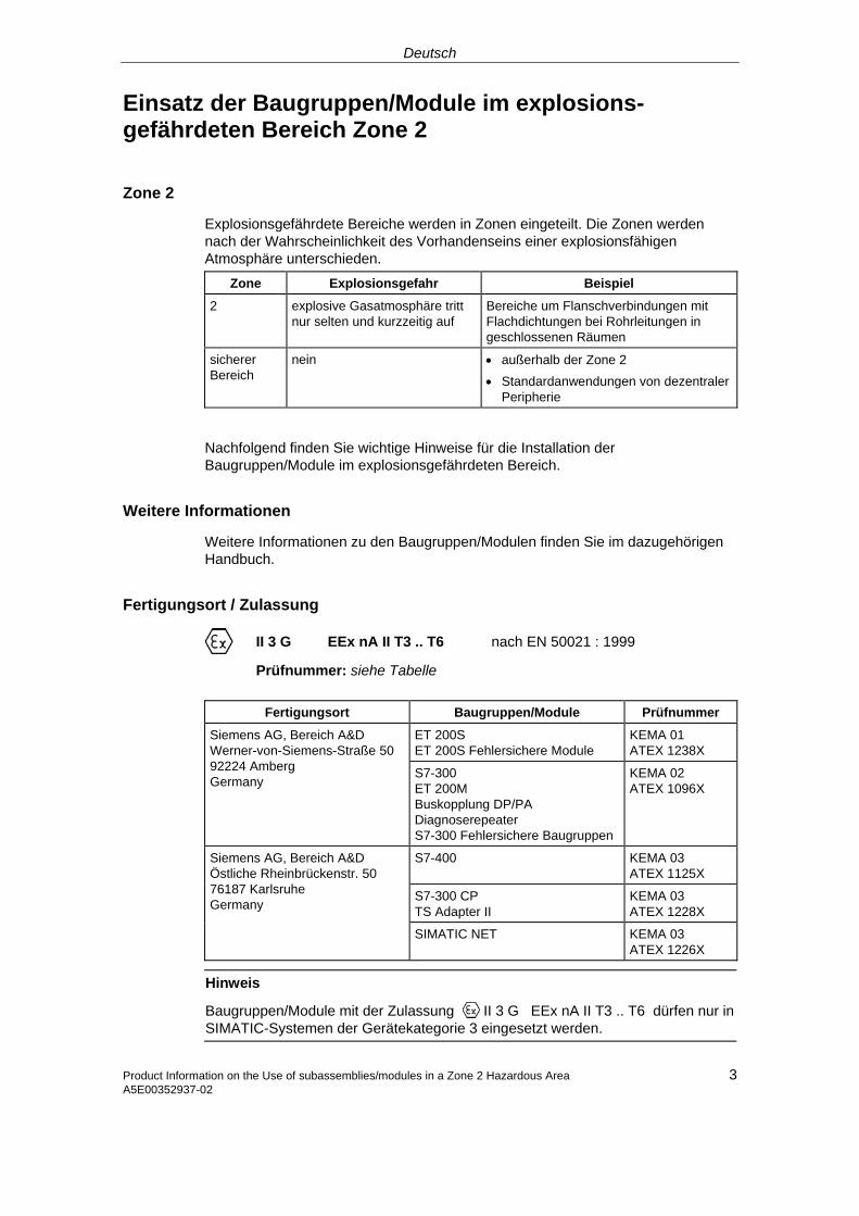
Deutsch
Einsatz der Baugruppen/Module im explosions-gefährdeten Bereich Zone 2
Zone 2
Explosionsgefährdete Bereiche werden in Zonen eingeteilt. Die Zonen werden nach der Wahrscheinlichkeit des Vorhandenseins einer explosionsfähigen Atmosphäre unterschieden.
Zone Explosionsgefahr Beispiel
2 explosive Gasatmosphäre tritt nur selten und kurzzeitig auf
Bereiche um Flanschverbindungen mit Flachdichtungen bei Rohrleitungen in geschlossenen Räumen
sicherer Bereich
nein • außerhalb der Zone 2 • Standardanwendungen von dezentraler
Peripherie
Nachfolgend finden Sie wichtige Hinweise für die Installation der Baugruppen/Module im explosionsgefährdeten Bereich.
Weitere Informationen
Weitere Informationen zu den Baugruppen/Modulen finden Sie im dazugehörigen Handbuch.
Fertigungsort / Zulassung
II 3 G EEx nA II T3 .. T6 nach EN 50021 : 1999
Prüfnummer: siehe Tabelle
Fertigungsort Baugruppen/Module Prüfnummer
ET 200S ET 200S Fehlersichere Module
KEMA 01 ATEX 1238X
Siemens AG, Bereich A&D Werner-von-Siemens-Straße 50 92224 Amberg Germany
S7-300 ET 200M Buskopplung DP/PA Diagnoserepeater S7-300 Fehlersichere Baugruppen
KEMA 02 ATEX 1096X
S7-400 KEMA 03 ATEX 1125X
S7-300 CP TS Adapter II
KEMA 03 ATEX 1228X
Siemens AG, Bereich A&D Östliche Rheinbrückenstr. 50 76187 Karlsruhe Germany
SIMATIC NET KEMA 03 ATEX 1226X
Hinweis
Baugruppen/Module mit der Zulassung II 3 G EEx nA II T3 .. T6 dürfen nur in SIMATIC-Systemen der Gerätekategorie 3 eingesetzt werden.
Product Information on the Use of subassemblies/modules in a Zone 2 Hazardous Area 3 A5E00352937-02

Deutsch
Instandhaltung
Für eine Reparatur müssen die betroffene Baugruppen/Module an den Fertigungsort geschickt werden. Nur dort darf die Reparatur durchgeführt werden.
Besondere Bedingungen
1. Baugruppen/Module müssen in einen Schaltschrank oder ein metallisches Gehäuse eingebaut werden. Diese müssen mindestens die Schutzart IP 54 (nach EN 60529) gewährleisten. Dabei sind die Umgebungsbedingungen zu berücksichtigen, in denen das Gerät installiert wird. Für das Gehäuse muss eine Herstellererklärung für Zone 2 vorliegen (gemäß EN 50021).
2. Wenn am Kabel bzw. an der Kabeleinführung dieses Gehäuses unter Betriebs-bedingungen eine Temperatur > 70 °C erreicht wird oder wenn unter Betriebs-bedingungen die Temperatur an der Aderverzweigung > 80 °C sein kann, müssen die Temperatureigenschaften der Kabel mit den tatsächlich gemessenen Temperaturen übereinstimmen.
3. Die eingesetzten Kabeleinführungen müssen der geforderten IP-Schutzart und dem Abschnitt 7.2 (gemäß EN 50021) entsprechen.
4. Alle Geräte, einschließlich Schalter etc., die an den Ein- und Ausgängen von SIMATIC-Systemen angeschlossen werden, müssen für den Explosionsschutz Typ EEx nA oder EEx nC genehmigt sein.
5. Es müssen Maßnahmen getroffen werden, dass die Nennspannung durch Transienten um nicht mehr als 40 % überschritten werden kann.
6. Umgebungstemperaturbereich: 0° C bis 60° C
7. Innerhalb des Gehäuses ist an einem nach dem Öffnen gut sichtbaren Platz ein Schild mit folgender Warnung anzubringen:
! Warnung Das Gehäuse darf nur kurze Zeit geöffnet werden, z. B. für visuelle Diagnose. Betätigen Sie dabei keine Schalter, ziehen oder stecken keine Baugruppen und trennen keine elektrischen Leitungen (Steckverbindungen). Diese Warnung kann unberücksichtigt bleiben, wenn bekannt ist, dass keine explosionsgefährdete Atmosphäre herrscht. Liste der zugelassenen Baugruppen/Module
Die Liste mit den zugelassenen Baugruppen/Module finden Sie im Internet:
http://www4.ad.siemens.de/view/cs/
unter der Beitrags-ID 13702947.
4 Product Information on the Use of subassemblies/modules in a Zone 2 Hazardous Area A5E00352937-02

English
Use of subassemblies/modules in a Zone 2 Hazardous Area
Zone 2
Hazardous areas are divided up into zones. The zones are distinguished according to the probability of the existence of an explosive atmosphere.
Zone Explosion Hazard Example
2 Explosive gas atmosphere occurs only seldom and for a short time
Areas around flange joints with flat gaskets in pipes in enclosed spaces
Safe area No • Outside zone 2 • Standard distributed I/O applications
Below you will find important information on the installation of the subassemblies/modules in a hazardous area.
Further Information
You will find further information on the subassemblies/modules in the corresponding manual.
Production Location / Certification
II 3 G EEx nA II T3 .. T6 to EN 50021 : 1999
Test number: see table below
Production Location Subassemblies/Modules Test Number
ET-200S ET 200S fault-tolerant modules
KEMA 01 ATEX 1238X
Siemens AG, Bereich A&D Werner-von-Siemens-Straße 50 92224 Amberg Germany
S7-300 ET-200M DP/PA bus interface Diagnostics repeater S7-300 fault-tolerant modules
KEMA 02 ATEX 1096X
S7-400 KEMA 03 ATEX 1125X
S7-300 CP TS Adapter II
KEMA 03 ATEX 1228X
Siemens AG, Bereich A&D Östliche Rheinbrückenstr. 50 76187 Karlsruhe Germany
SIMATIC NET KEMA 03 ATEX 1226X
Note
Subassemblies/modules with II 3 G EEx nA II T3 .. T6 certification can only be used in SIMATIC systems rated as category 3 equipment.
Product Information on the Use of subassemblies/modules in a Zone 2 Hazardous Area 5 A5E00352937-02

English
Maintenance
If repair is necessary, the affected subassemblies/modules must be sent to the production location. Repairs can only be carried out there.
Special Conditions
1. Subassemblies/modules must be installed in a cabinet or metal housing. These must comply with the IP 54 degree of protection as a minimum. The environmental conditions under which the equipment is installed must be taken into account. There must be a manufacturer's declaration for zone 2 available for the housing (in accordance with EN 50021).
2. If a temperature of > 70 °C is reached in the cable or at the cable entry of this housing under operating conditions, or if a temperature of > 80 °C can be reached at the junction of the conductors under operating conditions, the temperature-related properties of the cables must correspond to the temperatures actually measured.
3. The cable entries used must comply with the required IP degree of protection and Section 7.2 (in accordance with EN 50021).
4. All devices (including switches, etc.) that are connected to the inputs and outputs of SIMATIC systems must be approved for EEx nA or EEx nC explosion protection.
5. Steps must be taken to ensure that the rated voltage through transients cannot be exceeded by more than 40 %.
6. Ambient temperature range: 0° C to 60° C
7. A sign containing the following warning must be put up inside the housing in an easily visible position when the housing is opened:
! Warning The housing can only be opened for a short time (e.g. for visual diagnostics). If you do this, do not operate any switches, remove or install any modules or disconnect any electrical cables (plug-in connections). You can disregard this warning if you know that the atmosphere is not hazardous (i.e. there is no risk of explosion).
List of Approved Subassemblies/Modules
You will find the list of approved subassemblies/modules under the ID 13702947 on the Internet:
http://www4.ad.siemens.de/view/cs/.
6 Product Information on the Use of subassemblies/modules in a Zone 2 Hazardous Area A5E00352937-02

Français
Utilisation des modules / coupleurs dans la zone à risque d'explosion 2
Zone 2
Les environnements à risque d'explosion sont répartis en zones. Les zones se distinguent par la probabilité de présence d'une atmosphère explosive.
Zone Risque d'explosion Exemple
2 Formation rare et brève d'une atmosphère gazeuse explosive
Environnement de raccords à joints plats dans le cas de conduites dans des locaux fermés
Zone sûre Non • A l'extérieur de la zone 2 • Utilisation standard de périphérie
décentralisée
Vous trouverez ci-après des remarques importantes pour l'installation de la station de périphérie décentralisée des modules / coupleurs dans la zone à risque d'explosion.
Informations complémentaires
Des informations complémentaires sur les modules / cartouches se trouvent dans le manuel correspondant.
Lieu de fabrication / Homologation
II 3 G EEx nA II T3 .. T6 selon EN 50021 : 1999
Numéro de contrôle : voir tableau
Lieu de fabrication Modules / coupleurs Numéro de contrôle
ET 200S Modules à sécurité intrinsèque ET 200S
KEMA 01 ATEX 1238X
Siemens AG, Bereich A&D Werner-von-Siemens-Straße 5092224 Amberg Germany S7-300
ET 200M Couplage de bus DP/PA Répéteur de diagnostic Modules à sécurité intrinsèque S7-300
KEMA 02 ATEX 1096X
S7-400 KEMA 03 ATEX 1125X
S7-300 CP TS Adapter II
KEMA 03 ATEX 1228X
Siemens AG, Bereich A&D Östliche Rheinbrückenstr. 50 76187 Karlsruhe Germany
SIMATIC NET KEMA 03 ATEX 1226X
7 Product Information on the Use of subassemblies/modules in a Zone 2 Hazardous AreaA5E00352937-02

Français
Nota
Les modules / coupleurs homologués II 3 G EEx nA II T3 .. T6 ne peuvent être utilisés que dans des systèmes SIMATIC de catégorie 3.
Entretien
Si une réparation est nécessaire, le module / coupleur concerné doit être expédié au lieu de production. La réparation ne doit être effectuée qu'en ce lieu.
Conditions particulières
1. Les modules / coupleurs doivent être installés dans une armoire ou un boîtier métallique. Ceux-ci doivent assurer au moins l'indice de protection IP 54. Il faut alors tenir compte des conditions d'environnement dans lesquelles l'appareil est installé. Le boîtier doit faire l’objet d’une déclaration de conformité du fabricant pour la zone 2 (selon EN 50021).
2. Si dans les conditions d’exploitation, une température > 70 °C est atteinte au niveau du câble ou de l’entrée du câble dans ce boîtier, ou bien si la température au niveau de la dérivation des conducteurs peut être > 80 °C, les capacités de résistance thermique des câbles doivent corespondre aux températures effectivement mesurées.
3. Les entrées de câbles utilisées doivent avoir le niveau de protection IP exigé et être conformes au paragraphe 7.2 (selon EN 50021).
4. Tous les appareillages (y compris les interrupteurs, etc.) raccordés aux entrées et sorties de systèmes SIMATIC doivent être homologués pour la protection antidéflagrante type EEx nA ou EEx nC.
5. Il faut prendre des mesures pour que la tension nominale ne puisse pas être dépassée de plus de 40% sous l’influence de transitoires.
6. Plage de température ambiante : 0° C à 60° C
7. A l’intérieur du boîtier, il faut placer, à un endroit bien visible après ouverture, une plaquette comportant l’avertissement suivant :
! Avertissement Ouvir le boîtier le moins longtemps possible, par exemple pour effectuer un diagnostic visuel. Ce faisant, n’actionnez aucun commutateur, ne déconnectez aucun module et ne débanchez pas de câbles électriques (connexions). Le respect de cet avertissement n’est pas impératif s’il est certain que l’environnement ne présente pas de risque d’explosion. Liste des modules / coupleurs homologués
Vous trouverez sur Internet la liste des modules / coupleurs homologués :
http://www4.ad.siemens.de/view/cs/
référence ID 13702947.
8 Product Information on the Use of subassemblies/modules in a Zone 2 Hazardous Area A5E00352937-02

Español
Aplicación de los módulos / tarjetas en áreas con peligro de explosión, zona 2
Zona 2
Las áreas con peligro de explosión se clasifican en zonas. Las zonas se diferencian según la probabilidad de la existencia de una atmósfera capaz de sufrir una explosión.
Zona Peligro de explosión Ejemplo
2 La atmósfera explosiva de gas sólo se presenta rara vez y muy brevemente
Áreas alrededor de uniones abridadas con juntas planas en tuberías en locales cerrados
Área segura no • fuera de la zona 2 • Aplicaciones estándar de la periferia
descentralizada
A continuación encontrará importantes informaciones para la instalación de los módulos / tarjetas en áreas con peligro de explosión.
Otras informaciones
Encontrará otras informaciones relativas a los módulos / tarjetas en el Manual correspondiente.
Lugar de fabricación / Homologación
II 3 G EEx nA II T3 .. T6 según norma EN 50021 : 1999
Número de comprobación: véase tabla
Lugar de fabricación Módulos / tarjetas Número de comprobación
ET 200S Grupos ET 200S a prueba de fallos
KEMA 01 ATEX 1238 X
Siemens AG, Bereich A&DWerner-von-Siemens-Straße 50 92224 Amberg Germany
S7-300 ET 200M Acoplamiento de bus DP/PA Repetidor de diagnóstico Grupos S7-300 a prueba de fallos
KEMA 02 ATEX 1096 X
S7-400 KEMA 03 ATEX 1125 X
S7-300 CP TS Adapter
KEMA 03 ATEX 1228 X
Siemens AG, Bereich A&D Östliche Rheinbrückenstr. 50 76187 Karlsruhe Germany
SIMATIC NET KEMA 03 ATEX 1226 X
9 Product Information on the Use of subassemblies/modules in a Zone 2 Hazardous Area A5E00352937-02

Español
Nota
Los módulos / tarjetas con la homologación II 3 G EEx nA II T3 .. T6 pueden utilizarse únicamente en los sistemas SIMATIC de la categoría de equipo 3.
Mantenimiento
Para una reparación se ha de remitir el módulo / tarjeta afectado al lugar de fabricación. Sólo allí se puede realizar la reparación.
Condiciones especiales
1. Los módulos / tarjetas se han de montar en un armario eléctrico de distribución o en una carcasa metálica. Éstos deben garantizar como mínimo el grado de protección IP 54 (conforme a EN 60529). Para ello se han de tener en cuenta las condiciones ambientales, en las cuales se instala el equipo. La caja deberá contar con una declaración del fabricante para la zona 2 (conforme a EN 50021).
2. Si durante la operación se alcanzara una temperatura > 70° C en el cable o la entrada de cables de esta caja o bien una temperatura > 80° C en la bifurcación de hilos, deberán adaptarse las propiedades térmicas de los cables a las temperaturas medidas efectivamente.
3. Las entradas de cable utilizadas deben cumplir el grado de protección IP exigido y lo expuesto en el apartado 7.2 (conforme a EN 50021).
4. Todos los dispositivos –inclusive interruptores, etc.– conectados a las entradas y salidas de sistemas SIMATIC deben estar homologados para la protección contra explosiones del tipo EEx nA o EEx nC.
5. Es necesario adoptar las medidas necesarias para evitar que la tensión nominal pueda rebasar en más del 40 % debido a efectos transitorios.
6. Margen de temperatura ambiente: 0° C hasta 60° C
7. Dentro de la caja deberá colocarse en un lugar perfectamente visible tras su apertura un rótulo con la siguiente advertencia:
! Precaución Abrir la caja sólo brevemente, p.ej. para el diagnóstico visual. Durante este tiempo Ud. no deberá activar ningún interruptor, desenchufar o enchufar módulos ni separar conductores eléctricos (conexiones enchufables). Esta advertencia puede ignorarse si Ud. sabe que en la atmósfera existente no hay peligro de explosión.
Lista de los módulos / tarjetas homologados
En la internet hallará Ud. una lista con los módulos / tarjetas homologados:
http://www4.ad.siemens.de/view/cs/
bajo el ID de asignación 13702947.
10 Product Information on the Use of subassemblies/modules in a Zone 2 Hazardous Area A5E00352937-02

Italiano
Impiego delle unità/moduli nell'area a pericolo di esplosione zona 2
Zona 2
Le aree a pericolo di esplosione vengono suddivise in zone. Le zone vengono distinte secondo la probabilità della presenza di un'atmosfera esplosiva.
Zona Pericolo di esplosione Esempio
2 L'atmosfera esplosiva si presente solo raramente e brevemente
Aree intorno a collegamenti a flange con guarnizioni piatte nelle condotte in ambienti chiusi
Area sicura No • Al di fuori della zona 2 • Applicazioni standard di periferia
decentrata
Qui di seguito sono riportate delle avvertenze importanti per l'installazione delle unità/moduli nell'area a pericolo di esplosione.
Ulteriori informazioni
Ulteriori informazioni sulle unità/moduli si trovano nel corrispondente manuale.
Luogo di produzione / Omologazione
II 3 G EEx nA II T3 .. T6 secondo EN 50021 : 1999
Numero di controllo: vedi tabella
Luogo di produzione Unità/moduli Numero di controllo
ET 200S Unità ad elevata sicurezza ET 200S
KEMA 01 ATEX 1238X
Siemens AG, Bereich A&D Werner-von-Siemens-Straße 50 92224 Amberg Germany
S7-300 ET 200M Accoppiamento di bus DP/PA Repeater di diagnostica Unità ad elevata sicurezza S7-300
KEMA 02 ATEX 1096X
S7-400 KEMA 03 ATEX 1125X
S7-300 CP TS Adapter II
KEMA 03 ATEX 1228X
Siemens AG, Bereich A&D Östliche Rheinbrückenstr. 50 76187 Karlsruhe Germany
SIMATIC NET KEMA 03 ATEX 1226X
11 Product Information on the Use of subassemblies/modules in a Zone 2 Hazardous AreaA5E00352937-02

Italiano
Avvertenza
Le unità/moduli con l'omologazione II 3 G EEx nA II T3 .. T6 possono essere impiegati solo nei sistemi SIMATIC della categoria di apparecchiature 3.
Manutenzione
Per una riparazione, le unità/i moduli interessati devono essere inviati al luogo di produzione. La riparazione può essere effettuata solo lì.
Condizioni particolari
1. Le unità/i moduli devono essere montati in un armadio elettrico o in un contenitore metallico. Questi devono assicurare almeno il tipo di protezione IP 54. In questo caso bisogna tenere conto delle condizioni ambientali nelle quali l'apparecchiatura viene installata. Per il contenitore deve essere presente una dichiarazione del costruttore per la zona 2 (secondo EN 50021).
2. Se nei cavi o nel loro punto di ingresso in questo contenitore viene raggiunta in condizioni di esercizio una temperatura > 70 °C o se in condizioni di esercizio la temperatura nella derivazione dei fili può essere > 80 °C, le caratteristiche di temperatura dei cavi devono essere conformi alla temperatura effettivamente misurata.
3. Gli ingressi dei cavi usati devono essere conformi al tipo di protezione richiesto e alla sezione 7.2 (secondo EN 50021).
4. Tutte le apparecchiature, inclusi interruttori, ecc. che vengono collegati agli ingressi/uscite di sistemi SIMATIC, devono essere stati omologati per la protezione da esplosione tipo EEx nA o EEx nC.
5. Devono essere prese delle misure per evitare che la tensione nominale possa essere superata per più del 40% da parte di transienti.
6. Campo termico ambientale: da 0° C a 60° C
7. All’interno del contenitore va apportata, in un luogo ben visibile dopo l’apertura, una targhetta con il seguente avvertimento:
! Attenzione Il contenitore può rimanere aperto solo per breve tempo, ad esempio per una diagnostica a vista. In tal caso non azionare alcun interruttore, non disinnestare o innestare unità e non staccare connessioni elettriche (connettori). Non è necessario tenere conto di questo avvertimento se è noto che non c’è un’atmosfera a rischio di esplosione
Elenco delle unità/moduli omologati
L'elenco con le unità/moduli omologati si trova in Internet al sito:
http://www4.ad.siemens.de/view/cs/
all’ID di voce 13702947.
12 Product Information on the Use of subassemblies/modules in a Zone 2 Hazardous Area A5E00352937-02

Nederlands
Gebruik van de componenten/modulen in het explosief gebied zone 2
Zone 2
Explosieve gebieden worden ingedeeld in zones. Bij de zones wordt onderscheiden volgens de waarschijnlijkheid van de aanwezigheid van een explosieve atmosfeer.
Zone Explosiegevaar Voorbeeld
2 Een explosieve gasatmosfeer treedt maar zelden op en voor korte duur
Gebieden rond flensverbindingen met pakkingen bij buisleidingen in gesloten vertrekken
Veilig gebied
neen • Buiten de zone 2 • Standaardtoepassingen van decentrale
periferie
Hierna vindt u belangrijke aanwijzingen voor de installatie van de componenten/modulen in het explosief gebied.
Verdere informatie
In het bijhorende handboek vindt u verdere informatie over de componenten/modulen
Productieplaats / Vergunning
II 3 G EEx nA II T3 .. T6 conform EN 50021 : 1999
Keuringsnummer: zie tabel
Productieplaats Componenten/modulen Keuringsnummer
ET 200S ET 200S tegen fouten beveiligde componenten
KEMA 01 ATEX 1238X
Siemens AG, Bereich A&D Werner-von-Siemens-Strasse 50 92224 Amberg Germany S7-300
ET 200 M Buskoppeling DP/PA Diagnoserepeater S7-300 tegen fouten beveiligde componenten
KEMA 02 ATEX 1096X
S7-400 KEMA 03 ATEX 1125X
S7-300 CP TS Adapter II
KEMA 03 ATEX 1228X
Siemens AG, Bereich A&D Östliche Rheinbrückenstr. 50 76187 Karlsruhe Germany
SIMATIC NET KEMA 03 ATEX 1226X
13 Product Information on the Use of subassemblies/modules in a Zone 2 Hazardous Area A5E00352937-02

Nederlands
Opmerking
Componenten/modulen met de vergunning II 3 G EEx nA II T3 .. T6 mogen slechts worden gebruikt in SIMATIC-systemen van de apparaatcategorie 3.
Instandhouding
Voor een reparatie moeten de betreffende componenten/modulen naar de plaats van vervaardiging worden gestuurd. Alleen daar mag de reparatie worden uitgevoerd.
Speciale voorwaarden
1. Componenten/modulen moeten worden ingebouwd in een schakelkast of in een behuizing van metaal. Deze moeten minstens de veiligheidsgraad IP 54 waarborgen. Hierbij dient rekening te worden gehouden met de omgevingsvoorwaarden waarin het apparaat wordt geïnstalleerd. Voor de behuizing dient een verklaring van de fabrikant voor zone 2 te worden ingediend (volgens EN 50021).
2. Als aan de kabel of aan de kabelinvoering van deze behuizing onder bedrijfsomstandigheden een temperatuur wordt bereikt > 70 °C of als onder bedrijfsomstandigheden de temperatuur aan de adervertakking > 80 °C kan zijn, moeten de temperatuureigenschappen van de kabel overeenstemmen met de werkelijk gemeten temperaturen.
3. De aangebrachte kabelinvoeringen moeten de vereiste IP-veiligheidsgraad hebben en in overeenstemming zijn met alinea 7.2 (volgens EN 50021).
4. Alle apparaten, schakelaars enz. inbegrepen, die worden aangesloten op de in- en uitgangen van SIMATIC-systemen, moeten zijn goedgekeurd voor de explosiebeveiliging type EEx nA of EEx nC.
5. Er dienen maatregelen te worden getroffen, zodat de nominale spanning door transiënten met niet meer dan 40 % kan worden overschreden.
6. Omgevingstemperatuurbereik: 0° C tot 60° C
7. Binnen de behuizing dient op een na het openen goed zichtbare plaats een bord te worden aangebracht met de volgende waarschuwing:
! Waarschuwing De behuizing mag slechts voor korte tijd worden geopend, bijv. voor een visuele diagnose. Bedien hierbij geen schakelaar, trek of steek geen modulen en ontkoppel geen elektrische leidingen (steekverbindingen). Deze waarschuwing kan buiten beschouwing blijven, indien bekend is dat er geen explosieve atmosfeer heerst.
Lijst van de toegelaten componenten/modulen
De lijst met de toegelaten componenten/modulen vindt u in het internet:
http://www4.ad.siemens.de/view/cs/
onder de bijdrage-ID 13702947.
14 Product Information on the Use of subassemblies/modules in a Zone 2 Hazardous Area A5E00352937-02

Dansk
Brug af komponenter/moduler i det eksplosionsfarlige område zone 2
Zone 2
Eksplosionsfarlige områder inddeles i zoner. Zonerne adskiller sig indbyrdes efter hvor sandsynligt det er, at der er en eksplosiv atmosfære.
Zone Eksplosionsfare Eksempel
2 Eksplosiv gasatmosfære optræder kun sjældent og varer kort
Områder rundt om flangeforbindelser med flade pakninger ved rørledninger i lukkede rum
Sikkert område
Nej • Uden for zone 2 • Standardanvendelser decentral periferi
I det følgende findes vigtige henvisninger vedr. installation af komponenter/moduler i det eksplosionsfarlige område.
Yderligere informationer
Yderligere informationer om komponenterne/modulerne findes i den pågældende manual.
Produktionssted / Godkendelse
II 3 G EEx nA II T3 .. T6 efter EN 50021 : 1999
Kontrolnummer: se tabel
Produktionssted Komponenter/moduler Kontrolnummer
ET 200S ET 200S fejlsikre komponenter
KEMA 01 ATEX 1238X
Siemens AG, Bereich A&D Werner-von-Siemens-Straße 50 92224 Amberg Germany S7-300
ET 200M Buskobling DP/PA Diagnoserepeater S7-300 fejlsikre komponenter
KEMA 02 ATEX 1096X
S7-400 KEMA 03 ATEX 1125X
S7-300 CP TS Adapter II
KEMA 03 ATEX 1228X
Siemens AG, Bereich A&D Östliche Rheinbrückenstr. 50 76187 Karlsruhe Germany
SIMATIC NET KEMA 03 ATEX 1226X
Bemærk
Komponenter/moduler med godkendelsen II 3 G EEx nA II T3 .. T6 må kun monteres i SIMATIC-systemer for udstyrskategori 3.
15 Product Information on the Use of subassemblies/modules in a Zone 2 Hazardous Area A5E00352937-02

Dansk
Vedligeholdelse
Hvis de pågældende komponenter/moduler skal repareres, bedes De sende dem til produktionsstedet. Reparation må kun udføres der.
Særlige betingelser
1. Komponenterne/modulerne skal monteres i et kontrolskab eller et metalkabinet. Disse skal mindst kunne sikre beskyttelsesklasse IP 54. I denne forbindelse skal der tages højde for de omgivelsestemperaturer, i hvilke udstyret er installeret. Der skal være udarbejdet en erklæring fra fabrikanten for kabinettet for zone 2 (iht. EN 50021).
2. Hvis kablet eller kabelindføringen på dette hus når op på en temperatur på > 70 °C under driftsbetingelser eller hvis temperaturen på åreforegreningen kan være > 80 °C under driftsbetingelser, skal kablernes temperaturegenskaber stemme overens med de temperaturer, der rent faktisk måles.
3. De benyttede kabelindføringer skal være i overensstemmelse med den krævede IP-beskyttelsestype og afsnittet 7.2 (iht. EN 50021).
4. Alle apparater, inkl. kontakter osv., der forbindes med ind- og udgangene til SIMATIC-systemerne, skal være godkendt til eksplosionsbeskyttelse af type EEx nA eller EEx nC.
5. Der skal træffes foranstaltninger, der sørger for, at den nominelle spænding via transienter ikke kan overskrides mere end 40 %.
6. Omgivelsestemperaturområde: 0° C til 60° C
7. I kabinettet skal der anbringes et skilt, der skal kunne ses, når kabinettet åbnes. Dette skilt skal have følgende advarsel:
! Advarsel Kabinettet må kun åbnes i kort tid, f.eks. til visuel diagnose. Tryk i denne forbindelse ikke på kontakter, træk eller isæt ikke komponenter og afbryd ikke elektriske ledninger (stikforbindelser). Der skal ikke tages højde for denne advarsel, hvis man ved, at der ikke er nogen eksplosionsfarlig atmosfære.
Liste over godkendte komponenter/moduler
Listen med de godkendte komponenter/moduler findes på internettet:
http://www4.ad.siemens.de/view/cs/
under bidrags-ID 13702947.
16 Product Information on the Use of subassemblies/modules in a Zone 2 Hazardous Area A5E00352937-02

Suomi
Rakenneryhmien/moduulien käyttö räjähdysvaarannetuilla alueilla, vyöhyke 2
Vyöhyke 2
Räjähdysvaarannetut alueet jaetaan vyöhykkeisiin. Vyöhykkeet erotellaan räjähdyskelpoisen ilmakehän olemassa olon todennäköisyyden mukaan.
Vyöhyke Räjähdysvaara Esimerkki
2 Räjähtävä kaasuilmakehä ilmaantuu vain harvoin ja lyhytaikaisesti
Alueet putkistojen lattatiivisteillä varustuilla laippaliitoksilla suljetuissa tiloissa
turvallinen alue
ei • vyöhykkeen 2 ulkopuolella • Hajautetun ulkopiirin vakiosovellukset
Seuraavasta löydätte tärkeitä ohjeita rakenneryhmien/moduulien asennukseen räjähdysvaarannetuilla alueilla.
Lisätietoja
Lisätietoja rakenneryhmiin/moduuleihin löydätte niihin kuuluvista ohjekirjasta.
Valmistuspaikka / Hyväksyntä
II 3 G EEx nA II T3 .. T6 EN 50021 mukaan: 1999
Tarkastusnumero: katso taulukko
Valmistuspaikka Rakenneryhmät/moduulit Tarkastusnumero
ET 200S ET 200S läpi-iskuvarmat rakenneryhmät
KEMA 01 ATEX 1238X
Siemens AG, Bereich A&D Werner-von-Siemens-Straße 5092224 Amberg Germany S7-300
ET 200M Väyläkytkin DP/PA Dignoositoistin S7-300 läpi-iskuvarmat rakenneryhmät
KEMA 02 ATEX 1096X
S7-400 KEMA 03 ATEX 1125X
S7-300 CP TS Adapter II
KEMA 03 ATEX 1228X
Siemens AG, Bereich A&D Östliche Rheinbrückenstr. 50 76187 Karlsruhe Germany
SIMATIC NET KEMA 03 ATEX 1226X
Ohje
Rakenneryhmät/moduulit hyväksynnän II 3 G EEx nA II T3 .. T6 kanssa saadaan käyttää ainoastaan laitekategorian 3 SIMATIC-järjestelmissä.
Product Information on the Use of subassemblies/modules in a Zone 2 Hazardous Area A5E00352937-02
17

Suomi
Kunnossapito
Korjausta varten täytyy kyseinen rakenneryhmä/moduuli lähettää valmistuspaikkaan. Korjaus voidaan suorittaa ainoastaan siellä.
Erityiset vaatimukset
1. Rakenneryhmät/moduulit täytyy asentaa kytkentäkaappiin tai metalliseen koteloon. Näiden täytyy olla vähintään kotelointiluokan IP 54 mukaisia. Tällöin on huomioitava ympäristöolosuhteet, johon laite asennetaan. Kotelolle täytyy olla valmistajaselvitys vyöhykettä 2 varten (EN 50021 mukaan).
2. Kun johdolla tai tämän kotelon johdon sisäänviennillä saavutetaan > 70 °C lämpötila tai kun käyttöolosuhteissa lämpötila voi piuhajaotuksella olla > 80 °C, täytyy johdon lämpötilaominaisuuksien vastata todellisesti mitattuja lämpötiloja.
3. Käytettyjen johtojen sisäänohjauksien täytyy olla vaaditun IP-kotelointiluokan ja kohdan 7.2 (EN 50021 mukaan) mukaisia.
4. Kaikkien laitteiden, kytkimet jne. mukaan lukien, jotka liitetään SIMATIC-järjestelmien tuloille ja lähdöille, täytyy olla hyväksyttyjä tyypin EEx nA tai EEx nC räjähdyssuojausta varten.
5. Toimenpiteet täytyy suorittaa, ettei nimellisjännite voi transienttien kautta ylittyä enemmän kuin 40 %.
6. Ympäristölämpötila-alue: 0° C ... 60° C
7. Kotelon sisälle, avauksen jälkeen näkyvälle paikalle, on kiinnitettävä kilpi, jossa on seuraava varoitus:
! Varoitus Kotelo saadaan avata ainoastaan lyhyeksi ajaksi, esim. visuaalista diagnoosia varten. Älä tällöin käytä mitään kytkimiä, vedä tai liitä mitään rakenneryhmiä, äläkä erota mitään sähköjohtoja (pistoliittimiä). Tätä varoitusta ei tarvitse huomioida, kun on tiedossa, että minkäänlaista räjähdysvaarannettua ilmakehää ei ole olemassa.
Hyväksyttyjen rakenneryhmien/moduulien lista
Lista hyväksytyistä rakennesarjoista/moduuleista löytyy internetistä osoitteesta:
http://www4.ad.siemens.de/view/cs/
käyttäjätunnuksella 13702947.
18 Product Information on the Use of subassemblies/modules in a Zone 2 Hazardous Area A5E00352937-02

Svenska
Användning av komponentgrupperna/modulerna i explosionsriskområde zon 2
Zon 2
Explosionsriskområden delas in i zoner. Zonerna delas in enligt sannolikheten att en atmosfär med explosionsfara föreligger.
Zon Explosionsfara Exempel
2 Explosiv gasatmosfär uppstår endast sällan eller kortvarigt
Områden kring flänsförbindelser med packningar vid rörledningar i slutna utrymmen
Säkert område
Nej • Utanför zon 2 • Standardanvändning av decentral
periferi
Nedan följer viktiga anvisningar om installationen av komponentgrupperna/modulerna i ett explosionsriskområde.
Ytterligare information
Ytterligare information om komponentgrupperna/modulerna finner du i tillhörande handbok.
Tillverkningsort / Godkännande
II 3 G EEx nA II T3 .. T6 enligt EN 50021 : 1999
Kontrollnummer: se tabell
Tillverkningsort Komponentgrupper/ moduler
Kontrollnummer
ET 200S ET 200S Felsäkra komponentgrupper
KEMA 01 ATEX 1238X
Siemens AG, Bereich A&D Werner-von-Siemens-Straße 5092224 Amberg Germany
S7-300 ET 200M Busskoppling DP/PA Diagnosrepeater S7-300 Felsäkra komponentgrupper
KEMA 02 ATEX 1096X
S7-400 KEMA 03 ATEX 1125X
S7-300 CP TS Adapter II
KEMA 03 ATEX 1228X
Siemens AG, Bereich A&D Östliche Rheinbrückenstr. 50 76187 Karlsruhe Germany
SIMATIC NET KEMA 03 ATEX 1226X
Product Information on the Use of subassemblies/modules in a Zone 2 Hazardous Area 19 A5E00352937-02

Svenska
Anvisning
Komponentgrupper/moduler med godkännande II 3 G EEx nA II T3 .. T6 får endast användas i SIMATIC-system i apparatgrupp 3.
Underhåll
Vid reparation måste den aktuella komponentgrupperna/modulerna insändas till tillverkaren. Reparationer får endast genomföras där.
Särskilda villkor
1. Komponentgrupperna/modulerna måste monteras i ett kopplingsskåp eller metallhus. Dessa måste minst vara av skyddsklass IP 54. Därvid ska omgivningsvillkoren där enheten installeras beaktas. För kåpan måste en tillverkardeklaration för zon 2 föreligga (enligt EN 50021).
2. Om en temperatur på > 70°C uppnås vid husets kabel resp kabelinföring under driftvillkor eller om temperaturen vid trådförgreningen kan vara > 80°C under driftvillkor, måste kabelns temperaturegenskaper överensstämma med den verkligen uppmätta temperaturen.
3. De använda kabelinföringarna måste uppfylla kraven i det krävda IP-skyddsutförandet och i avsnitt 7.2 (enligt EN 50021).
4. Alla apparater, inklusive brytare osv, som ansluts till in- och utgångarna på SIMATIC-system, måste vara godkända för explosionsskydd av typ EEx nA eller EEx nC.
5. Åtgärder måste vidtas så, att märkspänningen ej kan överskridas med mer än 40 % genom transienter.
6. Omgivningstemperatur: 0° C till 60° C
7. När huset öppnats ska en skylt med följande varning monteras på ett tydligt synligt ställe huset:
! Varning Huset får endast öppnas under kort tid, t ex för visuell diagnos. Använd därvid inga brytare, lossa eller anslut inga enheter och frånskilj inga elektriska ledningar (insticksanslutningar). Ingen hänsyn måste tas till denna varning om det är säkert att det inte råder någon explosionsfarlig atmosfär.
Lista över godkända komponentgrupper/moduler
Lista över godkända komponentgrupper/moduler finns på Internetadressen:
http://www4.ad.siemens.de/view/cs/
under bidrags-ID 13702947.
20 Product Information on the Use of subassemblies/modules in a Zone 2 Hazardous Area A5E00352937-02

Português
Uso de grupos construtivos/módulos em área exposta ao perigo de explosão 2
Zona 2
As áreas expostas ao perigo de explosão são divididas em zonas. As zonas são diferenciadas de acordo com a probabilidade da existência de uma atmosfera explosiva.
Zona Perigo de explosão Exemplo
2 Só raramente e por um breve período de tempo surgem atmosferas explosivas
Áreas em torno de ligações flangeadas com vedações chatas em tubulações em recintos fechados
Área segura não • fora da zona 2 • Aplicações descentralizadas de
periferia descentralizada
A seguir, o encontrará avisos importantes para a instalação de grupos construtivos/ módulos em área exposta ao perigo de explosão.
Mais informações
Para obter mais informações sobre grupos construtivos/módulos, consulte o respectivo manual.
Local de produção / Licença
II 3 G EEx nA II T3 .. T6 seg. EN 50021 : 1999
Número de ensaio: veja a tabela
Local de produção Grupos construtivos/módulos
N° de ensaio
ET 200S ET 200S Grupos construtivos protegidos contra erro
KEMA 01 ATEX 1238X
Siemens AG, Bereich A&D Werner-von-Siemens-Straße 50 92224 Amberg Alemanha S7-300
ET 200M Acoplador bus DP/PA Repetidor de diagnóstico S7-300 Grupos construtivos protegidos contra erro
KEMA 02 ATEX 1096X
S7-400 KEMA 03 ATEX 1125X
S7-300 CP TS Adapter II
KEMA 03 ATEX 1228X
Siemens AG, Bereich A&D Östliche Rheinbrückenstr. 50 76187 Karlsruhe Alemanha
SIMATIC NET KEMA 03 ATEX 1226X
Product Information on the Use of subassemblies/modules in a Zone 2 Hazardous Area 21 A5E00352937-02

Português
Aviso
Os grupos construtivos/módulos com a licença II 3 G EEx nA II T3 .. T6 só podem ser aplicados em sistemas SIMATIC da categoria de aparelho 3.
Reparo
Os grupos construtivos/módulos em questão devem ser remetidos para o local de produção a fim de que seja realizado o reparo. Apenas lá deve ser efetuado o reparo.
Condições especiais
1. Os grupos construtivos/módulos devem ser montados em um armário de distribuição ou em uma caixa metálica. Estes devem garantir no mínimo o tipo de protecção IP 54. Durante este trabalho deverão ser levados em consideração as condições locais, nas quais o aparelho será instalado. Para a caixa deverá ser apresentada uma declaração do fabricante para a zona 2 (de acordo com EN 50021).
2. Caso no cabo ou na entrada do cabo desta carcaça sob as condições operacionais seja atingida uma temperatura de > 70 °C, ou caso sob condições operacionais a temperatura na ramificação do fio poderá atingir > 80 °C, as caraterísticas de temperatura deverão corresponder às temperaturas realmente medidas.
3. As entradas de cabo utilizadas devem corresponder ao tipo exigido de protecção IP e à seção 7.2 (de acordo com o EN 50021).
4. Todos os aparelhos, inclusive as chaves, etc., que estejam conectadas em entradas e saídas dos sistemas SIMATIC devem possuir a licença para a protecção de explosão do tipo EEx nA ou EEx nC.
5. Precisam ser tomadas medidas para que a tensão nominal através de transitórios não possa ser ultrapassada em mais que 40 %.
6. Área de temperatura ambiente: 0° C até 60° C
7. No âmbito da carcaça deve ser colocada, após a abertura, em um ponto bem visível uma placa com a seguinte advertência:
! Advertência A carcaça deve ser aberta apenas por um breve período de tempo, por ex. para diagnóstico visual. Não acione nenhum interruptor, não retire ou conecte nenhum módulo e não separe nenhum fio elétrico (ligações de tomada). Esta advertência poderá ser ignorada caso se saiba que não há nenhuma atmosfera sujeita ao perigo de explosão.
Lista dos grupos construtivos/módulos autorizados
A lista com os grupos construtivos/módulos autorizados encontram-se na Internet:
http://www4.ad.siemens.de/view/cs/
sob o número de ID 13702947.
22 Product Information on the Use of subassemblies/modules in a Zone 2 Hazardous Area A5E00352937-02

Ελληνικά
Χρήση των δοµικών συγκροτηµάτων/µονάδων σε επικίνδυνη για έκρηξη περιοχή, ζώνη 2
Ζώνη 2
Οι επικίνδυνες για έκρηξη περιοχές χωρίζονται σε ζώνες. Οι ζώνες διαφέρουν σύµφωνα µε την πιθανότητα ύπαρξης ενός ικανού για έκρηξη περιβάλλοντος.
Ζώνη Κίνδυνος έκρηξης Παράδειγµα
2 Εκρηκτικό περιβάλλον αερίου παρουσιάζεται µόνο σπάνια και για σύντοµο χρονικό διάστηµα
Περιοχές γύρω από φλαντζωτές συνδέσεις µε τσιµούχες σε σωληνώσεις σε κλειστούς χώρους
Ασφαλής περιοχή
όχι • Εκτός της ζώνης 2 • Τυπικές εφαρµογές αποκεντρωµένης
περιφέρειας
Στη συνέχεια θα βρείτε σηµαντικές υποδείξεις για την εγκατάσταση των δοµικών συγκροτηµάτων/µονάδων σε επικίνδυνη για έκρηξη περιοχή.
Επιπλέον πληροφορίες
Επιπλέον πληροφορίες για τα δοµικά συγκροτήµατα/µονάδες θα βρείτε στο αντίστοιχο εγχειρίδιο.
Τόπος κατασκευής / Άδεια
II 3 G EEx nA II T3 .. T6 σύµφωνα µε το πρότυπο EN 50021 : 1999
Αριθµός ελέγχου: βλέπε πίνακα
Τόπος κατασκευής ∆οµικά συγκροτήµατα/µονάδες Αιθµ. ελέγχου
ET 200S ET 200S Ασφαλή σε περίπτωση βλάβης δοµικά συγκροτήµατα
KEMA 01 ATEX 1238X
Siemens AG, Bereich A&D Werner-von-Siemens-Straße 5092224 Amberg Germany
S7-300 ET 200M Σύζευξη διαύλου DP/PA Επαναλήπτης διάγνωσης S7-300 Ασφαλή σε περίπτωση βλάβης δοµικά συγκροτήµατα
KEMA 02 ATEX 1096X
S7-400 KEMA 03 ATEX 1125X
S7-300 CP TS Adapter II
KEMA 03 ATEX 1228X
Siemens AG, Bereich A&D Östliche Rheinbrückenstr. 50 76187 Karlsruhe Germany
SIMATIC NET KEMA 03 ATEX 1226X
Product Information on the Use of subassemblies/modules in a Zone 2 Hazardous Area 23 A5E00352937-02

Ελληνικά
Υπόδειξη
Τα δοµικά συγκροτήµατα/οι µονάδες µε την άδεια II 3 G EEx nA II T3 .. T6 επιτρέπεται να τοποθετηθούν µόνο σε συστήµατα αυτοµατισµού SIMATIC της κατηγορίας συσκευής 3.
Συντήρηση
Για µια επισκευή πρέπει να σταλθούν τα αντίστοιχα δοµικά συγκροτήµατα/µονάδες στον τόπο κατασκευής. Μόνο εκεί επιτρέπεται να γίνει η επισκευή.
Ιδιαίτερες προϋποθέσεις
1. Τα δοµικά συγκροτήµατα/µονάδες πρέπει να ενσωµατωθούν σε ένα ερµάριο ζεύξης ή σε ένα µεταλλικό περίβληµα. Αυτά πρέπει να εξασφαλίζουν το λιγότερο το βαθµό προστασίας IP 54 (κατά EN 60529). Σε αυτήν την περίπτωση πρέπει να ληφθούν υπόψη οι περιβαλλοντικές συνθήκες, στις οποίες θα εγκατασταθεί η συσκευή. Για το περίβληµα πρέπει να προβλέπεται δήλωση του κατασκευαστή για τη ζώνη 2 (σύµφωνα µε το πρότυπο EN 50021).
2. Εάν στο καλώδιο ή στην είσοδο του καλωδίου αυτού του περιβλήµατος κάτω από συνθήκες λειτουργίας η θερµοκρασία ξεπεράσει τους 70 °C ή όταν κάτω από συνθήκες λειτουργίας η θερµοκρασία στη διακλάδωση του σύρµατος µπορεί να είναι µεγαλύτερη από 80 °C, πρέπει οι θερµοκρασιακές ιδιότητες των καλωδίων να ταυτίζονται µε τις πραγµατικά µετρηµένες θερµοκρασίες.
3. Οι χρησιµοποιούµενες εισόδοι καλωδίων πρέπει να συµµορφώνονται µε το βαθµό προστασίας IP 54 στην ενότητα 7.2 (σύµφωνα µε το πρότυπο EN 50021).
4. Όλες οι συσκευές, συµπεριλαµβανοµένων διακοπτών κ.α., που συνδέονται στις εισόδους και εξόδους των συστηµάτων SIMATIC, πρέπει να φέρουν εγκριµένη προστασία κατά έκρηξης τύπου EEx nA ή EEx nC.
5. Πρέπει να ληφθούν µέτρα, να µην µπορεί να γίνει υπέρβαση της ονοµαστικής τάσης µέσω αιφνίδιας µεταβολής της τάσης πάνω από 40 %.
6. Περιοχή θερµοκρασίας περιβάλλοντος: 0° C έως 60° C
7. Πρέπει να τοποθετηθεί µέσα στο περίβληµα σε ευδιάκριτο σηµείο µετά το άνοιγµα µία πινακίδα µε την ακόλουθη προειδοποίηση:
! Προειδοποίηση Το περίβληµα επιτρέπεται να ανοίγει µόνο για µικρό χρονικό διάστηµα, π.χ. για τη διενέργεια οπτικής διάγνωσης. Μην κάνετε χρήση διακοπτών, µην τραβάτε ή εµβυσµατώνετε δοµικά συγκροτήµατα και µη διαχωρίζετε ηλεκτροφόρους αγωγούς (εµβσυµατώσιµες συνδέσεις). Η προειδοποίηση αυτή δε χρειάζεται να ληφθεί υπ’ όψιν, εάν είναι γνωστό ότι δεν υφίσταται ατµόσφαιρα παρουσιάζουσα κίνδυνο έκρηξης.
Κατάλογος των εγκεκριµένων δοµικών συγκροτηµάτων/µονάδων
Η λίστα µε τα εγκριµένα δοµικά συγκροτήµατα/µονάδες υπάρχει στο διαδίκτυο:
http://www4.ad.siemens.de/view/cs/
µε τον κωδικό συνδροµής 13702947. 24 Product Information on the Use of subassemblies/modules in a Zone 2 Hazardous Area A5E00352937-02

Česky
Použití konstrukčních skupin / modulů v prostředí s nebezpečím výbuchu Zóna 2
Zóna 2
Oblasti s nebezpečím výbuchu jsou rozděleny do zón. Zóny jsou rozlišeny podle pravděpodobnosti výskytu explosivní atmosféry.
Zóna Nebezpečí exploze Příklad
2 Explosivní plynová atmosféra se vyskytuje pouze zřídka a krátkodobě
Oblasti kolem přírubových spojů s plochým těsněním u potrubí v uzavřených prostorech
Bezpečná oblast
není • Mimo zónu 2 • Standardní aplikace necentrálních
periferií
Dále naleznete důležité pokyny pro instalaci konstrukčních skupin/modulů v oblastech s nebezpečím výbuchu.
Další informace
Další informace ke konstrukčním skupinám/modulům naleznete v příslušné příručce.
Místo výroby / Registrace
II 3 G EEx nA II T3 .. T6 dle EN 50021 : 1999
Zkušební číslo: viz tabulka
Místo výroby Konstrukční skupiny/Moduly Kontrolní číslo
ET 200S ET 200S Konstrukční skupiny odolné proti chybám
KEMA 01 ATEX 1238X
Siemens AG, Bereich A&D Werner-von-Siemens-Straße 50 92224 Amberg Germany S7-300
ET 200M Spojka sběrnice DP/PA Diagnostické translační relé S7-300 Konstrukční skupiny odolné proti chybám
KEMA 02 ATEX 1096X
S7-400 KEMA 03 ATEX 1125X
S7-300 CP TS Adapter II
KEMA 03 ATEX 1228X
Siemens AG, Bereich A&D Östliche Rheinbrückenstr. 50 76187 Karlsruhe Germany
SIMATIC NET KEMA 03 ATEX 1226X
25 Product Information on the Use of subassemblies/modules in a Zone 2 Hazardous AreaA5E00352937-02

Česky
Upozornění
Konstrukční skupiny/Moduly s osvědčením II 3 G EEx nA II T3 .. T6 smějí být použity pouze v systémech SIMATIC, přístrojové kategorie 3.
Údržba
K opravě musí být příslušné konstrukční skupiny/moduly zaslány do výrobního místa. Oprava smí být provedena pouze zde.
Zvláštní podmínky
1. Konstrukční skupiny/moduly musí být zabudovány v rozvaděči nebo kovovém krytu. Ty musí minimálně zajišťovat druh ochrany IP 54 (dle EN 60529). Přitom je nutno respektovat okolní podmínky, v nichž je přístroj instalován. Pro kryt musí být k dispozici prohlášení výrobce pro zónu 2 (dle EN 50021).
2. Pokud je na kabelu popř. kabelovém vedení tohoto krytu dosaženo za provozních podmínek teploty > 70 °C, nebo když za provozních podmínek může být na kabelových větvích teplota > 80 °C, musí teplotní vlastnosti kabelu souhlasit se skutečně naměřenými teplotami.
3. Použité kabelové přívody musí odpovídat požadovanému druhu ochrany IP a odstavci 7.2 (dle EN 50021).
4. Všechny přístroje, včetně spínačů atd. napojených na vstupy a výstupy systémů SIMATIC, musí mít osvědčení vůči výbuchu typu EEx nA nebo EEx nC.
5. Musí být provedena opatření k zamezení přechodného překročení jmenovitého napětí, nepřesahující více než 40 %.
6. Rozsah teploty okolí: 0° C do 60° C
7. Uvnitř krytu je nutno na dobře viditelném místě po otevření připevnit štítek s následujícím varováním:
! Varování Kryt smí být otevřen pouze krátce, např. pro vizuální diagnostiku. Nepoužívejte přitom žádný spínač, nevytahujte ani nezasunujte žádné konstrukční skupiny a neoddělujte žádná elektrická vedení (konektorové spoje). Toto varování nemusíte respektovat, pokud je známo, že se na místě nevyskytuje explozivní atmosféra.
Seznam konstrukčních skupin/modulů s osvědčením
Seznam konstrukčních skupin/modulů s osvědčením naleznete na Internetu:
http://www4.ad.siemens.de/view/cs/
pod identifikací příspěvku ID 13702947.
26 Product Information on the Use of subassemblies/modules in a Zone 2 Hazardous Area A5E00352937-02

Estnisch
Sõlmede/moodulite kasutamine plahvatusohtliku piirkonna tsoonis 2
Tsoon 2
Plahvatusohtlikud piirkonnad jagatakse tsoonideks. Tsoone eristatakse vastavalt plahvatusohtliku keskkonna esinemise tõenäosusele.
Tsoon Plahvatusoht Näide
2 üldine plahvatav keskkond esineb ainult harva ja lühiajaliselt
Piirkonnad lamedate rõngastihenditega torustike äärikliidete ümbruses suletud ruumides
ohutu piirkond
ei • väljaspool tsooni 2 • Mittstsentraalse välisseadme
standardsed rakendused
Järgnevalt leaite Te olulisi juhiseid sõlmede/moodulite paigaldamiseks plahvatusohtlikus piirkonnas.
Täiendav info
Üksikasjalik info sõlmede/moodulite kohta on toodud seadme juurde kuuluvas käsiraamatus.
Valmistamiskoht / Kasutusluba
II 3 G EEx nA II T3 .. T6 vastavalt standardile EN 50021 : 1999
Katsetusnumber: vaadake tabelit
Valmistamiskoht Sõlmed/moodulid Katsetusnumber
ET 200S ET 200S Rikkekindlad sõlmed
KEMA 01 ATEX 1238X
Siemens AG, Bereich A&D Werner-von-Siemens-Straße 50 92224 Amberg Germany
S7-300 ET 200M Siinühendus DP/PA Diagnostikarepiiter S7-300 Rikkekindlad sõlmed
KEMA 02 ATEX 1096X
S7-400 KEMA 03 ATEX 1125X
S7-300 CP TS Adapter II
KEMA 03 ATEX 1228X
Siemens AG, Bereich A&D Östliche Rheinbrückenstr. 50 76187 Karlsruhe Germany
SIMATIC NET KEMA 03 ATEX 1226X
Juhis
Sõlmi/mooduleid kasutusloaga II 3 G EEx nA II T3 .. T6 tohib kasutada ainult SIMATIC-süsteemides, mille seadmeklass on 3.
27 Product Information on the Use of subassemblies/modules in a Zone 2 Hazardous AreaA5E00352937-02

Estnisch
Korrashoid
Parandamiseks tuleb sõlmed/moodulid saata valmistamiskohta. Parandustöid tohib teha ainult seal.
Eritingimused
1. Sõlmed/moodulid tuleb monteerida jaotuskarpi või metallkorpusesse. Need peavad tagama kaitseastme vähemalt IP 54 (vastavalt standardile EN 60529). Seejuures peab arvesse võtma seadme paigaldamise keskkonna tingimusi. Korpuse jaoks peab tsooni 2 jaoks olema tootja juhis (vastavalt standardile EN 50021).
2. Kui selle korpuse kaabli juures või kaabelvaheliku (kaabelsisestuse) juures töötingimustes saavutatakse temperatuur > 70 °C või, kui töötingimustes temperatuur soone hargnemiskoha juures võib olla > 80 °C, peavad kaabli termilised omadusd olema vastavuses tegelikult mõõdetud temperatuuridega.
3. Kasutatavad kaabelvahelikud (kaabelsisestused) peavad vastama nõutud IP-kaitseastmele ja osas 7.2 toodud nõuetele (vastavalt standardile EN 50021).
4. Kõik seadmed, kaasa arvatud lülitid, jt., mis SIMATIC-süsteemide sisendite ja väljundite külge ühendatakse, peavad võimaldama plahvatuskaitse tüüpi EEx nA või EEx nC.
5. Peab rakendama abinõusid, et nimipinget üleminekute tõttu ei saaks ületatada üle 40 %.
6. Ümbritseva keskkona temperatuurivahemik: 0° C kuni 60° C
7. Korpuse sisse tuleb sellisesse kohta, mis pärast avamist on hästi nähtav, panna silt järgmise hoiatusega:
! Ettevaatust Korpust tohib avada ainult lühikeseks ajals, näiteks visuaalse diagnostika jaoks. Seejuures ärge kasutage ühtegi lülitit ega võtke välja ega pange sisse ühtegi sõlme ega lahutage ühtegi elektrijuhet (pistikühendused). Seda hoiatust võib mitte arvesse võtta, kui on teada, et ei esine mingit plahvatusohtlikku keskkonda.
Lubatud sõlmede/moodulite loetelu
Lubatud sõlmede/modulite loetelu leiate Te internetist:
http://www4.ad.siemens.de/view/cs/
lisas-ID 13702947.
28 Product Information on the Use of subassemblies/modules in a Zone 2 Hazardous Area A5E00352937-02

Latviski
Ierīču/moduļu pielietojums sprādzienbīstamas teritorijas zonā 2
Zona 2
Sprādzienbīstamās teritorijas ir sadalītas zonās. Šīs zonas atšķir pēc sprādzienbīstamas atmosfēras pastāvēšanas iespējamības.
Zona Sprādzienbīstamība Piemērs
2 eksplozīva gāzes atmosfēra izveidojas reti un uz īsu laiku
Teritorijas ap atloku savienojumiem ar plakaniem blīvējumiem uz cauruļvadiem slēgtās telpās
droša teritorija
nē • Ārpus zonas 2 • Decentralizētas perifērijas ierīces
standartlietojumi
Turpmāk atrodamas svarīgas norādes par ierīču/moduļu uzstādīšanu sprādzienbīstamajā zonā.
Turpmāka informācija
Turpmāka informācija par ierīcēm/moduļiem ir atrodama attiecīgajā rokasgrāmatā.
Izgatavošanas vieta / Atļauja
II 3 G EEx nA II T3 .. T6 saskaņā ar EN 50021 : 1999
Pārbaudes numurs: skatīt tabulu
Izgatavošanas vieta Ierīces/moduļi Pārbaudes
numurs
ET 200S KEMA 01 ATEX 1238X
Siemens AG, Bereich A&D Werner-von-Siemens-Straße 50 92224 Amberg Germany
S7-300 ET 200M Kopnes savienotājs DP/PA Diagnostikas atkārtotājs S7-300 Pret kļūdām aizsargātas ierīces
KEMA 02 ATEX 1096X
S7-400 KEMA 03 ATEX 1125X
S7-300 CP TS Adapter II
KEMA 03 ATEX 1228X
Siemens AG, Bereich A&D Östliche Rheinbrückenstr. 50 76187 Karlsruhe Germany
SIMATIC NET KEMA 03 ATEX 1226X
Product Information on the Use of subassemblies/modules in a Zone 2 Hazardous Area 29 A5E00352937-02

Latviski
Norāde
Ierīces/moduļi ar atļauju II 3 G EEx nA II T3 .. T6 var tikt pielietotas tikai 3.kategorijas SIMATIC sistēmās.
Tehniskā apkope
Attiecīgu ierīču/moduļu remontam tie ir jānosūta ražotājam. Remontu drīkst veikt tikai tur.
Īpaši apstākļi
1. Ierīces/moduļi jāiebūvē sadales skapī vai metāla korpusā. Tiem jānodrošina aizsardzības līmenis ne mazāks kā IP 54 (saskaņā ar EN 60529). Turklāt, ierīces uzstādīšanā jāievēro apkārtējas vides apstākļi. Korpusam ir nepieciešams izgatavotāja apliecinājums zonai 2 (saskaņā ar EN 50021).
2. Ja uz kabeļa vai šī korpusa kabeļu ievades ekspluatācijas apstākļos tiek sasniegta temperatūra > 70 °C vai ja ekspluatācijas apstākļos uz kabeļa atzariem var būt temperatūra > 80 °C, kabeļu temperatūras īpašībām jāatbilst faktiski nomērītām temperatūrām.
3. Pielietojamām kabeļu ievadēm jāatbilst nepieciešamajam aizsardzības veidam IP un sadaļai 7.2 (saskaņā ar EN 50021).
4. Visām ierīcēm, ieskaitot pārslēgus utt., kas tiek pieslēgti pie SIMATIC sistēmu ievadēm un izvadēm, jābūt atļaujām EEx nA vai EEx nC tipa sprādzienaizsardzībai.
5. Nepieciešams veikt pasākumus, lai pārejas spriegums nepārsniegtu nominālo spriegumu vairāk kā par 40 %.
6. Apkārtējas temperatūras diapazons: 0° C līdz 60° C
7. Korpusa iekšpusē, vietā, kas ir labi redzama, atverot to, ir jāizvieto plāksne ar sekojošo brīdinājumu:
! Brīdinājums Korpusu var atvērt tikai īslaicīgi, piemēram, vizuālai diagnostikai. Pie tam nenospiediet nekādus slēdžus, neievietojiet un neizņemiet nekādas ierīces un nepārtrauciet elektriskās līnijas (spraudsavienojumus). Šis brīdinājums var tikt neņemts vērā, ja ir zināms, ka nepastāv sprādzienbīstama atmosfēra.
Pieļaujamo ierīču/moduļu saraksts
Pieļaujamo ierīču/moduļu saraksts ir atrodams Internetā:
http://www4.ad.siemens.de/view/cs/
zem datu ID 13702947.
30 Product Information on the Use of subassemblies/modules in a Zone 2 Hazardous Area A5E00352937-02

Lietuviška
Konstrukcinių grupių/modulių panaudojimas sprogioje 2 zonos aplinkoje
Zona 2
Sprogi aplinka yra apibūdinama keliomis zonomis. Zonos skirstomos pagal galimos sprogios terpės atsiradimo tikimybę.
Zona Sprogimo pavojus Pavyzdys
2 sprogi atmosfera būna retai ir trumpai
Uždarų patalpų vamzdynuose - flanšo su tarpikliais sujungimų vietose
saugioji sritis
nėra • ne zonoje 2 • Standartinė periferinė sistema
Toliau pateikiamas informacija apie konstrukcinių grupių ir modulių montavimą sprogioje aplinkoje.
Papildoma informacija
Papildomos informacijos apie konstrukcines grupes/modulius rasite eksploatacijos vadove.
Pagaminimo vieta / Saugos reikalavimai
II 3 G EEx nA II T3 .. T6 pagal EN 50021 : 1999
Patikros numeris: žiūr. lentelėje
Pagaminimo vieta Konstrukcinės grupės/moduliai Patikros
numeris
ET 200S ET 200S nuo trukdžių apsaugotos konstrukcinės grupės
KEMA 01 ATEX 1238X
Siemens AG, Bereich A&D Werner-von-Siemens-Straße 50 92224 Ambergas Vokietija S7-300
ET 200M Magistralinė jungtis DP/PA Diagnozės retransliatorius S7-300 nuo trukdžių apsaugotos konstrukcinės grupės
KEMA 02 ATEX 1096X
S7-400 KEMA 03 ATEX 1125X
S7-300 CP KEMA 03 ATEX 1228X
Siemens AG, Bereich A&D Östliche Rheinbrückenstr. 50 76187 Karlsruhe Vokietija
SIMATIC NET KEMA 03 ATEX 1226X
Product Information on the Use of subassemblies/modules in a Zone 2 Hazardous Area 31 A5E00352937-02

Lietuviška
Nuoroda
Konstrukcines grupes/modulius, kurių leidimas eksploatuoti yra II 3 G EEx nA II T3 .. T6 galima naudoti tik 3 kategorijos sistemose "SIMATIC".
Priežiūra
Esant gedimams, konstrukcinę grupę/modulį išsiųskite gamintojui. Tik jis gali kvalifikuotai suremontuoti įtaisą.
Specialiosios sąlygos
1. Konstrukcines grupes/modulius montuokite jungimo spintoje arba metaliniame korpuse. Korpuso ar jungimo spintos saugos klasė turi būti mažiausiai "IP 54" (pagal EN 60529). Būtina atsižvelgti į kitas aplinkos sąlygas. Norint korpusą eksploatuoti zonoje 2, būtinas gamintojo pažymėjimas (pagal EN 50021).
2. Jei korpuso kabelio arba kabelio prijungimo temperatūra pakyla daugiau nei 70 °C arba laidų atšakoje temperatūra padidėja daugiau nei 80 °C, reikia naudoti kabelius, kurių terminės savybės atitinka išmatuotas temperatūros vertes.
3. Kabelių sujungimai turi būti saugos klasės IP ir atitikti 7.2 skyriaus (pagal EN 50021) reikalavimus.
4. Visi prietaisai, įskaitant ir jungiklius, jungiami sistemų "SIMATIC" įeigose ir išeigose, turi būti tipo "EEx nA" arba "EEx nC" - apsaugoti nuo sprogimo.
5. Būtina imtis priemonių, kad pereinamųjų grandžių vardinė įtampa neviršytų 40 %.
6. Leistina aplinkos temperatūra: 0° C iki 60° C
7. Atidarę korpusą, jo viduje gerai matomoje vietoje, įtaisykite lentelę su įspėjimu:
! Įspėjimas Korpusą` atidaryti tik trumpam laikui, pvz., patikrai. Neliesti jungiklių, konstrukcinių grupių neištraukti ir nekišti, neatjungti elektrinių sujungimų (kištukinių sujungimų). Šio įspėjimo galima nepaisyti, kai yra žinoma, jog darbinė aplinka yra nesprogi.
Leistinų konstrukcinių grupių/modulių sąrašas
Leistinų konstrukcinių grupių/modulių sąrašą rasite interneto puslapyje:
http://www4.ad.siemens.de/view/cs/
įvedę kodą 13702947.
32 Product Information on the Use of subassemblies/modules in a Zone 2 Hazardous Area A5E00352937-02

Magya
A főegységek/modulok alkalmazása a 2. zóna robbanásveszélyes környezetben
2. zóna
A robbanásveszélyes környezeteket zónákba sorolják be. A robbanásveszélyes légkör előfordulásának valószínűsége alapján különböztetik meg a zónákat.
Zóna Robbanásveszély Példa
2 robbanásveszélyes gázat tartalmazó légkör csak ritkán és rövid ideig lép fel
zárt helységekben elhelyezett csővezetékeknél a lapos tömítéssel rendelkező karimás kötések környezetében
biztonságos környezet
nem • a 2. zónán kívül • a decentrális periféria készülékek
standard alkalmazásai
A következőkben fontos utasításokat talál a főegységek/modulok telepítéséhez a robbanásveszélyes környezetbe.
További információk
A további információkat a főegységekhez/modulokhoz megtalálja a hozzátartozó kézikönyvben.
Gyártási hely / Engedélyezés
II 3 G EEx nA II T3 .. T6 az EN 50021 : 1999 szerint
Ellenőrző szám: lásd a táblázatot
Gyártási hely Főegységek/modulok Ellenőrző szám
ET 200S ET 200S hibabiztos főegységek
KEMA 01 ATEX 1238X
Siemens AG, Bereich A&D Werner-von-Siemens-Straße 50 92224 Amberg Germany
S7-300 ET 200M DP/PA buszcsatoló Diagnózisrepeater S7-300 hibabiztos főegységek
KEMA 02 ATEX 1096X
S7-400 KEMA 03 ATEX 1125X
S7-300 CP TS Adapter II
KEMA 03 ATEX 1228X
Siemens AG, Bereich A&D Östliche Rheinbrückenstr. 50 76187 Karlsruhe Germany
SIMATIC NET KEMA 03 ATEX 1226X
33 Product Information on the Use of subassemblies/modules in a Zone 2 Hazardous Area A5E00352937-02

Magya
Utasítás
Az II 3 G EEx nA II T3 .. T6 engedélyezéssel rendelkező főegységeket/modulokat alkalmazhatja csak a 3. felszerelés-kategóriába tartozó SIMATIC rendszerekbe.
Karbantartás
Javítás esetén küldje az érintett főegységeket/modulokat a gyártási helyre. Csak itt hajthatják végre a javítást.
Különleges feltételek
1. A főegységeket/modulokat egy kapcsolószekrénybe vagy egy fém házba kell beszerelni. Ezeknek kell biztosítaniuk legalább az IP 54 védettségi fokozatot (EN 60529 szerint). Itt figyelembe kell venni azokat a környezeti feltételeket, amelyek fellépnek a készülék telepítésekor. A házhoz meg kell legyen a gyártói nyilatkozat a 2. zónához (az EN 50021 szerint).
2. Ha a jelen ház kábelén ill. kábelvezetésen üzemi feltételek mellett a hőmérséklet > 70 °C, vagy ha az üzemi feltételek mellett a hőmérséklet > 80 °C az érelágazásokon, akkor meg kell egyezzenek a kábel hőmérsékleti tulajdonságai a ténylegesen mért hőmérsékletekkel.
3. Az alkalmazott kábelvezetések meg kell feleljenek a követelt IP védettségi fokozatnak és a 7.2. bekezdésnek (EN 50021 szerint).
4. Minden készülék, kapcsolót stb. beleértve, amelyeket a SIMATIC rendszerek be- és kimeneteire csatlakoztattak, engedélyezve kell legyen az EEx nA vagy EEx nC típusú robbanásvédelemhez.
5. Intézkedéseket kell hozni, hogy a tranziensek ne lépjék túl a névleges feszültséget több mint 40 %-al.
6. Környezeti hőmérséklet tartomány: 0° C ... 60° C
7. A házon belül -a nyitáskor jól látható helyen- helyezzen el egy táblát a következő figyelmeztetéssel:
! Figyelmeztetés A házat csak rövid ideig szabad nyitani, pl. optikai diagnózishoz. Eközben ne működtessen egy kapcsolót sem, ne húzzon ki vagy dugjon be egy főegységet sem és ne válasszon le villamos vezetékeket (dugós csatlakozók). Ez a figyelmeztetés mellőzhető, ha tudott, hogy nem áll fenn robbanásveszélyes légkör.
A megengedett főegységek/modulok listája
A megengedett főegységek/modulok listáját megtalálja az interneten:
http://www4.ad.siemens.de/view/cs/
a 13702947 cikk azonosító szám alatt.
34 Product Information on the Use of subassemblies/modules in a Zone 2 Hazardous Area A5E00352937-02

Malti
Tqegħid tal-Komponenti / Modules fiż-Żona 2, fejn hemm Riskju ta' Splużjoni
Żona 2
Sezzjonijiet fejn hemm riskju ta' splużjoni jitqassmu f'żoni. Tagħmel distinzjoni bejn żona u oħra skond il-probabbiltà li jkun hemm ambjent li jista' jwassal għal splużjoni.
Żona Periklu ta' Splużjoni Eżempju
2 ambjent gassuż li jista' jisplodi jfeġġ rarament u għal żmien qasir
Żoni madwar flanġ ġojnts b'gaskits ċatti f'kanni ġewwa spazji magħluqin
żona ż-żgura
le • barra miż-żona 2 • użu normali ta' devices periferali
deċentralizzati
Issib hawn taħt indikazzjonijiet importanti għall-installazzjoni ta' komponenti / modules fiż-żona fejn hemm riskju ta' splużjoni.
Aktar Tagħrif
Aktar tagħrif fuq il-komponenti / modules jinstab fil-manwal ikkonċernat.
Post ta' Manifattura / Approvazzjoni
II 3 G EEx nA II T3 .. T6 skond EN 50021 : 1999
Numru taċ-Ċertifikat: ara t-tabella
Post ta' Manifattura Komponenti / Modules Numru taċ-
Ċertifikat
ET 200S ET 200S modules ma jistgħux ifallu
KEMA 01 ATEX 1238X
Siemens AG, Bereich A&D Werner-von-Siemens-Straße 50 92224 Amberg Germany
S7-300 ET 200M bus coupling DP/PA Ripetitur ta' dijanjosi S7-300 modules ma jistgħux ifallu
KEMA 02 ATEX 1096X
S7-400 KEMA 03 ATEX 1125X
S7-300 CP TS Adapter
KEMA 03 ATEX 1228X
Siemens AG, Bereich A&D Östliche Rheinbrückenstr. 50 76187 Karlsruhe Germany
SIMATIC NET KEMA 03 ATEX 1226X
Nota
Komponenti / modules bl-approvazzjoni II 3 G EEx nA II T3 .. T6 jistgħu jintużaw biss ġewwa sistemi SIMATIC tal-kategorija 3.
35 Product Information on the Use of subassemblies/modules in a Zone 2 Hazardous AreaA5E00352937-02

Malti
Manutenzjoni
Fil-każ li jkun hemm bżonn ta' tiswija, il-komponenti / modules ikkonċernati għandhom jintbagħtu fil-post ta' manifattura. It-tiswijiet jistgħu jsiru biss f'dan il-post.
Kundizzjonijiet Speċjali
1. Komponenti / modules għandhom jiġu mmontati ġewwa swiċċ kabinett jew kaxxa tal-metall. Dawn iridu jiggarantixxu protezzjoni mill-inqas tat-tip IP 54 (skond EN 60529). Inti u tagħmel hekk, trid taħseb għall-kundizzjonijiet ambjentali ta' waqt l-installazzjoni tad-device. Irid ikun hemm dikjarazzjoni tal-manifatturier għall-kaxxa għaż-żona 2 (skond EN 50021).
2. Jekk fil-kejbil, jew fil-kaxxa mad-daħla għall-kejbil, tintlaħaq temperatura ta' aktar minn 70 °C taħt kundizzjonijiet ta' ħidma, jew jekk fil-post fejn jinfirdu l-wajers jista' jkun li hemm temperatura ta' aktar minn 80 °C, il-kejbil irid ikollu proprjetajiet ta' temperatura xierqa għat-temperaturi tabilħaqq imkejlin.
3. Id-daħliet għall-kejbil li jintużaw iridu jikkonformaw mat-tip ta' protezzjoni IP mitlub u t-taqsima 7.2 (skond EN 50021).
4. Id-devices kollha, swiċċijiet etc. inklużi, li jitqabbdu ma' l-inputs u l-outputs ta' sistemi SIMATIC, iridu jkunu approvati għal protezzjoni kontra splużjoni tat-tip EEx nA jew EEx nC.
5. Iridu jittieħdu miżuri biex il-vultaġġ nominali ma jitqabbiżx b'aktar minn 40% minħabba transitorji.
6. Varjazzjoni tat-temperatura ambjentali: 0° C sa 60° C
7. Għandha titqiegħed tabella bit-twissija li ġejja ġewwa l-kaxxa, f'post li jidher sew wara li tinfetaħ il-kaxxa:
! Twissija Il-kaxxa tista' tinfetaħ biss għal żmien qasir, per eżempju għal dijanjosi viżwali. Inti u tagħmel hekk, ma tista' tmiss l-ebda swiċċ, ddaħħal jew tneħħi l-ebda module u tneħħi l-ebda kejbil elettriku (konnessjonijiet li tipplaggjahom). Tista' ma tagħtix każ ta' din it-twissija meta taf li m'hemmx riskju ta' splużjoni fl-ambjent.
Lista ta' Komponenti / Modules Approvati
Issib il-lista ta' komponenti / modules approvati fl-internet:
http://www4.ad.siemens.de/view/cs/
bin-numru ta' identifikazzjoni 13702947.
36 Product Information on the Use of subassemblies/modules in a Zone 2 Hazardous Area A5E00352937-02

Polski
Zastosowanie grup konstrukcyjnych / modułów w 2 strefie zagrożenia wybuchem
Strefa 2
Otoczenie zagrożone wybuchem dzielone jest na strefy. Strefy dzielą się ze względu na stopień prawdopodobieństwa powstania atmosfery stwarzającej możliwość powstania wybuchu.
Strefa Niebezpieczeństwo eksplozji Przykład
2 atmosfera gazowa z zagrożeniem wybuchem występuje rzadko i na krótki okres czasu
miejsca wokół łącz w kanałach technicznych z opaskami przy przewodach instalacyjnych w pomieszczeniach zamkniętych
obszar bezpieczny
nie • poza 2 strefą • standardowe zastosowanie
decentralnych urządzeń peryferyjnych
Dalej znajdą Państwo informacje dotyczące instalacji grup konstrukcyjnych / modułów w otoczeniu zagrożonym wybuchem.
Pozostałe informacje
Dalsze informacje dotyczące grup konstrukcyjnych / modułów znajdą państwo w odpowiedniej instrukcji.
Miejsce produkcji / Rejestracja
II 3 G EEx nA II T3 .. T6 stosownie do EN 50021 : 1999
Nr testu: zobacz tabela
Miejsce produkcji Grupy konstrukcyjne / moduły Nr testu
ET 200S ET 200S grupy konstrukcyjne odporne na uszkodzenia
KEMA 01 ATEX 1238X
Siemens AG, Bereich A&D Werner-von-Siemens-Straße 50 92224 Amberg Niemcy S7-300
ET 200M Zbierające łącze sprzężające DP/PA powtarzacz diagnozy S7-300 grupy konstrukcyjne odporne na uszkodzenia
KEMA 02 ATEX 1096X
S7-400 KEMA 03 ATEX 1125X
S7-300 CP TS Adapter II
KEMA 03 ATEX 1228X
Siemens AG, Bereich A&D Östliche Rheinbrückenstr. 50 76187 Karlsruhe Niemcy
SIMATIC NET KEMA 03 ATEX 1226X
Product Information on the Use of subassemblies/modules in a Zone 2 Hazardous Area A5E00352937-02
37

Polski
Uwaga
Grupy konstrukcyjne / moduły zarejestrowane jako II 3 G EEx nA II T3 .. T6 wolno stosować jedynie w systemach SIMATIC o 3 kategorii urządzenia.
Konserwacja
W celu naprawy należy odpowiednie grupy konstrukcyjne / moduły przesłać do miejsca produkcji. Jedynie serwis producenta jest upoważniony do dokonywania napraw.
Warunki szczególne
1. Grupy konstrukcyjne / moduły muszą zostać zamontowane do skrzynki ochronnej lub metalowej puszki ochronnej. Muszą one spełniać wymagania co najmniej stopnia IP 54 (stosownie do EN 60529). Należy brać pod uwagę warunki otoczenia, w którym urządzenie będzie instalowane. Należy posiadać oświadczenie producenta dopuszczające puszkę do użytku w strefie 2 (stosownie do EN 50021).
2. W przypadku, gdyby na przewodzie tej puszki podczas pracy temperatura mogła przekroczyć > 70 °C, lub żyła przewodu mogłaby osiągnąć temperaturę > 80 °C, właściwości cieplne przewodu muszą zostać dobrane do takich wartości.
3. Wszystkie stosowane przewody muszą odpowiadać właściwemu stopniowi ochrony IP oraz warunkom określonym w punkcie 7.2 (stosownie do EN 50021).
4. Wszystkie urządzenia włączając w to przełączniki itp., które podłączane są do wejść lub wyjść systemów SIMATIC muszą być dopuszczone do ochrony przeciw wybuchom typu EEx nA lub EEx nC.
5. Muszą zostać spełnione takie warunki, aby napięcie miana w przejściach nie mogło przekroczyć więcej niż 40 %.
6. Temperatura otoczenia: od 0° C do 60° C
7. W puszce w dobrze widocznym po otwarciu miejscu należy umieścić ostrzeżenie następującej treści:
! Uwaga Puszkę wolno otworzyć jedynie na krótki okres czasu na przykład w celu kontroli optycznej. Nie wolno przy tym naciskać na żaden z przełączników, nie wolno wyciągać ani montować żadnej grupy konstrukcyjnej ani też odłączać żadnych przewodów elektrycznych (łącza wsuwkowe). Powyższego ostrzeżenia nie trzeba przestrzegać jeśli wiadomo jest, iż na miejscu nie ma zagrożenia wybuchem.
Lista dopuszczonych grup konstrukcyjnych / modułów
Wykaz dopuszczonych grup konstrukcyjnych / modułów znajduje się na stronie internetowej:
http://www4.ad.siemens.de/view/cs/
w części ID 13702947.
38 Product Information on the Use of subassemblies/modules in a Zone 2 Hazardous Area A5E00352937-02

Slovensky
Použitie konštrukčných skupín / modulov v prostredí s nebezpečenstvom výbuchu zóny 2
Zóna 2
Prostredia s nebezpečenstvom výbuchu sa rozdeľujú do zón. Zóny sa rozlišujú podľa pravdepodobnosti prítomnosti atmosféry so schopnosťou výbuchu.
Zóna Nebezpečenstvo explózie Príklad
2 plynová atmosféra s nebezpečenstvom výbuchu sa vyskytuje len zriedka a krátkodobo
priestory okolo prírubových spojov s plochými tesneniami pri potrubných vedeniach v uzavretých priestoroch
bezpečná oblasť
nie • mino zóny 2 • štandardné použitia decentrálnej
periférie
Ďalej nájdete dôležité pokyny pre inštaláciu konštrukčných skupín / modulov v prostredí s nebezpečenstvom výbuchu.
Ďalšie informácie
Ďalšie informácie ku konštrukčným skupinám / modulom nájdete v príslušnej príručke.
Miesto vyhotovenia / Osvedčenie
II 3 G EEx nA II T3 .. T6 podľa EN 50021 : 1999
Číslo skúšky : pozri tabuľka
Miesto vyhotovenia Konštrukčné skupiny / moduly Číslo skúšky
ET 200S ET 200S konštrukčné skupiny odolné voči poruchám
KEMA 01 ATEX 1238X
Siemens AG, divízia A&D Werner-von-Siemens-Straße 50 92224 Amberg Nemecko S7-300
ET 200M Zbernicový väzbový člen DP/PA opakovač diagnózy S7-300 konštrukčné skupiny odolné voči poruchám
KEMA 02 ATEX 1096X
S7-400 KEMA 03 ATEX 1125X
S7-300 CP TS Adapter II
KEMA 03 ATEX 1228X
Siemens AG, divízia A&D Östliche Rheinbrückenstr. 50 76187 Karlsruhe Nemecko
SIMATIC NET KEMA 03 ATEX 1226X
Product Information on the Use of subassemblies/modules in a Zone 2 Hazardous Area 39 A5E00352937-02

Slovensky
Upozornenie
Konštrukčné skupiny / moduly s osvedčením II 3 G EEx nA II T3 .. T6 sa smú používať len v systémoch SIMATIC kategórie zariadenia 3.
Údržba
Za účelom opravy sa musia príslušné konštrukčné skupiny / moduly zaslať na miesto vyhotovenia. Oprava sa smie vykonávať len na tomto mieste !
Špeciálne podmienky
1. Konštrukčné skupiny / moduly sa musia vmontovať do spínacej skrine alebo do kovového puzdra schránky. Tie musia zabezpečovať druh ochrany minimálne IP 54 (podľa EN 60529). Pritom je potrebné zohľadniť podmienky prostredia, do ktorého sa bude zariadenie inštalovať. V prípade puzdra musí existovať vyhlásenie výrobcu pre zónu 2 (podľa EN 50021).
2. V prípade, že na kábli, prípadne na káblovom prívode tohto puzdra presiahne teplota pri prevádzkových podmienkach hodnotu > 70 °C, alebo ak na vetve žily môže byť pri prevádzkových podmienkach teplota > 80 °C, musia tepelné vlastnosti kábla vyhovovať skutočne nameraným hodnotám.
3. Všetky použité káblové prívody musia zodpovedať požadovanému druhu ochrany IP a odseku 7.2 (podľa EN 50021).
4. Všetky zariadenia, vrátane prepínača, atď., ktoré sa pripoja na vstupy a výstupy systémov SIMATIC, musia byť schválené pre ochranu voči výbuchu typu EEx nA alebo EEx nC.
5. Musia sa splniť také opatrenia, aby sa menovité napätie cez prechody nemohlo prekročiť o viac ako 40 %.
6. Rozsah okolitých teplôt: 0° C až 60° C
7. V puzdre je na dobre viditeľné miesto po otvorení potrebné umiestniť štítok s nasledovnou výstrahou:
! Výstraha Puzdro sa môže otvoriť len počas krátkej doby, napríklad pre vizuálnu diagnózu. Nestlačte pritom žiadny prepínač, nevytiahnite alebo nezasuňte žiadnu konštrukčnú skupinu a neoddeľte žiadne elektrické vedenia (zástrčkové spojenia). Túto výstrahu si nemusíte všímať v takom prípade, ak je známe, že sa na mieste nevyskytuje atmosféra s nebezpečenstvom výbuchu.
Zoznam dovolených konštrukčných skupín / modulov
Zoznam dovolených konštrukčných skupín / modulov sa nachádza na internete :
http://www4.ad.siemens.de/view/cs/
v článku ID 13702947.
40 Product Information on the Use of subassemblies/modules in a Zone 2 Hazardous Area A5E00352937-02

Slovensko
Uporaba sklopov/modulov v eksplozivno ogroženem območju cone 2
Cona 2
Eksplozivno ogrožena območja se delijo na cone. Cone se ločijo po verjetnosti prisotnosti eksplozivne atmosfere.
Cona Nevarnost eksplozije Primer
2 eksplozivna zmes plinov v atmosferi je redka in traja le kratko.
Območja okoli prirobnih spojev z ploskimi tesnili pri cevnih napeljavah v zaprtih prostorih.
sigurno območje
ne • izven cone 2 • Standardna uporaba decentralne
periferije.
Sledijo pomembni napotki o inštalaciji sklopov/modulov v eksplozivno ogroženem območju.
Nadaljnje informacije
Nadaljnje informacije o sklopih/modulih najdete v priloženem priročniku.
Mesto izdelave / Dovoljenje - Atest
II 3 G EEx nA II T3 .. T6 po EN 50021 : 1999
kontrolna številka: glej tabelo
Mesto izdelave Sklopi/moduli kontrolna
številka:
ET 200S ET 200S Sklopi varovani proti okvari
KEMA 01 ATEX 1238X
Siemens AG, Bereich A&D Werner-von-Siemens-Straße 50 92224 Amberg Germany S7-300
ET 200M bus vezava DP/PA Diagnozni repeater S7-300 Sklopi varovani proti okvari
KEMA 02 ATEX 1096X
S7-400 KEMA 03 ATEX 1125X
S7-300 CP TS Adapter II
KEMA 03 ATEX 1228X
Siemens AG, Bereich A&D Östliche Rheinbrückenstr. 50 76187 Karlsruhe Germany
SIMATIC NET KEMA 03 ATEX 1226X
Opozorilo
Sklopi/moduli z dovoljenjem II 3 G EEx nA II T3 .. T6 se lahko uporabijo samo v SIMATIC-Sistemih kategorije 3 .
41 Product Information on the Use of subassemblies/modules in a Zone 2 Hazardous Area A5E00352937-02

Slovensko
Vzdrževanje
V primeru popravila pošljete sklope/module na kraj izdelave. Popravila lahko izvajajo samo na tem naslovu!
Posebni pogoji
1. Sklopi/moduli se morajo vgraditi v elektro omaro ali metalno ohišje. Omara/ohišje mora zadostiti varovanju IP 54 (po EN 60529). Pri tem je potrebno upoštevati tudi pogoje okolice, v kateri se naprava nahaja. Ohišje mora imeti izjavo (atest) proizvajalca za uporabo v coni 2 (po EN 50021).
2. Če na kablu oz. uvodnici tega ohišja v režimu obratovanja temperatura doseže vrednost > 70 °C ali če doseže na razcepih vodnikov v obratovanju temperatura vrednost > 80 °C, se morajo temperaturne lastnosti kablov skladati z dejansko namerjenimi.
3. Uporabljene uvodnice morajo ustrezati predpisani IP zaščiti in poglavju 7.2 (po EN 50021).
4. Vse naprave, vključno s stikali itd., ki so priklopljene na vhodih oz. izhodih sistemov SIMATIC, morajo biti odobrene za zaščito proti eksplozijam tipa EEx nA ali EEx nC.
5. Zagotoviti se mora, da nazivna napetost ne prekorači več kot 40% pri tranzienci (preklopih, vklopih,...).
6. Temperaturno območje okolice: 0° C do 60° C
7. V notranjosti ohišja, na odprtem dobro vidljivem mestu, se pritrdi napis z naslednjim opozorilom:
! Opozorilo Ohišje se lahko odpre samo za kratek čas, npr. za vizualno diagnozo. Pri tem ne vklapljajte/izklaplajte stikal, sklopov ali električnih vodnikov (vtičnih spojev). Opozorilo ne velja, kadar je znano, da ni eksplozivne atmosfere.
Seznam dovoljenih sklopov/modulov
Seznam dovoljenih sklopov/modulov najdete na internetu na spletni strani:
http://www4.ad.siemens.de/view/cs/
pod ID prispevka 13702947.
42 Product Information on the Use of subassemblies/modules in a Zone 2 Hazardous Area A5E00352937-02

Türkçe
Patlama tehlikesi olan Alan 2 bölgesinde ünite gruplarının/modüllerin kullanılması
Alan 2
Patlama tehlikesi olan bölgeler alanlara ayrılır. Alanlar, patlayabilecek atmosfere sahip ortam ihtimaline göre farklı derecelere ayrılır.
Alan Patlama tehlikesi Örnek
2 Patlayıcı gaz atmosferi sadece nadir ve kısa bir süre için söz konusu
Kapalı alanlardaki boru bağlantılarında yassı contalı flanş bağlantıları civarındaki bölgeler
Güvenli bölge
hayır • Alan 2 haricinde • Merkezi olmayan periferi standart
uygulamaları
Aşağıda, ünite gruplarının/modüllerin patlama tehlikesi olan bölgelerde kurulması için önemli bilgiler bulacaksınız.
Daha başka bilgiler
Ünite grupları/modüller hakkında daha fazla bilgi için ilgili kılavuza bakınız.
İmalat yeri / Lisans
II 3 G EEx nA II T3 .. T6 EN 50021 standartına göre: 1999
Test numarası: bkz. Tablo
İmalat yeri Ünite grupları/Modüller Kontrol
numarası
ET 200S ET 200S Hataya karşı emniyetli ünite grupları
KEMA 01 ATEX 1238X
Siemens AG, Bereich A&D Werner-von-Siemens-Straße 50 92224 Amberg Germany S7-300
ET 200M Bus kuplajı DP/PA Diyagnoz repeater ünitesi S7-300 Hataya karşı emniyetli ünite grupları
KEMA 02 ATEX 1096X
S7-400 KEMA 03 ATEX 1125X
S7-300 CP TS Adapter II
KEMA 03 ATEX 1228X
Siemens AG, Bereich A&D Östliche Rheinbrückenstr. 50 76187 Karlsruhe Germany
SIMATIC NET KEMA 03 ATEX 1226X
43 Product Information on the Use of subassemblies/modules in a Zone 2 Hazardous AreaA5E00352937-02

Türkçe
Bilgi
II 3 G EEx nA II T3 .. T6 lisanslı ünite grupları/modüller sadece 3 numaralı cihaz kategorisine ait SIMATIC sistemlerine kullanılabilir.
Bakım ve koruma
Bir onarım gerekli olması halinde, ilgili ünite grupları/modüller imalat yerine gönderilmelidir. Onarım sadece orada yapılabilir ve yapılmalıdır.
Özel koşullar
1. Ünite grupları/modüller bir şalter dolabı içine veya metal kasa içine monte edilmelidir. Bu kasalar en az IP 54 (EN 60529 standartına göre) koruma türüne ait olmalıdır. Burada, cihazın kurulduğu çevre koşulları dikkate alınmalıdır. Kullanılacak kasa için, alan 2 için geçerli bir üretici beyanı mevcut olmalıdır (EN 50021 standartına istinaden).
2. Kabloda ya da bu kasanın kablo girişindeki işletme koşullarında sıcaklık > 70 °C oluyorsa veya işletme koşullarında kablo telleri (damarları) ayrılma noktasında sıcaklık > 80 °C olma ihtimali varsa, kablonun sıcaklık ile ilgili özellikleri, gerçekten ölçülmüş sıcaklıklara uygun olmalıdır.
3. Kullanılmış olan kablo girişleri, talep edilen IP koruma türüne ve bölüm 7.2 (EN 50021 standartına göre) dahilindeki taleplere uygun olmalıdır.
4. SIMATIC sistemlerinin giriş ve çıkışlarına bağlanan tüm cihazlar (şalterler vs. dahil) için, EEx nA veya EEx nC patlamaya karşı koruma tipine istinaden izin alınmış olmalıdır.
5. Nominal gerilimin transiyentlerden (hatlardaki dalgalanmalardan dolayı ani gerilim ve akım değişiklikleri) dolayı azami %40 aşılması için gerekli önlemler alınmalıdır.
6. Çevre sıcaklığı aralığı: 0° C ile 60° C arasında
7. Kasa dahilinde, açıldıktan sonra iyi görülebilen bir yere aşağıdaki uyarı takılmalıdır:
! İkaz Kasa sadece kısa bir süre açılmalıdır, örn. görsel diyagnoz için. Herhangi bir şaltere basmayınız, herhangi bir ünite grubunu çekip çıkarmayınız veya takmayınız, elektrik hatlarını (soket bağlantıları) ayırmayınız. Eğer patlama tehlikesi söz konusu olan bir atmosfer olmadığı biliniyorsa, işbu ikaz göz ardı edilebilir.
İzin verilmiş olan ünite gruplarının/modüllerin listesi
İzin verilmiş olan ünite gruplarının/modüllerin listesi için internete bakınız:
http://www4.ad.siemens.de/view/cs/
Doküman ID 13702947.
44 Product Information on the Use of subassemblies/modules in a Zone 2 Hazardous Area A5E00352937-02

Copyright 2005 by Siemens AGA5E00437368-01
Produktinformation zum Handbuch
Dezentrales Peripheriesystem ET 200S, Ausgabe 12/2004
Einleitung
Diese Produktinformation beschreibt Korrekturen und Ergänzungen zum HandbuchET 200S (Bestandteil des Dokumentationspaketes ET 200S mit der Bestellnum-mer 6ES7151-1AA10-8AA0).
Neue Bestellnummern der Module
Folgende Module werden schrittweise überarbeitet und die Bestellnummer erhöht:
Die neuen Module sind
für zukünftige Funktionen vorbereitet
kompatibel zum Vorgänger-Modul
in HW-Konfig über ein aktuelles HW-Update projektierbar.
Hinweis
Da die neuen Module zum Vorgänger kompatibel sind, können Sie die Module inHW-Konfig auch mit der ursprünglichen-Bestellnummer projektieren. Allerdingssind dann keine Funktionserweiterungen nutzbar.
Module Neue Bestellnummer
2DI DC24V ST 6ES7-131-4BB01-0AA0
2DI DC24V HF 6ES7 131-4BB01-0AB0
4DI DC24V ST 6ES7 131-4BD01-0AA0
4DI DC24V/SRC ST 6ES7 131-4BD51-0AA0
4DI DC24V HF 6ES7 131-4BD01-0AB0
2DO DC24V/0,5A ST 6ES7 132-4BB01-0AA0
2DO DC24V/2A ST 6ES7 132-4BB31-0AA0
2DO DC24V/0,5A HF 6ES7 132-4BB01-0AB0
2DO DC24V/2A HF 6ES7 132-4BB31-0AB0

2Produktinformation zum Handbuch Dezentrales Peripheriesystem ET 200S, Ausgabe 12/2004
A5E00437368-01
Module Neue Bestellnummer
4DO DC24V/0,5A ST 6ES7 132-4BD01-0AA0
4DO DC24V/2A ST 6ES7 132-4BD31-0AA0
2RO NO DC24..120V/5A AC24..230V/5A 6ES7 132-4HB01-0AB0
2AI I 2WIRE ST 6ES7 134-4GB01-0AB0
2AI I 4WIRE ST 6ES7 134-4GB11-0AB0
2AI U ST 6ES7 134-4FB01-0AB0
2AI RTD HF 6ES7 134-4NB51-0AB0
2AI TC HF 6ES7 134-4NB01-0AB0
2AO U ST 6ES7 135-4FB01-0AB0
2AO I ST 6ES7 135-4GB01-0AB0
RESERVE (Baubreite 15 mm) 6ES7 138-4AA01-0AA0
RESERVE (Baubreite 30 mm) 6ES7 138-4AA11-0AA0
Powermodul PM-E DC24V 6ES7 138-4CA01-0AA0
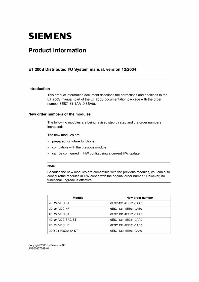
Copyright 2005 by Siemens AGA5E00437368-01
Product information
ET 200S Distributed I/O System manual, version 12/2004
Introduction
This product information document describes the corrections and additions to theET 200S manual (part of the ET 200S documentation package with the ordernumber 6ES7151-1AA10-8BA0).
New order numbers of the modules
The following modules are being revised step by step and the order numbersincreased:
The new modules are
• prepared for future functions
• compatible with the previous module
• can be configured in HW config using a current HW update.
Note
Because the new modules are compatible with the previous modules, you can alsoconfigurethe modules in HW config with the original order number. However, nofunctional upgrade is effective.
Module New order number
2DI 24 VDC ST 6ES7-131-4BB01-0AA0
2DI 24 VDC HF 6ES7 131-4BB01-0AB0
4DI 24 VDC ST 6ES7 131-4BD01-0AA0
4DI 24 VDC/SRC ST 6ES7 131-4BD51-0AA0
4DI 24 VDC HF 6ES7 131-4BD01-0AB0
2DO 24 VDC/0.5A ST 6ES7 132-4BB01-0AA0

2Product informationET 200S Distributed I/O System manual, version 12/2004
A5E00437368-01
Module New order number
2DO 24 VDC/2A ST 6ES7 132-4BB31-0AA0
2DO 24 VDC/0.5A HF 6ES7 132-4BB01-0AB0
2DO 24 VDC/2A HF 6ES7 132-4BB31-0AB0
4DO 24 VDC/0.5A ST 6ES7 132-4BD01-0AA0
4DO 24 VDC/2A ST 6ES7 132-4BD31-0AA0
2RO NO DC24..120V/5A 24..230V AC/5A 6ES7 132-4HB01-0AB0
2AI I 2WIRE ST 6ES7 134-4GB01-0AB0
2AI I 4WIRE ST 6ES7 134-4GB11-0AB0
2AI U ST 6ES7 134-4FB01-0AB0
2AI RTD HF 6ES7 134-4NB51-0AB0
2AI TC HF 6ES7 134-4NB01-0AB0
2AO U ST 6ES7 135-4FB01-0AB0
2AO I ST 6ES7 135-4GB01-0AB0
RESERVE (Width15 mm) 6ES7 138-4AA01-0AA0
RESERVE (Width30 mm) 6ES7 138-4AA11-0AA0
Power module PM-E 24 VDC 6ES7 138-4CA01-0AA0

Copyright 2005 by Siemens AGA5E00437368-01
Information produit
Système de périphérie décentralisée ET 200S, édition 12/2004
Introduction
Cette information produit décrit les corrections et compléments apportés au manuelSystème de périphérie décentralisée ET 200S (EWA-4NEB7806024-03 12).
Nouveaux numéros de référence des modules
Les modules suivants ont été révisés l’un après l’autre et leur numéro de référence aété incrémenté :
Les nouveaux modules sont
• préparés pour des fonctions à venir
• compatibles avec le module précédent
• configurables dans HW Config via une mise à jour matérielle actuelle.
Nota
Les nouveaux modules étant compatibles avec le module précédent, vous pouvezconfigurer les modules dans HW Config aussi avec le numéro de référence original.Les extensions fonctionnelles ne seront toutefois pas utilisables.
Module Nouveau numéro de référence
2DI DC24V ST 6ES7-131-4BB01-0AA0
2DI DC24V HF 6ES7 131-4BB01-0AB0
4DI DC24V ST 6ES7 131-4BD01-0AA0
4DI DC24V/SRC ST 6ES7 131-4BD51-0AA0
4DI DC24V HF 6ES7 131-4BD01-0AB0
2DO DC24V/0,5A ST 6ES7 132-4BB01-0AA0
2DO DC24V/2A ST 6ES7 132-4BB31-0AA0

2Information produitSystème de périphérie décentralisée ET 200S, édition 12/2004
A5E00437368-01
Module Nouveau numéro de référence
2DO DC24V/0,5A HF 6ES7 132-4BB01-0AB0
2DO DC24V/2A HF 6ES7 132-4BB31-0AB0
4DO DC24V/0,5A ST 6ES7 132-4BD01-0AA0
4DO DC24V/2A ST 6ES7 132-4BD31-0AA0
2RO NO DC24..120V/5A AC24..230V/5A 6ES7 132-4HB01-0AB0
2AI I 2WIRE ST 6ES7 134-4GB01-0AB0
2AI I 4WIRE ST 6ES7 134-4GB11-0AB0
2AI U ST 6ES7 134-4FB01-0AB0
2AI RTD HF 6ES7 134-4NB51-0AB0
2AI TC HF 6ES7 134-4NB01-0AB0
2AO U ST 6ES7 135-4FB01-0AB0
2AO I ST 6ES7 135-4GB01-0AB0
RESERVE (encombrement 15 mm) 6ES7 138-4AA01-0AA0
RESERVE (encombrement 30 mm) 6ES7 138-4AA11-0AA0
Module de puissance PM-E DC24V 6ES7 138-4CA01-0AA0

Copyright 2005 by Siemens AGA5E00437368-01
Información de producto
Unidad de periferia descentralizada ET 200S, edición 12/2004
Introducción
Esta información de producto describe las correcciones y ampliaciones realizadas delmanual ET 200S (A5E00171904-11).
Nuevas referencias de los módulos
Los módulos siguientes se modifican periódicamente y se clasifican cada vez bajo unnúmero de referencia más alto:
Los nuevos módulos
• están preparados para futuras funciones
• son compatibles con módulos anteriores
• se configuran en HW–Config con una actualización de HW.
Nota
Dado que los nuevos módulos son compatibles con módulos anteriores, también esposible configurarlos en HW–Config con las referencias anteriores. En tal caso, no esnecesario ampliar las funciones.
Módulos Nuevas referencias
2DI DC24V ST 6ES7-131-4BB01-0AA0
2DI DC24V HF 6ES7 131-4BB01-0AB0
4DI DC24V ST 6ES7 131-4BD01-0AA0
4DI DC24V/SRC ST 6ES7 131-4BD51-0AA0
4DI DC24V HF 6ES7 131-4BD01-0AB0
2DO DC24V/0,5A ST 6ES7 132-4BB01-0AA0
2DO DC24V/2A ST 6ES7 132-4BB31-0AA0

2Información de productoUnidad de periferia descentralizada ET 200S, edición 12/2004
A5E00437368-01
Módulos Nuevas referencias
2DO DC24V/0,5A HF 6ES7 132-4BB01-0AB0
2DO DC24V/2A HF 6ES7 132-4BB31-0AB0
4DO DC24V/0,5A ST 6ES7 132-4BD01-0AA0
4DO DC24V/2A ST 6ES7 132-4BD31-0AA0
2RO NO DC24..120V/5A AC24..230V/5A 6ES7 132-4HB01-0AB0
2AI I 2WIRE ST 6ES7 134-4GB01-0AB0
2AI I 4WIRE ST 6ES7 134-4GB11-0AB0
2AI U ST 6ES7 134-4FB01-0AB0
2AI RTD HF 6ES7 134-4NB51-0AB0
2AI TC HF 6ES7 134-4NB01-0AB0
2AO U ST 6ES7 135-4FB01-0AB0
2AO I ST 6ES7 135-4GB01-0AB0
RESERVE (Ancho15 mm) 6ES7 138-4AA01-0AA0
RESERVE (Ancho 30 mm) 6ES7 138-4AA11-0AA0
Módulo de potencia PM-E DC24V 6ES7 138-4CA01-0AA0

Copyright 2005 by Siemens AGA5E00437368-01
Informazione sul prodotto
Sistema di perifieria decentrata ET 200S, edizione 12/2004
Introduzione
Nelle informazioni sul prodotto sono contenute le correzioni, nonché le integrazionirelative al manuale ET 200S (A5E00158304-11).
Nuovi numeri di ordinazione dei moduli
I seguenti moduli vengono aggiornati gradualmente e i numeri di ordinazioneaumentati:
I nuovi moduli sono
• preparati per funzioni future
• compatibili con i moduli precedenti
• progettabili nella Configurazione HW con un aggiornamento HW.
Avvertenza
Poiché i nuovi moduli sono compatibili con i precedenti è possibile progettarli nellaCofigurazione HW anche con i numeri di ordinazione originali. In questo caso nonsono però applicabili ampliamenti funzionali.
Moduli Nuovo numero di ordinazione
2DI DC24V ST 6ES7-131-4BB01-0AA0
2DI DC24V HF 6ES7 131-4BB01-0AB0
4DI DC24V ST 6ES7 131-4BD01-0AA0
4DI DC24V/SRC ST 6ES7 131-4BD51-0AA0
4DI DC24V HF 6ES7 131-4BD01-0AB0
2DO DC24V/0,5A ST 6ES7 132-4BB01-0AA0
2DO DC24V/2A ST 6ES7 132-4BB31-0AA0
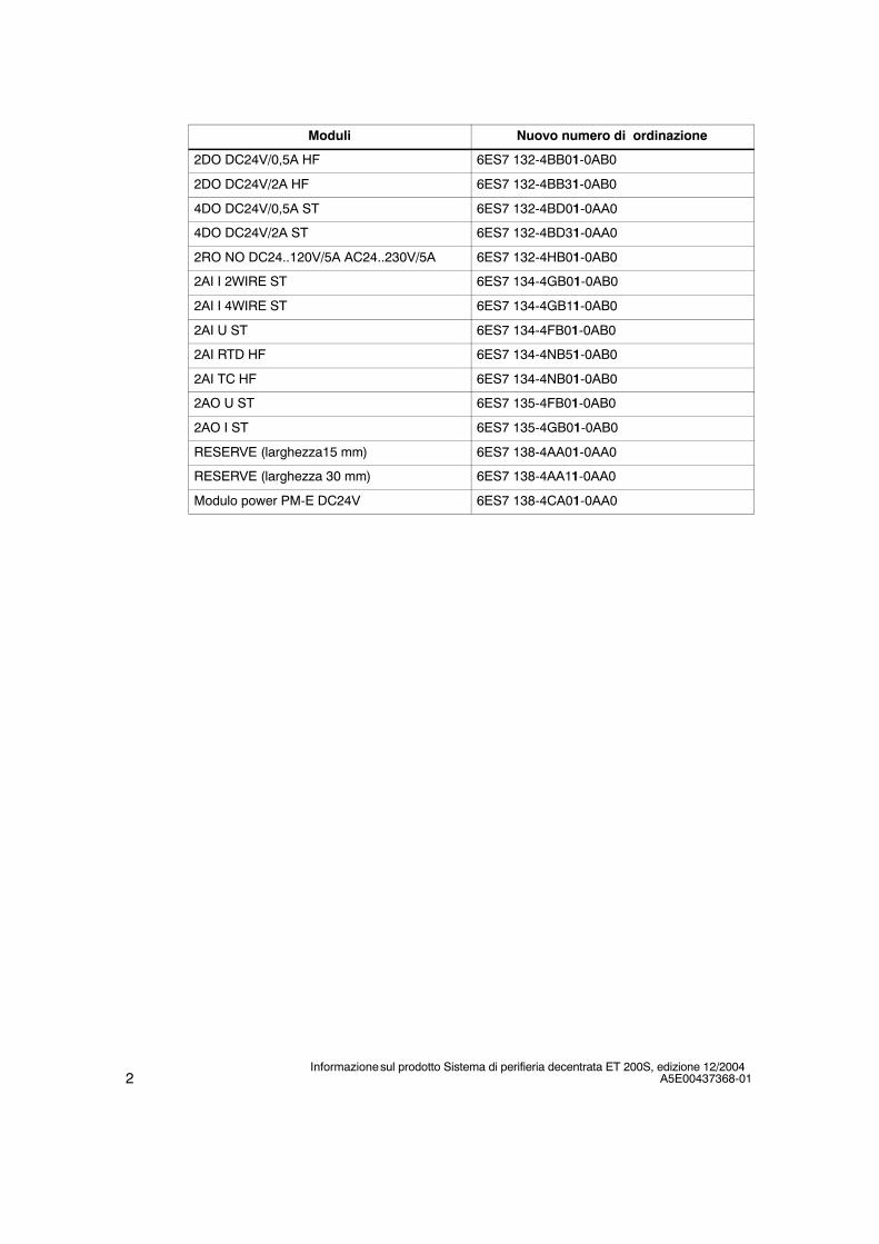
2Informazione sul prodotto Sistema di perifieria decentrata ET 200S, edizione 12/2004
A5E00437368-01
Moduli Nuovo numero di ordinazione
2DO DC24V/0,5A HF 6ES7 132-4BB01-0AB0
2DO DC24V/2A HF 6ES7 132-4BB31-0AB0
4DO DC24V/0,5A ST 6ES7 132-4BD01-0AA0
4DO DC24V/2A ST 6ES7 132-4BD31-0AA0
2RO NO DC24..120V/5A AC24..230V/5A 6ES7 132-4HB01-0AB0
2AI I 2WIRE ST 6ES7 134-4GB01-0AB0
2AI I 4WIRE ST 6ES7 134-4GB11-0AB0
2AI U ST 6ES7 134-4FB01-0AB0
2AI RTD HF 6ES7 134-4NB51-0AB0
2AI TC HF 6ES7 134-4NB01-0AB0
2AO U ST 6ES7 135-4FB01-0AB0
2AO I ST 6ES7 135-4GB01-0AB0
RESERVE (larghezza15 mm) 6ES7 138-4AA01-0AA0
RESERVE (larghezza 30 mm) 6ES7 138-4AA11-0AA0
Modulo power PM-E DC24V 6ES7 138-4CA01-0AA0