Signet 2551 Magmeter · 3-2551.090-1 Rev. G 10/08 English 1.0 Description The 2551 Magmeter...
20
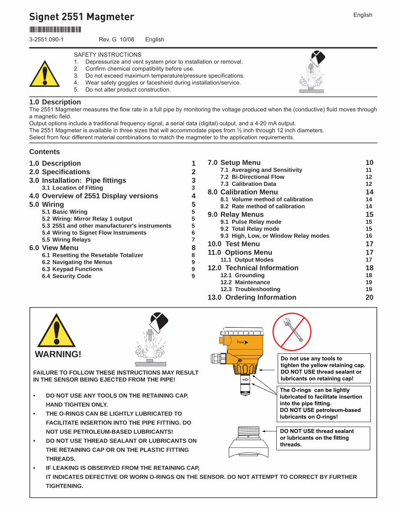
Signet 2551 Magmeter SAFETY INSTRUCTIONS 1. Depressurize and vent system prior to installation or removal. 2. Confirm chemical compatibility before use. 3. Do not exceed maximum temperature/pressure specifications. 4. Wear safety goggles or faceshield during installation/service. 5. Do not alter product construction. *3-2551.090-1* 3-2551.090-1 Rev. G 10/08 English 1.0 Description The 2551 Magmeter measures the flow rate in a full pipe by monitoring the voltage produced when the (conductive) fluid moves through a magnetic field. Output options include a traditional frequency signal, a serial data (digital) output, and a 4-20 mA output. The 2551 Magmeter is available in three sizes that will accommodate pipes from ½ inch through 12 inch diameters. Select from four different material combinations to match the magmeter to the application requirements. English 1.0 Description 1 2.0 Specifications 2 3.0 Installation: Pipe fittings 3 3.1 Location of Fitting 3 4.0 Overview of 2551 Display versions 4 5.0 Wiring 5 5.1 Basic Wiring 5 5.2 Wiring: Mirror Relay 1 output 5 5.3 2551 and other manufacturer's instruments 5 5.4 Wiring to Signet Flow Instruments 6 5.5 Wiring Relays 7 6.0 View Menu 8 6.1 Resetting the Resetable Totalizer 8 6.2 Navigating the Menus 9 6.3 Keypad Functions 9 6.4 Security Code 9 7.0 Setup Menu 10 7.1 Averaging and Sensitivity 11 7.2 Bi-Directional Flow 12 7.3 Calibration Data 12 8.0 Calibration Menu 14 8.1 Volume method of calibration 14 8.2 Rate method of calibration 14 9.0 Relay Menus 15 9.1 Pulse Relay mode 15 9.2 Total Relay mode 15 9.3 High, Low, or Window Relay modes 16 10.0 Test Menu 17 11.0 Options Menu 17 11.1 Output Modes 17 12.0 Technical Information 18 12.1 Grounding 18 12.2 Maintenance 19 12.3 Troubleshooting 19 13.0 Ordering Information 20 FAILURE TO FOLLOW THESE INSTRUCTIONS MAY RESULT IN THE SENSOR BEING EJECTED FROM THE PIPE! • DO NOT USE ANY TOOLS ON THE RETAINING CAP. HAND TIGHTEN ONLY. • THE O-RINGS CAN BE LIGHTLY LUBRICATED TO FACILITATE INSERTION INTO THE PIPE FITTING. DO NOT USE PETROLEUM-BASED LUBRICANTS! • DO NOT USE THREAD SEALANT OR LUBRICANTS ON THE RETAINING CAP OR ON THE PLASTIC FITTING THREADS. • IF LEAKING IS OBSERVED FROM THE RETAINING CAP, IT INDICATES DEFECTIVE OR WORN O-RINGS ON THE SENSOR. DO NOT ATTEMPT TO CORRECT BY FURTHER TIGHTENING. The O-rings can be lightly lubricated to facilitate insertion into the pipe fitting. DO NOT USE petroleum-based lubricants on O-rings! DO NOT USE thread sealant or lubricants on the fitting threads. Flow Do not use any tools to tighten the yellow retaining cap. DO NOT USE thread sealant or lubricants on retaining cap! Contents WARNING!
Transcript of Signet 2551 Magmeter · 3-2551.090-1 Rev. G 10/08 English 1.0 Description The 2551 Magmeter...
Signet 2551 Magmeter
SAFETY INSTRUCTIONS1. Depressurize and vent system prior to installation or removal.2. Confi rm chemical compatibility before use.3. Do not exceed maximum temperature/pressure specifi cations.4. Wear safety goggles or faceshield during installation/service.5. Do not alter product construction.
*3-2551.090-1*
3-2551.090-1 Rev. G 10/08 English
1.0 DescriptionThe 2551 Magmeter measures the fl ow rate in a full pipe by monitoring the voltage produced when the (conductive) fl uid moves through a magnetic fi eld.Output options include a traditional frequency signal, a serial data (digital) output, and a 4-20 mA output.The 2551 Magmeter is available in three sizes that will accommodate pipes from ½ inch through 12 inch diameters.Select from four different material combinations to match the magmeter to the application requirements.
English
1.0 Description 12.0 Specifi cations 23.0 Installation: Pipe fi ttings 3 3.1 Location of Fitting 34.0 Overview of 2551 Display versions 45.0 Wiring 5 5.1 Basic Wiring 5 5.2 Wiring: Mirror Relay 1 output 5 5.3 2551 and other manufacturer's instruments 5 5.4 Wiring to Signet Flow Instruments 6 5.5 Wiring Relays 76.0 View Menu 8 6.1 Resetting the Resetable Totalizer 8 6.2 Navigating the Menus 9 6.3 Keypad Functions 9 6.4 Security Code 9
7.0 Setup Menu 10 7.1 Averaging and Sensitivity 11 7.2 Bi-Directional Flow 12 7.3 Calibration Data 128.0 Calibration Menu 14 8.1 Volume method of calibration 14 8.2 Rate method of calibration 149.0 Relay Menus 15 9.1 Pulse Relay mode 15 9.2 Total Relay mode 15 9.3 High, Low, or Window Relay modes 1610.0 Test Menu 1711.0 Options Menu 17 11.1 Output Modes 1712.0 Technical Information 18 12.1 Grounding 18 12.2 Maintenance 19 12.3 Troubleshooting 1913.0 Ordering Information 20
FAILURE TO FOLLOW THESE INSTRUCTIONS MAY RESULT IN THE SENSOR BEING EJECTED FROM THE PIPE!
• DO NOT USE ANY TOOLS ON THE RETAINING CAP. HAND TIGHTEN ONLY.
• THE O-RINGS CAN BE LIGHTLY LUBRICATED TO FACILITATE INSERTION INTO THE PIPE FITTING. DO NOT USE PETROLEUM-BASED LUBRICANTS!
• DO NOT USE THREAD SEALANT OR LUBRICANTS ON THE RETAINING CAP OR ON THE PLASTIC FITTING THREADS.
• IF LEAKING IS OBSERVED FROM THE RETAINING CAP, IT INDICATES DEFECTIVE OR WORN O-RINGS ON THE SENSOR. DO NOT ATTEMPT TO CORRECT BY FURTHER TIGHTENING.
The O-rings can be lightlylubricated to facilitate insertioninto the pipe fitting.DO NOT USE petroleum-basedlubricants on O-rings!
DO NOT USE thread sealantor lubricants on the fittingthreads.
Flow
Do not use any tools totighten the yellow retaining cap.DO NOT USE thread sealant orlubricants on retaining cap!
Contents
WARNING!
2 2551 Magmeter
Wetted Materials: • Sensor body and Electrodes and Grounding ring:
• -P0, -P1, -P2: Polypropylene and 316L SS• -T0, -T1, -T2: PVDF and Titanium• -V0, -V1,-V2: PVDF and Hastelloy-C• -W0, -W1, -W2: PVDF and 316L SS• O-rings: FPM (standard) EPDM, Kalrez® (optional)
The user is responsible for determining the chemical suitability of these materials for a specifi c application.
• Case: PBT• Display window: Polyamide
Power Requirements• 4 to 20 mA: 21.6 to 26.4 VDC, 22.1 mA max. 400 mV p-p maximum ripple voltage• Frequency: 5 to 26.4 VDC, 15 mA max. • Digital: 5 to 6.5 VDC, 15 mA max.• Auxiliary (only required for units with relays): 9 to 24 VDC, 0.4A max• Reverse polarity and short circuit protected Performance• Pipe size range: DN15 to DN300 (½ to 12 in.)• Flow Range Minimum: 0.05 m/s (0.15 ft/s) (Bi-directional) Maximum: 10 m/s (33 ft/s) • Linearity: ±1% of reading +0.01m/s (0.033 ft/s)• Repeatability ±0.5% of reading @ 25°C (77°F)• Minimum Conductivity: 20 μS/cm
Output Specifi cationsCurrent output (4 to 20 mA)• Max Loop Resistance: 300Ω• Loop Accuracy: 32 μA max. error (25°C @ 24 VDC)• Temp. drift: ±1 μA per °C max. • Power supply rejection: ±1 μA per V• Isolation: Low voltage <48 VAC/DC from electrodes and aux power• Maximum cable: 300 m (1000 ft.)• Error condition: 22.1 mA
Frequency output:• Output modes: Freq, Freq÷10, or Mirror Relay 1• Max. Pullup Voltage: 30 VDC• Reverse Polarity Protected to -40 V• Max. Current Sink: 50 mA, current limited• Maximum cable: 300 m (1000 ft.)
Digital (S3L) Output:• Serial ASCII, TTL level 9600 bps• Compatible with Signet 8900
Standards and Approvals• CE• UL, CUL (for display versions with relays) • NEMA 4X / IP65 Enclosure (with cap installed)• EMC: EN55011: 1998 +A1:99+A2:02 Class B Emissions EN61326: 1997 +A1:98+A2:01 EN61000-6-2:2001• Safety: EN61010-1:2001• U.S. Patent No. 7,055,396 B1
2.0 Specifi cations
40
80
120
160
200
3
6
8
11
14
0 40 80 120 160 200
-18 4 27 49 71 93
°F
°C
psibar
240
115
2551Pressure vs. Temperature
Media Temperature
Ope
ratin
g P
ress
ure
2551AcceptableMedia Range
Dimensions
116.8 mm(4.6 in.)
-XO-X1-X2
95.3 mm(3.75 in.)
Pipe Range 1/2 to 4 in. -XO = 58 mm (2.3 in.) 5 to 8 in. -X1 = 91 mm (3.6 in.) 10 to 12 in. -X2 = 167 mm (6.6 in.)
X = Sensor Body P, T, V, or W
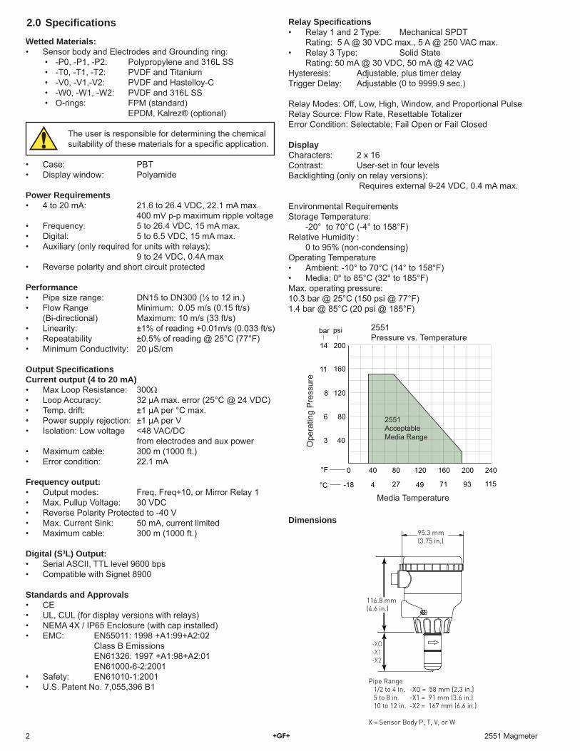
Relay Specifi cations• Relay 1 and 2 Type: Mechanical SPDT Rating: 5 A @ 30 VDC max., 5 A @ 250 VAC max.• Relay 3 Type: Solid State Rating: 50 mA @ 30 VDC, 50 mA @ 42 VACHysteresis: Adjustable, plus timer delayTrigger Delay: Adjustable (0 to 9999.9 sec.)
Relay Modes: Off, Low, High, Window, and Proportional PulseRelay Source: Flow Rate, Resettable TotalizerError Condition: Selectable; Fail Open or Fail Closed
Display Characters: 2 x 16 Contrast: User-set in four levelsBacklighting (only on relay versions): Requires external 9-24 VDC, 0.4 mA max.
Environmental RequirementsStorage Temperature: -20° to 70°C (-4° to 158°F)Relative Humidity : 0 to 95% (non-condensing)Operating Temperature• Ambient: -10° to 70°C (14° to 158°F) • Media: 0° to 85°C (32° to 185°F) Max. operating pressure: 10.3 bar @ 25°C (150 psi @ 77°F)1.4 bar @ 85°C (20 psi @ 185°F)

32551 Magmeter
3.1 Installation: Selecting a Location• The 2551 requires a full pipe and a fully developed turbulent fl ow profi le for accurate
measurement.• If the piping system harbors air pockets or bubbles, take steps to locate the sensor so
the air pockets will not contact the electrodes.• In vertical installations, assemble the 2551 so the conduit ports are facing downward.
This prevents condensation inside the conduit from being directed into the 2551 electronics housing.
• Chemical injection systems can temporarily alter the fl uid conductivity and cause anomalies in the magmeter measurement.
To avoid this problem, install the magmeter UPSTREAM of the injection point.
15 x I.D. 5 x I.D.
Reducer+GF+
10 x I.D. 5 x I.D.
Inlet OutletFlange
+GF+
50 x I.D. 5 x I.D.
Valve/Pump+GF+
40 x I.D. 5 x I.D.
2 x 90° Elbow3 dimensions
+GF+
25 x I.D. 5 x I.D.
2 x 90° Elbow+GF+
20 x I.D. 5 x I.D.
90° Elbow+GF+
+GF++G
F+
+GF+
+G
F+
+GF+
+GF+
O.K.O.K. O.K.
Vertical flow is OK IF the pipe remains full at all times.
3. Installation: Pipe fi ttingsGeorg Fischer offers a wide selection of installation fi ttings that control the position of the Magmeter electrodes in relation to the dimensions of the pipe. You will fi nd a complete list of order numbers for installation fi ttings in the Calibration Tables on pages 12-13.
Select a location with suffi cient distance of straight pipe immediately upstream of the sensor.
Locating the sensor in a trap or where the fl ow is upward helps to protect the sensor from exposure to air bubbles when the system is in operation.
These confi gurations are not recommended because it is diffi cult to keep the pipe full.
Type Description
2 to 4 inch, cut 1-7/16 inch hole in pipeOver 4 inch, cut 2-1/8 inch hole in pipe
0.5 to 4 inch versions PVC or CPVC
2 to 4 inch, cut 1-7/16 inch hole in pipe6 to 8 inch, cut 2-1/8 inch hole in pipe
Available in 10 and 12 inch sizes onlyCut 2-1/2 inch hole in pipeWeld in place using solvent cement
Available in 10 and 12 inch sizes onlyCut 2-1/8 inch hole in pipe
Iron, Carbon Steel, 316 SS Threaded tees
Carbon steel & stainless steel Weld-onWeldolets
2 to 4 inch, cut 1-7/16 inch hole in pipeOver 4 inch, cut 2-1/8 inch hole in pipe
For pipes from DN 15 to 50 mmPP or PVDF
Type Description
Plastic tees
MetricUnion tees
PVCSaddles
IronStrap-onsaddles
PVCGlue-onSaddles
PPClamp-onSaddles
1.5 in. to 8 in. PVDF insert > 8 in. PVC insert
Fiberglasstees &saddles:
FPT FPS
0.5 to 2 in. versionsMounts on threaded pipe ends
In a gravity-fl ow system, the tank must be designed so the level does not drop below the outlet.
This causes the pipe to draw air in from the tank.If air bubbles pass across the Magmeter electrodes, the output will become erratic.
+GF+
Flow
Flow 6.25 GPMTotal 1234567.8>
ENTER
Signet FlowTransmitter
Flow 6.25 GPMTotal 1234567.8>
ENTER
Signet FlowTransmitter
Flow
4 2551 Magmeter
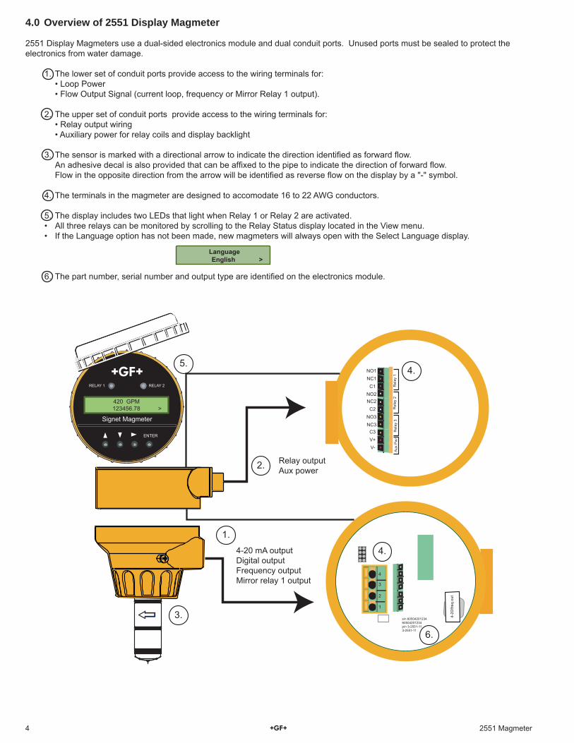
4.0 Overview of 2551 Display Magmeter
2551 Display Magmeters use a dual-sided electronics module and dual conduit ports. Unused ports must be sealed to protect the electronics from water damage.
1. The lower set of conduit ports provide access to the wiring terminals for: • Loop Power • Flow Output Signal (current loop, frequency or Mirror Relay 1 output).
2. The upper set of conduit ports provide access to the wiring terminals for: • Relay output wiring • Auxiliary power for relay coils and display backlight
3. The sensor is marked with a directional arrow to indicate the direction identifi ed as forward fl ow. An adhesive decal is also provided that can be affi xed to the pipe to indicate the direction of forward fl ow. Flow in the opposite direction from the arrow will be identifi ed as reverse fl ow on the display by a "-" symbol.
4. The terminals in the magmeter are designed to accomodate 16 to 22 AWG conductors.
5. The display includes two LEDs that light when Relay 1 or Relay 2 are activated.• All three relays can be monitored by scrolling to the Relay Status display located in the View menu.• If the Language option has not been made, new magmeters will always open with the Select Language display.
6. The part number, serial number and output type are identifi ed on the electronics module.
Language English >
4-20 mA outputDigital outputFrequency outputMirror relay 1 output
Rel
ay 1
Rel
ay 2
NO1
NO2
NO3
NC1
NC2
NC3
C1
C2
C3V+V-
Rel
ay 3
Aux
Pw
r
Relay outputAux power
Signet Magmeter
RELAY 1 RELAY 2
ENTER
420 GPM 123456.78 >
4-20
/freq
out
s/n 6050420123460504201234p/n 3-2551-113-2551-11
2.
3.
4.5.
6.
4.
1
2
3
4
1.
52551 Magmeter
5.0 Wiring
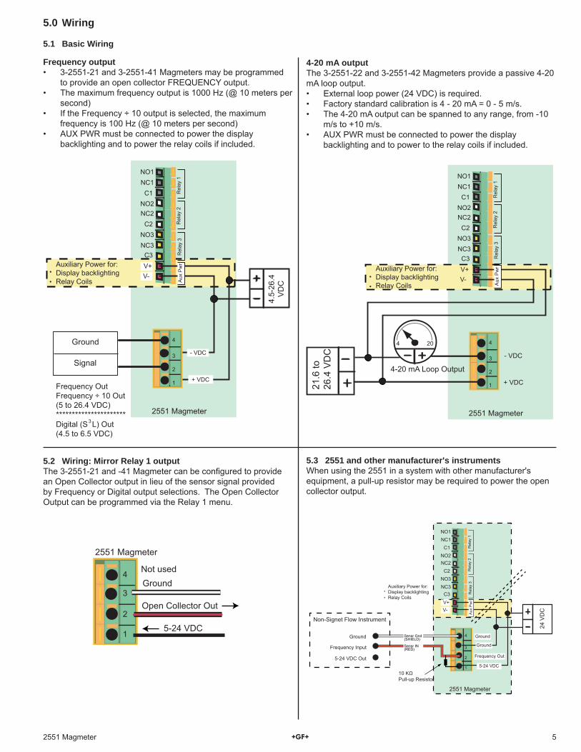
5.1 Basic Wiring
2551 Magmeter
4.5-
26.4
VD
C
Rel
ay 1
Rel
ay 2
NO1
NO2
NO3
NC1
NC2
NC3
C1
C2
C3 Rel
ay 3
V+V-
+ VDC
- VDC
Aux
Pw
r
3
Frequency OutFrequency ÷ 10 Out(5 to 26.4 VDC)**********************Digital (S L) Out(4.5 to 6.5 VDC)
1
2
3
4
Auxiliary Power for:Display backlightingRelay Coils
Ground
Signal
1
2
3
4
5-24 VDC
GroundNot used
Open Collector Out
2551 Magmeter
4-20 mA outputThe 3-2551-22 and 3-2551-42 Magmeters provide a passive 4-20 mA loop output.• External loop power (24 VDC) is required.• Factory standard calibration is 4 - 20 mA = 0 - 5 m/s.• The 4-20 mA output can be spanned to any range, from -10
m/s to +10 m/s.• AUX PWR must be connected to power the display
backlighting and to power to the relay coils if included.
5.2 Wiring: Mirror Relay 1 outputThe 3-2551-21 and -41 Magmeter can be confi gured to provide an Open Collector output in lieu of the sensor signal provided by Frequency or Digital output selections. The Open Collector Output can be programmed via the Relay 1 menu.
Frequency output• 3-2551-21 and 3-2551-41 Magmeters may be programmed
to provide an open collector FREQUENCY output.• The maximum frequency output is 1000 Hz (@ 10 meters per
second)• If the Frequency ÷ 10 output is selected, the maximum
frequency is 100 Hz (@ 10 meters per second)• AUX PWR must be connected to power the display
backlighting and to power the relay coils if included.
5.3 2551 and other manufacturer's instrumentsWhen using the 2551 in a system with other manufacturer's equipment, a pull-up resistor may be required to power the open collector output.
1
2
3
4
Frequency Out
2551 Magmeter
24 V
DC
Rel
ay 1
Rel
ay 2
NO1
NO2
NO3
NC1
NC2
NC3
C1
C2
C3 Rel
ay 3
V+V-
5-24 VDC
Ground
Ground
Aux
Pw
r
Sensr Gnd(SHIELD)
Sensr IN(RED)
Non-Signet Flow Instrument
Ground
Frequency Input
5-24 VDC Out
Auxiliary Power for:Display backlightingRelay Coils
10 KΩPull-up Resistor
2551 Magmeter
Rel
ay 1
Rel
ay 2
NO1
NO2
NO3
NC1
NC2
NC3
C1
C2
C3 Rel
ay 3
V+
21.6
to26
.4 V
DC
V-
+ VDC
- VDC
Aux
Pw
r
4-20 mA Loop Output
1
2
3
4
Auxiliary Power for:Display backlightingRelay Coils
4 20
6 2551 Magmeter
-+
12-24 V10 W
12-24 V10 W
4-20 mA
Totalreset
AUXoutput
PLSoutput
1 2Gnd -+++ Gnd
Freq
. IN
Sen
. Pw
r.
Freq
. IN
Iso.
Gnd
Std. SensorOpen Collector Sensor
1
2
3
4
Frequency Out
2551 Magmeter
24 VDC
Rel
ay 1
Rel
ay 2
NO1
NO2
NO3
NC1
NC2
NC3
C1
C2
C3 Rel
ay 3
V+V-
5-24 VDC
Ground
Ground
Aux
Pw
r
Signet 5075, 5500, 5600
Auxiliary Power for:Display backlightingRelay Coils
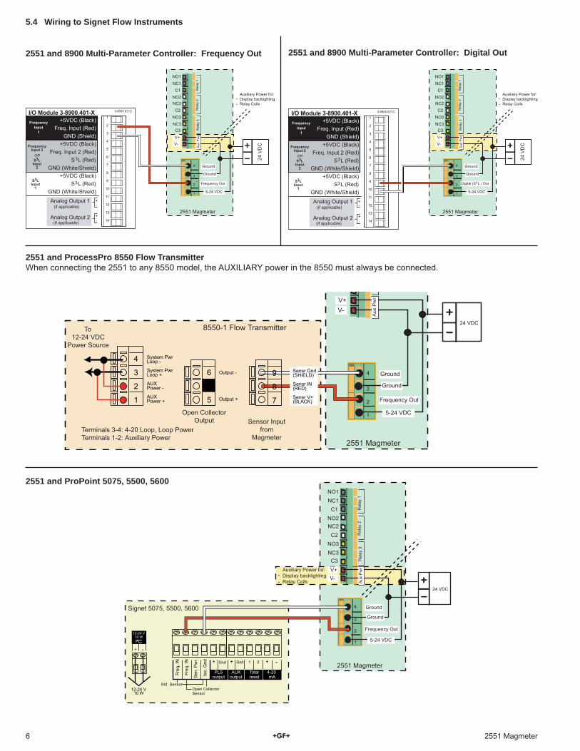
2551 and 8900 Multi-Parameter Controller: Frequency Out
2551 and ProPoint 5075, 5500, 5600
2551 and ProcessPro 8550 Flow TransmitterWhen connecting the 2551 to any 8550 model, the AUXILIARY power in the 8550 must always be connected.
8550-1 Flow Transmitter
1
2
3
4
Frequency Out
2551 Magmeter
Output -
Output +
System PwrLoop -
System PwrLoop +
AUXPower -
AUXPower +
4
3
2
1
6
5
9
8
7Open Collector
Output Sensor Inputfrom
MagmeterTerminals 3-4: 4-20 Loop, Loop PowerTerminals 1-2: Auxiliary Power
Sensr Gnd(SHIELD)
Sensr IN(RED)
Sensr V+(BLACK)
To12-24 VDC
Power Source
24 VDC
V+V-
5-24 VDC
Ground
GroundA
ux P
wr
5.4 Wiring to Signet Flow Instruments
3-8900.621CI/O Module 3-8900.401-X1
2
3
4
5
6
7
8
9
10
11
12
13
14
+5VDC (Black)Freq. Input (Red)
GND (Shield)+5VDC (Black)
Freq. Input 2 (Red)S L (Red)
GND (White/Shield)+5VDC (Black)
S L (Red)GND (White/Shield)
3
3
Analog Output 1
Analog Output 2
(if applicable)
(if applicable)
FrequencyInput
1
FrequencyInput 2ORS3L
Input2
S3LInput
1
+-
+-
1
2
3
4
Frequency Out
2551 Magmeter
24 V
DC
Rel
ay 1
Rel
ay 2
NO1
NO2
NO3
NC1
NC2
NC3
C1
C2
C3 Rel
ay 3
V+V-
5-24 VDC
Ground
Ground
Aux
Pw
r
Auxiliary Power for:Display backlightingRelay Coils
3-8900.621CI/O Module 3-8900.401-X1
2
3
4
5
6
7
8
9
10
11
12
13
14
+5VDC (Black)Freq. Input (Red)
GND (Shield)+5VDC (Black)
Freq. Input 2 (Red)S L (Red)
GND (White/Shield)+5VDC (Black)
S L (Red)GND (White/Shield)
3
3
Analog Output 1
Analog Output 2
(if applicable)
(if applicable)
FrequencyInput
1
FrequencyInput 2ORS3L
Input2
S3LInput
1
+-
+-
1
2
3
4
Digital (S L ) Out
2551 Magmeter
24 V
DC
Rel
ay 1
Rel
ay 2
NO1
NO2
NO3
NC1
NC2
NC3
C1
C2
C3 Rel
ay 3
V+V-
5-24 VDC
Ground
Ground
Aux
Pw
r
3
Auxiliary Power for:Display backlightingRelay Coils
2551 and 8900 Multi-Parameter Controller: Digital Out
72551 Magmeter
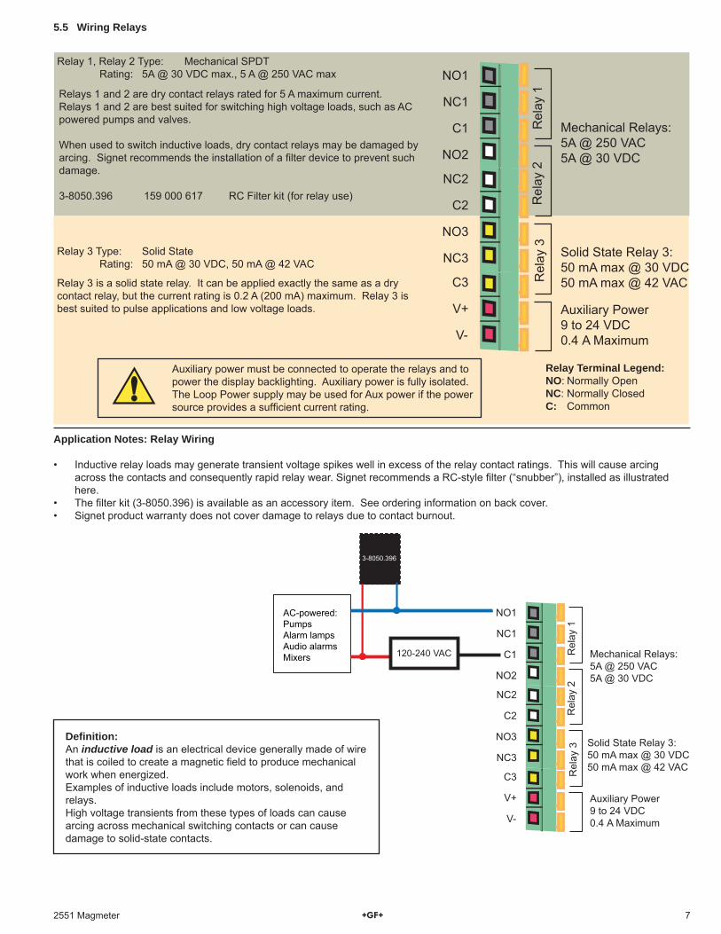
Relay 3 is a solid state relay. It can be applied exactly the same as a dry contact relay, but the current rating is 0.2 A (200 mA) maximum. Relay 3 is best suited to pulse applications and low voltage loads.
Relays 1 and 2 are dry contact relays rated for 5 A maximum current.Relays 1 and 2 are best suited for switching high voltage loads, such as AC powered pumps and valves.
When used to switch inductive loads, dry contact relays may be damaged by arcing. Signet recommends the installation of a fi lter device to prevent such damage.
3-8050.396 159 000 617 RC Filter kit (for relay use)
Relay 3 Type: Solid State Rating: 50 mA @ 30 VDC, 50 mA @ 42 VAC
Relay 1, Relay 2 Type: Mechanical SPDT Rating: 5A @ 30 VDC max., 5 A @ 250 VAC max
5.5 Wiring Relays
Rel
ay 1
Rel
ay 2
Solid State Relay 3:50 mA max @ 30 VDC50 mA max @ 42 VAC
NO1
NO2
NO3
NC1
NC2
NC3
C1
C2
C3
V+
V-
Auxiliary Power9 to 24 VDC0.4 A Maximum
Mechanical Relays:5A @ 250 VAC5A @ 30 VDC
Rel
ay 3
Auxiliary power must be connected to operate the relays and to power the display backlighting. Auxiliary power is fully isolated. The Loop Power supply may be used for Aux power if the power source provides a suffi cient current rating.
Relay Terminal Legend:NO: Normally OpenNC: Normally ClosedC: Common
Application Notes: Relay Wiring
• Inductive relay loads may generate transient voltage spikes well in excess of the relay contact ratings. This will cause arcing across the contacts and consequently rapid relay wear. Signet recommends a RC-style fi lter (“snubber”), installed as illustrated here.
• The fi lter kit (3-8050.396) is available as an accessory item. See ordering information on back cover.• Signet product warranty does not cover damage to relays due to contact burnout.
Rel
ay 1
Rel
ay 2
Solid State Relay 3:50 mA max @ 30 VDC50 mA max @ 42 VAC
NO1
NO2
NO3
NC1
NC2
NC3
C1
C2
C3
V+
V-
Auxiliary Power9 to 24 VDC0.4 A Maximum
Mechanical Relays:5A @ 250 VAC5A @ 30 VDC
Rel
ay 3
3-8050.396
AC-powered:PumpsAlarm lampsAudio alarmsMixers 120-240 VAC
Defi nition:An inductive load is an electrical device generally made of wire that is coiled to create a magnetic fi eld to produce mechanical work when energized.Examples of inductive loads include motors, solenoids, and relays.High voltage transients from these types of loads can cause arcing across mechanical switching contacts or can cause damage to solid-state contacts.
8 2551 Magmeter
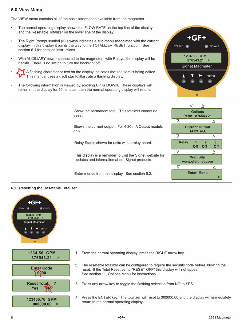
6.0 View Menu
The VIEW menu contains all of the basic information available from the magmeter.
• The normal operating display shows the FLOW RATE on the top line of the display and the Resetable Totalizer on the lower line of the display.
• The Right Prompt symbol (>) always indicates a sub-menu associated with the current display. In this display it points the way to the TOTALIZER RESET function. See section 6.1 for detailed instructions.
• With AUXILIARY power connected to the magmeters with Relays, the display will be backlit. There is no switch to turn the backlight off.
• A fl ashing character or text on the display indicates that the item is being edited. This manual uses a (red) star to illustrate a fl ashing display.
• The following information is viewed by scrolling UP or DOWN. These displays will remain in the display for 10 minutes, then the normal operating display will return.
1. From the normal operating display, press the RIGHT arrow key.
3. Press any arrow key to toggle the fl ashing selection from NO to YES.
4. Press the ENTER key. The totalizer will reset to 000000.00 and the display will immediately return to the normal operating display.
2. The resetable totalizer can be confi gured to require the security code before allowing the reset. If the Total Reset set to "RESET OFF" this display will not appear.
See section 11, Options Menu for instructions.
6.1 Resetting the Resetable Totalizer
Signet Magmeter
RELAY 1 RELAY 2
ENTER
1234.56 GPM 876543.21 >
Show the permanent total. This totalizer cannot be reset.
Relay States shown for units with a relay board.
This display is a reminder to visit the Signet website for updates and information about Signet products.
Enter menus from this display. See section 6.2.
Shows the current output. For 4-20 mA Output models only.
123456.78 GPM 000000.00 >
1234.56 GPM 876543.21 >
Enter Code0000
Reset Total ?Yes No
Signet Magmeter
RELAY 1 RELAY 2
ENTER
1234.56 GPM 876543.21 >
GallonsPerm 876543.21
Current Output14.89 mA
Relay 1 2 3 Off Off Off
Web Sitewww.gfsignet.com
Enter Menu >
92551 Magmeter
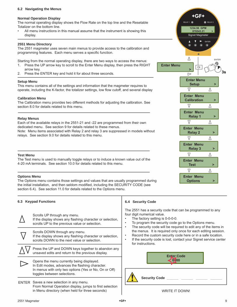
6.2 Navigating the Menus
6.4 Security Code
The 2551 has a security code that can be programmed to any four digit numerical value.• The factory setting is 0-0-0-0.• To program the security code go to the Options menu.• The security code will be required to edit any of the items in
the menus. It is required only once for each editing session.• Record the custom security code here or in a safe location.• If the security code is lost, contact your Signet service center
for instructions.
Enter Code 0000
Scrolls UP through any menu.If the display shows any fl ashing character or selection, scrolls UP to the previous value or selection.
Scrolls DOWN through any menu.If the display shows any fl ashing character or selection, scrolls DOWN to the next value or selection.
Press the UP and DOWN keys together to abandon any unsaved edits and return to the previous display.
Opens the menu currently being displayed.In Edit modes, advances the fl ashing character.In menus with only two options (Yes or No, On or Off) toggles between selections.
Saves a new selection in any menu.From Normal Operation display, jumps to fi rst selection in Menu directory (when held for three seconds)
ENTER
Normal Operation DisplayThe normal operating display shows the Flow Rate on the top line and the Resetable Totalizer on the bottom line.• All menu instructions in this manual assume that the instrument is showing this
display.
Calibration MenuThe Calibration menu provides two different methods for adjusting the calibration. See section 8.0 for details related to this menu.
Relay MenusEach of the available relays in the 2551-21 and -22 are programmed from their own dedicated menu. See section 9 for details related to these menus.Note: Menu items associated with Relay 2 and relay 3 are suppressed in models without relays. See section 9.0 for details related to this menu.
Test MenuThe Test menu is used to manually toggle relays or to induce a known value out of the 4-20 mA terminals. See section 10.0 for details related to this menu.
Options MenuThe Options menu contains those settings and values that are usually programmed during the initial installation, and then seldom modifi ed, including the SECURITY CODE (see section 6.4). See section 11.0 for details related to the Options menu.
Setup MenuThis menu contains all of the settings and information that the magmeter requires to operate, including the K-factor, the totalizer settings, low fl ow cutoff, and several display
2551 Menu DirectoryThe 2551 magmeter uses seven main menus to provide access to the calibration and programming features. Each menu serves a specifi c function.
Starting from the normal operating display, there are two ways to access the menus:1. Press the UP arrow key to scroll to the Enter Menu display, then press the RIGHT
arrow key.2. Press the ENTER key and hold it for about three seconds.
Security Code ______ ______ ______ ______
Enter Menu Setup >
Enter Menu Calibration >
Enter Menu Relay 1 >
Enter Menu Relay 2 >
Signet Magmeter
RELAY 1 RELAY 2
ENTER
1234.56 GPM 876543.21 >
Enter Menu Relay 3 >
Enter Menu Test >
Enter Menu Options >
Enter Menu >
3s
ENTER
Or
6.3 Keypad Functions
WRITE IT DOWN!
10 2551 Magmeter
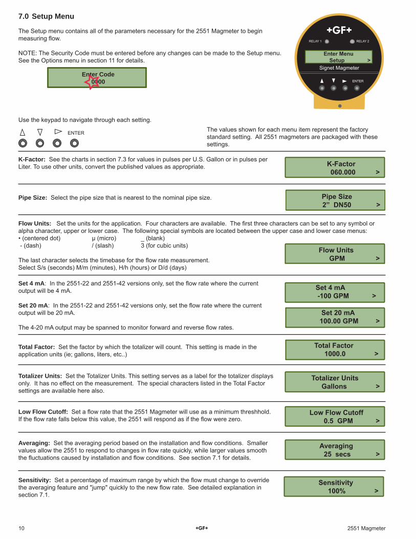
K-Factor 060.000 >
K-Factor: See the charts in section 7.3 for values in pulses per U.S. Gallon or in pulses per Liter. To use other units, convert the published values as appropriate.
Pipe Size: Select the pipe size that is nearest to the nominal pipe size.
Averaging: Set the averaging period based on the installation and fl ow conditions. Smaller values allow the 2551 to respond to changes in fl ow rate quickly, while larger values smooth the fl uctuations caused by installation and fl ow conditions. See section 7.1 for details.
7.0 Setup Menu
Flow Units: Set the units for the application. Four characters are available. The fi rst three characters can be set to any symbol or alpha character, upper or lower case. The following special symbols are located between the upper case and lower case menus:• (centered dot) μ (micro) _ (blank) - (dash) / (slash) 3 (for cubic units)
The last character selects the timebase for the fl ow rate measurement.Select S/s (seconds) M/m (minutes), H/h (hours) or D/d (days)
Total Factor: Set the factor by which the totalizer will count. This setting is made in the application units (ie; gallons, liters, etc..)
Totalizer Units: Set the Totalizer Units. This setting serves as a label for the totalizer displays only. It has no effect on the measurement. The special characters listed in the Total Factor settings are available here also.
Low Flow Cutoff: Set a fl ow rate that the 2551 Magmeter will use as a minimum threshhold. If the fl ow rate falls below this value, the 2551 will respond as if the fl ow were zero.
Sensitivity: Set a percentage of maximum range by which the fl ow must change to override the averaging feature and "jump" quickly to the new fl ow rate. See detailed explanation in section 7.1.
Signet Magmeter
RELAY 1 RELAY 2
ENTER
Enter Menu Setup >
The Setup menu contains all of the parameters necessary for the 2551 Magmeter to begin measuring fl ow.
NOTE: The Security Code must be entered before any changes can be made to the Setup menu.See the Options menu in section 11 for details.
The values shown for each menu item represent the factory standard setting. All 2551 magmeters are packaged with these settings.
Set 4 mA: In the 2551-22 and 2551-42 versions only, set the fl ow rate where the current output will be 4 mA.
Set 20 mA: In the 2551-22 and 2551-42 versions only, set the fl ow rate where the current output will be 20 mA.
The 4-20 mA output may be spanned to monitor forward and reverse fl ow rates.
ENTER
Pipe Size 2” DN50 >
Sensitivity 100% >
Flow Units GPM >
Set 4 mA -100 GPM >
Set 20 mA 100.00 GPM >
Total Factor 1000.0 >
Totalizer Units Gallons >
Low Flow Cutoff 0.5 GPM >
Averaging 25 secs >
Use the keypad to navigate through each setting.
Enter Code 0000
112551 Magmeter
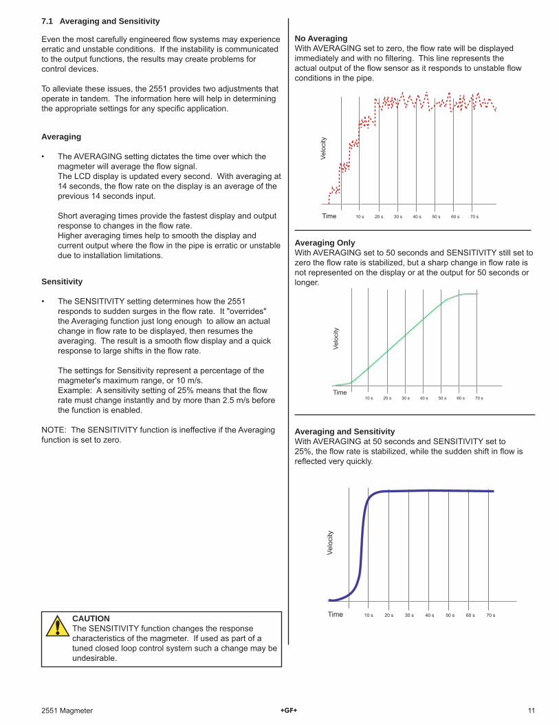
Sensitivity
• The SENSITIVITY setting determines how the 2551 responds to sudden surges in the fl ow rate. It "overrides" the Averaging function just long enough to allow an actual change in fl ow rate to be displayed, then resumes the averaging. The result is a smooth fl ow display and a quick response to large shifts in the fl ow rate.
The settings for Sensitivity represent a percentage of the magmeter's maximum range, or 10 m/s.
Example: A sensitivity setting of 25% means that the fl ow rate must change instantly and by more than 2.5 m/s before the function is enabled.
NOTE: The SENSITIVITY function is ineffective if the Averaging function is set to zero.
No AveragingWith AVERAGING set to zero, the fl ow rate will be displayed immediately and with no fi ltering. This line represents the actual output of the fl ow sensor as it responds to unstable fl ow conditions in the pipe.
Averaging OnlyWith AVERAGING set to 50 seconds and SENSITIVITY still set to zero the fl ow rate is stabilized, but a sharp change in fl ow rate is not represented on the display or at the output for 50 seconds or longer.
Averaging and SensitivityWith AVERAGING at 50 seconds and SENSITIVITY set to 25%, the fl ow rate is stabilized, while the sudden shift in fl ow is refl ected very quickly.
Averaging
• The AVERAGING setting dictates the time over which the magmeter will average the fl ow signal.
The LCD display is updated every second. With averaging at 14 seconds, the fl ow rate on the display is an average of the previous 14 seconds input.
Short averaging times provide the fastest display and output
response to changes in the fl ow rate. Higher averaging times help to smooth the display and
current output where the fl ow in the pipe is erratic or unstable due to installation limitations.
10 s 20 s 30 s 40 s 50 s 60 s 70 sTime
Velo
city
10 s 20 s 30 s 40 s 50 s 60 s 70 s
Time
Velo
city
10 s 20 s 30 s 40 s 50 s 60 s 70 sTime
Velo
city
Even the most carefully engineered fl ow systems may experience erratic and unstable conditions. If the instability is communicated to the output functions, the results may create problems for control devices.
To alleviate these issues, the 2551 provides two adjustments that operate in tandem. The information here will help in determining the appropriate settings for any specifi c application.
7.1 Averaging and Sensitivity
CAUTIONThe SENSITIVITY function changes the response characteristics of the magmeter. If used as part of a tuned closed loop control system such a change may be undesirable.
12 2551 Magmeter
7.3 Calibration Data: K-factors
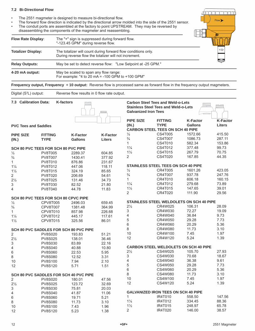
7.2 Bi-Directional Flow
• The 2551 magmeter is designed to measure bi-directional fl ow.• The forward fl ow direction is indicated by the directional arrow molded into the side of the 2551 sensor.• The conduit ports are assembled at the factory to point UPSTREAM. They may be reversed by
disassembling the components of the magmeter and reassembling.
Flow Rate Display: The "+" sign is suppressed during forward fl ow. "-123.45 GPM" during reverse fl ow.
Totalizer Display: The totalizer will count during forward fl ow conditions only. During reverse fl ow the totalizer will not increment.
Relay Outputs: May be set to detect reverse fl ow: "Low Setpoint at -25 GPM."
4-20 mA output: May be scaled to span any fl ow range: For example: "4 to 20 mA = -100 GPM to +100 GPM"
Frequency output, Frequency ÷ 10 output: Reverse fl ow is processed same as forward fl ow in the frequency output magmeters.
Digital (S3L) output: Reverse fl ow results in 0 fl ow rate output.
Flow
PVC Tees and Saddles
PIPE SIZE FITTING K-Factor K-Factor(IN.) TYPE Gallons Liters
SCH 80 PVC TEES FOR SCH 80 PVC PIPE ½ PV8T005 2289.37 604.85¾ PV8T007 1430.41 377.921 PV8T010 876.86 231.671¼ PV8T012 447.06 118.111½ PV8T015 324.19 85.652 PV8T020 206.69 54.612½ PV8T025 131.46 34.733 PV8T030 82.52 21.804 PV8T040 44.78 11.83 SCH 80 PVC TEES FOR SCH 80 CPVC PIPE ½ CPV8T005 2496.03 659.45¾ CPV8T007 1381.48 364.991 CPV8T010 857.98 226.681¼ CPV8T012 445.17 117.611½ CPV8T015 325.56 86.01 SCH 80 PVC SADDLES FOR SCH 80 PVC PIPE 2 PV8S020 193.83 51.212½ PV8S025 138.01 36.463 PV8S030 83.89 22.164 PV8S040 40.88 10.806 PV8S060 22.53 5.958 PV8S080 12.52 3.3110 PV8S100 7.94 2.1012 PV8S120 5.71 1.51 SCH 80 PVC SADDLES FOR SCH 40 PVC PIPE 2 PV8S020 180.01 47.562½ PV8S025 123.72 32.693 PV8S030 75.81 20.034 PV8S040 41.87 11.066 PV8S060 19.71 5.218 PV8S080 11.73 3.1010 PV8S100 7.43 1.9612 PV8S120 5.23 1.38
Carbon Steel Tees and Weld-o-LetsStainless Steel Tees and Weld-o-LetsGalvanized Iron Tees
PIPE SIZE FITTING K-Factor K-Factor(IN.) TYPE Gallons LitersCARBON STEEL TEES ON SCH 40 PIPE ½ CS4T005 1572.66 415.50¾ CS4T007 1086.73 287.111 CS4T010 582.34 153.861¼ CS4T012 377.48 99.731½ CS4T015 267.79 70.752 CS4T020 167.85 44.35 STAINLESS STEEL TEES ON SCH 40 PIPE ½ CR4T005 1601.26 423.05¾ CR4T007 937.78 247.761 CR4T010 606.18 160.151¼ CR4T012 279.68 73.891½ CR4T015 147.65 39.012 CR4T020 111.90 29.56 STAINLESS STEEL WELDOLETS ON SCH 40 PIPE 2½ CR4W025 106.31 28.093 CR4W030 72.27 19.094 CR4W040 36.84 9.735 CR4W050 29.28 7.736 CR4W060 20.29 5.368 CR4W080 11.73 3.1010 CR4W100 7.45 1.9712 CR4W120 5.24 1.39 CARBON STEEL WELDOLETS ON SCH 40 PIPE 2½ CS4W025 105.70 27.933 CS4W030 70.68 18.674 CS4W040 36.38 9.615 CS4W050 29.28 7.736 CS4W060 20.29 5.368 CS4W080 11.73 3.1010 CS4W100 7.45 1.9712 CS4W120 5.24 1.39
GALVANIZED IRON TEES ON SCH 40 PIPE 1 IR4T010 558.50 147.561¼ IR4T012 334.45 88.361½ IR4T015 248.97 65.782 IR4T020 146.00 38.57
132551 Magmeter
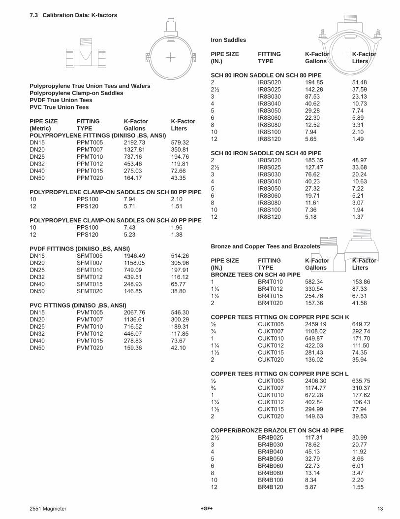
7.3 Calibration Data: K-factors
Polypropylene True Union Tees and WafersPolypropylene Clamp-on SaddlesPVDF True Union TeesPVC True Union Tees
PIPE SIZE FITTING K-Factor K-Factor(Metric) TYPE Gallons LitersPOLYPROPYLENE FITTINGS (DIN/ISO ,BS, ANSI) DN15 PPMT005 2192.73 579.32DN20 PPMT007 1327.81 350.81DN25 PPMT010 737.16 194.76DN32 PPMT012 453.46 119.81DN40 PPMT015 275.03 72.66DN50 PPMT020 164.17 43.35
POLYPROPYLENE CLAMP-ON SADDLES ON SCH 80 PP PIPE10 PPS100 7.94 2.1012 PPS120 5.71 1.51
POLYPROPYLENE CLAMP-ON SADDLES ON SCH 40 PP PIPE10 PPS100 7.43 1.9612 PPS120 5.23 1.38 PVDF FITTINGS (DIN/ISO ,BS, ANSI) DN15 SFMT005 1946.49 514.26DN20 SFMT007 1158.05 305.96DN25 SFMT010 749.09 197.91DN32 SFMT012 439.51 116.12DN40 SFMT015 248.93 65.77DN50 SFMT020 146.85 38.80 PVC FITTINGS (DIN/ISO ,BS, ANSI) DN15 PVMT005 2067.76 546.30DN20 PVMT007 1136.61 300.29DN25 PVMT010 716.52 189.31DN32 PVMT012 446.07 117.85DN40 PVMT015 278.83 73.67DN50 PVMT020 159.36 42.10
Iron Saddles
PIPE SIZE FITTING K-Factor K-Factor(IN.) TYPE Gallons Liters
SCH 80 IRON SADDLE ON SCH 80 PIPE 2 IR8S020 194.85 51.482½ IR8S025 142.28 37.593 IR8S030 87.53 23.134 IR8S040 40.62 10.735 IR8S050 29.28 7.746 IR8S060 22.30 5.898 IR8S080 12.52 3.3110 IR8S100 7.94 2.1012 IR8S120 5.65 1.49
SCH 80 IRON SADDLE ON SCH 40 PIPE 2 IR8S020 185.35 48.972½ IR8S025 127.47 33.683 IR8S030 76.62 20.244 IR8S040 40.23 10.635 IR8S050 27.32 7.226 IR8S060 19.71 5.218 IR8S080 11.61 3.0710 IR8S100 7.36 1.9412 IR8S120 5.18 1.37
Bronze and Copper Tees and Brazolets
PIPE SIZE FITTING K-Factor K-Factor(IN.) TYPE Gallons LitersBRONZE TEES ON SCH 40 PIPE1 BR4T010 582.34 153.861¼ BR4T012 330.54 87.331½ BR4T015 254.76 67.312 BR4T020 157.36 41.58 COPPER TEES FITTING ON COPPER PIPE SCH K½ CUKT005 2459.19 649.72¾ CUKT007 1108.02 292.741 CUKT010 649.87 171.701¼ CUKT012 422.03 111.501½ CUKT015 281.43 74.352 CUKT020 136.02 35.94
COPPER TEES FITTING ON COPPER PIPE SCH L½ CUKT005 2406.30 635.75¾ CUKT007 1174.77 310.371 CUKT010 672.28 177.621¼ CUKT012 402.84 106.431½ CUKT015 294.99 77.942 CUKT020 149.63 39.53
COPPER/BRONZE BRAZOLET ON SCH 40 PIPE2½ BR4B025 117.31 30.993 BR4B030 78.62 20.774 BR4B040 45.13 11.925 BR4B050 32.79 8.666 BR4B060 22.73 6.018 BR4B080 13.14 3.4710 BR4B100 8.34 2.2012 BR4B120 5.87 1.55

14 2551 Magmeter
8.0 Calibration MenuThe K-factors published in this manual assume that the fl ow conditions in the pipe are ideal.Many factors that affect the fl ow rate are beyond the control of the magmeter; variations in actual pipe dimensions, pipe smoothness, and other fl ow conditions will contribute to the total system error.
Performing a custom calibration with the magmeter in place will adjust the K-factor and can serve to compensate for installation conditions that may be less than ideal.
Select one of the calibration methods in this menu to achieve the most accurate measurement possible in a specifi c application.
At START, the 2551 begins counting the fl ow past the sensor.
At STOP, the 2551 stores the total fl ow accumulated since the START.
Enter the VOLUME that has been pumped past the sensor.
This error message appears if volume entered or the accumulated fl ow is zero. Repeat the test after checking the system.
Using the information from the RATE MATCHING method, the 2551 will recalculate a new K-Factor. Press ENTER to accept the new value, or use the keypad to adjust the value.
The fl ow rate shown is based on the existing calibration of the 2551.Use the keypad to modify the fl ow rate to match the reference meter. The 2551 will automatically calculate a new K-cactor based on the new fl ow rate.
This message appears if the new K-Factor is less than 0.0001 or greater than 999999.To correct the problem, reexamine the fl ow rate and make certain it is accurate.
8.2 Rate method of calibrationUse this method if the 2551 Magmeter must be calibrated to match a reference fl ow meter. This is the method most commonly used by monitoring agencies, and for large pipes where volumetric calibration is impractical. The accuracy of this calibration method is largely dependent on the accuracy of the reference meter and the proximity of the reference to the Signet 2551 Magmeter.
8.1 Volume method of calibrationUse the volume method of calibration if the fl uid passing the magmeter can be measured by a volumetric method (as in a vessel of known volume, or by weight). It requires the ability to pump a known volume of water past the magmeter, and then input the volume into the 2551 program. It is most useful for small pipes and lower fl ow rates.When performed properly, volumetric calibration is the most accurate method. For best results a fi ve minute test period is recommended, and the test period should be no less than two minutes.
Press EnterTo Start
Enter Volume000000. GPM
K-Factor45.6789
Value must bemore than 0.0
K-Factor Out of Range
Press EnterTo Stop
Using the information from the VOLUME method, the 2551 will recalculate a new K-Factor. Press ENTER to accept the new value, or use the keypad to adjust the value.
This message appears if the new K-Factor is less than 0.0001 or greater than 999999.To correct the problem, perform the volumetric fl ow again, and be certain that the volume entered is accurate.
Enter Menu Setup >
Enter Menu Calibration >
Signet Magmeter
RELAY 1 RELAY 2
ENTER
1234.56 GPM 876543.21 >
Enter Menu >
3s
ENTER
Or
Set New Flowrate45.6789
K-Factor56.7890
K-Factor Out of Range
NOTE: The Security Code must be entered before selecting the calibration method.
Enter Code0000
152551 Magmeter
9.0 Relay Menus
Magmeter models 3-2551-21 and 3-2551-22 have two dry contact relays (Relays 1 and 2) and one Solid State relay (Relay 3).
Any of these relays can be set to any of the operating modes listed below.
The setpoint values for HIGH, LOW and WINDOW modes can be set to negative values if required.For example, a LOW alarm might be set to activate if the fl ow rate falls below -10 GPM.
Negative values are not available for relays in PULSE or TOTAL modes.
Off: If a relay is not used, it can be turned Off to prevent contact wear.
9.2 Total Relay modeProgram a relay to activate when the Resetable totalizer reaches a specifi c value. The maximum setting is 999999.
Application example: A fi lter must be replaced in a R.O. system every 10000 gallons. The service representative that installs a new fi lter sets relay 3 to Total mode, sets the setpoint at 10000 and resets the totalizer to 000000.00. When the totalizer is reset, the relay will be deactivated and the process begins anew.
Every time the Totalizer reaches 10000, the relay activates and lights a message indicator to remind the operator to contact the service representative to replace the fi lter.
9.1 Pulse Relay modeProgram a relay to activate for a fi xed period, for each volume of fl uid that passes the sensor.For example, program the relay to pulse once for 100 ms for every 3 gallons that pass by the sensor.
Relay 1 Mode Pulse >
Relay 1 Width 0.1 secs >
Relay 1 Volume 0.0000 Gal >
Relay Volume: Set the volume of fl uid that the 2551 must measure before activating the relay for one pulse.
Pulse Width: Adjust the length of time the relay will remain activated. The pulse width setting is dependent on the type of external equipment being connected to the relay.
Relay 1 Mode Total >
Relay 1 Set High 000000 >
Enter Menu Setup >
Enter Menu Calibration >
Enter Menu Relay 1 >
Signet Magmeter
RELAY 1 RELAY 2
ENTER
1234.56 GPM 876543.21 >
Enter Menu >
3s
ENTER
Or
NOTE: The Security Code must be entered before modifying the relay menu.
Enter Code0000
16 2551 Magmeter
The values shown for each menu item represent the factory standard setting. All 2551 magmeters are packaged with these settings.
The menu repeats for Relay 2 and Relay 3.
Hysteresis
Time
Low Setpoint
Process
Relay activatedRelay deactivated
Hysteresis
Time
High Setpoint
Process
High LimitHysteresis
Hysteresis
Window
Time
Low Limit
Process
9.3 High, Low, or Window Relay modes
Program the relay to activate when the fl ow rate reaches a setpoint (High or Low) or when the fl ow rate moves outside of a prescribed range (Window).
Reverse FlowThe setpoint values for HIGH, LOW and WINDOW modes can be set to negative values if required.For example, a LOW alarm might be set to activate if the fl ow rate falls to -10 GPM.
Set High: Set the fl ow rate where a High relay will be activated.
Set Low: Set the fl ow rate where a Low relay will be activated.
Hysteresis: Set a fl ow rate increment where the relay will be deactivated. The hysteresis setting serves to prevent relay "chatter" when the fl ow rate recovers from an alarm condition by requiring the low rate to move substantially within the setpoint.
Delay: Set a time period for the relay to wait after reaching the setpoint. This delay serves to prevent the relay "chatter" by allowing the fl ow rate time to move back within the setpoint.
Relay 1 Mode Low >
Relay 1 Mode High >
Relay 1 Mode Window >
Relay 1 Set Low 00.000 GPM >
Relay 1 Set High 00.000 GPM >
Relay 1 Set Low 00.000 GPM >
Relay 1 Hys 00.000 GPM >
Relay 1 Delay 0.1 secs >
Relay 1 Set High 00.000 GPM >
Relay 1 Hys 00.000 GPM >
Relay 1 Delay 0.1 secs >
Relay 1 Hys 00.000 GPM >
Relay 1 Delay 0.1 secs >
Enter Menu Setup >
Enter Menu Calibration >
Enter Menu Relay 1 >
Signet Magmeter
RELAY 1 RELAY 2
ENTER
1234.56 GPM 876543.21 >
Enter Menu >
3s
ENTER
Or
NOTE: The Security Code must be entered before modifying the relay menu.
Enter Code0000
Relay behavior with LOW Setpoint
Relay behavior with HIGH Setpoint
Relay behavior with WINDOW Setpoints
172551 Magmeter
11.0 Options Menu
The Options Menu contains those features and settings that will normally be set one time and then seldom changed. These include language preference, decimal placement, Security Code assignment, etc.
Language English >
Security Code **** >
Contrast 2 >
Total Reset Lock On >
Noise Rejection 60 Hz >
Flow Decimal ****.** >
Total Decimal ******.** >
Separator ddd.d >
Output Mode Frequency >
Signet Magmeter
RELAY 1 RELAY 2
ENTER
Enter Menu Options >
Select from English, German, French or Spanish.This Selection will be displayed at fi rst power-up of a new magmeter.
Security Code can be set to any four digit number. Factory standard setting is 0000.
Set for best view after the magmeter is installed. Larger number means display appears darker.
Lock ON requires the Security Code before resetting the Resetable Totalizer. Lock OFF reset with no security code.
Filters out common 50 or 60 Hz electrical noise.
Set the maximum resolution for the FLOW RATE display by limiting the decimal to this point. The Flow Rate display will auto-scale from this resolution up to whole units.
Set the maximum resolution for the TOTALIZER display by limiting the decimal to this point. The Totalizer display will always show this resolution.
Select decimal point or comma for use in numeric displays.
For Frequency/Digital models only: Select Freq output, Freq ÷ 10 output, Mirror Relay 1 output or S3L Digital output.
11.1 Output Modes
In FREQUENCY output mode, the 2551 serves as a traditional fl ow sensor and provides an output pulse that is compatible with all Signet POWERED fl ow instruments. It is not compatible with the 5090 Self-Powered Flow Meter or the 8150-1 Battery-powered fl ow totalizer. The frequency output range is from 0 Hz to 1000 Hz.
The FREQUENCY ÷ 10 output mode reduces the output frequency of the 2551 to a range that is useful for some programmable logic controllers (PLC). The frequency output range is from 0 Hz to 100 Hz. This shift does not affect the stated accuracy of the 2551 Magmeter's frequency output.
The MIRROR RELAY 1 output mode allows 2551 Frequency/Digital models to use the Open Collector Output like a relay that can be programmed via the Relay 1 menu.If the magmeter is equipped with relays, this mode will mirror the settings of Relay 1.If the magmeter is not equipped with relays, this mode can still be selected and programmed via the Relay 1 menu.
The S3L Digital output mode switches the 2551 to the Signet serial data output called S3L (Signet Serial Sensor Link). In this mode the 2551 can be added to the serial bus of the Signet 8900 Multi-Parameter Controller.
Shown for 4-20 mA models OnlyUse the keypad to enter any current output from 4.0 mA minimum to 22.1 mA maximum.
10.0 Test Menu
The Test menu provides a simple method to verify that the system is operating properly. Auxiliary power MUST be connected to the 2551 to activate the relays
Signet Magmeter
RELAY 1 RELAY 2
ENTER
Enter Menu Test >
Test Output 4.20 mA >
Test Relay 1 Open Closed >
Test Relay 2 Open Closed >
Test Relay 3 Open Closed >
Shown for Relay models OnlyToggle any of these relays ON and OFF to verify that the system is operating properly.
The values shown for each menu item represent the factory standard setting. All 2551 magmeters are packaged with these settings.
V+
V-
Auxiliary Power9 to 24 VDC0.4 A Maximum
Auxiliary power MUST be connected to the 2551 to test the relays.
18 2551 Magmeter
Grounding rings on plastic pipe(Install between flanges)
ormetal straps on metal pipe
Earth ground
SensorGrounding ring
(10 cm to 1.3 m) (10 cm to 1.3 m)
4 in. to 50 in. 4 in. to 50 in.
Instrument
4.
2.2.
Do not terminateshield at Magmeter
3.
1.
12.0 Technical Information
12.1 Grounding
Precalibration conditioning: The magmeter may appear to be unstable immediately after installation. Allow the sensor to sit in a full pipe for 24 hours before beginning calibration and operation.• Use a cable gland or a liquid tight connector to seal the cable ports from water intrusion.• Use Tefl on tape or a suitable sealant on cable ports.• The 2551 magmeter must be carefully grounded to eliminate electrical noise that may interfere with the measurement.• Grounding requirements will vary with each installation.• The following recommendations should be applied in sequence until the interference is eliminated.
The ground terminal on the outside of the yellow housing is connected internally to the grounding ring at the tip of the sensor. Connect a conductor (14 AWG/1.5 mm2 wire recommended) from this terminal directly to Earth ground to prevent electrical noise from interfering with the magmeter signal.
If the interference persists, apply step #2: Connect grounding rings, metal clamps or grounding electrodes to the pipe immediately upstream and downstream of the
magmeter sensor location. These devices must be in contact with the fl uid.
If the interference persists, apply step #3: The shield from the output cable must be terminated at the remote instrument ONLY.
This shield must not be connected at both ends!
If the interference persists, apply step #4: Connect an additional wire (minimum AWG 14/1.5 mm2) from the remote instrument ground to the magmeter ground terminal.
Environmental Recommendations:• When used properly, this product presents no inherent danger to the environment.• Please follow local ordinance when disposing of this or any product with electronic components.
12.2 MaintenanceThe 2551 Magmeter requires very little maintenance. There are no user-serviceable components in the magmeter.
• If the fl uid contains deposits and solids that may coat the electrodes, a regular cleaning regimen is recommended.• Do not use abrasive materials on the metal electrodes. Clean with soft cloth and mild detergent only.• Use a cotton swab and mild detergent to remove deposits on the metal electrodes.
192551 Magmeter
• Connect 24 VDC ±10% connected to loop terminals 1 and 3.
• The fl uid is too clean for magmeter.
• Electronic component failure.
• 4-20 mA is not scaled properly.
• Magmeter installed too close to upstream obstruction.
• Magmeter located in area exposed to air bubbles/pockets.
• Magmeter is installed in pipe backwards.
• Electrical noise is interfering with the measurement.
• Electrodes are coated with deposits or chemical oxide layers.
• Output is not 0 when fl ow is stopped.
• Output is erratic and unstable.
• No fl ow rate, current output is 22 mA.
• No 4-20 mA output.
• Electrodes not adequately conditioned in fl uid.
• Fluid is moving inside the pipe.
• Loop power not connected correctly.
Symptom Possible Cause Solution
• No Frequency output.• No S3L output.
• Relocate the magmeter to have straight uninterrupted pipe upstream of the sensor for at least 10 x the pipe diameter.
• Eliminate air bubbles in the pipe.• Remove the magmeter and reinstall
with the fl ow direction arrow on the sensor body pointed DOWNSTREAM.
• Review the grounding of the magmeter and the pipe. Install adequate Earth ground to allow the magmeter to operate properly.
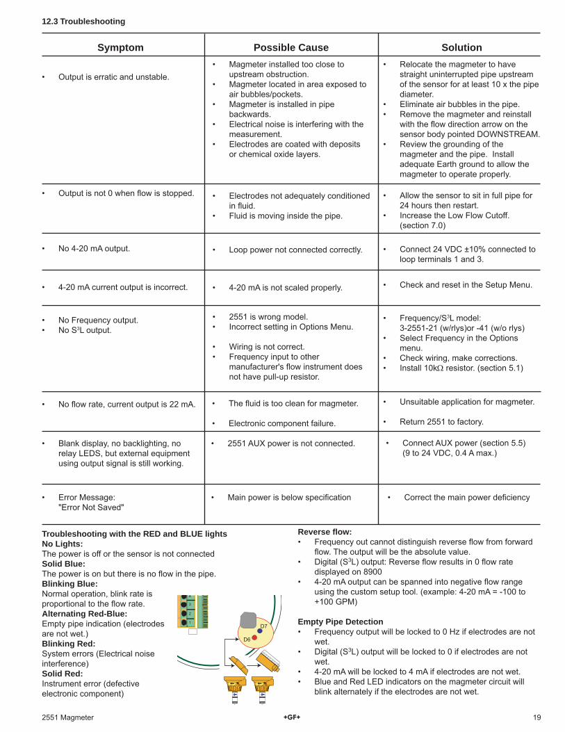
12.3 Troubleshooting
• Allow the sensor to sit in full pipe for 24 hours then restart.
• Increase the Low Flow Cutoff. (section 7.0)
• Check and reset in the Setup Menu.
• 2551 is wrong model.• Incorrect setting in Options Menu.
• Wiring is not correct.• Frequency input to other
manufacturer's fl ow instrument does not have pull-up resistor.
• Frequency/S3L model: 3-2551-21 (w/rlys)or -41 (w/o rlys)• Select Frequency in the Options
menu.• Check wiring, make corrections.• Install 10kΩ resistor. (section 5.1)
• Unsuitable application for magmeter.
• Return 2551 to factory.
• 4-20 mA current output is incorrect.
• Blank display, no backlighting, no relay LEDS, but external equipment using output signal is still working.
• 2551 AUX power is not connected. • Connect AUX power (section 5.5) (9 to 24 VDC, 0.4 A max.)
• Error Message: "Error Not Saved"
• Main power is below specifi cation • Correct the main power defi ciency
Troubleshooting with the RED and BLUE lightsNo Lights:The power is off or the sensor is not connectedSolid Blue:The power is on but there is no fl ow in the pipe.Blinking Blue:Normal operation, blink rate is proportional to the fl ow rate.Alternating Red-Blue:Empty pipe indication (electrodes are not wet.)Blinking Red:System errors (Electrical noise interference)Solid Red:Instrument error (defective electronic component)
1
2
3
4
D7
D6
Flow Flow
Reverse fl ow:• Frequency out cannot distinguish reverse fl ow from forward
fl ow. The output will be the absolute value.• Digital (S3L) output: Reverse fl ow results in 0 fl ow rate
displayed on 8900• 4-20 mA output can be spanned into negative fl ow range
using the custom setup tool. (example: 4-20 mA = -100 to +100 GPM)
Empty Pipe Detection• Frequency output will be locked to 0 Hz if electrodes are not
wet.• Digital (S3L) output will be locked to 0 if electrodes are not
wet.• 4-20 mA will be locked to 4 mA if electrodes are not wet.• Blue and Red LED indicators on the magmeter circuit will
blink alternately if the electrodes are not wet.
Georg Fischer Signet LLC, 3401 Aerojet Avenue, El Monte, CA 91731-2882 U.S.A. • Tel. (626) 571-2770 • Fax (626) 573-2057For Worldwide Sales and Service, visit our website: www.gfsignet.com • Or call (in the U.S.): (800) 854-4090
3-2551.090-1 Rev. G 10/08 English © Georg Fischer Signet LLC 2008 Printed in U.S.A. on recycled paper
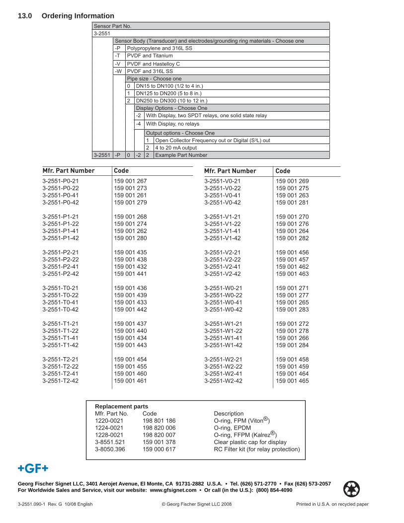
13.0 Ordering Information
3-2551-V0-21 159 001 2693-2551-V0-22 159 001 2753-2551-V0-41 159 001 2633-2551-V0-42 159 001 281
3-2551-V1-21 159 001 2703-2551-V1-22 159 001 2763-2551-V1-41 159 001 2643-2551-V1-42 159 001 282
3-2551-V2-21 159 001 4563-2551-V2-22 159 001 4573-2551-V2-41 159 001 4623-2551-V2-42 159 001 463
3-2551-W0-21 159 001 2713-2551-W0-22 159 001 2773-2551-W0-41 159 001 2653-2551-W0-42 159 001 283
3-2551-W1-21 159 001 2723-2551-W1-22 159 001 2783-2551-W1-41 159 001 2663-2551-W1-42 159 001 284
3-2551-W2-21 159 001 4583-2551-W2-22 159 001 4593-2551-W2-41 159 001 4643-2551-W2-42 159 001 465
3-2551-P0-21 159 001 2673-2551-P0-22 159 001 2733-2551-P0-41 159 001 2613-2551-P0-42 159 001 279
3-2551-P1-21 159 001 2683-2551-P1-22 159 001 2743-2551-P1-41 159 001 2623-2551-P1-42 159 001 280
3-2551-P2-21 159 001 4353-2551-P2-22 159 001 4383-2551-P2-41 159 001 4323-2551-P2-42 159 001 441
3-2551-T0-21 159 001 4363-2551-T0-22 159 001 4393-2551-T0-41 159 001 4333-2551-T0-42 159 001 442
3-2551-T1-21 159 001 4373-2551-T1-22 159 001 4403-2551-T1-41 159 001 4343-2551-T1-42 159 001 443
3-2551-T2-21 159 001 4543-2551-T2-22 159 001 4553-2551-T2-41 159 001 4603-2551-T2-42 159 001 461
Mfr. Part Number CodeMfr. Part Number Code
Sensor Part No.3-2551
Sensor Body (Transducer) and electrodes/grounding ring materials - Choose one-P Polypropylene and 316L SS-T PVDF and Titanium-V PVDF and Hastelloy C-W PVDF and 316L SS
Pipe size - Choose one0 DN15 to DN100 (1/2 to 4 in.)1 DN125 to DN200 (5 to 8 in.)2 DN250 to DN300 (10 to 12 in.)
Display Options - Choose One-2 With Display, two SPDT relays, one solid state relay-4 With Display, no relays
Output options - Choose One1 Open Collector Frequency out or Digital (S3L) out2 4 to 20 mA output
3-2551 -P 0 -2 2 Example Part Number
Replacement partsMfr. Part No. Code Description1220-0021 198 801 186 O-ring, FPM (Viton®)1224-0021 198 820 006 O-ring, EPDM1228-0021 198 820 007 O-ring, FFPM (Kalrez®)3-8551.521 159 001 378 Clear plastic cap for display3-8050.396 159 000 617 RC Filter kit (for relay protection)