Temporal Mediators: Integration of Temporal Reasoning and Temporal-Data Maintenance

1
Photocurrent detection of the orbital angular momentum of light
Zhurun Ji,1 Wenjing Liu,1 Sergiy Krylyuk,2 Xiaopeng Fan,1, 3 Zhifeng Zhang,4 Anlian Pan,3
Liang Feng,1,4 Albert Davydov2 and Ritesh Agarwal1,*
5
1. Department of Materials Science and Engineering, University of Pennsylvania,
Philadelphia, Pennsylvania 19104, United States
2. Material Science and Engineering Division, National Institute of Standards and
Technology, Gaithersburg, Maryland 20899, United States
3. Key Laboratory for Micro-Nano Physics and Technology of Hunan Province, State Key 10
Laboratory of Chemo/Biosensing and Chemometrics, and College of Materials Science
and Engineering, Hunan University, Changsha 410082, China
4. Department of Electrical and Systems Engineering, University of Pennsylvania,
Philadelphia, Pennsylvania 19104, United States
* [email protected] 15
Abstract:
Applications that use the orbital angular momentum (OAM) of light show promise for increasing
the bandwidth of optical communication networks. However, direct photocurrent detection of
different OAM modes has not yet been demonstrated. Most studies of current responses to 20
electromagnetic fields have focused on optical intensity–related effects, but phase information
has been lost. In this study, we designed a photodetector based on tungsten ditelluride (WTe2)
with carefully fabricated electrode geometries to facilitate direct characterization of the
topological charge of OAM of light. This orbital photogalvanic effect, driven by the helical
phase gradient, is distinguished by a current winding around the optical beam axis with a 25
magnitude proportional to its quantized OAM mode number. Our study provides a route to
develop on-chip detection of optical OAM modes, which can enable the development of next-
generation photonic circuits.
One Sentence Summary:
On-chip photodetection of orbital angular momentum of light interaction between the oscillating 30
electromagnetic field of light and the electric or magnetic dipole moment of matter can be
designed to go beyond simple intensity and temporal characteristics by manipulating light’s
different degrees of freedom (e.g., frequency, polarization, phase, and angular momentum). One

2
such property is the spin angular momentum (SAM) of light, which can induce a linear motion of
electrons to generate dc photocurrent that switches with light helicity. This circular
photogalvanic effect (1–3) is governed by angular momentum conservation laws and is a
powerful technique for exploring the interaction between the chiral degree of freedom of matter
and SAM of light. 5
In addition to spin, light can also carry an orbital angular momentum (OAM) (4, 5). While
SAM of light is associated with its polarization state and has a bounded value 𝑆 = ±ℏ per photon,
OAM is also quantized but unbounded, given by 𝐿 = 𝑚ℏ (𝑚 is the mode number and ℏ is Planck’s
constant divided by 2π). OAM of light leads to a spatial distribution of the phase of the optical
field, which manifests as a helical wavefront or an azimuthal phase dependence e𝑖𝑚𝜙 (𝜙 is the 10
azimuthal angle). Exploiting the OAM modes of light has been widely proposed to enable the next
generation of high-capacity photonics, but direct electrical readout of OAM is a challenge, thus
limiting its applications towards system-level integrations that require on-chip generation (6, 7),
waveguiding (8), to detection (9,10) of OAM.
Extensive theoretical (11–13) and some experimental studies have reported on the 15
interaction between OAM of light and atomic media (14, 15), generating new selection rules and
optical responses. These studies suggest that the optical phase gradient modifies the excitation
processes, but the results cannot be translated to obtain direct photocurrent generation for
fabricating OAM-sensitive photodetectors. This is because dc photocurrent response does not
inherently carry phase information, and the slow variation of vector potential associated with OAM 20
of light compared to the Brillouin zone size limits its influence onmicroscopic processes (16). Here
we show that OAM of light can induce a strong, nonlocal interaction between electromagnetic
waves and matter. Additionally, we discuss our observation of a distinctive photocurrent from
OAM emerging from the phase gradient of optical fields, the direction and amplitude of which
directly reflect the different OAM modes (Fig. 1). 25
The in-plane electric field of a monochromatic, Laguerre-Gaussian (LG0m) beam with OAM
order 𝑚 propagating in the �̂�-direction is given by (17),
𝑬(𝒓, 𝑡) = 𝑢(𝜌, 𝑧)𝑒𝑖𝑚𝜙𝑒𝑖(𝑘𝑧𝑧−𝜔𝑡)�̂� + 𝑐. 𝑐. (1)
under the paraxial approximation, where 𝒓 = (𝜌, 𝜙, 𝑧) is the position in the cylindrical coordinate,
𝑢(𝜌, 𝑧) is the donut-shaped LG mode profile, 𝑘𝑧�̂� is the wave vector, 𝜔 is the frequency, t is time, 30
c.c. is the complex conjugate, and polarization of light is determined by �̂� = (�̂� + 𝑖𝜎�̂�), with 𝜎
being the optical helicity (−1 < 𝜎 < 1) or SAM of the beam. The electric field can be Fourier
expanded as 𝑬(𝒓, 𝜔) = 1/(2𝜋)3∫ 𝑑𝒒𝑬(𝒒 , 𝜔)𝑒𝑖𝒒∙𝒓. When the OAM order 𝑚 is nonzero, besides
𝒌 = 𝑘𝑧�̂�, an ‘azimuthal photon momentum’ 𝑞𝜑 also arises from the helical phase 𝜙 . Then, a
general second order dc response from the interaction of 𝑬(𝒒, 𝜔) and 𝑬(−𝒒, −𝜔), by accounting 35
for the helical phase is (Supplementary material section S1.1 to S1.4)

3
𝑗𝑘
(𝑑𝑐)(𝒓, 𝑡) = ∬𝑑𝒒𝑑(−𝒒)𝑑𝜔𝑑(−𝜔)
(2𝜋)8𝜉𝑖𝑗𝑘(𝒒 , 𝜔; −𝒒, −𝜔)𝐸𝑖(𝒒 , 𝜔)𝐸𝑗(−𝒒 , −𝜔)𝑒−𝑖(𝜔−𝜔)𝑡𝑒𝑖(𝒒−𝒒)∙𝒓|𝒒=𝑞𝜙𝝓
≈ 𝛼𝑖𝑗𝑘(𝜔, −𝜔)𝐸𝑖(𝒓, 𝜔)𝐸𝑗 (𝒓, −𝜔) + β𝑖𝑗𝑘𝑙(𝜔, −𝜔)∇𝑙𝐸𝑖(𝒓, 𝜔)𝐸𝑗
(𝒓, −𝜔) (2)
where the subscripts i, j, k and l stand for directions in the cylindrical coordinate system, and at
normal incidence, the summations of i, j and k are over in-plane components (i.e., 𝜌 and 𝜙). In the
small perturbation limit (𝒒 is ~10−3 times smaller than Brillouin zone length), the second order
conductivity tensor can be expanded up to the first order of 𝒒 to obtain, 𝜉𝑖𝑗𝑘 (𝒒 , 𝜔; −𝒒, −𝜔) ≈5
𝛼𝑖𝑗𝑘 + 𝑖𝑞𝑙𝛽𝑖𝑗𝑘𝑙 . 𝛼𝑖𝑗𝑘 corresponds to the conventional photogalvanic conductivity tensor, which
implies that in the small 𝒒 limit OAM of light does not appreciably change the dipole selection
rules, and hence the local current response to light field will be determined by its local intensity
and polarization, regardless of the OAM order. It explains the absence of signatures of OAM
transfer to matter in photoemission experiments (16), and further suggests that when the lowest 10
order 𝛼𝑖𝑗𝑘 tensor exists, as in previous high harmonic generation studies (18), OAM carrying
optical beams are almost equivalent to plane waves (since 𝛼𝑖𝑗𝑘 is unchanged), except for
modifying the phase factors under phase-matching conditions. However, the conductivity tensor,
𝛽𝑖𝑗𝑘𝑙 goes beyond the dipole-approximation and describes a part of spatially nonlocal current
proportional to the helical phase gradient, and hence the OAM of light-induced photocurrent can 15
be obtained as (Supplementary materials section S1.3)
𝐽𝑘(𝜌, 𝜙) = 𝛽𝑖𝑗𝑘𝜙 (𝜔, −𝜔)
1
2[∇ϕ𝐸𝑖(𝒓, 𝜔)𝐸𝑗
(𝒓, −𝜔) − ∇ϕ𝐸𝑗(𝒓, −𝜔)𝐸𝑖 (𝒓, 𝜔)] ∝ 𝑚 (3)
The gradient operator ∇ϕ in Eq. (3) directly corresponds to the helical phase gradient in the 𝜙
direction and is a signature of the nonlocality of the photocurrent. 𝛽𝑖𝑗𝑘𝑙 can also be divided into a
symmetric ( 𝛽𝑖𝑗𝑘𝑙+ = (𝛽𝑖𝑗𝑘𝑙
+ 𝛽𝑗𝑖𝑘𝑙 )/2) part dependent on linear polarization and an antisymmetric 20
(𝛽𝑖𝑗𝑘𝑙− = (𝛽𝑖𝑗𝑘𝑙
− 𝛽𝑗𝑖𝑘𝑙 )/2) part that switches with light helicity. Therefore, the phase information
of OAM of light is maintained in the nonlocal, polarization-dependent photocurrent 𝐽𝑘, and forms
the central hypothesis of our studies.
LG0𝑚 modes (Figs. 1 and 2) were obtained by modulating a linearly-polarized collimated
light beam from a Ti-sapphire laser (wavelength: 1 𝜇𝑚) with a phase-only spatial light modulator 25
(SLM). The beam was then transmitted through a quarter waveplate (QWP) and focused by a 60×
objective to a spot size of ~3 to 20 𝜇m, and the sample was irradiated at normal incidence (19). To
measure the response from OAM of light, a material system with symmetry-forbidden
photogalvanic response (described by 𝛼 ⃡ ) under normal incidence, but supporting the nonlocal
response (described by 𝛽) when the helical phase gradient breaks certain in-plane symmetries is 30
desired. The material chosen in our study is ~50- to 200-nm thick exfoliated single-crystalline
WTe2 in Td phase (Pmn21), a type-II Weyl semimetal (20) with large nonlinear optical
susceptibilities (21, 22) and a symmetry-forbidding contribution from tensor 𝛼 under normal
incidence (along c-axis). In the laboratory cylindrical coordinate (𝜌, 𝜙, 𝑧) frame, measurable terms
related to the nonlocal current and response to light helicity include 𝛽𝜌𝜙𝜌𝜙− and 𝛽𝜌𝜙𝜙𝜙
− , which 35

4
correspond to photocurrents along radial ( �̂� ) and azimuthal ( �̂� ) directions, respectively
(Supplementary material section S1.3).
To identify and characterize photocurrent response from the helical phase profile of the
optical beam, one must design suitable electrodes and distinguish all possible sources of current.
First, since photocurrent related to the helical phase profile may flow in the radial or azimuthal 5
directions, electrodes were designed into a U shape (Fig. 2A) to collect the radial current (see
Supplementary materials sections S2.1, S2.2 for the electrostatic model and results from other
electrode geometries). Second, because this current described by β𝑖𝑗𝑘𝑙− has a circular polarization
dependence, the polarization of light was continuously modulated by a QWP, and the photocurrent
was measured as a function of the QWP rotation angle α (Fig. 2B). In a 180o period, the light goes 10
through linear (0o)–left circular (45o)–linear (90o)–right circular (135o) –linear (180o) polarization
states. The total measured photocurrent can be divided into three parts: (i) current that switches
with circular polarization with a 180o-period modulation (𝐽𝐶) (23), (ii) the part sensitive to linear
polarization with a 90o-period modulation ( 𝐽𝐿) (24), and (iii) the polarization-independent
component (𝐽0, includes thermal currents). Third, aside from the azimuthal phase profile, a LG 15
beam also carries an annular intensity profile. As it evident from Eq. (2), it can generate spatially-
dispersive photogalvanic current (𝐽𝑠−𝑃𝐺𝐸) proportional to the local light intensity gradient (i.e.,
𝜕|𝑬(𝜌)|2/𝜕𝜌) (21). Although 𝐽𝑠−𝑃𝐺𝐸 is also sensitive to light helicity, its effect can be eliminated
by measuring signals from both OAM +𝑚 and −𝑚 beams because the local light intensity is
preserved when OAM order reverses sign (the same argument holds for contributions from radial 20
phase profiles; see supplementary materials section S1.4).
To first examine the existence of photocurrent from OAM of light, OAM order 𝑚 = +1
and 𝑚 = −1 beams generated by the SLM were measured using the ‘U’-shaped electrodes with
the beam center fixed at the center of the electrode arcs (Fig. 2A). The results show that both OAM
+1 and -1 beams gave rise to polarization-dependent currents (Fig. 2B). 𝐽𝐶 from OAM +1 and 25
OAM -1 beams have similar amplitudes but opposite polarities. By measuring the beam size and
spatial dependence (Supplementary material section S2.3) and by comparing the results from
various electrode geometries and mirror symmetric electrode pairs, it was further confirmed that
the observed 𝐽𝐶 did not originate from external symmetry reductions like material defects, edge
effects, or beam imperfections (see supplementary materials sections S3.1 and S3.2 for details). 30
The polarity switch of 𝐽𝐶 cannot be attributed to spatial intensity gradients either, because the two
𝑚 = ±1 beams have the same intensity profile but only differ by their helical phases (±𝜙).
Therefore, these results suggest that a distinctive current – which we term the orbital photogalvanic
effect (OPGE) – originates from the light OAM. OPGE is distinct from any other reported
photogalvanic effects due to its nonlocal nature, spatially dispersive features, and sensitivity to the 35
wavefront shape of light beam.
The mechanism of this photocurrent can be understood as light transferring its OAM and
energy simultaneously to the electrons. Because the optical-phase varies in the azimuthal direction,

5
it induces a spatial imbalance of excited carriers, producing a net current. This process has
similarities with the photon drag effect (25, 26) (Supplementary materials section S1.3), but here
the spatial variation of photon momentum plays a vital role, causing the nonlocal OPGE current
to flow either along or perpendicular to the helical phase gradient. The OAM-carrying beam has a
magnetic field 𝑩(ω) parallel to the beam propagation direction and through a magnetic dipole like 5
interaction, the in-plane electric field 𝑬(−𝜔) and the out-of-plane magnetic field 𝑩(𝜔) generates
a dc photocurrent, which is the OPGE current, J𝑂𝑃𝐺𝐸 ∝ 𝑬(−𝜔)𝑩(𝜔). 𝐽𝑂𝑃𝐺𝐸 is proportional to the
amplitude of the perpendicular magnetic field that changes with phase gradient, so when the OAM
index reverses sign, the direction of OPGE current also flips (Fig. 2B). As noted in Eq. 3, the
OPGE current can be distinctively projected onto the OAM order [when spin-orbit coupling of 10
light (27) is not considered], with a proportionality factor dependent on the material’s conductivity
tensor.
To demonstrate the discrete behavior of the OPGE current, light with OAM
±4, ±3, ±2, ±1 were generated sequentially by a phase-only SLM (with constant optical power),
and the radial photocurrent was measured using the U-shaped electrode geometry with beam center 15
fixed at the center of the electrode arcs. The measurement results (Fig. 2C) clearly show that 𝐽𝐶
displays step-like changes from OAM order -4 to 4, in good agreement with the theoretical model,
which implies that the measured 𝐽𝐶 is attributed to light helicity-sensitive OPGE current described
by the conductivity tensor 𝛽𝑖𝑗𝑘𝑙− (see Supplementary material section S2.4 for discussion of
geometrical constants related to the LG profiles of different OAM orders). Our results show that 20
when JC is proportional to the OAM order, the linear polarization-dependent current, 𝐽𝐿, and the
polarization-independent thermal current, 𝐽0 do not have such dependence (Fig. 2C, inset), which
indicates that they are dominated by different mechanisms (although OPGE current described by
𝛽𝑖𝑗𝑘𝑙+ is also present; Supplementary materials section S1.3, S1.4). Furthermore, since the measured
OPGE current is proportional to the product of SAM and OAM, and the winding number of the 25
light field is −𝑚 ∙ 𝜎 (14), the OPGE current thus directly characterizes the topological property of
light (see Supplementary materials section S1.3, and S2.5 for generalization to mixtures of
different OAM orders).
Besides scalar OAM beams, there are vectorial OAM beams with space-variant states of
polarization in addition to the helical phase distribution (28). Owing to the sensitivity of OPGE on 30
both the SAM and OAM of the optical field (Fig. 2), we studied the mechanism of photocurrent
generation from these beams. Vectorial OAM beams can be represented on a higher-order Poincare
sphere (HOPS) (29, 30), and the 𝑚 = +1, 𝜎 = −1 HOPS is taken as an example (Fig. 3A, P1–P5
are five representative states). In the parameter space (represented by the spherical coordinates Θ
and Φ ) of the HOPS, the state of the optical field is represented by |ψ(Θ, Φ)⟩ =35
cos (Θ
2)exp (−𝑖Φ/2)|𝐿−𝑚⟩ + sin (
Θ
2)exp (𝑖Φ/2)|𝑅𝑚⟩, where |𝑅𝑚⟩ and |𝐿−𝑚⟩ are scaler vortex
beams with OAM +𝑚 (−𝑚), SAM σ = −1 (σ = 1), respectively. The azimuthal OPGE current
from an arbitrary state |ψ(Θ, Φ)⟩ from this HOPS can then be written as,
6
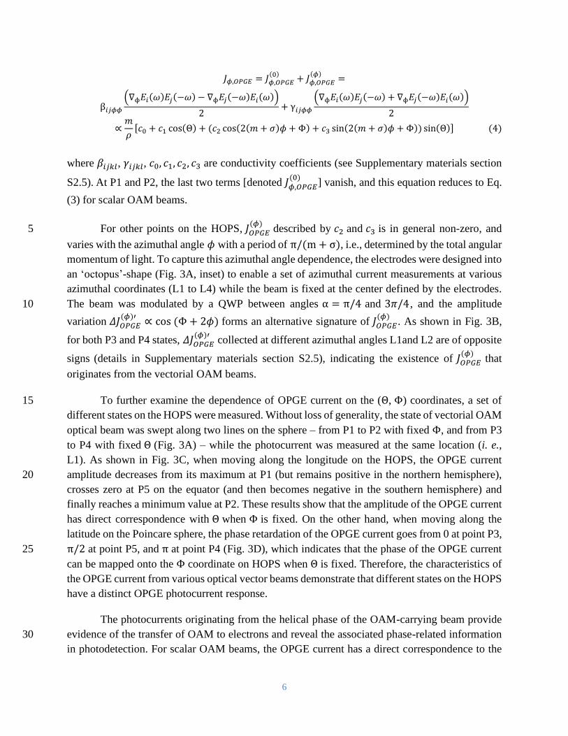
𝐽𝜙,𝑂𝑃𝐺𝐸 = 𝐽𝜙,𝑂𝑃𝐺𝐸(0)
+ 𝐽𝜙,𝑂𝑃𝐺𝐸(𝜙)
=
β𝑖𝑗𝜙𝜙
(∇ϕ𝐸𝑖(𝜔)𝐸𝑗 (−𝜔) − ∇ϕ𝐸𝑗(−𝜔)𝐸𝑖
(𝜔))
2+ γ𝑖𝑗𝜙𝜙
(∇ϕ𝐸𝑖(𝜔)𝐸𝑗
(−𝜔) + ∇ϕ𝐸𝑗(−𝜔)𝐸𝑖 (𝜔))
2
∝𝑚
𝜌[𝑐0 + 𝑐1 cos(Θ) + (𝑐2 cos(2(𝑚 + 𝜎)𝜙 + Φ) + 𝑐3 sin(2(𝑚 + 𝜎)𝜙 + Φ)) sin(Θ)] (4)
where 𝛽𝑖𝑗𝑘𝑙 , 𝛾𝑖𝑗𝑘𝑙
, 𝑐0, 𝑐1, 𝑐2, 𝑐3 are conductivity coefficients (see Supplementary materials section
S2.5). At P1 and P2, the last two terms [denoted 𝐽𝜙,𝑂𝑃𝐺𝐸(0)
] vanish, and this equation reduces to Eq.
(3) for scalar OAM beams.
For other points on the HOPS, 𝐽𝑂𝑃𝐺𝐸(𝜙)
described by 𝑐2 and 𝑐3 is in general non-zero, and 5
varies with the azimuthal angle 𝜙 with a period of π/(m + σ), i.e., determined by the total angular
momentum of light. To capture this azimuthal angle dependence, the electrodes were designed into
an ‘octopus’-shape (Fig. 3A, inset) to enable a set of azimuthal current measurements at various
azimuthal coordinates (L1 to L4) while the beam is fixed at the center defined by the electrodes.
The beam was modulated by a QWP between angles α = π/4 and 3𝜋/4 , and the amplitude 10
variation 𝛥𝐽𝑂𝑃𝐺𝐸(𝜙)′
∝ cos (Φ + 2𝜙) forms an alternative signature of 𝐽𝑂𝑃𝐺𝐸(𝜙)
. As shown in Fig. 3B,
for both P3 and P4 states, 𝛥𝐽𝑂𝑃𝐺𝐸(𝜙)′
collected at different azimuthal angles L1and L2 are of opposite
signs (details in Supplementary materials section S2.5), indicating the existence of 𝐽𝑂𝑃𝐺𝐸(𝜙)
that
originates from the vectorial OAM beams.
To further examine the dependence of OPGE current on the (Θ, Φ) coordinates, a set of 15
different states on the HOPS were measured. Without loss of generality, the state of vectorial OAM
optical beam was swept along two lines on the sphere – from P1 to P2 with fixed Φ, and from P3
to P4 with fixed Θ (Fig. 3A) – while the photocurrent was measured at the same location (i. e.,
L1). As shown in Fig. 3C, when moving along the longitude on the HOPS, the OPGE current
amplitude decreases from its maximum at P1 (but remains positive in the northern hemisphere), 20
crosses zero at P5 on the equator (and then becomes negative in the southern hemisphere) and
finally reaches a minimum value at P2. These results show that the amplitude of the OPGE current
has direct correspondence with Θ when Φ is fixed. On the other hand, when moving along the
latitude on the Poincare sphere, the phase retardation of the OPGE current goes from 0 at point P3,
π/2 at point P5, and π at point P4 (Fig. 3D), which indicates that the phase of the OPGE current 25
can be mapped onto the Φ coordinate on HOPS when Θ is fixed. Therefore, the characteristics of
the OPGE current from various optical vector beams demonstrate that different states on the HOPS
have a distinct OPGE photocurrent response.
The photocurrents originating from the helical phase of the OAM-carrying beam provide
evidence of the transfer of OAM to electrons and reveal the associated phase-related information 30
in photodetection. For scalar OAM beams, the OPGE current has a direct correspondence to the

7
topological winding number of light; for vectorial OAM beams, the variation of OPGE current
with the azimuthal coordinate reflects its phase and polarization distribution simultaneously. On
the basis of these results, we expect that the OAM order or the coordinates of any arbitrary OAM
state on a HOPS can be specifically determined by measuring currents via a small matrix of
electrodes. Once a device geometry is fixed, characterized, and calibrated, a single electrode matrix 5
can detect a variety of OAM modes, including their arbitrary mixtures. With further optimization,
on-chip detection of OAM modes of light will be possible, thus potentially facilitating OAM-based
optical communication by expanding the parameter space of light.

8
Figure captions:
Figure 1: Schematic of the photocurrent measurement from optical beams carrying (OAM).
Figure 2: Evidence of the nonlocal photocurrent generated by OAM of light and its 5
dependence on OAM order. A. Optical image of a photodetector device with U-shaped electrodes
on WTe2. The light spot is focused at the center of the arc defined by the electrodes (blue circle).
Scale bar: 10 µm. (B) Measured photocurrent amplitudes from OAM +1 (red curve) and −1 (blue
curve) beams, as a function of the QWP angle (a). The insets are charge-coupled device (CCD)
images of OAM +1 and −1 beams. (C) Normalized photocurrent that switches with circular 10
polarization, from beams with OAM order ranging from −4 to 4. Error bars represent the standard
deviations of the fitting. (Inset) Three components of the photocurrent from OAM −4 to 4 beams:
J0, JL and JC.
Figure 3: OPGE current from generalized vectorial OAM states on a HOPS. A. Schematic of 15
the 𝑚 = 1, σ = −1 HOPS, with states represented by (Θ, Φ) spherical coordinates and five points
P1-P5. Each subplot shows polarization distribution (single-headed arrows) with or without a
linear polarizer oriented in the horizontal direction (double-headed arrows), and the corresponding
intensity profile as recorded by a CCD camera. (Inset) Optical image of the octopus-shaped
electrodes. Four pairs of electrodes (L1, L2, L3, and L4) are located at four azimuthal coordinates 20
(ϕ = 0, π/2, π, 3π/2, respectively). Scale bar: 10 μm. B. Relative photocurrent amplitudes at two
QWP angles (π/4 and 3π/4) from two states (P3, P4) measured at two locations (L1, L2). C.
OPGE current amplitude from a set of states on the line connecting P1, P5 and P2 with a same Φ.
(Inset) Calculations showing a Φ-independent distribution of OPGE current. D. Relative phase of
OPGE current with respect to state P3, from a set of states on the line connecting P3, P5 and P4 25
with a fixed Θ. (Inset) Calculation showing a Θ-independent distribution of OPGE current phase.
30

9
References and Notes:
References:
1. E. Ivchenko, S. Ganichev. Optical Spectroscopy of Semiconductor Nanostructures
(Springer, 2008). 5
2. J. Sipe, A. Shkrebtii, Phys. Rev. B 61, 5337 (2000).
3. S. Dhara, E. J. Mele, R. Agarwal, Science 349, 726 (2015).
4. L. Allen, M. W. Beijersbergen, R. Spreeuw, J. Woerdman, Physical Review A 45, 8185
(1992).
5. L. Allen, M. Padgett, M. Babiker, in Progress in optics. (Elsevier, 1999), vol. 39, pp. 291-10
372.
6. P. Miao et al., Science 353, 464 (2016).
7. C.-W. Qiu, Y. Yang, Science 357, 645 (2017).
8. Y. Chen et al., Phys. Rev. Lett. 121, 233602 (2018).
9. G. C. Berkhout, M. P. Lavery, J. Courtial, M. W. Beijersbergen, M. J. Padgett, Phys. Rev. 15
Lett. 105, 153601 (2010).
10. C. Schulze, A. Dudley, D. Flamm, M. Duparre, A. Forbes, New Journal of Physics 15,
073025 (2013).
11. M. G. Mandujano, J. A. Maytorena, Physical Review A 88, 023811 (2013).
12. G. F. Quinteiro, D. Reiter, T. Kuhn, Physical Review A 91, 033808 (2015). 20
13. K. Shintani, K. Taguchi, Y. Tanaka, Y. Kawaguchi, Phys. Rev. B 93, 195415 (2016).
14. G. Walker, A. Arnold, S. Franke-Arnold, Phys. Rev. Lett. 108, 243601 (2012).
15. C. T. Schmiegelow et al., Nat. Commun. 7, 12998 (2016).
16. N. Clayburn et al., Phys. Rev. B 87, 035204 (2013).
17. D. L. Andrews, Structured light and its applications: An introduction to phase-structured 25
beams and nanoscale optical forces. (Academic press, 2011).
18. K. Dholakia, N. Simpson, M. Padgett, L. Allen, Physical Review A 54, R3742 (1996).
19. Materials and methods are available as supplementary materials.
20. A. A. Soluyanov et al., Nature 527, 495 (2015).
21. Z. Ji et al., Nature materials, 1 (2019). 30
22. G. B. Osterhoudt et al., Nat. Mater. 18, 471–475 (2019).
23. F. de Juan, A. G. Grushin, T. Morimoto, J. E. Moore, Nat. Commun. 8, 15995 (2017).
24. S. M. Young, A. M. Rappe, Phys. Rev. Lett. 109, 116601 (2012).
25. J. L. Cheng, N. Vermeulen, J. E. Sipe, Sci. Rep. 7, 43843 (2017).
26. J. Karch et al., Phys. Rev. Lett. 107, 276601 (2011). 35
27. Z. Shao, J. Zhu, Y. Chen, Y. Zhang, S. Yu, Nat. Commun. 9, 1 (2018).
28. C. Maurer, A. Jesacher, S. Fürhapter, S. Bernet, M. Ritsch-Marte, New Journal of Physics
9, 78 (2007).
29. G. Milione, H. Sztul, D. Nolan, R. Alfano, Phys. Rev. Lett. 107, 053601 (2011).
30. D. Naidoo et al., Nature Photonics 10, 327 (2016). 40
Acknowledgements

10
The authors thank E. Mele for helpful discussions. Funding: This work was supported by the ONR-MURI
(grant N00014-17-1- 2661), US-ARO (grants W911NF-17-1-0436 and W911NF-19-1- 0249), and NSF-
USA (grants RAISE-EQuIP-NSF-ECCS-1842612, NSF-QII-TAQS-1936276, and ECCS-1932803 and a
seed grant from MRSEC/DMR-1720530). A.P. is supported by the National Natural Science Foundation
of China (51525202 and U19A2090). S.K. and A.D. acknowledge support from the National Institute of 5 Standards and Technology, U.S. Department of Commerce.

11
Figure 1
5
10
WTe2
A Current
Metal contact

12
Figure 2
5
-4
-3
-2
-1
0
1
2
3
4
-4 -2 0 2 4 6
Normalized JC
OA
M o
rder
A
𝑞 = 𝑞𝜙𝜙
= 𝐽𝜌 �̂�
C
-4 -3 -2 -1 0 1 2 3 4-0.04
-0.02
0.00
0.02
0.04
Ph
oto
cu
rre
nt
(nA
)
OAM order
J0 x 0.01 JL x 0.1 JC
B
Light spot center
-3.6
-3.4
jLCP jRCP
OAM +1
OAM -1
jLCP jRCP
0 45 90 135 180
-3.2
-3.0
Ph
oto
cu
rre
nt
(nA
)
Quarter wave plate angle (o)

13
Figure 3
-0.05
0.00
0.05
0.10
OP
GE
cu
rren
t (n
A)
P5
-0.1
0.0
0.1
0.2
J
OP
GE (
nA
)
P3, L1
P4, L1
P3, L2
P4, L2
0
90
180
Ph
as
e o
f O
PG
E c
urr
en
t (o
)
P4 P3
P2
P1
P1 P2
A
C
P4P3 P5P5
D
Θ
magnitude phase
+−
( , )
L1
L2
L3
B
Φ
𝝓
L4
( , )
( / , )( / , )
( / , )
( / , )