Signal Processing for Digital Mode Amateur Radio Processing for Digital Mode Amateur Radio ......
23
Signal Processing for Digital Mode Amateur Radio David Farrell, CEPD, Inc. AC0[email protected] www.cepd.com IEEE Signal Processing Society July 16, 2015 1
Transcript of Signal Processing for Digital Mode Amateur Radio Processing for Digital Mode Amateur Radio ......
Signal Processing for Digital
Mode Amateur Radio David Farrell, CEPD, Inc.
www.cepd.com
IEEE Signal Processing Society
July 16, 2015
1

Ham Radio Popularity
How to get your license
HF Transmission
Traditional PC to Radio Interface
A Few Popular Digital Modes and How They Work
Digital Mode Bands and Frequencies
Source Code
Example Waterfall
References
Topics
2

▪ At the beginning of 2015, there were over 726,000
licensed operators
▪ Around 9000 new licenses are issued each year
▪ Much of the recent growth of ham radio can be attributed
to the FCC’s 2007 decision to do away with the Morse
code requirement for all amateur licenses
Ham Radio Popularity
3

The classifications of new licenses are Technician, General and Extra.
Read the free study guides at http://www.kb6nu.com/tech-manual/ , or
buy a book at www.arrl.org .
Register on www.QRZ.com and take their practice exams.
Find an exam time and location near you:
http://www.arrl.org/find-an-amateur-radio-license-exam-session .
You can take all three exams in one sitting if you pass. There is a small
fee per exam.
How to get your license
4
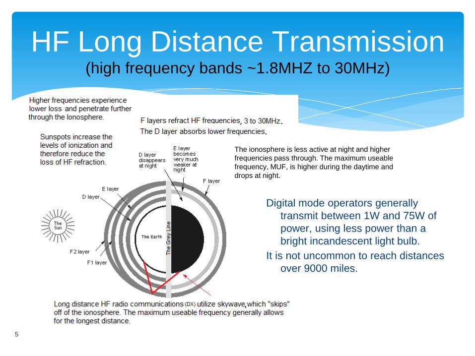
Digital mode operators generally
transmit between 1W and 75W of
power, using less power than a
bright incandescent light bulb.
It is not uncommon to reach distances
over 9000 miles.
HF Long Distance Transmission (high frequency bands ~1.8MHZ to 30MHz)
5
The ionosphere is less active at night and higher
frequencies pass through. The maximum useable
frequency, MUF, is higher during the daytime and
drops at night.
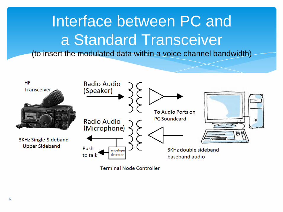
Interface between PC and
a Standard Transceiver (to insert the modulated data within a voice channel bandwidth)
6

The computer does the signal
processing
7
The signal processing consists of encoding and
modulation, decoding and demodulation. PCs and
SBCs are well suited for the signal processing given
the low bandwidths and today’s processing power:
channels are half duplex
bandwidth is less than 3KHz
soundcard sample rates are >8KHz

BPSK Waveform
Mode Baud Interval ~wpm
BPSK31 31.25 0.032 50
BPSK63 62.5 0.016 100
BPSk125 125 0.008 200
Binary information is transmitted by imparting a 180-degree phase shift
(binary "zero") or no phase shift (binary "one") in each symbol interval.
PSK31 signals can be recovered 7 dB below the noise floor. There is no
error correction. The bandwidth is approximately equal to the baud rate.
(binary phase shift keying)
PSK related modes: PSK31 PSK63 PSK125 Q15X25
8

Varicode is a Huffman code for use in PSK. It supports
all ASCII characters, but the characters used most
frequently in English have shorter codes. The space
between characters is indicated by a 00 sequence, a
variation of Fibonacci coding. [Wikipedia]
The average character length is 6.3 bits. No Varicode
characters can begin or end with a zero.
Varicode was adopted by the ITU in Recommendation
ITU-R M.2034.
9
Varicode
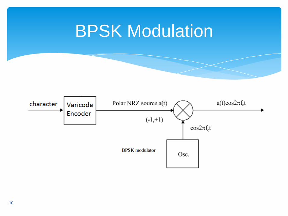
BPSK Modulation
10
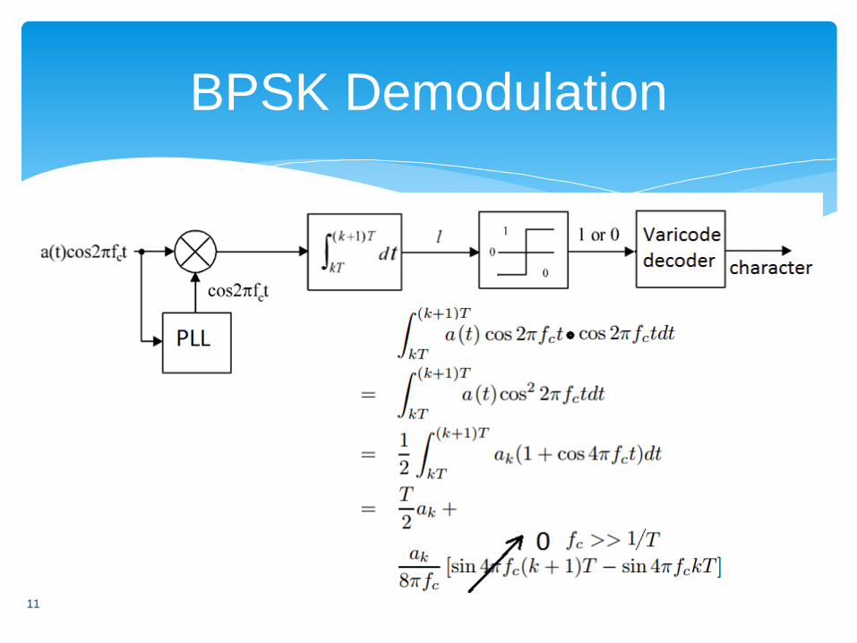
BPSK Demodulation
11

FSK:
RTTY AMTOR / SITOR PACTOR CLOVER2000
Packet radio (Bell 103 Bell 202): APRS
The Automatic Packet Reporting System is popular on
VHF/UHF for telemetry and instant messaging.
MFSK:
MFSK Olivia Contestia JT65 FSK441 JT6M WSPR
FSK Modes (multiple frequency shift keying)
12
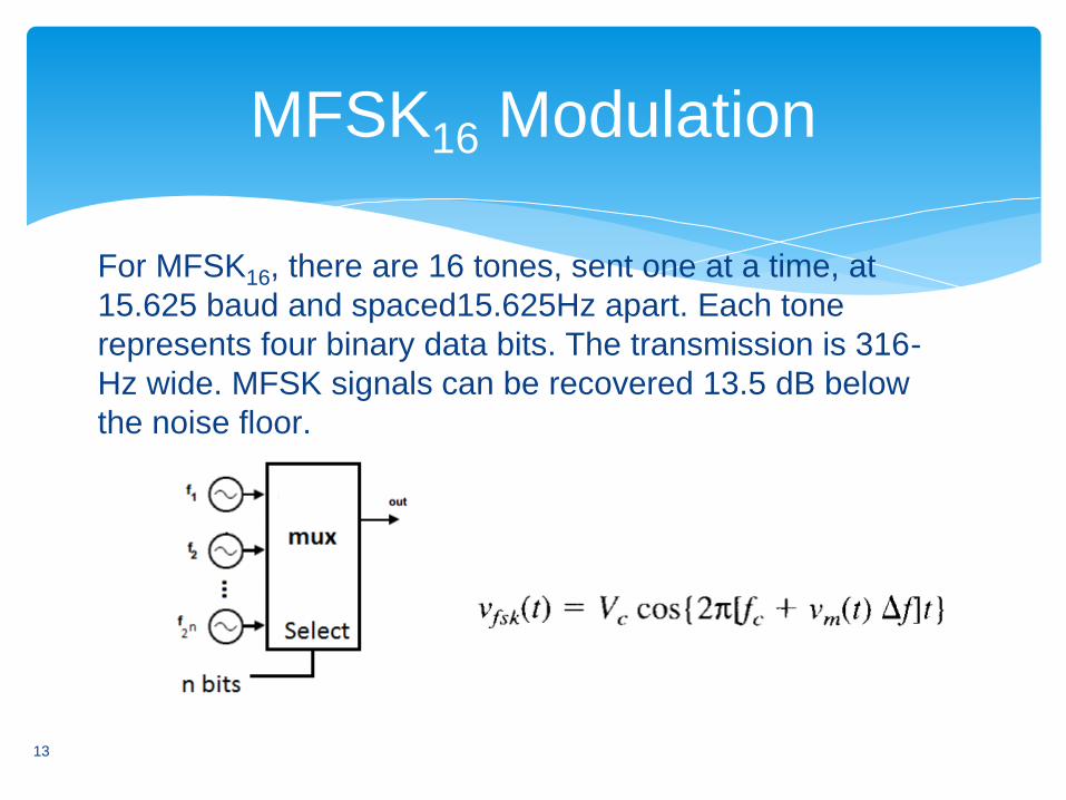
For MFSK16, there are 16 tones, sent one at a time, at
15.625 baud and spaced15.625Hz apart. Each tone
represents four binary data bits. The transmission is 316-
Hz wide. MFSK signals can be recovered 13.5 dB below
the noise floor.
MFSK16 Modulation
13

MFSK Demodulation
PLL
Method
Synchronous
Detection Non-
coherent 14
Olivia
Olivia transmits a stream of ASCII (7-bit) characters. The
characters are sent in blocks of 5. Olivia has 40 formats
(modes) based upon different values for bandwidth and
the number of tones (bit-rate = Bandwidth / tones ).
Tones: 2, 4, 8, 16, 32, 64, 128, 256
Bandwidths (Hz): 125, 250, 500, 1000, 2000
For example, Olivia 16/500 is 16 tones and 500Hz
bandwidth.
Olivia signals can be recovered 17 dB below the noise
floor. Olivia utilizes error correction.
15
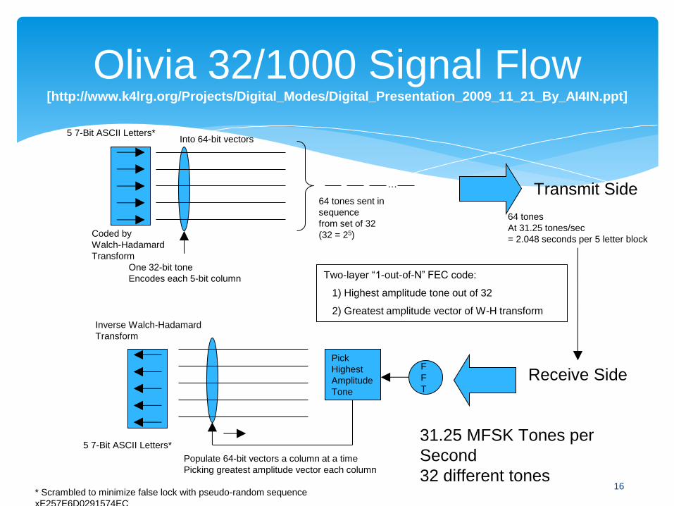
Olivia 32/1000 Signal Flow [http://www.k4lrg.org/Projects/Digital_Modes/Digital_Presentation_2009_11_21_By_AI4IN.ppt]
Coded by
Walch-Hadamard
Transform
Into 64-bit vectors
…
64 tones sent in
sequence
from set of 32
(32 = 25)
Transmit Side
Receive Side
64 tones
At 31.25 tones/sec
= 2.048 seconds per 5 letter block
31.25 MFSK Tones per
Second
32 different tones
One 32-bit tone
Encodes each 5-bit column
F
F
T
Pick
Highest
Amplitude
Tone
Populate 64-bit vectors a column at a time
Picking greatest amplitude vector each column
Inverse Walch-Hadamard
Transform
5 7-Bit ASCII Letters*
Two-layer “1-out-of-N” FEC code:
1) Highest amplitude tone out of 32
2) Greatest amplitude vector of W-H transform
* Scrambled to minimize false lock with pseudo-random sequence
xE257E6D0291574EC
5 7-Bit ASCII Letters*
16

JT65 HF
JT65 is a variant of WSJT. Message content is
limited and each message is only 13 characters.
Messages must start within a few seconds of each
1 minute UTC boundary. Signals can be recovered
24 dB below the noise floor. Extensive error
correction is utilized.
17

More detail on JT65
JT65 uses the Reed Solomon code RS(63,12). After being
compressed into 72 bits, a JT65 message is augmented with 306
uniquely defined error-correcting bits. JT65 Transmission uses 64-
tone MFSK, with each symbol value corresponding to a distinct tone.
It is divided into 126 contiguous time intervals, each of length 0.372 s
(4096 samples at 11025 samples per second). Within each interval
the waveform is a constant-amplitude sinusoid at one of 65 pre-
defined frequencies, and frequency changes between intervals are
accomplished in a phase-continuous manner. The synchronizing
tone is at frequency 1270.5 Hz and is normally sent in each interval
having a “1” in the pseudo-random sequence.
18
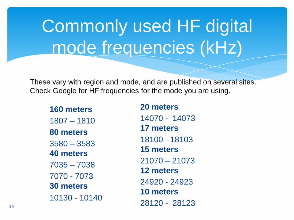
160 meters
1807 – 1810
80 meters
3580 – 3583
40 meters
7035 – 7038
7070 - 7073
30 meters
10130 - 10140
Commonly used HF digital
mode frequencies (kHz)
20 meters
14070 - 14073
17 meters
18100 - 18103
15 meters
21070 – 21073
12 meters
24920 - 24923
10 meters
28120 - 28123 19
These vary with region and mode, and are published on several sites.
Check Google for HF frequencies for the mode you are using.

▪ FLDigi
▪ Olivia on Linux
▪ sourceforge links
▪ West Mountain Radio's links
▪ JT65
▪ PSK31 DLL
Where to find source code
20

Example
21
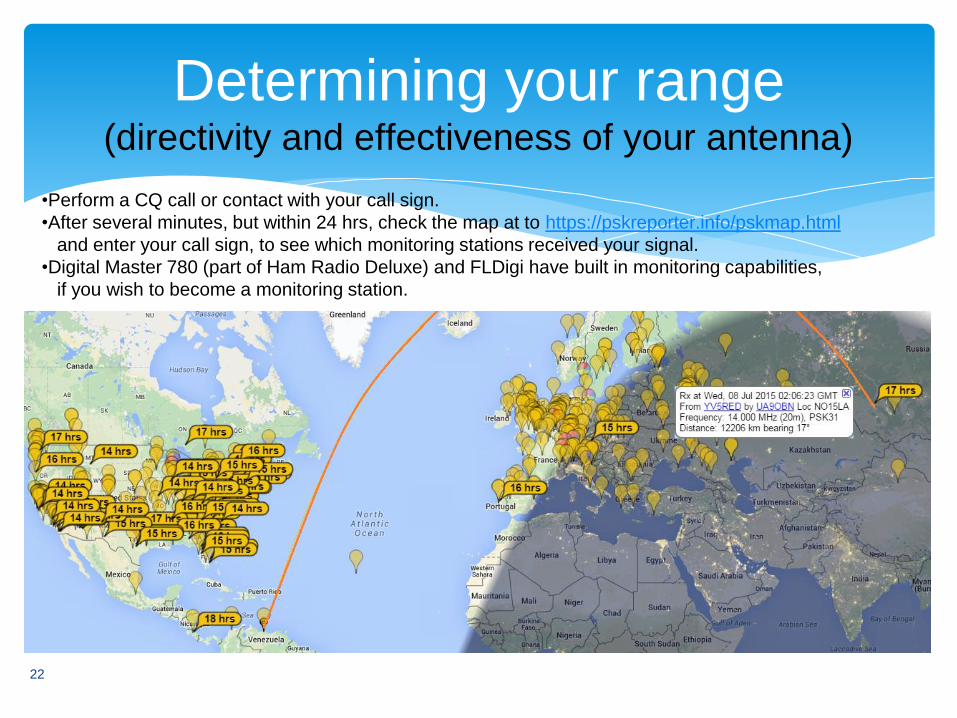
Determining your range (directivity and effectiveness of your antenna)
22
•Perform a CQ call or contact with your call sign.
•After several minutes, but within 24 hrs, check the map at to https://pskreporter.info/pskmap.html
and enter your call sign, to see which monitoring stations received your signal.
•Digital Master 780 (part of Ham Radio Deluxe) and FLDigi have built in monitoring capabilities,
if you wish to become a monitoring station.

http://www.speroni.com/FCC/Licenses.html www.artechhouse.com/uploads/.../xiong_863_ch04.pdf www.wikipedia.com http://ee.eng.usm.my/eeacad/mandeep/EEE436/CHAPTER2.pdf http://ijater.com/Files/d8bf7da6-cc28-499a-9598-44dbde2a48c8_ICETT_03_10.pdf http://www.control.aau.dk/~kresten/stuff/GND/FSK_signals_demod.pdf http://cs.unomaha.edu/~stanw/psk31/intro.pdf http://www.arrl.org/files/file/Technology/tis/info/pdf/0101033.pdf http://www.arrl.org/files/file/Technology/tis/info/pdf/x9907003.pdf http://rf.harris.com/media/Radio%20Comms%20in%20the%20Digital%20Age%20-%201_tcm26-12947.pdf http://www.ti.com/lit/an/slaa618/slaa618.pdf http://www.ips.gov.au/Category/Educational/Other%20Topics/Radio%20Communication/Intro%20to%20HF%20Radio.pdf http://www.radio-electronics.com/info/propagation/ionospheric/ionosphere.php
References (this presentation can be found at
https://app.box.com/IeeeSPS-ham)
23