Sigma Control Kaeser
222
Service Manual Controller SIGMA CONTROL 2 SCREW FLUID ≥1.1.3 9_9450 03 HCE This manual is intendend as a guide to the installation, operation and maintenance of your HPC Screw Compressor. It is important from a safety point of view that the work of installing and maintaining the compressor is undertaken by trained personnel and should be entrusted to an HPC Authorised Distributor Victoria Gardens, Burgess Hill, West Sussex RH15 9RQ Telephone: +44 (0)1444 241671 ● Fax: +44 (0)1444 247304 [email protected] ● www.hpccompressors.co.uk Manufacturer: KAESER KOMPRESSOREN 96410 Coburg • PO Box 2143 • GERMANY • Tel. +49-(0)9561-6400 • Fax +49-(0)9561-640130 http://www.kaeser.com
-
Upload
cristinka-negura -
Category
Documents
-
view
1.786 -
download
103
Transcript of Sigma Control Kaeser
Service Manual
Controller
SIGMA CONTROL 2 SCREW FLUID ≥1.1.3
9_9450 03 HCE
This manual is intendend as a guide to the installation, operationand maintenance of your HPC Screw Compressor.It is important from a safety point of view that the work ofinstalling and maintaining the compressor is undertaken bytrained personnel and should be entrusted to an HPC Authorised Distributor
Victoria Gardens, Burgess Hill, West Sussex RH15 9RQTelephone: +44 (0)1444 241671 ● Fax: +44 (0)1444 247304 [email protected] ● www.hpccompressors.co.uk
Manufacturer:
KAESER KOMPRESSOREN
96410 Coburg • PO Box 2143 • GERMANY • Tel. +49-(0)9561-6400 • Fax +49-(0)9561-640130
http://www.kaeser.com

/KKW/SSC 2.03 en 02 BA-SIGMA CONTROL FLUID/KKW/SSC 2.03 0220130508 151238
Quick User Guide
Controller
SIGMA CONTROL 2 SCREW FLUID ≥1.1.3
9_9450 03 HCE
Manufacturer:
KAESER KOMPRESSOREN
96410 Coburg • PO Box 2143 • GERMANY • Tel. +49-(0)9561-6400 • Fax +49-(0)9561-640130
http://www.kaeser.com

1. Important settings ............................................................................................................. 12. Setting the contrast and the brightness ............................................................................ 23. Setting the display language ............................................................................................ 34. Logging on with Equipment Card ..................................................................................... 45. Adjusting the system setpoint pressure ........................................................................... 66. Activating the «clock» key. ............................................................................................... 77. Activate the «remote control» key .................................................................................... 108. Changing the control mode .............................................................................................. 139. Outputting important operational states of the machine ................................................... 1410. Resetting maintenance interval counters ......................................................................... 1511. Pressure relief valve checking ......................................................................................... 1712. Checking the temperature sensor and overheating shutdown function ........................... 2013. Interpreting operation messages ...................................................................................... 2214. Interpreting diagnostic messages .................................................................................... 2515. Interpreting fault messages .............................................................................................. 2616. Interpreting warning messages ........................................................................................ 3117. Interpreting system messages ......................................................................................... 36
Contents
9_9450 03 HCEQuick User Guide Controller SIGMA CONTROL 2 SCREW FLUID ≥1.1.3 i

Contents
iiQuick User Guide Controller SIGMA CONTROL 2 SCREW FLUID ≥1.1.3 9_9450 03 HCE
1 Important settingsIn this chapter, important or often used settings are explained in brief. Detailed information on func‐tion, configuration, fault removal and important instructions concerning safe operation are found insubsequent chapters.
Setting and other work on the machine may only be carried out by the following persons:■ persons trained on the machine/controller and persons instructed by and under the su‐
pervision of a specialist,■ trained technicians,■ authorised Service personnel.
1 Important settings
9_9450 03 HCEQuick User Guide Controller SIGMA CONTROL 2 SCREW FLUID ≥1.1.3 1
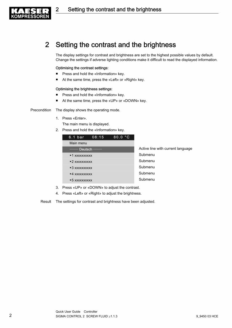
2 Setting the contrast and the brightnessThe display settings for contrast and brightness are set to the highest possible values by default.Change the settings if adverse lighting conditions make it difficult to read the displayed information.
Optimising the contrast settings:■ Press and hold the «Information» key.■ At the same time, press the «Left» or «Right» key.
Optimising the brightness settings:■ Press and hold the «Information» key.■ At the same time, press the «UP» or «DOWN» key.
Precondition The display shows the operating mode.
1. Press «Enter».The main menu is displayed.
2. Press and hold the «Information» key.
6 . 1 b a r 0 8 : 1 5 8 0 . 0 ° CMain menu
········· Deutsch ········· Active line with current language
▶1 xxxxxxxxxx Submenu
▶2 xxxxxxxxxx Submenu
▶3 xxxxxxxxxx Submenu
▶4 xxxxxxxxxx Submenu
▶5 xxxxxxxxxx Submenu
3. Press «UP» or «DOWN» to adjust the contrast.4. Press «Left» or «Right» to adjust the brightness.
Result The settings for contrast and brightness have been adjusted.
2 Setting the contrast and the brightness
2Quick User Guide Controller SIGMA CONTROL 2 SCREW FLUID ≥1.1.3 9_9450 03 HCE
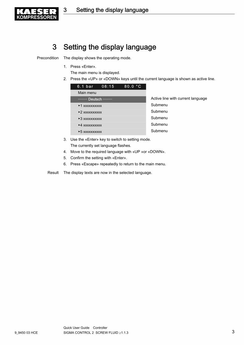
3 Setting the display languagePrecondition The display shows the operating mode.
1. Press «Enter».The main menu is displayed.
2. Press the «UP» or «DOWN» keys until the current language is shown as active line.
6 . 1 b a r 0 8 : 1 5 8 0 . 0 ° CMain menu
········· Deutsch ········· Active line with current language
▶1 xxxxxxxxxx Submenu
▶2 xxxxxxxxxx Submenu
▶3 xxxxxxxxxx Submenu
▶4 xxxxxxxxxx Submenu
▶5 xxxxxxxxxx Submenu
3. Use the «Enter» key to switch to setting mode.The currently set language flashes.
4. Move to the required language with «UP »or «DOWN».5. Confirm the setting with «Enter».6. Press «Escape» repeatedly to return to the main menu.
Result The display texts are now in the selected language.
3 Setting the display language
9_9450 03 HCEQuick User Guide Controller SIGMA CONTROL 2 SCREW FLUID ≥1.1.3 3
4 Logging on with Equipment CardProceed as follows:■ Take the plastic sleeve from the control cabinet.■ Remove one Equipment Card.■ Note the number on the reverse side of the Equipment Card.■ Safely store the number.■ Log on with Equipment Card
➤ Proceed in the prescribed sequence of actions.
Remove the Equipment Card from the control cabinet.
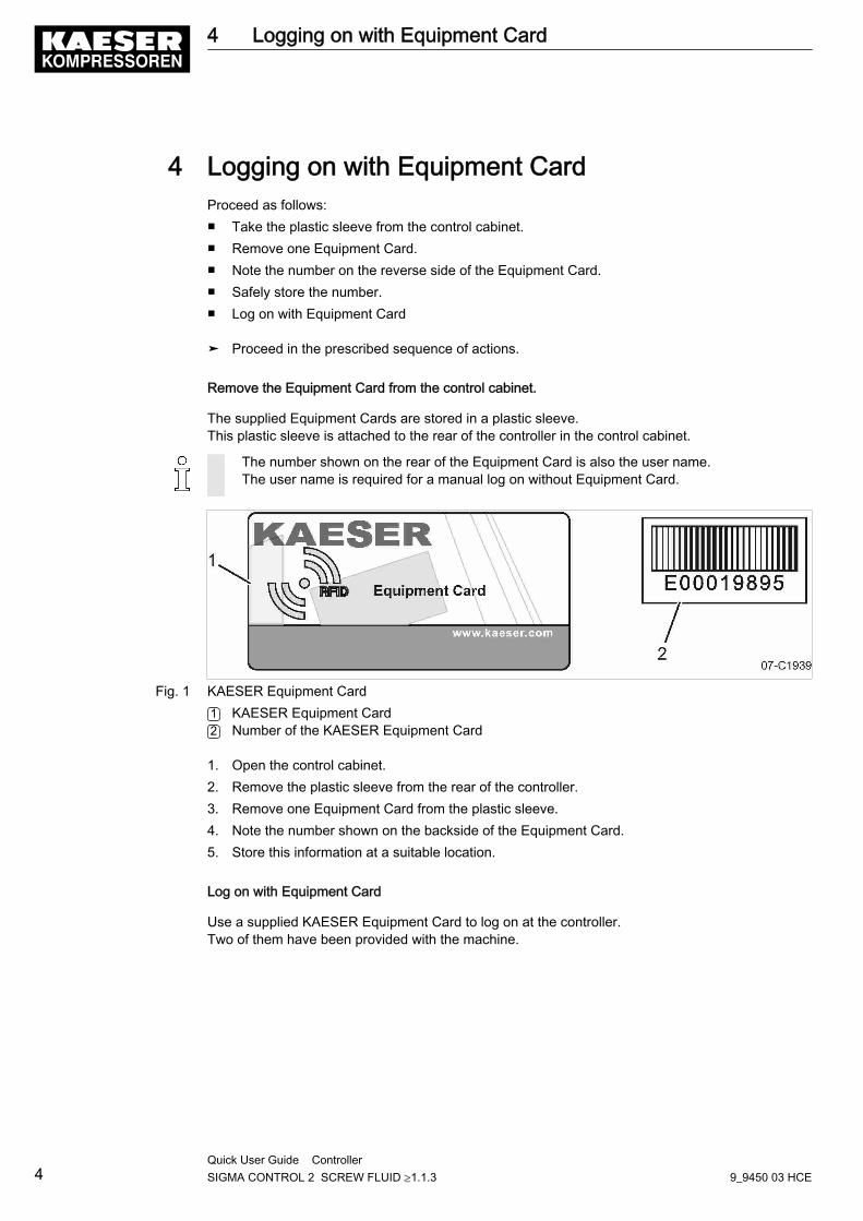
The supplied Equipment Cards are stored in a plastic sleeve.This plastic sleeve is attached to the rear of the controller in the control cabinet.
The number shown on the rear of the Equipment Card is also the user name.The user name is required for a manual log on without Equipment Card.
Fig. 1 KAESER Equipment Card1 KAESER Equipment Card2 Number of the KAESER Equipment Card
1. Open the control cabinet.2. Remove the plastic sleeve from the rear of the controller.3. Remove one Equipment Card from the plastic sleeve.4. Note the number shown on the backside of the Equipment Card.5. Store this information at a suitable location.
Log on with Equipment Card
Use a supplied KAESER Equipment Card to log on at the controller.Two of them have been provided with the machine.
4 Logging on with Equipment Card
4Quick User Guide Controller SIGMA CONTROL 2 SCREW FLUID ≥1.1.3 9_9450 03 HCE
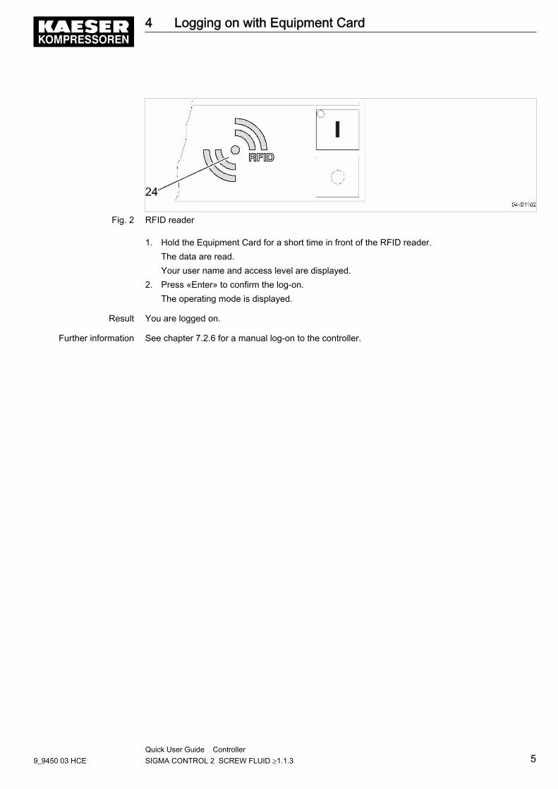
Fig. 2 RFID reader
1. Hold the Equipment Card for a short time in front of the RFID reader.The data are read.Your user name and access level are displayed.
2. Press «Enter» to confirm the log-on.The operating mode is displayed.
Result You are logged on.
Further information See chapter 7.2.6 for a manual log-on to the controller.
4 Logging on with Equipment Card
9_9450 03 HCEQuick User Guide Controller SIGMA CONTROL 2 SCREW FLUID ≥1.1.3 5
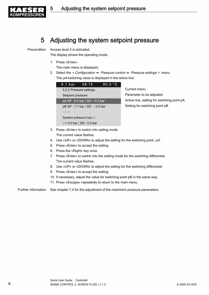
5 Adjusting the system setpoint pressurePrecondition Access level 2 is activated.
The display shows the operating mode.
1. Press «Enter».The main menu is displayed.
2. Select the < Configuration ➙ Pressure control ➙ Pressure settings > menu.The pA switching value is displayed in the active line.
6 . 1 b a r 0 8 : 1 5 8 0 . 0 ° C5.2.2 Pressure settings Current menu
Setpoint pressure Parameter to be adjusted
pA SP : 8.0 bar ¦ SD : -0.5 bar Active line, setting for switching point pA
pB SP : 7.7 bar ¦ SD : - 0.5 bar Setting for switching point pB
·········
System pressure low ☐
↓< 5.0 bar ¦ SD : 0.5 bar
3. Press «Enter» to switch into setting mode.The current value flashes.
4. Use «UP» or «DOWN» to adjust the setting for the switching point pA .5. Press «Enter» to accept the setting.6. Press the «Right» key once.7. Press «Enter» to switch into the setting mode for the switching differential.
The current value flashes.8. Use «UP» or «DOWN» to adjust the setting for the switching differential.9. Press «Enter» to accept the setting.10. If necessary, adjust the value for switching point pB in the same way.11. Press «Escape» repeatedly to return to the main menu.
Further information See chapter 7.4 for the adjustment of the machine's pressure parameters.
5 Adjusting the system setpoint pressure
6Quick User Guide Controller SIGMA CONTROL 2 SCREW FLUID ≥1.1.3 9_9450 03 HCE
6 Activating the «clock» key.Activating/deactivating the check box
Check box Check box for reset Status
☑ ☒ activated
☐ ☐ deactivated
Tab. 1 Check box status
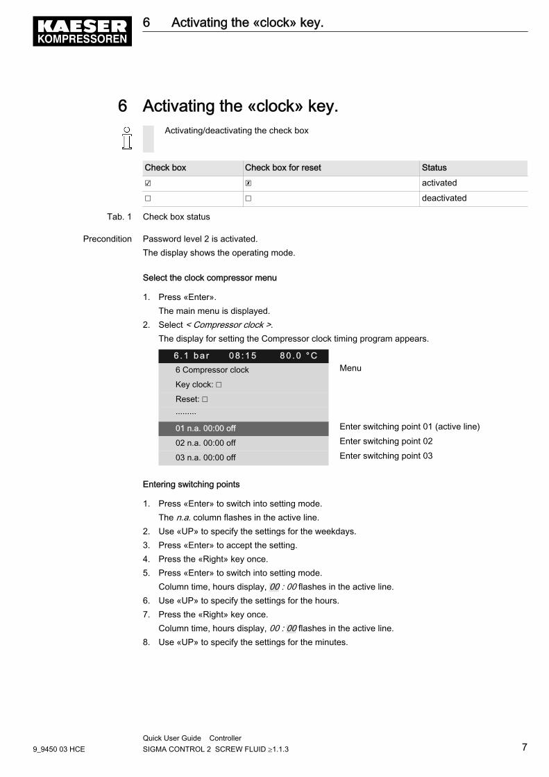
Precondition Password level 2 is activated.The display shows the operating mode.
Select the clock compressor menu
1. Press «Enter».The main menu is displayed.
2. Select < Compressor clock >.The display for setting the Compressor clock timing program appears.
6 . 1 b a r 0 8 : 1 5 8 0 . 0 ° C6 Compressor clock Menu
Key clock: ☐
Reset: ☐
·········
01 n.a. 00:00 off Enter switching point 01 (active line)
02 n.a. 00:00 off Enter switching point 02
03 n.a. 00:00 off Enter switching point 03
Entering switching points
1. Press «Enter» to switch into setting mode.The n.a. column flashes in the active line.
2. Use «UP» to specify the settings for the weekdays.3. Press «Enter» to accept the setting.4. Press the «Right» key once.5. Press «Enter» to switch into setting mode.
Column time, hours display, 00 : 00 flashes in the active line.6. Use «UP» to specify the settings for the hours.7. Press the «Right» key once.
Column time, hours display, 00 : 00 flashes in the active line.8. Use «UP» to specify the settings for the minutes.
6 Activating the «clock» key.
9_9450 03 HCEQuick User Guide Controller SIGMA CONTROL 2 SCREW FLUID ≥1.1.3 7
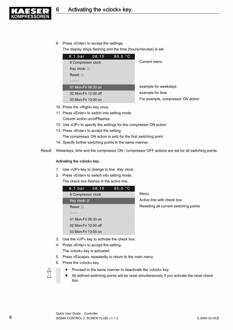
9. Press «Enter» to accept the settings.The display stops flashing and the time (hours/minutes) is set.
6 . 1 b a r 0 8 : 1 5 8 0 . 0 ° C6 Compressor clock Current menu
Key clock: ☐
Reset: ☐
·········
01 Mon-Fri 06:30 on example for weekdays
02 Mon-Fri 12:00 off example for time
03 Mon-Fri 13:00 on For example, compressor ON action
10. Press the «Right» key once.11. Press «Enter» to switch into setting mode.
Column action on/off flashes.12. Use «UP» to specify the settings for the compressor ON action.13. Press «Enter» to accept the setting.
The compressor ON action is setz for the first switching point.14. Specify further switching points in the same manner.
Result Weekdays, time and the compressor ON / compressor OFF actions are set for all switching points.
Activating the «clock» key.
1. Use «UP» key to change to line Key clock .2. Press «Enter» to switch into setting mode.
The check box flashes in the active line.
6 . 1 b a r 0 8 : 1 5 8 0 . 0 ° C6 Compressor clock Menu
Key clock: ☑ Active line with check box
Reset: ☐ Resetting all current switching points
·········
01 Mon-Fri 06:30 on
02 Mon-Fri 12:00 off
03 Mon-Fri 13:00 on
3. Use the «UP» key to activate the check box.4. Press «Enter» to accept the setting.
The «clock» key is activated.5. Press «Escape» repeatedly to return to the main menu.6. Press the «clock» key.
■ Proceed in the same manner to deactivate the «clock» key.■ All defined switching points will be reset simultaneously if you activate the reset check
box.
6 Activating the «clock» key.
8Quick User Guide Controller SIGMA CONTROL 2 SCREW FLUID ≥1.1.3 9_9450 03 HCE

Result The machine runs according to the defined switching points of the clock program.
Further information See chapter 7.5 for configuration of starting and stopping the machine.See chapter 7.8.2 for configuration of load changeover based on a clock program.
6 Activating the «clock» key.
9_9450 03 HCEQuick User Guide Controller SIGMA CONTROL 2 SCREW FLUID ≥1.1.3 9
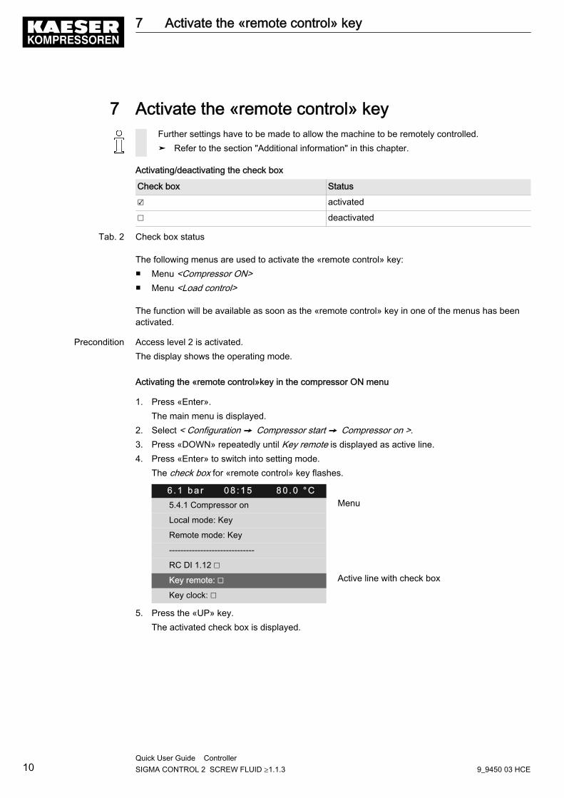
7 Activate the «remote control» keyFurther settings have to be made to allow the machine to be remotely controlled.➤ Refer to the section "Additional information" in this chapter.
Activating/deactivating the check box
Check box Status
☑ activated
☐ deactivated
Tab. 2 Check box status
The following menus are used to activate the «remote control» key:■ Menu <Compressor ON>■ Menu <Load control>
The function will be available as soon as the «remote control» key in one of the menus has beenactivated.
Precondition Access level 2 is activated.The display shows the operating mode.
Activating the «remote control»key in the compressor ON menu
1. Press «Enter».The main menu is displayed.
2. Select < Configuration ➙ Compressor start ➙ Compressor on >.3. Press «DOWN» repeatedly until Key remote is displayed as active line.4. Press «Enter» to switch into setting mode.
The check box for «remote control» key flashes.
6 . 1 b a r 0 8 : 1 5 8 0 . 0 ° C5.4.1 Compressor on Menu
Local mode: Key
Remote mode: Key
------------------------------
RC DI 1.12 ☐
Key remote: ☐ Active line with check box
Key clock: ☐
5. Press the «UP» key.The activated check box is displayed.
7 Activate the «remote control» key
10Quick User Guide Controller SIGMA CONTROL 2 SCREW FLUID ≥1.1.3 9_9450 03 HCE
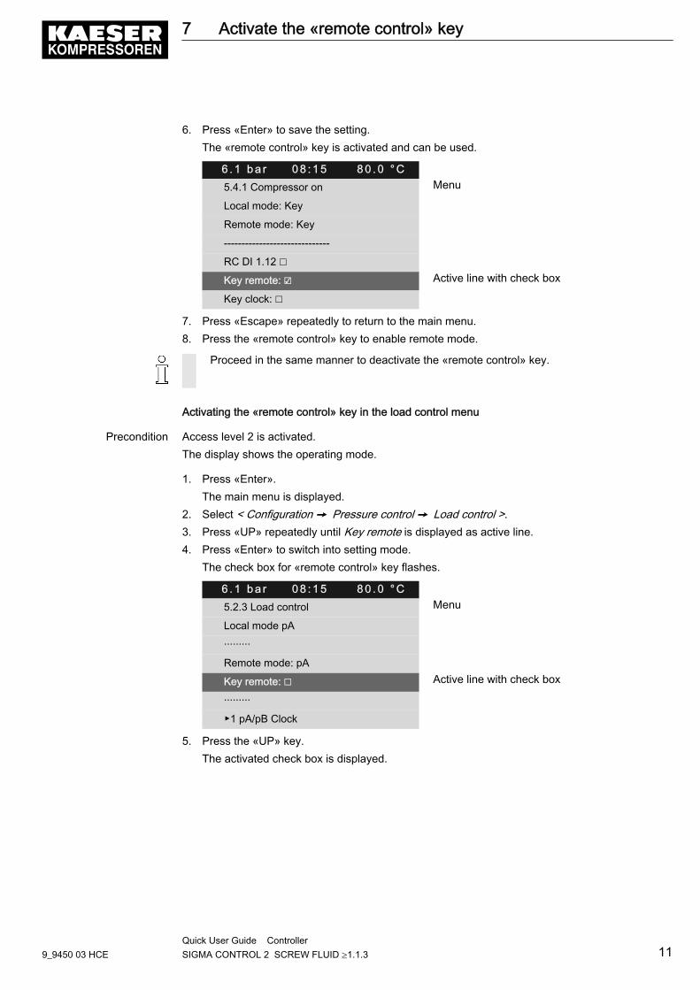
6. Press «Enter» to save the setting.The «remote control» key is activated and can be used.
6 . 1 b a r 0 8 : 1 5 8 0 . 0 ° C5.4.1 Compressor on Menu
Local mode: Key
Remote mode: Key
------------------------------
RC DI 1.12 ☐
Key remote: ☑ Active line with check box
Key clock: ☐
7. Press «Escape» repeatedly to return to the main menu.8. Press the «remote control» key to enable remote mode.
Proceed in the same manner to deactivate the «remote control» key.
Activating the «remote control» key in the load control menu
Precondition Access level 2 is activated.The display shows the operating mode.
1. Press «Enter».The main menu is displayed.
2. Select < Configuration ➙ Pressure control ➙ Load control >.3. Press «UP» repeatedly until Key remote is displayed as active line.4. Press «Enter» to switch into setting mode.
The check box for «remote control» key flashes.
6 . 1 b a r 0 8 : 1 5 8 0 . 0 ° C5.2.3 Load control Menu
Local mode pA
·········
Remote mode: pA
Key remote: ☐ Active line with check box
·········
▶1 pA/pB Clock
5. Press the «UP» key.The activated check box is displayed.
7 Activate the «remote control» key
9_9450 03 HCEQuick User Guide Controller SIGMA CONTROL 2 SCREW FLUID ≥1.1.3 11
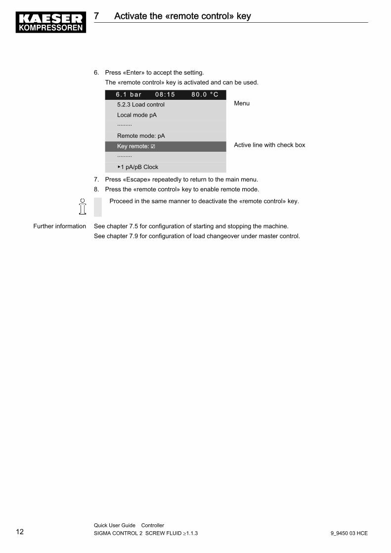
6. Press «Enter» to accept the setting.The «remote control» key is activated and can be used.
6 . 1 b a r 0 8 : 1 5 8 0 . 0 ° C5.2.3 Load control Menu
Local mode pA
·········
Remote mode: pA
Key remote: ☑ Active line with check box
·········
▶1 pA/pB Clock
7. Press «Escape» repeatedly to return to the main menu.8. Press the «remote control» key to enable remote mode.
Proceed in the same manner to deactivate the «remote control» key.
Further information See chapter 7.5 for configuration of starting and stopping the machine.See chapter 7.9 for configuration of load changeover under master control.
7 Activate the «remote control» key
12Quick User Guide Controller SIGMA CONTROL 2 SCREW FLUID ≥1.1.3 9_9450 03 HCE
8 Changing the control modeThe standard setting of the control mode depends on the machine type.As an example, the change from DUAL to QUADRO control mode is described below.
Precondition Access level 2 is activated.The display shows the operating mode.
1. Press «Enter».The main menu is displayed.
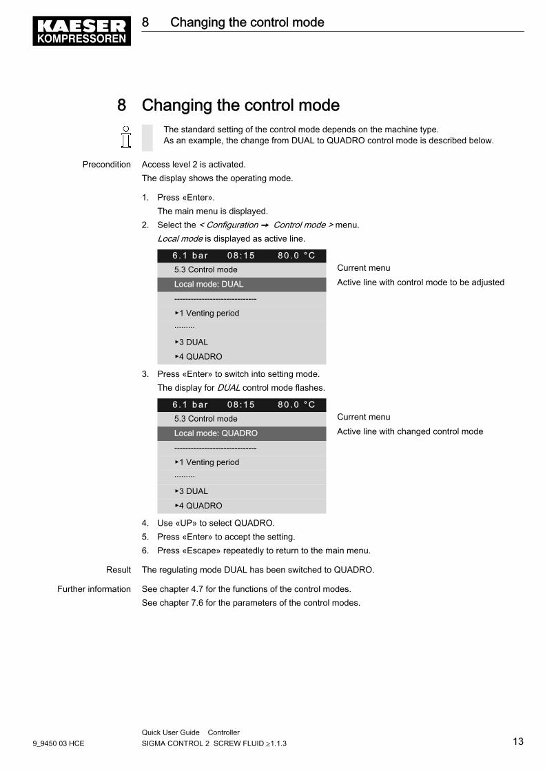
2. Select the < Configuration ➙ Control mode > menu.Local mode is displayed as active line.
6 . 1 b a r 0 8 : 1 5 8 0 . 0 ° C5.3 Control mode Current menu
Local mode: DUAL Active line with control mode to be adjusted
------------------------------
▶1 Venting period
·········
▶3 DUAL
▶4 QUADRO
3. Press «Enter» to switch into setting mode.The display for DUAL control mode flashes.
6 . 1 b a r 0 8 : 1 5 8 0 . 0 ° C5.3 Control mode Current menu
Local mode: QUADRO Active line with changed control mode
------------------------------
▶1 Venting period
·········
▶3 DUAL
▶4 QUADRO
4. Use «UP» to select QUADRO.5. Press «Enter» to accept the setting.6. Press «Escape» repeatedly to return to the main menu.
Result The regulating mode DUAL has been switched to QUADRO.
Further information See chapter 4.7 for the functions of the control modes.See chapter 7.6 for the parameters of the control modes.
8 Changing the control mode
9_9450 03 HCEQuick User Guide Controller SIGMA CONTROL 2 SCREW FLUID ≥1.1.3 13
9 Outputting important operational states of the ma‐chineImportant operational machine states can be assigned via floating relay contacts as a binary signalon the outputs DOR 1.05 – DOR 1.07. Further outputs are optionally available. You can assign ev‐ery output only once.
Precondition Access level 2 is activated.The display shows the operating mode.
Configuration ➙ I/O Periphery ➙ DO Functions menu
1. Press «Enter».The main menu is displayed.
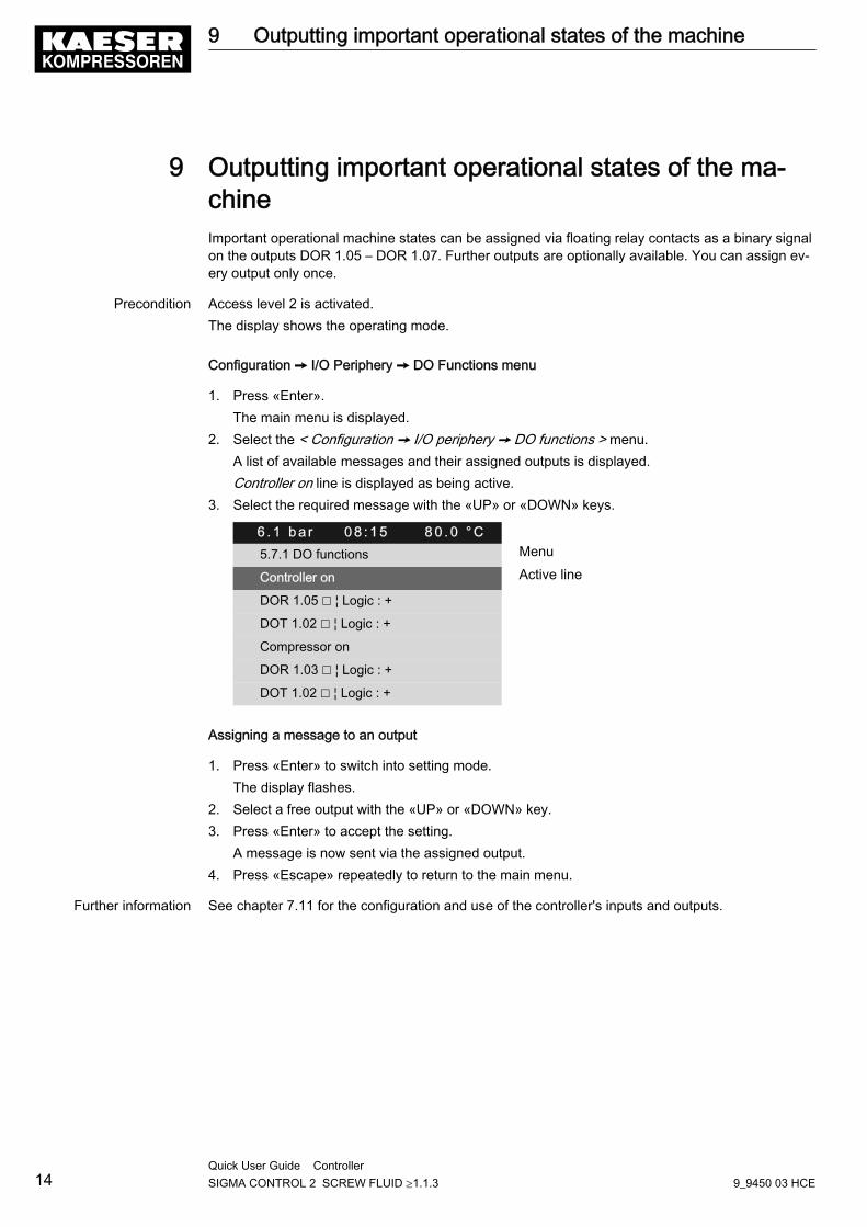
2. Select the < Configuration ➙ I/O periphery ➙ DO functions > menu.A list of available messages and their assigned outputs is displayed.Controller on line is displayed as being active.
3. Select the required message with the «UP» or «DOWN» keys.
6 . 1 b a r 0 8 : 1 5 8 0 . 0 ° C5.7.1 DO functions Menu
Controller on Active line
DOR 1.05 ☐ ¦ Logic : +
DOT 1.02 ☐ ¦ Logic : +
Compressor on
DOR 1.03 ☐ ¦ Logic : +
DOT 1.02 ☐ ¦ Logic : +
Assigning a message to an output
1. Press «Enter» to switch into setting mode.The display flashes.
2. Select a free output with the «UP» or «DOWN» key.3. Press «Enter» to accept the setting.
A message is now sent via the assigned output.4. Press «Escape» repeatedly to return to the main menu.
Further information See chapter 7.11 for the configuration and use of the controller's inputs and outputs.
9 Outputting important operational states of the machine
14Quick User Guide Controller SIGMA CONTROL 2 SCREW FLUID ≥1.1.3 9_9450 03 HCE
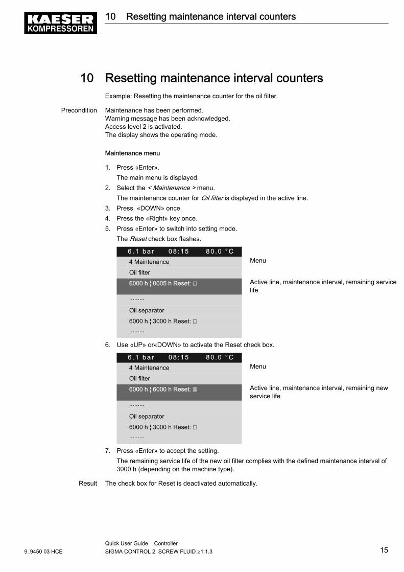
10 Resetting maintenance interval countersExample: Resetting the maintenance counter for the oil filter.
Precondition Maintenance has been performed.Warning message has been acknowledged.Access level 2 is activated.The display shows the operating mode.
Maintenance menu
1. Press «Enter».The main menu is displayed.
2. Select the < Maintenance > menu.The maintenance counter for Oil filter is displayed in the active line.
3. Press «DOWN» once.4. Press the «Right» key once.5. Press «Enter» to switch into setting mode.
The Reset check box flashes.
6 . 1 b a r 0 8 : 1 5 8 0 . 0 ° C4 Maintenance Menu
Oil filter
6000 h ¦ 0005 h Reset: ☐ Active line, maintenance interval, remaining servicelife
·········
Oil separator
6000 h ¦ 3000 h Reset: ☐
·········
6. Use «UP» or«DOWN» to activate the Reset check box.
6 . 1 b a r 0 8 : 1 5 8 0 . 0 ° C4 Maintenance Menu
Oil filter
6000 h ¦ 6000 h Reset: ☒ Active line, maintenance interval, remaining newservice life
·········
Oil separator
6000 h ¦ 3000 h Reset: ☐
·········
7. Press «Enter» to accept the setting.The remaining service life of the new oil filter complies with the defined maintenance interval of3000 h (depending on the machine type).
Result The check box for Reset is deactivated automatically.
10 Resetting maintenance interval counters
9_9450 03 HCEQuick User Guide Controller SIGMA CONTROL 2 SCREW FLUID ≥1.1.3 15
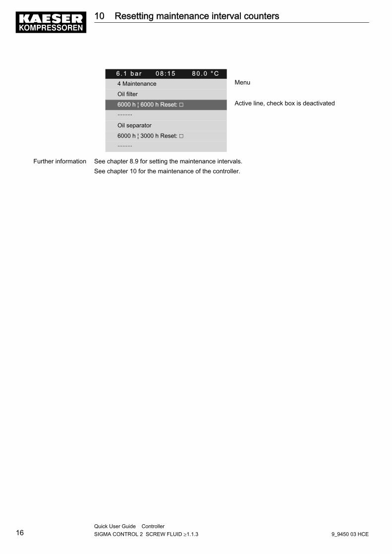
6 . 1 b a r 0 8 : 1 5 8 0 . 0 ° C4 Maintenance Menu
Oil filter
6000 h ¦ 6000 h Reset: ☐ Active line, check box is deactivated
·········
Oil separator
6000 h ¦ 3000 h Reset: ☐
·········
Further information See chapter 8.9 for setting the maintenance intervals.See chapter 10 for the maintenance of the controller.
10 Resetting maintenance interval counters
16Quick User Guide Controller SIGMA CONTROL 2 SCREW FLUID ≥1.1.3 9_9450 03 HCE
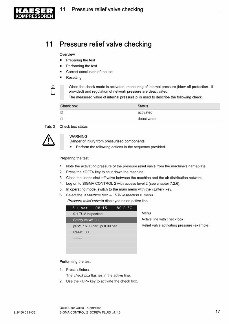
11 Pressure relief valve checkingOverview■ Preparing the test■ Performing the test■ Correct conclusion of the test■ Resetting
When the check mode is activated, monitoring of internal pressure (blow-off protection - ifprovided) and regulation of network pressure are deactivated.The measured value of internal pressure pi is used to describe the following check.
Check box Status
☑ activated
☐ deactivated
Tab. 3 Check box status
WARNINGDanger of injury from pressurised components!➤ Perform the following actions in the sequence provided.
Preparing the test
1. Note the activating pressure of the pressure relief valve from the machine's nameplate.2. Press the «OFF» key to shut down the machine.3. Close the user's shut-off valve between the machine and the air distribution network.4. Log on to SIGMA CONTROL 2 with access level 2 (see chapter 7.2.6).5. In operating mode, switch to the main menu with the «Enter» key.6. Select the < Machine test ➙ TÜV inspection > menu.
Pressure relief valve is displayed as an active line.
6 . 1 b a r 0 8 : 1 5 8 0 . 0 ° C9.1 TÜV inspection Menu
Safety valve: ☐ Active line with check box
pRV: 16.00 bar ¦ pi 0.00 bar Relief valve activating pressure (example)
Reset: ☐
·········
Performing the test
1. Press «Enter».The check box flashes in the active line.
2. Use the «UP» key to activate the check box.
11 Pressure relief valve checking
9_9450 03 HCEQuick User Guide Controller SIGMA CONTROL 2 SCREW FLUID ≥1.1.3 17
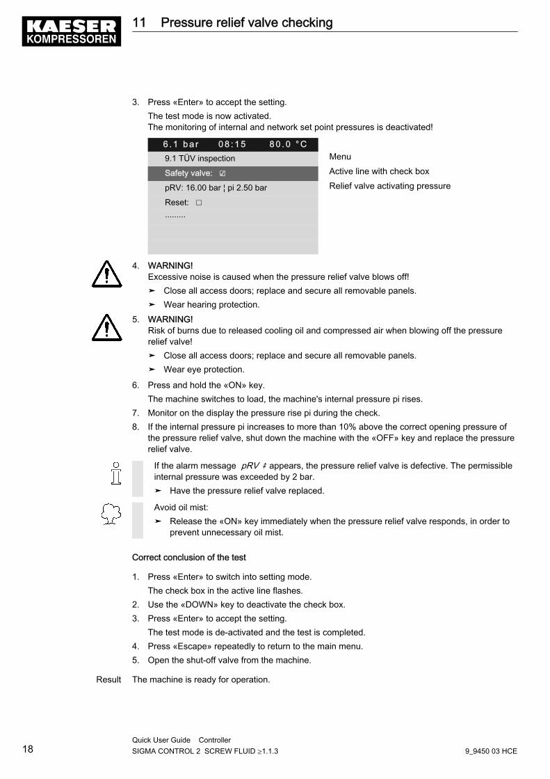
3. Press «Enter» to accept the setting.The test mode is now activated.The monitoring of internal and network set point pressures is deactivated!
6 . 1 b a r 0 8 : 1 5 8 0 . 0 ° C9.1 TÜV inspection Menu
Safety valve: ☑ Active line with check box
pRV: 16.00 bar ¦ pi 2.50 bar Relief valve activating pressure
Reset: ☐
·········
4. WARNING! Excessive noise is caused when the pressure relief valve blows off!➤ Close all access doors; replace and secure all removable panels.➤ Wear hearing protection.
5. WARNING! Risk of burns due to released cooling oil and compressed air when blowing off the pressurerelief valve!➤ Close all access doors; replace and secure all removable panels.➤ Wear eye protection.
6. Press and hold the «ON» key.The machine switches to load, the machine's internal pressure pi rises.
7. Monitor on the display the pressure rise pi during the check.8. If the internal pressure pi increases to more than 10% above the correct opening pressure of
the pressure relief valve, shut down the machine with the «OFF» key and replace the pressurerelief valve.
If the alarm message pRV ⇞ appears, the pressure relief valve is defective. The permissibleinternal pressure was exceeded by 2 bar.➤ Have the pressure relief valve replaced.
Avoid oil mist:➤ Release the «ON» key immediately when the pressure relief valve responds, in order to
prevent unnecessary oil mist.
Correct conclusion of the test
1. Press «Enter» to switch into setting mode.The check box in the active line flashes.
2. Use the «DOWN» key to deactivate the check box.3. Press «Enter» to accept the setting.
The test mode is de-activated and the test is completed.4. Press «Escape» repeatedly to return to the main menu.5. Open the shut-off valve from the machine.
Result The machine is ready for operation.
11 Pressure relief valve checking
18Quick User Guide Controller SIGMA CONTROL 2 SCREW FLUID ≥1.1.3 9_9450 03 HCE
Resetting
If the test is canceled when opening the pressure relief valve, SIGMA CONTROL 2 will indicate thehighest measured value as internal pressure.Activate the check box for reset in order to reset the stored value.➤ Activate the check box.
Further information See chapter 8.10 to test the pressure relief valve.
11 Pressure relief valve checking
9_9450 03 HCEQuick User Guide Controller SIGMA CONTROL 2 SCREW FLUID ≥1.1.3 19
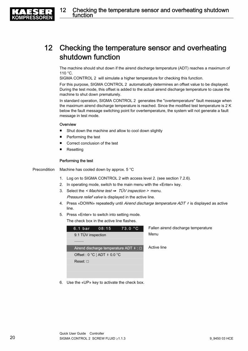
12 Checking the temperature sensor and overheatingshutdown functionThe machine should shut down if the airend discharge temperature (ADT) reaches a maximum of110 °C.SIGMA CONTROL 2 will simulate a higher temperature for checking this function.For this purpose, SIGMA CONTROL 2 automatically determines an offset value to be displayed.During the test mode, this offset is added to the actual airend discharge temperature to cause themachine to shut down prematurely.In standard operation, SIGMA CONTROL 2 generates the "overtemperature" fault message whenthe maximum airend discharge temperature is reached. Since the modified test temperature is 2 Kbelow the fault message switching point for overtemperature, the system will not generate a faultmessage in test mode.
Overview■ Shut down the machine and allow to cool down slightly■ Performing the test■ Correct conclusion of the test■ Resetting
Performing the test
Precondition Machine has cooled down by approx. 5 °C
1. Log on to SIGMA CONTROL 2 with access level 2. (see section 7.2.6).2. In operating mode, switch to the main menu with the «Enter» key.3. Select the < Machine test ➙ TÜV inspection > menu.
Pressure relief valve is displayed in the active line.4. Press «DOWN» repeatedly until Airend discharge temperature ADT ⇞ is displayed as active
line.5. Press «Enter» to switch into setting mode.
The check box in the active line flashes.
6 . 1 b a r 0 8 : 1 5 7 3 . 0 ° C Fallen airend discharge temperature
9.1 TÜV inspection Menu
·········
Airend discharge temperature ADT ⇞ : ☐ Active line
Offset : 0 °C ¦ ADT ⇞ 0.0 °C
Reset: ☐
6. Use the «UP» key to activate the check box.
12 Checking the temperature sensor and overheating shutdownfunction
20Quick User Guide Controller SIGMA CONTROL 2 SCREW FLUID ≥1.1.3 9_9450 03 HCE
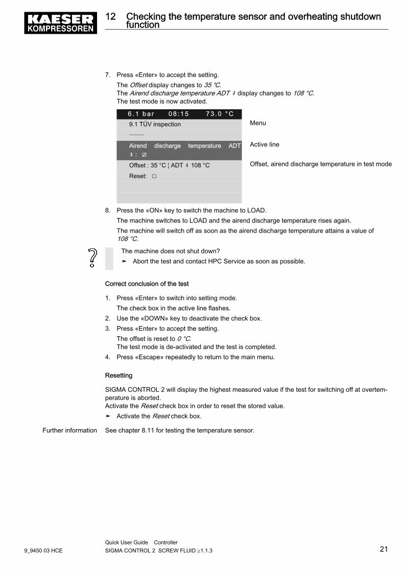
7. Press «Enter» to accept the setting.The Offset display changes to 35 ℃.The Airend discharge temperature ADT ⇞ display changes to 108 °C.The test mode is now activated.
6 . 1 b a r 0 8 : 1 5 7 3 . 0 ° C9.1 TÜV inspection Menu
·········
Airend discharge temperature ADT⇞ : ☑
Active line
Offset : 35 °C ¦ ADT ⇞ 108 °C Offset, airend discharge temperature in test mode
Reset: ☐
8. Press the «ON» key to switch the machine to LOAD.The machine switches to LOAD and the airend discharge temperature rises again.The machine will switch off as soon as the airend discharge temperature attains a value of108 °C.
The machine does not shut down?➤ Abort the test and contact HPC Service as soon as possible.
Correct conclusion of the test
1. Press «Enter» to switch into setting mode.The check box in the active line flashes.
2. Use the «DOWN» key to deactivate the check box.3. Press «Enter» to accept the setting.
The offset is reset to 0 °C.The test mode is de-activated and the test is completed.
4. Press «Escape» repeatedly to return to the main menu.
Resetting
SIGMA CONTROL 2 will display the highest measured value if the test for switching off at overtem‐perature is aborted.Activate the Reset check box in order to reset the stored value.➤ Activate the Reset check box.
Further information See chapter 8.11 for testing the temperature sensor.
12 Checking the temperature sensor and overheating shutdownfunction
9_9450 03 HCEQuick User Guide Controller SIGMA CONTROL 2 SCREW FLUID ≥1.1.3 21
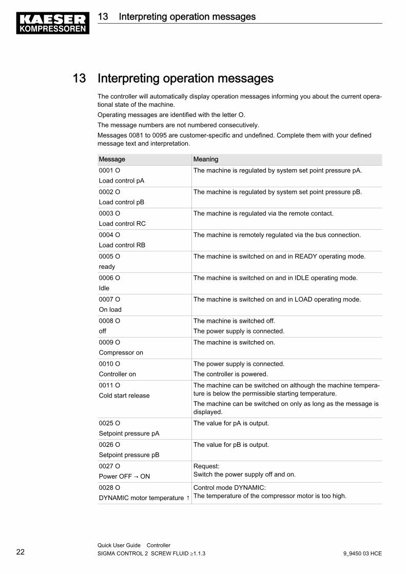
13 Interpreting operation messagesThe controller will automatically display operation messages informing you about the current opera‐tional state of the machine.Operating messages are identified with the letter O.The message numbers are not numbered consecutively.Messages 0081 to 0095 are customer-specific and undefined. Complete them with your definedmessage text and interpretation.
Message Meaning
0001 OLoad control pA
The machine is regulated by system set point pressure pA.
0002 OLoad control pB
The machine is regulated by system set point pressure pB.
0003 OLoad control RC
The machine is regulated via the remote contact.
0004 OLoad control RB
The machine is remotely regulated via the bus connection.
0005 Oready
The machine is switched on and in READY operating mode.
0006 OIdle
The machine is switched on and in IDLE operating mode.
0007 OOn load
The machine is switched on and in LOAD operating mode.
0008 Ooff
The machine is switched off.The power supply is connected.
0009 OCompressor on
The machine is switched on.
0010 OController on
The power supply is connected.The controller is powered.
0011 OCold start release
The machine can be switched on although the machine tempera‐ture is below the permissible starting temperature.The machine can be switched on only as long as the message isdisplayed.
0025 OSetpoint pressure pA
The value for pA is output.
0026 OSetpoint pressure pB
The value for pB is output.
0027 OPower OFF → ON
Request:Switch the power supply off and on.
0028 ODYNAMIC motor temperature ↑
Control mode DYNAMIC:The temperature of the compressor motor is too high.
13 Interpreting operation messages
22Quick User Guide Controller SIGMA CONTROL 2 SCREW FLUID ≥1.1.3 9_9450 03 HCE
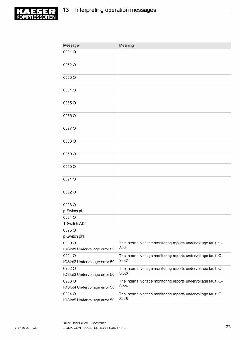
Message Meaning
0081 O
0082 O
0083 O
0084 O
0085 O
0086 O
0087 O
0088 O
0089 O
0090 O
0091 O
0092 O
0093 Op-Switch pi
0094 OT-Switch ADT
0095 Op-Switch pN
0200 OIOSlot1 Undervoltage error 50
The internal voltage monitoring reports undervoltage fault IO‐Slot1
0201 OIOSlot2 Undervoltage error 50
The internal voltage monitoring reports undervoltage fault IO‐Slot2
0202 OIOSlot3 Undervoltage error 50
The internal voltage monitoring reports undervoltage fault IO‐Slot3
0203 OIOSlot4 Undervoltage error 50
The internal voltage monitoring reports undervoltage fault IO‐Slot4
0204 OIOSlot5 Undervoltage error 50
The internal voltage monitoring reports undervoltage fault IO‐Slot5
13 Interpreting operation messages
9_9450 03 HCEQuick User Guide Controller SIGMA CONTROL 2 SCREW FLUID ≥1.1.3 23
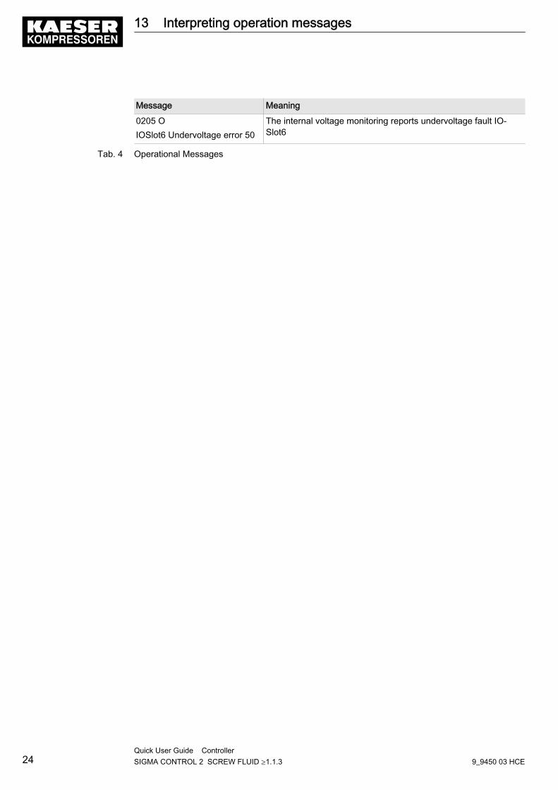
Message Meaning
0205 OIOSlot6 Undervoltage error 50
The internal voltage monitoring reports undervoltage fault IO‐Slot6
Tab. 4 Operational Messages
13 Interpreting operation messages
24Quick User Guide Controller SIGMA CONTROL 2 SCREW FLUID ≥1.1.3 9_9450 03 HCE

14 Interpreting diagnostic messagesDiagnostic messages are identified with the letter D.They provide information on the status of the controller, the connected input and output modulesand support the HPC service in trouble-shooting.
14 Interpreting diagnostic messages
9_9450 03 HCEQuick User Guide Controller SIGMA CONTROL 2 SCREW FLUID ≥1.1.3 25

15 Interpreting fault messagesAlarm messages are identified with the letter A.The message numbers are not numbered consecutively.Messages 0081 to 0095 are customer-specific and may differ from the suggested values. Com‐plete them with your defined message text, possible causes and remedies.
Message Possible cause Remedy0001 ADirection of rotation
The compressor drive motor isturning in the wrong direction.
Change overphase lines L1and L2.
0002 AMotor temperature ⇞
Compressor drive motor over‐heated.
Clean the motor.Keep ambientconditions withinspecified limits.
0003 ApRV ⇞
The activating pressure of thepressure relief valve on the oilseparator tank has been ex‐ceeded.
Change the pres‐sure relief valve.
0004 AEMERGENCY STOP
EMERGENCY STOP controldevice actuated.
Unlatch the push‐button.
0005 AOil separator Temperature ⇞
Maximum air temperature atthe oil separator tank outlet isexceeded.
Check the line tothe trip relay.
0007 APower supply monitor
Fault in mains power supply. Have the mainspower supplychecked.
0009 ASIGMA CONTROL 2 T⇞
Permissible enclosure temper‐ature for SIGMA CONTROL 2exceeded.
Keep ambientconditions withinspecified limits.Control cabinet:Check filter matsand fan.
0010 ABlow-off protection ⇞
The activating pressure of thepressure relief valve on the oilseparator tank has been ex‐ceeded.
Change the oilseparator car‐tridge.Open the shut-offvalve in the vent‐ing line.
0011 AOil-/air cooler fan Overcurrent
Overload shut-down of the firstfan motor.
Investigate causeof shut-down.Reset the over‐load relay.
0012 AAccess doors
Door open / interlocked panelremoved while the machine isrunning.
Fit and secure allpanels and closeaccess doors.
15 Interpreting fault messages
26Quick User Guide Controller SIGMA CONTROL 2 SCREW FLUID ≥1.1.3 9_9450 03 HCE
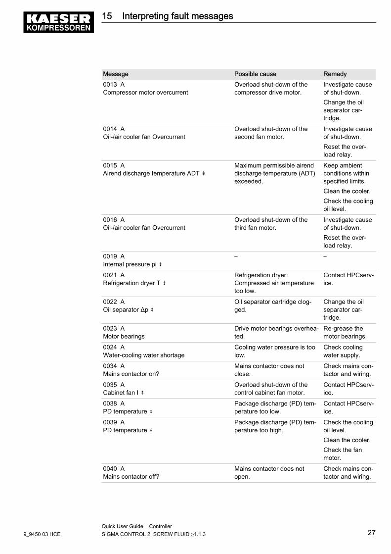
Message Possible cause Remedy0013 ACompressor motor overcurrent
Overload shut-down of thecompressor drive motor.
Investigate causeof shut-down.Change the oilseparator car‐tridge.
0014 AOil-/air cooler fan Overcurrent
Overload shut-down of thesecond fan motor.
Investigate causeof shut-down.Reset the over‐load relay.
0015 AAirend discharge temperature ADT ⇞
Maximum permissible airenddischarge temperature (ADT)exceeded.
Keep ambientconditions withinspecified limits.Clean the cooler.Check the coolingoil level.
0016 AOil-/air cooler fan Overcurrent
Overload shut-down of thethird fan motor.
Investigate causeof shut-down.Reset the over‐load relay.
0019 AInternal pressure pi ⇟
– –
0021 ARefrigeration dryer T ⇟
Refrigeration dryer:Compressed air temperaturetoo low.
Contact HPCserv‐ice.
0022 AOil separator Δp ⇞
Oil separator cartridge clog‐ged.
Change the oilseparator car‐tridge.
0023 AMotor bearings
Drive motor bearings overhea‐ted.
Re-grease themotor bearings.
0024 AWater-cooling water shortage
Cooling water pressure is toolow.
Check coolingwater supply.
0034 AMains contactor on?
Mains contactor does notclose.
Check mains con‐tactor and wiring.
0035 ACabinet fan I ⇞
Overload shut-down of thecontrol cabinet fan motor.
Contact HPCserv‐ice.
0038 APD temperature ⇟
Package discharge (PD) tem‐perature too low.
Contact HPCserv‐ice.
0039 APD temperature ⇞
Package discharge (PD) tem‐perature too high.
Check the coolingoil level.Clean the cooler.Check the fanmotor.
0040 AMains contactor off?
Mains contactor does notopen.
Check mains con‐tactor and wiring.
15 Interpreting fault messages
9_9450 03 HCEQuick User Guide Controller SIGMA CONTROL 2 SCREW FLUID ≥1.1.3 27
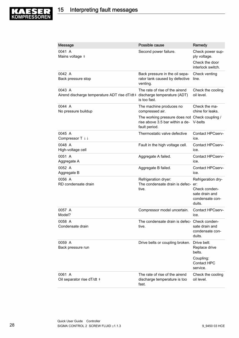
Message Possible cause Remedy0041 AMains voltage ⇟
Second power failure. Check power sup‐ply voltage.Check the doorinterlock switch.
0042 ABack pressure stop
Back pressure in the oil sepa‐rator tank caused by defectiveventing.
Check ventingline.
0043 AAirend discharge temperature ADT rise dT/dt⇞
The rate of rise of the airenddischarge temperature (ADT)is too fast.
Check the coolingoil level.
0044 ANo pressure buildup
The machine produces nocompressed air.The working pressure does notrise above 3.5 bar within a de‐fault period.
Check the ma‐chine for leaks.Check coupling /V-belts
0045 ACompressor T ↓↓
Thermostatic valve defective Contact HPCserv‐ice.
0048 AHigh-voltage cell
Fault in the high voltage cell. Contact HPCserv‐ice.
0051 AAggregate A
Aggregate A failed. Contact HPCserv‐ice.
0052 AAggregate B
Aggregate B failed. Contact HPCserv‐ice.
0056 ARD condensate drain
Refrigeration dryer:The condensate drain is defec‐tive.
Refrigeration dry‐er:Check conden‐sate drain andcondensate con‐duits.
0057 AModel?
Compressor model uncertain. Contact HPCserv‐ice.
0058 ACondensate drain
The condensate drain is defec‐tive.
Check conden‐sate drain andcondensate con‐duits.
0059 ABack pressure run
Drive belts or coupling broken. Drive belt:Replace drivebelts.Coupling:Contact HPCservice.
0061 AOil separator rise dT/dt ⇞
The rate of rise of the airenddischarge temperature is toofast.
Check the coolingoil level.
15 Interpreting fault messages
28Quick User Guide Controller SIGMA CONTROL 2 SCREW FLUID ≥1.1.3 9_9450 03 HCE
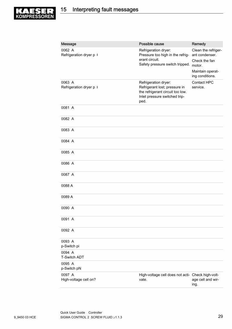
Message Possible cause Remedy0062 ARefrigeration dryer p ⇞
Refrigeration dryer:Pressure too high in the refrig‐erant circuit.Safety pressure switch tripped.
Clean the refriger‐ant condenser.Check the fanmotor.Maintain operat‐ing conditions.
0063 ARefrigeration dryer p ⇟
Refrigeration dryer:Refrigerant lost; pressure inthe refrigerant circuit too low.Inlet pressure switched trip‐ped.
Contact HPCservice.
0081 A
0082 A
0083 A
0084 A
0085 A
0086 A
0087 A
0088 A
0089 A
0090 A
0091 A
0092 A
0093 Ap-Switch pi
0094 AT-Switch ADT
0095 Ap-Switch pN
0097 AHigh-voltage cell on?
High-voltage cell does not acti‐vate.
Check high-volt‐age cell and wir‐ing.
15 Interpreting fault messages
9_9450 03 HCEQuick User Guide Controller SIGMA CONTROL 2 SCREW FLUID ≥1.1.3 29
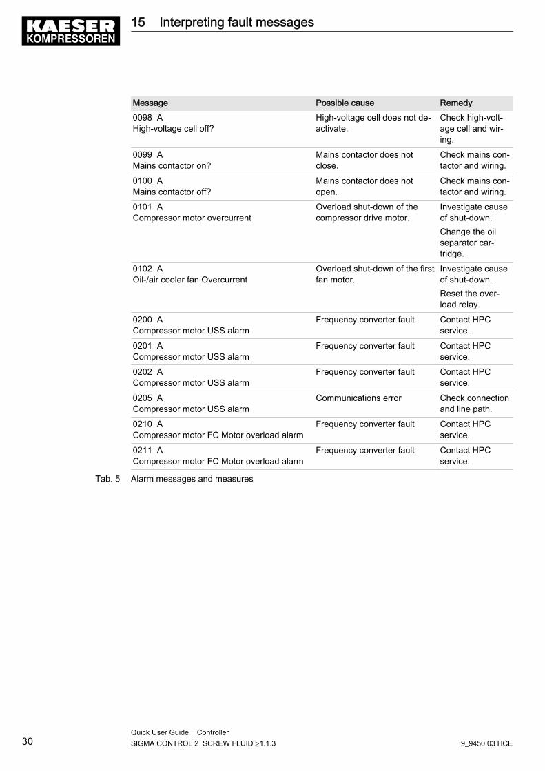
Message Possible cause Remedy0098 AHigh-voltage cell off?
High-voltage cell does not de‐activate.
Check high-volt‐age cell and wir‐ing.
0099 AMains contactor on?
Mains contactor does notclose.
Check mains con‐tactor and wiring.
0100 AMains contactor off?
Mains contactor does notopen.
Check mains con‐tactor and wiring.
0101 ACompressor motor overcurrent
Overload shut-down of thecompressor drive motor.
Investigate causeof shut-down.Change the oilseparator car‐tridge.
0102 AOil-/air cooler fan Overcurrent
Overload shut-down of the firstfan motor.
Investigate causeof shut-down.Reset the over‐load relay.
0200 ACompressor motor USS alarm
Frequency converter fault Contact HPCservice.
0201 ACompressor motor USS alarm
Frequency converter fault Contact HPCservice.
0202 ACompressor motor USS alarm
Frequency converter fault Contact HPCservice.
0205 ACompressor motor USS alarm
Communications error Check connectionand line path.
0210 ACompressor motor FC Motor overload alarm
Frequency converter fault Contact HPCservice.
0211 ACompressor motor FC Motor overload alarm
Frequency converter fault Contact HPCservice.
Tab. 5 Alarm messages and measures
15 Interpreting fault messages
30Quick User Guide Controller SIGMA CONTROL 2 SCREW FLUID ≥1.1.3 9_9450 03 HCE
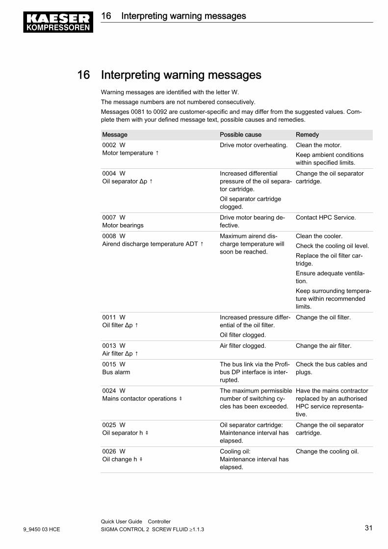
16 Interpreting warning messagesWarning messages are identified with the letter W.The message numbers are not numbered consecutively.Messages 0081 to 0092 are customer-specific and may differ from the suggested values. Com‐plete them with your defined message text, possible causes and remedies.
Message Possible cause Remedy0002 WMotor temperature ↑
Drive motor overheating. Clean the motor.Keep ambient conditionswithin specified limits.
0004 WOil separator Δp ↑
Increased differentialpressure of the oil separa‐tor cartridge.Oil separator cartridgeclogged.
Change the oil separatorcartridge.
0007 WMotor bearings
Drive motor bearing de‐fective.
Contact HPC Service.
0008 WAirend discharge temperature ADT ↑
Maximum airend dis‐charge temperature willsoon be reached.
Clean the cooler.Check the cooling oil level.Replace the oil filter car‐tridge.Ensure adequate ventila‐tion.Keep surrounding tempera‐ture within recommendedlimits.
0011 WOil filter Δp ↑
Increased pressure differ‐ential of the oil filter.Oil filter clogged.
Change the oil filter.
0013 WAir filter Δp ↑
Air filter clogged. Change the air filter.
0015 WBus alarm
The bus link via the Profi‐bus DP interface is inter‐rupted.
Check the bus cables andplugs.
0024 WMains contactor operations ⇞
The maximum permissiblenumber of switching cy‐cles has been exceeded.
Have the mains contractorreplaced by an authorisedHPC service representa‐tive.
0025 WOil separator h ⇞
Oil separator cartridge:Maintenance interval haselapsed.
Change the oil separatorcartridge.
0026 WOil change h ⇞
Cooling oil:Maintenance interval haselapsed.
Change the cooling oil.
16 Interpreting warning messages
9_9450 03 HCEQuick User Guide Controller SIGMA CONTROL 2 SCREW FLUID ≥1.1.3 31
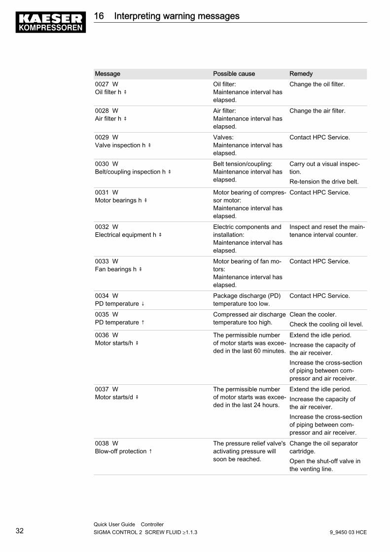
Message Possible cause Remedy0027 WOil filter h ⇞
Oil filter:Maintenance interval haselapsed.
Change the oil filter.
0028 WAir filter h ⇞
Air filter:Maintenance interval haselapsed.
Change the air filter.
0029 WValve inspection h ⇞
Valves:Maintenance interval haselapsed.
Contact HPC Service.
0030 WBelt/coupling inspection h ⇞
Belt tension/coupling:Maintenance interval haselapsed.
Carry out a visual inspec‐tion.Re-tension the drive belt.
0031 WMotor bearings h ⇞
Motor bearing of compres‐sor motor:Maintenance interval haselapsed.
Contact HPC Service.
0032 WElectrical equipment h ⇞
Electric components andinstallation:Maintenance interval haselapsed.
Inspect and reset the main‐tenance interval counter.
0033 WFan bearings h ⇞
Motor bearing of fan mo‐tors:Maintenance interval haselapsed.
Contact HPC Service.
0034 WPD temperature ↓
Package discharge (PD)temperature too low.
Contact HPC Service.
0035 WPD temperature ↑
Compressed air dischargetemperature too high.
Clean the cooler.Check the cooling oil level.
0036 WMotor starts/h ⇞
The permissible numberof motor starts was excee‐ded in the last 60 minutes.
Extend the idle period.Increase the capacity ofthe air receiver.Increase the cross-sectionof piping between com‐pressor and air receiver.
0037 WMotor starts/d ⇞
The permissible numberof motor starts was excee‐ded in the last 24 hours.
Extend the idle period.Increase the capacity ofthe air receiver.Increase the cross-sectionof piping between com‐pressor and air receiver.
0038 WBlow-off protection ↑
The pressure relief valve'sactivating pressure willsoon be reached.
Change the oil separatorcartridge.Open the shut-off valve inthe venting line.
16 Interpreting warning messages
32Quick User Guide Controller SIGMA CONTROL 2 SCREW FLUID ≥1.1.3 9_9450 03 HCE
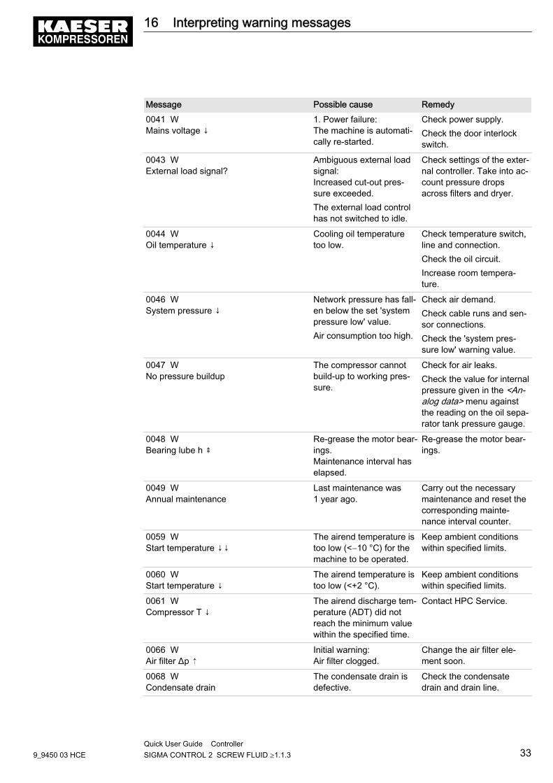
Message Possible cause Remedy0041 WMains voltage ↓
1. Power failure:The machine is automati‐cally re-started.
Check power supply.Check the door interlockswitch.
0043 WExternal load signal?
Ambiguous external loadsignal:Increased cut-out pres‐sure exceeded.The external load controlhas not switched to idle.
Check settings of the exter‐nal controller. Take into ac‐count pressure dropsacross filters and dryer.
0044 WOil temperature ↓
Cooling oil temperaturetoo low.
Check temperature switch,line and connection.Check the oil circuit.Increase room tempera‐ture.
0046 WSystem pressure ↓
Network pressure has fall‐en below the set 'systempressure low' value.Air consumption too high.
Check air demand.Check cable runs and sen‐sor connections.Check the 'system pres‐sure low' warning value.
0047 WNo pressure buildup
The compressor cannotbuild-up to working pres‐sure.
Check for air leaks.Check the value for internalpressure given in the <An‐alog data> menu againstthe reading on the oil sepa‐rator tank pressure gauge.
0048 WBearing lube h ⇞
Re-grease the motor bear‐ings.Maintenance interval haselapsed.
Re-grease the motor bear‐ings.
0049 WAnnual maintenance
Last maintenance was1 year ago.
Carry out the necessarymaintenance and reset thecorresponding mainte‐nance interval counter.
0059 WStart temperature ↓↓
The airend temperature istoo low (<−10 °C) for themachine to be operated.
Keep ambient conditionswithin specified limits.
0060 WStart temperature ↓
The airend temperature istoo low (<+2 °C).
Keep ambient conditionswithin specified limits.
0061 WCompressor T ↓
The airend discharge tem‐perature (ADT) did notreach the minimum valuewithin the specified time.
Contact HPC Service.
0066 WAir filter Δp ⇡
Initial warning:Air filter clogged.
Change the air filter ele‐ment soon.
0068 WCondensate drain
The condensate drain isdefective.
Check the condensatedrain and drain line.
16 Interpreting warning messages
9_9450 03 HCEQuick User Guide Controller SIGMA CONTROL 2 SCREW FLUID ≥1.1.3 33
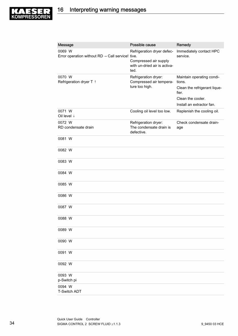
Message Possible cause Remedy0069 WError operation without RD → Call service!
Refrigeration dryer defec‐tive.Compressed air supplywith un-dried air is activa‐ted.
Immediately contact HPCservice.
0070 WRefrigeration dryer T ↑
Refrigeration dryer:Compressed air tempera‐ture too high.
Maintain operating condi‐tions.Clean the refrigerant lique‐fier.Clean the cooler.Install an extractor fan.
0071 WOil level ↓
Cooling oil level too low. Replenish the cooling oil.
0072 WRD condensate drain
Refrigeration dryer:The condensate drain isdefective.
Check condensate drain‐age
0081 W
0082 W
0083 W
0084 W
0085 W
0086 W
0087 W
0088 W
0089 W
0090 W
0091 W
0092 W
0093 Wp-Switch pi
0094 WT-Switch ADT
16 Interpreting warning messages
34Quick User Guide Controller SIGMA CONTROL 2 SCREW FLUID ≥1.1.3 9_9450 03 HCE

Message Possible cause Remedy0095 Wp-Switch pN
Tab. 6 Warning messages and remedies
16 Interpreting warning messages
9_9450 03 HCEQuick User Guide Controller SIGMA CONTROL 2 SCREW FLUID ≥1.1.3 35
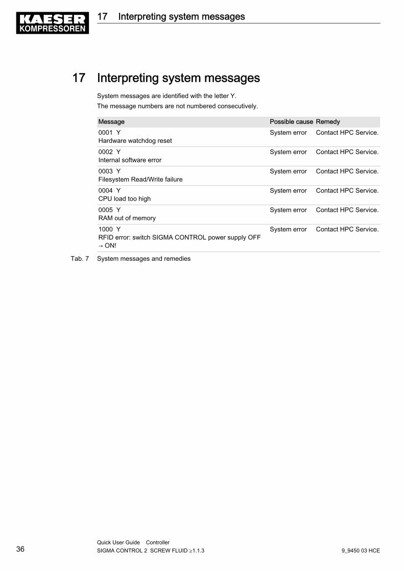
17 Interpreting system messagesSystem messages are identified with the letter Y.The message numbers are not numbered consecutively.
Message Possible cause Remedy0001 YHardware watchdog reset
System error Contact HPC Service.
0002 YInternal software error
System error Contact HPC Service.
0003 YFilesystem Read/Write failure
System error Contact HPC Service.
0004 YCPU load too high
System error Contact HPC Service.
0005 YRAM out of memory
System error Contact HPC Service.
1000 YRFID error: switch SIGMA CONTROL power supply OFF→ ON!
System error Contact HPC Service.
Tab. 7 System messages and remedies
17 Interpreting system messages
36Quick User Guide Controller SIGMA CONTROL 2 SCREW FLUID ≥1.1.3 9_9450 03 HCE
1 Regarding this document1.1 Using this document ......................................................................................................... 11.2 Copyright .......................................................................................................................... 1
1.2.1 Software .............................................................................................................. 11.3 Updating the operating manual ........................................................................................ 11.4 Symbols and labels .......................................................................................................... 2
1.4.1 Warnings ............................................................................................................. 21.4.2 Potential damage warnings ................................................................................ 21.4.3 Other alerts and their symbols ............................................................................ 3
2 Technical Specifications2.1 SIGMA CONTROL 2 Controller ....................................................................................... 4
2.1.1 User interface with display, CPU and interfaces ................................................. 42.1.2 Input/output modules .......................................................................................... 52.1.3 Sensors ............................................................................................................... 7
3 Safety and Responsibility3.1 Basic instructions ............................................................................................................. 93.2 Specified use .................................................................................................................... 93.3 Improper use .................................................................................................................... 9
4 Design and Function4.1 The controller ................................................................................................................... 104.2 Operating panel ................................................................................................................ 114.3 Display ............................................................................................................................. 14
4.3.1 Operating mode .................................................................................................. 144.3.2 Main menu .......................................................................................................... 154.3.3 Setting parameters ............................................................................................. 154.3.4 Activating keys with check boxes ....................................................................... 16
4.4 Access rights .................................................................................................................... 164.4.1 Secure storage of the RFID Equipment Cards ................................................... 17
4.5 Checking the machine status with KAESER CONNECT ................................................ 174.6 Menus – overview ............................................................................................................ 18
4.6.1 Operating mode .................................................................................................. 184.6.2 Menu structure .................................................................................................... 19
4.7 Operating modes and control modes ............................................................................... 304.7.1 Operating modes ................................................................................................ 304.7.2 Control modes .................................................................................................... 314.7.3 Frequency-controlled drive (SFC) ....................................................................... 324.7.4 MODULATING control ........................................................................................ 33
5 Installation and Operating Conditions5.1 Maintaining ambient conditions ........................................................................................ 345.2 Installation conditions ....................................................................................................... 34
6 Installation6.1 Reporting Transport Damage ........................................................................................... 356.2 Machine identification ....................................................................................................... 35
7 Initial Start-up7.1 Outline .............................................................................................................................. 367.2 Configuring the controller ................................................................................................. 36
7.2.1 Selecting menu options ...................................................................................... 367.2.2 Changing the display language .......................................................................... 377.2.3 Note the number of the KAESER Equipment Card ............................................ 387.2.4 Control access to SIGMA CONTROL 2 with the Equipment Card ..................... 387.2.5 Generate password for SIGMA CONTROL 2 .................................................... 38
Contents
9_9450 03 HCEService Manual Controller SIGMA CONTROL 2 SCREW FLUID ≥1.1.3 i
7.2.6 Control access to SIGMA CONTROL 2 via manual input ................................... 407.2.7 Generate password for KAESER CONNECT .................................................... 427.2.8 Check/set time and date ..................................................................................... 427.2.9 Set display formats ............................................................................................. 447.2.10 Setting and activating summer/winter time ......................................................... 47
7.3 Using KAESER CONNECT ............................................................................................. 477.3.1 Calling up KAESER CONNECT for SIGMA CONTROL 2 ................................. 487.3.2 Displaying the system status .............................................................................. 497.3.3 Display graphs .................................................................................................... 517.3.4 Displaying messages .......................................................................................... 537.3.5 Calling up the IO display ..................................................................................... 547.3.6 Creating additional user accounts ...................................................................... 547.3.7 Settings ............................................................................................................... 577.3.8 Performing a data backup ................................................................................... 587.3.9 Closing KAESER CONNECT: ............................................................................ 58
7.4 Adjusting the pressure parameters of the machine .......................................................... 597.4.1 Displaying pressure parameters ......................................................................... 607.4.2 Configuring the pressure parameters for compressors ...................................... 617.4.3 Activating/deactivating the «LOAD/IDLE» key .................................................... 64
7.5 Configuring machine start and stop ................................................................................. 657.5.1 Automatic start/stop in programmed clock mode ................................................ 657.5.2 Setting up the holiday period .............................................................................. 687.5.3 Starting the machine remotely from a control centre (remote ON/OFF) ............. 697.5.4 Activating/deactivating the idle phase (unloading function) ................................ 727.5.5 Activating/deactivating and adjusting the "automatic restart after a power
failure" function ...................................................................................................73
7.6 Activating and adjusting the control modes ...................................................................... 757.6.1 Selecting a control mode .................................................................................... 757.6.2 Adjust the idle time of DUAL mode ..................................................................... 767.6.3 Adjusting the minimum running and unloaded period in QUADRO control
mode ...................................................................................................................77
7.7 Activating the settings for the refrigeration dryer .............................................................. 787.7.1 Setting the CLOCK mode ................................................................................... 797.7.2 Output messages ................................................................................................ 807.7.3 Fault in the refrigeration dryer – call Service ...................................................... 817.7.4 Fault in the refrigeration dryer – activate fault mode ........................................... 81
7.8 Configuring the machine for local mode ........................................................................... 837.8.1 Select the < Configuration ➙ Pressure control ➙ Load control > menu ............ 837.8.2 Configuring the system pressure setpoint changeover using the clock
program ..............................................................................................................83
7.8.3 Configure the system pressure setpoint change-over using the clock ............... 867.9 Configuring the machine for master control ..................................................................... 88
7.9.1 List of the various master controllers .................................................................. 887.9.2 Configuring Profibus mode (SIGMA AIR MANAGER or VESIS) ........................ 897.9.3 Configuring the Profibus interface without SIGMA AIR MANAGER or VESIS .. 987.9.4 Configuring the master control of two machines in master/slave operation
(Ethernet interface) .............................................................................................99
7.9.5 Configuring master control using the LOAD remote contact (e.g.,SIGMA AIR MANAGER BASIC) .........................................................................
105
7.9.6 Configuring the master control with local/LOAD remote contact ........................ 1087.9.7 Configuring setpoint pressure pre-selection via remote contact ......................... 1117.9.8 Configuring master control of compressors regulated by pressure switch ......... 1137.9.9 Examples of time settings for equal overall load ................................................ 121
7.10 Configuring e-mail ............................................................................................................ 122
Contents
iiService Manual Controller SIGMA CONTROL 2 SCREW FLUID ≥1.1.3 9_9450 03 HCE
7.11 Configuring input and output signals ................................................................................ 1247.11.1 Outputting important operational states of the machine ..................................... 1257.11.2 Displaying analog input values ........................................................................... 1267.11.3 Displaying additional binary input signals ........................................................... 130
7.12 Activating remote acknowledgement ............................................................................... 1347.12.1 Selecting the < Configuration ➙ Acknowledgement > menu .............................. 1357.12.2 Setting the remote acknowledgement function ................................................... 1357.12.3 Activate the «Remote control» key ..................................................................... 1357.12.4 Assigning an input .............................................................................................. 136
7.13 Linking to an external pressure transducer ...................................................................... 1377.13.1 Selecting the < Configuration ➙ Pressure control > menu ................................. 1387.13.2 Assigning an input to an external sensor ............................................................ 138
7.14 Starting the machine ........................................................................................................ 139
8 Operation8.1 Switching on and off ......................................................................................................... 141
8.1.1 Switching on ....................................................................................................... 1418.1.2 Switching off ....................................................................................................... 141
8.2 Switching off in an emergency and switching on again .................................................... 1428.3 Acknowledging fault and warning messages ................................................................... 1428.4 Displaying messages ....................................................................................................... 144
8.4.1 Select Status menu ............................................................................................. 1458.5 Displaying the current operating mode ............................................................................ 1468.6 Adjusting working pressure .............................................................................................. 1478.7 Displaying analog data ..................................................................................................... 1488.8 Displaying operating data ................................................................................................. 149
8.8.1 Interpreting operation messages ........................................................................ 1508.9 Setting the maintenance interval ...................................................................................... 1528.10 Pressure relief valve checking ......................................................................................... 1538.11 Checking the temperature sensor and overheating shutdown function ........................... 155
9 Fault Recognition and Rectification9.1 Basic instructions ............................................................................................................. 1589.2 Interpreting fault messages .............................................................................................. 1589.3 Interpreting system messages ......................................................................................... 1639.4 Interpreting diagnostic messages .................................................................................... 1639.5 Interpreting warning messages ........................................................................................ 164
10 Maintenance10.1 Maintenance Work ........................................................................................................... 169
11 Spares, Operating Materials, Service11.1 Note the nameplate .......................................................................................................... 17011.2 HPC AIR SERVICE ......................................................................................................... 17011.3 Service Addresses ........................................................................................................... 17011.4 Displaying the version number, machine model, material number and serial number ..... 170
12 Decommissioning, Storage and Transport12.1 De-commissioning ............................................................................................................ 17212.2 Packing ............................................................................................................................ 17212.3 Storage ............................................................................................................................. 17212.4 Transporting ..................................................................................................................... 17212.5 Disposal ........................................................................................................................... 172
Contents
9_9450 03 HCEService Manual Controller SIGMA CONTROL 2 SCREW FLUID ≥1.1.3 iii

Contents
ivService Manual Controller SIGMA CONTROL 2 SCREW FLUID ≥1.1.3 9_9450 03 HCE
Fig. KAESER Equipment Card .......................................................................................................... 4Fig. RFID reader ................................................................................................................................ 5
Fig. 1 System structure ........................................................................................................................ 10Fig. 2 Keys – overview ......................................................................................................................... 11Fig. 3 Indicators – overview .................................................................................................................. 12Fig. 4 RFID reader ................................................................................................................................ 13Fig. 5 KAESER CONNECT for SIGMA CONTROL 2 .......................................................................... 17Fig. 6 Header ........................................................................................................................................ 18Fig. 7 Back of the KAESER Equipment Card ....................................................................................... 38Fig. 8 Login window .............................................................................................................................. 48Fig. 9 KAESER CONNECT ................................................................................................................. 49
Fig. 10 Language selection .................................................................................................................... 49Fig. 11 Status display ............................................................................................................................. 50Fig. 12 Main menu .................................................................................................................................. 50Fig. 13 Status menu with submenus ...................................................................................................... 51Fig. 14 Pressure/temperature graphs ..................................................................................................... 52Fig. 15 Arrow keys .................................................................................................................................. 52Fig. 16 Messages ................................................................................................................................... 53Fig. 17 User administration menu .......................................................................................................... 55Fig. 18 "Log on to write" window ............................................................................................................ 55Fig. 19 Creating a new user ................................................................................................................... 56Fig. 20 Settings ...................................................................................................................................... 57Fig. 21 Data backup ............................................................................................................................... 58Fig. 22 Header ........................................................................................................................................ 59Fig. 23 Pressure rise in frequency-controlled machines ........................................................................ 63Fig. 24 Profibus plug wiring .................................................................................................................... 90Fig. 25 Electrical diagram example with SIGMA AIR MANAGER ......................................................... 91Fig. 26 Communication interface ............................................................................................................ 93Fig. 27 Insert the communication module. ............................................................................................. 93Fig. 28 Front plate of the PROFIBUS communication module ............................................................... 94Fig. 29 Direct connection of two SIGMA CONTROL 2 .......................................................................... 101Fig. 30 LOAD remote contact ................................................................................................................. 106Fig. 31 Wiring diagram for local/LOAD remote contact: ......................................................................... 108Fig. 32 Machine with pressure switch regulation .................................................................................... 114Fig. 33 Function diagram ........................................................................................................................ 117Fig. 34 Switching on and off ................................................................................................................... 141Fig. 35 Switching off in an emergency ................................................................................................... 142Fig. 36 Acknowledging messages .......................................................................................................... 143
List of Illustrations
9_9450 03 HCEService Manual Controller SIGMA CONTROL 2 SCREW FLUID ≥1.1.3 v

List of Illustrations
viService Manual Controller SIGMA CONTROL 2 SCREW FLUID ≥1.1.3 9_9450 03 HCE
Tab. 1 Danger levels and their definitions (personal injury) .................................................................. 2Tab. 2 Danger levels and their definition (damage to property) ............................................................ 2Tab. 3 User interface ............................................................................................................................. 4Tab. 4 Display data ................................................................................................................................ 4Tab. 5 Interfaces .................................................................................................................................... 5Tab. 6 RFID ........................................................................................................................................... 5Tab. 7 SC2IOM-1 .................................................................................................................................. 5Tab. 8 SC2IOM-2 .................................................................................................................................. 6Tab. 9 SC2IOM-3 .................................................................................................................................. 6
Tab. 10 Power supply specifications ....................................................................................................... 6Tab. 11 Cable lengths ............................................................................................................................. 7Tab. 12 Degree of protection, IOM .......................................................................................................... 7Tab. 13 IOM dimensions ......................................................................................................................... 7Tab. 14 Pressure transducer ................................................................................................................... 7Tab. 15 Resistance thermometer ............................................................................................................ 7Tab. 16 Keys ........................................................................................................................................... 11Tab. 17 Indicators .................................................................................................................................... 12Tab. 18 RFID reader ................................................................................................................................ 13Tab. 19 Reset check box status .............................................................................................................. 16Tab. 20 Check box status ........................................................................................................................ 16Tab. 21 Menu structure ........................................................................................................................... 20Tab. 22 Status menu ............................................................................................................................... 22Tab. 23 Configuration menu .................................................................................................................... 23Tab. 24 Pressure control menu ............................................................................................................... 24Tab. 25 I/O periphery menu ..................................................................................................................... 25Tab. 26 Communication menu ................................................................................................................ 26Tab. 27 Profibus ...................................................................................................................................... 27Tab. 28 Modbus ....................................................................................................................................... 27Tab. 29 Modbus TCP .............................................................................................................................. 28Tab. 30 DEVICENET ............................................................................................................................... 28Tab. 31 PROFINET ................................................................................................................................. 28Tab. 32 Connections menu ..................................................................................................................... 29Tab. 33 Components menu ..................................................................................................................... 29Tab. 34 Power switching module – menu ................................................................................................ 30Tab. 35 Machine identification ................................................................................................................. 35Tab. 36 Remote control identification ...................................................................................................... 35Tab. 37 Machine identification ................................................................................................................. 35Tab. 38 Language diversity ..................................................................................................................... 37Tab. 39 Date format ................................................................................................................................. 44Tab. 40 Time formats .............................................................................................................................. 44Tab. 41 Units of pressure ........................................................................................................................ 45Tab. 42 Units of temperature ................................................................................................................... 46Tab. 43 Display illumination ..................................................................................................................... 46Tab. 44 Arrow keys and functions ........................................................................................................... 52Tab. 45 Compressor pressure parameters .............................................................................................. 59Tab. 46 Setting limits for system set-point pressure (* Cut-in pressure min) .......................................... 61Tab. 47 Pressure condition for LOAD ..................................................................................................... 61Tab. 48 Pressure condition for IDLE ...................................................................................................... 61Tab. 49 Example: Activated output .......................................................................................................... 62Tab. 50 Settings for machine start and stop. ........................................................................................... 65Tab. 51 Example of a machine ON/OFF timer program .......................................................................... 66Tab. 52 Local operating mode (local mode) ............................................................................................ 83Tab. 53 Example of system pressure changeover switching points ........................................................ 84Tab. 54 Master control – overview ........................................................................................................... 88
List of Tables
9_9450 03 HCEService Manual Controller SIGMA CONTROL 2 SCREW FLUID ≥1.1.3 vii
Tab. 55 Profibus DP pin connection ........................................................................................................ 89Tab. 56 Master-slave configuration procedure ........................................................................................ 100Tab. 57 Function diagram ........................................................................................................................ 116Tab. 58 Example switching points ........................................................................................................... 118Tab. 59 Example for a clock program for equal duty cycling during the day ........................................... 121Tab. 60 Example for a clock program for equal duty cycling during the week ........................................ 122Tab. 61 Assigned output signals ............................................................................................................. 125Tab. 62 Logic ........................................................................................................................................... 133Tab. 63 Transmission of sensor value ..................................................................................................... 137Tab. 64 Checklist of installation conditions .............................................................................................. 139Tab. 65 Information of a message ........................................................................................................... 144Tab. 66 Message abbreviations .............................................................................................................. 144Tab. 67 Operating mode display ............................................................................................................. 146Tab. 68 Displaying possible operating modes ......................................................................................... 147Tab. 69 Operational Messages ............................................................................................................... 150Tab. 70 Check box status ........................................................................................................................ 153Tab. 71 Fault messages and remedies ................................................................................................... 158Tab. 72 System messages and remedies ............................................................................................... 163Tab. 73 Warning messages and remedies .............................................................................................. 164
List of Tables
viiiService Manual Controller SIGMA CONTROL 2 SCREW FLUID ≥1.1.3 9_9450 03 HCE
1 Regarding this document1.1 Using this document
The operating manual contains important information to the entire life cycle ofSIGMA CONTROL 2.The operating manual is a component of the product.➤ Keep the manual in a safe place throughout the life of SIGMA CONTROL 2.➤ Pass the manual on to the next owner/user of the machine.➤ Ensure that all amendments received are inserted into the operating manual.
1.2 CopyrightThis operating manual is protected by copyright. Any queries regarding the use or duplication ofthis documentation should be referred to KAESER. Correct use of information will be fully suppor‐ted.
1.2.1 Software
The software used in SIGMA CONTROL 2 contains copyright-protected software which is licensedby GNU General Public License in versions 2 and 3.A copy of these licenses is contained in SIGMA CONTROL 2.Display the licenses by pointing your browser to the "COPYING" file in the root directory ofSIGMA CONTROL 2.URL:http:// <Hostname>/ SIGMA CONTROL 2 COPYINGThe licenses can be also found under this address:http://www.gnu.org/licenses/gpl-2.0.txthttp://www.gnu.org/licenses/gpl.txtWithin three years from receipt of SIGMA CONTROL 2, you may obtain the complete source codeby sending a corresponding order to the following address:HPC Engineering PLCVictoria Gardens, Industrial Estate,Burgess Hill, West Sussex, RH 15 9RQ.Telephone (01444) 241671Fax (01444) 247304This offer is valid for anybody having this information.
1.3 Updating the operating manualThe page <http://www.kaeser.com/sc2manual> of our website provides frequently updated versionof the operating manual.Be prepared to provide the material number and the serial number of the machine in which theSIGMA CONTROL 2 is installed.Both numbers can be found on the nameplate of the machine.➤ Download the desired operating manual from our server and forward it to your operators.
1 Regarding this document1.1 Using this document
9_9450 03 HCEService Manual Controller SIGMA CONTROL 2 SCREW FLUID ≥1.1.3 1
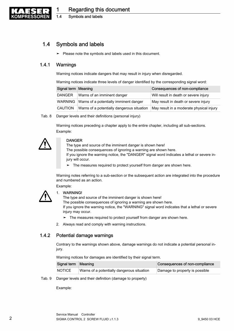
1.4 Symbols and labels➤ Please note the symbols and labels used in this document.
1.4.1 Warnings
Warning notices indicate dangers that may result in injury when disregarded.
Warning notices indicate three levels of danger identified by the corresponding signal word:
Signal term Meaning Consequences of non-compliance
DANGER Warns of an imminent danger Will result in death or severe injury
WARNING Warns of a potentially imminent danger May result in death or severe injury
CAUTION Warns of a potentially dangerous situation May result in a moderate physical injury
Tab. 8 Danger levels and their definitions (personal injury)
Warning notices preceding a chapter apply to the entire chapter, including all sub-sections.Example:
DANGERThe type and source of the imminent danger is shown here!The possible consequences of ignoring a warning are shown here.If you ignore the warning notice, the "DANGER" signal word indicates a lethal or severe in‐jury will occur.➤ The measures required to protect yourself from danger are shown here.
Warning notes referring to a sub-section or the subsequent action are integrated into the procedureand numbered as an action.Example:
1. WARNING! The type and source of the imminent danger is shown here!The possible consequences of ignoring a warning are shown here.If you ignore the warning notice, the "WARNING" signal word indicates that a lethal or severeinjury may occur.➤ The measures required to protect yourself from danger are shown here.
2. Always read and comply with warning instructions.
1.4.2 Potential damage warnings
Contrary to the warnings shown above, damage warnings do not indicate a potential personal in‐jury.
Warning notices for damages are identified by their signal term.
Signal term Meaning Consequences of non-compliance
NOTICE Warns of a potentially dangerous situation Damage to property is possible
Tab. 9 Danger levels and their definition (damage to property)
Example:
1 Regarding this document1.4 Symbols and labels
2Service Manual Controller SIGMA CONTROL 2 SCREW FLUID ≥1.1.3 9_9450 03 HCE
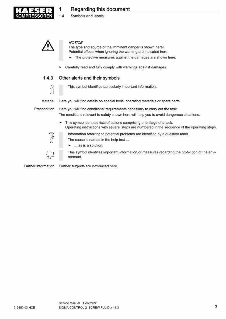
NOTICEThe type and source of the imminent danger is shown here!Potential effects when ignoring the warning are indicated here.➤ The protective measures against the damages are shown here.
➤ Carefully read and fully comply with warnings against damages.
1.4.3 Other alerts and their symbols
This symbol identifies particularly important information.
Material Here you will find details on special tools, operating materials or spare parts.
Precondition Here you will find conditional requirements necessary to carry out the task.The conditions relevant to safety shown here will help you to avoid dangerous situations.
➤ This symbol denotes lists of actions comprising one stage of a task.Operating instructions with several steps are numbered in the sequence of the operating steps.
Information referring to potential problems are identified by a question mark.The cause is named in the help text ...➤ ... as is a solution.
This symbol identifies important information or measures regarding the protection of the envi‐ronment.
Further information Further subjects are introduced here.
1 Regarding this document1.4 Symbols and labels
9_9450 03 HCEService Manual Controller SIGMA CONTROL 2 SCREW FLUID ≥1.1.3 3
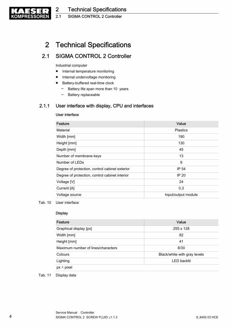
2 Technical Specifications2.1 SIGMA CONTROL 2 Controller
Industrial computer■ Internal temperature monitoring■ Internal undervoltage monitoring■ Battery-buffered real-time clock
─ Battery life span more than 10 years─ Battery replaceable
2.1.1 User interface with display, CPU and interfaces
User interface
Feature Value
Material Plastics
Width [mm] 190
Height [mm] 130
Depth [mm] 45
Number of membrane keys 13
Number of LEDs 9
Degree of protection, control cabinet exterior IP 54
Degree of protection, control cabinet interior IP 20
Voltage [V] 24
Current [A] 0,3
Voltage source Input/output module
Tab. 10 User interface
Display
Feature Value
Graphical display [px] 255 x 128
Width [mm] 82
Height [mm] 41
Maximum number of lines/characters 8/30
Colours Black/white with gray levels
Lighting LED backlit
px ≙ pixel
Tab. 11 Display data
2 Technical Specifications2.1 SIGMA CONTROL 2 Controller
4Service Manual Controller SIGMA CONTROL 2 SCREW FLUID ≥1.1.3 9_9450 03 HCE
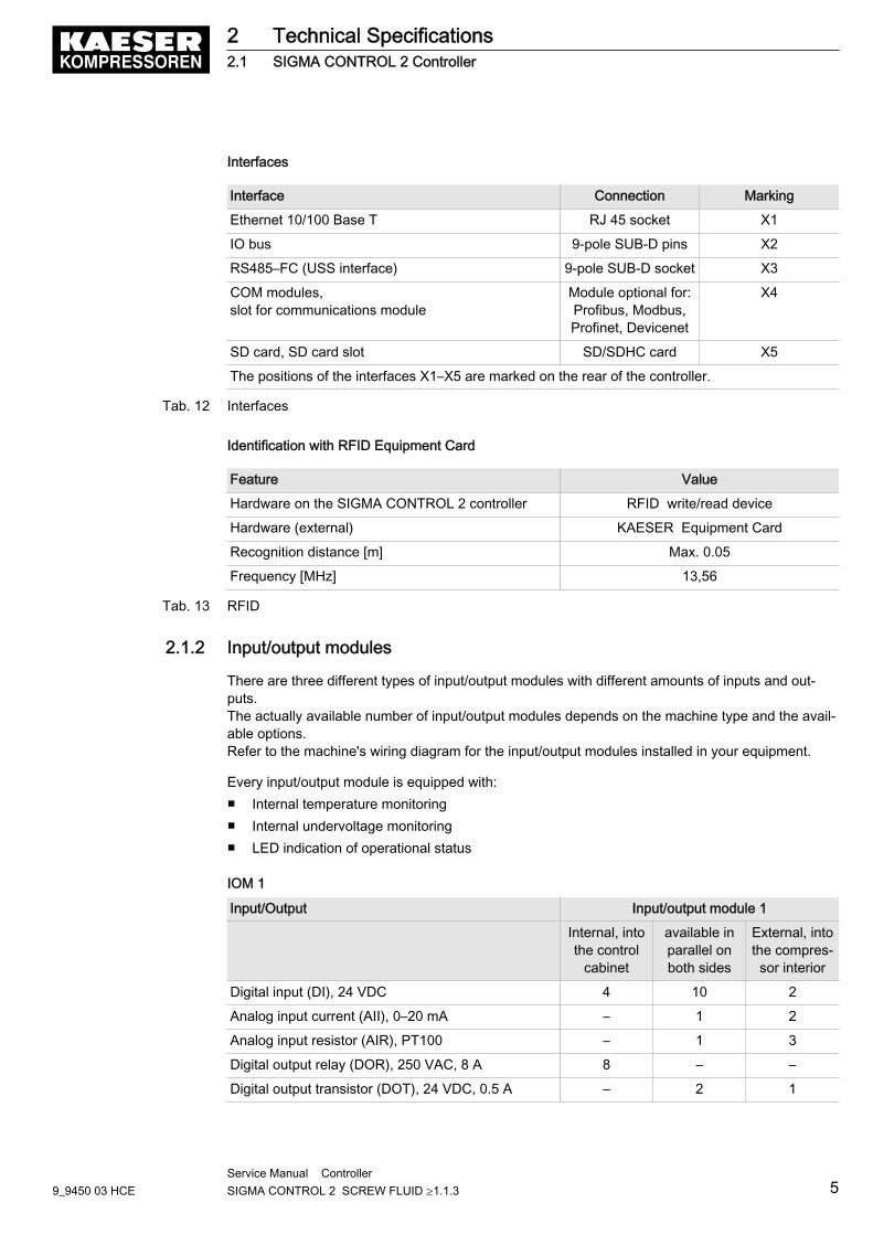
Interfaces
Interface Connection Marking
Ethernet 10/100 Base T RJ 45 socket X1
IO bus 9-pole SUB-D pins X2
RS485–FC (USS interface) 9-pole SUB-D socket X3
COM modules,slot for communications module
Module optional for:Profibus, Modbus,Profinet, Devicenet
X4
SD card, SD card slot SD/SDHC card X5
The positions of the interfaces X1–X5 are marked on the rear of the controller.
Tab. 12 Interfaces
Identification with RFID Equipment Card
Feature Value
Hardware on the SIGMA CONTROL 2 controller RFID write/read device
Hardware (external) KAESER Equipment Card
Recognition distance [m] Max. 0.05
Frequency [MHz] 13,56
Tab. 13 RFID
2.1.2 Input/output modules
There are three different types of input/output modules with different amounts of inputs and out‐puts.The actually available number of input/output modules depends on the machine type and the avail‐able options.Refer to the machine's wiring diagram for the input/output modules installed in your equipment.
Every input/output module is equipped with:■ Internal temperature monitoring■ Internal undervoltage monitoring■ LED indication of operational status
IOM 1
Input/Output Input/output module 1
Internal, intothe control
cabinet
available inparallel onboth sides
External, intothe compres‐sor interior
Digital input (DI), 24 VDC 4 10 2
Analog input current (AII), 0–20 mA – 1 2
Analog input resistor (AIR), PT100 – 1 3
Digital output relay (DOR), 250 VAC, 8 A 8 – –
Digital output transistor (DOT), 24 VDC, 0.5 A – 2 1
2 Technical Specifications2.1 SIGMA CONTROL 2 Controller
9_9450 03 HCEService Manual Controller SIGMA CONTROL 2 SCREW FLUID ≥1.1.3 5
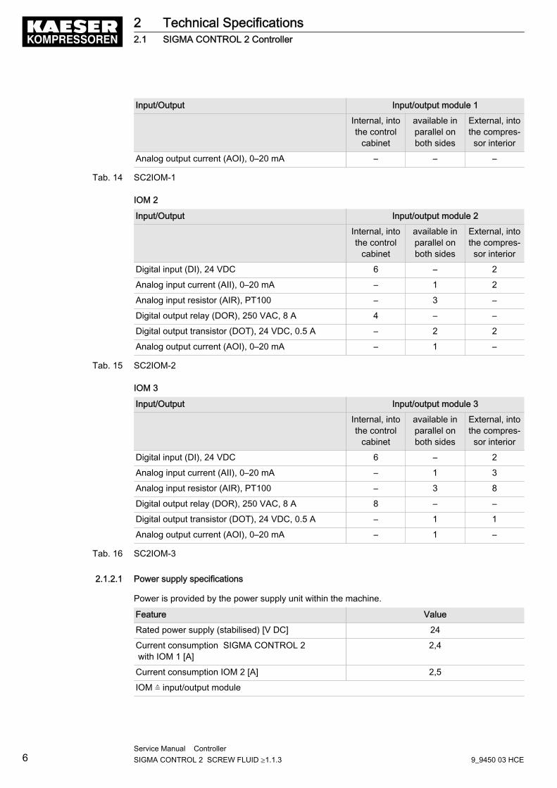
Input/Output Input/output module 1
Internal, intothe control
cabinet
available inparallel onboth sides
External, intothe compres‐sor interior
Analog output current (AOI), 0–20 mA – – –
Tab. 14 SC2IOM-1
IOM 2
Input/Output Input/output module 2
Internal, intothe control
cabinet
available inparallel onboth sides
External, intothe compres‐sor interior
Digital input (DI), 24 VDC 6 – 2
Analog input current (AII), 0–20 mA – 1 2
Analog input resistor (AIR), PT100 – 3 –
Digital output relay (DOR), 250 VAC, 8 A 4 – –
Digital output transistor (DOT), 24 VDC, 0.5 A – 2 2
Analog output current (AOI), 0–20 mA – 1 –
Tab. 15 SC2IOM-2
IOM 3
Input/Output Input/output module 3
Internal, intothe control
cabinet
available inparallel onboth sides
External, intothe compres‐sor interior
Digital input (DI), 24 VDC 6 – 2
Analog input current (AII), 0–20 mA – 1 3
Analog input resistor (AIR), PT100 – 3 8
Digital output relay (DOR), 250 VAC, 8 A 8 – –
Digital output transistor (DOT), 24 VDC, 0.5 A – 1 1
Analog output current (AOI), 0–20 mA – 1 –
Tab. 16 SC2IOM-3
2.1.2.1 Power supply specifications
Power is provided by the power supply unit within the machine.
Feature Value
Rated power supply (stabilised) [V DC] 24
Current consumption SIGMA CONTROL 2 with IOM 1 [A]
2,4
Current consumption IOM 2 [A] 2,5
IOM ≙ input/output module
2 Technical Specifications2.1 SIGMA CONTROL 2 Controller
6Service Manual Controller SIGMA CONTROL 2 SCREW FLUID ≥1.1.3 9_9450 03 HCE
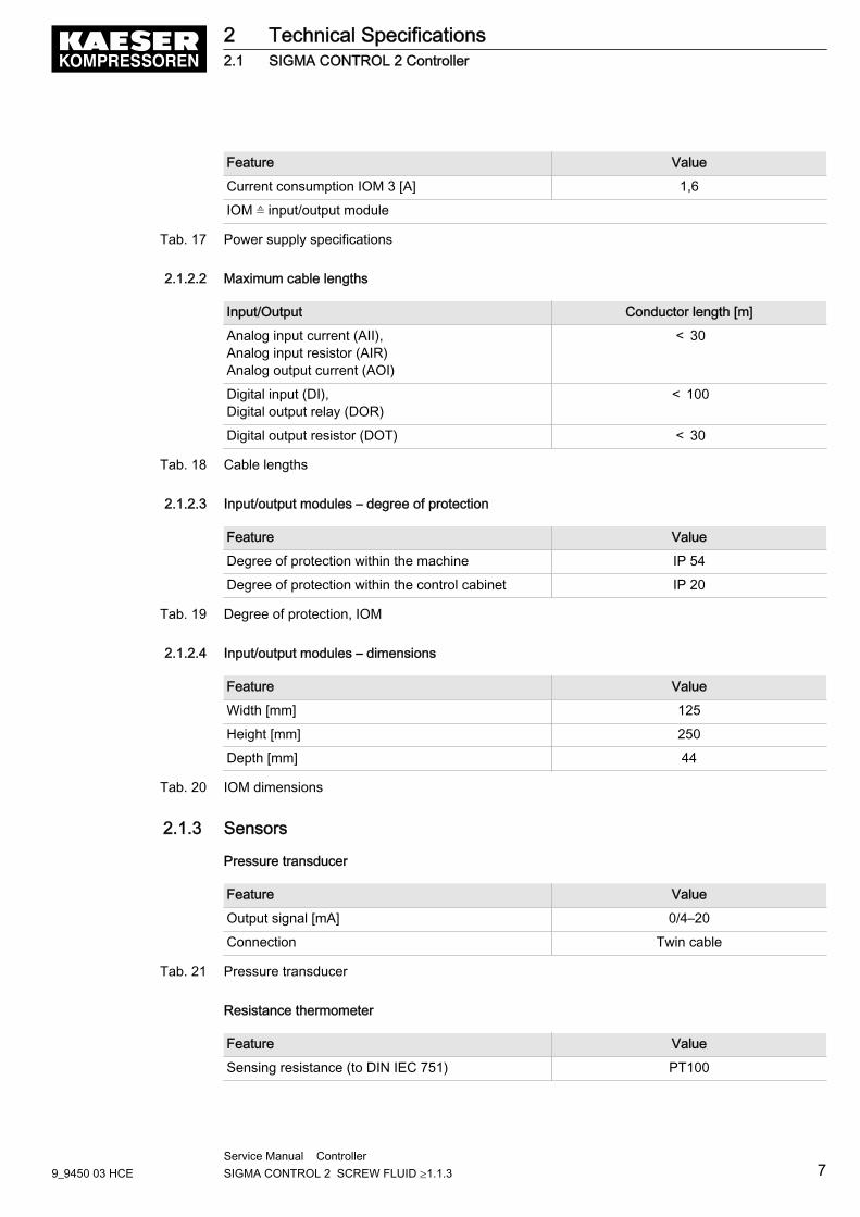
Feature Value
Current consumption IOM 3 [A] 1,6
IOM ≙ input/output module
Tab. 17 Power supply specifications
2.1.2.2 Maximum cable lengths
Input/Output Conductor length [m]
Analog input current (AII),Analog input resistor (AIR)Analog output current (AOI)
< 30
Digital input (DI),Digital output relay (DOR)
< 100
Digital output resistor (DOT) < 30
Tab. 18 Cable lengths
2.1.2.3 Input/output modules – degree of protection
Feature Value
Degree of protection within the machine IP 54
Degree of protection within the control cabinet IP 20
Tab. 19 Degree of protection, IOM
2.1.2.4 Input/output modules – dimensions
Feature Value
Width [mm] 125
Height [mm] 250
Depth [mm] 44
Tab. 20 IOM dimensions
2.1.3 Sensors
Pressure transducer
Feature Value
Output signal [mA] 0/4–20
Connection Twin cable
Tab. 21 Pressure transducer
Resistance thermometer
Feature Value
Sensing resistance (to DIN IEC 751) PT100
2 Technical Specifications2.1 SIGMA CONTROL 2 Controller
9_9450 03 HCEService Manual Controller SIGMA CONTROL 2 SCREW FLUID ≥1.1.3 7

Feature Value
Connection Twin cable
Tab. 22 Resistance thermometer
2 Technical Specifications2.1 SIGMA CONTROL 2 Controller
8Service Manual Controller SIGMA CONTROL 2 SCREW FLUID ≥1.1.3 9_9450 03 HCE
3 Safety and Responsibility3.1 Basic instructions
SIGMA CONTROL 2 is manufactured to the latest engineering standards and acknowledged safetyregulations.The safety regulations of the machine in which SIGMA CONTROL 2 is installed apply.
3.2 Specified useSIGMA CONTROL 2 is solely intended for the control of machines in which SIGMA CONTROL 2 isfactory-installed. Any other use is considered incorrect. The manufacturer is not liable for any dam‐ages that may result from incorrect use. The user alone is liable for any risks incurred.➤ Adhere to the specifications given in these operating instructions and the machine's service
manual.➤ Operate the machine only within its performance limits and under the permitted ambient condi‐
tions.
3.3 Improper useImproper usage can cause damage to property and/or (severe) injuries.➤ Use SIGMA CONTROL 2 only as intended.➤ Do not use SIGMA CONTROL 2 to control other machines or products for which
SIGMA CONTROL 2 is not intended.
3 Safety and Responsibility3.1 Basic instructions
9_9450 03 HCEService Manual Controller SIGMA CONTROL 2 SCREW FLUID ≥1.1.3 9
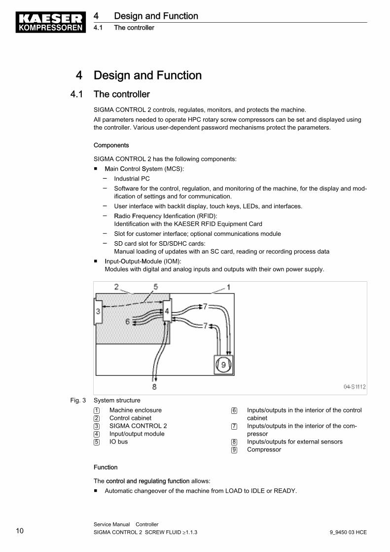
4 Design and Function4.1 The controller
SIGMA CONTROL 2 controls, regulates, monitors, and protects the machine.All parameters needed to operate HPC rotary screw compressors can be set and displayed usingthe controller. Various user-dependent password mechanisms protect the parameters.
Components
SIGMA CONTROL 2 has the following components:■ Main Control System (MCS):
─ Industrial PC─ Software for the control, regulation, and monitoring of the machine, for the display and mod‐
ification of settings and for communication.─ User interface with backlit display, touch keys, LEDs, and interfaces.─ Radio Frequency Idenfication (RFID):
Identification with the KAESER RFID Equipment Card─ Slot for customer interface; optional communications module─ SD card slot for SD/SDHC cards:
Manual loading of updates with an SC card, reading or recording process data■ Input-Output-Module (IOM):
Modules with digital and analog inputs and outputs with their own power supply.
Fig. 3 System structure1 Machine enclosure2 Control cabinet3 SIGMA CONTROL 24 Input/output module5 IO bus
6 Inputs/outputs in the interior of the controlcabinet
7 Inputs/outputs in the interior of the com‐pressor
8 Inputs/outputs for external sensors9 Compressor
Function
The control and regulating function allows:■ Automatic changeover of the machine from LOAD to IDLE or READY.
4 Design and Function4.1 The controller
10Service Manual Controller SIGMA CONTROL 2 SCREW FLUID ≥1.1.3 9_9450 03 HCE
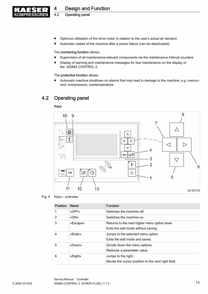
■ Optimum utilisation of the drive motor in relation to the user's actual air demand.■ Automatic restart of the machine after a power failure (can be deactivated).
The monitoring function allows:■ Supervision of all maintenance-relevant components via the maintenance interval counters.■ Display of warning and maintenance messages for due maintenance on the display of
the SIGMA CONTROL 2 .
The protective function allows:■ Automatic machine shutdown on alarms that may lead to damage to the machine, e.g. overcur‐
rent, overpressure, overtemperature.
4.2 Operating panelKeys
Fig. 4 Keys – overview
Position Name Function
1 «OFF» Switches the machine off.
2 «ON» Switches the machine on.
3 «Escape» Returns to the next higher menu option level.Exits the edit mode without saving.
4 «Enter» Jumps to the selected menu option.Exits the edit mode and saves.
5 «Down» Scrolls down the menu options.Reduces a parameter value.
6 «Right» Jumps to the right.Moves the cursor position to the next right field.
4 Design and Function4.2 Operating panel
9_9450 03 HCEService Manual Controller SIGMA CONTROL 2 SCREW FLUID ≥1.1.3 11
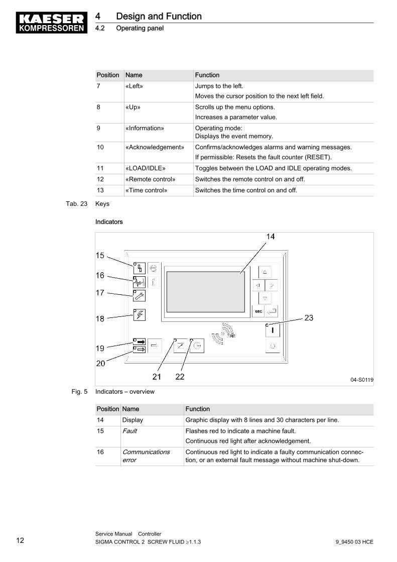
Position Name Function
7 «Left» Jumps to the left.Moves the cursor position to the next left field.
8 «Up» Scrolls up the menu options.Increases a parameter value.
9 «Information» Operating mode:Displays the event memory.
10 «Acknowledgement» Confirms/acknowledges alarms and warning messages.If permissible: Resets the fault counter (RESET).
11 «LOAD/IDLE» Toggles between the LOAD and IDLE operating modes.
12 «Remote control» Switches the remote control on and off.
13 «Time control» Switches the time control on and off.
Tab. 23 Keys
Indicators
Fig. 5 Indicators – overview
Position Name Function
14 Display Graphic display with 8 lines and 30 characters per line.
15 Fault Flashes red to indicate a machine fault.Continuous red light after acknowledgement.
16 Communicationserror
Continuous red light to indicate a faulty communication connec‐tion, or an external fault message without machine shut-down.
4 Design and Function4.2 Operating panel
12Service Manual Controller SIGMA CONTROL 2 SCREW FLUID ≥1.1.3 9_9450 03 HCE

Position Name Function
17 Warning Flashes in yellow in the following events:■ Maintenance work due■ Warning message
Continuous yellow light after acknowledgement.
18 Voltage applied tocontroller
Continuous green light when voltage is applied to the controller.
19 LOAD Continuous green light when the machine is running in LOAD.
20 IDLE Continuous green light when the machine is running in IDLE.Flashes when the «LOAD/IDLE» toggle key is pressed.
21 Remote control Continuous green light when the machine is in remote control.
22 Time control Continuous green light when the machine is controlled by the tim‐er.
23 ON Continuous green light when the machine switched on.
Tab. 24 Indicators
RFID reader
RFID is the abbreviation for “Radio Frequency Indentification” and enables the identification of per‐sons or objects.Placing a suitable transponder in front of the RFID reader of the controller will automatically acti‐vate the communication between transponder and SIGMA CONTROL 2 .A suitable transponder is the KAESER RFID Equipment Card. Two of them have been providedwith the machine.
Typical application:■ Users log on to the machine.
(no manual input of the password required.)
The KAESER RFID Equipment Cards are carefully packed in a plastic sleeve.This plastic sleeve is attached to the rear of the controller in the control cabinet.
Fig. 6 RFID reader
Position Name Function
24 RFID RFID reader for the communication with a suitable RFID transponder.
Tab. 25 RFID reader
4 Design and Function4.2 Operating panel
9_9450 03 HCEService Manual Controller SIGMA CONTROL 2 SCREW FLUID ≥1.1.3 13
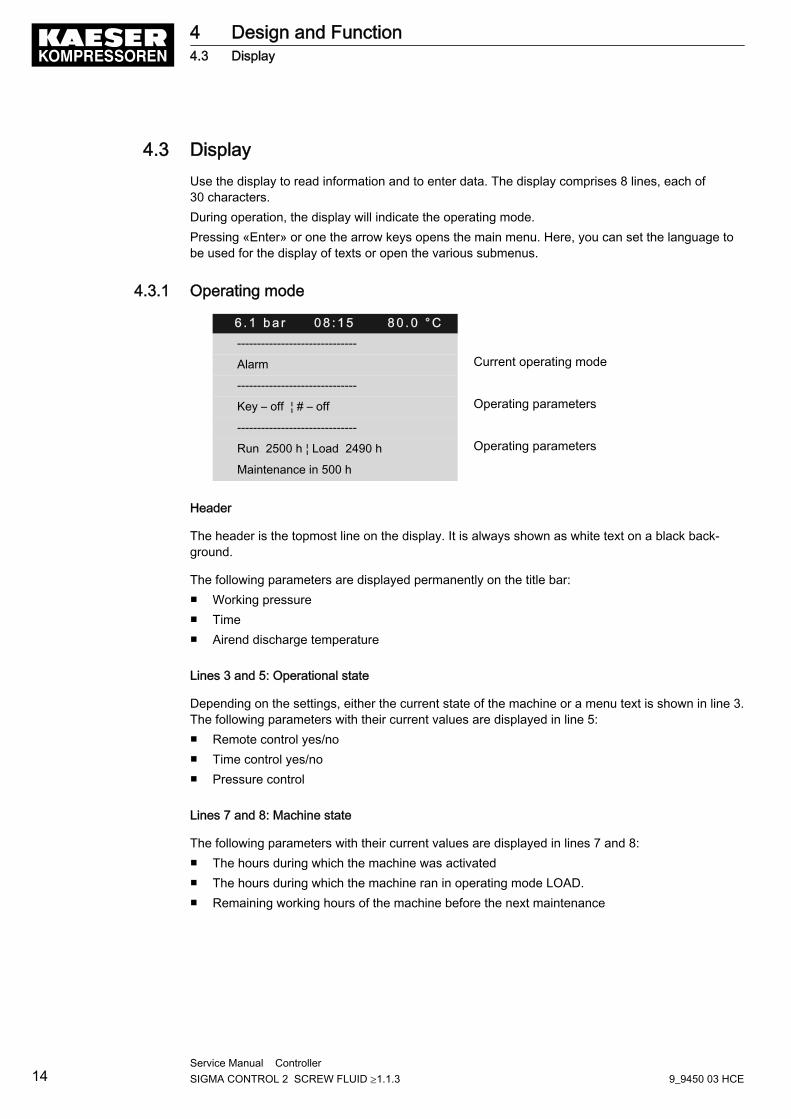
4.3 DisplayUse the display to read information and to enter data. The display comprises 8 lines, each of30 characters.During operation, the display will indicate the operating mode.Pressing «Enter» or one the arrow keys opens the main menu. Here, you can set the language tobe used for the display of texts or open the various submenus.
4.3.1 Operating mode
6 . 1 b a r 0 8 : 1 5 8 0 . 0 ° C------------------------------
Alarm Current operating mode
------------------------------
Key – off ¦ # – off Operating parameters
------------------------------
Run 2500 h ¦ Load 2490 h Operating parameters
Maintenance in 500 h
Header
The header is the topmost line on the display. It is always shown as white text on a black back‐ground.
The following parameters are displayed permanently on the title bar:■ Working pressure■ Time■ Airend discharge temperature
Lines 3 and 5: Operational state
Depending on the settings, either the current state of the machine or a menu text is shown in line 3.The following parameters with their current values are displayed in line 5:■ Remote control yes/no■ Time control yes/no■ Pressure control
Lines 7 and 8: Machine state
The following parameters with their current values are displayed in lines 7 and 8:■ The hours during which the machine was activated■ The hours during which the machine ran in operating mode LOAD.■ Remaining working hours of the machine before the next maintenance
4 Design and Function4.3 Display
14Service Manual Controller SIGMA CONTROL 2 SCREW FLUID ≥1.1.3 9_9450 03 HCE
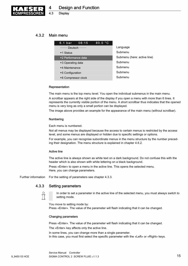
4.3.2 Main menu
6 . 1 b a r 0 8 : 1 5 8 0 . 0 ° C········· Deutsch ········· Language
▶1 Status Submenu
▶2 Performance data Submenu (here: active line)
▶3 Operating data Submenu
▶4 Maintenance Submenu
▶5 Configuration Submenu
▶6 Compressor clock Submenu
Representation
The main menu is the top menu level. You open the individual submenus in the main menu.A scrollbar appears at the right side of the display if you open a menu with more than 6 lines. Itrepresents the currently visible portion of the menu. A short scrollbar thus indicates that the openedmenu is very long as only a small portion can be displayed.The image above provides an example for the appearance of the main menu (without scrollbar).
Numbering
Each menu is numbered.Not all menus may be displayed because the access to certain menus is restricted by the accesslevel, and some menus are displayed or hidden due to specific settings or options.For example, you can recognise subordinate menus in the menu structure by the number preced‐ing their designation. The menu structure is explained in chapter 4.6.2.
Active line
The active line is always shown as white text on a dark background. Do not confuse this with theheader which is also shown with white lettering on a black background.Press «Enter» to open a menu in the active line. This opens the selected menu.Here, you can change parameters.
Further information For the setting of parameters see chapter 4.3.3.
4.3.3 Setting parameters
In order to set a parameter in the active line of the selected menu, you must always switch tosetting mode.
You move to setting mode by:Press «Enter». The value of the parameter will flash indicating that it can be changed.
Changing parameters
Press «Enter». The value of the parameter will flash indicating that it can be changed.The «Enter» key affects only the active line.In some lines, you can change more than a single parameter.In this case, you must first select the specific parameter with the «Left» or «Right» keys.
4 Design and Function4.3 Display
9_9450 03 HCEService Manual Controller SIGMA CONTROL 2 SCREW FLUID ≥1.1.3 15
Resetting current parameters
In order to reset current parameters to Zero, activate the check box for Reset in the active line ofthe display.First, press «Enter» to switch into setting mode. The check box Reset will flash.You then press «UP». The check box is activated and flashes.Press «Enter» to save the settings.The parameters no longer flash and are reset. The check box for Reset is again deactivated.
Check box Reset Status
☒ activated
☐ deactivated
Tab. 26 Reset check box status
4.3.4 Activating keys with check boxes
Certain keys of the SIGMA CONTROL 2 are locked by default. Activate the corresponding checkboxes in the active line of the display to unlock these keys.First, press «Enter» to switch into setting mode. The check box will flash.You then press «Up». The check box is activated and flashes.Press again «Enter» to save the settings.The display line no longer flashes and the key is activated.Proceed correspondingly to deactivate a key.
Check box Status
☑ activated
☐ deactivated
Tab. 27 Check box status
4.4 Access rightsAccess to the controller is governed by the user name combined with a password.Users log on using an RFID Equipment Card by default. Alternatively, you can manually enter theuser name and the password.
Throughout this operating manual, the RFID Equipment Card will be simply called the "Equip‐ment Card".
When the controller is switched on, the lowest level of access (level 0) is activated.You have access to a further level: Level 2.In level 2, you can display and specify further parameters and, for instance, reset the system pres‐sure or the maintenance counters.The access level will automatically return to level 0 after 10 minutes without any key being pressed.
4 Design and Function4.4 Access rights
16Service Manual Controller SIGMA CONTROL 2 SCREW FLUID ≥1.1.3 9_9450 03 HCE
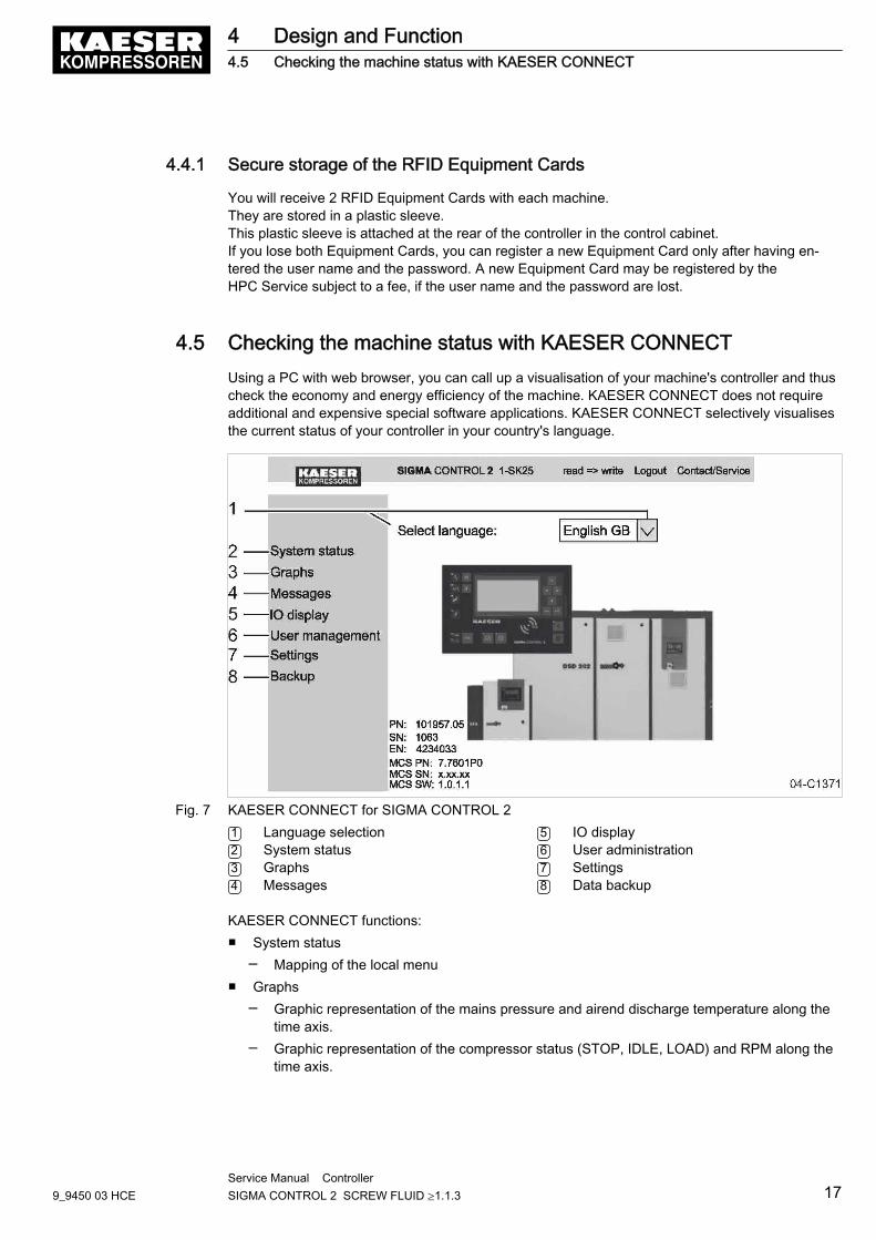
4.4.1 Secure storage of the RFID Equipment Cards
You will receive 2 RFID Equipment Cards with each machine.They are stored in a plastic sleeve.This plastic sleeve is attached at the rear of the controller in the control cabinet.If you lose both Equipment Cards, you can register a new Equipment Card only after having en‐tered the user name and the password. A new Equipment Card may be registered by theHPC Service subject to a fee, if the user name and the password are lost.
4.5 Checking the machine status with KAESER CONNECTUsing a PC with web browser, you can call up a visualisation of your machine's controller and thuscheck the economy and energy efficiency of the machine. KAESER CONNECT does not requireadditional and expensive special software applications. KAESER CONNECT selectively visualisesthe current status of your controller in your country's language.
Fig. 7 KAESER CONNECT for SIGMA CONTROL 21 Language selection2 System status3 Graphs4 Messages
5 IO display6 User administration7 Settings8 Data backup
KAESER CONNECT functions:■ System status
─ Mapping of the local menu■ Graphs
─ Graphic representation of the mains pressure and airend discharge temperature along thetime axis.
─ Graphic representation of the compressor status (STOP, IDLE, LOAD) and RPM along thetime axis.
4 Design and Function4.5 Checking the machine status with KAESER CONNECT
9_9450 03 HCEService Manual Controller SIGMA CONTROL 2 SCREW FLUID ≥1.1.3 17
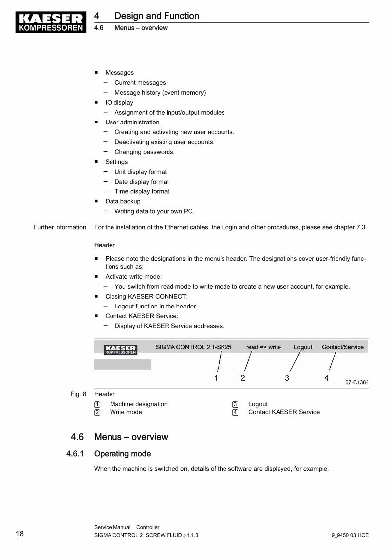
■ Messages─ Current messages─ Message history (event memory)
■ IO display─ Assignment of the input/output modules
■ User administration─ Creating and activating new user accounts.─ Deactivating existing user accounts.─ Changing passwords.
■ Settings─ Unit display format─ Date display format─ Time display format
■ Data backup─ Writing data to your own PC.
Further information For the installation of the Ethernet cables, the Login and other procedures, please see chapter 7.3.
Header
■ Please note the designations in the menu's header. The designations cover user-friendly func‐tions such as:
■ Activate write mode:─ You switch from read mode to write mode to create a new user account, for example.
■ Closing KAESER CONNECT:─ Logout function in the header.
■ Contact KAESER Service:─ Display of KAESER Service addresses.
Fig. 8 Header1 Machine designation2 Write mode
3 Logout4 Contact KAESER Service
4.6 Menus – overview
4.6.1 Operating mode
When the machine is switched on, details of the software are displayed, for example,
4 Design and Function4.6 Menus – overview
18Service Manual Controller SIGMA CONTROL 2 SCREW FLUID ≥1.1.3 9_9450 03 HCE
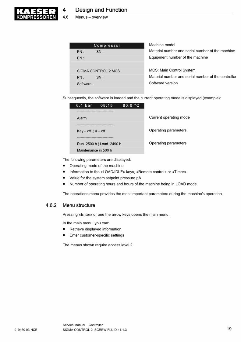
C o m p r e s s o r Machine model
PN : SN : Material number and serial number of the machine
EN : Equipment number of the machine
SIGMA CONTROL 2 MCS MCS: Main Control System
PN : SN : Material number and serial number of the controller
Software : Software version
Subsequently, the software is loaded and the current operating mode is displayed (example):
6 . 1 b a r 0 8 : 1 5 8 0 . 0 ° C------------------------------
Alarm Current operating mode
------------------------------
Key – off ¦ # – off Operating parameters
------------------------------
Run 2500 h ¦ Load 2490 h Operating parameters
Maintenance in 500 h
The following parameters are displayed:■ Operating mode of the machine■ Information to the «LOAD/IDLE» keys, «Remote control» or «Timer»■ Value for the system setpoint pressure pA■ Number of operating hours and hours of the machine being in LOAD mode.
The operations menu provides the most important parameters during the machine's operation.
4.6.2 Menu structure
Pressing «Enter» or one the arrow keys opens the main menu.
In the main menu, you can:■ Retrieve displayed information■ Enter customer-specific settings
The menus shown require access level 2.
4 Design and Function4.6 Menus – overview
9_9450 03 HCEService Manual Controller SIGMA CONTROL 2 SCREW FLUID ≥1.1.3 19
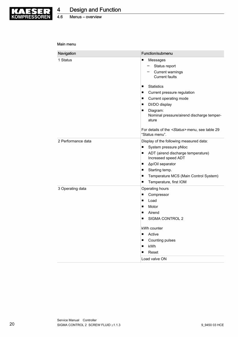
Main menu
Navigation Function/submenu
1 Status ■ Messages─ Status report─ Current warnings
Current faults
■ Statistics■ Current pressure regulation■ Current operating mode■ DI/DO display■ Diagram:
Nominal pressure/airend discharge temper‐ature
For details of the <Status> menu, see table 29“Status menu”.
2 Performance data Display of the following measured data:■ System pressure pNloc■ ADT (airend discharge temperature)
Increased speed ADT■ Δp/Oil separator■ Starting temp.■ Temperature MCS (Main Control System)■ Temperature, first IOM
3 Operating data Operating hours■ Compressor■ Load■ Motor■ Airend■ SIGMA CONTROL 2
kWh counter■ Active■ Counting pulses■ kWh■ Reset
Load valve ON
4 Design and Function4.6 Menus – overview
20Service Manual Controller SIGMA CONTROL 2 SCREW FLUID ≥1.1.3 9_9450 03 HCE
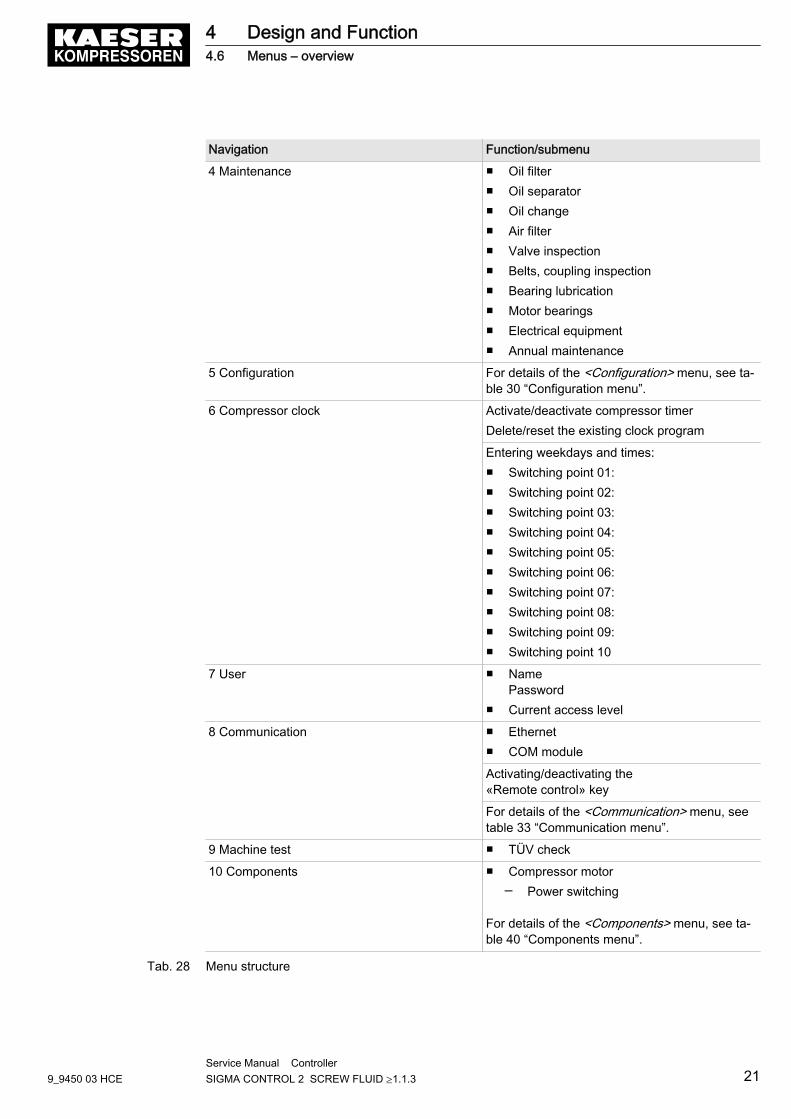
Navigation Function/submenu
4 Maintenance ■ Oil filter■ Oil separator■ Oil change■ Air filter■ Valve inspection■ Belts, coupling inspection■ Bearing lubrication■ Motor bearings■ Electrical equipment■ Annual maintenance
5 Configuration For details of the <Configuration> menu, see ta‐ble 30 “Configuration menu”.
6 Compressor clock Activate/deactivate compressor timerDelete/reset the existing clock program
Entering weekdays and times:■ Switching point 01:■ Switching point 02:■ Switching point 03:■ Switching point 04:■ Switching point 05:■ Switching point 06:■ Switching point 07:■ Switching point 08:■ Switching point 09:■ Switching point 10
7 User ■ NamePassword
■ Current access level
8 Communication ■ Ethernet■ COM module
Activating/deactivating the«Remote control» key
For details of the <Communication> menu, seetable 33 “Communication menu”.
9 Machine test ■ TÜV check
10 Components ■ Compressor motor─ Power switching
For details of the <Components> menu, see ta‐ble 40 “Components menu”.
Tab. 28 Menu structure
4 Design and Function4.6 Menus – overview
9_9450 03 HCEService Manual Controller SIGMA CONTROL 2 SCREW FLUID ≥1.1.3 21
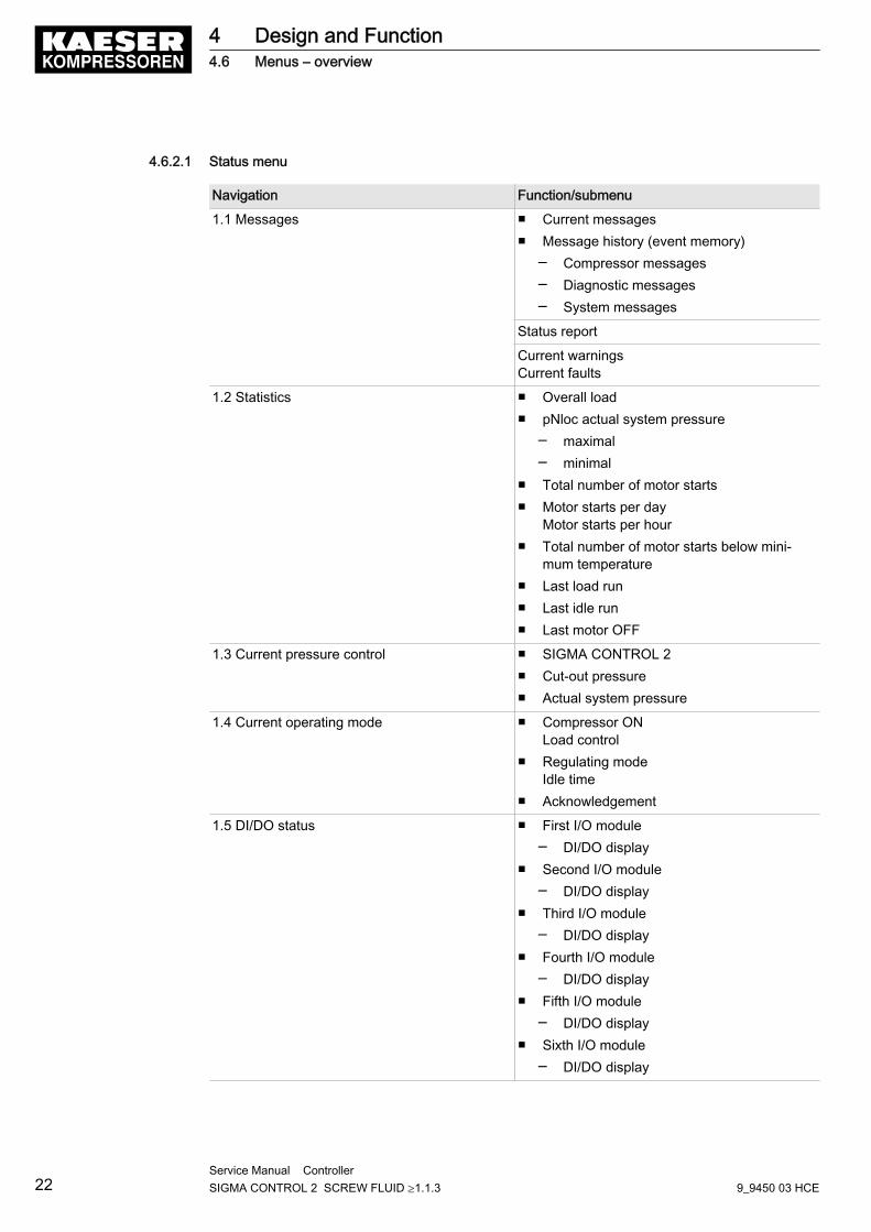
4.6.2.1 Status menu
Navigation Function/submenu
1.1 Messages ■ Current messages■ Message history (event memory)
─ Compressor messages─ Diagnostic messages─ System messages
Status report
Current warningsCurrent faults
1.2 Statistics ■ Overall load■ pNloc actual system pressure
─ maximal─ minimal
■ Total number of motor starts■ Motor starts per day
Motor starts per hour■ Total number of motor starts below mini‐
mum temperature■ Last load run■ Last idle run■ Last motor OFF
1.3 Current pressure control ■ SIGMA CONTROL 2■ Cut-out pressure■ Actual system pressure
1.4 Current operating mode ■ Compressor ON Load control
■ Regulating modeIdle time
■ Acknowledgement
1.5 DI/DO status ■ First I/O module─ DI/DO display
■ Second I/O module─ DI/DO display
■ Third I/O module─ DI/DO display
■ Fourth I/O module─ DI/DO display
■ Fifth I/O module─ DI/DO display
■ Sixth I/O module─ DI/DO display
4 Design and Function4.6 Menus – overview
22Service Manual Controller SIGMA CONTROL 2 SCREW FLUID ≥1.1.3 9_9450 03 HCE
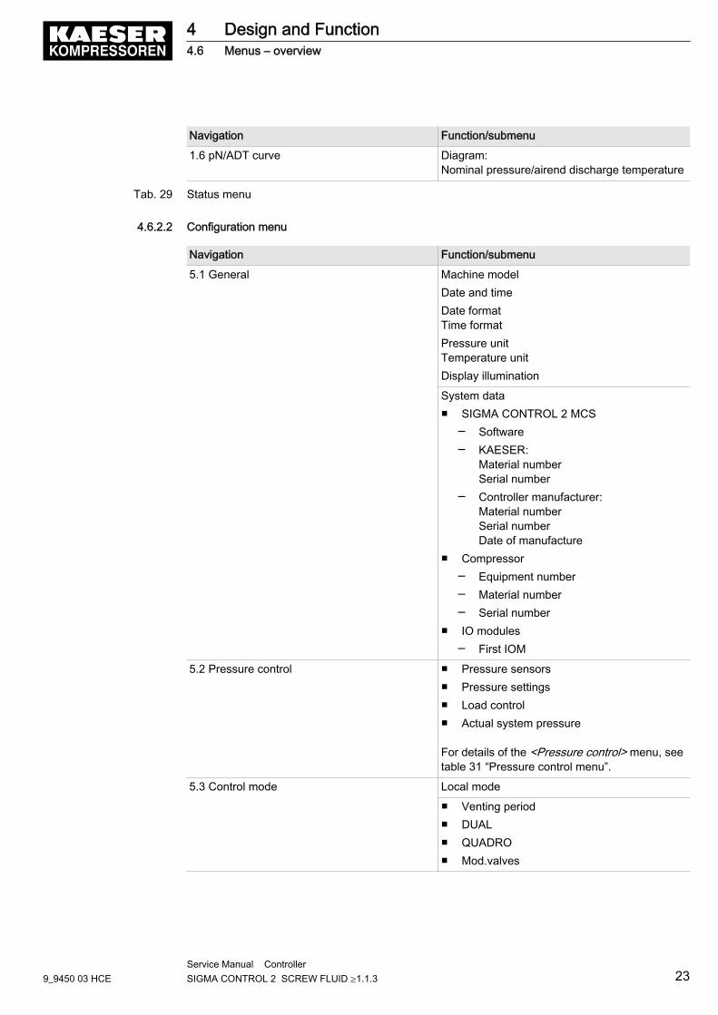
Navigation Function/submenu
1.6 pN/ADT curve Diagram:Nominal pressure/airend discharge temperature
Tab. 29 Status menu
4.6.2.2 Configuration menu
Navigation Function/submenu
5.1 General Machine modelDate and timeDate formatTime formatPressure unitTemperature unitDisplay illumination
System data■ SIGMA CONTROL 2 MCS
─ Software─ KAESER:
Material numberSerial number
─ Controller manufacturer:Material numberSerial numberDate of manufacture
■ Compressor─ Equipment number─ Material number─ Serial number
■ IO modules─ First IOM
5.2 Pressure control ■ Pressure sensors■ Pressure settings■ Load control■ Actual system pressure
For details of the <Pressure control> menu, seetable 31 “Pressure control menu”.
5.3 Control mode Local mode
■ Venting period■ DUAL■ QUADRO■ Mod.valves
4 Design and Function4.6 Menus – overview
9_9450 03 HCEService Manual Controller SIGMA CONTROL 2 SCREW FLUID ≥1.1.3 23
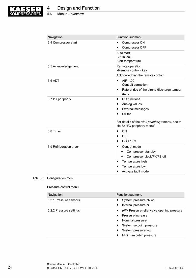
Navigation Function/submenu
5.4 Compressor start ■ Compressor ON■ Compressor OFF
Auto startCut-in lockStart temperature
5.5 Acknowledgement Remote operation«Remote control» keyAcknowledging the remote contact
5.6 ADT ■ AIR 1.00Conduit correction
■ Rate of rise of the airend discharge temper‐ature
5.7 I/O periphery ■ DO functions■ Analog values■ External messages■ Switch
For details of the <I/O periphery> menu, see ta‐ble 32 “I/O periphery menu”.
5.8 Timer ■ ON■ OFF■ DOR 1.03
5.9 Refrigeration dryer ■ Control mode─ Compressor standby─ Compressor clock/FK/FB off
■ Temperature high■ Temperature low■ Activate fault mode
Tab. 30 Configuration menu
Pressure control menu
Navigation Function/submenu
5.2.1 Pressure sensors ■ System pressure pNloc■ Internal pressure pi
5.2.2 Pressure settings ■ pRV Pressure relief valve opening pressure■ Pressure increase■ Nominal pressure■ System setpoint pressure■ System pressure low■ Minimum cut-in pressure
4 Design and Function4.6 Menus – overview
24Service Manual Controller SIGMA CONTROL 2 SCREW FLUID ≥1.1.3 9_9450 03 HCE
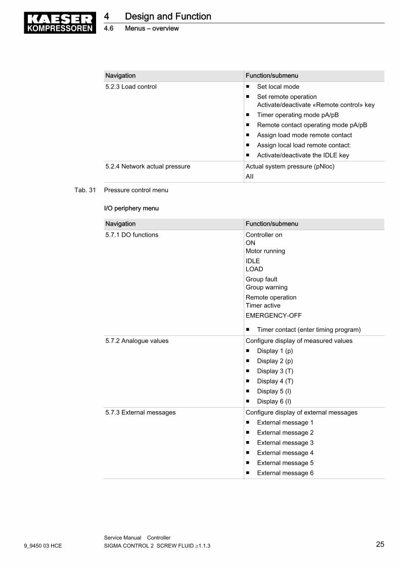
Navigation Function/submenu
5.2.3 Load control ■ Set local mode■ Set remote operation
Activate/deactivate «Remote control» key■ Timer operating mode pA/pB■ Remote contact operating mode pA/pB■ Assign load mode remote contact■ Assign local load remote contact:■ Activate/deactivate the IDLE key
5.2.4 Network actual pressure Actual system pressure (pNloc)AII
Tab. 31 Pressure control menu
I/O periphery menu
Navigation Function/submenu
5.7.1 DO functions Controller onONMotor runningIDLELOADGroup faultGroup warningRemote operationTimer activeEMERGENCY-OFF
■ Timer contact (enter timing program)
5.7.2 Analogue values Configure display of measured values■ Display 1 (p)■ Display 2 (p)■ Display 3 (T)■ Display 4 (T)■ Display 5 (I)■ Display 6 (I)
5.7.3 External messages Configure display of external messages■ External message 1■ External message 2■ External message 3■ External message 4■ External message 5■ External message 6
4 Design and Function4.6 Menus – overview
9_9450 03 HCEService Manual Controller SIGMA CONTROL 2 SCREW FLUID ≥1.1.3 25
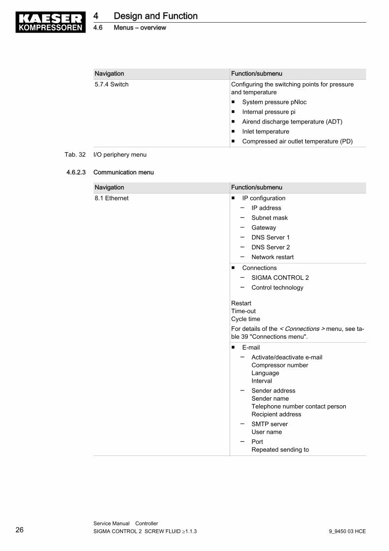
Navigation Function/submenu
5.7.4 Switch Configuring the switching points for pressureand temperature■ System pressure pNloc■ Internal pressure pi■ Airend discharge temperature (ADT)■ Inlet temperature■ Compressed air outlet temperature (PD)
Tab. 32 I/O periphery menu
4.6.2.3 Communication menu
Navigation Function/submenu
8.1 Ethernet ■ IP configuration─ IP address─ Subnet mask─ Gateway─ DNS Server 1─ DNS Server 2─ Network restart
■ Connections─ SIGMA CONTROL 2─ Control technology
RestartTime-outCycle timeFor details of the < Connections > menu, see ta‐ble 39 "Connections menu".
■ E-mail─ Activate/deactivate e-mail
Compressor numberLanguageInterval
─ Sender addressSender nameTelephone number contact personRecipient address
─ SMTP serverUser name
─ PortRepeated sending to
4 Design and Function4.6 Menus – overview
26Service Manual Controller SIGMA CONTROL 2 SCREW FLUID ≥1.1.3 9_9450 03 HCE
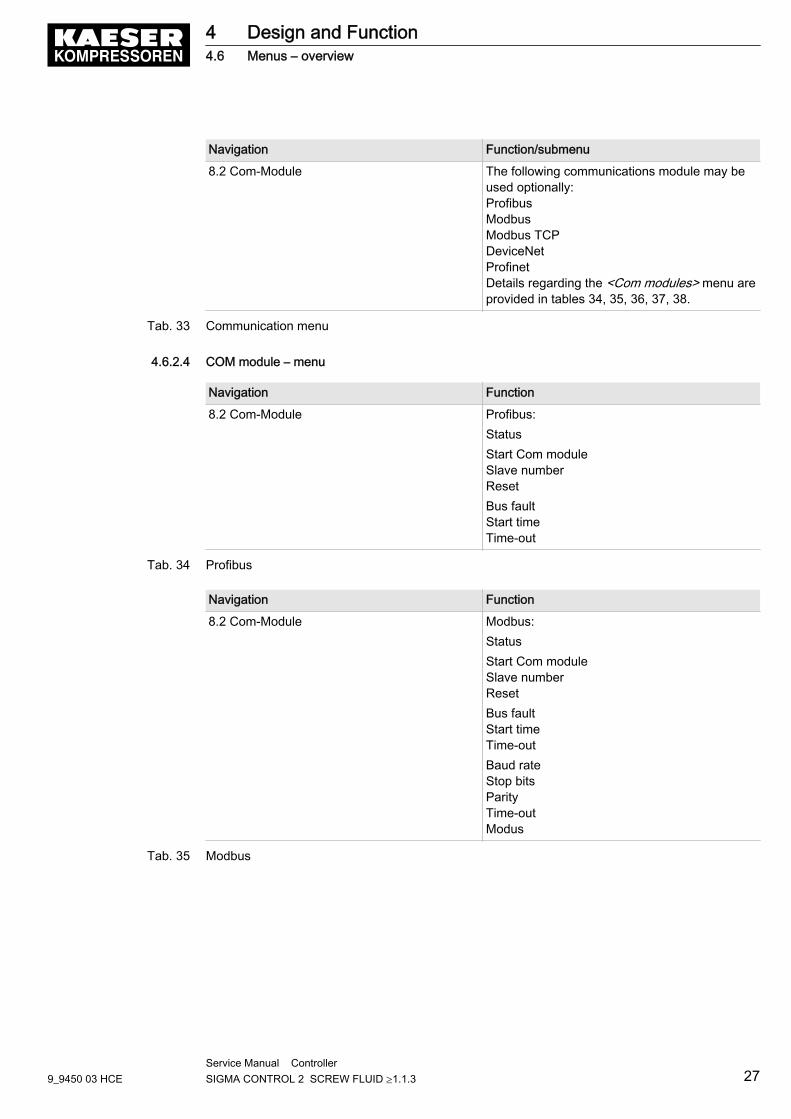
Navigation Function/submenu
8.2 Com-Module The following communications module may beused optionally:ProfibusModbusModbus TCPDeviceNetProfinetDetails regarding the <Com modules> menu areprovided in tables 34, 35, 36, 37, 38.
Tab. 33 Communication menu
4.6.2.4 COM module – menu
Navigation Function
8.2 Com-Module Profibus:StatusStart Com moduleSlave numberResetBus faultStart timeTime-out
Tab. 34 Profibus
Navigation Function
8.2 Com-Module Modbus:StatusStart Com moduleSlave numberResetBus faultStart timeTime-outBaud rateStop bitsParityTime-outModus
Tab. 35 Modbus
4 Design and Function4.6 Menus – overview
9_9450 03 HCEService Manual Controller SIGMA CONTROL 2 SCREW FLUID ≥1.1.3 27
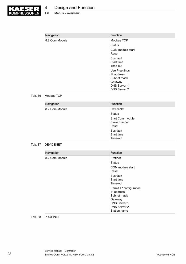
Navigation Function
8.2 Com-Module Modbus TCPStatusCOM module startResetBus faultStart timeTime-outUse P settingsIP addressSubnet maskGatewayDNS Server 1DNS Server 2
Tab. 36 Modbus TCP
Navigation Function
8.2 Com-Module DeviceNetStatusStart Com moduleSlave numberResetBus faultStart timeTime-out
Tab. 37 DEVICENET
Navigation Function
8.2 Com-Module ProfinetStatusCOM module startResetBus faultStart timeTime-outPermit IP configurationIP addressSubnet maskGatewayDNS Server 1DNS Server 2Station name
Tab. 38 PROFINET
4 Design and Function4.6 Menus – overview
28Service Manual Controller SIGMA CONTROL 2 SCREW FLUID ≥1.1.3 9_9450 03 HCE
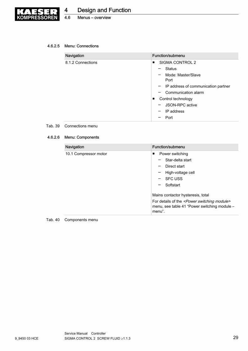
4.6.2.5 Menu: Connections
Navigation Function/submenu
8.1.2 Connections ■ SIGMA CONTROL 2─ Status─ Mode: Master/Slave
Port─ IP address of communication partner─ Communication alarm
■ Control technology─ JSON-RPC active─ IP address─ Port
Tab. 39 Connections menu
4.6.2.6 Menu: Components
Navigation Function/submenu
10.1 Compressor motor ■ Power switching─ Star-delta start─ Direct start─ High-voltage cell─ SFC USS─ Softstart
Mains contactor hysteresis, totalFor details of the <Power switching module>menu, see table 41 “Power switching module –menu”.
Tab. 40 Components menu
4 Design and Function4.6 Menus – overview
9_9450 03 HCEService Manual Controller SIGMA CONTROL 2 SCREW FLUID ≥1.1.3 29
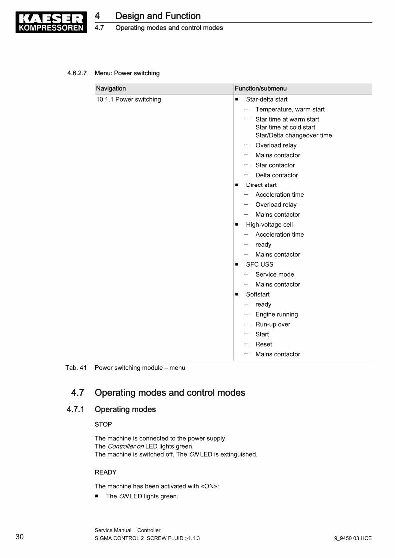
4.6.2.7 Menu: Power switching
Navigation Function/submenu
10.1.1 Power switching ■ Star-delta start─ Temperature, warm start─ Star time at warm start
Star time at cold startStar/Delta changeover time
─ Overload relay─ Mains contactor─ Star contactor─ Delta contactor
■ Direct start─ Acceleration time─ Overload relay─ Mains contactor
■ High-voltage cell─ Acceleration time─ ready─ Mains contactor
■ SFC USS─ Service mode─ Mains contactor
■ Softstart─ ready─ Engine running─ Run-up over─ Start─ Reset─ Mains contactor
Tab. 41 Power switching module – menu
4.7 Operating modes and control modes
4.7.1 Operating modes
STOP
The machine is connected to the power supply.The Controller on LED lights green.The machine is switched off. The ON LED is extinguished.
READY
The machine has been activated with «ON»:■ The ON LED lights green.
4 Design and Function4.7 Operating modes and control modes
30Service Manual Controller SIGMA CONTROL 2 SCREW FLUID ≥1.1.3 9_9450 03 HCE

■ The drive motor is stopped.■ The inlet valve is closed.■ The minimum pressure/check valve shuts off the oil separator from the distribution network.■ The venting valve is open.
The compressor motor starts as soon as system pressure is lower than the set point pressure (cut-off pressure).In addition, timing and/or remote control may affect the start of the motor.
LOAD
The compressor motor runs under load.■ The inlet valve is open.■ The airend delivers compressed air to the distribution network.
IDLE
The compressor motor runs unloaded with low power consumption.■ The inlet valve is closed.■ The minimum pressure/check valve shuts off the oil separator from the distribution network.■ The venting valve is open.
A small volume of air circulates through the bleed hole in the inlet valve, through the airend andback to the inlet valve via the venting line.
4.7.2 Control modes
Using the selected control mode, the controller switches the machine between its various opera‐tional states in order to compensate for air being drawn by consumers, and to maintain the systempressure between the set minimum and maximum values. The control mode also rules the degreeof energy efficiency of the machine.The machine-dependant venting phase between the LOAD and READY operating modes ensuresload changes at minimum material stresses.
The controller SIGMA CONTROL 2 can operate in the following modes:■ DUAL■ QUADRO■ VARIO■ DYNAMIC■ MODULATING control
DUAL
In the DUAL control mode, the machine is switched back and forth between LOAD and IDLE tomaintain the machine working pressure between the preset minimum and maximum values. Whenmaximum pressure is reached, the machine switches to IDLE. When the preset idling time haselapsed the machine is READY.The idling time is factory preset according to the maximum starting frequency of the compressormotor. The shorter the idling time setting, the sooner (and more frequently) the drive motor is stop‐ped.
4 Design and Function4.7 Operating modes and control modes
9_9450 03 HCEService Manual Controller SIGMA CONTROL 2 SCREW FLUID ≥1.1.3 31
Option C1
QUADRO
In contrast to the the DUAL regulating mode, the machine will switch from LOAD to READY inQUADRO mode after periods with low compressed air consumption.After periods with a high compressed air consumption, the machine will switch from LOAD toREADY after passing through IDLE.In this control mode, the controller requires two specified times: The running time and the idle/standstill time.The shorter these times are set, the sooner (and more frequently) the motor is stopped.
VARIO
The VARIO mode is based on the DUAL control mode. The difference to DUAL is that the idlingtime is automatically lengthened or shortened to compensate for higher or lower machine startingfrequencies.
CONTINUOUS
In the DUAL control mode, the machine is switched back and forth between LOAD and IDLE, inorder to maintain the machine working pressure between the preset minimum and maximum val‐ues. When maximum pressure is reached, the machine switches to IDLE. However, the machinedoes not switch to READY.
DYNAMIC
In contrast to the the DUAL regulating mode, the machine will switch from LOAD to READY inDYNAMIC mode at low drive motor temperature.And from LOAD via IDLE to READY at a high drive motor temperature.The lower the drive motor temperature, the sooner (and, therefore, more often and longer) it isstopped.
MODULATING control
The MODULATING control is an additional mechanical regulation. It continuously changes the de‐livery volume within the machine's control range.A control valve, the proportional controller, changes the degree of opening of the inlet valve whenthe machine transports compressed air into the air network (LOAD)The load and power consumption of the drive motor rises and falls with the air demand.
4.7.3 Frequency-controlled drive (SFC)
If the machine runs in LOAD,the frequency converter compares the ACTUAL value with the TAR‐GET value of the system pressure and regulates, depending on the difference, the speed of thecompressor motor and the airend.The speed of the airend determines the rate of compressed air delivery and the working pressure.If air consumption rises, the frequency converter increases motor speed and therefore increasesthe volume of air delivered.If air consumption drops, the converter reduces motor speed and therefore reduces the volume ofair delivered.The network pressure remains constant – within the control range of the converter – regardless offluctuating air demand.
4 Design and Function4.7 Operating modes and control modes
32Service Manual Controller SIGMA CONTROL 2 SCREW FLUID ≥1.1.3 9_9450 03 HCE
Option C1
If the network pressure exceeds the TARGET value:
Outside the frequency converter's range of control the machine reverts to the selected controlmode.
DUAL:The minimum controllable speed is reached and the machine switches to IDLE. The drive motorruns unloaded with low power consumption.When the preset idling time has elapsed, the machine switches tdo READY.VARIO/QUADRO/CONTINUOUS:The minimum controllable speed is reached and, depending on the air demand at the time, the ma‐chine switches either to READY or to IDLE.DYNAMIC:The minimum controllable speed is reached and, depending on the air temperature of the drive mo‐tor, the machine switches either to READY or to IDLE.
If the network pressure falls below the TARGET value:
The frequency converter runs the motor up to a speed at which air delivery matches the air de‐mand.The inlet valve opens and the machine delivers compressed air.The frequency converter varies the speed of the drive motor according to the air demand. Thepower consumption of the drive motor rises and falls according to air demand.
4.7.4 MODULATING control
With the help of a mechanical control valve (the proportional controller), the opening and closing ofthe inlet valve is continuously varied in relation to the actual air demand. The airend delivers com‐pressed air to the distribution network.The load and power consumption of the drive motor rises and falls with the air demand.To ensure optimal control on large compressors, the control air for the proportional controller is tak‐en from an external air receiver.
4 Design and Function4.7 Operating modes and control modes
9_9450 03 HCEService Manual Controller SIGMA CONTROL 2 SCREW FLUID ≥1.1.3 33
5 Installation and Operating Conditions5.1 Maintaining ambient conditions
➤ Follow the instructions in the machine's service manual.
5.2 Installation conditionsThe installation and operating conditions depend the machine into which the controller is installed.
NOTICEUV radiation!Direct sunlight (UV radiation) can destroy the display screen.➤ Do not allow the display screen to be subjected to direct sunlight.
➤ See the machine's operating manual for required conditions.
5 Installation and Operating Conditions5.1 Maintaining ambient conditions
34Service Manual Controller SIGMA CONTROL 2 SCREW FLUID ≥1.1.3 9_9450 03 HCE
6 Installation6.1 Reporting Transport Damage
1. Check the machine for visible and hidden transport damage.2. Inform the carrier and the manufacturer in writing of any damage without delay.
6.2 Machine identificationIf the machine is run in sequenced operation its identification as detailed in the installation diagramis to be taken into account.
Identifying the machine for operation in remote mode.
➤ Attach the following notice to warn of remote machine operation (suggestion):
Remote control: danger of unexpected starting!➤ Make sure the power supply disconnecting device is switched off before commencing any
work on the machine.
Tab. 42 Machine identification
➤ Label the starting device in the remote control centre as follows (suggestions):
Remote control: danger of unexpected starting!➤ Before starting, make sure that no one is working on the machine and that it can be safely
started.
Tab. 43 Remote control identification
Identifying the machine for clock control mode operation
➤ Attach the following notice to warn of remote machine operation (suggestion):
Clock control: danger of unexpected starting!➤ Make sure the power supply disconnecting device is switched off before commencing any
work on the machine.
Tab. 44 Machine identification
6 Installation6.1 Reporting Transport Damage
9_9450 03 HCEService Manual Controller SIGMA CONTROL 2 SCREW FLUID ≥1.1.3 35
7 Initial Start-up7.1 Outline
SIGMA CONTROL 2 was designed and developed for a number of applications. Potential settingsare correspondingly varied.It is possible that only a few of these settings are needed for the initial start-up. This depends onthe application.The following sections explain the large number of practical applications, but only one configurationis relevant for any specific use.7.2: Configuring the controller (display format, units, languages, etc.)7.3: Using KAESER CONNECT7.4: Adjusting the pressure parameters of the machine and possible modules7.5: Configuring machine start and stop7.6: Activating and adjusting the control modes7.8: Configuring the machine for local mode7.9: Configuring the machine for master control7.10: Configuring e-mail7.11: Configuring input and output signals7.12: Activating remote acknowledgement7.13: Linking to an external pressure transducer7.14: Commissioning the machine
7.2 Configuring the controllerAll controller settings are explained in detail in the following sections. The most common set‐tings are summarised for experienced users in section "Important settings" in the beginning ofthis manual.
➤ Carry out settings as required:■ 7.2.1: Selecting menu options (introduction)■ 7.2.2: Changing the display language■ 7.2.3: Note the number of the KAESER Equipment Card■ 7.2.4: Control access to SIGMA CONTROL 2 with the Equipment Card■ 7.2.5: Generate password for SIGMA CONTROL 2■ 7.2.6: Control access to SIGMA CONTROL 2 via manual input■ 7.2.7: Generate password for KAESER CONNECT■ 7.2.8: Set time and date■ 7.2.9: Set display formats (date, time, units of pressure and temperature)■ 7.2.10: Activate summer/winter time■ 7.3.6: Add user accounts
7.2.1 Selecting menu options
All menu options can be selected with the «DOWN», «UP» and «Enter» keys.
7 Initial Start-up7.1 Outline
36Service Manual Controller SIGMA CONTROL 2 SCREW FLUID ≥1.1.3 9_9450 03 HCE

Example: Select < Configuration ➙ General> menu option
Precondition The display shows the operating mode.
1. Press «Enter».The main menu is displayed.
2. Press the «UP» or «DOWN» key until Configuration is displayed as active line.3. In order to open the < Configuration > menu, press «Enter» once.4. Use the «DOWN» or «UP» keys to select a submenu in the < Configuration > menu, < General
> or < Pressure control > for instance.5. Press «UP» repeatedly until General is displayed as active line.6. Press «Enter».
The current menu is the < General > submenu in the < Configuration > menu.7. Use the «DOWN» or «UP» keys to select a menu option in the < General > submenu, <
System information > for instance.
7.2.2 Changing the display language
The controller can display text messages in the following languages:
... Estonian Italian Norwegian SpanishBulgarian Finnish Japanese Polish Spanish
(South-America)Chinese French Korean Portuguese CzechDanish French
(Canada)Croatian Romanian Turkish
German Greek Latvian Russian ...English Hebrew Lithuanian Swedish ...English(USA)
Indonesian Dutch Slovenian ...
Tab. 45 Language diversity
Some of the units, as well as clock and date format, will be adjusted according to the languageselected.
Precondition The display shows the operating mode.
1. Press «Enter».The main menu is displayed.
2. Press the «UP» key once.The set language is displayed as being active.
3. Use the «Enter» key to switch to setting mode.The currently set language flashes.
4. Use the «DOWN» or «UP» keys to select the desired language.5. Press «Enter» to accept the setting.6. Press «Escape» repeatedly to return to the main menu.
The display texts are now in the selected language.
7 Initial Start-up7.2 Configuring the controller
9_9450 03 HCEService Manual Controller SIGMA CONTROL 2 SCREW FLUID ≥1.1.3 37
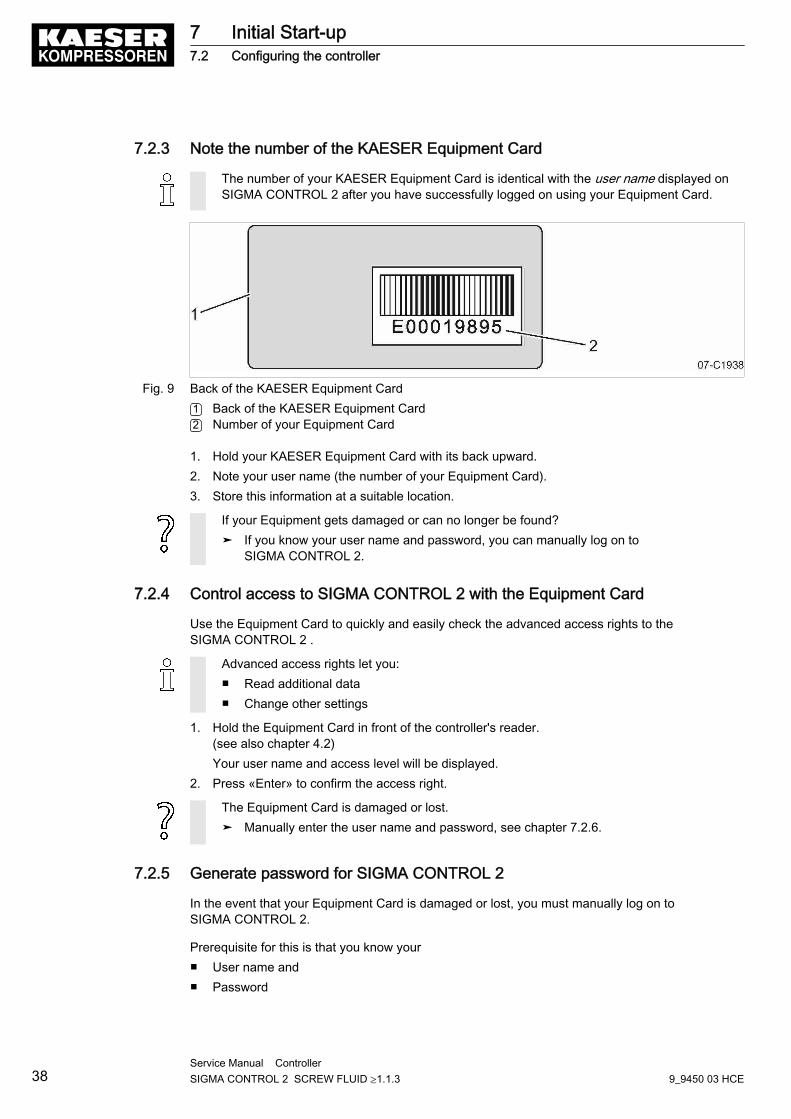
7.2.3 Note the number of the KAESER Equipment Card
The number of your KAESER Equipment Card is identical with the user name displayed onSIGMA CONTROL 2 after you have successfully logged on using your Equipment Card.
Fig. 9 Back of the KAESER Equipment Card1 Back of the KAESER Equipment Card2 Number of your Equipment Card
1. Hold your KAESER Equipment Card with its back upward.2. Note your user name (the number of your Equipment Card).3. Store this information at a suitable location.
If your Equipment gets damaged or can no longer be found?➤ If you know your user name and password, you can manually log on to
SIGMA CONTROL 2.
7.2.4 Control access to SIGMA CONTROL 2 with the Equipment Card
Use the Equipment Card to quickly and easily check the advanced access rights to theSIGMA CONTROL 2 .
Advanced access rights let you:■ Read additional data■ Change other settings
1. Hold the Equipment Card in front of the controller's reader.(see also chapter 4.2)Your user name and access level will be displayed.
2. Press «Enter» to confirm the access right.
The Equipment Card is damaged or lost.➤ Manually enter the user name and password, see chapter 7.2.6.
7.2.5 Generate password for SIGMA CONTROL 2
In the event that your Equipment Card is damaged or lost, you must manually log on toSIGMA CONTROL 2.
Prerequisite for this is that you know your■ User name and■ Password
7 Initial Start-up7.2 Configuring the controller
38Service Manual Controller SIGMA CONTROL 2 SCREW FLUID ≥1.1.3 9_9450 03 HCE
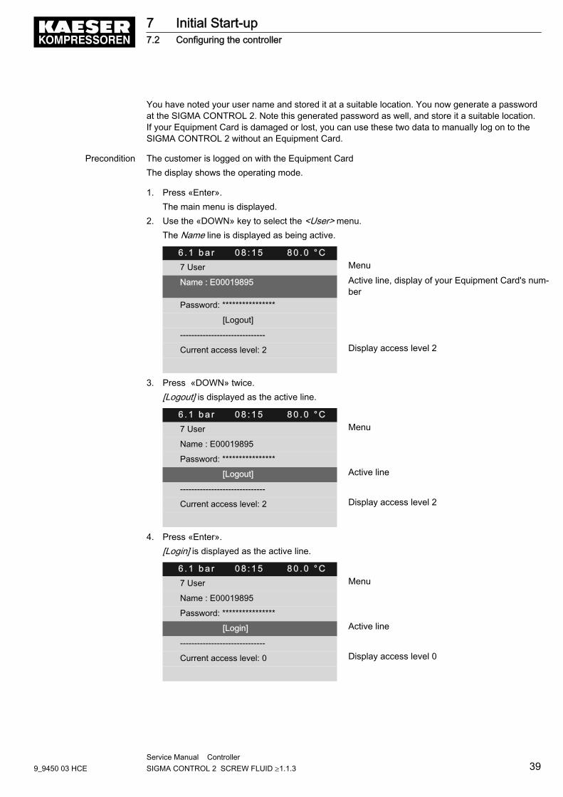
You have noted your user name and stored it at a suitable location. You now generate a passwordat the SIGMA CONTROL 2. Note this generated password as well, and store it a suitable location.If your Equipment Card is damaged or lost, you can use these two data to manually log on to theSIGMA CONTROL 2 without an Equipment Card.
Precondition The customer is logged on with the Equipment CardThe display shows the operating mode.
1. Press «Enter».The main menu is displayed.
2. Use the «DOWN» key to select the <User> menu.The Name line is displayed as being active.
6 . 1 b a r 0 8 : 1 5 8 0 . 0 ° C7 User Menu
Name : E00019895 Active line, display of your Equipment Card's num‐ber
Password: ****************
[Logout]
------------------------------
Current access level: 2 Display access level 2
3. Press «DOWN» twice.[Logout] is displayed as the active line.
6 . 1 b a r 0 8 : 1 5 8 0 . 0 ° C7 User Menu
Name : E00019895
Password: ****************
[Logout] Active line
------------------------------
Current access level: 2 Display access level 2
4. Press «Enter».[Login] is displayed as the active line.
6 . 1 b a r 0 8 : 1 5 8 0 . 0 ° C7 User Menu
Name : E00019895
Password: ****************
[Login] Active line
------------------------------
Current access level: 0 Display access level 0
7 Initial Start-up7.2 Configuring the controller
9_9450 03 HCEService Manual Controller SIGMA CONTROL 2 SCREW FLUID ≥1.1.3 39
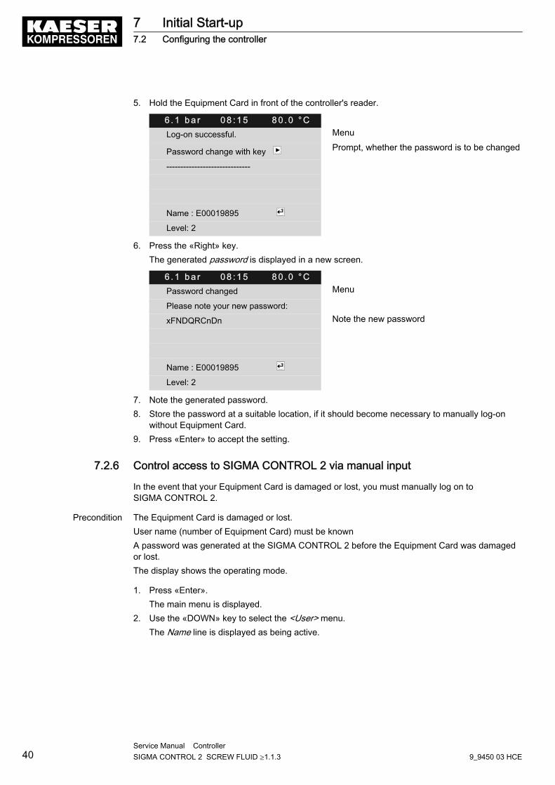
5. Hold the Equipment Card in front of the controller's reader.
6 . 1 b a r 0 8 : 1 5 8 0 . 0 ° CLog-on successful. Menu
Password change with key Prompt, whether the password is to be changed
------------------------------
Name : E00019895
Level: 2
6. Press the «Right» key.The generated password is displayed in a new screen.
6 . 1 b a r 0 8 : 1 5 8 0 . 0 ° CPassword changed Menu
Please note your new password:
xFNDQRCnDn Note the new password
Name : E00019895
Level: 2
7. Note the generated password.8. Store the password at a suitable location, if it should become necessary to manually log-on
without Equipment Card.9. Press «Enter» to accept the setting.
7.2.6 Control access to SIGMA CONTROL 2 via manual input
In the event that your Equipment Card is damaged or lost, you must manually log on toSIGMA CONTROL 2.
Precondition The Equipment Card is damaged or lost.User name (number of Equipment Card) must be knownA password was generated at the SIGMA CONTROL 2 before the Equipment Card was damagedor lost.The display shows the operating mode.
1. Press «Enter».The main menu is displayed.
2. Use the «DOWN» key to select the <User> menu.The Name line is displayed as being active.
7 Initial Start-up7.2 Configuring the controller
40Service Manual Controller SIGMA CONTROL 2 SCREW FLUID ≥1.1.3 9_9450 03 HCE
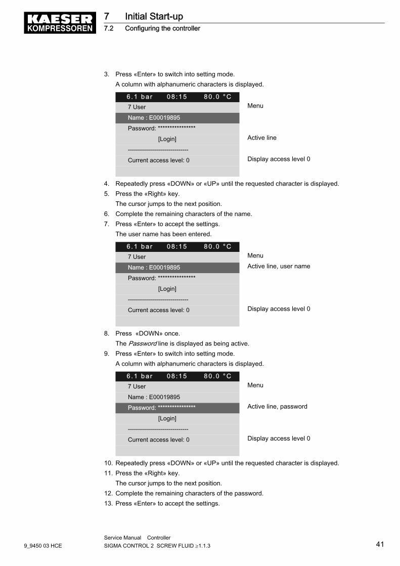
3. Press «Enter» to switch into setting mode.A column with alphanumeric characters is displayed.
6 . 1 b a r 0 8 : 1 5 8 0 . 0 ° C7 User Menu
Name : E00019895
Password: ****************
[Login] Active line
------------------------------
Current access level: 0 Display access level 0
4. Repeatedly press «DOWN» or «UP» until the requested character is displayed.5. Press the «Right» key.
The cursor jumps to the next position.6. Complete the remaining characters of the name.7. Press «Enter» to accept the settings.
The user name has been entered.
6 . 1 b a r 0 8 : 1 5 8 0 . 0 ° C7 User Menu
Name : E00019895 Active line, user name
Password: ****************
[Login]
------------------------------
Current access level: 0 Display access level 0
8. Press «DOWN» once.The Password line is displayed as being active.
9. Press «Enter» to switch into setting mode.A column with alphanumeric characters is displayed.
6 . 1 b a r 0 8 : 1 5 8 0 . 0 ° C7 User Menu
Name : E00019895
Password: **************** Active line, password
[Login]
------------------------------
Current access level: 0 Display access level 0
10. Repeatedly press «DOWN» or «UP» until the requested character is displayed.11. Press the «Right» key.
The cursor jumps to the next position.12. Complete the remaining characters of the password.13. Press «Enter» to accept the settings.
7 Initial Start-up7.2 Configuring the controller
9_9450 03 HCEService Manual Controller SIGMA CONTROL 2 SCREW FLUID ≥1.1.3 41
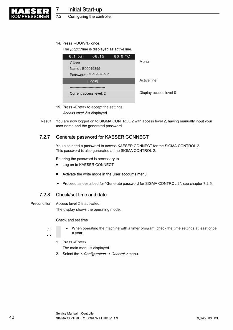
14. Press «DOWN» once.The [Login] line is displayed as active line.
6 . 1 b a r 0 8 : 1 5 8 0 . 0 ° C7 User Menu
Name : E00019895
Password: ****************
[Login] Active line
------------------------------
Current access level: 2 Display access level 0
15. Press «Enter» to accept the settings.Access level 2 is displayed.
Result You are now logged on to SIGMA CONTROL 2 with access level 2, having manually input youruser name and the generated password.
7.2.7 Generate password for KAESER CONNECT
You also need a password to access KAESER CONNECT for the SIGMA CONTROL 2.This password is also generated at the SIGMA CONTROL 2.
Entering the password is necessary to■ Log on to KAESER CONNECT
■ Activate the write mode in the User accounts menu
➤ Proceed as described for "Generate password for SIGMA CONTROL 2”, see chapter 7.2.5.
7.2.8 Check/set time and date
Precondition Access level 2 is activated.The display shows the operating mode.
Check and set time
➤ When operating the machine with a timer program, check the time settings at least oncea year.
1. Press «Enter».The main menu is displayed.
2. Select the < Configuration ➙ General > menu.
7 Initial Start-up7.2 Configuring the controller
42Service Manual Controller SIGMA CONTROL 2 SCREW FLUID ≥1.1.3 9_9450 03 HCE

3. Press the «DOWN» key repeatedly until the current time is displayed as active line.
6 . 1 b a r 0 8 : 1 5 8 0 . 0 ° C5.1 General Menu
▶1 System information
·········
Model:
·········
Date/time
13:04:11 08:15:37 Current time
4. Press the «Right» key.5. Press «Enter» to switch into setting mode.
The hours display flashes. 00: 00: 00.6. Use «UP» or «DOWN» to change the hour setting.7. Press the «Right» key.
The minutes display flashes. 00: 00: 00.8. Use «UP» or «DOWN» to change the minute setting.9. Press the «Right» key.
The seconds display flashes. 00: 00: 00 .10. Use «UP» or «DOWN» to change the second setting.11. Press «Enter» to save the settings.12. Press «Escape» repeatedly to return to the main menu.
Check/set the date
Precondition Password level 2 is activated,the < Configuration ➙ General > menu is selected (see 7.2.1).
1. Press the «DOWN» key repeatedly until the current date is displayed as active line.
6 . 1 b a r 0 8 : 1 5 8 0 . 0 ° C5.1 General Menu
▶1 System information
·········
Model:
·········
Date/time
13:04:11 08:15:37 Current date
2. Press «Enter» to switch into setting mode.The day display flashes. 00: 00: 00.
3. Use «UP» or «DOWN» to change the day setting.4. Press the «Right» key.
The month display flashes. 00: 00: 00.5. Use «UP» or «DOWN» to change the month setting.6. Press the «Right» key.
The year display flashes. 00: 00: 00 .
7 Initial Start-up7.2 Configuring the controller
9_9450 03 HCEService Manual Controller SIGMA CONTROL 2 SCREW FLUID ≥1.1.3 43
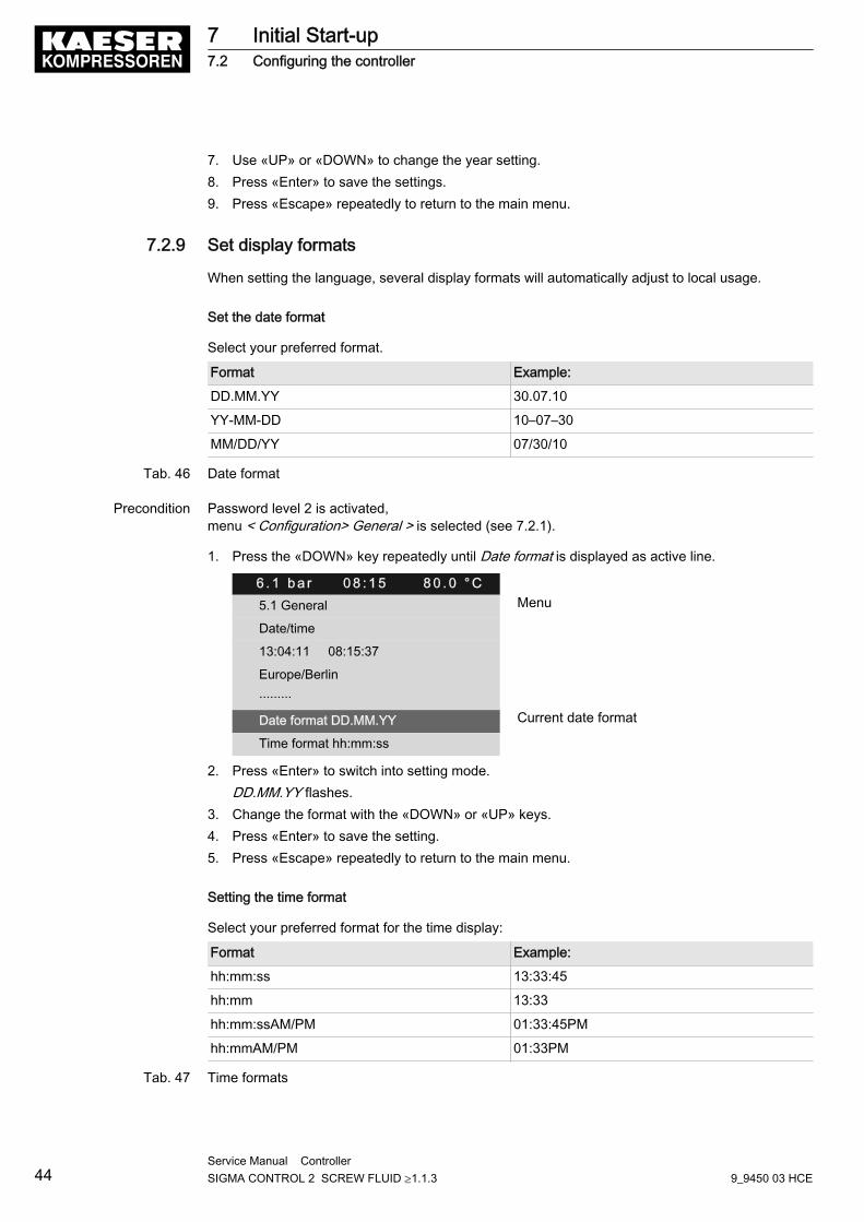
7. Use «UP» or «DOWN» to change the year setting.8. Press «Enter» to save the settings.9. Press «Escape» repeatedly to return to the main menu.
7.2.9 Set display formats
When setting the language, several display formats will automatically adjust to local usage.
Set the date format
Select your preferred format.
Format Example:
DD.MM.YY 30.07.10
YY-MM-DD 10–07–30
MM/DD/YY 07/30/10
Tab. 46 Date format
Precondition Password level 2 is activated,menu < Configuration> General > is selected (see 7.2.1).
1. Press the «DOWN» key repeatedly until Date format is displayed as active line.
6 . 1 b a r 0 8 : 1 5 8 0 . 0 ° C5.1 General Menu
Date/time
13:04:11 08:15:37
Europe/Berlin
·········
Date format DD.MM.YY Current date format
Time format hh:mm:ss
2. Press «Enter» to switch into setting mode.DD.MM.YY flashes.
3. Change the format with the «DOWN» or «UP» keys.4. Press «Enter» to save the setting.5. Press «Escape» repeatedly to return to the main menu.
Setting the time format
Select your preferred format for the time display:
Format Example:
hh:mm:ss 13:33:45
hh:mm 13:33
hh:mm:ssAM/PM 01:33:45PM
hh:mmAM/PM 01:33PM
Tab. 47 Time formats
7 Initial Start-up7.2 Configuring the controller
44Service Manual Controller SIGMA CONTROL 2 SCREW FLUID ≥1.1.3 9_9450 03 HCE
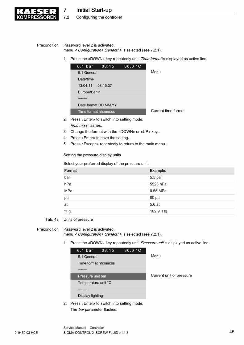
Precondition Password level 2 is activated,menu < Configuration> General > is selected (see 7.2.1).
1. Press the «DOWN» key repeatedly until Time format is displayed as active line.
6 . 1 b a r 0 8 : 1 5 8 0 . 0 ° C5.1 General Menu
Date/time
13:04:11 08:15:37
Europe/Berlin
·········
Date format DD.MM.YY
Time format hh:mm:ss Current time format
2. Press «Enter» to switch into setting mode.hh:mm:ss flashes.
3. Change the format with the «DOWN» or «UP» keys.4. Press «Enter» to save the setting.5. Press «Escape» repeatedly to return to the main menu.
Setting the pressure display units
Select your preferred display of the pressure unit:
Format Example:
bar 5.5 bar
hPa 5523 hPa
MPa 0.55 MPa
psi 80 psi
at 5.6 at
"Hg 162.9 "Hg
Tab. 48 Units of pressure
Precondition Password level 2 is activated,menu < Configuration> General > is selected (see 7.2.1).
1. Press the «DOWN» key repeatedly until Pressure unit is displayed as active line.
6 . 1 b a r 0 8 : 1 5 8 0 . 0 ° C5.1 General Menu
Time format hh:mm:ss
·········
Pressure unit bar Current unit of pressure
Temperature unit °C
·········
Display lighting
2. Press «Enter» to switch into setting mode.The bar parameter flashes.
7 Initial Start-up7.2 Configuring the controller
9_9450 03 HCEService Manual Controller SIGMA CONTROL 2 SCREW FLUID ≥1.1.3 45
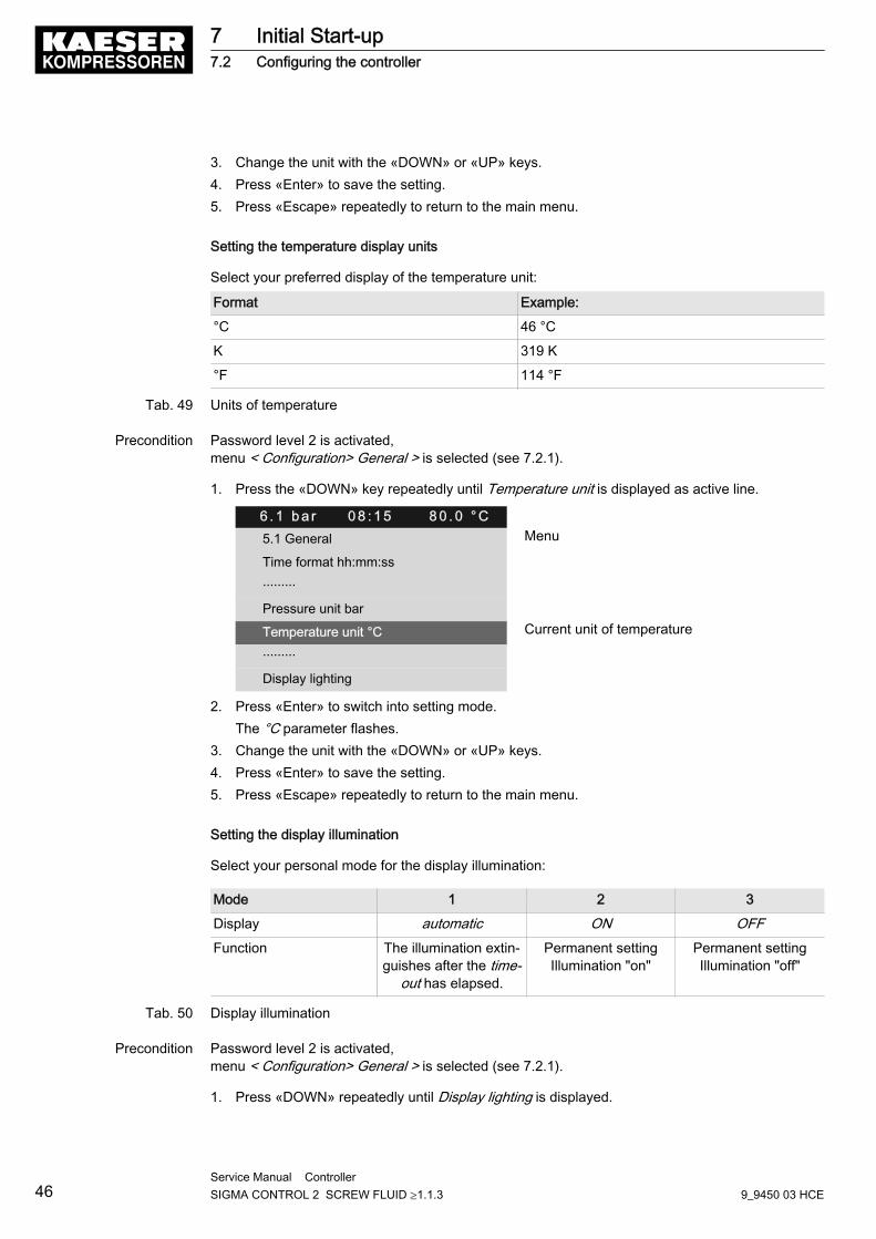
3. Change the unit with the «DOWN» or «UP» keys.4. Press «Enter» to save the setting.5. Press «Escape» repeatedly to return to the main menu.
Setting the temperature display units
Select your preferred display of the temperature unit:
Format Example:
°C 46 °C
K 319 K
°F 114 °F
Tab. 49 Units of temperature
Precondition Password level 2 is activated,menu < Configuration> General > is selected (see 7.2.1).
1. Press the «DOWN» key repeatedly until Temperature unit is displayed as active line.
6 . 1 b a r 0 8 : 1 5 8 0 . 0 ° C5.1 General Menu
Time format hh:mm:ss
·········
Pressure unit bar
Temperature unit °C Current unit of temperature
·········
Display lighting
2. Press «Enter» to switch into setting mode.The °C parameter flashes.
3. Change the unit with the «DOWN» or «UP» keys.4. Press «Enter» to save the setting.5. Press «Escape» repeatedly to return to the main menu.
Setting the display illumination
Select your personal mode for the display illumination:
Mode 1 2 3
Display automatic ON OFFFunction The illumination extin‐
guishes after the time-out has elapsed.
Permanent settingIllumination "on"
Permanent settingIllumination "off"
Tab. 50 Display illumination
Precondition Password level 2 is activated,menu < Configuration> General > is selected (see 7.2.1).
1. Press «DOWN» repeatedly until Display lighting is displayed.
7 Initial Start-up7.2 Configuring the controller
46Service Manual Controller SIGMA CONTROL 2 SCREW FLUID ≥1.1.3 9_9450 03 HCE
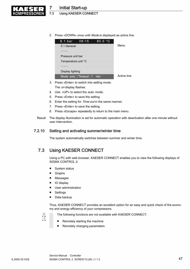
2. Press «DOWN» once until Mode is displayed as active line.
6 . 1 b a r 0 8 : 1 5 8 0 . 0 ° C5.1 General Menu
·········
Pressure unit bar
Temperature unit °C
·········
Display lighting
Mode: auto. ¦ Timeout : 1 min Active line
3. Press «Enter» to switch into setting mode.The on display flashes.
4. Use «UP» to select the auto. mode.5. Press «Enter» to save the setting.6. Enter the setting for Time-out in the same manner.7. Press «Enter» to save the setting.8. Press «Escape» repeatedly to return to the main menu.
Result The display illumination is set for automatic operation with deactivation after one minute withoutuser intervention.
7.2.10 Setting and activating summer/winter time
The system automatically switches between summer and winter time.
7.3 Using KAESER CONNECTUsing a PC with web browser, KAESER CONNECT enables you to view the following displays ofSIGMA CONTROL 2:
■ System status■ Graphs■ Messages■ IO display■ User administration■ Settings■ Data backup
Thus, KAESER CONNECT provides an excellent option for an easy and quick check of the econo‐my and energy efficiency of your compressors.
The following functions are not available with KAESER CONNECT:
■ Remotely starting the machine■ Remotely changing parameters
7 Initial Start-up7.3 Using KAESER CONNECT
9_9450 03 HCEService Manual Controller SIGMA CONTROL 2 SCREW FLUID ≥1.1.3 47
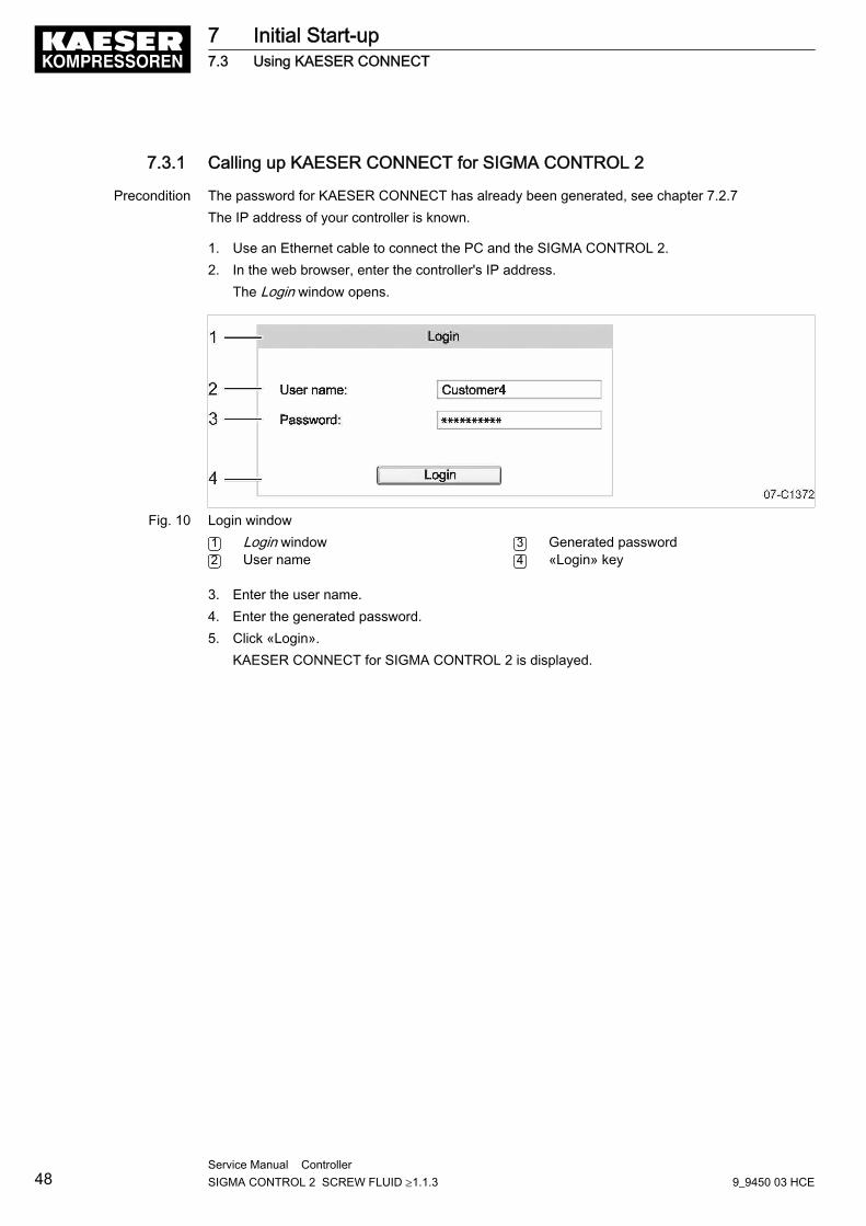
7.3.1 Calling up KAESER CONNECT for SIGMA CONTROL 2
Precondition The password for KAESER CONNECT has already been generated, see chapter 7.2.7The IP address of your controller is known.
1. Use an Ethernet cable to connect the PC and the SIGMA CONTROL 2.2. In the web browser, enter the controller's IP address.
The Login window opens.
Fig. 10 Login window1 Login window2 User name
3 Generated password4 «Login» key
3. Enter the user name.4. Enter the generated password.5. Click «Login».
KAESER CONNECT for SIGMA CONTROL 2 is displayed.
7 Initial Start-up7.3 Using KAESER CONNECT
48Service Manual Controller SIGMA CONTROL 2 SCREW FLUID ≥1.1.3 9_9450 03 HCE
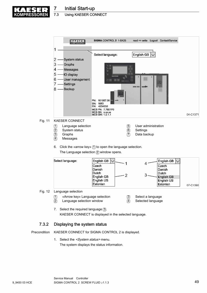
Fig. 11 KAESER CONNECT1 Language selection2 System status3 Graphs4 Messages
5 User administration6 Settings7 Data backup
6. Click the «arrow key» 1 to open the language selection.The Language selection 2 window opens.
Fig. 12 Language selection1 «Arrow key» Language selection2 Language selection window
3 Select a language4 Selected language
7. Select the required language 3 .KAESER CONNECT is displayed in the selected language.
7.3.2 Displaying the system status
Precondition KAESER CONNECT for SIGMA CONTROL 2 is displayed.
1. Select the <System status> menu.The system displays the status information.
7 Initial Start-up7.3 Using KAESER CONNECT
9_9450 03 HCEService Manual Controller SIGMA CONTROL 2 SCREW FLUID ≥1.1.3 49
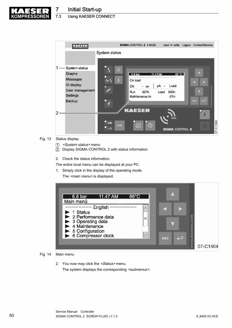
Fig. 13 Status display1 <System status> menu2 Display SIGMA CONTROL 2 with status information
2. Check the status information.The entire local menu can be displayed at your PC.1. Simply click in the display of the operating mode.
The <main menu> is displayed.
Fig. 14 Main menu
2. You now may click the <Status> menu.The system displays the corresponding <submenus>.
7 Initial Start-up7.3 Using KAESER CONNECT
50Service Manual Controller SIGMA CONTROL 2 SCREW FLUID ≥1.1.3 9_9450 03 HCE
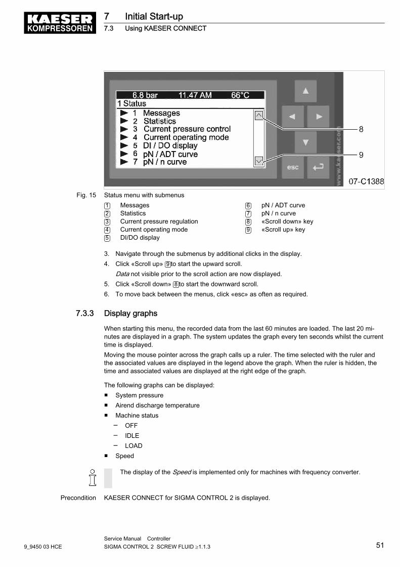
Fig. 15 Status menu with submenus1 Messages2 Statistics3 Current pressure regulation4 Current operating mode5 DI/DO display
6 pN / ADT curve7 pN / n curve8 «Scroll down» key9 «Scroll up» key
3. Navigate through the submenus by additional clicks in the display.4. Click «Scroll up» 9 to start the upward scroll.
Data not visible prior to the scroll action are now displayed.5. Click «Scroll down» 8 to start the downward scroll.6. To move back between the menus, click «esc» as often as required.
7.3.3 Display graphs
When starting this menu, the recorded data from the last 60 minutes are loaded. The last 20 mi‐nutes are displayed in a graph. The system updates the graph every ten seconds whilst the currenttime is displayed.Moving the mouse pointer across the graph calls up a ruler. The time selected with the ruler andthe associated values are displayed in the legend above the graph. When the ruler is hidden, thetime and associated values are displayed at the right edge of the graph.
The following graphs can be displayed:■ System pressure■ Airend discharge temperature■ Machine status
─ OFF─ IDLE─ LOAD
■ Speed
The display of the Speed is implemented only for machines with frequency converter.
Precondition KAESER CONNECT for SIGMA CONTROL 2 is displayed.
7 Initial Start-up7.3 Using KAESER CONNECT
9_9450 03 HCEService Manual Controller SIGMA CONTROL 2 SCREW FLUID ≥1.1.3 51
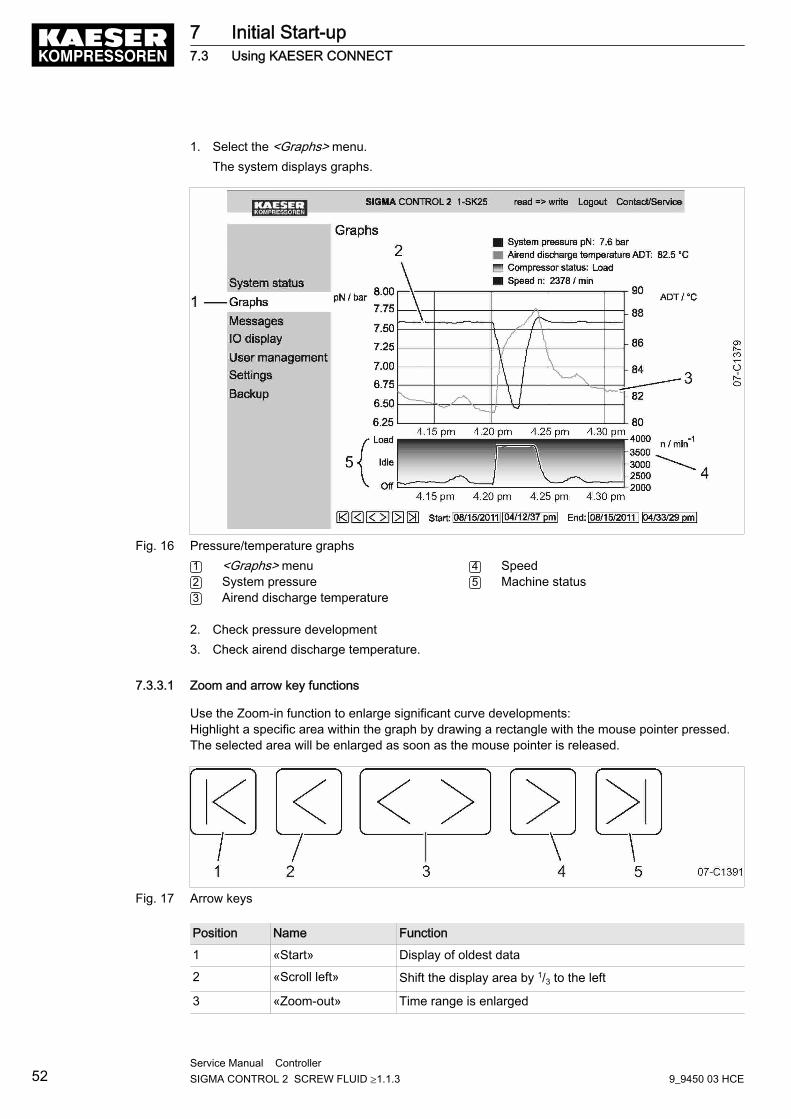
1. Select the <Graphs> menu.The system displays graphs.
Fig. 16 Pressure/temperature graphs1 <Graphs> menu2 System pressure3 Airend discharge temperature
4 Speed5 Machine status
2. Check pressure development3. Check airend discharge temperature.
7.3.3.1 Zoom and arrow key functions
Use the Zoom-in function to enlarge significant curve developments:Highlight a specific area within the graph by drawing a rectangle with the mouse pointer pressed.The selected area will be enlarged as soon as the mouse pointer is released.
Fig. 17 Arrow keys
Position Name Function
1 «Start» Display of oldest data
2 «Scroll left» Shift the display area by 1/3 to the left
3 «Zoom-out» Time range is enlarged
7 Initial Start-up7.3 Using KAESER CONNECT
52Service Manual Controller SIGMA CONTROL 2 SCREW FLUID ≥1.1.3 9_9450 03 HCE
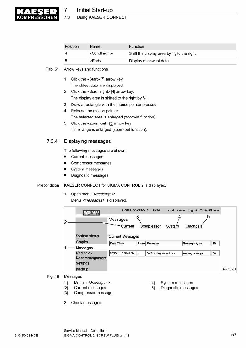
Position Name Function
4 «Scroll right» Shift the display area by 1/3 to the right
5 «End» Display of newest data
Tab. 51 Arrow keys and functions
1. Click the «Start» 1 arrow key.The oldest data are displayed.
2. Click the «Scroll right» 4 arrow key.The display area is shifted to the right by 1/3.
3. Draw a rectangle with the mouse pointer pressed.4. Release the mouse pointer.
The selected area is enlarged (zoom-in function).5. Click the «Zoom-out» 3 arrow key.
Time range is enlarged (zoom-out function).
7.3.4 Displaying messages
The following messages are shown:■ Current messages■ Compressor messages■ System messages■ Diagnostic messages
Precondition KAESER CONNECT for SIGMA CONTROL 2 is displayed.
1. Open menu <messages>.Menu <messages> is displayed.
Fig. 18 Messages1 Menu < Messages >2 Current messages3 Compressor messages
4 System messages5 Diagnostic messages
2. Check messages.
7 Initial Start-up7.3 Using KAESER CONNECT
9_9450 03 HCEService Manual Controller SIGMA CONTROL 2 SCREW FLUID ≥1.1.3 53
7.3.5 Calling up the IO display
The assignment of the I/O modules is displayed in the <IO display> menu.➤ Select the <IO display> menu.
The assignment of the input/output modules is displayed.
7.3.6 Creating additional user accounts
Use the <User administration> menu to create additional user accounts for other employees.
In order to be able to create user accounts, you must active the write mode 2 . The systemwill prompt you to enter and confirm your user name and your password (see chapter 7.2.7).Subsequently, the write mode is activated.The write mode is granted only to one person at a time.If a second user attempts to log on in write mode, he will be refused by the system.The system will return an error message.
String length for personally created user names and passwords:■ User name: 6 to 16 characters, the second character must not be a number.■ Password: 6 to 16 characters
Precondition The generated password is available.KAESER CONNECT for SIGMA CONTROL 2 is displayed.
1. Select the <User administration> menu.The system displays the <User administration> menu.
7 Initial Start-up7.3 Using KAESER CONNECT
54Service Manual Controller SIGMA CONTROL 2 SCREW FLUID ≥1.1.3 9_9450 03 HCE
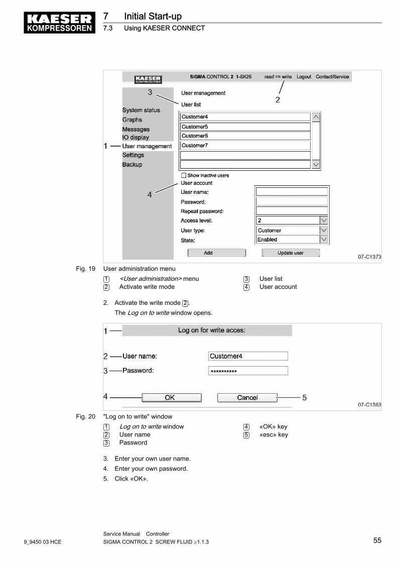
Fig. 19 User administration menu1 <User administration> menu2 Activate write mode
3 User list4 User account
2. Activate the write mode 2 .The Log on to write window opens.
Fig. 20 "Log on to write" window1 Log on to write window2 User name3 Password
4 «OK» key5 «esc» key
3. Enter your own user name.4. Enter your own password.5. Click «OK».
7 Initial Start-up7.3 Using KAESER CONNECT
9_9450 03 HCEService Manual Controller SIGMA CONTROL 2 SCREW FLUID ≥1.1.3 55
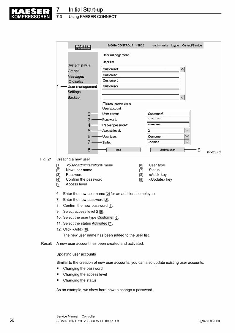
Fig. 21 Creating a new user1 <User administration> menu2 New user name3 Password4 Confirm the password5 Access level
6 User type7 Status8 «Add» key9 «Update» key
6. Enter the new user name 2 for an additional employee.7. Enter the new password 3 .8. Confirm the new password 4 .9. Select access level 2 5 .10. Select the user type Customer 6 .11. Select the status Activated 7 .12. Click «Add» 8 .
The new user name has been added to the user list.
Result A new user account has been created and activated.
Updating user accounts
Similar to the creation of new user accounts, you can also update existing user accounts.■ Changing the password■ Changing the access level■ Changing the status
As an example, we show here how to change a password.
7 Initial Start-up7.3 Using KAESER CONNECT
56Service Manual Controller SIGMA CONTROL 2 SCREW FLUID ≥1.1.3 9_9450 03 HCE
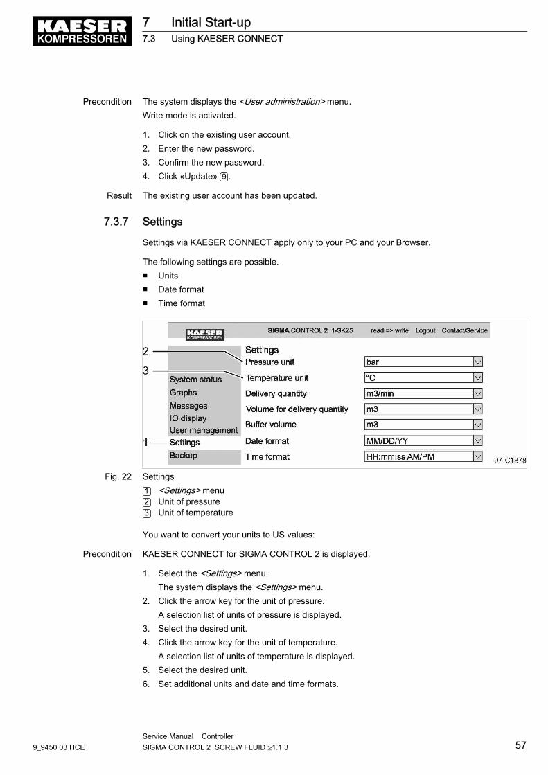
Precondition The system displays the <User administration> menu.Write mode is activated.
1. Click on the existing user account.2. Enter the new password.3. Confirm the new password.4. Click «Update» 9 .
Result The existing user account has been updated.
7.3.7 Settings
Settings via KAESER CONNECT apply only to your PC and your Browser.
The following settings are possible.■ Units■ Date format■ Time format
Fig. 22 Settings1 <Settings> menu2 Unit of pressure3 Unit of temperature
You want to convert your units to US values:
Precondition KAESER CONNECT for SIGMA CONTROL 2 is displayed.
1. Select the <Settings> menu.The system displays the <Settings> menu.
2. Click the arrow key for the unit of pressure.A selection list of units of pressure is displayed.
3. Select the desired unit.4. Click the arrow key for the unit of temperature.
A selection list of units of temperature is displayed.5. Select the desired unit.6. Set additional units and date and time formats.
7 Initial Start-up7.3 Using KAESER CONNECT
9_9450 03 HCEService Manual Controller SIGMA CONTROL 2 SCREW FLUID ≥1.1.3 57

7.3.8 Performing a data backup
In order to use KAESER CONNECT to easily back up data from SIGMA CONTROL 2 to your ownPC, use the <Data backup> menu.
You can choose to either perform a full backup or partial backups.■ Full■ Log files■ Settings■ User data
Precondition KAESER CONNECT for SIGMA CONTROL 2 is displayed.
1. Open the <Data backup> menu.The system displays the <Data backup> menu.
Fig. 23 Data backup1 <Data backup> menu2 Selection3 «Data backup» key
2. Select 2 .3. Click the «Data backup» 3 key.
Result Data are saved to your PC.
7.3.9 Closing KAESER CONNECT:
In order to close KAESER CONNECT for SIGMA CONTROL 2, click Logout 3 in the header.
7 Initial Start-up7.3 Using KAESER CONNECT
58Service Manual Controller SIGMA CONTROL 2 SCREW FLUID ≥1.1.3 9_9450 03 HCE
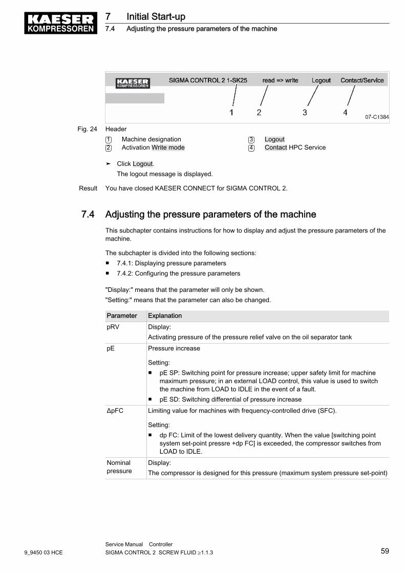
Fig. 24 Header1 Machine designation2 Activation Write mode
3 Logout4 Contact HPC Service
➤ Click Logout.The logout message is displayed.
Result You have closed KAESER CONNECT for SIGMA CONTROL 2.
7.4 Adjusting the pressure parameters of the machineThis subchapter contains instructions for how to display and adjust the pressure parameters of themachine.
The subchapter is divided into the following sections:■ 7.4.1: Displaying pressure parameters■ 7.4.2: Configuring the pressure parameters
"Display:" means that the parameter will only be shown."Setting:" means that the parameter can also be changed.
Parameter Explanation
pRV Display:Activating pressure of the pressure relief valve on the oil separator tank
pE Pressure increase
Setting:■ pE SP: Switching point for pressure increase; upper safety limit for machine
maximum pressure; in an external LOAD control, this value is used to switchthe machine from LOAD to IDLE in the event of a fault.
■ pE SD: Switching differential of pressure increase
ΔpFC Limiting value for machines with frequency-controlled drive (SFC).
Setting:■ dp FC: Limit of the lowest delivery quantity. When the value [switching point
system set-point pressre +dp FC] is exceeded, the compressor switches fromLOAD to IDLE.
Nominalpressure
Display:The compressor is designed for this pressure (maximum system pressure set-point)
7 Initial Start-up7.4 Adjusting the pressure parameters of the machine
9_9450 03 HCEService Manual Controller SIGMA CONTROL 2 SCREW FLUID ≥1.1.3 59
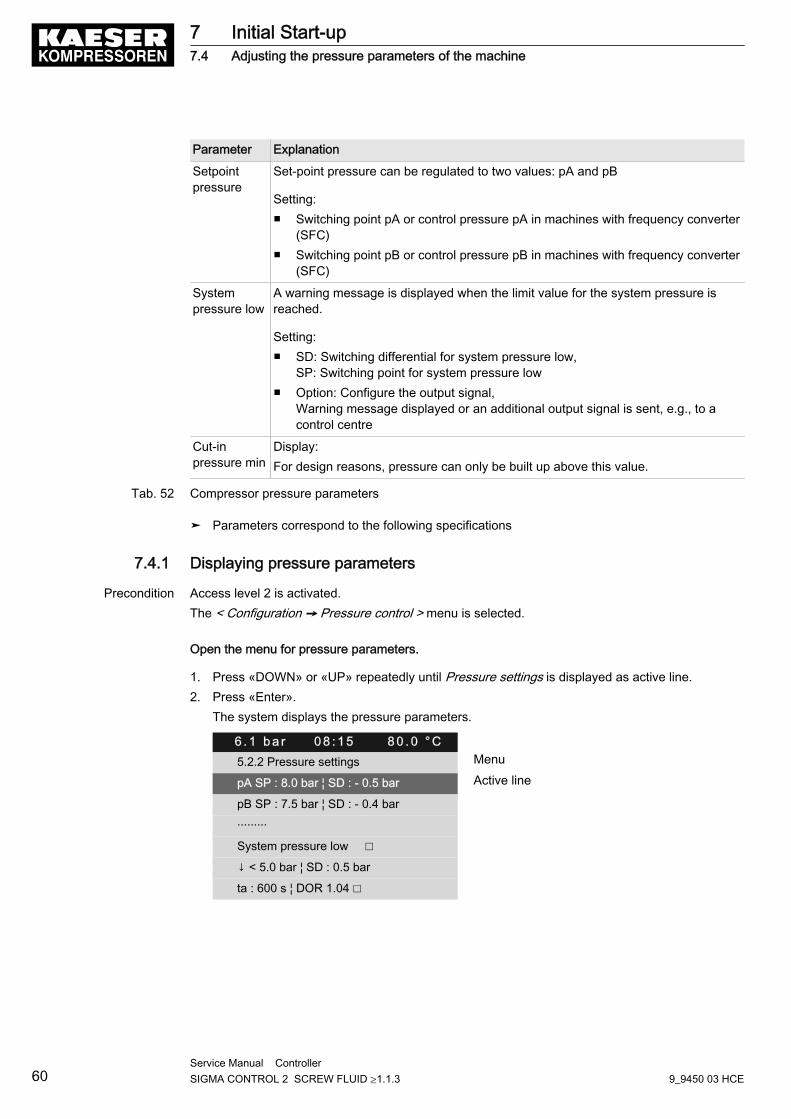
Parameter Explanation
Setpointpressure
Set-point pressure can be regulated to two values: pA and pB
Setting:■ Switching point pA or control pressure pA in machines with frequency converter
(SFC)■ Switching point pB or control pressure pB in machines with frequency converter
(SFC)
Systempressure low
A warning message is displayed when the limit value for the system pressure isreached.
Setting:■ SD: Switching differential for system pressure low,
SP: Switching point for system pressure low■ Option: Configure the output signal,
Warning message displayed or an additional output signal is sent, e.g., to acontrol centre
Cut-inpressure min
Display:For design reasons, pressure can only be built up above this value.
Tab. 52 Compressor pressure parameters
➤ Parameters correspond to the following specifications
7.4.1 Displaying pressure parameters
Precondition Access level 2 is activated.The < Configuration ➙ Pressure control > menu is selected.
Open the menu for pressure parameters.
1. Press «DOWN» or «UP» repeatedly until Pressure settings is displayed as active line.2. Press «Enter».
The system displays the pressure parameters.
6 . 1 b a r 0 8 : 1 5 8 0 . 0 ° C5.2.2 Pressure settings Menu
pA SP : 8.0 bar ¦ SD : - 0.5 bar Active line
pB SP : 7.5 bar ¦ SD : - 0.4 bar
·········
System pressure low ☐
↓ < 5.0 bar ¦ SD : 0.5 bar
ta : 600 s ¦ DOR 1.04 ☐
7 Initial Start-up7.4 Adjusting the pressure parameters of the machine
60Service Manual Controller SIGMA CONTROL 2 SCREW FLUID ≥1.1.3 9_9450 03 HCE
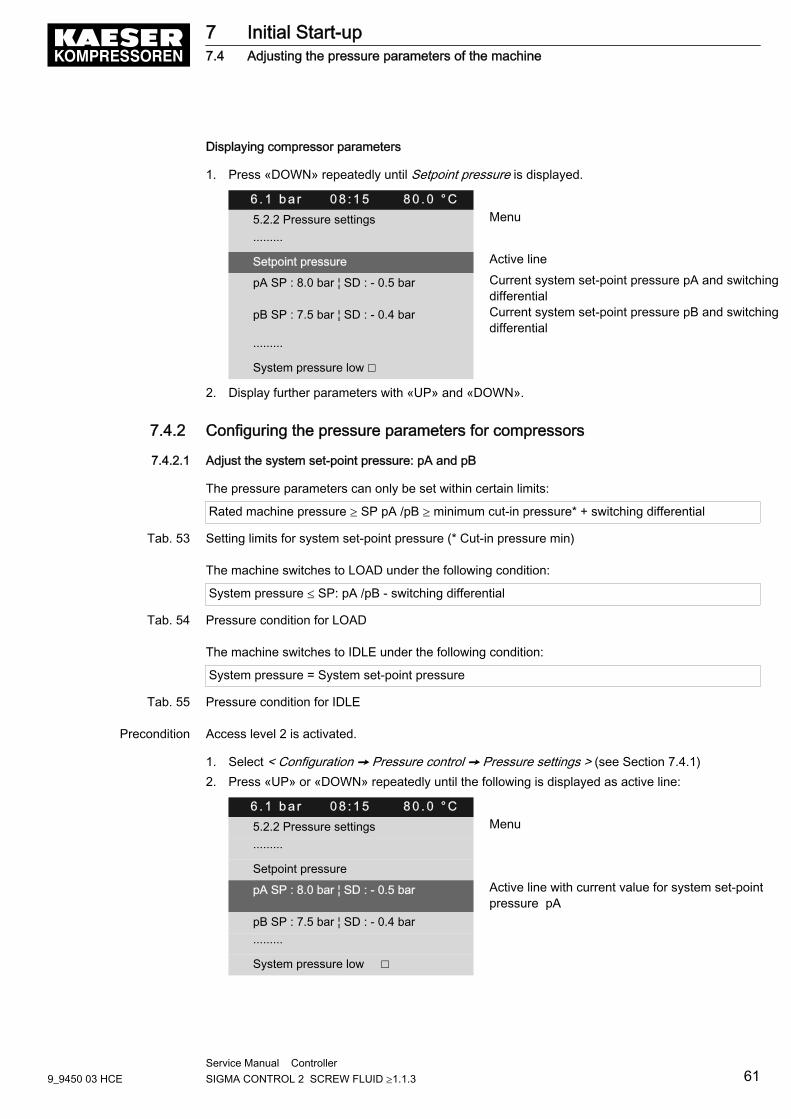
Displaying compressor parameters
1. Press «DOWN» repeatedly until Setpoint pressure is displayed.
6 . 1 b a r 0 8 : 1 5 8 0 . 0 ° C5.2.2 Pressure settings Menu
·········
Setpoint pressure Active line
pA SP : 8.0 bar ¦ SD : - 0.5 bar Current system set-point pressure pA and switchingdifferential
pB SP : 7.5 bar ¦ SD : - 0.4 bar Current system set-point pressure pB and switchingdifferential
·········
System pressure low ☐
2. Display further parameters with «UP» and «DOWN».
7.4.2 Configuring the pressure parameters for compressors
7.4.2.1 Adjust the system set-point pressure: pA and pB
The pressure parameters can only be set within certain limits:
Rated machine pressure ≥ SP pA /pB ≥ minimum cut-in pressure* + switching differential
Tab. 53 Setting limits for system set-point pressure (* Cut-in pressure min)
The machine switches to LOAD under the following condition:
System pressure ≤ SP: pA /pB - switching differential
Tab. 54 Pressure condition for LOAD
The machine switches to IDLE under the following condition:
System pressure = System set-point pressure
Tab. 55 Pressure condition for IDLE
Precondition Access level 2 is activated.
1. Select < Configuration ➙ Pressure control ➙ Pressure settings > (see Section 7.4.1)2. Press «UP» or «DOWN» repeatedly until the following is displayed as active line:
6 . 1 b a r 0 8 : 1 5 8 0 . 0 ° C5.2.2 Pressure settings Menu
·········
Setpoint pressure
pA SP : 8.0 bar ¦ SD : - 0.5 bar Active line with current value for system set-pointpressure pA
pB SP : 7.5 bar ¦ SD : - 0.4 bar
·········
System pressure low ☐
7 Initial Start-up7.4 Adjusting the pressure parameters of the machine
9_9450 03 HCEService Manual Controller SIGMA CONTROL 2 SCREW FLUID ≥1.1.3 61
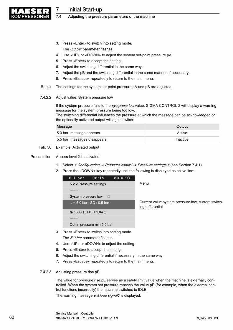
3. Press «Enter» to switch into setting mode.The 8.0 bar parameter flashes.
4. Use «UP» or «DOWN» to adjust the system set-point pressure pA.5. Press «Enter» to accept the setting.6. Adjust the switching differential in the same way.7. Adjust the pB and the switching differential in the same manner, if necessary.8. Press «Escape» repeatedly to return to the main menu.
Result The settings for the system set-point pressure pA and pB are adjusted.
7.4.2.2 Adjust value: System pressure low
If the system pressure falls to the sys.press.low value, SIGMA CONTROL 2 will display a warningmessage for the system pressure being too low.The switching differential influences the pressure at which the message can be acknowledged orthe optionally activated output will again switch:
Message Output
5.0 bar message appears Active
5.5 bar messages disappears Inactive
Tab. 56 Example: Activated output
Precondition Access level 2 is activated.
1. Select < Configuration ➙ Pressure control ➙ Pressure settings > (see Section 7.4.1)2. Press the «DOWN» key repeatedly until the following is displayed as active line:
6 . 1 b a r 0 8 : 1 5 8 0 . 0 ° C5.2.2 Pressure settings Menu
·········
System pressure low ☐
↓ < 5.0 bar ¦ SD : 0.5 bar Current value system pressure low, current switch‐ing differential
ta : 600 s ¦ DOR 1.04 ☐
·········
Cut-in pressure min 5.0 bar
3. Press «Enter» to switch into setting mode.The 5.0 bar parameter flashes.
4. Use «UP» or «DOWN» to adjust the setting.5. Press «Enter» to accept the setting.6. Adjust the switching differential if necessary in the same way.7. Press «Escape» repeatedly to return to the main menu.
7.4.2.3 Adjusting pressure rise pE
The value for pressure rise pE serves as a safety limit value when the machine is externally con‐trolled. When the system set pressure reaches the value pE (for example, when the external con‐trol functions incorrectly) the machine switches to IDLE.The warning message ext.load signal? is displayed.
7 Initial Start-up7.4 Adjusting the pressure parameters of the machine
62Service Manual Controller SIGMA CONTROL 2 SCREW FLUID ≥1.1.3 9_9450 03 HCE
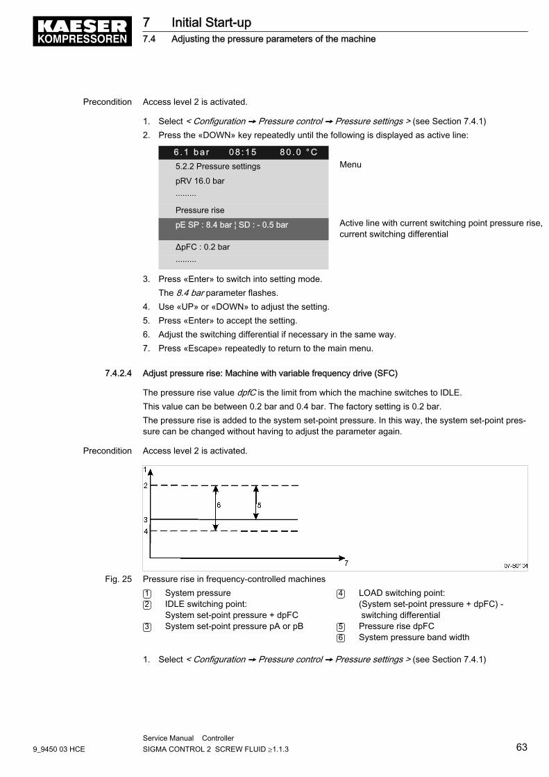
Precondition Access level 2 is activated.
1. Select < Configuration ➙ Pressure control ➙ Pressure settings > (see Section 7.4.1)2. Press the «DOWN» key repeatedly until the following is displayed as active line:
6 . 1 b a r 0 8 : 1 5 8 0 . 0 ° C5.2.2 Pressure settings Menu
pRV 16.0 bar
·········
Pressure rise
pE SP : 8.4 bar ¦ SD : - 0.5 bar Active line with current switching point pressure rise,current switching differential
ΔpFC : 0.2 bar
·········
3. Press «Enter» to switch into setting mode.The 8.4 bar parameter flashes.
4. Use «UP» or «DOWN» to adjust the setting.5. Press «Enter» to accept the setting.6. Adjust the switching differential if necessary in the same way.7. Press «Escape» repeatedly to return to the main menu.
7.4.2.4 Adjust pressure rise: Machine with variable frequency drive (SFC)
The pressure rise value dpfC is the limit from which the machine switches to IDLE.This value can be between 0.2 bar and 0.4 bar. The factory setting is 0.2 bar.The pressure rise is added to the system set-point pressure. In this way, the system set-point pres‐sure can be changed without having to adjust the parameter again.
Precondition Access level 2 is activated.
Fig. 25 Pressure rise in frequency-controlled machines1 System pressure2 IDLE switching point:
System set-point pressure + dpFC3 System set-point pressure pA or pB
4 LOAD switching point:(System set-point pressure + dpFC) - switching differential
5 Pressure rise dpFC6 System pressure band width
1. Select < Configuration ➙ Pressure control ➙ Pressure settings > (see Section 7.4.1)
7 Initial Start-up7.4 Adjusting the pressure parameters of the machine
9_9450 03 HCEService Manual Controller SIGMA CONTROL 2 SCREW FLUID ≥1.1.3 63
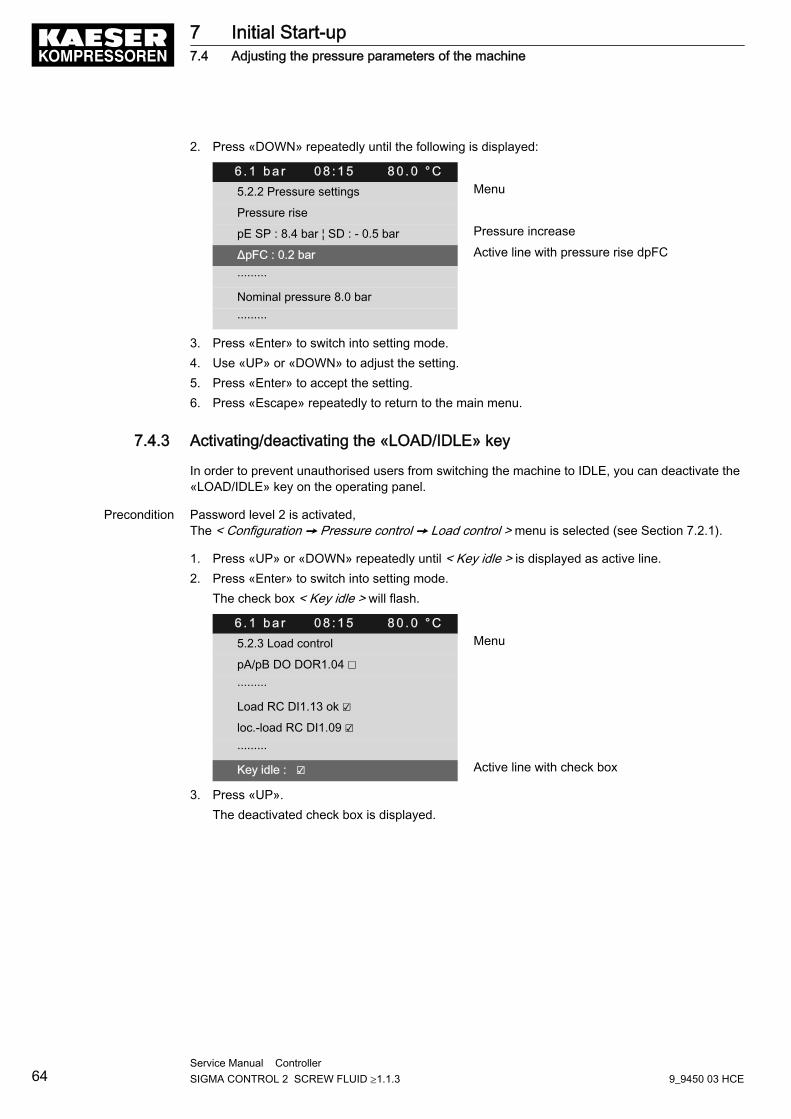
2. Press «DOWN» repeatedly until the following is displayed:
6 . 1 b a r 0 8 : 1 5 8 0 . 0 ° C5.2.2 Pressure settings Menu
Pressure rise
pE SP : 8.4 bar ¦ SD : - 0.5 bar Pressure increase
ΔpFC : 0.2 bar Active line with pressure rise dpFC
·········
Nominal pressure 8.0 bar
·········
3. Press «Enter» to switch into setting mode.4. Use «UP» or «DOWN» to adjust the setting.5. Press «Enter» to accept the setting.6. Press «Escape» repeatedly to return to the main menu.
7.4.3 Activating/deactivating the «LOAD/IDLE» key
In order to prevent unauthorised users from switching the machine to IDLE, you can deactivate the«LOAD/IDLE» key on the operating panel.
Precondition Password level 2 is activated,The < Configuration ➙ Pressure control ➙ Load control > menu is selected (see Section 7.2.1).
1. Press «UP» or «DOWN» repeatedly until < Key idle > is displayed as active line.2. Press «Enter» to switch into setting mode.
The check box < Key idle > will flash.
6 . 1 b a r 0 8 : 1 5 8 0 . 0 ° C5.2.3 Load control Menu
pA/pB DO DOR1.04 ☐
·········
Load RC DI1.13 ok ☑
loc.-load RC DI1.09 ☑
·········
Key idle : ☑ Active line with check box
3. Press «UP».The deactivated check box is displayed.
7 Initial Start-up7.4 Adjusting the pressure parameters of the machine
64Service Manual Controller SIGMA CONTROL 2 SCREW FLUID ≥1.1.3 9_9450 03 HCE
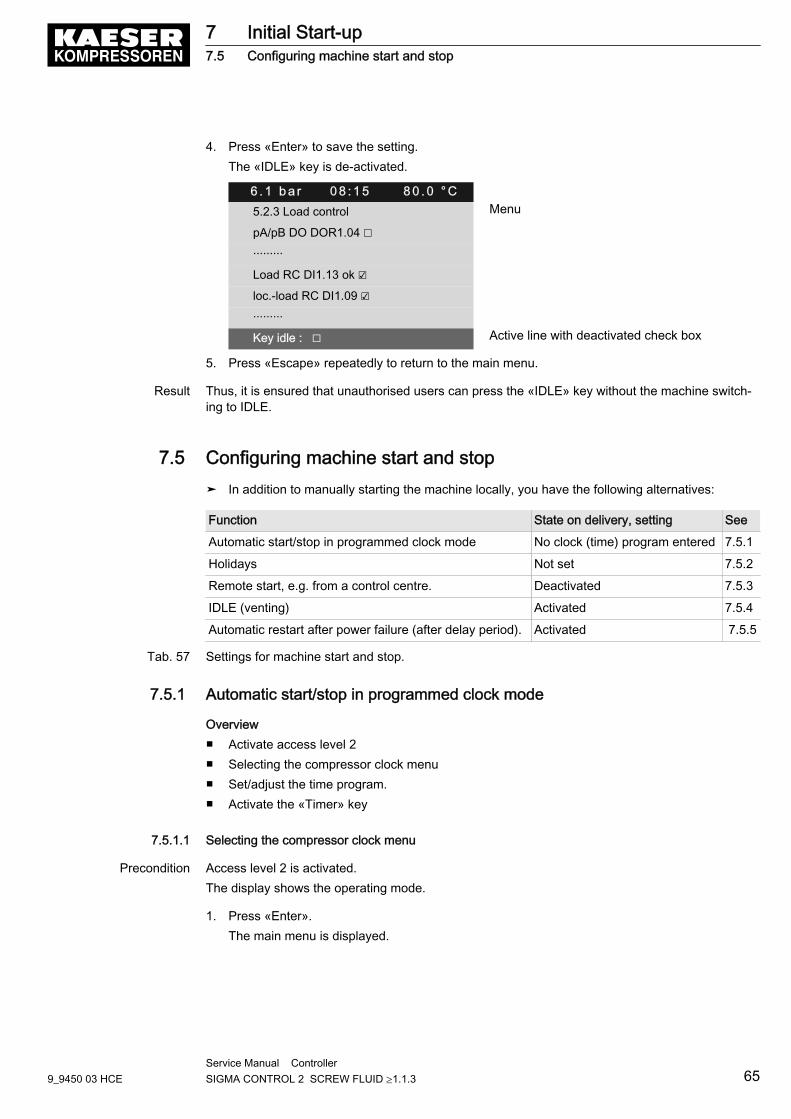
4. Press «Enter» to save the setting.The «IDLE» key is de-activated.
6 . 1 b a r 0 8 : 1 5 8 0 . 0 ° C5.2.3 Load control Menu
pA/pB DO DOR1.04 ☐
·········
Load RC DI1.13 ok ☑
loc.-load RC DI1.09 ☑
·········
Key idle : ☐ Active line with deactivated check box
5. Press «Escape» repeatedly to return to the main menu.
Result Thus, it is ensured that unauthorised users can press the «IDLE» key without the machine switch‐ing to IDLE.
7.5 Configuring machine start and stop➤ In addition to manually starting the machine locally, you have the following alternatives:
Function State on delivery, setting See
Automatic start/stop in programmed clock mode No clock (time) program entered 7.5.1
Holidays Not set 7.5.2
Remote start, e.g. from a control centre. Deactivated 7.5.3
IDLE (venting) Activated 7.5.4
Automatic restart after power failure (after delay period). Activated 7.5.5
Tab. 57 Settings for machine start and stop.
7.5.1 Automatic start/stop in programmed clock mode
Overview■ Activate access level 2■ Selecting the compressor clock menu■ Set/adjust the time program.■ Activate the «Timer» key
7.5.1.1 Selecting the compressor clock menu
Precondition Access level 2 is activated.The display shows the operating mode.
1. Press «Enter».The main menu is displayed.
7 Initial Start-up7.5 Configuring machine start and stop
9_9450 03 HCEService Manual Controller SIGMA CONTROL 2 SCREW FLUID ≥1.1.3 65
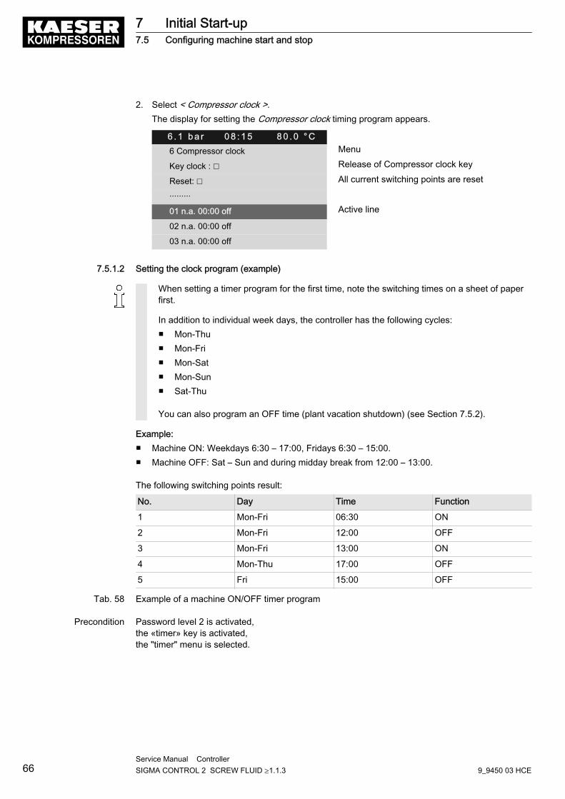
2. Select < Compressor clock >.The display for setting the Compressor clock timing program appears.
6 . 1 b a r 0 8 : 1 5 8 0 . 0 ° C6 Compressor clock Menu
Key clock : ☐ Release of Compressor clock key
Reset: ☐ All current switching points are reset
·········
01 n.a. 00:00 off Active line
02 n.a. 00:00 off
03 n.a. 00:00 off
7.5.1.2 Setting the clock program (example)
When setting a timer program for the first time, note the switching times on a sheet of paperfirst.
In addition to individual week days, the controller has the following cycles:■ Mon-Thu■ Mon-Fri■ Mon-Sat■ Mon-Sun■ Sat-Thu
You can also program an OFF time (plant vacation shutdown) (see Section 7.5.2).
Example:■ Machine ON: Weekdays 6:30 – 17:00, Fridays 6:30 – 15:00.■ Machine OFF: Sat – Sun and during midday break from 12:00 – 13:00.
The following switching points result:
No. Day Time Function
1 Mon-Fri 06:30 ON
2 Mon-Fri 12:00 OFF
3 Mon-Fri 13:00 ON
4 Mon-Thu 17:00 OFF
5 Fri 15:00 OFF
Tab. 58 Example of a machine ON/OFF timer program
Precondition Password level 2 is activated,the «timer» key is activated,the "timer" menu is selected.
7 Initial Start-up7.5 Configuring machine start and stop
66Service Manual Controller SIGMA CONTROL 2 SCREW FLUID ≥1.1.3 9_9450 03 HCE
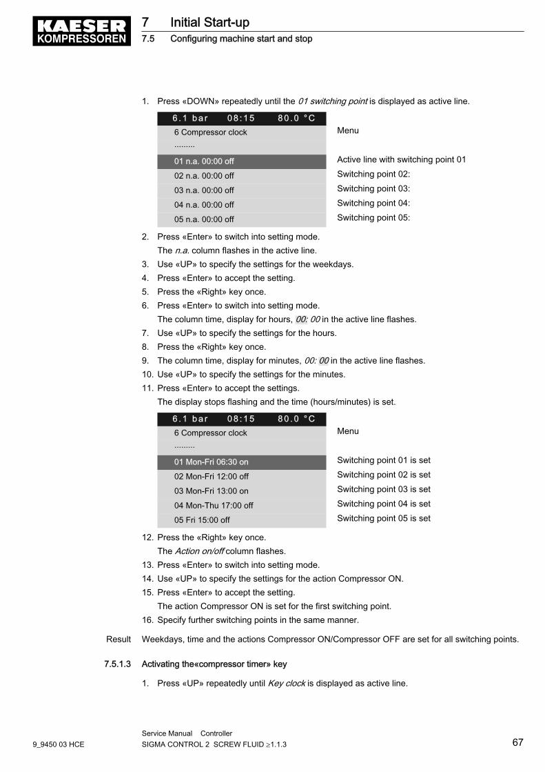
1. Press «DOWN» repeatedly until the 01 switching point is displayed as active line.
6 . 1 b a r 0 8 : 1 5 8 0 . 0 ° C6 Compressor clock Menu
·········
01 n.a. 00:00 off Active line with switching point 01
02 n.a. 00:00 off Switching point 02:
03 n.a. 00:00 off Switching point 03:
04 n.a. 00:00 off Switching point 04:
05 n.a. 00:00 off Switching point 05:
2. Press «Enter» to switch into setting mode.The n.a. column flashes in the active line.
3. Use «UP» to specify the settings for the weekdays.4. Press «Enter» to accept the setting.5. Press the «Right» key once.6. Press «Enter» to switch into setting mode.
The column time, display for hours, 00: 00 in the active line flashes.7. Use «UP» to specify the settings for the hours.8. Press the «Right» key once.9. The column time, display for minutes, 00: 00 in the active line flashes.10. Use «UP» to specify the settings for the minutes.11. Press «Enter» to accept the settings.
The display stops flashing and the time (hours/minutes) is set.
6 . 1 b a r 0 8 : 1 5 8 0 . 0 ° C6 Compressor clock Menu
·········
01 Mon-Fri 06:30 on Switching point 01 is set
02 Mon-Fri 12:00 off Switching point 02 is set
03 Mon-Fri 13:00 on Switching point 03 is set
04 Mon-Thu 17:00 off Switching point 04 is set
05 Fri 15:00 off Switching point 05 is set
12. Press the «Right» key once.The Action on/off column flashes.
13. Press «Enter» to switch into setting mode.14. Use «UP» to specify the settings for the action Compressor ON.15. Press «Enter» to accept the setting.
The action Compressor ON is set for the first switching point.16. Specify further switching points in the same manner.
Result Weekdays, time and the actions Compressor ON/Compressor OFF are set for all switching points.
7.5.1.3 Activating the«compressor timer» key
1. Press «UP» repeatedly until Key clock is displayed as active line.
7 Initial Start-up7.5 Configuring machine start and stop
9_9450 03 HCEService Manual Controller SIGMA CONTROL 2 SCREW FLUID ≥1.1.3 67
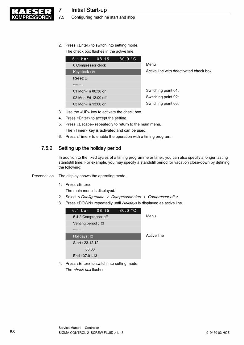
2. Press «Enter» to switch into setting mode.The check box flashes in the active line.
6 . 1 b a r 0 8 : 1 5 8 0 . 0 ° C6 Compressor clock Menu
Key clock : ☑ Active line with deactivated check box
Reset: ☐
·········
01 Mon-Fri 06:30 on Switching point 01:
02 Mon-Fri 12:00 off Switching point 02:
03 Mon-Fri 13:00 on Switching point 03:
3. Use the «UP» key to activate the check box.4. Press «Enter» to accept the setting.5. Press «Escape» repeatedly to return to the main menu.
The «Timer» key is activated and can be used.6. Press «Timer» to enable the operation with a timing program.
7.5.2 Setting up the holiday period
In addition to the fixed cycles of a timing programme or timer, you can also specify a longer lastingstandstill time. For example, you may specify a standstill period for vacation close-down by definingthe following:
Precondition The display shows the operating mode.
1. Press «Enter».The main menu is displayed.
2. Select < Configuration ➙ Compressor start ➙ Compressor off >.3. Press «DOWN» repeatedly until Holidays is displayed as active line.
6 . 1 b a r 0 8 : 1 5 8 0 . 0 ° C5.4.2 Compressor off Menu
Venting period : ☐
·········
Holidays : ☐ Active line
Start : 23.12.12
00:00
End : 07.01.13
4. Press «Enter» to switch into setting mode.The check box flashes.
7 Initial Start-up7.5 Configuring machine start and stop
68Service Manual Controller SIGMA CONTROL 2 SCREW FLUID ≥1.1.3 9_9450 03 HCE
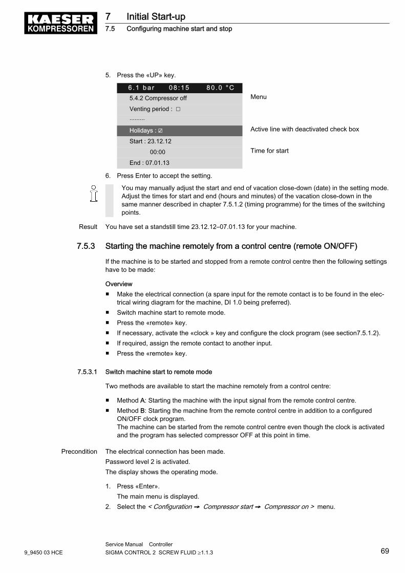
5. Press the «UP» key.
6 . 1 b a r 0 8 : 1 5 8 0 . 0 ° C5.4.2 Compressor off Menu
Venting period : ☐
·········
Holidays : ☑ Active line with deactivated check box
Start : 23.12.12
00:00 Time for start
End : 07.01.13
6. Press Enter to accept the setting.
You may manually adjust the start and end of vacation close-down (date) in the setting mode.Adjust the times for start and end (hours and minutes) of the vacation close-down in thesame manner described in chapter 7.5.1.2 (timing programme) for the times of the switchingpoints.
Result You have set a standstill time 23.12.12–07.01.13 for your machine.
7.5.3 Starting the machine remotely from a control centre (remote ON/OFF)
If the machine is to be started and stopped from a remote control centre then the following settingshave to be made:
Overview■ Make the electrical connection (a spare input for the remote contact is to be found in the elec‐
trical wiring diagram for the machine, DI 1.0 being preferred).■ Switch machine start to remote mode.■ Press the «remote» key.■ If necessary, activate the «clock » key and configure the clock program (see section7.5.1.2).■ If required, assign the remote contact to another input.■ Press the «remote» key.
7.5.3.1 Switch machine start to remote mode
Two methods are available to start the machine remotely from a control centre:
■ Method A: Starting the machine with the input signal from the remote control centre.■ Method B: Starting the machine from the remote control centre in addition to a configured
ON/OFF clock program.The machine can be started from the remote control centre even though the clock is activatedand the program has selected compressor OFF at this point in time.
Precondition The electrical connection has been made.Password level 2 is activated.The display shows the operating mode.
1. Press «Enter».The main menu is displayed.
2. Select the < Configuration ➙ Compressor start ➙ Compressor on > menu.
7 Initial Start-up7.5 Configuring machine start and stop
9_9450 03 HCEService Manual Controller SIGMA CONTROL 2 SCREW FLUID ≥1.1.3 69
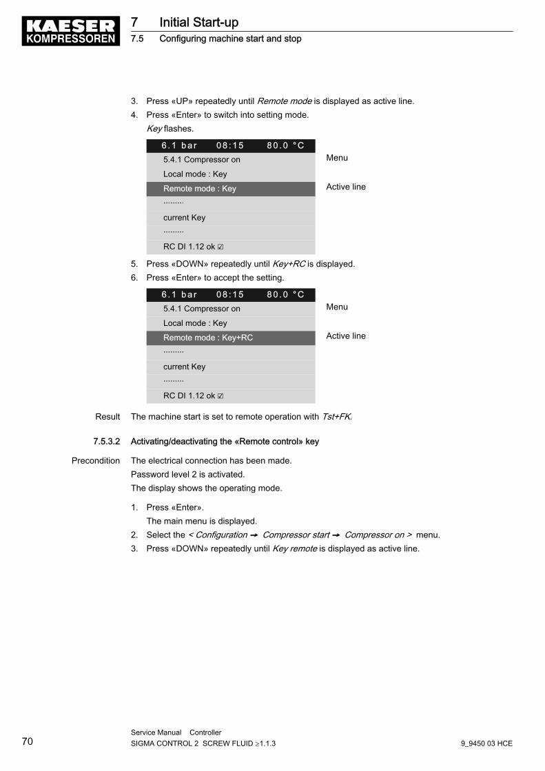
3. Press «UP» repeatedly until Remote mode is displayed as active line.4. Press «Enter» to switch into setting mode.
Key flashes.
6 . 1 b a r 0 8 : 1 5 8 0 . 0 ° C5.4.1 Compressor on Menu
Local mode : Key
Remote mode : Key Active line
·········
current Key
·········
RC DI 1.12 ok ☑
5. Press «DOWN» repeatedly until Key+RC is displayed.6. Press «Enter» to accept the setting.
6 . 1 b a r 0 8 : 1 5 8 0 . 0 ° C5.4.1 Compressor on Menu
Local mode : Key
Remote mode : Key+RC Active line
·········
current Key
·········
RC DI 1.12 ok ☑
Result The machine start is set to remote operation with Tst+FK.
7.5.3.2 Activating/deactivating the «Remote control» key
Precondition The electrical connection has been made.Password level 2 is activated.The display shows the operating mode.
1. Press «Enter».The main menu is displayed.
2. Select the < Configuration ➙ Compressor start ➙ Compressor on > menu.3. Press «DOWN» repeatedly until Key remote is displayed as active line.
7 Initial Start-up7.5 Configuring machine start and stop
70Service Manual Controller SIGMA CONTROL 2 SCREW FLUID ≥1.1.3 9_9450 03 HCE
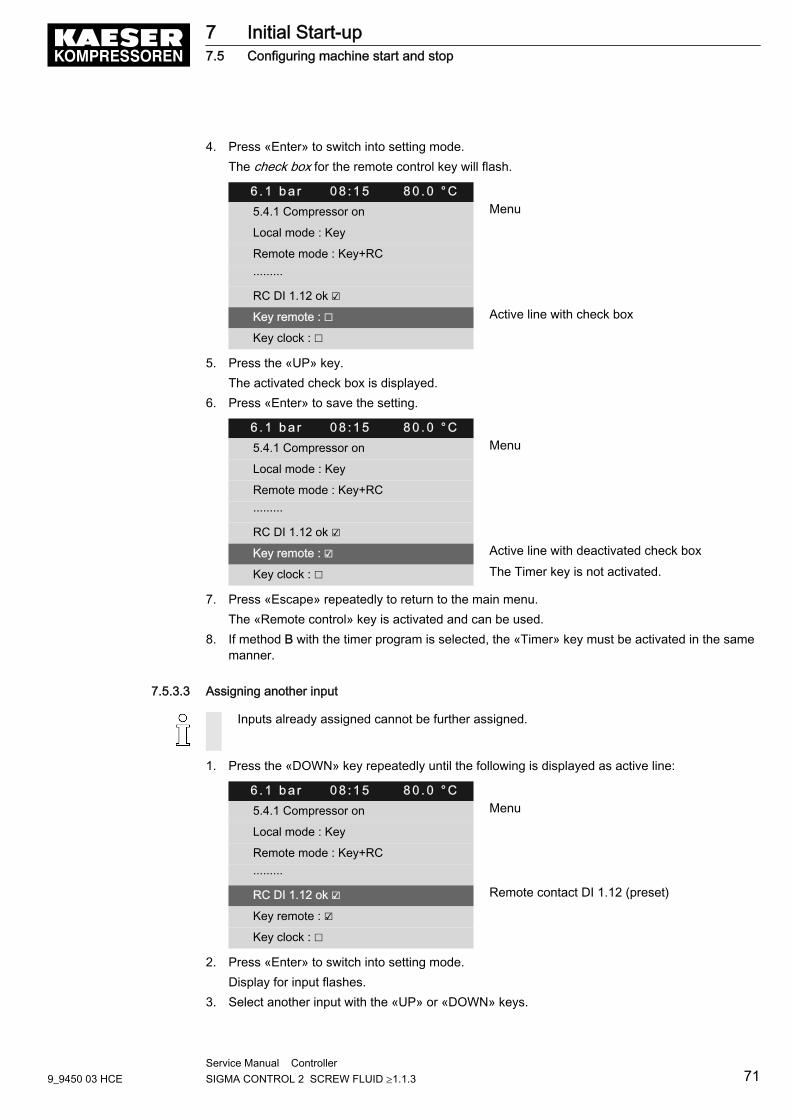
4. Press «Enter» to switch into setting mode.The check box for the remote control key will flash.
6 . 1 b a r 0 8 : 1 5 8 0 . 0 ° C5.4.1 Compressor on Menu
Local mode : Key
Remote mode : Key+RC
·········
RC DI 1.12 ok ☑
Key remote : ☐ Active line with check box
Key clock : ☐
5. Press the «UP» key.The activated check box is displayed.
6. Press «Enter» to save the setting.
6 . 1 b a r 0 8 : 1 5 8 0 . 0 ° C5.4.1 Compressor on Menu
Local mode : Key
Remote mode : Key+RC
·········
RC DI 1.12 ok ☑
Key remote : ☑ Active line with deactivated check box
Key clock : ☐ The Timer key is not activated.
7. Press «Escape» repeatedly to return to the main menu.The «Remote control» key is activated and can be used.
8. If method B with the timer program is selected, the «Timer» key must be activated in the samemanner.
7.5.3.3 Assigning another input
Inputs already assigned cannot be further assigned.
1. Press the «DOWN» key repeatedly until the following is displayed as active line:
6 . 1 b a r 0 8 : 1 5 8 0 . 0 ° C5.4.1 Compressor on Menu
Local mode : Key
Remote mode : Key+RC
·········
RC DI 1.12 ok ☑ Remote contact DI 1.12 (preset)
Key remote : ☑
Key clock : ☐
2. Press «Enter» to switch into setting mode.Display for input flashes.
3. Select another input with the «UP» or «DOWN» keys.
7 Initial Start-up7.5 Configuring machine start and stop
9_9450 03 HCEService Manual Controller SIGMA CONTROL 2 SCREW FLUID ≥1.1.3 71
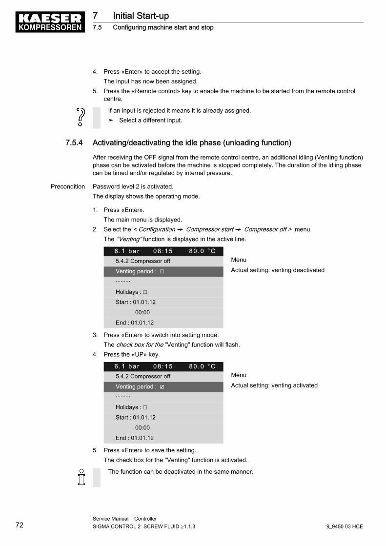
4. Press «Enter» to accept the setting.The input has now been assigned.
5. Press the «Remote control» key to enable the machine to be started from the remote controlcentre.
If an input is rejected it means it is already assigned.➤ Select a different input.
7.5.4 Activating/deactivating the idle phase (unloading function)
After receiving the OFF signal from the remote control centre, an additional idling (Venting function)phase can be activated before the machine is stopped completely. The duration of the idling phasecan be timed and/or regulated by internal pressure.
Precondition Password level 2 is activated.The display shows the operating mode.
1. Press «Enter».The main menu is displayed.
2. Select the < Configuration ➙ Compressor start ➙ Compressor off > menu.The "Venting" function is displayed in the active line.
6 . 1 b a r 0 8 : 1 5 8 0 . 0 ° C5.4.2 Compressor off Menu
Venting period : ☐ Actual setting: venting deactivated
·········
Holidays : ☐
Start : 01.01.12
00:00
End : 01.01.12
3. Press «Enter» to switch into setting mode.The check box for the "Venting" function will flash.
4. Press the «UP» key.
6 . 1 b a r 0 8 : 1 5 8 0 . 0 ° C5.4.2 Compressor off Menu
Venting period : ☑ Actual setting: venting activated
·········
Holidays : ☐
Start : 01.01.12
00:00
End : 01.01.12
5. Press «Enter» to save the setting.The check box for the "Venting" function is activated.
The function can be deactivated in the same manner.
7 Initial Start-up7.5 Configuring machine start and stop
72Service Manual Controller SIGMA CONTROL 2 SCREW FLUID ≥1.1.3 9_9450 03 HCE
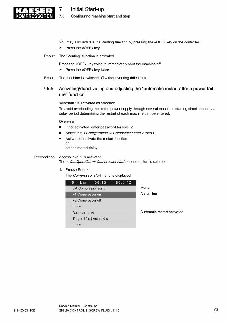
You may also activate the Venting function by pressing the «OFF» key on the controller.➤ Press the «OFF» key.
Result The "Venting" function is activated.
Press the «OFF» key twice to immediately shut the machine off.➤ Press the «OFF» key twice.
Result The machine is switched off without venting (idle time).
7.5.5 Activating/deactivating and adjusting the "automatic restart after a power fail‐ure" function
'Autostart:' is activated as standard.To avoid overloading the mains power supply through several machines starting simultaneously adelay period determining the restart of each machine can be entered.
Overview■ If not activated, enter password for level 2■ Select the < Configuration ➙ Compressor start > menu.■ Activate/deactivate the restart function
orset the restart delay.
Precondition Access level 2 is activated.The < Configuration ➙ Compressor start > menu option is selected.
1. Press «Enter».The Compressor start menu is displayed.
6 . 1 b a r 0 8 : 1 5 8 0 . 0 ° C5.4 Compressor start Menu
▶1 Compressor on Active line
▶2 Compressor off
·········
Autostart: : ☑ Automatic restart activated.
Target 10 s ¦ Actual 0 s
·········
7 Initial Start-up7.5 Configuring machine start and stop
9_9450 03 HCEService Manual Controller SIGMA CONTROL 2 SCREW FLUID ≥1.1.3 73
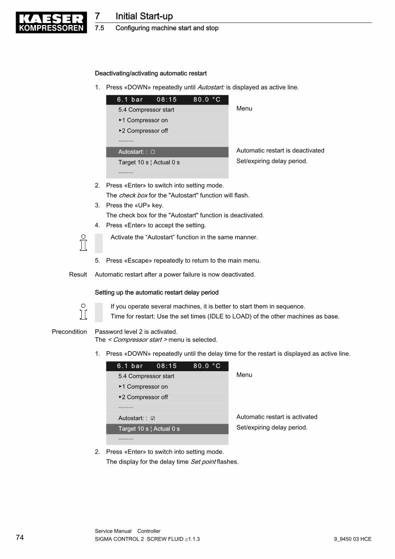
Deactivating/activating automatic restart
1. Press «DOWN» repeatedly until Autostart: is displayed as active line.
6 . 1 b a r 0 8 : 1 5 8 0 . 0 ° C5.4 Compressor start Menu
▶1 Compressor on
▶2 Compressor off
·········
Autostart: : ☐ Automatic restart is deactivated
Target 10 s ¦ Actual 0 s Set/expiring delay period.
·········
2. Press «Enter» to switch into setting mode.The check box for the "Autostart" function will flash.
3. Press the «UP» key.The check box for the "Autostart" function is deactivated.
4. Press «Enter» to accept the setting.
Activate the “Autostart” function in the same manner.
5. Press «Escape» repeatedly to return to the main menu.
Result Automatic restart after a power failure is now deactivated.
Setting up the automatic restart delay period
If you operate several machines, it is better to start them in sequence.Time for restart: Use the set times (IDLE to LOAD) of the other machines as base.
Precondition Password level 2 is activated.The < Compressor start > menu is selected.
1. Press «DOWN» repeatedly until the delay time for the restart is displayed as active line.
6 . 1 b a r 0 8 : 1 5 8 0 . 0 ° C5.4 Compressor start Menu
▶1 Compressor on
▶2 Compressor off
·········
Autostart: : ☑ Automatic restart is activated
Target 10 s ¦ Actual 0 s Set/expiring delay period.
·········
2. Press «Enter» to switch into setting mode.The display for the delay time Set point flashes.
7 Initial Start-up7.5 Configuring machine start and stop
74Service Manual Controller SIGMA CONTROL 2 SCREW FLUID ≥1.1.3 9_9450 03 HCE

3. Change the time using the «DOWN» or «UP» keys.
6 . 1 b a r 0 8 : 1 5 8 0 . 0 ° C5.4 Compressor start Menu
▶1 Compressor on
▶2 Compressor off
·········
Autostart: : ☑
Target 12 s ¦ Actual 0 s Active line
·········
4. Press «Enter» to accept the setting.5. Press «Escape» repeatedly to return to the main menu.
Result You have adjusted the delay tome for the restart after a mains failure from 10 s to 12 s.
7.6 Activating and adjusting the control modesThe controller is provided with various control modes that can bring about different capacity utilisa‐tion depending on machine application. Chapter 4.7 provides a comprehensive description of allcontrol modes.
7.6.1 Selecting a control mode
The following control modes are possible:■ DUAL■ QUADRO■ VARIO■ DYNAMIC■ CONTINUOUS
The standard setting of the control mode depends on the machine type.
Precondition Password level 2 is activated.The display shows the operating mode.
1. Press «Enter».The main menu is displayed.
7 Initial Start-up7.6 Activating and adjusting the control modes
9_9450 03 HCEService Manual Controller SIGMA CONTROL 2 SCREW FLUID ≥1.1.3 75
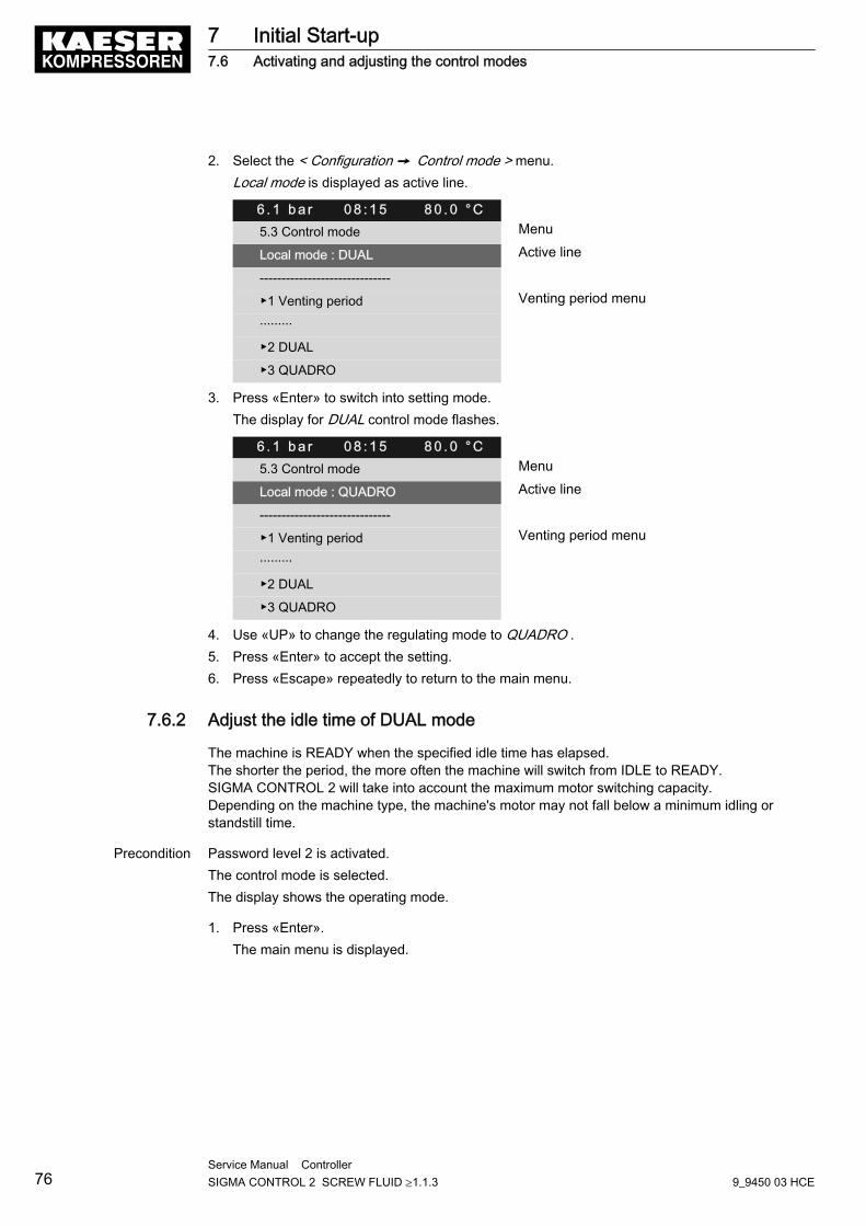
2. Select the < Configuration ➙ Control mode > menu.Local mode is displayed as active line.
6 . 1 b a r 0 8 : 1 5 8 0 . 0 ° C5.3 Control mode Menu
Local mode : DUAL Active line
------------------------------
▶1 Venting period Venting period menu
·········
▶2 DUAL
▶3 QUADRO
3. Press «Enter» to switch into setting mode.The display for DUAL control mode flashes.
6 . 1 b a r 0 8 : 1 5 8 0 . 0 ° C5.3 Control mode Menu
Local mode : QUADRO Active line
------------------------------
▶1 Venting period Venting period menu
·········
▶2 DUAL
▶3 QUADRO
4. Use «UP» to change the regulating mode to QUADRO .5. Press «Enter» to accept the setting.6. Press «Escape» repeatedly to return to the main menu.
7.6.2 Adjust the idle time of DUAL mode
The machine is READY when the specified idle time has elapsed.The shorter the period, the more often the machine will switch from IDLE to READY.SIGMA CONTROL 2 will take into account the maximum motor switching capacity.Depending on the machine type, the machine's motor may not fall below a minimum idling orstandstill time.
Precondition Password level 2 is activated.The control mode is selected.The display shows the operating mode.
1. Press «Enter».The main menu is displayed.
7 Initial Start-up7.6 Activating and adjusting the control modes
76Service Manual Controller SIGMA CONTROL 2 SCREW FLUID ≥1.1.3 9_9450 03 HCE
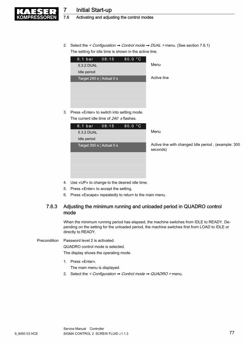
2. Select the < Configuration ➙ Control mode ➙ DUAL > menu. (See section 7.6.1)The setting for idle time is shown in the active line.
6 . 1 b a r 0 8 : 1 5 8 0 . 0 ° C5.3.2 DUAL Menu
Idle period
Target 240 s ¦ Actual 0 s Active line
3. Press «Enter» to switch into setting mode.The current idle time of 240 s flashes.
6 . 1 b a r 0 8 : 1 5 8 0 . 0 ° C5.3.2 DUAL Menu
Idle period
Target 300 s ¦ Actual 0 s Active line with changed Idle period , (example: 300seconds)
4. Use «UP» to change to the desired idle time.5. Press «Enter» to accept the setting.6. Press «Escape» repeatedly to return to the main menu.
7.6.3 Adjusting the minimum running and unloaded period in QUADRO controlmode
When the minimum running period has elapsed, the machine switches from IDLE to READY. De‐pending on the setting for the unloaded period, the machine switches first from LOAD to IDLE ordirectly to READY.
Precondition Password level 2 is activated.QUADRO control mode is selected.The display shows the operating mode.
1. Press «Enter».The main menu is displayed.
2. Select the < Configuration ➙ Control mode ➙ QUADRO > menu.
7 Initial Start-up7.6 Activating and adjusting the control modes
9_9450 03 HCEService Manual Controller SIGMA CONTROL 2 SCREW FLUID ≥1.1.3 77
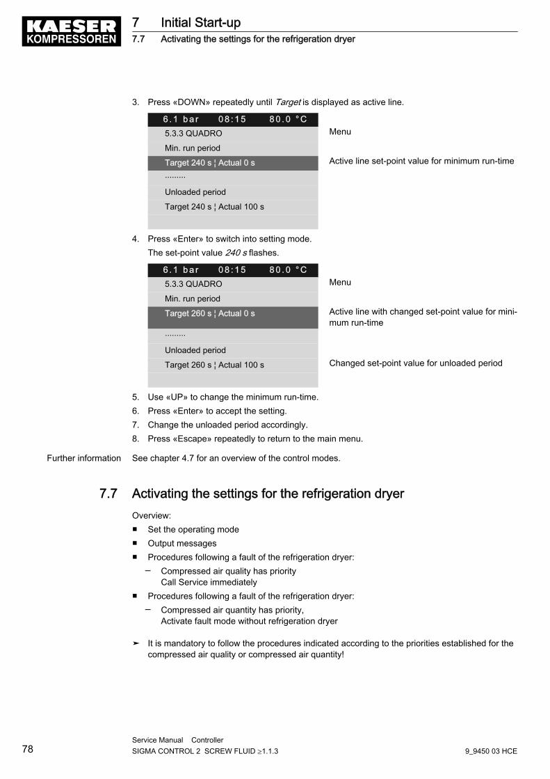
3. Press «DOWN» repeatedly until Target is displayed as active line.
6 . 1 b a r 0 8 : 1 5 8 0 . 0 ° C5.3.3 QUADRO Menu
Min. run period
Target 240 s ¦ Actual 0 s Active line set-point value for minimum run-time
·········
Unloaded period
Target 240 s ¦ Actual 100 s
4. Press «Enter» to switch into setting mode.The set-point value 240 s flashes.
6 . 1 b a r 0 8 : 1 5 8 0 . 0 ° C5.3.3 QUADRO Menu
Min. run period
Target 260 s ¦ Actual 0 s Active line with changed set-point value for mini‐mum run-time
·········
Unloaded period
Target 260 s ¦ Actual 100 s Changed set-point value for unloaded period
5. Use «UP» to change the minimum run-time.6. Press «Enter» to accept the setting.7. Change the unloaded period accordingly.8. Press «Escape» repeatedly to return to the main menu.
Further information See chapter 4.7 for an overview of the control modes.
7.7 Activating the settings for the refrigeration dryerOverview:■ Set the operating mode■ Output messages■ Procedures following a fault of the refrigeration dryer:
─ Compressed air quality has priorityCall Service immediately
■ Procedures following a fault of the refrigeration dryer:─ Compressed air quantity has priority,
Activate fault mode without refrigeration dryer
➤ It is mandatory to follow the procedures indicated according to the priorities established for thecompressed air quality or compressed air quantity!
7 Initial Start-up7.7 Activating the settings for the refrigeration dryer
78Service Manual Controller SIGMA CONTROL 2 SCREW FLUID ≥1.1.3 9_9450 03 HCE
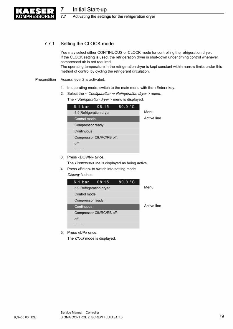
7.7.1 Setting the CLOCK mode
You may select either CONTINUOUS or CLOCK mode for controlling the refrigeration dryer.If the CLOCK setting is used, the refrigeration dryer is shut-down under timing control whenevercompressed air is not required.The operating temperature in the refrigeration dryer is kept constant within narrow limits under thismethod of control by cycling the refrigerant circulation.
Precondition Access level 2 is activated.
1. In operating mode, switch to the main menu with the «Enter» key.2. Select the < Configuration ➙ Refrigeration dryer > menu.
The < Refrigeration dryer > menu is displayed.
6 . 1 b a r 0 8 : 1 5 8 0 . 0 ° C5.9 Refrigeration dryer Menu
Control mode Active line
Compressor ready:
Continuous
Compressor Clk/RC/RB off:
off
·········
3. Press «DOWN» twice.The Continuous line is displayed as being active.
4. Press «Enter» to switch into setting mode.Display flashes.
6 . 1 b a r 0 8 : 1 5 8 0 . 0 ° C5.9 Refrigeration dryer Menu
Control mode
Compressor ready:
Continuous Active line
Compressor Clk/RC/RB off:
off
·········
5. Press «UP» once.The Clock mode is displayed.
7 Initial Start-up7.7 Activating the settings for the refrigeration dryer
9_9450 03 HCEService Manual Controller SIGMA CONTROL 2 SCREW FLUID ≥1.1.3 79
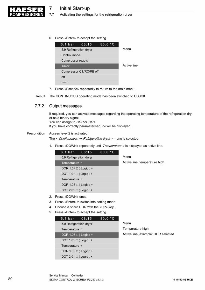
6. Press «Enter» to accept the setting.
6 . 1 b a r 0 8 : 1 5 8 0 . 0 ° C5.9 Refrigeration dryer Menu
Control mode
Compressor ready:
Timer Active line
Compressor Clk/RC/RB off:
off
·········
7. Press «Escape» repeatedly to return to the main menu.
Result The CONTINUOUS operating mode has been switched to CLOCK.
7.7.2 Output messages
If required, you can activate messages regarding the operating temperature of the refrigeration dry‐er as a binary signal.You can assign to DOR or DOT.If you have correctly parameterised, ok will be displayed.
Precondition Access level 2 is activated.The < Configuration ➙ Refrigeration dryer > menu is selected.
1. Press «DOWN» repeatedly until Temperature ↑ is displayed as active line.
6 . 1 b a r 0 8 : 1 5 8 0 . 0 ° C5.9 Refrigeration dryer Menu
Temperature ↑ Active line, temperature high
DOR 1.07 ☐ ¦ Logic : +
DOT 1.01 ☐ ¦ Logic : +
Temperature ⇟
DOR 1.03 ☐ ¦ Logic : +
DOT 2.01 ☐ ¦ Logic : +
2. Press «DOWN» once.3. Press «Enter» to switch into setting mode.4. Choose a spare DOR with the «UP» key.5. Press «Enter» to accept the setting.
6 . 1 b a r 0 8 : 1 5 8 0 . 0 ° C5.9 Refrigeration dryer Menu
Temperature ↑ Temperature high
DOR 1.05 ☐ ¦ Logic : + Active line, example: DOR selected
DOT 1.01 ☐ ¦ Logic : +
Temperature ⇟
DOR 1.03 ☐ ¦ Logic : +
DOT 2.01 ☐ ¦ Logic : +
7 Initial Start-up7.7 Activating the settings for the refrigeration dryer
80Service Manual Controller SIGMA CONTROL 2 SCREW FLUID ≥1.1.3 9_9450 03 HCE
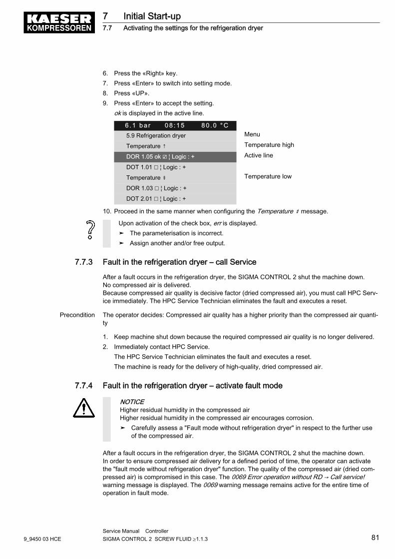
6. Press the «Right» key.7. Press «Enter» to switch into setting mode.8. Press «UP».9. Press «Enter» to accept the setting.
ok is displayed in the active line.
6 . 1 b a r 0 8 : 1 5 8 0 . 0 ° C5.9 Refrigeration dryer Menu
Temperature ↑ Temperature high
DOR 1.05 ok ☑ ¦ Logic : + Active line
DOT 1.01 ☐ ¦ Logic : +
Temperature ⇟ Temperature low
DOR 1.03 ☐ ¦ Logic : +
DOT 2.01 ☐ ¦ Logic : +
10. Proceed in the same manner when configuring the Temperature ⇟ message.
Upon activation of the check box, err is displayed.➤ The parameterisation is incorrect.➤ Assign another and/or free output.
7.7.3 Fault in the refrigeration dryer – call Service
After a fault occurs in the refrigeration dryer, the SIGMA CONTROL 2 shut the machine down.No compressed air is delivered.Because compressed air quality is decisive factor (dried compressed air), you must call HPC Serv‐ice immediately. The HPC Service Technician eliminates the fault and executes a reset.
Precondition The operator decides: Compressed air quality has a higher priority than the compressed air quanti‐ty
1. Keep machine shut down because the required compressed air quality is no longer delivered.2. Immediately contact HPC Service.
The HPC Service Technician eliminates the fault and executes a reset.The machine is ready for the delivery of high-quality, dried compressed air.
7.7.4 Fault in the refrigeration dryer – activate fault mode
NOTICEHigher residual humidity in the compressed airHigher residual humidity in the compressed air encourages corrosion.➤ Carefully assess a "Fault mode without refrigeration dryer" in respect to the further use
of the compressed air.
After a fault occurs in the refrigeration dryer, the SIGMA CONTROL 2 shut the machine down.In order to ensure compressed air delivery for a defined period of time, the operator can activatethe "fault mode without refrigeration dryer" function. The quality of the compressed air (dried com‐pressed air) is compromised in this case. The 0069 Error operation without RD → Call service!warning message is displayed. The 0069 warning message remains active for the entire time ofoperation in fault mode.
7 Initial Start-up7.7 Activating the settings for the refrigeration dryer
9_9450 03 HCEService Manual Controller SIGMA CONTROL 2 SCREW FLUID ≥1.1.3 81
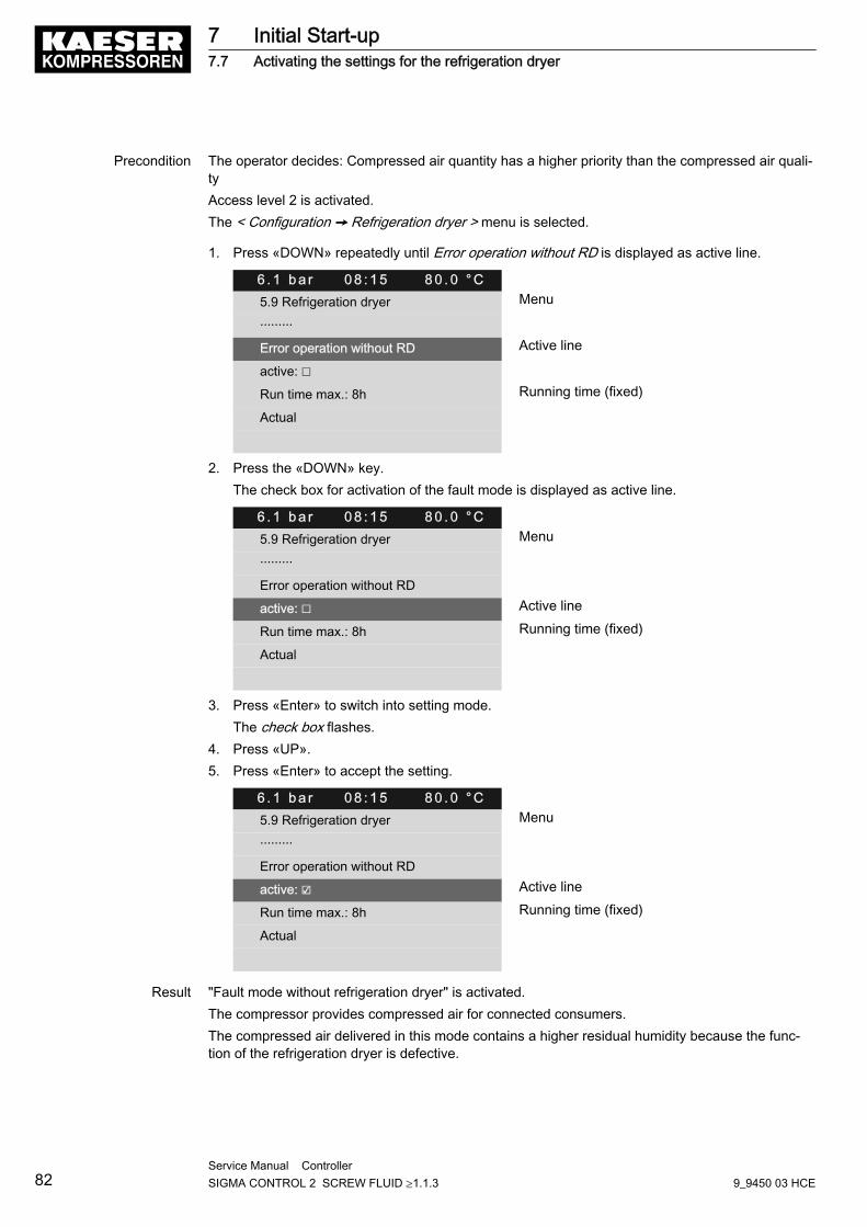
Precondition The operator decides: Compressed air quantity has a higher priority than the compressed air quali‐tyAccess level 2 is activated.The < Configuration ➙ Refrigeration dryer > menu is selected.
1. Press «DOWN» repeatedly until Error operation without RD is displayed as active line.
6 . 1 b a r 0 8 : 1 5 8 0 . 0 ° C5.9 Refrigeration dryer Menu
·········
Error operation without RD Active line
active: ☐
Run time max.: 8h Running time (fixed)
Actual
2. Press the «DOWN» key.The check box for activation of the fault mode is displayed as active line.
6 . 1 b a r 0 8 : 1 5 8 0 . 0 ° C5.9 Refrigeration dryer Menu
·········
Error operation without RD
active: ☐ Active line
Run time max.: 8h Running time (fixed)
Actual
3. Press «Enter» to switch into setting mode.The check box flashes.
4. Press «UP».5. Press «Enter» to accept the setting.
6 . 1 b a r 0 8 : 1 5 8 0 . 0 ° C5.9 Refrigeration dryer Menu
·········
Error operation without RD
active: ☑ Active line
Run time max.: 8h Running time (fixed)
Actual
Result "Fault mode without refrigeration dryer" is activated.The compressor provides compressed air for connected consumers.The compressed air delivered in this mode contains a higher residual humidity because the func‐tion of the refrigeration dryer is defective.
7 Initial Start-up7.7 Activating the settings for the refrigeration dryer
82Service Manual Controller SIGMA CONTROL 2 SCREW FLUID ≥1.1.3 9_9450 03 HCE
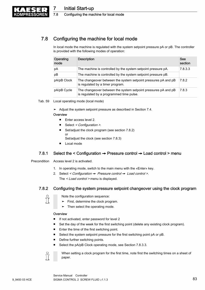
7.8 Configuring the machine for local modeIn local mode the machine is regulated with the system setpoint pressure pA or pB. The controlleris provided with the following modes of operation:
Operatingmode
Description Seesection
pA The machine is controlled by the system setpoint pressure pA. 7.8.3.3
pB The machine is controlled by the system setpoint pressure pB.
pA/pB Clock The changeover between the system setpoint pressures pA and pBis regulated by a timer program.
7.8.2
pA/pB Cycle The changeover between the system setpoint pressures pA and pBis regulated by a programmed time pulse.
7.8.3
Tab. 59 Local operating mode (local mode)
➤ Adjust the system setpoint pressure as described in Section 7.4.Overview
■ Enter access level 2.■ Select < Configuration >.■ Set/adjust the clock program (see section 7.8.2)
orSet/adjust the clock (see section 7.8.3)
■ Local mode
7.8.1 Select the < Configuration ➙ Pressure control ➙ Load control > menu
Precondition Access level 2 is activated.
1. In operating mode, switch to the main menu with the «Enter» key.2. Select < Configuration ➙ Pressure control ➙ Load control >.
The < Load control > menu is displayed.
7.8.2 Configuring the system pressure setpoint changeover using the clock program
Note the configuration sequence:➤ First, determine the clock program.➤ Then select the operating mode.
Overview■ If not activated, enter password for level 2■ Set the day of the week for the first switching point (delete any existing clock program).■ Enter the time of the first switching point.■ Select the system setpoint pressure for the first switching point pA or pB.■ Define further switching points.■ Select the pA/pB Clock operating mode, see Section 7.8.3.3.
When setting a clock program for the first time, note first the switching times on a sheet ofpaper.
7 Initial Start-up7.8 Configuring the machine for local mode
9_9450 03 HCEService Manual Controller SIGMA CONTROL 2 SCREW FLUID ≥1.1.3 83
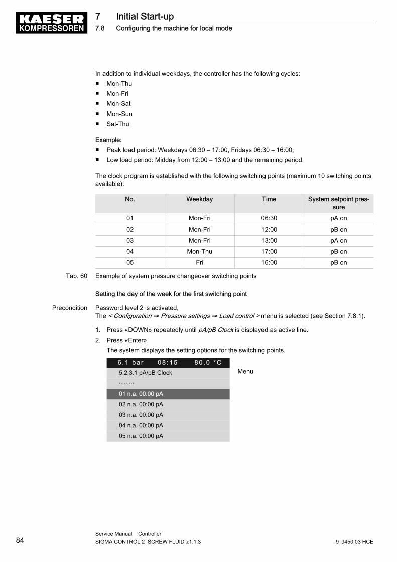
In addition to individual weekdays, the controller has the following cycles:■ Mon-Thu■ Mon-Fri■ Mon-Sat■ Mon-Sun■ Sat-Thu
Example:■ Peak load period: Weekdays 06:30 – 17:00, Fridays 06:30 – 16:00;■ Low load period: Midday from 12:00 – 13:00 and the remaining period.
The clock program is established with the following switching points (maximum 10 switching pointsavailable):
No. Weekday Time System setpoint pres‐sure
01 Mon-Fri 06:30 pA on
02 Mon-Fri 12:00 pB on
03 Mon-Fri 13:00 pA on
04 Mon-Thu 17:00 pB on
05 Fri 16:00 pB on
Tab. 60 Example of system pressure changeover switching points
Setting the day of the week for the first switching point
Precondition Password level 2 is activated,The < Configuration ➙ Pressure settings ➙ Load control > menu is selected (see Section 7.8.1).
1. Press «DOWN» repeatedly until pA/pB Clock is displayed as active line.2. Press «Enter».
The system displays the setting options for the switching points.
6 . 1 b a r 0 8 : 1 5 8 0 . 0 ° C5.2.3.1 pA/pB Clock Menu
·········
01 n.a. 00:00 pA
02 n.a. 00:00 pA
03 n.a. 00:00 pA
04 n.a. 00:00 pA
05 n.a. 00:00 pA
7 Initial Start-up7.8 Configuring the machine for local mode
84Service Manual Controller SIGMA CONTROL 2 SCREW FLUID ≥1.1.3 9_9450 03 HCE
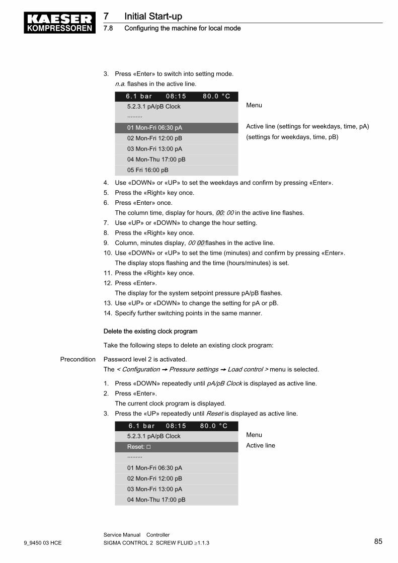
3. Press «Enter» to switch into setting mode.n.a. flashes in the active line.
6 . 1 b a r 0 8 : 1 5 8 0 . 0 ° C5.2.3.1 pA/pB Clock Menu
·········
01 Mon-Fri 06:30 pA Active line (settings for weekdays, time, pA)
02 Mon-Fri 12:00 pB (settings for weekdays, time, pB)
03 Mon-Fri 13:00 pA
04 Mon-Thu 17:00 pB
05 Fri 16:00 pB
4. Use «DOWN» or «UP» to set the weekdays and confirm by pressing «Enter».5. Press the «Right» key once.6. Press «Enter» once.
The column time, display for hours, 00: 00 in the active line flashes.7. Use «UP» or «DOWN» to change the hour setting.8. Press the «Right» key once.9. Column, minutes display, 00 00 flashes in the active line.10. Use «DOWN» or «UP» to set the time (minutes) and confirm by pressing «Enter».
The display stops flashing and the time (hours/minutes) is set.11. Press the «Right» key once.12. Press «Enter».
The display for the system setpoint pressure pA/pB flashes.13. Use «UP» or «DOWN» to change the setting for pA or pB.14. Specify further switching points in the same manner.
Delete the existing clock program
Take the following steps to delete an existing clock program:
Precondition Password level 2 is activated.The < Configuration ➙ Pressure settings ➙ Load control > menu is selected.
1. Press «DOWN» repeatedly until pA/pB Clock is displayed as active line.2. Press «Enter».
The current clock program is displayed.3. Press the «UP» repeatedly until Reset is displayed as active line.
6 . 1 b a r 0 8 : 1 5 8 0 . 0 ° C5.2.3.1 pA/pB Clock Menu
Reset: ☐ Active line
·········
01 Mon-Fri 06:30 pA
02 Mon-Fri 12:00 pB
03 Mon-Fri 13:00 pA
04 Mon-Thu 17:00 pB
7 Initial Start-up7.8 Configuring the machine for local mode
9_9450 03 HCEService Manual Controller SIGMA CONTROL 2 SCREW FLUID ≥1.1.3 85
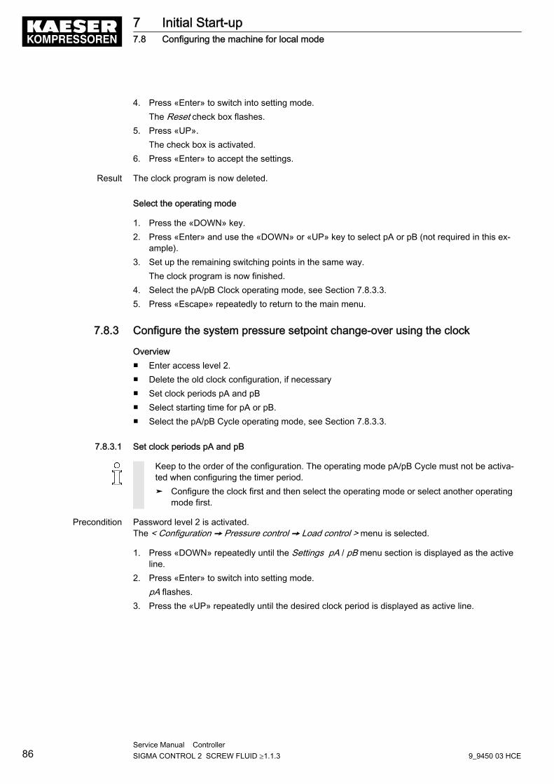
4. Press «Enter» to switch into setting mode.The Reset check box flashes.
5. Press «UP».The check box is activated.
6. Press «Enter» to accept the settings.
Result The clock program is now deleted.
Select the operating mode
1. Press the «DOWN» key.2. Press «Enter» and use the «DOWN» or «UP» key to select pA or pB (not required in this ex‐
ample).3. Set up the remaining switching points in the same way.
The clock program is now finished.4. Select the pA/pB Clock operating mode, see Section 7.8.3.3.5. Press «Escape» repeatedly to return to the main menu.
7.8.3 Configure the system pressure setpoint change-over using the clock
Overview■ Enter access level 2.■ Delete the old clock configuration, if necessary■ Set clock periods pA and pB■ Select starting time for pA or pB.■ Select the pA/pB Cycle operating mode, see Section 7.8.3.3.
7.8.3.1 Set clock periods pA and pB
Keep to the order of the configuration. The operating mode pA/pB Cycle must not be activa‐ted when configuring the timer period.➤ Configure the clock first and then select the operating mode or select another operating
mode first.
Precondition Password level 2 is activated.The < Configuration ➙ Pressure control ➙ Load control > menu is selected.
1. Press «DOWN» repeatedly until the Settings pA / pB menu section is displayed as the activeline.
2. Press «Enter» to switch into setting mode.pA flashes.
3. Press the «UP» repeatedly until the desired clock period is displayed as active line.
7 Initial Start-up7.8 Configuring the machine for local mode
86Service Manual Controller SIGMA CONTROL 2 SCREW FLUID ≥1.1.3 9_9450 03 HCE
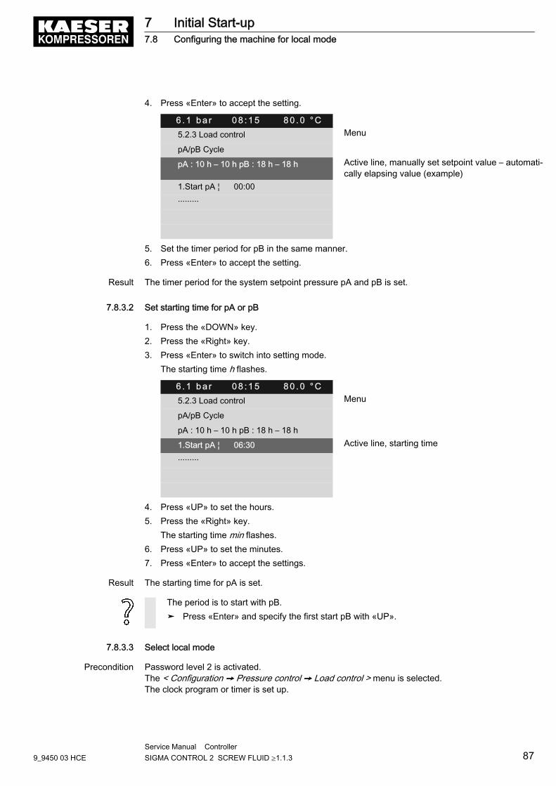
4. Press «Enter» to accept the setting.
6 . 1 b a r 0 8 : 1 5 8 0 . 0 ° C5.2.3 Load control Menu
pA/pB Cycle
pA : 10 h – 10 h pB : 18 h – 18 h Active line, manually set setpoint value – automati‐cally elapsing value (example)
1.Start pA ¦ 00:00
·········
5. Set the timer period for pB in the same manner.6. Press «Enter» to accept the setting.
Result The timer period for the system setpoint pressure pA and pB is set.
7.8.3.2 Set starting time for pA or pB
1. Press the «DOWN» key.2. Press the «Right» key.3. Press «Enter» to switch into setting mode.
The starting time h flashes.
6 . 1 b a r 0 8 : 1 5 8 0 . 0 ° C5.2.3 Load control Menu
pA/pB Cycle
pA : 10 h – 10 h pB : 18 h – 18 h
1.Start pA ¦ 06:30 Active line, starting time
·········
4. Press «UP» to set the hours.5. Press the «Right» key.
The starting time min flashes.6. Press «UP» to set the minutes.7. Press «Enter» to accept the settings.
Result The starting time for pA is set.
The period is to start with pB.➤ Press «Enter» and specify the first start pB with «UP».
7.8.3.3 Select local mode
Precondition Password level 2 is activated.The < Configuration ➙ Pressure control ➙ Load control > menu is selected.The clock program or timer is set up.
7 Initial Start-up7.8 Configuring the machine for local mode
9_9450 03 HCEService Manual Controller SIGMA CONTROL 2 SCREW FLUID ≥1.1.3 87
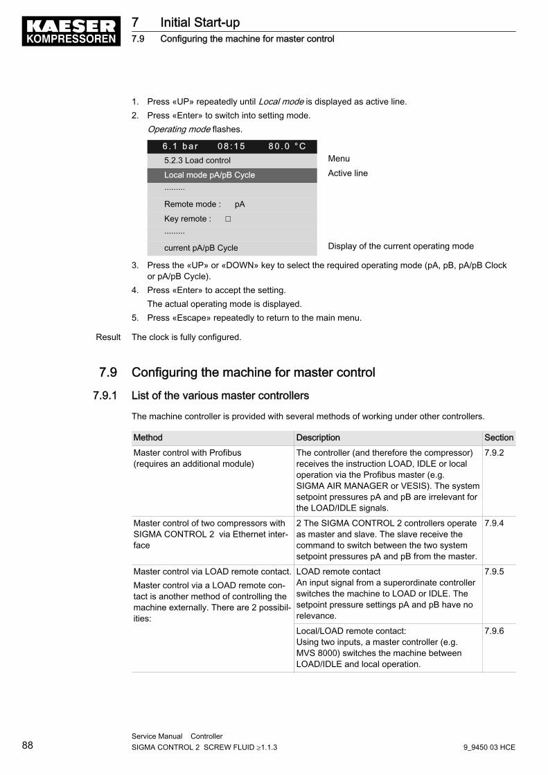
1. Press «UP» repeatedly until Local mode is displayed as active line.2. Press «Enter» to switch into setting mode.
Operating mode flashes.
6 . 1 b a r 0 8 : 1 5 8 0 . 0 ° C5.2.3 Load control Menu
Local mode pA/pB Cycle Active line
·········
Remote mode : pA
Key remote : ☐
·········
current pA/pB Cycle Display of the current operating mode
3. Press the «UP» or «DOWN» key to select the required operating mode (pA, pB, pA/pB Clockor pA/pB Cycle).
4. Press «Enter» to accept the setting.The actual operating mode is displayed.
5. Press «Escape» repeatedly to return to the main menu.
Result The clock is fully configured.
7.9 Configuring the machine for master control
7.9.1 List of the various master controllers
The machine controller is provided with several methods of working under other controllers.
Method Description Section
Master control with Profibus(requires an additional module)
The controller (and therefore the compressor)receives the instruction LOAD, IDLE or localoperation via the Profibus master (e.g.SIGMA AIR MANAGER or VESIS). The systemsetpoint pressures pA and pB are irrelevant forthe LOAD/IDLE signals.
7.9.2
Master control of two compressors withSIGMA CONTROL 2 via Ethernet inter‐face
2 The SIGMA CONTROL 2 controllers operateas master and slave. The slave receive thecommand to switch between the two systemsetpoint pressures pA and pB from the master.
7.9.4
Master control via LOAD remote contact.Master control via a LOAD remote con‐tact is another method of controlling themachine externally. There are 2 possibil‐ities:
LOAD remote contactAn input signal from a superordinate controllerswitches the machine to LOAD or IDLE. Thesetpoint pressure settings pA and pB have norelevance.
7.9.5
Local/LOAD remote contact:Using two inputs, a master controller (e.g.MVS 8000) switches the machine betweenLOAD/IDLE and local operation.
7.9.6
7 Initial Start-up7.9 Configuring the machine for master control
88Service Manual Controller SIGMA CONTROL 2 SCREW FLUID ≥1.1.3 9_9450 03 HCE
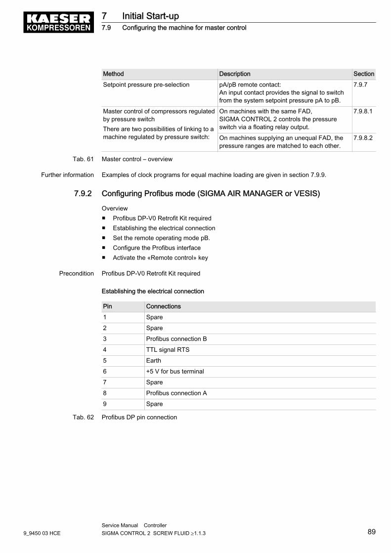
Method Description Section
Setpoint pressure pre-selection pA/pB remote contact:An input contact provides the signal to switchfrom the system setpoint pressure pA to pB.
7.9.7
Master control of compressors regulatedby pressure switchThere are two possibilities of linking to amachine regulated by pressure switch:
On machines with the same FAD,SIGMA CONTROL 2 controls the pressureswitch via a floating relay output.
7.9.8.1
On machines supplying an unequal FAD, thepressure ranges are matched to each other.
7.9.8.2
Tab. 61 Master control – overview
Further information Examples of clock programs for equal machine loading are given in section 7.9.9.
7.9.2 Configuring Profibus mode (SIGMA AIR MANAGER or VESIS)
Overview■ Profibus DP-V0 Retrofit Kit required■ Establishing the electrical connection■ Set the remote operating mode pB.■ Configure the Profibus interface■ Activate the «Remote control» key
Precondition Profibus DP-V0 Retrofit Kit required
Establishing the electrical connection
Pin Connections
1 Spare
2 Spare
3 Profibus connection B
4 TTL signal RTS
5 Earth
6 +5 V for bus terminal
7 Spare
8 Profibus connection A
9 Spare
Tab. 62 Profibus DP pin connection
7 Initial Start-up7.9 Configuring the machine for master control
9_9450 03 HCEService Manual Controller SIGMA CONTROL 2 SCREW FLUID ≥1.1.3 89
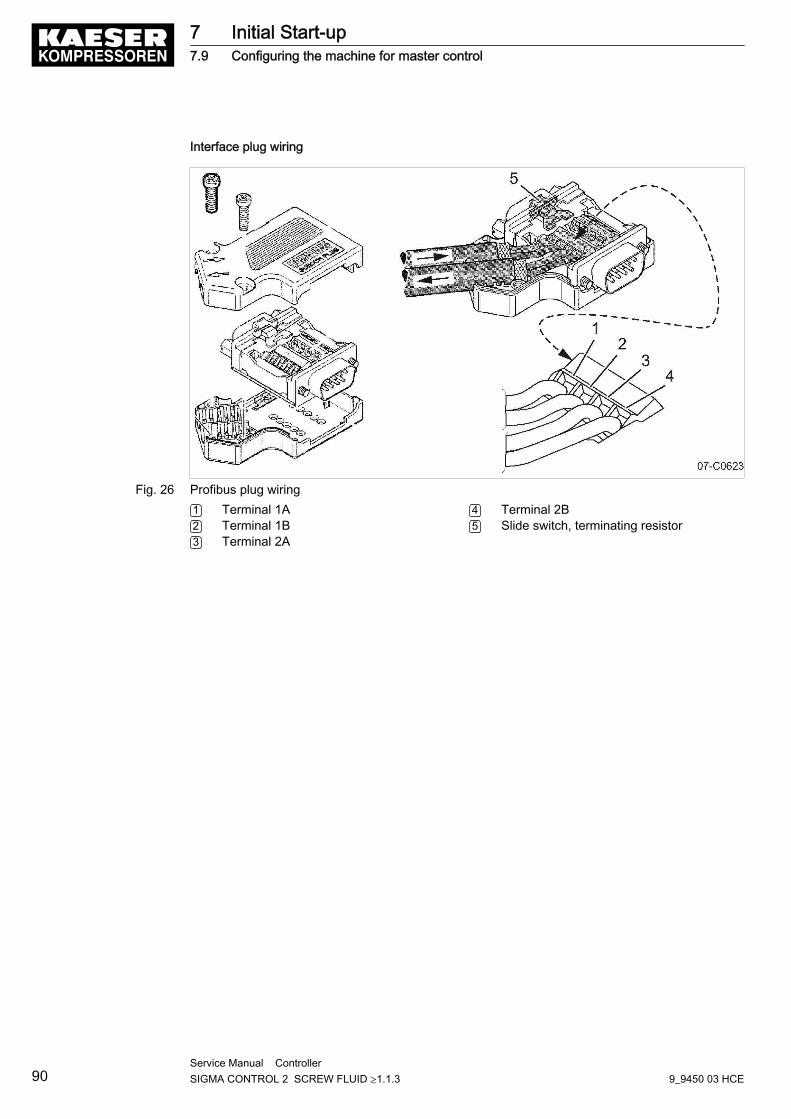
Interface plug wiring
Fig. 26 Profibus plug wiring1 Terminal 1A2 Terminal 1B3 Terminal 2A
4 Terminal 2B5 Slide switch, terminating resistor
7 Initial Start-up7.9 Configuring the machine for master control
90Service Manual Controller SIGMA CONTROL 2 SCREW FLUID ≥1.1.3 9_9450 03 HCE
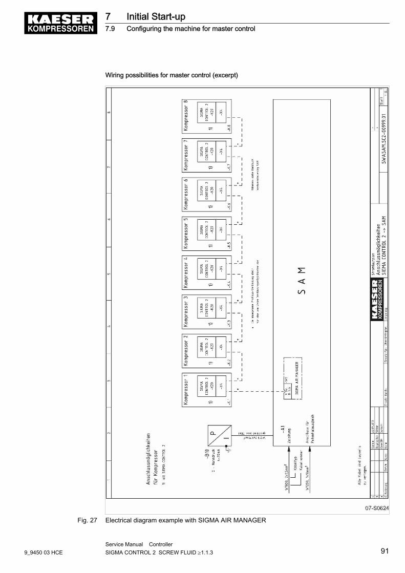
Wiring possibilities for master control (excerpt)
Fig. 27 Electrical diagram example with SIGMA AIR MANAGER
7 Initial Start-up7.9 Configuring the machine for master control
9_9450 03 HCEService Manual Controller SIGMA CONTROL 2 SCREW FLUID ≥1.1.3 91
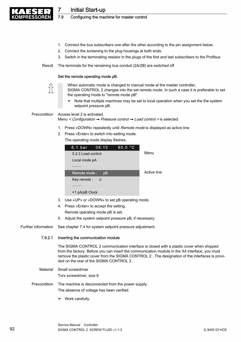
1. Connect the bus subscribers one after the other according to the pin assignment below.2. Connect the screening to the plug housings at both ends.3. Switch in the terminating resistor in the plugs of the first and last subscribers to the Profibus.
Result The terminals for the remaining bus conduit (2A/2B) are switched off.
Set the remote operating mode pB.
When automatic mode is changed to manual mode at the master controller,SIGMA CONTROL 2 changes into the set remote mode. In such a case it is preferable to setthe operating mode to "remote mode pB".➤ Note that multiple machines may be set to local operation when you set the the system
setpoint pressure pB.
Precondition Access level 2 is activated.Menu < Configuration ➙ Pressure control ➙ Load control > is selected.
1. Press «DOWN» repeatedly until Remote mode is displayed as active line.2. Press «Enter» to switch into setting mode.
The operating mode display flashes.
6 . 1 b a r 0 8 : 1 5 8 0 . 0 ° C5.2.3 Load control Menu
Local mode pA
·········
Remote mode : pB Active line
Key remote : ☑
·········
▶1 pA/pB Clock
3. Use «UP» or «DOWN» to set pB operating mode.4. Press «Enter» to accept the setting.
Remote operating mode pB is set.5. Adjust the system setpoint pressure pB, if necessary.
Further information See chapter 7.4 for system setpoint pressure adjustment.
7.9.2.1 Inserting the communication module
The SIGMA CONTROL 2 communication interface is closed with a plastic cover when shippedfrom the factory. Before you can insert the communication module in the X4 interface, you mustremove the plastic cover from the SIGMA CONTROL 2 . The designation of the interfaces is provi‐ded on the rear of the SIGMA CONTROL 2.
Material Small screwdriverTorx screwdriver, size 9
Precondition The machine is disconnected from the power supply.The absence of voltage has been verified.
➤ Work carefully.
7 Initial Start-up7.9 Configuring the machine for master control
92Service Manual Controller SIGMA CONTROL 2 SCREW FLUID ≥1.1.3 9_9450 03 HCE
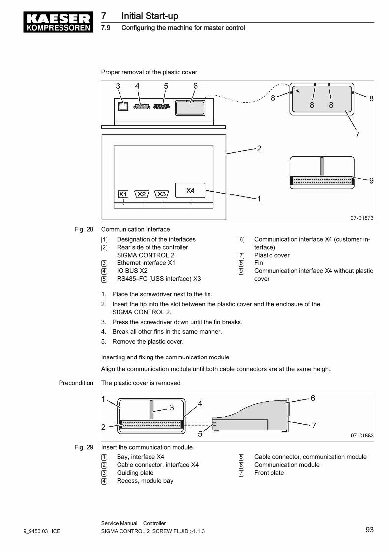
Proper removal of the plastic cover
Fig. 28 Communication interface1 Designation of the interfaces2 Rear side of the controller
SIGMA CONTROL 23 Ethernet interface X14 IO BUS X25 RS485–FC (USS interface) X3
6 Communication interface X4 (customer in‐terface)
7 Plastic cover8 Fin9 Communication interface X4 without plastic
cover
1. Place the screwdriver next to the fin.2. Insert the tip into the slot between the plastic cover and the enclosure of the
SIGMA CONTROL 2.3. Press the screwdriver down until the fin breaks.4. Break all other fins in the same manner.5. Remove the plastic cover.
Inserting and fixing the communication module
Align the communication module until both cable connectors are at the same height.
Precondition The plastic cover is removed.
Fig. 29 Insert the communication module.1 Bay, interface X42 Cable connector, interface X43 Guiding plate4 Recess, module bay
5 Cable connector, communication module6 Communication module7 Front plate
7 Initial Start-up7.9 Configuring the machine for master control
9_9450 03 HCEService Manual Controller SIGMA CONTROL 2 SCREW FLUID ≥1.1.3 93
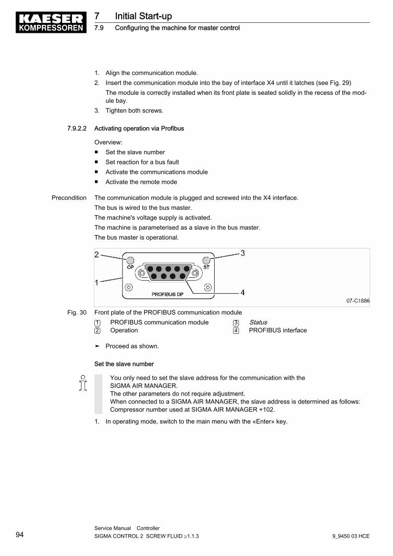
1. Align the communication module.2. Insert the communication module into the bay of interface X4 until it latches (see Fig. 29)
The module is correctly installed when its front plate is seated solidly in the recess of the mod‐ule bay.
3. Tighten both screws.
7.9.2.2 Activating operation via Profibus
Overview:■ Set the slave number■ Set reaction for a bus fault■ Activate the communications module■ Activate the remote mode
Precondition The communication module is plugged and screwed into the X4 interface.The bus is wired to the bus master.The machine's voltage supply is activated.The machine is parameterised as a slave in the bus master.The bus master is operational.
Fig. 30 Front plate of the PROFIBUS communication module1 PROFIBUS communication module2 Operation
3 Status4 PROFIBUS interface
➤ Proceed as shown.
Set the slave number
You only need to set the slave address for the communication with theSIGMA AIR MANAGER.The other parameters do not require adjustment.When connected to a SIGMA AIR MANAGER, the slave address is determined as follows:Compressor number used at SIGMA AIR MANAGER +102.
1. In operating mode, switch to the main menu with the «Enter» key.
7 Initial Start-up7.9 Configuring the machine for master control
94Service Manual Controller SIGMA CONTROL 2 SCREW FLUID ≥1.1.3 9_9450 03 HCE
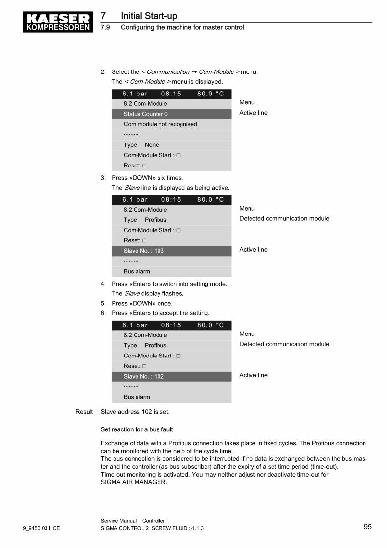
2. Select the < Communication ➙ Com-Module > menu.The < Com-Module > menu is displayed.
6 . 1 b a r 0 8 : 1 5 8 0 . 0 ° C8.2 Com-Module Menu
Status Counter 0 Active line
Com module not recognised
·········
Type None
Com-Module Start : ☐
Reset: ☐
3. Press «DOWN» six times.The Slave line is displayed as being active.
6 . 1 b a r 0 8 : 1 5 8 0 . 0 ° C8.2 Com-Module Menu
Type Profibus Detected communication module
Com-Module Start : ☐
Reset: ☐
Slave No. : 103 Active line
·········
Bus alarm
4. Press «Enter» to switch into setting mode.The Slave display flashes.
5. Press «DOWN» once.6. Press «Enter» to accept the setting.
6 . 1 b a r 0 8 : 1 5 8 0 . 0 ° C8.2 Com-Module Menu
Type Profibus Detected communication module
Com-Module Start : ☐
Reset: ☐
Slave No. : 102 Active line
·········
Bus alarm
Result Slave address 102 is set.
Set reaction for a bus fault
Exchange of data with a Profibus connection takes place in fixed cycles. The Profibus connectioncan be monitored with the help of the cycle time:The bus connection is considered to be interrupted if no data is exchanged between the bus mas‐ter and the controller (as bus subscriber) after the expiry of a set time period (time-out).Time-out monitoring is activated. You may neither adjust nor deactivate time-out forSIGMA AIR MANAGER.
7 Initial Start-up7.9 Configuring the machine for master control
9_9450 03 HCEService Manual Controller SIGMA CONTROL 2 SCREW FLUID ≥1.1.3 95
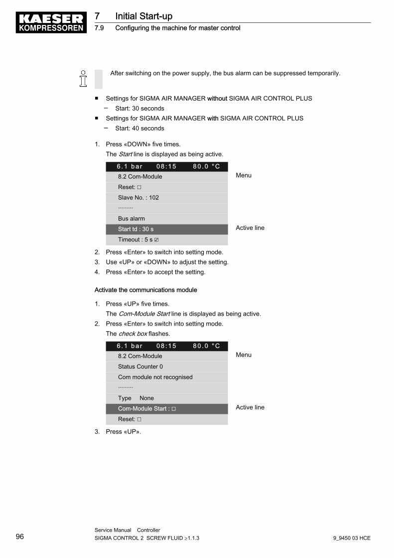
After switching on the power supply, the bus alarm can be suppressed temporarily.
■ Settings for SIGMA AIR MANAGER without SIGMA AIR CONTROL PLUS─ Start: 30 seconds
■ Settings for SIGMA AIR MANAGER with SIGMA AIR CONTROL PLUS─ Start: 40 seconds
1. Press «DOWN» five times.The Start line is displayed as being active.
6 . 1 b a r 0 8 : 1 5 8 0 . 0 ° C8.2 Com-Module Menu
Reset: ☐
Slave No. : 102
·········
Bus alarm
Start td : 30 s Active line
Timeout : 5 s ☑
2. Press «Enter» to switch into setting mode.3. Use «UP» or «DOWN» to adjust the setting.4. Press «Enter» to accept the setting.
Activate the communications module
1. Press «UP» five times.The Com-Module Start line is displayed as being active.
2. Press «Enter» to switch into setting mode.The check box flashes.
6 . 1 b a r 0 8 : 1 5 8 0 . 0 ° C8.2 Com-Module Menu
Status Counter 0
Com module not recognised
·········
Type None
Com-Module Start : ☐ Active line
Reset: ☐
3. Press «UP».
7 Initial Start-up7.9 Configuring the machine for master control
96Service Manual Controller SIGMA CONTROL 2 SCREW FLUID ≥1.1.3 9_9450 03 HCE
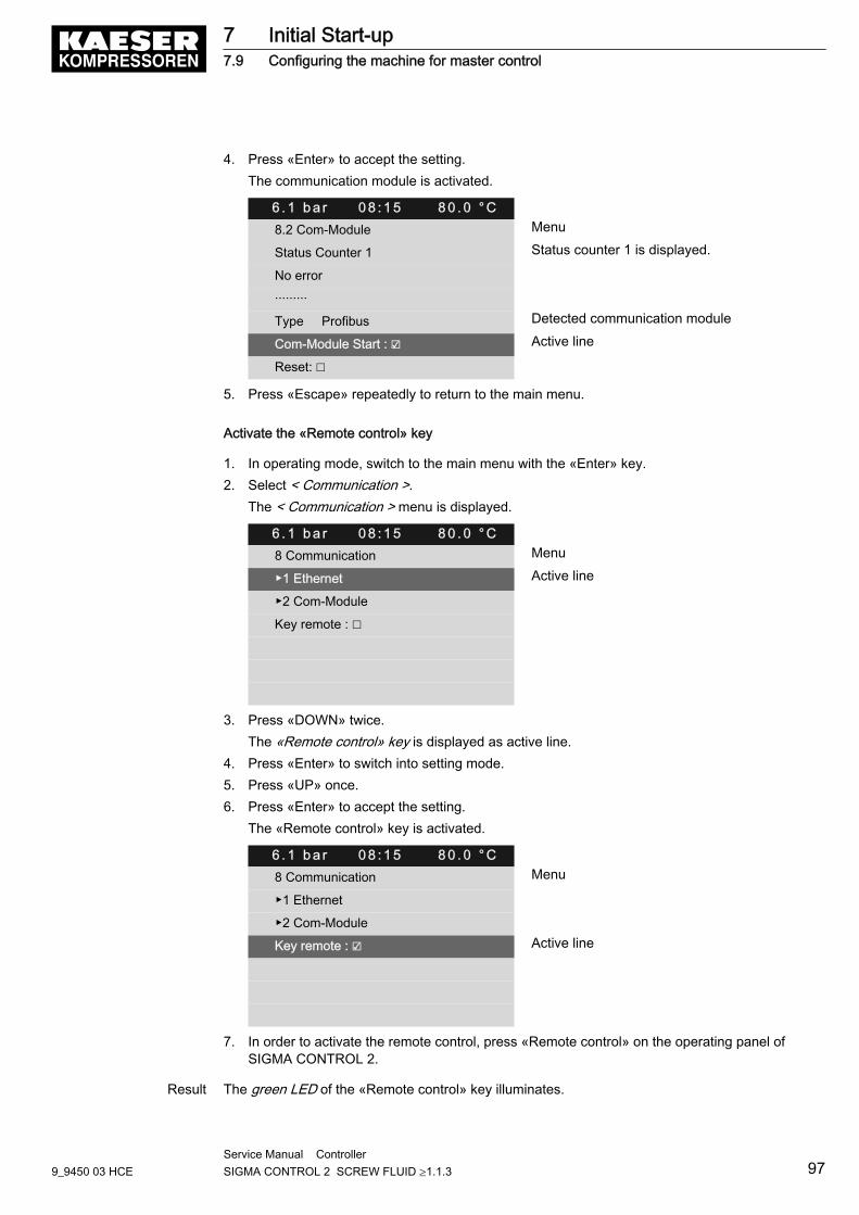
4. Press «Enter» to accept the setting.The communication module is activated.
6 . 1 b a r 0 8 : 1 5 8 0 . 0 ° C8.2 Com-Module Menu
Status Counter 1 Status counter 1 is displayed.
No error
·········
Type Profibus Detected communication module
Com-Module Start : ☑ Active line
Reset: ☐
5. Press «Escape» repeatedly to return to the main menu.
Activate the «Remote control» key
1. In operating mode, switch to the main menu with the «Enter» key.2. Select < Communication >.
The < Communication > menu is displayed.
6 . 1 b a r 0 8 : 1 5 8 0 . 0 ° C8 Communication Menu
▶1 Ethernet Active line
▶2 Com-Module
Key remote : ☐
3. Press «DOWN» twice.The «Remote control» key is displayed as active line.
4. Press «Enter» to switch into setting mode.5. Press «UP» once.6. Press «Enter» to accept the setting.
The «Remote control» key is activated.
6 . 1 b a r 0 8 : 1 5 8 0 . 0 ° C8 Communication Menu
▶1 Ethernet
▶2 Com-Module
Key remote : ☑ Active line
7. In order to activate the remote control, press «Remote control» on the operating panel ofSIGMA CONTROL 2.
Result The green LED of the «Remote control» key illuminates.
7 Initial Start-up7.9 Configuring the machine for master control
9_9450 03 HCEService Manual Controller SIGMA CONTROL 2 SCREW FLUID ≥1.1.3 97
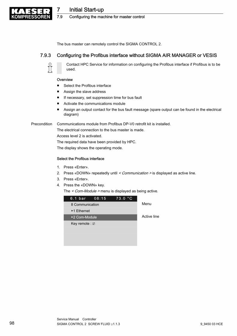
The bus master can remotely control the SIGMA CONTROL 2.
7.9.3 Configuring the Profibus interface without SIGMA AIR MANAGER or VESIS
Contact HPC Service for information on configuring the Profibus interface if Profibus is to beused.
Overview■ Select the Profibus interface■ Assign the slave address■ If necessary, set suppression time for bus fault■ Activate the communications module■ Assign an output contact for the bus fault message (spare output can be found in the electrical
diagram)
Precondition Communications module from Profibus DP-V0 retrofit kit is installed.The electrical connection to the bus master is made.Access level 2 is activated.The required data have been provided by HPC.The display shows the operating mode.
Select the Profibus interface
1. Press «Enter».2. Press «DOWN» repeatedly until < Communication > is displayed as active line.3. Press «Enter».4. Press the «DOWN» key.
The < Com-Module > menu is displayed as being active.
6 . 1 b a r 0 8 : 1 5 7 3 . 0 ° C8 Communication Menu
▶1 Ethernet
▶2 Com-Module Active line
Key remote : ☑
7 Initial Start-up7.9 Configuring the machine for master control
98Service Manual Controller SIGMA CONTROL 2 SCREW FLUID ≥1.1.3 9_9450 03 HCE
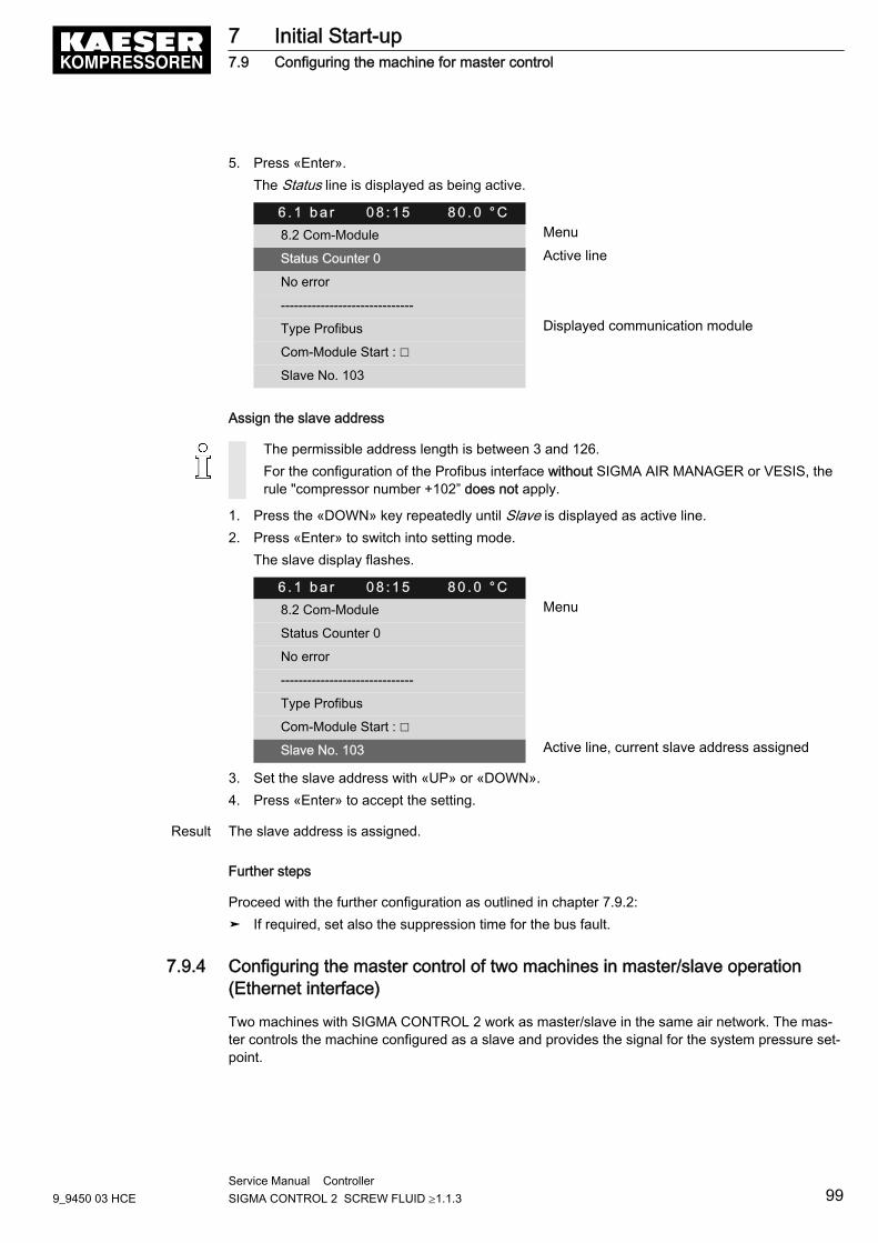
5. Press «Enter».The Status line is displayed as being active.
6 . 1 b a r 0 8 : 1 5 8 0 . 0 ° C8.2 Com-Module Menu
Status Counter 0 Active line
No error
------------------------------
Type Profibus Displayed communication module
Com-Module Start : ☐
Slave No. 103
Assign the slave address
The permissible address length is between 3 and 126.For the configuration of the Profibus interface without SIGMA AIR MANAGER or VESIS, therule "compressor number +102” does not apply.
1. Press the «DOWN» key repeatedly until Slave is displayed as active line.2. Press «Enter» to switch into setting mode.
The slave display flashes.
6 . 1 b a r 0 8 : 1 5 8 0 . 0 ° C8.2 Com-Module Menu
Status Counter 0
No error
------------------------------
Type Profibus
Com-Module Start : ☐
Slave No. 103 Active line, current slave address assigned
3. Set the slave address with «UP» or «DOWN».4. Press «Enter» to accept the setting.
Result The slave address is assigned.
Further steps
Proceed with the further configuration as outlined in chapter 7.9.2:➤ If required, set also the suppression time for the bus fault.
7.9.4 Configuring the master control of two machines in master/slave operation(Ethernet interface)
Two machines with SIGMA CONTROL 2 work as master/slave in the same air network. The mas‐ter controls the machine configured as a slave and provides the signal for the system pressure set‐point.
7 Initial Start-up7.9 Configuring the machine for master control
9_9450 03 HCEService Manual Controller SIGMA CONTROL 2 SCREW FLUID ≥1.1.3 99
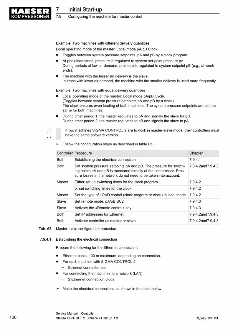
Example: Two machines with different delivery quantitiesLocal operating mode of the master: Local mode pA/pB Clock.■ Toggles between system pressure setpoints pA and pB by a clock program.■ At peak load times, pressure is regulated to system set-point pressure pA.
During periods of low air demand, pressure is regulated to system setpoint pB (e.g., at week‐ends).
■ The machine with the lesser air delivery is the slave.In times with lower air demand, the machine with the smaller delivery is used more frequently.
Example: Two machines with equal delivery quantities■ Local operating mode of the master: Local mode pA/pB Cycle.
(Toggles between system pressure setpoints pA and pB by a clock).The clock ensures even loading of both machines. The system pressure setpoints are set thesame for both machines.
■ During timer period 1, the master regulates to pA and signals the slave for pB.During timer period 2, the master regulates to pB and signals the slave to pA.
If two machines SIGMA CONTROL 2 are to work in master-slave mode, their controllers musthave the same software version.
➤ Follow the configuration steps as described in table 63 .
Controller Procedure Chapter
Both Establishing the electrical connection 7.9.4.1
Both Set system pressure setpoints pA and pB. The pressure for switch‐ing points pA and pB is measured directly at the compressor. Pres‐sure losses in the network do not need to be taken into account.
7.9.4.2and7.9.4.3
Master Either set up switching times for the clock program 7.9.4.2
or set switching times for the clock 7.9.4.2
Master Set the type of LOAD control (clock program or clock) in local mode. 7.9.4.2
Slave Set remote mode: pA/pB SC2 7.9.4.3
Slave Activate the «Remote control» key 7.9.4.3
Both Set IP addresses for Ethernet 7.9.4.2and7.9.4.3
Both Activate controller as master or slave 7.9.4.2and7.9.4.3
Tab. 63 Master-slave configuration procedure
7.9.4.1 Establishing the electrical connection
Prepare the following for the Ethernet connection:
■ Ethernet cable, 100 m maximum, depending on connection.■ For each machine with SIGMA CONTROL 2 :
─ Ethernet connector set■ For connecting the machines to a network (LAN):
─ 2 Ethernet connection plugs
➤ Make the electrical connections as shown in the table below.
7 Initial Start-up7.9 Configuring the machine for master control
100Service Manual Controller SIGMA CONTROL 2 SCREW FLUID ≥1.1.3 9_9450 03 HCE
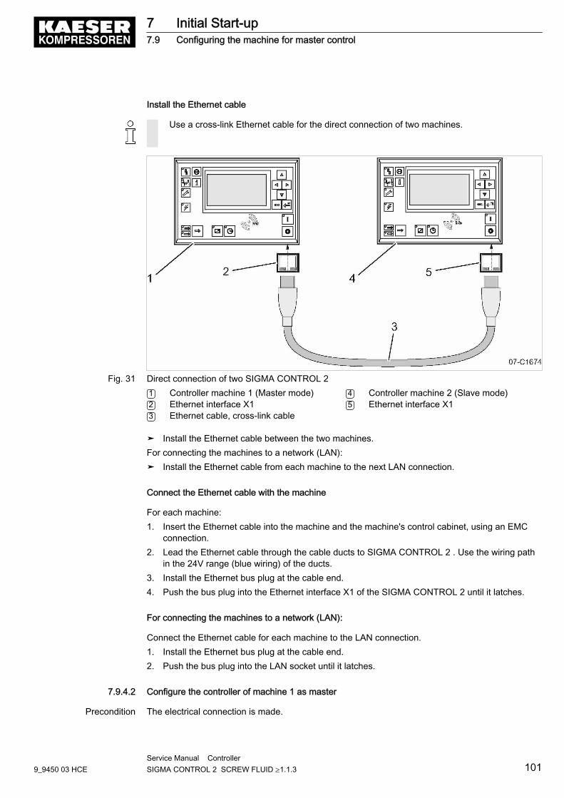
Install the Ethernet cable
Use a cross-link Ethernet cable for the direct connection of two machines.
Fig. 31 Direct connection of two SIGMA CONTROL 21 Controller machine 1 (Master mode)2 Ethernet interface X13 Ethernet cable, cross-link cable
4 Controller machine 2 (Slave mode)5 Ethernet interface X1
➤ Install the Ethernet cable between the two machines.For connecting the machines to a network (LAN):➤ Install the Ethernet cable from each machine to the next LAN connection.
Connect the Ethernet cable with the machine
For each machine:1. Insert the Ethernet cable into the machine and the machine's control cabinet, using an EMC
connection.2. Lead the Ethernet cable through the cable ducts to SIGMA CONTROL 2 . Use the wiring path
in the 24V range (blue wiring) of the ducts.3. Install the Ethernet bus plug at the cable end.4. Push the bus plug into the Ethernet interface X1 of the SIGMA CONTROL 2 until it latches.
For connecting the machines to a network (LAN):
Connect the Ethernet cable for each machine to the LAN connection.1. Install the Ethernet bus plug at the cable end.2. Push the bus plug into the LAN socket until it latches.
7.9.4.2 Configure the controller of machine 1 as master
Precondition The electrical connection is made.
7 Initial Start-up7.9 Configuring the machine for master control
9_9450 03 HCEService Manual Controller SIGMA CONTROL 2 SCREW FLUID ≥1.1.3 101
Set the switching points pA and pB
1. Select the < Configuration ➙ Pressure control ➙ Pressure settings > menu.The switching point pA is displayed as the active line.
2. Press «Enter» to switch into setting mode.The display of switching point pA flashes.
3. Use «UP» or «DOWN» to set the required value.4. Press «Enter» to accept the setting.5. Press «DOWN» once.
The switching point pB is displayed as the active line.6. Proceed as described for switching point pA.
Deactivate the «Remote control» key
1. Select the < Configuration ➙ Pressure control ➙ Load control > menu.Local mode line is displayed as being active.
2. Press «DOWN» three times.The «Remote control» key is displayed as active line.
3. Press «Enter» to switch into setting mode.The check box flashes.
4. Press «UP» key to deactivate the check box.5. Press «Enter» to accept the setting.
Setting the times
SIGMA CONTROL 2 provides the following options for selecting times:
■ Clock program, or■ Timer
1. Decide your desired method.2. Apply the corresponding settings (table).
7 Initial Start-up7.9 Configuring the machine for master control
102Service Manual Controller SIGMA CONTROL 2 SCREW FLUID ≥1.1.3 9_9450 03 HCE
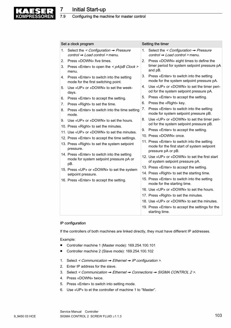
Set a clock program Setting the timer
1. Select the < Configuration ➙ Pressurecontrol ➙ Load control > menu.
2. Press «DOWN» five times.3. Press «Enter» to open the < pA/pB Clock >
menu.4. Press «Enter» to switch into the setting
mode for the first switching point.5. Use «UP» or «DOWN» to set the week‐
days.6. Press «Enter» to accept the setting.7. Press «Right» to set the time.8. Press «Enter» to switch into the time setting
mode.9. Use «UP» or «DOWN» to set the hours.10. Press «Right» to set the minutes.11. Use «UP» or «DOWN» to set the minutes.12. Press «Enter» to accept the time settings.13. Press «Right» to set the system setpoint
pressure.14. Press «Enter» to switch into the setting
mode for system setpoint pressure pA orpB.
15. Press «UP» or «DOWN» to set the systemsetpoint pressure.
16. Press «Enter» to accept the setting.
1. Select the < Configuration ➙ Pressurecontrol ➙ Load control > menu.
2. Press «DOWN» eight times to define thetimer period for system setpoint pressure pAand pB.
3. Press «Enter» to switch into the settingmode for the system setpoint pressure pA.
4. Use «UP» or «DOWN» to set the timer peri‐od for the system setpoint pressure pA.
5. Press «Enter» to accept the setting.6. Press the «Right» key.7. Press «Enter» to switch into the setting
mode for system setpoint pressure pB.8. Use «UP» or «DOWN» to set the timer peri‐
od for the system setpoint pressure pB.9. Press «Enter» to accept the setting.10. Press «DOWN» once.11. Press «Enter» to switch into the setting
mode for the first start of system setpointpressure pA or pB.
12. Use «UP» or «DOWN» to set the first startof system setpoint pressure pA.
13. Press «Enter» to accept the setting.14. Press «Right» to set the starting time.15. Press «Enter» to switch into the setting
mode for the starting time.16. Use «UP» or «DOWN» to set the hours.17. Press «Right» to set the minutes.18. Use «UP» or «DOWN» to set the minutes.19. Press «Enter» to accept the settings for the
starting time.
IP configuration
If the controllers of both machines are linked directly, they must have different IP addresses.
Example:■ Controller machine 1 (Master mode): 169.254.100.101■ Controller machine 2 (Slave mode): 169.254.100.102
1. Select < Communication ➙ Ethernet ➙ IP configuration >.2. Enter IP address for the slave.3. Select < Communication ➙ Ethernet ➙ Connections ➙ SIGMA CONTROL 2 >.4. Press «DOWN» twice.5. Press «Enter» to switch into setting mode.6. Use «UP» to et the controller of machine 1 to “Master”.
7 Initial Start-up7.9 Configuring the machine for master control
9_9450 03 HCEService Manual Controller SIGMA CONTROL 2 SCREW FLUID ≥1.1.3 103
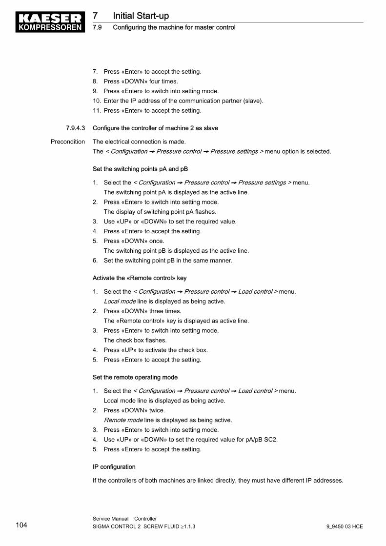
7. Press «Enter» to accept the setting.8. Press «DOWN» four times.9. Press «Enter» to switch into setting mode.10. Enter the IP address of the communication partner (slave).11. Press «Enter» to accept the setting.
7.9.4.3 Configure the controller of machine 2 as slave
Precondition The electrical connection is made.The < Configuration ➙ Pressure control ➙ Pressure settings > menu option is selected.
Set the switching points pA and pB
1. Select the < Configuration ➙ Pressure control ➙ Pressure settings > menu.The switching point pA is displayed as the active line.
2. Press «Enter» to switch into setting mode.The display of switching point pA flashes.
3. Use «UP» or «DOWN» to set the required value.4. Press «Enter» to accept the setting.5. Press «DOWN» once.
The switching point pB is displayed as the active line.6. Set the switching point pB in the same manner.
Activate the «Remote control» key
1. Select the < Configuration ➙ Pressure control ➙ Load control > menu.Local mode line is displayed as being active.
2. Press «DOWN» three times.The «Remote control» key is displayed as active line.
3. Press «Enter» to switch into setting mode.The check box flashes.
4. Press «UP» to activate the check box.5. Press «Enter» to accept the setting.
Set the remote operating mode
1. Select the < Configuration ➙ Pressure control ➙ Load control > menu.Local mode line is displayed as being active.
2. Press «DOWN» twice.Remote mode line is displayed as being active.
3. Press «Enter» to switch into setting mode.4. Use «UP» or «DOWN» to set the required value for pA/pB SC2.5. Press «Enter» to accept the setting.
IP configuration
If the controllers of both machines are linked directly, they must have different IP addresses.
7 Initial Start-up7.9 Configuring the machine for master control
104Service Manual Controller SIGMA CONTROL 2 SCREW FLUID ≥1.1.3 9_9450 03 HCE
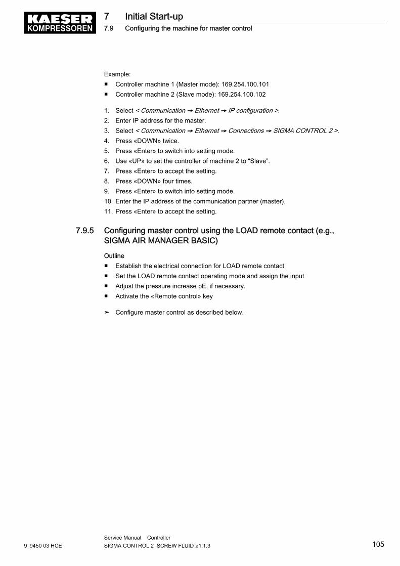
Example:■ Controller machine 1 (Master mode): 169.254.100.101■ Controller machine 2 (Slave mode): 169.254.100.102
1. Select < Communication ➙ Ethernet ➙ IP configuration >.2. Enter IP address for the master.3. Select < Communication ➙ Ethernet ➙ Connections ➙ SIGMA CONTROL 2 >.4. Press «DOWN» twice.5. Press «Enter» to switch into setting mode.6. Use «UP» to set the controller of machine 2 to “Slave”.7. Press «Enter» to accept the setting.8. Press «DOWN» four times.9. Press «Enter» to switch into setting mode.10. Enter the IP address of the communication partner (master).11. Press «Enter» to accept the setting.
7.9.5 Configuring master control using the LOAD remote contact (e.g.,SIGMA AIR MANAGER BASIC)
Outline■ Establish the electrical connection for LOAD remote contact■ Set the LOAD remote contact operating mode and assign the input■ Adjust the pressure increase pE, if necessary.■ Activate the «Remote control» key
➤ Configure master control as described below.
7 Initial Start-up7.9 Configuring the machine for master control
9_9450 03 HCEService Manual Controller SIGMA CONTROL 2 SCREW FLUID ≥1.1.3 105
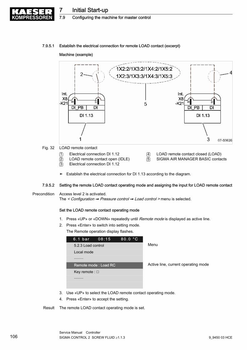
7.9.5.1 Establish the electrical connection for remote LOAD contact (excerpt)
Machine (example)
Fig. 32 LOAD remote contact1 Electrical connection DI 1.122 LOAD remote contact open (IDLE)3 Electrical connection DI 1.12
4 LOAD remote contact closed (LOAD)5 SIGMA AIR MANAGER BASIC contacts
➤ Establish the electrical connection for DI 1.13 according to the diagram.
7.9.5.2 Setting the remote LOAD contact operating mode and assigning the input for LOAD remote contact
Precondition Access level 2 is activated.The < Configuration ➙ Pressure control ➙ Load control > menu is selected.
Set the LOAD remote contact operating mode
1. Press «UP» or «DOWN» repeatedly until Remote mode is displayed as active line.2. Press «Enter» to switch into setting mode.
The Remote operation display flashes.
6 . 1 b a r 0 8 : 1 5 8 0 . 0 ° C5.2.3 Load control Menu
Local mode
·········
Remote mode : Load RC Active line, current operating mode
Key remote : ☐
·········
3. Use «UP» to select the LOAD remote contact operating mode.4. Press «Enter» to accept the setting.
Result The remote LOAD contact operating mode is set.
7 Initial Start-up7.9 Configuring the machine for master control
106Service Manual Controller SIGMA CONTROL 2 SCREW FLUID ≥1.1.3 9_9450 03 HCE
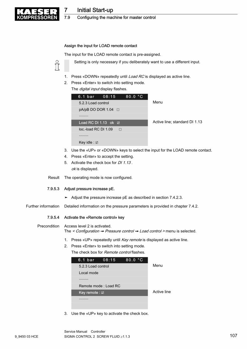
Assign the input for LOAD remote contact
The input for the LOAD remote contact is pre-assigned.
Setting is only necessary if you deliberately want to use a different input.
1. Press «DOWN» repeatedly until Load RC is displayed as active line.2. Press «Enter» to switch into setting mode.
The digital input display flashes.
6 . 1 b a r 0 8 : 1 5 8 0 . 0 ° C5.2.3 Load control Menu
pA/pB DO DOR 1.04 ☐
·········
Load RC DI 1.13 ok ☑ Active line; standard DI 1.13
loc.-load RC DI 1.09 ☐
·········
Key idle : ☑
3. Use the «UP» or «DOWN» keys to select the input for the LOAD remote contact.4. Press «Enter» to accept the setting.5. Activate the check box for DI 1.13 .
ok is displayed.
Result The operating mode is now configured.
7.9.5.3 Adjust pressure increase pE.
➤ Adjust the pressure increase pE as described in section 7.4.2.3.
Further information Detailed information on the pressure parameters is provided in chapter 7.4.2.
7.9.5.4 Activate the «Remote control» key
Precondition Access level 2 is activated.The < Configuration ➙ Pressure control ➙ Load control > menu is selected.
1. Press «UP» repeatedly until Key remote is displayed as active line.2. Press «Enter» to switch into setting mode.
The check box for Remote control flashes.
6 . 1 b a r 0 8 : 1 5 8 0 . 0 ° C5.2.3 Load control Menu
Local mode
·········
Remote mode : Load RC
Key remote : ☑ Active line
·········
3. Use the «UP» key to activate the check box.
7 Initial Start-up7.9 Configuring the machine for master control
9_9450 03 HCEService Manual Controller SIGMA CONTROL 2 SCREW FLUID ≥1.1.3 107
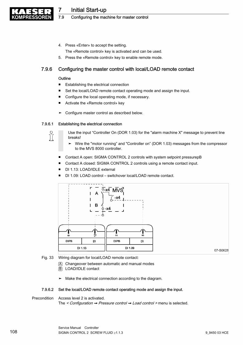
4. Press «Enter» to accept the setting.The «Remote control» key is activated and can be used.
5. Press the «Remote control» key to enable remote mode.
7.9.6 Configuring the master control with local/LOAD remote contact
Outline■ Establishing the electrical connection■ Set the local/LOAD remote contact operating mode and assign the input.■ Configure the local operating mode, if necessary.■ Activate the «Remote control» key
➤ Configure master control as described below.
7.9.6.1 Establishing the electrical connection
Use the input “Controller On (DOR 1.03) for the "alarm machine X" message to prevent linebreaks!➤ Wire the "motor running” and "Controller on” (DOR 1.03) messages from the compressor
to the MVS 8000 controller.
■ Contact A open: SIGMA CONTROL 2 controls with system setpoint pressurepB■ Contact A closed: SIGMA CONTROL 2 controls using a remote contact input.■ DI 1.13: LOAD/IDLE external■ DI 1.09: LOAD control – switchover local/LOAD remote contact.
Fig. 33 Wiring diagram for local/LOAD remote contact:A Changeover between automatic and manual modesB LOAD/IDLE contact
➤ Make the electrical connection according to the diagram.
7.9.6.2 Set the local/LOAD remote contact operating mode and assign the input.
Precondition Access level 2 is activated.The < Configuration ➙ Pressure control ➙ Load control > menu is selected.
7 Initial Start-up7.9 Configuring the machine for master control
108Service Manual Controller SIGMA CONTROL 2 SCREW FLUID ≥1.1.3 9_9450 03 HCE
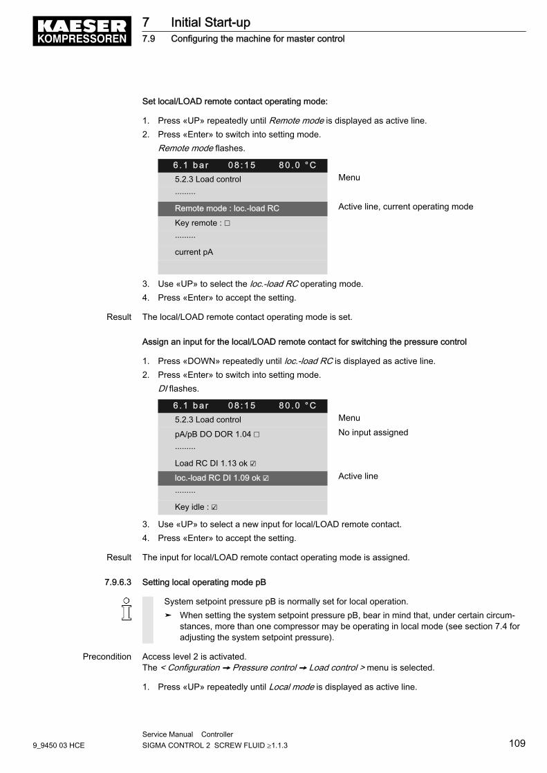
Set local/LOAD remote contact operating mode:
1. Press «UP» repeatedly until Remote mode is displayed as active line.2. Press «Enter» to switch into setting mode.
Remote mode flashes.
6 . 1 b a r 0 8 : 1 5 8 0 . 0 ° C5.2.3 Load control Menu
·········
Remote mode : loc.-load RC Active line, current operating mode
Key remote : ☐
·········
current pA
3. Use «UP» to select the loc.-load RC operating mode.4. Press «Enter» to accept the setting.
Result The local/LOAD remote contact operating mode is set.
Assign an input for the local/LOAD remote contact for switching the pressure control
1. Press «DOWN» repeatedly until loc.-load RC is displayed as active line.2. Press «Enter» to switch into setting mode.
DI flashes.
6 . 1 b a r 0 8 : 1 5 8 0 . 0 ° C5.2.3 Load control Menu
pA/pB DO DOR 1.04 ☐ No input assigned
·········
Load RC DI 1.13 ok ☑
loc.-load RC DI 1.09 ok ☑ Active line
·········
Key idle : ☑
3. Use «UP» to select a new input for local/LOAD remote contact.4. Press «Enter» to accept the setting.
Result The input for local/LOAD remote contact operating mode is assigned.
7.9.6.3 Setting local operating mode pB
System setpoint pressure pB is normally set for local operation.➤ When setting the system setpoint pressure pB, bear in mind that, under certain circum‐
stances, more than one compressor may be operating in local mode (see section 7.4 foradjusting the system setpoint pressure).
Precondition Access level 2 is activated.The < Configuration ➙ Pressure control ➙ Load control > menu is selected.
1. Press «UP» repeatedly until Local mode is displayed as active line.
7 Initial Start-up7.9 Configuring the machine for master control
9_9450 03 HCEService Manual Controller SIGMA CONTROL 2 SCREW FLUID ≥1.1.3 109
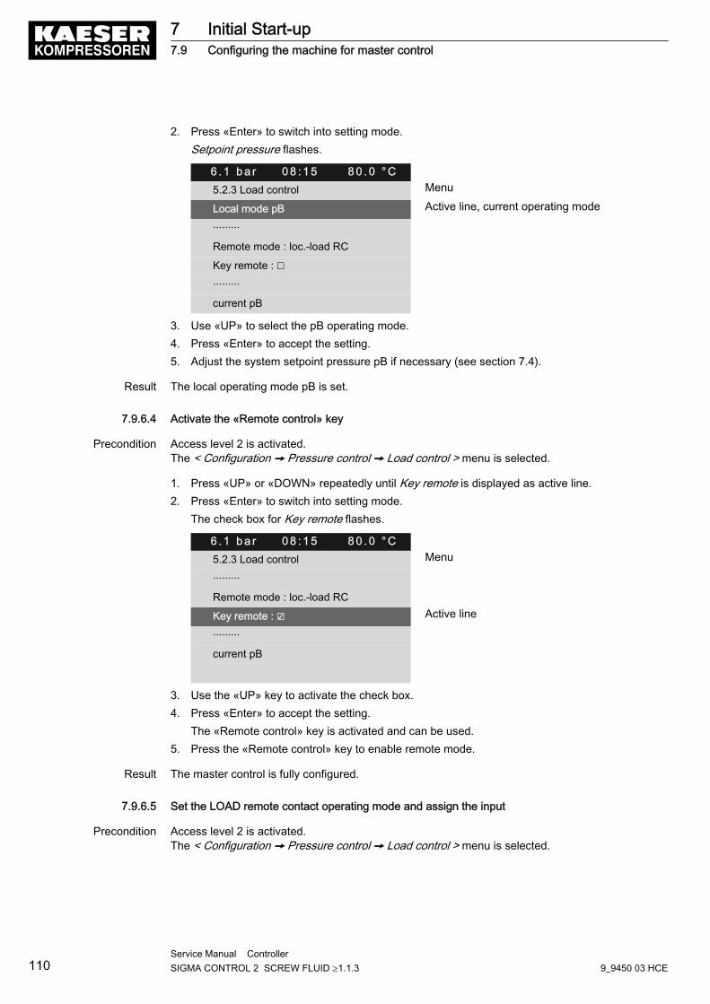
2. Press «Enter» to switch into setting mode.Setpoint pressure flashes.
6 . 1 b a r 0 8 : 1 5 8 0 . 0 ° C5.2.3 Load control Menu
Local mode pB Active line, current operating mode
·········
Remote mode : loc.-load RC
Key remote : ☐
·········
current pB
3. Use «UP» to select the pB operating mode.4. Press «Enter» to accept the setting.5. Adjust the system setpoint pressure pB if necessary (see section 7.4).
Result The local operating mode pB is set.
7.9.6.4 Activate the «Remote control» key
Precondition Access level 2 is activated.The < Configuration ➙ Pressure control ➙ Load control > menu is selected.
1. Press «UP» or «DOWN» repeatedly until Key remote is displayed as active line.2. Press «Enter» to switch into setting mode.
The check box for Key remote flashes.
6 . 1 b a r 0 8 : 1 5 8 0 . 0 ° C5.2.3 Load control Menu
·········
Remote mode : loc.-load RC
Key remote : ☑ Active line
·········
current pB
3. Use the «UP» key to activate the check box.4. Press «Enter» to accept the setting.
The «Remote control» key is activated and can be used.5. Press the «Remote control» key to enable remote mode.
Result The master control is fully configured.
7.9.6.5 Set the LOAD remote contact operating mode and assign the input
Precondition Access level 2 is activated.The < Configuration ➙ Pressure control ➙ Load control > menu is selected.
7 Initial Start-up7.9 Configuring the machine for master control
110Service Manual Controller SIGMA CONTROL 2 SCREW FLUID ≥1.1.3 9_9450 03 HCE
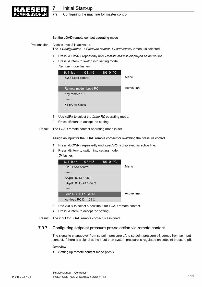
Set the LOAD remote contact operating mode
Precondition Access level 2 is activated.The < Configuration ➙ Pressure control ➙ Load control > menu is selected.
1. Press «DOWN» repeatedly until Remote mode is displayed as active line.2. Press «Enter» to switch into setting mode.
Remote mode flashes.
6 . 1 b a r 0 8 : 1 5 8 0 . 0 ° C5.2.3 Load control Menu
·········
Remote mode : Load RC Active line
Key remote : ☐
·········
▶1 pA/pB Clock
·········
3. Use «UP» to select the Load RC operating mode.4. Press «Enter» to accept the setting.
Result The LOAD remote contact operating mode is set.
Assign an input for the LOAD remote contact for switching the pressure control
1. Press «DOWN» repeatedly until Load RC is displayed as active line.2. Press «Enter» to switch into setting mode.
DI flashes.
6 . 1 b a r 0 8 : 1 5 8 0 . 0 ° C5.2.3 Load control Menu
·········
pA/pB RC DI 1.05 ☐
pA/pB DO DOR 1.04 ☐
·········
Load RC DI 1.13 ok ☑ Active line
loc.-load RC DI 1.09 ☐
3. Use «UP» to select a new input for LOAD remote contact.4. Press «Enter» to accept the setting.
Result The input for LOAD remote contact is assigned.
7.9.7 Configuring setpoint pressure pre-selection via remote contact
The signal to changeover from setpoint pressure pA to setpoint pressure pB comes from an inputcontact. If there is a signal at the input then system pressure is regulated on setpoint pressure pB.
Overview■ Setting up remote contact mode pA/pB
7 Initial Start-up7.9 Configuring the machine for master control
9_9450 03 HCEService Manual Controller SIGMA CONTROL 2 SCREW FLUID ≥1.1.3 111
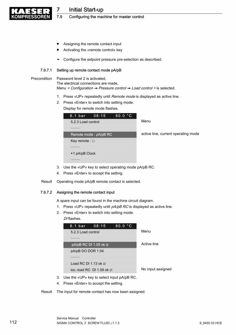
■ Assigning the remote contact input■ Activating the «remote control» key
➤ Configure the setpoint pressure pre-selection as described.
7.9.7.1 Setting up remote contact mode pA/pB
Precondition Password level 2 is activated,The electrical connections are made,Menu < Configuration ➙ Pressure control ➙ Load control > is selected.
1. Press «UP» repeatedly until Remote mode is displayed as active line.2. Press «Enter» to switch into setting mode.
Display for remote mode flashes.
6 . 1 b a r 0 8 : 1 5 8 0 . 0 ° C5.2.3 Load control Menu
·········
Remote mode : pA/pB RC active line, current operating mode
Key remote : ☐
·········
▶1 pA/pB Clock
·········
3. Use the «UP» key to select operating mode pA/pB RC.4. Press «Enter» to accept the setting.
Result Operating mode pA/pB remote contact is selected.
7.9.7.2 Assigning the remote contact input
A spare input can be found in the machine circuit diagram.1. Press «UP» repeatedly until pA/pB RC is displayed as active line.2. Press «Enter» to switch into setting mode.
DI flashes.
6 . 1 b a r 0 8 : 1 5 8 0 . 0 ° C5.2.3 Load control Menu
·········
pA/pB RC DI 1.05 ok ☑ Active line
pA/pB DO DOR 1.04
·········
Load RC DI 1.13 ok ☑
loc.-load RC DI 1.09 ok ☑ No input assigned
3. Use the «UP» key to select input pA/pB RC.4. Press «Enter» to accept the setting.
Result The input for remote contact has now been assigned.
7 Initial Start-up7.9 Configuring the machine for master control
112Service Manual Controller SIGMA CONTROL 2 SCREW FLUID ≥1.1.3 9_9450 03 HCE
7.9.7.3 Activating the «remote control» key
Precondition Password level 2 is activated,Menu < Configuration ➙ Pressure control ➙ Load control > is selected.
1. Press «UP» repeatedly until Key remote is displayed as active line.2. Press «Enter» to switch into setting mode.
Check box flashes.
6 . 1 b a r 0 8 : 1 5 8 0 . 0 ° C5.2.3 Load control Menu
·········
Remote mode : pA/pB RC
Key remote : ☑ Active line
·········
current pB
3. Use the «UP» key to activate the check box.4. Press «Enter» to accept the setting.
The «remote control» key can be used.5. Press the «remote control» key to enable remote mode.
Result The operating mode is now configured.
7.9.8 Configuring master control of compressors regulated by pressure switch
➤ Configure the master control as previously described.
7.9.8.1 Configuring master control via floating relay contact
Requirement:A machine with SIGMA CONTROL 2 (e.g. series BSD) and a conventional machine withoutSIGMA CONTROL 2 of the same capacity are to run in sequence as base load or peak load ma‐chines.
Proposal:■ Set/adjust the clock program or clock on SIGMA CONTROL 2 .■ Select local mode with time control pA/pB Clock or clock pA/pB Cycle.■ Set the system setpoint pressures pA and pB analogous to the required values. They must be
identical to the pressure switch settings on the machine without SIGMA CONTROL 2 .■ To make the setpoint changeover between the two machines possible, a floating relay contact
must be assigned to the selected local operating mode. An auxiliary contactor can be ener‐gised via this contact to activate the pressure switches for pA and pB on the compressor with‐out SIGMA CONTROL 2 . See the example wiring diagram below.
Overview■ Establishing the electrical connection■ Set the system setpoint pressure pA and pB.■ Configure/adjust the local operating mode
7 Initial Start-up7.9 Configuring the machine for master control
9_9450 03 HCEService Manual Controller SIGMA CONTROL 2 SCREW FLUID ≥1.1.3 113
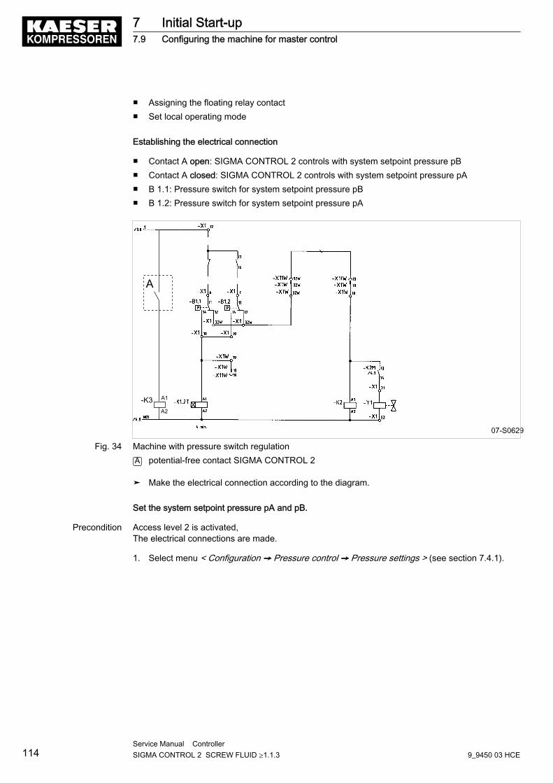
■ Assigning the floating relay contact■ Set local operating mode
Establishing the electrical connection
■ Contact A open: SIGMA CONTROL 2 controls with system setpoint pressure pB■ Contact A closed: SIGMA CONTROL 2 controls with system setpoint pressure pA■ B 1.1: Pressure switch for system setpoint pressure pB■ B 1.2: Pressure switch for system setpoint pressure pA
07-S0629
A
-K3 A1
A2
Fig. 34 Machine with pressure switch regulationA potential-free contact SIGMA CONTROL 2
➤ Make the electrical connection according to the diagram.
Set the system setpoint pressure pA and pB.
Precondition Access level 2 is activated,The electrical connections are made.
1. Select menu < Configuration ➙ Pressure control ➙ Pressure settings > (see section 7.4.1).
7 Initial Start-up7.9 Configuring the machine for master control
114Service Manual Controller SIGMA CONTROL 2 SCREW FLUID ≥1.1.3 9_9450 03 HCE
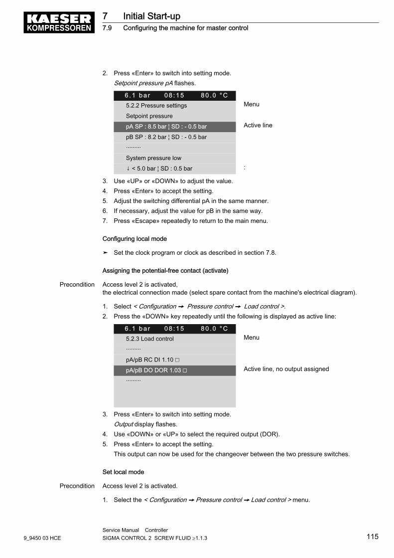
2. Press «Enter» to switch into setting mode.Setpoint pressure pA flashes.
6 . 1 b a r 0 8 : 1 5 8 0 . 0 ° C5.2.2 Pressure settings Menu
Setpoint pressure
pA SP : 8.5 bar ¦ SD : - 0.5 bar Active line
pB SP : 8.2 bar ¦ SD : - 0.5 bar
·········
System pressure low
↓ < 5.0 bar ¦ SD : 0.5 bar :
3. Use «UP» or «DOWN» to adjust the value.4. Press «Enter» to accept the setting.5. Adjust the switching differential pA in the same manner.6. If necessary, adjust the value for pB in the same way.7. Press «Escape» repeatedly to return to the main menu.
Configuring local mode
➤ Set the clock program or clock as described in section 7.8.
Assigning the potential-free contact (activate)
Precondition Access level 2 is activated,the electrical connection made (select spare contact from the machine's electrical diagram).
1. Select < Configuration ➙ Pressure control ➙ Load control >.2. Press the «DOWN» key repeatedly until the following is displayed as active line:
6 . 1 b a r 0 8 : 1 5 8 0 . 0 ° C5.2.3 Load control Menu
·········
pA/pB RC DI 1.10 ☐
pA/pB DO DOR 1.03 ☐ Active line, no output assigned
·········
3. Press «Enter» to switch into setting mode.Output display flashes.
4. Use «DOWN» or «UP» to select the required output (DOR).5. Press «Enter» to accept the setting.
This output can now be used for the changeover between the two pressure switches.
Set local mode
Precondition Access level 2 is activated.
1. Select the < Configuration ➙ Pressure control ➙ Load control > menu.
7 Initial Start-up7.9 Configuring the machine for master control
9_9450 03 HCEService Manual Controller SIGMA CONTROL 2 SCREW FLUID ≥1.1.3 115
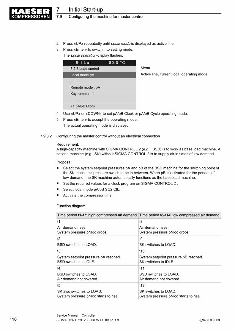
2. Press «UP» repeatedly until Local mode is displayed as active line.3. Press «Enter» to switch into setting mode.
The Local operation display flashes.
6 . 1 b a r 8 0 . 0 ° C5.2.3 Load control Menu
Local mode pA Active line, current local operating mode
·········
Remote mode : pA
Key remote : ☐
·········
▶1 pA/pB Clock
4. Use «UP» or «DOWN» to set pA/pB Clock or pA/pB Cycle operating mode.5. Press «Enter» to accept the operating mode.
The actual operating mode is displayed.
7.9.8.2 Configuring the master control without an electrical connection
Requirement:A high-capacity machine with SIGMA CONTROL 2 (e.g., BSD) is to work as base load machine. Asecond machine (e.g., SK) without SIGMA CONTROL 2 is to supply air in times of low demand.
Proposal:■ Select the system setpoint pressures pA and pB of the BSD machine for the switching point of
the SK machine's pressure switch to be in between. When pB is activated for the periods oflow demand, the SK machine automatically functions as the base load machine.
■ Set the required values for a clock program on SIGMA CONTROL 2 .■ Select local mode pA/pB SC2 Clk.■ Activate the compressor timer
Function diagram:
Time period t1–t7: high compressed air demand Time period t8–t14: low compressed air demand
t1Air demand rises.System pressure pNloc drops.
t8:Air demand rises.System pressure pNloc drops.
t2BSD switches to LOAD.
t9:SK switches to LOAD.
t3:System setpoint pressure pA reached.BSD switches to IDLE.
t10:System setpoint pressure pB reached.SK switches to IDLE.
t4:BSD switches to LOAD.Air demand not covered.
t11:BSD switches to LOAD.Air demand not covered.
t5:SK also switches to LOAD.System pressure pNloc starts to rise.
t12:SK switches to LOAD.System pressure pNloc starts to rise.
7 Initial Start-up7.9 Configuring the machine for master control
116Service Manual Controller SIGMA CONTROL 2 SCREW FLUID ≥1.1.3 9_9450 03 HCE
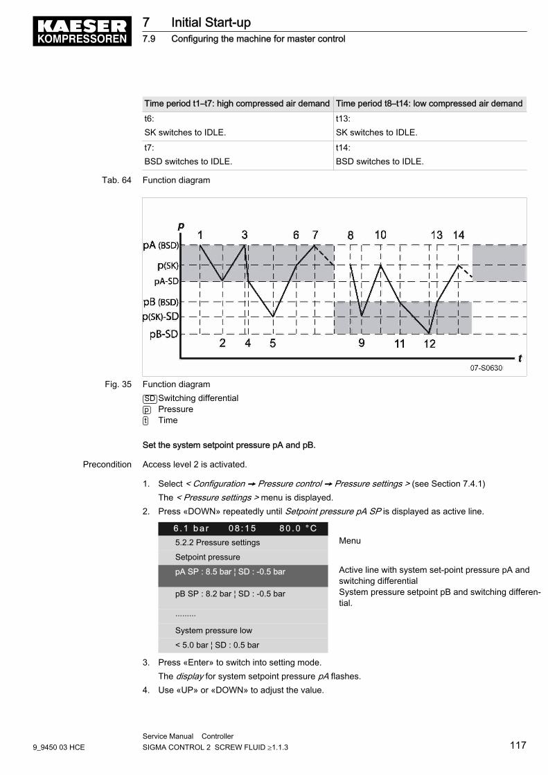
Time period t1–t7: high compressed air demand Time period t8–t14: low compressed air demand
t6:SK switches to IDLE.
t13:SK switches to IDLE.
t7:BSD switches to IDLE.
t14:BSD switches to IDLE.
Tab. 64 Function diagram
Fig. 35 Function diagramSD Switching differentialp Pressuret Time
Set the system setpoint pressure pA and pB.
Precondition Access level 2 is activated.
1. Select < Configuration ➙ Pressure control ➙ Pressure settings > (see Section 7.4.1)The < Pressure settings > menu is displayed.
2. Press «DOWN» repeatedly until Setpoint pressure pA SP is displayed as active line.
6 . 1 b a r 0 8 : 1 5 8 0 . 0 ° C5.2.2 Pressure settings Menu
Setpoint pressure
pA SP : 8.5 bar ¦ SD : -0.5 bar Active line with system set-point pressure pA andswitching differential
pB SP : 8.2 bar ¦ SD : -0.5 bar System pressure setpoint pB and switching differen‐tial.
·········
System pressure low
< 5.0 bar ¦ SD : 0.5 bar
3. Press «Enter» to switch into setting mode.The display for system setpoint pressure pA flashes.
4. Use «UP» or «DOWN» to adjust the value.
7 Initial Start-up7.9 Configuring the machine for master control
9_9450 03 HCEService Manual Controller SIGMA CONTROL 2 SCREW FLUID ≥1.1.3 117
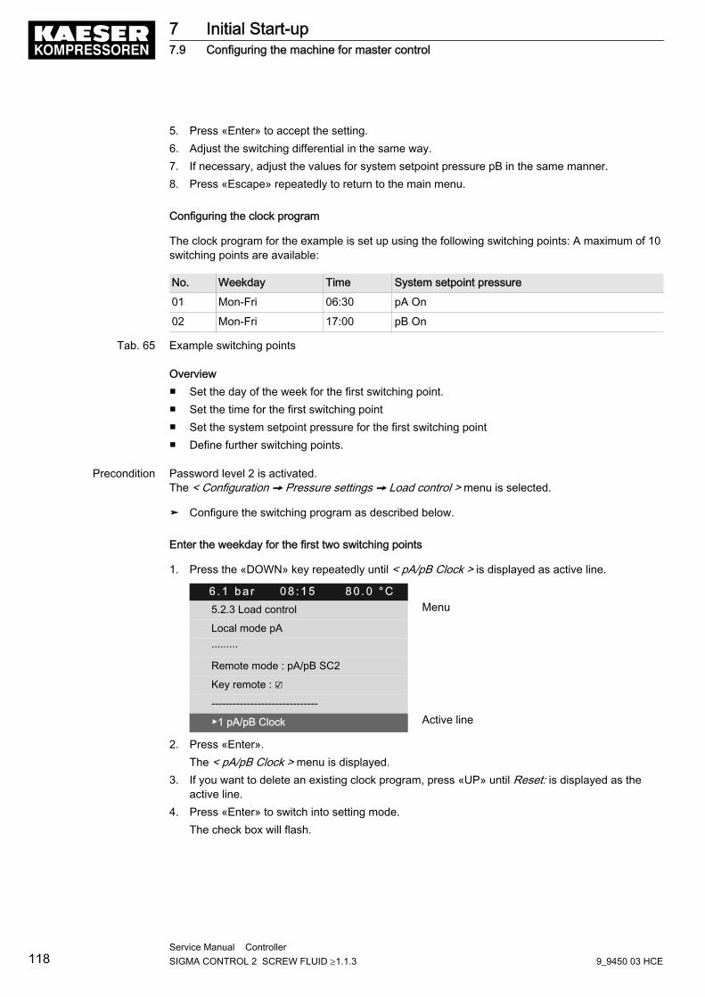
5. Press «Enter» to accept the setting.6. Adjust the switching differential in the same way.7. If necessary, adjust the values for system setpoint pressure pB in the same manner.8. Press «Escape» repeatedly to return to the main menu.
Configuring the clock program
The clock program for the example is set up using the following switching points: A maximum of 10switching points are available:
No. Weekday Time System setpoint pressure
01 Mon-Fri 06:30 pA On
02 Mon-Fri 17:00 pB On
Tab. 65 Example switching points
Overview■ Set the day of the week for the first switching point.■ Set the time for the first switching point■ Set the system setpoint pressure for the first switching point■ Define further switching points.
Precondition Password level 2 is activated.The < Configuration ➙ Pressure settings ➙ Load control > menu is selected.
➤ Configure the switching program as described below.
Enter the weekday for the first two switching points
1. Press the «DOWN» key repeatedly until < pA/pB Clock > is displayed as active line.
6 . 1 b a r 0 8 : 1 5 8 0 . 0 ° C5.2.3 Load control Menu
Local mode pA
·········
Remote mode : pA/pB SC2
Key remote : ☑
------------------------------
▶1 pA/pB Clock Active line
2. Press «Enter».The < pA/pB Clock > menu is displayed.
3. If you want to delete an existing clock program, press «UP» until Reset: is displayed as theactive line.
4. Press «Enter» to switch into setting mode.The check box will flash.
7 Initial Start-up7.9 Configuring the machine for master control
118Service Manual Controller SIGMA CONTROL 2 SCREW FLUID ≥1.1.3 9_9450 03 HCE
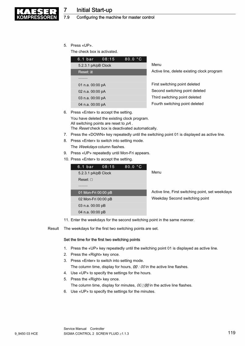
5. Press «UP».The check box is activated.
6 . 1 b a r 0 8 : 1 5 8 0 . 0 ° C5.2.3.1 pA/pB Clock Menu
Reset: ☒ Active line, delete existing clock program
·········
01 n.a. 00:00 pA First switching point deleted
02 n.a. 00:00 pA Second switching point deleted
03 n.a. 00:00 pA Third switching point deleted
04 n.a. 00:00 pA Fourth switching point deleted
6. Press «Enter» to accept the setting.You have deleted the existing clock program.All switching points are reset to pA .The Reset check box is deactivated automatically.
7. Press the «DOWN» key repeatedly until the switching point 01 is displayed as active line.8. Press «Enter» to switch into setting mode.
The Weekdays column flashes.9. Press «UP» repeatedly until Mon-Fri appears.10. Press «Enter» to accept the setting.
6 . 1 b a r 0 8 : 1 5 8 0 . 0 ° C5.2.3.1 pA/pB Clock Menu
Reset: ☐
·········
01 Mon-Fri 00:00 pB Active line, First switching point, set weekdays
02 Mon-Fri 00:00 pB Weekday Second switching point
03 n.a. 00:00 pB
04 n.a. 00:00 pB
11. Enter the weekdays for the second switching point in the same manner.
Result The weekdays for the first two switching points are set.
Set the time for the first two switching points
1. Press the «UP» key repeatedly until the switching point 01 is displayed as active line.2. Press the «Right» key once.3. Press «Enter» to switch into setting mode.
The column time, display for hours, 00 : 00 in the active line flashes.4. Use «UP» to specify the settings for the hours.5. Press the «Right» key once.
The column time, display for minutes, 00 : 00 in the active line flashes.6. Use «UP» to specify the settings for the minutes.
7 Initial Start-up7.9 Configuring the machine for master control
9_9450 03 HCEService Manual Controller SIGMA CONTROL 2 SCREW FLUID ≥1.1.3 119
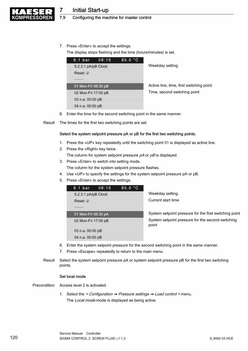
7. Press «Enter» to accept the settings.The display stops flashing and the time (hours/minutes) is set.
6 . 1 b a r 0 8 : 1 5 8 0 . 0 ° C5.2.3.1 pA/pB Clock Weekday setting.
Reset: ☑
·········
01 Mon-Fri 06:30 pB Active line, time, first switching point
02 Mon-Fri 17:00 pB Time, second switching point
03 n.a. 00:00 pB
04 n.a. 00:00 pB
8. Enter the time for the second switching point in the same manner.
Result The times for the first two switching points are set.
Select the system setpoint pressure pA or pB for the first two switching points.
1. Press the «UP» key repeatedly until the switching point 01 is displayed as active line.2. Press the «Right» key twice.
The column for system setpoint pressure pA or pB is displayed.3. Press «Enter» to switch into setting mode.
The column for the system setpoint pressure flashes.4. Use «UP» to specify the settings for the system setpoint pressure pA or pB.5. Press «Enter» to accept the settings.
6 . 1 b a r 0 8 : 1 5 8 0 . 0 ° C5.2.3.1 pA/pB Clock Weekday setting.
Reset: ☑ Current start time
·········
01 Mon-Fri 06:30 pA System setpoint pressure for the first switching point
02 Mon-Fri 17:00 pB System setpoint pressure for the second switchingpoint
03 n.a. 00:00 pB
04 n.a. 00:00 pB
6. Enter the system setpoint pressure for the second switching point in the same manner.7. Press «Escape» repeatedly to return to the main menu.
Result Select the system setpoint pressure pA or system setpoint pressure pB for the first two switchingpoints.
Set local mode
Precondition Access level 2 is activated.
1. Select the < Configuration ➙ Pressure settings ➙ Load control > menu.The Local mode mode is displayed as being active.
7 Initial Start-up7.9 Configuring the machine for master control
120Service Manual Controller SIGMA CONTROL 2 SCREW FLUID ≥1.1.3 9_9450 03 HCE
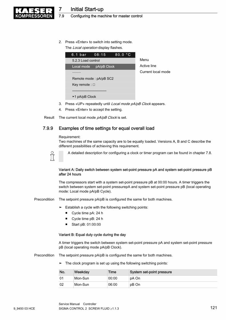
2. Press «Enter» to switch into setting mode.The Local operation display flashes.
6 . 1 b a r 0 8 : 1 5 8 0 . 0 ° C5.2.3 Load control Menu
Local mode pA/pB Clock Active line
········· Current local mode
Remote mode : pA/pB SC2
Key remote : ☐
------------------------------
▶1 pA/pB Clock
3. Press «UP» repeatedly until Local mode pA/pB Clock appears.4. Press «Enter» to accept the setting.
Result The current local mode pA/pB Clock is set.
7.9.9 Examples of time settings for equal overall load
Requirement:Two machines of the same capacity are to be equally loaded. Versions A, B and C describe thedifferent possibilities of achieving this requirement.
A detailed description for configuring a clock or timer program can be found in chapter 7.8.
Variant A: Daily switch between system set-point pressure pA and system set-point pressure pBafter 24 hours
The compressors start with a system set-point pressure pB at 00:00 hours. A timer triggers theswitch between system set-point pressurepA and system set-point pressure pB (local operatingmode: Local mode pA/pB Cycle).
Precondition The setpoint pressure pA/pB is configured the same for both machines.
➤ Establish a cycle with the following switching points:■ Cycle time pA: 24 h■ Cycle time pB: 24 h■ Start pB: 01:00:00
Variant B: Equal duty cycle during the day
A timer triggers the switch between system set-point pressure pA and system set-point pressurepB (local operating mode pA/pB Clock).
Precondition The setpoint pressure pA/pB is configured the same for both machines.
➤ The clock program is set up using the following switching points:
No. Weekday Time System set-point pressure
01 Mon-Sun 00:00 pA On
02 Mon-Sun 06:00 pB On
7 Initial Start-up7.9 Configuring the machine for master control
9_9450 03 HCEService Manual Controller SIGMA CONTROL 2 SCREW FLUID ≥1.1.3 121
No. Weekday Time System set-point pressure
03 Mon-Sun 12:00 pA On
04 Mon-Sun 18:00 pB On
Tab. 66 Example for a clock program for equal duty cycling during the day
Variant C: Equal duty cycle during the week
A timer triggers the switch between system set-point pressure pA and system set-point pressurepB (local operating mode: pA/pB SC2 Clk).
Precondition The setpoint pressure pA/pB is configured the same for both machines.
➤ The clock program is set up using the following switching points:
No. Weekday Time System set-point pressure
01 Mon 00:00 pA On
02 Mon 21:00 pB On
03 Tue 18:00 pA On
04 Wed 15:00 pB On
05 Thu 12:00 pA On
06 Fri 09:00 pB On
07 Sat 06:00 pA On
08 Sun 03:00 pB On
Tab. 67 Example for a clock program for equal duty cycling during the week
7.10 Configuring e-mailSIGMA CONTROL 2 uses e-mail to send information (messages) to an e-mail address.For this purpose, an Ethernet connection with an SMTP server is required.
Overview■ Select the menu < Communication ➙ Ethernet >.■ Configure and activate the e-mail function.■ Set interval and suppress repeats.
Select menu
1. Select the menu < Communication ➙ Ethernet >.
7 Initial Start-up7.10 Configuring e-mail
122Service Manual Controller SIGMA CONTROL 2 SCREW FLUID ≥1.1.3 9_9450 03 HCE
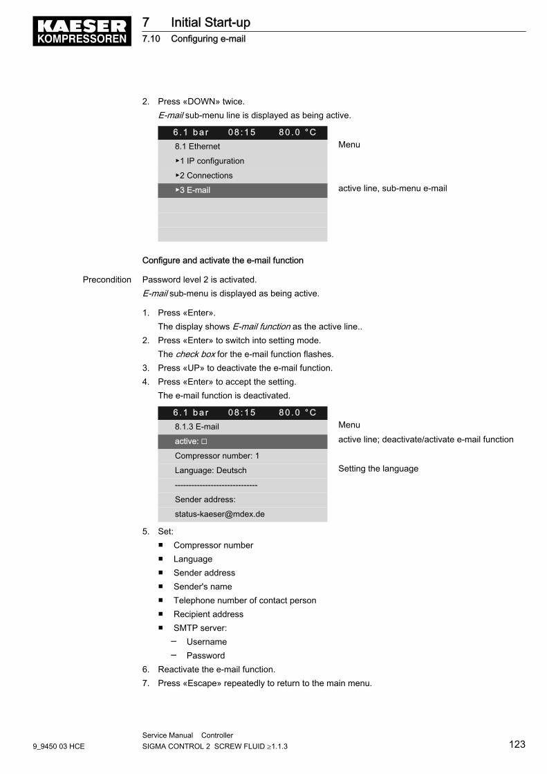
2. Press «DOWN» twice.E-mail sub-menu line is displayed as being active.
6 . 1 b a r 0 8 : 1 5 8 0 . 0 ° C8.1 Ethernet Menu
▶1 IP configuration
▶2 Connections
▶3 E-mail active line, sub-menu e-mail
Configure and activate the e-mail function
Precondition Password level 2 is activated.E-mail sub-menu is displayed as being active.
1. Press «Enter».The display shows E-mail function as the active line..
2. Press «Enter» to switch into setting mode.The check box for the e-mail function flashes.
3. Press «UP» to deactivate the e-mail function.4. Press «Enter» to accept the setting.
The e-mail function is deactivated.
6 . 1 b a r 0 8 : 1 5 8 0 . 0 ° C8.1.3 E-mail Menu
active: ☐ active line; deactivate/activate e-mail function
Compressor number: 1
Language: Deutsch Setting the language
------------------------------
Sender address:
5. Set:■ Compressor number■ Language■ Sender address■ Sender's name■ Telephone number of contact person■ Recipient address■ SMTP server:
─ Username─ Password
6. Reactivate the e-mail function.7. Press «Escape» repeatedly to return to the main menu.
7 Initial Start-up7.10 Configuring e-mail
9_9450 03 HCEService Manual Controller SIGMA CONTROL 2 SCREW FLUID ≥1.1.3 123
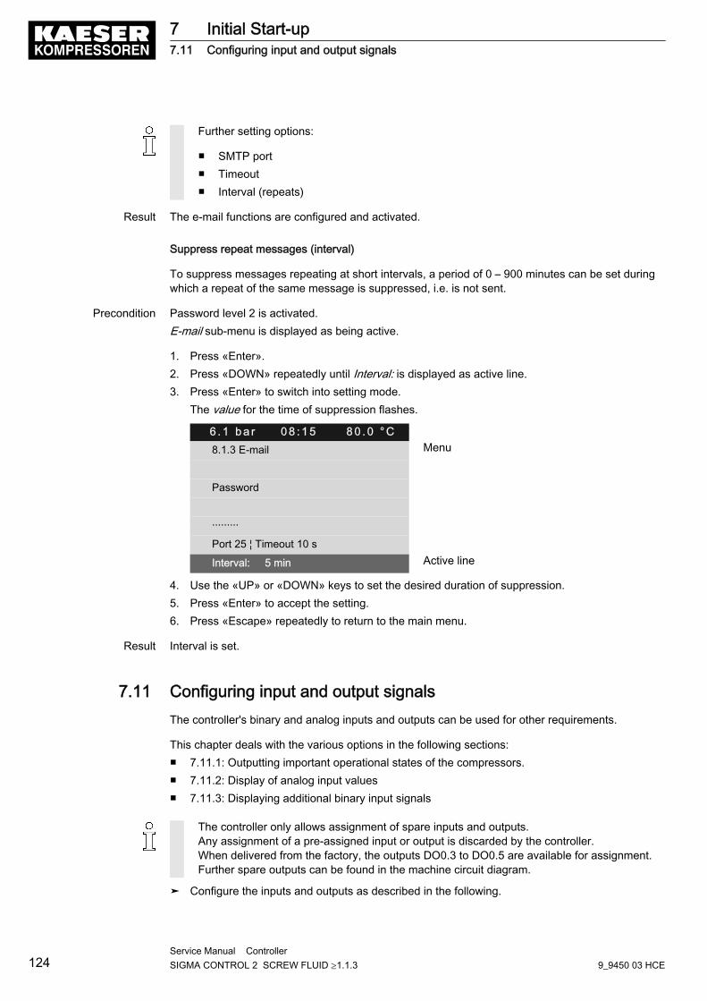
Further setting options:
■ SMTP port■ Timeout■ Interval (repeats)
Result The e-mail functions are configured and activated.
Suppress repeat messages (interval)
To suppress messages repeating at short intervals, a period of 0 – 900 minutes can be set duringwhich a repeat of the same message is suppressed, i.e. is not sent.
Precondition Password level 2 is activated.E-mail sub-menu is displayed as being active.
1. Press «Enter».2. Press «DOWN» repeatedly until Interval: is displayed as active line.3. Press «Enter» to switch into setting mode.
The value for the time of suppression flashes.
6 . 1 b a r 0 8 : 1 5 8 0 . 0 ° C8.1.3 E-mail Menu
Password
·········
Port 25 ¦ Timeout 10 s
Interval: 5 min Active line
4. Use the «UP» or «DOWN» keys to set the desired duration of suppression.5. Press «Enter» to accept the setting.6. Press «Escape» repeatedly to return to the main menu.
Result Interval is set.
7.11 Configuring input and output signalsThe controller's binary and analog inputs and outputs can be used for other requirements.
This chapter deals with the various options in the following sections:■ 7.11.1: Outputting important operational states of the compressors.■ 7.11.2: Display of analog input values■ 7.11.3: Displaying additional binary input signals
The controller only allows assignment of spare inputs and outputs.Any assignment of a pre-assigned input or output is discarded by the controller.When delivered from the factory, the outputs DO0.3 to DO0.5 are available for assignment.Further spare outputs can be found in the machine circuit diagram.
➤ Configure the inputs and outputs as described in the following.
7 Initial Start-up7.11 Configuring input and output signals
124Service Manual Controller SIGMA CONTROL 2 SCREW FLUID ≥1.1.3 9_9450 03 HCE
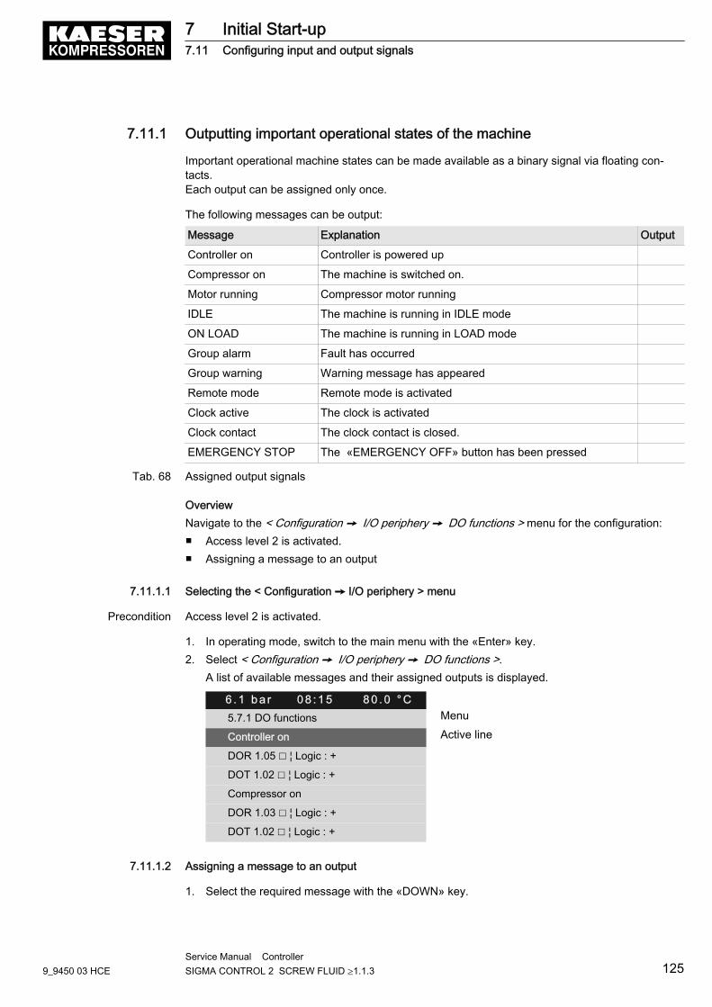
7.11.1 Outputting important operational states of the machine
Important operational machine states can be made available as a binary signal via floating con‐tacts.Each output can be assigned only once.
The following messages can be output:
Message Explanation Output
Controller on Controller is powered up
Compressor on The machine is switched on.
Motor running Compressor motor running
IDLE The machine is running in IDLE mode
ON LOAD The machine is running in LOAD mode
Group alarm Fault has occurred
Group warning Warning message has appeared
Remote mode Remote mode is activated
Clock active The clock is activated
Clock contact The clock contact is closed.
EMERGENCY STOP The «EMERGENCY OFF» button has been pressed
Tab. 68 Assigned output signals
OverviewNavigate to the < Configuration ➙ I/O periphery ➙ DO functions > menu for the configuration:■ Access level 2 is activated.■ Assigning a message to an output
7.11.1.1 Selecting the < Configuration ➙ I/O periphery > menu
Precondition Access level 2 is activated.
1. In operating mode, switch to the main menu with the «Enter» key.2. Select < Configuration ➙ I/O periphery ➙ DO functions >.
A list of available messages and their assigned outputs is displayed.
6 . 1 b a r 0 8 : 1 5 8 0 . 0 ° C5.7.1 DO functions Menu
Controller on Active line
DOR 1.05 ☐ ¦ Logic : +
DOT 1.02 ☐ ¦ Logic : +
Compressor on
DOR 1.03 ☐ ¦ Logic : +
DOT 1.02 ☐ ¦ Logic : +
7.11.1.2 Assigning a message to an output
1. Select the required message with the «DOWN» key.
7 Initial Start-up7.11 Configuring input and output signals
9_9450 03 HCEService Manual Controller SIGMA CONTROL 2 SCREW FLUID ≥1.1.3 125
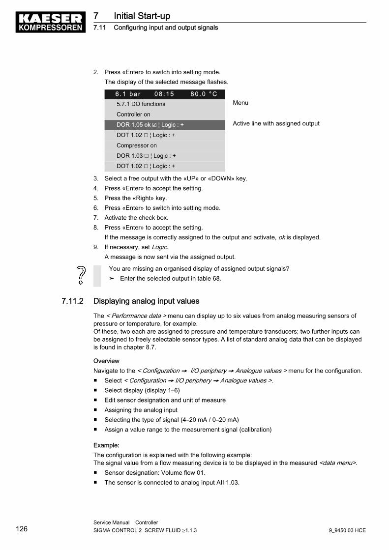
2. Press «Enter» to switch into setting mode.The display of the selected message flashes.
6 . 1 b a r 0 8 : 1 5 8 0 . 0 ° C5.7.1 DO functions Menu
Controller on
DOR 1.05 ok ☑ ¦ Logic : + Active line with assigned output
DOT 1.02 ☐ ¦ Logic : +
Compressor on
DOR 1.03 ☐ ¦ Logic : +
DOT 1.02 ☐ ¦ Logic : +
3. Select a free output with the «UP» or «DOWN» key.4. Press «Enter» to accept the setting.5. Press the «Right» key.6. Press «Enter» to switch into setting mode.7. Activate the check box.8. Press «Enter» to accept the setting.
If the message is correctly assigned to the output and activate, ok is displayed.9. If necessary, set Logic.
A message is now sent via the assigned output.
You are missing an organised display of assigned output signals?➤ Enter the selected output in table 68.
7.11.2 Displaying analog input values
The < Performance data > menu can display up to six values from analog measuring sensors ofpressure or temperature, for example.Of these, two each are assigned to pressure and temperature transducers; two further inputs canbe assigned to freely selectable sensor types. A list of standard analog data that can be displayedis found in chapter 8.7.
OverviewNavigate to the < Configuration ➙ I/O periphery ➙ Analogue values > menu for the configuration.■ Select < Configuration ➙ I/O periphery ➙ Analogue values >.■ Select display (display 1–6)■ Edit sensor designation and unit of measure■ Assigning the analog input■ Selecting the type of signal (4–20 mA / 0–20 mA)■ Assign a value range to the measurement signal (calibration)
Example:The configuration is explained with the following example:The signal value from a flow measuring device is to be displayed in the measured <data menu>.■ Sensor designation: Volume flow 01.■ The sensor is connected to analog input AII 1.03.
7 Initial Start-up7.11 Configuring input and output signals
126Service Manual Controller SIGMA CONTROL 2 SCREW FLUID ≥1.1.3 9_9450 03 HCE
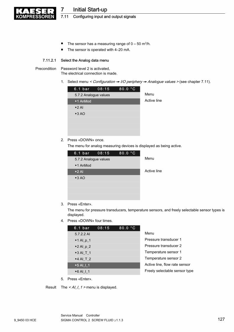
■ The sensor has a measuring range of 0 – 50 m3/h.■ The sensor is operated with 4–20 mA.
7.11.2.1 Select the Analog data menu
Precondition Password level 2 is activated,The electrical connection is made.
1. Select menu < Configuration ➙ I/O periphery ➙ Analogue values > (see chapter 7.11).
6 . 1 b a r 0 8 : 1 5 8 0 . 0 ° C5.7.2 Analogue values Menu
▶1 AnMod Active line
▶2 AI
▶3 AO
2. Press «DOWN» once.The menu for analog measuring devices is displayed as being active.
6 . 1 b a r 0 8 : 1 5 8 0 . 0 ° C5.7.2 Analogue values Menu
▶1 AnMod
▶2 AI Active line
▶3 AO
3. Press «Enter».The menu for pressure transducers, temperature sensors, and freely selectable sensor types isdisplayed.
4. Press «DOWN» four times.
6 . 1 b a r 0 8 : 1 5 8 0 . 0 ° C5.7.2.2 AI Menu
▶1 AI_p_1 Pressure transducer 1
▶2 AI_p_2 Pressure transducer 2
▶3 AI_T_1 Temperature sensor 1
▶4 AI_T_2 Temperature sensor 2
▶5 AI_I_1 Active line, flow rate sensor
▶6 AI_I_1 Freely selectable sensor type
5. Press «Enter».
Result The < AI_I_1 > menu is displayed.
7 Initial Start-up7.11 Configuring input and output signals
9_9450 03 HCEService Manual Controller SIGMA CONTROL 2 SCREW FLUID ≥1.1.3 127
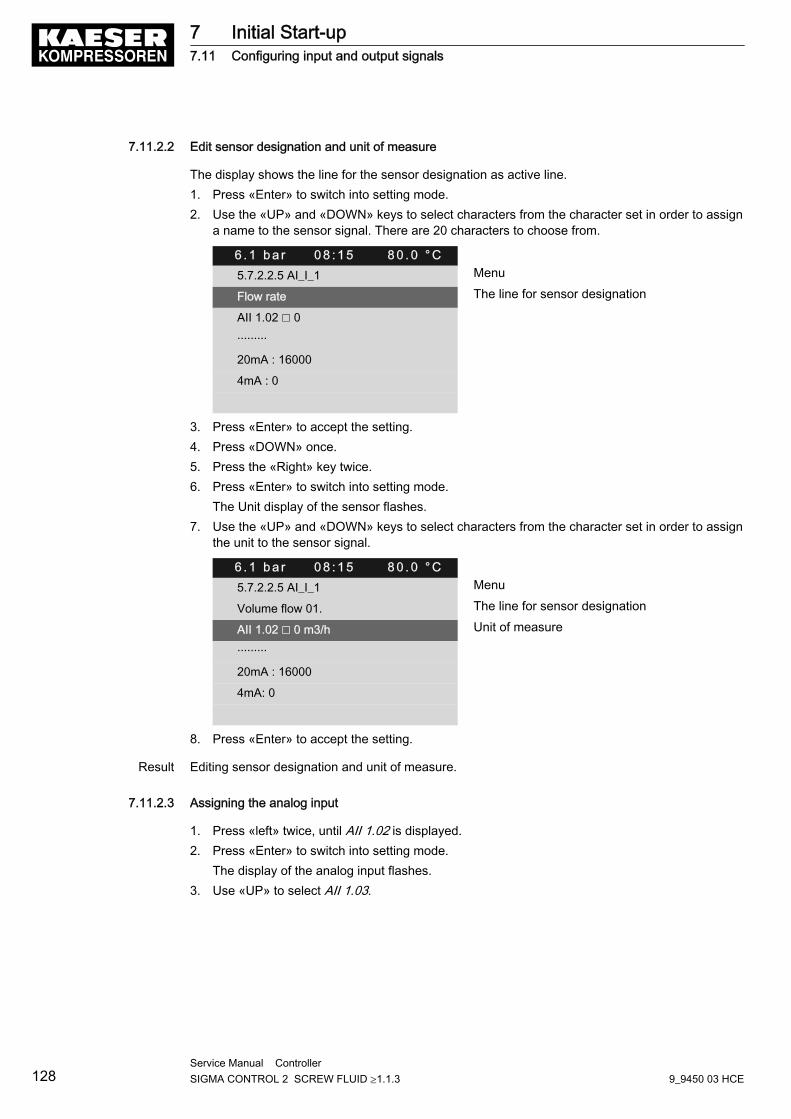
7.11.2.2 Edit sensor designation and unit of measure
The display shows the line for the sensor designation as active line.1. Press «Enter» to switch into setting mode.2. Use the «UP» and «DOWN» keys to select characters from the character set in order to assign
a name to the sensor signal. There are 20 characters to choose from.
6 . 1 b a r 0 8 : 1 5 8 0 . 0 ° C5.7.2.2.5 AI_I_1 Menu
Flow rate The line for sensor designation
AII 1.02 ☐ 0
·········
20mA : 16000
4mA : 0
3. Press «Enter» to accept the setting.4. Press «DOWN» once.5. Press the «Right» key twice.6. Press «Enter» to switch into setting mode.
The Unit display of the sensor flashes.7. Use the «UP» and «DOWN» keys to select characters from the character set in order to assign
the unit to the sensor signal.
6 . 1 b a r 0 8 : 1 5 8 0 . 0 ° C5.7.2.2.5 AI_I_1 Menu
Volume flow 01. The line for sensor designation
AII 1.02 ☐ 0 m3/h Unit of measure
·········
20mA : 16000
4mA: 0
8. Press «Enter» to accept the setting.
Result Editing sensor designation and unit of measure.
7.11.2.3 Assigning the analog input
1. Press «left» twice, until AII 1.02 is displayed.2. Press «Enter» to switch into setting mode.
The display of the analog input flashes.3. Use «UP» to select AII 1.03.
7 Initial Start-up7.11 Configuring input and output signals
128Service Manual Controller SIGMA CONTROL 2 SCREW FLUID ≥1.1.3 9_9450 03 HCE
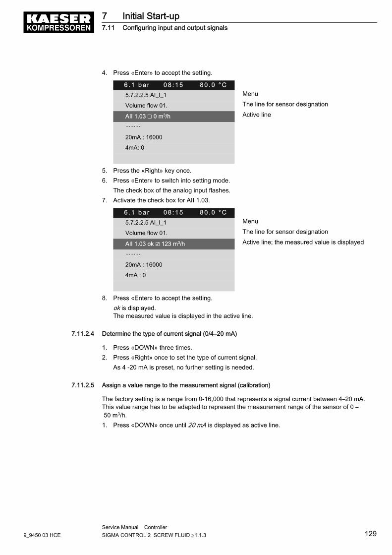
4. Press «Enter» to accept the setting.
6 . 1 b a r 0 8 : 1 5 8 0 . 0 ° C5.7.2.2.5 AI_I_1 Menu
Volume flow 01. The line for sensor designation
AII 1.03 ☐ 0 m3/h Active line
·········
20mA : 16000
4mA: 0
5. Press the «Right» key once.6. Press «Enter» to switch into setting mode.
The check box of the analog input flashes.7. Activate the check box for AII 1.03.
6 . 1 b a r 0 8 : 1 5 8 0 . 0 ° C5.7.2.2.5 AI_I_1 Menu
Volume flow 01. The line for sensor designation
AII 1.03 ok ☑ 123 m3/h Active line; the measured value is displayed
·········
20mA : 16000
4mA : 0
8. Press «Enter» to accept the setting.ok is displayed.The measured value is displayed in the active line.
7.11.2.4 Determine the type of current signal (0/4–20 mA)
1. Press «DOWN» three times.2. Press «Right» once to set the type of current signal.
As 4 -20 mA is preset, no further setting is needed.
7.11.2.5 Assign a value range to the measurement signal (calibration)
The factory setting is a range from 0-16,000 that represents a signal current between 4–20 mA.This value range has to be adapted to represent the measurement range of the sensor of 0 – 50 m3/h.1. Press «DOWN» once until 20 mA is displayed as active line.
7 Initial Start-up7.11 Configuring input and output signals
9_9450 03 HCEService Manual Controller SIGMA CONTROL 2 SCREW FLUID ≥1.1.3 129
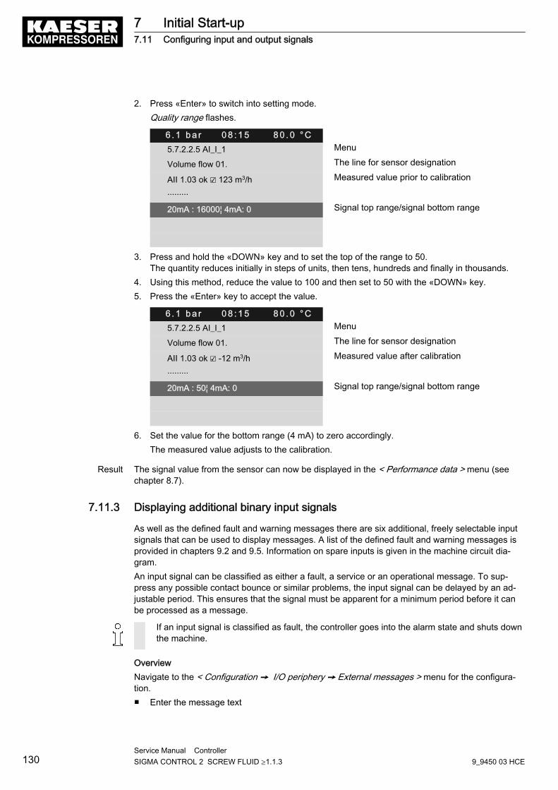
2. Press «Enter» to switch into setting mode.Quality range flashes.
6 . 1 b a r 0 8 : 1 5 8 0 . 0 ° C5.7.2.2.5 AI_I_1 Menu
Volume flow 01. The line for sensor designation
AII 1.03 ok ☑ 123 m3/h Measured value prior to calibration
·········
20mA : 16000¦ 4mA: 0 Signal top range/signal bottom range
3. Press and hold the «DOWN» key and to set the top of the range to 50.The quantity reduces initially in steps of units, then tens, hundreds and finally in thousands.
4. Using this method, reduce the value to 100 and then set to 50 with the «DOWN» key.5. Press the «Enter» key to accept the value.
6 . 1 b a r 0 8 : 1 5 8 0 . 0 ° C5.7.2.2.5 AI_I_1 Menu
Volume flow 01. The line for sensor designation
AII 1.03 ok ☑ -12 m3/h Measured value after calibration
·········
20mA : 50¦ 4mA: 0 Signal top range/signal bottom range
6. Set the value for the bottom range (4 mA) to zero accordingly.The measured value adjusts to the calibration.
Result The signal value from the sensor can now be displayed in the < Performance data > menu (seechapter 8.7).
7.11.3 Displaying additional binary input signals
As well as the defined fault and warning messages there are six additional, freely selectable inputsignals that can be used to display messages. A list of the defined fault and warning messages isprovided in chapters 9.2 and 9.5. Information on spare inputs is given in the machine circuit dia‐gram.An input signal can be classified as either a fault, a service or an operational message. To sup‐press any possible contact bounce or similar problems, the input signal can be delayed by an ad‐justable period. This ensures that the signal must be apparent for a minimum period before it canbe processed as a message.
If an input signal is classified as fault, the controller goes into the alarm state and shuts downthe machine.
OverviewNavigate to the < Configuration ➙ I/O periphery ➙ External messages > menu for the configura‐tion.■ Enter the message text
7 Initial Start-up7.11 Configuring input and output signals
130Service Manual Controller SIGMA CONTROL 2 SCREW FLUID ≥1.1.3 9_9450 03 HCE
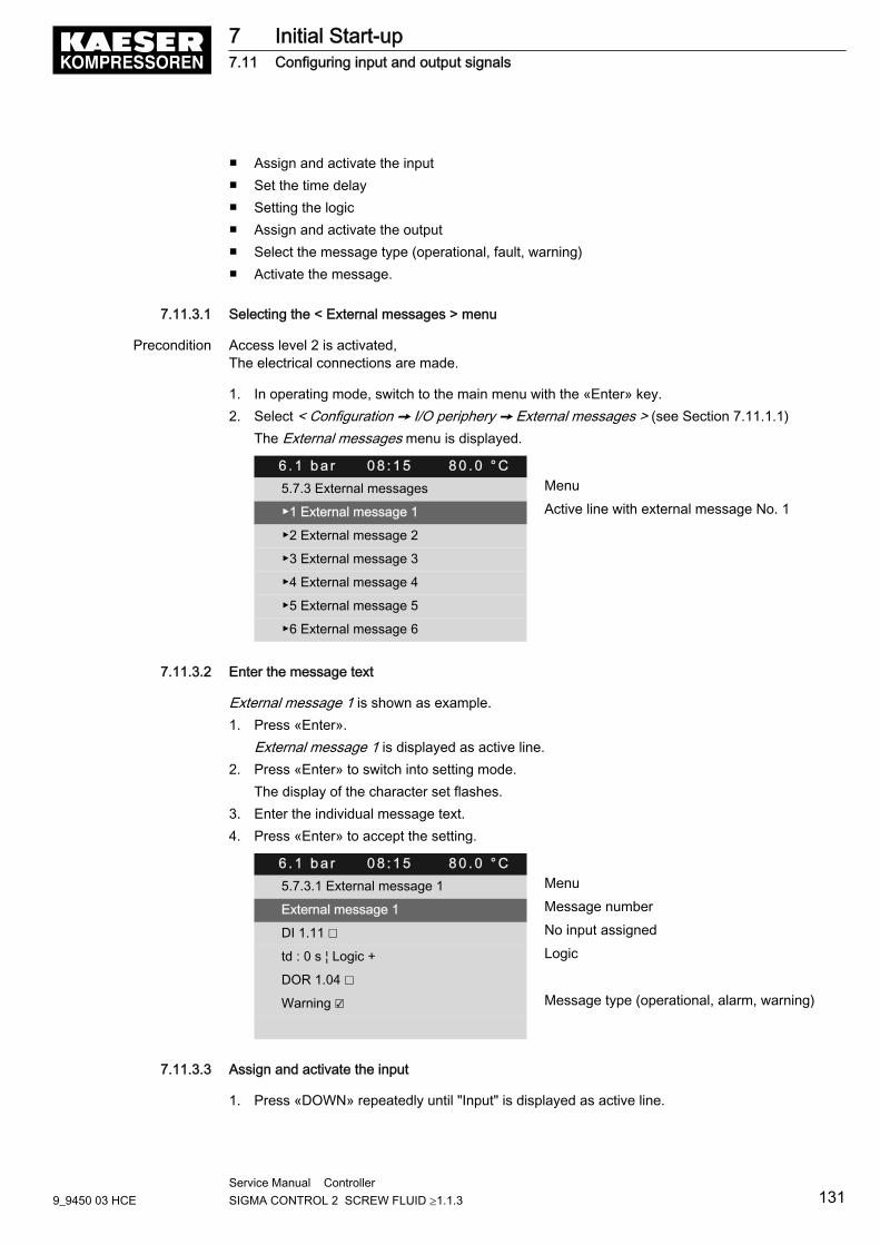
■ Assign and activate the input■ Set the time delay■ Setting the logic■ Assign and activate the output■ Select the message type (operational, fault, warning)■ Activate the message.
7.11.3.1 Selecting the < External messages > menu
Precondition Access level 2 is activated,The electrical connections are made.
1. In operating mode, switch to the main menu with the «Enter» key.2. Select < Configuration ➙ I/O periphery ➙ External messages > (see Section 7.11.1.1)
The External messages menu is displayed.
6 . 1 b a r 0 8 : 1 5 8 0 . 0 ° C5.7.3 External messages Menu
▶1 External message 1 Active line with external message No. 1
▶2 External message 2
▶3 External message 3
▶4 External message 4
▶5 External message 5
▶6 External message 6
7.11.3.2 Enter the message text
External message 1 is shown as example.1. Press «Enter».
External message 1 is displayed as active line.2. Press «Enter» to switch into setting mode.
The display of the character set flashes.3. Enter the individual message text.4. Press «Enter» to accept the setting.
6 . 1 b a r 0 8 : 1 5 8 0 . 0 ° C5.7.3.1 External message 1 Menu
External message 1 Message number
DI 1.11 ☐ No input assigned
td : 0 s ¦ Logic + Logic
DOR 1.04 ☐
Warning ☑ Message type (operational, alarm, warning)
7.11.3.3 Assign and activate the input
1. Press «DOWN» repeatedly until "Input" is displayed as active line.
7 Initial Start-up7.11 Configuring input and output signals
9_9450 03 HCEService Manual Controller SIGMA CONTROL 2 SCREW FLUID ≥1.1.3 131
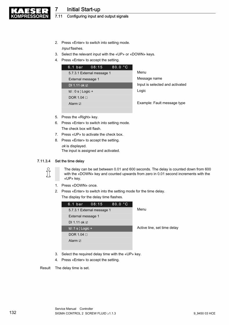
2. Press «Enter» to switch into setting mode.Input flashes.
3. Select the relevant input with the «UP» or «DOWN» keys.4. Press «Enter» to accept the setting.
6 . 1 b a r 0 8 : 1 5 8 0 . 0 ° C5.7.3.1 External message 1 Menu
External message 1 Message name
DI 1.11 ok ☑ Input is selected and activated
td : 0 s ¦ Logic + Logic
DOR 1.04 ☐
Alarm ☑ Example: Fault message type
5. Press the «Right» key.6. Press «Enter» to switch into setting mode.
The check box will flash.7. Press «UP» to activate the check box.8. Press «Enter» to accept the setting.
ok is displayed.The input is assigned and activated.
7.11.3.4 Set the time delay
The delay can be set between 0.01 and 600 seconds. The delay is counted down from 600with the «DOWN» key and counted upwards from zero in 0.01 second increments with the«UP» key.
1. Press «DOWN» once.2. Press «Enter» to switch into the setting mode for the time delay.
The display for the delay time flashes.
6 . 1 b a r 0 8 : 1 5 8 0 . 0 ° C5.7.3.1 External message 1 Menu
External message 1
DI 1.11 ok ☑
td :1 s ¦ Logic + Active line, set time delay
DOR 1.04 ☐
Alarm ☑
3. Select the required delay time with the «UP» key.4. Press «Enter» to accept the setting.
Result The delay time is set.
7 Initial Start-up7.11 Configuring input and output signals
132Service Manual Controller SIGMA CONTROL 2 SCREW FLUID ≥1.1.3 9_9450 03 HCE
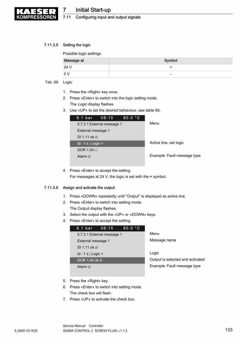
7.11.3.5 Setting the logic
Possible logic settings
Message at Symbol
24 V +
0 V -
Tab. 69 Logic
1. Press the «Right» key once.2. Press «Enter» to switch into the logic setting mode.
The Logic display flashes.3. Use «UP» to set the desired behaviour, see table 69.
6 . 1 b a r 0 8 : 1 5 8 0 . 0 ° C5.7.3.1 External message 1 Menu
External message 1
DI 1.11 ok ☑
td : 1 s ¦ Logic + Active line, set logic
DOR 1.04 ☐
Alarm ☑ Example: Fault message type
4. Press «Enter» to accept the setting.For messages at 24 V, the logic is set with the + symbol.
7.11.3.6 Assign and activate the output
1. Press «DOWN» repeatedly until "Output" is displayed as active line.2. Press «Enter» to switch into setting mode.
The Output display flashes.3. Select the output with the «UP» or «DOWN» keys.4. Press «Enter» to accept the setting.
6 . 1 b a r 0 8 : 1 5 8 0 . 0 ° C5.7.3.1 External message 1 Menu
External message 1 Message name
DI 1.11 ok ☑
td : 1 s ¦ Logic + Logic
DOR 1.04 ok ☑ Output is selected and activated
Alarm ☑ Example: Fault message type
5. Press the «Right» key.6. Press «Enter» to switch into setting mode.
The check box will flash.7. Press «UP» to activate the check box.
7 Initial Start-up7.11 Configuring input and output signals
9_9450 03 HCEService Manual Controller SIGMA CONTROL 2 SCREW FLUID ≥1.1.3 133
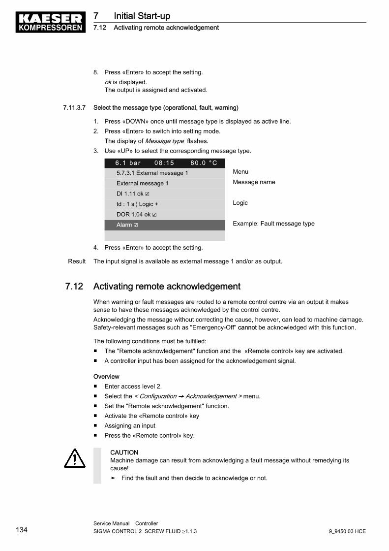
8. Press «Enter» to accept the setting.ok is displayed.The output is assigned and activated.
7.11.3.7 Select the message type (operational, fault, warning)
1. Press «DOWN» once until message type is displayed as active line.2. Press «Enter» to switch into setting mode.
The display of Message type flashes.3. Use «UP» to select the corresponding message type.
6 . 1 b a r 0 8 : 1 5 8 0 . 0 ° C5.7.3.1 External message 1 Menu
External message 1 Message name
DI 1.11 ok ☑
td : 1 s ¦ Logic + Logic
DOR 1.04 ok ☑
Alarm ☑ Example: Fault message type
4. Press «Enter» to accept the setting.
Result The input signal is available as external message 1 and/or as output.
7.12 Activating remote acknowledgementWhen warning or fault messages are routed to a remote control centre via an output it makessense to have these messages acknowledged by the control centre.Acknowledging the message without correcting the cause, however, can lead to machine damage.Safety-relevant messages such as "Emergency-Off" cannot be acknowledged with this function.
The following conditions must be fulfilled:■ The "Remote acknowledgement" function and the «Remote control» key are activated.■ A controller input has been assigned for the acknowledgement signal.
Overview■ Enter access level 2.■ Select the < Configuration ➙ Acknowledgement > menu.■ Set the "Remote acknowledgement" function.■ Activate the «Remote control» key■ Assigning an input■ Press the «Remote control» key.
CAUTIONMachine damage can result from acknowledging a fault message without remedying itscause!➤ Find the fault and then decide to acknowledge or not.
7 Initial Start-up7.12 Activating remote acknowledgement
134Service Manual Controller SIGMA CONTROL 2 SCREW FLUID ≥1.1.3 9_9450 03 HCE
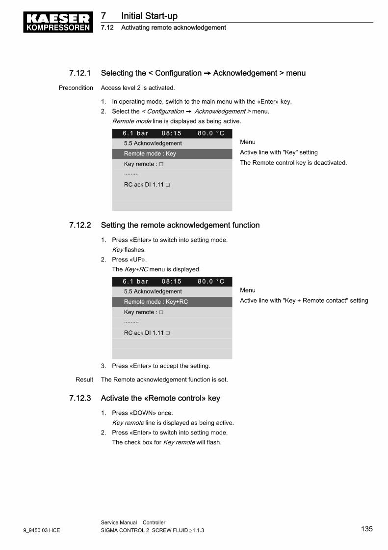
7.12.1 Selecting the < Configuration ➙ Acknowledgement > menu
Precondition Access level 2 is activated.
1. In operating mode, switch to the main menu with the «Enter» key.2. Select the < Configuration ➙ Acknowledgement > menu.
Remote mode line is displayed as being active.
6 . 1 b a r 0 8 : 1 5 8 0 . 0 ° C5.5 Acknowledgement Menu
Remote mode : Key Active line with "Key" setting
Key remote : ☐ The Remote control key is deactivated.
·········
RC ack DI 1.11 ☐
7.12.2 Setting the remote acknowledgement function
1. Press «Enter» to switch into setting mode.Key flashes.
2. Press «UP».The Key+RC menu is displayed.
6 . 1 b a r 0 8 : 1 5 8 0 . 0 ° C5.5 Acknowledgement Menu
Remote mode : Key+RC Active line with "Key + Remote contact" setting
Key remote : ☐
·········
RC ack DI 1.11 ☐
3. Press «Enter» to accept the setting.
Result The Remote acknowledgement function is set.
7.12.3 Activate the «Remote control» key
1. Press «DOWN» once.Key remote line is displayed as being active.
2. Press «Enter» to switch into setting mode.The check box for Key remote will flash.
7 Initial Start-up7.12 Activating remote acknowledgement
9_9450 03 HCEService Manual Controller SIGMA CONTROL 2 SCREW FLUID ≥1.1.3 135
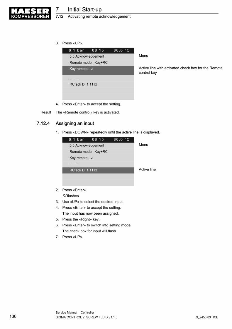
3. Press «UP».
6 . 1 b a r 0 8 : 1 5 8 0 . 0 ° C5.5 Acknowledgement Menu
Remote mode : Key+RC
Key remote : ☑ Active line with activated check box for the Remotecontrol key
·········
RC ack DI 1.11 ☐
4. Press «Enter» to accept the setting.
Result The «Remote control» key is activated.
7.12.4 Assigning an input
1. Press «DOWN» repeatedly until the active line is displayed.
6 . 1 b a r 0 8 : 1 5 8 0 . 0 ° C5.5 Acknowledgement Menu
Remote mode : Key+RC
Key remote : ☑
·········
RC ack DI 1.11 ☐ Active line
2. Press «Enter».DI flashes.
3. Use «UP» to select the desired input.4. Press «Enter» to accept the setting.
The input has now been assigned.5. Press the «Right» key.6. Press «Enter» to switch into setting mode.
The check box for input will flash.7. Press «UP».
7 Initial Start-up7.12 Activating remote acknowledgement
136Service Manual Controller SIGMA CONTROL 2 SCREW FLUID ≥1.1.3 9_9450 03 HCE
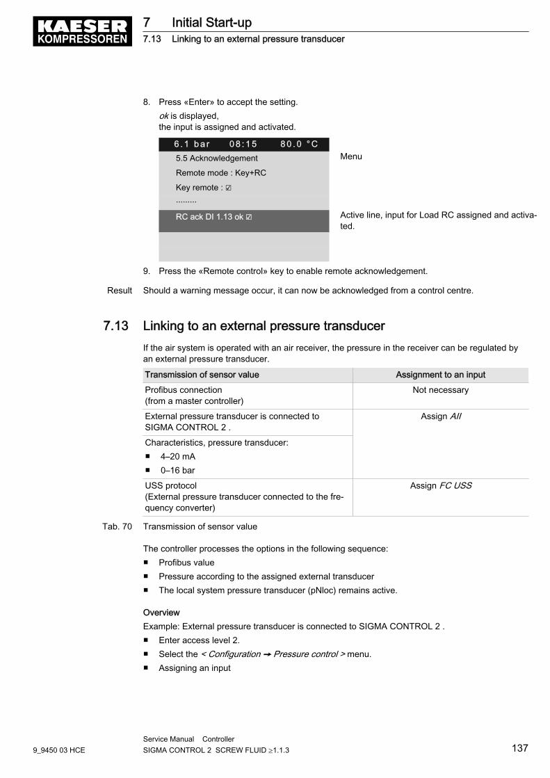
8. Press «Enter» to accept the setting.ok is displayed,the input is assigned and activated.
6 . 1 b a r 0 8 : 1 5 8 0 . 0 ° C5.5 Acknowledgement Menu
Remote mode : Key+RC
Key remote : ☑
·········
RC ack DI 1.13 ok ☑ Active line, input for Load RC assigned and activa‐ted.
9. Press the «Remote control» key to enable remote acknowledgement.
Result Should a warning message occur, it can now be acknowledged from a control centre.
7.13 Linking to an external pressure transducerIf the air system is operated with an air receiver, the pressure in the receiver can be regulated byan external pressure transducer.
Transmission of sensor value Assignment to an input
Profibus connection(from a master controller)
Not necessary
External pressure transducer is connected toSIGMA CONTROL 2 .
Assign AII
Characteristics, pressure transducer:■ 4–20 mA■ 0–16 bar
USS protocol(External pressure transducer connected to the fre‐quency converter)
Assign FC USS
Tab. 70 Transmission of sensor value
The controller processes the options in the following sequence:■ Profibus value■ Pressure according to the assigned external transducer■ The local system pressure transducer (pNloc) remains active.
OverviewExample: External pressure transducer is connected to SIGMA CONTROL 2 .■ Enter access level 2.■ Select the < Configuration ➙ Pressure control > menu.■ Assigning an input
7 Initial Start-up7.13 Linking to an external pressure transducer
9_9450 03 HCEService Manual Controller SIGMA CONTROL 2 SCREW FLUID ≥1.1.3 137
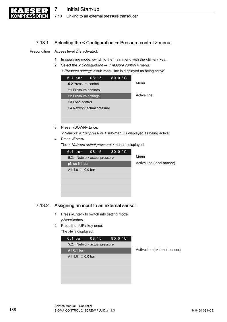
7.13.1 Selecting the < Configuration ➙ Pressure control > menu
Precondition Access level 2 is activated.
1. In operating mode, switch to the main menu with the «Enter» key.2. Select the < Configuration ➙ Pressure control > menu.
< Pressure settings > sub-menu line is displayed as being active.
6 . 1 b a r 0 8 : 1 5 8 0 . 0 ° C5.2 Pressure control Menu
▶1 Pressure sensors
▶2 Pressure settings Active line
▶3 Load control
▶4 Network actual pressure
3. Press «DOWN» twice.< Network actual pressure > sub-menu is displayed as being active.
4. Press «Enter».The < Network actual pressure > menu is displayed.
6 . 1 b a r 0 8 : 1 5 8 0 . 0 ° C5.2.4 Network actual pressure Menu
pNloc 6.1 bar Active line (local sensor)
AII 1.01 ☐ 0.0 bar
7.13.2 Assigning an input to an external sensor
1. Press «Enter» to switch into setting mode.pNloc flashes.
2. Press the «UP» key once.The AII is displayed.
6 . 1 b a r 0 8 : 1 5 8 0 . 0 ° C5.2.4 Network actual pressure
AII 6.1 bar Active line (external sensor)
AII 1.01 ☐ 0.0 bar
7 Initial Start-up7.13 Linking to an external pressure transducer
138Service Manual Controller SIGMA CONTROL 2 SCREW FLUID ≥1.1.3 9_9450 03 HCE
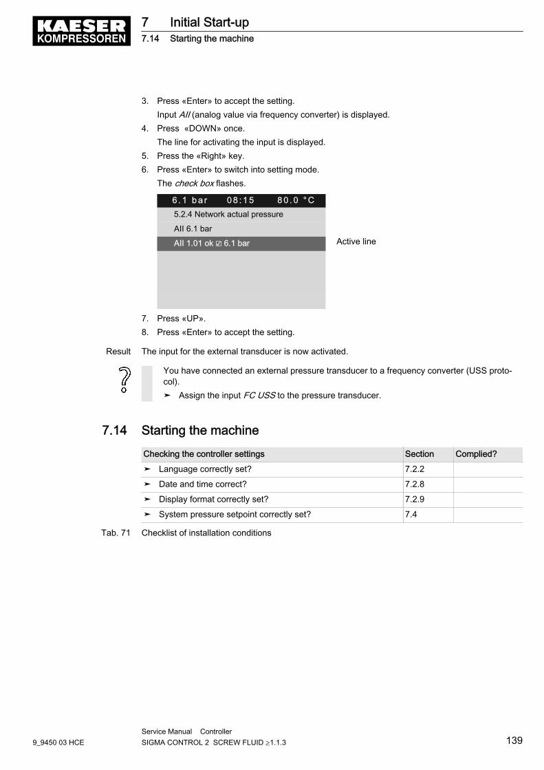
3. Press «Enter» to accept the setting.Input AII (analog value via frequency converter) is displayed.
4. Press «DOWN» once.The line for activating the input is displayed.
5. Press the «Right» key.6. Press «Enter» to switch into setting mode.
The check box flashes.
6 . 1 b a r 0 8 : 1 5 8 0 . 0 ° C5.2.4 Network actual pressure
AII 6.1 bar
AII 1.01 ok ☑ 6.1 bar Active line
7. Press «UP».8. Press «Enter» to accept the setting.
Result The input for the external transducer is now activated.
You have connected an external pressure transducer to a frequency converter (USS proto‐col).➤ Assign the input FC USS to the pressure transducer.
7.14 Starting the machine
Checking the controller settings Section Complied?
➤ Language correctly set? 7.2.2
➤ Date and time correct? 7.2.8
➤ Display format correctly set? 7.2.9
➤ System pressure setpoint correctly set? 7.4
Tab. 71 Checklist of installation conditions
7 Initial Start-up7.14 Starting the machine
9_9450 03 HCEService Manual Controller SIGMA CONTROL 2 SCREW FLUID ≥1.1.3 139
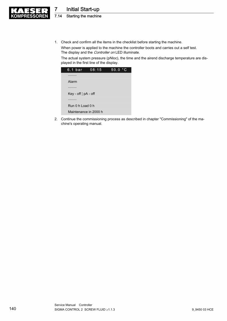
1. Check and confirm all the items in the checklist before starting the machine.When power is applied to the machine the controller boots and carries out a self test.The display and the Controller on LED illuminate.The actual system pressure (pNloc), the time and the airend discharge temperature are dis‐played in the first line of the display.
6 . 1 b a r 0 8 : 1 5 5 0 . 0 ° C·········
Alarm
·········
Key - off ¦ pA - off
·········
Run 0 h Load 0 h
Maintenance in 2000 h
2. Continue the commissioning process as described in chapter "Commissioning" of the ma‐chine's operating manual.
7 Initial Start-up7.14 Starting the machine
140Service Manual Controller SIGMA CONTROL 2 SCREW FLUID ≥1.1.3 9_9450 03 HCE
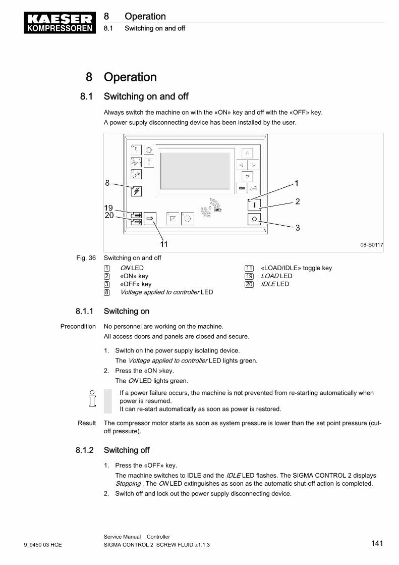
8 Operation8.1 Switching on and off
Always switch the machine on with the «ON» key and off with the «OFF» key.A power supply disconnecting device has been installed by the user.
Fig. 36 Switching on and off1 ON LED2 «ON» key3 «OFF» key8 Voltage applied to controller LED
11 «LOAD/IDLE» toggle key19 LOAD LED20 IDLE LED
8.1.1 Switching on
Precondition No personnel are working on the machine.All access doors and panels are closed and secure.
1. Switch on the power supply isolating device.The Voltage applied to controller LED lights green.
2. Press the «ON »key.The ON LED lights green.
If a power failure occurs, the machine is not prevented from re-starting automatically whenpower is resumed.It can re-start automatically as soon as power is restored.
Result The compressor motor starts as soon as system pressure is lower than the set point pressure (cut-off pressure).
8.1.2 Switching off
1. Press the «OFF» key.The machine switches to IDLE and the IDLE LED flashes. The SIGMA CONTROL 2 displaysStopping . The ON LED extinguishes as soon as the automatic shut-off action is completed.
2. Switch off and lock out the power supply disconnecting device.
8 Operation8.1 Switching on and off
9_9450 03 HCEService Manual Controller SIGMA CONTROL 2 SCREW FLUID ≥1.1.3 141
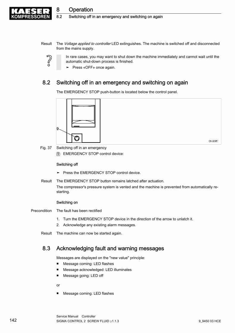
Result The Voltage applied to controller LED extinguishes. The machine is switched off and disconnectedfrom the mains supply.
In rare cases, you may want to shut down the machine immediately and cannot wait until theautomatic shut-down process is finished.➤ Press «OFF» once again.
8.2 Switching off in an emergency and switching on againThe EMERGENCY STOP push-button is located below the control panel.
Fig. 37 Switching off in an emergency9 EMERGENCY STOP control device:
Switching off
➤ Press the EMERGENCY STOP control device.
Result The EMERGENCY STOP button remains latched after actuation.The compressor's pressure system is vented and the machine is prevented from automatically re-starting.
Switching on
Precondition The fault has been rectified
1. Turn the EMERGENCY STOP device in the direction of the arrow to unlatch it.2. Acknowledge any existing alarm messages.
Result The machine can now be started again.
8.3 Acknowledging fault and warning messagesMessages are displayed on the "new value" principle:■ Message coming: LED flashes■ Message acknowledged: LED illuminates■ Message going: LED off
or
■ Message coming: LED flashes
8 Operation8.2 Switching off in an emergency and switching on again
142Service Manual Controller SIGMA CONTROL 2 SCREW FLUID ≥1.1.3 9_9450 03 HCE
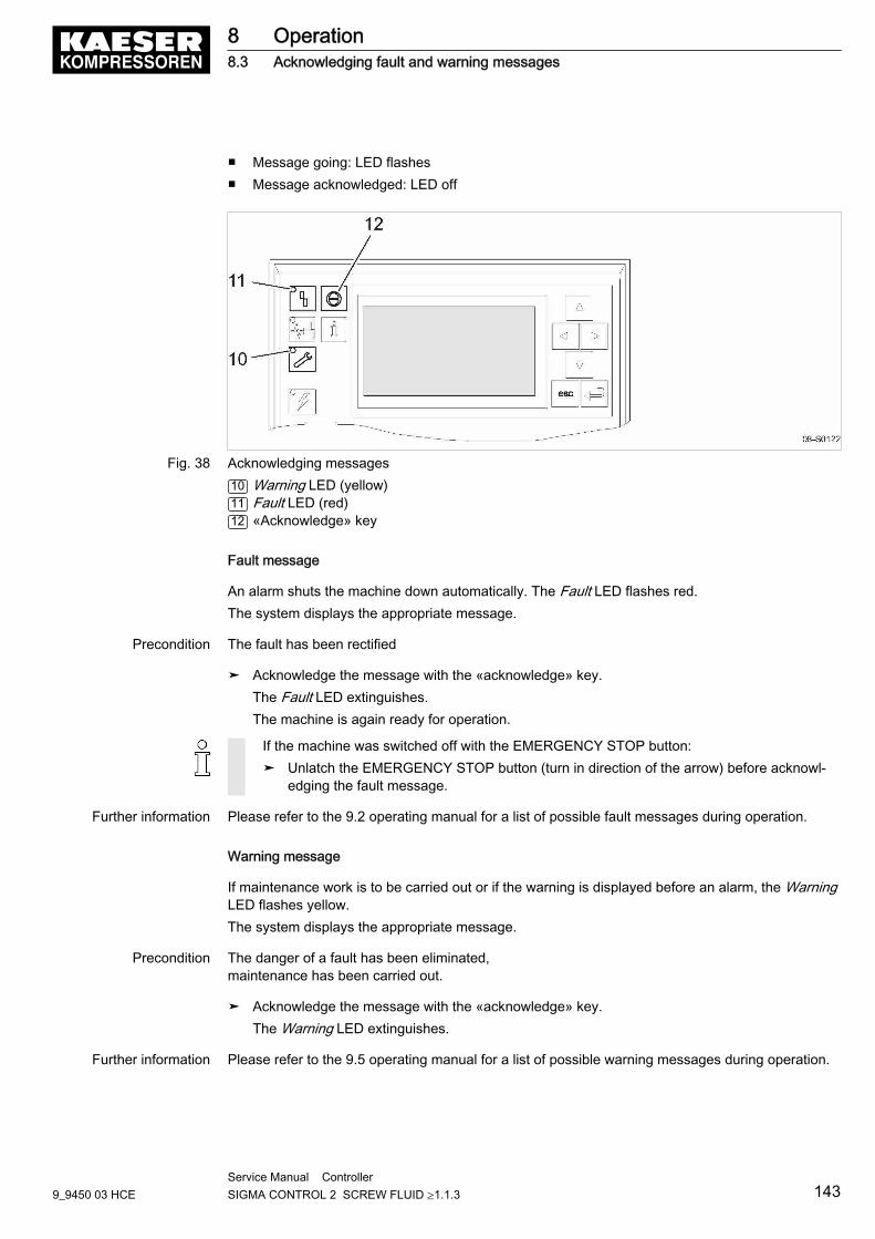
■ Message going: LED flashes■ Message acknowledged: LED off
Fig. 38 Acknowledging messages10 Warning LED (yellow)11 Fault LED (red)12 «Acknowledge» key
Fault message
An alarm shuts the machine down automatically. The Fault LED flashes red.The system displays the appropriate message.
Precondition The fault has been rectified
➤ Acknowledge the message with the «acknowledge» key.The Fault LED extinguishes.The machine is again ready for operation.
If the machine was switched off with the EMERGENCY STOP button:➤ Unlatch the EMERGENCY STOP button (turn in direction of the arrow) before acknowl‐
edging the fault message.
Further information Please refer to the 9.2 operating manual for a list of possible fault messages during operation.
Warning message
If maintenance work is to be carried out or if the warning is displayed before an alarm, the WarningLED flashes yellow.The system displays the appropriate message.
Precondition The danger of a fault has been eliminated,maintenance has been carried out.
➤ Acknowledge the message with the «acknowledge» key.The Warning LED extinguishes.
Further information Please refer to the 9.5 operating manual for a list of possible warning messages during operation.
8 Operation8.3 Acknowledging fault and warning messages
9_9450 03 HCEService Manual Controller SIGMA CONTROL 2 SCREW FLUID ≥1.1.3 143
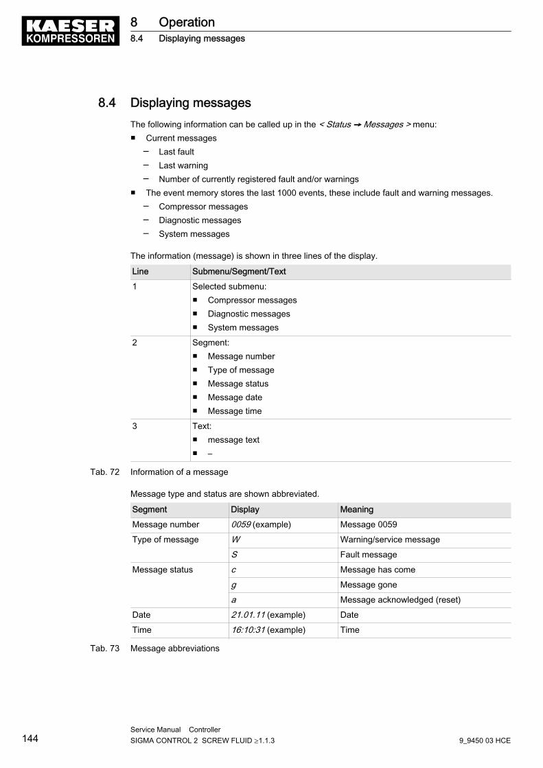
8.4 Displaying messagesThe following information can be called up in the < Status ➙ Messages > menu:■ Current messages
─ Last fault─ Last warning─ Number of currently registered fault and/or warnings
■ The event memory stores the last 1000 events, these include fault and warning messages.─ Compressor messages─ Diagnostic messages─ System messages
The information (message) is shown in three lines of the display.
Line Submenu/Segment/Text
1 Selected submenu:■ Compressor messages■ Diagnostic messages■ System messages
2 Segment:■ Message number■ Type of message■ Message status■ Message date■ Message time
3 Text:■ message text■ –
Tab. 72 Information of a message
Message type and status are shown abbreviated.
Segment Display Meaning
Message number 0059 (example) Message 0059
Type of message W Warning/service message
S Fault message
Message status c Message has come
g Message gone
a Message acknowledged (reset)
Date 21.01.11 (example) Date
Time 16:10:31 (example) Time
Tab. 73 Message abbreviations
8 Operation8.4 Displaying messages
144Service Manual Controller SIGMA CONTROL 2 SCREW FLUID ≥1.1.3 9_9450 03 HCE
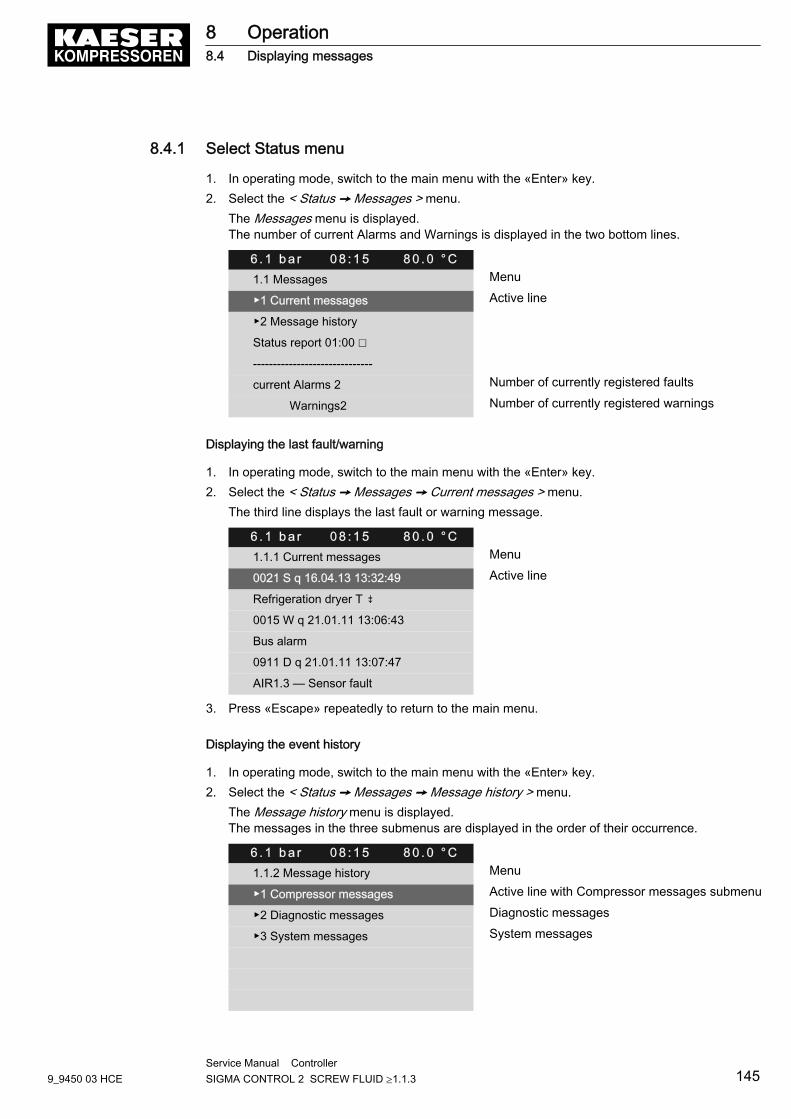
8.4.1 Select Status menu
1. In operating mode, switch to the main menu with the «Enter» key.2. Select the < Status ➙ Messages > menu.
The Messages menu is displayed.The number of current Alarms and Warnings is displayed in the two bottom lines.
6 . 1 b a r 0 8 : 1 5 8 0 . 0 ° C1.1 Messages Menu
▶1 Current messages Active line
▶2 Message history
Status report 01:00 ☐
------------------------------
current Alarms 2 Number of currently registered faults
Warnings2 Number of currently registered warnings
Displaying the last fault/warning
1. In operating mode, switch to the main menu with the «Enter» key.2. Select the < Status ➙ Messages ➙ Current messages > menu.
The third line displays the last fault or warning message.
6 . 1 b a r 0 8 : 1 5 8 0 . 0 ° C1.1.1 Current messages Menu
0021 S q 16.04.13 13:32:49 Active line
Refrigeration dryer T ⇟
0015 W q 21.01.11 13:06:43
Bus alarm
0911 D q 21.01.11 13:07:47
AIR1.3 — Sensor fault
3. Press «Escape» repeatedly to return to the main menu.
Displaying the event history
1. In operating mode, switch to the main menu with the «Enter» key.2. Select the < Status ➙ Messages ➙ Message history > menu.
The Message history menu is displayed.The messages in the three submenus are displayed in the order of their occurrence.
6 . 1 b a r 0 8 : 1 5 8 0 . 0 ° C1.1.2 Message history Menu
▶1 Compressor messages Active line with Compressor messages submenu
▶2 Diagnostic messages Diagnostic messages
▶3 System messages System messages
8 Operation8.4 Displaying messages
9_9450 03 HCEService Manual Controller SIGMA CONTROL 2 SCREW FLUID ≥1.1.3 145
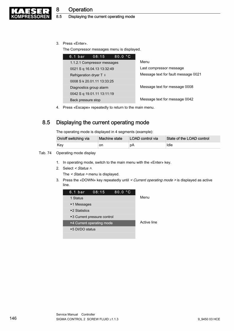
3. Press «Enter».The Compressor messages menu is displayed.
6 . 1 b a r 0 8 : 1 5 8 0 . 0 ° C1.1.2.1 Compressor messages Menu
0021 S q 16.04.13 13:32:49 Last compressor message
Refrigeration dryer T ⇟ Message text for fault message 0021
0008 S k 20.01.11 13:33:25
Diagnostics group alarm Message text for message 0008
0042 S q 19.01.11 13:11:19
Back pressure stop Message text for message 0042
4. Press «Escape» repeatedly to return to the main menu.
8.5 Displaying the current operating modeThe operating mode is displayed in 4 segments (example):
On/off switching via Machine state LOAD control via State of the LOAD control
Key on pA Idle
Tab. 74 Operating mode display
1. In operating mode, switch to the main menu with the «Enter» key.2. Select < Status >.
The < Status > menu is displayed.3. Press the «DOWN» key repeatedly until < Current operating mode > is displayed as active
line.
6 . 1 b a r 0 8 : 1 5 8 0 . 0 ° C1 Status Menu
▶1 Messages
▶2 Statistics
▶3 Current pressure control
▶4 Current operating mode Active line
▶5 DI/DO status
8 Operation8.5 Displaying the current operating mode
146Service Manual Controller SIGMA CONTROL 2 SCREW FLUID ≥1.1.3 9_9450 03 HCE
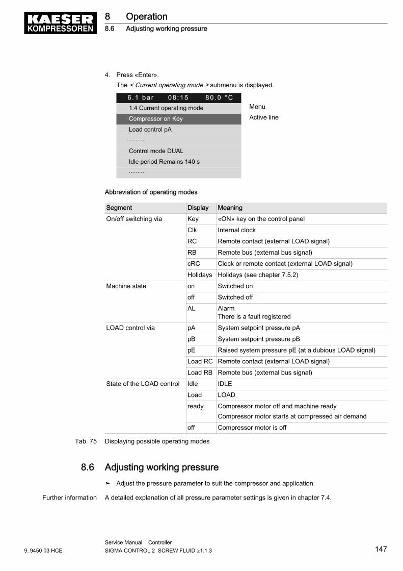
4. Press «Enter».The < Current operating mode > submenu is displayed.
6 . 1 b a r 0 8 : 1 5 8 0 . 0 ° C1.4 Current operating mode Menu
Compressor on Key Active line
Load control pA
·········
Control mode DUAL
Idle period Remains 140 s
·········
Abbreviation of operating modes
Segment Display Meaning
On/off switching via Key «ON» key on the control panel
Clk Internal clock
RC Remote contact (external LOAD signal)
RB Remote bus (external bus signal)
cRC Clock or remote contact (external LOAD signal)
Holidays Holidays (see chapter 7.5.2)
Machine state on Switched on
off Switched off
AL AlarmThere is a fault registered
LOAD control via pA System setpoint pressure pA
pB System setpoint pressure pB
pE Raised system pressure pE (at a dubious LOAD signal)
Load RC Remote contact (external LOAD signal)
Load RB Remote bus (external bus signal)
State of the LOAD control Idle IDLE
Load LOAD
ready Compressor motor off and machine readyCompressor motor starts at compressed air demand
off Compressor motor is off
Tab. 75 Displaying possible operating modes
8.6 Adjusting working pressure➤ Adjust the pressure parameter to suit the compressor and application.
Further information A detailed explanation of all pressure parameter settings is given in chapter 7.4.
8 Operation8.6 Adjusting working pressure
9_9450 03 HCEService Manual Controller SIGMA CONTROL 2 SCREW FLUID ≥1.1.3 147
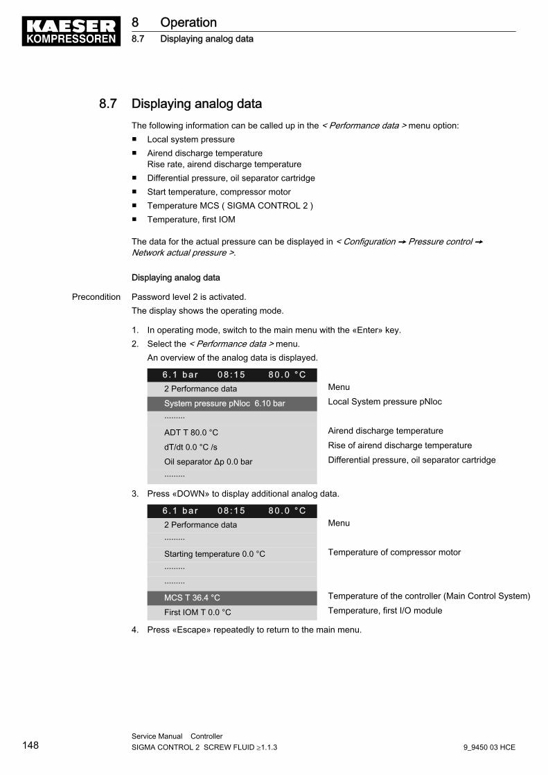
8.7 Displaying analog dataThe following information can be called up in the < Performance data > menu option:■ Local system pressure■ Airend discharge temperature
Rise rate, airend discharge temperature■ Differential pressure, oil separator cartridge■ Start temperature, compressor motor■ Temperature MCS ( SIGMA CONTROL 2 )■ Temperature, first IOM
The data for the actual pressure can be displayed in < Configuration ➙ Pressure control ➙Network actual pressure >.
Displaying analog data
Precondition Password level 2 is activated.The display shows the operating mode.
1. In operating mode, switch to the main menu with the «Enter» key.2. Select the < Performance data > menu.
An overview of the analog data is displayed.
6 . 1 b a r 0 8 : 1 5 8 0 . 0 ° C2 Performance data Menu
System pressure pNloc 6.10 bar Local System pressure pNloc
·········
ADT T 80.0 °C Airend discharge temperature
dT/dt 0.0 °C /s Rise of airend discharge temperature
Oil separator Δp 0.0 bar Differential pressure, oil separator cartridge
·········
3. Press «DOWN» to display additional analog data.
6 . 1 b a r 0 8 : 1 5 8 0 . 0 ° C2 Performance data Menu
·········
Starting temperature 0.0 °C Temperature of compressor motor
·········
·········
MCS T 36.4 °C Temperature of the controller (Main Control System)
First IOM T 0.0 °C Temperature, first I/O module
4. Press «Escape» repeatedly to return to the main menu.
8 Operation8.7 Displaying analog data
148Service Manual Controller SIGMA CONTROL 2 SCREW FLUID ≥1.1.3 9_9450 03 HCE
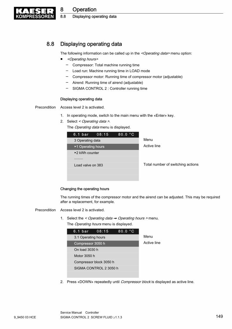
8.8 Displaying operating dataThe following information can be called up in the <Operating data> menu option:■ <Operating hours>
─ Compressor: Total machine running time─ Load run: Machine running time in LOAD mode─ Compressor motor: Running time of compressor motor (adjustable)─ Airend: Running time of airend (adjustable)─ SIGMA CONTROL 2 : Controller running time
Displaying operating data
Precondition Access level 2 is activated.
1. In operating mode, switch to the main menu with the «Enter» key.2. Select < Operating data >.
The Operating data menu is displayed.
6 . 1 b a r 0 8 : 1 5 8 0 . 0 ° C3 Operating data Menu
▶1 Operating hours Active line
▶2 kWh counter
·········
Load valve on 383 Total number of switching actions
Changing the operating hours
The running times of the compressor motor and the airend can be adjusted. This may be requiredafter a replacement, for example.
Precondition Access level 2 is activated.
1. Select the < Operating data ➙ Operating hours > menu.The Operating hours menu is displayed.
6 . 1 b a r 0 8 : 1 5 8 0 . 0 ° C3.1 Operating hours Menu
Compressor 3050 h Active line
On load 3030 h
Motor 3050 h
Compressor block 3050 h
SIGMA CONTROL 2 3050 h
2. Press «DOWN» repeatedly until Compressor block is displayed as active line.
8 Operation8.8 Displaying operating data
9_9450 03 HCEService Manual Controller SIGMA CONTROL 2 SCREW FLUID ≥1.1.3 149
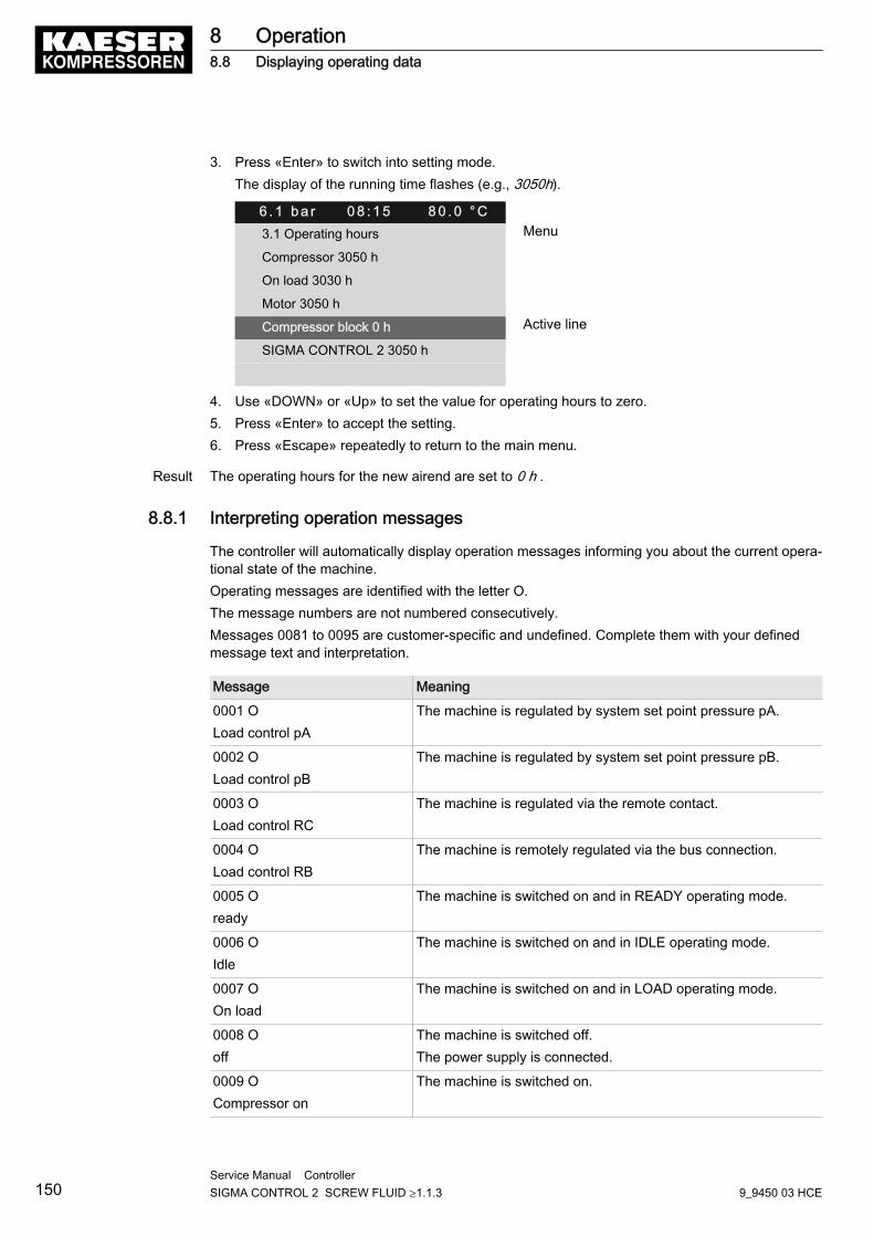
3. Press «Enter» to switch into setting mode.The display of the running time flashes (e.g., 3050h).
6 . 1 b a r 0 8 : 1 5 8 0 . 0 ° C3.1 Operating hours Menu
Compressor 3050 h
On load 3030 h
Motor 3050 h
Compressor block 0 h Active line
SIGMA CONTROL 2 3050 h
4. Use «DOWN» or «Up» to set the value for operating hours to zero.5. Press «Enter» to accept the setting.6. Press «Escape» repeatedly to return to the main menu.
Result The operating hours for the new airend are set to 0 h .
8.8.1 Interpreting operation messages
The controller will automatically display operation messages informing you about the current opera‐tional state of the machine.Operating messages are identified with the letter O.The message numbers are not numbered consecutively.Messages 0081 to 0095 are customer-specific and undefined. Complete them with your definedmessage text and interpretation.
Message Meaning
0001 OLoad control pA
The machine is regulated by system set point pressure pA.
0002 OLoad control pB
The machine is regulated by system set point pressure pB.
0003 OLoad control RC
The machine is regulated via the remote contact.
0004 OLoad control RB
The machine is remotely regulated via the bus connection.
0005 Oready
The machine is switched on and in READY operating mode.
0006 OIdle
The machine is switched on and in IDLE operating mode.
0007 OOn load
The machine is switched on and in LOAD operating mode.
0008 Ooff
The machine is switched off.The power supply is connected.
0009 OCompressor on
The machine is switched on.
8 Operation8.8 Displaying operating data
150Service Manual Controller SIGMA CONTROL 2 SCREW FLUID ≥1.1.3 9_9450 03 HCE
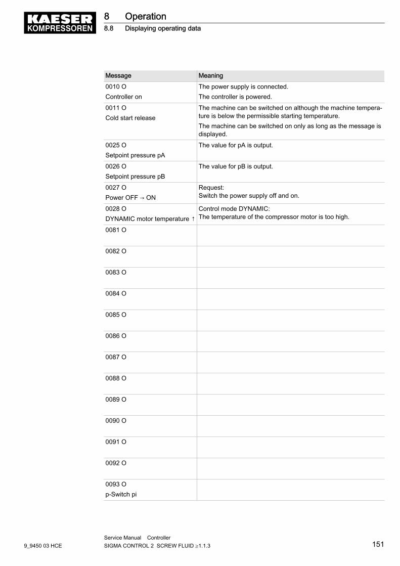
Message Meaning
0010 OController on
The power supply is connected.The controller is powered.
0011 OCold start release
The machine can be switched on although the machine tempera‐ture is below the permissible starting temperature.The machine can be switched on only as long as the message isdisplayed.
0025 OSetpoint pressure pA
The value for pA is output.
0026 OSetpoint pressure pB
The value for pB is output.
0027 OPower OFF → ON
Request:Switch the power supply off and on.
0028 ODYNAMIC motor temperature ↑
Control mode DYNAMIC:The temperature of the compressor motor is too high.
0081 O
0082 O
0083 O
0084 O
0085 O
0086 O
0087 O
0088 O
0089 O
0090 O
0091 O
0092 O
0093 Op-Switch pi
8 Operation8.8 Displaying operating data
9_9450 03 HCEService Manual Controller SIGMA CONTROL 2 SCREW FLUID ≥1.1.3 151
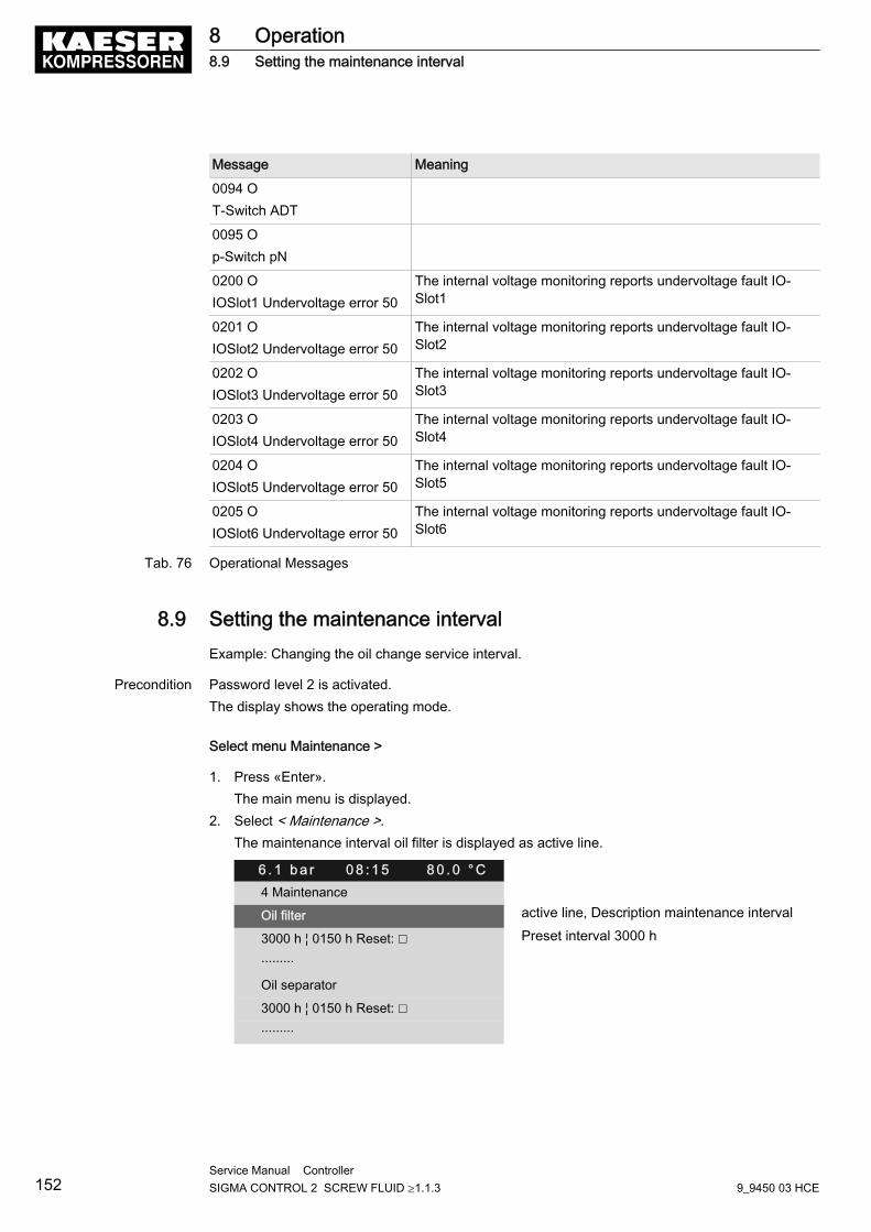
Message Meaning
0094 OT-Switch ADT
0095 Op-Switch pN
0200 OIOSlot1 Undervoltage error 50
The internal voltage monitoring reports undervoltage fault IO‐Slot1
0201 OIOSlot2 Undervoltage error 50
The internal voltage monitoring reports undervoltage fault IO‐Slot2
0202 OIOSlot3 Undervoltage error 50
The internal voltage monitoring reports undervoltage fault IO‐Slot3
0203 OIOSlot4 Undervoltage error 50
The internal voltage monitoring reports undervoltage fault IO‐Slot4
0204 OIOSlot5 Undervoltage error 50
The internal voltage monitoring reports undervoltage fault IO‐Slot5
0205 OIOSlot6 Undervoltage error 50
The internal voltage monitoring reports undervoltage fault IO‐Slot6
Tab. 76 Operational Messages
8.9 Setting the maintenance intervalExample: Changing the oil change service interval.
Precondition Password level 2 is activated.The display shows the operating mode.
Select menu Maintenance >
1. Press «Enter».The main menu is displayed.
2. Select < Maintenance >.The maintenance interval oil filter is displayed as active line.
6 . 1 b a r 0 8 : 1 5 8 0 . 0 ° C4 Maintenance
Oil filter active line, Description maintenance interval
3000 h ¦ 0150 h Reset: ☐ Preset interval 3000 h
·········
Oil separator
3000 h ¦ 0150 h Reset: ☐
·········
8 Operation8.9 Setting the maintenance interval
152Service Manual Controller SIGMA CONTROL 2 SCREW FLUID ≥1.1.3 9_9450 03 HCE
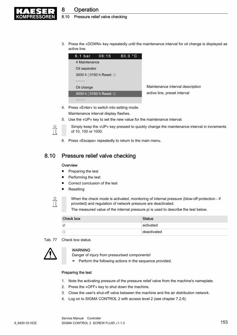
3. Press the «DOWN» key repeatedly until the maintenance interval for oil change is displayed asactive line.
6 . 1 b a r 0 8 : 1 5 8 0 . 0 ° C4 Maintenance
Oil separator
3000 h ¦ 0150 h Reset: ☐
·········
Oil change Maintenance interval description
3000 h ¦ 0150 h Reset: ☐ active line, preset interval
·········
4. Press «Enter» to switch into setting mode.Maintenance interval display flashes.
5. Use the «UP» key to set the new value for the maintenance interval.
Simply keep the «UP» key pressed to quickly change the maintenance interval in incrementsof 10, 100 or 1000.
6. Press «Escape» repeatedly to return to the main menu.
8.10 Pressure relief valve checkingOverview■ Preparing the test■ Performing the test■ Correct conclusion of the test■ Resetting
When the check mode is activated, monitoring of internal pressure (blow-off protection - ifprovided) and regulation of network pressure are deactivated.The measured value of the internal pressure pi is used to describe the test below.
Check box Status
☑ activated
☐ deactivated
Tab. 77 Check box status
WARNINGDanger of injury from pressurised components!➤ Perform the following actions in the sequence provided.
Preparing the test
1. Note the activating pressure of the pressure relief valve from the machine's nameplate.2. Press the «OFF» key to shut down the machine.3. Close the user's shut-off valve between the machine and the air distribution network.4. Log on to SIGMA CONTROL 2 with access level 2 (see chapter 7.2.6).
8 Operation8.10 Pressure relief valve checking
9_9450 03 HCEService Manual Controller SIGMA CONTROL 2 SCREW FLUID ≥1.1.3 153
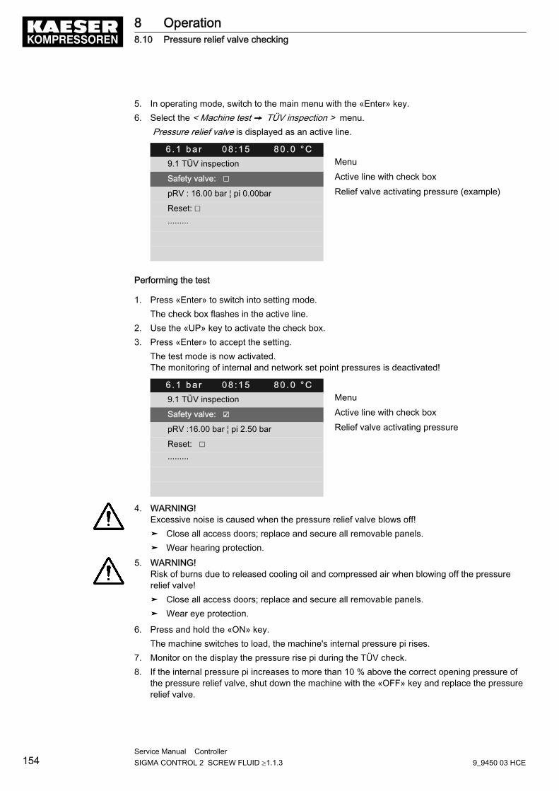
5. In operating mode, switch to the main menu with the «Enter» key.6. Select the < Machine test ➙ TÜV inspection > menu.
Pressure relief valve is displayed as an active line.
6 . 1 b a r 0 8 : 1 5 8 0 . 0 ° C9.1 TÜV inspection Menu
Safety valve: ☐ Active line with check box
pRV : 16.00 bar ¦ pi 0.00bar Relief valve activating pressure (example)
Reset: ☐
·········
Performing the test
1. Press «Enter» to switch into setting mode.The check box flashes in the active line.
2. Use the «UP» key to activate the check box.3. Press «Enter» to accept the setting.
The test mode is now activated.The monitoring of internal and network set point pressures is deactivated!
6 . 1 b a r 0 8 : 1 5 8 0 . 0 ° C9.1 TÜV inspection Menu
Safety valve: ☑ Active line with check box
pRV :16.00 bar ¦ pi 2.50 bar Relief valve activating pressure
Reset: ☐
·········
4. WARNING! Excessive noise is caused when the pressure relief valve blows off!➤ Close all access doors; replace and secure all removable panels.➤ Wear hearing protection.
5. WARNING! Risk of burns due to released cooling oil and compressed air when blowing off the pressurerelief valve!➤ Close all access doors; replace and secure all removable panels.➤ Wear eye protection.
6. Press and hold the «ON» key.The machine switches to load, the machine's internal pressure pi rises.
7. Monitor on the display the pressure rise pi during the TÜV check.8. If the internal pressure pi increases to more than 10 % above the correct opening pressure of
the pressure relief valve, shut down the machine with the «OFF» key and replace the pressurerelief valve.
8 Operation8.10 Pressure relief valve checking
154Service Manual Controller SIGMA CONTROL 2 SCREW FLUID ≥1.1.3 9_9450 03 HCE
If the alarm message pRV ⇞ appears, the pressure relief valve is defective. The permissibleinternal pressure was exceeded by 2 bar.➤ Have the pressure relief valve replaced.
Avoid oil mist:➤ Release the «ON» key immediately when the pressure relief valve responds, in order to
prevent unnecessary oil mist.
Correct conclusion of the test
1. Press «Enter» to switch into setting mode.The check box flashes in the active line.
2. Use the «DOWN» key to deactivate the check box.3. Press «Enter» to accept the setting.
The test mode is de-activated and the test is completed.4. Press «Escape» repeatedly to return to the main menu.5. Open the shut-off valve from the machine.
Result The machine is ready for operation.
Resetting
If the test is canceled when opening the pressure relief valve, SIGMA CONTROL 2 will indicate thehighest measured value as internal pressure.Activate the check box for reset in order to reset the stored value.➤ Activate the check box.
8.11 Checking the temperature sensor and overheating shutdown func‐tionThe machine should shut down if the airend discharge temperature (VET) reaches a maximum of110 °C.SIGMA CONTROL 2 will simulate a higher temperature for checking this function.For this purpose, SIGMA CONTROL 2 automatically determines an offset value to be displayed.During the test mode, this is added to the actual airend discharge temperature to cause the ma‐chine to shut down prematurely.In standard operation, SIGMA CONTROL 2 generates the "overtemperature" fault message whenthe maximum airend discharge temperature is reached. Since the modified test temperature is 2 Kbelow the fault message switching point for overtemperature, the system will not generate a faultmessage in test mode.
Overview■ Shut down the machine and allow to cool down slightly■ Performing the test■ Correct conclusion of the test■ Resetting
Performing the test
Precondition Machine cooled down by approx. 5 °C
8 Operation8.11 Checking the temperature sensor and overheating shutdown function
9_9450 03 HCEService Manual Controller SIGMA CONTROL 2 SCREW FLUID ≥1.1.3 155
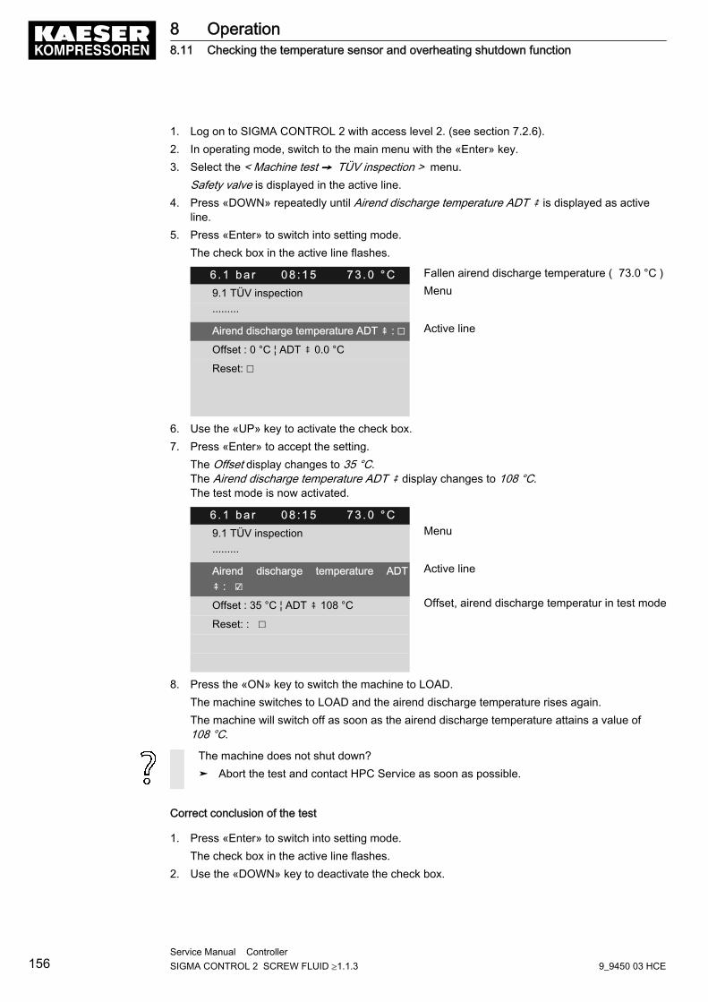
1. Log on to SIGMA CONTROL 2 with access level 2. (see section 7.2.6).2. In operating mode, switch to the main menu with the «Enter» key.3. Select the < Machine test ➙ TÜV inspection > menu.
Safety valve is displayed in the active line.4. Press «DOWN» repeatedly until Airend discharge temperature ADT ⇞ is displayed as active
line.5. Press «Enter» to switch into setting mode.
The check box in the active line flashes.
6 . 1 b a r 0 8 : 1 5 7 3 . 0 ° C Fallen airend discharge temperature ( 73.0 °C )
9.1 TÜV inspection Menu
·········
Airend discharge temperature ADT ⇞ : ☐ Active line
Offset : 0 °C ¦ ADT ⇞ 0.0 °C
Reset: ☐
6. Use the «UP» key to activate the check box.7. Press «Enter» to accept the setting.
The Offset display changes to 35 °C.The Airend discharge temperature ADT ⇞ display changes to 108 °C.The test mode is now activated.
6 . 1 b a r 0 8 : 1 5 7 3 . 0 ° C9.1 TÜV inspection Menu
·········
Airend discharge temperature ADT⇞ : ☑
Active line
Offset : 35 °C ¦ ADT ⇞ 108 °C Offset, airend discharge temperatur in test mode
Reset: : ☐
8. Press the «ON» key to switch the machine to LOAD.The machine switches to LOAD and the airend discharge temperature rises again.The machine will switch off as soon as the airend discharge temperature attains a value of108 °C.
The machine does not shut down?➤ Abort the test and contact HPC Service as soon as possible.
Correct conclusion of the test
1. Press «Enter» to switch into setting mode.The check box in the active line flashes.
2. Use the «DOWN» key to deactivate the check box.
8 Operation8.11 Checking the temperature sensor and overheating shutdown function
156Service Manual Controller SIGMA CONTROL 2 SCREW FLUID ≥1.1.3 9_9450 03 HCE
3. Press «Enter» to accept the setting.The offset is reset to 0 °C.The test mode is de-activated and the test is completed.
4. Press «Escape» repeatedly to return to the main menu.
Resetting
SIGMA CONTROL 2 will display the highest measured value if the test for switching off at overtem‐perature is aborted.Activate the check box for reset in order to reset the stored value.➤ Activate the check box.
8 Operation8.11 Checking the temperature sensor and overheating shutdown function
9_9450 03 HCEService Manual Controller SIGMA CONTROL 2 SCREW FLUID ≥1.1.3 157
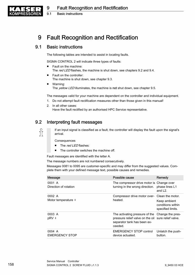
9 Fault Recognition and Rectification9.1 Basic instructions
The following tables are intended to assist in locating faults.
SIGMA CONTROL 2 will indicate three types of faults:■ Fault on the machine:
The red LED flashes, the machine is shut down, see chapters 9.2 and 9.4.■ Fault on the controller:
The machine is shut down, see chapter 9.3.■ Warning:
The yellow LED illuminates, the machine is not shut down, see chapter 9.5.
The messages valid for your machine are dependent on the controller and individual equipment.1. Do not attempt fault rectification measures other than those given in this manual!2. In all other cases:
Have the fault rectified by an authorised HPC Service representative.
9.2 Interpreting fault messagesIf an input signal is classified as a fault, the controller will display the fault upon the signal'sarrival.
Consequences■ The red LED flashes:■ The controller switches the machine off.
Fault messages are identified with the letter A.The message numbers are not numbered consecutively.Messages 0081 to 0095 are customer-specific and may differ from the suggested values. Com‐plete them with your defined message text, possible causes and remedies.
Message Possible cause Remedy0001 ADirection of rotation
The compressor drive motor isturning in the wrong direction.
Change overphase lines L1and L2.
0002 AMotor temperature ⇞
Compressor drive motor over‐heated.
Clean the motor.Keep ambientconditions withinspecified limits.
0003 ApRV ⇞
The activating pressure of thepressure relief valve on the oilseparator tank has been ex‐ceeded.
Change the pres‐sure relief valve.
0004 AEMERGENCY STOP
EMERGENCY STOP controldevice actuated.
Unlatch the push-button.
9 Fault Recognition and Rectification9.1 Basic instructions
158Service Manual Controller SIGMA CONTROL 2 SCREW FLUID ≥1.1.3 9_9450 03 HCE
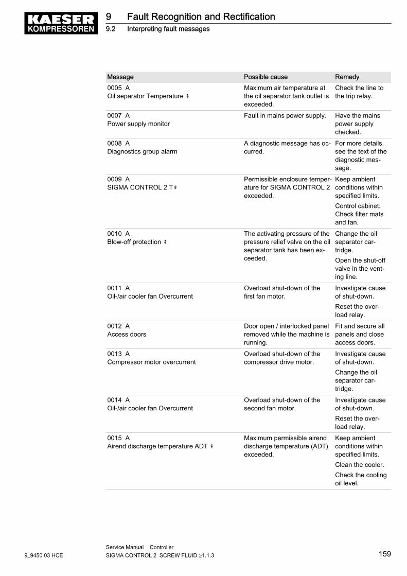
Message Possible cause Remedy0005 AOil separator Temperature ⇞
Maximum air temperature atthe oil separator tank outlet isexceeded.
Check the line tothe trip relay.
0007 APower supply monitor
Fault in mains power supply. Have the mainspower supplychecked.
0008 ADiagnostics group alarm
A diagnostic message has oc‐curred.
For more details,see the text of thediagnostic mes‐sage.
0009 ASIGMA CONTROL 2 T⇞
Permissible enclosure temper‐ature for SIGMA CONTROL 2exceeded.
Keep ambientconditions withinspecified limits.Control cabinet:Check filter matsand fan.
0010 ABlow-off protection ⇞
The activating pressure of thepressure relief valve on the oilseparator tank has been ex‐ceeded.
Change the oilseparator car‐tridge.Open the shut-offvalve in the vent‐ing line.
0011 AOil-/air cooler fan Overcurrent
Overload shut-down of thefirst fan motor.
Investigate causeof shut-down.Reset the over‐load relay.
0012 AAccess doors
Door open / interlocked panelremoved while the machine isrunning.
Fit and secure allpanels and closeaccess doors.
0013 ACompressor motor overcurrent
Overload shut-down of thecompressor drive motor.
Investigate causeof shut-down.Change the oilseparator car‐tridge.
0014 AOil-/air cooler fan Overcurrent
Overload shut-down of thesecond fan motor.
Investigate causeof shut-down.Reset the over‐load relay.
0015 AAirend discharge temperature ADT ⇞
Maximum permissible airenddischarge temperature (ADT)exceeded.
Keep ambientconditions withinspecified limits.Clean the cooler.Check the coolingoil level.
9 Fault Recognition and Rectification9.2 Interpreting fault messages
9_9450 03 HCEService Manual Controller SIGMA CONTROL 2 SCREW FLUID ≥1.1.3 159
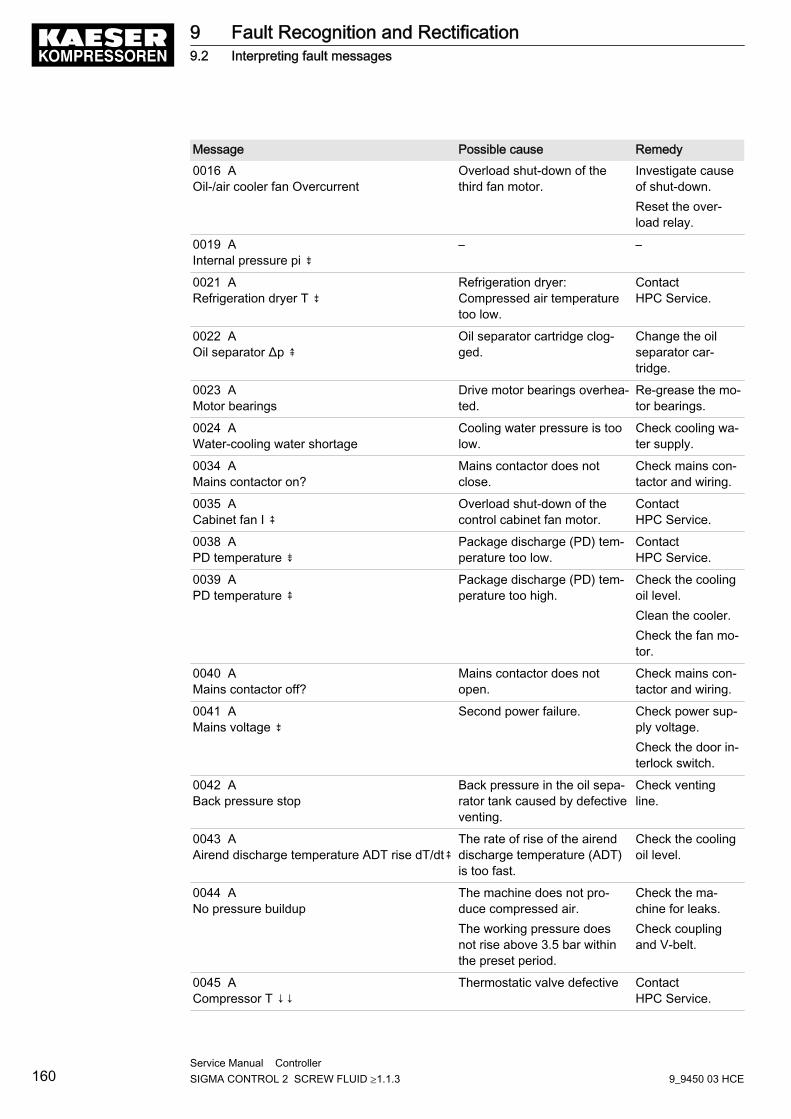
Message Possible cause Remedy0016 AOil-/air cooler fan Overcurrent
Overload shut-down of thethird fan motor.
Investigate causeof shut-down.Reset the over‐load relay.
0019 AInternal pressure pi ⇟
– –
0021 ARefrigeration dryer T ⇟
Refrigeration dryer:Compressed air temperaturetoo low.
ContactHPC Service.
0022 AOil separator Δp ⇞
Oil separator cartridge clog‐ged.
Change the oilseparator car‐tridge.
0023 AMotor bearings
Drive motor bearings overhea‐ted.
Re-grease the mo‐tor bearings.
0024 AWater-cooling water shortage
Cooling water pressure is toolow.
Check cooling wa‐ter supply.
0034 AMains contactor on?
Mains contactor does notclose.
Check mains con‐tactor and wiring.
0035 ACabinet fan I ⇞
Overload shut-down of thecontrol cabinet fan motor.
ContactHPC Service.
0038 APD temperature ⇟
Package discharge (PD) tem‐perature too low.
ContactHPC Service.
0039 APD temperature ⇞
Package discharge (PD) tem‐perature too high.
Check the coolingoil level.Clean the cooler.Check the fan mo‐tor.
0040 AMains contactor off?
Mains contactor does notopen.
Check mains con‐tactor and wiring.
0041 AMains voltage ⇟
Second power failure. Check power sup‐ply voltage.Check the door in‐terlock switch.
0042 ABack pressure stop
Back pressure in the oil sepa‐rator tank caused by defectiveventing.
Check ventingline.
0043 AAirend discharge temperature ADT rise dT/dt⇞
The rate of rise of the airenddischarge temperature (ADT)is too fast.
Check the coolingoil level.
0044 ANo pressure buildup
The machine does not pro‐duce compressed air.The working pressure doesnot rise above 3.5 bar withinthe preset period.
Check the ma‐chine for leaks.Check couplingand V-belt.
0045 ACompressor T ↓↓
Thermostatic valve defective ContactHPC Service.
9 Fault Recognition and Rectification9.2 Interpreting fault messages
160Service Manual Controller SIGMA CONTROL 2 SCREW FLUID ≥1.1.3 9_9450 03 HCE
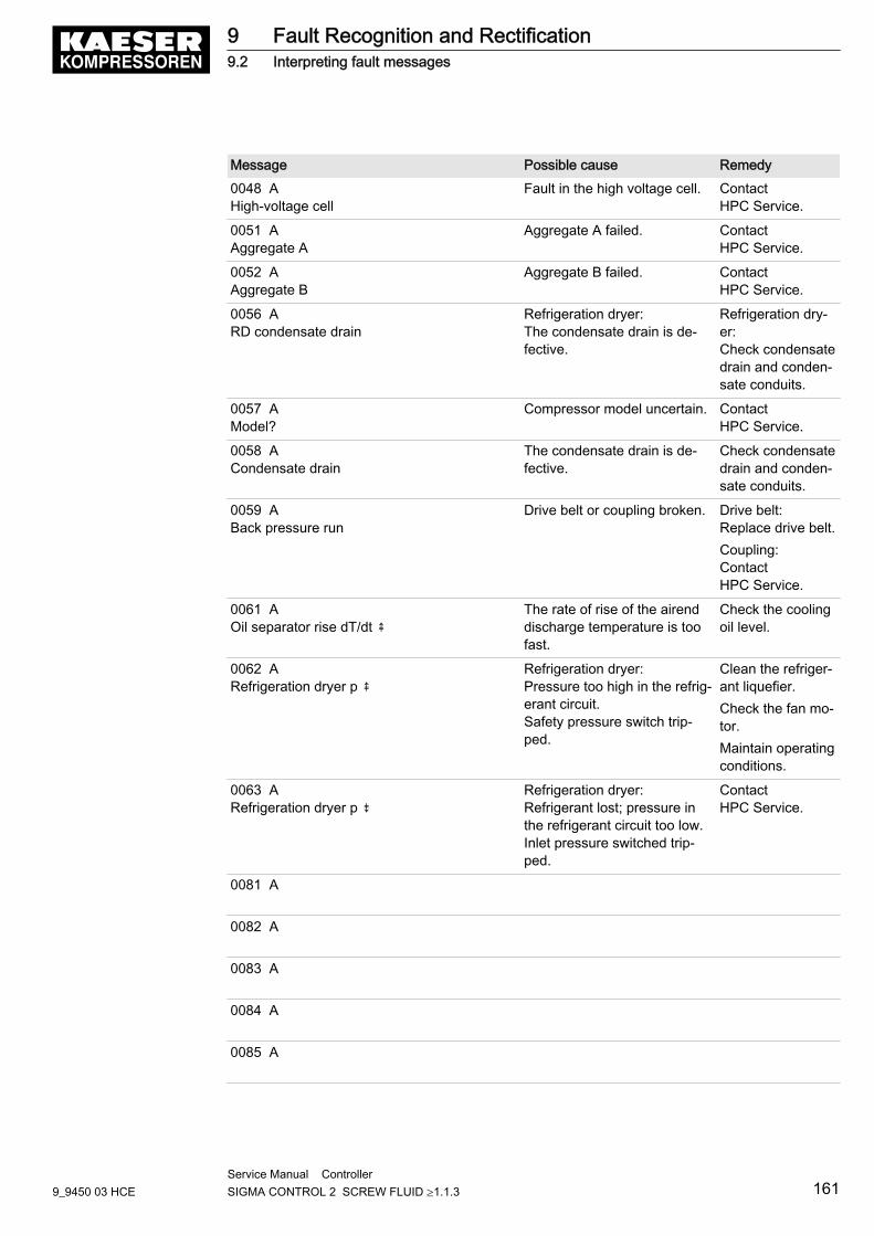
Message Possible cause Remedy0048 AHigh-voltage cell
Fault in the high voltage cell. ContactHPC Service.
0051 AAggregate A
Aggregate A failed. ContactHPC Service.
0052 AAggregate B
Aggregate B failed. ContactHPC Service.
0056 ARD condensate drain
Refrigeration dryer:The condensate drain is de‐fective.
Refrigeration dry‐er:Check condensatedrain and conden‐sate conduits.
0057 AModel?
Compressor model uncertain. ContactHPC Service.
0058 ACondensate drain
The condensate drain is de‐fective.
Check condensatedrain and conden‐sate conduits.
0059 ABack pressure run
Drive belt or coupling broken. Drive belt:Replace drive belt.Coupling:ContactHPC Service.
0061 AOil separator rise dT/dt ⇞
The rate of rise of the airenddischarge temperature is toofast.
Check the coolingoil level.
0062 ARefrigeration dryer p ⇞
Refrigeration dryer:Pressure too high in the refrig‐erant circuit.Safety pressure switch trip‐ped.
Clean the refriger‐ant liquefier.Check the fan mo‐tor.Maintain operatingconditions.
0063 ARefrigeration dryer p ⇟
Refrigeration dryer:Refrigerant lost; pressure inthe refrigerant circuit too low.Inlet pressure switched trip‐ped.
ContactHPC Service.
0081 A
0082 A
0083 A
0084 A
0085 A
9 Fault Recognition and Rectification9.2 Interpreting fault messages
9_9450 03 HCEService Manual Controller SIGMA CONTROL 2 SCREW FLUID ≥1.1.3 161
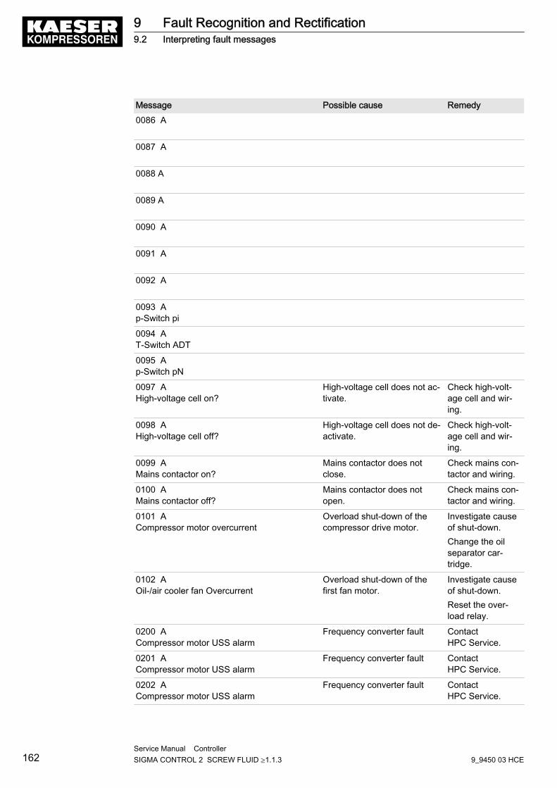
Message Possible cause Remedy0086 A
0087 A
0088 A
0089 A
0090 A
0091 A
0092 A
0093 Ap-Switch pi
0094 AT-Switch ADT
0095 Ap-Switch pN
0097 AHigh-voltage cell on?
High-voltage cell does not ac‐tivate.
Check high-volt‐age cell and wir‐ing.
0098 AHigh-voltage cell off?
High-voltage cell does not de‐activate.
Check high-volt‐age cell and wir‐ing.
0099 AMains contactor on?
Mains contactor does notclose.
Check mains con‐tactor and wiring.
0100 AMains contactor off?
Mains contactor does notopen.
Check mains con‐tactor and wiring.
0101 ACompressor motor overcurrent
Overload shut-down of thecompressor drive motor.
Investigate causeof shut-down.Change the oilseparator car‐tridge.
0102 AOil-/air cooler fan Overcurrent
Overload shut-down of thefirst fan motor.
Investigate causeof shut-down.Reset the over‐load relay.
0200 ACompressor motor USS alarm
Frequency converter fault ContactHPC Service.
0201 ACompressor motor USS alarm
Frequency converter fault ContactHPC Service.
0202 ACompressor motor USS alarm
Frequency converter fault ContactHPC Service.
9 Fault Recognition and Rectification9.2 Interpreting fault messages
162Service Manual Controller SIGMA CONTROL 2 SCREW FLUID ≥1.1.3 9_9450 03 HCE
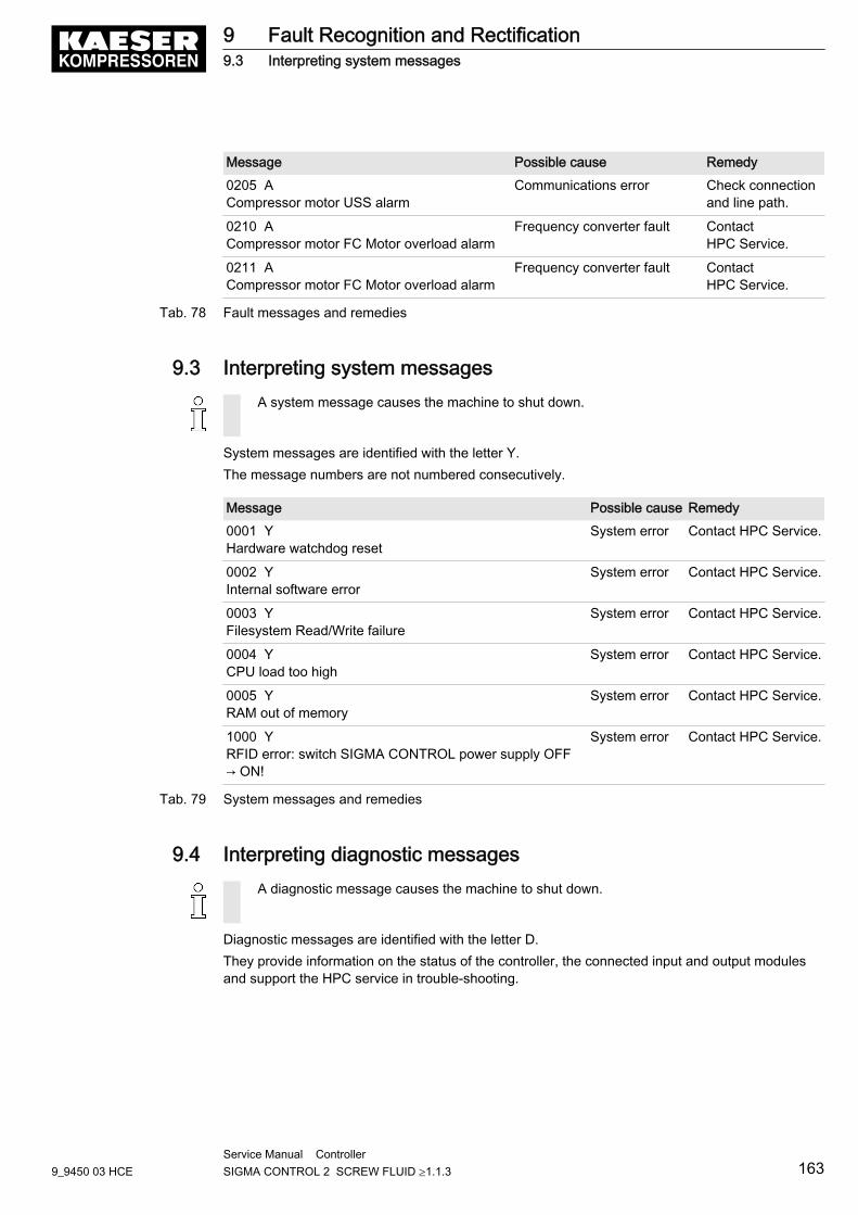
Message Possible cause Remedy0205 ACompressor motor USS alarm
Communications error Check connectionand line path.
0210 ACompressor motor FC Motor overload alarm
Frequency converter fault ContactHPC Service.
0211 ACompressor motor FC Motor overload alarm
Frequency converter fault ContactHPC Service.
Tab. 78 Fault messages and remedies
9.3 Interpreting system messagesA system message causes the machine to shut down.
System messages are identified with the letter Y.The message numbers are not numbered consecutively.
Message Possible cause Remedy0001 YHardware watchdog reset
System error Contact HPC Service.
0002 YInternal software error
System error Contact HPC Service.
0003 YFilesystem Read/Write failure
System error Contact HPC Service.
0004 YCPU load too high
System error Contact HPC Service.
0005 YRAM out of memory
System error Contact HPC Service.
1000 YRFID error: switch SIGMA CONTROL power supply OFF→ ON!
System error Contact HPC Service.
Tab. 79 System messages and remedies
9.4 Interpreting diagnostic messagesA diagnostic message causes the machine to shut down.
Diagnostic messages are identified with the letter D.They provide information on the status of the controller, the connected input and output modulesand support the HPC service in trouble-shooting.
9 Fault Recognition and Rectification9.3 Interpreting system messages
9_9450 03 HCEService Manual Controller SIGMA CONTROL 2 SCREW FLUID ≥1.1.3 163
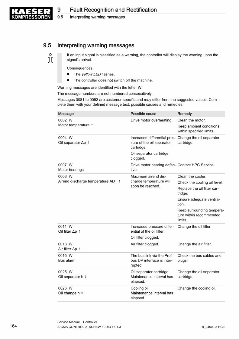
9.5 Interpreting warning messagesIf an input signal is classified as a warning, the controller will display the warning upon thesignal's arrival.
Consequences■ The yellow LED flashes.■ The controller does not switch off the machine.
Warning messages are identified with the letter W.The message numbers are not numbered consecutively.Messages 0081 to 0092 are customer-specific and may differ from the suggested values. Com‐plete them with your defined message text, possible causes and remedies.
Message Possible cause Remedy0002 WMotor temperature ↑
Drive motor overheating. Clean the motor.Keep ambient conditionswithin specified limits.
0004 WOil separator Δp ↑
Increased differential pres‐sure of the oil separatorcartridge.Oil separator cartridgeclogged.
Change the oil separatorcartridge.
0007 WMotor bearings
Drive motor bearing defec‐tive.
Contact HPC Service.
0008 WAirend discharge temperature ADT ↑
Maximum airend dis‐charge temperature willsoon be reached.
Clean the cooler.Check the cooling oil level.Replace the oil filter car‐tridge.Ensure adequate ventila‐tion.Keep surrounding tempera‐ture within recommendedlimits.
0011 WOil filter Δp ↑
Increased pressure differ‐ential of the oil filter.Oil filter clogged.
Change the oil filter.
0013 WAir filter Δp ↑
Air filter clogged. Change the air filter.
0015 WBus alarm
The bus link via the Profi‐bus DP interface is inter‐rupted.
Check the bus cables andplugs.
0025 WOil separator h ⇞
Oil separator cartridge:Maintenance interval haselapsed.
Change the oil separatorcartridge.
0026 WOil change h ⇞
Cooling oil:Maintenance interval haselapsed.
Change the cooling oil.
9 Fault Recognition and Rectification9.5 Interpreting warning messages
164Service Manual Controller SIGMA CONTROL 2 SCREW FLUID ≥1.1.3 9_9450 03 HCE
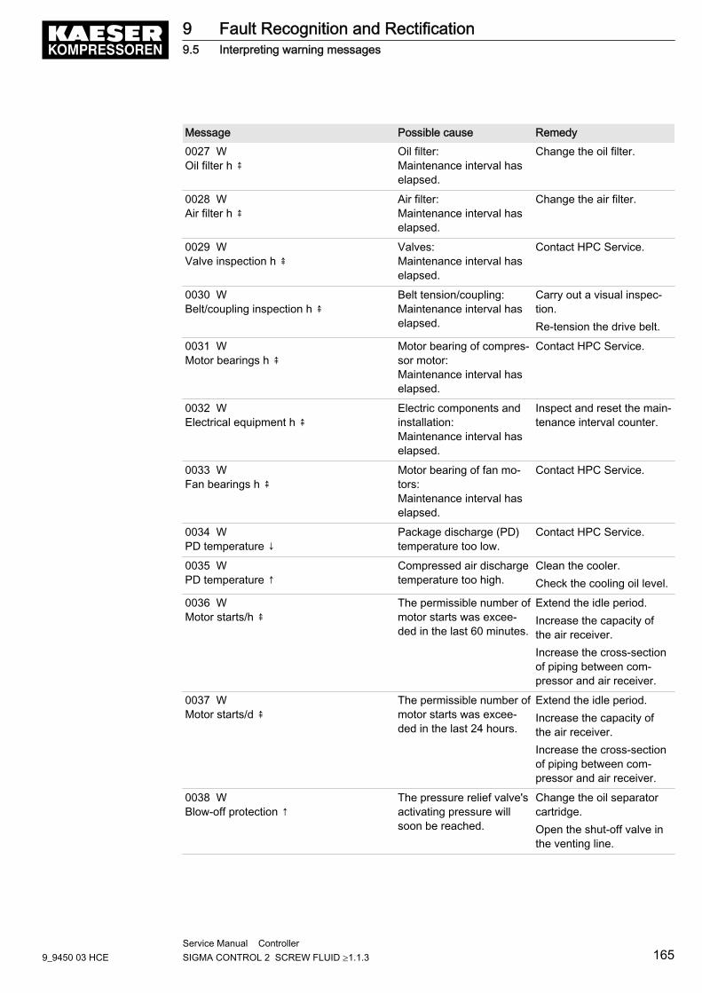
Message Possible cause Remedy0027 WOil filter h ⇞
Oil filter:Maintenance interval haselapsed.
Change the oil filter.
0028 WAir filter h ⇞
Air filter:Maintenance interval haselapsed.
Change the air filter.
0029 WValve inspection h ⇞
Valves:Maintenance interval haselapsed.
Contact HPC Service.
0030 WBelt/coupling inspection h ⇞
Belt tension/coupling:Maintenance interval haselapsed.
Carry out a visual inspec‐tion.Re-tension the drive belt.
0031 WMotor bearings h ⇞
Motor bearing of compres‐sor motor:Maintenance interval haselapsed.
Contact HPC Service.
0032 WElectrical equipment h ⇞
Electric components andinstallation:Maintenance interval haselapsed.
Inspect and reset the main‐tenance interval counter.
0033 WFan bearings h ⇞
Motor bearing of fan mo‐tors:Maintenance interval haselapsed.
Contact HPC Service.
0034 WPD temperature ↓
Package discharge (PD)temperature too low.
Contact HPC Service.
0035 WPD temperature ↑
Compressed air dischargetemperature too high.
Clean the cooler.Check the cooling oil level.
0036 WMotor starts/h ⇞
The permissible number ofmotor starts was excee‐ded in the last 60 minutes.
Extend the idle period.Increase the capacity ofthe air receiver.Increase the cross-sectionof piping between com‐pressor and air receiver.
0037 WMotor starts/d ⇞
The permissible number ofmotor starts was excee‐ded in the last 24 hours.
Extend the idle period.Increase the capacity ofthe air receiver.Increase the cross-sectionof piping between com‐pressor and air receiver.
0038 WBlow-off protection ↑
The pressure relief valve'sactivating pressure willsoon be reached.
Change the oil separatorcartridge.Open the shut-off valve inthe venting line.
9 Fault Recognition and Rectification9.5 Interpreting warning messages
9_9450 03 HCEService Manual Controller SIGMA CONTROL 2 SCREW FLUID ≥1.1.3 165
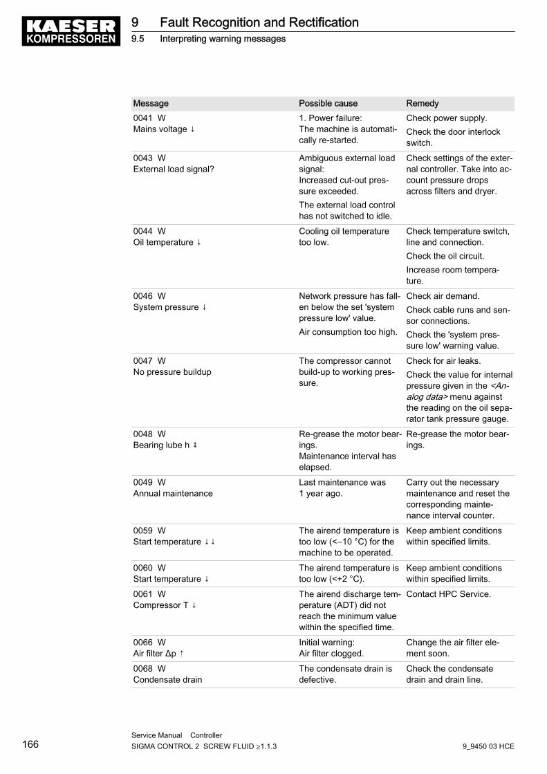
Message Possible cause Remedy0041 WMains voltage ↓
1. Power failure:The machine is automati‐cally re-started.
Check power supply.Check the door interlockswitch.
0043 WExternal load signal?
Ambiguous external loadsignal:Increased cut-out pres‐sure exceeded.The external load controlhas not switched to idle.
Check settings of the exter‐nal controller. Take into ac‐count pressure dropsacross filters and dryer.
0044 WOil temperature ↓
Cooling oil temperaturetoo low.
Check temperature switch,line and connection.Check the oil circuit.Increase room tempera‐ture.
0046 WSystem pressure ↓
Network pressure has fall‐en below the set 'systempressure low' value.Air consumption too high.
Check air demand.Check cable runs and sen‐sor connections.Check the 'system pres‐sure low' warning value.
0047 WNo pressure buildup
The compressor cannotbuild-up to working pres‐sure.
Check for air leaks.Check the value for internalpressure given in the <An‐alog data> menu againstthe reading on the oil sepa‐rator tank pressure gauge.
0048 WBearing lube h ⇞
Re-grease the motor bear‐ings.Maintenance interval haselapsed.
Re-grease the motor bear‐ings.
0049 WAnnual maintenance
Last maintenance was1 year ago.
Carry out the necessarymaintenance and reset thecorresponding mainte‐nance interval counter.
0059 WStart temperature ↓↓
The airend temperature istoo low (<−10 °C) for themachine to be operated.
Keep ambient conditionswithin specified limits.
0060 WStart temperature ↓
The airend temperature istoo low (<+2 °C).
Keep ambient conditionswithin specified limits.
0061 WCompressor T ↓
The airend discharge tem‐perature (ADT) did notreach the minimum valuewithin the specified time.
Contact HPC Service.
0066 WAir filter Δp ⇡
Initial warning:Air filter clogged.
Change the air filter ele‐ment soon.
0068 WCondensate drain
The condensate drain isdefective.
Check the condensatedrain and drain line.
9 Fault Recognition and Rectification9.5 Interpreting warning messages
166Service Manual Controller SIGMA CONTROL 2 SCREW FLUID ≥1.1.3 9_9450 03 HCE
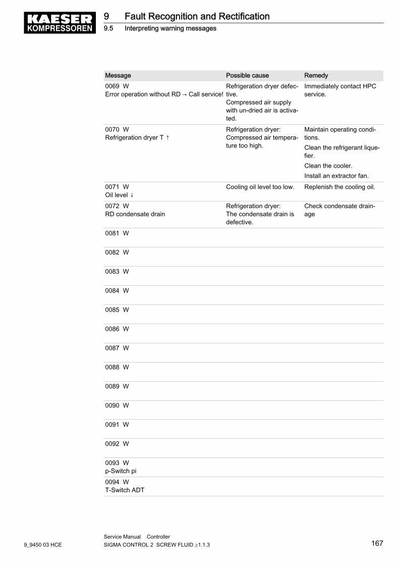
Message Possible cause Remedy0069 WError operation without RD → Call service!
Refrigeration dryer defec‐tive.Compressed air supplywith un-dried air is activa‐ted.
Immediately contact HPCservice.
0070 WRefrigeration dryer T ↑
Refrigeration dryer:Compressed air tempera‐ture too high.
Maintain operating condi‐tions.Clean the refrigerant lique‐fier.Clean the cooler.Install an extractor fan.
0071 WOil level ↓
Cooling oil level too low. Replenish the cooling oil.
0072 WRD condensate drain
Refrigeration dryer:The condensate drain isdefective.
Check condensate drain‐age
0081 W
0082 W
0083 W
0084 W
0085 W
0086 W
0087 W
0088 W
0089 W
0090 W
0091 W
0092 W
0093 Wp-Switch pi
0094 WT-Switch ADT
9 Fault Recognition and Rectification9.5 Interpreting warning messages
9_9450 03 HCEService Manual Controller SIGMA CONTROL 2 SCREW FLUID ≥1.1.3 167
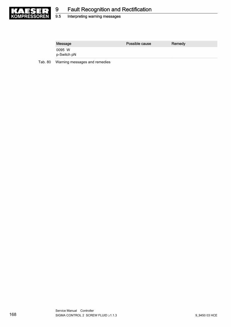
Message Possible cause Remedy0095 Wp-Switch pN
Tab. 80 Warning messages and remedies
9 Fault Recognition and Rectification9.5 Interpreting warning messages
168Service Manual Controller SIGMA CONTROL 2 SCREW FLUID ≥1.1.3 9_9450 03 HCE
10 Maintenance10.1 Maintenance Work
The SIGMA CONTROL 2 and the I/O modules are maintenance-free.
10 Maintenance10.1 Maintenance Work
9_9450 03 HCEService Manual Controller SIGMA CONTROL 2 SCREW FLUID ≥1.1.3 169
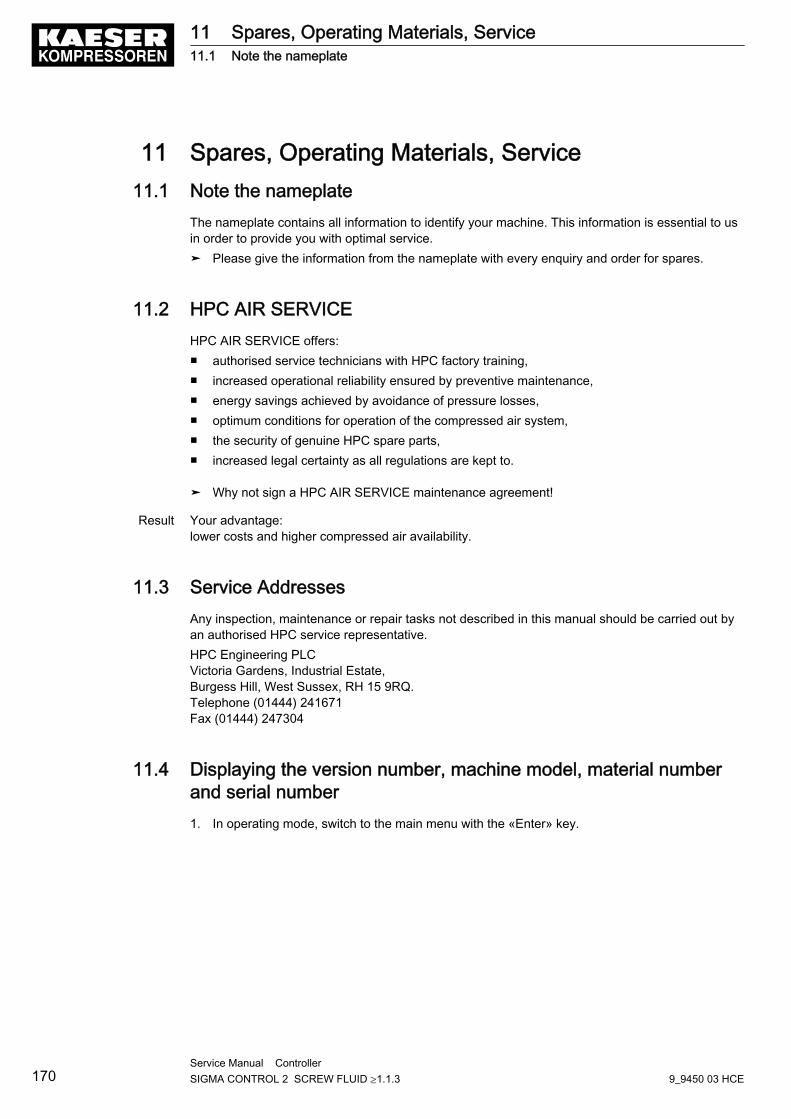
11 Spares, Operating Materials, Service11.1 Note the nameplate
The nameplate contains all information to identify your machine. This information is essential to usin order to provide you with optimal service.➤ Please give the information from the nameplate with every enquiry and order for spares.
11.2 HPC AIR SERVICEHPC AIR SERVICE offers:■ authorised service technicians with HPC factory training,■ increased operational reliability ensured by preventive maintenance,■ energy savings achieved by avoidance of pressure losses,■ optimum conditions for operation of the compressed air system,■ the security of genuine HPC spare parts,■ increased legal certainty as all regulations are kept to.
➤ Why not sign a HPC AIR SERVICE maintenance agreement!
Result Your advantage:lower costs and higher compressed air availability.
11.3 Service AddressesAny inspection, maintenance or repair tasks not described in this manual should be carried out byan authorised HPC service representative.HPC Engineering PLCVictoria Gardens, Industrial Estate,Burgess Hill, West Sussex, RH 15 9RQ.Telephone (01444) 241671Fax (01444) 247304
11.4 Displaying the version number, machine model, material numberand serial number1. In operating mode, switch to the main menu with the «Enter» key.
11 Spares, Operating Materials, Service11.1 Note the nameplate
170Service Manual Controller SIGMA CONTROL 2 SCREW FLUID ≥1.1.3 9_9450 03 HCE
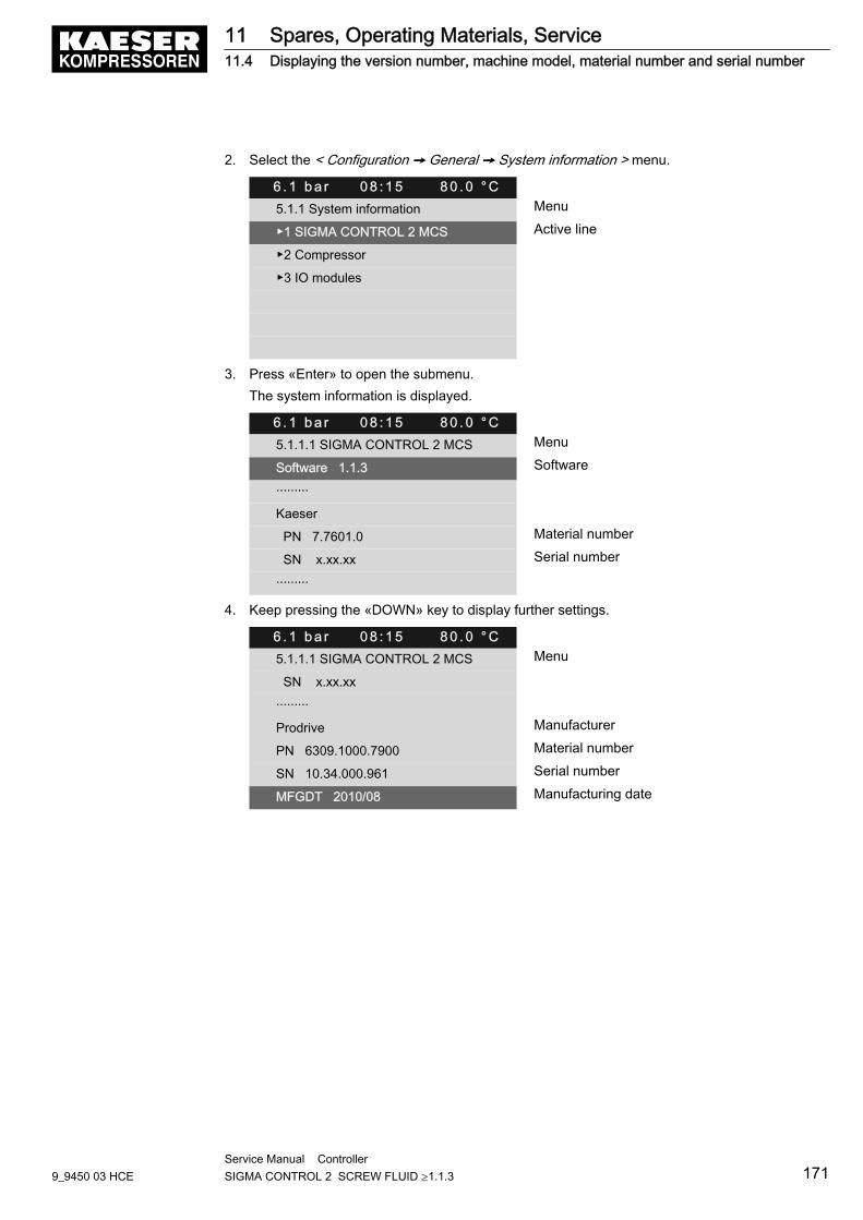
2. Select the < Configuration ➙ General ➙ System information > menu.
6 . 1 b a r 0 8 : 1 5 8 0 . 0 ° C5.1.1 System information Menu
▶1 SIGMA CONTROL 2 MCS Active line
▶2 Compressor
▶3 IO modules
3. Press «Enter» to open the submenu.The system information is displayed.
6 . 1 b a r 0 8 : 1 5 8 0 . 0 ° C5.1.1.1 SIGMA CONTROL 2 MCS Menu
Software 1.1.3 Software
·········
Kaeser
PN 7.7601.0 Material number
SN x.xx.xx Serial number
·········
4. Keep pressing the «DOWN» key to display further settings.
6 . 1 b a r 0 8 : 1 5 8 0 . 0 ° C5.1.1.1 SIGMA CONTROL 2 MCS Menu
SN x.xx.xx
·········
Prodrive Manufacturer
PN 6309.1000.7900 Material number
SN 10.34.000.961 Serial number
MFGDT 2010/08 Manufacturing date
11 Spares, Operating Materials, Service11.4 Displaying the version number, machine model, material number and serial number
9_9450 03 HCEService Manual Controller SIGMA CONTROL 2 SCREW FLUID ≥1.1.3 171
12 Decommissioning, Storage and Transport12.1 De-commissioning
➤ Follow the instructions in the machine's service manual.
12.2 Packing➤ Follow the instructions in the machine's service manual.
12.3 Storage➤ Follow the instructions in the machine's service manual.
12.4 Transporting➤ Follow the instructions in the machine's service manual.
12.5 Disposal➤ Follow the instructions in the machine's service manual.
12 Decommissioning, Storage and Transport12.1 De-commissioning
172Service Manual Controller SIGMA CONTROL 2 SCREW FLUID ≥1.1.3 9_9450 03 HCE